Embed Size (px)
Citation preview

CHA E-Gun SOP Page 1 of 7Revision 2-121010
CHA E-Gun SOP
1. Scope
1.1 This document provides the procedure for operating the CHA E-Gun.
2. Table of Contents1. Scope...........................................................................................................................................................12. Table of Contents........................................................................................................................................1

CHA E-Gun SOP Page 2 of 7Revision 2-121010
3. Reference Documents.................................................................................................................................23.1 Referenced within this Document.........................................................................................................23.2 External Documents..............................................................................................................................2
4. Equipment and/or Materials.......................................................................................................................25. Safety...........................................................................................................................................................26. Setup Procedures........................................................................................................................................2
6.1 Record Information in Log Book............................................................................................................26.2 Vent the Chamber.................................................................................................................................36.3 Load the Chamber.................................................................................................................................36.4 Pump Down Chamber...........................................................................................................................46.5 Set Deposition Program Parameters.....................................................................................................4
7. Film Deposition Procedures.........................................................................................................................58. Shutdown Procedures.................................................................................................................................69. Process Notes..............................................................................................................................................7
9.1 Typical Film Characteristics...................................................................................................................79.2 Process Summary..................................................................................................................................7
10. Revision History...........................................................................................................................................7
Figure 1, Right Side Control Panel............................................................................................................................3Figure 2, Front Control Panel....................................................................................................................................4Figure 3, Bottom Control Panel................................................................................................................................5Figure 4, Left Side Telemark Controls.......................................................................................................................6
3. Reference Documents
3.1 Referenced within this Document
3.1.1 None
3.2 External Documents
3.2.1 None
4. Equipment and/or Materials
4.1 CHA E-Gun
4.2 Wafer/Sample
4.3 Target Material
4.4 Crucible
5. Safety
5.1 Follow all Nanofab safety procedures.
6. Setup Procedures
6.1 Record Information in Log Book
6.1.1 Record all setup and processing information in the log book.
Ion Gauge
Valve Controls
Chamber Bell ControlShutter Control
Figure , Right Side Control Panel
CHA E-Gun SOP Page 3 of 7Revision 2-121010
6.2 Vent the Chamber
6.2.1 Turn off the ion gauge (IG1 or IG2), if either is on. The IG readout should be blank when it is off. See Error: Reference source not found.
6.2.2 Close the HI-VAC valve. See Error: Reference source not found.
6.2.3 Vent the chamber by moving the VENT switch to the OPEN position. See Error: Reference source not found.
6.2.4 The convectron gauge will show an increase in the chamber pressure (B).
6.2.5 When you hear purge gas escaping from the bell, move the vent switch to the CLOSE position.
6.3 Load the Chamber
6.3.1 Raise the bell by moving the HOIST switch to the RAISE position. See Error: Reference source not found.
6.3.2 Secure substrate in the spring clips.
6.3.3 Open the shutter by moving the SHUTTER switch to OPEN. See Error: Reference source not found.
6.3.4 Place evaporation material in the crucible.
6.3.5 Close the shutter.
6.3.6 Lower the bell with the HOIST switch.

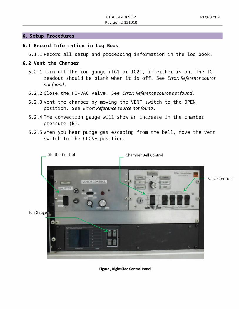
Inficon Controller
Telemark Controller
Figure , Front Control Panel
Joystick
Emission Current ADJ Knob
CHA E-Gun SOP Page 4 of 7Revision 2-121010
6.3.7 Move the HOIST switch to the STOP position.
6.4 Pump Down Chamber
6.4.1 Start the Mechanical Pump by turning power to on. See Error: Reference source not found.
6.4.2 If the pump turns itself off, turn it back on.
6.4.3 Open the ROUGH valve. See Error: Reference source not found.
6.4.4 When chamber pressure reaches 50 mTorr close the ROUGH valve.
6.4.5 Turn off the mechanical pump.
6.4.6 Open the HI-VAC valve.
6.4.7 After waiting 45 minutes, turn on the ion gauge (IG1) only. See Error: Reference source not found.
6.4.8 Wait for the pressure to drop to about 2x10⁻⁶ Torr.
6.5 Set Deposition Program Parameters
6.5.1 Turn on the INFICON 6000 controller. See Error: Reference source not found.
6.5.2 Press DSPL to enter the DISPLAY INDEX menu on the INFICON 6000 controller.
6.5.3 To change program settings: (if no change is necessary skip to 6.5.4)
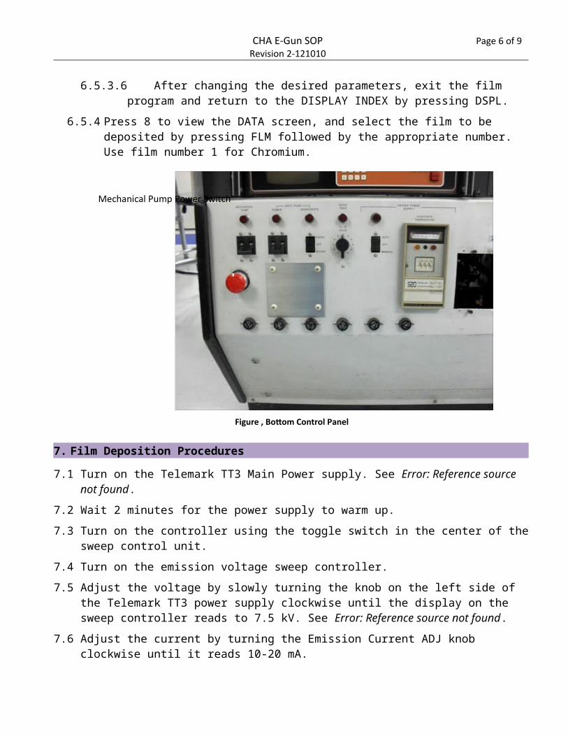
Mechanical Pump Power Switch
Figure , Bottom Control Panel
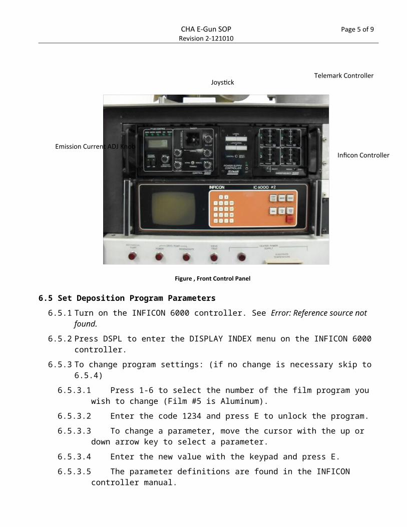
CHA E-Gun SOP Page 5 of 7Revision 2-121010
6.5.3.1 Press 1-6 to select the number of the film program you wish to change (Film #5 is Aluminum).
6.5.3.2 Enter the code 1234 and press E to unlock the program.
6.5.3.3 To change a parameter, move the cursor with the up or down arrow key to select a parameter.
6.5.3.4 Enter the new value with the keypad and press E.
6.5.3.5 The parameter definitions are found in the INFICON controller manual.
6.5.3.6 After changing the desired parameters, exit the film program and return to the DISPLAY INDEX by pressing DSPL.
6.5.4 Press 8 to view the DATA screen, and select the film to be deposited by pressing FLM followed by the appropriate number. Use film number 1 for Chromium.
7. Film Deposition Procedures
7.1 Turn on the Telemark TT3 Main Power supply. See Error: Reference source not found.
7.2 Wait 2 minutes for the power supply to warm up.
7.3 Turn on the controller using the toggle switch in the center of the sweep control unit.
7.4 Turn on the emission voltage sweep controller.
7.5 Adjust the voltage by slowly turning the knob on the left side of the Telemark TT3 power supply clockwise until the display on the sweep controller reads to 7.5 kV. See Error: Reference source notfound.
Voltage AdjustMain Power
Figure , Left Side Telemark Controls
CHA E-Gun SOP Page 6 of 7Revision 2-121010
7.6 Adjust the current by turning the Emission Current ADJ knob clockwise until it reads 10-20 mA.
7.7 Look through the window to make sure the beam is centered on the crucible and wait for it to glow orange.
7.8 Center the beam using the joystick. See Error: Reference source not found.
7.9 Slowly adjust the Emission Current 5 to 10 mA at a time using the Emission Current ADJ knob.
7.10 Press the MAN button on the INFICON controller.
7.11 Press the ZERO THK button on the INFICON to zero the crystal thickness monitor.
7.12 If desired, turn the MOTOR CONTROL to LO, and move the direction knob to FWD or REV to rotate the samples during deposition.
7.13 Open the shutter to begin deposition.
7.14 The INFICON controller will monitor the deposition rate, and deposition thickness.
7.15 To increase the deposition rate, increase the Emission Current.
8. Shutdown Procedures
8.1 At the desired deposition thickness, close the shutter.
8.2 SLOWLY decrease the Emission Current.
8.3 Turn off the MOTOR CONTROL (if used).
8.4 Slowly decrease the Emission Voltage.

CHA E-Gun SOP Page 7 of 7Revision 2-121010
8.5 Turn off the Emission Voltage and wait 2 minutes.
8.6 Turn off the ion gage (IG1).
8.7 Turn off power supply controller.
8.8 Wait two minutes.
8.9 Turn off main power on left side TT3 Telemark power supply.
8.10 Turn off Inficon.
8.11 Close the HI-VAC valve
8.12 Move the VENT switch to OPEN to vent the chamber.
8.13 Wait until pressure on readout B is above 9.0^2.
8.14 Turn off vent.
8.15 Raise the bell and remove the substrate and replace the lower two glass slides.
8.16 Lower the bell.
8.17 Move hoist switch to stop after lowering.
8.18 Rough the chamber to about 50 mTorr.
8.18.1 Turn on the mechanical pump.
8.18.2 Open the Rough valve.
8.19 Close the rough valve when pressure reaches 50 mTorr.
8.20 Turn off the mechanical pump.
8.21 Open the HI-VAC valve and leave the chamber under high vacuum when you are finished.
9. Process Notes
9.1 Typical Film Characteristics
9.2 Process Summary
10. Revision History
Rev Date Originator Description of Changes
1 22 Jan 2010 Sam Bell2 10 Dec 2010 Sam Bell Added figure 4 and edited text3 9 Aug 2011 Sam Bell Added shutdown steps