Embed Size (px)
Citation preview
DRAFT (25.03.2002)
1
Subject: AIRCRAFT WIRING SYSTEMSTRAINING PROGRAM
Date: 03/21/02Initiated By: WG8
AC No: 120-YYChange:DRAFT
Table of Contents:1. PURPOSE................................................................................................... 12. APPLICABILITY. ........................................................................................ 23. RELATED 14 CFR PARTS......................................................................... 24. ADVISORY CIRCULARS. .......................................................................... 35. REPORTS................................................................................................... 46. OTHER DOCUMENTS................................................................................ 47. DEFINITIONS. ............................................................................................ 48. BACKGROUND. ......................................................................................... 69. OBJECTIVE................................................................................................ 710. ESSENTIAL ELEMENTS FOR WIRING SYSTEMS TRAININGPROGRAM. ......................................................................................................... 8APPENDIX A - WIRING SYSTEMS MINIMUM INITIAL TRAINING PROGRAM 9APPENDIX B - CURRICULUM AND LESSONS PLAN .................................... 10APPENDIX C - WIRE SYSTEM......................................................................... 31APPENDIX D - HISTORY .................................................................................. 32
1. PURPOSE.
This Advisory Circular (AC) provides guidance for developing an enhanced wiringsystems training program. The guidance in this AC is based on recommendationssubmitted to the FAA from the Aging Transport Systems rulemaking AdvisoryCommittee (ATSRAC). The guidance and recommendations in this AC are derived fromthe best practices training developed through extensive research by ATSRAC IndustryWorking Groups 5 and 8. This AC is an effort by the FAA to officially endorse thesebest practices and to dispense this information industry wide so the benefits of thisinformation can be effectively realized. Adoption of the recommendations in this ACwill result in a training program that will improve the awareness and skill level of theaviation personnel in wiring system production, modification, maintenance, inspection,

DRAFT (25.03.2002)
2
alterations and repair. This AC promotes a philosophy of training for all personnel whocome into contact with aircraft wiring systems as part of their job and tailors the trainingfor each workgroup to their particular needs.
To fully realize the objectives of this AC, air carriers, air operators, type certificateholders, STC holders, maintenance providers, repair stations and persons performingfield approval modifications or repairs, will need to rethink their current approach tomaintaining and modifying aircraft wiring and systems. This may require more thansimply updating maintenance manuals and work cards and enhancing training.Maintenance personnel need to be aware that aircraft wiring systems should bemaintained with the same level of intensity as any other system in the aircraft. They alsoneed to recognize that visual inspection of wiring has inherent limitations. Small defectssuch as breached or cracked insulations, especially in small gage wire may not always beapparent. Therefore effective wiring maintenance combines visual inspection techniqueswith improved wiring maintenance practices and training.
2. APPLICABILITY.
This AC provides acceptable, but not inclusive, means of complying with the FederalAviation Regulations. The information in this AC is based on lessons learned by jointFAA, JAA, ATSRAC, and industry, manufacturers and airline working groups. Therecommendations in this AC can be applied to any aircraft training program.
3. RELATED 14 CFR PARTS.
a. Part 21, Certification Procedures for Products and Parts.
b. Part 25, Airworthiness Standards, Transport Category Airplanes
c. Part 43, Maintenance, Preventive Maintenance, Rebuilding, and Alteration
d. Part 91, General Operating and Flight Rules.
e. Part 119, Certification: Air Carriers and Commercial Operators.
f. Part 121, Operating Requirements: Domestic, Flag, and SupplementalOperations.
g. Part 125, Certification and Operations: Airplanes Having a SeatingCapacity of 20 or More Passengers or a Maximum Payload Capacity of6,000 pounds or More.

DRAFT (25.03.2002)
3
h. Part 129, Operations: Foreign Air Carriers and Foreign Operators ofU.S.-Registered Aircraft Engaged in Common Carriage.
i. Part 135, Operating Requirements: Commuter and On-demandOperations.
j. Part 145,
4. ADVISORY CIRCULARS.
a. AC 20-53A, Protection Of Airplane Fuel Systems Against Fuel VaporIgnition Due To Lightning
b. AC 20-13, Protection Of Aircraft Electrical/Electronic Systems AgainstThe Indirect Effects Of Lightning
c. AC 25-16, Electrical Fault and Fire Protection and Prevention.
d. AC 25.981-1B, Fuel Tank Ignition Source Prevention Guidelines
e. AC 43-3, Nondestructive Testing in Aircraft.
f. AC 43-4A, Corrosion Control for Aircraft.
g. AC 43-7, Ultrasonic Testing for Aircraft.
h. AC 43-12A, Preventive Maintenance.
i. AC 43.13-1A, Acceptable Methods, Techniques and Practices--AircraftInspection and Repair.
j. AC 43.13-1B, Acceptable Methods, Techniques and Practices for Repairsand Alterations to Aircraft.
k. AC 43-204, Visual Inspection For Aircraft
l. AC 65-15A, Airframe & Powerplant Mechanics Airframe Handbook,Chapter 11. Aircraft Electrical Systems
m. AC 120-XX, Program to enhance aircraft wiring system maintenance

DRAFT (25.03.2002)
4
5. REPORTS.
a. Aging Systems Task Force Aging Transport Systems Task 1 andTask 2 Final Report.
b. Transport Aircraft Intrusive Inspection Project, Final Report.
c. Aging Transport Systems Rulemaking Advisory Committee, Task 3Working Group, Final Report.
d. The Standard Wiring Practices Task 4 Working Group, Final Report.
e. Aircraft Wiring Systems Training, Task 5 Working Group, FinalReport.
f. ATA Specification 117 (Wiring Maintenance Practices/Guidelines).
g. National Transportation Safety Board, Safety Recommendation,September 19, 2000, A-00-105 through -108.
6. OTHER DOCUMENTS.
a. ATA Operator/Manufacturer Scheduled Maintenance Development asrevised, ATA Maintenance Steering Group (MSG-3), may be obtainedfrom the Air Transport Association of America; Suite 1100: 1301Pennsylvania Ave, NW; Washington, DC 20004-1707.
b. Handbook Bulletin 91-15 "Origin and propagation of inaccessible aircraftfire under in-flight airflow conditions.”
7. DEFINITIONS.
Arc tracking. A phenomenon that occurs in electrical wiring when leakage currents on awet insulation surface are great enough to vaporize the moisture, resulting in theformation of dry spots, which offer a high amount of resistance to current flow. In turn,an induced voltage will develop across these spots and result in the occurrence of smallsurface discharges.

DRAFT (25.03.2002)
5
Combustible. The ability of any solid, liquid or gaseous material to cause a fire to besustained after removal of the ignition source. The term is used in place ofinflammable/flammable. It should not be interpreted as identifying material that willburn when subjected to a continuous source of heat as occurs when a fire develops.
Contamination. With regard to wiring contamination refers to either of the followingsituations:
a. The presence of a foreign material that is likely to cause degradation ofwiring.
b. The presence of a foreign material that is capable of sustainingcombustion after removal of ignition source.
Detailed Inspection (DET). An intensive examination of a specific item, installation orassembly to detect damage, failure or irregularity. Available lighting is normallysupplemented with a direct source of good lighting at an intensity deemed appropriate.Inspection aids such as mirrors, magnifying lenses or other means may be necessary.Surface cleaning and elaborate access procedures may be required.
Functional Failure. Failure of an item to perform its intended function within specifiedlimits.
General Visual Inspection (GVI). A visual examination of an interior or exterior area,installation or assembly to detect obvious damage, failure or irregularity. This level ofinspection is made from within touching distance unless otherwise specified. A mirrormay be necessary to enhance visual access to all exposed surfaces in the inspection area.This level of inspection is made under normally available lighting conditions such asdaylight, hangar lighting, flashlight or droplight and may require removal or opening ofaccess panels or doors. Stands, ladders or platforms may be required to gain proximity tothe area being checked.
Lightning/High Intensity Radiated Field (L/HIRF) protection. Is the protection ofairplane electrical systems and structure from indueced voltages or currents by means ofshielded wires, raceways, bonding jumpers, connectors, composite fairings withconductive mesh, static dischargers, and the inherent conductivity of the structure, butmay include aircraft specific devices, e.g., RF Gaskets.
Maintenance. As defined in 14 CFR 1.1 “maintenance means inspection, overhaul,repair, preservation, and the replacement of parts, but excludes preventive maintenance.”For the purposes of this advisory circular, it also includes preventive maintenance asdescribed in both § 1.1 and 14 CFR part 43, Appendix A(c).
Maintenance Significant Item (MSI). Items identified by the manufacturer whose failureA. could affect safety (on ground or in flight) and/orB. is undetectable during operations, and/orC. could have significant operational impact, and/orD. could have significant economic impact.

DRAFT (25.03.2002)
6
Needling. The puncturing of a wire’s insulation to make contact with the core to test thecontinuity and presence of voltage in the wire segment.
Stand-alone GVI. A General Visual Inspection which is not performed as part of a zonalinspection.
Structural Significant Item (SSI). Any detail, element or assembly that contributessignificantly to carrying flight, ground, pressure, or control loads and whose failure couldaffect the structural integrity necessary for the safety of the aircraft.
Swarf. British term used to describe the metal particles, generated from drilling andmachining operations. Such particles may accumulate on and between wires within awire bundle.
Wire System. An electrical connection between two or more points including theassociated termination devices (e.g., connectors, terminal blocks, splices) and thenecessary means for its installation and identification. (See Appendix C, Wire System.)
Zonal Inspection. A collective term comprising selected General Visual Inspections andvisual checks that are applied to each zone, defined by access and area, to check systemand power plant installations and structure for security and general condition.
8. BACKGROUND.
The NTSB has recommended that the FAA address all wiring issues identified in theAging Systems Plan, either through rulemaking or through other means. The NTSBspecifically cited the need for improved training of maintenance personnel to ensureadequate recognition and repair of potentially unsafe wiring conditions.
To address the issues identified in the Aging Systems Plan, in 1998 the FAA establishedthe Aging Transport Systems Rulemaking Advisory Committee (ATSRAC). TheATSRAC provides the forum for the airlines, manufacturers, and other regulatoryauthorities to make recommendations to the FAA based on the Aging Systems Plan. ThisAdvisory Circular addresses only the training program. It does not attempt to deal withthe condition of the fleet's wiring, or develop performance tests for wiring. This advisorycircular captures, in FAA guidance form, the aircraft wiring training program developedby ATSRAC. This includes a training syllabus, curriculum, training target groups and amatrix outlining training for each training group.
For more information see Appendix D – History.

DRAFT (25.03.2002)
7
9. OBJECTIVE.
The objective of this wiring maintenance training program is to give the operators ormaintenance repair organizations a model for the development of their own wiringmaintenance training program. This will ensure that proper procedures, methodstechniques, and practices are used when performing maintenance, preventivemaintenance, inspection, alteration, and cleaning of wiring systems.
This program was developed for eight different target groups and may be used for theminimum requirements for initial and recurrent training (see training matrix). Dependingon the duties some may fall into more than one target group and therefore must fullfill allobjectives of the associated target groups.The target groups are:
1 Qualified staff performing wire systems maintenanceThese staff members are personnel who perform wire systems maintenance and theirtraining is based on their job description and the work being done by them.(e.g. FAA: electricians/avionics / A/P mechanics JAA: Cat A or B2)
2 Qualified staff performing maintenance inspections on wiring systemsThese staff members are personnel who perform wire systems inspections (but notmaintenance) and their training is based on their job description and the work beingdone by them.
(e.g. FAA: Inspectors / A/P mechanics JAA: Cat B2)
3 Qualified staff performing electrical/avionic engineering on in service aircraftThese staff members are personnel who are authorized to design wire systemsinstallations, modifications and repairs.(e.g. FAA/JAA: electric/avionic engineers)
4 Qualified staff performing general maintenance/inspections not involving wiremaintenance.(LRU change is not considered wire maintenance)These staff members are personnel who perform maintenance on aircraft that mayrequire removal/reconnection of electrical connective devices(e.g. FAA: A/P mechanics JAA: Cat A or B1)
5 Qualified staff performing other engineering or planning work on in service aircraftThese staff members are personnel who are authorized to design mechanical/structuresystems installations, modifications and repairs, or personnel who are authorized toplan maintenance tasks.

DRAFT (25.03.2002)
8
6 Other service staff with duties in proximity to wire systemsThese staff members are personnel who’s duties would bring them into contact/viewof aircraft wire systems.This would include, but not be limited to, aircraft cleaners, cargo loaders, fuelers,lavatory servicing personnel, deicing personnel, push back personnel.
7 Flight Deck Crewe.g. Pilots, Flight Engineers
8 Cabin Crew
10. ESSENTIAL ELEMENTS FOR WIRING SYSTEMS TRAINING PROGRAM.
a. Initial Training.
Initial training should be conducted for each designated work group.The initial training for each designated work group is outlined in Wiring SystemsMinimum Initial Training Program - Appendix A. Curriculum and Lesson Plans foreach dedicated module are included in Appendix B.The most important criteria is to meet the objectives of the Lesson Plans – AppendixB. The method of reaching the objectives should be at the discretion of the trainingorganization. However, supporting documentation such as Advisory Circular 120-XX and TBD are an integral part of training and should be used to supportdevelopment of the Curriculum and Lesson Plans
b. Refresher Training
Refresher training should be conducted in a period not to exceed two years. It couldconsist of a review of previously covered material plus any new material or revisionsto publications. Refresher training will follow the Wiring Systems Minimum InitialTraining Program - Appendix A for that particular target group.
DRAFT (25.03.2002)
9
APPENDIX A - WIRING SYSTEMS MINIMUM INITIAL TRAININGPROGRAMPlease see: Appendix A.xls

DRAFT (25.03.2002)
10
APPENDIX B - CURRICULUM AND LESSONS PLAN
Table of Contents:
CURRICULUM AND LESSON PLANS ............................................................. 11WIRING SYSTEMS CURRICULUM .................................................................. 11WIRING SYSTEMS LESSON PLAN ................................................................. 14
MODULE A: INTRODUCTION .................................................................................. 14MODULE B: WIRING PRACTICES DOCUMENTATION ....................................... 17MODULE C: INSPECTION ......................................................................................... 19MODULE D: HOUSEKEEPING.................................................................................. 21MODULE E: WIRE....................................................................................................... 24MODULE F: CONNECTIVE DEVICES...................................................................... 27MODULE G: CONNECTIVE DEVICES REPAIR...................................................... 29

DRAFT (25.03.2002)
11
AGING TRANSPORT SYSTEMS RULEMAKING ADVISORY COMMITTEE(ATSRAC)
CURRICULUM AND LESSON PLANS
WIRING SYSTEMS CURRICULUM
Overview
This training is targeted to the person who performs airplane maintenance, inspections,alterations or repairs on structure and/or wiring systems. After training the person is ableto properly evaluate the wiring system and effectively use the manufacturers Chapter 20Wiring System overhaul manual for that airplane. This must include; wiring systemcondition, applicable repair schemes, wiring modifications and ancillary repairs to wiringsystems and components. All of the training components are integrated to maintainwiring system quality and airworthiness in the airplane.
ObjectivesDepending on the modules taught, the person demonstrates competency in the followingskills:
A. Demonstrate the safe handling of airplane electrical systems, LineReplaceable Units (LRU's), tooling, troubleshooting procedures, and electricalmeasurement.
B. Know the construction and navigation of the applicable airplane wiringsystem overhaul or wiring practices manual
C. Know the different types of inspections, human factors in inspections, zonalareas and typical damages.
D. Know the contamination sources, materials, cleaning and protectionprocedures.
E. Demonstrate the correct identification of different wire types, their inspectioncriteria, and damage tolerance, repair and preventative maintenanceprocedures.
F. Know the procedures to identify, inspect and find the correct repair for typicaltypes of connective devices found on the person's airplane.
G. Demonstrate the procedures for replacement of all parts of typical types ofconnective devices found on the person's airplane.
Scope
The course is to be used by training providers for all maintenance persons at any stage intheir careers. The person can be trained to the appropriate level using the applicable

DRAFT (25.03.2002)
12
modules, depending the persons experience, work assignment and operators policy. Thetime stated for each module is a minimum.
MODULE A – INTRODUCTION: 4 hours
1. Safety practices2. Electrostatic Discharge Sensitive (ESDS) Device handling and
protection3. Tools, special tools and equipment4. Verify calibration/certification of instruments, tools, and
equipment5. Required wiring checks using the Troubleshooting Procedures
and Charts (incl. No Fault Found Data)6. Measurement and troubleshooting using meters.7. LRU replacement general practices
MODULE B – WIRING PRACTICES DOCUMENTATION: 5 hours
1. Chapter 20 structure/overview2. Chapter 20 cross-reference Index3. Chapter 20 important Data and Tables4. Wiring Diagram Manual5. Other Documentation as applicable
MODULE C – INSPECTION: 3 hours
1. General Visual Inspection (GVI), Detailed Inspection (DET)and Special Detailed Inspection (SDI), Zonal Inspection,Enhanced Zonal Analysis Procedure (EZAP)
2. Human factors in inspection3. Zonal areas of inspection4. Wiring system damage
MODULE D – HOUSEKEEPING: 3 hours
1. Airplane external contamination sources2. Airplane internal contamination sources3. Other contamination sources4. Contamination protection planning5. Protection during airplane maintenance and repair6. Cleaning processes
DRAFT (25.03.2002)
13
MODULE E – WIRE: 6 hours
1. Identification, type and construction2. Insulation damage limits3. Inspection criteria and standards of wire and wire bundles4. Wire bundle installation practices5. Typical damage and areas found (airplane specific)6. Maintenance and repair procedures7. Sleeving8. Unused wires-termination and storage9. Electrical bonding and grounds
MODULE F – CONNECTIVE DEVICES: 3 hours
1. General types and identification2. Cautions and protections3. Visual inspection procedures4. Typical damage found5. Repair procedures
MODULE G – CONNECTIVE DEVICE REPAIR: 6 hours
1. Circular Connectors2. Rectangular Connectors3. Terminal Blocks-Modular4. Terminal Blocks- Non-modular5. Grounding Modules6. Pressure Seals

DRAFT (25.03.2002)
14
WIRING SYSTEMS LESSON PLANMODULE A: INTRODUCTION
Overview
Through Module A, the instructor lays the groundwork of safe effective maintenance andrepair of the airplane wiring systems and LRU removal and replacement, including BITE,without damage to the airplane or injury to the student.The Instructor may vary the depth and scope of the topics to be covered, depending onthe type of airplane to be maintained and skills of the persons.
Objectives
After this module is complete the student is able to demonstrate the following skills:
1. Know the safety procedures of normal and non-normal maintenanceprocedures so the person can protect him/herself and the airplane.
2. Recognize ESDS equipment and demonstrate standard anti-static proceduresso that no damage occurs to that equipment.
3. Demonstrate the correct use of hand tools including specialized and automatedtools and equipment.
4. Verify the calibration of electrical measuring instruments, tools andequipment so that correct maintenance procedures may be carried out.
5. Demonstrate the process and procedures to successfully use theTroubleshooting Procedures and charts of current airplane faults and know re-occurring problems causing “No Fault Found” on removed LRU’s.
6. Demonstrate the correct use of electrical meters for measuring voltage,current, resistance, continuity, insulation and short to ground.
7. Know the removal and replacement techniques so that no damage will occurto the LRU or airplane connector.
Strategies
Normal classroom lecture is used for the majority of the training. The followingstrategies can be used to expedite learning and are recommended to the instructor.
Electrostatic Discharge Sensitive (ESDS) Devicehandling and protection........................................................................Video/Training AidsCalibration/certification of instruments, tools, and equipment ...................Company PolicyWiring checks using the Troubleshooting Procedures and Charts............Airplane manualsMeasurement and troubleshooting using meters.....................................Meters and circuitsLRU removal and replacement .................................................................Airplane manuals
DRAFT (25.03.2002)
15
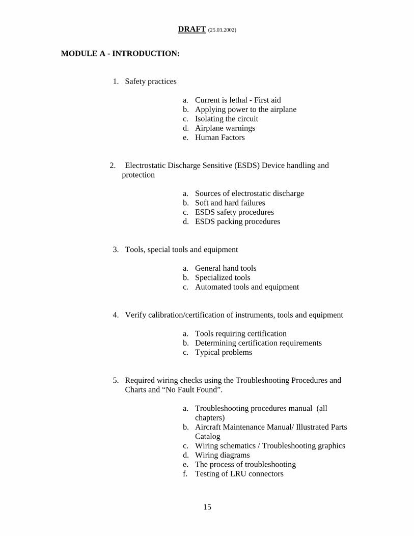
MODULE A - INTRODUCTION:
1. Safety practices
a. Current is lethal - First aidb. Applying power to the airplanec. Isolating the circuitd. Airplane warningse. Human Factors
2. Electrostatic Discharge Sensitive (ESDS) Device handling andprotection
a. Sources of electrostatic dischargeb. Soft and hard failuresc. ESDS safety proceduresd. ESDS packing procedures
3. Tools, special tools and equipment
a. General hand toolsb. Specialized toolsc. Automated tools and equipment
4. Verify calibration/certification of instruments, tools and equipment
a. Tools requiring certificationb. Determining certification requirementsc. Typical problems
5. Required wiring checks using the Troubleshooting Procedures andCharts and “No Fault Found”.
a. Troubleshooting procedures manual (allchapters)
b. Aircraft Maintenance Manual/ Illustrated PartsCatalog
c. Wiring schematics / Troubleshooting graphicsd. Wiring diagramse. The process of troubleshootingf. Testing of LRU connectors

DRAFT (25.03.2002)
16
g. Troubleshooting exercisesh. Company “No Fault Found” policy and data
6. Measurement and troubleshooting using meters
a. Voltage, current and resistanceb. Continuityc. Insulationd. Short to grounde. Loop impedance.
7. LRU removal and replacement techniques
a. Different retention devicesb. Certification considerations (e.g. CAT 2/CAT3
Landing)c. LRU re-racking proceduresd. Built in test equipment (BITE)
DRAFT (25.03.2002)
17
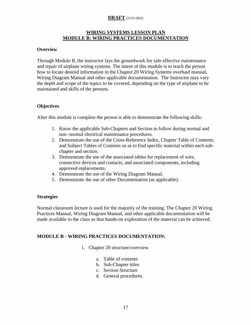
WIRING SYSTEMS LESSON PLANMODULE B: WIRING PRACTICES DOCUMENTATION
Overview
Through Module B, the instructor lays the groundwork for safe effective maintenanceand repair of airplane wiring systems. The intent of this module is to teach the personhow to locate desired information in the Chapter 20 Wiring Systems overhaul manual,Wiring Diagram Manual and other applicable documentation. The Instructor may varythe depth and scope of the topics to be covered, depending on the type of airplane to bemaintained and skills of the persons.
Objectives
After this module is complete the person is able to demonstrate the following skills:
1. Know the applicable Sub-Chapters and Section to follow during normal andnon -normal electrical maintenance procedures.
2. Demonstrate the use of the Cross-Reference Index, Chapter Table of Contents,and Subject Tables of Contents so as to find specific material within each sub-chapter and section.
3. Demonstrate the use of the associated tables for replacement of wire,connective devices and contacts, and associated components, includingapproved replacements.
4. Demonstrate the use of the Wiring Diagram Manual.5. Demonstrate the use of other Documentation (as applicable).
Strategies
Normal classroom lecture is used for the majority of the training. The Chapter 20 WiringPractices Manual, Wiring Diagram Manual, and other applicable documentation will bemade available to the class so that hands-on exploration of the material can be achieved.
MODULE B - WIRING PRACTICES DOCUMENTATION:
1. Chapter 20 structure/overview
a. Table of contentsb. Sub-Chapter titlesc. Section Structured. General procedures.
DRAFT (25.03.2002)
18
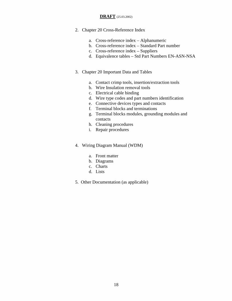
2. Chapter 20 Cross-Reference Index
a. Cross-reference index – Alphanumericb. Cross-reference index – Standard Part numberc. Cross-reference index – Suppliersd. Equivalence tables – Std Part Numbers EN-ASN-NSA
3. Chapter 20 Important Data and Tables
a. Contact crimp tools, insertion/extraction toolsb. Wire Insulation removal toolsc. Electrical cable bindingd. Wire type codes and part numbers identificatione. Connective devices types and contactsf. Terminal blocks and terminationsg. Terminal blocks modules, grounding modules and
contactsh. Cleaning proceduresi. Repair procedures
4. Wiring Diagram Manual (WDM)
a. Front matterb. Diagramsc. Chartsd. Lists
5. Other Documentation (as applicable)

DRAFT (25.03.2002)
19
WIRING SYSTEMS LESSON PLANMODULE C: INSPECTION
Overview
Through Module C, the instructor lays the groundwork for safe effective maintenanceand repair of airplane wiring systems, by teaching the skills of inspection so as to identifywiring system damage. The Instructor may vary the depth and scope of the topics to becovered, depending on the type of airplane to be maintained and skills of the persons.
Objectives
After this module is complete the person is able to demonstrate the following skills:
1. Know the different types of inspections: General Visual Inspection (GVI),Detailed Inspection (DET), Special Detailed Inspection (SDI), ZonalInspection and Enhanced Zonal Analysis Procedure (EZAP), criteria andstandards so that the person knows which tools are used to ensure inspectionprocedures and standards are achieved which leads to all defects being found.
2. Know the effects of fatigue and complacency during inspection and how tocombat their effects (Human Factors).
3. Know the specific zonal inspection requirements related to system affiliationand environmental conditions.
4. Recognize typical wiring system damage, such as hot gas, fluidcontamination, external mechanically induced damage, chafing, corrosion andsigns of overheating of wire, wire bundles and connective and control deviceassemblies.
Strategies
Normal classroom lecture is used for the majority of the training. ATA 117 video andcolor photos of actual wiring systems damage could be used to show typical problemsfound on the airplane. Examples of discrepancies will be made available to the student.
MODULE C – INSPECTION
1. General Visual Inspection (GVI), Detailed Inspection(DET), Special Detailed Inspection (SDI), Zonal Inspectionand Enhanced Zonal Analysis Procedure (EZAP)
2. Criteria and standards
a. Tools
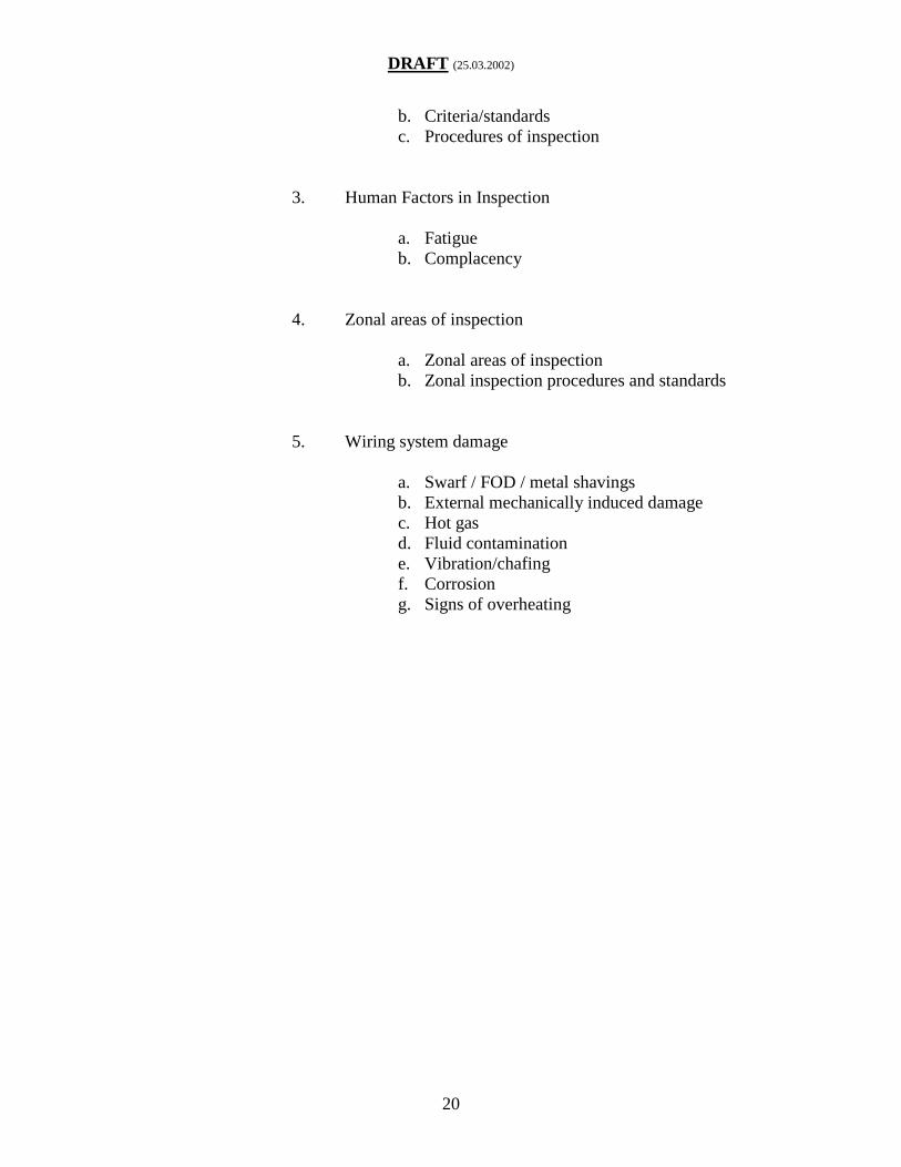
DRAFT (25.03.2002)
20
b. Criteria/standardsc. Procedures of inspection
3. Human Factors in Inspection
a. Fatigueb. Complacency
4. Zonal areas of inspection
a. Zonal areas of inspectionb. Zonal inspection procedures and standards
5. Wiring system damage
a. Swarf / FOD / metal shavingsb. External mechanically induced damagec. Hot gasd. Fluid contaminatione. Vibration/chafingf. Corrosiong. Signs of overheating

DRAFT (25.03.2002)
21
WIRING SYSTEMS LESSON PLANMODULE D: HOUSEKEEPING
Overview
Through Module D, the instructor lays the groundwork for safe effective maintenanceand repair of airplane wiring systems by teaching housekeeping strategies. This will keepthe wiring system free of contamination and if contamination is found, techniques onremoval or cleaning. The Instructor may vary the depth and scope of the topics to becovered, depending on the type of airplane to be maintained and skills of the persons.
Objectives
After this module is complete the person is able to demonstrate the following skills:
1. Recognize external contamination and other damage due to externalenvironmental conditions.
2. Know the airplane internal contamination sources, so that inspection processescan be effectively carried out and contamination damage easily recognized.
3. Recognize other possible contamination sources.4. Know the procedures and processes to protect wiring systems during
maintenance and repair.5. Know the procedures to be followed when carrying out repairs on wiring
systems in different parts of the airplane.6. Know the process of cleaning wiring systems during maintenance and repair.
Strategies
Normal classroom lecture is used for the majority of the training. ATA 117 video andcolor photos of actual wiring systems contamination could be used to show typicalproblems found on the airplane. Relevant Aircraft Maintenance Manual and/or Chapter20 Wiring Practices procedures will be used. The ATSRAC Task Group 1, Non-Intrusive Inspection Final Report could be used to identify typical housekeeping issues.
MODULE D – HOUSEKEEPING
1. Airplane external contamination sources
a. De-ice fluidsb. Water and rainc. Snow and iced. Miscellaneous (e.g. cargo / beverage spillage)

DRAFT (25.03.2002)
22
e. Air erosion
2. Airplane internal contamination sources
a. Hydraulic oilsb. Engine and APU oilsc. Fueld. Greasese. Galleys and toiletsf. Lint/Dustg. Bleed air and hot areash. Hazardous materials
3. Other contamination sources
a. Paintb. Corrosion inhibitorc. Drill shavings / Swarfd. Foreign objects (screws, washers, rivets, tools,
etc.)e. Animal waste
4. Contamination protection planning
a. Have a plan / types of plan / area mappingb. Protection and Caution Recommendationsc. Proceduresd. Keep cleaning
5. Protection during airplane maintenance and repair
a. Recommended general maintenance protectionprocedures.
b. Recommended airframe repair protectionprocedures.
c. Recommended powerplant repair protectionprocedures.
d. Drip and Heat shield repair and installationprocedures.

DRAFT (25.03.2002)
23
6. Cleaning Processes
a. Fluid contamination1) Snow and ice2) De-ice fluid3) Cargo spillage4) Water and rain5) Galleys6) Toilets water waste7) Oils and greases8) Pressure washing
b. Solid contamination1) Drill shavings / Swarf2) Foreign objects (screws, washers, rivets,
tools, etc.)
c. Environmental contamination1) Lint and dust2) Paint3) Corrosion inhibitor4) Animal waste

DRAFT (25.03.2002)
24
WIRING SYSTEMS LESSON PLANMODULE E: WIRE
Overview
Through Module E, the instructor lays the groundwork for safe effective maintenance,alteration and repair of airplane wiring systems by teaching wire selection and inspectionstrategies. The Instructor may vary the depth and scope of the topics to be covered,depending on the type of airplane to be maintained and skills of the persons.
Objectives
After this module is complete the person is able to demonstrate the following skills:
1. Demonstrate the procedure used to identify specific wire types using theairplane manuals.
2. Know from approved data different insulation types and their relativequalities.
3. Know the inspection criteria for wire and wire bundles.4. Know the standard installation practices for wire and wire bundles (airplane
specific).5. Know typical damage that can be found (airplane specific).6. Demonstrate the repair procedures for typical damage found on the student’s
type of airplane.7. Demonstrate the procedures to fitting differing types of sleeving (airplane
specific).8. Know the procedures for termination and storage of unused wires.9. Demonstrate the correct installation practices for electrical bonds and grounds
(airplane specific).
Strategies
Normal classroom lecture is used for the majority of the training with hands-on practicefor Section 6. Chapter 20 Wiring Practices, Wiring Diagram Manual and WDM Listswill be made available to the class so that hands-on use of the manual can be utilized sothat wire identification, inspection, installation and repair procedures can be fullyexplored. Examples of wire discrepancies will be made available to the student. TheATSRAC Task Group 1, Intrusive Inspection Final Report could be used to identifytypical wire issues.
MODULE E – WIRE
1. Identification, type and construction

DRAFT (25.03.2002)
25
a. Wire type codes – alphanumericb. Wire type codes – specification and standard
part numberc. Wire type codes – specified wire and alternated. Manufacturer identification
2. Insulation qualities
a. Types of insulationb. Typical insulation damagec. Carbon Arcing
3. Inspection criteria and standards of wire and wire bundles
a. Inspection of individual wiringb. Inspection of wire bundles
4. Wire bundle installation practices
a. Routingb. Segregation rulesc. Clearanced. Clamp inspectione. Clamp removal and fittingf. Conduit types and fittingg. Raceways
5. Typical damage and areas found (airplane specific)
a. Vibrationb. Corrosionc. Contaminationd. Personnel traffic passage

DRAFT (25.03.2002)
26
6. Maintenance and repair procedures
a. Wire damage assessment and classificationb. Approved repairs - Improper repairsc. Shielded wire repaird. Repair techniquese. Terminals and splicesf. Preventative maintenance procedures
7. Sleevinga. Identification sleevesb. Shrink sleevesc. Screen braid grounding crimp sleevesd. Screen braid grounding solder sleeves
8. Unused wires - termination and storage
a. Termination – End capsb. Storage and attachment
9. Electrical bonding and grounds
a. Inspection standardsb. Primary Bonding (HIRF protection)c. Secondary Bonding (System grounding)d. Lightning strikes

DRAFT (25.03.2002)
27
WIRING SYSTEMS LESSON PLANMODULE F: CONNECTIVE DEVICES
Overview
Through Module F, the instructor lays the groundwork for safe effective maintenance,alteration and repair of airplane wiring systems by teaching the identification, inspectionand repair of connective devices found on the airplane. The Instructor may vary thedepth and scope of the topics to be covered, depending on the type of airplane to bemaintained and skills of the persons.
Objectives
After this module is complete the person is able to demonstrate the following skills:
1. Know the general types and positive identification of connective devices andpressure seals (airplane specific).
2. Know the various safety procedures, cautions and warnings prior toinspection.
3. Know the relevant inspection procedures for each type of connector so thatany internal or external damage can be found.
4. Recognize typical external and internal damage to the connector.5. Demonstrate where to find the relevant repair schemes from Ch. 20 for
connector repair.
Strategies
Normal classroom lecture is used for the majority of the training. The Chapter 20 WiringPractices manual will be made available to the class so that hands-on use of the manualcan be utilized. Connector identification, inspection and repair procedures will be fullyexplored. Color photographs of typical external damage and internal damage could beused to show problems on the airplane. The ATSRAC Task Group 1, Non-IntrusiveInspection and Intrusive Inspection Final Report, Chapter 7, could be used to identifytypical connector issues.
MODULE F – CONNECTIVE DEVICES
1. General types and identification
a. Part number identificationb. Reference tablesc. Specific connective devices and pressure seal
chapters

DRAFT (25.03.2002)
28
2. Cautions and protections
a. Safety precautionsb. Maintenance precautions
3. Visual inspection procedures
a. Installed inspection criteriab. Removed inspection criteria
4. Typical damage found
a. Exterior damageb. Internal damage
5. Repair procedures
a. Finding the correct sectionb. Finding the correct partc. Finding the correct toolingd. Confirming the correct repair

DRAFT (25.03.2002)
29
WIRING SYSTEMS LESSON PLANMODULE G: CONNECTIVE DEVICES REPAIR
Overview
Through Module G, the instructor lays the groundwork for safe effective maintenance,alteration and repair of airplane wiring systems. This module is primarily a hands-onclass, emphasizing the repair and replacement of connective devices found on theairplane. This list can be used to cover typical connectors for airplanes, and can beadjusted to suit training requirements. The Instructor may vary the depth and scope ofthe topics to be covered, depending on the type of airplane to be maintained and skills ofthe persons.
Objective
After this module is complete the person will have the following skills.
1. Demonstrate the replacement of components for circular connectors.2. Demonstrate the replacement of components for rectangular connectors.3. Demonstrate the replacement of components for terminal blocks-modular.4. Demonstrate the replacement of components for terminal blocks-non-modular.5. Demonstrate the replacement of components for grounding modules.6. Demonstrate the replacement of pressure seals
Strategies
This class is primarily a hands-on class to give the student motor skills in the repair ofconnective devices from their airplane. The Chapter 20 Wiring Practices Manual and theappropriate connective devices will be made available to the class so repair procedurescan be fully explored. Photographs of typical internal conditions and external damagecould be made available. It is recommended that MODULE F: CONNECTORS shouldprecede this module.
MODULE G – CONNECTIVE DEVICES REPAIR
1. Circular Connectors
a. Disassemblyb. Back-shell maintenancec. Contact extraction and insertiond. Contact Crimping

DRAFT (25.03.2002)
30
e. Assembly and strain relief
2. Rectangular Connectors
a. Disassemblyb. Back-shell maintenancec. Contact extraction and insertiond. Contact Crimpinge. Assembly and strain relief
3. Terminal Blocks - Modular
a. Disassemblyb. Contact extraction and insertionc. Contact Crimpingd. Assembly and strain relief
4. Terminal Block – Non-modular
a. Disassemblyb. Terminal Lug Crimpingc. Terminal Lug Stackingd. Assembly, torque and strain relief
5. Grounding Modules
a. Disassemblyb. Contact extraction and insertionc. Contact Crimpingd. Assembly and strain relief
6. Pressure Seals
a. Disassemblyb. Maintenancec. Assembly and strain relief

DRAFT (25.03.2002)
31
APPENDIX C - WIRE SYSTEM
As stated in the definitions section of this Advisory Circular “Wire System” isdefined as follows:
An electrical connection between two or more points including the associatedtermination devices (e.g., connectors, terminal blocks, splices) and the necessarymeans for its installation and identification.
The definition of “wire system” includes the following:
• Wires (e.g., wire, cable, coax, databus,feeders, ribbon cable).
• Bus bars.• Connection to electrical devices (e.g.,
relays, push button, interrupters, switches,contactors, terminal blocks, feed-throughconnectors).
• Circuit breakers or other circuit protectiondevices (not performance).
• Electrical contacts.• Connector and accessories (e.g., backshell,
sealing boot grommet sealing plugs).• Electrical grounding and bonding devices
(e.g., modules, straps, studs).
• Electrical splices.• Shield or braids.• Conduits that have electrical termination.• Clamps and other devices used to route and
support the wire bundle.• Cable tie devices.• Labels or other means of identification
methods.• Pressure seals associated with wiring
systems.• Wiring inside shelves, panels, racks,
junction boxes, distribution panels, back-planes of equipment racks (including circuitboard back-planes), wire integration units,etc.
The following wires and devices (along with the mating connections at the terminationpoints of the wire on those devices) are not considered part of the “wire system”:
• Wiring inside avionics equipment (e.g., flight management system computer, flightdata recorder, VHF radio, primary flight display).
• Equipment qualified to the standards of RTCA Document DO-160 or shown to beequivalent (other than those specifically included in this definition).
• Equipment qualified to a technical standard order (TSO).• Portable, carry on, or otherwise non-permanently mounted (not part of the certification
basis) electrical equipment.• Fiber optics.

DRAFT (25.03.2002)
32
APPENDIX D - HISTORY
BACKGROUND. Safety concerns about aging wiring systems in airplanes were broughtto the forefront of the public and governmental attention by a fatal accident involving aBoeing Model 747-131 airplane on July 17, 1996. The National Transportation SafetyBoard (NTSB) determined that the probable cause of the accident was an explosion of thecenter wing fuel tank resulting from ignition of the flammable fuel/air mixture in thetank. Although the source of ignition energy for the explosion could not be determinedwith certainty, the NTSB believes the most likely source was a short circuit outside of thecenter wink fuel tank that allowed excessive voltage to enter it through electrical wiringassociated with the fuel quantity indication system. In its investigation the NTSB foundseveral potentially unsafe conditions in and near the electrical wiring of the airplane,including cracked wire insulation, metal shavings adhered to a floor beam along whichfuel quantity indication system wires would have been routed, other debris, and sulfidedeposits. The NTSB also found evidence of several repairs to the accident airplane thatdid not comply with the guidelines in Boeing’s Standard Wiring Practices Manual.
Noncompliant repairs included the use of an oversized strain relief clampon the terminal block of the No. 1 fuel tank compensator, which did notadequately secure the wires; numerous open-ended (rather than sealed)wire splices, which exposed conductors to possible water contamination;several wire bundles containing numerous wire splices on adjacent wiresat the same location; and excessive solder on the connector pins inside thefuel totalizer gauge, which had connected the pins/wires from the rightwing main fuel tank and the CWT FQIS.
Most alarming is the NTSB’s finding that deterioration, damage, and contamination ofaircraft wiring and related components and noncompliant repairs were common in theairline transport airplanes (especially in the older airplanes) that it inspected during theinvestigation. Therefore, the NTSB concluded that “the condition of the wiring system inthe accident airplane was not atypical for an airplane of its age and one that had beenmaintained in accordance with prevailing industry practices.”1
The NTSB found the unsafe conditions of aircraft wiring systems especially disturbingbecause the existence of these conditions revealed the general shortcomings of the currentvisual wiring inspection criteria. During its examinations the NTSB found that a largeportion of the aircraft wiring is difficult, if not impossible, to inspect because of itsinaccessibility and that wire damage or other potentially unsafe conditions may not bedetected, even on visible and accessible portions of aircraft wiring. The NTSB thereforeconcluded that “insufficient attention has been paid to the condition of aircraft electricalwiring, resulting in potential safety hazards.”
1 The widespread existence of such conditions was also corroborated by Boeing’s serviceletter (SL) 747-SL-20-048 (dated January 25, 1995), which detailed similar conditionsfound in numerous 747s.
DRAFT (25.03.2002)
33
The accident investigation into the 1996 fatal accident resulted in a heightened awarenessof the importance of maintaining the integrity of aircraft wiring. The FAA began toinvestigate fuel tank wiring, and to strengthen its focus on aging wiring in general. Alsoin 1997 the White House Commission on Aviation Safety and Security (WHCSS) issuedthe following recommendation to the FAA: “In cooperation with airlines andmanufacturers, the FAA’s Aging Aircraft Program should be expanded to cover non-structural systems.” In July 1998, the FAA issued the Aging Transport Non-StructuralSystems Plan, (hereinafter “Aging Systems Plan”) which addressed the WHCSSrecommendation. The Aging Systems Plan focused specifically on wiring systems. Inthe Aging Systems Plan the FAA describes the results of its evaluation of five transportcategory airplanes deemed representative of the “aging fleet of transport airplanes.” TheFAA found conditions similar to those found by the NTSB during airplane inspections inconnection with the 1996 Boeing accident investigation, including the following:
• Deterioration of wiring and related components.• Stiff and cracked wire.• Contamination of wire bundles with metal shavings, dust, and fluids.• Cracked wire insulation.• Corrosion on connector pins.• Improper wire installation and repairs.
The FAA’s Aging Systems Plan also detailed several tasks aimed at correcting theseproblems, including the following:
• Improving wiring inspection criteria and providing more detailed descriptions ofundesirable conditions.
• Improving inspector training to ensure that it adequately addresses the recognitionand repair of aging wiring components.
• Developing new methods for nondestructive testing of wiring.
The NTSB has recommended that the FAA address all wiring issues identified in theAging Systems Plan, either through rulemaking or through other means. The NTSBspecifically cited the need for improved training of maintenance personnel to ensureadequate recognition and repair of potentially unsafe wiring conditions.
To address the issues identified in the Aging Systems Plan, in 1998 the FAA establishedthe Aging Transport Systems Rulemaking Advisory Committee (ATSRAC). TheATSRAC provides the forum for the airlines, manufacturers, and other regulatoryauthorities to make recommendations to the FAA based on the Aging Systems Plan. TheATSRAC effort was divided into two phases; Non-intrusive inspections which utilizedonly the current visual inspections, and Intrusive inspections which involved opening upthe wire bundles and subjecting the wires to non-destructive test equipment andlaboratory analysis. The traditional arms-length examination method used in the first non-intrusive (visual only) effort, ultimately proved its inadequacy. The Non-IntrusiveInspection Final Report stated," Existing maintenance programs may benefit from

DRAFT (25.03.2002)
34
providing additional wiring inspection detail" (Non-Intrusive Inspection Final Report,Page 8). This Non-Intrusive report went on to say that discrepancies found during thesurvey did not appear to be wire-type dependent. These statements lead to the formationof the Intrusive Inspection Group that was to determine if visual inspections worked, andto assess the state of the wiring in the fleet of aging aircraft.
The results of the Intrusive inspection group found that wire type did matter, "That thereare typical characteristic flaws for each type of wire" (Intrusive Inspection Group FinalReport, Chapter 6, Page 53). The group also determined that mixing of different wiretypes within the same bundle could be hazardous, "The inherent differences in theperformance and chemistry of the wire insulation types should be ample reason toconclude that mixing of certain wire types in the same bundle could be hazardous toaircraft safety due to the potential for arcing and fire" (Intrusive Inspection Group FinalReport, Chapter 6 Page 54). The assessment of visual inspection proved it was inadequatealone, to discern the majority of degenerative conditions such as cracking and arcing. Thereport also concluded that Polyvinyl Chloride (PVC) wiring was considered a flammablematerial. The overall assessment on the state of the wiring in the fleet was subjected tofault tree analysis rather than in the Executive Summary . This General Threat Analysis(GTA) used "plausible, hypothetical situations" (Intrusive Inspection Group Final Report,Chapter 7, Page 67), but the report also declared the results of between .44 to 3.62breaches per 1000 feet of wire, depending on aircraft type (Intrusive Inspection GroupFinal Report, Appendix 3.1.7 Table 3.2.7-2). This information was contained in theSpecific Recommendations portion of the final report. The final statement was, "Unless aflaw type can be ruled out as impossible (e.g. delamination for non-tape-wrappedinsulation) or highly unlikely (cracking in relatively new installations) all flaw typesshould be considered possible" (Intrusive Inspection Group Final Report, Chapter 7, Page70).