Embed Size (px)
Citation preview

1
Table of Contents
Chapter I: Introduction
1.1 Introduction............................................................................4
1.2 Features ..................................................................................4
Chapter II: Getting Started
2.1 Opening Blast Resistant Glazing Design 2007......................7
2.2 Disclaimer and Limitations....................................................7
2.3 Tool Bar……………………………………………………..11
2.4 Starting a New Design ...........................................................11
2.5 Opening an Existing Design ..................................................12
2.6 Saving a Design .....................................................................14
2.6.1 Save Project ...............................................................15
2.6.2 Save As ......................................................................15
2.7 System of Units......................................................................16
2.8 Printing of Document.............................................................17
Chapter III: Project Information
3.1 Access ....................................................................................19
3.2 Description.............................................................................20
3.3 Closing the Project Information Window..............................20
Chapter IV: Design Input
4.1 Access ....................................................................................21
4.2 User Input...............................................................................23
4.3 Design Blast Details...............................................................24
4.3.1 UFC 4-010-01 ............................................................25
4.3.2 ISC/GSA ....................................................................25
4.3.3 User-Defined..............................................................25
4.4 Rectangular Dimensions ........................................................25
4.5 Glass Constructions ...............................................................26
4.5.1 Single Glazed Lite......................................................26
4.5.1.1 Annealed Glass ...........................................27
4.5.1.2 Heat Strengthened Glass .............................27
4.5.2 Double Glazed Insulating Unit ..................................27
4.5.2.1 Outboard Lite ..............................................27
4.5.2.2 Inboard Lite.................................................28
4.5.2.3 Air Space.....................................................28
4.5.2.4 Other Definitions ........................................29

2
Chapter V: Design Results
5.1 Access ....................................................................................30
5.2 Design Load Details...............................................................31
5.2.1 Equivalent 3- Second Duration Design Load ............31
5.2.2 Load Resistance .........................................................32
5.2.3 Approximate Maximum Air Blast Pressure...............32
5.3 Glazing Design.......................................................................33
5.3.1 PVB Interlayer Nominal Thickness ...........................33
5.4 Framing and Attachment Requirement..................................34
5.5 Comments ..............................................................................35
5.6 Closing the Design Results Window .....................................36

3
List of Figures Figure Title Page
2.1 Disclaimer and Limitations...................................................8
2.2 Tool Bar ...............................................................................11
2.3 New Project..........................................................................12
2.4 Save Changes to Design.......................................................12
2.5 Opening an Existing Project ................................................13
2.6 Open Window ......................................................................13
2.7 Save Project .........................................................................14
2.8 Save Project As ....................................................................14
2.9 Save As Window..................................................................15
2.10 System of Units....................................................................16
2.11 Print Project Report..............................................................17
2.12 Print Window.......................................................................18
3.1 Project Information Access..................................................19
3.2 Project Information Window ...............................................20
4.1 Minimized Design Input Window .......................................21
4.2 Design Input Access ............................................................22
4.3 Design Input Window..........................................................23
4.4 Design Blast Details.............................................................24
4.5 Glass Constructions .............................................................26
4.6 Single Glazed Lite................................................................26
4.7 Double Glazed Insulating Units...........................................28
5.1 Design Results Window.......................................................30
5.2 Design Loads Details ...........................................................31
5.3 Glazing Design Section........................................................33
5.4 Framing and Attachment Section.........................................34
5.5 Comment Section, Within AM E 1300-02 ..........................35
5.6 Comment Section, Beyond ASTM E-1300-02 ....................35
4
CHAPTER I
Introduction
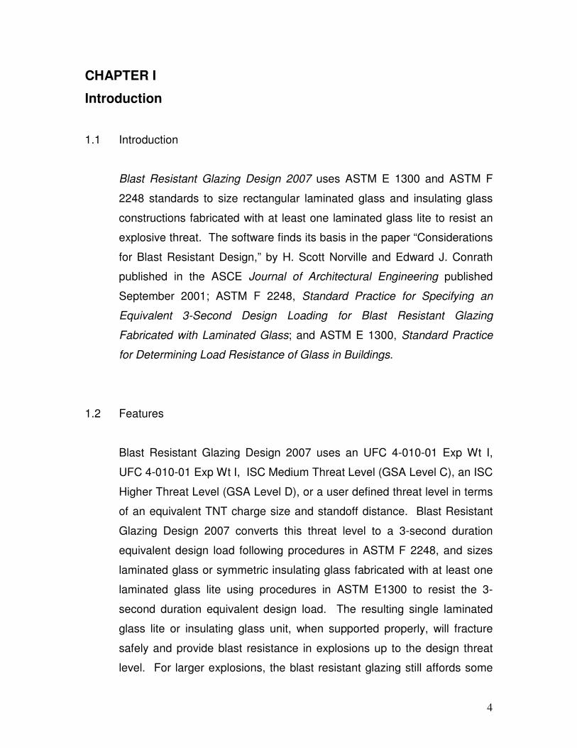
1.1 Introduction
Blast Resistant Glazing Design 2007 uses ASTM E 1300 and ASTM F
2248 standards to size rectangular laminated glass and insulating glass
constructions fabricated with at least one laminated glass lite to resist an
explosive threat. The software finds its basis in the paper “Considerations
for Blast Resistant Design,” by H. Scott Norville and Edward J. Conrath
published in the ASCE Journal of Architectural Engineering published
September 2001; ASTM F 2248, Standard Practice for Specifying an
Equivalent 3-Second Design Loading for Blast Resistant Glazing
Fabricated with Laminated Glass; and ASTM E 1300, Standard Practice
for Determining Load Resistance of Glass in Buildings.
1.2 Features
Blast Resistant Glazing Design 2007 uses an UFC 4-010-01 Exp Wt I,
UFC 4-010-01 Exp Wt I, ISC Medium Threat Level (GSA Level C), an ISC
Higher Threat Level (GSA Level D), or a user defined threat level in terms
of an equivalent TNT charge size and standoff distance. Blast Resistant
Glazing Design 2007 converts this threat level to a 3-second duration
equivalent design load following procedures in ASTM F 2248, and sizes
laminated glass or symmetric insulating glass fabricated with at least one
laminated glass lite using procedures in ASTM E1300 to resist the 3-
second duration equivalent design load. The resulting single laminated
glass lite or insulating glass unit, when supported properly, will fracture
safely and provide blast resistance in explosions up to the design threat
level. For larger explosions, the blast resistant glazing still affords some

5
protection. Blast Resistant Glazing Design 2007 provides
recommendations concerning the appropriate size of a sealant bead to
attach the blast resistant glazing to the window frame and gives forces
necessary to design connections to attach window frames to the structure.
As input to Blast Resistant Glazing Design 2007, the user provides the
threat level, the rectangular dimensions of the fenestration, and the
desired window glass construction, i.e., single laminated glass or an
insulating glass unit fabricated with at least one laminated glass lite. The
window frame must support the blast resistant glazing continuously along
all four sides. Blast Resistant Glazing Design 2007 uses the following
constructions for blast resistant glazing: single laminated glass, fabricated
with either annealed or heat strengthened glass plies and a PVB
interlayer, or insulating glass units. The program allows one of the two
following insulating glass constructions: (1) a monolithic glass lite facing
the outside of the building and a laminated glass lite facing the inside, or
(2) laminated glass for both lites of the insulating glass unit. As stated
above, all glass plies can be either annealed or heat strengthened glass,
not fully tempered.
Blast Resistant Glazing Design 2007 displays the equivalent 3-second
duration design loading, the approximate maximum air blast pressure, the
nominal glass thickness for a single laminated glass lite or the nominal
thicknesses for the lites that comprise the insulating glass unit required to
resist the 3-second duration equivalent design loading according to ASTM
E1300 after it completes the blast resistant glazing design calculation.
Blast Resistant Glazing Design 2007 always uses lites having equal
nominal thicknesses in insulating glass units. The program also displays
the recommended size of the structural sealant bead to attach the blast
resistant glazing to the window frame, and the loads required to design the
window frame members and to connect the window frame to the building.

6
Blast Resistant Glazing Design 2007 prints a blast resistant glazing report
with the design load details, the project details, the glazing information, the
glass construction, design load details, and the framing and attachment
requirements and loads.

7
CHAPTER II
Getting Started
2.1 Opening Blast Resistant Glazing Design 2007
Blast Resistant Glazing Design 2007 opens in three ways. (1) The user
can follow the path Start / All Programs / Standards Design Group, Inc /
Blast Resistant Glazing Design 2007; (2) the user can double click on a
program file with the extension “.brd”; or (3) if the user creates a program
shortcut on the desktop, the user can open the program by double clicking
on this shortcut.
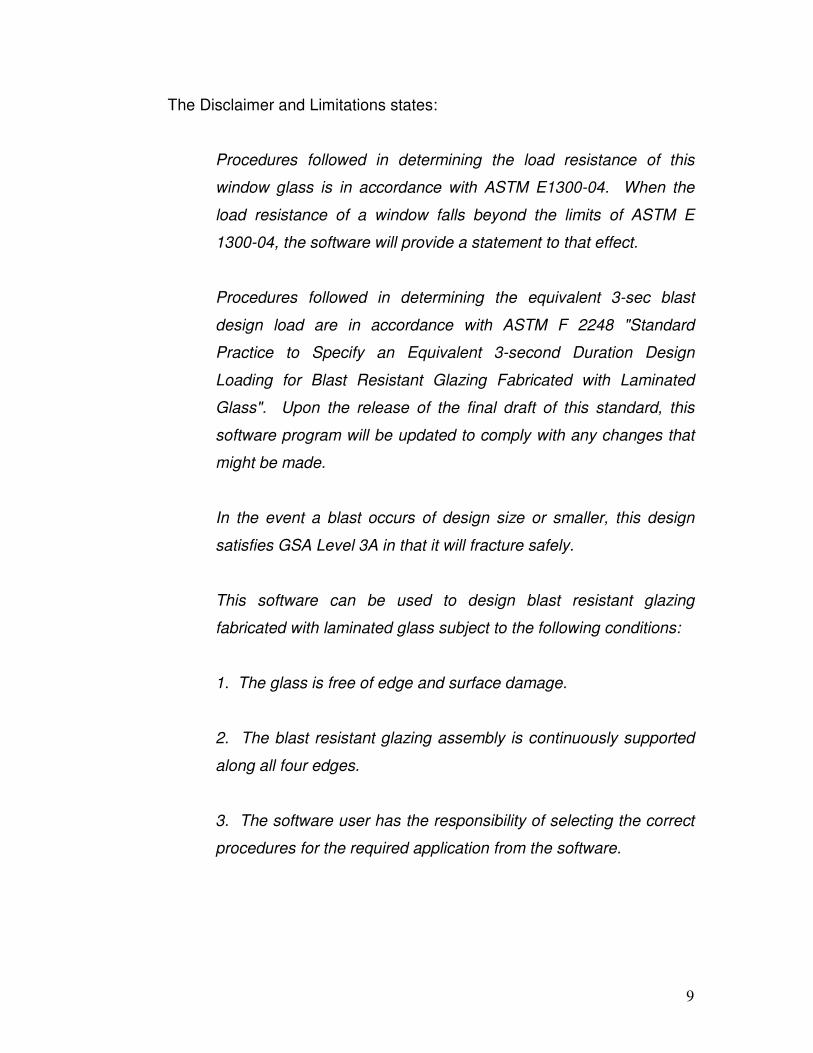
2.2 Disclaimer and Limitations
When the program opens, the “Disclaimer and Limitations” window
appears as shown in Figure 2.1. Before continuing, the user must read
and understand the disclaimer and the limitations of the software. After
reading the program limitations, click on the “I have read and understand
the limitations of this software” check box after reading and understanding
the limitations of Blast Resistant Glazing Design 2007. Press the “Ok”
button to continue.

8
Figure 2.1: Disclaimer and Limitations
9
The Disclaimer and Limitations states:
Procedures followed in determining the load resistance of this
window glass is in accordance with ASTM E1300-04. When the
load resistance of a window falls beyond the limits of ASTM E
1300-04, the software will provide a statement to that effect.
Procedures followed in determining the equivalent 3-sec blast
design load are in accordance with ASTM F 2248 "Standard
Practice to Specify an Equivalent 3-second Duration Design
Loading for Blast Resistant Glazing Fabricated with Laminated
Glass". Upon the release of the final draft of this standard, this
software program will be updated to comply with any changes that
might be made.
In the event a blast occurs of design size or smaller, this design
satisfies GSA Level 3A in that it will fracture safely.
This software can be used to design blast resistant glazing
fabricated with laminated glass subject to the following conditions:
1. The glass is free of edge and surface damage.
2. The blast resistant glazing assembly is continuously supported
along all four edges.
3. The software user has the responsibility of selecting the correct
procedures for the required application from the software.

10
4. The stiffness of members supporting any glass edge shall be
sufficient that under an equivalent 3 sec. design load, edge
deflections of glazing shall not exceed L/160, where L denotes the
length of the supported edge.
5. The non-factored load values for laminated glass are
representative of test data and calculations performed for polyvinyl
butyric interlayer at a temperature of 50º C (122° F).
For other limiting conditions that may apply, refer to Section 5 of
ASTM E1300, local building codes, and ASTM F 2248 "Standard
Practice to Specify an Equivalent 3-second Duration Design
Loading for Blast Resistant Glazing Fabricated with Laminated
Glass".
SDG does not guarantee and disclaims any responsibility for any
particular results relating to the use of the Blast Resistant Glazing
Design 2007 Software Program.
SDG disclaims any liability for any personal injury or any loss or
damage of any kind, including all indirect, special, or consequential
damages and lost profits, arising out of or relating to the use of the
Blast Resistant Glazing Design 2007 Software Program.
11
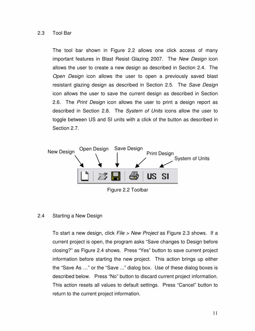
2.3 Tool Bar
The tool bar shown in Figure 2.2 allows one click access of many
important features in Blast Resist Glazing 2007. The New Design icon
allows the user to create a new design as described in Section 2.4. The
Open Design icon allows the user to open a previously saved blast
resistant glazing design as described in Section 2.5. The Save Design
icon allows the user to save the current design as described in Section
2.6. The Print Design icon allows the user to print a design report as
described in Section 2.8. The System of Units icons allow the user to
toggle between US and SI units with a click of the button as described in
Section 2.7.
Figure 2.2 Toolbar
2.4 Starting a New Design
To start a new design, click File > New Project as Figure 2.3 shows. If a
current project is open, the program asks “Save changes to Design before
closing?” as Figure 2.4 shows. Press “Yes” button to save current project
information before starting the new project. This action brings up either
the “Save As …” or the “Save ...” dialog box. Use of these dialog boxes is
described below. Press “No” button to discard current project information.
This action resets all values to default settings. Press “Cancel” button to
return to the current project information.
New Design Open Design Save Design
Print Design System of Units

12
Figure 2.3: New Project
Figure 2.4: Save Changes to Design
2.5 Opening an Existing Design
The user can open an existing document in three ways. The first consists
of pressing “File/Open Project…” as Figure 2.5 shows. The second
consists of pressing the Open File button on the tool bar. The “Open”
window (Figure 2.6) then appears. Follow the path to the desired project
file and press the “Open” button on the bottom of the “Open Window” as
Figure 2.7 shows. This opens the details of the design from the file. If the
Open Project button was pressed by mistake, simply press the “Cancel”
button and the programs returns to the current project. The third consists

13
of double clicking on the desired file without first opening the program.
This action automatically opens Blast Resistant Glazing Design 2007 with
the design information from the previously saved file loaded.
Figure 2.5: Opening an Existing Project
Figure 2.6: Open Window

14
2.6 Saving a Design
To save a design, press File > Save Project (Figure 2.7) or File > Save
Project As …(Figure 2.8). Pressing the Save button produces the same
result as pressing File > Save Project.
Figure 2.7: Save Project
Figure 2.8: Save Project As

15
2.6.1 Save Project
If the project has not been previously saved, the program brings up
the “Save As” window as Figure 2.9 shows. Type in a file name to
the left of the “Save” button and press the “Save” button to save the
current project. If the project has been previously saved, the
program automatically writes the data for the current project to the
previously saved file.
Figure 2.9: Save As Window
2.6.2 Save As
Pressing File > Save Project As… always brings up the “Save As”
window shown in Figure 2.9. This allows the renaming of the
current project or the saving of a new project. Follow the steps in
Section 2.4 of the document to save a file using the “Save As…”
command.

16
2.7 System of Units
Blast Resistant Glazing Design 2007 uses both US and SI units. The
program allows the user to toggle between the US and SI systems of
units, automatically updating all data in the current design. To change the
system of units click on the path Tools > System of Units as Figure 2.10
shows. Blast Resistant Glazing Design 2007 also has System of Units
buttons on the toolbar (Figure 2.2). Press the desired unit system button
on the tool bar.
Figure 2.10: System of Units
17
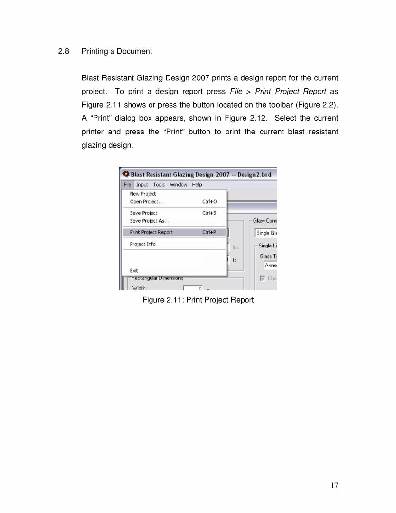
2.8 Printing a Document
Blast Resistant Glazing Design 2007 prints a design report for the current
project. To print a design report press File > Print Project Report as
Figure 2.11 shows or press the button located on the toolbar (Figure 2.2).
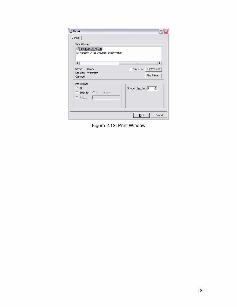
A “Print” dialog box appears, shown in Figure 2.12. Select the current
printer and press the “Print” button to print the current blast resistant
glazing design.
Figure 2.11: Print Project Report
18
Figure 2.12: Print Window

19
CHAPTER III
Project Information
3.1 Access
To access the “Project Information” window click on File > Project Info,
Figure 3.1.
Figure 3.1: Project Information Access

20
3.2 Description
The “Project Information” window (Figure 3.2) contains reference
information about the design project that includes the project name,
location and designer. The window provides a field for comments and
other information relevant to the project. This information is displayed on
the report. Project Information data are for the user’s information only.
The software does not require this information to perform design
calculations.
Figure 3.2: Project Information Window
3.3 Closing the Project Information Window
To close the Project Information window click on the “Done” button or
press the “X” button at the top, right-hand corner of the window. Although
the window is closed, the program stores all the information for the current
project. To edit the data in this window, reopen the Project Information
window and edit as necessary.

21
Chapter IV:
Design Input
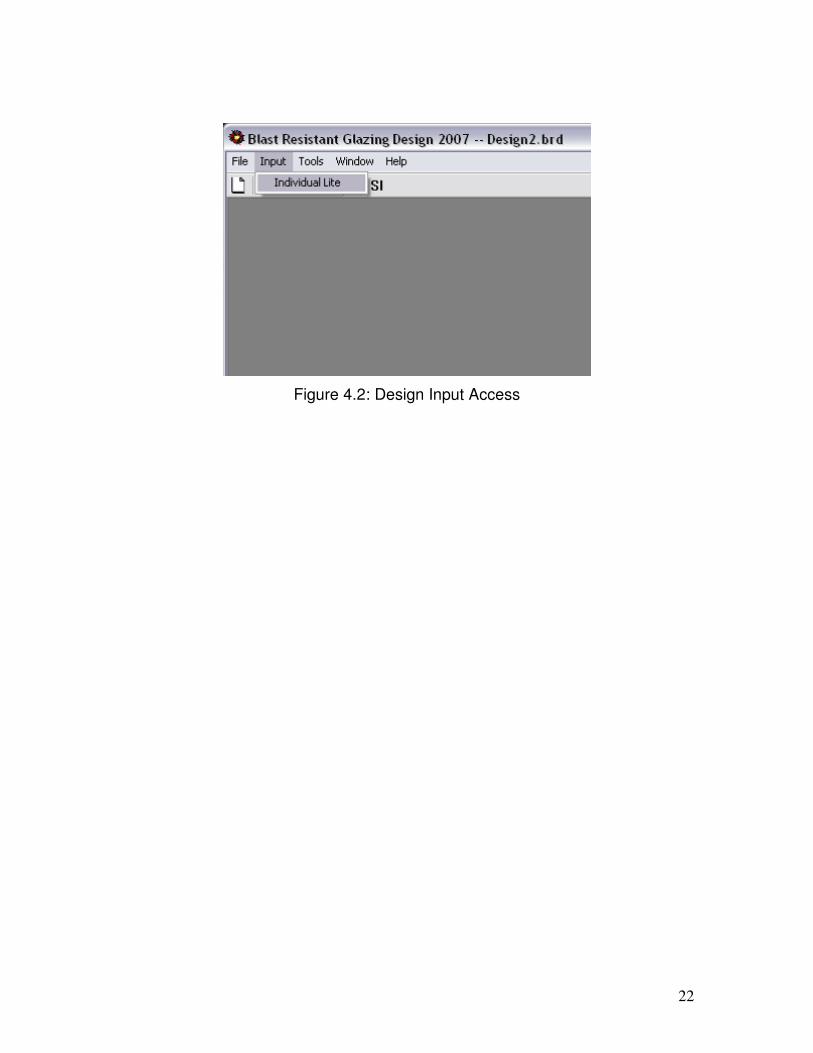
4.1 Access
Upon startup of the program, Blast Resistant Glazing Design 2007
automatically displays the “Design Input” window. From time to time the
user might close or minimize this window. Although this window is closed,
Blast Resistant Glazing Design 2007 stores all the information for the
current project. If the window is minimized, Blast Resistant Glazing
Design 2007 places the window in the bottom left hand corner of the
window as shown in Figure 4.1. Press the Restore button to activate the
window. If the window is closed, the program hides the window. To
access the “Design Input” window select on Input > Individual Lite as
Figure 4.2 shows.
Figure 4.1: Minimized Design Input Window
22
Figure 4.2: Design Input Access

23
4.2 User Input
Figure 4.3 shows the “Design Input” window. This window facilitates input
of the required information for a blast resistant glazing design. This
window has three sections: the “Design Blast Details” section, the
“Rectangular Dimensions” section, and the “Glass Construction” section.
Figure 4.3: Design Input Window
24
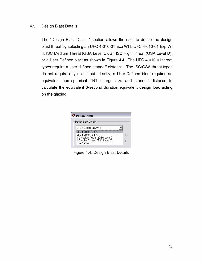
4.3 Design Blast Details
The “Design Blast Details” section allows the user to define the design
blast threat by selecting an UFC 4-010-01 Exp Wt I, UFC 4-010-01 Exp Wt
II, ISC Medium Threat (GSA Level C), an ISC High Threat (GSA Level D),
or a User-Defined blast as shown in Figure 4.4. The UFC 4-010-01 threat
types require a user-defined standoff distance. The ISC/GSA threat types
do not require any user input. Lastly, a User-Defined blast requires an
equivalent hemispherical TNT charge size and standoff distance to
calculate the equivalent 3-second duration equivalent design load acting
on the glazing.
Figure 4.4: Design Blast Details

25
4.3.1 UFC 4-010-01
Choosing “UFC 4-010-01 Exp Wt I” or “UFC 4-010-01 Exp Wt II”
defines a blast threat consistent with Unified Facilities Criteria, as
defined by the US Government.
4.3.2 ISC/GSA
Choosing “ISC Medium Threat – (GSA Level C)” or “ISC Higher
Threat – (GSA Level D)” defines a blast threat consistent with
existing US Government definitions.
4.3.2 User-Defined
A user-defined blast requires the user to input the equivalent
hemispherical TNT charge size and standoff distance associated
with a design threat. Blast Resistant Glazing Design 2007 accepts
TNT charge sizes ranging from 10 lb. (4.54 kg) to 2000 lb. (907 kg).
4.4 Rectangular Dimensions
The Rectangular Dimensions section allows the user to input the size of
the fenestration to be glazed. Ambiguity exists in the design community
as to whether these dimensions represent the size of the blast resistant
glazing itself or the raw opening size. This is a question that the glazing
designer must answer. In general, using the raw opening dimensions will
result in acceptable, if conservative, glass thickness selection

26
4.5 Glass Constructions
Blast Resistant Glazing Design 2007 designs for glazing constructions of a
single glazed lite or double glazed insulating unit as indicated by Figure
4.5.
Figure 4.5: Glass Constructions
4.5.1 Single Glazed Lite
For a single glazed lite, Blast Resistant Glazing Design 2007
facilitates designs only with laminated glass fabricated with
annealed or heat strengthened glass plies as shown in Figure 4.6.
The program uses only laminated glass with nominal 6 mm (1/4 in.)
or larger thickness for blast resistant glazing design.
Figure 4.6: Single Glazed Lite

27
4.5.1.1 Annealed Glass
Annealed Glass consists of a flat monolithic glass lite of
uniform thickness having residual surface stresses that are
nearly zero.
4.5.1.2 Heat Strengthened Glass
Heat strengthened glass consists of a flat monolithic glass
lite of uniform thickness that has been subjected to a
special heat treatment process where the residual surface
compression ranges from 24 MPa (3500 psi) to 52 MPa
(7500 psi).
4.5.2 Double Glazed Insulating Unit
Any combination of two glass lites enclosing a sealed space filled
with air or other gas.
4.5.2.1 Outboard Lite
The outboard lite of an insulating glass unit is the lite that
faces toward the outside of the building. Blast Resistant
Glazing Design 2007 allows the user to select laminated or
monolithic glass fabricated with annealed or heat
strengthened glass for the outboard lite. To select the
outboard lite as monolithic, uncheck the box marked
“check for laminated” shown in Figure 4.7.

28
4.5.2.2 Inboard Lite
The inboard lite is the lite of an insulating glass unit that
faces toward the inside of the building. Consistent with
ASTM F 2248-03, Blast Resistant Glazing Design 2007
requires laminated glass for the inboard lite. Blast
Resistant Glazing Design 2007 allows fabrication of the
laminated glass with either annealed or heat strengthened
glass.
Figure 4.7: Double Glazed Insulating Unit
4.5.2.3 Air Space
The air spaced is the sealed space in an insulating glass
unit. The air space thickness consists of the distance
between the glass lites in the insulating glass in inches
(mm). The program uses a default value 0.5 in. (12.7 mm)
for the air space. The user can change this value.

29
4.5.2.4 Other Definitions
For other definitions related to glass and glazing, refer to
ASTM E 1300 or ASTM C 1048.

30
Chapter V
Design Results
5.1 Access
To access the “Design” window, click the “Calculate” button on the Design
Input window shown in Figure 5.1. This calculates the nominal
thickness(es) of the blast resistant glazing, the recommended size of the
structural sealant bead, and the uniformly distributed loads required to
design the window glass frame and attach it to the structure.
Figure 5.1: Design Results Window
31
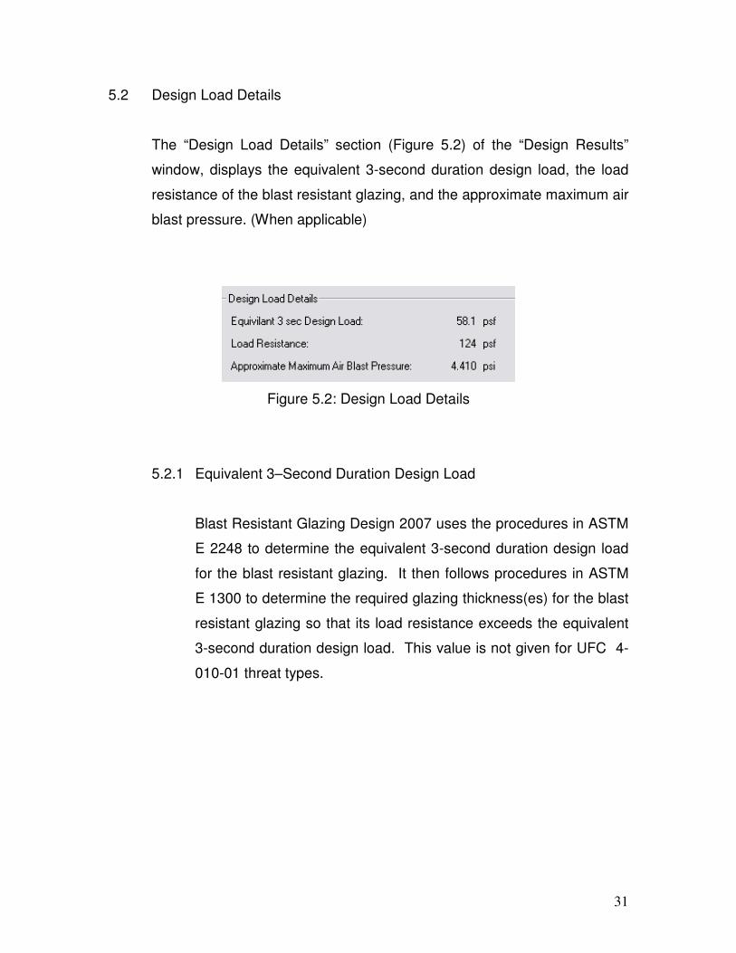
5.2 Design Load Details
The “Design Load Details” section (Figure 5.2) of the “Design Results”
window, displays the equivalent 3-second duration design load, the load
resistance of the blast resistant glazing, and the approximate maximum air
blast pressure. (When applicable)
Figure 5.2: Design Load Details
5.2.1 Equivalent 3–Second Duration Design Load
Blast Resistant Glazing Design 2007 uses the procedures in ASTM
E 2248 to determine the equivalent 3-second duration design load
for the blast resistant glazing. It then follows procedures in ASTM
E 1300 to determine the required glazing thickness(es) for the blast
resistant glazing so that its load resistance exceeds the equivalent
3-second duration design load. This value is not given for UFC 4-
010-01 threat types.
32
5.2.2 Load Resistance
The load resistance is the uniform lateral load that a glass
construction can sustain based upon a given probability of
breakage and load duration. ASTM E 1300 uses a 3-second load
duration and a probability of breakage of 8 lites per 1000 at its first
occurrence of the design loading. In the event of a blast loading
occurring equal to the design threat, blast resistant glazing will
fracture safely. If the load resistance of a blast resistant glazing
falls beyond the limits of ASTM E 1300 for the current design, Blast
Resistant Glazing Design 2007 displays a load resistance of “N/A”
for the current design, and does not display the glazing design
section explained in Section 5.2.
5.2.3 Approximate Maximum Air Blast Pressure
If a “User-Defined” threat is selected, the program displays an
approximate maximum air blast pressure. For UFC 4-010-01 and
ISC/GSA threat types, the program does not display an
approximate maximum air blast pressure for security reasons.
33
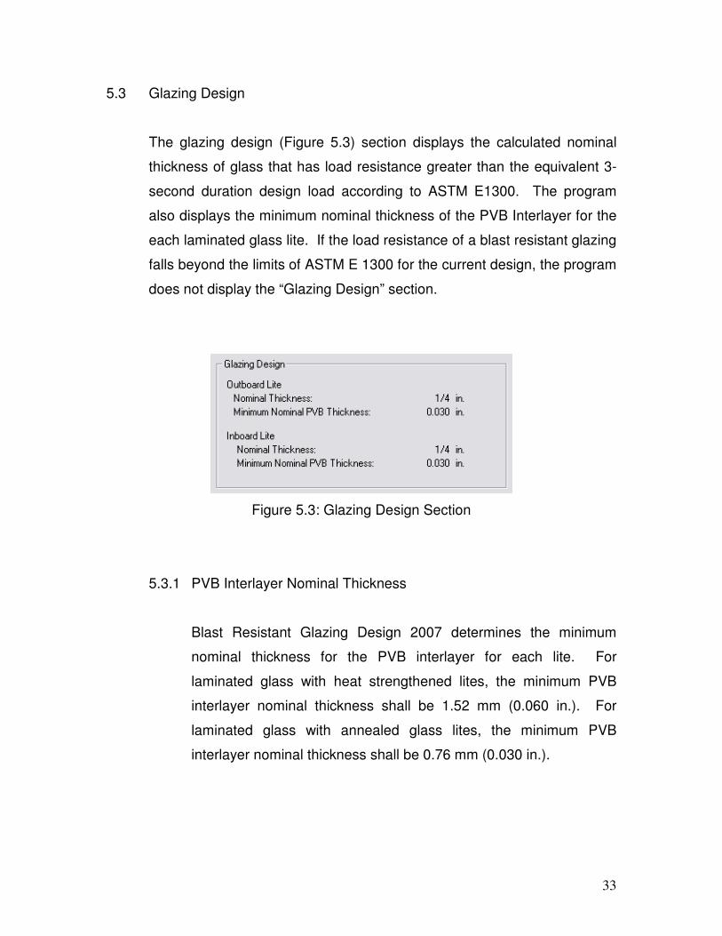
5.3 Glazing Design
The glazing design (Figure 5.3) section displays the calculated nominal
thickness of glass that has load resistance greater than the equivalent 3-
second duration design load according to ASTM E1300. The program
also displays the minimum nominal thickness of the PVB Interlayer for the
each laminated glass lite. If the load resistance of a blast resistant glazing
falls beyond the limits of ASTM E 1300 for the current design, the program
does not display the “Glazing Design” section.
Figure 5.3: Glazing Design Section
5.3.1 PVB Interlayer Nominal Thickness
Blast Resistant Glazing Design 2007 determines the minimum
nominal thickness for the PVB interlayer for each lite. For
laminated glass with heat strengthened lites, the minimum PVB
interlayer nominal thickness shall be 1.52 mm (0.060 in.). For
laminated glass with annealed glass lites, the minimum PVB
interlayer nominal thickness shall be 0.76 mm (0.030 in.).

34
5.4 Framing and Attachment Requirements
This section gives the design requirement for the framing and window
attachment as Figure 5.43 shows. The first comment displays the
recommended size of the structural sealant bead to attach the blast
resistant glazing to the frame. The second comment gives the uniformly
distributed static design load acting over the window surface area that the
frame and its attachment to the building must resist in the event that the
design blast occurs.
Figure 5.4: Framing and Attachment Section

35
5.5 Comments
The comment section (Figure 5.5) gives additional information for the blast
resistant glazing design. The comment section explains the GSA and/or
UFC 4-010-01 Hazard/Protection level for the design. A GSA level 3A is a
“High Protection, Very Low Hazard” performance criterion. Under this
criterion in the event of a design level blast the glazing cracks, and
fragments enter the space and land on the floor no further than 3.3 ft (1.0
m) from the window.
Figure 5.5: Comment Section, Within ASTM E 1300
If the load resistance of a blast resistant glazing falls beyond the limits of
ASTM E 1300, the software only displays the equivalent 3-second design
load and does not provide any other results. The comment block shown in
Figure 5.6, states that for the particular design additional design
considerations are required.
Figure 5.6: Comment Section, Beyond ASTM E-1300-02

36
5.6 Closing the Design Results Window
To close the design results window press the “Close” button on the bottom
of the window or press the “X” button located on the top right-hand corner
of the Design Results window. To recalculate the results, follow the
instruction in Section 5.1 of this document.