Embed Size (px)
Citation preview

V 1.11, 11 Sep 2012
FW 1.11
Table of Contents
1. Introduction 2. Assembly 3. Installation 4. Launch 5. General Navigation Functionality 6. Setup 7. Forced OBD2 Connection 8. Speed Correction 9. Data 10. Performance Calculations 11. OBD2 Code Reading 12. Scan 13. Unichip Map Selection 14. Optional Equipment
Attachment A – Assembly Procedures Attachment B – OBD2 Codes Attachment C – P-metric Tire Size Conversion Attachment D – Display Connections Attachment E – Warranty

1. Introduction. Thanks for purchasing the Flux2 system. Flux2 is a self-contained communication and display
system which connects to virtually any vehicle’s OBD2 data port and provides an interface between the user and vehicle. In addition, Flux2 is designed to work with a Unichip Performance Computer and allows the user to access all five performance data sets in the Unichip.
2. Assembly. Your Flux2 Display comes with an articulated windshield suction cup mount that can be attached to the
rear of the Display case if desired. Always use the kit provided components and fasteners to assemble and the windshield mount to your Flux2 Display – failure to do so may result in internal damage to the Display or an insecure installation that could come loose during an inopportune time during vehicle operation. See Attachment A for assembly details.
3. Installation. Before affixing the Flux2 to your windshield, connect the kit provided wiring looms into the appropriate
ports on the Display unit. With the basic Flux2 kit, you received two cables, one to connect the Flux2 Display to the vehicle’s OBD2 port and the other to connect the Flux2 Display to the Unichip. Note that basic Flux2 functionality requires only the OBD2 Port connection while Unichip map switching requires the Unichip Connection Loom.
Manufactured by
UNICHIP OF NORTH AMERICA
www.unichip.us
UNICHIP
COMM
BOOST
EGT
OBD
Unichip
Connection Loom OBD2
Connection Loom
Existing PnP or
Hardwire Unichip
Connection
To OBD2 port
under dash
Connect all together
a. Plug the OBD2 Connection Loom’s 8-pin Plug into the Flux2 Display Port labeled OBD. Connect the Unichip Connection Loom to the Flux2 Display Port labeled UNICHIP. Ensure the Plugs are correctly oriented prior to pushing them into the Display Connectors; each plug is keyed so that it only installs with the correct orientation. Note that each of these connectors has a small locking tab which should be oriented on the same side of the Display Connector as the half-round cut-out on the surface of the Display body. These locking tabs slip over a small tab on the female connector and when correctly installed prevent the Plug from being removed. To remove a Plug, press down on the locking tab to raise it above the female connector’s tab.
Warning: Use care when routing the looms as poor routing may allow the loom to cause interference with vehicle controls. Use Zip ties to securely attach the loom to the car. Do not leave extra loom loosely around the passenger compartment
b. After using the kit provided articulated windshield suction cup mount to secure your Flux2 Display to your vehicle’s windshield, carefully route the OBD2 Connector Loom to the vehicle’s ODB2 port and connect the Plug.

Warning: Ensure the Flux2 Display installation does not block your field of view. By carefully positioning the suction cup mount and properly articulating the mounting arm, the Flux2 Display can be visually positioned in front of the vehicle’s A-pillar or dash pad rather than blocking your view out the windshield.
Note: (1) Your vehicle’s OBD2 port is located underneath the dashboard, near the steering column. The port may be open and exposed or it may be behind a trim panel. The connector is in the same shape as the OBD2 Plug on the Flux2 harness. If the vehicle’s OBD2 port is exposed, it will probably have a slip off cover that must be removed to connect Flux2.
(2) By regulation, the OBD2 port will be located within two feet (61 cm) of the steering wheel and you will not need tools to access the port.
Warning: The OBD2 connector plug often has a cover and is not mounted very securely. Pushing on the OBD2 connector case can cause the case to separate from the connector resulting in damage. Use caution and both hands when connecting to avoid pushing the OEM port into a position which precludes a connection. Some VW vehicles, in particular, are prone to this.
c. Next connect the Unichip Connection Loom to the Unichip Performance Computer; the Unichip Performance Computer Connector has both a female and male plug. Disconnect the exiting 24-pin connector from the Unichip Computer and insert it into the female plug side of the Unichip Connection Loom and then plug the male plug side into the Unichip.
Note: If you have another map switching device (like a 2-way or 5-way mechanical switch or the Bluetooth Flux Receiver), you should disconnect that device before installing the Flux2. Although you won’t damage the Flux2 Display, some positions of those other devices will inhibit the Flux2 Display’s map switching capability).
Warning: Use care when routing the looms as poor routing may allow the loom to cause interference with vehicle controls. Use Zip ties to securely attach the loom to the car. Do not leave extra loom loosely around the passenger compartment
d. Connecting external accessories. If you have purchased the EGT or Boost add-on kits, connect the cables provided with the sensor into the appropriate connector on the back of the Flux2 display. Ensure you connect the kit’s 4-pin Molex Plug into the correct port on the back of the Flux2 Display.
Warning: Use care when routing the looms as poor routing may allow the loom to cause interference with vehicle controls. Use Zip ties to securely attach the loom to the car. Do not leave extra loom loosely around the passenger compartment
4. Launch. Once installation is completed, either start the vehicle or turn the ignition key on to power up the factory
computer and hit any button on the Flux2 Display to turn it on. You will see a version information screen that will automatically switch to the first caution display 5 seconds after launching. You can also press the buttons on either side of < ------------
CONTINUE CONTINUE CONTINUE CONTINUE ------------ > to proceed to the first caution display immediately.
Whether using the Flux2 Display or doing anything else in your vehicle, SAFELY OPERATING YOUR VEHICLE MUST ALWAYS BE YOUR PRIORITY. Excessive focus on the Flux2 Display while operating your vehicle is dangerous and the lack of attention afforded to operating the vehicle may lead to an accident which results in damage or loss of live. Pressing the I ACCEPTI ACCEPTI ACCEPTI ACCEPT > button on the first and second caution display indicates your understanding of the dangers associated with using a display system in your vehicle.

< >
>
>
a. Accepting the second caution screen by pressing the IIII ACCEPTACCEPTACCEPTACCEPT > button automatically launches a vehicle communication procedure during which Flux2 determines the OBD2 protocol your vehicle uses so that it can communicate with your factory computer. There are a number of OBD2 protocols and Flux2 will step through each automatically until it establishes communication and this will occur each time you power up your Flux2 Display and no action is required by you.
b. Once communication with the factory computer is established, the Flux2 display will automatically change to a Link Success display which confirms the OBD2 protocol in use. After 5 seconds the display will automatically advance to the Flux2 Main Menu Page. You may also press the buttons on either side of the <------------ CONTINUE CONTINUE CONTINUE CONTINUE ------------> display to advance without any delay.
Note: To speed up launch, once Flux2 has established communication it no longer searches for protocols so if you switch the Flux2 to a different vehicle, you may have to “force” communication.
When you connect to a new vehicle, Flux2 will run through a normal LINKINGLINKINGLINKINGLINKING TO VEHICLETO VEHICLETO VEHICLETO VEHICLE display but may fail to connect. If that happens, you should select < SETUPSETUPSETUPSETUP and either select AUTO DETECTAUTO DETECTAUTO DETECTAUTO DETECT or manually step through the protocols until communication is established.
c. The Flux2 Display Main Menu Page features navigation options to view live parametric data, to scan the factory computer for fault codes, to change screen settings, correct vehicle speed readings, and connect to the factory computer, and to change maps in the Unichip computer. Each of these functions is described below.
d. When you turn the vehicle’s ignition key off, your OEM ECU will power down and stop communicating with the Flux2. Although the time for Flux2 to power down after switching the key off varies between vehicle types, shortly after the communication stops, the Flux2 Display will transition to a NO LINK TO VEHICLENO LINK TO VEHICLENO LINK TO VEHICLENO LINK TO VEHICLE display.

e. If you take no action, the Flux2 will power down automatically from this screen after a few seconds. If you wish to immediately power the Display down, push the PWR OFFPWR OFFPWR OFFPWR OFF > button.
f. The NO LINK TO VEHICLENO LINK TO VEHICLENO LINK TO VEHICLENO LINK TO VEHICLE display will also appear if OBD2 communication is interrupted for other reasons and if you wish to reestablish the connection, press the < RETRYRETRYRETRYRETRY button.
5. General Navigation Functionality. On all Flux2 Display screens, you will see arrows pointing to buttons on the Display case. If an arrow is present, the function is available and if the arrow is not present, the function is unavailable. Normally, the arrow will be absent if communication with the factory computer has been lost; to regain the function, press the < SETUPSETUPSETUPSETUP button and reestablish communication. Button pushes produce an audible beep for confirmation so if you do not hear a beep the button press was not registered.
6. SETUP. Pressing the < SETUPSETUPSETUPSETUP button enters the rotary allowing you to change between English or Metric units,
change the display settings, change OBD2 communication settings, and change the vehicle speed display.
a. Unit Selection. To change the display units to Metric, press the METRIC METRIC METRIC METRIC > button and to change to English units
press the < ENGLISHENGLISHENGLISHENGLISH button. To return to the Main Menu, press the < flux 2 main menuflux 2 main menuflux 2 main menuflux 2 main menu button. To adjust the Display screen settings, press the < UNITSUNITSUNITSUNITS: button.
b. Display Contrast. Increase or decrease the contrast as desired by using the < - and + > buttons. To return to the Main Menu, press the < flux 2 main menuflux 2 main menuflux 2 main menuflux 2 main menu button. To adjust the Display backlight settings, press the <
display contrastdisplay contrastdisplay contrastdisplay contrast button.
c. Increase or decrease the backlight as desired by using the < - and + > buttons. To return to the Main Menu, press the <
flux 2 main menuflux 2 main menuflux 2 main menuflux 2 main menu button. To manually select OBD2 settings, press the < display backlightdisplay backlightdisplay backlightdisplay backlight button.
7. Forced OBD2 Connection. If for some reason your Flux2 Display will not automatically connect to your
vehicle, the display screen will change to the OBDII LINK FAILUREOBDII LINK FAILUREOBDII LINK FAILUREOBDII LINK FAILURE screen.

a. From this screen, either select < AUTOAUTOAUTOAUTO----DETDETDETDET to reattempt an automatic connection, or manually choose the appropriate OBD2 protocol by pressing the SETSETSETSET----UPUPUPUP > button. Pressing SETSETSETSET----UPUPUPUP > shows you the currently selected protocol and gives you the < SELECTSELECTSELECTSELECT button which enables you to cycle through all available options… Auto, ISO 9141, ISO 14230F, ISO 14230S, J1850 VPW, J1850 PWM, and CAN 11-500 and then repeat the list.
b. If you know the correct protocol for your vehicle, press the < SELECTSELECTSELECTSELECT button until that protocol appears in the < ModeModeModeMode: line and press CONNECTCONNECTCONNECTCONNECT >.
c. While the Flux2 Display attempts to connect, you will see ------------ please wait please wait please wait please wait ------------ displayed indicating the OBD2 protocol currently in use. If the connection attempt is successful, the Flux2 Display will change to the Main Menu page. If the connection attempt is unsuccessful, a ** connection failed **** connection failed **** connection failed **** connection failed ** message will appear.
d. To reattempt the connection, press the < OBD II MODE SELECTOBD II MODE SELECTOBD II MODE SELECTOBD II MODE SELECT button. To change the OBD2 protocol, press the < CONNCONNCONNCONN: button. Without a connection, there are no other navigation options.
e. If you do not know the correct protocol for your vehicle, press the < SELECTSELECTSELECTSELECT button until the next protocol appears in the < ModeModeModeMode: line and press CONNECTCONNECTCONNECTCONNECT >. If the connection is unsuccessful, select the next protocol by pressing the <
connconnconnconn: button and then initiate the connection attempt by pressing the < OBD II MODE SELECTOBD II MODE SELECTOBD II MODE SELECTOBD II MODE SELECT button.
f. If the Flux2 Display will not connect, try disconnecting the OBD2 cable from the vehicle’s OBD2 port. Leave the cable disconnected for about 30 seconds, reconnect the cable, and cycle through the connection options again.
8. Speed Correction. Pressing the < mode mode mode mode button advances the screen to the Speed Speed Speed Speed
CorrectionCorrectionCorrectionCorrection page. Pressing the < - or the + > buttons on this screen changes the vehicle speed on the < DataDataDataData screen by the selected percentage so that you can correctly compensate for aftermarket tire/wheel packages and/or modified vehicle gearing. You can change the speed by up to 50% and your performance calculations are automatically compensated for by the same amount. The selected change will be maintained through power cycles until you change it to something else. To approximate the required change percentage for your application, see Attachment C.

*** Note: The corrected speed reading is only in the Flux2 Display and the OEM speedometer is not affected.
9. Data. The < DATADATADATADATA button on the Flux2 Display Home Page launches the Parametric Data Page from which you can
monitor your vehicle’s operating conditions and access the Acceleration Calculation Page.
a. The Parametric Data Page displays three lines of user selectable data on the Display’s left side. Each parameter has an abbreviation indicating what the displayed data represents as well as the current value. The three lines are not mutually exclusive so you can have the same data on multiple lines if desired but each window must have something displayed.
b. To change the parameter being displayed on any line, push the button to the left of that line and step through the rotary. The rotary wraps and will repeat.
c. Whenever the button is pushed a preview of the upcoming parameter is displayed and will continue to be displayed as long as the button is pressed.
d. The displayable items are dependent upon what data your vehicle’s factory computer uses, so some items may produce no values on some vehicles. Additionally, data field population varies by vehicle because of the factory computer’s response time and may take several seconds on some applications.
e. The supported information rotary is listed in this chart. Note that those values that have associated English or Metric units are automatically changed by choosing the desired system under SETUPSETUPSETUPSETUP.
f. Not all vehicles support all parameters and if your vehicle’s ECU does not support a Flux2 request, that display line will show < Unsupported.Unsupported.Unsupported.Unsupported. This does not mean there is a problem with the Flux2 Display, it simply means your vehicle does not use the requested parameter – for example OPEN LP/TEMP or CLSD LP OPEN LP/TEMP or CLSD LP OPEN LP/TEMP or CLSD LP OPEN LP/TEMP or CLSD LP on a diesel application – and therefore has nothing with which to respond. Press the < UnsupportedUnsupportedUnsupportedUnsupported button to step to the next parameter until you find a supported item.
Display Text Vehicle Parameter
RPM Engine speed in revolutions/minute
MPH or KPH Vehicle speed in either mph or kph
TADV Ignition advance in degrees before top dead center
INTK Intake Air Temperature in degrees F or C
TPS Throttle Position in percentage
OPEN LP/TEMP or CLSD LP Fuel system status
LOAD Calculated engine load in percentage
TEMP Coolant temperature in degrees F of C
SF1 Short term fuel trim, bank 1
LF1 Long term fuel trim, bank 1
SF2 Short term fuel trim, bank 2
LF2 Long term fuel trim, bank 2
XEGT *** Exhaust Gas Temperature ***
XB *** Boost pressure ***
Batt Vehicle battery voltage

*** Note: Although XEGT and XBST appear on the list, they will not function unless those sensors are added to your Flux2 Display. The EGT and Boost sensors are available from Unichip of North America or your local dealers.
10. Performance Calculations. Pressing the PERF > button on the Data page opens the Acceleration Timing page.
<
<
< – >
<
<
< >
<
Warning: All performance driving must be done in an area that ensures safe acceleration and braking AND must be in an area where such driving is lawful. UNA does not endorse or condone imprudent or unlawful driving.
a. The Acceleration Timing page measures standing start accelerations of 0-60 or 0-100 mph or 0-100 or 0-160 kph. As with all Flux2 Display screens, switching between English or Metric units is done on the SETUPSETUPSETUPSETUP page.
b. To measure your vehicle’s acceleration, locate an area in which you will be able to accelerate to the required speed and slow back down with plenty of room left over. Position the vehicle where you want to begin the acceleration and bring it to a complete stop. When ready to accelerate, press the < BEGIN SPEED RUNBEGIN SPEED RUNBEGIN SPEED RUNBEGIN SPEED RUN button and the Display will change to the timing screen. As soon as the vehicle begins to move, the TIMETIMETIMETIME will start and as soon as the vehicle reaches the selected target speed, the TIMETIMETIMETIME will freeze.
<
<
< – >
<
c. When you reach the selected speed, the SPEED RUN RESULTSSPEED RUN RESULTSSPEED RUN RESULTSSPEED RUN RESULTS screen will automatically appear showing the time and speed the time was stopped at. Often the speed will be slightly higher than the selected speed because of the factory ECU communication rate.
d. When you are finished, exit the screen by pushing the < Flux 2 main menuFlux 2 main menuFlux 2 main menuFlux 2 main menu button which will return you to the Acceleration Timing Page.

11. OBD2 Code Reading. The factory computer controlling your vehicle constantly monitors operations for
faults and records those faults whenever they occur. For easy display, these faults are identified by alpha numeric codes called Parameter ID typically five characters long. There are literally thousands of PID codes and while some are common to all vehicles and manufacturers, some are proprietary to particular manufactures.
a. Random faults can and do occur during normal operation and do not necessarily represent a problem that must be corrected. To decide when a detected fault becomes a PID code, the factory computer controlling your vehicle uses sampling schemes to see how many times a fault is detected in a given amount of time. The faults are grouped into three categories based upon these sampling schemes… normal operation, pending codes, and active codes.
b. Normal operation – the sampling results are below acceptable fault rates and no codes are generated. You will not know anything about these faults even when scanning the factory computer for codes.
c. Pending PID codes – the sampling results indicate a problem that does not rise to the level of immediate attention but will require attention if it gets any worse. You will not know anything about these faults during normal operation but will see them if you scan the factory computer.
d. Active PID codes – the sampling results indicate a problem requiring immediate attention. Active PID’s will often, but not always, trigger a Check Engine Light. You will see all Active PID codes when you scan the factory computer.
e. All Active and Pending OBD2 codes displayed on your Flux2 with the < ScanScanScanScan function.
f. Refer to Attachment B for a description of OBD2 fault codes and a description of their structure.
g. Since different OEM’s use different PID, an attempt to list them in this document is impractical. To decode a PID once you have obtained it from the Flux2, do an internet search using the terminology “OBD2 code xXXXX.”
12. Scan. From the Main MenuMain MenuMain MenuMain Menu, press the < ScanScanScanScan button on the display’s left side to launch the OBD2 function.
a. The display initially reports the number of Stored PID codes detected during the scan… in this example, the vehicle has three stored codes. To display the Stored PID codes, select the button left of the < 3 CODES STORED3 CODES STORED3 CODES STORED3 CODES STORED graphic.
b. The display now shows the first PID codes alpha numeric code B3292 B3292 B3292 B3292 and indicates which of the detected PID codes is currently displayed, in this case 1 of 31 of 31 of 31 of 3. To view the alpha numeric PID codes for each of the detected codes, press the button by the current code and the display will cycle through all stored codes in a rotary that will return to the first code after displaying the last.
c. To show detected pending PID codes, press the button to the right of NEXTNEXTNEXTNEXT > on any SCANSCANSCANSCAN page and the display indicate pending codes. The screen functionality for pending PID codes is identical to stored PID code functionality.

d. To view available freeze frame data for the displayed PID codes, press the button for < FreezeFreezeFreezeFreeze. Remember not all PID codes have freeze frame data.
e. To clear all of the PID codes detected during the SCAN operation, press the < CLEAR ALLCLEAR ALLCLEAR ALLCLEAR ALL button. Because this action will clear all stored and pending codes, if you are performing diagnostics do not select < CLEAR ALLCLEAR ALLCLEAR ALLCLEAR ALL until you have cycled through all detected PID codes and their associated freeze frame data.
<
<
< >
<
<
< >
<
f. If the clear function is successful, the display will change to NO CODES STOREDNO CODES STOREDNO CODES STOREDNO CODES STORED.
g. Component failures on some newer CAN OBD2 protocol vehicles produce codes that cannot be cleared with a scanning device. Codes on these vehicles will only clear when the faulty component has been replaced and the OEM computer receives valid data back from the new component. Your Flux2 Display will indicate what the faulty component is or may be, but you will have to repair the fault for the code to clear.
13. Unichip Map Selection. Flux2 is designed to interface with Unichip Q Performance Computers and
provides a convenient way to change the map settings in the Unichip. Access the Unichip map selection functionality by pressing the UNIchipUNIchipUNIchipUNIchip > button on the Flux2 Main Menu.

a. If your vehicle is not equipped with a Unichip Q Performance Computer, or if the connection is faulty, the display will show Unichip not detected Unichip not detected Unichip not detected Unichip not detected and give you the option to navigate back to the main menu.
b. If your vehicle is equipped with a Unichip, pressing the UNICHIP UNICHIP UNICHIP UNICHIP > button navigates you to the Flux2 Map Selection Page.
c. To change maps, use the < - or + > until the selected map is as desired. Note that the default map names are UNICHIP UNICHIP UNICHIP UNICHIP
MAP 1MAP 1MAP 1MAP 1 through 5555 but each description can be programmed as desired by your Flux2 dealer or by ordering a Map Description cable and a Hyperterminal software program. This function is not a rotary and will not step below map 1 nor above map 5.
d. Unichip Map switching may only be performed with the vehicle ignition key on and the engine not running. If you attempt to change Unichip Maps while the engine is running, the Flux2 will display a warning and the Unichip Map will remain unchanged.
e. Your new map selection is only selected when you leave the Map Selection screen by returning to the Flux2 Main Flux2 Main Flux2 Main Flux2 Main
MenuMenuMenuMenu. If you cycle ignition power while still on the Map Selection screen, the selected map will revert to the previously selected option.
f. The Unichip has up to 5 Map locations, and you may select any of the 5 locations with the Flux2.
g. On some vehicles, when you cycle the ignition key to change maps the OBD2 connection will be broken; if that occurs, although the Unichip will still show detected, it will not switch maps. If you’re vehicle operates this way, Force the OBD2 connections (see paragraph 7) and then change the map as desired.
Warning: If you select an unprogrammed Map location, your vehicle will not start. No damage to your vehicle or the Flux2 Display will result but you must choose a correctly programmed map position for your vehicle to operate.
14. Optional Equipment. Exhaust Gas Temperature and Boost Sensor kits are available separately which allow
the Flux2’s EGT and Boost options to display correctly. Each kit includes everything required and details are available at www.unichip.us.

15. Attachment A – Assembly Procedures
1. Remove the Windshield Suction Cup Mount and the bag of fasteners from the poly bag.
2. To facilitate mounting the flange to the Flux2 Display, remove the tensioning cup from the ball joint.
3. Position the mounting flange over the holes in the center of the back of the Flux2 Display.
4. Install first a split washer and then a flat washer onto the first screw and place it through one of the flange slots and turn it a few turns into the threads of the Flux2 Display.
5. Place the washers in the same order on the remaining three screws and turn them each in turn into the Flux2 Display.
6. Center the flange and tighten each of the screws until the split washers are flat. Do not over tighten the screws or the Flux2 Display will be damaged.
7. Place the Windshield Suction Cup stalk’s ball into the flange’s socket and gently seat and tighten the tensioning cup.
Flange
Ball
Cup
Flat
Split
Attachment B – OBD2 codes
Your Flux2 Display will read, display, and clear OBD2 Digital Trouble Codes (DTC’s) which are alpha numeric codes used to aid in vehicle troubleshooting. There are literally thousands of DTC’s used by your vehicle.
Proprietary DTC’s
Some of those DTC’s are proprietary to the manufacturer and, as such, the manufacturer is not compelled to disclose what those codes mean. Your Flux2 Display may display unusual characters or may display all ??????’s if it is unable to interpret the data generated by these proprietary DTC’s. An internet search or a phone call to a certified dealer may help you determine the fault.
Open source DTC’s
Many DTC’s are by legislation common across all manufacturers and must be readable by testing centers for emissions compliance. Your Flux2 Display will properly display these codes and you can find the plain text description for each of these codes by doing an internet search of the code.
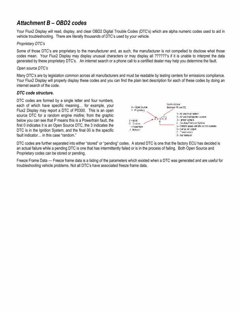
DTC code structure.
DTC codes are formed by a single letter and four numbers, each of which have specific meaning… for example, your Flux2 Display may report a DTC of P0300. This is an open source DTC for a random engine misfire; from the graphic below you can see that P means this is a Powertrain fault, the first 0 indicates it is an Open Source DTC, the 3 indicates the DTC is in the Ignition System, and the final 00 is the specific fault indicator… in this case “random.”
DTC codes are further separated into either “stored” or “pending” codes. A stored DTC is one that the factory ECU has decided is an actual failure while a pending DTC is one that has intermittently failed or is in the process of failing. Both Open Source and Proprietary codes can be stored or pending.
Freeze Frame Data — Freeze frame data is a listing of the parameters which existed when a DTC was generated and are useful for troubleshooting vehicle problems. Not all DTC’s have associated freeze frame data.

Attachment C – P-metric Tire Size Conversion
To enter the correct Speed Conversion in the Flux2 Display, you must first determine the value. You can either use an accurate GPS system, pace your vehicle with a known accurate vehicle, or use the gear and/or tire sizes to calculate the value.
GPS or Pacing
To determine an accurate correction, drive your vehicle at a moderate steady pace on a level road – if possible with cruise control set – and compare the speed on your GPS to the speedometer. Divide the speedometer reading by the GPS reading to determine the correction you will enter into the Flux2 Display.
If you are using a pace vehicle, have that vehicle drive at a moderate steady pace on a level road – if possible with cruise control set – while you carefully maintain station next to the pace vehicle. Note your speedometer reading and divide that value with the speed from the pace car to determine the value you enter into the Flux2 Display.
Tire Size Correction
To calculate the Speed correction percentage required for your aftermarket tire and wheel package, you need the first section of the OEM and aftermarket tires. Using the following equation, you can calculate the circumference of both and dividing the OEM number by the aftermarket number will produce the correction percentage.
The equation is…
[(Width x Aspect Ratio x 2) + wheel diameter] 3.14159 = circumference
… and all of those values are available on the tire side wall.
If, for example, you have 255/35-17 aftermarket tires on your vehicle, those tires tread is 255 mm wide, the Aspect Ratio (comparison of the sidewall height compared to the tread width) is 35%, and the rims have a 17-inch diameter. You can do the calculation in either English or Metric units, but in either case you have to convert something since the standard sizes show width in mm and rim size in inches.
In our example, the tires are 255 mm wide which is 10.04 inches and the aspect ratio is 0.35 so filling in the first portion of the equation gives us…
10.04 x 0.35 x 2 = 7.03 inches
… and the wheel diameter is 17 inches, so filling in the rest of the equation yields…
(7.03 + 17) 3.14149 = 75.49 inch circumference
If you the OEM tires were 225/45-15, running the same calculation give a 73.09 inch circumference.
Dividing the OEM circumference by the aftermarket circumference…
(75.49 / 73.09) x 100= 1.033 which is a 3.3% decrease.
To correct your displayed speed, enter – 3% in the Flux2 Display’s SPEED CORRECTIONSPEED CORRECTIONSPEED CORRECTIONSPEED CORRECTION screen.

Attachment D – Display Connections
The connections in black are those for the basic Flux2 Display connections for normal operation. These connections are made with the harness provided with the kit
The connections in red are those for programming the Flux2 Display and/or the Unichip. To update the Flux2 Display firmware, create map names for the display, or to program the Unichip, connect the appropriate cables into these ports. These ports are not used during normal operation.
The connections in grey are those used to connect the Boost and/or EGT upgrade sensors into the Flux2 Display. These components are sold separately and, if used, are used during normal operation. For details, visit www.unichip.us talk with your dealers.
Manufactured by
UNICHIP OF NORTH AMERICA
www.unichip.us

Attachment E – Warranty For 90 days following the original owner’s purchase of a Unichip, Unichip of North America (UNA) warrants no other ECU product generates more power from a specific gasoline engine than a properly functioning, custom tuned Unichip in the specific vehicle for which it is tuned. If another ECU product generates more power from that engine within 90 days of the original owner’s purchase of the Unichip, the original owner can contact their Unichip dealer for a refund of all Unichip parts, Unichip installation charges, and Unichip custom tuning. Shipping, testing, dynamometer costs and the cost of removing any UNA parts are specifically not covered by this warranty and will not be refunded to the owner.
To claim a refund, owners must provide dynamometer proof another ECU product produced more power when installed on the specific vehicle and that vehicle and all of its parts were in an identical condition other than the ECU enhancement. Three repeatable dynamometer tests must be performed using the Unichip and three repeatable tests using the other ECU product. The average of the three tests performed on each product shall constitute that product’s score for determining power. The same technician, using the same dynamometer in an identical condition with the same settings, must perform all test runs. All environmental conditions including ambient and IAT temperature and pressure altitude and the vehicle’s cooling system temperatures and drive train temperatures must also be identical for all six runs. IAT and Coolant temperature data logged information for each run is required. The vehicle must also use the same fuel for all six tests. UNA reserves the rights to, at UNA’s exclusive discretion, re-tune the Unichip involved in a performance warranty claim at no cost to the customer making the claim or to provide a warranty refund; if after a retune, the Unichip still makes less power than another product, the owner will receive a refund IAW this warranty statement.
All UNA parts, including Unichip piggyback computers, Flux modules, harnesses, and accessories also carry a limited warranty against manufacturer’s defect. This warranty is valid for the original owner only, for one year from the date of purchase regardless of the installation date. UNA only warrants Unichip products sold by an authorized UNA reseller. If a UNA product is found defective, the original purchaser may contact the reseller from whom they purchased the product for a replacement component at no cost. Shipping, testing, dynamometer costs, and the cost of removing any UNA parts are specifically not covered by this warranty and will not be refunded to the owner.
The above warranties are expressly made in lieu of any and all other warranties, express or implied, including any warranty on the engineering or design of the goods as well as the implied warranties of merchantability and fitness for a particular purpose.
Any and all warranties on the Unichip are void if: 1) the custom installation or custom tuning of the Unichip was performed by anyone other than a UNA qualified dealer or tuner, 2) anyone other than a qualified UNA tuner or dealer alters or modifies or attempts to alter or modify any of the electronic data within the Unichip or 3) the UNA product is used for anything other than its intended purpose or is physically or electrically damaged.
For all warranty claims, the product return shipping date stamp must be within the appropriate time limitation from the time of purchase. Additionally, proof of purchase in the form of either a properly completed warranty card or a sales receipt indicating both the date of sale and owners name is required and is the owner’s responsibility. Customers with hard-wire installations are responsible for providing proof of when and where the installation was performed. Warranty claims will be denied if the customer cannot provide proof of purchase.
UNA is not liable for incidental, consequential, or punitive damages attributable directly or indirectly to the Unichip or UNA’s actions or inactions with respect to the Unichip. UNA is also specifically not responsible or liable for damage of any kind: 1) to a vehicle into which UNA products are installed or 2) resulting from the use of a vehicle equipped with any UNA products.
UNA believes high performance driving should be confined to appropriate venues such as racetracks or organized closed course events such as Autocross competitions, and does not sanction or participate in any street racing or other illicit driving activity.