Embed Size (px)
Citation preview
SCION xB 2008 - NAVIGATION SYSTEM Preparation
Page 1 of 17 pages Issue: A 05/02/07
Part Number: 08545-00930 NOTE: Part number of this accessory may not be the same as the part number shown.
Kit Contents Item # Quantity Reqd. Description
1 1 Navigation System 2 1 GPS Antenna 3 1 Wire Harness 4 1 DVD-ROM 5 1 Owner’s Manual
Hardware Bag Contents Item # Quantity Reqd. Description
1 1 Earth Plate 2 2 Cord Clamp 3 5 Wire Tie 4 3 Foam Tape 5 1 Protection Sheet 6 8 Bolt(M5×8) 7 1 Adhesive Tape
Additional Items Required For Installation Item # Quantity Reqd. Description
Conflicts None
Recommended Tools Personal & Vehicle Protection
Notes
Vehicle protection Blankets, Masking tape, Vinyl tape
Special Tools Notes None Installation Tools Notes Panel Clip Removal Tool e.g. Toyota SST P/N:-
00002-06002-01 Wrench Open End, 10mm Socket 10mm Ratchet Extension Screwdriver Phillips Torque Wrench 36 lbf ・in Pliers Scissors Nipper Special Chemicals Notes None
General Applicability
Recommended Sequence of Application Item # Accessory
1 Navigation System 2 Satellite Radio 3 Subwoofer 4 Interior lights
*Mandatory Vehicle Service Parts (may be required for reassembly) Item # Quantity Reqd. Description
Legend
STOP: Damage to the vehicle may occur. Do not proceed until process has been complied with. OPERATOR SAFETY: Use caution to avoid risk of injury. CAUTION: A process that must be carefully observed in order to reduce the risk of damage to the accessory/vehicle and to ensure a quality installation.TOOLS & EQUIPMENT: Used in Figures calls out the specific tools and equipment recommended for this process. REVISION MARK: This mark highlights a change in installation with respect to previous issue.
SCION xB 2008 - NAVIGATION SYSTEM Procedure
Page 2 of 17 pages Issue: A 05/02/07
Care must be taken when installing this accessory to ensure damage does not occur to the vehicle. The installation of this accessory should follow approved guidelines to ensure a quality installation. These guidelines can be found in the "Accessory Installation Practices" document. This document covers such items as:-
• Vehicle Protection (use of covers and blankets, cleaning chemicals, etc.). • Safety (eye protection, rechecking torque procedure, etc.). • Vehicle Disassembly/Reassembly (panel removal, part storage, etc.). • Electrical Component Disassembly/Reassembly (battery disconnection, connector removal, etc.).
Please see your Toyota dealer for a copy of this document.
1. Vehicle Protection
(a) Remove the negative battery cable (Fig. 1-1).
(1) Protect the fender before starting.
(2) Do not touch the positive terminal with any tool when removing cable.
2. Disassembly of Vehicle
NOTE: Place all removed parts on a protected surface. NOTE: When disconnecting wiring connectors do NOT pull on the wiring, pull on the connector only. NOTE: Engage the parking brake while working.
(a) Remove the instrument panel cluster finish
center panel.
(1) Apply masking tape around the instrument panel cluster finish center panel (Fig. 2-1).
(2) Disengage the 4 clips and 3 claws and remove the instrument panel cluster finish center panel (Fig. 2-1).
Ratchet, 10mm Socket
Negative Battery Cable
Battery
Fig. 1-1
Fig. 2-1 Instrument panel cluster finish center panel Claws (×3)
Panel Removal Tool Clips (×4)
Masking tape
SCION xB 2008 - NAVIGATION SYSTEM Procedure
Page 3 of 17 pages Issue: A 05/02/07
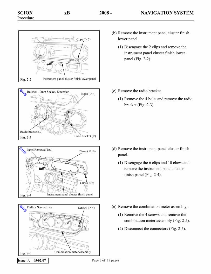
(b) Remove the instrument panel cluster finish lower panel.
(1) Disengage the 2 clips and remove the instrument panel cluster finish lower panel (Fig. 2-2).
(c) Remove the radio bracket.
(1) Remove the 4 bolts and remove the radio bracket (Fig. 2-3).
(d) Remove the instrument panel cluster finish panel.
(1) Disengage the 6 clips and 10 claws and remove the instrument panel cluster finish panel (Fig. 2-4).
(e) Remove the combination meter assembly.
(1) Remove the 4 screws and remove the combination meter assembly (Fig. 2-5).
(2) Disconnect the connectors (Fig. 2-5).
Fig. 2-2 Instrument panel cluster finish lower panel
Clips (×2)
Fig. 2-5 Combination meter assembly
Screws (×4) Phillips Screwdriver
Fig. 2-3
Radio bracket (L)
Bolts (×4) Ratchet, 10mm Socket, Extension
Radio bracket (R)
Fig. 2-4 Instrument panel cluster finish panel
Claws (×10)
Clips (×6)
Panel Removal Tool

SCION xB 2008 - NAVIGATION SYSTEM Procedure
Page 4 of 17 pages Issue: A 05/02/07
(f) Remove the instrument panel lower finish panel.
(1) Disengage the 2 clips and 8 claws and remove the instrument panel lower finish panel (Fig. 2-6).
(2) Disconnect the connectors (Fig. 2-6).
(g) Remove the center console side cover (L)
(1) Disengage the 3 claws and remove the center console side cover (L) (Fig. 2-7).
(h) Remove the center console side cover (R).
(1) Disengage the 3 claws and remove the center console side cover (R) (Fig. 2-8).
Guide
Fig. 2-8
Claws (×3)
Center console side cover (R)
Claws (×3)
Guide
Center console side cover (L) Fig. 2-7
Fig. 2-6 Instrument panel lower finish panel
Clips (×2)
Claws (×8) Panel Removal Tool
SCION xB 2008 - NAVIGATION SYSTEM Procedure
Page 5 of 17 pages Issue: A 05/02/07
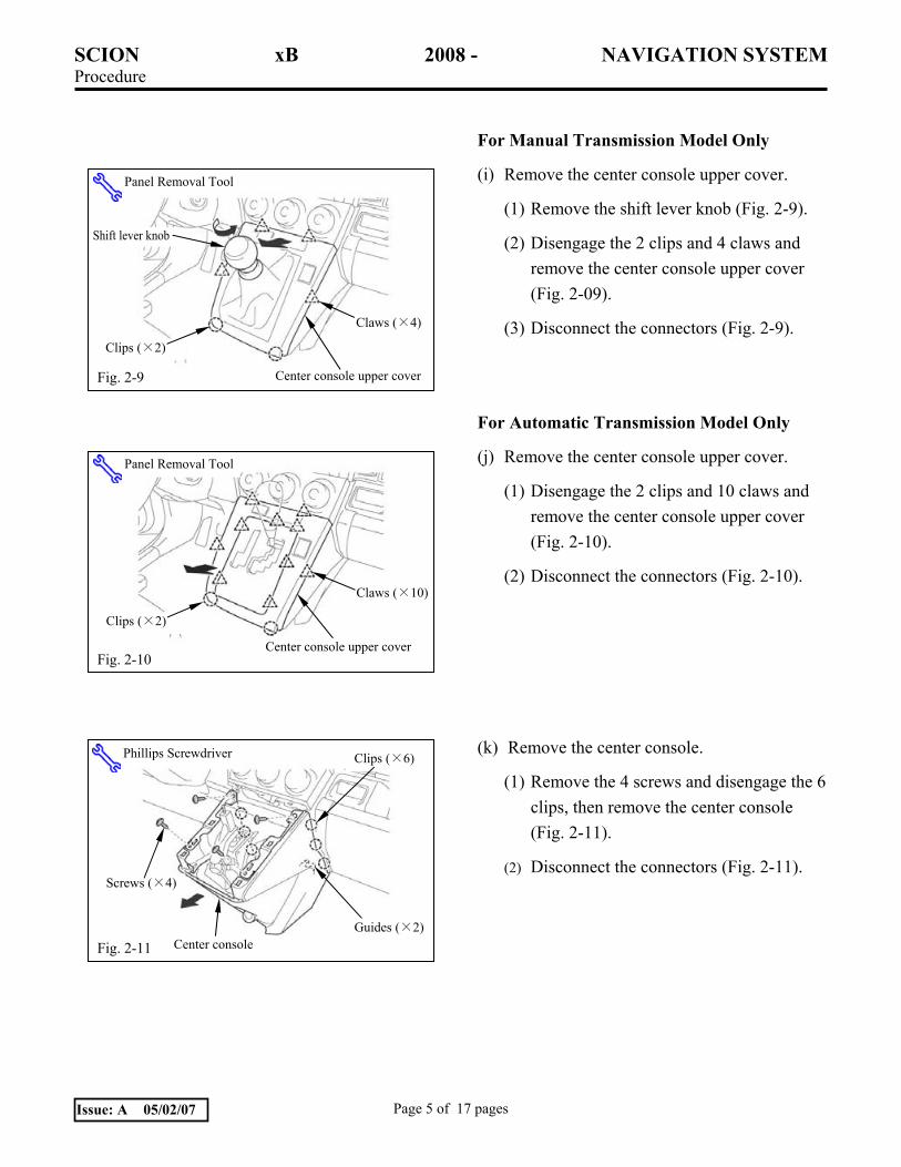
For Manual Transmission Model Only
(i) Remove the center console upper cover.
(1) Remove the shift lever knob (Fig. 2-9).
(2) Disengage the 2 clips and 4 claws and remove the center console upper cover (Fig. 2-09).
(3) Disconnect the connectors (Fig. 2-9).
For Automatic Transmission Model Only
(j) Remove the center console upper cover.
(1) Disengage the 2 clips and 10 claws and remove the center console upper cover (Fig. 2-10).
(2) Disconnect the connectors (Fig. 2-10).
(k) Remove the center console.
(1) Remove the 4 screws and disengage the 6 clips, then remove the center console (Fig. 2-11).
(2) Disconnect the connectors (Fig. 2-11).
Fig. 2-11
Phillips Screwdriver
Center console
Clips (×6)
Screws (×4)
Guides (×2)
Fig. 2-10
Panel Removal Tool
Center console upper cover
Clips (×2)
Claws (×10)
Fig. 2-9
Clips (×2)
Claws (×4)
Shift lever knob
Panel Removal Tool
Center console upper cover

SCION xB 2008 - NAVIGATION SYSTEM Procedure
Page 6 of 17 pages Issue: A 05/02/07
(l) Remove the rear console upper cover.
(1) Disengage the clip and 7 claws and remove the rear console upper cover (Fig 2-12).
(m) Remove the rear console box.
(1) Remove the non-woven fabric (Fig. 2-13).
(2) Remove the 3 bolts and 2 plastic clips (Fig. 2-13).
NOTE: Perform the wiring operation with the rear console box lifted. It is not necessary to disconnect the connectors.
Non-woven fabric
Fig. 2-13 Plastic clips (×2) Rear console box
Ratchet, 10mm Socket, Extension
Bolts (×3)
Claws (×7)
Rear console upper cover
Fig. 2-12
Clip
Panel Removal Tool
Front
SCION xB 2008 - NAVIGATION SYSTEM Procedure
Page 7 of 17 pages Issue: A 05/02/07
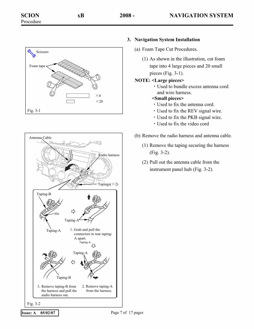
3. Navigation System Installation
(a) Foam Tape Cut Procedures.
(1) As shown in the illustration, cut foam tape into 4 large pieces and 20 small pieces (Fig. 3-1).
NOTE: <Large pieces> ・Used to bundle excess antenna cord and wire harness.
<Small pieces> ・Used to fix the antenna cord. ・Used to fix the REV signal wire. ・Used to fix the PKB signal wire. ・Used to fix the video cord
(b) Remove the radio harness and antenna cable.
(1) Remove the taping securing the harness (Fig. 3-2).
(2) Pull out the antenna cable from the instrument panel hub (Fig. 3-2).
Fig. 3-1
Scissors
Foam tape
×4 ×20
Antenna Cable
Fig. 3-2
Tapings(×2)
Radio harness
Taping-A
Taping-B
Taping-B
Slit
Taping-A
Taping-A
1. Grab and pull the connectors to tear taping-A apart.
2. Remove taping-A from the harness.
3. Remove taping-B from the harness and pull the audio harness out.
Taping-A
SCION xB 2008 - NAVIGATION SYSTEM Procedure
Page 8 of 17 pages Issue: A 05/02/07
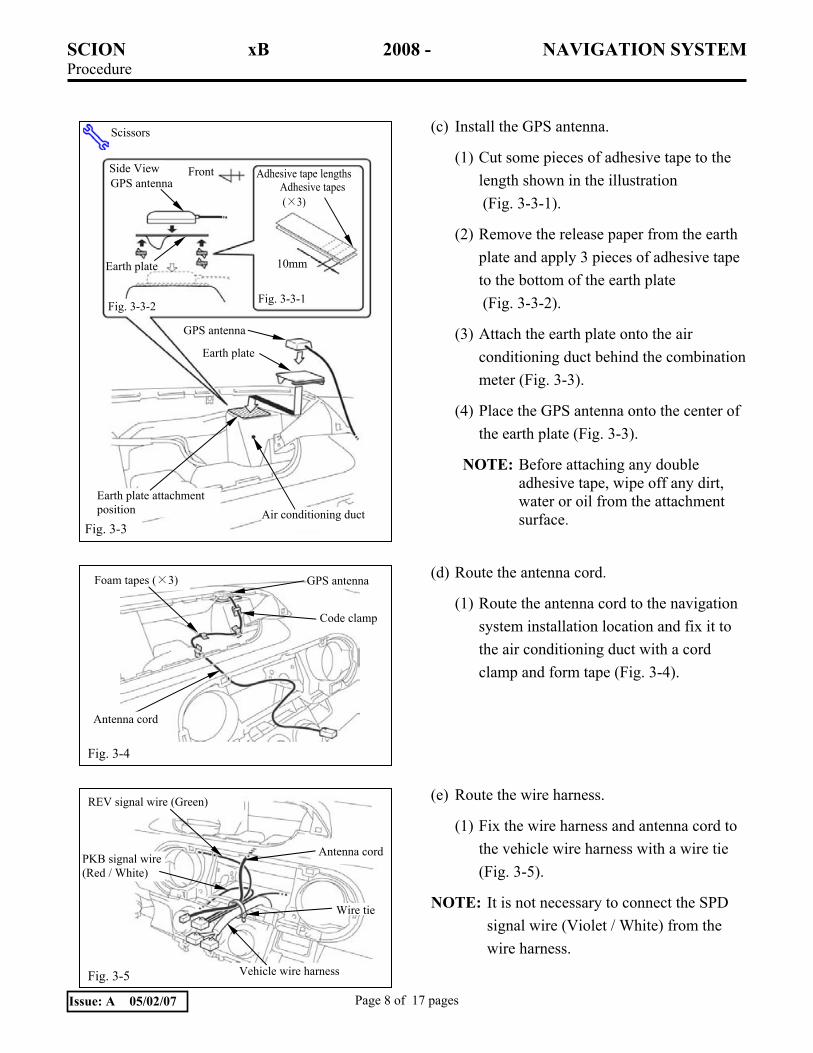
(c) Install the GPS antenna.
(1) Cut some pieces of adhesive tape to the length shown in the illustration (Fig. 3-3-1).
(2) Remove the release paper from the earth plate and apply 3 pieces of adhesive tape to the bottom of the earth plate (Fig. 3-3-2).
(3) Attach the earth plate onto the air conditioning duct behind the combination meter (Fig. 3-3).
(4) Place the GPS antenna onto the center of the earth plate (Fig. 3-3).
NOTE: Before attaching any double adhesive tape, wipe off any dirt, water or oil from the attachment surface.
(d) Route the antenna cord.
(1) Route the antenna cord to the navigation system installation location and fix it to the air conditioning duct with a cord clamp and form tape (Fig. 3-4).
(e) Route the wire harness.
(1) Fix the wire harness and antenna cord to the vehicle wire harness with a wire tie (Fig. 3-5).
NOTE: It is not necessary to connect the SPD signal wire (Violet / White) from the wire harness.
Fig. 3-4
Antenna cord
Foam tapes (×3) GPS antenna
Code clamp
Fig. 3-5
PKB signal wire (Red / White)
Antenna cord
REV signal wire (Green)
Vehicle wire harness
Wire tie
Fig. 3-3
10mm
Fig. 3-3-1
GPS antenna
Earth plate
Air conditioning duct
Adhesive tape lengths
Earth plate
GPS antenna Adhesive tapes (×3)
Side View
Earth plate attachment position
Fig. 3-3-2
Scissors
Front
SCION xB 2008 - NAVIGATION SYSTEM Procedure
Page 9 of 17 pages Issue: A 05/02/07
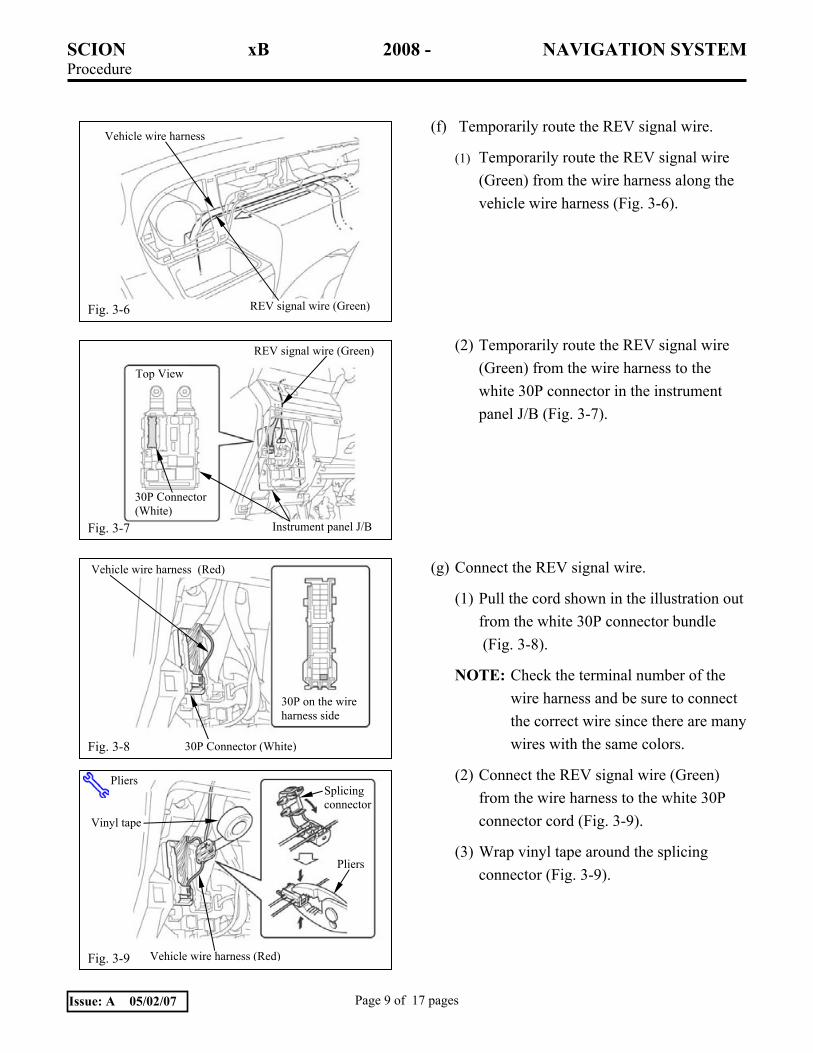
(f) Temporarily route the REV signal wire.
(1) Temporarily route the REV signal wire (Green) from the wire harness along the vehicle wire harness (Fig. 3-6).
(2) Temporarily route the REV signal wire (Green) from the wire harness to the white 30P connector in the instrument panel J/B (Fig. 3-7).
(g) Connect the REV signal wire.
(1) Pull the cord shown in the illustration out from the white 30P connector bundle (Fig. 3-8).
NOTE: Check the terminal number of the wire harness and be sure to connect the correct wire since there are many wires with the same colors.
(2) Connect the REV signal wire (Green) from the wire harness to the white 30P connector cord (Fig. 3-9).
(3) Wrap vinyl tape around the splicing connector (Fig. 3-9).
Vehicle wire harness (Red)
Fig. 3-8
30P on the wire harness side
30P Connector (White)
Fig. 3-9 Vehicle wire harness (Red)
Vinyl tape
Splicing connector
Pliers
Pliers
Fig. 3-6 REV signal wire (Green)
Vehicle wire harness
Instrument panel J/B
30P Connector (White)
Top View
Fig. 3-7
REV signal wire (Green)
SCION xB 2008 - NAVIGATION SYSTEM Procedure
Page 10 of 17 pages Issue: A 05/02/07
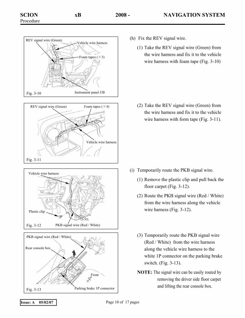
(h) Fix the REV signal wire.
(1) Take the REV signal wire (Green) from the wire harness and fix it to the vehicle wire harness with foam tape (Fig. 3-10)
(2) Take the REV signal wire (Green) from the wire harness and fix it to the vehicle wire harness with form tape (Fig. 3-11).
(i) Temporarily route the PKB signal wire.
(1) Remove the plastic clip and pull back the floor carpet (Fig. 3-12).
(2) Route the PKB signal wire (Red / White) from the wire harness along the vehicle wire harness (Fig. 3-12).
(3) Temporarily route the PKB signal wire (Red / White) from the wire harness along the vehicle wire harness to the white 1P connector on the parking brake switch. (Fig. 3-13).
NOTE: The signal wire can be easily routed by removing the driver side floor carpet and lifting the rear console box.
Fig. 3-10
REV signal wire (Green) Vehicle wire harness
Foam tapes (×3)
Instrument panel J/B
Fig. 3-12 PKB signal wire (Red / White)
Plastic clip
Vehicle wire harness
Fig. 3-11
REV signal wire (Green)
Vehicle wire harness
Foam tapes (×4)
Fig. 3-13
PKB signal wire (Red / White)
Front
Rear console box
Parking brake 1P connector
SCION xB 2008 - NAVIGATION SYSTEM Procedure
Page 11 of 17 pages Issue: A 05/02/07
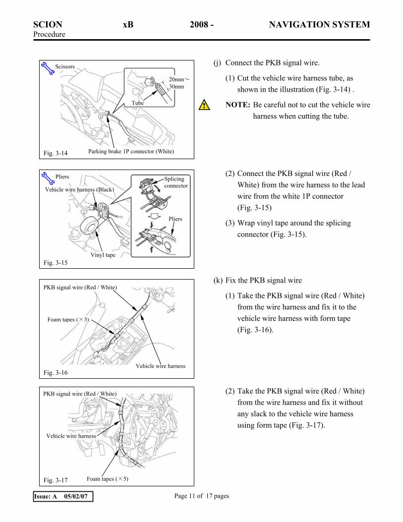
(j) Connect the PKB signal wire.
(1) Cut the vehicle wire harness tube, as shown in the illustration (Fig. 3-14) .
NOTE: Be careful not to cut the vehicle wire harness when cutting the tube.
(2) Connect the PKB signal wire (Red / White) from the wire harness to the lead wire from the white 1P connector (Fig. 3-15)
(3) Wrap vinyl tape around the splicing connector (Fig. 3-15).
(k) Fix the PKB signal wire
(1) Take the PKB signal wire (Red / White) from the wire harness and fix it to the vehicle wire harness with form tape (Fig. 3-16).
(2) Take the PKB signal wire (Red / White) from the wire harness and fix it without any slack to the vehicle wire harness using form tape (Fig. 3-17).
Fig. 3-17
PKB signal wire (Red / White)
Foam tapes (×5)
Vehicle wire harness
Fig. 3-14
Scissors
Parking brake 1P connector (White)
Tube
20mm~30mm
Fig. 3-15
Pliers Splicing connector Vehicle wire harness (Black)
Pliers
Vinyl tape
Fig. 3-16
PKB signal wire (Red / White)
Foam tapes (×3)
Vehicle wire harness

SCION xB 2008 - NAVIGATION SYSTEM Procedure
Page 12 of 17 pages Issue: A 05/02/07
(l) Bundle any excess wire harness and antenna cord.
(1) Bundle the wire harness and antenna cord and fix them to the air conditioning unit shown in the illustration with wire tie and foam tape. (Fig. 3-18).
NOTE: Engage the splicing connector of the SPD signal wire (Violet / White).
NOTE: Bundle the SPD signal wire (Violet / White) from the wire harness with other cords.
(m) Fix the video cord.
(1) Remove the vinyl covering from the video cord (Fig. 3-19).
(2) Fix the video cord to the navigation system with foam tape (Fig. 3-19).
(n) Install the brackets.
(1) Install the brackets (L and R) onto the navigation system with the 8 bolts (M5×8) (Fig. 3-20).
Fig. 3-19 Navigation system
Foam tapeVideo cord
Fig. 3-20
Right Side View Left Side View
Phillips Screwdriver
Radio bracket (R)Radio bracket (L)
Navigation system
Bolts (M5×8) (×8)
Fig. 3-18
Antenna cord
Foam tapes (×2) Wire harness
Splicing connector
SPD signal wire (Violet / White)
Wire tie
Foam tapes (×2)
SCION xB 2008 - NAVIGATION SYSTEM Procedure
Page 13 of 17 pages Issue: A 05/02/07
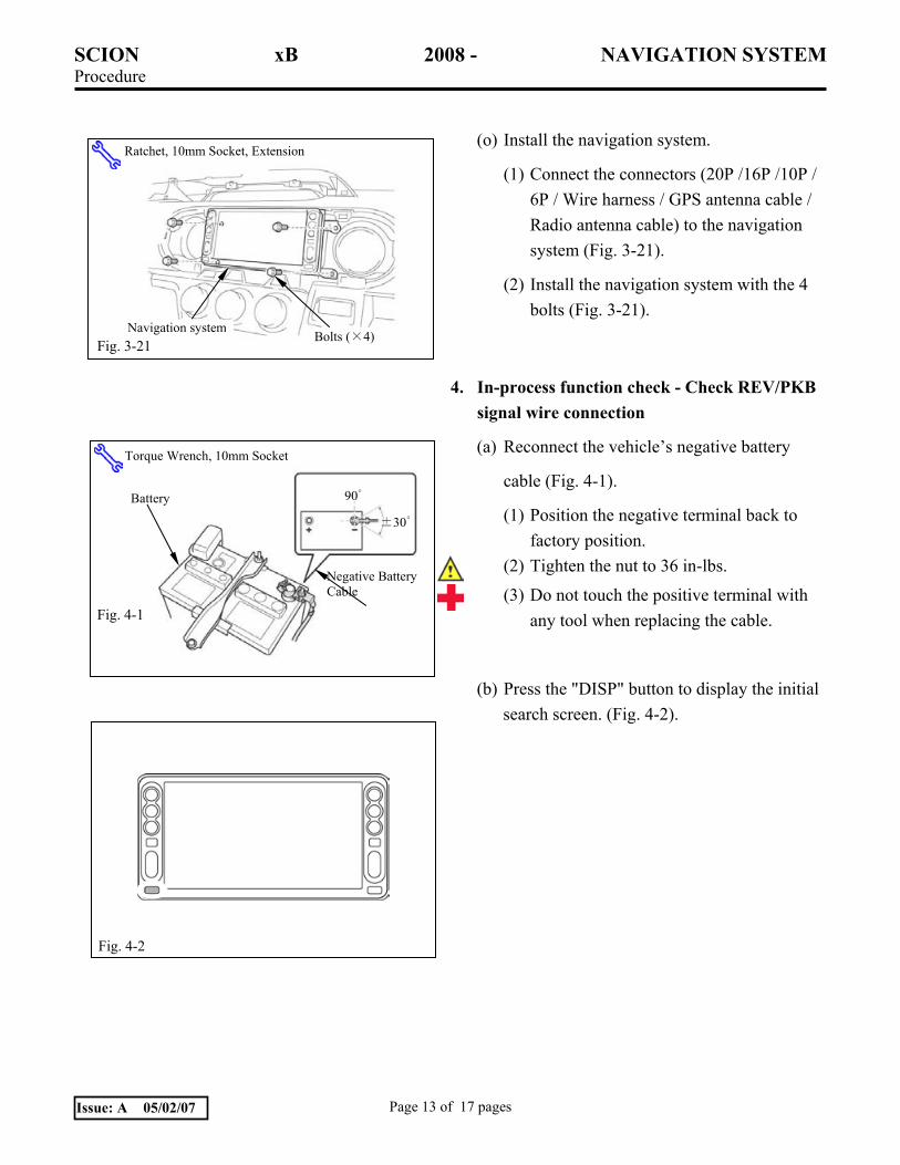
(o) Install the navigation system.
(1) Connect the connectors (20P /16P /10P / 6P / Wire harness / GPS antenna cable / Radio antenna cable) to the navigation system (Fig. 3-21).
(2) Install the navigation system with the 4 bolts (Fig. 3-21).
4. In-process function check - Check REV/PKB signal wire connection
(a) Reconnect the vehicle’s negative battery
cable (Fig. 4-1).
(1) Position the negative terminal back to factory position.
(2) Tighten the nut to 36 in-lbs.
(3) Do not touch the positive terminal with any tool when replacing the cable.
(b) Press the "DISP" button to display the initial search screen. (Fig. 4-2).
Fig. 3-21
Ratchet, 10mm Socket, Extension
Navigation system Bolts (×4)
Fig. 4-2
Torque Wrench, 10mm Socket
Negative Battery Cable
90゜
Fig. 4-1
±30゜
Battery
SCION xB 2008 - NAVIGATION SYSTEM Procedure
Page 14 of 17 pages Issue: A 05/02/07
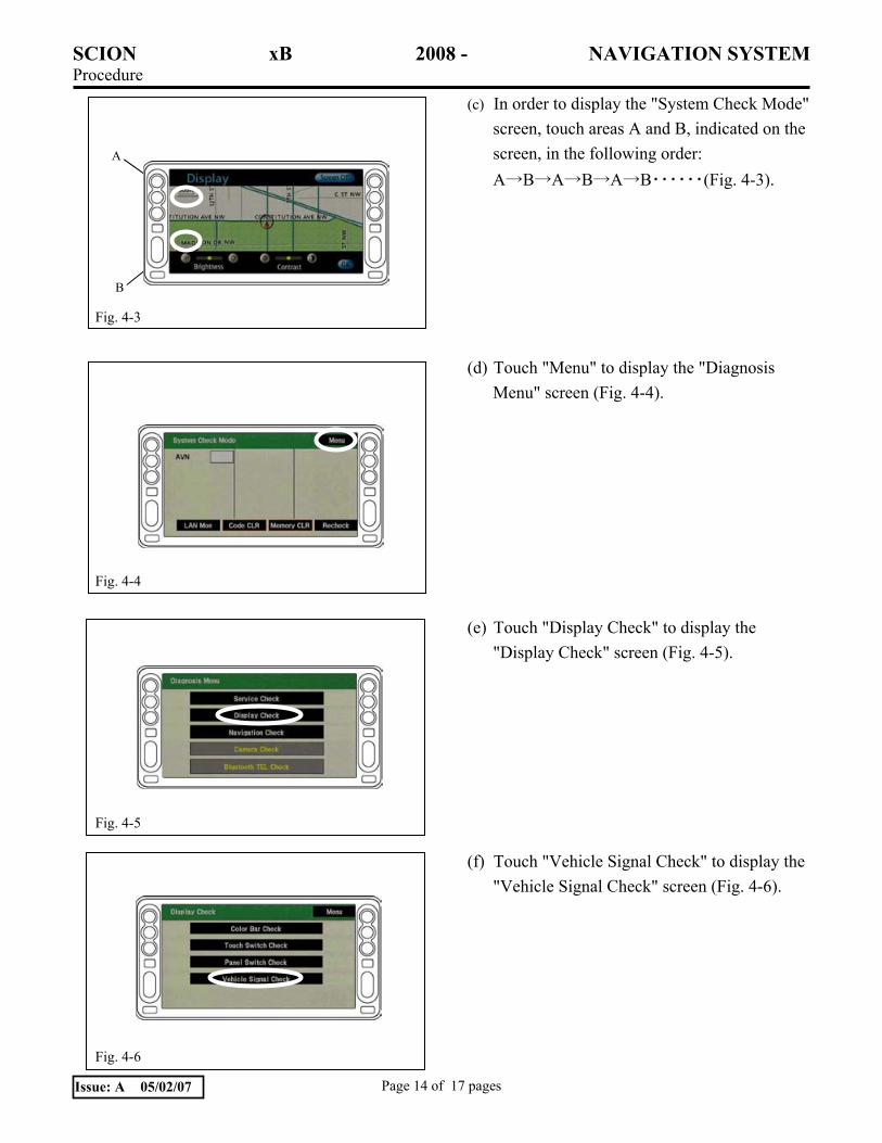
(c) In order to display the "System Check Mode" screen, touch areas A and B, indicated on the screen, in the following order: A→B→A→B→A→B・・・・・・(Fig. 4-3).
(d) Touch "Menu" to display the "Diagnosis Menu" screen (Fig. 4-4).
(e) Touch "Display Check" to display the "Display Check" screen (Fig. 4-5).
(f) Touch "Vehicle Signal Check" to display the "Vehicle Signal Check" screen (Fig. 4-6).
Fig. 4-3
A
B
Fig. 4-4
Fig. 4-5
Fig. 4-6

SCION xB 2008 - NAVIGATION SYSTEM Procedure
Page 15 of 17 pages Issue: A 05/02/07
(g) Perform the following confirmation tests by referring to the indications circled on the screen (Fig. 4-7).
PKB
(1) When the PKB is engaged →ON
(2) When the PKB is disengaged →OFF
REV
(3) When the shift lever is engaged in the R position →ON
(4) When the shift lever is engaged in any position other than R →OFF
NOTE: If the results are not as specified, check the connection again.
(h) Terminate the operation by pressing the "DISP" button on the screen for more than 3 seconds (Fig. 4-8).
Fig. 4-7
Fig. 4-8
SCION xB 2008 - NAVIGATION SYSTEM Procedure
Page 16 of 17 pages Issue: A 05/02/07
5. Completing the installation
(a) Complete the reassembly of the vehicle.
(1) Reconnect any disconnected connectors.
(2) Verify the panels fit together properly with no uneven gaps between them.
(b) Clean up and remove any trash.
(c) Place the owner’s manual left in their protective bags, IPOD cable and DVD jewel case in the glove box.

SCION xB 2007 - NAVIGATION SYSTEM Checklist - these points MUST be checked to ensure a quality installation.
Check: Look For:
Page 17 of 17 pages Issue: A 05/02/07
Accessory Function Checks
Press the “MENU” button and check that the
menu screen appears.
Touch the “Volume” button and check that
the volume level displayed on the volume
screen changes accordingly.
Press the “MAP/VOICE” button and check
that the map screen appears.
Touch and scroll the map displayed on the
screen and check that the map can be
scrolled.
Vehicle Function Checks
Hazard Switch
Air Conditioner
Front Passenger Seat Belt Monitor
Door Key Lock Monitor
Cigarette Lighter
Refer to your Car Owner’s Manual, and return the Power Windows to their initial positions.
Refer to your Car Owner’s Manual, and return the Back Door Lock to its initial position.
Steering wheel audio controls
TRAC, TPMS and Combo Meter, Parking
Brake and Reverse
Functioning Hazard Switch
Functioning Air Conditioner
Functioning Front Passenger Seat Belt Monitor
Functioning Door Key Lock Monitor
Functioning Cigarette Lighter
Auto-open and Auto-close operation of each of the Power Windows is possible with the driver’s seat master switch.
Door Lock and Unlock functions operate correctly.
Volume, Mode and Seek function
Ensure LED operation