Embed Size (px)
Citation preview

PHONE 770-413-5680 www.precisionhose.com FAX 770-413-5643 2
Precision Hose, Inc. is a manufacturer of stripwound metal hose, corrugated metal hose and wire braid and metal expansion joints. Although only incorporated in 1991, the principal stockholders have over 100 years of experience in the metal hose and expansion joint industry.
In March of 2001, we moved into our new facility which is a state of the art manufacturing plant. Located on six acres in the Stone Mountain area of Atlanta, Georgia, we occupy 50,000 square feet with additional land available to expand to over 100,000 square feet.
Quality, service, and fair pricing is the basis on how we operate our business. We welcome you to tour our facility on your next visit to the Atlanta area.
Quality Assurance ..............................3
Sizes Available ......................................3
Materials Available ............................3
Types of Expansion Joints ...........4,5
Definitions ...........................................6,7
Temperature Factors .........................8
Saturated Steam ..................................8
Thermal Expansion Data ..................9
Installation Instructions ...............10
General Conversion Factors ....... 11
Corrosion Resistance ...............12,13
Specification Inquiry Sheet ........14
Warranty ................................................15
Table of Contents

PHONE 770-413-5680 www.precisionhose.com FAX 770-413-5643 3
Quality AssurancePHI expansion joints are manufactured to the highest quality standards in the industry. All expansion joints and bellows are 100% tested either by hydro, pneumatic, liquid penetrant, or mass spectrometer. PHI can offer many additional test if required such as but not limited to cycle life, burst test, ultrasonic, chemical analysis, radiography, shock and vibration, and charpy impact testing. At PHI we are continuing to strive for better product and quality improvements. These product and quality improvements are from the standard catalog item to the more complicated aerospace product lines. PHI designs all expansion joints and bellows to EJMA, ASME B31.1, ASME B31.3 and ASME section 8.
Size Ranges AvailablePHI offers their metallic bellows product line from 2-1/2” diameter through 100” diameter. These bellows are available both as single ply bellows and as multi-ply bellows. The single ply bellows are offered from a thickness of .008” to .125” and the mult-ply bellows are available up to a thickness of .160” combined wall thickness.
Materials AvailablePHI standard material for bellows is type 321 stainless steel but many other alloys are available. Stainless steel is available in types 304L, 310, 316, and 316L.
The nickel alloys available are 400, 600, 625, 800.
Please contact the factory for other types of alloys that are also available.
DeliveryPHI has a normal delivery for standard bellows and expansion joints of three to five days depending on the size, quantity and alloy. For exotic alloys or high quantities please contact the factory for a quotation.
PHONE 770-413-5680 www.precisionhose.com FAX 770-413-5643 4
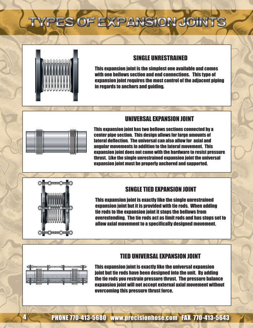
SINGLE UNRESTRAINED
This expansion joint is the simplest one available and comes with one bellows section and end connections. This type of expansion joint requires the most control of the adjacent piping in regards to anchors and guiding.
SINGLE TIED EXPANSION JOINT
This expansion joint is exactly like the single unrestrained expansion joint but it is provided with tie rods. When adding tie rods to the expansion joint it stops the bellows from overextending. The tie rods act as limit rods and has stops set to allow axial movement to a specifically designed movement.
UNIvERSAL EXPANSION JOINT
This expansion joint has two bellows sections connected by a center pipe section. This design allows for large amounts of lateral deflection. The universal can also allow for axial and angular movements in addition to the lateral movement. This expansion joint does not come with the hardware to resist pressure thrust. Like the single unrestrained expansion joint the universal expansion joint must be properly anchored and supported.
TIED UNIvERSAL EXPANSION JOINT
This expansion joint is exactly like the universal expansion joint but tie rods have been designed into the unit. By adding the tie rods you restrain pressure thrust. The pressure balance expansion joint will not accept external axial movement without overcoming this pressure thrust force.
PHONE 770-413-5680 www.precisionhose.com FAX 770-413-5643 5
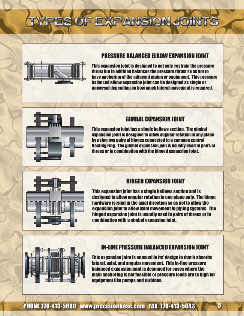
PRESSURE BALANCED ELBOW EXPANSION JOINT
This expansion joint is designed to not only restrain the pressure thrust but in addition balances the pressure thrust so as not to have anchoring of the adjacent piping or equipment. This pressure balanced elbow expansion joint can be designed as single or universal depending on how much lateral movement is required.
HINGED EXPANSION JOINT
This expansion joint has a single bellows section and is designed to allow angular rotation in one plane only. The hinge hardware is rigid in the axial direction so as not to allow the expansion joint to allow axial movement in piping systems. The hinged expansion joint is usually used in pairs of threes or in combination with a gimbal expansion joint.
GIMBAL EXPANSION JOINT
This expansion joint has a single bellows section. The gimbal expansion joint is designed to allow angular rotation in any plane by using two pairs of hinges connected to a common central floating ring. The gimbal expansion join is usually used in pairs of threes or in combination with the hinged expansion joint.
IN-LINE PRESSURE BALANCED EXPANSION JOINT
This expansion joint is unusual in its’ design in that it absorbs lateral, axial, and angular movement. This in-line pressure balanced expansion joint is designed for cases where the main anchoring is not feasible or pressure loads are to high for equipment like pumps and turbines.
PHONE 770-413-5680 www.precisionhose.com FAX 770-413-5643 6
Bellows-The flexible element of an Expansion Joint consisting of one or more convolutions.
Control Rods-Devices, usually in the form of rods or bars, attached to the Expansion Joint assembly whose primary function is to distribute the movement between the two bellows of a universal Expansion Joint. Control rods are not designed to restrain bellows pressure thrust.
Cover-A device used to provide limited protection of the exterior surface of the bellows of an expansion joint from foreign objects or mechanical damage. A cover is sometimes referred to as a shroud.
Convolution-The smallest flexible unit of a bellows. The total movement capacity of a bellows is proportional to the number of convolutions.
Equalizing and Reinforcing Rings-Devices used on some expansion joints fitting snugly in the roots of the convolutions. The primary purpose of these devices is to reinforce the bellows against internal pressure. Equalizing rings are made of cast iron, steel, stainless steel or other suitable alloys and are approximately “T” shaped in cross section. Reinforcing or root rings are fabricated from tubing or solid round bars of carbon steel, stainless steel or other suitable alloys.
Flanged Ends-The ends of an expansion joint equipped with flanges for the purpose of bolting the expansion joint to the mating flanges of adjacent equipment or piping.
Internal Sleeve-A device which minimizes contact between the inner surface of the bellows of an expansion joint and the fluid flowing through it. These devices have also been referred to as liners or baffles.
Limit Rods-Devices, usually in the form of rods or bars, attached to the expansion joint assembly whose primary function is to restrict the bellows movement range (axial, lateral and angular) during normal operation. In the event of a main anchor failure, they are designed to prevent bellows over-extension or over-compression while restraining the full pressure loading and dynamic forces generated by the anchor failure.
PHONE 770-413-5680 www.precisionhose.com FAX 770-413-5643 7
Purge Connections-Purge connections, where required, are usually installed at the sealed end of each internal sleeve of an expansion joint for the purpose of injecting a liquid or gas between the bellows and the internal sleeve to keep the area clear of erosive and corrosive media and/or solids that could pack the convolutions. Purging may be continuous, intermittent or just on start-up or shut down, as required. These are sometimes called aeration connections.
Shipping Devices-Rigid support devices installed on an expansion joint to maintain the overall length of the assembly for shipment. These devices may also be used to precompress, preextend or laterally offset the bellows. They should not be used to resist pressure thrust during testing.
Slotted Hinges-Devices installed as diametrically opposed pairs on an Expansion Joint permitting axial and one plane angular movement. Slotted hinges can be designed to perform as control devices, distributing movements between two bellows of a universal Expansion Joint but do not restrain pressure thrust. They may also be designed as limiting devices, restricting the bellows movement range and can restrain the full pressure loading and dynamic forces generated by an anchor failure. These devices can be used to transmit extraneous loads and forces, such as system dead weight, wind and seismic loads transverse to the Expansion Joint axis, rather than across the flexible bellows element.
Stabilizer-A device, internally or externally attached to the Expansion Joint assembly, whose primary function is to increase the stability of a universal Expansion Joint assembly.
Tangents-The straight un-convoluted portions at the end of the bellows.
Tangent Reinforcement-A reinforcing member located around the circumference of the bellows tangent for the purpose of reducing excessive pressure stresses which could lead to circumferential yielding.
Tie Rods-Devices, usually in the form of rods, or bars, attached to the expansion joint assembly whose primary function is to continuously restrain the full bellows pressure thrust during normal operation while permitting only lateral deflection. Angular rotation can be accommodated only if two tie rods are use and located 90˚ opposed to the direction of rotation.
Weld Ends-The ends of an expansion joint equipped with pipe suitably beveled for welding to adjacent equipment or piping.
PHONE 770-413-5680 www.precisionhose.com FAX 770-413-5643 8
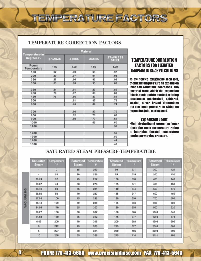
TEMPERATURE CORRECTION FACTORS FOR ELEvATED
TEMPERATURE APPLICATIONS
As the service temperature increases, the maximum pressure an expansion joint can withstand decreases. The material from which the expansion joint is made and the method of fitting attachment mechanical, soldered, welded, silver brazed determines the maximum pressure at which an expansion joint can be used.
Expansion Joint•Multiply the listed correction factor times the room temperature rating to determine elevated temperature maximum working pressure.
PHONE 770-413-5680 www.precisionhose.com FAX 770-413-5643 9
-325 -2.37 -3.85 -2.22 -2.04 -3.00 -2.62 -2.22 – – – – -3.88 -3.15 -4.68 -2.70-300 -2.24 -3.63 -2.10 -1.92 -2.83 -2.50 -2.10 -2.44 – – – -3.64 -2.87 -4.46 -2.55-275 -2.11 -3.41 -1.98 -1.80 -2.66 -2.38 -1.98 -2.35 – – – -3.40 -2.70 -4.21 -2.40-250 -1.98 -3.19 -1.86 -1.68 -2.49 -2.26 -1.86 -2.25 – -2.30 – -3.16 -2.53 -3.97 -2.25-225 -1.85 -2.96 -1.74 -1.57 -2.32 -2.14 -1.74 -2.13 – -2.17 – -2.93 -2.36 -3.71 -2.10-200 -1.71 -2.73 -1.62 -1.46 -2.15 -2.02 -2.01 -2.01 – -2.04 – -2.70 -2.19 -3.44 -1.95-175 -1.58 -2.50 -1.50 -1.35 -1.98 -1.90 -1.50 -1.83 – -1.87 – -2.47 -2.12 -3.16 -1.81-150 -1.45 -2.27 -1.37 -1.24 -1.81 -1.79 -1.38 -1.65 – -1.7 – -2.24 -1.95 -2.88 -1.67-125 -1.30 -2.01 -1.23 -1.11 -1.60 -1.59 -1.23 -1.47 – -1.54 – -2.00 -1.74 -2.57 -1.49-100 -1.15 -1.75 -1.08 -0.98 -1.39 -1.38 -1.08 -1.29 – -1.37 -1.83 -1.76 -1.53 -2.27 -1.31-75 -1.00 -1.50 -0.94 -0.85 -1.18 -1.18 -0.93 -1.11 – -1.17 -1.57 -1.52 -1.33 -1.97 -1.13-50 -0.84 -1.24 -0.79 -0.72 -0.98 -0.98 -0.78 -0.93 – -0.97 -1.31 -1.29 -1.13 -1.67 -0.96-25 -0.68 -0.98 -0.63 -0.57 -0.78 -0.77 -0.62 -0.75 – -0.76 -1.05 -1.02 -0.89 -1.32 -0.760 -0.49 -0.72 -0.46 -0.42 -0.57 -0.57 -0.46 -0.56 – -0.56 -0.79 -0.75 -0.66 -0.97 -0.56
25 -0.321 -0.46 -0.30 -0.27 -0.37 -0.37 -0.30 -0.36 – -0.36 -0.51 -0.48 -0.42 -0.63 -0.3650 -0.14 -0.21 -0.13 -0.12 -0.16 -0.20 -0.14 -0.16 – -0.16 -0.22 -0.21 -0.19 -0.28 -0.1670 0 0 0 0 0 0 0 0 0 0 0 0 0 0 0
100 0.23 0.34 0.22 0.20 0.32 0.28 0.22 0.25 0.28 0.26 0.34 0.35 0.31 0.46 0.26125 0.42 0.62 0.40 0.36 0.58 0.52 0.40 0.47 0.52 0.48 0.62 0.64 0.56 0.85 0.48150 0.61 0.90 0.58 0.53 0.84 0.75 0.58 0.69 0.76 0.70 0.90 0.94 0.82 1.23 0.70175 0.80 1.18 0.76 0.69 1.10 0.99 0.76 0.92 0.99 0.92 1.18 1.23 1.07 1.62 0.92200 0.99 1.46 0.94 0.86 1.37 1.22 0.94 1.15 1.23 1.15 1.48 1.52 1.33 2.00 1.14225 1.21 1.75 1.13 1.03 1.64 1.46 1.13 1.38 1.49 1.38 1.77 1.83 1.59 2.41 1.37250 1.40 2.03 1.33 1.21 1.91 1.71 1.32 1.61 1.76 1.61 2.05 2.14 1.86 2.83 1.60275 1.61 2.32 1.52 1.38 2.18 1.96 1.51 1.85 2.03 1.85 2.34 2.45 2.13 3.24 1.83300 1.82 2.61 1.71 1.56 2.45 2.21 1.69 2.08 2.30 2.09 2.62 2.76 2.40 3.67 2.06325 2.04 2.90 1.90 1.74 2.72 2.44 1.88 2.32 2.59 2.32 2.91 3.08 2.68 4.09 2.29350 2.26 3.20 2.10 1.93 2.99 2.68 2.08 2.56 2.88 2.56 3.19 3.41 2.96 4.52 2.53375 2.48 3.50 2.30 2.11 3.26 2.91 2.27 2.80 3.18 2.80 3.48 3.73 3.24 4.95 2.77400 2.70 3.80 2.50 2.30 3.53 3.25 2.47 3.05 3.48 3.05 3.88 4.05 3.52 5.39 3.01425 2.93 4.10 2.72 2.50 3.80 3.52 2.69 3.30 3.76 3.29 4.17 4.38 – 5.83 3.25450 3.16 4.41 2.93 2.69 4.07 3.79 2.91 3.55 4.04 3.53 4.47 4.72 – 6.28 3.50475 3.39 4.71 3.14 2.89 4.34 4.06 3.13 3.80 4.31 3.78 4.76 5.06 – 6.72 3.74500 3.62 5.01 3.35 3.08 4.61 4.33 3.34 4.05 4.59 4.02 5.06 5.40 – 7.17 3.99525 3.86 5.31 3.58 3.28 4.88 4.61 3.57 4.31 4.87 4.27 5.35 5.75 – 7.63 4.25550 4.11 5.62 3.80 3.49 5.15 4.90 3.80 4.56 5.16 4.52 5.64 6.10 – 8.10 4.50575 4.35 5.93 4.02 3.69 5.42 5.18 4.03 4.83 5.44 4.77 – 6.45 – 8.56 4.76600 4.60 6.24 4.24 3.90 5.69 5.46 4.27 5.09 5.72 5.02 – 6.80 – 9.03 5.01625 4.86 6.55 4.47 4.10 5.96 5.75 4.51 5.35 6.01 5.27 – 7.16 – – 5.27650 5.11 6.87 4.69 4.31 6.23 6.05 4.75 5.62 6.30 5.53 – 7.53 – – 5.53675 5.37 7.18 4.92 4.52 6.50 6.34 4.99 5.89 6.58 5.79 – 7.89 – – 5.80700 5.63 7.50 5.14 4.73 6.77 6.64 5.24 6.16 6.88 6.05 – 8.26 – – 6.06725 5.90 7.82 5.38 4.94 7.04 6.94 5.50 6.44 7.17 6.31 – 8.64 – – 6.32750 6.16 8.15 5.62 5.16 7.31 7.25 5.76 6.71 7.47 6.57 – 9.02 – – 6.59775 6.43 8.47 5.86 5.38 7.58 7.55 6.02 6.99 7.76 6.84 – 9.40 – – 6.85800 6.70 8.80 6.10 5.60 7.85 7.85 6.27 7.27 8.06 7.10 – 9.78 – – 7.12825 6.97 9.13 6.34 5.82 8.15 8.16 6.54 7.54 8.35 7.38 – 10.17 – – 7.40850 7.25 9.46 6.59 6.05 8.45 8.48 6.81 7.82 8.66 7.67 – 10.57 – – 7.69875 7.53 9.79 6.83 6.27 8.75 8.80 7.08 8.09 8.95 7.95 – 10.96 – – 7.97900 7.81 10.12 7.07 6.49 9.05 9.12 7.35 8.37 9.26 8.23 – 11.35 – – 8.26925 8.08 10.46 7.31 6.71 9.35 9.44 7.72 8.64 9.56 8.52 – 11.75 – – 8.53950 8.35 10.80 7.56 6.94 9.65 9.77 8.09 8.92 9.87 8.80 – 12.16 – – 8.81975 8.62 11.14 7.81 7.17 9.95 10.09 8.46 9.20 10.18 9.09 – 12.57 – – 9.08
1000 8.89 11.48 8.06 7.40 10.25 10.42 8.83 9.49 10.49 9.37 – 12.98 – – 9.361025 9.17 11.82 8.30 7.62 10.55 10.75 8.98 9.77 10.80 9.66 – 13.39 – – –1050 9.46 12.16 8.55 7.95 10.85 11.09 9.14 10.05 11.11 9.94 – 13.81 – – –1075 9.75 12.50 8.80 8.18 11.15 11.43 9.29 10.34 11.42 10.23 – 14.23 – – –1100 10.04 12.84 9.05 8.31 11.45 11.77 9.45 10.63 11.74 10.51 – 14.65 – – –1125 10.31 13.18 9.28 8.53 11.78 12.11 9.78 10.92 12.05 10.80 – – – – –1150 10.57 13.52 9.52 8.76 12.11 12.47 10.11 11.21 12.38 11.09 – – – – –1175 10.83 13.86 9.76 8.98 12.44 12.81 10.44 11.50 12.69 11.37 – – – – –1200 11.10 14.20 10.00 9.20 12.77 13.15 10.78 11.80 13.02 11.66 – – – – –1225 11.38 14.54 10.26 9.42 13.10 13.50 – 12.09 13.36 11.98 – – – – –1250 11.66 14.88 10.53 9.65 13.43 13.86 – 12.39 13.71 12.29 – – – – –1275 11.94 15.22 10.79 9.88 13.76 14.22 – 12.69 14.04 12.61 – – – – –1300 12.22 15.56 11.06 10.11 14.09 14.58 – 12.99 14.39 12.93 – – – – –1325 12.50 15.90 11.30 10.33 14.39 14.94 – 13.29 14.74 13.25 – – – – –1350 12.78 16.24 11.55 10.56 14.69 15.30 – 13.59 15.10 13.56 – – – – –1375 13.06 16.58 11.80 10.78 14.99 15.66 – 13.90 15.44 13.88 – – – – –1400 13.34 16.92 12.05 11.01 15.29 16.02 – 14.20 15.80 14.20 – – – – –1425 – 17.30 – – – – – 14.51 16.16 14.51 – – – – –1450 – 17.69 – – – – – 14.82 16.53 14.83 – – – – –1475 – 18.08 – – – – – 15.13 16.88 15.14 – – – – –1500 – 18.47 – – – – – 15.44 17.25 15.45 – – – – –1525 – – – – – – – 15.76 17.61 15.77 – – – – –1550 – – – – – – – 16.07 17.98 16.08 – – – – –1575 – – – – – – – 16.39 18.35 16.40 – – – – –1600 – – – – – – – 16.71 18.73 16.71 – – – – –
Temp.deg F
Carbon Steel Carbon-MolyLow-Chrome(thru 3 Cr Mo)
AusteniticStainless
Steels18Cr 8 Ni
5 Cr Mothru
9 Cr Mo
12 Cr17Cr27 Cr
310SS25 Cr20 Ni
Monel (400)67 Ni30 Cr
3-1/2Nickel Nickel 200 Alloy 800,
825
Alloy600,
625, 691Copper Brass 70 Cu
30 Ni Aluminum WroughtIron
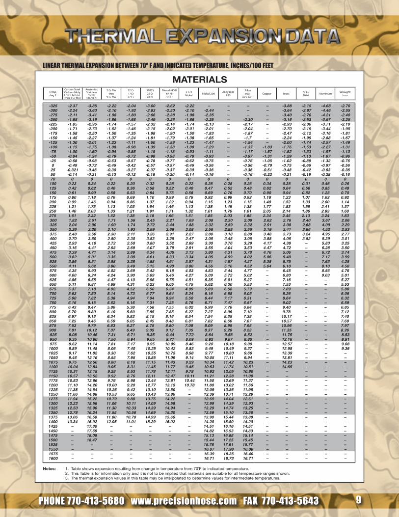
Notes: 1. Table shows expansion resulting from change in temperature from 70˚F to indicated temperature. 2. This Table is for information only and it is not to be implied that materials are suitable for all temperature ranges shown. 3. The thermal expansion values in this table may be interpolated to determine values for intermediate temperatures.
MATERIALS
LINEAR THERMAL EXPANSION BETWEEN 70º F AND INDICATED TEMPERATURE, INCHES/100 FEET
PHONE 770-413-5680 www.precisionhose.com FAX 770-413-5643 10
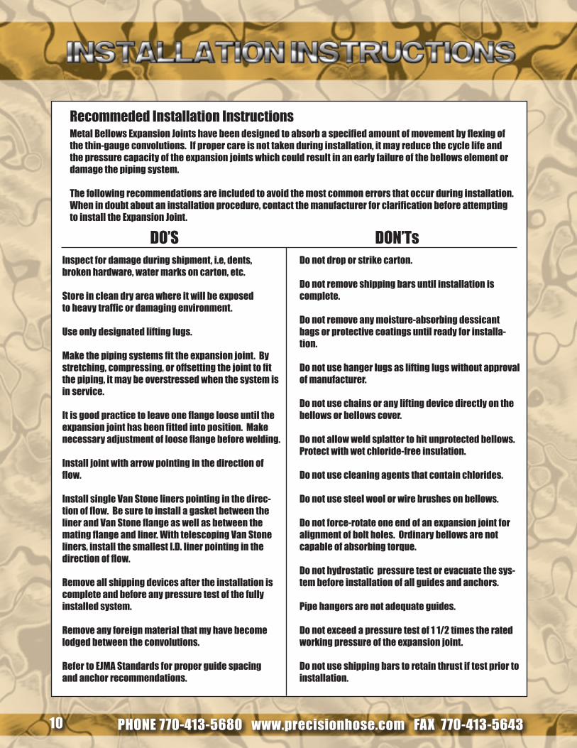
Recommeded Installation InstructionsMetal Bellows Expansion Joints have been designed to absorb a specified amount of movement by flexing of the thin-gauge convolutions. If proper care is not taken during installation, it may reduce the cycle life and the pressure capacity of the expansion joints which could result in an early failure of the bellows element or damage the piping system.
The following recommendations are included to avoid the most common errors that occur during installation. When in doubt about an installation procedure, contact the manufacturer for clarification before attempting to install the Expansion Joint.
Inspect for damage during shipment, i.e, dents, broken hardware, water marks on carton, etc.
Store in clean dry area where it will be exposed to heavy traffic or damaging environment.
Use only designated lifting lugs.
Make the piping systems fit the expansion joint. By stretching, compressing, or offsetting the joint to fit the piping, it may be overstressed when the system is in service.
It is good practice to leave one flange loose until the expansion joint has been fitted into position. Make necessary adjustment of loose flange before welding.
Install joint with arrow pointing in the direction of flow.
Install single van Stone liners pointing in the direc-tion of flow. Be sure to install a gasket between the liner and Van Stone flange as well as between the mating flange and liner. With telescoping Van Stone liners, install the smallest I.D. liner pointing in the direction of flow.
Remove all shipping devices after the installation is complete and before any pressure test of the fully installed system.
Remove any foreign material that my have become lodged between the convolutions.
Refer to EJMA Standards for proper guide spacing and anchor recommendations.
Do not drop or strike carton.
Do not remove shipping bars until installation is complete.
Do not remove any moisture-absorbing dessicant bags or protective coatings until ready for installa-tion.
Do not use hanger lugs as lifting lugs without approval of manufacturer.
Do not use chains or any lifting device directly on the bellows or bellows cover.
Do not allow weld splatter to hit unprotected bellows. Protect with wet chloride-free insulation.
Do not use cleaning agents that contain chlorides.
Do not use steel wool or wire brushes on bellows.
Do not force-rotate one end of an expansion joint for alignment of bolt holes. Ordinary bellows are not capable of absorbing torque.
Do not hydrostatic pressure test or evacuate the sys-tem before installation of all guides and anchors.
Pipe hangers are not adequate guides.
Do not exceed a pressure test of 1 1/2 times the rated working pressure of the expansion joint.
Do not use shipping bars to retain thrust if test prior to installation.
DO’S DON’Ts

PHONE 770-413-5680 www.precisionhose.com FAX 770-413-5643 11
PHONE 770-413-5680 www.precisionhose.com FAX 770-413-5643 12
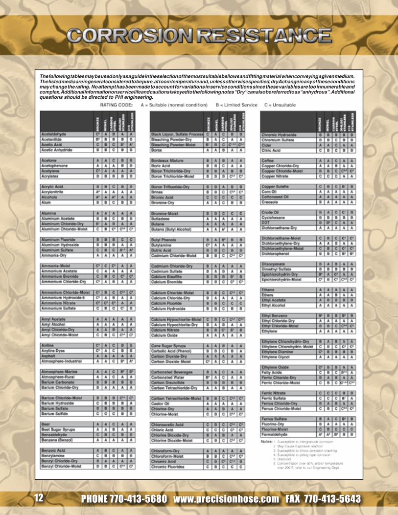
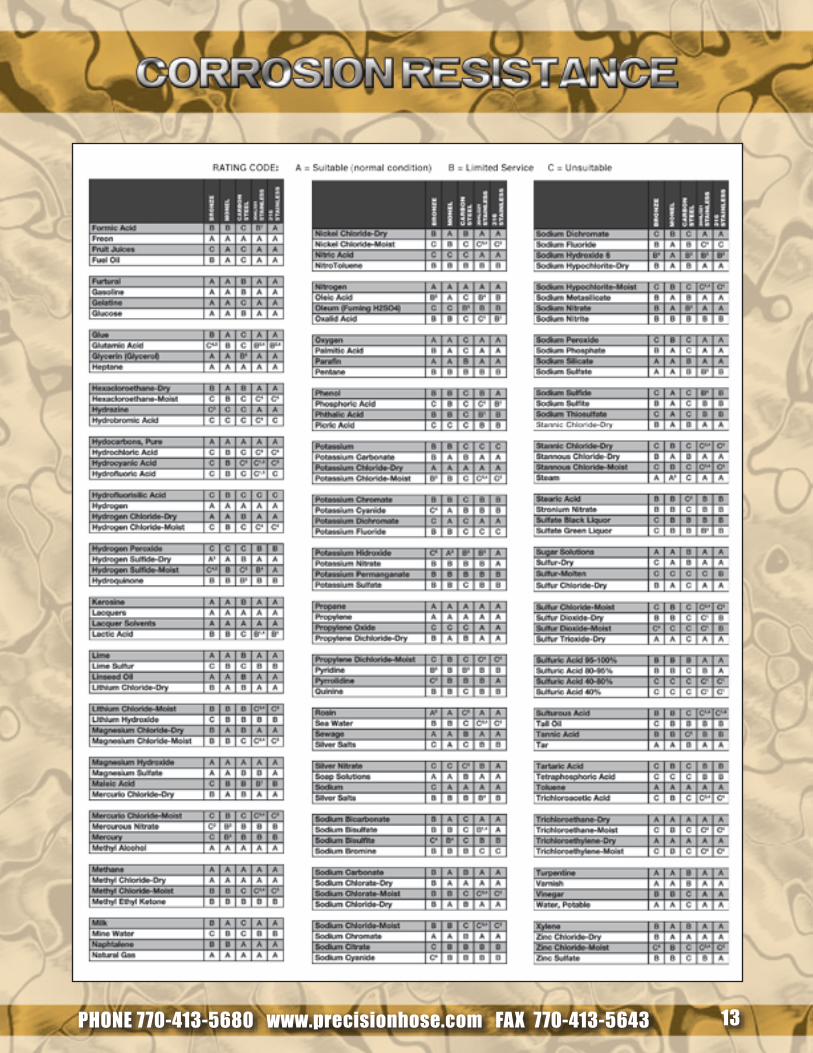
The following tables may be used only as a guide in the selection of the most suitable bellows and fitting material when conveying a given medium. The listed media are in general considered to be pure, at room temperature and , unless otherwise specified, dry A change in any of these conditions may change the rating. No attempt has been made to account for variations in service conditions since these variables are too innumerable and complex. Additional information on service life and cautions is keyed to the following notes “Dry” can also be referred to as “anhydrous”. Additional questions should be directed to PHI engineering.
PHONE 770-413-5680 www.precisionhose.com FAX 770-413-5643 13

PHONE 770-413-5680 www.precisionhose.com FAX 770-413-5643 14
Customer: Date: Page:Project: Prepared By:Item or Tag Number:Quantity:SizeStyle or Type (single, universal, hinged, gimbal, etc.)
End ConnectionsThickness/Flange RatingMaterial
*PressureDesignOperating
Test
*TemperatureDesignOperatingInstallation
MediaMediaFlow VelocityFlow Direction
Movements
and
Life Cycles
Installation
Axial ExtensionAxial CompressionLateralAngularNumber of Cycles
Design
Axial ExtensionAxial CompressionLateralAngularNumber of Cycles
Operating
Axial ExtensionAxial CompressionLateralAngularNumber of Cycles
MaterialsBellowsLinerCover
DimensionsOverall LengthMaximum O.D.Minimum I.D.
Spring Rates
Maximum Axial Spring RateMaximum Lateral Spring RateMaximum Angular SpringRate
Quality Assurance
Required Code
PHONE 770-413-5680 www.precisionhose.com FAX 770-413-5643 15
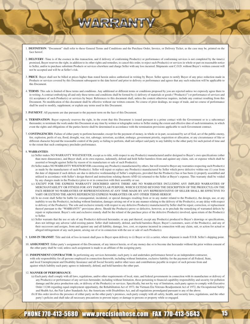
1. DEFINITION: “Document” shall refer to these General Terms and Conditions and the Purchase Order, Invoice, or Delivery Ticket, as the case may be, printed on the face hereof.
2. DELIVERY: Time is of the essence in this transaction, and if delivery of conforming Product(s) or performance of conforming services is not completed by the time(s) promised, Buyer reserves the right, in addition to its other rights and remedies, to cancel this order, to reject such Product(s) or services in whole or part on reasonable notice to Seller, and/or to purchase substitute Products or services elsewhere and charge Seller with any loss incurred. Shipments sent C.O.D. without Buyer’s written consent will not be accepted and will be at Seller’s risk.
3. PRICE: Buyer shall not be billed at prices higher than stated herein unless authorized in writing by Buyer. Seller agrees to notify Buyer of any price reduction made in Products or services covered by this Document subsequent to the date hereof and prior to delivery or performance and agrees that any such reduction will be applicable to this Document.
4. TERMS: This sale is limited of these terms and conditions. Any additional or different terms or conditions proposed by you are rejected unless we expressly agree there to in writing. A contract embodying all and only these terms and conditions shall be formed by (i) delivery of materials or goods (“Product(s)”) or performance of services and (ii) acceptance of such Product(s) or services by buyer. References to this document shall, unless the context otherwise requires, include any contract resulting from this Document. No modification of this document shall be effective without our written consent. No course of prior dealings, no usage of trade, and no course of performance shall be used to modify, supplement, or explain any terms used in this Document.
5. PAYMENT: All payments are due pursuant to the payment term on the face of this Document.
6. TERMINATION: Buyer expressly reserves the right, in the event that this Document is issued pursuant to a prime contact with the Government or to a subcontract thereunder, to terminate the work under this Document at any time by written or telegraphic notice to Seller stating the extent and effective date of such termination, in which event the rights and obligations of the parties hereto shall be determined in accordance with the termination provisions applicable to such Government contract.
7. CONTINGENCIES: Failure of either party to perform hereunder, except for the payment of money, in whole or in part, occasioned by act of God, act of the public enemy, fire, explosion, perils of sea, flood, drought, war, riot, sabotage, terrorism, accident, embargo, government priority, requisition or allocation, or any circumstance of like or different character beyond the reasonable control of the party so failing to perform, shall not subject said party to any liability to the other party for such period of time and to the extent that such contingency precludes performance.
8. WARRANTIES:(a) Seller makes NO WARRANTY WHATSOEVER, except as to title, with respect to any Product(s) manufactured and/or designed to Buyer’s own specifications (other
than mere dimensions), and Buyer shall, at its own expense, indemnify, defend and hold Seller harmless from and against any claim, suit, or expense which shall be asserted or brought against Seller by reason of its manufacture or sale of such Product(s).
(b) Seller makes NO WARRANTY WHATSOEVER concerning any Product(s) manufactured by others, but will extend to Buyer any warranties respecting such Product(s) as made by the manufacturer of such Product(s). Seller will repair or replace any Product(s) manufactured by Seller which prove defective within one (1) year from the date of shipment if such defects are due to defective workmanship of Seller’s employees, provided that the Product(s) has or has been (i) properly assembled and utilized in accordance with Seller’s design thereof and instructions relating thereto AND (ii) returned to the Seller at Buyer’s expense. This warranty shall be voided by any changes made in the Product(s) prior to or in connection with their assembly or use.
(c) EXCEPT FOR THE EXPRESS WARRANTY DESCRIBED ABOVE THERE ARE NO WARRANTIES INCLUDING ANY IMPLIED WARRANTIES OF MERCHANTABILITY OR FITNESS FOR ANY PARTICULAR PURPOSE, WHICH EXTEND BEYOND THE DESCRIPTION OF THE PRODUCT(S) ON THE FACE HEREOF NO WARRANTIES OF REPRESENTATIONS AT ANY TIME MADE BY ANY REPRESENTATIVE OF SELLER SHALL BE EFFECTIVE TO VARY OR EXTEND THE ABOVE REFERENCED EXPRESS WARRANTIES OR ANY OTHER TERMS HEREOF.
(d) In no event shall Seller be liable for consequential, incidental, or special damages resulting from or in any matter related to the Product(s), the design, use, or any inability to use the Product(s), including without limitation, damages arising out of or in any manner relating to the delivery of the Product(s), or any delay with respect to delivery of the Product(s). The sole and exclusive remedy with respect to any defective Product(s) manufactured by Seller shall be repair, correction, or replacement thereof pursuant to the “WARRANTY” provisions above. Should the Product(s) prove so defective, however, as to preclude the remedying of warranted defects by repair or replacement. Buyer’s sole and exclusive remedy shall be the refund of the purchase price of the defective Product(s) involved, upon return of the Product(s) to Seller.
(e) Seller warrants that the use or sale of any Product(s) delivered hereunder, or any part thereof, except any Product(s) produced to Buyer’s drawings or specifications, does not infringe any adverse valid existing patent. Seller shall indemnify, defend, and hold harmless Buyer, Buyer’s customers, users of the Product(s), and any of their successors and assigns, from and against any and all liability, damage, loss, cost, or expense incurred in connection with any claim, suit, or action for actual or alleged infringement of any such patent, arising out of or in connection with the use or sale of such Product(s).
9. LOSS IN TRANSIT: Title and risk of loss in transit shall pass to Buyer upon delivery to (i) Buyer or (ii) a carrier, where shipment is made F.O.B. Seller’s shipping point.
10. ASSIGNMENT: Either party’s assignment of this Document, of any interest herein, or of any money due or to become due hereunder without the prior written consent of the other party shall be void, unless such assignment is made to an affiliate of the assigning party.
11. INDEPENDENT CONTRACTOR: In performing any services hereunder, each party is and undertakes performance hereof as an independent contractor, with sole responsibility for all persons employed in connection therewith, including without limitation, exclusive liability for the payment of all Federal, State, and local Unemployment and Disability Insurance and all Social Security and/or other taxes and contributions payable in respect of such persons from and against which liability each party agrees to indemnify, defend, and hold harmless the other part. 12. MANNER OF PERFORMANCE:
(a) Each party shall comply with all laws, regulations, and/or other requirements of local, state, and federal governments in connection with its manufacture or delivery of any Product(s) or performance of any services hereunder, including without limitation, those pertaining to financial capability responsibility and security for pollution damage and the price production sale, or delivery of the Product(s) or services. Specifically, but not by way of limitation, each party agrees to comply with Executive Order 11246 regarding equal employment opportunity, the Rehabilitation Act of 1973, the Vietnam Era Veterans Readjustment Act of 1972, the Occupational Safety and Health Act, the Fair Labor Standards Act. the Americans with Disabilities Act, and all regulations promulgated pursuant to any of the above.
(b) If this order involves the presence of either party on the other party’s premises, such party comply with all safety, health, and security laws, regulations, and the other party’s policies and shall take all necessary precautions to prevent injury or damage to persons or property while so engaged.