Embed Size (px)
Citation preview
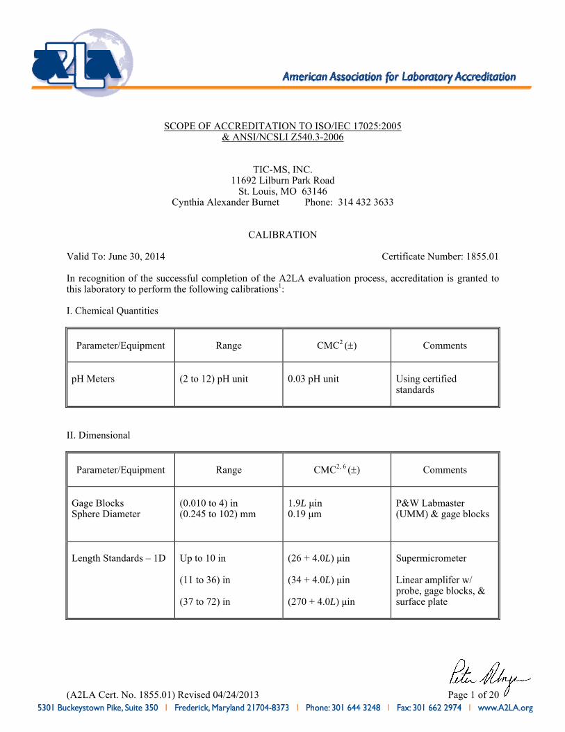
(A2LA Cert. No. 1855.01) Revised 04/24/2013 Page 1 of 20
SCOPE OF ACCREDITATION TO ISO/IEC 17025:2005
& ANSI/NCSLI Z540.3-2006
TIC-MS, INC. 11692 Lilburn Park Road
St. Louis, MO 63146 Cynthia Alexander Burnet Phone: 314 432 3633
CALIBRATION
Valid To: June 30, 2014 Certificate Number: 1855.01 In recognition of the successful completion of the A2LA evaluation process, accreditation is granted to this laboratory to perform the following calibrations1: I. Chemical Quantities
Parameter/Equipment
Range
CMC2 ()
Comments
pH Meters
(2 to 12) pH unit
0.03 pH unit
Using certified standards
II. Dimensional
Parameter/Equipment
Range
CMC2, 6 ()
Comments
Gage Blocks Sphere Diameter
(0.010 to 4) in (0.245 to 102) mm
1.9L μin 0.19 μm
P&W Labmaster (UMM) & gage blocks
Length Standards – 1D
Up to 10 in (11 to 36) in (37 to 72) in
(26 + 4.0L) μin (34 + 4.0L) μin (270 + 4.0L) μin
Supermicrometer Linear amplifer w/ probe, gage blocks, & surface plate
(A2LA Cert. No. 1855.01) Revised 04/24/2013 Page 2 of 20
Parameter/Equipment
Range
CMC2, 6 ()
Comments
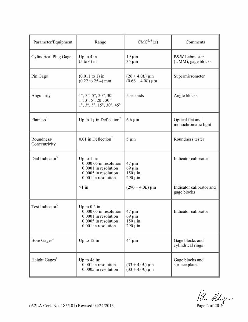
Cylindrical Plug Gage
Up to 4 in (5 to 6) in
19 µin 35 µin
P&W Labmaster (UMM), gage blocks
Pin Gage
(0.011 to 1) in (0.22 to 25.4) mm
(26 + 4.0L) µin (0.66 + 4.0L) µm
Supermicrometer
Angularity
1”, 3”, 5”, 20”, 30” 1’, 3’, 5’, 20’, 30’ 1, 3, 5, 15, 30, 45
5 seconds
Angle blocks
Flatness3
Up to 1 in Deflection7
6.6 µin
Optical flat and monochromatic light
Roundness/ Concentricity
0.01 in Deflection7
5 µin
Roundness tester
Dial Indicator3
Up to 1 in:
0.000 05 in resolution 0.0001 in resolution 0.0005 in resolution 0.001 in resolution
>1 in
47 µin 69 µin 150 µin 290 µin (290 + 4.0L) µin
Indicator calibrator Indicator calibrator and gage blocks
Test Indicator3
Up to 0.2 in:
0.000 05 in resolution 0.0001 in resolution 0.0005 in resolution 0.001 in resolution
47 µin 69 µin 150 µin 290 µin
Indicator calibrator
Bore Gages3
Up to 12 in
44 µin
Gage blocks and cylindrical rings
Height Gages7
Up to 48 in:
0.001 in resolution 0.0005 in resolution
(33 + 4.0L) µin (33 + 4.0L) µin
Gage blocks and surface plates
(A2LA Cert. No. 1855.01) Revised 04/24/2013 Page 3 of 20
Parameter/Equipment
Range
CMC2, 6 ()
Comments
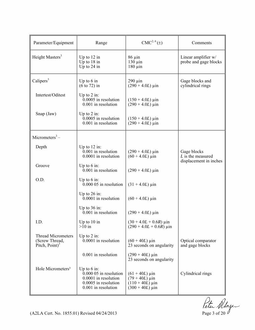
Height Masters3
Up to 12 in Up to 18 in Up to 24 in
86 µin 130 µin 180 µin
Linear amplifier w/ probe and gage blocks
Calipers3
Intertest/Oditest Snap (Jaw)
Up to 6 in (6 to 72) in Up to 2 in:
0.0005 in resolution 0.001 in resolution
Up to 2 in:
0.0005 in resolution 0.001 in resolution
290 µin (290 + 4.0L) µin (150 + 4.0L) µin (290 + 4.0L) µin (150 + 4.0L) µin (290 + 4.0L) µin
Gage blocks and cylindrical rings
Micrometers3 –
Depth Groove O.D. I.D.
Thread Micrometers (Screw Thread, Pitch, Point)3
Hole Micrometers³
Up to 12 in:
0.001 in resolution 0.0001 in resolution
Up to 6 in:
0.001 in resolution Up to 6 in:
0.000 05 in resolution Up to 26 in:
0.0001 in resolution Up to 36 in:
0.001 in resolution Up to 10 in >10 in Up to 2 in:
0.0001 in resolution
0.001 in resolution Up to 6 in:
0.000 05 in resolution 0.0001 in resolution 0.0005 in resolution 0.001 in resolution
(290 + 4.0L) µin (60 + 4.0L) µin (290 + 4.0L) µin (31 + 4.0L) µin (60 + 4.0L) µin (290 + 4.0L) µin (30 + 4.0L + 0.6R) µin (290 + 4.0L + 0.6R) µin (60 + 40L) µin 23 seconds on angularity (290 + 40L) µin 23 seconds on angularity (61 + 40L) µin (79 + 40L) µin (110 + 40L) µin (300 + 40L) µin
Gage blocks L is the measured displacement in inches Optical comparator and gage blocks Cylindrical rings
(A2LA Cert. No. 1855.01) Revised 04/24/2013 Page 4 of 20
Parameter/Equipment
Range
CMC2, 6 ()
Comments
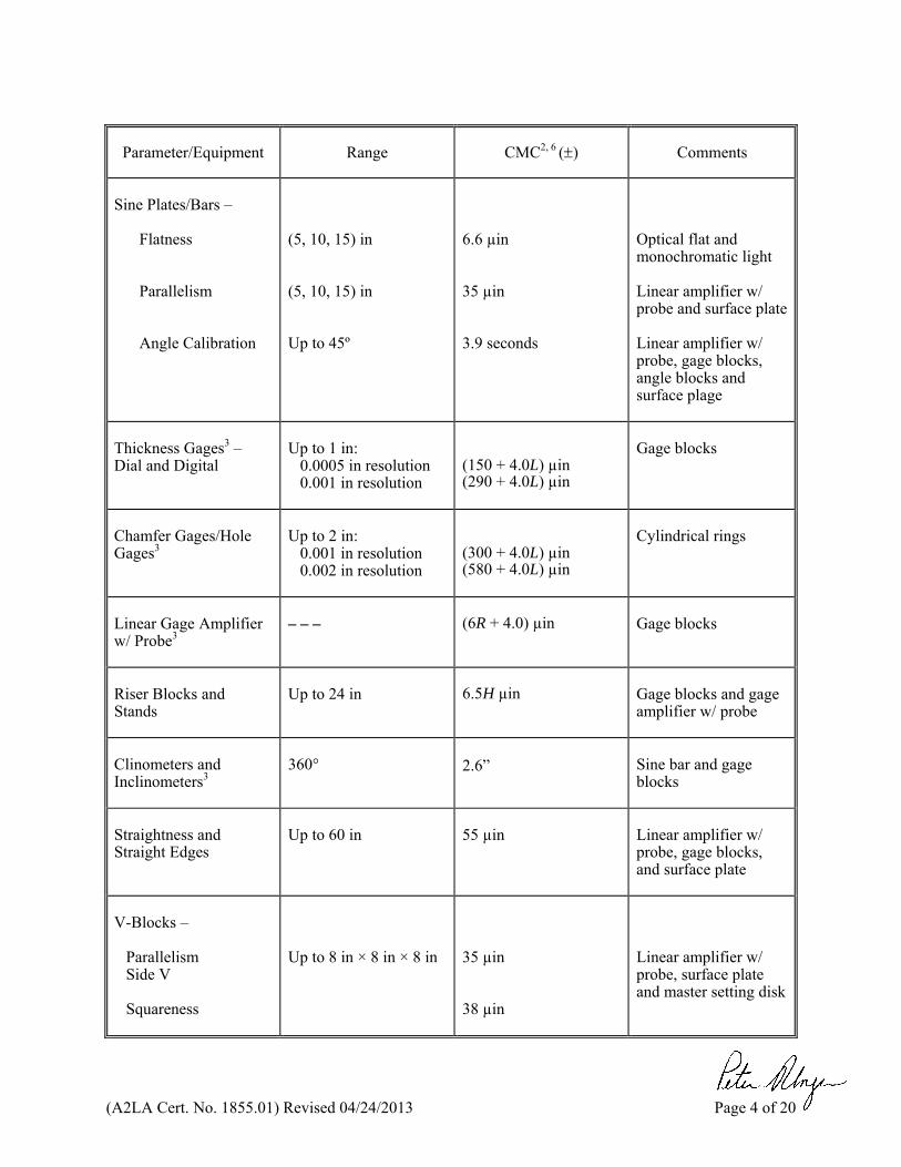
Sine Plates/Bars –
Flatness Parallelism Angle Calibration
(5, 10, 15) in (5, 10, 15) in Up to 45º
6.6 µin 35 µin 3.9 seconds
Optical flat and monochromatic light Linear amplifier w/ probe and surface plate Linear amplifier w/ probe, gage blocks, angle blocks and surface plage
Thickness Gages3 – Dial and Digital
Up to 1 in:
0.0005 in resolution 0.001 in resolution
(150 + 4.0L) µin (290 + 4.0L) µin
Gage blocks
Chamfer Gages/Hole Gages3
Up to 2 in:
0.001 in resolution 0.002 in resolution
(300 + 4.0L) µin (580 + 4.0L) µin
Cylindrical rings
Linear Gage Amplifier w/ Probe3
– – –
(6R + 4.0) µin
Gage blocks
Riser Blocks and Stands
Up to 24 in
6.5H µin
Gage blocks and gage amplifier w/ probe
Clinometers and Inclinometers3
360°
2.6”
Sine bar and gage blocks
Straightness and Straight Edges
Up to 60 in
55 µin
Linear amplifier w/ probe, gage blocks, and surface plate
V-Blocks –
Parallelism Side V Squareness
Up to 8 in × 8 in × 8 in
35 µin 38 µin
Linear amplifier w/ probe, surface plate and master setting disk
(A2LA Cert. No. 1855.01) Revised 04/24/2013 Page 5 of 20
Parameter/Equipment
Range
CMC2, 6 ()
Comments
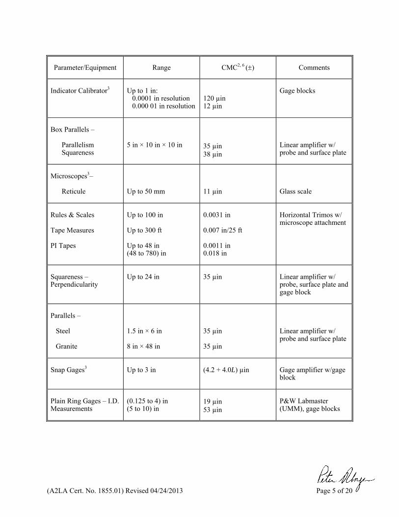
Indicator Calibrator3
Up to 1 in:
0.0001 in resolution 0.000 01 in resolution
120 µin 12 µin
Gage blocks
Box Parallels –
Parallelism Squareness
5 in × 10 in × 10 in
35 µin 38 µin
Linear amplifier w/ probe and surface plate
Microscopes3–
Reticule
Up to 50 mm
11 µin
Glass scale
Rules & Scales Tape Measures PI Tapes
Up to 100 in Up to 300 ft Up to 48 in (48 to 780) in
0.0031 in 0.007 in/25 ft 0.0011 in 0.018 in
Horizontal Trimos w/ microscope attachment
Squareness – Perpendicularity
Up to 24 in
35 µin
Linear amplifier w/ probe, surface plate and gage block
Parallels –
Steel Granite
1.5 in × 6 in 8 in × 48 in
35 µin 35 µin
Linear amplifier w/ probe and surface plate
Snap Gages3
Up to 3 in
(4.2 + 4.0L) µin
Gage amplifier w/gage block
Plain Ring Gages – I.D. Measurements
(0.125 to 4) in (5 to 10) in
19 µin 53 µin
P&W Labmaster (UMM), gage blocks
(A2LA Cert. No. 1855.01) Revised 04/24/2013 Page 6 of 20
Parameter/Equipment
Range
CMC2, 6 ()
Comments
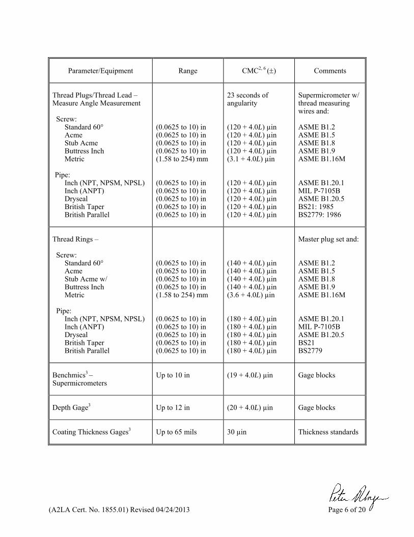
Thread Plugs/Thread Lead – Measure Angle Measurement Screw:
Standard 60° Acme Stub Acme Buttress Inch Metric
Pipe:
Inch (NPT, NPSM, NPSL) Inch (ANPT) Dryseal British Taper British Parallel
(0.0625 to 10) in (0.0625 to 10) in (0.0625 to 10) in (0.0625 to 10) in (1.58 to 254) mm (0.0625 to 10) in (0.0625 to 10) in (0.0625 to 10) in (0.0625 to 10) in (0.0625 to 10) in
23 seconds of angularity (120 + 4.0L) µin (120 + 4.0L) µin (120 + 4.0L) µin (120 + 4.0L) µin (3.1 + 4.0L) µin (120 + 4.0L) µin (120 + 4.0L) µin (120 + 4.0L) µin (120 + 4.0L) µin (120 + 4.0L) µin
Supermicrometer w/ thread measuring wires and: ASME B1.2 ASME B1.5 ASME B1.8 ASME B1.9 ASME B1.16M ASME B1.20.1 MIL P-7105B ASME B1.20.5 BS21: 1985 BS2779: 1986
Thread Rings – Screw:
Standard 60° Acme Stub Acme w/ Buttress Inch Metric
Pipe:
Inch (NPT, NPSM, NPSL) Inch (ANPT) Dryseal British Taper British Parallel
(0.0625 to 10) in (0.0625 to 10) in (0.0625 to 10) in (0.0625 to 10) in (1.58 to 254) mm (0.0625 to 10) in (0.0625 to 10) in (0.0625 to 10) in (0.0625 to 10) in (0.0625 to 10) in
(140 + 4.0L) µin (140 + 4.0L) µin (140 + 4.0L) µin (140 + 4.0L) µin (3.6 + 4.0L) µin (180 + 4.0L) µin (180 + 4.0L) µin (180 + 4.0L) µin (180 + 4.0L) µin (180 + 4.0L) µin
Master plug set and: ASME B1.2 ASME B1.5 ASME B1.8 ASME B1.9 ASME B1.16M ASME B1.20.1 MIL P-7105B ASME B1.20.5 BS21 BS2779
Benchmics3 – Supermicrometers
Up to 10 in
(19 + 4.0L) µin
Gage blocks
Depth Gage3
Up to 12 in
(20 + 4.0L) µin
Gage blocks
Coating Thickness Gages3
Up to 65 mils
30 µin
Thickness standards
(A2LA Cert. No. 1855.01) Revised 04/24/2013 Page 7 of 20
Parameter/Equipment
Range
CMC2, 6 ()
Comments
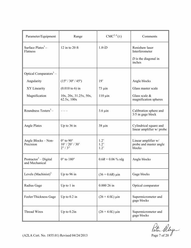
Surface Plates3 – Flatness
12 in to 20 ft
1.8D
Renishaw laser Interferometer D is the diagonal in inches
Optical Comparators3 –
Angularity XY Linearity Magnification
(15º / 30º / 45º) (0.010 to 6) in 10x, 20x, 31.25x, 50x, 62.5x, 100x
19’ 73 µin 110 µin
Angle blocks Glass master scale Glass scale & magnification spheres
Roundness Testers3 –
– – –
3.6 µin
Calibration sphere and 3/5 in gage block
Angle Plates
Up to 36 in
38 µin
Cylindrical square and linear amplifier w/ probe
Angle Blocks – Non-Precision
0° to 90° 10’ / 20’ / 30’ 2” / 3”
1.2’ 1.2’ 1.2’
Linear amplifier w/ probe and master angle blocks
Protractor3 – Digital and Mechanical
0° to 180°
0.6R + 0.06 % rdg
Angle blocks
Levels (Machinist)3
Up to 96 in
(36 + 0.6R) µin
Gage blocks
Radius Gage
Up to 1 in
0.000 26 in
Optical comparator
Feeler/Thickness Gage
Up to 0.2 in
(26 + 4.0L) µin
Supermicrometer and gage blocks
Thread Wires
Up to 0.2in
(26 + 4.0L) µin
Supermicrometer and gage blocks
(A2LA Cert. No. 1855.01) Revised 04/24/2013 Page 8 of 20
Parameter/Equipment
Range
CMC2, 6 ()
Comments
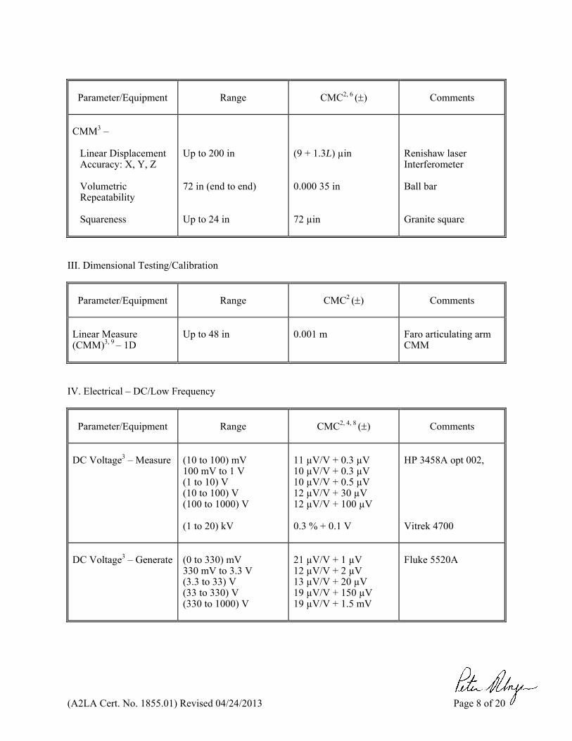
CMM3 –
Linear Displacement Accuracy: X, Y, Z Volumetric Repeatability Squareness
Up to 200 in 72 in (end to end) Up to 24 in
(9 + 1.3L) µin 0.000 35 in 72 µin
Renishaw laser Interferometer Ball bar Granite square
III. Dimensional Testing/Calibration
Parameter/Equipment
Range
CMC2 ()
Comments
Linear Measure (CMM)3, 9 – 1D
Up to 48 in
0.001 m
Faro articulating arm CMM
IV. Electrical – DC/Low Frequency
Parameter/Equipment
Range
CMC2, 4, 8 ()
Comments
DC Voltage3 – Measure
(10 to 100) mV 100 mV to 1 V (1 to 10) V (10 to 100) V (100 to 1000) V (1 to 20) kV
11 µV/V + 0.3 µV 10 µV/V + 0.3 µV 10 µV/V + 0.5 µV 12 µV/V + 30 µV 12 µV/V + 100 µV 0.3 % + 0.1 V
HP 3458A opt 002, Vitrek 4700
DC Voltage3 – Generate
(0 to 330) mV 330 mV to 3.3 V (3.3 to 33) V (33 to 330) V (330 to 1000) V
21 µV/V + 1 µV 12 µV/V + 2 µV 13 µV/V + 20 µV 19 µV/V + 150 µV 19 µV/V + 1.5 mV
Fluke 5520A
(A2LA Cert. No. 1855.01) Revised 04/24/2013 Page 9 of 20
Parameter/Equipment
Range
CMC2, 4, 5, 8 ()
Comments
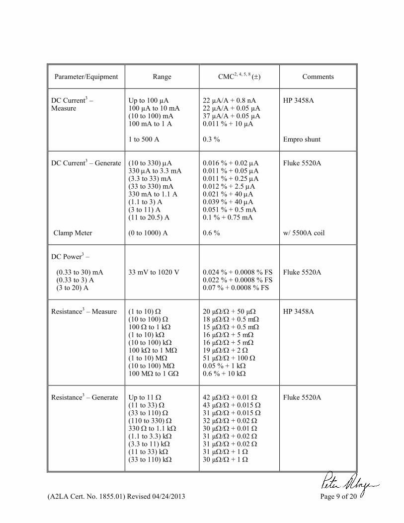
DC Current3 – Measure
Up to 100 µA 100 µA to 10 mA (10 to 100) mA 100 mA to 1 A 1 to 500 A
22 µA/A + 0.8 nA 22 µA/A + 0.05 µA 37 µA/A + 0.05 µA 0.011 % + 10 µA 0.3 %
HP 3458A Empro shunt
DC Current3 – Generate Clamp Meter
(10 to 330) A 330 A to 3.3 mA (3.3 to 33) mA (33 to 330) mA 330 mA to 1.1 A (1.1 to 3) A (3 to 11) A (11 to 20.5) A (0 to 1000) A
0.016 % + 0.02 A 0.011 % + 0.05 A 0.011 % + 0.25 A 0.012 % + 2.5 A 0.021 % + 40 A 0.039 % + 40 A 0.051 % + 0.5 mA 0.1 % + 0.75 mA 0.6 %
Fluke 5520A w/ 5500A coil
DC Power3 –
(0.33 to 30) mA (0.33 to 3) A (3 to 20) A
33 mV to 1020 V
0.024 % + 0.0008 % FS 0.022 % + 0.0008 % FS 0.07 % + 0.0008 % FS
Fluke 5520A
Resistance3 – Measure
(1 to 10) (10 to 100) 100 to 1 k (1 to 10) k (10 to 100) k 100 k to 1 M (1 to 10) M (10 to 100) M 100 M to 1 G
20 µ/ + 50 µ 18 µ/ + 0.5 m 15 µ/ + 0.5 m 16 µ/ + 5 m 16 µ/ + 5 m 19 µ/ + 2 51 µ/ + 100 0.05 % + 1 k 0.6 % + 10 k
HP 3458A
Resistance3 – Generate
Up to 11 (11 to 33) (33 to 110) (110 to 330) 330 to 1.1 k (1.1 to 3.3) k (3.3 to 11) k (11 to 33) k (33 to 110) k
42 µ/ + 0.01 43 µ/ + 0.015 31 µ/ + 0.015 32 µ/ + 0.02 30 µ/ + 0.01 31 µ/ + 0.02 31 µ/ + 0.02 31 µ/ + 1 30 µ/ + 1
Fluke 5520A
(A2LA Cert. No. 1855.01) Revised 04/24/2013 Page 10 of 20
Parameter/Equipment
Range
CMC2, 5, 8 ()
Comments
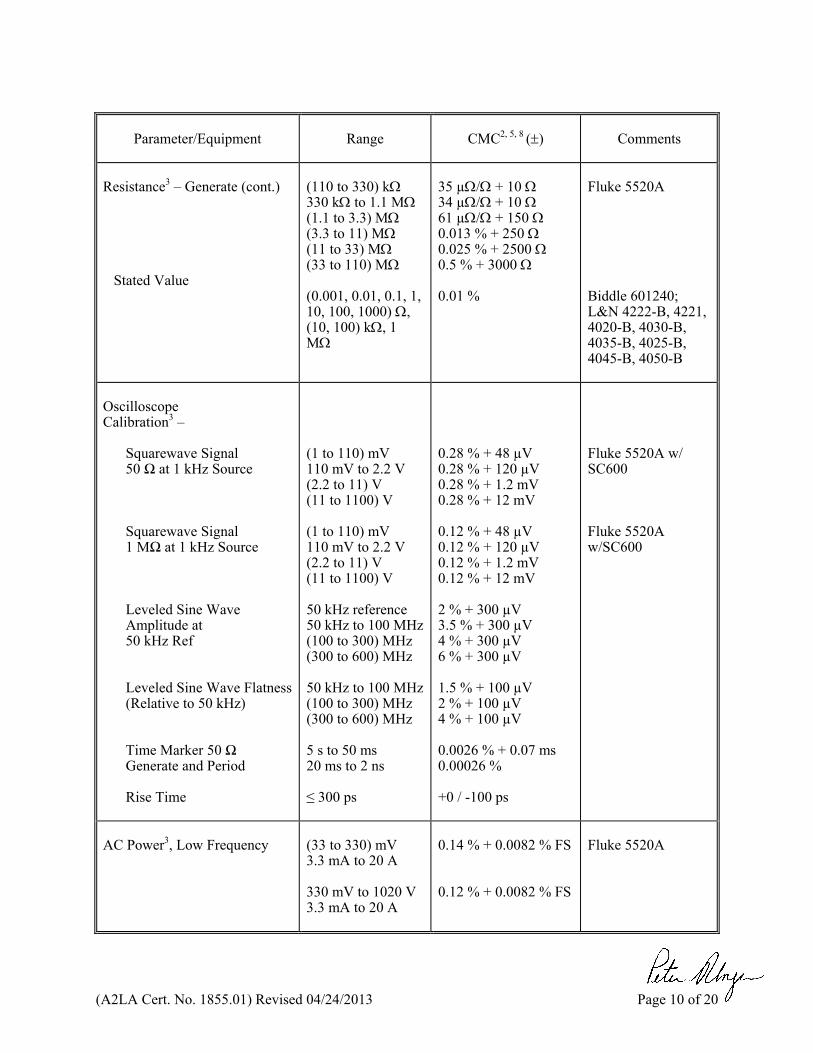
Resistance3 – Generate (cont.)
Stated Value
(110 to 330) k 330 k to 1.1 M (1.1 to 3.3) M (3.3 to 11) M (11 to 33) M (33 to 110) M (0.001, 0.01, 0.1, 1, 10, 100, 1000) , (10, 100) k, 1 M
35 µ/ + 10 34 µ/ + 10 61 µ/ + 150 0.013 % + 250 0.025 % + 2500 0.5 % + 3000 0.01 %
Fluke 5520A Biddle 601240; L&N 4222-B, 4221, 4020-B, 4030-B, 4035-B, 4025-B, 4045-B, 4050-B
Oscilloscope Calibration3 –
Squarewave Signal 50 Ω at 1 kHz Source Squarewave Signal 1 MΩ at 1 kHz Source
Leveled Sine Wave Amplitude at 50 kHz Ref Leveled Sine Wave Flatness (Relative to 50 kHz) Time Marker 50 Ω Generate and Period Rise Time
(1 to 110) mV 110 mV to 2.2 V (2.2 to 11) V (11 to 1100) V (1 to 110) mV 110 mV to 2.2 V (2.2 to 11) V (11 to 1100) V 50 kHz reference 50 kHz to 100 MHz (100 to 300) MHz (300 to 600) MHz 50 kHz to 100 MHz (100 to 300) MHz (300 to 600) MHz 5 s to 50 ms 20 ms to 2 ns ≤ 300 ps
0.28 % + 48 µV 0.28 % + 120 µV 0.28 % + 1.2 mV 0.28 % + 12 mV 0.12 % + 48 µV 0.12 % + 120 µV 0.12 % + 1.2 mV 0.12 % + 12 mV 2 % + 300 µV 3.5 % + 300 µV 4 % + 300 µV 6 % + 300 µV 1.5 % + 100 µV 2 % + 100 µV 4 % + 100 µV 0.0026 % + 0.07 ms 0.00026 % +0 / -100 ps
Fluke 5520A w/ SC600 Fluke 5520A w/SC600
AC Power3, Low Frequency
(33 to 330) mV 3.3 mA to 20 A 330 mV to 1020 V 3.3 mA to 20 A
0.14 % + 0.0082 % FS 0.12 % + 0.0082 % FS
Fluke 5520A
(A2LA Cert. No. 1855.01) Revised 04/24/2013 Page 11 of 20
Parameter/Equipment
Range
CMC2, 5, 8 ()
Comments
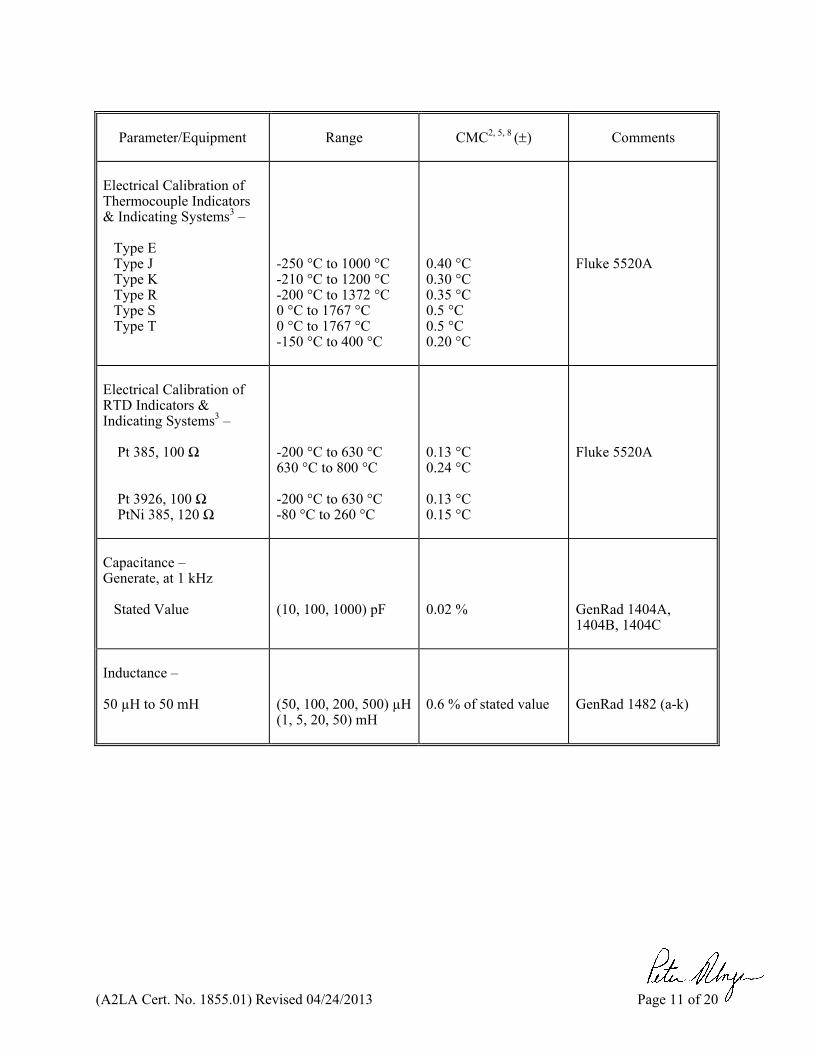
Electrical Calibration of Thermocouple Indicators & Indicating Systems3 –
Type E Type J Type K Type R Type S Type T
-250 °C to 1000 °C -210 °C to 1200 °C -200 °C to 1372 °C 0 °C to 1767 °C 0 °C to 1767 °C -150 °C to 400 °C
0.40 °C 0.30 °C 0.35 °C 0.5 °C 0.5 °C 0.20 °C
Fluke 5520A
Electrical Calibration of RTD Indicators & Indicating Systems3 –
Pt 385, 100 Ω Pt 3926, 100 Ω
PtNi 385, 120 Ω
-200 °C to 630 °C 630 °C to 800 °C -200 °C to 630 °C -80 °C to 260 °C
0.13 °C 0.24 °C 0.13 °C 0.15 °C
Fluke 5520A
Capacitance – Generate, at 1 kHz
Stated Value
(10, 100, 1000) pF
0.02 %
GenRad 1404A, 1404B, 1404C
Inductance – 50 µH to 50 mH
(50, 100, 200, 500) µH (1, 5, 20, 50) mH
0.6 % of stated value
GenRad 1482 (a-k)
(A2LA Cert. No. 1855.01) Revised 04/24/2013 Page 12 of 20
Parameter/Range
Frequency
CMC2, 4, 5, 8 ()
Comments
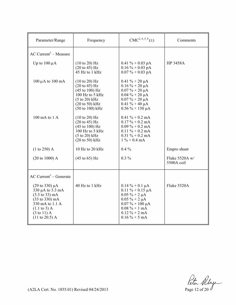
AC Current3 – Measure
Up to 100 A 100 A to 100 mA 100 mA to 1 A (1 to 250) A (20 to 1000) A
(10 to 20) Hz (20 to 45) Hz 45 Hz to 1 kHz (10 to 20) Hz (20 to 45) Hz (45 to 100) Hz 100 Hz to 5 kHz (5 to 20) kHz (20 to 50) kHz (50 to 100) kHz (10 to 20) Hz (20 to 45) Hz (45 to 100) Hz 100 Hz to 5 kHz (5 to 20) kHz (20 to 50) kHz 10 Hz to 20 kHz (45 to 65) Hz
0.41 % + 0.03 pA 0.16 % + 0.03 pA 0.07 % + 0.03 pA 0.41 % + 20 μA 0.16 % + 20 μA 0.07 % + 20 μA 0.04 % + 20 μA 0.07 % + 20 μA 0.41 % + 40 μA 0.56 % + 150 μA 0.41 % + 0.2 mA 0.17 % + 0.2 mA 0.09 % + 0.2 mA 0.11 % + 0.2 mA 0.31 % + 0.2 mA 1 % + 0.4 mA 0.4 % 0.3 %
HP 3458A Empro shunt Fluke 5520A w/ 5500A coil
AC Current3 – Generate
(29 to 330) μA 330 μA to 3.3 mA (3.3 to 33) mA (33 to 330) mA 330 mA to 1.1 A (1.1 to 3) A (3 to 11) A (11 to 20.5) A
40 Hz to 1 kHz
0.14 % + 0.1 μA 0.11 % + 0.15 μA 0.05 % + 2 μA 0.05 % + 2 μA 0.07 % + 100 μA 0.08 % + 1 mA 0.12 % + 2 mA 0.16 % + 5 mA
Fluke 5520A
(A2LA Cert. No. 1855.01) Revised 04/24/2013 Page 13 of 20
Parameter/Range
Frequency
CMC2, 5 ()
Comments
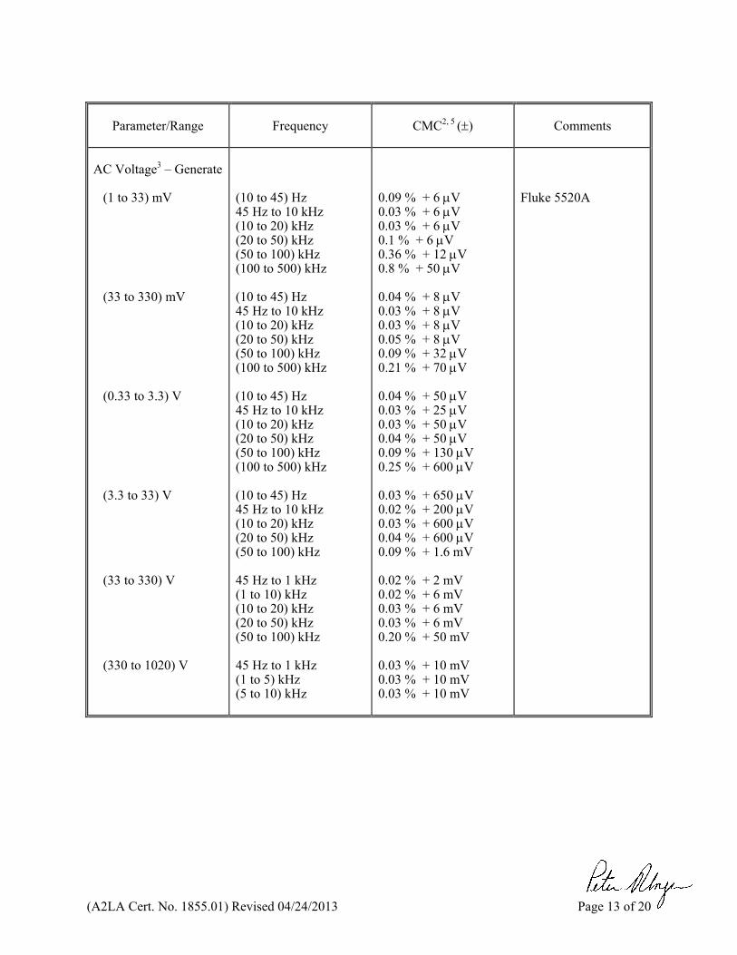
AC Voltage3 – Generate
(1 to 33) mV (33 to 330) mV (0.33 to 3.3) V (3.3 to 33) V (33 to 330) V (330 to 1020) V
(10 to 45) Hz 45 Hz to 10 kHz (10 to 20) kHz (20 to 50) kHz (50 to 100) kHz (100 to 500) kHz (10 to 45) Hz 45 Hz to 10 kHz (10 to 20) kHz (20 to 50) kHz (50 to 100) kHz (100 to 500) kHz (10 to 45) Hz 45 Hz to 10 kHz (10 to 20) kHz (20 to 50) kHz (50 to 100) kHz (100 to 500) kHz (10 to 45) Hz 45 Hz to 10 kHz (10 to 20) kHz (20 to 50) kHz (50 to 100) kHz 45 Hz to 1 kHz (1 to 10) kHz (10 to 20) kHz (20 to 50) kHz (50 to 100) kHz 45 Hz to 1 kHz (1 to 5) kHz (5 to 10) kHz
0.09 % + 6 V 0.03 % + 6 V 0.03 % + 6 V 0.1 % + 6 V 0.36 % + 12 V 0.8 % + 50 V 0.04 % + 8 V 0.03 % + 8 V 0.03 % + 8 V 0.05 % + 8 V 0.09 % + 32 V 0.21 % + 70 V 0.04 % + 50 V 0.03 % + 25 V 0.03 % + 50 V 0.04 % + 50 V 0.09 % + 130 V 0.25 % + 600 V 0.03 % + 650 V 0.02 % + 200 V 0.03 % + 600 V 0.04 % + 600 V 0.09 % + 1.6 mV 0.02 % + 2 mV 0.02 % + 6 mV 0.03 % + 6 mV 0.03 % + 6 mV 0.20 % + 50 mV 0.03 % + 10 mV 0.03 % + 10 mV 0.03 % + 10 mV
Fluke 5520A
(A2LA Cert. No. 1855.01) Revised 04/24/2013 Page 14 of 20
Parameter/Range
Frequency
CMC2, 4, 8 ()
Comments
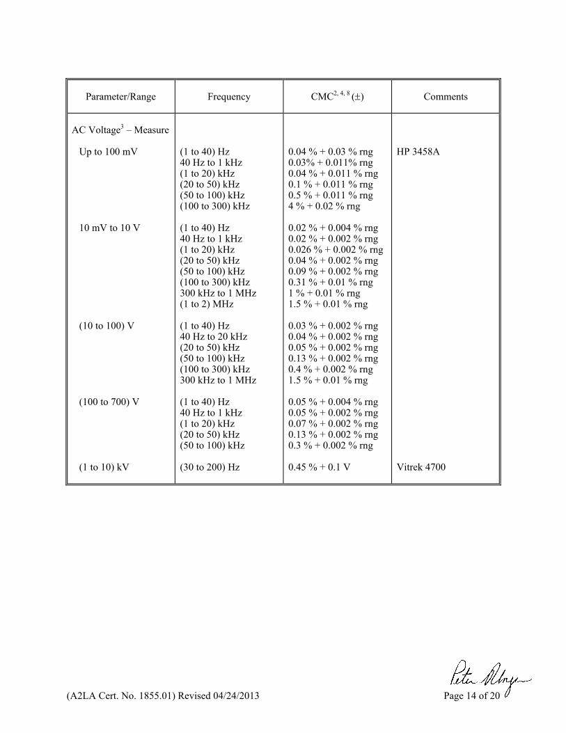
AC Voltage3 – Measure
Up to 100 mV 10 mV to 10 V (10 to 100) V (100 to 700) V (1 to 10) kV
(1 to 40) Hz 40 Hz to 1 kHz (1 to 20) kHz (20 to 50) kHz (50 to 100) kHz (100 to 300) kHz (1 to 40) Hz 40 Hz to 1 kHz (1 to 20) kHz (20 to 50) kHz (50 to 100) kHz (100 to 300) kHz 300 kHz to 1 MHz (1 to 2) MHz (1 to 40) Hz 40 Hz to 20 kHz (20 to 50) kHz (50 to 100) kHz (100 to 300) kHz 300 kHz to 1 MHz (1 to 40) Hz 40 Hz to 1 kHz (1 to 20) kHz (20 to 50) kHz (50 to 100) kHz (30 to 200) Hz
0.04 % + 0.03 % rng 0.03% + 0.011% rng 0.04 % + 0.011 % rng 0.1 % + 0.011 % rng 0.5 % + 0.011 % rng 4 % + 0.02 % rng 0.02 % + 0.004 % rng 0.02 % + 0.002 % rng 0.026 % + 0.002 % rng 0.04 % + 0.002 % rng 0.09 % + 0.002 % rng 0.31 % + 0.01 % rng 1 % + 0.01 % rng 1.5 % + 0.01 % rng 0.03 % + 0.002 % rng 0.04 % + 0.002 % rng 0.05 % + 0.002 % rng 0.13 % + 0.002 % rng 0.4 % + 0.002 % rng 1.5 % + 0.01 % rng 0.05 % + 0.004 % rng 0.05 % + 0.002 % rng 0.07 % + 0.002 % rng 0.13 % + 0.002 % rng 0.3 % + 0.002 % rng 0.45 % + 0.1 V
HP 3458A Vitrek 4700
(A2LA Cert. No. 1855.01) Revised 04/24/2013 Page 15 of 20
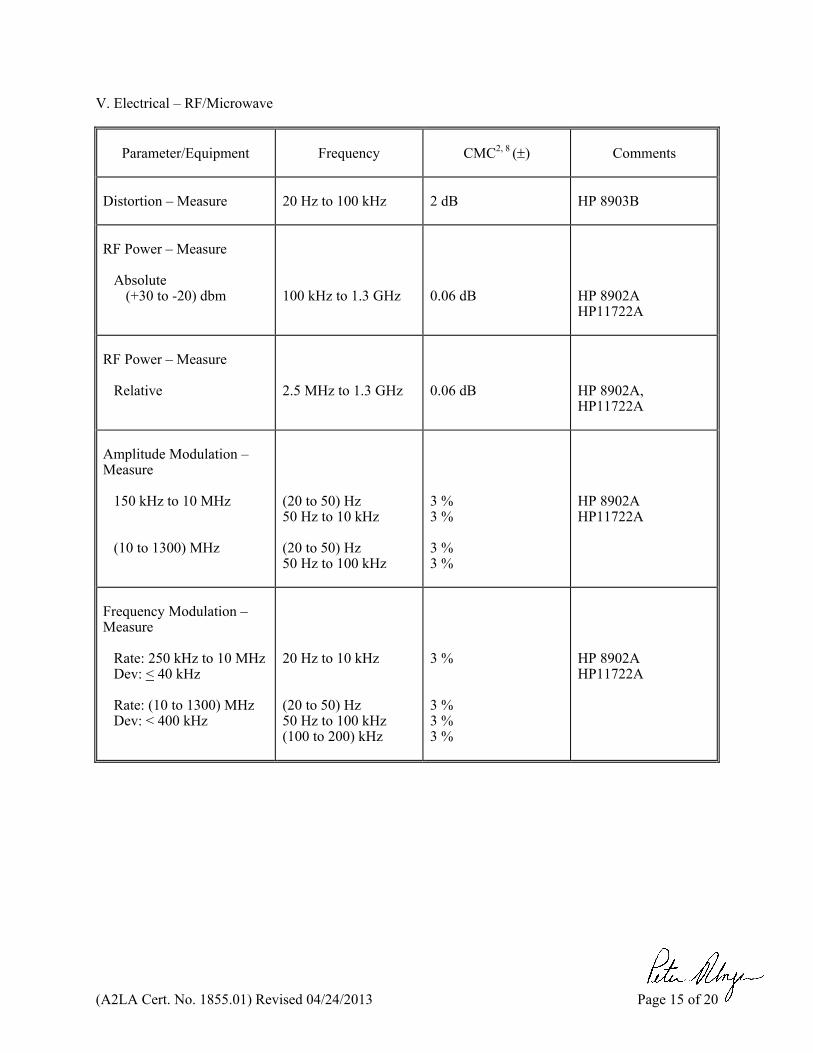
V. Electrical – RF/Microwave
Parameter/Equipment
Frequency
CMC2, 8 ()
Comments
Distortion – Measure
20 Hz to 100 kHz
2 dB
HP 8903B
RF Power – Measure
Absolute (+30 to -20) dbm
100 kHz to 1.3 GHz
0.06 dB
HP 8902A HP11722A
RF Power – Measure
Relative
2.5 MHz to 1.3 GHz
0.06 dB
HP 8902A, HP11722A
Amplitude Modulation – Measure
150 kHz to 10 MHz (10 to 1300) MHz
(20 to 50) Hz 50 Hz to 10 kHz (20 to 50) Hz 50 Hz to 100 kHz
3 % 3 % 3 % 3 %
HP 8902A HP11722A
Frequency Modulation – Measure
Rate: 250 kHz to 10 MHz Dev: < 40 kHz Rate: (10 to 1300) MHz Dev: < 400 kHz
20 Hz to 10 kHz (20 to 50) Hz 50 Hz to 100 kHz (100 to 200) kHz
3 % 3 % 3 % 3 %
HP 8902A HP11722A
(A2LA Cert. No. 1855.01) Revised 04/24/2013 Page 16 of 20
Parameter/Equipment
Frequency
CMC2 ()
Comments
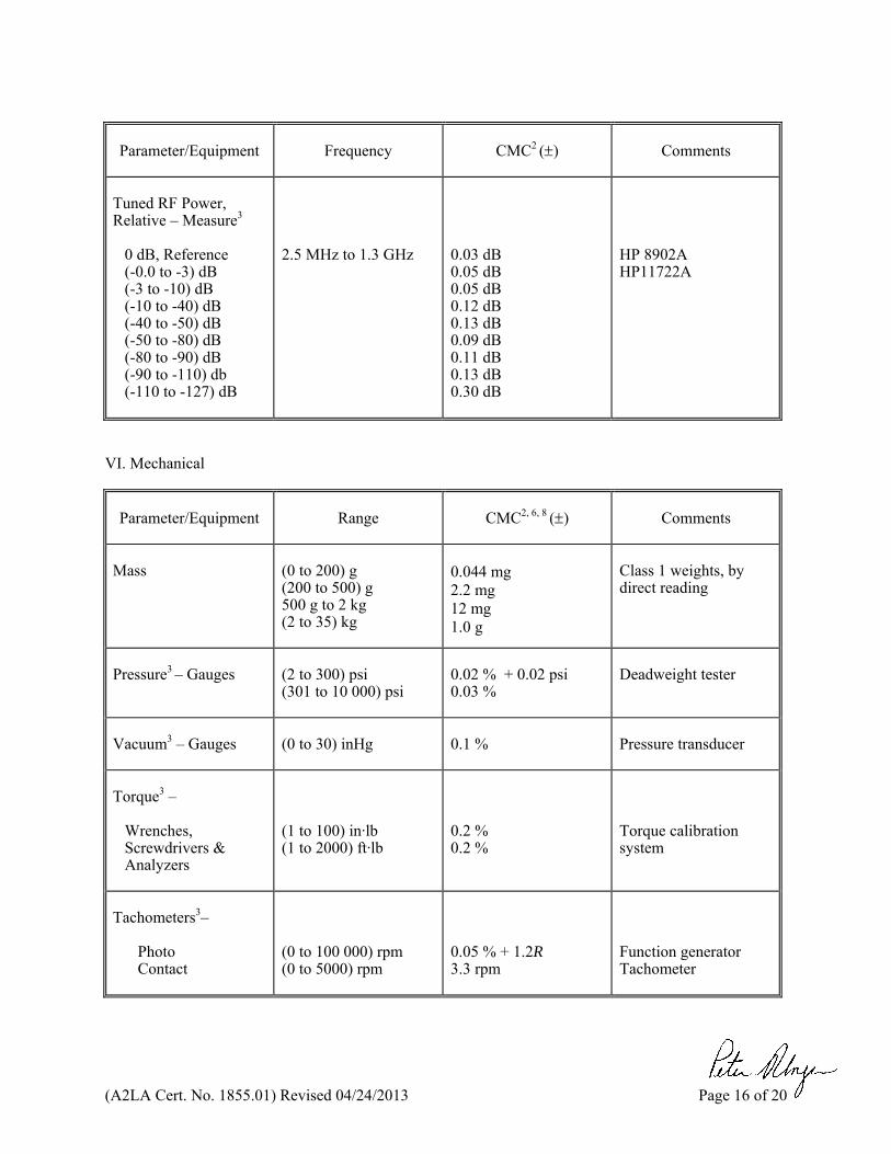
Tuned RF Power, Relative – Measure3
0 dB, Reference (-0.0 to -3) dB (-3 to -10) dB (-10 to -40) dB (-40 to -50) dB (-50 to -80) dB (-80 to -90) dB (-90 to -110) db (-110 to -127) dB
2.5 MHz to 1.3 GHz
0.03 dB 0.05 dB 0.05 dB 0.12 dB 0.13 dB 0.09 dB 0.11 dB 0.13 dB 0.30 dB
HP 8902A HP11722A
VI. Mechanical
Parameter/Equipment
Range
CMC2, 6, 8 ()
Comments
Mass
(0 to 200) g (200 to 500) g 500 g to 2 kg (2 to 35) kg
0.044 mg 2.2 mg 12 mg 1.0 g
Class 1 weights, by direct reading
Pressure3 – Gauges
(2 to 300) psi (301 to 10 000) psi
0.02 % + 0.02 psi 0.03 %
Deadweight tester
Vacuum3 – Gauges
(0 to 30) inHg
0.1 %
Pressure transducer
Torque3 –
Wrenches, Screwdrivers & Analyzers
(1 to 100) in·lb (1 to 2000) ft·lb
0.2 % 0.2 %
Torque calibration system
Tachometers3–
Photo Contact
(0 to 100 000) rpm (0 to 5000) rpm
0.05 % + 1.2R 3.3 rpm
Function generator Tachometer
(A2LA Cert. No. 1855.01) Revised 04/24/2013 Page 17 of 20
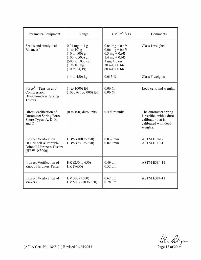
Parameter/Equipment
Range
CMC2, 6, 8 ()
Comments
Scales and Analytical Balances3
0.01 mg to 1 g (1 to 10) g (10 to 100) g (100 to 500) g (500 to 1000) g (1 to 10) kg (10 to 14) kg (14 to 450) kg
0.04 mg + 0.6R 0.06 mg + 0.6R 0.3 mg + 0.6R 1.4 mg + 0.6R 3 mg + 0.6R 30 mg + 0.6R 60 mg + 0.6R 0.013 %
Class 1 weights Class F weights
Force3 – Tension and Compression, Dynamometers, Spring Testers
(1 to 1000) lbf (1000 to 100 000) lbf
0.06 % 0.06 %
Load cells and weights
Direct Verification of Durometer Spring Force – Shore Types A, D, M, and O
(0 to 100) duro units
0.4 duro units
The durometer spring is verified with a duro-calibrator that is calibrated with dead weights.
Indirect Verification Of Brinnell & Portable Brinnell Hardness Testers (HBW10/3000)
HBW (100 to 350) HBW (351 to 650)
0.037 mm 0.029 mm
ASTM E10-12 ASTM E110-10
Indirect Verification of Knoop Hardness Tester
HK (250 to 650) HK (>650)
0.49 μm 0.52 μm
ASTM E384-11
Indirect Verification of Vickers
HV 300 (>600) HV 500 (250 to 350)
0.62 μm 0.78 μm
ASTM E384-11
(A2LA Cert. No. 1855.01) Revised 04/24/2013 Page 18 of 20
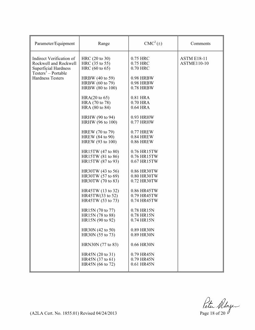
Parameter/Equipment
Range
CMC2 ()
Comments
Indirect Verification of Rockwell and Rockwell Superficial Hardness Testers3 – Portable Hardness Testers
HRC (20 to 30) HRC (35 to 55) HRC (60 to 65) HRBW (40 to 59) HRBW (60 to 79) HRBW (80 to 100) HRA(20 to 65) HRA (70 to 78) HRA (80 to 84) HRHW (90 to 94) HRHW (96 to 100) HREW (70 to 79) HREW (84 to 90) HREW (93 to 100) HR15TW (47 to 80) HR15TW (81 to 86) HR15TW (87 to 93) HR30TW (43 to 56) HR30TW (57 to 69) HR30TW (70 to 83) HR45TW (13 to 32) HR45TW(33 to 52) HR45TW (53 to 73) HR15N (70 to 77) HR15N (78 to 88) HR15N (90 to 92) HR30N (42 to 50) HR30N (55 to 73) HRN30N (77 to 83) HR45N (20 to 31) HR45N (37 to 61) HR45N (66 to 72)
0.75 HRC 0.75 HRC 0.70 HRC 0.98 HRBW 0.98 HRBW 0.78 HRBW 0.81 HRA 0.70 HRA 0.64 HRA 0.93 HRHW 0.77 HRHW 0.77 HREW 0.84 HREW 0.86 HREW 0.76 HR15TW 0.76 HR15TW 0.67 HR15TW 0.86 HR30TW 0.80 HR30TW 0.72 HR30TW 0.86 HR45TW 0.79 HR45TW 0.74 HR45TW 0.78 HR15N 0.78 HR15N 0.74 HR15N 0.89 HR30N 0.89 HR30N 0.66 HR30N 0.79 HR45N 0.79 HR45N 0.61 HR45N
ASTM E18-11 ASTME110-10
(A2LA Cert. No. 1855.01) Revised 04/24/2013 Page 19 of 20
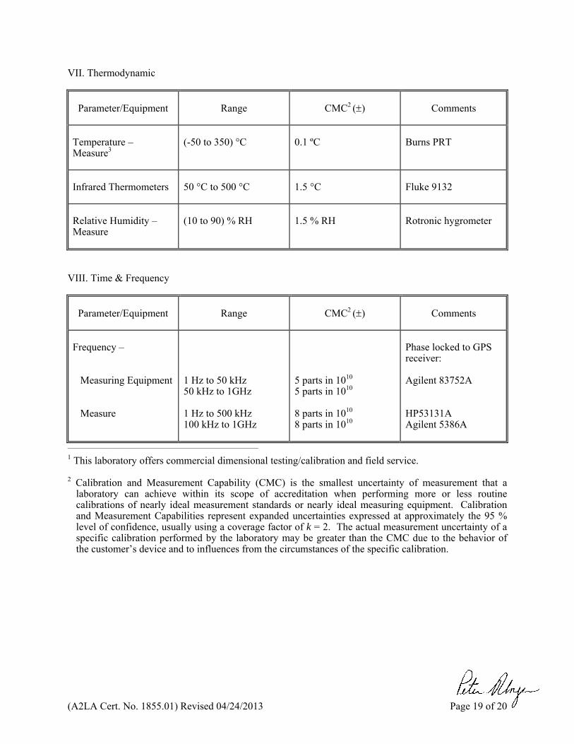
VII. Thermodynamic
Parameter/Equipment
Range
CMC2 ()
Comments
Temperature – Measure3
(-50 to 350) °C
0.1 ºC
Burns PRT
Infrared Thermometers
50 °C to 500 °C
1.5 °C
Fluke 9132
Relative Humidity – Measure
(10 to 90) % RH
1.5 % RH
Rotronic hygrometer
VIII. Time & Frequency
Parameter/Equipment
Range
CMC2 ()
Comments
Frequency –
Measuring Equipment Measure
1 Hz to 50 kHz 50 kHz to 1GHz 1 Hz to 500 kHz 100 kHz to 1GHz
5 parts in 1010
5 parts in 1010 8 parts in 1010
8 parts in 1010
Phase locked to GPS receiver: Agilent 83752A
HP53131A Agilent 5386A
__________________________________________________________ 1 This laboratory offers commercial dimensional testing/calibration and field service.
2 Calibration and Measurement Capability (CMC) is the smallest uncertainty of measurement that a laboratory can achieve within its scope of accreditation when performing more or less routine calibrations of nearly ideal measurement standards or nearly ideal measuring equipment. Calibration and Measurement Capabilities represent expanded uncertainties expressed at approximately the 95 % level of confidence, usually using a coverage factor of k = 2. The actual measurement uncertainty of a specific calibration performed by the laboratory may be greater than the CMC due to the behavior of the customer’s device and to influences from the circumstances of the specific calibration.
(A2LA Cert. No. 1855.01) Revised 04/24/2013 Page 20 of 20
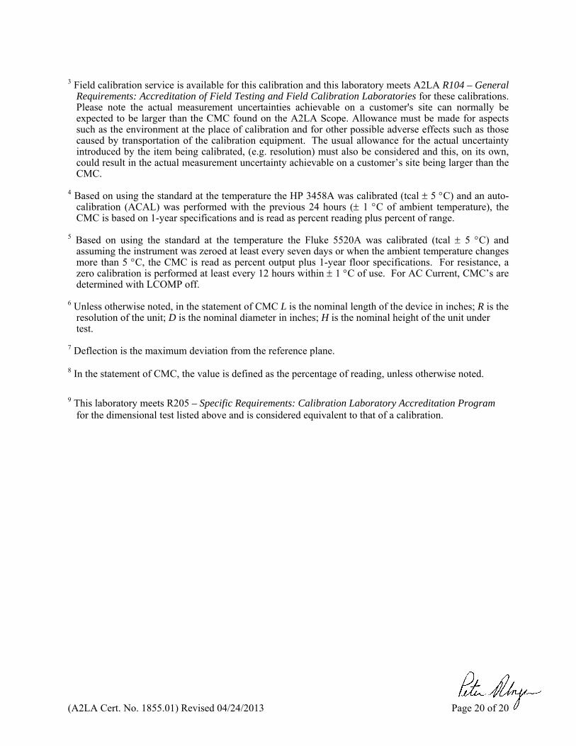
3 Field calibration service is available for this calibration and this laboratory meets A2LA R104 – General
Requirements: Accreditation of Field Testing and Field Calibration Laboratories for these calibrations. Please note the actual measurement uncertainties achievable on a customer's site can normally be expected to be larger than the CMC found on the A2LA Scope. Allowance must be made for aspects such as the environment at the place of calibration and for other possible adverse effects such as those caused by transportation of the calibration equipment. The usual allowance for the actual uncertainty introduced by the item being calibrated, (e.g. resolution) must also be considered and this, on its own, could result in the actual measurement uncertainty achievable on a customer’s site being larger than the CMC.
4 Based on using the standard at the temperature the HP 3458A was calibrated (tcal 5 C) and an auto-
calibration (ACAL) was performed with the previous 24 hours ( 1 C of ambient temperature), the CMC is based on 1-year specifications and is read as percent reading plus percent of range.
5 Based on using the standard at the temperature the Fluke 5520A was calibrated (tcal 5 C) and
assuming the instrument was zeroed at least every seven days or when the ambient temperature changes more than 5 C, the CMC is read as percent output plus 1-year floor specifications. For resistance, a zero calibration is performed at least every 12 hours within 1 C of use. For AC Current, CMC’s are determined with LCOMP off.
6 Unless otherwise noted, in the statement of CMC L is the nominal length of the device in inches; R is the
resolution of the unit; D is the nominal diameter in inches; H is the nominal height of the unit under test.
7 Deflection is the maximum deviation from the reference plane. 8 In the statement of CMC, the value is defined as the percentage of reading, unless otherwise noted.
9 This laboratory meets R205 – Specific Requirements: Calibration Laboratory Accreditation Program for the dimensional test listed above and is considered equivalent to that of a calibration.
A2LA has accredited
TIC-MS, INC. St. Louis, MO
for technical competence in the field of
Calibration
This laboratory is accredited in accordance with the recognized International Standard ISO/IEC 17025:2005 General Requirements for the Competence of Testing and Calibration Laboratories. This laboratory also meets the requirements of ANSI/NCSLI Z540.3-2006 and any additional program requirements in the field of calibration. This accreditation demonstrates technical competence for a defined scope and the
operation of a laboratory quality management system (refer to joint ISO-ILAC-IAF Communiqué dated 8 January 2009).
Presented this 13th day of August 2012.
_______________________ President & CEO For the Accreditation Council Certificate Number 1855.01 Valid to June 30, 2014
For the calibrations to which this accreditation applies, please refer to the laboratory’s Calibration Scope of Accreditation.