Embed Size (px)
Citation preview

Introduction ........................................................................................
Safety Warning ..................................................................................
Package Contents ..............................................................................
Product Overview ..............................................................................
Using the TPX™ System ....................................................................
Installation ...................................................................................
Wiring the System ................................................................
Power ..................................................................................
Visual Alert ..........................................................................
Laser Jammer .....................................................................
Aux Out ................................................................................
Mounting the Main Detector Unit ........................................
Detector Unit Operation ..............................................................
Power/GPS Datapoint Activation ..........................................
City/Highway ........................................................................
Volume and Brightness Control / Radar Detection Activation ...
Alert Off ...............................................................................
Radar and Laser Signal Detection ........................................
GPS Datapoint Warning ........................................................
Button Backlights ................................................................
Troubleshooting ...................................................................................
Maintenance and Care ........................................................................
Service ................................................................................................
Warranty Service .........................................................................
Non-Warranty Service ................................................................
Warranty .............................................................................................
Specifications .....................................................................................
Accessories ........................................................................................
FCC Statement ...................................................................................
4556888891010111212121313141415151819192021222323
TABLE OF CONTENTS
You may register this product online at www.AdaptivTech.com.

4 5
SAFETY WARNING
When using the TPX™ Motorcycle Radar and Laser Detection System PRO and its associated components, it is the sole responsibility of the operator to install all components properly and to ensure that they will not interfere with safe operation of the vehicle, nor will they cause any personal injury or damage in the event of an accident. The operator should operate the vehicle in a safe manner while using the system and its components. Do not use the system if you find it distracting. Do not use the system if it is unsafe or dangerous to do so.
Warning: Using this system is not a license to speed! Always ride safely and obey traffic laws.
Warning: It is your responsibility to be familiar with all laws applicable to the possession and use of radar detectors in your locality. The manufacturer and retailer assume no responsibility for any use or application of this product in violation of any applicable law. Please check your state and local laws and regulations before installing this product.
PACKAGE CONTENTS
• TPX™DetectorUnit• TPX™VisualAlert• TPX™VisualAlertDoubleSidedAdhesiveTape• TPX™QuickReleasePlate• TPX™WiringHarness• DatabaseDownloadUSBCable• CableTies• Manual• ProductRegistrationForm
INTRODUCTION
Dear TPX™ Motorcycle Radar and Laser Detection System PRO Owner,
Congratulations on your purchase of the TPX™ Motorcycle Radar and Laser Detection System PRO. This system is the result of customer feedback and years of research and development by the motorcycle-minded engineers who started the company. The unit was designed from the ground up with the rider in mind every step of the way.
The TPX™ Motorcycle Radar and Laser Detection System PRO is not cluttered with unnecessary features. Its simple and straight forward design allows you to focus on your ride instead of fiddling with bells and whistles.
Our goal is to provide you with the highest quality radar and laser detectors designed specifically for motorcycles. Enjoy your new TPX™ Motorcycle Radar and Laser Detection System PRO. Enjoy your ride, and ride safe.
Sincerely,
Adaptiv Technologies

6 7
Figure 1c
Figure 1b
Release Lever
Front Laser Lens
Radar Lens
PRODUCT OVERVIEW PRODUCT OVERVIEW(CONTINUED)
The TPX™ Motorcycle Radar and Laser Detection System PRO is designed specifically for motorcycle use. The system detects radar signals used by traffic enforcement agencies in the United States, including the X, K, and Ka radar bands, as well as police laser guns. The GPS datapoint feature will alert you of Red Light Camera (RLC) controlled intersections and stationary Speed Cameras (SC). It is weather resistant with large, easy to operate buttons and a bright LCD display. The system comes with the TPX™ Visual Alert and can also be used with the TPX™ Wireless Headset (sold separately). An audio output connection is provided for those riders who choose to use the TPX™ Radar and Laser Detection System PRO with an existing sound or communication system.
Figure 1a
Power and GPS Datapoint Activation Button
LCD Display
Volume/Brightness Increase, GPS
Datapoint Selection, and Radar Detection
Activation Button
Volume/Brightness Decrease and GPS
Datapoint Selection Button
Rear Laser Lens
City/Highway Mode and Volume/Brightness Mode Button
Alert Off and Backlight Toggle Button
Power Input
BACKLIGHT
MODE

8 9
Visual AlertThe TPX™ Visual Alert is designed to be mounted on any part of the motorcycle that can easily be seen by the rider.
There are two mounting options for the Visual Alert.
Option 1: Using Double-Sided Adhesive Tape
Determine an appropriate location for mounting the Visual Alert. The best location is one that encompasses the rider’s peripheral field of view, with the LEDs pointed directly at the rider’s face. The surface directly above the gauges is an ideal location on most motorcycles.
Clean the bottom surface of the Visual Alert and the chosen mounting surface on the motorcycle with mild soap and water or alcohol. Rinse with water to remove all traces of soap if necessary.
Once the surfaces are clean and dry, remove one liner of the Double-Sided Adhesive Tape and apply to the bottom surface of the Visual Alert.
Figure 2
USING THE TPX™ SYSTEM PRO
INSTALLATION
Wiring the System
Warning: Installation of the TPX™ System PRO should be performed by a qualified technician. Improper installation may interfere with the safety and proper operation of the product and/or vehicle.
Power
The TPX™ Detector Unit is powered by the motorcycle’s 12V power source. If the motorcycle’s power output is not 12V, a voltage adapter is required.
To provide power to the unit, connect the red (+) terminal cable to a switched power wire on the motorcycle and the black (-) terminal cable to a ground point. Alternatively, you can also connect the red (+) terminal cable to the positive (+) terminal of the battery and the black (-) terminal cable to the negative (-) terminal of the battery. Route the Wiring Harness through the motorcycle and plug the Wiring Harness Plug into the Wiring Harness Jack on the Detector Unit as shown in Figure 2.
Warning: Connecting the Wiring Harness directly to the battery with the Detector Unit connected may drain the battery if the motorcycle is not operated for an extended period, even with the Detector Unit turned off. Disconnect the Wiring Harness Plug if the Detector Unit is not going to be used for an extended period of time.
Warning: Do not connect Wiring Harness Plug into the Detector Unit before positive (red) and negative (black) terminal cables are connected to the bike’s battery.
NOTE: The system is supplied with caps for the Wiring Harness Plug and the Detector Unit Power Input. When not in use, place the caps over the connectors to help prevent corrosion.
NOTE: The Wiring Harness is designed with a “c-clip” on the plug. This clip can be used to secure the plug to the Quick Release Plate post for cable management purposes.
Wiring Harness Plug
•
•
•
10 11
Mounting the Detector Unit
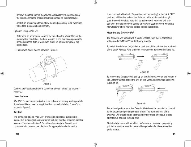
The Detector Unit comes with a Quick Release Plate that is compatible with any AdaptivMount™ or third party mounts.
To install the Detector Unit, slide the back end of the unit into the front end of the Quick Release Plate until they lock together as shown in Figure 4a.
Figure 4a
Figure 4b
Connect the Visual Alert into the connector labeled “Visual” as shown in Figure 3.
Laser Jammer
The TPX™ Laser Jammer System is an optional accessory sold separately. If you have this accessory, plug it into the connector labeled “Laser” as shown in Figure 2.
Aux Out
The connector labeled “Aux Out” provides an additional audio output signal. This audio signal can be utilized with any number of communication systems. The connector is a 3.5mm female mono jack. Contact your communication system manufacturer for appropriate adapter device.
Remove the other liner of the Double-Sided Adhesive Tape and apply the Visual Alert to the chosen mounting surface on the motorcycle.
Apply firm pressure and then allow mounted assembly to sit overnight while tape increases bond strength.
Option 2: Using Cable Ties
Determine an appropriate location for mounting the Visual Alert on the motorcycle’s handlebar. The best location is one that encompasses the rider’s peripheral field of view, with the LEDs pointed directly at the rider’s face.
Fasten with Cable Ties as shown in Figure 3.
•
•
•
•
Figure 3
If you connect a Bluetooth Transmitter (sold separately) to the “AUX OUT” port, you will be able to hear the Detector Unit’s audio alerts through your Bluetooth Headset. Note that some Bluetooth Headsets will only pair with a single Bluetooth device. Check with your Bluetooth Headset’s manufacturer about multiple device pairing capabilities.
To remove the Detector Unit, pull up on the Release Lever on the bottom of the Detector Unit and slide the unit off the Quick Release Plate as shown in Figure 4b.
For optimal performance, the Detector Unit should be mounted horizontal to the ground and pointing straight ahead. The front and rear of the Detector Unit should not be obstructed by any metal or opaque plastic objects (e.g. gauges, fairings, etc.).
Tinted windscreens will not affect performance. However, opaque (e.g. painted or mirrored) windscreens will negatively affect laser detection performance.

12 13
DETECTOR UNIT OPERATION
Power / GPS Datapoint Activation
Press and hold the button on the Detector Unit for two or more seconds to turn the unit on/off. The Detector Unit will automatically go through a start-up sequence each time it is turned on.
Press the button to activate Red Light Camara (RLC ) and Speed Camera (SC ) GPS Datapoint warnings. When the display is showing RLC, press the or button to activate or deactivate RLC Datapoint warnings. When the display is showing SC, press the or button to activate or deactivate SC Datapoint warnings.
If the Detector Unit is connected directly to the battery and is not going to be used for an extended period of time, disconnect the Wiring Harness Plug, as the Detector Unit draws a small amount of power from the battery even in the “off” position.
City/HighwayPress the button to toggle between Highway ( ), Highway No X ( ), Highway No X & K ( ), City ( ) and City No X ( ), and City No X & K ( ) Modes. These modes are designed to maximize performance while reducing false alerts.
Highway Mode is recommended when riding on open roadways where interference with the Detector Unit occurs less frequently.
Highway No X and Highway No X & K Modes are identical to Highway Mode with the exception that it ignores incoming X and X & K band signals.
City Mode is recommended when riding in residential, industrial, and business areas where interference is common. In this mode, the Detector Unit will provide an initial double beep and flash to alert you that it has detected a signal. It will then remain alert-less until the detected signal reaches four or more bars in strength. Most false alerts are weak in strength and this Anti-Annoying™ feature is designed to cut down on the amount of unnecessary alerts.
City No X and City No X & K Modes are identical to City Mode with the exception that it ignores incoming X and X & K band signals.
Volume and Brightness Control / Radar Detection ActivationPress and hold the button for two or more seconds to toggle between Volume Control ( ) and Brightness Control ( ) Modes.
When in Volume Control Mode, the and buttons control the volume on the Detector Unit as well as the optional Wireless Headset.
When in Brightness Control Mode, the and buttons control the brightness of the flashing LEDs on the optional Visual Alert.
Warning: The flashing LEDs in the Visual Alert can be extremely bright, especially at night time. It can be distracting and dangerous if you are not familiar with the brightness level. Before riding with the Visual Alert, especially at night, take the time to familiarize yourself with the system in a safe, controlled setting.
The Detector Unit, Visual Alert, and the optional Wireless Headset will retain the last volume and brightness settings each time the power is reset.
To activate Radar Detection function, press and hold the button for five or more seconds to toggle between activation and deactivation. When the Radar Detection function is deactivated, the display will show your speed in mph (kmh for International Version).
Alert Off
Press the button to temporarily disable all alerts ( ).
When activated, the volume on the Detector Unit and the optional Wireless Headset will be muted, and the LEDs of the Visual Alert will not flash. The alerts will be turned off for the remainder of the existing detected signal and for any new signal received within 20 seconds of the button press. The Detector Unit will automatically turn the alerts back on after this period.

14 15
In response to the individual targeting nature of police radar guns, any laser signal detected during this period will override the Alert Off function.
Radar and Laser Signal Detection
When a radar or laser signal is detected, the Detector Unit beeps and flashes at frequencies according to detected signal strength. Slower beeps and flashes indicate weak signal detection. Rapid beeps and flashes indicate strong signal detection. Each radar band or laser signal has its own distinct beep.
The LCD displays the detected radar band or laser signal and the corresponding signal strength. There are three distinct radar bands and one laser band as described below:
X band ( ) - The oldest and least common police radar band. Many automatic door openers and other nuisance signals use this band. An X band reading has a high probability of being a false alert. This band is ignored in City No X, City No X & K, Highway No X, and Highway No X & K Modes. However, a few remaining law enforcement agencies still use this band.
K band ( ) - A common police radar band. There is a slight chance of this signal being a false alert. This band is ignored in City No X & K and Highway No X & K Modes.
Ka band ( ) - The newest and a common police radar band. There is a very high chance of this signal originating from a police radar gun.
Laser ( ) - Growing in popularity among police traffic enforcement. There is a very high chance of this signal originating from a police laser gun.
GPS Datapoint Warning
When the GPS Datapoint function is activated (either RLC, SC, or both are in the “ON” position), the Detector Unit will beep when it is 0.3 miles (500
TROUBLESHOOTING
Problem Possible Causes Possible Solutions
No display or audio on Detector Unit
Detector Unit not powered on
Detector Unit not properly connected to power source
Vehicle not turned on (if connected to a “switched” power wire)
Hold down Detector Unit Power Button for two seconds
Check fuse, replace with a 250V, 1A fuse if necessary
Check power connections
Make sure that plug is inserted into Detector Unit properly
Turn vehicle on
If your TPX™ Detection System PRO is not operating properly, please refer to the following guide:
meters) away from a Red Light Camera (RLC ) controlled intersection or Speed Camera (SC ) location registered in our database.
Our GPS database is updated monthly. To find the version of the database installed in the Detector Unit, press the button until the display shows “DB-XXXX”. The first two digits indicate the year and the second two digits indicate the month of the database date. To update the database in the Detector Unit, go to www.AdaptivTech.com.
Button Backlights
Press and hold the button for two or more seconds to toggle the button backlights on/off.

16 17
Problem Possible Causes Possible Solutions
Detector Unit resets when vehicle goes over a bump
Poor electrical connection
Check power connections
Detector Unit feels very warm
Normal Operation It is normal for the Detector Unit to feel warm
The Detector Unit did not register a signal when driving past a police vehicle
Police radar is not turned on
Non-radar or laser detection methods are being used
Slow down
The Detector Unit sensitivity appears weak
The Detector Unit is not mounted properly
The front and/or rear of the Detector Unit is obstructed
Check that the Detector Unit is mounted horizontal to the ground
Check that the front and rear of the Detector Unit are not obstructed by any metal or opaque plastic objects
If using the Detector Unit in an automobile, check that the detector is not blocked by windshield wipers
If using the Detector Unit in an automobile, determine if the vehicle has an Instaclear®, ElectriClear®, or solar reflective windshield, which may hinder the detector’s performance
Problem Possible Causes Possible Solutions
Detector Unit detects radar or laser signal but no police in vicinity
Other radar or laser sources in vicinity
Other radar detectors in proximity
Pinched or damaged Wiring Harness
Press Alert Off button
Increase distance between radar detectors in other vehicles
Check Wiring Harness and remove any pinches
Vehicle nearby may be equipped with blind spot sensor
Detector Unit does not power on
Malfunction on the display and/or sound
Logic error Restore default settings:
Power on Detector Unit Unplug Wiring Harness Plug from Detector Unit While holding down Mode and Alert Off buttons, plug Wiring Harness Plug into Detector Unit
TROUBLESHOOTING (CONT’D)TROUBLESHOOTING (CONT’D)
A Special Note About Group Riding: Under certain group riding circumstances, multiple Detector Units may interfere with each other resulting in false alerts. If this occurs, increase following distances or turn off all but one Detector Unit.
1.
2.
3.

18 19
SERVICE
Warranty Service
If you believe that your TPX™ System is not functioning properly please follow the following procedure:
1. Review the Troubleshooting section.
2. If your problem is not resolved after reviewing the Troubleshooting section, have your serial number ready and call us at 646-722-0253. We will try to resolve your problem over the phone.
3. If your System needs to be returned for repair, we will provide you with a Return Merchandise Authorization (RMA) Number and a shipping address. Write the RMA Number on the outside of the shipping box. Include the following items in your shipment:
The Detector Unit and Wiring Harness Copy of sales receipt (originals cannot be returned) Your name, phone number, address, and email address (we promise not to spam)
All shipment must be sent prepaid by way of a traceable carrier, such as UPS, FedEx, USPS Priority Mail, etc., and should be insured. Adaptiv Technologies is not responsible for any loss or damage incurred during shipping.
Warranty service will only be honored for units purchased from authorized agents.
Repairs will not be performed on units without a readable serial number.
Please allow 4-8 weeks for the return of the unit.
a.b.c.
MAINTENANCE AND CAREThe TPX™ Detector Unit is water resistant. It is designed to withstand temporary exposure to moisture, such as rain or fog. However, it should not be exposed to moisture for a prolonged period of time. Do not leave the Detector Unit out in the rain when not in use. Do not hose the Detector Unit down. Do not submerge the Detector Unit as this will void the warranty.
Remove the Detector Unit from your motorcycle when your motorcycle is not in operation if it is exposed to an outdoor environment.
Clean the Detector Unit with a damp lint-free cloth only. Do not use any chemicals as they may attack the plastic.
Dry the Detector Unit with a lint-free cloth after it has been exposed to moisture.

20 21
Adaptiv Technologies, LLC warrants to the original purchaser that the TPX™ Motorcycle Radar and Laser Detection System will be free of defects in workmanship and materials for a period of two years from the date of first consumer purchase. The TPX™ System consists of the Detector Unit assembly, the Wiring Harness, and the respective parts of each. Adaptiv Technologies will, at its option, repair or replace a detective TPX™ Radar and Laser Detection System upon delivery to Adaptiv Technologies accompanied by the original sales receipt or other proof of first consumer purchase within the warranty period. You are responsible for all charges required to ship the product for warranty service, but the return charges will be at Adaptiv Technologies’ expense if the product is repaired or replaced under warranty. This warranty gives you specific rights, and you may also have other rights which vary from state to state.
EXCLUSIONS: This limited warranty does not apply:
To any products sold separately (such as any mount assemblies);
To any defects caused by misuse, abuse, accidents, modifications, negligence, tampering, or unauthorized repair;
In the State of Virginia, the District of Columbia, or in any other country or jurisdiction in which possession of radar detector equipment is illegal;
If the serial number has been altered, defaced, or removed; or
To installation of the unit.
ALL IMPLIED WARRANTIES, INCLUDING IMPLIED WARRANTIES OF MERCHANTABILITY AND FITNESS FOR A PARTICULAR PURPOSE ARE LIMITED IN DURANTION TO THE PERIOD OF THIS WARRANTY*.* Some states do not allow limitations on the duration of implied warranties and/or do not allow the exclusion or limitation of incidental or consequential damages, so the above limitations may not apply to you.
WARRANTY
1.
2.
3.
4.
5.
Non-Warranty Service
For all non-warranty service, follow the same procedure described in the Warranty Service section and include a non-refundable payment of $75 for basic diagnostics and repair. Do not send cash. If there are any additional charges, we will notify you before performing the repair.

22 23
ACCESSORIES
The following parts and accessories are available for purchase. For more information, go to www.AdaptivTech.com or call us at 866-ADAPTIV (866-232-7848) or 646-722-0253.
TPX™ Wireless Headset
TPX™ Visual Alert
TPX™ Replacement Wiring Harness
TPX™QuickReleasePlate
TPX™ Automotive Kit
TPX™ Automotive Dash Mount
TPX™ Bluetooth Transceiver
TPX™ 12V USB Power Supply
TPX™ Motorcycle Laser Jammer System
AdaptivMount ™
Safety Precautions
This equipment has been tested and found to comply with the limits for a Class B digital device, pursuant to Part 15 of the FCC Rules. These limits are designed to provide reasonable protection against harmful interference in a residential installation.
This equipment generates, uses, and can radiate radio frequency energy and, if not installed and used in accordance with the instructions, may cause harmful interference to radio communications. However, there is no guarantee that interference will not occur in a particular installation.
If this equipment does cause harmful interference to radio or television reception which can be determined by turning the equipment off and on, the user is encouraged to try to correct the interference by one or more of the following measures.
SPECIFICATIONS
Radar Frequencies:North America Version:10.500 – 10.550 GHz (X Band)24.050 – 24.250 GHz (K Band)33.400 – 36.000 GHz (Ka Super Wide Band)
International Version:23.850 – 24.250 GHz (K Band)34.000 – 35.120 GHz (Ka Narrow Band)
Laser Wavelength: 910 +/- 50 nanometers (nm)
Wireless RF Transmitter Frequency: 418 MHz
Operating Temperature Range: -20°C to +70°C (-4°F to +158°F)
Dimensions: 4.5” x 2.9” x 1.9”
Weight: 7.5 oz Power Requirements: 12V DC
Fuse: 1A, 250V
US PATENTS 7,504,9837,830,2987,986,2568,098,184
OTHER PATENTS PENDING
FCC STATEMENT

5001-00R1
•Reorientorrelocatethereceivingantenna. •Increasetheseparationbetweentheequipmentandreceiver. •Connecttheequipmentintoanoutletonacircuitdifferentfromthatto which the receiver is connected. •Consultthedealeroranexperiencedradio,TVtechnicalforhelp. •Onlyshieldedinterfacecableshouldbeused.
Finally, any changes or modifications to the equipment by the user not expressly approved by the grantee or manufacturer could void the users authority to operate such equipment.
This device complies with part 15 of the FCC rules. Operation is subject to the following two conditions: (1) This device may not cause harmful interference, and (2) this device must accept any interference received, including interference that may cause undesired operation of this device.
Caution
Any changes or modifications in construction of this device which are not expressly approved by the party responsible for compliance could void the user’s authority to operate the equipment.
CE Warning
•Changesandmodificationsnotexpresslyapprovedbythepartyresponsible for compliance could void the user’s authority to operate the equipment.
•It is desirable that it be installed and operated with at least 20cm or more between the radiator and person’s body (excluding extremities: hands, wrists, feet, and ankles).
Warning: Modifications not approved by Adaptiv Technologies, LLC may violate FCC rules and void user’s authority to operate this device.
Adaptiv Technologies, LLCwww.AdaptivTech.com
866-ADAPTIV(866-232-7848) 646-722-0253
MOTORCYCLE RADAR AND LASERDETECTION SYSTEM
MANUAL
PRO