Embed Size (px)
Citation preview

BT-300 Service Manual V2.0
Table of Contents
TERMS OF WARRANTY................................................................3
CAUTION.........................................................................................3
HOW TO CONTACT US ….............................................................4
DEFINITION OF WARNING, CAUTION, NOTE.............................6
GENERAL PRECAUTION ON ENVIRONMENT............................7
GENERAL PRECAUTION ON ELECTRIC SAFETY.....................8
SECTION 1. GENERAL INFORMATION .................9
1.1 Product Overview....................................................................9
1.2 Product Features...................................................................10
1.3 Product Configuration..........................................................10
SECTION 2. TECHNICAL DESCRIPTION...................................11
2.2 Main Unit.................................................................................121.2. Composition.........................................................................122.2. Main Board..........................................................................13
2.2.3Key Board.............................................................................25
2.3Doppler Probe.........................................................................262.3.1 Composition.......................................................................27
2.4UC Probe................................................................................272.4.1 Composition.......................................................................272.4.2 Technical Description.........................................................28
SECTION 3. TROUBLESHOOTING.............................................30
1

BT-300 Service Manual V2.0
3.1 Warning Sign Occasion and Status Checking...................30
Alarm Occasion and Status Checking Up.................................31
3.2 Troubleshooting on the Other Situation.............................31
SECTION 4. MAINTENANCE AND CLEANING..........................33
4.1 Maintenance and Cleaning...................................................33 Caution....................................................................................34
4.2 Regular Inspection................................................................34
SECTION 5. SPECIFICATIONS....................................................35
2

BT-300 Service Manual V2.0
Terms of Warranty
- This product is manufactured and examined by strict quality control and
inspection system.
- Compensation standard concerning repair, replacement and refund of the
product complies with “Consumer’s protection law” issued by Economic
Planning Dept.
- BT-300 is guaranteed by BISTOS Co., Ltd. And its warranty period is two
years from the date of purchase.
- Warranty repair or replacement will be made by BISTOS Service Center
with free of charge during warranty period if properly used under normal
condition in accordance with the instructions for use.
- In the event of a malfunction or failure during warranty period, customer
should inform BISTOS Co., Ltd. of the model name, serial number, date
of purchase and explanation of failure about the defective equipment.
3
Caution
Federal law restricts this device to sale by or on the order of a physician

BT-300 Service Manual V2.0
How to contact us …
4

BT-300 Service Manual V2.0
5
BT-300 Service Manual V2.0
Definition of Warning, Caution, Note
6
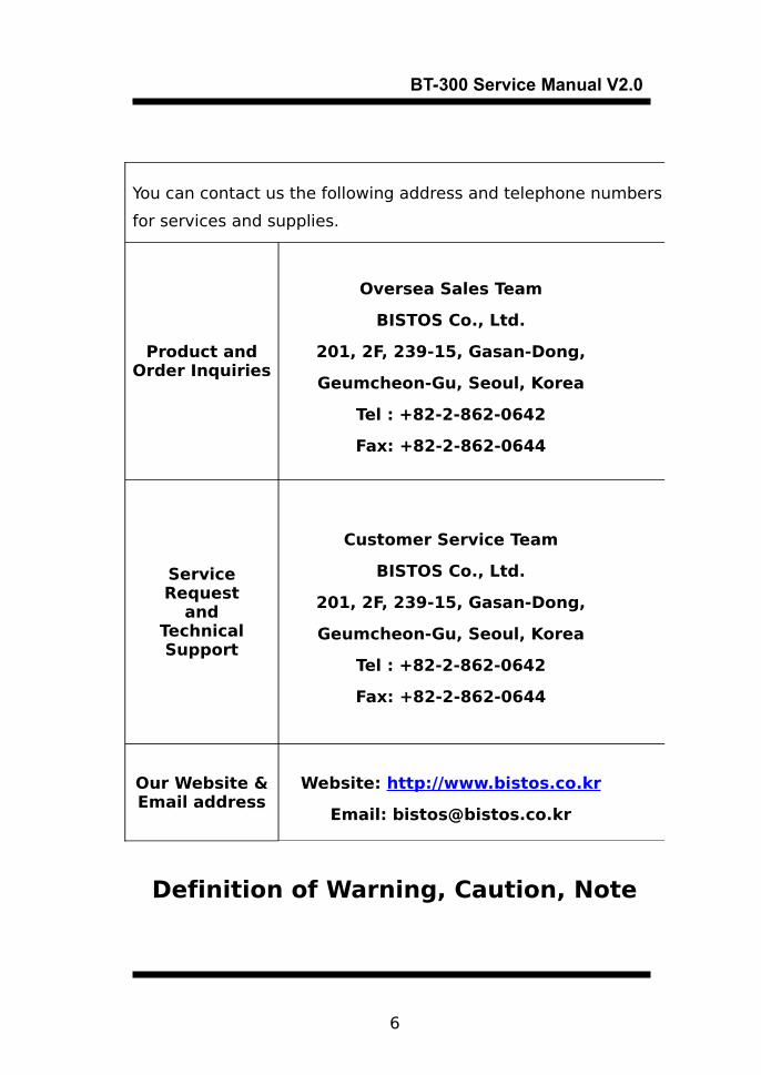
You can contact us the following address and telephone numbers
for services and supplies.
Product andOrder Inquiries
Oversea Sales Team
BISTOS Co., Ltd.
201, 2F, 239-15, Gasan-Dong,
Geumcheon-Gu, Seoul, Korea
Tel : +82-2-862-0642
Fax: +82-2-862-0644
Service Request
andTechnical Support
Customer Service Team
BISTOS Co., Ltd.
201, 2F, 239-15, Gasan-Dong,
Geumcheon-Gu, Seoul, Korea
Tel : +82-2-862-0642
Fax: +82-2-862-0644
Our Website &Email address
Website: http://www.bistos.co.kr
Email: [email protected]

BT-300 Service Manual V2.0
For a special emphasis on agreement, terms are defined as
listed below in operation manual. Users should operate the
equipment according to all the Warning and Caution
instructions.
Manufacturer or Sales agency takes no responsibility for any
kind of damage or breakdown that is caused by misuse and
failure to maintain the equipment.
Warning
A Warning indicates a potentially hazardous situation which, if not avoided, could result in death or serious injury.
Caution
A Caution indicates a potentially hazardous situation which, if not avoided, may result in minor or moderate injury.
Note
A Note indicates a particular point of information; something on which to focus your attention.
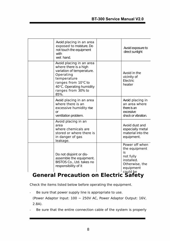
General Precaution on Environment
Do not keep or operate the equipment under the environment
listed below.
7
BT-300 Service Manual V2.0
General Precaution on Electric Safety
Check the items listed below before operating the equipment.
- Be sure that power supply line is appropriate to use.
(Power Adaptor Input: 100 ~ 250V AC, Power Adaptor Output: 16V,
2.8A).
- Be sure that the entire connection cable of the system is properly
8
Avoid placing in an areaexposed to moisture. Do not touch the equipment withwet hand.
Avoid exposure todirect sunlight
Avoid placing in an areawhere there is a highvariation of temperature.Operating temperatureranges from 10°C to40°C. Operating humidityranges from 30% to 85%.
Avoid in thevicinity of Electricheater
Avoid placing in an areawhere there is anexcessive humidity rise orventilation problem.
Avoid placing inan area wherethere is an excessiveshock or vibration.
Avoid placing in an areawhere chemicals arestored or where there isin danger of gas leakage.
Avoid dust andespecially metalmaterial into theequipment.
Do not disjoint or dis-assemble the equipment. BISTOS Co., Ltd. takes noresponsibility of it
Power off whenthe equipment isnot fully installed. Otherwise, theequipment could be

BT-300 Service Manual V2.0
and firmly fixed.
NoteThe equipment should not be placed in the vicinity of electric generator, X-ray, broadcasting apparatus to eliminate the electric noise during operation. Otherwise, it may cause incorrect result.Self-power line is important for BT-300. To use the same power source with other electric instruments may cause incorrect result.
NoteBT-300 is classified as listed below;- This equipment conforms to Class I, Type-BF. - Do not use the equipment in the vicinity of flammable
anesthetics and solvents. - The equipment conforms to Class I according to IEC/EN 60601-1 (Safety of Electric Medical Equipment)- This equipment conforms to Level B according to IEC/EN
60601-1-2 (Electromagnetic Compatibility Requirements)
NoteAccessory equipment connected to the analog and digital interfaces must be certified according to the respective IEC standards ( e.g. IEC 950 for data processing equipment and IEC 601-1 for medical equipment ). Furthermore all configurations shall comply with the system standard EN 60601-1-1:1993.If in doubt, consult the technical service department or your local representative.
Section 1. General Information
1.1 Product Overview
BT-300 is the fetal monitor that measures the fetal heart rate(FHR)
which may be evaluated to predict fetal status and uterine contraction. BT-300 irradiates ultrasound wave to the abdomen of a
pregnant woman, and detects the Doppler frequency signal reflected from the heart of the fetus. BT-300 analyzes this signal and displays
the heart rate by LED. Also, BT-300 provides the sound from the
9

BT-300 Service Manual V2.0
heart of fetus.
BT-300 measures the uterine contraction of a pregnant woman by pressure sensors and displays the numerical values.
And BT-300 prints the heart rate of the fetus and the values of
uterine contraction.
1.2 Product Features
BT-300 records the heart rate of the fetus, the uterine contraction
of a pregnant woman, and basic information of the equipment
with a provided thermal printer.
BT-300 is capable of Monitoring of fetal heart rate with one or two
pulsed Ultrasound Transducer(s).
BT-300 can record automatically with thermal printer through
printer setup.
BT-300 is compact and light, potable and easy to use.
BT-300 uses a free voltage(100 – 240VAC input) power adaptor.
1.3 Product Configuration
BT-300 system consists of the followings. Unpack the package and
check out the following items. Also, be sure to check to see any
damage of main body and accessories
① BT-300 Main Body
② Ultrasound Transducer(Doppler Probe) - 2 EA(1 EA for BT-300S)
③ Tocotransducer(UC Probe) - 1EA
④ Event Marker -1EA
⑤ Thermal Print Paper - 2EA
⑥ Power Adaptor -1EA
⑦ Power Cord -1EA
⑧ Ultrasound Gel -1EA
⑨ Abdominal Transducer(Probe) Belt -3 EA(2 EA for BT-300S)
⑩ User’s Manual -1EA
Contents Name Description
10

BT-300 Service Manual V2.0
BT-300 Main Body
Main body of BT-300 (2-year Warranty)
Doppler ProbeUltrasound Transducer for
Measuring FHR
UC ProbePressure Sensor(Tocotransducer) for Measuring Uterine contraction
Event MarkerUsed for a specific event(for example, fetal Movement)
Z-folded type Paper
Z-folder type thermal Paper
Probe BeltUsed for Holding Doppler Probe
and/or UC Probe
Power AdaptorAdaptor for transform AC Power to
DC 16V
Power Cord AC Power cord
Ultrasound Gel Ultrasonic coupling gel
Section 2. Technical Description
2.1 General
BT-300 is capable of monitoring fetal heart rate and maternal
uterine contractions. Simultaneous trends of fetal heart rates (FHR)
and uterine activity (UA) are plotted by the built-in chart recorder.
FHR and UA are displayed continuously at numeric display on the
front panel.
Measuring fetal heart rate is using 1MHz ultrasound wave which
transmits the burst pulse to the 7 ultrasound sensors about 3.47KHz
periodically. This wave is reflected to the part of different medium.
11

BT-300 Service Manual V2.0
Particularly, the reflection wave is shifted from moving targets like
heart, blood, etc. This phenomenon is a Doppler effect. This
reflected signal is converted to electrical signal and it can get some
useful information by many other processes.
Also, BT-300 measures the uterine contraction of a pregnant woman
by pressure sensors and displays waveform by means of numerical
values. This waveform informs the period and magnitude of the
uterine contraction.
DSP(digital signal processor) calculates the fetal heart rate and
uterine contraction, and transmits them to CPU by serial
communication.
CPU displays these values to the 7-segment, records on the thermal
paper and transmits to serial port for central monitoring system.
CPU performs these operations by input of key.
Refer to the operator’s manual for more detailed operations.
2.2 Main Unit
1.2. Composition
12
①

BT-300 Service Manual V2.0
① Key Board② Print Engine③ Main Board
2.2. Main Board
Circuit Diagram
< Analog Part >
13
② ③

BT-300 Service Manual V2.0
A V P 1 2
C 2 8
U C _ I D
D O P 1 _ Q
R 1 0
R 5 3
-
+
U 3 C
T L 0 6 4
1 0
98
411
R 7 3
V O L 2 _ 2
A V P 1 2
-
+
U 4 D
T L 0 6 4
1 2
1 31 4
411
A V P 1 2
G 4
1
C 3
C 4 6
A V P 5
D O P 2 _ S
C 2 7D 3
C 3 8
D 1 _ R E F
R 4 3
G 3
1
R 3 4
A V P 5
R 5 8
D O P 1 _ H R
A V P 1 2
A V P 1 2
R 4 1
R 5 9
Q 1
C 5
+
-
U 7 A
T L 0 6 4
3
21
411
R 7 1
R 3
D O P 2 _ I
A V P 5
R 2 2
R 8 2
R 6 6
R 1 3
R 4 5
R 6 5
R 3 9
C 1 4
R 1
R 1 9
U 1 0
7 8 L 0 5
1 3
2
O U T I N
GND
R 3 6
C 3 9
C 1 7
C 8
R 8 4
R 2
+C 5 9
D 7
U 2
D G 2 1 2
21 51 0
7
31 41 1
6
11 698
1 341 25
D 1D 2D 3D 4
S 1S 2S 3S 4
I N 1I N 2I N 3I N 4
V +V -
V C CG N D
D 2
C 3 7
-
+
U 4 A
T L 0 6 4
3
21
411
L 1
A V P 5
R 1 6
R 3 0
R 4 2
R 7 6
D 6D 5
R 1 1
C 5 0
S T I M U L A T O R
A V P 5
C 2 3
C 1 5
D 9
R 4 9
C 3 0
C 7
R 4 0
R 3 1
V O L 1 _ 0
+ C 4 7
R 3 3
J 5
A N A L _ S I G
2 4 6 8
1 3 5 7
R 2 0
C 3 2
A V P 1 2
C 4 9
R 7 5
R 6 4
D O P 2 _ H R
C 2 6
-
+
U 1 D
T L 0 6 4
1 2
1 31 4
411
R 3 7
R 6 3
C 3 3
A V P 5
C 4 0
C 5 6
Q 5
R 1 7
Q 2
C 4 4
A V P 5
G 2
1
-
+
U 6 B
T L 0 6 4
5
67
411
C 4 3
A V P 5A V P 5
A V P 5
-
+
U 4 B
T L 0 6 4
5
67
411
D O P 1 _ I
A V P 5
C 3 5
A V P 1 2
A V P 1 2
C 1 9
R 7 8
V O L 2 _ 0
R 6 7
R 2 6
A V P 5
C 6 2
R 5 4
R 4 7
R 5 6
Q 4
C 5 5
R 1 4
J 1
L M B 0 5 0 9 - 6 P
123568N 1
N 2N 3 -
+
U 3 A
T L 0 6 4
3
21
411
C 2 2
+
-
U 7 C
T L 0 6 4
1 0
98
411
+C 6 4
R 3 5
+ C 5 8
C 9
R 7
J 3
A N A L _ C O N
2 4 6 8
1 3 5 7
R 5 0
U C
M A R KG 6
1
+C 5 1
R 6 8
R 2 5
C 1 1
D O P 2 _ P
R 1 6 5
R 3 2
L 2
C 6 1
C 2 0
C 3 4
R 5 5
C 4 1
D O P 1 _ I D
A V P 5
J 6
5 2 6 7 - 2
12
-
+
U 1 B
T L 0 6 4
5
67
411
J 2
L M B 0 5 0 9 - 6 P
123568N 1
N 2N 3
( M A R K J A C K )
R 8 3
C 1 6 9
I V P 1 6
R 6 1
A V P 1 2
R 7 7
J 7
L M B 0 5 0 9 - 6 P
123568N 1
N 2N 3
R 8 1
R 4
C 5 2
A V P 1 2
R 2 8
-
+
U 3 B
T L 0 6 4
5
67
411
C 3 6
R 8 0
A V P 1 2
R 1 5A V P 1 2
R 5 2
C 1 0
A V P 5
G 5
1
+C 1
+
-
U 7 D
T L 0 6 4
1 2
1 31 4
411
A V P 1 2
C 1 7 0
C 3 1
V O L 1 _ 1
C 1 8
R 1 8
A V P 1 2
A V P 1 2
J 8
H T J - 0 3 5 - 1 0
12
V O L 2 _ 1
R 2 7
C 2
C 4
G 1
1
C 6 0
J 4
T R A N S D U C E R
2468
1357
R 8
A V P 5
D O P 1 _ S
C 4 2
D 8
R 4 4
R 2 4
D 1
Q 3
A V P 5
R 7 2
-
+
U 6 A
T L 0 6 4
3
21
411
R 1 2
V O L 1 _ 2
A V P 5
C 4 8
R 9
R 5
R 7 4
R 7 0
C 2 4
-
+
U 3 D
T L 0 6 4
1 2
1 31 4
411
U 5
C D 4 0 5 1 B
6
1 67
3
1 11 0
9
1 31 41 51 2
1524
I N H
V D DV E E
O / I
ABC
I / O 0I / O 1I / O 2I / O 3I / O 4I / O 5I / O 6I / O 7
A V P 1 2
C 6
C 2 5
D O P 2 _ Q
P C B - 1 0 0 - M A I N - P 0 3 C
B T 3 0 0 D / S A N A L O G C I R C U I T b y R & D d e p t . b i s t o s . c o . l t d .
C
1 2, 1 0 2 0 , 2 0 0 3월 요 일 월
T i t l e
S i z e D o c u m e n t N u m b e r R e v
D a t e : S h e e t o f
R 2 1
R 7 9
G 7
1
-
+
U 6 C
T L 0 6 4
1 0
98
411
R 2 3
A V P 5
C 6 5
C 5 3
C 6 3
C 5 4
A V P 5
R 6 9
C 1 2
R 4 6
I V P 1 6
R 6 0
U 9 L M 7 8 1 2
1
2
3V I
GND
V O
A V P 5
D O P 2 _ I D
A V P 5
D 1 _ R E F
D O P 1 _ S
C 2 9
R 6
D O P 1 _ P
C 2 1
C 1 3
+ C 5 7
R 4 8
C 4 5
-
+
U 1 C
T L 0 6 4
1 0
98
411
D O P 2 _ S
D 4
R 3 8
R 5 7
P W M
-
+
U 4 C
T L 0 6 4
1 0
98
411
R 6 2
C 1 6
R 2 9
-
+
U 1 A
T L 0 6 4
3
21
411
-
+
U 6 D
T L 0 6 4
1 2
1 31 4
411
U 8
T D A 2 0 3 0
1
2
3
4
5
R 5 1
< Digital Part >
14

BT-300 Service Manual V2.0
/ I D D _ R D
D 7
V 1 2 8
1
R 1 0 9
C 1 4 2
V 5 1
1
V 7 7
1
M A R K
D V P 5
P D 5
V 9 4
1
V 1 2 3
1
U 4 2 B
7 4 H C 7 4
1 2
1 1
98
1 01 3
D
C L K
P R EC L R
V 7 5
1
V 3 5
1
D V P 5
P D 5
C 1 0 1
+
C 1 5 0
C 1 6 7
U 2 3
1 5 . 7 6 M H z O S C ( 5 V )
1
23
4N C
G N DO U T
V C C
S E G E 1
C 1 2 2 1 0 4
U 2 5
M C P 3 2 0 4 - B I / S L
1234567
1 41 31 21 11 098
C H 0C H 1C H 2C H 3N CN CD G N D
V D DV R E F
A G N DC L K
D O U TD I N
C S / S H D N
A D C _ R
S E G _ A
P D 4
C 9 4
S E G E 7
C 7 3
R 9 6
V 7 6
1
U 3 8 B7 4 H C 3 9 3
1 3
1 2
1 11 0
98
147
A
C L R
Q AQ BQ CQ D
VCC
GND
J 1 2
6 P
123456
D O P 1 _ Q
P V P 2 4
S T R O B E 1
P D 4
V 4 3
1
U 2 4
7 4 H C 5 7 4
1 1 0
1 1 2 0
1 91 81 71 61 51 41 31 2
23456789
O E G N D
C L K V C C
Q 1Q 2Q 3Q 4Q 5Q 6Q 7Q 8
D 1D 2D 3D 4D 5D 6D 7D 8
M O T O R _ C K 1
1 5 . 9 7 4 4 M
8 K
P D 4
V 8 5
1
C 7 0
G A T E 1
S E G _ V 7
S E G E 5
A L M / R E CU C _ R E F
/ P R N C _ W R
R 1 1 3
U 1 7
M M 1 0 7 5
1234 5
678
T CR E S E TC KG N D V C C
R C TV s
R E S E T
U 3 4 , 1 4 P
C 1 2 1
U 1 9
7 4 H C 5 7 4
1 1 0
1 1 2 0
1 91 81 71 61 51 41 31 2
23456789
O E G N D
C L K V C C
Q 1Q 2Q 3Q 4Q 5Q 6Q 7Q 8
D 1D 2D 3D 4D 5D 6D 7D 8
C 1 0 2
J 1 3
H E A D E R 2 0 X 2
24681 01 21 41 61 82 02 22 42 62 83 03 23 43 63 84 0
13579
1 11 31 51 71 92 12 32 52 72 93 13 33 53 73 9
L E D _ H 1 G
D 4
1 5 . 9 7 4 4 M
R 1 2 7
V 1 1 6
1
V 5 8
1
I N I _ E N
R T C _ A S
V 6 6
1
S E G E 3
P D 0
U 4 0 C
7 4 H C 0 8
9
1 08
D O P 2 _ I D
D V P 5
A D C _ C S
V 8 9
1
V 4 0
1
Q 1 1
D V P 5
S T R O B E 0
P D 7
P D 7
U 4 0 D
7 4 H C 0 8
1 2
1 31 1
R 1 1 4
D O P 1 _ P
D V P 5
P D 1
R 1 5 3
V 6 5
1
V 8 7
1
J 1 5
H T J - 0 2 0 - 0 4
1
23
C 1 0 4
( S M D )
R T C _ R / W
P D 3
P D 0
P D 4
V 1 0 1
1
U 3 2 D
7 4 H C 0 8
1 2
1 31 1
C 1 4 0
R 9 1
S E G E 2
C 1 1 5
D V P 3 . 3
R S _ D S P
D 5
S E G _ V 3
D U A L
C 1 3 0
V 1 0 9
1
P V P 2 4
D 3
V P P
2 K
R 1 1 2
R 8 9
R 1 5 2
P V P 2 4
U 4 2 , 1 4 P
R X _ Q
J 1 8
D U A L / S I N G L E
1 2
U 1 5
7 4 H C 5 7 4
1 1 0
1 1 2 0
1 91 81 71 61 51 41 31 2
23456789
O E G N D
C L K V C C
Q 1Q 2Q 3Q 4Q 5Q 6Q 7Q 8
D 1D 2D 3D 4D 5D 6D 7D 8
U 4 1 B
7 4 H C 0 8
4
56
V 4 4
1
D V P 5
T X
T P H _ C K
P D 6
P A P E R
P D 5
V 4 8
1
V 7 8
1
I V P 1 6
S E G _ V 1
C 1 6 4
R 9 8
U 2 9
P Q 2 C F 1
4
2
3
5
1
V c
VIN
GND
F B
SW
V 9 6
1
A N A _ R S
R X _ I
S E G _ C
C 1 4 6
C 7 6
V 8 6
1
V 7 3
1
V 1 3 0
1V 8 1
1
C 1 1 7
D V P 5
D V P 5
D 3
V 1 0 8
1
V 1 1 9
1
/ A N A _ R S
R 1 3 5
4 . 7 K
C 1 0 9
V 4 1
1
C 6 8
V 4 6
1
V 9 5
1
R 9 9
R 1 6 8
V 8 0
1
D 0
2 K
L E D _ H 1 R
P D 4
U 3 4 A
7 4 H C 7 4
2
3
56
41
D
C L K
P R EC L R
U 4 1 A
7 4 H C 0 8
1
23
C 9 0
A D C _ C S
L E D _ A L M / R E C
1 M
P D 7
U 3 3 B7 4 H C 3 9 3
1 3
1 2
1 11 0
98
147
A
C L R
Q AQ BQ CQ D
VCC
GND
C 7 2
U 3 1
L M 1 1 1 7 M P X - 3 . 3
3
1
24 I N
GND/A
DJ
O U T4
V 6 2
1
U 4 0 A
7 4 H C 0 8
1
23
D V P 5
V O L _ U P 2
2 K
P D 0
P D 0
P D 2
U 3 7 C
7 4 H C 0 8
9
1 08
C 9 3
L E D _ A L M
C 1 2 9
U 3 0
7 4 H C 2 4 5
23456789
1 91
1 81 71 61 51 41 31 21 1
2 01 0
A 0A 1A 2A 3A 4A 5A 6A 7
O ED I R
B 0B 1B 2B 3B 4B 5B 6B 7
V C CG N D
C 1 1 0
S E G _ E
V 9 7
1
R 1 3 7
4 . 7 K
C 1 3 4
R 1 1 8
C 1 3 5
D V P 5
A L M / R E C
L E D _ A L MS E G _ V 2
D 2
/ T P H _ L E
C 1 3 8
U 3 7 B
7 4 H C 0 8
4
56
V 1 2 1
1
C 1 3 11 0 4
D V P 5
S T R O B E 1
P D 7
P D 7
V 8 8
1
V 1 1 7
1
V 3 9
1
U 3 7 , 1 4 P
T X
P D 5
V 3 3
1
Q 6
S E G _ V 1
L E D _ H 2 R
I F _ S D O
P D 6
Q 1 0
R 1 5 7
C 9 5
J 1 0
P I C D / L R S T
13
24
D V P 3 . 3
P D 7
G A T E 1
P D 4
C 8 0
R 1 4 8
V 7 9
1
C 7 4
/ S E G E _ W R
G A T E 2
V 1 2 2
1
D V P 1 . 8
D V P 5
D V P 5
P D 3
V 3 8
1
R 1 0 7
C 1 4 1
U 3 5
L M 2 5 7 6 S - 5 . 0
21
3
4
5
V O U TV I N
GND
F B
SW
S T I M U L A T O R
A D C _ R
A N A _ R S
V O L _ U P 1 / A L M
I F _ S C K
P D 2
U 2 2 A 7 4 H C 0 4
1 2
147
R 1 3 6
4 . 7 K
U 4 1 C
7 4 H C 0 8
9
1 08
U 4 1 , 1 4 P
M C K 0
D 1
M O T O R _ C K 0
I F _ S D O
1 M
S E G _ V 6S E G _ V 7
P D 6
P D 2
V 7 2
1
U 1 2 A
7 4 H C 0 4
12
147
V 8 4
1
C 1 0 5
U 3 2 A
7 4 H C 0 8
1
23
D 5
S E G _ V 5
4 K
P D 3
P D 7
P D 2
P D 3
U 4 2 A
7 4 H C 7 4
2
3
56
41
D
C L K
P R EC L R
C 8 3
U 3 9 B
7 4 H C 0 4
34
C 6 9
V O L 2 _ 1
D V P 3 . 3
P D 0
C 1 6 6
C 1 6 2
U 3 2 B
7 4 H C 0 8
4
56
P A P E R
P D 0
C 1 3 2
V 6 8
1
R 1 6 1
R 9 7
+ C 1 4 7
V O L 1 _ 1
/ T P H _ L E
L E D _ I N F O
V 7 4
1
R 1 2 1
C 1 5 5
R 1 5 0
C 1 2 4
V 1 1 3
1
C 1 0 3
L E D _ H 2 R
S T R O B E 0
L E D _ A L M / R E C
/ S E G V _ W R
P D 5
U 1 1
7 4 H C 5 7 4
1 1 0
1 1 2 0
1 91 81 71 61 51 41 31 2
23456789
O E G N D
C L K V C C
Q 1Q 2Q 3Q 4Q 5Q 6Q 7Q 8
D 1D 2D 3D 4D 5D 6D 7D 8
R 1 3 4
4 . 7 K
U 1 2 C
7 4 H C 0 4
56
147
V O L 1 _ 0
4 K
1 5 . 9 7 4 4 M
R 9 5
J 1 4
5 2 6 7 - 212
R 8 5
C 1 5 4
C 1 4 5
/ S E G D _ W R
/ K E Y D _ R D
/ V O L D _ W R
/ A N A _ R S
P D 6
C 8 9
C 6 7
R 1 3 9
V 5 5
1
D V P 5
S E G E 7
1 M
S E G _ E
P D 6
C 1 1 6
L 4
R 1 4 9
L 5
V O L 2 _ 2
D V P 5
I F _ S C K
S E G _ V 3
P D 5
C 1 1 3
C 1 0 6
V 7 0
1
I N I _ E N
D U A L
C 1 1 9
U 2 2 D7 4 H C 0 4
9 8
147
V 9 0
1
S E G _ V 6
P D 2
C 1 2 0
R X _ I
1 6 K
P D 3
U 2 2 B 7 4 H C 0 4
3 4
147
U 2 0
S S T 3 9 V F 5 1 2
1 21 11 0987652 72 62 32 542 82 932
2 22 43 1
1 31 41 51 71 81 92 02 1
3 21 6
13 0
A 0A 1A 2A 3A 4A 5A 6A 7A 8A 9
A 1 0A 1 1A 1 2A 1 3A 1 4A 1 5A 1 6
C EO E
W E
D 0D 1D 2D 3D 4D 5D 6D 7
V C CG N D
13 0
C 1 3 7
R 1 1 9
D V P 1 . 8
R X
D 6
M C K 2
P D 5
P D 4
P D 1
R 1 5 1
V 1 1 5
1
C 1 6 3
V 1 2 5
1
V 1 2 9
1
P W M
D V P 5
S E G _ B
V 5 6
1
V 5 9
1
V 8 2
1
U 3 9 , 1 4 P
D 0
I N I _ E N
I N I _ E N
S E G _ V 4
R 1 2 3
R 1 3 2
R 1 4 7
R 1 0 3
V P P
/ I D D _ R D
D 1 1
12
A D C _ C K
U C _ R E F
R 1 0 0
V 6 3
1
Q 1 2
R 1 1 5
+C 1 5 1
R E C / Z O O M
T P H _ C K
4 K
/ K E Y D _ R D
P D 1
U 2 2 F
7 4 H C 0 4
1 31 2
147
U 3 9 A
7 4 H C 0 4
12
D O P 2 _ I
G A T E 2
D U A L
V 5 4
1
V 4 5
1
U 1 2 B
7 4 H C 0 4
34
147
C 1 6 5
D 1 0
12
R 8 6
T P H _ D I
V O L _ D N 2 / V O L _ D N
1 6 K
L E D _ H 2 GL E D _ R E C / Z O O M
P D 4
C 9 7
C 1 1 2
+
C 1 3 3
J 9
1 5 P
123456789
1 01 11 21 31 41 5
R 1 5 8
D V P 5
D V P 5
L E D _ H 1 G
P D 6
R 1 6 4
V 5 0
1
U C _ I D
R T C _ D S
S E G _ G
P D 4
R 1 6 9
R 1 1 0
C 7 5
R 1 3 0
V 1 1 1
1
V O L 1 _ 2
S E G E 0
U 2 2 C 7 4 H C 0 4
5 6
147
C 1 2 8
U 3 9 E
7 4 H C 0 4
1110
C 1 6 1
D O P 2 _ H R
D V P 3 . 3
D V P 5
D V P 5
/ K E Y D _ R D
P D 1
V 4 9
1
A D C _ X
S E G _ C
P D 3
P D 1
P D 6
P D 2
P D 1
U 1 2 D
7 4 H C 0 4
9 8
147
R 1 5 6
C 9 2
V 1 1 4
1
D V P 3 . 3
M C K 3
P D 0
V 5 2
1
U 3 2 C
7 4 H C 0 8
9
1 08
P D 6
C 9 9
V 1 2 7
1
V 1 2 4
1
R 1 4 1
D V P 5
I N I _ E N
S E G _ V 2
8 K
I F _ S D I
R T C _ / C S
P D 2
C 1 5 2
D O P 2 _ P
U 3 2 , 1 4 P
V O L _ U P 1 / A L M
P D 1
C 1 6 8
R 9 0
C 1 2 5
U 1 8
D S 1 2 C 8 8 7
1 92 3
456789
1 01 1
11 8
1 41 3
1 51 7
1 2
2 4
I R QS Q W
A D 0A D 1A D 2A D 3A D 4A D 5A D 6A D 7
M O TR S T
A SC S
R / WD S
G N D
2 4
R 1 4 2
R 1 2 4
C 1 2 6
C 1 5 31 0 4
V 1 1 2
1
D V P 5
D V P 5
L E D _ I N F OQ 8
D V P 3 . 3
R T C _ / C S
C 1 3 9
R 1 0 2
V 3 4
1
U 3 7 A
7 4 H C 0 8
1
23
( F E M A L E )
D V P 5
D V P 5
S E G E 6
C 8 4
V 1 3 1
1
R 1 0 4
U 1 8 , 2 4 P
P D 6
C 1 4 3
R 1 4 3
R 1 3 8
U 1 3
7 4 H C 5 7 4
1 1 0
1 1 2 0
1 91 81 71 61 51 41 31 2
23456789
O E G N D
C L K V C C
Q 1Q 2Q 3Q 4Q 5Q 6Q 7Q 8
D 1D 2D 3D 4D 5D 6D 7D 8
D V P 5
P D 3
P D 2
Q 7
R 1 2 5
V 1 0 3
1
V 3 2
1T P H _ D I
1 M
P D 7
R 1 2 6
C 7 1
+C 1 5 9
V 1 2 6
1
C 8 7
C 6 6
D V P 5
P D 5
P D 7
R 8 8
U 2 1
7 4 H C 2 4 5
23456789
1 91
1 81 71 61 51 41 31 21 1
2 01 0
A 0A 1A 2A 3A 4A 5A 6A 7
O ED I R
B 0B 1B 2B 3B 4B 5B 6B 7
V C CG N D
V 6 1
1
R 9 2
S E G E 5
C 1 6 0
R 1 0 6
D V P 5
P D 0
U 2 7
7 4 H C 5 7 4
1 1 0
1 1 2 0
1 91 81 71 61 51 41 31 2
23456789
O E G N D
C L K V C C
Q 1Q 2Q 3Q 4Q 5Q 6Q 7Q 8
D 1D 2D 3D 4D 5D 6D 7D 8
Q 9
J 1 6
5 2 6 7 - 2
12
D O P 2 _ Q
S E G _ D
P D 1
C 1 3 6
R 1 5 9
C 9 1
C V D D : 1 . 8 V D V D D : 3 . 3 V
T M S 3 2 0 V C 5 4 0 2
U 1 6
T M S 3 2 0 V C 5 4 0 2
3143440505776 70
9 3
10611112843356751121301652689112514288 86 8589 87 8384
9 91 0 01 0 11 0 21 0 31 0 41 1 31 1 41 1 51 1 61 1 71 1 81 1 91 2 11 2 21 2 3
1 3 11 3 21 3 31 3 41 3 61 3 71 3 81 3 91 4 01 4 1
578
1 01 1
1 0 71 0 81 0 9
5 86 98 19 51 2 01 2 41 3 563 94 6
5 4
5 3
6 0
5 9
4 9
4 8
4 4
4 3
4 7
4 5
4 2
4 1
5 1
8 2
9 69 7
7 97 87 7
9 4
6164656667 63 32 31 2730 28 2629
9 8
21 202224 19232592 55 18 13129 127 1762
1 0 5
9
Vss
VssVss
Vss
VssVss
Vss
Vss
V s s
Vss
Vss
Vss
DVDD
DVDD
DVDD
DVDD
DVDD
DVDD
CVDD
CVDD
CVDD
CVDD
CVDD
CVDDTC
K TDI
TDO
TMS
TRST
EMU0
EMU1
/OFF
D 0D 1D 2D 3D 4D 5D 6D 7D 8D 9D 1 0D 1 1D 1 2D 1 3D 1 4D 1 5
A 0A 1A 2A 3A 4A 5A 6A 7A 8A 9A 1 0A 1 1A 1 2
A 1 4A 1 5
A 1 7A 1 8A 1 9
H D 0H D 1H D 2H D 3H D 4H D 5H D 6H D 7
H C N T L 0H C N T L 1
B F S X 1
B F S X 0
B D X 1
B D X 0
B C L K X 1
B C L K X 0
B F S R 1
B F S R 0
B D R 1
B D R 0
B C L K R 1
B C L K R 0
H I N T / T O U T 1
T O U T 0
X 1C L K I N / X 2
C L K M D 3C L K M D 2C L K M D 1
C L K O U T
IACK
INT0
INT1
INT2
INT3
NMI
MP/MC
BIO XFHOLD
HOLD
AMS
C
IAQ
R S
DS PSISMSTR
B
READ
Y
R/WIOSTR
B
HPIEN
AHR
DYHR
/WHA
S
HDS2
HDS1
HCS
HBIL
A 1 6
A 1 3
V 3 1
1
V 6 4
1
V O L 2 _ 0
D V P 5
I V P 1 6
R 9 3
R 1 3 3
U 2 6
M A X 2 3 2 C S E
1 1
1 01 2
9
1 4
71 3
8
2
1
3
4
5
6
1 6
1 5
T 1 I N
T 2 I NR 1 O U T
R 2 O U T
T 1 O U T
T 2 O U TR 1 I N
R 2 I N
V +
C 1 +
C 1 -
C 2 +
C 2 -
V -
V D D
G N D
V 1 0 6
1
R 1 0 8
V 1 0 7
1
S E G _ V 5
R S _ D S P
C 8 2
C 1 1 8
R 1 1 6P D 2
V 1 1 8
1
C 9 8
R 1 1 1
P 1
D - S U B 9 P
594837261
N 2N 1
V 1 0 0
1
R 1 2 8
+
C 1 4 4
P C B - 1 0 0 - M A I N - P 0 3 C
B T 3 0 0 D / S D I G I T A L C I R C U I T d e s i g n e d b y B I S T O S R & D D e p t .
D
2 2, 1 0 2 2 , 2 0 0 3수 요 일 월
T i t l e
S i z e D o c u m e n t N u m b e r R e v
D a t e : S h e e t o f
R X
U 4 0 B
7 4 H C 0 8
4
56
V 1 0 2
1
R 1 6 2
D V P 5
D V P 5
D V P 5
/ L E D D _ W R
/ S E G V _ W R
S E G _ V 4
U 3 3 A7 4 H C 3 9 3
1
2
3456
147
A
C L R
Q AQ BQ CQ D
VCC
GND
U 3 8 A7 4 H C 3 9 3
1
2
3456
147
A
C L R
Q AQ BQ CQ D
VCC
GND
C 7 8
C 1 0 8C 1 0 7
C 1 4 9
R 1 0 5
D V P 5
M C K 1
V 1 1 0
1
C 1 5 7
U 3 9 D
7 4 H C 0 4
98
V 6 0
1
V 1 0 5
1
A D C _ C K
A D C _ X
P D 6
U 2 2 E
7 4 H C 0 4
1 11 0
147
R 1 2 2
V 4 7
1
C 7 7 C 8 1
R 9 4
D V P 3 . 3
D [ 0 . . 7 ]
R 1 6 0
R 1 4 5
R 1 0 1
C 1 1 4
L 3
U C
D V P 5
D V P 5
S E G E 1
S E G _ G
P D 5
C 1 7 1
R 1 2 0
R 1 2 9
C 1 4 8
V 7 1
1
V 3 6
1
V 6 9
1
D O P 1 _ I D
D 4
D O O R
M O T O R _ C K 3
V O L _ D N 1 / V O L _ U P
C 1 2 7
V 6 7
1
C 9 6
/ P R N C _ W R
R T C _ A S
V O L _ D N 2 / V O L _ D N
P D 0
V 5 3
1
R 8 7
C 8 6
+
C 1 5 6
D 2
S E G E 3
P D 4
P D 1
R 1 4 6
D V P 5
D V P 5
V O L _ D N 1 / V O L _ U P
/ S E G E _ W R
R 1 4 4
J 1 1
P I C D / L
1234567
D V P 5
C 1 1 1
Q 1 3
D V P 3 . 3
S E G E 4
P D 2
U 3 6
L M 1 1 1 7 M P X - 1 . 8
3
1
24 I N
GND/A
DJ
O U T4
P D 6
U 3 4 B
7 4 H C 7 4
1 2
1 1
98
1 01 3
D
C L K
P R EC L R
D V P 5
1 6 K
V 9 9
1
V 1 2 0
1
C 8 5
L E D _ H 1 R
S E G _ F
R X _ Q
S E G _ D
R E C / Z O O M
S E G E 6
P D 3
R T C _ D S
R 1 4 0
I F _ S D I
L E D _ R E C / Z O O M
M O T O R _ C K 2
/ I D D _ R D
V O L _ U P 2
S E G E 2
/ V O L D _ W R
P D 1
C 1 5 8
C 7 9
V C C
V 8 3
1
D O P 1 _ H R
D V P 3 . 3
D 7
1 M
/ S E G D _ W R
V 9 8
1
C 1 0 0
D V P 5
S E G _ A
S E G _ B
S E G E 0
P D 3
V 5 7
1
R 1 5 4
U 3 9 C
7 4 H C 0 4
56
C 8 8
D V P 5
D V P 5
L E D _ H 2 G
P D [ 0 . . 7 ]
U 3 7 D
7 4 H C 0 8
1 2
1 31 1
R 1 3 1
C 1 2 3
V 4 2
1
D O P 1 _ I
R T C _ R / W
/ L E D D _ W R
P D 5
P D 7
V 9 1
1
R 1 5 5
J 1 7
5 2 6 7 - 3
123
V 3 7
1
U 4 0 , 1 4 P
D 1
D 6
S E G _ F
P D 0
P D 7
V 9 2
1
U 4 1 D
7 4 H C 0 8
1 2
1 31 1
V 1 0 4
1
V 9 3
1
S E G E 4
P D 3
U 2 8
T D 6 2 0 6 4 A F
36
1 11 4
2791 6
81
18 17B 1B 2B 3B 4
C 1C 2C 3C 4
K 2 & 3K 1 & 4
G2 G1
U 4 3
P I C 1 6 C 7 7 / T Q F P
1 8
3 0
72 8
1 92 02 12 22 32 4
3 23 53 63 74 24 34 41
3 83 94 04 12345
2 52 62 7
3 1
89
1 01 11 41 51 61 7
M C L R / V P P
O S C 1 / C L K
V D DV D D
R A 0 / A N 0R A 1 / A N 1R A 2 / A N 2R A 3 / A N 3 / R E FR A 4 / T 0 C L KR A 5 / A N 4 / S S
R C 0 / T 1 O S O / T 1 C L KR C 1 / T 1 O S I / C C P 2
R C 2 / C C P 1R C 3 / S C K / S C L
R C 4 / S D I / S D AR C 5 / S D O
R C 6 / T X / C KR C 7 / R X / D T
R D 0 / P S P 0R D 1 / P S P 1R D 2 / P S P 2R D 3 / P S P 3R D 4 / P S P 4R D 5 / P S P 5R D 6 / P S P 6R D 7 / P S P 7
R E 0 / R D / A N 5R E 1 / W R / A N 6
R E 2 / C S / A N 7
O S C 2 / C L K O U T
R B 0 / I N TR B 1R B 2R B 3R B 4R B 5R B 6R B 7
R 1 1 7
Technical Description
1 Doppler signal generation circuitThe burst signal drives the ultrasound sensor using by Q1 ~
15

BT-300 Service Manual V2.0
Q3. The L-C impedance matching circuit is used to match the received ultrasound signal and the signal is amplified about 40 dB at Q5.U2 demodulates by 1MHz to get the Doppler signal and the most adequate signals are abstracted through the 4 stages filter.BT-300 uses the 1MHz ultrasound, so the Doppler frequency is low frequency about 100 ~ 200Hz. The OP Amps (U6A, U6D) perform the frequency doubling by full-wave rectifier to hear clearly when user hears the fetal heart signal. After using the amplifier and LPF, this signal is adjusted the volume (U5, 8 steps) and transferred to audio amplifier (U8).The other rectifier circuit (U4A, U4D) is used to calculate the heart rate, this signal is amplified and used LPF for envelope detection. And adjust the DC level to fit in the input level of U25, A/D converter (0 ~ 3.3V).
2 Sound output circuitThe signal of Doppler (DOP1_S, DOP2_S), alarm and information are summed in U7A. The signal for alarm(bee bee bee) and information(ding~ dong~) is PWM signal generated from U43.This signal is converted to be able to hear using RC low pass filter. This signal and Doppler signal are integrated and output to speaker by audio amplifier (U8).
③ A/D converter & DSP circuitMCP3204(U28) A/D converter is possible to convert to 4 channels and converts each signal DOP_1HR, DOP2_HR, UC to 12 bits digital signal by 200Hz periodically. The range of analog input signal of this A/D converter must be in 0 ~ +3.3V. The converted digital signal is transmitted to DSP(U16) by serial and calculated an useful value using many signal processing techniques. DSP is TMS320VC5402 by TI company and the fetal heart rate is calculated at 0.25 second using auto-correlation algorithm. The output is transmitted to CPU to display and record.
④ TX burst pulse generation circuitU33, U34, U37~42 generate the burst signal for driving the ultrasound sensor and control signal for demodulation.The timing diagram is below.
< Timing Diagram >
16
3.47KHz

BT-300 Service Manual V2.0
⑤ CPU circuit CPU(U43) is PIC16F77, when it has malfunction, CPU resets
itself using MM1075(U17) watch-dog IC. FHR and UA are displayed on the 7-segment and signal quality is displayed on the LED.
Thermal print is operated +24V. CPU controls the stepping motor and TPH to record the calculated data on the thermal paper. Door open or paper out is recognized by sensor. If that situation happens during recording, then CPU stops recording and displays “See Prn” on the display panel.
Time and date are calculated automatically at the DS12C887(U18). CPU reads the value and records on the recording paper.Each key is recognized by CPU which performs each operation.
Connection
A. Doppler Probe Connector
17
DOP1_I,Q
DOP2_I,Q
Tx
Receive Time
DOP1_P
32 usec
DOP2_P
128 usec
128 usec

BT-300 Service Manual V2.0
J 1
L M B 0 5 0 9 - 6 P
123568N 1
N 2N 3
S I G N A L
J 2
L M B 0 5 0 9 - 6 P
123568N 1
N 2N 3
S T I M U L A T O R
A V P 1 2
D O P 2 _ I D
A V P 1 2
D O P 1 _ I D
S I G N A L
Pin Name I/O Description1 Stimulat
orI Acoustic stimulator enable signal
2 GND - Ground3 AVP12 O +12V power5 GND - Ground6 Signal I/O Transmitting and receiving ultrasound
signal8 DOP_ID I Identity signal
B. UC Probe Connector
A V P 1 2 S I G N A L
U C _ I D
J 7
L M B 0 5 0 9 - 6 P
123568N 1
N 2N 3
Pin Name I/O Description1 NC - -2 GND - Ground3 AVP12 O +12V power5 Signal I UC out signal6 NC - -8 UC_ID I Identity signal
C. Mark Jack Connection
18

BT-300 Service Manual V2.0
J 6
5 2 6 7 - 2
12
S I G N A L
Pin Name I/O Description1 Signal I Mark enable signal2 GND - Ground
D. Doppler 2 control signal (only BT-300 dual)
D O P 2 _ I
D O P 2 _ H R
S I G N A L J 5
A N A L _ S I G
2 4 6 8
1 3 5 7
V O L 2 _ 2
V O L 2 _ 1
D O P 2 _ Q
A V P 5
D O P 2 _ PD O P 2 _ S
A V P 1 2
J 3
A N A L _ C O N
2 4 6 8
1 3 5 7V O L 2 _ 0
J 4
T R A N S D U C E R
2468
1357
Name DescriptionSignal Transmitting and receiving ultrasound signalDOP2_P Digital pulse for transmittingVOL2_0 Volume control signal 0VOL2_1 Volume control signal 1VOL2_2 Volume control signal 2DOP2_Q 180° control signal for demodulationDOP2_I 0° control signal for demodulationDOP2_S Doppler sound signalDOP2_HR Doppler heart rate signalAVP5 +5V powerAVP12 +12V power
E. Speaker Connector
19

BT-300 Service Manual V2.0
J 6
5 2 6 7 - 2
12
S I G N A L
Pin Name I/O Description1 Signal O Sound output2 GND - Ground
F. Input Power Connector
I V P 1 6
J 1 5
H T J - 0 2 0 - 0 4
123
J 1 6
5 2 6 7 - 2
12
Pin Name I/O Description1 IVP I +16V input power2 IVP16 I +16V input power through power switch
G. CPU Reset Connector
R E S E TV P P
J 1 0
P I C D / L R S T
13
24
Pin Name I/O Description1 VPP I Power for program writing to CPU2 RESET O CPU reset signal3 NC - -4 RESET O CPU reset signal
H. Dual / Single Recognized Connector
20

BT-300 Service Manual V2.0
D V P 5J 1 8
D U A L / S I N G L E
1 2S I G N A L
Pin Name I/O Description1 DVP5 O +5V power2 SIGNAL I Recognized signal
I. CPU Program Download Connector
V P P
/ I D D _ R D/ K E Y D _ R D
J 1 1
P I C D / L
1234567
P D 7P D 6
D V P 5
This connector is used only to download the CPU program.
J. Central Monitor Interface Connector (RS-232C)
( F E M A L E )
T X
R X
P 1
D - S U B 9 P
594837261
N 2N 1
Pin Name I/O Description2 RX I Receiving signal for central monitor3 TX O Transmitting signal for central monitor5 GND - Ground
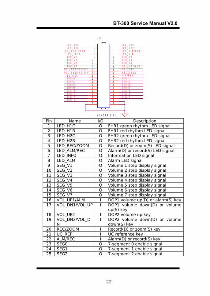
K. Key Board Connector
21
BT-300 Service Manual V2.0
S E G E 6
J 1 3
H E A D E R 2 0 X 2
24681 01 21 41 61 82 02 22 42 62 83 03 23 43 63 84 0
13579
1 11 31 51 71 92 12 32 52 72 93 13 33 53 73 9
L E D _ I N F O
S E G _ V 5
S E G E 0
L E D _ H 1 R
L E D _ R E C / Z O O M
S E G _ C
L E D _ H 2 RL E D _ H 2 G
V O L _ U P 1 / A L M
R E C / Z O O M
L E D _ A L M / R E C
S E G E 1
L E D _ H 1 G
S E G _ B
S E G _ V 6S E G _ V 3
V O L _ U P 2
L E D _ A L M
S E G _ V 7V O L _ D N 1 / V O L _ U P
A L M / R E C
S E G _ E
S E G E 2
S E G _ AS E G _ D
V O L _ D N 2 / V O L _ D N
S E G _ V 4
S E G E 5S E G E 3
U C _ R E F
S E G _ V 1 S E G _ V 2
S E G _ FS E G _ G
S E G E 7S E G E 4
Pin Name I/O Description1 LED_H1G O FHR1 green rhythm LED signal2 LED_H1R O FHR1 red rhythm LED signal3 LED_H2G O FHR2 green rhythm LED signal4 LED_H2R O FHR2 red rhythm LED signal5 LED_REC/ZOOM O Record(D) or zoom(S) LED signal6 LED_ALM/REC O Alarm(D) or record(S) LED signal7 LED_INFO O Information LED signal8 LED_ALM O Alarm LED signal9 SEG_V1 O Volume 1 step display signal
10 SEG_V2 O Volume 2 step display signal11 SEG_V3 O Volume 3 step display signal12 SEG_V4 O Volume 4 step display signal13 SEG_V5 O Volume 5 step display signal14 SEG_V6 O Volume 6 step display signal15 SEG_V7 O Volume 7 step display signal16 VOL_UP1/ALM I DOP1 volume up(D) or alarm(S) key17 VOL_DN1/VOL_UP I DOP1 volume down(D) or volume
up(S) key18 VOL_UP2 I DOP2 volume up key19 VOL_DN2/VOL_D
NI DOP2 volume down(D) or volume
down(S) key20 REC/ZOOM I Record(D) or zoom(S) key21 UC_REF I UC reference key22 ALM/REC I Alarm(D) or record(S) key23 SEG0 O 7-segment 0 enable signal24 SEG1 O 7-segment 1 enable signal25 SEG2 O 7-segment 2 enable signal
22

BT-300 Service Manual V2.0
26 SEG3 O 7-segment 3 enable signal27 SEG4 O 7-segment 4 enable signal28 SEG5 O 7-segment 5 enable signal29 SEG6 O 7-segment 6 enable signal30 SEG7 O 7-segment 7 enable signal31 SEGA O 7-segment A display signal32 SEGB O 7-segment B display signal33 SEGC O 7-segment C display signal34 SEGD O 7-segment D display signal35 SEGE O 7-segment E display signal36 SEGF O 7-segment F display signal37 SEGG O 7-segment G display signal38 GND - Ground39 GND - Ground40 GND - Ground* D : dual, S : single
L. TPH Connector
S T R O B E 0
/ T P H _ L E
S T R O B E 1
D V P 5
T P H _ C K
P V P 2 4
T P H _ D I
J 9
1 5 P
123456789
1 01 11 21 31 41 5
Pin Name I/O Description1 PVP24 O +24V power2 PVP24 O +24V power3 GND - Ground4 GND - Ground5 DVP5 O +5V power6 NC - -7 STROBE
0O TPH strobe 0 signal
8 STROBE1
O TPH strobe 1 signal
23

BT-300 Service Manual V2.0
9 TPH_CK O TPH clock signal10 /TPH_LE O TPH LE signal (active low)11 TPH_DI O TPH data signal12 GND - Ground13 GND - Ground14 PVP24 O +24V power15 PVP24 O +24V power
M. Motor Connector
M C K 0
M C K 2
C 1 3 8
J 1 2
6 P
123456P V P 2 4
M C K 1
I V P 1 6
U 2 8
T D 6 2 0 6 4 A F
36
1 11 4
2791 6
81
18
17
B 1B 2B 3B 4
C 1C 2C 3C 4
K 2 & 3K 1 & 4
G2
G1
C 1 4 1
M C K 3
Pin Name I/O Description1 MCK0 O Motor clock 0 signal2 MCK1 O Motor clock 1 signal3 MCK2 O Motor clock 2 signal4 MCK3 O Motor clock 3 signal5 PVP24 O +24V power6 PVP24 O +24V power
N. Printer Door Check ConnectorJ 1 4
5 2 6 7 - 212
s i g n a l
Pin Name I/O Description1 SIGNAL I Door open check signal2 GND - Ground
O. Printer Paper Check Connector
24

BT-300 Service Manual V2.0
R 1 6 1
U 2 2 F
7 4 H C 0 4
1 31 2
147U 2 2 E
7 4 H C 0 4
1 11 0
147
P A P E R
D V P 5
J 1 7
5 2 6 7 - 3
123
R 1 6 0
R 1 5 9
Pin Name I/O Description1 LL O Level signal2 DVP5 O +5V power3 PAP I Paper check signal
2.2.3 Key Board
Circuit Diagram
25

BT-300 Service Manual V2.0
S E G _ D
S E G _ G
S E G _ D
L E D _ I N F O
U C _ R E F
S E G _ E
S E G _ C
V O L _ U P 2
D 1
1
2
3
4
5
6
7
8 9
1 0
1 1
1 2
1 3
1 4
1 5
1 6D P
G
F
E
D
C
B
A 9
1 0
1 1
1 2
1 3
1 4
1 5
1 6S E G _ B
S E G _ E
U 3
123456789 1 0
1 11 21 31 41 51 61 71 8
1 E1 D1 C1 D P2 E2 D2 G2 C2 D P 2 B
2 A2 F
2 C O M1 C O M
1 B1 A1 G1 F
S E G _ FS E G _ V 5
S W 3
1 2
J 1
H E A D E R 2 0 X 2
24681 01 21 41 61 82 02 22 42 62 83 03 23 43 63 84 0
13579
1 11 31 51 71 92 12 32 52 72 93 13 33 53 73 9
S E G _ AS E G _ C
S E G E 7
L E D _ A L M / R E CL E D _ I N F O
S E G E 2
S E G _ A
S E G _ D
V O L _ D N 1 / V O L _ U P
R E C / Z O O M
S E G E 4
S E G E 3
L E D _ H 1 R
U C _ R E F
A L M / R E C
L E D _ A L M
S W 6
1 2
S E G _ B
S E G _ D
D 4
P C B - 1 0 0 - K E Y - P 0 2 . D S N C
B T 3 0 0 D / S K E Y C I R C U I T d e s i g n e d b y B i s t o s R & D D e p t .
A
1 1, 9 1 6 , 2 0 0 3화 요 일 월
T i t l e
S i z e D o c u m e n t N u m b e r R e v
D a t e : S h e e t o f
S E G _ A
L E D _ A L M / R E C
S E G _ E
S E G _ D
S E G _ V 4S E G _ C
S E G _ B
S E G _ F
L E D _ H 2 R
V O L _ U P 2
S E G _ V 2
S E G E 1
S E G _ V 3
A L M / R E C
S E G _ V 2
D 2
S W 4
1 2
S E G _ E
S E G _ V 3
S E G E 4
L E D _ H 2 G
L E D _ R E C / Z O O M
S E G _ V 7
S E G _ C
L E D _ H 1 G
V O L _ U P 1 / A L M
D 7
S E G _ G
L E D _ H 1 R
S E G _ F
S E G E 6
D 5
S E G E 2
S E G _ V 5S E G _ G
S E G E 3
S E G _ V 7
S W 1
1 2
S E G E 5
S E G _ V 1
S E G E 6
S E G _ V 6
S W 5
1 2
L E D _ R E C / Z O O M
S E G _ B
L E D _ H 2 G
S E G E 7
L E D _ A L M
D 6
U 2
87
91 01 11 2 1
2345
D 3B
D 2FAD 1 E
DD P
CGS E G E 1
S E G _ C
L E D _ H 2 R
S E G E 5
V O L _ D N 2 / V O L _ D N
U 1
87
91 01 11 2 1
2345
D 3B
D 2FAD 1 E
DD P
CG
S E G _ A
R E C / Z O O M
S E G _ F
S E G _ V 6
S E G _ V 1
S E G _ A
S W 2
1 2
S E G E 0
S E G _ V 4
V O L _ D N 1 / V O L _ U P
S E G E 0
S E G _ G
S E G _ F
S W 7
1 2
S E G _ BS E G _ G
V O L _ U P 1 / A L M V O L _ D N 2 / V O L _ D N
S E G _ E
D 3L E D _ H 1 G
Technical DescriptionFHR and UA are displayed on the 7-segment U1, U2, U3 and signal quality is displayed on the two colors LED D2, D4.D3, D5, D6, D7 LED display the state of alarm, recording, zoom and information operation respectively. SW1 ~ SW7 are key switches.D1 is displayed the volume step.
ConnectionThis connection is same as the key board connection in main board.
2.3 Doppler Probe
26

BT-300 Service Manual V2.0
2.3.1 Composition
① Ultrasound Sensor② Doppler Case③ Probe Cable
2.4 UC Probe
2.4.1 Composition
27
①
②
③
①
①

BT-300 Service Manual V2.0
① UC Board② UC Case③ Probe Cable
2.4.2 Technical Description
Circuit Diagram
28
②③

BT-300 Service Manual V2.0
P C B - 1 0 0 - U C - P 0 2 . D S N C
B T 3 0 0 D / S U C P R O B E C I R C U I T b y B i s t o s R & D D e p t .
A
1 1, 9 1 6 , 2 0 0 3화 요 일 월
T i t l e
S i z e D o c u m e n t N u m b e r R e v
D a t e : S h e e t o f
UCV
B1
A V P 1
V 1 5
1
R 8
A V P 1 2
G N D 1
V 1 2
1
R 5
R 6
G 3
1
+
-
U 1 C
T L 0 6 4
1 0
98
41
1
V 1 6
1
U C _ R E F
U C _ R E F
V 1 4
1
R 3
U 2
7 8 L 0 5
1 3
2
O U T I N
GN
D
U C _ R E F
UCM1
G 2
1
U C _ R E F
V 6
1
V R 1
13
2
V 1
1
R 4
V 3
1
C 2
V 2
1
R 7
V 8
1
R 1 2
A V P 1 2
G 4
1
V R 21 3
2A V P 1 2
U C _ O U T 1
V 7
1
C 1
UCP1
+
-
U 1 B
T L 0 6 4
5
67
411
V 1 3
1
A V P 1 2
V 5
1
R 1 1
J P 1
1 2 3
G 1
1
V 1 7
1
V 9
1
V 1 0
1
V 4
1
V 1 1
1
R 9
S G N D 1
R 1 0
+
-
U 1 A
T L 0 6 4
3
21
41
1
C 3
J P 2
1
2
3
4
R 1
Technical Description
The uterine contraction is converted to electrical signal by using pressure sensor “strain gauge“. This signal is compensated the difference of production by adjusting the offset and gain. And it is transmitted to main board.
Connection
Pin Name I/O Description1 UC_OUT
1O UC output
2 GND1 - Ground3 AVP12 I +12V power4 SGND1 - Shield ground
29

BT-300 Service Manual V2.0
Section 3. Troubleshooting
3.1Warning Sign Occasion and Status Checking
1 After the monitor power on, Information sound rings once.
2 If the ultrasound transducer pulls out of the connector during
monitoring(error #4), it rings once every 3 seconds until the
transducer is connected to the connector or pressing the
ALM(alarm) pushbutton causes the alarm function disable.
3 When the REC(record) pushbutton is pressed for recording in case
of print door open or under recording, when the door is opened, it
rings once every 3 seconds and “ERR 1” - “REC ERR 1” in BT-300D
-appears in the FHR and UC display as shown below until the door
is closed or pressing the ALM(alarm) pushbutton causes the alarm
function to be disabled and return to the normal monitoring mode.
[Figure 4.1 Front Panel for BT-300S]
[Figure 4.2 Front Panel for BT-300D]
4 When the REC(record) pushbutton is pressed for recording in case
of paper empty or printer door open, or when the paper runs out
under recording, it rings once every 3 seconds and “ERR 2” - “REC
ERR 2” in BT-300D - appears in the FHR and the UC display until
the paper is installed or pressing the ALM(alarm) pushbutton
causes the alarm function to be disabled and go back to the
normal monitoring mode.
30

BT-300 Service Manual V2.0
5 When the auto-printing period is expired, it rings once, right after
stop recording.
Error Number Cause Solution
1 Printer door open Close the door
2 Paper empty Insert the paper
3 Printer door open & Paper empty
Close the door & Insert the paper
4 Dop1 probe open under normal operation Connect the Dop1 probe
5 Dop2 probe open under normal operation Connect the Dop2 probe
[Table 4.1 Errors and Trouble shooting]
Alarm Occasion and Status Checking Up
When the measured FHR is beyond the alarm setting range for more
than 20 seconds during monitoring, it rings every 3 second until the
FHR is within the alarm setting range at least once or pressing the
ALM(alarm) pushbutton causes the alarm function to be disabled on
purpose.
3.2Troubleshooting on the Other Situation
3.2.1 Power operation
Not operate the power
31

BT-300 Service Manual V2.0
1 Check AC input supply 110/220 V 2 Check +16V Power Adaptor output replace Power Adaptor3 Check DC power in Main Board
+16V (IVP16) : L2 point+24V (PVP24) : U29 - D10 point+5V (DVP5) : U35 - 4pin+3.3V (DVP3.3) : U31 - 2pin+1.8V (DVP2.8) : U36 - 2pin+12V (AVP12) : U9 - 3pin+5V (AVP5) : U10 - 1pin
3.2.2 Doppler operation
Not display the HR value1 Check HR signal in Main Board DOP1_HR signal : U4C-8pin2 Refer to display operation
Not hear the Doppler sound1 Check sound signal in Main Board
DOP1_S signal : U6C-8pin2 Check volume operation U53 Refer to sound operation
3.2.3 UC operation
Not display the UC value1 Check UC signal in Main Board U7C - 8pin2 Refer to display operation
3.2.4 Sound operation
Not hear the Alarm / Information sound1 Check the PWM U43 - 36pin2 Check the Audio Amp U8
3.2.5 Key operation
Not operate the key1 Check Main Board / Key Board cable re-connection (J13)2 Check the key input signal in Main Board U21 - input
3.2.6 Display operation
32

BT-300 Service Manual V2.0
Not operate the display 1 Check Main Board / Key Board cable re-connection (J13)2 Check the display output signal in Main Board
U11, U13, U15, U19 - output
3.2.7 Print operation
Not operate print1 Check the cable Main Board / Print Engine
re-connection (J9, J12, J14, J17) 2 Check the TPH control signal in Main Board
U43 - 5pin, 22pin, 24pin, U27 – 14pin, 15pin3 Check the motor control signal in Main Board
U27 - 19in, 18pin, 17pin, 16pin
3.2.8 RS-232C operation
Not operate serial communication1 Check the serial in/out signal in Main Board U26
Section 4. Maintenance and Cleaning
4.1Maintenance and Cleaning
You can keep BT-300 clean in many different ways. Use the
following recommendations to avoid the damage or stain of the
machine.
If you use the material that is not approved, it may cause damage
33

BT-300 Service Manual V2.0
to the product. In this case, the product will not be guaranteed even
within warranty period.
Caution
Check the main unit and the probes thoroughly after cleaning.Do not use the old and damaged equipment.
To keep the machine clean, apply alcohol on a soft cloth and scrub
the body and the probe once a month. Do not use lacquer, thinner,
ethylene, or the oxidizing substance.
Keep the probes from dust or stain. Wipe the cable with a soaked
cloth that is wet with warm water (40℃ / 104℉), and with the clinical
alcohol once a week.
Do not soak the machine or the probes into any liquid or detergent.
Keep the machine or the probes away from any liquid.
4.2Regular Inspection
Perform the periodical safety inspection on BT-300 once a year. For
the inspection details, see the service manual provided by BISTOS
Co., Ltd.
.
34

BT-300 Service Manual V2.0
Section 5. Specifications
Ultrasound Mode
Technique: Pulsed Doppler Wave /Autocorrelation Processing
Pulse Repetition Frequency: 3.5 KHzPulse Duration: 128㎲Center Frequency: 1MHzIntensity: <10mW/cm2Heart Rate Counting Range: 50 ~ 240 BPMFHR Accuracy: ±2% of rangeLeakage Current: <10㎂Dual Fetus
Uterine Activity Mode
Range, Tocotransducer: 0 ~ 99 Relative UnitsExcitation Voltage: +5.0VdcResolution: 1 Relative UnitBandwidth, Tocotransducer: DC ~ 0.5Hz
Power Requirements
Line Voltage: 100 ~ 250VACLine Frequency: 50 or 60HzPower Consumption: 80VA max
Physical Characteristic
Height: 19.1cm (7.5 in)Width: 18.7cm(7.4 in)Depth: 20.1cm(7.9 in)Weight: 6Kg(13.2 lbs)
Environmental Characteristics
Operating Temperature: 10℃(50℉) to 40℃(104℉)Operating Humidity: 30% ~ 85% non-condensingStorage Temperature: -10℃(14℉) to 60℃(131℉)Storage Humidity: 20% ~ 95% non-condensingOperating Atmospheric Pressure: 70 ㎪ ~ 106㎪Storage Atmospheric Pressure: 70 ㎪ ~ 106㎪
35

BT-300 Service Manual V2.0
Functional Features
FM UCDual Fetal Movement External Type
Reference (Zeroing) Control
PrinterThermal Array TypePrint Speed: 10, 20, 30 mm/minPaper Feeding FunctionPrint Contrast: 1, 2, 3 stepsAuto Print Period: 0(Off), 10, 20, 30, 40, 50, 60min
Display7-Segment LED2 Channels (HR, UC)-BT-300S/3 Channels (HR1, HR2, UC)-BT-300D
IndicatorsHeart Rhythm (Green: Stable, Red: Unstable)Alarm On/Off StatePrint On/Off StateAC Power (Green LED)
SoundDoppler Sound with Volume Control (8 steps)Alarms Sound: exceed FHR RangeInformation Sound: Doppler Probe Off, Paper Off, Door Open, Watch Dog
Set-up FunctionAlarm Upper/Lower Limit Value Event Mark FunctionPrint Speed Zoom in FunctionPrint Contrast Doppler2 Offset FunctionAuto Print Period
External LinkRS-232C: for Central Monitoring(Option)
36
BT-300 Service Manual V2.0
Service Telephone and Fax. Numbers
Telephone: 82-2-862–0642, 0643Fax: 82-2-862–0644
BISTOS Co., Ltd201, 2F, 239-15, Gasan-Dong
Geumcheon-Gu,Seoul, Korea
Model Name: BT-300
EC Representative: Econet Medical GmbhHigh-t'Park Mainstr. 6c-6d D-45768 Marl/Germany
Telephone: +49 2365 92 437 - 0Fax: +49 2365 92 437 – 55
37