Embed Size (px)
Citation preview
INSTALLATION MANUAL

Platinum Plus RReevviissiioonn:: BB WWAARRRRAANNTTYY DDoocc.. NNaammee:: PP++ IInnssttaallllaattiioonn MMaannuuaall
UWARRANTY & LIMITATION OF LIABILITY
1. ROTEM warrants that the product shall be free of defects in materials or workmanship and will conform to the technical specification for a period of 1 (one) year from the date of initial installation on sight (the "warranty period").
2. Load cells are not covered by ROTEM’s warranty.
3. ROTEM warrants that during said warranty period, any item/items or part/parts of equipment found defective with respect to materials or workmanship or which do not conform to the technical specification shall be repaired or replaced (at ROTEM's sole discretion), free of charge.
4. During the warranty period, in the event of an alleged defect, authorized resellers in relevant regions should be notified as soon as possible from the date of noticing the said defect, but no longer than thirty (30) days from such a discovery. The report shall include (1) a short description of the defects noticed (2) type of card / component and its matching serial number.
5. ROTEM's sole liability under this warranty is the repair or replacement of the defective item of product.
Conditions and Limitations
1. UROTEM will not be responsible for any labor costs or expenses associated with replacement of defective items or other parts of the product or repair.
2. This warranty shall not cover: (i) product or part therein which has been modified (without prior written approval of ROTEM), or (ii) product or part therein which has not handled or installed by an authorized reseller of ROTEM or (iii) product or part therein which has either handled or installed not in strict accordance with ROTEM's instructions, (iv) products which were used for function other than agriculture industry.
3. This warranty will not apply in the following cases: (i) if all components of the product are not originally supplied by ROTEM (ii) the defect is the result of an act of nature, lighting strikes, electrical power surge or interruption of electricity (iii) the defect is the result of accident, misuse, abuse, alteration, neglect, improper or unauthorized maintenance or repair.
ROTEM warns and alerts all users that the Product is inherently complex and may not be completely free of errors. ROTEM's products are designed and manufactured to provide reliable operation. Strict tests and quality control procedures are applied to every product. However, the possibility that something may fail beyond our control exists. Since these products are designed to operate climate control and other systems in confined livestock environments, where failure may cause severe damage, the user should provide adequate backup and alarm systems. These are to operate critical systems even in case of a ROTEM system failure. Neglecting to provide such a backup will be regarded as the user’s willingness to accept the risk of loss, injury and financial damage.
In no event will ROTEM be liable to a user or any third party for any direct, indirect, special, consequential or incidental damages, including but not limited to any damage or injury to business earnings, lost profits or goodwill, personal injury, costs of delay, any failure of delivery, costs of lost or damaged data or documentation, lost or damaged products or goods, lost sales, lost orders, lost income.
Except for the above express warranty, ROTEM makes no other warranties, express or implied, relating to the products. ROTEM disclaims and excludes the implied warranties of merchantability and fitness for a particular purpose. No person is authorized to make any other warranty or representation concerning the performance of the products other than as provided by ROTEM
Software Version:3.00 Document Version:1.0
.
Platinum Plus RReevviissiioonn:: BB WWAARRRRAANNTTYY DDoocc.. NNaammee:: PP++ IInnssttaallllaattiioonn MMaannuuaall
UTABLE OF CONTENTS
1. UNPACKING........................................................................... 1
2. MOUNTING AND SETUP ....................................................... 2
3. HIGH VOLTAGE WIRING ....................................................... 4
3.1 Platinum Plus Power Supply Wiring .................................... 4
3.2 Relay Wiring ........................................................................ 5
3.3 Winch Card Relay Wiring (optional) .................................... 7
4. EMERGENCY CARD INSTALLATION (OPTIONAL) ............. 9
5. SCALES INSTALLATION (OPTIONAL) ............................... 13
5.1 Bird Scale .......................................................................... 13
5.2 Feed Scale ........................................................................ 15
5.3 Silo Scale .......................................................................... 16
6. LOW VOLTAGE WIRING ..................................................... 17
6.1 Analog Input ...................................................................... 17
6.2 Weather Station Wiring (optional) ..................................... 20
6.3 Digital Input ....................................................................... 21
6.4 Analog Output ................................................................... 21
6.5 Alarm Card Wiring ............................................................. 22
6.6 Communication Card Wiring ............................................. 23
7. TROUBLESHOOTING .......................................................... 24
Platinum Plus PPaaggee:: 11 RReevviissiioonn:: BB CChhaapptteerr:: UUnnppaacckkiinngg DDoocc.. NNaammee:: PP++ IInnssttaallllaattiioonn MMaannuuaall
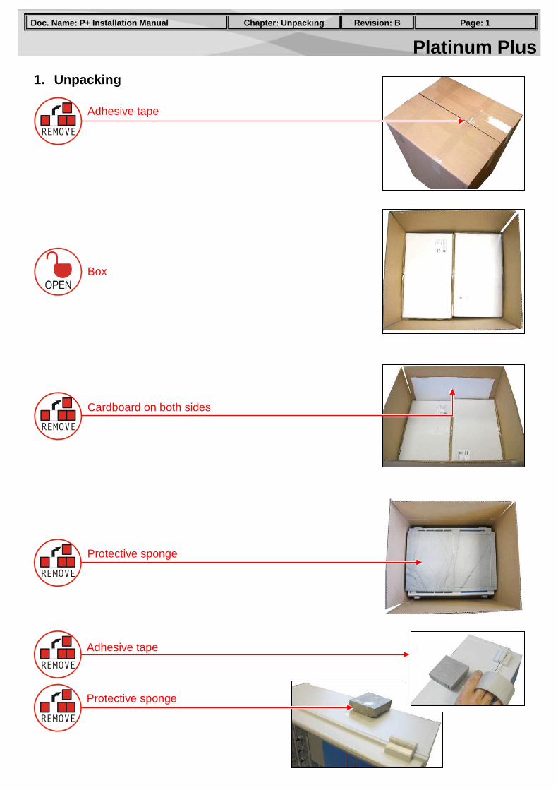
1. Unpacking
Adhesive tape
Cardboard on both sides
Box
Protective sponge
Adhesive tape
Protective sponge
Platinum Plus PPaaggee:: 22 RReevviissiioonn:: BB CChhaapptteerr:: MMoouunnttiinngg aanndd SSeettuupp DDoocc.. NNaammee:: PP++ IInnssttaallllaattiioonn MMaannuuaall
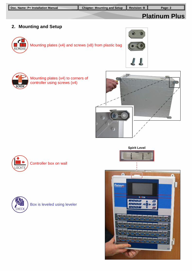
2. Mounting and Setup
Mounting plates (x4) and screws (x8) from plastic bag
Mounting plates (x4) to corners of controller using screws (x4)
Controller box on wall
Box is leveled using leveler
Spirit Level
Platinum Plus PPaaggee:: 33 RReevviissiioonn:: BB CChhaapptteerr:: MMoouunnttiinngg aanndd SSeettuupp DDoocc.. NNaammee:: PP++ IInnssttaallllaattiioonn MMaannuuaall
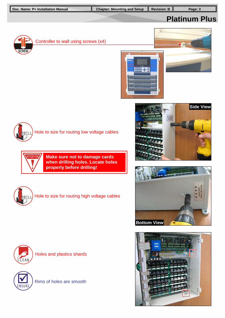
Controller to wall using screws (x4)
Hole to size for routing low voltage cables
Make sure not to damage cards when drilling holes. Locate holes properly before drilling!
Side View
Bottom View
Hole to size for routing high voltage cables
Holes and plastics shards
Rims of holes are smooth
Platinum Plus PPaaggee:: 44 RReevviissiioonn:: BB CChhaapptteerr:: HHiigghh VVoollttaaggee WWiirriinngg DDoocc.. NNaammee:: PP++ IInnssttaallllaattiioonn MMaannuuaall
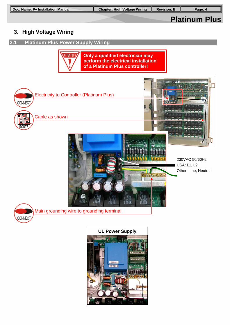
3. High Voltage Wiring
3.1 Platinum Plus Power Supply Wiring
Electricity to Controller (Platinum Plus)
Only a qualified electrician may perform the electrical installation of a Platinum Plus controller!
UL Power Supply
Cable as shown
230VAC 50/60Hz USA: L1, L2 Other: Line, Neutral
Main grounding wire to grounding terminal
Platinum Plus PPaaggee:: 55 RReevviissiioonn:: BB CChhaapptteerr:: HHiigghh VVoollttaaggee WWiirriinngg DDoocc.. NNaammee:: PP++ IInnssttaallllaattiioonn MMaannuuaall
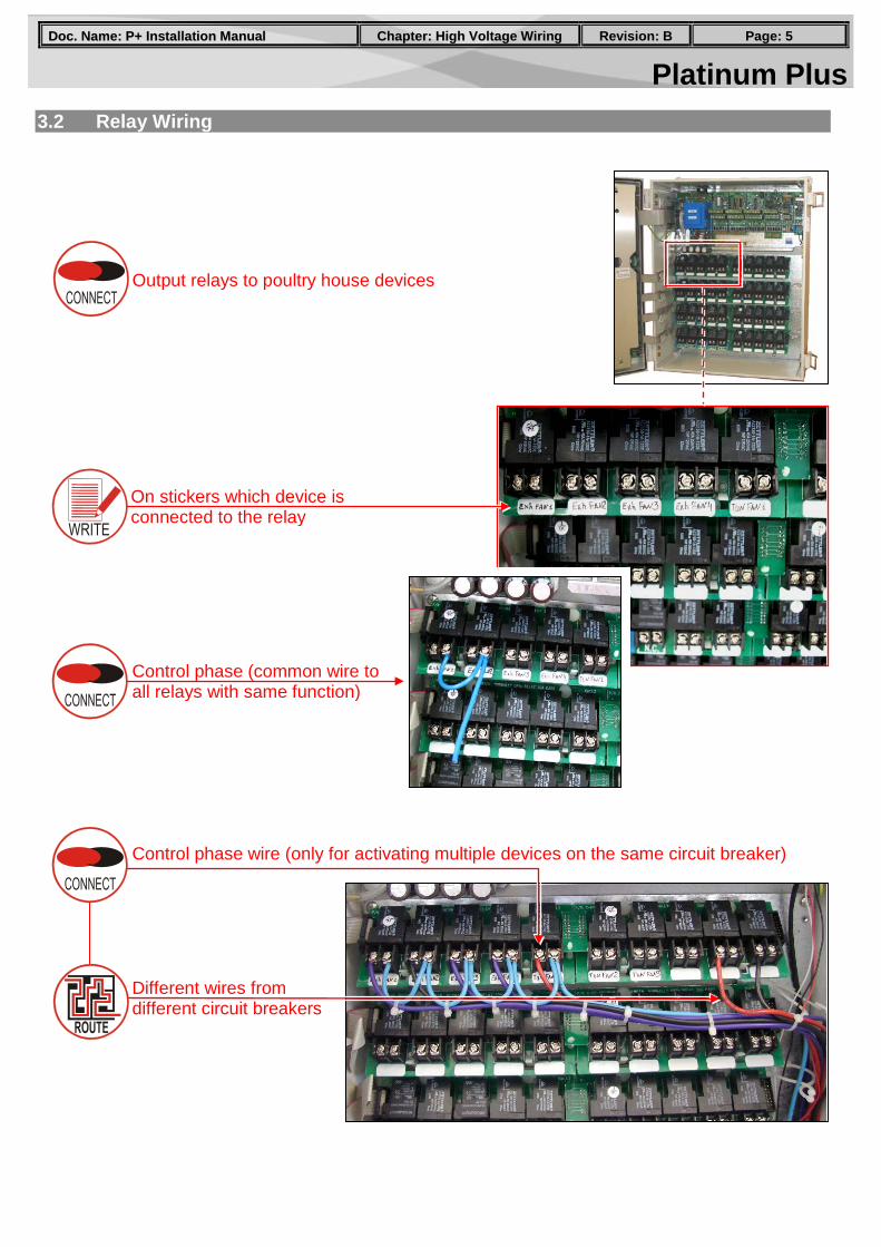
3.2 Relay Wiring
Control phase (common wire to all relays with same function)
Control phase wire (only for activating multiple devices on the same circuit breaker)
Different wires from different circuit breakers
Output relays to poultry house devices
On stickers which device is connected to the relay
Platinum Plus PPaaggee:: 66 RReevviissiioonn:: BB CChhaapptteerr:: HHiigghh VVoollttaaggee WWiirriinngg DDoocc.. NNaammee:: PP++ IInnssttaallllaattiioonn MMaannuuaall
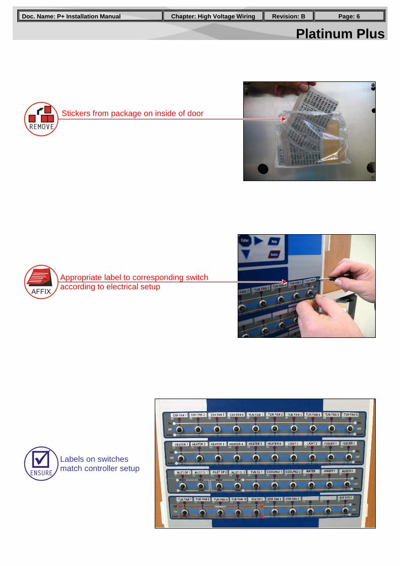
Stickers from package on inside of door
Labels on switches match controller setup
Appropriate label to corresponding switch according to electrical setup
Platinum Plus PPaaggee:: 77 RReevviissiioonn:: BB CChhaapptteerr:: HHiigghh VVoollttaaggee WWiirriinngg DDoocc.. NNaammee:: PP++ IInnssttaallllaattiioonn MMaannuuaall
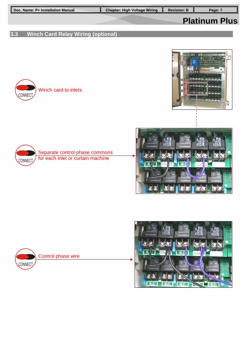
3.3 Winch Card Relay Wiring (optional)
Separate control phase commons for each inlet or curtain machine
Winch card to inlets
Control phase wire
Platinum Plus PPaaggee:: 88 RReevviissiioonn:: BB CChhaapptteerr:: HHiigghh VVoollttaaggee WWiirriinngg DDoocc.. NNaammee:: PP++ IInnssttaallllaattiioonn MMaannuuaall
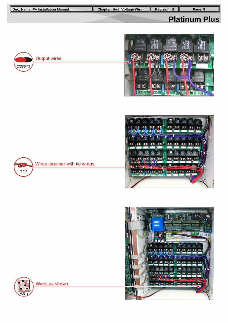
Output wires
Wires together with tie wraps
Wires as shown
Platinum Plus PPaaggee:: 99 RReevviissiioonn:: BB CChhaapptteerr:: EEmmeerrggeennccyy CCaarrdd IInnssttaallllaattiioonn DDoocc.. NNaammee:: PP++ IInnssttaallllaattiioonn MMaannuuaall
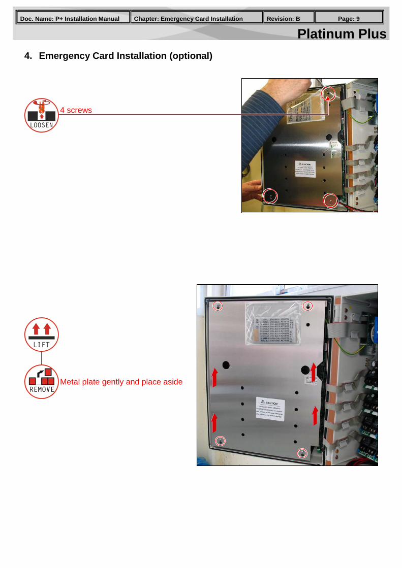
4. Emergency Card Installation (optional)
4 screws
Metal plate gently and place aside
Platinum Plus PPaaggee:: 1100 RReevviissiioonn:: BB CChhaapptteerr:: EEmmeerrggeennccyy CCaarrdd IInnssttaallllaattiioonn DDoocc.. NNaammee:: PP++ IInnssttaallllaattiioonn MMaannuuaall
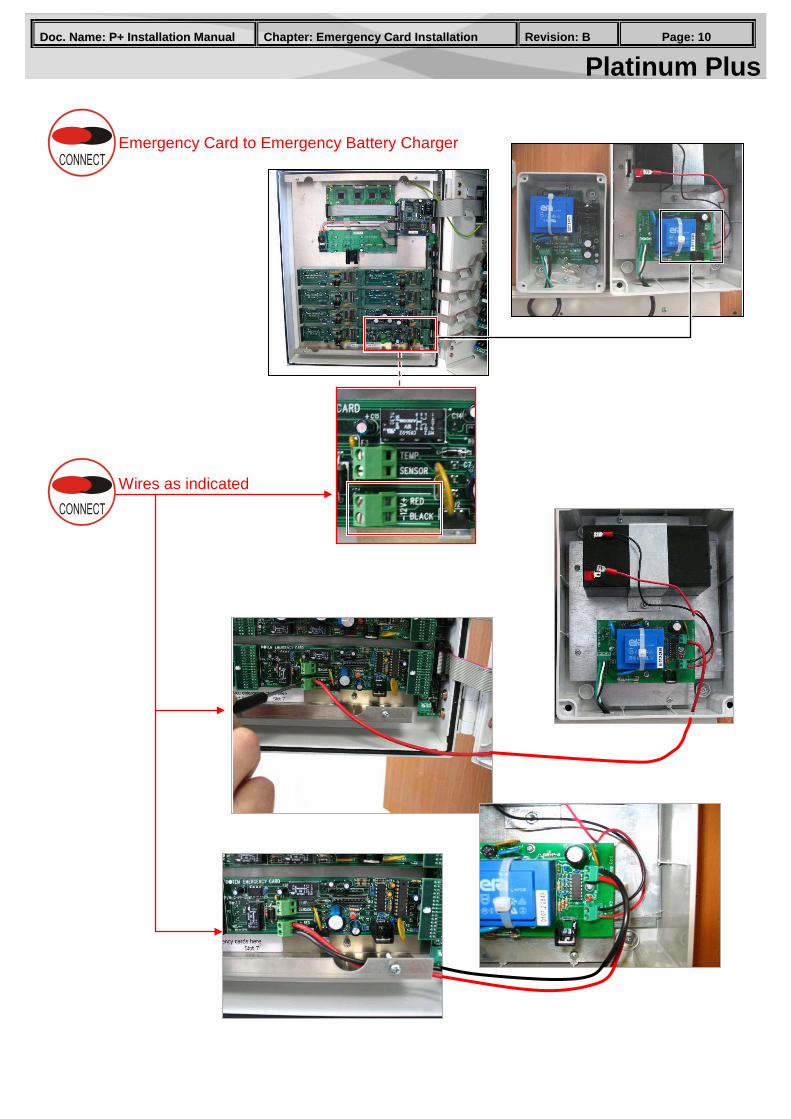
Wires as indicated
Emergency Card to Emergency Battery Charger
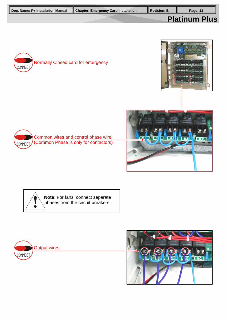
Platinum Plus PPaaggee:: 1111 RReevviissiioonn:: BB CChhaapptteerr:: EEmmeerrggeennccyy CCaarrdd IInnssttaallllaattiioonn DDoocc.. NNaammee:: PP++ IInnssttaallllaattiioonn MMaannuuaall
Normally Closed card for emergency
Common wires and control phase wire (Common Phase is only for contactors)
Output wires
Note: For fans, connect separate phases from the circuit breakers.
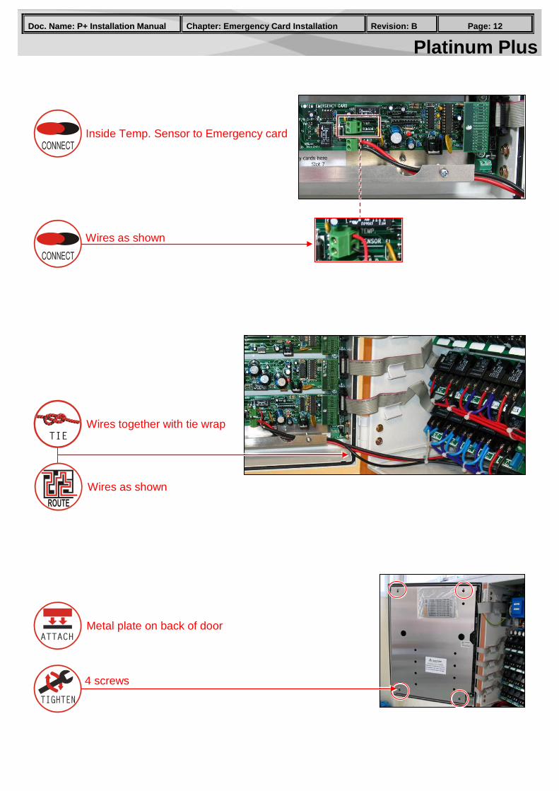
Platinum Plus PPaaggee:: 1122 RReevviissiioonn:: BB CChhaapptteerr:: EEmmeerrggeennccyy CCaarrdd IInnssttaallllaattiioonn DDoocc.. NNaammee:: PP++ IInnssttaallllaattiioonn MMaannuuaall
Inside Temp. Sensor to Emergency card
Wires as shown
Wires together with tie wrap
Wires as shown
Metal plate on back of door
4 screws
Platinum Plus PPaaggee:: 1133 RReevviissiioonn:: BB CChhaapptteerr:: SSccaalleess IInnssttaallllaattiioonn DDoocc.. NNaammee:: PP++ IInnssttaallllaattiioonn MMaannuuaall
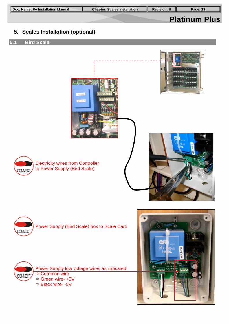
5. Scales Installation (optional)
5.1 Bird Scale
Electricity wires from Controller to Power Supply (Bird Scale)
Power Supply (Bird Scale) box to Scale Card
Power Supply low voltage wires as indicated Common wire Green wire- +5V Black wire- -5V
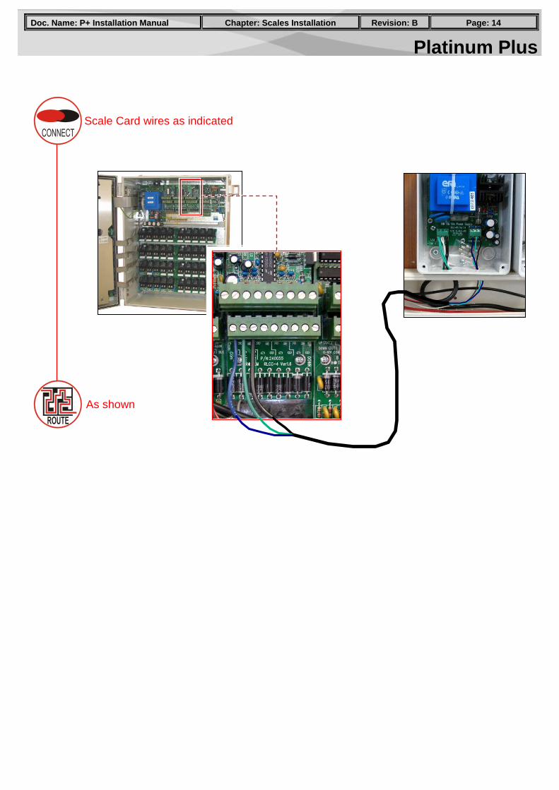
Platinum Plus PPaaggee:: 1144 RReevviissiioonn:: BB CChhaapptteerr:: SSccaalleess IInnssttaallllaattiioonn DDoocc.. NNaammee:: PP++ IInnssttaallllaattiioonn MMaannuuaall
As shown
Scale Card wires as indicated
Platinum Plus PPaaggee:: 1155 RReevviissiioonn:: BB CChhaapptteerr:: SSccaalleess IInnssttaallllaattiioonn DDoocc.. NNaammee:: PP++ IInnssttaallllaattiioonn MMaannuuaall
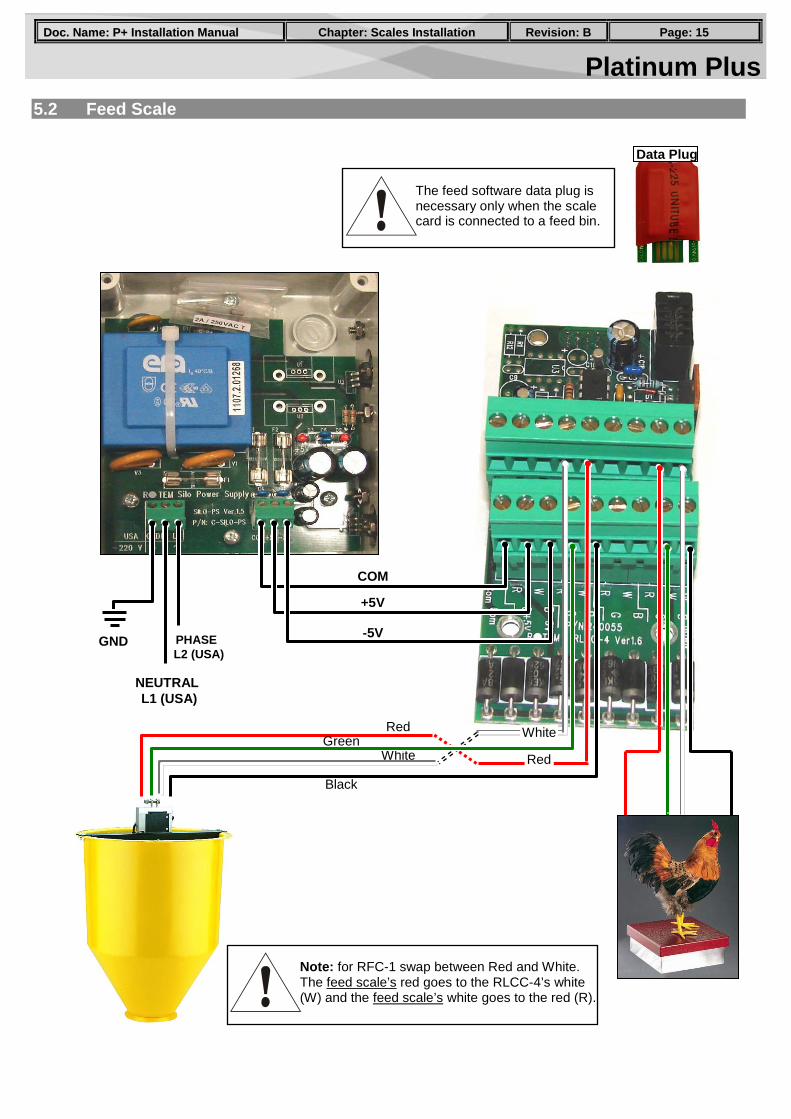
5.2 Feed Scale
Data Plug
230VAC
GND
COM
+5V
-5V PHASE L2 (USA)
NEUTRAL L1 (USA)
Red
White Red
White
Note: for RFC-1 swap between Red and White. The feed scale’s red goes to the RLCC-4’s white (W) and the feed scale’s white goes to the red (R).
The feed software data plug is necessary only when the scale card is connected to a feed bin.
Green
Black
Platinum Plus PPaaggee:: 1166 RReevviissiioonn:: BB CChhaapptteerr:: SSccaalleess IInnssttaallllaattiioonn DDoocc.. NNaammee:: PP++ IInnssttaallllaattiioonn MMaannuuaall
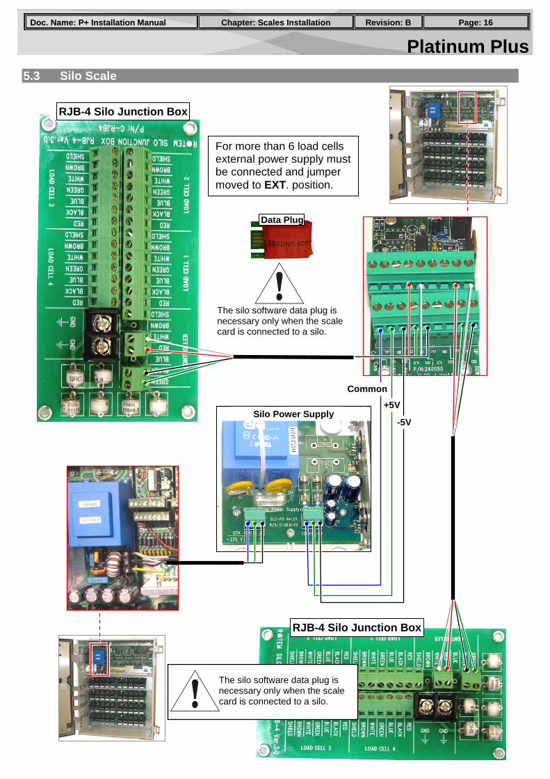
5.3 Silo Scale
RJB-4 Silo Junction Box
RJB-4 Silo Junction Box
Silo Power Supply
For more than 6 load cells external power supply must be connected and jumper moved to EXT. position.
+5V
Common
-5V
The silo software data plug is necessary only when the scale card is connected to a silo.
Data Plug
The silo software data plug is necessary only when the scale card is connected to a silo.
Platinum Plus PPaaggee:: 1177 RReevviissiioonn:: BB CChhaapptteerr:: CCoonnttrroolllleerr CCoonnffiigguurraattiioonn DDoocc.. NNaammee:: PP++ IInnssttaallllaattiioonn MMaannuuaall
6. Low Voltage Wiring
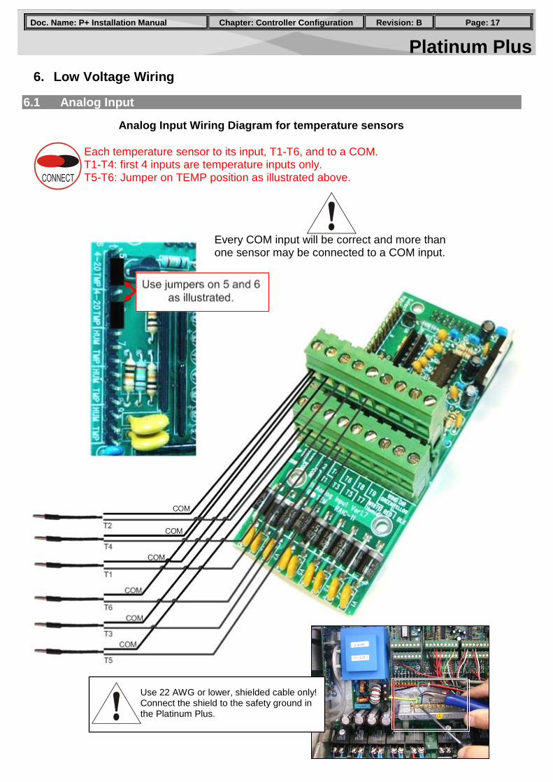
6.1 Analog Input
Each temperature sensor to its input, T1-T6, and to a COM. T1-T4: first 4 inputs are temperature inputs only. T5-T6: Jumper on TEMP position as illustrated above.
Analog Input Wiring Diagram for temperature sensors
Every COM input will be correct and more than one sensor may be connected to a COM input.
Use 22 AWG or lower, shielded cable only! Connect the shield to the safety ground in the Platinum Plus.
Platinum Plus PPaaggee:: 1188 RReevviissiioonn:: BB CChhaapptteerr:: CCoonnttrroolllleerr CCoonnffiigguurraattiioonn DDoocc.. NNaammee:: PP++ IInnssttaallllaattiioonn MMaannuuaall
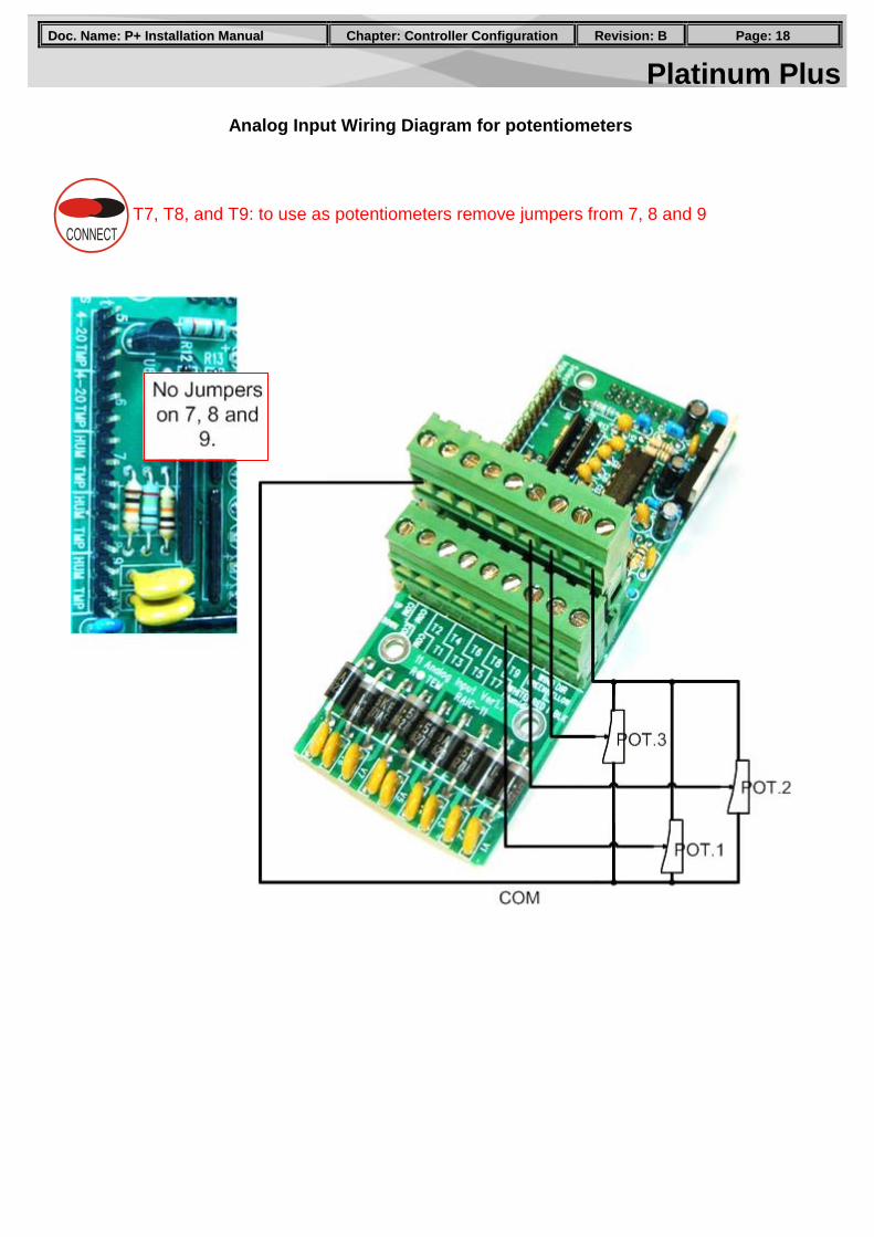
Analog Input Wiring Diagram for potentiometers
T7, T8, and T9: to use as potentiometers remove jumpers from 7, 8 and 9
Platinum Plus PPaaggee:: 1199 RReevviissiioonn:: BB CChhaapptteerr:: CCoonnttrroolllleerr CCoonnffiigguurraattiioonn DDoocc.. NNaammee:: PP++ IInnssttaallllaattiioonn MMaannuuaall
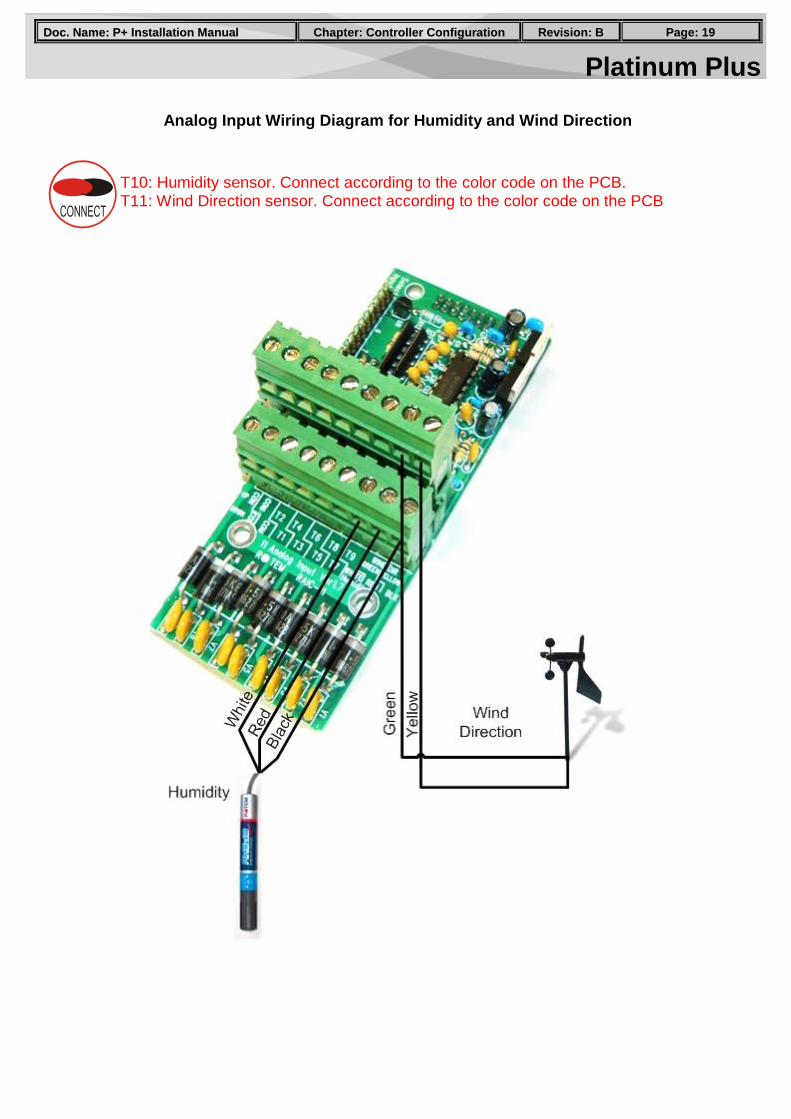
Analog Input Wiring Diagram for Humidity and Wind Direction
T10: Humidity sensor. Connect according to the color code on the PCB. T11: Wind Direction sensor. Connect according to the color code on the PCB
Platinum Plus PPaaggee:: 2200 RReevviissiioonn:: BB CChhaapptteerr:: CCoonnttrroolllleerr CCoonnffiigguurraattiioonn DDoocc.. NNaammee:: PP++ IInnssttaallllaattiioonn MMaannuuaall
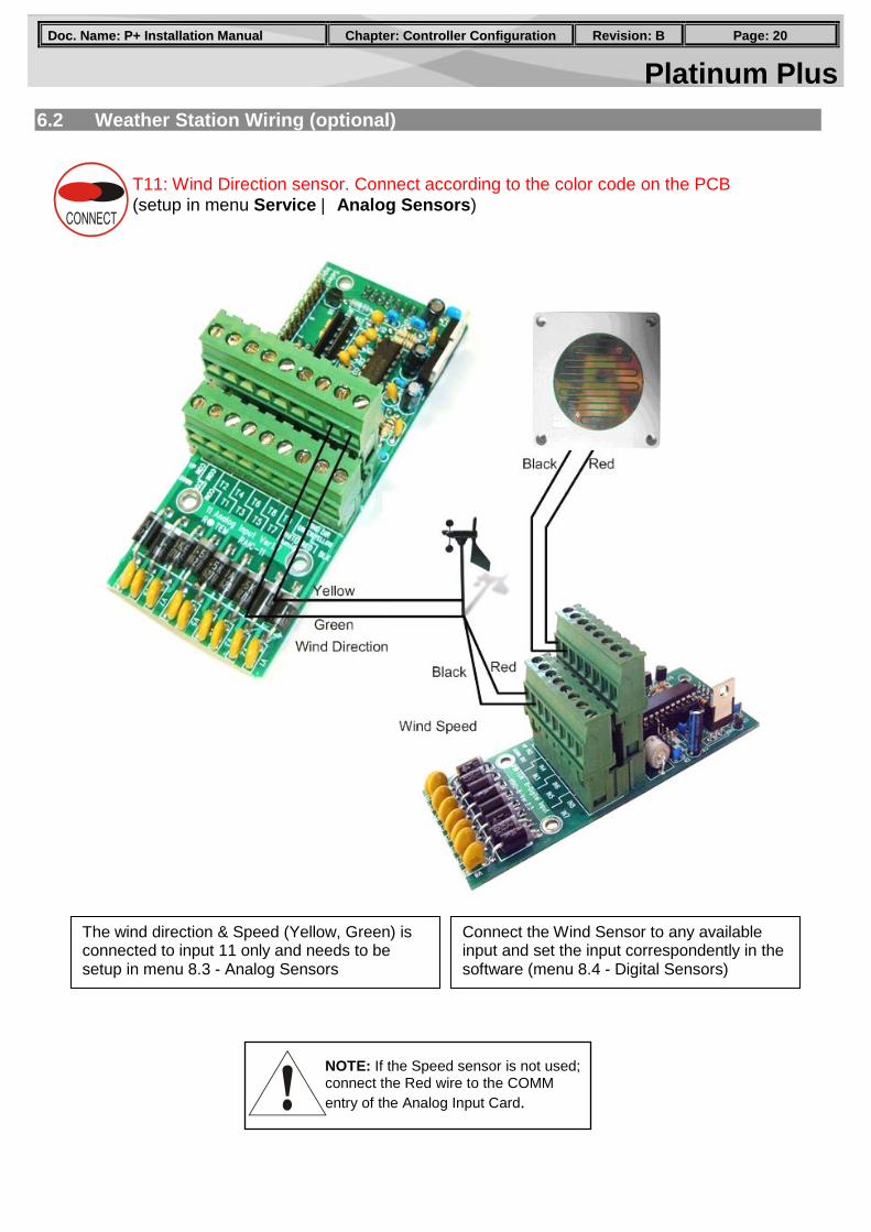
6.2 Weather Station Wiring (optional)
Connect the Wind Sensor to any available input and set the input correspondently in the software (menu 8.4 - Digital Sensors)
The wind direction & Speed (Yellow, Green) is connected to input 11 only and needs to be setup in menu 8.3 - Analog Sensors
NOTE: If the Speed sensor is not used; connect the Red wire to the COMM entry of the Analog Input Card.
T11: Wind Direction sensor. Connect according to the color code on the PCB (setup in menu Service | Analog Sensors)
Platinum Plus PPaaggee:: 2211 RReevviissiioonn:: BB CChhaapptteerr:: CCoonnttrroolllleerr CCoonnffiigguurraattiioonn DDoocc.. NNaammee:: PP++ IInnssttaallllaattiioonn MMaannuuaall
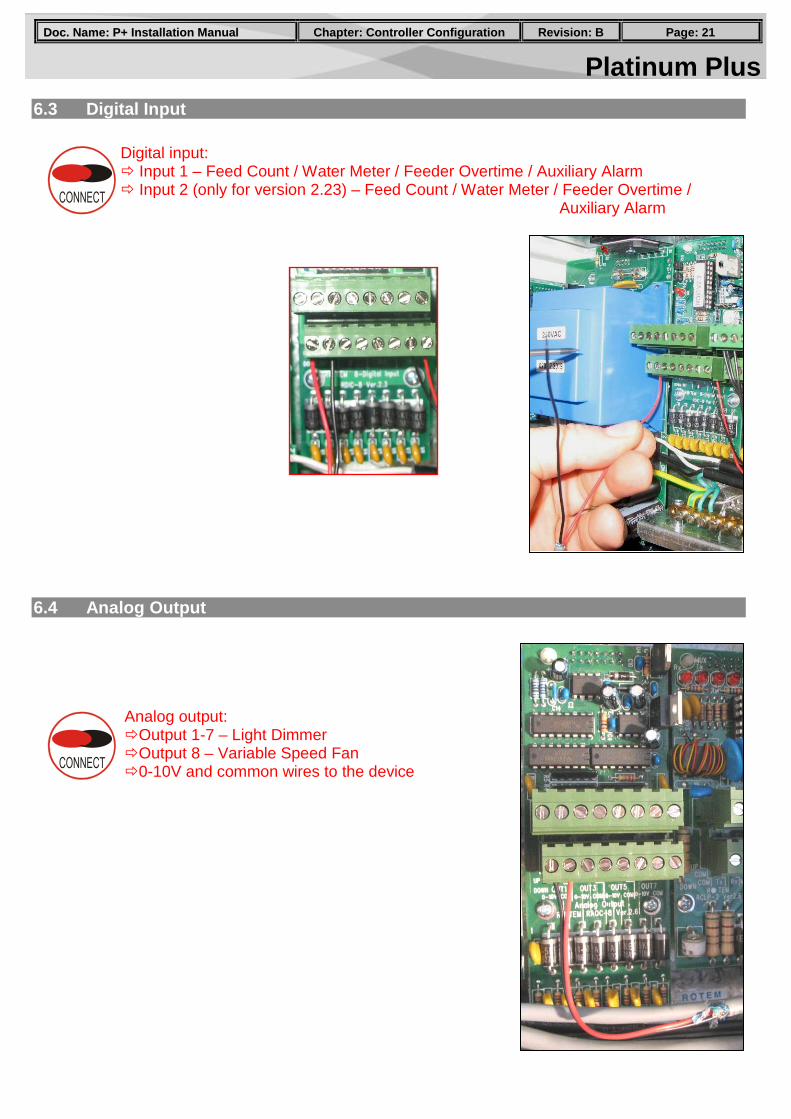
6.3 Digital Input
6.4 Analog Output
Digital input: Input 1 – Feed Count / Water Meter / Feeder Overtime / Auxiliary Alarm Input 2 (only for version 2.23) – Feed Count / Water Meter / Feeder Overtime /
Auxiliary Alarm
Analog output: Output 1-7 – Light Dimmer Output 8 – Variable Speed Fan 0-10V and common wires to the device
Platinum Plus PPaaggee:: 2222 RReevviissiioonn:: BB CChhaapptteerr:: CCoonnttrroolllleerr CCoonnffiigguurraattiioonn DDoocc.. NNaammee:: PP++ IInnssttaallllaattiioonn MMaannuuaall
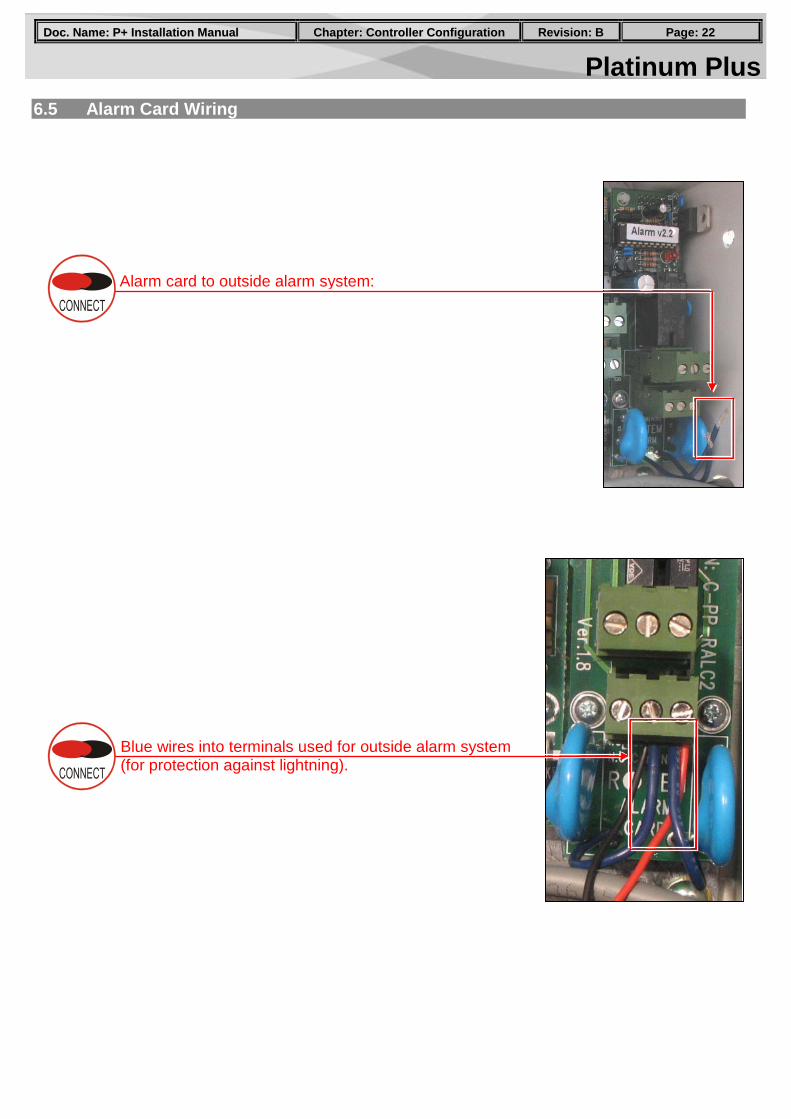
6.5 Alarm Card Wiring
Alarm card to outside alarm system:
Blue wires into terminals used for outside alarm system (for protection against lightning).
Platinum Plus PPaaggee:: 2233 RReevviissiioonn:: BB CChhaapptteerr:: CCoonnttrroolllleerr CCoonnffiigguurraattiioonn DDoocc.. NNaammee:: PP++ IInnssttaallllaattiioonn MMaannuuaall
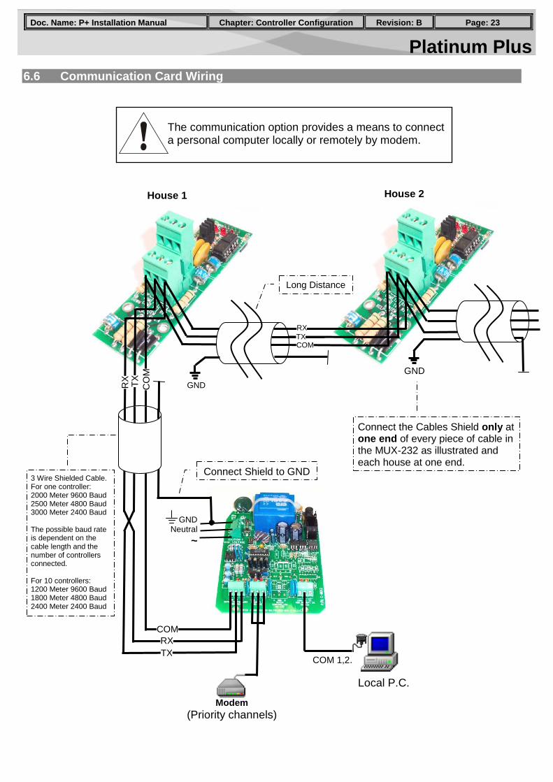
6.6 Communication Card Wiring
Modem (Priority channels)
COM 1,2.
Local P.C.
COM RX TX
CO
M
GND Neutral
~
GND
TX R
X
RX TX
COM
GND
House 1 House 2
Long Distance
Connect Shield to GND
Connect the Cables Shield only at one end of every piece of cable in the MUX-232 as illustrated and each house at one end.
3 Wire Shielded Cable. For one controller: 2000 Meter 9600 Baud 2500 Meter 4800 Baud 3000 Meter 2400 Baud The possible baud rate is dependent on the cable length and the number of controllers connected. For 10 controllers: 1200 Meter 9600 Baud 1800 Meter 4800 Baud 2400 Meter 2400 Baud
The communication option provides a means to connect a personal computer locally or remotely by modem.
Platinum Plus PPaaggee:: 2244 RReevviissiioonn:: BB CChhaapptteerr:: AAppppeennddiixx DDoocc.. NNaammee:: PP++ IInnssttaallllaattiioonn MMaannuuaall
7. Troubleshooting
Display Problem Possible Cause Possible Solution
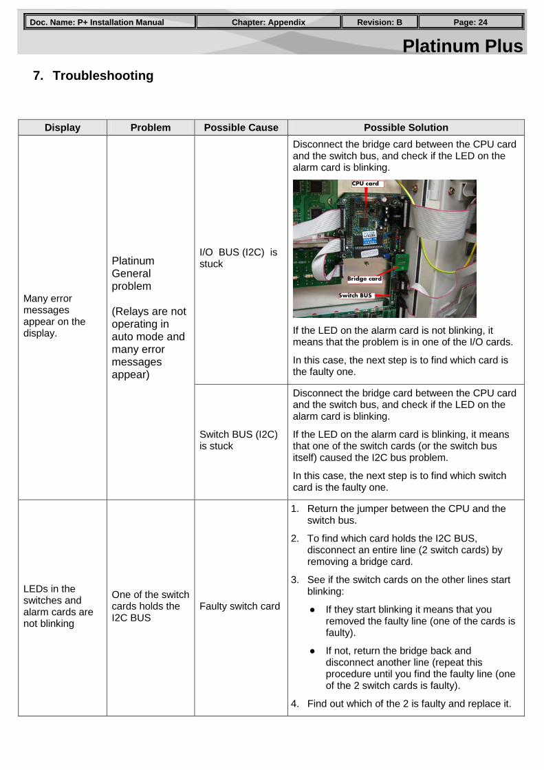
Many error messages appear on the display.
Platinum General problem (Relays are not operating in auto mode and many error messages appear)
I/O BUS (I2C) is stuck
Disconnect the bridge card between the CPU card and the switch bus, and check if the LED on the alarm card is blinking.
If the LED on the alarm card is not blinking, it means that the problem is in one of the I/O cards.
In this case, the next step is to find which card is the faulty one.
Switch BUS (I2C) is stuck
Disconnect the bridge card between the CPU card and the switch bus, and check if the LED on the alarm card is blinking.
If the LED on the alarm card is blinking, it means that one of the switch cards (or the switch bus itself) caused the I2C bus problem.
In this case, the next step is to find which switch card is the faulty one.
LEDs in the switches and alarm cards are not blinking
One of the switch cards holds the I2C BUS
Faulty switch card
1. Return the jumper between the CPU and the switch bus.
2. To find which card holds the I2C BUS, disconnect an entire line (2 switch cards) by removing a bridge card.
3. See if the switch cards on the other lines start blinking:
● If they start blinking it means that you removed the faulty line (one of the cards is faulty).
● If not, return the bridge back and disconnect another line (repeat this procedure until you find the faulty line (one of the 2 switch cards is faulty).
4. Find out which of the 2 is faulty and replace it.
Platinum Plus PPaaggee:: 2255 RReevviissiioonn:: BB CChhaapptteerr:: AAppppeennddiixx DDoocc.. NNaammee:: PP++ IInnssttaallllaattiioonn MMaannuuaall
Display Problem Possible Cause Possible Solution
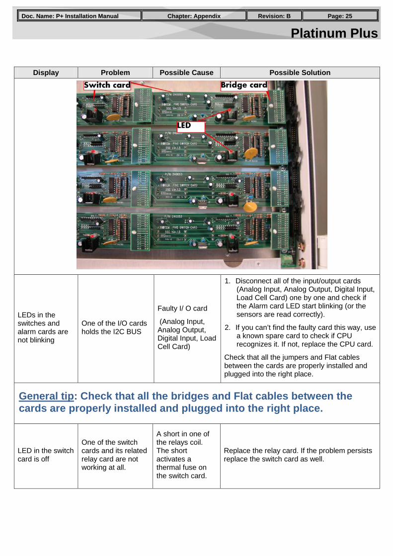
LEDs in the switches and alarm cards are not blinking
One of the I/O cards holds the I2C BUS
Faulty I/ O card
(Analog Input, Analog Output, Digital Input, Load Cell Card)
1. Disconnect all of the input/output cards (Analog Input, Analog Output, Digital Input, Load Cell Card) one by one and check if the Alarm card LED start blinking (or the sensors are read correctly).
2. If you can’t find the faulty card this way, use a known spare card to check if CPU recognizes it. If not, replace the CPU card.
Check that all the jumpers and Flat cables between the cards are properly installed and plugged into the right place.
General tip: Check that all the bridges and Flat cables between the cards are properly installed and plugged into the right place.
LED in the switch card is off
One of the switch cards and its related relay card are not working at all.
A short in one of the relays coil. The short activates a thermal fuse on the switch card.
Replace the relay card. If the problem persists replace the switch card as well.
Platinum Plus PPaaggee:: 2266 RReevviissiioonn:: BB CChhaapptteerr:: AAppppeennddiixx DDoocc.. NNaammee:: PP++ IInnssttaallllaattiioonn MMaannuuaall
Display Problem Possible Cause Possible Solution
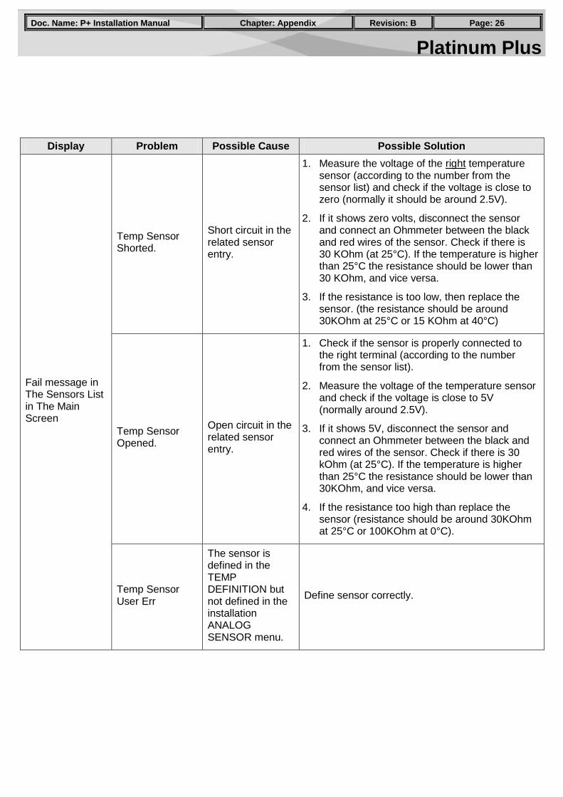
Fail message in The Sensors List in The Main Screen
Temp Sensor Shorted.
Short circuit in the related sensor entry.
1. Measure the voltage of the right temperature sensor (according to the number from the sensor list) and check if the voltage is close to zero (normally it should be around 2.5V).
2. If it shows zero volts, disconnect the sensor and connect an Ohmmeter between the black and red wires of the sensor. Check if there is 30 KOhm (at 25°C). If the temperature is higher than 25°C the resistance should be lower than 30 KOhm, and vice versa.
3. If the resistance is too low, then replace the sensor. (the resistance should be around 30KOhm at 25°C or 15 KOhm at 40°C)
Temp Sensor Opened.
Open circuit in the related sensor entry.
1. Check if the sensor is properly connected to the right terminal (according to the number from the sensor list).
2. Measure the voltage of the temperature sensor and check if the voltage is close to 5V (normally around 2.5V).
3. If it shows 5V, disconnect the sensor and connect an Ohmmeter between the black and red wires of the sensor. Check if there is 30 kOhm (at 25°C). If the temperature is higher than 25°C the resistance should be lower than 30KOhm, and vice versa.
4. If the resistance too high than replace the sensor (resistance should be around 30KOhm at 25°C or 100KOhm at 0°C).
Temp Sensor User Err
The sensor is defined in the TEMP DEFINITION but not defined in the installation ANALOG SENSOR menu.
Define sensor correctly.
Platinum Plus PPaaggee:: 2277 RReevviissiioonn:: BB CChhaapptteerr:: AAppppeennddiixx DDoocc.. NNaammee:: PP++ IInnssttaallllaattiioonn MMaannuuaall
Display Problem Possible Cause Possible Solution
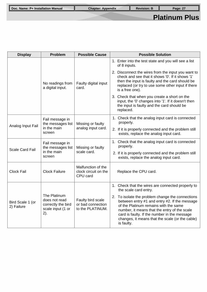
No readings from a digital input.
Faulty digital input card.
1. Enter into the test state and you will see a list of 8 inputs.
2. Disconnect the wires from the input you want to check and see that it shows '0'. If it shows '1' then the input is faulty and the card should be replaced (or try to use some other input if there is a free one).
3. Check that when you create a short on the input, the '0' changes into '1'. If it doesn't then the input is faulty and the card should be replaced.
Analog Input Fail
Fail message in the messages list in the main screen
Missing or faulty analog input card.
1. Check that the analog input card is connected properly.
2. If it is properly connected and the problem still exists, replace the analog input card.
Scale Card Fail
Fail message in the messages list in the main screen
Missing or faulty scale card.
1. Check that the analog input card is connected properly.
2. If it is properly connected and the problem still exists, replace the analog input card.
Clock Fail Clock Failure Malfunction of the clock circuit on the CPU card
Replace the CPU card.
Bird Scale 1 (or 2) Failure
The Platinum does not read correctly the bird scale input (1 or 2).
Faulty bird scale or bad connection to the PLATINUM.
1. Check that the wires are connected properly to the scale card entry.
2. To isolate the problem change the connections between entry #1 and entry #2. If the message of the Platinum remains with the same number, it means that the entry of the scale card is faulty. If the number in the message changes, it means that the scale (or the cable) is faulty.
Platinum Plus PPaaggee:: 2288 RReevviissiioonn:: BB CChhaapptteerr:: AAppppeennddiixx DDoocc.. NNaammee:: PP++ IInnssttaallllaattiioonn MMaannuuaall
Display Problem Possible Cause Possible Solution
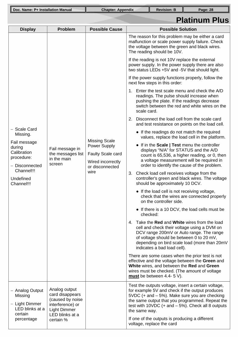
− Scale Card Missing.
Fail message during Calibration procedure:
− Disconnected Channel!!!
Undefined Channel!!!
Fail message in the messages list in the main screen
Missing Scale Power Supply
Faulty Scale card
Wired incorrectly or disconnected wire
The reason for this problem may be either a card malfunction or scale power supply failure. Check the voltage between the green and black wires. The reading should be 10V.
If the reading is not 10V replace the external power supply. In the power supply there are also two status LEDs +5V and -5V that should light.
If the power supply functions properly, follow the next few steps in this order:
1. Enter the test scale menu and check the A/D readings. The pulse should increase when pushing the plate. If the readings decrease switch between the red and white wires on the scale card.
2. Disconnect the load cell from the scale card and test resistance on points on the load cell.
● If the readings do not match the required values, replace the load cell in the platform.
● If in the Scale | Test menu the controller displays “N/A” for STATUS and the A/D count is 65,536, a higher reading, or 0, then a voltage measurement will be required in order to identify the cause of the problem.
3. Check load cell receives voltage from the controller's green and black wires. The voltage should be approximately 10 DCV.
● If the load cell is not receiving voltage, check that the wires are connected properly on the controller side.
● If there is a 10 DCV, the load cells must be checked:
4. Take the Red and White wires from the load cell and check their voltage using a DVM on DCV range 200mV or Auto range. The range of voltage should be between 0 to 20 mV, depending on bird scale load (more than 20mV indicates a bad load cell).
There are some cases when the prior test is not effective and the voltage between the Green and White wires, and between the Red and Green wires must be checked. (The amount of voltage must be between 4.4- 5 V).
− Analog Output Missing
− Light Dimmer LED blinks at a certain percentage
Analog output card disappears (caused by noise interference) or Light Dimmer LED blinks at a certain %
Test the outputs voltage, insert a certain voltage, for example 5V and check if the output produces 5VDC (+ and – 5%). Make sure you are checking the same output that you programmed. Repeat the test with 10VDC (+ and – 5%). Check all 8 outputs the same way.
If one of the outputs is producing a different voltage, replace the card
Platinum Plus PPaaggee:: 2299 RReevviissiioonn:: BB CChhaapptteerr:: AAppppeennddiixx DDoocc.. NNaammee:: PP++ IInnssttaallllaattiioonn MMaannuuaall
Display Problem Possible Cause Possible Solution
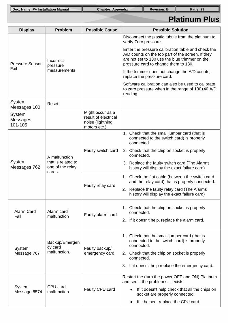
Pressure Sensor Fail
Incorrect pressure measurements
Disconnect the plastic tubule from the platinum to verify Zero pressure.
Enter the pressure calibration table and check the A/D counts on the top part of the screen. If they are not set to 130 use the blue trimmer on the pressure card to change them to 130.
If the trimmer does not change the A/D counts, replace the pressure card.
Software calibration can also be used to calibrate to zero pressure when in the range of 130±40 A/D reading.
System Messages 100
Reset
System Messages 101-105
Might occur as a result of electrical noise (lightning, motors etc.)
System Messages 762
A malfunction that is related to one of the relay cards.
Faulty switch card
1. Check that the small jumper card (that is connected to the switch card) is properly connected.
2. Check that the chip on socket is properly connected.
3. Replace the faulty switch card (The Alarms history will display the exact failure card)
Faulty relay card
1. Check the flat cable (between the switch card and the relay card) that is properly connected.
2. Replace the faulty relay card (The Alarms history will display the exact failure card)
Alarm Card Fail
Alarm card malfunction Faulty alarm card
1. Check that the chip on socket is properly connected.
2. If it doesn't help, replace the alarm card.
System Message 767
Backup/Emergency card malfunction.
Faulty backup/ emergency card
1. Check that the small jumper card (that is connected to the switch card) is properly connected.
2. Check that the chip on socket is properly connected.
3. If it doesn't help replace the emergency card.
System Message 8574
CPU card malfunction Faulty CPU card
Restart the (turn the power OFF and ON) Platinum and see if the problem still exists.
● If it doesn't help check that all the chips on socket are properly connected.
● If it helped, replace the CPU card

Platinum Plus PPaaggee:: 3300 RReevviissiioonn:: BB CChhaapptteerr:: AAppppeennddiixx DDoocc.. NNaammee:: PP++ IInnssttaallllaattiioonn MMaannuuaall
Display Problem Possible Cause Possible Solution
Digital Card Fail
Digital input card malfunction
Faulty digital input card
1. Check that the chip on socket is properly connected.
2. If it doesn't help, replace the digital input card.
System Message 107
Saving to the EEPROM malfunction
Faulty CPU card
Restart the (turn the power OFF and ON) Platinum and see if the problems still exists.
● If it doesn't help check that all the chips on socket are properly connected.
● If it helped, replace the CPU card