Embed Size (px)
Citation preview

TABLE OF CONTENTS
1.0 INTRODUCTION . . . . . . . . . . . . . . . . . . . . . . . . . . . . . . . . . . . . . . . . . . . . . . . . . . . . . . . . .1
1.1 SYSTEM COVERAGE . . . . . . . . . . . . . . . . . . . . . . . . . . . . . . . . . . . . . . . . . . . . . . .11.2 SIX-STEP TROUBLESHOOTING PROCEDURE . . . . . . . . . . . . . . . . . . . . . . . . . .1
2.0 IDENTIFICATION OF SYSTEM . . . . . . . . . . . . . . . . . . . . . . . . . . . . . . . . . . . . . . . . . . . . .1
3.0 SYSTEM DESCRIPTION AND FUNCTIONAL OPERATION . . . . . . . . . . . . . . . . . . . . . .2
3.1 GENERAL DESCRIPTION . . . . . . . . . . . . . . . . . . . . . . . . . . . . . . . . . . . . . . . . . . . .23.2 FUNCTIONAL OPERATION . . . . . . . . . . . . . . . . . . . . . . . . . . . . . . . . . . . . . . . . . . .2
3.2.1 FUEL CONTROL . . . . . . . . . . . . . . . . . . . . . . . . . . . . . . . . . . . . . . . . . .23.2.2 ON-BOARD DIAGNOSTICS . . . . . . . . . . . . . . . . . . . . . . . . . . . . . . . . . . .23.2.3 OTHER CONTROLS . . . . . . . . . . . . . . . . . . . . . . . . . . . . . . . . . . . . . . . . .63.2.4 PCM OPERATING MODES . . . . . . . . . . . . . . . . . . . . . . . . . . . . . . . . . .143.2.5 NON-MONITORED CIRCUITS . . . . . . . . . . . . . . . . . . . . . . . . . . . . . . . .143.2.6 SKIS OVERVIEW . . . . . . . . . . . . . . . . . . . . . . . . . . . . . . . . . . . . . . . . . .153.2.7 SKIM ON-BOARD DIAGNOSTICS. . . . . . . . . . . . . . . . . . . . . . . . . . . . .153.2.8 SKIS OPERATION. . . . . . . . . . . . . . . . . . . . . . . . . . . . . . . . . . . . . . . . . .153.2.9 PROGRAMMING THE POWERTRAIN CONTROL MODULE . . . . . . .163.2.10 PROGRAMMING THE SENTRY KEY IMMOBILIZER MODULE . . . . .163.2.11 PROGRAMMING THE IGNITION KEYS TO THE SENTRY KEY
IMMOBILIZER MODULE. . . . . . . . . . . . . . . . . . . . . . . . . . . . . . . . . . . . .163.3 DIAGNOSTIC TROUBLE CODES . . . . . . . . . . . . . . . . . . . . . . . . . . . . . . . . . . . . .17
3.3.1 HARD CODE . . . . . . . . . . . . . . . . . . . . . . . . . . . . . . . . . . . . . . . . . . . . . .173.3.2 INTERMITTENT CODE. . . . . . . . . . . . . . . . . . . . . . . . . . . . . . . . . . . . . .173.3.3 STARTS SINCE SET COUNTER . . . . . . . . . . . . . . . . . . . . . . . . . . . . . .173.3.4 DISTANCE SINCE MI SET . . . . . . . . . . . . . . . . . . . . . . . . . . . . . . . . . . .17
3.4 USING THE DRBIIIT . . . . . . . . . . . . . . . . . . . . . . . . . . . . . . . . . . . . . . . . . . . . . . . .183.5 DRBIIIT ERROR MESSAGES AND BLANK SCREEN . . . . . . . . . . . . . . . . . . . . .18
3.5.1 DRBIIIT DOES NOT POWER UP. . . . . . . . . . . . . . . . . . . . . . . . . . . . . .183.5.2 DISPLAY IS NOT VISIBLE . . . . . . . . . . . . . . . . . . . . . . . . . . . . . . . . . . .18
4.0 DISCLAIMERS, SAFETY, WARNINGS . . . . . . . . . . . . . . . . . . . . . . . . . . . . . . . . . . . . . .18
4.1 DISCLAIMERS. . . . . . . . . . . . . . . . . . . . . . . . . . . . . . . . . . . . . . . . . . . . . . . . . . . . .184.2 SAFETY . . . . . . . . . . . . . . . . . . . . . . . . . . . . . . . . . . . . . . . . . . . . . . . . . . . . . . . . . .18
4.2.1 TECHNICIAN SAFETY INFORMATION. . . . . . . . . . . . . . . . . . . . . . . . .184.2.2 VEHICLE PREPARATION FOR TESTING. . . . . . . . . . . . . . . . . . . . . . .194.2.3 SERVICING SUB ASSEMBLIES . . . . . . . . . . . . . . . . . . . . . . . . . . . . . .194.2.4 DRBIIIT SAFETY INFORMATION . . . . . . . . . . . . . . . . . . . . . . . . . . . . .19
4.3 WARNINGS AND CAUTIONS . . . . . . . . . . . . . . . . . . . . . . . . . . . . . . . . . . . . . . . .194.3.1 ROAD TEST WARNINGS . . . . . . . . . . . . . . . . . . . . . . . . . . . . . . . . . . . .194.3.2 VEHICLE DAMAGE CAUTIONS . . . . . . . . . . . . . . . . . . . . . . . . . . . . . .19
5.0 REQUIRED TOOLS AND EQUIPMENT . . . . . . . . . . . . . . . . . . . . . . . . . . . . . . . . . . . . .20
6.0 GLOSSARY OF TERMS . . . . . . . . . . . . . . . . . . . . . . . . . . . . . . . . . . . . . . . . . . . . . . . . . .20
7.0 DIAGNOSTIC INFORMATION AND PROCEDURES . . . . . . . . . . . . . . . . . . . . . . . . . . .23
COMMUNICATION*NO RESPONSE FROM PCM (PCI BUS) - NGC . . . . . . . . . . . . . . . . . . . . . . . . . . . . . .24*NO RESPONSE FROM PCM (PCI BUS) - SBEC . . . . . . . . . . . . . . . . . . . . . . . . . . . . .25
i

TABLE OF CONTENTS - Continued
*NO RESPONSE FROM PCM (PCM SCI ONLY) - NGC . . . . . . . . . . . . . . . . . . . . . . . .27*NO RESPONSE FROM PCM (SCI ONLY) - SBEC . . . . . . . . . . . . . . . . . . . . . . . . . . . .30*PCI BUS COMMUNICATION FAILURE . . . . . . . . . . . . . . . . . . . . . . . . . . . . . . . . . . . . .33
DRIVEABILITY - SBECP0106-BAROMETRIC PRESSURE OUT OF RANGE . . . . . . . . . . . . . . . . . . . . . . . . . .36P0107-MAP SENSOR VOLTAGE TOO LOW . . . . . . . . . . . . . . . . . . . . . . . . . . . . . . . . .39P0108-MAP SENSOR VOLTAGE TOO HIGH . . . . . . . . . . . . . . . . . . . . . . . . . . . . . . . . .42P0111-INTAKE AIR TEMP SENSOR PERFORMANCE . . . . . . . . . . . . . . . . . . . . . . . . .44P0117-ECT SENSOR VOLTAGE TOO LOW . . . . . . . . . . . . . . . . . . . . . . . . . . . . . . . . . .46P0118-ECT SENSOR VOLTAGE TOO HIGH . . . . . . . . . . . . . . . . . . . . . . . . . . . . . . . . .48P0121-TPS VOLTAGE DOES NOT AGREE WITH MAP . . . . . . . . . . . . . . . . . . . . . . . .50P0122-THROTTLE POSITION SENSOR VOLTAGE LOW . . . . . . . . . . . . . . . . . . . . . . .55P0123-THROTTLE POSITION SENSOR VOLTAGE HIGH . . . . . . . . . . . . . . . . . . . . . .58P0125-CLOSED LOOP TEMP NOT REACHED . . . . . . . . . . . . . . . . . . . . . . . . . . . . . . .61P0131-1/1 O2 SENSOR SHORTED TO GROUND. . . . . . . . . . . . . . . . . . . . . . . . . . . . .63P0137-1/2 O2 SENSOR SHORTED TO GROUND. . . . . . . . . . . . . . . . . . . . . . . . . . . . .63P0132-1/1 O2 SENSOR SHORTED TO VOLTAGE . . . . . . . . . . . . . . . . . . . . . . . . . . . .65P0138-1/2 O2 SENSOR SHORTED TO VOLTAGE . . . . . . . . . . . . . . . . . . . . . . . . . . . .65P0133-1/1 O2 SENSOR SLOW RESPONSE . . . . . . . . . . . . . . . . . . . . . . . . . . . . . . . . .68P0139-1/2 O2 SENSOR SLOW RESPONSE . . . . . . . . . . . . . . . . . . . . . . . . . . . . . . . . .68P0134-1/1 O2 SENSOR STAYS AT CENTER . . . . . . . . . . . . . . . . . . . . . . . . . . . . . . . . .70P0140-1/2 O2 SENSOR STAYS AT CENTER . . . . . . . . . . . . . . . . . . . . . . . . . . . . . . . . .70P0135-1/1 O2 SENSOR HEATER FAILURE . . . . . . . . . . . . . . . . . . . . . . . . . . . . . . . . . .73P0141-1/2 O2 SENSOR HEATER FAILURE . . . . . . . . . . . . . . . . . . . . . . . . . . . . . . . . . .75P0171-1/1 FUEL SYSTEM LEAN. . . . . . . . . . . . . . . . . . . . . . . . . . . . . . . . . . . . . . . . . . .77P0172-1/1 FUEL SYSTEM RICH . . . . . . . . . . . . . . . . . . . . . . . . . . . . . . . . . . . . . . . . . . .82P0201-INJECTOR #1 CONTROL CIRCUIT. . . . . . . . . . . . . . . . . . . . . . . . . . . . . . . . . . .87P0202-INJECTOR #2 CONTROL CIRCUIT. . . . . . . . . . . . . . . . . . . . . . . . . . . . . . . . . . .87P0203-INJECTOR #3 CONTROL CIRCUIT. . . . . . . . . . . . . . . . . . . . . . . . . . . . . . . . . . .87P0204-INJECTOR #4 CONTROL CIRCUIT. . . . . . . . . . . . . . . . . . . . . . . . . . . . . . . . . . .87P0205-INJECTOR #5 CONTROL CIRCUIT. . . . . . . . . . . . . . . . . . . . . . . . . . . . . . . . . . .87P0206-INJECTOR #6 CONTROL CIRCUIT. . . . . . . . . . . . . . . . . . . . . . . . . . . . . . . . . . .87P0300-MULTIPLE CYLINDER MIS-FIRE. . . . . . . . . . . . . . . . . . . . . . . . . . . . . . . . . . . . .90P0301-CYLINDER #1 MISFIRE . . . . . . . . . . . . . . . . . . . . . . . . . . . . . . . . . . . . . . . . . . . .90P0302-CYLINDER #2 MISFIRE . . . . . . . . . . . . . . . . . . . . . . . . . . . . . . . . . . . . . . . . . . . .90P0303-CYLINDER #3 MISFIRE . . . . . . . . . . . . . . . . . . . . . . . . . . . . . . . . . . . . . . . . . . . .90P0304-CYLINDER #4 MISFIRE . . . . . . . . . . . . . . . . . . . . . . . . . . . . . . . . . . . . . . . . . . . .90P0305-CYLINDER #5 MISFIRE . . . . . . . . . . . . . . . . . . . . . . . . . . . . . . . . . . . . . . . . . . . .90P0306-CYLINDER #6 MISFIRE . . . . . . . . . . . . . . . . . . . . . . . . . . . . . . . . . . . . . . . . . . . .90P0320-NO CRANK REFERENCE SIGNAL AT PCM. . . . . . . . . . . . . . . . . . . . . . . . . . . .97P0340-NO CAM SIGNAL AT PCM . . . . . . . . . . . . . . . . . . . . . . . . . . . . . . . . . . . . . . . . .102P0351-IGNITION COIL #1 PRIMARY CIRCUIT . . . . . . . . . . . . . . . . . . . . . . . . . . . . . .106P0352-IGNITION COIL #2 PRIMARY CIRCUIT . . . . . . . . . . . . . . . . . . . . . . . . . . . . . .106P0353-IGNITION COIL #3 PRIMARY CIRCUIT . . . . . . . . . . . . . . . . . . . . . . . . . . . . . .106P0401 - EGR SYSTEM FAILURE . . . . . . . . . . . . . . . . . . . . . . . . . . . . . . . . . . . . . . . . .109P0403 - EGR SOLENOID CIRCUIT . . . . . . . . . . . . . . . . . . . . . . . . . . . . . . . . . . . . . . . .113P0420-1/1 CATALYTIC CONVERTER EFFICIENCY. . . . . . . . . . . . . . . . . . . . . . . . . . .115P0441-EVAP PURGE FLOW MONITOR . . . . . . . . . . . . . . . . . . . . . . . . . . . . . . . . . . . .117P0442-EVAP LEAK MONITOR .040 LEAK DETECTED . . . . . . . . . . . . . . . . . . . . . . . .119P0455-EVAP LEAK MONITOR LARGE LEAK DETECTED . . . . . . . . . . . . . . . . . . . . .119P0456 - EVAP LEAK MONITOR .020 LEAK DETECTED. . . . . . . . . . . . . . . . . . . . . . .119P0443-EVAP PURGE SOLENOID CIRCUIT . . . . . . . . . . . . . . . . . . . . . . . . . . . . . . . . .123
ii
TABLE OF CONTENTS - Continued
P0460-FUEL LEVEL UNIT NO CHANGE OVER MILES. . . . . . . . . . . . . . . . . . . . . . . .125P0462-FUEL LEVEL SENDING UNIT VOLTS TOO LOW. . . . . . . . . . . . . . . . . . . . . . .127P0463-FUEL LEVEL SENDING UNIT VOLTS TOO HIGH . . . . . . . . . . . . . . . . . . . . . .127P0500-NO VEHICLE SPEED SIGNAL (3SP AUTO AND MANUALTRANSMISSIONS) . . . . . . . . . . . . . . . . . . . . . . . . . . . . . . . . . . . . . . . . . . . . . . . . . . . . .128P0500-NO VEHICLE SPEED SIGNAL (4SP AUTO TRANS) . . . . . . . . . . . . . . . . . . . .130P0508 - IAC MOTOR SENSE CIRCUIT LOW. . . . . . . . . . . . . . . . . . . . . . . . . . . . . . . .132P0509 - IAC MOTOR SENSE CIRCUIT HIGH . . . . . . . . . . . . . . . . . . . . . . . . . . . . . . .134P0600-PCM FAILURE SPI COMMUNICATIONS. . . . . . . . . . . . . . . . . . . . . . . . . . . . . .136P0601-PCM INTERNAL CONTROLLER FAILURE . . . . . . . . . . . . . . . . . . . . . . . . . . . .136P0622-GENERATOR FIELD NOT SWITCHING PROPERLY . . . . . . . . . . . . . . . . . . . .137P0645-A/C CLUTCH RELAY CKT . . . . . . . . . . . . . . . . . . . . . . . . . . . . . . . . . . . . . . . . .139P0700-EATX CONTROLLER DTC PRESENT. . . . . . . . . . . . . . . . . . . . . . . . . . . . . . . .142P0703-BRAKE SWITCH SENSE CIRCUIT . . . . . . . . . . . . . . . . . . . . . . . . . . . . . . . . . .143P1192-INLET AIR TEMP SENSOR VOLTAGE LOW. . . . . . . . . . . . . . . . . . . . . . . . . . .146P1193-INLET AIR TEMP SENSOR VOLTAGE HIGH . . . . . . . . . . . . . . . . . . . . . . . . . .148P1195-1/1 O2 SENSOR SLOW DURING CATALYST MONITOR . . . . . . . . . . . . . . . .150P1281-ENGINE IS COLD TOO LONG. . . . . . . . . . . . . . . . . . . . . . . . . . . . . . . . . . . . . .152P1282-FUEL PUMP RELAY CONTROL CIRCUIT. . . . . . . . . . . . . . . . . . . . . . . . . . . . .153P1294-TARGET IDLE NOT REACHED . . . . . . . . . . . . . . . . . . . . . . . . . . . . . . . . . . . . .155P1297-NO CHANGE IN MAP FROM START TO RUN. . . . . . . . . . . . . . . . . . . . . . . . .157P1299-VACUUM LEAK FOUND (IAC FULLY SEATED) . . . . . . . . . . . . . . . . . . . . . . . .160P1388-AUTO SHUTDOWN RELAY CONTROL CIRCUIT. . . . . . . . . . . . . . . . . . . . . . .162P1389-NO ASD RELAY OUTPUT VOLTAGE AT PCM . . . . . . . . . . . . . . . . . . . . . . . . .164P1391-INTERMITTENT LOSS OF CMP OR CKP. . . . . . . . . . . . . . . . . . . . . . . . . . . . .169P1398-MIS-FIRE ADAPTIVE NUMERATOR AT LIMIT . . . . . . . . . . . . . . . . . . . . . . . . .173P1478-BATTERY TEMP SENSOR VOLTS OUT OF LIMIT . . . . . . . . . . . . . . . . . . . . .175P1486-EVAP LEAK MONITOR PINCHED HOSE FOUND . . . . . . . . . . . . . . . . . . . . . .176P1491-RAD FAN CONTROL RELAY CIRCUIT . . . . . . . . . . . . . . . . . . . . . . . . . . . . . . .179P1494-LEAK DETECT PUMP SW OR MECHANICAL FAULT . . . . . . . . . . . . . . . . . . .182P1495-LEAK DETECTION PUMP SOLENOID CIRCUIT . . . . . . . . . . . . . . . . . . . . . . .184P1496-5 VOLT SUPPLY, OUTPUT TOO LOW . . . . . . . . . . . . . . . . . . . . . . . . . . . . . . .186P1594-CHARGING SYSTEM VOLTAGE TOO HIGH . . . . . . . . . . . . . . . . . . . . . . . . . .190P1595-SPEED CONTROL SOLENOID CIRCUITS . . . . . . . . . . . . . . . . . . . . . . . . . . . .192P1683-SPD CTRL PWR RELAY; OR S/C 12V DRIVER CKT . . . . . . . . . . . . . . . . . . .192P1598-A/C PRESSURE SENSOR VOLTS TOO HIGH. . . . . . . . . . . . . . . . . . . . . . . . .197P1599-A/C PRESSURE SENSOR VOLTS TOO LOW . . . . . . . . . . . . . . . . . . . . . . . . .200P1682-CHARGING SYSTEM VOLTAGE TOO LOW. . . . . . . . . . . . . . . . . . . . . . . . . . .203P1685-WRONG OR INVALID KEY MSG RECEIVED FROM SKIM. . . . . . . . . . . . . . .206P1686-NO SKIM BUS MESSAGE RECEIVED . . . . . . . . . . . . . . . . . . . . . . . . . . . . . . .208P1695-NO CCD/J1850 MESSAGE FROM BODY CONTROL MODULE . . . . . . . . . . .210P1696-PCM FAILURE EEPROM WRITE DENIED . . . . . . . . . . . . . . . . . . . . . . . . . . . .212P1697-PCM FAILURE SRI MILE NOT STORED . . . . . . . . . . . . . . . . . . . . . . . . . . . . .212P1698-NO BUS MESSAGE FROM TRANS CONTROL MODULE . . . . . . . . . . . . . . .214P1899-P/N SWITCH STUCK IN PARK OR IN GEAR (4SP AUTO TRNAS) . . . . . . . .216*CHECKING PCM POWER AND GROUND CIRCUITS . . . . . . . . . . . . . . . . . . . . . . . .218*CHECKING RADIATOR FAN RELAY OUTPUT . . . . . . . . . . . . . . . . . . . . . . . . . . . . . .219*CHECKING THE A/C RELAY OUTPUT . . . . . . . . . . . . . . . . . . . . . . . . . . . . . . . . . . . .220
DRIVEABILITY - NGCINTERMITTENT CONDITION. . . . . . . . . . . . . . . . . . . . . . . . . . . . . . . . . . . . . . . . . . . . .222P0016-CRANKSHAFT/CAMSHAFT TIMING MISALIGNMENT . . . . . . . . . . . . . . . . . .223P0031-O2 SENSOR 1/1 HEATER CIRCUIT LOW . . . . . . . . . . . . . . . . . . . . . . . . . . . .227
iii

TABLE OF CONTENTS - Continued
P0037-O2 SENSOR 1/2 HEATER CIRCUIT LOW . . . . . . . . . . . . . . . . . . . . . . . . . . . .227P0032-O2 SENSOR 1/1 HEATER CIRCUIT HIGH . . . . . . . . . . . . . . . . . . . . . . . . . . . .229P0038-O2 SENSOR 1/2 HEATER CIRCUIT HIGH . . . . . . . . . . . . . . . . . . . . . . . . . . . .229P0068-MANIFOLD PRESSURE/THROTTLE POSITION CORRELATION - HIGHFLOW/VACUUM LEAK . . . . . . . . . . . . . . . . . . . . . . . . . . . . . . . . . . . . . . . . . . . . . . . . . .232P0070-AMBIENT TEMP SENSOR STUCK . . . . . . . . . . . . . . . . . . . . . . . . . . . . . . . . . .238P0071-AMBIENT TEMP SENSOR PERFORMANCE . . . . . . . . . . . . . . . . . . . . . . . . . .238P0072-AMBIENT TEMP SENSOR LOW . . . . . . . . . . . . . . . . . . . . . . . . . . . . . . . . . . . .242P0073-AMBIENT TEMP SENSOR HIGH. . . . . . . . . . . . . . . . . . . . . . . . . . . . . . . . . . . .244P0106-MAP SENSOR PERFORMANCE . . . . . . . . . . . . . . . . . . . . . . . . . . . . . . . . . . . .246P0107-MAP SENSOR LOW . . . . . . . . . . . . . . . . . . . . . . . . . . . . . . . . . . . . . . . . . . . . . .250P0108-MAP SENSOR HIGH. . . . . . . . . . . . . . . . . . . . . . . . . . . . . . . . . . . . . . . . . . . . . .253P0110-INTAKE AIR TEMPERATURE SENSOR STUCK. . . . . . . . . . . . . . . . . . . . . . . .256P0111-INTAKE AIR TEMPERATURE SENSOR PERFORMANCE. . . . . . . . . . . . . . . .256P0112-INTAKE AIR TEMPERATURE SENSOR LOW. . . . . . . . . . . . . . . . . . . . . . . . . .259P0113-INTAKE AIR TEMPERATURE SENSOR HIGH . . . . . . . . . . . . . . . . . . . . . . . . .261P0116-ENGINE COOLANT TEMPERATURE PERFORMANCE. . . . . . . . . . . . . . . . . .263P0117-ENGINE COOLANT TEMPERATURE SENSOR LOW . . . . . . . . . . . . . . . . . . .266P0118-ENGINE COOLANT TEMPERATURE SENSOR HIGH . . . . . . . . . . . . . . . . . . .268P0121-THROTTLE POSITION SENSOR #1 PERFORMANCE . . . . . . . . . . . . . . . . . .270P0122-THROTTLE POSITION SENSOR #1 LOW . . . . . . . . . . . . . . . . . . . . . . . . . . . .276P0123-THROTTLE POSITION SENSOR #1 HIGH . . . . . . . . . . . . . . . . . . . . . . . . . . . .279P0125-INSUFFICIENT COOLANT TEMP FOR CLOSED-LOOP FUEL CONTROL . .282P0128-THERMOSTAT RATIONALITY . . . . . . . . . . . . . . . . . . . . . . . . . . . . . . . . . . . . . .284P0129-BAROMETRIC PRESSURE OUT-OF-RANGE LOW. . . . . . . . . . . . . . . . . . . . .289P0131-O2 SENSOR 1/1 VOLTAGE LOW . . . . . . . . . . . . . . . . . . . . . . . . . . . . . . . . . . .292P0137-O2 SENSOR 1/2 VOLTAGE LOW . . . . . . . . . . . . . . . . . . . . . . . . . . . . . . . . . . .292P0132-O2 SENSOR 1/1 VOLTAGE HIGH . . . . . . . . . . . . . . . . . . . . . . . . . . . . . . . . . . .295P0138-O2 SENSOR 1/2 VOLTAGE HIGH . . . . . . . . . . . . . . . . . . . . . . . . . . . . . . . . . . .295P0133-O2 SENSOR 1/1 SLOW RESPONSE . . . . . . . . . . . . . . . . . . . . . . . . . . . . . . . .298P0139-O2 SENSOR 1/2 SLOW RESPONSE . . . . . . . . . . . . . . . . . . . . . . . . . . . . . . . .298P0135-O2 SENSOR 1/1 HEATER PERFORMANCE . . . . . . . . . . . . . . . . . . . . . . . . . .300P0141-O2 SENSOR 1/2 HEATER PERFROMANCE . . . . . . . . . . . . . . . . . . . . . . . . . .300P0171-FUEL SYSTEM 1/1 LEAN. . . . . . . . . . . . . . . . . . . . . . . . . . . . . . . . . . . . . . . . . .303P0172-FUEL SYSTEM 1/1 RICH . . . . . . . . . . . . . . . . . . . . . . . . . . . . . . . . . . . . . . . . . .308P0201-FUEL INJECTOR #1 . . . . . . . . . . . . . . . . . . . . . . . . . . . . . . . . . . . . . . . . . . . . . .312P0202-FUEL INJECTOR #2 . . . . . . . . . . . . . . . . . . . . . . . . . . . . . . . . . . . . . . . . . . . . . .312P0203-FUEL INJECTOR #3 . . . . . . . . . . . . . . . . . . . . . . . . . . . . . . . . . . . . . . . . . . . . . .312P0204-FUEL INJECTOR #4 . . . . . . . . . . . . . . . . . . . . . . . . . . . . . . . . . . . . . . . . . . . . . .312P0300-MULTIPLE CYLINDER MISFIRE . . . . . . . . . . . . . . . . . . . . . . . . . . . . . . . . . . . .315P0301-CYLINDER #1 MISFIRE . . . . . . . . . . . . . . . . . . . . . . . . . . . . . . . . . . . . . . . . . . .315P0302-CYLINDER #2 MISFIRE . . . . . . . . . . . . . . . . . . . . . . . . . . . . . . . . . . . . . . . . . . .315P0303-CYLINDER #3 MISFIRE . . . . . . . . . . . . . . . . . . . . . . . . . . . . . . . . . . . . . . . . . . .315P0304-CYLINDER #4 MISFIRE . . . . . . . . . . . . . . . . . . . . . . . . . . . . . . . . . . . . . . . . . . .315P0315-NO CRANK SENSOR LEARNED. . . . . . . . . . . . . . . . . . . . . . . . . . . . . . . . . . . .323P0325-KNOCK SENSOR #1 CIRCUIT . . . . . . . . . . . . . . . . . . . . . . . . . . . . . . . . . . . . .325P0335-CRANKSHAFT POSITION SENSOR CIRCUIT . . . . . . . . . . . . . . . . . . . . . . . . .328P0339-CRANKSHAFT POSITION SENSOR INTERMITTENT . . . . . . . . . . . . . . . . . . .333P0340-CAMSHAFT POSITION SENSOR CIRCUIT . . . . . . . . . . . . . . . . . . . . . . . . . . .337P0344-CAMSHAFT POSITION SENSOR INTERMITTENT . . . . . . . . . . . . . . . . . . . . .342P0351-IGNITION COIL #1 CIRCUIT . . . . . . . . . . . . . . . . . . . . . . . . . . . . . . . . . . . . . . .346P0352-IGNITION COIL #2 CIRCUIT . . . . . . . . . . . . . . . . . . . . . . . . . . . . . . . . . . . . . . .346P0420-CATALYTIC 1/1 EFFICIENCY. . . . . . . . . . . . . . . . . . . . . . . . . . . . . . . . . . . . . . .348
iv

TABLE OF CONTENTS - Continued
P0432-CATALYTIC 2/1 EFFICIENCY. . . . . . . . . . . . . . . . . . . . . . . . . . . . . . . . . . . . . . .348P0440-GENERAL EVAP SYSTEM FAILURE. . . . . . . . . . . . . . . . . . . . . . . . . . . . . . . . .350P0441-EVAP PURGE SYSTEM PERFORMANCE . . . . . . . . . . . . . . . . . . . . . . . . . . . .355P0442-EVAP SYSTEM MEDIUM LEAK . . . . . . . . . . . . . . . . . . . . . . . . . . . . . . . . . . . . .357P0455-EVAP SYSTEM LARGE LEAK . . . . . . . . . . . . . . . . . . . . . . . . . . . . . . . . . . . . . .357P0443-EVAP PURGE SOLENOID CIRCUIT . . . . . . . . . . . . . . . . . . . . . . . . . . . . . . . . .362P0452-NVLD PRESSURE SWITCH SENSE CIRCUIT LOW . . . . . . . . . . . . . . . . . . . .365P0453-NVLD PRESSURE SWITCH SENSE CIRCUIT HIGH. . . . . . . . . . . . . . . . . . . .368P0456-EVAP SYSTEM SMALL LEAK . . . . . . . . . . . . . . . . . . . . . . . . . . . . . . . . . . . . . .370P0461-FUEL LEVEL SENSOR #1 PERFORMANCE . . . . . . . . . . . . . . . . . . . . . . . . . .372P0462-FUEL LEVEL SENSOR #1 LOW . . . . . . . . . . . . . . . . . . . . . . . . . . . . . . . . . . . .374P0463-FUEL LEVEL SENSOR #1 HIGH . . . . . . . . . . . . . . . . . . . . . . . . . . . . . . . . . . . .374P0480-LOW SPEED FAN CONTROL RELAY CIRCUIT . . . . . . . . . . . . . . . . . . . . . . . .375P0498-NVLD CANISTER VENT VALVE SOLENOID CIRCUIT LOW. . . . . . . . . . . . . .379P0499-NVLD CANISTER VENT VALVE SOLENOID CIRCUIT HIGH . . . . . . . . . . . . .380P0501-VEHICLE SPEED SENSOR #1 PERFORMANCE (AUTO TRANS) . . . . . . . . .382P0501-VEHICLE SPEED SENSOR #1 PERFORMANCE (MANUAL TRANS) . . . . . .383P0506-IDLE SPEED LOW PERFORMANCE . . . . . . . . . . . . . . . . . . . . . . . . . . . . . . . .385P0507-IDLE SPEED HIGH PERFORMANCE . . . . . . . . . . . . . . . . . . . . . . . . . . . . . . . .385P0519-IDLE SPEED PERFORMANCE . . . . . . . . . . . . . . . . . . . . . . . . . . . . . . . . . . . . .385P0508-IAC VALVE SENSE CIRCUIT LOW . . . . . . . . . . . . . . . . . . . . . . . . . . . . . . . . . .387P0509-IAC VALVE SENSE CIRCUIT HIGH. . . . . . . . . . . . . . . . . . . . . . . . . . . . . . . . . .390P0513-INVALID SKIM KEY. . . . . . . . . . . . . . . . . . . . . . . . . . . . . . . . . . . . . . . . . . . . . . .392P0516-BATTERY TEMPERATURE SENSOR LOW . . . . . . . . . . . . . . . . . . . . . . . . . . .394P0517-BATTERY TEMPERATURE SENSOR HIGH . . . . . . . . . . . . . . . . . . . . . . . . . . .396P0522 PRESSURE SENSOR LOW . . . . . . . . . . . . . . . . . . . . . . . . . . . . . . . . . . . . . . . .398P0532-A/C PRESSURE SENSOR LOW . . . . . . . . . . . . . . . . . . . . . . . . . . . . . . . . . . . .399P0533-A/C PRESSURE SENSOR HIGH. . . . . . . . . . . . . . . . . . . . . . . . . . . . . . . . . . . .402P0551-POWER STEERING SWITCH PERFORMANCE . . . . . . . . . . . . . . . . . . . . . . .405P0562-BATTERY VOLTAGE LOW . . . . . . . . . . . . . . . . . . . . . . . . . . . . . . . . . . . . . . . . .407P0563-BATTERY VOLTAGE HIGH. . . . . . . . . . . . . . . . . . . . . . . . . . . . . . . . . . . . . . . . .410P0579-SPEED CONTROL SWITCH #1 PERFORMANCE . . . . . . . . . . . . . . . . . . . . . .412P0580-SPEED CONTROL SWITCH #1 LOW . . . . . . . . . . . . . . . . . . . . . . . . . . . . . . . .415P0581-SPEED CONTROL SWITCH #1 HIGH. . . . . . . . . . . . . . . . . . . . . . . . . . . . . . . .417P0582-SPEED CONTROL VACUUM SOLENOID CIRCUIT . . . . . . . . . . . . . . . . . . . . .419P0586-SPEED CONTROL VENT SOLENOID CIRCUIT. . . . . . . . . . . . . . . . . . . . . . . .421P0594-SPEED CONTROL SERVO POWER CIRCUIT . . . . . . . . . . . . . . . . . . . . . . . . .423P0600-SERIAL COMMUNICATION LINK. . . . . . . . . . . . . . . . . . . . . . . . . . . . . . . . . . . .426P0601-INTERNAL MEMORY CHECKSUM INVALID. . . . . . . . . . . . . . . . . . . . . . . . . . .426P0622-GENERATOR FIELD CONTROL CIRCUIT . . . . . . . . . . . . . . . . . . . . . . . . . . . .427P0627-FUEL PUMP RELAY CIRCUIT . . . . . . . . . . . . . . . . . . . . . . . . . . . . . . . . . . . . . .429P0630-VIN NOT PROGRAMMED IN PCM . . . . . . . . . . . . . . . . . . . . . . . . . . . . . . . . . .432P0632-ODOMETER NOT PROGRAMMED IN PCM. . . . . . . . . . . . . . . . . . . . . . . . . . .433P0633-SKIM KEY NOT PROGRAMMED IN PCM. . . . . . . . . . . . . . . . . . . . . . . . . . . . .434P0645-A/C CLUTCH RELAY CIRCUIT . . . . . . . . . . . . . . . . . . . . . . . . . . . . . . . . . . . . .435P0685-ASD RELAY CONTROL CIRCUIT . . . . . . . . . . . . . . . . . . . . . . . . . . . . . . . . . . .438P0688-ASD RELAY SENSE CIRCUIT LOW . . . . . . . . . . . . . . . . . . . . . . . . . . . . . . . . .441P0700-TRANSMISSION CONTROL SYSTEM/READ TRANSMISSION DTCSON THE DRBIIIT . . . . . . . . . . . . . . . . . . . . . . . . . . . . . . . . . . . . . . . . . . . . . . . . . . . . . . .444P0703-BRAKE SWITCH #2 CIRCUIT . . . . . . . . . . . . . . . . . . . . . . . . . . . . . . . . . . . . . .445P0833-CLUTCH RELEASED SWITCH CIRCUIT . . . . . . . . . . . . . . . . . . . . . . . . . . . . .448P0850-PARK/NEUTRAL SWITCH PERFORMANCE . . . . . . . . . . . . . . . . . . . . . . . . . .450P1602-PCM NOT PROGRAMMED . . . . . . . . . . . . . . . . . . . . . . . . . . . . . . . . . . . . . . . .451
v

TABLE OF CONTENTS - Continued
P1603-PCM INTERNAL DUAL-PORT RAM COMMUNICATION . . . . . . . . . . . . . . . . .452P1604-PCM INTERNAL DUAL-PORT RAM READ/WRITE INTEGRITY FAILURE . . .452P1607-PCM INTERNAL SHUTDOWN TIMER RATIONALITY . . . . . . . . . . . . . . . . . . .452P1681-NO FUEL LEVEL BUS MESSAGE. . . . . . . . . . . . . . . . . . . . . . . . . . . . . . . . . . .453P1686-NO SKIM BUS MESSAGES . . . . . . . . . . . . . . . . . . . . . . . . . . . . . . . . . . . . . . . .455P1687-NO CLUSTER BUS MESSAGE . . . . . . . . . . . . . . . . . . . . . . . . . . . . . . . . . . . . .457P1696-EEPROM MEMORY WRITE DENIED/INVALID. . . . . . . . . . . . . . . . . . . . . . . . .458P1697-EMR (SRI) MILEAGE NOT STORED. . . . . . . . . . . . . . . . . . . . . . . . . . . . . . . . .458P1698-NO TRANSMISSION BUS MESSAGE. . . . . . . . . . . . . . . . . . . . . . . . . . . . . . . .460P2302-IGNITION COIL #1 SECONDARY CIRCUIT-INSUFFICIENT IONIZATION . . .462P2305-IGNITION COIL #2 SECONDARY CIRCUIT-INSUFFICIENT IONIZATION . . .462P2503-CHARGING SYSTEM VOLTAGE LOW . . . . . . . . . . . . . . . . . . . . . . . . . . . . . . .464*CHECKING PCM POWER AND GROUND CIRCUITS . . . . . . . . . . . . . . . . . . . . . . . .467*CHECKING THE A/C RELAY OUTPUT . . . . . . . . . . . . . . . . . . . . . . . . . . . . . . . . . . . .468
SENTRY KEY IMMOBILIZERANTENNA FAILURE . . . . . . . . . . . . . . . . . . . . . . . . . . . . . . . . . . . . . . . . . . . . . . . . . . . .470COP FAILURE. . . . . . . . . . . . . . . . . . . . . . . . . . . . . . . . . . . . . . . . . . . . . . . . . . . . . . . . .470EEPROM FAILURE. . . . . . . . . . . . . . . . . . . . . . . . . . . . . . . . . . . . . . . . . . . . . . . . . . . . .470INTERNAL FAULT . . . . . . . . . . . . . . . . . . . . . . . . . . . . . . . . . . . . . . . . . . . . . . . . . . . . . .470RAM FAILURE. . . . . . . . . . . . . . . . . . . . . . . . . . . . . . . . . . . . . . . . . . . . . . . . . . . . . . . . .470SERIAL LINK INTERNAL FAULT . . . . . . . . . . . . . . . . . . . . . . . . . . . . . . . . . . . . . . . . . .470STACK OVERFLOW FAILURE. . . . . . . . . . . . . . . . . . . . . . . . . . . . . . . . . . . . . . . . . . . .470PCM STATUS FAILURE . . . . . . . . . . . . . . . . . . . . . . . . . . . . . . . . . . . . . . . . . . . . . . . . .472SERIAL LINK EXTERNAL FAULT . . . . . . . . . . . . . . . . . . . . . . . . . . . . . . . . . . . . . . . . .472ROLLING CODE FAILURE. . . . . . . . . . . . . . . . . . . . . . . . . . . . . . . . . . . . . . . . . . . . . . .474VIN MISMATCH. . . . . . . . . . . . . . . . . . . . . . . . . . . . . . . . . . . . . . . . . . . . . . . . . . . . . . . .474TRANSPONDER COMMUNICATION FAILURE . . . . . . . . . . . . . . . . . . . . . . . . . . . . . .476TRANSPONDER CYCLIC REDUNDANCY CHECK (CRC) FAILURE . . . . . . . . . . . . .476TRANSPONDER ID MISMATCH . . . . . . . . . . . . . . . . . . . . . . . . . . . . . . . . . . . . . . . . . .476TRANSPONDER RESPONSE MISMATCH . . . . . . . . . . . . . . . . . . . . . . . . . . . . . . . . . .476
STARTING*CHECKING FUEL DELIVERY. . . . . . . . . . . . . . . . . . . . . . . . . . . . . . . . . . . . . . . . . . . .479*CHECKING FUEL PRESSURE LEAK DOWN . . . . . . . . . . . . . . . . . . . . . . . . . . . . . . .482*CHECKING HARD START (FUEL DELIVERY SYSTEM) . . . . . . . . . . . . . . . . . . . . . .483*ENGINE CRANKS DOES NOT START . . . . . . . . . . . . . . . . . . . . . . . . . . . . . . . . . . . .485*NO CRANK CONDITION. . . . . . . . . . . . . . . . . . . . . . . . . . . . . . . . . . . . . . . . . . . . . . . .490*NO RESPONSE FROM PCM WITH A NO START CONDITION . . . . . . . . . . . . . . . .493*START AND STALL CONDITION . . . . . . . . . . . . . . . . . . . . . . . . . . . . . . . . . . . . . . . . .494
VERIFICATION TESTSVERIFICATION TESTS. . . . . . . . . . . . . . . . . . . . . . . . . . . . . . . . . . . . . . . . . . . . . . . . . .497
8.0 COMPONENT LOCATIONS . . . . . . . . . . . . . . . . . . . . . . . . . . . . . . . . . . . . . . . . . . . . . .509
8.1 CONTROL MODULES AND FUSE & RELAY CENTER . . . . . . . . . . . . . . . . . . .5098.2 CONTROLS AND SOLENOID . . . . . . . . . . . . . . . . . . . . . . . . . . . . . . . . . . . . . . .5098.3 DATA LINK CONNECTOR . . . . . . . . . . . . . . . . . . . . . . . . . . . . . . . . . . . . . . . . . .5118.4 SENSORS . . . . . . . . . . . . . . . . . . . . . . . . . . . . . . . . . . . . . . . . . . . . . . . . . . . . . . .5128.5 FUEL SYSTEM . . . . . . . . . . . . . . . . . . . . . . . . . . . . . . . . . . . . . . . . . . . . . . . . . . .5148.6 SWITCHES . . . . . . . . . . . . . . . . . . . . . . . . . . . . . . . . . . . . . . . . . . . . . . . . . . . . . .515
vi

TABLE OF CONTENTS - Continued
9.0 CONNECTOR PINOUTS . . . . . . . . . . . . . . . . . . . . . . . . . . . . . . . . . . . . . . . . . . . . . . . .517
A/C COMPRESSOR CLUTCH . . . . . . . . . . . . . . . . . . . . . . . . . . . . . . . . . . . . . . . . . . . .517A/C PRESSURE SENSOR . . . . . . . . . . . . . . . . . . . . . . . . . . . . . . . . . . . . . . . . . . . . . . .517AMBIENT TEMPERATURE SENSOR (EXCEPT BASE). . . . . . . . . . . . . . . . . . . . . . . .517BODY CONTROL MODULE C3 . . . . . . . . . . . . . . . . . . . . . . . . . . . . . . . . . . . . . . . . . . .518BRAKE LAMP SWITCH . . . . . . . . . . . . . . . . . . . . . . . . . . . . . . . . . . . . . . . . . . . . . . . . .519BRAKE TRANSMISSION SHIFT INTERLOCK SOLENOID (EATX). . . . . . . . . . . . . . .519CAMSHAFT POSITION SENSOR (GAS) . . . . . . . . . . . . . . . . . . . . . . . . . . . . . . . . . . .519CLUTCH PEDAL INTERLOCK SWITCH (MTX) . . . . . . . . . . . . . . . . . . . . . . . . . . . . . .519CRANKSHAFT POSITION SENSOR (GAS) . . . . . . . . . . . . . . . . . . . . . . . . . . . . . . . . .520DATA LINK CONNECTOR . . . . . . . . . . . . . . . . . . . . . . . . . . . . . . . . . . . . . . . . . . . . . . .520EGR SOLENOID (3.3L/3.8L EXPORT) . . . . . . . . . . . . . . . . . . . . . . . . . . . . . . . . . . . . .520ENGINE COOLANT TEMP SENSOR (GAS) . . . . . . . . . . . . . . . . . . . . . . . . . . . . . . . . .520ENGINE OIL PRESSURE SWITCH (GAS) . . . . . . . . . . . . . . . . . . . . . . . . . . . . . . . . . .521EVAP/PURGE SOLENOID (GAS) . . . . . . . . . . . . . . . . . . . . . . . . . . . . . . . . . . . . . . . . .521FUEL INJECTOR NO. 1 (2.4L/3.3L/3.8L). . . . . . . . . . . . . . . . . . . . . . . . . . . . . . . . . . . .521FUEL INJECTOR NO. 2 (2.4L/3.3L/3.8L). . . . . . . . . . . . . . . . . . . . . . . . . . . . . . . . . . . .521FUEL INJECTOR NO. 3 (2.4L/3.3L/3.8L). . . . . . . . . . . . . . . . . . . . . . . . . . . . . . . . . . . .522FUEL INJECTOR NO. 5 (3.3L/3.8L). . . . . . . . . . . . . . . . . . . . . . . . . . . . . . . . . . . . . . . .522FUEL INJECTOR NO. 6 (3.3L/3.8L). . . . . . . . . . . . . . . . . . . . . . . . . . . . . . . . . . . . . . . .522FUEL PUMP MODULE . . . . . . . . . . . . . . . . . . . . . . . . . . . . . . . . . . . . . . . . . . . . . . . . . .522GENERATOR . . . . . . . . . . . . . . . . . . . . . . . . . . . . . . . . . . . . . . . . . . . . . . . . . . . . . . . . .523GENERATOR (GENERATOR SIDE) . . . . . . . . . . . . . . . . . . . . . . . . . . . . . . . . . . . . . . .523IDLE AIR CONTROL MOTOR (GAS). . . . . . . . . . . . . . . . . . . . . . . . . . . . . . . . . . . . . . .523IGNITION COIL (2.4L). . . . . . . . . . . . . . . . . . . . . . . . . . . . . . . . . . . . . . . . . . . . . . . . . . .523IGNITION COIL (3.3L/3.8L) . . . . . . . . . . . . . . . . . . . . . . . . . . . . . . . . . . . . . . . . . . . . . .524INLET AIR TEMPERATURE SENSOR. . . . . . . . . . . . . . . . . . . . . . . . . . . . . . . . . . . . . .524FUSES (IPM) . . . . . . . . . . . . . . . . . . . . . . . . . . . . . . . . . . . . . . . . . . . . . . . . . . . . . . . . . .526FUEL PUMP RELAY (GAS) . . . . . . . . . . . . . . . . . . . . . . . . . . . . . . . . . . . . . . . . . . . . . .526INTEGRATED POWER MODULE C1 . . . . . . . . . . . . . . . . . . . . . . . . . . . . . . . . . . . . . .527INTEGRATED POWER MODULE C2 . . . . . . . . . . . . . . . . . . . . . . . . . . . . . . . . . . . . . .527INTEGRATED POWER MODULE C3 . . . . . . . . . . . . . . . . . . . . . . . . . . . . . . . . . . . . . .528INTEGRATED POWER MODULE C4 . . . . . . . . . . . . . . . . . . . . . . . . . . . . . . . . . . . . . .529INTEGRATED POWER MODULE C5 . . . . . . . . . . . . . . . . . . . . . . . . . . . . . . . . . . . . . .529INTEGRATED POWER MODULE C6 . . . . . . . . . . . . . . . . . . . . . . . . . . . . . . . . . . . . . .529INTEGRATED POWER MODULE C7 . . . . . . . . . . . . . . . . . . . . . . . . . . . . . . . . . . . . . .530INTEGRATED POWER MODULE C8 . . . . . . . . . . . . . . . . . . . . . . . . . . . . . . . . . . . . . .530INTEGRATED POWER MODULE C9 . . . . . . . . . . . . . . . . . . . . . . . . . . . . . . . . . . . . . .530KNOCK SENSOR (3.3L/3.8L ABS EXCEPT EXPORT) . . . . . . . . . . . . . . . . . . . . . . . .531LEAK DETECTION PUMP (3.3L/3.8L EXCEPT EXPORT) . . . . . . . . . . . . . . . . . . . . . .531LEFT SPEED CONTROL SWITCH . . . . . . . . . . . . . . . . . . . . . . . . . . . . . . . . . . . . . . . .531MANIFOLD ABSOLUTE PRESSURE SENSOR (GAS) . . . . . . . . . . . . . . . . . . . . . . . .531NATURAL VACUUM LEAK DETECTION ASSEMBLY (2.4L EXCEPT EXPORT) . . . .532OXYGEN SENSOR 1/1 UPSTREAM (GAS) . . . . . . . . . . . . . . . . . . . . . . . . . . . . . . . . .532OXYGEN SENSOR 1/2 DOWNSTREAM (GAS) . . . . . . . . . . . . . . . . . . . . . . . . . . . . . .532POWERTRAIN CONTROL MODULE C1 (NGC) . . . . . . . . . . . . . . . . . . . . . . . . . . . . . .533POWERTRAIN CONTROL MODULE C1 (SBEC) . . . . . . . . . . . . . . . . . . . . . . . . . . . . .534POWERTRAIN CONTROL MODULE C2 (NGC) . . . . . . . . . . . . . . . . . . . . . . . . . . . . . .535POWERTRAIN CONTROL MODULE C2 (SBEC) . . . . . . . . . . . . . . . . . . . . . . . . . . . . .536POWERTRAIN CONTROL MODULE C3 (NGC) . . . . . . . . . . . . . . . . . . . . . . . . . . . . . .537POWERTRAIN CONTROL MODULE C4 (NGC) (EATX) . . . . . . . . . . . . . . . . . . . . . . .538RIGHT SPEED CONTROL SWITCH . . . . . . . . . . . . . . . . . . . . . . . . . . . . . . . . . . . . . . .538
vii

TABLE OF CONTENTS - Continued
SENTRY KEY IMMOBILIZER MODULE . . . . . . . . . . . . . . . . . . . . . . . . . . . . . . . . . . . .539SPEED CONTROL SERVO (GAS). . . . . . . . . . . . . . . . . . . . . . . . . . . . . . . . . . . . . . . . .539THROTTLE POSITION SENSOR (GAS) . . . . . . . . . . . . . . . . . . . . . . . . . . . . . . . . . . . .539TRANSMISSION RANGE SENSOR (EATX) . . . . . . . . . . . . . . . . . . . . . . . . . . . . . . . . .539
10.0 SCHEMATIC DIAGRAMS . . . . . . . . . . . . . . . . . . . . . . . . . . . . . . . . . . . . . . . . . . . . . . . .541
10.1 2003 RS 2.4L. . . . . . . . . . . . . . . . . . . . . . . . . . . . . . . . . . . . . . . . . . . . . . . . . . . . .54110.2 2003 RS 3.3L/3.8L . . . . . . . . . . . . . . . . . . . . . . . . . . . . . . . . . . . . . . . . . . . . . . . .543
11.0 CHARTS AND GRAPHS . . . . . . . . . . . . . . . . . . . . . . . . . . . . . . . . . . . . . . . . . . . . . . . .545
viii

IMPORTANT
New for the 2003 RS equipped with the 2.4L isa combined Powertrain Control Module andTransmission Control Module in a singlecontrol module. This new module is the NextGeneration Controller (NGC) forDaimlerChrysler and will be referred to as thePowertrain Control Module (PCM).New Diagnostics procedures and New DTCnumbers are some of the changes you willsee which reflect the new combined moduletechnology. The PCM will have four colorcoded connectors C1 through C4, (C1-BLK,C2-ORANGE, C3-WHITE, C4-GREEN), eachPCM connector will have 38 pins each. Twonew tools are introduced to help indiagnosing and repairing the new PCMterminals and harness connectors. The Miller#3638 terminal removal pick is introduced,you must use the Miller #3638 tool to releasethe connector terminals or harness andconnector damage will occur. Also, the Miller#8815 Pinout Box is introduced, you mustuse the Miller #8815 tool to probe the PCMterminals or terminal damage will occur.There is also a new Verification test andmodule replacement procedure for the newPCM.
1.0 INTRODUCTION
The procedures contained in this manual includespecifications, instructions, and graphics needed todiagnose the PCM Powertrain System. The diag-nostics in this manual are based on the failurecondition or symptom being present at time ofdiagnosis.
Please follow the recommendations below whenchoosing your diagnostic path.1. First make sure the DRBIIIt is communicating
with the appropriate modules; ie., if the DRBIIItdisplays a No Response condition, you mustdiagnose this first before proceeding.
2. Read DTC’s (diagnostic trouble codes) with theDRBIIIt.
3. If no DTC’s are present, identify the customercomplaint.
4. Once the DTC or customer complaint is identi-fied, locate the matching test in the Table ofContents and begin to diagnose the symptom.
All component location views are in Section 8.0.All connector pinouts are in Section 9.0. All systemschematics are in Section 10.0.
An * placed before the symptom description indi-cates a customer complaint.
When repairs are required, refer to the appropri-ate service information for the proper removal andrepair procedure.
Diagnostic procedures change every year. Newdiagnostic systems may be added; carryover sys-tems may be enhanced. READ THIS DIAGNOSTICINFORMATION BEFORE TRYING TO DIAG-NOSE A VEHICLE CODE. It is recommended thatyou review the entire diagnostic information tobecome familiar with all new and changed diagnos-tic procedures.
If you have any comments or recommendationsafter reviewing the diagnostic information, pleasefill out the form at the back of the book and mail itback to us.
1.1 SYSTEM COVERAGE
This diagnostic procedures manual covers the2003 RS vehicle equipped with the following en-gines and powertrain control modules:• 2.4L (NGC)• 3.3L/3.8L (SBEC)
1.2 SIX-STEP TROUBLESHOOTINGPROCEDURE
Diagnosis of the powertrain control module(PCM) is done in six basic steps:• verification of complaint• verification of any related symptoms• symptom analysis• problem isolation• repair of isolated problem• verification of proper operation
2.0 IDENTIFICATION OFSYSTEM
The Powertrain Control Module (PCM) monitorsand controls:• Fuel System• Idle Air Control System• Ignition System• Charging System• Speed Control System• Cooling system
1
GENERAL INFORMATION

3.0 SYSTEM DESCRIPTION ANDFUNCTIONAL OPERATION
3.1 GENERAL DESCRIPTION
These Sequential Fuel Injection (SFI) engine sys-tems have the latest in technical advances. TheOBDII/Euro Stage III OBD diagnostics incorpo-rated with the Powertrain Control Module (PCM)are intended to assist the field technician in repair-ing vehicle problems by the quickest means.
3.2 FUNCTIONAL OPERATION
3.2.1 FUEL CONTROLThe PCM controls the air/fuel ratio of the engine
by varying fuel injector on time. Mass air flow iscalculated using the speed density method usingenigne speed, manifold absolute pressure, and airtemperature change.
Different fuel calculation strategies are used de-pending on the operational state of the engine.During crank mode, a longer pulse width fuel pulseis delivered followed by fuel pulses determined by acrank time strategy. Cold engine operation is deter-mined via an open loop strategy until the O2sensors have reached operating temperature. Atthis point, the strategy enters a closed loop modewhere fuel requirements are based upon the state ofthe O2 sensors, engine speed, MAP, throttle posi-tion, air temperature, battery voltage, and coolanttemperature.
3.2.2 ON-BOARD DIAGNOSTICSThe PCM has been programmed to monitor many
different circuits of the fuel injection system. Thismonitoring is called on-board diagnosis.
Certain criteria, or arming conditions, must bemet for a trouble code to be entered into the PCMmemory. The criteria may be a range of: engine rpm,engine temperature, and/or input voltage to thePCM. If a problem is sensed with a monitoredcircuit, and all of the criteria or arming conditionsare met, then a trouble code will be stored in thePCM.
It is possible that a trouble code for a monitoredcircuit may not be entered into the PCM memoryeven though a malfunction has occurred. This mayhappen because one of the trouble code criteria havenot been met.
The PCM compares input signal voltages fromeach input device with specifications (the estab-lished high and low limits of the range) that areprogrammed into it for that device. If the inputvoltage is not within specifications and other trou-
ble code criteria are met, a trouble code will bestored in the PCM memory.
The On Board Diagnostics have evolved to thesecond Generation of Diagnostics referred to asOBDII/Euro Stage III OBD. These OBDII/EuroStage III OBD Diagnostics control the functionsnecessary to meet the requirements of CaliforniaOBDII, Federal OBD regulation and European reg-ulation. These requirements specify the inclusion ofa Malfunction Indicator Light (MIL) located on theinstrument panel. The purpose of the MIL is toinform the vehicle operator in the event of a mal-function of any emission system or component.
MIL Lamp StrategyI/M Readiness OK to test = Key On Engine OFF
– MIL Lamp will remain on until the vehicle isstarted or Ignition is turned off.
I/M not ready for testing = Key On Engine OFF– MIL Lamp on solid for (15) seconds then MILLamp will flash on/off for (5) seconds then it willremain on until the vehicle is started or the Ignitionis turned off.
2
GENERAL INFORMATION

OBD II/EURO STAGE III OBD MONITOR INFORMATION
Comprehensive Major Monitors Major MonitorsComponents Non Fuel Control Fuel Control
Monitor & Non Misfire & Misfire
Run constantly Run Once Per Trip Run Constantly
Includes All Engine Hardware Monitors Entire Emission Monitors Entire System
- Sensors, Switches, System
Solenoids, etc.
One Trip Faults - Turns On Two Trip Faults - Turns On Two Trip Faults - Turns On
The MIL and Sets DTC After The MIL and Sets DTC After The MIL and Sets DTC After
One Failure Two Consecutive Failures Two Consecutive Failures
Priority 3 Priority 1 or 3 Priority 2 or 4
All Checked For Continuity Done Stop Testing = YesFuel Control Monitor
Open Monitors Fuel Control
Short To Ground Oxygen Sensor Heater System For:
Short To Voltage Oxygen Sensor ResponseFuel System LeanFuel System RichInputs Checked For
Requires 3 ConsecutiveRationality Catalytic Converter
Fuel System Good Trips ToEfficiency Except EWMA
Extinguish The MILOutputs Checked For - up to 6 tests per trip
Functionality and a one trip fault
EGR SystemMisfire Monitor
Evaporative Emission Monitors For Engine Misfire
System at:
1000 RPM Counter
(Type B)
**200 RPM Counter
(Type A)
Requires 3 Consecutive Requires 3 Consecutive Requires 3 Consecutive
Global/Alternate Good Trips Global Good Trips Misfire Good Tripsto Extinguish the MIL* to Extinguish the MIL* To Extinguish the MIL
*40 Warm Up Cycles are required to erase **Type A misfire is a two
DTC’s after the MIL has been extinguished. trip failure. The MIL willilluminate and blink atthe first failure.
3
GENERAL INFORMATION

OBDII Monitor Run Process2.0L/2.4L NGC Vehicles
The following procedure has been established toassist Technicians in the field with enabling andrunning OBDII Monitors. The order listed in thefollowing procedure is intended to allow the techni-cian to effectively complete each monitor and to setthe CARB Readiness Status in the least time pos-sible.
**NOTE**A. Once the monitor run process has begun, do
not turn off the ignition. By turning the igni-tion key off, monitor enabling conditions willbe lost. NVLD Monitor runs after key off.
B. By performing a Battery Disconnect, or Se-lecting Erase DTCs, the CARB Readiness andall additional OBDII information will becleared.
Monitor Preliminary Checks:1. Plug a DRBIIIt into the vehicle’s DLC.2. Turn the ignition, KEY ON–ENGINE OFF.
Watch for MIL lamp illumination during thebulb check. MIL lamp must have illuminated, ifnot, repair MIL lamp.
3. On the DRB IIIt Select #1 DRB III Standalone.4. Select #1 1998-2002 Diagnostics5. Select #1 Engine6. Select #2 DTCs and Related Functions7. Select #1 Read DTCs
*Verify that No Emissions Related DTCs arePresent.*If an Emissions DTC is Present, the OBD IIMonitors may not run and the CARB Readinesswill not update.*The Emissions related DTC, will need to berepaired, then cleared. By clearing DTCs, theOBD Monitors will need to be run and completedto set the CARB Readiness Status.
8. Return to Engine Select Function Menu andSelect #9, OBD II Monitors.
9. Select #3 CARB Readiness Status.
Do all the CARB Readiness Status Locations readYES?
*YES, then all monitors have been completed andthis vehicle is ready to be I/M or Emission Tested.*NO, then the following procedure needs to befollowed to run/complete all available monitors.
**NOTE**A. Only the monitors, which are not YES in the
CARB Readiness Status, need to be completed.B. Specific criteria need to be met for each monitor.
Each monitor has a Pre-Test screen to assist inrunning the monitor.
For additional information, refer to the ChryslerCorporation Technical Training Workbook titledOn Board Diagnostics: OBDII/EOBD, part num-ber 81-699-01050.
The most efficient order to run the monitors hasbeen outlined below, including suggestions to aidthe process.
A. NATURAL VACUUM LEAK DETECTION WITHPURGE MONITOR
This monitor requires a cool down cycle, usuallyan overnight soak for at least 8 hours without theengine running. The ambient temperature mustdecrease overnight – parking the vehicle outside isadvised. To run this test the fuel level must bebetween 15-85% full. For the monitor run condi-tions select the EVAP MON PRE-TEST in theDRB IIIt, OBD II Monitors Menu. The Purge mon-itor will run if the small leak test reports a pass.Criteria for NVLD monitor.1. Engine off time greater than @ one hour2. Fuel Level between 15% and 85%3. Start Up ECT and IAT within 10°C (18°F).4. Vehicle started and run until Purge Monitor
reports a result.
NOTE: If the vehicle does not report a resultand the conditions where correct. It may takeup to two weeks to fail the small leak monitor.DO NOT use this test to attempt to determinea fault. Use the appropriate serviceinformation procedure for finding a smallleak. If there are no faults and the conditionsare correct this test will run and report apass. Note the Small leak test can find leaksless than 10 thousands of an inch. If a smallleak is present it takes approximately oneweek of normal driving to report a failure.
B. CATALYST/O2 MONITORWith NGC, Catalyst and O2 Monitor information
are acquired and processed at the same time. Mostvehicles will need to be driven at highway speed(<50 mph) for a few minutes. Some trucks run themonitor at idle in drive. If the vehicle is equippedwith a manual transmission, using 4th gear mayassist in meeting the monitor running criteria. Forthe monitor run conditions, select the BANK 1 CATMON PRE-TEST in the DRB IIIt, OBD II MonitorsMenu.
C. EGR MONITORThe EGR monitor now runs in a closed throttle
decel or at idle on a warm vehicle. However, it isnecessary to maintain the TPS, Map and RPMranges to allow the monitor to complete itself. For
4
GENERAL INFORMATION
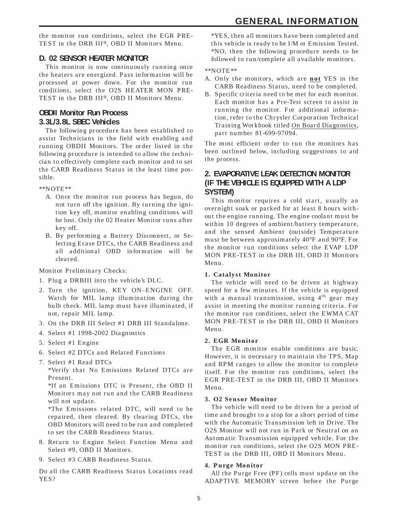
the monitor run conditions, select the EGR PRE-TEST in the DRB IIIt, OBD II Monitors Menu.
D. 02 SENSOR HEATER MONITORThis monitor is now continuously running once
the heaters are energized. Pass information will beprocessed at power down. For the monitor runconditions, select the O2S HEATER MON PRE-TEST in the DRB IIIt, OBD II Monitors Menu.
OBDII Monitor Run Process3.3L/3.8L SBEC Vehicles
The following procedure has been established toassist Technicians in the field with enabling andrunning OBDII Monitors. The order listed in thefollowing procedure is intended to allow the techni-cian to effectively complete each monitor and to setthe CARB Readiness Status in the least time pos-sible.
**NOTE**A. Once the monitor run process has begun, do
not turn off the ignition. By turning the igni-tion key off, monitor enabling conditions willbe lost. Only the 02 Heater Monitor runs afterkey off.
B. By performing a Battery Disconnect, or Se-lecting Erase DTCs, the CARB Readiness andall additional OBD information will becleared.
Monitor Preliminary Checks:1. Plug a DRBIII into the vehicle’s DLC.2. Turn the ignition, KEY ON–ENGINE OFF.
Watch for MIL lamp illumination during thebulb check. MIL lamp must have illuminated, ifnot, repair MIL lamp.
3. On the DRB III Select #1 DRB III Standalone.4. Select #1 1998-2002 Diagnostics5. Select #1 Engine6. Select #2 DTCs and Related Functions7. Select #1 Read DTCs
*Verify that No Emissions Related DTCs arePresent.*If an Emissions DTC is Present, the OBD IIMonitors may not run and the CARB Readinesswill not update.*The Emissions related DTC, will need to berepaired, then cleared. By clearing DTCs, theOBD Monitors will need to be run and completedto set the CARB Readiness Status.
8. Return to Engine Select Function Menu andSelect #9, OBD II Monitors.
9. Select #3 CARB Readiness Status.
Do all the CARB Readiness Status Locations readYES?
*YES, then all monitors have been completed andthis vehicle is ready to be I/M or Emission Tested.*NO, then the following procedure needs to befollowed to run/complete all available monitors.
**NOTE**A. Only the monitors, which are not YES in the
CARB Readiness Status, need to be completed.B. Specific criteria need to be met for each monitor.
Each monitor has a Pre-Test screen to assist inrunning the monitor. For additional informa-tion, refer to the Chrysler Corporation TechnicalTraining Workbook titled On Board Diagnostics,part number 81-699-97094.
The most efficient order to run the monitors hasbeen outlined below, including suggestions to aidthe process.
2. EVAPORATIVE LEAK DETECTION MONITOR(IF THE VEHICLE IS EQUIPPED WITH A LDPSYSTEM)
This monitor requires a cold start, usually anovernight soak or parked for at least 8 hours with-out the engine running. The engine coolant must bewithin 10 degrees of ambient/battery temperature,and the sensed Ambient (outside) Temperaturemust be between approximately 40°F and 90°F. Forthe monitor run conditions select the EVAP LDPMON PRE-TEST in the DRB III, OBD II MonitorsMenu.
1. Catalyst MonitorThe vehicle will need to be driven at highway
speed for a few minutes. If the vehicle is equippedwith a manual transmission, using 4th gear mayassist in meeting the monitor running criteria. Forthe monitor run conditions, select the EWMA CATMON PRE-TEST in the DRB III, OBD II MonitorsMenu.
2. EGR MonitorThe EGR monitor enable conditions are basic.
However, it is necessary to maintain the TPS, Mapand RPM ranges to allow the monitor to completeitself. For the monitor run conditions, select theEGR PRE-TEST in the DRB III, OBD II MonitorsMenu.
3. O2 Sensor MonitorThe vehicle will need to be driven for a period of
time and brought to a stop for a short period of timewith the Automatic Transmission left in Drive. TheO2S Monitor will not run in Park or Neutral on anAutomatic Transmission equipped vehicle. For themonitor run conditions, select the O2S MON PRE-TEST in the DRB III, OBD II Monitors Menu.
4. Purge MonitorAll the Purge Free (PF) cells must update on the
ADAPTIVE MEMORY screen before the Purge
5
GENERAL INFORMATION
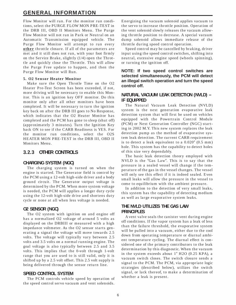
Flow Monitor will run. For the monitor run condi-tions, select the PURGE FLOW MON PRE-TEST inthe DRB III, OBD II Monitors Menu. The PurgeFlow Monitor will not run in Park or Neutral on anAutomatic Transmission equipped vehicle. ThePurge Flow Monitor will attempt to run everyother throttle closure. If all of the parameters aremet and it still does not run, with your foot firmlyon the Service Brake, slightly (1/4) open the Throt-tle and quickly close the Throttle. This will allowthe Purge Free update to happen, and then thePurge Flow Monitor will Run.
5. O2 Sensor Heater MonitorMake sure the Open Throtle Time on the O2
Heater Pre-Test Screen has been exceeded, if not,more driving will be necessary to enable this Mon-itor. This is an ignition key OFF monitor. Do thismonitor only after all other monitors have beencompleted. It will be necessary to turn the ignitionkey back on after the DRB III goes to No Response,which indicates that the O2 Heater Monitor hascompleted and the PCM has gone to sleep (shut off)(approximately 3 minutes). Turn the Ignition Keyback ON to see if the CARB Readiness is YES. Forthe monitor run conditions, select the O2SHEATER MON PRE-TEST in the DRB III, OBD IIMonitors Menu.
3.2.3 OTHER CONTROLS
CHARGING SYSTEM (NGC)The charging system is turned on when the
engine is started. The Generator field is control bythe PCM using a 12-volt high-side driver and a bodyground circuit. The Generator output voltage isdetermined by the PCM. When more system voltageis needed, the PCM will applies a longer duty cycleusing the 12-volt high-side drive and shortens dutycycle or none at all when less voltage is needed.
O2 SENSOR (NGC)The O2 system with ignition on and engine off
has a normalized O2 voltage of around 5 volts asdisplayed on the DRBIII or measured with a highimpedance voltmeter. As the O2 sensor starts gen-erating a signal the voltage will move towards 2.5volts. The voltage will typically vary between 2.5volts and 3.5 volts on a normal running engine. Thegoal voltage is also typically between 2.5 and 3.5volts. This implies that the 0-volt through 1-voltrange that you are used to is still valid, only it isshifted up by a 2.5 volt offset. This 2.5 volt supply isbeing delivered through the sensor return line.
SPEED CONTROL SYSTEMThe PCM controls vehicle speed by operation of
the speed control servo vacuum and vent solenoids.
Energizing the vacuum solenoid applies vacuum tothe servo to increase throttle position. Operation ofthe vent solenoid slowly releases the vacuum allow-ing throttle position to decrease. A special vacuumdump solenoid allows immediate release of thethrottle during speed control operation.
Speed control may be cancelled by braking, driverinput using the speed control switches, shifting intoneutral, excessive engine speed (wheels spinning),or turning the ignition off.
NOTE: If two speed control switches areselected simultaneously, the PCM will detectan illegal switch operation and turn the speedcontrol off.
NATURAL VACUUM LEAK DETECTION (NVLD) –IF EQUIPPED
The Natural Vacuum Leak Detection (NVLD)system is the next generation evaporative leakdetection system that will first be used on vehiclesequipped with the Powertrain Control Module(PCM) or Next Generation Controller (NGC) start-ing in 2002 M.Y. This new system replaces the leakdetection pump as the method of evaporative sys-tem leak detection. The current CARB requirementis to detect a leak equivalent to a 0.0209 (0.5 mm)hole. This system has the capability to detect holesof this size very dependably.
The basic leak detection theory employed withNVLD is the 9Gas Law9. This is to say that thepressure in a sealed vessel will change if the tem-perature of the gas in the vessel changes. The vesselwill only see this effect if it is indeed sealed. Evensmall leaks will allow the pressure in the vessel tocome to equilibrium with the ambient pressure.
In addition to the detection of very small leaks,this system has the capability of detecting mediumas well as large evaporative system leaks.
THE NVLD UTILIZES THE GAS LAWPRINCIPLES
A vent valve seals the canister vent during engineoff conditions. If the vapor system has a leak of lessthan the failure threshold, the evaporative systemwill be pulled into a vacuum, either due to the cooldown from operating temperature or diurnal ambi-ent temperature cycling. The diurnal effect is con-sidered one of the primary contributors to the leakdetermination by this diagnostic. When the vacuumin the system exceeds about 19 H2O (0.25 KPA), avacuum switch closes. The switch closure sends asignal to the PCM. The PCM, via appropriate logicstrategies (described below), utilizes the switchsignal, or lack thereof, to make a determination ofwhether a leak is present.
6
GENERAL INFORMATION

THE NVLD DEVICE AND HOW IT FUNCTIONSThe NVLD Assembly is designed with a normally
open vacuum switch, a normally closed solenoid,and a seal, which is actuated by both the solenoidand a diaphragm. The NVLD is located on theatmospheric vent side of the canister.
The normally open vacuum switch will close withabout 19 H2O (0.25 KPA) vacuum in the evaporativesystem. The diaphragm actuates the switch. This isabove the opening point of the fuel inlet check valvein the fill tube so cap off leaks can be detected.Submerged fill systems must have recirculationlines that do not have the in-line normally closedcheck valve that protects the system from failednozzle liquid ingestion, in order to detect cap offconditions.
The normally closed valve in the NVLD is in-tended to maintain the seal on the evaporativesystem during the engine off condition. If vacuum inthe evaporative system exceeds 39 to 69 H2O (0.75 to1.5 KPA), the valve will be pulled off the seat,opening the seal. This will protect the system fromexcessive vacuum as well as allowing sufficientpurge flow in the event that the solenoid was tobecome inoperative. The solenoid actuates the valveto unseal the canister vent while the engine isrunning. It also will be used to close the vent duringthe medium and large leak tests and during thepurge flow check. This solenoid requires initial 1.5amps of current to pull the valve open but after 100ms. will be duty cycled down to an average of about150 mA for the remainder of the drive cycle.
Another feature in the NVLD Assembly is adiaphragm that will open the seal with pressure inthe evaporative system. The seal will be opened atabout 0.59 H2O (0.12 KPA) pressure to permit theventing of vapors during refueling. An added bene-fit to this is that it will also allow the tank to9breathe9 during increasing temperatures, thus lim-iting the pressure in the tank to this low level. Thisis beneficial because the induced vacuum during asubsequent declining temperature will achieve theswitch closed (pass threshold) sooner than if thetank had to decay from a built up pressure.
The NVLD Assembly itself has 3 wires: Switchsense, solenoid driver and ground. It also includes aresistor to protect the switch from a short to batteryor a short to ground. The PCM utilizes a high-sidedriver to energize and duty-cycle the solenoid.
THE PCM’S ROLE IN NVLD DIAGNOSIS:The integral part of the diagnostic system that
makes engine-off leak detection possible is a specialcircuit in the PCM controller. After the vehicle isturned off, a special part of the controller stays aliveand monitors for an NVLD switch closure. Thiscircuit within the PCM is very specific in its func-tion and consumes very little power. If a switch
closure is detected, it will log the event and timefrom key-off, and then power down. This informa-tion will be processed at the next key cycle.
NVLD LEAK DETECTION
Small Leak Test (Passive)If, after a specified delay after key off (perhaps 5
minutes), the switch closes or is closed, the test willbe pass, indicating that there is no leak. The PCMrecords the switch closure. The NVLD circuit in thePCM will shut down for the remainder of thatparticular engine off (soak) period. When the engineis started, the switch closure is recorded as a 9Pass,9and the timers that are recording accumulated timeare reset.
This diagnostic test can take at least a week tomature a leak fault. A week has been chosen for thisbecause the vehicle will have been exposed to thelargest possible drive scenarios before a decision ismade (most vehicles should see both daily work andweekend driving cycles). This also satisfies CARB’sstated goal of getting 3 MIL illuminations within amonth for 0.0209 (0.5 mm) leak detection diagnostic.
The diagnostics will log engine run time andengine off time to determine when a week haselapsed. There is a limit on the total amount of runtime that is applied to the one-week timer. There isalso a limit on the total soak time that will beallowed to be applied to the one-week timer. Therewill be a limit on the amount of accrued run timeduring one specific drive that can be applied to theone-week timer.
The enabling criteria to run this monitor are:• Fuel level less than 85%• Ambient temperature greater than 40 °F (4.4 °C)
Rationality Tests1. The rationality check of the switch, solenoid and
seal will be performed as follows:• At key-on, the NVLD solenoid will be energized to
vent any vacuum that may be trapped in theevaporative system from the previous soak. Thisshould result in an open switch condition.
• The solenoid will be de-energized (to seal thesystem) at the point where purge begins. Thesystem / NVLD component rationality passes forthat drive cycle if the switch closes after purgebegins.
• The solenoid is then re-energized for the remain-der of the drive cycle.
• If the switch events are not seen in a certainperiod of time, the rationality check will havefailed (2 trip rule).
7
GENERAL INFORMATION

2. Purge Flow:The above rationality check is considered suffi-
cient to confirm purge solenoid function and con-formance with the purge flow test requirement. ThePurge Flow Monitor is passed based on switchactivity when purge is turned on or based on a richfuel control shift when purge is turned on.
Medium and Large Leak Test (Intrusive)
NOTE: This intrusive test will only be run ifthe Small Leak (passive) test fails, or isinconclusive (the switch does not close)
Enabling Conditions:• 40 °F to 90 °F• Engine temperature at startup within 10 °F of
the ambient temperature• Fuel level less than 85%
The intrusive Medium and Large leak are con-ducted as follows:• De-energize the NVLD solenoid to seal the can-
ister vent.• Activate purge shortly after closed loop. Pull the
tank vacuum past the vacuum switch point (19H2O vacuum) of the NVLD for a specific timewhile tracking the standard purge flow rate.
• Turn purge off and determine how long it takes todecay the tank vacuum and reopen the switch.Determine the leak size from the time it took toreopen the switch. Note: Fuel level is an impor-tant determining factor.
• If the switch does not close, a more aggressivepurge flow will be applied to determine if it is avery large leak, missing fuel cap, problem withthe NVLD device, purge flow problem, etc...
FIGURE 1
8
GENERAL INFORMATION

FIGURE 2
9
GENERAL INFORMATION

LEAK DETECTION PUMP SYSTEM — IFEQUIPPED
The evaporative emission system is designed toprevent the escape of fuel vapors from the fuelsystem. Leaks in the system, even small ones, canallow fuel vapors to escape into the atmosphere.Government regulations require onboard testing tomake sure that the evaporative (EVAP) system isfunctioning properly. The leak detection systemtests for EVAP system leaks and blockage. It alsoperforms self-diagnostics. During self-diagnostics,the Powertrain Control Module (PCM) first checksthe Leak Detection Pump (LDP) for electrical andmechanical faults. If the first checks pass, the PCMthen uses the LDP to seal the vent valve and pumpair into the system to pressurize it. If a leak ispresent, the PCM will continue pumping the LDP toreplace the air that leaks out. The PCM determinesthe size of the leak based on how fast/long it mustpump the LDP as it tries to maintain pressure inthe system.
EVAP LEAK DETECTION SYSTEM COMPONENTS(FIGURE 1)
Service Port: Used with special tools like theMiller Evaporative Emissions Leak Detector(EELD) to test for leaks in the system.
EVAP Purge Solenoid: The PCM uses theEVAP purge solenoid to control purging of excessfuel vapors stored in the EVAP canister. It remainsclosed during leak testing to prevent loss of pres-sure.
EVAP Canister: The EVAP canister stores fuelvapors from the fuel tank for purging.
EVAP Purge Orifice: Limits purge volume.EVAP System Air Filter: Provides air to the
LDP for pressurizing the system. It filters out dirtwhile allowing a vent to atmosphere for the EVAPsystem.
Leak Detection Pump (LDP) Components:The main purpose of the LDP is to pressurize the
fuel system for leak checking. It closes the EVAPsystem vent to atmospheric pressure so the systemcan be pressurized for leak testing. The diaphragmis powered by engine vacuum. It pumps air into theEVAP system to develop a pressure of about 7.59H2O (1⁄4) psi. A reed switch in the LDP allows thePCM to monitor the position of the LDP diaphragm.The PCM uses the reed switch input to monitor howfast the LDP is pumping air into the EVAP system.This allows detection of leaks and blockage.
The LDP assembly consists of several parts (Fig-ure 2). The solenoid is controlled by the PCM, and itconnects the upper pump cavity to either enginevacuum or atmospheric pressure. A vent valvecloses the EVAP system to atmosphere, sealing thesystem during leak testing. The pump section of theLDP consists of a diaphragm that moves up anddown to bring air in through the air filter and inletcheck valve, and pump it out through an outletcheck valve into the EVAP system.
The diaphragm is pulled up by engine vacuum,and pushed down by spring pressure, as the LDPsolenoid turns on and off. The LDP also has amagnetic reed switch to signal diaphragm positionto the PCM. When the diaphragm is down, theswitch is closed, which sends a 12 V (system volt-age) signal to the PCM. When the diaphragm is up,the switch is open, and there is no voltage sent tothe PCM. This allows the PCM to monitor LDPpumping action as it turns the LDP solenoid on andoff.
LDP AT REST (NOT POWERED)When the LDP is at rest (no electrical/vacuum)
the diaphragm is allowed to drop down if theinternal (EVAP system) pressure is not greater thanthe return spring. The LDP solenoid blocks theengine vacuum port and opens the atmosphericFIGURE 1
FIGURE 2
10
GENERAL INFORMATION

pressure port connected through the EVAP systemair filter. The vent valve is held open by the dia-phragm. This allows the canister to see atmosphericpressure (Figure 3).
DIAPHRAGM UPWARD MOVEMENTWhen the PCM energizes the LDP solenoid, the
solenoid blocks the atmospheric port leadingthrough the EVAP air filter and at the same timeopens the engine vacuum port to the pump cavityabove the diaphragm. The diaphragm moves up-ward when the vacuum above the diaphragm ex-ceeds spring force. This upward movement closesthe vent valve. It also causes low pressure below thediaphragm, unseating the inlet check valve andallowing air in from the EVAP air filter. When thediaphragm completes its upward movement, theLDP reed switch turns from closed to open (Figure4).
DIAPHRAGM DOWNWARD MOVEMENTBased on reed switch input, the PCM de-
energizes the LDP solenoid, causing it to block thevacuum port, and open the atmospheric port. Thisconnects the upper pump cavity to atmospherethrough the EVAP air filter. The spring is now ableto push the diaphragm down. The downward move-ment of the diaphragm closes the inlet check valveand opens the outlet check valve pumping air intothe evaporative system. The LDP reed switch turnsfrom open to closed, allowing the PCM to monitorLDP pumping (diaphragm up/down) activity (Fig-ure 5). During the pumping mode, the diaphragmwill not move down far enough to open the ventvalve.
The pumping cycle is repeated as the solenoid isturned on and off. When the evaporative systembegins to pressurize, the pressure on the bottom ofthe diaphragm will begin to oppose the springpressure, slowing the pumping action. The PCMwatches the time from when the solenoid is de-energized, until the diaphragm drops down farenough for the reed switch to change from open toclosed. If the reed switch changes too quickly, a leakmay be indicated. The longer it takes the reedswitch to change state, the tighter the evaporativesystem is sealed. If the system pressurizes tooquickly, a restriction somewhere in the EVAP sys-tem may be indicated.
PUMPING ACTIONDuring portions of this test, the PCM uses the
reed switch to monitor diaphragm movement. Thesolenoid is only turned on by the PCM after the reedswitch changes from open to closed, indicating thatthe diaphragm has moved down. At other timesduring the test, the PCM will rapidly cycle the LDPsolenoid on and off to quickly pressurize the system.During rapid cycling, the diaphragm will not moveenough to change the reed switch state. In the state
FIGURE 3
FIGURE 4
FIGURE 5
11
GENERAL INFORMATION

of rapid cycling, the PCM will use a fixed timeinterval to cycle the solenoid.
If the system does not pass the EVAP LeakDetection Test, the following DTCs may be set:• P0442 - EVAP LEAK MONITOR 0.0409 LEAK
DETECTED• P0455 - EVAP LEAK MONITOR LARGE LEAK
DETECTED• P0456 - EVAP LEAK MONITOR 0.0209 LEAK
DETECTED• P1486 - EVAP LEAK MON PINCHED HOSE
FOUND• P1494 - LEAK DETECTION PUMP SW OR
MECH FAULT• P1495 - LEAK DETECTION PUMP SOLENOID
CIRCUIT
ENABLING CONDITIONS TO RUN EVAP LEAKDETECTION TEST1. Cold start: with ambient temperature (obtained
from modeling the inlet air temperature sensoron passenger vehicles and the battery tempera-ture sensor on Jeep & truck vehicles) between4°C (40°F) and 32°C (90°F) for 0.040 leak. Be-tween 4°C (40°F) and 29°C (85°F) for 0.020 leak.
2. Engine coolant temperature within: -12° to -8°C(10° to 18°F) of battery/ambient.
3. Battery voltage between 10 and 15 volts.
NOTE: If battery voltage drops below 10 voltsfor more than 5 seconds during enginecranking, the EVAP Leak Detection Test willnot run.4. Low fuel warning light off (fuel level must be
between 15% and 85%).
5. MAP sensor reading 22 in Hg or above (This isthe manifold absolute pressure, not vacuum).
6. No engine stall during test.
NOTE: The following values are approximateand vehicle specific. Use the values seen inpre test/monitor test screen on the DRBIII T.See TSB 25-02-98 for more detail.
A DTC will not set if a one-trip fault is set or if theMIL is illuminated for any of the following:• Purge Solenoid• All engine Controller Self Test Faults• All Cam and/or Crank Sensor Faults• MAP Sensor Faults• Ambient/Battery Temperature Sensor Electrical
Faults• All Coolant Sensor Faults• All TPS Faults
• LDP Pressure Switch Faults• EGR Solenoid Electrical Faults• All Injector Faults• Baro Out Of Range• Vehicle Speed Faults• LDP Solenoid Circuit
FIGURE 6 SECTION 1When the ignition key is turned to “ON”, the LDP
diaphragm should be in the down position and theLDP reed switch should be closed. If the EVAPsystem has residual pressure, the LDP diaphragmmay be up. This could result in the LDP reed switchbeing open when the key is turned to “ON” and aP1494 fault could be set because the PCM is expect-ing the reed switch to be closed.
After the key is turned “ON”, the PCM immedi-ately tests the LDP solenoid circuit for electricalfaults. If a fault is detected, DTC P1495 will set, theMIL will illuminate, and the remaining EVAP LeakDetection Test is canceled.
NOTE: If battery temperature is not withinrange, or if the engine coolant temperature isnot within a specified range of the batterytemperature, the PCM will not run tests forDTC P1494, P1486, P0442, P0455 and P0441.These temperature calibrations may bedifferent between models.
FIGURE 6 SECTION 2If DTC P1495 is not set, the PCM will check for
DTC P1494. If the LDP reed switch was closedwhen the key was turned to “ON”, the PCM ener-gizes the LDP solenoid for up to 8 seconds andmonitors the LDP switch. As the LDP diaphragm ispulled up by engine vacuum, the LDP reed switchshould change from closed to open. If it does not, the
FIGURE 6
12
GENERAL INFORMATION

PCM sets a temporary fault (P1494) in memory, andwaits until the next time the Enabling Conditionsare met to run the test again. If this is againdetected, P1494 is stored and the MIL is illumi-nated. If the problem is not detected during the nextenabling cycle, the temporary fault will be cleared.
However, if the PCM detects the reed switch openwhen the key is turned to “ON”, the PCM mustdetermine if this condition is due to residual pres-sure in the EVAP system, or an actual fault. ThePCM stores information in memory on EVAP sys-tem purging from previous engine run or drivecycles.
If little or no purging took place, residual pres-sure could be holding the LDP diaphragm up,causing the LDP switch to be open. Since this is nota malfunction, the PCM cancels the EVAP LeakDetection Test without setting the temporary fault.
If there was sufficient purging during the previ-ous cycle to eliminate EVAP system pressure, thePCM judges that this is a malfunction and sets atemporary fault in memory. The next time that theEnabling Conditions are met, the test will runagain. If the fault is again detected, the MIL willilluminate and DTC 1494 will be stored. If the faultis not detected, the temporary fault will be cleared.
FIGURE 6 SECTION 3If no fault has been detected so far, the PCM
begins testing for possible blockage in the EVAPsystem between the LDP and the fuel tank. This isdone by monitoring the time required for the LDP topump air into the EVAP system during two to threepump cycles. If no blockage is present, the LDPdiaphragm is able to quickly pump air out of theLDP each time the PCM turns off the LDP solenoid.If a blockage is present, the PCM detects that theLDP takes longer to complete each pump cycle. Ifthe pump cycles take longer than expected (approx-imately 6 to 10 seconds) the PCM will suspect ablockage. On the next drive when Enabling Condi-tions are met, the test will run again. If blockage isagain detected, P1486 is stored, and the MIL isilluminated.
FIGURE 6 SECTION 4After the LDP blockage tests are completed, the
PCM then tests for EVAP system leakage. First, thePCM commands the LDP to rapidly pump for 20 to50 seconds (depending on fuel level) to build pres-sure in the EVAP system. This evaluates the systemto see if it can be sufficiently pressurized. Thisevaluation (rapid pump cycling) may occur severaltimes prior to leak checking. The LDP reed switchdoes not close and open during rapid pumpingbecause the diaphragm does not travel through itsfull range during this part of the test.
FIGURE 6 SECTION 5Next, the PCM performs one or more test cycles
by monitoring the time required for the LDP reedswitch to close (diaphragm to drop) after the LDPsolenoid is turned off.
If the switch does not close, or closes after a longdelay, it means that the system does not have anysignificant leakage and the EVAP Leak DetectionTest is complete.
However, if the LDP reed switch closes quickly,there may be a leak or the fuel level may be lowenough that the LDP must pump more to finishpressurizing the EVAP system. In this case, thePCM will rapidly pump the LDP again to buildpressure in the EVAP system, and follow that bymonitoring the time needed for several LDP testcycles. This process of rapid pumping followed byseveral LDP test cycles may repeat several timesbefore the PCM judges that a leak is present.
When leaks are present, the LDP test cycle timewill be inversely proportional to the size of the leak.The larger the leak, the shorter the test cycle time.The smaller the leak, the longer the test cycle time.DTC’s may be set when a leak as small as 0.5 mm(0.0209) diameter is present.
If the system detects a leak, a temporary faultwill be stored in PCM memory. The time it takes todetect a .020, .040, or Large leak is based oncalibrations that vary from model to model. Theimportant point to remember is if a leak is againdetected on the next EVAP Leak Detection Test, theMIL will illuminate and a DTC will be stored basedon the size of leak detected. If no leak is detectedduring the next test, the temporary fault will becleared.
DIAGNOSTIC TIPSDuring diagnosis, you can compare the LDP so-
lenoid activity with the monitor sequence in Figure6. If the PCM detects a problem that could set aDTC, the testing is halted and LDP solenoid activ-ity will stop. As each section of the test begins, itindicates that the previous section passed success-fully. By watching to see which tests complete, youcan see if any conditions are present that the PCMconsiders abnormal.
For example, if the LDP solenoid is energized forthe test cycles to test for blockage (P1486), it meansthat the LDP has already passed its test for P1494.Then, if the PCM detects a possible blockage, it willset a temporary fault without turning on the MILand continue the leak portion of the test. However,the PCM will assume that the system is alreadypressurized and skip the rapid pump cycles.
Always diagnose leaks, if possible, before discon-necting connections. Disconnecting connectionsmay mask a leak condition.
13
GENERAL INFORMATION

Keep in mind that if the purge solenoid seat isleaking, it could go undetected since the leak wouldend up in the intake manifold. Disconnect the purgesolenoid at the manifold when leak checking. Inaddition, a pinched hose fault (P1486) could set ifthe purge solenoid does not purge the fuel systemproperly (blocked seat). The purge solenoid mustvent the fuel system prior to the LDP system test. Ifthe purge solenoid cannot properly vent the systemthe LDP cannot properly complete the test forP1486 and this fault can set due to pressure beingin the EVAP system during the test sequence.
Multiple actuation’s of the DRBIIIt Leak Detec-tion Pump (LDP) Monitor Test can hide a 0.020 leakbecause of excess vapor generation. Additionally,any source for additional vapor generation can hidea small leak in the EVAP system. Excess vaporgeneration can delay the fall of the LDP diaphragmthus hiding the small leak. An example of thiscondition could be bringing a cold vehicle into awarm shop for testing or high ambient tempera-tures.
Fully plugged and partially plugged underhoodvacuum lines have been known to set MIL condi-tions. P1494 and P0456 can be set for this reason.Always, thoroughly, check plumbing for pinches orblockage before condemning components.
TEST EQUIPMENTThe Evaporative Emission Leak Detector (EELD)
Miller Special Tool 8404 is capable of visually de-tecting leaks in the evaporative system and willtake the place of the ultrasonic leak detector 6917A.The EELD utilizes shop air and a smoke generatorto visually detect leaks down to 0.020 or smaller.The food grade oil used to make the smoke includesan UV trace dye that will leave telltale signs of theleak under a black light. This is helpful whencomponents have to be removed to determine theexact leak location. For detailed test instructions,follow the operators manual packaged with theEELD.
IMPORTANTBe sure that the PCM has the latest software
update. Reprogram as indicated by any applicableTechnical Service Bulletin. After LDP repairs arecompleted, verify the repair by running theDRBIIIt Leak Detection Pump (LDP) Monitor Testas described in Technical Service Bulletin 18-12-99.
3.2.4 PCM OPERATING MODESAs input signals to the PCM change, the PCM
adjusts its response to output devices. For example,the PCM must calculate a different injector pulsewidth and ignition timing for idle than it does forwide open throttle. There are several different
modes of operation that determine how the PCMresponds to the various input signals.
There are two types of engine control operation:open loop and closed loop.
In open loop operation, the PCM receives inputsignals and responds according to preset program-ming. Inputs from the heated oxygen sensors arenot monitored.
In closed loop operation, the PCM monitors theinputs from the heated oxygen sensors. This inputindicates to the PCM whether or not the calculatedinjector pulse width results in the ideal air-fuelratio of 14.7 parts air to 1 part fuel. By monitoringthe exhaust oxygen content through the oxygensensor, the PCM can fine tune injector pulse width.Fine tuning injector pulse width allows the PCM toachieve the lowest emission levels while maintain-ing optimum fuel economy.
The engine start-up (crank), engine warm-up,and wide open throttle modes are open loop modes.Under most operating conditions, closed loop modesoccur with the engine at operating temperature.
3.2.5 NON-MONITORED CIRCUITSThe PCM does not monitor the following circuits,
systems, and conditions even though they couldhave malfunctions that result in driveability prob-lems. A diagnostic code may not be displayed for thefollowing conditions. However, problems with thesesystems may cause a diagnostic code to be displayedfor other systems. For example, a fuel pressureproblem will not register a diagnostic code directly,but could cause a rich or lean condition. This couldcause an oxygen sensor, fuel system, or misfiremonitor trouble code to be stored in the PCM.
Engine Timing − The PCM cannot detect anincorrectly indexed timing chain, camshaftsprocket, or crankshaft sprocket. The PCM alsocannot detect an incorrectly indexed distributor.(*)
Fuel Pressure − Fuel pressure is controlled bythe fuel pressure regulator. The PCM cannot detecta clogged fuel pump inlet filter, clogged in-line filter,or a pinched fuel supply.(*)
Fuel Injectors − The PCM cannot detect if a fuelinjector is clogged, the pintle is sticking, or thewrong injectors are installed.(*)
Fuel Requirements − Poor quality gasoline cancause problems such as hard starting, stalling, andstumble. Use of methanol-gasoline blends may re-sult in starting and driveability problems. See indi-vidual symptoms and their definitions in Section6.0 (Glossary of Terms).
PCM Grounds − The PCM cannot detect a poorsystem ground. However, a diagnostic trouble codemay be stored in the PCM as a result of thiscondition.
14
GENERAL INFORMATION

Throttle Body Air Flow − The PCM cannotdetect a clogged or restricted air cleaner inlet orfilter element.(*)
Exhaust System − The PCM cannot detect aplugged, restricted, or leaking exhaust system.(*)
Cylinder Compression − The PCM cannot de-tect uneven, low, or high engine cylinder compres-sion.(*)
Excessive Oil Consumption − Although thePCM monitors the exhaust stream oxygen contentthrough the oxygen sensor when the system is in aclosed loop, it cannot determine excessive oil con-sumption.
NOTE: Any of these conditions could resultin a rich or lean condition causing an oxygensensor TROUBLE CODE to be stored in thePCM, or the vehicle may exhibit one or moreof the driveability symptoms listed in theTable of Contents.
3.2.6 SKIS OVERVIEWThe Sentry Key Immobilizer System (SKIS) is
designed to prevent unauthorized vehicle opera-tion. The system consists of a Sentry Key Immobi-lizer Module (SKIM), ignition key(s) equipped witha transponder chip and PCM. When the ignitionswitch is turned on, the SKIM interrogates theignition key. If the ignition key is Valid or Invalid,the SKIM sends a PCI Bus message to the PCMindicating ignition key status. Upon receiving thismessage the PCM will terminate engine operation,or allow the engine to continue to operate.
3.2.7 SKIM ON-BOARD DIAGNOSTICSThe SKIM has been programmed to transmit and
monitor many different coded messages as well asPCI Bus messages. This monitoring is called OnBoard Diagnosis.
Certain criteria must be met for a diagnostictrouble code to be entered into the SKIM memory.The criteria may be a range of; Input voltage, PCIBus message, or coded messages to the SKIM. If allof the criteria for monitoring a circuit or functionare met and a fault is sensed, a diagnostic troublecode will be stored in the SKIM memory.
3.2.8 SKIS OPERATIONWhen ignition power is supplied to the SKIM, the
SKIM performs an internal self-test. After the self-test is completed, the SKIM energizes the antenna(this activates the transponder chip) and sends achallenge to the transponder chip. The transponderchip responds to the challenge by generating anencrypted response message using the following:
Secret Key - This is an electronically storedvalue (identification number) that is unique to each
SKIS. The secret key is stored in the SKIM, PCMand all ignition key transponders.
Challenge - This is a random number that isgenerated by the SKIM at each ignition key cycle.
The secret key and challenge are the two vari-ables used in the algorithm that produces theencrypted response message. The transponder usesthe crypto algorithm to receive, decode and respondto the message sent by the SKIM. After respondingto the coded message, the transponder sends atransponder I.D. message to the SKIM. The SKIMcompares the transponder I.D. to the available validkey codes in the SKIM memory (8 key maximum atany one time). After validating the key ignition theSKIM sends a PCI Bus message called a SeedRequest to the engine controller then waits for aPCM response. If the PCM does not respond, theSKIM will send the seed request again. After threefailed attempts the SKIM will stop sending the seedrequest and store a trouble code. If the PCM sendsa seed response, the SKIM sends a valid/invalid keymessage to the PCM. This is an encrypted messagethat is generated using the following:
VIN - Vehicle Identification NumberSeed - This is a random number that is generated
by the PCM at each ignition key cycle.The VIN and seed are the two variables used in
the rolling code algorithm that encrypts the valid/invalid key message. The PCM uses the rolling codealgorithm to receive, decode and respond to thevalid/invalid key message sent by the SKIM. Aftersending the valid/invalid key message the SKIMwaits 3.5 seconds for a PCM status message fromthe PCM. If the PCM does not respond with a validkey message to the SKIM, a fault is detected and atrouble code is stored.
The SKIS incorporates a VTSS LED located onthe instrument panel upper cover. The LED re-ceives switched ignition voltage and is hardwired tothe body control module. The LED is actuated whenthe SKIM sends a PCI Bus message to the bodycontroller requesting the LED on. The body control-ler then provides the ground for the LED. TheSKIM will request VTSS LED operation for thefollowing:
– bulb checks at ignition on– to alert the vehicle operator to a SKIS mal-
function– customer key programming mode
For all faults except transponder faults and VTSSLED remains on steady. In the event of a transpon-der fault the LED flashes at a rate of 1 Hz (once persecond). If a fault is present the LED will remain onor flashing for the complete ignition cycle. If a faultis stored in SKIM memory which prevents thesystem from operating properly, the PCM will allow
15
GENERAL INFORMATION

the engine to start and run (for 2 seconds) up to sixtimes. After the sixth attempt, the PCM disablesthe starter relay until the fault is corrected.
3.2.9 PROGRAMMING THE POWERTRAINCONTROL MODULE
Important Note: Before replacing the PCM for afailed driver, control circuit or ground circuit, besure to check the related component/circuit integ-rity for failures not detected due to a double fault inthe circuit. Most PCM driver/control circuit failuresare caused by internal failure to components (i.e.12-volt pull-ups, drivers and ground sensors). Thesefailures are difficult to detect when a double faulthas occurred and only one DTC has set.
NOTE: If the PCM and the SKIM are replacedat the same time, program the VIN into thePCM first. All vehicle keys will then need tobe replaced and programmed to the newSKIM.
The SKIS Secret Key is an I.D. code that isunique to each SKIS. This code is programmed andstored in the SKIM, engine controller and transpon-der chip (ignition key). When replacing the PCM itis necessary to program the secret key into thePCM.
NOTE: After replacing the PCM, you mustreprogram pinion factor.1. Turn the ignition on (transmission in park/
neutral).2. Use the DRBIIIt and select THEFT ALARM,
SKIM then MISCELLANEOUS.3. Select PCM REPLACED.4. Enter secured access mode by entering the vehi-
cle four-digit PIN.
NOTE: If three attempts are made to enterthe secure access mode using an incorrectPIN, secured access mode will be locked outfor one hour. To exit this lockout mode, turnthe ignition to the run position for one hourthen enter the correct PIN. (Ensure allaccessories are turned off. Also monitor thebattery state and connect a battery charger ifnecessary).5. Press ENTER to transfer the secret key (the
SKIM will send the secret key to the PCM).
3.2.10 PROGRAMMING THE SENTRY KEYIMMOBILIZER MODULE
NOTE: If the PCM and the SKIM are replacedat the same time, program the VIN into thePCM first. All vehicle keys will then need tobe replaced and programmed to the newSKIM.1. Turn the ignition on (transmission in park/
neutral).2. Use the DRBIIIt and select THEFT ALARM,
SKIM then MISCELLANEOUS.3. Select SKIM MODULE REPLACEMENT (GAS-
OLINE).4. Program the vehicle four-digit PIN into the
SKIM.5. Select COUNTRY CODE and enter the correct
country.
NOTE: Be sure to enter the correct countrycode. If the incorrect country code isprogrammed into SKIM, the SKIM must bereplaced.6. Select UPDATE VIN (the SKIM will learn the
VIN from the PCM).7. Press ENTER to transfer the VIN (the PCM will
send the VIN to the SKIM).8. The DRBIIIt will ask if you want to transfer the
secret key. Select ENTER to transfer secret keyfrom the PCM. This will ensure the currentvehicle ignition keys will still operate the SKISsystem.
3.2.11 PROGRAMMING THE IGNITIONKEYS TO THE SENTRY KEYIMMOBILIZER MODULE
1. Turn the ignition on (transmission in park/neutral).
2. Use the DRBIIIt and select THEFT ALARM,SKIM, then MISCELLANEOUS.
3. Select PROGRAM IGNITION KEYS.4. Enter secured access mode by entering the vehi-
cle four-digit PIN.
NOTE: A maximum of eight keys can belearned to each SKIM AT ONE TIME. Once akey is learned to a SKIM it (the key) cannot betransferred to another vehicle.
If ignition key programming is unsuccessful, theDRBIIIt will display one of the following messages:
16
GENERAL INFORMATION

Programming Not Attempted - The DRBIIItattempts to read the programmed key status andthere are no keys programmed in the SKIM mem-ory.
Programming Key Failed - (Possible Used KeyFrom Wrong Vehicle) - SKIM is unable to programkey due to one of the following:
– faulty ignition key transponder– ignition key is programmed to another vehicle.8 Keys Already Learned, Programming Not
Done - SKIM transponder ID memory is full.1. Obtain ignition keys to be programmed from
customer (8 keys maximum)2. Using the DRBIIIt, erase all ignition keys by
selecting MISCELLANEOUS and ERASE ALLCURRENT IGN. KEYS
3. Program all ignition keys.Learned Key In Ignition - Ignition key tran-
sponder ID is currently programmed in SKIM mem-ory.
3.3 DIAGNOSTIC TROUBLE CODES
Each diagnostic trouble code is diagnosed byfollowing a specific testing procedure. The diagnos-tic test procedures contain step-by-step instructionsfor determining the cause of trouble codes as well asno trouble code problems. It is not necessary toperform all of the tests in this book to diagnose anindividual code.
Always begin by reading the diagnostic troublecodes using the DRBIIIt.
3.3.1 HARD CODEA diagnostic trouble code that comes back within
one cycle of the ignition key is a hard code. Thismeans that the defect is there every time thepowertrain control module checks that circuit orfunction. Procedures in this manual verify if theDTC is a hard code at the beginning of each test.When it is not a hard code, an intermittent testmust be performed.
DTC’s that are for OBDII/Euro Stage III OBDmonitors will not set with just the ignition key on.Comparing these to non-emission DTC’s, they willseem like an intermittent. These DTC’s require aset of parameters to be performed (The DRBIIItpre-test screens will help with this for MONITORDTC’s), this is called a TRIP. All OBDII/Euro StageIII OBD DTCs will be set after one or in some casestwo trip failures, and the MIL will be turned on.These DTC’s require three successful, no failures,TRIPS to extinguish the MIL, followed by 40warm-up cycles to erase the DTC. For furtherexplanation of TRIPS, Pre-test screens, Warm-up
cycles, and the use of the DRBIIIt, refer to the OnBoard Diagnostic training booklet #81-699-97094.
3.3.2 INTERMITTENT CODEA diagnostic trouble code that is not there every
time the PCM checks the circuit is an intermittentDTC. Most intermittent DTC’s are caused by wiringor connector problems. Defects that come and golike this are the most difficult to diagnose; theymust be looked for under specific conditions thatcause them. The following checks may assist you inidentifying a possible intermittent problem:• Visually inspect related wire harness connectors.
Look for broken, bent, pushed out, or corrodedterminals.
• Visually inspect the related harnesses. Look forchafed, pierced, or partially broken wire.
• Refer to any technical service bulletins that mayapply.
• Use the DRBIIIt data recorder or co-pilot.
3.3.3 STARTS SINCE SET COUNTERThe start since set counter counts the number of
times the vehicle has been started since codes werelast set, erased, or the battery was disconnected.The reset counter will count up to 255 start counts.
The number of starts helps determine when thetrouble code actually happened. This is recorded bythe PCM and can be viewed on the DRBIIIt asSTARTS since set.
When there are no trouble codes stored in mem-ory, the DRBIIIt will display NO DTC’s Detectedand the reset counter will show STARTS since clear= XXX.
3.3.4 DISTANCE SINCE MI SETThe Euro Stage III OBD directive requires that
the distance traveled by the vehicle while the MI isactivated must be available at any instant throughthe serial port on the standard data link connector.This feature works as follows:1. If the MI is illuminated due to a fault, the
distance count is updated (i.e. it is counting).2. If there is a stale MI fault (i.e. the fault is still
frozen in memory but the MI has been extin-guished due to 3 good trips), the distance count isheld (i.e. frozen).
3. If the distance count is being held due to (Item2.) and the fault is cleared, the distance iscleared (set to zero).
4. If the distance count is being held due to (Item2.) and another MI occurs, the distance count isreset (to) and begins updating anew.
5. If a fault occurs while the MI is already illumi-nated due to a previous fault (the distance count
17
GENERAL INFORMATION

is updating), then the distance count continuesto update w/out interruption.
6. If the MI is flashing due to active misfire andthere is an active fault (i.e. matured fault forwhich 3 good trips have not occurred), the dis-tance count behaves as the MI in ON.
7. If the MI is flashing due to active misfire andthere is no active fault (i.e. the MI is flashing fora 1 malf.), the distance count behaves as if theMI is off (because it is not yet a matured fault).
8. The distance count is cleared whenever the faultis cleared. (Via 40 warm up cycles, or via scantool).
3.4 USING THE DRBIIIT
Refer to the DRBIIIt user’s guide for instructionsand assistance with reading DTC’s, erasing DTC’s,and other DRBIIIt functions.
3.5 DRBIIIT ERROR MESSAGES ANDBLANK SCREEN
Under normal operation, the DRBIIIt will dis-play one of only two error messages:
– User-Requested WARM Boot or User-Requested COLD Boot
If the DRBIIIt should display any other errormessage, record the entire display and call the StarCenter for information and assistance. This is asample of such an error message display:
ver: 2.14date: 26 Jul93file: key_itf.ccdate: Jul 26 1993line: 548err: 0x1User-Requested COLD Boot
Press MORE to switch between this displayand the application screen.
Press F4 when done noting information.
3.5.1 DRBIIIT DOES NOT POWER UPIf the LED’s do not light or no sound is emitted at
start up, check for loose cable connections or a badcable. Check the vehicle battery voltage (data linkconnector cavity 16). A minimum of 11 volts isrequired to adequately power the DRBIIIt.
If all connections are proper between theDRBIIItand the vehicle or other devices, and the vehiclebattery is fully charged, and inoperative DRBIIItmay be the result of faulty cable or vehicle wiring.
3.5.2 DISPLAY IS NOT VISIBLELow temperatures will affect the visibility of the
display. Adjust the contrast to compensate for thiscondition
4.0 DISCLAIMERS, SAFETY,WARNINGS
4.1 DISCLAIMERS
All information, illustrations, and specificationscontained in this manual are based on the latestinformation available at the time of publication.The right is reserved to make changes at any timewithout notice.
4.2 SAFETY
4.2.1 TECHNICIAN SAFETY INFORMATION
WARNING: ENGINES PRODUCE CARBONMONOXIDE THAT IS ODORLESS, CAUSESSLOWER REACTION TIME, AND CAN LEADTO SERIOUS INJURY. WHEN THE ENGINE ISOPERATING, KEEP SERVICE AREAS WELLVENTILATED OR ATTACH THE VEHICLEEXHAUST SYSTEM TO THE SHOP EXHAUSTREMOVAL SYSTEM.
Set the parking brake and block the wheels beforetesting or repairing the vehicle. It is especiallyimportant to block the wheels on front-wheel drivevehicles; the parking brake does not hold the drivewheels.
When servicing a vehicle, always wear eye pro-tection, and remove any metal jewelry such aswatchbands or bracelets that might make an inad-vertent electrical contact.
18
GENERAL INFORMATION

When diagnosing a powertrain system problem,it is important to follow approved procedures whereapplicable. These procedures can be found in ser-vice manual procedures. Following these proce-dures is very important to the safety of individualsperforming diagnostic tests.
4.2.2 VEHICLE PREPARATION FORTESTING
Make sure the vehicle being tested has a fullycharged battery. If it does not, false diagnostic codesor error messages may occur.
4.2.3 SERVICING SUB ASSEMBLIESSome components of the powertrain system are
intended to be serviced in assembly only. Attempt-ing to remove or repair certain system sub-components may result in personal injury and/orimproper system operation. Only those componentswith approved repair and installation procedures inthe service manual should be serviced.
4.2.4 DRBIIIT SAFETY INFORMATION
WARNING: EXCEEDING THE LIMITS OF THEDRBIIIT MULTIMETER IS DANGEROUS. ITCAN EXPOSE YOU TO SERIOUS INJURY.CAREFULLY READ AND UNDERSTAND THECAUTIONS AND THE SPECIFICATIONLIMITS.
Follow the vehicle manufacturer’s service specifi-cations at all times.• Do not use the DRBIIIt if it has been damaged.• Do not use the test leads if the insulation is
damaged or if metal is exposed.• To avoid electrical shock, do not touch the test
leads, tips, or the circuit being tested.• Choose the proper range and function for the
measurement. Do not try voltage or current mea-surements that may exceed the rated capacity.
• Do not exceed the limits shown in the table below:
FUNCTION INPUT LIMIT
Volts 0 - 500 peak volts AC0 - 500 volts DC
Ohms (resistance)* 0 - 1.12 megohms
Frequency MeasuredFrequency Generated
0 - 10 kHz
Temperature -58 - 1100°F-50 - 600°C
* Ohms cannot be measured if voltage is present.Ohms can be measured only in a non-poweredcircuit.
• Voltage between any terminal and ground mustnot exceed 500v DC or 500v peak AC.
• Use caution when measuring voltage above 25vDC or 25v AC.
• The circuit being tested must be protected by a10A fuse or circuit breaker.
• Use the low current shunt to measure circuits upto 10A. Use the high current clamp to measurecircuits exceeding 10A.
• When testing for the presence of voltage or cur-rent, make sure the meter is functioning cor-rectly. Take a reading of a known voltage orcurrent before accepting a zero reading.
• When measuring current, connect the meter inseries with the load.
• Disconnect the live test lead before disconnectingthe common test lead.
• When using the meter function, keep theDRBIIIt away from spark plug or coil wires toavoid measuring error from outside interference.
4.3 WARNINGS AND CAUTIONS
4.3.1 ROAD TEST WARNINGSSome complaints will require a test drive as part
of the repair verification procedure. The purpose ofthe test drive is to try to duplicate the diagnosticcode or symptom condition.
CAUTION: Before road testing a vehicle, besure that all components are reassembled.During the test drive, do not try to read theDRBIIIT screen while in motion. Do not hangthe DRBIII T from the rear view mirror oroperate it yourself. Have an assistantavailable to operate the DRBIII T.
4.3.2 VEHICLE DAMAGE CAUTIONSBefore disconnecting any control module, make
sure the ignition is off. Failure to do so coulddamage the module.
When testing voltage or continuity at any controlmodule, use the terminal side (not the wire end) ofthe connector. Do not probe a wire through theinsulation; this will damage it and eventually causeit to fail because of corrosion.
Be careful when performing electrical tests so asto prevent accidental shorting of terminals. Suchmistakes can damage fuses or components. Also, asecond DTC could be set, making diagnosis of theoriginal problem more difficult.
19
GENERAL INFORMATION

5.0 REQUIRED TOOLS ANDEQUIPMENT
DRBIIIt (diagnostic read-out box) scan toolEvaporative System Diagnostic Kit #6917fuel filler adapter #8382fuel pressure adapter (C-6631) or #6539fuel pressure kit (C-4799-B) or #5069fuel release hose (C-4799-1)Min Air flow fitting #6714Pinout Box (Miller #8815)jumper wiresohmmeteroscilloscopevacuum gaugevoltmeter12 volt test light minimum 25 ohms resistance
with probe #6801
CAUTION: A 12 volt test light should not beused for the following circuits, damage to thepowertrain controller will occur.• 5 Volt Supply• 8 Volt Supply• J1850 PCI Bus• CCD Bus• CKP Sensor Signal• CMP Sensor Signal• Vehicle Speed Sensor Signal• O2 Sensor Signal
6.0 GLOSSARY OF TERMS
ABS anti-lock brake system
backfire,popback
fuel ignites in either the intake orthe exhaust system
CKP crank position sensor
CMP camshaft position sensor
cuts out,misses
a steady pulsation or the inability ofthe engine to maintain a consistentrpm
DLC data link connector (previouslycalled engine diagnostic connector)
detona-tion,sparkknock
a mild to severe ping, especially un-der loaded engine conditions
ECT engine coolant temperature sensor
EGR exhaust gas recirculation valve andsystem
genera-tor
previously called alternator
hardstart
The engine takes longer than usualto start, even though it is able tocrank normally.
hesita-tion, sag,stumble
There is a momentary lack of re-sponse when the throttle is opened.This can occur at all vehicle speeds.If it is severe enough, the enginemay stall.
IAT intake/inlet air temperature sensor
IAC idle air control motor
JTEC Combined engine and transmissioncontrol module
lack ofpower,sluggish
The engine has less than expectedpower, with little or no increase invehicle speed when the throttle isopened.
LDP leak detection pump
MAP manifold absolute pressure sensor
MIL malfunction indicator lamp
MTV manifold tuning valve
NGC next generation controller
O2S oxygen sensor
PCI programmable communication inter-face
PCM powertrain control module
PCV positive crankcase ventilation
PEP peripheral expansion port
poor fueleconomy
There is significantly less fuel mile-age than other vehicles of the samedesign ad configuration
rough,unstable,or er-ratic idlestalling
The engine runs unevenly at idleand causes the engine to shake if itis severe enough. The engine idlerpm may vary (called hunting). Thiscondition may cause stalling if it issevere enough.
SBEC single board engine controller
SKIM sentry key immobilizer module
SKIS sentry key immobilizer system
start &stall
The engine starts but immediatelydies.
20
GENERAL INFORMATION

surge engine rpm fluctuation without cor-responding change in throttle posi-tion sensor
TPS throttle position sensor
TRS transmission range sensor
VSS vehicle speed sensor/signal
21
GENERAL INFORMATION

NOTES
22

7.0
DIAGNOSTIC INFORMATION ANDPROCEDURES
23

Symptom:*NO RESPONSE FROM PCM (PCI BUS) - NGC
POSSIBLE CAUSES
PCM PCI NO RESPONSE
POWERTRAIN CONTROL MODULE
PCI BUS CIRCUIT OPEN
TEST ACTION APPLICABILITY
1 Turn the ignition on.NOTE: As soon as one or more module communicates with the DRB, answerthe question.With the DRB, enter Body then Body ComputerWith the DRB, enter Body then Electro/Mechanical Cluster (MIC).With the DRB, enter Passive Restraints then Airbag.Were you able to establish communications with any of the modules?
All
Yes → Go To 2
No → Refer to symptom PCI Bus Communication Failure in the Com-munications category.Perform POWERTRAIN VERIFICATION TEST VER - 1 - NGC.
2 With the DRB read the Powertrain DTC’s. This is to ensure power and grounds to thePCM are operational.NOTE: If the DRB will not read PCM DTC’s, follow the NO RESPONSE TOPCM (PCM SCI only) symptom path.Turn the ignition off.Disconnect the PCM harness connectors.CAUTION: DO NOT PROBE THE PCM HARNESS CONNECTORS. PROBINGTHE PCM HARNESS CONNECTORS WILL DAMAGE THE PCM TERMI-NALS RESULTING IN POOR TERMINAL TO PIN CONNECTION. INSTALLMILLER SPECIAL TOOL #8815 TO PERFORM DIAGNOSIS.Use Scope input cable CH7058, Cable to Probe adapter CH7062, and the red andblack test probes.Connect the scope input cable to the channel one connector on the DRB. Attach thered and black leads and the cable to probe adapter to the scope input cable.With the DRBIIIt select Pep Module Tools.Select lab scope.Select Live Data.Select 12 volt square wave.Press F2 for Scope.Press F2 and use the down arrow to set voltage range to 20 volts. Set Probe to x10.Press F2 again when complete.Connect the Black lead to the chassis ground. Connect the Red lead to the PCI Buscircuit in the appropriate terminal of special tool #8815.Turn the ignition on.Observe the voltage display on the DRB Lab Scope.Does the voltage pulse from 0 to approximately 7.5 volts?
All
Yes → Replace and program the Powertrain Control Module in accor-dance with the Service Information.Perform POWERTRAIN VERIFICATION TEST VER - 1 - NGC.
No → Repair the PCI Bus circuit for an open.Perform POWERTRAIN VERIFICATION TEST VER - 1 - NGC.
24
COMMUNICATION

Symptom:*NO RESPONSE FROM PCM (PCI BUS) - SBEC
POSSIBLE CAUSES
PCM PCI NO RESPONSE
PCI BUS CIRCUIT OPEN
POWERTRAIN CONTROL MODULE
TEST ACTION APPLICABILITY
1 Turn the ignition on.NOTE: As soon as one or more module communicates with the DRB, answerthe question.With the DRB, enter Body then Body Computer.With the DRB, enter Anti-Lock Brakes.With the DRB, enter Body then Electro/Mechanical Cluster (MIC).With the DRB, enter Passive Restraints then Airbag.Were you able to establish communications with any of the modules?
All
Yes → Go To 2
No → Refer to symptom PCI Bus Communication Failure in the Com-munications category.Perform POWERTRAIN VERIFICATION TEST VER - 1.
25
COMMUNICATION
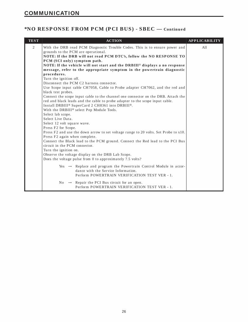
TEST ACTION APPLICABILITY
2 With the DRB read PCM Diagnostic Trouble Codes. This is to ensure power andgrounds to the PCM are operational.NOTE: If the DRB will not read PCM DTC’s, follow the NO RESPONSE TOPCM (SCI only) symptom path.NOTE: If the vehicle will not start and the DRBIIIt displays a no responsemessage, refer to the appropriate symptom in the powertrain diagnosticprocedures.Turn the ignition off.Disconnect the PCM C2 harness connector.Use Scope input cable CH7058, Cable to Probe adapter CH7062, and the red andblack test probes.Connect the scope input cable to the channel one connector on the DRB. Attach thered and black leads and the cable to probe adapter to the scope input cable.Install DRBIIIt SuperCard 2 CH8361 into DRBIIIt.With the DRBIIIt select Pep Module Tools.Select lab scope.Select Live Data.Select 12 volt square wave.Press F2 for Scope.Press F2 and use the down arrow to set voltage range to 20 volts. Set Probe to x10.Press F2 again when complete.Connect the Black lead to the PCM ground. Connect the Red lead to the PCI Buscircuit in the PCM connector.Turn the ignition on.Observe the voltage display on the DRB Lab Scope.Does the voltage pulse from 0 to approximately 7.5 volts?
All
Yes → Replace and program the Powertrain Control Module in accor-dance with the Service Information.Perform POWERTRAIN VERIFICATION TEST VER - 1.
No → Repair the PCI Bus circuit for an open.Perform POWERTRAIN VERIFICATION TEST VER - 1.
26
COMMUNICATION
*NO RESPONSE FROM PCM (PCI BUS) - SBEC — Continued

Symptom:*NO RESPONSE FROM PCM (PCM SCI ONLY) - NGC
POSSIBLE CAUSES
CHECK PCM POWERS AND GROUNDS
PCM SCI TRANSMIT CIRCUIT SHORTED TO VOLTAGE
PCM SCI RECEIVE CIRCUIT SHORTED TO VOLTAGE
PCM SCI CIRCUITS SHORTED TOGETHER
PCM SCI TRANSMIT CIRCUIT SHORTED TO GROUND
PCM SCI RECEIVE CIRCUIT SHORTED TO GROUND
PCM SCI RECEIVE CIRCUIT OPEN
PCM SCI TRANSMIT CIRCUIT OPEN
POWERTRAIN CONTROL MODULE
TEST ACTION APPLICABILITY
1 Perform the symptom Checking PCM Power and Ground Circuits in the Driveabilitycategory.NOTE: With the DRBIIIt in the generic scan tool mode, attempt to commu-nicate with the PCM.NOTE: If the DRBIIIt can communicate with the PCM in the generic scantool mode, it may not be necessary to perform this step.Did the vehicle pass this test?
All
Yes → Go To 2
No → Repair as necessary.Perform POWERTRAIN VERIFICATION TEST VER - 1 - NGC.
2 Turn the ignition off.Disconnect the DRBIIIt from the DLC.Disconnect the PCM harness connectors.Turn the ignition on.Measure the voltage of the PCM SCI Transmit circuit at the Data Link harnessconnector (cav 7).Is the voltage above 1.0 volt?
All
Yes → Repair the PCM SCI Transmit circuit for a short to voltage.Perform POWERTRAIN VERIFICATION TEST VER - 1 - NGC.
No → Go To 3
3 Turn the ignition off.Disconnect the DRBIIIt from the DLC.Disconnect the PCM harness connectors.Turn the ignition on.Measure the voltage of the PCM SCI Receive circuit at the Data Link harnessconnector (cav 12).Is the voltage above 1.0 volt?
All
Yes → Repair the PCM SCI Receive circuit for a short to voltage.Perform POWERTRAIN VERIFICATION TEST VER - 1 - NGC.
No → Go To 4
27
COMMUNICATION

TEST ACTION APPLICABILITY
4 Turn the ignition off.Disconnect the DRBIIIt from the DLC.Disconnect the PCM harness connectors.Measure the resistance between the PCM SCI Transmit circuit and the PCM SCIReceive circuit at the Data Link harness connector (cavs 7 and 12).Is the resistance below 5.0 ohms?
All
Yes → Repair the short between the PCM SCI Transmit and the PCMSCI Receive circuits.Perform POWERTRAIN VERIFICATION TEST VER - 1 - NGC.
No → Go To 5
5 Turn the ignition off.Disconnect the PCM harness connectors.Disconnect the DRBIIIt from the DLC.Measure the resistance between ground and the PCM SCI Transmit circuit at theData Link harness connector (cav 7).Is the resistance below 5.0 ohms?
All
Yes → Repair the PCM SCI Transmit circuit for a short to ground.Perform POWERTRAIN VERIFICATION TEST VER - 1 - NGC.
No → Go To 6
6 Turn the ignition off.Disconnect the PCM harness connector.Disconnect the DRBIIIt from the DLC.Measure the resistance between ground and the PCM SCI Receive circuit in the DataLink harness connector (cav 12).Is the resistance below 5.0 ohms?
All
Yes → Repair the PCM SCI Receive circuit for a short to ground.Perform POWERTRAIN VERIFICATION TEST VER - 1 - NGC.
No → Go To 7
7 Turn the ignition off.Disconnect the PCM harness connector.Disconnect the DRBIIIt from the DLC.CAUTION: DO NOT PROBE THE PCM HARNESS CONNECTORS. PROBINGTHE PCM HARNESS CONNECTORS WILL DAMAGE THE PCM TERMI-NALS RESULTING IN POOR TERMINAL TO PIN CONNECTION. INSTALLMILLER SPECIAL TOOL #8815 TO PERFORM DIAGNOSIS.Measure the resistance of the PCM SCI Receive circuit from the Data Link harnessconnector (cav 12) to the appropriate terminal of special tool #8815.Is the resistance below 5.0 ohms?
All
Yes → Go To 8
No → Repair the PCM SCI Receive circuit for an open.Perform POWERTRAIN VERIFICATION TEST VER - 1 - NGC.
28
COMMUNICATION
*NO RESPONSE FROM PCM (PCM SCI ONLY) - NGC — Continued

TEST ACTION APPLICABILITY
8 Turn the ignition off.Disconnect the PCM harness connector.Disconnect the DRBIIIt from the DLC.CAUTION: DO NOT PROBE THE PCM HARNESS CONNECTORS. PROBINGTHE PCM HARNESS CONNECTORS WILL DAMAGE THE PCM TERMI-NALS RESULTING IN POOR TERMINAL TO PIN CONNECTION. INSTALLMILLER SPECIAL TOOL #8815 TO PERFORM DIAGNOSIS.Measure the resistance of the PCM SCI Transmit circuit from the Data Link harnessconnector (cav 7) to the appropriate terminal of special tool #8815.Is the resistance below 5.0 ohms?
All
Yes → Go To 9
No → Repair the PCM SCI Transmit circuit for an open.Perform POWERTRAIN VERIFICATION TEST VER - 1 - NGC.
9 If there are no possible causes remaining, view repair. All
RepairReplace and program the Powertrain Control Module in accor-dance with the Service Information.Perform POWERTRAIN VERIFICATION TEST VER - 1 - NGC.
29
COMMUNICATION
*NO RESPONSE FROM PCM (PCM SCI ONLY) - NGC — Continued

Symptom:*NO RESPONSE FROM PCM (SCI ONLY) - SBEC
POSSIBLE CAUSES
CHECK PCM POWERS AND GROUNDS
SCI TRANSMIT CIRCUIT SHORTED TO VOLTAGE
TRANSMISSION CONTROL MODULE
SCI RECEIVE CIRCUIT SHORTED TO VOLTAGE
SCI CIRCUITS SHORTED TOGETHER
SCI TRANSMIT CIRCUIT SHORTED TO GROUND
SCI RECEIVE CIRCUIT SHORTED TO GROUND
SCI RECEIVE CIRCUIT OPEN
SCI TRANSMIT CIRCUIT OPEN
POWERTRAIN CONTROL MODULE
TEST ACTION APPLICABILITY
1 Perform the symptom Checking PCM Power and Ground Circuits in the Driveabilitycategory.NOTE: With the DRBIIIt in the generic scan tool mode, attempt to commu-nicate with the PCM.NOTE: If the DRBIIIt can communicate with the PCM in the generic scantool mode, it may not be necessary to perform this step.Did the vehicle pass this test?
All
Yes → Go To 2
No → Repair as necessary.Perform POWERTRAIN VERIFICATION TEST VER - 1.
2 Turn the ignition off.Disconnect the PCM C2 harness connector.Disconnect the DRB from the DLC.Measure the resistance between ground and the SCI Transmit (PCM) circuit.Is the resistance below 5.0 ohms?
All
Yes → Go To 3
No → Go To 4
3 Turn the ignition off.Disconnect the TCM harness connector (if equipped).NOTE: If vehicle is not equipped with a TCM, answer yes to the question.Measure the resistance between ground and the SCI Transmit (PCM) circuit.Is the resistance below 5.0 ohms?
All
Yes → Repair the SCI Transmit (PCM) circuit for a short to ground.Perform POWERTRAIN VERIFICATION TEST VER - 1.
No → Replace the Transmission Control Module in accordance with theservice information.Perform POWERTRAIN VERIFICATION TEST VER - 1.
30
COMMUNICATION

TEST ACTION APPLICABILITY
4 Turn the ignition off.Disconnect the DRB from the DLC.Disconnect the PCM harness connectors.Disconnect the TCM harness connector (if equipped).Turn the ignition on.Measure the voltage of the SCI Transmit (PCM) circuit at the DLC connector.Is the voltage above 1.0 volt?
All
Yes → Repair the SCI Transmit (PCM) circuit for a short to voltage.Perform POWERTRAIN VERIFICATION TEST VER - 1.
No → Go To 5
5 Turn the ignition off.Disconnect the DRB from the DLC.Disconnect the PCM harness connectors.Turn the ignition on.Measure the voltage of the SCI Receive (PCM) circuit at the DLC connector.Is the voltage above 1.0 volt?
All
Yes → Repair the SCI Receive (PCM) circuit for a short to voltage.Perform POWERTRAIN VERIFICATION TEST VER - 1.
No → Go To 6
6 Turn the ignition off.Disconnect the DRB from the DLC.Disconnect the PCM harness connectors.Measure the resistance between the SCI Transmit (PCM) circuit and the SCI Receive(PCM) circuit at the PCM connector.Is the resistance below 5.0 ohms?
All
Yes → Repair the short between the SCI Transmit (PCM) and the SCIReceive (PCM) circuits.Perform POWERTRAIN VERIFICATION TEST VER - 1.
No → Go To 7
7 Turn the ignition off.Disconnect the PCM C2 harness connector.Disconnect the DRB from the DLC.Measure the resistance between ground and the SCI Receive (PCM) circuit.Is the resistance below 5.0 ohms?
All
Yes → Repair the SCI Receive (PCM) circuit for a short to ground.Perform POWERTRAIN VERIFICATION TEST VER - 1.
No → Go To 8
8 Turn the ignition off.Disconnect the PCM C2 harness connector.Disconnect the DRB from the DLC.Measure the resistance of the SCI Receive (PCM) circuit between the PCM C2connector and the DLC.Is the resistance below 5.0 ohms?
All
Yes → Go To 9
No → Repair the SCI Receive (PCM) circuit for an open.Perform POWERTRAIN VERIFICATION TEST VER - 1.
31
COMMUNICATION
*NO RESPONSE FROM PCM (SCI ONLY) - SBEC — Continued

TEST ACTION APPLICABILITY
9 Turn the ignition off.Disconnect the PCM C2 harness connector.Disconnect the DRB from the DLC.Measure the resistance of the SCI Transmit (PCM) circuit between the PCM C2connector and the DLC.Is the resistance below 5.0 ohms?
All
Yes → Go To 10
No → Repair the SCI Transmit (PCM) circuit for an open.Perform POWERTRAIN VERIFICATION TEST VER - 1.
10 If there are no possible causes remaining, view repair. All
RepairReplace and program the Powertrain Control Module in accor-dance with the Service Information.Perform POWERTRAIN VERIFICATION TEST VER - 1.
32
COMMUNICATION
*NO RESPONSE FROM PCM (SCI ONLY) - SBEC — Continued

Symptom:*PCI BUS COMMUNICATION FAILURE
POSSIBLE CAUSES
WIRING HARNESS INTERMITTENT
OPEN PCI BUS CIRCUIT AT THE DATA LINK CONNECTOR (DLC)
PCI BUS CIRCUIT SHORTED TO VOLTAGE
MODULE SHORT TO VOLTAGE
PCI BUS CIRCUIT SHORTED TO GROUND
MODULE SHORT TO GROUND
TEST ACTION APPLICABILITY
1 Note: Determine which modules this vehicle is equipped with before begin-ning.Note: When attempting to communicate with any of the modules on thisvehicle, the DRB will display 1 of 2 different communication errors: a NORESPONSE message or a BUS +/- SIGNALS OPEN message.Turn the ignition on.Using the DRB, attempt to communicate with the following control modules:Airbag Control ModuleBody Control ModuleMIC (INSTRUMENT CLUSTER)Was the DRBIIIt able to communicate with one or more Module(s)?
All
Yes → Go To 2
No → Go To 3
2 Turn the ignition off.Note: Visually inspect the related wiring harness. Look for any chafed,pierced, pinched, or partially broken wires.Note: Visually inspect the related wire harness connectors. Look for broken,bent, pushed out, or corroded terminals.Note: If the DRB can not communicate with a single module, refer to thecategory list for the related symptom.Were any problems found?
All
Yes → Repair wiring harness/connectors as necessary.Perform BODY VERIFICATION TEST - VER 1.
No → Test Complete.
33
COMMUNICATION

TEST ACTION APPLICABILITY
3 Turn the ignition off.Disconnect the PCM/ECM harness connector. Note: If equipped with NGC follow thecaution below.CAUTION: DO NOT PROBE THE PCM HARNESS CONNECTORS. PROBINGTHE PCM HARNESS CONNECTORS WILL DAMAGE THE PCM TERMI-NALS RESULTING IN POOR TERMINAL TO PIN CONNECTION. INSTALLMILLER SPECIAL TOOL #8815 TO PERFORM DIAGNOSIS.Disconnect the DRB from the Data Link Connector (DLC).Disconnect the negative battery cable.Measure the resistance of the PCI Bus circuit between the Data Link Connector(DLC) and the PCM/ECM harness connector.Is the resistance below 5.0 ohms?
All
Yes → Go To 4
No → Repair the PCI Bus circuit for an open.Perform BODY VERIFICATION TEST - VER 1.
4 NOTE: Reconnect the PCM/ECM harness connector and the negative bat-tery cable.Turn the ignition on.Measure the voltage of the PCI Bus circuit at the Data Link Connector (DLC).Is the voltage above 7.0 volts?
All
Yes → Go To 5
No → Go To 6
5 Turn the ignition off.Using a voltmeter, connect one end to the PCI Bus circuit at the DLC, and the otherend to ground.Note: When performing the next step turn the ignition off (wait one minute)before disconnecting any module. When the module is disconnected turnthe ignition on to check for a short to voltage.Turn the ignition on.While monitoring the voltmeter, disconnect each module the vehicle is equipped withone at a time.Is the voltage steadily above 7.0 volts with all the modules disconnected?
All
Yes → Repair the PCI Bus circuit for a short to voltage.Perform BODY VERIFICATION TEST - VER 1.
No → Replace the module that when disconnected the short to voltagewas eliminated.Perform BODY VERIFICATION TEST - VER 1.
34
COMMUNICATION
*PCI BUS COMMUNICATION FAILURE — Continued

TEST ACTION APPLICABILITY
6 Turn the ignition off.Disconnect the negative battery cable.Using a ohmmeter, connect one end to the PCI Bus circuit at the DLC, and the otherend to ground.While monitoring the ohmmeter, disconnect each module the vehicle is equipped withone at a time.NOTE: Total bus resistance to ground thru all of the modules is typicallybetween 350 to 1000 ohms. The more modules on the bus, the lower the totalbus resistance will be.Is the resistance below 150.0 ohms with all the modules disconnected?
All
Yes → Repair the PCI Bus circuit for a short to ground.Perform BODY VERIFICATION TEST - VER 1.
No → Replace the module that when disconnected the short to groundwas eliminated.Perform BODY VERIFICATION TEST - VER 1.
35
COMMUNICATION
*PCI BUS COMMUNICATION FAILURE — Continued

Symptom:P0106-BAROMETRIC PRESSURE OUT OF RANGE
When Monitored and Set Condition:
P0106-BAROMETRIC PRESSURE OUT OF RANGE
When Monitored: With the ignition key on. No Cam or Crank signal within 75 ms. Enginespeed at less than 250 RPM. Battery voltage greater than 10.4 volts.
Set Condition: The PCM senses the voltage from the MAP sensor to be less than 2.196volts but above 0.0392 volts for 300 milliseconds.
POSSIBLE CAUSES
MAP SENSOR VOLTAGE BELOW 2.2 VOLTS
(F855) 5-VOLT SUPPLY CIRCUIT SHORTED TO VOLTAGE
(F855) 5-VOLT SUPPLY CIRCUIT SHORTED TO GROUND
(F855) 5-VOLT SUPPLY CIRCUIT OPEN
(K1) MAP SENSOR SIGNAL CIRCUIT OPEN
(K1) MAP SENSOR SIGNAL CIRCUIT SHORTED TO GROUND
(K1) MAP SENSOR SIGNAL CIRCUIT SHORT TO (K900) SENSOR GROUND
MAP SENSOR INTERNAL FAILURE
PCM
TEST ACTION APPLICABILITY
1 Turn the ignition on. (Do not start engine)With the DRBIIIt, read the MAP Sensor voltage.Is the voltage below 2.2 volts?
All
Yes → Go To 2
No → Refer to the INTERMITTENT CONDITION symptom in theDriveability category.Perform POWERTRAIN VERIFICATION TEST VER - 5.
2 Turn the ignition off.Disconnect the MAP Sensor harness connector.Turn the ignition on.Measure the voltage of the (F855) 5-volt Supply circuit in the MAP Sensor harnessconnector.Is the voltage between 4.5 to 5.2 volts?
All
Yes → Go To 3
No → Go To 7
36
DRIVEABILITY - SBEC

TEST ACTION APPLICABILITY
3 Turn the ignition off.Disconnect the MAP Sensor harness connector.Disconnect the PCM harness connector.Measure the resistance of the (K1) MAP Sensor Signal circuit between the MAPSensor harness connector and the PCM harness connector.Is the resistance below 5.0 ohms?
All
Yes → Go To 4
No → Repair the open in the (K1) MAP Sensor Signal circuit.Perform POWERTRAIN VERIFICATION TEST VER - 5.
4 Turn the ignition off.Disconnect the MAP Sensor harness connector.Disconnect the PCM harness connector.Measure the resistance of the (K1) MAP Sensor Signal circuit in the MAP Sensorharness connector to ground.Is the resistance below 100 ohms?
All
Yes → Repair the short to ground in the (K1) MAP Sensor Signal circuit.Perform POWERTRAIN VERIFICATION TEST VER - 5.
No → Go To 5
5 Turn the ignition off.Disconnect the Map Sensor harness connector.Disconnect PCM harness connector.Measure the resistance of the (K1) MAP Sensor Signal circuit in the MAP Sensorharness connector to (K900) Sensor Ground circuit.Is the resistance below 100 ohms?
All
Yes → Repair the short to (K900) Sensor Ground in the (K1) MAP SensorSignal circuit.Perform POWERTRAIN VERIFICATION TEST VER - 5.
No → Go To 6
6 Turn the ignition off.Disconnect the MAP Sensor harness connector.Turn the ignition on.With the DRBIIIt, monitor the MAP Sensor voltage.Is the voltage above 2.2 volts?
All
Yes → Replace the MAP Sensor.Perform POWERTRAIN VERIFICATION TEST VER - 5.
No → Go To 10
7 Turn the ignition off.Disconnect the MAP Sensor harness connector.Turn the ignition on.Measure the voltage of the (F855) 5-volt Supply circuit in the MAP Sensor harnessconnector.Is the voltage above 5.2 volts?
All
Yes → Repair the the short to battery voltage in the (F855) 5-volt Supplycircuit.Perform POWERTRAIN VERIFICATION TEST VER - 5.
No → Go To 8
37
DRIVEABILITY - SBEC
P0106-BAROMETRIC PRESSURE OUT OF RANGE — Continued

TEST ACTION APPLICABILITY
8 Turn the ignition off.Disconnect the MAP Sensor harness connector.Disconnect the PCM harness connector.Measure the resistance of the (F855) 5-volt Supply circuit in the MAP Sensor harnessconnector to ground.Is the resistance below 100 ohms?
All
Yes → Repair the short to ground in the (F855) 5-volt Supply circuit.Perform POWERTRAIN VERIFICATION TEST VER - 5.
No → Go To 9
9 Turn the ignition off.Disconnect the MAP Sensor harness connector.Disconnect the PCM harness connector.Measure the resistance of the (F855) 5-volt Supply circuit between the MAP Sensorharness connector and the PCM harness connector.Is the resistance below 5.0 ohms?
All
Yes → Go To 10
No → Repair the open in the (F855) 5-volt Supply circuit.Perform POWERTRAIN VERIFICATION TEST VER - 5.
10 NOTE: Before Continuing: Disconnect the PCM harness connector andcheck the related wiring terminals for corrosion, damage or terminal pushout. Repair as necessary.Using the schematics as a guide, inspect the wire harness and connectors. Payparticular attention to all Power and Ground circuits.If there are no possible causes remaining, view repair.
All
RepairReplace and program the Powertrain Control Module in accor-dance with the Service Information.Perform POWERTRAIN VERIFICATION TEST VER - 5.
38
DRIVEABILITY - SBEC
P0106-BAROMETRIC PRESSURE OUT OF RANGE — Continued

Symptom:P0107-MAP SENSOR VOLTAGE TOO LOW
When Monitored and Set Condition:
P0107-MAP SENSOR VOLTAGE TOO LOW
When Monitored: Engine speed between 600 to 3500 RPM. TPS voltage less than 1.2volts. Battery voltage greater than 10.4 volts.
Set Condition: The MAP sensor signal voltage is below 0.0392 volt for 1.7 seconds.
POSSIBLE CAUSES
MAP SENSOR VOLTAGE BELOW .04 VOLTS
(F855) 5-VOLT SUPPLY CIRCUIT SHORTED TO GROUND
(F855) 5-VOLT SUPPLY CIRCUIT OPEN
MAP SENSOR INTERNAL FAILURE
(K1) MAP SENSOR SIGNAL CIRCUIT SHORTED TO GROUND
(K1) MAP SENSOR SIGNAL CIRCUIT SHORTED TO (K900) SENSOR GROUND CIRCUIT
PCM
TEST ACTION APPLICABILITY
1 Turn the ignition on.With the DRBIIIt, read the MAP Sensor voltage.Is the voltage below 1.2 volts?
All
Yes → Go To 3
No → Go To 2
2 Start the engine.With the DRBIIIt, read the MAP Sensor voltage.Is the voltage below .04 volts?
All
Yes → Go To 3
No → Refer to the INTERMITTENT CONDITION symptom in theDriveability category.Perform POWERTRAIN VERIFICATION TEST VER - 5.
3 Turn the ignition off.Disconnect the MAP Sensor harness connector.Turn the ignition on.Measure the voltage of the (F855) 5-volt Supply circuit in the MAP Sensor harnessconnector.Is the voltage between 4.5 to 5.2 volts?
All
Yes → Go To 4
No → Go To 7
39
DRIVEABILITY - SBEC

TEST ACTION APPLICABILITY
4 Turn the ignition off.Disconnect the MAP Sensor harness connector.Disconnect the PCM harness connector.Measure the resistance of the (K1) MAP Sensor Signal circuit between the MAPSensor harness connector and ground.Is the resistance below 100 ohms?
All
Yes → Repair the short to ground in the (K1) MAP Sensor Signal circuit.Perform POWERTRAIN VERIFICATION TEST VER - 5.
No → Go To 5
5 Turn the ignition off.Disconnect the MAP Sensor harness connector.Disconnect the PCM harness connector.Measure the resistance between the (K1) MAP Sensor Signal circuit and the (K900)Sensor Ground circuit in the MAP Sensor harness connector.Is the resistance below 100 ohms?
All
Yes → Repair the short to (K900) Sensor Ground circuit in the (K1) MAPSensor Signal circuit.Perform POWERTRAIN VERIFICATION TEST VER - 5.
No → Go To 6
6 Turn the ignition off.Disconnect the MAP Sensor harness connector.Turn the ignition on.With the DRBIIIt, monitor the MAP Sensor voltage.Is the voltage above 1.2 volts?
All
Yes → Replace the MAP Sensor.Perform POWERTRAIN VERIFICATION TEST VER - 5.
No → Go To 9
7 Turn the ignition off.Disconnect the MAP Sensor harness connector.Disconnect the PCM harness connector.Measure the resistance of the (F855) 5-volt Supply circuit in the MAP Sensor harnessconnector to ground.Is the resistance below 100 ohms?
All
Yes → Repair the short to ground in the (F855) 5-volt Supply circuit.Perform POWERTRAIN VERIFICATION TEST VER - 5.
No → Go To 8
8 Turn the ignition off.Disconnect the MAP Sensor harness connector.Disconnect the PCM harness connector.Measure the resistance of the (F855) 5-volt Supply circuit between the MAP Sensorharness connector and the PCM harness connector.Is the resistance below 5.0 ohms?
All
Yes → Go To 9
No → Repair the open in the (F855) 5-volt Supply circuit.Perform POWERTRAIN VERIFICATION TEST VER - 5.
40
DRIVEABILITY - SBEC
P0107-MAP SENSOR VOLTAGE TOO LOW — Continued

TEST ACTION APPLICABILITY
9 NOTE: Before Continuing: Disconnect the PCM harness connector andcheck the related wiring terminals for corrosion, damage or terminal pushout. Repair as necessary.Using the schematics as a guide, inspect the wire harness and connectors. Payparticular attention to all Power and Ground circuits.If there are no possible causes remaining, view repair.
All
RepairReplace and program the Powertrain Control Module in accor-dance with the Service Information.Perform POWERTRAIN VERIFICATION TEST VER - 5.
41
DRIVEABILITY - SBEC
P0107-MAP SENSOR VOLTAGE TOO LOW — Continued

Symptom:P0108-MAP SENSOR VOLTAGE TOO HIGH
When Monitored and Set Condition:
P0108-MAP SENSOR VOLTAGE TOO HIGH
When Monitored: Engine speed between 600 to 3500 RPM. TP sensor voltage less than1.2 volts for greater than 1.7 seconds. Battery voltage greater than 10.4 volts
Set Condition: The MAP sensor signal voltage is greater than 4.96 volts.
POSSIBLE CAUSES
MAP SENSOR VOLTAGE ABOVE 4.6 VOLTS
(K1) MAP SENSOR SIGNAL CIRCUIT SHORTED TO (F855) 5-VOLT SUPPLY CIRCUIT
(K1) MAP SENSOR SIGNAL CIRCUIT SHORTED TO BATTERY VOLTAGE
(K1) MAP SENSOR SIGNAL CIRCUIT OPEN
(K900) SENSOR GROUND CIRCUIT OPEN
MAP SENSOR INTERNAL FAILURE
PCM
TEST ACTION APPLICABILITY
1 Start the engine.With the DRBIIIt, read the MAP Sensor voltage.Is the voltage above 4.6 volts?
All
Yes → Go To 2
No → Refer to the INTERMITTENT CONDITION symptom in theDriveability category.Perform POWERTRAIN VERIFICATION TEST VER - 5.
2 Turn the ignition off.Disconnect the MAP Sensor harness connector.Disconnect the PCM harness connector.Measure the resistance between the (K1) MAP Sensor Signal circuit and the (F855)5-volt Supply circuit in the MAP Sensor harness connector.Is the resistance below 100 ohms?
All
Yes → Repair the short to the (F855) 5-volt Supply circuit in the (K1)MAP Sensor Signal circuit.Perform POWERTRAIN VERIFICATION TEST VER - 5.
No → Go To 3
42
DRIVEABILITY - SBEC

TEST ACTION APPLICABILITY
3 Turn the ignition off.Disconnect the MAP Sensor harness connector.Turn the ignition on.Measure the voltage of the (K1) MAP Sensor Signal circuit in the MAP Sensorharness connector.Is the voltage above 5.2 volts?
All
Yes → Repair the the short to battery voltage in the (K1) MAP SensorSignal circuit.Perform POWERTRAIN VERIFICATION TEST VER - 5.
No → Go To 4
4 Turn the ignition off.Disconnect the MAP Sensor harness connector.Disconnect the PCM harness connector.Measure the resistance of the (K1) MAP Sensor Signal circuit between the MAPSensor harness connector and the PCM harness connector.Is the resistance below 5.0 ohms?
All
Yes → Go To 5
No → Repair the open in the (K1) MAP Sensor Signal circuit.Perform POWERTRAIN VERIFICATION TEST VER - 5.
5 Turn the ignition off.Disconnect the MAP Sensor harness connector.Disconnect the PCM harness connector.Measure the resistance of the (K900) Sensor Ground circuit between the MAP Sensorharness connector and the PCM harness connector.Is the resistance below 5.0 ohms?
All
Yes → Go To 6
No → Repair the open in the (K900) Sensor ground circuit.Perform POWERTRAIN VERIFICATION TEST VER - 5.
6 Turn the ignition off.Disconnect the MAP Sensor harness connector.Connect a jumper wire between the (K1) MAP Sensor Signal circuit and the (K900)Sensor ground circuit.With the DRBIIIt, monitor the MAP Sensor voltage.Turn the ignition on.Is the voltage below 1.0 volt?
All
Yes → Replace the MAP Sensor.Perform POWERTRAIN VERIFICATION TEST VER - 5.
No → Go To 7
7 NOTE: Before Continuing: Disconnect the PCM harness connector andcheck the related wiring terminals for corrosion, damage or terminal pushout. Repair as necessary.Using the schematics as a guide, inspect the wire harness and connectors. Payparticular attention to all Power and Ground circuits.If there are no possible causes remaining, view repair.
All
RepairReplace and program the Powertrain Control Module in accor-dance with the Service Information.Perform POWERTRAIN VERIFICATION TEST VER - 5.
43
DRIVEABILITY - SBEC
P0108-MAP SENSOR VOLTAGE TOO HIGH — Continued

Symptom:P0111-INTAKE AIR TEMP SENSOR PERFORMANCE
When Monitored and Set Condition:
P0111-INTAKE AIR TEMP SENSOR PERFORMANCE
When Monitored: With the ignition on. Coolant Temperature greater than 71°C (160°F)No Inlet Air Temperature Sensor Faults present
Set Condition: After 5 warm cycles have occurred (coolant increases from great than4.4°C (40°F) to a minimum of 71°C (160°F) and the odometer mileage has increased 196.6miles and the Inlet Air Temperature has increased less than 3°C (5.4°F) change intemperature. Two trip fault.
POSSIBLE CAUSES
GOOD TRIP EQUAL TO ZERO
IAT SENSOR VOLTAGE BELOW 1.0 VOLTS
RESISTANCE IN THE (K900) SENSOR GROUND CIRCUIT
RESISTANCE IN THE (K21) IAT SENSOR SIGNAL CIRCUIT VOLTAGE DROP
PCM
TEST ACTION APPLICABILITY
1 NOTE: If DTC P1192 or P1193 have set along with P0111, diagnose P1192 orP1193 first before continuing.Turn the ignition on.With the DRBIIIt, read DTC’s.Is the Good Trip displayed and equal to zero?
All
Yes → Go To 2
No → Refer to the INTERMITTENT CONDITION symptom in theDriveability category.Perform POWERTRAIN VERIFICATION TEST VER - 5.
2 Turn the ignition off.Disconnect the Inlet Air Temperature Sensor harness connector.Turn the ignition on.With the DRBIIIt, read the IAT voltage.Is the voltage above 4.6 volts?
All
Yes → Go To 3
No → Go To 4
44
DRIVEABILITY - SBEC

TEST ACTION APPLICABILITY
3 Turn the ignition off.Disconnect the Inlet Air Temperature Sensor harness connector.Using a jumper wire, jumper across the IAT Sensor harness connector.Turn the ignition on.With the DRBIIIt, read the IAT voltage.Is the voltage below 1.0 volt?
All
Yes → Replace the Inlet Air Temperature Sensor.Perform POWERTRAIN VERIFICATION TEST VER - 5.
No → Go To 4
4 NOTE: Ensure the voltmeter leads meet the terminals in the connector andthat there is good terminal to wire connection.NOTE: Ensure the voltmeter leads are connected for positive polarityBackprobe (K900) Sensor ground circuit at the IAT Sensor harness connector andPCM harness connector.Start the engine.Allow the engine to idle.Is the voltage below 0.10 volt?
All
Yes → Go To 5
No → Repair the high resistance in the (K900) Sensor Ground circuit.Perform POWERTRAIN VERIFICATION TEST VER - 5.
5 NOTE: Ensure the voltmeter leads meet the terminals in the connector andthat there is good terminal to wire connection.NOTE: Ensure the voltmeter leads are connected for positive polarityBackprobe the (K21) IAT Sensor Signal circuit at the IAT Sensor harness connectorand PCM harness connector.Start the engine.Allow the engine to idle.Is the voltage below 0.10 volt?
All
Yes → Go To 6
No → Repair the high resistance in the (K21) IAT Sensor Signal circuit.Perform POWERTRAIN VERIFICATION TEST VER - 5.
6 NOTE: Before Continuing: Disconnect the PCM harness connector andcheck the related wiring terminals for corrosion, damage or terminal pushout. Repair as necessary.Using the schematics as a guide, inspect the wire harness and connectors. Payparticular attention to all Power and Ground circuits.If there are no possible causes remaining, view repair.
All
RepairReplace and program the Powertrain Control Module in accor-dance with the Service Information.Perform POWERTRAIN VERIFICATION TEST VER - 5.
45
DRIVEABILITY - SBEC
P0111-INTAKE AIR TEMP SENSOR PERFORMANCE — Continued

Symptom:P0117-ECT SENSOR VOLTAGE TOO LOW
When Monitored and Set Condition:
P0117-ECT SENSOR VOLTAGE TOO LOW
When Monitored: With the ignition on. Battery voltage greater than 10.4 volts.
Set Condition: The Engine Coolant Temperature (ECT) sensor circuit voltage at the PCMis less than 0.5 volt for more than 2.6 seconds.
POSSIBLE CAUSES
ECT SENSOR VOLTAGE BELOW 1.0 VOLTS
ECT SENSOR INTERNAL FAILURE
(K2) ECT SENSOR SIGNAL SHORTED TO GROUND
(K2) ECT SENSOR SIGNAL SHORTED TO (K900) SENSOR GROUND CIRCUIT
PCM
TEST ACTION APPLICABILITY
1 Turn the ignition on.With the DRBIIIt, read the ECT voltage.Is the voltage below 1.0 volt?
All
Yes → Go To 2
No → Refer to the INTERMITTENT CONDITION symptom in theDriveability category.Perform POWERTRAIN VERIFICATION TEST VER - 5.
2 Turn the ignition off.Disconnect the ECT harness connector.Turn the ignition on.With the DRBIIIt, read ECT voltage.Is the voltage above 1.0 volt?
All
Yes → Replace the ECT Sensor.Perform POWERTRAIN VERIFICATION TEST VER - 5.
No → Go To 3
3 Turn the ignition off.Disconnect the ECT Sensor harness connector.Disconnect the PCM harness connector.Measure the resistance of the (K2) ECT Sensor Signal circuit in the ECT Sensorharness connector to ground.Is the resistance below 100 ohms?
All
Yes → Repair the short to ground in the (K2) ECT Sensor Signal circuit.Perform POWERTRAIN VERIFICATION TEST VER - 5.
No → Go To 4
46
DRIVEABILITY - SBEC

TEST ACTION APPLICABILITY
4 Turn the ignition off.Disconnect the ECT Sensor harness connector.Disconnect the PCM harness connector.Measure the resistance between the (K2) ECT Sensor Signal circuit and the (K900)Sensor Ground circuit in the ECT Sensor harness connector.Is the resistance below 100 ohms?
All
Yes → Repair the short to the (K900) Sensor Ground circuit in the (K2)ECT Sensor Signal circuit.Perform POWERTRAIN VERIFICATION TEST VER - 5.
No → Go To 5
5 NOTE: Before Continuing: Disconnect the PCM harness connector andcheck the related wiring terminals for corrosion, damage or terminal pushout. Repair as necessary.Using the schematics as a guide, inspect the wire harness and connectors. Payparticular attention to all Power and Ground circuits.If there are no possible causes remaining, view repair.
All
RepairReplace and program the Powertrain Control Module in accor-dance with the Service Information.Perform POWERTRAIN VERIFICATION TEST VER - 5.
47
DRIVEABILITY - SBEC
P0117-ECT SENSOR VOLTAGE TOO LOW — Continued

Symptom:P0118-ECT SENSOR VOLTAGE TOO HIGH
When Monitored and Set Condition:
P0118-ECT SENSOR VOLTAGE TOO HIGH
When Monitored: With the ignition on. Battery voltage greater than 10.4 volts.
Set Condition: The Engine Coolant Temperature (ECT) sensor circuit voltage at the PCMis greater than 4.96 volts for more than 2.6 seconds.
POSSIBLE CAUSES
ECT SENSOR VOLTAGE ABOVE 4.6 VOLTS
(K2) ECT SENSOR SIGNAL CIRCUIT SHORTED TO BATTERY VOLTAGE
ECT SENSOR INTERNAL FAILURE
(K2) ECT SENSOR SIGNAL CIRCUIT OPEN
(K900) SENSOR GROUND CIRCUIT OPEN
PCM
TEST ACTION APPLICABILITY
1 Turn the ignition on.With the DRBIIIt, read the ECT voltage.Is the voltage above 4.6 volts?
All
Yes → Go To 2
No → Refer to the INTERMITTENT CONDITION symptom in theDriveability category.Perform POWERTRAIN VERIFICATION TEST VER - 5.
2 Turn the ignition off.Disconnect the ECT Sensor harness connector.Turn the ignition on.Measure the voltage of the (K2) ECT Sensor Signal circuit in the ECT Sensor harnessconnector.Is the voltage above 5.2 volts?
All
Yes → Repair the short to battery voltage in the (K2) ECT Sensor Signalcircuit.Perform POWERTRAIN VERIFICATION TEST VER - 5.
No → Go To 3
48
DRIVEABILITY - SBEC

TEST ACTION APPLICABILITY
3 Turn the ignition off.Disconnect the ECT harness connector.Connect a jumper wire between the (K2) ECT Sensor Signal circuit and the (K900)Sensor ground circuit in the ECT harness connector.Turn the ignition on.With the DRBIIIt, read ECT voltage.Is the voltage below 1.0 volt?
All
Yes → Replace the ECT Sensor.Perform POWERTRAIN VERIFICATION TEST VER - 5.
No → Go To 4
4 Turn the ignition off.Disconnect the ECT Sensor harness connector.Disconnect the PCM harness connector.Measure the resistance of the (K2) ECT Sensor Signal circuit between the ECTSensor harness connector and the PCM harness connector.Is the resistance below 5.0 ohms?
All
Yes → Go To 5
No → Repair the open in the (K2) ECT Sensor Signal circuit.Perform POWERTRAIN VERIFICATION TEST VER - 5.
5 Turn the ignition off.Disconnect the ECT Sensor harness connector.Disconnect the PCM harness connector.Measure the resistance of the (K900) Sensor Ground circuit between the ECT Sensorharness connector and the PCM harness connector.Is the resistance below 5.0 ohms?
All
Yes → Go To 6
No → Repair the open in the (K900) Sensor Ground circuit.Perform POWERTRAIN VERIFICATION TEST VER - 5.
6 NOTE: Before Continuing: Disconnect the PCM harness connector andcheck the related wiring terminals for corrosion, damage or terminal pushout. Repair as necessary.Using the schematics as a guide, inspect the wire harness and connectors. Payparticular attention to all Power and Ground circuits.If there are no possible causes remaining, view repair.
All
RepairReplace and program the Powertrain Control Module in accor-dance with the Service Information.Perform POWERTRAIN VERIFICATION TEST VER - 5.
49
DRIVEABILITY - SBEC
P0118-ECT SENSOR VOLTAGE TOO HIGH — Continued

Symptom:P0121-TPS VOLTAGE DOES NOT AGREE WITH MAP
When Monitored and Set Condition:
P0121-TPS VOLTAGE DOES NOT AGREE WITH MAP
When Monitored: With the engine running and no MAP Sensor or TP Sensor DTC’s set.
Set Condition: When the manifold vacuum is low, the TP sensor signal should be high.Conversely, when manifold vacuum is high, the TP sensor signal should be low. If the MAPSensor and TP Sensor do not respond within 4 seconds as stated above, a DTC will be set.
POSSIBLE CAUSES
GOOD TRIP EQUAL TO ZERO
HIGH RESISTANCE IN (F855) 5-VOLT SUPPLY CIRCUIT
(F855) 5-VOLT SUPPLY CIRCUIT SHORTED TO GROUND
MAP SENSOR
HIGH RESISTANCE IN THE (K1) MAP SENSOR SIGNAL CIRCUIT
(K1) MAP SENSOR SIGNAL CIRCUIT SHORTED TO GROUND
HIGH RESISTANCE IN (K900) SENSOR GROUND CIRCUIT
TP SENSOR OPERATION
HIGH RESISTANCE IN (F855) 5-VOLT SUPPLY CIRCUIT
(F855) 5-VOLT SUPPLY CIRCUIT SHORTED TO GROUND
TP SENSOR
HIGH RESISTANCE IN (K22) TP SENSOR SIGNAL CIRCUIT
(K22) TP SENSOR SIGNAL CIRCUIT SHORT TO GROUND
HIGH RESISTANCE IN THE (K900) SENSOR GROUND CIRCUIT
PCM
50
DRIVEABILITY - SBEC

TEST ACTION APPLICABILITY
1 NOTE: Diagnose any TP Sensor or MAP Sensor component DTC first beforecontinuing.NOTE: If the P0500 - No Vehicle Speed Signal is set long with this DTC, referto the P0500 diagnostics before continuing.NOTE: The throttle plate and linkage should be free from binding andcarbon build up.NOTE: Ensure the throttle plate is at the idle position.Turn the ignition on.With the DRBIIIt, read DTC’s.Is the Good Trip displayed and equal to zero?
All
Yes → Go To 2
No → Refer to the INTERMITTENT CONDITION symptom in theDriveability category.Perform POWERTRAIN VERIFICATION TEST VER - 5.
2 Start the engine.With the DRBIIIt, monitor the MAP Sensor voltage.Snap the throttle.Does the MAP Sensor voltage vary from below 2.0 volts at idle to above 3.5 volts atWOT.
All
Yes → Go To 3
No → Go To 10
3 Turn the ignition on.With the DRBIIIt, monitor the TP Sensor voltage while slowly depressing thethrottle pedal from the idle position to the wide open throttle position.Does voltage start approximately at 0.8 of a volt and go above 3.5 volts with a smoothvoltage chang
All
Yes → Refer to the INTERMITTENT CONDITION symptom in theDriveability category.Perform POWERTRAIN VERIFICATION TEST VER - 5.
No → Go To 4
4 Turn the ignition off.Disconnect the TP Sensor harness connector.Disconnect the PCM harness connector.Measure the resistance of the (F855) 5-volt Supply circuit from the TP Sensorharness connector to the PCM harness connector.Is the resistance below 5.0 ohms?
All
Yes → Go To 5
No → Repair the high resistance in the (F855) 5-volt Supply circuit.Perform POWERTRAIN VERIFICATION TEST VER - 5.
5 Turn the ignition off.Disconnect the TP Sensor harness connector.Disconnect the PCM harness connector.Measure the resistance of the (K6) 5-volt Supply circuit from the TP Sensor harnessconnector to ground.Is the resistance above 100k ohms?
All
Yes → Go To 6
No → Repair the short to ground in the (F855) 5-volt Supply circuit.Perform POWERTRAIN VERIFICATION TEST VER - 5.
51
DRIVEABILITY - SBEC
P0121-TPS VOLTAGE DOES NOT AGREE WITH MAP — Continued

TEST ACTION APPLICABILITY
6 Turn the ignition off.Disconnect the TP Sensor harness connector.Disconnect the PCM harness connector.Measure the resistance of the (K22) TP Sensor Signal circuit from the TP Sensorharness connector to the PCM harness connector.Is the resistance below 5.0 ohms?
All
Yes → Go To 7
No → Repair the high resistance in the (K22) TP Sensor Signal circuit.Perform POWERTRAIN VERIFICATION TEST VER - 5.
7 Turn the ignition off.Disconnect the TP Sensor harness connector.Disconnect the PCM harness connector.Measure the resistance of the (K22) TP Sensor Signal circuit from the TP Sensorharness connector to ground.Is the resistance above 100k ohms?
All
Yes → Go To 8
No → Repair the short to ground in the (K22) TP Sensor Signal circuit.Perform POWERTRAIN VERIFICATION TEST VER - 5.
8 Turn the ignition off.Disconnect the TP Sensor harness connector.Disconnect the PCM harness connector.Measure the resistance of the (K900) Sensor Ground circuit from the TP Sensorharness connector to the PCM harness connector.Is the resistance below 5.0 ohms?
All
Yes → Go To 9
No → Repair the high resistance in the (K900) Sensor Ground circuit.Perform POWERTRAIN VERIFICATION TEST VER - 5.
9 Connect a jumper wire between the (K22) TP Sensor Signal circuit and the (K4)Sensor Ground circuit .Does the DRBIIIt display TP voltage from approximately 4.9 volts to below 0.5 of avolt?
All
Yes → Replace the TP Sensor.Perform POWERTRAIN VERIFICATION TEST VER - 5.
No → Go To 16
10 Turn the ignition off.Disconnect the MAP Sensor harness connector.Disconnect the PCM harness connector.Measure the resistance of the (F855) 5-volt Supply circuit from the MAP Sensorharness connector to the PCM harness connector.Is the resistance below 5.0 ohms?
All
Yes → Go To 11
No → Repair the high resistance in the (F855) 5-volt Supply circuit.Perform POWERTRAIN VERIFICATION TEST VER - 5.
52
DRIVEABILITY - SBEC
P0121-TPS VOLTAGE DOES NOT AGREE WITH MAP — Continued

TEST ACTION APPLICABILITY
11 Turn the ignition off.Disconnect the MAP Sensor harness connector.Disconnect the PCM harness connector.Measure the resistance of the (F855) 5-volt Supply circuit from the MAP Sensorharness connector to ground.Is the resistance above 100k ohms?
All
Yes → Go To 12
No → Repair the short to ground in the (F855) 5-volt Supply circuit.Perform POWERTRAIN VERIFICATION TEST VER - 5.
12 Turn the ignition off.Disconnect the MAP Sensor harness connector.Disconnect the PCM harness connector.Measure the resistance of the (K1) MAP Sensor Signal circuit from the MAP Sensorharness connector to the PCM harness connector.Is the resistance below 5.0 ohms?
All
Yes → Go To 13
No → Repair the high resistance in the (K1) MAP Sensor Signal circuit.Perform POWERTRAIN VERIFICATION TEST VER - 5.
13 Turn the ignition off.Disconnect the MAP Sensor harness connector.Disconnect the PCM harness connector.Measure the resistance of the (K1) MAP Sensor Signal circuit from the MAP Sensorharness connector to ground.Is the resistance above 100k ohms?
All
Yes → Go To 14
No → Repair the short to ground in the (K1) MAP Sensor Signal circuit.Perform POWERTRAIN VERIFICATION TEST VER - 5.
14 Turn the ignition off.Disconnect the MAP Sensor harness connector.Disconnect the PCM harness connector.Measure the resistance of the (K900) Sensor ground circuit from the MAP Sensorharness connector to the PCM harness connector.Is the resistance below 5.0 ohms?
All
Yes → Go To 15
No → Repair the high resistance in the (K900) Sensor Ground circuit.Perform POWERTRAIN VERIFICATION TEST VER - 5.
53
DRIVEABILITY - SBEC
P0121-TPS VOLTAGE DOES NOT AGREE WITH MAP — Continued

TEST ACTION APPLICABILITY
15 Turn the ignition off.Disconnect the MAP Sensor harness connector.With the DRBIIIt, monitor the MAP Sensor voltage.Turn the ignition on.Connect a jumper wire between the (K1) MAP Sensor Signal circuit and the (K4)Sensor Ground circuit .Cycle the ignition switch off and then on again.With the DRBIIIt, monitor the MAP Sensor voltage.Does the DRBIIIt display MAP voltage from approximately 4.9 volts to below 0.5volt?
All
Yes → Replace the MAP Sensor.Perform POWERTRAIN VERIFICATION TEST VER - 5.
No → Go To 16
16 NOTE: Before Continuing: Disconnect the PCM harness connector andcheck the related wiring terminals for corrosion, damage or terminal pushout. Repair as necessary.Using the schematics as a guide, inspect the wire harness and connectors. Payparticular attention to all Power and Ground circuits.If there are no possible causes remaining, view repair.
All
RepairReplace and program the Powertrain Control Module in accor-dance with the Service Information.Perform POWERTRAIN VERIFICATION TEST VER - 5.
54
DRIVEABILITY - SBEC
P0121-TPS VOLTAGE DOES NOT AGREE WITH MAP — Continued

Symptom:P0122-THROTTLE POSITION SENSOR VOLTAGE LOW
When Monitored and Set Condition:
P0122-THROTTLE POSITION SENSOR VOLTAGE LOW
When Monitored: With the ignition on. Battery voltage greater than 10.4 volts.
Set Condition: Throttle Position Sensor voltage at the PCM is less than 0.16 volt for 0.7seconds.
POSSIBLE CAUSES
TP SENSOR VOLTAGE BELOW 0.2
(F855) 5-VOLT SUPPLY CIRCUIT SHORTED TO GROUND
(F855) 5-VOLT SUPPLY CIRCUIT SHORTED TO (K900) SENSOR GROUND CIRCUIT
(F855) 5-VOLT SUPPLY CIRCUIT OPEN
TP SENSOR INTERNAL FAILURE
(K22) TP SENSOR SIGNAL CIRCUIT SHORTED TO GROUND
(K22) TP SENSOR SIGNAL CIRCUIT SHORTED TO (K900) SENSOR GROUND CIRCUIT
TCM INTERNALLY SHORTED TP SIGNAL CIRCUIT
PCM
TEST ACTION APPLICABILITY
1 Turn the ignition on.With the DRBIIIt, read the TP Sensor voltage.Is the voltage below 0.2 of a volt?
All
Yes → Go To 2
No → Refer to the INTERMITTENT CONDITION symptom in theDriveability category.Perform POWERTRAIN VERIFICATION TEST VER - 5.
2 Turn the ignition off.Disconnect the MAP Sensor harness connector.Turn the ignition on.Measure the voltage of the (F855) 5-volt Supply circuit in the MAP Sensor harnessconnector.Is the voltage between 4.5 to 5.2 volts?
All
Yes → Go To 3
No → Go To 7
55
DRIVEABILITY - SBEC

TEST ACTION APPLICABILITY
3 Turn the ignition off.Disconnect the TP Sensor harness connector.With the DRBIIIt, monitor the TP Sensor voltage.Turn the ignition on.Is the voltage above 4.5 volts?
All
Yes → Replace the TP Sensor.Perform POWERTRAIN VERIFICATION TEST VER - 5.
No → Go To 4
4 Turn the ignition off.Disconnect the TP Sensor harness connector.Disconnect the PCM harness connector.Measure the resistance of the (K22) TP Sensor Signal circuit in the TP Sensorharness connector to ground.Is the resistance below 100 ohms?
All
Yes → Repair the short to ground in the (K22) TP Sensor Signal circuit.Perform POWERTRAIN VERIFICATION TEST VER - 5.
No → Go To 5
5 Turn the ignition off.Disconnect the TP Sensor harness connector.Disconnect the PCM harness connector.Measure the resistance between the (K22) TP Sensor Signal circuit and the (K900)Sensor Ground circuit in the TP Sensor harness connector.Is the resistance below 100 ohms?
All
Yes → Repair the short to (K900) Sensor Ground circuit in the (K22)Throttle Position Sensor Signal circuit.Perform POWERTRAIN VERIFICATION TEST VER - 5.
No → Go To 6
6 Turn the ignition off.Disconnect the TP Sensor harness connector.Disconnect the TCM harness connector.With the DRBIIIt, monitor the TP Sensor voltage.Turn the ignition on.Is the voltage above 4.5 volts?
All
Yes → Replace the Transmission Control Module.Perform POWERTRAIN VERIFICATION TEST VER - 5.
No → Go To 7
7 Turn the ignition off.Disconnect the TP Sensor harness connector.Disconnect the PCM harness connector.Measure the resistance of the (F855) 5-volt Supply circuit in the TP Sensor harnessconnector to ground.Is the resistance below 100 ohms?
All
Yes → Repair the short to ground in the (F855) 5-volt Supply circuit.Perform POWERTRAIN VERIFICATION TEST VER - 5.
No → Go To 8
56
DRIVEABILITY - SBEC
P0122-THROTTLE POSITION SENSOR VOLTAGE LOW — Continued

TEST ACTION APPLICABILITY
8 Turn the ignition off.Disconnect the TP Sensor harness connector.Disconnect the PCM harness connector.Measure the resistance of the (F855) 5-volt Supply circuit in the TP Sensor harnessconnector to (K900) Sensor Ground circuit.Is the resistance below 100 ohms?
All
Yes → Repair the short to (K900) Sensor Ground circuit in the (F855)5-volt Supply circuit.Perform POWERTRAIN VERIFICATION TEST VER - 5.
No → Go To 9
9 Turn the ignition off.Disconnect the TP Sensor harness connector.Disconnect the PCM harness connector.Measure the resistance of the (F855) 5-volt Supply circuit between the TP Sensorharness connector and the PCM harness connector.Is the resistance below 5.0 ohms?
All
Yes → Go To 10
No → Repair the open in the (F855) 5-volt Supply circuit.Perform POWERTRAIN VERIFICATION TEST VER - 5.
10 NOTE: Before Continuing: Disconnect the PCM harness connector andcheck the related wiring terminals for corrosion, damage or terminal pushout. Repair as necessary.Using the schematics as a guide, inspect the wire harness and connectors. Payparticular attention to all Power and Ground circuits.If there are no possible causes remaining, view repair.
All
RepairReplace and program the Powertrain Control Module in accor-dance with the Service Information.Perform POWERTRAIN VERIFICATION TEST VER - 5.
57
DRIVEABILITY - SBEC
P0122-THROTTLE POSITION SENSOR VOLTAGE LOW — Continued

Symptom:P0123-THROTTLE POSITION SENSOR VOLTAGE HIGH
When Monitored and Set Condition:
P0123-THROTTLE POSITION SENSOR VOLTAGE HIGH
When Monitored: With the ignition on. Battery voltage greater than 10.4 volts.
Set Condition: Throttle Position Sensor voltage at the PCM is greater than 4.5 volts for0.7 seconds.
POSSIBLE CAUSES
THROTTLE POSITION SENSOR SWEEP
INTERMITTENT CONDITION
(K22) TP SENSOR SIGNAL CIRCUIT SHORTED TO (F855) 5-VOLT SUPPLY CIRCUIT
(K22) TP SENSOR SIGNAL CIRCUIT SHORTED TO BATTERY VOLTAGE
TP SENSOR INTERNAL FAILURE
(K22) TP SENSOR SIGNAL CIRCUIT OPEN
(K900) SENSOR GROUND CIRCUIT OPEN
PCM
TEST ACTION APPLICABILITY
1 NOTE: Ensure the throttle is fully closed and free from binding or carbonbuild up.Start the engine.With the DRBIIIt, read the TP Sensor voltage.Is the voltage above 4.5 volts?
All
Yes → Go To 2
No → Go To 8
2 Turn the ignition off.Disconnect the TP Sensor harness connector.Disconnect the PCM harness connector.Measure the resistance between the (K22) TP Sensor Signal circuit and the (F855)5-volt Supply circuit in the TP Sensor harness connector.Is the resistance below 100 ohms?
All
Yes → Repair the short to the (F855) 5-volt Supply circuit in the (K22)Throttle Position Sensor Signal circuit.Perform POWERTRAIN VERIFICATION TEST VER - 5.
No → Go To 3
58
DRIVEABILITY - SBEC
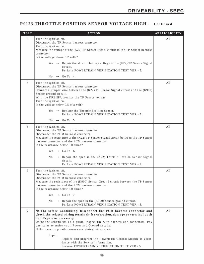
TEST ACTION APPLICABILITY
3 Turn the ignition off.Disconnect the TP Sensor harness connector.Turn the ignition on.Measure the voltage of the (K22) TP Sensor Signal circuit in the TP Sensor harnessconnector.Is the voltage above 5.2 volts?
All
Yes → Repair the short to battery voltage in the (K22) TP Sensor Signalcircuit.Perform POWERTRAIN VERIFICATION TEST VER - 5.
No → Go To 4
4 Turn the ignition off.Disconnect the TP Sensor harness connector.Connect a jumper wire between the (K22) TP Sensor Signal circuit and the (K900)Sensor ground circuit.With the DRBIIIt, monitor the TP Sensor voltage.Turn the ignition on.Is the voltage below 0.5 of a volt?
All
Yes → Replace the Throttle Position Sensor.Perform POWERTRAIN VERIFICATION TEST VER - 5.
No → Go To 5
5 Turn the ignition off.Disconnect the TP Sensor harness connector.Disconnect the PCM harness connector.Measure the resistance of the (K22) TP Sensor Signal circuit between the TP Sensorharness connector and the PCM harness connector.Is the resistance below 5.0 ohms?
All
Yes → Go To 6
No → Repair the open in the (K22) Throttle Position Sensor Signalcircuit.Perform POWERTRAIN VERIFICATION TEST VER - 5.
6 Turn the ignition off.Disconnect the TP Sensor harness connector.Disconnect the PCM harness connector.Measure the resistance of the (K900) Sensor Ground circuit between the TP Sensorharness connector and the PCM harness connector.Is the resistance below 5.0 ohms?
All
Yes → Go To 7
No → Repair the open in the (K900) Sensor ground circuit.Perform POWERTRAIN VERIFICATION TEST VER - 5.
7 NOTE: Before Continuing: Disconnect the PCM harness connector andcheck the related wiring terminals for corrosion, damage or terminal pushout. Repair as necessary.Using the schematics as a guide, inspect the wire harness and connectors. Payparticular attention to all Power and Ground circuits.If there are no possible causes remaining, view repair.
All
RepairReplace and program the Powertrain Control Module in accor-dance with the Service Information.Perform POWERTRAIN VERIFICATION TEST VER - 5.
59
DRIVEABILITY - SBEC
P0123-THROTTLE POSITION SENSOR VOLTAGE HIGH — Continued

TEST ACTION APPLICABILITY
8 Turn the ignition on.With the DRBIIIt, monitor the TP Sensor voltage.Slowly open the throttle from the idle position to the wide open throttle position.Does voltage start at approximately 0.8 of a volt and go above 3.5 volts with a smoothtransition?
All
Yes → Repair as necessaryPerform POWERTRAIN VERIFICATION TEST VER - 5.
No → Replace the Throttle Position Sensor.Perform POWERTRAIN VERIFICATION TEST VER - 5.
60
DRIVEABILITY - SBEC
P0123-THROTTLE POSITION SENSOR VOLTAGE HIGH — Continued

Symptom:P0125-CLOSED LOOP TEMP NOT REACHED
When Monitored and Set Condition:
P0125-CLOSED LOOP TEMP NOT REACHED
When Monitored: With battery voltage greater than 10.4 volts, after engine is started.
Set Condition: The engine temperature does not go above 15°C (60°F). Failure timedepends on start-up coolant temperature and ambient temperature. (i.e. 2 minutes for astart temp of 10°C (50°F) or up to 10 mintues for a vehicle with a start-up temp of -28°C(20°F). Two trips are required to set this DTC.
POSSIBLE CAUSES
LOW COOLANT LEVEL
THERMOSTAT OPERATION
ENGINE COOLANT TEMPERATURE SENSOR
TEST ACTION APPLICABILITY
1 NOTE: If a Engine Coolant Temperature (ECT) DTC is set along with thiscode, diagnose the ECT DTC first.NOTE: Inspect the ECT terminals and related PCM terminals. Ensure theterminals are free from corrosion and damage.NOTE: The best way to diagnose this DTC is to allow the vehicle to sitovernight outside in order to have a totally cold soaked engine.Note: Extremely cold outside ambient temperatures may have caused thisDTC to set.WARNING: Never open the cooling system when the engine is hot. Thesystem is under pressure. Extreme burns or scalding may result. Allow theengine to cool before opening the cooling system.Check the coolant system to make sure that the coolant is in good condition and atthe proper level.Is the coolant level and condition OK?
All
Yes → Go To 2
No → Inspect the vehicle for a coolant leak and add the necessaryamount of coolant.Perform POWERTRAIN VERIFICATION TEST VER - 5.
61
DRIVEABILITY - SBEC

TEST ACTION APPLICABILITY
2 Note: This test works best if performed on a cold engine (cold soak)Turn the ignition on.With the DRBIIIt, read the Eng Coolant Tmp Deg value. If the engine was allowedto sit overnight (cold soak), the temperature value should be a sensible value that issomewhere close to the ambient temperature.Note: If engine coolant temperature is above 82°C (180°F), allow the engineto cool until 65°C (150°F) is reached.Start the Engine.Using the appropriate service information, determine the proper opening tempera-ture of the thermostat.Did the thermostat open at the proper temperature?
All
Yes → Go To 3
No → Replace the thermostat.Perform POWERTRAIN VERIFICATION TEST VER - 5.
3 Turn the ignition on.With the DRBIIIt, read the Eng Coolant Tmp Deg value. If the engine was allowedto sit overnight (cold soak), the temperature value should be a sensible value that issomewhere close to the ambient temperature.Note: If engine coolant temperature is above 82°C (180°F), allow the engineto cool until 65°C (150°F) is reached.Start the Engine.During engine warm-up monitor the Eng Coolant Tmp Deg value. The temp degvalue change should be a smooth transition from start up to normal operating temp82°C (180°F) . Also monitor the actual coolant temperature with a thermometer.NOTE: As the engine warms up to operating temperature, the actual coolanttemperature (thermometer reading) and the Eng Coolant Tmp Deg in theDRB values should stay relatively close to each other.Does the actual coolant temperature and the reading on the DRBIIIt remainrelatively the same with a
All
Yes → Test Complete.
No → Replace the Engine Coolant Temperature Sensor.Perform POWERTRAIN VERIFICATION TEST VER - 5.
62
DRIVEABILITY - SBEC
P0125-CLOSED LOOP TEMP NOT REACHED — Continued

Symptom List:P0131-1/1 O2 SENSOR SHORTED TO GROUNDP0137-1/2 O2 SENSOR SHORTED TO GROUND
Test Note: All symptoms listed above are diagnosed using the same tests.The title for the tests will be P0131-1/1 O2 SENSOR SHORTEDTO GROUND.
When Monitored and Set Condition:
P0131-1/1 O2 SENSOR SHORTED TO GROUND
When Monitored: At engine shutdown O2 Heater Diagnostics test. Then at subsequentcold start. Cold start is defined as engine coolant below 37°C (100°F), ambient/batterysensor reading within 6.6°C (44°F), and engine coolant temperature above 63°C (146°F) onthe previous key off.
Set Condition: The oxygen sensor signal voltage is below 0.078 volts for 5 seconds afterstarting engine.
P0137-1/2 O2 SENSOR SHORTED TO GROUND
When Monitored: Engine running for 119 seconds. Coolant temperature above 80°C(176°F). Vehicle speed greater than 40 mph. Two trip fault.
Set Condition: The oxygen sensor signal voltage is below 0.078 volts for 61 seconds afterstarting engine.
POSSIBLE CAUSES
O2 SENSOR BELOW 0.08 VOLTS
O2 SENSOR OPERATION
O2 SENSOR SIGNAL CIRCUIT SHORTED TO GROUND
O2 SENSOR SIGNAL CIRCUIT SHORTED TO SENSOR GROUND CIRCUIT
O2 SENSOR SIGNAL SHORTED TO HEATER CONTROL/GROUND CIRCUIT
PCM
TEST ACTION APPLICABILITY
1 Start the engine.Allow the engine to reach normal operating temperature.With the DRBIIIt, read the O2 Sensor voltage.Is the voltage below 0.08?
All
Yes → Go To 2
No → Refer to the INTERMITTENT CONDITION symptom in theDriveability category.Perform POWERTRAIN VERIFICATION TEST VER - 5.
63
DRIVEABILITY - SBEC

TEST ACTION APPLICABILITY
2 WARNING: WHEN THE ENGINE IS OPERATING, DO NOT STAND IN ADIRECT LINE WITH THE FAN. DO NOT PUT YOUR HANDS NEAR THEPULLEYS, BELTS OR FAN. DO NOT WEAR LOOSE CLOTHING.Start the engine.Disconnect the O2 Sensor harness connector.With the DRBIIIt, monitor the O2 Sensor voltage.Is the O2 Sensor voltage above 0.08?
All
Yes → Replace the O2 SensorPerform POWERTRAIN VERIFICATION TEST VER - 5.
No → Go To 3
3 Turn the ignition off.Disconnect the O2 Sensor harness connector.Disconnect the PCM harness connector.Measure the resistance between ground and the O2 Sensor Signal circuit in the O2Sensor harness connector.Is the resistance below 100 ohms?
All
Yes → Repair the O2 Sensor Signal circuit for a short to ground.Perform POWERTRAIN VERIFICATION TEST VER - 5.
No → Go To 4
4 Turn the ignition off.Disconnect the O2 Sensor harness connector.Disconnect the PCM harness connector.Measure the resistance between the O2 Sensor Signal circuit and the Sensor groundcircuit in the O2 Sensor harness connector.Is the resistance below 100 ohms?
All
Yes → Repair the O2 Sensor Signal circuit for a short to the Sensorground circuit.Perform POWERTRAIN VERIFICATION TEST VER - 5.
No → Go To 5
5 Turn the ignition off.Disconnect the O2 Sensor harness connector.Disconnect the PCM harness connector.Measure the resistance between the O2 Sensor Signal circuit and the Heatercontrol/ground circuit in the O2 Sensor harness connector.Is the resistance below 100 ohms?
All
Yes → Repair the O2 Sensor Signal circuit for a short to the Heatercontrol/ground circuit.Perform POWERTRAIN VERIFICATION TEST VER - 5.
No → Go To 6
6 NOTE: Before Continuing: Disconnect the PCM harness connector andcheck the related wiring terminals for corrosion, damage or terminal pushout. Repair as necessary.Using the schematics as a guide, inspect the wire harness and connectors. Payparticular attention to all Power and Ground circuits.If there are no possible causes remaining, view repair.
All
RepairReplace and program the Powertrain Control Module in accor-dance with the Service Information.Perform POWERTRAIN VERIFICATION TEST VER - 5.
64
DRIVEABILITY - SBEC
P0131-1/1 O2 SENSOR SHORTED TO GROUND — Continued

Symptom List:P0132-1/1 O2 SENSOR SHORTED TO VOLTAGEP0138-1/2 O2 SENSOR SHORTED TO VOLTAGE
Test Note: All symptoms listed above are diagnosed using the same tests.The title for the tests will be P0132-1/1 O2 SENSOR SHORTEDTO VOLTAGE.
When Monitored and Set Condition:
P0132-1/1 O2 SENSOR SHORTED TO VOLTAGE
When Monitored: Engine running for 119 seconds. Battery voltage greater than 10 volts.Coolant temperature above 80°C (176°F).
Set Condition: The Oxygen Sensor voltage is above 1.21 volts for 2.8 seconds. One tripfault.
P0138-1/2 O2 SENSOR SHORTED TO VOLTAGE
When Monitored: The engine running for 119 seconds. Battery voltage greater than 10.4volts. Coolant temperature above 80°C (176°F).
Set Condition: The Oxygen Sensor voltage is above 1.21 volts for 2.8 seconds. Two tripfault.
POSSIBLE CAUSES
O2 SENSOR BELOW 1.2 VOLTS
O2 SENSOR OPERATION
O2 SENSOR SIGNAL SHORTED TO VOLTAGE
O2 SENSOR SIGNAL OPEN
O2 SENSOR GROUND CIRCUIT OPEN
PCM
TEST ACTION APPLICABILITY
1 Start the engine.Allow the engine to idle.With the DRBIIIt, read the O2 Sensor voltage.Is the voltage above 1.2 volts?
All
Yes → Go To 2
No → Refer to the INTERMITTENT CONDITION symptom in theDriveability category.Perform POWERTRAIN VERIFICATION TEST VER - 5.
65
DRIVEABILITY - SBEC

TEST ACTION APPLICABILITY
2 WARNING: WHEN THE ENGINE IS OPERATING, DO NOT STAND IN ADIRECT LINE WITH THE FAN. DO NOT PUT YOUR HANDS NEAR THEPULLEYS, BELTS OR FAN. DO NOT WEAR LOOSE CLOTHING.Start the engine.Disconnect the O2 Sensor harness connector.With the DRBIIIt, monitor the O2 Sensor voltage.Is the O2 Sensor voltage below 1.2 volts?
All
Yes → Replace the O2 Sensor.Perform POWERTRAIN VERIFICATION TEST VER - 5.
No → Go To 3
3 Turn the ignition off.Disconnect the O2 Sensor harness connectorWARNING: WHEN THE ENGINE IS OPERATING, DO NOT STAND IN ADIRECT LINE WITH THE FAN. DO NOT PUT YOUR HANDS NEAR THEPULLEYS, BELTS OR FAN. DO NOT WEAR LOOSE CLOTHING.Start the engine and allow the engine to idle.Measure the voltage of the O2 Sensor Signal circuit in the O2 Sensor harnessconnector.Is the voltage above 1.2 volts?
All
Yes → Repair the O2 Sensor Signal circuit for a shorted to voltage.Perform POWERTRAIN VERIFICATION TEST VER - 5.
No → Go To 4
4 Turn the ignition off.Disconnect the O2 Sensor harness connectorDisconnect the PCM harness connector.Measure the resistance of the O2 Sensor Signal circuit between the O2 Sensorharness connector and the PCM harness connector.Is the resistance below 5.0 ohms?
All
Yes → Go To 5
No → Repair the O2 Sensor Signal for an open.Perform POWERTRAIN VERIFICATION TEST VER - 5.
5 Turn the ignition off.Disconnect the O2 Sensor harness connectorDisconnect the PCM harness connector.Measure the resistance of the O2 Sensor ground circuit from the O2 Sensor harnessconnector and the PCM harness connector.Is the resistance below 5.0 ohms?
All
Yes → Go To 6
No → Repair the O2 Sensor ground cirucit for an open.Perform POWERTRAIN VERIFICATION TEST VER - 5.
66
DRIVEABILITY - SBEC
P0132-1/1 O2 SENSOR SHORTED TO VOLTAGE — Continued

TEST ACTION APPLICABILITY
6 NOTE: Before Continuing: Disconnect the PCM harness connector andcheck the related wiring terminals for corrosion, damage or terminal pushout. Repair as necessary.Using the schematics as a guide, inspect the wire harness and connectors. Payparticular attention to all Power and Ground circuits.If there are no possible causes remaining, view repair.
All
RepairReplace and program the Powertrain Control Module in accor-dance with the Service Information.Perform POWERTRAIN VERIFICATION TEST VER - 5.
67
DRIVEABILITY - SBEC
P0132-1/1 O2 SENSOR SHORTED TO VOLTAGE — Continued

Symptom List:P0133-1/1 O2 SENSOR SLOW RESPONSEP0139-1/2 O2 SENSOR SLOW RESPONSE
Test Note: All symptoms listed above are diagnosed using the same tests.The title for the tests will be P0133-1/1 O2 SENSOR SLOWRESPONSE.
When Monitored and Set Condition:
P0133-1/1 O2 SENSOR SLOW RESPONSE
When Monitored: Start and drive vehicle greater than 10 MPH with throttle open for aminimum 200 seconds. Coolant greater than 70°C (158°F). EVAP Purge is active. Testperforms in idle drive.
Set Condition: The oxygen sensor signal voltage is switching from below 0.33 volts toabove 0.61 volts and back fewer times than required in 60 seconds. Two trip fault..
P0139-1/2 O2 SENSOR SLOW RESPONSE
When Monitored: Start engine. Allow engine to idle. For 1st part of test, if limits areexceeded, test passes. If not, 2nd part of test runs. Engine running for grater than 295seconds. amb/batt temp >44°F, Baro >22.139 HG, MAP >13.8 & <21.69 HG, RPM >1400 &<2500 (4cylinder) RPM > 1120 & <1950(6 cylinder) and vss >22 and < 60 MPH.
Set Condition: The oxygen sensor signal voltage is has not switched below 0.35 volts toabove 0.53 volts in 411 seconds of engine run. Two trip fault.
POSSIBLE CAUSES
GOOD TRIP EQUAL TO ZERO
EXHAUST LEAK
O2 SENSOR SIGNAL CIRCUIT VOLTAGE DROP
O2 SENSOR GROUND CIRCUIT VOLTAGE DROP
O2 SENSOR
TEST ACTION APPLICABILITY
1 NOTE: Check for contaminates that may have damaged the O2 Sensor:contaminated fuel, unapproved silicone, oil and coolant.Turn the ignition on.With the DRBIIIt, read DTC’s.Is the Good Trip displayed and equal to zero?
All
Yes → Go To 2
No → Refer to the INTERMITTENT CONDITION symptom in theDriveability category.Perform POWERTRAIN VERIFICATION TEST VER - 5.
68
DRIVEABILITY - SBEC

TEST ACTION APPLICABILITY
2 Start the engine.Inspect the exhaust system for leak between the engine and the O2 sensors.Are there any exhaust leaks?
All
Yes → Repair or replace the leaking exhaust parts as necessary.Perform POWERTRAIN VERIFICATION TEST VER - 5.
No → Go To 3
3 NOTE: Ensure the voltmeter leads meet the terminals in the connector andthat there is good terminal to wire connection.NOTE: Ensure the voltmeter leads are connected for positive polarityPerform a voltage drop test by backprobing the O2 Sensor Signal circuit at the O2Sensor harness connector and at the PCM harness connector.Start the engine.Allow the engine to idle.Is the voltage below 0.10 volt?
All
Yes → Go To 4
No → Repair the high resistance on the O2 Sensor Signal circuit.Perform POWERTRAIN VERIFICATION TEST VER - 5.
4 NOTE: Ensure the voltmeter leads meet the terminals in the connector andthat there is good terminal to wire connection.NOTE: Ensure the voltmeter leads are connected for positive polarityBackprobe between the O2 Sensor ground circuit at the O2 Sensor harness connectorand PCM harness connector.Start the engine.Allow the engine to idle.Is the voltage below 0.10 volt?
All
Yes → Go To 5
No → Repair the high resistance on the O2 Sensor ground circuit.Perform POWERTRAIN VERIFICATION TEST VER - 5.
5 If there are no possible causes remaining, view repair. All
RepairReplace the O2 SensorPerform POWERTRAIN VERIFICATION TEST VER - 5.
69
DRIVEABILITY - SBEC
P0133-1/1 O2 SENSOR SLOW RESPONSE — Continued
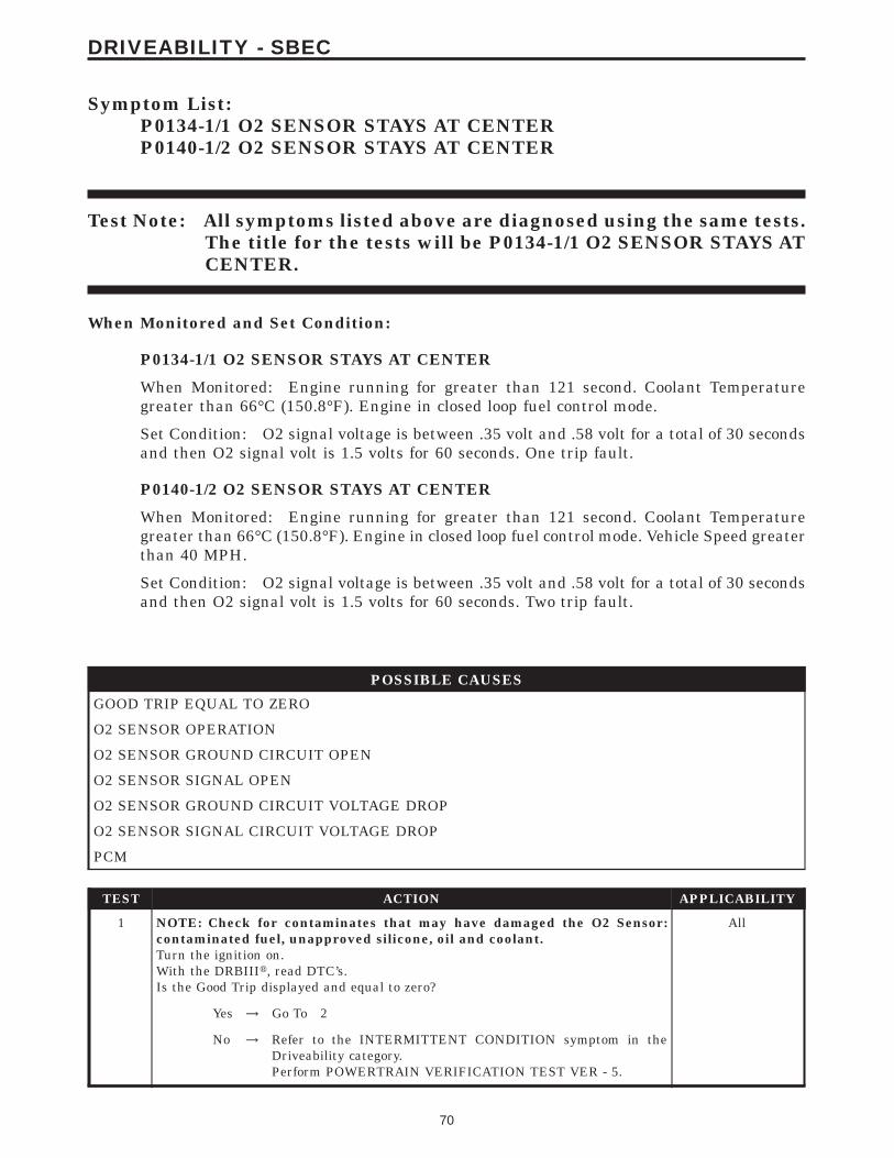
Symptom List:P0134-1/1 O2 SENSOR STAYS AT CENTERP0140-1/2 O2 SENSOR STAYS AT CENTER
Test Note: All symptoms listed above are diagnosed using the same tests.The title for the tests will be P0134-1/1 O2 SENSOR STAYS ATCENTER.
When Monitored and Set Condition:
P0134-1/1 O2 SENSOR STAYS AT CENTER
When Monitored: Engine running for greater than 121 second. Coolant Temperaturegreater than 66°C (150.8°F). Engine in closed loop fuel control mode.
Set Condition: O2 signal voltage is between .35 volt and .58 volt for a total of 30 secondsand then O2 signal volt is 1.5 volts for 60 seconds. One trip fault.
P0140-1/2 O2 SENSOR STAYS AT CENTER
When Monitored: Engine running for greater than 121 second. Coolant Temperaturegreater than 66°C (150.8°F). Engine in closed loop fuel control mode. Vehicle Speed greaterthan 40 MPH.
Set Condition: O2 signal voltage is between .35 volt and .58 volt for a total of 30 secondsand then O2 signal volt is 1.5 volts for 60 seconds. Two trip fault.
POSSIBLE CAUSES
GOOD TRIP EQUAL TO ZERO
O2 SENSOR OPERATION
O2 SENSOR GROUND CIRCUIT OPEN
O2 SENSOR SIGNAL OPEN
O2 SENSOR GROUND CIRCUIT VOLTAGE DROP
O2 SENSOR SIGNAL CIRCUIT VOLTAGE DROP
PCM
TEST ACTION APPLICABILITY
1 NOTE: Check for contaminates that may have damaged the O2 Sensor:contaminated fuel, unapproved silicone, oil and coolant.Turn the ignition on.With the DRBIIIt, read DTC’s.Is the Good Trip displayed and equal to zero?
All
Yes → Go To 2
No → Refer to the INTERMITTENT CONDITION symptom in theDriveability category.Perform POWERTRAIN VERIFICATION TEST VER - 5.
70
DRIVEABILITY - SBEC

TEST ACTION APPLICABILITY
2 Turn the ignition off.Disconnect the O2 Sensor harness connector.Turn the ignition on.Connect a test light to battery voltage, probe the O2 Sensor Signal circuit in the O2Sensor harness connector.With the DRBIIIt, read the O2 Sensor voltage.Is the voltage above 1.0 volts?
All
Yes → Replace the O2 Sensor.Perform POWERTRAIN VERIFICATION TEST VER - 5.
No → Go To 3
3 Turn the ignition off.Disconnect the O2 Sensor harness connectorDisconnect the PCM harness connector.Measure the resistance of the O2 Sensor ground circuit between the O2 Sensorharness connector and the PCM harness connector.Is the resistance below 5.0 ohms?
All
Yes → Go To 4
No → Repair the O2 Sensor ground circuit for an open.Perform POWERTRAIN VERIFICATION TEST VER - 5.
4 Turn the ignition off.Disconnect the O2 Sensor harness connectorDisconnect the PCM harness connector.Measure the resistance of the O2 Sensor Signal circuit between the O2 Sensorharness connector and the PCM harness connector.Is the resistance below 5.0 ohms?
All
Yes → Go To 5
No → Repair the O2 Sensor Signal for an open.Perform POWERTRAIN VERIFICATION TEST VER - 5.
5 NOTE: Ensure the voltmeter leads meet the terminals in the connector andthat there is good terminal to wire connection.NOTE: Ensure the voltmeter leads are connected for positive polarityPerform a voltage drop test by back probing between the O2 Sensor ground circuit atthe O2 Sensor harness connector and PCM harness connector.Start the engine.Allow the engine to idle.Is the voltage below 0.10 volt?
All
Yes → Go To 6
No → Repair the high resistance on the O2 Sensor ground circuit.Perform POWERTRAIN VERIFICATION TEST VER - 5.
71
DRIVEABILITY - SBEC
P0134-1/1 O2 SENSOR STAYS AT CENTER — Continued

TEST ACTION APPLICABILITY
6 NOTE: Ensure the voltmeter leads meet the terminals in the connector andthat there is good terminal to wire connection.NOTE: Ensure the voltmeter leads are connected for positive polarityPerform a voltage drop test by back probing between the O2 Sensor Signal circuit atthe O2 Sensor harness connector and PCM harness connector.Start the engine.Allow the engine to idle.Is the voltage below 0.10 volt?
All
Yes → Go To 7
No → Repair the high resistance on the O2 Sensor Signal circuit.Perform POWERTRAIN VERIFICATION TEST VER - 5.
7 NOTE: Before Continuing: Disconnect the PCM harness connector andcheck the related wiring terminals for corrosion, damage or terminal pushout. Repair as necessary.Using the schematics as a guide, inspect the wire harness and connectors. Payparticular attention to all Power and Ground circuits.If there are no possible causes remaining, view repair.
All
RepairReplace and program the Powertrain Control Module in accor-dance with the Service Information.Perform POWERTRAIN VERIFICATION TEST VER - 5.
72
DRIVEABILITY - SBEC
P0134-1/1 O2 SENSOR STAYS AT CENTER — Continued

Symptom:P0135-1/1 O2 SENSOR HEATER FAILURE
When Monitored and Set Condition:
P0135-1/1 O2 SENSOR HEATER FAILURE
When Monitored: During vehicle shutdown after vehicle had been driven greater than 10MPH with throttle open for a minimum of 3 minutes. Battery voltage greater than 11.0volts.
Set Condition: O2 sensor voltage continues to rise (instead of fall) after the diagnosticshas turned the ASD relay back on. Two trip fault.
POSSIBLE CAUSES
O2 SENSOR HEATER OPERATION
O2 HEATER ELEMENT
O2 SENSOR HEATER CONTROL CIRCUIT OPEN
O2 SENSOR HEATER CONTROL CIRCUIT SHORTED TO GROUND
ASD RELAY OUTPUT CIRCUIT OPEN
PCM
TEST ACTION APPLICABILITY
1 Turn the ignition on.With the DRBIIIt, read DTC’s.Is the Good Trip display and equal to zero?
All
Yes → Go To 3
No → Go To 2
2 Turn the ignition off.NOTE: Wait a minimum of 8 minutes to allow the O2 Sensor to cool downbefore continuing the test. Allow the O2 Sensor voltage to stabilize between0.4 to 0.6 volts.Turn the ignition on.With the DRBIIIt, actuate the O2 Heater Test.With the DRBIIIt, monitor O2 Sensor voltage for at least 2 minutes.Does the voltage stay between 0.4 and 0.6
All
Yes → Go To 3
No → Refer to the INTERMITTENT CONDITION symptom in theDriveability category.Perform POWERTRAIN VERIFICATION TEST VER - 5.
73
DRIVEABILITY - SBEC

TEST ACTION APPLICABILITY
3 NOTE: Allow the O2 sensor to cool down to room temperature.Turn the ignition off.Disconnect the O2 Sensor harness connector.Measure the resistance across the O2 Sensor Heater element component side.Is the resistance between 2.0 and 7.0 ohms?
All
Yes → Go To 4
No → Replace the O2 Sensor.Perform POWERTRAIN VERIFICATION TEST VER - 5.
4 Turn the ignition off.Disconnect the O2 Sensor harness connector.Disconnect the PCM harness connector.Measure the resistance of the O2 Sensor Heater Control circuit between the O2Sensor harness connector and the PCM harness connector.Is the resistance below 5.0 ohms?
All
Yes → Go To 5
No → Repair the O2 Sensor Heater Control circuit for an open.Perform POWERTRAIN VERIFICATION TEST VER - 5.
5 Turn the ignition off.Disconnect the O2 Sensor harness connector.Disconnect the PCM harness connector.Measure the resistance of the O2 Sensor Heater Control circuit in the O2 Sensorharness connector to ground.Is the resistance below 5.0 ohms?
All
Yes → Repair the O2 Sensor Heater Control circuit for a short to ground.Perform POWERTRAIN VERIFICATION TEST VER - 5.
No → Go To 6
6 Turn the ignition off.Disconnect the O2 Sensor harness connector.With the DRBIIIt, actuate the O2 Heater Test.Measure the voltage of the ASD Relay Output circuit in the O2 Sensor harnessconnector.Is the voltage above 11.0 volts?
All
Yes → Go To 7
No → Repair the ASD Relay Output circuit for an open.Perform POWERTRAIN VERIFICATION TEST VER - 5.
7 NOTE: Before Continuing: Disconnect the PCM harness connector andcheck the related wiring terminals for corrosion, damage or terminal pushout. Repair as necessary.Using the schematics as a guide, inspect the wire harness and connectors. Payparticular attention to all Power and Ground circuits.If there are no possible causes remaining, view repair.
All
RepairReplace and program the Powertrain Control Module in accor-dance with the Service Information.Perform POWERTRAIN VERIFICATION TEST VER - 5.
74
DRIVEABILITY - SBEC
P0135-1/1 O2 SENSOR HEATER FAILURE — Continued

Symptom:P0141-1/2 O2 SENSOR HEATER FAILURE
When Monitored and Set Condition:
P0141-1/2 O2 SENSOR HEATER FAILURE
When Monitored: During vehicle shutdown after the vehicle has been driven for greaterthan 10 miles with the throttle open for a minimum of 3 minutes. Battery voltage greaterthan 11.0 volts.
Set Condition: O2 sensor continues to rise, (instead of fall) after the diagnostics hasturned the ASD relay back on. Two trip fault.
POSSIBLE CAUSES
O2 SENSOR HEATER OPERATION
O2 HEATER ELEMENT
O2 SENSOR HEATER GROUND CIRCUIT OPEN
ASD RELAY OUTPUT CIRCUIT OPEN
PCM
TEST ACTION APPLICABILITY
1 Turn the ignition on.With the DRBIIIt, read DTC’s.Is the Good Trip display and equal to zero?
All
Yes → Go To 3
No → Go To 2
2 Turn the ignition off.NOTE: Wait a minimum of 8 minutes to allow the O2 Sensor to cool downbefore continuing the test. Allow the O2 Sensor voltage to stabilize between0.4 to 0.6 volts.Turn the ignition on.With the DRBIIIt, actuate the O2 Heater Test.With the DRBIIIt, monitor O2 Sensor voltage for at least 2 minutes.Does the voltage stay between 0.4 and 0.6 volts?
All
Yes → Go To 3
No → Refer to the INTERMITTENT CONDITION symptom in theDriveability category.Perform POWERTRAIN VERIFICATION TEST VER - 5.
75
DRIVEABILITY - SBEC

TEST ACTION APPLICABILITY
3 NOTE: Allow the O2 sensor to cool down to room temperature.Turn the ignition off.Disconnect the O2 Sensor harness connector.Measure the resistance across the O2 Sensor Heater element component side.NOTE: O2 Sensor Heater Resistance Specification: 1/1 and 2/1 O2 Sensor 3.0to 4.0 ohms 2/1 and 2/2 4.0 to 5.0 ohms.Is the resistance between 4.0 and 7.0 ohms?
All
Yes → Go To 4
No → Replace the O2 Sensor.Perform POWERTRAIN VERIFICATION TEST VER - 5.
4 Turn the ignition off.Disconnect the O2 Sensor harness connector.Measure the resistance of the O2 Sensor Heater ground circuit in the O2 Sensorharness connector.Is the resistance below 5.0 ohms?
All
Yes → Go To 5
No → Repair the O2 Sensor Heater ground circuit for an open.Perform POWERTRAIN VERIFICATION TEST VER - 5.
5 Turn the ignition off.Disconnect the O2 Sensor harness connector.With the DRBIIIt, actuate the O2 Heater Test.Measure the voltage of the ASD Relay Output circuit in the O2 Sensor harnessconnector.Is the voltage above 11.0 volts?
All
Yes → Go To 6
No → Repair the open in the ASD Relay Output circuit.Perform POWERTRAIN VERIFICATION TEST VER - 5.
6 NOTE: Before Continuing: Disconnect the PCM harness connector andcheck the related wiring terminals for corrosion, damage or terminal pushout. Repair as necessary.Using the schematics as a guide, inspect the wire harness and connectors. Payparticular attention to all Power and Ground circuits.If there are no possible causes remaining, view repair.
All
RepairReplace and program the Powertrain Control Module in accor-dance with the Service Information.Perform POWERTRAIN VERIFICATION TEST VER - 5.
76
DRIVEABILITY - SBEC
P0141-1/2 O2 SENSOR HEATER FAILURE — Continued

Symptom:P0171-1/1 FUEL SYSTEM LEAN
When Monitored and Set Condition:
P0171-1/1 FUEL SYSTEM LEAN
When Monitored: With the engine running in closed loop mode, the ambient/batterytemperature above 20 deg. F and altitude below 8000 ft.
Set Condition: If the PCM multiplies short term compensation by long term adaptive anda certain percentage is exceeded for two trips, a freeze frame is stored, the MIL illuminatesand a trouble code is stored.
POSSIBLE CAUSES
GOOD TRIP EQUAL TO ZERO
RESTRICTED FUEL SUPPLY LINE
FUEL PUMP INLET STRAINER PLUGGED
FUEL PUMP MODULE
O2 SENSOR
O2 SENSOR SIGNAL CIRCUIT SHORTED TO GROUND
O2 SENSOR HEATER OPERATION
THROTTLE POSITION SENSOR VOLTAGE GREATER THAN 0.92 VOLTS WITH THROTTLECLOSED
TP SENSOR SWEEP
MAP SENSOR OPERATION
ECT SENSOR OPERATION
ENGINE MECHANICAL PROBLEM
FUEL FILTER/PRESSURE REGULATOR (HIGH)
PCM
TEST ACTION APPLICABILITY
1 NOTE: Check for contaminates that may have damaged the O2 Sensor:contaminated fuel, unapproved silicone, oil and coolant.Turn the ignition on.With the DRBIIIt, read DTC’s.Is the Good Trip displayed and equal to zero?
All
Yes → Go To 2
No → Refer to the INTERMITTENT CONDITION symptom in theDriveability category.Perform POWERTRAIN VERIFICATION TEST VER - 5.
77
DRIVEABILITY - SBEC

TEST ACTION APPLICABILITY
2 Warning: The fuel system is under a constant pressure (even with the engineoff). Before testing or servicing any fuel system hose, fitting or line, the fuelsystem pressure must be released.Install a fuel pressure gauge to the fuel rail.Turn the ignition on.With the DRBIIIt, actuate the ASD Fuel System test and observe the fuel pressuregauge.NOTE: Fuel pressure specification is 400 KPa +/- 34 KPa (58 psi +/- 5 psi).Turn the ignition off.Choose a conclusion that best matches your fuel pressure reading.
All
Within SpecificationGo To 3
Above SpecificationReplace the fuel filter/pressure regulator.Perform POWERTRAIN VERIFICATION TEST VER - 5.
Below SpecificationGo To 13
Caution: Stop All Actuations.
3 Turn the ignition onWith the DRBIIIt, read the O2 Sensor voltage.Is the voltage between 0.4 to 0.6 volts?
All
Yes → Go To 4
No → Go To 10
4 Turn the ignition off.NOTE: Wait a minimum of 10 minutes to allow the O2 Sensor to cool downbefore continuing the test. Allow the O2 Sensor voltage to stabilize between0.4 to 0.6 volts.Turn the ignition on.With the DRBIIIt, actuate the O2 Heater Test.With the DRBIIIt, monitor O2 Sensor voltage for at least 2 minutes.Does the voltage stay between 0.4 and 0.6 volts.
All
Yes → Replace the O2 Sensor.Perform POWERTRAIN VERIFICATION TEST VER - 5.
No → Go To 5
5 Turn the ignition on.With the DRBIIIt, read TP Sensor voltage.NOTE: The throttle must be against the stop.Is the TP Sensor voltage 0.92 or less with the throttle closed?
All
Yes → Go To 6
No → Check for a binding throttle condition. If OK, replace the TPSensor.Perform POWERTRAIN VERIFICATION TEST VER - 5.
78
DRIVEABILITY - SBEC
P0171-1/1 FUEL SYSTEM LEAN — Continued

TEST ACTION APPLICABILITY
6 Turn the ignition on.With the DRBIIIt, read the TP Sensor voltage.While monitoring the DRBIIIt, slowly open and close the throttle.Does the voltage increase and decease smoothly?
All
Yes → Go To 7
No → Replace the TP Sensor.Perform POWERTRAIN VERIFICATION TEST VER - 5.
7 Turn the ignition off.Connect a Vacuum Gauge to a Manifold Vacuum source.Start the engine.Allow the engine to idle.Note: If engine will not idle, maintain a constant RPM above idle.With the DRBIIIt in Sensors, read the MAP Sensor vacuum value.Is the DRBIIIt reading within 19 of the Vacuum Gauge reading?
All
Yes → Go To 8
No → Replace the MAP Sensor.Perform POWERTRAIN VERIFICATION TEST VER - 5.
8 Note: For this test to be valid, the thermostat must be operating correctly.Note: This test works best if performed on a cold engine (cold soak)Turn the ignition on.With the DRBIIIt, read the Engine Coolant Temperature (ECT) Sensor value. If theengine was allowed to sit overnight (cold soak), the temperature value should be asensible value that is somewhere close to the ambient temperature.Note: If engine coolant temperature is above 82°C (180°F), allow the engineto cool until 65°C (150°F) is reached.Start the Engine.During engine warm-up, monitor the Engine Coolant Temperature value. Thetemperature value change should be a smooth transition from start up to normaloperating temperature 82°C (180°F). The value should reach at least 82°C (180°F).Did the Engine Coolant Temperature value increase a smooth transition and did itreach at least 82°C
All
Yes → Go To 9
No → Replace the Engine Coolant Temperature Sensor.Perform POWERTRAIN VERIFICATION TEST VER - 5.
9 Check for any of the following conditions/mechanical problems.AIR INDUCTION SYSTEM - must be free from leaks.ENGINE VACUUM - must be at least 13 inches in neutralENGINE VALVE TIMING - must be within specificationsENGINE COMPRESSION - must be within specificationsENGINE EXHAUST SYSTEM - must be free of any restrictions or leaks.ENGINE PCV SYSTEM - must flow freelyTORQUE CONVERTER STALL SPEED - must be within specificationsPOWER BRAKE BOOSTER - no internal vacuum leaksFUEL - must be free of contaminationFUEL INJECTOR - plugged or restricted injector; control wire not connected tocorrect injectorAre there any engine mechanical problems?
All
Yes → Repair as necessary.Perform POWERTRAIN VERIFICATION TEST VER - 5.
No → Test Complete.
79
DRIVEABILITY - SBEC
P0171-1/1 FUEL SYSTEM LEAN — Continued

TEST ACTION APPLICABILITY
10 Turn the ignition on.Disconnect the O2 Sensor harness connector.With the DRBIIIt, monitor the O2 Sensor voltage.Is the O2 Sensor voltage between 0.40 to 0.60 volts?
All
Yes → Replace the O2 SensorPerform POWERTRAIN VERIFICATION TEST VER - 5.
No → Go To 11
11 Turn the ignition off.Disconnect the O2 Sensor harness connector.Disconnect the PCM harness connector.Measure the resistance of the O2 Sensor Signal circuit in the PCM harness connectorto ground.Is the resistance below 5.0 ohms?
All
Yes → Repair the O2 Sensor Signal for a short to ground.Perform POWERTRAIN VERIFICATION TEST VER - 5.
No → Go To 12
12 NOTE: Before Continuing: Disconnect the PCM harness connector andcheck the related wiring terminals for corrosion, damage or terminal pushout. Repair as necessary.Using the schematics as a guide, inspect the wire harness and connectors. Payparticular attention to all Power and Ground circuits.If there are no possible causes remaining, view repair.
All
RepairReplace and program the Powertrain Control Module in accor-dance with the Service Information.Perform POWERTRAIN VERIFICATION TEST VER - 5.
13 Turn the ignition off.Warning: The fuel system is under a constant pressure (even with the engineoff). Before testing or servicing any fuel system hose, fitting or line, the fuelsystem pressure must be released.Raise vehicle on hoist, and disconnect the fuel pressure line at the fuel pump module.Install special 5/16 fuel line adapter tool #6539 between disconnected fuel line andthe fuel pump module.Attach a fuel pressure test gauge to the T fitting on tool #6539.Turn the ignition on.With the DRBIIIt, actuate the ASD Fuel System test and observe the fuel pressuregauge.NOTE: Fuel pressure specification is 400 KPa +/- 34 KPa (58 psi +/- 5 psi).Is the fuel pressure within specification?
All
Yes → Repair or replace fuel supply line as necessary.Perform POWERTRAIN VERIFICATION TEST VER - 5.
No → Go To 14
Caution: Stop All Actuations.
80
DRIVEABILITY - SBEC
P0171-1/1 FUEL SYSTEM LEAN — Continued

TEST ACTION APPLICABILITY
14 Turn the ignition off.Warning: The fuel system is under a constant pressure (even with the engineoff). Before testing or servicing any fuel system hose,fitting or line, the fuelsystem pressure must be released.Remove the Fuel Pump Module and inspect the Fuel Inlet Strainer.Is the Fuel Inlet Strainer plugged?
All
Yes → Replace the Fuel Pump Inlet Strainer.Perform POWERTRAIN VERIFICATION TEST VER - 5.
No → Go To 15
15 If there are no possible causes remaining, view repair. All
RepairReplace the Fuel Pump Module.Perform POWERTRAIN VERIFICATION TEST VER - 5.
81
DRIVEABILITY - SBEC
P0171-1/1 FUEL SYSTEM LEAN — Continued

Symptom:P0172-1/1 FUEL SYSTEM RICH
When Monitored and Set Condition:
P0172-1/1 FUEL SYSTEM RICH
When Monitored: With the engine running in closed loop mode, the ambient/batterytemperature above 20 deg. F and altitude below 8000 ft.
Set Condition: If the PCM multiplies short term compensation by long term adaptive andthe result is below a certain value for two trips, a freeze frame is stored, the MILilluminates and a trouble code is stored.
POSSIBLE CAUSES
GOOD TRIP EQUAL TO ZERO
O2 SENSOR HEATER OPERATION
O2 SENSOR
EVAP PURGE SOLENOID OPERATION
O2 SENSOR SIGNAL CIRCUIT SHORTED TO VOLTAGE
O2 SENSOR SIGNAL CIRCUIT OPEN
THROTTLE POSITION SENSOR VOLTAGE GREATER THAN 0.92 VOLTS WITH THROTTLECLOSED
TP SENSOR SWEEP
MAP SENSOR OPERATION
ECT SENSOR OPERATION
ENGINE MECHANICAL PROBLEM
FUEL FILTER/PRESSURE REGULATOR (HIGH)
PCM
TEST ACTION APPLICABILITY
1 NOTE: Check for contaminates that may have damaged the O2 Sensor:contaminated fuel, unapproved silicone, oil and coolant.Turn the ignition on.With the DRBIIIt, read DTC’s.Is the Good Trip displayed and equal to zero?
All
Yes → Go To 2
No → Refer to the INTERMITTENT CONDITION symptom in theDriveability category.Perform POWERTRAIN VERIFICATION TEST VER - 5.
82
DRIVEABILITY - SBEC

TEST ACTION APPLICABILITY
2 Warning: The fuel system is under a constant pressure (even with the engineoff). Before testing or servicing any fuel system hose, fitting or line, the fuelsystem pressure must be released.Install a fuel pressure gauge to the fuel rail.Turn the ignition on.With the DRBIIIt, actuate the ASD Fuel System test and observe the fuel pressuregauge.NOTE: Fuel pressure specification is 400 KPa +/- 34 KPa (58 psi +/- 5 psi).Turn the ignition off.Choose a conclusion that best matches your fuel pressure reading.
All
Within SpecificationGo To 3
Above SpecificationReplace the fuel filter/pressure regulator.Perform POWERTRAIN VERIFICATION TEST VER - 5.
Caution: Stop All Actuations.
3 Turn the ignition onWith the DRBIIIt, read the O2 Sensor voltage.Is the voltage between 0.4 to 0.6 volts?
All
Yes → Go To 4
No → Go To 11
4 Turn the ignition off.NOTE: Wait a minimum of 10 minutes to allow the O2 Sensor to cool downbefore continuing the test. Allow the O2 Sensor voltage to stabilize between0.4 to 0.6 volts.Turn the ignition on.With the DRBIIIt, actuate the O2 Heater Test.With the DRBIIIt, monitor O2 Sensor voltage for at least 2 minutes.Does the voltage stay between 0.4 and 0.6
All
Yes → Replace the O2 Sensor.Perform POWERTRAIN VERIFICATION TEST VER - 5.
No → Go To 5
5 Turn the ignition off.Disconnect the hoses at the Evap Purge Solenoid.Using a hand vacuum pump, apply 10 inches of vacuum to the Evap Purge Solenoidvacuum source port on the component side.Did the Evap Purge Solenoid hold vacuum?
All
Yes → Go To 6
No → Replace the EVAP Purge Solenoid.Perform POWERTRAIN VERIFICATION TEST VER - 5.
83
DRIVEABILITY - SBEC
P0172-1/1 FUEL SYSTEM RICH — Continued

TEST ACTION APPLICABILITY
6 Turn the ignition on.With the DRBIIIt, read TPS voltage.NOTE: The throttle must be against the stop.Is the TPS voltage 0.92 of a volt or less with the throttle closed?
All
Yes → Go To 7
No → Check for a binding throttle condition. If OK, replace the TPSensor.Perform POWERTRAIN VERIFICATION TEST VER - 5.
7 Turn the ignition on.With the DRBIIIt, read the TP Sensor voltage.While monitoring the DRBIIIt, slowly open and close the throttle.Does the voltage increase and decease smoothly?
All
Yes → Go To 8
No → Replace the TP Sensor.Perform POWERTRAIN VERIFICATION TEST VER - 5.
8 Turn the ignition off.Connect a Vacuum Gauge to a Manifold Vacuum source.Start the engine.Allow the engine to idle.Note: If engine will not idle, maintain a constant RPM above idle.With the DRBIIIt in Sensors, read the MAP Sensor vacuum value.Is the DRB reading within 19 of the Vacuum Gauge reading?
All
Yes → Go To 9
No → Replace the MAP Sensor.Perform POWERTRAIN VERIFICATION TEST VER - 5.
9 Note: For this test to be valid, the thermostat must be operating correctly.Note: This test works best if performed on a cold engine (cold soak)Turn the ignition on.With the DRBIIIt, read the Engine Coolant Temperature Sensor value. If the enginewas allowed to sit overnight (cold soak), the temperature value should be a sensiblevalue that is somewhere close to the ambient temperature.Note: If engine coolant temperature is above 82°C (180°F), allow the engineto cool until 65°C (150°F) is reached.Start the Engine.During engine warm-up, monitor the Engine Coolant Temperature value. The tempvalue change should be a smooth transition from start up to normal operating temp82°C (180°F). The value should reach at least 82°C (180°F).Did the Engine Coolant Temperature value increase a smooth transition and did itreach at least 82°C
All
Yes → Go To 10
No → Replace the Engine Coolant Temperature Sensor.Perform POWERTRAIN VERIFICATION TEST VER - 5.
84
DRIVEABILITY - SBEC
P0172-1/1 FUEL SYSTEM RICH — Continued

TEST ACTION APPLICABILITY
10 Check for any of the following conditions/mechanical problems.AIR INDUCTION SYSTEM - must be free from restrictions.ENGINE VACUUM - must be at least 13 inches in neutralENGINE VALVE TIMING - must be within specificationsENGINE COMPRESSION - must be within specificationsENGINE EXHAUST SYSTEM - must be free of any restrictions or leaks.ENGINE PCV SYSTEM - must flow freelyTORQUE CONVERTER STALL SPEED - must be within specificationsPOWER BRAKE BOOSTER - no internal vacuum leaksFUEL - must be free of contaminationFUEL INJECTOR - plugged or restricted injector; control wire not connected tocorrect injectorAre there any engine mechanical problems?
All
Yes → Repair as necessary.Perform POWERTRAIN VERIFICATION TEST VER - 5.
No → Test Complete.
11 Turn the ignition on.Disconnect the O2 Sensor harness connector.With the DRBIIIt, monitor the O2 Sensor voltage.Is the O2 Sensor voltage between 0.4 to 0.6 volts?
All
Yes → Replace the O2 SensorPerform POWERTRAIN VERIFICATION TEST VER - 5.
No → Go To 12
12 Turn the ignition off.Disconnect the O2 Sensor harness connector.Disconnect the PCM harness connector.Measure the resistance of the O2 Sensor Signal circuit between the PCM harnessconnector and the O2 Sensor harness connector.Is the resistance below 5.0 ohms?
All
Yes → Go To 13
No → Check for O2 Sensor Signal circuit for an open.Perform POWERTRAIN VERIFICATION TEST VER - 5.
13 WARNING: WHEN THE ENGINE IS OPERATING, DO NOT STAND IN ADIRECT LINE WITH THE FAN. DO NOT PUT YOUR HANDS NEAR THEPULLEYS, BELTS OR FAN. DO NOT WEAR LOOSE CLOTHING.Turn the ignition off.Disconnect the O2 Sensor harness connector.Start the engine.Measure the voltage of the O2 Sensor Signal circuit in the O2 Sensor harnessconnector.Is the voltage above 0.60 volt?
All
Yes → Repair the O2 Sensor Signal for a short to voltage.Perform POWERTRAIN VERIFICATION TEST VER - 5.
No → Go To 14
85
DRIVEABILITY - SBEC
P0172-1/1 FUEL SYSTEM RICH — Continued

TEST ACTION APPLICABILITY
14 NOTE: Before Continuing: Disconnect the PCM harness connector andcheck the related wiring terminals for corrosion, damage or terminal pushout. Repair as necessary.Using the schematics as a guide, inspect the wire harness and connectors. Payparticular attention to all Power and Ground circuits.If there are no possible causes remaining, view repair.
All
RepairReplace and program the Powertrain Control Module in accor-dance with the Service Information.Perform POWERTRAIN VERIFICATION TEST VER - 5.
86
DRIVEABILITY - SBEC
P0172-1/1 FUEL SYSTEM RICH — Continued

Symptom List:P0201-INJECTOR #1 CONTROL CIRCUITP0202-INJECTOR #2 CONTROL CIRCUITP0203-INJECTOR #3 CONTROL CIRCUITP0204-INJECTOR #4 CONTROL CIRCUITP0205-INJECTOR #5 CONTROL CIRCUITP0206-INJECTOR #6 CONTROL CIRCUIT
Test Note: All symptoms listed above are diagnosed using the same tests.The title for the tests will be P0201-INJECTOR #1 CONTROLCIRCUIT.
When Monitored and Set Condition:
P0201-INJECTOR #1 CONTROL CIRCUIT
When Monitored: With battery voltage greater than 10.4 volts. Auto Shutdown Relayenergized. Engine speed less than 3000 rpm.
Set Condition: No inductive spike is detected after injector turn off.
P0202-INJECTOR #2 CONTROL CIRCUIT
When Monitored: With battery voltage greater than 10.4 volts. Auto Shutdown Relayenergized. Engine speed less than 3000 rpm.
Set Condition: No inductive spike is detected after injector turn off.
P0203-INJECTOR #3 CONTROL CIRCUIT
When Monitored: With battery voltage greater than 10.4 volts. Auto Shutdown Relayenergized. Engine speed less than 3000 rpm.
Set Condition: No inductive is detected after injector turn off.
P0204-INJECTOR #4 CONTROL CIRCUIT
When Monitored: With battery voltage greater than 10.4 volts. Auto Shutdown Relayenergized. Engine speed less than 3000 rpm.
Set Condition: No inductive spike is detected after injector turn off, and with no otherinjectors on.
P0205-INJECTOR #5 CONTROL CIRCUIT
When Monitored: With battery voltage greater than 10.4 volts. Auto Shutdown Relayenergized. Engine speed less than 3000 rpm.
Set Condition: No inductive spike is detected after injector turn off.
87
DRIVEABILITY - SBEC

P0206-INJECTOR #6 CONTROL CIRCUIT
When Monitored: With battery voltage greater than 10.4 volts. Auto Shutdown Relayenergized. Engine speed less than 3000 rpm.
Set Condition: No inductive spike is detected after injector turn off.
POSSIBLE CAUSES
(K342) ASD RELAY OUTPUT CIRCUIT OPEN
GOOD TRIP EQUAL TO ZERO
FUEL INJECTOR
FUEL INJECTOR DRIVER CIRCUIT OPEN
FUEL INJECTOR DRIVER CIRCUIT SHORTED TO GROUND
PCM
TEST ACTION APPLICABILITY
1 NOTE: Record the Freeze Frame Information that set along with the DTC.Turn the ignition on.With the DRBIIIt, read DTC’s.Is the Good Trip displayed and equal to zero?
All
Yes → Go To 2
No → Refer to the INTERMITTENT CONDITION symptom in theDriveability category.Perform POWERTRAIN VERIFICATION TEST VER - 5.
2 Turn the ignition off.Disconnect the Fuel Injector harness connector.Measure the resistance of the Fuel Injector, component side.Is the resistance between 10 and 16 ohms?
All
Yes → Go To 3
No → Replace the Fuel Injector.Perform POWERTRAIN VERIFICATION TEST VER - 5.
3 Turn the ignition off.Disconnect the Fuel Injector harness connector.Remove the ASD Relay from the IPM.Turn the ignition on.Jumper the Fused B+ circuit and the ASD Relay Output circuit in the IPM.Using a 12-volt test light connected to ground, probe the (K342) ASD Relay Outputcircuit.Does the test light illuminate brightly?
All
Yes → Go To 4
No → Repair the open in the (K342) ASD Relay Output circuit.Perform POWERTRAIN VERIFICATION TEST VER - 5.
88
DRIVEABILITY - SBEC
P0201-INJECTOR #1 CONTROL CIRCUIT — Continued

TEST ACTION APPLICABILITY
4 Turn the ignition off.Disconnect the Fuel Injector harness connector.Disconnect the PCM harness connector.Measure the resistance of the Fuel Injector driver circuit between the Fuel Injectorharness connector and the PCM harness connector.Is the resistance below 5.0 ohms?
All
Yes → Go To 5
No → Repair the open in the Fuel Injector driver circuit.Perform POWERTRAIN VERIFICATION TEST VER - 5.
5 Turn the ignition off.Disconnect the Fuel Injector harness connector.Disconnect the PCM harness connector.Measure the resistance between ground and the Fuel Injector driver circuit in theFuel Injector harness connector.Is the resistance below 100k ohms?
All
Yes → Repair the open in the Fuel Injector driver circuit.Perform POWERTRAIN VERIFICATION TEST VER - 5.
No → Go To 6
6 NOTE: Before Continuing: Disconnect the PCM harness connector andcheck the related wiring terminals for corrosion, damage or terminal pushout. Repair as necessary.Using the schematics as a guide, inspect the wire harness and connectors. Payparticular attention to all Power and Ground circuits.If there are no possible causes remaining, view repair.
All
RepairReplace and program the Powertrain Control Module in accor-dance with the Service Information.Perform POWERTRAIN VERIFICATION TEST VER - 5.
89
DRIVEABILITY - SBEC
P0201-INJECTOR #1 CONTROL CIRCUIT — Continued

Symptom List:P0300-MULTIPLE CYLINDER MIS-FIREP0301-CYLINDER #1 MISFIREP0302-CYLINDER #2 MISFIREP0303-CYLINDER #3 MISFIREP0304-CYLINDER #4 MISFIREP0305-CYLINDER #5 MISFIREP0306-CYLINDER #6 MISFIRE
Test Note: All symptoms listed above are diagnosed using the same tests.The title for the tests will be P0300-MULTIPLE CYLINDERMIS-FIRE.
When Monitored and Set Condition:
P0300-MULTIPLE CYLINDER MIS-FIRE
When Monitored: Any time the engine is running, and the adaptive numerator has beensuccessfully updated.
Set Condition: When more than a 2% (2.5% LEV) misfire rate is measured during twotrips. Above 3000 RPM 1 trip less than 3000 RPM 2 trip.
P0301-CYLINDER #1 MISFIRE
When Monitored: Any time the engine is running, and the adaptive numerator has beensuccessfully updated.
Set Condition: When more than a 2% (2.5% LEV) misfire rate is measured during twotrips, or with a 10% to 30% misfire rate during one trip.
P0302-CYLINDER #2 MISFIRE
When Monitored: Any time the engine is running, and the adaptive numerator has beensuccessfully updated.
Set Condition: When more than a 2% (2.5% LEV) misfire rate is measured during twotrips, or with a 10% to 30% misfire rate during one trip.
P0303-CYLINDER #3 MISFIRE
When Monitored: Any time the engine is running, and the adaptive numerator has beensuccessfully updated.
Set Condition: When more than a 2% (2.5% LEV) misfire rate is measured during twotrips, or with a 10% to 30% misfire rate during one trip.
P0304-CYLINDER #4 MISFIRE
When Monitored: Any time the engine is running, and the adaptive numerator has beensuccessfully updated.
Set Condition: When more than a 2% (2.5% LEV) misfire rate is measured during twotrips, or with a 10% to 30% misfire rate during one trip.
90
DRIVEABILITY - SBEC

P0305-CYLINDER #5 MISFIRE
When Monitored: Any time the engine is running, and the adaptive numerator has beensuccessfully updated.
Set Condition: When more than a 2% (2.5% LEV) misfire rate is measured during twotrips, or with a 10% to 30% misfire rate during one trip.
P0306-CYLINDER #6 MISFIRE
When Monitored: Any time the engine is running, and the adaptive numerator has beensuccessfully updated.
Set Condition: When more than a 2% (2.5 LEV) misfire rate is measured during two trips,or with a 10% to 30% misfire rate during one trip.
POSSIBLE CAUSES
INTERMITTENT MISFIRE
VISUAL INSPECTION
IGNITION WIRE
ASD RELAY OUPUT CIRCUIT
ENGINE MECHANICAL PROBLEM
IGNITION COIL
COIL CONTROL CIRCUIT
SPARK PLUG
CHECKING FUEL PRESSURE
FUEL PUMP INLET STRAINER PLUGGED
RESTRICTED FUEL SUPPLY LINE
FUEL PUMP MODULE
CHECKING FUEL LEAK DOWN
FUEL INJECTOR
INJECTOR CONTROL CIRCUIT
PCM
91
DRIVEABILITY - SBEC
P0300-MULTIPLE CYLINDER MIS-FIRE — Continued

TEST ACTION APPLICABILITY
1 NOTE: Check for any TSB’s that apply to a Misfire condition. Review thevehicle repair history for any misfire condition repairs that have beenperformed.Read and record the FREEZE FRAME DATA. Select OBD II MONITORS. Read andrecord the MIS-FIRE SIMILAR CONDITIONS WINDOW DATA.With these screens, attempt to duplicate the condition(s) that has set this DTC.When the vehicle is operating in the SIMILAR CONDITIONS WINDOW, refer to theWHICH CYLINDER IS MISFIRING screen.Observe the WHICH CYLINDER IS MISFIRING screen for at least one minute.Is there a misfire present?
All
Yes → Go To 2
No → Test Complete.
2 NOTE: Anything that affects the speed of the crankshaft can cause a misfireDTC.NOTE: When a Misfire is detected for a particular cylinder, the PCM willshut down that cylinders Injector Control circuit.- Visually inspect the engine for any of the following conditions.- Worn serpentine belt- Binding Engine-Driven accessories: A/C Compressor, P/S Pump, Water pump.- Misalignment Water pump, P/S Pump and A/C Compressor pulleys- Corroded PCM power and ground circuits.- Improper CKP, CMP, MAP, and TP Sensor mounting- Poor connector/terminal to component connection. i.e., CKP sensor, Fuel Injector,Ign coil, etc.- Vacuum leaks- Restricted Air Induction system or Exhaust system.Were any of the above conditions present?
All
Yes → Repair as necessary.Perform POWERTRAIN VERIFICATION TEST VER - 5.
No → Go To 3
3 Turn the ignition off.Disconnect the Ignition Coil harness connector.Disconnect the Fuel Injector harness connector.Ignition on, engine not running.With the DRBIIIt, actuate the ASD Relay.Using a 12-volt test light connected to ground, probe the (A142) ASD Relay Outputcircuit at the Ignition Coil harness connector and Fuel Injector harness connector.Does the test light illuminate brightly?
All
Yes → Go To 4
No → Repair the excessive resistance or short to ground in the (A142)ASD Relay Output circuit.Perform POWERTRAIN VERIFICATION TEST VER - 5.
92
DRIVEABILITY - SBEC
P0300-MULTIPLE CYLINDER MIS-FIRE — Continued

TEST ACTION APPLICABILITY
4 Turn the ignition off.Disconnect the Ignition wire from the spark plug.Disconnect the Fuel Injector harness connector of the cylinder being tested.NOTE: Before continuing inspect the ignition wire for damage or carbontracking. Replace as necessary.Install a spark tester on the ignition wire.While cranking the engine observe the spark coming from the spark tester.NOTE: A crisp blue spark that is able to jump the gap of the spark testershould be generated.Is good spark present?
All
Yes → Go To 5
No → Go To 14
5 Turn the ignition off.Remove the Spark Plug.Inspect the Spark Plug for the following conditions.- Cracks- Carbon Tracking- Foreign Material- Gap size out of specifications- Loose or broke electrodeNOTE: Lightly tap the bottom of the spark plug on a solid surface. Theelectrode in the spark plug should not move.Were any of the above condition present?
All
Yes → Replace the Spark Plug.Perform POWERTRAIN VERIFICATION TEST VER - 5.
No → Go To 6
6 Warning: The fuel system is under a constant pressure (even with the engineoff). Before testing or servicing any fuel system hose, fitting or line, the fuelsystem pressure must be released.Install a fuel pressure gauge to the fuel rail.Start the engine and observe the fuel pressure reading.NOTE: Fuel pressure specification is 334 KPa +/- 34 KPa (49 psi +/- 5 psi).Choose a conclusion that best matches your fuel pressure reading.
All
Within SpecificationGo To 7
Below SpecificationGo To 12
Above SpecificationReplace the fuel filter/pressure regulator.Perform POWERTRAIN VERIFICATION TEST VER - 5.
93
DRIVEABILITY - SBEC
P0300-MULTIPLE CYLINDER MIS-FIRE — Continued
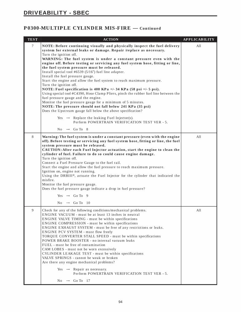
TEST ACTION APPLICABILITY
7 NOTE: Before continuing visually and physically inspect the fuel deliverysystem for external leaks or damage. Repair /replace as necessary.Turn the ignition off.WARNING: The fuel system is under a constant pressure even with theengine off. Before testing or servicing any fuel system hose, fitting or line,the fuel system pressure must be released.Install special tool #6539 (5/169) fuel line adapter.Install the fuel pressure gauge.Start the engine and allow the fuel system to reach maximum pressure.Turn the ignition off.NOTE: Fuel specification is 400 KPa +/- 34 KPa (58 psi +/- 5 psi).Using special tool #C4390, Hose Clamp Pliers, pinch the rubber fuel line between thefuel pressure gauge and the engine.Monitor the fuel pressure gauge for a minimum of 5 minutes.NOTE: The pressure should not fall below 241 KPa (35 psi)Does the Upstream gauge fall below the above specification?
All
Yes → Replace the leaking Fuel Injector(s).Perform POWERTRAIN VERIFICATION TEST VER - 5.
No → Go To 8
8 Warning: The fuel system is under a constant pressure (even with the engineoff). Before testing or servicing any fuel system hose, fitting or line, the fuelsystem pressure must be released.CAUTION: After each Fuel Injector actuation, start the engine to clean thecylinder of fuel. Failure to do so could cause engine damage.Turn the ignition off.Connect a Fuel Pressure Gauge to the fuel rail.Start the engine and allow the fuel pressure to reach maximum pressure.Ignition on, engine not running.Using the DRBIIIt, actuate the Fuel Injector for the cylinder that indicated themisfire.Monitor the fuel pressure gauge.Does the fuel pressure gauge indicate a drop in fuel pressure?
All
Yes → Go To 9
No → Go To 10
9 Check for any of the following conditions/mechanical problems.ENGINE VACUUM - must be at least 13 inches in neutralENGINE VALVE TIMING - must be within specificationsENGINE COMPRESSION - must be within specificationsENGINE EXHAUST SYSTEM - must be free of any restrictions or leaks.ENGINE PCV SYSTEM - must flow freelyTORQUE CONVERTER STALL SPEED - must be within specificationsPOWER BRAKE BOOSTER - no internal vacuum leaksFUEL - must be free of contaminationCAM LOBES - must not be worn excessivelyCYLINDER LEAKAGE TEST - must be within specificationsVALVE SPRINGS - cannot be weak or brokenAre there any engine mechanical problems?
All
Yes → Repair as necessary.Perform POWERTRAIN VERIFICATION TEST VER - 5.
No → Go To 17
94
DRIVEABILITY - SBEC
P0300-MULTIPLE CYLINDER MIS-FIRE — Continued

TEST ACTION APPLICABILITY
10 Turn the ignition off.Disconnect the Fuel Injector harness connector.Ignition on, engine not running.NOTE: When a Misfire is detected for a particular cylinder, the PCM willshut down that cylinders Injector Control circuit.With the DRBIIIt, erase DTCs.Using a 12-volt test light connected to 12-volts, probe the Injector Control circuit.With the DRBIIIt, actuate the Fuel Injector.Does the test light blink/flicker?
All
Yes → Replace the Fuel Injector.Perform POWERTRAIN VERIFICATION TEST VER - 5.
No → Go To 11
11 Turn the ignition off.Disconnect the Fuel Injector harness connector.Disconnect the PCM harness connectors.CAUTION: DO NOT PROBE THE PCM HARNESS CONNECTORS. PROBINGTHE PCM HARNESS CONNECTORS WILL DAMAGE THE PCM TERMI-NALS RESULTING IN POOR TERMINAL TO PIN CONNECTION. INSTALLMILLER SPECIAL TOOL #8815 TO PERFORM DIAGNOSIS.Check the Injector Control circuit for an open, short to ground, and short to voltage.Was a problem found with the Injector Control circuit?
All
Yes → Repair the excessive resistance or short in the Injector Controlcircuit.Perform POWERTRAIN VERIFICATION TEST VER - 5.
No → Go To 17
12 Turn the ignition off.Warning: The fuel system is under a constant pressure (even with the engineoff). Before testing or servicing any fuel system hose, fitting or line, the fuelsystem pressure must be released.Raise vehicle on hoist, and disconnect the fuel pressure line at the fuel pump module.Install special tool #6539 (5/169) fuel line adapter fuel pressure gauge between thefuel supply line and the fuel pump module.Ignition on, engine not running.With the DRBIIIt, actuate the ASD Fuel System test and observe the fuel pressuregauge.NOTE: Fuel pressure specification is 400 KPa +/- 34 KPa (58 psi +/- 5 psi).Is the fuel pressure within specification?
All
Yes → Repair or replace fuel supply line as necessary.Perform POWERTRAIN VERIFICATION TEST VER - 5.
No → Go To 13
13 Turn the ignition off.Warning: The fuel system is under a constant pressure (even with the engineoff). Before testing or servicing any fuel system hose,fitting or line, the fuelsystem pressure must be released.Remove the Fuel Pump Module and inspect the Fuel Inlet Strainer.Is the Fuel Inlet Strainer plugged?
All
Yes → Replace the Fuel Pump Inlet Strainer.Perform POWERTRAIN VERIFICATION TEST VER - 5.
No → Test Complete.
95
DRIVEABILITY - SBEC
P0300-MULTIPLE CYLINDER MIS-FIRE — Continued

TEST ACTION APPLICABILITY
14 Turn the ignition off.Remove the ignition wire.Measure the resistance of the ignition wire.Is the resistance below 10K ohms?
All
Yes → Go To 15
No → Replace the Ignition Wire.Perform POWERTRAIN VERIFICATION TEST VER - 5.
15 Turn the ignition off.Disconnect the Ignition Coil harness connector.Remove the Fuel Pump Relay or ASD Relay.Using a 12-volt test light connected to 12-volts, probe the Ignition Coil Controlcircuit.Crank the engine for 5 seconds while observing the test light.NOTE: The primary resistance of the 4.7L Ignition coil is 0.6 to 0.9 of an ohmand the resistance of a 5.7L Ignition coil is 0.558 to 0.682 of an ohm at 77°F(25°C).Does the test light brightly blink/flicker?
All
Yes → Replace the Ignition Coil.Perform POWERTRAIN VERIFICATION TEST VER - 5.
No → Go To 16
16 Turn the ignition off.Disconnect the Ignition Coil harness connector.Disconnect the PCM harness connectors.Check the Coil Control circuit for an open, short to ground, and short to voltage.Was a problem found with the Coil Control circuit?
All
Yes → Repair the Coil Control circuit.Perform POWERTRAIN VERIFICATION TEST VER - 5.
No → Go To 17
17 NOTE: Before continuing, check the PCM harness connector terminals forcorrosion, damage, or terminal push out. Repair as necessary.Using the schematics as a guide, inspect the wire harness and connectors. Payparticular attention to all Power and Ground circuits.If there are no possible causes remaining, view repair.
All
RepairReplace and program the Powertrain Control Module in accor-dance with the Service Information.Perform POWERTRAIN VERIFICATION TEST VER - 5.
96
DRIVEABILITY - SBEC
P0300-MULTIPLE CYLINDER MIS-FIRE — Continued

Symptom:P0320-NO CRANK REFERENCE SIGNAL AT PCM
When Monitored and Set Condition:
P0320-NO CRANK REFERENCE SIGNAL AT PCM
When Monitored: Engine cranking. Battery voltage greater than 10.4 volts.
Set Condition: No CKP signal is present during engine cranking, and at least 8 camshaftposition sensor signals have occurred.
POSSIBLE CAUSES
INTERMITTENT CKP SIGNAL
INTERMITTENT CMP SIGNAL
INTERMITTENT WIRING
INTERMITTENT CONDITION
(F888) 8-VOLT SUPPLY CIRCUIT OPEN
(F888) 8-VOLT SUPPLY CIRCUIT SHORTED TO GROUND
(F888) 8-VOLT SUPPLY CIRCUIT SHORTED TO VOLTAGE
(K24) CKP SENSOR SIGNAL CIRCUIT OPEN
(K24) CKP SENSOR SIGNAL CIRCUIT SHORTED TO GROUND
(K24) CKP SENSOR SIGNAL CIRCUIT SHORTED TO VOLTAGE
(K24) CKP SENSOR SIGNAL SHORTED TO (F888) 8-VOLT SUPPLY CIRCUIT
(K900) SENSOR GROUND CIRCUIT OPEN
PCM
CRANKSHAFT POSITION SENSOR
TEST ACTION APPLICABILITY
1 Ignition on, engine not running.With the DRBIIIt, read DTCs and record the related Freeze Frame data.With the DRBIIIt, read the Current CKP State while cranking the engine.Does the DRBIIIt display Current CKP State Present while cranking the engine?
All
Yes → Go To 2
No → Go To 6
97
DRIVEABILITY - SBEC

TEST ACTION APPLICABILITY
2 NOTE: The following tests may help in identifying a possible intermittentcondition with the Crank Sensor or its related wire harness.Ignition on, engine not running.With the DRBIIIt as a Dual Channel Lab Scope and the Miller special tool #6801,backprobe the (K24) CKP Signal circuit in the Crank Sensor connector and the PCMharness connector.Wiggle the related wire harness and connections.Monitor the lab scope screen.WARNING: WHEN THE ENGINE IS OPERATING, DO NOT STAND IN ADIRECT LINE WITH THE FAN. DO NOT PUT YOUR HANDS NEAR THEPULLEYS, BELTS OR FAN. DO NOT WEAR LOOSE CLOTHING.Start the engine.Lightly tap on the Crank Sensor and wiggle the CKP Sensor connector and therelated wire harness.Observe the lab scope screen.Look for any erratic pulses generated by the CKP Sensor.Did the CKP Sensor generate any erratic pulses?
All
Yes → Carefully inspect the wire harness and connections, repair asnecessary, if ok, replace the Crank Position Sensor.Perform POWERTRAIN VERIFICATION TEST VER - 5.
No → Go To 3
3 Turn the ignition off.With the DRBIIIt lab scope probe and the Miller special tool #6801, back probe theCamshaft Position (CMP) Sensor Signal circuit in the PCM harness connector.WARNING: WHEN THE ENGINE IS OPERATING, DO NOT STAND IN ADIRECT LINE WITH THE FAN. DO NOT PUT YOUR HANDS NEAR THEPULLEYS, BELTS OR FAN. DO NOT WEAR LOOSE CLOTHING.Turn the ignition on. (do not start or crank the engine)Observe the lab scope screen.Look for any pulses generated by the CMP Sensor.Did the CMP Sensor generate any pulses?
All
Yes → Replace the Camshaft Position Sensor.Perform POWERTRAIN VERIFICATION TEST VER - 5.
No → Go To 4
4 Turn the ignition off.With the DRBIIIt lab scope probe and the Miller special tool #6801, backprobe theCKP Signal circuit in the PCM harness connector.WARNING: WHEN THE ENGINE IS OPERATING, DO NOT STAND IN ADIRECT LINE WITH THE FAN. DO NOT PUT YOUR HANDS NEAR THEPULLEYS, BELTS OR FAN. DO NOT WEAR LOOSE CLOTHING.Start the engine.Observe the lab scope screen while wiggling the wiring harness and connectors.Were there any irregularities in the lab scope pattern?
All
Yes → Check the harness connectors carefully. If OK, replace the Crank-shaft Position Sensor.Perform POWERTRAIN VERIFICATION TEST VER - 5.
No → Go To 5
98
DRIVEABILITY - SBEC
P0320-NO CRANK REFERENCE SIGNAL AT PCM — Continued

TEST ACTION APPLICABILITY
5 WARNING: WHEN THE ENGINE IS OPERATING, DO NOT STAND IN ADIRECT LINE WITH THE FAN. DO NOT PUT YOUR HANDS NEAR THEPULLEYS, BELTS OR FAN. DO NOT WEAR LOOSE CLOTHING.NOTE: The conditions that set the DTC are not present at this time. Thefollowing list may help in identifying the intermittent condition.With the engine running at normal operating temperature, monitor the DRBIIItparameters related to the DTC while wiggling the wiring harness. Look for param-eter values to change and/or a DTC to set.Review the DRBIIIt Freeze Frame information. If possible, try to duplicate theconditions under which the DTC was set.Refer to any Technical Service Bulletins (TSB) that may apply.Visually inspect the related wiring harness. Look for any chafed, pierced, pinched, orpartially broken wires.Visually inspect the related wiring harness connectors. Look for broken, bent, pushedout, or corroded terminals.Were any of the above conditions present?
All
Yes → Repair as necessaryPerform POWERTRAIN VERIFICATION TEST VER - 5.
No → Test Complete.
6 Turn the ignition off.Disconnect the CKP Sensor harness connector.Ignition on, engine not running.Measure the voltage of the (F888) 8-volt Supply circuit at the CKP Sensor harnessconnector.Is the voltage between 7.5 and 9.1 volts?
All
Yes → Go To 7
No → Go To 14
7 Turn the ignition off.Disconnect the CKP Sensor harness connector.Ignition on, engine not running.Measure the voltage on the (K24) CKP Sensor Signal circuit at the CKP Sensorharness connector.Is the voltage between 4.5 and 5.0 volts?
All
Yes → Go To 8
No → Go To 10
8 Turn the ignition off.Disconnect the CKP Sensor harness connector.Disconnect the PCM harness connectors.Measure the resistance of the (K900) Sensor ground circuit from the CKP Sensorharness connector to the PCM harness connector.Is the resistance below 5.0 ohms?
All
Yes → Go To 9
No → Repair the open in the (K900) Sensor ground circuit.Perform POWERTRAIN VERIFICATION TEST VER - 5.
99
DRIVEABILITY - SBEC
P0320-NO CRANK REFERENCE SIGNAL AT PCM — Continued

TEST ACTION APPLICABILITY
9 NOTE: Inspect the slots on the flywheel for damage. If a problem is foundrepair as necessary.If there are no possible causes remaining, view repair.
All
RepairReplace the Crankshaft Position Sensor.Perform POWERTRAIN VERIFICATION TEST VER - 5.
10 Turn the ignition off.Disconnect the CKP Sensor harness connector.Disconnect the PCM harness connectors.Measure the resistance of the (K24) CKP Sensor Signal circuit from the CKP Sensorharness connector to the PCM harness connector.Is the resistance below 5.0 ohms?
All
Yes → Go To 11
No → Repair the open in the (K24) CKP Sensor Signal circuit.Perform POWERTRAIN VERIFICATION TEST VER - 5.
11 Turn the ignition off.Disconnect the CKP Sensor harness connector.Disconnect the PCM harness connectors.Measure the resistance between ground and the (K24) CKP Sensor Signal circuit atthe CKP Sensor harness connector.Is the resistance below 100 ohms?
All
Yes → Repair the short to ground in the (K24) CKP Sensor Signal circuit.Perform POWERTRAIN VERIFICATION TEST VER - 5.
No → Go To 12
12 Turn the ignition off.Disconnect the CKP Sensor harness connector.Ignition on, engine not running.Measure the voltage of the (K24) CKP Sensor Signal circuit at the CKP Sensorharness connector.Is the voltage above 5.3 volts?
All
Yes → Repair the short to voltage in the (K24) CKP Sensor Signalcircuit.Perform POWERTRAIN VERIFICATION TEST VER - 5.
No → Go To 13
13 Turn the ignition off.Disconnect the CKP Sensor harness connector.Disconnect the PCM harness connectors.Measure the resistance between the (K24) CKP Sensor Signal circuit and the (F888)8-volt Supply circuit at the CKP Sensor harness connector.Is the resistance below 5.0 ohms?
All
Yes → Repair the short between the (F888) 8-volt Supply circuit and the(K24) CKP Sensor Signal circuit.Perform POWERTRAIN VERIFICATION TEST VER - 5.
No → Go To 17
100
DRIVEABILITY - SBEC
P0320-NO CRANK REFERENCE SIGNAL AT PCM — Continued

TEST ACTION APPLICABILITY
14 Turn the ignition off.Disconnect the CKP Sensor harness connector.Disconnect the PCM harness connectors.Measure the resistance of the (F888) 8-volt Supply circuit from the CKP Sensorharness connector to the PCM harness connector.Is the resistance below 5.0 ohms?
All
Yes → Go To 15
No → Repair the open in the (F888) 8-volt Supply circuit.Perform POWERTRAIN VERIFICATION TEST VER - 5.
15 Turn the ignition off.Disconnect the PCM harness connectors.Disconnect the CKP Sensor harness connector.Measure the resistance between ground and the (F888) 8-volt Supply circuit at theCKP Sensor harness connector.Is the resistance below 100 ohms?
All
Yes → Repair the short to ground in the (F888) 8-volt Supply circuit.Perform POWERTRAIN VERIFICATION TEST VER - 5.
No → Go To 16
16 Turn the ignition off.Disconnect the CKP Sensor harness connector.Ignition on, engine not running.Measure the voltage of the (F888) 8-volt Supply circuit at the CKP Sensor harnessconnector.Is the voltage above 5.3 volts?
All
Yes → Repair the short to voltage in the (F888) 8-volt Supply circuit.Perform POWERTRAIN VERIFICATION TEST VER - 5.
No → Go To 17
17 NOTE: Before continuing, check the PCM harness connector terminals forcorrosion, damage, or terminal push out. Repair as necessary.Using the schematics as a guide, inspect the wire harness and connectors. Payparticular attention to all Power and Ground circuits.If there are no possible causes remaining, view repair.
All
RepairReplace and program the Powertrain Control Module per ServiceInformation.Perform POWERTRAIN VERIFICATION TEST VER - 5.
101
DRIVEABILITY - SBEC
P0320-NO CRANK REFERENCE SIGNAL AT PCM — Continued

Symptom:P0340-NO CAM SIGNAL AT PCM
When Monitored and Set Condition:
P0340-NO CAM SIGNAL AT PCM
When Monitored: Engine cranking/running. Battery voltage greater than 10.4 volts.
Set Condition: At least 5 seconds or 2.5 engine revolutions have elapsed with crankshaftposition sensor signals present but no camshaft position sensor signal.
POSSIBLE CAUSES
INTERMITTENT CRANKSHAFT POSITION SENSOR SIGNAL
INTERMITTENT CAMSHAFT POSITION SENSOR SIGNAL
INTERMITTENT CONDITION
(F888) 8-VOLT SUPPLY CIRCUIT SHORTED TO GROUND
(F888) 8-VOLT SUPPLY CIRCUIT OPEN
(F888) 8-VOLT SUPPLY CIRCUIT SHORTED TO VOLTAGE
(K44) CMP SENSOR SIGNAL CIRCUIT SHORTED TO GROUND
(K44) CMP SENSOR SIGNAL CIRCUIT OPEN
(K44) CMP SENSOR SIGNAL CIRCUIT SHORTED TO VOLTAGE
(K44) CMP SENSOR SIGNAL SHORTED TO (F888) 8-VOLT SUPPLY CIRCUIT
(K900) SENSOR GROUND CIRCUIT OPEN
PCM
CAMSHAFT POSITION SENSOR
TEST ACTION APPLICABILITY
1 With the DRBIIIt, read the Current Camshaft Position (CMP) Sensor State whilecranking the engine.Does the DRBIIIt display Current CMP State Present while cranking the engine.
All
Yes → Go To 2
No → Go To 4
102
DRIVEABILITY - SBEC

TEST ACTION APPLICABILITY
2 Turn the ignition off.With the DRBIIIt lab scope probe and the Miller special tool #6801, back probe theCrankshaft Position (CKP) Sensor signal circuit in the PCM harness connector.WARNING: WHEN THE ENGINE IS OPERATING, DO NOT STAND IN ADIRECT LINE WITH THE FAN. DO NOT PUT YOUR HANDS NEAR THEPULLEYS, BELTS OR FAN. DO NOT WEAR LOOSE CLOTHING.Turn the ignition on. (do not start or crank the engine)Observe the lab scope screen.Look for any pulses generated by the Crankshaft Position (CKP) Sensor.Did the CKP Sensor generate any pulses?
All
Yes → Replace the Crankshaft Position Sensor.Perform POWERTRAIN VERIFICATION TEST VER - 5.
No → Go To 3
3 Turn the ignition off.With the DRBIIIt lab scope probe and the Miller special tool #6801, backprobe theCMP Signal circuit in the PCM harness connector.WARNING: WHEN THE ENGINE IS OPERATING, DO NOT STAND IN ADIRECT LINE WITH THE FAN. DO NOT PUT YOUR HANDS NEAR THEPULLEYS, BELTS OR FAN. DO NOT WEAR LOOSE CLOTHING.Turn the ignition on. (do not start or crank the engine)Observe the lab scope screen.Look for any pulses generated by the CMP Sensor.Did the CMP Sensor generate any pulses?
All
Yes → Replace the Camshaft Position Sensor.Perform POWERTRAIN VERIFICATION TEST VER - 5.
No → Refer to the INTERMITTENT CONDITION symptom in theDriveability category.Perform POWERTRAIN VERIFICATION TEST VER - 5.
4 Turn the ignition off.Disconnect the CMP Sensor harness connector.Turn the ignition on.Measure the voltage of the (F888) 8-volt Supply circuit in the CMP Sensor harnessconnector.Is the voltage between 7.5 and 9.1 volts?
All
Yes → Go To 5
No → Go To 12
5 Turn the ignition off.Disconnect the CMP Sensor harness connector.Turn the ignition on.Measure the voltage of the (K44) CMP Sensor Signal circuit in the CMP Sensorharness connector.Is the voltage between 4.5 and 5.0 volts?
All
Yes → Go To 6
No → Go To 8
103
DRIVEABILITY - SBEC
P0340-NO CAM SIGNAL AT PCM — Continued

TEST ACTION APPLICABILITY
6 Turn the ignition off.Disconnect the CMP Sensor harness connector.Disconnect the PCM harness connector.Measure the resistance of the (K900) Sensor Ground circuit between the CMP Sensorharness connector and the PCM harness connector.Is the resistance below 5.0 ohms?
All
Yes → Go To 7
No → Repair the open in the (K900) Sensor Ground circuit.Perform POWERTRAIN VERIFICATION TEST VER - 5.
7 NOTE: Inspect the Camshaft sprocket or Magnet Target for damage per theService Information. If a problem is found repair as necessary.If there are no possible causes remaining, view repair.
All
RepairReplace the Camshaft Position Sensor.Perform POWERTRAIN VERIFICATION TEST VER - 5.
8 Turn the ignition off.Disconnect the CMP Sensor harness connector.Disconnect the PCM harness connector.Measure the resistance of the (K44) CMP Sensor Signal circuit in the CMP Sensorharness connector to ground.Is the resistance below 100 ohms?
All
Yes → Repair the short to ground in the (K44) CMP Sensor Signalcircuit.Perform POWERTRAIN VERIFICATION TEST VER - 5.
No → Go To 9
9 Turn the ignition off.Disconnect the CMP Sensor harness connector.Disconnect the PCM harness connector.Measure the resistance of the (K44) CMP Sensor Signal circuit between the CMPSensor harness connector and the PCM harness connector.Is the resistance below 5.0 ohms?
All
Yes → Go To 10
No → Repair the open in the (K44) CMP Sensor Signal circuit.Perform POWERTRAIN VERIFICATION TEST VER - 5.
10 Turn the ignition off.Disconnect the CMP Sensor harness connector.Turn the ignition on.Measure the voltage of the (K44) CMP Sensor Signal circuit in the CMP Sensorharness connector.Is the voltage above 5.0 volts?
All
Yes → Repair the short to voltage in the (K44) CMP Sensor Signalcircuit.Perform POWERTRAIN VERIFICATION TEST VER - 5.
No → Go To 11
104
DRIVEABILITY - SBEC
P0340-NO CAM SIGNAL AT PCM — Continued
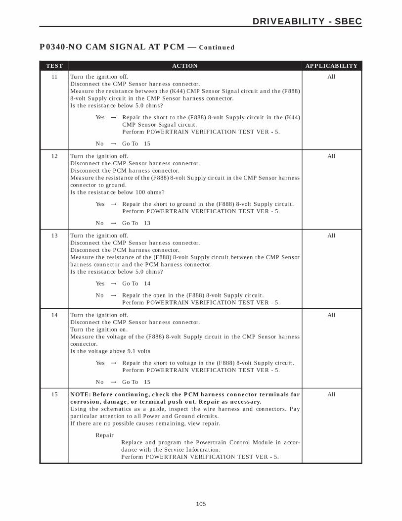
TEST ACTION APPLICABILITY
11 Turn the ignition off.Disconnect the CMP Sensor harness connector.Measure the resistance between the (K44) CMP Sensor Signal circuit and the (F888)8-volt Supply circuit in the CMP Sensor harness connector.Is the resistance below 5.0 ohms?
All
Yes → Repair the short to the (F888) 8-volt Supply circuit in the (K44)CMP Sensor Signal circuit.Perform POWERTRAIN VERIFICATION TEST VER - 5.
No → Go To 15
12 Turn the ignition off.Disconnect the CMP Sensor harness connector.Disconnect the PCM harness connector.Measure the resistance of the (F888) 8-volt Supply circuit in the CMP Sensor harnessconnector to ground.Is the resistance below 100 ohms?
All
Yes → Repair the short to ground in the (F888) 8-volt Supply circuit.Perform POWERTRAIN VERIFICATION TEST VER - 5.
No → Go To 13
13 Turn the ignition off.Disconnect the CMP Sensor harness connector.Disconnect the PCM harness connector.Measure the resistance of the (F888) 8-volt Supply circuit between the CMP Sensorharness connector and the PCM harness connector.Is the resistance below 5.0 ohms?
All
Yes → Go To 14
No → Repair the open in the (F888) 8-volt Supply circuit.Perform POWERTRAIN VERIFICATION TEST VER - 5.
14 Turn the ignition off.Disconnect the CMP Sensor harness connector.Turn the ignition on.Measure the voltage of the (F888) 8-volt Supply circuit in the CMP Sensor harnessconnector.Is the voltage above 9.1 volts
All
Yes → Repair the short to voltage in the (F888) 8-volt Supply circuit.Perform POWERTRAIN VERIFICATION TEST VER - 5.
No → Go To 15
15 NOTE: Before continuing, check the PCM harness connector terminals forcorrosion, damage, or terminal push out. Repair as necessary.Using the schematics as a guide, inspect the wire harness and connectors. Payparticular attention to all Power and Ground circuits.If there are no possible causes remaining, view repair.
All
RepairReplace and program the Powertrain Control Module in accor-dance with the Service Information.Perform POWERTRAIN VERIFICATION TEST VER - 5.
105
DRIVEABILITY - SBEC
P0340-NO CAM SIGNAL AT PCM — Continued

Symptom List:P0351-IGNITION COIL #1 PRIMARY CIRCUITP0352-IGNITION COIL #2 PRIMARY CIRCUITP0353-IGNITION COIL #3 PRIMARY CIRCUIT
Test Note: All symptoms listed above are diagnosed using the same tests.The title for the tests will be P0351-IGNITION COIL #1 PRI-MARY CIRCUIT.
When Monitored and Set Condition:
P0351-IGNITION COIL #1 PRIMARY CIRCUIT
When Monitored: With battery voltage greater than 8 volts during engine cranking orgreater than 13 volts with engine running. Engine RPM less than 3000. No coil in dwellduring test.
Set Condition: Peak current is not achieved with battery based dwell plus 1.5 msec ofdiagnostic offset. It takes less than 3 seconds during cranking or up to 6 seconds whilerunning to set.
P0352-IGNITION COIL #2 PRIMARY CIRCUIT
When Monitored: With battery voltage greater than 8 volts during engine cranking orgreater than 13 volts with engine running. Engine RPM less than 3000. No coil in dwellduring test.
Set Condition: Peak current is not achieved with battery based dwell plus 1.5 msec ofdiagnostic offset. It takes less than 3 seconds during cranking or up to 6 seconds whilerunning to set.
P0353-IGNITION COIL #3 PRIMARY CIRCUIT
When Monitored: With battery voltage greater than 8 volts during engine cranking orgreater than 13 volts with engine running. Engine RPM less than 3000. No coil in dwellduring test.
Set Condition: Peak current is not achieved with battery based dwell plus 1.5 msec ofdiagnostic offset. It takes less than 3 seconds during cranking or up to 6 seconds whilerunning to set.
POSSIBLE CAUSES
GOOD TRIP EQUAL TO ZERO
IGNITION COIL
CHECKING THE BCM FOR DTC(S)
(K342) ASD RELAY OUTPUT CIRCUIT
IGNITION COIL DRIVER CIRCUIT OPEN
IGNITION COIL DRIVER CIRCUIT SHORTED TO GROUND
106
DRIVEABILITY - SBEC

POSSIBLE CAUSES
PCM
TEST ACTION APPLICABILITY
1 NOTE: Record the Freeze Frame Information that set along with the DTC.Turn the ignition on.With the DRBIIIt, read DTC’s.Is the Good Trip displayed and equal to zero?
All
Yes → Go To 2
No → Refer to the INTERMITTENT CONDITION symptom in theDriveability category.Perform POWERTRAIN VERIFICATION TEST VER - 5.
2 NOTE: Ensure the DRB is able to establish communication with the BCM. Ifcommunication can not be established, refer to the Body CommunicationCategory and perform the appropriate test.Turn the ignition on.With the DRBIIIt, check for DTC(s) in the BCM.Are any Ignition MUX circuit faults present?
All
Yes → Refer to the Body Communication Category and perform theappropriate symptom(s).Perform POWERTRAIN VERIFICATION TEST VER - 5.
No → Go To 3
3 Turn the ignition off.Disconnect the Ignition Coil harness connector.Turn the ignition on.With the DRBIIIt, actuate the ASD Relay.Using a 12-volt test light connected to ground, probe the (K342) ASD Relay Outputcircuit in the Ignition Coil harness connector.Does the test light illuminate brightly?
All
Yes → Go To 4
No → Repair the (K342) ASD Relay Output circuit.Perform POWERTRAIN VERIFICATION TEST VER - 5.
4 Turn the ignition off.Disconnect the Ignition Coil harness connector.Using a 12-volt test light connected to 12-volts, probe the Ignition Coil Driver circuit.Crank the engine for 5 second while observing the test light.Does the test light blink/flicker?
All
Yes → Replace the Ignition Coil.Perform POWERTRAIN VERIFICATION TEST VER - 5.
No → Go To 5
107
DRIVEABILITY - SBEC
P0351-IGNITION COIL #1 PRIMARY CIRCUIT — Continued

TEST ACTION APPLICABILITY
5 Turn the ignition off.Disconnect the Ignition Coil harness connector.Disconnect the PCM harness connector.Measure the resistance of the Ignition Coil driver circuit between the Ignition Coilharness connector and the PCM harness connector.Is the resistance below 5.0 ohms?
All
Yes → Go To 6
No → Repair the Ignition Coil driver circuit for an open.Perform POWERTRAIN VERIFICATION TEST VER - 5.
6 Turn the ignition off.Disconnect the Ignition Coil harness connector.Disconnect the PCM harness connector.Measure the resistance between ground and the Ignition Coil driver circuit in theIgnition Coil harness connector.Is the resistance below 100k ohms?
All
Yes → Repair the Ignition Coil driver circuit for a short to ground.Perform POWERTRAIN VERIFICATION TEST VER - 5.
No → Go To 7
7 NOTE: Before continuing, check the PCM harness connector terminals forcorrosion, damage, or terminal push out. Repair as necessary.Using the schematics as a guide, inspect the wire harness and connectors. Payparticular attention to all Power and Ground circuits.If there are no possible causes remaining, view repair.
All
RepairReplace and program the Powertrain Control Module in accor-dance with the Service Information.Perform POWERTRAIN VERIFICATION TEST VER - 5.
108
DRIVEABILITY - SBEC
P0351-IGNITION COIL #1 PRIMARY CIRCUIT — Continued

Symptom:P0401 - EGR SYSTEM FAILURE
When Monitored and Set Condition:
P0401 - EGR SYSTEM FAILURE
When Monitored: With the ignition on and the battery voltage greater than 10.4 volts.
Set Condition: Conditions are met, the EGR is turned off and on momentarily. Theoxygen sensor signal is monitor for changes in its output signal during this test. If nosignificant change or too much change is seen, a flag is set.
POSSIBLE CAUSES
GOOD TRIP EQUAL TO ZERO
EGR SOLENOID VACUUM SUPPLY
EGR VALVE OPERATION (CLOSED)
(F202) FUSED IGNITION SWITCH OUTPUT CIRCUIT OPEN
EGR VALVE OPERATION (OPEN)
(K35) EGR SOLENOID CONTROL CIRCUIT SHORTED TO VOLTAGE
(K35) EGR SOLENOID CONTROL CIRCUIT OPEN
EGR SOLENOID (CLOSED)
(K35) EGR SOLENOID CONTROL CIRCUIT SHORT TO GND
EGR SOLENOID (OPEN)
PCM
TEST ACTION APPLICABILITY
1 Turn the ignition on.With the DRBIIIt, read DTC’s.Is the Good Trip displayed and equal to zero?
All
Yes → Go To 2
No → Refer to the INTERMITTENT CONDITION symptom in theDriveability category.Perform POWERTRAIN VERIFICATION TEST VER - 5.
2 Start the engine.Allow the engine to reach operating temperature.Does the engine run rough or stall at idle?
All
Yes → Go To 3
No → Go To 6
109
DRIVEABILITY - SBEC

TEST ACTION APPLICABILITY
3 Disconnect the vacuum hose from the EGR Valve.Start the engine and allow it to idle.Does the engine run rough or stall at idle?
All
Yes → Remove the EGR Valve and inspect the valve for an obstructionthat would keep the valve open. If OK, replace the EGR Valve.Perform POWERTRAIN VERIFICATION TEST VER - 5.
No → Go To 4
4 Turn the ignition off.Disconnect the PCM harness connector.Disconnect the EGR Solenoid harness connector.Measure the resistance of the (K35) EGR Solenoid Control circuit in the EGRSolenoid harness connector to ground.Is the resistance below 5.0 ohms?
All
Yes → Repair the (K35) EGR Solenoid Control circuirt for a short toground.Perform POWERTRAIN VERIFICATION TEST VER - 5.
No → Go To 5
5 Turn the ignition off.Disconnect the EGR Solenoid harness connector.Using a 12-volt test light connected to 12-volts, probe the (K35) EGR SolenoidControl circuit.Turn the ignition on.With the DRBIIIt, actuate the EGR Solenoid.Observe the test light.Does the test light flash on and off?
All
Yes → Replace the EGR Solenoid.Perform POWERTRAIN VERIFICATION TEST VER - 5.
No → Replace and program the Powertrain Control Module in accor-dance with the Service Information.Perform POWERTRAIN VERIFICATION TEST VER - 5.
6 Turn the ignition off.Disconnect the EGR Solenoid vacuum supply at the EGR Solenoid.Connect a vacuum gauge to the EGR Solenoid vacuum supply.Start the engine.Observe the vacuum gauge.Does the vacuum gauge read above 109?
All
Yes → Go To 7
No → Repair the EGR Solenoid vacuum supply.Perform POWERTRAIN VERIFICATION TEST VER - 5.
110
DRIVEABILITY - SBEC
P0401 - EGR SYSTEM FAILURE — Continued

TEST ACTION APPLICABILITY
7 Disconnect the vacuum hose from the EGR Valve. Inspect the vacuum hose for anyobstructions.Connect a Vacuum Pump to the EGR Valve.Start the engine.Using the Vacuum Pump, apply vacuum to the EGR Valve.Does the engine run rough or stall at idle?
All
Yes → Go To 8
No → Remove the EGR Valve and inspect the valve for an obstructionthat would keep the valve form opening. If OK, replace the EGRValve.Perform POWERTRAIN VERIFICATION TEST VER - 5.
8 Turn the igntion off.Disconnect the EGR Solenoid harness connector.Turn the ignition on.Using a 12-volt Test Light connected to ground, probe the (F202) Fused IgnitionSwitch Output circuit in the EGR Solenoid harness connector.Does the 12-volt test light illuminate?
All
Yes → Go To 9
No → Repair the (F202) Fused Ignition Switch Output circuit for anopen.Perform POWERTRAIN VERIFICATION TEST VER - 5.
9 Turn the ignition off.Disconnect the EGR Solenoid harness connector.Turn the ignition on.Measure the voltage of the (K35) EGR Solenoid Control circuit in the EGR Solenoidconnector.Is the voltage above 1.0 volts?
All
Yes → Repair the (K35) EGR Solenoid Control circuit for a short tovoltage.Perform POWERTRAIN VERIFICATION TEST VER - 5.
No → Go To 10
10 Turn the ignition off.Disconnect the PCM harness connector.Disconnect the EGR Solenoid harness connector.Measure the resistance of the (K35) EGR Solenoid Control circuit between the PCMharness connector and the EGR Solenoid harness connector.Is the resistance below 5.0 ohms?
All
Yes → Go To 11
No → Repair the (K35) EGR solenoid control circuit for an open.Perform POWERTRAIN VERIFICATION TEST VER - 5.
111
DRIVEABILITY - SBEC
P0401 - EGR SYSTEM FAILURE — Continued

TEST ACTION APPLICABILITY
11 Turn the ignition off.Disconnect the EGR Solenoid harness connector.Using a 12-volt test light connected to 12-volts, probe the (K35) EGR SolenoidControl circuit in the EGR Solenoid harness connector.Turn the ignition on.With the DRBIIIt, actuate the EGR Solenoid.Observe the test light.Does the test light flash on and off.
All
Yes → Inspect the EGR Solenoid Back Pressure hose and tube forobstructions or damage. If OK, replace the EGR Solenoid.Perform POWERTRAIN VERIFICATION TEST VER - 5.
No → Go To 12
12 NOTE: Before continuing, check the PCM harness connector terminals forcorrosion, damage, or terminal push out. Repair as necessary.Using the schematics as a guide, inspect the wire harness and connectors. Payparticular attention to all Power and Ground circuits.If there are no possible causes remaining, view repair.
All
RepairReplace and program the Powertrain Control Module in accor-dance with the Service Information.Perform POWERTRAIN VERIFICATION TEST VER - 5.
112
DRIVEABILITY - SBEC
P0401 - EGR SYSTEM FAILURE — Continued

Symptom:P0403 - EGR SOLENOID CIRCUIT
When Monitored and Set Condition:
P0403 - EGR SOLENOID CIRCUIT
When Monitored: Engine running. Battery voltage greater than 10.4 volts.
Set Condition: The EGR solenoid control circuit is not in the expected state whenrequested to operate by the PCM for 86.4 seconds.
POSSIBLE CAUSES
GOOD TRIP EQUAL TO ZERO
EGR SOLENOID
(F202) FUSED IGNITION SWITCH OUTPUT CIRCUIT OPEN
(K35) EGR SOLENOID CONTROL CIRCUIT SHORTED TO VOLTAGE
(K35) EGR SOLENOID CONTROL CIRCUIT SHORTED TO GROUND
(K35) EGR SOLENOID CONTROL CIRCUIT OPEN
PCM
TEST ACTION APPLICABILITY
1 Turn the ignition on.With the DRBIIIt, read DTC’s.Is the Good Trip displayed and equal to zero?
All
Yes → Go To 2
No → Refer to the INTERMITTENT CONDITION symptom in theDriveability category.Perform POWERTRAIN VERIFICATION TEST VER - 5.
2 Turn the ignition off.Disconnect the EGR Solenoid harness connector.Turn the ignition on.Turn all accessories off.Using a 12-volt Test Light connected to the (F202) Fused Ignition Switch Outputcircuit, probe the EGR Solenoid Control circuit.With the DRBIIIt, actuate the EGR solenoid.Does the 12-volt test light flash on and off?
All
Yes → Inspect the EGR Valve Back Pressure hose and tube for obstruc-tions or damage. If OK, replace the EGR Solenoid.Perform POWERTRAIN VERIFICATION TEST VER - 5.
No → Go To 3
113
DRIVEABILITY - SBEC

TEST ACTION APPLICABILITY
3 Turn the ignition off.Disconnect the EGR Solenoid harness connector.Turn the ignition on.Using a 12-volt Test Light connected to ground, probe the (F202) Fused IgnitionSwitch Output circuit in the EGR Solenoid harness connector.Does the 12-volt test light illuminate?
All
Yes → Go To 4
No → Repair the open in the (F202) Fused Ignition Switch Outputcircuit.Perform POWERTRAIN VERIFICATION TEST VER - 5.
4 Turn the ignition off.Disconnect the PCM harness connector.Disconnect the EGR Solenoid harness connector.Measure the resistance of the (K35) EGR Solenoid Control circuit to ground.Is the resistance below 5.0 ohms?
All
Yes → Repair the short to ground in the (K35) EGR Solenoid Controlcircuit.Perform POWERTRAIN VERIFICATION TEST VER - 5.
No → Go To 5
5 Turn the ignition off.Disconnect the EGR Solenoid harness connector.Turn the ignition on.Measure the voltage on the (K35) EGR Solenoid Control circuit in the EGR Solenoidconnector.Is the voltage above 1.0 volt?
All
Yes → Repair the short to voltage in the (K35) EGR Solenoid Controlcircuit.Perform POWERTRAIN VERIFICATION TEST VER - 5.
No → Go To 6
6 Turn the ignition off.Disconnect the PCM harness connector.Disconnect the EGR Solenoid harness connector.Measure the resistance of the (K35) EGR Solenoid Control circuit between the PCMharness connector and the EGR Solenoid harness connector.Is the resistance below 5.0 ohms?
All
Yes → Go To 7
No → Repair the open in the (K35) EGR Solenoid Control circuit.Perform POWERTRAIN VERIFICATION TEST VER - 5.
7 NOTE: Before continuing, check the PCM harness connector terminals forcorrosion, damage, or terminal push out. Repair as necessary.Using the schematics as a guide, inspect the wire harness and connectors. Payparticular attention to all Power and Ground circuits.If there are no possible causes remaining, view repair.
All
RepairReplace and program the Powertrain Control Module in accor-dance with the Service Information.Perform POWERTRAIN VERIFICATION TEST VER - 5.
114
DRIVEABILITY - SBEC
P0403 - EGR SOLENOID CIRCUIT — Continued

Symptom:P0420-1/1 CATALYTIC CONVERTER EFFICIENCY
When Monitored and Set Condition:
P0420-1/1 CATALYTIC CONVERTER EFFICIENCY
When Monitored: After engine warm up to 70°C (158°F), 180 seconds of open throttleoperation, at a speed greater than 18 mph and less than 55 mph, with the engine at1200-1700 rpm and MAP vacuum between 15.0 and 21.0 inches of mercury (Hg).
Set Condition: As catalyst efficiency deteriorates, the switch rate of the downstream O2sensor approaches that of the upstream O2 sensor. If at any point during the test theswitch ratio reaches a predetermined value a counter is incremented by one.
POSSIBLE CAUSES
GOOD TRIP EQUAL TO ZERO
VISUALLY INSPECT CATALYTIC CONVERTER
EXHAUST LEAK
ENGINE MECHANICAL CONDITION
AGING O2 SENSOR
CATALYTIC CONVERTER
TEST ACTION APPLICABILITY
1 NOTE: If a O2 Sensor DTC(s) set along with the Catalytic ConverterEfficiency DTC diagnose the O2 Sensor DTC(s) before continuing.NOTE: Check for contaminates that may have damaged the O2 Sensor andCatalytic Converter: contaminated fuel, unapproved silicone, oil and cool-ant, repair necessary.Turn the ignition on.With the DRBIIIt, read DTC’s.Is the Good Trip displayed and equal to zero?
All
Yes → Go To 2
No → Refer to the INTERMITTENT CONDITION symptom in theDriveability category.Perform POWERTRAIN VERIFICATION TEST VER - 5.
2 Inspect the Catalytic Converter for the following damage.Damage Catalytic Converter, dent and holes.Severe discoloration caused by overheating the Catalytic Converter.Catalytic Converter broke internally.Leaking Catalytic Converter.Were any problems found?
All
Yes → Replace the Catalytic Converter. Repair the condition that mayhave caused the failure.Perform POWERTRAIN VERIFICATION TEST VER - 5.
No → Go To 3
115
DRIVEABILITY - SBEC

TEST ACTION APPLICABILITY
3 Start the engine.Inspect the exhaust for leak between the engine and the O2 sensor.Inspect the exhaust for leaks between the engine and the appropriate rear O2 Sensor.Are there any exhaust leaks?
All
Yes → Repair or replace the leaking exhaust parts as necessary.Perform POWERTRAIN VERIFICATION TEST VER - 5.
No → Go To 4
4 Check the exhaust for excessive smoke caused by an internal problem in the engine.Is a engine mechanical condition present?
All
Yes → Repair the engine mechanical condition as necessary.Perform POWERTRAIN VERIFICATION TEST VER - 5.
No → Go To 5
5 A new rear O2 Sensor along with an aging front O2 Sensor may cause the DTC to set.Review the vehicles repair history.Has the rear O2 Sensor been replace without replacing the front O2 Sensor?
All
Yes → Replace the Front O2 Sensor as necessary.Perform POWERTRAIN VERIFICATION TEST VER - 5.
No → Go To 6
6 If there are no possible cause remaining, view repair. All
RepairReplace the Catalytic Converter.Perform POWERTRAIN VERIFICATION TEST VER - 5.
116
DRIVEABILITY - SBEC
P0420-1/1 CATALYTIC CONVERTER EFFICIENCY — Continued
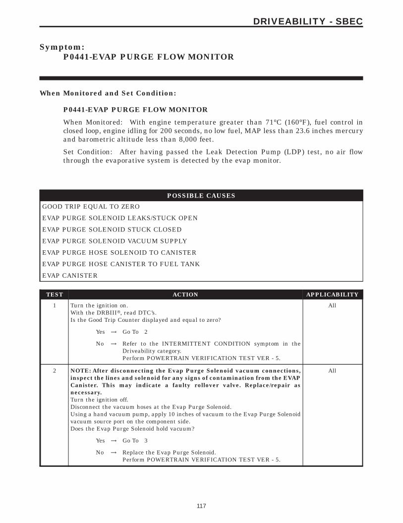
Symptom:P0441-EVAP PURGE FLOW MONITOR
When Monitored and Set Condition:
P0441-EVAP PURGE FLOW MONITOR
When Monitored: With engine temperature greater than 71°C (160°F), fuel control inclosed loop, engine idling for 200 seconds, no low fuel, MAP less than 23.6 inches mercuryand barometric altitude less than 8,000 feet.
Set Condition: After having passed the Leak Detection Pump (LDP) test, no air flowthrough the evaporative system is detected by the evap monitor.
POSSIBLE CAUSES
GOOD TRIP EQUAL TO ZERO
EVAP PURGE SOLENOID LEAKS/STUCK OPEN
EVAP PURGE SOLENOID STUCK CLOSED
EVAP PURGE SOLENOID VACUUM SUPPLY
EVAP PURGE HOSE SOLENOID TO CANISTER
EVAP PURGE HOSE CANISTER TO FUEL TANK
EVAP CANISTER
TEST ACTION APPLICABILITY
1 Turn the ignition on.With the DRBIIIt, read DTC’s.Is the Good Trip Counter displayed and equal to zero?
All
Yes → Go To 2
No → Refer to the INTERMITTENT CONDITION symptom in theDriveability category.Perform POWERTRAIN VERIFICATION TEST VER - 5.
2 NOTE: After disconnecting the Evap Purge Solenoid vacuum connections,inspect the lines and solenoid for any signs of contamination from the EVAPCanister. This may indicate a faulty rollover valve. Replace/repair asnecessary.Turn the ignition off.Disconnect the vacuum hoses at the Evap Purge Solenoid.Using a hand vacuum pump, apply 10 inches of vacuum to the Evap Purge Solenoidvacuum source port on the component side.Does the Evap Purge Solenoid hold vacuum?
All
Yes → Go To 3
No → Replace the Evap Purge Solenoid.Perform POWERTRAIN VERIFICATION TEST VER - 5.
117
DRIVEABILITY - SBEC

TEST ACTION APPLICABILITY
3 Using a hand vacuum pump, apply 10 inches of vacuum to the Evap Purge Solenoidvacuum source port on the component side.Turn the ignition on.Observe the vacuum gauge.With the DRBIIIt, actuate the EVAP Purge Solenoid .Does the vacuum drop when the solenoid is actuated?
All
Yes → Go To 4
No → Replace the Evap Purge Solenoid.Perform POWERTRAIN VERIFICATION TEST VER - 5.
4 Turn the ignition off.Carefully inspect the Evap Purge Solenoid vacuum supply hose for proper routing.Check for a pinched or plugged hose from the throttle body to the Purge Solenoid.Inspect the vacuum port at the throttle body for any damage or plugging.Were any problems found?
All
Yes → Repair the vacuum supply hose/tube as necessary.Perform POWERTRAIN VERIFICATION TEST VER - 5.
No → Go To 5
5 Visually inspect the Evap Purge hose from the Evap Purge Solenoid to the EvapCanister.Look for any physical damage such as a pinched, plugged, ripped or dry rotted hose.Were any problems found?
All
Yes → Repair or replace hose as necessary.Perform POWERTRAIN VERIFICATION TEST VER - 5.
No → Go To 6
6 Visually inspect the Evap Purge hose from between the Evap Canister and the FuelTank.Check for any physical damage such as a pinched, plugged, ripped or dry rotted hose.Were any problems found?
All
Yes → Repair or replace hose as necessary.Perform POWERTRAIN VERIFICATION TEST VER - 5.
No → Go To 7
7 Visually inspect the Evap Canister for the following.Check for physical damage or signs of fuel that has entered the canister.Check for signs of fuel, this may indicate a bad rollover valve.Were any problems found?
All
Yes → Repair or Replace as necessary.Perform POWERTRAIN VERIFICATION TEST VER - 5.
No → Test Complete.
118
DRIVEABILITY - SBEC
P0441-EVAP PURGE FLOW MONITOR — Continued

Symptom List:P0442-EVAP LEAK MONITOR .040 LEAK DETECTEDP0455-EVAP LEAK MONITOR LARGE LEAK DETECTEDP0456 - EVAP LEAK MONITOR .020 LEAK DETECTED
Test Note: All symptoms listed above are diagnosed using the same tests.The title for the tests will be P0442-EVAP LEAK MONITOR.040 LEAK DETECTED.
When Monitored and Set Condition:
P0442-EVAP LEAK MONITOR .040 LEAK DETECTED
When Monitored: Immediately after a cold start, with battery/ambient temperaturebetween 4°C (40°F) and 32°C (90°F) and coolant temperature within -12°C (20°F) ofbattery/ambient.
Set Condition: If there is a leak larger than 0.0409 and smaller than 0.0809 in theevaporative system.
P0455-EVAP LEAK MONITOR LARGE LEAK DETECTED
When Monitored: Immediately after a cold start, with battery/ambient temperaturebetween 4°C (40°F) and 32°C (90°F) and coolant temperature within -12°C (10°F) ofbattery/ambient.
Set Condition: There is a leak larger than 0.0809 in the evaporative system.
P0456 - EVAP LEAK MONITOR .020 LEAK DETECTED
When Monitored: Immediately after a cold start, with battery/ambient temperaturebetween 4°C (40°F) and 30°C (86°F) and coolant temperature within -12°C (10°F) ofbattery/ambient.
Set Condition: If there is a leak larger than 0.0209 and smaller than 0.0409 in theevaporative system.
POSSIBLE CAUSES
GOOD TRIP EQUAL TO ZERO
VERIFY EVAPORATIVE EMISSION SYSTEM LEAK
EVAPORATIVE EMISSION LEAK DETECTION
EVAP PURGE SOLENOID LEAKS/STUCK OPEN
INTERMITTENT LDP MONITOR FAILURE
119
DRIVEABILITY - SBEC

TEST ACTION APPLICABILITY
1 NOTE: Since a hot vehicle can conceal a leak, it is best to perform this testat room temperature.NOTE: A loose gas cap could have caused this DTC to set. Make sure gas capis tight and in good condition. Ensure the gas cap meets OEM specifications.Turn the ignition on.With the DRBIIIt, read DTC’s.Is the Good Trip Counter displayed and equal to zero?
All
Yes → Go To 2
No → Refer to the INTERMITTENT CONDITION symptom in theDriveability category.Perform POWERTRAIN VERIFICATION TEST VER - 6.
2 To continue testing you will need Miller Tool #8404 Evaporative Emission LeakDetector (EELD).WARNING: Keep lit cigarettes, sparks, flames, and other ignition sourcesaway from the test area to prevent the ignition of explosive gases. Keep thetest area well ventilated.NOTE: The fuel tank should have between 20% and 80% of fuel tank capacityto properly test the Evap system.Connect and apply a continuous vacuum supply (i.e. 209Hg) to the Leak DetectionPump. A vacuum pump such as an A/C recovery unit works well.Using the DRBIIIt, select Engine/System Tests and actuate the Leak Detect PumpTest (Option 3/Hold PSI).NOTE: The above energizes the LDP solenoid and allows the constantvacuum source to apply vacuum to the LDP pump diaphragm. This lifts thediaphragm up and seals the atmospheric canister vent valve at the bottomof the Leak Detection Pump.Connect the red power lead of Miller Tool #8404 to the battery positive terminal andthe black ground lead to battery negative terminal.NOTE: See Charts and Graph support material EELD Calibration Setup foran example.Connect shop air to the #8404 EELD.Set the smoke/air control switch to AIR.Insert the tester’s AIR supply tip (clear hose) into the appropriate calibration orificeon the tester’s control panel (based on DTC leak size).Press the remote smoke/air start button.Position the red flag on the air flow meter so it is aligned with the indicator ball.When the calibration is complete, release the remote button. The EELD is nowcalibrated the flow meter in liters per minute to the size leak indicated by the DTCset in the PCM.Install the service port adapter #8404-14 on the vehicle’s service port.Connect the Air supply hose from the EELD to the service port.Press the remote button to activate AIR flow.NOTE: Larger volume fuel tanks, and/or those with less fuel, may require 4to 5 minutes to fill.Compare the flow meter indicator ball reading to the red flag.ABOVE the red flag indicates a leak present.BELOW the red flag indicates a sealed system.Is the indicator ball above the red flag?
All
Yes → Go To 3
No → Refer to the INTERMITTENT CONDITION symptom in theDriveability category.Perform POWERTRAIN VERIFICATION TEST VER - 6.
120
DRIVEABILITY - SBEC
P0442-EVAP LEAK MONITOR .040 LEAK DETECTED — Continued

TEST ACTION APPLICABILITY
3 NOTE: A thorough visual inspection of the Evap system hoses, tubes, andconnections may save time in your diagnosis. Look for any physical damageor signs of wetness at connections. The strong smell of fuel vapors may aiddiagnosis also.To continue testing, you will need Miller Tool #8404 Evaporative Emissions LeakDetector (EELD).Remove the Air supply hose from the service port.Connect the SMOKE supply tip (black hose) to the service port.Set the smoke/air control switch to SMOKE.NOTE: The flow meter indicator ball will not move at this point.Press the remote smoke/air start button.NOTE: Ensure that smoke has filled the EVAP system by continuing to pressthe remote smoke/air start button, remove the vehicle fuel cap, and wait forthe smoke to exit. Once smoke is indicated reinstall the fuel cap.NOTE: For optimal performance, introduce smoke into the system for anadditional 60 seconds; continue introducing smoke at 15 second intervals,as necessary.While still holding the remote smoke/air start button, use the white light (#8404-CLL) to follow the EVAP system path, and look for the source of the leak indicated byexiting smoke.If a leak is concealed from view (i.e., top of fuel tank), release the remote smoke/airstart button, and use the ultraviolet (UV) black light #8404-UVL and the yellowgoggles 8404-20 to look for residual traces of dye that is left behind by the smoke.The exiting smoke deposits a residual fluid that is either bright green or brightyellow in color when viewed with a UV light.NOTE: HosesWas a leak found?
All
Yes → Repair or replace the leaking component as necessary.Perform POWERTRAIN VERIFICATION TEST VER - 6.
No → Go To 4
4 NOTE: After disconnecting the Evap Purge Solenoid vacuum connections,inspect the lines and solenoid for any signs of contamination from the EVAPCanister. This may indicate a faulty rollover valve. Replace/repair asnecessary.Turn the ignition off.Disconnect the vacuum hoses at the Evap Purge Solenoid.Using a hand vacuum pump, apply 10 inches of vacuum to the Evap Purge Solenoidvacuum source port on the component side.NOTE: Monitor the vacuum gauge for at least 15 seconds.Does the Evap Purge Solenoid hold vacuum?
All
Yes → Go To 5
No → Replace the Evap Purge Solenoid.Perform POWERTRAIN VERIFICATION TEST VER - 6.
121
DRIVEABILITY - SBEC
P0442-EVAP LEAK MONITOR .040 LEAK DETECTED — Continued

TEST ACTION APPLICABILITY
5 At this time, the conditions required to set the DTC are not present.NOTE: Use the Freeze Frame Data to help you duplicate the conditions thatset the DTC. Pay particular attention to the DTC set conditions, such as,VSS, MAP, ECT, and Load.NOTE: A thorough visual inspection of the Evap system hoses, tubes, andconnections may save time in your diagnosis. Look for any physical damageor signs of wetness at connections. The strong smell of fuel vapors may aiddiagnosis also.NOTE: Refer to any Technical Service Bulletins (TSB’s) that may apply.With the DRBIIIt in System Tests, perform the LDP Monitor Test. This will force thePCM to run the LDP Monitor. If the monitor fails, further diagnosis is required tofind faulty component. If the monitor passes, the condition is not present at this time.Were any problems found?
All
Yes → Repair as necessary.Perform POWERTRAIN VERIFICATION TEST VER - 6.
No → Test Complete.
122
DRIVEABILITY - SBEC
P0442-EVAP LEAK MONITOR .040 LEAK DETECTED — Continued

Symptom:P0443-EVAP PURGE SOLENOID CIRCUIT
When Monitored and Set Condition:
P0443-EVAP PURGE SOLENOID CIRCUIT
When Monitored: The ignition on or engine running. Battery voltage greater than 10volts.
Set Condition: The PCM will set a trouble code if the actual state of the solenoid does notmatch the intended state within 0.5 seconds.
POSSIBLE CAUSES
GOOD TRIP EQUAL TO ZERO
(K52) EVAP PURGE SOLENOID CONTROL CIRCUIT OPEN
(K52) EVAP PURGE SOLENOID CONTROL CIRCUIT SHORTED TO GROUND
(K70) EVAP PURGE SOLENOID SENSE CIRCUIT OPEN
(K70) EVAP PURGE SOLENOID SENSE CIRCUIT SHORTED TO GROUND
EVAP PURGE SOLENOID
PCM
TEST ACTION APPLICABILITY
1 Turn the ignition on.With the DRBIIIt, read DTC’s.Is the Good Trip Counter displayed and equal to zero?
All
Yes → Go To 2
No → Refer to the INTERMITTENT CONDITION symptom in theDriveability category.Perform POWERTRAIN VERIFICATION TEST VER - 5.
2 Turn the ignition off.Disconnect the Evap Purge Solenoid harness connector.Measure the resistance between the terminals of the Evap Purge Solenoid.Is the resistance between 10.0 and 15.0 ohms?
All
No → Replace the Evap Purge Solenoid.Perform POWERTRAIN VERIFICATION TEST VER - 5.
Yes → Go To 3
123
DRIVEABILITY - SBEC

TEST ACTION APPLICABILITY
3 Turn the ignition off.Disconnect the Evap Purge Solenoid harness connector.Disconnect the Powertrain Control Module harness connectors.Measure the resistance of the (K52) Evap Purge Solenoid Control circuit from thePCM harness connector to the Evap Purge Solenoid harness connector.Is the resistance below 5.0 ohms?
All
Yes → Go To 4
No → Repair the open in the (K52) Evap Purge Solenoid Control circuit.Perform POWERTRAIN VERIFICATION TEST VER - 5.
4 Turn the ignition off.Disconnect the Evap Purge Solenoid harness connector.Disconnect the Powertrain Control Module harness connectors.Measure the resistance of the (K52) Evap Purge Solenoid Control circuit in the EvapPurge Solenoid harness connector to ground.Is the resistance below 5.0 ohms?
All
Yes → Repair the short to ground in the (K52) Evap Purge SolenoidControl circuit.Perform POWERTRAIN VERIFICATION TEST VER - 5.
No → Go To 5
5 Turn the ignition off.Disconnect the Evap Purge Solenoid harness connector.Disconnect the Powertrain Control Module harness connectors.Measure the resistance of the (K70) Evap Purge Solenoid Sense circuit from the PCMharness connector to the Evap Purge Solenoid harness connector.Is the resistance below 5.0 ohms?
All
Yes → Go To 6
No → Repair the open in the (K70) Evap Purge Solenoid Sense circuit.Perform POWERTRAIN VERIFICATION TEST VER - 5.
6 Turn the ignition off.Disconnect the Evap Purge Solenoid harness connector.Disconnect the Powertrain Control Module harness connectors.Measure the resistance between ground and the (K70) Evap Purge Solenoid Sensecircuit at the Evap Purge Solenoid harness connector.Is the resistance below 5.0 ohms?
All
Yes → Repair the short to ground in the (K70) Evap Purge SolenoidSense circuit.Perform POWERTRAIN VERIFICATION TEST VER - 5.
No → Go To 7
7 NOTE: Before continuing, check the PCM harness connector terminals forcorrosion, damage, or terminal push out. Repair as necessary.Using the schematics as a guide, inspect the wire harness and connectors. Payparticular attention to all Power and Ground circuits.If there are no possible causes remaining, view repair.
All
RepairReplace and program the Powertrain Control Module in accor-dance with the Service Information.Perform POWERTRAIN VERIFICATION TEST VER - 5.
124
DRIVEABILITY - SBEC
P0443-EVAP PURGE SOLENOID CIRCUIT — Continued

Symptom:P0460-FUEL LEVEL UNIT NO CHANGE OVER MILES
When Monitored and Set Condition:
P0460-FUEL LEVEL UNIT NO CHANGE OVER MILES
When Monitored: TEST #1: With the ignition on, the fuel level is compared to thepreviuos key down after a 20 second delay. TEST #2: The PCM monitor the fuel level atignition on.
Set Condition: TEST #1: If the PCM does not see a difference in fuel level of greater than0.1 volt the test will fail. TEST #2: If the PCM does not see a change in the fuel level of.1765 over a set amount of miles the test will fail. See Charts and Graphs (Fuel LevelVoltage Change Over Miles Chart) for an example.
POSSIBLE CAUSES
GOOD TRIP EQUAL TO ZERO
VISUALLY INSPECT FUEL TANK
(N4) FUEL LEVEL SENSOR SIGNAL CIRCUIT SHORTED TO GROUND
(N4) FUEL LEVEL SENSOR SIGNAL CIRCUIT OPEN
(Z201) GROUND CIRCUIT OPEN
INTERNAL INSPECTION OF THE FUEL TANK
FUEL LEVEL SENSOR
TEST ACTION APPLICABILITY
1 NOTE: Diagnose P0462 or P0463 first, if set along with P0460.NOTE: Inspect the Fuel Pump Module harness connector for any corrosionor damage.Turn the ignition on.With the DRBIIIt, read DTC’s.Is the Good Trip displayed and equal to zero?
All
Yes → Go To 2
No → Refer to the INTERMITTENT CONDITION symptom in theDriveability category.Perform POWERTRAIN VERIFICATION TEST VER - 5.
2 Visually inspect the Fuel Tank for damage that may restrict the Fuel Sending Unitfloat from moving.Is the Fuel Tank OK?
All
Yes → Go To 3
No → Replace the Fuel Tank as necessary.Perform POWERTRAIN VERIFICATION TEST VER - 5.
125
DRIVEABILITY - SBEC

TEST ACTION APPLICABILITY
3 Turn the ignition off.Disconnect the Fuel Pump Module harness connector.Disconnect the BCM harness connector.Measure the resistance of the (N4) Fuel Level Sensor Signal circuit between the FuelPump Module harness connector and the BCM harness connector.Is the resistance below 5.0 ohms?
All
Yes → Go To 4
No → Repair the open in the (N4) Fuel Level Sensor Signal circuit.Perform POWERTRAIN VERIFICATION TEST VER - 5.
4 Turn the ignition off.Disconnect the Fuel Pump Module harness connector.Measure the resistance of the (N4) Fuel Level Sensor Signal circuit in the Fuel PumpModule harness connector to ground.Is the resistance below 100 ohms?
All
Yes → Repair the short to ground in the (N4) Fuel Level Sensor Signalcircuit.Perform POWERTRAIN VERIFICATION TEST VER - 5.
No → Go To 5
5 Turn the ignition off.Disconnect the Fuel Pump Module harness connector.Using a 12-volt test light connected to battery voltage, probe the (Z201) Groundcircuit in the Fuel Pump Module harness connector.Does the test light illuminate brightly?
All
Yes → Go To 6
No → Repair the open in the (Z201) Ground circuit.Perform POWERTRAIN VERIFICATION TEST VER - 5.
6 WARNING: The fuel system is under a constant pressure even with theengine off. Before opening the fuel system the fuel pressure must be release.Relieve the fuel pressure in accordance with the service information.Remove the Fuel Tank in accordance with the Service Information.Remove the Fuel Pump Module.Visually inspect the inside of the Fuel Tank for any obstructions or deformities.Inspect the Fuel Pump Module Float arm for damage.Were any problems found?
All
Yes → Repair or replace as necessary.Perform POWERTRAIN VERIFICATION TEST VER - 5.
No → Go To 7
7 If there are no possible causes remaining, view repair. All
RepairReplace the Fuel Level Sensor.Perform POWERTRAIN VERIFICATION TEST VER - 5.
126
DRIVEABILITY - SBEC
P0460-FUEL LEVEL UNIT NO CHANGE OVER MILES — Continued

Symptom List:P0462-FUEL LEVEL SENDING UNIT VOLTS TOO LOWP0463-FUEL LEVEL SENDING UNIT VOLTS TOO HIGH
Test Note: All symptoms listed above are diagnosed using the same tests.The title for the tests will be P0462-FUEL LEVEL SENDINGUNIT VOLTS TOO LOW.
When Monitored and Set Condition:
P0462-FUEL LEVEL SENDING UNIT VOLTS TOO LOW
When Monitored: Ignition on and battery voltage above 10.4 volts.
Set Condition: The fuel level sensor signal voltage goes below 0.4 volts for more than 90seconds.
P0463-FUEL LEVEL SENDING UNIT VOLTS TOO HIGH
When Monitored: Ignition on and battery voltage above 10.4 volts.
Set Condition: The fuel level sensor signal voltage at the PCM goes above 9.9 volts formore than 90 seconds.
POSSIBLE CAUSES
GOOD TRIP EQUAL TO ZERO
INTERMITTENT CONDITION
TEST ACTION APPLICABILITY
1 Turn the ignition on.With the DRBIIIt, read DTC’s.Is the Good Trip displayed and equal to zero?
All
Yes → Refer to the Instrument Cluster Category and perform the appro-priate symptoms.Perform POWERTRAIN VERIFICATION TEST VER - 5.
No → Refer to the INTERMITTENT CONDITION symptom in theDriveability category.Perform POWERTRAIN VERIFICATION TEST VER - 5.
127
DRIVEABILITY - SBEC

Symptom:P0500-NO VEHICLE SPEED SIGNAL (3SP AUTO AND MANUALTRANSMISSIONS)
When Monitored and Set Condition:
P0500-NO VEHICLE SPEED SIGNAL (3SP AUTO AND MANUAL TRANSMIS-SIONS)
When Monitored: With the engine running, transmission not in park or neutral, brakesnot applied, and engine rpm greater than 1800.
Set Condition: This code will set if no vehicle speed signal is received from the VehicleSpeed Sensor for more than 7.2 seconds for 2 consecutive trips.
POSSIBLE CAUSES
VEHICLE SPEED SENSOR OPERATION
(F888) 8-VOLT SUPPLY CIRCUIT OPEN
(N7) VSS SIGNAL CIRCUIT SHORTED TO GROUND
(N7) VSS SIGNAL CIRCUIT OPEN
PCM
(K900) SENSOR GROUND CIRCUIT OPEN
VEHICLE SPEED SENSOR
TEST ACTION APPLICABILITY
1 Raise the drive wheels off the ground.WARNING: BE SURE TO KEEP HANDS AND FEET CLEAR OF ROTATINGWHEELS.Start the engine.With the DRBIIIt, monitor the Vehicle Speed SensorPlace the transmission in any forward gear.Allow the wheels to rotate.Does the DRBIIIt display vehicle speed above 0 MPH/Kph?
All
Yes → Refer to the INTERMITTENT CONDITION symptom in theDriveability category.Perform POWERTRAIN VERIFICATION TEST VER - 5.
No → Go To 2
2 Turn the ignition off.Disconnect the Vehicle Speed Sensor harness connector.Turn the ignition on.Measure the voltage of the (F888) 8-Volt Supply circuit in the VSS harness connector.Is the voltage above 7.0 volts?
All
Yes → Go To 3
No → Repair the open in the (F888) 8-Volt Supply circuit.Perform POWERTRAIN VERIFICATION TEST VER - 5.
128
DRIVEABILITY - SBEC

TEST ACTION APPLICABILITY
3 Turn the ignition off.Disconnect the Vehicle Speed Sensor harness connector.Turn the ignition on.Measure the voltage of the (N7) Vehicle Speed Sensor Signal circuit in the VSSharness connector.Is the voltage between 4.5 to 5.0 volts?
All
Yes → Go To 4
No → Go To 5
4 Turn the ignition off.Disconnect the Vehicle Speed Sensor harness connector.Measure the resistance of the (K900) Sensor Ground circuit between the VSS harnessconnector and ground.Is the resistance below 5.0 ohms?
All
Yes → Remove and inspect the Pinion Gear. If OK, replace the VehicleSpeed Sensor.Perform POWERTRAIN VERIFICATION TEST VER - 5.
No → Repair the open in the (K900) Sensor ground circuit.Perform POWERTRAIN VERIFICATION TEST VER - 5.
5 Turn the ignition off.Disconnect the Vehicle Speed Sensor harness connector.Disconnect the PCM harness connector.Measure the resistance of the (N7) VSS Signal circuit between the VSS harnessconnector and the PCM harness connector.Is the resistance below 5 ohms?
All
Yes → Go To 6
No → Repair the open in the (N7) VSS Signal circuit.Perform POWERTRAIN VERIFICATION TEST VER - 5.
6 Turn the ignition off.Disconnect the Vehicle Speed Sensor harness connector.Disconnect the PCM harness connector.Measure the resistance of the (N7) VSS Signal circuit in the VSS harness connectorto ground.Is the resistance below 100 ohms?
All
Yes → Repair the short to ground in the (N7) VSS Signal circuit.Perform POWERTRAIN VERIFICATION TEST VER - 5.
No → Go To 7
7 NOTE: Before continuing, check the PCM harness connector terminals forcorrosion, damage, or terminal push out. Repair as necessary.Using the schematics as a guide, inspect the wire harness and connectors. Payparticular attention to all Power and Ground circuits.If there are no possible causes remaining, view repair,
All
RepairReplace and program the Powertrain Control Module in accor-dance with the Service Information.Perform POWERTRAIN VERIFICATION TEST VER - 5.
129
DRIVEABILITY - SBEC
P0500-NO VEHICLE SPEED SIGNAL (3SP AUTO AND MANUAL TRANS-MISSIONS) — Continued

Symptom:P0500-NO VEHICLE SPEED SIGNAL (4SP AUTO TRANS)
When Monitored and Set Condition:
P0500-NO VEHICLE SPEED SIGNAL (4SP AUTO TRANS)
When Monitored: With the engine running, transmission not in park or neutral, brakesnot applied, and engine rpm greater than 1800.
Set Condition: This code will set if no vehicle speed signal is received from the TCM(transmission control module) for more than 7.2 seconds for 2 consecutive trips.
POSSIBLE CAUSES
GOOD TRIP EQUAL TO ZERO
(N7) VSS SIGNAL SHORTED TO VOLTAGE
VSS SIGNAL FROM TCM
(N7) VEHICLE SPEED SENSOR SIGNAL SHORTED TO GROUND
TEST ACTION APPLICABILITY
1 NOTE: Before continuing this test use the DRB and check Pinion Factor. Ifnot correct, reset and retest vehicle.Turn the ignition on.With the DRBIIIt, read DTC’s.Is the Good Trip displayed and equal to zero?
All
Yes → Go To 2
No → Refer to the INTERMITTENT CONDITION symptom in theDriveability category.Perform POWERTRAIN VERIFICATION TEST VER - 5.
2 Turn the ignition off.Disconnect the TCM harness connector.Turn the ignition on.Measure the voltage of the (N7) VSS Signal circuit in the TCM harness connector.Is the voltage above 6.0 volts?
All
Yes → Repair the short to voltage in the (N7) VSS Signal circuit.Perform POWERTRAIN VERIFICATION TEST VER - 5.
No → Go To 3
130
DRIVEABILITY - SBEC

TEST ACTION APPLICABILITY
3 Turn the ignition off.Disconnect the TCM harness connector.Turn the ignition on.Connect a jumper wire to the (N7) VSS Signal circuit in the TCM harness connector.With the DRBIIIt, monitor the Vehicle Speed Signal display.Tap the other end of the jumper wire rapidly to ground.Does the Vehicle Speed Signal display the MPH/kmh above 0?
All
Yes → Go To 4
No → Replace the Transmission Comtrol Module in accordance with theService Information.Perform POWERTRAIN VERIFICATION TEST VER - 5.
4 Turn the ignition off.Disconnect the PCM harness connector.Disconnect the TCM harness connector.Measure the resistance of the (N7) Vehicle Speed Sensor Signal circuit in the PCMharness connector to ground.Is the resistance below 100 ohms?
All
Yes → Repair the (N7) Vehicle Speed Sensor Signal circuit for a short toground.Perform POWERTRAIN VERIFICATION TEST VER - 5.
No → Go To 5
5 Turn the ignition off.Disconnect the PCM harness connector.Disconnect the TCM harness connector.Measure the resistance of the (N7) Vehicle Speed Sensor Signal circuit between thePCM harness connector and the TCM harness connector.Is the resistance below 5.0 ohms?
All
Yes → Go To 6
No → Repair the (N7) Vehicle Speed Sensor Signal circuit for an open.Perform POWERTRAIN VERIFICATION TEST VER - 5
6 NOTE: Before continuing, check the PCM harness connector terminals forcorrosion, damage, or terminal push out. Repair as necessary.Using the schematics as a guide, inspect the wire harness and connector.Pay particular attention to all Power and Ground circuits.If there is no possible causes remaining, view repair.
All
RepairReplace and program the Powertrain Control Module in accor-dance with the Service Information.Perform POWERTRAIN VERIFICATION TEST VER - 5.
131
DRIVEABILITY - SBEC
P0500-NO VEHICLE SPEED SIGNAL (4SP AUTO TRANS) — Continued

Symptom:P0508 - IAC MOTOR SENSE CIRCUIT LOW
When Monitored and Set Condition:
P0508 - IAC MOTOR SENSE CIRCUIT LOW
When Monitored: Engine running. The batterty voltage greater than 10 volts.
Set Condition: IAC Valve Sense current is less than 146.33 mA for 500 milli seconds.
POSSIBLE CAUSES
INTERMITTENT CONDITION
IAC MOTOR
IAC MOTOR DRIVER CIRCUIT SHORTED TO GROUND
IAC MOTOR SENSE CIRCUIT OPEN
IAC MOTOR SENSE CIRCUIT SHORTED TO GROUND
IAC MOTOR DRIVER CIRCUIT OPEN
PCM
TEST ACTION APPLICABILITY
1 NOTE: If the engine will not idle, maintain an engine speed between 800 and1500 RPM.Start the engine.Allow the engine to idle.With the DRBIIIt, read the IAC Current.Is the IAC Current below 146 mA?
All
Yes → Go To 2
No → Refer to the INTERMITTENT CONDITION symptom in theDriveability category.Perform POWERTRAIN VERIFICATION TEST VER - 5.
2 Turn the ignition off.Disconnect the IAC Motor harness connector.Remove the IAC Motor.NOTE: Inspect the IAC air passages for restriction and damage to the IACvalve.Measure the resistance across the IAC Motor pin terminals (component).Is the resistance 9.7 +/- 1.0 ohms?
All
Yes → Go To 3
No → Replace the IAC Motor.Perform POWERTRAIN VERIFICATION TEST VER - 5.
132
DRIVEABILITY - SBEC

TEST ACTION APPLICABILITY
3 Turn the ignition off.Disconnect the IAC Motor harness connector.Disconnect the Powertrain Control Module harness connectors.Measure the resistance of the IAC Motor Sense circuit from the PCM harnessconnector to the IAC Motor harness connector.Is the resistance below 5.0 ohms?
All
Yes → Go To 4
No → Repair the open in the IAC Sense circuit.Perform POWERTRAIN VERIFICATION TEST VER - 5.
4 Turn the ignition off.Disconnect the IAC Motor harness connector.Disconnect the PCM harness connectors.Measure the resistance of the IAC Motor Sense in the IAC Motor harness connectorto ground.Is the resistance below 5.0 ohms?
All
Yes → Repair the short to ground in the IAC Motor Sense circuit.Perform POWERTRAIN VERIFICATION TEST VER - 5.
No → Go To 5
5 Turn the ignition off.Disconnect the IAC Motor harness connector.Disconnect the Powertrain Control Module harness connectors.Measure the resistance of the IAC Motor Driver circuit from the PCM harnessconnector to the IAC Motor harness connector.Is the resistance below 5.0 ohms?
All
Yes → Go To 6
No → Repair the open in the IAC Motor Driver circuit.Perform POWERTRAIN VERIFICATION TEST VER - 5.
6 Turn the ignition off.Disconnect the IAC Motor harness connector.Disconnect the PCM harness connectors.Measure the resistance of the IAC Motor Driver circuit in the IAC Motor harnessconnector to ground.Is the resistance below 100 ohms?
All
Yes → Repair the short to ground in the IAC Motor Driver circuit.Perform POWERTRAIN VERIFICATION TEST VER - 5.
No → Go To 7
7 NOTE: Before continuing, check the PCM harness connector terminals forcorrosion, damage, or terminal push out. Repair as necessary.Using the schematics as a guide, inspect the wire harness and connectors. Payparticular attention to all Power and Ground circuits.If there are no possible causes remaining, view repair.
All
RepairReplace and program the Powertrain Control Module in accor-dance with the Service Information.Perform POWERTRAIN VERIFICATION TEST VER - 5.
133
DRIVEABILITY - SBEC
P0508 - IAC MOTOR SENSE CIRCUIT LOW — Continued

Symptom:P0509 - IAC MOTOR SENSE CIRCUIT HIGH
When Monitored and Set Condition:
P0509 - IAC MOTOR SENSE CIRCUIT HIGH
When Monitored: Engine running. The batterty voltage greater than 10 volts.
Set Condition: IAC Valve Sense current is greater than 999.9 mA for 500 milli seconds.
POSSIBLE CAUSES
INTERMITTENT CONDITION
IAC MOTOR
IAC MOTOR SENSE CIRCUIT SHORTED TO VOLTAGE
IAC MOTOR DRIVER CIRCUIT SHORTED TO VOLTAGE
IAC MOTOR SENSE CIRCUIT SHORTED TO IAC MOTOR DRIVER CIRCUIT
PCM
TEST ACTION APPLICABILITY
1 NOTE: If the engine will not idle, maintain an engine speed between 800 and1500 RPM.Start the engine.Allow the engine to idle.With the DRBIIIt, read the IAC Current.Is the IAC Current above 999 mA?
All
Yes → Go To 2
No → Refer to the INTERMITTENT CONDITION symptom in theDriveability category.Perform POWERTRAIN VERIFICATION TEST VER - 5.
2 Turn the ignition off.Disconnect the IAC Motor harness connector.With the DRBIIIt, monitor the IAC Current.Turn the ignition on.Does the DRBIIIt display IAC Current at 0mA?
All
Yes → Replace the IAC Motor.Perform POWERTRAIN VERIFICATION TEST VER - 5.
No → Go To 3
134
DRIVEABILITY - SBEC

TEST ACTION APPLICABILITY
3 Turn the ignition off.Disconnect the IAC Motor harness connector.Turn the ignition on.With the DRBIIIt, actuate the ASD Relay.Measure the voltage of the IAC Motor Sense circuit in the IAC Motor harnessconnector.Is the voltage above 0.5 of a volt?
All
Yes → Repair the short to voltage in the IAC Motor Sense circuit.Perform POWERTRAIN VERIFICATION TEST VER - 5.
No → Go To 4
4 Turn the ignition off.Disconnect the IAC Motor harness connector.Turn the ignition on.With the DRBIIIt, actuate the ASD Relay.Measure the voltage of the IAC Motor Driver circuit in the IAC Motor harnessconnector.Is the voltage above 0.5 of a volt?
All
Yes → Repair the short to voltage in the IAC Motor Driver circuit.Perform POWERTRAIN VERIFICATION TEST VER - 5.
No → Go To 5
5 Turn the ignition off.Disconnect the IAC Motor harness connector.Measure the resistance across the IAC Motor harness connector.Is the resistance below 5.0 ohms?
All
Yes → Repair the shorted to the IAC Motor Driver circuit IAC MotorSense circuit.Perform POWERTRAIN VERIFICATION TEST VER - 5.
No → Go To 6
6 NOTE: Before continuing, check the PCM harness connector terminals forcorrosion, damage, or terminal push out. Repair as necessary.Using the schematics as a guide, inspect the wire harness and connectors. Payparticular attention to all Power and Ground circuits.If there are no possible causes remaining, view repair.
All
RepairReplace and program the Powertrain Control Module in accor-dance with the Service Information.Perform POWERTRAIN VERIFICATION TEST VER - 5.
135
DRIVEABILITY - SBEC
P0509 - IAC MOTOR SENSE CIRCUIT HIGH — Continued

Symptom List:P0600-PCM FAILURE SPI COMMUNICATIONSP0601-PCM INTERNAL CONTROLLER FAILURE
Test Note: All symptoms listed above are diagnosed using the same tests.The title for the tests will be P0600-PCM FAILURE SPICOMMUNICATIONS.
When Monitored and Set Condition:
P0600-PCM FAILURE SPI COMMUNICATIONS
When Monitored: Ignition key on.
Set Condition: Internal Bus communication failure between processors.
P0601-PCM INTERNAL CONTROLLER FAILURE
When Monitored: Ignition key on.
Set Condition: Internal checksum for software failed, does not match calculated value.
POSSIBLE CAUSES
PCM INTERNAL OR SPI
TEST ACTION APPLICABILITY
1 NOTE: Before continuing, check the PCM harness connector terminals forcorrosion, damage, or terminal push out. Repair as necessary.Using the schematics as a guide, inspect the wire harness and connectors. Payparticular attention to all Power and Ground circuits.The Powertrain Control Module is reporting internal errors, view repair to continue.
All
RepairReplace and program the Powertrain Control Module in accor-dance with the Service Information.Perform POWERTRAIN VERIFICATION TEST VER - 5.
136
DRIVEABILITY - SBEC

Symptom:P0622-GENERATOR FIELD NOT SWITCHING PROPERLY
When Monitored and Set Condition:
P0622-GENERATOR FIELD NOT SWITCHING PROPERLY
When Monitored: With the ignition on. Engine running.
Set Condition: When the PCM tries to regulate the generator field with no result duringmonitoring.
POSSIBLE CAUSES
GENERATOR OPERATION
(K342) ASD RELAY OUTPUT CIRCUIT OPEN
(K20) GENERATOR FIELD DRIVER CIRCUIT SHORTED TO GROUND
(K20) GENERATOR FIELD DRIVER CIRCUIT OPEN
GENERATOR FIELD COIL OPEN
GENERATOR FIELD COIL SHORTED
PCM
TEST ACTION APPLICABILITY
1 Turn the ignition on.Record all DTCs and the related Freeze Frame data.Using a 12-volt test light connected to ground, backprobe the (K20) Generator FieldDriver circuit in the back of the Generator.With the DRBIIIt, actuate the Generator Field Driver circuit.Does the test light illuminate brightly and flash?
All
Yes → Refer to the INTERMITTENT CONDITION symptom in theDriveability category.Perform POWERTRAIN VERIFICATION TEST VER - 3.
No → Go To 2
2 NOTE: Carefully inspect all Connectors for corrosion or spread Terminalsbefore continuing.Disconnect the Generator Field harness connector.Turn the ignition on.With the DRBIIIt actuate the Generator Field Driver circuit.Using a 12-volt test light connected to ground, probe the (K342) ASD Relay Outputcircuit.Does the test light illuminate brightly?
All
Yes → Go To 3
No → Repair the (K342) ASD Relay Output circuit.Perform POWERTRAIN VERIFICATION TEST VER - 3.
137
DRIVEABILITY - SBEC

TEST ACTION APPLICABILITY
3 Turn the ignition off.Disconnect the PCM harness connector.Disconnect the Generator Field harness connector.Measure the resistance of the (K20) Generator Field Driver circuit from PCMharness connector to ground.Is the resistance below 100 ohms?
All
Yes → Repair the (K20) Generator Field Driver circuit for a short toground.Perform POWERTRAIN VERIFICATION TEST VER - 3.
No → Go To 4
4 Turn the ignition off.Disconnect the PCM harness connector.Disconnect the Generator Field harness connector.Measure the resistance of the (K20) Generator Field Driver circuit from the PCMharness connector to the Generator Field harness connector.Is the resistance below 5.0 ohms?
All
Yes → Go To 5
No → Repair the (K20) Generator Field Driver circuit for an open.Perform POWERTRAIN VERIFICATION TEST VER - 3.
5 Turn the ignition off.Disconnect the Generator Field harness connector.Measure the resistance across the Generator Field Terminals at the Generator.Is the resistance above 15.0 ohms?
All
Yes → Replace the Generator.Perform POWERTRAIN VERIFICATION TEST VER - 3.
No → Go To 6
6 Turn the ignition off.Disconnect the Generator Field harness connector.Measure the resistance across the Generator Field Terminals at the Generator.Is the resistance below 0.5 ohms?
All
Yes → Replace the Generator.Perform POWERTRAIN VERIFICATION TEST VER - 3.
No → Go To 7
7 NOTE: Before continuing, check the PCM harness connector terminals forcorrosion, damage, or terminal push out. Repair as necessary.Using the schematics as a guide, inspect the wire harness and connectors. Payparticular attention to all Power and Ground circuits.If there is no more possible causes remaining, view repair.
All
RepairReplace and program the Powertrain Control Module in accor-dance with the Service Information.Perform POWERTRAIN VERIFICATION TEST VER - 3.
138
DRIVEABILITY - SBEC
P0622-GENERATOR FIELD NOT SWITCHING PROPERLY — Continued

Symptom:P0645-A/C CLUTCH RELAY CKT
When Monitored and Set Condition:
P0645-A/C CLUTCH RELAY CKT
When Monitored: With the ignition on. Battery voltage greater than 10.4 volts. A/CSwitch on.
Set Condition: An open or shorted condition is detected in the A/C clutch relay controlcircuit.
POSSIBLE CAUSES
A/C CLUTCH RELAY OPERATION
FUSED IGNITION SWITCH OUTPUT CIRCUIT OPEN
INTELLIGENT POWER MODULE
A/C CLUTCH RELAY
IPM FUSE & RELAY CENTER
(C13) A/C CLUTCH RELAY CONTROL CKT OPEN
(C13) A/C CLUTCH RELAY CONTROL CIRCUIT SHORT TO GROUND
PCM
TEST ACTION APPLICABILITY
1 Turn the ignition on.With the DRBIIIt, actuate the A/C Clutch Relay.Is the A/C Clutch Relay operating?
All
Yes → Refer to the INTERMITTENT CONDITION symptom in theDriveability category.Perform POWERTRAIN VERIFICATION TEST VER - 5.
No → Go To 2
2 Turn the ignition off.Remove the A/C Clutch Relay from the IPM.Turn the ignition on.Using a 12-volt test light connected to ground, probe the Fused Ignition Switchcircuit in the IPM.Does the test light illuminate?
All
Yes → Go To 3
No → Go To 8
139
DRIVEABILITY - SBEC

TEST ACTION APPLICABILITY
3 Turn the ignition off.Remove the A/C Clutch Relay from the IPM.Turn the ignition on.Using a 12-volt test light connected to 12-volts, probe the A/C Clutch Relay Controlcircuit in the IPM.With the DRBIIIt, actuate the A/C Clutch Relay.Does the test light flash on and off?
All
Yes → Replace the A/C Clutch Relay.Perform POWERTRAIN VERIFICATION TEST VER - 5.
No → Go To 4
4 Turn the ignition off.Disconnect the Intelligent Power Module C3 harness connector.Turn the ignition on.Using a 12-volt test light connected to 12-volts, probe the A/C Clutch Relay Controlcircuit in the IPM harness connector.With the DRBIIIt, actuate the A/C Clutch Relay.Does the test light flash on and off?
All
Yes → Replace the IPM Fused & Relay Center.Perform POWERTRAIN VERIFICATION TEST VER - 5.
No → Go To 5
5 Turn the ignition off.Disconnect the Intelligent Power Module C3 harness connector.Disconnect the PCM harness connector.Measure the resistance of the (C13) A/C Clutch Relay Control circuit between theIntelligent Power Module C3 harness connector and the PCM harness connector.Is the resistance below 5.0 ohms?
All
Yes → Go To 6
No → Repair the (C13) A/C Clutch Relay Control circuit for an open.Perform POWERTRAIN VERIFICATION TEST VER - 5.
6 Turn the ignition off.Disconnect the Intelligent Power Module C3 harness connector.Disconnect the PCM harness connector.Measure the resistance of the (C13) A/C Clutch Relay Control circuit in theIntelligent Power Module C3 harness connector to ground.Is the resistance below 5.0 ohms?
All
Yes → Repair the (C13) A/C Clutch Relay Control circuit for a short toground.Perform POWERTRAIN VERIFICATION TEST VER - 5.
No → Go To 7
7 NOTE: Before continuing, check the PCM harness connector terminals forcorrosion, damage, or terminal push out. Repair as necessary.Using the schematics as a guide, inspect the wire harness and connectors. Payparticular attention to all Power and Ground circuits.If there are no possible causes remaining, view repair.
All
RepairReplace and program the Powertrain Control Module Module inaccordance with the Service Information.Perform POWERTRAIN VERIFICATION TEST VER - 5.
140
DRIVEABILITY - SBEC
P0645-A/C CLUTCH RELAY CKT — Continued

TEST ACTION APPLICABILITY
8 Turn the ignition off.Disconnect the Intelligent Power Module C3 harness connector.Turn the ignition on.Using a 12-volt test light connected to ground, probe the Fused Ignition Switchcircuit in the IPM harness connector.Does the test light illuminate?
All
Yes → Replace the IPM Fuse & Relay Center.Perform POWERTRAIN VERIFICATION TEST VER - 5.
No → Repair the Fused Ignition Switch Output circuit for an open.Perform POWERTRAIN VERIFICATION TEST VER - 5.
141
DRIVEABILITY - SBEC
P0645-A/C CLUTCH RELAY CKT — Continued

Symptom:P0700-EATX CONTROLLER DTC PRESENT
TEST ACTION APPLICABILITY
1 This is an informational DTC letting you know that a DTC(s) is stored in theTransmission Control Module.Erase this DTC from the PCM after all Transmission DTC(s) have been repaired.Using the DRBIIIt, read the Transmission Controller DTC and refer to theTransmission Category and perform the appropriate symptom.PCM Diagnostic Information complete.
All
ContinueTest Complete.
142
DRIVEABILITY - SBEC

Symptom:P0703-BRAKE SWITCH SENSE CIRCUIT
When Monitored and Set Condition:
P0703-BRAKE SWITCH SENSE CIRCUIT
When Monitored: TEST #1: Vehicle speed greater than 17 MPH to enable. TEST #2:Speed must be 0 and brake switch indicates on.
Set Condition: TEST #1: If vehicle speed goes to 0 MPH without brake input. Conditionmust be repeated 9 times to set fault. Two trip fault. TEST #2: If vehicle speed go above 17MPH for more than 6.4 seconds without a change with the brake depressed. Conditionmust be repeat 9 times to set fault.
POSSIBLE CAUSES
GOOD TRIP EQUAL TO ZERO
FUSED B+ CIRCUIT
BRAKE SWITCH SENSE CIRCUIT SHORTED TO VOLTAGE
BRAKE SWITCH SENSE SHORTED TO GROUND
BRAKE SWITCH SENSE CIRCUIT OPEN
GROUND CIRCUIT OPEN
BRAKE LAMP SWITCH OPERATION
PCM
TEST ACTION APPLICABILITY
1 NOTE: Ensure the Brake Switch is adjusted properly before continuing.Turn the ignition on.With the DRBIIIt, read DTC’s.Is the Good Trip displayed and equal to zero?
All
Yes → Go To 2
No → Refer to the INTERMITTENT CONDITION symptom in theDriveability category.Perform POWERTRAIN VERIFICATION TEST VER - 4.
2 Turn the ignition off.Disconnect the Brake Lamp Switch harness connector.Using a 12-volt test light connected to ground, check the Fused B+ circuit in theBrake Lamp Switch harness connector.Does the test light illuminate brightly?
All
Yes → Go To 3
No → Repair the Fuse B+ circuit.Perform POWERTRAIN VERIFICATION TEST VER - 4.
143
DRIVEABILITY - SBEC

TEST ACTION APPLICABILITY
3 Turn the ignition off.Disconnect the Brake Lamp Switch harness connector.Disconnect the PCM harness connector.Remove the ASD Relay from the PDC.Using a jumper wire, jumper between the Fused B+ circuit and ASD Relay Outputcircuit in the PDC.Turn the ignition on.Measure the voltage of the Brake Switch Sense circuit in the Brake Lamp Switchharness connector.Is the voltage above 1.0 volts?
All
Yes → Repair the Brake Switch Sense circuit shorted to voltage.Perform POWERTRAIN VERIFICATION TEST VER - 4.
No → Go To 4
4 Turn the ignition off.Disconnect the Brake Lamp Switch harness connector.Disconnect the PCM harness connector.Measure the resistance of the Brake Switch Sense circuit in the Brake Lamp Switchharness connector to ground.Is the resistance below 5.0 ohms?
All
Yes → Repair the Brake Switch Sense circuit shorted to ground.Perform POWERTRAIN VERIFICATION TEST VER - 4.
No → Go To 5
5 Turn the ignition off.Disconnect the Brake Lamp Switch harness connector.Disconnect the PCM harness connector.Measure the resistance of the Brake Switch Sense circuit between the Brake LampSwitch harness connector and the PCM harness connector.Is the resistance below 5.0 ohms?
All
Yes → Go To 6
No → Repair the Brake Switch Sense circuit for an open.Perform POWERTRAIN VERIFICATION TEST VER - 4.
6 Turn the ignition off.Disconnect the Brake Lamp Switch harness connector.Measure the resistance of the Ground circuit in the Brake Lamp Switch harnessconnector to ground.Is the resistance below 5.0 ohms?
All
Yes → Go To 7
No → Repair the Ground circuit for an open.Perform POWERTRAIN VERIFICATION TEST VER - 4.
7 Turn the ignition off.Disconnect the Brake Lamp Switch harness connector.Measure the resistance between the Ground circuit terminal and the Brake SwitchSense terminal in the Brake Lamp Switch.Monitor Brake Switch Sense with the DRBIIIt.Does the resistance change from below 5.0 ohms to open circuit?
All
Yes → Go To 8
No → Replace the Brake Lamp Switch.Perform POWERTRAIN VERIFICATION TEST VER - 4.
144
DRIVEABILITY - SBEC
P0703-BRAKE SWITCH SENSE CIRCUIT — Continued

TEST ACTION APPLICABILITY
8 If there are no possible causes remaining, view repair. All
RepairReplace and program the Powertrain Control Module in accor-dance with the Service Information.Perform POWERTRAIN VERIFICATION TEST VER - 4.
145
DRIVEABILITY - SBEC
P0703-BRAKE SWITCH SENSE CIRCUIT — Continued

Symptom:P1192-INLET AIR TEMP SENSOR VOLTAGE LOW
When Monitored and Set Condition:
P1192-INLET AIR TEMP SENSOR VOLTAGE LOW
When Monitored: With the ignition on and battery voltage greater than 10.4 volts.
Set Condition: The Inlet Air Temperature (IAT) sensor circuit voltage at the PCM goesbelow 0.098 volt for 5 seconds.
POSSIBLE CAUSES
IAT SENSOR VOLTAGE BELOW 1.0 VOLT
IAT SENSOR INTERNAL FAILURE
(K21) IAT SENSOR SIGNAL SHORTED TO GROUND
(K21) IAT SENSOR SIGNAL SHORTED TO (K900) SENSOR GROUND CIRCUIT
PCM
TEST ACTION APPLICABILITY
1 Turn the ignition on.With the DRBIIIt, read the IAT voltage.Is the voltage below 1.0 volt?
All
Yes → Go To 2
No → Refer to the INTERMITTENT CONDITION symptom in theDriveability category.Perform POWERTRAIN VERIFICATION TEST VER - 5.
2 Turn the ignition off.Disconnect the IAT harness connector.Turn the ignition on.With the DRBIIIt, read IAT voltage.Is the voltage above 1.0 volt?
All
Yes → Replace the IAT Sensor.Perform POWERTRAIN VERIFICATION TEST VER - 5.
No → Go To 3
3 Turn the ignition off.Disconnect the IAT Sensor harness connector.Disconnect the PCM harness connector.Measure the resistance of the (K21) IAT Sensor Signal circuit between the IATSensor harness connector and ground.Is the resistance below 100 ohms?
All
Yes → Repair the short to ground in the (K21) IAT Sensor Signal circuit.Perform POWERTRAIN VERIFICATION TEST VER - 5.
No → Go To 4
146
DRIVEABILITY - SBEC

TEST ACTION APPLICABILITY
4 Turn the ignition off.Disconnect the IAT Sensor harness connector.Disconnect the PCM harness connector.Measure the resistance between the (K21) IAT Sensor Signal circuit and the (K900)Sensor ground circuit in the IAT Sensor harness connector.Is the resistance below 100 ohms?
All
Yes → Repair the short between the (K900) Sensor ground circuit andthe (K21) IAT Sensor Signal circuit.Perform POWERTRAIN VERIFICATION TEST VER - 5.
No → Go To 5
5 NOTE: Before continuing, check the PCM harness connector terminals forcorrosion, damage, or terminal push out. Repair as necessary.Using the schematics as a guide, inspect the wire harness and connectors. Payparticular attention to all Power and Ground circuits.If there are no possible causes remaining, view repair.
All
RepairReplace and program the Powertrain Control Module in accor-dance with the Service Information.Perform POWERTRAIN VERIFICATION TEST VER - 5.
147
DRIVEABILITY - SBEC
P1192-INLET AIR TEMP SENSOR VOLTAGE LOW — Continued

Symptom:P1193-INLET AIR TEMP SENSOR VOLTAGE HIGH
When Monitored and Set Condition:
P1193-INLET AIR TEMP SENSOR VOLTAGE HIGH
When Monitored: With the ignition on and battery voltage greater than 10.4 volts.
Set Condition: The inlet air temperature (IAT) sensor circuit voltage at the PCM goesabove 4.9 volts for 5 seconds.
POSSIBLE CAUSES
IAT SENSOR VOLTAGE ABOVE 4.6 VOLTS
(K21) IAT SENSOR SIGNAL CIRCUIT SHORTED TO BATTERY VOLTAGE
IAT SENSOR INTERNAL FAILURE
(K21) IAT SENSOR SIGNAL CIRCUIT OPEN
(K900) SENSOR GROUND CIRCUIT OPEN
PCM
TEST ACTION APPLICABILITY
1 Turn the ignition on.With the DRBIIIt, read the IAT voltage.Is the voltage above 4.6 volts?
All
Yes → Go To 2
No → Refer to the INTERMITTENT CONDITION symptom in theDriveability category.Perform POWERTRAIN VERIFICATION TEST VER - 5.
2 Turn the ignition off.Disconnect the IAT Sensor harness connector.Turn the ignition on.Measure the voltage of the (K21) IAT Sensor Signal circuit in the IAT Sensor harnessconnector.Is the voltage above 5.2 volts?
All
Yes → Repair the short to voltage in the (K21) IAT Sensor Signal circuit.Perform POWERTRAIN VERIFICATION TEST VER - 5.
No → Go To 3
148
DRIVEABILITY - SBEC

TEST ACTION APPLICABILITY
3 Turn the ignition off.Disconnect the IAT harness connector.Connect a jumper wire between the (K21) IAT Sensor Signal circuit and the (K900)Sensor Ground circuit in the IAT harness connector.Turn the ignition on.With the DRBIIIt, read IAT voltage.Is the voltage below 1.0 volt?
All
Yes → Replace the IAT Sensor.Perform POWERTRAIN VERIFICATION TEST VER - 5.
No → Go To 4
4 Turn the ignition off.Disconnect the IAT Sensor harness connector.Disconnect the PCM harness connector.Measure the resistance of the (K21) IAT Sensor Signal circuit between the IATSensor harness connector and the PCM harness connector.Is the resistance below 5.0 ohms?
All
Yes → Go To 5
No → Repair the open in the (K21) IAT Sensor Signal circuit.Perform POWERTRAIN VERIFICATION TEST VER - 5.
5 Turn the ignition off.Disconnect the IAT Sensor harness connector.Disconnect the PCM harness connector.Measure the resistance of the (K900) Sensor Ground circuit between the IAT Sensorharness connector and the PCM harness connector.Is the resistance below 5.0 ohms?
All
Yes → Go To 6
No → Repair the open in the (K900) Sensor Ground circuit.Perform POWERTRAIN VERIFICATION TEST VER - 5.
6 NOTE: Before continuing, check the PCM harness connector terminals forcorrosion, damage, or terminal push out. Repair as necessary.Using the schematics as a guide, inspect the wire harness and connectors. Payparticular attention to all Power and Ground circuits.If there are no possible causes remaining, view repair.
All
RepairReplace and program the Powertrain Control Module in accor-dance with the Service Information.Perform POWERTRAIN VERIFICATION TEST VER - 5.
149
DRIVEABILITY - SBEC
P1193-INLET AIR TEMP SENSOR VOLTAGE HIGH — Continued

Symptom:P1195-1/1 O2 SENSOR SLOW DURING CATALYST MONITOR
When Monitored and Set Condition:
P1195-1/1 O2 SENSOR SLOW DURING CATALYST MONITOR
When Monitored: With the engine running, coolant greater than 70°C (158°F), openthrottle, steady to slightly increasing vehicle speed greater than 18 mph but less than 55mph, with a light load on the engine, for a period no less than 5 minutes.
Set Condition: The oxygen sensor signal voltage is switching from below 0.39 volt toabove 0.6 volts and back fewer times than required.
POSSIBLE CAUSES
GOOD TRIP EQUAL TO ZERO
EXHAUST LEAK
O2 SENSOR SIGNAL CIRCUIT VOLTAGE DROP
O2 SENSOR GROUND CIRCUIT VOLTAGE DROP
O2 SENSOR
TEST ACTION APPLICABILITY
1 Turn the ignition on.With the DRBIIIt, read DTC’s.Is the Good Trip displayed and equal to zero?
All
Yes → Go To 2
No → Refer to the INTERMITTENT CONDITION symptom in theDriveability category.Perform POWERTRAIN VERIFICATION TEST VER - 5.
2 Start the engine.Inspect the exhaust for leak between the engine and the O2 sensor.Inspect the exhaust for leaks between the engine and the appropriate rear O2 Sensor.Are there any exhaust leaks?
All
Yes → Repair or replace the leaking exhaust parts as necessary.Perform POWERTRAIN VERIFICATION TEST VER - 5.
No → Go To 3
150
DRIVEABILITY - SBEC

TEST ACTION APPLICABILITY
3 NOTE: Ensure the voltmeter leads meet the terminals in the connector andthat there is good terminal to wire connection.NOTE: Ensure the voltmeter leads are connected for positive polarityBack probe the O2 Sensor Signal circuit at the O2 Sensor harness connector andPCM harness connector.Start the engine.Allow the engine to idle.Is the voltage below 0.10 volt?
All
Yes → Go To 4
No → Repair the high resistance on the O2 Sensor Signal circuit.Perform POWERTRAIN VERIFICATION TEST VER - 5.
4 NOTE: Ensure the voltmeter leads meet the terminals in the connector andthat there is good terminal to wire connection.NOTE: Ensure the voltmeter leads are connected for positive polarityBack probe the O2 Sensor ground circuit at the O2 Sensor harness connector andPCM harness connector.Start the engine.Allow the engine to idle.Is the voltage below 0.10 volt?
All
Yes → Go To 5
No → Repair the high resistance on the O2 Sensor ground circuit.Perform POWERTRAIN VERIFICATION TEST VER - 5.
5 If there are no possible causes remaining, view repair. All
RepairReplace the O2 Sensor.Perform POWERTRAIN VERIFICATION TEST VER - 5.
151
DRIVEABILITY - SBEC
P1195-1/1 O2 SENSOR SLOW DURING CATALYST MONITOR — Continued

Symptom:P1281-ENGINE IS COLD TOO LONG
When Monitored and Set Condition:
P1281-ENGINE IS COLD TOO LONG
When Monitored: The ignition key on, engine running.
Set Condition: The engine does not warm to 71°C (160°F) while driving (throttle off idle)greater than 20 MPH for 27 minutes after start.
POSSIBLE CAUSES
COOLING SYSTEM PROBLEM
TEST ACTION APPLICABILITY
1 NOTE: The best way to diagnose this DTC is to allow the vehicle to remainoutside overnight in order to have a completely cold soaked engine.NOTE: Extremely cold outside ambient temperatures may cause this DTC toset.Verify that the coolant level is correct. If not, repair as necessaryNOTE: Ensure the ECT Sensor is operating correctly.With the DRBIIIt, monitor the Engine Coolant Temperature value during the warmup cycle. Make sure the transition of the temperature change is smooth.Did the engine temperature reach a minimum of 71°C (160°F)?
All
Yes → Test Complete.
No → Refer to the Service Information for cooling system performancediagnosis. The most probable cause is a Thermostat problem.Also, refer to any related TSBs.Perform POWERTRAIN VERIFICATION TEST VER - 5.
152
DRIVEABILITY - SBEC

Symptom:P1282-FUEL PUMP RELAY CONTROL CIRCUIT
When Monitored and Set Condition:
P1282-FUEL PUMP RELAY CONTROL CIRCUIT
When Monitored: With the ignition on. Battery voltage greater than 10.4 volts.
Set Condition: An open or shorted condition is detected in the fuel pump relay controlcircuit.
POSSIBLE CAUSES
FUEL PUMP RELAY OPERATION
FUEL PUMP RELAY
(K31) FUEL PUMP RELAY CONTROL CIRCUIT OPEN
(K31) FUEL PUMP RELAY CONTROL CIRCUIT SHORTED TO GROUND
(Y135) FUSED IGNITION SWITCH OUTPUT CIRCUIT OPEN
PCM
TEST ACTION APPLICABILITY
1 Ignition on, engine not running.With the DRBIIIt, read DTCs and record the related Freeze Frame data.With the DRBIIIt, actuate the Fuel Pump Relay.Is the Fuel Pump Relay clicking?
All
Yes → Refer to the INTERMITTENT CONDITION Symptom (Diagnos-tic Procedure).Perform POWERTRAIN VERIFICATION TEST VER - 2.
No → Go To 2
2 Turn the ignition off.Remove the Fuel Pump Relay.Note: Check connectors - Clean/repair as necessary.Measure the resistance between terminals 1 (85) and 2 (86) of the Fuel Pump Relay.Is the resistance between 50 and 90 ohms?
All
Yes → Go To 3
No → Replace the Fuel Pump Relay.Perform POWERTRAIN VERIFICATION TEST VER - 2.
153
DRIVEABILITY - SBEC

TEST ACTION APPLICABILITY
3 Turn the ignition off.Remove the Fuel Pump Relay from the IPM.Disconnect the PCM harness connectors.Measure the resistance of the (K31) Fuel Pump Relay Control circuit from the FuelPump Relay connector to the PCM harness connector.Is the resistance below 5.0 ohms?
All
Yes → Go To 4
No → Repair the open in the (K31) Fuel Pump Relay Control circuit.Perform POWERTRAIN VERIFICATION TEST VER - 2.
4 Turn the ignition off.Remove the Fuel Pump Relay from the IPM.Disconnect the PCM harness connectors.Measure the resistance between ground and the (K31) Fuel Pump Relay Controlcircuit.Is the resistance below 100 ohms?
All
Yes → Repair the short to ground in the (K31) Fuel Pump Relay Controlcircuit.Perform POWERTRAIN VERIFICATION TEST VER - 2.
No → Go To 5
5 Turn the ignition off.Remove the Fuel Pump Relay from the IPM.Ignition on, engine not running.Using a 12-volt test light connected to ground, probe the (Y135) Fused IgnitionSwitch output circuit in the Fuel Pump Relay connector.Does the test light illuminate brightly?
All
Yes → Go To 6
No → Repair the open in the (Y135) Fused Ignition Switch Outputcircuit. Inspect the related fuse and repair as necessary.Perform POWERTRAIN VERIFICATION TEST VER - 2.
6 NOTE: Before continuing, check the PCM harness connector terminals forcorrosion, damage, or terminal push out. Repair as necessary.Using the schematics as a guide, inspect the wire harness and connectors. Payparticular attention to all Power and Ground circuits.If there are no possible causes remaining, view repair.
All
RepairReplace and program the Powertrain Control Module per ServiceInformation.Perform POWERTRAIN VERIFICATION TEST VER - 2.
154
DRIVEABILITY - SBEC
P1282-FUEL PUMP RELAY CONTROL CIRCUIT — Continued

Symptom:P1294-TARGET IDLE NOT REACHED
When Monitored and Set Condition:
P1294-TARGET IDLE NOT REACHED
When Monitored: With the engine idling and the transmission in drive, if automatic.There must not be a MAP sensor trouble code or a Throttle Position Sensor trouble code.
Set Condition: The engine idle is not within 200 rpm above or 100 rpm below the targetidle for 40 seconds. One trip fault.
POSSIBLE CAUSES
GOOD TRIP EQUAL TO ZERO
IAC MOTOR PASSAGES
VACUUM LEAKS
AIR INDUCTION SYSTEM
THROTTLE BODY AND THROTTLE LINKAGE
TEST ACTION APPLICABILITY
1 Turn the ignition on.With the DRBIIIt, read DTC’s.Is the Good Trip displayed and equal to zero?
ENGINE - 3.3L V6SMPI or ENGINE -
3.8L V6 SMPI
Yes → Go To 2
No → Refer to the INTERMITTENT CONDITION symptom in theDriveability category.Perform POWERTRAIN VERIFICATION TEST VER - 5.
2 Turn the ignition off.Remove the IAC Motor.Inspect the IAC Motor and passages way for any obstructions or damage to motor.Were any problems found?
ENGINE - 3.3L V6SMPI or ENGINE -
3.8L V6 SMPI
Yes → Repair as necessary.Perform POWERTRAIN VERIFICATION TEST VER - 5.
No → Go To 3
3 Start the engine.Inspect the vehicle for external vacuum leaks.Inspect the engine for internal vacuum leaks.Were any vacuum leaks found?
ENGINE - 3.3L V6SMPI or ENGINE -
3.8L V6 SMPI
Yes → Repair the vacuum leak as necessary.Perform POWERTRAIN VERIFICATION TEST VER - 5.
No → Go To 4
155
DRIVEABILITY - SBEC

TEST ACTION APPLICABILITY
4 Inspect the Air Induction System for the following problems.Restrictions: Dirty Air Cleaner, Foreign material trapped in the air intake tube, etc.Leaks: Air Intake tube connection, Air Cleaner housing, etc.Were any problems found?
ENGINE - 3.3L V6SMPI or ENGINE -
3.8L V6 SMPI
Yes → Repair or replace as necessary.Perform POWERTRAIN VERIFICATION TEST VER - 5.
No → Go To 5
5 Inspect the throttle body plate carbon build up or other restrictions.Inspect the throttle linkage for binding and smooth operation.Ensure the throttle plate is resting on the stop at idle.Were any problems found?
ENGINE - 3.3L V6SMPI or ENGINE -
3.8L V6 SMPI
Yes → Repair or replace as necessary.Perform POWERTRAIN VERIFICATION TEST VER - 5.
No → Test Complete.
156
DRIVEABILITY - SBEC
P1294-TARGET IDLE NOT REACHED — Continued

Symptom:P1297-NO CHANGE IN MAP FROM START TO RUN
When Monitored and Set Condition:
P1297-NO CHANGE IN MAP FROM START TO RUN
When Monitored: With engine RPM +/- 64 of target idle and the throttle blade at closedthrottle.
Set Condition: Too small of a difference is seen between barometric pressure with ignitionon (engine not running) and manifold vacuum for 8.80 seconds (engine running).
POSSIBLE CAUSES
GOOD TRIP EQUAL TO ZERO
MAP SENSOR VOLTAGE BELOW 3.19 VOLTS
(F855) 5-VOLT SUPPLY CIRCUIT SHORTED TO GROUND
(F855) 5-VOLT SUPPLY CIRCUIT OPEN
MAP SENSOR
(K1) MAP SENSOR SIGNAL CIRCUIT SHORTED TO GROUND
(K1) MAP SENSOR SIGNAL CIRCUIT SHORTED TO (K900) SENSOR GROUND CIRCUIT
MAP SENSOR VACUUM PORT
PCM
TEST ACTION APPLICABILITY
1 NOTE: If a MAP high or Low DTC set along with P1297, diagnose the Highor Low DTC first before continuing.Turn the ignition on.With the DRBIIIt, read DTC’s.Is the Good Trip displayed and equal to zero?
All
Yes → Go To 2
No → Refer to the INTERMITTENT CONDITION symptom in theDriveability category.Perform POWERTRAIN VERIFICATION TEST VER - 5.
2 Turn the ignition off.Remove the MAP Sensor.Inspect the vacuum port, check for restrictions or any foreign materials.Were any restrictions found?
All
Yes → Repair as necessary.Perform POWERTRAIN VERIFICATION TEST VER - 5.
No → Go To 3
157
DRIVEABILITY - SBEC

TEST ACTION APPLICABILITY
3 Turn the ignition on.With the DRBIIIt, read the MAP Sensor voltage.Is the voltage below 3.19 volts?
All
Yes → Go To 4
No → Refer to the INTERMITTENT CONDITION symptom in theDriveability category.Perform POWERTRAIN VERIFICATION TEST VER - 5.
4 Turn the ignition off.Disconnect the MAP Sensor harness connector.Turn the ignition on.Measure the voltage of the (F855) 5-volt Supply circuit in the MAP Sensor harnessconnector.Is the voltage between 4.5 to 5.2 volts?
All
Yes → Go To 5
No → Go To 8
5 Turn the ignition off.Disconnect the MAP Sensor harness connector.With the DRBIIIt, monitor the MAP Sensor voltage.Turn the ignition on.Is the voltage above 1.2 volts?
All
Yes → Replace the MAP Sensor.Perform POWERTRAIN VERIFICATION TEST VER - 5.
No → Go To 6
6 Turn the ignition off.Disconnect the MAP Sensor harness connector.Disconnect the PCM harness connector.Measure the resistance of the (K1) MAP Sensor Signal circuit in the MAP Sensorharness connector to ground.Is the resistance below 100 ohms?
All
Yes → Repair the short to ground in the (K1) MAP Sensor Signal circuit.Perform POWERTRAIN VERIFICATION TEST VER - 5.
No → Go To 7
7 Turn the ignition off.Disconnect the MAP Sensor harness connector.Disconnect the PCM harness connector.Measure the resistance between the (K1) MAP Sensor Signal circuit and the (K900)Sensor Ground circuit in the MAP Sensor harness connector.Is the resistance below 100 ohms?
All
Yes → Repair the short to the (K900) Sensor ground circuit in the (K1)MAP Sensor Signal circuit.Perform POWERTRAIN VERIFICATION TEST VER - 5.
No → Go To 10
158
DRIVEABILITY - SBEC
P1297-NO CHANGE IN MAP FROM START TO RUN — Continued

TEST ACTION APPLICABILITY
8 Turn the ignition off.Disconnect the MAP Sensor harness connector.Disconnect the PCM harness connector.Measure the resistance of the (F855) 5-Volt Supply circuit in the MAP Sensor harnessconnector to ground.Is the resistance below 100 ohms?
All
Yes → Repair the short to ground in the (F855) 5-volt Supply circuit.Perform POWERTRAIN VERIFICATION TEST VER - 5.
No → Go To 9
9 Turn the ignition off.Disconnect the MAP Sensor harness connector.Disconnect the PCM harness connector.Measure the resistance of the (F855) 5-volt Supply circuit between the MAP Sensorharness connector and the PCM harness connector.Is the resistance below 5.0 ohms?
All
Yes → Go To 10
No → Repair the open in the (F855) 5-volt Supply circuit.Perform POWERTRAIN VERIFICATION TEST VER - 5.
10 NOTE: Before continuing, check the PCM harness connector terminals forcorrosion, damage, or terminal push out. Repair as necessary.Using the schematics as a guide, inspect the wire harness and connectors. Payparticular attention to all Power and Ground circuits.If there are no possible causes remaining, view repair.
All
RepairReplace and program the Powertrain Control Module in accor-dance with the Service Information.Perform POWERTRAIN VERIFICATION TEST VER - 5.
159
DRIVEABILITY - SBEC
P1297-NO CHANGE IN MAP FROM START TO RUN — Continued

Symptom:P1299-VACUUM LEAK FOUND (IAC FULLY SEATED)
When Monitored and Set Condition:
P1299-VACUUM LEAK FOUND (IAC FULLY SEATED)
When Monitored: With the engine running.
Set Condition: The MAP sensor signal does not correlate to the TPS signal.
POSSIBLE CAUSES
VACUUM LEAK
THROTTLE POSITION SENSOR SWEEP
MAP SENSOR OPERATION
TP SENSOR FULLY SEATED
INTERMITTENT CONDITION
TEST ACTION APPLICABILITY
1 NOTE: A large vacuum leak is likely the cause of this DTC.Inspect the Intake manifold for vacuum leaks.Inspect the Power Brake Booster for any vacuum leaks.Inspect the PCV system for proper operation or any vacuum leaks.Were any vacuum leaks found?
All
Yes → Repair vacuum leak as necessary.Perform POWERTRAIN VERIFICATION TEST VER - 5.
No → Go To 2
2 NOTE: The throttle must be fully seated and rest on the throttle stop.Turn the ignition on.With the DRBIIIt, read the TP Sensor voltage.Is the voltage below 1.5 volts?
All
Yes → Go To 3
No → Replace the TP Sensor.Perform POWERTRAIN VERIFICATION TEST VER - 5.
3 Turn the ignition on.With the DRBIIIt, monitor the TP Sensor voltage.Slowly open the throttle from the idle position to the wide open throttle position.Does voltage start at approximately 0.8 volts and go above 3.5 volts with a smoothvoltage change?
All
Yes → Go To 4
No → Replace the Throttle Position Sensor.Perform POWERTRAIN VERIFICATION TEST VER - 5.
160
DRIVEABILITY - SBEC

TEST ACTION APPLICABILITY
4 Turn the ignition off.Connect a vacuum gauge to manifold vacuum.Start the engine and allow it to reach operating temperature.NOTE: If the engine will not idle, maintain a constant RPM above idle.With the DRBIIIt, read the MAP Sensor vacuum value.Is the DRB reading within 19 of the vacuum gauge?
All
Yes → Refer to the INTERMITTENT CONDITION symptom in theDRIVEABILITY category.
No → Replace the MAP SensorPerform POWERTRAIN VERIFICATION TEST VER - 5.
161
DRIVEABILITY - SBEC
P1299-VACUUM LEAK FOUND (IAC FULLY SEATED) — Continued

Symptom:P1388-AUTO SHUTDOWN RELAY CONTROL CIRCUIT
When Monitored and Set Condition:
P1388-AUTO SHUTDOWN RELAY CONTROL CIRCUIT
When Monitored: With ignition on. Battery voltage above 10.4 volts.
Set Condition: An open or shorted condition is detected in the ASD relay control circuit.
POSSIBLE CAUSES
ASD RELAY OPERATION
FUSED B+ OUTPUT CIRCUIT
ASD RELAY
IPM FUSE & RELAY CENTER
(K51) ASD RELAY CONTROL CIRCUIT OPEN
(K51) ASD RELAY CONTROL CIRCUIT SHORT TO GROUND
PCM
TEST ACTION APPLICABILITY
1 Turn the ignition on.With the DRBIIIt, actuate the ASD Relay.Is the ASD Relay operating?
All
Yes → Refer to the INTERMITTENT CONDITION symptom in theDriveability category.Perform POWERTRAIN VERIFICATION TEST VER - 5.
No → Go To 2
2 NOTE: Inspect the ASD Relay fuse located in the IPM. If the ASD Relay fuseis open, repair the cause of the open first before continuing. Inspect the ASDRelay Output circuit for a short to ground for the cause of the open fuse.Turn the ignition off.Remove the ASD Relay from the IPM.Turn the ignition on.Using a 12-volt test light connected to ground, probe the Fused B+ circuit in the IPM.Does the test light illuminate?
All
Yes → Go To 3
No → Replace the IPM Fuse & Relay Center.Perform POWERTRAIN VERIFICATION TEST VER - 5.
162
DRIVEABILITY - SBEC
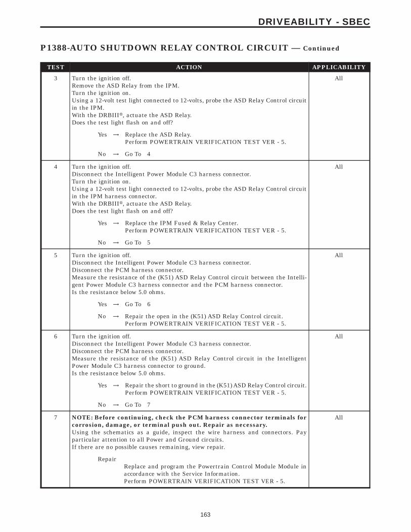
TEST ACTION APPLICABILITY
3 Turn the ignition off.Remove the ASD Relay from the IPM.Turn the ignition on.Using a 12-volt test light connected to 12-volts, probe the ASD Relay Control circuitin the IPM.With the DRBIIIt, actuate the ASD Relay.Does the test light flash on and off?
All
Yes → Replace the ASD Relay.Perform POWERTRAIN VERIFICATION TEST VER - 5.
No → Go To 4
4 Turn the ignition off.Disconnect the Intelligent Power Module C3 harness connector.Turn the ignition on.Using a 12-volt test light connected to 12-volts, probe the ASD Relay Control circuitin the IPM harness connector.With the DRBIIIt, actuate the ASD Relay.Does the test light flash on and off?
All
Yes → Replace the IPM Fused & Relay Center.Perform POWERTRAIN VERIFICATION TEST VER - 5.
No → Go To 5
5 Turn the ignition off.Disconnect the Intelligent Power Module C3 harness connector.Disconnect the PCM harness connector.Measure the resistance of the (K51) ASD Relay Control circuit between the Intelli-gent Power Module C3 harness connector and the PCM harness connector.Is the resistance below 5.0 ohms.
All
Yes → Go To 6
No → Repair the open in the (K51) ASD Relay Control circuit.Perform POWERTRAIN VERIFICATION TEST VER - 5.
6 Turn the ignition off.Disconnect the Intelligent Power Module C3 harness connector.Disconnect the PCM harness connector.Measure the resistance of the (K51) ASD Relay Control circuit in the IntelligentPower Module C3 harness connector to ground.Is the resistance below 5.0 ohms.
All
Yes → Repair the short to ground in the (K51) ASD Relay Control circuit.Perform POWERTRAIN VERIFICATION TEST VER - 5.
No → Go To 7
7 NOTE: Before continuing, check the PCM harness connector terminals forcorrosion, damage, or terminal push out. Repair as necessary.Using the schematics as a guide, inspect the wire harness and connectors. Payparticular attention to all Power and Ground circuits.If there are no possible causes remaining, view repair.
All
RepairReplace and program the Powertrain Control Module Module inaccordance with the Service Information.Perform POWERTRAIN VERIFICATION TEST VER - 5.
163
DRIVEABILITY - SBEC
P1388-AUTO SHUTDOWN RELAY CONTROL CIRCUIT — Continued

Symptom:P1389-NO ASD RELAY OUTPUT VOLTAGE AT PCM
When Monitored and Set Condition:
P1389-NO ASD RELAY OUTPUT VOLTAGE AT PCM
When Monitored: With ignition key on. Battery voltage greater than 10.4 volts.
Set Condition: No voltage sensed at the PCM when the ASD relay is energized.
POSSIBLE CAUSES
INTERMITTENT CONDITION
ASD RELAY
ASD RELAY
FUSED B+ CIRCUIT
FUSED B+ CIRCUIT
(K342) ASD RELAY OUTPUT CIRCUIT OPEN (NO START)
ASD RELAY OUTPUT CIRCUIT OPEN (NO START)
IPM FUSE & RELAY CENTER
IPM FUSE & RELAY CENTER
(K342) ASD RELAY OUTPUT CIRCUIT OPEN
ASD RELAY OUTPUT CIRCUIT OPEN
PCM START
PCM START
PCM
PCM
TEST ACTION APPLICABILITY
1 NOTE: Inspect the ASD Relay fuse located in the IPM. If the ASD Relay fuseis open, repair the cause of the open first before continuing. Inspect the ASDRelay Output circuit for a short to ground for the cause of the open fuse.NOTE: Diagnose P1388 - Auto Shutdown Relay Control Circuit first if setalong with this DTC.With the DRBIIIt, erase the DTC.Attempt to start the engine. If the engine will not start, crank the engine for at least15 seconds. It may be necessary to repeat several times.Does the DTC reset.
All
Yes → Go To 2
No → Go To 9
164
DRIVEABILITY - SBEC

TEST ACTION APPLICABILITY
2 Attempt to start the engine.Does the engine start.
All
Yes → Go To 3
No → Go To 5
3 Turn the ignition off.Disconnect the PCM harness connector.Disconnect the IPM C4 harness connectorMeasure the resistance of the (K342) ASD Output circuit between the IPM harnessconnector and the PCM harness connector.Is the resistance below 5.0 ohms?
All
Yes → Go To 4
No → Repair the (K342) ASD Relay Output circuit for an open.Perform POWERTRAIN VERIFICATION TEST VER - 5.
4 NOTE: Before continuing, check the PCM harness connector terminals forcorrosion, damage, or terminal push out. Repair as necessary.Using the schematics as a guide, inspect the wire harness and connectors. Payparticular attention to all Power and Ground circuits.If there are no possible causes remaining, view repair.
All
RepairReplace and program the Powertrain Control Module in accor-dance with the Service Information.Perform POWERTRAIN VERIFICATION TEST VER - 5.
5 Turn the ignition off.Install a substitute relay in place of the ASD Relay.With the DRBIIIt, erase DTCs.Attempt to start the engine.With the DRBIIIt, read DTCs.Does the DTC reset?
All
Yes → Go To 6
No → Replace the ASD Relay.Perform POWERTRAIN VERIFICATION TEST VER - 5.
6 Turn the ignition off.Remove the ASD Relay from the IPM.Using a 12-volt test light connected to ground, probe the Fused B+ circuit in the IPM.Does the test light illuminate?
All
Yes → Go To 7
No → Replace the IPM Fuse & Relay Center.Perform POWERTRAIN VERIFICATION TEST VER - 5.
165
DRIVEABILITY - SBEC
P1389-NO ASD RELAY OUTPUT VOLTAGE AT PCM — Continued
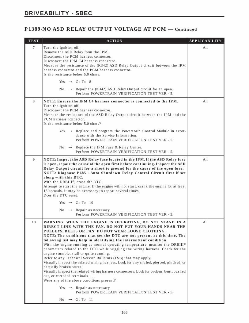
TEST ACTION APPLICABILITY
7 Turn the ignition off.Remove the ASD Relay from the IPM.Disconnect the PCM harness connector.Disconnect the IPM C4 harness connector.Measure the resistance of the (K342) ASD Relay Output circuit between the IPMharness connector and the PCM harness connector.Is the resistance below 5.0 ohms.
All
Yes → Go To 8
No → Repair the (K342) ASD Relay Output circuit for an open.Perform POWERTRAIN VERIFICATION TEST VER - 5.
8 NOTE: Ensure the IPM C4 harness connector is connected to the IPM.Turn the ignition off.Disconnect the PCM harness connector.Measure the resistance of the ASD Relay Output circuit between the IPM and thePCM harness connector.Is the resistance below 5.0 ohms?
All
Yes → Replace and program the Powertrain Control Module in accor-dance with the Service Information.Perform POWERTRAIN VERIFICATION TEST VER - 5.
No → Replace the IPM Fuse & Relay Center.Perform POWERTRAIN VERIFICATION TEST VER - 5.
9 NOTE: Inspect the ASD Relay fuse located in the IPM. If the ASD Relay fuseis open, repair the cause of the open first before continuing. Inspect the ASDRelay Output circuit for a short to ground for the cause of the open fuse.NOTE: Diagnose P685 - Auto Shutdown Relay Control Circuit first if setalong with this DTC.With the DRBIIIt, erase the DTC.Attempt to start the engine. If the engine will not start, crank the engine for at least15 seconds. It may be necessary to repeat several times.Does the DTC reset.
All
Yes → Go To 10
No → Repair as necessaryPerform POWERTRAIN VERIFICATION TEST VER - 5.
10 WARNING: WHEN THE ENGINE IS OPERATING, DO NOT STAND IN ADIRECT LINE WITH THE FAN. DO NOT PUT YOUR HANDS NEAR THEPULLEYS, BELTS OR FAN. DO NOT WEAR LOOSE CLOTHING.NOTE: The conditions that set the DTC are not present at this time. Thefollowing list may help in identifying the intermittent condition.With the engine running at normal operating temperature, monitor the DRBIIItparameters related to the DTC while wiggling the wiring harness. Check for theengine stumble, stall or quite running.Refer to any Technical Service Bulletins (TSB) that may apply.Visually inspect the related wiring harness. Look for any chafed, pierced, pinched, orpartially broken wires.Visually inspect the related wiring harness connectors. Look for broken, bent, pushedout, or corroded terminals.Were any of the above conditions present?
All
Yes → Repair as necessaryPerform POWERTRAIN VERIFICATION TEST VER - 5.
No → Go To 11
166
DRIVEABILITY - SBEC
P1389-NO ASD RELAY OUTPUT VOLTAGE AT PCM — Continued

TEST ACTION APPLICABILITY
11 Attempt to start the engine.Does the engine start.
All
Yes → Go To 12
No → Go To 14
12 Turn the ignition off.Disconnect the PCM harness connector.Disconnect the IPM C4 harness connectorMeasure the resistance of the ASD Output circuit between the IPM harnessconnector and the PCM harness connector.Is the resistance below 5.0 ohms?
All
Yes → Go To 13
No → Repair the ASD Relay Output circuit for an open.Perform POWERTRAIN VERIFICATION TEST VER - 5.
13 If there are no possible causes remaining, view repair. All
RepairReplace and program the Powertrain Control Module in accor-dance with the Service Information.Perform POWERTRAIN VERIFICATION TEST VER - 5.
14 Turn the ignition off.Install a substitute relay in place of the ASD Relay.With the DRBIIIt, erase DTCs.Attempt to start the engine.With the DRBIIIt, read DTCs.Does the DTC reset?
All
Yes → Go To 15
No → Replace the ASD Relay.Perform POWERTRAIN VERIFICATION TEST VER - 5.
15 Turn the ignition off.Remove the ASD Relay from the IPM.Using a 12-volt test light connected to ground, probe the Fused B+ circuit in the IPM.Does the test light illuminate?
All
Yes → Go To 16
No → Replace the IPM Fuse & Relay Center.Perform POWERTRAIN VERIFICATION TEST VER - 5.
16 Turn the ignition off.Remove the ASD Relay from the IPM.Disconnect the PCM harness connector.Disconnect the IPM C4 harness connector.Measure the resistance of the ASD Relay Output circuit between the IPM harnessconnector and the PCM harness connector.Is the resistance below 5.0 ohms.
All
Yes → Go To 17
No → Repair the ASD Relay Output circuit for an open.Perform POWERTRAIN VERIFICATION TEST VER - 5.
167
DRIVEABILITY - SBEC
P1389-NO ASD RELAY OUTPUT VOLTAGE AT PCM — Continued

TEST ACTION APPLICABILITY
17 NOTE: Ensure the IPM C4 harness connector is connected to the IPM.Turn the ignition off.Disconnect the PCM harness connector.Measure the resistance of the ASD Relay Output circuit between the IPM and thePCM harness connector.Is the resistance below 5.0 ohms?
All
Yes → Replace and program the Powertrain Control Module in accor-dance with the Service Information.Perform POWERTRAIN VERIFICATION TEST VER - 5.
No → Replace the IPM Fuse & Relay Center.Perform POWERTRAIN VERIFICATION TEST VER - 5.
168
DRIVEABILITY - SBEC
P1389-NO ASD RELAY OUTPUT VOLTAGE AT PCM — Continued

Symptom:P1391-INTERMITTENT LOSS OF CMP OR CKP
When Monitored and Set Condition:
P1391-INTERMITTENT LOSS OF CMP OR CKP
When Monitored: Engine running or cranking.
Set Condition: When the failure counter reaches 20 for 2 consecutive trips.
POSSIBLE CAUSES
WIRING HARNESS INSPECTION
TONE WHEEL/PULSE RING INSPECTION
WIRING HARNESS INSPECTION
TONE WHEEL/PULSE RING INSPECTION
CHECKING INTERMITTENT CRANKSHAFT POSITION SENSOR SIGNAL WITH LAB
CHECKING INTERMITTENT CAMSHAFT POSITION SENSOR SIGNAL WITH LAB
CHECKING INTERMITTENT CKP WIRING WITH LAB SCOPE
CHECKING INTERMITTENT CMP WIRING WITH LAB SCOPE
INTERMITTENT CONDITION
CAMSHAFT POSITION SENSOR
CRANKSHAFT POSITION SENSOR
TEST ACTION APPLICABILITY
1 Turn the ignition on.With the DRBIIIt, read DTC’s.Is the Good Trip displayed and equal to zero?
All
Yes → Go To 2
No → Go To 10
2 Turn the ignition off.With the DRBIIIt lab scope probe and the Miller special tool #6801, backprobe the(K44) CMP Signal circuit in the CMP harness connector.WARNING: WHEN THE ENGINE IS OPERATING, DO NOT STAND IN ADIRECT LINE WITH THE FAN. DO NOT PUT YOUR HANDS NEAR THEPULLEYS, BELTS OR FAN. DO NOT WEAR LOOSE CLOTHING.Start the engine.Observe the lab scope screen.Are there any irregular or missing signals?
All
Yes → Go To 3
No → Go To 6
169
DRIVEABILITY - SBEC

TEST ACTION APPLICABILITY
3 Visually inspect the related wiring harness. Look for any chafed, pierced, pinched, orpartially broken wires.Visually inspect the related wiring harness connectors. Look for broken, bent, pushedout, or corroded terminals.Ensure the Crankshaft Position Sensor and the Camshaft Position Sensor areproperly installed and the mounting bolt(s) tight.Refer to any TSB that may apply.Were any of the above conditions present?
All
Yes → Repair as necessaryPerform POWERTRAIN VERIFICATION TEST VER - 5.
No → Go To 4
4 Turn the ignition off.Remove the Camshaft Position Sensor.Inspect the Tone Wheel/Pulse Ring or Cam Magnet Target for damage, foreignmaterial, or excessive movement.Were any problems found?
All
Yes → Repair or replace the Tone Wheel/Pulse Ring as necessary.Perform POWERTRAIN VERIFICATION TEST VER - 5.
No → Go To 5
5 If there are no possible causes remaining, view repair. All
RepairReplace the Camshaft Position Sensor.Perform POWERTRAIN VERIFICATION TEST VER - 5.
6 Turn the ignition off.With the DRBIIIt lab scope probe and the Miller special tool #6801, backprobe the(K24) CKP Signal circuit in the CKP harness connector.WARNING: WHEN THE ENGINE IS OPERATING, DO NOT STAND IN ADIRECT LINE WITH THE FAN. DO NOT PUT YOUR HANDS NEAR THEPULLEYS, BELTS OR FAN. DO NOT WEAR LOOSE CLOTHING.Start the engine.Observe the lab scope screen.Are there any irregular or missing signals?
All
Yes → Go To 7
No → Go To 10
7 Visually inspect the related wiring harness. Look for any chafed, pierced, pinched, orpartially broken wires.Visually inspect the related wiring harness connectors. Look for broken, bent, pushedout, or corroded terminals.Ensure the Crankshaft Position Sensor and the Camshaft Position Sensor areproperly installed and the mounting bolt(s) are tight.Refer to any TSB that may apply.Were any of the above conditions present?
All
Yes → Repair as necessaryPerform POWERTRAIN VERIFICATION TEST VER - 5.
No → Go To 8
170
DRIVEABILITY - SBEC
P1391-INTERMITTENT LOSS OF CMP OR CKP — Continued

TEST ACTION APPLICABILITY
8 Turn the ignition off.Remove the Crankshaft Position Sensor.Inspect the Tone Wheel/Flex Plate slots for damage, foreign material, or excessivemovement.Were any problems found?
All
Yes → Repair or replace the Tone Wheel/Flex Plate as necessary.Perform POWERTRAIN VERIFICATION TEST VER - 5.
No → Go To 9
9 If there are no possible causes remaining, view repair. All
RepairReplace the Crankshaft Position Sensor.Perform POWERTRAIN VERIFICATION TEST VER - 5.
10 Turn the ignition off.With the DRBIIIt lab scope probe and the Miller special tool #6801, backprobe the(K24) CKP Signal circuit in the PCM harness connector.WARNING: WHEN THE ENGINE IS OPERATING, DO NOT STAND IN ADIRECT LINE WITH THE FAN. DO NOT PUT YOUR HANDS NEAR THEPULLEYS, BELTS OR FAN. DO NOT WEAR LOOSE CLOTHING.Turn the ignition on. (do not start the engine)Observe the lab scope screen.Look for any pulses generated by the CKP Sensor.Did the CKP Sensor generate any pulses?
All
Yes → Replace the Crankshaft Position Sensor.Perform POWERTRAIN VERIFICATION TEST VER - 5.
No → Go To 11
11 Turn the ignition off.With the DRBIIIt lab scope probe and the Miller special tool #6801, backprobe the(K44) CMP Signal circuit in the PCM harness connector.WARNING: WHEN THE ENGINE IS OPERATING, DO NOT STAND IN ADIRECT LINE WITH THE FAN. DO NOT PUT YOUR HANDS NEAR THEPULLEYS, BELTS OR FAN. DO NOT WEAR LOOSE CLOTHING.Turn the ignition on. (do not start the engine)Observe the lab scope screen.Look for any pulses generated by the CMP Sensor.Did the CMP Sensor generate any pulses?
All
Yes → Replace the Camshaft Position Sensor.Perform POWERTRAIN VERIFICATION TEST VER - 5.
No → Go To 12
171
DRIVEABILITY - SBEC
P1391-INTERMITTENT LOSS OF CMP OR CKP — Continued

TEST ACTION APPLICABILITY
12 Turn the ignition off.With the DRBIIIt lab scope probe and the Miller special tool #6801, backprobe theCKP Signal circuit in the PCM harness connector.WARNING: WHEN THE ENGINE IS OPERATING, DO NOT STAND IN ADIRECT LINE WITH THE FAN. DO NOT PUT YOUR HANDS NEAR THEPULLEYS, BELTS OR FAN. DO NOT WEAR LOOSE CLOTHING.Start the engine.Observe the lab scope screen while wiggling the wiring harness and connectors.Were there any irregularities in the lab scope pattern?
All
Yes → Check the harness connectors carefully. If OK, replace the Crank-shaft Position Sensor.Perform POWERTRAIN VERIFICATION TEST VER - 5.
No → Go To 13
13 Turn the ignition off.With the DRBIIIt lab scope probe and the Miller special tool #6801, backprobe theCMP Signal circuit in the PCM harness connector.WARNING: WHEN THE ENGINE IS OPERATING, DO NOT STAND IN ADIRECT LINE WITH THE FAN. DO NOT PUT YOUR HANDS NEAR THEPULLEYS, BELTS OR FAN. DO NOT WEAR LOOSE CLOTHING.Start the engine.Observe the lab scope screen while wiggling the wiring harness and connectors.Were there any irregularities in the lab scope pattern?
All
Yes → Check the harness connectors carefully. If OK, replace the Cam-shaft Position Sensor.Perform POWERTRAIN VERIFICATION TEST VER - 5.
No → Go To 14
14 WARNING: WHEN THE ENGINE IS OPERATING, DO NOT STAND IN ADIRECT LINE WITH THE FAN. DO NOT PUT YOUR HANDS NEAR THEPULLEYS, BELTS OR FAN. DO NOT WEAR LOOSE CLOTHING.NOTE: The conditions that set the DTC are not present at this time. Thefollowing list may help in identifying the intermittent condition.With the engine running at normal operating temperature, monitor the DRBIIItparameters related to the DTC while wiggling the wiring harness. Look for param-eter values to change and/or a DTC to set.Review the DRBIIIt Freeze Frame information. If possible, try to duplicate theconditions under which the DTC was set.Refer to any Technical Service Bulletins (TSB) that may apply.Visually inspect the related wiring harness. Look for any chafed, pierced, pinched, orpartially broken wires.Visually inspect the related wiring harness connectors. Look for broken, bent, pushedout, or corroded terminals.Were any of the above conditions present?
All
Yes → Repair as necessaryPerform POWERTRAIN VERIFICATION TEST VER - 5.
No → Test Complete.
172
DRIVEABILITY - SBEC
P1391-INTERMITTENT LOSS OF CMP OR CKP — Continued

Symptom:P1398-MIS-FIRE ADAPTIVE NUMERATOR AT LIMIT
When Monitored and Set Condition:
P1398-MIS-FIRE ADAPTIVE NUMERATOR AT LIMIT
When Monitored: Under closed throttle decel with A/C off, ECT above 75, and more than50 seconds after engine start.
Set Condition: One of the CKP sensor target windows has more than 2.86% variance fromthe reference window.
POSSIBLE CAUSES
ADAPTIVE NUMERATOR WILL NOT RELEARN
TONE WHEEL/PULSE RING INSPECTION
WIRING HARNESS INSPECTION
CRANKSHAFT POSITION SENSOR
TEST ACTION APPLICABILITY
1 Note: Check for any TSB’s that may apply to this symptom.Turn the ignition on.With the DRBIIIt in the miscellaneous menu, choose Clear PCM battery disconnectto reset the PCM.With the DRBIIIt, choose the Misfire PretestRoad test the vehicle and relearn the adaptive numerator.The adaptive numerator is learned when the Adaptive Numerator Done Learningline on the Misfire screen changes to Yes.Did the adaptive numerator relearn?
All
Yes → Refer to the INTERMITTENT CONDITION symptom in theDriveability category.Perform POWERTRAIN VERIFICATION TEST VER - 5.
No → Go To 2
2 Visually inspect the CKP wiring harness. Look for any chafed, pierced, pinched, orpartially broken wires.Visually inspect the CKP wiring harness connectors. Look for broken, bent, pushedout, or corroded terminals.Ensure the Crankshaft Position Sensor properly installed and the mounting bolt(s)tight.Refer to any TSB that may apply.Were any of the above conditions present?
All
Yes → Repair as necessary.Perform POWERTRAIN VERIFICATION TEST VER - 5.
No → Go To 3
173
DRIVEABILITY - SBEC

TEST ACTION APPLICABILITY
3 Turn the ignition off.Remove the Crankshaft Position Sensor.Inspect the Tone Wheel/Flex Plate slots for damage, foreign material, or excessivemovement.Were any problems found?
All
Yes → Repair or replace the Tone Wheel/Flex Plate as necessary.Perform POWERTRAIN VERIFICATION TEST VER - 5.
No → Go To 4
4 If there are no possible causes remaining, view repair. All
RepairReplace the Crankshaft Position Sensor.Perform POWERTRAIN VERIFICATION TEST VER - 5.
174
DRIVEABILITY - SBEC
P1398-MIS-FIRE ADAPTIVE NUMERATOR AT LIMIT — Continued

Symptom:P1478-BATTERY TEMP SENSOR VOLTS OUT OF LIMIT
When Monitored and Set Condition:
P1478-BATTERY TEMP SENSOR VOLTS OUT OF LIMIT
When Monitored: Ignition on.
Set Condition: The Battery Temperature Sensor, internal to the PCM, goes above 4.9volts or below 0.1 volt for more than 3.2 seconds.
POSSIBLE CAUSES
PCM
TEST ACTION APPLICABILITY
1 The PCM has detected a fault with the Battery Temperature Sensor which is internalto the Powertrain Control Module.If there are no possible causes remaining, view repair.
All
ReviewReplace and program the Powertrain Control Module in accor-dance with the Service Information.Perform POWERTRAIN VERIFICATION TEST VER - 5.
175
DRIVEABILITY - SBEC
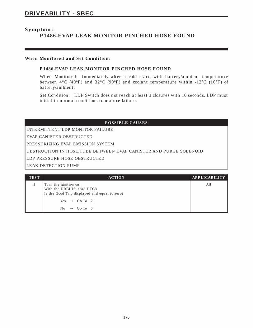
Symptom:P1486-EVAP LEAK MONITOR PINCHED HOSE FOUND
When Monitored and Set Condition:
P1486-EVAP LEAK MONITOR PINCHED HOSE FOUND
When Monitored: Immediately after a cold start, with battery/ambient temperaturebetween 4°C (40°F) and 32°C (90°F) and coolant temperature within -12°C (10°F) ofbattery/ambient.
Set Condition: LDP Switch does not reach at least 3 closures with 10 seconds. LDP mustinitial in normal conditions to mature failure.
POSSIBLE CAUSES
INTERMITTENT LDP MONITOR FAILURE
EVAP CANISTER OBSTRUCTED
PRESSURIZING EVAP EMISSION SYSTEM
OBSTRUCTION IN HOSE/TUBE BETWEEN EVAP CANISTER AND PURGE SOLENOID
LDP PRESSURE HOSE OBSTRUCTED
LEAK DETECTION PUMP
TEST ACTION APPLICABILITY
1 Turn the ignition on.With the DRBIIIt, read DTC’s.Is the Good Trip displayed and equal to zero?
All
Yes → Go To 2
No → Go To 6
176
DRIVEABILITY - SBEC

TEST ACTION APPLICABILITY
2 To continue testing you will need Miller Tool #8404 Evaporative Emission LeakDetector (EELD).WARNING: Keep lighted cigarettes, sparks, flames, and other ignitionsources away from the test area to prevent the ignition of explosive gases.Keep the test area well ventilated.NOTE: The fuel tank should have between 20% and 80% of fuel tank capacityto properly test the Evap system.Disconnect the vacuum supply hose at the Leak Detection Pump.Connect and apply a continuous vacuum supply (i.e. 209Hg) to the Leak DetectionPump. A vacuum pump such as an A/C recovery unit works well.Using the DRBIIIt, select Engine/System Tests and actuate the Leak Detect PumpTest (Option 3/Hold PSI).NOTE: The above energizes the LDP solenoid and allows the constantvacuum source to apply vacuum to the LDP pump diaphragm. This lifts thediaphragm up and seals the atmospheric canister vent valve at the bottomof the Leak Detection Pump.Connect the red power lead of Miller Tool #8404 to the battery positive terminal andthe black ground lead to battery negative terminal.NOTE: See Charts and Graph support material EELD Calibration Setup foran example.Connect shop air to the #8404 EELD.Set the smoke/air control switch to AIR.Insert the tester’s AIR supply tip (clear hose) into the appropriate calibration orificeon the tester’s control panel (based on DTC leak size).Press the remote smoke/air start button.Position the red flag on the flow meter so it is aligned with the indicator ball.When the calibration is complete, release the remote button. The EELD is nowcalibrated the flow meter in liters per minute to the size leak indicated by the DTCset in the PCM.Install the service port adapter #8404-14 on the vehicle’s service port.Connect the Air supply hose from the EELD to the service port.Press the remote button to activate AIR flow.NOTE: Larger volume fuel tanks, and/or those with less fuel, may require 4to 5 minutes to fill.The flow meter gauge on the EELD will read zero LPM when the EVAP system iscompletely pressurized.Disconnect the hose at the EVAP Canister that goes to the Fuel Tank.Did the pressure drop when the hose was disconnected?
All
Yes → Go To 3
No → Repair the obstruction in the EVAP system between the EVAPCanister and the Fuel Tank.Perform POWERTRAIN VERIFICATION TEST VER - 6.
3 Note: All previously disconnected hose(s) reconnected.Re-pressurize the EVAP System. Using Miller Tool #8404, hold down the RemoteSmoke/Air Start Button and monitor the gauge.The flow meter gauge on the EELD reads 0 LPM the EVAP system completelypressurized.Disconnect the LDP Pressure hose at the EVAP Canister. The LDP Pressure hose isthe hose that connects the Evap Canister to the Leak Detection Pump.Did the pressure drop when the hose was disconnected?
All
Yes → Go To 4
No → Replace the EVAP Canister.Perform POWERTRAIN VERIFICATION TEST VER - 6.
177
DRIVEABILITY - SBEC
P1486-EVAP LEAK MONITOR PINCHED HOSE FOUND — Continued

TEST ACTION APPLICABILITY
4 Note: All previously disconnected hose(s) reconnected.Re-pressurize the EVAP System. On Miller Tool #8404, set the Pressure/Hold switchto Open and set the Vent switch to Closed. Turn the pump timer On and watch thegauge.The flow meter gauge on the EELD reads 0 LPM the EVAP system completelypressurized.Disconnect the EVAP hoses at the Purge Solenoid.Did the pressure drop when the hose was disconnected?
All
Yes → Go To 5
No → Repair or replace hose/tube as necessary.Perform POWERTRAIN VERIFICATION TEST VER - 6.
5 Disconnect and remove the LDP pressure hose. The LDP pressure hose is the hosethat connects the EVAP Canister to the Leak Detection Pump.Inspect the LDP pressure hose for any obstructions or physical damage.Is the LDP pressure hose free from defects?
All
Yes → Replace the Leak Detection Pump.Perform POWERTRAIN VERIFICATION TEST VER - 6.
No → Repair/replace hose as necessary.Perform POWERTRAIN VERIFICATION TEST VER - 6.
6 At this time, the conditions required to set the DTC are not present.Note: Use the Freeze Frame Data to help you duplicate the conditions thatset the DTC. Pay particular attention to the DTC set conditions, such as,VSS, MAP, ECT, and Load.Note: A thorough visual inspection of the Evap system hoses, tubes, andconnections may save time in your diagnosis. Look for any physical damageor signs of wetness at connections. The strong smell of fuel vapors may aiddiagnosis also.Note: Refer to any Technical Service Bulletins (TSB’s) that may apply.With the DRBIIIt in System Tests, perform the LDP Monitor Test. This will force thePCM to run the LDP Monitor. If the monitor fails, further diagnosis is required tofind faulty component. If the monitor passes, the condition is not present at this time.Were any problems found?
All
Yes → Repair as necessary.Perform POWERTRAIN VERIFICATION TEST VER - 6.
No → Test Complete.
178
DRIVEABILITY - SBEC
P1486-EVAP LEAK MONITOR PINCHED HOSE FOUND — Continued

Symptom:P1491-RAD FAN CONTROL RELAY CIRCUIT
When Monitored and Set Condition:
P1491-RAD FAN CONTROL RELAY CIRCUIT
When Monitored: With the ignition on. Battery voltage greater than 10.4 volts.
Set Condition: An open or shorted circuit is detected in the radiator fan relay controlcircuit.
POSSIBLE CAUSES
RADIATOR FAN RELAY OPERATION
GROUND CIRCUIT
RADIATOR FAN RELAY
(N173) RADIATOR FAN RELAY CONTROL CIRCUIT OPEN (IPM)
(K173) RADIATOR FAN RELAY CONTROL CIRCUIT OPEN (PCM)
(N173) RADIATOR FAN RELAY CONTROL CIRCUIT SHORTED TO GROUND (IPM)
(K173) RADIATOR FAN RELAY CONTROL CIRCUIT SHORT TO GROUND (PCM)
INTELLIGENT POWER MODULE (SHORTED)
INTELLIGENT POWER MODULE (OPEN)
PCM
TEST ACTION APPLICABILITY
1 Turn the ignition on.With the DRBIIIt, actuate the Radiator Fan Relay.Do the fans operate?
All
Yes → Refer to the INTERMITTENT CONDITION symptom in theDriveability category.Perform POWERTRAIN VERIFICATION TEST VER - 5.
No → Go To 2
2 Turn the ignition off.Disconnect the Radiator Fan Relay harness connector.Using a 12-volt test light connected to 12-volts, probe the Ground circuit in theRadiator Fan Relay harness connector.Does the test light illuminate?
All
Yes → Go To 3
No → Repair the Ground circuit for an open.Perform POWERTRAIN VERIFICATION TEST VER - 5.
179
DRIVEABILITY - SBEC

TEST ACTION APPLICABILITY
3 Turn the ignition off.Remove the Radiator Fan Relay from the Radiator Fan Relay connector.Connect a jumper wire between cavity 3 and cavity 4.Turn the ignition on.With the DRBIIIt, actuate the Radiator Fan Relay.Do the Radiator Fans operate?
All
Yes → Replace the Radiator Fan Relay.Perform POWERTRAIN VERIFICATION TEST VER - 5.
No → Go To 4
4 Turn the ignition off.Disconnect the Radiator Fan Relay harness connector.Disconnect the PCM harness connector.Measure the resistance of the Radiator Fan Relay Control circuit between theRadiator Fan Relay harness connector and the PCM harness connector.Is the resistance below 5.0 ohms?
All
Yes → Go To 5
No → Go To 8
5 Turn the ignition off.Disconnect the Radiator Fan Relay harness connector.Disconnect the IPM C2 harness connector.Measure the resistance of the (N173) Radiator Fan Relay Control circuit in theRadiator Fan Relay harness connector to ground.Is the resistance below 5.0 ohms?
All
Yes → Repair the short to ground in the (N173) Radiator Fan RelayControl circuit, between the Radiator Fan Relay harness connec-tor and the IPM harness connector.Perform POWERTRAIN VERIFICATION TEST VER - 5.
No → Go To 6
6 Turn the ignition off.Disconnect the PCM harness connector.Disconnect the IPM C3 harness connector.Measure the resistance of the (K173) Radiator Fan Relay Control circuit in the PCMharness connector to ground.Is the resistance below 5.0 ohms?
All
Yes → Repair the short to ground in the (K173) Radiator Fan RelayControl circuit, between PCM harness connector and the IPMharness connector.Perform POWERTRAIN VERIFICATION TEST VER - 5.
No → Go To 7
7 Turn the ignition off.Disconnect IPM C2 harness connector and IPM C3 harness connector.Measure the resistance between ground and the IPM C2 connector terminal 1of theIPM.Is the resistance below 5.0 ohms?
All
Yes → Replace the IPM Fuse & Relay Center.Perform POWERTRAIN VERIFICATION TEST VER - 5.
No → Go To 11
180
DRIVEABILITY - SBEC
P1491-RAD FAN CONTROL RELAY CIRCUIT — Continued

TEST ACTION APPLICABILITY
8 Turn the ignition off.Disconnect the Radiator Fan Relay harness connector.Disconnect the IPM C2 harness connector.Measure the resistance of the (N173) Radiator Fan Relay Control circuit between theIPM harness connector and the Radiator Fan Relay harness connector.Is the resistance below 5.0 ohms.
All
Yes → Go To 9
No → Repair the open in the (N173) Radiator Fan Relay Control circuit,between the Radiator Fan Relay harness connector and the IPMharness connector.Perform POWERTRAIN VERIFICATION TEST VER - 5.
9 Turn the ignition off.Disconnect the PCM harness connector.Disconnect the IPM C3 harness connector.Measure the resistance of the (K173) Radiator Fan Relay Control circuit between theIPM harness connector and the PCM harness connector.Is the resistance below 5.0 ohms.
All
Yes → Go To 10
No → Repair the open in the (K173) Radiator Fan Relay Control circuit,between PCM harness connector and the IPM harness connector.Perform POWERTRAIN VERIFICATION TEST VER - 5.
10 Turn the ignition off.Disconnect IPM C2 harness connector and IPM C3 harness connector.Measure the resistance of the IPM circuit between the IPM C2 connector terminal 1and the IPM C3 connector terminal 18.Is the resistance above 5.0 ohms?
All
Yes → Replace the IPM Fuse & Relay Center.Perform POWERTRAIN VERIFICATION TEST VER - 5.
No → Go To 11
11 NOTE: Before continuing, check the PCM harness connector terminals forcorrosion, damage, or terminal push out. Repair as necessary.Using the schematics as a guide, inspect the wire harness and connectors. Payparticular attention to all Power and Ground circuits.If there are no possible causes remaining, view repair.
All
RepairReplace and program the Powertrain Control Module in accor-dance with the Service Information.Perform POWERTRAIN VERIFICATION TEST VER - 5.
181
DRIVEABILITY - SBEC
P1491-RAD FAN CONTROL RELAY CIRCUIT — Continued

Symptom:P1494-LEAK DETECT PUMP SW OR MECHANICAL FAULT
When Monitored and Set Condition:
P1494-LEAK DETECT PUMP SW OR MECHANICAL FAULT
When Monitored: Immediately after a cold start, with battery/ambient temperaturebetween 4°C (40°F) and 32°C (90°F) and coolant temperature within -12°C (10°F) ofbattery/ambient.
Set Condition: The state of the switch does not change when the solenoid is energized.
POSSIBLE CAUSES
GOOD TRIP EQUAL TO ZERO
LDP VACUUM SUPPLY
LEAK DETECTION PUMP
(K107) LDP SWITCH SENSE CIRCUIT SHORTED TO GROUND
(K107) LDP SWITCH SENSE CIRCUIT OPEN
PCM
TEST ACTION APPLICABILITY
1 Turn the ignition on.With the DRBIIIt, read DTC’s.Is the Good Trip displayed and equal to zero?
All
Yes → Go To 2
No → Refer to the INTERMITTENT CONDITION symptom in theDriveability category.Perform POWERTRAIN VERIFICATION TEST VER - 6.
2 Turn the ignition off.Disconnect the vacuum supply hose at the Leak Detection Pump.Connect a vacuum gauge to the disconnected vacuum supply hose at the LeakDetection Pump.Start the engine and read the vacuum gauge.Does the vacuum gauge read at least 13 in/Hg?
All
Yes → Go To 3
No → Repair leak or obstruction in vacuum hose as necessary.Perform POWERTRAIN VERIFICATION TEST VER - 6.
182
DRIVEABILITY - SBEC

TEST ACTION APPLICABILITY
3 Turn the ignition off.Disconnect the Leak Detection Pump harness connector.Turn the ignition on.With the DRBIIIt in Inputs/Outputs, read the Leak Detect Pump Sw state.While observing the Leak Detect Pump Switch state, connect a jumper wire betweena 12-volt source and the (K107) LDP Switch Sense circuit.Did the Leak Detect Pump Sw state change when the jumper was connected?
All
Yes → Replace the Leak Detection Pump.Perform POWERTRAIN VERIFICATION TEST VER - 6.
No → Go To 4
4 Turn the ignition off.Disconnect the Leak Detection Pump harness connector.Disconnect the Powertrain Control Module harness connectors.Measure the resistance of the (K107) LDP Switch Sense circuit in the LDP harnessconnector to ground.Is the resistance below 5.0 Ohms?
All
Yes → Repair the short to ground in the (K107) LDP Switch SenseCircuit.Perform POWERTRAIN VERIFICATION TEST VER - 6.
No → Go To 5
5 Turn the ignition off.Disconnect the Leak Detection Pump harness connector.Disconnect the Powertrain Control Module harness connectors.Measure the resistance of the (K107) LDP Switch Sense circuit between the LDPharness connector and the PCM harness connector.Is the resistance below 5.0 Ohms?
All
Yes → Go To 6
No → Repair the open in the (K107) LDP Switch Sense Circuit.Perform POWERTRAIN VERIFICATION TEST VER - 6.
6 NOTE: Before continuing, check the PCM harness connector terminals forcorrosion, damage, or terminal push out. Repair as necessary.Using the schematics as a guide, inspect the wire harness and connectors. Payparticular attention to all Power and Ground circuits.If there are no possible causes remaining, view repair.
All
RepairReplace and program the Powertrain Control Module in accor-dance with the Service Information.Perform POWERTRAIN VERIFICATION TEST VER - 6.
183
DRIVEABILITY - SBEC
P1494-LEAK DETECT PUMP SW OR MECHANICAL FAULT — Continued
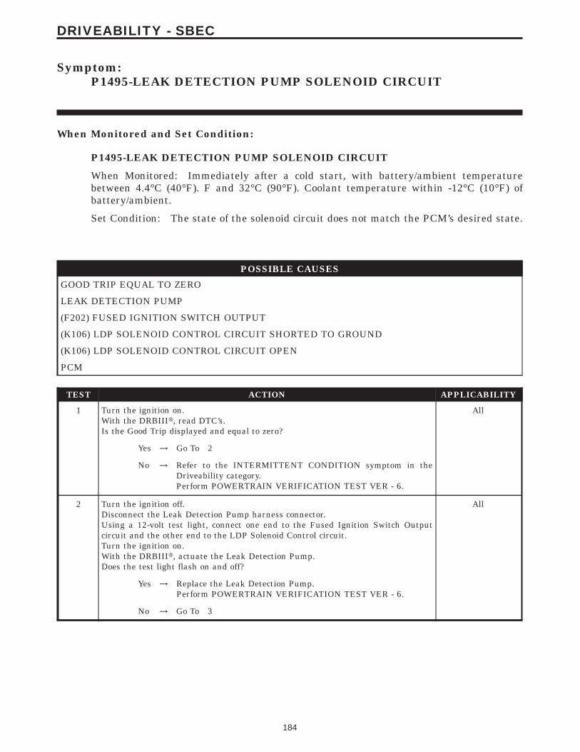
Symptom:P1495-LEAK DETECTION PUMP SOLENOID CIRCUIT
When Monitored and Set Condition:
P1495-LEAK DETECTION PUMP SOLENOID CIRCUIT
When Monitored: Immediately after a cold start, with battery/ambient temperaturebetween 4.4°C (40°F). F and 32°C (90°F). Coolant temperature within -12°C (10°F) ofbattery/ambient.
Set Condition: The state of the solenoid circuit does not match the PCM’s desired state.
POSSIBLE CAUSES
GOOD TRIP EQUAL TO ZERO
LEAK DETECTION PUMP
(F202) FUSED IGNITION SWITCH OUTPUT
(K106) LDP SOLENOID CONTROL CIRCUIT SHORTED TO GROUND
(K106) LDP SOLENOID CONTROL CIRCUIT OPEN
PCM
TEST ACTION APPLICABILITY
1 Turn the ignition on.With the DRBIIIt, read DTC’s.Is the Good Trip displayed and equal to zero?
All
Yes → Go To 2
No → Refer to the INTERMITTENT CONDITION symptom in theDriveability category.Perform POWERTRAIN VERIFICATION TEST VER - 6.
2 Turn the ignition off.Disconnect the Leak Detection Pump harness connector.Using a 12-volt test light, connect one end to the Fused Ignition Switch Outputcircuit and the other end to the LDP Solenoid Control circuit.Turn the ignition on.With the DRBIIIt, actuate the Leak Detection Pump.Does the test light flash on and off?
All
Yes → Replace the Leak Detection Pump.Perform POWERTRAIN VERIFICATION TEST VER - 6.
No → Go To 3
184
DRIVEABILITY - SBEC

TEST ACTION APPLICABILITY
3 Turn the ignition off.Disconnect the Leak Detection Pump harness connector.Turn the ignition on.Using a 12-volt test light connected to ground, probe the (F202) Ignition SwitchOutput circuit in the LDP harness connector.Does the test light illuminate brightly?
All
Yes → Go To 4
No → Repair the (F202) Fused Ignition Switch Output circuit.Perform POWERTRAIN VERIFICATION TEST VER - 6.
4 Turn the ignition off.Disconnect the Leak Detection Pump harness connector.Disconnect the Powertrain Control Module harness connector.Measure the resistance of the (K106) LDP Solenoid Control circuit in the LDPharness connector to ground.Is the resistance below 5.0 ohms?
All
Yes → Repair the short to ground in the (K106) LDP Solenoid Controlcircuit.Perform POWERTRAIN VERIFICATION TEST VER - 6.
No → Go To 5
5 Turn the ignition off.Disconnect the Leak Detection Pump harness connector.Disconnect the Powertrain Control Module harness connector.Measure the resistance of the (K106) LDP Solenoid Control circuit between the LDPSolenoid harness connector and the PCM harness connector.Is the resistance below 5.0 ohms?
All
Yes → Go To 6
No → Repair the (K106) LDP Solenoid Control circuit for an open.Perform POWERTRAIN VERIFICATION TEST VER - 6.
6 NOTE: Before continuing, check the PCM harness connector terminals forcorrosion, damage, or terminal push out. Repair as necessary.Using the schematics as a guide, inspect the wire harness and connectors. Payparticular attention to all Power and Ground circuits.If there are no possible causes remaining, view repair.
All
RepairReplace and program the Powertrain Control Module in accor-dance with the Service Information.Perform POWERTRAIN VERIFICATION TEST VER - 6.
185
DRIVEABILITY - SBEC
P1495-LEAK DETECTION PUMP SOLENOID CIRCUIT — Continued

Symptom:P1496-5 VOLT SUPPLY, OUTPUT TOO LOW
When Monitored and Set Condition:
P1496-5 VOLT SUPPLY, OUTPUT TOO LOW
When Monitored: With the ignition on.
Set Condition: The 5-volt supply to the sensors is below 3.5 volts for 4 seconds.
POSSIBLE CAUSES
INTERMITTENT CONDITION
THROTTLE POSITION SENSOR
MAP SENSOR
A/C PRESSURE SENSOR
EGR SOLENOID
(F855) 5-VOLT SUPPLY SHORTED TO GROUND
PCM
TEST ACTION APPLICABILITY
1 Turn the ignition on.With the DRBIIIt, read the DTC’s.Is the Good Trip displayed and equal to zero?
All
Yes → Go To 2
No → Go To 9
2 Turn the ignition off.Disconnect the TP Sensor harness connector.Turn the ignition on.Measure the (F855) 5-volt Supply circuit at the TP Sensor harness connector.Is the Voltage below 4.5 Volts?
All
Yes → Go To 3
No → Go To 8
186
DRIVEABILITY - SBEC

TEST ACTION APPLICABILITY
3 Turn the ignition off.Disconnect the TP Sensor harness connector.Turn the ignition on.Connect a voltmeter to the (F855) 5-volt Supply circuit at the TP Sensor harnessconnector.Monitor the voltage display.Turn the ignition off.Disconnect the MAP Sensor harness connector.Turn the ignition on.Did the (F855) 5-volt Supply go from below 4.5 volts to above 4.5 volts when MAPSensor was disconne
All
Yes → Replace the MAP Sensor.Perform POWERTRAIN VERIFICATION TEST VER - 5.
No → Go To 4
4 Turn the ignition off.Disconnect the TP Sensor harness connector.Turn the ignition on.Connect a voltmeter to the (F855) 5-volt Supply circuit at the Throttle PositionSensor harness connector.Monitor the voltage display.Turn the ignition off.Disconnect the A/C Pressure Sensor harness connector.Turn the ignition on.Did the (F855) 5-volt Supply go from below 4.5 volts to above 4.5 volts when the A/Csensor was disc
All
Yes → Replace the A/C Pressure Sensor.Perform POWERTRAIN VERIFICATION TEST VER - 5.
No → Go To 5
5 Turn the ignition off.Disconnect the TP Sensor harness connector.Turn the ignition on.Connect a voltmeter to the (F855) 5-volt Supply circuit at the TP Sensor harnessconnector.Monitor the voltage display.Turn the ignition off.Disconnect the EGR Solenoid harness connector.Turn the ignition on.Did the 5-volt Supply go from below 4.5 volts to above 4.5 volts when the EGR wasdisconnected?
All
Yes → Replace the EGR Solenoid.Perform POWERTRAIN VERIFICATION TEST VER - 5.
No → Go To 6
187
DRIVEABILITY - SBEC
P1496-5 VOLT SUPPLY, OUTPUT TOO LOW — Continued

TEST ACTION APPLICABILITY
6 Turn the ignition off.Disconnect the TP Sensor harness connector.Disconnect the MAP Sensor harness connector.Disconnect the A/C Pressure Sensor harness connector.Disconnect the EGR Solenoid harness connector.Disconnect the PCM harness connectors.Measure the resistance of the (F855) 5-volt Supply circuit in the TP Sensor harnessconnector to ground.Is the resistance below 5.0 ohms?
All
Yes → Repair the short to ground in the (F855) 5-Volt Supply Circuit.Perform POWERTRAIN VERIFICATION TEST VER - 5.
No → Go To 7
7 NOTE: Before Continuing: Disconnect the PCM harness connector andcheck the related wiring terminals for corrosion, damage or terminal pushout. Repair as necessary.NOTE: Before continuing, check the PCM harness connector terminals forcorrosion, damage, or terminal push out. Repair as necessary.Using the schematics as a guide, inspect the wire harness and connectors. Payparticular attention to all Power and Ground circuits.If there are no possible causes remaining, view repair.
All
RepairReplace and program the Powertrain Control Module in accor-dance with the Service Information.Perform POWERTRAIN VERIFICATION TEST VER - 5.
8 NOTE: The TP Sensor harness connector must be connected during thistest.Disconnect the MAP Sensor harness connector.Turn the ignition on.Measure the (F855) 5-volt Supply circuit in the MAP Sensor harness connector.Is the Voltage below 4.5 Volts?
All
Yes → Replace the TP Sensor.Perform POWERTRAIN VERIFICATION TEST VER - 5.
No → Go To 9
188
DRIVEABILITY - SBEC
P1496-5 VOLT SUPPLY, OUTPUT TOO LOW — Continued

TEST ACTION APPLICABILITY
9 WARNING: WHEN THE ENGINE IS OPERATING, DO NOT STAND IN ADIRECT LINE WITH THE FAN. DO NOT PUT YOUR HANDS NEAR THEPULLEYS, BELTS OR FAN. DO NOT WEAR LOOSE CLOTHING.NOTE: The conditions that set the DTC are not present at this time. Thefollowing list may help in identifying the intermittent condition.With the engine running at normal operating temperature, monitor the DRBIIItparameters related to the DTC while wiggling the wiring harness. Look for param-eter values to change and/or a DTC to set.Review the DRBIIIt Freeze Frame information. If possible, try to duplicate theconditions under which the DTC was set.Refer to any Technical Service Bulletins (TSB) that may apply.Visually inspect the related wiring harness. Look for any chafed, pierced, pinched, orpartially broken wires.Visually inspect the related wiring harness connectors. Look for broken, bent, pushedout, or corroded terminals.Were any of the above conditions present?
All
Yes → Repair as necessaryPerform POWERTRAIN VERIFICATION TEST VER - 5.
No → Test Complete.
189
DRIVEABILITY - SBEC
P1496-5 VOLT SUPPLY, OUTPUT TOO LOW — Continued

Symptom:P1594-CHARGING SYSTEM VOLTAGE TOO HIGH
When Monitored and Set Condition:
P1594-CHARGING SYSTEM VOLTAGE TOO HIGH
When Monitored: The engine running. The engine speed greater than 380 RPM.
Set Condition: Battery voltage is 1 volt greater than desired system voltage.
POSSIBLE CAUSES
TARGET VOLTAGE DIFFERS FROM BATTERY VOLTAGE
INTERMITTENT CONDITION
(K20) GENERATOR FIELD DRIVER CIRCUIT SHORTED TO GROUND
GENERATOR FIELD
PCM
TEST ACTION APPLICABILITY
1 Note: Battery must be fully charged.Note: Generator Belt tension and condition must be checked before con-tinuing.Turn the ignition on.With DRBIIIt, actuate the Generator Field Driver.With a 12-volt test light connected to ground, backprobe the (K20) Generator FieldDriver circuit in the back of Generator harness connector.Does the test light illuminate brightly and flash?
All
Yes → Go To 2
No → Go To 5
2 With DRBIIIt, stop all actuation.Turn the ignition on.With DRBIIIt, read the Target Charging voltage.Is the Target Charging voltage above 13 volts?
All
Yes → Go To 3
No → Go To 4
3 Start the engine.With the DRBIIIt, manually set the engine speed to 1600 RPM.With DRBIIIt, read both the Battery voltage and the Target Charging voltage.Compare the Target Charging Voltage to the Battery Voltage reading.Monitor voltage for 5 minutes, if necessary. Look for a 1.0 volt difference or more.Was there more than a 1.0 volt difference?
All
Yes → Replace the Powertrain Control Module in accordance with theService Information.Perform POWERTRAIN VERIFICATION TEST VER - 3.
No → Go To 4
190
DRIVEABILITY - SBEC

TEST ACTION APPLICABILITY
4 WARNING: WHEN THE ENGINE IS OPERATING, DO NOT STAND IN ADIRECT LINE WITH THE FAN. DO NOT PUT YOUR HANDS NEAR THEPULLEYS, BELTS OR FAN. DO NOT WEAR LOOSE CLOTHING.NOTE: The conditions that set the DTC are not present at this time. Thefollowing list may help in identifying the intermittent condition.With the engine running at normal operating temperature, monitor the DRBIIItparameters related to the DTC while wiggling the wiring harness. Look for param-eter values to change and/or a DTC to set.Review the DRBIIIt Freeze Frame information. If possible, try to duplicate theconditions under which the DTC was set.Refer to any Technical Service Bulletins (TSB) that may apply.Visually inspect the related wiring harness. Look for any chafed, pierced, pinched, orpartially broken wires.Visually inspect the related wiring harness connectors. Look for broken, bent, pushedout, or corroded terminals.Were any of the above conditions present?
All
Yes → Repair as necessaryPerform POWERTRAIN VERIFICATION TEST VER - 3.
No → Test Complete.
5 Turn the ignition off.Disconnect the PCM harness connector.Disconnect the Generator Field harness connector.Measure the resistance of the (K20) Generator Field Driver circuit from the PCMharness connector to ground.Is the resistance below 5.0 ohms?
All
Yes → Repair the short to ground in the (K20) Generator Field Drivercircuit.Perform POWERTRAIN VERIFICATION TEST VER - 3.
No → Go To 6
6 Turn the ignition off.Disconnect the Generator Field harness connector.Measure resistance of the Generator Field Driver terminal pin of the Generator toground.Is the resistance below 5.0 ohms?
All
Yes → Repair or replace the shorted Generator as necessary.Perform POWERTRAIN VERIFICATION TEST VER - 3.
No → Go To 7
7 NOTE: Before continuing, check the PCM harness connector terminals forcorrosion, damage, or terminal push out. Repair as necessary.Using the schematics as a guide, inspect the wire harness and connectors. Payparticular attention to all Power and Ground circuits.If there are no possible causes remaining, view repair.
All
RepairReplace and program the Powertrain Control Module in accor-dance with the Service Information.Perform POWERTRAIN VERIFICATION TEST VER - 3.
191
DRIVEABILITY - SBEC
P1594-CHARGING SYSTEM VOLTAGE TOO HIGH — Continued

Symptom List:P1595-SPEED CONTROL SOLENOID CIRCUITSP1683-SPD CTRL PWR RELAY; OR S/C 12V DRIVER CKT
Test Note: All symptoms listed above are diagnosed using the same tests.The title for the tests will be P1595-SPEED CONTROL SOLE-NOID CIRCUITS.
When Monitored and Set Condition:
P1595-SPEED CONTROL SOLENOID CIRCUITS
When Monitored: With the ignition on. Battery voltage greater than 10.4 volts. SpeedControl Switched on.
Set Condition: The Powertrain Control Module actuates the vacuum and vent solenoidsbut they do not respond.
P1683-SPD CTRL PWR RELAY; OR S/C 12V DRIVER CKT
When Monitored: With the ignition key on. The speed control switched on.
Set Condition: The speed control power supply circuit is either open or shorted to ground.
POSSIBLE CAUSES
GROUND CIRCUIT OPEN
S/C SERVO
INTERMITTENT CONDITION
(V30) S/C BRAKE SWITCH OUTPUT CIRCUIT
(V30) SPEED CONTROL BRAKE SWITCH OUTPUT OPEN
BRAKE LAMP SWITCH
SPEED CONTROL POWER SUPPLY CIRCUIT
PCM (S/C POWER SUPPLY)
SPEED CONTROL VACUUM SOLENOID
(V36) SPEED CONTROL VACUUM SOLENOID CONTROL CIRCUIT OPEN
(V36) SPEED CONTROL VACUUM SOLENOID CONTROL CIRCUIT SHORTED TO GROUND
PCM (VACUUM SOLENOID)
SPEED CONTROL VENT SOLENOID
(V35) SPEED CONTROL VENT SOLENOID CONTROL CIRCUIT OPEN
(V35) SPEED CONTROL VENT SOLENOID CONTROL CIRCUIT SHORTED TO GROUND
PCM (VENT SOLENOID)
192
DRIVEABILITY - SBEC
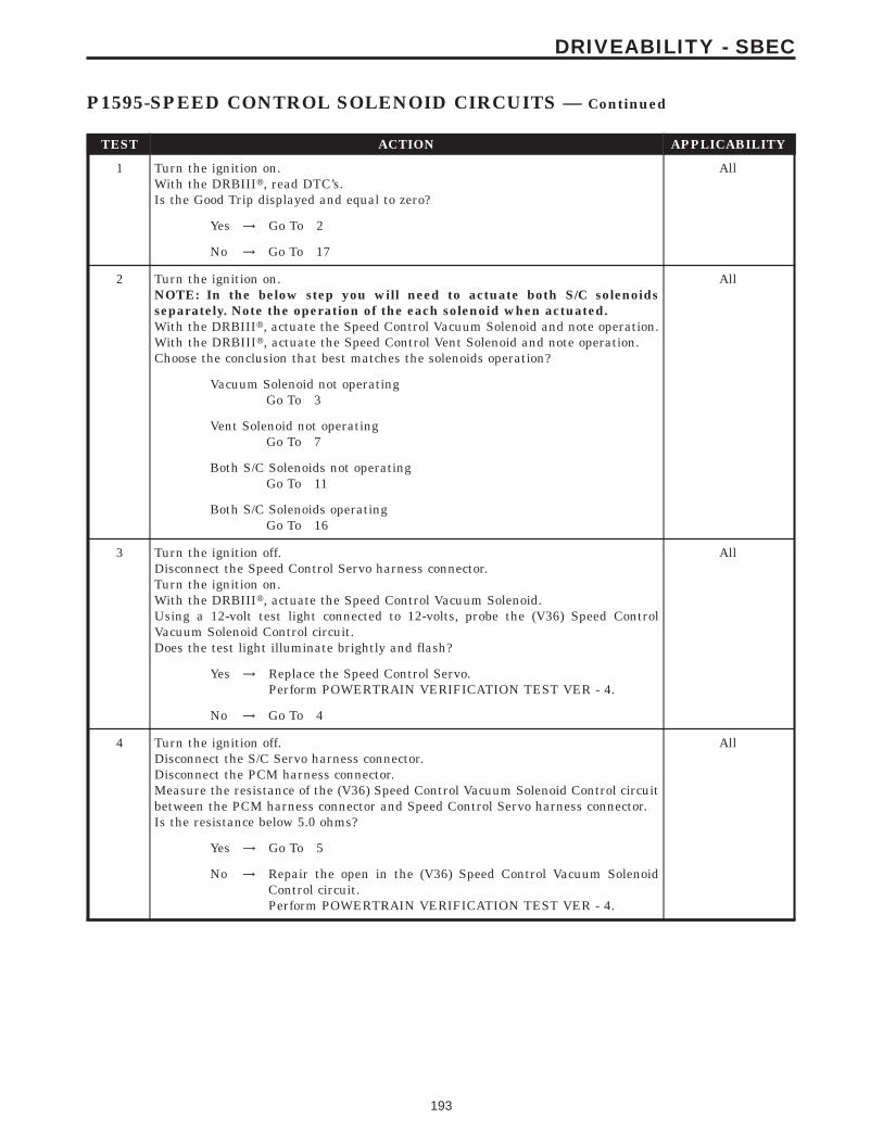
TEST ACTION APPLICABILITY
1 Turn the ignition on.With the DRBIIIt, read DTC’s.Is the Good Trip displayed and equal to zero?
All
Yes → Go To 2
No → Go To 17
2 Turn the ignition on.NOTE: In the below step you will need to actuate both S/C solenoidsseparately. Note the operation of the each solenoid when actuated.With the DRBIIIt, actuate the Speed Control Vacuum Solenoid and note operation.With the DRBIIIt, actuate the Speed Control Vent Solenoid and note operation.Choose the conclusion that best matches the solenoids operation?
All
Vacuum Solenoid not operatingGo To 3
Vent Solenoid not operatingGo To 7
Both S/C Solenoids not operatingGo To 11
Both S/C Solenoids operatingGo To 16
3 Turn the ignition off.Disconnect the Speed Control Servo harness connector.Turn the ignition on.With the DRBIIIt, actuate the Speed Control Vacuum Solenoid.Using a 12-volt test light connected to 12-volts, probe the (V36) Speed ControlVacuum Solenoid Control circuit.Does the test light illuminate brightly and flash?
All
Yes → Replace the Speed Control Servo.Perform POWERTRAIN VERIFICATION TEST VER - 4.
No → Go To 4
4 Turn the ignition off.Disconnect the S/C Servo harness connector.Disconnect the PCM harness connector.Measure the resistance of the (V36) Speed Control Vacuum Solenoid Control circuitbetween the PCM harness connector and Speed Control Servo harness connector.Is the resistance below 5.0 ohms?
All
Yes → Go To 5
No → Repair the open in the (V36) Speed Control Vacuum SolenoidControl circuit.Perform POWERTRAIN VERIFICATION TEST VER - 4.
193
DRIVEABILITY - SBEC
P1595-SPEED CONTROL SOLENOID CIRCUITS — Continued

TEST ACTION APPLICABILITY
5 Turn the ignition off.Disconnect the S/C Servo harness connector.Disconnect the PCM harness connector.Measure the resistance of the (V36) Speed Control Vacuum Solenoid Control circuitin the PCM harness connector to ground.Is the resistance below 5.0 ohms?
All
Yes → Repair the short to ground in the (V36) Speed Control VacuumSolenoid Control circuit.Perform POWERTRAIN VERIFICATION TEST VER - 4.
No → Go To 6
6 If the there are no possible causes remaining, view repair. All
RepairReplace and program the Powertrain Control Module in accor-dance with the Service Information.Perform POWERTRAIN VERIFICATION TEST VER - 4.
7 Turn the ignition off.Disconnect the Speed Control Servo harness connector.Turn the ignition on.With the DRBIIIt, actuate the Speed Control Vent Solenoid.Using a 12-volt test light connected to 12-volts, probe the (V35) Speed Control VentSolenoid Control circuit in the Speed Control Servo harness connector.Does the test light illuminate brightly and flash?
All
Yes → Replace the Speed Control Servo.Perform POWERTRAIN VERIFICATION TEST VER - 4.
No → Go To 8
8 Turn the ignition off.Disconnect the S/C Servo harness connector.Disconnect the PCM harness connector.Measure the resistance of the (V35) Speed Control Vent Solenoid Control circuitbetween the PCM harness connector and Speed Control Servo harness connector.Is the resistance below 5.0 ohms?
All
Yes → Go To 9
No → Repair the open in the (V35) Speed Control Vacuum SolenoidControl circuit.Perform POWERTRAIN VERIFICATION TEST VER - 4.
9 Turn the ignition off.Disconnect the S/C Servo harness connector.Disconnect the PCM harness connector.Measure the resistance of the (V35) Speed Control Vent Solenoid Control circuit inthe PCM harness connector to ground.Is the resistance below 5.0 ohms?
All
Yes → Repair the short to ground in the (V35) Speed Control VacuumSolenoid Control circuit.Perform POWERTRAIN VERIFICATION TEST VER - 4.
No → Go To 10
194
DRIVEABILITY - SBEC
P1595-SPEED CONTROL SOLENOID CIRCUITS — Continued

TEST ACTION APPLICABILITY
10 NOTE: Before continuing, check the PCM harness connector terminals forcorrosion, damage, or terminal push out. Repair as necessary.Using the schematics as a guide, inspect the wire harness and connectors. Payparticular attention to all Power and Ground circuits.If the there are no possible causes remaining, view repair.
All
RepairReplace and program the Powertrain Control Module in accor-dance with the Service Information.Perform POWERTRAIN VERIFICATION TEST VER - 4.
11 Turn the ignition off.Disconnect the S/C Servo harness connector.Turn the ignition on.Using a 12-volt test light connected to ground, probe the S/C Brake Switch Outputcircuit in the S/C Servo harness connector.Does the test light illuminate brightly?
All
Yes → Replace the Speed Control Servo.Perform POWERTRAIN VERIFICATION TEST VER - 4.
No → Go To 12
12 Turn the ignition off.Disconnect the Speed Control Servo harness connector.Disconnect the Brake Lamp Switch harness connector.Measure the resistance of the (V30) Speed Control Brake Switch Output circuitbetween the Speed Control Servo harness connector and Brake Lamp Switch harnessconnector.Is the resistance below 5.0 ohms?
All
Yes → Go To 13
No → Repair the open in the (V30) Speed Control Brake Switch Outputcircuit.Perform POWERTRAIN VERIFICATION TEST VER - 4.
13 Disconnect the Brake Lamp Switch harness connector.Turn the ignition on.Using a 12-volt test light connected to ground, probe the Speed Control Power Supplycircuit in the Brake Lamp Switch harness connector.Does the test light illuminate brightly?
All
Yes → Replace the Brake Lamp Switch.Perform POWERTRAIN VERIFICATION TEST VER - 4.
No → Go To 14
14 Turn the ignition off.Disconnect the PCM harness connector.Disconnect the Brake Lamp Switch harness connector.Measure the resistance of the (V32) Speed Control Power Supply circuit between thePCM harness connector and the Brake Lamp Switch harness connector.Is the resistance below 5.0 ohms?
All
Yes → Go To 15
No → Repair the open in the Speed Control Supply circuit.Perform POWERTRAIN VERIFICATION TEST VER - 4.
195
DRIVEABILITY - SBEC
P1595-SPEED CONTROL SOLENOID CIRCUITS — Continued

TEST ACTION APPLICABILITY
15 NOTE: Before continuing, check the PCM harness connector terminals forcorrosion, damage, or terminal push out. Repair as necessary.Using the schematics as a guide, inspect the wire harness and connectors. Payparticular attention to all Power and Ground circuits.If there are no possible causes remaining, view repair.
All
RepairReplace and program the Powertrain Control Module in accor-dance with the Service Information.Perform POWERTRAIN VERIFICATION TEST VER - 4.
16 NOTE: The Vacuum Reservoir and vacuum circuit must be operatingcorrectly. Inspect the Vacuum Reservoir and vacuum circuit for any dam-age or disconnected hoses. Repair and retest as necessary.Start the engine and allow it to reach operating temperature. This will allow theVacuum Reservoir to build up vacuum.Turn the engine off (ignition on).Using the DRBIIIt, actuate the S/C Servo.Monitor the S/C Servo to throttle operation.NOTE: The throttle should move until all the vacuum has been releasedfrom the Vacuum Reservoir.Does the S/C Servo open and close the throttle plate?
All
Yes → Go To 17
No → Replace the S/C Servo.Perform POWERTRAIN VERIFICATION TEST VER - 4.
17 Turn the ignition off.Disconnect the S/C Servo harness connector.Using a 12-volt test light connected to 12-volts, probe the ground circuit in the S/CServo harness connector.Does the test light illuminate brightly?
All
Yes → Go To 18
No → Repair the open in the ground circuit.Perform POWERTRAIN VERIFICATION TEST VER - 4.
18 WARNING: WHEN THE ENGINE IS OPERATING, DO NOT STAND IN ADIRECT LINE WITH THE FAN. DO NOT PUT YOUR HANDS NEAR THEPULLEYS, BELTS OR FAN. DO NOT WEAR LOOSE CLOTHING.NOTE: The conditions that set the DTC are not present at this time. Thefollowing list may help in identifying the intermittent condition.With the engine running at normal operating temperature, monitor the DRBIIItparameters related to the DTC while wiggling the wiring harness. Look for param-eter values to change and/or a DTC to set.Review the DRBIIIt Freeze Frame information. If possible, try to duplicate theconditions under which the DTC was set.Refer to any Technical Service Bulletins (TSB) that may apply.Visually inspect the related wiring harness. Look for any chafed, pierced, pinched, orpartially broken wires.Visually inspect the related wiring harness connectors. Look for broken, bent, pushedout, or corroded terminals.Were any of the above conditions present?
All
Yes → Repair as necessaryPerform POWERTRAIN VERIFICATION TEST VER - 4.
No → Test Complete.
196
DRIVEABILITY - SBEC
P1595-SPEED CONTROL SOLENOID CIRCUITS — Continued

Symptom:P1598-A/C PRESSURE SENSOR VOLTS TOO HIGH
When Monitored and Set Condition:
P1598-A/C PRESSURE SENSOR VOLTS TOO HIGH
When Monitored: Engine running. The A/C relay energized.
Set Condition: The A/C pressure sensor signal at the PCM goes above 4.92 volts.
POSSIBLE CAUSES
INTERMITTENT CONDITION
(C18) A/C PRESSURE SENSOR SIGNAL CIRCUIT SHORTED TO (F855) 5-VOLT SUPPLY CIRCUIT
(C18) A/C PRESSURE SENSOR SIGNAL CIRCUIT SHORTED TO BATTERY VOLTAGE
A/C PRESSURE SENSOR INTERNAL FAILURE
(C18) A/C PRESSURE SENSOR SIGNAL CIRCUIT OPEN
(K900) SENSOR GROUND CIRCUIT OPEN
PCM
TEST ACTION APPLICABILITY
1 NOTE: Ensure the A/C refrigerant System is properly charged per theService Information.Start the engine.With the DRBIIIt, read the A/C Pressure Sensor voltage.Is the voltage above 4.6 volts?
All
Yes → Go To 2
No → Go To 8
2 Turn the ignition off.Disconnect the A/C Pressure Sensor harness connector.Disconnect the PCM harness connector.Measure the resistance between the (C18) A/C Pressure Sensor Signal circuit and the(F855) 5-volt Supply circuit in the A/C Pressure Sensor harness connector.Is the resistance below 5.0 ohms?
All
Yes → Repair the (C18) A/C Pressure Sensor Signal circuit for a short tothe (F855) 5-volt Supply circuit.Perform POWERTRAIN VERIFICATION TEST VER - 2.
No → Go To 3
197
DRIVEABILITY - SBEC
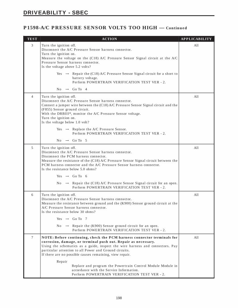
TEST ACTION APPLICABILITY
3 Turn the ignition off.Disconnect the A/C Pressure Sensor harness connector.Turn the ignition on.Measure the voltage on the (C18) A/C Pressure Sensor Signal circuit at the A/CPressure Sensor harness connector.Is the voltage above 5.2 volts?
All
Yes → Repair the (C18) A/C Pressure Sensor Signal circuit for a short tobattery voltage.Perform POWERTRAIN VERIFICATION TEST VER - 2.
No → Go To 4
4 Turn the ignition off.Disconnect the A/C Pressure Sensor harness connector.Connect a jumper wire between the (C18) A/C Pressure Sensor Signal circuit and the(F855) Sensor ground circuit.With the DRBIIIt, monitor the A/C Pressure Sensor voltage.Turn the ignition on.Is the voltage below 1.0 volt?
All
Yes → Replace the A/C Pressure Sensor.Perform POWERTRAIN VERIFICATION TEST VER - 2.
No → Go To 5
5 Turn the ignition off.Disconnect the A/C Pressure Sensor harness connector.Disconnect the PCM harness connector.Measure the resistance of the (C18) A/C Pressure Sensor Signal circuit between thePCM harness connector and the A/C Pressure Sensor harness connector.Is the resistance below 5.0 ohms?
All
Yes → Go To 6
No → Repair the (C18) A/C Pressure Sensor Signal circuit for an open.Perform POWERTRAIN VERIFICATION TEST VER - 2.
6 Turn the ignition off.Disconnect the A/C Pressure Sensor harness connector.Measure the resistance between ground and the (K900) Sensor ground circuit at theA/C Pressure Sensor harness connector.Is the resistance below 30 ohms?
All
Yes → Go To 7
No → Repair the (K900) Sensor ground circuit for an open.Perform POWERTRAIN VERIFICATION TEST VER - 2.
7 NOTE: Before continuing, check the PCM harness connector terminals forcorrosion, damage, or terminal push out. Repair as necessary.Using the schematics as a guide, inspect the wire harness and connectors. Payparticular attention to all Power and Ground circuits.If there are no possible causes remaining, view repair.
All
RepairReplace and program the Powertrain Control Module Module inaccordance with the Service Information.Perform POWERTRAIN VERIFICATION TEST VER - 2.
198
DRIVEABILITY - SBEC
P1598-A/C PRESSURE SENSOR VOLTS TOO HIGH — Continued

TEST ACTION APPLICABILITY
8 NOTE: Ensure the A/C refrigerant System is properly charged per theService Information.NOTE: The conditions that set the DTC are not present at this time. Thefollowing list may help in identifying the intermittent condition.WARNING: WHEN THE ENGINE IS OPERATING, DO NOT STAND IN ADIRECT LINE WITH THE FAN. DO NOT PUT YOUR HANDS NEAR THEPULLEYS, BELTS OR FAN. DO NOT WEAR LOOSE CLOTHING.With the engine running at normal operating temperature, monitor the DRBIIItparameters related to the DTC while wiggling the wiring harness. Look for param-eter values to change and/or a DTC to set.Review the DRBIIIt Freeze Frame information. If possible, try to duplicate theconditions under which the DTC was set.Refer to any Technical Service Bulletins (TSB) that may apply.Visually inspect the related wiring harness. Look for any chafed, pierced, pinched, orpartially broken wires.Visually inspect the related wiring harness connectors. Look for broken, bent, pushedout, or corroded terminals.Were any of the above conditions present?
All
Yes → Repair as necessaryPerform POWERTRAIN VERIFICATION TEST VER - 2.
No → Test Complete.
199
DRIVEABILITY - SBEC
P1598-A/C PRESSURE SENSOR VOLTS TOO HIGH — Continued

Symptom:P1599-A/C PRESSURE SENSOR VOLTS TOO LOW
When Monitored and Set Condition:
P1599-A/C PRESSURE SENSOR VOLTS TOO LOW
When Monitored: Engine running. The A/C relay energized.
Set Condition: The A/C pressure sensor signal voltage at the PCM goes below 0.58 voltsfor 2.6 seconds.
POSSIBLE CAUSES
INTERMITTENT CONDITION
(F855) 5-VOLT SUPPLY CIRCUIT SHORTED TO GROUND
(F855) 5-VOLT SUPPLY CIRCUIT OPEN
A/C PRESSURE SENSOR INTERNAL FAILURE
(C18) A/C PRESSURE SENSOR SIGNAL CIRCUIT SHORTED TO GROUND
(C18) A/C PRESSURE SENSOR SIGNAL CIRCUIT SHORTED TO (K900) SENSOR GROUND CIR-CUIT
PCM (F855) 5-VOLT SUPPLY CIRCUIT
PCM (C18) A/C PRESSURE SENSOR SIGNAL
TEST ACTION APPLICABILITY
1 NOTE: Ensure the A/C refrigerant System is properly charged per theService Information.Start the engine.With the DRBIIIt, read the A/C Pressure Sensor voltage.Is the voltage below 0.6 of a volt?
All
Yes → Go To 2
No → Go To 10
2 Turn the ignition off.Disconnect the A/C Pressure Sensor harness connector.Turn the ignition on.Measure the voltage of the (F855) 5-volt Supply circuit in the A/C Pressure Sensorharness connector.Is the voltage between 4.5 to 5.2 volts?
All
Yes → Go To 3
No → Go To 7
200
DRIVEABILITY - SBEC

TEST ACTION APPLICABILITY
3 Turn the ignition off.Disconnect the A/C Pressure Sensor harness connector.With the DRBIIIt, monitor the A/C Pressure Sensor voltage.Turn the ignition on.Is the voltage above 0.6 of a volt?
All
Yes → Replace the A/C Pressure Sensor.Perform POWERTRAIN VERIFICATION TEST VER - 2.
No → Go To 4
4 Turn the ignition off.Disconnect the A/C Pressure Sensor harness connector.Disconnect the PCM harness connector.Measure the resistance between ground and the (C18) A/C Pressure Sensor Signalcircuit in the A/C Pressure Sensor harness connector.Is the resistance below 100 ohms?
All
Yes → Repair the (C18) A/C Pressure Sensor Signal circuit for a short toground.Perform POWERTRAIN VERIFICATION TEST VER - 2.
No → Go To 5
5 Turn the ignition off.Disconnect the A/C Pressure Sensor harness connector.Disconnect the PCM harness connector.Measure the resistance between the (C18) A/C Pressure Sensor Signal circuit and the(K900) Sensor ground circuit in the A/C Pressure Sensor harness connector.Is the resistance below 100 ohms?
All
Yes → Repair the (C18) A/C Pressure Sensor Signal circuit for a short tothe (K900) Sensor ground circuit.Perform POWERTRAIN VERIFICATION TEST VER - 2.
No → Go To 6
6 NOTE: Before continuing, check the PCM harness connector terminals forcorrosion, damage, or terminal push out. Repair as necessary.Using the schematics as a guide, inspect the wire harness and connectors. Payparticular attention to all Power and Ground circuits.If there are no possible causes remaining, view repair.
All
RepairReplace and program the Powertrain Control Module Module inaccordance with the Service Information.Perform POWERTRAIN VERIFICATION TEST VER - 2.
7 Turn the ignition off.Disconnect the A/C Pressure Sensor harness connector.Disconnect the PCM harness connector.Measure the resistance between ground and the (F855) 5-volt Supply circuit in theA/C Pressure Sensor harness connector.Is the resistance below 100 ohms?
All
Yes → Repair the (F855) 5-volt Supply circuit for a short to ground.Perform POWERTRAIN VERIFICATION TEST VER - 2.
No → Go To 8
201
DRIVEABILITY - SBEC
P1599-A/C PRESSURE SENSOR VOLTS TOO LOW — Continued

TEST ACTION APPLICABILITY
8 Turn the ignition off.Disconnect the A/C Pressure Sensor harness connector.Disconnect the PCM harness connector.Measure the resistance of the (F855) 5-Volt Supply circuit between the A/C PressureSensor harness connector and the PCM harness connector.Is the resistance below 5.0 ohms?
All
Yes → Go To 9
No → Repair the (F855) 5-volt Supply circuit for an open.Perform POWERTRAIN VERIFICATION TEST VER - 2.
9 NOTE: Before continuing, check the PCM harness connector terminals forcorrosion, damage, or terminal push out. Repair as necessary.Using the schematics as a guide, inspect the wire harness and connectors. Payparticular attention to all Power and Ground circuits.If there are no possible causes remaining, view repair.
All
RepairReplace and program the Powertrain Control Module in accor-dance with the Service Information.Perform POWERTRAIN VERIFICATION TEST VER - 2.
10 NOTE: Ensure the A/C refrigerant System is properly charges per theService Information.WARNING: WHEN THE ENGINE IS OPERATING, DO NOT STAND IN ADIRECT LINE WITH THE FAN. DO NOT PUT YOUR HANDS NEAR THEPULLEYS, BELTS OR FAN. DO NOT WEAR LOOSE CLOTHING.NOTE: The conditions that set the DTC are not present at this time. Thefollowing list may help in identifying the intermittent condition.With the engine running at normal operating temperature, monitor the DRBIIItparameters related to the DTC while wiggling the wiring harness. Look for param-eter values to change and/or a DTC to set.Review the DRBIIIt Freeze Frame information. If possible, try to duplicate theconditions under which the DTC was set.Refer to any Technical Service Bulletins (TSB) that may apply.Visually inspect the related wiring harness. Look for any chafed, pierced, pinched, orpartially broken wires.Visually inspect the related wiring harness connectors. Look for broken, bent, pushedout, or corroded terminals.Were any of the above conditions present?
All
Yes → Repair as necessaryPerform POWERTRAIN VERIFICATION TEST VER - 2.
No → Test Complete.
202
DRIVEABILITY - SBEC
P1599-A/C PRESSURE SENSOR VOLTS TOO LOW — Continued

Symptom:P1682-CHARGING SYSTEM VOLTAGE TOO LOW
When Monitored and Set Condition:
P1682-CHARGING SYSTEM VOLTAGE TOO LOW
When Monitored: With the ignition on. Engine RPM greater than 1152 RPM. With noother charging system codes set.
Set Condition: The battery sense voltage is 1 volt below the charging goal for 13.47seconds. The PCM senses the battery voltage turns off the field driver and senses thebattery voltage again. If the voltages are the same, the code is set.
POSSIBLE CAUSES
B+ CIRCUIT HIGH RESISTANCE
GENERATOR GROUND HIGH RESISTANCE
INTERMITTENT CONDITION
(K20) GENERATOR FIELD DRIVER CIRCUIT OPEN
(K342) ASD RELAY OUTPUT CIRCUIT OPEN
GENERATOR
TEST ACTION APPLICABILITY
1 NOTE: Inspect the vehicle for aftermarket accessories that may exceed theGenerator System output.Turn the ignition off.NOTE: The battery must be fully charged and be able to pass a load test.NOTE: The Generator belt tension and condition must be checked beforecontinuing.Start the engine.Allow the idle to stabilize.With the DRBIIIt, read the Target Charging Voltage.Is the Target Charging Voltage above 15.1 volts?
All
Yes → Go To 8
No → Go To 2
2 WARNING: WHEN THE ENGINE IS OPERATING, DO NOT STAND IN ADIRECT LINE WITH THE FAN. DO NOT PUT YOUR HANDS NEAR THEPULLEYS, BELTS OR FAN. DO NOT WEAR LOOSE CLOTHING.Turn the ignition on.NOTE: Ensure all wires are clear of the engine’s moving parts.Measure the voltage between the Generator B+ Terminal and the Battery+ Post.Start the engine.Is the voltage above 0.4 of a volt?
All
Yes → Repair the B+ circuit for high resistance between the Generatorand Battery.Perform POWERTRAIN VERIFICATION TEST VER - 3.
No → Go To 3
203
DRIVEABILITY - SBEC

TEST ACTION APPLICABILITY
3 WARNING: WHEN THE ENGINE IS OPERATING, DO NOT STAND IN ADIRECT LINE WITH THE FAN. DO NOT PUT YOUR HANDS NEAR THEPULLEYS, BELTS OR FAN. DO NOT WEAR LOOSE CLOTHING.Start the engine.Warm the engine to operating temperature.NOTE: Ensure all wires are clear of the engine’s moving parts.Measure the voltage between the Generator case and Battery ground post.Is the voltage above 0.1 of a volt?
All
Yes → Repair Generator Case Ground for high resistance between theGenerator Case and Battery ground terminal.Perform POWERTRAIN VERIFICATION TEST VER - 3.
No → Go To 4
4 Start the engine.WARNING: WHEN THE ENGINE IS OPERATING, DO NOT STAND IN ADIRECT LINE WITH THE FAN. DO NOT PUT YOUR HANDS NEAR THEPULLEYS, BELTS OR FAN. DO NOT WEAR LOOSE CLOTHING.Turn on all accessories, manually set engine speed to 1600 RPM.With DRBIIIt, read Target Charging and Charging voltage.Compare the two readings.Is there more than a 1.0 volt difference?
All
Yes → Go To 5
No → Go To 8
5 Turn the ignition off.Disconnect the PCM harness connector.Disconnect the Generator Field harness connector.Measure the resistance of the (K20) Generator Field Driver circuit from the PCMharness connector to Generator harness connector.Is the resistance below 5.0 ohms?
All
Yes → Go To 6
No → Repair the open in the (K20) Generator Field Driver circuit.Perform POWERTRAIN VERIFICATION TEST VER - 3.
6 Disconnect the Generator Field harness connector.Turn the ignition on.With the DRBIIIt actuate the Generator Field Driver.Using a 12-volt test light connected to ground, probe the ASD Relay Output circuit inthe Generator harness connector.Does the test light illuminate brightly?
All
Yes → Go To 7
No → Repair the (K342) ASD Relay Output circuit.Perform POWERTRAIN VERIFICATION TEST VER - 3.
7 If there is no possible causes remaining, view repair. All
Yes → Repair or replace the Generator as necessary..Perform POWERTRAIN VERIFICATION TEST VER - 3.
204
DRIVEABILITY - SBEC
P1682-CHARGING SYSTEM VOLTAGE TOO LOW — Continued

TEST ACTION APPLICABILITY
8 WARNING: WHEN THE ENGINE IS OPERATING, DO NOT STAND IN ADIRECT LINE WITH THE FAN. DO NOT PUT YOUR HANDS NEAR THEPULLEYS, BELTS OR FAN. DO NOT WEAR LOOSE CLOTHING.NOTE: The conditions that set the DTC are not present at this time. Thefollowing list may help in identifying the intermittent condition.With the engine running at normal operating temperature, monitor the DRBIIItparameters related to the DTC while wiggling the wiring harness. Look for param-eter values to change and/or a DTC to set.Review the DRBIIIt Freeze Frame information. If possible, try to duplicate theconditions under which the DTC was set.Refer to any Technical Service Bulletins (TSB) that may apply.Visually inspect the related wiring harness. Look for any chafed, pierced, pinched, orpartially broken wires.Visually inspect the related wiring harness connectors. Look for broken, bent, pushedout, or corroded terminals.Were any of the above conditions present?
All
Yes → Repair as necessaryPerform POWERTRAIN VERIFICATION TEST VER - 3.
No → Test Complete.
205
DRIVEABILITY - SBEC
P1682-CHARGING SYSTEM VOLTAGE TOO LOW — Continued

Symptom:P1685-WRONG OR INVALID KEY MSG RECEIVED FROM SKIM
When Monitored and Set Condition:
P1685-WRONG OR INVALID KEY MSG RECEIVED FROM SKIM
When Monitored: With the ignition on.
Set Condition: The PCM does not receive a Valid Key message from the SKIM.
POSSIBLE CAUSES
INCORRECT VIN IN PCM
INVALID SKIM KEY NOT PRESENT
NO COMMUNICATION WITH SKIM
NO VIN PROGRAMMED IN THE PCM
PCM
SKIM TROUBLE CODES SET
TEST ACTION APPLICABILITY
1 Turn the ignition on.With the DRBIIIt, read the PCM DTCs. Look for P1685.Is the Starts Since Set counter for DTC P1685 displayed and equal to 0?
All
Yes → Go To 2
No → Go To 7
2 With the DRBIIIt, attempt to communicate with the SKIM.Turn the ignition on.Can the DRBIIIt communicate with the SKIM?
All
Yes → Go To 3
No → Refer to symptom BUS +/- SIGNAL OPEN FROM SKIM in theCOMMUNICATION category.Perform SKIS VERIFICATION.
3 Turn the ignition on.With the DRBIIIt, check for SKIM DTCs.Are any DTCs present in the SKIM?
All
Yes → Repair all SKIM DTCs.Perform SKIS VERIFICATION.
No → Go To 4
4 Turn the ignition on.With the DRBIIIt, display the VIN that is programmed in the PCM.Has a VIN been programmed into the PCM?
All
Yes → Go To 5
No → Program the correct VIN into the PCM and retest.Perform SKIS VERIFICATION.
206
DRIVEABILITY - SBEC

TEST ACTION APPLICABILITY
5 Turn the ignition on.With the DRBIIIt, display the VIN that is programmed in the PCM.Was the correct VIN programmed into the PCM?
All
Yes → Go To 6
No → Replace and program the Powertrain Control Module in accor-dance with the Service Information.Perform SKIS VERIFICATION.
6 Turn the ignition off.Replace and program the Sentry Key Immobilizer Module in accordance with theService Information.Turn the ignition on.With the DRBIIIt, erase all SKIM and PCM DTCs.NOTE: Before continuing, check the PCM harness connector terminals forcorrosion, damage, or terminal push out. Repair as necessary.Attempt to start and idle the engine.With the DRB III, read the PCM DTCs.Using the schematics as a guide, inspect the wire harness and connectors. Payparticular attention to all Power and Ground circuits.Does the DRB III display this code?
All
Yes → Replace and program the Powertrain Control Module in accor-dance with the Service Information.Perform SKIS VERIFICATION.
No → Test Complete.
7 NOTE: This DTC could have been set if the SKIM harness connector wasdisconnected, or if the SKIM was replaced recently.NOTE: All keys that the customer uses for this vehicle must be tested toverify they are operating properly.NOTE: Ensure the customer is not attempting to use a non-SKIM duplicatekey.Turn the ignition on.Verify the correct VIN is programmed into the PCM and SKIM.Turn the ignition off.With the next customer key turn the ignition key on and crank the engine to start.With the DRBIIIt, read the PCM DTCs. Look for P1685Is the Starts Since Set counter for DTC P1685 displayed and equal to 0?
All
Yes → Replace the Ignition Key.Perform SKIS VERIFICATION.
No → Test Complete.
NOTE: If this DTC cannot be reset, it could have been an actual theftattempt.
207
DRIVEABILITY - SBEC
P1685-WRONG OR INVALID KEY MSG RECEIVED FROM SKIM —Continued

Symptom:P1686-NO SKIM BUS MESSAGE RECEIVED
When Monitored and Set Condition:
P1686-NO SKIM BUS MESSAGE RECEIVED
When Monitored: With the ignition on.
Set Condition: The PCM does not receive a Bus message from the SKIM when expected.
POSSIBLE CAUSES
SKIM/PCM
INTERMITTENT CONDITION
LOSS OF SKIM COMMUNICATION
PCI BUS CIRCUIT OPEN FROM PCM TO SKIM
TEST ACTION APPLICABILITY
1 Turn the ignition on.With the DRBIIIt, read the PCM DTCs. Look for P1686.Is the Starts Since Set counter on the DTC screen for P1686 equal to Zero?
All
Yes → Go To 2
No → Go To 5
2 Turn the ignition on.With the DRBIIIt, attempt to communicate with the SKIM.NOTE: This test will indicate if the Bus is operational from the DLC to theSKIM.Was the DRBIIIt able to communicate with the SKIM?
All
Yes → Go To 3
No → Refer to symptom BUS +/- SIGNAL OPEN FROM SKIM in theCOMMUNICATION category.Perform SKIS VERIFICATION.
3 Turn the ignition off.Disconnect the PCM harness connectors.Disconnect the SKIM harness connector.Measure the resistance of the PCI Bus circuit between the PCM harness connectorand the SKIM harness connector.Is the resistance below 5.0 ohms?
All
Yes → Go To 4
No → Repair the PCI Bus circuit between the PCM and the SKIM for anopen.Perform SKIS VERIFICATION.
208
DRIVEABILITY - SBEC

TEST ACTION APPLICABILITY
4 Turn the ignition off.Replace the Sentry Key Immobilizer Module in accordance with the Service Infor-mation.Turn the ignition on.Display and erase all PCM and SKIM DTCs.Perform 5 ignition key cycles leaving the ignition key on for 90 seconds per cycle.With the DRBIIIt, display PCM DTCs.Does the DRBIIIt display the same DTC?
All
Yes → Replace and program the PCM in accordance with the ServiceInformation.Perform SKIS VERIFICATION.
No → Test Complete.
5 WARNING: KEEP CLEAR OF THE ENGINE’S MOVING PARTS.NOTE: The conditions that set the DTC are not present at this time. Thefollowing list may help in identifying the intermittent condition.With the engine running and at normal operating temperature, monitor the DRBIIItparameters related to the DTC while wiggling the wiring harness. Look for param-eter values to change and/or a DTC to set.Review the DTC When Monitored and Set Conditions. If possible, try to duplicate theconditions under which the DTC was set.Refer to any Technical Service Bulletins (TSB) that may apply.Visually inspect the related wiring harness. Look for any chafed, pierced, pinched, orpartially broken wires.Visually inspect the related wiring harness connectors. Look for broken, bent, pushedout, or corroded terminals.Were any of the above conditions present?
All
Yes → Repair as necessaryPerform SKIS VERIFICATION.
No → Test Complete.
209
DRIVEABILITY - SBEC
P1686-NO SKIM BUS MESSAGE RECEIVED — Continued

Symptom:P1695-NO CCD/J1850 MESSAGE FROM BODY CONTROL MODULE
When Monitored and Set Condition:
P1695-NO CCD/J1850 MESSAGE FROM BODY CONTROL MODULE
When Monitored: With the ignition on. Battery voltage greater than 10.4 volts.
Set Condition: No BUS messages recieved from the BCM for 20 seconds.
POSSIBLE CAUSES
INTERMITTENT CONDITION
COMMUNICATE WITH BCM
PCI BUS CIRCUIT OPEN
PCM
TEST ACTION APPLICABILITY
1 Turn the ignition on.With the DRBIIIt, erase DTCs.Cycle the ignition key on and off several times. Leaving the ignition on for at least 20seconds.With the DRBIIIt, read DTC’s.Does the DTC reset?
All
Yes → Go To 2
No → Go To 4
2 Turn the ignition on.With the DRBIIIt, attempt to communicate with the BCM.Can communication be established with the BCM?
All
Yes → Go To 3
No → Refer to the Communication Category and perform the appropri-ate symptom related to no communication with BCM.Perform POWERTRAIN VERIFICATION TEST VER - 1.
3 Turn the ignition off.Disconnect the PCM harness connectorDisconnect the BCM harness connector.NOTE: Inspect the PCI Bus terminal at both the PCM connectors and theBCM connectors. Check for corrosion, damage or terminal push out.Measure the resistance of the PCI BUS circuit between the PCM harness connectorand the BCM harness connector.Is the resistance below 5.0 ohms?
All
Yes → Replace and program the Powertrain Control Module in accor-dance with the Service Information.Perform POWERTRAIN VERIFICATION TEST VER - 1.
No → Repair the PCI BUS circuit for an open.Perform POWERTRAIN VERIFICATION TEST VER - 1.
210
DRIVEABILITY - SBEC

TEST ACTION APPLICABILITY
4 WARNING: WHEN THE ENGINE IS OPERATING, DO NOT STAND IN ADIRECT LINE WITH THE FAN. DO NOT PUT YOUR HANDS NEAR THEPULLEYS, BELTS OR FAN. DO NOT WEAR LOOSE CLOTHING.NOTE: The conditions that set the DTC are not present at this time. Thefollowing list may help in identifying the intermittent condition.With the engine running at normal operating temperature, monitor the DRBIIItparameters related to the DTC while wiggling the wiring harness. Look for param-eter values to change and/or a DTC to set.Review the DRBIIIt Freeze Frame information. If possible, try to duplicate theconditions under which the DTC was set.Refer to any Technical Service Bulletins (TSB) that may apply.Visually inspect the related wiring harness. Look for any chafed, pierced, pinched, orpartially broken wires.Visually inspect the related wiring harness connectors. Look for broken, bent, pushedout, or corroded terminals.Were any of the above conditions present?
All
Yes → Repair as necessaryPerform POWERTRAIN VERIFICATION TEST VER - 1.
No → Test Complete.
211
DRIVEABILITY - SBEC
P1695-NO CCD/J1850 MESSAGE FROM BODY CONTROL MODULE —Continued

Symptom List:P1696-PCM FAILURE EEPROM WRITE DENIEDP1697-PCM FAILURE SRI MILE NOT STORED
Test Note: All symptoms listed above are diagnosed using the same tests.The title for the tests will be P1696-PCM FAILURE EEPROMWRITE DENIED.
When Monitored and Set Condition:
P1696-PCM FAILURE EEPROM WRITE DENIED
When Monitored: Ignition key on, Continuous.
Set Condition: An attempt to program/write to the internal EEPROM failed, Also checksat powerdown.
P1697-PCM FAILURE SRI MILE NOT STORED
When Monitored: Ignition key on, Continuous.
Set Condition: An attempt to program/write to the internal EEPROM failed, Also checksat powerdown.
POSSIBLE CAUSES
DRB DISPLAYS WRITE FAILURE
DRB DISPLAYS WRITE REFUSED 2ND TIME
DRB DISPLAYS SRI MILEAGE INVALID
COMPARE SRI MILEAGE WITH ODOMETER
TEST ACTION APPLICABILITY
1 With the DRBIIIt, perform the SRI Memory Test.Does the DRBIIIt display Write Failure?
All
Yes → Replace and program the Powertrain Control Module in accor-dance with the Service Information.Perform POWERTRAIN VERIFICATION TEST VER - 1.
No → Go To 2
2 With the DRBIIIt, perform the SRI Memory Test.Does the DRBIIIt display Write Refused?
All
Yes → Go To 3
No → Go To 4
212
DRIVEABILITY - SBEC

TEST ACTION APPLICABILITY
3 With the DRBIIIt, perform the SRI Memory Test a second time.NOTE: Retest the SRI Memory two more times.Does the DRBIIIt display Write Refused again?
All
Yes → Replace and program the Powertrain Control Module in accor-dance with the Service Information.Perform POWERTRAIN VERIFICATION TEST VER - 1.
No → Test Complete.
4 With the DRBIIIt, perform the SRI Memory Test.Does the DRBIIIt display SRI Mileage Invalid?
All
Yes → Update the mileage and retest the SRI Memory.Perform POWERTRAIN VERIFICATION TEST VER - 1.
No → Go To 5
5 Compare the SRI Mileage stored with the Instrument Panel Odometer.Is the mileage within the specified range displayed on the DRBIIIt?
All
Yes → Test Complete.
No → Update the mileage and retest the SRI Memory.Perform POWERTRAIN VERIFICATION TEST VER - 1.
213
DRIVEABILITY - SBEC
P1696-PCM FAILURE EEPROM WRITE DENIED — Continued

Symptom:P1698-NO BUS MESSAGE FROM TRANS CONTROL MODULE
When Monitored and Set Condition:
P1698-NO BUS MESSAGE FROM TRANS CONTROL MODULE
When Monitored: Equipped with a 4 speed automatic transmission. The ignition on.Battery voltage greater than 10.4 volts.
Set Condition: No bus messages from the TCM for 20 seconds, two trips required.
POSSIBLE CAUSES
INTERMITTENT CONDITION
COMMUNICATE WITH TCM
PCM
TEST ACTION APPLICABILITY
1 Turn the ignition on.With the DRBIIIt, erase DTCs.Cycle the ignition key on and off several times. Leaving the ignition on for at least 20seconds.With the DRBIIIt, read DTC’s.Does the DTC reset?
All
Yes → Go To 2
No → Go To 3
2 Turn the ignition on.With the DRBIIIt, attempt to communicate with the TCM.Can communication be established with the TCM?
All
Yes → Replace and program the Powertrain Control Module in accor-dance with the Service Information.Perform POWERTRAIN VERIFICATION TEST VER - 1.
No → Refer to the Communication Category and perform the appropri-ate symptom related to no communication with TCM.Perform POWERTRAIN VERIFICATION TEST VER - 1.
214
DRIVEABILITY - SBEC

TEST ACTION APPLICABILITY
3 WARNING: WHEN THE ENGINE IS OPERATING, DO NOT STAND IN ADIRECT LINE WITH THE FAN. DO NOT PUT YOUR HANDS NEAR THEPULLEYS, BELTS OR FAN. DO NOT WEAR LOOSE CLOTHING.NOTE: The conditions that set the DTC are not present at this time. Thefollowing list may help in identifying the intermittent condition.With the engine running at normal operating temperature, monitor the DRBIIItparameters related to the DTC while wiggling the wiring harness. Look for param-eter values to change and/or a DTC to set.Review the DRBIIIt Freeze Frame information. If possible, try to duplicate theconditions under which the DTC was set.Refer to any Technical Service Bulletins (TSB) that may apply.Visually inspect the related wiring harness. Look for any chafed, pierced, pinched, orpartially broken wires.Visually inspect the related wiring harness connectors. Look for broken, bent, pushedout, or corroded terminals.Were any of the above conditions present?
All
Yes → Repair as necessaryPerform POWERTRAIN VERIFICATION TEST VER - 1.
No → Test Complete.
215
DRIVEABILITY - SBEC
P1698-NO BUS MESSAGE FROM TRANS CONTROL MODULE — Continued

Symptom:P1899-P/N SWITCH STUCK IN PARK OR IN GEAR (4SP AUTOTRNAS)
When Monitored and Set Condition:
P1899-P/N SWITCH STUCK IN PARK OR IN GEAR (4SP AUTO TRNAS)
When Monitored: Continuously with the transmission in Park, Neutral, or Drive andNOT in Limp-in mode.
Set Condition: This code will set if the PCM detects an incorrect Park/Neutral switchstate for a given mode of vehicle operation. Two trip fault.
POSSIBLE CAUSES
INTERMITTENT PARK/NEUTRAL SWITCH
(T41) P/N POSITION SWITCH SENSE CIRCUIT SHORTED TO GROUND
(T41) P/N POSITION SWITCH SENSE CIRCUIT OPEN
TRANSMISSION RANGE SENSOR
POWERTRAIN CONTROL MODULE
TEST ACTION APPLICABILITY
1 Turn the ignition on.With the DRBIIIt, read PCM DTCs.Is the Good Trip displayed and equal to zero?
All
Yes → Go To 2
No → Go To 7
2 Turn the ignition on.With the DRBIIIt, read the Park/Neutral Position Switch input state.While moving the gear selector through all gear positions (Park to 1 and back toPark), monitor the DRB display.Did the DRBIIIt display show P/N and D/R in the correct gear positions?
All
Yes → Go To 7
No → Go To 3
3 Turn the ignition off.Disconnect the PCM harness connector.Disconnect the Transmission Range Sensor harness connector.Measure the resistance between ground and the (T41) P/N Position Switch Sensecircuit.Is the resistance above 100k ohms?
All
Yes → Go To 4
No → Repair the short to ground in the (T41) P/N Position Switch Sensecircuit.Perform 41TE TRANSMISSION VERIFICATION TEST - VER 1..
216
DRIVEABILITY - SBEC

TEST ACTION APPLICABILITY
4 Turn the ignition off.Disconnect the PCM harness connector.Disconnect the Transmission Range Sensor harness connector.Measure the resistance of the (T41) P/N Position Switch Sense circuit.Is the resistance below 5.0 ohms?
All
Yes → Go To 5
No → Repair theopen in the (T41) P/N Position Switch Sense circuit.Perform 41TE TRANSMISSION VERIFICATION TEST - VER 1..
5 Turn the ignition off.Disconnect the PCM harness connector.Move the Gear selector through all gear positions, from Park to 1st and back.While moving the gear selector through each gear, measure the resistance betweenground and the (T41) P/N Position Switch Sense circuit.Did the resistance change from below 10.0 ohms to above 10.0 ohms?
All
Yes → Go To 6
No → Replace the Transmission Range Sensor.Perform 41TE TRANSMISSION VERIFICATION TEST - VER 1..
6 NOTE: Before Continuing: Disconnect the PCM harness connector andcheck the related wiring terminals for corrosion, damage or terminal pushout. Repair as necessary.Using the schematics as a guide, inspect the wire harness and connectors. Payparticular attention to all Power and Ground circuits.If there are no possible causes remaining, view repair.
All
RepairReplace and program the Powertrain Module in accordance withthe Service Information.Perform 41TE TRANSMISSION VERIFICATION TEST - VER 1..
7 At this time, the conditions required to set the DTC are not present.NOTE: Use the Freeze Frame Data to help duplicate the conditions that setthe DTC. Pay particular attention to the DTC set conditions, such as, VSS,MAP, ECT, and Load.NOTE: Visually inspect the related wiring harness. Look for any chafed,pierced, pinched, or partially broken wires.NOTE: Visually inspect the related wiring harness connectors. Look forbroken, bent, pushed out, or corroded terminals.NOTE: Refer to any technical service bulletins (TSB) that may apply.Were any problems found?
All
Yes → Repair as necessary.Perform 41TE TRANSMISSION VERIFICATION TEST - VER 1..
No → Test Complete.
217
DRIVEABILITY - SBEC
P1899-P/N SWITCH STUCK IN PARK OR IN GEAR (4SP AUTO TRNAS) —Continued

Symptom:*CHECKING PCM POWER AND GROUND CIRCUITS
POSSIBLE CAUSES
PCM FUSED B+ CIRCUIT
PCM FUSED IGNITION SWITCH OUTPUT CIRCUIT
PCM GROUND CIRCUITS
TEST ACTION APPLICABILITY
1 Turn the ignition off.Disconnect the PCM harness connector.Using a 12-volt test light connected to ground, probe the PCM Fused B+ circuit in thePCM harness connector.Does the test light illuminate brightly?
All
Yes → Go To 2
No → Repair the Fused B+ circuit.Perform POWERTRAIN VERIFICATION TEST VER - 1.
2 Turn the ignition off.Disconnect the PCM harness connector.Turn the ignition on.Using a 12-volt test light connected to ground, probe the PCM Fused Ignition SwitchOutput circuit in the PCM harness connector.Does the test light illuminate brightly?
All
Yes → Go To 3
No → Repair the Ignition Switch Output circuitPerform POWERTRAIN VERIFICATION TEST VER - 1.
3 Turn the ignition off.Disconnect the PCM harness connector.Using a 12-volt test light connected to battery voltage, probe the PCM ground circuitsin the PCM harness connector.Does the test light illuminate brightly?
All
Yes → Test Complete.
No → Repair the PCM ground circuits.Perform POWERTRAIN VERIFICATION TEST VER - 1.
218
DRIVEABILITY - SBEC

Symptom:*CHECKING RADIATOR FAN RELAY OUTPUT
POSSIBLE CAUSES
RADIATOR FAN RELAY OPERATION
GROUND CIRCUIT OPEN
RADIATOR FAN RELAY OUTPUT CIRCUIT
RADIATOR FAN ASSEMBLY
TEST ACTION APPLICABILITY
1 Turn the ignition off.Disconnect the Radiator Fan Relay harness connector.Using a jumper wire, momentarily jumper the Fuse B+ circuit and Radiator FanRelay Output circuit in the Radiator Fan Relay harness connector.Are both Fans operating?
All
Yes → The Radiator Fan System operating properly at this time.Perform POWERTRAIN VERIFICATION TEST VER - 2.
No → Go To 2
2 Turn the ignition off.Disconnect the Radiator Fan harness connector.Measure both Ground circuit in the Radiator Fan Motor harness connectors toground.Is the resistance below 5.0 ohms?
All
Yes → Go To 3
No → Repair the open in the Ground circuit(s).Perform POWERTRAIN VERIFICATION TEST VER - 2.
3 Turn the ignition off.Disconnect the Radiator Fan Relay harness connector.Disconnect both Radiator Fan Motor harness connectors.Measure the voltage in both Radiator Fan Motor harness connectors.Is the voltage above 10 volts?
All
Yes → Replace the Radiator Fan Assembly.Perform POWERTRAIN VERIFICATION TEST VER - 2.
No → Repair the open in the Radiator Fan Relay Output circuit(s).Perform POWERTRAIN VERIFICATION TEST VER - 2.
219
DRIVEABILITY - SBEC

Symptom:*CHECKING THE A/C RELAY OUTPUT
POSSIBLE CAUSES
A/C CLUTCH RELAY OPERATION
GROUND CIRCUIT OPEN
A/C CLUTCH
FUSED B+ CIRCUIT
A/C CLUTCH OUTPUT CIRCUIT
IPM FUSE & RELAY CENTER
A/C CLUTCH RELAY
TEST ACTION APPLICABILITY
1 NOTE: Ensure that the refrigerant system is properly charged. Refer to theappropriate Service Information.Turn the ignition on.With the DRBIIIt, actuate the A/C Clutch Relay.Is the A/C Clutch actuating?
All
Yes → The A/C Clutch System operating properly at this time.Perform POWERTRAIN VERIFICATION TEST VER - 2.
No → Go To 2
2 Turn the ignition off.Disconnect the A/C Clutch harness connector.Measure the Ground circuit in the A/C Clutch harness connector to ground.Is the resistance below 5.0 ohms?
All
Yes → Go To 3
No → Repair the open in the Ground circuit.Perform POWERTRAIN VERIFICATION TEST VER - 2.
3 Disconnect the A/C Clutch harness connector.Turn the ignition on.With the DRBIIIt, actuate the A/C Clutch Relay.Measure the voltage of the (C3) A/C Clutch Relay Output circuit in the A/C Clutchharness connector.Is the voltage above 11.0 volts?
All
Yes → Replace the A/C Clutch.Perform POWERTRAIN VERIFICATION TEST VER - 2.
No → Go To 4
220
DRIVEABILITY - SBEC

TEST ACTION APPLICABILITY
4 Turn the ignition off.Remove the A/C Clutch Relay from the IPM.Using a 12-volt test light connected to ground, probe the Fused B+ circuit in the IPM.Does the test light illuminate brightly?
All
Yes → Go To 5
No → Check for an open A/C Clutch fuse, repair the cause of the openfuse. If OK, replace the IPM Fuse & Relay Center.Perform POWERTRAIN VERIFICATION TEST VER - 2.
5 Turn the ignition off.Disconnect the IPM C3 harness connector.Disconnect the A/C Clutch harness connector.Measure the resistance of the (C3) A/C Clutch Relay Output circuit between the IPMharness connector and the A/C Clutch harness connector.Is the resistance below 5.0 ohms?
All
Yes → Go To 6
No → Repair the open in the (C3) A/C Clutch Relay Output circuit.Perform POWERTRAIN VERIFICATION TEST VER - 2.
6 NOTE: Ensure all IPM harness connectors are connected.Turn the ignition off.Disconnect the A/C Clutch harness connector.Remove the A/C Clutch Relay from the IPM.Measure the resistance of the (C3) A/C Clutch Relay Output circuit between the IPMand the A/C Clutch harness connector.Is the resistance below 5.0 ohms?
All
Yes → Replace the A/C Clutch Relay.Perform POWERTRAIN VERIFICATION TEST VER - 2.
No → Replace the IPM Fused & Relay Center.Perform POWERTRAIN VERIFICATION TEST VER - 2.
221
DRIVEABILITY - SBEC
*CHECKING THE A/C RELAY OUTPUT — Continued

Symptom:INTERMITTENT CONDITION
POSSIBLE CAUSES
INTERMITTENT CONDITION
TEST ACTION APPLICABILITY
1 NOTE: The conditions that set the DTC are not present at this time. Thefollowing list may help in identifying the intermittent condition.WARNING: WHEN THE ENGINE IS OPERATING, DO NOT STAND IN ADIRECT LINE WITH THE FAN. DO NOT PUT YOUR HANDS NEAR THEPULLEYS, BELTS OR FAN. DO NOT WEAR LOOSE CLOTHING.Refer to any Technical Service Bulletins (TSBs) that may apply.Review the DRB Freeze Frame information. If possible, try to duplicate theconditions under which the DTC set.With the engine running at normal operating temperature, monitor the DRBparameters related to the DTC while wiggling the wire harness. Look for parametervalues to change and/or a DTC to set.Visually inspect the related wire harness. Look for any chafed, pierced, pinched,partially broken wires and broken, bent, pushed out, or corroded terminals.CAUTION: NEVER PROBE THE PCM HARNESS CONNECTORS. PROBINGTHE PCM HARNESS CONNECTORS WILL DAMAGE THE PCM TERMI-NALS RESULTING IN POOR TERMINAL TO PIN CONNECTION. INSTALLMILLER SPECIAL TOOL #8815 TO PERFORM DIAGNOSIS.Inspect and clean all PCM, engine, and chassis grounds.If numerous trouble codes were set, use a wire schematic to help you find anycommon ground or supply circuits.For any Relay DTCs, actuate the Relay with the DRBIIIt and wiggle the related wireharness to try to interrupt the actuation.For intermittent Evaporative Emission trouble codes perform a visual and physicalinspection of the related parts including hoses and the Fuel cap.A co-pilot, data recording, and/or lab scope should be used to help diagnoseintermittent conditions.Use the DRBIIIt to perform a System Test if one applies to failing component.Were any problems found during the above inspections?
All
Yes → Repair as necessary
No → Test Complete.
222
DRIVEABILITY - NGC

Symptom:P0016-CRANKSHAFT/CAMSHAFT TIMING MISALIGNMENT
When Monitored and Set Condition:
P0016-CRANKSHAFT/CAMSHAFT TIMING MISALIGNMENT
When Monitored: Engine cranking and Engine running
Set Condition: Powertrain Control Module detects an error when the camshaft position isout of phase with the crankshaft position.
POSSIBLE CAUSES
INTERMITTENT CONDITION
CHECKING INTERMITTENT CMP SIGNAL WITH LAB
CMP WIRE HARNESS INSPECTION
TONE WHEEL/PULSE RING INSPECTION
CKP WIRE HARNESS INSPECTION
TONE WHEEL/PULSE RING INSPECTION
INTERMITTENT CKP SIGNAL
CAMSHAFT POSITION SENSOR
CRANKSHAFT POSITION SENSOR
TEST ACTION APPLICABILITY
1 WARNING: WHEN THE ENGINE IS OPERATING, DO NOT STAND IN ADIRECT LINE WITH THE FAN. DO NOT PUT YOUR HANDS NEAR THEPULLEYS, BELTS OR FAN. DO NOT WEAR LOOSE CLOTHING.Ignition on, engine not running.With the DRBIIIt, read DTCs and record the related Freeze Frame data.With the DRBIIIt, erase DTCs.Start the engine and run until operating temp is reached. (Closed Loop)If the DTC does not reset it may be necessary to take the vehicle on a test drive.Does the DTC reset?
All
Yes → Go To 2
No → Refer to the INTERMITTENT CONDITION symptom in theDriveability category.Perform POWERTRAIN VERIFICATION TEST VER - 5 - NGC.
223
DRIVEABILITY - NGC

TEST ACTION APPLICABILITY
2 Turn the ignition off.With the DRBIIIt lab scope probe and the Miller special tool #6801, backprobe the(K44) CMP Signal circuit at the CMP harness connector.WARNING: WHEN THE ENGINE IS OPERATING, DO NOT STAND IN ADIRECT LINE WITH THE FAN. DO NOT PUT YOUR HANDS NEAR THEPULLEYS, BELTS OR FAN. DO NOT WEAR LOOSE CLOTHING.Start the engine.Observe the lab scope screen.Are there any irregular or missing signals?
All
Yes → Go To 3
No → Go To 6
3 Visually inspect the related wire harness. Look for any chafed, pierced, pinched, orpartially broken wires.Visually inspect the related wire harness connectors. Look for broken, bent, pushedout, or corroded terminals.Ensure the Crankshaft Position Sensor and the Camshaft Position Sensor areproperly installed and the mounting bolt(s) tight.Refer to any TSBs that may apply.Were any of the above conditions present?
All
Yes → Repair as necessaryPerform POWERTRAIN VERIFICATION TEST VER - 5 - NGC.
No → Go To 4
4 Turn the ignition off.Remove the Camshaft Position Sensor.Inspect the Tone Wheel/Pulse Ring for damage, foreign material, or excessivemovement.Were any problems found?
All
Yes → Repair or replace the Tone Wheel/Pulse Ring as necessary.Perform POWERTRAIN VERIFICATION TEST VER - 5 - NGC.
No → Go To 5
5 If there are no possible causes remaining, view repair. All
RepairReplace the Camshaft Position Sensor.Perform POWERTRAIN VERIFICATION TEST VER - 5 - NGC.
6 WARNING: WHEN THE ENGINE IS OPERATING, DO NOT STAND IN ADIRECT LINE WITH THE FAN. DO NOT PUT YOUR HANDS NEAR THEPULLEYS, BELTS OR FAN. DO NOT WEAR LOOSE CLOTHING.Start the engine.Gently tap on the Cam Position Sensor and wiggle the Sensor.Ignition on, engine not running.Inspect the Sensor harness connector, PCM harness connector, Sensor connector, andPCM connector for loose, bent, corroded, or pushed out pins/terminals.Inspect the related wire harness and the splices in the (K44) CMP circuits.Did the DTC reset?
All
Yes → Repair the wiring/connector concerns as needed or replace theCamshaft Position Sensor.Perform POWERTRAIN VERIFICATION TEST VER - 5 - NGC.
No → Go To 7
224
DRIVEABILITY - NGC
P0016-CRANKSHAFT/CAMSHAFT TIMING MISALIGNMENT — Continued

TEST ACTION APPLICABILITY
7 Turn the ignition off.With the DRBIIIt lab scope probe and the Miller special tool #6801, backprobe the(K24) CKP Signal circuit at the CKP harness connector.WARNING: WHEN THE ENGINE IS OPERATING, DO NOT STAND IN ADIRECT LINE WITH THE FAN. DO NOT PUT YOUR HANDS NEAR THEPULLEYS, BELTS OR FAN. DO NOT WEAR LOOSE CLOTHING.Start the engine.Observe the lab scope screen.Are there any irregular or missing signals?
All
Yes → Go To 8
No → Go To 11
8 Visually inspect the related wire harness. Look for any chafed, pierced, pinched, orpartially broken wires.Visually inspect the related wire harness connectors. Look for broken, bent, pushedout, or corroded terminals.Ensure the Crankshaft Position Sensor and the Camshaft Position Sensor areproperly installed and the mounting bolt(s) tight.Refer to any TSBs that may apply.Were any of the above conditions present?
All
Yes → Repair as necessaryPerform POWERTRAIN VERIFICATION TEST VER - 5 - NGC.
No → Go To 9
9 Turn the ignition off.Remove the Crankshaft Position Sensor.Inspect the Tone Wheel/Flex Plate slots for damage, foreign material, or excessivemovement.Were any problems found?
All
Yes → Repair or replace the Tone Wheel/Flex Plate as necessary.Perform POWERTRAIN VERIFICATION TEST VER - 5 - NGC.
No → Go To 10
10 If there are no possible causes remaining, view repair. All
RepairReplace the Crankshaft Position Sensor.Perform POWERTRAIN VERIFICATION TEST VER - 5 - NGC.
225
DRIVEABILITY - NGC
P0016-CRANKSHAFT/CAMSHAFT TIMING MISALIGNMENT — Continued

TEST ACTION APPLICABILITY
11 NOTE: The conditions that set this DTC are not present at this time. Thefollowing test may help in identifying the intermittent condition.WARNING: WHEN THE ENGINE IS OPERATING, DO NOT STAND IN ADIRECT LINE WITH THE FAN. DO NOT PUT YOUR HANDS NEAR THEPULLEYS, BELTS OR FAN. DO NOT WEAR LOOSE CLOTHING.Start the engine.Gently tap on the Crank Position Sensor and wiggle the CKP Sensor.Turn the ignition off.Inspect the Sensor harness connector, PCM harness connector, Sensor connector, andPCM connector for loose, bent, corroded, or pushed out pins/terminals.Inspect the related wire harness and the splices in the (K24) CKP circuits.Were any problems found?
All
Yes → Repair the wiring/connector concerns as needed or replace theCrankshaft Position Sensor.Perform POWERTRAIN VERIFICATION TEST VER - 5 - NGC.
No → Test Complete.
226
DRIVEABILITY - NGC
P0016-CRANKSHAFT/CAMSHAFT TIMING MISALIGNMENT — Continued

Symptom List:P0031-O2 SENSOR 1/1 HEATER CIRCUIT LOWP0037-O2 SENSOR 1/2 HEATER CIRCUIT LOW
Test Note: All symptoms listed above are diagnosed using the same tests.The title for the tests will be P0031-O2 SENSOR 1/1 HEATERCIRCUIT LOW.
When Monitored and Set Condition:
P0031-O2 SENSOR 1/1 HEATER CIRCUIT LOW
When Monitored: Battery voltage above 10.6 volts, ASD is powered up, and O2 heater ison.
Set Condition: Desired state does not match Actual state.
P0037-O2 SENSOR 1/2 HEATER CIRCUIT LOW
When Monitored: Battery voltage above 10.6 volts, ASD is powered up, and O2 heater ison.
Set Condition: Desired state does not match Actual state.
POSSIBLE CAUSES
O2 SENSOR HEATER OPERATION
O2 HEATER ELEMENT
O2 HEATER CONTROL CIRCUIT
O2 HEATER CONTROL SHORTED TO GROUND
PCM
TEST ACTION APPLICABILITY
1 Ignition on, engine not running.With the DRBIIIt, read DTCs and record the related Freeze Frame data.Is the Good Trip Counter displayed and equal to zero?
All
Yes → Go To 3
No → Go To 2
227
DRIVEABILITY - NGC

TEST ACTION APPLICABILITY
2 Turn the ignition off.NOTE: Allow the O2 Sensor to cool down before continuing the test. The O2Sensor voltage should stabilize at 5.0 volts. Raising the hood may help inreducing under hood temps quicker.Ignition on, engine not running.With the DRBIIIt, actuate the O2 Heater Test.With the DRBIIIt, monitor O2 Sensor voltage for at least 2 minutes.Does the O2 Sensor voltage stay above 4.5 volts?
All
Yes → Go To 3
No → Refer to the INTERMITTENT CONDITION symptom in theDriveability category.Perform POWERTRAIN VERIFICATION TEST VER - 5 - NGC.
3 Turn the ignition off.NOTE: Allow the O2 sensor to cool down to room temperature.Disconnect the O2 Sensor harness connector.Measure the resistance across the O2 Sensor Heater element component side.NOTE: Heater Resistance Specification: 1/1 and 2/1 = 3.0 to 4.0 ohms or 1/2and 2/2 = 4.0 to 5.0 ohms.Is the O2 Sensor Heater element within specification?
All
Yes → Go To 4
No → Replace the O2 Sensor.Perform POWERTRAIN VERIFICATION TEST VER - 5 - NGC.
4 Turn the ignition off.Disconnect the O2 Sensor harness connector.Ignition on, engine not running.With the DRBIIIt, actuate the O2 Heater Test.Using a 12-volt test light connected to ground, probe the O2 Heater Control circuit inthe O2 Sensor harness connector.Does the test illuminate brightly and flash on and off?
All
Yes → Replace the O2 Sensor.Perform POWERTRAIN VERIFICATION TEST VER - 5 - NGC.
No → Go To 5
5 Turn the ignition off.Disconnect the O2 Sensor harness connector.Disconnect the PCM harness connector.Measure the resistance between ground and the O2 Heater Control circuit in the O2Sensor harness connector.Is the resistance below 5.0 ohms?
All
Yes → Repair the short to ground in the O2 Sensor Heater Controlcircuit.Perform POWERTRAIN VERIFICATION TEST VER - 5 - NGC.
No → NOTE: Before continuing, check the PCM harness connectorterminals for corrosion, damage, or terminal push out. Repair asnecessary. Replace and program the Powertrain Control Modulein accordance with the Service Information.Perform POWERTRAIN VERIFICATION TEST VER - 5 - NGC.
228
DRIVEABILITY - NGC
P0031-O2 SENSOR 1/1 HEATER CIRCUIT LOW — Continued

Symptom List:P0032-O2 SENSOR 1/1 HEATER CIRCUIT HIGHP0038-O2 SENSOR 1/2 HEATER CIRCUIT HIGH
Test Note: All symptoms listed above are diagnosed using the same tests.The title for the tests will be P0032-O2 SENSOR 1/1 HEATERCIRCUIT HIGH.
When Monitored and Set Condition:
P0032-O2 SENSOR 1/1 HEATER CIRCUIT HIGH
When Monitored: Battery voltage above 10.6 volts, ASD is powered up, and O2 heater isoff.
Set Condition: Desired state does not equal Actual state.
P0038-O2 SENSOR 1/2 HEATER CIRCUIT HIGH
When Monitored: Battery voltage above 10.6 volts, ASD is powered up, and O2 heater isoff.
Set Condition: Desired state does not equal Actual state.
POSSIBLE CAUSES
O2 SENSOR HEATER OPERATION
O2 HEATER ELEMENT
O2 HEATER GROUND CIRCUIT OPEN
O2 SENSOR
O2 HEATER CONTROL SHORTED TO VOLTAGE
O2 HEATER CONTROL CIRCUIT OPEN
PCM
TEST ACTION APPLICABILITY
1 Ignition on, engine not running.With the DRBIIIt, read DTCs and record the related Freeze Frame data.Is the Good Trip Counter displayed and equal to zero?
All
Yes → Go To 3
No → Go To 2
229
DRIVEABILITY - NGC

TEST ACTION APPLICABILITY
2 Turn the ignition off.NOTE: Allow the O2 Sensor to cool down before continuing the test. The O2Sensor voltage should stabilize at 5.0 volts. Raising the hood may help inreducing under hood temps quicker.Ignition on, engine not running.With the DRBIIIt, actuate the O2 Heater Test.With the DRBIIIt, monitor O2 Sensor voltage for at least 2 minutes.Does the O2 Sensor voltage stay above 4.5 volts?
All
Yes → Go To 3
No → Refer to the INTERMITTENT CONDITION symptom in theDriveability category.Perform POWERTRAIN VERIFICATION TEST VER - 5 - NGC.
3 Turn the ignition off.NOTE: Allow the O2 sensor to cool down to room temperature.Disconnect the O2 Sensor harness connector.Measure the resistance across the O2 Sensor Heater element component side.NOTE: Heater Resistance Specification: 1/1 and 2/1 = 3.0 to 4.0 ohms or 1/2and 2/2 = 4.0 to 5.0 ohms.Is the O2 Sensor Heater element within specification?
All
Yes → Go To 4
No → Replace the O2 Sensor.Perform POWERTRAIN VERIFICATION TEST VER - 5 - NGC.
4 Turn the ignition off.Disconnect the O2 Sensor harness connector.Ignition on, engine not running.With the DRBIIIt, actuate the O2 Heater Test.Using a 12-volt test light connected to ground, probe the O2 Heater Control circuit inthe O2 Sensor harness connector.Does the test illuminate brightly and flash on and off?
All
Yes → Go To 5
No → Go To 6
5 Turn the ignition off.Disconnect the O2 Sensor harness connector.Measure the resistance between engine ground and the O2 Heater ground circuit inthe O2 Sensor harness connector.Is the resistance below 5.0 ohms?
All
Yes → Replace the O2 Sensor.Perform POWERTRAIN VERIFICATION TEST VER - 5 - NGC.
No → Repair the open in the O2 Heater ground circuit.Perform POWERTRAIN VERIFICATION TEST VER - 5 - NGC.
230
DRIVEABILITY - NGC
P0032-O2 SENSOR 1/1 HEATER CIRCUIT HIGH — Continued

TEST ACTION APPLICABILITY
6 Turn the ignition off.Disconnect the O2 Sensor harness connector.Disconnect the PCM harness connector.Ignition on, engine not running.Measure the voltage on the O2 Heater Control circuit at the O2 Sensor harnessconnector.Does the voltmeter indicate any voltage present?
All
Yes → Repair the short to voltage in the O2 Heater Control circuit.Perform POWERTRAIN VERIFICATION TEST VER - 5 - NGC.
No → Go To 7
7 Turn the ignition off.Disconnect the O2 Sensor harness connector.Disconnect the PCM harness connector.CAUTION: DO NOT PROBE THE PCM HARNESS CONNECTORS. PROBINGTHE PCM HARNESS CONNECTORS WILL DAMAGE THE PCM TERMI-NALS RESULTING IN POOR TERMINAL TO PIN CONNECTION. INSTALLMILLER SPECIAL TOOL #8815 TO PERFORM DIAGNOSIS.Measure the resistance of the O2 Heater Control circuit from the O2 Sensor harnessconnector to the appropriate terminal of special tool #8815Is the resistance below 5.0 ohms?
All
Yes → NOTE: Before continuing, check the PCM harness connectorterminals for corrosion, damage, or terminal push out. Repair asnecessary. Replace and program the Powertrain Control Modulein accordance with the Service Information.Perform POWERTRAIN VERIFICATION TEST VER - 5 - NGC.
No → Repair the open in the O2 Heater Control circuit.Perform POWERTRAIN VERIFICATION TEST VER - 5 - NGC.
231
DRIVEABILITY - NGC
P0032-O2 SENSOR 1/1 HEATER CIRCUIT HIGH — Continued

Symptom:P0068-MANIFOLD PRESSURE/THROTTLE POSITION CORRELA-TION - HIGH FLOW/VACUUM LEAK
When Monitored and Set Condition:
P0068-MANIFOLD PRESSURE/THROTTLE POSITION CORRELATION - HIGHFLOW/VACUUM LEAK
When Monitored: Engine Running, during all drive modes.
Set Condition: If vacuum drops below 1.5 Hg with engine RPM greater than 2000 RPMat closed throttle.
POSSIBLE CAUSES
GOOD TRIP EQUAL TO ZERO
VACUUM LEAK
HIGH RESISTANCE IN MAP (K6) 5 VOLT SUPPLY CIRCUIT
RESISTANCE TO GROUND IN MAP (K6) 5 VOLT SUPPLY CIRCUIT
MAP SENSOR
HIGH RESISTANCE IN (K1) MAP SIGNAL CIRCUIT
RESISTANCE TO GROUND IN (K1) MAP SIGNAL CIRCUIT
HIGH RESISTANCE IN (K4) MAP GROUND CIRCUIT
PCM
TP SENSOR OPERATION
HIGH RESISTANCE IN TP SENSOR (K6) 5 VOLT SUPPLY CIRCUIT
RESISTANCE TO GROUND IN TP SENSOR (K6) 5 VOLT SUPPLY CIRCUIT
TP SENSOR
HIGH RESISTANCE IN (K22) TP SIGNAL CIRCUIT
RESISTANCE TO GROUND IN (K22) TP SENSOR SIGNAL CIRCUIT
HIGH RESISTANCE IN TP (K4) SENSOR GROUND CIRCUIT
PCM
232
DRIVEABILITY - NGC

TEST ACTION APPLICABILITY
1 NOTE: Diagnose any TP Sensor or MAP Sensor component DTCs beforecontinuing.NOTE: If the P0501 - No Vehicle Speed Signal is set along with this DTC,refer to the P0501 diagnostics before continuing.NOTE: The throttle plate and linkage must be free from binding and carbonbuild up.NOTE: Ensure the throttle plate is at the idle position.Ignition on, engine not running.With the DRBIIIt, read DTCs and record the related Freeze Frame data.Is the Good Trip Counter displayed and equal to zero?
All
Yes → Go To 2
No → Refer to the INTERMITTENT CONDITION symptom in theDriveability category.Perform POWERTRAIN VERIFICATION TEST VER - 5 - NGC.
2 NOTE: This code is enabled on engines with a plastic intake manifold and isintended to shut down the engine if a large crack occurs.NOTE: A large vacuum leak is most likely the cause of this DTC.Inspect the Intake Manifold for leaks and cracks.Inspect the Power Brake Booster for any vacuum leaks.Inspect the PCV system for proper operation or any vacuum leaks.Were any vacuum leaks found?
All
Yes → Repair the vacuum leak as necessary.Perform POWERTRAIN VERIFICATION TEST VER - 5 - NGC.
No → Go To 3
3 Start the engine.With the DRBIIIt, monitor the MAP Sensor voltage.Snap the throttle.Does the MAP Sensor voltage vary from below 2.0 volts at idle to above 3.5 volts atWOT?
All
Yes → Go To 4
No → Go To 12
4 Ignition on, engine not running.With the DRBIIIt, monitor the TP Sensor voltage while slowly depressing thethrottle pedal from the idle position to the wide open throttle position.Does the voltage start approximately at 0.8 volts and go above 3.5 volts with a smoothtransition?
All
Yes → Refer to the INTERMITTENT CONDITION symptom in theDriveability category.Perform POWERTRAIN VERIFICATION TEST VER - 5 - NGC.
No → Go To 5
233
DRIVEABILITY - NGC
P0068-MANIFOLD PRESSURE/THROTTLE POSITION CORRELATION -HIGH FLOW/VACUUM LEAK — Continued

TEST ACTION APPLICABILITY
5 Turn the ignition off.Disconnect the TP Sensor harness connector.Disconnect the PCM harness connector.CAUTION: DO NOT PROBE THE PCM HARNESS CONNECTORS. PROBINGTHE PCM HARNESS CONNECTORS WILL DAMAGE THE PCM TERMI-NALS RESULTING IN POOR TERMINAL TO PIN CONNECTION. INSTALLMILLER SPECIAL TOOL #8815 TO PERFORM DIAGNOSIS.Measure the resistance of the (K6) 5 Volt Supply circuit from the TP Sensor harnessconnector to the appropriate terminal of special tool #8815.Is the resistance below 5.0 ohms?
All
Yes → Go To 6
No → Repair the TP Sensor (K6) 5 Volt Supply circuit.Perform POWERTRAIN VERIFICATION TEST VER - 5 - NGC.
6 Turn the ignition off.Disconnect the TP Sensor harness connector.Disconnect the PCM harness connector.Measure the resistance between ground and the (K6) 5 Volt Supply circuit at the TPSensor harness connector.Is the resistance above 100k ohms?
All
Yes → Go To 7
No → Repair the (K6) 5 Volt Supply circuit.Perform POWERTRAIN VERIFICATION TEST VER - 5 - NGC.
7 Turn the ignition off.Disconnect the TP Sensor harness connector.With the DRBIIIt, monitor the TP Sensor voltage.Ignition on, engine not running.Connect a jumper wire between the (K22) TP Signal circuit and the (K4) Sensorground circuit .Does the TP Sensor voltage change from approximately 4.9 volts to below 0.5 of avolt?
All
Yes → Replace the Throttle Position Sensor.Perform POWERTRAIN VERIFICATION TEST VER - 5 - NGC.
No → Go To 8
8 Turn the ignition off.Disconnect the TP Sensor harness connector.Disconnect the PCM harness connector.CAUTION: DO NOT PROBE THE PCM HARNESS CONNECTORS. PROBINGTHE PCM HARNESS CONNECTORS WILL DAMAGE THE PCM TERMI-NALS RESULTING IN POOR TERMINAL TO PIN CONNECTION. INSTALLMILLER SPECIAL TOOL #8815 TO PERFORM DIAGNOSIS.Measure the resistance of the (K22) TP Signal circuit from the TP Sensor harnessconnector to the appropriate terminal of special tool #8815.Is the resistance below 5.0 ohms?
All
Yes → Go To 9
No → Repair the (K22) TP Signal circuit.Perform POWERTRAIN VERIFICATION TEST VER - 5 - NGC.
234
DRIVEABILITY - NGC
P0068-MANIFOLD PRESSURE/THROTTLE POSITION CORRELATION -HIGH FLOW/VACUUM LEAK — Continued

TEST ACTION APPLICABILITY
9 Turn the ignition off.Disconnect the TP Sensor harness connector.Disconnect the PCM harness connector.Measure the resistance between ground and the (K22) TP Signal circuit in the TPSensor harness connector.Is the resistance above 100k ohms?
All
Yes → Go To 10
No → Repair the (K22) TP Sensor Signal circuit.Perform POWERTRAIN VERIFICATION TEST VER - 5 - NGC.
10 Turn the ignition off.Disconnect the TP Sensor harness connector.Disconnect the PCM harness connector.CAUTION: DO NOT PROBE THE PCM HARNESS CONNECTORS. PROBINGTHE PCM HARNESS CONNECTORS WILL DAMAGE THE PCM TERMI-NALS RESULTING IN POOR TERMINAL TO PIN CONNECTION. INSTALLMILLER SPECIAL TOOL #8815 TO PERFORM DIAGNOSIS.Measure the resistance of the (K4) Sensor ground circuit from the TP Sensor harnessconnector to the appropriate terminal of special tool #8815.Is the resistance below 5.0 ohms?
All
Yes → Go To 11
No → Repair the (K4) Sensor Ground circuit.Perform POWERTRAIN VERIFICATION TEST VER - 5 - NGC.
11 NOTE: Before continuing, check the PCM harness connector terminals forcorrosion, damage, or terminal push out. Repair as necessary.If there are no possible causes remaining, view repair.
All
RepairReplace and program the Powertrain Control Module in accor-dance with the Service Information.Perform POWERTRAIN VERIFICATION TEST VER - 5 - NGC.
12 Turn the ignition off.Disconnect the MAP Sensor harness connector.Disconnect the PCM harness connector.CAUTION: DO NOT PROBE THE PCM HARNESS CONNECTORS. PROBINGTHE PCM HARNESS CONNECTORS WILL DAMAGE THE PCM TERMI-NALS RESULTING IN POOR TERMINAL TO PIN CONNECTION. INSTALLMILLER SPECIAL TOOL #8815 TO PERFORM DIAGNOSIS.Measure the resistance of the (K6) 5 Volt Supply circuit from the MAP Sensorharness connector to the appropriate terminal of special tool #8815.Is the resistance below 5.0 ohms?
All
Yes → Go To 13
No → Repair the MAP (K6) 5 Volt Supply circuit.Perform POWERTRAIN VERIFICATION TEST VER - 5 - NGC.
235
DRIVEABILITY - NGC
P0068-MANIFOLD PRESSURE/THROTTLE POSITION CORRELATION -HIGH FLOW/VACUUM LEAK — Continued

TEST ACTION APPLICABILITY
13 Turn the ignition off.Disconnect the MAP Sensor harness connector.Disconnect the PCM harness connector.Measure the resistance between ground and the (K6) 5 Volt Supply circuit at theMAP Sensor harness connector.Is the resistance above 100k ohms?
All
Yes → Go To 14
No → Repair the short to ground in the (K6) 5 Volt Supply circuit.Perform POWERTRAIN VERIFICATION TEST VER - 5 - NGC.
14 Turn the ignition off.Disconnect the MAP Sensor harness connector.With the DRBIIIt, monitor the MAP Sensor voltage.Ignition on, engine not running.Connect a jumper wire between the (K1) MAP Sensor Signal circuit and the (K4)Sensor ground circuit .Cycle the ignition switch from off to on.With the DRBIIIt, monitor the MAP Sensor voltage.Does the DRBIIIt display MAP voltage from approximately 4.9 volts to below 0.5volt?
All
Yes → Replace the MAP Sensor.Perform POWERTRAIN VERIFICATION TEST VER - 5 - NGC.
No → Go To 15
15 Turn the ignition off.Disconnect the MAP Sensor harness connector.Disconnect the PCM harness connector.CAUTION: DO NOT PROBE THE PCM HARNESS CONNECTORS. PROBINGTHE PCM HARNESS CONNECTORS WILL DAMAGE THE PCM TERMI-NALS RESULTING IN POOR TERMINAL TO PIN CONNECTION. INSTALLMILLER SPECIAL TOOL #8815 TO PERFORM DIAGNOSIS.Measure the resistance of the (K1) MAP Signal circuit from the MAP Sensor harnessconnector to the appropriate terminal of special tool #8815.Is the resistance below 5.0 ohms?
All
Yes → Go To 16
No → Repair the (K1) MAP Signal circuit.Perform POWERTRAIN VERIFICATION TEST VER - 5 - NGC.
16 Turn the ignition off.Disconnect the MAP Sensor harness connector.Disconnect the PCM harness connector.Measure the resistance between ground and the (K1) MAP Signal circuit at the MAPSensor harness connector.Is the resistance above 100k ohms?
All
Yes → Go To 17
No → Repair the (K1) MAP Signal circuit.Perform POWERTRAIN VERIFICATION TEST VER - 5 - NGC.
236
DRIVEABILITY - NGC
P0068-MANIFOLD PRESSURE/THROTTLE POSITION CORRELATION -HIGH FLOW/VACUUM LEAK — Continued

TEST ACTION APPLICABILITY
17 Turn the ignition off.Disconnect the MAP Sensor harness connector.Disconnect the PCM harness connector.CAUTION: DO NOT PROBE THE PCM HARNESS CONNECTORS. PROBINGTHE PCM HARNESS CONNECTORS WILL DAMAGE THE PCM TERMI-NALS RESULTING IN POOR TERMINAL TO PIN CONNECTION. INSTALLMILLER SPECIAL TOOL #8815 TO PERFORM DIAGNOSIS.Measure the resistance of the (K4) Sensor ground circuit from the MAP Sensorharness connector to the appropriate terminal of special tool #8815.Is the resistance below 5.0 ohms?
All
Yes → Go To 18
No → Repair the (K4) Sensor Ground circuit.Perform POWERTRAIN VERIFICATION TEST VER - 5 - NGC.
18 NOTE: Before continuing, check the PCM harness connector terminals forcorrosion, damage, or terminal push out. Repair as necessary.If there are no possible causes remaining, view repair.
All
RepairReplace and program the Powertrain Control Module in accor-dance with the Service Information.Perform POWERTRAIN VERIFICATION TEST VER - 5 - NGC.
237
DRIVEABILITY - NGC
P0068-MANIFOLD PRESSURE/THROTTLE POSITION CORRELATION -HIGH FLOW/VACUUM LEAK — Continued

Symptom List:P0070-AMBIENT TEMP SENSOR STUCKP0071-AMBIENT TEMP SENSOR PERFORMANCE
Test Note: All symptoms listed above are diagnosed using the same tests.The title for the tests will be P0070-AMBIENT TEMP SENSORSTUCK.
When Monitored and Set Condition:
P0070-AMBIENT TEMP SENSOR STUCK
When Monitored: Engine Running.
Set Condition: After 4 warm-up cycles, the PCM did not see a 2°C (35°F) change in theAmbient Temperature Sensor voltage within 200 miles . Two Trip Fault
P0071-AMBIENT TEMP SENSOR PERFORMANCE
When Monitored: Engine off time is greater than 480 minutes. Ambient temperature isgreater than 4°C (39°F).
Set Condition: After a calibrated amount of cool down time, the PCM compares the ECTSensor, IAT Sensor and the Ambient Air Temperature Sensor values. If the Ambient AirTemperature Sensor value is not within 10°C (53°F) of the other two temperartue sensorsan error is detected. Two Trip Fault.
POSSIBLE CAUSES
GOOD TRIP EQUAL TO ZERO
(K25) AAT SIGNAL CIRCUIT SHORTED TO BATTERY VOLTAGE
AMBIENT AIR TEMPERATURE SENSOR VOLTAGE BELOW 1.0 VOLT
(K25) AAT SIGNAL CIRCUIT OPEN
(K4) SENSOR GROUND CIRCUIT OPEN
(K25) AAT SIGNAL CIRCUIT SHORTED TO GROUND
(K25) AAT SIGNAL CIRCUIT SHORTED TO (K4) SENSOR GROUND
PCM LOW
PCM HIGH
238
DRIVEABILITY - NGC

TEST ACTION APPLICABILITY
1 Ignition on, engine not running.With the DRBIIIt, read DTCs and record the related Freeze Frame data.Is the Good Trip Counter displayed and equal to zero?
All
Yes → Go To 2
No → Refer to the INTERMITTENT CONDITION symptom in theDriveability category.Perform POWERTRAIN VERIFICATION TEST VER - 5 - NGC.
2 NOTE: Visually inspect both the component and the PCM connectors. Lookfor damage, partially broken wires and backed out or corroded terminalsTurn the ignition off.Disconnect the Ambient Air Temp Sensor harness connector.Ignition on, engine not running.Measure the voltage of the (K25) AAT Signal circuit in the Ambient Air TemperatureSensor harness connector.Is the voltage above 5.2 volts?
All
Yes → Repair the short to battery voltage in the (K25) AAT Signalcircuit.Perform POWERTRAIN VERIFICATION TEST VER - 5 - NGC.
No → Go To 3
3 Turn the ignition off.Disconnect the Ambient Air Temperature Sensor harness connector.Ignition on, engine not running.With the DRBIIIt, read the Ambient Air Temperature Sensor voltage.Is the voltage above 4.9 volts?
All
Yes → Go To 4
No → Go To 7
4 Turn the ignition off.Disconnect the Ambient Air Temperature Sensor harness connector.Using a jumper wire, jumper across the Ambient Air Temperature Sensor harnessconnector.Ignition on, engine not running.With the DRBIIIt, read the Ambient Air Temperature voltage.Is the voltage below 1.0 volt?
All
Yes → Replace the Ambient Air Temperature Sensor.Perform POWERTRAIN VERIFICATION TEST VER - 5 - NGC.
No → Go To 5
239
DRIVEABILITY - NGC
P0070-AMBIENT TEMP SENSOR STUCK — Continued

TEST ACTION APPLICABILITY
5 Turn the ignition off.Disconnect the Ambient Air Temperature Sensor harness connector.Disconnect the PCM harness connector.CAUTION: DO NOT PROBE THE PCM HARNESS CONNECTORS. PROBINGTHE PCM HARNESS CONNECTORS WILL DAMAGE THE PCM TERMI-NALS RESULTING IN POOR TERMINAL TO PIN CONNECTION. INSTALLMILLER SPECIAL TOOL #8815 TO PERFORM DIAGNOSIS.Measure the resistance of the (K25) AAT Signal circuit from the Ambient AirTemperature Sensor harness connector to the appropriate terminal of special tool#8815.Is the resistance below 5.0 ohms?
All
Yes → Go To 6
No → Repair the open in the (K25) AAT Signal circuit.Perform POWERTRAIN VERIFICATION TEST VER - 5 - NGC.
6 Turn the ignition off.Disconnect the Ambient Air Temperature Sensor harness connector.Disconnect the PCM harness connector.CAUTION: DO NOT PROBE THE PCM HARNESS CONNECTORS. PROBINGTHE PCM HARNESS CONNECTORS WILL DAMAGE THE PCM TERMI-NALS RESULTING IN POOR TERMINAL TO PIN CONNECTION. INSTALLMILLER SPECIAL TOOL #8815 TO PERFORM DIAGNOSIS.Measure the resistance of the (K167) Sensor ground circuit from the Ambient AirTemperature Sensor harness connector to the appropriate terminal of special tool#8815.Is the resistance below 5.0 ohms?
All
Yes → NOTE: Before continuing, check the PCM harness connectorterminals for corrosion, damage, or terminal push out. Repair asnecessary. Replace and program the Powertrain Contorl Modulein accordance with the Service Information.Perform POWERTRAIN VERIFICATION TEST VER - 5 - NGC.
No → Repair the open in the (K4) Sensor ground circuit.Perform POWERTRAIN VERIFICATION TEST VER - 5 - NGC.
7 Turn the ignition off.Disconnect the Ambient Air Temperature Sensor harness connector.Disconnect the PCM harness connector.Measure the resistance between ground and the (K25) AAT Signal circuit.Is the resistance below 100 ohms?
All
Yes → Repair the short to ground in the (K25) AAT Signal circuit.Perform POWERTRAIN VERIFICATION TEST VER - 5 - NGC.
No → Go To 8
240
DRIVEABILITY - NGC
P0070-AMBIENT TEMP SENSOR STUCK — Continued

TEST ACTION APPLICABILITY
8 Turn the ignition off.Disconnect the Ambient Air Temperature Sensor harness connector.Disconnect the PCM harness connector.Measure the resistance between the (K25) AAT Signal circuit and the (K4) Sensorground circuit in the Ambient Air Temperature Sensor harness connector.Is the resistance below 100 ohms?
All
Yes → Repair the Sensor ground shorted to the (K25) AAT Signal circuit.Perform POWERTRAIN VERIFICATION TEST VER - 5 - NGC.
No → NOTE: Before continuing, check the PCM harness connectorterminals for corrosion, damage or terminal push out. Repair asnecessary. Replace and program the Powertrain Control Modulein accordance with the Service Information.Perform POWERTRAIN VERIFICATION TEST VER - 5 - NGC.
241
DRIVEABILITY - NGC
P0070-AMBIENT TEMP SENSOR STUCK — Continued

Symptom:P0072-AMBIENT TEMP SENSOR LOW
When Monitored and Set Condition:
P0072-AMBIENT TEMP SENSOR LOW
When Monitored: The ignition key on.
Set Condition: Ambient Temperture Sensor is less than .0392 of a volt at the PCM. OneTrip Fault.
POSSIBLE CAUSES
AMBIENT AIR TEMPERATURE SENSOR VOLTAGE BELOW 0.3 VOLTS
AMBIENT AIR TEMPERATURE SENSOR INTERNAL FAILURE
(K25) AAT SIGNAL CIRCUIT SHORTED TO GROUND
(K25) AAT SIGNAL CIRCUIT SHORTED TO (K4) SENSOR GROUND CIRCUIT
PCM
TEST ACTION APPLICABILITY
1 Ignition on, engine not running.With the DRBIIIt, read the Ambient Air Temperature Sensor voltage.Is the voltage below 0.3 of a volt?
All
Yes → Go To 2
No → Refer to the INTERMITTENT CONDITION symptom in theDriveability category.Perform POWERTRAIN VERIFICATION TEST VER - 5 - NGC.
2 Turn the ignition off.Disconnect the Ambient Air Temperature Sensor harness connector.Ignition on, engine not running.With the DRBIIIt, read Ambient Air Temperature Sensor voltage.Is the voltage above 1.0 volt?
All
Yes → Replace the Ambient Air Temperature Sensor.Perform POWERTRAIN VERIFICATION TEST VER - 5 - NGC.
No → Go To 3
3 Turn the ignition off.Disconnect the Ambient Air Temperature Sensor harness connector.Disconnect the PCM harness connector.Measure the resistance between ground and the (K25) AAT Signal circuit in theAmbient Air Temperature Sensor harness connector.Is the resistance below 100 ohms?
All
Yes → Repair the short to ground in the (K25) AAT Signal circuit.Perform POWERTRAIN VERIFICATION TEST VER - 5 - NGC.
No → Go To 4
242
DRIVEABILITY - NGC
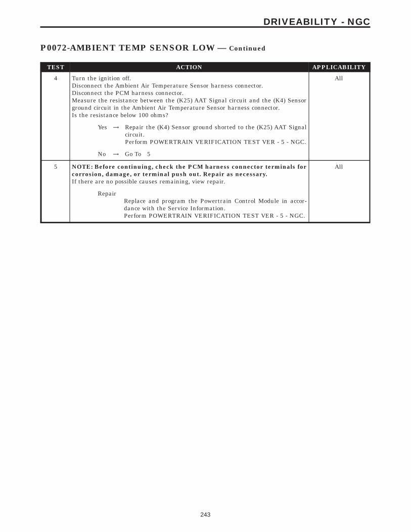
TEST ACTION APPLICABILITY
4 Turn the ignition off.Disconnect the Ambient Air Temperature Sensor harness connector.Disconnect the PCM harness connector.Measure the resistance between the (K25) AAT Signal circuit and the (K4) Sensorground circuit in the Ambient Air Temperature Sensor harness connector.Is the resistance below 100 ohms?
All
Yes → Repair the (K4) Sensor ground shorted to the (K25) AAT Signalcircuit.Perform POWERTRAIN VERIFICATION TEST VER - 5 - NGC.
No → Go To 5
5 NOTE: Before continuing, check the PCM harness connector terminals forcorrosion, damage, or terminal push out. Repair as necessary.If there are no possible causes remaining, view repair.
All
RepairReplace and program the Powertrain Control Module in accor-dance with the Service Information.Perform POWERTRAIN VERIFICATION TEST VER - 5 - NGC.
243
DRIVEABILITY - NGC
P0072-AMBIENT TEMP SENSOR LOW — Continued

Symptom:P0073-AMBIENT TEMP SENSOR HIGH
When Monitored and Set Condition:
P0073-AMBIENT TEMP SENSOR HIGH
When Monitored: The ignition key on.
Set Condition: The Ambient Temperature Sensor voltage is greater than 4.94 volts. OneTrip Fault.
POSSIBLE CAUSES
AMBIENT AIR TEMPERATURE SENSOR VOLTAGE ABOVE 4.8 VOLTS
(K25) AAT SIGNAL CIRCUIT SHORTED TO BATTERY VOLTAGE
AMBIENT AIR TEMPERATURE SENSOR INTERNAL FAILURE
(K25) AAT SIGNAL CIRCUIT OPEN
(K4) SENSOR GROUND CIRCUIT OPEN
PCM
TEST ACTION APPLICABILITY
1 Ignition on, engine not running.With the DRBIIIt, read the Ambient Air Temperature Sensor voltage.Is the voltage above 4.8 volts?
All
Yes → Go To 2
No → Refer to the INTERMITTENT CONDITION symptom in theDriveability category.Perform POWERTRAIN VERIFICATION TEST VER - 5 - NGC.
2 Turn the ignition off.Disconnect the Ambient Air Temperature Sensor harness connector.Ignition on, engine not running.Measure the voltage of the (K25) AAT Signal circuit in the Ambient Air TemperatureSensor harness connector.Is the voltage above 5.2 volts?
All
Yes → Repair the short to battery voltage in the (K25) AAT Signalcircuit.Perform POWERTRAIN VERIFICATION TEST VER - 5 - NGC.
No → Go To 3
244
DRIVEABILITY - NGC

TEST ACTION APPLICABILITY
3 Turn the ignition off.Disconnect the Ambient Air Temperature Sensor harness connector.Connect a jumper wire between the (K145) AAT Signal circuit and the (K167) Sensorground circuit in the Ambient Air Temperature Sensor harness connector.Ignition on, engine not running.With the DRBIIIt, read Ambient Air Temperature Sensor voltage.Is the voltage below 1.0 volt?
All
Yes → Replace the Ambient Air Temperature Sensor.Perform POWERTRAIN VERIFICATION TEST VER - 5 - NGC.
No → Go To 4
4 Turn the ignition off.Disconnect the Ambient Air Temperature Sensor harness connector.Disconnect the PCM harness connector.CAUTION: DO NOT PROBE THE PCM HARNESS CONNECTORS. PROBINGTHE PCM HARNESS CONNECTORS WILL DAMAGE THE PCM TERMI-NALS RESULTING IN POOR TERMINAL TO PIN CONNECTION. INSTALLMILLER SPECIAL TOOL #8815 TO PERFORM DIAGNOSIS.Measure the resistance of the (K25) AAT Signal circuit from the Ambient AirTemperature Sensor harness connector to the appropriate terminal of special tool#8815.Is the resistance below 5.0 ohms?
All
Yes → Go To 5
No → Repair the open in the (K25) AAT Signal circuit.Perform POWERTRAIN VERIFICATION TEST VER - 5 - NGC.
5 Turn the ignition off.Disconnect the Ambient Air Temperature Sensor harness connector.Disconnect the PCM harness connector.CAUTION: DO NOT PROBE THE PCM HARNESS CONNECTORS. PROBINGTHE PCM HARNESS CONNECTORS WILL DAMAGE THE PCM TERMI-NALS RESULTING IN POOR TERMINAL TO PIN CONNECTION. INSTALLMILLER SPECIAL TOOL #8815 TO PERFORM DIAGNOSIS.Measure the resistance of the (K4) Sensor ground circuit from the Ambient AirTemperature Sensor harness connector to the appropriate terminal of special tool#8815.Is the resistance below 5.0 ohms?
All
Yes → Go To 6
No → Repair the open in the (K4) Sensor ground circuit.Perform POWERTRAIN VERIFICATION TEST VER - 5 - NGC.
6 NOTE: Before continuing, check the PCM harness connector terminals forcorrosion, damage, or terminal push out. Repair as necessary.If there are no possible causes remaining, view repair.
All
RepairReplace and program the Powertrain Control Module in accor-dance with the Service Information.Perform POWERTRAIN VERIFICATION TEST VER - 5 - NGC.
245
DRIVEABILITY - NGC
P0073-AMBIENT TEMP SENSOR HIGH — Continued

Symptom:P0106-MAP SENSOR PERFORMANCE
When Monitored and Set Condition:
P0106-MAP SENSOR PERFORMANCE
When Monitored: With engine greater than 64 RPM and the throttle blade at closedthrottle.
Set Condition: Too small of a difference is seen between barometric pressure with ignitionon (engine running) and manifold vacuum for 2.80 seconds.
POSSIBLE CAUSES
GOOD TRIP EQUAL TO ZERO
(K6) 5 VOLT SUPPLY CIRCUIT SHORTED TO GROUND
(K6) 5 VOLT SUPPLY CIRCUIT OPEN
MAP SENSOR INTERNAL FAILURE
(K1) MAP SIGNAL CIRCUIT SHORTED TO GROUND
(K1) MAP SIGNAL CIRCUIT SHORTED TO (K4) SENSOR GROUND CIRCUIT
MAP (K6) 5 VOLT SUPPLY CIRCUIT OPEN
MAP SENSOR VACUUM PORT
MAP SENSOR
PCM (K6) 5 VOLT SUPPLY CIRCUIT
PCM (K1) MAP SENSOR SIGNAL
TEST ACTION APPLICABILITY
1 NOTE: If a MAP high or Low DTC set along with P0106, diagnose the Highor Low DTC first before continuing.Ignition on, engine not running.With the DRBIIIt, read DTCs and record the related Freeze Frame data.Is the Good Trip Counter displayed and equal to zero?
All
Yes → Go To 2
No → Refer to the INTERMITTENT CONDITION symptom in theDriveability category.Perform POWERTRAIN VERIFICATION TEST VER - 5 - NGC.
2 Ignition on, engine not running.With the DRBIIIt, read the MAP Sensor voltage.Is the voltage below 3.19 volts?
All
Yes → Go To 3
No → Go To 11
246
DRIVEABILITY - NGC

TEST ACTION APPLICABILITY
3 Turn the ignition off.Disconnect the MAP Sensor harness connector.Ignition on, engine not running.Measure the voltage of the (K6) 5 Volt Supply circuit in the MAP Sensor harnessconnector.Is the voltage between 4.5 to 5.2 volts?
All
Yes → Go To 4
No → Go To 8
4 Turn the ignition off.Disconnect the MAP Sensor harness connector.With the DRBIIIt, monitor the MAP Sensor voltage.Ignition on, engine not running.Is the voltage between 4.75 and 5.2 volts?
All
Yes → Inspect the MAP sensor and the intake for any restrictions, repairas necessary. If OK, replace the MAP Sensor.Perform POWERTRAIN VERIFICATION TEST VER - 5 - NGC.
No → Go To 5
5 Turn the ignition off.Disconnect the MAP Sensor harness connector.Disconnect the PCM harness connector.Measure the resistance between ground and the (K1) MAP Signal circuit at the MAPSensor harness connector.Is the resistance below 100 ohms?
All
Yes → Repair the short to ground in the (K1) MAP Signal circuit.Perform POWERTRAIN VERIFICATION TEST VER - 5 - NGC.
No → Go To 6
6 Turn the ignition off.Disconnect the MAP Sensor harness connector.Disconnect the PCM harness connector.Measure the resistance between the (K1) MAP Signal circuit and the (K4) Sensorground circuit in the MAP Sensor harness connector.Is the resistance below 100 ohms?
All
Yes → Repair the (K4) Sensor ground shorted to the (K1) MAP Signalcircuit.Perform POWERTRAIN VERIFICATION TEST VER - 5 - NGC.
No → Go To 7
7 NOTE: Before continuing, check the PCM harness connector terminals forcorrosion, damage, or terminal push out. Repair as necessary.If there are no possible causes remaining, view repair.
All
RepairReplace and program the Powertrain Control Module in accor-dance with the Service Information.Perform POWERTRAIN VERIFICATION TEST VER - 5 - NGC.
247
DRIVEABILITY - NGC
P0106-MAP SENSOR PERFORMANCE — Continued

TEST ACTION APPLICABILITY
8 Turn the ignition off.Disconnect the MAP Sensor harness connector.Disconnect the PCM harness connector.Measure the resistance between ground and the (K6) 5 Volt Supply circuit in theMAP Sensor harness connector.Is the resistance below 100 ohms?
All
Yes → Repair the short to ground in the (K6) 5 Volt Supply circuit.Perform POWERTRAIN VERIFICATION TEST VER - 5 - NGC.
No → Go To 9
9 Turn the ignition off.Disconnect the MAP Sensor harness connector.Disconnect the PCM harness connector.CAUTION: DO NOT PROBE THE PCM HARNESS CONNECTORS. PROBINGTHE PCM HARNESS CONNECTORS WILL DAMAGE THE PCM TERMI-NALS RESULTING IN POOR TERMINAL TO PIN CONNECTION. INSTALLMILLER SPECIAL TOOL #8815 TO PERFORM DIAGNOSIS.Measure the resistance of the (K6) 5 Volt Supply circuit from the MAP Sensorharness connector to the appropriate terminal of special tool #8815.Is the resistance below 5.0 ohms?
All
Yes → Go To 10
No → Repair the open in the (K6) 5 Volt Supply circuit.Perform POWERTRAIN VERIFICATION TEST VER - 5 - NGC.
10 NOTE: Before continuing, check the PCM harness connector terminals forcorrosion, damage, or terminal push out. Repair as necessary.If there are no possible causes remaining, view repair.
All
RepairReplace and program the Powertrain Control Module in accor-dance with the Service Information.Perform POWERTRAIN VERIFICATION TEST VER - 5 - NGC.
11 Turn the ignition off.Disconnect the MAP Sensor harness connector.Disconnect the PCM harness connector.CAUTION: DO NOT PROBE THE PCM HARNESS CONNECTORS. PROBINGTHE PCM HARNESS CONNECTORS WILL DAMAGE THE PCM TERMI-NALS RESULTING IN POOR TERMINAL TO PIN CONNECTION. INSTALLMILLER SPECIAL TOOL #8815 TO PERFORM DIAGNOSIS.Measure the resistance of the (K6) 5 Volt Supply circuit from the MAP Sensorharness connector to the appropriate terminal of special tool #8815.Is the resistance below 5.0 ohms?
All
Yes → Go To 12
No → Repair the open in the (K6) 5 Volt Supply circuit.Perform POWERTRAIN VERIFICATION TEST VER - 5 - NGC.
12 Turn the ignition off.Remove the MAP Sensor.Inspect the vacuum port, check for restrictions or any foreign materials.Were any restrictions found?
All
Yes → Repair as necessary.Perform POWERTRAIN VERIFICATION TEST VER - 5 - NGC.
No → Go To 13
248
DRIVEABILITY - NGC
P0106-MAP SENSOR PERFORMANCE — Continued

TEST ACTION APPLICABILITY
13 If there are no possible causes remaining, view repair. All
RepairReplace the MAP Sensor.Perform POWERTRAIN VERIFICATION TEST VER - 5 - NGC.
249
DRIVEABILITY - NGC
P0106-MAP SENSOR PERFORMANCE — Continued
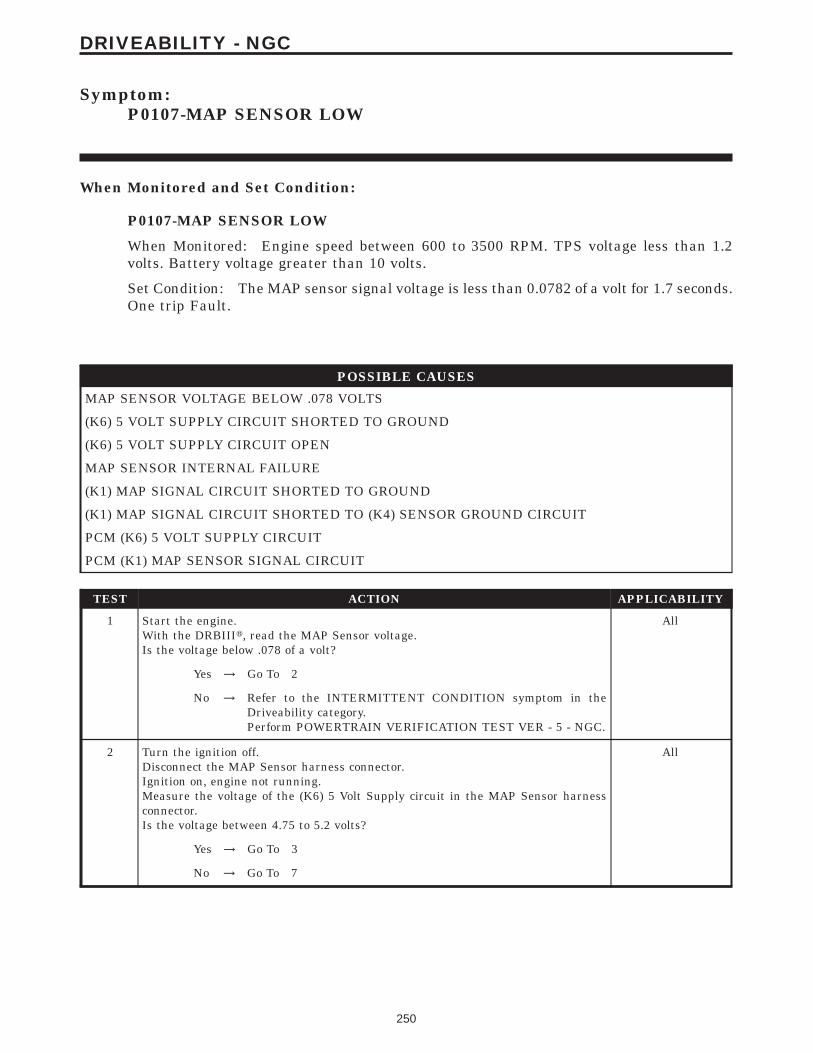
Symptom:P0107-MAP SENSOR LOW
When Monitored and Set Condition:
P0107-MAP SENSOR LOW
When Monitored: Engine speed between 600 to 3500 RPM. TPS voltage less than 1.2volts. Battery voltage greater than 10 volts.
Set Condition: The MAP sensor signal voltage is less than 0.0782 of a volt for 1.7 seconds.One trip Fault.
POSSIBLE CAUSES
MAP SENSOR VOLTAGE BELOW .078 VOLTS
(K6) 5 VOLT SUPPLY CIRCUIT SHORTED TO GROUND
(K6) 5 VOLT SUPPLY CIRCUIT OPEN
MAP SENSOR INTERNAL FAILURE
(K1) MAP SIGNAL CIRCUIT SHORTED TO GROUND
(K1) MAP SIGNAL CIRCUIT SHORTED TO (K4) SENSOR GROUND CIRCUIT
PCM (K6) 5 VOLT SUPPLY CIRCUIT
PCM (K1) MAP SENSOR SIGNAL CIRCUIT
TEST ACTION APPLICABILITY
1 Start the engine.With the DRBIIIt, read the MAP Sensor voltage.Is the voltage below .078 of a volt?
All
Yes → Go To 2
No → Refer to the INTERMITTENT CONDITION symptom in theDriveability category.Perform POWERTRAIN VERIFICATION TEST VER - 5 - NGC.
2 Turn the ignition off.Disconnect the MAP Sensor harness connector.Ignition on, engine not running.Measure the voltage of the (K6) 5 Volt Supply circuit in the MAP Sensor harnessconnector.Is the voltage between 4.75 to 5.2 volts?
All
Yes → Go To 3
No → Go To 7
250
DRIVEABILITY - NGC

TEST ACTION APPLICABILITY
3 Turn the ignition off.Disconnect the MAP Sensor harness connector.Ignition on, engine not running.With the DRBIIIt, monitor the MAP Sensor voltage.Is the voltage above 1.2 volts?
All
Yes → Replace the MAP Sensor.Perform POWERTRAIN VERIFICATION TEST VER - 5 - NGC.
No → Go To 4
4 Turn the ignition off.Disconnect the MAP Sensor harness connector.Disconnect the PCM harness connector.Measure the resistance between ground and the (K1) MAP Signal circuit at the MAPSensor harness connector.Is the resistance below 100 ohms?
All
Yes → Repair the short to ground in the (K1) MAP Signal circuit.Perform POWERTRAIN VERIFICATION TEST VER - 5 - NGC.
No → Go To 5
5 Turn the ignition off.Disconnect the MAP Sensor harness connector.Disconnect the PCM harness connector.Measure the resistance between the (K1) MAP Signal circuit and the (K4) Sensorground circuit in the MAP Sensor harness connector.Is the resistance below 100 ohms?
All
Yes → Repair the (K4) Sensor ground shorted to the (K1) MAP Signalcircuit.Perform POWERTRAIN VERIFICATION TEST VER - 5 - NGC.
No → Go To 6
6 NOTE: Before continuing, check the PCM harness connector terminals forcorrosion, damage, or terminal push out. Repair as necessary.If there are no possible causes remaining, view repair.
All
RepairReplace and program the Powertrain Control Module in accor-dance with the Service Information.Perform POWERTRAIN VERIFICATION TEST VER - 5 - NGC.
7 Turn the ignition off.Disconnect the MAP Sensor harness connector.Disconnect the PCM harness connector.Measure the resistance of the (K6) 5 Volt Supply circuit in the MAP Sensor harnessconnector to ground.Is the resistance below 100 ohms?
All
Yes → Repair the short to ground in the (K6) 5 Volt Supply circuit.Perform POWERTRAIN VERIFICATION TEST VER - 5 - NGC.
No → Go To 8
251
DRIVEABILITY - NGC
P0107-MAP SENSOR LOW — Continued

TEST ACTION APPLICABILITY
8 Turn the ignition off.Disconnect the MAP Sensor harness connector.Disconnect the PCM harness connector.CAUTION: DO NOT PROBE THE PCM HARNESS CONNECTORS. PROBINGTHE PCM HARNESS CONNECTORS WILL DAMAGE THE PCM TERMI-NALS RESULTING IN POOR TERMINAL TO PIN CONNECTION. INSTALLMILLER SPECIAL TOOL #8815 TO PERFORM DIAGNOSIS.Measure the resistance of the (K6) 5 Volt Supply circuit from the MAP Sensorharness connector to the appropriate terminal of special tool #8815.Is the resistance below 5.0 ohms?
All
Yes → Go To 9
No → Repair the open in the (K6) 5 Volt Supply circuit.Perform POWERTRAIN VERIFICATION TEST VER - 5 - NGC.
9 NOTE: Before continuing, check the PCM harness connector terminals forcorrosion, damage, or terminal push out. Repair as necessary.If there are no possible causes remaining, view repair.
All
RepairReplace and program the Powertrain Control Module in accor-dance with the Service Information.Perform POWERTRAIN VERIFICATION TEST VER - 5 - NGC.
252
DRIVEABILITY - NGC
P0107-MAP SENSOR LOW — Continued

Symptom:P0108-MAP SENSOR HIGH
When Monitored and Set Condition:
P0108-MAP SENSOR HIGH
When Monitored: Engine speed between 600 to 3500 RPM. TP sensor voltage less than1.2 volts for greater than 1.7 seconds. Battery voltage greater than 10 volts
Set Condition: The MAP sensor signal voltage is greater than 4.92 volts. One trip Fault.
POSSIBLE CAUSES
MAP SENSOR VOLTAGE ABOVE 4.9 VOLTS
(K1) MAP SIGNAL CIRCUIT SHORTED TO (K6) 5 VOLT SUPPLY CIRCUIT
(K1) MAP SIGNAL CIRCUIT SHORTED TO BATTERY VOLTAGE
MAP SENSOR INTERNAL FAILURE
(K1) MAP SIGNAL CIRCUIT OPEN
(K4) SENSOR GROUND CIRCUIT OPEN
PCM
TEST ACTION APPLICABILITY
1 Start the engine.With the DRBIIIt, read the MAP Sensor voltage.Is the voltage above 4.9 volts?
All
Yes → Go To 2
No → Refer to the INTERMITTENT CONDITION symptom in theDriveability category.Perform POWERTRAIN VERIFICATION TEST VER - 5 - NGC.
2 Turn the ignition off.Disconnect the MAP Sensor harness connector.Disconnect the PCM harness connector.Measure the resistance between the (K1) MAP Signal circuit and the (K6) 5 VoltSupply circuit in the MAP Sensor harness connector.Is the resistance below 100 ohms?
All
Yes → Repair the (K1) MAP Signal circuit for a short to the (K6) 5 VoltSupply circuit.Perform POWERTRAIN VERIFICATION TEST VER - 5 - NGC.
No → Go To 3
253
DRIVEABILITY - NGC

TEST ACTION APPLICABILITY
3 Turn the ignition off.Disconnect the MAP Sensor harness connector.Ignition on, engine not running.Measure the voltage of the (K1) MAP Signal circuit in the MAP Sensor harnessconnector.Is the voltage above 5.2 volts?
All
Yes → Repair the short to battery voltage in the (K1) MAP Signal circuit.Perform POWERTRAIN VERIFICATION TEST VER - 5 - NGC.
No → Go To 4
4 Turn the ignition off.Disconnect the MAP Sensor harness connector.Connect a jumper wire between the (K1) MAP Sensor Signal circuit and the (K4)Sensor ground circuit.With the DRBIIIt, monitor the MAP Sensor voltage.Ignition on, engine not running.Is the voltage below 1.0 volt?
All
Yes → Replace the MAP Sensor.Perform POWERTRAIN VERIFICATION TEST VER - 5 - NGC.
No → Go To 5
5 Turn the ignition off.Disconnect the MAP Sensor harness connector.Disconnect the PCM harness connector.CAUTION: DO NOT PROBE THE PCM HARNESS CONNECTORS. PROBINGTHE PCM HARNESS CONNECTORS WILL DAMAGE THE PCM TERMI-NALS RESULTING IN POOR TERMINAL TO PIN CONNECTION. INSTALLMILLER SPECIAL TOOL #8815 TO PERFORM DIAGNOSIS.Measure the resistance of the (K1) MAP Signal circuit from the MAP Sensor harnessconnector to the appropriate terminal of special tool #8815.Is the resistance below 5.0 ohms?
All
Yes → Go To 6
No → Repair the open in the (K1) MAP Signal circuit.Perform POWERTRAIN VERIFICATION TEST VER - 5 - NGC.
6 Turn the ignition off.Disconnect the MAP Sensor harness connector.Disconnect the PCM harness connector.CAUTION: DO NOT PROBE THE PCM HARNESS CONNECTORS. PROBINGTHE PCM HARNESS CONNECTORS WILL DAMAGE THE PCM TERMI-NALS RESULTING IN POOR TERMINAL TO PIN CONNECTION. INSTALLMILLER SPECIAL TOOL #8815 TO PERFORM DIAGNOSIS.Measure the resistance of the (K4) Sensor ground circuit from the MAP Sensorharness connector to the appropriate terminal of special tool #8815.Is the resistance below 5.0 ohms?
All
Yes → Go To 7
No → Repair the open in the (K4) Sensor ground circuit.Perform POWERTRAIN VERIFICATION TEST VER - 5 - NGC.
254
DRIVEABILITY - NGC
P0108-MAP SENSOR HIGH — Continued

TEST ACTION APPLICABILITY
7 NOTE: Before continuing, check the PCM harness connector terminals forcorrosion, damage, or terminal push out. Repair as necessary.If there are no possible causes remaining, view repair.
All
RepairReplace and program the Powertrain Control Module in accor-dance with the Service Information.Perform POWERTRAIN VERIFICATION TEST VER - 5 - NGC.
255
DRIVEABILITY - NGC
P0108-MAP SENSOR HIGH — Continued

Symptom List:P0110-INTAKE AIR TEMPERATURE SENSOR STUCKP0111-INTAKE AIR TEMPERATURE SENSOR PERFORMANCE
Test Note: All symptoms listed above are diagnosed using the same tests.The title for the tests will be P0110-INTAKE AIR TEMPERA-TURE SENSOR STUCK.
When Monitored and Set Condition:
P0110-INTAKE AIR TEMPERATURE SENSOR STUCK
When Monitored: Engine Running.
Set Condition: After 4 warm-up cycles, the PCM did not see a 2°C (18°F) change in theIAT Sensor voltage within 200 miles . Two Trip Fault
P0111-INTAKE AIR TEMPERATURE SENSOR PERFORMANCE
When Monitored: Engine off time is greater than 480 minutes. Ambient temperature isgreater than 4°C (39°F).
Set Condition: After a calibrated amount of cool down time, the PCM compares the ECTSensor, IAT Sensor and the Ambient Air Temperature Sensor values. If the IAT Sensorvalue is not within 2°C (18°F) of the other two temperature sensors an error is detected.Two Trip Fault.
POSSIBLE CAUSES
GOOD TRIP EQUAL TO ZERO
(K21) IAT SIGNAL CIRCUIT SHORTED TO BATTERY VOLTAGE
IAT SENSOR VOLTAGE BELOW 1.0 VOLTS
(K21) IAT SIGNAL CIRCUIT OPEN
(K4) SENSOR GROUND CIRCUIT OPEN
(K21) IAT SIGNAL SHORTED TO GROUND
(K21) IAT SIGNAL CIRCUIT SHORTED TO (K4) SENSOR GROUND
PCM HIGH
PCM LOW
256
DRIVEABILITY - NGC

TEST ACTION APPLICABILITY
1 Ignition on, engine not running.With the DRBIIIt, read DTCs and record the related Freeze Frame data.Is the Good Trip Counter displayed and equal to zero?
All
Yes → Go To 2
No → Refer to the INTERMITTENT CONDITION symptom in theDriveability category.Perform POWERTRAIN VERIFICATION TEST VER - 5 - NGC.
2 Turn the ignition off.Disconnect the IAT Sensor harness connector.NOTE: Visually inspect both the component and the PCM connectors. Lookfor damaged, partially broken wires, and backed out or corroded terminals.Ignition on, engine not running.Measure the voltage on the (K21) IAT Signal circuit in the IAT Sensor harnessconnector.Is the voltage above 5.2 volts?
All
Yes → Repair the short to battery voltage in the (K21) IAT Signal circuit.Perform POWERTRAIN VERIFICATION TEST VER - 5 - NGC.
No → Go To 3
3 Turn the ignition off.Disconnect the IAT Sensor harness connector.Ignition on, engine not running.With the DRBIIIt, read the IAT Sensor voltage.Is the voltage above 4.9 volts?
All
Yes → Go To 4
No → Go To 7
4 Turn the ignition off.Disconnect the IAT Sensor harness connector.Using a jumper wire, jumper across the IAT Sensor harness connector.Ignition on, engine not running.With the DRBIIIt, read the IAT Sensor voltage.Is the voltage below 1.0 volt?
All
Yes → Replace the IAT Sensor.Perform POWERTRAIN VERIFICATION TEST VER - 5 - NGC.
No → Go To 5
5 Turn the ignition off.Disconnect the IAT Sensor harness connector.Disconnect the PCM harness connector.CAUTION: DO NOT PROBE THE PCM HARNESS CONNECTORS. PROBINGTHE PCM HARNESS CONNECTORS WILL DAMAGE THE PCM TERMI-NALS RESULTING IN POOR TERMINAL TO PIN CONNECTION. INSTALLMILLER SPECIAL TOOL #8815 TO PERFORM DIAGNOSIS.Measure the resistance of the (K21) IAT Signal circuit from the IAT Sensor harnessconnector to the appropriate terminal of special tool #8815.Is the resistance below 5.0 ohms?
All
Yes → Go To 6
No → Repair the open in the (K21) IAT Signal circuit.Perform POWERTRAIN VERIFICATION TEST VER - 5 - NGC.
257
DRIVEABILITY - NGC
P0110-INTAKE AIR TEMPERATURE SENSOR STUCK — Continued

TEST ACTION APPLICABILITY
6 Turn the ignition off.Disconnect the IAT Sensor harness connector.Disconnect the PCM harness connector.CAUTION: DO NOT PROBE THE PCM HARNESS CONNECTORS. PROBINGTHE PCM HARNESS CONNECTORS WILL DAMAGE THE PCM TERMI-NALS RESULTING IN POOR TERMINAL TO PIN CONNECTION. INSTALLMILLER SPECIAL TOOL #8815 TO PERFORM DIAGNOSIS.Measure the resistance of the (K4) Sensor ground circuit from the IAT Sensorharness connector to the appropriate terminal of special tool #8815.Is the resistance below 5.0 ohms?
All
Yes → NOTE: Before continuing, check the PCM harness connectorterminals for corrosion, damage, or terminal push out. Repair asnecessary. Replace and program the Powertrain Control Modulein accordance with the Service Information.Perform POWERTRAIN VERIFICATION TEST VER - 5 - NGC.
No → Repair the open in the (K4) Sensor ground circuit.Perform POWERTRAIN VERIFICATION TEST VER - 5 - NGC.
7 Turn the ignition off.Disconnect the IAT Sensor harness connector.Disconnect the PCM harness connector.Measure the resistance between ground and the (K21) IAT Signal circuit in the IATSensor harness connector.Is the resistance below 100 ohms?
All
Yes → Repair the short to ground in the (K21) IAT Signal circuit.Perform POWERTRAIN VERIFICATION TEST VER - 5 - NGC.
No → Go To 8
8 Turn the ignition off.Disconnect the IAT Sensor harness connector.Disconnect the PCM harness connector.Measure the resistance between the (K4) Sensor ground circuit and the (K21) IATSensor Signal circuit at the IAT Sensor harness connector.Is the resistance below 5.0 ohms?
All
Yes → Repair the (K4) Sensor ground circuit shorted to the (K21) IATSignal circuit.Perform POWERTRAIN VERIFICATION TEST VER - 5 - NGC.
No → NOTE: Before continuing, check the PCM harness connectorterminals for corrosion, damage, or terminal push out. Repair asnecessary. Replace and program the Powertrain Control Modulein accordance with the Service Information.Perform POWERTRAIN VERIFICATION TEST VER - 5 - NGC.
258
DRIVEABILITY - NGC
P0110-INTAKE AIR TEMPERATURE SENSOR STUCK — Continued

Symptom:P0112-INTAKE AIR TEMPERATURE SENSOR LOW
When Monitored and Set Condition:
P0112-INTAKE AIR TEMPERATURE SENSOR LOW
When Monitored: With the ignition on. Battery voltage greater than 10 volts.
Set Condition: The Intake Air Temperature (IAT) sensor voltage is less than 0.0784 of avolt. One trip Fault.
POSSIBLE CAUSES
IAT SENSOR VOLTAGE BELOW 1.0 VOLT
IAT SENSOR INTERNAL FAILURE
(K21) IAT SIGNAL SHORTED TO GROUND
(K21) IAT SIGNAL SHORTED TO (K4) SENSOR GROUND CIRCUIT
PCM
TEST ACTION APPLICABILITY
1 Ignition on, engine not running.With the DRBIIIt, read the IAT Sensor voltage.Is the voltage below 1.0 volt?
All
Yes → Go To 2
No → Refer to the INTERMITTENT CONDITION symptom in theDriveability category.Perform POWERTRAIN VERIFICATION TEST VER - 5 - NGC.
2 Turn the ignition off.Disconnect the IAT harness connector.Ignition on, engine not running.With the DRBIIIt, read IAT Sensor voltage.Is the voltage above 1.0 volt?
All
Yes → Replace the IAT Sensor.Perform POWERTRAIN VERIFICATION TEST VER - 5 - NGC.
No → Go To 3
3 Turn the ignition off.Disconnect the IAT Sensor harness connector.Disconnect the PCM harness connector.Measure the resistance between ground and the (K21) IAT Signal circuit at the IATSensor harness connector.Is the resistance below 100 ohms?
All
Yes → Repair the short to ground in the (K21) IAT Signal circuit.Perform POWERTRAIN VERIFICATION TEST VER - 5 - NGC.
No → Go To 4
259
DRIVEABILITY - NGC

TEST ACTION APPLICABILITY
4 Turn the ignition off.Disconnect the IAT Sensor harness connector.Disconnect the PCM harness connector.Measure the resistance between the (K21) IAT Sensor Signal circuit and the (K4)Sensor ground circuit in the IAT Sensor harness connector.Is the resistance below 100 ohms?
All
Yes → Repair the (K4) Sensor ground shorted to the (K21) IAT Signalcircuit.Perform POWERTRAIN VERIFICATION TEST VER - 5 - NGC.
No → Go To 5
5 NOTE: Before continuing, check the PCM harness connector terminals forcorrosion, damage, or terminal push out. Repair as necessary.If there are no possible causes remaining, view repair.
All
RepairReplace and program the Powertrain Control Module in accor-dance with the Service Information.Perform POWERTRAIN VERIFICATION TEST VER - 5 - NGC.
260
DRIVEABILITY - NGC
P0112-INTAKE AIR TEMPERATURE SENSOR LOW — Continued

Symptom:P0113-INTAKE AIR TEMPERATURE SENSOR HIGH
When Monitored and Set Condition:
P0113-INTAKE AIR TEMPERATURE SENSOR HIGH
When Monitored: With the ignition on. Battery voltage greater than 10 volts.
Set Condition: The Intake Air Temperature (IAT) sensor voltage at the PCM is greaterthan 4.98 volts. One trip Fault.
POSSIBLE CAUSES
IAT SENSOR VOLTAGE ABOVE 4.6 VOLTS
(K21) IAT SIGNAL CIRCUIT SHORTED TO BATTERY VOLTAGE
IAT SENSOR INTERNAL FAILURE
(K21) IAT SIGNAL CIRCUIT OPEN
(K4) SENSOR GROUND CIRCUIT OPEN
PCM
TEST ACTION APPLICABILITY
1 Ignition on, engine not running.With the DRBIIIt, read the IAT Sensor voltage.Is the voltage above 4.6 volts?
All
Yes → Go To 2
No → Refer to the INTERMITTENT CONDITION symptom in theDriveability category.Perform POWERTRAIN VERIFICATION TEST VER - 5 - NGC.
2 Turn the ignition off.Disconnect the IAT Sensor harness connector.Ignition on, engine not running.Measure the voltage of the (K21) IAT Signal circuit in the IAT Sensor harnessconnector.Is the voltage above 5.2 volts?
All
Yes → Repair the short to battery voltage in the (K21) IAT Signal circuit.Perform POWERTRAIN VERIFICATION TEST VER - 5 - NGC.
No → Go To 3
261
DRIVEABILITY - NGC

TEST ACTION APPLICABILITY
3 Turn the ignition off.Disconnect the IAT harness connector.Connect a jumper wire between the (K21) IAT Signal circuit and the (K4) Sensorground circuit in the IAT harness connector.Ignition on, engine not running.With the DRBIIIt, read IAT voltage.Is the voltage below 1.0 volt?
All
Yes → Replace the IAT Sensor.Perform POWERTRAIN VERIFICATION TEST VER - 5 - NGC.
No → Go To 4
4 Turn the ignition off.Disconnect the IAT Sensor harness connector.Disconnect the PCM harness connector.CAUTION: DO NOT PROBE THE PCM HARNESS CONNECTORS. PROBINGTHE PCM HARNESS CONNECTORS WILL DAMAGE THE PCM TERMI-NALS RESULTING IN POOR TERMINAL TO PIN CONNECTION. INSTALLMILLER SPECIAL TOOL #8815 TO PERFORM DIAGNOSIS.Measure the resistance of the (K21) IAT Signal circuit from the IAT Sensor harnessconnector to the appropriate terminal of special tool #8815.Is the resistance below 5.0 ohms?
All
Yes → Go To 5
No → Repair the open in the (K21) IAT Signal circuit.Perform POWERTRAIN VERIFICATION TEST VER - 5 - NGC.
5 Turn the ignition off.Disconnect the IAT Sensor harness connector.Disconnect the PCM harness connector.CAUTION: DO NOT PROBE THE PCM HARNESS CONNECTORS. PROBINGTHE PCM HARNESS CONNECTORS WILL DAMAGE THE PCM TERMI-NALS RESULTING IN POOR TERMINAL TO PIN CONNECTION. INSTALLMILLER SPECIAL TOOL #8815 TO PERFORM DIAGNOSIS.Measure the resistance of the (K4) Sensor ground circuit from the IAT Sensorharness connector to the appropriate terminal of special tool #8815.Is the resistance below 5.0 ohms?
All
Yes → Go To 6
No → Repair the open in the (K4) Sensor ground circuit.Perform POWERTRAIN VERIFICATION TEST VER - 5 - NGC.
6 NOTE: Before continuing, check the PCM harness connector terminals forcorrosion, damage, or terminal push out. Repair as necessary.If there are no possible causes remaining, view repair.
All
RepairReplace and program the Powertrain Control Module in accor-dance with the Service Information.Perform POWERTRAIN VERIFICATION TEST VER - 5 - NGC.
262
DRIVEABILITY - NGC
P0113-INTAKE AIR TEMPERATURE SENSOR HIGH — Continued

Symptom:P0116-ENGINE COOLANT TEMPERATURE PERFORMANCE
When Monitored and Set Condition:
P0116-ENGINE COOLANT TEMPERATURE PERFORMANCE
When Monitored: Engine off time is greater than 480 minutes. Ambient temperature isgreater than 4°C (39°F).
Set Condition: After a calibrated amount of cool down time, the PCM compares the ECTSensor, IAT Sensor and the Ambient Air Temperature Sensor values. If the ECT Sensorvalue is not within 2°C (18°F) of the other two temperartue sensors an error is detected.Two Trip Fault.
POSSIBLE CAUSES
GOOD TRIP EQUAL TO ZERO
(K2) ECT SIGNAL CIRCUIT SHORTED TO BATTERY VOLTAGE
ECT SENSOR VOLTAGE BELOW 1.0 VOLT
(K2) ECT SIGNAL CIRCUIT OPEN
(K4) SENSOR GROUND CIRCUIT OPEN
(K2) ECT SIGNAL CIRCUIT SHORTED TO GROUND
(K2) ECT SIGNAL SHORTED TO (K4) SENSOR GROUND
PCM HIGH
PCM LOW
TEST ACTION APPLICABILITY
1 NOTE: Due to the fact that the PCM compares the IAT, AAT and ECT sensorto see if they are within a calibrated temp of one another, the use of a blockheater can cause false readings for the PCM. Check with the customer to seeif they use a block heater.Ignition on, engine not running.With the DRBIIIt, read DTCs and record the related Freeze Frame data.Is the Good Trip Counter displayed and equal to zero?
All
Yes → Go To 2
No → Refer to the INTERMITTENT CONDITION symptom in theDriveability category.Perform POWERTRAIN VERIFICATION TEST VER - 5 - NGC.
263
DRIVEABILITY - NGC

TEST ACTION APPLICABILITY
2 Turn the ignition off.Disconnect the ECT Sensor harness connector.NOTE: Visually inspect both the component and the PCM connectors. Lookfor damaged, partially broken wires, and backed out or corroded terminals.Ignition on, engine not running.Measure the voltage on the (K2) ECT Signal circuit in the ECT Sensor harnessconnector.Is the voltage above 5.2 volts?
All
Yes → Repair the short to battery voltage in the (K2) ECT Signal circuit.Perform POWERTRAIN VERIFICATION TEST VER - 5 - NGC.
No → Go To 3
3 Turn the ignition off.Disconnect the ECT Sensor harness connector.Ignition on, engine not running.With the DRBIIIt, read the ECT Sensor voltage.Is the voltage above 4.6 volts?
All
Yes → Go To 4
No → Go To 7
4 Turn the ignition off.Disconnect the ECT Sensor harness connector.Using a jumper wire, jumper across the ECT Sensor harness connector.Ignition on, engine not running.With the DRBIIIt, read the ECT Sensor voltage.Is the voltage below 1.0 volt?
All
Yes → Replace the ECT Sensor.Perform POWERTRAIN VERIFICATION TEST VER - 5 - NGC.
No → Go To 5
5 Turn the ignition off.Disconnect the ECT Sensor harness connector.Disconnect the PCM harness connector.CAUTION: DO NOT PROBE THE PCM HARNESS CONNECTORS. PROBINGTHE PCM HARNESS CONNECTORS WILL DAMAGE THE PCM TERMI-NALS RESULTING IN POOR TERMINAL TO PIN CONNECTION. INSTALLMILLER SPECIAL TOOL #8815 TO PERFORM DIAGNOSIS.Measure the resistance of the (K2) ECT Signal circuit from the ECT Sensor harnessconnector to the appropriate terminal of special tool #8815.Is the resistance below 5.0 ohms?
All
Yes → Go To 6
No → Repair the open in the (K2) ECT Signal circuit.Perform POWERTRAIN VERIFICATION TEST VER - 5 - NGC.
264
DRIVEABILITY - NGC
P0116-ENGINE COOLANT TEMPERATURE PERFORMANCE — Continued

TEST ACTION APPLICABILITY
6 Turn the ignition off.Disconnect the ECT harness connector.Disconnect the PCM harness connector.CAUTION: DO NOT PROBE THE PCM HARNESS CONNECTORS. PROBINGTHE PCM HARNESS CONNECTORS WILL DAMAGE THE PCM TERMI-NALS RESULTING IN POOR TERMINAL TO PIN CONNECTION. INSTALLMILLER SPECIAL TOOL #8815 TO PERFORM DIAGNOSIS.Measure the resistance of the (K4) Sensor ground circuit from the ECT Sensorharness connector to the appropriate terminal of special tool # 8815.Is the resistance below 5.0 ohms?
All
Yes → NOTE: Before continuing, check the PCM harness connectorterminals for corrosion, damage, or terminal push out. Repair asnecessary. Replace and program the Powertrain Control Modulein accordance with the Service Information.Perform POWERTRAIN VERIFICATION TEST VER - 5 - NGC.
No → Repair the open in the (K4) Sensor ground circuit.Perform POWERTRAIN VERIFICATION TEST VER - 5 - NGC.
7 Disconnect the ECT Sensor harness connector.Turn the ignition off.Disconnect the PCM harness connector.Measure the resistance between ground and the (K2) ECT Signal circuit in the ECTSensor harness connector.Is the resistance below 100 ohms?
All
Yes → Repair the short to ground in the (K2) ECT Signal circuit.Perform POWERTRAIN VERIFICATION TEST VER - 5 - NGC.
No → Go To 8
8 Turn the ignition off.Disconnect the ECT Sensor harness connector.Disconnect the PCM harness connector.Measure the resistance between the (K2) ECT Sensor Signal circuit and the (K4)Sensor ground circuit at the ECT Sensor harness connector.Is the resistance below 5.0 ohms?
All
Yes → Repair the (K4) Sensor ground shorted to the (K2) ECT SensorSignal circuit.Perform POWERTRAIN VERIFICATION TEST VER - 5 - NGC.
No → NOTE: Before continuing, check the PCM harness connectorterminals for corrosion, damage, or terminal push out. Repair asnecessary. Replace and program the Powertrain Control Modulein accordance with the Service Information.Perform POWERTRAIN VERIFICATION TEST VER - 5 - NGC.
265
DRIVEABILITY - NGC
P0116-ENGINE COOLANT TEMPERATURE PERFORMANCE — Continued

Symptom:P0117-ENGINE COOLANT TEMPERATURE SENSOR LOW
When Monitored and Set Condition:
P0117-ENGINE COOLANT TEMPERATURE SENSOR LOW
When Monitored: With the ignition on. Battery voltage greater than 10 volts.
Set Condition: The Engine Coolant Temperature (ECT) sensor circuit voltage at the PCMis less than 0.0782 of a volt. One Trip Fault.
POSSIBLE CAUSES
ECT SENSOR VOLTAGE BELOW 1.0 VOLTS
ECT SENSOR INTERNAL FAILURE
(K2) ECT SIGNAL SHORTED TO GROUND
(K2) ECT SIGNAL SHORTED TO (K4) SENSOR GROUND CIRCUIT
PCM
TEST ACTION APPLICABILITY
1 Ignition on, engine not running.With the DRBIIIt, read the ECT Sensor voltage.Is the voltage below 1.0 volt?
All
Yes → Go To 2
No → Refer to the INTERMITTENT CONDITION symptom in theDriveability category.Perform POWERTRAIN VERIFICATION TEST VER - 5 - NGC.
2 Turn the ignition off.Disconnect the ECT harness connector.Ignition on, engine not running.With the DRBIIIt, read ECT Sensor voltage.Is the voltage between 4.8 and 5.2 volts?
All
Yes → Replace the ECT Sensor.Perform POWERTRAIN VERIFICATION TEST VER - 5 - NGC.
No → Go To 3
3 Turn the ignition off.Disconnect the ECT Sensor harness connector.Disconnect the PCM harness connector.Measure the resistance between ground and the (K2) ECT Signal circuit in the ECTSensor harness connector.Is the resistance below 100 ohms?
All
Yes → Repair the ground shorted to the (K2) ECT Signal circuit.Perform POWERTRAIN VERIFICATION TEST VER - 5 - NGC.
No → Go To 4
266
DRIVEABILITY - NGC

TEST ACTION APPLICABILITY
4 Turn the ignition off.Disconnect the ECT Sensor harness connector.Disconnect the PCM harness connector.Measure the resistance between the (K2) ECT Sensor Signal circuit and the (K4)Sensor ground circuit in the ECT Sensor harness connector.Is the resistance below 100 ohms?
All
Yes → Repair the (K4) Sensor ground shorted to the (K2) ECT SensorSignal circuit.Perform POWERTRAIN VERIFICATION TEST VER - 5 - NGC.
No → Go To 5
5 NOTE: Before continuing, check the PCM harness connector terminals forcorrosion, damage, or terminal push out. Repair as necessary.If there are no possible causes remaining, view repair.
All
RepairReplace and program the Powertrain Control Module in accor-dance with the Service Information.Perform POWERTRAIN VERIFICATION TEST VER - 5 - NGC.
267
DRIVEABILITY - NGC
P0117-ENGINE COOLANT TEMPERATURE SENSOR LOW — Continued

Symptom:P0118-ENGINE COOLANT TEMPERATURE SENSOR HIGH
When Monitored and Set Condition:
P0118-ENGINE COOLANT TEMPERATURE SENSOR HIGH
When Monitored: With the ignition on. Battery voltage greater than 10 volts.
Set Condition: The Engine Coolant Temperature (ECT) sensor voltage at the PCM isgreater than 4.98 volts. One trip Fault.
POSSIBLE CAUSES
ECT SENSOR VOLTAGE ABOVE 4.9 VOLTS
(K2) ECT SIGNAL CIRCUIT SHORTED TO BATTERY VOLTAGE
ECT SENSOR INTERNAL FAILURE
(K2) ECT SIGNAL CIRCUIT OPEN
(K4) SENSOR GROUND CIRCUIT OPEN
PCM
TEST ACTION APPLICABILITY
1 Ignition on, engine not running.With the DRBIIIt, read the ECT Sensor voltage.Is the voltage above 4.9 volts?
All
Yes → Go To 2
No → Refer to the INTERMITTENT CONDITION symptom in theDriveability category.Perform POWERTRAIN VERIFICATION TEST VER - 5 - NGC.
2 Turn the ignition off.Disconnect the ECT Sensor harness connector.Ignition on, engine not running.Measure the voltage of the (K2) ECT Signal circuit in the ECT Sensor harnessconnector.Is the voltage above 5.2 volts?
All
Yes → Repair the short to battery voltage in the (K2) ECT Signal circuit.Perform POWERTRAIN VERIFICATION TEST VER - 5 - NGC.
No → Go To 3
268
DRIVEABILITY - NGC

TEST ACTION APPLICABILITY
3 Turn the ignition off.Disconnect the ECT harness connector.Connect a jumper wire between the (K2) ECT Signal circuit and the (K4) Sensorground circuit in the ECT harness connector.Ignition on, engine not running.With the DRBIIIt, read ECT Sensor voltage.Is the voltage below 1.0 volt?
All
Yes → Replace the ECT Sensor.Perform POWERTRAIN VERIFICATION TEST VER - 5 - NGC.
No → Go To 4
4 Turn the ignition off.Disconnect the ECT Sensor harness connector.Disconnect the PCM harness connector.CAUTION: DO NOT PROBE THE PCM HARNESS CONNECTORS. PROBINGTHE PCM HARNESS CONNECTORS WILL DAMAGE THE PCM TERMI-NALS RESULTING IN POOR TERMINAL TO PIN CONNECTION. INSTALLMILLER SPECIAL TOOL #8815 TO PERFORM DIAGNOSIS.Measure the resistance of the (K2) ECT Signal circuit from the ECT Sensor harnessconnector to the appropriate terminal of special tool #8815.Is the resistance below 5.0 ohms?
All
Yes → Go To 5
No → Repair the open in the (K2) ECT Signal circuit.Perform POWERTRAIN VERIFICATION TEST VER - 5 - NGC.
5 Turn the ignition off.Disconnect the ECT Sensor harness connector.Disconnect the PCM harness connector.CAUTION: DO NOT PROBE THE PCM HARNESS CONNECTORS. PROBINGTHE PCM HARNESS CONNECTORS WILL DAMAGE THE PCM TERMI-NALS RESULTING IN POOR TERMINAL TO PIN CONNECTION. INSTALLMILLER SPECIAL TOOL #8815 TO PERFORM DIAGNOSIS.Measure the resistance of the (K4) Sensor ground circuit from the ECT Sensorharness connector to the appropriate terminal of special tool #8815.Is the resistance below 5.0 ohms?
All
Yes → Go To 6
No → Repair the open in the (K4) Sensor ground circuit.Perform POWERTRAIN VERIFICATION TEST VER - 5 - NGC.
6 NOTE: Before continuing, check the PCM harness connector terminals forcorrosion, damage, or terminal push out. Repair as necessary.If there are no possible causes remaining, view repair.
All
RepairReplace and program the Powertrain Control Module in accor-dance with the Service Information.Perform POWERTRAIN VERIFICATION TEST VER - 5 - NGC.
269
DRIVEABILITY - NGC
P0118-ENGINE COOLANT TEMPERATURE SENSOR HIGH — Continued

Symptom:P0121-THROTTLE POSITION SENSOR #1 PERFORMANCE
When Monitored and Set Condition:
P0121-THROTTLE POSITION SENSOR #1 PERFORMANCE
When Monitored: With the engine running and no MAP Sensor or TP Sensor DTC’s set.
Set Condition: The PCM determines a valid range in which the TP Sensor should be, ata given RPM/Load. The actual TP Sensor voltage is then compared to this value. If the TPSensor voltage does not fall within the expected range within a predetermined time anerror will be detected. One Trip Fault.
POSSIBLE CAUSES
GOOD TRIP EQUAL TO ZERO
HIGH RESISTANCE IN MAP (K6) 5 VOLT SUPPLY CIRCUIT
RESISTANCE TO GROUND IN MAP (K6) 5 VOLT SUPPLY CIRCUIT
MAP SENSOR
HIGH RESISTANCE IN (K1) MAP SIGNAL CIRCUIT
RESISTANCE TO GROUND IN (K1) MAP SIGNAL CIRCUIT
HIGH RESISTANCE IN (K4) MAP GROUND CIRCUIT
PCM
TP SENSOR OPERATION
HIGH RESISTANCE IN TP SENSOR (K6) 5 VOLT SUPPLY CIRCUIT
RESISTANCE TO GROUND IN TP SENSOR (K6) 5 VOLT SUPPLY CIRCUIT
TP SENSOR
HIGH RESISTANCE IN (K22) TP SIGNAL CIRCUIT
RESISTANCE TO GROUND IN (K22) TP SENSOR SIGNAL CIRCUIT
HIGH RESISTANCE IN TP (K4) SENSOR GROUND CIRCUIT
PCM
270
DRIVEABILITY - NGC

TEST ACTION APPLICABILITY
1 NOTE: Diagnose any TP Sensor or MAP Sensor component DTCs beforecontinuing.NOTE: The throttle plate and linkage must be free from binding and carbonbuild up.NOTE: Ensure the throttle plate is at the idle position.Ignition on, engine not running.With the DRBIIIt, read DTCs and record the related Freeze Frame data.Is the Good Trip Counter displayed and equal to zero?
All
Yes → Go To 2
No → Refer to the INTERMITTENT CONDITION symptom in theDriveability category.Perform POWERTRAIN VERIFICATION TEST VER - 5 - NGC.
2 Start the engine.With the DRBIIIt, monitor the MAP Sensor voltage.Snap the throttle.Does the MAP Sensor voltage vary from below 2.0 volts at idle to above 3.5 volts atWOT?
All
Yes → Go To 3
No → Go To 11
3 Ignition on, engine not running.With the DRBIIIt, monitor the TP Sensor voltage while slowly depressing thethrottle pedal from the idle position to the wide open throttle position.Does the voltage start approximately at 0.8 volts and go above 3.5 volts with a smoothtransition?
All
Yes → Refer to the INTERMITTENT CONDITION symptom in theDriveability category.Perform POWERTRAIN VERIFICATION TEST VER - 5 - NGC.
No → Go To 4
4 Turn the ignition off.Disconnect the TP Sensor harness connector.Disconnect the PCM harness connector.CAUTION: DO NOT PROBE THE PCM HARNESS CONNECTORS. PROBINGTHE PCM HARNESS CONNECTORS WILL DAMAGE THE PCM TERMI-NALS RESULTING IN POOR TERMINAL TO PIN CONNECTION. INSTALLMILLER SPECIAL TOOL #8815 TO PERFORM DIAGNOSIS.Measure the resistance of the (K6) 5 Volt Supply circuit from the TP Sensor harnessconnector to the appropriate terminal of special tool #8815.Is the resistance below 5.0 ohms?
All
Yes → Go To 5
No → Repair the TP Sensor (K6) 5 Volt Supply circuit.Perform POWERTRAIN VERIFICATION TEST VER - 5 - NGC.
271
DRIVEABILITY - NGC
P0121-THROTTLE POSITION SENSOR #1 PERFORMANCE — Continued

TEST ACTION APPLICABILITY
5 Turn the ignition off.Disconnect the TP Sensor harness connector.Disconnect the PCM harness connector.Measure the resistance between ground and the (K6) 5 Volt Supply circuit at the TPSensor harness connector.Is the resistance above 100k ohms?
All
Yes → Go To 6
No → Repair the (K6) 5 Volt Supply circuit.Perform POWERTRAIN VERIFICATION TEST VER - 5 - NGC.
6 Turn the ignition off.Disconnect the TP Sensor harness connector.With the DRBIIIt, monitor the TP Sensor voltage.Ignition on, engine not running.Connect a jumper wire between the (K22) TP Signal circuit and the (K4) Sensorground circuit .Does the TP Sensor voltage change from approximately 4.9 volts to below 0.5 of avolt?
All
Yes → Replace the Throttle Position Sensor.Perform POWERTRAIN VERIFICATION TEST VER - 5 - NGC.
No → Go To 7
7 Turn the ignition off.Disconnect the TP Sensor harness connector.Disconnect the PCM harness connector.CAUTION: DO NOT PROBE THE PCM HARNESS CONNECTORS. PROBINGTHE PCM HARNESS CONNECTORS WILL DAMAGE THE PCM TERMI-NALS RESULTING IN POOR TERMINAL TO PIN CONNECTION. INSTALLMILLER SPECIAL TOOL #8815 TO PERFORM DIAGNOSIS.Measure the resistance of the (K22) TP Signal circuit from the TP Sensor harnessconnector to the appropriate terminal of special tool #8815.Is the resistance below 5.0 ohms?
All
Yes → Go To 8
No → Repair the (K22) TP Signal circuit.Perform POWERTRAIN VERIFICATION TEST VER - 5 - NGC.
8 Turn the ignition off.Disconnect the TP Sensor harness connector.Disconnect the PCM harness connector.Measure the resistance between ground and the (K22) TP Signal circuit in the TPSensor harness connector.Is the resistance above 100k ohms?
All
Yes → Go To 9
No → Repair the (K22) TP Sensor Signal circuit.Perform POWERTRAIN VERIFICATION TEST VER - 5 - NGC.
272
DRIVEABILITY - NGC
P0121-THROTTLE POSITION SENSOR #1 PERFORMANCE — Continued

TEST ACTION APPLICABILITY
9 Turn the ignition off.Disconnect the TP Sensor harness connector.Disconnect the PCM harness connector.CAUTION: DO NOT PROBE THE PCM HARNESS CONNECTORS. PROBINGTHE PCM HARNESS CONNECTORS WILL DAMAGE THE PCM TERMI-NALS RESULTING IN POOR TERMINAL TO PIN CONNECTION. INSTALLMILLER SPECIAL TOOL #8815 TO PERFORM DIAGNOSIS.Measure the resistance of the (K4) Sensor ground circuit from the TP Sensor harnessconnector to the appropriate terminal of special tool #8815.Is the resistance below 5.0 ohms?
All
Yes → Go To 10
No → Repair the (K4) Sensor Ground circuit.Perform POWERTRAIN VERIFICATION TEST VER - 5 - NGC.
10 NOTE: Before continuing, check the PCM harness connector terminals forcorrosion, damage, or terminal push out. Repair as necessary.If there are no possible causes remaining, view repair.
All
RepairReplace and program the Powertrain Control Module in accor-dance with the Service Information.Perform POWERTRAIN VERIFICATION TEST VER - 5 - NGC.
11 Turn the ignition off.Disconnect the MAP Sensor harness connector.Disconnect the PCM harness connector.CAUTION: DO NOT PROBE THE PCM HARNESS CONNECTORS. PROBINGTHE PCM HARNESS CONNECTORS WILL DAMAGE THE PCM TERMI-NALS RESULTING IN POOR TERMINAL TO PIN CONNECTION. INSTALLMILLER SPECIAL TOOL #8815 TO PERFORM DIAGNOSIS.Measure the resistance of the (K6) 5 Volt Supply circuit from the MAP Sensorharness connector to the appropriate terminal of special tool #8815.Is the resistance below 5.0 ohms?
All
Yes → Go To 12
No → Repair the MAP (K6) 5 Volt Supply circuit.Perform POWERTRAIN VERIFICATION TEST VER - 5 - NGC.
12 Turn the ignition off.Disconnect the MAP Sensor harness connector.Disconnect the PCM harness connector.Measure the resistance between ground and the (K6) 5 Volt Supply circuit at theMAP Sensor harness connector.Is the resistance above 100k ohms?
All
Yes → Go To 13
No → Repair the short to ground in the (K6) 5 Volt Supply circuit.Perform POWERTRAIN VERIFICATION TEST VER - 5 - NGC.
273
DRIVEABILITY - NGC
P0121-THROTTLE POSITION SENSOR #1 PERFORMANCE — Continued

TEST ACTION APPLICABILITY
13 Turn the ignition off.Disconnect the MAP Sensor harness connector.With the DRBIIIt, monitor the MAP Sensor voltage.Ignition on, engine not running.Connect a jumper wire between the (K1) MAP Sensor Signal circuit and the (K4)Sensor ground circuit .Cycle the ignition switch from off to on.With the DRBIIIt, monitor the MAP Sensor voltage.Does the DRBIIIt display MAP voltage from approximately 4.9 volts to below 0.5volt?
All
Yes → Replace the MAP Sensor.Perform POWERTRAIN VERIFICATION TEST VER - 5 - NGC.
No → Go To 14
14 Turn the ignition off.Disconnect the MAP Sensor harness connector.Disconnect the PCM harness connector.CAUTION: DO NOT PROBE THE PCM HARNESS CONNECTORS. PROBINGTHE PCM HARNESS CONNECTORS WILL DAMAGE THE PCM TERMI-NALS RESULTING IN POOR TERMINAL TO PIN CONNECTION. INSTALLMILLER SPECIAL TOOL #8815 TO PERFORM DIAGNOSIS.Measure the resistance of the (K1) MAP Signal circuit from the MAP Sensor harnessconnector to the appropriate terminal of special tool #8815.Is the resistance below 5.0 ohms?
All
Yes → Go To 15
No → Repair the (K1) MAP Signal circuit.Perform POWERTRAIN VERIFICATION TEST VER - 5 - NGC.
15 Turn the ignition off.Disconnect the MAP Sensor harness connector.Disconnect the PCM harness connector.Measure the resistance between ground and the (K1) MAP Signal circuit at the MAPSensor harness connector.Is the resistance above 100k ohms?
All
Yes → Go To 16
No → Repair the (K1) MAP Signal circuit.Perform POWERTRAIN VERIFICATION TEST VER - 5 - NGC.
16 Turn the ignition off.Disconnect the MAP Sensor harness connector.Disconnect the PCM harness connector.CAUTION: DO NOT PROBE THE PCM HARNESS CONNECTORS. PROBINGTHE PCM HARNESS CONNECTORS WILL DAMAGE THE PCM TERMI-NALS RESULTING IN POOR TERMINAL TO PIN CONNECTION. INSTALLMILLER SPECIAL TOOL #8815 TO PERFORM DIAGNOSIS.Measure the resistance of the (K4) Sensor ground circuit from the MAP Sensorharness connector to the appropriate terminal of special tool #8815.Is the resistance below 5.0 ohms?
All
Yes → Go To 17
No → Repair the (K4) Sensor Ground circuit.Perform POWERTRAIN VERIFICATION TEST VER - 5 - NGC.
274
DRIVEABILITY - NGC
P0121-THROTTLE POSITION SENSOR #1 PERFORMANCE — Continued

TEST ACTION APPLICABILITY
17 NOTE: Before continuing, check the PCM harness connector terminals forcorrosion, damage, or terminal push out. Repair as necessary.If there are no possible causes remaining, view repair.
All
RepairReplace and program the Powertrain Control Module in accor-dance with the Service Information.Perform POWERTRAIN VERIFICATION TEST VER - 5 - NGC.
275
DRIVEABILITY - NGC
P0121-THROTTLE POSITION SENSOR #1 PERFORMANCE — Continued

Symptom:P0122-THROTTLE POSITION SENSOR #1 LOW
When Monitored and Set Condition:
P0122-THROTTLE POSITION SENSOR #1 LOW
When Monitored: With the ignition on. Battery voltage greater than 10 volts.
Set Condition: Throttle Position Sensor voltage at the PCM is less than 0.0978 of a volt.One Trip Fault.
POSSIBLE CAUSES
THROTTLE POSITION SENSOR SWEEP
INTERMITTENT CONDITION
(K6) 5 VOLT SUPPLY CIRCUIT SHORTED TO GROUND
(K6) 5 VOLT SUPPLY CIRCUIT OPEN
TP SENSOR INTERNAL FAILURE
(K22) TP SIGNAL CIRCUIT SHORTED TO GROUND
(K22) TP SIGNAL CIRCUIT SHORTED TO (K4) SENSOR GROUND CIRCUIT
PCM (K6) 5 VOLT SUPPLY CIRCUIT
PCM (K22) TP SENSOR SIGNAL
TEST ACTION APPLICABILITY
1 Ignition on, engine not running.With the DRBIIIt, read the Throttle Position Sensor voltage.Is the voltage below 0.2 of a volt?
All
Yes → Go To 2
No → Go To 10
2 Turn the ignition off.Disconnect the TP Sensor harness connector.Ignition on, engine not running.Measure the voltage of the (K6) 5 Volt Supply circuit in the TP Sensor harnessconnector.Is the voltage between 4.5 to 5.2 volts?
All
Yes → Go To 3
No → Go To 7
276
DRIVEABILITY - NGC

TEST ACTION APPLICABILITY
3 Turn the ignition off.Disconnect the TP Sensor harness connector.With the DRBIIIt, monitor the TP Sensor voltage.Ignition on, engine not running.Is the voltage above 4.5 volts?
All
Yes → Replace the Throttle Position Sensor.Perform POWERTRAIN VERIFICATION TEST VER - 5 - NGC.
No → Go To 4
4 Turn the ignition off.Disconnect the TP harness connector.Disconnect the PCM harness connector.Measure the resistance between ground and the (K22) TP Signal circuit at the TPSensor harness connector.Is the resistance below 100 ohms?
All
Yes → Repair the short to ground in the (K22) TP Signal circuit.Perform POWERTRAIN VERIFICATION TEST VER - 5 - NGC.
No → Go To 5
5 Turn the ignition off.Disconnect the TP Sensor harness connector.Disconnect the PCM harness connector.Measure the resistance between the (K22) TPS Signal circuit and the (K4) Sensorground circuit in the TPS harness connector.Is the resistance below 100 ohms?
All
Yes → Repair the short to (K4) Sensor ground in the (K22) TP Signalcircuit.Perform POWERTRAIN VERIFICATION TEST VER - 5 - NGC.
No → Go To 6
6 NOTE: Before continuing, check the PCM harness connector terminals forcorrosion, damage, or terminal push out. Repair as necessary.If there are no possible causes remaining, view repair.
All
RepairReplace and program the Powertrain Control Module in accor-dance with the Service Information.Perform POWERTRAIN VERIFICATION TEST VER - 5 - NGC.
7 Turn the ignition off.Disconnect the TP Sensor harness connector.Disconnect the PCM harness connector.Measure the resistance between ground and the (K6) 5 Volt Supply circuit in the TPSensor harness connector.Is the resistance below 100 ohms?
All
Yes → Repair the short to ground in the (K6) 5 Volt Supply circuit.Perform POWERTRAIN VERIFICATION TEST VER - 5 - NGC.
No → Go To 8
277
DRIVEABILITY - NGC
P0122-THROTTLE POSITION SENSOR #1 LOW — Continued

TEST ACTION APPLICABILITY
8 Turn the ignition off.Disconnect the TP Sensor harness connector.Disconnect the PCM harness connector.CAUTION: DO NOT PROBE THE PCM HARNESS CONNECTORS. PROBINGTHE PCM HARNESS CONNECTORS WILL DAMAGE THE PCM TERMI-NALS RESULTING IN POOR TERMINAL TO PIN CONNECTION. INSTALLMILLER SPECIAL TOOL #8815 TO PERFORM DIAGNOSIS.Measure the resistance of the (K6) 5 Volt Supply circuit from the TP Sensor harnessconnector to the appropriate terminal of special tool #8815.Is the resistance below 5.0 ohms?
All
Yes → Go To 9
No → Repair the open in the (K6) 5 Volt Supply circuit.Perform POWERTRAIN VERIFICATION TEST VER - 5 - NGC.
9 NOTE: Before continuing, check the PCM harness connector terminals forcorrosion, damage, or terminal push out. Repair as necessary.If there are no possible causes remaining, view repair.
All
RepairReplace and program the Powertrain Control Module in accor-dance with the Service Information.Perform POWERTRAIN VERIFICATION TEST VER - 5 - NGC.
10 Ignition on, engine not running.With the DRBIIIt, monitor the Throttle Position Sensor voltage.Slowly open the throttle from the idle position to the wide open throttle position.Does voltage start at approximately 0.7 of a volt and go above 3.5 volts with a smoothtransition?
All
Yes → Refer to the INTERMITTENT CONDITION symptom in theDriveability category.Perform POWERTRAIN VERIFICATION TEST VER - 5 - NGC.
No → Replace the Throttle Position Sensor.Perform POWERTRAIN VERIFICATION TEST VER - 5 - NGC.
278
DRIVEABILITY - NGC
P0122-THROTTLE POSITION SENSOR #1 LOW — Continued

Symptom:P0123-THROTTLE POSITION SENSOR #1 HIGH
When Monitored and Set Condition:
P0123-THROTTLE POSITION SENSOR #1 HIGH
When Monitored: With the ignition on. Battery voltage greater than 10 volts.
Set Condition: Throttle Position Sensor voltage at the PCM is greater than 4.47 volts.One Trip Fault.
POSSIBLE CAUSES
THROTTLE POSITION SENSOR SWEEP
INTERMITTENT CONDITION
(K22) TP SIGNAL CIRCUIT SHORTED TO (K6) 5 VOLT SUPPLY CIRCUIT
(K22) TP SIGNAL CIRCUIT SHORTED TO BATTERY VOLTAGE
TP SENSOR INTERNAL FAILURE
(K22) TP SIGNAL CIRCUIT OPEN
(K4) SENSOR GROUND CIRCUIT OPEN
PCM
TEST ACTION APPLICABILITY
1 NOTE: Ensure the throttle is fully closed and free from binding or carbonbuild up.Start the engine.With the DRBIIIt, read the TP Sensor voltage.Is the voltage above 4.5 volts?
All
Yes → Go To 2
No → Go To 8
2 Turn the ignition off.Disconnect the TP Sensor harness connector.Disconnect the PCM harness connector.Measure the resistance between the (K22) TP Signal circuit and the (K6) 5 VoltSupply circuit in the TP Sensor harness connector.Is the resistance below 100 ohms?
All
Yes → Repair the short to the (K6) 5 Volt Supply circuit in the (K22) TPSignal circuit.Perform POWERTRAIN VERIFICATION TEST VER - 5 - NGC.
No → Go To 3
279
DRIVEABILITY - NGC

TEST ACTION APPLICABILITY
3 Turn the ignition off.Disconnect the TP Sensor harness connector.Ignition on, engine not running.Measure the voltage of the (K22) TP Signal circuit in the TP Sensor harnessconnector.Is the voltage above 5.2 volts?
All
Yes → Repair the short to battery voltage in the (K22) TP Signal circuit.Perform POWERTRAIN VERIFICATION TEST VER - 5 - NGC.
No → Go To 4
4 Turn the ignition off.Disconnect the TP Sensor harness connector.Connect a jumper wire between the (K22) TP Signal circuit and the (K4) Sensorground circuit.With the DRBIIIt, monitor the TP Sensor voltage.Ignition on, engine not running.Is the voltage below 0.5 of a volt?
All
Yes → Replace the Throttle Position Sensor.Perform POWERTRAIN VERIFICATION TEST VER - 5 - NGC.
No → Go To 5
5 Turn the ignition off.Disconnect the TP harness connector.Disconnect the PCM harness connector.CAUTION: DO NOT PROBE THE PCM HARNESS CONNECTORS. PROBINGTHE PCM HARNESS CONNECTORS WILL DAMAGE THE PCM TERMI-NALS RESULTING IN POOR TERMINAL TO PIN CONNECTION. INSTALLMILLER SPECIAL TOOL #8815 TO PERFORM DIAGNOSIS.Measure the resistance of the (K22) TP Signal circuit from the TP harness connectorto the appropriate terminal of special tool #8815.Is the resistance below 5.0 ohms?
All
Yes → Go To 6
No → Repair the open in the (K22) TP Signal circuit.Perform POWERTRAIN VERIFICATION TEST VER - 5 - NGC.
6 Turn the ignition off.Disconnect the TP Sensor harness connector.Disconnect the PCM harness connector.CAUTION: DO NOT PROBE THE PCM HARNESS CONNECTORS. PROBINGTHE PCM HARNESS CONNECTORS WILL DAMAGE THE PCM TERMI-NALS RESULTING IN POOR TERMINAL TO PIN CONNECTION. INSTALLMILLER SPECIAL TOOL #8815 TO PERFORM DIAGNOSIS.Measure the resistance of the (K4) Sensor ground circuit from the TP Sensor harnessconnector to the appropriate terminal of special tool #8815.Is the resistance below 5.0 ohms?
All
Yes → Go To 7
No → Repair the open in the (K4) Sensor ground circuit.Perform POWERTRAIN VERIFICATION TEST VER - 5 - NGC.
280
DRIVEABILITY - NGC
P0123-THROTTLE POSITION SENSOR #1 HIGH — Continued

TEST ACTION APPLICABILITY
7 NOTE: Before continuing, check the PCM harness connector terminals forcorrosion, damage, or terminal push out. Repair as necessary.If there are no possible causes remaining, view repair.
All
RepairReplace and program the Powertrain Control Module in accor-dance with the Service Information.Perform POWERTRAIN VERIFICATION TEST VER - 5 - NGC.
8 Ignition on, engine not running.With the DRBIIIt, monitor the TP Sensor voltage.Slowly open the throttle from the idle position to the wide open throttle position.Does voltage start at approximately 0.7 of a volt and go above 3.5 volts with a smoothtransition?
All
Yes → Refer to the INTERMITTENT CONDITION symptom in theDriveability category.Perform POWERTRAIN VERIFICATION TEST VER - 5 - NGC.
No → Replace the Throttle Position Sensor.Perform POWERTRAIN VERIFICATION TEST VER - 5 - NGC.
281
DRIVEABILITY - NGC
P0123-THROTTLE POSITION SENSOR #1 HIGH — Continued

Symptom:P0125-INSUFFICIENT COOLANT TEMP FOR CLOSED-LOOP FUELCONTROL
When Monitored and Set Condition:
P0125-INSUFFICIENT COOLANT TEMP FOR CLOSED-LOOP FUEL CONTROL
When Monitored: With battery voltage greater than 10.4 volts, after engine is started.
Set Condition: The engine temperature does not go above 15°C (60°F). Failure timedepends on start-up coolant temperature and ambient temperature. (i.e. 2 minutes for astart temp of 10°C (50°F) or up to 10 minutes for a vehicle with a start-up temp of -28°C(20°F). Two Trip Fault.
POSSIBLE CAUSES
LOW COOLANT LEVEL
THERMOSTAT OPERATION
ENGINE COOLANT TEMPERATURE SENSOR
TEST ACTION APPLICABILITY
1 NOTE: If a Engine Coolant Temperature (ECT) DTC is set along with thiscode, diagnose the ECT DTC first.NOTE: Inspect the ECT terminals and related PCM terminals. Ensure theterminals are free from corrosion and damage.NOTE: The best way to diagnose this DTC is to allow the vehicle to sitovernight outside in order to have a totally cold soaked engine.Note: Extremely cold outside ambient temperatures may have caused thisDTC to set.WARNING: Never open the cooling system when the engine is hot. Thesystem is under pressure. Extreme burns or scalding may result. Allow theengine to cool before opening the cooling system.Check the coolant system to make sure that the coolant is in good condition and atthe proper level.Is the coolant level and condition OK?
All
Yes → Go To 2
No → Inspect the vehicle for a coolant leak and add the necessaryamount of coolant.Perform POWERTRAIN VERIFICATION TEST VER - 5 - NGC.
282
DRIVEABILITY - NGC

TEST ACTION APPLICABILITY
2 NOTE: This test works best if performed on a cold engine (cold soak).Ignition on, engine not running.With the DRBIIIt, read the ECT Deg value. If the engine was allowed to sit overnight(cold soak), the temperature value should be a sensible value that is somewhere closeto the ambient temperature.Note: If engine coolant temperature is above 82°C (180°F), allow the engineto cool until 65°C (150°F) is reached.Start the Engine.During engine warm-up, monitor the ECT Deg value. The temp deg value changeshould be a smooth transition from start up to normal operating temp 82°C (180°F). Also monitor the actual coolant temperature with a thermometer.NOTE: As the engine warms up to operating temperature, the actual coolanttemperature (thermometer reading) and the ECT Deg in the DRB sensorshould stay relatively close to each other.Using the appropriate service information, determine the proper opening tempera-ture of the thermostat.Did the thermostat open at the proper temperature?
All
Yes → Go To 3
No → Replace the thermostat.Perform POWERTRAIN VERIFICATION TEST VER - 5 - NGC.
3 Ignition on, engine not running.With the DRBIIIt, read the ECT Sensor temperature value. If the engine wasallowed to sit overnight (cold soak), the temperature value should be a sensible valuethat is somewhere close to the ambient temperature.Note: If engine coolant temperature is above 82°C (180°F), allow the engineto cool until 65°C (150°F) is reached.Start the Engine.During engine warm-up, monitor the ECT Deg value. The temp deg value changeshould be a smooth transition from start up to normal operating temp 82°C (180°F). Also monitor the actual coolant temperature with a thermometer.NOTE: As the engine warms up to operating temperature, the actual coolanttemperature (thermometer reading) and the ECT Sensor Temperature inthe DRBIIIt sensors should stay relatively close to each other.Is the thermometer reading relatively close to the DRBIIIt ECT Sensor reading?
All
Yes → Test Complete.
No → Replace the Engine Coolant Temperature Sensor.Perform POWERTRAIN VERIFICATION TEST VER - 5 - NGC.
283
DRIVEABILITY - NGC
P0125-INSUFFICIENT COOLANT TEMP FOR CLOSED-LOOP FUEL CON-TROL — Continued

Symptom:P0128-THERMOSTAT RATIONALITY
When Monitored and Set Condition:
P0128-THERMOSTAT RATIONALITY
When Monitored: The engine running.
Set Condition: The PCM predicts a coolant temperature value that it will compare to theactual coolant temperature. If the two coolant temperature values are not within 10°C(50°F) of each other an error is detected. Two Trip Fault.
POSSIBLE CAUSES
GOOD TRIP EQUAL TO ZERO
LOW COOLANT LEVEL
OTHER POSSIBLE CAUSES
SIGNAL CIRCUIT SHORTED TO BATTERY VOLTAGE
THERMOSTAT OPERATION
TEMPERATURE SENSOR VOLTAGE BELOW 1.0 VOLT
SIGNAL CIRCUIT OPEN
SENSOR GROUND CIRCUIT OPEN
SIGNAL CIRCUIT SHORTED TO GROUND
SIGNAL CIRCUIT SHORTED TO SENSOR GROUND
PCM LOW
PCM HIGH
TEST ACTION APPLICABILITY
1 NOTE: If any ECT, AAT, CMP or CKP sensor DTCs have set along with P0128,diagnose them first before continuing.NOTE: Ensure that Pinion Factor has been programmed correctly into thePCM.Ignition on, engine not running.With the DRBIIIt, read DTCs and record the related Freeze Frame data.Is the Good Trip displayed and equal to zero?
All
Yes → Go To 2
No → Refer to the INTERMITTENT CONDITION symptom in theDriveability category.Perform POWERTRAIN VERIFICATION TEST VER - 5 - NGC.
284
DRIVEABILITY - NGC

TEST ACTION APPLICABILITY
2 NOTE: If a Engine Coolant Temperature (ECT) DTC is set along with thiscode, diagnose the ECT DTC first.NOTE: Inspect the ECT terminals and related PCM terminals. Ensure theterminals are free from corrosion and damage.NOTE: The best way to diagnose this DTC is to allow the vehicle to sitovernight outside in order to have a totally cold soaked engine.Note: Extremely cold outside ambient temperatures may have caused thisDTC to set.WARNING: Never open the cooling system when the engine is hot. Thesystem is under pressure. Extreme burns or scalding may result. Allow theengine to cool before opening the cooling system.Check the coolant system to make sure that the coolant is in good condition and atthe proper level.Is the coolant level and condition OK?
All
Yes → Go To 3
No → Inspect the vehicle for a coolant leak and add the necessaryamount of coolant.Perform POWERTRAIN VERIFICATION TEST VER - 5 - NGC.
3 NOTE: This test works best if performed on a cold engine (cold soak).Ignition on, engine not running.With the DRBIIIt, read the ECT Deg value. If the engine was allowed to sit overnight(cold soak), the temperature value should be a sensible value that is somewhere closeto the ambient temperature.Note: If engine coolant temperature is above 82°C (180°F), allow the engineto cool until 65°C (150°F) is reached.Start the Engine.During engine warm-up, monitor the ECT Deg value. The temp deg value changeshould be a smooth transition from start up to normal operating temp 82°C (180°F). Also monitor the actual coolant temperature with a thermometer.NOTE: As the engine warms up to operating temperature, the actual coolanttemperature (thermometer reading) and the ECT Deg in the DRB sensorshould stay relatively close to each other.Using the appropriate service information, determine the proper opening tempera-ture of the thermostat.Did the thermostat open at the proper temperature?
All
Yes → Go To 4
No → Replace the thermostat.Perform POWERTRAIN VERIFICATION TEST VER - 5 - NGC.
4 Turn the ignition on.With the DRBIIIt, read and record the AAT Sensor Temperature valueUsing the DRB Temperature Probe #CH7050, measure the ambient air temperaturenear the AAT sensor.Is the AAT Sensor value with -15°C (5°F) of the temperature probe reading?
All
Yes → Go To 5
No → Go To 7
285
DRIVEABILITY - NGC
P0128-THERMOSTAT RATIONALITY — Continued

TEST ACTION APPLICABILITY
5 WARNING: MAKE SURE THE ENGINE COOLING SYSTEM IS COOL BE-FORE REMOVING THE PRESSURE CAP OR ANY HOSE. SEVERE PER-SONAL INJURY MAY RESULT FROM ESCAPING HOT COOLANT. THECOOLING SYSTEM IS PRESSURIZED WHEN HOT.Turn the ignition on.With the DRBIIIt, read and record the ECT Sensor Temperature valueUsing the DRB Temperature Probe #CH7050, measure the engine coolant tempera-ture.Is the ECT Sensor value with -15°C (5°F) of the temperature probe reading?
All
Yes → Go To 6
No → Go To 7
6 Inspect the Temperature sensors for any physical damage.Inspect the engine coolant. Ensure the coolant is at the proper level. Refer to theService Information COOLING.Ensure the Temperature sensors are properly mounted.Ensure the CMP and CKP sensors are mounted properly. Check the connectors forany signs of damage.WARNING: WHEN THE ENGINE IS OPERATING, DO NOT STAND IN ADIRECT LINE WITH THE FAN. DO NOT PUT YOUR HANDS NEAR THEPULLEYS, BELTS OR FAN. DO NOT WEAR LOOSE CLOTHING.Refer to any Technical Service Bulletins (TSBs) that may apply.With the engine running at normal operating temperature, monitor the Temperaturesensor parameters while wiggling the wire harness. Look for parameter values tochange.Visually inspect the related wire harness. Look for any chafed, pierced, pinched,partially broken wires and broken, bent, pushed out, or corroded terminals.CAUTION: NEVER PROBE THE PCM HARNESS CONNECTORS. PROBINGTHE PCM HARNESS CONNECTORS WILL DAMAGE THE PCM TERMI-NALS RESULTING IN POOR TERMINAL TO PIN CONNECTION. INSTALLMILLER SPECIAL TOOL #8815 TO PERFORM DIAGNOSIS.Inspect and clean all PCM, engine, and chassis grounds.Were any problems found during the above inspections?
All
Yes → Repair as necessaryPerform POWERTRAIN VERIFICATION TEST VER - 5 - NGC.
No → Test Complete.
7 NOTE: Visually inspect both the component and the PCM connectors. Lookfor damage, partially broken wires and backed out or corroded terminalsTurn the ignition off.Disconnect the applicable Temperature Sensor harness connector.Ignition on, engine not running.Measure the voltage of the Signal circuit in the applicable Temperature Sensorharness connector.Is the voltage above 5.2 volts?
All
Yes → Repair the short to battery voltage in the Signal circuit.Perform POWERTRAIN VERIFICATION TEST VER - 5 - NGC.
No → Go To 8
286
DRIVEABILITY - NGC
P0128-THERMOSTAT RATIONALITY — Continued

TEST ACTION APPLICABILITY
8 Turn the ignition off.Disconnect the applicable Temperature Sensor harness connector.Ignition on, engine not running.With the DRBIIIt, read the Temperature Sensor voltage.Is the voltage above 4.6 volts?
All
Yes → Go To 9
No → Go To 12
9 Turn the ignition off.Disconnect the applicable Temperature Sensor harness connector.Using a jumper wire, jumper across the Temperature Sensor harness connector.Ignition on, engine not running.With the DRBIIIt, read the Temperature voltage.Is the voltage below 1.0 volt?
All
Yes → Replace the applicable Temperature Sensor.Perform POWERTRAIN VERIFICATION TEST VER - 5 - NGC.
No → Go To 10
10 Turn the ignition off.Disconnect the applicable Temperature Sensor harness connector.Disconnect the PCM harness connector.CAUTION: DO NOT PROBE THE PCM HARNESS CONNECTORS. PROBINGTHE PCM HARNESS CONNECTORS WILL DAMAGE THE PCM TERMI-NALS RESULTING IN POOR TERMINAL TO PIN CONNECTION. INSTALLMILLER SPECIAL TOOL #8815 TO PERFORM DIAGNOSIS.Measure the resistance of the Signal circuit from the Temperature Sensor harnessconnector to the appropriate terminal of special tool #8815.Is the resistance below 5.0 ohms?
All
Yes → Go To 11
No → Repair the open in the Signal circuit.Perform POWERTRAIN VERIFICATION TEST VER - 5 - NGC.
11 Turn the ignition off.Disconnect the applicable Temperature Sensor harness connector.Disconnect the PCM harness connector.CAUTION: DO NOT PROBE THE PCM HARNESS CONNECTORS. PROBINGTHE PCM HARNESS CONNECTORS WILL DAMAGE THE PCM TERMI-NALS RESULTING IN POOR TERMINAL TO PIN CONNECTION. INSTALLMILLER SPECIAL TOOL #8815 TO PERFORM DIAGNOSIS.Measure the resistance of the Sensor ground circuit from the Ambient Air Temper-ature Sensor harness connector to the appropriate terminal of special tool #8815.Is the resistance below 5.0 ohms?
All
Yes → NOTE: Before continuing, check the PCM harness connectorterminals for corrosion, damage, or terminal push out. Repair asnecessary. Replace and program the Powertrain Contorl Modulein accordance with the Service Information.Perform POWERTRAIN VERIFICATION TEST VER - 5 - NGC.
No → Repair the open in the Sensor ground circuit.Perform POWERTRAIN VERIFICATION TEST VER - 5 - NGC.
287
DRIVEABILITY - NGC
P0128-THERMOSTAT RATIONALITY — Continued

TEST ACTION APPLICABILITY
12 Turn the ignition off.Disconnect the applicable Temperature Sensor harness connector.Disconnect the PCM harness connector.Measure the resistance between ground and the Signal circuit in the Temperatureharness connector.Is the resistance below 100 ohms?
All
Yes → Repair the short to ground in the Signal circuit.Perform POWERTRAIN VERIFICATION TEST VER - 5 - NGC.
No → Go To 13
13 Turn the ignition off.Disconnect the applicable Temperature Sensor harness connector.Disconnect the PCM harness connector.Measure the resistance between the Signal circuit and the Sensor ground circuit inthe Temperature Sensor harness connector.Is the resistance below 100 ohms?
All
Yes → Repair the Sensor ground shorted to the Signal circuit.Perform POWERTRAIN VERIFICATION TEST VER - 5 - NGC.
No → NOTE: Before continuing, check the PCM harness connectorterminals for corrosion, damage or terminal push out. Repair asnecessary. Replace and program the Powertrain Control Modulein accordance with the Service Information.Perform POWERTRAIN VERIFICATION TEST VER - 5 - NGC.
288
DRIVEABILITY - NGC
P0128-THERMOSTAT RATIONALITY — Continued

Symptom:P0129-BAROMETRIC PRESSURE OUT-OF-RANGE LOW
When Monitored and Set Condition:
P0129-BAROMETRIC PRESSURE OUT-OF-RANGE LOW
When Monitored: With the ignition key on. No Cam or Crank signal within 75 ms. Enginespeed at less than 250 RPM.
Set Condition: The PCM senses the voltage from the MAP sensor to be less than 2.196volts but above 0.0392 of a volt for 300 milliseconds.One Trip Fault.
POSSIBLE CAUSES
IAC SIGNAL CIRCUIT LOW
IAC SIGNAL CIRCUIT HIGH
INTERMITTENT CONDITION
(K6) 5 VOLT SUPPLY CIRCUIT SHORTED TO VOLTAGE
(K6) 5 VOLT SUPPLY CIRCUIT SHORTED TO GROUND
(K6) 5 VOLT SUPPLY CIRCUIT OPEN
MAP SENSOR INTERNAL FAILURE
(K1) MAP SIGNAL CIRCUIT OPEN
(K1) MAP SIGNAL CIRCUIT SHORTED TO GROUND
PCM (K6) 5 VOLT SUPPLY CIRCUIT
PCM (K1) MAP SIG CIRCUIT
TEST ACTION APPLICABILITY
1 Ignition on, engine not running.With the DRBIIIt, read the MAP Sensor voltage.Is the voltage below 2.2 volts.
All
Yes → Go To 2
No → Go To 11
2 Turn the ignition off.Disconnect the MAP Sensor harness connector.Ignition on, engine not running.Measure the voltage of the (K6) 5 Volt Supply circuit in the MAP Sensor harnessconnector.Is the voltage between 4.5 to 5.2 volts?
All
Yes → Go To 3
No → Go To 7
289
DRIVEABILITY - NGC

TEST ACTION APPLICABILITY
3 Turn the ignition off.Disconnect the MAP Sensor harness connector.Ignition on, engine not running.With the DRBIIIt, monitor the MAP Sensor voltage.Is the voltage above 2.2 volts?
All
Yes → Replace the MAP Sensor.Perform POWERTRAIN VERIFICATION TEST VER - 5 - NGC.
No → Go To 4
4 Turn the ignition off.Disconnect the MAP Sensor harness connector.Disconnect the PCM harness connector.CAUTION: DO NOT PROBE THE PCM HARNESS CONNECTORS. PROBINGTHE PCM HARNESS CONNECTORS WILL DAMAGE THE PCM TERMI-NALS RESULTING IN POOR TERMINAL TO PIN CONNECTION. INSTALLMILLER SPECIAL TOOL #8815 TO PERFORM DIAGNOSIS.Measure the resistance of the (K1) MAP Signal circuit from the MAP Sensor harnessconnector to the appropriate terminal of special tool #8815.Is the resistance below 5.0 ohms?
All
Yes → Go To 5
No → Repair the open in the (K1) MAP Signal circuit.Perform POWERTRAIN VERIFICATION TEST VER - 5 - NGC.
5 Turn the ignition off.Disconnect the MAP Sensor harness connector.Disconnect the PCM harness connector.Measure the resistance between ground and the (K1) MAP Signal circuit at the MAPSensor harness connector.Is the resistance below 100 ohms?
All
Yes → Repair the short to ground in the (K1) MAP Signal circuit.Perform POWERTRAIN VERIFICATION TEST VER - 5 - NGC.
No → Go To 6
6 NOTE: Before continuing, check the PCM harness connector terminals forcorrosion, damage, or terminal push out. Repair as necessary.If there are no possible causes remaining, view repair.
All
RepairReplace and program the Powertrain Control Module in accor-dance with the Service Information.Perform POWERTRAIN VERIFICATION TEST VER - 5 - NGC.
7 Turn the ignition off.Disconnect the MAP Sensor harness connector.Ignition on, engine not running.Measure the voltage of the (K6) 5 Volt Supply circuit in the MAP Sensor harnessconnector.Is the voltage above 5.2 volts?
All
Yes → Repair the short to battery voltage in the (K6) 5 Volt Supplycircuit.Perform POWERTRAIN VERIFICATION TEST VER - 5 - NGC.
No → Go To 8
290
DRIVEABILITY - NGC
P0129-BAROMETRIC PRESSURE OUT-OF-RANGE LOW — Continued

TEST ACTION APPLICABILITY
8 Turn the ignition off.Disconnect the MAP Sensor harness connector.Disconnect the PCM harness connector.Measure the resistance between ground and the (K6) 5 Volt Supply circuit at theMAP Sensor harness connector.Is the resistance below 100 ohms?
All
Yes → Repair the short to ground in the (K6) 5 Volt Supply circuit.Perform POWERTRAIN VERIFICATION TEST VER - 5 - NGC.
No → Go To 9
9 Turn the ignition off.Disconnect the MAP Sensor harness connector.Disconnect the PCM harness connector.CAUTION: DO NOT PROBE THE PCM HARNESS CONNECTORS. PROBINGTHE PCM HARNESS CONNECTORS WILL DAMAGE THE PCM TERMI-NALS RESULTING IN POOR TERMINAL TO PIN CONNECTION. INSTALLMILLER SPECIAL TOOL #8815 TO PERFORM DIAGNOSIS.Measure the resistance of the 5 Volt Supply circuit from the MAP Sensor harnessconnector to the appropriate terminal of special tool #8815.Is the resistance below 5.0 ohms?
All
Yes → Go To 10
No → Repair the open in the (K6) 5 Volt Supply circuit.Perform POWERTRAIN VERIFICATION TEST VER - 5 - NGC.
10 NOTE: Before continuing, check the PCM harness connector terminals forcorrosion, damage, or terminal push out. Repair as necessary.If there are no possible causes remaining, view repair.
All
RepairReplace and program the Powertrain Control Module in accor-dance with the Service Information.Perform POWERTRAIN VERIFICATION TEST VER - 5 - NGC.
11 Start the engine.NOTE: If the engine will not idle, maintain an engine speed between 800 and1500 RPM.Allow the engine to idle.With the DRBIIIt, read the IAC Current.Is the IAC Current below 146 mA?
All
Yes → Refer to P0508 - IAC Valve Sense LowPerform POWERTRAIN VERIFICATION TEST VER - 5 - NGC.
No → Go To 12
12 Start the engine.NOTE: If the engine will not idle, maintain an engine speed between 800 and1500 RPM.Allow the engine to idle.With the DRBIIIt, read the IAC Current.Is the IAC Current above 999 mA?
All
Yes → Refer to P0509 - IAC Valve Sense Circuit HighPerform POWERTRAIN VERIFICATION TEST VER - 5 - NGC.
No → Refer to the INTERMITTENT CONDITION symptom in theDriveability category.Perform POWERTRAIN VERIFICATION TEST VER - 5 - NGC.
291
DRIVEABILITY - NGC
P0129-BAROMETRIC PRESSURE OUT-OF-RANGE LOW — Continued

Symptom List:P0131-O2 SENSOR 1/1 VOLTAGE LOWP0137-O2 SENSOR 1/2 VOLTAGE LOW
Test Note: All symptoms listed above are diagnosed using the same tests.The title for the tests will be P0131-O2 SENSOR 1/1 VOLTAGELOW.
When Monitored and Set Condition:
P0131-O2 SENSOR 1/1 VOLTAGE LOW
When Monitored: Engine Running for less than 30 seconds. O2 Sensor Heater Temper-ature less than 251°C (484°F) Battery voltage greater than 10.99 volts.
Set Condition: The oxygen sensor signal voltage is below 2.5196 volts for 3 seconds. Onetrip Fault.
P0137-O2 SENSOR 1/2 VOLTAGE LOW
When Monitored: Engine Running for less than 30 seconds. O2 Sensor Heater Temper-ature less than 251°C (484°F) Battery voltage greater than 10.99 volts.
Set Condition: The oxygen sensor signal voltage is below 2.5196 volts for 3 seconds. Onetrip Fault.
POSSIBLE CAUSES
O2 SENSOR BELOW 2.52 VOLTS
O2 SENSOR
O2 RETURN CIRCUIT SHORTED TO GROUND
O2 SIGNAL CIRCUIT SHORTED TO GROUND
O2 SIGNAL CIRCUIT SHORTED TO O2 RETURN CIRCUIT
O2 SIGNAL SHORTED TO HEATER GROUND CIRCUIT
PCM RETURN CIRCUIT
PCM SIGNAL CIRCUIT
292
DRIVEABILITY - NGC

TEST ACTION APPLICABILITY
1 NOTE: If one of the O2 Sensors Signal or Return circuits are shorted toground, the DRBIIIt will display all O2 Sensor voltage readings low. The O2Sensor that is shorted to ground will display a voltage reading near or at 0volts.NOTE: It is important to perform the diagnostics on the O2 Sensor that setthe DTC.NOTE: After the repairs have been made, verify proper O2 Sensor operation.If all the O2 Sensor voltage readings have not returned to normal, follow thediagnostic procedure for the remaining O2 Sensors.Start the engine.Allow the engine to reach normal operating temperature.With the DRBIIIt, read the O2 Sensor voltage.Is the voltage below 2.52 volts?
All
Yes → Go To 2
No → Refer to the INTERMITTENT CONDITION symptom in theDriveability category.Perform POWERTRAIN VERIFICATION TEST VER - 5 - NGC.
2 Turn the ignition off.Disconnect the O2 Sensor harness connector.Ignition on, engine not running.With the DRBIIIt, monitor the O2 Sensor voltage.Is the O2 Sensor voltage above 4.8 volts?
All
Yes → Go To 3
No → Go To 5
3 Turn the ignition off.Disconnect the O2 Sensor harness connector.Ignition on, engine not running.Measure the voltage on the O2 Return circuit in the O2 Sensor harness connector.Is the voltage at 2.5 volts?
All
Yes → Replace the O2 Sensor.Perform POWERTRAIN VERIFICATION TEST VER - 5 - NGC.
No → Go To 4
4 Turn the ignition off.Disconnect the O2 Sensor harness connector.Disconnect the PCM harness connector.Measure the resistance between ground and the O2 Return circuit in the O2 Sensorharness connector.Is the resistance below 100 ohms?
All
Yes → Repair the short to ground in the O2 Return circuit.Perform POWERTRAIN VERIFICATION TEST VER - 5 - NGC.
No → NOTE: Before continuing, check the PCM harness connectorterminals for corrosion, damage, or terminal push out. Repair asnecessary. Replace and program the Powertrain Control Modulein accordance with the Service Information.Perform POWERTRAIN VERIFICATION TEST VER - 5 - NGC.
293
DRIVEABILITY - NGC
P0131-O2 SENSOR 1/1 VOLTAGE LOW — Continued

TEST ACTION APPLICABILITY
5 Turn the ignition off.Disconnect the O2 Sensor harness connector.Disconnect the PCM harness connector.Measure the resistance between ground and the O2 Signal circuit in the O2 Sensorharness connector.Is the resistance below 100 ohms?
All
Yes → Repair the short to ground in the O2 Signal circuit.Perform POWERTRAIN VERIFICATION TEST VER - 5 - NGC.
No → Go To 6
6 Turn the ignition off.Disconnect the O2 Sensor harness connector.Disconnect the PCM harness connector.Measure the resistance between the O2 Signal circuit and the O2 Return circuit inthe O2 Sensor harness connector.Is the resistance below 100 ohms?
All
Yes → Repair the O2 Return circuit shorted to the O2 Signal circuit.Perform POWERTRAIN VERIFICATION TEST VER - 5 - NGC.
No → Go To 7
7 Turn the ignition off.Disconnect the O2 Sensor harness connector.Disconnect the PCM harness connector.Measure the resistance between the O2 Signal circuit and the Heater ground circuitin the O2 Sensor harness connector.Is the resistance below 100 ohms?
All
Yes → Repair the Heater Ground circuit shorted to the O2 Signal circuit.Perform POWERTRAIN VERIFICATION TEST VER - 5 - NGC.
No → Go To 8
8 NOTE: Before continuing, check the PCM harness connector terminals forcorrosion, damage, or terminal push out. Repair as necessary.If there are no possible causes remaining, view repair.
All
RepairReplace and program the Powertrain Control Module in accor-dance with the Service Information.Perform POWERTRAIN VERIFICATION TEST VER - 5 - NGC.
294
DRIVEABILITY - NGC
P0131-O2 SENSOR 1/1 VOLTAGE LOW — Continued

Symptom List:P0132-O2 SENSOR 1/1 VOLTAGE HIGHP0138-O2 SENSOR 1/2 VOLTAGE HIGH
Test Note: All symptoms listed above are diagnosed using the same tests.The title for the tests will be P0132-O2 SENSOR 1/1 VOLTAGEHIGH.
When Monitored and Set Condition:
P0132-O2 SENSOR 1/1 VOLTAGE HIGH
When Monitored: The engine running for 119 seconds. O2 Sensor Heater Temperature isgreater than 496°C (925°F). Battery voltage greater than 10.99 volts.
Set Condition: The Oxygen Sensor voltage is above 3.9902 volts for 30 seconds. One tripfault.
P0138-O2 SENSOR 1/2 VOLTAGE HIGH
When Monitored: The engine running for 119 seconds. O2 Sensor Heater Temperature isgreater than 496°C (925°F). Battery voltage greater than 10.99 volts.
Set Condition: The Oxygen Sensor voltage is above 3.9902 volts for 30 seconds. One tripfault.
POSSIBLE CAUSES
O2 SENSOR ABOVE 3.99 VOLTS
O2 SENSOR
O2 RETURN CIRCUIT OPEN
O2 SIGNAL SHORTED TO VOLTAGE
O2 SIGNAL OPEN
PCM RETURN CIRCUIT
PCM SIGNAL CIRCUIT
295
DRIVEABILITY - NGC
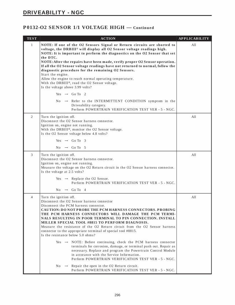
TEST ACTION APPLICABILITY
1 NOTE: If one of the O2 Sensors Signal or Return circuits are shorted tovoltage, the DRBIIIt will display all O2 Sensor voltage readings high.NOTE: It is important to perform the diagnostics on the O2 Sensor that setthe DTC.NOTE: After the repairs have been made, verify proper O2 Sensor operation.If all the O2 Sensor voltage readings have not returned to normal, follow thediagnostic procedure for the remaining O2 Sensors.Start the engine.Allow the engine to reach normal operating temperature.With the DRBIIIt, read the O2 Sensor voltage.Is the voltage above 3.99 volts?
All
Yes → Go To 2
No → Refer to the INTERMITTENT CONDITION symptom in theDriveability category.Perform POWERTRAIN VERIFICATION TEST VER - 5 - NGC.
2 Turn the ignition off.Disconnect the O2 Sensor harness connector.Ignition on, engine not running.With the DRBIIIt, monitor the O2 Sensor voltage.Is the O2 Sensor voltage below 4.8 volts?
All
Yes → Go To 3
No → Go To 5
3 Turn the ignition off.Disconnect the O2 Sensor harness connector.Ignition on, engine not running.Measure the voltage on the O2 Return circuit in the O2 Sensor harness connector.Is the voltage at 2.5 volts?
All
Yes → Replace the O2 Sensor.Perform POWERTRAIN VERIFICATION TEST VER - 5 - NGC.
No → Go To 4
4 Turn the ignition off.Disconnect the O2 Sensor harness connectorDisconnect the PCM harness connector.CAUTION: DO NOT PROBE THE PCM HARNESS CONNECTORS. PROBINGTHE PCM HARNESS CONNECTORS WILL DAMAGE THE PCM TERMI-NALS RESULTING IN POOR TERMINAL TO PIN CONNECTION. INSTALLMILLER SPECIAL TOOL #8815 TO PERFORM DIAGNOSIS.Measure the resistance of the O2 Return circuit from the O2 Sensor harnessconnector to the appropriate terminal of special tool #8815.Is the resistance below 5.0 ohms?
All
Yes → NOTE: Before continuing, check the PCM harness connectorterminals for corrosion, damage, or terminal push out. Repair asnecessary. Replace and program the Powertrain Control Modulein accorance with the Service Information.Perform POWERTRAIN VERIFICATION TEST VER - 5 - NGC.
No → Repair the open in the O2 Return circuit.Perform POWERTRAIN VERIFICATION TEST VER - 5 - NGC.
296
DRIVEABILITY - NGC
P0132-O2 SENSOR 1/1 VOLTAGE HIGH — Continued

TEST ACTION APPLICABILITY
5 Turn the ignition off.Disconnect the O2 Sensor harness connectorWARNING: WHEN THE ENGINE IS OPERATING, DO NOT STAND IN ADIRECT LINE WITH THE FAN. DO NOT PUT YOUR HANDS NEAR THEPULLEYS, BELTS OR FAN. DO NOT WEAR LOOSE CLOTHING.Start the engine and allow the engine to idle.Measure the voltage on the O2 Signal circuit in the O2 Sensor harness connector.Is the voltage above 5.0 volts?
All
Yes → Repair the short to voltage in the O2 Signal circuit.Perform POWERTRAIN VERIFICATION TEST VER - 5 - NGC.
No → Go To 6
6 Turn the ignition off.Disconnect the O2 Sensor harness connectorDisconnect the PCM harness connector.CAUTION: DO NOT PROBE THE PCM HARNESS CONNECTORS. PROBINGTHE PCM HARNESS CONNECTORS WILL DAMAGE THE PCM TERMI-NALS RESULTING IN POOR TERMINAL TO PIN CONNECTION. INSTALLMILLER SPECIAL TOOL #8815 TO PERFORM DIAGNOSIS.Measure the resistance of the O2 Signal circuit from the O2 Sensor harness connectorto the appropriate terminal of special tool #8815.Is the resistance below 5.0 ohms?
All
Yes → Go To 7
No → Repair the open in the O2 Signal circuit.Perform POWERTRAIN VERIFICATION TEST VER - 5 - NGC.
7 NOTE: Before continuing, check the PCM harness connector terminals forcorrosion, damage, or terminal push out. Repair as necessary.If there are no possible causes remaining, view repair.
All
RepairReplace and program the Powertrain Control Module in accor-dance with the Service Information.Perform POWERTRAIN VERIFICATION TEST VER - 5 - NGC.
297
DRIVEABILITY - NGC
P0132-O2 SENSOR 1/1 VOLTAGE HIGH — Continued

Symptom List:P0133-O2 SENSOR 1/1 SLOW RESPONSEP0139-O2 SENSOR 1/2 SLOW RESPONSE
Test Note: All symptoms listed above are diagnosed using the same tests.The title for the tests will be P0133-O2 SENSOR 1/1 SLOWRESPONSE.
When Monitored and Set Condition:
P0133-O2 SENSOR 1/1 SLOW RESPONSE
When Monitored: Start and drive vehicle greater than 20 MPH and less than 55 MPH.Throttle open for a minimum 120 seconds. Coolant Temp greater than 70°C (158°F)Catalytic Converter Temperature greater than 600°C (1112°F) EVAP Purge active.
Set Condition: The O2 sensor voltage switches only 11 times or less from lean to richwithin 20 second during monitoring. Two Trip Fault.
P0139-O2 SENSOR 1/2 SLOW RESPONSE
When Monitored: Start and drive vehicle greater than 20 MPH and less than 55 MPH.Throttle open for a minimum 120 seconds. Coolant Temp greater than 70°C (158°F)Catalytic Converter Temperature greater than 600°C (1112°F)
Set Condition: The O2 sensor voltage switches properly from lean to rich duringmonitoring. Two Trip Fault.
POSSIBLE CAUSES
GOOD TRIP EQUAL TO ZERO
EXHAUST LEAK
O2 SIGNAL CIRCUIT
O2 RETURN CIRCUIT
O2 SENSOR
298
DRIVEABILITY - NGC

TEST ACTION APPLICABILITY
1 NOTE: If one of the O2 Sensors Signal or Return circuits are shorted toground or voltage, all the other O2 Sensor voltage readings will be affected.NOTE: It is important to perform the diagnostics on the O2 Sensor that setthe DTC.NOTE: After the repairs have been made, verify proper O2 Sensor operation.If all the O2 Sensor voltage readings have not returned to normal, follow thediagnostic procedure for the remaining O2 Sensors.NOTE: Check for contaminates that may have damaged the O2 Sensor:contaminated fuel, unapproved silicone, oil and coolant.Ignition on, engine not running.With the DRBIIIt, read DTCs and record the related Freeze Frame data.Is the Good Trip Counter displayed and equal to zero?
All
Yes → Go To 2
No → Refer to the INTERMITTENT CONDITION symptom in theDriveability category.Perform POWERTRAIN VERIFICATION TEST VER - 5 - NGC.
2 Start the engine.Inspect the exhaust system for leaks between the engine and the O2 Sensors.Are there any exhaust leaks?
All
Yes → Repair or replace the leaking exhaust parts as necessary.Perform POWERTRAIN VERIFICATION TEST VER - 5 - NGC.
No → Go To 3
3 Turn the ignition offDisconnect the O2 Sensor harness connector.Ignition on, engine not running.Measure the voltage on the O2 Signal circuit in the O2 Sensor harness connector.Is the voltage approximately 5.0 volts?
All
Yes → Go To 4
No → Check the O2 Signal circuit for damage, short to ground, open, orshort to voltage. If OK, replace and program the PowertrainControl Module in accordance with the Service Information.Perform POWERTRAIN VERIFICATION TEST VER - 5 - NGC.
4 Turn the ignition off.Disconnect the O2 Sensor harness connector.Ignition on, engine not running.Measure the voltage on the O2 Return circuit in the O2 Sensor harness connector.Is the voltage at 2.5 volts?
All
Yes → Check the O2 Return circuit for damage, short to ground, open, orshort to voltage. If OK, replace and program the PowertrainControl Module in accordance with the Service Information.Perform POWERTRAIN VERIFICATION TEST VER - 5 - NGC.
No → Go To 5
5 If there are no possible causes remaining, view repair. All
RepairReplace the O2 SensorPerform POWERTRAIN VERIFICATION TEST VER - 5 - NGC.
299
DRIVEABILITY - NGC
P0133-O2 SENSOR 1/1 SLOW RESPONSE — Continued

Symptom List:P0135-O2 SENSOR 1/1 HEATER PERFORMANCEP0141-O2 SENSOR 1/2 HEATER PERFROMANCE
Test Note: All symptoms listed above are diagnosed using the same tests.The title for the tests will be P0135-O2 SENSOR 1/1 HEATERPERFORMANCE.
When Monitored and Set Condition:
P0135-O2 SENSOR 1/1 HEATER PERFORMANCE
When Monitored: Engine Running and Heater duty cycle greater than 0%
Set Condition: O2 Heater Temperature does not reach 575°C (959°F) within 45 secondduring monitoring conditions. Two Trip Fault.
P0141-O2 SENSOR 1/2 HEATER PERFROMANCE
When Monitored: Engine Running and Heater duty cycle greater than 0%.
Set Condition: O2 Heater Temperature does not reach 400°C (752°F) within 45 secondduring monitoring conditions. Two Trip Fault.
POSSIBLE CAUSES
O2 SENSOR HEATER OPERATION
O2 HEATER ELEMENT
O2 HEATER GROUND CIRCUIT OPEN
O2 HEATER CONTROL CIRCUIT OPEN
PCM
TEST ACTION APPLICABILITY
1 Ignition on, engine not running.With the DRBIIIt, read DTCs and record the related Freeze Frame data.Is the Good Trip Counter display and equal to zero?
All
Yes → Go To 3
No → Go To 2
300
DRIVEABILITY - NGC

TEST ACTION APPLICABILITY
2 Turn the ignition off.NOTE: Allow the O2 Sensor to cool down before continuing the test. The O2voltage should stabilize at 5.0 volts. Raising the hood may help in reducingunder hood temps.Ignition on, engine not running.With the DRBIIIt, actuate the O2 Heater Test.With the DRBIIIt, monitor O2 Sensor voltage for at least 2 minutes.Does the voltage stay above 4.5 volts?
All
Yes → Go To 3
No → Refer to the INTERMITTENT CONDITION symptom in theDriveability category.Perform POWERTRAIN VERIFICATION TEST VER - 5 - NGC.
3 NOTE: Allow the O2 sensor to cool down to room temperature.Turn the ignition off.Disconnect the O2 Sensor harness connector.Measure the resistance across the O2 Sensor Heater element component side.NOTE: O2 Sensor Heater Resistance Specification: 1/1 and 2/1 = 3.0 to 4.0ohms or 1/2 and 2/2 = 4.0 to 5.0 ohms.Is the resistance within the specifications?
All
Yes → Go To 4
No → Replace the O2 Sensor.Perform POWERTRAIN VERIFICATION TEST VER - 5 - NGC.
4 Turn the ignition off.Disconnect the O2 Sensor harness connector.Measure the resistance between an engine ground and the O2 Heater Ground circuitin the O2 Sensor harness connector.Is the resistance below 0.5 of an ohm?
All
Yes → Go To 5
No → Repair the open/high resistance in the O2 Heater Ground circuit.Perform POWERTRAIN VERIFICATION TEST VER - 5 - NGC.
5 Turn the ignition off.Disconnect the O2 Sensor harness connector.Disconnect the PCM harness connector.CAUTION: DO NOT PROBE THE PCM HARNESS CONNECTORS. PROBINGTHE PCM HARNESS CONNECTORS WILL DAMAGE THE PCM TERMI-NALS RESULTING IN POOR TERMINAL TO PIN CONNECTION. INSTALLMILLER SPECIAL TOOL #8815 TO PERFORM DIAGNOSIS.Measure the resistance of the O2 Heater Control circuit from the O2 Sensor harnessconnector to the appropriate terminal of special tool #8815.Is the resistance below 0.5 of an ohm?
All
Yes → Go To 6
No → Repair the open/high resistance in the O2 Heater Control circuit.Perform POWERTRAIN VERIFICATION TEST VER - 5 - NGC.
301
DRIVEABILITY - NGC
P0135-O2 SENSOR 1/1 HEATER PERFORMANCE — Continued

TEST ACTION APPLICABILITY
6 NOTE: Before continuing, check the PCM harness connector terminals forcorrosion, damage, terminal push out. Repair as necessary.If there are no possible causes remaining, view repair.
All
RepairReplace and program the Powertrain Control Module in accor-dance with the Service Information.Perform POWERTRAIN VERIFICATION TEST VER - 5 - NGC.
302
DRIVEABILITY - NGC
P0135-O2 SENSOR 1/1 HEATER PERFORMANCE — Continued

Symptom:P0171-FUEL SYSTEM 1/1 LEAN
When Monitored and Set Condition:
P0171-FUEL SYSTEM 1/1 LEAN
When Monitored: With the engine running in closed loop mode, the ambient/batterytemperature above 20°F(-7C) and altitude below 8500 ft.
Set Condition: If the PCM multiplies short term compensation by long term adaptive anda certain percentage is exceeded for two trips, a freeze frame is stored, the MIL illuminatesand a trouble code is stored.
POSSIBLE CAUSES
GOOD TRIP EQUAL TO ZERO
RESTRICTED FUEL SUPPLY LINE
FUEL PUMP INLET STRAINER PLUGGED
FUEL PUMP MODULE
O2 SENSOR
O2 SIGNAL CIRCUIT
O2 RETURN CIRCUIT
O2 SENSOR HEATER OPERATION
THROTTLE POSITION SENSOR SWEEP
MAP SENSOR OPERATION
ECT SENSOR OPERATION
ENGINE MECHANICAL PROBLEM
FUEL CONTAMINATION/EXHAUST LEAK
TEST ACTION APPLICABILITY
1 NOTE: Check for contaminates that may have damaged the O2 Sensor:contaminated fuel, unapproved silicone, oil and coolant.NOTE: Diagnose any Misfire DTC(s) first, if set along with the fuel systemDTC.Ignition on, engine not running.With the DRBIIIt, read DTCs and record the related Freeze Frame data.Is the Good Trip Counter displayed and equal to zero?
All
Yes → Go To 2
No → Refer to the INTERMITTENT CONDITION symptom in theDriveability category.Perform POWERTRAIN VERIFICATION TEST VER - 5 - NGC.
303
DRIVEABILITY - NGC

TEST ACTION APPLICABILITY
2 Warning: The fuel system is under a constant pressure (even with the engineoff). Before testing or servicing any fuel system hose, fitting or line, the fuelsystem pressure must be released.Install a fuel pressure gauge.Ignition on, engine not running.With the DRBIIIt, actuate the ASD Fuel System test and observe the fuel pressuregauge.NOTE: Fuel pressure specification is 400 KPa +/- 34 KPa (58 psi +/- 5 psi).Turn the ignition off.Choose a conclusion that best matches your fuel pressure reading.
All
Within SpecificationGo To 3
Below SpecificationGo To 12
Caution: Stop All Actuations.
3 NOTE: If one of the O2 Sensors Signal or Return circuits are shorted toground or voltage, all the other O2 Sensor voltage readings will be affected.NOTE: After the repairs have been made, verify proper O2 Sensor operation.If all the O2 Sensor voltage readings have not returned to normal, follow thediagnostic procedure for the remaining O2 Sensors.Start the engine.Allow the engine to reach normal operating temperature.With the DRBIIIt, read the O2 Sensor voltage.Is the voltage switching between 2.5 and 3.4 volts?
All
Yes → Go To 4
No → Go To 9
4 Turn the ignition off.NOTE: Allow the O2 Sensor to cool down before continuing the test. The O2voltage should stabilize at 5.0 volts. Raising the hood may help in reducingunder hood temps.Ignition on, engine not running.With the DRBIIIt, actuate the O2 Heater Test.With the DRBIIIt, monitor O2 Sensor voltage for at least 2 minutes.Does the voltage stay above 4.5 volts?
All
Yes → Replace the O2 Sensor.Perform POWERTRAIN VERIFICATION TEST VER - 5 - NGC.
No → Go To 5
5 Ignition on, engine not running.With the DRBIIIt, read the TP Sensor voltage.While monitoring the DRBIIIt, slowly open and close the throttle.Does the voltage increase and decease smoothly?
All
Yes → Go To 6
No → Replace the Throttle Position Sensor.Perform POWERTRAIN VERIFICATION TEST VER - 5 - NGC.
304
DRIVEABILITY - NGC
P0171-FUEL SYSTEM 1/1 LEAN — Continued

TEST ACTION APPLICABILITY
6 Turn the ignition off.Connect a Vacuum Gauge to a Manifold Vacuum source.Start the engine.Allow the engine to idle.Note: If engine will not idle, maintain a constant RPM above idle.With the DRBIIIt in Sensors, read the MAP Sensor vacuum value.Is the DRBIIIt reading within 19 of the Vacuum Gauge reading?
All
Yes → Go To 7
No → Replace the MAP Sensor.Perform POWERTRAIN VERIFICATION TEST VER - 5 - NGC.
7 Note: For this test to be valid, the thermostat must be operating correctly.Note: This test works best if performed on a cold engine (cold soak)Ignition on, engine not running.With the DRBIIIt, read the Engine Coolant Temperature (ECT) Sensor value. If theengine was allowed to sit overnight (cold soak), the temperature value should be asensible value that is somewhere close to the ambient temperature.Note: If engine coolant temperature is above 82°C (180°F), allow the engineto cool until 65°C (150°F) is reached.Start the Engine.During engine warm-up, monitor the ECT Sensor value. The temperature valuechange should be a smooth transition from start up to normal operating temperature82°C (180°F). The value should reach at least 82°C (180°F).Did the ECT value increase with a smooth transition and did it reach at least 82°C?
All
Yes → Go To 8
No → Replace the Engine Coolant Temperature Sensor.Perform POWERTRAIN VERIFICATION TEST VER - 5 - NGC.
8 Check for any of the following conditions/mechanical problems.AIR INDUCTION SYSTEM - must be free from leaks.ENGINE VACUUM - must be at least 13 inches in neutralENGINE VALVE TIMING - must be within specificationsENGINE COMPRESSION - must be within specificationsENGINE EXHAUST SYSTEM - must be free of any restrictions or leaks.ENGINE PCV SYSTEM - must flow freelyTORQUE CONVERTER STALL SPEED - must be within specificationsPOWER BRAKE BOOSTER - no internal vacuum leaksFUEL - must be free of contaminationFUEL INJECTOR - plugged or restricted injector; control wire not connected tocorrect injectorAre there any engine mechanical problems?
All
Yes → Repair as necessary.Perform POWERTRAIN VERIFICATION TEST VER - 5 - NGC.
No → Test Complete.
305
DRIVEABILITY - NGC
P0171-FUEL SYSTEM 1/1 LEAN — Continued

TEST ACTION APPLICABILITY
9 Ignition on, engine not running.Disconnect the O2 Sensor harness connector.With the DRBIIIt, monitor the O2 Sensor voltage.The O2 Sensor voltage should read 5.0 volts on the DRBIIIt with the connectordisconnected.Using a jumper wire, jump across the O2 Sensor harness connector from the O2Signal circuit to the O2 Return circuit at the O2 Sensor harness connector.NOTE: The voltage should drop from 5.0 volts to 2.5 volts with the jumperwire in place.Did the O2 Sensor volts change from 5.0 volts to 2.5 volts?
All
Yes → Replace the O2 SensorPerform POWERTRAIN VERIFICATION TEST VER - 5 - NGC.
No → Go To 10
10 Turn the ignition off.Disconnect the O2 Sensor harness connector.Ignition on, engine not running.With the DRBIIIt, monitor the O2 Sensor voltage.Is the voltage above 4.8 volts?
All
Yes → Go To 11
No → Check the O2 Signal circuit for a short to ground, open, or shortto voltage. Inspect the O2 Sensor connector and the PCM harnessconnector. If OK, replace and program the Powertrain ControlModule in accordance with the Service Information.Perform POWERTRAIN VERIFICATION TEST VER - 5 - NGC.
11 Turn the ignition off.Disconnect the O2 Sensor harness connector.Ignition on, engine not running.Measure the voltage on the O2 Return circuit in the O2 Sensor harness connector.Is the voltage at 2.5 volts?
All
Yes → Check the fuel system for contaminates. Also, check the exhaustsystem for any leaks.Perform POWERTRAIN VERIFICATION TEST VER - 5 - NGC.
No → Check the O2 Return circuit for a short to ground, open, or shortto voltage. Inspect the O2 Sensor connector and the PCM harnessconnector. If OK, replace and program the Powertrain ControlModule in accordance with the Service Information.Perform POWERTRAIN VERIFICATION TEST VER - 5 - NGC.
306
DRIVEABILITY - NGC
P0171-FUEL SYSTEM 1/1 LEAN — Continued

TEST ACTION APPLICABILITY
12 Turn the ignition off.Warning: The fuel system is under a constant pressure (even with the engineoff). Before testing or servicing any fuel system hose, fitting or line, the fuelsystem pressure must be released.Raise vehicle on hoist, and disconnect the fuel pressure line at the fuel pump module.Install special 5/16 fuel line adapter tool #6539 between the disconnected fuel lineand the fuel pump module.Turn the ignition on.With the DRBIIIt, actuate the ASD Fuel System test and observe the fuel pressuregauge.NOTE: Fuel pressure specification is 400 KPa +/- 34 KPa (58 psi +/- 5 psi).Is the fuel pressure within specification?
All
Yes → Repair or replace fuel supply line as necessary.Perform POWERTRAIN VERIFICATION TEST VER - 5 - NGC.
No → Go To 13
Caution: Stop All Actuations.
13 Turn the ignition off.Warning: The fuel system is under a constant pressure (even with the engineoff). Before testing or servicing any fuel system hose,fitting or line, the fuelsystem pressure must be released.Remove the Fuel Pump Module and inspect the Fuel Inlet Strainer.Is the Fuel Inlet Strainer plugged?
All
Yes → Replace the Fuel Pump Inlet Strainer.Perform POWERTRAIN VERIFICATION TEST VER - 5 - NGC.
No → Go To 14
14 If there are no possible causes remaining, view repair. All
RepairReplace the Fuel Pump Module.Perform POWERTRAIN VERIFICATION TEST VER - 5 - NGC.
307
DRIVEABILITY - NGC
P0171-FUEL SYSTEM 1/1 LEAN — Continued

Symptom:P0172-FUEL SYSTEM 1/1 RICH
When Monitored and Set Condition:
P0172-FUEL SYSTEM 1/1 RICH
When Monitored: With the engine running in closed loop mode, the ambient/batterytemperature above 20°F(-7°C) and altitude below 8500 ft.
Set Condition: If the PCM multiplies short term compensation by long term adaptive anda purge fuel multiplier and the result is below a certain value for 30 seconds over trips, afreeze frame is stored, the MIL illuminates and a trouble code is stored.
POSSIBLE CAUSES
GOOD TRIP EQUAL TO ZERO
O2 SENSOR HEATER OPERATION
O2 SENSOR
EVAP PURGE SOLENOID OPERATION
O2 SIGNAL CIRCUIT
O2 RETURN CIRCUIT
MAP SENSOR OPERATION
ECT SENSOR OPERATION
ENGINE MECHANICAL PROBLEM
FUEL FILTER/PRESSURE REGULATOR
PCM
TEST ACTION APPLICABILITY
1 NOTE: Check for contaminates that may have damaged the O2 Sensor:contaminated fuel, unapproved silicone, oil and coolant.Ignition on, engine not running.With the DRBIIIt, read DTCs and record the related Freeze Frame data.Is the Good Trip Counter displayed and equal to zero?
All
Yes → Go To 2
No → Refer to the INTERMITTENT CONDITION symptom in theDriveability category.Perform POWERTRAIN VERIFICATION TEST VER - 5 - NGC.
308
DRIVEABILITY - NGC

TEST ACTION APPLICABILITY
2 Warning: The fuel system is under a constant pressure (even with the engineoff). Before testing or servicing any fuel system hose, fitting or line, the fuelsystem pressure must be released.Install a fuel pressure gauge.Ignition on, engine not running.With the DRBIIIt, actuate the ASD Fuel System test and observe the fuel pressuregauge.NOTE: Fuel pressure specification is 400 KPa +/- 34 KPa (58 psi +/- 5 psi).Turn the ignition off.Choose a conclusion that best matches your fuel pressure reading.
All
Within SpecificationGo To 3
Above SpecificationReplace the fuel filter/pressure regulator.Perform POWERTRAIN VERIFICATION TEST VER - 5 - NGC.
Caution: Stop All Actuations.
3 NOTE: If one of the O2 Sensors Signal or Return circuits are shorted toground or voltage, all the other O2 Sensor voltage readings will be affected.NOTE: After the repairs have been made, verify proper O2 Sensor operation.If all the O2 Sensor voltage readings have not returned to normal, follow thediagnostic procedure for the remaining O2 Sensors.Start the engine.Allow the engine to reach normal operating temperature.With the DRBIIIt, read the O2 Sensor voltage.Is the voltage switching between 2.5 and 3.4 volts?
All
Yes → Go To 4
No → Go To 9
4 Turn the ignition off.NOTE: Allow the O2 Sensor to cool down before continuing the test. The O2voltage should stabilize at 5.0 volts. Raising the hood may help in reducingunder hood temps.Ignition on, engine not running.With the DRBIIIt, actuate the O2 Heater Test.With the DRBIIIt, monitor O2 Sensor voltage for at least 2 minutes.Does the voltage stay above 4.5 volts?
All
Yes → Replace the O2 Sensor.Perform POWERTRAIN VERIFICATION TEST VER - 5 - NGC.
No → Go To 5
5 Turn the ignition off.Disconnect the hoses at the Evap Purge Solenoid.Using a hand vacuum pump, apply 10 inches of vacuum to the Evap Purge Solenoidvacuum source port on the component side.Did the Evap Purge Solenoid hold vacuum?
All
Yes → Go To 6
No → Replace the EVAP Purge Solenoid.Perform POWERTRAIN VERIFICATION TEST VER - 5 - NGC.
309
DRIVEABILITY - NGC
P0172-FUEL SYSTEM 1/1 RICH — Continued

TEST ACTION APPLICABILITY
6 Turn the ignition off.Connect a Vacuum Gauge to a Manifold Vacuum source.Start the engine.Allow the engine to idle.Note: If engine will not idle, maintain a constant RPM above idle.With the DRBIIIt in Sensors, read the MAP Sensor vacuum value.Is the DRB reading within 19 of the Vacuum Gauge reading?
All
Yes → Go To 7
No → Replace the MAP Sensor.Perform POWERTRAIN VERIFICATION TEST VER - 5 - NGC.
7 Note: For this test to be valid, the thermostat must be operating correctly.Note: This test works best if performed on a cold engine (cold soak)Ignition on, engine not running.With the DRBIIIt, read the Engine Coolant Temperature Sensor value. If the enginewas allowed to sit overnight (cold soak), the temperature value should be a sensiblevalue that is somewhere close to the ambient temperature.Note: If engine coolant temperature is above 82°C (180°F), allow the engineto cool until 65°C (150°F) is reached.Start the Engine.During engine warm-up, monitor the Engine Coolant Temperature value. The tempvalue change should be a smooth transition from start up to normal operating temp82°C (180°F). The value should reach at least 82°C (180°F).Did the Engine Coolant Temperature value increase a smooth transition and did itreach at least 82°C
All
Yes → Go To 8
No → Replace the Engine Coolant Temperature Sensor.Perform POWERTRAIN VERIFICATION TEST VER - 5 - NGC.
8 Check for any of the following conditions/mechanical problems.AIR INDUCTION SYSTEM - must be free from restrictions.ENGINE VACUUM - must be at least 13 inches in neutralENGINE VALVE TIMING - must be within specificationsENGINE COMPRESSION - must be within specificationsENGINE EXHAUST SYSTEM - must be free of any restrictions or leaks.ENGINE PCV SYSTEM - must flow freelyTORQUE CONVERTER STALL SPEED - must be within specificationsPOWER BRAKE BOOSTER - no internal vacuum leaksFUEL - must be free of contaminationFUEL INJECTOR - plugged or restricted injector; control wire not connected tocorrect injectorAre there any engine mechanical problems?
All
Yes → Repair as necessary.Perform POWERTRAIN VERIFICATION TEST VER - 5 - NGC.
No → Test Complete.
310
DRIVEABILITY - NGC
P0172-FUEL SYSTEM 1/1 RICH — Continued

TEST ACTION APPLICABILITY
9 Ignition on, engine not running.Disconnect the O2 Sensor harness connector.With the DRBIIIt, monitor the O2 Sensor voltage.The O2 Sensor voltage should read 5.0 volts on the DRBIIIt with the connectordisconnected.Using a jumper wire, jump from the O2 Signal circuit to the O2 Return circuit in theO2 Sensor harness connector.NOTE: The voltage should drop from 5.0 volts down to 2.5 volts with thejumper wire connected.Did the O2 Sensor voltage drop from 5 volts to 2.5 volts?
All
Yes → Replace the O2 SensorPerform POWERTRAIN VERIFICATION TEST VER - 5 - NGC.
No → Go To 10
10 Turn the ignition off.Disconnect the O2 Sensor harness connector.Turn the ignition on.Measure the voltage of the O2 Signal circuit in the O2 Sensor harness connector.Is the voltage above 4.8 volts?
All
Yes → Check the O2 Signal circuit for damage, short to ground, open, orshort to voltage. Inspect the O2 Sensor connector and the PCMharness connector. If OK, replace the Powertrain Control Modulein accordance with the Service Information.Perform POWERTRAIN VERIFICATION TEST VER - 5 - NGC.
No → Go To 11
11 Turn the ignition off.Disconnect the O2 Sensor harness connector.Turn the ignition on.Measure the voltage on the O2 Return circuit in the O2 Sensor harness connector.Is the voltage at 2.5 volts?
All
Yes → NOTE: Before continuing, check the PCM harness connectorterminals for corrosion, damage, or terminal push out. Repair asnecessary. Replace and program the Powertrain Control Modulein accordance with the Service Information.Perform POWERTRAIN VERIFICATION TEST VER - 5 - NGC.
No → Check the O2 Return circuit for damage, short to ground, open, orshort to voltage. Inspect the O2 Sensor connector and the PCMharness connector. If OK, replace the Powertrain Control Modulein accordance with the Service Information.Perform POWERTRAIN VERIFICATION TEST VER - 5 - NGC.
311
DRIVEABILITY - NGC
P0172-FUEL SYSTEM 1/1 RICH — Continued

Symptom List:P0201-FUEL INJECTOR #1P0202-FUEL INJECTOR #2P0203-FUEL INJECTOR #3P0204-FUEL INJECTOR #4
Test Note: All symptoms listed above are diagnosed using the same tests.The title for the tests will be P0201-FUEL INJECTOR #1.
When Monitored and Set Condition:
P0201-FUEL INJECTOR #1
When Monitored: With battery voltage greater than 10 volts. Auto Shutdown Relayenergized. Engine speed less than 3000 rpm.
Set Condition: No inductive spike is detected after injector turn off. One Trip Fault.
P0202-FUEL INJECTOR #2
When Monitored: With battery voltage greater than 10 volts. Auto Shutdown Relayenergized. Engine speed less than 3000 rpm.
Set Condition: No inductive spike is detected after injector turn off. One Trip Fault.
P0203-FUEL INJECTOR #3
When Monitored: With battery voltage greater than 10 volts. Auto Shutdown Relayenergized. Engine speed less than 3000 rpm.
Set Condition: No inductive spike is detected after injector turn off. One Trip Fault.
P0204-FUEL INJECTOR #4
When Monitored: With battery voltage greater than 10 volts. Auto Shutdown Relayenergized. Engine speed less than 3000 rpm.
Set Condition: No inductive spike is detected after injector turn off. One Trip Fault.
POSSIBLE CAUSES
GOOD TRIP EQUAL TO ZERO
(F42) ASD RELAY OUTPUT CIRCUIT
FUEL INJECTOR
INJECTOR CONTROL CIRCUIT OPEN
INJECTOR CONTROL CIRCUIT SHORTED TO GROUND
PCM
312
DRIVEABILITY - NGC

TEST ACTION APPLICABILITY
1 Ignition on, engine not running.With the DRBIIIt, read DTCs and record the related Freeze Frame data.Is the Good Trip Counter displayed and equal to zero?
All
Yes → Go To 2
No → Refer to the INTERMITTENT CONDITION symptom in theDriveability category.Perform POWERTRAIN VERIFICATION TEST VER - 5 - NGC.
2 Turn the ignition off.Disconnect the Fuel Injector harness connector.Ignition on, engine not running.With the DRBIIIt, actuate the ASD Relay.Using a 12-volt test light connected to ground, backprobe the (F42) ASD RelayOutput circuit at the Fuel Injector harness connector.Does the test light illuminate brightly?
All
Yes → Go To 3
No → Repair the open or high resistance in the (F42) ASD Relay Outputcircuit.Perform POWERTRAIN VERIFICATION TEST VER - 5 - NGC.
3 Turn the ignition off.Disconnect the Fuel Injector harness connector.Ignition on, engine not running.Using a 12-volt test light connected to 12-volts, backprobe the Injector Controlcircuit.With the DRBIIIt, actuate the Fuel Injector.Does the test light blink/flicker?
All
Yes → Replace the Fuel Injector.Perform POWERTRAIN VERIFICATION TEST VER - 5 - NGC.
No → Go To 4
4 Turn the ignition off.Disconnect the Fuel Injector harness connector.Disconnect the PCM harness connectors.CAUTION: DO NOT PROBE THE PCM HARNESS CONNECTORS. PROBINGTHE PCM HARNESS CONNECTORS WILL DAMAGE THE PCM TERMI-NALS RESULTING IN POOR TERMINAL TO PIN CONNECTION. INSTALLMILLER SPECIAL TOOL #8815 TO PERFORM DIAGNOSIS.Measure the resistance of the Injector Control circuit from the Fuel Injector harnessconnector to the appropriate terminal of special tool #8815.Is the resistance below 5.0 ohms?
All
Yes → Go To 5
No → Repair the open in the Injector Control circuit.Perform POWERTRAIN VERIFICATION TEST VER - 5 - NGC.
313
DRIVEABILITY - NGC
P0201-FUEL INJECTOR #1 — Continued

TEST ACTION APPLICABILITY
5 Turn the ignition off.Disconnect the Fuel Injector harness connector.Disconnect the PCM harness connectors.Measure the resistance between ground and the Injector Control circuit at the FuelInjector harness connector.Is the resistance below 100 ohms?
All
Yes → Repair the short to ground in the Injector Control circuit.Perform POWERTRAIN VERIFICATION TEST VER - 5 - NGC.
No → Go To 6
6 NOTE: Before continuing, check the PCM harness connector terminals forcorrosion, damage, or terminal push out. Repair as necessary.If there are no possible causes remaining, view repair.
All
RepairReplace and program the Powertrain Control Module in accor-dance with the Service Information.Perform POWERTRAIN VERIFICATION TEST VER - 5 - NGC.
314
DRIVEABILITY - NGC
P0201-FUEL INJECTOR #1 — Continued

Symptom List:P0300-MULTIPLE CYLINDER MISFIREP0301-CYLINDER #1 MISFIREP0302-CYLINDER #2 MISFIREP0303-CYLINDER #3 MISFIREP0304-CYLINDER #4 MISFIRE
Test Note: All symptoms listed above are diagnosed using the same tests.The title for the tests will be P0300-MULTIPLE CYLINDERMISFIRE.
When Monitored and Set Condition:
P0300-MULTIPLE CYLINDER MISFIRE
When Monitored: Any time the engine is running, and the Target Learning Coefficienthas been successfully updated.
Set Condition: When more than a 1.8% misfire rate is measured during two trips. Above3000 RPM 1 trip less than 3000 RPM 2 trip.
P0301-CYLINDER #1 MISFIRE
When Monitored: Any time the engine is running, and the Target Learning Coefficienthas been successfully updated.
Set Condition: When more than a 1.8% misfire rate is measured during two trips, or witha 10% to 30% misfire rate during one trip.
P0302-CYLINDER #2 MISFIRE
When Monitored: Any time the engine is running, and the Target Learning Coefficienthas been successfully updated.
Set Condition: When more than a 1.8% misfire rate is measured during two trips, or witha 10% to 30% misfire rate during one trip.
P0303-CYLINDER #3 MISFIRE
When Monitored: Any time the engine is running, and the Target Learning Coefficienthas been successfully updated.
Set Condition: When more than a 1.8% misfire rate is measured during two trips, or witha 10% to 30% misfire rate during one trip.
P0304-CYLINDER #4 MISFIRE
When Monitored: Any time the engine is running, and the Target Learning Coefficienthas been successfully updated.
Set Condition: When more than a 1.8% misfire rate is measured during two trips, or witha 10% to 30% misfire rate during one trip.
315
DRIVEABILITY - NGC

POSSIBLE CAUSES
INTERMITTENT MISFIRE
VISUAL AND PHYSICAL INSPECTION
IGNITION WIRE
ASD RELAY OUPUT CIRCUIT (COIL)
ENGINE MECHANICAL PROBLEM
IGNITION COIL
COIL CONTROL CIRCUIT
SPARK PLUG
CHECKING FUEL PRESSURE
FUEL PUMP INLET STRAINER PLUGGED
RESTRICTED FUEL SUPPLY LINE
FUEL PUMP MODULE
CHECKING FUEL LEAK DOWN
FUEL INJECTOR OPERATION
ASD RELAY OUTPUT CIRCUIT (INJECTOR)
FUEL INJECTOR
INJECTOR CONTROL CIRCUIT
PCM (IGNITION SYSTEM)
PCM
TEST ACTION APPLICABILITY
1 Read and record the FREEZE FRAME DATA. Select OBD II MONITORS. Read andrecord the MIS-FIRE SIMILAR CONDITIONS WINDOW DATA.With these screens, attempt to duplicate the condition(s) that has set this DTC.When the vehicle is operating in the SIMILAR CONDITIONS WINDOW, refer to theWHICH CYLINDER IS MISFIRING screen.Observe the WHICH CYLINDER IS MISFIRING screen for at least one minute.Is there a misfire present?
All
Yes → Go To 2
No → Go To 18
316
DRIVEABILITY - NGC
P0300-MULTIPLE CYLINDER MISFIRE — Continued

TEST ACTION APPLICABILITY
2 NOTE: Reviewing the vehicle repair history may aid in the repair of themisfire condition.Visually and physically inspect the engine for any of the following conditions.- Worn serpentine belt- Binding Engine-Driven accessories.- Misaligned water pump, P/S pump and A/C compressor pulleys- Improper CKP sensor mounting- Poor connector/terminal to component connection. i.e., CKP sensor, Fuel Injector,Ign coil, etc.- Vacuum leaks- Restricted Air Induction systemNOTE: Ensure the powers and grounds for the PCM are operating properly.Were any of the above conditions present?
All
Yes → Repair as necessary.Perform POWERTRAIN VERIFICATION TEST VER - 5 - NGC.
No → Go To 3
3 Turn the ignition off.Disconnect the Ignition wire from the spark plug.NOTE: Before continuing, inspect the ignition wire for damage or carbontracking. Replace as necessary.Install a spark tester to the ignition wire.While cranking the engine, observe the spark coming from the spark tester.NOTE: A crisp blue spark should be generated that is able to jump the gapof the spark tester.Is good spark present?
All
Yes → Go To 4
No → Go To 14
4 Turn the ignition off.Remove the Spark Plug.Inspect the Spark Plug for the following conditions.- Cracks- Carbon Tracking- Foreign Material- Gap size out of specifications- Loose or broke electrodeNOTE: Lightly tap the bottom of the spark plug on a solid surface. Theelectrode in the spark plug should not move.Were any of the above condition present?
All
Yes → Replace the Spark Plug.Perform POWERTRAIN VERIFICATION TEST VER - 5 - NGC.
No → Go To 5
317
DRIVEABILITY - NGC
P0300-MULTIPLE CYLINDER MISFIRE — Continued

TEST ACTION APPLICABILITY
5 Warning: The fuel system is under a constant pressure (even with the engineoff). Before testing or servicing any fuel system hose, fitting or line, the fuelsystem pressure must be released.Install a fuel pressure gauge.Start the engine and observe the fuel pressure reading.NOTE: Fuel pressure specification is 400 KPa +/- 34 KPa (58 psi +/- 5 psi).Choose a conclusion that best matches your fuel pressure reading.
All
Within SpecificationGo To 6
Below SpecificationGo To 12
Above SpecificationReplace the fuel filter/pressure regulator.Perform POWERTRAIN VERIFICATION TEST VER - 5 - NGC.
6 NOTE: Before continuing visually and physically inspect the fuel deliverysystem for external leaks or damage. Repair /replace as necessary.Turn the ignition off.WARNING: The fuel system is under a constant pressure even with theengine off. Before testing or servicing any fuel system hose, fitting or line,the fuel system pressure must be released.Install special 5/16 fuel line adapter tool #6539.Attach a fuel pressure test gauge to the T fitting on the tool #6539Start the engine and allow the fuel system to reach maximum pressure.Turn the ignition off.NOTE: Fuel specification is 400 KPa +/- 34 KPa (58 psi +/- 5 psi).Using special tool #C4390, Hose Clamp Pliers, slowly clamp off the rubber hose onthe Fuel Pressure adapter between the fuel pressure gauge and the fuel pumpmodule.Monitor the fuel pressure gauge for a minimum of 5 minutes.NOTE: The pressure should not fall below 241 KPa (35 psi)Does the fuel pressure gauge fall below the above specification?
All
Yes → Replace the leaking Injector(s).Perform POWERTRAIN VERIFICATION TEST VER - 5 - NGC.
No → Go To 7
7 Warning: The fuel system is under a constant pressure (even with the engineoff). Before testing or servicing any fuel system hose, fitting or line, the fuelsystem pressure must be released.CAUTION: After each actuation of the Fuel Injector, start the engine to clearthe cylinder of fuel. Failure to do so could cause engine damage.Install a Fuel Pressure Gauge to the fuel rail.Start the engine and allow the fuel pressure to reach maximum pressure.Turn the engine off, leaving the ignition on.Using the DRBIIIt, actuate the Fuel Injector for the cylinder that indicated themisfire.Monitor the fuel pressure gauge.Does the fuel pressure gauge indicate a drop in fuel pressure?
All
Yes → Go To 8
No → Go To 9
318
DRIVEABILITY - NGC
P0300-MULTIPLE CYLINDER MISFIRE — Continued

TEST ACTION APPLICABILITY
8 Check for any of the following conditions/mechanical problems.ENGINE VACUUM - must be at least 13 inches in neutralENGINE VALVE TIMING - must be within specificationsENGINE COMPRESSION - must be within specificationsENGINE EXHAUST SYSTEM - must be free of any restrictions or leaks.ENGINE PCV SYSTEM - must flow freelyTORQUE CONVERTER STALL SPEED - must be within specificationsPOWER BRAKE BOOSTER - no internal vacuum leaksFUEL - must be free of contaminationAre there any engine mechanical problems?
All
Yes → Repair as necessary.Perform POWERTRAIN VERIFICATION TEST VER - 5 - NGC.
No → Go To 18
9 Turn the ignition off.Disconnect the Fuel Injector harness connector.Ignition on, engine not running.With the DRBIIIt, actuate the ASD Relay.Using a 12-volt test light connected to ground, probe the ASD Relay Output circuit atthe Fuel Injector harness connector.Does the test light illuminate brightly?
All
Yes → Go To 10
No → Repair the ASD Relay Output circuit.Perform POWERTRAIN VERIFICATION TEST VER - 5 - NGC.
10 Turn the ignition off.Disconnect the Fuel Injector harness connector.Ignition on, engine not running.Using a 12-volt test light connected to 12-volts, probe the Injector Control circuit.With the DRBIIIt, actuate the Fuel Injector.Does the test light blink/flicker?
All
Yes → Replace the Fuel Injector.Perform POWERTRAIN VERIFICATION TEST VER - 5 - NGC.
No → Go To 11
11 Turn the ignition off.Disconnect the Fuel Injector harness connector.Disconnect the PCM harness connectors.CAUTION: DO NOT PROBE THE PCM HARNESS CONNECTORS. PROBINGTHE PCM HARNESS CONNECTORS WILL DAMAGE THE PCM TERMI-NALS RESULTING IN POOR TERMINAL TO PIN CONNECTION. INSTALLMILLER SPECIAL TOOL #8815 TO PERFORM DIAGNOSIS.Check the Injector Control circuit.Was a problem found with the Injector Control circuit?
All
Yes → Repair the Injector Control circuit.Perform POWERTRAIN VERIFICATION TEST VER - 5 - NGC.
No → NOTE: Before continuing, check the PCM harness connectorterminals for corrosion, damage, or terminal push out. Repair asnecessary. Replace and program the Powertrain Control Modulein accordance with the Service Information.Perform POWERTRAIN VERIFICATION TEST VER - 5 - NGC.
319
DRIVEABILITY - NGC
P0300-MULTIPLE CYLINDER MISFIRE — Continued

TEST ACTION APPLICABILITY
12 Turn the ignition off.Warning: The fuel system is under a constant pressure (even with the engineoff). Before testing or servicing any fuel system hose, fitting or line, the fuelsystem pressure must be released.Raise vehicle on hoist, and disconnect the fuel pressure line at the fuel pump module.Install special 5/16 fuel line adapter tool #6539 between the disconnected fuel lineand the fuel pump module.Attach a fuel pressure test gauge to the T fitting on the tool #6539Ignition on, engine not running.With the DRBIIIt, actuate the ASD Fuel System test and observe the fuel pressuregauge.NOTE: Fuel pressure specification is 400 KPa +/- 34 KPa (58 psi +/- 5 psi).Is the fuel pressure within specification?
All
Yes → Repair or replace fuel supply line as necessary.Perform POWERTRAIN VERIFICATION TEST VER - 5 - NGC.
No → Go To 13
13 Turn the ignition off.Warning: The fuel system is under a constant pressure (even with the engineoff). Before testing or servicing any fuel system hose,fitting or line, the fuelsystem pressure must be released.Remove the Fuel Pump Module and inspect the Fuel Inlet Strainer.Is the Fuel Inlet Strainer plugged?
All
Yes → Replace the Fuel Pump Inlet Strainer.Perform POWERTRAIN VERIFICATION TEST VER - 5 - NGC.
No → NOTE: Before continuing, check the Fuel Pump Module harnessconnector terminals for corrosion, damage, or terminal push out.Ensure the ground circuit is operating properly. Repair as neces-sary. Replace the Fuel Pump Module.Perform POWERTRAIN VERIFICATION TEST VER - 5 - NGC.
14 Turn the ignition off.Remove the ignition wire.Measure the resistance of the ignition wire.Is the resistance below 10K ohms?
All
Yes → Go To 15
No → Replace the Ignition Wire.Perform POWERTRAIN VERIFICATION TEST VER - 5 - NGC.
15 Turn the ignition off.Disconnect the Ignition Coil harness connector.Ignition on, engine not running.With the DRBIIIt, actuate the ASD Relay.Using a 12-volt test light connected to ground, probe the ASD Relay Output circuit atthe Ignition Coil harness connector.Does the test light illuminate brightly?
All
Yes → Go To 16
No → Repair the ASD Relay Output circuit.Perform POWERTRAIN VERIFICATION TEST VER - 5 - NGC.
320
DRIVEABILITY - NGC
P0300-MULTIPLE CYLINDER MISFIRE — Continued

TEST ACTION APPLICABILITY
16 Turn the ignition off.Disconnect the Ignition Coil harness connector.Using a 12-volt test light connected to 12-volts, probe the Ignition Coil Controlcircuit.Crank the engine for 5 second while observing the test light.Does the test light blink/flicker?
All
Yes → Replace the Ignition Coil.Perform POWERTRAIN VERIFICATION TEST VER - 5 - NGC.
No → Go To 17
17 Turn the ignition off.Disconnect the Ignition Coil harness connector.Disconnect the PCM harness connector.CAUTION: DO NOT PROBE THE PCM HARNESS CONNECTORS. PROBINGTHE PCM HARNESS CONNECTORS WILL DAMAGE THE PCM TERMI-NALS RESULTING IN POOR TERMINAL TO PIN CONNECTION. INSTALLMILLER SPECIAL TOOL #8815 TO PERFORM DIAGNOSIS.Check the Coil Control circuit.Was a problem found with the Coil Control circuit?
All
Yes → Repair the Coil Control circuit.Perform POWERTRAIN VERIFICATION TEST VER - 5 - NGC.
No → NOTE: Before continuing, check the PCM harness connectorterminals for corrosion, damage, or terminal push out. Repair asnecessary. Replace and program the Powertrain Control Modulein accordance with the Service Information.Perform POWERTRAIN VERIFICATION TEST VER - 5 - NGC.
321
DRIVEABILITY - NGC
P0300-MULTIPLE CYLINDER MISFIRE — Continued

TEST ACTION APPLICABILITY
18 NOTE: The conditions that set the DTC are not present at this time.WARNING: WHEN THE ENGINE IS OPERATING, DO NOT STAND IN ADIRECT LINE WITH THE FAN. DO NOT PUT YOUR HANDS NEAR THEPULLEYS, BELTS OR FAN. DO NOT WEAR LOOSE CLOTHING.Refer to any Technical Service Bulletins (TSBs) that may apply.Review the DRB Freeze Frame information. If possible, try to duplicate theconditions under which the DTC set.With the engine running at normal operating temperature, monitor the DRBparameters related to the DTC while wiggling the wire harness. Look for parametervalues to change and/or a DTC to set.Visually inspect the related wire harness. Look for any chafed, pierced, pinched,partially broken wires and broken, bent, pushed out, or corroded terminals.CAUTION: NEVER PROBE THE PCM HARNESS CONNECTORS. PROBINGTHE PCM HARNESS CONNECTORS WILL DAMAGE THE PCM TERMI-NALS RESULTING IN POOR TERMINAL TO PIN CONNECTION. INSTALLMILLER SPECIAL TOOL #8815 TO PERFORM DIAGNOSIS.Inspect and clean all PCM, engine, and chassis grounds.NOTE: Reviewing the vehicle repair history may aid in the repair of themisfire condition.Visually and physically inspect the engine for any of the following conditions.- Worn serpentine belt- Binding Engine-Driven accessories.- Misaligned water pump, P/S pump and A/C compressor pulleys- Improper CKP sensor mounting- Poor connector/terminal to component connection. i.e., CKP sensor, Fuel Injector,Ign coil, etc.- Vacuum leaks- Restricted Air Induction systemWere any of the above conditions present?
All
Yes → Repair as necessary.Perform POWERTRAIN VERIFICATION TEST VER - 5 - NGC.
No → Test Complete.
322
DRIVEABILITY - NGC
P0300-MULTIPLE CYLINDER MISFIRE — Continued

Symptom:P0315-NO CRANK SENSOR LEARNED
When Monitored and Set Condition:
P0315-NO CRANK SENSOR LEARNED
When Monitored: Under closed throttle decel and A/C off. ECT above 75°C (167°F).Engine start time is greater than 50 seconds.
Set Condition: One of the CKP sensor target windows has more than 2.86% variance fromthe reference. One Trip Fault.
POSSIBLE CAUSES
DTC VERIFICATION
TONE WHEEL/PULSE RING INSPECTION
WIRING HARNESS INSPECTION
CRANKSHAFT POSITION SENSOR
TEST ACTION APPLICABILITY
1 NOTE: Check for any TSBs that may apply to this symptom.Ignition on, engine not running.With the DRBIIIt, clear DTCs, and perform the PCM battery disconnect to reset thePCM.Start the engine.If the MIL has not yet illuminated, test drive the vehicle to try to get the code to reset.Does the code reset while cranking or during the test drive?
All
Yes → Go To 2
No → Refer to the INTERMITTENT CONDITION symptom in theDriveability category.Perform POWERTRAIN VERIFICATION TEST VER - 5 - NGC.
2 Visually inspect the CKP wire harness. Look for any chafed, pierced, pinched, orpartially broken wires.Visually inspect the CKP wire harness connectors. Look for broken, bent, pushed out,or corroded terminals.Ensure the Crankshaft Position Sensor is properly installed and the mounting bolttight.Refer to any TSB that may apply.Were any of the above conditions present?
All
Yes → Repair as necessaryPerform POWERTRAIN VERIFICATION TEST VER - 5 - NGC.
No → Go To 3
323
DRIVEABILITY - NGC

TEST ACTION APPLICABILITY
3 Turn the ignition off.Remove the Crankshaft Position Sensor.Inspect the Tone Wheel/Flex Plate slots for damage, foreign material, or excessivemovement.Were any problems found?
All
Yes → Repair or replace the Tone Wheel/Flex Plate as necessary.Perform POWERTRAIN VERIFICATION TEST VER - 5 - NGC.
No → Go To 4
4 If there are no possible causes remaining, view repair. All
RepairReplace the Crankshaft Position Sensor.Perform POWERTRAIN VERIFICATION TEST VER - 5 - NGC.
324
DRIVEABILITY - NGC
P0315-NO CRANK SENSOR LEARNED — Continued

Symptom:P0325-KNOCK SENSOR #1 CIRCUIT
When Monitored and Set Condition:
P0325-KNOCK SENSOR #1 CIRCUIT
When Monitored: With the ignition on and the engine running.
Set Condition: The Knock Sensor circuit voltage falls below a minimum value at idle ordeceleration. The minimum value is from a look-up table internal to the PCM and is basedon engine rpm. DTC also sets if sensor output goes above 5.0 volts. One Trip Fault.
POSSIBLE CAUSES
GOOD TRIP EQUAL TO ZERO
(K42) KS SIGNAL CIRCUIT SHORTED TO VOLTAGE
(K42) KS SIGNAL CIRCUIT SHORTED TO GROUND
(K42) KS SIGNAL CIRCUIT OPEN
(K42) KS SIGNAL CIRCUIT SHORTED TO (K45) KS RETURN CIRCUIT
(K45) KS RETURN CIRCUIT OPEN
KNOCK SENSOR
TEST ACTION APPLICABILITY
1 Ignition on, engine not running.With the DRBIIIt, read DTCs and record the related Freeze Frame data.Is the Good Trip displayed and equal to zero?
All
Yes → Go To 2
No → Refer to the INTERMITTENT CONDITION symptom in theDriveability category.Perform POWERTRAIN VERIFICATION TEST VER - 5 - NGC.
2 Turn the ignition off.Disconnect the Knock Sensor harness connector.Measure the voltage of the (K42) KS Signal circuit in the Knock Sensor harnessconnector.Is the voltage above 2.0 volts?
All
Yes → Repair the short to voltage in the (K42) KS Signal circuit.Perform POWERTRAIN VERIFICATION TEST VER - 5 - NGC.
No → Go To 3
325
DRIVEABILITY - NGC

TEST ACTION APPLICABILITY
3 Turn the ignition off.Disconnect the Knock Sensor harness connector.Disconnect the PCM harness connector.Measure the resistance between ground and the (K42) KS Signal circuit at the KnockSensor harness connector.Is the resistance below 100 ohms?
All
Yes → Repair the short to ground in the (K42) KS Signal circuit.Perform POWERTRAIN VERIFICATION TEST VER - 5 - NGC.
No → Go To 4
4 Turn the ignition off.Disconnect the Knock Sensor harness connector.Disconnect the PCM harness connector.CAUTION: DO NOT PROBE THE PCM HARNESS CONNECTORS. PROBINGTHE PCM HARNESS CONNECTORS WILL DAMAGE THE PCM TERMI-NALS RESULTING IN POOR TERMINAL TO PIN CONNECTION. INSTALLMILLER SPECIAL TOOL #8815 TO PERFORM DIAGNOSIS.Measure the resistance of the (K42) KS Signal circuit from the Knock Sensor harnessconnector to the appropriate terminal of special tool #8815.Is the resistance below 5.0 ohms?
All
Yes → Go To 5
No → Repair the open in the (K42) KS Signal circuit.Perform POWERTRAIN VERIFICATION TEST VER - 5 - NGC.
5 Turn the ignition off.Disconnect the Knock Sensor harness connector.Measure the resistance between the (K42) KS Signal circuit and the (K45) KS Returncircuit in the Knock Sensor harness connector.Is the resistance below 100 ohms?
All
Yes → Repair the (K42) KS Signal circuit for a short to (K45) KS Returncircuit.Perform POWERTRAIN VERIFICATION TEST VER - 5 - NGC.
No → Go To 6
6 Turn the ignition off.Disconnect the Knock Sensor harness connector.Disconnect the PCM harness connector.CAUTION: DO NOT PROBE THE PCM HARNESS CONNECTORS. PROBINGTHE PCM HARNESS CONNECTORS WILL DAMAGE THE PCM TERMI-NALS RESULTING IN POOR TERMINAL TO PIN CONNECTION. INSTALLMILLER SPECIAL TOOL #8815 TO PERFORM DIAGNOSIS.Measure the resistance of the (K45) KS Return circuit from the Knock Sensorharness connector to the appropriate terminal of special tool #8815.Is the resistance below 5.0 ohms?
All
Yes → Go To 7
No → Repair the open in the (K45) KS Signal circuit.Perform POWERTRAIN VERIFICATION TEST VER - 5 - NGC.
326
DRIVEABILITY - NGC
P0325-KNOCK SENSOR #1 CIRCUIT — Continued
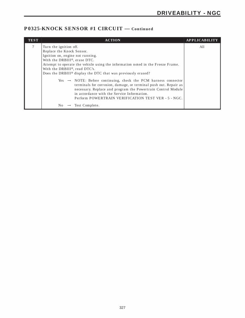
TEST ACTION APPLICABILITY
7 Turn the ignition off.Replace the Knock Sensor.Ignition on, engine not running.With the DRBIIIt, erase DTC.Attempt to operate the vehicle using the information noted in the Freeze Frame.With the DRBIIIt, read DTC’s.Does the DRBIIIt display the DTC that was previously erased?
All
Yes → NOTE: Before continuing, check the PCM harness connectorterminals for corrosion, damage, or terminal push out. Repair asnecessary. Replace and program the Powertrain Control Modulein accordance with the Service Information.Perform POWERTRAIN VERIFICATION TEST VER - 5 - NGC.
No → Test Complete.
327
DRIVEABILITY - NGC
P0325-KNOCK SENSOR #1 CIRCUIT — Continued

Symptom:P0335-CRANKSHAFT POSITION SENSOR CIRCUIT
When Monitored and Set Condition:
P0335-CRANKSHAFT POSITION SENSOR CIRCUIT
When Monitored: Engine cranking.
Set Condition: No CKP signal is present during engine cranking, and at least 8 camshaftposition sensor signals have occurred.
POSSIBLE CAUSES
CHECKING INTERMITTENT CMP SIGNAL WITH LAB
INTERMITTENT CKP SIGNAL
(K6) 5 VOLT SUPPLY CIRCUIT SHORTED TO GROUND
(K6) 5 VOLT SUPPLY CIRCUIT OPEN
(K6) 5 VOLT SUPPLY CIRCUIT SHORTED TO VOLTAGE
(K24) CKP SIGNAL CIRCUIT SHORTED GROUND
(K24) CKP SIGNAL CIRCUIT OPEN
(K24) CKP SIGNAL CIRCUIT SHORTED TO VOLTAGE
(K24) CKP SIGNAL SHORTED TO (K6) 5 VOLT SUPPLY CIRCUIT
(K4) SENSOR GROUND CIRCUIT OPEN
PCM - (K6) 5 VOLT SUPPLY
PCM - (K24) CKP SIGNAL
CRANKSHAFT POSITION SENSOR
TEST ACTION APPLICABILITY
1 Start the engine.With the DRBIIIt, read the CKP SYNC State.Does the DRBIIIt display CKP SYNC state IN SYNC?
All
Yes → Go To 2
No → Go To 4
328
DRIVEABILITY - NGC

TEST ACTION APPLICABILITY
2 Turn the ignition off.With the DRBIIIt lab scope probe and the Miller special tool #6801, back probe the(K44) Camshaft Position (CMP) Sensor Signal circuit in the CMP harness connector.WARNING: WHEN THE ENGINE IS OPERATING, DO NOT STAND IN ADIRECT LINE WITH THE FAN. DO NOT PUT YOUR HANDS NEAR THEPULLEYS, BELTS OR FAN. DO NOT WEAR LOOSE CLOTHING.Ignition on, engine not running.Wiggle the related wire harness and lightly tap on the Cam Position Sensor.Observe the lab scope screen.Look for any pulses generated by the CMP Sensor.Start the engine.Allow the engine to idle.Observe the lab scope screen.Did the CMP Sensor generate any erratic pulses?
All
Yes → Repair as necessary.Perform POWERTRAIN VERIFICATION TEST VER - 5 - NGC.
No → Go To 3
3 Turn the ignition off.With the DRBIIIt lab scope probe and the Miller special tool #6801, backprobe the(K24) CKP Signal circuit in the CKP harness connector.WARNING: WHEN THE ENGINE IS OPERATING, DO NOT STAND IN ADIRECT LINE WITH THE FAN. DO NOT PUT YOUR HANDS NEAR THEPULLEYS, BELTS OR FAN. DO NOT WEAR LOOSE CLOTHING.Ignition on, engine not running.Wiggle the related wire harness and lightly tap on the Crank Position Sensor.Observe the lab scope screen.Look for any pulses generated by the CKP Sensor.Start the engine.Allow the engine to idle.Observe the lab scope screen.Did the CKP Sensor generate any pulses?
All
Yes → Repair as necessary.Perform POWERTRAIN VERIFICATION TEST VER - 5 - NGC.
No → Test Complete.
4 Turn the ignition off.Disconnect the CKP Sensor harness connector.Ignition on, engine not running.Measure the voltage of the (K6) 5 Volt Supply circuit in the CKP Sensor harnessconnector.Is the voltage between 4.5 and 5.5 volts?
All
Yes → Go To 5
No → Go To 13
5 Turn the ignition off.Disconnect the CKP Sensor harness connector.Ignition on, engine not running.Measure the voltage of the (24) CKP Signal circuit in the CKP Sensor harnessconnector.Is the voltage between 4.5 and 5.0 volts?
All
Yes → Go To 6
No → Go To 8
329
DRIVEABILITY - NGC
P0335-CRANKSHAFT POSITION SENSOR CIRCUIT — Continued

TEST ACTION APPLICABILITY
6 Turn the ignition off.Disconnect the CKP Sensor harness connector.Disconnect the PCM harness connector.CAUTION: DO NOT PROBE THE PCM HARNESS CONNECTORS. PROBINGTHE PCM HARNESS CONNECTORS WILL DAMAGE THE PCM TERMI-NALS RESULTING IN POOR TERMINAL TO PIN CONNECTION. INSTALLMILLER SPECIAL TOOL #8815 TO PERFORM DIAGNOSIS.Measure the resistance of the (K4) Sensor Ground circuit from the CKP Sensorharness connector to the appropriate terminal of special tool #8815.Is the resistance below 5.0 ohms?
All
Yes → Go To 7
No → Repair the open in the (K4) Sensor Ground circuit.Perform POWERTRAIN VERIFICATION TEST VER - 5 - NGC.
7 NOTE: Inspect the slots on the flywheel for damage. If a problem is foundrepair as necessary.If there are no possible causes remaining, view repair.
All
RepairReplace the Crankshaft Position Sensor.Perform POWERTRAIN VERIFICATION TEST VER - 5 - NGC.
8 Turn the ignition off.Disconnect the CKP Sensor harness connector.Disconnect the PCM harness connector.Measure the resistance between ground and the (K24) CKP Signal circuit in the CKPSensor harness connector.Is the resistance below 5.0 ohms?
All
Yes → Repair the short to ground in the (K24) CKP Signal circuit.Perform POWERTRAIN VERIFICATION TEST VER - 5 - NGC.
No → Go To 9
9 Turn the ignition off.Disconnect the CKP Sensor harness connector.Disconnect the PCM harness connector.CAUTION: DO NOT PROBE THE PCM HARNESS CONNECTORS. PROBINGTHE PCM HARNESS CONNECTORS WILL DAMAGE THE PCM TERMI-NALS RESULTING IN POOR TERMINAL TO PIN CONNECTION. INSTALLMILLER SPECIAL TOOL #8815 TO PERFORM DIAGNOSIS.Measure the resistance of the (K24) CKP Signal circuit from the CKP Sensor harnessconnector to the appropriate terminal of special tool #8815.Is the resistance below 5.0 ohms?
All
Yes → Go To 10
No → Repair the open in the (K24) CKP Signal circuit.Perform POWERTRAIN VERIFICATION TEST VER - 5 - NGC.
330
DRIVEABILITY - NGC
P0335-CRANKSHAFT POSITION SENSOR CIRCUIT — Continued

TEST ACTION APPLICABILITY
10 Turn the ignition off.Disconnect the CKP Sensor harness connector.Ignition on, engine not running.Measure the voltage of the (K24) CKP Signal circuit in the CKP Sensor harnessconnector.Is the voltage above 5.5 volts?
All
Yes → Repair the short to battery voltage in the (K24) CKP Signalcircuit.Perform POWERTRAIN VERIFICATION TEST VER - 5 - NGC.
No → Go To 11
11 Turn the ignition off.Disconnect the CKP Sensor harness connector.Disconnect the PCM harness connector.Measure the resistance between the (K24) CKP Signal circuit and the (K6) 5 VoltSupply circuit in the CKP Sensor harness connector.Is the resistance below 5.0 ohms?
All
Yes → Repair the (K24) CKP Signal circuit shorted to the (K6) 5 VoltSupply circuit.Perform POWERTRAIN VERIFICATION TEST VER - 5 - NGC.
No → Go To 12
12 NOTE: Before continuing, check the PCM harness connector terminals forcorrosion, damage, or terminal push out. Repair as necessary.If there are no possible causes remaining, view repair.
All
RepairReplace and program the Powertrain Control Module in accor-dance with the Service Information.Perform POWERTRAIN VERIFICATION TEST VER - 5 - NGC.
13 Turn the ignition off.Disconnect the CKP Sensor harness connector.Disconnect the PCM harness connector.Measure the resistance between ground and the (K6) 5 Volt Supply circuit in the CKPSensor harness connector.Is the resistance below 100 ohms?
All
Yes → Repair the short to ground in the (K6) 5 Volt Supply circuit.Perform POWERTRAIN VERIFICATION TEST VER - 5 - NGC.
No → Go To 14
14 Turn the ignition off.Disconnect the CKP Sensor harness connector.Disconnect the PCM harness connector.CAUTION: DO NOT PROBE THE PCM HARNESS CONNECTORS. PROBINGTHE PCM HARNESS CONNECTORS WILL DAMAGE THE PCM TERMI-NALS RESULTING IN POOR TERMINAL TO PIN CONNECTION. INSTALLMILLER SPECIAL TOOL #8815 TO PERFORM DIAGNOSIS.Measure the resistance of the (K6) 5 Volt Supply circuit from the CKP Sensor harnessconnector to the appropriate terminal of special tool #8815.Is the resistance below 5.0 ohms?
All
Yes → Go To 15
No → Repair the open in the (K6) 5 Volt Supply circuit.Perform POWERTRAIN VERIFICATION TEST VER - 5 - NGC.
331
DRIVEABILITY - NGC
P0335-CRANKSHAFT POSITION SENSOR CIRCUIT — Continued

TEST ACTION APPLICABILITY
15 Turn the ignition off.Disconnect the CKP Sensor harness connector.Ignition on, engine not running.Measure the voltage on the (K6) 5 Volt Supply circuit in the CKP Sensor harnessconnector.Is the voltage above 5.5 volts?
All
Yes → Repair the short to battery voltage in the (K6) 5 Volt Supplycircuit.Perform POWERTRAIN VERIFICATION TEST VER - 5 - NGC.
No → Go To 16
16 NOTE: Before continuing, check the PCM harness connector terminals forcorrosion, damage, or terminal push out. Repair as necessary.If there are no possible causes remaining, view repair.
All
RepairReplace and program the Powertrain Control Module in accor-dance with the Service Information.Perform POWERTRAIN VERIFICATION TEST VER - 5 - NGC.
332
DRIVEABILITY - NGC
P0335-CRANKSHAFT POSITION SENSOR CIRCUIT — Continued

Symptom:P0339-CRANKSHAFT POSITION SENSOR INTERMITTENT
When Monitored and Set Condition:
P0339-CRANKSHAFT POSITION SENSOR INTERMITTENT
When Monitored: Engine running or Cranking.
Set Condition: When the failure counter reaches 20. One Trip Fault.
POSSIBLE CAUSES
GOOD TRIP EQUAL TO ZERO
WIRING HARNESS INSPECTION
(K6) 5 VOLT SUPPLY CIRCUIT OPEN OR SHORTED TO GROUND
TONE WHEEL/PULSE RING INSPECTION
CHECKING CAMSHAFT POSITION SENSOR SIGNAL WITH THE DRBIIIt LAB
CRANKSHAFT POSITION SENSOR
(K24) CKP SIGNAL CIRCUIT OPEN
(K24) CKP SIGNAL CIRCUIT SHORT TO GROUND
(K24) CKP SIGNAL CIRCUIT SHORTED TO B+
(K24) CKP SIGNAL CIRCUIT SHORT TO (K6) 5 VOLTS
PCM
TEST ACTION APPLICABILITY
1 Ignition on, engine not running.With the DRBIIIt, read DTCs and record the related Freeze Frame data.Is the Good Trip Counter displayed and equal to zero?
All
Yes → Go To 2
No → Refer to the INTERMITTENT CONDITION symptom in theDriveability category.Perform POWERTRAIN VERIFICATION TEST VER - 5 - NGC.
333
DRIVEABILITY - NGC

TEST ACTION APPLICABILITY
2 With the DRBIIIt, read and record Freeze Frame Data specific to the CKP signal,ECT, RPM, Sync state, vehicle speed, etc.)Turn the ignition off.With the DRBIIIt lab scope probe and the Miller special tool #6801, backprobe the(K24) CKP Signal circuit at the Sensor harness connector.WARNING: WHEN THE ENGINE IS OPERATING, DO NOT STAND IN ADIRECT LINE WITH THE FAN. DO NOT PUT YOUR HANDS NEAR THEPULLEYS, BELTS OR FAN. DO NOT WEAR LOOSE CLOTHING.Ignition on, engine not running.Observe the lab scope screen.Start the engine.Observe the lab scope screen.Are there any irregular or missing signals?
All
Yes → Go To 3
No → Go To 8
3 Visually inspect the related wire harness including the ground circuit. Look for anychafed, pierced, pinched, or partially broken wires.Visually inspect the related wire harness connectors. Look for broken, bent, pushedout, or corroded terminals.Ensure the Crankshaft Position Sensor and the Camshaft Position Sensor areproperly installed and the mounting bolt(s) are tight.Refer to any TSBs that may apply.Were any of the above conditions present?
All
Yes → Repair as necessaryPerform POWERTRAIN VERIFICATION TEST VER - 5 - NGC.
No → Go To 4
4 Turn the ignition off.Disconnect the CKP Sensor connector.Ignition on, engine not running.Measure the voltage on the (K6) 5 Volt Supply circuit.Is the voltage between 4.5 and 5.5 volts?
All
Yes → Go To 5
No → Repair the open or short to ground in the (K6) 5 Volt Supplycircuit. Use Miller special tool #8815 when checking for an opencircuit to prevent PCM harness connector terminal damage.Perform POWERTRAIN VERIFICATION TEST VER - 5 - NGC.
5 Turn the ignition off.Carefully disconnect the Battery (-) Ground cable.Remove the Crankshaft Position Sensor.Inspect the Tone Wheel/Flex Plate slots for damage, foreign material, or excessivemovement.Were any problems found?
All
Yes → Repair or replace the Tone Wheel/Flex Plate as necessary.Perform POWERTRAIN VERIFICATION TEST VER - 5 - NGC.
No → Go To 6
334
DRIVEABILITY - NGC
P0339-CRANKSHAFT POSITION SENSOR INTERMITTENT — Continued

TEST ACTION APPLICABILITY
6 NOTE: An intermittent glitch in the Camshaft Position Sensor can cause theP0339 to set.Turn the ignition off.With the DRBIIIt lab scope probe and the Miller special tool #6801, backprobe the(K44) CMP Signal circuit at the Sensor harness connector.WARNING: WHEN THE ENGINE IS OPERATING, DO NOT STAND IN ADIRECT LINE WITH THE FAN. DO NOT PUT YOUR HANDS NEAR THEPULLEYS, BELTS OR FAN. DO NOT WEAR LOOSE CLOTHING.Ignition on, engine not running.Wiggle the related wire harness and lightly tap on the Camshaft Position Sensor.Observe the lab scope screen.Start the engine.Observe the lab scope screen.Are there any irregular or missing signals?
All
Yes → Repair as necessary.Perform POWERTRAIN VERIFICATION TEST VER - 5 - NGC.
No → Go To 7
7 If there are no possible causes remaining, view repair. All
RepairReplace the Crankshaft Position Sensor.Perform POWERTRAIN VERIFICATION TEST VER - 5 - NGC.
8 Turn the ignition off.Disconnect the CKP Sensor connector.Disconnect the PCM connector.CAUTION: DO NOT PROBE THE PCM HARNESS CONNECTORS. PROBINGTHE PCM HARNESS CONNECTORS WILL DAMAGE THE PCM TERMI-NALS RESULTING IN POOR TERMINAL TO PIN CONNECTION. INSTALLMILLER SPECIAL TOOL #8815 TO PERFORM DIAGNOSIS.Measure the resistance in the (K24) CKP Signal circuit between the CKP harnessconnector and the appropriate terminal of special tool #8815.Wiggle the wire harness while taking this measurement.Is the resistance below 1.0 ohm?
All
Yes → Go To 9
No → Repair the open/high resistance in the (K24) CKP Signal circuit.Perform POWERTRAIN VERIFICATION TEST VER - 5 - NGC.
9 Turn the ignition off.Disconnect the PCM connector.Disconnect the CKP Sensor connector.Measure the resistance between ground and the (K24) CKP Signal circuit at the CKPSensor harness connector.Wiggle the related wire harness while monitoring the resistance value.Does the resistance stay below 100 ohms?
All
Yes → Repair the short to ground in the (K24) CKP Signal circuit.Perform POWERTRAIN VERIFICATION TEST VER - 5 - NGC.
No → Go To 10
335
DRIVEABILITY - NGC
P0339-CRANKSHAFT POSITION SENSOR INTERMITTENT — Continued

TEST ACTION APPLICABILITY
10 Turn the ignition off.Disconnect the CKP Sensor connector.Ignition on, engine not running.Measure the voltage on the (K24) CKP Signal circuit.Wiggle the related wire harness while taking this measurement.Does the voltage ever increase above 5.5 volts?
All
Yes → Repair the short to B+ voltage in the (K24) CKP Signal circuit.Perform POWERTRAIN VERIFICATION TEST VER - 5 - NGC.
No → Go To 11
11 Turn the ignition off.Disconnect the PCM harness connector.Disconnect the CKP Sensor harness connector.Measure the resistance between the (K6) 5 Volt Supply circuit and the (K24) CKPsignal circuit at the CKP Sensor harness connector.Wiggle the related wire harness while taking this measurement.Is the resistance below 5.0 ohms?
All
Yes → Repair the short to the (K6) 5 Volt Supply circuit in the (K24) CKPSignal circuit.Perform POWERTRAIN VERIFICATION TEST VER - 5 - NGC.
No → Go To 12
12 NOTE: Before continuing, check the PCM harness connector terminals forcorrosion, damage, or terminal push out. Repair as necessary.If there are no possible causes remaining, review repair.
All
RepairReplace and program the Powertrain Control Module in accor-dance with the Service Information.Perform POWERTRAIN VERIFICATION TEST VER - 5 - NGC.
336
DRIVEABILITY - NGC
P0339-CRANKSHAFT POSITION SENSOR INTERMITTENT — Continued

Symptom:P0340-CAMSHAFT POSITION SENSOR CIRCUIT
When Monitored and Set Condition:
P0340-CAMSHAFT POSITION SENSOR CIRCUIT
When Monitored: Engine cranking/running. Battery voltage greater than 10 volts.
Set Condition: At least 5 seconds or 2.5 engine revolutions have elapsed with crankshaftposition sensor signals present but no camshaft position sensor signal. One Trip Fault.
POSSIBLE CAUSES
INTERMITTENT CRANKSHAFT POSITION SENSOR SIGNAL
INTERMITTENT CAMSHAFT POSITION SENSOR SIGNAL
(K6) 5 VOLT SUPPLY CIRCUIT SHORTED TO GROUND
(K6) 5 VOLT SUPPLY CIRCUIT OPEN
(K6) 5 VOLT SUPPLY CIRCUIT SHORTED TO VOLTAGE
(K44) CMP SIGNAL CIRCUIT SHORTED GROUND
(K44) CMP SIGNAL CIRCUIT OPEN
(K44) CMP SIGNAL CIRCUIT SHORTED TO VOLTAGE
(K44) CMP SIGNAL SHORTED TO (K6) 5 VOLT SUPPLY CIRCUIT
(K4) SENSOR GROUND CIRCUIT OPEN
PCM - (K6) 5 VOLT SUPPLY
PCM - (K44) CMP SIGNAL
CAMSHAFT POSITION SENSOR
TEST ACTION APPLICABILITY
1 Start the engine.With the DRBIIIt, read the CMP SYNC State.Does the DRBIIIt display the CMP SYNC State IN SYNC?
All
Yes → Go To 2
No → Go To 4
337
DRIVEABILITY - NGC

TEST ACTION APPLICABILITY
2 Turn the ignition off.With the DRBIIIt lab scope probe and the Miller special tool #6801, back probe the(K24) CKP signal circuit in the CKP harness connector.WARNING: WHEN THE ENGINE IS OPERATING, DO NOT STAND IN ADIRECT LINE WITH THE FAN. DO NOT PUT YOUR HANDS NEAR THEPULLEYS, BELTS OR FAN. DO NOT WEAR LOOSE CLOTHING.Ignition on, engine not running.Wiggle the related wire harness and lightly tap the Crankshaft Position Sensor.Observe the lab scope screen.Start the engine.Allow the engine to idle.Observe the lab scope screen.Did the CKP Sensor generate any erratic pulses?
All
Yes → Repair as necessary.Perform POWERTRAIN VERIFICATION TEST VER - 5 - NGC.
No → Go To 3
3 Turn the ignition off.With the DRBIIIt lab scope probe and the Miller special tool #6801, backprobe the(K44) CMP Signal circuit in the CMP harness connector.WARNING: WHEN THE ENGINE IS OPERATING, DO NOT STAND IN ADIRECT LINE WITH THE FAN. DO NOT PUT YOUR HANDS NEAR THEPULLEYS, BELTS OR FAN. DO NOT WEAR LOOSE CLOTHING.Ignition on, engine not running.Wiggle the related wire harness and lightly tap on the Camshaft Position Sensor.Observe the lab scope screen.Start the engine.Allow the engine to idle.Observe the lab scope screen.Did the CMP Sensor generate any erratic pulses?
All
Yes → Repair as necessary.Perform POWERTRAIN VERIFICATION TEST VER - 5 - NGC.
No → Test Complete.
4 Turn the ignition off.Disconnect the CMP Sensor harness connector.Ignition on, engine not running.Measure the voltage of the (K6) 5 Volt Supply circuit in the CMP Sensor harnessconnector.Is the voltage between 4.5 and 5.5 volts?
All
Yes → Go To 5
No → Go To 13
5 Turn the ignition off.Disconnect the CMP Sensor harness connector.Ignition on, engine not running.Measure the voltage of the (K44) CMP Signal circuit in the CMP Sensor harnessconnector.Is the voltage between 4.5 and 5.0 volts?
All
Yes → Go To 6
No → Go To 8
338
DRIVEABILITY - NGC
P0340-CAMSHAFT POSITION SENSOR CIRCUIT — Continued

TEST ACTION APPLICABILITY
6 Turn the ignition off.Disconnect the CMP Sensor harness connector.Disconnect the PCM harness connector.CAUTION: DO NOT PROBE THE PCM HARNESS CONNECTORS. PROBINGTHE PCM HARNESS CONNECTORS WILL DAMAGE THE PCM TERMI-NALS RESULTING IN POOR TERMINAL TO PIN CONNECTION. INSTALLMILLER SPECIAL TOOL #8815 TO PERFORM DIAGNOSIS.Measure the resistance of the (K4) Sensor Ground circuit from the CMP Sensorharness connector to the appropriate terminal of special tool #8815.Is the resistance below 5.0 ohms?
All
Yes → Go To 7
No → Repair the open in the (K4) Sensor Ground circuit.Perform POWERTRAIN VERIFICATION TEST VER - 5 - NGC.
7 NOTE: Inspect the Camshaft sprocket for damage per the Service Informa-tion. If a problem is found repair as necessary.If there are no possible causes remaining, view repair.
All
RepairReplace the Camshaft Position Sensor.Perform POWERTRAIN VERIFICATION TEST VER - 5 - NGC.
8 Turn the ignition off.Disconnect the CMP Sensor harness connector.Disconnect the PCM harness connector.Measure the resistance between ground and the (K44) CMP Signal circuit in theCMP Sensor harness connector.Is the resistance below 100 ohms?
All
Yes → Repair the short to ground in the (K44) CMP Signal circuitPerform POWERTRAIN VERIFICATION TEST VER - 5 - NGC.
No → Go To 9
9 Turn the ignition off.Disconnect the CMP Sensor harness connector.Disconnect the PCM harness connector.CAUTION: DO NOT PROBE THE PCM HARNESS CONNECTORS. PROBINGTHE PCM HARNESS CONNECTORS WILL DAMAGE THE PCM TERMI-NALS RESULTING IN POOR TERMINAL TO PIN CONNECTION. INSTALLMILLER SPECIAL TOOL #8815 TO PERFORM DIAGNOSIS.Measure the resistance of the (K44) CMP Signal circuit from the CMP Sensorharness connector to the appropriate terminal of special tool #8815.Is the resistance below 5.0 ohms?
All
Yes → Go To 10
No → Repair the open in the (K44) CMP Signal circuit.Perform POWERTRAIN VERIFICATION TEST VER - 5 - NGC.
339
DRIVEABILITY - NGC
P0340-CAMSHAFT POSITION SENSOR CIRCUIT — Continued

TEST ACTION APPLICABILITY
10 Turn the ignition off.Disconnect the CMP Sensor harness connector.Ignition on, engine not running.Measure the voltage of the (K44) CMP Signal circuit in the CMP Sensor harnessconnector.Is the voltage above 5.2 volts?
All
Yes → Repair the short to battery voltage in the (K44) CMP Signalcircuit.Perform POWERTRAIN VERIFICATION TEST VER - 5 - NGC.
No → Go To 11
11 Turn the ignition off.Disconnect the CMP Sensor harness connector.Measure the resistance between the (K44) CMP Signal circuit and the (K6) 5 VoltSupply circuit in the CMP Sensor harness connector.Is the resistance below 5.0 ohms?
All
Yes → Repair the (K44) CMP Signal circuit shorted to the (K6) 5 VoltSupply circuit.Perform POWERTRAIN VERIFICATION TEST VER - 5 - NGC.
No → Go To 12
12 NOTE: Before continuing, check the PCM harness connector terminals forcorrosion, damage, or terminal push out. Repair as necessary.If there are no possible causes remaining, view repair.
All
RepairReplace and program the Powertrain Control Module in accor-dance with the Service Information.Perform POWERTRAIN VERIFICATION TEST VER - 5 - NGC.
13 Turn the ignition off.Disconnect the CMP Sensor harness connector.Disconnect the PCM harness connector.Measure the resistance between ground and the (K6) 5 Volt Supply circuit in theCMP Sensor harness connector.Is the resistance below 100 ohms?
All
Yes → Repair the short to ground in the (K6) 5 Volt Supply circuit.Perform POWERTRAIN VERIFICATION TEST VER - 5 - NGC.
No → Go To 14
14 Turn the ignition off.Disconnect the CMP Sensor harness connector.Disconnect the PCM harness connector.CAUTION: DO NOT PROBE THE PCM HARNESS CONNECTORS. PROBINGTHE PCM HARNESS CONNECTORS WILL DAMAGE THE PCM TERMI-NALS RESULTING IN POOR TERMINAL TO PIN CONNECTION. INSTALLMILLER SPECIAL TOOL #8815 TO PERFORM DIAGNOSIS.Measure the resistance of the (K6) 5 Volt Supply circuit between the CMP Sensorharness connector and the special tool #8815 terminal.Is the resistance below 5.0 ohms?
All
Yes → Go To 15
No → Repair the open in the (K6) 5 Volt Supply circuit.Perform POWERTRAIN VERIFICATION TEST VER - 5 - NGC.
340
DRIVEABILITY - NGC
P0340-CAMSHAFT POSITION SENSOR CIRCUIT — Continued

TEST ACTION APPLICABILITY
15 Turn the ignition off.Disconnect the CMP Sensor harness connector.Ignition on, engine not running.Measure the voltage of the (K6) 5 Volt Supply circuit in the CMP Sensor harnessconnector.Is the voltage above 5.5 volts?
All
Yes → Repair the short to battery voltage in the (K6) 5 Volt Supplycircuit.Perform POWERTRAIN VERIFICATION TEST VER - 5 - NGC.
No → Go To 16
16 NOTE: Before continuing, check the PCM harness connector terminals forcorrosion, damage, or terminal push out. Repair as necessary.If there are no possible causes remaining, view repair.
All
RepairReplace and program the Powertrain Control Module in accor-dance with the Service Information.Perform POWERTRAIN VERIFICATION TEST VER - 5 - NGC.
341
DRIVEABILITY - NGC
P0340-CAMSHAFT POSITION SENSOR CIRCUIT — Continued

Symptom:P0344-CAMSHAFT POSITION SENSOR INTERMITTENT
When Monitored and Set Condition:
P0344-CAMSHAFT POSITION SENSOR INTERMITTENT
When Monitored: Engine running or Cranking.
Set Condition: When the failure counter reaches 20. One Trip Fault.
POSSIBLE CAUSES
GOOD TRIP EQUAL TO ZERO
WIRING HARNESS INSPECTION
(K6) 5 VOLT SUPPLY CIRCUIT OPEN OR SHORTED TO GROUND
TONE WHEEL/PULSE RING INSPECTION
CHECKING CKP SIGNAL WITH THE DRBIIIt LAB
CAMSHAFT POSITION SENSOR
(K44) CMP SIGNAL CIRCUIT OPEN
(K44) CMP SIGNAL CIRCUIT SHORT TO GROUND
(K44) CMP SIGNAL CIRCUIT SHORTED TO B+
(K44) CMP SIGNAL CIRCUIT SHORT TO (K6) 5 VOLTS
PCM
TEST ACTION APPLICABILITY
1 Ignition on, engine not running.With the DRBIIIt, read DTCs and record the related Freeze Frame data.Is the Good Trip Counter displayed and equal to zero?
All
Yes → Go To 2
No → Refer to the INTERMITTENT CONDITION symptom in theDriveability category.Perform POWERTRAIN VERIFICATION TEST VER - 5 - NGC.
2 Turn the ignition off.With the DRBIIIt lab scope probe and the Miller special tool #6801, backprobe the(K44) CMP Signal circuit in the CMP harness connector.WARNING: WHEN THE ENGINE IS OPERATING, DO NOT STAND IN ADIRECT LINE WITH THE FAN. DO NOT PUT YOUR HANDS NEAR THEPULLEYS, BELTS OR FAN. DO NOT WEAR LOOSE CLOTHING.Ignition on, engine not running.Observe the lab scope screen.Start the engine.Observe the lab scope screen.Are there any irregular or missing signals?
All
Yes → Go To 3
No → Go To 8
342
DRIVEABILITY - NGC

TEST ACTION APPLICABILITY
3 Visually inspect the related wire harness including the ground circuit. Look for anychafed, pierced, pinched, or partially broken wires.Visually inspect the related wire harness connectors. Look for broken, bent, pushedout, or corroded terminals.Ensure the Crankshaft Position Sensor and the Camshaft Position Sensor areproperly installed and the mounting bolt(s) are tight.Refer to any TSBs that may apply.Were any of the above conditions present?
All
Yes → Repair as necessary.Perform POWERTRAIN VERIFICATION TEST VER - 5 - NGC.
No → Go To 4
4 Turn the ignition off.Disconnect the CMP Sensor connector.Ignition on, engine not running.Measure the voltage on the (K6) 5 Volt Supply circuit.Is the voltage between 4.5 and 5.5 volts?
All
Yes → Go To 5
No → Repair the open or short to ground in the (K6) 5 Volt Supplycircuit. Use Miller special tool #8815 when checking for an opencircuit to prevent PCM harness connector terminal damage.Perform POWERTRAIN VERIFICATION TEST VER - 5 - NGC.
5 Turn the ignition off.Carefully disconnect the Battery (-) Ground cable.Remove the Camshaft Position Sensor.Inspect the Tone Wheel/Pulse Ring for damage, foreign material, or excessivemovement.Were any problems found?
All
Yes → Repair or replace the Tone Wheel/Pulse Ring as necessary.Perform POWERTRAIN VERIFICATION TEST VER - 5 - NGC.
No → Go To 6
6 NOTE: An intermittent glitch in the Crankshaft Position Sensor can causethe P0344 to set.Turn the ignition off.With the DRBIIIt lab scope probe and the Miller special tool #6801, backprobe the(K24) CKP Signal circuit in the CKP Sensor harness connector.WARNING: WHEN THE ENGINE IS OPERATING, DO NOT STAND IN ADIRECT LINE WITH THE FAN. DO NOT PUT YOUR HANDS NEAR THEPULLEYS, BELTS OR FAN. DO NOT WEAR LOOSE CLOTHING.Ignition on, engine not running.Wiggle the related wire harness and lightly tap on the Crank Position Sensor.Observe the lab scope screen.Start the engine.Observe the lab scope screen.Are there any irregular or missing signals?
All
Yes → Repair as necessary.Perform POWERTRAIN VERIFICATION TEST VER - 5 - NGC.
No → Go To 7
343
DRIVEABILITY - NGC
P0344-CAMSHAFT POSITION SENSOR INTERMITTENT — Continued

TEST ACTION APPLICABILITY
7 If there are no possible causes remaining, view repair. All
RepairReplace the Camshaft Position Sensor.Perform POWERTRAIN VERIFICATION TEST VER - 5 - NGC.
8 Turn the ignition off.Disconnect the CMP Sensor connector.Disconnect the PCM connector.CAUTION: DO NOT PROBE THE PCM HARNESS CONNECTORS. PROBINGTHE PCM HARNESS CONNECTORS WILL DAMAGE THE PCM TERMI-NALS RESULTING IN POOR TERMINAL TO PIN CONNECTION. INSTALLMILLER SPECIAL TOOL #8815 TO PERFORM DIAGNOSIS.Measure the resistance in the (K44) CMP Signal circuit from the CMP harnessconnector to the appropriate terminal of special tool #8815.Wiggle the related wire harness while taking this measurement.Is the resistance below 5.0 ohms?
All
Yes → Go To 9
No → Repair the open/high resistance in the (K44) CMP Signal circuit.Perform POWERTRAIN VERIFICATION TEST VER - 5 - NGC.
9 Turn the ignition off.Disconnect the PCM connector.Disconnect the CMP Sensor connector.Measure the resistance between ground and the (K44) CMP Signal circuit in theCMP Sensor harness connector.Wiggle the related wire harness while monitoring the resistance value.Does the resistance stay below 100 ohms?
All
Yes → Repair the short to ground in the (K44) CMP Signal circuit.Perform POWERTRAIN VERIFICATION TEST VER - 5 - NGC.
No → Go To 10
10 Turn the ignition off.Disconnect the CMP Sensor connector.Ignition on, engine not running.Measure the voltage on the (K44) CMP Signal circuit.Wiggle the related wire harness while taking this measurement.Does the voltage ever increase above 5.5 volts?
All
Yes → Repair the short to B+ voltage in the (K44) CMP Signal circuit.Perform POWERTRAIN VERIFICATION TEST VER - 5 - NGC.
No → Go To 11
11 Turn the ignition off.Disconnect the PCM harness connector.Disconnect the CMP harness connector.Measure the resistance between the (K6) 5 Volt Supply circuit and the signal circuitin the CMP harness connector.Wiggle the related wire harness while taking this measurement.Is the resistance below 5.0 ohms?
All
Yes → Repair the short to the (K6) 5 Volt Supply circuit in the (K44)CMP Signal circuit.Perform POWERTRAIN VERIFICATION TEST VER - 5 - NGC.
No → Go To 12
344
DRIVEABILITY - NGC
P0344-CAMSHAFT POSITION SENSOR INTERMITTENT — Continued

TEST ACTION APPLICABILITY
12 NOTE: Before continuing, check the PCM harness connector terminals forcorrosion, damage, or terminal push out. Repair as necessary.If there are no possible causes remaining, view repair.
All
RepairReplace and program the Powertrain Control Module in accor-dance with the Service Information.Perform POWERTRAIN VERIFICATION TEST VER - 5 - NGC.
345
DRIVEABILITY - NGC
P0344-CAMSHAFT POSITION SENSOR INTERMITTENT — Continued

Symptom List:P0351-IGNITION COIL #1 CIRCUITP0352-IGNITION COIL #2 CIRCUIT
Test Note: All symptoms listed above are diagnosed using the same tests.The title for the tests will be P0351-IGNITION COIL #1 CIR-CUIT.
When Monitored and Set Condition:
P0351-IGNITION COIL #1 CIRCUIT
When Monitored: With battery voltage greater than 11 volts. Engine running. EngineRPM less than 8160. No coil in dwell during test.
Set Condition: Peak current is not achieved with battery based dwell plus 1.5 msec ofdiagnostic offset. It takes less than 3 seconds during cranking or up to 6 seconds whilerunning to set. One Trip Fault.
P0352-IGNITION COIL #2 CIRCUIT
When Monitored: With battery voltage greater than 11 volts. Engine running. EngineRPM less than 8160. No coil in dwell during test.
Set Condition: Peak current is not achieved with battery based dwell plus 1.5 msec ofdiagnostic offset. It takes less than 3 seconds during cranking or up to 6 seconds whilerunning to set. One trip Fault.
POSSIBLE CAUSES
GOOD TRIP EQUAL TO ZERO
IGNITION COIL
(A142) ASD RELAY OUTPUT CIRCUIT
IGNITION COIL DRIVER CIRCUIT OPEN
COIL CONTROL CIRCUIT SHORTED TO GROUND
PCM
TEST ACTION APPLICABILITY
1 NOTE: Record the Freeze Frame Information that set along with the DTC.Turn the ignition on.With the DRBIIIt, read DTC’s.Is the Good Trip displayed and equal to zero?
All
Yes → Go To 2
No → Refer to the INTERMITTENT CONDITION symptom in theDriveability category.Perform POWERTRAIN VERIFICATION TEST VER - 5 - NGC.
346
DRIVEABILITY - NGC
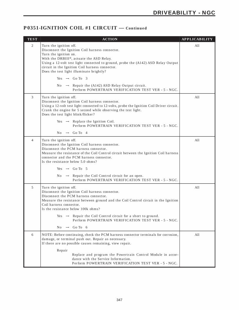
TEST ACTION APPLICABILITY
2 Turn the ignition off.Disconnect the Ignition Coil harness connector.Turn the ignition on.With the DRBIIIt, actuate the ASD Relay.Using a 12-volt test light connected to ground, probe the (A142) ASD Relay Outputcircuit in the Ignition Coil harness connector.Does the test light illuminate brightly?
All
Yes → Go To 3
No → Repair the (A142) ASD Relay Output circuit.Perform POWERTRAIN VERIFICATION TEST VER - 5 - NGC.
3 Turn the ignition off.Disconnect the Ignition Coil harness connector.Using a 12-volt test light connected to 12-volts, probe the Ignition Coil Driver circuit.Crank the engine for 5 second while observing the test light.Does the test light blink/flicker?
All
Yes → Replace the Ignition Coil.Perform POWERTRAIN VERIFICATION TEST VER - 5 - NGC.
No → Go To 4
4 Turn the ignition off.Disconnect the Ignition Coil harness connector.Disconnect the PCM harness connector.Measure the resistance of the Coil Control circuit between the Ignition Coil harnessconnector and the PCM harness connector.Is the resistance below 5.0 ohms?
All
Yes → Go To 5
No → Repair the Coil Control circuit for an open.Perform POWERTRAIN VERIFICATION TEST VER - 5 - NGC.
5 Turn the ignition off.Disconnect the Ignition Coil harness connector.Disconnect the PCM harness connector.Measure the resistance between ground and the Coil Control circuit in the IgnitionCoil harness connector.Is the resistance below 100k ohms?
All
Yes → Repair the Coil Control circuit for a short to ground.Perform POWERTRAIN VERIFICATION TEST VER - 5 - NGC.
No → Go To 6
6 NOTE: Before continuing, check the PCM harness connector terminals for corrosion,damage, or terminal push out. Repair as necessary.If there are no possible causes remaining, view repair.
All
RepairReplace and program the Powertrain Control Module in accor-dance with the Service Information.Perform POWERTRAIN VERIFICATION TEST VER - 5 - NGC.
347
DRIVEABILITY - NGC
P0351-IGNITION COIL #1 CIRCUIT — Continued

Symptom List:P0420-CATALYTIC 1/1 EFFICIENCYP0432-CATALYTIC 2/1 EFFICIENCY
Test Note: All symptoms listed above are diagnosed using the same tests.The title for the tests will be P0420-CATALYTIC 1/1 EFFI-CIENCY.
When Monitored and Set Condition:
P0420-CATALYTIC 1/1 EFFICIENCY
When Monitored: Engine Run time greater than 90 seconds. Engine Coolant greater than70°C (158°F) Vehicle speed greater than 20 MPH and less than 55 MPH. Engine Speedgreater than 1216 RPM and less than 1952 RPM.
Set Condition: As catalyst efficiency deteriorates, the switch rate of the downstream O2sensor approaches that of the upstream O2 sensor. If at any point during the test theswitch ratio reaches a predetermined value a counter is incremented by one. One TripFault.
P0432-CATALYTIC 2/1 EFFICIENCY
When Monitored: Engine Run time greater than 90 seconds. Engine Coolant greater than70°C (158°F) Vehicle speed greater than 20 MPH and less than 55 MPH. Engine Speedgreater than 1216 RPM and less than 1952 RPM.
Set Condition: As catalyst efficiency deteriorates, the switch rate of the downstream O2sensor approaches that of the upstream O2 sensor. If at any point during the test theswitch ratio reaches a predetermined value a counter is incremented by one. One TripFault.
POSSIBLE CAUSES
GOOD TRIP EQUAL TO ZERO
VISUALLY INSPECT CATALYTIC CONVERTER
EXHAUST LEAK
ENGINE MECHANICAL CONDITION
AGING O2 SENSOR
CATALYTIC CONVERTER
348
DRIVEABILITY - NGC

TEST ACTION APPLICABILITY
1 NOTE: A new rear O2 Sensor along with an aging front O2 Sensor may causethe DTC to set. Review the repair history of the vehicle before continuing.NOTE: If an O2 Sensor or Fuel System Lean DTC(s) is set along with theCatalytic Converter Efficiency DTC, diagnose the O2 Sensor DTC(s) beforecontinuing.NOTE: Check for contaminates that may have damaged the O2 Sensor andCatalytic Converter: contaminated fuel, unapproved silicone, oil and cool-ant, repair necessary.Ignition on, engine not running.With the DRBIIIt, read DTCs and record the related Freeze Frame data.Is the Good Trip Counter displayed and equal to zero?
All
Yes → Go To 2
No → Refer to the INTERMITTENT CONDITION symptom in theDriveability category.Perform POWERTRAIN VERIFICATION TEST VER - 5 - NGC.
2 Inspect the Catalytic Converter for the following damage.Damaged Catalytic Converter, dent and holes.Severe discoloration caused by overheating the Catalytic Converter.Catalytic Converter broke internally.Leaking Catalytic Converter.Were any problems found?
All
Yes → Replace the Catalytic Converter. Repair the condition that mayhave caused the failure.Perform POWERTRAIN VERIFICATION TEST VER - 5 - NGC.
No → Go To 3
3 Start the engine.Inspect the exhaust for leaks between the engine and the O2 Sensor.Inspect the exhaust for leaks between the engine and the appropriate rear O2 Sensor.Are there any exhaust leaks?
All
Yes → Repair or replace the leaking exhaust parts as necessary.Perform POWERTRAIN VERIFICATION TEST VER - 5 - NGC.
No → Go To 4
4 Check the exhaust for excessive smoke caused by an internal problem in the engine.Is a engine mechanical condition present?
All
Yes → Repair the engine mechanical condition as necessary.Perform POWERTRAIN VERIFICATION TEST VER - 5 - NGC.
No → Go To 5
5 A new rear O2 Sensor along with an aging front O2 Sensor may cause the DTC to set.Review the vehicles repair history.Has the rear O2 Sensor been replaced without replacing the front O2 Sensor?
All
Yes → Replace the Front O2 Sensor as necessary.Perform POWERTRAIN VERIFICATION TEST VER - 5 - NGC.
No → Go To 6
6 If there are no possible causes remaining, view repair. All
RepairReplace the Catalytic Converter.Perform POWERTRAIN VERIFICATION TEST VER - 5 - NGC.
349
DRIVEABILITY - NGC
P0420-CATALYTIC 1/1 EFFICIENCY — Continued

Symptom:P0440-GENERAL EVAP SYSTEM FAILURE
When Monitored and Set Condition:
P0440-GENERAL EVAP SYSTEM FAILURE
When Monitored: Engine Running. Fuel Level greater than 12%. Ambient Temperaturebetween 4°C and 32°C (39°F and 89°F)
Set Condition: The PCM does not see the NVLD switch close during the medium/largeleak test. The PCM will then increase the vacuum supply to the EVAP system byincreasing flow through the EVAP Purge valve. If the switch does not close with anincrease in vacuum, an error is detected. Two Trip Fault.
POSSIBLE CAUSES
GOOD TRIP EQUAL TO ZERO
VISUAL AND PHYSICAL INSPECTION
EVAP PURGE SOLENOID VACUUM SUPPLY INSPECTION
EVAP PURGE SOLENOID STUCK CLOSED
NVLD SWITCH OPERATION
(Z1) GROUND CIRCUIT OPEN
NVLD ASSEMBLY
(K107) NVLD SWITCH SIGNAL CIRCUIT OPEN
EVAPORATIVE EMISSION LEAK DETECTION
PCM
PCM
TEST ACTION APPLICABILITY
1 NOTE: If any of the following DTCs are set (P0443, P0452, P0453, P0498 orP0499) diagnose them first before continuing with P0440.Ignition on, engine not running.With the DRBIIIt, read DTCs and record the related Freeze Frame data.Is the Good Trip Counter displayed and equal to zero?
All
Yes → Go To 2
No → Refer to the INTERMITTENT CONDITION symptom in theDriveability category.Perform POWERTRAIN VERIFICATION TEST VER - 5 - NGC.
350
DRIVEABILITY - NGC

TEST ACTION APPLICABILITY
2 Perform a visual and physical inspection of the entire Evaporative Emission system.Check for the following conditions:- Hoses disconnected or left off- Holes or cracks- Loose seal points- Evidence of damaged components- Incorrect routing of hoses and tubes- Fuel Cap left off or bad gasket sealWere any of the above conditions found?
All
Yes → Repair as necessary.Perform POWERTRAIN VERIFICATION TEST VER - 5 - NGC.
No → Go To 3
3 Turn the ignition off.Carefully inspect the Evap Purge Solenoid vacuum supply hose for proper routing.Check for a pinched or plugged hose from the throttle body to the Purge Solenoid.Ensure the vacuum port at the throttle body is free from any blockage.Were any problems found?
All
Yes → Repair the vacuum supply, hose/tube as necessary.Perform POWERTRAIN VERIFICATION TEST VER - 5 - NGC.
No → Go To 4
4 Disconnect the vacuum supply hoses form the EVAP Purge Solenoid.Using a hand vacuum pump, apply 10 in Hg to the 9CAN9 side of the EVAP PurgeSolenoid.Ignition on, engine not running.Observe the vacuum gauge.With the DRBIIIt, actuate the EVAP Purge Solenoid .Does the vacuum drop when the solenoid is actuated?
All
Yes → Go To 5
No → Replace the Evap Purge Solenoid.Perform POWERTRAIN VERIFICATION TEST VER - 5 - NGC.
5 NOTE: The fuel level must be below 85%, or the Onboard Refueling VaporRecovery (ORVR) system control valve will seal the tank.Turn the ignition off.Install the Miller #8382 gas cap adaptor. Attach the gas cap to the adapter.Connect a hand-held vacuum pump to the gas cap adapter.NOTE: At 1( in Hg the switch should close. Using a manometer (Miller#6872A) connected to the service port can aid in properly reading thesystem vacuum.Slowly apply vacuum while monitoring the NVLD Switch State on the DRBIIIt. Donot exceed 29 in Hg while performing this step.NOTE: The NVLD Switch reads normally open. When the vacuum is appliedand 1( in Hg is reached the switch state should be in the closed position.Once the vacuum has been released the Switch state should return to theopen position.Did the NVLD Switch operate as described above?
All
Yes → Refer to the INTERMITTENT CONDITION symptom in theDriveability category.Perform POWERTRAIN VERIFICATION TEST VER - 5 - NGC.
No → Go To 6
351
DRIVEABILITY - NGC
P0440-GENERAL EVAP SYSTEM FAILURE — Continued

TEST ACTION APPLICABILITY
6 To continue testing you will need Miller Tool #8404 Evaporative Emission LeakDetector (EELD).WARNING: Keep lit cigarettes, sparks, flames, and other ignition sourcesaway from the test area to prevent the ignition of explosive gases. Keep thetest area well ventilated.NOTE: The fuel tank should have between 20% and 80% of fuel tank capacityto properly test the Evap system.Connect the red power lead of EELD to the battery positive terminal and the blackground lead to battery negative terminal.NOTE: See Charts and Graph support material EELD Calibration Setup foran example.Block the vent hose of the EVAP Canister.Connect shop air to the EELD.Set the smoke/air control switch to AIR.Insert the tester’s AIR supply tip (clear hose) into the .040 orifice on the tester’scontrol panel.Press the remote smoke/air start button.Position the red flag on the air flow meter so it is aligned with the indicator ball.When the calibration is complete, release the remote button. The EELD is nowcalibrated the flow meter in liters per minute.Install the service port adapter #8404-14 on the vehicle’s service port.Connect the Air supply hose from the EELD to the service port.Press the remote button to activate AIR flow.NOTE: Larger volume fuel tanks, lower fuel levels or if the vehicle isequipped with a Flow Management Valve, this may indicate high flow andwill require 4 to 5 minutes to fill.Compare the flow meter indicator ball reading to the red flag.ABOVE the red flag indicates a leak present.BELOW the red flag indicates a sealed system.Is the indicator ball above the red flag?
All
Yes → Go To 7
No → Go To 8
352
DRIVEABILITY - NGC
P0440-GENERAL EVAP SYSTEM FAILURE — Continued

TEST ACTION APPLICABILITY
7 NOTE: A thorough visual inspection of the Evap system hoses, tubes, andconnections may save time in your diagnosis. Look for any physical damageor signs of wetness at connections. The strong smell of fuel vapors may aiddiagnosis also.To continue testing, you will need Miller Tool #8404 Evaporative Emissions LeakDetector (EELD).Remove the Air supply hose from the service port.Connect the SMOKE supply tip (black hose) to the service port.Set the smoke/air control switch to SMOKE.NOTE: The flow meter indicator ball will not move at this point.Press the remote smoke/air start button.NOTE: Ensure that smoke has filled the EVAP system by continuing to pressthe remote smoke/air start button, remove the vehicle fuel cap, and wait forthe smoke to exit. Once smoke is indicated reinstall the fuel cap.NOTE: For optimal performance, introduce smoke into the system for anadditional 60 seconds; continue introducing smoke at 15 second intervals,as necessary.While still holding the remote smoke/air start button, use the white light (#8404-CLL) to follow the EVAP system path, and look for the source of the leak indicated byexiting smoke.If a leak is concealed from view (i.e., top of fuel tank), release the remote smoke/airstart button, and use the ultraviolet (UV) black light #8404-UVL and the yellowgoggles 8404-20 to look for residual traces of dye that are left behind by the smoke.The exiting smoke deposits a residual fluid that is either bright green or brightyellow in color when viewed with a UV light.NOTE: Carefully inspect the vent side of the EVAP Canister. Due to thefiltering system in the canister the smoke or dye may or may not be visual.Introducing smoke into the filtered side of the canister may assist inlocating the leak.Was a leak found?
All
Yes → Repair or replace the leaking component as necessary.Perform POWERTRAIN VERIFICATION TEST VER - 6 - NGC.
No → NOTE: Before continuing, check the PCM harness connectorterminals for corrosion, damage or terminal push out. Repair asnecessary. Replace and program the Powertrain Control Modulein accordance with the Service Information.Perform POWERTRAIN VERIFICATION TEST VER - 5 - NGC.
8 Turn the ignition off.Disconnect the NVLD electrical harness connector.Check connectors - Clean/repair as necessary.Using a jumper wire, jumper across the (K107) NVLD Switch Sense circuit and the(Z1) Ground circuit in the NVLD electrical harness connector.Monitor the NVLD Switch state on the DRBIIIt.Does the Switch change from OPEN to CLOSED.
All
Yes → Replace the NVLD Assembly.Perform POWERTRAIN VERIFICATION TEST VER - 5 - NGC.
No → Go To 9
353
DRIVEABILITY - NGC
P0440-GENERAL EVAP SYSTEM FAILURE — Continued

TEST ACTION APPLICABILITY
9 Turn the ignition off.Disconnect the NVLD electrical harness connector.Measure the resistance between the (Z1) Ground circuit and ground.Is the resistance below 5.0 ohms?
All
Yes → Go To 10
No → Repair the open in the (Z1) Ground circuit.Perform POWERTRAIN VERIFICATION TEST VER - 5 - NGC.
10 Turn the ignition off.Disconnect the NVLD electrical harness connector.Disconnect the PCM harness connector.CAUTION: DO NOT PROBE THE PCM HARNESS CONNECTORS. PROBINGTHE PCM HARNESS CONNECTORS WILL DAMAGE THE PCM TERMI-NALS RESULTING IN POOR TERMINAL TO PIN CONNECTION. INSTALLMILLER SPECIAL TOOL #8815 TO PERFORM DIAGNOSIS.Measure the resistance of the (K107) NVLD Switch Signal circuit from the NVLDelectrical harness connector to the appropriate terminal of the special tool #8815.Is the resistance below 5.0 ohms?
All
Yes → NOTE: Before continuing, check the PCM harness connectorterminals for corrosion, damage or terminal push out. Repair asnecessary. Replace and program the Powertrain Control Modulein accordance with the Service Information.Perform POWERTRAIN VERIFICATION TEST VER - 5 - NGC.
No → Repair the open in the (K107) NVLD Switch Signal Circuit.Perform POWERTRAIN VERIFICATION TEST VER - 5 - NGC.
354
DRIVEABILITY - NGC
P0440-GENERAL EVAP SYSTEM FAILURE — Continued

Symptom:P0441-EVAP PURGE SYSTEM PERFORMANCE
When Monitored and Set Condition:
P0441-EVAP PURGE SYSTEM PERFORMANCE
When Monitored: Cold start test. Engine Running. Small Leak Test Passed.
Set Condition: The PCM activates the EVAP Purge solenoid and gradually increases tomaximum flow. During flow, the PCM looks for the NVLD switch to close. If the PCM doesnot see the NVLD switch close at maximum flow an error is detected. Two Trip Fault.
POSSIBLE CAUSES
GOOD TRIP EQUAL TO ZERO
INTERMITTENT CONDITION
CHECKING EVAP PURGE SOLENOID FUNCTIONALITY
EVAP PURGE SOLENOID VACUUM SUPPLY
TEST ACTION APPLICABILITY
1 NOTE: If any of the following DTCs are set (P0443, P0452, P0453, P0498 orP0499) diagnose them first before continuing with P0441.Ignition on, engine not running.With the DRBIIIt, read DTCs and record the related Freeze Frame data.Is the Good Trip Counter displayed and equal to zero?
All
Yes → Go To 2
No → Refer to the INTERMITTENT CONDITION symptom in theDriveability category.Perform POWERTRAIN VERIFICATION TEST VER - 5 - NGC.
2 NOTE: After disconnecting the Evap Purge vacuum connections, inspectthe lines and solenoid for any signs of contamination or foreign materials.Using a hand vacuum pump, apply 10 in Hg to 9CAN9 side of the EVAP PurgeSolenoid.Ignition on, engine not running.Observe the vacuum gauge.With the DRBIIIt, actuate the EVAP Purge Solenoid .Does the vacuum drop when the solenoid is actuated?
All
Yes → Go To 3
No → Replace the Evap Purge Solenoid.Perform POWERTRAIN VERIFICATION TEST VER - 5 - NGC.
355
DRIVEABILITY - NGC

TEST ACTION APPLICABILITY
3 Turn the ignition off.Carefully inspect the Evap Purge Solenoid vacuum supply hose for proper routing.Check for a pinched or plugged hose from the throttle body to the Purge Solenoid.Inspect the vacuum port at the throttle body for any damage or plugging.Were any problems found?
All
Yes → Repair the vacuum supply hose/tube as necessary.Perform POWERTRAIN VERIFICATION TEST VER - 5 - NGC.
No → Refer to the INTERMITTENT CONDITION symptom in theDriveability category.Perform POWERTRAIN VERIFICATION TEST VER - 5 - NGC.
356
DRIVEABILITY - NGC
P0441-EVAP PURGE SYSTEM PERFORMANCE — Continued

Symptom List:P0442-EVAP SYSTEM MEDIUM LEAKP0455-EVAP SYSTEM LARGE LEAK
Test Note: All symptoms listed above are diagnosed using the same tests.The title for the tests will be P0442-EVAP SYSTEM MEDIUMLEAK.
When Monitored and Set Condition:
P0442-EVAP SYSTEM MEDIUM LEAK
When Monitored: Engine Running. Cold start test. Fuel Level greater than 12%. AmbientTemperature between 4°C and 32°C (39°F and 89°F) Close Loop fuel system. Test runswhen small leak test is maturing.
Set Condition: The PCM activates the EVAP Purge Solenoid to pull the EVAP system intoa vacuum to close the NVLD swtich. Once the NVLD swtich is closed, the PCM turns theEVAP Pugre solenoid off to seal the EVAP system. If the NVLD switch reopens before thecalibrated amount of time for a Medium leak an error is detected. Two Trip Fault.
P0455-EVAP SYSTEM LARGE LEAK
When Monitored: Engine Running. Cold start test. Fuel Level greater than 12%. AmbientTemperature between 4°C and 32°C (39°F and 89°F) Close Loop fuel system. Test runswhen small leak test is maturing.
Set Condition: The PCM activates the EVAP Purge Solenoid to pull the EVAP system intoa vacuum to close the NVLD swtich. Once the NVLD switch is closed, the PCM turns theEVAP Purge solenoid off to seal the EVAP system. If the NVLD switch reopens before thecalibrated amount of time for a Large leak an error is detected. Two Trip Fault.
POSSIBLE CAUSES
INTERMITTENT CONDITION
VISUAL AND PHYSICAL INSPECTION
EVAPORATIVE EMISSION LEAK DETECTION
EVAP PURGE SOLENOID OPERATION
NVLD SWITCH OPERATION
357
DRIVEABILITY - NGC

TEST ACTION APPLICABILITY
1 NOTE: Since a hot vehicle can conceal a leak, it is best to perform this testat room temperature.NOTE: A loose gas cap could have caused this DTC to set. Make sure gas capis tight and in good condition. Ensure the gas cap meets OEM specifications.Ignition on, engine not running.With the DRBIIIt, read DTCs and record the related Freeze Frame data.Is the Good Trip Counter displayed and equal to zero?
All
Yes → Go To 2
No → Go To 7
2 Perform a visual and physical inspection of the entire Evaporative Emission system.Check for the follow conditions:- Holes or cracks- Loose seal points- Evidence of damaged components- Incorrect routing of hoses and tubes- Fuel Cap gasket sealWere any of the above conditions found?
All
Yes → Repair as necessary.Perform POWERTRAIN VERIFICATION TEST VER - 6 - NGC.
No → Go To 3
358
DRIVEABILITY - NGC
P0442-EVAP SYSTEM MEDIUM LEAK — Continued

TEST ACTION APPLICABILITY
3 To continue testing you will need Miller Tool #8404 Evaporative Emission LeakDetector (EELD).WARNING: Keep lighted cigarettes, sparks, flames, and other ignitionsources away from the test area to prevent the ignition of explosive gases.Keep the test area well ventilated.NOTE: The fuel tank should have between 20% and 80% of fuel tank capacityto properly test the Evap system.Connect the red power lead of the EELD to the battery positive terminal and theblack ground lead to battery negative terminal.NOTE: See Charts and Graph support material EELD Calibration Setup foran example.Block the vent hose of the EVAP Canister.Connect shop air to the EELD.Set the smoke/air control switch to AIR.Insert the tester’s AIR supply tip (clear hose) into the appropriate calibration orificeon the tester’s control panel (based on DTC leak size).Press the remote smoke/air start button.Position the red flag on the air flow meter so it is aligned with the indicator ball.When the calibration is complete, release the remote button. The EELD is nowcalibrated the flow meter in liters per minute to the size leak indicated by the DTCset in the PCM.Install the service port adapter #8404-14 on the vehicle’s service port.Connect the Air supply hose from the EELD to the service port.Press the remote button to activate AIR flow.NOTE: Larger volume fuel tanks, lower fuel levels or if the vehicle isequipped with a Flow Management Valve may indicate high flow and willrequire 4 to 5 minutes to fillCompare the flow meter indicator ball reading to the red flag.ABOVE the red flag indicates a leak present.BELOW the red flag indicates a sealed system.Is the indicator ball above the red flag?
All
Yes → Go To 4
No → Go To 7
359
DRIVEABILITY - NGC
P0442-EVAP SYSTEM MEDIUM LEAK — Continued

TEST ACTION APPLICABILITY
4 NOTE: A thorough visual inspection of the Evap system hoses, tubes, andconnections may save time in your diagnosis. Look for any physical damageor signs of wetness at connections. The strong smell of fuel vapors may aiddiagnosis also.To continue testing, you will need Miller Tool #8404 Evaporative Emissions LeakDetector (EELD).Remove the Air supply hose from the service port.Connect the SMOKE supply tip (black hose) to the service port.Set the smoke/air control switch to SMOKE.NOTE: The flow meter indicator ball will not move in the smoke mode.Press the remote smoke/air start button.NOTE: Ensure that smoke has filled the EVAP system by continuing to pressthe remote smoke/air start button, remove the vehicle fuel cap, and wait forthe smoke to exit. Once smoke is indicated reinstall the fuel cap.NOTE: For optimal performance, introduce smoke into the system for anadditional 60 seconds; continue introducing smoke at 15 second intervals,as necessary.While still holding the remote smoke/air start button, use the white light (#8404-CLL) to follow the EVAP system path, and look for the source of the leak indicated byexiting smoke.If a leak is concealed from view (i.e., top of fuel tank), release the remote smoke/airstart button, and use the ultraviolet (UV) black light #8404-UVL and the yellowgoggles 8404-20 to look for residual traces of dye that is left behind by the smoke.The exiting smoke deposits a residual fluid that is either bright green or brightyellow in color when viewed with a UV light.NOTE: Carefully inspect the vent side of the EVAP Canister. Due to thefiltering system in the canister the smoke may not be as thick. Introducingsmoke into the filtered side of the canister may assist in locating the leak.Was a leak found?
All
Yes → Repair or replace the leaking component as necessary.Perform POWERTRAIN VERIFICATION TEST VER - 6 - NGC.
No → Go To 5
5 NOTE: After disconnecting the Evap Purge Solenoid vacuum connections,inspect the lines and solenoid for any signs of contamination from the EVAPCanister. This may indicate a faulty rollover valve. Replace/repair asnecessary.Turn the ignition off.Disconnect the vacuum hoses at the Evap Purge Solenoid.Using a hand vacuum pump, apply 10 in Hg to the 9CAN9 of the EVAP PurgeSolenoid.NOTE: Monitor the vacuum gauge for at least 15 seconds.Does the EVAP Purge Solenoid hold vacuum?
All
Yes → Go To 6
No → Replace the Evap Purge Solenoid.Perform POWERTRAIN VERIFICATION TEST VER - 6 - NGC.
360
DRIVEABILITY - NGC
P0442-EVAP SYSTEM MEDIUM LEAK — Continued

TEST ACTION APPLICABILITY
6 NOTE: The fuel level must be below 85%, or the ORVR control valve will sealthe tank.Turn the ignition off.Install the Miller #8382 gas cap adaptor. Attach the gas cap to the adapter.Connect a hand-held vacuum pump to the gas cap adapter.NOTE: At 1( in Hg the NVLD switch should close. Using a manometer (Miller#6872A) connected to the service port can aid in properly reading thesystem vacuum.Slowly apply vacuum while monitoring the NVLD Switch State on the DRBIIIt. Donot exceed 29 in Hg while performing this step.NOTE: The NVLD Switch reads normally open. When the vacuum is appliedand 1( in Hg is reached the switch state should be in the closed position.Once the vacuum has been released the Switch state should return to theopen position.Did the NVLD Switch operate as described above?
All
Yes → Go To 7
No → Replace the NVLD Assembly.Perform POWERTRAIN VERIFICATION TEST VER - 6 - NGC.
7 WARNING: WHEN THE ENGINE IS OPERATING, DO NOT STAND IN ADIRECT LINE WITH THE FAN. DO NOT PUT YOUR HANDS NEAR THEPULLEYS, BELTS OR FAN. DO NOT WEAR LOOSE CLOTHING.Review the DRBIIIt Freeze Frame information. If possible, try to duplicate theconditions under which the DTC was set.Refer to any Technical Service Bulletins (TSB) that may apply.NOTE: A loose gas cap could have caused this DTC to set. Make sure gas capis tight and in good condition. Ensure the gas cap meets OEM specifications.Perform a visual and physical inspection of the entire Evaporative Emission system.Check for the following conditions:- Holes or cracks- Loose seal points- Evidence of damaged components- Incorrect routing of hoses and tubes- Fuel Cap gasket sealWere any of the above conditions found?
All
Yes → Repair as necessary.Perform POWERTRAIN VERIFICATION TEST VER - 6 - NGC.
No → Test Complete.
361
DRIVEABILITY - NGC
P0442-EVAP SYSTEM MEDIUM LEAK — Continued

Symptom:P0443-EVAP PURGE SOLENOID CIRCUIT
When Monitored and Set Condition:
P0443-EVAP PURGE SOLENOID CIRCUIT
When Monitored: The ignition on or engine running. Battery voltage greater than 10volts.
Set Condition: The PCM will set a trouble code if the actual state of the solenoid does notmatch the intended state.
POSSIBLE CAUSES
GOOD TRIP EQUAL TO ZERO
EVAP PURGE SOLENOID OPERATION
(K52) EVAP PURGE SOL CONTROL CIRCUIT OPEN
(K52) EVAP PURGE SOLENOID CONTROL CIRCUIT SHORTED TO GROUND
(K108) EVAP PURGE SOL RETURN CIRCUIT OPEN
(K108) EVAP PURGE SOL RETURN CIRCUIT SHORTED TO GROUND
POWERTRAIN CONTROL MODULE
TEST ACTION APPLICABILITY
1 Ignition on, engine not running.With the DRBIIIt, read DTCs and record the related Freeze Frame data.Is the Good Trip Counter displayed and equal to zero?
All
Yes → Go To 2
No → Refer to the INTERMITTENT CONDITION symptom in theDriveability category.Perform POWERTRAIN VERIFICATION TEST VER - 5 - NGC.
2 Turn the ignition off.Disconnect the EVAP Purge Solenoid harness connector.Ignition on, engine not running.Using a 12-volt test light, jumper across the EVAP Purge Solenoid harness connector.With the DRBIIIt, actuate the EVAP Purge Solenoid.Does the test light flash on and off?
All
Yes → Replace the EVAP Purge Solenoid.Perform POWERTRAIN VERIFICATION TEST VER - 5 - NGC.
No → Go To 3
362
DRIVEABILITY - NGC

TEST ACTION APPLICABILITY
3 Turn the ignition off.Disconnect the Evap Purge Solenoid harness connector.Disconnect the PCM harness connectors.CAUTION: DO NOT PROBE THE PCM HARNESS CONNECTORS. PROBINGTHE PCM HARNESS CONNECTORS WILL DAMAGE THE PCM TERMI-NALS RESULTING IN POOR TERMINAL TO PIN CONNECTION. INSTALLMILLER SPECIAL TOOL #8815 TO PERFORM DIAGNOSIS.Measure the resistance of the (K52) Evap Purge Solenoid Control circuit from theEvap Purge Solenoid harness connector to the appropriate terminal of special tool#8815.Is the resistance below 5.0 ohms?
All
Yes → Go To 4
No → Repair the open in the (K52) Evap Purge Sol Control circuit.Perform POWERTRAIN VERIFICATION TEST VER - 5 - NGC.
4 Turn the ignition off.Disconnect the Evap Purge Solenoid harness connector.Disconnect the PCM harness connectors.Measure the resistance between ground and the (K52) Evap Purge Sol Control circuitat the Evap Purge Solenoid harness connector.Is the resistance below 5.0 ohms?
All
Yes → Repair the short to ground in the (K52) Evap Purge SolenoidControl circuit.Perform POWERTRAIN VERIFICATION TEST VER - 5 - NGC.
No → Go To 5
5 Turn the ignition off.Disconnect the Evap Purge Solenoid harness connector.Disconnect the PCM harness connectors.CAUTION: DO NOT PROBE THE PCM HARNESS CONNECTORS. PROBINGTHE PCM HARNESS CONNECTORS WILL DAMAGE THE PCM TERMI-NALS RESULTING IN POOR TERMINAL TO PIN CONNECTION. INSTALLMILLER SPECIAL TOOL #8815 TO PERFORM DIAGNOSIS.Measure the resistance of the (K108) Evap Purge Sol Return circuit from the EvapPurge Solenoid harness connector to the appropriate terminal of special tool #8815.Is the resistance below 5.0 ohms?
All
Yes → Go To 6
No → Repair the open in the (K108) Evap Purge Sol Return circuit.Perform POWERTRAIN VERIFICATION TEST VER - 5 - NGC.
6 Turn the ignition off.Disconnect the Evap Purge Solenoid harness connector.Disconnect the PCM harness connectors.Measure the resistance between ground and the (K108) Evap Purge Sol Returncircuit at the Evap Purge Solenoid harness connector.Is the resistance below 5.0 ohms?
All
Yes → Repair the short to ground in the (K108) Evap Purge SolenoidReturn circuit.Perform POWERTRAIN VERIFICATION TEST VER - 5 - NGC.
No → Go To 7
363
DRIVEABILITY - NGC
P0443-EVAP PURGE SOLENOID CIRCUIT — Continued

TEST ACTION APPLICABILITY
7 NOTE: Before continuing, check the PCM harness connector terminals forcorrosion, damage, or terminal push out. Repair as necessary.If there are no possible causes remaining, view repair.
All
RepairReplace and program the Powertrain Control Module in accor-dance with the Service Information.Perform POWERTRAIN VERIFICATION TEST VER - 5 - NGC.
364
DRIVEABILITY - NGC
P0443-EVAP PURGE SOLENOID CIRCUIT — Continued

Symptom:P0452-NVLD PRESSURE SWITCH SENSE CIRCUIT LOW
When Monitored and Set Condition:
P0452-NVLD PRESSURE SWITCH SENSE CIRCUIT LOW
When Monitored: Immediately after engine start up.
Set Condition: The PCM activates the NLVD Solenoid. If PCM does not see NVLD switchopen, an error is detected. One Trip Fault.
POSSIBLE CAUSES
GOOD TRIP EQUAL TO ZERO
NVLD SWITCH OPERATION
NVLD ASSEMBLY
(K52) EVAP PURGE SOL CONTROL CIRCUIT SHORTED TO GROUND
(K107) NVLD SWITCH SIGNAL CIRCUIT SHORTED TO GROUND
EVAP PURGE SOLENOID LEAKS/STUCK OPEN
PCM
TEST ACTION APPLICABILITY
1 Ignition on, engine not running.With the DRBIIIt, read DTCs and record the related Freeze Frame data.Is the Good Trip Counter displayed and equal to zero?
All
Yes → Go To 2
No → Refer to the INTERMITTENT CONDITION symptom in theDriveability category.Perform POWERTRAIN VERIFICATION TEST VER - 5 - NGC.
2 Turn the ignition off.Disconnect the EVAP Purge Solenoid harness connector.Ignition on, engine not running.Using a 12-volt test light, jumper across the EVAP Purge Solenoid harness connector.With the DRBIIIt, actuate the EVAP Purge Solenoid.Does the test light flash on and off?
All
Yes → Go To 3
No → Go To 7
365
DRIVEABILITY - NGC

TEST ACTION APPLICABILITY
3 NOTE: After disconnecting the Evap Purge Solenoid vacuum connections,inspect the lines and solenoid for any signs of contamination from the EVAPCanister. This may indicate a faulty rollover valve. Replace/repair asnecessary.Turn the ignition off.Disconnect the vacuum hoses at the Evap Purge Solenoid.Using a hand vacuum pump, apply 10 in Hg to the 9CAN9 of the EVAP PurgeSolenoid.NOTE: Monitor the vacuum gauge for at least 15 seconds.Does the EVAP Purge Solenoid hold vacuum?
All
Yes → Go To 4
No → Replace the Evap Purge Solenoid.Perform POWERTRAIN VERIFICATION TEST VER - 5 - NGC.
4 Ignition on, engine not running.Using the DRBIIIt, monitor the NVLD Switch State.Does the DRBIIIt display the NVLD state OPEN?
All
Yes → Refer to the INTERMITTENT CONDITION symptom in theDriveability category.Perform POWERTRAIN VERIFICATION TEST VER - 5 - NGC.
No → Go To 5
5 Turn the ignition on.Using the DRBIIIt, monitor the NVLD Switch State.Disconnect the NVLD electrical connector.Does the Switch change from CLOSED to OPEN?
All
Yes → Replace the NVLD Assembly.Perform POWERTRAIN VERIFICATION TEST VER - 5 - NGC.
No → Go To 6
6 Turn the ignition off.Disconnect the NVLD electrical harness connector.Disconnect the PCM harness connector.Measure the resistance between ground and the (K107) NVLD Switch Signal circuitin the NVLD Assembly harness connector.Is the resistance below 5.0 ohms?
All
Yes → Repair the short to ground in the (K107) NVLD Switch Signalcircuit.Perform POWERTRAIN VERIFICATION TEST VER - 5 - NGC.
No → NOTE: Before continuing, check the PCM harness connectorterminals for corrosion, damage or terminal push out. Repair asnecessary. Replace and program the Powertrain Control Modulein accordance with the Service Information.Perform POWERTRAIN VERIFICATION TEST VER - 5 - NGC.
366
DRIVEABILITY - NGC
P0452-NVLD PRESSURE SWITCH SENSE CIRCUIT LOW — Continued

TEST ACTION APPLICABILITY
7 Turn the ignition off.Disconnect the EVAP Purge Solenoid harness connector.Disconnect the Powertrain Control Module harness connectors.Measure the resistance between ground and the (K52) EVAP Purge Sol Controlcircuit at the EVAP Purge Solenoid harness connector.Is the resistance below 5.0 ohms?
All
Yes → Repair the short to ground in the (K52) EVAP Purge Sol Controlcircuit.Perform POWERTRAIN VERIFICATION TEST VER - 5 - NGC.
No → NOTE: Before continuing, check the PCM harness connectorterminals for corrosion, damage or terminal push out. Repair asnecessary. Replace and program the Powertrain Control Modulein accordance with the Service Information.Perform POWERTRAIN VERIFICATION TEST VER - 5 - NGC.
367
DRIVEABILITY - NGC
P0452-NVLD PRESSURE SWITCH SENSE CIRCUIT LOW — Continued

Symptom:P0453-NVLD PRESSURE SWITCH SENSE CIRCUIT HIGH
When Monitored and Set Condition:
P0453-NVLD PRESSURE SWITCH SENSE CIRCUIT HIGH
When Monitored: Engine Running.
Set Condition: If the PCM does not see the NVLD swtich close during test an error isdetected. One Trip Fault.
POSSIBLE CAUSES
NVLD SWITCH OPERATION
(K107) NVLD SWITCH SIGNAL CIRCUIT SHORTED TO BATTERY VOLTAGE
(K107) NVLD SWITCH SIGNAL CIRCUIT SHORTED TO (K106) NVLD SOL CONTROL CIRCUIT
NVLD ASSEMBLY
(Z1) GROUND CIRCUIT OPEN
(K107) NVLD SWITCH SIGNAL CIRCUIT OPEN
PCM
TEST ACTION APPLICABILITY
1 Start the engine.Allow the engine to idle.Using the DRBIIIt, perform the NVLD FORCED MONITOR TEST.Monitor the NVLD Switch state.NOTE: As the test runs, the NVLD Switch should go from an OPEN state toa CLOSED state and then return to OPEN when the test is complete.Did the NVLD Switch operate as described above?
All
Yes → Refer to the INTERMITTENT CONDITION symptom in theDriveability category.Perform POWERTRAIN VERIFICATION TEST VER - 5 - NGC.
No → Go To 2
2 Turn the ignition off.Disconnect the NVLD electrical harness connector.Ignition on, engine not running.Measure the voltage on the (K107) NVLD Switch Signal circuit in the NVLDelectrical harness connector.Is the voltage above 5.5 volts?
All
Yes → Repair short to battery voltage in the (K107) NVLD Switch Signalcircuit.Perform POWERTRAIN VERIFICATION TEST VER - 5 - NGC.
No → Go To 3
368
DRIVEABILITY - NGC

TEST ACTION APPLICABILITY
3 Turn the ignition off.Disconnect the NVLD electrical harness connector.Measure the resistance between the (K107) NVLD Switch Signal circuit and (K106)NVLD Sol Control circuit in the NVLD electrical harness connector.Is the resistance below 5.0 ohms?
All
Yes → Repair the (K107) NVLD Switch Signal circuit shorted to the(K106) NVLD Sol Control circuit.Perform POWERTRAIN VERIFICATION TEST VER - 5 - NGC.
No → Go To 4
4 Turn the ignition off.Disconnect the NVLD electrical harness connector.Using a jumper wire, jumper across the NVLD Switch Signal circuit and the Groundcircuit.Monitor the NVLD Switch state on the DRBIIIt.Does the Switch change from OPEN to CLOSED?
All
Yes → Replace the NVLD Assembly.Perform POWERTRAIN VERIFICATION TEST VER - 5 - NGC.
No → Go To 5
5 Turn the ignition off.Disconnect the NVLD electrical harness connector.Measure the resistance between the (Z1) Ground circuit and ground.Is the resistance below 5.0 ohms?
All
Yes → Go To 6
No → Repair the open in the (Z1) Ground circuit.Perform POWERTRAIN VERIFICATION TEST VER - 5 - NGC.
6 Turn the ignition off.Disconnect the NVLD electrical harness connector.Disconnect the PCM harness connector.CAUTION: DO NOT PROBE THE PCM HARNESS CONNECTORS. PROBINGTHE PCM HARNESS CONNECTORS WILL DAMAGE THE PCM TERMI-NALS RESULTING IN POOR TERMINAL TO PIN CONNECTION. INSTALLMILLER SPECIAL TOOL #8815 TO PERFORM DIAGNOSIS.Measure the resistance of the (K107) NVLD Switch Signal circuit from the NVLDelectrical harness connector to the appropriate terminal of special tool # 8815.Is the resistance below 5.0 ohms?
All
Yes → NOTE: Before continuing, check the PCM harness connectorterminals for corrosion, damage or terminal push out. Repair asnecessary. Replace and program the Powertrain Control Modulein accordance with the Service Information.Perform POWERTRAIN VERIFICATION TEST VER - 5 - NGC.
No → Repair the open in the (K107) NVLD Switch Signal circuit.Perform POWERTRAIN VERIFICATION TEST VER - 5 - NGC.
369
DRIVEABILITY - NGC
P0453-NVLD PRESSURE SWITCH SENSE CIRCUIT HIGH — Continued

Symptom:P0456-EVAP SYSTEM SMALL LEAK
When Monitored and Set Condition:
P0456-EVAP SYSTEM SMALL LEAK
When Monitored: Ignition off. Fuel Level less than 88%. Ambient Temperature between4°C to 43°C (39°F to 109°F)
Set Condition: Due to temperature changes a vacuum is created in the fuel tank andEVAP system. With the EVAP system sealed, the PCM monitors the NVLD switch. If theNVLD switch does not close within a calibrated amount of time an error is detected.
POSSIBLE CAUSES
INTERMITTENT CONDITION
VISUAL AND PHYSICAL INSPECTION
EVAPORATIVE EMISSION LEAK DETECTION
TEST ACTION APPLICABILITY
1 NOTE: The difference in ambient temperature, outside temp VS shop temp,may conceal a leak, it is best to perform this test after the vehicle’stemperature has stabilized in the work area.Ignition on, engine not running.With the DRBIIIt, read DTCs and record the related Freeze Frame data.Is the Good Trip Counter displayed and equal to zero?
All
Yes → Go To 2
No → Go To 4
2 Perform a visual and physical inspection of the entire Evaporative Emission system.Check for the following conditions:- Holes or cracks- Loose seal points- Evidence of damaged components- Incorrect routing of hoses and tubes- Fuel Cap gasket sealWere any of the above conditions found?
All
Yes → Repair as necessary.Perform POWERTRAIN VERIFICATION TEST VER - 5 - NGC.
No → Go To 3
370
DRIVEABILITY - NGC

TEST ACTION APPLICABILITY
3 NOTE: A thorough visual inspection of the Evap system hoses, tubes, andconnections may save time in your diagnosis. Look for any physical damageor signs of wetness at connections. The strong smell of fuel vapors may aiddiagnosis also.Use the Miller Tool #8404 Evaporative Emissions Leak Detector (EELD).Connect the SMOKE supply tip (black hose) to the service port.Set the smoke/air control switch to SMOKE.Block the vent hose of the EVAP Canister.NOTE: The flow meter indicator ball will not move at this point.Press the remote smoke/air start button.NOTE: Ensure that smoke has filled the EVAP system by continuing to pressthe remote smoke/air start button, remove the vehicle fuel cap, and wait forthe smoke to exit. Once smoke is indicated reinstall the fuel cap.NOTE: For optimal performance, introduce smoke into the system for anadditional 60 seconds; continue introducing smoke at 15 second intervals,as necessary.While still holding the remote smoke/air start button, use the white light (#8404-CLL) to follow the EVAP system path, and look for the source of the leak indicated byexiting smoke.If a leak is concealed from view (i.e., top of fuel tank), release the remote smoke/airstart button, and use the ultraviolet (UV) black light #8404-UVL and the yellowgoggles 8404-20 to look for residual traces of dye that are left behind by the smoke.The exiting smoke deposits a residual fluid that is either bright green or brightyellow in color when viewed with a UV light.NOTE: Carefully inspect the vent side of the EVAP Canister. Due to thefiltering system in the canister the smoke or dye may or may not be visual.Introducing smoke into the filtered side of the canister may assist inlocating the leak.Was a leak found?
All
Yes → Repair or replace the leaking component as necessary.Perform POWERTRAIN VERIFICATION TEST VER - 5 - NGC.
No → Go To 4
4 WARNING: WHEN THE ENGINE IS OPERATING, DO NOT STAND IN ADIRECT LINE WITH THE FAN. DO NOT PUT YOUR HANDS NEAR THEPULLEYS, BELTS OR FAN. DO NOT WEAR LOOSE CLOTHING.Review the DRBIIIt Freeze Frame information. If possible, try to duplicate theconditions under which the DTC was set.Refer to any Technical Service Bulletins (TSB) that may apply.NOTE: A loose gas cap could have caused this DTC to set. Make sure gas capis tight and in good condition. Ensure the gas cap meets OEM specifications.Perform a visual and physical inspection of the entire Evaporative Emission system.Check for the following conditions:- Holes or cracks- Loose seal points- Evidence of damaged components- Incorrect routing of hoses and tubes- Fuel Cap gasket sealWere any of the above conditions found?
All
Yes → Repair as necessary.Perform POWERTRAIN VERIFICATION TEST VER - 5 - NGC.
No → Test Complete.
371
DRIVEABILITY - NGC
P0456-EVAP SYSTEM SMALL LEAK — Continued

Symptom:P0461-FUEL LEVEL SENSOR #1 PERFORMANCE
When Monitored and Set Condition:
P0461-FUEL LEVEL SENSOR #1 PERFORMANCE
When Monitored: TEST #1: With the ignition on, the fuel level is compared to theprevious key down after a 20 second delay. TEST #2: The PCM monitors the fuel level atignition on.
Set Condition: TEST #1: If the PCM does not see a difference in fuel level of greater than0.1 volt the test will fail. TEST #2: If the PCM does not see a change in the fuel level of.1765 over a set amount of miles the test will fail. Two Trip Fault.
POSSIBLE CAUSES
GOOD TRIP EQUAL TO ZERO
VISUALLY INSPECT FUEL TANK
(G4) FUEL LEVEL SIGNAL CIRCUIT SHORTED TO GROUND
(G4) FUEL LEVEL SIGNAL CIRCUIT OPEN
(Z2) GROUND CIRCUIT OPEN
INTERNAL INSPECTION OF THE FUEL TANK
FUEL LEVEL SENSOR
TEST ACTION APPLICABILITY
1 NOTE: Diagnose P0462 or P0463 first, if set along with P0461.NOTE: Inspect the Fuel Pump Module harness connector for any corrosionor damage.Ignition on, engine not running.With the DRBIIIt, read DTCs and record the related Freeze Frame data.Is the Good Trip Counter displayed and equal to zero?
All
Yes → Go To 2
No → Refer to the INTERMITTENT CONDITION symptom in theDriveability category.Perform POWERTRAIN VERIFICATION TEST VER - 5 - NGC.
2 Visually inspect the Fuel Tank for damage that may restrict the Fuel Sending Unitfloat from moving.Is the Fuel Tank OK?
All
Yes → Go To 3
No → Replace the Fuel Tank as necessary.Perform POWERTRAIN VERIFICATION TEST VER - 5 - NGC.
372
DRIVEABILITY - NGC

TEST ACTION APPLICABILITY
3 Turn the ignition off.Disconnect the Fuel Pump Module harness connector.Measure the resistance between ground and the (G4) Fuel Level Signal circuit at theFuel Pump Module harness connector.Is the resistance below 100 ohms?
All
Yes → Repair the short to ground in the (G4) Fuel Level Signal circuit.Perform POWERTRAIN VERIFICATION TEST VER - 5 - NGC.
No → Go To 4
4 Turn the ignition off.Disconnect the Fuel Pump Module harness connector.Disconnect the Instrument Cluster harness connector.Measure the resistance of the (G4) Fuel Level Signal circuit from the Fuel PumpModule harness connector to the BCM harness connector.Is the resistance below 5.0 ohms?
All
Yes → Go To 5
No → Repair the open in the (G4) Fuel Level Signal circuit.Perform POWERTRAIN VERIFICATION TEST VER - 5 - NGC.
5 Turn the ignition off.Disconnect the Fuel Pump Module harness connector.Measure the resistance of the (Z2) Ground circuit from the Fuel Pump Moduleharness connector to ground.Is the resistance below 5.0 ohms?
All
Yes → Go To 6
No → Repair the open in the (Z2) Ground circuit.Perform POWERTRAIN VERIFICATION TEST VER - 5 - NGC.
6 WARNING: The fuel system is under a constant pressure even with theengine off. Before opening the fuel system the fuel pressure must be release.Relieve the fuel pressure in accordance with the service information.Remove the Fuel Tank in accordance with the Service Information.Remove the Fuel Pump Module.Visually inspect the inside of the Fuel Tank for any obstructions or deformities.Inspect the Fuel Pump Module Float arm for damage.Were any problems found?
All
Yes → Repair or replace as necessary.Perform POWERTRAIN VERIFICATION TEST VER - 5 - NGC.
No → Go To 7
7 If there are no possible causes remaining, view repair. All
RepairReplace the Fuel Level Sensor.Perform POWERTRAIN VERIFICATION TEST VER - 5 - NGC.
373
DRIVEABILITY - NGC
P0461-FUEL LEVEL SENSOR #1 PERFORMANCE — Continued

Symptom List:P0462-FUEL LEVEL SENSOR #1 LOWP0463-FUEL LEVEL SENSOR #1 HIGH
Test Note: All symptoms listed above are diagnosed using the same tests.The title for the tests will be P0462-FUEL LEVEL SENSOR #1LOW.
When Monitored and Set Condition:
P0462-FUEL LEVEL SENSOR #1 LOW
When Monitored: Ignition on and battery voltage above 10.4 volts.
Set Condition: The fuel level sensor signal voltage goes below 0.1961 volts for more than5 seconds. One Trip Fault.
P0463-FUEL LEVEL SENSOR #1 HIGH
When Monitored: Ignition on and battery voltage above 10.4 volts.
Set Condition: The fuel level sensor signal voltage at the PCM goes above 4.7 volts formore than 5 seconds. One Trip Fault.
POSSIBLE CAUSES
GOOD TRIP EQUAL TO ZERO
INTERMITTENT CONDITION
TEST ACTION APPLICABILITY
1 Turn the ignition on.With the DRBIIIt, read DTC’s.Is the Good Trip displayed and equal to zero?
All
Yes → Refer to the Instrument Cluster Category and perform the appro-priate symptoms.Perform POWERTRAIN VERIFICATION TEST VER - 5 - NGC.
No → Refer to the INTERMITTENT CONDITION symptom in theDriveability category.Perform POWERTRAIN VERIFICATION TEST VER - 5 - NGC.
374
DRIVEABILITY - NGC
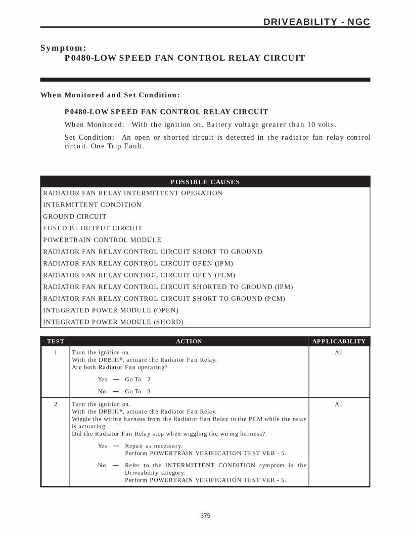
Symptom:P0480-LOW SPEED FAN CONTROL RELAY CIRCUIT
When Monitored and Set Condition:
P0480-LOW SPEED FAN CONTROL RELAY CIRCUIT
When Monitored: With the ignition on. Battery voltage greater than 10 volts.
Set Condition: An open or shorted circuit is detected in the radiator fan relay controlcircuit. One Trip Fault.
POSSIBLE CAUSES
RADIATOR FAN RELAY INTERMITTENT OPERATION
INTERMITTENT CONDITION
GROUND CIRCUIT
FUSED B+ OUTPUT CIRCUIT
POWERTRAIN CONTROL MODULE
RADIATOR FAN RELAY CONTROL CIRCUIT SHORT TO GROUND
RADIATOR FAN RELAY CONTROL CIRCUIT OPEN (IPM)
RADIATOR FAN RELAY CONTROL CIRCUIT OPEN (PCM)
RADIATOR FAN RELAY CONTROL CIRCUIT SHORTED TO GROUND (IPM)
RADIATOR FAN RELAY CONTROL CIRCUIT SHORT TO GROUND (PCM)
INTEGRATED POWER MODULE (OPEN)
INTEGRATED POWER MODULE (SHORD)
TEST ACTION APPLICABILITY
1 Turn the ignition on.With the DRBIIIt, actuate the Radiator Fan Relay.Are both Radiator Fan operating?
All
Yes → Go To 2
No → Go To 3
2 Turn the ignition on.With the DRBIIIt, actuate the Radiator Fan Relay.Wiggle the wiring harness from the Radiator Fan Relay to the PCM while the relayis actuating.Did the Radiator Fan Relay stop when wiggling the wiring harness?
All
Yes → Repair as necessary.Perform POWERTRAIN VERIFICATION TEST VER - 5.
No → Refer to the INTERMITTENT CONDITION symptom in theDriveability category.Perform POWERTRAIN VERIFICATION TEST VER - 5.
375
DRIVEABILITY - NGC

TEST ACTION APPLICABILITY
3 Turn the ignition off.Disconnect the Radiator Fan Relay harness connector.Using a 12-volt test light connected to 12-volts, probe the Ground circuit in theRadiator Fan Relay harness connector.Does the test light illuminate?
All
Yes → Go To 4
No → Repair the Ground circuit for an open.Perform POWERTRAIN VERIFICATION TEST VER - 5.
4 NOTE: Inspect the Radiator Fan fuse located in the IPM.Turn the ignition off.Disconnect the Radiator Fan Relay harness connector.Measure the voltage of the Fused B+ Output circuit in the Radiator Fan harnessconnector.Is the voltage above 11.0 volts?
All
Yes → Go To 5
No → Repair the Fused B+ circuit. Check and replace any open fuses.Perform POWERTRAIN VERIFICATION TEST VER - 5.
5 NOTE: Ensure the Radiator Fan Relay harness connector is connected.Turn the ignition off.Disconnect the PCM harness connector.Turn the ignition on.CAUTION: DO NOT PROBE THE PCM HARNESS CONNECTORS. PROBINGTHE PCM HARNESS CONNECTORS WILL DAMAGE THE PCM TERMI-NALS RESULTING IN POOR TERMINAL TO PIN CONNECTION. INSTALLMILLER SPECIAL TOOL #8815 TO PERFORM DIAGNOSIS.Using a jumper wire, momentarily jumper the Radiator Fan Relay Control circuit inthe appropriate terminal of special tool # 8815 to ground.Did the Radiator Fans operate?
All
Yes → Before continuing, check the PCM harness connector terminalsfor corrosion, damage, or terminal push out. Repair as necessary.Replace and program the Powertrain Control Module in accor-dance with the Service Information.Perform POWERTRAIN VERIFICATION TEST VER - 5.
No → Go To 6
6 Turn the ignition off.Disconnect the Radiator Fan Relay harness connector.Disconnect the PCM harness connector.CAUTION: DO NOT PROBE THE PCM HARNESS CONNECTORS. PROBINGTHE PCM HARNESS CONNECTORS WILL DAMAGE THE PCM TERMI-NALS RESULTING IN POOR TERMINAL TO PIN CONNECTION. INSTALLMILLER SPECIAL TOOL #8815 TO PERFORM DIAGNOSIS.Measure the resistance of the Radiator Fan Relay Control circuit between theRadiator Fan Relay harness connector and the appropriate terminal of special tool #8815.Is the resistance below 5.0 ohms?
All
Yes → Go To 7
No → Go To 10
376
DRIVEABILITY - NGC
P0480-LOW SPEED FAN CONTROL RELAY CIRCUIT — Continued

TEST ACTION APPLICABILITY
7 Turn the ignition off.Disconnect the Radiator Fan Relay harness connector.Disconnect the PCM harness connector.Measure the resistance of the Radiator Fan Relay Control circuit in the Radiator FanRelay harness connector to ground.Is the resistance below 5.0 ohms?
All
Yes → Go To 8
No → Replace Radiator Fan Relay.Perform POWERTRAIN VERIFICATION TEST VER - 5.
8 Turn the ignition off.Disconnect the Radiator Fan Relay harness connector.Disconnect the IPM C2 harness connector.Measure the resistance of the Radiator Fan Relay Control circuit in the Radiator FanRelay harness connector to ground.Is the resistance below 5.0 ohms?
All
Yes → Repair the Radiator Fan Relay Control circuit for a short toground between the Radiator Fan Relay harness connector andthe IPM harness connector.Perform POWERTRAIN VERIFICATION TEST VER - 5.
No → Go To 9
9 Turn the ignition off.Disconnect the PCM harness connector.Disconnect the IPM C3 harness connector.Measure the resistance of the Radiator Fan Relay Control circuit in the PCM harnessconnector to ground.Is the resistance below 5.0 ohms?
All
Yes → Repair the Radiator Fan Relay Control circuit for a short toground between PCM harness connector and the IPM harnessconnector.Perform POWERTRAIN VERIFICATION TEST VER - 5.
No → Replace the IPM Fuse & Relay Center.Perform POWERTRAIN VERIFICATION TEST VER - 5.
10 Turn the ignition off.Disconnect the Radiator Fan Relay harness connector.Disconnect the IPM C2 harness connector.Measure the resistance of the Radiator Fan Relay Control circuit between the IPMharness connector and the Radiator Fan Relay harness connector.Is the resistance below 5.0 ohms.
All
Yes → Go To 11
No → Repair the Radiator Fan Relay Control circuit for an openbetween the Radiator Fan Relay harness connector and the IPMharness connector.Perform POWERTRAIN VERIFICATION TEST VER - 5.
377
DRIVEABILITY - NGC
P0480-LOW SPEED FAN CONTROL RELAY CIRCUIT — Continued

TEST ACTION APPLICABILITY
11 Turn the ignition off.Disconnect the PCM harness connector.Disconnect the IPM C3 harness connector.Measure the resistance of the Radiator Fan Relay Control circuit between the IPMharness connector and the PCM harness connector.Is the resistance below 5.0 ohms.
All
Yes → Replace the IPM Fuse & Relay Center.Perform POWERTRAIN VERIFICATION TEST VER - 5.
No → Repair the Radiator Fan Relay Control circuit for an openbetween PCM harness connector and the IPM harness connector.Perform POWERTRAIN VERIFICATION TEST VER - 5.
378
DRIVEABILITY - NGC
P0480-LOW SPEED FAN CONTROL RELAY CIRCUIT — Continued

Symptom:P0498-NVLD CANISTER VENT VALVE SOLENOID CIRCUIT LOW
When Monitored and Set Condition:
P0498-NVLD CANISTER VENT VALVE SOLENOID CIRCUIT LOW
When Monitored: Engine Running.
Set Condition: The PCM detects a short in the NVLD Canister vent solenoid circuits. Onetrip Fault.
POSSIBLE CAUSES
GOOD TRIP EQUAL TO ZERO
NVLD SOLENOID
(K106) NVLD SOLENOID CONTROL CIRCUIT SHORT TO GROUND
PCM
TEST ACTION APPLICABILITY
1 Ignition on, engine not running.With the DRBIIIt, read DTCs and record the related Freeze Frame data.Is the Good Trip Counter displayed and equal to zero?
All
Yes → Go To 2
No → Refer to the INTERMITTENT CONDITION symptom in theDriveability category.Perform POWERTRAIN VERIFICATION TEST VER - 5 - NGC.
2 Turn the ignition off.Disconnect the NVLD electrical harness connector.Measure the resistance of the NVLD Solenoid coil.Is the resistance between 7.5 to 8.5 ohms?
All
Yes → Go To 3
No → Replace the NVLD Assembly.Perform POWERTRAIN VERIFICATION TEST VER - 5 - NGC.
3 Turn the ignition off.Disconnect the NVLD electrical harness connector.Disconnect the PCM harness connector.Measure the resistance between ground and the (K106) NVLD Sol Control circuit atthe NVLD electrical harness connector.Is the resistance below 5.0 ohms?
All
Yes → Repair the short to ground in the (K106) NVLD Solenoid Controlcircuit.Perform POWERTRAIN VERIFICATION TEST VER - 5 - NGC.
No → NOTE: Before continuing, check the PCM harness connectorterminals for corrosion, damage or terminal push out. Repair asnecessary. Replace and program the Powertrain Control Modulein accordance with the Service Information.Perform POWERTRAIN VERIFICATION TEST VER - 5 - NGC.
379
DRIVEABILITY - NGC

Symptom:P0499-NVLD CANISTER VENT VALVE SOLENOID CIRCUIT HIGH
When Monitored and Set Condition:
P0499-NVLD CANISTER VENT VALVE SOLENOID CIRCUIT HIGH
When Monitored: Engine Running.
Set Condition: The PCM detects an open in the NVLD Canister vent solenoid circuits.One trip Fault.
POSSIBLE CAUSES
GOOD TRIP EQUAL TO ZERO
NVLD SOLENOID
(K106) NVLD SOL CONTROL CIRCUIT SHORT TO BATTERY VOLTAGE
(K106) NVLD SOL CONTROL CIRCUIT OPEN
(Z1) GROUND CIRCUIT OPEN
PCM
TEST ACTION APPLICABILITY
1 Ignition on, engine not running.With the DRBIIIt, read DTCs and record the related Freeze Frame data.Is the Good Trip Counter displayed and equal to zero?
All
Yes → Go To 2
No → Refer to the INTERMITTENT CONDITION symptom in theDriveability category.Perform POWERTRAIN VERIFICATION TEST VER - 5 - NGC.
2 Turn the ignition off.Disconnect the NVLD Assembly harness connector.Measure the resistance of the NVLD Solenoid coil.Is the resistance between 7.5 to 8.5 ohms?
All
Yes → Go To 3
No → Replace the NVLD Assembly.Perform POWERTRAIN VERIFICATION TEST VER - 5 - NGC.
380
DRIVEABILITY - NGC

TEST ACTION APPLICABILITY
3 Turn the ignition off.Disconnect the NVLD Assembly harness connector.Disconnect the PCM harness connector.Turn the ignition on.Measure the voltage on the (K106) NVLD Sol Control circuit in the NVLD Assemblyharness connector.Is the voltage above 1.0 volt?
All
Yes → Repair the short to battery voltage in the (K106) NVLD SolControl circuit.Perform POWERTRAIN VERIFICATION TEST VER - 5 - NGC.
No → Go To 4
4 Turn the ignition off.Disconnect the NVLD Assembly harness connector.Disconnect the PCM harness connector.CAUTION: DO NOT PROBE THE PCM HARNESS CONNECTORS. PROBINGTHE PCM HARNESS CONNECTORS WILL DAMAGE THE PCM TERMI-NALS RESULTING IN POOR TERMINAL TO PIN CONNECTION. INSTALLMILLER SPECIAL TOOL #8815 TO PERFORM DIAGNOSIS.Measure the resistance of the (K106) NVLD Sol Control circuit from the NVLDAssembly harness connector to the appropriate terminal of special tool #8815.Is the resistance below 5.0 ohms?
All
Yes → Go To 5
No → Repair the open in the (K106) NVLD Sol Control circuit.Perform POWERTRAIN VERIFICATION TEST VER - 5 - NGC.
5 Turn the ignition off.Disconnect the NVLD Assembly harness connector.Measure the resistance between the (Z1) Ground circuit and ground.Is the resistance below 5.0 ohms?
All
Yes → Go To 6
No → Repair the open in the (Z1) Ground circuit.Perform POWERTRAIN VERIFICATION TEST VER - 5 - NGC.
6 NOTE: Before continuing, check the PCM harness connector terminals forcorrosion, damage, or terminal push out. Repair as necessary.If there are no possible causes remaining, view repair.
All
RepairReplace and program the Powertrain Control Module in accor-dance with the Service Information.Perform POWERTRAIN VERIFICATION TEST VER - 5 - NGC.
381
DRIVEABILITY - NGC
P0499-NVLD CANISTER VENT VALVE SOLENOID CIRCUIT HIGH —Continued

Symptom:P0501-VEHICLE SPEED SENSOR #1 PERFORMANCE (AUTOTRANS)
When Monitored and Set Condition:
P0501-VEHICLE SPEED SENSOR #1 PERFORMANCE (AUTO TRANS)
When Monitored: Engine running. Transmission not in park or neutral. Brakes notapplied. Engine run time greater than 10 seconds.
Set Condition: The PCM does not see vehicle speed signal from the transmission controlside of the PCM. Two Trip Fault.
POSSIBLE CAUSES
GOOD TRIP EQUAL TO ZERO
TRANSMISSION DTC(S)
PCM
TEST ACTION APPLICABILITY
1 NOTE: Ensure that the Pinion Factor has been programmed and the correcttire size has been programmed in before continuing.Ignition on, engine not running.With the DRBIIIt, read PCM DTCs and record the related Freeze Frame data.Is the Good Trip displayed and equal to zero?
All
Yes → Go To 2
No → Refer to the INTERMITTENT CONDITION symptom in theDriveability category.Perform POWERTRAIN VERIFICATION TEST VER - 5 - NGC.
2 Turn the ignition on.With the DRBIIIt, check the Transmission DTCs.Are there any Transmission DTCs present?
All
Yes → Refer to the appropriate Transmission DTC in the Transmissioncategory.Perform POWERTRAIN VERIFICATION TEST VER - 5 - NGC.
No → NOTE: Before continuing, check the PCM harness connectorterminals for corrosion, damage, or terminal push out. Repair asnecessary. Replace and program the Powertrain Module in accor-dance with the Service Information.Perform POWERTRAIN VERIFICATION TEST VER - 5 - NGC.
382
DRIVEABILITY - NGC

Symptom:P0501-VEHICLE SPEED SENSOR #1 PERFORMANCE (MANUALTRANS)
When Monitored and Set Condition:
P0501-VEHICLE SPEED SENSOR #1 PERFORMANCE (MANUAL TRANS)
When Monitored: With the engine running. Clutch not depressed. Engine rpm greaterthan 1500.
Set Condition: The PCM does not receive a vehicle speed sensor signal for more than 11seconds. 2 consecutive trips.
POSSIBLE CAUSES
VEHICLE SPEED SENSOR OPERATION
(K7) 5 VOLT SUPPLY CIRCUIT OPEN
(G7) VSS SIGNAL CIRCUIT SHORTED TO GROUND
(G7) VSS SIGNAL CIRCUIT OPEN
PCM VSS SIGNAL
(K4) SENSOR GROUND CIRCUIT OPEN
VEHICLE SPEED SENSOR
TEST ACTION APPLICABILITY
1 Raise the drive wheels off the ground.WARNING: BE SURE TO KEEP HANDS AND FEET CLEAR OF ROTATINGWHEELS.Start the engine.With the DRBIIIt, monitor the Vehicle Speed SensorPlace the transmission in any forward gear.Allow the wheels to rotate.Does the DRBIIIt display vehicle speed above 0 MPH/KMH?
All
Yes → Refer to the INTERMITTENT CONDITION symptom in theDriveability category.Perform POWERTRAIN VERIFICATION TEST VER - 5 - NGC.
No → Go To 2
2 Turn the ignition off.Disconnect the Vehicle Speed Sensor harness connector.Turn the ignition on.Measure the voltage of the (K7) 5 Volt Supply circuit in the VSS harness connector.Is the voltage above 4.6 volts?
All
Yes → Go To 3
No → Repair the (K7) 5 Volt Supply circuit for an open.Perform POWERTRAIN VERIFICATION TEST VER - 5 - NGC.
383
DRIVEABILITY - NGC

TEST ACTION APPLICABILITY
3 Turn the ignition off.Disconnect the Vehicle Speed Sensor harness connector.Turn the ignition on.Measure the voltage of the (G7) VSS Signal circuit in the VSS harness connector.Is the voltage between 4.5 to 5.0 volts?
All
Yes → Go To 4
No → Go To 5
4 Turn the ignition off.Disconnect the Vehicle Speed Sensor harness connector.Measure the resistance of the (K4) Sensor ground circuit between the VSS harnessconnector and ground.Is the resistance below 5.0 ohms?
All
Yes → Remove and inspect the Pinion Gear. If OK, replace the VehicleSpeed Sensor.Perform POWERTRAIN VERIFICATION TEST VER - 5 - NGC.
No → Repair the (K4) Sensor ground circuit for an open.Perform POWERTRAIN VERIFICATION TEST VER - 5 - NGC.
5 Turn the ignition off.Disconnect the Vehicle Speed Sensor harness connector.Disconnect the PCM harness connector.Measure the resistance of the (G7) Vehicle Speed Sensor Signal circuit in the VSSharness connector to ground.Is the resistance below 100 ohms?
All
Yes → Repair the (G7) VSS Signal circuit for a short to ground.Perform POWERTRAIN VERIFICATION TEST VER - 5 - NGC.
No → Go To 6
6 Turn the ignition off.Disconnect the Vehicle Speed Sensor harness connector.Disconnect the PCM harness connector.CAUTION: DO NOT PROBE THE PCM HARNESS CONNECTORS. PROBINGTHE PCM HARNESS CONNECTORS WILL DAMAGE THE PCM TERMI-NALS RESULTING IN POOR TERMINAL TO PIN CONNECTION. INSTALLMILLER SPECIAL TOOL #8815 TO PERFORM DIAGNOSIS.Measure the resistance of the (G7) VSS Signal circuit between the VSS harnessconnector and to the appropriate terminal of special tool #8815.Is the resistance below 5 ohms?
All
Yes → Go To 7
No → Repair the (G7) VSS Signal circuit for an open.Perform POWERTRAIN VERIFICATION TEST VER - 5 - NGC.
7 NOTE: Before continuing, check the PCM harness connector terminals forcorrosion, damage, or terminal push out. Repair as necessary.If there are no possible causes remaining, view repair,
All
RepairReplace and program the Powertrain Control Module in accor-dance with the Service Information.Perform POWERTRAIN VERIFICATION TEST VER - 5 - NGC.
384
DRIVEABILITY - NGC
P0501-VEHICLE SPEED SENSOR #1 PERFORMANCE (MANUAL TRANS)— Continued

Symptom List:P0506-IDLE SPEED LOW PERFORMANCEP0507-IDLE SPEED HIGH PERFORMANCEP0519-IDLE SPEED PERFORMANCE
Test Note: All symptoms listed above are diagnosed using the same tests.The title for the tests will be P0506-IDLE SPEED LOW PER-FORMANCE.
When Monitored and Set Condition:
P0506-IDLE SPEED LOW PERFORMANCE
When Monitored: Engine Running. During an idle condition.
Set Condition: If the engine RPM does not come within a calibratable low limit of thetarget idle speed, a failure timer will increment. When the appropriate failure timerreaches its maximum threshold without sign of RPM trending towards control, a soft failis generated. When a calibratable number of the soft fails is reached, a I trip fault is set.When two 1 trip faults occur in a row, a the DTC is set and the MIL illuminates.
P0507-IDLE SPEED HIGH PERFORMANCE
When Monitored: Engine Running. During an idle condition.
Set Condition: If the engine RPM does not come within a calibratable high limit of thetarget idle speed, a failure timer will increment. When the appropriate failure timerreaches its maximum threshold without sign of RPM trending towards control, a soft failis generated. When a calibratable number of the soft fails is reached, a I trip fault is set.When two 1 trip faults occur in a row, a the DTC is set and the MIL illuminates.
P0519-IDLE SPEED PERFORMANCE
When Monitored: With the engine idling and the transmission in drive, if automatic.There must not be a MAP sensor trouble code or a Throttle Position Sensor trouble code.
Set Condition: The engine idle is not within 200 rpm above or 100 rpm below the targetidle for 40 seconds. Two trip fault.
POSSIBLE CAUSES
GOOD TRIP EQUAL TO ZERO
IAC MOTOR PASSAGES
VACUUM LEAKS
AIR INDUCTION SYSTEM
THROTTLE BODY AND THROTTLE LINKAGE
385
DRIVEABILITY - NGC

TEST ACTION APPLICABILITY
1 Ignition on, engine not running.With the DRBIIIt, read DTCs and record the related Freeze Frame data.Is the Good Trip Counter displayed and equal to zero?
All
Yes → Go To 2
No → Refer to the INTERMITTENT CONDITION symptom in theDriveability category.Perform POWERTRAIN VERIFICATION TEST VER - 5 - NGC.
2 Turn the ignition off.Remove the IAC Motor.Inspect the IAC Motor and passages for any obstructions or damage to motor.Were any problems found?
All
Yes → Repair as necessary.Perform POWERTRAIN VERIFICATION TEST VER - 5 - NGC.
No → Go To 3
3 Start the engine.Inspect the vehicle for external vacuum leaks.Inspect the engine for internal vacuum leaks.Were any vacuum leaks found?
All
Yes → Repair the vacuum leak as necessary.Perform POWERTRAIN VERIFICATION TEST VER - 5 - NGC.
No → Go To 4
4 Inspect the Air Induction System for the following problems.Restrictions: Dirty Air Cleaner, Foreign material trapped in the air intake tube, etc.Leaks: Air Intake tube connection, Air Cleaner housing, etc.Were any problems found?
All
Yes → Repair or replace as necessary.Perform POWERTRAIN VERIFICATION TEST VER - 5 - NGC.
No → Go To 5
5 Inspect the throttle body plate carbon build up or other restrictions.Inspect the throttle linkage for binding and smooth operation.Ensure the throttle plate is resting on the stop at idle.Were any problems found?
All
Yes → Repair or replace as necessary.Perform POWERTRAIN VERIFICATION TEST VER - 5 - NGC.
No → Test Complete.
386
DRIVEABILITY - NGC
P0506-IDLE SPEED LOW PERFORMANCE — Continued

Symptom:P0508-IAC VALVE SENSE CIRCUIT LOW
When Monitored and Set Condition:
P0508-IAC VALVE SENSE CIRCUIT LOW
When Monitored: Engine running. Battery voltage greater than 10 volts.
Set Condition: The IAC sense circuit is less than 175 mA. One Trip Fault.
POSSIBLE CAUSES
IAC MOTOR OPERATION
IAC MOTOR
(K39) IAC MOTOR CONTROL CIRCUIT SHORTED TO GROUND
(K60) IAC SIGNAL CIRCUIT OPEN
(K60) IAC SIGNAL CIRCUIT SHORTED TO GROUND
(K39) IAC MOTOR CONTROL CIRCUIT OPEN
PCM
TEST ACTION APPLICABILITY
1 NOTE: If the engine will not idle, maintain an engine speed between 800 and1500 RPM.Start the engine.Allow the engine to idle.With the DRBIIIt, read the IAC Current.Is the IAC Current below 146 mA?
All
Yes → Go To 2
No → Refer to the INTERMITTENT CONDITION symptom in theDriveability category.Perform POWERTRAIN VERIFICATION TEST VER - 5 - NGC.
2 Turn the ignition off.Disconnect the IAC Motor harness connector.Remove the IAC Motor.NOTE: Inspect the IAC air passages for restriction and damage to the IACvalve.Measure the resistance across the IAC Motor pin terminals (component).Is the resistance 9.7 +/- 1.0 ohms?
All
Yes → Go To 3
No → Replace the IAC Motor.Perform POWERTRAIN VERIFICATION TEST VER - 5 - NGC.
387
DRIVEABILITY - NGC

TEST ACTION APPLICABILITY
3 Turn the ignition off.Disconnect the IAC Motor harness connector.Disconnect the PCM harness connectors.CAUTION: DO NOT PROBE THE PCM HARNESS CONNECTORS. PROBINGTHE PCM HARNESS CONNECTORS WILL DAMAGE THE PCM TERMI-NALS RESULTING IN POOR TERMINAL TO PIN CONNECTION. INSTALLMILLER SPECIAL TOOL #8815 TO PERFORM DIAGNOSIS.Measure the resistance of the (K60) IAC Signal circuit from the IAC Motor harnessconnector to the appropriate terminal of special tool #8815.Is the resistance below 5.0 ohms?
All
Yes → Go To 4
No → Repair the open in the (K60) IAC Signal circuit.Perform POWERTRAIN VERIFICATION TEST VER - 5 - NGC.
4 Turn the ignition off.Disconnect the IAC Motor harness connector.Disconnect the PCM harness connectors.Measure the resistance between ground and the (K60) IAC Signal in the IAC Motorharness connector.Is the resistance below 100 ohms?
All
Yes → Repair the short to ground in the (K60) IAC Signal circuit.Perform POWERTRAIN VERIFICATION TEST VER - 5 - NGC.
No → Go To 5
5 Turn the ignition off.Disconnect the IAC Motor harness connector.Disconnect the PCM harness connectors.Measure the resistance between ground and the (K39) IAC Motor Control circuit inthe IAC Motor harness connector.Is the resistance below 100 ohms?
All
Yes → Repair the short to ground in the (K39) IAC Motor Control circuit.Perform POWERTRAIN VERIFICATION TEST VER - 5 - NGC.
No → Go To 6
6 Turn the ignition off.Disconnect the IAC Motor harness connector.Disconnect the PCM harness connectors.CAUTION: DO NOT PROBE THE PCM HARNESS CONNECTORS. PROBINGTHE PCM HARNESS CONNECTORS WILL DAMAGE THE PCM TERMI-NALS RESULTING IN POOR TERMINAL TO PIN CONNECTION. INSTALLMILLER SPECIAL TOOL #8815 TO PERFORM DIAGNOSIS.Measure the resistance of the (K39) IAC Return circuit from the IAC Motor harnessconnector to the appropriate terminal of special tool #8815.Is the resistance below 5.0 ohms?
All
Yes → Go To 7
No → Repair the open in the (K39) IAC Motor Control circuit.Perform POWERTRAIN VERIFICATION TEST VER - 5 - NGC.
388
DRIVEABILITY - NGC
P0508-IAC VALVE SENSE CIRCUIT LOW — Continued

TEST ACTION APPLICABILITY
7 NOTE: Before continuing, check the PCM harness connector terminals forcorrosion, damage, or terminal push out. Repair as necessary.If there are no possible causes remaining, view repair.
All
RepairReplace and program the Powertrain Control Module in accor-dance with the Service Information.Perform POWERTRAIN VERIFICATION TEST VER - 5 - NGC.
389
DRIVEABILITY - NGC
P0508-IAC VALVE SENSE CIRCUIT LOW — Continued
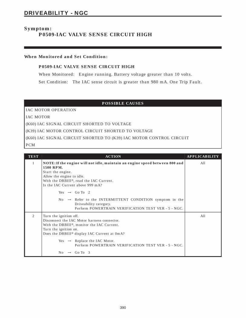
Symptom:P0509-IAC VALVE SENSE CIRCUIT HIGH
When Monitored and Set Condition:
P0509-IAC VALVE SENSE CIRCUIT HIGH
When Monitored: Engine running. Battery voltage greater than 10 volts.
Set Condition: The IAC sense circuit is greater than 980 mA. One Trip Fault.
POSSIBLE CAUSES
IAC MOTOR OPERATION
IAC MOTOR
(K60) IAC SIGNAL CIRCUIT SHORTED TO VOLTAGE
(K39) IAC MOTOR CONTROL CIRCUIT SHORTED TO VOLTAGE
(K60) IAC SIGNAL CIRCUIT SHORTED TO (K39) IAC MOTOR CONTROL CIRCUIT
PCM
TEST ACTION APPLICABILITY
1 NOTE: If the engine will not idle, maintain an engine speed between 800 and1500 RPM.Start the engine.Allow the engine to idle.With the DRBIIIt, read the IAC Current.Is the IAC Current above 999 mA?
All
Yes → Go To 2
No → Refer to the INTERMITTENT CONDITION symptom in theDriveability category.Perform POWERTRAIN VERIFICATION TEST VER - 5 - NGC.
2 Turn the ignition off.Disconnect the IAC Motor harness connector.With the DRBIIIt, monitor the IAC Current.Turn the ignition on.Does the DRBIIIt display IAC Current at 0mA?
All
Yes → Replace the IAC Motor.Perform POWERTRAIN VERIFICATION TEST VER - 5 - NGC.
No → Go To 3
390
DRIVEABILITY - NGC

TEST ACTION APPLICABILITY
3 Turn the ignition off.Disconnect the IAC Motor harness connector.Turn the ignition on.With the DRBIIIt, actuate the ASD Relay.Measure the voltage of the (K60) IAC Signal circuit in the IAC Motor harnessconnector.Is the voltage above 0.5 of a volt?
All
Yes → Repair the short to voltage in the (K60) IAC Signal circuit.Perform POWERTRAIN VERIFICATION TEST VER - 5 - NGC.
No → Go To 4
4 Turn the ignition off.Disconnect the IAC Motor harness connector.Turn the ignition on.With the DRBIIIt, actuate the ASD Relay.Measure the voltage of the (K39) IAC Motor Driver circuit in the IAC Motor harnessconnector.Is the voltage above 0.5 of a volt?
All
Yes → Repair the short to voltage in the (K39) IAC Motor Control circuit.Perform POWERTRAIN VERIFICATION TEST VER - 5 - NGC.
No → Go To 5
5 Turn the ignition off.Disconnect the IAC Motor harness connector.Measure the resistance across the IAC Motor harness connector.Is the resistance below 5.0 ohms?
All
Yes → Repair the (K60) IAC Motor Signal circuit short to the (K39) IACMotor Control circuit.Perform POWERTRAIN VERIFICATION TEST VER - 5 - NGC.
No → Go To 6
6 NOTE: Before continuing, check the PCM harness connector terminals forcorrosion, damage, or terminal push out. Repair as necessary.If there are no possible causes remaining, view repair.
All
RepairReplace and program the Powertrain Control Module in accor-dance with the Service Information.Perform POWERTRAIN VERIFICATION TEST VER - 5 - NGC.
391
DRIVEABILITY - NGC
P0509-IAC VALVE SENSE CIRCUIT HIGH — Continued

Symptom:P0513-INVALID SKIM KEY
When Monitored and Set Condition:
P0513-INVALID SKIM KEY
When Monitored: Ignition on.
Set Condition: The PCM detects an invalid SKIM key.
POSSIBLE CAUSES
INCORRECT VIN IN PCM
INVALID SKIM KEY NOT PRESENT
NO COMMUNICATION WITH SKIM
NO VIN PROGRAMMED IN THE PCM
PCM
SKIM TROUBLE CODES SET
TEST ACTION APPLICABILITY
1 Turn the ignition on.With the DRBIIIt, read the PCM DTCs.Is the Good Trip Counter displayed and equal to zero?
All
Yes → Go To 2
No → Go To 7
2 With the DRBIIIt, attempt to communicate with the SKIM.Turn the ignition on.Can the DRBIIIt communicate with the SKIM?
All
Yes → Go To 3
No → Refer to the No Communication category.Perform SKIS VERIFICATION.
3 Turn the ignition on.With the DRBIIIt, check for SKIM DTCs.Are any DTCs present in the SKIM?
All
Yes → Refer to SKIM category for the related symptom(s).Perform SKIS VERIFICATION.
No → Go To 4
4 Turn the ignition on.With the DRBIIIt, display the VIN that is programmed in the PCM.Has a VIN been programmed into the PCM?
All
Yes → Go To 5
No → Program the correct VIN into the PCM and retest.Perform SKIS VERIFICATION.
392
DRIVEABILITY - NGC

TEST ACTION APPLICABILITY
5 Turn the ignition on.With the DRBIIIt, display the VIN that is programmed in the PCM.Was the correct VIN programmed into the PCM?
All
Yes → Go To 6
No → Replace and program the Powertrain Control Module in accor-dance with the Service Information.Perform SKIS VERIFICATION.
6 Turn the ignition off.Replace and program the Sentry Key Immobilizer Module in accordance with theService Information.Turn the ignition on.With the DRBIIIt, erase all SKIM and PCM DTCs.Attempt to start and idle the engine.With the DRBIIIt, read the PCM DTCs.Does the DRBIIIt display this code?
All
Yes → NOTE: Before continuing, check the PCM harness connectortermnals for corrosion, damage, or terminal push out. Repair asnecessary. Replace and program the Powertrain Control Modulein accordance with the Service Information.Perform SKIS VERIFICATION.
No → Test Complete.
7 NOTE: You must obtain the SKIM pin number.NOTE: This DTC could have been set if the SKIM harness connector wasdisconnected, or if the SKIM was replaced recently.NOTE: All keys that the customer uses for this vehicle must be tested toverify they are operating properly.Turn the ignition on.Verify the correct VIN is programmed into the PCM and SKIM.Turn the ignition off.With the next customer key turn the ignition key on and crank the engine to start.With the DRBIIIt, read the PCM DTCs. Look for P0513.Is the Good Trip Counter for DTC P0513 displayed and equal to 0?
All
Yes → Replace the Ignition Key.Perform SKIS VERIFICATION.
No → Test Complete.
NOTE: If this DTC cannot be reset, it could have been an actual theftattempt.
393
DRIVEABILITY - NGC
P0513-INVALID SKIM KEY — Continued

Symptom:P0516-BATTERY TEMPERATURE SENSOR LOW
When Monitored and Set Condition:
P0516-BATTERY TEMPERATURE SENSOR LOW
When Monitored: Ignition on.
Set Condition: Battery temperature sensor voltage below 0.5 of a volt.
POSSIBLE CAUSES
BATTERY TEMP SENSOR VOLTAGE BELOW 0.5 VOLTS
BATTERY TEMP SENSOR INTERNAL FAILURE
BATTERY TEMP SIGNAL SHORTED TO GROUND
BATTERY TEMP SIGNAL SHORTED TO SENSOR GROUND CIRCUIT
PCM
TEST ACTION APPLICABILITY
1 Ignition on, engine not running.With the DRBIIIt, read the Battery Temp Sensor voltage.Is the voltage below 0.5 volt?
All
Yes → Go To 2
No → Refer to the INTERMITTENT CONDITION symptom in theDriveability category.Perform POWERTRAIN VERIFICATION TEST VER - 5 - NGC.
2 Turn the ignition off.Disconnect the Battery Temp Sensor harness connector.Ignition on, engine not running.With the DRBIIIt, read Battery Temp Sensor voltage.Does the Battery Temp Sensor voltage read approximately 5.0 volts?
All
Yes → Replace the Battery Temperature Sensor.Perform POWERTRAIN VERIFICATION TEST VER - 5 - NGC.
No → Go To 3
3 Turn the ignition off.Disconnect the Battery Temp Sensor harness connector.Disconnect the PCM harness connector.Measure the resistance between ground and the Battery Temp Signal circuit in theBattery Temp Sensor harness connector.Is the resistance below 100 ohms?
All
Yes → Repair the short to ground in the Battery Temp Signal circuit.Perform POWERTRAIN VERIFICATION TEST VER - 5 - NGC.
No → Go To 4
394
DRIVEABILITY - NGC

TEST ACTION APPLICABILITY
4 Turn the ignition off.Disconnect the Battery Temp Sensor harness connector.Disconnect the PCM harness connector.Measure the resistance between the Battery Temp Signal circuit and the Sensorground circuit in the Battery Temp Sensor harness connector.Is the resistance below 100 ohms?
All
Yes → Repair the Sensor ground shorted to the Battery Temp SensorSignal circuit.Perform POWERTRAIN VERIFICATION TEST VER - 5 - NGC.
No → Go To 5
5 NOTE: Before continuing, check the PCM harness connector terminals forcorrosion, damage, or terminal push out. Repair as necessary.If there are no possible causes remaining, view repair.
All
RepairReplace and program the Powertrain Control Module in accor-dance with the Service Information.Perform POWERTRAIN VERIFICATION TEST VER - 5 - NGC.
395
DRIVEABILITY - NGC
P0516-BATTERY TEMPERATURE SENSOR LOW — Continued

Symptom:P0517-BATTERY TEMPERATURE SENSOR HIGH
When Monitored and Set Condition:
P0517-BATTERY TEMPERATURE SENSOR HIGH
When Monitored: Ignition on.
Set Condition: Battery temperature voltage above 4.8 volts.
POSSIBLE CAUSES
BATTERY TEMP VOLTAGE ABOVE 4.8 VOLTS
BATTERY TEMP SIGNAL CIRCUIT SHORTED TO BATTERY VOLTAGE
BATTERY TEMP SENSOR INTERNAL FAILURE
BATTERY TEMP SIGNAL CIRCUIT OPEN
SENSOR GROUND CIRCUIT OPEN
PCM
TEST ACTION APPLICABILITY
1 Ignition on, engine not running.With the DRBIIIt, read the Battery Temp Sensor voltage.Is the voltage above 4.8 volts?
All
Yes → Go To 2
No → Refer to the INTERMITTENT CONDITION symptom in theDriveability category.Perform POWERTRAIN VERIFICATION TEST VER - 5 - NGC.
2 Turn the ignition off.Disconnect the Battery Temp Sensor harness connector.Ignition on, engine not running.Measure the voltage of the Battery Temp Signal circuit in the Battery Temp Sensorharness connector.Is the voltage above 5.2 volts?
All
Yes → Repair the short to battery voltage in the Battery Temp Signalcircuit.Perform POWERTRAIN VERIFICATION TEST VER - 5 - NGC.
No → Go To 3
396
DRIVEABILITY - NGC
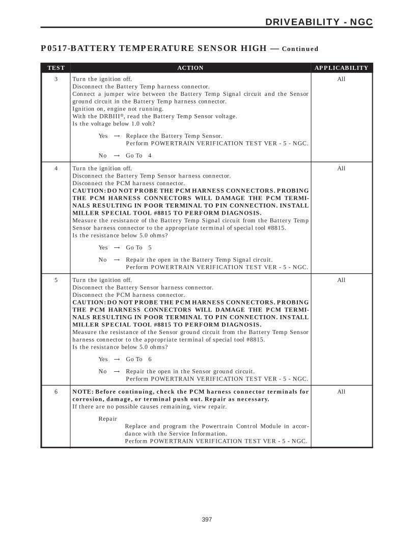
TEST ACTION APPLICABILITY
3 Turn the ignition off.Disconnect the Battery Temp harness connector.Connect a jumper wire between the Battery Temp Signal circuit and the Sensorground circuit in the Battery Temp harness connector.Ignition on, engine not running.With the DRBIIIt, read the Battery Temp Sensor voltage.Is the voltage below 1.0 volt?
All
Yes → Replace the Battery Temp Sensor.Perform POWERTRAIN VERIFICATION TEST VER - 5 - NGC.
No → Go To 4
4 Turn the ignition off.Disconnect the Battery Temp Sensor harness connector.Disconnect the PCM harness connector.CAUTION: DO NOT PROBE THE PCM HARNESS CONNECTORS. PROBINGTHE PCM HARNESS CONNECTORS WILL DAMAGE THE PCM TERMI-NALS RESULTING IN POOR TERMINAL TO PIN CONNECTION. INSTALLMILLER SPECIAL TOOL #8815 TO PERFORM DIAGNOSIS.Measure the resistance of the Battery Temp Signal circuit from the Battery TempSensor harness connector to the appropriate terminal of special tool #8815.Is the resistance below 5.0 ohms?
All
Yes → Go To 5
No → Repair the open in the Battery Temp Signal circuit.Perform POWERTRAIN VERIFICATION TEST VER - 5 - NGC.
5 Turn the ignition off.Disconnect the Battery Sensor harness connector.Disconnect the PCM harness connector.CAUTION: DO NOT PROBE THE PCM HARNESS CONNECTORS. PROBINGTHE PCM HARNESS CONNECTORS WILL DAMAGE THE PCM TERMI-NALS RESULTING IN POOR TERMINAL TO PIN CONNECTION. INSTALLMILLER SPECIAL TOOL #8815 TO PERFORM DIAGNOSIS.Measure the resistance of the Sensor ground circuit from the Battery Temp Sensorharness connector to the appropriate terminal of special tool #8815.Is the resistance below 5.0 ohms?
All
Yes → Go To 6
No → Repair the open in the Sensor ground circuit.Perform POWERTRAIN VERIFICATION TEST VER - 5 - NGC.
6 NOTE: Before continuing, check the PCM harness connector terminals forcorrosion, damage, or terminal push out. Repair as necessary.If there are no possible causes remaining, view repair.
All
RepairReplace and program the Powertrain Control Module in accor-dance with the Service Information.Perform POWERTRAIN VERIFICATION TEST VER - 5 - NGC.
397
DRIVEABILITY - NGC
P0517-BATTERY TEMPERATURE SENSOR HIGH — Continued

Symptom:P0522 PRESSURE SENSOR LOW
When Monitored and Set Condition:
P0522 PRESSURE SENSOR LOW
When Monitored: Engine running and battery voltage above 10.4 volts.
Set Condition: The oil pressure sensor voltage at PCM goes below 0.1 of a volt for 0.5 ofa second.
POSSIBLE CAUSES
OIL PRESSURE SENSOR VOLTAGE BELOW 0.1 VOLTS
OIL PRESSURE SENSOR INTERNAL FAILURE
(G6) OIL PRESS SIGNAL SHORTED TO GROUND
PCM
TEST ACTION APPLICABILITY
1 NOTE: Ensure the engine oil pressure is at the correct pressure beforecontinuing.Ignition on, engine not running.With the DRBIIIt, read the Oil Pressure Sensor voltage.Is the voltage below 0.1 volt?
All
Yes → Go To 2
No → Refer to the INTERMITTENT CONDITION symptom in theDriveability category.Perform POWERTRAIN VERIFICATION TEST VER - 5 - NGC.
2 Turn the ignition off.Disconnect the Oil Pressure Sensor harness connector.Ignition on, engine not running.With the DRBIIIt, read Oil Pressure Sensor voltage.Does the Oil Pressure Sensor voltage read approximately 5.0 volts?
All
Yes → Replace the Oil Pressure Sensor.Perform POWERTRAIN VERIFICATION TEST VER - 5 - NGC.
No → Go To 3
3 Turn the ignition off.Disconnect the Oil Pressure Sensor harness connector.Disconnect the PCM harness connector.Measure the resistance between ground and the (G6) Oil Press Signal circuit in theOil Pressure Sensor harness connector.Is the resistance below 100 ohms?
All
Yes → Repair the ground shorted to the (G6) Oil Press Signal circuit.Perform POWERTRAIN VERIFICATION TEST VER - 5 - NGC.
No → Replace and program the Powertrain Control Module in accor-dance with the Service Information.Perform POWERTRAIN VERIFICATION TEST VER - 5 - NGC.
398
DRIVEABILITY - NGC

Symptom:P0532-A/C PRESSURE SENSOR LOW
When Monitored and Set Condition:
P0532-A/C PRESSURE SENSOR LOW
When Monitored: The engine running. The A/C relay energized.
Set Condition: The A/C pressure sensor signal voltage at the PCM goes below 0.58 voltsfor 2.6 seconds. One Trip Fault.
POSSIBLE CAUSES
A/C PRESSURE SENSOR VOLTAGE BELOW 0.6 VOLTS
(K7) 5 VOLT SUPPLY CIRCUIT SHORTED TO GROUND
(K7) 5 VOLT SUPPLY CIRCUIT OPEN
A/C PRESSURE SENSOR INTERNAL FAILURE
(C18) A/C PRESSURE SIGNAL CIRCUIT SHORTED TO GROUND
(C18) A/C PRESSURE SIGNAL CIRCUIT SHORTED TO (K4) SENSOR GROUND CIRCUIT
PCM (K7) 5 VOLT SUPPLY CIRCUIT
PCM A/C PRESSURE SENSOR SIGNAL
TEST ACTION APPLICABILITY
1 NOTE: Ensure the A/C refrigerant System is properly charged per theService Information.Start the engine.With the DRBIIIt, read the A/C Pressure Sensor voltage.Is the voltage below 0.6 of a volt?
All
Yes → Go To 2
No → Refer to the INTERMITTENT CONDITION symptom in theDriveability category.Perform POWERTRAIN VERIFICATION TEST VER - 2 - NGC.
2 Turn the ignition off.Disconnect the A/C Pressure Sensor harness connector.Turn the ignition on.Measure the voltage of the (K7) 5 Volt Supply circuit in the A/C Pressure Sensorharness connector.Is the voltage between 4.5 to 5.2 volts?
All
Yes → Go To 3
No → Go To 7
399
DRIVEABILITY - NGC

TEST ACTION APPLICABILITY
3 Turn the ignition off.Disconnect the A/C Pressure Sensor harness connector.With the DRBIIIt, monitor the A/C Pressure Sensor voltage.Turn the ignition on.Is the voltage above 0.6 of a volt?
All
Yes → Replace the A/C Pressure Sensor.Perform POWERTRAIN VERIFICATION TEST VER - 2 - NGC.
No → Go To 4
4 Turn the ignition off.Disconnect the A/C Pressure Sensor harness connector.Disconnect the PCM harness connector.Measure the resistance between ground and the (C18) A/C Pressure Signal circuit inthe A/C Pressure Sensor harness connector.Is the resistance below 100 ohms?
All
Yes → Repair the short to ground in the (C18) A/C Pressure Signalcircuit.Perform POWERTRAIN VERIFICATION TEST VER - 2 - NGC.
No → Go To 5
5 Turn the ignition off.Disconnect the A/C Pressure Sensor harness connector.Disconnect the PCM harness connector.Measure the resistance between the (C18) A/C Pressure Sensor Signal circuit and the(K4) Sensor ground circuit in the A/C Pressure Sensor harness connector.Is the resistance below 100 ohms?
All
Yes → Repair the short to the (K4) Sensor ground circuit in the (C18) A/CPressure Signal circuit.Perform POWERTRAIN VERIFICATION TEST VER - 2 - NGC.
No → Go To 6
6 NOTE: Before continuing, check the PCM harness connector terminals forcorrosion, damage, or terminal push out. Repair as necessary.If there are no possible causes remaining, view repair.
All
RepairReplace and program the Powertrain Control Module in accor-dance with the Service Information.Perform POWERTRAIN VERIFICATION TEST VER - 2 - NGC.
7 Turn the ignition off.Disconnect the A/C Pressure Sensor harness connector.Disconnect the PCM harness connector.Measure the resistance between ground and the (K7) 5 Volt Supply circuit in the A/CPressure Sensor harness connector.Is the resistance below 100 ohms?
All
Yes → Repair the short to ground in the (K7) 5 Volt Supply circuit.Perform POWERTRAIN VERIFICATION TEST VER - 2 - NGC.
No → Go To 8
400
DRIVEABILITY - NGC
P0532-A/C PRESSURE SENSOR LOW — Continued

TEST ACTION APPLICABILITY
8 Turn the ignition off.Disconnect the A/C Pressure Sensor harness connector.Disconnect the PCM harness connector.CAUTION: DO NOT PROBE THE PCM HARNESS CONNECTORS. PROBINGTHE PCM HARNESS CONNECTORS WILL DAMAGE THE PCM TERMI-NALS RESULTING IN POOR TERMINAL TO PIN CONNECTION. INSTALLMILLER SPECIAL TOOL #8815 TO PERFORM DIAGNOSIS.Measure the resistance of the (K7) 5 Volt Supply circuit from the A/C Pressure Sensorharness connector to the appropriate terminal of special tool #8815.Is the resistance below 5.0 ohms?
All
Yes → Go To 9
No → Repair the open in the (K7) 5 Volt Supply circuit.Perform POWERTRAIN VERIFICATION TEST VER - 2 - NGC.
9 NOTE: Before continuing, check the PCM harness connector terminals forcorrosion, damage, or terminal push out. Repair as necessary.If there are no possible causes remaining, view repair.
All
RepairReplace and program the Powertrain Control Module in accor-dance with the Service Information.Perform POWERTRAIN VERIFICATION TEST VER - 2 - NGC.
401
DRIVEABILITY - NGC
P0532-A/C PRESSURE SENSOR LOW — Continued

Symptom:P0533-A/C PRESSURE SENSOR HIGH
When Monitored and Set Condition:
P0533-A/C PRESSURE SENSOR HIGH
When Monitored: The engine running. The A/C relay energized.
Set Condition: The A/C pressure sensor signal at the PCM goes above 4.92 volts. One tripFault.
POSSIBLE CAUSES
A/C PRESSURE SENSOR VOLTAGE ABOVE 4.6 VOLTS
(C18) A/C PRESSURE SIGNAL CIRCUIT SHORTED TO (K7) 5 VOLT SUPPLY CIRCUIT
(C18) A/C PRESSURE SIGNAL CIRCUIT SHORTED TO BATTERY VOLTAGE
A/C PRESSURE SENSOR INTERNAL FAILURE
(C18) A/C PRESSURE SIGNAL CIRCUIT OPEN
(K4) SENSOR GROUND CIRCUIT OPEN
PCM
TEST ACTION APPLICABILITY
1 NOTE: Ensure the A/C refrigerant System is properly charged per theService Information.Start the engine.With the DRBIIIt, read the A/C Pressure Sensor voltage.Is the voltage above 4.6 volts?
All
Yes → Go To 2
No → Refer to the INTERMITTENT CONDITION symptom in theDriveability category.Perform POWERTRAIN VERIFICATION TEST VER - 2 - NGC.
2 Turn the ignition off.Disconnect the A/C Pressure Sensor harness connector.Disconnect the PCM harness connector.Measure the resistance between the (C18) A/C Pressure Signal circuit and the (K7)5 Volt Supply circuit in the A/C Pressure Sensor harness connector.Is the resistance below 5.0 ohms?
All
Yes → Repair the (C18) A/C Pressure Signal circuit for a short to the (K7)5 Volt Supply circuit.Perform POWERTRAIN VERIFICATION TEST VER - 2 - NGC.
No → Go To 3
402
DRIVEABILITY - NGC

TEST ACTION APPLICABILITY
3 Turn the ignition off.Disconnect the A/C Pressure Sensor harness connector.Turn the ignition on.Measure the voltage on the (C18) A/C Pressure Sensor Signal circuit at the A/CPressure Sensor harness connector.Is the voltage above 5.2 volts?
All
Yes → Repair the (C18) A/C Pressure Signal circuit for a short to batteryvoltage.Perform POWERTRAIN VERIFICATION TEST VER - 2 - NGC.
No → Go To 4
4 Turn the ignition off.Disconnect the A/C Pressure Sensor harness connector.Connect a jumper wire between the (C18) A/C Pressure Signal circuit and the (K4)Sensor ground circuit.With the DRBIIIt, monitor the A/C Pressure Sensor voltage.Turn the ignition on.Is the voltage below 1.0 volt?
All
Yes → Replace the A/C Pressure Sensor.Perform POWERTRAIN VERIFICATION TEST VER - 2 - NGC.
No → Go To 5
5 Turn the ignition off.Disconnect the A/C Pressure Sensor harness connector.Disconnect the PCM harness connector.CAUTION: DO NOT PROBE THE PCM HARNESS CONNECTORS. PROBINGTHE PCM HARNESS CONNECTORS WILL DAMAGE THE PCM TERMI-NALS RESULTING IN POOR TERMINAL TO PIN CONNECTION. INSTALLMILLER SPECIAL TOOL #8815 TO PERFORM DIAGNOSIS.Measure the resistance of the (C18) A/C Pressure Sensor Signal circuit from the A/CPressure Sensor harness connector to the appropriate terminal of special tool #8815.Is the resistance below 5.0 ohms?
All
Yes → Go To 6
No → Repair the (C18) A/C Pressure Signal circuit for an open.Perform POWERTRAIN VERIFICATION TEST VER - 2 - NGC.
6 Turn the ignition off.Disconnect the A/C Pressure Sensor harness connector.Disconnect the PCM harness connector.CAUTION: DO NOT PROBE THE PCM HARNESS CONNECTORS. PROBINGTHE PCM HARNESS CONNECTORS WILL DAMAGE THE PCM TERMI-NALS RESULTING IN POOR TERMINAL TO PIN CONNECTION. INSTALLMILLER SPECIAL TOOL #8815 TO PERFORM DIAGNOSIS.Measure the resistance of the (K4) Sensor ground circuit from the A/C PressureSensor harness connector to the appropriate terminal of special tool #8815.Is the resistance below 5.0 ohms?
All
Yes → Go To 7
No → Repair the (K4) Sensor ground circuit for an open.Perform POWERTRAIN VERIFICATION TEST VER - 2 - NGC.
403
DRIVEABILITY - NGC
P0533-A/C PRESSURE SENSOR HIGH — Continued

TEST ACTION APPLICABILITY
7 NOTE: Before continuing, check the PCM harness connector terminals forcorrosion, damage, or terminal push out. Repair as necessary.If there are no possible causes remaining, view repair.
All
RepairReplace and program the Powertrain Control Module in accor-dance with the Service Information.Perform POWERTRAIN VERIFICATION TEST VER - 2 - NGC.
404
DRIVEABILITY - NGC
P0533-A/C PRESSURE SENSOR HIGH — Continued

Symptom:P0551-POWER STEERING SWITCH PERFORMANCE
When Monitored and Set Condition:
P0551-POWER STEERING SWITCH PERFORMANCE
When Monitored: With the ignition key on and engine running.
Set Condition: With the vehicle above 80 KMH (50 MPH) for over 30 seconds, the powersteering pressure switch remains open.
POSSIBLE CAUSES
GOOD TRIP COUNTER = 0
POWER STEERING PRESSURE SWITCH (Z1) GROUND CIRCUIT OPEN
(K10) PSP SWITCH SIGNAL CIRCUIT SHORTED TO GROUND
(K10) PSP SWITCH SIGNAL CIRCUIT OPEN
POWER STEERING PRESSURE SWITCH
PCM
TEST ACTION APPLICABILITY
1 Ignition on, engine not running.With the DRBIIIt, read DTCs and record the related Freeze Frame data.Is the Good Trip Counter displayed and equal to zero?
All
Yes → Go To 2
No → Refer to the INTERMITTENT CONDITION symptom in theDriveability category.Perform POWERTRAIN VERIFICATION TEST VER - 2 - NGC.
2 Turn the ignition off.Disconnect the Power Steering Pressure Switch harness connector.Measure the resistance between Ground and the PSP Switch (Z1) ground circuit atthe Power Steering Pressure Switch connector.Is the resistance below 5.0 ohms?
All
Yes → Go To 3
No → Repair the open in the PSP Switch (Z1) ground circuit.Perform POWERTRAIN VERIFICATION TEST VER - 2 - NGC.
3 Turn the ignition off.Disconnect the Power Steering Pressure Switch harness connector.Disconnect the PCM harness connector(s).Measure the resistance between ground and the (K10) PSP Switch Signal circuit atthe Switch connector.Is the resistance below 100 ohms?
All
Yes → Repair the short to ground in the (K10) PSP Switch Signal circuit.Perform POWERTRAIN VERIFICATION TEST VER - 2 - NGC.
No → Go To 4
405
DRIVEABILITY - NGC

TEST ACTION APPLICABILITY
4 Turn the ignition off.Disconnect the Power Steering Pressure Switch harness connector.Disconnect the PCM harness connector(s).CAUTION: DO NOT PROBE THE PCM HARNESS CONNECTORS. PROBINGTHE PCM HARNESS CONNECTORS WILL DAMAGE THE PCM TERMI-NALS RESULTING IN POOR TERMINAL TO PIN CONNECTION. INSTALLMILLER SPECIAL TOOL #8815 TO PERFORM DIAGNOSIS.Measure resistance of Power Steering PSP Switch Signal circuit from the PowerSteering Pressure Sensor harness connector to the appropriate terminal of specialtool #8815.Is the resistance below 5.0 ohms?
All
Yes → Go To 5
No → Repair the open in the (K10) PSP Switch Signal circuit.Perform POWERTRAIN VERIFICATION TEST VER - 2 - NGC.
5 Turn the ignition off.Disconnect the Power Steering Pressure Switch harness connector.Ignition on, engine not running.Connect a Jumper Wire to the (K10) PSP Switch Signal circuit at harness connector.Using the DRBIIIt, while monitoring the Power Steering Pressure Switch.Touch the Jumper Wire to the Ground circuit at the Power Steering Pressure Switchharness connector several times.Did the Power Steering Pressure Switch status change from Hi to Low?
All
Yes → Replace the Power Steering Pressure Switch.Perform POWERTRAIN VERIFICATION TEST VER - 2 - NGC.
No → Go To 6
6 NOTE: Before continuing, check the PCM harness connector terminals forcorrosion, damage, or terminal push out. Repair as necessary.If there are no possible causes remaining, view repair.
All
RepairReplace and program the Powertrain Control Module in accor-dance with the Service Information.Perform POWERTRAIN VERIFICATION TEST VER - 2 - NGC.
406
DRIVEABILITY - NGC
P0551-POWER STEERING SWITCH PERFORMANCE — Continued

Symptom:P0562-BATTERY VOLTAGE LOW
When Monitored and Set Condition:
P0562-BATTERY VOLTAGE LOW
When Monitored: The engine running. The engine speed greater than 1150 RPM.
Set Condition: The battery sensed voltage is 1 volt below the charging goal for 13.47seconds. The PCM senses the battery voltage turns off the field driver and senses thebattery voltage again. If the voltages are the same, the code is set. One trip Fault.
POSSIBLE CAUSES
GOOD TRIP EQUAL TO ZERO
B+ CIRCUIT HIGH RESISTANCE
GENERATOR GROUND HIGH RESISTANCE
GENERATOR OPERATION
(Z1) GENERATOR FIELD GROUND CIRCUIT OPEN
(K20) GEN FIELD CONTROL CIRCUIT SHORTED TO GROUND
(K20) GEN FIELD CONTROL CIRCUIT OPEN
PCM
TEST ACTION APPLICABILITY
1 NOTE: Ensure the Battery is in good condition. Using the MidtronicsBattery Tester, test the Battery before continuing.NOTE: Inspect the vehicle for aftermarket accessories that may exceed theGenerator System output.Turn the ignition off.NOTE: Ensure the generator drive belt is in good operating condition.NOTE: Inspect the fuses in the PDC. If a fuse is found to be open use thewiring diagram/schematic as a guide, inspect the wiring and connectors fordamage.Ignition on, engine not running.With the DRBIIIt, read DTCs and record the related Freeze Frame data.Is the Good Trip Counter displayed and equal to zero?
All
Yes → Go To 2
No → Refer to the INTERMITTENT CONDITION symptom in theDriveability category.Perform POWERTRAIN VERIFICATION TEST VER - 3 - NGC.
407
DRIVEABILITY - NGC

TEST ACTION APPLICABILITY
2 WARNING: WHEN THE ENGINE IS OPERATING, DO NOT STAND IN ADIRECT LINE WITH THE FAN. DO NOT PUT YOUR HANDS NEAR THEPULLEYS, BELTS OR FAN. DO NOT WEAR LOOSE CLOTHING.Ignition on, engine not running.NOTE: Ensure all wires are clear of the engine’s moving parts.Measure the voltage between the Generator B+ Terminal and the Battery+ Post.Start the engine.Is the voltage above 0.4 of a volt?
All
Yes → Repair the B+ circuit for high resistance between the Generatorand Battery.Perform POWERTRAIN VERIFICATION TEST VER - 3 - NGC.
No → Go To 3
3 WARNING: WHEN THE ENGINE IS OPERATING, DO NOT STAND IN ADIRECT LINE WITH THE FAN. DO NOT PUT YOUR HANDS NEAR THEPULLEYS, BELTS OR FAN. DO NOT WEAR LOOSE CLOTHING.Start the engine.Allow the engine to reach normal operating temperature.NOTE: Ensure all wires are clear of the engine’s moving parts.Measure the voltage between the Generator case and Battery ground post.Is the voltage above 0.1 of a volt?
All
Yes → Repair Generator Ground for high resistance, Generator Case toBattery ground side.Perform POWERTRAIN VERIFICATION TEST VER - 3 - NGC.
No → Go To 4
4 Turn the ignition off.Disconnect the Generator Field harness connector.Using a 12-volt test light, jumper it across the Generator Field harness connector.Ignition on, engine not running.With the DRBIIIt, actuate the Generator Field Driver circuit.Does the test light illuminate brightly and flash on and off?
All
Yes → Replace the Generator.Perform POWERTRAIN VERIFICATION TEST VER - 3 - NGC.
No → Go To 5
5 Turn the ignition off.Disconnect the Generator Field harness connector.Using a 12-volt test connected to battery voltage, probe the Generator (Z1) Groundcircuit in the Generator Field harness connector.Does the test light illuminate brightly?
All
Yes → Go To 6
No → Repair the open in the (Z1) Generator Field Ground circuit.Perform POWERTRAIN VERIFICATION TEST VER - 3 - NGC.
408
DRIVEABILITY - NGC
P0562-BATTERY VOLTAGE LOW — Continued

TEST ACTION APPLICABILITY
6 Ignition on, engine not running.Disconnect the Generator Field harness connector.Disconnect the PCM harness connector.Measure the resistance between ground and the (K20) Gen Field Control circuit inthe Generator Field harness connector.Is the resistance below 100 ohms?
All
Yes → Repair the (K20) Gen Field Control circuit for a short to ground.Perform POWERTRAIN VERIFICATION TEST VER - 3 - NGC.
No → Go To 7
7 Turn the ignition off.Disconnect the Generator Field harness connector.Disconnect the PCM harness connector.CAUTION: DO NOT PROBE THE PCM HARNESS CONNECTORS. PROBINGTHE PCM HARNESS CONNECTORS WILL DAMAGE THE PCM TERMI-NALS RESULTING IN POOR TERMINAL TO PIN CONNECTION. INSTALLMILLER SPECIAL TOOL #8815 TO PERFORM DIAGNOSIS.Measure the resistance of the (K20) Gen Field Control circuit from the GeneratorField harness connector to the appropriate terminal of the special tool #8815.Is the resistance below 5.0 ohms?
All
Yes → Go To 8
No → Repair the open in the (K20) Gen Field Control circuit.Perform POWERTRAIN VERIFICATION TEST VER - 3 - NGC.
8 NOTE: Before continuing, check the PCM harness connector terminals forcorrosion, damage or terminal push out. Repair as necessary.If there are no possible causes remaining, view repair.
All
RepairReplace and program the Powertrain Control Module in accor-dance with the Service Information.Perform POWERTRAIN VERIFICATION TEST VER - 3 - NGC.
409
DRIVEABILITY - NGC
P0562-BATTERY VOLTAGE LOW — Continued

Symptom:P0563-BATTERY VOLTAGE HIGH
When Monitored and Set Condition:
P0563-BATTERY VOLTAGE HIGH
When Monitored: With the ignition on. Engine RPM greater than 380 RPM.
Set Condition: Battery voltage is 1 volt greater than desired system voltage. One TripFault
POSSIBLE CAUSES
GOOD TRIP EQUAL TO ZERO
GENERATOR OPERATION
(K20) GEN FIELD CONTROL CIRCUIT SHORTED TO BATTERY VOLTAGE
PCM
TEST ACTION APPLICABILITY
1 NOTE: Ensure the Battery is in good condition. Using the MidtronicsBattery Tester, test the Battery before continuing.NOTE: Inspect the vehicle for aftermarket accessories that may exceed theGenerator System output.Turn the ignition off.NOTE: Ensure the generator drive belt is in good operating condition.NOTE: Inspect the fuses in the PDC. If a fuse is found to be open use thewiring diagram/schematic as a guide, inspect the wiring and connectors fordamage.Ignition on, engine not running.With the DRBIIIt, read DTCs and record the related Freeze Frame data.Is the Good Trip Counter displayed and equal to zero?
All
Yes → Go To 2
No → Refer to the INTERMITTENT CONDITION symptom in theDriveability category.Perform POWERTRAIN VERIFICATION TEST VER - 3 - NGC.
2 Turn the ignition off.Disconnect the Generator Field harness connector.Using a 12-volt test light, jumper it across the Generator Field harness connector.Ignition on, engine not running.With the DRBIIIt, actuate the Generator Field Driver circuit.Does the test light illuminate brightly and flash on and off?
All
Yes → Go To 4
No → Go To 3
410
DRIVEABILITY - NGC

TEST ACTION APPLICABILITY
3 Turn the ignition off.Disconnect the Generator Field harness connector.Disconnect the PCM harness connector.Measure the voltage on the (K20) Gen Field Control circuit at the Generator Fieldharness connector.Is the voltage above 1.0 volt?
All
Yes → Repair the short to voltage in the (K20) Gen Field Control circuit.Perform POWERTRAIN VERIFICATION TEST VER - 3 - NGC.
No → Go To 4
4 NOTE: Before continuing, check the PCM harness connector terminals forcorrosion, damage or terminal push out. Repair as necessary.If there are no possible causes remaining, view repair.
All
RepairReplace and program the Powertrain Control Module in accor-dance with the Service Information.Perform POWERTRAIN VERIFICATION TEST VER - 3 - NGC.
411
DRIVEABILITY - NGC
P0563-BATTERY VOLTAGE HIGH — Continued

Symptom:P0579-SPEED CONTROL SWITCH #1 PERFORMANCE
POSSIBLE CAUSES
SPEED CONTROL SWITCH STATUS
SPEED CONTROL SWITCHES
(V37) S/C SWITCH SIGNAL CIRCUIT SHORTED TO SENSOR GROUND
(V37) S/C SWITCH SIGNAL CIRCUIT SHORTED TO GROUND
(V37) S/C SWITCH SIGNAL CIRCUIT SHORTED TO BATTERY VOLTAGE
(V37) S/C SWITCH SIGNAL CIRCUIT OPEN
(K4) SENSOR GROUND OPEN
PCM
TEST ACTION APPLICABILITY
1 Ignition on, engine not running.With the DRBIIIt, monitor each switch function for the Speed Control Switches.Press and release each Speed Control Button.- Resume/Accel- Cancel- Decel (Coast)- On/Off- SetDoes each switch function change status when pressing and then depressing eachswitch?
All
Yes → Refer to the INTERMITTENT CONDITION symptom in theDriveability category.Perform POWERTRAIN VERIFICATION TEST VER - 4 - NGC.
No → Go To 2
2 Turn the ignition off.Remove the Speed Control Switches from the steering wheel.Measure the resistance across each Switch Control Switch.Monitor the ohmmeter while pressing each function button on each switch.Resume/Accel - 15,400 ohmsCancel - 909 +/- 9 ohmsDecel (Coast) - 2940 +/- 30 ohmsOn/Off - 0 ohmsSet - 6650 +/- 66 ohmsDoes the function on the Speed Control Switches have the correct ohm value?
All
Yes → Go To 3
No → Replace the Speed Control Switch that had the incorrect resis-tance value.Perform POWERTRAIN VERIFICATION TEST VER - 4 - NGC.
412
DRIVEABILITY - NGC

TEST ACTION APPLICABILITY
3 Turn the ignition off.Disconnect the Speed Control On/Off Switch harness connector.Disconnect the Speed Control Resume/Accel Switch harness connector.Disconnect the PCM harness connector.Measure the resistance between the (V37) S/C Switch Signal circuit and the (K4)Sensor ground circuit in the Speed Control harness connector.Is the resistance below 5.0 ohms?
All
Yes → Repair the (V37) S/C Switch Signal circuit shorted to the (K4)Sensor Ground circuit.Perform POWERTRAIN VERIFICATION TEST VER - 4 - NGC.
No → Go To 4
4 Turn the ignition off.Disconnect the Speed Control On/Off Switch harness connector.Disconnect the Speed Control Resume/Accel Switch harness connector.Disconnect the PCM harness connector.Measure the voltage of the (V37) Speed Control Switch Signal circuit at the SpeedControl harness connector.Is the is the voltage above 5.0 volts?
All
Yes → Repair the (V37) S/C Switch Signal circuit shorted to the batteryvoltage.Perform POWERTRAIN VERIFICATION TEST VER - 4 - NGC.
No → Go To 5
5 Turn the ignition off.Disconnect the Speed Control On/Off Switch harness connector.Disconnect the Speed Control Resume/Accel Switch harness connector.Disconnect the PCM harness connector.Measure the resistance between ground and the (V37) S/C Switch Signal circuit atthe Speed Control harness connector.Is the resistance below 100 ohms?
All
Yes → Repair the (V37) Speed Control Switch Signal circuit shorted tothe ground.Perform POWERTRAIN VERIFICATION TEST VER - 4 - NGC.
No → Go To 6
6 NOTE: The measurement must be taken from both Speed Control Switchharness connectors.Turn the ignition off.Disconnect the Speed Control On/Off Switch harness connector.Disconnect the Speed Control Resume/Accel Switch harness connector.Disconnect the PCM harness connector.CAUTION: DO NOT PROBE THE PCM HARNESS CONNECTORS. PROBINGTHE PCM HARNESS CONNECTORS WILL DAMAGE THE PCM TERMI-NALS RESULTING IN POOR TERMINAL TO PIN CONNECTION. INSTALLMILLER SPECIAL TOOL #8815 TO PERFORM DIAGNOSIS.Measure the resistance of the (V37) S/C Switch Signal circuit from the Speed Controlharness connector to the appropriate terminal of special tool #8815.Is the resistance below 5.0 ohms for both measurements?
All
Yes → Go To 7
No → Repair the (V37) Speed Control Switch Signal circuit for an open.Perform POWERTRAIN VERIFICATION TEST VER - 4 - NGC.
413
DRIVEABILITY - NGC
P0579-SPEED CONTROL SWITCH #1 PERFORMANCE — Continued
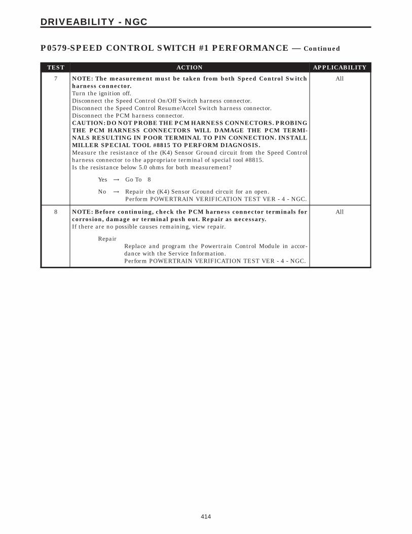
TEST ACTION APPLICABILITY
7 NOTE: The measurement must be taken from both Speed Control Switchharness connector.Turn the ignition off.Disconnect the Speed Control On/Off Switch harness connector.Disconnect the Speed Control Resume/Accel Switch harness connector.Disconnect the PCM harness connector.CAUTION: DO NOT PROBE THE PCM HARNESS CONNECTORS. PROBINGTHE PCM HARNESS CONNECTORS WILL DAMAGE THE PCM TERMI-NALS RESULTING IN POOR TERMINAL TO PIN CONNECTION. INSTALLMILLER SPECIAL TOOL #8815 TO PERFORM DIAGNOSIS.Measure the resistance of the (K4) Sensor Ground circuit from the Speed Controlharness connector to the appropriate terminal of special tool #8815.Is the resistance below 5.0 ohms for both measurement?
All
Yes → Go To 8
No → Repair the (K4) Sensor Ground circuit for an open.Perform POWERTRAIN VERIFICATION TEST VER - 4 - NGC.
8 NOTE: Before continuing, check the PCM harness connector terminals forcorrosion, damage or terminal push out. Repair as necessary.If there are no possible causes remaining, view repair.
All
RepairReplace and program the Powertrain Control Module in accor-dance with the Service Information.Perform POWERTRAIN VERIFICATION TEST VER - 4 - NGC.
414
DRIVEABILITY - NGC
P0579-SPEED CONTROL SWITCH #1 PERFORMANCE — Continued

Symptom:P0580-SPEED CONTROL SWITCH #1 LOW
When Monitored and Set Condition:
P0580-SPEED CONTROL SWITCH #1 LOW
When Monitored: With the ignition key on. Battery voltage above 10 volts.
Set Condition: The PCM detects the Speed Control Switch Signal circuit voltage is lessthan 0.43. One Trip Fault.
POSSIBLE CAUSES
SPEED CONTROL SWITCH VOLTAGE LOW
SPEED CONTROL ON/OFF SWITCH
SPEED CONTROL RESUME/ACCEL SWITCH
(V37) S/C SWITCH SIGNAL CIRCUIT SHORTED TO (K4) SENSOR GROUND
(V37) S/C SWITCH SIGNAL CIRCUIT SHORTED TO GROUND
PCM
TEST ACTION APPLICABILITY
1 NOTE: Do not press any of the Speed Control Switch buttons.Ignition on, engine not running.With the DRBIIIt, read the Speed Control voltage.Is the Speed Control voltage below 1.0 volt?
All
Yes → Go To 2
No → Refer to the INTERMITTENT CONDITION symptom in theDriveability category.Perform POWERTRAIN VERIFICATION TEST VER - 4 - NGC.
2 Ignition on, engine not running.With the DRBIIIt, monitor the Speed Control Switch voltage.Disconnect the Speed Control On/Off Switch harness connector.Did the voltage change to above 4.7 volts?
All
Yes → Replace the Speed Control On/Off Switch.Perform POWERTRAIN VERIFICATION TEST VER - 4 - NGC.
No → Go To 3
3 Ignition on, engine not running.With the DRBIIIt, monitor the Speed Control Switch voltage.Disconnect the Speed Control Resume/Accel Switch harness connector.Did the volt change to above 4.7 volts?
All
Yes → Replace the Speed Control Resume/Accel Switch.Perform POWERTRAIN VERIFICATION TEST VER - 4 - NGC.
No → Go To 4
415
DRIVEABILITY - NGC

TEST ACTION APPLICABILITY
4 Turn the ignition off.Disconnect the Speed Control On/Off Switch harness connector.Disconnect the Speed Control Resume/Accel Switch harness connector.Disconnect the PCM harness connector.CAUTION: DO NOT PROBE THE PCM HARNESS CONNECTORS. PROBINGTHE PCM HARNESS CONNECTORS WILL DAMAGE THE PCM TERMI-NALS RESULTING IN POOR TERMINAL TO PIN CONNECTION. INSTALLMILLER SPECIAL TOOL #8815 TO PERFORM DIAGNOSIS.Measure the resistance between the (K4) Sensor ground circuit and the (V37) S/CSwitch Signal circuit at the Speed Control Switch.Is the resistance below 5.0 ohms?
All
Yes → Repair the (V37) S/C Switch Signal circuit short to (K4) Sensorground circuit.Perform POWERTRAIN VERIFICATION TEST VER - 4 - NGC.
No → Go To 5
5 Turn the ignition off.Disconnect the Speed Control On/Off Switch harness connector.Disconnect the Speed Control Resume/Accel Switch harness connector.Disconnect the PCM harness connector.CAUTION: DO NOT PROBE THE PCM HARNESS CONNECTORS. PROBINGTHE PCM HARNESS CONNECTORS WILL DAMAGE THE PCM TERMI-NALS RESULTING IN POOR TERMINAL TO PIN CONNECTION. INSTALLMILLER SPECIAL TOOL #8815 TO PERFORM DIAGNOSIS.Measure the resistance between ground and the (V37) S/C Switch Signal circuit tothe appropriate terminal of special tool #8815.Is the resistance below 5.0 ohms?
All
Yes → Repair the short to ground in the (V37) S/C Switch Signal circuit.Perform POWERTRAIN VERIFICATION TEST VER - 4 - NGC.
No → Go To 6
6 NOTE: Before continuing, disconnect the PCM harness connector andcheck the related wiring terminals for corrosion, damage or terminal pushout. Repair as necessary.If there are no possible causes remaining, view repair.
All
RepairReplace and program the Powertrain Control Module in accor-dance with the Service Information.Perform POWERTRAIN VERIFICATION TEST VER - 4 - NGC.
416
DRIVEABILITY - NGC
P0580-SPEED CONTROL SWITCH #1 LOW — Continued

Symptom:P0581-SPEED CONTROL SWITCH #1 HIGH
When Monitored and Set Condition:
P0581-SPEED CONTROL SWITCH #1 HIGH
When Monitored: With the ignition key on. Battery voltage above 10 volts.
Set Condition: The PCM detects an open or short to voltage in the Speed Control SwitchSignal circuit. One Trip Fault.
POSSIBLE CAUSES
SPEED CONTROL SWITCH VOLTAGE HIGH
SPEED CONTROL SWITCHES
(V37) S/C SWITCH SIGNAL CIRCUIT SHORTED TO BATTERY VOLTAGE
(K4) SENSOR GROUND OPEN
PCM
TEST ACTION APPLICABILITY
1 NOTE: Do not press any of the Speed Control Switch buttons.Ignition on, engine not running.With the DRBIIIt, read the Speed Control voltage.Is the Speed Control voltage above 4.8 volt?
All
Yes → Go To 2
No → Refer to the INTERMITTENT CONDITION symptom in theDriveability category.Perform POWERTRAIN VERIFICATION TEST VER - 4 - NGC.
2 Turn the ignition off.Remove the Speed Control Switches from the steering wheel.Measure the resistance across each Speed Control Switch.Monitor the ohmmeter while pressing each function button on each switch.Resume/Accel - 15,400 ohmsCancel - 909 +/- 9 ohmsDecel (Coast) - 2940 +/- 30 ohmsOn/Off - 0 ohmsSet - 6650 +/- 66 ohmsDoes the function on the Speed Control Switches have the correct ohm value?
All
Yes → Go To 3
No → Replace the Speed Control Switch that had the incorrect resis-tance value.Perform POWERTRAIN VERIFICATION TEST VER - 4 - NGC.
417
DRIVEABILITY - NGC

TEST ACTION APPLICABILITY
3 Turn the ignition off.Disconnect the Speed Control On/Off Switch harness connector.Disconnect the Speed Control Resume/Accel Switch harness connector.Disconnect the PCM harness connector.Measure the voltage of the (V37) S/C Switch Signal circuit at the Speed Controlharness connector.Is the is the voltage above 5.0 volts?
All
Yes → Repair the (V37) S/C Switch Signal circuit shorted to the batteryvoltage.Perform POWERTRAIN VERIFICATION TEST VER - 4 - NGC.
No → Go To 4
4 NOTE: The measurement must be taken from both Speed Control Switchharness connector.Turn the ignition off.Disconnect the Speed Control On/Off Switch harness connector.Disconnect the Speed Control Resume/Accel Switch harness connector.Disconnect the PCM harness connector.CAUTION: DO NOT PROBE THE PCM HARNESS CONNECTORS. PROBINGTHE PCM HARNESS CONNECTORS WILL DAMAGE THE PCM TERMI-NALS RESULTING IN POOR TERMINAL TO PIN CONNECTION. INSTALLMILLER SPECIAL TOOL #8815 TO PERFORM DIAGNOSIS.Measure the resistance of the (K4) Sensor Ground circuit from the Speed Controlharness connector to the appropriate terminal of special tool #8815.Is the resistance below 5.0 ohms for both measurement?
All
Yes → NOTE: Before continuing, check the PCM harness connectorterminals for corrosion, damage or terminal push out. Repair asnecessary. Replace and program the Powertrain Control Modulein accordance with the Service Information.Perform POWERTRAIN VERIFICATION TEST VER - 4 - NGC.
No → Repair the (K4) Sensor Ground circuit for an open.Perform POWERTRAIN VERIFICATION TEST VER - 4 - NGC.
418
DRIVEABILITY - NGC
P0581-SPEED CONTROL SWITCH #1 HIGH — Continued

Symptom:P0582-SPEED CONTROL VACUUM SOLENOID CIRCUIT
When Monitored and Set Condition:
P0582-SPEED CONTROL VACUUM SOLENOID CIRCUIT
When Monitored: Ignition on. Speed Control active.
Set Condition: The PCM detects an open or short to voltage in the Speed Control VacuumControl circuit. One Trip Fault.
POSSIBLE CAUSES
SPEED CONTROL SOLENOID OPERATION
SPEED CONTROL VACUUM SOLENOID
(V36) S/C VACUUM SOL CONTROL CIRCUIT SHORTED TO GROUND
(V36) S/C VACUUM SOL CONTROL CIRCUIT OPEN
PCM (VACUUM SOLENOID)
TEST ACTION APPLICABILITY
1 Ignition on, engine not running.With the DRBIIIt, read DTCs and record the related Freeze Frame data.With the DRBIIIt, actuate the Speed Control Vacuum Solenoid and note operation.Does the Speed Control Vacuum Solenoid actuate properly?
All
Yes → Refer to the INTERMITTENT CONDITION symptom in theDriveability category.Perform POWERTRAIN VERIFICATION TEST VER - 4 - NGC.
No → Go To 2
2 Turn the ignition off.Disconnect the Speed Control Servo harness connector.Ignition on, engine not running.With the DRBIIIt, actuate the Speed Control Vacuum Solenoid.Using a 12-volt test light connected to ground, probe the S/C Vacuum Control circuit.Does the test light illuminate brightly and flash?
All
Yes → Replace the Speed Control Servo.Perform POWERTRAIN VERIFICATION TEST VER - 4 - NGC.
No → Go To 3
419
DRIVEABILITY - NGC

TEST ACTION APPLICABILITY
3 Turn the ignition off.Disconnect the S/C Servo harness connector.Disconnect the PCM harness connector.CAUTION: DO NOT PROBE THE PCM HARNESS CONNECTORS. PROBINGTHE PCM HARNESS CONNECTORS WILL DAMAGE THE PCM TERMI-NALS RESULTING IN POOR TERMINAL TO PIN CONNECTION. INSTALLMILLER SPECIAL TOOL #8815 TO PERFORM DIAGNOSIS.Measure the resistance of the (V36) S/C Vacuum Sol Control circuit from the SpeedControl Servo harness connector to the appropriate terminal of special tool # 8815.Is the resistance below 5.0 ohms?
All
Yes → Go To 4
No → Repair the open/high resistance in the (V36) S/C Vacuum SolControl circuit.Perform POWERTRAIN VERIFICATION TEST VER - 4 - NGC.
4 Turn the ignition off.Disconnect the S/C Servo harness connector.Disconnect the PCM harness connector.Measure the resistance between ground and the (V36) S/C Vacuum Solenoid Controlcircuit at the Speed Control Servo harness connector.Is the resistance below 100 ohms?
All
Yes → Repair the short to ground in the (V36) S/C Vacuum Sol Controlcircuit.Perform POWERTRAIN VERIFICATION TEST VER - 4 - NGC.
No → Go To 5
5 NOTE: Before continuing, check the PCM harness connector terminals forcorrosion, damage, or terminal push out. Repair as necessary.If the there are no possible causes remaining, view repair.
All
RepairReplace and program the Powertrain Control Module in accor-dance with the Service Information.Perform POWERTRAIN VERIFICATION TEST VER - 4 - NGC.
420
DRIVEABILITY - NGC
P0582-SPEED CONTROL VACUUM SOLENOID CIRCUIT — Continued

Symptom:P0586-SPEED CONTROL VENT SOLENOID CIRCUIT
When Monitored and Set Condition:
P0586-SPEED CONTROL VENT SOLENOID CIRCUIT
When Monitored: Ignition on. Speed Control active.
Set Condition: The PCM detects an open or short to voltage in the Speed Control VentControl circuit. One Trip Fault.
POSSIBLE CAUSES
SPEED CONTROL SOLENOID OPERATION
SPEED CONTROL VENT SOLENOID
(V35) S/C VENT SOL CONTROL CIRCUIT OPEN
(V35) S/C VENT SOL CONTROL CIRCUIT SHORTED TO GROUND
PCM (VENT SOLENOID)
TEST ACTION APPLICABILITY
1 Ignition on, engine not running.With the DRBIIIt, read DTCs and record the related Freeze Frame data.With the DRBIIIt, actuate the Speed Control Vent Solenoid and note operation.Does the Speed Control Vent Solenoid acutate properly?
All
Yes → Refer to the INTERMITTENT CONDITION symptom in theDriveability category.Perform POWERTRAIN VERIFICATION TEST VER - 4 - NGC.
No → Go To 2
2 Turn the ignition off.Disconnect the Speed Control Servo harness connector.Ignition on, engine not running.With the DRBIIIt, actuate the Speed Control Vent Solenoid.Using a 12-volt test light connected to ground, probe the (V35) Speed Control VentSolenoid Control circuit in the Speed Control Servo harness connector.Does the test light illuminate brightly and flash?
All
Yes → Replace the Speed Control Servo.Perform POWERTRAIN VERIFICATION TEST VER - 4 - NGC.
No → Go To 3
421
DRIVEABILITY - NGC

TEST ACTION APPLICABILITY
3 Turn the ignition off.Disconnect the S/C Servo harness connector.Disconnect the PCM harness connector.CAUTION: DO NOT PROBE THE PCM HARNESS CONNECTORS. PROBINGTHE PCM HARNESS CONNECTORS WILL DAMAGE THE PCM TERMI-NALS RESULTING IN POOR TERMINAL TO PIN CONNECTION. INSTALLMILLER SPECIAL TOOL #8815 TO PERFORM DIAGNOSIS.Measure the resistance of the (V35) S/C Vent Sol Control circuit from the SpeedControl Servo harness connector to the appropriate terminal of special tool #8815.Is the resistance below 5.0 ohms?
All
Yes → Go To 4
No → Repair the open/high resistance in the (V35) S/C Vent Sol Controlcircuit.Perform POWERTRAIN VERIFICATION TEST VER - 4 - NGC.
4 Turn the ignition off.Disconnect the S/C Servo harness connector.Disconnect the PCM harness connector.Measure the resistance between ground and the (V35) S/C Vent Sol Control circuit atthe Speed Control Servo harness connector.Is the resistance below 100 ohms?
All
Yes → Repair the short to ground in the (V35) Speed Control VentSolenoid Control circuit.Perform POWERTRAIN VERIFICATION TEST VER - 4 - NGC.
No → Go To 5
5 NOTE: Before continuing, check the PCM harness connector terminals forcorrosion, damage, or terminal push out. Repair as necessary.If the there are no possible causes remaining, view repair.
All
RepairReplace and program the Powertrain Control Module in accor-dance with the Service Information.Perform POWERTRAIN VERIFICATION TEST VER - 4 - NGC.
422
DRIVEABILITY - NGC
P0586-SPEED CONTROL VENT SOLENOID CIRCUIT — Continued

Symptom:P0594-SPEED CONTROL SERVO POWER CIRCUIT
When Monitored and Set Condition:
P0594-SPEED CONTROL SERVO POWER CIRCUIT
When Monitored: With the ignition key on. The speed control switched on.
Set Condition: The PCM detects a open or short in the Speed Control Power Supplycircuit. One Trip Fault.
POSSIBLE CAUSES
(V40) S/C BRAKE SWITCH OUTPUT CIRCUIT
(V32) S/C POWER SUPPLY CIRCUIT
(V32) S/C POWER SUPPLY CIRCUIT SHORTED TO GROUND
(V40) S/C BRAKE SWITCH OUTPUT CIRCUIT SHORTEDTO GROUND
(V40) S/C BRAKE SWITCH OUTPUT CIRCUIT OPEN
BRAKE LAMP SWITCH
PCM (S/C SOURCE CIRCUIT)
TEST ACTION APPLICABILITY
1 Turn the ignition off.Disconnect the Speed Control Servo harness connector.Ignition on, engine not running.NOTE: It is necessary to PRESS and HOLD the Speed Control Switch in theON position while checking for voltage.Using a 12-volt test light connected to ground, probe the (V40) S/C Brake SwitchOutput terminal in the Servo Harness connector.Does the test light illuminate brightly?
All
Yes → Refer to the INTERMITTENT CONDITION symptom in theDriveability category.Perform POWERTRAIN VERIFICATION TEST VER - 5 - NGC.
No → Go To 2
423
DRIVEABILITY - NGC

TEST ACTION APPLICABILITY
2 Turn the ignition off.Disconnect the PCM harness connector.Disconnect the Brake Lamp Switch harness connector.CAUTION: DO NOT PROBE THE PCM HARNESS CONNECTORS. PROBINGTHE PCM HARNESS CONNECTORS WILL DAMAGE THE PCM TERMI-NALS RESULTING IN POOR TERMINAL TO PIN CONNECTION. INSTALLMILLER SPECIAL TOOL #8815 TO PERFORM DIAGNOSIS.Measure the resistance of the (V32) S/C Power Supply circuit from the Brake LampSwitch harness connector to the appropriate terminal of special tool #8815.Is the resistance below 5.0 ohms?
All
Yes → Go To 3
No → Repair the open/high resistance in the (V32) S/C Power Supplycircuit between the PCM and Brake Switch.Perform POWERTRAIN VERIFICATION TEST VER - 5 - NGC.
3 Turn the ignition off.Disconnect the PCM harness connector.Disconnect the Brake Switch harness connector.Measure the resistance between ground and the (V32) S/C Power Supply circuit inthe Brake Switch harness connector.Is the resistance below 100 ohms?
All
Yes → Go To 4
No → Repair the short to ground in the (V32) S/C Power Supply circuit.Perform POWERTRAIN VERIFICATION TEST VER - 5 - NGC.
4 Turn the ignition off.Disconnect the S/C Servo harness connector.Disconnect the Brake Switch harness connector.Measure the resistance of the (V40) S/C Brake Switch Output circuit from the BrakeSwitch harness connector to the S/C Servo harness connector.Is the resistance below 5.0 ohms?
All
Yes → Go To 5
No → Repair the open/high resistance in the (V40) S/C Brake SwitchOutput circuit.Perform POWERTRAIN VERIFICATION TEST VER - 5 - NGC.
5 Turn the ignition off.Disconnect the Speed Control Servo harness connector.Disconnect the Brake Switch harness connector.Measure the resistance between ground and the (V40) S/C Brake Switch Outputcircuit at the Speed Control Servo harness connector.Is the resistance below 100 ohms?
All
Yes → Repair the short to ground in the (V40) S/C Brake Switch Outputcircuit.Perform POWERTRAIN VERIFICATION TEST VER - 5 - NGC.
No → Go To 6
424
DRIVEABILITY - NGC
P0594-SPEED CONTROL SERVO POWER CIRCUIT — Continued

TEST ACTION APPLICABILITY
6 Disconnect the Brake Lamp Switch harness connector.Ignition on, engine not running.Using a 12-volt test light connected to ground, probe the (V32) Speed Control PowerSupply circuit in the Brake Lamp Switch harness connector.NOTE: It is necessary to HOLD the Cruise Control Switch in the ON positionto get an accurate reading.Does the test light illuminate brightly?
All
Yes → Replace the Brake Lamp Switch.Perform POWERTRAIN VERIFICATION TEST VER - 5 - NGC.
No → Go To 7
7 NOTE: Before continuing, check the PCM harness connector terminals forcorrosion, damage, or terminal push out. Repair as necessary.If there are no possible causes remaining, view repair.
All
RepairReplace and program the Powertrain Control Module in accor-dance with the Service Information.Perform POWERTRAIN VERIFICATION TEST VER - 5 - NGC.
425
DRIVEABILITY - NGC
P0594-SPEED CONTROL SERVO POWER CIRCUIT — Continued

Symptom List:P0600-SERIAL COMMUNICATION LINKP0601-INTERNAL MEMORY CHECKSUM INVALID
Test Note: All symptoms listed above are diagnosed using the same tests.The title for the tests will be P0600-SERIAL COMMUNICA-TION LINK.
When Monitored and Set Condition:
P0600-SERIAL COMMUNICATION LINK
When Monitored: With the ignition on.
Set Condition: Internal Bus communication failure between processors.
P0601-INTERNAL MEMORY CHECKSUM INVALID
When Monitored: With the ignition on.
Set Condition: Internal checksum for software failed, does not match calculated value.
POSSIBLE CAUSES
PCM INTERNAL OR SPI
TEST ACTION APPLICABILITY
1 The Powertrain Control Module is reporting internal errors, view repair to continue. All
RepairReplace and program the Powertrain Control Module in accor-dance with the Service Information.Perform POWERTRAIN VERIFICATION TEST VER - 1 - NGC.
426
DRIVEABILITY - NGC

Symptom:P0622-GENERATOR FIELD CONTROL CIRCUIT
When Monitored and Set Condition:
P0622-GENERATOR FIELD CONTROL CIRCUIT
When Monitored: With the ignition on. Engine running.
Set Condition: When the PCM tries to regulate the generator field with no result duringmonitoring. One Trip Fault.
POSSIBLE CAUSES
GOOD TRIP EQUAL TO ZERO
GENERATOR OPERATION
(Z1) GEN FIELD GROUND CIRCUIT OPEN
(K20) GEN FIELD CONTROL CIRCUIT SHORTED TO BATTERY VOLTAGE
(K20) GEN FIELD CONTROL CIRCUIT SHORTED TO GROUND
(K20) GEN FIELD CONTROL CIRCUIT OPEN
PCM
TEST ACTION APPLICABILITY
1 Ignition on, engine not running.With the DRBIIIt, read DTCs and record the related Freeze Frame data.Is the Good Trip Counter displayed and equal to zero?
All
Yes → Refer to the INTERMITTENT CONDITION symptom in theDriveability category.Perform POWERTRAIN VERIFICATION TEST VER - 3 - NGC.
No → Go To 2
2 Turn the ignition off.Disconnect the Generator Field harness connector.Using a 12-volt test light, jumper it across the Generator Field harness connector.Ignition on, engine not running.With the DRBIIIt, actuate the Generator Field Driver circuit.Does the test light illuminate brightly and flash on and off?
All
Yes → Replace the Generator.Perform POWERTRAIN VERIFICATION TEST VER - 3 - NGC.
No → Go To 3
427
DRIVEABILITY - NGC

TEST ACTION APPLICABILITY
3 Turn the ignition off.Disconnect the Generator Field harness connector.Using a 12-volt test connected to battery voltage, probe the (Z1) Gen Ground circuitin the Generator Field harness connector.Does the test light illuminate brightly?
All
Yes → Go To 4
No → Repair the open in the (Z1) Gen Field Ground circuit.Perform POWERTRAIN VERIFICATION TEST VER - 3 - NGC.
4 Turn the ignition off.Disconnect the Generator Field harness connector.Disconnect the PCM harness connector.Measure the voltage on the (K20) Gen Field Control circuit in the Generator Fieldharness connector.Is the voltage above 1.0 volts?
All
Yes → Repair the short to voltage in the (K20) Gen Field Control circuit.Perform POWERTRAIN VERIFICATION TEST VER - 3 - NGC.
No → Go To 5
5 Turn the ignition on.Disconnect the Generator Field harness connector.Disconnect the PCM harness connector.Measure the resistance between ground and the (K20) Gen Field Control circuit inthe Generator Field harness connector.Is the resistance below 100 ohms?
All
Yes → Repair the (K20) Gen Field Control circuit for a short to ground.Perform POWERTRAIN VERIFICATION TEST VER - 3 - NGC.
No → Go To 6
6 Turn the ignition off.Disconnect the Generator Field harness connector.Disconnect the PCM harness connector.CAUTION: DO NOT PROBE THE PCM HARNESS CONNECTORS. PROBINGTHE PCM HARNESS CONNECTORS WILL DAMAGE THE PCM TERMI-NALS RESULTING IN POOR TERMINAL TO PIN CONNECTION. INSTALLMILLER SPECIAL TOOL #8815 TO PERFORM DIAGNOSIS.Measure the resistance of the (K20) Gen Field Control circuit from the GeneratorField harness connector to the appropriate terminal of the special tool #8815.Is the resistance below 5.0 ohms?
All
Yes → Go To 7
No → Repair the open in the (K20) Gen Field Control circuit.Perform POWERTRAIN VERIFICATION TEST VER - 3 - NGC.
7 NOTE: Before continuing, check the PCM connector terminals for corro-sion, damage, or terminal push out. Repair as necessary.If there are no possible causes remaining, view repair.
All
RepairReplace and program the Powertrain Control Module in accor-dance with the Service Information.Perform POWERTRAIN VERIFICATION TEST VER - 3 - NGC.
428
DRIVEABILITY - NGC
P0622-GENERATOR FIELD CONTROL CIRCUIT — Continued
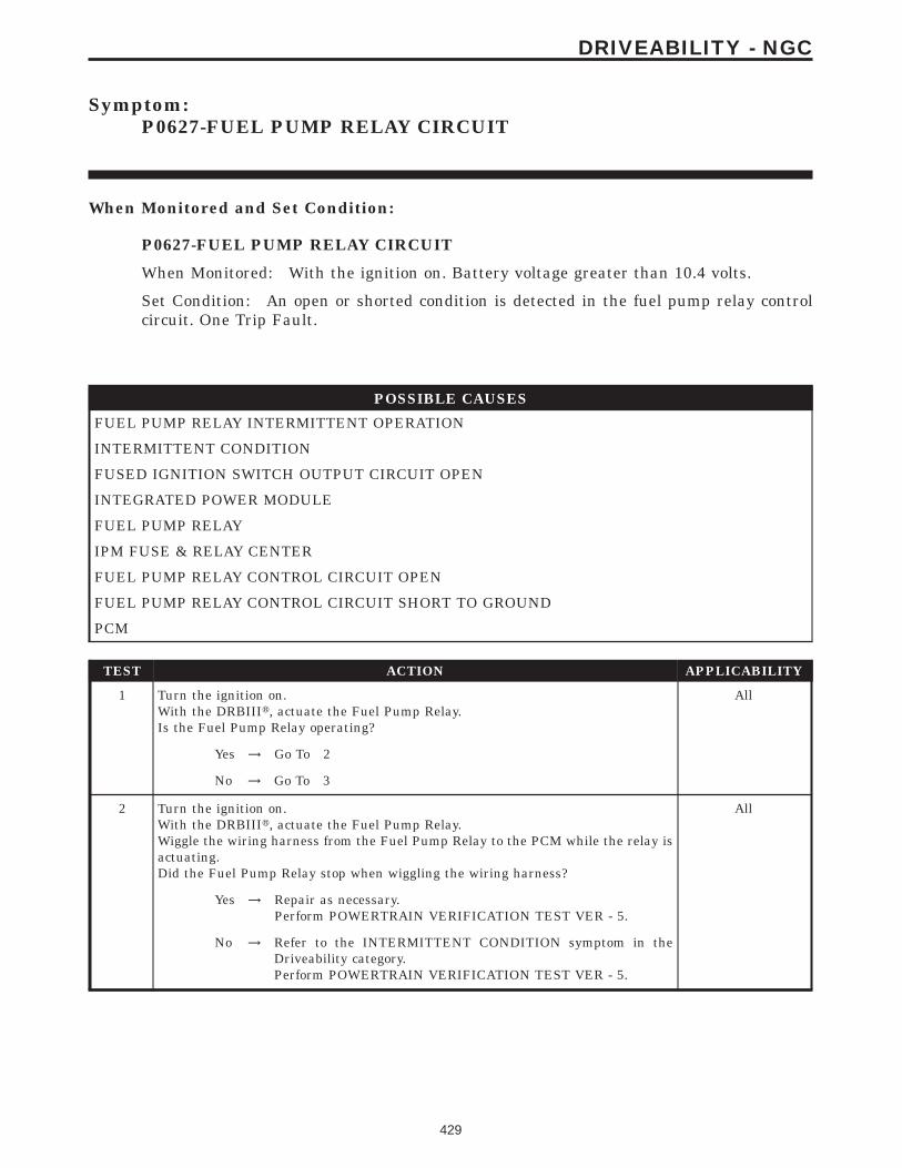
Symptom:P0627-FUEL PUMP RELAY CIRCUIT
When Monitored and Set Condition:
P0627-FUEL PUMP RELAY CIRCUIT
When Monitored: With the ignition on. Battery voltage greater than 10.4 volts.
Set Condition: An open or shorted condition is detected in the fuel pump relay controlcircuit. One Trip Fault.
POSSIBLE CAUSES
FUEL PUMP RELAY INTERMITTENT OPERATION
INTERMITTENT CONDITION
FUSED IGNITION SWITCH OUTPUT CIRCUIT OPEN
INTEGRATED POWER MODULE
FUEL PUMP RELAY
IPM FUSE & RELAY CENTER
FUEL PUMP RELAY CONTROL CIRCUIT OPEN
FUEL PUMP RELAY CONTROL CIRCUIT SHORT TO GROUND
PCM
TEST ACTION APPLICABILITY
1 Turn the ignition on.With the DRBIIIt, actuate the Fuel Pump Relay.Is the Fuel Pump Relay operating?
All
Yes → Go To 2
No → Go To 3
2 Turn the ignition on.With the DRBIIIt, actuate the Fuel Pump Relay.Wiggle the wiring harness from the Fuel Pump Relay to the PCM while the relay isactuating.Did the Fuel Pump Relay stop when wiggling the wiring harness?
All
Yes → Repair as necessary.Perform POWERTRAIN VERIFICATION TEST VER - 5.
No → Refer to the INTERMITTENT CONDITION symptom in theDriveability category.Perform POWERTRAIN VERIFICATION TEST VER - 5.
429
DRIVEABILITY - NGC

TEST ACTION APPLICABILITY
3 Turn the ignition off.Remove the Fuel Pump Relay from the IPM.Turn the ignition on.Using a 12-volt test light connected to ground, probe the Fused Ignition Switchcircuit in the IPM.Does the test light illuminate?
All
Yes → Go To 4
No → Go To 9
4 Turn the ignition off.Remove the Fuel Pump Relay from the IPM.Turn the ignition on.Using a 12-volt test light connected to 12-volts, probe the Fuel Pump Relay Controlcircuit in the IPM.With the DRBIIIt, actuate the Fuel Pump Relay.Does the test light flash on and off?
All
Yes → Replace the Fuel Pump Relay.Perform POWERTRAIN VERIFICATION TEST VER - 5.
No → Go To 5
5 Turn the ignition off.Disconnect the IPM C3 harness connector.Turn the ignition on.Using a 12-volt test light connected to 12-volts, probe the Fuel Pump Relay Controlcircuit in the IPM harness connector..With the DRBIIIt, actuate the Fuel Pump Relay.Does the test light flash on and off?
All
Yes → Replace the IPM Fused & Relay Center.Perform POWERTRAIN VERIFICATION TEST VER - 5.
No → Go To 6
6 Turn the ignition off.Disconnect the IPM C3 harness connector.Disconnect the PCM harness connector.Measure the resistance of the Fuel Pump Relay Control circuit between the IPM C3harness connector and the PCM harness connector.Is the resistance below 5.0 ohms?
All
Yes → Go To 7
No → Repair the Fuel Pump Relay Control circuit for an open.Perform POWERTRAIN VERIFICATION TEST VER - 5.
7 Turn the ignition off.Disconnect the IPM C3 harness connector.Disconnect the PCM harness connector.Measure the resistance of the Fuel Pump Relay Control circuit in the IPM C3 harnessconnector to ground.Is the resistance below 5.0 ohms?
All
Yes → Repair the Fuel Pump Relay Control circuit for a short to ground.Perform POWERTRAIN VERIFICATION TEST VER - 5.
No → Go To 8
430
DRIVEABILITY - NGC
P0627-FUEL PUMP RELAY CIRCUIT — Continued

TEST ACTION APPLICABILITY
8 If there are no possible causes remaining, view repair. All
RepairReplace and program the Powertrain Control Module in accor-dance with the Service Information.Perform POWERTRAIN VERIFICATION TEST VER - 5.
9 Turn the ignition off.Disconnect the IPM C9 harness connector.Turn the ignition on.Using a 12-volt test light connected to ground, probe the Fused Ignition Switchcircuit in the IPM harness connector.Does the test light illuminate?
All
Yes → Test Complete.
No → Repair the Fused Ignition Switch Output circuit for an open.Perform POWERTRAIN VERIFICATION TEST VER - 5.
431
DRIVEABILITY - NGC
P0627-FUEL PUMP RELAY CIRCUIT — Continued

Symptom:P0630-VIN NOT PROGRAMMED IN PCM
When Monitored and Set Condition:
P0630-VIN NOT PROGRAMMED IN PCM
When Monitored: Ignition on.
Set Condition: The VIN has not been programmed into the PCM.
POSSIBLE CAUSES
PROGRAMMING VIN INTO PCM
VERIFY PCM PROGRAMMING
PCM
TEST ACTION APPLICABILITY
1 Ignition on, engine not running.With the DRBIIIt, erase DTCs.Using the DRBIIIt, program VIN into the PCM.Start the engine.NOTE: If the engine will not start, crank the engine over for 15 seconds.Crank at least 2 times with the ignition switch returning to the off positioneach time.Allow the engine to reach normal operating temperature.With the DRBIIIt, read DTCs.Does the DTC reset?
All
Yes → Go To 2
No → The VIN has been successfully programmed into the PCM. Test iscomplete.Perform POWERTRAIN VERIFICATION TEST VER - 1 - NGC.
2 NOTE: The ignition switch must be left in the off position for a minimum of10 seconds.Cycle the ignition switch to the off position and then back to run.Attempt to program the PCM with the applicable information.Start the vehicle and allow it to reach normal operating temperatures.With the DRBIIIt, read DTCs.Does the DTC reset?
All
Yes → Replace and program the Powertrain Control Module in accor-dance with the Service Information.Perform POWERTRAIN VERIFICATION TEST VER - 1 - NGC.
No → The VIN has been successfully programmed into the PCM. Test iscomplete.Perform POWERTRAIN VERIFICATION TEST VER - 1 - NGC.
432
DRIVEABILITY - NGC

Symptom:P0632-ODOMETER NOT PROGRAMMED IN PCM
When Monitored and Set Condition:
P0632-ODOMETER NOT PROGRAMMED IN PCM
When Monitored: Ignition on.
Set Condition: The mileage has not been programmed into the PCM.
POSSIBLE CAUSES
PROGRAMMING MILEAGE INTO PCM
VERIFY PCM PROGRAMMING
PCM
TEST ACTION APPLICABILITY
1 Ignition on, engine not running.With the DRBIIIt, erase DTCs.Using the DRBIIIt, program the mileage into the PCM.Start the engine.Allow the engine to reach normal operating temperature.With the DRBIIIt, read DTCs.Does the DTC reset?
All
Yes → Go To 2
No → The mileage has been succcessfully programmed into the PCM.Test is complete.Perform POWERTRAIN VERIFICATION TEST VER - 1 - NGC.
2 NOTE: The ignition switch must be left in the off position for a minimum of10 seconds.Cycle the ignition switch to the off position and then back to run.Attempt to program the PCM with the applicable information.Start the vehicle and allow it to reach normal operating temperatures.With the DRBIIIt, read DTCs.Does the DTC reset?
All
Yes → Replace and program the Powertrain Control Module in accor-dance with the Service Information.Perform POWERTRAIN VERIFICATION TEST VER - 1 - NGC.
No → The mileage has been successfully programmed into the PCM.Test is complete.Perform POWERTRAIN VERIFICATION TEST VER - 1 - NGC.
433
DRIVEABILITY - NGC

Symptom:P0633-SKIM KEY NOT PROGRAMMED IN PCM
When Monitored and Set Condition:
P0633-SKIM KEY NOT PROGRAMMED IN PCM
When Monitored: Ignition on.
Set Condition: The SKIM Key information has not been programmed into the PCM.
POSSIBLE CAUSES
PROGRAMMING SKIM KEY INTO PCM
VERIFY PCM PROGRAMMING
PCM
TEST ACTION APPLICABILITY
1 Ignition on, engine not running.With the DRBIIIt, erase DTCs.Using the DRBIIIt, program the SKIM Key information into the PCM.Start the engine.NOTE: If the engine will not start, crank the engine over for 15 seconds.Crank at least 2 times with the ignition switch returning to the off positioneach time.Allow the engine to reach normal operating temperature.With the DRBIIIt, read DTCs.Does the DTC reset?
All
Yes → Go To 2
No → The SKIM KEY information has been succcessfully programmedinto the PCM. Test is complete.Perform SKIS VERIFICATION.
2 NOTE: The ignition switch must be left in the off position for a minimum of10 seconds.Cycle the ignition switch to the off position and then back to run.Attempt to program the PCM with the applicable information.Start the vehicle and allow it to reach normal operating temperatures.With the DRBIIIt, read DTCs.Does the DTC reset?
All
Yes → Replace and program the Powertrain Control Module in accor-dance with the Service Information.Perform SKIS VERIFICATION.
No → The SKIM Key Information has been successfully programmedinto the PCM. Test is complete.Perform SKIS VERIFICATION.
434
DRIVEABILITY - NGC

Symptom:P0645-A/C CLUTCH RELAY CIRCUIT
When Monitored and Set Condition:
P0645-A/C CLUTCH RELAY CIRCUIT
When Monitored: With the ignition on. Battery voltage greater than 10 volts. A/C Switchon.
Set Condition: An open or shorted condition is detected in the A/C clutch relay controlcircuit. One Trip Fault.
POSSIBLE CAUSES
A/C CLUTCH RELAY INTERMITTENT OPERATION
INTERMITTENT CONDITION
FUSED IGNITION SWITCH OUTPUT CIRCUIT OPEN
INTEGRATED POWER MODULE
A/C CLUTCH RELAY
IPM FUSE & RELAY CENTER
A/C CLUTCH RELAY CONTROL CKT OPEN
A/C CLUTCH RELAY CONTROL CIRCUIT SHORT TO GROUND
PCM
TEST ACTION APPLICABILITY
1 Turn the ignition on.With the DRBIIIt, actuate the A/C Clutch Relay.Is the A/C Clutch Relay operating?
All
Yes → Go To 2
No → Go To 3
2 Turn the ignition on.With the DRBIIIt, actuate the A/C Clutch Relay.Wiggle the wiring harness from the A/C Clutch Relay to the PCM while the relay isactuating.Did the A/C Clutch Relay stop when wiggling the wiring harness?
All
Yes → Repair as necessary.Perform POWERTRAIN VERIFICATION TEST VER - 5.
No → Refer to the INTERMITTENT CONDITION symptom in theDriveability category.Perform POWERTRAIN VERIFICATION TEST VER - 5.
435
DRIVEABILITY - NGC

TEST ACTION APPLICABILITY
3 Turn the ignition off.Remove the A/C Clutch Relay from the IPM.Turn the ignition on.Using a 12-volt test light connected to ground, probe the Fused Ignition Switchcircuit in the IPM.Does the test light illuminate?
All
Yes → Go To 4
No → Go To 9
4 Turn the ignition off.Remove the A/C Clutch Relay from the IPM.Turn the ignition on.Using a 12-volt test light connected to 12-volts, probe the A/C Clutch Relay circuit inthe IPM.With the DRBIIIt, actuate the A/C Clutch Relay.Does the test light flash on and off?
All
Yes → Replace the A/C Clutch Relay.Perform POWERTRAIN VERIFICATION TEST VER - 5.
No → Go To 5
5 Turn the ignition off.Disconnect the IPM C3 harness connector.Turn the ignition on.Using a 12-volt test light connected to 12-volts, probe the A/C Clutch Relay Controlcircuit in the IPM harness connector.With the DRBIIIt, actuate the A/C Clutch Relay.Does the test light flash on and off?
All
Yes → Replace the IPM Fused & Relay Center.Perform POWERTRAIN VERIFICATION TEST VER - 5.
No → Go To 6
6 Turn the ignition off.Disconnect the IPM C3 harness connector.Disconnect the PCM harness connector.Measure the resistance of the A/C Clutch Relay Control circuit between the IPM C3harness connector and the PCM harness connector.Is the resistance below 5.0 ohms?
All
Yes → Go To 7
No → Repair the A/C Clutch Relay Control circuit for an open.Perform POWERTRAIN VERIFICATION TEST VER - 5.
7 Turn the ignition off.Disconnect the IPM C3 harness connector.Disconnect the PCM harness connector.Measure the resistance of the A/C Clutch Relay Control circuit in the IPM C3 harnessconnector to ground.Is the resistance below 5.0 ohms?
All
Yes → Repair the A/C Clutch Relay Control circuit for a short to ground.Perform POWERTRAIN VERIFICATION TEST VER - 5.
No → Go To 8
436
DRIVEABILITY - NGC
P0645-A/C CLUTCH RELAY CIRCUIT — Continued

TEST ACTION APPLICABILITY
8 If there are no possible causes remaining, view repair. All
RepairReplace and program the Powertrain Control Module Module inaccordance with the Service Information.Perform POWERTRAIN VERIFICATION TEST VER - 5.
9 Turn the ignition off.Disconnect the IPM C3 harness connector.Turn the ignition on.Using a 12-volt test light connected to ground, probe the Fused Ignition Switchcircuit in the IPM harness connector.Does the test light illuminate?
All
Yes → Replace the IPM Fuse & Relay Center.Perform POWERTRAIN VERIFICATION TEST VER - 5.
No → Repair the Fused Ignition Switch Output circuit for an open.Perform POWERTRAIN VERIFICATION TEST VER - 5.
437
DRIVEABILITY - NGC
P0645-A/C CLUTCH RELAY CIRCUIT — Continued

Symptom:P0685-ASD RELAY CONTROL CIRCUIT
When Monitored and Set Condition:
P0685-ASD RELAY CONTROL CIRCUIT
When Monitored: With ignition on. Battery voltage above 10 volts.
Set Condition: An open or shorted condition is detected in the ASD relay control circuit.One trip Fault.
POSSIBLE CAUSES
ASD RELAY INTERMITTENT OPERATION
INTERMITTENT CONDITION
FUSED B+ OUTPUT CIRCUIT
ASD RELAY
IPM FUSE & RELAY CENTER
ASD RELAY CONTROL CIRCUIT OPEN
ASD RELAY CONTROL CIRCUIT SHORT TO GROUND
PCM
TEST ACTION APPLICABILITY
1 Turn the ignition on.With the DRBIIIt, actuate the ASD Relay.Is the ASD Relay operating?
All
Yes → Go To 2
No → Go To 3
2 Turn the ignition on.With the DRBIIIt, actuate the ASD Relay.Wiggle the wiring harness from the ASD Relay to the PCM while the relay isactuating.Did the ASD Relay stop when wiggling the wiring harness?
All
Yes → Repair as necessary.Perform POWERTRAIN VERIFICATION TEST VER - 5.
No → Refer to the INTERMITTENT CONDITION symptom in theDriveability category.Perform POWERTRAIN VERIFICATION TEST VER - 5.
438
DRIVEABILITY - NGC

TEST ACTION APPLICABILITY
3 NOTE: Inspect the ASD Relay fuse located in the IPM. If the ASD Relay fuseis open, repair the cause of the open first before continuing. Inspect the ASDRelay Output circuit for a short to ground for the cause of the open fuse.Turn the ignition off.Remove the ASD Relay from the IPM.Turn the ignition on.Using a 12-volt test light connected to ground, probe the Fused B+ circuit in the IPM.Does the test light illuminate?
All
Yes → Go To 4
No → Replace the IPM Fuse & Relay Center.Perform POWERTRAIN VERIFICATION TEST VER - 5.
4 Turn the ignition off.Remove the ASD Relay from the IPM.Turn the ignition on.Using a 12-volt test light connected to 12-volts, probe the ASD Relay Control circuitin the IPM.With the DRBIIIt, actuate the ASD Relay.Does the test light flash on and off?
All
Yes → Replace the ASD Relay.Perform POWERTRAIN VERIFICATION TEST VER - 5.
No → Go To 5
5 Turn the ignition off.Disconnect the IPM C3 harness connector.Turn the ignition on.Using a 12-volt test light connected to 12-volts, probe the ASD Relay Control circuitin the IPM harness connector.With the DRBIIIt, actuate the ASD Relay.Does the test light flash on and off?
All
Yes → Replace the IPM Fused & Relay Center.Perform POWERTRAIN VERIFICATION TEST VER - 5.
No → Go To 6
6 Turn the ignition off.Disconnect the IPM C3 harness connector.Disconnect the PCM harness connector.Measure the resistance of the ASD Relay Control circuit between the IPM C3 harnessconnector and the PCM harness connector.Is the resistance below 5.0 ohms.
All
Yes → Go To 7
No → Repair the ASD Relay Control circuit for an open.Perform POWERTRAIN VERIFICATION TEST VER - 5.
439
DRIVEABILITY - NGC
P0685-ASD RELAY CONTROL CIRCUIT — Continued
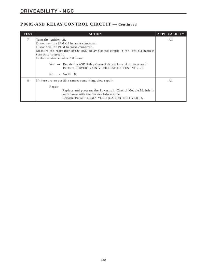
TEST ACTION APPLICABILITY
7 Turn the ignition off.Disconnect the IPM C3 harness connector.Disconnect the PCM harness connector.Measure the resistance of the ASD Relay Control circuit in the IPM C3 harnessconnector to ground.Is the resistance below 5.0 ohms.
All
Yes → Repair the ASD Relay Control circuit for a short to ground.Perform POWERTRAIN VERIFICATION TEST VER - 5.
No → Go To 8
8 If there are no possible causes remaining, view repair. All
RepairReplace and program the Powertrain Control Module Module inaccordance with the Service Information.Perform POWERTRAIN VERIFICATION TEST VER - 5.
440
DRIVEABILITY - NGC
P0685-ASD RELAY CONTROL CIRCUIT — Continued

Symptom:P0688-ASD RELAY SENSE CIRCUIT LOW
When Monitored and Set Condition:
P0688-ASD RELAY SENSE CIRCUIT LOW
When Monitored: With ignition key on. Battery voltage greater than 10 volts.
Set Condition: No voltage sensed at the PCM when the ASD relay is energized. One TripFault.
POSSIBLE CAUSES
INTERMITTENT CONDITION
ASD RELAY
FUSED B+ CIRCUIT
ASD RELAY OUTPUT CIRCUIT OPEN (NO START)
IPM FUSE & RELAY CENTER
IPM FUSE & RELAY CENTER
ASD RELAY OUTPUT CIRCUIT OPEN
PCM START
PCM
TEST ACTION APPLICABILITY
1 NOTE: Inspect the ASD Relay fuse located in the IPM. If the ASD Relay fuseis open, repair the cause of the open first before continuing. Inspect the ASDRelay Output circuit for a short to ground for the cause of the open fuse.NOTE: Diagnose P685 - Auto Shutdown Relay Control Circuit first if setalong with this DTC.With the DRBIIIt, erase the DTC.Attempt to start the engine. If the engine will not start, crank the engine for at least15 seconds. It may be necessary to repeat several times.Does the DTC reset.
All
Yes → Go To 2
No → Repair as necessaryPerform POWERTRAIN VERIFICATION TEST VER - 5.
2 Attempt to start the engine.Does the engine start.
All
Yes → Go To 3
No → Go To 5
441
DRIVEABILITY - NGC

TEST ACTION APPLICABILITY
3 Turn the ignition off.Disconnect the PCM harness connector.Disconnect the IPM C4 harness connectorMeasure the resistance of the ASD Output circuit between the IPM harnessconnector and the PCM harness connector.Is the resistance below 5.0 ohms?
All
Yes → Go To 4
No → Repair the ASD Relay Output circuit for an open.Perform POWERTRAIN VERIFICATION TEST VER - 5.
4 If there are no possible causes remaining, view repair. All
RepairReplace and program the Powertrain Control Module in accor-dance with the Service Information.Perform POWERTRAIN VERIFICATION TEST VER - 5.
5 Turn the ignition off.Install a substitute relay in place of the ASD Relay.With the DRBIIIt, erase DTCs.Attempt to start the engine.With the DRBIIIt, read DTCs.Does the DTC reset?
All
Yes → Go To 6
No → Replace the ASD Relay.Perform POWERTRAIN VERIFICATION TEST VER - 5.
6 Turn the ignition off.Remove the ASD Relay from the IPM.Using a 12-volt test light connected to ground, probe the Fused B+ circuit in the IPM.Does the test light illuminate?
All
Yes → Go To 7
No → Replace the IPM Fuse & Relay Center.Perform POWERTRAIN VERIFICATION TEST VER - 5.
7 Turn the ignition off.Remove the ASD Relay from the IPM.Disconnect the PCM harness connector.Disconnect the IPM C4 harness connector.Measure the resistance of the ASD Relay Output circuit between the IPM harnessconnector and the PCM harness connector.Is the resistance below 5.0 ohms.
All
Yes → Go To 8
No → Repair the ASD Relay Output circuit for an open.Perform POWERTRAIN VERIFICATION TEST VER - 5.
442
DRIVEABILITY - NGC
P0688-ASD RELAY SENSE CIRCUIT LOW — Continued

TEST ACTION APPLICABILITY
8 NOTE: Ensure the IPM C4 harness connector is connected to the IPM.Turn the ignition off.Disconnect the PCM harness connector.Measure the resistance of the ASD Relay Output circuit between the IPM and thePCM harness connector.Is the resistance below 5.0 ohms?
All
Yes → Replace and program the Powertrain Control Module in accor-dance with the Service Information.Perform POWERTRAIN VERIFICATION TEST VER - 5.
No → Replace the IPM Fuse & Relay Center.Perform POWERTRAIN VERIFICATION TEST VER - 5.
443
DRIVEABILITY - NGC
P0688-ASD RELAY SENSE CIRCUIT LOW — Continued

Symptom:P0700-TRANSMISSION CONTROL SYSTEM/READ TRANSMISSIONDTCS ON THE DRBIIIt
TEST ACTION APPLICABILITY
1 This is an informational DTC letting you know that a DTC(s) is stored in theTransmission Control Module.Erase this DTC from the PCM after all Transmission DTC(s) have been repaired.Using the DRBIIIt, read the Transmission Controller DTC and refer to theTransmission Category and perform the appropriate symptom.PCM Diagnostic Information complete.
All
ContinueTest Complete.
444
DRIVEABILITY - NGC

Symptom:P0703-BRAKE SWITCH #2 CIRCUIT
When Monitored and Set Condition:
P0703-BRAKE SWITCH #2 CIRCUIT
When Monitored: TEST #1: Vehicle speed greater than 20 MPH to enable. TEST #2:Speed must be 0 and brake switch indicates on.
Set Condition: TEST #1: If vehicle speed goes to 0 MPH without brake input. Conditionmust be repeated 15 times to set fault. Two trip fault. TEST #2: If vehicle speed goes above20 MHP for more than 6.0 seconds without a change in brake state. Condition must berepeat 15 times to set fault. Two Trip Fault.
POSSIBLE CAUSES
GOOD TRIP EQUAL TO ZERO
(F32) FUSED B+ CIRCUIT
(K29) BRAKE SWITCH SIGNAL CIRCUIT SHORTED TO VOLTAGE
(K29) BRAKE SWITCH SIGNAL SHORTED TO GROUND
(K29) BRAKE SWITCH SIGNAL CIRCUIT OPEN
(Z1) GROUND CIRCUIT OPEN
BRAKE LAMP SWITCH OPERATION
PCM
TEST ACTION APPLICABILITY
1 NOTE: Ensure the Brake Switch is adjusted properly before continuing.Ignition on, engine not running.With the DRBIIIt, read DTCs and record the related Freeze Frame data.Is the Good Trip displayed and equal to zero?
All
Yes → Go To 2
No → Refer to the INTERMITTENT CONDITION symptom in theDriveability category.Perform POWERTRAIN VERIFICATION TEST VER - 4 - NGC.
2 Turn the ignition off.Disconnect the Brake Lamp Switch harness connector.Using a 12-volt test light connected to ground, check the (F32) Fused B+ circuit in theBrake Lamp Switch harness connector.Does the test light illuminate brightly?
All
Yes → Go To 3
No → Repair the (F32) Fused B+ circuit. Inspect the related fuse andrepair as necessary.Perform POWERTRAIN VERIFICATION TEST VER - 4 - NGC.
445
DRIVEABILITY - NGC

TEST ACTION APPLICABILITY
3 Turn the ignition off.Disconnect the Brake Lamp Switch harness connector.Disconnect the PCM harness connector.Turn the ignition on.Measure the voltage of the (K29) Brake Switch Signal circuit in the Brake LampSwitch harness connector.Is the voltage above 1.0 volts?
All
Yes → Repair the short to voltage in the (K29) Brake Switch Signalcircuit.Perform POWERTRAIN VERIFICATION TEST VER - 4 - NGC.
No → Go To 4
4 Turn the ignition off.Disconnect the Brake Lamp Switch harness connector.Disconnect the PCM harness connector.Measure the resistance between ground and the (K29) Brake Switch Signal circuit atthe Brake Lamp Switch harness connector.Is the resistance below 5.0 ohms?
All
Yes → Repair the short to ground in the (K29) Brake Switch Signalcircuit.Perform POWERTRAIN VERIFICATION TEST VER - 4 - NGC.
No → Go To 5
5 Turn the ignition off.Disconnect the Brake Lamp Switch harness connector.Disconnect the PCM harness connector.CAUTION: DO NOT PROBE THE PCM HARNESS CONNECTORS. PROBINGTHE PCM HARNESS CONNECTORS WILL DAMAGE THE PCM TERMI-NALS RESULTING IN POOR TERMINAL TO PIN CONNECTION. INSTALLMILLER SPECIAL TOOL #8815 TO PERFORM DIAGNOSIS.Measure the resistance of the (K29) Brake Switch Signal circuit from the BrakeLamp Switch harness connector to the appropriate terminal of special tool #8815.Is the resistance below 5.0 ohms?
All
Yes → Go To 6
No → Repair the open in the (K29) Brake Switch Signal circuit.Perform POWERTRAIN VERIFICATION TEST VER - 4 - NGC.
6 Turn the ignition off.Disconnect the Brake Lamp Switch harness connector.Measure the resistance between ground and the (Z1) Ground circuit at the BrakeLamp Switch harness connector.Is the resistance below 5.0 ohms?
All
Yes → Go To 7
No → Repair the open in the (Z1) Ground circuit.Perform POWERTRAIN VERIFICATION TEST VER - 4 - NGC.
446
DRIVEABILITY - NGC
P0703-BRAKE SWITCH #2 CIRCUIT — Continued

TEST ACTION APPLICABILITY
7 Turn the ignition off.Disconnect the Brake Lamp Switch harness connector.Measure the resistance between the Ground circuit terminal and the Brake SwitchSense terminal in the Brake Lamp Switch.Apply and release the brake pedal while monitoring the ohmmeter.Does the resistance change from below 5.0 ohms to open circuit?
All
Yes → Go To 8
No → Replace the Brake Lamp Switch.Perform POWERTRAIN VERIFICATION TEST VER - 4 - NGC.
8 NOTE: Before continuing, check the PCM harness connector terminals forcorrosion, damage, or terminal push out. Repair as necessary.If there are no possible causes remaining, view repair.
All
RepairReplace and program the Powertrain Control Module in accor-dance with the Service Information.Perform POWERTRAIN VERIFICATION TEST VER - 4 - NGC.
447
DRIVEABILITY - NGC
P0703-BRAKE SWITCH #2 CIRCUIT — Continued

Symptom:P0833-CLUTCH RELEASED SWITCH CIRCUIT
When Monitored and Set Condition:
P0833-CLUTCH RELEASED SWITCH CIRCUIT
When Monitored: During crank or when engine speed is between 1500-2880 RPM andvehicle speed is greater than 25 MPH.
Set Condition: A short to ground is detected during startup. An open circuit is detectedwhen engine Speed is between 1500-2880 RPM, vehicle speed is >25 MPH, and deltathrottle is >1.1 volts for 4 seconds. This cycle must repeat 5 times per trip for 2 trips.
POSSIBLE CAUSES
CLUTCH PEDAL POSITION SWITCH OPERATION
CLUTCH PEDAL POSITION SWITCH
CLUTCH UPSTOP SIGNAL CIRCUIT OPEN
CLUTCH UPSTOP SIGNAL CIRCUIT SHORTED TO GROUND
GROUND CIRCUIT
PCM
TEST ACTION APPLICABILITY
1 With the DRBIIIt, monitor the Clutch Upstop Switch.Depress the Clutch Pedal completely to the floor and release all the way up severaltimes.Did the Clutch Upstop Switch state change open to closed?
All
Yes → Refer to the INTERMITTENT CONDITION symptom in theDriveability category.Perform POWERTRAIN VERIFICATION TEST VER - 5 - NGC.
No → Go To 2
2 Disconnect the Clutch Pedal Position Switch harness connector.Connect a jumper wire between the Ground circuit and the Clutch Upstop SwitchSignal circuit in the Clutch Pedal Position Switch harness connector.With the DRBIIIt, monitor the Clutch Upstop Switch status.Did the Clutch Upstop Switch status change from Open to Closed?
All
Yes → Replace the Clutch Pedal Position Switch.Perform POWERTRAIN VERIFICATION TEST VER - 5 - NGC.
No → Go To 3
448
DRIVEABILITY - NGC

TEST ACTION APPLICABILITY
3 Turn the ignition off.Disconnect the Clutch Pedal Position Switch harness connector.Disconnect the PCM harness connector.Measure the resistance of the Clutch Upstop Signal circuit in the Clutch PedalPosition Switch harness connector to ground.Is the resistance below 100 ohms?
All
Yes → Repair the Clutch Upstop circuit for a short to ground.Perform POWERTRAIN VERIFICATION TEST VER - 5 - NGC.
No → Go To 4
4 Turn the ignition off.Disconnect the Clutch Pedal Position Switch harness connector.Disconnect the PCM harness connector.CAUTION: DO NOT PROBE THE PCM HARNESS CONNECTORS. PROBINGTHE PCM HARNESS CONNECTORS WILL DAMAGE THE PCM TERMI-NALS RESULTING IN POOR TERMINAL TO PIN CONNECTION. INSTALLMILLER SPECIAL TOOL #8815 TO PERFORM DIAGNOSIS.Measure the resistance of the Clutch Upstop Signal circuit between the Clutch PedalPosition Switch harness connector and the appropriate terminal of special tool #8815.Is the resistance below 5.0 ohms?
All
Yes → Go To 5
No → Repair the Clutch Upstop Signal circuit for an open.Perform POWERTRAIN VERIFICATION TEST VER - 5 - NGC.
5 Turn the ignition off.Disconnect Clutch Pedal Position Switch harness connector.Using a 12-volt test light connected to 12-volts, probe the ground circuit in the ClutchPedal Position Switch harness connector.Does the test light illuminate brightly?
All
Yes → Go To 6
No → Repair the ground circuit for an open.Perform POWERTRAIN VERIFICATION TEST VER - 5 - NGC.
6 If there are no possible causes remaining, view repair. All
RepairReplace and program the Powertrain Control Module in accor-dance with the Service Information.Perform POWERTRAIN VERIFICATION TEST VER - 5 - NGC.
449
DRIVEABILITY - NGC
P0833-CLUTCH RELEASED SWITCH CIRCUIT — Continued

Symptom:P0850-PARK/NEUTRAL SWITCH PERFORMANCE
When Monitored and Set Condition:
P0850-PARK/NEUTRAL SWITCH PERFORMANCE
When Monitored: Continuously with the transmission in Park, Neutral, or Drive andNOT in Limp-in mode.
Set Condition: The PCM detects an incorrect Park/Neutral switch state for a given modeof vehicle operation. Two Trip Fault.
POSSIBLE CAUSES
GOOD TRIP EQUAL TO ZERO
TRANSMISSION DTC(S)
PCM
TEST ACTION APPLICABILITY
1 Ignition on, engine not running.NOTE: Before continuing, ensure that communication can be establishedwith the TCM. If the DRBIIIt can not communicate with the TCM refer tothe Communication Category and preform the appropriate symptom.With the DRBIIIt, read PCM DTCs and record the related Freeze Frame data.Is the Good Trip displayed and equal to zero?
All
Yes → Go To 2
No → Refer to the INTERMITTENT CONDITION symptom in theDriveability category.Perform POWERTRAIN VERIFICATION TEST VER - 5 - NGC.
2 Turn the ignition on.With the DRBIIIt, check the Transmission DTCs.Are there any Transmission DTCs present?
All
Yes → Refer to the appropriate Transmission DTC in the Transmissioncategory.Perform POWERTRAIN VERIFICATION TEST VER - 5 - NGC.
No → NOTE: Before continuing, check the PCM harness connectorterminals for corrosion, damage, or terminal push out. Repair asnecessary. Replace and program the Powertrain Module in accor-dance with the Service Information.Perform POWERTRAIN VERIFICATION TEST VER - 5 - NGC.
450
DRIVEABILITY - NGC

Symptom:P1602-PCM NOT PROGRAMMED
When Monitored and Set Condition:
P1602-PCM NOT PROGRAMMED
When Monitored: Ignition on.
Set Condition: The PCM has not been programmed.
POSSIBLE CAUSES
PCM NOT PROGRAMMED
VERIFY PCM PROGRAMMING
PCM
TEST ACTION APPLICABILITY
1 Ignition on, engine not running.With the DRBIIIt, erase DTCs.With the DRBIIIt program the PCM.Start the engine.Allow the engine to reach normal operating temperature.With the DRBIIIt, read DTCs.Does the DTC reset?
All
Yes → Go To 2
No → The PCM has been successfully programmed. Test is complete.Perform POWERTRAIN VERIFICATION TEST VER - 1 - NGC.
2 NOTE: The ignition switch must be left in the off position for a minimum of10 seconds.Cycle the ignition switch to the off position and then back to run.Attempt to program the PCM.Start the vehicle and allow it to reach normal operating temperatures.With the DRBIIIt, read DTCs.Does the DTC reset?
All
Yes → Replace and program the Powertrain Control Module in accor-dance with the Service Information.Perform POWERTRAIN VERIFICATION TEST VER - 1 - NGC.
No → The PCM has been successfully programmed into the PCM. Testis complete.Perform POWERTRAIN VERIFICATION TEST VER - 1 - NGC.
451
DRIVEABILITY - NGC

Symptom List:P1603-PCM INTERNAL DUAL-PORT RAM COMMUNICATIONP1604-PCM INTERNAL DUAL-PORT RAM READ/WRITE INTEG-RITY FAILUREP1607-PCM INTERNAL SHUTDOWN TIMER RATIONALITY
Test Note: All symptoms listed above are diagnosed using the same tests.The title for the tests will be P1603-PCM INTERNAL DUAL-PORT RAM COMMUNICATION.
When Monitored and Set Condition:
P1607-PCM INTERNAL SHUTDOWN TIMER RATIONALITY
When Monitored: During cold start.
Set Condition: Compares shut down time to coolant temperature.
POSSIBLE CAUSES
FUSED IGNITION SWITCH OUTPUT (OFF-RUN-START)
PCM INTERNAL FAULURE
TEST ACTION APPLICABILITY
1 Turn the ignition off.Disconnect the PCM harness connector.CAUTION: DO NOT PROBE THE PCM HARNESS CONNECTORS. PROBINGTHE PCM HARNESS CONNECTORS WILL DAMAGE THE PCM TERMI-NALS RESULTING IN POOR TERMINAL TO PIN CONNECTION. INSTALLMILLER SPECIAL TOOL #8815 TO PERFORM DIAGNOSIS.Turn the ignition to run.Using a 12-volt test light connected to ground, probe the Fused Ignition SwitchOutput (Off-Run-Start) cavity C1-12 circuit at the appropriate terminal of the specialtool #8815.NOTE: If the test light illuminates, wiggle the wiring harness to ensure thatthe problem is not an intermittent wiring problem.Does the test light illuminate brightly?
All
Yes → Replace the Powertrain Control Module in accordance with theService Information.Perform POWERTRAIN VERIFICATION TEST VER - 1 - NGC.
No → Check all related fuses. Repair the Fused Ignition Switch Outputcircuit.Perform POWERTRAIN VERIFICATION TEST VER - 1 - NGC.
452
DRIVEABILITY - NGC

Symptom:P1681-NO FUEL LEVEL BUS MESSAGE
When Monitored and Set Condition:
P1681-NO FUEL LEVEL BUS MESSAGE
When Monitored: Ignition on.
Set Condition: No fuel level BUS messages received by the PCM for 20 seconds.
POSSIBLE CAUSES
DTC RESET
COMMUNICATE WITH BCM
FUEL LEVEL BUS MESSAGE
PCI BUS CIRCUIT OPEN FROM PCM TO BCM
BCM
TEST ACTION APPLICABILITY
1 NOTE: If a fuel level circuit or performance DTC is set along with P1681,diagnose the circuit/performance DTC before continuing.Turn the ignition on.With the DRBIIIt, erase DTCs.Start the engine on and off several times. Leave the engine running for at least 20second each time.With the DRBIIIt, read DTCs.Does the DTC reset?
All
Yes → Go To 2
No → Refer to the INTERMITTENT CONDITION symptom in theDriveability category.Perform POWERTRAIN VERIFICATION TEST VER - 1 - NGC.
2 Ignition on, engine not running.With the DRBIIIt, attempt to communicate with the BCM.Can communication be established with the BCM?
All
Yes → Go To 3
No → Refer to the Communication Category and perform the appropri-ate symptom related to no communication with BCM.Perform POWERTRAIN VERIFICATION TEST VER - 1 - NGC.
3 Turn the ignition on.Using the DRBIIIt, read the Fuel Level parameter in the PCM.Does the DRBIIIt display a fuel level value?
All
Yes → Replace and program the Powertrain Control Module in accor-dance with the Service Information.Perform POWERTRAIN VERIFICATION TEST VER - 1 - NGC.
No → Go To 4
453
DRIVEABILITY - NGC
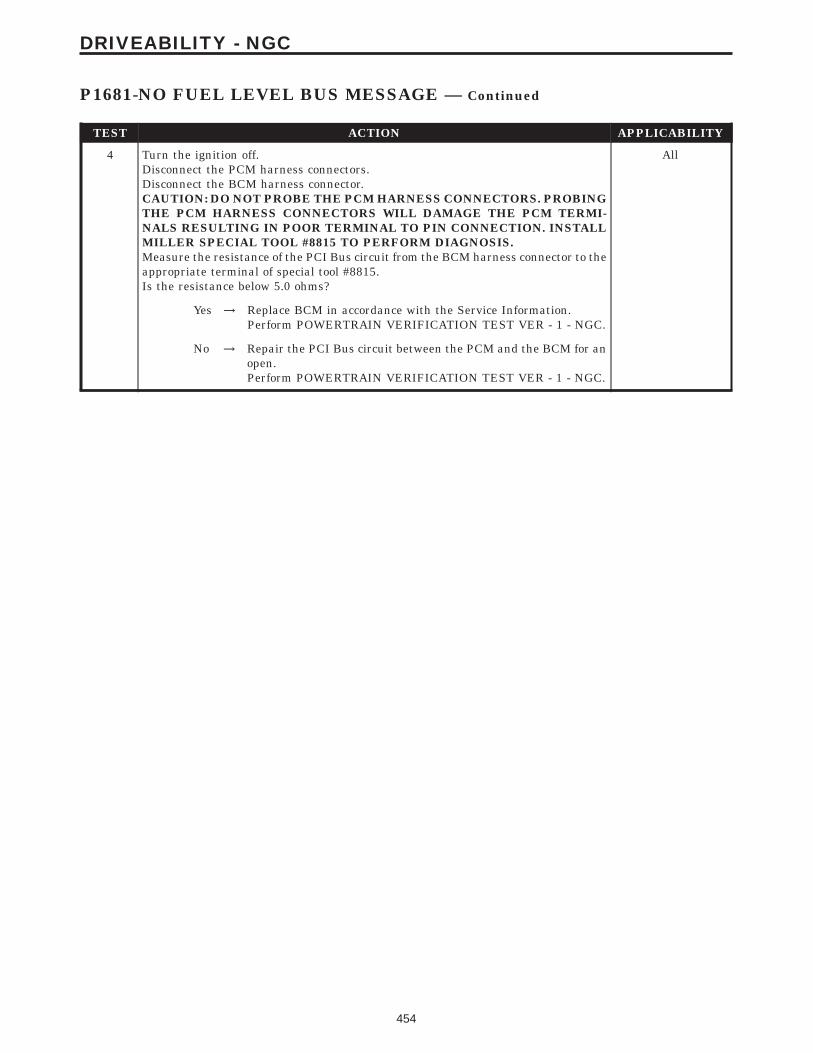
TEST ACTION APPLICABILITY
4 Turn the ignition off.Disconnect the PCM harness connectors.Disconnect the BCM harness connector.CAUTION: DO NOT PROBE THE PCM HARNESS CONNECTORS. PROBINGTHE PCM HARNESS CONNECTORS WILL DAMAGE THE PCM TERMI-NALS RESULTING IN POOR TERMINAL TO PIN CONNECTION. INSTALLMILLER SPECIAL TOOL #8815 TO PERFORM DIAGNOSIS.Measure the resistance of the PCI Bus circuit from the BCM harness connector to theappropriate terminal of special tool #8815.Is the resistance below 5.0 ohms?
All
Yes → Replace BCM in accordance with the Service Information.Perform POWERTRAIN VERIFICATION TEST VER - 1 - NGC.
No → Repair the PCI Bus circuit between the PCM and the BCM for anopen.Perform POWERTRAIN VERIFICATION TEST VER - 1 - NGC.
454
DRIVEABILITY - NGC
P1681-NO FUEL LEVEL BUS MESSAGE — Continued

Symptom:P1686-NO SKIM BUS MESSAGES
When Monitored and Set Condition:
P1686-NO SKIM BUS MESSAGES
When Monitored: Ignition on or Engine Running.
Set Condition: No BUS messages are received from the SKIM for 20 seconds.
POSSIBLE CAUSES
INTERMITTENT CONDITION
PCI BUS CIRCUIT OPEN FROM PCM TO SKIM
LOSS OF SKIM COMMUNICATION
SKIM/PCM
TEST ACTION APPLICABILITY
1 Turn the ignition on.With the DRBIIIt, read the DTCs and record the related Freeze Frame data.Is the Good Trip Counter displayed and equal to zero?
All
Yes → Go To 2
No → Go To 5
2 Turn the ignition on.With the DRB III, attempt to communicate with the SKIM.NOTE: This test will indicate if the Bus is operational from the DLC to theSKIM.Was the DRB III able to communicate with the SKIM?
All
Yes → Go To 3
No → Refer to symptom BUS +/- SIGNAL OPEN FROM SKIM in theCOMMUNICATION category.Perform SKIS VERIFICATION.
3 Turn the ignition off.Disconnect the PCM harness connectors.Disconnect the SKIM harness connector.CAUTION: DO NOT PROBE THE PCM HARNESS CONNECTORS. PROBINGTHE PCM HARNESS CONNECTORS WILL DAMAGE THE PCM TERMI-NALS RESULTING IN POOR TERMINAL TO PIN CONNECTION. INSTALLMILLER SPECIAL TOOL #8815 TO PERFORM DIAGNOSIS.Measure the resistance of the PCI Bus circuit from the SKIM harness connector tothe appropriate terminal of special tool #8815.Is the resistance below 5.0 ohms?
All
Yes → Go To 4
No → Repair the PCI Bus circuit between the PCM and the SKIM for anopen.Perform SKIS VERIFICATION.
455
DRIVEABILITY - NGC

TEST ACTION APPLICABILITY
4 Turn the ignition off.Replace the Sentry Key Immobilizer Module in accordance with the Service Infor-mation.Turn the ignition on.Display and erase all PCM and SKIM DTCs.Perform 5 ignition key cycles leaving the ignition key on for 90 seconds per cycle.With the DRB, display PCM DTCs.Does the DRB display the same DTC?
All
Yes → Replace and program the PCM in accordance with the ServiceInformation.Perform SKIS VERIFICATION.
No → Test Complete.
5 WARNING: WHEN THE ENGINE IS OPERATING, DO NOT STAND IN ADIRECT LINE WITH THE FAN. DO NOT PUT YOUR HANDS NEAR THEPULLEYS, BELTS OR FAN. DO NOT WEAR LOOSE CLOTHING.NOTE: The conditions that set the DTC are not present at this time. Thefollowing list may help in identifying the intermittent condition.With the engine running and at normal operating temperature, monitor the DRBparameters related to the DTC while wiggling the wire harness. Look for parametervalues to change and/or a DTC to set.Review the DTC When Monitored and Set Conditions. If possible, try to duplicate theconditions under which the DTC was set.Refer to any Technical Service Bulletins (TSB) that may apply.Visually inspect the related wire harness. Look for any chafed, pierced, pinched, orpartially broken wires.Visually inspect the related wire harness connectors. Look for broken, bent, pushedout, or corroded terminals.Were any of the above conditions present?
All
Yes → Repair as necessary.Perform SKIS VERIFICATION.
No → Test Complete.
456
DRIVEABILITY - NGC
P1686-NO SKIM BUS MESSAGES — Continued

Symptom:P1687-NO CLUSTER BUS MESSAGE
When Monitored and Set Condition:
P1687-NO CLUSTER BUS MESSAGE
When Monitored: Engine Running.
Set Condition: No BUS messages received from the MIC (Instrument Cluster) for 20seconds.
POSSIBLE CAUSES
DTC RESET
COMMUNICATE WITH CLUSTER
INSTRUMENT CLUSTER OPERATION
PCM
TEST ACTION APPLICABILITY
1 Turn the ignition on.With the DRBIIIt, erase DTCs.Start the engine on and off several times. Leave the engine running for at least 20second each time.With the DRBIIIt, read DTCs.Does the DTC reset?
All
Yes → Go To 2
No → Refer to the INTERMITTENT CONDITION symptom in theDriveability category.Perform POWERTRAIN VERIFICATION TEST VER - 1 - NGC.
2 Ignition on, engine not running.With the DRBIIIt, attempt to communicate with the Instrument cluster.Can communication be established with the Instrument Cluster?
All
Yes → Go To 3
No → Refer to the Communication Category and perform the appropri-ate symptom related to no communication with cluster.Perform POWERTRAIN VERIFICATION TEST VER - 1 - NGC.
3 Start the engineAllow the engine to idle.Is the correct engine speed display (Tachometer) in the instrument cluster?
All
Yes → Replace and program the Powertrain Control Module in accor-dance with the Service Information.Perform POWERTRAIN VERIFICATION TEST VER - 1 - NGC.
No → Refer to the Instrument Category and perform the appropriatesymptom.Perform POWERTRAIN VERIFICATION TEST VER - 1 - NGC.
457
DRIVEABILITY - NGC

Symptom List:P1696-EEPROM MEMORY WRITE DENIED/INVALIDP1697-EMR (SRI) MILEAGE NOT STORED
Test Note: All symptoms listed above are diagnosed using the same tests.The title for the tests will be P1696-EEPROM MEMORYWRITE DENIED/INVALID.
When Monitored and Set Condition:
P1696-EEPROM MEMORY WRITE DENIED/INVALID
When Monitored: Ignition key on continuous.
Set Condition: An attempt to program/write to the internal EEPROM failed. Also checksat powerdown.
P1697-EMR (SRI) MILEAGE NOT STORED
When Monitored: Ignition key on continuous.
Set Condition: An attempt to program/write to the internal EEPROM failed. Also checksat powerdown.
POSSIBLE CAUSES
DRB DISPLAYS WRITE FAILURE
DRB DISPLAYS WRITE REFUSED 2ND TIME
DRB DISPLAYS SRI MILEAGE INVALID
COMPARE SRI MILEAGE WITH ODOMETER
TEST ACTION APPLICABILITY
1 With the DRBIIIt, perform the SRI Memory Test.Does the DRBIIIt display Write Failure?
All
Yes → Replace and program the Powertrain Control Module in accor-dance with the Service Information.Perform POWERTRAIN VERIFICATION TEST VER - 1 - NGC.
No → Go To 2
2 With the DRBIIIt, perform the SRI Memory Test.Does the DRBIIIt display Write Refused?
All
Yes → Go To 3
No → Go To 4
458
DRIVEABILITY - NGC

TEST ACTION APPLICABILITY
3 With the DRBIIIt, perform the SRI Memory Test a second time.NOTE: Retest the SRI Memory two more times.Does the DRBIIIt display Write Refused again?
All
Yes → Replace and program the Powertrain Control Module in accor-dance with the Service Information.Perform POWERTRAIN VERIFICATION TEST VER - 1 - NGC.
No → Test Complete.
4 With the DRBIIIt, perform the SRI Memory Test.Does the DRBIIIt display SRI Mileage Invalid?
All
Yes → Update the mileage and retest the SRI Memory.Perform POWERTRAIN VERIFICATION TEST VER - 1 - NGC.
No → Go To 5
5 Compare the SRI Mileage stored with the Instrument Panel Odometer.Is the mileage within the specified range displayed on the DRBIIIt?
All
Yes → Test Complete.
No → Update the mileage and retest the SRI Memory.Perform POWERTRAIN VERIFICATION TEST VER - 1 - NGC.
459
DRIVEABILITY - NGC
P1696-EEPROM MEMORY WRITE DENIED/INVALID — Continued

Symptom:P1698-NO TRANSMISSION BUS MESSAGE
When Monitored and Set Condition:
P1698-NO TRANSMISSION BUS MESSAGE
When Monitored: Equipped with automatic transmission. Engine Running Batteryvoltage greater than 10 volts.
Set Condition: No bus messages are received from the TCM for 20 seconds, two tripsrequired.
POSSIBLE CAUSES
PCI BUS UNABLE TO COMMUNICATE WITH DRBIIIt
(F12) FUSED IGNITION SWITCH OUTPUT (OFF-RUN-START)
INTERMITTENT CONDITION
PCM
TEST ACTION APPLICABILITY
1 NOTE: If P1603 or P1604 are set along with this DTC, diagnose them firstbefore continuing with P1698.NOTE: Before continuing, inspect all fuses and ensure that all power andground circuits are operating properly.NOTE: Check all powers and grounds to the PCM before continuing.Turn the ignition on.With the DRBIIIt, erase DTCs.Start the engine, allow the engine to run for at least 20 seconds with the gear selectorin Drive. Repeat at least 2 times.With the DRBIIIt, read DTC’s.Does the DTC reset?
All
Yes → Go To 2
No → Refer to the INTERMITTENT CONDITION symptom in theDriveability category.Perform POWERTRAIN VERIFICATION TEST VER - 1 - NGC.
460
DRIVEABILITY - NGC

TEST ACTION APPLICABILITY
2 Turn the ignition off.Disconnect the PCM harness connector.CAUTION: DO NOT PROBE THE PCM HARNESS CONNECTORS. PROBINGTHE PCM HARNESS CONNECTORS WILL DAMAGE THE PCM TERMI-NALS RESULTING IN POOR TERMINAL TO PIN CONNECTION. INSTALLMILLER SPECIAL TOOL #8815 TO PERFORM DIAGNOSIS.Turn the ignition to run.Using a 12-volt test light connected to ground, probe the (F12) Fused Ignition SwitchOutput (Off-Run-Start) cavity C1-12 circuit at the appropriate terminal of the specialtool #8815.NOTE: If the test light illuminates, wiggle the wiring harness to ensure thatthe problem is not an intermittent wiring problem.Does the test light illuminate brightly?
All
Yes → Go To 3
No → Check all related fuses. Repair the (F12) Fused Ignition SwitchOutput circuit for an open.Perform POWERTRAIN VERIFICATION TEST VER - 1 - NGC.
3 Note: Determine which modules this vehicle is equipped with before begin-ning.Note: When attempting to communicate with any of the modules on thisvehicle, the DRB will display 1 of 2 different communication errors: a NORESPONSE message or a BUS +/- SIGNALS OPEN message.Turn the ignition on.Using the DRB, attempt to communicate with the following control modules:Body Control Module (BCM)Instrument Cluster (MIC)Controller Antilock Brake (CAB)Was the DRB able to communicate with one or more Module(s)?
All
Yes → Replace and program the Powertrain Control Module in accor-dance with the Service Information.Perform POWERTRAIN VERIFICATION TEST VER - 1 - NGC.
No → Refer to the Communication category and perform the PCI BUSCOMMUNICATION FAILURE symptom.Perform POWERTRAIN VERIFICATION TEST VER - 1 - NGC.
461
DRIVEABILITY - NGC
P1698-NO TRANSMISSION BUS MESSAGE — Continued

Symptom List:P2302-IGNITION COIL #1 SECONDARY CIRCUIT-INSUFFICIENTIONIZATIONP2305-IGNITION COIL #2 SECONDARY CIRCUIT-INSUFFICIENTIONIZATION
Test Note: All symptoms listed above are diagnosed using the same tests.The title for the tests will be P2302-IGNITION COIL #1 SEC-ONDARY CIRCUIT-INSUFFICIENT IONIZATION.
When Monitored and Set Condition:
P2302-IGNITION COIL #1 SECONDARY CIRCUIT-INSUFFICIENT IONIZATION
When Monitored: Engine Running.
Set Condition: If PCM detects that the secondary ignition burn time is incorrect or notpresent an error is detected. One Trip Fault.
P2305-IGNITION COIL #2 SECONDARY CIRCUIT-INSUFFICIENT IONIZATION
When Monitored: Engine Running.
Set Condition: If PCM detects that the secondary ignition burn time is incorrect or notpresent an error is detected. One Trip Fault
POSSIBLE CAUSES
INTERMITTENT CONDITION
SPARK PLUG
IGNITION WIRE
IGNITION COIL OPERATION
IGNITION COIL
TEST ACTION APPLICABILITY
1 Ignition on, engine not running.With the DRBIIIt, read DTCs and record the related Freeze Frame data.Is the Good Trip Counter displayed and equal to zero?
All
Yes → Go To 2
No → Go To 4
462
DRIVEABILITY - NGC

TEST ACTION APPLICABILITY
2 Turn the ignition off.Remove the ignition wire.Measure the resistance of the ignition wire.Is the resistance below 10K ohms?
All
Yes → Go To 3
No → Replace the Ignition Wire.Perform POWERTRAIN VERIFICATION TEST VER - 2 - NGC.
3 Turn the ignition off.Disconnect the Ignition Coil harness connector.Remove the ignition coil.NOTE: Before continuing inspect the Ignition Coil for damage or carbontracking coil or the spark plug insulator boot. If a problem is found, replacethe ignition coil.Install a spark tester to the Ignition Coil.Reconnect the Ignition Coil harness connector to the Ignition Coil.While cranking the engine observe the spark coming from the spark tester.NOTE: The Ignition Coil should generate a crisp blue spark that is able tojumper the gap of the spark tester.Does the Ignition Coil generate a good spark.
All
Yes → Replace the Spark Plug.Perform POWERTRAIN VERIFICATION TEST VER - 2 - NGC.
No → Replace the Ignition Coil.Perform POWERTRAIN VERIFICATION TEST VER - 2 - NGC.
4 Turn the ignition off.Remove the Spark Plug.Inspect the Spark Plug for the following conditions.- Cracks- Carbon Tracking- Foreign Material- Gap size out of specifications- Loose or broke electrodeNOTE: Lightly tap the bottom of the spark plug on a solid surface. Theelectrode in the spark plug should not move.Were any of the above condition present?
All
Yes → Replace the Spark Plug.Perform POWERTRAIN VERIFICATION TEST VER - 2 - NGC.
No → Refer to the INTERMITTENT CONDITION symptom in theDriveability category.Perform POWERTRAIN VERIFICATION TEST VER - 2 - NGC.
463
DRIVEABILITY - NGC
P2302-IGNITION COIL #1 SECONDARY CIRCUIT-INSUFFICIENT ION-IZATION — Continued

Symptom:P2503-CHARGING SYSTEM VOLTAGE LOW
When Monitored and Set Condition:
P2503-CHARGING SYSTEM VOLTAGE LOW
When Monitored: The engine running. The engine speed greater than 1157 RPM.
Set Condition: The battery sensed voltage is 1 volt below the charging goal for 13.47seconds. The PCM senses the battery voltage turns off the field driver and senses thebattery voltage again. If the voltages are the same, the code is set.
POSSIBLE CAUSES
CHARGING VOLTAGE BELOW 15.1 VOLTS
(A11) B+ CIRCUIT HIGH RESISTANCE
GENERATOR GROUND HIGH RESISTANCE
GENERATOR OPERATION
(Z1) GEN FIELD GROUND CIRCUIT OPEN
(K20) GEN FIELD CONTROL CIRCUIT SHORTED TO BATTERY VOLTAGE
(K20) GEN FIELD CONTROL CIRCUIT SHORTED TO GROUND
(K20) GEN FIELD CONTROL CIRCUIT OPEN
PCM
TEST ACTION APPLICABILITY
1 NOTE: Inspect the vehicle for aftermarket accessories that may exceed theGenerator System output.Turn the ignition off.NOTE: The battery must be fully charged.NOTE: The Generator belt tension and condition must be checked beforecontinuing.Start the engine.Allow the idle to stabilize.With the DRBIIIt, read the Target Charging Voltage.Is the Target Charging Voltage above 15.1 volts?
All
Yes → Refer to the INTERMITTENT CONDITION symptom in theDriveability category.Perform POWERTRAIN VERIFICATION TEST VER - 3 - NGC.
No → Go To 2
464
DRIVEABILITY - NGC

TEST ACTION APPLICABILITY
2 WARNING: WHEN THE ENGINE IS OPERATING, DO NOT STAND IN ADIRECT LINE WITH THE FAN. DO NOT PUT YOUR HANDS NEAR THEPULLEYS, BELTS OR FAN. DO NOT WEAR LOOSE CLOTHING.Ignition on, engine not running.NOTE: Ensure all wires are clear of the engine’s moving parts.Start the engine.Measure the voltage between the (A11) Generator B+ Terminal and the Battery+Post.Is the voltage above 0.4 of a volt?
All
Yes → Repair the (A11) B+ circuit for high resistance between theGenerator and Battery.Perform POWERTRAIN VERIFICATION TEST VER - 3 - NGC.
No → Go To 3
3 WARNING: WHEN THE ENGINE IS OPERATING, DO NOT STAND IN ADIRECT LINE WITH THE FAN. DO NOT PUT YOUR HANDS NEAR THEPULLEYS, BELTS OR FAN. DO NOT WEAR LOOSE CLOTHING.Start the engine.Warm the engine to operating temperature.NOTE: Ensure all wires are clear of the engine’s moving parts.Measure the voltage between the Generator case and Battery ground post.Is the voltage above 0.1 of a volt?
All
Yes → Repair Generator Ground for high resistance, Generator Case toBattery ground side.Perform POWERTRAIN VERIFICATION TEST VER - 3 - NGC.
No → Go To 4
4 Turn the ignition off.Disconnect the Generator Field harness connector.Using a 12-volt test light, jumper it across the Generator Field harness connector.Ignition on, engine not running.With the DRBIIIt, actuate the Gen Field Control circuit.Does the test light illuminate brightly and flash on and off?
All
Yes → Replace the Generator.Perform POWERTRAIN VERIFICATION TEST VER - 3 - NGC.
No → Go To 5
5 Turn the ignition off.Disconnect the Generator Field harness connector.Using a 12-volt test connected to battery voltage, probe the (Z1) Gen Field Groundcircuit in the Generator Field harness connector.Does the test light illuminate brightly?
All
Yes → Go To 6
No → Repair the open in the (Z1) Gen Field Ground circuit.Perform POWERTRAIN VERIFICATION TEST VER - 3 - NGC.
465
DRIVEABILITY - NGC
P2503-CHARGING SYSTEM VOLTAGE LOW — Continued

TEST ACTION APPLICABILITY
6 Turn the ignition off.Disconnect the Generator Field harness connector.Disconnect the PCM harness connector.Measure the voltage on the (K20) Gen Field Control circuit at the Generator Fieldharness connector.Is the voltage above 1.0 volt?
All
Yes → Repair the short to voltage in the (K20) Gen Field Control circuit.Perform POWERTRAIN VERIFICATION TEST VER - 3 - NGC.
No → Go To 7
7 Turn the ignition on.Disconnect the Generator Field harness connector.Disconnect the PCM harness connector.Measure the resistance between ground and the (K20) Gen Field Control circuit inthe Generator Field harness connector.Is the resistance below 100 ohms?
All
Yes → Repair the (K20) Gen Field Control circuit for a short to ground.Perform POWERTRAIN VERIFICATION TEST VER - 3 - NGC.
No → Go To 8
8 Turn the ignition off.Disconnect the Generator Field harness connector.Disconnect the PCM harness connector.CAUTION: DO NOT PROBE THE PCM HARNESS CONNECTORS. PROBINGTHE PCM HARNESS CONNECTORS WILL DAMAGE THE PCM TERMI-NALS RESULTING IN POOR TERMINAL TO PIN CONNECTION. INSTALLMILLER SPECIAL TOOL #8815 TO PERFORM DIAGNOSIS.Measure the resistance of the (K20) Gen Field Control circuit from the GeneratorField harness connector to the appropriate terminal of the special tool #8815.Is the resistance below 5.0 ohms?
All
Yes → Go To 9
No → Repair the open in the (K20) Generator Field Control circuit.Perform POWERTRAIN VERIFICATION TEST VER - 3 - NGC.
9 If there are no possible causes remaining, view repair. All
RepairReplace and program the Powertrain Control Module in accor-dance with the Service Information.Perform POWERTRAIN VERIFICATION TEST VER - 3 - NGC.
466
DRIVEABILITY - NGC
P2503-CHARGING SYSTEM VOLTAGE LOW — Continued

Symptom:*CHECKING PCM POWER AND GROUND CIRCUITS
POSSIBLE CAUSES
(A14) PCM FUSED B+ CIRCUIT
(A41) PCM FUSED IGNITION SWITCH OUTPUT CIRCUIT
(Z12) PCM GROUND CIRCUITS
TEST ACTION APPLICABILITY
1 NOTE: The battery must be fully charged before continuing.Turn the ignition off.Disconnect the PCM harness connector.CAUTION: DO NOT PROBE THE PCM HARNESS CONNECTORS. PROBINGTHE PCM HARNESS CONNECTORS WILL DAMAGE THE PCM TERMI-NALS RESULTING IN POOR TERMINAL TO PIN CONNECTION. INSTALLMILLER SPECIAL TOOL #8815 TO PERFORM DIAGNOSIS.Using a 12-volt test light connected to ground, probe the (A14) PCM Fused B+ circuitin the Pinout Box.Does the test light illuminate brightly?
All
Yes → Go To 2
No → Repair the (A14) Fused B+ circuit.Perform POWERTRAIN VERIFICATION TEST VER - 1 - NGC.
2 Turn the ignition off.Disconnect the PCM harness connector.CAUTION: DO NOT PROBE THE PCM HARNESS CONNECTORS. PROBINGTHE PCM HARNESS CONNECTORS WILL DAMAGE THE PCM TERMI-NALS RESULTING IN POOR TERMINAL TO PIN CONNECTION. INSTALLMILLER SPECIAL TOOL #8815 TO PERFORM DIAGNOSIS.Turn the ignition on.Using a 12-volt test light connected to ground, probe the (A41) PCM Fused IgnitionSwitch Output circuit in the Pinout Box.Does the test light illuminate brightly?
All
Yes → Go To 3
No → Repair the (A41) Ignition Switch Output circuitPerform POWERTRAIN VERIFICATION TEST VER - 1 - NGC.
3 Turn the ignition off.Disconnect the PCM harness connector.CAUTION: DO NOT PROBE THE PCM HARNESS CONNECTORS. PROBINGTHE PCM HARNESS CONNECTORS WILL DAMAGE THE PCM TERMI-NALS RESULTING IN POOR TERMINAL TO PIN CONNECTION. INSTALLMILLER SPECIAL TOOL #8815 TO PERFORM DIAGNOSIS.Using a 12-volt test light connected to battery voltage, probe the (Z12) PCM groundcircuits in the Pinout Box.Does the test light illuminate brightly?
All
Yes → Test Complete.
No → Repair the (Z12) PCM ground circuits.Perform POWERTRAIN VERIFICATION TEST VER - 1 - NGC.
467
DRIVEABILITY - NGC

Symptom:*CHECKING THE A/C RELAY OUTPUT
POSSIBLE CAUSES
A/C CLUTCH RELAY OPERATION
GROUND CIRCUIT OPEN
A/C CLUTCH
(A17) FUSED B+ CIRCUIT
(C3) A/C CLUTCH OUTPUT CIRCUIT
A/C CLUTCH RELAY
TEST ACTION APPLICABILITY
1 NOTE: Ensure that the refrigerant system is properly charged. Refer to theappropriate Service Information.Turn the ignition on.With the DRBIIIt, actuate the A/C Clutch Relay.Is the A/C Clutch actuating?
All
Yes → The A/C Clutch System operating properly at this time.Perform POWERTRAIN VERIFICATION TEST VER - 2 - NGC.
No → Go To 2
2 Turn the ignition off.Disconnect the A/C Clutch harness connector.Measure the Ground circuit in the A/C Clutch harness connector to ground.Is the resistance below 5.0 ohms?
All
Yes → Go To 3
No → Repair the Ground circuit for an open.Perform POWERTRAIN VERIFICATION TEST VER - 2 - NGC.
3 Disconnect the A/C Clutch harness connector.Turn the ignition on.With the DRBIIIt, actuate the A/C Clutch Relay.Measure the voltage of the A/C Clutch Relay Output circuit in the A/C Clutch harnessconnector.Is the voltage above 11.0 volts?
All
Yes → Replace the A/C Clutch.Perform POWERTRAIN VERIFICATION TEST VER - 2 - NGC.
No → Go To 4
4 Turn the ignition off.Remove the A/C Clutch Relay from the PDC.Using a 12-volt test light connected to ground, probe the (A17) Fused B+ circuit in thePDC.Does the test light illuminate brightly?
All
Yes → Go To 5
No → Repair the (A17) Fused B+ circuit. Inspect fuses and replace asnecessary.Perform POWERTRAIN VERIFICATION TEST VER - 2 - NGC.
468
DRIVEABILITY - NGC

TEST ACTION APPLICABILITY
5 Turn the ignition off.Disconnect the A/C Clutch Relay from the PDC.Disconnect the A/C Clutch harness connector.Measure the resistance of the (C3) A/C Clutch Relay Output circuit between the PDCand the A/C Clutch harness connector.Is the resistance below 5.0 ohms?
All
Yes → Replace the A/C Clutch Relay.Perform POWERTRAIN VERIFICATION TEST VER - 2 - NGC.
No → Repair the (C3) A/C Clutch Relay Output circuit for an open.Perform POWERTRAIN VERIFICATION TEST VER - 2 - NGC.
469
DRIVEABILITY - NGC
*CHECKING THE A/C RELAY OUTPUT — Continued

Symptom List:ANTENNA FAILURECOP FAILUREEEPROM FAILUREINTERNAL FAULTRAM FAILURESERIAL LINK INTERNAL FAULTSTACK OVERFLOW FAILURE
Test Note: All symptoms listed above are diagnosed using the same tests.The title for the tests will be ANTENNA FAILURE.
When Monitored and Set Condition:
ANTENNA FAILURE
When Monitored: Every 250 milliseconds with the ignition on.
Set Condition: The SKIM’s microcontroller determines that an antenna circuit fault hasoccurred for 2.0 consecutive seconds.
COP FAILURE
When Monitored: With the ignition on.
Set Condition: The COP timer is not reset by the micro controller every 65.5 milliseconds.
EEPROM FAILURE
When Monitored: With the ignition on.
Set Condition: When the value written to EEPROM memory does not equal the valueread back after the write operation.
INTERNAL FAULT
When Monitored: With the ignition on.
Set Condition: The SKIM has detected a fault during an internal self test.
RAM FAILURE
When Monitored: With the ignition on.
Set Condition: The RAM fails a test that checks the RAM’s ability to retain memory.
SERIAL LINK INTERNAL FAULT
When Monitored: With the ignition on.
Set Condition: The SKIM fails an internal J1850 communication self test.
STACK OVERFLOW FAILURE
When Monitored: With the ignition on.
Set Condition: The micro controller has exceeded its stack space limit.
470
SENTRY KEY IMMOBILIZER

POSSIBLE CAUSES
SKIM INTERNAL DTC FAILURE
TEST ACTION APPLICABILITY
1 Note: This trouble code indicates an internal SKIM fault.With the DRBIIIt, read and record the SKIM DTCs and then erase the SKIM DTCsPerform 10 ignition key cycles, leaving the ignition key on for a minimum of 90seconds per cycle.With the DRBIIIt , read the SKIM DTCs.Did the same SKIM DTC return?
All
Yes → Replace and program the Sentry Key Immobilizer Module inaccordance with the Service Information.Perform SKIS VERIFICATION.
No → Test Complete.
471
SENTRY KEY IMMOBILIZER
ANTENNA FAILURE — Continued

Symptom List:PCM STATUS FAILURESERIAL LINK EXTERNAL FAULT
Test Note: All symptoms listed above are diagnosed using the same tests.The title for the tests will be PCM STATUS FAILURE.
When Monitored and Set Condition:
PCM STATUS FAILURE
When Monitored: With the ignition on.
Set Condition: This DTC exists when a PCM STATUS message was not received from thePCM for at least 20.0 consecutive seconds.
SERIAL LINK EXTERNAL FAULT
When Monitored: At ignition on, after ignition on during any rolling code handshake thatoccurs with the PCM due to a SKIM reset, or during SECRET KEY transfers to the PCM.
Set Condition: When the SKIM does not receive an expected PCI BUS message trans-mission acknowledgement from the PCM after 3 transmit attempts.
POSSIBLE CAUSES
INTERMITTENT WIRING HARNESS PROBLEM
WIRING HARNESS INSPECTION
SKIM/PCM
TEST ACTION APPLICABILITY
1 NOTE: Ensure the PCM has proper power and ground connections beforecontinuing.With the DRBIIIt, read and record the SKIM DTCs then erase the SKIM DTCs.Turn the ignition off.Wait 2 minutes.Turn the ignition on.With the DRBIIIt, read the SKIM DTCs.Does the DRBIIIt display the DTC that was previously erased?
All
Yes → Go To 2
No → Go To 4
472
SENTRY KEY IMMOBILIZER

TEST ACTION APPLICABILITY
2 Turn the ignition off.NOTE: Visually inspect the related wiring harness and CCD/PCI Bus(whichever applicable) circuits. Look for any chafed, pierced, pinched, orpartially broken wires.NOTE: Visually inspect the related wiring harness connectors. Look forbroken, bent, pushed out, or corroded terminals.Note: Refer to any Technical Service Bulletins (TSB) that may apply.Were any problems found?
All
Yes → Repair as necessary.Perform SKIS VERIFICATION.
No → Go To 3
3 NOTE: Before proceeding it will be necessary to obtain the SKIM PIN.Turn the ignition on.With the DRBIIIt, display and erase all PCM and SKIM DTC’s.Perform 5 ignition key cycles, leaving the ignition key on for a minimum of 90 secondsper cycle.With the DRBIIIt, read the SKIM DTCs.Does the code appear?
All
Yes → Replace and program the Powertrain Control Module in accor-dance with the Service Information.Perform SKIS VERIFICATION.
No → Test Complete.
4 Turn the ignition off.Note: Visually inspect the related wiring harness. Look for any chafed,pierced, pinched, or partially broken wires.NOTE: Visually inspect the related wiring harness connectors. Look forbroken, bent, pushed out, or corroded terminals.Note: Refer to any Technical Service Bulletins (TSB) that may apply.Were any problems found?
All
Yes → Repair wiring harness/connectors as necessary.Perform SKIS VERIFICATION.
No → Test Complete.
473
SENTRY KEY IMMOBILIZER
PCM STATUS FAILURE — Continued

Symptom List:ROLLING CODE FAILUREVIN MISMATCH
Test Note: All symptoms listed above are diagnosed using the same tests.The title for the tests will be ROLLING CODE FAILURE.
When Monitored and Set Condition:
ROLLING CODE FAILURE
When Monitored: At ignition on, after ignition on during any rolling code handshake thatoccurs with the PCM due to a SKIM or PCM reset.
Set Condition: When a PCM STATUS message with a Valid Key status is not received bythe SKIM within 3.5 seconds of transmitting the last Valid Key Code message to the PCM.
VIN MISMATCH
When Monitored: With the ignition on.
Set Condition: When the VIN received from the PCM does not match the VIN stored inthe SKIM’s EEPROM.
POSSIBLE CAUSES
VERIFYING PCM VIN
REPLACE SKIM AND CHECK DTC’S
INTERMITTENT WIRING HARNESS PROBLEM
PCM
TEST ACTION APPLICABILITY
1 With the DRBIIIt, erase the SKIM DTCs.Turn the ignition off.Wait 10 seconds.Turn the ignition on and wait 2 minutes.With the DRBIIIt, read the SKIM DTCs.Does the DRBIIIt display the DTC that was previously erased?
All
Yes → Go To 2
No → Go To 4
474
SENTRY KEY IMMOBILIZER

TEST ACTION APPLICABILITY
2 Turn the ignition on.With the DRBIIIt, select Engine system from the main menu.Display and record the Vehicle Identification Number.NOTE: Ensure that a VIN has been programmed into the PCM. If a VIN is notdisplayed, attempt to program the PCM with the correct vehicle VIN beforecontinuing.Does the VIN recorded from the PCM match the VIN of the vehicle?
All
Yes → Go To 3
No → Replace and program the Powertrain Control Module in accor-dance with the Service Information.Perform SKIS VERIFICATION.
3 Turn the ignition off.Replace and program the Sentry Key Immobilizer Module in accordance with theService Information.Turn the ignition on.With the DRBIIIt, display and clear all PCM and SKIM DTC’s.Perform 5 ignition key cycles leaving the ignition key on for 90 seconds per cycle.With the DRBIIIt, check for SKIM DTCs.Does the DRBIIIt display the same DTC?
All
Yes → Replace and program the Powertrain Control Module in accor-dance with the Service Information.Perform SKIS VERIFICATION.
No → The repair is complete.Perform SKIS VERIFICATION.
4 Turn the ignition off.Note: Visually inspect the related wiring harness. Look for any chafed,pierced, pinched, or partially broken wires.NOTE: Visually inspect the related wiring harness connectors. Look forbroken, bent, pushed out, or corroded terminals.Note: Refer to any Technical Service Bulletins (TSB) that may apply.Were any problems found?
All
Yes → Repair wiring harness/connectors as necessary.Perform SKIS VERIFICATION.
No → Test Complete.
475
SENTRY KEY IMMOBILIZER
ROLLING CODE FAILURE — Continued

Symptom List:TRANSPONDER COMMUNICATION FAILURETRANSPONDER CYCLIC REDUNDANCY CHECK (CRC) FAILURETRANSPONDER ID MISMATCHTRANSPONDER RESPONSE MISMATCH
Test Note: All symptoms listed above are diagnosed using the same tests.The title for the tests will be TRANSPONDER COMMUNICA-TION FAILURE.
When Monitored and Set Condition:
TRANSPONDER COMMUNICATION FAILURE
When Monitored: At ignition on and during Key Programming Mode.
Set Condition: When the SKIM does not receive a transponder response after 8 consec-utive transponder read attempts within 2.0 seconds.
TRANSPONDER CYCLIC REDUNDANCY CHECK (CRC) FAILURE
When Monitored: At ignition on and during Key Programming Mode.
Set Condition: When 5 consecutive transponder signal transmissions are sent to theSKIM with the correct message format but with invalid data.
TRANSPONDER ID MISMATCH
When Monitored: At ignition on and during Key Programming Mode.
Set Condition: When the transponder ID read by the SKIM does not match any of thetransponder ID’s stored in the SKIM’s memory.
TRANSPONDER RESPONSE MISMATCH
When Monitored: At ignition on and during Key Programming Mode.
Set Condition: When the transponder’s crypto algorithm result fails to match the SKIM’sresult.
POSSIBLE CAUSES
CHECKING MULTIPLE KEY OPERATION
SKIM
INTERMITTENT WIRING HARNESS PROBLEM
REPLACE IGNITION KEY
476
SENTRY KEY IMMOBILIZER

TEST ACTION APPLICABILITY
1 With the DRBIIIt, read and record the SKIM DTCs.With the DRBIIIt, erase the SKIM DTCs.NOTE: Perform the following test several times to ensure the DTC iscurrent.Turn the ignition off.Wait 10 seconds.Turn the ignition on.With the DRBIIIt, read the SKIM DTCs.Does the DRBIIIt display the DTC that was previously erased?
All
Yes → Go To 2
No → Go To 7
2 Are there multiple vehicle ignition keys available? All
Yes → Go To 3
No → Go To 4
3 NOTE: Perform the following steps using one of the vehicle ignition keys.When finished, repeat the procedure using each of the other vehicle keysone at a time.With the DRBIIIt, erase the SKIM DTCs.Turn the ignition off.Wait 10 seconds.Turn the ignition on.With the DRBIIIt, read the SKIM DTCs.Is the DTC present for all ignition keys?
All
Yes → Replace and program the Sentry Key Immobilizer Module inaccordance with the Service Information.Perform SKIS VERIFICATION.
No → Replace the ignition key(s) that cause the SKIM DTC.Perform SKIS VERIFICATION.
4 With the DRBIIIt, attempt to reprogram the ignition keys to the SKIM.With the DRBIIIt, erase the SKIM DTCs.Wait 10 seconds.Turn the ignition on.With the DRBIIIt, read the SKIM DTCs.Does the DTC set again?
All
Yes → Go To 5
No → Test Complete.
5 Replace the ignition key with a new key.With the DRBIIIt, program the new ignition key to the SKIM.With the DRBIIIt, erase the SKIM DTCs.Turn the ignition off.Wait 10 seconds.Turn the ignition on.With the DRBIIIt, read the SKIM DTCs.Does the DTC set again?
All
Yes → Go To 6
No → Test Complete.
477
SENTRY KEY IMMOBILIZER
TRANSPONDER COMMUNICATION FAILURE — Continued
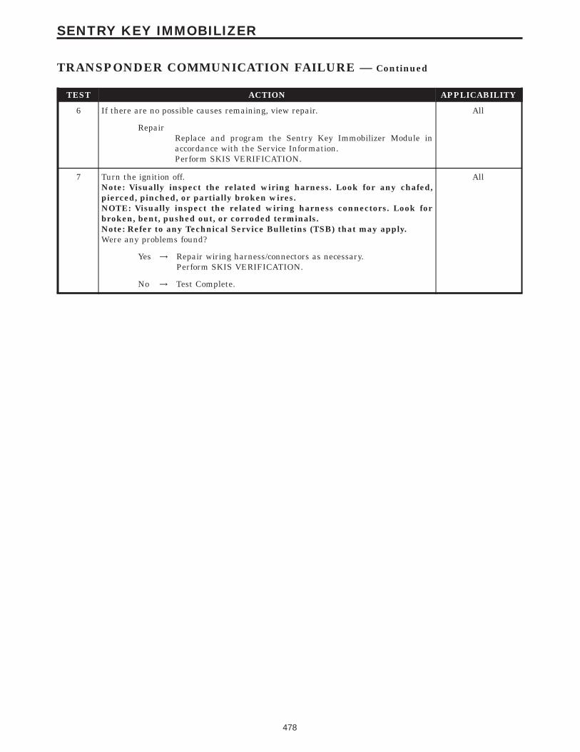
TEST ACTION APPLICABILITY
6 If there are no possible causes remaining, view repair. All
RepairReplace and program the Sentry Key Immobilizer Module inaccordance with the Service Information.Perform SKIS VERIFICATION.
7 Turn the ignition off.Note: Visually inspect the related wiring harness. Look for any chafed,pierced, pinched, or partially broken wires.NOTE: Visually inspect the related wiring harness connectors. Look forbroken, bent, pushed out, or corroded terminals.Note: Refer to any Technical Service Bulletins (TSB) that may apply.Were any problems found?
All
Yes → Repair wiring harness/connectors as necessary.Perform SKIS VERIFICATION.
No → Test Complete.
478
SENTRY KEY IMMOBILIZER
TRANSPONDER COMMUNICATION FAILURE — Continued

Symptom:*CHECKING FUEL DELIVERY
POSSIBLE CAUSES
FUEL PUMP RELAY
FUEL PRESSURE OUT OF SPECS
RESTRICTED FUEL SUPPLY LINE
FUEL PUMP INLET STRAINER PLUGGED
FUEL PUMP MODULE
FUEL DELIVERY SYSTEM OPERATION
FUEL PUMP RELAY FUSED B+ CIRCUIT
(A141) FUEL PUMP RELAY OUTPUT CIRCUIT OPEN
(Z1) FUEL PUMP GROUND CIRCUIT OPEN/HIGH RESISTANCE
FUEL PUMP MODULE
TEST ACTION APPLICABILITY
1 Turn the ignition on.With the DRBIIIt, actuate the ASD Fuel System test.Note: It may be necessary to use a mechanics stethoscope in the next step.Listen for fuel pump operation at the fuel tank.Does the Fuel Pump operate?
All
Yes → Go To 2
No → Go To 5
Caution: Stop All Actuations.
2 Turn the ignition off.WARNING: The fuel system is under a constant pressure even with theengine off. Before testing or servicing any fuel system hose, fitting or line,the fuel system pressure must be released.Install a fuel gauge.Turn the ignition on.With the DRBIIIt, actuate the ASD Fuel System test and observe the fuel pressuregauge.NOTE: Fuel pressure specification is 400 KPa +/- 34 KPa (58 psi +/- 5 psi).Choose a conclusion that best matches your fuel pressure reading.
All
Below SpecificationGo To 3
Within SpecificationThe Fuel Delivery System is operating normally.Perform POWERTRAIN VERIFICATION TEST VER - 1 - NGC.
Above SpecificationReplace the fuel filter/fuel pressure regulator.Perform POWERTRAIN VERIFICATION TEST VER - 1 - NGC.
Caution: Stop All Actuations.
479
STARTING

TEST ACTION APPLICABILITY
3 Turn the ignition off.WARNING: The fuel system is under a constant pressure even with theengine off. Before testing or servicing any fuel system hose, fitting or line,the fuel system pressure must be released.Raise vehicle on hoist, and disconnect the fuel pressure line at the fuel pump module.Install special 5/16 fuel line adapter tool #6539 between the disconnected fuel lineand the fuel pump module.Attach a fuel pressure test gauge to the T fitting on the tool #6539Turn the ignition on.With the DRBIIIt, actuate the ASD Fuel System test and observe the fuel pressuregauge.NOTE: Fuel pressure specification is 400 KPa +/- 34 KPa (58 psi +/- 5 psi).Is the fuel pressure within specification now?
All
Yes → Repair/replace fuel supply line as necessary.Perform POWERTRAIN VERIFICATION TEST VER - 1 - NGC.
No → Go To 4
Caution: Stop All Actuations.
4 Turn the ignition off.WARNING: The fuel system is under a constant pressure even with theengine off. Before testing or servicing any fuel system hose,fitting or line,the fuel system pressure must be released.Remove the Fuel Pump Module and inspect the Fuel Inlet Strainer.Is the Fuel Inlet Strainer plugged?
All
Yes → Replace the Fuel Pump Inlet Strainer.Perform POWERTRAIN VERIFICATION TEST VER - 1 - NGC.
No → Replace the Fuel Pump Module.Perform POWERTRAIN VERIFICATION TEST VER - 1 - NGC.
5 Turn the ignition off.Disconnect the fuel pump module harness connector.Turn the ignition on.With the DRBIIIt, actuate the ASD Fuel System test.Using a 12 volt test light connected to ground, probe the (A141) Fuel Pump RelayOutput circuit at the Fuel Pump Module harness connector.Does the test light illuminate brightly?
All
Yes → Go To 6
No → Go To 8
Caution: Stop All Actuations.
6 Turn the ignition off.Disconnect the Fuel Pump Module harness connector.Note: Check connectors - It is critical that the connector is free from anysigns of corrosion or deformities - Clean/repair as necessary.Using a test light connected to battery voltage, probe the (Z1) Fuel Pump groundcircuit at the Fuel Pump Module harness connector.Does the test light illuminate brightly?
All
Yes → Go To 7
No → Repair the open/high resistance in the (Z1) fuel pump groundcircuit.Perform POWERTRAIN VERIFICATION TEST VER - 1 - NGC.
480
STARTING
*CHECKING FUEL DELIVERY — Continued

TEST ACTION APPLICABILITY
7 If there are no possible causes remaining, view repair. All
RepairReplace the Fuel Pump Module.Perform POWERTRAIN VERIFICATION TEST VER - 1 - NGC.
8 Turn the ignition off.Remove the Fuel Pump Relay from the PDC.With a 12 volt test light connected to ground, probe the Fuel Pump Relay Fused B+circuit at the PDC.Does the test light illuminate?
All
Yes → Go To 9
No → Repair the Fuel Pump Realy Fused B+ circuit. Check for open fusein the PDC.Perform POWERTRAIN VERIFICATION TEST VER - 1 - NGC.
9 Turn the ignition off.Remove the Fuel Pump Relay from the PDC.Disconnect the Fuel Pump Module harness connector.NOTE: Check connectors - It is critical that the connector is free from anysigns of corrosion or deformitiesMeasure the resistance of the (A141) Fuel Pump Relay Output circuit from the relayconnector to the fuel pump module connector.Is the resistance below 5.0 ohms?
All
Yes → Replace the Fuel Pump Relay.Perform POWERTRAIN VERIFICATION TEST VER - 1 - NGC.
No → Repair the (A141) Fuel Pump Relay Output circuit for an open.Perform POWERTRAIN VERIFICATION TEST VER - 1 - NGC.
481
STARTING
*CHECKING FUEL DELIVERY — Continued

Symptom:*CHECKING FUEL PRESSURE LEAK DOWN
POSSIBLE CAUSES
CHECKING FUEL PRESSURE
FUEL PUMP MODULE
CHECKING FUEL LEAK DOWN
TEST ACTION APPLICABILITY
1 Warning: The fuel system is under a constant pressure (even with the engineoff). Before testing or servicing any fuel system hose, fitting or line, the fuelsystem pressure must be released.Install a fuel pressure gauge.Start the engine and observe the fuel pressure reading.NOTE: Fuel pressure specification is 400 KPa +/- 34 KPa (58 psi +/- 5 psi).Turn the ignition off.Monitor the fuel pressure gauge for a minimum of 5 minutes.NOTE: The pressure should not fall below 241 KPa (35 psi)Does the fuel pressure gauge fall below the above specification?
All
Yes → Go To 2
No → Fuel System is operating normally.Perform POWERTRAIN VERIFICATION TEST VER - 2 - NGC.
2 NOTE: Before continuing visually and physically inspect the fuel deliverysystem for external leaks or damage. Repair /replace as necessary.Turn the ignition off.WARNING: The fuel system is under a constant pressure even with theengine off. Before testing or servicing any fuel system hose, fitting or line,the fuel system pressure must be released.Install special 5/16 fuel line adapter tool #6539.Attach a fuel pressure test gauge to the T fitting on the tool #6539Start the engine and allow the fuel system to reach maximum pressure.Turn the ignition off.NOTE: Fuel specification is 400 KPa +/- 34 KPa (58 psi +/- 5 psi).Using special tool #C4390, Hose Clamp Pliers, slowly clamp off the rubber hose onthe Fuel Pressure adapter between the fuel pressure gauge and the engine.Monitor the fuel pressure gauge for a minimum of 5 minutes.NOTE: The pressure should not fall below 241 KPa (35 psi)Does the fuel pressure gauge fall below the above specification?
All
Yes → Check the Fuel Delivery System between the fuel gauge and thefuel pump module. Inspect the seal points and the fuel lines forsigns of fuel leakage. Repair/Replace as necessary. If OK, replacethe Fuel Pump Module.Perform POWERTRAIN VERIFICATION TEST VER - 2 - NGC.
No → Check the Fuel Delivery System between the fuel gauge and thefuel pump module. Inspect the seal points and the fuel lines forsigns of fuel leakage. Repair/Replace as necessary. If OK, replacethe Fuel Pump Module.Perform POWERTRAIN VERIFICATION TEST VER - 2 - NGC.
482
STARTING

Symptom:*CHECKING HARD START (FUEL DELIVERY SYSTEM)
POSSIBLE CAUSES
RESTRICTED FUEL SUPPLY LINE
FUEL PUMP MODULE
FUEL PUMP INLET STRAINER PLUGGED
FUEL INJECTOR(S)
FUEL PUMP MODULE
FUEL CONTAMINATION
TEST ACTION APPLICABILITY
1 Turn the ignition off.WARNING: The fuel system is under a constant pressure even with theengine off. Before testing or servicing any fuel system hose, fitting or line,the fuel system pressure must be released.Install a fuel gauge.Turn the ignition on.With the DRBIIIt, actuate the ASD Fuel System test and observe the fuel pressuregauge.NOTE: Fuel pressure specification is 400 KPa +/- 34 KPa (58 psi +/- 5 psi).Choose a conclusion that best matches your fuel pressure reading.
All
Below SpecificationGo To 2
Within SpecificationGo To 4
2 Turn the ignition off.WARNING: The fuel system is under a constant pressure even with theengine off. Before testing or servicing any fuel system hose, fitting or line,the fuel system pressure must be released.Raise vehicle on hoist, and disconnect the fuel supply line at the fuel pump module.Install special 5/16 fuel line adapter tool #6539 between the disconnected fuel lineand the fuel pump module.Attach a fuel pressure test gauge to the T fitting on the tool #6539Turn the ignition on.With the DRBIIIt, actuate the ASD Fuel System test and observe the fuel pressuregauge.NOTE: Fuel pressure specification is 400 KPa +/- 34 KPa (58 psi +/- 5 psi).Is the fuel pressure within specification?
All
Yes → Visually and physically inspect the fuel supply lines between thefuel tank and the fuel rail. Repair/replace as necessary. If noproblem is found replace the fuel filter.Perform POWERTRAIN VERIFICATION TEST VER - 2 - NGC.
No → Go To 3
483
STARTING

TEST ACTION APPLICABILITY
3 Turn the ignition off.WARNING: The fuel system is under a constant pressure even with theengine off. Before testing or servicing any fuel system hose,fitting or line,the fuel system pressure must be released.Remove the Fuel Pump Module and inspect the Fuel Inlet Strainer.Is the Fuel Inlet Strainer plugged?
All
Yes → Replace the Fuel Pump Inlet Strainer.Perform POWERTRAIN VERIFICATION TEST VER - 2 - NGC.
No → Replace the Fuel Pump Module.Perform POWERTRAIN VERIFICATION TEST VER - 2 - NGC.
4 Fuel pressure gauge still installed.NOTE: Fuel pressure specification is 400 KPa +/- 34 KPa (58 psi +/- 5 psi).Ensure the fuel pressure is at maximum pressure.Monitor the fuel pressure gauge for a minimum of 5 minutes.NOTE: The pressure should not fall below 241 KPa (35 psi)Does the fuel pressure gauge fall below the above specification?
All
Yes → Go To 5
No → Check the fuel for contaminants.Perform POWERTRAIN VERIFICATION TEST VER - 2 - NGC.
5 NOTE: Before continuing visually and physically inspect the fuel deliverysystem for external leaks or damage. Repair /replace as necessary.Turn the ignition off.WARNING: The fuel system is under a constant pressure even with theengine off. Before testing or servicing any fuel system hose, fitting or line,the fuel system pressure must be released.Install special 5/16 fuel line adapter tool #6539.Attach a fuel pressure test gauge to the T fitting on the tool #6539Start the engine and allow the fuel system to reach maximum pressure.Turn the ignition off.NOTE: Fuel specification is 400 KPa +/- 34 KPa (58 psi +/- 5 psi).Using special tool #C4390, Hose Clamp Pliers, slowly clamp off the rubber hose onthe Fuel Pressure adapter between the fuel pressure gauge and the engine.Monitor the fuel pressure gauge for a minimum of 5 minutes.NOTE: The pressure should not fall below 241 KPa (35 psi)Does the fuel pressure gauge fall below the above specification?
All
Yes → Check the Fuel Delivery System between the fuel gauge and thefuel pump module. Inspect the seal points and the fuel lines forsigns of fuel leakage. Repair/Replace as necessary. If OK, replacethe Fuel Pump Module.Perform POWERTRAIN VERIFICATION TEST VER - 2 - NGC.
No → Check the Fuel Delivery System between the fuel gauge and thefuel injectors. Inspect the seal points and the fuel lines for signs offuel leakage. Repair/Replace as necessary. If OK, replace theleaking Fuel Injector(s).Perform POWERTRAIN VERIFICATION TEST VER - 2 - NGC.
484
STARTING
*CHECKING HARD START (FUEL DELIVERY SYSTEM) — Continued

Symptom:*ENGINE CRANKS DOES NOT START
POSSIBLE CAUSES
FUEL PUMP RELAY
NO START PRE-TEST
POWERTRAIN FUSES OPEN
FUEL PRESSURE OUT OF SPECS
RESTRICTED FUEL SUPPLY LINE
FUEL PUMP INLET STRAINER PLUGGED
FUEL PUMP MODULE
FUEL PUMP RELAY FUSED B+ CIRCUIT
OTHER POSSIBLE CAUSES FOR NO START
FUEL PUMP RELAY OUTPUT CIRCUIT OPEN
FUEL PUMP GROUND CIRCUIT OPEN/HIGH RESISTANCE
IPM FUSE & RELAY CENTER
FUEL PUMP MODULE
TEST ACTION APPLICABILITY
1 Note: The following list of items must be checked before continuing withany no start tests.The battery must be fully charged and pass a load test. A low charge battery mayproduce invalid test results. If the battery is low, charge the battery and then attemptto start the vehicle by cranking the engine for 15 seconds, 3 consecutive times.This will allow any DTC’s to set that may have been erased due to a dead battery.Ensure the Battery, Ignition voltage and Ground to the PCM are ok.Make sure the PCM communicates with the DRBIIIt and that there are no DTC’sstored in the PCM memory. If the PCM reports a No Response condition, refer to theCommunication category for the proper tests.Read the PCM DTC’s with the DRBIIIt. If any DTC’s are present, they must berepaired before continuing with any other No Start diagnostic tests. Refer to theSymptom list for the related P-code that is reported by the PCM.Ensure that the PCI bus is functional. Attempt to communicate with the InstrumentCluster and SKIM, If you are unable to establish communicate refer to theCommunication category for the proper symptoms.The Sentry Key Immobilizer System must be operating properly. Check for propercommunication with the DRBIIIt and check for DTC’s that may be stored in theSentry Key Immobilizer Module (SKIM). repair the DTC(s) before continuing.If no DTC’s are found, using the DRBIIIt select Clear PCM (Batt Disconnect).Crank the engine several times. Using the DRBIIIt, read DTC’s. If a DTC is presentperform the DTC diagnostics before continuing.Were any problems found?
All
Yes → Repair as necessary.Perform POWERTRAIN VERIFICATION TEST VER - 1.
No → Go To 2
485
STARTING
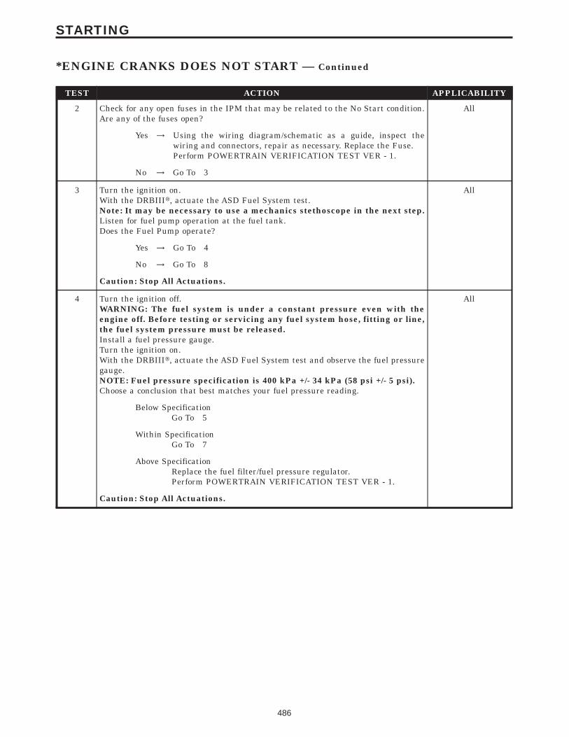
TEST ACTION APPLICABILITY
2 Check for any open fuses in the IPM that may be related to the No Start condition.Are any of the fuses open?
All
Yes → Using the wiring diagram/schematic as a guide, inspect thewiring and connectors, repair as necessary. Replace the Fuse.Perform POWERTRAIN VERIFICATION TEST VER - 1.
No → Go To 3
3 Turn the ignition on.With the DRBIIIt, actuate the ASD Fuel System test.Note: It may be necessary to use a mechanics stethoscope in the next step.Listen for fuel pump operation at the fuel tank.Does the Fuel Pump operate?
All
Yes → Go To 4
No → Go To 8
Caution: Stop All Actuations.
4 Turn the ignition off.WARNING: The fuel system is under a constant pressure even with theengine off. Before testing or servicing any fuel system hose, fitting or line,the fuel system pressure must be released.Install a fuel pressure gauge.Turn the ignition on.With the DRBIIIt, actuate the ASD Fuel System test and observe the fuel pressuregauge.NOTE: Fuel pressure specification is 400 kPa +/- 34 kPa (58 psi +/- 5 psi).Choose a conclusion that best matches your fuel pressure reading.
All
Below SpecificationGo To 5
Within SpecificationGo To 7
Above SpecificationReplace the fuel filter/fuel pressure regulator.Perform POWERTRAIN VERIFICATION TEST VER - 1.
Caution: Stop All Actuations.
486
STARTING
*ENGINE CRANKS DOES NOT START — Continued

TEST ACTION APPLICABILITY
5 Turn the ignition off.WARNING: The fuel system is under a constant pressure even with theengine off. Before testing or servicing any fuel system hose, fitting or line,the fuel system pressure must be released.Raise vehicle on hoist, and disconnect the fuel pressure line at the fuel pump module.Install special 5/16 fuel line adapter tool #6539 between the disconnected fuel lineand the fuel pump module.Attach a fuel pressure test gauge to the T fitting on the tool #6539Turn the ignition on.With the DRBIIIt, actuate the ASD Fuel System test and observe the fuel pressuregauge.NOTE: Fuel pressure specification is 400 KPa +/- 34 KPa (58 psi +/- 5 psi).Is the fuel pressure within specification now?
All
Yes → Repair/replace fuel supply line as necessary.Perform POWERTRAIN VERIFICATION TEST VER - 1.
No → Go To 6
Caution: Stop All Actuations.
6 Turn the ignition off.WARNING: The fuel system is under a constant pressure even with theengine off. Before testing or servicing any fuel system hose,fitting or line,the fuel system pressure must be released.Remove the Fuel Pump Module and inspect the Fuel Inlet Strainer.Is the Fuel Inlet Strainer plugged?
All
Yes → Replace the Fuel Pump Inlet Strainer.Perform POWERTRAIN VERIFICATION TEST VER - 1.
No → Replace the Fuel Pump Module.Perform POWERTRAIN VERIFICATION TEST VER - 1.
7 The following items need to be checked as a possible cause for a no start condition.Refer to any Technical Service Bulletins that may apply to the symptom.The spark plugs must be free from fuel, oil, coolant and/or any foreign material ordeposits.The fuel must be free from contamination.The exhaust may be free from restrictions.The engine compression must be within specifications.The engine valve timing must be within specifications.The engine must be free from vacuum leaks.Were any of the above conditions found?
All
Yes → Repair as necessary.Perform POWERTRAIN VERIFICATION TEST VER - 1.
No → Test Complete.
487
STARTING
*ENGINE CRANKS DOES NOT START — Continued
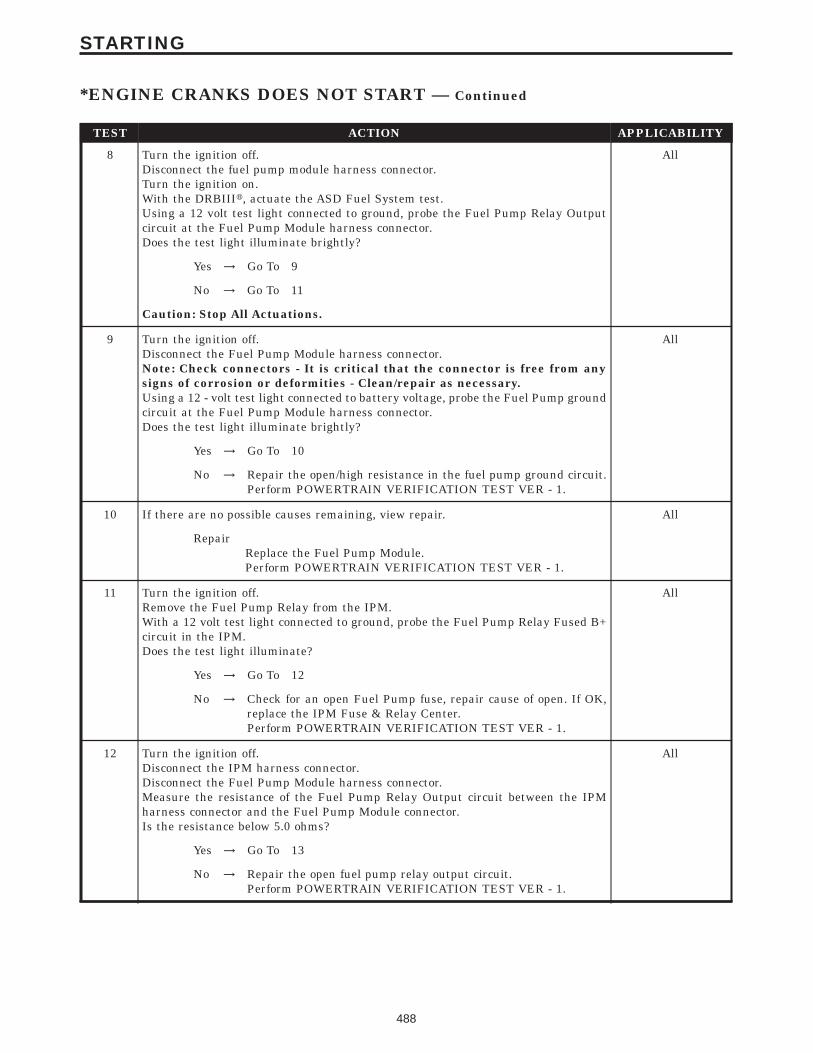
TEST ACTION APPLICABILITY
8 Turn the ignition off.Disconnect the fuel pump module harness connector.Turn the ignition on.With the DRBIIIt, actuate the ASD Fuel System test.Using a 12 volt test light connected to ground, probe the Fuel Pump Relay Outputcircuit at the Fuel Pump Module harness connector.Does the test light illuminate brightly?
All
Yes → Go To 9
No → Go To 11
Caution: Stop All Actuations.
9 Turn the ignition off.Disconnect the Fuel Pump Module harness connector.Note: Check connectors - It is critical that the connector is free from anysigns of corrosion or deformities - Clean/repair as necessary.Using a 12 - volt test light connected to battery voltage, probe the Fuel Pump groundcircuit at the Fuel Pump Module harness connector.Does the test light illuminate brightly?
All
Yes → Go To 10
No → Repair the open/high resistance in the fuel pump ground circuit.Perform POWERTRAIN VERIFICATION TEST VER - 1.
10 If there are no possible causes remaining, view repair. All
RepairReplace the Fuel Pump Module.Perform POWERTRAIN VERIFICATION TEST VER - 1.
11 Turn the ignition off.Remove the Fuel Pump Relay from the IPM.With a 12 volt test light connected to ground, probe the Fuel Pump Relay Fused B+circuit in the IPM.Does the test light illuminate?
All
Yes → Go To 12
No → Check for an open Fuel Pump fuse, repair cause of open. If OK,replace the IPM Fuse & Relay Center.Perform POWERTRAIN VERIFICATION TEST VER - 1.
12 Turn the ignition off.Disconnect the IPM harness connector.Disconnect the Fuel Pump Module harness connector.Measure the resistance of the Fuel Pump Relay Output circuit between the IPMharness connector and the Fuel Pump Module connector.Is the resistance below 5.0 ohms?
All
Yes → Go To 13
No → Repair the open fuel pump relay output circuit.Perform POWERTRAIN VERIFICATION TEST VER - 1.
488
STARTING
*ENGINE CRANKS DOES NOT START — Continued

TEST ACTION APPLICABILITY
13 NOTE: Ensure all IPM harness connector are connected.Turn the ignition off.Disconnect the Fuel Pump Module harness connector.Remove the Fuel Pump Relay from the IPM.Measure the resistance of the Fuel Pump Relay Output circuit between the IPM andthe Fuel Pump Module harness connector.Is the resistance below 5.0 ohms?
All
Yes → Replace the Fuel Pump Relay.Perform POWERTRAIN VERIFICATION TEST VER - 1.
No → Replace the IPM Fused & Relay Center.Perform POWERTRAIN VERIFICATION TEST VER - 1.
489
STARTING
*ENGINE CRANKS DOES NOT START — Continued

Symptom:*NO CRANK CONDITION
POSSIBLE CAUSES
REPAIR MECHANICAL CONDITION
TRANSMISSION RANGE SENSOR
BATTERY CIRCUIT RESISTANCE TOO HIGH
IGNITION SWITCH OUTPUT CIRCUIT OPEN
STARTER RELAY CONTROL CIRCUIT OPEN
STARTER RELAY OUTPUT CIRCUIT OPEN
FUSED B(+) CIRCUIT OPEN
FUSED IGNITION SWITCH OUTPUT (START) CIRCUIT OPEN
STARTER
STARTER MOTOR RELAY
STARTER RELAY
TEST ACTION APPLICABILITY
1 NOTE: Check all PCM powers and grounds before continuing.NOTE: Ensure that SKIS is operating properly. Check the SKIM for DTC. Ifa SKIM DTC(s) is present diagnose them first before continuing.WARNING: MAKE SURE THE BATTERY IS DISCONNECTED, THEN WAITTWO MINUTES BEFORE PROCEEDING.Turn the engine over by hand to ensure the engine is not seized.Is the engine able to turn over?
All
Yes → Go To 2
No → Repair the mechanical condition preventing the starter motorfrom cranking.Perform POWERTRAIN VERIFICATION TEST VER - 1.
2 Turn the ignition off.Disconnect the PCM harness connectors.Move the Gear selector through all gear positions, from Park to 1st and back.While moving the gear selector through each gear, measure the resistance betweenground and the P/N Position Switch Sense circuit.Did the resistance change from above 10.0 ohms to below 10.0 ohms?
All
Yes → Go To 3
No → Replace the Transmission Range Sensor.Perform POWERTRAIN VERIFICATION TEST VER - 1.
3 Turn the ignition off.Check the Battery Cables for high resistance using the service information proce-dure.Did either Battery Cable have a voltage drop greater than 0.2 volt?
All
Yes → Repair the Battery circuit for high resistance.Perform POWERTRAIN VERIFICATION TEST VER - 1.
No → Go To 4
490
STARTING

TEST ACTION APPLICABILITY
4 Turn the ignition off.Disconnect the PCM harness connector.CAUTION: DO NOT PROBE THE PCM HARNESS CONNECTORS. PROBINGTHE PCM HARNESS CONNECTORS WILL DAMAGE THE PCM TERMI-NALS RESULTING IN POOR TERMINAL TO PIN CONNECTION. INSTALLMILLER SPECIAL TOOL #8815 TO PERFORM DIAGNOSIS.Turn the ignition to the Start position.Using a 12-volt test light connected to ground, probe the Fused Ignition SwitchOutput (Start) circuit in the appropriate terminal of special tool #8815.Does the test light illuminate brightly?
All
Yes → Go To 5
No → Repair the Fused Ignition Switch (Start) circuit for an open orhigh resistance.Perform POWERTRAIN VERIFICATION TEST VER - 1.
5 Turn ignition off.Remove the Starter Relay from PDC.WARNING: The Parking Brake must be engaged and the transmission mustbe in Park for a vehicle equipped with an automatic transmission.WARNING: The Starter may Engage in the next step. Keep away frommoving engine parts.Briefly connect a jumper wire between Starter Relay B+ circuit and the Starter RelayOutput Circuits.Turn the ignition to the crank position.Did the Starter Motor crank the engine?
All
Yes → Go To 6
No → Go To 9
6 Turn the ignition off.Remove the Starter Relay from the PDC.Turn the ignition on.Using a 12-volt test light, probe the Ignition Switch Output circuit in the StarterRelay connector.While observing 12-volt test light, hold ignition key in the start position.Does the test light illuminate brightly?
All
Yes → Go To 7
No → Repair the Ignition Switch Output circuit for an open or highresistance.Perform POWERTRAIN VERIFICATION TEST VER - 1.
7 Turn the ignition off.Remove the Starter Relay from the PDC.Disconnect the PCM harness connector.Measure the Starter Relay Control circuit between the Relay terminal and the PCMharness connector.Is the resistance below 5.0 ohms?
All
Yes → Go To 8
No → Repair the Starter Relay Control circuit for an open.Perform POWERTRAIN VERIFICATION TEST VER - 1.
491
STARTING
*NO CRANK CONDITION — Continued

TEST ACTION APPLICABILITY
8 Turn the ignition off.Install a substitute a Relay in the of the Starter Motor Relay.Attempt to start the vehicle.Does the engine crank over?
All
Yes → Replace the Starter Motor Relay.Perform POWERTRAIN VERIFICATION TEST VER - 1.
No → Replace and program the Powertrain Control Module in accor-dance with the Service Information.Perform POWERTRAIN VERIFICATION TEST VER - 1.
9 Turn ignition off.Remove the Starter Relay from the PDC.Disconnect the Starter Relay Output connector from the Starter Solenoid.Measure the resistance of the Starter Relay Output circuit between the Relay and theSolenoid harness connector.Is the resistance below 5.0 ohms?
All
Yes → Go To 10
No → Repair Starter Relay Output circuit for an open.Perform POWERTRAIN VERIFICATION TEST VER - 1.
10 Turn the ignition off.Remove the Starter Relay from the PDC.Using a 12-volt test light connected to ground, probe the Fused B+ circuit at theStarter Relay terminal.Does the test light illuminate brightly?
All
Yes → Go To 11
No → Repair the Fused B(+) Circuit for an open or high resistance.Perform POWERTRAIN VERIFICATION TEST VER - 1.
11 If there are no other possible causes remaining, review repair. All
RepairReplace the Starter.Perform POWERTRAIN VERIFICATION TEST VER - 1.
492
STARTING
*NO CRANK CONDITION — Continued
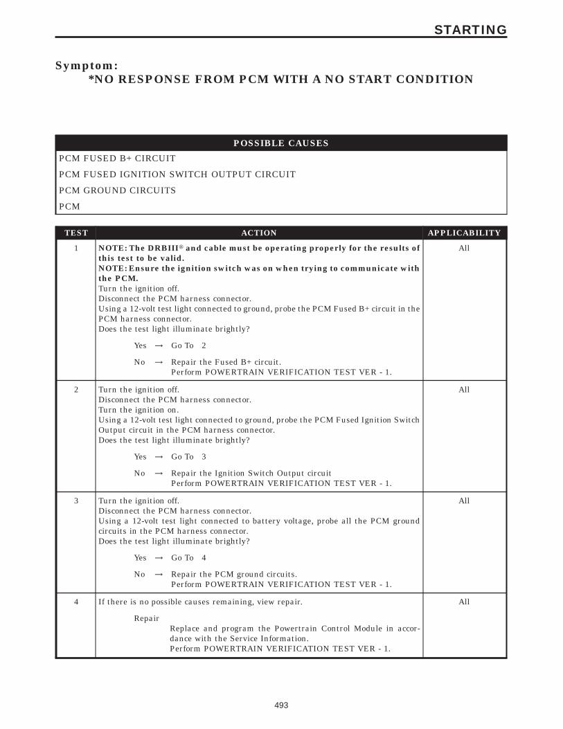
Symptom:*NO RESPONSE FROM PCM WITH A NO START CONDITION
POSSIBLE CAUSES
PCM FUSED B+ CIRCUIT
PCM FUSED IGNITION SWITCH OUTPUT CIRCUIT
PCM GROUND CIRCUITS
PCM
TEST ACTION APPLICABILITY
1 NOTE: The DRBIIIt and cable must be operating properly for the results ofthis test to be valid.NOTE: Ensure the ignition switch was on when trying to communicate withthe PCM.Turn the ignition off.Disconnect the PCM harness connector.Using a 12-volt test light connected to ground, probe the PCM Fused B+ circuit in thePCM harness connector.Does the test light illuminate brightly?
All
Yes → Go To 2
No → Repair the Fused B+ circuit.Perform POWERTRAIN VERIFICATION TEST VER - 1.
2 Turn the ignition off.Disconnect the PCM harness connector.Turn the ignition on.Using a 12-volt test light connected to ground, probe the PCM Fused Ignition SwitchOutput circuit in the PCM harness connector.Does the test light illuminate brightly?
All
Yes → Go To 3
No → Repair the Ignition Switch Output circuitPerform POWERTRAIN VERIFICATION TEST VER - 1.
3 Turn the ignition off.Disconnect the PCM harness connector.Using a 12-volt test light connected to battery voltage, probe all the PCM groundcircuits in the PCM harness connector.Does the test light illuminate brightly?
All
Yes → Go To 4
No → Repair the PCM ground circuits.Perform POWERTRAIN VERIFICATION TEST VER - 1.
4 If there is no possible causes remaining, view repair. All
RepairReplace and program the Powertrain Control Module in accor-dance with the Service Information.Perform POWERTRAIN VERIFICATION TEST VER - 1.
493
STARTING

Symptom:*START AND STALL CONDITION
POSSIBLE CAUSES
CHECKING DTCS
CHECKING SKIM DTCS
FUEL PRESSURE OUT OF SPECS
TP SENSOR SWEEP
TP SENSOR VOLTAGE GREATER THAN 0.92 VOLTS WITH THROTTLE CLOSED
ECT SENSOR OPERATION
OTHER POSSIBLE CAUSES FOR START & STALL
RESTRICTED FUEL SUPPLY LINE
FUEL PUMP INLET STRAINER PLUGGED
FUEL PUMP MODULE
TEST ACTION APPLICABILITY
1 Turn the ignition on.With the DRBIIIt, read DTC’s.Are any DTCs present?
All
Yes → Refer to the Driveability Category and perform the appropriatesymptom.Perform POWERTRAIN VERIFICATION TEST VER - 1.
No → Go To 2
2 Turn the ignition on.NOTE: If you are unable to communicate with the SKIM, refer to theCommunication Category and perform the appropriate symptom.With the DRBIIIt, read the SKIM codes.Are there any SKIM DTCs?
All
Yes → Refer to the Vehicle Theft category and perform the appropriatesymptom.Perform POWERTRAIN VERIFICATION TEST VER - 1.
No → Go To 3
494
STARTING

TEST ACTION APPLICABILITY
3 Turn the ignition off.WARNING: The fuel system is under a constant pressure even with theengine off. Before testing or servicing any fuel system hose, fitting or line,the fuel system pressure must be released.Install a fuel pressure gauge to the fuel rail test port.Turn the ignition on.With the DRBIIIt, actuate the ASD Fuel System test and observe the fuel pressuregauge.NOTE: Fuel pressure specification is 400 KPa +/- 34 KPa (58 psi +/- 5 psi).Choose a conclusion that best matches your fuel pressure reading.
All
Below SpecificationGo To 4
Within SpecificationGo To 6
Above SpecificationReplace the fuel filter/fuel pressure regulator.Perform POWERTRAIN VERIFICATION TEST VER - 1.
Caution: Stop All Actuations.
4 Turn the ignition off.WARNING: The fuel system is under a constant pressure even with theengine off. Before testing or servicing any fuel system hose, fitting or line,the fuel system pressure must be released.Raise vehicle on hoist, and disconnect the fuel pressure line at the fuel pump module.Install special 5/16 fuel line adapter tool #6539 between the disconnected fuel lineand the fuel pump module.Attach a fuel pressure test gauge to the 9T9 fitting on tool #6539.Turn the ignition on.With the DRBIIIt, actuate the ASD Fuel System test and observe the fuel pressuregauge.NOTE: Fuel pressure specification is 400 KPa +/- 34 KPa (58 psi +/- 5 psi).Is the fuel pressure within specification now?
All
Yes → Repair/replace fuel supply line as necessary.Perform POWERTRAIN VERIFICATION TEST VER - 1.
No → Go To 5
Caution: Stop All Actuations.
5 Turn the ignition off.WARNING: The fuel system is under a constant pressure even with theengine off. Before testing or servicing any fuel system hose,fitting or line,the fuel system pressure must be released.Remove the Fuel Pump Module and inspect the Fuel Inlet Strainer.Is the Fuel Inlet Strainer plugged?
All
Yes → Replace the Fuel Pump Inlet Strainer.Perform POWERTRAIN VERIFICATION TEST VER - 1.
No → Replace the Fuel Pump Module.Perform POWERTRAIN VERIFICATION TEST VER - 1.
495
STARTING
*START AND STALL CONDITION — Continued
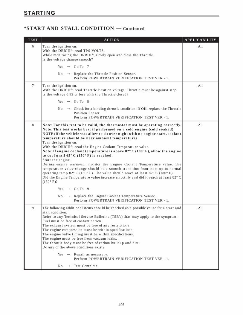
TEST ACTION APPLICABILITY
6 Turn the ignition on.With the DRBIIIt, read TPS VOLTS.While monitoring the DRBIIIt, slowly open and close the Throttle.Is the voltage change smooth?
All
Yes → Go To 7
No → Replace the Throttle Position Sensor.Perform POWERTRAIN VERIFICATION TEST VER - 1.
7 Turn the ignition on.With the DRBIIIt, read Throttle Position voltage. Throttle must be against stop.Is the voltage 0.92 or less with the Throttle closed?
All
Yes → Go To 8
No → Check for a binding throttle condition. If OK, replace the ThrottlePosition Sensor.Perform POWERTRAIN VERIFICATION TEST VER - 1.
8 Note: For this test to be valid, the thermostat must be operating correctly.Note: This test works best if performed on a cold engine (cold soaked).NOTE: If the vehicle was allow to sit over night with no engine start, coolanttemperature should be near ambient temperatures.Turn the ignition on.With the DRBIIIt, read the Engine Coolant Temperature value.Note: If engine coolant temperature is above 82° C (180° F), allow the engineto cool until 65° C (150° F) is reached.Start the engine.During engine warm-up, monitor the Engine Coolant Temperature value. Thetemperature value change should be a smooth transition from start up to normaloperating temp 82° C (180° F). The value should reach at least 82° C (180° F).Did the Engine Temperature value increase smoothly and did it reach at least 82° C(180° F)?
All
Yes → Go To 9
No → Replace the Engine Coolant Temperature Sensor.Perform POWERTRAIN VERIFICATION TEST VER - 1.
9 The following additional items should be checked as a possible cause for a start andstall condition.Refer to any Technical Service Bulletins (TSB’s) that may apply to the symptom.Fuel must be free of contamination.The exhaust system must be free of any restrictions.The engine compression must be within specifications.The engine valve timing must be within specifications.The engine must be free from vacuum leaks.The throttle body must be free of carbon buildup and dirt.Do any of the above conditions exist?
All
Yes → Repair as necessary.Perform POWERTRAIN VERIFICATION TEST VER - 1.
No → Test Complete.
496
STARTING
*START AND STALL CONDITION — Continued

Verification Tests
41TE TRANSMISSION VERIFICATION TEST - VER 1. APPLICABILITY
1. Connect the DRBIIIt to the Data Link Connector (DLC).2. Reconnect any disconnected components.3. With the DRBIIIt, erase all Transmission DTC’s, also erase the PCM DTC’s.4. With the DRBIIIt, display transmission temperature. Start and run the engine until thetransmission temperature is HOT (above 110 deg. F).5. Check the transmission fluid and adjust if necessary. Refer to the Service information for theFluid Fill procedure.6. NOTE: If the Transmission Control Module or torque converter has been replacedor if the transmission has been repaired or replaced it is necessary to perform theDRBIIIt Quick Learn Procedure and reset the (Pinion Factor(7. Road test the vehicle. With the DRBIIIt, monitor the engine RPM. Make 15 to 20 1-2, 2-3,3-4 upshifts. Perform these shifts from a standing start to 45 MPH with a constant throttleopening of 20 to 25 degrees.8. Below 25 MPH, make 5 to 8 wide open throttle kickdowns to 1st gear. Allow at least 5 secondseach in 2nd and 3rd gear between each kickdown.9. For a specific DTC, drive the vehicle to the Symptom’s When Monitored/When Set conditionsto verify the DTC repair.10. Check for Diagnostic Trouble Codes (DTC’s) during the road test. If a DTC sets during theroad test , return to the Symptom list and follow the path.11. NOTE: Erase P0700 DTC in the PCM to turn the MIL light off after makingtransmission repairs. This will turn the MIL off.Were any Trouble Codes set during the road test?
All
Yes → Refer to the Symptom List for appropriate diagnostic tests.
No → Repair is complete.
497
VERIFICATION TESTS

BODY VERIFICATION TEST - VER 1 APPLICABILITY
1. Disconnect all jumper wires and reconnect all previously disconnected components andconnectors.2. NOTE: If the SKIM, PCM/ECM or FCM was replaced, refer to the service informa-tion for proper programming procedures.3. If the Body Control Module (BCM) was replaced, turn the ignition on for 15 seconds (to allowthe new BCM to learn VIN) or engine may not start (if VTSS equipped). If the vehicle isequipped with VTSS, use the DRBIIIt and enable VTSS.4. Program all RKE transmitters and other options as necessary.5. If any HVAC door actuator circuits were repaired, with the DRBIIIt in HVAC, System Tests,select Actuator Circuit Test. (Manual Temp Control only).6. If any actuators were replaced in the HVAC System, with the DRBIIIt in HVAC, selectSystem Tests then select HVAC Door Recalibration (Manual Temp Control only).7. If any actuators were replaced in the ATC System, with the DRBIIIt in Automatic TempControl, select Miscellaneous then select Reset ATC Head.8. For Three-Zone HVAC Systems, if HVAC Control/Rear Blower Rear Control was replaced/Rear Blend Pot Circuit Open/Short DTC was set/any rear blend pot circuit was repaired,proceed to Number 9 & 10.9. With DRBIIIt in HVAC, select System Tests then select HVAC Door Recalibration. DoorRecalibration must pass before proceeding to next step.10. With DRBIIIt in HVAC, select System Tests then select Reset Rear Blend Switch Span.Rotate Rear Blend/Mode control on Rear Blower Rear Control to full cold. Wait five seconds,then rotate control to full hot.11. If any repairs were made to the power sliding door or power liftgate, use the DRBIIIt andperform the open and close system tests. Observe the instructions on the DRBIIIt screen.12. Ensure that all accessories are turned off and the battery is fully charged.13. With the DRBIIIt, record and erase all DTCs from ALL modules. Start and run the enginefor 2 minutes. Operate all functions of the system that caused the original concern.14. Turn the ignition off and wait 5 seconds. Turn the ignition on and using the DRBIIIt, readDTCs from ALL modules.Are any DTC’s present or is the original condition still present?
All
Yes → Repair is not complete, refer to the appropriate symptom.
No → Repair is complete.
POWERTRAIN VERIFICATION TEST VER - 1 - SBEC APPLICABILITY
1. NOTE: If the PCM has been replaced and the correct VIN and mileage have notbeen programmed, a DTC will be set in the ABS Module, Airbag Module and theSKIM.2. NOTE: If the vehicle is equipped with a Sentry Key Immobilizer System, Secret Keydata must be updated. Refer to the Service Information for the PCM, SKIM and theTransponder (ignition key) for programming information.3. Inspect the vehicle to ensure that all components related to the repair are connected properly.4. Inspect the engine oil for fuel contamination. Replace the oil and filter as necessary.5. Attempt to start the engine.6. If the No Start condition is still present, refer to the symptom list and perform the diagnostictesting as necessary. refer to any Technical Service Bulletins that may apply.7. Run the engine for one warm-up cycle to verify operation.8. With the DRBIIIt, confirm that no DTCs or Secondary Indicators are present and that allcomponents are functioning properly.9. If a DTC is present, refer to the appropriate category and select the corresponding symptom.Are any DTCs present?
All
Yes → Repair is not complete, refer to appropriate symptom.
No → Repair is complete.
498
VERIFICATION TESTS
Verification Tests — Continued

POWERTRAIN VERIFICATION TEST VER - 1 - NGC APPLICABILITY
1. NOTE: After completing the Powertrain Verification Test the Transmission Verifi-cation Test must be performed.2. NOTE: If the PCM has been replaced and the correct VIN and mileage have notbeen programmed, a DTC will be set in the ABS Module, Airbag Module and theSKIM.3. NOTE: If the vehicle is equipped with a Sentry Key Immobilizer System, Secret Keydata must be updated. Refer to the Service Information for the PCM, SKIM and theTransponder (ignition key) for programming information.4. Inspect the vehicle to ensure that all components related to the repair are connected properly.5. Inspect the engine oil for fuel contamination. Replace the oil and filter as necessary.6. Attempt to start the engine.7. If the No Start condition is still present, refer to the symptom list and perform the diagnostictesting as necessary. refer to and Technical Service Bulletins that may apply.8. Run the engine for one warm-up cycle to verify operation.9. With the DRBIIIt, confirm that no DTCs or Secondary Indicators are present and that allcomponents are functioning properly.10. If a DTC is present, refer to the appropriate category and select the corresponding symptom.Are any DTCs present?
All
Yes → Repair is not complete, refer to appropriate symptom.
No → Repair is complete.
POWERTRAIN VERIFICATION TEST VER - 2 - SBEC APPLICABILITY
1. NOTE: If the PCM has been replaced and the correct VIN and mileage have notbeen programmed, a DTC will be set in the ABS Module, Airbag Module and theSKIM.2. NOTE: If the vehicle is equipped with a Sentry Key Immobilizer System, Secret Keydata must be updated. Refer to the Service Information for the PCM, SKIM and theTransponder (ignition key) for programming information.3. Inspect the vehicle to ensure that all components related to the repair are connected properly.4. With the DRBIIIt, clear DTCs and Reset Memory all engine values.5. Run the engine for one warm-up cycle to verify proper operation.6. Road test the vehicle. Use all accessories that may be related to this repair.7. With the DRBIIIt, confirm that no DTC’s or Secondary Indicators are present and that allcomponents are functioning properly.8. If this test is being performed after a No Trouble Code test, verify the symptom is no longerpresent.9. If the symptom is still present, or any other symptom or DTC is present refer to theappropriate category and perform the corresponding symptom.10. Refer to any Technical Service Bulletins that may apply.11. If there are no DTCs present and all components are functional properly, the repair iscomplete.Are any DTCs present?
All
Yes → Repair is not complete, refer to appropriate symptom.
No → Repair is complete.
499
VERIFICATION TESTS
Verification Tests — Continued

POWERTRAIN VERIFICATION TEST VER - 2 - NGC APPLICABILITY
1. NOTE: After completing the Powertrain Verification Test the Transmission Verifi-cation Test must be performed.2. NOTE: If the PCM has been replaced and the correct VIN and mileage have notbeen programmed, a DTC will be set in the ABS Module, Airbag Module and theSKIM.3. NOTE: If the vehicle is equipped with a Sentry Key Immobilizer System, Secret Keydata must be updated. Refer to the Service Information for the PCM, SKIM and theTransponder (ignition key) for programming information.4. Inspect the vehicle to ensure that all components related to the repair are connected properly.5. With the DRBIIIt, clear DTCs and Reset Memory all engine values.6. Run the engine for one warm-up cycle to verify proper operation.7. Road test the vehicle. Use all accessories that may be related to this repair.8. With the DRBIIIt, confirm that no DTC’s or Secondary Indicators are present and that allcomponents are functioning properly.9. If this test is being performed after a No Trouble Code test, verify the symptom is no longerpresent.10. If the symptom is still present, or any other symptom or DTC is present refer to theappropriate category and perform the corresponding symptom.11. Refer to any Technical Service Bulletins that may apply.12. If there are no DTCs present and all components are functional properly, the repair iscomplete.Are any DTCs present?
All
Yes → Repair is not complete, refer to appropriate symptom.
No → Repair is complete.
POWERTRAIN VERIFICATION TEST VER - 3 - SBEC APPLICABILITY
1. NOTE: If the PCM has been replaced and the correct VIN and mileage have notbeen programmed, a DTC will be set in the ABS Module, Airbag Module and theSKIM.2. NOTE: If the vehicle is equipped with a Sentry Key Immobilizer System, Secret Keydata must be updated. Refer to the Service Information for the PCM, SKIM and theTransponder (ignition key) for programming information.3. Inspect the vehicle to ensure that all components related to the repair are connected properly.4. With the DRBIIIt, clear DTCs.5. Perform generator output test. Refer to the appropriate service information as necessary.6. Start the engine and set engine speed to 2000 RPM for at least thirty seconds.7. Cycle the ignition key off and on.8. With the DRBIIIt, read the DTCs. If the DTC returns, or any other symptom or DTC ispresent, refer to the appropriate category and perform the corresponding symptom.9. If there are no DTCs present and all components are functioning properly, the repair iscomplete.Are any DTCs present?
All
Yes → Repair is not complete, refer to appropriate symptom.
No → Repair is complete.
500
VERIFICATION TESTS
Verification Tests — Continued

POWERTRAIN VERIFICATION TEST VER - 3 - NGC APPLICABILITY
1. NOTE: After completing the Powertrain Verification Test the Transmission Verifi-cation Test must be performed.2. NOTE: If the PCM has been replaced and the correct VIN and mileage have notbeen programmed, a DTC will be set in the ABS Module, Airbag Module and theSKIM.3. NOTE: If the vehicle is equipped with a Sentry Key Immobilizer System, Secret Keydata must be updated. Refer to the Service Information for the PCM, SKIM and theTransponder (ignition key) for programming information.4. Inspect the vehicle to ensure that all components related to the repair are connected properly.5. With the DRBIIIt, clear DTCs.6. Perform generator output test. Refer to the appropriate service information as necessary.7. Start the engine and set engine speed to 2000 RPM for at least thirty seconds.8. Cycle the ignition key off and on.9. With the DRBIIIt, read the DTCs. If the DTC returns, or any other symptom or DTC ispresent, refer to the appropriate category and perform the corresponding symptom.10. If there are no DTCs present and all components are functioning properly, the repair iscomplete.Are any DTCs present?
All
Yes → Repair is not complete, refer to appropriate symptom.
No → Repair is complete.
501
VERIFICATION TESTS
Verification Tests — Continued

POWERTRAIN VERIFICATION TEST VER - 4 - SBEC APPLICABILITY
1. NOTE: If the PCM has been replaced and the correct VIN and mileage have notbeen programmed, a DTC will be set in the ABS Module, Airbag Module and theSKIM.2. NOTE: If the vehicle is equipped with a Sentry Key Immobilizer System, Secret Keydata must be updated. Refer to the Service Information for the PCM, SKIM and theTransponder (ignition key) for programming information.3. Inspect the vehicle to ensure that all engine components are properly installed andconnected.4. Connect the DRBIIIt to the data link connector and erase all codes.5. Turn the speed control ON (if equipped, cruise light will be on).6. Press and release the SET switch. If the speed control did not engage, the repair is notcomplete. Check for TSBs that pertain to speed control problems and then, if necessary, returnto the Symptom List.7. Press and hold the RESUME/ACCEL Switch. If the vehicle speed did not increase by at least2 mph, the repair is not complete. Check for TSBs that pertain to speed control problem andthen, if necessary, return to Symptom List.8. Press and hold the COAST switch. The vehicle speed should decrease. If it did not decrease,the repair is not complete. Check for TSBs that pertain to speed control problem and then, ifnecessary, return to Symptom List.9. Using caution, press and release the brake pedal. If the speed control did not disengage, therepair is not complete. Check for TSBs that pertain to speed control problem and then, ifnecessary, return to Symptom List.10. Bring the vehicle speed back up to 35 MPH.11. Press the RESUME/ACCEL switch. If the speed control did not resume the previously setspeed, the repair is not complete. Check for TSBs that pertain to speed control problem andthen, if necessary, return to Symptom List.12. Hold down the SET switch. If the vehicle did not decelerate, the repair is not complete.Check for TSBs that pertain to speed control problem and then, if necessary, return to SymptomList.13. Ensure vehicle speed is greater than 35 mph and release the SET Switch. If vehicle did notadjust and set a new vehicle speed, the repair is not complete. Check for TSBs that pertain tospeed control problem and then, if necessary, return to Symptom List.14. Press and release the CANCEL switch. If the speed control did not disengage, the repair isnot complete. Check for TSBs that pertain to speed control problem and then, if necessary,return to Symptom List.15. Bring the vehicle speed back up above 35 mph and engage speed control.16. Press the OFF switch to turn OFF, (Cruise light will be off). If the speed control did notdisengage, the repair is not complete. Check for TSBs that pertain to speed control problem andthen, if necessary, return to Symptom List.17. If the vehicle successfully passed all of the previous tests, the speed control system is nowfunctioning as designed. The repair is now complete.Did the Speed Control pass the above test?
All
Yes → Repair is complete.
No → Repair is not complete, refer to appropriate symptom.
502
VERIFICATION TESTS
Verification Tests — Continued

POWERTRAIN VERIFICATION TEST VER - 4 - NGC APPLICABILITY
1. NOTE: After completing the Powertrain Verification Test the Transmission Verifi-cation Test must be performed.2. NOTE: If the PCM has been replaced and the correct VIN and mileage have notbeen programmed, a DTC will be set in the ABS Module, Airbag Module and theSKIM.3. NOTE: If the vehicle is equipped with a Sentry Key Immobilizer System, Secret Keydata must be updated. Refer to the Service Information for the PCM, SKIM and theTransponder (ignition key) for programming information.4. Inspect the vehicle to ensure that all engine components are properly installed andconnected.5. Connect the DRBIIIt to the data link connector and erase all codes.6. Turn the speed control ON (if equipped, cruise light will be on).7. Press and release the SET Switch. If the speed control did not engage, the repair is notcomplete. Check for TSBs that pertain to speed control problem and then, if necessary, returnto Symptom List.8. Press and hold the RESUME/ACCEL Switch. If the vehicle speed did not increase by at least2 mph, the repair is not complete. Check for TSBs that pertain to speed control problem andthen, if necessary, return to Symptom List.9. Press and hold the COAST switch. The vehicle speed should decrease. If it did not decrease,the repair is not complete. Check for TSBs that pertain to speed control problem and then, ifnecessary, return to Symptom List.10. Using caution, press and release the brake pedal. If the speed control did not disengage, therepair is not complete. Check for TSBs that pertain to speed control problem and then, ifnecessary, return to Symptom List.11. Bring the vehicle speed back up to 35 MPH.12. Press the RESUME/ACCEL switch. If the speed control did not resume the previously setspeed, the repair is not complete. Check for TSBs that pertain to speed control problem andthen, if necessary, return to Symptom List.13. Hold down the SET switch. If the vehicle did not decelerate, the repair is not complete.Check for TSBs that pertain to speed control problem and then, if necessary, return to SymptomList.14. Ensure vehicle speed is greater than 35 mph and release the SET Switch. If vehicle did notadjust and set a new vehicle speed, the repair is not complete. Check for TSBs that pertain tospeed control problem and then, if necessary, return to Symptom List.15. Press and release the CANCEL switch. If the speed control did not disengage, the repair isnot complete. Check for TSBs that pertain to speed control problem and then, if necessary,return to Symptom List.16. Bring the vehicle speed back up above 35 mph and engage speed control.17. Turn the Speed Control Off. (Cruise light will be off). If the speed control did not disengage,the repair is not complete. Check for TSBs that pertain to speed control problem and then, ifnecessary, return to Symptom List.18. If the vehicle successfully passed all of the previous tests, the speed control system is nowfunctioning as designed. The repair is now complete.Did the Speed Control pass the above test?
All
Yes → Repair is complete.
No → Repair is not complete, refer to appropriate symptom.
503
VERIFICATION TESTS
Verification Tests — Continued

POWERTRAIN VERIFICATION TEST VER - 5- SBEC APPLICABILITY
1. NOTE: If the PCM has been replaced and the correct VIN and mileage have notbeen programmed, a DTC will be set in the ABS Module, Airbag Module and theSKIM.2. NOTE: If the vehicle is equipped with a Sentry Key Immobilizer System, Secret Keydata must be updated. Refer to the Service Information for the PCM, SKIM and theTransponder (ignition key) for programming information.3. Inspect the vehicle to ensure that all engine components are properly installed andconnected. Reassemble and reconnect components as necessary.4. Connect the DRBIIIt to the data link connector.5. Ensure the fuel tank has at least a quarter tank of fuel. Turn off all accessories.6. If a Comprehensive Component DTC was repaired, perform steps 5 - 8. If a Major OBDIIMonitor DTC was repaired skip those steps and continue verification.7. After the ignition has been off for at least 10 seconds, restart the vehicle and run 2 minutes.8. If the Good Trip counter changed to one or more and there are no new DTC’s, the repair wassuccessful and is now complete. Erase DTC’s and disconnect the DRBIIIt.9. If the repaired DTC has reset, the repair is not complete. Check for any related TSB’s or flashupdates and return to the Symptom list.10. If another DTC has set, return to the Symptom List and follow the path specified for thatDTC.11. With the DRBIIIt, monitor the appropriate pre-test enabling conditions until all conditionshave been met. Once the conditions have been met, switch screen to the appropriate OBDIImonitor, (Audible beeps when the monitor is running).12. If the monitor ran, and the Good Trip counter changed to one or more, the repair wassuccessful and is now complete. Erase DTC’s and disconnect the DRBIIIt.13. If the repaired OBDII trouble code has reset or was seen in the monitor while on the roadtest, the repair is not complete. Check for any related technical service bulletins or flashupdates and return to Symptom List.14. If another DTC has set, return to the Symptom List and follow the path specified for thatDTC.Are any DTCs present?
All
Yes → Repair is not complete, refer to appropriate symptom.
No → Repair is complete.
504
VERIFICATION TESTS
Verification Tests — Continued

POWERTRAIN VERIFICATION TEST VER - 5 - NGC APPLICABILITY
1. NOTE: After completing the Powertrain Verification Test the Transmission Verifi-cation Test must be performed.2. NOTE: If the PCM has been replaced and the correct VIN and mileage have notbeen programmed, a DTC will be set in the ABS Module, Airbag Module and theSKIM.3. NOTE: If the vehicle is equipped with a Sentry Key Immobilizer System, Secret Keydata must be updated. Refer to the Service Information for the PCM, SKIM and theTransponder (ignition key) for programming information.4. Inspect the vehicle to ensure that all engine components are properly installed andconnected. Reassemble and reconnect components as necessary.5. Connect the DRBIIIt to the data link connector.6. Ensure the fuel tank has at least a quarter tank of fuel. Turn off all accessories.7. If a Comprehensive Component DTC was repaired, perform steps 5 - 8. If a Major OBDIIMonitor DTC was repaired skip those steps and continue verification.8. After the ignition has been off for at least 10 seconds, restart the vehicle and run 2 minutes.9. If the Good Trip counter changed to one or more and there are no new DTC’s, the repair wassuccessful and is now complete. Erase DTC’s and disconnect the DRBIIIt.10. If the repaired DTC has reset, the repair is not complete. Check for any related TSB’s orflash updates and return to the Symptom list.11. If another DTC has set, return to the Symptom List and follow the path specified for thatDTC.12. With the DRBIIIt, monitor the appropriate pre-test enabling conditions until all conditionshave been met. Once the conditions have been met, switch screen to the appropriate OBDIImonitor, (Audible beeps when the monitor is running).13. If the monitor ran, and the Good Trip counter changed to one or more, the repair wassuccessful and is now complete. Erase DTC’s and disconnect the DRBIIIt.14. If the repaired OBDII trouble code has reset or was seen in the monitor while on the roadtest, the repair is not complete. Check for any related technical service bulletins or flashupdates and return to Symptom List.15. If another DTC has set, return to the Symptom List and follow the path specified for thatDTC.Are any DTCs present?
All
Yes → Repair is not complete, refer to appropriate symptom.
No → Repair is complete.
505
VERIFICATION TESTS
Verification Tests — Continued

POWERTRAIN VERIFICATION TEST VER - 6 - SBEC APPLICABILITY
1. NOTE: If the PCM has been replaced and the correct VIN and mileage have notbeen programmed, a DTC will be set in the ABS Module, Airbag Module and theSKIM.2. NOTE: If the vehicle is equipped with a Sentry Key Immobilizer System, Secret Keydata must be updated. Refer to the Service Information for the PCM, SKIM and theTransponder (ignition key) for programming information.3. Inspect the vehicle to ensure that all engine components are properly installed andconnected. Reassemble and reconnect components as necessary.4. The LDP Monitor Test Mode has been added to the DRBIIIt to verify repairs to the LDPSystem. A DRBIIIt software program was written which causes the PCM to run the LDPMonitor as part of this test. Test failures will be indicated through a stored DTC.5. LDP Monitor Test Mode is a useful way to run a total system performance test. Use this testto verify any type of LDP system repair.6. Software program makes temporary changes to operating mode of PCM. For this reason, itis critical that test not be interrupted. PCM’s left in this mode as result of interrupted test willilluminate the MIL for 8-10 mi of driving with no DTC’s stored.7. Erasing DTC’s will not change this condition.8. If a vehicle is found to be stuck in the mode described above, the LDP Dealer Test should bere-run in its entirety so that the software program in the DRBIIIt can restore the PCMoperating mode.9. Note similarity to LDP Monitor screen found under OBDII Monitors. Failure modes arefewer in this System Test than OBDII LDP Monitor.10. System Test failure may have been, for example, due to a large leak, but the PCM will setthe Small Leak DTC to indicate failures that occurred as part of the system test.11. Connect the DRBIIIt to the data link connector. Engine running, turn off all accessories.12. Note: While test is being performed, PCM must see RPM, minimum MAP, No Vehicle speedand minimum Throttle Position sensor (At idle, in park.) With DRBIIIt in System Tests,perform the LDP Monitor Test and follow the instructions on the screen.13. If the LDP Monitor Test failed and a .020 Leak DTC has set, the repair is not complete.Check for any related Technical Service Bulletins and return to Symptom List.14. If any other trouble code has set, return to Symptom List and follow the path specified forthat trouble code. If the LDP Monitor Test passed, the repair was successful and testing is nowcomplete.Are any DTCs present?
All
Yes → Repair is not complete, refer to appropriate symptom.
No → Repair is complete.
506
VERIFICATION TESTS
Verification Tests — Continued

POWERTRAIN VERIFICATION TEST VER - 6 - NGC APPLICABILITY
1. Install the Miller Tool #8404 Evaporative Emission Leak Detector (EELD). according to theinstructions in the pervious DTC table.2. Set the smoke/air control switch to AIR.3. Insert the tester’s AIR supply tip (clear hose) into the appropriate calibration orifice on thetester’s control panel (based on DTC leak size).4. Press the remote smoke/air start button.5. Position the red flag on the air flow meter so it is aligned with the indicator ball.6. When the calibration is complete, release the remote button. The EELD is now calibrated theflow meter in liters per minute to the size leak indicated by the DTC set in the PCM.7. Install the service port adapter #8404-14 on the vehicle’s service port.8. Connect the Air supply hose from the EELD to the service port.9. Press the remote button to activate AIR flow.10. NOTE: Larger volume fuel tanks, lower fuel levels or if the vehicle is equippedwith a Flow Management Valve may indicate high flow and will require 4 to 5minutes to fill.11. Compare the flow meter indicator ball reading to the red flag.12. ABOVE the red flag indicates a leak present.13. BELOW the red flag indicates a sealed system.14. If the indicator ball shows a leak present, perform the smoke test indicated in the previoustest and identify the leak and repair. Perform this verification test when the repair is complete.Did the indicator ball indicate the a leak is present??
All
Yes → Repeat the DTC test to identify the leak and repair.
No → Repair is complete.
SKIS VERIFICATION APPLICABILITY
1. Reconnect all previously disconnected components and connectors.2. Obtain the vehicle’s unique Personal Identification Number (PIN) assigned to it’s originalSKIM. This number can be obtained from the vehicle’s invoice or Chrysler’s Customer Center(1-800-992-1997).3. NOTE: When entering the PIN, care should be taken because the SKIM will onlyallow 3 consecutive attempts to enter the correct PIN. If 3 consecutive incorrectPIN’s are entered the SKIM will Lock Out the DRB III for 1 hour.4. To exit Lock Out mode, the ignition key must remain in the Run position continually for 1hour. Turn off all accessories and connect a battery charger if necessary.5. With the DRB III, select Theft Alarm, SKIM and Miscellaneous. Then select desiredprocedure and follow the steps that will be displayed.6. If the SKIM has been replaced, ensure all of the vehicle ignition keys are programmed to thenew SKIM.7. NOTE: Prior to returning vehicle to the costumer, perform a module scan to be surethat all DTC’s are erased. Erase any DTC’s that are found.8. With the DRB III erase all DTC’s. Perform 5 ignition key cycles leaving the key on for at least90 seconds per cycle.9. With the DRB III, read the SKIM DTC’s.Are there any SKIM DTC’s?
All
Yes → Repair is not complete, refer to appropriate symptom.
No → Repair is complete.
507
VERIFICATION TESTS
Verification Tests — Continued

SKIS VERIFICATION APPLICABILITY
1. Reconnect all previously disconnected components and connectors.2. Obtain the vehicle’s unique Personal Identification Number (PIN) assigned to it’s originalSKIM. This number can be obtained from the vehicle’s invoice or Chrysler’s Customer Center(1-800-992-1997).3. NOTE: When entering the PIN, care should be taken because the SKIM will onlyallow 3 consecutive attempts to enter the correct PIN. If 3 consecutive incorrect PINsare entered, the SKIM will Lock Out the DRBIIIt for 1 hour.4. To exit Lock Out mode, the ignition key must remain in the Run position continually for 1hour. Turn off all accessories and connect a battery charger if necessary.5. With the DRBIIIt, select Theft Alarm, SKIM and Miscellaneous. Then, select the desiredprocedure and follow the steps that will be displayed.6. If the SKIM has been replaced, ensure all of the vehicle ignition keys are programmed to thenew SKIM.7. NOTE: Prior to returning vehicle to the customer, perform a module scan to be surethat all DTCs are erased. Erase any DTCs that are found.8. With the DRBIIIt, erase all DTCs. Perform 5 ignition key cycles leaving the key on for atleast 90 seconds per cycle.9. With the DRBIIIt, read the SKIM DTCs.Are there any SKIM DTCs?
All
Yes → Repair is not complete, refer to appropriate symptom.
No → Repair is complete.
508
VERIFICATION TESTS
Verification Tests — Continued

8.0 COMPONENT LOCATIONS
8.1 CONTROL MODULES AND FUSE & RELAY CENTER2.4L 3.3L/3.8L
8.2 CONTROLS AND SOLENOID3.3L/3.8L
COMPONENT
LOCATIONS
509
COMPONENT LOCATIONS

2.4L 3.3L/3.8L
2.4L 3.3L/3.8L
2.4L 3.3L/3.8L
COMPONENT
LOCATIONS
510
COMPONENT LOCATIONS
8.2 CONTROLS AND SOLENOID (Continued)

2.4L 3.3L/3.8L
8.3 DATA LINK CONNECTOR
COMPONENT
LOCATIONS
511
COMPONENT LOCATIONS

8.4 SENSORS2.4L
3.3L/3.8L 2.4L
3.3L/3.8L 2.4L
COMPONENT
LOCATIONS
512
COMPONENT LOCATIONS

3.3L/3.8L 2.4L
3.3L/3.8L 2.4L
3.3L/3.8L 2.4L
COMPONENT
LOCATIONS
513
COMPONENT LOCATIONS

3.3L/3.8L
2.4L 3.3L/3.8L
8.5 FUEL SYSTEM2.4L 3.3L/3.8L
COMPONENT
LOCATIONS
514
COMPONENT LOCATIONS
8.4 SENSORS (Continued)

8.6 SWITCHES
COMPONENT
LOCATIONS
515
COMPONENT LOCATIONS

NOTES
516

9.0 CONNECTOR PINOUTS
A/C COMPRESSOR CLUTCHCAV CIRCUIT FUNCTION
1 C3 20DB/YL (2.4L) A/C COMPRESSOR CLUTCH RELAY OUTPUT
1 C3 18DB/YL (3.3L/3.8L/DIESEL)
A/C COMPRESSOR CLUTCH RELAY OUTPUT
2 Z153 18BK/GY GROUND
A/C PRESSURE SENSORCAV CIRCUIT FUNCTION
1 K900 18DB/DG (GAS) SENSOR GROUND
1 C918 20BK/LB (DIESEL) A/C PRESSURE SENSOR GROUND
2 F855 20PK/YL (2.4L) 5 VOLT SUPPLY
2 F851 20LB/PK (DIESEL) SENSOR REFERENCE VOLTAGE B
2 F855 18PK/YL (3.3L/3.8L) 5 VOLT SUPPLY
3 C18 18LB/BR (3.3L/3.8L) A/C PRESSURE SENSOR SIGNAL
3 C18 20LB/BR (DIESEL) A/C PRESSURE SENSOR SIGNAL
3 C18 18LB/BR (2.4L) A/C PRESSURE SIGNAL
4 - -
AMBIENT TEMPERATURE SENSOR (EXCEPT BASE)CAV CIRCUIT FUNCTION
1 G31 18VT/LG (EXCEPT2.4L)
AMBIENT TEMPERATURE SENSOR SIGNAL
1 G31 18VT/LG (2.4L) AAT SIGNAL
2 K900 18DB/DG (2.4L) SENSOR GROUND
2 G931 18VT/BR (EXCEPT2.4L)
AMBIENT TEMPERATURE SENSOR RETURN
CONNECTOR
PINOUTS
517
CONNECTOR PINOUTS

BODY CONTROL MODULE C3CAV CIRCUIT FUNCTION
1 G23 22VT/DB (POWERSLIDING DOOR)
SLIDING DOORS OVERHEAD SWITCH MUX
2 D123 20WT/BR FLASH PROGRAM ENABLE
3 G152 22VT/GY (POWERSLIDING DOOR)
RIGHT SLIDING DOOR WAKE UP SIGNAL
4 G151 22VT/BR (POWERSLIDING DOOR)
LEFT SLIDING DOOR WAKE UP SIGNAL
5 G76 20VT/YL RIGHT SLIDING DOOR AJAR SWITCH SENSE
6 G75 22VT (LHD) LEFT FRONT DOOR AJAR SWITCH SENSE
6 G74 22VT/WT (RHD) RIGHT FRONT DOOR AJAR SWITCH SENSE
7 G75 22VT (RHD) LEFT FRONT DOOR AJAR SWITCH SENSE
7 G74 22VT/WT (LHD) RIGHT FRONT DOOR AJAR SWITCH SENSE
8 G77 22VT/GY LEFT SLIDING DOOR AJAR SWITCH SENSE
9 E10 20OR/DG (3 ZONEATC/MTC)
PANEL LAMPS DRIVER (REAR BLOWER SWITCH)
10 - -
11 L162 20WT/VT (EXPORT) RIGHT SIDE REPEATER LAMP FEED
12 G42 22VT/WT (POWERSLIDING DOOR)
RIGHT SLIDING DOOR PILLAR SWITCH MUX
13 G165 20VT/GY (EXPORT) LIFTGATE CYLINDER LOCK SWITCH MUX
14 G163 22VT/LB LEFT CYLINDER LOCK SWITCH MUX
15 G162 22VT/WT (EXCEPTEXPORT)
RIGHT CYLINDER LOCK SWITCH MUX
15 G162 22VT/TN (EXPORT) RIGHT CYLINDER LOCK SWITCH MUX
16 - -
17 F503 20WT/PK FUSED IGNITION SWITCH OUTPUT (RUN)
18 G41 22VT/DG (POWERSLIDING DOOR)
LEFT SLIDING DOOR PILLAR SWITCH MUX
19 L163 20WT/BR (EXPORT) LEFT SIDE REPEATER LAMP FEED
20 N4 20DB/WT FUEL LEVEL SENSOR SIGNAL
21 G161 22VT/DG (LHD) LEFT DOOR LOCK SWITCH MUX
21 G160 22VT/LG (RHD) RIGHT DOOR LOCK SWITCH MUX
22 G161 22VT/DG (RHD) LEFT DOOR LOCK SWITCH MUX
22 G160 22VT/LG (LHD) RIGHT DOOR LOCK SWITCH MUX
23 D25 20WT/VT PCI BUS
24 - -
25 M11 20YL/VT COURTESY LAMPS DRIVER
26 P31 20TN/YL (POWER RE-LEASE EXCEPT GAS LHDSWB EXPORT)
LIFTGATE RELEASE DRIVER
27 - -
28 - -
29 G78 20VT/OR LIFTGATE AJAR SWITCH SENSE
30 G70 22VT/LB (EXPORT) HOOD AJAR SWITCH SENSE
31 F500 18DG/PK FUSED IGNITION SWITCH OUTPUT (RUN)
32 - -
33 M21 20YL/BR COURTESY LAMPS DRIVER
34 M27 20YL/LB READING LAMPS DRIVER
CONNECTOR
PINOUTS
518
CONNECTOR PINOUTS

BRAKE LAMP SWITCHCAV CIRCUIT FUNCTION
1 A103 18GY/RD FUSED B(+)
2 L50 18WT/TN (GAS) BRAKE LAMP SWITCH OUTPUT
2 L50 18WT/TN (DIESEL) PRIMARY BRAKE SWITCH SIGNAL
3 V30 20VT/WT (GAS) SPEED CONTROL BRAKE SWITCH OUTPUT
4 V32 20VT/YL (GAS) SPEED CONTROL ON/OFF SWITCH SENSE
5 Z429 20BK/OR GROUND
6 B29 20DG/WT SECONDARY BRAKE SWITCH SIGNAL
BRAKE TRANSMISSION SHIFT INTERLOCK SOLENOID (EATX)CAV CIRCUIT FUNCTION
1 K32 18DB/YL BRAKE TRANSMISSION SHIFT INTERLOCK SOLENOID CONTROL
2 F2 18PK/YL FCM OUTPUT (UNLOCK-RUN-START)
CAMSHAFT POSITION SENSOR (GAS)CAV CIRCUIT FUNCTION
1 F855 20PK/YL (2.4L) 5 VOLT SUPPLY
1 F888 18BR/PK (3.3L/3.8L) 8 VOLT SUPPLY
2 K900 20DB/DG SENSOR GROUND
3 K44 18DB/GY (3.3L/3.8L) CAMSHAFT POSITION SENSOR SIGNAL
3 K44 18DB/GY (2.4L) CMP SIGNAL
CLUTCH PEDAL INTERLOCK SWITCH (MTX)CAV CIRCUIT FUNCTION
1 T141 20YL/OR FUSED IGNITION SWITCH OUTPUT (START)
2 T751 20YL (DIESEL) FUSED IGNITION SWITCH OUTPUT (START)
2 Z429 20BK/OR (GAS) GROUND
CONNECTOR
PINOUTS
519
CONNECTOR PINOUTS

CRANKSHAFT POSITION SENSOR (GAS)CAV CIRCUIT FUNCTION
1 F888 18BR/PK (3.3L/3.8L) 8 VOLT SUPPLY
1 F855 20PK/YL (2.4L) 5 VOLT SUPPLY
2 K900 18DB/DG (3.3L/3.8L) SENSOR GROUND
2 K900 20DB/DG (2.4L) SENSOR GROUND
3 K24 18BR/LB (2.4L) CKP SIGNAL
3 K24 18BR/LB (3.3L/3.8L) CRANKSHAFT POSITION SENSOR SIGNAL
DATA LINK CONNECTORCAV CIRCUIT FUNCTION
1 - -
2 D25 20WT/VT PCI BUS
3 - -
4 Z11 18BK/LG GROUND
5 Z111 18BK/WT GROUND
6 - -
7 D21 20WT/DG (GAS) SCI TRANSMIT (PCM)
7 D21 20WT/DG (DIESEL) SCI TRANSMIT (ECM)
8 - -
9 D123 20WT/BR FLASH PROGRAM ENABLE
10 - -
11 - -
12 D20 20WT/LG (GAS) SCI RECEIVE (PCM)
13 - -
14 -
15 D15 20DG/YL (GAS) SCI TRANSMIT (TCM)
16 A105 20DB/RD FUSED B(+)
EGR SOLENOID (3.3L/3.8L EXPORT)CAV CIRCUIT FUNCTION
1 K35 18DB/VT EGR SOLENOID CONTROL
2 F202 18PK/GY FUSED IGNITION SWITCH OUTPUT (RUN-START)
ENGINE COOLANT TEMP SENSOR (GAS)CAV CIRCUIT FUNCTION
1 K900 18DB/DG SENSOR GROUND
2 K2 18VT/OR (3.3L/3.8L) ENGINE COOLANT TEMPERATURE SENSOR SIGNAL
2 K2 18VT/OR (2.4L) ECT SIGNAL
CONNECTOR
PINOUTS
520
CONNECTOR PINOUTS

ENGINE OIL PRESSURE SWITCH (GAS)CAV CIRCUIT FUNCTION
1 G6 16VT/GY (3.3L/3.8L) ENGINE OIL PRESSURE SWITCH SENSE
1 G6 16VT/GY (2.4L) OIL PRESSURE SIGNAL
2 - -
EVAP/PURGE SOLENOID (GAS)CAV CIRCUIT FUNCTION
1 K52 18DB/WT (3.3L/3.8L) EVAPORATIVE EMISSION SOLENOID CONTROL
1 K52 18DB/WT (2.4L) EVAP PURGE CONTROL
2 K70 18DB/BR (2.4L) EVAP PURGE SIGNAL
2 K70 18DB/BR (3.3L/3.8L) EVAPORATIVE EMISSION SOLENOID SENSE
FUEL INJECTOR NO. 1 (2.4L/3.3L/3.8L)CAV CIRCUIT FUNCTION
1 K342 16BR/WT AUTOMATIC SHUT DOWN RELAY OUTPUT
2 K11 16BR/YL (3.3L/3.8L) FUEL INJECTOR NO. 1 DRIVER
2 K11 16BR/YL (2.4L) INJECTOR CONTROL NO. 1
FUEL INJECTOR NO. 2 (2.4L/3.3L/3.8L)CAV CIRCUIT FUNCTION
1 K342 16BR/WT AUTOMATIC SHUT DOWN RELAY OUTPUT
2 K12 16BR/DB (3.3L/3.8L) FUEL INJECTOR NO. 2 DRIVER
2 K12 16BR/DB (2.4L) INJECTOR CONTROL NO. 2
CONNECTOR
PINOUTS
521
CONNECTOR PINOUTS

FUEL INJECTOR NO. 3 (2.4L/3.3L/3.8L)CAV CIRCUIT FUNCTION
1 K342 16BR/WT AUTOMATIC SHUT DOWN RELAY OUTPUT
2 K13 16BR/LB (3.3L/3.8L) FUEL INJECTOR NO. 3 DRIVER
2 K13 16BR/LB (2.4L) INJECTOR CONTROL NO. 3
FUEL INJECTOR NO. 5 (3.3L/3.8L)CAV CIRCUIT FUNCTION
1 K342 16BR/WT AUTOMATIC SHUT DOWN RELAY OUTPUT
2 K38 16BR/OR FUEL INJECTOR NO. 5 DRIVER
FUEL INJECTOR NO. 6 (3.3L/3.8L)CAV CIRCUIT FUNCTION
1 K342 16BR/WT AUTOMATIC SHUT DOWN RELAY OUTPUT
2 K58 16BR/VT FUEL INJECTOR NO. 6 DRIVER
FUEL PUMP MODULECAV CIRCUIT FUNCTION
1 Z201 18BK/OR (GAS) GROUND
2 Z201 20BK/DB (LHD/DIESEL/GAS)
GROUND
2 Z201 18BK/OR (RHD/DIESEL)
GROUND
3 N4 20DB/WT FUEL LEVEL SENSOR SIGNAL
4 N1 18DB/OR (GAS) FUEL PUMP RELAY OUTPUT
CONNECTOR
PINOUTS
522
CONNECTOR PINOUTS
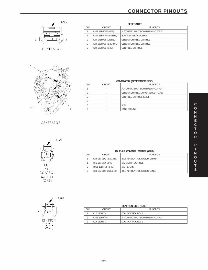
GENERATORCAV CIRCUIT FUNCTION
1 K342 16BR/WT (GAS) AUTOMATIC SHUT DOWN RELAY OUTPUT
1 K342 16BR/WT (DIESEL) ECM/PCM RELAY OUTPUT
2 K20 14BR/GY (DIESEL) GENERATOR FIELD CONTROL
2 K20 18BR/GY (3.3L/3.8L) GENERATOR FIELD CONTROL
2 K20 18BR/GY (2.4L) GEN FIELD CONTROL
GENERATOR (GENERATOR SIDE)CAV CIRCUIT FUNCTION
1 - AUTOMATIC SHUT DOWN RELAY OUTPUT
2 - GENERATOR FIELD DRIVER (EXCEPT 2.4L)
2 - GEN FIELD CONTROL (2.4L)
3 - -
4 - B(+)
5 - CASE GROUND
IDLE AIR CONTROL MOTOR (GAS)CAV CIRCUIT FUNCTION
1 K39 18VT/DG (3.3L/3.8L) IDLE AIR CONTROL MOTOR DRIVER
1 K61 18VT/GY (2.4L) IAC MOTOR CONTROL
2 K961 18BR/VT (2.4L) IAC RETURN
2 K60 18VT/LG (3.3L/3.8L) IDLE AIR CONTROL MOTOR SENSE
IGNITION COIL (2.4L)CAV CIRCUIT FUNCTION
1 K17 18DB/TN COIL CONTROL NO. 2
2 K342 16BR/WT AUTOMATIC SHUT DOWN RELAY OUTPUT
3 K19 18DB/DG COIL CONTROL NO. 1
CONNECTOR
PINOUTS
523
CONNECTOR PINOUTS

IGNITION COIL (3.3L/3.8L)CAV CIRCUIT FUNCTION
1 K18 16DB/OR IGNITION COIL NO. 3 DRIVER
2 K342 16BR/WT AUTOMATIC SHUT DOWN RELAY OUTPUT
3 K19 16DB/DG IGNITION COIL NO. 1 DRIVER
4 K17 16DB/TN IGNITION COIL NO. 2 DRIVER
INLET AIR TEMPERATURE SENSORCAV CIRCUIT FUNCTION
1 K21 18DB/LG (3.3L/3.8L) INLET AIR TEMPERATURE SENSOR SIGNAL
1 K21 18DB/LG (2.4L) IAT SIGNAL
2 K900 20DB/DG SENSOR GROUND
CONNECTOR
PINOUTS
524
CONNECTOR PINOUTS

CONNECTOR
PINOUTS
525
CONNECTOR PINOUTS

FUSES (IPM)FUSENO.
AMPS FUSED CIRCUIT FUNCTION
1 20A INTERNAL FUSED B(+)
2 15A INTERNAL FUSED PARK LAMP RELAY OUTPUT
3 15A INTERNAL FUSED PARK LAMP RELAY OUTPUT
4 30A INTERNAL FUSED B(+)
5 20A F306 16DB/PK FUSED ACCESSORY RELAY OUTPUT
6 20A F307 16LB/PK (BATTERY POSITION) FUSED B(+)
6 20A F307 16LB/PK (ACCESSORY RELAY POSITION) FUSED ACCESSORY RELAY OUTPUT
8 20A INTERNAL FUSED B(+)
9 40A INTERNAL FUSED B(+)
10 40A C7 12DB FUSED FRONT BLOWER MOTOR RELAY OUTPUT
11 20A F302 18GY/PK FUSED ACCESSORY RELAY OUTPUT
12 25A C51 12LB/BR FUSED REAR BLOWER MOTOR RELAY OUTPUT
13 40A C15 12DB/WT FUSED REAR WINDOW DEFOGGER RELAY OUTPUT
14 15A INTERNAL FUSED B(+) (I.O.D.)
15 20A INTERNAL (EATX) FUSED B(+)
15 20A INTERNAL (DIESEL) FUSED B(+)
16 25A INTERNAL FUSED B(+)
17 20A INTERNAL FUSED B(+)
18 15A INTERNAL FUSED B(+)
19 40A A101 12VT/RD FUSED B(+)
20 40A A102 12WT/RD FUSED B(+)
21 25A A111 12DG/RD FUSED B(+)
22 40A A110 12OR/RD FUSED B(+)
23 10A A106 20LB/RD FUSED B(+)
24 20A A701 16BR/RD FUSED B(+) (HAZARD)
26 20A A103 18GY/RD FUSED B(+)
27 40A A112 12OR/RD FUSED B(+)
28 40A F30 12PK/YL FUSED ACCESSORY RELAY OUTPUT
30 40A INTERNAL (EXPORT) FUSED B(+)
31 40A A113 12WT/RD FUSED B(+)
32 40A A115 12YL/RD FUSED B(+)
33 15A INTERNAL FUSED ACCESSORY RELAY OUTPUT
FUEL PUMP RELAY (GAS)CAV CIRCUIT FUNCTION
30 N1 18DB/OR FUEL PUMP RELAY OUTPUT
85 K31 18BR FUEL PUMP RELAY CONTROL
86 INTERNAL FUSED IGNITION SWITCH OUTPUT (RUN-START)
87 INTERNAL FUSED B(+)
87A - -
CONNECTOR
PINOUTS
526
CONNECTOR PINOUTS

INTEGRATED POWER MODULE C1CAV CIRCUIT FUNCTION
1 F301 18VT/PK FUSED ACCESSORY RELAY OUTPUT
2 - -
3 - -
4 L43 18WT/DB LEFT LOW BEAM DRIVER
5 Z344 16BK/TN GROUND
6 L34 16WT/GY RIGHT HIGH BEAM DRIVER
7 W1 18BR/TN WASHER FLUID LEVEL SWITCH SENSE
8 L33 18WT/LG LEFT HIGH BEAM DRIVER
9 G31 18VT/LG (EXCEPT2.4L/BASE)
AMBIENT TEMPERATURE SENSOR SIGNAL
9 G31 18VT/LG (2.4L) AAT SIGNAL
10 L44 16WT/TN RIGHT LOW BEAM DRIVER
11 F300 18OR/PK FUSED ACCESSORY RELAY OUTPUT
12 - -
13 Z343 18BK/LG GROUND
14 - -
15 L78 18WT/OR FUSED PARK LAMP RELAY OUTPUT (RIGHT)
16 L77 18WT/BR FUSED PARK LAMP RELAY OUTPUT (LEFT)
17 - -
18 G931 18VT/BR (EXCEPT2.4L/BASE)
AMBIENT TEMPERATURE SENSOR RETURN
19 W20 18BR/YL REAR WASHER PUMP MOTOR CONTROL
20 W10 18BR FRONT WASHER PUMP MOTOR CONTROL
INTEGRATED POWER MODULE C2CAV CIRCUIT FUNCTION
1 N173 16DB/VT (GAS) RADIATOR FAN RELAY CONTROL
2 V53 12BR/OR (EXPORT) HEADLAMP WASHER RELAY OUTPUT
3 L60 16WT/TN (EXPORT) RIGHT FRONT TURN SIGNAL DRIVER
3 L60 16WT/TN (EXCEPTEXPORT)
RIGHT FRONT TURN SIGNAL DRIVER
4 L13 18WT/YL (EXPORT) HEADLAMP ADJUST SIGNAL
5 X2 18DG/OR HORN RELAY OUTPUT
6 L90 18WT/OR (FOGLAMPS)
FRONT FOG LAMP RELAY OUTPUT
7 L61 16WT/LG LEFT FRONT TURN SIGNAL DRIVER
8 - -
9 A112 12OR/RD FUSED B(+)
10 L89 18WT/YL (FOGLAMPS)
FRONT FOG LAMP RELAY OUTPUT
CONNECTOR
PINOUTS
527
CONNECTOR PINOUTS

INTEGRATED POWER MODULE C3CAV CIRCUIT FUNCTION
1 Z115 18BK/OR (2.4L EATX) GROUND
1 Z115 20BK/OR (3.3L/3.8LEATX)
GROUND
1 N21 20DB/TN (DIESEL) LIFT PUMP RELAY CONTROL
2 F1 18PK/WT (GAS EATX) FCM OUTPUT (UNLOCK-RUN-START)
3 T751 18YL (GAS) FUSED IGNITION SWITCH OUTPUT (START)
3 T751 20YL (DIESEL) FUSED IGNITION SWITCH OUTPUT (START)
4 T2 18DG/WT (2.4L/DIESELMTX)
TRS REVERSE SENSE
5 T16 18YL/OR (GAS EATX) TRANSMISSION CONTROL RELAY OUTPUT
5 N2 18DB/YL (DIESEL) LIFT PUMP RELAY OUTPUT
6 F202 18PK/GY (DIESEL) FUSED IGNITION SWITCH OUTPUT (RUN-START)
6 T15 18YL/BR (GAS EATX) TRANSMISSION CONTROL RELAY CONTROL
7 C3 20DB/YL (GAS) A/C COMPRESSOR CLUTCH RELAY OUTPUT
7 C3 18DB/YL (DIESEL) A/C COMPRESSOR CLUTCH RELAY OUTPUT
8 Z114 18BK/LG (DIESEL) GROUND
8 K31 18BR (GAS) FUEL PUMP RELAY CONTROL
9 C13 18LB/OR (GAS) A/C COMPRESSOR CLUTCH RELAY CONTROL
9 C13 20LB/OR (DIESEL) A/C COMPRESSOR CLUTCH RELAY CONTROL
10 A119 16RD/OR (DIESEL) FUSED B(+)
10 A104 18YL/RD (3.3L/3.8LEATX)
FUSED B(+)
11 C41 20LB/DG (DIESEL) CABIN HEATER ASSIST CONTROL
12 - -
13 D25 18WT/VT (GAS) PCI BUS
13 D25 20WT/VT (DIESEL) PCI BUS
14 T752 18DG/OR (2.4L) STARTER RELAY CONTROL
14 T752 18DG/OR (3.3L/3.8L) STARTER MOTOR RELAY CONTROL
14 T752 20DG/OR (DIESEL) STARTER MOTOR RELAY CONTROL
15 Z116 18BK/VT GROUND
16 K51 18BR/WT (GAS) AUTOMATIC SHUT DOWN RELAY CONTROL
16 K51 20BR/WT (DIESEL) ECM/PCM RELAY CONTROL
17 F202 18PK/GY (DIESEL) FUSED IGNITION SWITCH OUTPUT (RUN-START)
17 F202 20PK/GY (GAS) FUSED IGNITION SWITCH OUTPUT (RUN-START)
18 K173 18BR/VT (3.3L/3.8L) RADIATOR FAN RELAY CONTROL
18 K173 18BR/WT (2.4L) RAD FAN RELAY CONTROL
19 F202 20PK/GY (GAS) FUSED IGNITION SWITCH OUTPUT (RUN-START)
19 K342 16BR/WT (DIESEL) ECM/PCM RELAY OUTPUT
20 A109 18OR/RD (GAS) FUSED B(+)
CONNECTOR
PINOUTS
528
CONNECTOR PINOUTS
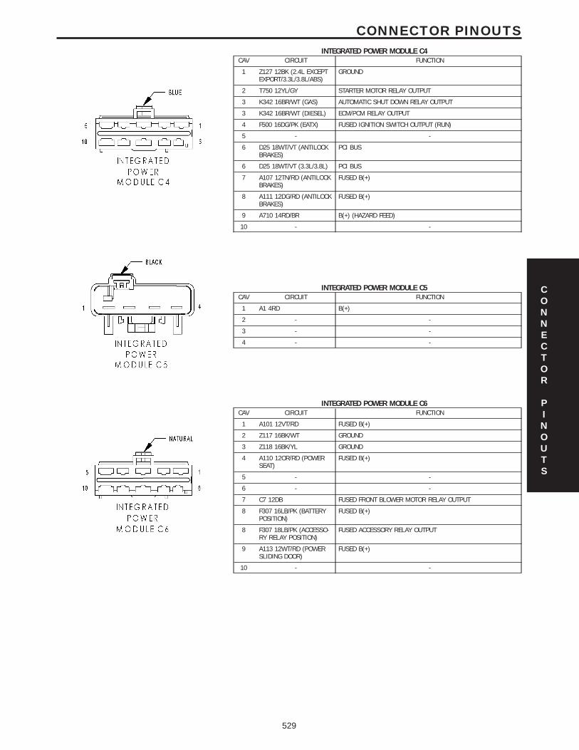
INTEGRATED POWER MODULE C4CAV CIRCUIT FUNCTION
1 Z127 12BK (2.4L EXCEPTEXPORT/3.3L/3.8L/ABS)
GROUND
2 T750 12YL/GY STARTER MOTOR RELAY OUTPUT
3 K342 16BR/WT (GAS) AUTOMATIC SHUT DOWN RELAY OUTPUT
3 K342 16BR/WT (DIESEL) ECM/PCM RELAY OUTPUT
4 F500 16DG/PK (EATX) FUSED IGNITION SWITCH OUTPUT (RUN)
5 - -
6 D25 18WT/VT (ANTILOCKBRAKES)
PCI BUS
6 D25 18WT/VT (3.3L/3.8L) PCI BUS
7 A107 12TN/RD (ANTILOCKBRAKES)
FUSED B(+)
8 A111 12DG/RD (ANTILOCKBRAKES)
FUSED B(+)
9 A710 14RD/BR B(+) (HAZARD FEED)
10 - -
INTEGRATED POWER MODULE C5CAV CIRCUIT FUNCTION
1 A1 4RD B(+)
2 - -
3 - -
4 - -
INTEGRATED POWER MODULE C6CAV CIRCUIT FUNCTION
1 A101 12VT/RD FUSED B(+)
2 Z117 16BK/WT GROUND
3 Z118 16BK/YL GROUND
4 A110 12OR/RD (POWERSEAT)
FUSED B(+)
5 - -
6 - -
7 C7 12DB FUSED FRONT BLOWER MOTOR RELAY OUTPUT
8 F307 16LB/PK (BATTERYPOSITION)
FUSED B(+)
8 F307 18LB/PK (ACCESSO-RY RELAY POSITION)
FUSED ACCESSORY RELAY OUTPUT
9 A113 12WT/RD (POWERSLIDING DOOR)
FUSED B(+)
10 - -
CONNECTOR
PINOUTS
529
CONNECTOR PINOUTS

INTEGRATED POWER MODULE C7CAV CIRCUIT FUNCTION
1 C16 20DB/GY FUSED REAR WINDOW DEFOGGER RELAY OUTPUT
2 T751 20YL (GAS) FUSED IGNITION SWITCH OUTPUT (START)
2 T141 20YL/OR (DIESEL) FUSED IGNITION SWITCH OUTPUT (START)
3 D25 20WT/VT PCI BUS
4 L13 20WT/YL (EXPORT) HEADLAMP ADJUST SIGNAL
5 K32 18DB/YL (GAS) BRAKE TRANSMISSION SHIFT INTERLOCK SOLENOID CONTROL
6 - -
7 W7 20BR/GY FRONT WIPER PARK SWITCH SENSE
8 B20 20DG/OR BRAKE FLUID LEVEL SWITCH SENSE
9 F201 18PK/OR ORC RUN-START DRIVER
10 F214 18PK/LG (SIACM) SIACM RUN-START DRIVER
11 A106 20LB/RD FUSED B(+)
12 - -
13 F2 18PK/YL (GAS) FCM OUTPUT (UNLOCK-RUN-START)
14 - -
15 A114 16GY/RD FUSED B(+) (I.O.D.)
16 D123 20WT/BR FLASH PROGRAM ENABLE
17 L50 18WT/TN BRAKE LAMP SWITCH OUTPUT
18 X13 16DG/GY (PREMIUM8 SPEAKER)
NAME BRAND SPEAKER RELAY OUTPUT
19 X3 20DG/VT HORN SWITCH SENSE
20 F100 18PK/VT ORC RUN ONLY DRIVER
INTEGRATED POWER MODULE C8CAV CIRCUIT FUNCTION
1 W3 14BR/WT FRONT WIPER HIGH/LOW RELAY LOW SPEED OUTPUT
2 N1 18DB/OR (GAS) FUEL PUMP RELAY OUTPUT
2 N1 16DB/OR (DIESEL) FUEL HEATER RELAY OUTPUT
3 A108 20LG/RD FUSED B(+)
4 A103 18GY/RD FUSED B(+)
5 L77 20WT/BR FUSED PARK LAMP RELAY OUTPUT (LEFT)
6 W4 14BR/OR FRONT WIPER HIGH/LOW RELAY HIGH SPEED OUTPUT
7 C51 12LB/BR (3 ZONEATC/MTC)
FUSED REAR BLOWER MOTOR RELAY OUTPUT
8 - -
9 L78 18WT/OR FUSED PARK LAMP RELAY OUTPUT (RIGHT)
10 L60 18WT/TN RIGHT FRONT TURN SIGNAL DRIVER
INTEGRATED POWER MODULE C9CAV CIRCUIT FUNCTION
1 A102 12WT/RD FUSED B(+)
2 F20 18PK/WT FUSED IGNITION SWITCH OUTPUT (RUN-START)
3 C15 12DB/WT FUSED REAR WINDOW DEFOGGER RELAY OUTPUT
4 A105 18DB/RD FUSED B(+)
5 L61 20WT/LB LEFT FRONT TURN SIGNAL DIVER
6 A701 18BR/RD FUSED B(+) (HAZARD)
6 A701 16BR/RD FUSED B(+) (HAZARD)
7 F306 16DB/PK FUSED ACCESSORY RELAY OUTPUT
8 F30 12PK/YL (POWERWINDOWS)
FUSED ACCESSORY RELAY OUTPUT
9 A115 20YL/RD (POWERDRIVER SEAT)
FUSED B(+)
9 A115 12YL/RD (POWERLIFTGATE/EXCEPT POWERDRIVER SEAT)
FUSED B(+)
10 F302 18GY/PK FUSED ACCESSORY RELAY OUTPUT
CONNECTOR
PINOUTS
530
CONNECTOR PINOUTS

KNOCK SENSOR (3.3L/3.8L ABS EXCEPT EXPORT)CAV CIRCUIT FUNCTION
1 K42 18DB/YL KNOCK SENSOR SIGNAL
2 K900 18DB/DG SENSOR GROUND
LEAK DETECTION PUMP (3.3L/3.8L EXCEPT EXPORT)CAV CIRCUIT FUNCTION
1 K107 18VT/WT LEAK DETECTION PUMP SWITCH SENSE
2 K106 18VT/LB LEAK DETECTION PUMP SOLENOID CONTROL
3 F202 18PK/GY FUSED IGNITION SWITCH OUTPUT (RUN-START)
4 - -
LEFT SPEED CONTROL SWITCHCAV CIRCUIT FUNCTION
B Z23 20BK/VT LEFT SPEED CONTROL SWITCH GROUND
A V37 20VT/TN (EXPORT) SPEED CONTROL SWITCH SIGNAL
A V37 20DG/VT (EXCEPTEXPORT)
SPEED CONTROL SWITCH SIGNAL
A V37 18VT (2.4L) S/C SWITCH SIGNAL
MANIFOLD ABSOLUTE PRESSURE SENSOR (GAS)CAV CIRCUIT FUNCTION
1 K1 18VT/BR (3.3L/3.8L) MANIFOLD ABSOLUTE PRESSURE SENSOR SIGNAL
1 K1 18VT/BR (2.4L) MAP SIGNAL
2 K900 18DB/DG SENSOR GROUND
3 F855 18PK/YL 5 VOLT SUPPLY
CONNECTOR
PINOUTS
531
CONNECTOR PINOUTS

NATURAL VACUUM LEAK DETECTION ASSEMBLY (2.4L EXCEPT EXPORT)CAV CIRCUIT FUNCTION
1 Z166 18BK/WT GROUND
2 K107 20VT/WT NVLD SWITCH SIGNAL
3 K106 20VT/LB NVLD SOL CONTROL
OXYGEN SENSOR 1/1 UPSTREAM (GAS)CAV CIRCUIT FUNCTION
1 K99 18BR/LG (3.3L/3.8L) OXYGEN SENSOR 1/1 HEATER CONTROL
1 Z42 18BK/LG (2.4L) GROUND
2 K99 18BR/LG (2.4L) O2 1/1 HEATER CONTROL
2 K342 16BR/WT (3.3L/3.8L) AUTOMATIC SHUT DOWN RELAY OUTPUT
3 K902 18BR/DG (3.3L/3.8L) OXYGEN SENSOR 1/1 GROUND
3 K902 18BR/DG (2.4L) O2 RETURN (UP)
4 K41 18DB/LB (2.4L) O2 1/1 SIGNAL
4 K41 18DB/LB (3.3L/3.8L) OXYGEN SENSOR 1/1 SIGNAL
OXYGEN SENSOR 1/2 DOWNSTREAM (GAS)CAV CIRCUIT FUNCTION
1 Z43 18BK/DB GROUND
2 K342 16BR/WT (3.3L/3.8L) AUTOMATIC SHUT DOWN RELAY OUTPUT
2 K299 18BR/WT (2.4L) O2 1/2 HEATER CONTROL
3 K904 18DB/DG (2.4L) O2 RETURN (DOWN)
3 K902 18BR/DG (3.3L/3.8L) OXYGEN SENSOR 1/2 GROUND
4 K141 18DB/YL (3.3L/3.8L) OXYGEN SENSOR 1/2 SIGNAL
4 K141 18DB/YL (2.4L) O2 1/2 SIGNAL
CONNECTOR
PINOUTS
532
CONNECTOR PINOUTS

POWERTRAIN CONTROL MODULE C1 (NGC)CAV CIRCUIT FUNCTION
1 - -
2 - -
3 - -
4 - -
5 - -
6 - -
7 - -
8 - -
9 Z130 18BK/BR GROUND
10 - -
11 F202 20PK/GY FUSED IGNITION SWITCH OUTPUT (RUN-START)
12 F1 18PK/WT (EXCEPT EX-PORT)
FUSED IGNITION SWITCH OUTPUT (RUN-START)
13 N7 18DB/OR (MTX) VEHICLE SPEED SIGNAL
14 - -
15 - -
16 - -
17 - -
18 Z131 18BK/DG GROUND
19 - -
20 G6 16VT/GY OIL PRESSURE SIGNAL
21 - -
22 G31 18VT/LG AAT SIGNAL
23 - -
24 - -
25 D20 20WT/LG SCI RECEIVE (PCM)
26 D123 20WT/BR SCI RECEIVE (TCM)
27 - -
28 - -
29 A109 18OR/RD FUSED B(+)
30 T751 18YL FUSED IGNITION SWITCH OUTPUT (START)
31 K141 18DB/YL O2 1/2 SIGNAL
32 K904 18DB/DG O2 RETURN (DOWN)
33 - -
34 - -
35 - -
36 D21 20WT/BR SCI TRANSMIT (PCM)
37 D15 18DG/YL SCI TRANSMIT (TCM)
38 D25 18WT/VT PCI BUS
CONNECTOR
PINOUTS
533
CONNECTOR PINOUTS

POWERTRAIN CONTROL MODULE C1 (SBEC)CAV CIRCUIT FUNCTION
1 - -
2 K18 16DB/OR IGNITION COIL NO. 3 DRIVER
3 K17 16DB/TN IGNITION COIL NO. 2 DRIVER
4 - -
5 V32 18VT/YL SPEED CONTROL ON/OFF SWITCH SENSE
6 K342 16BR/WT AUTOMATIC SHUT DOWN RELAY OUTPUT
7 K13 16BR/LB FUEL INJECTOR NO. 3 DRIVER
8 K20 18BR/GY GENERATOR FIELD CONTROL
9 - -
10 Z130 18BK/BR GROUND
11 K19 16DB/DG IGNITION COIL NO. 1 DRIVER
12 G6 16VT/GY ENGINE OIL PRESSURE SWITCH SENSE
13 K11 16BR/YL FUEL INJECTOR NO. 1 DRIVER
14 K58 16BR/VT FUEL INJECTOR NO. 6 DRIVER
15 K38 16BR/OR FUEL INJECTOR NO. 5 DRIVER
16 K14 16BR/TN FUEL INJECTOR NO. 4 DRIVER
17 K12 16BR/DB FUEL INJECTOR NO. 2 DRIVER
18 K99 18BR/LG OXYGEN SENSOR 1/1 HEATER CONTROL
19 - -
20 F202 18PK/GY FUSED IGNITION SWITCH OUTPUT (RUN-START)
21 - -
22 - -
23 - -
24 - -
25 K42 18DB/YL (ABS EX-CEPT EXPORT)
KNOCK SENSOR SIGNAL
26 K2 18VT/OR ENGINE COOLANT TEMPERATURE SENSOR SIGNAL
27 K902 18BR/DG OXYGEN SENSOR GROUND
28 - -
29 - -
30 K41 18DB/LB OXYGEN SENSOR 1/1 SIGNAL
31 T752 18DG/OR STARTER MOTOR RELAY CONTROL
32 K24 18BR/LB CRANKSHAFT POSITION SENSOR SIGNAL
33 K44 18DB/GY CAMSHAFT POSITION SENSOR SIGNAL
34 - -
35 K22 18BR/OR THROTTLE POSITION SENSOR SIGNAL
36 K1 18VT/BR MANIFOLD ABSOLUTE PRESSURE SENSOR SIGNAL
37 K21 18DB/LG INTAKE AIR TEMPERATURE SENSOR SIGNAL
38 T751 18YL FUSED IGNITION SWITCH OUTPUT (START)
39 - -
40 K35 18DB/VT EGR SOLENOID CONTROL
CONNECTOR
PINOUTS
534
CONNECTOR PINOUTS

POWERTRAIN CONTROL MODULE C2 (NGC)CAV CIRCUIT FUNCTION
1 - -
2 - -
3 - -
4 - -
5 - -
6 - -
7 - -
8 - -
9 K17 18DB/TN COIL CONTROL NO. 2
10 K19 18DB/DG COIL CONTROL NO. 1
11 K14 16 BR/TN INJECTOR CONTROL NO. 4
12 K13 16BR/LB INJECTOR CONTROL NO. 3
13 K12 16BR/DB INJECTOR CONTROL NO. 2
14 K11 16BR/YL INJECTOR CONTROL NO. 1
15 - -
16 - -
17 - -
18 K99 18BR/LG O2 1/1 HEATER CONTROL
19 K20 18BR/GY GEN FIELD CONTROL
20 K2 18VT/OR ECT SIGNAL
21 K22 18BR/OR TP SIGNAL
22 - -
23 K1 18VT/BR MAP SIGNAL
24 K942 18BR/LG KS RETURN
25 K42 18DB/YL KS SIGNAL
26 - -
27 K900 18DB/DG SENSOR GROUND
28 K961 18BR/VT IAC RETURN
29 F855 20PK/YL 5 VOLT SUPPLY
30 K21 18DB/LG IAT SIGNAL
31 K41 18DB/LB O2 1/1 SIGNAL
32 K902 18BR/DG O2 RETURN (UP)
33 - -
34 K44 18DB/GY CMP SIGNAL
35 K24 18BR/LB CKP SIGNAL
36 - -
37 - -
38 K61 18VT/GY IAC MOTOR CONTROL
CONNECTOR
PINOUTS
535
CONNECTOR PINOUTS

POWERTRAIN CONTROL MODULE C2 (SBEC)CAV CIRCUIT FUNCTION
41 V37 18VT SPEED CONTROL SWITCH SIGNAL
42 C18 18LB/BR A/C PRESSURE SENSOR SIGNAL
43 K900 18DB/DG SENSOR GROUND
44 F888 18BR/PK 8 VOLT SUPPLY
45 - -
46 A109 18OR/RD FUSED B(+)
47 - -
48 - -
49 K39 18VT/DG IDLE AIR CONTROL NO. 1 DRIVER
50 Z131 18BK/DG GROUND
51 K141 18DB/YL OXYGEN SENSOR 1/2 SIGNAL
52 - -
53 - -
54 - -
55 - -
56 V36 18VT/YL SPEED CONTROL VACUUM SOLENOID CONTROL
57 K60 18VT/LG IDLE AIR CONTROL NO. 2 DRIVER
58 - -
59 D25 18WT/VT PCI BUS
60 - -
61 F855 18PK/YL (EXPORT) 5 VOLT SUPPLY
61 F855 20PK/YL (EXCEPTEXPORT)
5 VOLT SUPPLY
62 B29 18DG/WT SECONDARY BRAKE SWITCH SIGNAL
63 T10 18DG/LG TORQUE MANAGEMENT REQUEST SENSE
64 C13 18LB/OR A/C COMPRESSOR CLUTCH RELAY CONTROL
65 D21 18WT/BR (EXPORT) SCI TRANSMIT (PCM)
65 D21 20WT/BR (EXCEPTEXPORT)
SCI TRANSMIT (PCM)
66 N7 18DB/OR VEHICLE SPEED SENSOR SIGNAL
67 K51 18BR/WT AUTOMATIC SHUT DOWN RELAY CONTROL
68 K52 18DB/WT EVAPORATIVE EMISSION SOLENOID CONTROL
69 - -
70 K70 18DB/BR EVAPORATIVE EMISSION SOLENOID SENSE
71 - -
72 K107 20VT/WT (EXCEPTEXPORT)
LEAK DETECTION PUMP SWITCH SENSE
73 K173 18BR/VT RADIATOR FAN RELAY CONTROL
74 K31 18BR FUEL PUMP RELAY CONTROL
75 D20 20WT/LG SCI RECEIVE (PCM)
76 T41 18YL/DB PARK/NEUTRAL POSITION SWITCH SENSE (TRS T41)
77 K106 20VT/LB (EXCEPTEXPORT)
LEAK DETECTION PUMP SOLENOID CONTROL
78 - -
79 - -
80 V35 18VT/OR SPEED CONTROL VENT SOLENOID CONTROL
CONNECTOR
PINOUTS
536
CONNECTOR PINOUTS

POWERTRAIN CONTROL MODULE C3 (NGC)CAV CIRCUIT FUNCTION
1 - -
2 - -
3 K51 18BR/WT AUTOMATIC SHUT DOWN RELAY CONTROL
4 - -
5 V35 18VT/OR S/C VENT CONTROL
6 K173 18BR/VT RAD FAN RELAY CONTROL
7 V32 18VT/YL S/C SUPPLY
8 - -
9 K299 18BR/WT O2 1/2 HEATER CONTROL
10 - -
11 C13 18LB/OR A/C CLUTCH RELAY CONTROL
12 V36 18VT/YL S/C VACUUM CONTROL
13 - -
14 - -
15 - -
16 - -
17 - -
18 - -
19 K342 16BR/WT AUTOMATIC SHUT DOWN RELAY OUTPUT
20 K52 18DB/WT EVAP PURGE CONTROL
21 T141 18YL (MTX) FUSED IGNITION SWITCH OUTPUT (START)
22 - -
23 B29 18DG/WT BRAKE SWITCH SIGNAL
24 - -
25 - -
26 - -
27 - -
28 K342 16BR/WT AUTOMATIC SHUT DOWN RELAY OUTPUT
29 K70 18DB/BR EVAP PURGE SIGNAL
30 - -
31 C18 18LB/BR A/C PRESSURE SIGNAL
32 K91 18DB/YL BATTERY TEMP SIGNAL
33 - -
34 V37 18VT S/C SWITCH SIGNAL
35 K107 20VT/WT NVLD SWITCH SIGNAL
36 - -
37 K31 18BR FUEL PUMP RELAY CONTROL
38 T752 18DG/OR STARTER RELAY CONTROL
CONNECTOR
PINOUTS
537
CONNECTOR PINOUTS

POWERTRAIN CONTROL MODULE C4 (NGC) (EATX)CAV CIRCUIT FUNCTION
1 T60 18YL/GY OVERDRIVE SOLENOID CONTROL
2 T59 18YL/LB UNDERDRIVE SOLENOID CONTROL
3 - -
4 - -
5 - -
6 T19 18YL/DB 2-4 SOLENOID CONTROL
7 - -
8 - -
9 - -
10 T20 18DG/WT LOW/REVERSE SOLENOID CONTROL
11 - -
12 Z133 16BK/LG GROUND
13 Z133 16BK/LG GROUND
14 - -
15 T1 18DG/LB TRS T1 SENSE
16 T3 18DG/DB TRS T3 SENSE
17 - -
18 T15 18YL/BR TRANSMISSION CONTROL RELAY CONTROL
19 T16 18YL/OR TRANSMISSION CONTROL RELAY OUTPUT
20 - -
21 - -
22 T9 18DG/TN OVERDRIVE PRESSURE SWITCH SENSE
23 - -
24 - -
25 - -
26 - -
27 T41 18DG/GY TRS T41 SENSE
28 T16 18YL/OR TRANSMISSION CONTROL RELAY OUTPUT
29 T50 18YL/TN LOW/REVERSE PRESSURE SWITCH SENSE
30 T47 18YL/DG 2-4 PRESSURE SWITCH SENSE
31 - -
32 T14 18DG/BR OUTPUT SPEED SENSOR SIGNAL
33 T52 18DG/WT INPUT SPEED SENSOR SIGNAL
34 T13 18DG/VT SPEED SENSOR GROUND
35 T54 18DG/OR TRANSMISSION TEMPERATURE SENSOR SIGNAL
36 - -
37 T42 18DG/YL TRS T42 SENSE
38 T16 18YL/OR TRANSMISSION CONTROL RELAY OUTPUT
RIGHT SPEED CONTROL SWITCHCAV CIRCUIT FUNCTION
A V37 20VT/TN (EXPORT) SPEED CONTROL SWITCH SIGNAL
A V37 20DG/VT (EXCEPTEXPORT)
SPEED CONTROL SWITCH SIGNAL
A V37 18VT (2.4L) S/C SWITCH SIGNAL
B Z23 20BK/VT RIGHT SPEED CONTROL SWITCH GROUND
CONNECTOR
PINOUTS
538
CONNECTOR PINOUTS

SENTRY KEY IMMOBILIZER MODULECAV CIRCUIT FUNCTION
1 - -
2 D25 20WT/VT PCI BUS
3 - -
4 F20 20PK/WT FUSED IGNITION SWITCH OUTPUT (RUN-START)
5 Z120 22BK/WT GROUND
6 A114 20GY/RD (LHD EX-PORT)
FUSED B(+) (I.O.D.)
6 A114 18GY/RD (EXCEPTLHD EXPORT)
FUSED B(+) (I.O.D.)
SPEED CONTROL SERVO (GAS)CAV CIRCUIT FUNCTION
1 V36 18VT/YL (3.3L/3.8L) SPEED CONTROL VACUUM SOLENOID CONTROL
1 V36 18VT/YL (2.4L) S/C VACUUM CONTROL
2 V35 18VT/OR (2.4L) S/C VENT CONTROL
2 V35 18VT/OR (3.3L/3.8L) SPEED CONTROL VENT SOLENOID CONTROL
3 V30 20VT/WT SPEED CONTROL BRAKE SWITCH OUTPUT
4 Z155 18BK/LG GROUND
THROTTLE POSITION SENSOR (GAS)CAV CIRCUIT FUNCTION
1 K900 18DB/DG SENSOR GROUND
2 K22 18BR/OR (3.3L/3.8L) THROTTLE POSITION SENSOR SIGNAL
2 K22 18BR/OR (2.4L) TP SIGNAL
3 F855 18PK/YL (3.3L/3.8L) 5 VOLT SUPPLY
3 F855 20PK/YL (2.4L) 5 VOLT SUPPLY
TRANSMISSION RANGE SENSOR (EATX)CAV CIRCUIT FUNCTION
1 - -
2 - -
3 T13 18DG/VT SPEED SENSOR GROUND
4 T54 18DG/OR TRANSMISSION TEMPERATURE SENSOR SIGNAL
5 T41 18DG/GY (3.3L/3.8L) TRS T41 SENSE
6 - -
7 T1 18DG/LB TRS T1 SENSE
8 T3 18DG/DB TRS T3 SENSE
9 T42 18DG/YL TRS T42 SENSE
10 T41 18YL/DB (3.3L/3.8L) PARK/NEUTRAL POSITION SWITCH SENSE (TRS T41)
10 T41 18DG/GY (2.4L) TRS T41 SENSE
CONNECTOR
PINOUTS
539
CONNECTOR PINOUTS

NOTES
540

10.0 SCHEMATIC DIAGRAMS
10.1 2003 RS 2.4L
SCHEMATIC
DIAGRAMS
541
SCHEMATIC DIAGRAMS

SCHEMATIC
DIAGRAMS
542
SCHEMATIC DIAGRAMS
10.1 2003 RS 2.4L (Continued)

10.2 2003 RS 3.3L/3.8L
SCHEMATIC
DIAGRAMS
543
SCHEMATIC DIAGRAMS

NOTES
544

11.0 CHARTS AND GRAPHS
NGC VEHICLES
CHARTS
AND
GRAPHS
545
CHARTS AND GRAPHS

SBEC VEHICLES
CHARTS
AND
GRAPHS
546
CHARTS AND GRAPHS
10.1 2003 RS 2.4L (Continued)

CHARTS
AND
GRAPHS
547
CHARTS AND GRAPHS

CHARTS
AND
GRAPHS
548
CHARTS AND GRAPHS
10.1 2003 RS 2.4L (Continued)