Embed Size (px)
Citation preview

DEC 2011
TABLE OF CONTENTS - 1
TABLE OF CONTENTS
COVER SHEET 000 Cover Sheet
BIDDING REQUIREMENTS 100 Notice to Bidders 110 Instruction to Bidders 120 Instruction to Providers 200 Proposal 210 Contract
CONTRACT CONDITIONS 300 General Conditions
SPECIFICATIONS 400 Standard Specifications
1000 Clearing and Grubbing Division 1 Earthwork
1100 Removal of Structures and Obstructions 1200 Roadway and Drainage Excavation and Embankment Construction 1300 Roadway Shaping
2000 Granular Bases and Surfacing Division 2 Granular Bases and Surfacing
2100 Process in Place Surfacing
3000 Asphalt Pavement Division 3 Asphalt Construction
3100 Fog and Flush Seal Coats 3200 Asphalt Concrete Crack Sealing 3300 Asphalt Surface Treatment 3400 Cold Milling Asphalt Concrete
4000 Portland Cement Concrete Pavement (PCC Pavement) Division 4 Portland Cement Construction
4100 Undersealing 4200 Pavement Jacking 4300 Curb and Gutter 4400 Sidewalk 4500 PCC Pavement for Alleys and Parking Lots 4600 Retrofit Tie Bar 4700 Flowable Fill

DEC 2011
TABLE OF CONTENTS - 2
5000 Pavement Marking Division 5 Pavement Marking
6000 Storm Sewer System Division 6 Storm Sewer Construction
7000 Sanitary Sewer System Division 7 Sanitary Sewer Construction
8000 Water System Division 8 Water System Construction
Division 9 Structures (blank)
10000 Landscaping Division 10 Incidental Construction
10100 Planting Trees, Shrubs and Vines 10200 Geotextiles and Impermeable Plastic Membrane
Division 11 (blank)
Division 12 (blank)
Division 13 (blank)
Division 14 (blank)
Division 15 (blank)
Division 16 (blank)
Division 17 (blank)
Division 18 (blank)
Division 19 (blank)
20000 Special Provisions Division 20 Special Provisions

DEC 2011
000 - 1
CONTRACT DOCUMENTS FOR
TITLE OF PROJECT
(Project #xxxx)
VERMILLION, SOUTH DAKOTA
TABLE OF CONTENTS 100 – Notice to Bidders 110 – Instructions to Bidders 200 – Proposal 300 – General Conditions 400 – Standard Specifications 1000 – Specifications particular to project 20000 – Special Provisions Details Drawings
2010
XXXX XXXXXX
(Assistant) City Engineer

DEC 2011
100 - 1
100 - NOTICE TO BIDDERS Notice is hereby given that the Governing Body of the City of Vermillion, South Dakota will meet at the City Hall meeting room of said City on the 30th day of March 2011, at 2:00p.m. at which time bids and proposals will be received, publicly opened and read. The bids will be acted upon by the City Council at City Hall located at 25 Center Street on the 4th day of April 2011, at 7:00 p.m. The materials and services required are as follows:
2011 PCC PARKING LOTS The major quantities are 3,140 SY of Concrete Pavement, 6-Inch; 2,098 SY of Concrete Pavement, 8-Inch; 1,345 CY of Unclassified Excavation; 370 Tons of Crushed Aggregate Base Course; 310 Tons of Crushed Concrete (1 ½-inch to 2-inch Dia.); 2,310 SY Geotextile Separator (Woven); 535 EA of Drilled Pavement Ties; 1 EA of Drop Inlet, Type B; 18 FT of 12” RCP, Class III
Copies of the specifications are available for review at the office of the City Engineer, 25 Center Street, Vermillion, South Dakota, 57069. Bid security is required according to state law and the bid specifications. Payment for the materials and services herein provided for will be in cash. The City of Vermillion reserves the right to reject any or all bids and to waive any irregularities therein. Dated at Vermillion, South Dakota this 8th day of March, 2011. CITY OF VERMILLION ___________________________________ Jose L. Dominguez, P.E., City Engineer Publish: March 11th and March 18th, 2011

DEC 2011
110 - 1
110 - INSTRUCTIONS TO BIDDERS 1.) Each BID shall be in an opaque, sealed envelope. The envelope shall be marked on the
outside with the name of the BIDDER and the name of the project, material or equipment on which he is BIDDING, together with the number of Addenda received as follows:
RETURN ADDRESS (Individual, Company or Corporation) (Street Address) (City, State, Zip Code) TO: City Engineer City of Vermillion City Hall 25 Center Street Vermillion, SD 57069 BID ON: 2011 Chip Seal BID OPENING DATE: June 1, 2011 BID OPENING TIME: by 2:00 P.M. 2.) ALL BIDS must be accompanied either by a BID BOND in an amount of ten
percent (10%) of the total BID, issued by a surety authorized to do business in the State of South Dakota, said BOND to be made payable to the City of Vermillion, South Dakota, or by a certified check, cashier's check, or bank draft payable to the City of Vermillion, South Dakota, in the amount of five percent (5%) of the total BID, said check to be drawn on a state or national bank.
3.) The City will retain the BOND or CHECK of the two lowest responsible and competent bidders. The BOND or CHECK of the unsuccessful BIDDERS will be returned following opening and checking of proposals. The BOND or CHECK of the two lowest bidders will be returned when the contract has been executed. Proposal guaranties in the form of BONDS will be voided rather than returned.
4.) The BOND or CHECK will be retained by the City as liquidated damages if the successful BIDDER refuses or fails to enter into an Agreement and/or furnish satisfactory Payment and Performance Bond and General Liability Insurance as required in the specifications and contract.
5.) Any person who plans to BID on the project, material or equipment may submit to the Engineer a written request for an interpretation of any part of the drawings and/or specifications or contract documents prior to the time set for opening BIDS. Any requested interpretation will be in writing by the Engineer.
6.) The City may require that any party who submits a BID to list materials, manufacturer's name of major equipment, and subcontractors to be used on this project.

DEC 2011
110 - 2
7.) No BID will be accepted from, or contract awarded to any person who is in arrears upon any debt to, or in default upon a contract with the City of Vermillion, South Dakota, or who is a defaulter as surety or otherwise, upon any obligation to the City of Vermillion, South Dakota, or who may have in a former contract with said City, in the opinion of the Governing Body thereof, failed to perform work satisfactory as to character, quality or time.
8.) BIDDERS are warned that any BID, which is materially deficient in any of the following requirements, will be rejected as informal.
(a) All proposals and their accompanying statements must be made upon printed proposal forms provided by the City and attached to the contract documents. The proposal form may be removed from the contract documents package and submitted in a sealed envelope.
(b) Any BID or proposal that is modified, altered or conditioned by the BIDDER in such a way that it will affect the total BID amount shall be considered "not according to specifications" and therefore shall be rejected.
(c) Alternate BIDS, options or discounts written on proposal forms will not be considered in awarding the contract unless requested by the City.
9.) Any BID may be withdrawn by letter, by telegram, or in person before the time set for the opening of the BIDS. BIDS may be modified by mail or telegram but said modifications must be received prior to the time set for the opening of the BIDS. Telegraphic modifications shall not reveal the BID price but, shall set forth the modifications in such a manner that the final prices or terms will not be known to the City until the sealed BID is opened. Any telegraphic modifications may not be withdrawn after the time set for the opening of BIDS. All telegraphic modifications must be confirmed in writing by the successful BIDDER before award of the contract. No BID shall be changed or altered by telephone.
10.) The City may waive any informality or minor defects, accept any considered advantage to the City, or reject any and all BIDS. Any BID may be withdrawn prior to the scheduled time for the opening of BIDS or authorized postponement thereof. No BIDDER may withdraw a BID within 30 days after the actual date of the opening thereof.
11.) BIDDERS must satisfy themselves of the accuracy of the estimated quantities in the BID Schedule by examination of the site and review of the drawings and specifications including ADDENDA. After BIDS have been submitted, the BIDDER shall not assert that there was a misunderstanding concerning the quantities of WORK or of the nature of the WORK to be done.
END OF INSTRUCTIONS TO BIDDERS

DEC 2011
120 - 1
120 - INSTRUCTIONS TO PROVIDERS
1.) Each QUOTE shall be in an opaque, sealed envelope. The envelope shall be marked on the outside with the name of the Provider and the name of the project, material or equipment on which he is QUOTING as follows:
RETURN ADDRESS (Individual, Company or Corporation) (Street Address) (City, State, Zip Code) TO: City Engineer City of Vermillion City Hall 120 E Main Street Vermillion, SD 57069 QUOTE ON: 2011 Chip Seal QUOTE OPENING DATE: June 1, 2011 QUOTE OPENING TIME: by 2:00 P.M.
2.) Any person who plans to provide a QUOTE on the project, material or equipment may submit to the Engineer a written request for an interpretation of any part of the drawings and/or specifications or contract documents prior to the time set for opening QUOTES. Any requested interpretation will be in writing by the Engineer.
3.) The City may require that any party who submits a QUOTE to list materials, manufacturer's name of major equipment, and subcontractors to be used on this project.
4.) No QUOTE will be accepted from, or contract awarded to any person who is in arrears upon any debt to, or in default upon a contract with the City of Vermillion, South Dakota, or who is a defaulter as surety or otherwise, upon any obligation to the City of Vermillion, South Dakota, or who may have in a former contract with said City, in the opinion of the Governing Body thereof, failed to perform work satisfactory as to character, quality or time.
5.) Providers are warned that any, and all, QUOTES may be rejected at the City’s discretion.
6.) Any QUOTE may be withdrawn by letter, by telegram, or in person before the time set for the opening of the QUOTES. QUOTES may be modified by mail or telegram, but said modifications must be received prior to the time set for the opening of the QUOTES. Telegraphic modifications shall not reveal the QUOTE price but, shall set forth the modifications in such a manner that the final prices or terms will not be known to the City until the sealed QUOTE is opened. Any telegraphic modifications may not be withdrawn after the time set for the opening of QUOTES. All telegraphic modifications must be confirmed in writing by the successful provider before award of the contract. No QUOTE shall be changed or altered by telephone.

DEC 2011
120 - 2
7.) The City may waive any informality or minor defects, accept any considered advantage to the City, or reject any and all QUOTES. Any QUOTE may be withdrawn prior to the scheduled time for the opening of QUOTES or authorized postponement thereof. No PROVIDER may withdraw a QUOTE within 30 days after the actual date of the opening thereof.
8.) PROVIDERS must satisfy themselves of the accuracy of the estimated quantities in the QUOTE schedule by examination of the site and review of the specifications. After QUOTES have been submitted, the PROVIDER shall not assert that there was a misunderstanding concerning the quantities of WORK or of the nature of the WORK to be done.
END OF INSTRUCTIONS TO PROVIDERS

DEC 2011
200 - 1
200 - PROPOSAL TO THE HONORABLE MAYOR AND THE DATE OF BID CITY COUNCIL OF THE CITY OF OPENING VERMILLION, SOUTH DAKOTA The undersigned being familiar with all details, conditions, and requirements hereby proposes to furnish all labor, tools, material and equipment necessary for PROJECT TITTLE for the City of Vermillion, South Dakota as advertised in accordance with the drawings and specifications therefore furnished by the Engineer for the following prices: ITEM DESCRIPTION UNIT QUAN UNIT PRICE TOTAL PRICE
1 Mobilization LS 1 $ $
2 Traffic Control LS 1 $ $
3 Unclassified Excavation CY 1,345 $ $
4 Crushed Aggregate Base Course Tons 370 $ $
5 Crushed Concrete (1 ½-inch to 2-inch Dia.) Tons 310 $ $
6 Geotextile Separator (Woven) SY 2,310 $ $
7 Concrete Pavement, 6-Inch SY 3,140 $ $
8 Concrete Pavement, 8-Inch SY 2,098 $ $
9 Drilled Pavement Ties EA 535 $ $
10 Drop Inlet, Type B EA 1 $ $
11 12” RCP, Class III FT 18 $ $
12 Landscaping LS 1 $ $
13 Erosion Control LS 1 $ $
TOTAL AMOUNT
$ $
The undersigned acknowledges receipt of the following addenda _____________. The undersigned submits herewith the bid security required by the Contract Documents. In submitting this bid, it is understood that the right is reserved by the City to reject any or all bids, and it is agreed that this bid may not be withdrawn during the period of days provided in the Contract Documents. The undersigned, if awarded the contract, agrees to complete the work by COMPLETION DATE. Bidder further agrees to pay as liquidated damages, the sum for each working day thereafter as provided in the Schedule of Liquidated Damages of the General Conditions.

DEC 2011
200 - 2
RESPECTFULLY SUBMITTED ______________________________________ Company Name ______________________________________ Company's Authorized Rep. (printed) ______________________________________ Signature ______________________________________ Contractor's excise tax number or South Dakota DOR 9 digit temporary number OFFICIAL ADDRESS _________________________________ _________________________________ _________________________________ ________________________________ City, State Zip Telephone No.
END OF PROPOSAL
DEC 2011
210 - 1
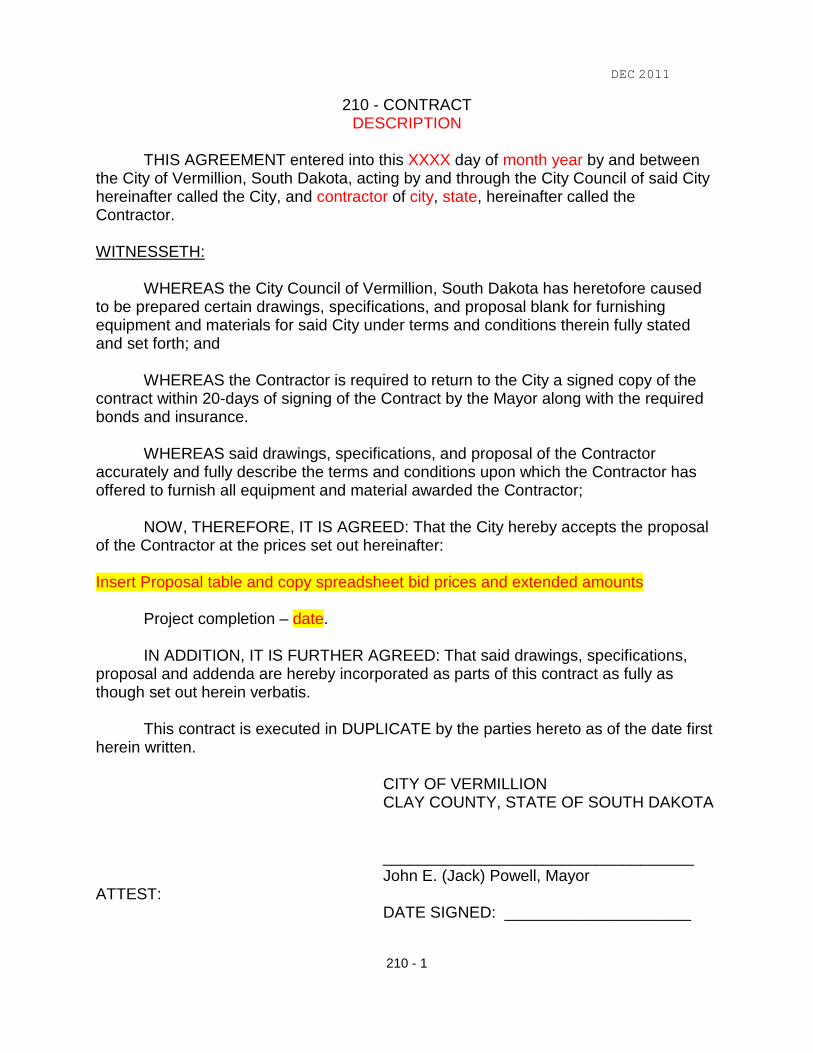
210 - CONTRACT DESCRIPTION
THIS AGREEMENT entered into this XXXX day of month year by and between
the City of Vermillion, South Dakota, acting by and through the City Council of said City hereinafter called the City, and contractor of city, state, hereinafter called the Contractor. WITNESSETH:
WHEREAS the City Council of Vermillion, South Dakota has heretofore caused to be prepared certain drawings, specifications, and proposal blank for furnishing equipment and materials for said City under terms and conditions therein fully stated and set forth; and
WHEREAS the Contractor is required to return to the City a signed copy of the
contract within 20-days of signing of the Contract by the Mayor along with the required bonds and insurance.
WHEREAS said drawings, specifications, and proposal of the Contractor accurately and fully describe the terms and conditions upon which the Contractor has offered to furnish all equipment and material awarded the Contractor;
NOW, THEREFORE, IT IS AGREED: That the City hereby accepts the proposal of the Contractor at the prices set out hereinafter: Insert Proposal table and copy spreadsheet bid prices and extended amounts
Project completion – date.
IN ADDITION, IT IS FURTHER AGREED: That said drawings, specifications, proposal and addenda are hereby incorporated as parts of this contract as fully as though set out herein verbatis.
This contract is executed in DUPLICATE by the parties hereto as of the date first herein written. CITY OF VERMILLION CLAY COUNTY, STATE OF SOUTH DAKOTA ___________________________________ John E. (Jack) Powell, Mayor ATTEST: DATE SIGNED: _____________________

DEC 2011
210 - 2
___________________________________ Michael D. Carlson, Finance Officer Contractor CONTRACTOR ___________________________________ DATE SIGNED: _____________________

DEC 2011
300 - 1
300 – GENERAL CONDITIONS
1.) DEFINITION OF TERMS
Wherever the term "Engineer" is used, it shall be taken as meaning the City Engineer or Utility Engineer duly appointed by the Governing Body to have supervision of the work of construction, and to their authorized assistants limited to the duties entrusted to them.
Wherever the term "Contractor" is used, it shall be taken as meaning the party of the second part, who contracts directly with the City to do the work to be performed under the Contract.
Wherever the term "City" or "Owner" is used, it shall be taken as meaning the City of Vermillion, South Dakota, party of the first part, as represented by its proper officers.
2.) INTERPRETATION OF SPECIFICATIONS
The Engineer shall decide all cases that may arise as to the intent and meaning of these specifications or the accompanying drawings and as to the proper execution of the work, and their decision shall be final during the progress of the work.
Any ambiguity or discrepancies in the drawings or specifications shall be decided by using the best class of work and materials, which any interpretation would admit of.
All materials and details of whatever nature, not distinctly specified in the drawings and specifications for the work, or in the proposal of the bidder, shall be subject to the approval of the Engineer.
3.) MEANING UNDERSTOOD
The Contractor, before submitting a bid upon the work covered by these specifications and drawings, shall satisfy himself as to the meaning of these specifications and the accompanying drawings. The tender of such bid is to be considered that he fully understands the same.
4.) LAWS AND ORDINANCE
All City, County, State or Federal laws, ordinances or regulations limiting or controlling the actions, or operations of all persons engaged upon the work, or affecting the material supplied therefor, must be complied with.
5.) TAXES
The Contractor will pay all sales, consumer, use, excise and other taxes required by law of the place where the work is performed. The total amount of such taxes shall be included in the amount bid. Adjustments will not be made after bidding. The Contractor shall obtain the necessary tax license from the State of South Dakota and shall furnish the license number to the City.

DEC 2011
300 - 2
6.) CONTRACT BONDS
The Contractor will be required to execute a performance and payment bond, for the use of the City and also for the use of all persons doing work or furnishing skill, tools, machinery or materials, under or for the purpose of the execution of the work. The bonds shall provide that the Contractor shall fully and faithfully perform the contract within the time according to the terms therein prescribed and shall pay as they become due, all just claims for work done and for tools, machinery, skill and materials furnished thereunder for the full protection of the City against loss or damage occasioned by mechanics liens or other liens, or by loss or claims on account of material or labor furnished.
The bonds shall be delivered to the City along with the signed contract, and shall be in an amount equal to the aggregate amount of the contract. They shall be in such form as the City may prescribe or the State may require and shall be executed by a surety satisfactory to the City.
7.) CONTRACTOR'S INSURANCE
During the life of the contract, the Contractor shall effect and maintain, with companies satisfactory to the City, the types and amount of insurance required. All insurance shall be from insurance companies duly authorized to do business in and under the laws of the State of South Dakota. No work shall commence until the insurance is in effect and approved by the City. The Contractor shall not allow any sub-contractor to commence work on their sub-contract until all similar insurance required of the sub-contractor has been so obtained and approved.
The Contractor shall carry General and Automobile Liability Insurance covering claims for damages for bodily injury, including accidental death, as well as from claims for property damage which may arise from operations under the contract, and shall include coverage for explosion, collapse and damage to underground pipes, wires and other utilities caused by mechanical equipment. The City of Vermillion shall be named an additional insured.
The Contractor agrees to insure their employees in accordance with the provisions of the "Workmen's Compensation Act" of the State of South Dakota as amended and now in force. Such insurance shall be placed by the Contractor in a Company authorized under the laws of the State of South Dakota to insure the liability above specified, or in lieu of such insurance said Contractor agrees to guarantee their liability to pay the compensation provided for in said "Workmen's Compensation Act."
Minimum limits shall be:
General Liability
General Aggregate 1,000,000 Products/Completed Operations Aggregate 1,000,000 Personal and Advertising Injury Limit 1,000,000

DEC 2011
300 - 3
Each Occurrence Limit 1,000,000 Fire Damage (any one fire) 100,000 Medical Expense (any one person) 5,000
Automobile Liability
Combined Single Limit 1,000,000 Or Bodily Injury (per person) 1,000,000 Bodily Injury (per accident) 1,000,000 Property Damage (per accident) 1,000,000
Workers Compensation and Employers' Liability
Each Accident 100,000 Disease - Policy Limit 500,000 Disease - Each Employee 100,000
Certificates of insurance shall be filed with the City along with the signed contract. Approval of the insurance by the City shall not relieve or decrease the liability of the Contractor hereunder.
8.) CLAIMS AND DAMAGES
The Contractor shall be responsible for and shall save and hold the City harmless against all damages for injuries to real or personal property or for any injury sustained by any person growing out of any neglect, act or deed of said Contractor or of their employees that is in the nature of a legal liability. The Contractor hereby agrees to indemnify and save the City harmless against all suits or actions of every name and description brought against said City on account of such neglect, act or deed in the prosecution of the work embraced in this contract. The Contractor further agrees to indemnify, keep and save harmless said City from all claims, judgments, awards and costs which may in any wise come against said City by reason of any accidental injuries or death suffered by any person employed on the work. The Contractor hereby agrees to save and hold the City harmless against all claims and liens for labor or materials furnished during or under this contract and shall furnish satisfactory evidence whenever called upon to do so, that all such claims have been paid.
All loss or damage arising out of the nature of the work to be done under this agreement, or from any unforeseen or unusual obstruction or difficulties which may be encountered in the prosecution of the same or for any action of the elements is to be sustained by the Contractor.

DEC 2011
300 - 4
9.) EMPLOYEES
The Contractor shall employ only competent foremen, mechanics and laborers, and shall discharge, whenever requested to do so, any person who, in the opinion of the Engineer, is incompetent, disorderly or untrustworthy.
10.) PROTECTION OF PROPERTY
The Contractor, shall at their own expense, shore up, protect and make good or replace any buildings, walls, fences, poles, or other property injured or moved by reason of the construction. He shall protect from injury all water, gas, or sewer pipes, electrical and communication cables or conduits encountered, or any other underground structure. In case any such become damaged, the Contractor shall be responsible for their repair.
The Contractor shall place and maintain all necessary barricades and lights that are necessary to protect the public from accident or injury.
11.) PUBLIC CONVENIENCES
No materials, or other obstruction, shall be placed within five (5) feet of the fire hydrants, which must be at all times readily accessible to the Fire Department.
During the progress of the work, the convenience of the public and of the residents along the street must be provided for as far as practicable. Convenient access to driveways, houses and buildings along the street must be maintained wherever possible. Temporary approaches to and crossings of intersecting streets and sidewalks must be provided and kept in good condition, wherever practicable.
12.) BARRIERS, LIGHTS, WATCHMAN
The Contractor shall provide and maintain such fences, barriers, "street closed" signs, red lights and watchman as may be necessary to prevent avoidable accidents to residents and to the public and to protect the project until opened for traffic.
13.) STAKES, BENCH MARKS
The Contractor shall preserve all stakes, benchmarks, property corners, monuments, etc., and shall not excavate near them without the permission of the Engineer, or until they have been removed, witnessed or otherwise disposed of by the Engineer. Benchmarks, property corners, or stakes, which become moved or disturbed, shall be reset by the Engineer. Cost of such replacement may be deducted from the amount due the Contractor under the contract.

DEC 2011
300 - 5
14.) PROSECUTION OF WORK
The Contractor shall commence and prosecute the work at such point as the Engineer may direct and conform to this direction as to the order of time in which the different parts of the work shall be done, and to all their instructions as to workmanship, quality of material, etc., so as to accomplish the object of this contract in accordance with all its terms and within the time specified, but not so as to effect the Contractor's method and manner of constructing the work in its details. The Contractor shall give their personal attention to the faithful prosecution of said work, shall not sublet the aforesaid work, or any part thereof without the previous consent of the party of the first part endorsed in the agreement, but shall keep the matter under their control.
15.) ABANDONMENT
If the work to be done under this agreement or any part thereof should be abandoned by the Contractor, the City shall have the right under the direction of the Engineer, to place such, and as many persons as he may deem advisable by contract or otherwise, to work at, and complete, the work herein described, or such part thereof, and to use such materials as he may find along the line of work, or in the case they are unfit, or insufficient, to procure other materials for the completion of the same, and the expense for such materials and labor shall be charged to the Contractor, and the expense so charged shall be deducted from any sums that may be due or may become due to the Contractor under this agreement and in case such expense is greater than the sum which would be payable under this contract, if the same had been completed by the said Contractor, he shall pay the amount of such excess to the party of the first part.
16.) INSPECTION
The Engineer may provide for the inspection, by assistants and inspectors under their direction, of all materials used and all work done under this contract. Such inspection may extend to all or any part of the work, and to the preparation or manufacture of all material to be used, whether within the limits of the work on the street, or at any other place. The engineer and all inspectors shall have free access to all parts of the work, including mines, quarries, fabricators, factories, or other places where any part of the materials to be used is procured, manufactured or prepared. The Contractor shall furnish the Engineer all information relating to the work and the material therefor, which the Engineer may deem necessary or pertinent, and with such samples of materials as may be required at no cost to the City. The Contractor shall, at their own expense, supply the inspectors with such labor and assistance as may be necessary in the handling of materials for proper inspection. The costs for testing will be the City's responsibility. Inspectors shall have authority to reject defective material and to suspend any work that is being improperly done, subject to the final decision of the Engineer. Inspectors shall have no authority to permit deviations from, relax any of the provisions of these specifications without the permission or instruction of the Engineer, or delay the Contractor by failure to inspect materials and work with reasonable promptness.
DEC 2011
300 - 6
The payment of any compensation, whatever may be its character or form, or the giving of any gratuity, or the granting of any valuable favor, by the Contractor to any inspector, directly or indirectly, is strictly prohibited, and any such act on the part of the Contractor will constitute a violation of these specifications.
17.) CHANGES
The quantities in the Proposal are approximate and the Contractor shall not be entitled to damages if the amount of work actually performed shall be less than estimated. The City reserves the right to delete work from the contract. The Contractor may request reimbursement for materials paid for and delivered to the job site provided the materials are in good useable condition and the final quantity is more than ten percent (10%) below the estimated quantity from the Proposal or approved Change Orders.
The City shall have the right on the order of the Engineer to make such changes in grades, routes and other details, as it may deem necessary, and such changes shall be paid according to the unit prices set forth in the bid, or if such changes involve a class of work not provided for in the bid, it shall be paid for as "Extra Work."
18.) EXTRA WORK
The Contractor shall, upon written order from the Engineer, perform such extra work as the Engineer may deem necessary for the proper execution of the work.
For such work done by the Contractor for which specific unit prices are not named in the contract, a unit or lump sum price will be agreed upon by both the Contractor and the Engineer and so noted in either partial or final payments or a change order.
19.) ARBITRATION
In case of dissent by either party to this contract, the value of the changes, additional, or omitted work shall be submitted to a Board of Arbitration, consisting of three (3) members, one (1) to be appointed by each of the parties hereto, and the third (3rd
20.) NOTICE
) by the two (2) thus chosen. The decision of any two (2) shall be final and binding and each of the parties shall pay one-half (½) the cost incurred by such resort to arbitration.
Notice of imperfections in the work or materials, or of any other nature, to any agent or foreman in charge of any portion of the work, in the absence of the Contractor, will be considered as notice to the Contractor.

DEC 2011
300 - 7
21.) ACCEPTANCE
All work shall be subject to the acceptance of the Owner and/or the Engineer and such acceptance is not to be given if the work presented for acceptance by the Contractor has not been executed in a good and workmanlike manner and according to these specifications, and each part thereof pertaining thereto. Acceptance may be made by the block or such portion as warrants it being opened for traffic; and based upon all work contracted for in the portion to be accepted. It is expressly provided, however, that no acceptance of payment shall operate as releasing Contractor from the stipulations of the guarantee.
22.) SUSPENSION
The Engineer may from time to time, suspend the work at certain places, or altogether, if in their opinion public needs require it or if the weather is not suitable for doing the work. The City will not be liable for extra costs the Contractor may incur.
23.) SUBCONTRACT
The Contractor will not be allowed to sublet the whole or any part of the work under this contract without the written permission from the Engineer to do so. No sub-contract shall under any circumstances relieve the Contractor of their liability and obligations. Should any sub-contractor fail to perform the work undertaken by him in a satisfactory manner, the Engineer may at their option require the Contractor to terminate such contract.
24.) ASSIGNMENT OF CONTRACT
No assignment by the Contractor of any principle construction contract or any part thereof or of the funds to be received thereunder by the Contractor, will be recognized unless such assignment has had the written approval of the Engineer and the Surety has been given due notice of such assignment and has furnished written consent thereto.
25.) OLD MATERIAL
All materials or structures removed and not required for the new construction, but which the City may desire to reserve, shall be delivered and neatly stockpiled, by the Contractor, as the Engineer may direct. Such reserved material shall be considered in the custody of the Contractor until delivered at the place designated.
All old material removed from the work including excess excavation, not reserved by the City, nor to be used again in the work, shall belong to the Contractor and must be removed by him as promptly as possible at the Contractor's expense. It must not be placed on the sidewalks or adjacent streets, or on any other street or property belonging to the City, nor on the property of private owners, without the written consent of the Engineer, or the owner of the property.

DEC 2011
300 - 8
26.) WASTE MATERIAL
The City owns a rubble site for the disposal of asphalt, concrete and concrete with rebar. The Contractor may utilize this site at no cost. The rubble must be no more than 3 feet in diameter. A representative of the Street Department will meet the Contractor at the site to show where to place the materials. The Engineer will provide a key and the Contractor is responsible for locking the gate at the end of each day. The key must be returned to the Engineer before final payment can be processed.
Recyclable materials shall either be taken to the Vermillion Recycling Center at 840 North Crawford Road or the Contractor shall arrange with the Solid Waste Director for their pick-up.
Garbage may be taken to the Vermillion Landfill on Bluff Road. The current fee will be charged and is the Contractor's responsibility. Hours of operation are Monday through Friday from 8:00 a.m. to 4:30 p.m.
27.) INCIDENTAL WORK
All the work to be done by the Contractor for which specific unit prices are not named in the contract, but obviously necessary for the proper completion of the work, shall be considered as incidental and as being a part of the work and included with the work for which prices are named in the contract. The Contractor will not be entitled to any extra or additional compensation therefor.
28.) DELAYS
In case the Contractor is delayed in the prosecution of the work by reason of the direction of the party of the first part, or by reason of any legal difficulty which may arise for which he is not responsible or by reason of a National Emergency, he shall be entitled to an extension of the date of completion equal to the aggregate time occasioned by such delays. The Contractor may not seek monetary relief for delays.
29.) TIME OF COMPLETION
The Contractor shall complete the entire work to be done under these specifications by the completion date as specified in the Proposal or Special Provisions. Failure to complete the work on or by the completion date, or within such extra time as may have been allowed by increases in the contract or by formally approved extensions granted by the Engineer, there shall be deducted from any monies or amounts due or that may become due the Contractor, the sum set forth in the schedule shown in the section headed Schedule of Liquidated Damages, for each and every working day, that the work shall remain uncompleted. This sum shall be considered and treated not as a penalty, but as liquidated damages due the City from the Contractor by reason of inconveniences to the

DEC 2011
300 - 9
public, added cost of engineering and supervision, and other items which have caused an expenditure of public funds resulting from their failure to complete the work within the time specified in the contract.
30.) WORKING DAY
A working day is a calendar day, except holidays, Saturdays and Sundays, on which weather and other conditions not under the control of the Contractor will permit normal construction operation to proceed for the major part of the day. Saturdays will be counted as working days if the Contractor utilizes such a day for construction work. The Contractor shall not carry on construction operations, other than emergency repairs and work protection, on Sundays and holidays without written permission from the Engineer.
31.) SCHEDULE OF LIQUIDATED DAMAGES
Amount of Contract Liquidated Damages Per Day
Less than $50,000 $250.00 At least $50,000 but less than $100,000 $325.00 At least $100,000 but less than $500,000 $500.00 At least $500,000 but less than $1,000,000 $725.00 At least $1,000,000 but less than $2,000,000 $900.00 At least $2,000,000 but less than $4,000,000 $1,450.00 At least $4,000,000 but less than $10,000,000 $1,800.00 $10,000,000 or more $2,300.00
32.) TERMINATION FOR BREACH
In the event that any of the provisions of this contract are violated by the Contractor or by any of their sub-contractors, the party of the first part may serve written notice upon the Contractor and the Surety of its intention to terminate such contract.
33.) GUARANTEE
The Contractor shall guarantee all the materials used and all the work done under these specifications, the drawings herein before referred to and the instructions of the Engineer. Any defects in the completed work, or any part of it, or any failure of the work to fully perform or endure the service for which it was intended, which in the opinion of the Engineer, are attributable to the use of materials, skill or workmanship not in compliance with the said specifications, drawings and instructions. And the Contractor, shall at their own expense, at such time and in such manner as the Engineer shall direct, repair or take up and reconstruct any such defective work, in full compliance with the original specifications.
The guarantee shall cover the contract as to workmanship and materials for a period of one (1) year commencing on the day final payment is made.

DEC 2011
300 - 10
34.) PAYMENTS
Contractor shall submit a payment request no later than the 22nd of each month. If payment is requested on the basis of materials not incorporated in the work but delivered and suitably stored at the site the payment request shall also be accompanied by a bill of sale or invoice. Once the payment request has been reviewed and approved by the Engineer the payment will be made around the 10th
Ten percent (10%), or less, is retained from the amount earned until the final payment request is made. Along with the last payment request, the Contractor shall furnish documentation warranting that all of the materials used are free and clear of all liens. The last payment will not be issued until the required documentation is furnished.
of the following month.
35.) CLEANING UP
The Contractor shall remove from the work all surplus earth or rejected materials, rubbish of any description, and dispose of the same to the satisfaction of the Engineer, leaving the ground near the work in a neat condition, free of encumbrance.
36.) “OR EQUAL” CLAUSE
Whenever in the specifications, an article, material, mechanical equipment or process is referred to by trade name, name of manufacturer or reference to a catalog number, it shall be understood to mean and specify the particular materials, equipment or process designated, or any equal thereto in quality, finish, design, efficiency, durability and equally serviceable and for the particular purpose for which it is intended.
37.) PRE-CONSTRUCTION
Prior to beginning construction, the Contractor shall give the Engineer's Office forty-eight (48) hours notice.
A preconstruction meeting may be held if necessary.
END OF GENERAL CONDITIONS

DEC 2011
400 - 1
400 – STANDARD SPECIFICATIONS
1.) STANDARD SPECIFICATIONS The specifications will be the South Dakota DOT “Standard Specifications for Roads and Bridges” 2004 edition, hereinafter referred to as “DOT Specifications”. A copy is available for review in the City of Vermillion Engineering Department. Copies may be obtained from the DOT office in Pierre or their website.
2.) CONFLICTS BETWEEN DOCUMENT PROVISIONS First) Special Provisions Second) the Details Third) the Drawings Fourth) City of Vermillion Specifications Fifth) the General Conditions Sixth) the DOT Specifications
END OF STANDARD SPECIFICATIONS

DEC 2011
1000 - 1
1000 - CLEARING AND GRUBBING 1) DESCRIPTION This work consists of clearing, grubbing, removing and disposing of vegetation and debris within the limits of the right-of-way, borrow and easement areas, except objects designated to be removed in accordance with other sections of these specifications.
2) MATERIALS LEFT BLANK
3) CONSTRUCTION REQUIREMENTS Shall be the same as those in the South Dakota Department of Transportation ‘Standard Specifications for Roads and Bridges’ 2004 Edition section 100.
4) METHOD OF MEASUREMENT
• Remove Trees shall be measured on a per each basis for any trees over 6-inches in diameter. The diameter will be measured 2-feet above the ground.
• Remove Stumps shall be measured on a per each basis for any stump over 6-inches in diameter. The diameter will be measured 2-feet above the ground.
• Clearing will be measured on a lump sum basis. No separate measurement for trees and stumps is required.
5) BASIS OF PAYMENT
• Remove Trees will be paid for at the contract unit price per each for removal and disposal of vegetation and debris. When these items are not included in the contract, the removal of trees and stumps will be incidental to the lump sum price of Clearing.
• Remove Stumps will be paid for at the contract unit price per each for removal and disposal of vegetation and debris. When these items are not included in the contract, the removal of trees and stumps will be incidental to the lump sum price of Clearing.
DEC 2011
1000 - 2
• Clearing will be paid as a lump sum for removal and disposal of vegetation and
debris.
END OF CLEARING AND GRUBBING

DEC 2011
1100 - 1
1100 - REMOVAL OF STRUCTURES AND OBSTRUCTIONS 1) DESCRIPTION This work consists of removal and disposal of buildings, fences, structures, pavements, abandoned pipe lines, pipe culverts, other obstructions which are not designated or permitted to remain, and which are not removed and disposed of under other items in the contract. It shall also include the salvaging of designated materials and backfilling the resulting trenches, holes and pits.
2) MATERIALS LEFT BLANK
3) CONSTRUCTION REQUIREMENTS Shall be the same as those in the South Dakota Department of Transportation ‘Standard Specifications for Roads and Bridges’ 2004 Edition section 110.
4) METHOD OF MEASUREMENT
• Removal of Structure and Obstruction measurement shall be on a lump sum basis for the removal of all structures and obstructions, no separate measurements shall be made.
• Remove PCC Pvmt measurement shall be on a square yard basis. Removal of curb and gutter is considered incidental and will be considered part of the PCC pavement.
• Remove Asphalt Pvmt measurement shall be on a square yard basis.
• Remove Sidewalk measurement shall be on a square yard basis.
• Remove Curb and Gutter measurement shall be on linear basis.
• Remove Strm Swr Manhole, ≤ 8-feet measurement shall be on a unit basis for
any storm sewer manhole 8-feet or less in depth being removed.
• Remove Strm Swr Manhole, > 8-feet measurement shall be on a unit basis for any storm sewer manhole more than 8-feet in depth being removed.
• Remove San Swr Manhole, ≤ 8-feet measurement shall be on a unit basis for any
sanitary sewer manhole 8-feet or less in depth being removed.
• Remove San Swr Manhole, > 8-feet measurement shall be on a unit basis for any sanitary sewer manhole more than 8-feet in depth being removed.

DEC 2011
1100 - 2
• Remove Inlet, ≤ 8-feet measurement shall be on a unit basis for any inlets 8-feet or less in depth being removed.
• Remove Inlet, > 8-feet measurement shall be on a unit basis for any inlets more
than 8-feet in depth being removed.
• Remove Strm Swr Pipe measurement shall be on a linear basis. Measurement shall include the end sections.
• Remove San Swr Pipe measurement shall be on a linear basis.
• Remove Water Main measurement shall be on a linear basis.
• Remove Water Fittings measurement shall be on a unit basis.
• Remove Water Box measurement shall be on a unit basis.
• Remove Firehydrant measurement shall be on a unit basis.
5) BASIS OF PAYMENT
• Removal of Structure and Obstruction payment will be a lump sum payment for removal and disposal of such items, excavation and subsequent backfill incidental to their removal. Payment will also include salvage of materials removed, their custody, preservation, storage on the right-of-way, and disposal as specified.
• Remove PCC Pvmt will be paid for at the contract unit price per square yard for removal and disposal of PCC pavement and curb and gutter, excavation and subsequent backfill incidental to their removal. Payment will also include salvage of materials removed, their custody, preservation, storage on the right-of-way, and disposal as specified.
• Remove Asphalt Pvmt will be paid for at the contract unit price per square yard
for removal and disposal of asphalt pavement, excavation and subsequent backfill incidental to their removal. Payment will also include salvage of materials removed, their custody, preservation, storage on the right-of-way, and disposal as specified.
• Remove Sidewalk will be paid for at the contract unit price per square yard for
removal and disposal of sidewalks, excavation and subsequent backfill incidental to their removal. Payment will also include salvage of materials removed, their custody, preservation, storage on the right-of-way, and disposal as specified.

DEC 2011
1100 - 3
• Remove Curb and Gutter will be paid for at the contract unit price per linear feet for removal and disposal of curb and gutter, excavation and subsequent backfill incidental to their removal. Payment will also include salvage of materials removed, their custody, preservation, storage on the right-of-way, and disposal as specified.
• Remove Strm Swr Manhole, ≤ 8-feet will be paid for at the contract unit price per each for removal and disposal of storm sewer manholes 8-feet or less in depth, excavation and subsequent backfill incidental to their removal. Payment will also include salvage of materials removed, their custody, preservation, storage on the right-of-way, and disposal as specified.
• Remove Strm Swr Manhole, > 8-feet will be paid for at the contract unit price per each for removal and disposal of storm sewer manholes more than 8-feet in depth, excavation and subsequent backfill incidental to their removal. Payment will also include salvage of materials removed, their custody, preservation, storage on the right-of-way, and disposal as specified.
• Remove San Swr Manhole, ≤ 8-feet will be paid for at the contract unit price per each for removal and disposal of sanitary sewer manholes 8-feet or less in depth, excavation and subsequent backfill incidental to their removal. Payment will also include salvage of materials removed, their custody, preservation, storage on the right-of-way, and disposal as specified.
• Remove San Swr Manhole, > 8-feet will be paid for at the contract unit price per each for removal and disposal of sanitary sewer manholes more than 8-feet in depth, excavation and subsequent backfill incidental to their removal. Payment will also include salvage of materials removed, their custody, preservation, storage on the right-of-way, and disposal as specified.
• Remove Inlet, ≤ 8-feet will be paid for at the contract unit price per each for removal and disposal of inlets 8-feet or less in depth, excavation and subsequent backfill incidental to their removal. Payment will also include salvage of materials removed, their custody, preservation, storage on the right-of-way, and disposal as specified.
• Remove Inlet, > 8-feet will be paid for at the contract unit price per each for removal and disposal of inlets more than 8-feet in depth, excavation and subsequent backfill incidental to their removal. Payment will also include salvage of materials removed, their custody, preservation, storage on the right-of-way, and disposal as specified.

DEC 2011
1100 - 4
• Remove Strm Swr Pipe will be paid for at the contract unit price per each for removal and disposal of storm sewer pipe, excavation and subsequent backfill incidental to their removal. Payment will also include salvage of materials removed, their custody, preservation, storage on the right-of-way, and disposal as specified.
• Remove San Swr Pipe will be paid for at the contract unit price per each for removal and disposal of sanitary sewer pipe, excavation and subsequent backfill incidental to their removal. Payment will also include salvage of materials removed, their custody, preservation, storage on the right-of-way, and disposal as specified.
• Remove Water Main will be paid for at the contract unit price per each for
removal and disposal of water pipe, excavation and subsequent backfill incidental to their removal. Payment will also include salvage of materials removed, their custody, preservation, storage on the right-of-way, and disposal as specified.
• Remove Water Fittings will be paid for at the contract unit price per each for removal and disposal of water fittings, excavation and subsequent backfill incidental to their removal. Payment will also include salvage of materials removed, their custody, preservation, storage on the right-of-way, and disposal as specified.
• Remove Water Box will be paid for at the contract unit price per each for
removal and disposal of water box, excavation and subsequent backfill incidental to their removal. Payment will also include salvage of materials removed, their custody, preservation, storage on the right-of-way, and disposal as specified.
• Remove Firehydrant will be paid for at the contract unit price per each for
removal and disposal of firehydrant, excavation and subsequent backfill incidental to their removal. Payment will also include salvage of materials removed, their custody, preservation, storage on the right-of-way, and disposal as specified.
END OF REMOVAL OF STRUCTURES AND OBSTRUCTIONS

DEC 2011
1200 - 1
1200 - ROADWAY AND DRAINAGE EXCAVATION AND EMBANKMENT CONSTRUCTION
1) DESCRIPTION This work consists of excavation, placement and disposal of material necessary for the construction of the roadway including hauling, watering, and when required, the placement of select subgrade topping.
2) MATERIALS
• Unclassified Excavation: All materials except those classified as rock excavation, unclassified/rock excavation, or muck excavation, encountered during the construction of the work, regardless of their nature or manner, in which they are removed, will be considered unclassified excavation.
• Unclassified/Rock Excavation: Unclassified/Rock excavation consists of the excavation and placement of both soil and rock when both are anticipated throughout the project area. This item differs from unclassified excavation in that an undetermined quantity of rock shall be excavated in addition to the materials included in unclassified excavation.
• Rock Excavation: Rock excavation shall consist of a sound, solid mass of mineral
matter in place and of such hardness and texture that it can not be loosened or broken down by ripping in a single pass with a tractor mounted hydraulic ripper equipped with one digging point. The ripper and tooth shall be of a standard design, adequately sized and used with a large crawler type tractor rated between 370 and 460 net fly wheel horsepower, operating in low gear, with sufficient downward force on the ripper.
• Muck Excavation: Muck excavation consists of the removal and disposal of
saturated organic mixtures of soils and organic matter which requires additional work or equipment not normally required for unclassified excavation.
• Unclassified Excavation, Digouts: Unclassified excavation, digouts consists of
the removal and disposal of unstable material below an existing surface on which surfacing material is to be placed. When granular material is used for backfill, the excavated area shall extend to a daylight point so that lateral drainage is provided. The exposed undercut surface shall be compacted prior to backfilling. The existing gravel shall be salvaged before and replaced after the unstable material has been removed.

DEC 2011
1200 - 2
• Select Subgrade Topping: Sources of selected subgrade topping material will be confined to the areas specified. The upper 6-inches of sodded areas, materials with high humus or silt content and outwashed material in poorly drained areas will not be acceptable. Unsatisfactory material found within the specified sources shall not be used as select subgrade topping.
• Undercutting: Undercutting shall consist of excavating, replacing, and
compacting the material immediately below the finished subgrade surface, at locations specified and to the depth specified.
• Water: Water shall be furnished by the Contractor and shall be free from
injurious matter.
3) CONSTRUCTION REQUIREMENTS Shall be the same as those in the South Dakota Department of Transportation ‘Standard Specifications for Roads and Bridges’ 2004 Edition section 120.
4) METHOD OF MEASUREMENT
• Unclassified Excavation will be measured in cubic yards. Measurement will include unsuitable material excavated and removed to obtain proper compaction in cut sections and in foundations for fill sections.
Accepted quantities of excavation will be measured in its original position by cross sectioning. The area excavated will include overbreakage or slides not due to carelessness of the Contractor.
• Unclassified / Rock Excavation will be measured in cubic yards. Measurement
will include unsuitable material excavated and removed to obtain proper compaction in cut sections and in foundations for fill sections.
Accepted quantities of excavation will be measured in its original position by cross sectioning. The area excavated will include overbreakage or slides not due to carelessness of the Contractor.
• Rock Excavation will be measured in cubic yards. Measurement will include
unsuitable material excavated and removed to obtain proper compaction in cut sections and in foundations for fill sections.
Accepted quantities of excavation will be measured in its original position by cross sectioning. The area excavated will include overbreakage or slides not due to carelessness of the Contractor.
• Muck Excavation will be measured in cubic yards. Measurement will include unsuitable material excavated and removed to obtain proper compaction in cut

DEC 2011
1200 - 3
sections and in foundations for fill sections. Accepted quantities of excavation will be measured in its original position by cross sectioning. The area excavated will include overbreakage or slides not due to carelessness of the Contractor.
• Undercutting will be measured in cubic yards. Measurement will include unsuitable material excavated and removed to obtain proper compaction in cut sections and in foundations for fill sections.
Accepted quantities of excavation will be measured in its original position by cross sectioning. The area excavated will include overbreakage or slides not due to carelessness of the Contractor.
• Select Subgrade Topping will be measured in cubic yards. Measurement will
include the volume measured from its original position by cross sectioning plus shrinkage. The shrinkage factor shall be 1.3.
• Option Borrow Excavation will be measured in cubic yards from its original
position by cross sectioning. Original cross sections will be taken prior to removal of any material and final sections will be taken following placement of topsoil. Salvaged topsoil which is stockpiled from the optioned borrow sources will be included as option borrow excavation. The quantity of topsoil stockpiled and respread on optioned borrow sources will be determined by measuring the stockpiles prior to removal of the material from the stockpiles.
• Topsoil will be measured in cubic yards from its original position by cross sectioning.
• Contractor Furnished Borrow will be measured in cubic yards from its original
position by cross sectioning. Original cross sections will be taken prior to removal of any material and final sections will be taken following placement of topsoil. Salvaged topsoil will not be measured.
• Water will be measured by the thousand gallons to the nearest 0.1-MGal.
5) BASIS OF PAYMENT
• Unclassified Excavation completed and accepted work will be paid for at the contract unit price per cubic yard. Payment will be full compensation for

DEC 2011
1200 - 4
excavation, construction and compaction of cuts and embankments, shaping of slopes, finishing of surface, disposal of surplus materials, completion of subgrade, shoulders, and roadway, and maintenance.
Scarifying, shaping and recompacting shall be incidental. Separate payment will not be made.
• Unclassified / Rock Excavation completed and accepted work will be paid for at
the contract unit price per cubic yard. Payment will be full compensation for excavation, construction and compaction of cuts and embankments, shaping of slopes, finishing of surface, disposal of surplus materials, completion of subgrade, shoulders, and roadway, and maintenance.
Scarifying, shaping and recompacting shall be incidental. Separate payment will not be made.
• Rock Excavation completed and accepted work will be paid for at the contract unit price per cubic yard. Payment will be full compensation for excavation, construction and compaction of cuts and embankments, shaping of slopes, finishing of surface, disposal of surplus materials, completion of subgrade, shoulders, and roadway, and maintenance.
Scarifying, shaping and recompacting shall be incidental. Separate payment will not be made.
• Muck Excavation completed and accepted work will be paid for at the contract unit price per cubic yard. Payment will be full compensation for excavation, construction and compaction of cuts and embankments, shaping of slopes, finishing of surface, disposal of surplus materials, completion of subgrade, shoulders, and roadway, and maintenance.
Scarifying, shaping and recompacting shall be incidental. Separate payment will not be made.
• Undercutting completed and accepted work will be paid for at the contract unit price per cubic yard. Payment will be full compensation for excavation, construction and compaction of cuts and embankments, shaping of slopes, finishing of surface, disposal of surplus materials, completion of subgrade, shoulders, and roadway, and maintenance.
Scarifying, shaping and recompacting shall be incidental. Separate payment will not be made. Payment will be full compensation for work over and above that normally required for unclassified excavation.
DEC 2011
1200 - 5
• Select Subgrade Topping will be paid for at the contract unit price per cubic yard. Payment will be full compensation for work over and above that normally required for embankment construction.
• Option Borrow Excavation will be paid for at the contract unit price per cubic
yard. Payment will be full compensation for excavation and furnishing the material on the project, construction and compaction of embankments, shaping of slopes, finishing of surface, completion of subgrade, shoulders, and roadway, and maintenance, and for furnishing materials (except topsoil), labor, and incidentals required for restoration of the pit.
• Topsoil will be paid for at the contract unit price per cubic yard. Payment will be
full compensation for excavation and furnishing the material on the project, construction and compaction of embankments, shaping of slopes, finishing surface, and maintenance, and for furnishing materials, labor and incidentals.
• Contractor Furnished Borrow will be paid for at the contract unit price per
cubic yard. Payment will be full compensation for excavation and furnishing the material on the project, construction and compaction of embankments, shaping of slopes, finishing of surface, completion of subgrade, shoulders, and roadway, and maintenance, and for furnishing materials (except topsoil), labor, and incidentals required for restoration of the pit.
• Water will be paid for at the contract unit price per thousand gallons (MGal).
END OF ROADWAY AND DRAINAGE EXCAVATION AND EMBANKMENT
CONSTRUCTION

DEC 2011
1300 - 1
1300 - ROADWAY SHAPING 1) DESCRIPTION This work consists of reshaping an existing surface prior to placement of surfacing material.
2) MATERIALS LEFT BLANK
3) CONSTRUCTION REQUIREMENTS Shall be the same as those in the South Dakota Department of Transportation ‘Standard Specifications for Roads and Bridges’ 2004 Edition section 210.
4) METHOD OF MEASUREMENT
• Surface Preparation will be measured to the nearest 0.001-mile, horizontally along the centerline.
• Ordinary Roadway Shaping will be measured to the nearest 0.001-mile, horizontally along the centerline.
• Heavy Roadway Shaping will be measured to the nearest 0.001-mile,
horizontally along the centerline.
5) BASIS OF PAYMENT
• Surface Preparation will be paid for at the contract unit price per mile. Payment will be full compensation for scarifying, reworking, shaping, compacting, reprocessing blotters if required, equipment, labor and incidentals necessary to satisfactorily complete the work.
• Ordinary Roadway Shaping will be paid for at the contract unit price per mile. Payment will be full compensation for equipment, labor and incidentals necessary to satisfactorily remove the existing surfacing, shape, replace and compact the materials specified.

DEC 2011
1300 - 2
• Heavy Roadway Shaping will be paid for at the contract unit price per mile. Payment will be full compensation for equipment, labor and incidentals necessary to satisfactorily remove the existing surfacing, shape, replace and compact the materials specified.
END OF ROADWAY SHAPING

MARCH 2012
2000 - 1
2000 - GRANULAR BASES AND SURFACING 1) DESCRIPTION This work consists of providing one or more courses of aggregate on a prepared surface.
2) MATERIALS Materials shall conform to the following sections found in the South Dakota Department of Transportation ‘Standard Specifications for Roads and Bridges’ 2004 Edition:
• Subbase, Base Course, Gravel Cushion, and Gravel Surfacing shall conform to the South Dakota Department of Transportation ‘Standard Specifications for Roads and Bridges’ 2004 Edition section 882. Granular additives (sand, rock, etc.) may be necessary to produce material of the type specified.
• Clay Binder, when required for gravel surfacing, shall conform to the South Dakota Department of Transportation ‘Standard Specifications for Roads and Bridges’ 2004 Edition section 883.
• Crushed Concrete, Ballast:
SIEVE PERCENT PASSING
3-inch 100 2-inch 95 – 100 1-1/2-inch 95 – 100 1-inch 65 – 95 ¾-inch 55 – 90 ½-inch 45 – 85 # 4 35 – 65 #8 25 – 60 # 40 15 – 35 # 200 Less than 12
3) CONSTRUCTION REQUIREMENTS Shall be the same as those in the South Dakota Department of Transportation ‘Standard Specifications for Roads and Bridges’ 2004 Edition section 260.
4) METHOD OF MEASUREMENT
• Subbase will be measured to the nearest 0.1-ton.
• Subbase, Salvaged will be measured to the nearest 0.1-ton.

MARCH 2012
2000 - 2
• Subbase, Install Only will be measured to the nearest 0.1-ton.
• Base Course will be measured to the nearest 0.1-ton.
• Base Course, Salvaged will be measured to the nearest 0.1-ton.
• Base Course, Install Only will be measured to the nearest 0.1-ton.
• Gravel Cushion will be measured to the nearest 0.1-ton.
• Gravel Cushion, Salvaged will be measured to the nearest 0.1-ton.
• Gravel Surfacing will be measured to the nearest 0.1-ton. This also includes the clay binder.
• Gravel Surfacing, Salvaged will be measured to the nearest 0.1-ton.
• Crushed Concrete, Ballast will be measured to the nearest 0.1-ton.
5) BASIS OF PAYMENT
• Subbase will be paid for at the contract unit price per ton. Payment will be full compensation for furnishing and placing materials, labor, equipment, test strips (if required), and all incidentals required.
• Subbase, Salvaged will be paid for at the contract unit price per ton. Payment will be full compensation for furnishing and placing materials, labor, equipment, test strips (if required), and all incidentals required.
• Subbase, Install Only will be paid for at the contract unit price per ton. Payment
will be full compensation for placing materials, labor, equipment, test strips (if required, and all incidentals required.
• Base Course will be paid for at the contract unit price per ton. Payment will be
full compensation for furnishing and placing materials, labor, equipment, test strips (if required), and all incidentals required.
• Base Course, Salvaged will be paid for at the contract unit price per ton.
Payment will be full compensation for furnishing and placing materials, labor, equipment, test strips (if required), and all incidentals required.
• Base Course, Install Only will be paid for at the contract unit price per ton.
Payment will be full compensation for placing materials, labor, equipment, test strips (if required, and all incidentals required.
MARCH 2012
2000 - 3
• Gravel Cushion will be paid for at the contract unit price per ton. Payment will be full compensation for furnishing and placing materials, labor, equipment, test strips (if required), and all incidentals required.
• Gravel Cushion, Salvaged will be paid for at the contract unit price per ton. Payment will be full compensation for furnishing and placing materials, labor, equipment, test strips (if required), and all incidentals required.
• Gravel Surfacing will be paid for at the contract unit price per ton. Payment will
be full compensation for furnishing and placing materials, labor, equipment, test strips (if required), and all incidentals required.
• Gravel Surfacing, Salvaged will be paid for at the contract unit price per ton.
Payment will be full compensation for furnishing and placing materials, labor, equipment, test strips (if required), and all incidentals required.
• Crushed Concrete, Ballast will be paid for at the contract unit price per ton. Payment will be full compensation for furnishing and placing materials, labor, equipment, test strips (if required), and all incidentals required.
If roadway shaping is required, and a bid item is not provided, payment for the granular material items will be full compensation for necessary shaping work.
END OF GRANULAR BASES AND SURFACING

DEC 2011
2100 - 1
2100 - PROCESS IN PLACE SURFACING 1) DESCRIPTION Process In Place Surfacing shall consist of processing and blending the asphalt mix and granular material, placing, watering, shaping and compacting the material to the typical section.
2) MATERIALS The asphalt mix and granular material shall be processed to provide a nominal 1-inch maximum size. A tolerance of 5-percent in material retained on a 1-inch sieve will be permitted, provided all material passes a 1 1/2 –inch sieve.
3) CONSTRUCTION REQUIREMENTS Shall be the same as those in the South Dakota Department of Transportation ‘Standard Specifications for Roads and Bridges’ 2004 Edition section 280.
4) METHOD OF MEASUREMENT
• Process In Place Surfacing material will be measured to the nearest square yard.
5) BASIS OF PAYMENT
• Process In Place Surfacing will be paid for at the contract price per square yard inclusive of all costs for processing, blending, placing, shaping, compacting, equipment, test strips, labor and incidentals necessary to satisfactorily complete the work.
END OF PROCESS IN PLACE SURFACING

DEC 2011
3000 - 1
3000 - ASPHALT PAVEMENT 1) DESCRIPTION This work consists of cleaning the roadway surface, tack coat application, and the placement of a hot plant-mix surface with a bituminous paver over the existing surface.
2) MATERIALS
• Tack Coat: Tack coat shall be emulsified asphalt, SS-1H or CSS-1h
• Asphalt Binder: Asphalt binder shall be PG58-28 or PG64-22
• The Contractor shall perform the asphalt concrete mix designs and furnish the job mix formulas to the Engineer prior to the placement of any asphalt pavement. The design shall meet the following specifications for medium volume traffic:
MIX DESIGN PARAMETER SPECIFICATION % Air Voids 3.5 Min. % VMA* 3/4” nominal maximum size 13.5 Min. 1/2” nominal maximum size 14.5 Min. Marshall Blows 50 Marshall Stability 1500 Min. Marshall Flow 8-16 Dust/Binder Ratio (based on effective binder) 0.6-1.4 Moisture Sensitivity** 70 Min.
The lower specification limit (LSL) for in place density is 91.0 percent of the lot average maximum specific gravity (Rice Method) test results. The upper specification limit (USL) for in place density is 96.0 percent.
COMPOSITE MINERAL AGGREGATE REQUIREMENTS (without hydrated lime) SPECIFICATION 3/4" 100% passing 1/2" 75-95% passing #4 45-75% passing #8 30-55% passing #16 20-45% passing #40 10-30% passing #200 3.0-7.0% passing +#4 Fractured Faces % Min. 70% 2-FF -#4 Manufactured Fines 20% Min.*** +#4 Lightweight Particles 3.0 % Max. -#4 Lightweight Particles 3.0 % Max.

DEC 2011
3000 - 2
COMPOSITE MINERAL AGGREGATE REQUIREMENTS (without hydrated lime) SPECIFICATION Liquid Limit (LL) 25 Max Plasticity Index (PI) N.P. L.A. Abrasion Loss 40 Max. Sodium Soundness Loss (five cycles) +#4 15% Max. -#4 15% Max.
* If the percent passing the 1/2-inch sieve is greater than or equal to 90 percent, the mix shall be considered 1/2-inch nominal maximum size. If the percent passing the 1/2-inch sieve is less than 90 percent, the mix shall be considered 3/4-inch nominal maximum size. ** Hydrated lime shall be used to meet the moisture sensitivity requirement of the mix. Hydrated lime will not be required if the moisture sensitivity requirements are met without the addition of hydrated lime. *** Manufactured fines shall be manufactured solely from material retained on the 3/4-inch sieve, unless the aggregate material is produced from a ledge rock source. Once the job mix formula is submitted, the mix must be within the following tolerances.
TOLERANCE FROM ATTRIBUTE TARGET VALUE Sieve 5/8" thru 3/8” ± 7 % Sieve #4 thru #50 ± 5 % Sieve #100 thru #200 ± 2.0 % % Asphalt Binder ± 0.3 % Liquid Limit Maximum or less % Lightweight Particles Maximum or less Plasticity Index Maximum or less % Fractured Faces Minimum or more % Hydrated Lime ± 0.1 % % Air Voids ± 1.0% In Place Density (% Compaction) Minimum Specified & Maximum
Specified
3) CONSTRUCTION REQUIREMENTS
• Tests: The Contractor shall furnish, at minimum, one complete set of test results to verify the materials meet the parameters and requirements in item 2. If any test

DEC 2011
3000 - 3
fails, the Contractor shall immediately make the appropriate adjustments in the production of the mix and/or the placement. Another complete set of test results shall then be furnished.
• The City reserves the right to limit the number of streets closed to traffic and the work schedule. The purpose is to close no more than can be completed in 1-day and also to minimize inconvenience to the public, while providing for the Contractor’s efficient operation. The Contractor must provide a work schedule to the Engineer on or before the preconstruction meeting. The Contractor and Engineer must agree on the schedule before work may commence.
The area to be paved shall be cleaned by brooming prior to applying the tack coat. The rate of application shall be such that approximately 0.04-gallons of bitumen residue is applied per square yard. Tack coat shall be applied only to that surface on which the overlay can be completed in the same day. All mixed material shall be delivered to the finishing machine in time to permit completion of spreading, finishing and compacting during the specified working hours. The mixture shall be placed on the road at a temperature of 250 to 300° F.
4) METHOD OF MEASUREMENT
• Asphalt Pvmt shall be measured in tons of mixture placed and compacted. This item shall include the design, production and placement of the mixture; the preparation of the base; the tack coat and any other incidentals that are necessary. Weight tickets shall be furnished to the Inspector at the end of each day.
5) BASIS OF PAYMENT
• Asphalt Pvmt shall be paid for at the contract unit price bid per ton, which price shall be full compensation for furnishing all materials, labor, equipment, tools, supplies and incidentals necessary to complete the work.
END OF ASPHALT PAVEMENT

DEC 2011
3100 - 1
3100 - FOG AND FLUSH SEAL COATS 1) DESCRIPTION This work consists of preparing and treating a prepared surface with asphalt material and sand as required.
2) MATERIALS Materials shall conform to the following sections found in the South Dakota Department of Transportation ‘Standard Specifications for Roads and Bridges’ 2004 Edition:
• Asphalt: Section 890 • Blotting Sand for Prime Coats: Section 879
• Sand for Flush Seal: Section 879
3) CONSTRUCTION REQUIREMENTS Shall be the same as those in the South Dakota Department of Transportation ‘Standard Specifications for Roads and Bridges’ 2004 Edition section 330.
4) METHOD OF MEASUREMENT
• Asphalt will be measured to the nearest 0.1-ton.
• Blotting Sand for Prime will be measured to the nearest 0.1-ton.
• Sand for Flush Seal will be measured to the nearest 0.1-ton.
5) BASIS OF PAYMENT
• Asphalt will be paid for at the contract unit price per ton complete in place. Separate payment will not be made for water for dilution of emulsified asphalt.
• Blotting Sand for Prime will be paid for at the contract unit price per ton complete in place. Payment will be full compensation for furnishing, installing, and all incidentals required to complete the work.
• Sand for Flush Seal will be paid for at the contract unit price per ton complete in
place. Payment will be full compensation for furnishing, installing, and all incidentals required to complete the work.
END OF FOG AND FLUSH SEAL COATS

DEC 2011
3200 - 1
3200 - ASPHALT CONCRETE CRACK SEALING 1) DESCRIPTION This work shall consist of routing and sealing transverse and longitudinal cracks in an asphalt concrete roadway surface with the specified sealant.
2) MATERIALS The sealant shall conform to the requirements of ASTM 3405 with the following modifications:
• Penetration 90-150
• Bond at -20º F, Std. Specimen, 3 cycles, 200% Extension Passes The sealant shall have a unit weight no greater than 9.36 lbs./gal Only products that meet the above requirements and have performed satisfactorily based on the South Dakota Department of Transportation analysis may be used. A listing of acceptable products may be obtained from the South Dakota Department of Transportation’s approved products list. The blocking medium shall be an inert, compressible material, which is compatible with the sealant.
3) CONSTRUCTION REQUIREMENTS Shall be the same as those in the South Dakota Department of Transportation ‘Standard Specifications for Roads and Bridges’ 2004 Edition section 350.
4) METHOD OF MEASUREMENT
• Asphalt Concrete Crack Sealing will be measured by the pound of sealant used. The manufacturer’s weights of the sealant will be accepted as the basis of measurement.
5) BASIS OF PAYMENT
• Asphalt Concrete Crack Sealing will be paid at the contract unit price per pound and shall be full compensation for routing, furnishing, heating, placing, and blotting the sealant. Blocking medium shall be incidental.
END OF ASPHALT CONCRETE CRACK SEALING

DEC 2011
3300 - 1
3300 - ASPHALT SURFACE TREATMENT 1) DESCRIPTION The work consists of cleaning of the surface and an application of asphalt binder immediately covered by a layer of aggregate.
2) MATERIALS
• Asphalt: Asphalt shall be one coat of RC-800R.
• Cover Aggregate: Cover aggregate will be supplied by the City.
3) CONSTRUCTION REQUIREMENTS
1. Weather and Seasonal Requirements: Surface treatment operations will be permitted only during daylight hours, when conditions are dry and when wind does not adversely affect the spraying operations. Work may only be performed when the temperature is 70° F (in the shade and rising) and between June 1st and September 15th
.
2. Equipment: • A rotary power broom, or sweeper, capable of capturing the dirt • Equipment for heating and applying (heating equipment and distributor)
the asphalt conforming to the requirements in the South Dakota Department of Transportation ‘Standard Specifications for Roads and Bridges’ 2004 Edition section 330.3.C.
• A self propelled aggregate spreader, with positive controls capable of depositing the required quantity of aggregate uniformly over the full width of the asphalt application.
• A self-propelled pneumatic smooth tire roller capable of completely covering a width of 60-inches and furnish a minimum uniform rolling weight of 250-pounds per inch.
• Loader to load chips • Truck to haul to spreader
3. Construction Method: The area to be chipped shall be cleaned by sweeping prior
to applying the asphalt. All manholes and inlet grates shall be covered prior to sealing. The rate of application shall be 0.3-gallons of RC-800R asphalt per square yard. The asphalt shall be placed at a temperature of 260° F or above.
Chips must be applied as soon as possible after the application of the asphalt at a rate of 23-pounds per square yard. The chips shall be rolled and after rolling the street shall be opened to traffic. The next day the City of Vermillion shall sweep the excess chips.

DEC 2011
3300 - 2
4. Traffic Control: Contractor shall supply 2 flaggers when work is in progress. Contractor shall give the City of Vermillion 1-week notice before starting the project for placement of “No Parking” signs and notices.
4) METHOD OF MEASUREMENT
• Chip Seal shall be measured in square yards. This item shall include the RC-800R, placement of the RC-800R and chips, sweeping of the base, covering and uncovering manholes and inlet grates and flagging.
5) BASIS OF PAYMENT
• Chip Seal shall be paid for at the contract unit price bid per square yard for chip seal, which price shall be full compensation for furnishing all materials, labor, equipment, tools, supplies and incidentals necessary to complete the work.
END OF ASPHALT SURFACE TREATMENT

DEC 2011
3400 - 1
3400 – COLD MILLING ASPHALT CONCRETE 1) DESCRIPTION The work consists of cold milling a portion of the existing asphalt concrete surface course and hauling and stockpiling the removed material.
2) MATERIALS Cold milled asphalt concrete material shall be milled to provide a nominal 1-inch maximum size. A tolerance of 5% in material retained on a 1-inch sieve will be permitted, provided all material passes a 1 ½ -inch sieve.
3) CONSTRUCTION REQUIREMENTS Shall be the same as those in the South Dakota Department of Transportation ‘Standard Specifications for Roads and Bridges’ 2004 Edition section 332.
4) METHOD OF MEASUREMENT
• Cold Milling Asphalt Concrete will not be measure. Plans quantity will be used. If changes from the plan quantity are ordered these areas will be measure and the plan quantity appropriately adjusted.
5) BASIS OF PAYMENT
• Cold Milling Asphalt Concrete will be paid at the contract unit price per square yard.
END OF COLD MILLING ASPHALT CONCRETE

DEC 2011
4000 - 1
4000 - PORTLAND CEMENT CONCRETE PAVEMENT 1) DESCRIPTION This work consists of constructing Portland Cement Concrete Pavement on prepared surfaces.
2) MATERIALS Materials shall conform to the following sections found in the South Dakota Department of Transportation ‘Standard Specifications for Roads and Bridges’ 2004 Edition:
• Cement Section 750 (only Type II)
• Admixtures Sections 751 and 752
• Water Section 790
• Fine Aggregate Section 800
• Coarse Aggregate Section 820
• Reinforcing Steel Section 1010
• Joint Filler Section 860
• Joint Sealant Section 870
• Curing Materials Section 821
• Dowel Bar Assemblies Section 1010
• Fly Ash Sections 605 and 753 Concrete shall meet the South Dakota Department of Transportation ‘Standard Specifications for Roads and Bridges’ 2004 Edition specifications for Class A40 concrete with course aggregate consisting of crushed quartzite.
3) CONSTRUCTION REQUIREMENTS Shall be the same as those in the South Dakota Department of Transportation ‘Standard Specifications for Roads and Bridges’ 2004 Edition section 380.

DEC 2011
4000 - 2
4) METHOD OF MEASUREMENT
• PCC Pvmt will be measured to the nearest 0.1 square yard.
• PCC Fillet will be measured to the nearest 0.1 square yard.
• PCC Approach will be measured to the nearest 0.1 square yard.
• Dowel Bar Assemblies will be measured by the actual number of bars furnished and installed.
5) BASIS OF PAYMENT
• PCC Pvmt will be paid for at the contract unit price per square yard. Payment will be full compensation for furnishing all materials (including reinforcing steel), labor equipment, and all incidentals necessary. Payment will also be full compensation for trimming and water used to moisten the subgrade ahead of the paver and curing concrete.
• PCC Fillet will be paid for at the contract unit price per square yard.
Payment will be full compensation for furnishing all materials (including reinforcing steel), labor equipment, and all incidentals necessary. Payment will also be full compensation for trimming and water used to moisten the subgrade ahead of the paver and curing concrete.
• PCC Approach will be paid for at the contract unit price per square yard.
Payment will be full compensation for furnishing all materials (including reinforcing steel), labor equipment, and all incidentals necessary. Payment will also be full compensation for trimming and water used to moisten the subgrade ahead of the paver and curing concrete.
• Dowel Bar Assemblies will be paid for at the contract unit price per each dowel
bar. Payment will be full compensation for labor, materials, equipment, and all incidentals necessary to furnish and install the assemblies.
END OF PORTLAND CEMENT CONCRETE PAVEMENT

DEC 2011
4100 - 1
4100 - UNDERSEALING 1) DESCRIPTION This work consists of filling existing voids under PCC pavement by drilling injection holes and pumping a cement/fly ash grout under the pavement slab.
2) MATERIALS
• Design Mix: The design mix for grout shall conform to the following proportions by absolute volume: 1 Part Portland cement 3 Parts fly ash Water to achieve the specified fluidity Fluidity of the grout when measured by a flow cone in accordance with ASTM C939 shall have a time of efflux between 9 and 15 seconds. The Contractor shall submit for approval, materials proposed for use. The submittals shall include mill certification for cement, physical and chemical analysis for fly ash, and tests of the grout slurry by a South Dakota Department of Transportation approved testing laboratory. Tests shall show one, three, and seven day strengths, flow cone times, shrinkage and expansion observed, and time of initial set. The seven day strength shall be at least 600-psi as measured in accordance with ASTM C942. As an alternate, standard 6-inch diameter by 12-inch high water tight concrete cylinder molds may be used to determine seven day strength. When the cylinder molds are used, the strength shall be 700-psi minimum.
• Cement Section 750 (only Type 1 or 2)
• Water Section 790
• Fly Ash Section 753
3) CONSTRUCTION REQUIREMENTS Shall be the same as those in the South Dakota Department of Transportation ‘Standard Specifications for Roads and Bridges’ 2004 Edition section 391.

DEC 2011
4100 - 2
4) METHOD OF MEASUREMENT
• PCC Drill Holes will be measured per each (only accepted holes will be paid for). The holes drilled after the deflection testing will not be included for payment.
• PCC Pvmt Undersealing will be measured to the nearest cubic foot. Portland cement will be the only material measured for payment. One bag of cement (94-pounds) shall equal one cubic foot of PCC pavement undersealing.
• Deflection Testing will be measured per each test location. Testing before and
after undersealing at the same joint will be measured as separate locations.
Should the testing, after the undersealing is performed, indicate a need for further undersealing at that joint, all addition testing at that joint will be at no cost to the City.
5) BASIS OF PAYMENT
• PCC Drill Holes will be paid for at the contract unit price per each. Payment will be full compensation for all materials, equipment, tools, and incidentals required to drill, plug and seal the holes after the undersealing is completed.
• PCC Pvmt Undersealing will be paid for at the contract unit price per cubic foot. Payment will be full compensation for all materials, including fly ash and water, labor, equipment, tools, and incidentals required.
• Deflection Testing will be paid for at the contract unit price per each test
location. Payment will be full compensation for all materials, equipment, tools, and incidentals required.
END OF UNDERSEALING

DEC 2011
4200 - 1
4200 - PAVEMENT JACKING 1) DESCRIPTION This work consists of hydraulic pressure jacking PCC pavement to correct the pavement profile. Jacking is accomplished by drilling injection holes and pumping a cement/fly ash slurry or liquid polyurethane (foam) under the slab.
2) MATERIALS
• Cement Section 750 (only Type 1 or 2)
• Water Section 790
• Fly Ash Section 753
• Design Mix: The design mix for grout shall conform to the following proportions by absolute volume: 1 Part Portland cement 3 Parts fly ash Water to achieve the specified fluidity Fluidity of the grout when measured by a flow cone in accordance with ASTM C939 shall have a time of efflux between 16 and 36 seconds. During the initial injection at each hole an efflux time between 9 and 15 seconds will be permitted. The use of material with an efflux time between 9 and 15 seconds shall be discontinued prior to movement of the pavement. The Contractor shall be required to perform this test prior to placing the material. The Contractor shall submit for approval, materials proposed for use. The submittals shall include mill certification for cement, physical and chemical analysis for fly ash, and tests of the grout slurry by a South Dakota Department of Transportation approved testing laboratory. Tests shall show one, three, and seven day strengths, flow cone times, shrinkage and expansion observed, and time of initial set. The seven day strength shall be at least 600-psi as measured in accordance with ASTM C942. As an alternate, standard 6-inch diameter by 12-inch high water tight concrete cylinder molds may be used to determine seven day strength. When the cylinder molds are used, the strength shall be 700-psi minimum.
• Jacking Foam: Water blown formulation of high-density polyurethane. The high density, closed cell polyurethane shall be hydrophobic and shall exhibit the following physical characteristics and properties:

DEC 2011
4200 - 2
DENSITY, LB/CU.FT COMPRESSIVE STRENGTH
(ASTM D1622) (ASTM D1621) 3.0 40 psi 3.5 50 psi 4.0 60 psi 6.0 110 psi The polyurethane foam shall have a free rise density of 3.0 to 3.2 lbs/cu.ft., with a minimum compressive strength of 40-psi. The material shall be resistant to oils, gasoline and most solvents. The high-density polyurethane formulation shall reach 90% of full compressive strength within 15-minutes from injection.
3) CONSTRUCTION REQUIREMENTS Shall be the same as those in the South Dakota Department of Transportation ‘Standard Specifications for Roads and Bridges’ 2004 Edition section 392.
4) METHOD OF MEASUREMENT
• PCC Pvmt Jacking Slurry will be measured to the nearest cubic foot. Portland cement will be the only material measured for payment. One bag of cement (94-pounds) shall equal one cubic foot of PCC pavement jacking slurry.
• PCC Pvmt Jacking Foam will be measured to the nearest pound.
5) BASIS OF PAYMENT
• PCC Pvmt Jacking Slurry will be paid for at the contract unit price per cubic foot. Payment will be full compensation for all materials, including fly ash, water, labor, equipment, tools, and incidentals required.
• PCC Pvmt Jacking Foam will be paid for at the contract unit price per pound. Payment will be full compensation for all materials, including high-density polyurethane foam, labor, equipment, tools, and incidentals required.
END OF PAVEMENT JACKING

DEC 2011
4300 - 1
4300 - CURB AND GUTTER 1) DESCRIPTION This work consists of constructing concrete curb and gutter.
2) MATERIALS Materials shall conform to the following sections found in the South Dakota Department of Transportation ‘Standard Specifications for Roads and Bridges’ 2004 Edition:
• Concrete: Section 460 (only Class A40)
• Expansion Joint Filler: Section 860
• Curing Compound: Section 821
• Reinforcing Steel: Section 1010
3) CONSTRUCTION REQUIREMENTS Shall be the same as those in the South Dakota Department of Transportation ‘Standard Specifications for Roads and Bridges’ 2004 Edition section 650.
4) METHOD OF MEASUREMENT
• Concrete Curb and Gutter, 6-inches will be measured to the nearest foot. Measurement for concrete curb and gutter will be along the flowline of the gutter. Deductions will not be made for lengths of drop inlets, grates, etc., or for the tapering of curb for entrances. Separate measurements will be made for the various types specified and constructed.
5) BASIS OF PAYMENT
• Concrete Curb and Gutter, 6-inches will be paid for at the contract unit price per foot. Payment will be full compensation for furnishing materials, the expansion joints, steel reinforcement, forms bracing, excavation, backfill, labor, equipment, and incidental necessary.
END OF CURB AND GUTTER

DEC 2011
4400 - 1
4400 - SIDEWALKS 1) DESCRIPTION This work consists of constructing concrete sidewalks on a prepared subgrade.
2) MATERIALS Materials shall conform to the following sections found in the South Dakota Department of Transportation ‘Standard Specifications for Roads and Bridges’ 2004 Edition:
• Concrete: Section 460 (only Class A40 with course aggregate consisting of crushed quartzite)
• Expansion Joint Filler: Section 860
• Curing Compound: Section 821
• Cushion Material: Cushion material shall consist of quarry rock, gravel, or sand, crushed or screened to eliminate material retained on a ¾-inch sieve. The material shall be free from roots, sod, and lumps of dirt. Not more than 25% by weight shall pass a No. 200 sieve.
3) CONSTRUCTION REQUIREMENTS The foundation shall be excavated, shaped, and compacted to a firm, uniform bearing surface. Unsuitable foundation material shall be removed and replaced as directed. The foundation shall be thoroughly moistened immediately prior to placing concrete. Cushion material shall be placed to the depth specified and satisfactorily compacted. Forms shall be made of wood not less than 2-inches nominal thickness or of steel of equal rigidity. Flexible strips may be used on curves. The forms shall be securely held to line and grade and shall not deviate more than 1/8-inch from an accurate template 10-feet in length. The forms shall remain in place for not less than 12-hours after concrete placement. Joint and edging tools shall have an approved ¼-inch radius. Immediately after the water sheen has disappeared the concrete shall be brushed or broomed to slightly roughen the surface and remove tool marks. Contraction joints shall be placed at intervals that will provide square sections. The contraction joints shall be formed by a grooving tool or sawing to a depth of at least 1/3 the thickness of the sidewalk. When the sidewalk is 8-feet or greater in width, a longitudinal joint shall be provided at the center.

DEC 2011
4400 - 2
Expansion joints shall be constructed of ½-inch Preformed Expansion Joint Filler at a maximum spacing of 50-feet or at the locations and of the dimensions specified on the plans. When adjacent to buildings, provide a double thickness of Preformed Expansion Joint Filler at the back of the sidewalk. Place ½-inch Preformed Expansion Joint Filler longitudinally along the backface of the curb and gutter. All other obstructions will require ½-inch Preformed Expansion Joint Filler, as directed by the Engineer. The expansion joint filler shall be placed the full depth of the sidewalk. Sidewalks shall be protected and cured in accordance with the South Dakota Department of Transportation ‘Standard Specifications for Roads and Bridges’ 2004 Edition section 460.3, except the minimum curing time shall be 72-hours. After the curing period, the area adjacent to new sidewalk shall be filled to the required elevation with suitable material. The material shall be compacted to the same degree as the adjacent embankment or ground surface.
4) METHOD OF MEASUREMENT
• Sidewalk will be measured to the nearest tenth of a square yard.
5) BASIS OF PAYMENT
• Sidewalk will be paid for at the contract unit price per square yard.
Payment will be full compensation for excavation other than removal of existing sidewalk.
Payment will be full compensation for labor, equipment, tools, backfilling, furnishing and placing materials, including granular material, preformed expansion joint material and incidentals necessary, including disposal of excavation and discarded materials.
END OF SIDEWALKS
DEC 2011
4500 - 1
4500 - PCC PAVEMENT FOR ALLEYS AND PARKING LOTS 1) DESCRIPTION This work consists of constructing Portland Cement Concrete Pavement on prepared surfaces for alleyways and parking lots.
2) MATERIALS Materials shall conform to the following sections found in the South Dakota Department of Transportation ‘Standard Specifications for Roads and Bridges’ 2004 Edition:
• Cement Section 750 (only Type II)
• Admixtures Sections 751 and 752
• Water Section 790
• Fine Aggregate Section 800
• Coarse Aggregate Section 820
• Reinforcing Steel Section 1010
• Joint Filler Section 860
• Joint Sealant Section 870
• Curing Materials Section 821
• Dowel Bar Assemblies Section 1010
• Fly Ash Sections 605 and 753 Concrete shall meet the South Dakota Department of Transportation ‘Standard Specifications for Roads and Bridges’ 2004 Edition specifications for Class A40 concrete with course aggregate consisting of crushed quartzite.
3) CONSTRUCTION REQUIREMENTS Concrete shall be unloaded and deposited uniformly across the subgrade or subbase as close as possible to its final position. At a minimum, the use of a self-propelled vibratory screed is required. The screed shall run on forms.

DEC 2011
4500 - 2
With the exception of the above items, the rest of the Construction requirements shall be the same as those in the South Dakota Department of Transportation ‘Standard Specifications for Roads and Bridges’ 2004 Edition section 380.
4) METHOD OF MEASUREMENT
• PCC Pvmt, Alley, Parking Lots will be measured to the nearest 0.1 square yard.
5) BASIS OF PAYMENT
• PCC Pvmt, Alley, Parking Lots will be paid for at the contract unit price per square yard.
Payment will be full compensation for furnishing all materials (including reinforcing steel), labor equipment, and all incidentals necessary. Payment will also be full compensation for trimming and water used to moisten the subgrade ahead of the paver and curing concrete.
END OF PCC PAVEMENT FOR ALLEYS AND PARKING LOTS
DEC 2011
4600 - 1
4600 – RETROFIT TIE BAR 1) DESCRIPTION This work consists of drilling holes and placing tie bars perpendicular across cracks or joints in concrete pavement.
2) MATERIALS Materials shall conform to the following sections found in the South Dakota Department of Transportation ‘Standard Specifications for Roads and Bridges’ 2004 Edition:
• Reinforcing Steel Section 1010
• Epoxy resin adhesive shall be of the type intended for horizontal applications, and shall conform to the requirements of ASTM C881, Type IV, Grade 3 (equivalent to AASHTO M235, Type IV, Grade 3)
3) CONSTRUCTION REQUIREMENTS
1. Stitching and Drilled Tie Bars: The Contractor shall install No. 5 epoxy coated deformed tie bars into drilled holes in the existing concrete pavement. An epoxy resin adhesive must be used to anchor the steel bar in the drilled hole. The drill used may be rig mounted or hand held with the use of a drill template. The equipment needs to be reviewed prior to construction by Engineer and/or the Street Superintendent.
The steel bars shall be cut to the specified length by sawing and shall be free from burring or other deformations. Shearing will not be permitted. The diameter of the drilled holes in the existing concrete pavement for the steel bars shall not be less than 1/8-inch nor more than 3/8-inch greater than the overall diameter of the steel bar. The holes shall be drilled at an angle alternating from opposite sides of the joint to produce a cross stitching pattern. The drilled holes shall be blown out with compressed air using a device that will reach to the back of the hole to ensure that all debris or loose material has been removed prior to epoxy injection. Damage to pavement shall be repaired to the satisfaction of the Engineer at the Contractor’s expense. Mix the epoxy resin as recommended by the manufacturer and apply by an injection method approved by the Engineer. If an epoxy pump is utilized, it shall be capable of metering the components at the manufacturers designated rate and be equipped with an automatic shut-off. The pump shall shut-off when any of the components are not being metered at the designated rate. Fill the drilled holes

DEC 2011
4600 - 2
sufficiently with epoxy prior to the insertion of the tie bar such that the epoxy will be level with the top of the concrete pavement after insertion of the tie bar. Rotate the steel bar during installation to eliminate voids and ensure complete bonding of the bar. Insertion of the bars by the dipping method will not be allowed. The top of the drilled hole shall be filled with epoxy or excess epoxy removed such that the epoxy is level with the existing pavement. No bars shall be installed within 9-inches of an existing transverse contraction joint. Any bars not functioning or damaged shall be repaired or replaced at the Contractor’s expense. 4) METHOD OF MEASUREMENT
• Retrofitting Tie Bars (Stitching) will be measured per each bar installed.
• Drilled Tie Bars will be measured per each bar installed.
5) BASIS OF PAYMENT
• Retrofitting Tie Bars (Stitching) will be paid for at the contract unit price per each. Payment will be full compensation for epoxy, tie bars, drilling holes, removal of debris or loose material, applying the adhesive, installing the tie bars into the holes and all other items incidental to the installation of the tie bars.
• Drilled Tie Bars will be paid for at the contract unit price per each. Payment will be full compensation for epoxy, tie bars, drilling holes, removal of debris or loose material, applying the adhesive, installing the tie bars into the holes and all other items incidental to the installation of the tie bars.
END OF RETROFIT TIE BAR

DEC 2011
4700 - 1
4700 – FLOWABLE FILL 1) DESCRIPTION This work consists of furnishing and installing flowable fill, also known as controlled density fill or ‘K-Crete’.
2) MATERIALS Materials shall conform to the following sections found in the South Dakota Department of Transportation ‘Standard Specifications for Roads and Bridges’ 2004 Edition:
• Cement Section 750 (only Type I or Type II)
• Admixtures Section 751 and 752
• Water Section 790
• Coarse Aggregate Section 820
• Fly Ash Section 605 and 753
• Fine Aggregate shall be natural sand consisting of mineral aggregate particles conforming to the following gradation requirements:
o Passing 3/8-Inch Sieve 100% o Passing No. 200 Sieve 0-10%
MIX DESIGN MATERIAL (FOR BACKFILL) RATE PER CY Portland Cement, Type II 100-lb Fine Aggregate 2,600-lb Coarse Aggregate None Water 60-gal Fly Ash, Type C 300-lb
MIX DESIGN MATERIAL (FOR PLUG) RATE PER CY Portland Cement, Type I 200-lb Fine Aggregate 2,600-lb Coarse Aggregate None Water 35-gal “W.R. Grace – Darafill” or approved equal
1 (3-oz) capsule

DEC 2011
4700 - 2
3) CONSTRUCTION REQUIREMENTS Both of the mixes shown above are designed to produce a minimum compressive strength of 100-psi. The City Engineer may allow adjustments to the proportion of water at the site to provide the necessary consistency of the mix. The flowable fill shall be contained within the required limits with sandbags or other methods approved by the City Engineer. The Contractor shall prevent flotation or movement of pipes, and structures, due to the buoyant force from the flowable fill until the flowable fill hardens. Overlying surfacing materials shall not be placed sooner than 4-hours after placement of flowable fill. 4) METHOD OF MEASUREMENT
• Flowable Fill, Backfill will be measured per cubic yard.
• Flowable Fill, Plug will be measured per cubic yard.
5) BASIS OF PAYMENT
• Flowable Fill, Backfill will be paid for at the contract unit price per cubic yard. Payment will be full compensation for furnishing and installing flowable fill. This includes sandbags, labor, materials, equipment and incidentals necessary to complete the work.
• Flowable Fill, Plug will be paid for at the contract unit price per cubic yard. Payment will be full compensation for furnishing and installing flowable fill. This includes sandbags, labor, materials, equipment and incidentals necessary to complete the work.
END OF FLOWABLE FILL

DEC 2011
5000 - 1
5000 - PAVEMENT MARKING
1) DESCRIPTION
This work consists of furnishing and applying pavement marking materials and surface
grooving of Portland cement pavement or asphalt concrete pavement.
2) MATERIALS
Materials shall conform to the following sections found in the South Dakota Department
of Transportation ‘Standard Specifications for Roads and Bridges’ 2004 Edition:
• Cold Applied Plastic Pavement Markings and Legends: Section 983
• Paint: Section 980
• Glass Beads: Section 981
3) CONSTRUCTION REQUIREMENTS
Shall be the same as those in the South Dakota Department of Transportation ‘Standard
Specifications for Roads and Bridges’ 2004 Edition section 633.
4) METHOD OF MEASUREMENT
• Cold Applied Plastic Pvmt Marking of the width and color specified will be
measured by the foot.
• Cold Applied Plastic Pvmt Marking Arrows will be measured by count of each
type specified.
• Cold Applied Plastic Pvmt Marking Messages will be measured by count of
each complete word specified.
• Cold Applied Plastic Pvmt Marking Areas will be measured to the nearest
square foot.
• Pvmt Marking Paint and Beads will be measured to the nearest ½ gallon of
paint.
• Grooving for Pvmt Marking Tape will either be measured to the nearest foot,
along the length of the groove for the width of grooving specified in the plans.
Grooving for words and messages will be measured by the word. Grooving for
arrows will measured by the each and miscellaneous grooving will measured to
the nearest square foot.

DEC 2011
5000 - 2
5) BASIS OF PAYMENT
• Cold Applied Plastic Pvmt Marking will be paid for at the contract unit price
per foot for each width specified.
• Cold Applied Plastic Pvmt Marking Arrows will be paid for at the contract unit
price per each for each type specified.
• Cold Applied Plastic Pvmt Marking Messages will be paid for at the contract
unit price per each word specified.
• Cold Applied Plastic Pvmt Marking Areas will be paid for at the contract unit
price per square foot.
• Pvmt Marking Paint and Beads will be paid for at the contract unit price per
gallon for each color specified. Payment will be full compensation for furnishing
paint and beads and for labor, equipment, and incidentals necessary.
• Grooving for Pvmt Marking Tape will be paid for at the contract unit price per
foot for the width of groove specified or the contract unit price per word, per
arrow, each or square foot as required by the respective contract item. Payment
will be full compensation for equipment, labor, materials, and all incidentals
required.
END OF PAVEMENT MARKING
DEC 2011
6000 - 1
6000 - STORM SEWER SYSTEM 1) DESCRIPTION This work consists of furnishing and installing concrete pipe, manholes and drop inlets.
2) MATERIALS
Materials shall conform to the following sections found in the South Dakota Department of Transportation ‘Standard Specifications for Roads and Bridges’ 2004 Edition:
• Concrete Section 462 (only M6)
• Castings Castings will be provided by the City
• Steel Reinforcement Section 1010
• Curing Compound Section 821
• Precast Units: Precast manhole units shall conform to AASHTO M 199
• Mortar: Mortar shall consist of one part Portland cement and two parts mortar
sand conforming to sections 750 and 810 respectively. As an alternate, a commercially available grout conforming to section 460.3.S may be used.
• Reinforced Concrete Pipe: Reinforced concrete pipe shall comply with the ASTM C76 for Reinforced Concrete Pipe. Unless otherwise specified on the drawings or in the specifications, RCP class III pipe shall be furnished.
• Stabilization Rock: 1 ½-inch maximum size crushed aggregate shall be used as directed by the Engineer for proper bedding of the pipe in wet and unstable areas.
3) CONSTRUCTION REQUIREMENTS a) PIPE CONSTRUCTION
1. Excavation:
The trench shall be dug to the alignment and depth required and only so far in advance of the pipe as the Engineer will permit. In general, the Contractor shall not leave more than 100-feet of trench open at one time and all trenches shall be backfilled prior to the end of the day’s work. Care shall be taken to maintain vertical trench walls in the pipe zone. The trench width shall not be less than 12-inches or more than 24-inches greater than the outside diameter of the pipe. The trench walls may be backsloped from a point level with the top of the pipe.

DEC 2011
6000 - 2
All pipes must be bedded in ¾-inch crushed quartzite. The bedding material must extend 3-inches below the pipe and 1/6 of the pipe diameter above the bottom of the pipe. Ledge rock, boulders and large stones shall be removed to provide a clearance of at least 4-inches on all sides of the pipe.
2. Trench Bracing and Sheeting: Trenches shall be securely held by bracing and sheeting which may be removed when the backfill level has reached the elevation necessary to protect the pipe work and adjacent property. Trenches shall be so braced that personnel may work therein safely and efficiently. In the event that sheeting is not considered necessary, the Contractor shall assume all liability for all damages to property or injury to workmen or other persons, which may occur because of such omission.
3. Protection of Structures: The Contractor shall, at his own expense, shore up and otherwise protect any building or other structure which may, in the opinion of the Engineer, be endangered during the work, and the Contractor shall restore all structures, culverts, fences, walls or other properties disturbed during the work to a condition similar or equal to that existing before their operation.
4. Water: The contractor shall keep the trenches free from water at all times as work progresses. Water shall not be permitted to rise in un-backfilled trenches after the pipe has been laid.
5. Pipe Laying: The pipe shall be carefully laid to the line and grade shown on the drawings using a laser beam to obtain a uniform grade and line. All pipes shall be laid with the bells upgrade. Any discrepancy or irregularity of line and grade stakes shall be immediately called to the attention of the Engineer and pipe laying shall be discontinued until the cause of the discrepancy is found and corrected and the Engineer gives permission to continue. As construction progresses, the pipe shall be cleaned of any foreign material enter the pipe. When the work is stopped, the exposed end of the pipe shall be plugged to prevent the entrance of dirt, animals or other foreign objects. The interior of all pipes shall be clean and free of foreign material at the time of acceptance by the owner.
6. Joints: Joints shall be effectively protected against infiltration of backfill soil by providing a full circumferential wrap with a 2-foot wide strip of drainage fabric around the perimeter of the pipe. The drainage fabric shall be centered over the

DEC 2011
6000 - 3
joint. The Engineer shall require the use of construction adhesives if the Contractors method of installation does not secure the drainage fabric over the center of the joint while placing backfill. When the plans require the use of rubber gaskets at joints they shall be installed according to manufacturer instructions.
7. Backfill: Backfill around the pipe and fittings shall be thoroughly tamped, by hand, to a level 12-inches above the pipe using selected materials containing no stones larger than 2-inches in diameter. At street intersections and at other points where paving, walks, curb and gutter or other permanent improvements have been made or are proposed within the foreseeable future, as shown on the plans or in the specifications, backfill shall be placed in successive layers so as to provide a degree of compaction equal to 95% of the maximum density as determined by the Standard Proctor Method (AASHTO 799). In all other areas, the compaction above the level of 12-inches over the top of the pipe shall be at least equal to the surrounding soil. All existing gravel surfaces shall be replaced to the same thickness as the existing surface or 6-inches of crushed aggregate base course, whichever is greater. Unless otherwise specified in the specifications, any surplus material remaining shall become the property of the Contractor and it shall be his duty to dispose of it at his own expense.
8. Protecting Underground and Surface Structures: Temporary supports, adequate protection and maintenance of all underground and surface utility structures, drains, sewers, house and service connections for both sewer and water and other obstructions encountered in the progress of the work shall be furnished by the Contractor at his own expenses under the direction of the Engineer. Whenever possible, all existing utility structures or branch connections leading therefrom will be located in advance of the excavation of the trench and properly marked. The Contractor shall not cut any existing utility lines unless it is determined by the Engineer that it must be done to install the new sewer pipes. All utility lines that are cut or broken by the Contractor without the approval of the Engineer shall be repaired or replaced by the Contractor at his own expense.
9. Removal of Trees: The Contractor shall include in his bid for furnishing and installing the sewer pipe the cost of removing and disposing, as directed by the Engineer, such trees that interfere with the sewer construction.

DEC 2011
6000 - 4
10. Extras: No extra allowance will be made for rock, water, quicksand, or other unexpected material except as covered by other bid items; and Contractors in making their bids, do so with the full understanding that the work be completed for the price named in their bid except for extras ordered, in writing, by the Engineer.
11. Pavement Cutting: Where storm sewer is installed in streets on which asphalt or concrete pavement exists, the pavement shall be neatly cut out in a straight line along both edges of the trench. Cutting shall be done with a concrete saw. The paving so cut will be removed, loaded and hauled to a site designated by the Engineer. Cut width of paving will be approved by the Engineer.
12. Pavement Restoration: Pavement repair shall present a finished surface similar to the surrounding street surface. PCC pavement shall be repaired to the same thickness and reinforcement as was existing before the pavement was cut. Asphalt pavement shall be repaired to the same thickness as the existing pavement or 4-inches, whichever is greater, properly compacted with an adequate sized roller or vibratory packer. The surface of the finished repair shall conform to the grade of the existing pavement and a depression or a hump of more than ¼-inch will not be allowed.
b) MANHOLE CONSTRUCTION
Concrete for cast in place manholes shall be proportioned, mixed, hauled and placed in accordance with the South Dakota Department of Transportation ‘Standard Specifications for Roads and Bridges’ 2004 Edition section 460. When the foundation for a manhole is in a new embankment, the embankment shall be constructed at least 1-foot above the footing before the foundation is prepared. The foundation shall be compacted to the same degree as specified for the adjacent embankment.

DEC 2011
6000 - 5
Castings shall be set in full mortar beds or secured as specified. Castings shall be set to the plan elevations. Inlet and outlet pipe connections shall be the same size and kind and shall meet the same requirements as the pipe they connect. Pipe sections shall be flush on the inside of the structure wall and project outside for proper connection with the next pipe section. Masonry shall fit neatly and tightly around the pipe. Upon completion and curing of the unit, the sheeting, bracing, forms, and falsework shall be removed and the excavation backfilled. Backfill shall be placed in layers not exceeding 6-inches thick and compacted to the same degree as specified for adjacent embankment. Installations shall be finished and left in a satisfactory condition. The following specific provisions shall apply to the various types of construction:
1. Cast in Place Concrete: The foundation for manholes shall be thoroughly moistened immediately prior to placing concrete.
Steel reinforcement shall be placed in accordance with the South Dakota Department of Transportation ‘Standard Specifications for Roads and Bridges’ 2004 Edition section 480. Concrete shall be protected and cured in accordance with the South Dakota Department of Transportation ‘Standard Specifications for Roads and Bridges’ 2004 Edition section 460. The minimum curing time shall be 72-hours. The finished surface of the concrete shall present a neat and smooth appearance.
2. Precast Sectional Reinforced Concrete Units: Precast manholes shall conform to the
South Dakota Department of Transportation ‘Standard Specifications for Roads and Bridges’ 2004 Edition section 560.
The bottom precast section shall be set in a full mortar bed, and the joints between sections and around pipes shall be filled with mortar.
3. Adjusting Manhole Covers: When the manhole rim and cover is to be lowered
sufficiently to require reconstruction of the arch or raised more than 1-foot, or when reconstruction of existing manhole is specified without change in grade, the manhole shall be reconstructed to the extent necessary to provide the adjustment specified.
When the rim and manhole is to be lowered to an extent which does not require reconstruction of the arch or when the rim and cover are to be raised 1-foot or less, the adjustment shall be made by removing the top as necessary and setting the rim at the proper elevation on a building up concrete.

DEC 2011
6000 - 6
c) INLET CONSTRUCTION
Shall be the same as those in the South Dakota Department of Transportation ‘Standard Specifications for Roads and Bridges’ 2004 Edition section 670.
4) METHOD OF MEASUREMENT
• Strm Swr, ≤8-ft will be measured in feet, to the nearest tenth, by the Engineer. The length will be obtained by measuring from the center of structure to the center of structure. This is only for pipe buried 8-feet or less (invert to top of ground).
• Strm Swr, >8-ft will be measured in feet, to the nearest tenth, by the Engineer. The length will be obtained by measuring from the center of structure to the center of structure. This is only for pipe buried more than 8-feet (invert to top of ground).
• Strm Stabilization Rock will be measured in linear feet of crushed rock
compacted in place to the nearest tenth. The rock shall be 1 ½-inch maximum size crushed aggregate.
• Strm Manhole, ≤8-ft will be measured per each. Item is for storm manholes 8-
feet or less in depth measured from the bottom of the floor to the top of casting.
• Strm Manhole, >8-ft will be measured per each. Item is for storm manholes greater than 8-feet in depth measured from the bottom of the floor to the top of casting.
• Adjust Strm Manhole will be measured as a unit for each manhole being
adjusted.
• Replace Strm Manhole Covers will be measured as a unit for each manhole being replaced.
• Connect to Exist. Strm Manhole will be measured as a unit for each connection
being performed. • Inlet, Type V, ≤8-ft will be measured per each. Item is for inlets 8-feet or less in
depth measured from the bottom of the floor to the flowline of the grate.
• Inlet, Type V, >8-ft will be measured per each. Item is for inlets greater than 8-ft in depth measured from the bottom of the floor to the flowline of the grate.

DEC 2011
6000 - 7
• Inlet, Type B, ≤8-ft will be measured per each. Item is for inlets 8-feet or less in depth measured from the bottom of the floor to the flowline of the grate.
• Inlet, Type B, >8-ft will be measured per each. Item is for inlets greater than 8-ft in depth measured from the bottom of the floor to the flowline of the grate.
• Adjust Inlet, Type V will be measured per each inlet adjusted.
• Adjust Inlet, Type B will be measured per each inlet adjusted.
• Replace Inlet Top, Type V will be measured per each inlet top replaced.
• Replace Inlet Top, Type B will be measured per each inlet top replaced.
• Connect to Exist. Inlet will be measured per each connection being performed.
5) BASIS OF PAYMENT
• Strm Swr, ≤8-ft will be paid for at the contract unit price per foot for furnishing the pipe, special sections, gaskets, connecting devices and coupling bands and for installing the pipe, special sections, gaskets, drainage fabric, construction adhesive, preformed mastic, connecting devices and coupling bands.
• Strm Swr, >8-ft will be paid for at the contract unit price per foot for furnishing the pipe, special sections, gaskets, connecting devices and coupling bands and for installing the pipe, special sections, gaskets, drainage fabric, construction adhesive, preformed mastic, connecting devices and coupling bands.
• Strm Stabilization Rock will be paid for at contract unit price per linear feet of crushed rock compacted in place. Payment will be full compensation for furnishing and installing the crushed aggregate.
• Strm Manhole, ≤8-ft will be paid for at the contract unit price per manhole for
each design furnished and accepted, inclusive of materials, labor, equipment, excavation and incidentals necessary.
• Strm Manhole, >8-ft will be paid for at the contract unit price per manhole for each design furnished and accepted, inclusive of materials, labor, equipment, excavation and incidentals necessary.
• Adjust Strm Manhole will be paid for at the contract unit price per each
adjustment performed. Payment will be full compensation for furnishing materials, labor and equipment necessary.
• Replace Strm Manhole Covers will be paid for at the contract unit price per each
manhole cover replaced. Payment will be full compensation for furnishing

DEC 2011
6000 - 8
materials, labor and equipment necessary.
• Connect to Exist. Strm Manhole will be paid for at the unit price bid per each connection. Payment includes coring or cutting into the existing manhole, pipe connectors, grout and waterstop (when required).
• Inlet, Type V, ≤8-ft will be paid for at the contract unit price per each. Payment
will be full compensation for furnishing all materials (including reinforcing steel), labor, equipment, and all incidentals necessary.
• Inlet, Type V, >8-ft will be paid for at the contract unit price per each. Payment will be full compensation for furnishing all materials (including reinforcing steel), labor, equipment, and all incidentals necessary.
• Inlet, Type B, ≤8-ft will be paid for at the contract unit price per each. Payment
will be full compensation for furnishing all materials (including reinforcing steel), labor, equipment, and all incidentals necessary.
• Inlet, Type B, >8-ft will be paid for at the contract unit price per each. Payment will be full compensation for furnishing all materials (including reinforcing steel), labor, equipment, and all incidentals necessary.
• Adjust Inlet, Type V will be paid for at the contract unit price per each. Payment will be full compensation for furnishing all materials (including reinforcing steel), labor, equipment, and all incidentals necessary.
• Adjust Inlet, Type B will be paid for at the contract unit price per each. Payment
will be full compensation for furnishing all materials (including reinforcing steel), labor, equipment, and all incidentals necessary.
• Replace Inlet Top, Type V will be paid for at the contract unit price per each.
Payment will be full compensation for furnishing all materials (including reinforcing steel), labor, equipment, and all incidentals necessary.
• Replace Inlet Top, Type B will be paid for at the contract unit price per each.
Payment will be full compensation for furnishing all materials (including reinforcing steel), labor, equipment, and all incidentals necessary.
• Connect to Exist. Inlet will be paid for at the unit price bid per each connection.
Payment includes coring or cutting into the existing inlet, pipe connectors, grout and waterstop (when required).
END OF STORM SEWER SYSTEM
DEC 2011
7000 - 1
7000 - SANITARY SEWER SYSTEM 1) DESCRIPTION
This work consists of furnishing and installing sanitary sewer pipe, sanitary sewer force main, sanitary sewer manholes and sanitary sewer services.
2) MATERIALS
• PVC Solid Wall Gravity Sewer Pipe: PVC Solid Wall pipe and fittings shall meet the latest revision of ASTM D-3034 with Elastomeric Gasket Joints. The flow characteristics must provide a Manning ‘n’ coefficient of 0.009. All pipe fittings shall have a rubber ring bell and spigot joints – the bell of which shall consist of integral wall section stiffened with 2 PVC retainer rings, which securely lock the solid cross section rubber ring into position. The sealing ring must meet ASTM D-3212 ‘Joints for Drain and Sewer Pipes using Flexible Elastomeric Seals.’ The minimum wall thickness shall be: Diameter 4 6 8 10 12 15 Wall Thickness 0.120 0.180 0.240 0.300 0.360 0.437 Providing a minimum SDR of 35 and minimum ‘pipe stiffness’ of F/∆Y=46-psi when measured at 5% deflection.
• PVC Ribbed Gravity Sewer Pipe (12-inches and larger only): All ribbed PVC pipe and fittings shall meet (Non-spiral ribbed type) and UNI-BELL specification UNI-B-9. Pipe shall have a smooth interior (Manning ‘n’ coefficient of 0.009) with solid cross sectional rib exterior. Exterior ribs shall be perpendicular to the axis of the pipe to allow placement of sealing gaskets without additional cutting or machining. The rubber gasket is pre-positioned around the spigot of the pipe and is inserted into a smooth bell to provide a tight joint in compliance with ASTM D-3212. The pipe wall will be homogeneous and contain no seams. The pipe shall have a ‘pipe stiffness’ of F/∆Y=60-psi when measured at 5% deflection for sizes 12-inches to 18-inches, and 46-psi for sizes 21-inches to 30-inches.
• PVC Corrugated Sewer Pipe (12-inches and larger only): All PVC corrugate sewer pipe and fittings shall meet the latest revision of ASTM F-949. The pipe shall have a smooth interior (Manning ‘n’ coefficient of 0.009). Elastomeric spigot of the seals (gaskets) shall be pre-positioned on spigot of the pipe and inserted into a smooth bell to provide a tight joint in compliance with ASTM D-3212. The pipe shall have a ‘pipe stiffness’ of F/∆Y=50-psi when measured at 5% deflection in accordance with Test Method D-2412.
• PVC Sewer Force Main Pipe: PVC sewer force main pipe and fittings shall conform
insofar as appropriate to the City Water Supply Pipeline specifications including the hydrostatic pressure testing.

DEC 2011
7000 - 2
• Sanitary Sewer Manholes: All manholes shall be constructed of precast concrete, with cast iron rings and covers as shown on the drawings. Precast concrete manholes shall have concentric cones with 27-inch top opening diameter. Joints between precast manhole sections shall be sealed by installing a RAM-NEK sealing strip or approved equal. Steps are not required unless so designated on the drawings.
• Concrete: Concrete used in the construction of manholes shall be mixed and transported
in accordance with ASTM specification for ready mixed concrete, designation C-94. Concrete shall develop a compressive strength of 3,500-psi in 28-days. Any concrete, which is not plastic or workable when it reaches the job, shall be rejected.
• Manhole rings and covers: Cast iron manhole rings and covers shall be tough, close-
grained gray iron, sound, smooth, clean and free from sand holes or other defects. They shall be Neenah R-1733 heavy-duty frame with platen solid lid and 2 closed pickholes or approved equal. Bid proposal will state when manhole rings and covers will be furnished by the City. The Contractor shall be responsible for loading, transporting and installation.
• Manhole water stop: A rubber gasket fastened with a stainless steel band shall be
installed on all plastic pipes with smooth outside surface near the center of the manhole walls.
• External Inflow and Infiltration Barrier: External inflow and infiltration barriers shall be
as manufactured by Sealing Systems, Inc., Wrapid Seal as manufactured by CANUSA-CPS, Cretex or approved equal. The barrier shall be a continuous band made of high quality EPDM rubber with a minimum thickness of 60-mils. Each unit shall have a 2-inch wide mastic strip on the top and bottom of the band. The mastic shall be non-hardening butyl rubber sealant, with a minimum thickness of 3/16-inch, and shall seal to the cone/top of the manhole section and over the flange of the casting.
• Internal Inflow and Infiltration Barrier: Internal inflow and infiltration barriers shall be
installed on all new sanitary sewer manholes, or when a sanitary sewer manhole is adjusted 4-inches or more, and where indicated on the plans or in the field. Internal inflow and infiltration barriers may be either rubber with metal bands or a low density polyethylene insert conforming to Standard Detail Drawing 5.7.17 — Manhole Internal Chimney Seal — or other internal chimney seal products as approved by the Engineer.
• Service connections: Wyes for service connections shall be installed where shown on
the drawings or where directed by the Engineer. Future manhole openings shall be provided as shown on the drawings. All connections, which are for future use, shall be capped with a watertight stopper as recommended by the pipe manufacturer. The ends of pipe, which enter masonry, shall be neatly cut to fit the interface of the masonry. When directed, such cutting shall be done before the pipes are built in.
All sewer taps must be inspected by the City when connecting to the mainline.
• Select Fill Material: Select fill material shall be used for backfill where native material
is unsuitable for use. The granular fill material shall be used as directed by the Engineer.

DEC 2011
7000 - 3
• Sanitary Sewer Bedding Material: Sanitary sewer bedding material shall meet the South Dakota Department of Transportation ‘Standard Specifications for Roads and Bridges’ 2004 Edition section 820, size no. 1 gradation.
• Pipe Tracer Wire: Pipe tracer wire shall be provided and installed for sanitary sewer
services. The tracer wire shall be a #12 solid copper with a HDPE or HMWPE jacket. Field splices shall be a heat shrunk waterproof mechanical crimp connection as manufactured by 3M or approved equal. The wire shall be taped to the sanitary sewer service at a minimum of ten foot intervals. The wire shall be brought to the ground surface at every clean-out, or if at a structure, it shall be cut 2-feet above the ground surface and attached to the side of the structure.
• Trench Stabilization Material: 1 to 3-inch clean, angular, well-graded crushed rock shall
be used as directed by the Engineer to stabilize the bottom of the trench. The trench stabilization material shall not come in contact with the pipe and will not eliminate the need for sanitary sewer bedding material.
3) CONSTRUCTION REQUIREMENTS
• Excavation: The trench shall be dug to the alignment and depth required and only so far in advance of the pipe as the Engineer will permit. In general, the Contractor shall not leave more than 300-feet of trench open at one time and all trenches shall be backfilled prior to the end of the day’s work. Care shall be taken to maintain vertical trench walls in the pipe zone. The trench width shall not be less than 12-inches or more than 24-inches greater than the outside diameter of the pipe. The trench walls may be backsloped from a point level with the top of the pipe. The trench shall be excavated as nearly as possible to the required grade so that the pipe may be laid on undisturbed ground. Any part of the trench excavated below grade shall be backfilled with clean sand thoroughly compacted into place. Where the bottom of the trench uncovered at subgrade is soft, and in the opinion of the Engineer, cannot support the pipe, further depth and/or width shall be excavated and refilled to the pipe subgrade with crushed rock thoroughly compacted into place which the Contractor will be allowed extra compensation for. Other means of securing a firm foundation for the pipe may be adopted if approved or ordered by the Engineer. Ledge rock, boulders and large stones shall be removed to provide a clearance of at least 4-inches on all sides of the pipe. Adequate clearance for properly jointing the pipe shall be provided at all bell holes. Excavation below subgrade in rock or boulders shall be refilled to subgrade with clean sand, thoroughly compacted. Construction equipment and methods shall insure systematic progress of the work without causing danger to completed work or to adjacent public or private property.
• Trench Bracing and Sheeting: Trenches shall be securely held by bracing and sheeting which may be removed when the backfill level has reached the elevation necessary to protect the pipe work and adjacent property. Trenches shall be so braced that personnel may work therein safely and efficiently. In the event that sheeting is not considered necessary, the Contractor shall assume all liability for all damages to property or injury

DEC 2011
7000 - 4
to workmen or other persons, which may occur because of such omission.
• Protection of Structures: The Contractor shall, at his own expense, shore up and otherwise protect any building or other structure which may, in the opinion of the Engineer, be endangered during the work, and the Contractor shall restore all structures, culverts, fences, walls or other properties disturbed during the work to a condition similar or equal to that existing before their operation.
• Water: The contractor shall keep the trenches free from water at all times as work progresses. Water shall not be permitted to rise in un-backfilled trenches after the pipe has been laid.
• Sewer and Water Installation Contractors: A sewer and water installation contractor as defined in the South Dakota State Plumbing Code shall have a state license issued by the Board under the South Dakota Sewer and Water Installers Rules and Regulations as set out in the State Plumbing Code before work can be performed within the City of Vermillion and the State of South Dakota. The above license shall not be required of persons licensed as Plumbing Contractors, Plumbers, or Plumber’s Apprentice under State statute 36-25. The applicable City license shall also be provided by the Contractor.
• Pipe Laying: The pipe shall be carefully laid to the line and grade shown on the drawings using a laser beam to obtain a uniform grade and line. All pipes shall be laid with the bells upgrade. Any discrepancy or irregularity of line and grade stakes shall be immediately called to the attention of the Engineer and pipe laying shall be discontinued until the cause of the discrepancy is found and corrected and the Engineer gives permission to continue. As construction progresses, the pipe shall be cleaned of any foreign material enter the pipe. When the work is stopped, the exposed end of the pipe shall be plugged to prevent the entrance of dirt, animals or other foreign objects. The interior of all pipes shall be clean and free of foreign material at the time of acceptance by the owner.
• Joints: All pipes shall be laid with the bell end of the pipe upstream. Before joining the pipe in the trench, the bell and spigot surfaces shall be wiped free of dirt or other foreign matter. A lubricant or sealer as recommended by the pipe manufacturer shall be applied to the bell and spigot mating surfaces just before they are joined together.
All sewer repairs and new sewer connections must use a Strong Back Fernco, or approved equal, when connecting to an existing pipe. This applies to all connections within the City’s right-of-way.
• Manholes: Manholes and drop manholes shall be constructed at points shown on the drawings or at points otherwise designated by the Engineer. The base of the manhole shall be cast in place or be precast concrete, 8-inches thick with a 48-inch inside diameter unless otherwise stated in the plans or special provisions. The floor is an essential part of the manhole. The floor shall be a smooth steel-troweled finish. Main channels shall be molded, or made up of a half section of tile. Lateral channels shall be molded and directional. Invert channels to be at least ½ diameter of a sewer. Floors and footings may be built in two stages with an 8-inch footing and 3-inch (minimum)

DEC 2011
7000 - 5
finished floor. Mix for the finished floor shall be equal or better than the specified concrete mix. All joints in pre-cast concrete manholes shall be sealed with RAM-NEK or approved equal. Mortar and adjusting rings shall be used to set casting to grade.
• Backfill: Backfill around the pipe and fittings shall be thoroughly tamped, by hand, to a level 12-inches above the pipe using selected materials. Stones larger than 2-inches in diameter shall not be placed within 2-feet of the top of the sanitary sewer pipe. Backfill shall not contain debris, frozen material, large clods or stones, organic matter or other unstable material. At street intersections and at other points where paving, walks, curb and gutter or other permanent improvements have been made or are proposed within the foreseeable future, as shown on the plans or in the specifications, backfill shall be placed in successive layers so as to provide a degree of compaction equal to 95% of the maximum density as determined by the Standard Proctor Method (AASHTO 799). The City will pay for the testing. All testing required due to failing results shall be paid for by the Contractor. In all other areas, the compaction above the level of 12-inches over the top of the pipe shall be at least equal to the surrounding soil. All existing gravel surfaces shall be replaced to the same thickness as the existing surface or 6-inches of crushed aggregate base course, whichever is greater. Unless otherwise specified in the specifications, any surplus material remaining shall become the property of the Contractor and it shall be his duty to dispose of it at his own expense.
• Protecting Underground and Surface Structures: Temporary supports, adequate protection and maintenance of all underground and surface utility structures, drains, sewers, house and service connections for both sewer and water and other obstructions encountered in the progress of the work shall be furnished by the Contractor at his own expenses under the direction of the Engineer. Whenever possible, all existing utility structures or branch connections leading therefrom will be located in advance of the excavation of the trench and properly marked. The Contractor shall not cut any existing utility lines unless it is determined by the Engineer that it must be done to install the new sewer pipes. All utility lines that are cut or broken by the Contractor without the approval of the Engineer shall be repaired or replaced by the Contractor at his own expense.
• Removal of Trees: The Contractor shall include in his bid for furnishing and installing the sewer pipe the cost of removing and disposing, as directed by the Engineer, such trees that interfere with the sewer construction.
• Extras: No extra allowance will be made for rock, water, quicksand, or other unexpected material except as covered by other bid items; and Contractors in making their bids, do so with the full understanding that the work be completed for the price named in their bid except for extras ordered, in writing, by the Engineer.
• Pavement Cutting: Where sanitary sewer is installed in streets on which asphalt or concrete pavement exists, the pavement shall be neatly cut out in a straight line along both edges of the trench. Cutting shall be done with a concrete saw. The paving so cut

DEC 2011
7000 - 6
will be removed, loaded and hauled to a site designated by the Engineer. Cut width of paving will be approved by the Engineer.
• Pavement Restoration: Pavement repair shall present a finished surface similar to the surrounding street surface. PCC pavement shall be repaired to the same thickness and reinforcement as was existing before the pavement was cut. Asphalt pavement shall be repaired to the same thickness as the existing pavement or 4-inches, whichever is greater, properly compacted with an adequate sized roller or vibratory packer. The surface of the finished repair shall conform to the grade of the existing pavement and a depression or a hump of more than ¼-inch will not be allowed.
• Test Requirements:
• Laboratory or Plan Testing: PVC pipe, ABS pipe and reinforced concrete pipe shall be tested at the factory. The manufacturer shall furnish a certificate and test reports for each carload, showing the conformity of his material with the specifications herein, and that each and every piece of pipe, and fittings, has been inspected for visible physical defects, and defective pieces rejected.
• Deflection Test: No deflection is allowed in the sewer main piping unless prior approval has been obtained from the Engineer.
The city sewer department shall make a televised camera inspection of the sewer main some time after the sewer main backfilling has been completed. All expenses incurred for the camera inspection shall be borne entirely by the city.
If the City’s televised camera cannot be pulled through the sewer main, or possible deformities are televised in the sewer main, the Contractor may be directed to pull a mandrel, sphere, or go/no-go device through the sewer main after the sewer main backfilling is complete. The diameter of the previous devices shall be no more than 95% of the inside diameter of the sewer pipe. All expenses incurred for the deflection testing shall be borne entirely by the Contractor.
Any sewer main which the previous devices do not pass through the sewer main shall be corrected by the Contractor at no additional expense to the owner. The Contractor shall be responsible for all related costs for corrective methods, including all street, alley, boulevard or etc., restoration.
If defective workmanship, material or insufficient testing results are found in the sewer main or manholes, all shall be corrected by the Contractor at no additional expense to the owner. The Contractor shall be responsible for all related costs for corrective methods, including all street, alley, boulevard or etc., restoration.
• Infiltration Test: Tests for water tightness shall be made by the Contractor in the
presence of the Engineer, and the sewer and connections shall not leak under the exterior normal ground-water pressure in excess of a rate of 200 gallons per 24-hour day per mile of sewer per inch diameter. The tests and the measurements of infiltration shall be conducted in a manner approved by the Engineer.

DEC 2011
7000 - 7
When existing sanitary sewers which have service connections are being reconstructed or replaced (example: street reconstruction projects), the leakage test requirements may be waived or other testing methods substituted, subject to the approval of the Engineer.
• Manhole Tests: Visual and either manhole vacuum test or manhole exfiltration
test shall be performed on each manhole. The preferred manhole leakage test method is the manhole vacuum test. 1. Visual Test: The Engineer shall visually inspect each manhole, both
exterior and interior, for flaws, cracks, holes, or other inadequacies which might affect operation or watertight integrity of the manhole. Should any inadequacies be found, the Contractor, at his expense, shall make any repairs deemed necessary by the Engineer.
2. Manhole Vacuum Test: The test shall be performed in accordance with ASTM C1244. The following procedure is summarized from ASTM C1244 and shall be followed in conjunction with ASTM C1244 unless modified by the Engineer. The vacuum test shall include testing the top of the manhole, excluding the adjusting rings and manhole frame and cover. Testing will be allowed after backfill has occurred. Manhole vacuum tester assembly and vacuum pumps shall be as manufactured by Cherne Industries, Inc. or approved equal. Repairs of leaks may require the removal and replacement of manhole sections. The use of grout to repair leaks will not be allowed.
The procedure requires all lift holes to be plugged. All pipes entering the manhole shall be temporarily plugged, taking care to securely brace the pipes and plugs to prevent them from being drawn into the manhole. The test head shall be placed at the top of the manhole in accordance with the manufacturer’s recommendations. A vacuum of 10 inches of mercury shall be drawn on the manhole, the valve on the vacuum line of the test head closed, and the vacuum pump shut off. The time shall be measured for the vacuum to drop to 9 inches of mercury. The manhole shall pass if the time for the vacuum reading to drop from 10 inches of mercury to 9 inches of mercury meets or exceeds the values indicated in Table (Manhole Vacuum Test). If the manhole fails the initial test, necessary repairs shall be made by an approved method. The manhole shall then be retested until a satisfactory test is obtained.

DEC 2011
7000 - 8
Table (Manhole Vacuum Test) Minimum Test Times for
Various Manhole Diameters in Seconds
Depth, (ft) 48” Dia. 60” Dia. 72” Dia. Time, in seconds
8 20 26 33 10 25 33 41 12 30 39 49 14 35 46 57 16 40 52 67 18 45 59 73 20 50 65 81 22 55 72 89 24 59 78 97 26 64 85 105 28 69 91 113 30 74 98 121
3. Manhole Exfiltration Test: The Contractor shall furnish all
necessary equipment and materials and shall be responsible for conducting, in the present of the Engineer, an exfiltration test on each manhole. The manhole shall not allow exfiltration of water of more than 0.10 gallons per hour per foot diameter per foot head (0.10 gal/hr/ft dia/ft head) with head being measured from the top of the water surface in the test manhole to the groundwater level outside the manhole or to the bottom of the manhole, whichever is less.
All pipes leading into our out of the manhole shall be plugged to provide a watertight seal and the manhole filled with water to a level three to four inches below the casting rim. The water shall be allowed to stand for two hours prior to beginning the test to allow for absorption into the manhole. If the water had dropped at the end of the two hour stabilization period, additional water shall be added to bring the water level to the original elevation.
The minimum test period shall be for two hours and the values derived from Table (Manhole Exfiltration Test) will need to be adjusted for the actual test time. If the test fails to meet these requirements, the Contractor shall, at his own expense, determine the source of the leakage, repair or replacement all deficiencies, and retests the installation until passing, all in a manner approved by the Engineer.

DEC 2011
7000 - 9
Table (Manhole Exfiltration Test) Allowable Water Drop per Hour
Head 48” Dia. 60” Dia. 72” Dia. (ft) (gal) (in) (gal) (in) (gal) (in) 2 0.8 0.32 1.0 0.40 1.2 0.48 4 1.6 0.64 2.0 0.80 2.4 0.96 6 2.4 0.96 3.0 1.21 3.6 1.45 8 3.2 1.29 4.0 1.61 4.8 1.93 10 4.0 1.61 5.0 2.01 6.0 2.42 12 4.8 1.93 6.0 2.42 7.2 2.90 14 5.6 2.25 7.0 2.82 8.4 3.38 16 6.4 2.58 8.0 3.22 9.6 3.87 18 7.2 1.90 9.0 3.63 10.8 4.35 20 8.0 3.22 10.0 4.03 12.0 4.84 22 8.8 3.55 11.0 4.43 13.2 5.32 24 9.06 3.87 12.0 4.84 14.4 5.81 26 10.4 4.19 13.0 5.24 15.6 6.29 28 11.2 4.51 14.0 5.64 16.8 6.77 30 12.0 4.84 15.0 6.05 18.0 7.26

DEC 2011
7000 - 10
4) METHOD OF MEASUREMENT
• Connect to Exist. San Manhole will be measured as a unit for each connection being performed.
• San Swr Bedding Material will be measured in linear feet of compacted in place material.
• San Swr Stabilization Rock will be measured in linear feet of crushed rock compacted in place to the nearest tenth. The rock shall be 1 ½ - inch maximum size crushed aggregate.
• San Swr, ≤8-ft will be measured in feet, to the nearest tenth, by the Engineer. The length will be obtained by measuring from the center of structure to the center of structure. This is only for pipe buried 8-feet or less (invert to top of ground).
• San Swr, >8-ft will be measured in feet, to the nearest tenth, by the Engineer. The length will be obtained by measuring from the center of structure to the center of structure. This is only for pipe buried more than 8-feet (invert to top of ground).
• San Manhole, ≤8-ft will be measured per each. Item is for sanitary manholes 8-feet or less in depth measured from the bottom of the floor to the top of casting.
• San Manhole, >8-ft will be measured per each. Item is for sanitary manholes greater than 8-feet in depth measured from the bottom of the floors to the top of the casting.
• Adjust San Manhole will be measured as a unit for each manhole being adjusted.
• Replace San Manhole Covers will be measured as a unit for each manhole being replaced.
• Fitting will be measured as a unit for each fitting being installed.
• San Swr Tap will be measured as a unit for each tap being performed.
• Jacking/Boring/Tunneling will be measured in feet, to the nearest tenth, by the Engineer.
• Pvmt Cutting and Patching will be measured in square yard of pavement cut, removed and patched. The length and width of pavement cuts and patches will be measured by the Engineer.
5) BASIS OF PAYMENT
• Connect to Exist. San Manhole will be paid for at the unit price bid per each connection. Payment includes coring or cutting into the existing manhole, pipe connectors, grout and waterstop (when required).

DEC 2011
7000 - 11
• San Swr Bedding Material will be paid for at the unit price bid per lineal foot of compacted in place material, inclusive of materials, labor, equipment, excavation and incidentals necessary.
• San Swr Stabilization Rock will be paid for at contract unit price per linear feet of
crushed rock compacted in place. Payment will be full compensation for furnishing and installing the crushed aggregate.
• San Swr, ≤8-ft will be paid for at the contract unit price per foot for furnishing the pipe, special sections, gaskets, connecting devices and coupling bands and for installing the pipe, special sections, gaskets, connecting devices and coupling bands.
• San Swr, >8-ft will be paid for at the contract unit price per foot for furnishing the pipe, special sections, gaskets, connecting devices and coupling bands and for installing the pipe, special sections, gaskets, connecting devices and coupling bands.
• San Manhole, ≤8-ft will be paid for a the contract unit price per manhole for each design furnished and accepted, inclusive of materials, labor, equipment, excavation and incidentals necessary.
• San Manhole, >8-ft will be paid for a the contract unit price per manhole for each design furnished and accepted, inclusive of materials, labor, equipment, excavation and incidentals necessary.
• Adjust San Manhole will be paid for at the contract unit price per each adjustment performed. The installation of an internal inflow and infiltration barrier is included on all adjustments of 4-inches or more. Payment will be full compensation for furnishing materials, labor and equipment necessary.
• Replace San Manhole Covers will be paid for at the contract unit price per each manhole cover replaced. Payment will be full compensation for furnishing materials, labor and equipment necessary.
• Fitting will be paid for at the contract unit price per each fitting being installed. Payment will be full compensation for furnishing and installing any fitting required.
• San Swr Tap will be paid for at the contract unit price per each tap being performed. Payment will be full compensation for furnishing pipe, fittings, concrete encasement, and bedding and backfill material, tap, testing and inspection.
• Jacking/Boring/Tunneling will be paid for at the unit price bid per lineal foot of pipe jacked, bored or tunneled in place, complete and ready for use.
• Pvmt Cutting and Patching will be paid for at the contract unit price per square yard of pavement cut, removed and patched complete in place and ready to use, inclusive of materials, labor, equipment, excavation and incidentals necessary.
END OF SANITARY SEWER PIPE

DEC 2011
8000 - 1
8000 - WATER SYSTEM 1) DESCRIPTION
This work consists of furnishing and installation of the various sizes, types and classes of pressure piping, fittings, and other appurtenances required to complete the work in accordance with the Drawings and as specified herein.
2) MATERIALS
• Class 150 C900 & C905 PVC Water Pipe: PVC pressure pipe shall be Class 150 and shall meet the requirements of AWWA C900 (4”-12”) and AWWA C905 (14”-48”) with the exception that PVC Class Water Pipe shall be made to ductile iron O.D.'s instead of IPS. All Class 150 pipe shall meet the requirements of SDR 18. Pipe materials shall conform to ASTM D1784. The pipe shall bear the National Sanitation Seal for potable water pipe. Provisions must be made for expansion and contraction at each joint with a rubber ring. The bell shall consist of an integral wall section with a solid cross-section rubber ring which meets the requirements of ASTM D1869 for C900 and ASTM D1339 and ASTM F477 for C905. The bell section shall be designed to be at least as strong as the pipe wall. For water pipe to be installed by directional boring, Certa-Lok C900/RJ restrained joint PVC pressure pipe with Certa-Lok spline type coupling system, or approved equal, meeting the above requirements shall be provided.
Standard laying lengths shall be 20 ft. for all sizes. At least 85% of the total footage of pipe of any class and size shall be furnished in standard lengths, with the remaining 15% in random lengths. Pipe may be furnished with separate couplings in lieu of integral bell in order to achieve high deflection. Each length of pipe and bell shall be tested to four times the class pressure of the pipe for a minimum of five seconds.
• Class_150 C909 Ultra Blue PVCO Water Pipe: PVCO pressure pipe shall be Class 150 and shall meet the requirements of AWWA C909 with the exception that PVCO Class Water Pipe shall be made to ductile iron O.D.’s instead of IPS. The pipe shall bear the National Sanitation Seal for potable water pipe. Ultra Blue PVCO pipe shall be manufactured from rigid PVC compound with a cell classification of 12454-B in conformance with ASTM D1784. PVCO pipe will be made from standard PVC plastic pipe starting stock having a Hydrostatic Design Basis (HDB) of 4000 psi. The finished PVCO pipe shall have an HDB of 7100 psi. Pipe joints shall be push-on joints conforming to the provisions of ASTM D3139, sealed by means of a rubber ring seated in an integral bell or a coupling. Couplings shall be a twin gasket coupling with a positive stop in the middle that will position the pipe ends within the coupling. Rubber rings shall conform to the requirements of ASTM F477. Ultra Blue PVCO pipe shall be as manufactured by Uponor ETI Co. or approved equal.

DEC 2011
8000 - 2
• Pipe Fittings: Specials and fittings constructed of ductile iron, carbon steel for
repair couplings, shall be provided for all polyvinyl chloride (PVC) and molecularly oriented polyvinyl chloride (PVCO) water line piping and at locations shown on the drawings. Mechanical joint ductile iron fittings shall conform to the requirements of AWWA C111 and AWWA C153, and repair couplings shall conform to the requirements of AWWA C219. Bolts for mechanical joint fittings shall be Cor-Ten. Bolts for repair couplings shall be stainless steel with coated nuts and anti-seize compound. The outside of all ductile iron fittings shall be coated with a bituminous coating. The inside of the ductile iron fittings shall be coated with a standard thickness cement mortar lining. Repair couplings shall be epoxy coated inside and out. All sleeves shall be solid sleeves with mechanical joints. Repair couplings shall be long body with stab type installation. Direct buried ductile iron specials and fittings, and repair couplings, shall be wrapped with polyethylene encasement conforming to the requirements of AWWA C105.
• Mainline Gate Valves: Gate valves shall be designed for a bubble-tight, 200-psi water working pressure. The gate valves shall conform to AWWA Standard C 515 for "Resilient Seated Gate Valves." Gate valves shall be all bell with two inch (2") operating nut unless otherwise noted. Gate valves shall be iron body, fully bronze mounted, stationary stem, resilient wedge or disc seat with a clear water way equal to the full nominal diameter of the valve free of any sediment pockets, and shall be opened by turning counter-clockwise. The ductile iron wedge or disc shall have sealing surfaces permanently bonded with resilient material to meet ASTM D429 "test for rubber to metal bond". The operating nut or wheel shall have an arrow, cast in the metal indicating the direction of the opening. Each valve shall have the makers monogram or initials, pressure rating and year of manufacture cast on the body. The gate valves shall be provided with "O" ring seal plates. Valves shall be furnished with joints compatible with the pipe to which they are connected.
The seal plate shall be fitted with at least two (2) "O" rings. The "O" rings shall be precision rubber products quality number 122-70 or equivalent. All exterior ductile iron surfaces of valves shall be thoroughly cleaned and coated with asphaltic varnish, applied hot. All interior surfaces shall be coated with a non-toxic epoxy safe for potable water. All bronze shall be left bright. Bonnet bolts shall be stainless steel.
Prior to shipment from the factory, each valve shall be tested by hydraulic pressure equal to twice the specified water working pressure. A written certifica-tion shall be furnished by the manufacturer that each valve has been satisfactorily tested and watertight.
The valves and boxes shall be wrapped with polyethylene encasement conforming to AWWA C105.

DEC 2011
8000 - 3
• Valve Boxes: Valve boxes for gate valves shall be two piece cast iron, buffalo type (screw), with a 5-1/4 in. shaft diameter. Valve box castings shall be hot coated inside and outside with a rust resisting coating. The bottom part of the box shall have a bell conforming to the perimeter of the valve. The valve box covers shall be extra deep and fit the valve box snugly to prevent rattles or tipping due to traffic. Covers shall be provided with slots for easy and quick removal and supplied with the word “WATER” cast into the lid. Valve boxes shall be Tyler Model 666-S, or approved equal. The valve box shall be installed with a valve box adaptor. Valve box adaptors shall be the Valve Box Adaptor II by Adaptor Inc. or approved equal.
• Fire Hydrants (Furnished by City): Hydrants shall be non-jacket, traffic flange type, 5" valve operating against pressure. The hydrants shall be equipped with two 2 1/2" hose nozzles and one 4" steamer nozzle, a mechanical joint connection for 6" D.I. pipe and a barrel length for cover. Hydrants shall be Waterous WB67 manufactured according to City of Vermillion requirements or equal, and approved by the Water Superintendent. The buried portion of the hydrant shall be wrapped with polyethylene encasement in accordance with AWWA C105. The fire hydrants are furnished by the City at no cost to the Contractor. The fire hydrants are located at 115 W. Duke Street. The Contractor shall be responsible for loading, transporting, and installation.
• Sleeves: Sleeves shall be of gasketed, solid sleeve type, with diameter to properly fit the new water main pipe to the existing water main as shown on the drawings. All sleeves shall be ductile iron meeting the requirements of pipe fittings as specified in Section 3.02a of these Specifications. The sleeve shall be wrapped on the exterior with polyethylene wrapping in accordance with AWWA C105.
• Repair Coupling/Reducers: Repair coupling/reducers shall be a two-layered EPDM gasketed, long body, stab type coupling/reducers, capable of joining water main pipes with diameter differences up to 1.3 inches. The repair coupling/reducers shall be Hymax 2000 series, or approved equal. All repair couplings/reducers shall be carbon steel meeting the requirements of pipe fittings as specified in Section 3.02a of these Specifications. The repair coupling/reducers shall be wrapped on the exterior with polyethylene wrapping in accordance with AWWA C105.

DEC 2011
8000 - 4
• Mechanical Joint Restraints: Mechanical joint restraints shall be incorporated in the design of the follower gland. The restraint mechanism shall consist of a plurality of individually actuated gripping surfaces to maximize restraint capability. Glands shall be manufactured of ductile iron conforming to ASTM A536-80. The gland shall be such that it can replace the standardized mechanical joint gland and can be used with the standardized mechanical joint bell conforming to AWWA C111 and AWWA C153. Twist-off nuts, sized the same as tee head bolts, shall be used to insure proper actuating of restraining devices. Bolts shall be Cor-Ten. The restraining glands shall have a pressure rating equal to that of the pipe on which it is used and shall be EBAA Iron, Inc., or approved equal.
• Pipe Tracer Wire: Pipe tracer wire shall be provided and installed for
underground water main location. The tracer wire shall be a #12 solid copper with a HDPE or HMWPE jacket. Field splices shall be a heat shrunk water proof mechanical crimp connection as manufactured by 3M or approved equal. The wire shall be taped to the water main at a maximum of ten foot intervals. The wire shall be brought to the ground surface at every valve box and fire hydrant.
• Select Fill Material: Select fill material shall be used for backfill where native
material is unsuitable for use. The granular fill material shall be used as directed by the Engineer.
• Water Main Bedding Material: Water main bedding material shall meet the South
Dakota Department of Transportation ‘Standard Specifications for Roads and Bridges’ 2004 Edition section 820, size no. 1 gradation. Water main bedding material shall be used at locations where proposed water main is placed under street pavement and as directed by the Engineer for proper bedding of the pipe in wet and unstable areas.
• Trench Stabilization Material: 1” to 3” clean, angular, well-graded crushed rock
shall be used as directed by the Engineer to stabilize the bottom of the trench. The trench stabilization material shall not come in contact with the pipe and will not eliminate the need for water main bedding material.
• Polyethylene sheet film: Polyethylene sheet film of 8 mil nominal thickness shall
be provided and used for encasement of all fire hydrants, valves, tees, crosses, and any other ductile iron mechanical joint fittings and specials conforming to AWWA C105.
3) CONSTRUCTION REQUIREMENTS
• Excavation: The trench shall be dug to the alignment and depth required and only so far in advance of the pipe as the Engineer will permit. In general, the Contractor shall not leave more than 300-feet of trench open at one time and all trenches shall be backfilled prior to the end of the day’s work.

DEC 2011
8000 - 5
Care shall be taken to maintain vertical trench walls in the pipe zone. The trench width shall not be less than 12-inches or more than 24-inches greater than the outside diameter of the pipe. The trench walls may be backsloped from a point level with the top of the pipe. The trench shall be excavated as nearly as possible to the required grade so that the pipe may be laid on undisturbed ground. Any part of the trench excavated below grade shall be backfilled with clean sand thoroughly compacted into place. Where the bottom of the trench uncovered at subgrade is soft, and in the opinion of the Engineer, cannot support the pipe, further depth and/or width shall be excavated and refilled to the pipe subgrade with crushed rock thoroughly compacted into place which the Contractor will be allowed extra compensation for. Other means of securing a firm foundation for the pipe may be adopted if approved or ordered by the Engineer. Ledge rock, boulders and large stones shall be removed to provide a clearance of at least 4-inches on all sides of the pipe. Adequate clearance for properly jointing the pipe shall be provided at all bell holes. Excavation below subgrade in rock or boulders shall be refilled to subgrade with clean sand, thoroughly compacted. Construction equipment and methods shall insure systematic progress of the work without causing danger to completed work or to adjacent public or private property.
• Trench Bracing and Sheeting: Trenches shall be securely held by bracing and sheeting which may be removed when the backfill level has reached the elevation necessary to protect the pipe work and adjacent property. Trenches shall be so braced that personnel may work therein safely and efficiently. In the event that sheeting is not considered necessary, the Contractor shall assume all liability for all damages to property or injury to workmen or other persons, which may occur because of such omission.
• Protection of Structures: The Contractor shall, at his own expense, shore up and otherwise protect any building or other structure which may, in the opinion of the Engineer, be endangered during the work, and the Contractor shall restore all structures, culverts, fences, walls or other properties disturbed during the work to a condition similar or equal to that existing before their operation.
• Water: The contractor shall keep the trenches free from water at all times as work progresses. Water shall not be permitted to rise in un-backfilled trenches after the pipe has been laid.
• Sewer and Water Installation Contractors: A sewer and water installation contractor as defined in the South Dakota State Plumbing Code shall have a state license issued by the Board under the South Dakota Sewer and Water Installers Rules and Regulations as set out in the State Plumbing Code before work can be performed within the City of Vermillion and the State of South Dakota. The

DEC 2011
8000 - 6
above license shall not be required of persons licensed as Plumbing Contractors, Plumbers, or Plumber’s Apprentice under State statute 36-25. The applicable City license shall also be provided by the Contractor.
• Pipe Laying
: The installation of PVC or PVCO water pipe shall conform to AWWA C605 standards. All pipe and accessories shall be new. Pipe and accessories shall be handled in such a manner as to insure delivery to the trench in sound, undamaged condition. Particular care shall be taken not to injure the pipe coatings. No other pipe or material of any kind shall be placed inside a pipe or fitting. The interior of the pipe shall be thoroughly cleaned of foreign matter before being lowered into the trench, and shall be kept clean during laying operations by plugging or other approved method. The full length of each section of pipe shall rest solidly upon the pipe bed with the recesses to accommodate bells and joints, shaped by hand. Each pipe shall be laid true to line and grade and in such a manner as to form a close concentric joint with the adjoining pipe. Pipe shall not be laid in water or when trench or weather conditions are unsuitable for work. Water shall be kept from the trench until the joints have been completed in a satisfactory manner.
When work is not in progress, open ends of pipe and fittings shall be securely closed to prevent the entrance of trench water or other extraneous substances. Any section of pipe found to be defective before or after laying shall be replaced with sound pipe without additional expense to the City.
Where water lines cross under gravity sewer lines, the water pipe shall be fully encased for a distance of ten feet (10') each side of the sewer line. The encasement shall consist of PVC encasement pipe closed at the ends with flexible reducing couplings. If no joint occurs in the sewer pipe for ten feet each side of the water line, encasement will not be required. The Contractor shall encase piping at other locations as shown on the Drawings or as may be directed by the Engineer.
• Replacing Existing mains
: Where new water main is to be installed alongside the existing main, the existing main must remain in service until the new water main has met all testing requirements. Existing water services shall be reconnected to the new water main before the existing main is taken out of service. In instances where the existing main is unable to be kept in service during construction of the new water main, temporary services shall be provided with prior approval by the Engineer. In instances where the existing main must be removed, the cost for removing existing pipe shall be included in the price bid for new water main pipe.
• Cross Connections
: Wherever feeder mains intersect existing mains, a cross connection shall be made with appropriate fittings as required, the City to do all necessary closing of the valves. The cost of each such cross-connection shall be included in the price bid for the new fittings installed.
• Joint Restraints and Blocking: Joint restraints shall be installed on the pressure

DEC 2011
8000 - 7
pipe fittings, valves, and fire hydrants at the locations shown on the Drawings and described in the Bid Proposal to conform to AWWA C600 standards and manufacturer’s recommendations. Tees, fire hydrants, and plugs shall also be blocked with solid precast concrete blocks with soil bearing surface equal to or exceeding that shown for poured blocks. Poured concrete may be required by Engineer if in their judgment field conditions are unsuitable for precast blocks.
• Sleeves and Fittings: Sleeves and fittings shall be handled and installed in accordance with AWWA C600 standards and manufacturer’s recommendations.
• Cutting Pipe: Cutting of pipe shall be done in a neat and workmanlike manner
without damage to the pipe. Cutting shall be done by means of an approved type of mechanical cutter.
• Jointing: The type of joint used shall conform to the requirement for the
applicable type of pipe. Jointing operations shall be carried out in strict adherence to the manufacturer’s recommendations. When joining PVC pipe to cast or ductile iron fittings, the bevel on the PVC shall be made the same as the bevel required for the fitting (normally shorter and steeper than factory pipe bevel). When joining to mechanical joint fittings, there shall be no pipe bevel.
• Polyethylene sheet film: All ductile iron fire hydrants, valves, tees, crosses, and
any other mechanical joint fittings and specials shall be wrapped with polyethylene encasement conforming to AWWA C105. The fitting shall be wrapped with a flat film sheet or split length of tubing by passing the sheet under the fitting and bringing it up around body. Seams shall be made by bringing the edges together, folding over twice, and taping down. The sheet film shall extend two feet beyond the joint area and be secured in place with plastic adhesive tape wrapped circumferentially around the pipe not less than three turns. Any rips, punctures or other damage shall be repaired with overlapping patches and adhesive tape.
• Setting Valves, Valve Boxes, and Fire Hydrants: Valves, valve boxes, and fire
hydrants shall be installed where shown on the Drawings and as directed by the Engineer in accordance with AWWA Standard C600 except as further specified herein. Valve boxes shall be centered on the valves. Earth fill shall be carefully tamped around each valve box to a distance of four feet (4') on all sides of the box or to the undisturbed trench face if less than four feet. Fire hydrants shall be set at such elevations that the connecting pipe will not have less cover than the distributing mains. The hydrant or valve shall be set upon a minimum solid precast concrete block 4 in. thick x 7-1/2 in. x 15 in. Mechanical joint restraints shall be installed on all valves and hydrants. The back of the hydrant, opposite the pipe connection, shall be firmly wedged and blocked against the vertical face of the trench to prevent the hydrant from blowing off the line. Not less than 10 cubic feet of crushed quartzite shall be placed around the base of the hydrant to insure drainage. The backfill around hydrants shall be thoroughly compacted to the grade

DEC 2011
8000 - 8
line in a manner satisfactory to the Engineer. Hydrants and valves shall have the interiors cleaned of all foreign matter before installation. Stuffing boxes shall be tightened and the hydrant or valve shall be inspected in opened and closed posi-tions to insure that all parts are in working condition. All underground ductile iron valves, fittings, and fire hydrant bodies shall be installed with polyethylene wrapping protection installed in accordance with AWWA Standard C105.
• Backfill: Backfill around the pipe and fittings shall be thoroughly tamped, by hand, to a level 12-inches above the pipe using selected materials. Stones larger than 2-inches in diameter shall not be placed within 2-feet of the top of the sanitary sewer pipe. Backfill shall not contain debris, frozen material, large clods or stones, organic matter or other unstable material. At street intersections and at other points where paving, walks, curb and gutter or other permanent improvements have been made or are proposed within the foreseeable future, as shown on the plans or in the specifications, backfill shall be placed in successive layers so as to provide a degree of compaction equal to 95% of the maximum density as determined by the Standard Proctor Method (AASHTO 799). The City will pay for the testing. All testing required due to failing results shall be paid for by the Contractor. In all other areas, the compaction above the level of 12-inches over the top of the pipe shall be at least equal to the surrounding soil. All existing gravel surfaces shall be replaced to the same thickness as the existing surface or 6-inches of crushed aggregate base course, whichever is greater. Unless otherwise specified in the specifications, any surplus material remaining shall become the property of the Contractor and it shall be his duty to dispose of it at his own expense.
• Protecting Underground and Surface Structures: Temporary supports, adequate protection and maintenance of all underground and surface utility structures, drains, sewers, house and service connections for both sewer and water and other obstructions encountered in the progress of the work shall be furnished by the Contractor at his own expenses under the direction of the Engineer. Whenever possible, all existing utility structures or branch connections leading therefrom will be located in advance of the excavation of the trench and properly marked. The Contractor shall not cut any existing utility lines unless it is determined by the Engineer that it must be done to install the new sewer pipes. All utility lines that are cut or broken by the Contractor without the approval of the Engineer shall be repaired or replaced by the Contractor at his own expense.
• Removal of Trees: The Contractor shall include in his bid for furnishing and installing the sewer pipe the cost of removing and disposing, as directed by the Engineer, such trees that interfere with the sewer construction.
• Extras: No extra allowance will be made for rock, water, quicksand, or other

DEC 2011
8000 - 9
unexpected material except as covered by other bid items; and Contractors in making their bids, do so with the full understanding that the work be completed for the price named in their bid except for extras ordered, in writing, by the Engineer.
• Pavement Cutting: Where storm sewer is installed in streets on which asphalt or concrete pavement exists, the pavement shall be neatly cut out in a straight line along both edges of the trench. Cutting shall be done with a concrete saw. The paving so cut will be removed, loaded and hauled to a site designated by the Engineer. Cut width of paving will be approved by the Engineer.
• Pavement Restoration: Pavement repair shall present a finished surface similar to the surrounding street surface. PCC pavement shall be repaired to the same thickness and reinforcement as was existing before the pavement was cut. Asphalt pavement shall be repaired to the same thickness as the existing pavement or 4-inches, whichever is greater, properly compacted with an adequate sized roller or vibratory packer. The surface of the finished repair shall conform to the grade of the existing pavement and a depression or a hump of more than ¼-inch will not be allowed.
• Test Requirements:
• Water Main Hydrostatic Pressure Testing: Hydrostatic pressure testing shall be done in accordance with AWWA Standard C605. Upon completion of the installation of the water main all piping shall be hydrostatically tested, by the contractor, by pumping water into the water main up to a pressure of 120 psi. The 120 psi pressure must be maintained for a period of two (2) hours minimum. The Engineer must be present to observe the hydrostatic pressure test of the water main before the water main will be accepted by the City. If the Contractor is unable to maintain a pressure of 120 psi +/- 5 psi for two hours, the Contractor shall then measure the leakage rate by pumping water into the water main at 120 psi.
The allowable leakage under this test shall not exceed the value determined by the following formula:
L = ND(10.95) 7400
Where L = Allowable leakage, gallons per hour N = Number of joints in length of pipeline D = Nominal diameter of pipe, inches P = Test Pressure, PSI Gauge (the square root of 120 psi = 10.95)

DEC 2011
8000 - 10
If any section of the water main does not meet the pressure test or leakage test requirements, the Contractor at his own expense shall locate and repair any defects and retest the water main until it meets the requirements of the specified test.
The Contractor shall furnish all pumping equipment, labor, and gauges required for this hydrostatic pressure test and any added costs for this test shall be included in the unit price bid for water main pipe.
• Clean Up
: Upon completion of the work, the Contractor shall remove all surplus construction materials and debris resulting from the work, and all areas of work shall be left in an orderly manner.
• Disinfection
: Water main shall be disinfected in accordance with AWWA C651 or as directed by the Engineer. All water mains installed shall be chlorinated by the Contractor using the “tablet method”. The tablet method consists of placing calcium hypochlorite tablets in the water main as it is being installed and then filling the main with potable water when installation is completed. This method may be used only if pipes and appurtenances are kept clean and dry during construction.
During construction, 5-g calcium hypochlorite tablets shall be placed in each section of pipe. Also, one tablet shall be placed in each hydrant, hydrant branch, and other appurtenance. The number of 5-g tablets required for each pipe section shall be (0.0012)*(d*d)*(L) rounded to the next higher integer, where (d) is the inside pipe diameter, in inches, and (L) is the length of the pipe section, in feet. The tablets shall be attached by a food-grade adhesive. There shall be adhesive only on the broadside of the tablet attached to the surface of the pipe. Attach all the tablets inside and at the top of the main, with approximately equal numbers of tablets at each end of a given pipe length. If the tablets are attached before the pipe section is placed in the trench, their position shall be marked on the section to indicate that the pipe has been installed with the tablets at the top. Once water main construction, or portion thereof is complete, the Contractor shall request to have the pipe segment filled by City personnel. Once the pipe segment has been filled, the Contractor can begin the hydrostatic pressure testing requirements (Section 3.06).
The chlorinated water shall remain in the water main for a minimum of 24 hours. Upon completion of the minimum contact time, the Contractor shall request to have the water main flushed by City personnel. In order to prevent corrosion damage to the pipe lining, heavily chlorinated water shall not remain in contact with the water main for more than 72 hours. The water main shall be adequately flushed to remove all heavily
DEC 2011
8000 - 11
chlorinated water and remaining particulates. City of Vermillion personnel shall be responsible for the dechlorination and/or disposal of heavily chlorinated water.
Once flushing is complete and before the new water main is connected to the distribution system, two consecutive sets of acceptable samples, taken at least 24 hours apart, shall be collected by the Contractor from the new main for coliform bacteria testing; and, if required, the presence of a chlorine residual. At least one set of samples shall be collected from every 1,200 feet of the new water main.
Samples shall be collected in sterile bottles treated with sodium thiosulfate. No hose or fire hydrant shall be used in the collection of samples (for pipe repairs, if no other sampling port is available, well-flushed fire hydrants may be used with the understanding that they do not represent optimum sampling conditions). There should be no water in the trench up to the connection for sampling. A corporation cock may be installed in the main with a copper-tube gooseneck assembly. After samples have been collected, the gooseneck assembly may be removed and retained for future use.
If the initial disinfection produces a set of passing coliform bacteria tests (coliform bacteria absent), the water main can be put into service and service lines tapped. If the initial disinfection fails to produce a set of passing coliform bacteria tests, the Contractor must request that the water main be reflushed and resampled. If the second set of coliform bacteria tests fails, the Contractor shall rechlorinate the water main by the continuous feed or slug method (liquid chlorine injection through a service tap) until the coliform bacteria test passes. Cost for disinfecting the water main shall be included in the unit price bid for water main pipe.
4) METHOD OF MEASUREMENT
• Water Main Bedding Material will be measured in linear feet of compacted in place material.
• Water Main Stabilization Rock will be measured in linear feet of crushed rock compacted in place to the nearest tenth. The rock shall be 1 ½ - inch maximum size crushed aggregate.
• Insulation will be measured in linear feet, to the nearest tenth, by the Engineer. The length will be obtained by measuring the pipe being insulated.
• Water Main, ≤8-ft will be measured in feet, to the nearest tenth, by the Engineer. The length will be obtained by measuring from the center of fitting, or valve, to the center of fitting, or valve. This is only for pipe buried 8-feet of less (invert to top of ground).

DEC 2011
8000 - 12
• Water Main, >8-ft will be measured in feet, to the nearest tenth, by the Engineer. The
length will be obtained by measuring from the center of fitting, or valve, to the center of fitting, or valve. This is only for pipe buried more than 8-feet (invert to top of ground).
• Valve will be measured as a unit for each valve being installed.
• Fitting will be measured as a unit for each fitting being installed.
• Adjust Water Box will be measured as a unit for each water box being adjusted.
• Water Main Restraint will be measured as a unit for each restraint being installed.
• Jacking/Boring/Tunneling will be measured in feet, to the nearest tenth, by the Engineer.
• Firehydrant will be measured as a unit for each hydrant installed.
• Adjust Firehydrant will be measured as a unit for each hydrant being adjusted. 5) BASIS OF PAYMENT
• Water Main Bedding Material will be paid for at the unit price bid per linear foot of compacted in place material, inclusive of materials, labor, equipment, excavation and incidentals necessary.
• Water Main Stabilization Rock will be paid for at contract unit price per linear feet of crushed rock compacted in place. Payment will be full compensation for furnishing and installing the crushed aggregate.
• Insulation will be paid for at the contract unit price per linear feet of insulation installed. Payment will be full compensation for furnishing and installing the insulation.
• Water Main, ≤8-ft will be paid for at the contract unit price per foot for furnishing and installing the pipe. Payment will be full compensation for excavation, dewatering, tracer wire, testing, disinfection, and polyethylene wrap for ductile iron pipe and for fittings.
• Water Main, >8-ft will be paid for at the contract unit price per foot for furnishing and installing the pipe. Payment will be full compensation for excavation, dewatering, tracer wire, testing, disinfection, and polyethylene wrap for ductile iron pipe and for fittings.
• Valve will be paid for at the contract unit price per each valve being installed. Payment will be full compensation for furnishing and installing any valves required along with valve box and cover, valve box extension, and valve stem extension.
• Fitting will be paid for at the contract unit price per each fitting being installed. Payment will be full compensation for furnishing and installing any fitting required.

DEC 2011
8000 - 13
• Adjust Water Box will be paid for at the contract unit price per each adjustment performed.
Payment will be full compensation for furnishing all labor, material and equipment for the adjustment.
• Water Main Restraint will be paid for at the contract unit price per each restraint being installed. Payment will be full compensation for furnishing all labor, material and equipment necessary for the installation of the water main restraint.
• Jacking/Boring/Tunneling will be paid for at the unit price bid per linear foot of pipe jacked, bored or tunneled in place, complete and ready for use.
• Firehydrant will be paid for at the contract unit price per each hydrant being installed. Payment will be full compensation all labor, material and equipment necessary for the installation of the firehydrant. The firedrant will be supplied to the Contractor by the City.
• Adjust Firehydrant will be paid for at the contract unit price per each adjustment performed. Payment will be full compensation for furnishing all labor, material and equipment for the adjustment.
END OF SANITARY SEWER PIPE


DEC 2011
10000 - 1
10000 - LANDSCAPING 1) DESCRIPTION This work consists of preparing a seedbed, furnishing and planting seed, furnishing and applying fertilizer on seeded areas, and placing a mulch cover on slopes or other designated areas following seeding and fertilizing operation, except roadbeds, within the limits of the work.
2) MATERIALS
A) Seeding
i) General: The seed shall comply with the requirements of the South Dakota Seed
Law.
ii) Origin Limitations: Seed furnished shall have been grown in South Dakota, North Dakota, Montana, Wyoming, Nebraska, Iowa, or Minnesota.
iii) Labeling: Each bag of seed delivered to the project shall bear a tag which shows the following information:
1) Name and address of supplier 2) Project number for which seed is to be used 3) Suppliers lot number for each kind of seed in the mixture 4) Origin (where grown) for each kind of seed 5) Purity, germination, and other information required by South Dakota Seed
Law, for each kind of seed 6) Pounds of bulk seed of each kind of seed in each bag 7) Total pounds of bulk seed mixture in each bag 8) Pounds of pure live seed (PLS) of each kind of seed in each bag 9) Total pounds of PLS mixture in each bag 10) Dormant seed and hard seed
iv) Seed Mix:
1) 90 pounds per acre of bluegrass 2) 20 pounds per acre of ryegrass 3) 10 pounds per acre of fescue

DEC 2011
10000 - 2
B) Fertilizing i) Fertilizer shall be a dry, standard commercial project conforming to the South
Dakota Fertilizer Law and subsequent amendments or revisions. Each brand and grade of fertilizer must be registered with the State Department of Agriculture. Each bag or other container shall clearly show the net weight of the contents, the name and address of the manufacturer, the brand and grade, and the guaranteed analysis of the contents, and showing the minimum percentages of total nitrogen available, phosphoric acid, and water soluble potash, in that order. Fertilizer shall be in a condition, which will permit proper distribution.
ii) Testing of fertilizer will not be required. Before any fertilizer is approved for use, the Contractor shall submit to the Engineer a certified statement from the manufacturer stating that the fertilizer is registered for sale in South Dakota and complies with the South Dakota Fertilizer Law. The certified statement shall include the Contactor’s name, the project number, and all information that appears on the containers, as listed above.
iii) Fertilizer for small projects, under two acres of seeding area, shall be 18-46-0 which shall be applied at a rate of 200# per acres, unless specified otherwise by the Engineer.
Fertilizer type and quantity for projects with seeding area larger than two acres shall be based upon testing of topsoil for horticultural properties. Test results and fertilizer type shall be submitted to the Engineer for approval.
C) Mulching
i) Gray Hay or Straw Mulch
Grass hay or straw mulching shall be substantially free of noxious weed seeds and objectionable foreign matter. The mulch shall have been baled dry, in bales of approximately equal weight and shall be relatively dry when applied. The Engineer will reject materials having characteristics, making them unsuitable for the purpose intended.
ii) Fiber Mulch
Fiber Mulching shall contain no germination or growth inhibiting factors and shall have the property of becoming evenly dispersed and suspended when agitated in water. When sprayed uniformly on the surface of the soil, the fibers shall form a blotter-like ground cover, which will readily absorb water and allow infiltration to the underlying soil without restricting emergence of seedlings. Weight specification from suppliers, and for all applications, shall refer only to air dry weight of the fiber, considered to be 10 (10%) percent moisture.

DEC 2011
10000 - 3
iii) Compost or Wood Chip Mulch
Compost shall be ¾ inch minus and 3/8 inch minus screened material. Wood Chip Mulch shall be material passing the ¾ inch screen.
No chemical additives shall be added during the composting process. The process shall be completely natural utilizing the organic feedstock, water, and air. The material shall be composted to a ratio of 30 parts carbon to 1 part nitrogen before screening the material. The compost shall be registered through the South Dakota Department of Agriculture as a soil amendment.
iv) Hydroseeding Tackifier Amendment
Hydroseeding tackifier amendment shall be a safe, non-toxic polymer that can be used with any paper or fiber mulch products. The anionic high molecular weight polymer binds the hydroseeding media to the soil particles. The tackifier shall be hydropholic and allow water into the mulch matrix. The tackifier shall be a synthetic material that is free of week seed and any organic containments. It shall be compatible with biostimulants, fertilizers and surfactants. It shall not clump in the tank and clog the spray nozzle. The tackifier lubricates the slurry mix and tightens the slurry stream and will increase the shooting distance. The tackifier will break down from UV light in 5 – 6 weeks.
The tackifier can be used as a temporary dust abatement in non-traffic areas. The tackifier can be applied as a temporary soil stabilizer to protect against erosion. The tackifier can be applied through hydraulic equipment for clarifying sediment/holding ponds.
3) CONSTRUCTION REQUIREMENTS
A) Seeding i) General Requirements:
1) The topsoil to be used in the areas to be seeded or hydroseeded shall have a minimum depth of 6-inches.
2) The Contractor shall calibrate the drill or hydro seeder on each project. Calibration runs may be performed on areas to be seeded.
ii) Seasonal Limitations:
1) Shall be the same as those in the South Dakota Department of Transportation ‘Standard Specifications for Roads and Bridges’ 2004 Edition section 730.

DEC 2011
10000 - 4
iii) Equipment and Methods:
1) Seedbed Preparation: Initial preparation of newly graded areas for seeding shall be worked to a minimum depth of 6-inches. Every effort shall be made to obtain this depth on the first pass with tillage equipment. The implement used shall be a tool carrier with rigid shanks and sweeps or chisels or a heavy duty disk as appropriate to the conditions. The implement shall have a positive means of controlling depth of penetration. Lumps or clods exposed by the initial pass of tillage equipment over 2-inches in diameter shall be broken up. The number of additional passes required breaking up lumps or clods shall be kept to a minimum. Working the soil to a fine, pulverized condition shall be avoided.
After seedbed preparation has been completed, the Contractor shall pick up and dispose of all loose stones or boulders having a vertical projection of 2-inches or more above the soil surface. Logs, stumps, brush, weeds, cables, or other foreign material, which might interfere with the proper operation of drills, mowers, or other implements, shall be disposed of by the Contractor.
2) Reseeding of Previously Seeded Areas: Shall be the same as those in the South Dakota Department of Transportation ‘Standard Specifications for Roads and Bridges’ 2004 Edition section 730.
3) Drilling:
The specified seed mixture shall be drilled in uniformly, using a press drill equipped with individually mounted, adjustable, spring-loaded, double- disk furrow openers, fitting with depth control bands or drums. The depth control bands or drums shall provide a loose planting depth of 1 to 1 ½ - inches (distance from band to edge of opener disk) before compaction by the press wheel and a final planting depth of ¾ to 1-inch behind the wheel press. The press drill shall be mounted on rear press wheels, which carry a major portion of the weight of the drill and having no weight carrying wheels at the ends of the seed box. The press wheels shall be mounted independently of the furrow openers. A press wheel shall follow directly behind each opener to compact the soil over the drill row.

DEC 2011
10000 - 5
The seed box shall be equipped with positive feed mechanisms, which will accurately meter the seed to be planted, and agitators which will prevent bridging in the seed box and keep seeds uniformly mixed during drilling. The drill shall conform to the following: Drill Width Maximums: Single Units – 10-feet Flex coupled side-by-side units - 16-feet (max. two 8-foot members)
4) Hydroseeding:
The specified seed mixture shall be hydro seeded uniformly, using a hydro seeder. The hydro seeder shall be equipped with a gear-driven pump and a paddle agitator. Agitation by re-circulation from the pump will not be allowed. Agitation shall be sufficient to produce homogeneous slurry of seed and fertilizer in the designated proportions. Fertilizer of the specified formulation shall be included at the specified rate. Specified seed mixtures shall be included at the specified rate. No seed shall be added to the slurry until immediately prior to beginning the seeding operation. Legume seed shall be pellet inoculated with the appropriate bacteria. Inoculation rates shall be four times that required for dry seeding. The time allowed between placement of seed in the hydro seeder and emptying of the hydro seeder tank shall not exceed 30-minutes. Wood cellulose fiber mulch shall be degradable, wood cellulose fiber or 100% recycled long-fiber pulp, free from weeds or other foreign matter toxic to seed germination and suitable for hydro mulching. B) Fertilizing
i) Fertilizer shall be applied not more than forty-eight (48) hours prior to seeding or sodding, unless otherwise approved by the Engineer. Fertilizer shall be applied by one of the following methods:
1) With a fertilizer attachment on the drill, which will place the fertilizer in a band on or near the drill row behind the openers during the drilling operations (preferred method)?

DEC 2011
10000 - 6
2) By drilling in with an approved drill prior to seeding.
3) By spreading the fertilizer uniformly over the areas to be seeded prior to or during seedbed preparation (before final pass). This method will not be acceptable when seedbed preparation is not required.
4) Where the seed is sown by a hydraulic seeder, the required amount of fertilizer may be placed in the tank, mixed together with the water and the seed, and applied in the seeding operation.
5) Where required on areas to be sodded, thoroughly mix fertilizer into the top one (1) or two (2) inches of soil prior to laying sod.
6) On slopes steeper than 3:1, where fertilizer cannot be incorporated into the soil effectively by mechanized equipment, fertilizer may be applied by any approved method and raked in to a depth of approximately one (1) inch.
ii) Clods and stones having a vertical projection of two (2) inches or more above the soil surface and other foreign materials brought to the surface shall be removed.
iii) The Contractor shall, prior to acceptance of the project, re-fertilize any area on which the original fertilizer has been lost or displaced, as determined by the Engineer.
C) Mulching
i) Grass Hay or Straw Mulch
1) Placing Mulch
The rate of application shall be 4000 lbs. per acre unless otherwise specified by the Engineer. The mulch shall be placed within forty-eight (48) hours after the seeding has been completed. Mulching operations shall not be performed during periods of high winds, which preclude the proper placing of the mulch. The placing of mulch shall begin on the windward side of the areas to be covered.
The mulch shall be blown from a machine designed for that purpose and uniformly distributed over the seeded areas. The machine for placing the mulch shall be of an approved type, which will blow or eject, by constant air stream, a controlled amount of mulch. The machine shall cause a minimum of cutting or breakage in the length of the mulch.
Mulch containing excessive moisture, which prevents uniform feeding through the machine, shall not be used. Bales shall be broken up and loosened as they are fed into the blower to avoid placing of matted or unbroken lumps.
DEC 2011
10000 - 7
Mulch shall be placed uniformly over the seeded areas at the plan specified rates. The rates of application may be varied with the approval of the Engineer. Approximately ten percent (10%) of the soil surface shall be visible through the mulch blanket prior to mulch tiller (punching) operation.
Any existing cover left in place, as specified in Section 70.3C.2, shall be used as mulch, and the specified rate for mulching shall be reduced to leave ten percent (10%) of the soil surface visible through the mulch blanket and a loose thickness of cover of about one (1) inch prior to the punching operation.
Excessive cover, which will smother seedlings of small seeded grasses, shall be prohibited. The Engineer may order the placement of mulch on any area where protection is considered necessary to forestall erosion or encourage turf establishment.
ii) Punching
Immediately following application, the mulch shall be punched into the soil by a mulch tiller consisting of a series of dull, flat disks with notched or cutout edges. The disks shall be approximately twenty (20) inches in diameter, one-fourth (1/4) inch thick, and shall be spaced approximately eight (8) inches apart and shall be fitted with scrapers.
Working width of the tiller shall not exceed six (6) feet per member, but may be operated in gangs of not over three (3) members. The tiller shall be operated on contour, except on slopes 3:1 or steeper, where the Engineer may order diagonal operation and, if necessary, dual drive wheelers or crawler tread on the tractor to minimize side slip and rutting damage to slopes.
Tiller members shall be ballasted to push mulch into the soil approximately three (3) inches with ends exposed above the soil surface. When light disking is required in existing cover so the seed can be drilled into a depth of one (1) to one and one-half (1 ½) inches, the tiller members shall be ballasted to push mulch into the soil with the ends exposed above the soil surface. The Engineer shall determine on construction the depth to which the mulch is to be punched.
The mulch tiller shall follow as closely as possible behind the mulch blower. Mulch shall not be blown when the wind velocity causes appreciable displacement before it can be anchored by the mulch tiller. The Engineer may require more than one (1) pass of the mulch tiller or diagonal passes where necessary to assure adequate anchoring.

DEC 2011
10000 - 8
iii) Fiber Mulch
Rate of application shall be 2000 lbs. per acre unless otherwise specified by the Engineer. Excessive thickness of mulch, which will smother grass seedlings, shall be avoided.
Mulch shall be placed on a given area as soon as possible, or within forty-eight (48) hours after seeding.
iv) Compost
Apply a one-fourth (1/4) inch layer of compost over the seeded area, then water to protect against hot, dry weather or drying winds.
v) Hydroseeding Tackifier Amendment
1) Hydroseeding
When using as a tackifier with paper or fiber mulch, add three (3) lbs per acre. Slowly pour the tackifier into the water and thoroughly mix in the tank. Add mulch, seed, fertilizer and any other components in the tank and thoroughly mix.
2) Straw Tacking
Apply three (3) lbs. per acre with 750 lbs. of wood or paper mulch.
3) Temporary Dust Control
Apply to non-traffic areas at a rate of three (3) lbs. per acre with 1000 gallons of water. On slopes of 4:1 to 2:1, apply at a rate of 6 – 12 lbs. per acre.
4) Clarifying sediment/holding ponds
Slowly pour two-three (2 -3) lbs. of tackifier into 1000 gallons of water while the tank is agitating. Thoroughly mix for 15 minutes and spray to one surface acre of water.
vi) Care During Construction and Final Acceptance
Traffic, either foot, equipment or vehicular, shall be kept to a minimum over the seeded and mulched area.
The Contractor shall, prior to acceptance of the project, re-mulch any area on which the original mulch has been displaced as a result of excessive wind, water, or other causes.

DEC 2011
10000 - 9
With the exception of the above items, the rest of the Construction requirements shall be the same as those in the South Dakota Department of Transportation ‘Standard Specifications for Roads and Bridges’ 2004 Edition sections 730, 731 and 732.
4) METHOD OF MEASUREMENT
• Landscaping will be measured on a lump sum basis.
5) BASIS OF PAYMENT
• Landscaping will paid at the contract lump sum payment for full compensation for preparing a seedbed, furnishing and planting seed, furnishing and applying fertilizer on seeded areas, and placing a mulch cover on slopes or other designated areas following seeding and fertilizing operation, except on roadbeds, within the limits of the work.
END OF LANDSCAPING

DEC 2011
10100 - 1
10100 – PLANTING TREES, SCHRUBS, AND VINES
1) DESCRIPTION
A) General
This work consists of furnishing and planting or transplanting trees, shrubs, vines or other
plants of the species, grade and size specified. Included is the preparation of the ground,
storage, staking, wrapping, furnishing and placing topsoil, peat moss, mulch, water, and
other incidentals
2) MATERIALS
A) Plant Materials (Nursery Stock)
i) Limitations on Source of Material
Plants furnished shall have been grown in western South Dakota or states or
provinces located within the boundaries of Hardiness Zones 2, 3, or 4, as
established by the United States Department of Agriculture.
ii) Notification of Source of Supply and Verification of Origin
As soon as possible, and before any planting, the Contractor shall furnish written
notification of the location of the proposed source for each item of plant materials.
The Engineer may require the Contractor to furnish written verification from the
supplier and grower to establish the origin of plant materials, seed, or vegetative
material. The source of supply and origin of plant materials will be subject to
approval.
iii) Names of Plants
Plant materials furnished shall be of the genus, species, and variety specified and
shall follow standard names of plant materials as adopted by the American Joint
Committee on Horticultural Nomenclature and as this standard nomenclature is
referred to in the current edition of Standardized Plant Names. Substitutions will
not be permitted without the written consent of the Engineer.
iv) Form, Shape, and Condition of Plants

DEC 2011
10100 - 2
Trees furnished shall have been at least twice transplanted or root pruned, shall be well branched according to species or variety, and uniformly straight-trunked. Shrubs shall have been at least twice transplanted or root pruned and is heavily caned. Trees, shrubs, and vines shall be number one (1), heavy-grade, nursery-grown stock, strong, healthy, clean, well-grown, free from insects, disease, rodents, mechanical injuries, disfiguring knots, sunscald, frost cracks, broken bark, broken or dead branches, broken roots, stubs, or any other objectionable features and shall possess a healthy, normal root system of sufficient size to permit successful establishment and good growth and shall be typical of the species or variety specified. Evergreen plants delivered to the project with new growth in an advanced stage of candling out will be rejected.
v) Size of Plants
Plants shall be of uniform height and diameter. The figures shown on the plans indicate the minimum height of the plants called for. When such figures are used in connection with spread, they indicate the minimum and maximum spread of the plant to be furnished.
The height of each species or variety of plant shall be the vertical measurement of the plant from the ground upward as it stands in its natural position in the nursery without straightening branches or leaders. The measurements shall not include the fine or slender terminal leader, twig or branch growth, but shall stop where the main part of the plant ends. The spread of each species or variety shall be the horizontal measurement of the plant as it stands in its natural position in the nursery without straightening its branches. The measurements shall not include the fine or slender terminal shoots. Each plant shall be measured both in its smallest and greatest dimension and averaged. Caliper shall be taken six (6) inches above the ground level, up to and including four (4) inches caliper size, and twelve (12) inches above ground level for larger sizes.
vi) Nursery Stock
Plant materials shall be nursery grown unless otherwise specified, shall have been subjected to proper transplanting during growth in the nursery, shall bear evidence of proper top and root pruning, and shall be thrifty, well-grown, and hardy northern stock, grown under the same climatic conditions as exist at the location to be planted. Plants shall meet the standards as set forth in South Dakota Nursery Laws and in the edition of the American Standard for Nursery Stock. In all cases where grades are indicated in these standards, No. 1 or top grade will be required.
vii) Labeling
Legible labels must be attached to all specimens, boxes, bundles, bales, or other containers indicating the genus, species, size, grade, or age of each species or variety and the quantity contained.

DEC 2011
10100 - 3
viii) Inspection, Certificate, and Rejection of Plants.
Before removal from the nursery, plant materials, must be inspected by authorized Federal or State authorities. Plants must be declared and certified free of diseases and insects, and necessary inspection certificates to this effect must accompany each shipment, invoice, or order of plants. Plants not approved by the Plant Industry Representative or Nursery Inspector or otherwise not meeting these specifications will be rejected. Rejected plants shall immediately be removed and disposed of by the Contractor and replaced with approved nursery stock of like variety, size, and age at no additional cost.
B) Incidental Material
i) The topsoil shall conform to the requirements of Section 17.
ii) Organic soil conditions shall be granulated peat moss or other material as specified. The granulated peat moss shall be furnished in an air-dry condition and shall be free from woody substances and mineral matter such as sulfur or iron.
iii) Mulching material shall be as specified.
iv) Staking materials shall be six (6 ft.) foot T type studded steel posts. Guy wire shall be a minimum of twelve (12) gauge.
v) Wrapping material shall be a two (2) ply asphalt cemented Kraft Crepe paper in strips or burlap in strips and shall be secured to the trunk with a good-quality six (6) ply cotton.
vi) Tree ties shall be a minimum of one (1) inch wide, heavy duty canvas, with a steel grommet in each end to secure tie wire. Tie wire shall not be wrapped around tree, but shall be tied through the steel grommets in the canvas wrap. Lengths of garden hose shall not be used.
vii) Tree trunk guards shall be a minimum six (6) inches in diameter by twelve (12) inches in length, flexible PVC drain tile pipe.
3) CONSTRUCTION REQUIREMENTS
A) General
The digging, transporting, storing, layout, planting, pruning, watering, mulching, wrapping, staking, maintenance, and replacement of plants shall be performed by a qualified nurseryman, landscape specialist or by experienced crews under the direct supervision of a qualified nurseryman or landscape specialist.

DEC 2011
10100 - 4
B) Digging and Transporting Nursery Stock
Plants shall be dug with care and skill immediately before shipping. Possible injury to the roots, particularly to the fibrous roots, shall be avoided. Balled and burlapped plants shall be dug to retain as may fibrous roots as possible and shall come from soil which will form a firm ball. The soil in the ball shall be the original undisturbed soil in which the plant has been grown. The plant shall be dug, wrapped, packed, and transported in such a manner that, upon delivery, the soil in the ball will not have been cracked, loosened, or caused to drop away from contact with the small and fine feeding roots.
As plants are dug and during transportation to the planting site, precautions shall be taken to prevent roots from drying out, balls of earth from being broken, and to otherwise assure the arrival of plants at their destination in good condition.
C) Temporary Storage
Plant materials which cannot be immediately planted upon delivery shall be heeled in by placing the plants in a trench in a shaded location and covering the roots firmly with moist soil or by storing in a cool, most cellar or similar enclosure with roots packed in wet sphagnum moss and covered with tarpaulins. Other methods of storage must be approved by the Engineer. Roots shall be kept thoroughly moist at all times and stored plants shall be properly maintained by the Contractor.
Balled and burlapped plants shall be protected against drying by covering with wet sawdust, soil, or peat moss in a manner appropriate to the conditions.
Risks involved in storing and transporting plant materials shall be borne by the Contractor.
D) Stalking and Layout of Planting
Planting holes shall not be dug until all plant locations have been staked. Plan-shown locations, spacings and quantities may be adjusted by the Engineer to suit field conditions.
E) Planting-General Requirements
i) The Contractor shall notify the Engineer at least one (1) week in advance of the beginning of the planting operation.
ii) During planting operations, suitable warning signs
F) The Planting Operation
shall be provided in accordance with Section 7.
i) Digging of Planting Holes

DEC 2011
10100 - 5
1) The Contractor shall provide necessary safeguards to prevent accidents during the time the plant holes are open.
2) Planting holes shall have vertical sides and flat bottoms. The holes shall be of sufficient diameter to provide for not less than 12 (12) inches of topsoil backfill around the root ball. The hole shall be no deeper than the root ball is tall. Set the rootball on firm soil so that the top of the rootball will sit slightly higher than the final grade.
ii) Mixing Backfill Soil
Prior to planting, topsoil to be used for backfilling plant holes shall be thoroughly mixed with twenty-five (25%) percent peat moss by volume.
iii) Care of Plants Prior to Planting
When plants are taken from storage to the planting site, roots of plants shall be immersed in water immediately upon opening the bunds and kept in water until planted. The Contractor shall have sufficient tanks and pails to keep roots of plants from opened bundles in water until planted.
In transferring plants from the site of temporary storage to the planting site, only plants that can be planted in that day shall be transferred. Material not planted the day it is taken from storage shall be rewrapped in the approved manner or the roots kept immersed n water at the storage site until planted.
Bare roots shall not lie exposed to the sun or air.
iv) Method of Planting
1) Bare-Rooted Plants
Plants shall be set in the bottom of the planting holes on a compact cone of soil constructed by backfilling the planting hole with topsoil. Trees and shrubs shall be placed at the same depth as they grew in the nursery.
Roots shall be carefully spread over and around this cone of topsoil in their natural position.
Roots, when are broken or damaged, shall be cut back to firm tissue. After placing the plant in the hole and spreading the roots, topsoil shall be tampe3d in place carefully but firmly to insure that topsoil is around all of the roots and air pockets are not present. Care shall be taken to avoid bruising or breaking the roots when firming the soil around them.

DEC 2011
10100 - 6
2) Balled and Burlapped Plants
Plants shall not be handled by the plant stem. After the planting hole is dug as described in 3.F.i.2, the bottom portion of the wire basket shall be cut away prior to setting the plant in the hole. After setting the plant in the planting hole, the remaining portion of the wire basket shall be removed and the burlap cut six (6) inches below the top of the root ball. All twine and shipping tree wraps shall be removed from the trunk. Balled and burlapped plants shall have a minimum of twelve (12) inches of topsoil packed around the sides of the root ball.
3) Potted Plants
Potted plant holes shall be dug as described in 3.F.i.2. All plants shall be removed from containers in a manner which does not damage the root ball.
4) Holes can be backfilled in not less than two (2) lifts. The first list shall not exceed one-half (1/2) total hole depth. Each lift shall be heel stamped.
v) Cultivation
Shrub beds are to be cultivated as a unit two (2) feet on each side of rows before planting and the plants placed separately.
vi) Watering
All plants shall be thoroughly watered within four (4) hours of planting and every seven (7) days thereafter until a letter of acceptance for the project is received from the Engineer. Each plant shall receive the gallon equivalent on the size of the root ball planted, at each watering.
vii) Mulching
Mulch shall be place between and around the plants within forty-eight (48) hours after planting and shall be applied uniformly to cover the cultivated areas inside dikes to a depth of three (3) inches. Mulch shall be pulled back a minimum of one (1) foot from trunks and canes.
viii) Wrapping
Newly transplanted deciduous trees shall be wrapped with strips of two (2) ply Kraft asphalt crepe paper or burlap, starting at the bottom and lapping one-half (1/2) strip to a point well into the crown of the tree and not less than four (4) feet above the ground. Wrapping shall be secured with six (6) ply cotton twine, starting at the top and wrapping toward the bottom, or with as many separate ties as necessary to hold the wrapping security but loosely enough to allow a normal season’s growth.

DEC 2011
10100 - 7
ix) Staking
Each newly-planted deciduous tree under three (3) inches in caliper or conifer tree under eight (8) feet in height shall be staked with three (3) standard “T” type studded posts. The posts shall be driven an adequate distance away from the trunk of the tree so they are not driven into the root ball of the newly planted tree. A tie wire, 12-gauge minimum, shall be used for each post. Canvas tree ties shall secure the tie wire to the tree as specified in 2.B.6. Three (3) ties per tree are required.
x) Guying
Deciduous trees over three (3) inches in diameter or conifers over eight (8) feet in height shall be guyed. Guy wires, minimum 12 gauge, shall be secured using canvas tree ties and six (6) foot “T” type studded posts. Three (3) guys per tree are required. Posts shall be driven a minimum of two (2) feet into the ground.
G) Cleanup
When planting has been completed, debris and waste materials shall be removed form the area, excess earth materials graded or otherwise removed, damaged turf reseeded, and the area left in a neat, orderly, and finished condition.
H) Establishment Period
An establishment period shall begin immediately after original planting is made and shall continue for one year. The plants shall be guaranteed during this period against defects, including death and unsatisfactory growth, except for defects resulting from neglect by Owner, abuse, or damage by others, or unusual phenomena or incidents, which are beyond, landscape installer’s control.
Contractor shall be responsible for watering all plants until a letter of acceptance for the project is received from the Engineer.
I) Replacement of Plants
The Contractor shall remove and replace trees, shrubs or other plants found to be dead or in unhealthy condition during establishment period. The Contractor shall also plant missing trees, shrubs and plants, make replacements during growing season following end of establishment period, and furnish and plant replacements which comply with requirements shown and specified. The Contractor shall also replace trees and shrubs which are in doubtful condition at the end of the establishment period, unless, in the opinion of the Engineer, it is advisable to extend the establishment period for a full growing season. The Engineer will make another inspection at the end of the extended establishment period to determine acceptance or rejection. Only one (1) replacement will be required at the end of the establishment period, except for losses ore replacements due to failure to comply with specified requirements.

DEC 2011
10100 - 8
4) METHOD OF MEASUREMENT
• Trees will be paid for each specie or variety of tree.
• Shrubs will be paid for each specie or variety of shrub.
• Vines will be paid for each specie or variety of vine.
5) BASIS OF PAYMENT
• Trees will be paid at the contract unit price per tree once satisfactory completion of planting is completed. Payment will constitute full compensation for furnishing, transporting, handling, storing, planting, wrapping, pruning, watering, necessary excavation, disposal of surplus materials, furnishing and placing topsoil, peat moss, staking, mulching material and labor, equipment, tools and necessary incidentals.
• Shrubs will be paid at the contract unit price per shrub once satisfactory completion of planting is completed. Payment will constitute full compensation for furnishing, transporting, handling, storing, planting, wrapping, pruning, watering, necessary excavation, disposal of surplus materials, furnishing and placing topsoil, peat moss, staking, mulching material and labor, equipment, tools and necessary incidentals.
• Vines will be paid at the contract unit price per vine once satisfactory completion
of planting is completed. Payment will constitute full compensation for furnishing, transporting, handling, storing, planting, wrapping, pruning, watering, necessary excavation, disposal of surplus materials, furnishing and placing topsoil, peat moss, staking, mulching material and labor, equipment, tools and necessary incidentals.
END PLANTING TREES, SHRUBS, AND VINES

DEC 2011
10200 - 1
10200 – GEOTEXTILES AND IMPERMEABLE PLASTIC MEMBRANE 1) DESCRIPTION This work consists of furnishing and installing geotextiles, or impermeable plastic membranes, for use in any construction within the public right-of-way.
2) MATERIALS Materials shall conform to the following table: Test Method Drainage Fabric Stabilization Fabric Grab Strength ASTM D4632 Min. of 240-lbs Min. of 315-lbs Sewn Seam Strength ASTM D4632 Min. of 216-lbs Min. of 284-lbs Tear Strength ASTM D4533 Min. of 88-lbs Min. of 112-lbs Permittivity ASTM D4491 0.1-sec 0.05-sec-1
Apparent Opening Size
-1
ASTM D4751 Max. of 0.25-mm Max. of 0.43-mm Ultraviolet Stability ASTM D4355 Min. of 50% Min. of 50%
3) CONSTRUCTION REQUIREMENTS Material shall be installed per manufactures specifications.
4) METHOD OF MEASUREMENT
• Drainage Fabric shall be measured to the nearest square yard.
• Stabilization Fabric shall be measured to the nearest square yard.
5) BASIS OF PAYMENT
• Drainage Fabric will be paid for at the contract unit price per square yard. Payment will be full compensation for furnishing and installing materials.
• Stabilization Fabric will be paid for at the contract unit price per square yard. Payment will be full compensation for furnishing and installing materials.
END OF GEOTEXTILES AND IMPERMEABLE PLASTIC MEMBRANE


DEC 2011
20000 - 1
20000 - SPECIAL PROVISIONS
1. SCHEDULE
Work may not start until after START DATE, IF NECESSARY. All work must be
completed by COMPLETION DATE.
2. MOBILIZATION
This item shall consist of preparatory work and operations, including, but not limited to
the necessary movement of personnel, equipment, and incidentals to the project site; for
the establishment of offices, buildings and other facilities necessary for work on the
project; and for work and operations which must be performed, and for cost incurred
before starting work on the various contract items on the project site.
Mobilization will be paid on partial payments based on the following schedule:
25% of item with first payment request
50% of item with second payment request
75% of item with third payment request
100% of item with last payment request
3. TRAFFIC CONTROL
The Contractor is responsible for all traffic control and must follow the "Manual on
Uniform Traffic Control Devices." The Contractor must notify the City Engineer's
Office, 605-677-7083 and the Emergency Dispatch Center, 605-677-7070, at least
twenty-four (24) hours in advance whenever a street or alley is closed to traffic or
reduced to one lane. As long as two lanes can be maintained at all times, the notification
is not required, such as work within the parking lane. It is the Contractor’s
responsibility to notify them as soon as the street or alley is closed and again when it
is reopened. The Engineer must approve traffic control procedures. Streets may not be
left closed overnight. Streets may only be closed between 7:00 a.m. and 9:00 p.m.
The Contractor shall submit a proposed traffic control plan to the City Engineer for
review and approval two (2) weeks prior to commencing construction. The traffic control
plan shall, as a minimum, meet the requirements set forth in the “Manual on Uniform
Traffic Control Devices.”
Residents affected by the street or alley that will be closed must be notified a week
before by written notice. The Contractor is responsible for notifying the property
owners. A copy of the notification shall be delivered to the City for record keeping. "No
Parking" signs must also be placed the day before. The City has signs the Contractor may
use. The Contractor may close one lane of traffic at a time if flagmen are provided. The
above-mentioned notifications and provisions are still required. If the Contractor desires
to perform work while allowing traffic on the street, flagmen will be required.

DEC 2011
20000 - 2
Emergency vehicles must be allowed access to any construction areas. The Contractor
shall IMMEDIATELY move barricades, equipment, etc. to allow passage. The
Contractor at the Contractors expense shall repair any damages caused by such vehicles.
4. CONSTRUCTION STAKES, LINES AND GRADES
The City will set the necessary centerline, slope and grade stakes. The City will not be
responsible for delays in setting stakes unless the Contractor gives the City 48-hour
notice, not including Saturday, Sunday or Holidays, that stakes are needed.
The Contractor shall be responsible for the preservation of stakes and marks. If
construction stakes or marks are destroyed or disturbed by the Contractor, the cost of
replacing them will be charged to the Contractor.
On projects that include a bid item for Contractor Staking, the Contractor shall be
responsible for providing all stakes. The City will provide sufficient checks to minimize
the potential for deviations from the plans.
5. COOPERATION
The Contractor must cooperate with other contractors working in the area. The Contractor
shall allow access to City personnel and other utilities so they can complete their work.
The City reserves the right to alter the Contractor's schedule for special events.
6. REMOVALS
The asphalt millings shall be hauled to the City’s Rubble Site. The millings must be
placed into individual piles as directed by the Engineer. Larger chunks of asphalt will
also be deposited at the Rubble Site, but on different piles as the millings.
7. PROTECTION OF SAWCUT CONCRETE OR ASPHALTIC EDGES
The Contractor shall assume responsibility for protection of the sawcut edge. When the
sawcut edge is to be traveled on prior to placement of the final pavement surface, a wedge
of temporary asphaltic material shall be placed adjacent to the sawcut edge. The
Contractor shall re-saw the edges, at their expense, prior to placement of the final
pavement surface if the edges become rounded or damaged.
8. MANHOLES
The City will supply new manhole castings and covers, when desired by the City, at no
cost to the Contractor. The Contractor must pick them up at the Wastewater Treatment
Plant. The value of each casting and cover is $350. This is furnished for tax purposes
only; the Contractor will not be billed.

DEC 2011
20000 - 3
The Contractor shall remove the existing castings and covers along with any concrete
pavement surrounding the manhole. Full depth sawcutting will be required. The new
castings shall be adjusted to grade and mudded into place. High early strength concrete is
required around the castings to the same height as the adjacent pavement and must be tied
to the pavement with number five (5) bars.
9. DROP INLETS
The City, at no cost to the Contractor, will furnish Type B or V drop inlet tops. The
Contractor must pick them up at the Wastewater Treatment Plant and install them. The
value of each Type B or V drop inlet top is $350. This is furnished for tax purposes only;
the Contractor will not be billed.
All inlets shall be constructed of reinforced concrete, either cast in place or precast, with
cast iron frames and covers as specified. Joints between precast sections shall be sealed
by installing a RAM-NEK sealing strip or approved equal.
10. CONCRETE CURB AND GUTTER
Full depth sawcutting is required parallel to the curb and at least six (6) inches from the
curb face or as directed by the Engineer or Inspector. The gutter surface must be kept at
the height of the adjacent concrete pavement so the overlay can be placed on top. The
driveway curb shall have a lip so that the asphalt overlay butts up against it. Asphalt
overlays are not allowed on concrete approaches or ramps that are placed under this
contract. Fillets shall be placed flush with the new overlay.
11. DRIVEWAYS
The asphalt overlay must be feathered out in the driveways to maintain the gutter flow
line and prevent water from sitting in the driveways.
12. CURB RAMPS
Curb ramps must be installed according to the detail and meeting ADA requirements. The
City will furnish the precast detectable warning panels, which the Contractor must pick
up at the Service Center. The value of each detectable warning panel is $110. This is
furnished for tax purposes only; the Contractor will not be billed.
13. RESTORATION AND CLEANUP
If any material is deposited into a manhole, junction box, or inlet, the Contractor must
clean it out within twenty-four (24) hours. If not done, the City will clean it out, without
notification, and deduct two hundred twenty ($220) dollars per structure from amounts
due the Contractor.

DEC 2011
20000 - 4
14. BID ITEMS
Unless otherwise stated, all bid items are for furnishing and installation of the specified
item. Field measurements will be obtained as necessary and the quantities measured will
be the basis for payment.
Mobilization shall include all cost for preparatory work and operations, including, but
not limited to the necessary movement of personnel, equipment, and incidentals to the
project site; for the establishment of offices, buildings and other facilities necessary for
work on the project; and for work and operations which must be performed, and for cost
incurred before starting work on the various contract items on the project site. Payment
will be made at the contract lump sum price per schedule on Special Provisions.
Contractor Staking shall include all cost for setting the necessary centerline, slope,
grade and structure stakes for the project. Payment will be made at the contract lump sum
price.
Traffic Control shall include all cost for setting traffic devices and signs required for
during the construction of the project until the completion of the project. The Contractor
shall be responsible for any signs, or devices, damaged or stolen during the duration of
the project. Payment will be made at the contract lump sum price.
END OF SPECIAL PROVISIONS