Embed Size (px)
Citation preview

Table of contents
A) TRAINING REPORT
1. About Indian Oil Corporation Limited 01
2. Panipat Refinery 02
3. Atmospheric and Vacuum Distillation Unit 07
4. Continuous Catalytic Reforming Unit 17
5. Visbreaker Unit 24
6. Hydrogen Generation Unit 26
7. Residue Fluidised Catalytic Cracking Unit 31
8. Once Through Hydrocracker Unit 37
9. Diesel Hydrodesulphurisation Unit 45
10. Amine Regeneration Unit 49
11. Sour Water Stripping Unit 51
12. Bitumen Blowing Unit 54
13. Sulphur Recovery Unit 56
14. Oil Movement and Storage (OMS) 61
B) PROJECT REPORT 1- ARU PLANT 75
C) PROJECT REPORT 2- SRU PLANT 100-117

About Indian Oil Corporation Limited
Only three decades ago, India looked to the world for help in the quest of oil.
Then slowly the scenario changed. Indian Oil Corporation Limited was
incorporated in September 1964 by amalgamating Indian Refineries Limited
with Indian Oil Company played a leader role in this transformation.
It has following features:
India’s flagship national oil company.
India’s sole representative in the fortune’s prestigious listing of the
world’s 500 largest corporations, ranked 170th for the year 2005.
17th largest petroleum company in the world.
Ranks at 325 in the latest forbes’ international listing of “global 500”
largest public companies.
Accounts for
- 53% petroleum products market share
- 42% national refining capacity
- 67% downstream pipeline t’put capacity
Controls 10 of india’s 18 refineries with current combined rated
capacity of 49.30 mmtpa. These include subsidiaries viz. CPCL &
BRPL.
Owns & operates country’s largest network of cross-country crude oil
and product pipelines of 7,170 km with a combined capacity of 52.75
mmtpa
Well spread marketing infrastructure having
- 21,000 sales points
- 191 bulk storage terminals, installations & depots
- 94 aviation fuel stations
- 83 LPG bottling plants
Panipat Refinery
1. Introduction:-
Panipat Refinery is the 7th refinery of Indian Oil commissioned in 1998. Referred to, as
country’s technically advanced refinery is situated in the village Baholi in Panipat
District of Haryana. Built at the cost of Rs.3,868 crore, it has an installed capacity of
12.0MMTPA. Backed by global, state-of-the-art technologies from IFP-France, Haldor
Topsoe-Denmark, UNOCAL/UOP-USA, Stone & Webster-USA, and Delta-Hudson-
Canada. The refinery is designed for processing both indigenous and imported crudes. It
receives crude oil through the chaksu-Kamal branch pipeline of the Salaya-Mathura
pipeline Vadinar Gujarat coast to Panipat through a 1339 km long pipeline.
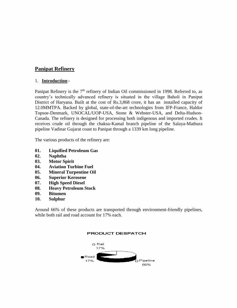
The various products of the refinery are:
01. Liquified Petroleum Gas
02. Naphtha
03. Motor Spirit
04. Aviation Turbine Fuel
05. Mineral Turpentine Oil
06. Superior Kerosene
07. High Speed Diesel
08. Heavy Petroleum Stock
09. Bitumen
10. Sulphur
Around 66% of these products are transported through environment-friendly pipelines,
while both rail and road account for 17% each.

Panipat Refinery meets demands of petroleum products not only of Haryana but also the
entire Northwest Region including Punjab, J&K, Himachal, Chandigarh, Western U.P.
and part of Rajasthan and Delhi.
Expansion Projects At Panipat Refinery
The project to increase the capacity of Panipat Refinery to 12 MMTPA is already
completed, which also takes into account future fuel quality requirements.
1. PXPTA at Panipat Refinery The project envisages putting up of facilities at Panipat Refinery for separation of para-
xylene from 110-150 degree C Naphtha cut by pooling the feedstock from Mathura and
Panipat Refineries. The project considers facilities like splitter, reformer, extraction plant,
and toluene disproportion plant besides utilities for production of para-xylene.
Project Cost: Rs. 5104 crore
Expected Commissioning: August 2006
On implementation, the production of para-xylene/PTA will result in import substitution
and value addition besides having an export potential.
2. Panipat Refinery Expansion by 6 MMTPA The proposed facilities comprise an additional CDU of 6 MMTPA along with
Hydrocracker, Delayed Coking Unit, Diesel Hydrotreater, Hydrogen Plant and Sulphur
Recovery Plant.
Project Cost: Rs. 4165 crore
Commissioned: June 2006
THE VARIOUS UNITS ARE:
1. Atmospheric and Vacuum Distillation Unit(AVU)
2. Continuous Catalytic Reformer Unit(CCRU)
3. Visbreaking Unit(VBU)
4. Hydrogen Generation Unit(HGU)
5. Resid Fluidized Catalytic Cracking Unit(RFCCU)
6. Once Through Hydrocracker Unit(HCU)
7. Diesel HydroDeSulphurisation Unit(DHDS)
8. Amine Regeneration Unit(ARU)
9. Sour Water Stripper Unit(SWSU)
10. Bitumen Blowing Unit(BBU)
11. Sulphur Recovery Unit(SRU)

1.1 Atmospheric and Vacuum Distillation Unit(AVU)
AVU is designed to process 6.0 MMTPA Bombay High and Arab Mix crudes in blocked
out operation. AVU, a fully integrated unit, consists of the following sections. Crude
Distillation Unit, Vacuum Distillation Unit, Naphtha Stabiliser, Naphtha Splitter, Mineral
Turpentine Oil Splitter, LPG Vaporizer, and Treating Units for Fuel Gas, LPG and
Naphtha.
The Unit was mechanically completed in February 1998 and trial operation of the various
sections started in phases starting from May 1998. The Unit was commissioned on 2nd
October 1998.
1.2 Continuous Catalytic Reformer Unit(CCRU)
M/s. IFP, FRANCE licenses the CCRU. This unit is designed to process 0.5 MMTPA of
SR Naphtha from Arab mix and/or Bombay High crude.
This unit consists of Naphtha Hydro Treating, Catalytic Reforming and Catalyst
Circulation and Regeneration Sections.
1.3 Visbreaking Unit(VBU)
Visbreaking Unit (VBU) is designed to process 0.4 MMTPA Arab mix vacuum residue.
This unit is a soaker Visbreaker, which reduces the viscosity of feed at lower
temperature.
The unit was mechanically completed in March 1998 and the trial operation started in
July, 98. The unit was commissioned on 29th October 1998.
1.4 Hydrogen Generation Unit(HGU)
The Hydrogen Generation Unit is designed for the production of 38,000 Metric Tonne of
Hydrogen per year. This unit is licensed by M/s. Haldor Topsoe-Denmark, which consists
of DeSulphurisation, Reforming and CO-conversion sections. With PSA system of M/s.
UOP-Belgium, Hydrogen requirement with purity of 99.9% vol. produced. These units
have been provided to cater the Hydrogen requirement of Hydrocracker unit as well as
Diesel Hydro DeSulphurisation Unit (DHDS). The unit was mechanically completed in
November 1998 and was commissioned on 11th February 1999.
1.5 Resid Fluidized Catalytic Cracking Unit(RFCC)
This is the first Resid Fluidized Catalytic Cracking Unit (RFCC) unit in the country;
capacity of the unit is 0.7 MMTPA. The unit is licensed by M/s. Stone and Webster

Engineering Corporation Limited-USA. The unit was mechanically completed in
November 1998 and commissioned on 28th January 1999.
1.6 Once Through Hydrocracker Unit(OHCU)
The capacity of the unit is 1.7 MMTPA and is the highest capacity Hydrocracker Unit in
the country. This unit is designed to convert vacuum gas oil to middle distillates and FCC
feed stock. The unit is licensed by M/s. UNOCAL/UOP-USA and is designed to operate
at a pressure of 162 kg/cm2g and 4200C. It has 3 reactors, each weighing about 500
Metric Tonne and wall thickness of 256mm to take care of this high pressure. The unit
was mechanically completed in November 1998 and was commissioned on 26th April’99.
1.7 Diesel HydroDeSulphurisation Unit(DHDS)
DHDS unit has been designed to reduce the sulfur content in High Speed Diesel to less
than 0.05% wt. The process technology for this unit was built within the record time on
LUM SUM TURN key (LSTK) basis by M/s. L&T. The capacity of the unit is 0.7
MMTPA. The unit was mechanically completed in March’99 and commissioned on the
12th July.
1.8 Amine Regeneration Unit(ARU)
ARU is designed to process Hydrogen Sulfide rich amine from amine Absorption units
and recover amine after releasing the acid gas to the Sulphur Recovery Unit. This unit
was mechanically completed in February’99 and was commissioned on 6th March’99.
1.9 Sour Water Stripper Unit(SWSU)
The unit consists of 2 Sour Water Stripping Units, one for the sour water from the
Hydrocracker unit and the other for the sour water from the remaining units. This unit
was mechanically completed in December’98 and was commissioned on 15th
February’99.
1.10 Bitumen Blowing Unit(BBU)
Bitumen Blowing Unit (BBU) has been designed to produce 3 grades of Bitumen, viz.:
80-100, 60-70 and 30-49 from vacuum residue of high Sulfur Crudes. The capacity of the
unit is 0.5 MMTPA. This unit was mechanically completed in March 1998; trial run of
the unit was taken in July 1998 and was commissioned on 12th December 1998.
1.11 Sulfur Recovery Unit(SRU)
SRU is designed to process Hydrogen Sulfide rich acid gas recover elemental sulfur. The
unit was designed by M/s. EIL for a capacity of 84tonnes per day 96% recovery

efficiency, which has further been revamped to 115 tonnes per day and 99% recovery
efficiency based on the process technology of M/s. Delta Hudson, Canada. This unit was
mechanically completed in March’99 and was commissioned on 30th March’99.
1.12 Other Facilities :
1.12.1 Offsites
The offsites facilities at Panipat Refinery are spread over an area of 115 acres. There are
77 Storage tanks having storage capacity of 400,000KL Crude Oil and 830,000KL of
Petroleum products. There are 7 nos. of pump stations, a blending station and connecting
pipelines. There are 7 nos. of LPG Horton Spheres each of 1500KL capacity. The offsites
operation is controlled from the centralized DCS control room of OM&S. The special
feature of offsite operation is that Tank Truck loading (TTL) and Tank Wagon Loading
(TWL) facilities are provided at the Marketing Terminal, which is adjacent to the
refinery. Offsite operation of the Refinery started with the receiving of the first batch of
crude oil in Refinery Storage Tanks on 30th November’97.
1.12.2 Thermal Power Station & Utilities
The Power and Steam requirement of the refinery is met from the Captive Power Plant
designed and constructed by BHEL in consultation with NTPC. Capacity of the power
plant is:
Steam Turbine Generator – 3 x 25 MW.
Gas Turbine Generator – 30 MW.
Steam boiler – 3 x 160 T/hr.
Heat Recovery Steam Generator: 125 T/hr.
The first boiler was commissioned in May’97 and first TG was commissioned in
August’97.
1.12.3 Nitrogen Plant
Nitrogen is produce in a cryogenic separation plant by air distillation after liquefying the
same. M/s. BHPV constructed the plant on a turnkey basis. The capacity of the plant is
800 NM3/hr. The plant was commissioned on December’97.
1.12.4 Miscellaneous
One raw water reservoir of capacity 200,000KL Raw water treatment plant of capacity 2100KL/hr. Four chains of DM Water treatment plant Compressed air system with 4 nos. of compressors and 3 nos. air drier. Cooling tower with 5 cells for TPS and 8 cells for process units.

Atmospheric and Vacuum Unit
1. Introduction
Atmospheric and vacuum unit is considered to be the mother unit of the refinery as it
converts the crude into several products and feed for the other units.
1.1 Sections in the Unit: AVU consists of following sections. .
a) Crude desalting section.
b) Preflash section.
c) Atmospheric Distillation section.
d) Stabiliser section.
e) Naphtha splitter and Caustic wash section.
f) MTO splitter section.
g) Vacuum Distillation section.
h) LPG Amine & caustic wash section.
i) Centralised Sour Fuel gas Amine treatment section.
j) LPG vaporiser section.
1.2 Products Extracted from Cdu/Vdu Main Columns
S.no Short name Long name Cut range º c Usage
1. GAS Fuel gas C1-C2 Internal fuel
2. LPG Liquefied Petroleum Gas C3-C4 Domestic fuel Gas
3. NAP Naphtha C5-120 MS Component
4. HN Heavy Naphtha C5-120 HSD Component
5. KERO Kerosene 140-270 Domestic fuel
6. ATF Aviation Turbine Fuel 140-240 Aeroplanes
7. LGO Light Gas Oil 240/270-320 HSD Component
8. HGO Heavy Gas Oil 320-370 HSD Component
9. VD Vacuum Diesel 370 HSD Component
10. LVGO Light Vacuum gas Oil 370-425 Feed to HCU/FCCU
11. HVGO Heavy Vacuum Gas Oil 425-550 Feed to HCU/FCCU
12. V.SLOP Vacuum Slop 550-560 IFO Component/ feed
to RFCCU
13. VR Vacuum Residue 560+ Bitumen/ VBU feed
1.4 Other Products
1) C5-90 º C cut: Naphtha splitter overhead product for feed to Hydrocarbon unit.
2) 90-120 º cut: Naphtha splitter bottom product for feed to Reformer.
3) MTO: Mineral turpentine oil ex MTO splitter middle.
4) HY. KERO: MTO splitter bottom (BH) product mainly used as a cutter stock
for VB fuel Oil & FFS.

2. Process Description
SH Steam
Crude Filter Desalter
Furnace
Atmospheric
Column
Unstablised Gasoline
Inter Naphtha
Heavy Naphtha
Kerosene/ATF
Light Gas Oil
Heavy Gas
Oil
SH Steam
Atmospheric Residue
Non-Condensable
Vacuum Residue
Heavy Vacuum
Gas Oil
Light Diesel Oil
Light Vacuum
Gas OilVacuum
Column
Fig. Block Flow Diagram of AVU

2.1 Feed Supply
Crude oil is stored in eight nos. storage tanks located in offsite area, each tank having a
nominal capacity of 50,000 KL. Booster pumps located in offsite area are taking suction
from one of these tanks and delivering crude to suction of unit feed pumps.
2.2 Feed Pre-Heat Circuit
Crude oil from crude charge pumps is charged to preheat exchanger trains in two parallel
streams. Provision has been kept to inject caustic and demulsifier solution at suction of
crude charge pumps.
Crude oil is heated upto 136-141º c in the first preheat train of heat exchangers operating
in two parallel sections.
2.3 Desalting
The process of desalting consists of three main stages viz. heating, mixing & separation.
The desalter in an electrostatic coalescer used for purification of crude from sludge, salts
and corrosion inducing salts. Sludge and salts like NACI generally gets deposited on the
tubes of exchangers and thus reduces preheat temperature. Salt if not removed will cause
corrosion in distillation column
These water-soluble impurities are brought along with the residual water content into the
crude oil. Much of the sediment also may be associated with this dispersion of water.
Water drops ordinarily are so small that gravity would require a prohibitively long time to
draw all of the drops to the bottom of a storage tank, even if the tank were free from
convection currents. Moreover this water dispersion, or in other words, the emulsion
received at the Refinery has been ‘aged’ over an extended period by stabiliser. These
stabiliser are molecules or groups of molecules, asphalts, etc. in the oil that are least
similar to the bulk oil (i.e. least similar to the most prevalent oil molecular species), and
therefore subject to less intermolecular force. Being less attracted to the internal body of
the oil, the exceptional material will be rejected to the interface of the oil water drops.
Such rejected surface active materials comprise a physical barrier that prevents water
drops getting close enough to bring about coalescence. Before the drops can coalesce,
therefore the stabiliser film must be reduced in thickness and tenacity, and ruptured. An
effective means for aiding this is heat. Heat increases the solvency of the bulk oil for the
stabiliser, reduces the viscosity of the oil and decreases the viscosity and cohesion of the
film. These effect though very much beneficial are normally not adequate to permit
coalescence.
Furthermore, another important consideration is that the chance of collision among drops
in this space population of drops is relatively few. The limitation of distance between
drops is dealt with by dispersing about 5% of fresh water to the oil. Thus the water has
been increased about 25 times and the distance between drops surfaces reduced by 10.
Even so, the added water is not likely to combine with a satisfactory portion of the brine
particles and coalesce effectively without additional means.
In desalting, the electric field is a powerful tool for overcoming the resistance of
stabilizing films. The collision and coalescence of drops is accomplished by an induced
dipole attraction between them. That is the electrical charges inherent in each droplet are

separated so that positive charges move to one end of the droplet and negative charges
move to the other end.
As droplets then approach each other, the force between them becomes very great. The
stabilizing films are squeezed between drops and coalescence is rapid. In a 5% emulsion,
drops average about two diameters apart; coalescence proceeds almost instantaneously.
The distance between drops then increases as drops fall due to gravity. For a 1 percent
emulsion, drops are four diameters apart and coalescence slows. When the emulsion
content is 0.1%, drops are eight diameters apart on the average. The forces of dipole
attraction, diminished by a factor of 250, are insignificant at this distance and the final
emulsion content shall depend on this to about 0.1%.
A two-stage bielectric desalter has been designed for 99% salt removal with an outlet salt
PPM of <0.1% wt. at outlet. It is designed to use stripped sour water for desalting which
is being taken ex stripped sour water unit. Provision to use DM water/service water is
also provided the desalter water vessel is maintained by level indicator controller. 2nd
stage desalting pumps are used for injecting stripped water into crude line upstream of 2nd
stage mixing valve under flow control after heating it with hot brine from the 1st stage
desalter in an exchanger. The 2nd stage aqueous phase is transferred to 1st stage desalter
by pumps under interface level control.
Then the desalted crude is further heated to 180ºc in the 2nd pre-heat train.
2.4 Crude Pre Flashing
Crude oil at 179-180º C enters pre-flash drum where 3-4% wt. of light ends are removed.
The flashed vapor is sent to flash zone of and also provision is there to route it to Hy.
Naphtha section of crude column. Crude after flashing in the preflash drum is pumped
through 3rd preheat train where it gains temperature upto 259-289ºc.
2.5 Fired Heater
The preheated crude is further heated and partially vaporized in Atmospheric Heater
having eight passes. (Four sections with 6 inches sch. 40 tubes).
The atmospheric heater is a box-type vertical furnace with up firing burners, 8 Nos. of
burners in each section are provided on the floor with FG and FO firing facilities. A total
32 nos. of burners have been provided in CDU heater. Out of 32 burners, 28 nos. of
burners have both FO and FG firing facility and 4 burners, called LP burners have facility
to fire off- gas from VDU column and FG (called support burners).
This heater is having two distinct heating sections i.e.
A) Radiant Section: It houses the burners and forms the combustion chamber or fire
box. Tubes are arranged in a vertical arrangement along the walls of each cell with tube
arrangement itself forming the cell.
B) Covection Sections: It receives heat from hot flue gases leaving the radiant section.
Tubes are arranged in horizontal bank and positioned above radiant section.
Preheated Crude oil enters the convection section in eight passes. Convection outlet of
each pass again enters the Radiation Zone of furnace. The floor of the furnace is
elevated above grade and the hot air duct supplying combustion air to burners runs
across the length of the furnace.
A return line is provided on fuel oil header to the burners of each furnace to maintain
desired circulation flow to avoid dead end of the header and associated problems i.e.
difference in pressure availability between extreme end burners, congealing of stagnant
portion etc. Shut down valves are also provided on the main fuel gas, IFO (S) & IFO(R),
support burners of LP gas burners respectively. These shutdown valves shall be
activated w.r.t trip logic’s provided.
Peep holes are provided on side walls of the furnace to inspect all radiant section tubes.
24 Nos. of soot blowers are provided to keep the convection bank clean.
Furnace has total 32 low Nox burners. Each cell has 8 burners along the center line of
the cell. One central burner is for combination fuel gas & hot well off gases firing while
the balance burners are for combination IFO & FG.
Air Pre-Heater Section
To recover the waste heat from fuel gases, two sets of cast and glass air preheaters in
parallel are provided along with two forced draft fans for air and one induced draft fan
for flue gases.
An air bypass damper to bypass APH is provided for bypassing the
combustion air, either partly or fully.
2.6 Crude Distillation Section
The column is provided with 56 trays of which 10 are baffle trays in the stripping
section. In addition 6 nos. of chimney trays are also provided in the column. Feed to the
column is on tray # 10. The vaporised portion of the feed along with the light ends from
the Preflashing Vessel are fractionated on trays above the flash zone to yield liquid side
draw products, pumparounds (circulating refluxes) and overhead vapor stream.
Heated and partly vaporised crude feed coming from fired heater enters the flash zone of
the column at tray no. 10 at 360-370 º C (LS crude)/370-380º C (HS crude).
Hydrocarbon vapours flash in this zone and get liberated. Non flashed liquid moves
down which is largely bottom product, called RCO. Certain degree of over flashing of
crude is desirable for proper stabilisation of RCO and fractionation of gas oil
components. Over flash is achieved by setting up COT at slightly higher value than
actually required. This over flashed material mostly condenses on 11th tray. The
condensed liquid withdrawn from 11th tray is put back on 10th tray into the column. Over
flash liquid travels down form tray 11 to tray 10. It strips out heavier vapour components
coming up from RCO stock collected at column bottom and which otherwise could
move and cause coloration of gas oil stream. Flow of over flash liquid could be

increased by either increasing COT or condensing more material on 11th tray or by
reducing HGO draw off and dropping more HGO components on 11th tray. However,
this will result is less gas oil yield and higher energy consumption without any
advantage. Too large flow of over flash liquid may result in drop in bottom temperature
and lighter bottom product, RCO.
MP steam having some degree of superheat is introduced in the column below tray 1, at
approximately 3.5 Kg/Cm2 (g) and 290º C for stripping of RCO. Steam stripping helps
to remove lighter constituents from the bottom product RCO by reducing their partial
pressure and helping them vaporise without requiring additional heat. Hydrocarbon
vapours liberated by flashing move up along with steam in the column for further mass
transfer at trays in upper section.
Reduced crude oil product is collected at bottom of the column.
3. Atmospheric Column Outlets
3.1 Over Head Section
The overhead vapours are totally condensed in Crude Overhead Air Condensers and trim
condenser. This condensed overhead product is separated as Hydrocarbon and water in
the Reflux Drum. Water is drawn out under inter-phase level control and sent to sour
water stripper or to ETP. Unstabilised naphtha containing Fuel Gas, LPG and Naphtha is
partially refluxed and partially pumped to the Stabilizer. Reflux demand is set by
column top temperature. The column overhead pressure is maintained by split range PIC
control with FG back up & flare connections.
3.2 Heavy Naphtha Section
Heavy Naphtha is with drawn as side product from tray # 44 to the Side Stripper. Light
ends in Hy. Naphtha are stripped in the Hy. Naphtha Reboiler using LGO as the hot
medium. Stripped vapours from the side stripper are routed to tray # 46 of the
Atmospheric Column. Hy Naphtha under flow control cooled in Hy Naphtha /BFW
Exchangers followed by a trim cooler and sent to storage.
3.3 Kero Section Kero is withdrawn as side product from tray # 31 to the Kero side stripper under level
control. Light ends in Kero are stripped in the Kero Reboiler using HVGO CR as the hot
medium. Stripped vapours from the side stripper are routed to tray # 33 of the
Atmospheric Column. The bottom product is routed to MP Steam Generator followed by
LMP Steam Generator and Crude Preheat exchanger (to reduce vapour pressure & hence
increase available NPSH) before being pumped. The discharge is routed to crude preheat
exchangers and finally cooled in air cooler and trim cooler before being routed under
flow control to storage.
3.4 Light Gas Oil Section
LGO is withdrawn as side product from tray # 22 to the LGO side Stripper. Light ends
in LGO are stripped using MP steam. Stripped vapours from the side stripper are routed
to tray # 24 of the Atmospheric Column. The bottom product is pumped through Hy.

Naphtha Reboiler, Crude preheat exchangers and finally cooled in tempered water
exchanger , air coolers and trim cooler before being routed to storage.
3.5 Heavy Gas Oil Section HGO is withdrawn from tray # 15 to the HGO side stripper under level control. Light
ends in HGO are stripped using MP steam. Stripped vapours from the side stripper are
routed to tray # 18 of the Atmospheric Column. The bottom product is routed to preheat
exchanger (to improve NPSH available) before being pumped through preheat
exchangers, tempered water exchanger and coolers before being finally routed to storage
on Flow Control.
3.6 Reduced Crude Stripped RCO drawn from the bottom of is pumped by RCO pumps to the Vacuum heater
of vacuum Distillation Unit on Level control. Single pump will operate during turndown
operation for both AM/BH operations. Starts up lines connect RCO to VR pump
discharge line.
3.7 Circulating Refluxes
In order to maximise heat recovery and balance tower loadings, heat is removed by way
of circulating reflux (or pump arounds) from each of the sections. These pump arounds
are withdrawn and pumped through preheat train for maximum heat recovery, thus
cooling these streams. Duty controllers are provided for removing the requisite duty.
HGO CR is used to reboil the Stabilizer Bottom in the Reboiler. LGO CR is used for
generating LP Steam. For turndown operations single pump will operate for
HN/Kero/LGO/HGO CR pumps.
3.8 Naphtha Stablizer and Caustic Wash Sections
Unstabilised Naphtha from Crude Column overhead is pumped to the Naphtha Stabilizer
after preheating with stabilizer bottoms in the Feed/Bottom exchanger. A bypass of 03-E-
52 has been provided to maintain NSU feed temperature in the range of 85-90 º C and
stabiliser feed temperature about 125- 128 º C. This column has 40 trays with feed
entering on the 21st tray. Necessary heat to reboil is provided by HGO-CR to the
Horizontal Thermosyphon Reboiler on Flow control (opposite acting). Temperature on
tray # 3 regulates HGO CR flow through the reboiler.
A) LPG
Stabiliser overhead vapors are condensed in the overhead condenser and then flow into
the reflux drum. Any water present with the overheads and separated in the Reflux drum
and part of Hydrocarbons refluxed. The balance (LPG) is pumped to Caustic & Amine
treating Unit for treatment
Fuel Gas generated during BH/AM operation is routed to Amine Treatment Unit (located
within CDU/VDU unit) to remove H2S before being routed to the Fuel gas KO Drum and
then to the plant Fuel Gas Distribution Header.

B) Stabilized Naphtha
Naphtha from stabiliser bottom after exchanging heat with feed Naphtha is routed to the
Naphtha Splitter. In case naphtha splitter is shutdown, the stabilised naphtha is cooled
and sent to rundown through CRU naphtha caustic wash system.
3.9 Naphtha Splitter Section
In the Naphtha Splitter, stabilized Naphtha is split to C5-65/90º C and 65/90-120/140 ºC
cuts as overhead and bottom product respectively. This column has 26 trays with feed
entering on 12th tray. Provision to route feed to tray # 16th and 9th are also provided.
A) Naphtha Overhead Product The overhead vapour is condensed in Air cooler and the condensed product flows to
the reflux drum from where a part is refluxed back to the column. This overhead
product is further cooled to 40º C before being routed to storage via Caustic Wash.
B) Naphtha Bottom Product
The bottom product is cooled in air cooler followed by heat exchanger to 40 º C
before being routed to storage via a separate caustic wash on FIC/LIC control.
C) Naphtha Splitter Fired Reboiler (Furnace) The heat for reboiling is provided by a fired heater 03-F-002. The heater can be fired
with FO/FG or combination fuel. Vacuum heater and Naphtha Splitter fired reboiler
share a common Air preheating system. . For better control Coil Outlet Temperature,
the principles of pass balancing is used. This is a vertical cylindrical Heater having
six flows passes. The radiant section is provided with 6” Sch. 40 tubes having two 8”
Sch. 40 tubes as last and second last tubes at the outlet of each pass while the pass
while the connection section is provided with 6” Sch. 40 tubes. The radiant section
tubes are disposed in a vertical arrangement along the walls of the combustion
chamber.
The heater is provided with 12 forced drafts, low Nox combination fuel fired burners
(fuel oil & Refinery fuel gas). These burners are arranged in a circle and are fired
vertically upward from the floor.
A combined air preheater system containing one cast Air preheater and one Glass Air
preheater alongwith two forced draft fans and one induced draft fan is provided for both
Vacuum Heater and Splitter Reboiler.
D) Naphtha Caustic Wash Units The Naphtha Splitter overhead Product & the Bottom product are Caustic washed to
remove H2S, phenols and mercaptans in two separate wash facilities.
3.10 MTO Splitter Section

Part of Kero/ATF, upstream of the Product Rundown Control Valve is pumped to the
MTO Splitter after exchanging heat with MTO bottom product (Hy. Kero). The balance
heat required is provided by HVGO CR in the Horizontal Thermosyphon Reboiler on
flow control (opposite acting).
The column is designed with 26 trays with feed entering on the 10th tray. Provision to
route the feed to the 8th tray is also provided.
a) MTO Splitter Overheads
The overheads are condensed in a tempered water Exchanger and routed to the Reflux
Drum from where a part of the condensed products is refluxed and the rest pumped to
Kero/ATF rundown line after cooling.
b) MTO Products
This product is drawn from a total draw tray below tray # 19. A part is refluxed and the
balance cooled before being rundown to storage.
c) Heavy KERO
The bottom product is pumped and finally cooled and routed to storage on flow control.
During AM operation this product is blended with Kero/ATF in the rundown line.
4. Vacuum Distillation Unit
Hot RCO from the atmospheric column bottom at 355/365º C is mixed with slop recycle
from Vacuum Column, heated and partially vaporised in the 8-pass Vacuum Furnace
and introduced to the flash zone of the Vacuum Column . The flash zone pressure is
57MM. Velocity Steam (MP) is injected into individual passes and regulated manually.
3-injection points have been provided on each pass. This is to maintain required
velocities in the heater passes and to prevent coking at high coil outlet temperatures. The
heater can be Fuel Gas, Fuel Oil or Combination fuel fired..
This is a twin cell cabin heater provided with eight flow passes. The radiant sections of 5:
sch. 40 tubes having 8” Sch. 40 tubes as last tubes and 6” Sch. 40 as second last tube at
the outlet of each pass while the convection section is provided with 5” Sch. 40 tubes.
The radiant section tubes are arranged horizontally along the side walls and arch of each
cell of combustion chamber. The common convection section has horizontal bank of
tubes positioned above the combustion chamber.
The heater consists of 24 forced draft, low Nox combination fuel fired burners (both fuel
oil and refinery fuel gas). Each cell is provided with 12 burners fired vertically upshot
from furnace floor along the centerline of the cell. Convection section is provided with 16
nos. of soot blowers, which are controlled by automatic sequential control panel from
grade level.
A combined air preheating system has been envisaged for Vacuum heater and Naphtha
Splitter Reboiler Furnace for maximum energy recovery.
4.1 Vacuum Column
The vaporised portion entering the flash zone of the column along with stripped light
ends from the column bottoms, rise up in the Vacuum column and is fractionated into
four side stream products in 5 packed sections. The Hydrocarbon vapours are condensed
in the HVGO, LVGO, and Vac. Diesel sections by circulating refluxes to yield the side
draw products.
The column has been provided for achieving low-pressure drop. Random packings have
been provided inside the column with combination bed in the slop (wash) section.
Demister pads have been provided above the wash zone to prevent asphaltenes carry over
and at the top, to minimize carry over of hydrocarbons to the ejector section. The
stripping section is provided with 10 baffle trays.
5. Vacuum Column Outlets
5.1 Vacuum Diesel Vac. Diesel is drawn from the top most packed section along with Circulating Reflux
(CR) and internal Reflux (IR) from Chimney tray below the Bed # 1 IR is returned to the
LVGO section (bed#2. The CR is returned to the top of the Vac. Diesel packing (Bed#1)
after exchanging heat. Higher overhead temperature would lead to high Hydrocarbon
carry over to ejector.
Slop oil from hot well is also joining to the vacuum diesel at rundown. Facility has also
been provided to route hot vac. diesel to DHDS feed
5.2 Light Vacuum Gas Oil This section comprises of two beds # 2, and # 3, for fractionation and heat transfer
respectively. LVGO is drawn along with CR and from Chimney tray # 2. It is combined
with HVGO CR & routed to the HVGO packing bed # 4 through spray nozzle distributor.
CR is returned to the top of the bed # 3 after exchanging heat with Crude in exchanger.
Product goes through crude preheat exchanger before exchanging heat with tempered
water exchanger.
5.3 Heavy Vacuum Gas Oil HVGO is drawn from the Chimney tray # 3 below bed # 4 along with CR and IR by
HVGO pumps. The IR is returned to the wash zone (Bed#5) through spray distribution
nozzles, on flow control to maintain the required irrigation rate of 0.7-0.3 gpm/ft2 on the
wash bed. The CR is used to reboil MTO and kero stripper and crude preheat train
exchangers, before being returned to the top of HVGO section on flow control. HVGO
product goes through crude preheat exchangers and TW exchanger before being routed to
storage.
5.4 Vacuum Slop
This section is a combination bed with demister pad provided above the wash zone to
prevent asphaltenes carry over. Slop distillate is withdrawn from chimney tray # 4 below
bed # 5 along with slop recycle on gravity to to the slop quench vessel. Slop distillate is
drawn from to the slop quench vessel by slop + recycle pumps. Slop recycle is routed to
Vacuum Heater. The slop product and quench is routed through crude preheat exchanger
and MP stream generator and tempered water exchanger. A part of this stream is routed
to the slop quench vessel.
5.5 Vacuum Residue
The liquid portion of the feed drops into the bottom section of the tower and is with
drawn as Vacuum Residue. MP Steam is used for stripping. In view of steam requirement
for BH operation being very low, separate control valves are provided in parallel for AM
and BH operations. The tower bottom temperature is kept at 350º C to reduce possible
cracking during holdup in the tower by quenching with cooled VR. Quenching is
achieved by returning a quench stream to the tower at a temp of 250º C after heat
exchange with crude in preheats train.
Split range Control Valve bypassed during AM operation. During BH operation it
ensures rundown temperature of 120º C. VR is used to generate LP Steam, before being
cooled in TW exchangers and finally sent to storage.
5.6 Overhead System
Vacuum is maintained by a 3-stage ejector system with surface condensers. The Vacuum
column overhead vapours are routed to the 1st stage ejectors. The outlet from the 1st stage
goes directly to the 1st stage inter condenser. Uncondensed vapours from 1st stage inter
condenser are routed 2nd stage ejector. The outlet from the 2nd stage ejector is routed to
the 2nd stage inter condenser from where the uncondensed vapours are sent to the 3rd
stage ejector system. The discharge of the 3rd stage goes to the after condenser.
The condensed portion from the condensers are routed to the hot well from where the non
condensable are sent to the Crude furnace low pressure burners or vented to the
atmosphere. Condensate from the hot well is pumped to the sour water stripper unit or to
WWTP by sour water pumps. Any oil which is carried over along with the steam
condensate is pumped to the Vacuum diesel run down line by slop oil pumps
intermittently after removing any traces of water in the coalescer. Provision has also been
provided to route the hot well slop oil to hot feed line to DHDS as well as to DHDS feed
tank.
Continuous Catalytic Reforming Unit
1. Introduction
Catalytic Reforming is a major conversion process that transforms low octane Naphtha feed
stock to high octane reformate (RON : 98) for use as a gasoline blending component to
make lead free petrol (MS). A rich hydrogen gas (about 90% purity) and LPG are obtained as

valuable by- products. The reformer can also be run for production of reformate rich in
benzene, toluene, and xylenes (BTX).
The catalytic reformer at Panipat Refinery uses continuous catalyst regeneration (CCR)
technology under the trade name Octanizing.
2. Process Description In a CCRU, the Naphtha feed after adequate hydrotreatment is passed over a slow moving
bimetallic catalyst bed in a series of adiabatic reactors in presence of hydrogen under low
pressure and high temperature conditions. The catalyst is continuously circulated and
regenerated in a Regenerator. The reformate obtained is then stabilized and routed for blending
into MS pool. The hydrogen rich gases produced in reformer are recycled partly to reformer and
balance to the naphtha hydrotreatment section and Hydrogen unit.
LPG
Reformate
H2 Rich Gas
Fuel Gas
LPG
Absorber
StabliserRecontacting
Drum
Hydrotreater Recycle
Gas Compressor
Hydrotreater
Naphtha
Feed
Seperator Stripper
Reforming
Reactors
Seperator
Purge to
ATU
Recycle Gas
Compressor
H2 Rich Gas
Compressor
Hydrotreated
Naphtha
Storage
At Panipat Refinery, Catalytic Reformer includes following three sections:
1. Naphtha Hydrotreating
2. Catalytic Reforming
3. Catalyst circulation and regeneration
2.1 Naphtha Hydrotreating
Fig. Process Flow Diagram of CCRU

The objective of this section is the elimination of the poisons or undesirable compounds
contained in the feed which contaminate the reformer catalyst and inhibit its metallic and acidic
functions.
These poisons are: Sulfur, Nitrogen compounds, Halogens, Oxygen, Water, Metals and the
undesirable compounds are Diolefins, Olefins.
Hydrotreatment is a catalytic process based on IFP's technology involving
HydroDeSulphurisation and hydrodenitrification reactions, which are carried out in a fixed bed
axial reactor in presence of hydrogen. The hydrotreater feed is a mixture of straight run
naphtha, hydrocracker naphtha and vis-breaker naphtha. Recycle H2 is mixed with the feed prior
to its entering the reactor. The major contaminants like S,N, O are converted to H2S, NH3 or
H2O respectively in the hydrotreater reactor. The liquid product from reactor is then stripped to
remove H2S, water, NH3 and light hydrocarbons in a stripper column. The stripper bottom
(Hydro- treated Naphtha) is then directly fed to the Reforming Section or routed to storage.
2.1.1 Chemical Reactions
All the reactions described below take place on a Nickel-molybdenum catalyst in presence of
hydrogen. Generally hydrogen is consumed during these reactions. Mainly two different kinds
of reactions occur.
Hydrorefining
Hydrogenation
Hydrorefining : Elimination by production of volatile compounds
A. Sulfur (Desulfurisation)
R-SH + H2 RH + H2S
R-S-R + 2 H2 RH + RH + H2S
R-S-S-R + 3 H2 2RH + 2 H2S
B. Oxygen
Oxygen or oxygen compounds modify the acidic function of the reforming catalyst. They are
eliminated by production of water. The oxygen compounds of a straight run are peroxides and
phenols.
OH
+ H2 + H2O
Hydrogenation: 1. Olefinic hydrocarbons at high temperature provoke coke deposit on the aromizer (or reformer)
catalyst as well as in the furnaces coils. They are eliminated by transformation into paraffins.
2. Aromatics hydrogenation occurs as a consequence of temperature and hydrogen partial
pressure.

Role of the catalyst: Cobalt-molybdenum and Nickel molybdenum catalysts are used to promote the
hydrodesulfurization and hydrodenitrification reaction.
Active form of the catalysts is their sulphided states. The active sulfide form is maintained, in
normal operation, by the partial pressure of H2S in the reactor.
Process Variables
a) Temperature
b) Space velocity
c) Hydrogen partial pressure or H2 recycle
d) Quality of the feed
2.1.2 Hydrotreater reaction section
A filter, 08-GN-00-101, to stop gums compounds, and an antipolymerization inhibitor
injection (to eliminate free radicals) are installed to eliminate the problems of fouling in
the pretreater.
The naphtha is introduced by means of pump 08-PA-CF-101 A/B under flow control
from a surge drum. The surge drum 08-VV-00-101 allows a steady feeding of the unit.
The feed is mixed with the recycle gas before being preheated in reactor feed/effluent
exchanger 08-EE-00-101A/B/C/D/E/F, heated up to reaction temperature in heater 08-
FF-00-101 and fed into the catalytic reactor 08-RB-00-101.
Reactor 08-RB-00-101 inlet temperature is controlled by fuel oil or fuel gas rate to the
burners of 08-FF-00-101. Hydrogenation, desulfurization and hydrotreating reactions are
conducted in pretreater reactor 08-RB-00-101.
The reactor feed effluent cooler is cooled down successively in 08-EE-00-101
A/B/C/D/E/F, then air cooler 08-EA-LP-101 and in water cooler 08-EE-00-102. The
make up gas, coming from catalytic reforming section, is fed at 08-EA-LP-101 inlet.
An online water injection is performed in order to wash the chlorides, sulfides and
ammonium salts which may deposit in solid form when the temperature is low.
In the pretreater separator drum 08-VV-00-102, in addition to the water settled, two
hydrocarbons phases are recovered:
* The hydrocarbons vapors
The most part of the hydrocarbons vapor phase represents the recycle gas which is taken
up by hydrotreater recycle compressor 08-KA-RP-101 A/B through compressor Knock-
out drum 08-VV-00-103.The other part of the vapor phase is sent under flow control to
the amine treating unit.
* The hydrocarbons liquids Are withdrawn under flow control reset by 08-VV-00-102 level control and sent to the
stripper 08-CC-00-101.
Before feeding 08-CC-00-101, the feed is preheated in 08-00-103 A/B feed/bottom
exchanger, against stripper bottom product.
Hydrotreater - Striping Section
The duty of the stripper is to eliminate from the reformer feed the light ends,
mainly the hydrogen sulfide.

An injection of corrosion inhibitor is performed in 08-CC-00-101 overhead product. Then
the vapors are condensed and cooled down in 08-EA-LP-102 air condenser and water
condenser and collected in 08-VV-00-104 stripper reflux drum.
A gas purge is done from 08-VV-00-104 under pressure control to the amine treating
unit. The condensed hydrocarbons are returned by stripper reflux pump 08-PA-CF-104
A/B under flow control reset by 08-VV-00-104 reflux drum level control to the
stripper 08-CC-00-101. The decanted sour water is recovered in 08-VV-00-104 boot and
can be purged to the sour water treatment.
Stripper bottom product, after cooling in 08-EE-00-103 A/B is sent to the reforming unit.
The heat necessary for stripper reboiling is supplied by 08-FF-00-102 stripper reboiler,
08-CC-00-101 bottom product is circulated to 08-FF-00-102 by pump 08-PA-CF-
105A/B. Partial vaporization occurs in 08-FF-00-102. Reboiling is controlled by 08-CC-
00-101 sensible tray temperature. Fuel oil or fuel gas can be used for 08-FF-00-102
firing.
3. Reformer & Regenerator
The objective of the Octanizing process is to produce a high octane number reformate which is a
main component of the gasoline pool and a hydrogen rich gas It includes two sections:
The naphtha catalytic reforming
The catalyst circulation and continuous regeneration
The reforming reactions take place in moving bed catalytic reactors from which the catalyst is
withdrawn, then regenerated and recycled. The catalyst circulation and regeneration are
performed on a continuous basis with full automatic control of all the operations. A high
temperature (in the range of 500 deg. C) is required to promote the chemical reactions, which
improve octane number. Hence the feed is heated up before entering the reactor. Moreover,
some of the desirable reactions are highly endothermic. This leads to splitting of the bulk of the
catalyst into several reactors with intermediate heaters.
The high performance of the Octanizing process is largely owed to low pressure operation which
in conventional fixed bed reactors would lead to very short cycle length. Hence Octanizing
involves continuous catalyst regeneration. Continuous regeneration eliminates the need of
shutdown for regeneration of the fixed bed reformers. It also minimizes the amount of catalyst
in the unit, while allowing high reformate yield and quality.
Main Products: There are essentially four primary products from the CCR Reformer:
High octane reformate stream,
Rich hydrogen gas stream,
Light reformate (benzene cut)
LPG stream (with or without C5)
There is an additional small secondary purge gas stream to fuel gas from the LPG

absorber drum. This is mostly C1, C2 light ends from the cracking reactions.
3.1 Chemical Reactions and Kinetics Naphtha feed to a CCR Reforming unit typically contains C6 to C11 paraffins, naphthenes and
aromatics. The purpose of this reforming process is to produce high octane aromatics from
naphthenes and paraffins either for use as a high octane gasoline blending component as in this
case or as a source of specific aromatic compounds.
Naphthenes convert rapidly and efficiently to aromatics. Paraffin’s do not under go conversion
easily, requiring higher severity conditions and even then conversion is slow and inefficient.
In this process conversion is achieved by passing the naphtha over a slow moving bimetallic
catalyst bed in adiabatic reactors, in the presence of hydrogen at relatively high temperatures
and low pressure In the CCR process, catalyst is withdrawn from the reaction section at a fixed
rate, regenerated in the continuous catalytic regeneration unit (CCR) and returned fresh to the
reaction section.
The rate of catalyst withdrawal and regeneration ensures a consistently high active catalyst with
a low carbon content and controlled chloride/water content. This maximises yields of both
reformate and H2 rich gas.
CR 201 Catalyst (catalytic reforming catalyst) The main features of CR201 catalyst are
High purity alumina support having strong resistance to attrition.
High selectivity and stability due to platinum associated with other metals (promoter).
High regenerability matching perfectly with continuous regeneration system.
Reactions:
1. Dehydrogenation of naphthenes The final step in the formation of an aromatic from naphthene is dehydrogenation:
The reaction is rapid and very endothermic. It is promoted by the metal catalyst function and
is favoured by high temp. and low pressure. Naphthenes are obviously the most desirable
feed components because in addition to being easy to promote they produce by-product
hydrogen as well as the aromatic hydrocarbon.
2. Isomerization of paraffins and naphthenes a) Paraffin isomerization occurs readily in reforming reactions. This reaction leads to an
increase in octane when rearranging to the corresponding branched isomer.
n-paraffin iso paraffin
b) The isomerization of a cyclopentane to a cyclohexane must occur as the first step in
converting the C5 naphthene to an aromatic.

Alkylcyclopentane Alkylcyclohexane
This isomerization involves ring re-arrangement and the probability of ring opening to form a
paraffin is high.
3. Paraffin dehydrocyclisation Paraffins dehydrocyclisation is the most difficult reforming reaction to promote. It requires a
difficult molecular rearrangement from a paraffin to a naphthene.
+ H2 + 3 H2
This reaction leads to a significant increase in octane number.
3.2 PROCESS DESCRIPTION IN BRIEF
Reaction section
Feed to the catalytic reforming section comes directly from the bottom of the hydrotreater
stripper after feed/bottoms exchange. A chloriding agent and water are injected before the
flow control valve for optimum reforming catalyst performance. After let down through the
feed flow control valve, the naphtha is mixed with recycle hydrogen from 08-KA-CF-201 in the
welded plate exchanger 08-EE-00-201. This is a true counter current exchanger designed for
minimum pressure drop and maximum heat recovery against reactor effluent. The combined
naphtha feed and recycle hydrogen are preheated here against the last reactor effluent and then
are further heated to the required first reactor inlet temperature in preheater 08-FF-00-201.
In the first reactor 08-RB-00-201, the reactions are predominantly endothermic and therefore
the
reactor effluent requires reheating in the first interheater 08-FF-00-202 to the required inlet
temperature of 08-RB-00-202. The reaction in 08-RB-00-202 are less endothermic but still
require reheating in 008-FF-00-203 before entering 08-RB-00-203. The effluent from 08-RB-
00-203 is cooled in 08-EE-00-201.
In the reactor the feed contacts the reforming catalyst which is divided approximately in the
ratio 15/25/60 in three different reactors. In the CCR process the catalyst circulates
continuously:
in the reactors, in the space between the external grid and the central pipe from the top to the
bottom.
from one reactor bottom to the top of the next one.
From the last reactor to the regeneration unit for regeneration.
from the regeneration unit, the regenerated catalyst returns to the 1st reactor.
In the regeneration unit, the catalyst is regenerated by means of an automatic regeneration
loop system. Catalyst circulation is achieved either by gravity flow or by gas lift systems.

Leaving 08-RB-00-203, the effluent after heat exchanging in 08-EE-00-201 against reactor feed,
is cooled by air and water exchange in 08-EA-LP-201 and 08-EE-00-202 respectively before
entering the separator 08-VV-201. Gas from the separator goes to recycle gas compressor 08-
KA-CF-201 and a part of the compressed gas is recycled to the reactors. The remaining gas
which constitutes the hydrogen production gas is routed to a compression and recontacting
section to improve hydrogen purity and recover liquid yield.
The separated liquid is pumped by 08-PA-CF-201A/B to be recontacted in the recontacting
section.
Compression and Recontacting section
The hydrogen production gas is routed to the H2 rich gas cooler 08-EE-00-203, the H2 rich
gas compressor K.O. drum 08-VV-00-202 and the two stage compressor 08-KA-RP-202 A/B.
An interstage cooler and knock out drum 08-EE-00-204 and 08-VV-00-203 are provided
between the stages to cool the compressed material and remove the condensed hydrocarbons.
The condensed liquid, on level control of 08-VV-00-202 and 203 is pressured back to the
reactor effluent at inlet of 08-VV-00-201.
The compressed hydrogen production gas is recontacted with the separated liquid from 08-PA-
CF-201 A/B.
The recontacted mixture is then cooled in three stages:
in water cooler 08-EE-00-205 (recontacting drum cooler)
in exchanger 08-EE-00-206 by exchanging heat with 08-VV-00-204 vapour effluent.
in exchanger 08-EE-00-207 by exchanging heat with 08-VV-00-204 liquid effluent.
by refrigeration with chilling medium in exchanger 08-EE-00-208.
Then the stream is fed into 08-VV-00-204 high pressure absorber.
The target temperature is 0 deg C at 25 kg/cm2g in recontacting drum 08-VV-00-204. The
conditions of the final stage separator for the hydrogen production gas are designed for:
a high recovery of the C3+ contained in the hydrogen,
a high concentration of hydrogen in the hydrogen rich gas product.
The separated liquid in the recontacting drum 08-VV-00-204 after heat up in 08-EE-00-207 is
pressured to the LPG recovery and stabilization section under level control.
Regeneration loop
Inert gas nitrogen is used as heat and reactant carrier in the catalyst regeneration loop. A
compressor ensures the gas circulation. At the discharge of 08-KA-00-301. The gas is split
into two flows.
The main flow, used in the two combustion zones is preheated in the feed/effluent exchanger
08-EE-00-301. Electrical heater 08-XY-00-301 allows for a precise adjustment of the
regenerator inlet temperature.
The gas, after preheating the spent catalyst in the top of the regenerator, flows through the two
radial beds.After coke burn off, the reaction heat is recovered in the feed-effluent exchanger 08-
EE-00-301.The secondary flow, used successively for calcination and oxychlorination is mixed
with air in order to reach a concentration of around 4 to 6% of oxygen, then heated through
feed/effluent exchanger 08-EE-00-302 and electrical heater 08-XY-00-302.

The calcination gas circulates upflow in an axial bed, is collected at the outlet, mixed with a
chlorination agent then circulates upflow through the axial oxychlorination bed.
After heat recovery in the feed effluent exchanger 08-EE-00-302 this gas is mixed with the
main flow. Then there is a mixing with the caustic recycle, the mixed phase is cooled down
in a trim cooler 08-EE-00-303 before entering in the caustic side compartment of the washing
drum.
The regeneration effluent gas is washed by contacting with a caustic solution. The liquid is
injected through a spray nozzle in the line located upstream the trim cooler. Contacting is
performed into a static mixer 08-M-00-303, right after the injection point. Final cooling is
done in the washing drum 08-VV-00-305.
Final washing is done in the washing drum by contacting water on bubble cap trays. The water
has two functions, washing of the gas and cooling. The gas coming out from the washing
drum goes through a dryer 08-LJ-00-301 then through a filter 08-GN-00-303 where the
eventual particles are trapped and finally back to the regeneration loop compressor 08-KA-00-
301. Pressure is controlled by means of gas purge from washing drum 08-VV-00-305. The
pressure of the regeneration loop is reset by the pressure of the first reactor
Visbreaker Unit
1. Introduction
The visbreaker is designed to process 400000 MTPA of Arab mix vacuum residue from a
crude mix of 50:50 Arab heavy and Arab light crudes. The unit consists of a two pass
heater and separation system. The products from the unit are fuel oil, gasohol, naphtha
and fuel gas.
Products
VB Gas 8200 MTPA
VB Naphtha 13600 MTPA
VB Gasohol 44800 MTPA
VB Tar (350 C) 333400 MTPA

2. Process
Visbreaking is essentially a mild thermal cracking operation at mild conditions where in
long chain molecules in heavy feedstocks are broken into short molecules there by
leading to a viscosity reduction of feedstock. During the cracking gas,, naphtha and gasoil
are produced as by products.
SHS
Soaker
AR
Quench
Fractionator
Unstablised
Gasoline
VB Gas Oil
2.1 Theory of Visbreaking
Heavy residues are a mixture molecules consisting of an oil phase and an asphaltene
phase in physical equilibrium with each other in colloidal form. During thermal cracking
the long molecules thus depleting the oil phase in the residue. While the asphaltenes in
the feed remain unaffected, additional asphaltenes may be formed by secondary
polymerisation reactions. At a certain and asphaltenes is disturbed and asphaltenes
precipitate. At this stage of conversion the product residue becomes unstable.
The viscosity reduction of a feedstock increases with increased conversion (yield of gas
and naphtha) upto a certain level, where maximum viscosity reduction is obtained.
Increase in conversion beyond this value leads to decrease in viscosity reduction. There is
a limiting conversion upto which a stable product can be obtained. Conversion beyond
this leads to an unstable product which is undesirable. The conversion at which viscosity
inversion takes place may be different for each feedstock and needs to be established for
Fig. Block Flow Diagram of VBU

each feedstock.
Asphaltenes, aromatic and paraffin content in the feedstock affect the limiting conversion
for a stable product in the following manner:
Higher asphaltenes lead to lower conversion.
Higher aromatics lead to higher conversion.
Higher paraffins lead to lower conversion.
2.3 Types of Visbreaking
A given conversion is visbreaker can be achieved by two ways:
High temp. low residence time cracking: Coil Visbreaking.
Low temp. high residence time cracking : Soaker visbreaking.
In coil visbreaking process the desired cracking is achieved in the furnace at high temp.
and the products of cracking are quenched and distilled in a down stream fractionator.
In the soaker visbreaking process, the furnace operators at a lower outlet temp. and a
soaker drum is provided at the outlet of the furnace to give adequate residence time to
obtain the desired conversion. The products from soaker drum are quenched and distilled
in the down stream fractionator.
3. Process Description
The Arab Mix vacuum residue is received from the offsites feed tank into the unit feed
sugre drum under level control. The feed is pumped by the feed charge pumps through a
set of VB Feed/VB Tar Exchangers (where it exchanges heat with the fractionator
bottom). The preheated feed is then pumped by the feed booster pumps into the two
passes of the VB heater under flow control. The visbreaker heater provides the necessary
heat for heating and cracking reactions of the feed under controlled conditions. The
effluents from the heater enter the soaker drum. A residence time of about 20 mins. is
given in the soaker drum.
The effluents from the soaker are quenched with gasoil to seize cracking reactions. The
quenched effluents enters the main fractionator, where gas and naphtha are with drawn as
overhead product, as side stream and VB Tar as bottom product.
The overheads from the fractionator are condensed and cooled in air condensers and
water coolers. Uncondensed gas is routed to the fuel gas collection header and sent to the

Amine Treating Unit for sulphur removal. a part of the condensed naphtha goes back to
the column as reflux and balance is routed to the naphtha stabiliser under fractionator
bottom level control. The stabiliser operators under total reflux and stabilised naphtha
from stabiliser bottom is sent to Reformer Surge Drum.
The gasoil is drawn from the main fractionator and steam stripped in the gasoil stripper
to meet flash point specification. Gasoil after heat recovery in the GO/Slops Exchanger
is cooled in water coolers and sent to the HSD Storage tanks.
Hydrogen Generation Unit
1. Introduction The Panipat Refinery Hydrogen Unit is designed to produce 38,000 MTPA of high purity
(99.99%) hydrogen gas Hydrogen is produced in the unit by Steam Reforming of
Naphtha based on the technology from M/S Haldor Topsoe A/S, Denmark.
The process for hydrogen generation involves the following four major steps.
Sulphur removal from Naphtha.
Steam reforming of Naphtha
Medium and low temperature shift conversions.
Hydrogen purification in a PSA unit.
Catalyst Poisons For maintaining long production cycle of hydrogen, the feed stocks for the unit consisting
of naphtha and process steam shall be free from poisons. The catalysts used in steam
reforming naphtha are highly selective, extremely active and very sensitive. The poisons
in hydrocarbon feed stocks are sulphur, chlorine and organometallic compounds.

2. Chemical Reactions and Kinetics
2.1 Steam to carbon ratio and carbon formation
The strichiometric requirement of steam per carbon atom for steam reforming and shift
reactions is 2.0, but it is always maintained higher as carbon forming reactions are
promoted under steam reforming conditions.
The severity of the carbon formation depends on:
1. The feed stocks
2. The operating conditions (steam to carbon ratio, pressure and temperature)
3. The type of reformer design.
4. The catalyst loading.
5. The state of catalyst
The carbon deposition occurs due to the following reactions.
CH4 C+2H2 Methane Cracking
CO+H2 C+H2O CO Reduction
2CO C+CO2 CO Disproportionation
In steam naphtha reformer cracking of higher hydrocarbons to carbon can also take place.
The risk of carbon formation by cracking is eliminated in the reformers with pre-reformer
configuration.
2.2 Desulphurization Systems
Desulphurization is the 1st step in producing hydrogen. As the reforming catalysts used in
the hydrogen plants are extremely active and sensitive to poisoning by sulphur, chloride
and organometallic compounds. So the removal of sulphur to extremely low level is very
much desirable. This is achieved by the reaction of organic sulphur compounds,
mercaptans with hydrogen to produce hydrogen sulphide. This is called hydrogenolysis
and is carried out using a sulphided cobalt m molybdenum oxide catalyst is presence of
hydrogen. Basically hydrogenolysis refers to the addition of hydrogen across a sulphur
carbon bond.
Some of typical reactions are shown below.
RSH+H2 RH+H2S 1.
RISR2+2H2 RIH+R2H+H2S 2.
RISSR2+3H2 RIH+R2H+2H2S 3.
C2H5 SH+H2 C2H6+H2S 4.

C6+H5SH+H2 C2H6+H2S 5.
CH3S C2 H5+2H2 C2H6+H2S 6.
C2 H5SS C2H5+3H2 2C2H6+2H2S 7.
C4 H8S+2H2
(Tetra hydrothiophene)
C4H10+H2S 8.
C4 H4S+4H2 (Thiophene) C4H10+H2S 9.
COS+H2 CO+H2S 10.
All the above reactions are exothermic bur because of the very low levels of sulphur
compounds found in most feed stocks any temperature rise observed is usually a result of
olefin saturation.
A hydrogen flow NM3/KG of naphtha is required for the hydrogenation of sulphur
compounds. The hydrogen sulphide produced during hydrogenolysis reactions is
adsorbed in sulphur adsorbers. The hydrogen sulphide produced reacts with zinc oxide to
produce sulphide and water according to the following reactions.
ZnO +H2S ZnS +H2O
The rate of reaction is a function of temperature, pressure and diffusion processes. Each
molecule of hydrogen sulphide must diffuse to the zinc oxide before reacting to
procedure the sulphide ion and water. The water then diffuse away from the reaction
zone, while the sulphide ion diffuse into the interior of the grannuler to replace the oxide
ion. This process continues unit the whole mass of zinc oxide is converted into zinc
sulphide.
The steam reforming of hydrocarbons can be described by the following reactions.
Cn Hm + nH2O NCO + (n+m/2) H2 Heat 1.
CH2+H2O CO2+H2+ Heat 2.
RISSR2+3H2 RIH+R2H+2H2S
3.
Reactions (1) and (2) are endothermic while (3) the shift reaction is exothermic. The
reforming reaction is strongly endothermic, so the forward reaction is favored by high
temperature as well as by low pressure while the shift reaction is exothermic and is
favored by low temperature but largely unaffected by changes in pressure.
The purpose of pre-reformer is to convert all the higher hydrocarbons into lower
hydrocarbons such as methane. The steam reforming of naphtha takes place in the heated
high alloy steel (25 Cr 35 NiNbTi) reformer tubes.
The reaction equilibrium is controlled by partial pressure of H2, CO, CO2, CH4 and H2O.
In the shift section most of the carbon monoxide in the reformed gas is reacted with
excess steam to produce additional hydrogen and carbon dioxide. The reactions are
taking place in the medium temperature and low temperature shift converters. These
converters are filled with catalysts, which is in the form of oxides of copper, zinc and
chromium for MT and oxides to copper, zinc and aluminum for LT shift reactors.

3. Process Description
3.1 Naptha Storage
Hydrogen unit feed is C5-90 cut naphtha from splitter unit (NSU) of atmospheric and
vacuum unit. Light naphtha from hydrocracker unit (OHCU) can also be sent to the
hydrogen unit feed tanks
This naphtha is a routed to the naphtha feed surge drum V-205.
The pressure in V-205 is maintained at 3 KG/CM2G. The pressure in the surge drum is
maintained by continuous purge of nitrogen.
3.2 Feed Naphtha
Naphtha feed pump P-201A/B (sundyne pump) takes suction from naphtha surge drum
and discharge naphtha to the feed system at 36 KG/CM2G, pressure.The feed flow is
controlled by FIC-0101 is cascade with the pressure controller PIC-0306C maintains a
constant pressure in the desulphurization section.
DMDS injection is provided in the down stream of the feed flow controller to maintain a
certain minimum amount of sulphur (more than 2 PPM) in the naphtha feed to prevent
stripping of sulphur from the hydrogenation catalyst during processing of low sulphur
naphtha feed.
The feed naphtha is mixed with recycle hydrogen in the mixing tank
The liquid naphtha mixed with hydrogen is evaporated in the shell side of one of the
naphtha feed vaporization E-214A/B. The temperature of the feed leaving the vaporizer is
about 215C and is controlled by controlling the pressure of saturated HP steam header
used for vaporizing the naphtha feed in E-214A/B. The vaporized naphtha feed is
superheated to about 380-400C in the naphtha feed preheater E-215 by exchanging heat
with superheated HP steam.

Recycle H2
Light NaphthaHydro-
Desulphurisation
Sulphur
Absorber 1 & 2
Pre-ReformerTubular ReformerMT-Shift
Converter
Pressure Shift
Adsorber
Product H2
Off Gases
3.2 Desulphurization
The desulphurization of feed naphtha takes place in two steps. The first step is
hydrogenation, where all organic sulphur is converted in to hydrogen sulphide (H2S) in
RB-201. The second step is the absorption of H2S, which takes place on ZnO catalyst in
ZnO absorbers RB-202A/B laid in series.
The vapor naphtha and hydrogen mixture enters the RB-201 hydrogenation reactor at a
temperature of 380C. All organic sulphur is converted to H2S in presence of sulphided
Co-Mo oxide catalyst in the reactor. The hydrogenated naphtha with H2S enters the
sulphur absorber RB-202A/B which are operated in series during normal operation
Sample points AP-0354 and AP-0355 are provided between the first and the second bed
of ZnO catalyst in each of the sulphur absorbers for accessing the life of the catalyst.
Both the sulphur absorbers are provided with nozzles for nitrogen purging.
Mixing Of Process Feed & Process Steam
The desulphurized naphtha feed and hydrogen is mixed with process steam and heated in
pre-reformer preheat coil E-202 located in the flue gas waste heat recovery section on the
tubular reformer.
Part of the process steam is sent through the ejector JA-201 to provide a recycle across
the pre-reformer RB-203.
Pre-Reformer
The mixture of gas (the process gas) and steam is heated to approximately 470-490C in
Fig. Block Flow Diagram of HGU
E-202, the pre-reformer feed pre heat coil in the waste heat recovery section of the
tubular reformer FF-201.The recycle of pre-reformed gas is one of the means of
controlling pre-reformer inlet temperature.
Tubular Reformer
The pre-reformed process gas is further preheated to approximately 630C in the
reformer feed preheat coil E-201 before it is routed to the tubular reformer FF-201
through the 14” line. The heat is transferred in E-201 by radiation as well as by
convection from the flue gas coming from the radiation section.
The tubular reformer is a balanced draught furnace containing 150 catalyst tubes,
installed in two separate chambers. Each chamber is provided with 108 nos. of radiant
wall burners. The burners are mounted equidistantly in 6 horizontal rows on the two
walls of each chamber. This arrangement and the large number of burners enables easy
control of the desired temperatures profile along the height of the reformer tubes and a
uniform distribution through out the length of the combustion chambers.
The major part of the fired heat released from the burners is transferred to the reformer
tubes by radiation from the walls and the balance by convection with the flue gas, while
the remaining part (except for heat losses) leaves the combustion chambers with the flue
gas as sensible heat.
The reformer effluent leaves the tubes at a temperature of approximately 930 C The
firing in the tubular reformer can be carried out by their different fuels. The primary fuel
gas is PSA off gas. Secondary fuel is fuel gas and the third fuel is vaporized naphtha.
FD fan KA-201 delivers the combustion air for the reformer at a pressure of 200MM
WC. The combustion air is preheated in exchanger E-213 to about 42C in seasons of
low ambient temperature with LP steam to prevent sulphur deposition on the glass tube
air preheater E-205 C. Combustion air is preheated up to 510 C in E-205A/B/C against
flue gas in the flue gas waste heat recovery section of reformer
Gas Purification Section
Shift Conversion
The process gas from the tubular reformer is cooled in the waste heat boiler E-206 to
about 280 C and is further cooled in the first BFW pre heater E-207 to 205C, the inlet
temperature of the MT shift converter.

MT Shift Converter
The inlet temperature of the MT shift converter shall be 205C. The temperature at four
different levels of the catalyst LK-811 bed is measured by 8 Nos. of thermocouples TI-
0802 to TI-0809. The performance of the catalyst can be monitored by means of the CO
content in the outlet gas from RB-204. During normal operation the temperature increase
across RB-204 shall be about 125-130C.
The process gas is cooled to approximately 205C in the second BFW preheater E-208.
LT Shift Converter
The inlet temperature of LT shift converter shall be maintained at about 205C.
The performance of the catalyst can be monitored by means of the CO content in the
outlet gas from RB-205The temperatures are measured at four levels of the catalyst bed
with eight thermocouples TI-0816 to TI-0823. During normal operation the temperature
rise in RB-205 shall be around 24 C.
For heating up the shift sections nitrogen recycle system has been installed consisting of
the N2 compressor KA-205, the cooler E-233 and the separator V-231 and the heater E-
232.
The synthesis gas from RB-205 is cooled to 40C (max.) in third BFW preheater E-209,
deaerator reboiler coil E-210, demineralized water heater E-211 and water cooler E-212.
The condensate is separated in V-202 are finally in V-203.
Residue Fluidised Catalytic Cracking Unit 1. Introduction The demand of the petroleum products in the world is shifting more towards light
distillates because of increasing demand of LPG and Gasolene as a result of the steady
growth in private transportation system and shift towards the cooking gas in the
developing countries. The declining market for fuel oil coupled with anticipated changes
in the future crude quality and the shift in product demand in favour of light distillate
placed and additional emphasis on upgrading the bottom of the barrel i.e. the heavier
residues into more and more light distillates.
2. Cracking Processes Cracking is a phenomenon by which large oil Molecules are decomposed into small
lower boiling molecules. At the same time certain of these molecules, which are
reactive, combine with one another to give even larger molecules than those present in
the original stock. The more stable molecules leave the system as cracked gasoline and
reactive ones polymerise forming fuel oil and even coke. Although primary objective
in development of the cracking process had been to get more and more of gasoline, all
other oils having boiling ranges intermediate between fuel oil and gasoline is also
produced.
In modern refining industries there are three basic processes for the conversion of heavy
oil into useful products namely thermal cracking, Fluidised catalytic cracking and
hydrocracking.
Catalytic cracking has many advantages over Thermal cracking viz.
1. Catalytic cracking gives more stable products.
2. For corresponding yield and quality of gasoline, catalytic cracking unit
operates under less severe conditions.
3. Catalytic cracking gives high-octane gasoline (viz. 91 octane).
4. It yields less gas viz. Methane, Ethane and Ethylene.
RFCC is an important secondary process unit of the refinery. The Fluidised Catalytic
Cracking Unit catalytically cracks the Vacuum Gas Oils from VDU, Hydrocracker
bottoms & Vacuum Residues to various high-priced Hydrocarbons.
The Hydrocarbon vapours are separated into following products in the fractionation and
Gas concentration section.
1. Fuel Gas
2. L.P.G.
3. Gasoline of High Octane Number.
4. HSD Component
5. Fuel Oil Component.
3. Feed and products
3.1 Feed of the unit: The RFCCU design is based on the following three different feed
mixes.
Feed Case 1: 85.7 wt% Hydrocracker Bottoms and

14.3 wt% of the Arabian Mix Vacuum Resid.
Feed Case 2: 100% Neat Hydrocracker Bottoms.
Feed Case 3: 43% arabian Mix Vacuum VGO
57% Bombay High VGO
3.2 Products: In this unit value-added products are obtained
LPG - finished product
LCN - used for MS blend
HCN - used for HSD blend
LCO - used for HSD blend
CLO/DCO - used for HPS blend
TCO - Mixture of HCN & LCO is the FCC unit product
4. Process Description
RFCCU consists of the following section, which operate in an integrated manner.
(a) Catalyst Section
(b) Fractionation Section
(c) Gas Concentration Section &
(d) Energy Recovery Section(CO Incinerator)

HP
Receiver
Na
ph
tha
Sp
litte
r
LCN
HCN
De
bu
ten
ise
r
Compressor
HCO
Flue Gas
to Stack
Main
Column
Air
Blowe
r
Reactor
RG-2
RG-1
DCO
O/H
Receiver
LCO
LPG
Str
ipp
er
Pri
ma
ry
Ab
so
rbe
r
Sp
on
ge
Ab
so
rbe
r
Off
Gas
Rich
Oil
Feed
Slurry +
HCO
4.1 Catalyst Section
Fig. Process Flow Diagram of RFCCU

The Fluid Catalytic Cracking process employs a catalyst in the form of minute spherical
particles, which behaves like a fluid when aerated with a vapour. This fluidised
catalyst is continuously circulated from the reaction zone to the regeneration zone. The
catalyst also transfers heat carried with it from one zone to the other viz. in the vessels
reactor and regenerator. The reaction and regeneration zones form the heart of the
catalytic cracking unit.
The catalyst section consists of the reactor and regenerator, which together with the
standpipes and riser form the catalyst circulation circuit. The catalyst circulates up the
Riser to the Reactor, down through the Stripper to the regenerator-1 across to the
Regenerator standpipe. The partially regenerated catalyst flows up the lift line and enters
the second stage regenerator below the air ring. The hot regenerated catalyst flows from
the second stage regenerator through a lateral to the withdrawal well. In the
withdrawal well, catalysts back to the Riser. The vertical riser is in fact the reactor in
which the entire reaction takes place. The reactor is a container for cyclone separators
at the end of vertical riser.
Fresh feed after heat exchange and heating upto 293/371 deg C in a feed preheater
along with recycle streams enters the base of the riser. In the riser the combined feed
is vaporised and raised to the reactor temperature by the hot catalyst flowing into the
riser from the regenerator. The oil vapours carry the catalyst upward through the riser.
Cracking reactions start immediately as the feed comes into contact with the hot catalyst.
These reactions continue till the oil vapours are separated from the catalyst in the reactor.
Ramshorn Separators and Two cyclones are mounted on top of the riser, separate
the catalyst from the oil vapours. This separation is required to prevent secondary
reactions, which will result in higher gas production. Total catalyst and hydrocarbon
vapours after cracking flow upwards and pass through Ramshorn separators &
Cyclone separators attached to top of the reactor. Ramshorn separates followed by
cyclones remove most of the entrained catalyst. oil vapours containing a small quantity
of catalyst pass overhead through the vapour line into the fractionator.
Coke is deposited on the catalyst in the reaction zone. The spent catalyst flows
downwards into the stripping section of the reactor and after steam stripping to remove
oil vapours from it the catalyst flows from the reactor standpipe to the Regenerator-1
through a slide valve. In the Regenerator-1, around 60-70% of the coke is burned and
remainder is burned in the second stage regenerator. Oxygen for burning being supplied
by an Air Blower. Air from the Blower is uniformly given to the regenerators’ bottom
through the respective air rings. The heat of combustion raises the catalyst
temperature to more than 700 deg C. Most of the heat in the catalyst is given to the feed
in the reactor riser to raise it to the reaction temperature and to provide the heat of
reaction. The regenerated catalyst from Regenerator-2 through withdrawal well flows
into the riser through a slide valve to complete the catalyst circulation cycle.
Catalyst particles in the flue gases leaving both the regenerators are separated at the top
of regenerator by two sets of two stage cyclones in each regenerator. The flue gas ex R-
1 regenerator is having rich in CO concentration and gas ex R-2 regenerator is having

rich in Oxygen concentration. The sensible and chemical heat in flue gas is utilised
in Flue gas cooler to generate high-pressure steam. The flue gas is passed through an
orifice chamber to reduce its pressure very near to atmospheric so that it can be vented
through a stack directly to atmosphere or supplied to CO incinerator at a slight positive
pressure of 2.0-2.1 PSI.
The flue gases are passed through the orifice chamber & regenerator, pressure is
controlled by double disc slide valve installed one at R-2 flue gas and two in series at
R-1 flue gas path. Orifice chamber holds back pressure downstream of double disc slide
valve. By reducing the pressure drop across slide valve, operating life of slide valve is
greatly extended by avoiding sudden acceleration of catalyst bearing flue gas stream.
4.2 Fractionation Section
In this section, the vapours coming out of the reactor top at very high temperature are
fractionated into the following products:
Off Gas
LPG
Light Naphtha (LCN)
Heavy Naphtha (HCN)
Light Cycle Oil (LCO)
Heavy Cycle Oil (HCO) (Recycled to the riser)
Decanted Oil (DO)
HCN & LCO are combined to produce a Total Cycle Oil (TCO) product. Heavy
cycle oil drawn from the column is totally recycled along with the feed after providing
for the recycle stream to the column.
The column bottom slurry containing a small quantity of catalyst is sent to a filter and
from the filter bottom, the thickened slurry is recycled back to the riser for recovering
catalyst and further cracking. From the top of slurry filters, clarified oil product is taken
out after cooling which goes for blending in Fuel Oil. Circulating light and heavy cycle
oil streams supply heat to feed as well as to Gas Concentration Unit. Excess heat
available from the fractionating column is used to raise high pressure steam in four
steam generators provided, one with Naphtha Splitter Reboiler and three exchangers with
main column bottoms.
Light cycle oil streams after steam stripping are used as gas oil blending components.
The unstabilised gasoline alongwith heavy naphtha and wet gas are sent to Gas
Concentration Unit for further processing. Both heavy naphtha and light cycle oil
being blending components for HSD can be blended in the unit and sent to product
blending station, as a single stream.
4.3 Gas Concentration Unit

The wet gas from the fractionator overhead receiver is compressed in a two-stage
centrifugal compressor and sent to a high-pressure receiver after cooling. Gas from the
HP receiver is sent to the Primary Absorber for recovery of C3's and heavier
components by absorption with stabilized gasoline taken from the debutanizer column
bottom and unstabilised gasoline from main column overhead receiver. Rich gasoline
from Absorber bottom is recycled back to the HP receiver. Condensate recovered
from interstage receiver of gas compressor is also routed to HP receiver. Valuable
components from the gas leaving the Primary Absorber are routed to Sponge absorber to
recover hydrocarbon heavier than C1 & C2. The lean oil is drawn from the FCC main
fractionator are recycled back to main fractionator again after Sponge absorber. Net lean
gas from the sponge Absorber is routed to Fuel Gas System after amine treatment.
Rich oil from the Sponge Absorber returns to the main fractionating column. Rich
gasoline from the bottom of HP receiver is stripped of hydrogen sulphide and lighter
ends in stripper column. The stripped gasoline is further stabilized in the debutaniser
removing C3, C4 components from it as cracked LPG and bottom product routed to
Naphtha Splitter where heavy naphtha from the bottom and light naphtha at the top will
come out. Light naphtha will be blended in MS pool and heavy naphtha in LCO. The
combined LCO & heavy naphtha is called TCO, routed to diesel pool. Both LPG &
gasoline are Merox treated before routing to storage.
4.4 CO Incinerator
The flue gas leaving the first stage regenerator via orifice chamber contains 12%
carbon monoxide, the rest being inerts like nitrogen, steam, carbon dioxide, etc. In the
CO Incinerator, flue gas is burnt with air converting carbon monoxide to carbon dioxide,
thus releasing the heat of combustion of CO in the flue gas cooler. This heat and heat
carried by second stage flue gas as well as sensible heat in flue gas available at a high
temperature is utilised for raising High Pressure Steam.
The flue gas cannot support its own combustion as the gas mixture contains large
proportions of inerts and requires a supplemental fuel to support combustion. The gas
is completely burnt when injected into a stable supplementary oil flame with sufficient
quantity of air. Incineration of the CO in the 1st stage regenerator flue gas is
accomplished at the CO incinerator. Hot CO incinerator effluent combines with the
second stage regenerator flue gas. This combined flue gas passes through a cooler
where the flue gas thermal energy is recovered by generating high pressure
superheated steam. The flue gases are then directed to the stack.
The two Motor operated valves are mounted at the RG-1 flue gas path after orifice
chamber. The one MOV enables diversion of flue gas directly to atmosphere through
the stack, in case CO-incinerator flame failure. At that time the R-2 flue gas will
continue to the flue gas cooler. The other MOV is for normal route of flue gas to the
CO Incinerator.
The Co-incinerator consists of two burners with 100% spare with dual firing provision,
both fuel oil & fuel gas. Two forced draft air fans are provided for meeting the air

requirement of flue gas and supplementary oil. Air is supplied in the CO incinerator in
two ducts. One is used for primary air and other is for secondary air requirement.
The condensate available from drive turbine of air blower and wet gas compressor
together with make up demineralised water as necessary is deaerated for removal of
oxygen in the deaerator provided in this unit. The deaerated water is supplied by HP
BFW & MP BFW pumps to the flue gas cooler as well as steam generators located
in FCC fractionation section, Visbreaker, Atmospheric & Vacuum Distillation Unit,
CCRU and Sulphur Recovery Units.
Feed water enters the economiser section of the flue gas cooler. Then it flushes to the
boiler upper drum making Low pressure Steam and circulates through the various
boiler tubes connecting upper drum & lower drum. The steam generated in the circuit is
collected in the upper drum and steam is effectively separated from the water by the
internals provided in the steam drum. The saturated HP steam generated in the flue gas
cooler alongwith imported saturated steam exchangers from the upper drum passes into
the superheater.
The superheater coils are located between the Co- incinerator and flue gas cooler.
The hot flue gas ex CO-incinerator come in contact first in superheater zone, then flue
gas cooler and lastly the economiser zone before leaving to the stack. Saturated steam is
fed to the inlet header and passes through the superheater coils, converting saturated
steam to superheated steam. The steam then passes through desuperheater where
deaerated water is used for desuperheating. From the desuperheater steam enters the
main HP steam header in the unit, which is fed from main boiler also.
Once Through Hydrocracker Unit
1. Introduction
In Modern refining industry there are three basic processes for the conversion of heavy
oil into useful products namely thermal cracking, fluidized catalytic cracking &

hydrocracking. Catalytic cracking produces large quantity of good quality Naphtha,
however the middle distillates are far from specification. Both thermal & catalytic
cracking units operate at lower pressures and thus have an advantage in capital cost,
metallurgy & engineering. But a particular feature of hydrocraking as compared to its
alternatives is its flexibility with respect to product pattern & its ability to produce high
quality products.
The yield of middle distillates obtained from Hydrocracker is much more than that
obtained from other processes. Also, Hydrocracker does not yield coke or pitches as by
product. The increased demand for environmentally acceptable products forced the
refiners to accept stringent specifications for gasoline & diesel necessitating the use of
hydrocracking technology to limit sulphur & aromatic in petroleum products. No post
treatment is required for the Hydrocracker products.
Process Licensor: UNOCAL/UOP has jointly licensed the hydrocracking technology
having trade name UNICRACKING.
Feed: Three types of VGO’s can be processed in the OHCU with 8000 on stream hours
and 50 % turndown ratio.
Feedstock ‘A’ : Arab mix VGO
Feedstock ‘B’ : Normal VGO (47% Arab mix VGO + 53%Bombay
high VGO)
Feedstock ‘C’ : Bombay high VGO
Product Yields (Wt %)
SR. PRODUCT
No.
1) LPG 1.56
2) Lt. Naphtha 3.75
3) Hy. Naphtha 5.48
4) Kero / ATF 24.92
5) Diesel 24.92
6) Unconverted Oil 40.0
2. Hydrocracking Technology
Hydrocracking process is a versatile process for catalytically hydrocracking heavy
petroleum fractions into lighter, more valuable products. Typical feeds to Hydrocracker
are heavy atmospheric & vacuum gas oils and catalytically or thermally cracked gas oils.
These feedstocks are converted to lower molecular weight products, usually maximising
naphtha or middle distillates.

With hydrocracking process sulphur, nitrogen & oxygen are almost completely removed
& olefins are saturated, there by giving products which are a mixture of essentially pure
paraffins, naphthenes & aromatics.
2.1 Process Configuration
Depending upon the feed quality, product mix desired and the capacity of unit, following
processing schemes can be adopted for Hydrocracker.
a) Single stage
b) Two stage
c) Once through (OHCU) hydrocraking unit.
In Panipat Refinery Once through process is used. In once through operation there is no
recycle and fractionation bottom is taken as product or feed for another secondary unit.
2.2 Hydrocracking Chemistry
A typical hydrocracking reaction is as follows.
C22 H46 + H2 C16H34 + C6H14
Hydrocracking is essentially the acid catalysed carbonium ion reactions of catalytic
cracking coupled with hydrogenation reactions. Hydrocracking catalyst is bifunctional
having acidic sites & metallic sites. The acidic sites are responsible for cracking reaction
whereas hydrogenation/dehydrogenation reaction takes place on metallic sites. Rate of
hydrocracking increases with the mol. wt. of paraffin.
Hydrocracking feedstocks typically contain Sulfur, Nitrogen, metals etc. which are
removed in the hydrotreating reactor. Some of the first reactions to occur in the
Unicracking unit are the hydrotreating reactions. These hydrotreating reactions are
catalyzed by the metal sites on the catalyst and, in general, are more rapid than the
cracking reactions.
The primary hydrotreating reactions are sulfur and nitrogen removal as well as olefin
saturation. The products of these reactions are the corresponding contaminant-free
hydrocarbon, along with H2S and NH3.
1) Sulfur Removal: The lighter compounds such as mercaptans and disulfides are easily
converted to H2S.
a. (Mercaptan)
C-C-C-C-SH + H2 C-C-C-C+ H2S
b. (Sulfide)

C-C-S-C-C+2 H2 2 C-C+ H2S
c. (Disulfide)
C-C-S-S-C-C-+3 H2 2 C-C+ 2 H2S
2) Nitrogen removal:
C C-C-C-C-C + NH3
C C
+5 H2 C
C C
N C-C-C-C + NH3
(Pyridine)
3) Oxygen Removal: Organically combined oxygen is removed by hydrogenation of the
carbon hydroxyl bond forming water and the corresponding hydrocarbon.
C C
C C-OH C C
+ H2 + H20
C C C C
C C
(Phenols)
3) Olefin Saturation: Olefin saturation reactions proceed very rapidly and have a high
heat of reaction.
a. (Linear Olefin)
C-C=C-C-C-C + H2 C-C-C-C-C-C (and isomers)
b. (Cyclic Olefins)
C C
C C C C
+ H2
C C C C
C C
4) Metals Removal: Removal of metals from the feed normally occurs in plug flow
fashion with respect to the catalyst bed. Typical organic metals native to most crude
oils are nickel and vanadium. Iron can be found concentrated at the top of catalyst
beds as iron sulfides, which are corrosion products. Sodium, calcium and magnesium
are due to contact of the feed with salt water or additives.

5) Aromatic Saturation: Aromatic saturation reactions are the most difficult. The
reactions are influenced by process conditions and are often equilibrium limited. Unit
design parameters would consider the desired degree of saturation for each specific
unit. The saturation reaction is very exothermic.
6) Halides Removal: Organic halides, such as chlorides and bromides, are decomposed
in the reactor. The inorganic ammonium halide salts which are produced when the
reactants are cooled are then dissolved by injecting water into the reactor effluent, as
shown below.
C C
C C-C-C-Cl C C-C-C
+ H2 +HCI
C C C C
C C
HCL + NH3 NH4Cl
Composition of Catalyst:
HC-K
MoO3 = 25 wt%
HC-22
Tungsten Oxide < 30 wt%
Nickel Oxide < 10 wt%
Aluminum Oxide < 10 wt%
silicon Oxide < 30 wt%
Hydrotreating Catalyst (HC-K): This catalyst is used for hydrotreating reactions i.e. to remove the
contaminants form the hydrocracker feed. Thus, these catalysts protect the hydrocracking catalyst
from feed contaminants. The hydrotreating catalyst is nickel molybdenum catalyst with excellent
desulfurization, denitrogenation, and hydrogenation activities.
Hydrocracking Catalyst (HC-22): This catalyst is used for hydrocracking reactions. This is a
Zeolitie catalyst having high cracking activity. Since hydrocracking involves cracking and
hydrogenation (addition of hydrogen) reactions, the catalyst is also bifunctional. The cracking function
is provided by acidic support (silica alumina, zeolite) of the catalyst and the hydrogenation function is
provided by the metals of the catalyst. Metals used in HC-22 are Ni & Tungsten. These selected
metals are dispersed on the acidic support of the catalyst.
3. Process Description
OHCU is divided into two major sections.
(i) Reactor Section.
(ii) Fractionator Section.

(iii)
PRT
Make up
Hydrogen
Charge
Pump
Unconverted
Bottoms
Gas Oil
Diesel
Kerosine
Light
Naphtha
LPG
Off Gas
Off GasOff Gas
Off Gas
Heavy
Naphtha
Gas Oil
Recycle
Compressor
Reac
tor
-I
Reac
tor
-III
Reac
tor
-II
Seperator
Flash DrumStr
ippe
r
Spo
nge
Abs
orbe
r
Pro
duct
Fra
ctio
nato
r
Ker
o
Str
ippe
r
Die
sel
Str
ippe
r
Vac
uum
Colu
mn
DeB
utan
izer
DeE
than
iser
3.1 Reactor Section
Fresh feed is received in the unit as cold VGO from N2 blanketed storage tankages ( 80 oC). Feed is filtered through an Automatic Backwash type filter in which particles up to
the size of 25 microns are removed. Filtered feed then goes to Feed Surge Drum from
where it is pumped by High-pressure Centrifugal pump to the Reactor Effluent
exchangers for preheating.
Recycle Gas Heating & Feed Heating System:
Recycle gas is pre-heated first by exchanging heat with Reactor Effluent & then heated in
a fuel gas fired Furnace (natural draft) from a temperature of 306-330 oC to a
temperature of 400-455 oC.
Fresh feed exchanges heat with Reactor Effluent only and is preheated upto 315-336 oC.
The recycle gas & the fresh feed joins at the outlet of Recycle Gas Heater & the
combined stream then go to the Reactors at a temperature of 358 oC.
Reactor System:
The first Reactor has three beds of hydrotreating catalyst in which Hydrotreating
Reactions i.e.Denitrification, Desulfurization & Olefin Saturation takes place.
Particulate matter & Metals are also removed in the first Reactor top where a small layer
of Demetallisation catalyst is provided. In the 2nd & 3rd Reactor, Hydrocracking
Reactions takes place. All the three reactors are divided into different beds with
Fig. Flow Diagram of Hydrocracker
Unit

intermediate quench facility to control the reactor temperature rise due to highly
exothermic reactions.
Reactor Effluent Cooling:
Reactor effluent consists of excess H2, products & gases formed during reactions. The
reactor effluent is cooled by exchanging heat with fresh feed, recycle H2 & flash drum
liquid to a temperature of 125 – 132 0C.
At this temperature wash water is injected using high pressure reciprocating wash water
injection pump at the U/S of air coolers in the cooled effluent to dissolve NH4Cl which
otherwise, can precipitate out at this temperature & foul the air cooler tubes. The effluent
is then sent to Air Cooler, where it is cooled to 55 0C.
Reactor Effluent Separation System: The cooled Reactor Effluent goes to a High Pressure Separator. Hydrogen rich gas
leaving from the top of the separator is recycled back to Reactor by Recycle Gas
Compressor.
Hydrocarbon Oil is drawn from the separator & this drives Power Recovery Turbine
which is connected to Feed Pump. This oil goes to a low-pressure separator called Flash
Drum/LP separator.
Off gases of LP separator, are sent to Amine Treating Unit. Sour water is sent to SWS
and Hydrocarbon oil from flash drum is heated by exchanging heat with Reactor
Effluents upto a temperature of 210 0C & then it goes to Fractionation Section.
Recycle Gas Compressor:
RG compressor is a centrifugal - HP Steam driven compressor. The gas from the HP
separator is compressed in it & the discharge gas is split into Quench & Recycle
streams. The Recycle Stream is heated in the Reactor Effluent Exchangers and then
Recycle Gas Heater after which it joins pre-heated Fresh feed & combined stream goes to
the 1st Reactor. The Quench stream is added between the Reactor beds for their
temperature control of catalyst beds in all the three reactors.
Make Up H2 Gas Compressor System: Pure H2, from H2 generation unit is compressed from 20 Kg. to 180 kg/cm2 (g) by Make
Up Gas Compressor. Make up Hydrogen is used to maintain the Reactor System
Pressure as hydrogen is consumed in the Reactors.
The system consists of three Reciprocating Compressors, each with three stages of
compression and having suction Knock Out Drums & Inter-stage coolers. Each
Compressor is capable of taking 60% of total load.
3.2 Fractionator Section:
Feed to the Fractionation Section comes from the Reactor Section Flash drum/LP
separator. This hydrocarbon liquid is pre-heated in the Reactor section by exchanging
heat with Reactor Effluent in exchangers to a temperature of 204-221 0C. This material
then combines with Rich Oil from Sponge Absorber and the combined feed is

preheated in a process heat exchangers to a temperature of 265 0C & sent to Stripper
Column.
Stripper Column:
The primary goal of the Stripper Column is to strip out all the H2S in the feed & to
maximize recovery of LPG. The overhead liquid of Stripper is unstabilised LPG & Light
Naphtha, which is sent to Debutanizer. The vapour from the Stripper Overhead Vessel is
sent to Sponge Absorber. The bottoms from the Stripper are Heavy Naphtha & heavier
products. The column has a Reboiler, which is Fuel gas and fuel oil fired. The bottoms
leaving the Stripper is sent to Product Fractionator after getting heated in the Feed
Fractionator charge heater upto a temperature of 385 0C.
Sponge Absorber:
The overhead vapour from Stripper Overhead Receiver is fed to the bottom of the
Sponge Absorber. The lean oil to Sponge Absorber is diesel, which is taken from the
Fractionator diesel R/D line. The off gases from the Sponge Absorber contains mainly
H2S, H2 & some light ends and these are sent to common gas treating facility / Sour Gas
header.
The rich oil from the Absorber is then preheated with process exchange & meets the
feed coming from Reaction Section. This combined feed then finally goes to Stripper.
Product Fractionator:
Stripper bottoms goes to the Product Fractionator after getting heated up in the
Fractionator charge heater to a temperature of 385 0C. The Fractionator separates the
different products from this feed. The Column has two side draws & associated
strippers. The overhead product from the Fractionator is Heavy Naphtha. First side draw
is of Kero/ATF & the 2nd side draw is of Diesel. Both the side draws are from chimney
trays & R/D, P/A & CR are drawn from this tray only. The unconverted bottoms from
the Product Fractionator is the unconverted oil along with unrecovered heavy diesel
which is sent directly to Vacuum column for Diesel recovery.
Diesel side stripper:
The Diesel side stripper is a steam stripper. This stripper has six trays & the vapors from
the stripper are routed back to Fractionator above the draw tray. The bottom level of the
side stripper controls the inflow to the Stripper.
Kero/ATF side stripper:
Vacuum Column Bottoms provide the heating for reboiling the Kero/ATF side stripper
has exchanger as reboiler. The stripper has ten trays & the vapour returns to the tray
above the draw dray of Fractionator column.

Product Fractionator Overhead:
The overhead vapours from the Fractionator are cooled via air-cooling & sent to
overhead receiver. The overhead hydrocarbon liquid is the Heavy Naphtha product,
which can be sent to separate storage or can be mixed in HSD pool in the unit itself. The
boot water is routed to sour water stripping unit
Vacuum Column:
The purpose of Vacuum Column is to increase the recovery of HSD portion from the
unconverted oil. The vacuum column consists of two-packed beds directly above the
Flash Zone. In this column, the only side draw, which is diesel, is from the chimney tray,
which is at the bottom of top packed bed. In this draw also CR, P/B & R/D are
withdrawn from the same chimney tray.
The bottoms from the Vacuum Column i.e. the unconverted oil is sent to FCC feed tanks.
The overhead vapors of this column are sent to three stage Ejector System. The non-
condensable vent from the ejector system is sent to furnace. This column is having a dual
(FG &FO) Fired Reboiler at the bottom.
Light Ends Recovery Section:
Debutanizer:
The net overhead liquid from the stripper is the feed to the Debutanizer. This column
separates the LPG & light Naphtha. This column is having Reboiler & the heat for
reboiling is provided by Diesel Pumparoud Stream from the Product Fractionator. This
column has 50 trays. The bottom product from this column is Light Naphtha. The
overhead vapour is first air-cooled & then water-cooled before it goes to overhead
receiver.
The liquid from the overhead receiver is sour LPG, which is partially used as reflux and
partially, routed to Deethanizer via amine column for H2S removal. The overhead gas is
sent to amine absorber.
Amine Column:
The unstabilised sour LPG from the debutanizer is the feed to amine column. In this
column, H2S is absorbed from LPG by contacting with 20% DEA. The rich amine is
routed to amine regeneration unit.
The LPG from this column goes to Amine Settler to remove any amine coming along
with LPG & after this, LPG goes to caustic washing & then to sand filter before going to
DeEthanizer column.
DeEthanizer Column:

The function of this column is to stabilise the LPG. The overhead vapours from the
column are cooled by cooling water & then routed to deethanizer receiver. This column
operates on total reflux. The overhead vapour from the receiver consist of light ends and
is sent to fuel gas system.
The bottom product from this column is a stabilized LPG. DeEthanizer is also having
reboiler & heat duty for reboiling is provided by Kerosene Pump around stream.
Diesel Hydrodesulphurisation Unit
1. Introduction
1.1 Purpose of the Dhds Process
The DHDS unit is set up to reduce sulfur content in the diesel and produce diesel with
0.25% Sulphur.
The unit treats the following gas-oils fractions.
1. S.R.Gas oil
2. Vacuum Diesel

3. Vis-Breaker Gas Oil
4. Total Cycle Oil
1.2 Hydrodesulfurisation Section
The purpose of the section is to reduce 90% Sulphur in feed diesel using hydrogen from
Catalytic Reformer or Hydrogen GenerationUnits. In addition to the deep
desulfurisation, the diolefin and olefins will be saturated and a denitrification will also
occur.
The choice of catalysts and operating conditions is made in order to avoid hydrogenation
of the aromatics.
Feedstocks are blended from various sources, straight run or cracked products Sulfur and
nitrogen contents are depending upon the crude. Cracked products are characterized by
the presence of unsaturated hydrocarbons (olefins, diolefins and aromatics)
Nowadays, more and more stringent specifications are imposed upon sulfur content of
diesel delivered by refineries.Denitrification improves the product stability.
The required level of desulfurisation is achieved by hydrotreating over a specially
selected catalyst.The presence of olefins or diolefins calls for additional bed installed in
upstream of the desulfurisation bed.In the present case, no aromatic hydrogenation is
aimed at.
The unit is able to produce treated Diesel Oil with maximum sulfur content of 500 ppm
by providing an additional second Reactor in series.
1.3 Amine Treatment Section
The Amine Treatment Section is designed to remove Hydrogen Sulfide (H2S) from
gaseous hydrocarbons effluents.
H2S removal from gaseous hydrocarbons effluents is achieved by means of a continuous
absorption/regeneration process using a 25% wt. Di-Ethanol Amine (DEA) for H2S
removal.
This section includes the following main equipments
- HP Amine Absorber
- LP Amine Absorber
2. Process Description

Hydrogen
Make up gas
Compressor
Section
Hydrogen
Reactor
Heater
System
Reactor
Section
Recycle gas
Compressor
Section
Feed
System
Stripper
Section
Naphtha
Stabilizer
Section
HP Amine
Absorber
Section
LP Amine
Absorber
Section Rich Amine
to ARU
Naphtha to
Storage
Gas Oil to
Storage
Separation
Section
Feed
Preheating
System
2.1 Feed/Reaction/Separation Section
SRGO, SRVD, VBGO, CGO and TCO are received into under flow control, with the
feed from storage under feed surge drum level control. The blend is filtered through
semi-automatic back-wash type filter and routed to surge drum.
As the solids get collected in the filter, the pressure differential across it increases. Once,
pressure differential reaches the set point, the filter is automatically backwashed. The
backwash liquid gets collected in the backwash tank and is pumped by backwash transfer
pump to slop tank in offsites.
The pressure in the feed surge drum maintained by split range fuel gas to flare pressure
control.
Recycle hydrogen from recycle compressor discharge joins the feed at feed-effluent heat
exchanger inlet.The recycle gas ensures an adequate hydrogen partial pressure at the
entry of the reactor . The mixed stream is heated first of all in exchangers and finally in
the reactor feed heater to the required reactor inlet temperature.
Fig. Block Flow Diagram of DHDS Unit
The reactor outlet stream is split in two. One part exchanges heat with the stripper feed ,
while the remaining part exchanges heat with the reactor feed. The two streams are
mixed together before entering feed-effluent heat exchanger.
The reactor effluents are cooled , first, in the effluent air-cooler , then in the effluent trim-
cooler .
To prevent ammonium salt deposits and the risk of corrosion, wash water is injected at
the inlet of the air cooler by washing water pump .
The H2 make up gas coming from the HGU/CRU is sent to the H2 make up KO drum.
H2 from CRU is passed through chlorine guard pot for removal of chlorine if any from
CRU. It is then compressed by the H2 make up compressor. The make up gas
joins the recycle gas stream from H.P. amine absorber upstream of the recycle KO drum.
From Effluent Water train Cooler effluent is collected in the cold separator where three
phases are separated. The sour water containing ammonium salts is partially recycled to
the wash water drum under level control of this drum while the residue is sent to the sour
water stripper .
The gas phase from the cold separator is routed to the HP amine absorber KO drum and
then is partly sent to the HP amine absorber where H2S is removed. The other part
bypasses the absorber and is directly routed to the recycle KO drum . This by-pass is for
control of H2S concentration in the recycle gas, which should be maintained within the
range of 0.1 to 1.0 mol percent (typically 0.5% mol).
In the H.P. amine absorber, the gas is washed by DEA solution (Lean Amine). Lean
amine is received from the ARU and heated in LP Amine Heater, by steam. A stream
from this heater goes to HP amine surge drum. The H.P. Lean amine circulation pump,
pumps lean amine from surge drum to H.P. amine absorption column top under flow
control. The other stream from Lean Amine Heater is sent to L.P. amine absorber . The
lean amine is fed at the top under flow control. The rich amine solution is withdrawn
under level control at the bottom and sent to L.P. amine absorber.
2.2 STRIPPER SECTION
The liquid hydrocarbon phase of cold separator constitutes the stripper feed.
The stripper feed is first preheated by exchange with stripper bottom product in the
stripper feed/bottom exchangers and then by exchange with the reactor effluent in the
stripper feed preheater exchanger in order to reach the required stripper inlet
temperature.
Medium pressure steam is injected under flow control at the bottom of the stripper in
order to maintain a diesel with the desired flash point and to strip off H2S. Light ends and

H2S from the top of the stripper and are partially condensed first in the stripper/stabilizer
air condenser and then in the stripper/stabilizer trim condenser. Corrosion inhibitor is
injected into the stripper overhead line upstream of the condenser to minimize the
corrosion.
Three streams are separated in the reflux drum: liquid HC (wild naphtha); free liquid
water, and a vapor stream. The vapor stream is sent to the L.P. amine absorber where it is
washed by a DEA solution to remove the H2S. The rich DEA solution is withdrawn
under level control at the bottom and sent to the ARU section for regeneration.
The amine drain from H.P. & L.P. Amine System is collected in HDS Amine Surge
Drum. The amine layer which gets collected in the first bootleg is pumped by HDS
Amine Sump Drum pump under level control to ARU. The hydrocarbon layer from
second bootleg is pumped by HDS Amine Sump Drum HC pump under level control to
the slop tank.
The decanted water from reflux drum is sent under boot level control to the washing
water surge drum . The liquid hydrocarbons are split into reflux, which is returned to the
stripper under flow control, and into liquid distillate (wild naphtha), which is Naphtha
Stabilizer under level/flow control.
The stripper bottom product is cooled against the stripper feed. Final cooling is then
achieved in the hydrotreated diesel air cooler and in the hydrotreated diesel trim cooler.
The free water contained in the product is removed in the coalescer (including a prefilter
) and routed to the washing water surge drum . The dry product is finally sent under
stripper bottom level control to battery limit.
2.3 Stabilizer Section
The feed to the stabilizer is heated up in the stabilizer feed/bottom exchanger before
entering the column at the top tray. The remaining H2 and H2S are stripped at the top
with the light ends to constitute the overhead gas which is mixed to the overhead of the
stripper. The stabilizer is heated by a steam reboiler operating under temperature control.
The bottom product is cooled in the feed/bottom exchanger then in the stabilized naphtha
cooler before being routed to storage under cascade level/flow control.
2.4 Catalyst Regeneration
During catalyst regeneration a mixture of nitrogen and oxygen (upto 1% vol.) is
circulated by the recycle compressor through the reaction section. The feed/effluent
exchanger is bypassed. The gaseous stream is preheated against the reactor effluent. A
bypass of this exchanger (under TC control) is used to control the furnace inlet
temperature and the effluent temperature. The required reactor inlet temperature is
reached in the reactor feed heater.
The reactor effluent is neutralized by injection of ammonia, before being cooled . A
caustic soda solution is injected and mixed with the effluent to control the salt deposit.
The mixture decants in the HP cold separator. The sour water is routed to the caustic

treatment under water level control, while the vapor phase goes back to the recycle KO
drum .The oxygen make-up is made through the make-up compressor by injecting air.
Amine Regeneration Unit
1. Introduction
The amine regeneration unit is designed to regenerate rich Diethanol amine containing
H2S/CO2 from fuel gas amine absorber. LPG amine absorber (located in CDU) and rich
amine solution from hydrocracker and Merox units to obtain lean DEA for reuse in amine
absorption units.
2. Process Description
2.1 Amine Flash Column and Heat Exchanger

The rich amine containing absorbed H2S and CO2 from various amine absorber units
enter the flash column at a pressure of 5.0 Kg/cm2g and temperature of 54 C. A
backpressure controller is provided near flash column in order to avoid any flashing in
the line. The flash column is a tall vertical vessel having diameter of 600mm at top
section and 3600mm at the bottom section. The flash column operates at a pressure of 1.0
Kg/cm2g. The feed enters below the packing and above the fourth tray. Because of the
flashing, any hydrocarbons dissolved in the amine get liberated, thereby reducing the
quantity of hydrocarbons going with the sour gas to sulphur unit, which spoils the
catalyst. Some H2S also gets liberated. A slipstream of lean amine solution making
counter current contact with liberated gases over a packed bad again absorbs the liberated
H2S.
The liberated hydrocarbons from top of the column enter the flare header through a
pressure control valve. Flash column is also provided with a oil skimmer at the bottom to
skim off any hydrocarbon liquid carry over along with rich amine.
From the flash column, the rich amine at 1.3 Kg/cm2g pressure and 54 C temperature is
pumped to amine regenerator after preheating to 96 C in lean amine / rich amine
exchanger coming from the bottom of amine regenerator at 121.2 C which in turn cools
down to 79.8 C. The lean amine from rich amine exchanger is further cooled to 47 C in
lean amine cooler and routed to Amine storage tank.
2.2 Regeneration
The hot rich DEA enters the amine regenerator. In the amine regenerator, the rich DEA is
stripped off of its absorbed sour gases H2S and CO2 using steam as the bottom heating
media in both the re-boilers provided at the bottom.
The amine regenerator is a tall vertical column 24200-mm high and has a diameter of
3600 mm. It contains 24 trays. The feed to amine regenerator enters the column on 21st
tray. Provision is there to introduce the feed on 17th and 19th tray also. The amine
regenerator operates at a top pressure of 0.90 Kg/cm2g. Reflux water enters the columns
on 24th tray and descends down. This prevents DEA losses into the overhead and ensures
complete removal of H2S. The re-boiler vapours from the bottom of the tower counter
currently contact the rich amine and strip it off H2S / CO2 present it the DEA solution.
The chemical reactions involved are:
R2NH3S ----------------------------- R2 NH + H2S
(R2NH3 ) CO3------------------------- R2 NH + CO2 + H2O
Where, R is a CH3,CH2,OH group.
The liberated sour gases and steam at 110 C and 0.90 Kg/cm2g pressure leave the
regenerator from the top and enters the regenerator over head condenser where the gases
are cooled and steam is condensed to 40 C by cooling water on the tube side. The
condensate and the gas flow freely from the condenser to the reflux drum. The sour gases
from the reflux drum top go to the sulphur recovery plant for production of sulphur.
From the bottom of the reflux drum, Reflux pumps take suction and deliver the liquid to
the regenerator top above the 24th trays as reflux. From the draw off pan below 1st tray of

regenerator lean amine flows into the amine re-boilers where it is heated by LP steam on
the tube side. From the re-boiler, liberated steam and gas enter the column below the first
trays.
From the regenerator bottom lean amine at a temperature of 121.2 C and pressure of 0.9
Kg/cm2g pressure enters the DEA feed bottom exchanger , where it gets cooled to 79 C
by exchanging its heat with the incoming rich DEA which gets heated from 53 C to 96
C. After it lean amine passes through exchanger to cool the lean amine to 47 C.
A small stream of lean amine is sent to the top of the amine flash column to re-absorb any
H2S liberated during flashing.
Sour Water Stripping Unit
1. Introduction
Refinery Sour Water Stripping Unit and a two stage Hydrocracker Sour Water Stripping
Unit are the two sour water stripping units of Panipat Refinery to treat Sour Water.
Refinery sour water stripper is designed to treat sour water from CDU, VDU, VBU,
CRU, FCCU, DHDS and intermittent sour condensate from SRU, HCU, sour water
stripper unit is designed to treat sour water from reaction section and fractionation section
of hydrocracker.
1.1 Unit Capacity
A)
i) Refinery sour water stripper capacity is 71805 Kg./hr. of sour water.
ii) HCU Sour Water stripper capacity is 16388 Kg./hr. of sour water.

B)
Turn down ratio for refinery sour water stripper is 40% of max. capacity.
Turn down ratio of HCU sour water stripper is 50% of max. capacity.
1.2 Feed Characterstics:
1) Refinery sour water:
H2S, ppmw : 2500
NH3, ppmw : 1100
2) HCU Sour Water:
H2S, ppmw : 42580
NH3, ppmw : 17740
1.3 Product Characterstics: H2S, ppmw : 50
NH3, ppmw : 50
2. Process Description
2.1 Single stage Refinery Sour Water Stripper Unit
Sour water from CDU, VDU, VBU, CRU, FCCU, DHDS and intermittent sour
condensate from SRU is received from a common line in a sour water surge drum. This is
a horizontal vessel and is provided with two baffle plates, which divide the drum into
three compartments. Sour water enters the middle compartment. Water settles down at
the bottom and flows into the 3rd compartment. Any oil contaminated with water over
flows from the top to the first compartment from where it is drained to OWS at regular
intervals.
The sour water from surge is pumped to single stage stripper column under flow control
through feed/bottom exchanger. In this exchanger sour water is heated from 440C to 96.5 0C in tube side and stripped water gets cooled from 123 0C to 70 0C on the shell side. The
feed enters at the 24th tray in normal operation.
Sour water stripper is a tall vertical column having a height of 33.5m and dia of 1.55m It
contains 39 numbers of valve trays made of 316 SS. The stripper operates at a top
pressure of 0.8 Kg/cm2g (floating with SRU header backpressure). Column top temp is to
be maintained 90OC and corresponding bottom temp. is 123 0C. The 33rd tray is a
chimney tray and provides partial draw off sump for pump around circuit. Manual oil
skimming facility is provided on this tray. For introducing the heat into the system
column is equipped with an LP steam heated kettle reboiler and a condensate Pot.
For controlling the column top temperature pump around system is provided. Circulating
reflux pumps will take sucion from the partial draw off tray No.33 and will discharge the
circulating reflux to air cooler where it is cooled and put back in the column above 39th

tray. Hydrogen sulphide and Ammonia gas recovered from column overhead at 900C and
0.8 Kg/cm2g. is sent to sulphur recovery unit through a steam-jacketed line.
From bottom of the stripper, stripped water containing ammonia and H2S less than 50
PPMW at 1.2 Kg/cm2g pressure and 123 0C temp is pumped out by stripped water pumps
to the desalter section of the crude unit. The stripped water is cooled by preheating the
feed as the 1st step, to bring down its temp. to 70 0C and further cooled to required battery
limit temperature of 40 0C in a water cooled exchanger.
2.2 Two-stage HCU sour water stripper unit
Hot sour water from the Hydro cracker Unit is mixed with the ammonia rich recycle
stream from second stripper overhead (to keep H2S in solution and for constructive
recovery). This mixed stream will be cooled in a water cooler to 37 0C and received in a
surge drum. Surge drum acts as a three phase separator like refinery sour water surge
drum to remove any flashed vapour and hydrocarbon liquid in the sour water. While the
flashed vapour is joined to the ammonia stripper overhead line to be routed to thermal
incinerator in SRU or acid flare. The entrained liquid oil, if any, is skimmed off from the
surge drum and drained to OWS via seal pot.
The sour water is sent to sour water storage tanks. Any hydrocarbon liquid not separated
in surge drum separates in tank. The sour water tanks are blanketed with nitrogen to keep
off air/oxygen.
Sour water from tank is pumped by the HCU SWS feed pumps to the first stage H2S
stripper column. Feed to is through feed/bottom exchanger where the incoming sour
water feed is preheated against 2nd stage bottoms, i.e. stripped water.
First stage stripper is 25.85 meter high and dia is 1.0 meter. It contains 32 Nos. of valve
trays. This column operates at top pressure of 7 Kg/cm2g and temperature of 840C.
The feed enters the column at 24th tray. The stripping section removes most of the steam
and almost pure H2S is produced at the top of the column. A slip stream quantity is taken
from the 2nd stage bottom (stripped water) from the outlet of exchanger and sent as hot
wash water to the stripper column. Since maintaining the temperature of 730C of this
stream is very important for column steady performance, an additional wash water cooler
is provided. The use of wash water helps in retaining the NH3 in the stripped water
stream.
H2S stripper is also equipped with MP steam heated kettle reboiler and 1st stage
condensate pot to provide the reboiling duty to maintain column bottom temperature of
166 0C. The MP steam flow to reboiler will be controlled by a flow ratio controller which
resets steam flow in accordance with sour water feed to 1st stage stripper, to maintain a
constant ratio of steam to sour water.
The sour water from the H2S stripper bottom, containing almost all ammonia and small
quantity of unrecovered H2S is fed to the 2nd stage HCU sour water stripper on 24th tray.

This water containing NH3 is stripped out to leave less than 50ppm by wt. of NH3 in the
stripped water.
2nd stage sour water stripper is a tall column of 32.25 meter high and dia of the column up
to 33 tray is 1.25 M and above 33 tray it is 1.8 meter. Total 39 trays are there in this
column. Tray 33 is chimney tray is providing necessary hold up for pump around system
to condensate Ammonia rich gases from 2nd stage stripper top is routed to SRU thermal
incinerator.
The required re-boiler duty for this column is supplied by the LP steam heated kettle
reboiler and condensate will be collected in 2nd stage condensate pot. 2nd stage stripper
column bottom temp is required to be maintained 121 0C. Flow ratio control cascading is
with sour water feed to H2S stripper to maintain a constant rate of steam to sour water
feed. This ratio should be sufficient to bring down ammonia content below 50ppm wt. in
stripped water from the column bottom.
The over head pump around circuit consists of circulating reflux pumps and 2nd stage
circulating reflux air cooler. Pumps take suction from partly draw off chimney tray No.33
and circulates the same at a constant rate at the column top. This circulating cold reflux
causes condensation the steam present in the vapour from tray 32. The ammonia (with
small H2S quantity) coming out from column top is routed to SRU ammonia incinerator
or acid flare header. The stripped water from 2nd stage column is pumped using stripped
water pumps to HCU sour water surge drum.
Bitumen Blowing Unit
1. Introduction
The unit is designed for producing 508800-tonnes/year bitumen from vacuum residue of
Arab mix crude by air blowing. Air blowing of vacuum residue at high temperature
considerably increases the contents of gums and asphaltenes at the expenses of
conversion of a portion of hydrocarbons into condensed oil. Bitumen is a colloidal
solution of asphaltenes and associated high molecular gums in the medium formed by oil
and low molecular gums. Asphaltene content in the bitumen influences its solidity and
softening point. The higher the asphaltene content, the more solid is the bitumen. Gums
increase bitumen binding properties and elasticity.
1.1 Product
S-35 50000 TPA (Penetration 30-40)
S-65 125000 TPA(Penetration 60-70)
S-90 325000 TPA(Penetration 80-100)
2. Process Description

2.1 Chemistry of Air Blowing
Air blowing of asphalt is a chemical conversion process involving dehydrogenation,
oxidation and polymerization. Air is injected uniformly over the bottom of the blowing
vessel & creates turbulent mixing as it rises through the asphalt. The reaction between
asphalt and oxygen from the air is exothermic. The heat of reaction is controlled by water
quenching if it is in excess of the heat requirements for the process.
The conditions of air blowing are regulated so that blown asphalt of the desired properties
is produced. The asphalt is hardened, as a result of air blowing and the properties of hard
air blown asphalt are less susceptible to change with varying temperature.
Most of the oxygen that reacts with the asphalt in blowing process forms water vapor.
Very small amounts are bound in oxides of carbon and sulfur and in the oils taken
overhead. Only 5-25% of the reacted oxygen remains bound in the blown asphalt.
2.2 Production Of Design Grade Bitumen
The feed to BBU is received from off sites storage tanks at a temperature of 160 C. It is
heated up to the reaction temperature of 230 C in charge heater. The hot feed goes under
flow control to the bitumen blowing drums. Air from air compressor is blown under flow
control into the contents of bitumen blowing drums.
Blown vapors are quenched in the top section of the bitumen blowing drums, using boiler
feed water and LP steam to remove the exothermic reaction heat. The quenched vapours
go to wash column where a circulating gas oil stream is employed to wash the vapor for
maximum recovery of the hydrocarbon content. The off gases after the wash column are
sent to bitumen incinerator.
Hot bitumen product from the bottom of bitumen blowing drum flows into the surge
drum. From here the hot product is pumped by the bitumen product pumps under
ultrasonic level controller to the bitumen product coolers where product bitumen is
cooled by generating LP steam. The cooled product at 170 C is routed to off site storage.

Sulphur Recovery Unit
1. Introduction
The function of SRU, is to recover sulphur from H2S present in acid gas from Amine
Treating/Regeneration Unit and H2S rich Sour Gas from single stage Refinery Sour
Water Stripper Unit and 1st stage of OHCU sour water stripper. This unit based on
MCRC (Maximum Claus Recovery Concept) is consisting of one Claus stage and three
MCRC converters for recovery of sulphur from above streams. The equipment in the unit
will be divided into three main sections, namely the Claus section, MCRC section and tail
gas incineration section.
Sulphur recovered in the process is stored in the sulphur pit and is pumped to a yard
where sulphur lumps are produced by quenching the molten sulphur using service water.
It is a combination of Claus process and the extension of Claus reaction upto the
temperature at which the product Sulphur starts condensing on the catalyst itself.
Extension of Claus reaction up to sulphur dew point enhances sulphur recoveries beyond
99%. As Sulphur condensation on the catalyst leads to its activity reduction, hence
regeneration of such portion of the catalyst bed is required.
The Sulphur Recovery Unit consists of one thermal reactor (main combustion chamber)
and four catalytic converters. The first catalytic converter is a conventional Claus
Converter while the last three are MCRC converters that alternate between a sub-dew
point mode and a regeneration mode. With such a four-converter MCRC configuration,
Sulphur Recovery higher than 99.0% is achievable. The salient feature of the MCRC
process is that regeneration takes place on line.
The acid gas from Amine Recovery Unit (ARU), H2S rich gas from the first stage
Sour Water Stripper Unit (SWS) and NH3 rich gas from the second stage Sour Water
Stripper Unit are fed to Sulphur Recovery Unit. Hydrogen sulphide content of feed gas is
converted into elemental Sulphur in the Sulphur Recovery Unit (SRU).
The SRU (115 TPD Capacity) is a standby train for existing SRU at Panipat Refinery
(Unit-22). This new train is utilising following facilities available in existing SRU as
common facilities for 2 trains:
- Feed gas KODs
- Fuel gas KODs
- BFW Pre-heater
- Combustion air blower
- Chemical Injection system
- Incineration Section including Vent stack
- Sulphur yard
2. Brief Process Description
2.1. Claus Section
The acid gas feed from Amine Regeneration Unit is introduced via the knockout drum
and H2S rich acid gas from first and second stage sour water stripper & first stage of
OHCU SWS unit and NH3 rich sour gas from second stage of OHCU SWS unit are
introduced via respective knockout drums . Acid gas from ARU preheated to 110 0C in
Acid Gas Pre-heater so that temperature of mix gas stream is maintained at 90 0C
(minimum). Sour water separated in the knockout drum is collected in the SWS/NH3 gas
condensate collection pit and the condensate is sent to SWS unit sump. Condensate from
Acid gas KOD is collection in Acid Gas Condensate collected pot and condensate is sent
to ARU sump.
The main reactions in the furnace are:
H2S + 3/2 O2 ------ SO2 + H2O + Heat
The major percentage of residual H2S combines with the produced SO2
to form Sulphur, according to the following reaction:
2H2S + SO2 ---------- 3/n Sn + 2H2O + Heat,n = 2.6 or 8

To obtain high percentage of Sulphur Recovery by the MCRC process, the ratio of H2S to
CO2 must be kept at a value of 2 to 1 in process gas from claus section. This is done by
cascading a process analyser (air demand analyser or ADA) to the air & acid gas flow
ratio control loop. The ADA is complete with a sample system and source module, a
detector and control module, a closed loop controller and an interface package. The ADA
will monitor the ratio of H2S to SO2 in the exit gas of Claus converter-I provided after
heater, based on the requirement of H2S/SO2 as 2.0 at the exit of reaction furnace. Any
deviation from the required ratio, an analyser signal changes the set point on the air/acid
gas flow ratio control loop. Thus, more (or less) H2S will be burned to maintain the
correct H2S/SO2 in the exit gas of Claus converter-I based on the requirement of H2S/SO2
as 2.0 at the exit of reaction furnace. Thus more, (or less) H2S will be burned to maintain
the correct H2S/SO2 ratio in the process. The air flow rate is first set by the air demand
ratio (air /acid gas) to get H2S/SO2 as 2. Finally it is tuned by ADA, based on the
analysis of exit gas from converter-I.
The hot reaction gases enter into a waste heat boiler (WHB) where heat is recovered by
generating steam at the pressure of 17.0 Kg/cm2a. The WHB is a fire tube boiler, it cools
process gases to 300 0C.
The gas leaving the WHB is further cooled to 185 0C by producing 6.5 Kg/cm2a steam in
the Sulphur condenser-I. The Sulphur produced in the reaction furnace condenses and
separates in the outlet channel of the Sulphur condenser-1 and flows to sulphur pit . The
sulphur condenser-I vapour effluent is reheated 273 0C by mixing with hot combustion
product at a temperature of 1287 0C from an in-line burner. The in-line burner uses a slip
stream of ARU gas from KOD as fuel to produce the hot combustion product. The
temperature of the exit gas of in-line burner is controlled by flow control of acid gas flow
to burner . The combustion air is obtained as slipstream from main blower and its flow
rate is automatically controlled based on the acid gas flow to burner. The preheated
vapours from the line burner mixing chamber further flow to Claus converter-I at 273 0C
where additional conversion to sulphur takes place. The reaction gases from the
converter-I is cooled in Re-heater–II (Gas Gas Exchanger) by heat exchange with cold
process gas from sulphur condenser-II . Further cooling of this gas takes place in sulphr
condenser-II. The produced sulphur condenses and flows to sulphur pit . In sulphur
condenser-I and condenser-II, low pressure steam of 6.5 Kg/cm2a pressure is produced
and taken out by pressure control to low pressure steam header. Pre-heated Boiler Feed
Water is supplied on level control in condensers. The sulphur condenser-II vapour
effluent is reheated to 276 0C in the Re-heater-II by heat exchange with exit gas from
converter-I. Re-heater-II is a Gas–Gas Exchanger.
2.2 MCRC Section
MCRC Section is equipped with three converters and three sulphur condensers. Process
gas from Claus section at temperature of 276 0C enters into the MCRC converter-II and
regenerates the catalyst at high temperature by vaporising sulphur from the catalyst pores
where it (sulphur) was already adsorbed when the converter was in sub-dew point mode.
Catalyst is regenerated and simultaneously Claus reaction further proceeds to produce
elemental sulphur in the regeneration mode reactor. The process gas flows directly to
sulphur condensers-III at a temperature of 296 0C. The elemental sulphur condenses and
separates in the outlet channel of the sulphur condenser and flows to sulphur pit . The
balance gas exiting from Sulfur Condenser-III at a temperature of 140 0C, goes to sub-
dew point converter-III . The Claus reaction conversion to sulphur occurs at sub-dew
point condition, where produced sulphur is adsorbed onto catalyst pore structure. The
leaving process gas from Catalytic Converter-III flows to condenser-IV where sulphur is
condensed and flows to sulphur pit . The balance process gas at a temp. of 124 0C leaving
Sulf. Condenser-IV goes to converter-IV without reheating. The Claus reaction
continues at sub-dew point mode to produce sulphur. The process gas from converter-IV
flows directly to condenser V, from where condensed sulphur is taken out to sulphur pit.
The tail gas from condenser–V is sent to incinerator. Sulphur condenser outlet channels
are provided with demisters to minimise sulphur loss due to entrainment. Adsorption of
sulphur on the sub-dew point converter catalyst depresses mist formation.
When the catalyst on the sub-dew point sulphur converter-IV reaches at saturation with
sulphur, these converters interchange positions with converter-II automatically by means
of switching valves. These switching valves operate on time cycle control system.
Interchange of position of converters-II & IV means, the process gas from Claus section
enters first into converter-IV which is put in regeneration mode and exit gas from
converter-IV after cooling in condenser-V enters into converter-II on sub-dew point
mode. Similarly in the next cycle converter-III will be in regeneration mode and
converter-IV will be put on sub-dew point mode by operating switching valves. Hence at
any time one converter is in regeneration mode and two converters are in sub-dew point
mode.
Due to low temperature reaction in the sub-dew point converters and in order to condense
as much sulphur vapour as possible, the last three condenser operate at low temperature.
This low temperature is obtained by generating steam at a lower pressure (1.0 kg/cm2g)
than in the proceeding condensers. The steam is condensed in air cooled steam condenser
after which the condensate is drained back into the shell side of the sulphur condenser by
pressure control.
2.3 Sulphur Storage
The discharge line of each sulphur condenser will be connected into its own buried seal
leg. As the sulphur fills the seal leg, it over flows into a header that connects to the
sulphur pit.
The sulphur drained to the pit is maintained in liquid stage at 130-140 0C using pit
heating coils. Saturated LP steam is used in jackets of liquid sulphur lines, sulphur pit
etc.During storage of sulphur, H2S dissolved in sulphur gets liberated gradually. Hence a
constant sweep air circulation is maintained over the liquid sulphur in the pit using a pit
ejector , while one of the ejectors is normally operating, the other one is kept as standby.
Air and steam from pit ejector containing H2S is routed to the thermal incinerator .

Liquid sulphur from pit is pumped to the existing sulphur yard using sulphur pumps ,
where it is solidified by spraying cold water.
The sulphur pumps are also used to recirculate part of liquid sulphur by opening part of
recirculation valve on pump discharge to pit thus providing agitation in liquid sulphur
pool. This helps in liberation of H2S from liquid sulphur pool.
2.4 Thermal Incinerator
In thermal incinerator, the combustible components in the Tail gas from the last
condenser of MCRC section and sweep gas from sulphur pit are thermally oxidised at
750 0C temperature. Tail gas from MCRC process and vent gas from sulphur pit are fed
to thermal incinerator and oxidised with an excess of air. A dedicated air blower is used
to supply oxidation air to incinerator. The thermal Incinerator converts almost all the H2S
and NH3 in the tail gas so that the H2S concentration in the stack gas is less than 10 ppm
(volume). Fuel gas flow rate to incinerator burner is based on exit gas temperature
control, which is set at 750 0C. Flow rate of primary air from incinerator blowers is
controlled based on the ratio with fuel gas flow rate. Secondary air flow rate is reset by
oxygen content of flue gases. Excess air operation is essential for complete incineration
of process gases. Oxygen content of stack gases is set at 2 vol %.
In additional to incinerator burner a reduction furnace burner and Reduced Furnace are
also provided to destroy NH3 rich sour gas while minimising NOX content of flue gas.
Hot gas from Reduction furnace flows to thermal incinerator.
The remove the heat generated in the thermal incinerator, the flue gas passes through the
tube bundle located in the WHB. Also a reduction furnace is provided for complete
destruction of NH3 in NH3 rich gas from SWS 2nd stage. The flue gases are cooled to 285 0C thereby generating MP steam (16.5 Kg/cm2g).
Finally, the flue gases are vented to atmosphere through vent stack at a temperature of
288/600 0C (normal/bypass mode). Shut down of thermal incinerator due to any reason
would lead the shut down of SRU.
2.5 Waste Heat Recovery System
MP steam is generated in Waste Heat Boiler (WHB) by cooling hot process gases from
main combustion chamber. Saturated MP steam produced in WHB is fed to MP steam
header. Sulphur condenser-I &II generate LP steam, which is fed to the LP steam header.
A part of LP steam is used for tracing purpose in the unit and as heating medium in Acid
Gas Pre-heater, BFW Pre-heater & in sulphur pit. Balance LP steam is exported to B/L.
BFW from B/L is pre-heated to 130 0C in a LP steam exchanger to avoid cold spots in
WHB and sulphur condensers. Pre-heated BFW is fed to WHB under its level control.
This control is provided to prevent tube dry out under all situations. BFW is also fed to
sulphur condensers I&II with level control. Normally BFW supply to MCRC condensers
is not required due to closed loop operation. However BFW makeup on level controls to
make up for losses due to leakage.

Blowdown from various exchangers is routed to Blow down drum where it is quenched
with water and drained to storm sewer. Condensate from all steam exchanger are sent to
atmospheric condensate flash pot and quenched with DM water and sent to LP
condensate header.
Apart from above processes OMS & WWTP are integral parts of the Refinery.
Oil Movement and Storage (OMS)
1. Introduction
The Oil Movement and Storage (OM&S) is an integral part of Production Department.
The activities of OM&S can be classified as follows:
1.1 OM&S Control Room
• Oil Accounting
• Co Ordination - OC-2, 3, & 4, SMPL, KBPL, KBP, TPS, WWTP
1.2 OC-2 Operation
• Crude and intermediate feed receipt, preparation, feeding
• Ifo & flo supply to units & TPS
• Slop receiving & processing
• Off spec. Tanker unloading
• Tk dipping, water draining, bleeding
1.3 OC-3 Operation
• Product receipt, preparation, blending
• Flo supply to units & dye dozing
• ATF transfer, mkt & ppl transfer, dipping
• Gt and bitumen feeding, b/l valve operation
1.4 OC-4 Operation
• Lpg, Propylene & 96 octane gasoline receipt, preparation & transfer to KBPL.

• Interlock & gas leak checking.
1.5 Crude receipt and product pattern:
Crude oil for Panipat Refinery is supplied through 24-inch chaksu-karnal branch pipeline
of the Salaya-Virangam-Mathura pipeline. The entire crude oil requirement is met either
by low sulphur (Bombay High) Crude Oil or by high sulphur imported Crude Oil
which is received at Salaya terminal. Crude oil is stored in 8 no. of floating roof tanks.
From the storage tanks the crude oil is pumped to Distillation unit through feed booster
pump.
Product Pattern:
CRUDE 100 ( % by weight)
LPG 3.3
NAPHTHA 5.3
MS 12.2
ATF 3.7
MTO 0.2
SKO 10.1
HSD 41.9
HPS 7.7
BITUMEN 6.7
SULFUR 0.3
FUEL & LOSS 8.37
2. Storage Tanks and Vessels
All petroleum stocks from crude oil to its lightest volatile fractions must be stored
during the intervals between production, transportation, refining, blending and
marketing. Hence, for this purpose, different types of tanks and vessels to suit the
characteristics of the product to be stored are provided.
2.1 Types of Tanks
There are three types of storage tanks at Panipat Refinery.
Cone roof or fixed roof tanks for storing heavy products i.e. less volatile material.
Floating roof tanks for storing crude oil and lighter products.
Cone cum floating roof tanks where contamination with water is not desirable.
2.1.1 Cone Roof Tank
This is a vertical cylindrical vessel made of welded plates. The fixed roof is supported on
internal structures. The shell at the bottom is thick while at the top it is thin.

2.1.2 Floating Roof Tanks
These are vertical cylindrical welded steel tanks with open tops equipped with floating
roof which cover and ride up and down, on the liquid stored in the tank. The floating
roof reduces evaporation loss.
2.1.3 Horton Spheres
LPG is stored above ground under pressure in Horton Spheres designed to withstand
safely the vapour pressure at the specified maximum temperature. At present there are 7
horton spheres in service. All the LPG Storage vessels are insulated with mineral wool.
The horton spheres have following fittings
Automatic level indicator Servo float type plus D.P. Cell
Pressure gauge
Temperature gauge
High level alarm
Two Nos. safety relief valves, both the safety valves are connected to
flare.
A manual vent joining the flare header.
31 Nos. of thermal fuses. In case of fire, they will blow and the
following operations will be initiated automatically.
Isolation of vapor return line.
Isolation of recalculation header
Isolation of LPG inlet/outlet line of the effected sphere.
Horton sphere have been provided with water sprinklers and water
deluge system.
2.2 Tank Pad The tank is erected on a specially prepared hardened pad. It is called tank pad.
2.3 Steam Coils and Insulated Tanks
If the liquid is to be stored at a higher temperature, than the ambient temperature, the
shell of the tank is covered with insulation to prevent loss of heat and/or is provided with
steam (heating) coils inside the tank, which are placed above the tank floor.
2.4 Hammering
If for any reason the condensate in the steam coil is not moving freely, the loud banging
sound will be heard. It can be heard from a distance. The phenomenon is called
"hammering". The remedy is to take immediate steps to drain out the condensate. Till
this is done, the steam inlet can be reduced or closed temporarily. In order to protect
the coils against damage due to hammering and to take care of expansion due to
variation in temperature, the supports on which coil is resting are welded to the tank
floor.
2.5 Inlet, Outlet, Mixer Nozzles
Each tank may have one or two nozzles in the shell. One nozzle is inlet outlet i.e. for
receiving oil and for taking out oil from the tank. The second nozzle will be found in
those tanks where provision is made for mixing the contents to a uniform density.
2.6 Dip Hatch
There is a ladder to go on the roof of the tank. A platform is provided at the landing,
where the ladder ends at the top Near this platform is situated a dip hatch with a cover
which should be kept closed all the time except while sampling/dipping. Normally at the
mouth of the pipe of dip hatch a ring of non-ferrous metal is fixed. This is to avoid the
generation of static electricity that may be produced when the steel tape of dip tape slides
over the edge of the pipe.
2.7 Reference Point
Sometime a guide made of non-ferrous metal with sloping notch wide enough to
accommodate the tape of dip tape is fitted. This guide or a marking on the rim of the
above said ring indicates the reference point.
2.8 Datum Plate
Exactly below and corresponding to the dip hatch a steel plate is provided at a
suitable height from floor of the tank is called datum plate. When a dip is taken, it is
here on this plate the bob of the dip tape rests.
2.9 Reference Height
Reference height is the distance between the marking on the rim of the pipe (nozzle) or
dip hatch and datum plate.
2.10 P.V. Valve (Breather Valve)
Fitted on the roof is a pressure cum vacuum relief valve. It has a dual function,
when the liquid is coming into the tank, the air inside the tank are expelled
out through this and no pressure is allowed to be built inside. Similarly, when the
liquid goes out from the tank, the air is allowed to enter through this valve into the
tank thus not allowing the creation of vacuum. If for any reason a vacuum is
created inside the tank, the shell of the tank will buckle. If the PV valve does not
function, the chances are that the pressure inside may not be regulated and the built
up pressure which will be more than the atmospheric pressure outside cause a blow up.
In such a case to minimize the damage to shell the joints where roof is welded to shell
are kept comparatively weak so that it is the roof where the blow up occurs.
2.11 Foam Chambers
This is a fire fighting equipment fitted on the tanks. These are fitted on the opening in
the tank shell nearest the roof and connected to a pipe which runs along the shell and
leads away from the tank. In the event of fire, foam is pumped into the tank. Thus, a
foam blanket is produced over the liquid surface cutting off the oxygen and thus the
fire gets extinguished.
2.12 Water Drain

The drain water from the tanks, water draws are provided. The arrangement of water
draw differs from design to design.
In Russian design the conical saucer shaped tank floor with a depression ending in a pit in
the center. Since the slope is towards center, all the water flows to wards depression in
the center and gets collected in the pit.
Generally the bottom of the tank (tank floor) is convex i.e. like an inverted saucer shape.
Here, the water in the tank gets collected towards the periphery
2.13 Water Draw in ATF Tanks
In ATF tanks even the tracer of water is not acceptable. That is the reason why a medium
sized. ATF tank is supposed to have 4 water draws while other tanks of comparable size
have only one water draw. Stagnant water at the bottom (no matter how small in qty.)
in ATF tank gives rise to a kind of algae which multiplies fast and forms
colonies. Organic chemical produced by colonies reacts with ATF and renders it off
specification. ATF fails is the test of silver strip.
2.14 Tank Cooling Arrangement
A circular ring of pipe is provided towards the top of the shell. Spray nozzles are fitted
into this ring which is connected with pipes to supply water through fire water system.
3. Water as a Static Generator
Petroleum products in motion, as and when being pumped through a pipeline, become
electro statically charged. If water is present in the oil, the hazard increases greatly
because even small amount of water in flowing oil can cause a dangerous build up of
static charges. Static sparks produced in this manner have caused many accidents.
Electrostatic charging of oils occurs when droplets of water settle through oil in tankage.
Keeping all petroleum products as free from water as possible avoids this hazardous
condition.
4. Tank Mixers: The three different types of mixing arrangement provided in different
tanks.
4.1 Propeller
It consists of a long shaft at end of which three curved blades are fitted. The other end is
brought out of the tank. If the rotation is in correct direction, it throws the heavy liquid,
which has a tendency to settle on tanks bottom, towards the top, thus setting in motion a
circular movement in the vertical plane. The settling and accumulation of sludge and
sediment on tank floor is considerably minimized and the tank may not require Cleaning.
4.2 Jet Mixer
Heavier portion of oil has tendency to settle down. Thus, heavier liquid is drawn through
tank outlet by a pump of adequate capacity & head and is returned to the
tank through a comparatively smaller dia line which enters the tank through a

separate nozzle.This nozzle is usually pointing towards the center of the tank roof. A
circulation is set in motion which results in thorough mixing.
4.3 Sacony Mixer
It consists of a vertical pipe with four nuts of circular holes at regular intervals, the
top end is open. It extends upto the 80% of safe filling height of the tank. It is
connected to the eductor placed on the tank floor. The eductor is fixed in the tank on the
discharge line of the circulation pump. When the content of the tank are circulated
through eductor, it creates a suction (pull) in the vertical pipe and pulling liquid from
all the levels of liquid through the holes in it. Thus oil from different levels gets mixed
and passes through the bore of the eductor.
5. Auto Level Measuring Instrument: Two types of auto tank level measuring
instruments are being used at Panipat Refinery.
5.1 Servo Level Xr:
These instruments are installed primarily on white oil tanks. These instruments can
measure both oil as well as water/ sediment level in the tank.
5.2 level Xr (Radar)
This type of system is installed for level gauging on black oil tanks.
6. Method of Dipping
There are two methods for dipping a tank:
a) The innage method
b) The ullage method.
6.1 Innage Method
It is normally applied for white oils. Here, the distance between the datum plate and
the surface of the liquid is measured with the help of dip tape.
6.2 Outage Method (Ullage Method)
Lower the bob though the dip hatch slowly till it touches the top of liquid surface. Lower
it a couple of centimeters more. The difference between the readings taken at the
reference height mark and of the oil mark on the bob or tape gives the height of the
empty space in the tank. By subtracting this from the reference height, the height of
the liquid column in the tank is obtained.
7. Blending
Blending operation is a mixing of various streams under controlled condition to get
required characteristics of final stream which meets various parameter like Rvp, octane
no, sulfur content, aromatics, viscosity, flash point etc.
Advantages in blending operation:

• Uniform mixing and no layering
• Less no. Of tanks requirement
• Less time required for tank preparation
• Less number of samples for certification
• Power saving due less circulation
• Less quality give away
7.1 Blending Station
Finished products: NAP, MS, GASOLINE, ATF, SKO, BH-HSD, HSD, ULSD, LDO,
HPS
Intermediate Streams: CRU feed, H2 Feed, IFO
Straight Run Products: LPG, MTO, Heavy Kero, Sulfur, and Bitumen
Following are some products that are received after blending
1. Motor Spirit: Lt. Naphtha (C5-90) + Lt. Naphtha ex-OHCU + FCC Gasoline +
Reformate + off spec.80 MT gasoline
2. Naphtha: C5-90 Naphtha ex-CDU + 90-140 Naphtha ex-CDU + Lt. Naphtha ex-
OHCU + Reformate
3. Superior Kerosene Oil: Kerosene ex-CDU + OHCU Kerosene
4. High Speed Diesel: Gas Oil ex-CDU + VDU Diesel + OHCU Gas Oil + VBU Gas
Oil + TCO ex-FCCU + Heavy Naphtha ex-OHCU + 120-140 Naphtha ex-CDU +
SKO ex-CDU/OHCU