Embed Size (px)
Citation preview
Planning and Development Department Government of AJ&K
General Technical Specifications Version-2014
TABLE OF CONTENTS
30. ELECTRICAL WORKS 30-1
30.1 GENERAL 30-1
30.1.1 SCOPE 30-1
30.1.2 CODES AND STANDARDS 30-1
30.1.3 QUALIFICATIONS 30-1
30.1.4 PERMANENT ELECTRICAL CONNECTION 30-2
30.1.5 SUBMITTALS 30-2
30.1.6 INSPECTION AND TESTS 30-2
30.1.7 DANGER BOARDS AND CHARTS 30-4
30.1.8 GUARANTEE 30-4
30.2 PRODUCTS 30-4
30.2.1 CONDUIT PIPES 30-4
30.2.2 CONDUIT ACCESSORIES 30-5
30.2.3 LT. CABLES 30-5
30.2.4 WIRING ACCESSORIES 30-6
30.2.5 FANS 30-8
30.2.6 LIGHTING FIXTURES 30-8
30.2.7 MAIN LT. SWITCH BOARD 30-9
30.2.8 SUBMAIN BOARDS 30-11
30.2.9 DISTRIBUTION BOARDS 30-11
30.2.10 EARTHING SYSTEM 30-12
30.2.11 LIGHTING PROTECTION SYSTEM 30-13
30.2.12 INDOOR TYPE 500 KV, 11/0.4 KV POWER TRANSFORMER 30-14
30.3 EXECUTION 30-16
30.3.1 INSTALLATION INSTRUCTIONS 30-16
30.3.2 CONDUIT INSTALLATION 30-16
30.3.3 WIRING INSTALLATION 30-18
30.3.4 WIRING ACCESSORIES INSTALLATION 30-19

Planning and Development Department Government of AJ&K
General Technical Specifications Version-2014
30.3.5 LIGHTING FIXTURE INSTALLATION 30-20
30.3.6 MAIN BOARDS INSTALLATION 30-21
30.3.7 EARTHING INSTALLATION 30-21
30.3.8 LIGHTING PROTECTION SYSTEM 30-22
30.3.9 500 KVA TRANSFORMER 30-23
30.4 TELEPHONE SYSTEM 30-23
30.4.1 SCOPE OF WORK 30-23
30.4.2 GENERAL 30-23
30.4.3 APPLICABLE STANDARDS / CODES 30-24
30.4.4 MATERIAL 30-24
30.4.5 INSTALLATION 30-27
30.5 MEASUREMENT AND PAYMENT 30-27
30.5.1 COMPOSITE RATE 30-27
30.5.2 LABOUR RATE 30-27
30.5.3 QUANTIFICATION 30-27
Planning and Development Department Government of AJ&K
General Technical Specifications Version-2014
Chapter-30 [Electrical Works] 30-1
30 . ELECTRICAL WORKS
30.1 GENERAL 30.1.1 SCOPE
The work shall include furnishing of all labour, materials, equipments tools and plants as required and providing the internal electrification and other works as specified consisting of but not limited to conduits and pipes, wires and cables, wiring fixtures, lighting system, power distribution, fans, fittings, earthing system. The Contractor shall execute the works as shown on the Drawings specified herein and or as directed by the Engineer-in-Charge, and shall be responsible for proper functioning, testing, commissioning and satisfactory operation and performance during the maintenance period.
30.1.2 CODES AND STANDARDS The work shall conform to the requirements of the following Codes and Standards, unless otherwise specified:
BS 31-79 Steel conduit and fittings for electrical wiring.
BS 89-77 Specification for direct acting indicating electrical measuring instruments and their accessories.
BS 142-82 General requirements for measuring relays used for Part-2 protection BS 159-57 Busbars and busbar connections
BS 161-76 Specifications for tungsten filament lamps for general service
BS 1853-79 Tubular fluorescent lamps for general lighting service
BS 3505-82 Un-plasticized PVC pipe for cold water services
BS 3871-65 Miniature air-break circuit breakers for A.C. Part I-(84) circuits.
BS 4553-70 PVC – insulted split concentric cables with copper conductors for electric supply
BS 4607-71 (P- 2) Rigid PVC conduits and Conduit fittings
BS 4752-77 Circuit breakers
BS 5419-77 Specification for air-break switches, air-break disconnectors etc.
BS 6004-84 Specification for PVC insulated cables for electric power and lighting.
BS 6346-77 PVC – insulted cables for electricity supply
BS 6360-81 Specification for conductors in insulated cables and cords
BS 6500-84 Specification for insulated flexible cords and cables
BS 6746-84 PVC insulation and sheath of electric cables
CP 1013-65 Earthing 30.1.3 QUALIFICATIONS
a) The Electrification Works shall be carried out by licensed workmen authorized to undertake such works under the provisions of Electricity Act, 1910 and the Electricity Rules 1937, as adopted and modified by the Government of Pakistan from time to time.
Planning and Development Department Government of AJ&K
General Technical Specifications Version-2014
Chapter-30 [Electrical Works] 30-2
b) The installation in general shall be carried out in conformity with the Electricity Rules 1937, and the latest edition of British/Pakistan standard or any equivalent International standard approved by WAPDA. However, in case of conflict between these specifications and the standards, the prevailing ruling will be the one which requires higher quality of workmanship & materials and safety to personnel or as interpreted by the Engineer-in-Charge.
c) The Contractor shall set out the work himself and if any discrepancy is found, he shall report the matter to the Engineer-in-Charge and shall act as directed. Any defective electrification work carried out by the Contractor shall be rectified or made good by the Contractor.
d) The electrical works shall keep pace with the civil works and the works of any other specialist contractor. The Engineer-in-Charge shall be kept informed about the programme and the progress of work so that there is no hindrance in the progress of work at Site.
30.1.4 PERMANENT ELECTRICAL CONNECTION The Contractor will co-ordinate in getting the permanent electrical connection from the Agency supplying electric power and fulfil formalities as required by the concerned local authorities. Actual charges, as demanded for permanent connections by the agency supplying power shall be borne by the Department.
30.1.5 SUBMITTALS The Contractor shall submit for approval of the Engineer-in-Charge:
a) All drawings of equipment, appliances, fixtures and accessories that are to be furnished under the Contract. These shall include detailed electrical drawings, wiring diagram, foundation details, etc. for all electrical switchgear, fusegear and all other systems.
Drawings and data for each equipment to be furnished before commencement of fabrication and manufacture. The drawings to be supplied by the Contractor shall be as follows.
Layout Drawings showing: - Arrangements - Dimensional plans, elevations and front view Foundation plans, anchor bolt locations - Buss bar locations and configurations - Incoming and outgoing cable terminating positions Terminal blocks locations - Earthing arrangements
Electrical Drawings showing:
- One-line diagram - Detailed wiring diagram - All interconnections - Instrument transformers - Relays, their locations and internal wiring diagrams - Other electrical devices including metres, instruments and their wiring diagram - Signal and alarm circuits
b) Manufacturer's installation, operation and maintenance manuals wherever applicable.
c) Specimens of all wiring accessories, fittings, fixtures, conduits, pipes, wires, cables and all the materials to be incorporated into the Works alongwith specifications of each.
d) A list of spare parts required for one year's operation of each equipment where deemed necessary together with unit price of each part.
30.1.6 INSPECTION AND TESTS a) Factory Tests
All type and routine tests on all equipment shall be performed at the manufacturer's works in the presence of the Engineer-in-Charge or his Representative. Type tests may be waived off in case
Planning and Development Department Government of AJ&K
General Technical Specifications Version-2014
Chapter-30 [Electrical Works] 30-3
test certificates are submitted by an Engineer-in-Charge's approved standard laboratory of international repute; but merely producing the test type certificates will not relieve the manufacturer to carry out the required standard/routine tests.The Contractor shall inform the Engineer-in-Charge about the date and time of test ofeach equipment at least two weeks in advance. The witnessing of test by the Engineer-in-Charge or his representative shall not absolve the Contractor from his responsibility for the proper functioning of the equipment, and for furnishing the guarantees.
b) Site Tests Upon completion of the installation, the Contractor shall perform field tests on all equipment, materials and systems. All tests shall be conducted in the presence of the Engineer-in-Charge for the purpose of demonstrating equipment or system compliance with the Specifications.
The Contractor shall furnish all tools, instruments, test equipment, materials, etc., and all qualified personnel required for the testing, setting and adjustment of all electrical equipment and material including putting the same into operation.
All tests shall be made with proper regard for the protection of the personnel and equipment and the Contractor shall be responsible for adequate protection of all personnel and equipment during such tests. The cost of any damages or rectification work due to any accident during the tests shall be the sole responsibility of Contractor.
The witnessing of any tests by the Engineer-in-Charge does not relieve the Contractor of his guarantees for materials, equipment and workmanship, or as any other obligations of the Contract.
c) Insulation Resistance Test Insulation resistance test shall be made on all electrical equipment by using a meggar of 500 volts for circuits upto 250 volts and 1000 volt for circuits between 250 and 500 volts.
The insulation resistance values of cables shall conform to the requirements of BS 6004, BS 6346 and Pakistan Electricity Rules.
Before making connections at the ends of each cable run or joint between cables, the insulation resistance test of each cable section shall be made. Each conductor of a multicore cable shall be tested individually with each of the other conductor of the group and also with earth.
All switch gears shall be given an insulation resistance measurement test after installation but before any wiring is connected. Insulation tests shall be made between open contacts of circuit breakers, switches and between each phase and earth.
d) Earth Resistance Test Earth resistance tests shall be made by the Contractor on the earthing system, separating and reconnecting each earth connection.
If it is indicated that soil treatment or other corrective measures are required to lower the ground resistance values, the Engineer-in-Charge will determine the extent of such corrective measures.
The electrical resistance of the E.C.C. together with the, resistance of the earthing leads measured from the connection with earth electrode to any other position in the complete installation shall not exceed one ohm.
Earth resistance test shall be performed as per Electrical Inspector's requirements. Where more than one earth electrode is installed, the earth resistance test of each of electrodes shall be measured by means of resistance bridge instrument.
e) Switchgear Each circuit breaker shall be operated electrically and mechanically. All interlocks and control circuits shall be checked for proper connections in accordance with the wiring diagrams given by the manufacturer.
Planning and Development Department Government of AJ&K
General Technical Specifications Version-2014
Chapter-30 [Electrical Works] 30-4
The Contractor shall properly identify the phases of all switchgear and cables for connections to give proper phase sequence.
Trip circuits shall be checked for correct operation and rating of equipment served. The correct size and function of fuses, disconnect switches, number of interlocks, indicating lights, alarms and remote control devices shall be in accordance with approved manufacturer drawings. Name plates shall be checked for proper designation of equipment served.
f) Completed Tests After any equipment has been tested, checked for operation, etc., and is accepted by the Engineer-in-Charge, the Contractor shall be responsible for the proper protection of that equipment so that subsequent testing of other equipment do not cause any damage to the already tested equipment.
g) Inspection Tests The Contractor shall be responsible for submitting the test certificates and getting the installation passed by the Electrical Inspector appointed by the Government. Any special requirements of the local building and or municipal authority shall also be complied with.
h) Ambient Conditions All material and equipment supplied and installed shall be designed, manufactured and tested to meet the following ambient conditions unless specifically stated otherwise for any material/equipment. Maximum ambient temperature: (+) 50 Degree Centigrade Minimum ambient temperature: (-) 15 Degree Centigrade Maximum relative humidity: 100%
30.1.7 DANGER BOARDS AND CHARTS The Contractor shall provide Danger Boards and Shocks Charts wherever required to comply with the requirements of local Electricity Rules and according to normal practice.
30.1.8 GUARANTEE The Contractor shall furnish written guarantee against performance of each equipment. Such guarantee shall be for replacement and repair of a part or whole equipment which may be found defective in material or workmanship. The guarantee shall cover a minimum period of 12 months after commissioning of the equipment.
30.2 PRODUCTS 30.2.1 CONDUIT PIPES
a) PVC Conduit Pipe The conduit for wiring of lights, socket outlets and other systems shall be made ofPVC conforming to BS 3505 Class-0.
The conduit shall have following wall thickness and standard weights:
Pipe dia. Weight/metre Wall thickness
20 mm 0.111 kg 1 to 1.3 mm
25 mm 0.148 kg 1.1 to 1.4 mm
Bigger diameter PVC pipes shall conform to BSS 3505 and shall be Class-B which can withstand pressure of 6 Kg/ Sq.cm.
Planning and Development Department Government of AJ&K
General Technical Specifications Version-2014
Chapter-30 [Electrical Works] 30-5
b) Steel Conduit Pipe Steel conduit shall conform to BS 31. The conduit shall be enamelled withgood quality non-cracking and non-flaking black paint.Pipe bigger than 25 mm in dia shall be MS galvanized both inside and outside and shall conform to BS 31.
c) Flexible Pipe Flexible conduit shall be spiral interlocked type made of steel strip construction and coated with zinc.
d) PVC Pipe and Accessories The PVC pipe shall be rigid. All pipes shall be minimum Class-D (working pressure – 12 bar), unless otherwise stated on drawings or bill of quantities. The buried PVC pipe should be able to withstand the external load acting upon it by continuous movement of heavy duty vehicles such as trucks. Cranes, forklift, etc. Where pipe change direction, manufactured smooth bends shall be used. Bending of pipes by heating or otherwise will be allowed in special cases only where bends cannot be installed as approved by the Engineer-in-Charge. Bending of pipes by heating shall be carried out by first filling the pipe with sand inside and then immediately removing the sand. The use of sharp 90-degree bends and tees will not be allowed. The bends shall conform to same specifications as given for PVC conduits for joining of pipe all precautions and procedures recommended by manufacturer shall be followed.
30.2.2 CONDUIT ACCESSORIES a) The use of factory made round PVC junction boxes is prohibited. Only cast iron junction boxes of
64 mm dia. and 64mm depth conforming to BS 31 having nipples to receive PVC pipe with force fit shall be used for ceiling outlets. The wall type junction box shall also be of cast iron having minimum dimensions of 64 mm dia. and 40 mm deep. Each junction box shall be provided with one piece cover which shall be fitted on the box with chromium plated screws.
b) Conduit accessories such as switch boxes, socket outlet boxes, pull boxes and inspection boxes shall be made of 16 SWG sheet steel having dust proofcovers. All boxes shall have required number of conduit entry holes and earth terminals for connecting E.C.C. All the rectangular or square shaped boxes shall have nipples to receive PVC conduit with force fit. All these boxes shall be painted inside and outside with black enamel, over a base coat of red oxide antirust paint. Shapes and sizes of these boxes shall be determined on each application.
c) Manufactured smooth bends shall be used where conduit changes direction. Bending of conduit by heating or otherwise shall be allowed only at special situations where bends cannot be installed with the permission of the Engineer-in-Charge. Use of sharp 90 degree bends and Tees is prohibited. Bends shall have enlarged ends to receive the conduit without any reduction in the internal diameter of the PVC pipe.
d) All accessories e.g. boxes, couplings, bends, solid plugs, bushes, reducers, check nuts etc. shall be equal in quality to the specified conduit.
e) Where inspection boxes occur in floor slabs a special non- ferrous metal floor trap shall be required.
30.2.3 LT. CABLES a) The Low Tension cables shall be manufactured to the requirements of B.S. 6004, B.S. 6500, B.S.
6346 or VDE 0271 and rated at 250/400, 300/500, 450/750 and 600/1000 volts as the case may be. The cables shall be manufactured by M/s Pakistan Cables limited or M/s Newage Cables limited or equivalent as approved by the Engineer-in-Charge.
b) The conductors shall be annealed copper conductors single or standard,circular or shaped as the case may be, conforming to B.S. 6360.
c) The conductors specified for use in the cables shall be of at least 98% IASC conductivity.

Planning and Development Department Government of AJ&K
General Technical Specifications Version-2014
Chapter-30 [Electrical Works] 30-6
d) The conductors shall be insulated with poly-vinyl chloride insulation. The minimum thickness of the insulation shall be in conformity with the specifications to which it is manufactured.
e) On all multi core cables proper markings for core identification shall be provided according to B.S. Specifications.
f) Power cables shall be multicore cables, insulated and sheathed, armoured or unarmoured as required.
g) Various conductors forming the cables shall be laid together and voids shall be filled with non-hygroscopic materials so as to give a circular shape to the cable.
h) A tough PVC shall be extruded over the cable so as to cover the insulated conductors and fillers. i) Where armouring is required, a soft PVC jacket shall be provided over the laid up cable. Steel wire
armouring shall be applied on a tough PVC sheath extruded over the cable so as to cover the insulated conductors, fillers, jacket and armouring.
j) Complete identification of the cable shall be embossed on the final over-sheath of the cable at every metre length.
k) All flexible cables shall have multi-stranded copper conductors insulated with PVC insulation. Where flexible cables are liable to rough handling, they shall have PVC sheath.
l) The following tests if required shall be carried out by the manufacturers: - Dielectric Strength Test - Instantaneous and long time break down strength test - Temperature rise test - High voltage test.
Test certificates covering all these tests shall accompany the cables supplied by the Contractor.
After carrying out the tests as laid down in these Specifications both ends of the cables shall be scaled at the manufacturer's works.
30.2.4 WIRING ACCESSORIES a) Switches i. ONE-WAY SWITCHES - INDOOR TYPE:
Switches for controlling light and fan points shall be single pole, rated for 5 Amps, 250 Volts A.C. The body of the switches shall be of Bakelite with white face plate suitable for flush mounting on a sheet steel outlet box. The switches shall be piano type having silvertipped contacts and shall operate with snap action. Switches manufactured by an approved manufacturer (M/s CLIPSAL, LEGRAND, BOCH or equivalent approved by the Engineer-in-Charge shall only be used.
a. Unless otherwise specified, wherever switches control only the light points, these shall be plate type gang switches installed on common outlet boxes.
b. Where specified metal front plates shall be used with single switches, the plate shall be finished in golden matt colour or as otherwise directed by the Engineer-in-Charge.
c. For locations where switches and fan regulators are installed together, single switches shall be grouped and fixed on 4 mm thick plastic sheet screwed to a sheet steel box of appropriate dimensions. Except for switches controlling light points, all single switches for fans, sockets, etc., shall have identification symbols on the operating levers.
ii. TWO-WAY SWITCHES – INDOOR TYPE:
Two-way switches for control of lights shall be of same make and specifications as for One-way switches except these shall be of use to control light circuit from two different locations.
SCREWS:
The fixing of switch plate on outlet boxes shall be by means of flat head countersunk galvanized screws with the head of the screw finished flush with the surface of the plate.
Planning and Development Department Government of AJ&K
General Technical Specifications Version-2014
Chapter-30 [Electrical Works] 30-7
SWITCHES - OUTDOOR USE/WEATHER PROOF:
The switches shall be pole rated for 5 Amps, 250 Volt with cast iron or steel body and gasketted cover. The conduit entry hole in the body shall have long threads to provide watertight fitting. Sealing compounds for water-tight connection shall be used at conduit entry in the body of the switch.
b) Switch-Socket Outlets Switch socket units shall be combined 2 and 3 pin 5 Amp or 3 pin 15 Amp 250 Volt A.C. moulded type with switch and socket on white face plate conforming to the requirements stated above for switches-indoor type. The outlets shall be heavy duty type suitable for mounting on sheet steel outlet box. The 3 pin 15 Amps sockets shall have shrouded live contacts and be designed such that the earth pin of 3 pin plug is engaged to socket earth before mating of live contacts.
Where metal plate switches are installed, the outlets shall also be provided with front plate of similar design as the switches.
In general use of 2 pin 5 Amp 250 Volts socket outlets shall be avoided. Where such outlets are specifically required, these shall conform to the Specification of switches and/or switch socket outlets as applicable.
The 2 pin/5 Amps, 250 Volts sockets outlet, if required for mounting on board in the given areas, shall be of the same shape and dimensions as the piano switches installed with it.
The switch – Socket Outlets shall be of CLIPSAL, LEGRAND, BOCH or other equivalent approved by the Engineer-in-Charge.
c) Outlet Box The outlet boxes for installation of switches, fan regulators and socket outlets shall be 16 SWG sheet steel or of PVC as specified having appropriate dimensions. The box shall have suitable arrangement for receiving the conduit. An earth terminal shall be provided for connecting the earth wire. The outlet box shall be given two coats of anti-rust red oxide paint.
d) Ceiling Rose The ceiling rose shall be suitable for 5 amps 250 volts single phase A.C. It shall have white plastic moulded base plate, copper or brass terminals for wiring with 2.5 sq.mm cable. The ceiling rose shall have a cover with cable inlet hole.
The ceiling rose shall not embody any fuse terminal as an integral part of it.
e) Switches for Group Control of Lights The switches for group control of lights shall conform to the same specifications as stated for miniature circuit breakers in section “Distribution Boards” of these Specifications. However, these shall not be provided with over-current protections. The switches shall be installed on sheet steel box with front plate and where stated in the Drawings.
f) Push-Button Station for Remote Control of Lights These shall comprise momentary contact ON - OFF push buttons, which shall control lights through contractors in L.T. Switch Boards/Distribution Boards. The push buttons shall have manufacturer furnished front plate suitable for mounting on an appropriate size sheet steel outlet box.
g) Lamp Holder i. All lamp holder shall be 2 pin type and suitable for 5 watt to 200 watt 250 volts incandescent lamp. ii. Lamp holder to be used with wall bracket shall be of brass pendant with good quality of porcelain
assembly for connection cable and holding lamp. iii. The holder of hanging lights shall be of backlite with ½” nipple to provide grip to the cord connected
to the holder.
Planning and Development Department Government of AJ&K
General Technical Specifications Version-2014
Chapter-30 [Electrical Works] 30-8
iv. For verandah’s where wall/ceiling brackets are not provided, backlite batten holder should be fixed with the outlet or on T-wood round block or otherwise as desired by the Engineer-in-Charge.
v. For incandescent lamp 500 watt and 1000 watts screw type brass holder with good quality of porcelain assembly shall be used. The top of the holder shall have the porcelain nipple for isolating the cable from holder.
h) Screws i. For fixing switch plates on the metallic boxes brass machines screw flat head not less 4 mm thick
shall be used. ii. To cover the junction/pull boxes with plastic/MS Cover galvanize machine screw 5mm shall be
used.
30.2.5 FANS a) Ceiling Fans
Ceiling fans shall be capacitor type, five speed suitable for 250 volts single phase 50 Hz. The air displacement shall be 330 cubic metre per minute for 1422 mm (56") sweep and 280 cubic metre per minute for 1219 mm (48") sweep at maximum speed. The fan motor shall be capacitor type and bearing shall be groove type to give noiseless operation.
The fan regulator shall have high grade steel laminations and shall have five speed marks and one "OFF" mark. The regulators shall be recessed or surface mounting type as required. Alternatively fan dimmers rated for 100 W, 250 Volts of approved make (PAK fans, GFC, Millat or as approved by the Engineer-in-Charge could be used.
The fan hook shall be made of 16 mm diameter mild steel rod. It should be in the form of a loop about 75 mm long and about 50 mm wide. The rod should be bent to have at least 200 mm extension on both sides for tying to reinforcement steel of slab. The fan and regulator shall be the first quality product from an approved manufacturer as above.
b) Wall Bracket Fans Fan motor shall be capacitor type and bearing shall be groove type to give noiseless operation. The fan regulator shall be built-in type with high grade steel laminations and shall have five speed marks and one "OFF" mark. The fan shall be of an approved make.
c) Exhaust Fans Exhaust fans shall be direct driven type complete with motor, angle iron frame, back draft dampers and mounting accessories. Blades shall be of steel and factory adjusted for pitch. Blades of back draft damper shall have a link rod and the design shall be such that damper remains in full open position without rattling when the fan is operating.
30.2.6 LIGHTING FIXTURES a) Incandescent Light Fixtures
The glass globes/shades/diffusers of the incandescent light fixtures shall be of first class quality glass free from any air bubbles or voids. The glass shallgenerally be of opal white colour unless otherwise specified. The shape of the glass may be spherical, hemispherical, flattened bottom or tablet shaped as required.
Surface mounted fixtures shall have white stove enamelled sheet steel body. It may also be satin brass or aluminium anodized finish as required. The fixing holes shall match the outlet box. Wall bracket light fixtures shall have back plates with matching holes of the outlet box and decorative finish as required.
All light fixtures shall have bi-pin brass lamp holders and shall be from an approved manufacturer conforming to BS 161. Light fixtures clear or frosted, shall have a minimum useful life of 1000 hours.
Planning and Development Department Government of AJ&K
General Technical Specifications Version-2014
Chapter-30 [Electrical Works] 30-9
b) Fluorescent light Fixtures All the light fixtures shall have lamps and ballasts of the wattage specified. The fluorescent lamp shall be either 600 mm - 20 watts or 1200 mm - 36 watts and the colour shall generally be day light, cool day light and/ or warm white with an average output pf 2600 lumens + (5%) for 36 watts and 1030 lumens (+ 5%) for 20 watts. The fluorescent lamps shall be from an approved manufacturer conforming to BS 1853 and having a minimum useful life of 5000 hours.
The ballast shall be totally enclosed type suitable for operation on 220 V, 50 Hz, single phase supply. A wiring diagram, wattage, voltage and current ratings shall be printed on the body of the ballast. The power loss shall not be more than 10 watts for 40 watts ballast. The ballast shall be noiseless in operation without any whistling sound. The manufacturer shall be calledupon to guarantee a trouble free life of 3 years, effective from the date of Completion Certificate.
All light fixtures shall be provided with power factor improvement capacitor to give a minimum p.f. of 0.9.The lamp holder shall be lock-in rotary type.
The starters shall be glow type with radio-interference suppressors / by-pass capacitor.
The internal wiring of the light fixture shall be carried out at manufacturer's factory with heat resistance wires of size not less than 1.5 mm square.
The louvers of light fixtures shall be made of anodized aluminium and/or moulded plastic. The diffusers shall be made of acrylic Perspex with a minimum sheet thickness of 3 mm.
The body of the light fixture shall be white or grey stove enamel as required. The industrial reflector shall have white stove enamel finish inside and grey / green stove enamel finish outside. Appropriate-sized bushed entry holes and fixing holes shall be provided. The thickness of the sheet steelused in the fabrication of the body and reflector shall not be less than 20 gauge.
The materials for louvers and paint of metal parts shall not deteriorate due to ultra-violet radiation from lamp with a minimum guarantee of 5 years.Pendent type fixtures shall have 2 Nos. 13 mm dia chromium plated pendent tubes for suspension or as per detail shown on the Drawings.
30.2.7 MAIN LT. SWITCH BOARD a) General
The LT. switchboard shall be indoor type, free standing, self supporting, floor mounted, totally enclosed, sheet steel clad, dust and vermin proof, completely wired, factory assembled and suitable for operation on 3 phase 4 wire system, 415 V, 50 Hz, AC supply. The board shall be suitable for installation and capable of front attendance. The switchboard shall comprise of multi panels suitable for housing air circuit breakers, moulded case breakers or load break switches as shown on the Drawings. The switch board shall be designed to suit service conditions and ensure security and safety during operation, inspection, operation, cleaning and maintenance. The switch board shall be designed and tested to International Electro Technical Commission (lEC) recommendations. Each panel shall withstand a voltage of 2000 volts insulation level for one minute power frequency test. The switchboard shall be divided into panels and panels divided into compartments to accommodate the required number of circuit breakers of fuse switches, bus bars, instrument transformers, protective relays metres, etc.
b) Air Circuit Breakers The Air Circuit Breaker (A.C.B) shall be triple pole of specified rating, fixed type, trip free, spring charged, quick make, quick break manually operated mechanism and visual ON/OFF position indicator. The circuit breaker shall be suitable for continuous duty for the rated current for indefinite period of time under service conditions. The circuit breaker shall have specified breaking capacity.
The A.C.B. shall conform to BS 4752. The contacts of the A.C.B. shall be heavy duty, spring charged and silver plated. Replaceable electric arc contacts and arc chutes shall be provided. The operating handles if made ofmetal shall be either earthed or additionally insulated to withstand full
Planning and Development Department Government of AJ&K
General Technical Specifications Version-2014
Chapter-30 [Electrical Works] 30-10
insulation voltage. A certified copy of full type tests carried out by an independent agency on identical breakers shall be acceptable in lieu of the following type and routine tests:
- Making capacity, breaking capacity and short time current tests. - Mechanicaland electrical life endurance tests. - Temperature rise test. - Power frequency withstand test. - Milli volt drop test.
c) Meters The following instruments shall be included in the main switchboard unless otherwise specified:
- 1 - KWH metre - 1 - Voltmeter 0-500 volts - 1 - Voltmeter phase selector switch - 1 - Ammeter commensurate with rating of ACB - 1 - Ammeter phase selector switch
All the instruments shall be flush mounted and back connected in a transparent dust proof cover with 96 mm or 144 mm Square dial which shall have prominent black graduations on white surface. The instruments shall be manufactured and tested in accordance with IEC Publications 51 or B.S. 89 Part 1.
d) Moulded Case Circuit Breakers The moulded case circuit breakers (MCCB) shall be triple pole and of the rating specified on the drawings. The MCCB shall be fixed type, having trip-free, manually operated mechanism and on/off/trip position indicators. The MCCB shall comprise of adjustable hydraulic magnetic releases for overload protection and instantaneous adjustable electro-magnetic releases for short circuit protection. The tripping devices shall have related time current characteristics so that positive discrimination and selective tripping is obtained assuring the tripping under fault conditions of only the breaker in the circuit ahead of the fault location. The MCCB shall have a rupturing capacity of 35 KA (or as specified) and shall be manufactured and tested to lEC Publication 157-1 Part I or BS 4752 or BS 3871 Part I.
The MCCBs shall be of BOCH, CLIPSAL, LEGNOL or equivalent approved by the Engineer-in-Charge.
e) Load Break Switches The load break switches shall be on load type having quick make and quick break mechanism with spring loaded handles and ON/OFF visual indications. The load break switches shall be designed for continuous operation on rated current, rated voltage and rated frequency to BS 5419. The contacts shall be heavy duty made of silver plated copper having 98% I.A.S.C conductivity. When the operating mechanism is in "OFF" position, the fuses shall be completely disconnected. If the handle is metallic it shall be properly earthed. Electric arch chambers with replaceable arch chutes shall be provided.
The load break switches shall be of BOCH, CLIPSAL, LEGNOL or equivalent approved by the Engineer-in-Charge.
f) HRC Fuses The HRC fuses shall be manufactured and tested to BS 88. A supplement of 100% spare fuses of each size shall be supplied with the switch-board. The fuse carriers and bases shall be made from moulded phenolic compound and/or porcelain.
Planning and Development Department Government of AJ&K
General Technical Specifications Version-2014
Chapter-30 [Electrical Works] 30-11
g) Bus Bars and Connections A set of four bus bars, three for phases and one for neutral, made of copper having 98% IASC conductivity shall be provided. The bus bars in panels and chambers shall be tin plated, air insulated having minimum clearance of 80 mm between phase to phase and 25 mm between phase to earth. The neutral bar shall be of the same section. All the bus bars shall be mounted on insulators at suitable intervals and should be extensible on both ends. The marking and arrangement of bus bars, main connections and small wiring shall conform to BS 159. Bus bars and bus bar connections shall also conform to BS 159.
h) Enclosures The enclosures shall be fabricated from 3 mm thick high grade sheet steel and shall be designed to house all the live parts which shall be accessible through front doors. The enclosures shall be tropical in design completely dust and vermin proof and liquid repellent, with special regard to danger of flashover both in service and in isolated position. Hinged lockable doors shall be provided on the front and bolted plates at the rear. Adequate air circulation by means of vent covered with suitable metal gauze shall be provided in the enclosures. All exterior and interior surfaces of the enclosure shall be thoroughly cleaned and freed of dust, rust and greasy matter. The enclosures shall be given three coats of paint. The primer shall be zinc chromate and/or iron oxide. The second and third coats shall be top quality battleship grey enamel. Enclosures for each panel shall be provided with designation labels as directed by the Engineer-in-Charge.
i) Earthing The switchboard shall be effectively earthed at two points by means of a copper strip of suitable cross-section bolted to connections near the bottom of the switchboard.
j) Accessories Designation labels, lifting lugs, foundation bolts, interconnecting nuts, bolts, washers, thimbles, lugs, levelling shims, cable glands and/or cable end boxes for all the sizes of incoming and outgoing cable shall be supplied with the switchboard.
30.2.8 SUBMAIN BOARDS The sub-main boards shall be similar to the Main L.T. Board and the components in its fabrication may differ and shall comprise of the components as shown on the Drawings. The rupturing capacity of each component for sub-main boards shall be as specified.
All other details and specifications as provided in sub-section 30.2.7 shall be applicable.
30.2.9 DISTRIBUTION BOARDS a) General
The distribution boards (DBS) shall be either free standing, cubicle type or wall mounting type suitable for surface and/or recessed mounting. Each distribution board (d.b.) shall be tropical in design, fully dust and vermin proof and liquid repellent. The cabinet housing the main components shall be fabricated from mild steel sheets 16 SWG thick and reinforced with structural steel members welded to it. Front access, mechanically locked and hinged doors, fully gasketted, having one or two leafs depending upon the size of the cabinet shall be provided on each cabinet. All openable parts shall be provided with gaskets or lining and screwed to the main body withchromium plated screws. The cabinets after fabrication shall be thoroughly cleaned, completely derusted and degreased before applying one coat of zinc or lead-based primer. Two coats of top quality synthetic emulsion or stove enamel paint in battleship grey colour shall then be applied. Allexposed parts of the dbs shall be covered with 5 mm thick backlite sheet. A load distribution chart shall be provided in each db showing the areas fed by each circuit and a suitably sized pocket inside the front door shall be provided for the purpose. Each db shall be delivered complete with all instruments, accessories, rating plates as approved by the Engineer-in-Charge.
Planning and Development Department Government of AJ&K
General Technical Specifications Version-2014
Chapter-30 [Electrical Works] 30-12
Suitable cable entry glands shall be provided as required for floor mounted boards on the incoming cables but for outgoing cables and/or wall mounted boards exact number of conduit entry holes as are required shall be provided with male brass bushes. The bushes shall be tin plated and fully shrouded or housed in gasketted compartments.
b) Components The main components e.g. moulded case circuit breakers, load break switches, HRC fuses and instruments that are required for db's as shown on the Drawings shall be the same as described in sub-section 30.2.7.
c) Miniature Circuit Breakers (MCB) The incoming line shall have triple pole MCB’s suitable for use on 415V 50 Hz, AC whereas the outgoing line shall have single pole or single phase MCB’s for use on 220V, 50 Hz, AC. The ratings shall be as shown on the Drawings and/or as directed by the Engineer-in-Charge.
The MCB’s shall be moulded case type having hydraulic magnetic short circuit releases, contacts, operating mechanism and arcing chambers.
The MCB’s shall be manufactured and tested to BS 3871 and shall have a rupturing capacity of 7.5 KA. The final circuit MCB, on the outgoing, shall however, be rated 5 KA. The MCB's shall be manufactured by an approved manufacturer whereas the distribution boards shall be manufactured by any bonafide manufacturer.
30.2.10 EARTHING SYSTEM a) General
The earthing system shall consist of earth electrodes, earth connecting points, earthing leads, earth continuity conductors and all accessories necessary for the satisfactory operation of the associated electrical system. The earthing system shall also comply with the requirements of CP-1013.
b) Earth Continuity Conductor The earth continuity conductor (ECC) shall be green or green/yellow coloured PVC insulated copper wire of sizes indicated on the Drawings. The ECC shall comply with the specifications as given for single core cable in Section 30.2.3. For bonding of miscellaneous metalwork, the size of ECC shall be as specified. All sockets, lugs, thimbles etc., shall be provided for a complete earthing installation.
c) Earth Electrodes The earth point shall comprise of a 600 x 600 x 5 mm electrolytic copper plate, tinned for protection against corrosion. The edges of the copper plate shall be chamfered. The plate shall have holes for connecting each earthing lead or tape to earth terminals. The terminals shall comprise of 16 mm dia. copper bolts and nuts and double spring washers. 13 mm dia. G.I. Pipe with a tee at the top end shall be provided for watering purpose during dry season.
d) Earth Connecting Point The earth connecting points shall comprise of tinned copper bar, rectangular in shape, having dimensions of 350x50x6mm, if not otherwise specified. Terminals for connection shall be arranged as required.
The terminals shall have brass or tinned copper bolts, nuts and washers for protection against corrosion. A hole shall be provided in the centre of the copper bar for fixing to the wall by means of 10 mm dia. nut and bolt using brass or tinned copper washers.
e) Earthing Lead The earthing lead shall connect the earth electrode to the earth connecting point. It shall be of round hard drawn bare electrolytic copper wire of the size shown on the Drawings.
Planning and Development Department Government of AJ&K
General Technical Specifications Version-2014
Chapter-30 [Electrical Works] 30-13
f) Earthing by Earth Rods The earth rod shall be of mild steel and shall be protected against rusting by a thick exterior layer of copper (not less than 0.33 millimeter), permanently molten or electrolytically deposited on a high strength steel core which shall provide rigidity for easy driving without bending.
g) Earth Rod Dimensions The earth rod shall have a nominal dia. of 16mm with chamfered head of 2mm x 45 chamfer. The overall length of earth rod shall be 3000 + 5mm.
30.2.11 LIGHTING PROTECTION SYSTEM a) Applicable Standards/Codes
Latest editions of the following standards and codes shall be applicable for the material specified within the scope of this section.
BS 6651 : Protection of structures against lightning
CP 326 : Protection of structures against lightning (code of practice).
IEC 1024-1 : Protection of structures against lightning
b) Material i) General
The installation of lightning protection system shall comprise; - Lighting arrestors - Down/Roof conductors. - Testing terminals - Earth electrodes
ii) Air Terminals The Air Terminals for lightning protection system shall be solid copper to ensure good corrosion resistance. The thread should be roll formed for maximum strength, with a bronze nut. The terminal base and the plate type test clamp shall be cast gun metal, designed with appropriate section thickness, mechanically strong, corrosion resistant with low electrical resistance. All other accessories for fixing of air terminals to the concrete surface and/or roof conductor/down conductor shall be of copper or brass, as approved by the Engineer-in-Charge.
iii) Down/Roof Conductors The down/roof conductors for lightning protection system shall be bare copper conductor of sizes as per approved shop drawings. All connections between metal work on the roof shall be with the same conductor sizes and material as for roof conductor. All accessories for fixing of copper conductor to concrete surface shall be of copper or brass as approved by the Engineer.
iv) Testing Terminals For each down conductor, a testing point shall be provided. It shall be installed 1.5 meters above the finished floor level or as convenient for testing purposes and as directed by the Engineer-in-Charge. The testing terminals shall have removable connections.
v) Earth Electrode The earth electrode for lightning protection system shall comprise 3 meter long, 14 mm dia. copper clad or galvanised steel rod having flat head at drive end and pointed conical tip at the driven end. The tip shall be hardened to facilitate driving. At the top of the pipe, a clamp for bolted connections shall be provided suitable for connection to the down conductor.
Planning and Development Department Government of AJ&K
General Technical Specifications Version-2014
Chapter-30 [Electrical Works] 30-14
30.2.12 INDOOR TYPE 500 KV, 11/0.4 KV POWER TRANSFORMER a) General
The transformers shall be complete, with all accessories and attachments as specified or otherwise required for satisfactory operation, service and maintenance.
All details, drawings, data, etc. for each type and rating of the Power Transformer shall be furnished with the bid.Transformer with accessories shall also comply with the General Specifications as of Sub-section 30.1 and with other relevant provisions of the Contract.The transformer shall be supplied taking into account WAPDA system’s requirements.
b) Applicable Standards/Codes Latest editions of the following standards and codes shall be applicable for all materials in scope of this section:
BS90 - Power transformers BS14 - Transformer oil BS171 - Specifications for power transformer BS223 - High voltage bushings IEC7 - Power transformers
c) Material (i) Power Transformer
The transformer tank shall be constructed of welded boiler plates and provided with external radiating tubes. The tank and radiating tubes shall be designed to withstand, without developing any deformation, pressure at least 25% greater than the maximum operating pressure. The steel cover plate shall be bolted to the tank using gasket for perfect oil seal.
Inspection hole with cover shall be provided on top of the tank. Two earth terminals shall be provided at the base of the tank. The tank shall be anti-corrosive painted and finished in gray colour. The oil preservation system shall have a conservator tank fitted with silica gel breather, oil level indicator and a drain valve.
The transformer core shall be built of non-aging, cold rolled, electrical silicon steel lamination and each lamination insulated to reduce eddy current losses. The core laminations shall be clamped and bolted effectively to reduce humming. The winding coils shall be of high grade electrolytic copper conductor, flat or round, paper insulated, thoroughly dried and impregnated as required. The medium voltage (MV) lead on indoor transformer shall be brought out to glazed porcelain insulator bushings for external connections to cables. Protective spark gaps of suitable design shall be connected in parallel to the MV bushings to protect the transformer from surge voltages. The three LV and one neutral phase leads shall be brought out and terminated at glazed porcelain insulator bushings for Connection to LV side by copper conductor cables.
Off-load tap changer shall be provided on MV side at suitable location preferably on the side of transformer tank. A clear marking illustrated by diagram shall be provided to indicate the tap positions. Double float Buchholz relay shall be provided on the transformer. It shall have required number of contacts for connection to tripping and alarm circuits.
The transformer shall be provided with the following accessories;
- Oil filling valve for vacuum filling of oil - Oil drain valve with sampling device - Bi-directional rollers - Lifting lugs - Dial type thermometer which shall have maximum temperature indicator pointer - Stem type thermometer fitted in a pocket for indicating the oil temperature - Diagram and rating plate

Planning and Development Department Government of AJ&K
General Technical Specifications Version-2014
Chapter-30 [Electrical Works] 30-15
- Jacking pads - Pressure release safety valve
i) Principal Data of Power Transformer The Power transformers shall be fully tropicalized, three phase, step down, oil filled, self cooled, core type, double wound, suitable for parallel operation and for indoor installation.
The Power transformers shall meet the minimum technical specifications but not limited to the following:
Description Data suggested Data submitted
Type 0.42
*Capacity (Rated continuous) As specified
Voltage ratio at no-load 11000/415 Volts
Frequency 50 Hz
Vector group Dy 11
Off load tapping arrangement (on HT side) -7.5%, -5%, -2.5%, 0% +2.5%, +5%,
HT connection 11 kV Delta
LT connection 400V with grounded star point.
Temperature rise of oilover ambient temperature 400 C maximum
Temperature rise of winding over ambient temperature 500 C maximum
Impedance voltage (%) 4
Voltage regulation for normal operating conditions
Not to exceed 2.5% of no-load
Voltage regulation at 85% pf at full load (%) 3.5
Rated maximum voltage HT/LT 15kV/0.6 kV
Basic insulation level 95 kV
Description Data suggested Data submitted
Power frequency withstand voltage 34 kV
Rated short-time current (kA) 25
Switching inrush current (Amps) 6-7 times of HV line current
Power losses at full load (Watts) Iron losses at unity pf Iron losses at 0.85 pf Copper losses at unity pf Copper losses at 0.85 pf
Data to be provided by the supplier
Planning and Development Department Government of AJ&K
General Technical Specifications Version-2014
Chapter-30 [Electrical Works] 30-16
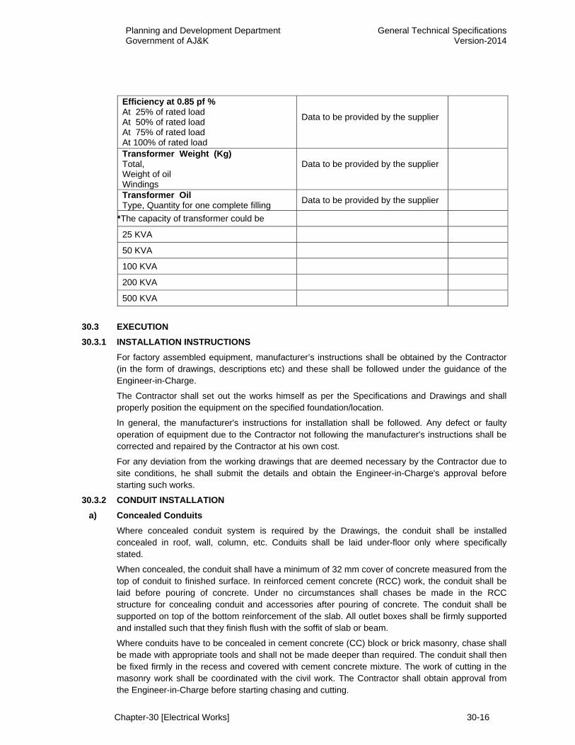
Efficiency at 0.85 pf % At 25% of rated load At 50% of rated load At 75% of rated load At 100% of rated load
Data to be provided by the supplier
Transformer Weight (Kg) Total, Weight of oil Windings
Data to be provided by the supplier
Transformer Oil Type, Quantity for one complete filling Data to be provided by the supplier
*The capacity of transformer could be
25 KVA
50 KVA
100 KVA
200 KVA
500 KVA
30.3 EXECUTION 30.3.1 INSTALLATION INSTRUCTIONS
For factory assembled equipment, manufacturer’s instructions shall be obtained by the Contractor (in the form of drawings, descriptions etc) and these shall be followed under the guidance of the Engineer-in-Charge.
The Contractor shall set out the works himself as per the Specifications and Drawings and shall properly position the equipment on the specified foundation/location.
In general, the manufacturer's instructions for installation shall be followed. Any defect or faulty operation of equipment due to the Contractor not following the manufacturer's instructions shall be corrected and repaired by the Contractor at his own cost.
For any deviation from the working drawings that are deemed necessary by the Contractor due to site conditions, he shall submit the details and obtain the Engineer-in-Charge's approval before starting such works.
30.3.2 CONDUIT INSTALLATION a) Concealed Conduits
Where concealed conduit system is required by the Drawings, the conduit shall be installed concealed in roof, wall, column, etc. Conduits shall be laid under-floor only where specifically stated.
When concealed, the conduit shall have a minimum of 32 mm cover of concrete measured from the top of conduit to finished surface. In reinforced cement concrete (RCC) work, the conduit shall be laid before pouring of concrete. Under no circumstances shall chases be made in the RCC structure for concealing conduit and accessories after pouring of concrete. The conduit shall be supported on top of the bottom reinforcement of the slab. All outlet boxes shall be firmly supported and installed such that they finish flush with the soffit of slab or beam.
Where conduits have to be concealed in cement concrete (CC) block or brick masonry, chase shall be made with appropriate tools and shall not be made deeper than required. The conduit shall then be fixed firmly in the recess and covered with cement concrete mixture. The work of cutting in the masonry work shall be coordinated with the civil work. The Contractor shall obtain approval from the Engineer-in-Charge before starting chasing and cutting.
Planning and Development Department Government of AJ&K
General Technical Specifications Version-2014
Chapter-30 [Electrical Works] 30-17
The termination of conduits at/or near the equipment/switch board shall be as shown diagrammatically on the Drawings or as directed by the Engineer-in-Charge. The exact locations of the termination shall be coordinated with the equipment/ switchboard to be installed. Any extension of conduit to suit the site condition shall be made without any extra cost. Conduit ends shall be properly plugged in order to prevent the entry of foreign materials. All openings through which concrete may leak shall be carefully plugged and boxes shall be suitably protected against filling with concrete. At all terminations of conduit, sharp edges of conduit ends shall be prevented to avoid the cutting or damaging of wires or cables during pulling through the conduits.
Under-floor conduit shall be installed at a minimum depth of 50 mm from the finished floor level or as otherwise shown on the Drawings. The conduits shall be installed empty before laying of floors with an 18 SWG steel wire drawn through the conduit for pulling the cable. No conduits shall be laid in bathroom floors.
The entire conduit system shall be installed and checked before the wiring is carried out. Any obstruction found shall be cleared before the installation of the cable.
Pull boxes and adaptable boxes shall be provided in conduit runs wherever required to facilitate pulling operation and shall' meet the following requirements:
- Pull boxes
For straight runs, the spacing shall not be more than 20 metres.
For runs with one 90 degree bend, the spacing shall not be more than 15 metres.
For runs with two 90 degrees bends, the spacing shall not be more than 10 metres.
- Adaptable boxes
For conduits upto 25 mm dia., the boxes shall be 50 mm in depth.
For conduits upto 40 mm dia., the boxes shall be 63 mm in depth. For conduits upto 50 mm. dia., the boxes shall be 87 mm in depth.
The rectangular inspection boxes or pull boxes shall be 16 SWG sheet steel of suitable design to receive conduits. The box shall be painted inside and outside with black enamel paint over a base coat of red oxide primer paint. The minimum length of inspection box shall not be less than four times the bending radius of the cable as recommended by the cable manufacturer. All concealed type pull boxes shall have a white plastic sheet of appropriate size fixed to the box by means of galvanized screws.
Adaptable boxes shall be 16 SWG sheet steel and painted and finished to the same quality as the distribution boards.Wherever the conduit lengths cross the expansion joint either along the columns or slab, suitable arrangement shall be provided so that when the conduit lengths in the expansion joints are stressed, the conduit shall not crack or break.
b) Surface Conduits The conduits for surface installation shall be of steel/PVC as shown on the Drawings or approved by the Engineer-in-Charge. The conduits at specified locations shall be installed on the surface of wall, columns, ceiling, etc. by means of steel saddles and clamps of approved design.
The saddles shall be installed on the surface by means of wall plugs and galvanized screws. Appropriate size of holes in the structure shall be made by drilling. The thickness of saddles shall not be less than 4 mm and clamps shall be of 16 SWG sheet steel. These shall be fixed at a maximum of 1000 mm spacing along horizontal and vertical runs of conduit. All accessories for complete installation of conduit system shall be provided by the Contractor. The requirements of pull boxes, etc. as specified for concealed conduits shall also be applicable for surface conduits.

Planning and Development Department Government of AJ&K
General Technical Specifications Version-2014
Chapter-30 [Electrical Works] 30-18
c) Galvanized Iron Pipes The galvanized iron (G.I) pipes shall be installed at a minimum depth of 900 mm measured from the top of pipes to finished ground level. The pipe shall be laid and checked for soundness before completion of civil works.
The G.I pipes at the entrance of the buildings shall be installed at locations as shown on the Drawings.
At all joints the pipe shall be firmly screwed and cotton yarn with waterproof compound shall be used to make the joint waterproof.At each termination, the pipe end shall have threads and socket screwed on thread for installing soft metal bush.
The soft metal bush shall be of approved quality and shall be male type.
The installation of pipes shall be complete in all respects including its fixing at terminations before wiring work is started. All sharp edges and burrs shall be removed by using reamer or any approved device.The entire conduit system shall be installed before wiring is carried out and conduit shall be checked for continuity. Any obstruction found shall be removed without damaging the installation.
d) PVC Pipe Rigid PVC pipes shall be installed under roads and paved areas, at crossing with other services and at cable entering building as shown on the drawings. The depth of the pipe shall vary according to the conditions at site, and approval of Engineer-in-Charge shall be obtained prior to installation. In general the pipes shall be installed underground at the following depths measured from the top of the pipe:
a) Under roads and paved surface 900 mm below the finished surface
b) When crossing other services 250 mm vertical clearance. for the crossing length. 500 mm horizontal clearance
with CC protective cover. The trench of required dimensions shall be excavated and the bottom of trench cleaned and levelled. A four inches thick bed of fine sand shall be provided over which the PVC pipes installed after proper alignment. Where two or more pipes are installed in the same trench the clearance between pipes shall not be less than two inches. After laying of pipe the trench shall be backfilled with clean-screened earth in layer of four inches. Each layer shall be properly compacted.
Where underground cables enter connection terminal boxes the PVC pipe shall be installed on surface by means of PVC clamps at a maximum interval of eighteen inches.After installation, the ends of the pipe shall be plugged with material impervious to water and chemicals. All joints shall be sealed adequately to prevent entry of foreign elements.
The installation of pipes shall be completed in all respects including its fixing at terminations, before cabling work is started. All sharp edges and burrs shall be removed by using reamer or any approved device. The pipe shall be thorough cleaned of dirt and dust from inside. The pipes shall be installed in proper co-ordination with other works.
30.3.3 WIRING INSTALLATION a) Conduit Wiring
The wiring through conduit shall be started only after the conduit system is completely installed and all outlet boxes, junction boxes, etc., are fixed in position.The wires shall be pulled in conduit with care, preferably without the use ofany lubricant. Where necessary and after approval of Engineer-in-Charge, the cable manufacturer's recommended lubricant shall be used. Use of any kind of oil or soap will not be permitted. Where several wires are to be installed in the same conduit, they shall be pulled together along with the earthconductor. All wires of same circuit shall be run in one
Planning and Development Department Government of AJ&K
General Technical Specifications Version-2014
Chapter-30 [Electrical Works] 30-19
conduit.The wires shall not be bent to a radius less than ten times the overall diameter of the wire, or more if otherwise recommended by the manufacturer.
The wiring shall be continuous between terminations and looping- in system shall be followed throughout. Spur and Tee connections are strictly prohibited. Any joint in wires shall not be allowed. The use of connectors shall only be allowed at locations where looping-in is rendered difficult. The consent of the Engineer-in-Charge shall be required for using connectors. The connector shall be of suitable rating having porcelain body and sunk-in screw terminals. The connector shall be wrapped with PVC insulation tape after its installation. A minimum of 6 inches (150 mm) extra length of cable/wire shall be provided at each termination to facilitate repairs in future.
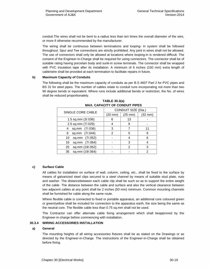
b) Maximum Capacity of Conduits The following shall be the maximum capacity of conduits as per B.S 4607 Part 2 for PVC pipes and BS 31 for steel pipes. The number of cables relate to conduit runs incorporating not more than two 90 degree bends or equivalent. Where runs include additional bends or restriction, the No. of wires shall be reduced proportionately.
TABLE 30.3(a) MAX. CAPACITY OF CONDUIT PIPES
SINGLE CORE CABLE CONDUIT SIZE (Dia.)
(20 mm) (25 mm) (32 mm) 1.5 sq.mm (3/.036) 6 13 - 2.5 sq.mm (7/.029) 4 9 - 4 sq.mm (7/.036) 3 7 11 6 sq.mm (7/.044) 2 5 9
10 sq.mm (7/.052) - 4 6 16 sq.mm (7/.064) - 3 4 25 sq.mm (19/.052) - 2 3 35 sq.mm (19/.064) - - 2
c) Surface Cable
All cables for installation on surface of wall, column, ceiling, etc., shall be fixed to the surface by means of galvanized steel clips secured to a steel channel by means of suitable stud plate, nuts and washer. The distancebetween each cable clip shall be such so as to support the entire weight of the cable. The distance between the cable and surface and also the vertical clearance between two adjacent cables at any point shall be 2 inches (50 mm) minimum. Common mounting channels shall be furnished for cable along the same route.
Where flexible cable is connected to fixed or portable apparatus, an additional core coloured green or green/yellow shall be included for connection to the apparatus earth, the size being the same as the neutral core. The flexible cable less than 0.75 sq.mm shall not be used.
The Contractor can offer alternate cable fixing arrangement which shall beapproved by the Engineer-in-charge before commencing with installation.
30.3.4 WIRING ACCESSORIES INSTALLATION a) General
The mounting heights of all wiring accessories fixtures shall be as stated on the Drawings or as directed by the Engineer-in-Charge. The instructions of the Engineer-in-Charge shall be obtained before fixing.
Planning and Development Department Government of AJ&K
General Technical Specifications Version-2014
Chapter-30 [Electrical Works] 30-20
b) Switches And Sockets Switches and switch sockets units shall be installed on 16 SWG thick sheet steel or PVC box as specified for surface mounting or recessed in wall. Where switches and fan regulators are provided at one place, these shall be grouped together and installed on a common plastic sheet fixed with the surface of the box. The fixing of plastic sheet on sheet Steel/PVC box shall be by means of flat headgalvanized screws sunk in the plastic plate so as to finish flush with the surface. The edges of the plastic plate shall be champhered.
c) Ceiling Fan Fan hook shall be installed in the RCC ceiling at the time of pouring ofconcrete. Fan hook extending rods shall be tied to the reinforcement before pouring of concrete.
The installation of fan shall include fixing of blades, down-rod, clamp, canopy and fan regulator, including testing and commissioning. The down rod shall be of required length having long threads and shall be provided with check nuts to secure it firmly with the clamp and with the body of the fan. A split pin shall be provided both at the fan body end and at the clamp for safety. Any scratches on the body of the fan or fan rod appearing during installation shall be cleaned and painted properly with the same quality paint as provided by the manufacturer.
d) Wall Bracket Fans Wall bracket fan shall be installed on wall at locations shown on the Drawings as per manufacturer's recommendations. Wiring between wall fan point and fan shall be with 3 core 0.5 sq.mm PVC insulated, PVC sheathed, flexible cable.
e) Exhaust Fans The openings for exhaust fan shall be provided by the Contractor at the time of construction of wall at locations shown in the Drawings or as directed by the Engineer-in-Charge. Mounting frame and accessories shall be embedded in concrete and the hole finished smoothly flushed with the ring. Hole shall be closed temporarily until installation of fan unit.
The fan units and the back draft dampers shall be installed, connected to the wiring and tested. The fan blades shall rotate smoothly with a clearance of 1/8 inch (3 mm) from inside of hole if it is an open unit and within its case if it is an enclosed unit.
30.3.5 LIGHTING FIXTURE INSTALLATION a) General
The mounting heights and position of light fixtures shall be as indicated on the Drawings.
The Contractor must ensure that the light fixtures are installed uniformly with respect to the dimensions of the area. Any modifications due to site conditions may be made with the approval of the Engineer-in-Charge. All fixtures shall be carefully aligned before fixing in position.
b) Fluorescent Light Fixtures The fluorescent light fixtures on the surface of ceiling shall be installed with the back of the body flush with the ceiling surface, and in a manner so as to facilitate wiring.
Nylon plugs and galvanized steel bolts or screws shall be used for fixing thelight fixture to the ceiling. Pendant light fixture shall have two holes in thetop of each casing for supporting to the roof by 3/4 inch (19 mm)dia. G.I. Pipe. Wiringfrom ceiling to fixture shall be installed inside the pipe. For light fixtures installation on false ceiling the light fixture shall be supported to the ceiling and installation method/detail shall be coordinated with ceiling design and submitted for approval of the Engineer-in-Charge.
The wiring between ceiling rose and fixture shall be with three core 0.75 sq.mm flexible cable, PVC insulated, PVC sheathed.
Planning and Development Department Government of AJ&K
General Technical Specifications Version-2014
Chapter-30 [Electrical Works] 30-21
c) Incandescent Light Fixtures The incandescent light fixtures shall be installed on the surface of ceiling or wall by means of nylon plugs and galvanized steel screws, such that their back finish flush with the surface for exposed conduits and flush with outlet box for concealed conduit system. Wherever convenient, screws for fixing light fixtures shall be screwed into the holes of the outlet box. The light on false ceiling shall be installed in a manner as described for fluorescent light fixture.
The wiring between ceiling rose and fixture shall be with three core 0.75 Sq.mm flexible cable, PVC insulated, PVC sheathed.
30.3.6 MAIN BOARDS INSTALLATION Floor mounting cubicle type main LT. switchboards, sub-main boards or distribution boards shall be erected with levelling shims, foundation bolts, washers, nuts, solder, lugs, clamps etc as shown on the Drawing.
The surface mounting main boards shall be installed on wall and shall be anchored by means of bolts or on steel channels as per manufacturer's instructions for installation. Wherever indicated, main boards for recessed mounting in wall shall be installed such that the door shall finish flush with the surface of the wall. The recess mounted main boards shall be installed before the plastering of walls. The main boards shall be protected to avoid any damage due to the civil work.
All loose parts despatched separately with the main boards shall be installed as per manufacturer's instructions and all adjustments or setting shall be made as required. All screws, nuts and bolts used for fixing the main boards shall be galvanized.
The location of main boards shall be as shown diagrammatically on the Drawings or as directed by the Engineer-in-Charge. The actual location shall however be determined at site, keeping in view the site conditions and in coordination with other equipment.The main boards installation shall include connecting all incoming and outgoing cables. The cable entry in the boards shall be provided from top or bottom as required.
30.3.7 EARTHING INSTALLATION a) General
Complete earthing systems as shown on the Drawings shall be installed by the Contractor. The earthing system shall give earth resistance, including the resistance of soil, earth leads and earth continuity conductor (E.C.C), equal to or less than one ohm.
At all connections of earth continuity conductor to switchboard, cable-end box or any other metallic body, proper size copper or brass sockets, thimbles or lugs shall be used to which the copper wire shall be connected by copper brazing. The soldering of copper wire at joints or terminations shall not be allowed. All tee-off connections shall be by copper brazing usingsuitable socket and clamps. After brazing, the jointed surface shall be protected by oxide inhibiting compound of low electrical resistance. For connections to metallic body, the surface shall be thoroughly cleaned before bolting the lug or socket.
Each transformer, switchboard, distribution board, etc., shall be connected at least at two points by two independent earth wires.
The earth wires shall in general run exposed on the surface of wall or cable trench or in conduits as shown on the Drawings. For under floor runs, these shall be installed in pipe/conduit of appropriate sizes. Where laid along underground cables, these shall be laid directly underground in unpaved area and in pipe in paved area.
Planning and Development Department Government of AJ&K
General Technical Specifications Version-2014
Chapter-30 [Electrical Works] 30-22
b) Earth Electrode The electrode plate shall be installed at a minimum depth of 6.0 metres from the ground or 1 metre below permanent water level whichever is less. The minimum horizontal distance between earth electrodes shall be equal to depth. The electrode shall be installed as per details shown on the Drawings.
c) Earth Continuity Conductor The earth continuity conductor (E.C.C.) of sizes shown on the Drawings shall be installed all along the cable runs and connected to the earthing bar/terminals provided in the equipment. The body of all switchboards shall also be connected to earth by specified size of E.C.C. All other metal workshall also be connected to earth by specified size of E.C.C. For bonding of miscellaneous metalwork, suitable material shall be used to provide a permanent, low resistance path to the ground. .
At any joint or termination the E.C.C shall be connected using proper accessories. No connection shall be made by twisting of earth conductors.
d) Earth Loop for Body Earth The earthing loop wherever required shall be installed for earthing of equipment, bonding, etc. Where run horizontally, it shall be installed along the wall at 300 mm above finished floor level by means of copper/brass saddles and clamps of approved design. The tee-off connection from the earth loop wires shall be copper brazed.
30.3.8 LIGHTING PROTECTION SYSTEM a) Air Terminals
The Air Terminals shall be installed on the roof as per approved shop drawings. The terminal base shall be firmly secured to the concrete surface. It should be ensured that air terminals and/or roof conductors/down conductors shall be firmly fixed together, so that electro dynamic or accidental mechanical forces will not cause any damage to the clamping. The materials used shall withstand the electromagnetic effects of lightning current and predictable accidental stresses without being damaged.
The Contractor shall submit the fixing arrangement for the approval of the Engineer-in-Charge.
b) Roof Conductor The roof conductors shall be installed on the roof as per approved shop drawings. The copper conductor shall be firmly secured to the concrete surface by means of copper or brass clamps of approved design at a maximum interval of 1000 mm.
The roof conductor shall be connected to the copper rod by means of copper clamps. The clamp to be tightly fixed to the rod and brazed to ensure low resistance path to earth. The contact surface between copper clamp and conductor shall be cleaned, silver painted, brazed after bolting and provided with a coat of anti- corrosive paint after installation.
c) Down Conductors The down conductor shall be installed along the shortest possible route from roof to earth electrode. It shall be secured on the surface of wall by means of clamps at a maximum interval of 1000 mm.In general, bends shall be avoided along the routes of down conductor and maximum possible bending radius will be provided at turns. All joints between conductors shall be electrically and mechanically strong and effective. Straight joints in the down conductor shall be bolted. The joint shall be given a coat of anti -corrosive paint after connection. All accessories such as nuts, bolts, washers, solder, paint etc. shall be furnished by the Contractor.
For each down conductor a removable terminal shall be provided for testing purpose at approximately 1.5 meter height. The location of testing terminals are not shown on the drawings.
Planning and Development Department Government of AJ&K
General Technical Specifications Version-2014
Chapter-30 [Electrical Works] 30-23
The Contractor must ensure that testing terminals are installed so as to facilitate testing. The testing terminals shall be bolted type and made in accordance with the specifications for straight bolted joints. The connecting earth lead from testing terminals to earth electrodes shall be continuous without any joint. All metal work, pipes etc., at the roof and within 2 meters along the route of down conductor shall be bonded to the lightning protection system. The bonding shall be effective and approval of the Engineer-in-Charge shall be obtained for the bonding method.
d) Earth Electrode In case the soil conditions at site permit, the earth electrodes may be installed by hammering the electrode in soil, until the top of the pipe is about 300 mm below the proposed ground level. If hammering down is not possible due to site conditions, a pit shall be first excavated in bare ground upto the required depth and electrode shall be installed upright in the pit. The excavated pit shall be backfilled in layers of 500 mm, each layer tamped and compacted. At the ground level an inspection chamber of cement concrete shall be constructed having dimensions as shown on the drawings. The inspection chamber shall have a cover supported on angle iron frame. The cover shall be approved by the Engineer-in-Charge and shall finish flush with the ground level.
30.3.9 500 KVA TRANSFORMER Transformers shall be installed at locations shown on drawings. All civil works including provision of under-floor cable trench, transformer oil pit, openings in wall, steel channel etc. shall be carried out under civil works. The Contractor shall be responsible for general checking and co-ordination with civil works to ensure compliance with the requirements of transformer manufacturer for installation of equipment. For installation, connecting testing and commissioning of transformers, the Contractor shall provide all required labour, materials, tools and testing equipment.
The transformer installation shall be carried out in accordance with specifications and the best-accepted practice. Any loose components supplied by manufacturer shall be assembled, installed and connected in place as to form a complete assembly as per manufacturer instructions. After the transformer is placed in position and aligned for MV & LV termination, the roller wheels shall be locked with the foundation steel channel to avoid any unintentional movement of the wheels.
After the transformer is installed and connected, a thorough check shall again be made for the proper fixing of accessories, neutral connections, oil level, etc. The transformer shall be tested before energizing as per instructions contained in the Section 30.1 of these Specifications.
30.4 TELEPHONE SYSTEM 30.4.1 SCOPE OF WORK
The work under this section consists of design, manufacturing, fabricating, supplying, installing, testing, energizing, operation and commissioning of all material and services for the complete proposed Telephone system as specified herein, as shown on Drawings and stated in the CSR and as directed by the Engineer-in-Charge. The system shall fully comply with the general requirements for telephone system as specified by the Pakistan Telecommunication Corporation Limited (PTCL).
The Contractor shall discuss the layout of the proposed Telephone system with the Engineer-in-Charge and co-ordinate at site with other services/systems for exact route, location and position of various equipments of the proposed system.
30.4.2 GENERAL The Telephone System is intended to establish efficient communication. The Telephone system shall be suitable for making local, long distance and overseas calls. The Digital telephone exchange shall be modular in design. The system shall have facility for expansion of Trunk lines and extensions in future.
The complete Telephone system equipment shall be fully electronic, state of the art design with elegant finish.

Planning and Development Department Government of AJ&K
General Technical Specifications Version-2014
Chapter-30 [Electrical Works] 30-24
The proposed Telephone System shall comprise the following equipments but not limited to; - Main Distribution Frame - Main Telephone Junction Box - Digital Telephone exchange - Mains power supply system - Back-up power supply system - Digital Telephone sets - All required accessories
The Contractor shall provide all equipment including concealed conduits and multi-core, 0.6 mm dia., tinned copper conductor cable, for complete proposed telephone system, as shown on the drawings, as explained in these specifications and as directed by the Engineer-in-Charge.
The Contractor shall also provide any other equipment and materials, which are deemed necessary for the completion of system, without any extra cost.
30.4.3 APPLICABLE STANDARDS / CODES The latest editions of the following standards / codes shall be applicable for the materials covered within the scope of this section:
BS 7640 - Telephone cables VDE 0816 IEC 189 BS 6360 DIN 40040 - Class & Reliability of units in Telecommunication DIN 5800 - Regulations for installation & operation of Telecommunication CCITT - Recommendations and local T&T regulations.
30.4.4 MATERIAL 30.4.4.1 DIGITAL TELEPHONE EXCHANGE (EPABX)
The EPABX shall be state-of-the-art, digital, non-blocking type utilizing Pulse Code Modulation (PCM) and Time Division Multiplexing (TDM) and Stored program Control (SPC). It must be field proven and conform to ITU-T A - Law Compounding standard. It shall initially be equipped with subscriber lines and trunk lines as specified. The system shall allow simultaneous voice and data communication over one twisted pair telephone cable. The system shall be capable of connecting tele-fax and tele-text etc.
The system shall be able to operate in the following environmental operating conditions:
Temperature : 0 to 50o C Humidity : 5 to 95 % The various types of interface circuits required are as follows:
Analogue Extension : Two wire Dual Tone Multi-frequency (DTMF) according to ITU-T Q.23 Analogue Trunk : In accordance with PTC standard
Digital, Trunk : 2 Mbit/sec (comprising 100 digital trunks)
Extensive and adjustable time-out facilities shall be available in the EPABX to enable the time-out and release in the following cases:
- when a call is not answered within a pre-defined time period - when during dialling, the inter-digit time period is exceeded - when an incomplete or invalid number is dialled - when an extension attempts to access a feature it is not allowed
The EPABX system shall incorporate a wide range of self-initiating diagnostic routines for the monitoring of system performance and identification of errors.
Planning and Development Department Government of AJ&K
General Technical Specifications Version-2014
Chapter-30 [Electrical Works] 30-25
The proposed EPABX should be configured to handle the following traffic:
- 0.35 Erlangs per each extension - 0.90 Erlangs per each trunk - Blocking of calls: less than one percent.
The Contractor shall state the maximum number of simultaneous calls possible within the exchange. An adequate range of alarm and test facilities shall be provided in the EPABX to enable the maintenance personnel to rapidly access and localize the fault conditions. The facility of remote access (via dialup modem) of the EPABX for operation and maintenance purposes shall be available.
The system shall also contain appropriate hardware and software for audible and visual display of the whole range of alarms from the EPABX equipment to enable the maintenance personnel to undertake corrective action immediately upon occurrence of the fault. It should be possible to carry out the fault diagnosis and rectification without interruption in the service.
The system shall operate on single-phase 230 Volt 50Hz supply. Power supply of the system shall be based on modular components and shall use low power dissipation. The system shall operate without the need of forced cooling. Backup batteries shall be of sufficient size to keep the system fully operational in case of power failure for one hour.
The EPABX system shall comply to the following interfaces and protocols:
- EURO ISDN BRI & PRI - ITR6 - Q.931 - QSIG - DPNSS - CCS - V.24/V.25/28/35 - LAP-D
30.4.4.2 MAIN DISTRIBUTION FRAME The termination equipment for the trunk and extensions circuits shall be wall-mounted type. It shall be sized to accommodate all internal and external circuits plus a twenty percent spare capacity. The connecting blocks will be of the quick-connect type. Each of the trunk circuits and outside cable pairs will be protected with over-voltage and over-current protectors. These protectors shall be either carbon or gas tube type.
Complete details of the distribution frames together with the over-voltage/over-current protection shall be provided as part of the Contactor’s proposal.
30.4.4.3 POWER SUPPLY In the equipment room, the mains supply provided by WAPDA shall be available. The mains voltage (230 Volt AC/50Hz) will be subject to possible fluctuations and variations normally encountered in the WAPDA power supply network.
The Contractor shall be solely responsible to ensure that its proposed equipment is designed to function from the WAPDA mains voltage and will provide all necessary power supply equipment i.e. rectifiers, chargers, batteries and accessories to ensure a complete and fully functional primary and standby power supply system.
As reserve power, the equipment shall be equipped with a 48 Volt DC reserve system, to provide system operation in the event of a commercial power failure or fault in the primary rectifier. The battery shall be designed to provide a maximum of eight (8) hours reserve power for the ultimate size of the EPABX. The batteries shall be of sealed maintenance free type, supplied complete with
Planning and Development Department Government of AJ&K
General Technical Specifications Version-2014
Chapter-30 [Electrical Works] 30-26
cells, connectors, stand and all accessories. The batteries will be so arranged so that they take over the system automatically upon the failure of the primary power supply system.
Complete details of the power supply system shall be included as part of the contract.
30.4.4.4 TELEPHONE SETS
a) Standard Telephone Sets The standard telephone sets shall be a single–line pushbutton telephone set. The keypad and dialling from the telephone set must conform to the ITU-T Q23 standard. It shall be equipped with a voice level volume control and a ringing signal volume control. It shall be possible to attach a hands free unit if required. The colour of the telephone set must be approved by the Engineer-in-Charge.
b) Executive Telephone Sets The EPABX shall have the provision to connect 2-channel digital phones if specified. The digital telephone sets of the EPABX shall not require any external power source e.g. 230 Volt AC or batteries and should be able to operate through loop-power.
All programming of the digital sets shall be done in the switch and if a digital set is replaced, there should not be any need for feeding the individual set data again. The range of digital extensions should be expandable. The maximum range shall be specified by the supplier. It should also operate on single pair standard telephone cable.
The digital phones should have the following features:
2-Channel desktop telephone with;
- 12 Key key-pad - 12 function keys with LED’s - Plus/minus Keys for volume control - Indications for incoming calls: calling party’s number/name (internal) - LCD display – 24 digit alpha–numeric display - Date/time indication on the LCD display - Intelligent dialog key control for function selection in the display by scrolling in the menu and
selecting the desired function - Open listing - Hands free talking - Options to connect additional function keys with LEDs. It should be possible to program
these keys for EPABX features or internal/external numbers
30.4.4.5 AUTO-ATTENDANT SYSTEM The EPABX will be equipped with an auto-attendant system comprising a PC with Voice Mail Software. All incoming calls to the EPABX will be first routed to the Auto-attendant system. The system will provide recorded instructions to the incoming caller about the various possibilities of connection to the required extension (e.g. self-dialling of extension or routing to the attendant console). The incoming caller will therefore, be able to either dial the required extension number or will be routed to the attendant console.
30.4.4.6 TELEPHONE CABLES The Telephone cables shall be multi-pair. The cables shall be PVC insulated, 0.6mm dia. tinned copper conductor cables.
30.4.4.7 PVC CONDUITS ON SURFACE The PVC conduits shall have same specifications as in section “PVC conduits & Pipes” of the specifications for Electrical Installations.
Planning and Development Department Government of AJ&K
General Technical Specifications Version-2014
Chapter-30 [Electrical Works] 30-27
30.4.5 INSTALLATION 30.4.5.1 DIGITAL TELEPHONE EXCHANGE (EPABX)
The EPABX shall be installed at location as specified by the Engineer-in-Charge and in accordance with the manufacturer’s instructions and details.
30.4.5.2 MAIN DISTRIBUTION FRAME The Main Distribution Frame including Auto-Attendant System and Call Accounting and Billing System shall be installed at location as specified by the Engineer-in-Charge and in accordance with the manufacturer’s instructions and details.
30.4.5.3 POWER SUPPLY The Power Supply shall be installed at location as specified by the Engineer-in-Charge and in accordance with the manufacturer’s instructions and details.
30.4.5.4 TELEPHONE SETS The Digital Telephone Sets shall be installed at location as specified by the Engineer-in-Charge and in accordance with the manufacturer’s instructions and details.
30.4.5.5 TELEPHONE CABLES The Telephone cables for the proposed Telephone system shall be installed in accordance with the manufacturer’s instructions and details.
30.4.5.6 PVC CONDUITS The PVC conduits shall be installed in or on surface of walls, columns and slabs. If installed on surface, the PVC conduits shall be installed with the use of suitable saddles. The saddles shall be spaced 18 inches center to center.
30.5 MEASUREMENT AND PAYMENT 30.5.1 COMPOSITE RATE
The measurement and payment for the items of the work of Electrical Installations/ Telephone Systemhereof shall be made corresponding to the applicable CSR item as provided in Contract Agreement and shall constitute full compensation, for procurements, transportations, performance in all respect and completion of work as specified including the site clearance as approved by the Engineer-in-Charge.
30.5.2 LABOUR RATE The measurement and payment for the items of the work of Electrical Installations/ Telephone System hereof shall be made corresponding to applicable CSR item as provided in Contract Agreement and shall constitute full compensation for procurements transportations, performance in all respect and completion of work as specified including site clearance, as approved by the Engineer-in-Charge except the cost of materials to be provided by Department at designated location as defined in the Contract Agreement.
30.5.3 QUANTIFICATION The unit of measurement shall be measured as mentioned below in accordance with corresponding CSR items.
1. For linear items, the quantity of work shall be measured linearly along centre line of structure. The unit of measurement shall be running meter or running foot. Following items of CSR are measured according to this criteria; Item No.: 30-9, 30-10, 30-21 to 30-55, 30-93, 30-94, 30-104 to 30-106 and 30-110
2. The following items of CSR shall be measured as Each Item No.: 30-111 to 30-114 and 30-117 to 30-123
Planning and Development Department Government of AJ&K
General Technical Specifications Version-2014
Chapter-30 [Electrical Works] 30-28
3. The following items of CSR shall be measured as Job Item No.: 30-91,30-92,30-95 to 30-97,30-107 to 30-109, 30-115 and 30-116
4. The following items of CSR shall be measured per point. Item No.: 30-1 to 30-8
5. The following items of CSR shall be measured as Nos. Item No.: 30-11 to 30-20,30-56 to 30-90 and 30-98 to 103