Embed Size (px)
Citation preview

TECHNICAL MANUALFOR
CORROSION CONTROL ASSESSMENTAND MAINTENANCE MANUAL
(CCAMM)
SUPERSEDURE NOTICE: THIS MANUAL SUPERSEDES T9630-AB-MMD-010 REV2, DATED 01 AUGUST 2008, AND ALL CHANGES THERETO.
DISTRIBUTION STATEMENT A: APPROVED FOR PUBLIC RELEASE; DISTRIBUTION IS UNLIMITED.
T9630-AB-MMD-010REVISION 3
TITLE-1 / (TITLE-2 Blank)@@FIpgtype@@TITLE@@!FIpgtype@@@@FIpgtype@@TITLE@@!FIpgtype@@
PUBLISHED BY DIRECTION OF COMMANDER, NAVAL SEA SYSTEMS COMMAND
*0910LP9842160* 30 JUN 2015
Downloaded from http://www.everyspec.com

TITLE-2@@FIpgtype@@BLANK@@!FIpgtype@@
Downloaded from http://www.everyspec.com

RECORD OF REVISIONSREV NO. DATE TITLE AND/OR BRIEF DESCRIPTION/PREPARING ACTIVITY
0 10 JUN 2005 INITIAL ISSUE.1 07 MAR 2006 DEVELOPED UNDER NAVSEA 05P22 01 AUG 2008 DEVELOPED UNDER NAVSEA 05P23 30 JUN 2015 MAJOR REVISION TO MANUAL TO EXPAND SCOPE BEYOND
TANKS AND VOIDS, ADD CONTENT FOR STRUCTURAL CON-DITION ASSESSMENT, AND IMPLEMENT THE MAINTENANCERISK DECISION MATRIX. THIS EDITION ALSO INCORPORATESCURRENT NAVSEA DIGITIZATION STANDARDS.
FOR OPTIMAL VIEWING OF THIS TECHNICAL MANUAL THE PAGE LAYOUT IN ADOBE ACROBATREADER SHOULD BE SINGLE PAGE. CONTINUOUS PAGE DISPLAY CAN CAUSE PROBLEMS WITHLINK REFERENCES AND THE BOOKMARKS.
T9630-AB-MMD-010
RECORD OF REVISIONS-1
Downloaded from http://www.everyspec.com

T9630-AB-MMD-010
RECORD OF REVISIONS-2
Downloaded from http://www.everyspec.com
FOREWORD
This manual provides process requirements and guidance for the survey, assessment, and repair or replace-ment of coatings and structures on Naval surface ships and aircraft carriers. It also contains requirements andguidance concerning the concurrent evaluation of structural supports for selected ancillary equipment such as tanklevel indicators, ladders, piping system components, etc., and for sacrificial anodes. The authority for develop-ment of this manual is assigned to the Naval Surface Warfare Center, Carderock Division by NAVSEA 05P. SEA05P2 is the technical authority for all coatings and sacrificial cathodic protection system evaluation and mainte-nance requirements covered by this manual, and is responsible for updating and disseminating this manual. SEA05P4 is the technical authority for all structural evaluation and maintenance requirements covered by this manual.Naval Sea Systems Command, Ship Design, Integration and Engineering (NAVSEA 05) maintains the overalltechnical authority for the manual.
This document contains both mandatory requirements and guidance information derived from NSTMChapter 100, NSTM Chapter 631, and the JFMM. The mandatory requirements are indicated by the words″shall″, “must”, or ″is required.″ Guidance information is indicated either by the word ″should″ or ″may″.
This manual consists of six chapters as follows:
Chapter 1 - General Information
Chapter 2 - Surveyor Qualification Requirements
Chapter 3 - Scheduling Of Surveys
Chapter 4 - Conduct Of Surveys
Chapter 5 - Data Collection and Reporting
Chapter 6 - Disposition and Maintenance Actions
Ships, training activities, supply points, depots, Naval Shipyards and Supervisors of Shipbuilding arerequested to arrange for the maximum practical use and evaluation of NAVSEA technical manuals. All errors,omissions, discrepancies and suggestions for improvement to NAVSEA technical manuals shall be forwarded to:
COMMANDERCODE 310 TMDERsNAVSURFWARCENDIV NSDSA4363 MISSILE WAY BLDG 1389PORT HUENEME, CA 93043-4307
on NAVSEA/SPAWAR Technical Manual Deficiency/Evaluation Report (TMDER), NAVSEA form 4160/1. Allfeedback comments shall be thoroughly investigated and originators will be advised of action resulting there-from. One copy of NAVSEA form 4160/1 is at the end of each separately bound technical manual 8-1/2 x 11inches or larger. Copies of NAVSEA form 4160/1 may be requisitioned from the Naval Systems Data SupportActivity Code 310 at the above address. Users are encouraged to transmit deficiency submittals via the NavalSystems Data Support Activity Web site located at:
https://mercury.tdmis.navy.mil/def_external/pubsearch.cfm
T9630-AB-MMD-010
FOREWORD-1
Downloaded from http://www.everyspec.com
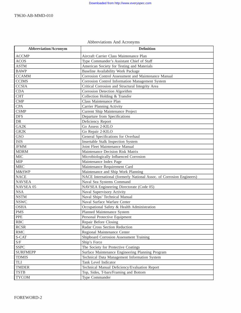
Abbreviations And Acronyms
Abbreviation/Acronym Definition
ACCMP Aircraft Carrier Class Maintenance PlanACOS Type Commander’s Assistant Chief of StaffASTM American Society for Testing and MaterialsBAWP Baseline Availability Work PackageCCAMM Corrosion Control Assessment and Maintenance ManualCCIMS Corrosion Control Information Management SystemCCSIA Critical Corrosion and Structural Integrity AreaCDA Corrosion Detection AlgorithmCHT Collection Holding & TransferCMP Class Maintenance PlanCPA Carrier Planning ActivityCSMP Current Ship Maintenance ProjectDFS Departure from SpecificationsDR Deficiency ReportGA2K Go Assess 2-KILOGR2K Go Repair 2-KILOGSO General Specifications for OverhaulISIS Insertable Stalk Inspection SystemJFMM Joint Fleet Maintenance ManualMDRM Maintenance Decision Risk MatrixMIC Microbiologically Influenced CorrosionMIP Maintenance Index PageMRC Maintenance Requirement CardM&SWP Maintenance and Ship Work PlanningNACE NACE International (formerly National Assoc. of Corrosion Engineers)NAVSEA Naval Sea Systems CommandNAVSEA 05 NAVSEA Engineering Directorate (Code 05)NSA Naval Supervisory ActivityNSTM Naval Ships’ Technical ManualNSWC Naval Surface Warfare CenterOSHA Occupational Safety & Health AdministrationPMS Planned Maintenance SystemPPE Personal Protective EquipmentRBC Repair Before ClosingRCSR Radar Cross Section ReductionRMC Regional Maintenance CenterS-CAT Shipboard Corrosion Assessment TrainingS/F Ship’s ForceSSPC The Society for Protective CoatingsSURFMEPP Surface Maintenance Engineering Planning ProgramTDMIS Technical Data Management Information SystemTLI Tank Level IndicatorTMDER Technical Manual Deficiency/Evaluation ReportTSTB Top, Sides, T-bars/Framing and BottomTYCOM Type Commander
T9630-AB-MMD-010
FOREWORD-2
Downloaded from http://www.everyspec.com

TABLE OF CONTENTS
Chapter/Paragraph Page
1 GENERAL INFORMATION . . . . . . . . . . . . . . . . . . . . . . . . . . . . . . 1-1
1-1 INTRODUCTION. . . . . . . . . . . . . . . . . . . . . . . . . . . . . . . . . . . . . . 1-11-1.1 Organization of Manual. . . . . . . . . . . . . . . . . . . . . . . . . . . . . . 1-2
1-2 PURPOSE. . . . . . . . . . . . . . . . . . . . . . . . . . . . . . . . . . . . . . . . . . 1-3
1-3 SCOPE. . . . . . . . . . . . . . . . . . . . . . . . . . . . . . . . . . . . . . . . . . . . 1-3
1-4 REFERENCES. . . . . . . . . . . . . . . . . . . . . . . . . . . . . . . . . . . . . . . 1-41-4.1 Navy References. . . . . . . . . . . . . . . . . . . . . . . . . . . . . . . . . . 1-51-4.2 SSPC References. . . . . . . . . . . . . . . . . . . . . . . . . . . . . . . . . . 1-71-4.3 ASTM Standards. . . . . . . . . . . . . . . . . . . . . . . . . . . . . . . . . . 1-7
1-5 DEFINITIONS AND TERMS. . . . . . . . . . . . . . . . . . . . . . . . . . . . . . . 1-81-5.1 Condition Assessment Terms. . . . . . . . . . . . . . . . . . . . . . . . . . . 1-8
1-5.1.1 Condition Based Maintenance. . . . . . . . . . . . . . . . . . . . 1-81-5.1.2 Maintenance Cycle. . . . . . . . . . . . . . . . . . . . . . . . . . 1-81-5.1.3 Structural System Survey and Inspection Levels. . . . . . . . . . 1-81-5.1.4 Recommend Maintenance Action Forms. . . . . . . . . . . . . . 1-9
1-5.2 Coating and Preservation Process Terms. . . . . . . . . . . . . . . . . . . . . 1-91-5.2.1 Surface Preparation. . . . . . . . . . . . . . . . . . . . . . . . . . 1-91-5.2.2 Coatings. . . . . . . . . . . . . . . . . . . . . . . . . . . . . . . . 1-91-5.2.3 Coating Touch-up Repairs. . . . . . . . . . . . . . . . . . . . . . 1-91-5.2.4 Critical Coated Areas. . . . . . . . . . . . . . . . . . . . . . . . . 1-101-5.2.5 Critical Corrosion and Structural Integrity Areas. . . . . . . . . . 1-10
1-5.3 Ship Compartment Terminology. . . . . . . . . . . . . . . . . . . . . . . . . . 1-111-5.3.1 Confined Space. . . . . . . . . . . . . . . . . . . . . . . . . . . . 1-111-5.3.2 Tanks (MRC G1N5). . . . . . . . . . . . . . . . . . . . . . . . . 1-11
1-5.3.2.1 Fresh Water. . . . . . . . . . . . . . . . . . . . 1-121-5.3.2.2 Fuel and Fuel Oil. . . . . . . . . . . . . . . . . 1-131-5.3.2.3 Lubricating (Lube) Oil (LO) and Hydraulic Oil.
. . . . . . . . . . . . . . . . . . . . . . . . . 1-151-5.3.2.4 Ballast and List Control. . . . . . . . . . . . . . 1-151-5.3.2.5 Collection, Holding & Transfer (CHT). . . . . 1-151-5.3.2.6 Wastewater Collecting (Plumbing Waste). . . . 1-151-5.3.2.7 Oily Waste and Contaminated Oil. . . . . . . . 1-15
1-5.3.3 Voids and Cofferdams (MRC G1N5). . . . . . . . . . . . . . . . 1-151-5.3.3.1 Voids (Normally Dry). . . . . . . . . . . . . . . 1-161-5.3.3.2 Voids (Floodable). . . . . . . . . . . . . . . . . 1-161-5.3.3.3 Voids (Cofferdams). . . . . . . . . . . . . . . . 1-161-5.3.3.4 Voids (Catapult Wing). . . . . . . . . . . . . . . 1-161-5.3.3.5 Sponson Voids. . . . . . . . . . . . . . . . . . . 1-17
1-5.3.4 Bilges (MRC G1N6). . . . . . . . . . . . . . . . . . . . . . . . . 1-171-5.3.5 Ventilation and Combustion Air Handling Compartments (MRC
G1N6). . . . . . . . . . . . . . . . . . . . . . . . . . . . . . . . 1-18
T9630-AB-MMD-010
i
Downloaded from http://www.everyspec.com

TABLE OF CONTENTS - Continued
Chapter/Paragraph Page
1-5.3.5.1 HVAC and CPS Ventilation Compartments. . . 1-181-5.3.5.2 Combustion Air Intakes. . . . . . . . . . . . . . 1-201-5.3.5.3 Combustion Exhaust Uptakes. . . . . . . . . . . 1-20
1-5.3.6 Topside/Weather Decks (MRC G1N6). . . . . . . . . . . . . . . 1-201-5.4 Ship Structure Terminology. . . . . . . . . . . . . . . . . . . . . . . . . . . . 1-21
1-5.4.1 Structural Integrity. . . . . . . . . . . . . . . . . . . . . . . . . . 1-211-5.4.2 Structural Assessment. . . . . . . . . . . . . . . . . . . . . . . . . 1-211-5.4.3 Scantlings. . . . . . . . . . . . . . . . . . . . . . . . . . . . . . . 1-211-5.4.4 Hull Girder. . . . . . . . . . . . . . . . . . . . . . . . . . . . . . 1-211-5.4.5 Ship Shell and Strake, Butts and Seams. . . . . . . . . . . . . . 1-22
1-5.4.5.1 Thin Hull Ships. . . . . . . . . . . . . . . . . . 1-221-5.4.6 Hull Framing: Longitudinal and Transverse. . . . . . . . . . . . . 1-221-5.4.7 Stiffeners, Stringers, Longitudinals, and Longitudinal Girders. . 1-221-5.4.8 Breasthooks. . . . . . . . . . . . . . . . . . . . . . . . . . . . . . 1-221-5.4.9 Keel. . . . . . . . . . . . . . . . . . . . . . . . . . . . . . . . . . 1-22
1-5.4.10 Decks and Platforms. . . . . . . . . . . . . . . . . . . . . . . . . 1-221-5.4.10.1 Gratings, Floor Plates, and Catwalks. . . . . . . 1-23
1-5.4.11 Bulkheads. . . . . . . . . . . . . . . . . . . . . . . . . . . . . . . 1-231-5.4.12 Swash Bulkheads and Decks. . . . . . . . . . . . . . . . . . . . . 1-231-5.4.13 Stanchions. . . . . . . . . . . . . . . . . . . . . . . . . . . . . . . 1-231-5.4.14 Superstructure, Deckhouse, and Island. . . . . . . . . . . . . . . 1-231-5.4.15 Masts, Stacks and Towers. . . . . . . . . . . . . . . . . . . . . . 1-241-5.4.16 Foundations. . . . . . . . . . . . . . . . . . . . . . . . . . . . . . 1-241-5.4.17 Sponsons and Sponson Shell. . . . . . . . . . . . . . . . . . . . . 1-241-5.4.18 Freeboard. . . . . . . . . . . . . . . . . . . . . . . . . . . . . . . 1-241-5.4.19 Drain Holes (Limber Holes). . . . . . . . . . . . . . . . . . . . . 1-241-5.4.20 Reinforcing Rings and Coamings. . . . . . . . . . . . . . . . . . 1-251-5.4.21 Plate Panel. . . . . . . . . . . . . . . . . . . . . . . . . . . . . . . 1-25
1-5.5 Planning Activities. . . . . . . . . . . . . . . . . . . . . . . . . . . . . . . . . 1-25
2 SURVEYOR QUALIFICATION REQUIREMENTS . . . . . . . . . . . . . . . . 2-1
2-1 ROLES AND RESPONSIBILITIES. . . . . . . . . . . . . . . . . . . . . . . . . . . . 2-12-1.1 Level 1 Structural and Coating Condition Surveyor. . . . . . . . . . . . . . . 2-12-1.2 Level 2 Structural Inspectors. . . . . . . . . . . . . . . . . . . . . . . . . . . 2-22-1.3 Coating Inspector (Quality Assurance). . . . . . . . . . . . . . . . . . . . . . 2-2
2-2 LEVEL 1 SURVEYOR QUALIFICATION REQUIREMENTS. . . . . . . . . . . . . 2-22-2.1 Qualifications of the Surveyor. . . . . . . . . . . . . . . . . . . . . . . . . . . 2-22-2.2 Documentation of Qualification as a Level 1 Surveyor. . . . . . . . . . . . . 2-32-2.3 Ship’s Force Interim Level 1 Surveyor Qualification. . . . . . . . . . . . . . 2-4
2-2.3.1 Additional Requirements for S/F Interim Surveyors of AircraftCarriers. . . . . . . . . . . . . . . . . . . . . . . . . . . . . . . 2-5
2-2.4 Maintaining Surveyor Qualification. . . . . . . . . . . . . . . . . . . . . . . . 2-5
2-3 TANK AND OTHER CONFINED SPACE ENTRY GUIDANCE. . . . . . . . . . . 2-5
T9630-AB-MMD-010
ii
Downloaded from http://www.everyspec.com

TABLE OF CONTENTS - Continued
Chapter/Paragraph Page
3 SCHEDULING OF SURVEYS . . . . . . . . . . . . . . . . . . . . . . . . . . . . . 3-1
3-1 GENERAL. . . . . . . . . . . . . . . . . . . . . . . . . . . . . . . . . . . . . . . . . . 3-13-1.1 Subdivision of Assigned MRC G1N6 Surveys For Large Areas. . . . . . . . 3-2
3-1.1.1 Machinery Compartments and Bilges. . . . . . . . . . . . . . . . 3-23-1.1.2 Amphibious Ship Well Decks and Stern Gates. . . . . . . . . . . 3-23-1.1.3 Aircraft Carrier and Amphibious Ship Hangar and Vehicle
Stowage Compartments. . . . . . . . . . . . . . . . . . . . . . 3-23-1.1.4 Exterior/Weather Decks, Superstructures, Masts, Islands, Towers.
. . . . . . . . . . . . . . . . . . . . . . . . . . . . . . . . . . . 3-23-1.1.5 Aircraft Elevators. . . . . . . . . . . . . . . . . . . . . . . . . . . 3-33-1.1.6 Other Compartments. . . . . . . . . . . . . . . . . . . . . . . . . 3-3
3-2 TIME-DIRECTED (PERIODIC) LEVEL 1 SURVEYS. . . . . . . . . . . . . . . . . 3-33-2.1 Tank and Void Initial Periodicities (MRC G1N5 Only). . . . . . . . . . . . . 3-33-2.2 General Structures Periodicities, MRC G1N6 Only. . . . . . . . . . . . . . . 3-4
3.3 SITUATIONAL SURVEYS. . . . . . . . . . . . . . . . . . . . . . . . . . . . . . . . . 3-63-3.1 Level 1 Surveys of Opportunity (MRC G1N5 Only). . . . . . . . . . . . . . 3-63-3.2 Extended Repair Availability Level 1 Surveys (MRC G1N5 Only). . . . . . 3-63-3.3 Post Damage Level 2 Inspections. . . . . . . . . . . . . . . . . . . . . . . . . 3-63-3.4 As-Arrived Surveys (MRC G1N5 Only). . . . . . . . . . . . . . . . . . . . . 3-6
3-4 CONDITION-DIRECTED REPEAT SURVEYS (RE-SURVEYS) (MRC G1N5ONLY). . . . . . . . . . . . . . . . . . . . . . . . . . . . . . . . . . . . . . . . . . 3-7
3-4.1 Re-Survey Period For Tanks and Voids With Repaired Coatings. . . . . . . . 3-8
3-5 SCHEDULING LEVEL 2 INSPECTIONS. . . . . . . . . . . . . . . . . . . . . . . . 3-83-5.1 Condition-Based Level 2 Inspections. . . . . . . . . . . . . . . . . . . . . . . 3-83-5.2 Time-Directed (Periodic) Level 2 Inspections. . . . . . . . . . . . . . . . . . 3-10
3-6 NON-MANNED ENTRY ASSESSMENTS (MRC G1N5 ONLY). . . . . . . . . . . 3-103-6.1 Tank Monitoring System and Tank Ranking Algorithm. . . . . . . . . . . . . 3-10
3-6.1.1 Tank Monitoring System Usage Requirements. . . . . . . . . . . 3-133-6.2 Insertable Stalk Imaging System and Corrosion Detection Algorithm. . . . . 3-15
3-6.2.1 Confined Space Requirements for Unmanned Entry ISIS Use. . 3-173-6.2.2 ISIS Usage Requirements and Limitations For Unmanned Use. . 3-17
4 CONDUCT OF SURVEYS . . . . . . . . . . . . . . . . . . . . . . . . . . . . . . . 4-1
4-1 GENERAL. . . . . . . . . . . . . . . . . . . . . . . . . . . . . . . . . . . . . . . . . . 4-14-1.1 Survey and Inspection Requirements. . . . . . . . . . . . . . . . . . . . . . . 4-14-1.2 Scope of Level 1 Surveys. . . . . . . . . . . . . . . . . . . . . . . . . . . . . 4-1
4-1.2.1 Uncoated Aluminum Surfaces. . . . . . . . . . . . . . . . . . . . 4-24-1.2.2 Assessment of Outfitting and Other Ship Systems. . . . . . . . . 4-34-1.2.3 Assessment of Surface Combatant Cross-Flooding Ducts (MRC
G1N6 Only). . . . . . . . . . . . . . . . . . . . . . . . . . . . 4-3
T9630-AB-MMD-010
iii
Downloaded from http://www.everyspec.com
TABLE OF CONTENTS - Continued
Chapter/Paragraph Page
4-2 SURVEY AND INSPECTION PLANNING AND PREPARATION. . . . . . . . . . 4-44-2.1 Safety Precautions and Personnel Protective Equipment (PPE). . . . . . . . . 4-4
4-2.1.1 Confined Spaces and Atmosphere Safety. . . . . . . . . . . . . . 4-44-2.1.2 Tanks and Voids (MRC G1N5). . . . . . . . . . . . . . . . . . . 4-54-2.1.3 Machinery Compartment and Bilge Safety (MRC G1N6). . . . . 4-54-2.1.4 Combustion Air Intakes and Uptakes (Exhaust) (MRC G1N6). . 4-54-2.1.5 HVAC Intake and Exhaust Fan Rooms, Trunks, and Plenums
(MRC G1N6). . . . . . . . . . . . . . . . . . . . . . . . . . . . 4-54-2.1.6 Superstructure/Deckhouses/Islands, Masts, and General Exterior
(MRC G1N6). . . . . . . . . . . . . . . . . . . . . . . . . . . . 4-54-2.2 Temporary Services and Ship Coordination. . . . . . . . . . . . . . . . . . . 4-6
4-2.2.1 Cleaning. . . . . . . . . . . . . . . . . . . . . . . . . . . . . . . . 4-64-2.2.2 Temporary Staging and Lift Equipment. . . . . . . . . . . . . . . 4-64-2.2.3 Interferences From Stowage. . . . . . . . . . . . . . . . . . . . . 4-64-2.2.4 Bilges (MRC G1N6). . . . . . . . . . . . . . . . . . . . . . . . . 4-64-2.2.5 Amphibious Ship Well Decks (MRC G1N6). . . . . . . . . . . . 4-6
4-2.3 Tools, Equipment, and Forms. . . . . . . . . . . . . . . . . . . . . . . . . . . 4-7
4-3 SURVEY OF OUTFITTING AND OTHER SHIP SYSTEMS. . . . . . . . . . . . . . 4-84-3.1 General Items To Survey (MRC G1N5 and G1N6). . . . . . . . . . . . . . . 4-9
4-3.1.1 Ladders. . . . . . . . . . . . . . . . . . . . . . . . . . . . . . . . 4-94-3.1.2 Insulation, Sheathing, and Damping Materials. . . . . . . . . . . 4-104-3.1.3 Structural Closures. . . . . . . . . . . . . . . . . . . . . . . . . . 4-11
4-3.2 Tanks (MRC G1N5). . . . . . . . . . . . . . . . . . . . . . . . . . . . . . . . 4-114-3.2.1 Sacrificial Anodes. . . . . . . . . . . . . . . . . . . . . . . . . . . 4-114-3.2.2 Tank Entry Penetrations (Manholes) and Tank Top Stuffing
Tubes. . . . . . . . . . . . . . . . . . . . . . . . . . . . . . . . 4-144-3.2.3 Tank Level Indicators (TLIs). . . . . . . . . . . . . . . . . . . . . 4-144-3.2.4 Sounding Tubes and Striker Plates. . . . . . . . . . . . . . . . . 4-144-3.2.5 Piping and Other Distributed Systems. . . . . . . . . . . . . . . . 4-154-3.2.6 ICCP System and TMS Components. . . . . . . . . . . . . . . . 4-17
4-3.3 Voids (MRC G1N5). . . . . . . . . . . . . . . . . . . . . . . . . . . . . . . . 4-184-3.3.1 Desiccants. . . . . . . . . . . . . . . . . . . . . . . . . . . . . . . 4-184-3.3.2 All Other Items in Voids. . . . . . . . . . . . . . . . . . . . . . . 4-194-3.3.3 Lead Ballast in Voids and Cofferdams. . . . . . . . . . . . . . . 4-19
4-3.4 Bilge Regions (MRC G1N6). . . . . . . . . . . . . . . . . . . . . . . . . . . 4-194-3.4.1 Sacrificial Anodes. . . . . . . . . . . . . . . . . . . . . . . . . . . 4-19
4-3.5 Combustion Air Intakes and Uptakes (MRC G1N6). . . . . . . . . . . . . . . 4-194-3.6 Structural Vent Plenums and Trunks (MRC G1N6). . . . . . . . . . . . . . . 4-204-3.7 Well Decks (MRC G1N6). . . . . . . . . . . . . . . . . . . . . . . . . . . . . 4-204-3.8 Exterior and Weather Deck Areas (MRC G1N6). . . . . . . . . . . . . . . . . 4-24
4-3.8.1 Additional Exterior and Weather Deck Components to Survey. . 4-24
4-4 ASSESSMENT OF COATING CONDITION. . . . . . . . . . . . . . . . . . . . . . . 4-254-4.1 Zone-Based Coating Condition Reporting. . . . . . . . . . . . . . . . . . . . 4-26
4-4.1.1 “V” Shaped Bottom Tanks and Voids. . . . . . . . . . . . . . . . 4-284-4.1.2 Welds. . . . . . . . . . . . . . . . . . . . . . . . . . . . . . . . . 4-28
T9630-AB-MMD-010
iv
Downloaded from http://www.everyspec.com

TABLE OF CONTENTS - Continued
Chapter/Paragraph Page
4-4.2 Staining and Dirt. . . . . . . . . . . . . . . . . . . . . . . . . . . . . . . . . . 4-284-4.3 Overall Coating Condition Scores. . . . . . . . . . . . . . . . . . . . . . . . . 4-29
4-4.3.1 Coating Condition Score Criteria. . . . . . . . . . . . . . . . . . 4-294-4.3.2 Localized vs. Scattered Coating Damage Distribution. . . . . . . 4-304-4.3.3 Blistering Evaluation. . . . . . . . . . . . . . . . . . . . . . . . . 4-30
4-4.3.3.1 Solvent Entrapment and Osmotic Blistering. . . 4-314-4.3.3.2 Blister-Like Coating Failure Over Rust. . . . . 4-314-4.3.3.3 Blister Reporting, Criteria, and Coating
Condition Rating (MRC G1N5 Only). . . . . 4-324-4.3.4 Coating Delamination and Disbonding. . . . . . . . . . . . . . . 4-33
4-4.3.4.1 Fuel Oil Storage and Service Tanks (MRCG1N5 Only). . . . . . . . . . . . . . . . . . . 4-33
4-4.4 Special Coating Condition Scoring Conventions. . . . . . . . . . . . . . . . . 4-354-4.4.1 Unknown Coating Condition in Zone. . . . . . . . . . . . . . . . 4-354-4.4.2 Uncoated Surfaces. . . . . . . . . . . . . . . . . . . . . . . . . . 4-354-4.4.3 Additional Coating Condition Information. . . . . . . . . . . . . 4-35
4-4.5 Mandatory Coating System Replacement. . . . . . . . . . . . . . . . . . . . . 4-354-4.6 Coating Condition Scoring Examples. . . . . . . . . . . . . . . . . . . . . . . 4-36
4-4.6.1 Example: Compensated Fuel Tank (MRC G1N5). . . . . . . . . 4-374-4.6.2 Example: Auxiliary Machinery Room Bilge Region (MRC
G1N6). . . . . . . . . . . . . . . . . . . . . . . . . . . . . . . . 4-374-4.6.3 Example: Exterior Main Deck Walkway Adjacent to
Superstructure (MRC G1N6). . . . . . . . . . . . . . . . . . . 4-38
4-5 SURVEY AND INSPECTION OF STRUCTURAL INTEGRITY. . . . . . . . . . . . 4-394-5.1 Overall Structural Integrity Condition Rating. . . . . . . . . . . . . . . . . . 4-39
4-5.1.1 Corrosion and Corrosion Rates. . . . . . . . . . . . . . . . . . . 4-394-5.1.2 Reporting of Structural Integrity Defects and Damage. . . . . . . 4-404-5.1.3 Data Required to Support Strength Calculations and Deferrals. . 4-42
4-5.2 Maximum Allowable Corrosion, Thinning and Wastage Criteria. . . . . . . . 4-474-5.3 Determination of Thickness Loss in the Structure. . . . . . . . . . . . . . . . 4-474-5.4 Sounding (Level 2 Inspection Only). . . . . . . . . . . . . . . . . . . . . . . 4-504-5.5 Ultrasonic Thickness Gauging. . . . . . . . . . . . . . . . . . . . . . . . . . . 4-50
4-6 RECORDING THE LOCATION OF COATING AND STRUCTURAL DAMAGE. . 4-51
4-7 PHOTOGRAPHIC RECORDS. . . . . . . . . . . . . . . . . . . . . . . . . . . . . . . 4-52
5 DATA COLLECTION AND REPORTING . . . . . . . . . . . . . . . . . . . . . . 5-1
5-1 MRC G1N5 AND G1N6 DATA COLLECTION FORMS. . . . . . . . . . . . . . . . 5-1
5-2 LEVEL 1 SURVEY REPORTING REQUIREMENTS. . . . . . . . . . . . . . . . . . 5-1
5-3 LEVEL 2 INSPECTION REPORTING REQUIREMENTS. . . . . . . . . . . . . . . 5-1
T9630-AB-MMD-010
v
Downloaded from http://www.everyspec.com
TABLE OF CONTENTS - Continued
Chapter/Paragraph Page
5-4 NON-MANNED ENTRY ASSESSMENT REPORTING REQUIREMENTS(TANKS AND VOIDS ONLY). . . . . . . . . . . . . . . . . . . . . . . . . . . . . 5-2
5-5 LEVEL 1 SURVEY CMP TASK COMPLETION/CLOSE-OUT. . . . . . . . . . . . 5-2
5-6 REPAIR 2-KILO DEVELOPMENT. . . . . . . . . . . . . . . . . . . . . . . . . . . . 5-2
5-7 REPAIR AND MODERNIZATION DOCUMENTATION. . . . . . . . . . . . . . . . 5-3
5-8 CCIMS DATA STORAGE AND RETRIEVAL. . . . . . . . . . . . . . . . . . . . . . 5-35-8.1 Handling of Digital Images. . . . . . . . . . . . . . . . . . . . . . . . . . . . 5-35-8.2 COSMOS Database Tool. . . . . . . . . . . . . . . . . . . . . . . . . . . . . . 5-4
5-9 DEFERRALS AND NON-CONFORMANCES. . . . . . . . . . . . . . . . . . . . . . 5-4
6 DISPOSITION AND MAINTENANCE ACTIONS . . . . . . . . . . . . . . . . . 6-1
6-1 GENERAL. . . . . . . . . . . . . . . . . . . . . . . . . . . . . . . . . . . . . . . . . . 6-1
6-2 CONDITION BASED MAINTENANCE REQUIREMENTS. . . . . . . . . . . . . . 6-16-2.1 Assignment of Risk Group (R#). . . . . . . . . . . . . . . . . . . . . . . . . . 6-1
6-2.1.1 Mission Critical and Severe Service Tanks and Voids (MRCG1N5). . . . . . . . . . . . . . . . . . . . . . . . . . . . . . . . 6-1
6-2.2 Assignment of Condition Rating (P# or S#). . . . . . . . . . . . . . . . . . . 6-2
6-3 MAINTENANCE DECISIONS AND PRIORITIZATION. . . . . . . . . . . . . . . . 6-36-3.1 Coating System Maintenance Actions. . . . . . . . . . . . . . . . . . . . . . . 6-3
6-3.1.1 Additional Tank and Void Coating Maintenance Requirementsand Recommendations. . . . . . . . . . . . . . . . . . . . . . . 6-3
6-3.1.2 Condition Unknown (Condition 0). . . . . . . . . . . . . . . . . 6-46-3.2 Structural Integrity Maintenance Actions. . . . . . . . . . . . . . . . . . . . . 6-4
6-3.2.1 Coating Repairs of New and Disturbed Surfaces Resulting FromStructure Repairs. . . . . . . . . . . . . . . . . . . . . . . . . . 6-5
6-3.3 Non-conformance Reporting. . . . . . . . . . . . . . . . . . . . . . . . . . . . 6-66-3.4 Repairs Other Than Coatings and Structures. . . . . . . . . . . . . . . . . . . 6-7
6-4 TOUCH-UP REPAIR OF COATINGS. . . . . . . . . . . . . . . . . . . . . . . . . . . 6-7
6-5 DISPOSITION OF ISIS/CDA FINDINGS. . . . . . . . . . . . . . . . . . . . . . . . 6-8
6-6 ADDITIONAL FACTORS FOR PRIORITIZATION AND SCHEDULING OFCOATINGS WORK. . . . . . . . . . . . . . . . . . . . . . . . . . . . . . . . . . . 6-8
6-6.1 Docking Required To Recoat. . . . . . . . . . . . . . . . . . . . . . . . . . . 6-86-6.2 Tanks and Voids With Equal Overall Condition Scores. . . . . . . . . . . . . 6-86-6.3 Adjacent Compartments. . . . . . . . . . . . . . . . . . . . . . . . . . . . . . 6-96-6.4 Dry (Non-Floodable) Void Compartments. . . . . . . . . . . . . . . . . . . . 6-96-6.5 Premature Coating Failure. . . . . . . . . . . . . . . . . . . . . . . . . . . . . 6-9
T9630-AB-MMD-010
vi
Downloaded from http://www.everyspec.com

TABLE OF CONTENTS - Continued
Chapter/Paragraph Page
6-7 GUIDANCE ON SELECTION OF COATINGS. . . . . . . . . . . . . . . . . . . . . 6-10
6-8 MANDATORY REPAIR BEFORE CLOSING (RBC) ITEMS IN TANKS ANDVOIDS. . . . . . . . . . . . . . . . . . . . . . . . . . . . . . . . . . . . . . . . . . 6-10
6-9 MAINTENANCE OF SHIPS APPROACHING DECOMMISSIONING. . . . . . . . 6-116-9.1 Surveys and Inspections. . . . . . . . . . . . . . . . . . . . . . . . . . . . . . 6-11
6-9.1.1 Tanks and Voids MRC G1N5. . . . . . . . . . . . . . . . . . . . 6-116-9.1.2 Compartments and Areas Other Than Tanks and Voids (MRC
G1N6). . . . . . . . . . . . . . . . . . . . . . . . . . . . . . . . 6-116-9.2 Coating System Repair and Replacement. . . . . . . . . . . . . . . . . . . . . 6-11
A MRC G1N5 Data Collection Form and Instructions . . . . . . . . . . . . . . . . . A-1
About this insert . . . . . . . . . . . . . . . . . . . . . . . . . . . . . . . . . . . . . . A-1
B MRC G1N6 Data Collection Form and Instructions . . . . . . . . . . . . . . . . . B-1
About this insert . . . . . . . . . . . . . . . . . . . . . . . . . . . . . . . . . . . . . . B-1
C Compartment Use Designations . . . . . . . . . . . . . . . . . . . . . . . . . . . . . C-1
D Repair 2-KILO/Deficiency Report Best Practices Guide . . . . . . . . . . . . . . D-1
T9630-AB-MMD-010
vii
Downloaded from http://www.everyspec.com

LIST OF TABLES
Table Title Page
1-1 Reference Documents . . . . . . . . . . . . . . . . . . . . . . . . . . . . . . . . . . . 1-4
3-1 MRC G1N5 Tank And Void Survey Periodicities . . . . . . . . . . . . . . . . . . . . 3-4
3-2 MRC G1N6 General Structure Survey Periodicities . . . . . . . . . . . . . . . . . . . 3-5
3-3 Ballast Tanks with TMS Installed . . . . . . . . . . . . . . . . . . . . . . . . . . . . . 3-14
3-4 ISIS Utilization Protocol . . . . . . . . . . . . . . . . . . . . . . . . . . . . . . . . . . 3-19
4-1 Coating Condition Ratings and ASTM D610 Rust Grades1 . . . . . . . . . . . . . . 4-30
4-2 Examples of Condition Ratings and Sizes of Affected Surface Areas . . . . . . . . . 4-37
4-3 Notional Example of Tank Coating Condition Scoring . . . . . . . . . . . . . . . . . 4-37
4-4 Notional Example of Bilge Region Coating Condition Scoring . . . . . . . . . . . . 4-38
4-5 Notional Example of Exterior Walkway Coating Condition Scoring . . . . . . . . . . 4-39
4-6 Material Reductions and Percentages . . . . . . . . . . . . . . . . . . . . . . . . . . . 4-49
6-1 Maintenance Decision Risk Matrix (MDRM) . . . . . . . . . . . . . . . . . . . . . . 6-12
6-2 MRC G1N5 Tank & Void Criticality/Risk Groups . . . . . . . . . . . . . . . . . . . 6-15
6-3 MRC G1N6 General Structure Criticality/Risk Groups . . . . . . . . . . . . . . . . . 6-16
T9630-AB-MMD-010
viii
Downloaded from http://www.everyspec.com

LIST OF ILLUSTRATIONS
Figure Title Page
1-1 Notional Inspection and Repair Planning Cycle . . . . . . . . . . . . . . . . . . . . . 1-1
1-2 Coating Failure and Structural Damage in a Machinery Compartment Bilge Area . . 1-11
1-3 Aircraft Carrier Catapult Wing Void . . . . . . . . . . . . . . . . . . . . . . . . . . . 1-17
1-4 Bilge Pocket Obscured by Oily Water and Sludge . . . . . . . . . . . . . . . . . . . 1-18
1-5 Illustration of Typical HVAC System Terminology . . . . . . . . . . . . . . . . . . . 1-19
1-6 Structural Components of Naval Ships . . . . . . . . . . . . . . . . . . . . . . . . . . 1-26
1-7 Typical Structural Elements . . . . . . . . . . . . . . . . . . . . . . . . . . . . . . . . 1-26
1-8 Notional Aircraft Carrier Structural Terminology . . . . . . . . . . . . . . . . . . . . 1-27
1-9 Examples of Reinforcing Rings and Coamings (Sheet 1 of 2) . . . . . . . . . . . . . 1-28
3-1 Painted Structures That Should Have Been Previously Repaired . . . . . . . . . . . . 3-9
3-2 Typical TMS Installation In Tank (Top) and Data Logger (Bottom) . . . . . . . . . . 3-12
3-3 TMS Relationship to MRC G1N5 Surveys . . . . . . . . . . . . . . . . . . . . . . . 3-13
3-4 Example of ISIS Tank Assessment Without Human Entry . . . . . . . . . . . . . . . 3-16
4-1 Bare Aluminum Water Tank With Acceptable Oxidation . . . . . . . . . . . . . . . . 4-3
4-2 Opening to a Cross-Flooding Duct on CG-47 Class Ship . . . . . . . . . . . . . . . . 4-4
4-3 Reportable Corrosion of Vertical Ladders and Deck Supports . . . . . . . . . . . . . 4-10
4-4 Corrosion of Aluminum Support for Stainless Steel Climber Safety Rail . . . . . . . 4-10
4-5 Anode Assessment Flow Chart . . . . . . . . . . . . . . . . . . . . . . . . . . . . . . 4-13
4-6 Heavy Rust Scale Of Steel Deck Manhole Cover Seating Surface . . . . . . . . . . . 4-14
4-7 Coating Damage and Corrosion of Sounding Tube Bob Striker Plate . . . . . . . . . 4-15
4-8 Corroded And Holed Degaussing System Conduit In A Tank . . . . . . . . . . . . . 4-17
4-9 Waster Plates Installed Under Fill or Suction Piping Tailpipes . . . . . . . . . . . . . 4-17
4-10 Typical ICCP Anode Cofferdam and Cabling in a Machinery Compartment Bilge . . 4-18
4-11 Well Deck Wing Wall And Deck Surface Areas In Way Of Planking . . . . . . . . . 4-22
4-12 Coating Breakdown Initiating in Tank Overhead and Stiffener Zones . . . . . . . . . 4-27
4-13 Examples of Osmotic Blistering Found in In-Service Tanks . . . . . . . . . . . . . . 4-31
T9630-AB-MMD-010
ix
Downloaded from http://www.everyspec.com

LIST OF ILLUSTRATIONS - Continued
Figure Title Page
4-14 Blister-Like Coating Failure Over Rust . . . . . . . . . . . . . . . . . . . . . . . . . . 4-32
4-15 Disbonded and Delaminated Coatings . . . . . . . . . . . . . . . . . . . . . . . . . . 4-34
4-16 Exfoliation Of The Surface Of An Aluminum Plate . . . . . . . . . . . . . . . . . . . 4-43
4-17 Drain Hole in Stiffener Enlarged by Corrosion . . . . . . . . . . . . . . . . . . . . . 4-44
4-18 Examples of MIC-Produced Isolated Pitting in a Waste Oil Tank . . . . . . . . . . . 4-45
4-19 Examples of Reportable Weld and Workmanship Defects . . . . . . . . . . . . . . . 4-46
4-20 Determination of the Percent Reduction in Plate Thickness . . . . . . . . . . . . . . 4-48
6-1 Burned Coating From Welding on Opposite Side of Plate . . . . . . . . . . . . . . . 6-6
T9630-AB-MMD-010
x
Downloaded from http://www.everyspec.com

SAFETY SUMMARY
GENERAL SAFETY NOTICES
The following general safety notices supplement the specific warnings and cautions appearing elsewherein this manual. They are recommended precautions that must be understood and applied during operation andmaintenance of the equipment covered herein. Should situations arise that are not covered in the general or spe-cific safety precautions, the commanding officer or other authority will issue orders as deemed necessary to coverthe situation. No work shall be undertaken on energized equipment or circuits until approval of the commandingofficer is obtained, and then only in accordance with Naval Ships’ Technical Manual (NSTM) S9086-KC-STM-010/Chapter 300.
DO NOT REPAIR OR ADJUST ALONE
Under no circumstances shall repair or adjustment of energized equipment be attempted alone. The imme-diate presence of someone capable of rendering first aid is required. Before making adjustments, be sure to pro-tect against grounding. If possible, adjustments should be made with one hand, with the other hand free and clearof equipment. Even when power has been removed from equipment circuits, dangerous potentials may still existdue to retention of charges by capacitors. Circuits must be grounded and all capacitors discharged prior toattempting repairs. Equipment should be deenergized and properly tagged out according to the ship’s StandardOperating Procedures.
TEST EQUIPMENT
Make certain test equipment is in good condition. If a metal-cased test meter must be held, ground the caseof the meter before starting measurement. Do not touch live equipment or personnel working on live equipmentwhile holding a test meter. Do not ground any measuring devices; these devices should not be held when takingmeasurements.
INTERLOCKS
Interlocks are provided for safety of personnel and equipment and should be used only for the purposeintended. They should not be battle shorted or otherwise modified except by authorized maintenance personnel.Do not depend solely upon interlocks for protection. Whenever possible, disconnect power at the power distri-bution source.
MOVING EQUIPMENT
Personnel shall remain clear of moving equipment. If equipment requires adjustment while in motion, asafety watch shall be posted. The safety watch shall be qualified to administer CPR, have a full view of theoperations being performed, and have immediate access to controls capable of stopping equipment motion.
FIRST AID
An injury, no matter how slight, shall never go unattended. Always obtain first aid or medical attentionimmediately, and file an injury report in accordance with OPNAVINST 5102.1 series, subj: Mishap Investigationand Reporting.
T9630-AB-MMD-010
xi
Downloaded from http://www.everyspec.com
SAFETY SUMMARY - Continued
RESUSCITATION
Personnel working with or near high voltage shall be familiar with approved methods of resuscitation.Should someone be injured and stop breathing, begin resuscitation immediately. A delay could cost the victim’slife. Resuscitation procedures shall be posted in all electrically hazardous areas.
GENERAL PRECAUTIONS
The following general precautions are to be observed at all times.
1. Install and ground all electrical components associated with this system/equipment in accordancewith applicable Navy regulations and approved shipboard practices.
2. Ensure that all maintenance operations comply with Navy Occupational Safety and Health(NAVOSH) Program Manual for Forces Afloat, OPNAVINST 5100.19 series.
3. Observe precautions set forth in NSTM S9086-KC-STM-010/Chapter 300 with respect to electricalequipment and circuits.
4. Ensure that protective guards and shutdown devices are properly installed and maintained aroundrotating parts of machinery and high voltage sources.
5. Do not wear loose clothing while working around rotating parts of machinery.
6. Ensure that special precautionary measures are employed to prevent applying power to the system/equipment any time maintenance work is in progress.
7. Do not make any unauthorized alterations to equipment or components.
8. Before working on electrical system/equipment, use the correct tag out procedure and check withvoltmeter to ensure that system is not energized.
9. Consider all circuits not known to be “dead,” “live” and dangerous at all times.
10. When working near electricity, do not use metal rules, flashlights, metallic pencils, or any otherobjects having exposed conducting material .
11. Deenergize all equipment before connecting or disconnecting meters or test leads.
12. When connecting a meter to terminals for measurement, use range higher than expected voltage.
13. Before operating equipment or performing any tests or measurements, ensure area is dry of water orother liquid conductive material and that frames of all motors and starter panels are securelygrounded.
14. Ensure that area is well-ventilated when using cleaning compound or solvent. Avoid prolongedbreathing of fumes and compound or solvent contact with skin or eyes.
WARNINGS AND CAUTIONS
Specific warnings and cautions applying to the system/equipment covered by this manual are summarizedbelow. These warnings and cautions appear elsewhere in the manual following paragraph headings and immedi-ately preceding the text to which they apply. They are repeated here for emphasis.
T9630-AB-MMD-010
xii
Downloaded from http://www.everyspec.com

SAFETY SUMMARY - Continued
Carefully examine the condition of any ladder feature or support for integritybefore using it. Examine deck and bulkhead supports, and any separate supportsthat may be provided for climber safety rails for exterior vertical ladders. Do notattempt to put your weight on a ladder element that would appear unable to sup-port you. (Page 4-9)
Current ISIS equipment is not explosion proof and has not been tested for use inflammable gas and potentially explosive atmospheres. (Page 3-17)
Use of the ball peen hammer and chipping hammer described below is restrictedto Level 2 Inspectors. No hammers shall be used on pressurized system bound-aries (structural or piping/machinery), including boundaries with an adjacent tankthat is filled with fluid. (Page 4-7)
Any surface cleaning method on steel structures that uses power tools, or thatmay create sparks may be considered “hot work”. All hot work shall comply withthe applicable fire prevention requirements; refer to NSTM Chapter 074, Vol-umes 1 and 3, or for private shipyards, the appropriate NAVSEA Standard Item.(Page 4-51)
T9630-AB-MMD-010
xiii / (xiv Blank)
Downloaded from http://www.everyspec.com

xiv@@FIpgtype@@BLANK@@!FIpgtype@@
Downloaded from http://www.everyspec.com
CHAPTER 1
GENERAL INFORMATION
1-1. INTRODUCTION.
The Corrosion Control Assessment and Maintenance Manual (CCAMM) provides process requirements andguidance for the conduct of surveys and inspections, and the disposition of their results used to make coating andstructural condition repair or replacement decisions in selected areas on Naval surface ships, craft, and aircraftcarriers. The requirements and guidance are in accordance with NSTM Chapter 100 and Chapter 631 and theJoint Fleet Maintenance Manual (JFFM). Data obtained in accordance with this manual shall be entered into theCorrosion Control Information Management System (CCIMS) database, and shall be utilized for all ships andcraft in the scope of this manual unless otherwise noted. The Corrosion Assessment Data Entry Tool (CADET)shall be used for data collection and processing for surface ships and craft, excluding aircraft carriers. For thepurpose of this document wherever the term CCIMS is used, the term also refers to the CADET system for sur-face ships and craft. In addition, wherever the term “surface ship” is used, it also refers to surface craft and air-craft carriers within the scope of this manual, unless otherwise noted.
A key event in planning for ship’s maintenance is the periodic survey of coated surfaces coupled with adetermination of the appropriate maintenance actions necessitated by the condition. This manual provides amethodology to determine corrective actions. It is intended to provide the Navy maintenance and repair commu-nity with a uniform set of requirements and guidelines for decision making for coating repairs, and identifyingareas of structural wastage and substrate loss for further structural evaluation by engineering.
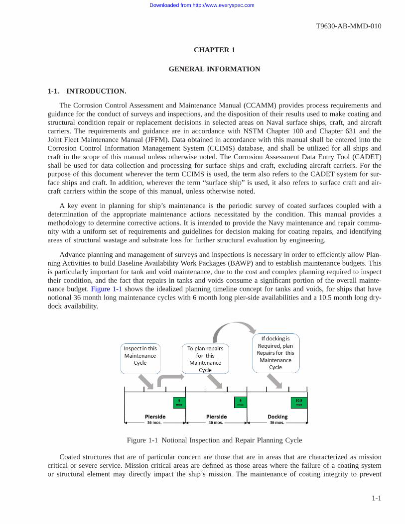
Advance planning and management of surveys and inspections is necessary in order to efficiently allow Plan-ning Activities to build Baseline Availability Work Packages (BAWP) and to establish maintenance budgets. Thisis particularly important for tank and void maintenance, due to the cost and complex planning required to inspecttheir condition, and the fact that repairs in tanks and voids consume a significant portion of the overall mainte-nance budget. Figure 1-1 shows the idealized planning timeline concept for tanks and voids, for ships that havenotional 36 month long maintenance cycles with 6 month long pier-side availabilities and a 10.5 month long dry-dock availability.
Coated structures that are of particular concern are those that are in areas that are characterized as missioncritical or severe service. Mission critical areas are defined as those areas where the failure of a coating systemor structural element may directly impact the ship’s mission. The maintenance of coating integrity to prevent
Figure 1-1 Notional Inspection and Repair Planning Cycle
T9630-AB-MMD-010
1-1
Downloaded from http://www.everyspec.com

structural degradation is necessary to ensure the safe and proper operation of the ship. Severe service areas arethose that require enhanced and targeted surveillance due to the highly corrosive conditions that can lead toaccelerated coating failure and structural degradation.
1-1.1 Organization of Manual. This manual is organized in the following chapters and appendices:
Chapter 1 General Information: Provides the purpose and scope of applicability of this manual. Referencescited herein are listed, as well as a brief description of some key references. Definitions of the terms associatedwith assessments, coatings, corrosion, and ship structures are included in this chapter.
Chapter 2 Surveyor Qualification Requirements: Describes the roles and responsibilities of Level 1 and Level2 survey and inspection personnel, and their qualification requirements. Requirements for the qualifications andscope of responsibilities for Ships Force Interim Level 1 Surveyors are provided. Requirements for maintainingassessment personnel qualifications are described.
Chapter 3 Scheduling of Surveys: Provides the requirements for the scheduling of Class Maintenance Plan(CMP)-driven Level 1 and Level 2 structural and coating condition surveys and inspections. Describes the typesof surveys discussed in this manual and their timing with respect to new ship delivery, complete recoating ofcompartments, and other events. Defines the locations that are to be assessed, and when the assessments of cer-tain locations are to be sub-divided in order to provide for better maintenance planning. Requirements governingthe uses and limitations of non-manned entry methods of condition assessment of tanks and voids are alsoincluded in this chapter.
Chapter 4 Conduct of Surveys: This chapter is generally concerned with the actions of the assessors duringthe actual shipboard assessments, but also includes the applicable planning and preparation requirements, andMaintenance Team requirements regarding temporary services that are needed for certain shipboard locations.Safety precautions and equipment, and assessment tools and equipment are described. Detailed requirementsconcerning coating, structure, and outfitting equipment assessment are described, as well as the requirementsconcerning the assignment of condition rating scores.
Chapter 5 Data Collection And Reporting: This chapter is generally concerned with actions that occur oncethe assessor has left the ship. It describes the requirements for the reporting of assessment findings and the cre-ation of recommended maintenance actions, and defines when CMP assessment tasks can be closed out. Require-ments for the use and maintenance of the CCIMS database are included in this chapter.
Chapter 6 Disposition And Maintenance Actions: This chapter describes the use of the Maintenance RiskDecision Matrix (MRDM) to disposition and prioritize the findings and maintenance actions that result from theassessments. It includes requirements concerning the submission of Departures From Specifications (DFS), itemsthat are considered mandatory “Repair Before Closing” work items for tank and void surveys, and maintenanceactions for ships that are approaching decommissioning.
Appendix A MRC G1N5 Data Collection Form and Instructions: Provides the form to be used to collect dataduring the performance of Level 1 surveys performed in tanks and voids, along with instructions for each datablock.
Appendix B MRC G1N6 Data Collection Form and Instructions: Provides the form to be used to collect dataduring the performance of Level 1 surveys performed in all ship locations other than tanks and voids, along withinstructions for each data block.
Appendix C Compartment Use Designations: Contains a table listing the standard Navy compartment func-tional use designation letters that are part of compartment numbering systems, and the corresponding functions.
T9630-AB-MMD-010
1-2
Downloaded from http://www.everyspec.com

Appendix D Repair 2-KILO/Deficiency Report Best Practices Guide: A guide to preparing well-written anddocumented recommended maintenance action 2-KILO or Deficiency Report (DR) forms that result from theassessments required in this manual. A recommended format for the narrative sections of these forms is alsodescribed.
1-2. PURPOSE.
The purpose of the CCAMM technical manual is to provide a consistent technical methodology for the man-agement of in-service coating and structural systems in selected areas. NSTM Chapter 631 and NAVSEA Stan-dard Item 009-32 establish the technical basis for coating selection and application based on type of service.NSTM Chapter 631 also sets the periodicities for inspecting tanks, voids, and other corrosion-prone areas, andcontains the requirements governing when the coating system in a compartment or area requires completereplacement. NSTM Chapter 100 establishes the requirements for survey, inspection, overall assessment, alter-ation, maintenance, and repair of all ship structure, and establishes the periodicities for surveying structural sys-tems and their coatings. Since the incidence of corrosion results in structural degradation, an inherent relation-ship exists between the initial stages of coating breakdown that, if uncorrected, will lead to structural damagefrom corrosion.
The scheduling of the periodic surveys required by both NSTM Chapter 631 and NSTM Chapter 100 isaccomplished by the respective Naval Planning Activities for surface ships and aircraft carriers. This is docu-mented in the individual ship CMP in conjunction with the Planned Maintenance System (PMS). The CCAMMprovides the requirements for the personnel conducting the surveys, and requirements and guidance concerningthe survey procedures, data collection and reporting. CCAMM also provides the requirements concerning the useof the Insertable Stalk Inspection System (ISIS) and Tank Corrosion Monitoring Systems (TCMS) to accomplishtank and void coating condition assessments without the need for human entry into those compartments.
CCAMM augments NSTM Chapters 100 and 631 by providing consistent coating and structural conditionratings based on the findings of the survey. The term “survey” is used throughout this manual for the Level 1surveys conducted in accordance with MRCs G1N5 and G1N6. The term “inspection” is used throughout thismanual for Level 2 structural inspections conducted as a result of the findings of an MRC G1N5 or G1N6 Level1 survey, or as otherwise directed.
CCAMM also provides assessment procedures for the disposition of survey results based on various factors,including the relative risk, the severity of the service, and whether the ship is in a drydock availability wheregreater access is afforded, especially for tanks. After the initial assessment of newly installed coating systems onthe schedule set by NSTM Chapter 631, CCAMM establishes the condition-based requirements for follow-onrepairs and assessments until the coating is completely replaced. NSTM Chapter 100 establishes similarfollow-on survey requirements for all structures, including tanks and voids.
1-3. SCOPE.
This manual is applicable to the types of ships and craft listed below:
Aircraft Carriers (CVN)
Combatants (CG, DDG, FFG, LCS)
Amphibious Warfare and Command Ships (LHA, LHD, LPD, LSD, LCC)
Patrol Craft (PC)
Use of this manual for submarines and mine warfare vessels is not authorized. The following exceptions areapplicable to aircraft carriers:
T9630-AB-MMD-010
1-3
Downloaded from http://www.everyspec.com

Propulsion Plant Water Tanks: This manual is not applicable to reserve feed water or freshwater drain collect-ing tanks. Requirements for painting and preservation of reserve feed and freshwater drain collecting tanks arecontained in the General Specifications for Overhaul of Surface Ships (GSO) Nuclear Supplement (NAVSEAS9AA0-AB-GOS-020).
Reactor Compartments and Reactor Plant Tanks: None of the requirements of this manual apply to any reac-tor compartments and reactor plant tanks. Requirements for periodic inspection and represervation of reactorcompartments and reactor plant tanks are contained in other documents.
In addition to the hull plating, a ship is divided into compartments by transverse and longitudinal bulkheadsand decks that are an integral part of the structure. Unless otherwise noted, the surveys required by this manualare limited to areas of steel or aluminum alloy ship permanent structure, and include all plating, framing andstiffening elements, structural stanchions, and foundations, and the coatings and other corrosion control systems(e.g. sacrificial anodes, desiccants) used to protect the structure from corrosion. Unless otherwise noted, thismanual is not applicable to the assessment or survey of coatings or corrosion on ship machinery, distributed sys-tems (e.g. piping, ducting, and electrical), or weapons, radar, or other combat systems.
1-4. REFERENCES.
Table 1-1 lists the reference documents cited in this manual. For several of these references, a brief descrip-tion of their scope is provided in the paragraphs below.
Table 1-1 Reference Documents
DOCUMENT NUMBER TITLE
29 CFR 1915, Subpart B Code of Federal Regulations; Occupational Safety andHealth Standards for Shipyard Employment; Confined andEnclosed Spaces and Other Dangerous Atmospheres inShipyard Employment
ASTM D 610 NOTE 4 Standard Test Method for Evaluating Degree of Rusting onPainted Steel Surfaces
ASTM D 714 NOTE 4 Standard Test Method for Evaluating Degree of Rusting onPainted Steel Surfaces
COMFLTFORCOINST 4790.3 Series NOTE 6 Joint Fleet Maintenance Manual (JFMM)MIL-STD-1689 Fabrication, Welding, And Inspection Of Ships StructureMIP 1000/005 NOTE 5 Hull Structure, GeneralMIP 1231/005 NOTE 5 TanksMIP 5882/012 NOTE 5 Aviation Support Facilities; Recovery, Assist, Securing and
Traversing (RAST)MIP 6300/001 NOTE 5 Preservatives and Coverings (Corrosion Control)MRC G1N5 (in MIP Series 1231) NOTE 5 Conduct Assessment Procedure for Tanks and VoidsMRC G1N6 (in MIP Series 1000) NOTE 5 Conduct Assessment Procedure for Interior Structural Sys-
temsMRC 2BF8 (in MIP 5882) NOTE 5 Conduct Assessment Procedure for RAST Track Troughs,
Bolts, and PostsNAVSEA LTR 4700 Ser 05P2/085, 14 Aug 2007 Insertable Stalk Inspection System (ISIS)NAVSEA 0989-026-1000 A4W Reactor Plant ManualNAVSEA 0989-036-0000 CVN 68 Class Steam Plant ManualNAVSEA S6470-AA-SAF-010 NAVSEA Technical Manual Naval Maritime Confined
Space ProgramNAVSEA S9AA0-AB-GOS-010/GSO General Specifications for Overhaul of Surface Ships
(GSO)
T9630-AB-MMD-010
1-4
Downloaded from http://www.everyspec.com

Table 1-1 Reference Documents - Continued
NAVSEA S9086-BS-STM-010 NSTM Chapter 050, Readiness and Care of Inactive ShipsNAVSEA S9086-CH-STM-030 NSTM Chapter 074, Volume 3, Gas Free EngineeringNAVSEA S9086-DA-STM-010 NSTM Chapter 100, Hull StructuresNAVSEA S9086-VD-STM-010 NSTM Chapter 631, Preservation of Ships in ServiceNAVSEA S9086-VF-STM-010 NSTM Chapter 633, Cathodic ProtectionNAVSEA S9086-VG-STM-010 NSTM Chapter 634, Deck CoveringsNAVSEA SE400-DA-MMO-010 Passive Countermeasures System Technical Manual,
Operation And Organizational Level Maintenance (FOUO)NAVSEA SG350-AD-MMC-010 Technical Manual: Tank Corrosion Monitoring Equipment;
Battenkill Technologies Model TMS001NAVSEA T9074-AS-GIB-010/271 Requirements for Nondestructive Testing MethodsNAVSEA T9633-AT-DSP-010 Ships Cathodic Protection Design Calculations, Design
Requirements ManualNAVSEA Std. Item 009-32 NOTE 3 Cleaning and Painting Requirements; AccomplishOPNAV Instruction 5100.23 Navy Occupational Safety And Health. Program ManualSSPC-PA 2 NOTE 1 Procedure For Determining Conformance To Dry Coating
Thickness RequirementsSSPC-VIS 2 NOTE 1 Standard Method of Evaluating Degree of Rusting on
Painted Steel SurfacesNOTES FOR TABLE 1-11. Available from SSPC - The Society for Protective Coatings (SSPC), 40 24th Street, 6th Floor, Pittsburgh, PA 15222-4656. Tel: (412) 281-2331.2. Available from NACE International (NACE), 1440 South Creek Drive, Houston, TX 77094-4906. Tel: (281) 228-6200.3. Available from the NAVSEA Standard Specification For Ship Repair And Alteration Committee (SSRAC), http://www.navsea.navy.mil/CNRMC/SERMC/SSRAC1/default.aspx4. Available from ASTM International, 100 Barr Harbor Drive, PO Box C700, West Conshohocken, PA, 19428-2959.5. Available as part of the periodic Force Revision (FR) distribution of Navy PMS requirements, or at https://www.spear.navy.mil6. Available from SUBMEPP at: https://eagle.submepp.navy.mil/eBusiness/
1-4.1 Navy References.
NAVSEA STANDARD ITEM 009-32 - “Cleaning and Painting Requirements”
Provides requirements for cleaning, surface preparation, and application of coating systems for all surfaceships and submarines. This standard is required to be used to specify maintenance painting work performed bynaval and commercial shipyards, repair activities, and contractors.
General Specifications for Overhaul of Surface Ships (GSO)
Provides technical and administrative requirements for the modernization and repair of surface ships built toUS Navy standards. For painting requirements, GSO Section 631 invokes NAVSEA Standard Item 009-32.
Naval Ships’ Technical Manual (NSTM) Chapter 50
The purpose of this manual is to provide specific requirements for the inactivation, preservation, long-termstorage, safe storage and reactivation of conventionally powered ships and craft.
Naval Ships’ Technical Manual (NSTM) Chapter 100
T9630-AB-MMD-010
1-5
Downloaded from http://www.everyspec.com

Technical manual that specifies the requirements for survey, inspection, alteration, maintenance, and repair ofall ship structure. The manual additionally specifies the criteria for overall assessment and analysis of corrodedor damaged structures including requirements for Departures From Specification (DFS) and risk assessment.
Naval Ships’ Technical Manual (NSTM) Chapter 631
This manual provides instructions, requirements, and information for prevention of corrosion and deteriora-tion of ships, boats, and small craft in the naval service by means of surface preparation, painting, and applica-tion of other preventive measures. Contains the requirements for repair and installation of coating systems byShip’s Force, and supplements Standard Item 009-32.
Naval Ships’ Technical Manual (NSTM) Chapter 633
This manual provides information on the equipment, design, installation, operation, and maintenance ofcathodic protection systems used on active U.S. Navy ships, submarines, boats, and craft.
Naval Ships’ Technical Manual (NSTM) Chapter 634
Provides information concerning: materials, installation procedures, maintenance and repair of nonskid coat-ings and treatments, deck coverings, gratings, and sealing methods and caulking compounds used for sealing deckseams.
PMS Maintenance Requirement Card (MRC) G1N5
Structural System Survey and Inspection maintenance requirement card containing the minimum content forthe conduct and reporting of survey results of surface ship tanks and voids. MRC G1N5 requires the performanceof the Level 1 Structural and Coating Condition Survey, coupled with the follow-on performance of a Level 2Structural Inspection as warranted. Appendix (A) contains the data collection form for conducting MRC G1N5and instructions on its use.
PMS Maintenance Requirement Card (MRC) G1N6
Structural System Survey and Inspection maintenance requirement card containing the minimum content forthe conduct and reporting of survey results of surface ship general structure surveys within internal compartments(other than tanks and voids) and including exterior (topside) areas. MRC G1N6 requires the performance of theLevel 1 Structural and Coating Condition Survey, coupled with the follow-on performance of a Level 2 Struc-tural Inspection as warranted. Appendix (B) contains the data collection form for conducting MRC G1N6 andinstructions on its use.
PMS Maintenance Requirement Card (MRC) G1E8
Maintenance requirement card for conducting surveys of surface ship (except aircraft carriers) combustion airintake and uptake (exhaust) systems and associated equipment. Effective mid-2012, this MRC is no longer appli-cable to the survey of the coatings and structures in the intake and uptake compartments, except for the structuralfoundations of the equipment.
PMS Maintenance Requirement Card (MRC) 2BF8
Maintenance requirement card containing the minimum content for the conduct and reporting of surveyresults of surface ship (except aircraft carriers) Recovery Assist, Securing and Traversing (RAST) track troughstructure surveys.
PMS Maintenance Index Page (MIP) 6300
Primary maintenance requirements for Ship’s Force to inspect interior and exterior ship structure (excludingtanks and voids) and a variety of machinery and equipment items in each compartment or area for corrosion anddamaged paint. It provides a framework to find, document, and treat corrosion related problems that can be pre-vented from becoming more severe and possibly causing structural repairs or equipment malfunctions in thefuture. The MIP contains MRCs describing survey procedures, as well as a series of supporting Unscheduled
T9630-AB-MMD-010
1-6
Downloaded from http://www.everyspec.com
MRCs (U-MRCs) that can be used to guide renewal of various types of corrosion preventive materials or mea-sures. MIP 6300/001 has been assigned to all surface ships and aircraft carriers, but not to submarines.
Insertable Stalk Inspection System (ISIS) - NAVSEA LTR Dated 14 Aug 2007 - 4700 Ser 05P2/085
The purpose of this letter is to provide the confined space requirements for safe insertion of ISIS into potablewater tanks, ballast tanks, and dry voids on Navy ships and submarines.
Joint Fleet Maintenance Manual (JFMM) - COMFLTFORCOINST 4790.3 Series
The JFMM provides a standardized, basic set of minimum maintenance requirements to be used by all TypeCommanders and subordinate commands. It provides technical instructions to ensure that maintenance is planned,executed, completed and documented within all Fleet commands. It also serves as a vehicle for implementingRegional Maintenance policies across all platforms. Sections of the JFMM that influence the processes andrequirements in this manual include Volume II, Part II, Chapter 1 “Ship Maintenance Validation, Screening andBrokering”, and Volume V, Part I, Chapter 8 “Departure from Specification”.
1-4.2 SSPC References.
SSPC-VIS 2 Standard Method for Evaluating Degree of Rusting on Painted Steel Surfaces
VIS 2 is a set of visual standards for evaluating the extent of rusting and coating breakdown on a surface.The standard contains photographs and computer generated diagrams of coated surfaces with various degrees ofcoating breakdown, rusting, and rust stains, for differing types of distribution (e.g. general, localized, and scat-tered). This standard uses the ASTM D 610 0-10 rating system to define the degree of rusting as a percentage ofthe surface area. While this standard and its photographs are intended for use on painted steel surfaces, survey-ors shall also adapt it for use in evaluating the condition of coatings and corrosion on aluminum alloy structures,when required.
SSPC-PA 2 Procedure For Determining Conformance To Dry Coating Thickness Requirements
This standard describes how to measure the dry film thickness (DFT) of a coating that has been applied to ametallic substrate using magnetic or electronic gauges, and provides a method for determining whether an appliedcoating system meets the specified minimum and maximum DFT requirements. The standard also describes theprocedure for calibrating these gauges, notes on gauge principles, and the factors affecting thickness measure-ments. Note that the performance of DFT measurements and the recording of the results is not normally requiredduring the conduct of coating condition surveys performed in accordance with MRCs G1N5 or G1N6. However,DFT data for existing coating systems may be requested as a part of special investigations.
1-4.3 ASTM Standards. Chapter 6 of the Annual Book of ASTM Standards contains testing standards for Paint,Related Coatings, and Aromatics. ASTM standard test methods that are required to be used as a part of conduct-ing coating condition surveys are described below.
ASTM D 610 Standard Test Method for Evaluating Degree of Rusting on Painted Steel Surfaces
This standard provides the primary basis for the condition ratings that are described in this manual. It pro-vides a numerical “rust grade” scale from 0-10 that is based on the percentage of a unit area that is rusted. A rustgrade of zero (0) indicates that greater than 50% of the surface is rusted, while a rust grade of 10 equates to amaximum of 0.01% of the surface area rusted. This standard provides photographic references to assist aninspector in evaluating the degree of rusting of a steel surface. As with SSPC-VIS 2, while this standard and itsphotographs are intended for use on painted steel surfaces, surveyors shall also adapt it for use in evaluating thecondition of coatings and corrosion on aluminum alloy structures, when required.
ASTM D 714 Standard Test Method for Evaluating Degree of Blistering of Paint
T9630-AB-MMD-010
1-7
Downloaded from http://www.everyspec.com

This standard provides photographic references that both defines blister sizes and frequency, and assist aninspector in evaluating the degree of blistering of a coating.
1-5. DEFINITIONS AND TERMS.
This section is intended to provide definitions of the terms associated with coatings and corrosion as theypertain to condition assessments and surveys required by this manual. Where compartments in ships are dis-cussed, this chapter also gives a description of the typical corrosion environment within that area.
1-5.1 Condition Assessment Terms.
1-5.1.1 Condition Based Maintenance. The purpose of condition-based maintenance for ship components is toensure that proactive maintenance action is executed to mitigate risk and preserve functions of critical ship struc-ture, and specified components attached to structure described in this manual. The goal of the coating and struc-tural condition surveys is to evaluate existing material conditions and identify the onset of coating failures, cor-rosion damage, and structural degradation. The objectives are accomplished through time-directed visualsurveillance to determine actual conditions at defined intervals based on historical performance and reliabilitydata. Subsequent condition-directed maintenance actions defined herein are based upon specific component criti-cality, and actual assessed material conditions, as described in Chapter 6.
1-5.1.2 Maintenance Cycle. In this manual, the term “maintenance cycle” refers to periodic availabilities asdefined by OPNAVNOTE 4700, “Representative Intervals, Durations, And Repair Mandays for Depot LevelMaintenance Availabilities of U.S. Navy Ships”. Forward Deployed Naval Force (FDNF) surface ships and air-craft carriers having Selected Restricted Availabilities (SRAs) at periodicities ranging between every 12 to 24months shall use 36 months as the period for next maintenance availability in interpreting the re-assessmentrequirements of this manual. However, when coating or structural repairs in the next maintenance cycle arerequired, these should be planned for the next actual maintenance availability, in order to reduce the risk of pro-gressive damage.
1-5.1.3 Structural System Survey and Inspection Levels. MRC G1N5 and G1N6 Structural System Survey andInspection procedures are required to monitor ship’s material readiness and are classified as:
a. Level 1 Structural and Coating Condition SurveyA Level 1 Structural and Coating Condition Survey (hereafter referred to as a “Level 1 survey”) is typicallya non-invasive survey of ship structures and coatings. Level 1 surveys are performed for regularly scheduledmaintenance assessments.
b. Level 2 Structural InspectionLevel 2 Structural Inspections (hereafter referred to as “Level 2 inspections”) are typically situational andlocation-specific inspections to characterize the condition of the structure, and include thickness gauging.Level 2 inspections usually result from either a deficiency discovered during a Level 1 survey, from a prob-lem reported by the ship, or as otherwise directed. If a Level 2 inspection is conducted such that the scope ofthe inspection includes a) the entire structure of the compartment, and b) the reporting of coating system dis-crepancies in addition to structural repairs, then it can be substituted for a Level 1 survey, and the associatedCMP GA2K task can be considered as completed.
If a Level 1 survey has not been performed in a compartment within the specified periodicity, and a Level 2inspection is being performed in that compartment, then the Level 2 inspection shall include all of the require-ments from a Level 1 survey in addition to the Level 2 inspection requirements.
T9630-AB-MMD-010
1-8
Downloaded from http://www.everyspec.com

1-5.1.4 Recommend Maintenance Action Forms. Maintenance candidate recommendations resulting fromassessments may include calls for follow-on inspections, or some type of preventive or corrective action. Theyare to be documented on Material Assessment Forms (MAF)/OPNAV 4790/2K (“Go Repair 2-KILOs, GR2K”),or, for Naval Shipyards, Deficiency Reports (DRs). Where the term GR2K is referred to in this manual, it alsoapplies to DRs used by Naval Shipyard assessment personnel to document maintenance actions.
1-5.2 Coating and Preservation Process Terms.
1-5.2.1 Surface Preparation. Surface preparation is the process of cleaning and removing degraded coating, dirtand debris, oil and fluids, rust and corrosion, and scale from substrate metal. The surface preparation process mustalso produce a measurable surface profile when a profile is required by the job specification. Proper surfacepreparation is necessary prior to the application of coatings and is a primary factor in coating performance andsubstrate protection. NAVSEA Standard Item 009-32 and NSTM 631 specify surface preparation requirementsand methods. All methods are fully described by industry standards published by SSPC and NACE.
1-5.2.2 Coatings. Coatings are formulated mixtures of materials that are applied and cured over a surfaceforming a continuous adherent film. The term “coatings” may apply to both conventional, liquid-based paints, aswell as to powder coatings or other specialty coatings. For the purpose of this manual, the two terms “coating”and “paint” are used interchangeably.
For depot maintenance activities, all coatings shall be installed in accordance with NAVSEA Standard Item009-32. NSTM Chapter 631 shall be used for coatings work performed by organizational activities (Ships Force).
Anti-corrosion coatings are applied to inhibit the permeation of water, oxygen, and corrosive ions to the metalsubstrate. Most corrosion protection coatings used on Naval ship structures have epoxy chemistries. Refer toNSTM Chapter 631 Section 7 for more information of the various types of coatings used.
1-5.2.3 Coating Touch-up Repairs. NSTM Chapter 631 provides the requirements for when complete represer-vation of a given compartment is required, based upon the location and the percentage of the surface area withcoating failure. When a compartment is assessed and the decision is made to defer replacement of the existingcoating system until a future availability, consideration should be given to the merits of performing touch-uppainting of the existing coating system to extend its life. NSTM Chapter 631 and Standard Item 009-32 providethe following definition of the depot-level scope of touch-up painting work:
Touch-up: Touch-up is defined as preservation operations on cumulative surface areas less than ten percent ofthe total area of the compartment, location (e.g. bilge, superstructure area, etc.), or item of equipment beingpreserved, with no individual area greater than 10 square feet. Included under touch-up operations are new anddisturbed areas of less than 10 square feet.
For compartments where abrasive blasting or water-jetting are the sole required surface preparation methodsand cleanliness standards in NAVSEA Standard Item 009-32 and NSTM Chapter 631, work that falls within thescope of touch-up painting, and work limited to the preservation of disturbed surfaces, the use of SSPC-SP 11power tool cleaning to bare metal is allowed as an acceptable alternative surface preparation method. SSPC-SP11 is a lesser degree of cleanliness than the abrasive blasting or water-jetting that would be required when acomplete coating system replacement is being performed. SSPC-SP 11 is the required minimum surface prepa-ration standard for many types of interior compartments on a ship other than tanks, voids, and certain other cor-rosion prone areas such as intakes and uptakes. Therefore, this allowance generally only affects tanks, voids,intakes and uptakes.
T9630-AB-MMD-010
1-9
Downloaded from http://www.everyspec.com
Standard Item 009-32 contains additional cost-reduction allowances when the scope of preservation work islimited to touch-up coating, such as reduced QA oversight of the work. Therefore, the life expectancy of thecoating in local areas that have been touched-up is less than that expected as the result of a complete represer-vation job.
Touch-up painting should be performed in order to prevent further degradation of the existing coating sys-tem, and arrest corrosion in order to limit the extent of structural material loss. Touch-up painting in tanks andvoids should only be accomplished in areas of localized corrosion when it is more cost effective than completereplacement (renewal) of the coating system and is warranted due to the risk of accelerated corrosion, such as insevere service tanks. It is not cost effective to attempt to perform touch-up coating when the distribution of failedpaint and corrosion is scattered throughout a compartment; therefore, touch-up coating is not recommended inthis circumstance.
1-5.2.4 Critical Coated Areas. The definition from NSTM Chapter 631 is: “Critical coated areas are areaswhere premature failure of the coating system cannot be detected by routine observation due to inaccessibility;those areas where premature failure impacts mission readiness and availability; those areas where restoration ofthe failed system cannot be undertaken without laying up the ship at an industrial facility or a forward repair site;and those areas of high corrosion incidence or high industrial represervation cost where rigorous QA proceduresare required to achieve target coating life goals.”
The term Critical Coated Areas (CCA) should not be confused with corrosion-prone areas on a ship. TheCCA term is specifically defined in NAVSEA Standard Item 009-32 and NSTM Chapter 631 for the purpose ofcontractually invoking a higher level of preservation process oversight and Quality Assurance (QA) requirementsto ensure the applied coating system will achieve its maximum service life.
1-5.2.5 Critical Corrosion and Structural Integrity Areas. “Critical Corrosion and Structural Integrity Areas”(CCSIAs) are those areas of ship structure (other than tanks and voids) that have historically demonstrated highmaintenance associated with corrosion or structural damage due to the nature of the environment or the localdesign susceptibility to cracking or mechanical damage in those areas. CCSIAs require a 36 month Level 1 sur-vey periodicity to determine the condition of the ship structure and coatings. CCSIAs are specified in the shipClass Maintenance Plans (CMP) and are class or ship specific. For some compartments, the two terms “CriticalCoated Area” and “Critical Corrosion and Structural Integrity Areas” overlap, such as machinery compartmentbilges. This is illustrated in Figure 1-2.
T9630-AB-MMD-010
1-10
Downloaded from http://www.everyspec.com

1-5.3 Ship Compartment Terminology.
Definition of “Compartment”: The word “compartment” is used in this manual to indicate each discrete loca-tion on a ship where a Level 1 survey or Level 2 inspection is required to be performed. Standard Naval arrange-ments terminology defines compartments as being bound by horizontal and vertical structure (either tight or non-tight), and generally require that compartments are assigned a number and designation. Appendix C lists thecommon compartment usage designation letters. Weather deck areas usually receive the “X” compartment desig-nation even though they are not completely bounded by structure. The term “compartment” is also used hereinto refer to weather deck areas.
Definition of “Zone”: The word “zone” is used in this manual specific to the scoring system described inChapter 4 that is used to characterize the overall condition of coatings in four discretely defined structural sur-face areas of a compartment.
1-5.3.1 Confined Space. A confined space is defined in NSTM Chapter 074, Volume 3 as follows: “A spacewhich has restricted openings for entry and exit and in which hazardous contaminants could be expected to beproduced but not removed by ventilation; or in which oxygen could be expected to be depleted or enriched”. Aconfined space is any area that personnel do not occupy on a routine basis and that has the potential for contain-ing or accumulating a dangerous atmosphere.
Tanks, voids, and certain other compartments meet the definition of a confined space. Corrosion in a tank orvoid can readily deplete the oxygen content of the air in the compartment. A certified marine chemist, gas-freeengineer, or designated Shipyard Competent Person or industrial hygienist must test the atmosphere of a confinedspace before access is allowed, to ensure that the compartment is safe for human entry. Requirements for gas-freeing vary by facility and organizations, and a gas-free certification that a compartment is safe for human entryperformed by one organization may not meet the gas-free certification requirements for personnel from anotherorganization. All personnel performing confined space surveys are required to know and comply with the gas-freecertification requirements of their command or activity.
1-5.3.2 Tanks (MRC G1N5). The interior of a ship is divided into compartments by transverse and longitudi-nal bulkheads and decks that are an integral part of the structure. Ships compartments are designated according
Figure 1-2 Coating Failure and Structural Damage in a Machinery Compartment Bilge Area
T9630-AB-MMD-010
1-11
Downloaded from http://www.everyspec.com

to the fluid that they contain or the function they perform. A term, such as “fuel oil” and “potable water,” includedin a tank’s name (or its Equipment Functional Description) is such a designation. The material within, and func-tion of, the tank establishes the corrosive environment of the substrate to be protected and the coating systeminstalled. Other factors affecting the service life of the coating in a tank include:
• Temperature of the stored material
• Geometric arrangement
• Mechanical damage
• Presence of dissolved oxygen
• Presence of chemicals and contaminants in the fluid medium (Chlorides, pH, gray water, black water)
• Presence of biological organisms and byproducts
• Local fluid flow rates within the tank
Tanks are categorized for purposes of coating repair decision making as mission critical or severe service asdescribed in Chapter 5.
Tanks normally have sounding tubes to check the level of liquid in the tank, and air vents (escapes) to allowair to fill the tank when it is being pumped out or to allow air to escape when the tank is being filled. Tanks maycontain liquid level indicators, anodes, sounding tubes with striker plates, ladders, and sensors. Tanks may alsocontain other functional elements (e.g. compressed air flasks, piping and piping system components, etc.) thatmay require special expertise to evaluate. With certain exceptions (anodes, sensors, etc.) many of these elementsare generally coated with the same coating system as the tank structure itself. Tank accesses are limited, and aremade by way of bolted manhole covers.
Many tanks contain petroleum products that are not normally subjected to salt water intrusion. These tanksinclude non-compensated fuel oil storage and service tanks, diesel service tanks, lube oil storage/sumps, andhydraulic oil storage tanks. Generally, once these tanks are filled, the fuel or oil provides an effective protectivebarrier inhibiting corrosion. It can be very difficult and expensive to completely remove oil from metal surfacesin these tanks prior to painting, and if it is not removed, it frequently leads to premature coating failures. There-fore, these types of tanks do not require painting.
Free standing tanks are not integral to the ship’s structure, and are not within the scope of this manual. Theymay be constructed from a variety of materials appropriate to their type of service, such as steel, aluminumalloys, copper alloys, or composites. If they are internally coated, they should be inspected and maintained inaccordance with their parent system PMS requirements.
1-5.3.2.1 Fresh Water. Fresh water tanks are all tanks that contain uncontaminated fresh water. Fresh watertanks place special demands on the coating system. Osmotic blistering in coatings is caused by water that pen-etrates through the coating film and is fairly common in fresh water tanks, especially in warm or hot water, sincehigher temperatures let water molecules diffuse through the paint film more easily. Due to water’s ability to pen-etrate a coating film and reach the substrate, fresh water tank coating systems must have excellent wet adhesionattributes to perform adequately. There are several types of tanks that hold fresh water as described below.
1-5.3.2.1.1 Feed Water. Feed water tanks are fresh water tanks that support propulsion systems, such as theship’s boilers. The most important of these tanks are the feed water tanks that are used as a source of makeupwater to the propulsion plant.
T9630-AB-MMD-010
1-12
Downloaded from http://www.everyspec.com
1-5.3.2.1.2 Fresh Water Drain Collecting (FWDC). Fresh Water Drain Collecting tanks are small tanks thatserve a specific function, normally associated with collecting clean steam condensate drains from steam-basedpropulsion systems.
1-5.3.2.1.3 Potable Water. Fresh water tanks that contain drinking water are designated as Potable Water Tanks.Potable water tanks on ships other than aircraft carriers and amphibious ships are typically smaller than othertanks and difficult to properly coat because of restricted maneuvering room. The potable water tank places addi-tional special demands on the coating system from the chemicals used in the treatment process. All materials incontact with potable water require special testing to ensure that potentially harmful chemicals do not contaminatethe water. Potable water tank coatings require National Sanitation Foundation (NSF) certification to ensure thatthey can be used safely in drinking water.
1-5.3.2.1.4 High Pressure Watermist Fire Fighting System. The high pressure water mist firefighting system hasbeen introduced on newer ship classes as a total-compartment fire extinguishing system, generally designed formachinery compartments, that discharges atomized fresh water to suppress shipboard fires.
1-5.3.2.2 Fuel and Fuel Oil. Fuel oil tanks represent the largest tank volume on most surface ships. There areseveral ways that tanks containing various types of fuel are categorized, as indicated below.
• Type of Fuel: fuel intended to be used for ship’s propulsion or on-board electrical power generation (boil-ers, gas turbines, diesel engines and generators), aircraft propulsion (aircraft and helicopters carried on board),or automotive propulsion (Marine Corps or other ground vehicles carried on board). Fuel (either propulsion oraviation) may also be used for auxiliary purposes, such as for Landing Craft, aircraft ground support equip-ment, vehicles, small ship’s boats, etc.
• Readiness for Service: Storage tanks, service tanks, overflow tanks, and stripping or contaminated fueltanks.
• Dual-purpose fuel/ballast: when a ship is designed with fuel tanks that are also intended to be used to bal-last the ship, these tanks are termed “compensated fuel tanks”.
Not all types of ships have all of the above types of fuel tanks. Note that fuel designated as “fuel oil” isalways used for ship propulsion, and is never to be used for aviation purposes whereas JP-5 aviation fuel isalways intended for aviation use, but may be used in ship propulsion applications.
Coatings are used in fuel tanks to both prevent corrosion of the structure, and to prevent contamination of thefuel with corrosion products such as rust. Clean fuel is generally not corrosive to steel and aluminum tanks, butwhen water is present in the tank, either by design (as is case for compensated fuel tanks) or by contamination(such as condensation of water vapor in the unfilled overhead), then a corrosive environment will be produced.When both water and fuel are present in a tank, the fuel will generally sit on top of the water, since water isheavier (denser) than fuel. When water is present, Microbiologically Influenced Corrosion (MIC) can be a fac-tor in addition to general corrosion, especially at the fuel/water interface areas.
The Navy has historically coated all types of fuel tanks. However, after analyzing many years of conditionassessment data, it has been determined that clean fuel oil (FO) storage and service tanks, with very few excep-tions, experienced minimal corrosion or coatings degradation. Therefore, effective in 2011, the requirement tore-paint clean, non-compensated FO storage and service tanks has been removed. However, periodic Level 1 sur-veys using MRC G1N5 continue to be used to validate the structural integrity of the tanks. This policy changedoes not affect aviation or automotive fuel tanks, which are still required to be coated in order to maximize theprevention of any contamination of these fuels.
T9630-AB-MMD-010
1-13
Downloaded from http://www.everyspec.com

Brief descriptions of each type of fuel tank category are provided in the following sub-paragraphs, beginningwith the type of fuel held in the tank, and followed by the designations for the readiness for service of the typeof fuel in the tank.
1-5.3.2.2.1 Fuel Oil (FO). The primary Fuel Oil (FO) used for propulsion and electrical generators is called“naval distillate” fuel, often known by the designation “F-76” as covered by specification MIL-PRF-16884. Theold term “Diesel Fuel Marine” (DFM) is seldom used now. Fuel oil tanks contain various grades of fuel intendedto be used for ship propulsion. The term is not necessarily specific as to whether the fuel will be used for a boiler,gas turbine, or diesel engine. See NSTM Chapter 541 for more information on allowable fuels for Navy appli-cations.
1-5.3.2.2.2 Aviation Fuel (JP-5). JP-5 tanks store fuel for aircraft. JP-5 fuel has stricter fuel property and purityrequirements for aviation safety and therefore have lower maximum allowable contamination limits for water,rust, or other undesirable items. Therefore, there is greater emphasis placed on preventing and detecting contami-nation in JP-5 fuel. In order of increasing severity of corrosive environment, the function or service of JP-5 tanksare categorized as Service, Storage, Ballast, Overflow, and Contaminated.
1-5.3.2.2.3 Automotive Gasoline (MOGAS). Automotive Gasoline or MOGAS is often a blend of separatelydistilled petroleum products. It is very volatile and produces large amounts of vapor at ordinary temperatures.The properties of these vapors make them extremely dangerous either due to their toxic or explosive nature.MOGAS Storage Tanks are designed to provide the greatest possible safety for storage. MOGAS storage systemsare of varying types and may include multiple tanks (i.e. outer, draw-off and cofferdams). They may also includethe use of seawater as in compensated fuel systems. Internal storage of MOGAS has been increasingly diminish-ing to the extent where MOGAS storage is more commonly accomplished in a portable manner, as opposed tostoring it internally within ship tanks.
1-5.3.2.2.4 Fuel Storage. Storage tanks are Receiving and Holding tanks that are used until the fuel is neededfor purification and transfer to the service tanks.
1-5.3.2.2.5 Fuel Service. Service tanks contain the fuel that has been purified and filtered and is ready to beused.
1-5.3.2.2.6 Contaminated Fuel (Stripping). Contaminated fuel tanks receive contaminated fuel and water fromthe fuel stripping pumps or other stripping equipment. The fuel stripping process removes water and any sedi-ment from tank bottoms where they settle. Contaminated JP-5 tanks may also receive contaminated fuel removedfrom aircraft.
1-5.3.2.2.7 Compensated Fuel . On some ships, the fuel storage tanks are designed to contain either fuel orseawater, or both at the same time. As the fuel is used by the ship, or transferred to another tank, seawater isadded to compensate for the weight of the lost fuel in order to maintain the proper waterborne stability (centerof gravity, list or trim control, etc.) of the ship. Fuel storage tanks may be classified as Fuel/Ballast tanks, wherethe tank may be filled with seawater for stability purposes. In these instances, the tanks are filled with either allfuel or all seawater. Upon completion of the need, the seawater is de-ballasted and refilled with fuel. Coatingsinstalled in compensating fuel tanks must be resistant to both fuel oil and seawater.
1-5.3.2.2.8 Non-Compensated Fuel. Fuel oil tanks that exclusively store fuel and are not designed to receiveseawater as ballast are called non-compensated tanks.
T9630-AB-MMD-010
1-14
Downloaded from http://www.everyspec.com

1-5.3.2.3 Lubricating (Lube) Oil (LO) and Hydraulic Oil. Lube oil (LO) tanks and LO sump tanks store lubri-cation oil for the main propulsion and auxiliary machinery systems. Main reduction gears (MRG) and control-lable pitch propellers (CPP) are typical equipment that may have LO tanks and LO sump tanks. LO tanks arerelatively small tanks. The major concern is water contamination in the lube oil that may cause corrosion prod-ucts, or flaking coating particles, that could disrupt flow to vital equipment. LO tank internals on surface shipsand aircraft carriers are generally not painted; however, Level 1 surveys using MRC G1N5 are required in orderto verify the structural integrity of LO and LO sump tanks that are integral to the ship’s structure. LO tanks thatare free-standing, or an integral part of engines or machinery are not required to be surveyed under the scope ofthis manual.
Hydraulic oil tanks serving machinery systems are treated similarly to LO tanks. They are generally notcoated, and require infrequent surveys to verify their structural integrity, only when they have one or moreboundaries that are comprised of ship structure.
1-5.3.2.4 Ballast and List Control. All ships have ballast tanks, normally at the bow and stern to adjust trim ofthe ship. Larger ships may have wing ballast tanks to control list. Some ships have additional ballast tanks tocompensate for the use of variable loads such as fuel, ammo and stores. Amphibious ships have large numbersof ballast tanks in order to allow them to sit lower in the water so that they can discharge and receive landingcraft.
1-5.3.2.5 Collection, Holding & Transfer (CHT). CHT tanks serve as reservoirs in sewage treatment systems.They may additionally be characterized as gravity CHT tanks or vacuum CHT tanks depending on the overallsystem design. Both “black water” and “gray water” can flow into these tanks. Additionally, depending on thespecific ship design, the flushing and other system water may be either sea water or fresh water. CHT systemsgenerally rely on bacterial colonies to help break down the sewage, and this action can create acidic byproductsthat increase the rate of coating degradation and corrosion of unprotected steel.
1-5.3.2.6 Wastewater Collecting (Plumbing Waste). Wastewater collecting tanks are drain and holding tanks forengineering compartments, dishwashers, laundry, galley and berthing areas. This waste water is commonlytermed “gray water”. These tanks differ from normal water tanks as they contain a mixture of caustic cleaningchemicals and detergents. On some classes of hulls these waste waters are mixed into the CHT system.
1-5.3.2.7 Oily Waste and Contaminated Oil. Bilge and oily waste tanks are specific types of wastewater tanksaccording to the primary drainage.
Oily Water and Oily Waste Tanks include tanks storing any oily waste liquid including bilge and oily waste.These tanks may contain substantial amounts of water as in the case of an Oily Water Holding Tank (OWHT) orBilge and Oily Waste Tanks. These tanks store bilge water until it can be further processed so that the water por-tion is sufficiently clean to allow overboard discharge. Other oily substances that may be contained in these tanksare fuel oil, JP-5, lube oil, and hydraulic oil.
1-5.3.3 Voids and Cofferdams (MRC G1N5). Voids and cofferdams are compartments that may be designed forreserve buoyancy, or to limit the extent of flooding after underwater hull damage, or to provide physical separa-tion between two different types of tanks. Voids may also simply be unusable volumes or areas in a ship result-ing from ship design and layout. Voids are normally designed to be empty. (Note that unapproved use of dry voidcompartments for storage may negatively impact survivability design requirements for the ship. Although notingand reporting this practice is not within the scope of the surveyor requirements contained in this manual, survey-ors may be asked to make note of this by their local authorities.) Void compartments may also be categorized as
T9630-AB-MMD-010
1-15
Downloaded from http://www.everyspec.com

accessible or inaccessible, depending on whether there are any provisions (or ability) for a human to enter them.Inspection and assessment of inaccessible voids are not within the scope of this publication. Common types ofvoids and cofferdams are described below.
1-5.3.3.1 Voids (Normally Dry). These types of voids are primarily meant to provide reserve buoyancy andsurvivability. Some special voids are the result of unusable volumes from ship design and layout.
1-5.3.3.2 Voids (Floodable). Floodable voids are those that are designed to provide counter flooding capabilityfor asymmetrical flooding after damage. They are designed to be dry and are not to be used for ship ballastingor trimming purposes such as list control. If floodable voids are used for other than damage control purposes theType Commander must be notified and they are required to be filled with fresh water and emptied as soon aspracticable. They may be termed Damage Control (DC) Voids, especially on aircraft carriers. Since floodablevoids are subject to seawater exposure, they require coating similar to ballast tanks.
1-5.3.3.3 Voids (Cofferdams). Cofferdams are normally located to separate one type of liquid from another, inorder to provide more physical separation than simply a common bulkhead between adjacent tanks. The coffer-dams have sounding tubes installed so that the crew can detect if liquid has leaked into the cofferdam from eitheradjacent tank. Cofferdams may be found under main propulsion machinery such as the reduction gears, to pro-vide separation between the lube oil sumps and other tanks such as fuel or water tanks. Cofferdams may be foundadjacent to potable and reserve feed water tanks separating these from other tanks such as fuel or ballast tanks.
1-5.3.3.4 Voids (Catapult Wing). These voids are only found on aircraft carriers. Catapult wing voids are com-partments outboard of the catapult trough walls on each side of the trough. Each void consists of the knuckleddown flight deck, the vertical longitudinal trough girder, and a cover plate. These voids provide access to theupper and lower support bar mounting fixtures. Triangular web frames are provided every four (4) feet betweenthe vertical longitudinal trough girder and the inclined (knuckled) flight deck to provide structural support for thecatapult trough walls. An example of an aircraft carrier catapult wing void is shown in Figure 1-3.
T9630-AB-MMD-010
1-16
Downloaded from http://www.everyspec.com

1-5.3.3.5 Sponson Voids. Sponson voids are a subset of dry voids located within the enclosed sponson struc-tures (see paragraph 1-5.4), and are typically located in the lower portions of the sponson above the lower ter-mination. The walking access and usable space in sponson voids is limited due to the angle of dead rise and nar-row flat connection of the lower termination. They are generally only found on aircraft carriers and large-deckamphibious ships. See Figure 1-8.
1-5.3.4 Bilges (MRC G1N6). Bilges are generally integral to engineering or machinery compartments locatedeither where the two sides of the hull meet at the keel, or above innerbottom tanks for some hull designs. Formany classes of ships, there are formally defined bilge volumes or areas, since a definition is required in orderto convey differing coating, corrosion control, or damage control requirements for the bilge area vs. the rest ofthe compartment. A formal bilge area definition may use an actual physical boundary (such as the lowest deckplate level in the compartment) in combination with an imaginary geometric plane boundary (e.g. a line that canbe drawn at some specific angle, extending until it intersects the port and starboard shell plating; this is normallyreferred to as the wet bilge line). This allows the defined bilge volume to take into account water that could riseup the sides of the compartment as the ship rolls.
The bilge areas of machinery compartments are generally the lowest accessible manned compartments of theship. Bilges may contain seawater, condensate water, oily detergents, oily waste, solvents, chemicals, dirt andother contaminants. Bilge areas are inherently difficult to both preserve and inspect due to their location, geomet-ric complexity, degree of interferences from piping and foundations, and the need to de-water (pump down) anyliquid in the bilge. Figure 1-4 shows a bilge pocket area that would require de-watering and cleaning prior tocompleting a survey, since the structure is obscured from view by a large amount of oily water and sludge. Oilyfilms on plating can make footing very slippery and treacherous. In addition to these factors, represervation inparticular is made more cumbersome due to the need to contain overflows, leaks, drips, and condensation frompiping systems and funnels throughout the surface preparation and painting process.
Figure 1-3 Aircraft Carrier Catapult Wing Void
T9630-AB-MMD-010
1-17
Downloaded from http://www.everyspec.com

1-5.3.5 Ventilation and Combustion Air Handling Compartments (MRC G1N6). Shipboard Heating, Ventila-tion, and Air Conditioning (HVAC) systems provide for the intake, circulation, and discharge of air through com-partments of the ship. On some classes of ships, the air handling system design may also be required to filter outChemical, Biological, and Radiological (CBR) contaminants before the air enters designated zones of the ship;these systems are termed Collective Protection Systems (CPS).
Combustion air handling to support the operation of gas turbines, boilers, or diesel engines is a separate airhandling system from HVAC and CPS systems, and may require filtration of the intake air, or cooling of the hightemperature exhaust gases in order to reduce the ships thermal signature.
From a corrosion perspective, there are some common characteristics of these systems that affect how cor-rosive the environment is in the compartments that the air passes through. Air intakes draw in humid, salt-ladenair, and may be subject to wave slap, salt spray, sand, insects, and other foreign material contributing to a corro-sive/erosive environment. Generally, the closer to the waterline that an air intake is located, the greater amountof salt and spray is ingested. Compartments that handle HVAC and CPS discharge air on the other hand tend tohave a less aggressive corrosion environment since they are blowing out relatively clean air.
Compartments that handle combustion air exhaust are often the most aggressively corrosive environmentsdue to the combination of acidic exhaust gases with salty, humid exterior air.
1-5.3.5.1 HVAC and CPS Ventilation Compartments. These air handling systems have some common terminol-ogy and some unique terminology pertaining to the compartments that the air passes through, as described below.Figure 1-5 is provided for reference.
Figure 1-4 Bilge Pocket Obscured by Oily Water and Sludge
T9630-AB-MMD-010
1-18
Downloaded from http://www.everyspec.com

Vent Plenum: A vent plenum is defined as an interior air handling chamber or compartment with an openingto the weather where ventilation air enters the ship before passing through a trunk, duct, or dampers prior tothe intake fan or fan room. On shipboard compartment or arrangement plans, a plenum may have its owncompartment designation, may be designated as a part of an adjacent fan room, or may simply be designatedas a plenum with no compartment number. A structural plenum will have one or more of its boundaries formedby primary ship structure (e.g. a deck, bulkhead, or shell plating), and the other boundaries may be formed bysheet metal. Note that this definition may also apply to vent plenums handling discharge, or exhaust, air.
Vent Trunk: The main structural enclosure carrying air to the deck(s) or compartments above or below the levelof the intake plenum or fan room. Trunks may have one or more boundaries (sides) that are integral to shipstructure.
Duct: The sheet metal branches off of a trunk carrying air to a specific compartment. Ducts may be rectangu-lar or circular (pipe). Sheet metal thicknesses for ducts may typically range up to 1/8-inch (0.125”), or evengreater depending on the size and damage control tightness designation of the duct.
1-5.3.5.1.1 HVAC and CPS Ventilation Intake Compartments. An HVAC or CPS intake compartment can be afan room or vent plenum facilitating the movement of air from the exterior (weather) to the interior ship com-partments. Air enters designated supply systems either by mechanical means (i.e. fans), or by natural convection.For ships with CPS, the intake fan rooms are generally physically divided by banks of filter elements designed
Figure 1-5 Illustration of Typical HVAC System Terminology
T9630-AB-MMD-010
1-19
Downloaded from http://www.everyspec.com

to remove any CBR contaminants, as well as entrained salt and moisture. Depending on the ship configuration,each side of the CPS filter bank may have different compartment number designations. The compartment or sideon the inlet side of the filter bank is often called the “dirty side”, and the compartment or side downstream of thefilter bank is called the “clean side”. The clean side of CPS fan rooms is generally not a corrosion prone area.
When conducting MRC G1N6 surveys in CPS intake fan rooms where the dirtyside plenums have either no unique compartment numbers, or have been assignedthe same compartment number as the clean side of the fan room, surveyors arerequired to remove bolted access panels in order to inspect each individual ple-num chamber. Depending on the ship configuration, there may be as many as 9of these plenums that must be accessed from the clean side of the fan room.
1-5.3.5.1.2 HVAC and CPS Ventilation Outlet Compartments. An HVAC or CPS outlet compartment can be afan room or vent plenum allowing for the movement of air from the interior of the ship to overboard. They mayalso be called exhaust or discharge compartments, vent plenums, or fan rooms. When the exhaust fans are oper-ating, relatively dry and particulate free air from inside the ship is being constantly blown out to overboard. Thisgenerally prevents humid salt air from coming into the compartment, making the compartment less susceptibleto corrosion than its equivalent intake compartment. However, this will not be sufficient to prevent green waterentry from wave slap, especially for compartments that are close to the waterline.
1-5.3.5.2 Combustion Air Intakes. The configuration and terminology used for combustion air intake compart-ments can vary widely by ship class and the type of propulsion system or electrical power generation system.The corrosiveness of the environment in combustion air intake compartments can be similar to that for HVACand CPS air intakes. An intake compartment or intake plenum for air going to boilers or diesel engines may havea design feature called an “air lift” or serpentine path intended to cause particulates, entrained moisture and saltsto fall out of the air before the air enters a trunk or ducting leading to the diesel engine or to the forced draftblowers for a boiler. Combustion intake air going to gas turbines must pass through a bank of moisture separa-tors and particulate filters before it reaches the gas turbine, in order to prevent corrosion and erosion of the gasturbine. This makes gas turbine air handling areas similar to CPS systems described above, with the area of thecompartment prior to the filter assembly being termed the “dirty sides,” and the area of the compartment wherethe filtered air is discharged called the “clean side.” A compartment containing the filter assembly may have asingle compartment designation number, but may have separate access doors or hatches to the clean and dirtysides.
1-5.3.5.3 Combustion Exhaust Uptakes. In general, only gas turbine ships have compartments designated as“uptake compartments”, since boiler and diesel engine exhaust gases usually go directly into an exhaust pipeenclosed within an exhaust stack. A combustion uptake compartment allows for the mixing of hot gas turbineexhaust gases with outside air, in order to cool the exhaust gases just before they exit the ship to reduce a ship’sheat signature. They are also called “mixing rooms” or “bliss rooms,” with the latter name coming from the blisscap assembly that sits above the exhaust pipe that comes up through the deck. Uptake compartments are highlysusceptible to corrosion due to the high volume of humid salt laden air and sea spray drawn in to the compart-ment via air intake louvers, high temperatures due to the exhaust, and the presence of acidic exhaust gases. Thedeck and equipment in these compartments is regularly wetted from sea spray, rain, etc.
1-5.3.6 Topside/Weather Decks (MRC G1N6). Topsides, or weather decks, are defined as exterior areas of theship that are directly exposed to weather conditions, but are not within the boundary of a formally designatedcompartment. The topside environment differs from the internal areas of the ship due to the combination of seawater, sea spray, ultraviolet light (sunlight) exposure, and wide temperature ranges, all of which can acceleratethe degradation of coating systems and corrosion of the structure. Certain topside areas may require that ″manaloft″ tag-outs be coordinated with the ship in order to secure radiating equipment. Likewise, the use of fall pro-tection equipment may also be required.
T9630-AB-MMD-010
1-20
Downloaded from http://www.everyspec.com

Items within the scope of topside condition surveys consist of steel and aluminum hull structure and super-structure, depending on the configuration of the ship. Decks, bulkheads, masts, and foundations shall all beassessed. The structure of aircraft elevators on aircraft carriers and amphibious ships, and the stern gates onamphibious ships shall also be assessed. Some ship classes, such as DDG-51 and LPD-17, have topside RadarCross Section Reduction (RCSR) voids and enclosures that are hollow exterior structures of composite or metal-lic framing, plates, and access panels having one or more boundaries that are ship structure (e.g. a deck or bulk-head) and are subject to the marine atmosphere and occasional seawater entry. See paragraph 4-3.8 for a moredetailed description of the scope of topside survey areas. Dissimilar metal junctions (referred to as bimetallicjoints or “detacouples”) can exist between steel structures and aluminum structures; and between these structuresand the hull, mechanical and electrical (HM&E) or command, control, communications, computers, combat sys-tems and intelligence (C5I) equipment mounted to them.
In most cases, there are no specific compartment numbers for topside areas, although individual ships maybreak the areas up into logical regions for the purpose of assigning work center responsibilities. MRC G1N6 sur-vey tasks may be pushed out by the Planning Activities using varying conventions, such as deck levels and rangesof frames, and the use of “-X” in the fourth part of a typical compartment number designation, e.g. “01-174-0-X”.
1-5.4 Ship Structure Terminology. A brief overview of the more commonly used terminology and nomencla-ture for ship structure is provided below. Figures 1-6 through 1-8 provide visual references for some of the termsbelow. Refer to NSTM Chapter 100 for more detailed information and strength criteria.
1-5.4.1 Structural Integrity. The ability of a structure to perform its intended function. These functions mayinclude carrying static and dynamic loads; providing structural, environmental, and damage control tightnessboundaries; and other functions.
1-5.4.2 Structural Assessment. Assessment of structural systems is the overall process of performing regularlyscheduled Level 1 Surveys, Level 2 Inspections, performing structural integrity strength analyses and evaluationof damage when discovered, predicting additional wastage and expected condition of the structure by the timerepairs are anticipated to be performed, and documenting the results and required repairs. The overall assessmentdetermines the subsequent need for repairs, prioritization of those repairs, and the associated risks and actionsrequired when seeking deferral of repairs.
To determine the extent of thickness loss from corrosion, or other damage, the original design scantlingthickness, geometries, and arrangement of plating and structural members may be obtained from the ship’s draw-ings. If not available on site, drawings for naval surface vessels may be obtained online from the Naval ShipsEngineering Drawing Repository (NSEDR) at https://nsedr.nnsy.navy.mil/webjedmics/index.jsp. A user accountmust be obtained prior to accessing this site.
1-5.4.3 Scantlings. The term scantling refers to the description of the overall structure of the ship; their sizeand thickness.
1-5.4.4 Hull Girder. The portion of the hull structure that contributes to longitudinal strength is referred to as“primary” or “hull girder” structure. The hull girder includes those portions of the ship’s structure that maintainthe structural strength and watertight integrity of the hull and other structure. The ship’s hull girder is a complexbox girder consisting of the plating and stiffeners of the shell, decks, innerbottom, keel, and longitudinal bulk-heads. Longitudinal strength structure is generally continuous through transverse structures, with the transversestructure constructed as an intercostal. An intercostal structural frame member is non-continuous, as it terminateson either side of a continuous member, and is attached to the continuous member by welding.
T9630-AB-MMD-010
1-21
Downloaded from http://www.everyspec.com
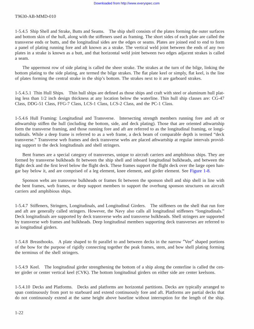
1-5.4.5 Ship Shell and Strake, Butts and Seams. The ship shell consists of the plates forming the outer surfacesand bottom skin of the hull, along with the stiffeners used as framing. The short sides of each plate are called thetransverse ends or butts, and the longitudinal sides are the edges or seams. Plates are joined end to end to forma panel of plating running fore and aft known as a strake. The vertical weld joint between the ends of any twoplates in a strake is known as a butt, and that horizontal weld joint between two edges adjacent strakes is calleda seam.
The uppermost row of side plating is called the sheer strake. The strakes at the turn of the bilge, linking thebottom plating to the side plating, are termed the bilge strakes. The flat plate keel or simply, flat keel, is the lineof plates forming the central strake in the ship’s bottom. The strakes next to it are garboard strakes.
1-5.4.5.1 Thin Hull Ships. Thin hull ships are defined as those ships and craft with steel or aluminum hull plat-ing less than 1/2 inch design thickness at any location below the waterline. Thin hull ship classes are: CG-47Class, DDG-51 Class, FFG-7 Class, LCS-1 Class, LCS-2 Class, and the PC-1 Class.
1-5.4.6 Hull Framing: Longitudinal and Transverse. Intersecting strength members running fore and aft orathwartship stiffen the hull (including the bottom, side, and deck plating). Those that are oriented athwartshipform the transverse framing, and those running fore and aft are referred to as the longitudinal framing, or longi-tudinals. While a deep frame is referred to as a web frame, a deck beam of comparable depth is termed “decktransverse.” Transverse web frames and deck transverse webs are placed athwartship at regular intervals provid-ing support to the deck longitudinals and shell stringers.
Bent frames are a special category of transverses, unique to aircraft carriers and amphibious ships. They areformed by transverse bulkheads fit between the ship shell and inboard longitudinal bulkheads, and between theflight deck and the first level below the flight deck. These frames support the flight deck over the large open han-gar bay below it, and are comprised of a leg element, knee element, and girder element. See Figure 1-8.
Sponson webs are transverse bulkheads or frames fit between the sponson shell and ship shell in line withthe bent frames, web frames, or deep support members to support the overhung sponson structures on aircraftcarriers and amphibious ships.
1-5.4.7 Stiffeners, Stringers, Longitudinals, and Longitudinal Girders. The stiffeners on the shell that run foreand aft are generally called stringers. However, the Navy also calls all longitudinal stiffeners “longitudinals.”Deck longitudinals are supported by deck transverse webs and transverse bulkheads. Shell stringers are supportedby transverse web frames and bulkheads. Deep longitudinal members supporting deck transverses are referred toas longitudinal girders.
1-5.4.8 Breasthooks. A plate shaped to fit parallel to and between decks in the narrow ″Vee″ shaped portionsof the bow for the purpose of rigidly connecting together the peak frames, stem, and bow shell plating formingthe terminus of the shell stringers.
1-5.4.9 Keel. The longitudinal girder strengthening the bottom of a ship along the centerline is called the cen-ter girder or center vertical keel (CVK). The bottom longitudinal girders on either side are center keelsons.
1-5.4.10 Decks and Platforms. Decks and platforms are horizontal partitions. Decks are typically arranged tospan continuously from port to starboard and extend continuously fore and aft. Platforms are partial decks thatdo not continuously extend at the same height above baseline without interruption for the length of the ship.
T9630-AB-MMD-010
1-22
Downloaded from http://www.everyspec.com
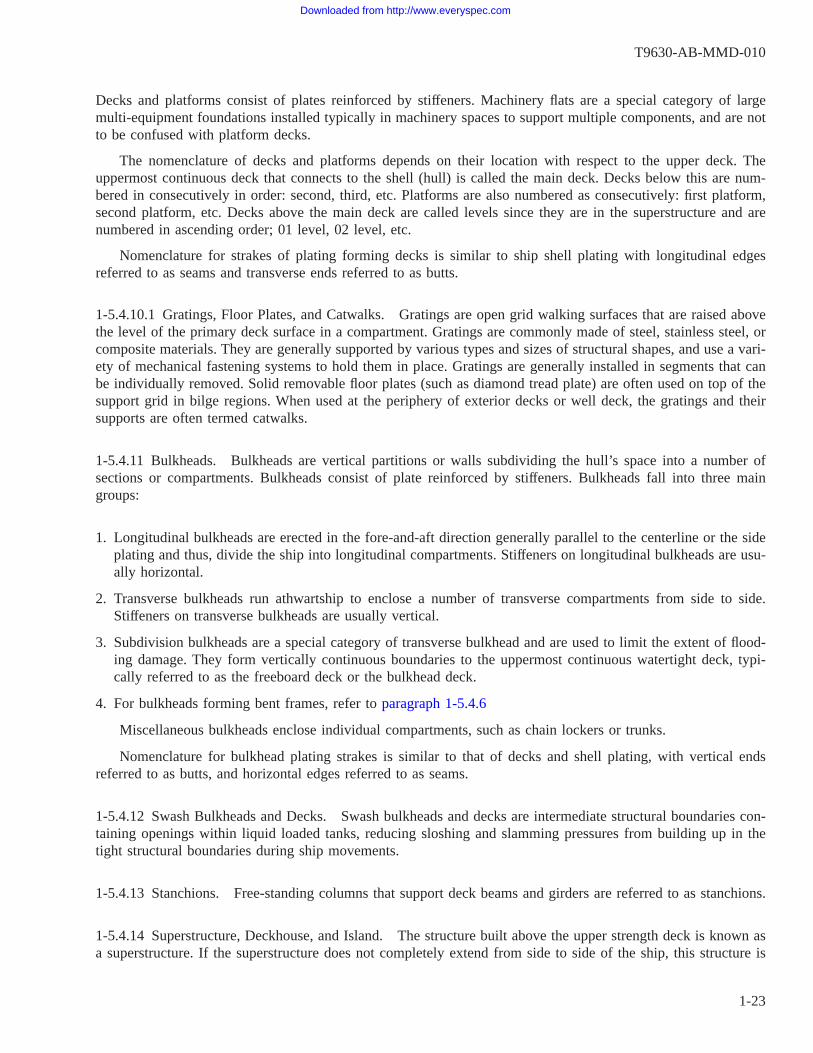
Decks and platforms consist of plates reinforced by stiffeners. Machinery flats are a special category of largemulti-equipment foundations installed typically in machinery spaces to support multiple components, and are notto be confused with platform decks.
The nomenclature of decks and platforms depends on their location with respect to the upper deck. Theuppermost continuous deck that connects to the shell (hull) is called the main deck. Decks below this are num-bered in consecutively in order: second, third, etc. Platforms are also numbered as consecutively: first platform,second platform, etc. Decks above the main deck are called levels since they are in the superstructure and arenumbered in ascending order; 01 level, 02 level, etc.
Nomenclature for strakes of plating forming decks is similar to ship shell plating with longitudinal edgesreferred to as seams and transverse ends referred to as butts.
1-5.4.10.1 Gratings, Floor Plates, and Catwalks. Gratings are open grid walking surfaces that are raised abovethe level of the primary deck surface in a compartment. Gratings are commonly made of steel, stainless steel, orcomposite materials. They are generally supported by various types and sizes of structural shapes, and use a vari-ety of mechanical fastening systems to hold them in place. Gratings are generally installed in segments that canbe individually removed. Solid removable floor plates (such as diamond tread plate) are often used on top of thesupport grid in bilge regions. When used at the periphery of exterior decks or well deck, the gratings and theirsupports are often termed catwalks.
1-5.4.11 Bulkheads. Bulkheads are vertical partitions or walls subdividing the hull’s space into a number ofsections or compartments. Bulkheads consist of plate reinforced by stiffeners. Bulkheads fall into three maingroups:
1. Longitudinal bulkheads are erected in the fore-and-aft direction generally parallel to the centerline or the sideplating and thus, divide the ship into longitudinal compartments. Stiffeners on longitudinal bulkheads are usu-ally horizontal.
2. Transverse bulkheads run athwartship to enclose a number of transverse compartments from side to side.Stiffeners on transverse bulkheads are usually vertical.
3. Subdivision bulkheads are a special category of transverse bulkhead and are used to limit the extent of flood-ing damage. They form vertically continuous boundaries to the uppermost continuous watertight deck, typi-cally referred to as the freeboard deck or the bulkhead deck.
4. For bulkheads forming bent frames, refer to paragraph 1-5.4.6
Miscellaneous bulkheads enclose individual compartments, such as chain lockers or trunks.
Nomenclature for bulkhead plating strakes is similar to that of decks and shell plating, with vertical endsreferred to as butts, and horizontal edges referred to as seams.
1-5.4.12 Swash Bulkheads and Decks. Swash bulkheads and decks are intermediate structural boundaries con-taining openings within liquid loaded tanks, reducing sloshing and slamming pressures from building up in thetight structural boundaries during ship movements.
1-5.4.13 Stanchions. Free-standing columns that support deck beams and girders are referred to as stanchions.
1-5.4.14 Superstructure, Deckhouse, and Island. The structure built above the upper strength deck is known asa superstructure. If the superstructure does not completely extend from side to side of the ship, this structure is
T9630-AB-MMD-010
1-23
Downloaded from http://www.everyspec.com
referred to as a deckhouse. On ships with large, open aircraft handling decks such as aircraft carriers and sometypes of amphibious ships, the superstructures rising above these decks are termed islands, and they are charac-terized by being several times taller than they are wide. The sides and decks of the superstructure are constructedof stiffened plating.
1-5.4.15 Masts, Stacks and Towers. Tall vertical or raked structures used to carry navigation lights, communi-cations antennae, radars, etc., or to enclose engine exhaust uptakes.
1-5.4.16 Foundations. Foundations are structural elements that are welded to the ship structure that providesupport and mounting points for a variety of shipboard equipment. Foundations can support a wide variety ofship machinery (engine modules, reduction gears, generators, boilers, pumps, motors, winches, heat exchangersand condensers, etc.) and combat/weapons systems (antennas, radar, guns, missile launchers, etc.).
Equipment can be mounted to foundations in a variety of ways, including direct fastening, varying types ofshock or noise isolation mounts, and via intermediate support frames or carriages that may be called machineryflats, bed plates, skids, or rafts.
Foundations are generally required to be painted the same as the structure that they are attached to. The coat-ings and corrosion condition of foundations are affected by both the nature of the environment of the compart-ment where they are located, and by the type of equipment that is being supported. For example, a foundationfor a seawater fire pump will be subjected to occasional exposure to seawater from leaks or maintenance actions,and will be more subject to corrosion than a foundation for a propulsion shaft bearing.
1-5.4.17 Sponsons and Sponson Shell. Sponsons are structural appendages/enclosures attached to, and locatedoutboard of the ship shell. They provide additional deck area and compartments for support of equipment, oradditional extensions of a flight deck or other deck structures, or both, and include the support structures below.Within the enclosed sponson structures, dry voids are located in the lower portions where accessibility is limited.Sponsons are generally only found on aircraft carriers and large-deck amphibious ships. See Figure 1-8.
Sponson shell plating is similar as described for ship shell plating, and forms the outboard enclosure of thesponson.
1-5.4.18 Freeboard. The term freeboard refers to the exterior weather-exposed side of the shell plating thatextends from the waterline (boot top) to the gunwales, or deck edges. For aircraft carriers and amphibious shipswith flight decks, it includes all structures external to the ship shell and sponson shell plating from the boot topto the flight decks, except for aircraft elevators. This area may also be structurally referred to as the wind andwater strakes. For the purposes of this manual, aircraft elevators have their own unique MRC G1N6 survey taskrequirements.
1-5.4.19 Drain Holes (Limber Holes). Drain holes (also sometimes called “limber holes”, “rat holes” or“snipes”) are holes that are incorporated into a structure by design to allow drainage of liquids from stiffeningelements or other pockets to a bilge or deck, in order to minimize water traps and ponding that can result instructural degradation. As designed, the holes generally should not be larger than 20% of the depth of the webof the stiffening element they are located in. The holes may be half-round, round, or oblong (flat oval). Half-round holes are generally used at the welded attachment edge of the member being drained; a round hole is oftenlocated adjacent to the attachment fillet weld of the member if a half-round hole has not been used. The termlimber hole or snipe is more commonly associated with triangular openings in vertical framing members at inter-secting horizontal stiffeners adjacent to shell or bulkhead plating, to allow fluid to flow along the horizontalmember until it reaches a drain hole.
T9630-AB-MMD-010
1-24
Downloaded from http://www.everyspec.com

1-5.4.20 Reinforcing Rings and Coamings. Various terminologies are often used for reinforcing rings andcoamings, including spool pieces, pipe sleeves, waterway bars, and others.
A reinforcing ring is provided around an opening to provide strength compensation and stiffening around theperiphery of the opening. If the size or location of an opening is such that it would impair the strength of thestructure, one of the measures to be taken to reduce stress in way of the hole is to provide a reinforcing ring.Reinforcing rings are often integral parts of deck and bulkhead watertight closure assemblies such as doors,hatches, scuttles, and manholes. The term “spool piece” is often used for ventilation ducting reinforcing rings indecks and bulkheads.
Coamings are generally vertical flat bars welded to the upper surfaces of decks or platforms, and are placedadjacent to or around the periphery of openings or edges of the decks. They are designed to deflect, contain, orprevent/direct the movement of water. On steel decks, they may be made of steel or stainless steel (CRES); onaluminum decks, they are made of aluminum. In some cases, reinforcing rings serve a dual function and also actas a coaming.
Coamings may be encountered in a greater variety of applications than reinforcing rings, such as:
• Around smaller size deck penetrations of piping, ducting, and cable/conduit.
• Around deck drains, especially when a deck covering material is installed, or when a machinery systemdrain pipe is directed to discharge over the deck drain.
• Around pumps, heat exchangers, and other fluid handling machinery to contain spills and leaks.
• Around the periphery of exterior deck and platform edges, to control and direct the flow of water to a deckdrain or scupper. In these cases, the term waterway bar is often used.
Pipe sleeves are reinforcing rings used to reinforce the pipe wall and provide structural compensation foropenings where piping passes through structures. In non-tight clearance openings they are referred to only asreinforcing rings or spools. In applications passing through tight structures, where the pipe is seal welded to theouter sleeve, they are referred to as pipe sleeves. Typically pipe sleeves with clear openings of 5 inch diameteror greater are used as structural compensation and reinforcement of the pipe wall, and pipe sleeves under thisdiameter serve only to reinforce the pipe wall from the knife edge condition with the structural boundary it passesthrough.
For the purpose of zone-based scoring coating systems described in Chapter 4, all of the items discussedabove are to be grouped with stiffeners.
Examples of reinforcing rings and coamings can be seen in Figure 1-3 and Figure 1-9.
1-5.4.21 Plate Panel. An individual segment of plating bounded on all sides by stiffeners or beams, plate webs,bulkheads, or other load bearing support structures. For example, the plate segment on a deck supported by twolongitudinal stiffeners on the fore and aft sides, and by deck transverse webs on the athwartship sides is an indi-vidual plate panel.
1-5.5 Planning Activities. Where the terms “Planning Activity” or “Planning Activities” is used herein, it refersto:
1. Surface Ships: Surface Maintenance Engineering Planning Program (SURFMEPP)
2. Aircraft Carriers: Carrier Planning Activity (CPA)
T9630-AB-MMD-010
1-25
Downloaded from http://www.everyspec.com
Figure 1-6 Structural Components of Naval Ships
Figure 1-7 Typical Structural Elements
T9630-AB-MMD-010
1-26
Downloaded from http://www.everyspec.com

Figure 1-8 Notional Aircraft Carrier Structural Terminology
T9630-AB-MMD-010
1-27
Downloaded from http://www.everyspec.com

Figure 1-9 Examples of Reinforcing Rings and Coamings (Sheet 1 of 2)
T9630-AB-MMD-010
1-28
Downloaded from http://www.everyspec.com

Figure 1-9 Examples of Reinforcing Rings and Coamings (Sheet 2 of 2)
T9630-AB-MMD-010
1-29 / (1-30 Blank)
Downloaded from http://www.everyspec.com

1-30@@FIpgtype@@BLANK@@!FIpgtype@@
Downloaded from http://www.everyspec.com

CHAPTER 2
SURVEYOR QUALIFICATION REQUIREMENTS
2-1. ROLES AND RESPONSIBILITIES.
In-service surveys of coatings and structures provide data needed for repair and replacement decision-making,and the experience and qualification of the surveyor is of utmost importance in obtaining accurate and actionabledata. Personnel who perform periodic in-service surveys of coating systems and corrosion on ship structures mustbe knowledgeable in each of these areas.
NSTM Chapter 100 and NSTM Chapter 631 both require the performance of periodic in-service surveys andinspections of coated structures. These are defined in NSTM Chapter 100 as Level 1 Structural System Surveysand in NSTM Chapter 631 as Condition-Based Coating Assessments. This manual provides for the combinationof these requirements to be executed in a single cost-effective process termed the “Level 1 Structural and Coat-ing Condition Survey,” performed by a “Level 1 Structural Condition Surveyor.”
NSTM Chapter 100 provides additional requirements for Level 2 inspections that shall be conducted to fur-ther evaluate structural deficiencies identified. NSTM Chapter 631 also provides requirements for a coatingsquality assurance (QA) inspector (i.e. “Coatings Inspector”) responsible for the oversight and acceptance of thecoating application process, from surface preparation through final coating cure.
The following describes the various roles discussed above in more detail.
2-1.1 Level 1 Structural and Coating Condition Surveyor. Level 1 Structural and Coating Condition Surveyors(hereafter referred to as “Level 1 Surveyor(s)”) perform scheduled in-service surveys per the CMP specific toeach ship class using MRC’s G1N5 and G1N6 as applicable, and are focused on ship structure and foundationscoating systems. These surveys are conducted by trained and certified surveyors in accordance with the require-ments of paragraph 2-2.
The responsibilities of the Level 1 Surveyor in performing the Level 1 survey shall be to:
• Determine the condition of a coating and structural system, and the corrosion condition of the structurethrough the performance of MRC’s G1N5 and G1N6.
• Document the conditions observed.
• Provide classification of each coating or structural discrepancy observed in accordance with the proceduresdescribed herein.
• Make repair recommendations for tank and void Repair Before Closing (RBC) items described in paragraph6-8, or any imminent safety hazard items described herein.
• Make initial coatings repair recommendations based on the conditions observed and the requirements ofChapter 6, as required by the respective Planning Activity business rules.
• Request follow-up Level 2 Inspections or engineering evaluations in a timely manner, as a result of theidentification of structural damage during the survey. (Refer to paragraph 3-5.1.)
• Where applicable, use the Tank Monitoring System (TMS) or the Insertable Stalk Inspection System (ISIS)to obtain coating condition data for certain types of tanks and voids, as defined herein.
T9630-AB-MMD-010
2-1
Downloaded from http://www.everyspec.com

Additionally, the Level 1 Surveyor may perform Ultrasonic Testing (UT) thickness gauging in areas wherestructural thickness loss due to corrosion is observed, in order to provide supplemental information or to supporta request for a Level 2 inspection. In order to perform this UT gauging, the Level 1 surveyor must be speciallyqualified as described in NSTM Chapter 100.
2-1.2 Level 2 Structural Inspectors. Level 2 Structural Inspectors (hereafter referred to as “Level 2 Inspec-tor(s)”) shall perform condition-directed Level 2 Inspections if warranted by deficiencies identified by a Level 1Survey, or as otherwise directed. Level 2 inspections are conducted in all cases where:
• Cracks, fractures, deformation, fatigue, or other signs of structural or physical damage beyond corrosion areidentified
• Where engineering analysis is required to determine the root cause of the damage or to determine if struc-tural integrity will be compromised by the anticipated time of projected repairs
• Where evidence of substrate loss of thickness is observed and UT thickness measurements are required
As described in NSTM Chapter 100, Level 2 inspections shall be conducted by: experienced naval architectsor structural engineers; trained structural surveyors with structural engineering experience and demonstrated pro-ficiency; or other agents as designated by NAVSEA or NAVSEA’s approved technical representatives. WhereNon-Destructive Testing (NDT) is required, the Level 2 Inspector shall be qualified to perform such activitiesusing procedures and equipment certified in accordance with NAVSEA Technical Publication T9074-AS-GIB-010/271. Where the only NDT required is ultrasonic testing for thickness measurement, refer to NSTM Chapter100 for the associated personnel, procedure, and equipment certification requirements.
As described in paragraph 1-5.1.3, if a Level 2 inspection is conducted such that the scope of the inspectionincludes a) the entire structure of the compartment, and b) the reporting of coating system discrepancies in addi-tion to structural repairs, then it can be substituted for a Level 1 survey. When this substitution is made, then theLevel 2 inspector is required to have had successfully completed the Shipboard Corrosion Assessment Training(S-CAT) course described below in addition to their other qualifications.
2-1.3 Coating Inspector (Quality Assurance). The Navy places great importance on the certification of person-nel involved in the preservation and quality assurance of critical coated areas, since omitting quality workman-ship in any step of the painting process can jeopardize the intended longevity of the coating system. The Navyhas long used the term “Coating Inspector” to refer to a person with defined responsibilities and qualificationrequirements. The Coating Inspector is responsible for the quality assurance oversight of preservation work, i.e.surface preparation and coating application, whether occurring during new ship construction or ship repair. Thequalification requirements for the Coating Inspector certification are described in NAVSEA Standard Item 009-32and NSTM Chapter 631. Coating inspections for QA oversight of preservation work are not within the scope ofthis manual.
2-2. LEVEL 1 SURVEYOR QUALIFICATION REQUIREMENTS.
2-2.1 Qualifications of the Surveyor. The following are the minimum requirements that shall be met to qualifyas a Level 1 Surveyor for all contractor and government individuals performing Level 1 Surveys. Individual TypeCommanders or the applicable Planning Activity may impose additional requirements at their discretion.
1. Successfully complete the NACE International Shipboard Corrosion Assessment Training (S-CAT) course.
T9630-AB-MMD-010
2-2
Downloaded from http://www.everyspec.com

2. Completion of a minimum of a 3 month period of on the job training (OJT) under the direct oversight andinstruction of a qualified Level 1 Surveyor who has a minimum of three years of experience, and accomplish-ment of all the requirements listed below. The 3-month OJT period may have commenced up to 6 months priorto the individual’s successful completion of the S-CAT course.
(a) Completed structural condition surveys on a minimum of fifty (50) compartments -or- performed a minimumof 100 hours of surveys.
It is highly recommended that individuals anticipating having duties performingboth MRC G1N5 and G1N6 surveys gain experience in surveying all types ofcompartments.
(b) Demonstrate, to the satisfaction of the overseeing qualified Level 1 Surveyor, proficiency with the surveyreporting forms required to be used for MRC’s G1N5 and G1N6, and demonstrate the written and verbalskills necessary to complete the documentation used for making repair recommendations and requestingfollow-up Level 2 Inspections.
(c) Demonstrate, to the satisfaction of the overseeing qualified Level 1 Surveyor, proficiency with the applicabledata entry requirements, e.g. CCIMS, CADET, or both.
(d) Demonstrate, to the satisfaction of the overseeing qualified Level 1 Surveyor, a working knowledge of Navyrequirements associated with surface preparation and application of coatings.
In order for surveyors to enter their findings into the respective data systems for surface ships or aircraft car-riers, they shall also complete any training on those data systems that may be required by the associated Plan-ning Activities.
2-2.2 Documentation of Qualification as a Level 1 Surveyor. Upon completion of the qualification require-ments, a letter of recommendation for certification as a Level 1 Surveyor shall be generated by the candidate’sparent command, activity, or company. The letter shall include the following items:
• The candidate’s S-CAT course completion date and S-CAT Technician Number and a copy of the certifi-cate.
• Documentation of completion of the OJT requirements in paragraph 2-2.1(b), and the name (or names) ofthe qualified Level 1 Surveyor(s) that provided the OJT.
• A listing of the ships where the required 50 compartments or 100 hours of OJT experience was gained.
The letter shall be submitted to each Navy Planning Activity for the applicable ship classes that the candi-date will be expected to perform surveys on. For Aircraft Carriers the letter of recommendation shall be submit-ted to the applicable TYCOM Corrosion Control Program Manager (CCPM). Contact the applicable PlanningActivity or CVN TYCOM for the address to be used for these letters.
The applicable Planning Activity (or CVN TYCOM CCPM) shall respond to the applicants with acceptanceor denial of the certification. Certification lasts for 3 years, and re-qualification is required as described inparagraph 2-2.4 beyond that period. The Planning Activities shall each maintain a master list of qualified Level
T9630-AB-MMD-010
2-3
Downloaded from http://www.everyspec.com

1 Surveyors and their certification expiration dates. The Aircraft Carrier TYCOMs shall provide, update andmaintain a master list of qualified Level 1 surveyors to the Carrier Planning Activity.
2-2.3 Ship’s Force Interim Level 1 Surveyor Qualification. Ship’s Force (S/F) personnel are an integral part ofthe survey and maintenance process reporting since they are responsible for maintaining the ship systems andhave a vested interest in keeping them in a high level of operational readiness and reliability. In order for S/Fpersonnel to obtain an Interim Qualification to perform Level 1 surveys, the requirements listed below shall bemet. Individual Type Commanders or the applicable Planning Activity may impose additional requirements attheir discretion.
1. Pay grade minimum E-4 for aircraft carriers, E-6 for other surface ships; greater than two years remainingat current Command.
2. Satisfactory completion of either the NACE S-CAT course, or, for aircraft carriers only, an alternativecourse developed and managed by the Commander Naval Air Forces (CNAF).
3. Completion of a minimum of a 3 month period of OJT under the direct oversight and instruction of a quali-fied Level 1 Surveyor who has a minimum of three years of experience, and accomplishment of the practicalrequirements listed below:
(a) Complete Level 1 Surveys on a minimum of fifty (50) compartments; or perform a minimum of 100 hoursof surveys.
(b) Demonstrate, to the satisfaction of the overseeing qualified Level 1 Surveyor, proficiency with the surveyreporting forms required to be used for MRC’s G1N5 and G1N6, and the written and verbal skills necessaryto complete the documentation used for condition reporting.
(c) Demonstrate, to the satisfaction of the overseeing qualified Level 1 Surveyor, proficiency with the applicabledata entry requirements, e.g. CCIMS, CADET, or both.
(d) Demonstrate, to the satisfaction of the overseeing qualified Level 1 Surveyor, a working knowledge of Navyrequirements associated with surface preparation and application of coatings.
In order for surveyors to enter their findings into the respective data systems for surface ships or aircraft car-riers, they shall also complete any training on those data systems that may be required by the associated Plan-ning Activities.
An Interim S/F Level 1 Surveyor qualification allows the individual to perform all surveys with the caveatslisted below. Condition P-#’s mentioned below are defined in paragraph 4-4.3.
• The MRC G1N5 survey data for any tank or void that was evaluated by the Interim S/F Level 1 Surveyoras being in overall corrosion Condition P1 or P2 can be directly entered into the CCIMS database by theInterim S/F surveyor, or provided to the appropriate personnel for entry.
• The MRC G1N5 survey data for any tank or void that was evaluated by the Interim S/F Level 1 Surveyoras being in overall corrosion Condition P3 or P4 must be reported to the applicable Type Commander’s Cor-rosion Control Program Specialist and be verified by a fully qualified Level 1 Surveyor prior to data entry intothe CCIMS database.
• The MRC G1N6 survey data for any compartment or area that was evaluated by the Interim S/F Level 1Surveyor can be directly entered into the CCIMS database by the Interim S/F surveyor, or provided to theappropriate personnel for entry.
T9630-AB-MMD-010
2-4
Downloaded from http://www.everyspec.com
A S/F Interim Level 1 Surveyor qualification can be upgraded to a full qualification after 3 years of experi-ence and demonstrated survey and reporting proficiency. Both interim and full qualifications are fully transfer-able once the individual transfers off the ship, and follows them to their next duty station. The Type CommanderNaval Engineering staff will maintain a list of S/F fully and interim qualified Level 1 Surveyors. This list will beprovided to the applicable Planning Activity upon request.
2-2.3.1 Additional Requirements for S/F Interim Surveyors of Aircraft Carriers. S/F surveyors planning to per-form inspections onboard Aircraft Carriers must be under the direct supervision of the TYCOM-designatedinspectors until all practical requirements have been accomplished and the S/F surveyor is recommended forinterim qualification.
S/F interim qualified Level 1 Surveyor personnel will work either a) under the supervision of the ship’s Cor-rosion Control Officer as part of the Corrosion Control team, b) under the supervision of a ship’s Division Officerwith responsibility for corrosion survey PMS, or c) under the supervision of a TYCOM In-Service Level 1 Sur-veyor until fully qualified by the Type Commander.
2-2.4 Maintaining Surveyor Qualification. To maintain qualification as a Level 1 Surveyor, one of the follow-ing must be accomplished:
1. Provide to the applicable Planning Activity(s), or for Aircraft Carriers, to the TYCOM Corrosion ControlProgram Manager, documentation of accomplishment of both of the following, within the 3 year certificationperiod:
• Performance of at least 24 hours of professional development in related corrosion, coatings, or structuralintegrity areas. This may consist of additional training classes, or attendance at seminars or conferences.
• At least 1.5 years of work experience in corrosion survey, preservation or planning. This time may beeither consecutive or cumulative.
2. Participate in one Navy Coating Assessors Summit conference (or related continuous education focused onNavy coatings, corrosion, and structural survey practices or results) during the second or third year of thequalification period.
The applicable Planning Activity (or CVN TYCOM CCPM) shall respond to the applicants with acceptanceor denial of the recertification and shall update their master list of qualified surveyors accordingly.
2-3. TANK AND OTHER CONFINED SPACE ENTRY GUIDANCE.
Performance of the Level 1 surveys may require personnel to enter tanks and other confined spaces, particu-larly when performing the MRC G1N5 surveys. Prospective Level 1 Surveyors must be aware that there are spe-cific Federal regulations and Navy requirements that must be complied with governing confined space entry. Thefollowing guidance is provided:
• Complete a formal training program concerning safe Confined Space Entry, complying with the require-ments of 29 CFR 1915 Subpart B “Confined and Enclosed Spaces and Other Dangerous Atmospheres in Ship-yard Employment.”
• In addition to meeting any requirements of 29 CFR 1915 Subpart B, the confined space entry training pro-gram should include the following topics: general awareness of the hazards associated with confined spaceentry; the form, function, and requirements for Confined Space Entry Certificates and practices for complyingwith the conditions stated on the Certificate; and what steps must be taken when conditions in the space changefrom the conditions that were in existence when the Certificate was issued.
T9630-AB-MMD-010
2-5
Downloaded from http://www.everyspec.com

• Personnel entering tanks and voids should be physically fit, due to the need to climb vertical ladders, andclimb and crawl around complex structures, often needing complex maneuvering.
• Personnel should keep their training current for the use of appropriate personal protective equipment (PPE,for example respirators) consistent with tank entry process definitions and requirements of the Certificate.
• Personnel in any confined space should always work with a safety observer or outside attendant who canreact to any emergencies and arrange rescue if needed. Details regarding the positioning of the observer shouldbe in accordance with local regulations or policies.
The surveyor shall always comply with the applicable confined space regulations and safety precautionswhen conducting a tank or void survey.
T9630-AB-MMD-010
2-6
Downloaded from http://www.everyspec.com

CHAPTER 3
SCHEDULING OF SURVEYS
3-1. GENERAL.
Level 1 Surveys are accomplished to determine the material condition of coating systems and ship structure,also referred to as the substrate. Periodic surveys may be time-directed, situational, or condition-directed.Requirements for performing periodic surveys on coatings and structures are specified in NSTM Chapter 631 andChapter 100, respectively. Survey and inspection results are used in the overall assessment of ship structure andcoating systems. There are two primary purposes and outcomes from these assessments:
1. Timely and accurate documentation of recommended repair actions to allow planning and budgeting in theships maintenance cycle.
2. Ensuring that the material condition of the ships is known throughout their life cycle, in order to keep themon track to achieve their expected service life.
The maintenance Planning Activities for aircraft carriers and surface ships are responsible for programmingand scheduling the accomplishment of these assessments into the respective CMP for each vessel, as well asmanaging their respective portions of the CCIMS database and its data entry processes. This facilitates theadvanced planning and development of Availability Work Packages (AWP). The surveys of each individual com-partment or area on each vessel are “pushed” by the Planning Activities to the ship CSMP as “Go Assess”2-Kilo’s (GA2K), and subsequently screened by the TYCOM Port Engineer or Maintenance Planning Manager(MPM) for execution by the appropriate maintenance activities. The executing maintenance activities mayinclude Regional Maintenance Centers (RMC), Naval shipyards, Ship’s Force, or maintenance contractors.TYCOMs, RMCs or Naval Shipyards may delegate the performance of the surveys to other activities, providedthat the surveyors are qualified as described in Chapter 2 of this manual.
Planned Maintenance System (PMS) MRC’s that are listed in the CMP sections of their associated Mainte-nance Index Pages (MIPs) are used to convey the specific survey requirements and forms to the surveyors. TheseMRCs use the “AP” periodicity code to indicate that they are intended to be performed by off-ship survey per-sonnel. The primary MRC control numbers that shall be pushed via GA2K’s by the Planning Activities are asfollows:
MRC G1N5: Tanks and voids
MRC G1N6: All areas other than tanks and voids, including interior compartments, structural trunks and ple-nums, exterior superstructure (including deckhouses, islands, masts, and foundations); aircraft elevators; sterngates, etc.
An MRC G1N5 tank and void survey must be performed far enough in advance of a maintenance period toallow for proper planning. The maintenance period for performing surveys may be either a docking maintenanceperiod or a non-docking, waterborne maintenance period. For those tanks and voids that can only be blasted andrecoated in drydock, the actions that can be taken based on the survey results are dependent on whether a dry-dock period is available. Refer to Chapter 5 for disposition and maintenance action requirements.
If it is not possible to survey a tank or void in advance of a maintenance period, and the survey is performedat the start of the maintenance period (as described in paragraph 3-3.2), then work that is required to beperformed during that availability cannot be planned and is called emergent work; refer to Chapter 5.
T9630-AB-MMD-010
3-1
Downloaded from http://www.everyspec.com

If a Level 1 survey has not been performed in a compartment within the specified periodicity, and a Level 2inspection is being performed in that compartment, then the Level 2 inspection shall include all of the require-ments from a Level 1 survey in addition to the Level 2 inspection reporting.
Refer to paragraph 6-9 for special requirements regarding the scheduling of surveys and inspections for shipsapproaching their decommissioning dates.
3-1.1 Subdivision of Assigned MRC G1N6 Surveys For Large Areas. To facilitate more efficient and accurateMRC G1N6 surveys, and the associated reporting and management of “go-repair” maintenance action 2-KILOs(GR2K), Planning Activities shall subdivide large compartments or exterior regions into discretely definedsmaller regions, assigning each its own GA2K survey push task as specified below. These subdivisions shall bemade on a ship-class basis.
For the purposes of writing GR2K recommended repair actions, the surveyor may further subdivide therespective compartment into more discrete regions, provided that the division strategy is clearly communicatedin the report.
3-1.1.1 Machinery Compartments and Bilges. Machinery compartments (main spaces, auxiliary spaces, pumprooms, equipment rooms) and any other compartments containing designated bilge areas shall be subdivided intothe bilge region and the rest of the compartment above the bilge region.
3-1.1.2 Amphibious Ship Well Decks and Stern Gates. Amphibious ship well decks shall be subdivided intosmaller regions as follows:
1. Overhead structure.
2. Port and starboard wing wall structure, from below the overhead plating to the wing wall walking deck plate(2 regions).
3. Wing wall and lower deck structure, including the structure behind batterboards and under deck planking.
Additionally, stern gates shall be assigned their own MRC G1N6 survey task.
3-1.1.3 Aircraft Carrier and Amphibious Ship Hangar and Vehicle Stowage Compartments. Hangar and vehiclestowage compartments may be subdivided into smaller regions as follows:
1. Overhead structure.
2. Port and starboard bulkheads, from below the overhead plating to the walking deck plate (2 regions).
3. Deck surface.
3-1.1.4 Exterior/Weather Decks, Superstructures, Masts, Islands, Towers. Surveys of the weather decks shall bedivided into regions defined by natural or logical breaks, using deck levels, port and starboard sides of deck-houses/superstructure/islands, etc. Masts and towers shall be assigned their own MRC G1N6 survey region whereappropriate, e.g. “Forward Mast” and “Aft Mast,” and may be further subdivided vertically according to platformlevels.
T9630-AB-MMD-010
3-2
Downloaded from http://www.everyspec.com

For surface ships with helicopter flight and hangar deck Recovery, Assist, Secur-ing, and Traversing (RAST) System tracks installed, survey of the trough struc-ture and coatings beneath the track cover plates is performed under the scope ofan assessment MRC in MIP 5882/012.
3-1.1.5 Aircraft Elevators. Each aircraft elevator shall be assigned its own MRC G1N6 survey task.
3-1.1.6 Other Compartments. In addition to the compartments listed in the preceding paragraphs, some com-partments are physically divided by false bulkheads, machinery (e.g. louvers, dampers, or filter assemblies), ver-tical distances/levels, or other obstructions that prevent access to the entire compartment via a given access.However, due to damage control compartment numbering requirements, a single compartment number/designa-tion may have been assigned for all of these discrete regions. An example might include the clean and dirty sidesof a CPS fan room or a gas turbine intake compartment.
Planning Activities may optionally subdivide and assign MRC G1N6 survey tasks to each discrete region ofthese compartments.
3-2. TIME-DIRECTED (PERIODIC) LEVEL 1 SURVEYS.
Periodic MRC G1N5 and G1N6, Level 1 surveys shall be scheduled and conducted at specific intervals asdefined in NSTM Chapters 631 and 100. Table 3-1 and 3-2 list the required survey periodicities. The surveyintervals are based on various factors including: coating life expectancy, corrosion severity of the service envi-ronment, mission criticality of the listed compartment, ship availability cycle, and risk management.
Major preparatory pressure washing or cleaning to remove sludge, debris, and standing fluids, and the instal-lation of any staging and lighting that may be required shall be accomplished by the ship or applicable host facil-ity prior to conduct of the survey as described in paragraph 4-2.2.
3-2.1 Tank and Void Initial Periodicities (MRC G1N5 Only). The limited availability, planning, and expenseassociated with manned entry into tanks and voids to perform surveys results in periodicity requirements that dif-fer from MRC G1N6 survey areas. Tank and void initial survey periodicities are based on coating time-to-failureand age degradation curves using historical assessment data. The intervals are chosen in order to balance the costof frequent surveys with the risk associated with a longer survey interval. The age degradation curves that wereused to assign the tank and void survey periodicities tabulated the percent of coating survival over a time inter-val in years.
For tanks and voids, the periodicities listed in Table 3-1 shall be used as initial survey times, with the clockstarting (or time zero) as defined below:
a. Newly-Built Vessels: Commissioning Date, or a date of approximate initial exposure to the tank servicefluid as selected by the Planning Activity.
b. In-Service Vessels: Date that the tank or void has been closed out or received final acceptance of a com-plete coating replacement.
After the initial surveys are completed, subsequent survey periodicities are based on the conditions found ofthe coating system and structure, as described in Chapter 6.
T9630-AB-MMD-010
3-3
Downloaded from http://www.everyspec.com

3-2.2 General Structures Periodicities, MRC G1N6 Only. Periodicities for MRC G1N6 Level 1 and Level 2surveys and inspections of general structure other than tanks and voids are stated in Table 3-2. These surveys andinspections shall be conducted at regular intervals using these time periods unless otherwise directed. The start-ing date is the commissioning date of the vessel, or a date of approximate initial exposure to the service envi-ronment as selected by the Planning Activity.
Table 3-1 MRC G1N5 Tank And Void Survey Periodicities
Type of Service Survey Periodicity1
JP-5 Contaminated/Settling/Purifier Drain tank; includes CVN JP-5 Purifier Drain Sump tanks 36 monthsCHT and VCHT tanks 48 monthsBallast tanks (including List Control) 72 monthsCompensated Fuel tanks 72 monthsFloodable Voids (Includes Damage Control Voids on CVNs) 72 monthsWaste Water & Plumbing Waste Drain tanks 72 monthsBilge Oily Waste Tanks, Contaminated Oil tanks 72 monthsPotable Water tanks 72 monthsFresh Water tanks associated with steam propulsion plants (non-CVN ships only) 72 monthsHigh Pressure Watermist Fresh Water Storage tanks 72 monthsSponson Voids (Aircraft Carriers, LHD’s, LHA’s) 72 monthsNon-Floodable Voids and Cofferdams: 4th deck or below on aircraft carriers and 2nd deck orbelow for surface ships
72 months
Catapult Trough Wing Voids and Catapult Water Brake tanks (Aircraft Carriers) 72 monthsMOGAS tanks3 72 monthsJP-5 Service tanks 96 monthsFuel Oil Storage and Service tanks5 120 monthsJP-5 Storage tanks (Including CVN JP-5 or Ballast Tanks, and CVN JP-5 Overflow or Ballasttanks)
120 months
LO and Hydraulic Oil tanks, and LO Sump tanks (Integral to Structure)2 120 monthsNon-Floodable Voids: above 4th deck on aircraft carriers and above 2nd deck on surface ships 120 monthsChain lockers and Their Sumps (Aircraft Carrier) 144 monthsChain lockers and Their Sumps (Other than Aircraft carriers) Note 4LCS-2 Class Uncoated Aluminum Tanks and Voids Note 6NOTES:1. Tank and void survey periodicities are allowed a tolerance of up to 12 months. For ships currently in a mainte-
nance availability, when the allowed tolerance period ends within the availability window, an additional toleranceperiod extending to the end of the ongoing availability is allowed.
2. LO and hydraulic oil tanks are not painted. MRC G1N5 Level 1 survey of these tanks is still required; how-ever, the coatings portion of the survey may be disregarded.
3. Portable or rack-mounted MOGAS storage containers are not inspected per this manual.4. To be accomplished during each regularly scheduled CNO drydock availability.5. Planning Activities may require 72 month initial survey periods for specific FO storage and service tanks by
ship class, when the maintenance history shows that those tanks are prone to more frequent contamination andcorrosion due to their configuration and service profile.
6. Accomplish during each regularly scheduled CNO drydock availability, but not longer than the periodicity forthe applicable type of service listed in this table.
T9630-AB-MMD-010
3-4
Downloaded from http://www.everyspec.com

Table 3-2 MRC G1N6 General Structure Survey Periodicities
Type of Service Survey Periodicity
Critical Corrosion and Structural Integrity Areas (CCSIA) specific to ship class identified inthe CMP and not identified here
36 months
Machinery Compartments: Areas above the bilge region 36 monthsBilge Regions: Any bilge region of any type of compartment (e.g. machinery compartments,pump rooms, shaft alleys, etc.)
36 months
Bilge Wells and Sumps 36 monthsHVAC and Combustion Air Intakes/Intake Plenums (Supply) 36 monthsCombustion Air Uptakes (Exhaust) 36 monthsAFFF Stations (Deck, foundations, and coamings only)1 36 monthsArresting Gear Foundations (Aircraft Carriers) 36 monthsHelicopter RAST or ASIST System Track Troughs (MRC 2BF8) 36 monthsTopside Radar Cross Section Reduction (RCSR) voids and enclosures 36 monthsExterior underwater hull shell plating and appendages including bilge keel7 36 monthsExterior underwater hull shell plating and appendages including bilge keel7 Note 5Interior compartments below waterline with one or more boundaries serving as hull of ship,not otherwise listed here
48 months
Cross-Flooding Ducts (CG47, DDG51 Classes Only) 72 monthsWell Deck Overheads (Amphibious Ships) 72 monthsWell Decks: Decks and bulkheads behind batterboards/beachboards 72 monthsWell Deck Stern Gates 72 monthsHVAC Outlet (Discharge) Plenums, Trunks, and Fan Rooms 72 monthsPropulsion Plant Vent Plenums (CVNs Only)2 72 monthsJet Blast Deflector Pits, Catapult Exhaust Blowdown Trunks, Barricade Stanchions and Wells(Aircraft Carriers)
72 months
Exterior structure surfaces above waterline, including Masts, Towers, Islands, Foundations, andAircraft Elevators (excludes freeboard coatings)
72 months
Level 2 Inspections3
DDG-51 Class bows 25 monthsAluminum alloy superstructures and deckhouses 27 monthsFFG-7 Class main and auxiliary machinery rooms 27 monthsAircraft elevators- CVNs only 36 monthsAircraft elevators- Non-CVN 72 monthsFreeboard (CVN’s Only) Note 4Exterior underwater hull shell plating & appendages, including bilge keels and sea chestinternals
Note 6
NOTES:1. AFFF Stations are CCSIAs. When they are not assigned a unique compartment number on a class of ships, and
are instead located within another compartment, the AFFF Station within that compartment shall be designated aCCSIA on that class of ships by the Planning Activity, and the MRC G1N6 survey task pushed accordingly.
2. CVN propulsion plant vent plenums shall be surveyed in accordance with this manual, but the data reportingand disposition shall be as described in paragraph 1-3 (Scope).
3. Refer to NSTM Chapter 100 for Level 2 inspection requirements. When required periodicities of Level 1 andLevel 2 surveys and inspections coincide, perform as a single event.
4. To be accomplished 12 to 18 months prior to a docking availability.5. 18-24 months prior to CNO drydock availabilities.6. Perform each time ship is docked.7. Procedures and disposition of visual survey of underwater hull shall be in accordance with the Underwater Hull
Ship Husbandry Manual, S0600-AA-PRO-170, as per NSTM Chapter 100.
T9630-AB-MMD-010
3-5
Downloaded from http://www.everyspec.com
3.3 SITUATIONAL SURVEYS.
3-3.1 Level 1 Surveys of Opportunity (MRC G1N5 Only). A Level 1 survey of opportunity is defined as anoptional survey performed in between scheduled surveys of a tank or void, when the subject compartment isopened and entered to support either scheduled or unscheduled maintenance on systems or components containedwithin, independent of the structure or coating system.
A Survey of Opportunity is not required when a tank or void has been opened,but not prepared for manned entry.
During a survey of opportunity, the full range of cleaning or pressure washing of surfaces, removal of inter-ferences, and installation of staging and lighting that may normally be provided in preparation for a scheduledtank and void survey generally may not be available, since the scope of these support services may have beenlimited to provide access only to the specific area or equipment that was the cause for entry. The scope of thesurvey of opportunity must be to the maximum extent practical within the limited areas that have been madesafely accessible, using the available lighting or portable lighting provided by the surveyor.
3-3.2 Extended Repair Availability Level 1 Surveys (MRC G1N5 Only). During extended repair availabilitiesmany tanks and voids may have been opened and available for survey for an extended period of time. For thosetanks and voids with either unknown material conditions, or that were overdue for their periodic surveys a Level1 survey shall be performed within the 0-20% availability completion time frame to determine if any structuraldamage is present that will require a Level 2 survey and possible repairs during the current availability. Refer toChapter 6 for making dispositions of the survey results.
3-3.3 Post Damage Level 2 Inspections. Following an event that resulted in readily observable damage to shipstructure, or the potential for structural damage in areas that cannot be observed (such as collision, tug strike, orgrounding), an emergent Level 2 inspection shall be conducted in accordance with NSTM Chapter 100. The tim-ing of this inspection relative to continued operation of the ship shall be determined on a case basis between thelocal engineering authority and the NAVSEA Structures Technical Warrant Holder.
3-3.4 As-Arrived Surveys (MRC G1N5 Only). An As-Arrived Level 1 or Level 2 survey or inspection is onethat is conducted at the start of a maintenance availability (or other docking initiative) prior to the execution ofpreviously scheduled full blast and paint maintenance action. This survey or inspection serves three purposes: 1)It provides an opportunity to de-scope the preservation work in the event that the current condition found is sub-stantially better than previously estimated; 2) It provides additional data for performance analysis; and 3) Emer-gent structural or other “Repair Before Closing” (RBC) discrepancies not originally in the scope of work for thesubject tank or void can be identified early in the availability.
A Level 2 inspection, conducted after blasting but prior to painting, is mandatory if all of the following con-ditions have been met:
• The compartment had a Condition P4 rating in its prior assessment, and
• Structural repair work had not already been planned for the affected area as a result of the prior assessment,and
T9630-AB-MMD-010
3-6
Downloaded from http://www.everyspec.com

• The prior assessment with the Condition P4 rating had been performed more than 12 months prior to thestart of the maintenance availability, and
• No touch-up painting had been performed in the prior availability as a result of the Condition 4 rating.
The following compartments are exempt from the above Level 2 inspectionrequirement; however, they may optionally have this inspection performed at thediscretion of the maintenance team, if judged to be prudent based on initialobservations of the tank or void at the time it is opened.
• Non-floodable dry voids
• JP-5 Storage and Service Tanks
• Non-compensated FO Service and Storage Tanks
The blasting that is performed prior to the conduct of the Level 2 inspection may be an interim “clean-upblast”, such as SSPC-SP 6 Commercial Blast Cleaning or SSPC-SP 14 Industrial Blast Cleaning, rather than theSSPC-SP 10 Near-White Blast Cleaning that is required at the time of painting.
An As-Arrived Level 1 survey, conducted prior to blasting, is mandatory if:
• The compartment had a Condition P2 or P3 rating in its prior assessment, or
• The compartment had a Condition P4 rating in its prior assessment and touch-up painting had been per-formed in the prior availability
3-4. CONDITION-DIRECTED REPEAT SURVEYS (RE-SURVEYS) (MRC G1N5 ONLY).
Condition-directed re-surveys are only applicable to tanks and voids due to the limited availability, planning,and expense associated with entry into these compartments.
A condition-directed survey is a repeat survey conducted at a specified interval based on the previouslydocumented material condition of an area. Chapter 6 provides the requirements for determining re-survey inter-vals based on material condition data collected during a previous overall assessment. The specified re-surveyinterval may be equal to or shorter than the initial full survey periodicity described in paragraph 3-2, based onthe actual conditions found and other factors. A re-survey at a shorter interval than the periods described inparagraph 3-2 may be warranted under the following conditions:
a. The material condition of the coating system and degree of corrosion documented during the previous over-all assessment shows initial stages of gradual degradation that have exceeded the criteria for that areadescribed in Chapter 6, but do not yet require complete blasting and replacement of the coating system. Thisincludes those tanks that were previously assessed without actual human entry using the Tank MonitoringSystem (TMS) or Insertable Stalk Inspection System (ISIS) described in paragraph 3-6.1, and where thosesystems indicated coating failure beyond the limits described in paragraph 6-5.
b. Where the extent of continued substrate material loss, projected to the time of the next available period tomake repairs, exceeds the maximum allowable wastage limits as required in NSTM Chapter 100.
T9630-AB-MMD-010
3-7
Downloaded from http://www.everyspec.com

c. Where the condition of the coating system is better than expected, but nearing the end of useful life basedon historical performance data.
d. Where re-examination of touch-up painting, temporary repairs, or repairs of suspect quality, is required toreduce the risk of undetected premature failure.
3-4.1 Re-Survey Period For Tanks and Voids With Repaired Coatings. Once a coating starts to fail, degradationis progressive. Coating touch-up repairs, whose scope are defined in paragraph 1-5.2.3, are temporary measuresthat do not provide the full protection and longevity of either the original coating, or a complete coating systemreplacement with its accompanying surface preparation and quality assurance oversight requirements. However,touch-up coating repairs in areas of localized coating damage do serve to prevent structural corrosion until suchtime that either the touched-up coating fails or the entire compartment coating system is replaced.
The performance of touch-up coating repairs in tanks and voids in the areas of localized coating damage doesnot alter the condition-based re-survey periodicities required in Chapter 6 and Table 6-1.
3-5. SCHEDULING LEVEL 2 INSPECTIONS.
3-5.1 Condition-Based Level 2 Inspections. A condition-based Level 2 inspection in accordance with NSTMChapter 100 is to be performed as a result of the Level 1 survey overall assessment, or if there are other reasonsto suspect physical damage to the structure, or as otherwise directed. When the results of the Level 1 survey showthat there is evidence of excessive corrosion resulting in thinning/wastage, buckling, distortion, cracking, or pit-ting of the ship’s structure, a Level 2 inspection shall be conducted. These types of structural deficiencies mayalso be present in areas with intact coating systems, either as a result of a prior finding and determination thatthe deficiencies were within acceptable limits, or due to past practices where unacceptably degraded structure wasnot documented, or where re-coating was performed without prior repair of the structure. This is illustrated inFigure 3-1. A Level 1 survey of a tank or void that results in a corrosion condition rating score of P4 (describedin paragraph 4-4) for a specific zone of the compartment is most likely to require a follow-up Level 2 inspectionand ultrasonic thickness gauging.
T9630-AB-MMD-010
3-8
Downloaded from http://www.everyspec.com

Figure 3-1 Painted Structures That Should Have Been Previously Repaired
T9630-AB-MMD-010
3-9
Downloaded from http://www.everyspec.com

As described in paragraph 4-5.5, ultrasonic thickness gauging data may have been collected during the Level1 survey to further characterize thinned/wasted areas of structure, and this data may be used to help make adetermination as to whether a Level 2 inspection is required. This data shall be made available for use by theLevel 2 Inspector as a part of their analysis.
When a determination is made during the conduct of a Level 1 survey that a Level 2 inspection is required, thelocal engineering authority shall be notified as soon as possible. The findings of the Level 2 inspection shallbe reported to the local NSA and applicable Planning Activity within 15 working days of the date of discov-ery of the potential structural deficiency(s) by the Level 1 surveyor.
3-5.2 Time-Directed (Periodic) Level 2 Inspections. NSTM Chapter 100 requires scheduled periodic Level 2inspections of specific areas of concern on certain ship classes with known structural degradation issues. Referto NSTM Chapter 100 and the applicable CMP tasks for additional information.
3-6. NON-MANNED ENTRY ASSESSMENTS (MRC G1N5 ONLY).
Non-manned entry assessment systems have been developed to reduce costs and do not require human entryand gas free certification. Two types of systems have been developed to determine the condition of coatingswithin tanks and voids. They are the Tank Monitoring System (TMS), and the Insertable Stalk Imaging System(ISIS). Each of these systems also has associated software that analyzes the data produced by the systems andprovides a rating. Each system has specified limits as to where they have been installed or can be used asdescribed below. Seawater ballast tanks with low geometric complexity (see Table 3-4) are the single type ofcompartment where the applicability of these systems overlaps and where they may be able to complement eachother.
A common rule for both of these systems is that their output may be used to determine if the coating condi-tion is satisfactory, and therefore more costly manned entry into the tank or void can be deferred. Once the out-put from either system exceeds its specified limits, this indicates that a degree of coatings failure and corrosionin the tank or void has been reached such that the next assessment required must be a manned-entry Level 1 sur-vey. Chapter 6 provides the detailed disposition requirements for ISIS-based results; the disposition of TMSresults is described below.
Personnel using ISIS and its software package to conduct assessments and make follow-up determinationsshall be qualified as described in Chapter 2. In addition, these personnel shall be trained on the ISIS system andits software. Personnel using the TMS and its software need not be qualified inspectors as described in Chapter2, but do require training on the system and its software.
3-6.1 Tank Monitoring System and Tank Ranking Algorithm. NAVSEA SG350-AD-MMC-010 is the TechnicalManual for the Tank Monitoring System (TMS). The TMS may also be called the Tank Corrosion MonitoringSystem (TCMS) on some ships. The Tank Monitoring System (TMS) is currently installed in the seawater bal-last tanks listed in Table 3-3.
The Tank Monitoring System (TMS) and Tank Ranking Algorithm (TRA) provide a means to determine ifactive corrosion is occurring in a seawater ballast tank without the need for opening or entry to the tank. Theresults can be used to determine if a manned entry assessment is required.
The system consists of one or more instrumented sacrificial anodes (zinc or aluminum) and up to five silver/silver chloride reference cells that are all connected via cabling to a battery-powered data logger. A typical con-figuration is shown in Figure 3-2. It operates on the principle that the more coating failure that occurs, the morebare metal area is exposed, and therefore the sacrificial anodes produce greater current output as they corrode toprotect the gradually increasing area of bare metal. The instrumented anodes measure the electrical current
T9630-AB-MMD-010
3-10
Downloaded from http://www.everyspec.com
between the structure and the anodes. Increasing current outputs over time indicate an increase in the amount ofbare structure. The reference cells measure the mixed potential in the tank, which approach more positive valueswith an increase in exposed metal. The system can only record data for the surfaces that are immersed in seawa-ter; therefore, two or more reference cells are always required, to provide for monitoring at varying fill levels ofthe tank.
Tank Top Conditions and TMS Ratings: The condition of the coatings on the tank top plating is generally nottaken into account in the TMS ratings. Although ballast tanks are never completely filled (i.e. “pressed”) withseawater to the top due to the risk of structural damage inherent in such a practice, they are typically filled totheir maximum allowable levels for periods of 24 hours or more at least once a year in normal service.Depending on the specific tank configuration and the location of the highest-mounted reference cell within thetank, the condition of the coating on the lower portions of stiffening elements that are affixed to the overheadtank top plating are accounted for in the TMS rating, provided that they are immersed in seawater when thetank is full.
If the maintenance activity is aware that a tank with the TMS installed has not been pressed for at least 24hours within the year prior to retrieving the data, then they should request the ship to do so; otherwise, theTRA software will rate that tank as “Red” (see paragraph 3-6.1.1 below) due to the condition of the upper partof the tank being unknown.
Blisters and TMS Ratings: Unbroken blisters have no effect on the TMS ratings, regardless of their size or fre-quency. Broken blisters are taken into account in the TRA in determining the final rating.
The data logger is generally installed just outside the tank. It records the applicable data over time and hasthe capacity to store up to 3 years of data when a 30-minute interval sampling rate is used in the system set-up.Maintenance personnel can then periodically retrieve the data for analysis using the TRA. The TRA may beuniquely configured for each tank based on its geometry and surface area.
The hardware and software required to download and analyze the TMS data has been provided to the appli-cable maintenance activities for those ships that have TMS installed. The hardware required consists of a stand-alone notebook computer and a cable to interface between the computer and data logger. A TRA software user’sguide is provided to the maintenance activity in conjunction with system training. Training typically consists ofone day of classroom and one day of shipboard instruction.
T9630-AB-MMD-010
3-11
Downloaded from http://www.everyspec.com

Figure 3-2 Typical TMS Installation In Tank (Top) and Data Logger (Bottom)
T9630-AB-MMD-010
3-12
Downloaded from http://www.everyspec.com
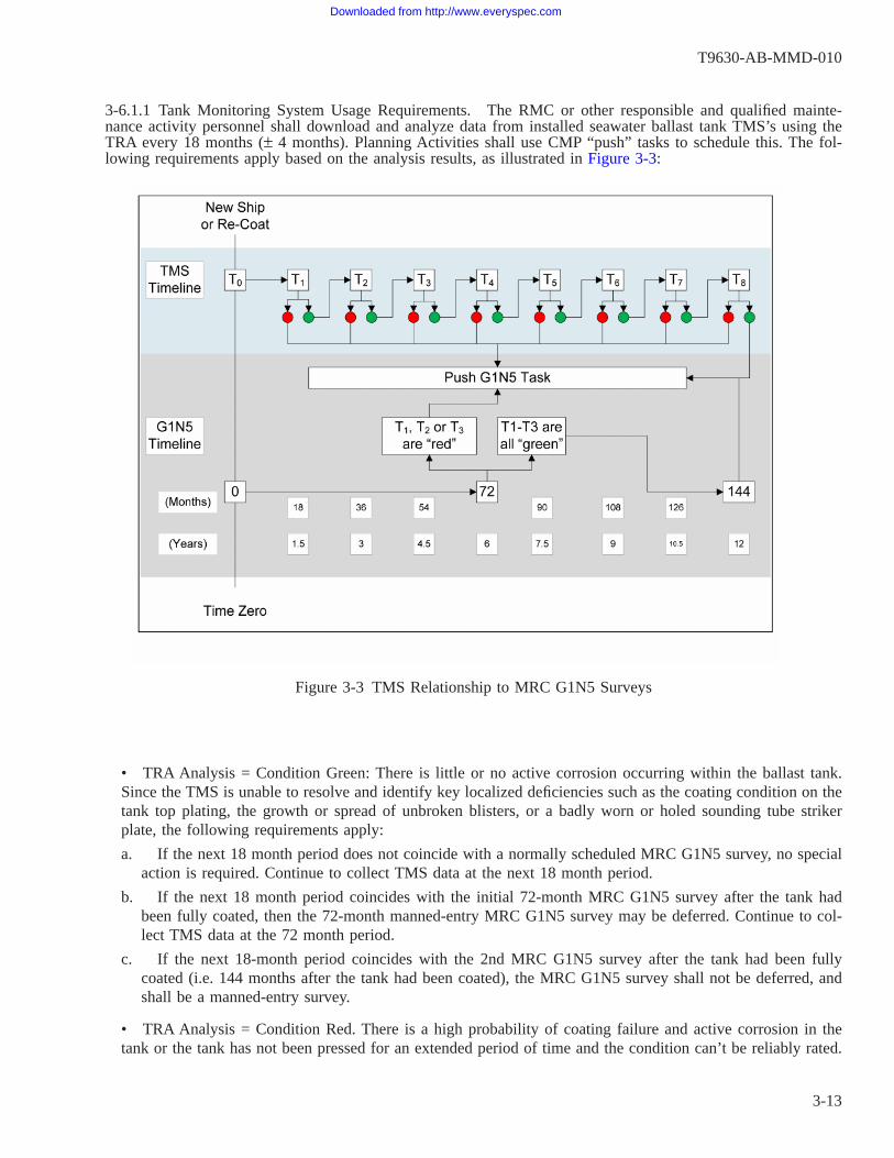
3-6.1.1 Tank Monitoring System Usage Requirements. The RMC or other responsible and qualified mainte-nance activity personnel shall download and analyze data from installed seawater ballast tank TMS’s using theTRA every 18 months (± 4 months). Planning Activities shall use CMP “push” tasks to schedule this. The fol-lowing requirements apply based on the analysis results, as illustrated in Figure 3-3:
• TRA Analysis = Condition Green: There is little or no active corrosion occurring within the ballast tank.Since the TMS is unable to resolve and identify key localized deficiencies such as the coating condition on thetank top plating, the growth or spread of unbroken blisters, or a badly worn or holed sounding tube strikerplate, the following requirements apply:
a. If the next 18 month period does not coincide with a normally scheduled MRC G1N5 survey, no specialaction is required. Continue to collect TMS data at the next 18 month period.
b. If the next 18 month period coincides with the initial 72-month MRC G1N5 survey after the tank hadbeen fully coated, then the 72-month manned-entry MRC G1N5 survey may be deferred. Continue to col-lect TMS data at the 72 month period.
c. If the next 18-month period coincides with the 2nd MRC G1N5 survey after the tank had been fullycoated (i.e. 144 months after the tank had been coated), the MRC G1N5 survey shall not be deferred, andshall be a manned-entry survey.
• TRA Analysis = Condition Red. There is a high probability of coating failure and active corrosion in thetank or the tank has not been pressed for an extended period of time and the condition can’t be reliably rated.
Figure 3-3 TMS Relationship to MRC G1N5 Surveys
T9630-AB-MMD-010
3-13
Downloaded from http://www.everyspec.com
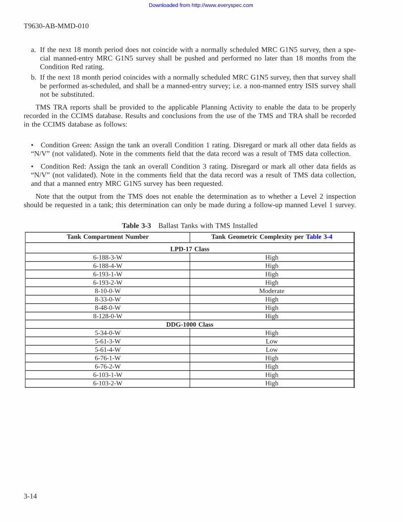
a. If the next 18 month period does not coincide with a normally scheduled MRC G1N5 survey, then a spe-cial manned-entry MRC G1N5 survey shall be pushed and performed no later than 18 months from theCondition Red rating.
b. If the next 18 month period coincides with a normally scheduled MRC G1N5 survey, then that survey shallbe performed as-scheduled, and shall be a manned-entry survey; i.e. a non-manned entry ISIS survey shallnot be substituted.
TMS TRA reports shall be provided to the applicable Planning Activity to enable the data to be properlyrecorded in the CCIMS database. Results and conclusions from the use of the TMS and TRA shall be recordedin the CCIMS database as follows:
• Condition Green: Assign the tank an overall Condition 1 rating. Disregard or mark all other data fields as“N/V” (not validated). Note in the comments field that the data record was a result of TMS data collection.
• Condition Red: Assign the tank an overall Condition 3 rating. Disregard or mark all other data fields as“N/V” (not validated). Note in the comments field that the data record was a result of TMS data collection,and that a manned entry MRC G1N5 survey has been requested.
Note that the output from the TMS does not enable the determination as to whether a Level 2 inspectionshould be requested in a tank; this determination can only be made during a follow-up manned Level 1 survey.
Table 3-3 Ballast Tanks with TMS Installed
Tank Compartment Number Tank Geometric Complexity per Table 3-4
LPD-17 Class6-188-3-W High6-188-4-W High6-193-1-W High6-193-2-W High8-10-0-W Moderate8-33-0-W High8-48-0-W High8-128-0-W High
DDG-1000 Class5-34-0-W High5-61-3-W Low5-61-4-W Low6-76-1-W High6-76-2-W High6-103-1-W High6-103-2-W High
T9630-AB-MMD-010
3-14
Downloaded from http://www.everyspec.com

3-6.2 Insertable Stalk Imaging System and Corrosion Detection Algorithm. The Insertable Stalk Imaging Sys-tem (ISIS) and its associated Corrosion Detection Algorithm (CDA) software are used to quantify and assess thecoating condition and corrosion damage in coated steel potable water, ballast tanks and dry voids. The ISIS cam-era collects high quality digital images of the surfaces that are then processed using the CDA either on or off-ship using the software graphical user interface. The CDA performs a quantitative image analysis to determinethe percentage of the area affected by corrosion. The results from the CDA algorithm eliminate much of the sub-jectivity of human inspectors, resulting in greater accuracy and repeatability, particularly where the percentage ofthe area affected by corrosion is very low.
The complete ISIS and CDA system as provided to RMC’s consists of the camera with a built-in light source,a universal hatch (manhole) mounting assembly and stalk system with cabling, the software, and a ruggedizedportable computer with a control mechanism for the stalk-mounted camera. An example of its use is shown inFigure 3-4.
The CDA software produces a coatings inspection report that provides the overall percentage of the tank sur-face area affected by corrosion. The CDA software and report also provides a means for the operator to add com-ments for any discrepancies or other factors noted in the photographs.
T9630-AB-MMD-010
3-15
Downloaded from http://www.everyspec.com
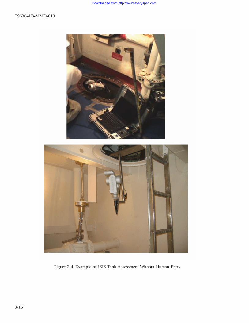
Figure 3-4 Example of ISIS Tank Assessment Without Human Entry
T9630-AB-MMD-010
3-16
Downloaded from http://www.everyspec.com

3-6.2.1 Confined Space Requirements for Unmanned Entry ISIS Use.
Current ISIS equipment is not explosion proof and has not been tested for use inflammable gas and potentially explosive atmospheres.
When conducting unmanned/non-human entry MRC G1N5 Level 1 surveys using the current ISIS equipment,its use shall be limited to ballast tanks, potable water tanks, and dry voids. Tank cleaning and gas-free certifica-tion for human entry is not required, but the requirements defined in NAVSEA letter 4700 Ser 05P2/085 dated14 August 2007, summarized below, shall be met.
• Without full gas free certification, ISIS shall only be used in potable water tanks, ballast tanks and dryvoids.
• Potable water tanks, ballast tanks and voids shall be tested for flammable gases and potentially explosiveatmospheres by an OSHA or Navy competent person qualified in accordance with NAVSEA Technical ManualS6470-AA-SAF-010, NSTM Chapter 074 Volume 3, or 29 CFR 1915 Subpart B prior to inserting the ISIScamera into the tank.
• Under no circumstances will any person enter a confined or poorly ventilated space unless the space hasbeen certified “safe for entry” by a Navy Gas Free Engineer or Marine Chemist in accordance with the docu-ments noted above.
• When opening, and working around opened tanks and voids, all safety requirements for working near con-fined spaces as outlined in the documents above shall be met.
• Tanks and voids identified by ISIS as having questionable or unsatisfactory results will require additionalaction that may involve manned entry.
• Strict adherence to the above confined space requirements for safe insertion of ISIS must be enforced tomaintain personnel and equipment safety.
3-6.2.2 ISIS Usage Requirements and Limitations For Unmanned Use.
Substituting ISIS for a mandatory manned entry G1N5 task pushed by the Plan-ning Activity requires the applicable Planning Activity concurrence prior toexecution.
ISIS shall not be used as an acceptable alternative to manned-entry surveys inaluminum tanks or voids, whether they are coated or not. ISIS and the CDA aredesigned to analyze rust corrosion products from steel structures only.
T9630-AB-MMD-010
3-17
Downloaded from http://www.everyspec.com

Unmanned entry ISIS use shall be limited to coated steel potable water tanks, ballast tanks and dry voids. Ifa tank or void has already been opened and certified as safe for human entry during an availability where anunmanned ISIS assessment task was planned, then a manned entry MRC G1N5 survey shall be conducted in thattank or void instead.
The ISIS/CDA system is only capable of analyzing the condition of surfaces that are within the line-of-sightof the camera; therefore, it is to be used as a screening tool to decide whether tanks and voids must be enteredto perform more thorough assessments. If a tank or void has multiple manholes/access points, then ISIS shall beused at each access point in order to increase the effective area of coverage and therefore the accuracy of theresults.
ISIS shall not be used as an acceptable alternative to manned-entry surveys inchain lockers, since a significant portion of the primary ship structure in chainlockers is often obscured from the camera line-of-sight by perforated secondaryprotective plating or sheathing.
The probability of detecting coating damage and corrosion outside of the line-of-sight of the cameradecreases as the structural complexity of the tank or void increases and lower percentages of the total surfacearea are observable. Structural complexity is characterized in terms of the ability to conduct line-of-sight assess-ments using remote assessment technology within various tank and void structural geometries.
In order to ensure that undetected coating failure and corrosion does not cause wastage of the underlying steelover time, more complex tanks and voids shall be subject to a follow-up human-entry MRC G1N5 survey of theentire compartment within the guidelines of acceptable risk delineated in Table 3-4, the ISIS Utilization Proto-col. This protocol delineates risk factors for each ISIS/CDA-determined overall tank or void condition rating invarious complex structural geometries, and identifies the associated risk of not following up with a manned-entryassessment to verify the ISIS/CDA assessed value. Refer to paragraph 6-5 for re-assessment and maintenancerequirements as a result of unmanned ISIS/CDA inspections.
An unmanned ISIS assessment is not equivalent to a manned-entry MRC G1N5survey, but the results shall still be entered into the CCIMS database. The ISISCDA report returns one single overall Condition score (P1-P4) based on itsanalysis of all of the images collected. This score shall be applied to all four sur-vey zones as a data convention in CCIMS. Other data elements (blocks on theMRC G1N5 data collection form) that cannot be completed due to the limitednature of the ISIS procedure and report shall be recorded as “Not Validated”(NV). The use of ISIS shall be noted in the comments and in the CCIMS record.
In addition to the coating and corrosion condition data provided by ISIS/CDA, personnel reviewing ISIS/CDA reports of unmanned tank and void assessments shall review the photographs for evidence of deficienciesin components present in these compartments as described in paragraphs 4-3.2 and 4-3.3, and shall documentthem in GR2K maintenance action forms as needed. For example, if an ISIS photograph shows that a tank levelindicator (TLI) cable was broken, it shall be documented on a GR2K.
T9630-AB-MMD-010
3-18
Downloaded from http://www.everyspec.com

A CDA software-compatible handheld digital camera is also available for useduring human-entry Level 1 MRC G1N5 surveys of tanks and voids. Whenimages from this camera are processed by the CDA software, the CDA-producedreport described above can be used to obtain highly accurate estimates of theoverall and localized corrosion damage areas. This report can be used to supple-ment the MRC G1N5 assessment data, but the surveyor is still required to com-plete the assessment data collection form.
Table 3-4 ISIS Utilization Protocol
Complexity - HighSee Note #1a
(Approx. surface area in line-of-sight 0%-33%)
Complexity - ModerateSee Note #1b
(Approx. surface area in line-of-sight 34%-65%)
Complexity - LowSee Note #1c
(Approx. surface area in line-of-sight 66%-100%)
Risk Factor (RF) - Low/Moderate/High See Notes 2 and 3Condition 1 Low Low LowCondition 2 Moderate Moderate LowCondition 3 High High ModerateCondition 4 High High High
Notes:1. Tank Complexity is defined in terms of tank structural geometry and the line-of-sight ability to assess tank coat-
ing condition by use of remote assessment technology:a. High - Tank structurally defined by a combination of more than one non tight (NT) swash bulkhead OR NT
swash decks - AND full depth NT longitudinal girders, full depth NT transverse floors, OR full depth side websdividing the tank into multiple cell structures. High complexity tanks have more than two cellular bays formed byNT longitudinal, transverse, or horizontal boundaries. Example: CVN double bottom tanks or JP-5 side tanks.
b. Moderate - Tank structurally defined by a combination of not more than one NT swash bulkhead or deck ORmore than one full depth NT transverse or longitudinal girders or bulkheads, OR typical framing including mul-tiple non-full depth transverse web frames, deck transverses, shell transverse or longitudinal girders, and longitudi-nal stiffeners and shell stringers. Moderate complexity tanks have no more than two cellular bays, but may havemultiple bays of non-full depth webs, transverses, or girders.
c. Low - Tank structurally defined by a combination of standard framing (BHD stiffeners, shell stringers, decklongitudinal etc.) with no more than one deep transverse or longitudinal girder, web frame, or shell transverse, andtypical shell stringers, longitudinal stiffeners and bulkhead stiffeners. Low complexity tanks are one cellular bayformed by full depth tight boundaries and no more than two non-full depth bays formed by web frames, decktransverses, longitudinal girders, etc. Tanks with more than two non-full depth bays are considered moderate com-plexity.
2. Tank “Risk Factor” is based on a MIL-PRF-23236 Type VII (edge-retentive, Ultra-High Solids (UHS)) coatingsystem applied in tank and on as-assessed ISIS assessment values of < 2% visible degradation to overall coatings.
3. Risk Factor (RF-Low/Moderate/High) delineates risk in the inspection process utilizing ISIS remote technologyto assess and determine overall tank coating condition and identifies the associated risk of not following up with aman-entry inspection to verify assessed value.
Note that the high-resolution photographs in the report produced from the ISIS CDA for a tank or void thatwas assessed without human entry can be reviewed by a qualified Level 1 Surveyor to make a determination asto whether a Level 2 inspection should be requested to evaluate discrepancies shown in the images. However,
T9630-AB-MMD-010
3-19
Downloaded from http://www.everyspec.com
this determination cannot be made for any surfaces of the tank or void that were not photographed. When a Level2 inspection is judged to be necessary for a tank or void that was assessed using ISIS without human entry, thisfinding shall be reported via a GR2K to the local engineering authority as soon as possible for action.
T9630-AB-MMD-010
3-20
Downloaded from http://www.everyspec.com
CHAPTER 4
CONDUCT OF SURVEYS
4-1. GENERAL.
General instructions for conducting surveys are contained in MRC’s G1N5 and G1N6. These MRCs requirethe completion of the applicable data forms (Refer to Chapter 5) that contain fields for collecting the data forsubsequent entry into the CCIMS database, and information that is required to write actionable maintenance can-didate recommendations on Material Assessment Forms (MAF)/OPNAV 4790/2K (“Go Repair 2-KILOs,GR2K”). Maintenance planners will use the data to determine the type and extent of maintenance or repairneeded, following the requirements and guidance provided in Chapter 6 of this manual. In addition to the stan-dard forms associated with the MRCs, individual ship class TYCOMs, in conjunction with their respective Plan-ning Activity, may create and require the use of customized data collection forms tailored to a specific area fora given ship class.
The requirements and guidance in this Chapter are provided to supplement the information currently providedin the referenced PMS MRCs.
4-1.1 Survey and Inspection Requirements. The primary purpose of periodic structural surveys and inspectionsis to provide for appropriately timed detection and quantification of the extent of any degraded coating systemsand structure, in order to prevent uncontrolled deterioration in the integrity and performance of ship structure.Structural system surveys and inspections shall be conducted in accordance with PMS MIP 1231/005 MRC G1N5for tanks and voids, PMS MIP 1000/005 MRC G1N6 for general structure, and any other system/location-specificPMS MRC’s described herein. As described in paragraph 1-5.1.3, the MRCs provide for Level 1 surveys that aregenerally visual surveys of coatings and structures performed with the use of basic inspection tools, and for Level2 inspections that are to be conducted if a Level 1 survey identifies a suspected structural deficiency. Level 2inspections may also be required if evidence of structural damage precludes the necessity of a Level 1 survey, orfor specific known problem areas, or as otherwise directed.
These surveys and inspections are focused on coated and non-coated ship structure and foundations, and shallbe conducted by trained and certified surveyors and inspectors in accordance with the requirements of Chapter2. Temporary services such as de-watering of bilges, installation of scaffolding, the use of man-lifts, or theremoval of interferences may be required to support the surveys and inspections as detailed in this Chapter of themanual.
The associated CMP assessment task for any given compartment shall not be recorded as completed andclosed-out until all the requirements of the MRCs are satisfied. This may include the accomplishment of both aLevel 1 survey and a Level 2 inspection, as described herein.
All coating systems and structures found in degraded condition shall be assessed for repairs in accordancewith Chapter 6, and NSTM Chapter 631 and Chapter 100 requirements.
4-1.2 Scope of Level 1 Surveys. The scope of all Level 1 surveys shall include all structural members and theirwelds. These include shell, deck/overhead, and bulkhead plating; longitudinal and transverse framing and stiff-eners or stringers; structural stanchions; machinery foundations; and the support structure for deck gratings,walkways, catwalks, and ladders. All pockets and sumps within a compartment shall be included in the survey.The focus of the MRC G1N5 and G1N6 surveys is the condition of coating systems and structural systems, andthe proper identification of any failure modes in these systems that will affect their reliability. The surveyors andinspectors shall inspect these two systems separately in order to completely fulfill the task.
T9630-AB-MMD-010
4-1
Downloaded from http://www.everyspec.com

a. MRC G1N5:
Coating System Condition:Coating maintenance actions are based on the overall assessed condition of the tank or void. The conditionof coatings and the extent (by area) of corrosion of the structure shall be based on estimates of the percent-age of affected surface areas. Rating scores shall be determined and reported for each of four defined “zones”of the tank or void as described in this Chapter.
Structural System Condition:Whenever structural material loss or damage is found to exceed, or can be reasonably projected to exceedestablished criteria, Level 2 inspections or repairs shall be scheduled and accomplished as described inChapters 5 and 6 of this manual. Paragraph 4-5.2 of this manual provides the maximum allowable wastagefor steel and aluminum structures as required by NSTM Chapter 100.
b. MRC G1N6:
Coating System Condition:Unlike MRC G1N5 (tanks and voids), an overall condition rating does not govern all coatings maintenanceactions; rather, separate (independent) maintenance action decisions shall be made for each individualGR2K prepared recommending coatings maintenance actions. For the purpose of recording completion of theoverall compartment GA2K assessment task, the condition of coatings and the extent (by area) of corrosionof the structure shall be based on estimates of the percentage of affected surface areas. Rating scores shallbe determined and reported for each of the four defined “zones” as described in this Chapter.
In addition, each discrete individual area of damaged or failed coatings and corrosion, and the recommendedrepairs shall be reported in the comments section of the survey form and shall be used to generate repair2-KILO maintenance actions. Damaged areas of coatings 1 square foot or greater shall be reported. For dam-aged areas of coatings less than 1 square foot, surveyors shall consider the location and associated potentialrisks of continued corrosion in determining whether to document and recommend repair actions. For eachrecommended GR2K coating repair action reflected in the comments section of the survey form, the surveyorshall also provide a P-number condition rating score as described in this Chapter.
Structural System Condition:Whenever structural material loss or damage is found to exceed, or can be reasonably projected to exceedestablished criteria, Level 2 inspections or repairs shall be scheduled and accomplished as described inChapters 5 and 6 of this manual. Paragraph 4-5.2 of this manual provides the maximum allowable wastagefor steel and aluminum structures as required by NSTM Chapter 100.
4-1.2.1 Uncoated Aluminum Surfaces. Some Naval vessels have aluminum alloy structures that are not painted.These uncoated areas may include certain types of tanks, voids, and other compartments or exterior weatherareas. The nature of aluminum alloys is that they will readily form a surface oxide layer, i.e. aluminum oxide, inboth atmospheric and water immersion environments. Over time, the gradual growth (thickening) of this oxidelayer will change the appearance of the aluminum surface from a bright, shiny mill finish to one that appearsgray or mottled. Although this oxide is a corrosion product, as it forms, its rate of growth generally slows as itgets thicker, and the oxide itself serves as a protective film. Therefore, the mere presence of this oxide film is nota reportable, maintenance-worthy condition. An example is shown in Figure 4-1.
T9630-AB-MMD-010
4-2
Downloaded from http://www.everyspec.com

There are forms of corrosion other than uniform oxidation in aluminum alloy structures that are of concernand are to be reported in the results of Level 1 surveys. These include pitting from a variety of possible causes,accelerated localized corrosion at dissimilar metal interfaces and crevices, exfoliation, and stress corrosion crack-ing (SCC).
4-1.2.2 Assessment of Outfitting and Other Ship Systems. While the focus of Level 1 surveys is on the condi-tion of ship structures and their coatings, there are many items of ship outfitting and distributed systems thateither cover the structure, or are directly attached or welded to the structure via their supports, hangers, andbrackets. Therefore, direct or incidental assessment of these items as a part of the scope of Level 1 surveys isinevitable. Outfitting items include, but are not be limited to, insulation, sheathing, damping, cathodic protectionsystem components, and ladders. Distributed systems include ventilation systems, piping systems, and electricalsystems. Details of the survey requirements for outfitting and other ship systems are described later in this Chap-ter.
4-1.2.3 Assessment of Surface Combatant Cross-Flooding Ducts (MRC G1N6 Only). Cross-flooding ducts onsurface combatants are ducts that are enclosed by ship structure that run athwartship in specific locations to pro-vide for rapid and equalized flooding in order to maintain the stability of the ship in the event of a damage inci-dent that involves flooding. Some of their openings are too small to permit human entry, but they can be viewedremotely from each end using strong lighting. An example is shown in Figure 4-2. Where obvious structural lossor damage is visible via remote observation, but cannot be accessed by the Level 1 surveyor, the surveyor shall
Figure 4-1 Bare Aluminum Water Tank With Acceptable Oxidation
T9630-AB-MMD-010
4-3
Downloaded from http://www.everyspec.com

note the need for specialized inspection techniques as part of any request for a follow-up Level 2 inspection.
4-2. SURVEY AND INSPECTION PLANNING AND PREPARATION.
The performance of shipboard surveys and inspections involves varying degrees of advance planning to gainaccess to the specific compartments and areas to be examined, and knowledge and preparation for the inherentrisks that may be associated with each area. In addition, personnel must be prepared with the proper tools, equip-ment, and forms.
4-2.1 Safety Precautions and Personnel Protective Equipment (PPE). The guidance and general informationthat follow concerning safety precautions to be observed and PPE to be used during the conduct of surveys andinspections may not be all-inclusive; in all cases, the applicable MRC’s (G1N5 and G1N6) provide the require-ments that shall be followed. Forces afloat shall comply with NAVOSH Program Manual for Forces Afloat,OPNAVINST 5100.19 series. Requirements for PPE shall be in accordance with OPNAV Instruction 5100.23.Whenever equipment tag-outs are required prior to the entry or survey of an assigned compartment or area, coor-dinate with the ship and strictly adhere to applicable tag-out procedures and requirements. Also refer to theJFMM for tag out/lock out and Work Authorization Form (WAF) requirements.
4-2.1.1 Confined Spaces and Atmosphere Safety. Tanks, voids, cofferdams, and any other confined spaces maycontain dangerous atmospheres that are unsafe to breathe, explosive, or toxic. Observe standard safety precau-tions and requirements in accordance with Naval Ship’s Technical Manual Chapter 074 (NSTM 074), Volume 3
Figure 4-2 Opening to a Cross-Flooding Duct on CG-47 Class Ship
T9630-AB-MMD-010
4-4
Downloaded from http://www.everyspec.com

- Gas Free Engineering, Technical Manual S6470-AA-SAF-010, Gas Free Engineering Manual, and OSHA CFRPart 1915, ″Confined and Enclosed Spaces and other Dangerous Atmospheres in Shipyard Employment; FinalRule.″
4-2.1.2 Tanks and Voids (MRC G1N5). In addition to confined space and atmosphere safety concerns, person-nel performing tank and void surveys must ensure that all applicable fluid system tag-outs have been completedand in place before entering a tank or void. This includes, but may not be limited to, tank filling, suction, andrecirculation valve tag-outs, and securing other tanks that could possibly overflow into the compartment beingsurveyed.
4-2.1.3 Machinery Compartment and Bilge Safety (MRC G1N6). Machinery compartments and bilge areasoften contain a variety of complex structural and machinery and piping arrangements that will require surveyorsto crawl around and under this equipment, much of them located below the deck plates. Bilges are to be pumpeddry prior to conducting a survey in order to remove all fluids that would prevent an accurate or complete survey.The surfaces in these areas may be covered with a residual oily film and be extremely slippery. In addition, theremay be extremely hot surfaces, and the environment in the compartment may be a concern for heat stress. Thesurveyor must also be aware of rotating shafts and other equipment. Hearing protection will generally berequired. There is no need to enter or open any electrically energized equipment as a part of this survey; there-fore tag-outs of electrical equipment in machinery compartments is generally not required in order to survey theircoatings and structures.
On CVNs, within the plant there may be areas that are bounded off by yellow and magenta rope or tape.Secured to the tape or rope will be a sign stating that within that boundary, personal dosimetry is required. Donot enter that boundary (including the bilge area below or the overhead area above) without personal monitoringdosimetry and explicit permission to be within that boundary.
4-2.1.4 Combustion Air Intakes and Uptakes (Exhaust) (MRC G1N6). Prior to entry in a combustion air uptake(exhaust) compartment, the applicable engines must be secured; this may also be required for intakes, due to thehigh velocity of the air that may pass through these compartments and the risk of engine foreign object damage(FOD) from accidentally-dropped objects. Hearing protection will likely be required for any areas where theengines were not required to be tagged-out. Safety harnesses may be required for any area that must be accessedvia a vertical ladder/rungs equipped with a climber safety rail or similar device. The use of a safety observerwhen conducting surveys in these compartments is recommended and may be required
4-2.1.5 HVAC Intake and Exhaust Fan Rooms, Trunks, and Plenums (MRC G1N6). Depending on the specificconfiguration and layout, fan rooms and plenums that open to the weather can be subject to high velocity airpassing through these compartments, and the risk of foreign object damage (FOD) to intake (supply) fans fromaccidentally-dropped objects. Therefore, for some of these compartments, it may be advisable or required to tag-out the applicable fans prior to entry into the compartment. Hearing protection may be required for any areaswhere the fans were not required to be tagged-out, and eye protection from blowing sand or dirt may also beadvisable.
4-2.1.6 Superstructure/Deckhouses/Islands, Masts, and General Exterior (MRC G1N6). Exterior areas may besubject to radiation sources and rotating equipment (antennas, radar, fire control, etc.). These should always bemarked by warning placards and paint boundary markings, and the surveyor must always be aware of them. Shiptag-out and “man-aloft” procedure requirements shall be strictly followed. The use of safety harnesses will berequired for any area that must be accessed via a vertical ladder/rungs equipped with a climber safety rail orsimilar device.
T9630-AB-MMD-010
4-5
Downloaded from http://www.everyspec.com

4-2.2 Temporary Services and Ship Coordination. In addition to any safety-required preparations and coordi-nation described above, the following paragraphs provide additional preparatory requirements and guidance forconducting surveys including general cleaning, physical access, and area specific considerations.
4-2.2.1 Cleaning. In preparation for a survey or inspection, compartments or areas shall have all liquids, sludge,slime, dirt and debris removed and shall be cleaned as necessary to allow a complete visual evaluation. Attentionshall be given to ensure that all stiffeners, framing elements, and sumps that could trap and hold fluids have beencleaned. If these items are not removed and prevent the required level of examination of any area, the surveyor/inspector is to coordinate removal of obstructions with the ship, and return to that compartment and complete theexamination before the task is considered complete.
If any area cannot be properly surveyed because of excessive dirt, debris, or fluids the surveyor has the rightand responsibility to request additional cleaning, such as low pressure water washing, prior to performing thesurvey. If an area is water-washed for cleaning, fresh water shall be used and all wash water shall be removedand the area dried.
Structures shall not be steamed out as this action can cause damage to the coating system. JP-5 and fuel tanksshall not be chemically cleaned with solvent emulsifier type compounds, as these chemicals, if not fully removed,can contaminate coalescer elements in the filter/separator and destroy their coalescing ability.
4-2.2.2 Temporary Staging and Lift Equipment. Temporary staging should not be required to be installed inorder to perform effective surveys in tanks or voids; the surveyor shall make their best estimation of the condi-tion of remotely-visible surfaces from the best accessible vantage point(s). However, there are some large tanksand voids, such as CVN damage control voids, where scaffolding may be required to effectively and safely per-form the Level 1 survey. Lift equipment or scaffolding may be required for other areas to effectively survey theoverheads, particularly in compartments such as well decks and hangar decks, where ducting and other distrib-uted systems hides structural surfaces from remote observation.
4-2.2.3 Interferences From Stowage. Interior compartments scheduled for survey may contain a variety ofitems placed there for storage (either authorized or unauthorized). Examples may include boxes and crates, cablespools, hawser lines, and many others. If the quantity and placement of these items is such that the surveyor can-not reasonably work around them to conduct a complete and accurate evaluation, then the surveyor has the rightand responsibility to request assistance from the ship to temporarily move these items during the survey.
4-2.2.4 Bilges (MRC G1N6). All bilge areas, including bilge wells and sumps, shall be pumped dry prior tosurvey. Ship’s Force shall be informed of surveys being conducted in the bilge areas, and shall take precautionsnot to discharge any fluids to the bilges during the survey. This may require certain systems or components to betagged out and secured. A number of deck plates, as determined by the surveyor, may need to be removed toallow sufficient visibility or access to all of the bilge regions in order to complete the survey of the coatings andstructural components. The surveyor shall request Ship’s Force and/or maintenance team assistance in theremoval of any deck plates. The area of removed deck plates should be roped off to warn personnel of the poten-tial danger due to loose or removed deck plates. Immediately after the survey, all removed deck plates shall bereinstalled by the activity that removed them.
4-2.2.5 Amphibious Ship Well Decks (MRC G1N6).
a. Overhead Structure: Lift equipment or scaffolding is required in order to survey the coated structure in theoverheads. This equipment shall be pre-arranged with the ship and the Port Engineer. Note that special safety
T9630-AB-MMD-010
4-6
Downloaded from http://www.everyspec.com
training may be required for personnel to ride in or use this equipment. If required, pressure washing of theoverhead surfaces in order to clean them to facilitate surveys shall follow a locally prepared and approvedcontrol procedure to prevent the wash water from draining through the stern gate to the local harbor or baywaters, potentially leading to a violation of local environmental discharge regulations.
b. Wing Walls and Decks Under Batterboards/Planking: The bulkhead and deck structures and their protectivecoatings are mostly obscured from view by composite or wood batterboards and planking that are bolted totheir surfaces. Therefore, in preparation for performing a MRC G1N6 survey of a well deck, the surveyor mustperform a pre-survey of the well deck and designate specific batterboards and planking to be removed. Thisselection should be based on clearly visible evidence of coatings failure, corrosion, or structural damage thatcan be discerned with the batterboards or planking in place, and the surveyor’s best judgment and experience.When no visible evidence of corrosion or structural damage is found, select no less than 5 and no more than10 batterboards, and no less than 5 and no more than 10 planks for removal, concentrating in areas near thestern of the ship where exposure to seawater would be most frequent.
Sumps in well decks must also be de-watered in order to properly perform the MRC G1N6 survey.
4-2.3 Tools, Equipment, and Forms. The minimum set of tools, equipment, and forms required to conduct sur-veys and complete MRC’s G1N5 and G1N6 are listed on each of the respective MRC’s. This paragraph providesguidance on the purpose of some of the items listed on those MRC’s, as well as some other tools and equipmentthat may be useful.
Use of the ball peen hammer and chipping hammer described below is restrictedto Level 2 Inspectors. No hammers shall be used on pressurized system bound-aries (structural or piping/machinery), including boundaries with an adjacent tankthat is filled with fluid.
• Flashlight: Used for dark areas and for examining the back sides of structural members. A head-mountedlight or headlamp is also helpful, as it allows both hands to be free for other purposes. An additional smallhand-held flashlight is useful in conjunction with an inspection mirror as described below.
• Rags: Use for cleaning away dirt and debris that may obscure the surface.
• Telescoping inspection mirror: Useful in conjunction with a for examining the back sides of stiffener flangesand framing, and internal areas of built-up foundations, where there is not sufficient access for direct visualexamination. A polished stainless steel inspection mirror is recommended to eliminate the possibility of bro-ken glass.
• Stiff bristle brush: In conjunction with the putty knife, useful for removing loose corrosion product, rustscale, loose paint, and other caked-on debris, from either structures or sacrificial anodes.
• Putty knife: Used to probe paint to see how well it is adhered. May also be used to remove corrosion andrust scale in order to get a better visual indication of the structure condition.
• Telescoping magnet (“retrieving tool”): Useful as a quick-check method to determine if a substrate struc-ture is steel (magnetic), or aluminum or other materials (non-magnetic).
• Pocket knife: For making small cuts on insulated surfaces, when there is sufficient cause or other evidence
T9630-AB-MMD-010
4-7
Downloaded from http://www.everyspec.com

to suggest extensive paint failure or corrosion beneath. May also be used for probing the condition of partiallyconsumed sacrificial anodes with a lot of loose corrosion products.
• Ball peen hammer: Used to “sound” a suspect metal structure for integrity while causing little or no dam-age to any intact coating system. See paragraph 4-5.4 for more information on how to perform sounding.
• Chipping hammer: Used for an obviously heavily corroded and scaled structure, to break away corrosionscale and expose the sound metal.
• Pit depth gauge: Tool that measures the depth of pitting in structures.
• Tape measure: Used to provide dimensional measurements for areas requiring repainting, or location infor-mation relative to a known reference point (e.g. “15 feet aft of the forward bulkhead”), or to provide roughdimensions for follow-up Level 2 inspections or structural repairs. Tape measures should be a minimum of 10feet long and up to 25-feet.
• SSPC-VIS 2: Pictorial guide to evaluating the degree of rusting on painted steel surfaces.
• Data collection forms: one copy per compartment or area to be surveyed is needed. Data collection andreporting requirements are provided in Chapter 5, and the forms are provided in Appendices A and B of thismanual. The official and most up to date version will be available from the Naval Forms Online web site at:https://navalforms.documentservices.dla.mil/
Although not required to conduct the surveys, the following items are highly recommended, as they can pro-vide more useful or accurate information in the survey report, especially in characterizing degraded areas ofcoatings or structure. These gauges would generally only be used in degraded areas.
• Dry Film Thickness (DFT) gauge: Non-destructive gauge used to determine paint thickness. The gaugemust be suitable for the type of substrate material, i.e. steel or aluminum. Basic training in the use of the DFTgauge is provided in the S-CAT course, and information on the proper use of these gauges and reporting thedata can be found in standard SSPC-PA 2. DFT data may be particularly useful as supplemental informationwhen the surveyor reports delaminating topcoat layers, to show the thickness of the remaining well-adheredprimer coatings.
• Ultrasonic Thickness (UT) gauge: Non-destructive gauge used to determine structure thickness. For thepurposes of the Level 1 Surveys described in this manual, this data would generally be collected in conjunc-tion with a recommendation to have a follow-up Level 2 inspection performed as described in NSTM Chap-ter 100. More detailed information on the types of gauges suitable for this purpose and guidance on their useare contained in NSTM Chapter 100. Basic training in the use of UT gauges is provided in the S-CAT course.Note that the use of UT gauges to perform thickness gauging may require the removal of corrosion or paintin order to get a reliable reading. In most cases where the use of a UT gauge is warranted, the coatings havealready experienced failure.
4-3. SURVEY OF OUTFITTING AND OTHER SHIP SYSTEMS.
The assessment and reporting of the condition of outfitting and distributed systems during the conduct ofLevel 1 surveys in tanks and voids is required by this manual and MRC G1N5, as these compartments are gen-erally only opened and made accessible to accommodate the performance of these surveys. Requirements andguidelines for the assessment and reporting of the condition of outfitting and distributed systems during the con-duct of Level 1 surveys in all other compartments and areas under the scope of MRC G1N6 vary with the typeof compartment or area, as described below.
T9630-AB-MMD-010
4-8
Downloaded from http://www.everyspec.com

Obvious deficiencies or damage to non-structural ship systems that cover or aredirectly attached to the ship structure, that are found during the conduct of thesesurveys and are judged to pose an imminent safety or mission impact risk, shallbe promptly reported to the ship for action.
4-3.1 General Items To Survey (MRC G1N5 and G1N6). Items described in this paragraph can be located inmany of the compartments under the scope of both MRC G1N5 and MRC G1N6 surveys.
4-3.1.1 Ladders. Vertical ladders are commonly located in tanks, voids, access and escape trunks, uptakes andintakes, and in a variety of exterior locations. Inclined ladders are most commonly located in passageways,machinery spaces, and exterior locations.
Carefully examine the condition of any ladder feature or support for integritybefore using it. Examine deck and bulkhead supports, and any separate supportsthat may be provided for climber safety rails for exterior vertical ladders. Do notattempt to put your weight on a ladder element that would appear unable to sup-port you.
Ladders may be made from steel, stainless steel, aluminum, or composite material (e.g. glass-reinforced plas-tic, GRP). Fabricated ladders are usually attached to the structure by support brackets and fasteners, although insome cases steel ladders may have integral brackets that are welded directly to the steel ship structure. Mostexterior vertical ladders that ascend more than one deck level also generally have an associated climber safetyrail installed for use with personnel safety harnesses; these rails often have independent structural support brack-ets welded to the ship structure.
Tanks and voids may or may not have ladders or other means to facilitate entry depending on their size andconfiguration. In tanks and voids, ladders may be fabricated, or may consist of a series of rungs welded directlyto the structure. Entry to tanks and voids may also be provided by way of hand and foot holes cut out into a platebelow the manhole.
Examine any and all of these types of ladder features and document any recommended repairs. Inspection ofladders in tanks and voids is a mandatory part of the MRC G1N5 Level 1 survey as reflected in the form.Examples of reportable corrosion on ladder structural supports are shown in Figures 4-3 and 4-4.
T9630-AB-MMD-010
4-9
Downloaded from http://www.everyspec.com

4-3.1.2 Insulation, Sheathing, and Damping Materials. In compartments other than tanks, acoustic dampingmaterial, metal sheathing, or various types of insulation (fire, thermal, acoustic) may be installed covering the
Figure 4-3 Reportable Corrosion of Vertical Ladders and Deck Supports
Figure 4-4 Corrosion of Aluminum Support for Stainless Steel Climber Safety Rail
T9630-AB-MMD-010
4-10
Downloaded from http://www.everyspec.com
painted structural members or foundations, preventing them from being directly evaluated. The surveyor shallexamine the condition of these materials. Indicate if any of these items can be reliably determined to be missing,or if they are wet or damaged to the point of requiring repair or replacement, and document the specific repairsrecommended on a GR2K. Examples of conditions that may be cause for such a determination include: water-logged and swelling insulation; crumbling or delaminating insulation and lagging materials with red rust stainsseeping through; corrosion of insulation fasteners or pins; and sheathing or damping materials that are bulging atseams, edges, or between fastening points in wetted areas, with rust or corrosion products visible at the exposededges.
These materials are not required to be removed to accomplish the surveys required by this manual. Theremoval of small areas or the careful lifting of edges of insulation materials may be accomplished in order toexamine the underlying coated structure. Efforts must be made by the surveyor to subsequently replace any areasremoved or lifted, and the total amount of insulation material removed must be reported in the comments sectionof the MRC form. The surveyor shall also notify the applicable Ship’s Force work center supervisor when insu-lation material has been removed or damaged during the conduct of the survey. The surveyor shall document thelocation and extent of this damage when making a recommendation to conduct a follow-up maintenance action.
4-3.1.3 Structural Closures. Structural closures include items such as doors, hatches, scuttles, bolted equipmentremoval plates (BERPs) and welded equipment removal plates (WERPs). Surveyors are not responsible for veri-fying the proper operation of doors, hatches, or scuttles, but should document any closures with visually obviousdamage. Review the CSMP for any work items that may have been previously submitted by the crew for theseitems, and review potential discrepancies with the local cognizant engineering authority before submitting themas GR2K items.
4-3.2 Tanks (MRC G1N5). There are several items commonly found in tanks that are to be examined and theircondition reported during the surveys described in this manual. Many of these items, if found deficient, are to beconsidered Repair Before Closing (RBC) items that shall be documented and brought to the immediate attentionof the ships’ Chief Engineer (CHENG) and the local engineering authority for disposition prior to closing thetank. This is due to the limited accessibility of tanks for assessment or repair purposes. As described in paragraph6-8, any RBC item that is not repaired requires a Departure from Specification (DFS).
4-3.2.1 Sacrificial Anodes. Cathodic protection is provided in tanks and voids exposed to seawater and in CHTtanks in the form of zinc or aluminum anodes bolted to the sides or bottom of the tank or floodable void. Anodetype designations beginning with a “Z” indicate zinc anodes (e.g. ZHC), and those beginning with an “A” indi-cate aluminum anodes (e.g. AHC). When a number is used as part of an anode designation, it indicates the weightof the anode in pounds. In some special cases, low voltage aluminum anodes may have been required to be usedin some designs; these anodes are identified with an “L” prefix (e.g. LNC). NAVSEA Technical PublicationT9633-AT-DSP-010 provides the design requirements for each area of the ship where sacrificial anodes arerequired, and NSTM Chapter 633 provides the maintenance and replacement requirements. Requirements in placeat the time of publication of this revision of CCAMM are reflected below. Individual ship class sacrificial anodeinstallation drawings may reflect older requirements that were in effect at the time of they were created or revised.Unless otherwise directed, individual ship class cathodic protection detail and installation drawings take prece-dence and shall be followed when making determinations concerning the replacement of sacrificial anodes.
Ballast tanks and compensated fuel tanks: One ZHC-42 anode is to be installed in each major segment of thetank bottom, i.e., within any area that could trap seawater. Anodes are to be located at the lowest point withina web-enclosed section on the floor area, not on the web, to ensure the anode is in any seawater in the tankat low water levels. An additional ZHC-42 anode shall be installed adjacent to each tank flooding valve forprotection of the valve area.Additional required anodes shall be either ZSS-12 or ZSS-24 anodes evenly dis-
T9630-AB-MMD-010
4-11
Downloaded from http://www.everyspec.com

tributed over the tank bottom and wall areas. Install an anode within three (3) meters (approx. 10 feet) of adissimilar metal (e.g. copper-nickel or stainless steel piping) at a slightly lower level than where the pipe(s)enters or exits the tank. At least 60% of the total number of anodes shall be in the lower ½ of the tank. Attachall anodes by bolting. If two smaller anodes are within 1 meter (approx. 3 feet) of each other, a single anodeof twice the capacity (i.e. twice the weight) may be substituted.
CHT Tanks: Type ZHC-42 or AHC-42 anodes are required to be installed in CHT tanks. One anode is to beinstalled per each 80 square feet (7.4 square meters) of painted tank surface area. Anodes are also to be locatedin the vicinity of dissimilar-metal junctions in the tank, including the pump suction and along the line of theair diffuser headers, specifically in the area of the header supports. Fifty percent of the anodes are to be locatedbelow the pump cut-out sensor, since this area will be submerged almost continuously. Thirty percent of theanodes are to be located between the duty pump cut-in sensor and the pump cut-out sensor. Twenty percent ofthe anodes are to be located above the duty pump cut-in sensor.
Using the requirements described above, the surveyor shall note whether anodes are missing from any por-tion of the tank where they are required. Installed anodes shall also be assessed, for the following conditions. AGR2K shall be written to record all of the recommended anode maintenance.
a. Sacrificial anodes are intended to sacrifice in service, and in the process may generate loose, light colored cor-rosion products. These corrosion products need to be removed by the surveyor in order to make an estimationof whether at least 50% of the anode has been consumed (depleted). The number and location of anodes thathave been depleted more than 50% shall be recorded.
b. Old anodes that are properly attached to the structure that show no evidence of any corrosion may be defec-tive. This condition is caused by improper anode material composition, and is sometimes termed a “passiveanode”. Small drill chips are generally required for chemical analysis in order to make this determination.Since this can indicate that the entire batch of anodes that were supplied from an anode vendor were defec-tive, this condition should be reported to the local engineering authority for action.
c. Anodes that have been mistakenly painted will not function as intended. These anodes shall be reported to theship or local engineering authority for action to either remove the paint or replace the anode. In addition, ifthe surveyor observes anodes that are covered with masking material remaining from the last time that thetank was painted, they shall either remove the masking material or report it to the ship for action.
All of the above anode deficiencies are considered Repair Before Closing (RBC) items and shall be correctedprior to closing the tank. Figure 4-5 is a decision flow chart for anode assessment and evaluation. The “Z” pre-fix for zinc anodes types is used in the figure; substitute “A” for aluminum anodes. Refer to NSTM Chapter 633,Section 7 for additional guidance on sacrificial anode maintenance.
T9630-AB-MMD-010
4-12
Downloaded from http://www.everyspec.com

Figure 4-5 Anode Assessment Flow Chart
T9630-AB-MMD-010
4-13
Downloaded from http://www.everyspec.com

4-3.2.2 Tank Entry Penetrations (Manholes) and Tank Top Stuffing Tubes. Examine the condition of the tankmanhole cover, the structural bolting ring and reinforcing ring around the opening, and the cover fasteners andgasket for damage. Indicate if any of these items are corroded or damaged to the point of requiring repainting,repair, or replacement, and document the specific repairs recommended. Any manhole that cannot be sealed orhas broken studs shall be considered to be an RBC item, and shall be brought to the immediate attention of thelocal engineering authority for disposition and repair before closing the tank. An example of heavy corrosion andscaling of a manhole cover seating surface requiring repair is shown in Figure 4-6.
A variety of ship systems may have electrical cables that must enter or pass through a tank, e.g. ICCP sys-tem, TMS, TLIs, degaussing system, etc. Examine any electrical cable penetration stuffing tubes on the tank topto determine if they appear to be properly capped or sealed. Any stuffing tubes that do not appear to be properlycapped or sealed shall be considered a Repair Before Closing (RBC) item, and shall be documented on a GR2Kmaintenance action form and brought to the immediate attention of the local engineering authority for dispositionbefore the tank is closed.
4-3.2.3 Tank Level Indicators (TLIs). There are several makes and models of remotely-monitored tank levelindicating devices that may be present in a tank, including their associated cables and cable supports. If the typeof TLI can be identified, document it on the MRC G1N5 data form. Examine any TLI and its cabling and sup-ports installed in the tank for visually obvious damage. Document any damage found and recommended repairactions. Except for unused cables that are properly dead-ended, bare or defective wiring associated with TLIs areconsidered RBC deficiencies.
4-3.2.4 Sounding Tubes and Striker Plates. Sounding tubes are an alternative to TLIs for manually determin-ing the fluid level in a tank. If they are installed an accompanying “striker plate” is located directly under thesounding tube, and attached either to the tube itself, or to the tank structure below the tube. The striker plate pro-
Figure 4-6 Heavy Rust Scale Of Steel Deck Manhole Cover Seating Surface
T9630-AB-MMD-010
4-14
Downloaded from http://www.everyspec.com

vides a flat, solid surface under the sounding tube that lets a person taking a sounding know that the weightedsounding bob has struck bottom, and prevents wear and corrosion of the tank structural boundary surface underthe sounding tube. Due to repeated striking of the sounding bob, the paint on the striker plate becomes damagedand corroded, as illustrated in Figure 4-7. Eventually, repeated impacts of the bob on the striker plate wears itaway, exposing the tank boundary plating or the shell plating of the ship to impact by the bob. Striker plates aredesigned to be periodically replaced as they wear out and corrode.
The sounding tubes, striker plates, and their supports shall be examined for visually obvious damage. Thestriker plate maximum thickness reduction allowed at the time of the survey is 25% of its original design thick-ness. If this level is exceeded, a GR2K repair 2-KILO shall be written to have it replaced in the next mainte-nance availability. If the striker plate is estimated to have lost more than 50% of its original thickness, it shall bedocumented and brought to the attention of the local engineering authority for immediate action, and shall berepaired before closing (RBC) the tank. In addition, the surveyor must check to see if there is a sounding plumbbob stuck or jammed in a sounding tube; this is also a RBC item.
In all tanks (except CHT) where radar TLIs are used, sounding tubes orwaveguide tubes are required directly below the radar TLI. Radar TLIs in CHTtanks use a different design that does not include the use of sounding tubes orwaveguide tubes within the tanks.
4-3.2.5 Piping and Other Distributed Systems. Tanks and voids will frequently have piping and other distrib-uted systems installed in them that either terminate in the compartment, or pass through it. Depending on thedesign requirements, there may be various types of supports or hangers for these systems. The surveyor shall
Figure 4-7 Coating Damage and Corrosion of Sounding Tube Bob Striker Plate
T9630-AB-MMD-010
4-15
Downloaded from http://www.everyspec.com

examine any installed distributed system and its supports for visually obvious damage, and shall document anydamage on a GR2K 2-KILO maintenance action form. Note that degaussing system cable conduit can be con-fused with fluid system piping, as shown in Figure 4-8. In order to report work items accurately, the surveyorshall determine the correct system of any piping or conduit, or note that they were unable to determine the sys-tem. The surveyor should examine any simple flappers on vent or overflow check valves to determine if theyswing freely or are damaged; otherwise, the surveyor shall not attempt to operate any valves. Piping or valvesthat are noted to be leaking or having any other visually obvious damage are to be considered RBC items, andshall be brought to the immediate attention of the local engineering authority for disposition or action before thetank or void is closed.
Piping that either discharges into (i.e. fills) or takes suction from a tank may have an associated waster plate,or fluid deflector plate installed below the bellmouth fitting on the end of the piping. In some cases, the wasterplate is installed directly to the tank structure below the pipe opening. Piping disciplines and documents may alsorefer to these terminating sections of the piping as “tailpipes”, and to the waster plates as “doubler plates”.Examples of these two styles of waster plates are shown in Figure 4-9. This waster plate serves to prevent ero-sion and accelerated corrosion on the tank structure due to swirling and turbulent fluids at these points. Thisfunction is similar to that of the striker plate under a sounding tube. These waster plates are designed to bereplaced as they wear out. If a waster plate has lost more than 25% of its original thickness through wear or pit-ting at the time of survey, a GR2K repair 2-KILO shall be written to have it replaced in the next maintenanceavailability. If the waster plate is estimated to have lost more than 50% of its original thickness, it shall be docu-mented and brought to the attention of the local engineering authority for immediate action, and shall be repairedbefore closing (RBC) the tank.
T9630-AB-MMD-010
4-16
Downloaded from http://www.everyspec.com

4-3.2.6 ICCP System and TMS Components. Tanks, voids, and other compartments below the waterline thathave the underwater hull shell plating as one of their boundaries may also have impressed current cathodic pro-
Figure 4-8 Corroded And Holed Degaussing System Conduit In A Tank
Figure 4-9 Waster Plates Installed Under Fill or Suction Piping Tailpipes
T9630-AB-MMD-010
4-17
Downloaded from http://www.everyspec.com

tection (ICCP) system components installed in them. Although the components themselves (anodes or referencecells) are installed on the underwater hull side of the shell plating, a cofferdam enclosure and associated cablingwould be present on the interior side. A typical anode cofferdam enclosure installed in a bilge area is shown inFigure 4-10.
As described in paragraph 3-6.1, some seawater ballast tanks may also have Tank Monitoring System (TMS)installed in them.
While conducting either a MRC G1N5 or G1N6 survey, any visually obvious damage to either ICCP or TMScomponents installed in a tank, void, or other compartment shall be documented and a recommended GR2Krepair action written for review and action by the maintenance team. Except for unused cables that are properlydead-ended, bare or defective wiring associated with ICCP components are considered RBC deficiencies.
Damage to any ICCP or TMS components shall be considered as RBC items, and shall be dispositioned priorto closing the tank.
4-3.3 Voids (MRC G1N5).
4-3.3.1 Desiccants. For voids in dry service, desiccant cartridges may have been installed in the past in orderto dehumidify the compartment to inhibit corrosion. However, performance analysis of the historical data sincethe time that ultra-high solids (UHS) coatings per MIL-PRF-23236 Type VII became the standard coating systemrequired for voids has shown that desiccants do not measurably improve the corrosion protection of the void sur-
Figure 4-10 Typical ICCP Anode Cofferdam and Cabling in a Machinery Compartment Bilge
T9630-AB-MMD-010
4-18
Downloaded from http://www.everyspec.com

faces. Effective in 2012, the use of desiccants in dry void compartments in surface ships and CVN’s is no longerrequired, and the surveyor may prepare a 2-KILO requesting the removal of them and the associated brackets asa weight-saving measure.
4-3.3.2 All Other Items in Voids. Sacrificial anodes (when installed in floodable voids), manholes, ladders,insulation, ICCP system components, and piping and other distributed systems shall be surveyed as described inparagraphs 4-3.1 and 4-3.2.
4-3.3.3 Lead Ballast in Voids and Cofferdams. When a void or cofferdam to be assessed contains lead ballast,the ballast is not required to be removed to perform the Level 1 survey. The surveyor shall assess the visible areasof ship structure and its coatings in these compartments.
4-3.4 Bilge Regions (MRC G1N6). In addition to primary structure and the items listed in paragraph 4-3.1,MRC G1N6 surveys in bilge regions and bilge wells shall include machinery and equipment foundations, and thesupport structure for deck gratings and walkways. On many ship classes, machinery is installed in modules orsuites of related equipment on a large structural support that is in turn mechanically fastened (bolted) to a foun-dation or set of foundations that is welded to the ship structure. These structural supports may be termed skids,rafts, or bedplates, and there are often shock mounts installed between them and the foundation that is welded tothe ship. These skids, rafts, bedplates, and foundations are within the scope of the MRC G1N6 surveys.
Additionally, pipe hangers, pipe supports, and other equipment supports welded to the structure in the bilgesshall be surveyed. In the course of conducting this survey, any deficiency identified posing an imminent safetyor mission impact shall be promptly reported to the ship.
ICCP system components located in bilge regions shall be surveyed as described in paragraph 4-3.2.6.
4-3.4.1 Sacrificial Anodes. Sacrificial anodes installed in bilges shall be surveyed as described in paragraph4-3.2.1. Additional guidance and information, adapted from NAVSEA Technical Publication T9633-AT-DSP-010,is provided below.
Each bilge pocket, bilge sump/well, or compartment that frequently holds seawater requires cathodic protec-tion. In bilge areas, bolted-on anodes should be used instead of the welded strap style, so that depleted anodescan be easily replaced by crew members. Proper functioning of the anodes depends on complete immersion inwater, a clean anode surface, and a positive contact between the anode and the surface requiring protection.Anodes normally are to be located in locations where they will be submerged whenever water is present in thearea, generally near the bilge pump suction, or on the starboard side close to the centerline keel. For dissimi-lar metal junctions in immersion areas, anodes should be installed within 2 feet of the junction.
Design requirements for sacrificial anodes in bilges have evolved with time, and those reflected in NAVSEATechnical Publication T9633-AT-DSP-010 may not have been in effect for older ship designs. Unless otherwisedirected, individual ship class cathodic protection detail and installation drawings take precedence and shall befollowed when making determinations concerning the replacement of sacrificial anodes.
4-3.5 Combustion Air Intakes and Uptakes (MRC G1N6). The survey of structural foundations of exhauststacks, BLISS caps, and their sway braces are also included under the scope of MRC G1E8. Review the CSMPfor any coating or structural repair work items submitted as a result of the last performance of the MRC G1E8survey prior to conducting the MRC G1N6 survey in these compartments.
T9630-AB-MMD-010
4-19
Downloaded from http://www.everyspec.com
4-3.6 Structural Vent Plenums and Trunks (MRC G1N6). Structural vent plenums and trunks are defined inparagraph 1-5.3.5. Structural vent plenums and trunks shall be surveyed using MRC G1N6. When surveying ventplenums and HVAC trunks, evaluate the coatings and structural condition of all of the internal boundaries.
The survey of HVAC sheet metal ducting is not within the scope of MRC G1N6 and this manual; CMP tasksto assess the condition of HVAC supply, exhaust, and recirculation system ducting are described in MRC’s G1Z2and G1Z3 in MIP series 5121.
Document any discrepancies and recommended repair actions on separate GR2K 2-KILO’s as appropriate forthe following specific components:
a. Exterior (weather) vent opening reinforcing ring structure: This area is a corrosion prone surface and is typi-cally where the coating breakdown and corrosion begins. Evaluate the exterior opening reinforcing ring struc-ture.
b. Screens and fixed metal louvers: Inspect vent screens and their frames for corrosion, cracks and deterioration.Inspect screen attachments for missing, loose and corroded fasteners and hardware. The fixed metal louvers(i.e. those that are welded either directly to the structural reinforcing ring, or installed as a bolted insertassembly) shall also be evaluated. Note that remotely-operated adjustable louver assemblies (e.g. damperassemblies) that are typically installed as bolted-in components are not required to be surveyed under thescope of this manual; however, visually obvious damage to these components should be separately docu-mented and reported.
c. Preheater (if accessible): Preheaters, when installed, are found in the ventilation supply systems and arelocated inside the ductwork upstream (e.g. on the intake or suction side) of the ventilation fan assembly. Thefins on the heat exchanger coils can collect moisture and salt from intake air and, when combined with theheat from the coils, can create an environment for corrosion.
d. Insulation (if present): The top/overhead of some ventilation plenums may be insulated; see paragraph4-3.1.2 for surveying procedures in the presence of insulation.
e. Drainage: Assess deck drains and any stiffener drain holes (e.g. limber holes, snipes or rat holes) to deter-mine if they are clear and free from debris and will allow water to drain from the bottom/deck of the venti-lation plenum. Plugged or clogged deck drains and drain holes require immediate attention to prevent accu-mulation of water and moisture that creates an environment for corrosion. The surveyor should try to removeany blockage found; if this is not possible, then the responsible ships’ work center should be notified.
4-3.7 Well Decks (MRC G1N6).
a. Overhead: In addition to the coating and structural condition, surveyors should also document any overheadequipment with visually obvious damage. Review the CSMP for any work items that may have been previ-ously submitted by the crew for these items, and review potential discrepancies with the local cognizant engi-neering authority before submitting them as GR2K items.
b. Wing Walls and Decks Under Planking: Wood or composite material planking is installed on amphibious shipwell deck wing walls and decks to protect the underlying structure from impact damage that can be caused byvehicles and amphibious craft. The planking installed on the wing walls is sometimes referred to as batterboards. The planking installed on the deck surfaces is sometimes referred to as beach boards. The plankingmaterials and the extent and style of their attachment to the structure will vary with the class of ship. Examplesare shown in Figure 4-11. Evaluate the condition of the bulkheads and decks in well deck areas that were madeaccessible by the removal of selected planking (see paragraph 4-2.2.5). Evaluate the condition of the securingstuds for cracks, corrosion, or mechanical damage. If the survey of the accessible areas indicates that there isevidence of widespread coating failure and corrosion under the planking, then document the condition and
T9630-AB-MMD-010
4-20
Downloaded from http://www.everyspec.com

submit a GR2K repair action to have all of the planking removed (or all of those within a prescribed area) andthe affected area(s) represerved in the next maintenance cycle.
T9630-AB-MMD-010
4-21
Downloaded from http://www.everyspec.com

Figure 4-11 Well Deck Wing Wall And Deck Surface Areas In Way Of Planking
T9630-AB-MMD-010
4-22
Downloaded from http://www.everyspec.com
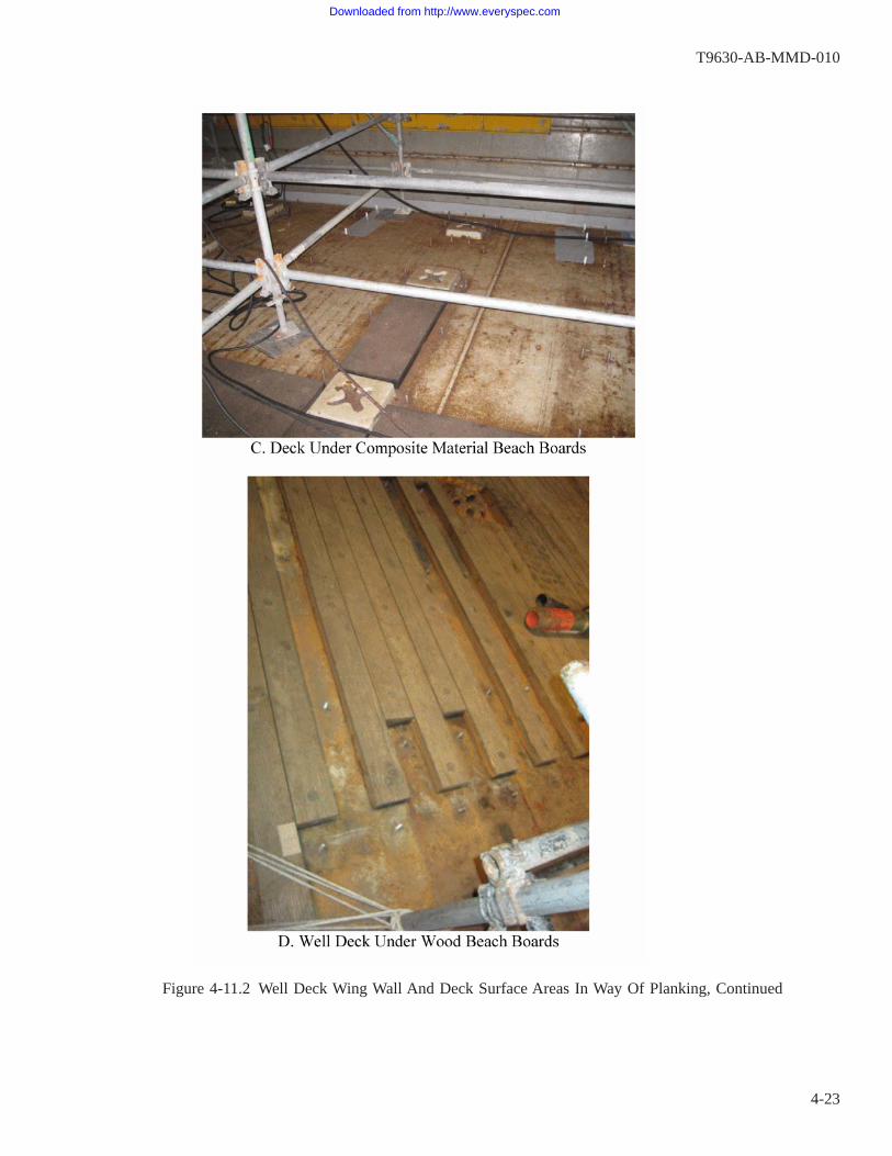
Figure 4-11.2 Well Deck Wing Wall And Deck Surface Areas In Way Of Planking, Continued
T9630-AB-MMD-010
4-23
Downloaded from http://www.everyspec.com
4-3.8 Exterior and Weather Deck Areas (MRC G1N6). Exterior areas and weather decks (e.g. “topsides”) shallbe surveyed using the procedures in MRC G1N6. Items to be surveyed include all steel and aluminum decks,bulkheads, structural stanchions and supports, and extended or overhanging platforms associated with superstruc-tures, deckhouses, flight deck islands, masts, aircraft elevators, catwalks, and bulwarks. Except for catwalk sup-port structure, unless otherwise specified the installation of temporary scaffolding or the use of powered lifts (e.g.cherry-pickers, JLG lifts, etc.) is not required to conduct these surveys; however, as described in paragraph4-2.1.6, surveyors may be required to wear safety harnesses to access certain areas. The coating and structuralcondition of surfaces that are only distantly visible due to the lack of access to perform a close-up survey shallbe evaluated. If any recommended repair work items are solely based on distant observations, this should benoted in the survey report and/or work items.
Level 1 surveys of the freeboard (see paragraph 1-5.4.18) and external shell plating above the waterline arelimited to the structural condition only.
Assessment of exterior composite structures are not required under the scope of this manual or MRC G1N6.
4-3.8.1 Additional Exterior and Weather Deck Components to Survey. Additional topside-specific componentsthat shall be surveyed, and guidance regarding the conduct of the survey and reporting of recommended coatingand structural repairs are provided below. In all cases, it is critical that any recommended repair action 2-KILOswritten as the result of the survey accurately describe the scope and location of the work.
• Superstructure/Deckhouse/Island Bulkheads and Overhanging Platforms: A superstructure, deckhouse, orisland bulkhead that vertically spans several deck levels, but that can only be viewed from a lower deck level,should be surveyed up to the next highest accessible deck or platform. For example, if surveying the forecastle(bow) region of a CG-47 class ship, the entire forward-facing bulkhead of the superstructure from the 01 levelthrough the 04 level should be evaluated. Likewise, the underside of an overhanging platform and its structuralsupports may need to be evaluated by a surveyor standing on a deck several levels below.
• Masts, towers, and their structural supports, intermediate platforms, and yardarms shall be surveyed. Inter-nally accessible masts that have assigned compartment numbers, such as those on the DDG-51 Class, shall besurveyed using two separately-pushed MRC G1N6 surveys, one for the exterior and one for the interior.
• Equipment foundations welded to the ship structure, for any type of equipment, i.e. hull and deck machin-ery, antennas, and weapons systems and their fire-control equipment.
• Structural supports and brackets welded to ship structure for ladders, handrails, safety rails and stanchions,and deck gratings.
In addition to documenting the discrepancy on a GR2K, any of these items that are found to be corroded tothe point that an imminent safety risk exists shall be reported to the ship for appropriate action when they arefound.
• Bi-metallic (steel/aluminum) transition pieces used to enable welding aluminum structures to steel struc-tures. These pieces, also known as “detacouples”, are generally located in a bulkhead 3-5 inches above the steeldeck, and are explosion-bonded strips of steel and aluminum. Since they are dissimilar metal interfaces, theyshould always be painted to help minimize dissimilar metal, or galvanic corrosion.
• Miscellaneous secondary structural enclosures, bulwarks, or shields welded to ship structure in order toprovide radar cross section (RCS) reduction. Note that on some ship classes/designs (e.g. LPD-17, DDG-51)bolted access panels will be required to be removed in order to gain access to these structural enclosures.
• Miscellaneous secondary structural enclosures welded to the periphery of flight decks to serve as wheelstops or provide physical protection to piping, cables or conduit, and other equipment. These enclosures mayalso require the removal of bolted access panels in order to perform the survey.
• Passive Countermeasure System (PCMS) materials may be installed over top of exterior structures on sev-
T9630-AB-MMD-010
4-24
Downloaded from http://www.everyspec.com

eral classes of surface ships, preventing direct visual observation of the condition of the underlying structure.If these materials have been incorrectly installed, or have experienced mechanical damage, wear and tear,delamination, or have loose or missing caulk at seams and edges, then seawater can get under the materialsand cause hidden corrosion of the metal. Look for tell-tale signs of corrosion under PCMS materials, such asunnatural bulges or blisters with corrosion products seeping from edges or seams. Document areas of probablestructural degradation under damaged PCMS materials and recommend repair actions.
Personnel performing MRC G1N6 surveys shall not remove or disturb anyPCMS materials, unless they have been qualified to do so as described in MIP4721/081 and the PCMS Technical Manual SE400-DA-MMO-010, Rev. 5 orlater. MRC’s A5X7 and A5X8 in MIP 4721/081 provide annually-scheduledCMP tasks to inspect PCMS materials. Before submitting repair tasks for dam-aged PCMS with suspected underlying structure corrosion, review the ships’CSMP to determine if the discrepancy has already been identified as a result ofthose inspections.
• Deck coverings, especially nonskid or other non-slip deck coverings, can delaminate and hold moistureagainst the deck plating underneath. The soundness of these deck coverings shall be assessed to ensure thestructure is protected from corrosion.
4-4. ASSESSMENT OF COATING CONDITION.
The gradual aging and breakdown of coatings over time will expose varying and increasing amounts of themetal substrate to the environment. Exposed metal will then begin to corrode at varying rates associated with thematerial of construction and the severity of the environment. If corrosion is allowed to continue without repairof the protective coating, it may eventually lead to significant metal thickness loss and structural integrity con-cerns.
All Level 1 surveys shall document the coating condition, and the extent and location(s) of coating damageand failures in accordance with the procedures and scoring system described below. There are 3 key coating con-dition determinations that must be made by Level 1 surveyors:
1. MRC G1N5 and MRC G1N6: For each assigned compartment, all Level 1 surveys shall report the overallcoating condition scores (P#’s) in each of four zones defined below.
2. MRC G1N6: Each individual GR2K reporting coating damage and recommended repair action shall beassigned a single coating condition score (P#) that is identical to the highest score that was assigned to thezone(s) affected by the work. Areas of damaged coatings 1 square foot or greater shall have GR2K mainte-nance action recommendations reported as the result of MRC G1N6 surveys. See paragraph 4-4.6 forexamples.
a. MRC G1N6 Surface Ship (Non-CVN) Bilge Regions: The P# assigned to all coating system deficienciesand GR2K recommended repairs in the bilge regions of surface ships shall be rated P3 or greater, regard-less of the extent of the coating damage by area. Any GR2K coating repair item submitted for these areasthat would have been rated a P1 or P2 based on an area-percentage score assigned to the affected zonesshall be assigned a P3 rating.
3. MRC G1N5 and MRC G1N6: A determination must be made as to whether the accumulated damage to thecoating system on the ship structure across all four zones in the assigned compartment exceeds the NSTM
T9630-AB-MMD-010
4-25
Downloaded from http://www.everyspec.com

Chapter 631 criteria concerning mandatory replacement of the entire coating system, i.e. either 10% or 20%of the total surface area, depending on the type of compartment. Refer to paragraph 4-4.5.
4-4.1 Zone-Based Coating Condition Reporting. Coating deterioration initiates and progresses at varying rateson different surfaces on a ship for a variety of reasons. For example, as illustrated in Figure 4-12 a tank top(overhead) corrodes differently than the tank bottom, and coating failure and corrosion often initiates sooner onstiffening elements due to the greater occurrence of edges and welds associated with them as compared to otherzones.
T9630-AB-MMD-010
4-26
Downloaded from http://www.everyspec.com

Figure 4-12 Coating Breakdown Initiating in Tank Overhead and Stiffener Zones
T9630-AB-MMD-010
4-27
Downloaded from http://www.everyspec.com

The large surface areas of compartments requiring survey for preservation maintenance planning shall besubdivided by the surveyor into four separately defined reporting zones. This enables better characterization ofthe overall coating condition of the compartment being assessed, as well as providing a means of establishing anoverall priority ranking for repairs relative to similar areas.
• Overhead (Top): The overhead boundary plating.
• Bulkheads/Shell (Sides): The entire collective side boundary plating (bulkheads or hull shell plating).
• Stiffeners (T-Bars): All of the collective stiffening elements that are not otherwise part of the definedboundary plating zones. Includes stiffeners, framing, stanchions, foundations, catwalk and deck plate support-ing structure, and reinforcing rings around manholes or other structural openings, etc.
• Bottom: The lowermost boundary plating or deck.
4-4.1.1 “V” Shaped Bottom Tanks and Voids. For tanks and voids that have a “V” shaped bottom, for the pur-poses of the zone definitions the bottom is defined as the surface area below the level of the lowest longitudinalstringer, or the lowest horizontal weld in the bulkhead/shell plating if no stringers are present. In the absence ofany clear demarcation, the bottom is defined as two feet up the bulkhead from the bottom of the “V”. False decksin tanks shall be included as part of the bulkhead/shell boundary evaluation and not as part of the stiffening/framing. Reinforced rings around holes through swash bulkheads shall be part of the stiffener evaluation, whilethe swash bulkhead itself shall be evaluated as part of the bulkhead/shell boundary.
4-4.1.2 Welds. Welds are similar to edges of structural members, in that coating degradation and corrosionoften initiate there. Therefore, it is important to account for their condition when performing a survey. However,by their nature, the proper zone-based scoring of welds may be challenging, since they are always present at theintersections of two or more zones. Surveyors shall use their best judgment in accounting for the condition ofwelds, and must attempt to avoid double-counting them in more than one zone. The following guidance is pro-vided:
• Butt welds that are simply used in adjoining plates, not in way of any stiffening elements, should be countedas part of the applicable overhead, bulkhead/shell, or bottom zone where the plates are located.
• Welds used as part of built-up (fabricated) stiffening elements, and those used to connect the stiffening ele-ments to overhead, bulkhead/shell, or deck plates, should be counted in the stiffener zone score.
• Welds present at the intersection between two different zones (e.g. where a bulkhead plate meets the over-head plate) should be counted in the scoring for one of those zones and disregarded in the other.
• If coating damage and corrosion is largely confined to the welds and could be characterized as “Localized”damage along continuous or contiguous (intersecting) welds, note this in the comments section of the data col-lection forms for potential GR2K touch-up repairs.
4-4.2 Staining and Dirt. The surveyor must be able to distinguish those areas where the coatings have actuallydegraded or failed from those areas where they are tightly adherent and intact, but are just dirty or have ruststaining on top of them. Tightly adhering coating is defined as not being easily removed with a dull putty knife.Surveyors are permitted to rub the surface free of all loosely adherent debris in order to discriminate areas of ruststaining and dirt from corrosion. Often a rag that has been dampened with water will remove enough staining,dirt, or other loose material hiding the coating system, to allow the surveyor to distinguish between stained ordirty coatings that are intact, and areas of actual failed coatings and corrosion. If there is heavy dried sludge orother dirt on the surface, a stiff bristle brush, or a non-metallic cleaning pad, or even a dull putty knife will be
T9630-AB-MMD-010
4-28
Downloaded from http://www.everyspec.com

required to remove the obscuring material. The loosely adherent debris shall not be counted as defective. How-ever, if the rubbing removes loose paint and exposes bare or corroded metal underneath, this constitutes coatingfailure, and the affected area shall be counted as a part of the damaged coating surface area as described below.
4-4.3 Overall Coating Condition Scores. Each of the four defined zones shall be assigned coating conditionscores according to the criteria below. The overall condition rating score for any given tank, compartment, orarea shall be rated according to the worst performing zone. For example, a tank with a set of zone conditionratings consisting of a P4 for the overhead, a P1 for the bulkheads and shell, a P3 for the stiffeners, and a P2 forthe bottom, (i.e. P4-P1-P3-P2) would be rated as overall condition P4.
Both the individual zone scores and the overall compartment condition rating are used to make and priori-tize decisions regarding preservation maintenance, as described in Chapter 6. These scores correspond to the P1through P4 designations described in Chapter 6. For tanks and voids under the scope of MRC G1N5, the over-all condition rating score of the compartment governs maintenance action. For all other general structure andcompartments under the scope of MRC G1N6, separate independent coating maintenance action decisions aregoverned by the score for each submitted coating repair 2-KILO (GR2K), according to the score assigned to theaffected zone(s). When an individual ship class CMP requires represervation of a specific compartment or areaunder the scope of MRC G1N6 on a strict time basis, and not on a condition basis, any coating maintenanceactions resulting from the survey shall be compared to the next scheduled represervation to determine the appro-priate course of action; refer to paragraph 6-3.1.
Note that all of the coating condition ratings are made independently of any determinations of structuralrepairs that may be required.
4-4.3.1 Coating Condition Score Criteria. The extent of coating damage or failure, and associated corrosion ofthe structure, is characterized according to the percentage of the surface area affected. ASTM D610, “StandardTest Method for Evaluating Degree of Rusting on Painted Steel Surfaces”, provides a standardized system fordetermining a “rust grade” based on making an estimation of the percentage of corrosion present in a user-designated area. These rust grades range from 0 to 10, with a rating of 10 indicating a near-perfect coating sys-tem with corrosion on less than 0.01% of the area, and 0 (zero) indicating extensive coating system failure andcorrosion affecting over 50% of the designated area.
The SSPC-VIS 2 pictorial standard booklet “Standard Method of Evaluating Degree of Rusting on PaintedSteel Surfaces” provides a pocket-sized, durable laminated set of reference photographs and images that corre-lates to the ASTM D610 “rust grades” that can be used to help make more accurate estimates. This booklet islisted on MRC’s G1N5 and G1N6 as a document to be used by surveyors.
Although the titles and text in the ASTM D610 and SSPC-VIS 2 standards allrefer to steel surfaces and “rust”, they are to be applied in a similar manner tocoated aluminum surfaces under the scope of this manual.
The Navy has established a “condition rating” score ranging from P1 to P4 that further groups the ASTMD610 rust grades into categories associated with maintenance action planning and decisions governing repair(touch-up) or replacement of the coating system. Table 4-1 shows the correlation between percentages of cor-roded surface area, the ASTM D610 rust grades, and the Navy condition ratings.
T9630-AB-MMD-010
4-29
Downloaded from http://www.everyspec.com

Table 4-1 Coating Condition Ratings and ASTM D610 Rust Grades1
Condition Rating ASTM Rust Grade Percent of CorrodedZone2
P1 10 None (0) to 0.01%9 >0.01% to 0.03%
P2 8 >0.03% to 0.10%7 >0.10% to 0.30%6 >0.30% to 1.00%
P3 5 >1.00% to 3.00%4 >3.00% to 10.00%
P4 3 >10.0% to 16.00%2 >10.0% to 16.00%1 >33.00% to 50.00%0 >50%
NOTES:1. Condition ratings shown in this table are prior to any modi-
fication for blisters in tank and void coatings. See paragraph4-4.3.3.
2. Zone definition in accordance with paragraph 4-4.2.
In locations where a portion of the structure is not visible due to the presence of a covering material such asinsulation, sheathing, or damping, the base unit area that the percentage shall be based on is the surface area thatis visible at the time of survey.
Example: if 5 sq. ft. of corrosion is identified on the overhead of a space that is 10 ft. x 10 ft. (100 sq. ft.),but 50% of the overhead structure is covered with insulation (50 sq. ft.), then the coating condition score forthe overhead zone is determined based on 5 sq. ft. of corrosion on 50 sq. ft. of visible coated structure. Thiswould be 10%, or an ASTM D610 Rust Grade of 4 and a coating condition rating score of P3.
4-4.3.2 Localized vs. Scattered Coating Damage Distribution. Coating maintenance decisions regardingtouch-up and repairs rely on the distribution of the coating damage and corrosion as well as the relative percent-age of the affected areas. Regardless of the mechanism of coating failure, the affected area(s) in each of the fourdefined zones in the compartment being surveyed shall also be characterized as to whether the distribution islocalized or scattered.
Localized damage is defined as failure occurring in a few concentrated regions within the compartment zonebeing evaluated. Scattered damage is defined as failure occurring in randomly distributed places throughout thezone being evaluated. The SSPC-VIS 2 pictorial standard booklet uses the terms spot rusting, general rusting andpinpoint rusting to characterize rust distribution. For the purposes of this manual, spot rusting is synonymous withlocalized rusting, and general rusting is synonymous with scattered rusting. Pinpoint rusting describes the natureof the rusting as being in small individual specks that could be either localized or scattered depending on the dis-tribution (although it usually occurs as scattered).
4-4.3.3 Blistering Evaluation.
Modification of the final coating condition rating scores as a result of a distinctpaint blistering evaluation is only required when conducting surveys of tanks and
T9630-AB-MMD-010
4-30
Downloaded from http://www.everyspec.com
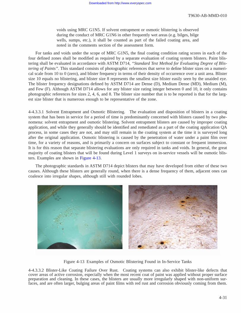
voids using MRC G1N5. If solvent entrapment or osmotic blistering is observedduring the conduct of MRC G1N6 in other frequently wet areas (e.g. bilges, bilgewells, sumps, etc.), it shall be counted as part of the failed coating area, andnoted in the comments section of the assessment form.
For tanks and voids under the scope of MRC G1N5, the final coating condition rating scores in each of thefour defined zones shall be modified as required by a separate evaluation of coating system blisters. Paint blis-tering shall be evaluated in accordance with ASTM D714, “Standard Test Method for Evaluating Degree of Blis-tering of Paints”. This standard consists of photographic references that serve to define blister sizes on a numeri-cal scale from 10 to 0 (zero), and blister frequency in terms of their density of occurrence over a unit area. Blistersize 10 equals no blistering, and blister size 8 represents the smallest size blister easily seen by the unaided eye.The blister frequency designations defined by ASTM D714 are Dense (D), Medium Dense (MD), Medium (M),and Few (F). Although ASTM D714 allows for any blister size rating integer between 0 and 10, it only containsphotographic references for sizes 2, 4, 6, and 8. The blister size number that is to be reported is that for the larg-est size blister that is numerous enough to be representative of the zone.
4-4.3.3.1 Solvent Entrapment and Osmotic Blistering. The evaluation and disposition of blisters in a coatingsystem that has been in service for a period of time is predominantly concerned with blisters caused by two phe-nomena: solvent entrapment and osmotic blistering. Solvent entrapment blisters are caused by improper coatingapplication, and while they generally should be identified and remediated as a part of the coating application QAprocess, in some cases they are not, and may still remain in the coating system at the time it is surveyed longafter the original application. Osmotic blistering is caused by the penetration of water under a paint film overtime, for a variety of reasons, and is primarily a concern on surfaces subject to constant or frequent immersion.It is for this reason that separate blistering evaluations are only required in tanks and voids. In general, the greatmajority of coating blisters that will be found during Level 1 surveys on in-service vessels will be osmotic blis-ters. Examples are shown in Figure 4-13.
The photographic standards in ASTM D714 depict blisters that may have developed from either of these twocauses. Although these blisters are generally round, when there is a dense frequency of them, adjacent ones cancoalesce into irregular shapes, although still with rounded lobes.
4-4.3.3.2 Blister-Like Coating Failure Over Rust. Coating systems can also exhibit blister-like defects thatcover areas of active corrosion, especially when the most recent coat of paint was applied without proper surfacepreparation and cleaning. In these cases, the blisters are usually more irregularly shaped with non-uniform sur-faces, and are often larger, bulging areas of paint films with red rust and corrosion obviously coming from them.
Figure 4-13 Examples of Osmotic Blistering Found in In-Service Tanks
T9630-AB-MMD-010
4-31
Downloaded from http://www.everyspec.com

An example is shown in Figure 4-14. These represent areas of failed coatings that may have significant pittingor corrosion of the substrate beneath them, and these shall always be counted as a part of the initial failed coat-ing condition rating. The surveyor shall remove as much of this failed paint as necessary in order to determinewhether actionable structural corrosion has occurred in these areas. The requirements in paragraph 4-4.3.3.3 donot apply to these blister-like defects.
4-4.3.3.3 Blister Reporting, Criteria, and Coating Condition Rating (MRC G1N5 Only). The surveyor shallrecord the ASTM D714 blister size and density on the MRC G1N5 data form for each of the four defined zones.For blister size, Navy conventions are only to use the even numbers 2, 4, 6, 8, and 10 when recording surveydata, and to use a 0 (zero) in the data form to signify that a blister size determination was unable to be made forthe area in question by the surveyor, for whatever reason.
Experience has shown that smaller, less frequent (i.e. less dense) blisters that are intact are acceptable, as theyremain stable for extended periods of time and therefore do not warrant coating system repair or replacement.However, larger and more frequent (i.e. more dense) blisters, and broken blisters of any size or density thatexpose the metal substrate, are not acceptable and shall be used to modify the coating condition rating accord-ing to the criteria and method described below.
The following blister conditions shall be assessed as failed coating:
• Broken blisters that expose the metal substrate
• Blister size 2 with medium, medium dense or dense distribution
• Blister size 4 or 6 with medium dense or dense distribution
• Blister size 8 with dense distribution
The extent of the area (in percent) that has unacceptable blistering shall be added to the coating failure andcorrosion area (in percent) determined per paragraph 4-4.3.1 above to arrive at a total coating failure percentage
Figure 4-14 Blister-Like Coating Failure Over Rust
T9630-AB-MMD-010
4-32
Downloaded from http://www.everyspec.com

for determination of the condition rating number for each zone. Acceptable blistering is not included as part ofthe coating system failure percentages for determining the condition rating.
Example: Tank bottom plate zone of approximately 200 sq. ft. had been determined by the surveyor to have1 sq. ft. of failed coating and corrosion prior to evaluating blisters. This would equate to 0.5% of the 200 sq.ft. area of the bottom and an initial Condition Rating score of P2. The blister evaluation showed that there wasan additional area of approximately 10 sq. ft. of unbroken size 4 blisters with a frequency distribution of“Dense” that exceeds the blister failure criteria, as well as a 20 sq. ft. area with size 6 blisters with a distribu-tion of “Few” that is acceptable. The 10 sq. ft. area of unacceptable blistering is 5% of the designated bottomzone area. Therefore, total area of failed coating on the tank bottom zone is 0.5 + 5 = 5.5%, resulting in thefinal Condition Rating score for the bottom to be reported as P3.
Intact blisters that show no evidence of rust or corrosion coming from beneath them shall not be broken.Intact blisters provide some corrosion protection of the underlying structure and shall be left undisturbed untilthe time that the coating system is repaired or replaced.
4-4.3.4 Coating Delamination and Disbonding. Disbonded coating is defined as failure of all layers of the coat-ing system down to bare metal, such that the coating no longer provides any corrosion protection. Delaminatedcoating is defined as one or more coats lifting off an underlying coat that is still providing some degree of cor-rosion protection. Examples are shown in Figure 4-15.
For any area where coating systems are required, disbonding of the coating system to bare metal is a failurethat shall be included as part of the percentage of coating failure area and reflected in the condition rating scores,regardless of whether or not corrosion is present.
Delamination between coats shall be considered as failed coating in tanks and floodable voids only, and thearea affected shall be counted in determining the coating condition rating scores and writing GR2K coating repairrecommendations.
In all other locations with delaminated topcoats, the surveyor shall use their judgment as to whether or notthe delaminated coating is an improperly applied cosmetic overcoat that does not necessarily warrant a GR2Kcoating repair recommendation. In either case, the presence and extent (by area) of the delaminated coated shallbe noted in the Comments section of the applicable data form.
Exceptions to the above requirements exist for areas where coatings were previously installed, but are nolonger required, such as clean Fuel Oil Storage and Service tanks as described below.
4-4.3.4.1 Fuel Oil Storage and Service Tanks (MRC G1N5 Only). Coating delamination and disbonding shallbe handled differently for FO storage and FO service tanks that no longer require painting effective with therelease of NAVSEA Standard Item 009-32, FY-11 edition, dated 24 July 2009. When surveys are performed onpreviously-painted FO storage and service tanks, if there is >10% coating delamination or disbonding, and theloose coating is still present in the tank, it could compromise fuel system cleanliness. This condition shall bedocumented on the MRC G1N5 data form and a GR2K work candidate shall be written. This condition shall beconsidered a mandatory Repair Before Closing (RBC) work item, since the loose paint could clog filters andaffect system readiness. Standard Item 009-32 contains requirements for handling these areas.
T9630-AB-MMD-010
4-33
Downloaded from http://www.everyspec.com

Figure 4-15 Disbonded and Delaminated Coatings
T9630-AB-MMD-010
4-34
Downloaded from http://www.everyspec.com
4-4.4 Special Coating Condition Scoring Conventions.
4-4.4.1 Unknown Coating Condition in Zone. If the coating or corrosion condition of any of the four zonescannot be determined due to the presence of some type of obstruction (e.g. insulation, etc.), the Condition scoreassigned to that zone(s) shall be set to P0 (zero), indicating it was unknown, or not validated (N/V). All N/Vscenarios must be explained in the Comments section of the applicable data form.
When the condition of a tank or void is not known, but a data record for that compartment is being enteredinto the CCIMS database for some other reason, the overall condition rating shall be set to P0 (zero).
4-4.4.2 Uncoated Surfaces. When a Level 1 survey is being conducted in a compartment where a coating isneither present nor required (for example, to assess the structural integrity of Lube Oil tanks), a Condition scoreof P10 shall be assigned for each of the four zones.
The following conventions shall be used when scoring the results of a Level 1 survey in an uncoated alumi-num tank, void, or other assigned compartment:
a. The first line of the comments should state that the tank or void is unpainted aluminum.
b. Paint condition and the Condition Rating scores shall be “P10”.
c. Blistering shall be scored as size 10, and density “N/A”. (MRC G1N5 Only)
d. Percent corrosion of area shall be recorded as 0 (zero). Specific instances of localized pitting or other cor-rosion, especially those requiring a follow-on Level 2 inspection, shall be described in the survey comments.
e. Localized vs. scattered corrosion shall be reported as appropriate to any findings described in the comments.
4-4.4.3 Additional Coating Condition Information. In addition to the gradual and general breakdown of a coat-ing system due to its age, coating failures can occur due to problems with the original surface preparation andapplication process, unexpected exposure to temperature extremes, accidental exposure to certain chemicals, anda variety of mechanically induced damage such as impact, abrasion, flexing, etc. NSTM Chapter 631, Section 6,provides brief descriptions and photographic examples of commonly used terms to describe other modes of coat-ing defects and damage, such as checking, cracking, and chalking. Level 1 surveyors should use these terms asapplicable when providing any written description of coating condition.
Surveyors shall also include in their condition reports whether interferences will or may be required to beremoved or lifted in order to gain access to problem areas in order to properly perform surface preparation andcoating. Interferences may include items such as pieces of equipment or machinery, distributed systems (piping,ducting, or electrical cable/conduit), and insulation materials.
4-4.5 Mandatory Coating System Replacement. There is a point when the extent of the accumulated coatingsystem damage throughout an assessed compartment becomes great enough that it becomes more economical toremove the entire old coating system and replace it, rather than performing extensive touch-up repairs that maybe scattered across the compartment. The criteria for complete coating system replacement in an assigned assess-ment compartment are derived from NSTM Chapter 631, and are given as follows:
Over 10% of total surface area: For the types of compartments listed below, when the accumulated damage toa coating system that would require repairs exceeds 10% of the total surface area in the compartment or des-ignated assessment area, the entire coating system shall be scheduled for replacement no later than the end ofthe next maintenance cycle.
T9630-AB-MMD-010
4-35
Downloaded from http://www.everyspec.com

• All tanks and their sumps (where coatings are required)
• All floodable voids
• All non-floodable voids below the waterline (non-CVN hulls)
• All non-floodable voids in any location (CVN hulls only)
• All bilge regions and their sumps
• All cofferdams
Over 20% of total surface area: For all other compartments not listed above, when the accumulated damage toa coating system that would require repairs exceeds 20% of the total surface area in the compartment or des-ignated assessment area, the entire coating system shall be scheduled for replacement no later than the end ofthe next maintenance cycle.
Due to the great variety of compartment layouts and geometries that can exist, it should be evident that thefour zone coating condition scoring system alone may not always reliably make the above determinations pos-sible. Therefore, during the conduct and reporting of the Level 1 survey, the surveyor must also annotate whetherthe above criteria have been exceeded. Given that a P4 score for a specific zone indicates that greater than 10%of the coating in that zone has failed, example and boundary conditions are described below.
a. If none of the four zone scores are P4 (e.g. P3-P3-P3-P3), then it is mathematically impossible for the 10%total cumulative criteria level to have been exceeded.
b. If all four of the four zone scores are P4 (e.g. P4-P4-P4-P4), then at a minimum, at least 10% of the totalcumulative compartment surface area has failed coatings. For those compartments where appropriate, the sur-veyor will also have to determine and report whether the 20% criteria has been exceeded.
c. If a P4 score is assigned to one, two, or three of the four zones, then the determination as to whether the10% or 20% NSTM Chapter 631 criteria has been exceeded still must be made. For example, a compartmentscore of P1 (top)-P4 (bulkheads)-P2 (stiffeners)-P1 (bottom) might exceed the 10% or 20% cumulative sur-face area criteria if it is a very irregular lay-out compartment where the bulkheads make up the greatest por-tion of the overall surface area by far.
4-4.6 Coating Condition Scoring Examples. Some notional examples of applying the coating condition scoringrequirements to the overall compartment coating condition, and the scoring of individual GR2K coating repairitems resulting from MRC G1N6 surveys are given below. For comparison purposes, Table 4-2 shows the maxi-mum cumulative sizes, in square feet and square inches, of surface areas with failed coatings and corrosion thatcan be present in a designated survey zone for each of the four coating condition scores, P1 through P4; examplesare given for areas of 100 square feet and 1000 square feet. Note that in the examples that follow, for zones witha P4 rating (or any localized area of severe corrosion), there may also be cause for the Level 1 surveyor to requesta follow-on Level 2 inspection, depending on the conditions found.
T9630-AB-MMD-010
4-36
Downloaded from http://www.everyspec.com
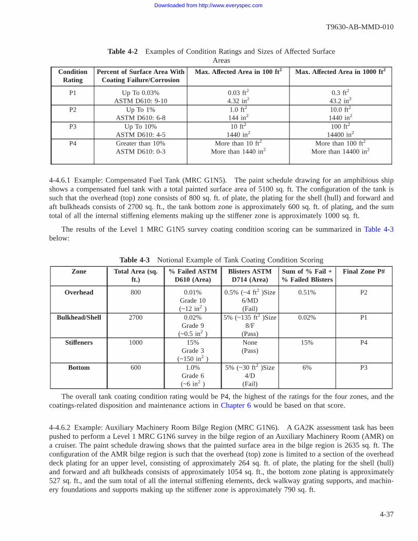
Table 4-2 Examples of Condition Ratings and Sizes of Affected SurfaceAreas
ConditionRating
Percent of Surface Area WithCoating Failure/Corrosion
Max. Affected Area in 100 ft2 Max. Affected Area in 1000 ft2
P1 Up To 0.03%ASTM D610: 9-10
0.03 ft2
4.32 in20.3 ft2
43.2 in2
P2 Up To 1%ASTM D610: 6-8
1.0 ft2
144 in210.0 ft2
1440 in2
P3 Up To 10%ASTM D610: 4-5
10 ft2
1440 in2100 ft2
14400 in2
P4 Greater than 10%ASTM D610: 0-3
More than 10 ft2
More than 1440 in2More than 100 ft2
More than 14400 in2
4-4.6.1 Example: Compensated Fuel Tank (MRC G1N5). The paint schedule drawing for an amphibious shipshows a compensated fuel tank with a total painted surface area of 5100 sq. ft. The configuration of the tank issuch that the overhead (top) zone consists of 800 sq. ft. of plate, the plating for the shell (hull) and forward andaft bulkheads consists of 2700 sq. ft., the tank bottom zone is approximately 600 sq. ft. of plating, and the sumtotal of all the internal stiffening elements making up the stiffener zone is approximately 1000 sq. ft.
The results of the Level 1 MRC G1N5 survey coating condition scoring can be summarized in Table 4-3below:
Table 4-3 Notional Example of Tank Coating Condition Scoring
Zone Total Area (sq.ft.)
% Failed ASTMD610 (Area)
Blisters ASTMD714 (Area)
Sum of % Fail +% Failed Blisters
Final Zone P#
Overhead 800 0.01%Grade 10(~12 in2 )
0.5% (~4 ft2 )Size6/MD(Fail)
0.51% P2
Bulkhead/Shell 2700 0.02%Grade 9
(~0.5 in2 )
5% (~135 ft2 )Size8/F
(Pass)
0.02% P1
Stiffeners 1000 15%Grade 3
(~150 in2 )
None(Pass)
15% P4
Bottom 600 1.0%Grade 6(~6 in2 )
5% (~30 ft2 )Size4/D
(Fail)
6% P3
The overall tank coating condition rating would be P4, the highest of the ratings for the four zones, and thecoatings-related disposition and maintenance actions in Chapter 6 would be based on that score.
4-4.6.2 Example: Auxiliary Machinery Room Bilge Region (MRC G1N6). A GA2K assessment task has beenpushed to perform a Level 1 MRC G1N6 survey in the bilge region of an Auxiliary Machinery Room (AMR) ona cruiser. The paint schedule drawing shows that the painted surface area in the bilge region is 2635 sq. ft. Theconfiguration of the AMR bilge region is such that the overhead (top) zone is limited to a section of the overheaddeck plating for an upper level, consisting of approximately 264 sq. ft. of plate, the plating for the shell (hull)and forward and aft bulkheads consists of approximately 1054 sq. ft., the bottom zone plating is approximately527 sq. ft., and the sum total of all the internal stiffening elements, deck walkway grating supports, and machin-ery foundations and supports making up the stiffener zone is approximately 790 sq. ft.
T9630-AB-MMD-010
4-37
Downloaded from http://www.everyspec.com

Note the area of the overhead of the machinery space where the bilge is located is disregarded in this assess-ment, since that area is to be assessed as a part of a separate GA2K assessment task
The results of the Level 1 MRC G1N6 survey coating condition scoring can be summarized in Table 4-4below:
Table 4-4 Notional Example of Bilge Region Coating Condition Scoring
Zone Total Area (sq. ft.) % Failed ASTM D610(Total Area)
Zone
Overhead 264 0.01%Grade 10(~3 in2 )
P1
Bulkhead/Shell 1054 0.5%Grade 4(~5 in2 )
P2
Stiffeners 790 5%Grade 4
(~40 in2 )
P3
Bottom 527 15%Grade 3
(~79 in2 )
P4
Since the sum total of all the failed coating area is 124 sq. ft., or approximately 4.7% of the 2635 sq. ft. ofthe total bilge region area, mandatory replacement of the entire bilge region coating system is not required, andlocal coating repairs and touch-up can be performed on each submitted GR2K.
The surveyor identified 5 discrete areas of failed coatings and corrosion in the bilge region whose sumaccounted for the 124 sq. ft., and submitted GR2K work items for each one. (The 3 sq. in. of localized coatingfailure on the overhead upper level platform plating was small enough as to not require a GR2K to be submit-ted.)
An example of one of the coating repair 2-KILOs submitted stated that there was approximately 15 sq. ft. offailed coatings and corrosion in one of the bilge pockets on the port side, spread over the side shell, an intersect-ing vertical transverse web frame, and the bottom plating/tank top. In this example, there are three survey zonesaffected by the area requiring coating repairs: the shell, the bottom, and the stiffener zones. Even though the 15sq. ft. only represents 0.5% of the overall 2635 sq. ft. of the coated bilge region, the condition rating that is tobe assigned to this GR2K is P4, the highest score for the three zones, that for the bottom zone. The P4 rating willbe used to determine the disposition and prioritization of this 2-KILO as described in Chapter 6.
Another coating repair 2-KILO submitted for this compartment described a local area of failed coating andcorrosion, limited solely to 3 sq. ft. of the forward bulkhead plating. Although the overall condition rating for thebulkhead/shell zone was P2, this 2-KILO shall be assigned a P3 rating for the purpose of dispositioning it inChapter 6, since this is a bilge region.
For the example above, had there have been no intermediate platform above this region of the bilge, with theonly overhead being the deck above the AMR, there would have been no overhead surface to assess, and thatzone would have been assigned a score of P10.
4-4.6.3 Example: Exterior Main Deck Walkway Adjacent to Superstructure (MRC G1N6). A GA2K assessmenttask has been pushed to perform a Level 1 MRC G1N6 survey on the 01 Level weather deck walkway alongsidethe superstructure (deckhouse) on the starboard side, from the forward end of the superstructure to a pointapproximately amidships at a natural break, a distance of approximately 120 feet. The only coated structure inthis survey location is the deck plate itself, and the superstructure bulkhead plating that extends continuously up
T9630-AB-MMD-010
4-38
Downloaded from http://www.everyspec.com

to the 03 level deck - there is no overhead or stiffening structure in this location. The total deck plate surfacearea in this location is approximately 840 sq. ft. and the total bulkhead surface area in this location, from the 01Level deck up to the 03 Level deck is approximately 2400 sq. ft.
The results of the Level 1 MRC G1N6 survey coating condition scoring can be summarized as shown inTable 4-5 below.
Table 4-5 Notional Example of Exterior Walkway Coating Condition Scoring
Zone Total Area(sq.ft)
% Failed ASTM D610 (Total Area)
Zone P#
Overhead 0 N/A P10Bulkhead/Shell 2400 1.0%
Grade 6(~24 ft2 )
P2
Stiffeners 0 N/A P10Bottom (Deck) 840 8%
Grade 4(~67 ft2 )
P3
As described in paragraph 4-4.4.2, the overhead and stiffener zones are recorded on the survey form as con-dition 10, as there is no structure or coating there. Since the sum total of all the failed coating area is 91 sq. ft.,it is well below the 20% mandatory replacement criteria for the entire location, and local coating repairs andtouch-up can be performed on each submitted GR2K.
The surveyor has also submitted two coating repair 2-KILOs, one for the bulkhead coating and one for thedeck nonskid and paint coating, and they are assigned P2 and P3 rating scores respectively.
4-5. SURVEY AND INSPECTION OF STRUCTURAL INTEGRITY.
Level 1 and Level 2 survey and inspection reporting of structural integrity shall document the existence andlocation(s) of individual structural defects and damage, such that maintenance actions can be determined inaccordance with Chapter 6 and NSTM Chapter 100. Note that in some cases the coating system may be in excel-lent condition, while the structure beneath it may have previously existing corrosion or other forms of damagedescribed below that shall be reported as part of the findings.
Chapter 6 provides the requirements and guidance concerning the disposition of structural discrepanciesidentified and documented as a result of the Level 1 assessment. In accordance with NSTM Chapter 100, Level2 inspections shall be recommended by the Level 1 surveyor if any structural defects, damage, or noticeablethickness loss is found. The requirements governing the performance of Level 2 inspections are detailed in NSTMChapter 100.
4-5.1 Overall Structural Integrity Condition Rating. Structural integrity failure modes include excessive corro-sion, holing, cracking, buckling and other types of physical damage or overload. Whenever structural materialloss or damage is found to exceed, or can be reasonably projected to exceed the requirements for structural integ-rity, the area shall be reported.
The structural integrity condition and failure modes described in this Chapter are designated as S1 throughS5 for purposes of repair related maintenance disposition in Chapter 6.
4-5.1.1 Corrosion and Corrosion Rates. Most common forms of corrosion reduce material thickness. A loss ofthickness in a structural element directly reduces its load carrying capability. Any given loss of thickness willrepresent a greater percentage loss for thinner structural elements than thicker ones. Therefore, at the same
T9630-AB-MMD-010
4-39
Downloaded from http://www.everyspec.com

amount of metal thickness loss from corrosion, the probability of structural (mechanical) failure is greatest forthin cross-section elements than thick ones. Since the function of many areas of ship structure is also to containor separate various types of liquids (e.g. tank boundaries, underwater hull shell), perforations or holes throughthese areas of structure also constitutes failure, even when there is no mechanical or stress related outcome.
Corrosion rate is the speed that corrosion progresses, and is usually expressed as thickness per unit time. InEnglish units, the rate is commonly expressed as thousandths of an inch (mil) per year (mil/yr) and in metric unitsit is commonly expressed as millimeters per year (mm/yr). Corrosion rates can be highly variable depending ona wide range of factors, and very localized corrosion rates, such as those that are involved when pitting is present,can be much higher than the overall average across a large area of structure. Variables that can affect both gen-eral wastage and localized corrosion rates of ship structure include, but are not limited to: material/alloy type andcondition; type and uniformity of the environment it is exposed to; temperature; presence or absence of cathodicprotection; presence or absence of dissimilar metal; and the presence or absence of crevices, dirt, and debrisdeposits. Typical ranges of general (uniform) corrosion rates, without taking into account any of the variables thatwould cause accelerated localized corrosion, are provided in NSTM Chapter 100 for common Naval structuralmaterials and shipboard locations (environments).
There are certain types of corrosion that may not appreciably or noticeably affect material thickness, but stillhave an effect on structural integrity. These include stress corrosion cracking (SCC), sensitization and intergranu-lar corrosion, and corrosion fatigue.
4-5.1.2 Reporting of Structural Integrity Defects and Damage. MRC G1N5 and G1N6 reporting of structuralintegrity condition shall document the existence and location(s) of the following types of structural defects anddamage, as required by NSTM Chapter 100. The following encompasses items that may be reported on by eitherthe Level 1 survey or Level 2 inspection, as appropriate.
a. General Corrosion and Wastage: Report visually obvious thinning and wastage in any areas in excess ofapproximately 2 inches in diameter. For steel structures, thinning and wastage may or may not be covered withhard or loose rust scale, or paint. Structural aluminum alloys generally do not corrode in a manner that pro-duces scale like steel alloys do, except for exfoliation described below. The determination of the amount ofthickness loss shall be as described in paragraph 4-5.3 below.
b. Exfoliation of aluminum structure: aluminum structural members such as rolled plate or extruded stiffenersmay be subject to a unique form of corrosion called exfoliation. Exfoliation of aluminum generally has theappearance of large flakes of metal peeling and lifting up off of the surface, resulting in a decrease in theload-bearing cross-sectional area of the member. An example is shown in Figure 4-16.
c. Enlarged Drain Holes: Drain holes, limber holes (or rat holes) that are present in structural members by design,that display jagged edges, knife edges or enlargement/elongation from corrosion, shall be reported. Anexample of a reportable enlarged drain hole is shown in Figure 4-17. Corners of drain holes are common areasfor crack initiation in aluminum structures.
1. Minor enlargement of drain holes not exceeding 25 percent of the depth (width) of a stiffener web (aftergrinding and smoothing the corroded hole perimeter to a fair radius) can be acceptable provided theremaining intact portion of the web is not compromised. When enlarged drain holes are encountered, thethickness of the intact section of the web of the member surrounding the opening must be determined, aswell as the extent of the drain hole enlargement before sound metal is determined. These actions and deter-minations shall require a Level 2 inspection.
d. Pitting Corrosion: Pitting corrosion is a local form of corrosion that most frequently occurs on horizontal sur-faces, such as tank and bilge bottom plating, where water, sludge, dirt, and other deposits can collect. How-ever, it can also occur in other structural details that lack drainage and can trap water. It is noteworthy for
T9630-AB-MMD-010
4-40
Downloaded from http://www.everyspec.com

coated surfaces because it can occur in isolated, widely dispersed spots on an otherwise intact painted surface,and the pits can be small diameter, but relatively deep, and experience rapid corrosion that can lead to holes(perforations) and leaks if not treated.
For the purposes of determining weld repair actions, pitting shall be distinguished from general corrosion andwastage. A corroded area is considered to be a pit if it is less than 2 inches in diameter; larger areas are con-sidered to be general corrosion. A pit depth gauge shall be used, and the depth, diameter, and distribution ofpits shall be reported.
Pits are to be reported as isolated when they are separated edge to edge by sound metal by a minimum dis-tance of two times the largest diameter of each pit. The distribution of pits is to be reported as scattered whenthe spacing between the pits is less than two times the largest diameter of each pit. Scattered pitting shall betreated as general corrosion for the purpose of repairs. When the occurrence of pitting is restricted to specificarea(s), report the approximate size of the affected area(s) in square feet. When there is isolated pitting suchas shown in Figure 4-18, report the approximate number of pits. The maximum pit depth, up to the point ofperforation (holing), shall always be reported. When there are numerous pits, it is not necessary to measureand report the depth of each individual pit; instead, report the range of pit depths from minimum to maxi-mum.
Pitting Caused by Microbiologically Influenced Corrosion (MIC): Fuel tanks subject to water contamination,waste oil tanks, and sumps/drain wells are particularly prone to pitting caused by MIC. An example is shownin Figure 4-18. MIC-produced pitting is often characterized by isolated, nearly perfectly round deep pits ona painted surface. Tank cleaning prior to entry by the surveyor may have resulted in any mounds of depos-its (called tubercles) on top of the pits being removed; however there may be residual rust spots at the pitsthat, if probed to remove any corrosion products, would reveal the pits.
e. Holing: The most obvious form of damage. Holing occurs through a structural element or member due to pit-ting, thinning, wastage, or other cause. Holes that are identified visually or as the result of sounding shall bedocumented. Where encountered, the cause of the degradation should be addressed in the reporting (e.g. “Hol-ing of stiffener S-17 Port occurring as a result of sea chest leakage and no drainage openings in the stringerweb to allow drainage to the bilge.”) Holing shall be evaluated by a Level 2 inspection.
f. Buckling, deformation, denting, and other signs of physical damage: These types of damage to ship structureare caused by overloading, collision, excess pressure, fatigue, impact, etc. Buckling is the consequence of anoverload of the structure, and generally can be identified by out-of-plane permanent deformation to the struc-ture. Fabrication related distortion from welding or from knuckling to meet alignment at erection breaksshould not be confused with physical damage. For plating panels, MIL-STD-1689 and NSTM Chapter 100provide guidance on the maximum allowed out of fairness conditions acceptable for plating. Stiffener flangeor web elements with kinks or obvious bows in the web plating shall be reported as physical damage.
g. Cracks and fractures in structural elements and their welds: Cracks may initiate at areas of stress concentra-tion associated with deformation, pits and holes, defective welds, inadequate initial design details, or in anylocation where corrosion has reduced the load-carrying capacity of the structure. For steel or aluminum struc-tures, cracks generally initiate as extremely fine hairline cracks without any visual deformation, and may onlybecome visually detectable after they have grown and caused cracking in the coating. The location andapproximate length of cracks shall be reported.
h. Delamination or other apparent structural damage to bimetallic transition strips: these strips are used wheresteel and aluminum structures are joined together by welding. Particular attention is needed in way of thesetype joints especially in the presence of insulation and joiner work around shower stalls and head areas wherewater can collect or wick.
T9630-AB-MMD-010
4-41
Downloaded from http://www.everyspec.com
i. Doubler Plates and Patches: Welded doubler plates, cold bond patches, composite patches, and other similartemporary repairs may have been installed in order to restore tightness or to locally reinforce the strength ofcorroded structures. When these items are found during surveys and inspections, and are found to be undocu-mented by current DFS’s, these temporary repairs shall be documented and treated in accordance Table 6-1.(Note that striker plates attached to structure are not to be confused with doubler plates; refer to paragraph4-3.2.4.) In addition, shell insert plates intentionally installed for reinforcement around seachests are not dou-bler plates.
j. Workmanship Defects: Defective workmanship is anything that does not comply with structural fabricationspecifications from the time of initial construction or repair. Areas with obvious deficient workmanship shouldbe determined in the visual examination of the surfaces of the compartment. Note that there is no requirementor expectation for the Level 1 surveyor to review the actual structure configuration and workmanship againstthe ship construction drawings; however, obvious defects shall be reported in the comments section of the sur-vey forms. Examples of reportable items are described below, some of which are illustrated in Figure 4-19:
• Welding Defects and Discontinuities: cracks, undercut base metal at toe of weld, incomplete or missingwelds, base metal burn-through (melt-through), arc craters, gouges.
• Fabrication Errors: Gouges in structural members adjacent to welds caused by grinding or other weld jointpreparation or cleaning tools, misaligned structure, sharp or ragged edges.
• In Service Damage: Notches, gouges, mechanical damage.
Generally, the design requirements of all Naval ship structures (with the excep-tion of the LCS and PC classes) require fully continuous welds, including thewrapping of welds in way of snipes and drainage scallops and at the terminationof welds. Welding with regular and intermittent starts and stops encountered out-side of tanks or wetted regions is termed “intermittent welds” (or “skip welds”or “stitch welding”), and may be by original design. Where encountered, thepresence of intermittent welds on structures should be noted in the assessmentcomments for later verification by the planning activity.
Pit depth and ultrasonic thickness gauging readings, if needed, shall be recorded in the comment section ofthe MRC G1N5 and G1N6 survey forms.
An S5 structural integrity finding can be determined and used by Level 1 surveyors based solely on visualappearance factors such as corrosion that has obviously reduced the applicable structural member section thick-ness more than 25%, holing, cracking, buckling or other signs of physical damage or overload described above.
Where obvious structural loss or damage is visible via remote observation, but cannot be readily accessed bythe Level 1 surveyor, the surveyor shall note the need for staging or lift equipment as part of any request for aLevel 2 inspection.
4-5.1.3 Data Required to Support Strength Calculations and Deferrals. When required, the following informa-tion shall be obtained to allow for accurate preparation of strength calculations supporting deferrals or mainte-nance actions. The Level 1 surveyor shall collect and record this information where within their capabilities; oth-erwise the information shall be obtained by the Level 2 Inspector.
T9630-AB-MMD-010
4-42
Downloaded from http://www.everyspec.com
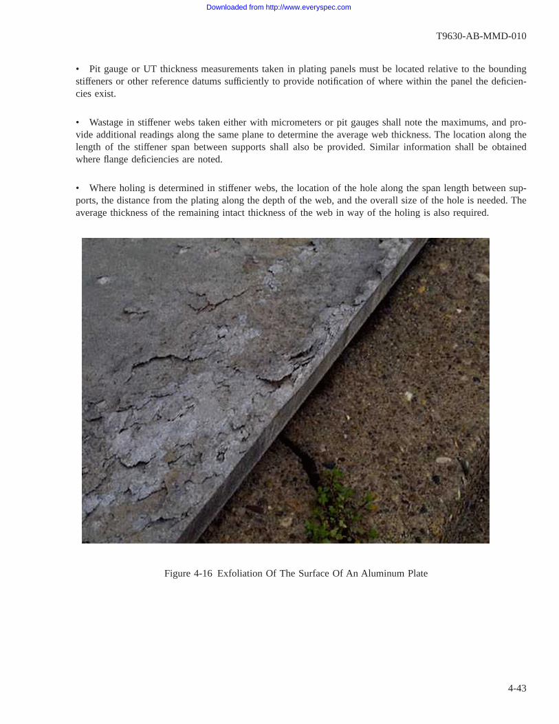
• Pit gauge or UT thickness measurements taken in plating panels must be located relative to the boundingstiffeners or other reference datums sufficiently to provide notification of where within the panel the deficien-cies exist.
• Wastage in stiffener webs taken either with micrometers or pit gauges shall note the maximums, and pro-vide additional readings along the same plane to determine the average web thickness. The location along thelength of the stiffener span between supports shall also be provided. Similar information shall be obtainedwhere flange deficiencies are noted.
• Where holing is determined in stiffener webs, the location of the hole along the span length between sup-ports, the distance from the plating along the depth of the web, and the overall size of the hole is needed. Theaverage thickness of the remaining intact thickness of the web in way of the holing is also required.
Figure 4-16 Exfoliation Of The Surface Of An Aluminum Plate
T9630-AB-MMD-010
4-43
Downloaded from http://www.everyspec.com

Figure 4-17 Drain Hole in Stiffener Enlarged by Corrosion
T9630-AB-MMD-010
4-44
Downloaded from http://www.everyspec.com

Figure 4-18 Examples of MIC-Produced Isolated Pitting in a Waste Oil Tank
T9630-AB-MMD-010
4-45
Downloaded from http://www.everyspec.com

Figure 4-19 Examples of Reportable Weld and Workmanship Defects
T9630-AB-MMD-010
4-46
Downloaded from http://www.everyspec.com

4-5.2 Maximum Allowable Corrosion, Thinning and Wastage Criteria. NSTM Chapter 100 provides the crite-ria governing the limits of maximum cross-sectional area and thickness loss for hull structural materials, beyondwhich repair or replacement is required. These limits are reflected in Table 6-1 as structural condition rating S5,and are as follows:
• ≥ 25% for steel structure (Except for LCS-1 and PC Class ships)
• ≥20% for steel structure on LCS-1 Class
• ≥10% for steel structure excluding hull and main deck plating between frames 7-14; and ≥5% for steel hulland main deck plating between frames 7-14 on PC Class
• ≥ 15% for aluminum structure
• ≥ 15% cross section area loss for stanchions, steel and aluminum
• For stanchions, stiffeners, beams, and frames: Application of the above limits shall be applied both to theindividual web and flange elements, and to the cross-section as a whole.
4-5.3 Determination of Thickness Loss in the Structure. In order to properly characterize and prioritizeinstances of structural material thickness losses using the maintenance decision risk matrix in Table 6-1, theactual thickness loss must be determined. Other than structural condition rating S1, representing no discerniblemetal loss, and the visually obvious failure modes that are a part of the condition S5 definition (e.g. holing,cracking, deformation, etc.), in general, the S2 through S5 ratings must be determined via either the optional useof UT gauging by a qualified Level 1 surveyor, or via a Level 2 inspection. When unable to determine the appli-cable thickness percentages of metal lost to determine the structural integrity scoring of the MDRM, the surveyormay use “SN/V”, signifying “not verifiable”.
A Level 1 Surveyor with access to the applicable structural drawings, or the ability to reliably determine theoriginal structural member thickness from an adjacent unaffected area, may be able to provide an initial estimateof the percentage of thickness lost from corrosion and pitting, using the pit depth gauge, and optionally, UTthickness gauging. Figure 4-20 shows how the percent material loss is calculated.
Table 4-6 shows various remaining plate thicknesses (variable “t” in Figure 4-20) and material reductions(variable “d” in Figure 4-20) for typical original thicknesses, and the respective percent reductions. The weightgauge designation column of Table 4-6 is a common terminology used for steel plate, indicating the number ofpounds per square foot (psf) that a steel plate of that thickness would weigh. Figure 4-20 and Table 4-6 are alsoapplicable to aluminum structures, with the exception of the weight gauge designations.
T9630-AB-MMD-010
4-47
Downloaded from http://www.everyspec.com

Determination of the percent reduction (wastage) in the thickness of a degraded structural member due togeneral corrosion or pitting is made via either Equation (1) or Equation (2) as follows:
Reduction (%) = {1 - (t/To)} x 100 Equation (1)
Reduction (%) = (d/To) x 100 Equation (2)
When the remaining thickness, t, and original thickness, To, are known then Equation (1) is used. When thedepth of damage, d, and original thickness, To, are known then Equation (2) is used.
Figure 4-20 Determination of the Percent Reduction in Plate Thickness
T9630-AB-MMD-010
4-48
Downloaded from http://www.everyspec.com

Table 4-6 Material Reductions and Percentages
PlateThick-
ness(Frac-
tion, in.)
PlateThick-
ness(Deci-
mal, in.)
Weight(Steel
PlatingOnly, #
(psf)
Measured Plate Thickness After %Wastage (in.)
Measured Pit Depth After % Wastage(in.)
5% 10% 15% 25% 5% 10% 15% 25%
1/8″ 0.125 5.1 0.119 0.113 0.106 0.094 0.006 0.013 0.019 0.0313/16″ 0.188 7.65 0.178 0.169 0.159 0.141 0.009 0.019 0.028 0.0471/4″ 0.250 10.2 0.238 0.225 0.213 0.188 0.013 0.025 0.038 0.0635/16″ 0.313 12.75 0.297 0.282 0.266 0.235 0.016 0.031 0.047 0.0783/8″ 0.375 15.3 0.356 0.338 0.319 0.281 0.019 0.038 0.056 0.0947/16″ 0.438 17.85 0.416 0.394 0.372 0.329 0.022 0.044 0.066 0.1101/2″ 0.500 20.4 0.475 0.450 0.425 0.375 0.025 0.050 0.075 0.1259/16″ 0.563 22.95 0.535 0.507 0.479 0.422 0.028 0.056 0.084 0.1415/8″ 0.625 25.5 0.594 0.563 0.531 0.469 0.031 0.063 0.094 0.1563/4″ 0.750 30.6 0.713 0.675 0.638 0.563 0.038 0.075 0.113 0.1887/8″ 0.875 35.7 0.831 0.788 0.744 0.656 0.044 0.088 0.131 0.2191″ 1.000 40.8 0.950 0.900 0.850 0.750 0.050 0.100 0.150 0.250
1-1/8″ 1.125 45.9 1.069 1.013 0.956 0.844 0.056 0.113 0.169 0.2811-1/4″ 1.250 51 1.188 1.125 1.063 0.938 0.063 0.125 0.188 0.3131-3/8″ 1.375 56.1 1.306 1.238 1.169 1.031 0.069 0.138 0.206 0.3441-1/2″ 1.500 61.2 1.425 1.350 1.275 1.125 0.075 0.150 0.225 0.3751-5/8″ 1.625 66.3 1.544 1.463 1.381 1.219 0.081 0.163 0.244 0.4061-3/4″ 1.750 71.4 1.663 1.575 1.488 1.313 0.088 0.175 0.263 0.4381-7/8″ 1.875 76.5 1.781 1.688 1.594 1.406 0.094 0.188 0.281 0.469
2″ 2.000 81.6 1.900 1.800 1.700 1.500 0.100 0.200 0.300 0.5002-1/4″ 2.250 91.8 2.138 2.025 1.913 1.688 0.113 0.225 0.338 0.5632-1/2″ 2.500 102 2.375 2.250 2.125 1.875 0.125 0.250 0.375 0.6252-3/4″ 2.750 112.2 2.613 2.475 2.338 2.063 0.138 0.275 0.413 0.688
3″ 3.000 122.4 2.850 2.700 2.550 2.250 0.150 0.300 0.450 0.7503-1/2″ 3.500 142.8 3.325 3.150 2.975 2.625 0.175 0.350 0.525 0.875
4″ 4.000 163.2 3.800 3.600 3.400 3.000 0.200 0.400 0.600 1.0004-1/2″ 4.500 183.6 4.275 4.050 3.825 3.375 0.225 0.450 0.675 1.125
5″ 5.000 204 4.750 4.500 4.250 3.750 0.250 0.500 0.750 1.2505-1/2″ 5.500 224.4 5.225 4.950 4.675 4.125 0.275 0.550 0.825 1.375
6″ 6.000 244.8 5.700 5.400 5.100 4.500 0.300 0.600 0.900 1.500
The following are examples of how Figure 4-20, Table 4-6, and Equations (1) and (2) can be implemented:
During a survey it is discovered that a shell stiffener flange is visibly thinned.
Measured flange thickness, t = 1/8 inch (0.125 inches)
Original flange thickness, To = 0.205 inches
Equation (1): Reduction % = {1-(t/To)} x 100 = {1-(0.125/0.205)} x 100 = 39%
During a survey an area of general corrosion is discovered in a bulkhead.
UT measured thickness, t = 0.279 inches
T9630-AB-MMD-010
4-49
Downloaded from http://www.everyspec.com

Original plate thickness, To = 0.375 inches
Equation (1): Reduction % = {1-(t/To)} x 100 = {1-(0.279/0.375)} x 100 = 25.6%
During a survey a pit in the steel shell plating is discovered.
Measured depth of pit, d = 3/16 inch (0.1875 inches)
Original plate thickness, To = 20.4# (0.5 inches)
Equation (2): Reduction % = (d/To) x 100 = (0.1875/0.5) x 100 = 37.5%
4-5.4 Sounding (Level 2 Inspection Only). “Sounding” the metal can be used to detect deteriorated structuralmembers beneath coating systems that appear to be intact, or beneath what appears to be only light corrosion orscale. Sounding shall never be performed on a pressurized system boundary, such as pressurized piping. Sound-ing the metal must be performed in a manner that does not unnecessarily damage intact coating systems on soundmetal, and therefore it should only be performed judiciously, when the surveyor has reason to believe the coat-ing system in the area may be compromised. Tap on the metal where deterioration is suspected, and listen forindications of material thinning. To baseline this method, tap on a non-corroded area of the same known designthickness. Then tap along the area under investigation and listen for pitch changes to determine the extent of thearea of deterioration. Signs of a structural issue include:
• Deflection of material when tapping
• Hollow drum sound when tapping
• Difference in sound of hammer blows from other areas of plating of the same original thickness and gen-eral surrounding structural support (stiffener spacing, welds, fluid presence on other side, etc.)
Hammers shall only be employed by a Level 2 inspector as required. Note that an unseen accumulation ofdebris or standing water on the opposite side of the structure being sounded can deaden the sound of a hammerblow.
When choosing where to perform sounding, particular attention shall be paid to areas where water collects,and where corrosion, scale or staining have already begun to develop. If an area appears to have large amountsof corrosion or thick rust-blistered paint, a chipping hammer should be used to break away corrosion and exposethe sound metal. Once sound metal has been exposed, the inspector can attempt to determine how much mate-rial wastage has occurred.
4-5.5 Ultrasonic Thickness Gauging. Ultrasonic testing (UT) for thickness gauging is the most commonly usedNon-Destructive Testing (NDT) method for structural inspection/evaluation. UT thickness gauging is the methodof placing a small handheld transducer on any given solid material to send ultrasonic sound waves through thematerial and determine its thickness. UT thickness gauging is used in evaluation of ship’s structures primarilywhen corrosion has occurred and material wastage is suspected. UT thickness gauging can be used to determinewhat percentage of the original material has wasted, if the allowable wastage limit has been exceeded, and todetermine if and how much material requires renewal.
UT thickness gauging is commonly performed as a part of a Level 2 inspection, and it is not required dur-ing a Level 1 survey. However, if the Level 1 surveyor is qualified as described in NSTM Chapter 100, the sur-veyor may perform UT thickness gauging in areas where structural thickness loss due to corrosion is observed,in order to provide supplemental information or to support a request for a Level 2 inspection. UT thickness dataprovided by the Level 1 surveyor must be accurately identified and linked to the structural member under inves-
T9630-AB-MMD-010
4-50
Downloaded from http://www.everyspec.com

tigation as described in paragraph 4-6, and recorded in the comments or narrative of the survey findings. WhenUT gauging is used during a Level 1 survey, a follow-up Level 2 inspection shall still be requested by the sur-veyor if he/she has reason to believe that excessive material wastage of the structure has occurred.
The following guidance is provided for Level 1 surveyors planning to perform UT thickness gauging.
Any surface cleaning method on steel structures that uses power tools, or thatmay create sparks may be considered “hot work”. All hot work shall comply withthe applicable fire prevention requirements; refer to NSTM Chapter 074, Vol-umes 1 and 3, or for private shipyards, the appropriate NAVSEA Standard Item.
• The structure must be cleaned of all loose rust, dirt and debris prior to testing in order to have sufficientcontact between the UT probe and test material surface. A power tool (i.e. sand paper flapper wheel, wirebrush, etc.) may be needed to smooth out a rusted area of structure prior to UT thickness gauging. Care mustbe taken to minimize the removal of any sound material during this cleaning.
• Paint on structure that is tightly adhered to the substrate and smooth does not need to be removed for UTthickness gauging if the UT thickness gauge being used has “echo to echo” or “through coat” technology. Thisis described in more detail in NSTM Chapter 100.
• Thickness readings may be inaccurate if there is structure attached to the other side of the surface beinggauged. For example: when performing UT thickness gauging on a tank top plate, if the probe is placeddirectly over a location where there is a stiffener web below, the UT gauge may give a false reading. In caseslike this, the UT probe should be moved a few inches to either side to validate and obtain repeatable readings.
• The presence of non-metallic foreign objects on the opposing side of structure that is being UT tested willnot affect the thickness readings. For example: inspecting the bulkhead of a full potable water tank from out-side the tank is feasible without removal of the water because water and steel have different acoustic imped-ances and the ultrasonic sound wave will reflect whenever it hits a boundary of two different acoustic imped-ances.
• Sufficient readings and grid densities should be used to accurately define the extent damaged and corrodedstructure back to sound metal and documented by sketches depicting the locations of the readings relative toframes and off centerline locations using points of reference easily established on construction drawings.
4-6. RECORDING THE LOCATION OF COATING AND STRUCTURAL DAMAGE.
The location of each instance of a coating or structural deficiency shall be identified as accurately as pos-sible, for the following purposes:
• To allow a determination to be made, from a review of prior CCIMS data entries or other sources, if thatdamage was previously identified and dispositioned.
• To provide precise information for follow-up Level 2 inspections.
• For accurate writing of GR2K repair jobs, if such action is determined to be warranted by the local engi-neering authority.
T9630-AB-MMD-010
4-51
Downloaded from http://www.everyspec.com

• When applicable for structural deficiencies, to allow for accurate preparation of strength calculations sup-porting deferrals, where required. (See paragraph 4-5.1.3.)
The following standard conventions shall be used by Level 1 and Level 2 surveyors and inspectors to accu-rately identify the location of a structural defect, as applicable. Where distance measurements are referred to, theymay be in either feet and inches, or meters and centimeters, as long as the units used are indicated.
• Identify the transverse location of the affected area by providing a reference point (e.g. “Centerline”,“PORT shell/tank top transition”, “STBD Longitudinal BHD”, etc.), and the approximate distance from thereference point to the beginning and end of the deteriorated area. State whether these measurements are(PORT) or (STBD) of the reference point.
• Identify the longitudinal location of the affected area by providing a reference point (e.g. “FWD BHD ###”,“FR 215”, etc.), and the approximate distance from the reference point to the beginning and end of the dete-riorated area. State whether these measurements are (FWD) or (AFT) of the reference point.
• Identify the vertical location of the affected area by providing a reference point (e.g. deck, tank top, bilgeshell plating, overhead plating, etc.) and the distance measured to the beginning and end of the deterioratedarea. State whether these measurements are (UP) or (DOWN) from the reference point. (This information isfor areas located on bulkheads or any vertical structure.)
• If known, identify the location of the affected area if it is located between stiffening elements (e.g.“Between stiffeners S-11 PORT & S-13 PORT”, or “Between Web FR 300 and Web FR 308).
Pit depth and ultrasonic thickness gauging readings, as required, shall be recorded in the comment section ofthe MRC G1N5 and G1N6 survey forms.
Refer to paragraph 5-6 for requirements and guidance concerning the preparation and submission of repair2-KILO’s using the above information.
4-7. PHOTOGRAPHIC RECORDS.
Surveyors and inspectors shall take digital photographs of all discrepancy areas that they record on the datacollection form for each compartment or area that will have a GR2K (repair 2-KILO) submitted recommendingmaintenance action. Surveyors and inspectors shall also upload these photographs into the applicable CCIMSdatabase. Photos must be labeled or identified in a manner that allows them to be later associated to the appro-priate discrepancy and assessment task. Photographs should be of sufficient resolution and include annotationclearly describing the direction viewed, location, and the discrepant condition being conveyed, etc. For digitalphotos, requirements for file name conventions and CCIMS database upload procedures will be set by the appro-priate Planning Activity responsible for maintaining the CCIMS database.
T9630-AB-MMD-010
4-52
Downloaded from http://www.everyspec.com

CHAPTER 5
DATA COLLECTION AND REPORTING
5-1. MRC G1N5 AND G1N6 DATA COLLECTION FORMS.
One data collection form shall be completed and submitted for each compartment or area that has beenassigned an assessment task (GA2K) in accordance with the CMP. Data collection forms are provided in Appen-dices (A) and (B) of this manual. The official and most up to date version is available from the Naval FormsOnline web site at: https://navalforms.documentservices.dla.mil/
The data collection forms help ensure that each of the features that are to be examined as part of a Level 1MRC G1N5 or MRC G1N6 survey are accounted for. Level 1 surveyors shall record the results of the surveysinto the automated data systems established by the respective maintenance activities in a timely manner in accor-dance with policies and procedures established by the applicable Planning Activity.
Data forms that are electronically reproduced on hand-held computing devices in order to facilitate datatransfer to the respective Planning Activities and upload into the CCIMS database are acceptable alternatives tothe above forms, provided that they have been approved by the applicable Planning Activities.
5-2. LEVEL 1 SURVEY REPORTING REQUIREMENTS.
The results of the Level 1 surveys shall be documented and submitted to the applicable Planning Activitieswithin 3 working days of completion of the survey. (Travel to and from the site is considered part of the surveytime period.) This includes all scheduled periodic surveys, surveys of opportunity, and “as arrived” surveysdescribed in Chapter 3. The method of transmission of the data shall be as established by the respective PlanningActivity as follows:
• Surface Ships: survey data, including the resulting repair 2-KILO work items, shall be entered by the sur-veyor/survey activity via the SURFMEPP CADET system.
• Aircraft Carriers: TYCOM-validated survey data shall be transmitted to the CPA via entry into CCIMS.
Repairs to coatings or other outfitting systems (e.g. sacrificial anodes, ladders, TLI’s, insulation, etc.) that arerecommended or required as a result of Level 1 surveys, and any requests for follow-on Level 2 inspections, shallbe documented on one or more maintenance notification forms (2-KILO) as needed.
5-3. LEVEL 2 INSPECTION REPORTING REQUIREMENTS.
The results of Level 2 inspections performed as a result of a Level 1 survey finding shall be documented andsubmitted to the applicable Planning Activities within 15 working days of discovery of the potential structuraldeficiency by the Level 1 surveyor. For other Level 2 inspections not stemming from a Level 1 survey, the resultsshall be submitted within 3 working days from the completion of the inspection.
Structural repairs that are determined to be required as a result of Level 2 inspections shall be documentedon one or more maintenance notification forms (2-KILO) as needed. Level 2 inspection reports, UT thicknessgauging reports, and all repair sketches and supporting data that may be required in accordance with NSTMChapter 100 shall be provided to the applicable Planning Activity upon request, in addition to the local engineer-ing authority and/or NAVSEA. The reports shall provide sufficient detail to perform structural analyses wherewarranted.
T9630-AB-MMD-010
5-1
Downloaded from http://www.everyspec.com

5-4. NON-MANNED ENTRY ASSESSMENT REPORTING REQUIREMENTS (TANKS AND VOIDSONLY).
The results of each periodic assessment performed using either the Tank Monitoring System (TMS) and itsTank Ranking Algorithm (TRA) software, or the Insertable Stalk Imaging System (ISIS) and its CorrosionDetection Algorithm (CDA) software, shall be reported to the applicable Planning Activity and entered into theCCIMS database.
5-5. LEVEL 1 SURVEY CMP TASK COMPLETION/CLOSE-OUT.
If a Level 1 survey of an assigned compartment has been completed and there is no request for a follow-onLevel 2 inspection, the assessment task shall be recorded as completed or closed-out once the completed surveydata form has been submitted and recorded with the applicable Planning Activity, and any recommended GR2Krepair actions are submitted.
When a Level 2 inspection of a compartment is required as a result of a Level 1 survey, the CMP task shallnot be recorded as completed or closed out until the required Level 2 inspection is completed. If the Level 2inspection is not completed within the 15 working day requirement (see paragraphs 3-5.1 and 5-3), the MRCG1N5 or G1N6 task (as applicable) shall have a minor DFS submitted for local NSA approval or the deferralmust be approved utilizing the documentation process requirements outlined in the JFMM. Once the Level 2inspection has been completed, or its deferral request has been approved, the Level 1 CMP task for that compart-ment may be closed out and the CMP updated to reflect the Last Completion Date (LCD).
5-6. REPAIR 2-KILO DEVELOPMENT.
For all deficiencies found, surveyors and inspectors shall prepare and submit repair 2-KILO (GR2K) forms,in accordance with the applicable Planning Activity business rules. Depending on the ship platform, these formsmay be directly generated from the “Comments” block on the data collection forms, and directly transferred tothe Block 35 “Remarks/Description” on the 2-KILO.
Level 1 surveyors may make initial coating system touch-up and repair recommendations as described herein,but are not to make direct structural repair recommendations. Structural repair 2-KILOs shall only be preparedby Level 2 structural inspectors.
The Maintenance Decision Risk Matrix (MDRM) described in Chapter 6 provides the means to prioritizeindividual compartment, area, or component maintenance requirements for both coating and structural deficiencyrepairs. In order to use the MRDM properly, each repair 2-KILO submitted requires the assignment of a RiskGroup R#, and either a coating condition P# or a structural integrity condition S#. In most cases, the appropri-ate R# can be determined by Level 1 survey personnel from a review of Table 6-2 and Table 6-3; however, somemay require the assistance of the applicable maintenance team; refer to paragraph 6-2.1. Level 1 survey person-nel are responsible for the assignment of coating condition P#’s as described in paragraph 4-4. Level 1 or Level2 survey and inspection personnel are responsible for the assignment of structural integrity S#’s as described inparagraph 4-5.
Repair 2-KILOs associated with outfitting items not related to the ship structure or its protective coatings donot require the use of the MDRM or any of the rating numbers described above. Other than those that aredescribed herein as Repair Before Closing (RBC) items in tanks and voids, they shall be handled by the mainte-nance teams like any other maintenance action item.
Level 1 and Level 2 surveyors and inspectors shall use their judgment to determine how to combine or splitup the repair work recommendations appropriate to the configuration of the compartment being surveyed. Thelocation within the compartment and the approximate square footage (when applicable) of each discrete repairrecommendation shall be reported.
T9630-AB-MMD-010
5-2
Downloaded from http://www.everyspec.com

Level 1 surveyors shall also use their judgment to report whether interferences will be required to be removedor lifted in order to gain access to problem areas in order to properly perform surface preparation and coating.Interferences may include items such as pieces of equipment or machinery, distributed systems (piping, ducting,or electrical cable/conduit), and insulation materials.
Unambiguous, accurate reporting of the conditions found and recommended repairs is essential to allowmaintenance planning managers to properly scope and screen each recommended work item. Appendix (D) pro-vides guidance and a recommended format for developing repair 2-KILO’s, particularly for coatings and struc-tural deficiencies. It addresses both Level 1 surveys and Level 2 inspections. Appendix (D) also includes a listof standard abbreviations for common terminology.
5-7. REPAIR AND MODERNIZATION DOCUMENTATION.
In order to effectively manage structural and coating life cycle information, and to enable accurate pushingof GA2K Level 1 survey tasking by the Planning Activities, maintenance teams shall provide the PlanningActivities with the following documentation:
a. For Tanks and Voids on all vessels, and for bilge regions and other CCSIAs specified in the CVN CMPOnly: Coating work completion Objective Quality Evidence (OQE) data, including the QA Checklist Formsrequired by NAVSEA Standard Item 009-32.
b. Adjudicated DFS’s pertaining to coating and structural repair work.
c. Docking Reports in accordance with NSTM Chapter 997 for docking availabilities.
d. Configuration/arrangements change data from SHIPALT’s affecting tank, void, or compartment numbering,type of service, or accesses.
Planning Activities shall convey to their respective Fleet maintenance activities the acceptable forms or for-mats of this data and how it shall be provided.
5-8. CCIMS DATA STORAGE AND RETRIEVAL.
Planning Activities shall use the CCIMS database(s) to store the following data at a minimum:
a. MRC G1N5: All data from the survey form.
b. MRC G1N6: The “Inspector” and “General” data blocks from the survey form, and all condition data.
c. Digital photographs.
d. Pertinent data from the items described in paragraph 5-7 above.
Planning Activities shall maintain a means to store and retrieve historical data from the CCIMS databases.
5-8.1 Handling of Digital Images. Handling of Digital Images
Digital images (photographs), when used in conjunction with objective quantitative survey results, are com-monly used and reviewed by maintenance teams, Planning Activities, and NAVSEA authorities when evaluatingdiscrepancies and recommended work items. Digital photographs required by Chapter 4 shall be provided to theapplicable Planning Activity in conjunction with the reporting of Level 1 and Level 2 survey and inspectionresults. The Planning Activities shall maintain a means to store and retrieve digital photographs in the CCIMSdatabase. Digital photographs shall be available for review by the maintenance teams, local engineering authori-ties, and NAVSEA to support repair 2-KILO development, DFS adjudication, and failure or trend analyses.
T9630-AB-MMD-010
5-3
Downloaded from http://www.everyspec.com

The CCIMS database is controlled as Distribution Statement D, restricting access to DOD employees andDOD contractors. Planning Activities shall establish and implement methods to control the appropriate Distribu-tion Statements to be applied to digital photograph files that are uploaded or downloaded from their respectiveCCIMS databases. For aircraft carrier CCIMS, prior to uploading any pictures, surveying activities and the CPAshall ensure the necessary reviews are accomplished to verify the pictures do not reveal Naval Nuclear Propul-sion Information (NNPI) or other restricted systems, and are labeled as Distribution Statement D.
5-8.2 COSMOS Database Tool. SURFMEPP has developed the Corrosion and Structural Monitoring System(COSMOS) database tool that tracks trends in corrosion and structural degradation on surface ships that is usedin conjunction with Surface CADET-CCIMS. The COSMOS data tool collects and displays current and histori-cal corrosion related assessment and repair work order data from the Navy 3M systems and categorizes them uti-lizing the maintenance decision risk matrix, Table 6-1.
COSMOS automatically creates a series of charts and reports on outstanding (open) repair work items in thethree categories of structural repairs, coating repairs, and various other corrosion-related repairs on other items(outfitting) conditions. These reports can be used in conjunction with the JFMM maintenance milestones to assistin the development of Baseline Availability Work Packages (BAWP) and to answer technical data calls asrequired. By rapidly isolating life cycle critical repair work, COSMOS functions as a companion piece to theassessment results stored within Surface CADET-CCIMS.
The COSMOS tool is located with Surface CADET-CCIMS under the SPEAR Maintenance domain at thefollowing URL: https://www.spear.navy.mil/, restricted applications section.
5-9. DEFERRALS AND NON-CONFORMANCES.
Any noncompliance with the requirements of this manual shall be documented and adjudicated using estab-lished practices for DFS’s and BAWP Change Management described in the JFFM and the CMP as applicable.
• Deferrals and non-conformances regarding requirements pertaining to the scheduling of Level 1 and Level2 surveys and inspections, and coating system repairs or replacements, are to be handled using BAWP ChangeManagement procedures.
• Deferrals and non-conformances regarding required structural repair actions are to be handled using DFSprocedures; refer to paragraph 6-3.3.
In most cases, it is generally not appropriate for the Level 1 surveyor to make recommendations regardingthe creation of DFS’s. The maintenance actions required as a result of the conditions found during surveys aredescribed in this manual, and if they are not followed within the required timeframe then a DFS is requiredaccording to the JFMM. However, there may be unique circumstances where it is appropriate for the surveyor torecommend a DFS. For example, in a tank survey, if all four zones are in Condition P1 without taking intoaccount any coating blisters, but the extent of intact blisters in a single zone drives that zone (and therefore theoverall score of the tank) to be modified to Condition P3 or P4, then a DFS recommendation may be prudent.Sample wording for this case may be “DUE TO THE MINIMAL NATURE OF CORROSION WITHIN THETANK AND THE LOCALIZED NATURE OF INTACT BLISTERING, RECOMMEND SUBMITTING A DFSTO POSTPONE TANK PRESERVATION ONE MAINTENANCE CYCLE.”
T9630-AB-MMD-010
5-4
Downloaded from http://www.everyspec.com

CHAPTER 6
DISPOSITION AND MAINTENANCE ACTIONS
6-1. GENERAL.
This chapter of the manual provides requirements and guidance for the disposition of coating and structuralcondition findings that are documented by the MRC G1N5 and G1N6 surveys, and any associated GR2K repairmaintenance action recommendations. TYCOM maintenance managers (i.e. Port Engineers, CVN MPMs anddepot level executing activities) shall use this Chapter to prioritize and make repair decisions and submit DFSsas needed. Planning Activities shall also use this Chapter to determine and schedule follow-on surveys andinspections (GA2K push tasks).
All findings that indicate corrosion has caused notable thickness loss or pitting, or evidence of other damagein the structures, whether coated or bare exposed metal, shall have a GR2K submitted to request a Level 2inspection, and UT thickness gauging if appropriate to determine the extent of wastage, and shall be dispositionedin accordance with Table 6-1 and NSTM Chapter 100 requirements.
Refer to paragraph 6-9 for special requirements regarding scheduling, and dispositions of survey and inspec-tion findings, for ships approaching their decommissioning dates.
6-2. CONDITION BASED MAINTENANCE REQUIREMENTS.
Actions that are required to be taken based on the assessed condition of coatings and structures at the timeof the surveys and inspections are dependent on a number of considerations in addition to the extent of coatingor structural damage. Other aspects of risk, including potential mission, safety and economic impacts, as well asfactors that impact the probability of failure, will affect the extent and priority of required repairs. Additionalsituational repair guidance is provided in this Chapter, including considerations for repairs that require docking,the type of adjacent space(s) that share a common structural division plate, and for ships at or near decommis-sioning.
The Maintenance Decision Risk Matrix (MDRM), Table 6-1, provides a condition-based framework for mak-ing and prioritizing both coating and structure repair decisions for a compartment or structural components’assigned level of mission criticality and/or risk as described below, and its assessed material condition asdescribed in Chapter 4. The MDRM and accompanying Tables 6-2 and 6-3 shall be used to determine the criti-cality of the structure and determine actions, priority and scheduling of repairs to the structure and coating sys-tems in the absence of engineering calculations demonstrating the adequacy of the structural systems. TheMDRM is intended to be used separately to make coating system re-inspection and/or repair/replacement deci-sions, and structural repair decisions, and to prioritize them.
6-2.1 Assignment of Risk Group (R#). For each repair GR2K submitted as a result of the Level 1 and Level2 surveys and inspections, determine the appropriate Risk Group rating (R1 through R5) on Table 6-1 for eitherthe compartment/area, or the type/location of the structural member or feature. These range from “Minimal” (R1)to “Critical” (R5), and are defined in Table 6-2 for tanks and voids, and Table 6-3 for all other areas.
TYCOM maintenance managers and/or Planning Activities are responsible for ensuring the correct assign-ment of Risk Groups to assessment findings and repair GR2Ks.
6-2.1.1 Mission Critical and Severe Service Tanks and Voids (MRC G1N5). “Mission Critical” tanks and voidsare those that affect the ship’s mission, the propulsion plant or that could have a negative impact on crew moraleshould they need to be taken out of service. The maintenance of the structural integrity in these areas, and of
T9630-AB-MMD-010
6-1
Downloaded from http://www.everyspec.com

coatings (where required) to prevent contamination of the fluid in the tank, is necessary to ensure the safe andproper operation of the ship. Mission Critical tanks are listed below:
• Boiler Feed Water Tanks
• JP-5 Service Tanks
• JP-5 Storage Tanks (except for CVNs)
• Fuel Oil (FO) Storage and Service Tanks
• Potable Water Tanks
• High Pressure Watermist System Fresh Water Storage Tanks
A “Severe Service” tank is one that is in a highly corrosive environment that leads to accelerated coatingdeterioration with attendant corrosion of the underlying structure. Severe Service tanks also includes those thatare prone to rapid and extensive coating blistering, such as those that hold warm or hot fresh water. Accordingly,Severe Service tanks require more frequent survey after initial coating damage is found. Severe Service tanks arelisted below:
• Seawater Ballast and Seawater List/Ballast Control Tanks
• Compensated Fuel Tanks
• JP-5 Contaminated Oil, Settling, and Purifier Drain Tanks
• CHT, Wastewater and Contaminated Oil Tanks
• Fresh Water Steam Condensate Drain Collecting Tanks
Risk group ratings balance both mission criticality and severe service conditions, and all of the above tanksand voids fall within the R4 and R5 risk groups in Table 6-2.
6-2.2 Assignment of Condition Rating (P# or S#). Once the Risk Group R# is identified, a maintenance actionshall be scheduled or accomplished based upon the as-found material condition rating, as per Table 6-1. Require-ments concerning the assignment of “Structural Integrity” (S1 through S5) and “Coating Integrity” (P1 throughP4) material condition ratings are contained in Chapter 4 of this manual, and are based on the extent of structuralwastage, coating breakdown, or related system damage and the requirements of NSTM Chapters 100 and 631.Note that coating system ratings are independent of any determinations of structural repairs that may be required.Coating system maintenance actions, including the Planning Activity scheduling of follow-on surveys of tanksand voids at reduced periodicities, only require an R# and a P#. Structural integrity maintenance actions onlyrequire an R# and an S#, although the associated P# may be provided as warranted, since structural repairs arealmost always coupled with represervation of new and disturbed surfaces.
Where the “#” sign is used, the use of an actual number is required. The Coat-ing Integrity Condition Rating P# is located at the left side of Table 6-1 and theStructural Integrity Condition Rating S# is found on the right side. For coatingintegrity condition P1 and structural integrity condition S1, there is no actualGR2K repair action that needs to be submitted.
T9630-AB-MMD-010
6-2
Downloaded from http://www.everyspec.com
Level 1 and Level 2 survey and inspection personnel are responsible for the assignment of P# and S# ratingsto each completed assessment and repair GR2K submitted, using the requirements provided in Chapter 4. Plan-ning Activities are authorized to adjust the initially reported P# and S# values based on available objective qual-ity evidence submitted with the report.
6-3. MAINTENANCE DECISIONS AND PRIORITIZATION.
The disposition and prioritization of Coating Integrity and Structural Integrity repair actions, including thesubmission of any associated DFSs, shall follow the requirements of the Table 6-1 MDRM and NSTM Chapters631 and 100, except where limited in paragraph 1-3.
6-3.1 Coating System Maintenance Actions.
MRC G1N5: The overall Coating Integrity condition rating P# of tanks and voids governs coatings mainte-nance actions in those compartments.
MRC G1N6: The Coating Integrity condition rating P# assigned to each coating repair GR2K submitted forall compartments other than tanks and voids governs coatings maintenance actions in those compartments; sepa-rate and independent maintenance actions may be taken for each GR2K. However, maintenance teams have theprerogative to combine coating repair GR2Ks into a single work item, provided that the maintenance action asso-ciated with the highest coating condition P# of the combined GR2Ks is performed.
When a CMP requires complete coating system replacement in specific compart-ments or areas solely on the basis of service time (coating system age), based onanalyses of past performance and cost metrics, Planning Activities shall compareany coating maintenance actions resulting from the survey that would be directedby the MRDM to the next scheduled full represervation to determine the appro-priate course of action, in accordance with the below:
a. If the next CMP time-based compartment represervation is scheduled to beperformed in the current or next maintenance cycle, then the condition-basedcoating repair actions reflected in the MRDM may be disregarded.
b. If the next CMP time-directed compartment represervation is scheduled tobe performed later than the next maintenance cycle following the Level 1 sur-vey, then the condition-based coating repair actions reflected in the MRDMshall be performed.
Refer to paragraph 4-4.5 for application of NSTM Chapter 631 criteria concerning mandatory replacement ofthe entire coating system in the designated compartment or area when the accumulated damage exceeds 10% or20% of the total surface area.
6-3.1.1 Additional Tank and Void Coating Maintenance Requirements and Recommendations. When it is notpossible to assess a tank or void in advance of a maintenance period, then work to be accomplished cannot beplanned and is called emergent, or growth work. Emergent work during a maintenance availability is always con-siderably more expensive than planned work, and in some cases may also have an impact on the overall avail-ability schedule. When a tank or void survey occurs at the start of a maintenance period, such as an Extended
T9630-AB-MMD-010
6-3
Downloaded from http://www.everyspec.com

Repair Survey (paragraph 3-3.2) or an As-Arrived Survey (paragraph 3-3.4), the actions taken based on the resultsof the survey must be considered relative to the cost and schedule impact that would result.
Based on the tank or void coating condition rating determined using Chapter 4, the coating system mainte-nance actions described in Table 6-1 and its notes, as supplemented in this paragraph, shall be performed at aminimum. The maintenance team has the discretion to replace the coating system in tanks and voids sooner thanrequired based on availability of resources and schedule.
a. R4/P3: If the tank or void is not an innerbottom tank or void, schedule and perform a complete blast andrecoat during the next maintenance availability cycle.
If the tank or void is in innerbottom, it shall be scheduled for complete blast and recoat during the next dock-ing availability maintenance cycle. If that docking availability is two maintenance cycles in the future, thenre-survey in next waterborne availability.
If the survey that produced the P3 finding in an innerbottom tank or void occurred at the beginning of a dock-ing availability, it is recommended that the maintenance team add a complete blast and recoat of the compart-ment to the current maintenance cycle Availability Work Package (AWP) if resources and schedule permit.
b. R4/P4, R5/P4: If the survey that produced the P4 finding occurred at the beginning of a maintenance cycle,it is recommended that the maintenance team add a complete blast and recoat of the tank or void to the cur-rent AWP if resources and schedule permit. However, if the tank or void is located in the innerbottom, theadditional requirements described below apply:
(1) Condition P4 finding determined within the 0-20% completion period of a docking availability -AND- thetank or void does not require drydocking to recoat as described in paragraph 6-6.1: if the tank or void isnot recoated in the current docking availability, it shall be scheduled for recoating in the next maintenancecycle.
(2) Condition P4 finding determined within the 0-20% completion period of a docking availability -AND- thetank or void does require drydocking to recoat as described in paragraph 6-6.1: the tank or void shall beadded to the current AWP for recoating. If unable to completely remediate during the current dockingavailability, the local NSA shall ensure that the deferral is documented via major DFS or by utilizing theJFMM BAWP deferral management process to document the non-compliance and coordinate a risk miti-gation plan with the applicable Planning Activity to determine follow on reprogramming requirements.
6-3.1.2 Condition Unknown (Condition 0). If a required Level 1 survey of a compartment was scheduled dur-ing an availability but was unable to be performed for any reason, the survey shall be scheduled as soon as prac-ticable within 36 months of the original scheduled date. The unknown condition shall be documented in theCCIMS database and the Condition rating shall be set to 0 (zero). A DFS shall be submitted in accordance withparagraph 6-3.3. For tanks and voids, the following additional requirements are applicable:
a. R5 or R4 tanks or voids, or any innerbottom R3 tank or void that requires docking in order to blast andrecoat: the BAWP for the next availability following the missed assessment shall provide for both an as-arrivedLevel 1 survey at the start of the availability, and work scope margin to allow for emergent work that may berequired based on the condition found during the survey.
6-3.2 Structural Integrity Maintenance Actions. The overall process for the assessment of structural systemintegrity consists of:
T9630-AB-MMD-010
6-4
Downloaded from http://www.everyspec.com
• Performing regularly scheduled Level 1 surveys.
• Performing regularly scheduled and condition-directed follow-up Level 2 inspections.
• Performing structural integrity strength analyses and evaluation of damage when discovered.
• Predicting additional wastage and the expected condition of the structure by the time repairs are anticipatedto be performed, where deferrals of coating system repairs are planned. This step requires the application ofcorrosion rate projections described in NSTM Chapter 100, as described in paragraph 4-5.1.1.
• Documenting the results and required repairs.
The overall assessment determines the subsequent need for repairs, prioritization of those repairs, and theassociated risks and actions required when seeking deferral of repairs.
When structural damage that is outside of specifications is present, the structure must be repaired to restorethe structural integrity, or it must be demonstrated to be adequate by analyses where deferrals are requested priorto continued operation of the vessel.
In the absence of case-specific strength evaluations that are prepared to demonstrate structural adequacy inconjunction with a DFS, the MDRM in Table 6-1 shall be used to determine the priority and scheduling of repairsto the structure.
6-3.2.1 Coating Repairs of New and Disturbed Surfaces Resulting From Structure Repairs. All planned oremergent structural repairs should always be made prior to represervation of a compartment or area.
Structural repair will in almost all cases require welding and will damage the surrounding coating system dueto the heat generated. Typical welding requirements call for all paint to be removed within a short distance ofeither side of the weld as a part of the weld joint preparation. However, these requirements generally only addressthe paint that is on the same side of the bulkhead plating (or in the same compartment) where the welding isactually being performed. In some cases, the heat of welding can also damage the coating system on the oppo-site side of the plate in the adjacent compartment or area. This might commonly occur for fillet welds made torenew corroded stiffeners on one side of the plate boundary. An example is shown in Figure 6-1.
Work item planners must take the above into consideration when preparing detailed repair items, and shallinclude scope for touch-up repairs to the damaged coating systems in compartments adjoining the ones wherestructural repair welding is being performed, as appropriate.
T9630-AB-MMD-010
6-5
Downloaded from http://www.everyspec.com

6-3.3 Non-conformance Reporting. Non-conformance adjudication is documentation of non-conformance totechnical requirements. For the purposes of CCAMM, non-conformance adjudication is documented by ChangeManagement for work planning and by Departures from Specification (DFS) for work execution and existingdeficient shipboard conditions. Non-compliance to the technical requirements and the MDRM for there-inspection, repair or restoration of coatings or structure deficiencies reported from Level 1 and Level 2 sur-veys and inspections requires formal documentation via the BAWP Change Management process or by submit-ting a DFS in accordance with the Joint Fleet Maintenance Manual (JFMM).
A major DFS is one for a currently deficient shipboard condition that affects the integrity, performance, dura-bility, reliability, maintainability, safety (including survivability), or other functionality of a system. For structuraland coating systems, a major DFS shall be submitted for the following non-compliant conditions:
a. MDRM Scores (Red) R5/S5 andR4/S5 for structural deficiencies.
b. MDRM Scores (Red) R5/P4 and R4/P4 for coating system deficiencies in innerbottom tanks or voids whenthe requirements of paragraph 6-3.1.1(b) are not met. Non-conformance reporting in this case shall be byeither a major DFS, or via the BAWP/AWP Change Management process.
c. Tanks and voids in unknown condition due to a planned but missed MRC G1N5 assessment as describedin paragraph 6-3.1.2 (a).
d. When multiple conditions of structural degradation exist exceeding the established criteria for structure
Figure 6-1 Burned Coating From Welding on Opposite Side of Plate
T9630-AB-MMD-010
6-6
Downloaded from http://www.everyspec.com

contributing to longitudinal strength and UNDEX whipping resistance as described in NSTM Chapter 100,structural integrity/strength analyses shall be prepared and are required to be included as justification for thedeferral with a major DFS request.
Minor DFSs shall be submitted where required for other structural and coating deficiencies as noted in theMDRM.
6-3.4 Repairs Other Than Coatings and Structures. For repairs pertaining to items other than ship structure andits coatings, unless otherwise specified herein (such as paragraph 6-8 RBC items for tanks and voids), GR2Kswritten for specific equipment or components (e.g. anodes, TLIs, ladders, vent screens, etc.) shall be dispositionedand managed by the TYCOM maintenance managers using their normal business practices, and do not requirethe use of the MDRM.
6-4. TOUCH-UP REPAIR OF COATINGS.
The objective of touch-up painting is to prevent or arrest structural material loss due to corrosion in the areaof the failed coating, and to retard the progression of coating failure such that the overall coating system canachieve its original intended service life. Refer to paragraph 1-5.2.3 for the definition and limits on depot-levelwork scope for touch-up coating when NAVSEA Standard Item 009-32 is used.
Requirements and recommendations regarding coating system touch-up maintenance actions are included inTable 6-1.
In compartments or locations under the scope of MRC G1N6, touch-up painting that is required or recom-mended herein may be screened by the maintenance team for either Organizational (O-Level), Intermediate(I-Level), or Depot (D-Level) accomplishment. O-Level touch-up painting is to be performed in accordance withthe guidance in NSTM Chapter 631 and applicable PMS requirements. Note that touch-up painting in some areasmay require significant staging for access, or additional services.
General requirements and guidance concerning the scheduling and performance of depot-level touch-up coat-ing in tanks and voids under the scope of MRC G1N5 are provided below.
a. Touch-up repairs do not change the condition rating of a tank or void in CCIMS. The only way for a tank orvoid condition rating other than P1 to be restored to a P1 is for the coating system to have been completelyreplaced by blasting and painting in accordance with Standard Item 009-32.
b. Touch-up repairs in tanks and voids should only be performed when the distribution of coating damage andcorrosion is “localized” as defined in paragraph 4-4.3.2. Touch-up repairs are not recommended or requiredwhen the coating damage is “scattered”, as it is not economical or practical to perform. Touch-up repairs ofareas of localized coating damage are required in specific instances described in this chapter (for example, insevere service tanks and voids in Condition P3 or P4); in most other cases, touch-up coating of localizeddamage is recommended but not required.
c. For dry voids in any condition, the local engineering authority may evaluate the need and benefits of touch-upon a case basis and act accordingly. These compartments shall be re-surveyed at the periodicities described inTable 6-1.
d. Touch-up coating repairs in tanks and voids are highly recommended to be made by a depot-level maintenanceactivity. Note that touch-up painting in some tanks and voids may require significant staging for access, oradditional services.
T9630-AB-MMD-010
6-7
Downloaded from http://www.everyspec.com

6-5. DISPOSITION OF ISIS/CDA FINDINGS.
As noted in paragraph 3-6, ISIS/CDA usage is currently limited to potable water tanks, seawater ballast tanks,and dry voids, and the findings can only be used to determine the requirements for follow-on surveys; ISIS/CDAfindings cannot be directly used as a basis for coating repair determinations. The re-survey requirements as aresult of ISIS/CDA findings and the associated tank/void complexity risk factors shown in Table 3-4 are describedbelow.
• Condition P1: The next survey shall be performed at the periodicity indicated in Table 3-1. This next sur-vey may be performed using ISIS and the CDA, or by a manned-entry MRC G1N5 Level 1 survey. However,unmanned ISIS surveys shall be limited to a maximum of two consecutive uses, after which a manned-entryMRC G1N5 survey is required.
• Condition P2: For potable water tanks and seawater ballast tanks, the next survey shall be conducted within36 months after the Condition 2 finding. For dry voids, the next survey shall be conducted within 72 monthsafter the Condition 2 finding. For tanks and voids with a “Low” complexity risk factor as per Table 3-4, thesefollow up surveys may be performed using ISIS and the CDA or by a manned-entry MRC G1N5 survey. How-ever, unmanned ISIS surveys shall be limited to a maximum of two consecutive uses, after which a manned-entry MRC G1N5 survey is required. For tanks and voids with a “Medium” or “High” complexity risk factoras per Table 3-4, these follow up surveys shall be performed by a manned-entry MRC G1N5 Level 1 survey.
• Condition P3 or P4: A manned-entry MRC G1N5 Level 1 survey shall be scheduled and conducted as soonas practicable. For potable water tanks and seawater ballast tanks, this survey should be performed at the nextavailability, but in no case shall it be conducted more than 12 months after the Condition P3 or P4 finding. Fordry voids, this survey should be performed at the next availability, but in no case shall it be conducted morethan 24 months after the Condition 3 or 4 finding. For any innerbottom tanks, the manned-entry MRC G1N5survey shall be conducted during the same availability that the ISIS survey was performed in.
6-6. ADDITIONAL FACTORS FOR PRIORITIZATION AND SCHEDULING OF COATINGS WORK.
The following factors shall be considered when determining the overall risks of continued operation, and thescheduling and prioritization of repair work.
6-6.1 Docking Required To Recoat. A docking-only tank, void, or other compartment is one that primarily isonly blasted and recoated in practice while in drydock, either due to the extremely high cost or schedule disrup-tion caused by attempting to blast and coat the compartment while the ship is waterborne, or due to fundamen-tal ship instability problems that may arise for certain ship class designs. Additional considerations that mandatea docking-only maintenance requirement concerns the harmful effects of blasting and coating operations on ship’smachinery, and the potential for abrasive blasting or power tool cleaning on thinned shell plating to perforate theplate and result in waterborne compartment flooding. If the only means to enter a compartment that does notcompromise the cleanliness and function of machinery is through a hole cut for access through the hull, then thecompartment must be considered as docking-only.
Due to the extended length of time between docking availabilities, complete replacement of a coating systemby blasting and recoating may be the appropriate action if in drydock, even if the compartment has not reachedCondition P4. If not, the condition of the tank or void shall be documented, touch-up painting performed ifrequired, and recoating shall be scheduled and performed in the next docking availability.
6-6.2 Tanks and Voids With Equal Overall Condition Scores. The overall coating integrity condition scoreresulting from a tank or void Level 1 G1N5 survey is the highest of the individual scores among the four desig-nated survey zones within the compartment. Therefore, for any given ship availability work package planning,
T9630-AB-MMD-010
6-8
Downloaded from http://www.everyspec.com
this can result in many tanks and voids all being in Condition P4 and potentially requiring more coating repairor replacement action than the available budget and schedule can support.
When determining those tanks and voids to recoat and those requiring a DFS to be submitted in accordancewith the requirements of this Chapter, the four zone-based condition ratings of each tank and void rated as Con-dition P4 can be added together, and ranked against one another for comparison, since those with higher sumswill usually represent those with greater extents of coating failure and corrosion. For example, a tank with coat-ing condition ratings of P4-P4-P4-P4 in the four zones would score 16, and would be given a higher priority forwork than another tank of the same type of service with a cumulative P4-P1-P3-P2 ranking score of 10, eventhough both tanks had an overall coating rating of Condition P4. In making these rankings, tanks and voids thatare designated as Risk Groups R5 and R4 shall be given the highest priority, followed by innerbottom tanks andvoids that are not Risk Group R5 or R4, then by non-innerbottom tanks and voids that are not Risk Groups R5or R4, and lastly by all other types of tanks and voids.
6-6.3 Adjacent Compartments. Compartments will always share at least one common boundary with one ormore adjacent compartments. The top of one tank, for example, may be the bottom of a tank immediately aboveit, and a bulkhead of a Risk Group R3 tank may also serve as the bulkhead of an adjacent R5 tank. In prioritiz-ing work for coating replacement, it is therefore necessary to determine what compartments are adjacent. Forexample, given two tanks that have been assessed on the MDRM as R3-P3, one that has shared boundary withan R5 tank should be given a higher priority than one that only has shared boundaries with R4 or R3 compart-ments.
6-6.4 Dry (Non-Floodable) Void Compartments. The rate of corrosion in a dry void compartment is limited bythe lack of humidity (moisture) or water that would occur in general atmospheric or immersion corrosion. Dueto the low risk associated with dry void compartments that are in coating condition P3 or P4, coating replace-ment for these compartments typically should be at the bottom of the priority list relative to other compartments,unless adjacent compartments are in higher risk groups as described above.
Dry voids adjacent to the shell above or below the waterline may be subject to cycles of condensation/watercollection and evaporation due to seasonal or daily thermal gradients and the amount of moisture retained in theenclosed atmosphere. In addition, where fluid piping systems pass through theses spaces, water may occasionallycollect due to condensation on cold surfaces of the pipe, or from piping system leaks. These factors shall be con-sidered in determining the risk associated with dry void compartments in coating condition P3 or P4 and in pro-jecting expected corrosion rates where coating repair or replacement is to be deferred. The presence of significantwastage in the compartment structure should be a clear indicator that the area has been exposed to water.
6-6.5 Premature Coating Failure. Although any coating system failure that prevents it from reaching its fullexpected service life can be considered a premature failure, special attention must be given in those instanceswhen blistering, disbonding or any other type of coating failure and corrosion becomes apparent in a compart-ment where a new coating system was installed within the last 12 months. Applying the coating condition scor-ing system defined in this manual, premature coating system failure could also be defined as any compartmentthat is assessed as being in coating condition P2 or higher within 1 year of a new coating system having beenapplied.
Premature coating failure is most often due to one or more problems during the surface preparation or coat-ing installation process that were not detected and corrected as a part of the QA oversight of the work. Coatingsystems that fail in less than one year should be expected to have the failure expand across the surface area ofthe compartment at an accelerated rate, and must be replaced in an accelerated time period relative to those thatdo not exhibit premature failure.
T9630-AB-MMD-010
6-9
Downloaded from http://www.everyspec.com
Although there are no regularly-scheduled initial survey periodicities for compartments reflected in Table 3-1within 12 months of a new coating system having been installed, there may have been some other irregular orspecial survey or inspection of opportunity, or a report from the ship that shows that premature coating failure ofa recently coated compartment is occurring. For maintenance teams and work planners, when premature coatingfailure has been reported or identified in a specific type of tank or with a specific coating system, it is recom-mended that special surveys be scheduled.
6-7. GUIDANCE ON SELECTION OF COATINGS.
Work planners should select options for coating service life to support remaining ship service life in accor-dance with NAVSEA Standard Item 009-32, understanding that costs for installing longer service life coatings(e.g. 15-20 year service life) are higher than for similar coatings with a shorter service life (e.g. 10-12 year ser-vice life).
When considering waterborne availability coatings work for innerbottom tanks and voids, and other compart-ments below the waterline with one or more boundaries serving as the shell/skin of the ship, work plannersshould review the current version of Standard Item 009-32 and the availability of coating systems qualified forapplication and curing at lower surface temperatures.
6-8. MANDATORY REPAIR BEFORE CLOSING (RBC) ITEMS IN TANKS AND VOIDS.
Due to the lengthy time between tank and void entries and the associated costs, these compartments areunique in that they contain numerous components and ancillary systems that must be checked to ensure that theyare in proper working order before closing them. These items are generically referred to as Repair Before Clos-ing (RBC) items. These items were previously discussed in Chapter 4, but are summarized again below.
• Structural integrity compromised (see paragraph 4-5)
• Sacrificial anodes that are either >50% depleted, passivated, or painted (see paragraph 4-3.2.1)
• Piping system leaks or visually-obvious damage (see paragraph 4-3.2.5)
• Stuck plumb bob (see paragraph 4-3.2.4)
• Broken, missing, or >50% worn sounding tube striker plate (see paragraph 4-3.2.4)
• Bare/defective wiring for TLIs, ICCP, TMS, or any other system (see paragraphs 4-3.2.3 and 4-3.2.6)
• Cable stuffing tubes not capped or properly sealed (see paragraph 4-3.2.2)
• Delaminating or disbonded paint in FO Storage or FO Service Tanks (see paragraph 4-4.3.4.1)
• Manhole cannot be sealed or has broken studs (see paragraph 4-3.2.2)
If any of these items are found during a tank closeout, they shall either be corrected before closing the tank,or a DFS shall be submitted to document the deficiency for future maintenance planning.
T9630-AB-MMD-010
6-10
Downloaded from http://www.everyspec.com
6-9. MAINTENANCE OF SHIPS APPROACHING DECOMMISSIONING.
For aircraft carriers approaching decommissioning, the requirements and allow-ances in this paragraph are not applicable to non-nuclear tanks, voids, or othercompartments adjacent to nuclear-cognizant compartments.
For ships that are within 5 years (60 months) of a planned decommissioning date, Level 1 surveys, Level 2inspections, and the maintenance of coating systems may be limited to those actions that are required to safelyoperate the ship until it is taken out of service as described below.
6-9.1 Surveys and Inspections.
6-9.1.1 Tanks and Voids MRC G1N5. Level 1 surveys and Level 2 inspections shall be accomplished at therequired periodicities based upon the most recent Level 1 survey overall condition score. The following require-ments and allowances also apply:
a. All tanks and voids that are in Condition 0 (zero, Unknown Condition), Condition P3, or Condition P4, ifdue for re-inspection, only require a Level 2 inspection in accordance with NSTM Chapter 100 in order toidentify required structural repairs; a Level 1 survey is not required.
b. Aircraft Carrier Non-Floodable Voids: When the vessel is within 128 months of its planned decommission-ing date, all CVN non-floodable voids that are in Condition 0 (zero, Unknown Condition), Condition P3, orCondition P4, if due for re-inspection, only require a Level 2 inspection in accordance with NSTM Chapter100 in order to identify required structural repairs. These Level 2 inspections shall be conducted once per eachmaintenance cycle occurring within this 128-month period. No Level 1 surveys are required
6-9.1.2 Compartments and Areas Other Than Tanks and Voids (MRC G1N6). Level 1 surveys and Level 2inspections shall be accomplished at the required periodicities shown in Table 3-2. The surveys and inspectionsshall be limited to determine the structural repairs that are required to safely operate the ship until it is taken outof service; the structural repairs shall be documented with 2-KILOs. Surveyors shall record and report the over-all 4-zone coating system condition scores, but no coating touch-up or repair 2-KILO’s are required.
6-9.2 Coating System Repair and Replacement. For ships with less than 5 years of service life remaining, fullcoating system replacement is only required to be performed when necessary in order to maintain ship structuralintegrity until decommissioning. Additional requirements may apply when out of service requirements such aslay up or mothballing for possible recall or foreign military sales dictate. Refer to NSTM Chapter 050 forrequirements concerning Pre-Inactivation Overhauls and the development of pre-inactivation overhaul workpackages.
Level 2 inspections and repairs in accordance with NSTM Chapter 100 shall be conducted in lieu of fullcoating system replacement when the last Level 1 survey results indicate that represervation is required. Local-ized coating touch-up repairs that have been identified are optional at the discretion of the maintenance team andlocal engineering authority; local preservation of structure that is newly repaired or replaced as a result of theLevel 2 inspection is recommended.
T9630-AB-MMD-010
6-11
Downloaded from http://www.everyspec.com
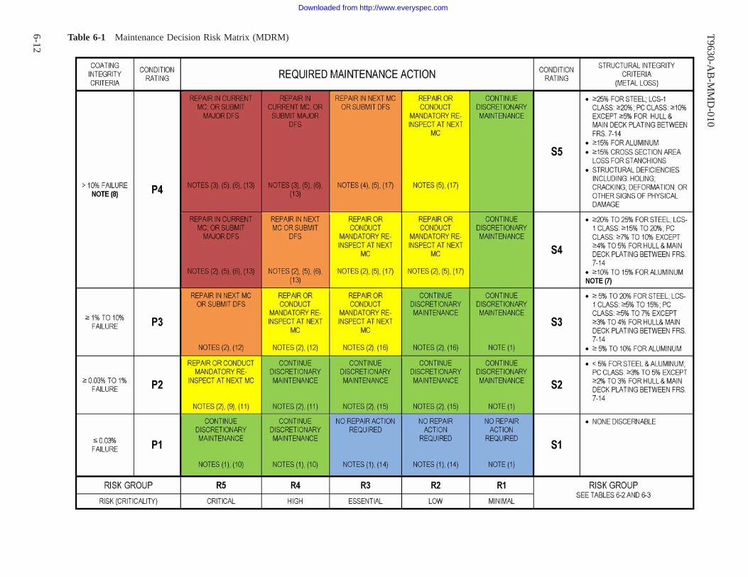
Table 6-1 Maintenance Decision Risk Matrix (MDRM)T
9630-AB
-MM
D-010
6-12
Downloaded from http://www.everyspec.com

NOTES FOR TABLE 6-1
GENERAL NOTES:
a. MC = Maintenance Cycle.
b. For tanks and voids (MRC G1N5 findings), the overall coating condition rating of the compartment governscoating maintenance actions. For all other locations (MRC G1N6 findings), separate and independent mainte-nance action decisions shall be made for each GR2K based on the highest coating condition rating for theaffected survey zone. Refer to paragraph 4-4.
c. “Continue Discretionary Maintenance” includes Organizational level (Ships Force) periodic corrosion inspec-tions and touch-up painting in accordance with PMS MIP 6300/001 or other applicable PMS requirements.
d. Requirements and limitations applicable to the disposition of ISIS/CDA findings in tanks and voids shall bein accordance with paragraph 6-5.
e. In the specific notes below, touch-up of coatings is in accordance with paragraph 6-4, and localized vs. scat-tered corrosion is as reported by the surveyor as defined in paragraph 4-4.3.2.
SPECIFIC NOTES:
1. No required coating or structural repairs.
2. No required structural repairs or structural DFS except where Note 7 applies; repair actions apply to coatingsystems only.
3. Accomplish structural repairs in accordance with NSTM Chapter 100 in the current maintenance cycle, orsubmit a major DFS and re-inspect structure in next maintenance cycle.
4. Accomplish structural repairs in accordance with NSTM Chapter 100 in the next maintenance cycle, or sub-mit a DFS. Re-inspect structure in next maintenance cycle.
5. Schedule and perform coating repair or replacement in accordance with NSTM Chapter 631 and StandardItem 009-32 in the next maintenance cycle, or submit a DFS.
6. Ultrasonic thickness gauge measurements of structure are required in accordance with NSTM Chapter 100prior to coating repairs.
7. Refer to NSTM Chapter 100 for exceptions requiring structural repair for structural condition S4.
8. Refer to paragraph 4-4.5 for application of NSTM Chapter 631 criteria concerning mandatory replacementof the entire coating system in the designated compartment or area when the accumulated damage exceeds10% or 20% of the total surface area.
9. Aircraft carrier potable water tanks in Condition 2 shall be scheduled for complete recoating at the nextdocking availability.
10. If a tank or void coating has been in service for one survey cycle then re-survey in the lesser of 72 monthsor at the next survey periodicity in Table 3-1. If a tank or void coating has been in service for two or moresurvey cycles then re-survey within 36 months. Touch-up of localized coating damage can be performed.Non-compensated clean FO tanks where coatings are no longer required are exempt from the requirementsof this note, and their assessment periods are controlled by Table 3-1.
11. Severe service tanks: re-survey within 36 months. Voids and non-severe service tanks: re-survey in the lesserof 72 months or at the next survey periodicity in Table 3-1. Innerbottom tank or void with scattered corro-sion: full blast & recoat at next docking availability. Touch-up of localized coating damage is recommended.
T9630-AB-MMD-010
6-13
Downloaded from http://www.everyspec.com

12. Touch-up of localized coating damage in severe service tanks and in non-CVN bilge regions is requiredwithin current MC; in all other compartments, it is recommended. Innerbottom tank or void: full blast &recoat at next docking availability; if next docking avail. is 2 MC’s in future, re-survey during next water-borne avail. MC. Not innerbottom tank or void: full blast & recoat in next maintenance cycle.
13. Touch-up of localized coating damage in severe service tanks and in non-CVN bilge regions is requiredwithin current MC; in all other compartments, it is recommended. For tanks and voids in the innerbottom,the requirements of 6-3.1.1(b) also apply. Perform an as-arrived Level 2 inspection in tanks and voids in thenext maintenance cycle prior to recoat to determine if structural repairs are needed.
14. If a tank or void coating has been in service for one survey cycle then re-survey at the next survey period-icity in Table 3-1. If a tank or void coating has been in service for two or more survey cycles then re-surveywithin 72 months. Touch-up of localized coating damage can be performed.
15. Re-survey tanks & voids in the lesser of 72 months or at the next survey periodicity in Table 3-1. Touch-upof localized coating damage is recommended.
16. Innerbottom tank or void: If next docking avail. is >36 months away, re-survey at 36 months during nextwaterborne avail. Touch-up of localized coating damage is recommended.
17. Unless exempted in paragraph 3-3.4, perform an as-arrived Level 2 inspection in tanks and voids prior torecoat to determine if structural repairs are needed. Touch-up of localized coating damage is recommended.
T9630-AB-MMD-010
6-14
Downloaded from http://www.everyspec.com

Table 6-2 MRC G1N5 Tank & Void Criticality/Risk Groups
Critical High Essential Low Minimal
- R5 - - R4 - - R3 - - R2 - - R1 -• Holing in Plate Boundariesand Supporting Framing; incl.sounding tube striker plates
• Fuel Oil (FO) Storage & Service Tanks • JP-5 Storage (including Over-flow/Ballast Tanks) (CVN Only)
• Pipe Hangers sup-porting Non- Grade AShock Systems
• Cracking, Buckling, or Signsof Overload in All Tank Struc-tures
• JP-5 Storage (including Overflow/BallastTanks) (Non-CVN)
• Floodable Voids, includingCVN DC Voids
• Feed Water Tanks (SurfaceShips)
• JP-5 Service Tanks • Non-Floodable (Dry) Voidsand Cofferdams
• Potable Water Tanks • JP-5 Contaminated & Settling Tanks/Puri-fier Drain Sump*
• Sponson Voids
• Sewage/ Waste (CHT) Tanks* • Lube Oil & Lube Oil Sump Tanks • Anchor Chain Lockers• Contaminated Drain System(Drainage & Collecting Tanks*
• Hydraulic Oil Tanks • Ladders, Hand/Foot GrabBars, and Handrails in Tanks
• Compensating Fuel/BallastTanks*
• Contaminated Oil Tanks* • Tank Striker Plates ExceptWhere Holed
• Seawater Ballast and SeawaterList/Ballast Control Tanks*
• Oily Waste, Waste Water & PlumbingWaste Drain Tanks*
• Catapult Water Brake Tanks(CVN)
• Fresh Water Steam Conden-sate Drain Collecting Tanks(Non-CVN)*
• List Control Tanks- Freshwater Service(CVN Only)
• Catapult Trough Wing Voids(CVN)
• High Pressure Water mistFresh Water Storage Tanks (FireFighting Systems)
• MOGAS (Gasoline) Tanks
• Pipe Hangers supporting Grade A ShockSystems
* = Severe service tanks as per paragraph 6-2.1.1.NOTES:(1) Refer to Table 6-1 for maintenance action requirements.(2) Where two or more categories apply, including those in Table 6-3, the higher risk category shall be used.(3) Includes all internal framing and stiffeners(4) All structural closures shall have the same risk category as the structure group they penetrate.(5) FO Storage & Service Tanks do not require re-coating. Refer to paragraph 4-4.3.4.1.(6) Aircraft carrier propulsion plant fresh water tanks are outside the scope of this manual per paragraph 1-3.
T9630-A
B-M
MD
-010
6-15
Downloaded from http://www.everyspec.com

Table 6-3 MRC G1N6 General Structure Criticality/Risk Groups
Critical High Essential Low Minimal
- R5 - - R4 - - R3 - - R2 - - R1 -• Holing in the FollowingPlate Boundaries and support-ing framing: All Tanks, Shell;Flight Deck; Water Tight andWeather Tight Enclosures; VitalSpaces; Subdivision Bulkheads;and DC Decks and presence ofdoublers in same
• Decks & Bulkheads Subject to Wettingand Drainage Collection Below DC Deck,Including Bilges
• Ship Shell & Framing Above DCDeck Aft of 0.2 L
• Non-tight & Fume-tight Structural Bulk-heads Above the DCDeck
• NonStructuralBulkheads,JoinerBulkheads• Deep Support Structure for Decks,
Shell, and Bulkhead Framing IncludingStanchions, Transverse Webs, Web Frames,Longitudinal Girders, and Vertical andHorizontal Webs on Bulkheads
• Bilge Keel • Service Trunks (Pip-ing, Wireway & Sys-tems Service, Equipment& Material Handling)Above DC Deck
• Cracking, Buckling, orSigns of Overload in All LoadBearing Structures
• Ship Shell, Stern Tubes, includingBreasthooks Below DC Deck
• Sponson Structure including Shell,Decks, Web Bulkheads
• Foundations & Back-ing Structure: Grade C
• Sea Chests and OverboardDischarges
• Ship Shell Above DC Deck Forward0.2 L, where L is the length between per-pendiculars.
• Superstructure/Island/Deck HouseEnclosures, Weather Decks
• Pipe Hangers- NonVital Systems
• Crack Arrest Structures Including: ShipShell Sheer Strake, Deck Stringer Strake,and Ship Shell Bilge Strakes within 3/5Amidship L
• Non-tight Structural BulkheadsBelow DC Deck, except in way ofBilges
• Floor Plates, Grating,& Outfitting Platforms,and their Support Struc-ture
• Longitudinal Strength BulkheadsUppermost and Lower Most Strakes
• Decks & Platform Decks except inway of: Bilges & Vital Space Bound-aries below the DC Deck
• Ladders, Hand/FootGrab Bars & HandrailsOutside of Tanks
• Innerbottom Deck • Vital Spaces Boundary Bulkheads;Airtight, Fire-tight & Weather TightBulkhead Boundaries; Trunks (Escape& Access ); Above DC Deck
• Flight Deck & Hangar Deck • Main Subdivision Bulkheads AboveDC Deck
• Deck Forming Top of Hanger or WellAreas
• Structural Ventilation Plenums &Trunks (Exhaust Discharge) & FanRooms
• Uppermost Strength Deck • Fixed Exterior Walkways/ Catwalks• DC Deck (Upper most deck that WTBHDs extend to)
• Service Trunks (Piping, Wireway, &Systems Service, Equipment and Mate-rial Handling Trunks) Below DC Deck(Non-watertight)
T9630-A
B-M
MD
-010
6-16
Downloaded from http://www.everyspec.com

Table 6-3 MRC G1N6 General Structure Criticality/Risk Groups - Continued
Critical High Essential Low Minimal
- R5 - - R4 - - R3 - - R2 - - R1 -• Vital Space Boundary Bulkheads,Including Trunks (Escape & Access ),Below DC Deck
• Foundations & Backing Structure:Shock Grade B (Note 6)
• Main Subdivision Bulkheads Below DCDeck
• Barricade Stanchion Recess (CVN)
• Skeg & Rudder • Fog, Foam & AFFF Stations, Foun-dation, Coaming
• Foundations & Backing Structure:Shock Grade A including Arresting Gearand Machinery Flats (Note 6)
• Anchor Chain Locker, Sump
• Masts & Towers (Note 6) • Aircraft Elevators (ACE)• Pipe Hangers: Grade A Systems • Helicopter RAST or ASIST System
Track Troughs• Cross Flooding Ducts & Freeing Ports& Framing
•Interior Compartments above WLwith boundaries serving as hull ofship, not otherwise listed
• Intakes (Combustion Air, Boiler, Diesel,Gas Turbine) Structural Boundaries (InletSupply)• Combustion Air Uptakes (Exhaust Dis-charge)• Structural Ventilation Plenums &Trunks (Inlet Supply)• Well Deck, Decks and BulkheadsBehind Batterboards/Beachboards
NOTES:(1) Refer to Table 6-1 for maintenance action requirements.(2) Where two or more categories apply, the higher risk category shall be used.(3) Includes all internal framing and stiffeners(4) All structural closures shall have the same risk category as the structure group they penetrate.(5) Drain collecting areas (sumps) and other wet areas where drainage is collected shall be considered the same as bilges.(6) Masts and yardarm elements, tower elements, and foundations comprised solely of cantilevers shall be treated as stanchions for determining structuralconditions ratings.
T9630-A
B-M
MD
-010
6-17/(6-18
Blank)
Downloaded from http://www.everyspec.com

6-18@@FIpgtype@@BLANK@@!FIpgtype@@
Downloaded from http://www.everyspec.com

APPENDIX A
MRC G1N5 DATA COLLECTION FORM AND INSTRUCTIONS
About this insert
4790_14 Tank and Void Structural and Coating Condition Survey (G1N5)-non-interactive
T9630-AB-MMD-010
A-1
Downloaded from http://www.everyspec.com

NAVSEA T9630-AB-MMD-010 Rev. 3
TANK AND VOID STRUCTURAL AND COATING CONDITION SURVEY (MRC G1N5)
I. SURVEYOR DATA1. Surveyor's Name: 2. Organization: 3. Phone Number:4. Date: 5. Survey Reason: 6. Survey Completed: Y N
II. GENERAL DATA7. Ship's Name: 8. Hull:10. Tank/Void Number: 11. Tank/Void Service:
9. Access Via:
13. APL:
III. PENETRATION DATA15. Manhole/Cover Condition: N/VUNSATSAT
IV. LADDER DATA
NAVSEA 4790/14 Page 1 of 4
12. Solid Ballast Present: Y N N/V 14. Painted Surface Area (sqft/sqm):
16. Other Penetration Condition: SAT UNSAT N/V
17. Ladders Damaged: N/VN/ANY 18. Damaged Ladder(s) Type, Material:
V. TANK LEVEL INDICATOR (TLI) DATA19. TLI Damaged: Y N N/A N/V 20. TLI Type:
VI. SOUNDING TUBE DATA21. Sounding Tube Damaged: Y N N/A N/V 22. Striker Plate Damaged (>25% worn): Y N N/A N/V
VII. CATHODIC PROTECTION DATA23. Sacrificial Anodes Present: Y N N/V 24. Number of Anodes > 50% Depleted, Damaged, or Missing:
VIII. DESICCANT DATA (VOIDS ONLY)25. Total Number of Desiccants Requiring Removal ("N/A" if none present):
IX. PIPING / VALVE DATA26. Piping Damaged: Y N N/A N/V 27. Valves Damaged or Leaking: Y N N/A N/V28. Piping Supports Damaged: Y N N/A N/V 29. Waster Plate Damaged: Y N N/A N/V
X. BLISTERING DATABottomStiffenersBulkheads/ShellOverheadSurvey Zone per CCAMM:
30.Blistering Size:34.Blistering Density:
41.40.39.38.% Unacceptable Blistering:
XI. COATING AND CORROSION DATA (if any area not visible, make note in comments section)
Coating Condition:% Corrosion + % Unacceptable Blistering:% Corrosion:
BottomStiffenersBulkheads/ShellOverheadSurvey Zone per CCAMM:42. 43. 44. 45.46. 47. 48. 49.
57.56.55.54.Corrosion Local, Scattered, or N/A:61.60.59.58.Local Corrosion Square Footage:
NoneScaling/ExfoliationPitting62. Select All Applicable Corrosion Issues: General/Surface Corrosion
XII. STRUCTURAL INTEGRITY DATA (evaluate structural condition regardless of coating condition)
Other Damage (Explain in Comments)Structural Integrity CompromisedWeld Crack/SeparationLocal Dent/CreaseDoubler Plate Installed/DamagedBuckling/DistortionPlate/Stiffener CrackHoling
63. Select All Applicable Structural Findings (all of the findings below require a Level 2 Structural Inspection):
Y N N/A65. UT Gauging Performed:Y N64. A Level 2 Structural Inspection is Required:
XIII. ADDITIONAL INFORMATION
68. COMMENTS: (Provide specific detail for each discrepancy for generating 2-KILOs. Continue comments on additional pages.)67. Picture File Number(s):66. No. of Pictures Taken:
31. 32. 33.35. 36. 37.
50. 51. 52. 53.
Downloaded from http://www.everyspec.com
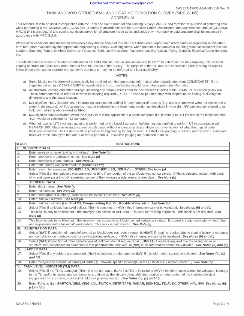
TANK AND VOID STRUCTURAL AND COATING CONDITION SURVEY (MRC G1N5) ADDENDUM
NAVSEA T9630-AB-MMD-010 Rev. 3
This Addendum is to be used in conjunction with the Tank and Void Structural and Coating Survey (MRC G1N5) form for the purpose of gathering data while performing a MIP1231/005 MRC G1N5 (AP-1) survey in accordance with the Corrosion Control Assessment and Maintenance Manual (CCAMM). MRC G1N5 is a structural and coating condition survey for all structure inside tanks and voids only. Non-tank or void structure shall be inspected in accordance with MRC G1N6. Where other conditions and suspected deficiencies beyond the scope of this MRC are discovered, report each discrepancy appropriately in this MRC form for further evaluation by the appropriate engineering authority. Outfitting items, when present in the tank/void requiring visual assessment include: Ladders, Sounding Tubes, Manhole Covers and Gaskets, Tank Level Indicators, Fasteners, Leaking Valves, Piping, Conduit, Electrical Cable Hangers, etc. The Maintenance Decision Risk Matrix contained in CCAMM shall be used in conjunction with this form to determine the Risk Ranking (R#) for each coating or structural repair work order created from the results of this survey. The purpose of the risk matrix is to provide a priority rating for repairs, follow-on surveys, and to determine those items that may or may not be deferred to a later availability.
NOTES:
a) Some blocks on this form will automatically be pre-filled with the appropriate information when downloaded from CCIMS/CADET. If the inspector did not use CCIMS/CADET to download this form, then he/she should record the appropriate information.
b) All structural, coating and other findings, including any notable issues shall be documented in detail in the COMMENTS section (block 68). These comments will be referred to when developing required 2-KILO. Provide all pertinent data with respect to the finding, including the dimensions and the exact location.
c) N/V signifies “Not Validated” when information could not be verified for any number of reasons (e.g. areas of tank/void were not visible due to water in the bottom). All N/V scenarios must be explained in the Comments section as described in Note (b). N/V can also be referred to as Unknown, which is abbreviated as UNK.
d) N/A signifies “Not Applicable” when the survey item is not applicable to a particular space (i.e. if there is no TLI present in the tank/void, then “N/A” would be selected for TLI Damaged).
e) When ultrasonic (UT) thickness gauging is performed by the Level 1 surveyor, he/she must be certified to perform UT in accordance with NSTM CH 100. Material wastage cannot be calculated without original ship design drawings for verification of what the original plate thickness should be. All UT data shall be provided to engineering for adjudication. UT thickness gauging is not required by level 1 surveyors, however, those surveyors that are qualified to perform UT thickness gauging are permitted to do so.
Page 2 of 4NAVSEA 4790/14
BLOCK INSTRUCTIONSI. SURVEYOR DATA1. Enter surveyor's name (and rank if military). See Note (a)2. Enter surveyor's organization name. See Note (a)3. Enter surveyor's phone number. See Note (a)4. Enter date survey was performed as: (MM/DD/YYYY)5. Enter reason for survey as: (SCHEDULED, UNSCHEDULED, INSURV, or OTHER) See Note (a)6. Select (Y)es if entire tank/void was surveyed, or (N)o if any portion of the tank/void was not surveyed. If (N)o is selected, explain with detail
why, and generate a 2-KILO requesting survey of the non-assessable area at a later date. See Note (b)
II. GENERAL DATA7. Enter ship's name. See Note (a)8. Enter hull number. See Note (a)9. Enter compartment number(s) from where tank/void is accessed. See Note (a)10. Enter tank/void number. See Note (a)11. Enter tank/void service (i.e.: Fuel Oil, Compensating Fuel Oil, Potable Water, etc.). See Note (a)12. Select (Y)es if tank/void has solid ballast, (N)o if it does not or (N/V) if this information cannot be validated. See Notes (b) and (c)13. This block is only to be filled out if the surveyor has access to APL data. It is used for tracking purposes. This block is not required. See
Note (a)
14. This block is only to be filled out if the surveyor has access to tank/void painted surface area data. It is used in conjunction with writing “blast and re-preserve entire tank/void” work orders. This block is not required. See Note (a)
III. PENETRATION DATA15. Select (SAT) if condition of manhole/cover of tank/void does not require repair, (UNSAT) if repair is required due to coating failure or structural
non-compliance on manhole cover or seating/bolting surface, or (N/V) if this information cannot be validated. See Notes (b) and (c)
16. Select (SAT) if condition of other penetrations of tank/void do not require repair, (UNSAT) if repair is required due to coating failure or structural non-compliance on components that penetrate the tank/void, or (N/V) if this information cannot be validated. See Notes (b) and (c)
IV. LADDER DATA17. Select (Y)es if any ladders are damaged, (N)o if no ladders are damaged or (N/V) if this information cannot be validated. See Notes (b), (c)
and (d)
18. Enter the type and material of damaged ladder(s). Provide specific location(s) in the COMMENTS section (block 68). See Note (b)V. TANK LEVEL INDICATOR (TLI) DATA19. Select (Y)es if the TLI is damaged, (N)o if it is not damaged, (N/A) if no TLI is installed or (N/V) if the information cannot be validated. Damage
to the TLI and/or its associated components is defined as the visually detectable degradation or deterioration of the installed physical equipment from corrosion, mechanical failure or physical impact. See Notes (b), (c) and (d)
20. Enter TLI type (i.e.: BARTON, GEM, KING, LVL SWITCH, METRITAPE, RADAR, SIGHTGL, TELFLEX, OTHER, N/A, N/V) See Notes (b), (c) and (d)
Downloaded from http://www.everyspec.com

TANK AND VOID STRUCTURAL AND COATING CONDITION SURVEY (MRC G1N5) ADDENDUM
NAVSEA T9630-AB-MMD-010 Rev. 3
Page 3 of 4NAVSEA 4790/14
VI. SOUNDING TUBE DATA21. Select (Y)es if the sounding tube is damaged, (N)o if it is not damaged, (N/A) if there is no sounding tube installed or (N/V) if the information
cannot be validated. Enter in the COMMENTS section (block 68) whether or not the sounding tube is vented. Damage is defined as the visually detectable degradation or deterioration from corrosion or physical impact. See Notes (b), (c) and (d)
22. Select (Y)es if the striker plate is damaged (>25% worn or pitted) or missing, (N)o if it is not damaged or missing, (N/A) if there is no sounding tube installed or (N/V) if the information cannot be validated. If the striker plate is damaged >50% by wear or pitting or is completely missing, repairs must be accomplished to restore the striker plate before the tank can be closed. All sounding tubes require a striker plate. See Notes (b), (c) and (d)
VII. CATHODIC PROTECTION DATA23. Select (Y)es if sacrificial anodes are installed in the tank/void, (N)o if none present or (N/V) if the information cannot be validated. See Notes
(b) and (c)
24. Enter number of anodes that are depleted greater than 50%, painted, missing, improperly functioning or otherwise damaged. (i.e.: 0, 1, 2, 3, etc.). See Note (b)
VIII. DESICCANT DATA25. Enter the total number of desiccants present in the void (i.e.: 1, 2, 3, etc.) and prepare a 2-KILO requesting their removal. If desiccants are not
present, enter (N/A). See Notes (b) and (d) NOTE: Effective beginning in 2012, the use of desiccants in dry void spaces in surface ships and CVN’s is no longer required, and the surveyor should prepare a 2-KILO requesting the removal of them and their associated brackets as a weight-saving measure if found during the survey.
IX. PIPING / VALVE DATA26. Select (Y)es if piping in the tank/void is damaged, (N)o if it is not, (N/A) if there is no piping or (N/V) if the information cannot be validated.
(For the purpose of this survey, include electrical cable conduit and degaussing system cable conduit as “piping”, and distinguish the applicable system (if possible) in the COMMENTS section (block 68)) See Notes (b), (c) and (d)
27. Select (Y)es if any valve(s) in the tank/void are damaged or leaking, (N)o if they are not, (N/A) if there are no valves, or (N/V) if the information cannot be validated. Surveyor shall NOT attempt to operate any valves, however, describe in the comments section if a valve appears to be damaged, leaking or may not properly function. See Notes (b), (c) and (d)
28. Select (Y)es if any piping supports in the tank/void are damaged, (N)o if they are not, (N/A) if there are no piping supports tank/void or (N/V) if the information cannot be validated. For the purpose of this survey, include electrical cable conduit and degaussing system cable conduit as “piping”, and distinguish the applicable system (if possible) in the COMMENTS section (block 68). A piping support missing appropriate hardware, including chaffing gear/rubber grommet, is considered damaged. See Notes (b), (c) and (d)
29. Select (Y)es if the waster plate below the suction bell mouth in the tank/void is damaged, (N)o if it is not, (N/A) if there is no suction bell mouth in the tank/void or (N/V) if the information cannot be validated. See Notes (b), (c) and (d)
X. BLISTERING DATA30-33. Enter blistering size for [Overhead], [Bulkheads/Shell], [Stiffeners], and [Bottom] as: (0=”N/V”, 2, 4, 6, 8 or 10=”NO BLISTERS” or N/A”).
See ASTM D 714
34-37. Enter blistering density for [Overhead], [Bulkheads/Shell], [Stiffeners], and [Bottom] as: (U=UNK, F=Few, M=Med, MD=Med Dense, D=Dense or N/A). See ASTM D 714
38-41. Enter % unacceptable blister area for [Overhead], [Bulkheads/Shell], [Stiffeners], and [Bottom] as a percentage (i.e. 0, 15, 25, etc.). The following blister conditions shall be assessed as failed coating: · Broken blisters that expose the metal substrate · Blister size 2 with medium, medium dense or dense distribution · Blister size 4 or 6 with medium dense or dense distribution · Blister size 8 with dense distribution See Note (b)
XI. COATING AND CORROSION DATA42-45. Enter % coating failure and corrosion area for [Overhead], [Bulkheads/Shell], [Stiffeners], and [Bottom] (i.e.: 0 – 100%). See SSPC-VIS 2
49-49. Enter adjusted % corrosion as a sum of the values from % unacceptable blistering blocks 38-41 and % corrosion block 42-45. If no unacceptable blistering was identified, these values will match the values in block 42-45.
50-53. Enter coating condition for [Overhead], [Bulkheads/Shell], [Stiffeners], and [Bottom] as: (P0=(N/V or UNK), P1=(0% to 0.03% of visible surface), P2=(>0.03% to 1% of visible surface), P3=(>1% to 10% of visible surface), P4=( >10% of visible surface), P10=(N/A, for uncoated surfaces)). These values are based off the adjusted % corrosion in blocks 46-49. Refer to the CCAMM for additional instruction. See Notes (b), (c) and (d)
54-57. Enter if corrosion is local or scattered for [Overhead], [Bulkheads/Shell], [Stiffeners], and [Bottom] as: (Local) or (Scattered). If no corrosion is present in a zone, enter (N/A).
58-61. Enter total square footage of local corrosion for [Overhead], [Bulkheads/Shell], [Stiffeners], and [Bottom] as a numerical value (i.e. 0, 15, 25, etc.) Localized areas of damage shall be considered for touch-up repair. See Note (b)
62. Perform a thorough assessment of the structure and select all applicable corrosion related issues that are present in the tank/void. If any of the items selected require a Level 2 structural inspection, select (Y)es in block 64. The structural condition must be evaluated regardless of the condition of the coating system. Surveyor shall identify areas where coatings may have been applied over damaged/deteriorated structure. See Note (b)
Downloaded from http://www.everyspec.com
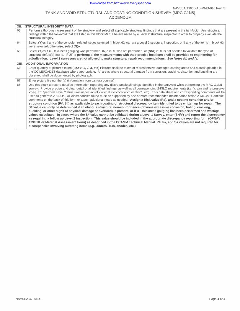
XII. STRUCTURAL INTEGRITY DATA63. Perform a thorough assessment of the structure and select all applicable structural findings that are present in the tank/void. Any structural
findings within the tank/void that are listed in this block MUST be evaluated by a Level 2 structural inspector in order to properly evaluate the structural integrity.
64. Select (Y)es if any of the corrosion related issues selected in block 62 warrant a Level 2 structural inspection, or if any of the items in block 63 were selected, otherwise, select (N)o.
65. Select (Y)es if UT thickness gauging was performed, (N)o if UT was not performed, or (N/A) if UT is not needed to validate the type of structural defect(s) found. If UT is performed, the measurements with their precise locations shall be provided to engineering for adjudication. Level 1 surveyors are not allowed to make structural repair recommendations. See Notes (d) and (e)
XIII. ADDITIONAL INFORMATION66. Enter quantity of pictures taken (i.e.: 0, 1, 2, 3, etc) Pictures shall be taken of representative damaged coating areas and stored/uploaded in
the CCIMS/CADET database where appropriate. All areas where structural damage from corrosion, cracking, distortion and buckling are observed shall be documented by photograph.
67. Enter picture file number(s) (information from camera counter)68. Use this block to record detailed information regarding any discrepancies/findings identified in the tank/void while performing the MRC G1N5
survey. Provide precise and clear detail of all identified findings, as well as all corresponding 2-KILO requirements (i.e. “clean and re-preserve xx-sq. ft.”, “perform Level 2 structural inspection of xxxxx at xxxxxxxxxxxx location”, etc). This data sheet and corresponding comments will be used to generate 2-KILOs. All discrepancies found must be supported by one or more recommended maintenance action 2-KILOs. Continue comments on the back of this form or attach additional notes as needed. Assign a Risk value (R#), and a coating condition and/or structure condition (P#, S#) as applicable to each coating or structural discrepancy item identified to be written up for repair. The S# value can only be determined if an obvious structural non-conformance (obvious excessive corrosion, holing, cracking, buckling, or other signs of physical damage or overload) is present, or if UT thickness gauging has been performed and wastage values calculated. In cases where the S# value cannot be validated during a Level 1 Survey, enter (SN/V) and report the discrepancy as requiring a follow up Level 2 Inspection. This value should be included in the appropriate discrepancy reporting form (OPNAV 4790/2K or Material Assessment Form) as described in the CCAMM Technical Manual. R#, P#, and S# values are not required for discrepancies involving outfitting items (e.g. ladders, TLIs, anodes, etc.)
TANK AND VOID STRUCTURAL AND COATING CONDITION SURVEY (MRC G1N5) ADDENDUM
NAVSEA T9630-AB-MMD-010 Rev. 3
Page 4 of 4NAVSEA 4790/14
Downloaded from http://www.everyspec.com

Downloaded from http://www.everyspec.com

APPENDIX B
MRC G1N6 DATA COLLECTION FORM AND INSTRUCTIONS
About this insert
4790_15 Structural and Coating Condition Survey (G1N6).non-interactive
T9630-AB-MMD-010
B-1
Downloaded from http://www.everyspec.com

NAVSEA T9630-AB-MMD-010 Rev. 3
STRUCTURAL AND COATING CONDITION SURVEY (MRC G1N6)I. SURVEYOR DATA1. Surveyor's Name: 2. Organization: 3. Phone Number:4. Date: 5. Survey Reason: 6. Survey Completed: Y N
II. GENERAL DATA7. Ship's Name: 8. Hull:9. Compartment Number: 10. Compartment Name:11. Access Via: 12. APL:
III. CATHODIC PROTECTION DATA13. Sacrificial Anodes in Compartment: N/VNY 14. Number of Anodes > 50% Depleted, Damaged or Missing:
IV. INSULATION AND DAMPING TILE DATASurvey Zone per CCAMM: Overhead Bulkheads/ShellInsulation Damaged: 15. 16.Y N N/A N/ANY17. Damping Tiles Loose or Damaged: N/ANY
V. COATING AND CORROSION DATA (if any area not visible, make note in comments section)Survey Zone per CCAMM: OverheadEstimated Total Painted Surface Area:
Bulkheads/Shell Stiffeners Deck/Bilge18. 19. 20. 21.
25.24.23.22.Percent Coated Structure Visible (%):29.28.27.26.Percent Corrosion (%):
30.Coating Condition:37.36.35.34.Corrosion Local, Scattered, or N/A:41.40.39.38.Local Corrosion Square Footage:
42. Select All Applicable Corrosion Issues: General/Surface Rust Scaling/ExfoliationGrating Support Structure Corroded NoneEquipment Foundation Corroded Other (Explain in Comments)
Pitting
43. Deck Covering Damaged: Y N N/A
VI. STRUCTURAL INTEGRITY DATA (evaluate structural condition regardless of coating condition)44. Select All Applicable Structural Findings (all of the findings below require a Level 2 Structural Inspection):
Holing Weld Crack/Separation Buckling/DistortionDoubler Plate Installed/DamagedEquipment Foundation Damaged/CrackedLack of Drainage/Air Escape Openings
Plate/Stiffener CrackGrating Support Structure Damaged/CrackedOther Damage (Explain in Comments)
Local Dent/CreaseStanchion Damaged
45. A Level 2 Structural Inspection is Required: Y N 46. UT Gauging Performed: Y N N/A
VII. ADDITIONAL INFORMATION47. No. of Pictures Taken: 48. Picture File Number(s):49. COMMENTS: (Provide specific detail for each discrepancy for generating 2-KILOs. Continue comments on additional pages.)
NAVSEA 4790/15 Page 1 of 3
31. 32. 33.
Downloaded from http://www.everyspec.com

STRUCTURAL AND COATING CONDITION SURVEY (MRC G1N6) ADDENDUM
NAVSEA T9630-AB-MMD-010 Rev. 3
This Addendum is to be used in conjunction with the Structural and Coating Survey (MRC G1N6) form for the purpose of gathering data while performing a MIP 1000/005 G1N6 (AP-1) survey in accordance with the Corrosion Control Assessment and Maintenance Manual (CCAMM). MRC G1N6 is a structural and coating condition survey for all surface ships' general structure except for tanks and voids (MRC G1N5). Where other conditions and suspected deficiencies beyond the scope of this MRC are discovered, report each discrepancy appropriately in this MRC form for further evaluation by the appropriate stakeholder. Outfitting items, when present in the compartment requiring visual assessment include: Insulation and Damping materials on structure, Piping and Electrical Supports/Hangers, Sacrificial Anodes, etc. Other incidental outfitting items that may commonly have reportable deficiencies include deck drains, ladder structural supports/mounts, structural closures, etc. The Maintenance Decision Risk Matrix contained in CCAMM shall be used in conjunction with this form to determine the Risk Ranking (R#) for each coating or structural repair work order created from the results of this survey. The purpose of the risk matrix is to provide a priority rating for repairs, follow-on surveys, and to determine the items that may or may not be deferred to a later availability.
NOTES:
a) Some blocks on this form will automatically be pre-filled with the appropriate information when downloaded from CADET. If the inspector did not use CADET to download this form, then he/she should record the appropriate information.
b) All structural, coating and other findings, including any notable issues shall be documented in detail in the Comments (block 49) section. These comments will be referred to when developing required repair action items. Provide all pertinent data with respect to the finding, including the dimensions and the exact location.
c) N/V signifies “Not Validated” when information could not be verified for any number of reasons (i.e. areas of compartment were not visible due to equipment obstructions). All N/V scenarios must be explained in the Comments section as described in Note (b).
d) N/A signifies “Not Applicable” when the survey item is not applicable to a particular space (i.e. if there is no insulation present in the overhead, then “N/A” would be selected for Insulation Damaged).
e) When ultrasonic (UT) thickness gauging is performed by the Level 1 surveyor, he/she must be certified to perform UT in accordance with NSTM CH 100. Material wastage cannot be calculated with original ship design drawings for verification of what the original plate thickness should be. All UT data shall be provided to engineering for adjudication. UT thickness gauging is not required by Level 1 surveyors; however, those personnel that are qualified to perform UT thickness gauging are permitted to do so.
Page 2 of 3NAVSEA 4790/15
BLOCK INSTRUCTIONSI. SURVEYOR DATA1. Enter surveyor's name (and rank if military). See Note (a)2. Enter surveyor's organization name. See Note (a)3. Enter surveyor's phone number. See Note (a)4. Enter date survey was performed as: (MM/DD/YYYY)5. Enter reason for survey as: (SCHEDULED, UNSCHEDULED, INSURV, or OTHER) See Note (a)6. Select (Y)es if entire space or assigned area was surveyed, or (N)o if any portion of the space or assigned area was not surveyed. If (N)o is
selected, explain with detail why, and generate a repair action item that requests survey of the non-assessable area at a later date. See Note (b)
II. GENERAL DATA7. Enter ship's name. See Note (a)8. Enter hull number. See Note (a)9. Enter compartment number, vent plenum number (if separate from compartment number), or designated weather deck area. See Note (a)10. Enter compartment name (i.e.: Main Engine Room 1, Chemical Defense Locker, etc.). See Note (a)11. Enter compartment or door/closure number(s) where space is accessed from. See Note (a)12. This block is only to be filled out if the surveyor has access to APL data. It is used for tracking purposes. This block is not required. See
Note (a)
III. CATHODIC PROTECTION DATA13. Select (Y)es if sacrificial anodes are installed in the compartment, (N)o if none present or (N/V) if the information cannot be validated. See
Notes (b) and (c)
14. Enter number of anodes that are depleted greater than 50%, painted, missing, improperly functioning or otherwise damaged. (i.e.: 0, 1, 2, 3, etc.). See Note (b)
IV. INSULATION AND DAMPING TILE DATA15-16. Select (Y)es if the insulation is damaged or stained. Select (N)o if it is not damaged. Select (N/A) if there is no insulation installed. This
includes the insulation on associated stiffeners. See Note (c)
17. Select (Y)es if damping tile is loose or damaged. Select (N)o if it is not. Select (N/A) if no damping tile is present. See Note (c)V. COATING AND CORROSION DATA18-21. Enter the estimated square footage of coated structure for [Overhead], [Bulkheads/Shell], [Stiffeners], and [Deck/Bilge]. Estimation should
include square footage of entire structure for each zone, regardless of how much is visible. (Enter a numerical value).
22-25. Enter the estimated percent of coated structure that is visible for [Overhead], [Bulkheads/Shell], [Stiffeners], and [Deck/Bilge] as (0-100%). Where 100% of the structure is not visible, explain why in COMMENTS block 49 (i.e.: "50% of overhead is insulated).
26-29. Enter percent coating failure and corrosion area for [Overhead], [Bulkheads/Shell], [Stiffeners], and [Deck/Bilge] as: (0 – 100%). See SSPC-VIS 2.
30-33. Enter coating condition for [Overhead], [Bulkheads/Shell], [Stiffeners], and [Deck/Bilge] as: (P0=N/V, P1=(0% to 0.03% of visible surface), P2=(>0.03% to 1% of visible surface), P3=(>1% to 10% of visible surface), P4=( >10% of visible surface), P10=N/A)). When surveying a compartment where the shell plating transitions from bilge shell plating to side shell plating [due to physical curvature of the hull], treat all portions above the turn of the bilge (where curvature angle exceeds ~45 degrees from horizontal) as a Bulkheads/Shell Zone. See Corrosion Control Assessment and Maintenance Manual (CCAMM) as guide. See Notes (b), (c) and (d)
Downloaded from http://www.everyspec.com

STRUCTURAL AND COATING CONDITION SURVEY (MRC G1N6) ADDENDUM
NAVSEA T9630-AB-MMD-010 Rev. 3
Page 3 of 3NAVSEA 4790/15
34-37.Enter if corrosion is local or scattered for [Overhead], [Bulkheads/Shell], [Stiffeners], and [Deck/Bilge] as: (Local) or (Scattered). If no corrosion is present in a zone, enter (N/A). See Note (d)
38-41. Enter total square footage of local corrosion for [Overhead], [Bulkheads/Shell], [Stiffeners], and [Deck/Bilge] as a numerical value (i.e. 0, 15, 25, etc.). Even if the Coating Condition of the space overall is a 1 or 2, all areas of localized corrosion 1 square foot or greater that require repair shall be identified in the comments section. For damaged areas of coatings less than 1 square foot, surveyor shall consider the location and associated potential risks of continued corrosion in determining whether to recommend repair actions. See Note (b)
42. Perform a thorough assessment of the structure and select all applicable corrosion related issues that are present in the compartment. The structural condition must be evaluated regardless of the condition of the coating system. Surveyor shall identify areas where coatings may have been applied over damaged/deteriorated structure. If any of the selected corrosion related findings require evaluation by a Level 2 structural inspector, select (Y)es in block 45. See Note (b)
43. Select (Y)es if there is damaged deck covering in the compartment other than deck paint (i.e. nonskid, cosmetic polymeric, terrazzo, deck tile, ceramic or quarry tile, rubber electrical sheets or mats). Select (N)o of the installed deck covering is not damaged. Select (N/A) if there is no deck covering installed in the space. See Notes (c) and (d)
VI. STRUCTURAL INTEGRITY DATA44. Perform a thorough assessment of the structure and select all applicable structural issues that are present in the compartment. Any structural
findings within the compartment that are listed in this block MUST be evaluated by a Level 2 structural inspection in order to properly evaluate the structural integrity.
45. Select (Y)es if any of the corrosion related issues selected in block 42 warrant a Level 2 structural inspection, or if any of the items in block 44 were selected. Otherwise, select (N)o.
46. Select (Y)es if UT thickness gauging was performed, (N)o if UT is required but could not be performed, or (N/A) if UT is not needed. If UT is performed, the information should be provided to engineering for adjudication. See Notes (d) and (e)
VII. ADDITIONAL DATA47. Enter quantity of pictures taken as a numerical value (i.e. 0=NONE, 1, 2, 3, etc.). Pictures shall be taken of representative damaged
coating areas, and stored/uploaded in the CCIMS/CADET database where appropriate. All areas where structural damage is observed shall be documented by photograph and stored as well.
48. Enter picture file number(s) (information from camera counter).49. Use this block to record detailed information regarding any discrepancies/findings identified in the compartment while performing the MRC
G1N6 survey. Provide precise and clear detail of all identified findings, as well as all corresponding action item requirements (i.e. “clean and re-preserve xx-sqft”, “perform Level 2 structural inspection of xxxxx at xxxxxxxxxxxx location”, etc). This data sheet and corresponding comments will be used to generate action items (2-KILO). For each discrepancy found, an action item must be generated. Continue comments on the back of this form or attach additional notes as needed. Assign a Risk value (R#), and a coating condition and/or structure condition (P#, S#) as applicable to each coating or structural discrepancy item identified to be written up for repair. The S# value can only be determined if an obvious structural non-conformance (obvious excessive corrosion, holing, cracking, buckling, or other signs of physical damage or overload) is present, or if UT thickness gauging has been performed and wastage values calculated. In cases where the S# value cannot be validated during a Level 1 Survey, enter SN/V and report the discrepancy as requiring a follow up Level 2 Inspection. This value should be included in the appropriate discrepancy reporting form (OPNAV 4790/2K or Material Assessment Form) as described in the CCAMM Technical Manual. R#, P#, and S# values are not required for discrepancies involving outfitting items (e.g. ladders, anodes, etc.)
Downloaded from http://www.everyspec.com

Downloaded from http://www.everyspec.com

B-6@@FIpgtype@@BLANK@@!FIpgtype@@
Downloaded from http://www.everyspec.com

APPENDIX C
COMPARTMENT USE DESIGNATIONS
Letter Type of Compartment Examples
A Stowage Spaces Storerooms, Issue rooms, Refrigerated Stores, Ordnancerelated stowage (inert)
C Vital Ship and Fire Control Operating Spacesthat are normally manned
CIC, Communications Office, Electronic Operating Spaces,IC Rooms, Pilot House, Plotting Rooms, Central ControlStation
E Machinery Spaces that are normally manned Auxiliary Machinery Rooms, Main Machinery Rooms,Pump Rooms, Refrigerating Machinery Rooms, SteeringGear Rooms
F Fuel and Lubricating Oil Compartments (foruse by ship)
Fuel-Oil, Diesel-Oil, Lubricating-Oil, Fog-Oil Compart-ments
G Gasoline Storage Compartments (for use byship)
Gasoline Compartments (including cofferdams)
J JP-5 JP-5 CompartmentsK Chemical and dangerous materials (other than
oil and gasoline)Chemicals & semi safe & dangerous materials, HAZMAT,Flammable Liquid Stowage
L Living quarters Habitability related, Living Spaces, Lounges, RecreationalAreas, Medical and Dental Spaces, Horizontal Passages
M Ammunition Spaces Magazines, Handling Rooms, Turrets, Gun MountsQ Miscellaneous Spaces not otherwise covered Shops, Offices, Laundry, Galley, Pantries, Wiring Trunks,
Unmanned Engineering, Electrical, & Electronic SpacesT Vertical Access Trunks Escape TrunksV Void Compartments Cofferdam Compartments (other than gasoline tank coffer-
dams), Void or Ballast Wing Compartments, Void WingCompartments
W Water Compartments Bilge Tanks, Sump Tanks, Oily Waste Water tanks, WasteOil Collecting, built-in Sewage Holding Tanks
X Weather Deck Area Boat Stowage, Fueling At Sea Station, Mast, Fantail, 02Level Port Walkway Between Frames # and #, etc.
T9630-AB-MMD-010
C-1 / (C-2 Blank)
Downloaded from http://www.everyspec.com

C-2@@FIpgtype@@BLANK@@!FIpgtype@@
Downloaded from http://www.everyspec.com

APPENDIX D
REPAIR 2-KILO/DEFICIENCY REPORT BEST PRACTICES GUIDE
D-1. GENERAL.
Unambiguous, accurate reporting of the conditions found during either Level 1 surveys or Level 2 inspec-tions, and the associated recommended repairs, is essential to allow maintenance planning managers and portengineers to properly scope and screen each recommended work item.
For tanks and voids (MRC G1N5), the overall coating condition rating of the compartment governs the coat-ing maintenance actions described in Chapter 6. For all other compartments (MRC G1N6), coating maintenanceaction decisions in accordance with Chapter 6 are made independently on each instance of reported coating dam-age and recommended repairs, using the coating condition P# score assigned to each work item as described inChapter 4.
For MRC G1N5 and G1N6, structural maintenance action decisions in accordance with Chapter 6 are madeon each instance of reported structural damage and recommended repairs, using the structural condition S# scoreas described in Chapter 4.
Whenever structural material loss or damage is found to exceed, or can be reasonably projected to exceed therequirements of NSTM Chapter 100, the integrity of the structure shall be evaluated and reported as warranted.
For the purpose of this Appendix, the best practices described also apply to Deficiency Reports (DR) used byNaval Shipyards.
For repair 2-KILOs submitted for any deficiencies related to corrosion, add the letter ’C’ in block 10 of theMaterial Assessment Forms (MAF)/OPNAV 4790/2K (2-KILO).
The text that the surveyor writes in the “Comments” blocks of the MRC G1N5 and G1N6 data forms gen-erally becomes the basis for subsequent 2-KILO submittals, in the Block 35 “Remarks” section. This informationcomplements the other data blocks and Condition scores recorded on the MRC G1N5 and G1N6 data forms.
In general, repair 2-KILO recommendations made by off-ship survey or inspection personnel should focus onthose items that are reasonably considered to be above and beyond the normal O-Level maintenance andrepreservation capabilities of Ship’s Force (S/F). However, the individual ship maintenance planning manager orport engineer has the right and responsibility to screen the submitted work items as they see fit for any givenmaintenance availability.
Most conditions and items that would require repair in tanks and voids surveyed per MRC G1N5 areadequately defined and covered in this publication and the MRC G1N5 data form, and are generally consideredto require Depot-level maintenance actions. However, shipboard areas under the scope of MRC G1N6 that aremore routinely accessible by S/F have much more variability.
D-2. WORK SCOPE OF INDIVIDUAL 2-KILOS.
A 2-KILO shall be specific to the discrepancy and the recommended repair or maintenance action and shouldnot take into account the overall condition of the compartment. Only one deficient condition should be addressedper 2-KILO, since the repair work for the various items may be scheduled or performed at different times, ormay be screened for performance by different organizations or activities. Where many similar conditions exist,and it is logical to assume that the work required will or should be performed by a single activity, in one evolu-tion, the 2-KILO may combine the deficiencies, or should reference the Job Control Numbers (JCNs) of the simi-lar 2-KILO’s, if known. For example:
T9630-AB-MMD-010
D-1
Downloaded from http://www.everyspec.com

1. Multiple instances of failed or damaged paint and corrosion on a single bulkhead and its stiffeners (string-ers) that should be touch-up painted should be combined in one 2-KILO.
2. If a series of multiple horizontal stringers that are present within a single bulkhead or shell panel in the spanbetween two transverse frames or girders have a structural deficiency, they could be documented on a single2-KILO, or may have individual 2-KILO’s written for each stringer with references to each of the other related2-KILOs.
D-3. TEMPLATES FOR PROBLEM AND REPAIR STATEMENTS.
The information in the Comments blocks of the MRC G1N5 and G1N6 data forms, or the Block 35 Remarkssection of 2-KILO forms shall state the problem, followed by the recommended repair or other follow-up action.Suggested templates for each are given below, followed by examples of many of the most common types of termsand items that would result from MRC G1N5 and G1N6 surveys.
Problem Statement: [CATEGORY] [COMPONENT] [PROBLEM DESCRIPTION] [DIMENSIONS][LOCATION] [ADDITIONAL APPLICABLE INFORMATION]
Recommended Repair: [RECOMMENDED COURSE OF ACTION] [PRIORITIZATION] [ADDITIONALCOMMENTS]
D-3.1 Category and Component: The Category is the basic description of the nature of the discrepancy and theinitial filter to help Planning Activities distribute work items. The most common categories and their relatedcomponents that are directly in the scope of MRC G1N5 and G1N6 surveys are the structural and coating ones.Additional components are also listed below that may be incidentally described from the findings of a survey.
Category: STRUCTURAL
Component:- Bimetallic Joints - Detacouple- Foundation - Mounts, Noise and Shock- Foundation - Structures- Foundation - Fasteners- Framing - Stiffener, Beam, Non-tight Reinforcing Rings, Coamings, Collars, and Similar Elements- Lifting and Handling - Padeyes and Support Structures- Major Support Members - Web Frames, Deck Transverses, Shell Transverse or Longitudinal Girders (non-double bottom), Major Bulkhead Vertical or Horizontal Girders, Collars for Same- Mast and Yard Arms- Penetrations - Piping Sleeves, HVAC Duct Coamings, Multi-Cable Transits (MCT) and Stuffing Tubes- Piping Discharge Waster Plate- Plate - Bulkhead and Bents Including Collars- Plate - Decks and Platforms (Top Surface)- Plate - Decks and Platforms (Underside)- Plate - Double Bottom Longitudinal Girders- Plate - Double Bottom Transverse Floors- Plate - Shell- Sounding Tube Striker Plate- Stanchions- Tie-Down Fittings- Weld
Category: COATINGComponent:
T9630-AB-MMD-010
D-2
Downloaded from http://www.everyspec.com
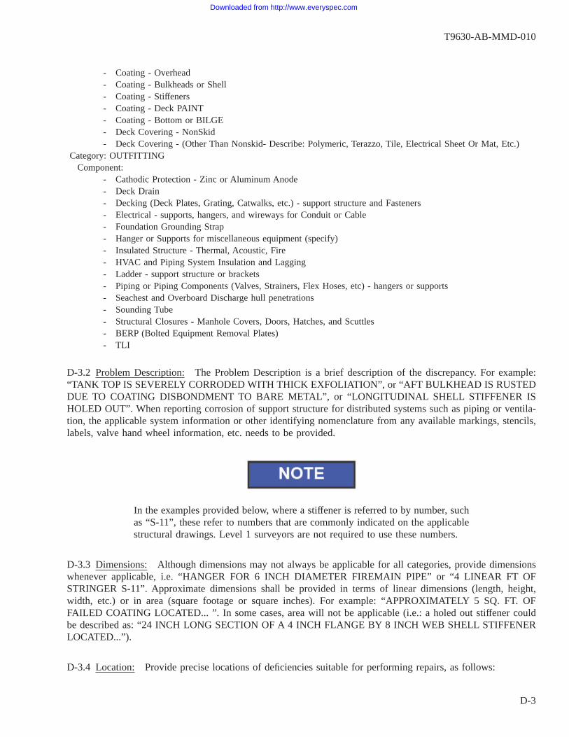
- Coating - Overhead- Coating - Bulkheads or Shell- Coating - Stiffeners- Coating - Deck PAINT- Coating - Bottom or BILGE- Deck Covering - NonSkid- Deck Covering - (Other Than Nonskid- Describe: Polymeric, Terazzo, Tile, Electrical Sheet Or Mat, Etc.)
Category: OUTFITTINGComponent:
- Cathodic Protection - Zinc or Aluminum Anode- Deck Drain- Decking (Deck Plates, Grating, Catwalks, etc.) - support structure and Fasteners- Electrical - supports, hangers, and wireways for Conduit or Cable- Foundation Grounding Strap- Hanger or Supports for miscellaneous equipment (specify)- Insulated Structure - Thermal, Acoustic, Fire- HVAC and Piping System Insulation and Lagging- Ladder - support structure or brackets- Piping or Piping Components (Valves, Strainers, Flex Hoses, etc) - hangers or supports- Seachest and Overboard Discharge hull penetrations- Sounding Tube- Structural Closures - Manhole Covers, Doors, Hatches, and Scuttles- BERP (Bolted Equipment Removal Plates)- TLI
D-3.2 Problem Description: The Problem Description is a brief description of the discrepancy. For example:“TANK TOP IS SEVERELY CORRODED WITH THICK EXFOLIATION”, or “AFT BULKHEAD IS RUSTEDDUE TO COATING DISBONDMENT TO BARE METAL”, or “LONGITUDINAL SHELL STIFFENER ISHOLED OUT”. When reporting corrosion of support structure for distributed systems such as piping or ventila-tion, the applicable system information or other identifying nomenclature from any available markings, stencils,labels, valve hand wheel information, etc. needs to be provided.
In the examples provided below, where a stiffener is referred to by number, suchas “S-11”, these refer to numbers that are commonly indicated on the applicablestructural drawings. Level 1 surveyors are not required to use these numbers.
D-3.3 Dimensions: Although dimensions may not always be applicable for all categories, provide dimensionswhenever applicable, i.e. “HANGER FOR 6 INCH DIAMETER FIREMAIN PIPE” or “4 LINEAR FT OFSTRINGER S-11”. Approximate dimensions shall be provided in terms of linear dimensions (length, height,width, etc.) or in area (square footage or square inches). For example: “APPROXIMATELY 5 SQ. FT. OFFAILED COATING LOCATED... ”. In some cases, area will not be applicable (i.e.: a holed out stiffener couldbe described as: “24 INCH LONG SECTION OF A 4 INCH FLANGE BY 8 INCH WEB SHELL STIFFENERLOCATED...”).
D-3.4 Location: Provide precise locations of deficiencies suitable for performing repairs, as follows:
T9630-AB-MMD-010
D-3
Downloaded from http://www.everyspec.com
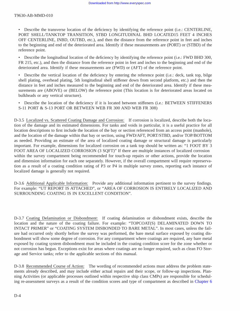
• Describe the transverse location of the deficiency by identifying the reference point (i.e.: CENTERLINE,PORT SHELL/TANKTOP TRANSITION, STBD LONGITUDINAL BHD LOCATED15 FEET 4 INCHESOFF CENTERLINE, INBD, OUTBD, etc.), and then the distance from the reference point in feet and inchesto the beginning and end of the deteriorated area. Identify if these measurements are (PORT) or (STBD) of thereference point.
• Describe the longitudinal location of the deficiency by identifying the reference point (i.e.: FWD BHD 300,FR 215, etc.), and then the distance from the reference point in feet and inches to the beginning and end of thedeteriorated area. Identify if these measurements are (FWD) or (AFT) of the reference point.
• Describe the vertical location of the deficiency by entering the reference point (i.e.: deck, tank top, bilgeshell plating, overhead plating, 5th longitudinal shell stiffener down from second platform, etc.) and then thedistance in feet and inches measured to the beginning and end of the deteriorated area. Identify if these mea-surements are (ABOVE) or (BELOW) the reference point (This location is for deteriorated areas located onbulkheads or any vertical structure).
• Describe the location of the deficiency if it is located between stiffeners (i.e.: BETWEEN STIFFENERSS-11 PORT & S-13 PORT OR BETWEEN WEB FR 300 AND WEB FR 308)
D-3.5 Localized vs. Scattered Coating Damage and Corrosion: If corrosion is localized, describe both the loca-tion of the damage and its estimated dimensions. For tanks and voids in particular, it is a useful practice for alllocation descriptions to first include the location of the bay or section referenced from an access point (manhole),and the location of the damage within that bay or section, using FWD/AFT, PORT/STBD, and/or TOP/BOTTOMas needed. Providing an estimate of the area of localized coating damage or structural damage is particularlyimportant. For example, dimensions for localized corrosion on a tank top should be written as: “1 FOOT BY 3FOOT AREA OF LOCALIZED CORROSION (3 SQFT)” If there are multiple instances of localized corrosionwithin the survey compartment being recommended for touch-up repairs or other actions, provide the locationand dimension information for each one separately. However, if the overall compartment will require represerva-tion as a result of a coating condition rating of P3 or P4 in multiple survey zones, reporting each instance oflocalized damage is generally not required.
D-3.6 Additional Applicable Information: Provide any additional information pertinent to the survey findings.For example: “UT REPORT IS ATTACHED”, or “AREA OF CORROSION IS ENTIRELY LOCALIZED ANDSURROUNDING COATING IS IN EXCELLENT CONDITION”.
D-3.7 Coating Delamination or Disbondment: If coating delamination or disbondment exists, describe thelocation and the nature of the coating failure. For example: “TOPCOAT(S) DELAMINATED DOWN TOINTACT PRIMER” or “COATING SYSTEM DISBONDED TO BARE METAL”. In most cases, unless the fail-ure had occurred only shortly before the survey was performed, the bare metal surface exposed by coating dis-bondment will show some degree of corrosion. For any compartment where coatings are required, any bare metalexposed by coating system disbondment must be included in the coating condition score for the zone whether ornot corrosion has begun. Exceptions exist for areas where coatings are no longer required, such as clean FO Stor-age and Service tanks; refer to the applicable sections of this manual.
D-3.8 Recommended Course of Action: The wording of recommended actions must address the problem state-ments already described, and may include either actual repairs and their scope, or follow-up inspections. Plan-ning Activities (or applicable processes outlined within respective ship class CMPs) are responsible for schedul-ing re-assessment surveys as a result of the condition scores and type of compartment as described in Chapter 6
T9630-AB-MMD-010
D-4
Downloaded from http://www.everyspec.com

of this manual. Therefore, all that is needed are statements such as “SCHEDULE NEXT ASSESSMENT IAWCCAMM.” for Condition P1 or P2 overall scores for a tank or void, or “SCHEDULE COMPLETE BLAST ANDPAINT IAW CCAMM.” for a tank or void with an overall Condition P3 or P4 score.
D-3.9 Surface Ships and CADET software: When entering 2-KILOs into the CADET data entry system, therewill be standardized repair recommendation text available in drop down menus for various types of discrepan-cies. The surveyor will either select this text, or may modify it to generate new recommended courses of action.Example: “RECOMMEND LEVEL 2 STRUCTURAL INSPECTOR RE-INSPECT WITH UT THICKNESSGAUGING TO VERIFY REMAINING MATERIAL THICKNESS.”
D-3.10 Prioritization via the Maintenance Decision Risk Matrix (MDRM): The MDRM described in Chapter6 provides a prioritization system for both coating system and structural maintenance requirements for individualcompartments, area, or structural components. Proper use of the MDRM requires all Level 1 and/or Level 2assessment findings and GR2K recommended repair actions to have a risk item number (R#) assigned based onthe tables in Chapter 6. In addition, findings pertaining to the condition of coatings require a preservation rating(P#), and findings pertaining to the condition of structures require a structural rating (S#). In some cases, it maybe appropriate to assign both a P# and an S# rating.
The requirements concerning the proper assignment of P# and S# condition ratings are more fully describedin Chapters 4 and 5. In assessment findings and repair 2-KILOs, the format for this should be “(R#, S#, P#)”.When a Level 1 surveyor is unable to determine the applicable thickness of metal lost due to corrosion, andtherefore also unable to determine that percentage of the original design thickness and the associated structuralintegrity rating, they may use “SN/V”, signifying “not verifiable”. An S5 finding can be determined and used byLevel 1 surveyors based solely on visual appearance factors such as: Obvious Excessive Corrosion, Holing,Cracking, Buckling or other signs of physical damage or overload.
A typical example of MDRM prioritization ratings for a corroded shell plate in the bilge of an engine roomwith corrosion affecting greater than 20 percent of the surface area, but an undetermined percentage of materialwastage would be: “R4, SN/V, P4”. Additional guidance is provided as follows:
• For deficiencies in coating systems only with no discernible structural metal loss, report R#, P#. The struc-tural integrity rating would be S1, but this is not required to be stated.
The P# assigned to all coating system deficiencies and GR2K recommended repairs in the bilge regions ofsurface ships shall be a minimum of P3 regardless of the extent of the coating damage by area. Any GR2Kcoating repair item submitted for these areas that would have been rated a P1 or P2 based on an area-percentage score assigned to the affected zones shall be assigned a P3 rating.
• For deficiencies in structural integrity, report R#, S#, and additionally the P# as warranted, since structuralrepairs in almost every case will involve the repair of the associated coating system.
• For deficiencies pertaining to “Outfitting” items only (e.g. anodes, TLI’s, insulation, etc.), the MRDM isnot used and R#, P# or S# ratings are not required.
D-3.11 Additional Comments: Provide any additional information that might help with the disposition orscreening of the deficiency, and to provide supplemental information that may affect the repairs. For example,provide information about a hard to reach deficiency, or where significant interferences must be removed in orderto perform a repair action: “FALSE DECK PANELS AND CABLES IN COMPARTMENT 2-128-1-E MUST BEREMOVED TO GAIN ACCESS FOR THE PLATING RENEWALS.”
T9630-AB-MMD-010
D-5
Downloaded from http://www.everyspec.com
In order to avoid redundant reporting and adjudication, it is also required for Level 1 surveyors to review theships’ CSMP for open repair jobs in the compartments they will be surveying. If the review shows that anyrequired repairs already have jobs written for them, reference the applicable JCN in the comments.
The SURFMEPP CADET system automatically retrieves open CSMP repair jobsand provides this information for each compartment, for each GA2K task pushedfor surface ships.
D-4. EXAMPLE TEXT FOR PROBLEM AND RECOMMENDED REPAIR STATEMENTS.
The examples provided below include language that might be used by either a Level 1 surveyor, or a Level2 inspector.
(1) CORROSION PROTECTION, COATING - BILGE: THICK EXFOLIATION IDENTIFIED OVER A 2 FTBY 3 FT AREA (6 SQFT) ON TANK TOP PL (F/O TANK 6-300-2-F), PORT SIDE BETWEEN FWD BHD300 AND FR 302, AND BETWEEN 4 FT AND 7 FT INBRD OF THE TANK TOP/MARGIN PLATE TRAN-SITION.
RECOMMEND LEVEL 2 INSPECTION TO POWER CLEAN CORRODED AREA AND PERFORM UTTHICKNESS GAUGING TO DETERMINE PERCENT MATERIAL WASTAGE AND FURTHER CORREC-TIVE ACTION. PRIORITY: (R4, SN/V, P4). DETERIORATED AREA IS ACCESSED BY CRAWLINGBETWEEN DK GRATING AND SHELL PL UNDERNEATH CONDENSATE CORNER.
(2) CORROSION PROTECTION, COATING - BOTTOM: LOCALIZED COATING SYSTEM FAILUREEXPOSING BARE METAL CURRENTLY WITH MINOR SURFACE SCALING AND NO APPRECIABLEMETAL LOSS APPROX 5FT BY 2FT (10SQFT) ON SHELL PLATING IN THE BOTTOM OF F/O TANK6-300-2-F BETWEEN FR 333 AND FR 338, AND BETWEEN 8FT AND 10FT PORT OF CENTERLINE.COATING SYSTEM ELSEWHERE IS IN EXCELLENT CONDITION.
RECOMMEND LOCAL TOUCH-UP PAINTING IAW STD 009-32 PRIOR TO CLOSEOUT OF TANK.PRIORITY: (R5, SN/V, P2).
(3) STRUCTURAL, FRAMING - STIFFENER: 12 IN BY 3 IN HOLE IN WEB OF STRINGER S-11 PORTBETWEEN 1 FT AND 2 FT AFT OF FR 208 AND CENTERED 3 INCHES FROM THE ATTACHED PLAT-ING. UT THICKNESS GAUGING ON WEB OF S-11 PORT REVEALED ACCEPTABLE MATERIALTHICKNESS FROM FR 208 TO 6 IN AFT OF FR 208, AND BEGINNING 2.5 FT AFT OF FR 208. THEAVERAGE THICKNESS OF THE REMAINING PORTION OF THE INTACT WEB ALONG THE DEPTHOF THE WEB IS 0.163 INCHES MINIMUM.
CROP AND RENEW 3 LINEAR FT OF STRINGER S-11 PORT, BETWEEN FR 208 AND FR 211 PERNAVSEA DWG 801-57888543 DETAIL 3-A SHEET 3. PRIORITY: (R5, S5, P2)
(4) STRUCTURAL, PLATE - SHELL: OBSERVED 10 IN X 10 IN AREA OF SHELL PLATING WITHSEVERE EXFOLIATION. THREE UT THICKNESS READINGS WERE OBTAINED ON CORRODED
T9630-AB-MMD-010
D-6
Downloaded from http://www.everyspec.com
AREA REVEALING THICKNESS AS LOW AS 0.298 IN ON 0.500 IN NOMINAL DESIGN PLATELOCATED STBD SIDE BETWEEN 2 IN AFT OF FR 182 AND FR 183, AND BETWEEN THE 20TH AND19TH STIFFENER BELOW SECOND PLATFORM. UT THICKNESS READINGS OBTAINED ON SUR-ROUNDING PLATE WITH NO COATING FAILURE REVEALED MATERIAL THICKNESS RANGINGBETWEEN 0.482 IN AND 0.499 IN. DETAILED UT REPORT WAS PROVIDED TO PORT ENGINEER(REPORT NO.: ABC_UT_20120229)
CROP AND RENEW 4 SQFT OF SHELL PLATING BETWEEN FR 181.5 AND FR 183.5, AND BETWEENTHE 20TH AND 19TH STIFFENER BELOW SECOND PLATFORM PER NAVSEA DWG 110-6011836,SHT 8. AREA IS EXTREMELY DIFFICULT TO ACCESS DUE TO TIGHT SURROUNDING STRUCTURE.PRIORITY: (R5, S5, P2)
(5) OUTFITTING, PIPING HANGER: STEEL HANGER WELDED TO OVERHEAD FOR 4 INCH DIAM-ETER CHT PIPE IS BADLY CORRODED AND PARTIALLY PERFORATED. ALL OF SURROUNDINGPAINT IS INTACT. LOCATED PORT SIDE OF SPACE ABOVE STORAGE LOCKER AT FR 349 AND 6FT INBD OF PORT SHELL PLATING, 6 IN BELOW FIRST DECK. SEE PHOTO.
SCOPE OF REPAIRS ALREADY COVERED UNDER JCN 20222EB141234. PRIORITY: (R2, S3, P1).
D-5. COMMONLY USED ABBREVIATIONS.
Although not required, many abbreviations are commonly used by Navy maintenance and survey personnel.Some of the more commonly used terms and their abbreviations are listed below.
Above ABV
Above Baseline ABLAft AFTBaseline BLBelow BLWBolted Equipment Removal Plate BERPBottom BOTBracket BRKTBulkhead BHDCenterline CLCenter Vertical keel CVKDeck DKDrawing DWGFeet/Foot FTFlange FLGFlat Bar FBForward FWDFoundation FDNFrame FRHorizontal HORIZIn Accordance With IAWInboard INBDInches INInnerbottom IBIn Way Of IWOKnuckle KNULevel LVL
T9630-AB-MMD-010
D-7
Downloaded from http://www.everyspec.com

Longitudinal LONGMulti-Cable Transit MCTNon-Tight NTOutboard OUTBDOverboard OVBDOverhead OVHDPiping PPGPlatform PLATFPlating PLPort PORTSquare Feet SQFTSquare Inches SQINStanchion STANStarboard STBDStiffener STIFStringer STGRTransverse TRANSVTrunk TRKVertical VERTWaterline WLWatertight WTWatertight Door WTDWeb Frame WEB FR
T9630-AB-MMD-010
D-8
Downloaded from http://www.everyspec.com

Ref: NAVSEAINST 4160.3 NAVSEA S0005-AA-GYD-030/TMMP
NAVSEA/SPAWAR TECHNICAL MANUAL DEFICIENCY/EVALUATION REPORT (TMDER)INSTRUCTIONS: Continue on 8 ½” x 11” on page if additional space is needed.1. Use this report to indicate deficiencies, problems and recommendations relating to publications.2. For CLASSIFIED TMDERs see OPNAVINST 5510H for mailing requirements.3. For TMDERs that affect more than one publication, submit a separate TMDER for each.4. Submit TMDERs at web site https://nsdsa.nmci.navy.mil or mail to: COMMANDER, CODE 310 TMDERs, NAVSURFWARCENDIV NSDSA, 4363 MISSILE WAY BLDG 1389, PORT HUENEME CA 93043-4307
1. PUBLICATION NUMBER 2. VOL/PART 3. REV/DATE OR CHG/DATE 4. SYSTEM/EQUIPMENT ID
5. TITLE OF PUBLICATION 6. REPORT CONTROL NUMBER(6 digit UIC-YY-any four: xxxxxx-10-xxxx)
7. RECOMMEND CHANGES TO PUBLICATION
7a. Page # 7b. Para # 7c. RECOMMENDED CHANGES AND REASONS
8. ORIGINATOR’S NAME AND WORK CENTER 9. DATE 10. ORIGINATOR’S E-MAIL ADDRESS 11. TMMA of Manual(NSDSA will complete)
12. SHIP OR ACTIVITY Name and Address (Include UIC/CAGE/HULL) 13. Phone Numbers:Commercial ( ) -DSN -FAX ( ) -
NAVSEA 4160/1 (Rev. 9-2010) S/N 0116-LF-985-4100
Downloaded from http://www.everyspec.com
FOLD HERE AND TAPE SECURELY PLEASE DO NOT STAPLE
INCLUDE COMPLETE ADDRESS USE
PROPER POSTAGE
FOR OFFICIAL USE ONLY
COMMANDER CODE 310 TMDERs NAVSURFWARCENDIV NSDSA 4363 MISSILE WAY BLDG 1389 PORT HUENEME CA 93043-4307
FOLD HERE AND TAPE SECURELY PLEASE DO NOT STAPLE
Downloaded from http://www.everyspec.com

blank back cover.
Downloaded from http://www.everyspec.com

T9630-AB-MMD-010
Downloaded from http://www.everyspec.com