Embed Size (px)
Citation preview

T300T300e
Automatic Floor Scrubber
English EN Service Information Manual
9014510Rev. 01 (3-2017)
*9014510*
For the latest Parts Manuals and other language Operator Manuals, visit:
www.tennantco.com/manuals
R
Hygenic ® Fully cleanable Recovery TankTennantTrue ® PartsIRIS ® a Tennant Technology

INTRODUCTION
This manual is available for each new model. It provides necessary operation and maintenance instructions.
Read this manual completely and understand the machine before operating or servicing it.
This machine will provide excellent service. However, the best results will be obtained at minimum costs if:
• The machine is operated with reasonable care.• The machine is maintained regularly - per the
machine maintenance instructions provided.• The machine is maintained with manufacturer
supplied or equivalent parts.
PROTECT THE ENVIRONMENT
Please dispose of packaging materials and used machine components such as batteries in an environmentally safe way according to your local waste disposal regulations.
Always remember to recycle.
Tennant CompanyPO Box 1452Minneapolis, MN 55440Phone: (800) 553- 8033 or (763) 513- 2850www.tennantco.com
Pro-Membrane, Membrane, Severe Environment, Zone Settings, Quite-Mode are US registered and unregistered trademarks of Tennant Company.
Trojan and HydroLINK are registered trademarks of Trojan Battery Company.
This product may contain portions of software that have various 3rd party licenses. More information can be found at: www.tennantco.com/opensource
Specifications and parts are subject to change without notice.
Original Instructions. Copyright © 2015- 2017 Tennant Company. All rights reserved.
INTENDED USE
The automatic floor scrubber is intended for commercial use, for example in hotels, schools, hospitals, factories, shops, offices and rental businesses. It is designed to scrub hard floor surfaces (concrete, tile, stone, synthetic, etc.) in an indoor environment. Do not use this machine on carpeted surfaces. Use only recommended pads/brushes and commercially available floor cleaning detergents. Do not use this machine other than described in this Operator Manual.
MACHINE DATA
Please fill out at time of installation for future reference.
Model No. - _________________________________________ Serial No. - _________________________________________
Installation Date - ____________________________________
SERIAL NUMBER LOCATION
UNCRATING MACHINE
Carefully check machine for signs of damage. Report damages at once to carrier. Contact distributor or Tennant for missing items.
To uncrate the machine, remove straps, wheel blocks and shipping brackets. Using the supplied ramp carefully back the machine off the pallet. Make sure scrub head is in the raised position.
ATTENTION: Do not remove machine from pallet without using ramp, machine damage may occur.
3T300, T300e Service Information (3-2017)
CONTENTS
CONTENTSIntroduction .....................................................2Intended Use ...................................................2Machine Data ..................................................2
Serial Number Location ..............................2Uncrating Machine ..........................................2
Contents ................................................................3Safety Precautions ................................................6General Information .............................................10
Component Locator ..................................10Electrical Schematic Symbols ..................11Electrical Schematic T300 (Drive Model) - 1 Of 3 ........................12Electrical Schematic T300 (Push Model) - 1 Of 3 .........................15Electrical Schematic T300e (Drive Model) - 1 Of 2 ..........................18Electrical Schematic T300e (Push Model) - 1 Of 2 ..........................20Fastener Torque .......................................23Sae (Standard) .........................................23Metric .......................................................23General Machine Dimensions/ Capacities/Performance ......................24General Machine Dimensions/ Capacities/Performance ......................25General Machine Dimensions/ Capacities/Performance ......................26General Machine Dimensions/ Capacities/Performance ......................27
Maintenance ........................................................32Maintenance Chart ...................................32Machine Maintenance ..............................33After Daily Use .........................................33After Weekly Use .....................................35After Every 50 Hours Of Use ....................36After Every 100 Hours Of Use ..................36Electric Motors .........................................37Belts .........................................................37Orbital Scrub Head Isolators (Lower) .......37Batteries ...................................................38Maintenance-Free Batteries .....................38Flooded (Wet) Lead-Acid Batteries ..........38Checking Connections / Cleaning ............38Charging Batteries ...................................39Squeegee Blade Replacement ................40Ec-H2o Nanoclean Water Conditioning
Cartridge Replacement .......................41
Loading/Unloading Machine For Transporting ........................................42Storing Machine .......................................43Freeze Protection .....................................43
Troubleshooting ...................................................44Faults .......................................................44Faults - Off Board Battery Charger ..........57Troubleshooting .......................................58Onboard Battery Charging On (Option) ...60Batteries Failed To Charge/ Reduced Run Time (Onboard Charger)..............61Off Board Battery Charging On (Option) ..62Batteries Failed To Charge/ Reduced Run Time (Off Board Charger) ............63Power-Up On ...........................................64Machine Failed To Power Up ...................65T300 Propel Subsystem (Option) .............66T300 Failed To Propel ..............................67T300e Propel Subsystem (Option) ...........68T300e Failed To Propel ............................69T300 Scrub Motor On ..............................70T300 Scrub Motor Failed To Turn On ......71T300e Scrub Motor On ............................72T300e Scrub Motor Failed To Turn On ...73Scrub Head Lift Actuator (Option) ............74Scrub Head Failed To Raise/Lower ..........75T300 Vacuum Fan On .............................76T300 Vacuum Fan Failed To Turn On .....77T300e Vacuum Fan On ...........................78T300e Vacuum Fan Failed To Turn On ..79T300 Solution Control On (Conventional) .....................................80T300 Solution Control Failed To Turn On (Conventional) .......................81T300e Solution Control On (Conventional) .....................................82T300e Solution Control Failed To Turn On (Conventional) .......................83T300 Solution Control On (Ec-H2o) .........84T300 Solution Control Failed To Turn On (Ec-H2o) ................................85T300e Solution Control On (Ec-H2o) .......86T300e Solution Control Failed To Turn On (Ec-H2o) ................................87T300 Se (Severe Environment) On ..........88T300 Se (Severe Environment) Failed To Turn On ................................89Sun-I/O Circuit Board Testing (Universal Schematic) .........................90

4 T300, T300e Service Information (3-2017)
CONTENTS
Sun-I/O Circuit Board Testing Procedure ............................................91Can Open Network Issues .......................92Connectors Fully Seated ..........................92Pin Fully Seated .......................................92Network Resistance .................................92Node (Module) Resistance .......................93Wire Continuity To Node ..........................93Machine Node Table ................................94
Service.................................................................95Service Diagnostics Tool ..........................95Programing A New Interface Module ........95Re-Configuring Existing Modules .............97Programming The I-Drive Module (Option) ...............................................99Displaying Fault Codes ..........................100Battery Charger Settings ........................101Off-Board Battery Charger: ....................101Changing Off-Board Battery Charger Settings ...............................101On-Board Battery Charger .....................103Changing On-Board Battery Charger Settings (Pro-Membrane Model) .......103Changing On-Board Battery Charger Settings (Pro-Panel Model) ...............104Battery Charger Operation .....................105Removing Scrub Head Assembly ...........106Installing Scrub Head Assembly .............107Checking And Adjusting Cylindrical Scrub Brush Pattern ..........................107Removing Lower Orbital Head Isolators 110Installing Lower Orbital Head Isolator .... 111Removing Transaxle Assembly (Option) 111Installing Transaxle Assembly (Option) ..112Ptc (Push-To-Connect) Fittings ..............113Making A Connection .............................113Disconnecting .........................................114Removing Vacuum Fan ..........................114Installing Vacuum Motor .........................115Removing Carbon Brushes ....................116Installing Carbon Brushes ......................116Removing Water Solenoid (T300e Shown) ..................................117Installing Water Solenoid........................118Adjusting Water Solenoid (T300e Only) .119
Control Modules ..........................................121Removing Machine Control Module (Option) .............................................121Installing Control Module ........................122Removing I-Drive Module (Option) .........122Installing I-Drive Module (Option) ...........123Removing Onboard Battery Charger (Option) .............................................123Installing Onboard Battery Charger ........124Removing Interface Module ...................125Installing Interface Module .....................125Removing Bail Switch, Speed Potentiometer, Or Directional Switch ..............................126Installing Bail Switch, Speed Potentiometer, Or Directional Switch ..............................128

5T300, T300e Service Information (3-2017)
CONTENTS

6 T300, T300e Service Information (3-2017)
SAFETY PRECAUTIONS
IMPORTANT SAFETY INSTRUCTIONS - SAVE THESE INSTRUCTIONS
The following warning precautions are used throughoutthis manual as indicated in their description:
WARNING: To warn of hazards or unsafepractices which could result in severe personalinjury or death.
FOR SAFETY: To identify actions which must befollowed for safe operation of equipment.
The following information signals potentiallydangerous conditions to the operator. Know whenthese conditions can exist. Locate all safety devices onthe machine. Report machine damage or faultyoperation immediately.
WARNING: To Reduce the Risk of Fire,Explosion, Electric Shock or Injury:
- Read manual before operating machine.
- Do not use or pick up flammable materials.
- Do not use near flammable liquids, vapors orcombustible dusts.This machine is not equipped with anexplosion proof motor. The electric motor willspark upon start up and during operationwhich could cause a flash fire or explosion ifmachine is used in an area where flammablevapors/liquids or combustible dusts arepresent.
- Batteries emit hydrogen gas. Explosion or firecan result. Keep sparks and open flame awaywhen charging.
- Disconnect battery cables and charger cordbefore cleaning and servicing machine.
- Do not charge batteries with damaged cord. Donot modify plug.
If the charger supply cord is damaged orbroken, it must be replaced by themanufacturer or its service agent or a similarlyqualified person in order to avoid a hazard.
- Do not use outdoors. Store indoors.
- Spinning pad/brush, keep hands away.
WARNING: Magnetic Field Hazard. Magneticpad driver/brush can be harmful to pacemakerwearers or medical implants.
This machine may be equipped with technologythat automatically communicates over the cellularnetwork. If the machine will be operated where cellphone use is restricted because of concernsrelated to equipment interference, please contact aTennant representative for information on how todisable the cellular communication functionality.
FOR SAFETY:
1. Do not operate machine:- Unless trained and authorized.- Unless operator manual is read and
understood.- Unless mentally and physically capable of
following machine instructions.- Under the influence of alcohol or drugs.- While using a cell phone or other types of
electronic devices.- If not in proper operating condition.- In outdoor areas. This machine is for
indoor use only.- In areas where flammable vapors/liquids or
combustible dusts are present.- With pads or accessories not supplied or
approved by Tennant. The use of otherpads may impair safety.
- In areas with possible falling objects.- In areas that are too dark to safely see the
controls or operate machine.
2. Before operating machine:- Check machine for fluid leaks.- Make sure all safety devices are in place
and operate properly.
3. When operating machine:- Use only as described in this manual.- Report machine damage or faulty operation
immediately.- Wear closed- toe, non- slip work shoes.- Reduce speed when turning.- Go slowly on inclines and slippery
surfaces.- Do not scrub on inclines that exceed 9%
grade or transport on inclines that exceed21% grade.
- Follow site safety guidelines concerningwet floors.
- Follow mixing, handling and disposalinstructions on chemical containers.
- Do not carry passengers on machine.- Use care when reversing machine.- Keep children and unauthorized persons
away from machine.- Do not allow machine to be used as a toy.
SAFETY PRECAUTIONS

SAFETY PRECAUTIONS
7T300, T300e Service Information (3-2017)
4. Before leaving or servicing machine:- Stop on level surface.- Set the parking brake, if equipped.- Turn off machine and remove key.
5. When servicing machine:- Disconnect battery connection and charger
cord before working on machine.- All work must be done with sufficient
lighting and visibility.- All repairs must be performed by trained
personnel.- Use Tennant supplied or approved
replacement parts.- Do not modify the machine from its original
design.- Do not jack up machine.- Avoid moving parts. Do not wear loose
clothing or jewelry and secure long hair.- Do not disconnect the off- board charger’s
DC cord from the machine’s receptaclewhen the charger is operating. Arcing mayresult. If the charger must be interruptedduring charging cycle, disconnect the ACpower supply cord first.
- Do not use incompatible battery chargersas this may damage battery packs andpotentially cause a fire hazard.
- Inspect charger cord regularly for damage.- Keep work area well ventilated.- Avoid contact with battery acid.- Keep all metal objects off batteries.- Do not power spray or hose off machine.- Use a hoist or adequate assistance when
lifting batteries.- Battery installation must be done by trained
personnel.- Wear personal protection equipment as
needed and where recommended in thismanual.
For Safety: wear protective gloves.
For Safety: wear eye protection.
6. When loading/unloading machine onto/offtruck or trailer:- Drain tanks before loading machine.- Use a ramp, truck or trailer that can support
the machine weight and operator.- Do not operate the machine on a ramp
incline that exceeds a 21% grade level.- Use a winch if ramp incline exceeds a 21%
grade level.- Lower the scrub head and squeegee before
tying down machine.- Turn machine off and remove key.- Set parking brake (if equipped).- Block machine wheels.- Use tie- down straps to secure machine.
8 T300, T300e Service Information (3-2017)
SAFETY PRECAUTIONS
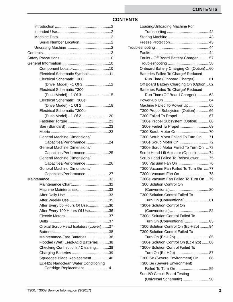
SAFETY LABELS
The safety labels appear on the machine in the locations indicated. Replace labels if they are missing or becomedamaged or illegible.
WARNING LABEL - Located on recovery tank cover.
WARNING LABEL -Electrical hazard.Disconnect batterycables before servicingmachine.Located on circuit breakerpanel.
WARNING LABEL -Batteries emithydrogen gas.Explosion or fire canresult. Keep sparksand open flame awaywhen charging.Located on bottom sideof recovery tank.
WARNING LABEL -Spinning pad. Keep hands away.Located on disk scrub head model.
WARNING LABEL -Spinning brush. Keep hands away.Located on cylindrical scrub headmodel.
WARNING LABEL -Magnetic Field Hazard. Magneticpad driver/brush can be harmfulto pacemaker wearers or medicalimplants.Located on Insta-Click magneticpad driver/brush.
FOR SAFETY LABEL -Do not power spray orhose off machine.Electrical malfunctionmay occur.Located on control console

SAFETY PRECAUTIONS
9T300, T300e Service Information (3-2017)
SAFETY LABELS
The safety labels appear on the machine in the locations indicated. Replace labels if they are missing or becomedamaged or illegible.
WARNING LABEL -Do not chargebatteries withdamaged cord.Electric shock canresult. Disconnectcharger cord beforeservicing.Located on controlconsole.
WARNING LABEL -Batteries emithydrogen gas.Explosion or firecan result. Keepsparks and openflame away whencharging.Located on controlconsole and bottomside of recovery tank.
WARNING LABEL - ElectricalHazard. Disconnect batterycables before servicingmachine.Located on circuit board panel.
WARNING LABEL -Spinning pad. Keephands away.Located on disk scrubhead model.
WARNING LABEL -Magnetic field hazard. Magneticpad driver/brush can be harmfulto pacemaker wearers or medicalimplants.Located on Insta-Click magnetic paddriver/brush.
WARNING LABEL -Flammablematerials orreactive metals cancause an explosionor fire. Do not pickup.Located near controlconsole.
WARNING LABEL -Flammablematerials can causeexplosion or fire. Donot use flammablematerials in tank(s).Located on backsideof solution tank cover.
FOR SAFETYLABEL - Readmanual beforeoperatingmachine.Located nearcontrol console.
WARNING LABEL -Spinning brush. Keephands away.Located on cylindricalscrub head model.
FOR SAFETY LABEL -Do not power spray orhose off machine.Electrical malfunctionmay occur.Located on control console

10 T300, T300e Service Information (3-2017)
GENERAL INFORMATION
I
A
H
EF
D
C
B
G
L
K
N
M
O
J
P
Q
ComponentsA BatteriesB Circuit Breakers and Optional
Machine Control Module C ec-H2O System ComponentsD Scrub Head Lift Contact
SwitchE Parking Brake SwitchF Scrub Head Drive BeltG Scrub Motor (Disk Shown)H SE (Severe Environment)
System
ComponentsI Solution Tank Fill PortJ Onboard Battery Charger*K Interface Module w/ mini-USB
Programming PortL Internal Bail SwitchM Forward/ Reverse Propel
Switch*N Scrub Head Linkage
(Configurable)O Transaxle Assembly*P Rear Squeegee Lift Contact
SwitchQ I-Drive Propel Control Module** Optional Equipment
GENERAL INFORMATION
Component Locator
T300, T300e Service Information (3-2017) 11
GENERAL INFORMATION
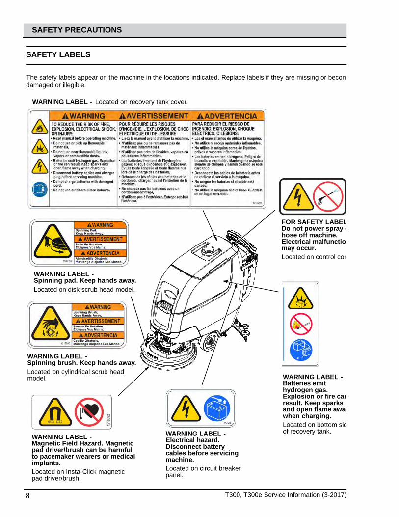
ELECTRICAL SCHEMATIC SYMBOLS
12
21
+ -
+ -
Switched B+
From Buss Bar
Switched B+ B- From Stando
B- From Stando
S-5 Seat Switch (N.O.)
Amer Encoder
Cable
C1 Capacitor (0.01Uf)
R1(11 Ω/40W)
+ -
MTR
ecH2O Pump
J3-2 Brush RT-
J3-5 Brush LT+
J3-6 Brush LT-
Right/Rear Brush
Left/Front* Brush
* Cylindrical = Uses Adaptor
ecH2O ControlModule
T16 Control
Board
VCC_A
Alarm
Com N.C.
N.O.
S-14 Pressure Sw.N.C. Opens @ 25 +/- 2 psi
Enable
GND_A
GND_B
Pressure IN
(ECH2O SW)
(ECH2O SW)
VCC_B VCC_C
Pump
(SOL-A)
ecH2O Valve
Sparger
e-Cell
65EA/BLU
5EA/GRN
8EA/GRY
7EA/PUR
3EA/ORA
4EA/YEL
(SOL-B)
(SPA-A)
(SPA-B)
(CELL-A)
(CELL-B)
(LED GND) (LED RED) (LED GRN)
SqueegeeActuator
Battery Positive +
Battery Negative -
D-8
FU2100A
70/TAN
M4A 86 85
B+
J7-1 B+ Control
B- Cable
8/GRY
FU1100A
FU1100A
102/BRN
Sweep OFF/Down = 2-1, 6-5Sweep ON/Center = 2-3, 6-7Vac & Sweep ON/Up = 3-4, 7-8
Cable
Pre-SweepBrush RelayCB3 (2.5A)
CB19 (25A)
CB16 (15A)
J7-4 Sweep
Note:ecH2O Enable:J7-10 Low=Turn ON ecH2O
Note:Pre-Sweep Enable:J6-10 B+ = Sweep Enable ON
Sweep Enable J6-1037/PUR
38/GRY
CB9 (2.5A) 79/WHT
CB10 (2.5A)
Note:ecH2O Side BrushJ7-12 Low=SV3 H20 Valve ONecH2O Pump ON 100%
13/BLK
88/GRY
9EA/WHT
S-15 Flush Switch
13EA/BLK
21/PNK
Extend Limit Sw.
22/BRN
MTR 26/BLU
25/GRN
2/BRN
Switched B+
From Buss Bar
Switched B+
From Buss Bar
Switched B+
To: CAN O
pen-(J6-14)
To: ThrottleSensor (G
ND
)
To: Curtis 1234(I/O GND)
To: CAN O
pen+(J6-13)
To: Back-Up Light Circuit
To: Back-Up Alarm Circuit
80/TAN
PMC001
12
12
MTR
10 4
1
3
2
7
9
6-4
6-8
5
6
11
12
8
6-1
6-2
6-3
6-6
6-5
6-7
ON
OFF
6
2
854
1
FWD
REV
6
2
8
BA
54 J1-33
GND Cable
J1-34
J1-21
W/WHT
V/GRN
U/ORN
J1-3
J1-4
J1-13
J1-11B
LU2
J1-32
J1-26
J1-31
J1-7
J1-18
J1-15
66/BLU
61/PNK
62/BRN
12/BRN
17/PURPropel Motor Assembly
17/PUR
15/GRN
87/PUR
Temp
Send
er
Brake
Solen
oid
59/WH
T 58GRY
RED1
WH
T5
BLK
6
YEL
T2
B1
B2
T1
YEL
J1-16
J1-35
J1-23
P1-C
BLU
YEL
P1-B
P1-D
BLK
P1-A
RED
J1-22
J1-9
J1-1
B+
J1-29
J1-28
J1-25
1
1
3
5
7
2
4
6
8
Pre-Sweep SwitchSweep OFF/Down = 2-1, 6-5Sweep ON/Center = 2-3, 6-7Vac & Sweep ON/Up = 3-4, 7-8
1
3
5
7
2
4
6
8
M3B MTR
MTR
MTR
MTR
FaST/ES Pump
D-9
D-6
D-7
D-12
67/PUR
64/YEL 81/PNK
Pre-SweepVacuum Fan
LH Side Broom Motor
Main Broom Motor
13/BLK
13/BLK
65/GRN
65/GRN
65/GRN
68/GRY
69/WHT
D-11
30 87
M3A
Curtis 1234Controller
PROG +
TX
RX
B+
KSI
INTERLOCK
FWD
FWD/REV Switch
Throttle Sensor
REV
B -
GNDB+
THROTTLE
BRAKE
CAN TERM L
CAN TERM H
U
DRV3
DRV4
DRV1
THERM
ISTOR
I/O G
ND
PHA
SE A
PHA
SE B
+5V
DRV2
COIL RETURN
V
W
BRAKE IN
(0-5 vdc)
(0-5 vdc) THRO
TTLE
CAN
L
8/GRY
8/GRY
18/GRY
16/BLU
94/YEL
9/WHT
11/PNK
14/YEL
58/GRY
58/GRY
CAN
H
6 Volt
IGN
15 ACC
30 BATT
75
50 Start
ST
To: Back-Up Alarm Circuit
+ -
Com N.C.
N.O.
1
3
5
7
2
4
6
8
MTR MTR
M3B
30 87
M3B
30 87a
M3A
IGN ST
+ -
Note: Key Switch ON
Key Switch
Battery
DPDT Switch
Pressure Switch
Motor
3 Phase AC Induction Motor
Motor Encoder
Momenary Switch N.O.
Contact Switch N.C.
Solenoid Valve
Sensor(Variable Resistor)
Circuit Breaker
Fuse
Diode
Single Continuation Tab
Double Continuation Tab
Relay Coil
N.C. Relay Contacts
N.O. Relay Contacts
Horn or Alarm
Light
Connected
Not Connected
Connector
Energized
Adaptor Harness
Notes
Assembly
AC Plug
CapacitorElectro-
MagneticBrake
Enabled (Applied)• Key O• Neutral - Ready State • Brake Command• Seat Switch Open• Curtis 1234 Fault (See Troubleshooting)
• Throttle Command• Seat Switch Closed
Disabled (Released)Operational Matrix:
Propel
Enabled• Seat Switch Closed • Foot Throttle Command• Fwd/Rev Switch Input
• Seat Switch Open• Neutral-Ready State• Brake Command• Curtis 1234 Fault
DisabledOperational Matrix:
* SV2 Water Valve Voltage
Range
Low1-LED2-LEDs3-LEDs
1-LED2-LEDs3-LEDs
1-LED2-LEDs3-LEDs
20%30%45%
30%55%80%
55%80%
100%
7.2 Volts10.8 Volts16.2 Volts
10.8 Volts19.8 Volts28.8 Volts
19.8 Volts28.8 Volts36 Volts
Med(Default)
High
Level PWM% @ Nominal 36 VDC

12 T300, T300e Service Information (3-2017)
GENERAL INFORMATION
ELECTRICAL SCHEMATIC T300 (DRIVE MODEL) - 1 of 3 5
43
21
BA
TTERY /
CH
AR
GER
SYSTEMS
PCB ASSEMBLY
POW
ER O
N/O
FF C
IRC
UITR
Y
CABLE, CHARGER
CABLE, CHARGER
CH
AR
GE
R IN
TER
LOC
K S
WITC
H (N
.C.)
OFF-B
OA
RD
CH
AR
GE
R O
NLY
: SW
. O
PE
N = C
HA
RG
ING
N.O
.
N.C
.
CO
M
CA
N C
OM
MU
NIC
ATIO
N
AC PLUG
RS
232 DE
BU
G P
OR
T
REVERSE SWITCH (GND. = REV.)
SW-4
J1-5
J1-4
J1-3
J1-2
J1-1J10-2
J10-3
J11-1
J11-2
USER
INTER
FAC
E M
OD
ULE
PRO
PEL SYSTEM
BA
TTER
Y+
SE
E S
EC
TION
A15
BA
TTER
Y+
#1209779PROPEL ENABLE(GND. = TURN OFF PROPEL)
SW
-1: KE
Y S
WITC
H
# 1011402S
WITC
HE
D/FU
SE
D/B
+
JTAG PORT
I-DRIVE SUPPLY VOLTAGE DETECT
J1-6
J1-7
J1-8
J1-9
J2-1
J2-5
J2-3
J2-4
J2-2
I-DRIVE STATUS
AUX2 OUT
AUX3_OUT
(GND. = SCRUB SPEED)
W/FUSE,GND CABLE ASSY B+ W/FUSE,GND CABLE ASSY
(2) 12VDC BATTERIES
OFF BOARD CHARGER CABLE ASSY
J2-12
OPER
ATO
R'S
SWITC
H/LED
TOU
CH
PAN
EL
J2-10
J2-11NOT USED
NOT USED
J2-8NOT USED
US
B P
OR
T
STATIC GROUNDING (PART OF MAIN HARNESSAND OP.STATION HARNESS)
J2-7
STATIC GROUND @ THE SCRUB HEAD
J9: 20 PIN
SJ8: 15 P
INS
J10-1
J2-9NOT USED
J2-6
MOM. SWITCH. TOGGLES EC-H2O ON/OFF
J2-13NOT USED
NOT USED
NOT USED
J2-14
J2-15
NO CONNECTION
BAIL SWITCH (N.O.)
SW-4
NO CONNECTIONBAIL SW. HARNESS
BAIL SWITCH INPUT @ J4-4: 0V OR 5V0V = NEUTRAL / SCRUB MTR OFF.5V = MAX. PROPEL / BURNISH MTR ON.
1/RE
D
5/GR
N
CAN- /GRN7/PU
R
7/PUR
4/YE
L
1/RE
D
CAN+ /YEL
13/BLK 13/BLK
CA
BLE
/RE
D
CA
BLE
/BLK
SH
IELD
/GR
N
CA
BLE
/NA
T.
35/GRN
34/YEL
33/ORA
37/PUR
36/BLU
37/PUR
36/BLU
34/YEL
35/GRN
GRN
GRN
GRN
WHT
33/ORA
113/BLK/WHT
1/RE
D
13/BLK
9/WHT
10/TAN10/TAN
1/RED
16/BLU
1/RED
YRG/8YRG/8
WHT
6/BLU
6/BLU
1/RED
1/RE
D
13/BLK13/BLK
CA
N+/Y
EL
CA
N-/G
RN
CA
BLE
/BLK
CA
BLE
/RE
D
CA
BLE
/NA
T.
SH
IELD
/GN
D
KNP/11KNP/11
4/YE
L
5/GR
N
6/BLU
6/BLU
NRB/24NRB/24
NAT/04NAT/04
KNP/14KNP/14
28/GRY
13/BLK1/RED
13/BLK13/BLK
27/PUR
18/GRY
20/TAN
105/GRN
105/GRN
105/GRN
105/GRN
105/GRN
105/GRN
105/GRN
38/GRY
2/BRN2/BRN 13/BLK
54/YEL
30/TAN
31/PNK
CA
N+
CA
N-
1
13
16
6
11
42
40
41
28
100K PROPEL SPEED LIMIT
POT.-1
1
2
3
CB-4
30A
SW
-2
CH
AR
GER
: ON
BO
AR
D
NC
P2-2
GND P1-B-
B+P
1-B+
CO
MP
2-3
CAN
+P
2-6
CAN
-P
2-10
NO
P2-4
CAN
_GN
DP
2-1
SENSE+
P2-5
SENSE-
P2-14
RESER
VED3
P2-11
LED+
P2-12
LED-
P2-13
RESER
VED1
P2-8
RESER
VED2
P2-9
RETU
RN
P2-7
MTR1PROPEL MOTOR
2 1
VAC FAN1
INTERFACE MODULE
+5V OUT J4-1
CAN-J3-2
CAN+J3-1
CHARGER INPUTJ7-9
KSIJ7-10
SENSE_GND J4-3
CO
MM
_GN
DJ5-1
TXJ5-3
RX
J5-4
V_BUS J6-1
SHLD_GNDJ3-3
N/CJ3-4
SENSOR_IN J4-4
BAIL OU
TJ5-2
GND J7-8
COM_GND2 J2-3
TX_2 J2-1
RX_2 J2-2
+5VDC_OUT J7-1
D- J6-2D+ J6-3ID J6-4GND_SHIELD J6-5
LSD_OUT_0J7-5
LSD_OUT_1J7-6
LSD_FLYBACKJ7-7
INPUT_0 J7-2
INPUT_1 J7-3
INPUT_2 J7-4
NOT USED J4-2
JTAG J1-1
12 VDC
+ --
KEY SWITCH1
OP.STATION BASE
I-DRIVE
B+P2-B+
KSI P1-5
M2P2-M2
M1P2-M1
GND_REF P1-13
B- P2-B-
AUX2_OUTP1-3
FUSED, B+_OUTP1-7
STATUSP1-10
POT LOW P1-8
REVERSE P1-12
SPD LIMIT P1-9
POT HIGH P1-2
AUX3_OUTP1-11
PROG_B+P3-2
LOW SPEED P1-4
DIG
ITAL_GN
DP
3-1
TXP
3-3
RX
P3-4
BAIL ON
/OFF
P1-1
OPEN_B P1-6
OPEN_C P1-14
CB
-14A
REAR FRAME
SW-3
EC-H2O SWITCH
TRANSAXLE
USER INTERFACE
EC-H2O
12 VDC
+ --

T300, T300e Service Information (3-2017) 13
GENERAL INFORMATION
ELECTRICAL SCHEMATIC T300 (DRIVE MODEL) - 2 of 3 1
GR
OU
ND
CA
N C
OM
MU
NIC
ATIO
N
BA
TTER
Y+
37A
EC-H
2O M
OD
ULE
PREM
IUM
CO
NTR
OLLER
4A E
CH
O B
RE
AK
ER
1 SE
NS
E4A
EC
HO
BR
EA
KE
R2 S
EN
SE
SE
E S
EC
TION
G18
SW-3
I-DRIVE B+ DETECT
E-STOP SWITCH
PROPEL ENABLE(GND. = TURN OFF PROPEL)
SW
ITCH
ED
/FUS
ED
/B+
HOUR METER
HM-1
4A ECHO MODULE, CB-3 STATUS
4A ECHO PUMP, CB-4 STATUS
SW-6
SW-7
SW-8
OPT. EC-H2O MODULE HARNESS
CA
N C
OM
MU
NIC
ATIO
N
(A) (B)
SW-11
ECHO/FAST PUMP
EC-H20 FLUSH SW.
NOT USEDOPT. DET. METERING
SCRUB HEAD LOW DOWN PRESS LEVEL(CLOSED = DP LEVEL OBTAINED)
SW-11: (INSIDE SCRUB ACTUATOR)19A
3-5A
INCLUDED IN CABLE ASSEMBLY
OPT. DET. METERING
0.5A
0.5A
INCLUDED IN CABLE ASSEMBLY
SCRUB HEAD POSITION (N.C.H.O.)(SW. RELEASED = CLOSED = HEAD DOWN)(SW. HELD = OPEN = FULL UP POSITION)
PARK BRAKE SW. (N.C.H.O.)(SW. RELEASED = CLOSED = BRAKE ON)(SW. HELD = OPEN = BRAKE OFF)
SQUEEGEE POSITION (N.C.H.O.)(SW. RELEASED = CLOSED = DOWN)(SW. HELD = OPEN = FULL UP POSITION)
AUX2_IN
AUX3_IN
I-DRIVE_STATUS
EC
-H2O
CE
LL
ECHO WCM PUMP
CA
N-/G
RN
CA
N+/Y
EL
43/ORA
43/ORA
11/PNK38/GRY
11/PNK
16/BLU16/BLU
13/BLK
6/BLU6/BLU
BLK
WHT
RED
30/TAN
29/WHT
31/PNK
13/BLK17/PUR
13/BLK
13/BLK
13/BLK
46/BLU
50/TAN
13/BLK28/GRY
13/BLK26/BLU
13/BLK25/GRN
28/GRY
3EB/ORA
46/BLU
46/BLU
13/BLK
13/BLK
13/BLK52/BRN
52/BRN50/TAN
9EA/WHT
13EA/BLK-WHT
CAN-/GRN
CAN+/YEL
13/BLK
NAT/06NAT/06
CA
N+/Y
EL
CA
N-/G
RN
50/TAN
13/BLK32/BRN
GRN15/GRN 13/BLKBLU
23/ORA
18/GRY
RED
BLK 20/TAN
19/WHT
1/RED BLUE
12/BRN
12/BRN
24/YEL
24/YEL
22/BRN
21/PNK
14/YEL
6/BLU
6/BLU
13/BLK13/BLK
1/RE
D1/R
ED
40/TAN
41/PNK
42/BRN
4EA/YEL
4EB/YEL
3EA/ORA
66/BLU
67/PUR
13
CA
N-
CA
N+
1
4650
11
16
6
46
50
28
CA
N-
CA
N+
40
41
42
FUSE-1
70A
SOLUTION VALVE: SV-1
4
SW-10PRESS NC, OPENS @ 6PSI +/-2PSI = FAULT
COMNC
NO
2
MACHINE CONTROL
B+J6
GND J7
HALF_1BJ10-4
HALF_0BJ10-2
HALF_2J10-6
HALF_2B+J10-5
NOT_USED1 J3-4
SHIELD1 J3-3
CAN-1 J3-2
CAN+1 J3-1
OPEN4J8-5
INPUT_0 J4-4
HALF_3J8-3
HALF_3B+J8-4
VALVE_OUTJ8-2
RETURNJ8-1
INPUT_1 J4-3
INPUT_5 J4-7
INPUT_4 J4-5
INPUT_3 J4-1
INPUT_2 J4-2
I-DRIVE_ENJ9-1
E-STOP_OUT J9-2
INPUT_6 J4-6
KSIJ8-7
HOURMETER J8-9
POT_LOW J8-10
WIPER J8-11
POT_+5VDC J8-12
I-DRIVE_B+ J9-7
PUMP_OUTJ8-6
OPEN1J9-6
OPEN2J9-8
OPEN3J9-9
TX_OUTJ1-1
RX_INJ1-2
232_GNDJ1-3
CAN+2J2-1
CAN-2J2-2
SHIELD2J2-3
NOT_USED2J2-4
DIGITAL_GND1 J9-10
DIGITAL_GND2 J4-8
DIGITAL_GND3 J8-8
AUX_2 J9-3
AUX_3 J9-4
STATUS J9-5
HALF_1AJ10-3
HALF_0AJ10-1
1
6 5
4
CB-3
4A
EC-H20 MODULE
VCC_1J12-11
GND_1 J12-5
VALVE_SUPPLYJ12-13
VALVE_OUTPUTJ12-14
VCC_2J12-12
GND_2 J12-6
CELL_A1J11-4
CELL_A2J11-5
CELL_B1J11-3
CELL_B2J11-6
FLUSH_GND J11-1
FLUSH_SW J11-2
PRESS_IN J12-9
CAN+ J12-2
CAN- J12-3
PUMPJ12-8
OPEN_1 J12-1
OPEN_2 J12-4
OPEN_3 J12-7
OPEN_4 J12-10
3
MTR-7
DET. PUMP
2 1
+ -C-1CAPACITOR, 0.01UF, 200V
2
M1A
EC-H2O RELAY8586
1
3
MTR-3
N.O.SW-5
DET. TANK LEVEL1 2
M1B
EC
-H2O
RE
LAY
3087
MTR-6
2
CB-2
4A
POT-2
DET. METERING POT.
3
2
1
6
MTR-2
SCRUB MOTOR-12 1
3
12
+ -
4
1
4
D-1
MTR-4
VAC FAN2 1
5
MTR-5
SCRUB HEAD ACT.4 3
3
14 T300, T300e Service Information (3-2017)
GENERAL INFORMATION
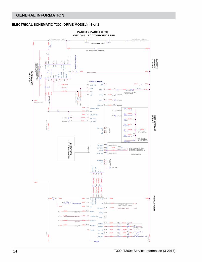
ELECTRICAL SCHEMATIC T300 (DRIVE MODEL) - 3 of 3
J2-9NOT USED
NO CONNECTION
BAIL SWITCH (N.O.)
SW-4
NO CONNECTIONBAIL SW. HARNESS
BAIL SWITCH INPUT @ J4-4: 0V OR 5V0V = NEUTRAL / SCRUB MTR OFF.5V = MAX. PROPEL / BURNISH MTR ON.
USER
INTER
FAC
E M
OD
ULE
PRO
PEL SYSTEM
SW
ITCH
ED
/FUS
ED
/B+
CH
AR
GE
R IN
TER
LOC
K S
WITC
H (N
.C.)
OFF-B
OA
RD
CH
AR
GE
R O
NLY
: SW
OP
EN
= CH
AR
GIN
G
N.O
.
N.C
.
CO
M
B+ W/FUSE,GND CABLE ASSY B+ W/FUSE,GND CABLE ASSY
(2) 12VDC BATTERIES
OFF BOARD CHARGER CABLE ASSY
J2-10
J2-11NOT USED
NOT USED
J2-8NOT USED
BA
TTER
Y+
CA
N C
OM
MU
NIC
ATIO
N
BA
TTER
Y+
AC PLUG
RS
232 DE
BU
G P
OR
T
JTAG PORT
J2-12
J2-6
MOM. SWITCH. TOGGLES EC-H2O ON/OFF
J2-13NOT USED
NOT USED
NOT USED
J2-14
J2-15
I-DRIVE STATUS
AUX2 OUT
AUX3_OUT
I-DRIVE SUPPLY VOLTAGE DETECT
PROPEL ENABLE(GND. = TURN OFF PROPEL)
CABLE, CHARGER
US
B P
OR
T
J1-6
J1-7
J1-8
J1-9
J2-1
J2-5
J2-3
J2-4
CABLE, CHARGER
(GND. = SCRUB SPEED)
BA
TTERY /
CH
AR
GER
SYSTEMS
STATIC GROUNDING (PART OF MAIN HARNESSAND OP.STATION HARNESS)
J2-7
STATIC GROUND @ THE SCRUB HEAD
J2-2S
W-1: K
EY
SW
ITCH
REVERSE SWITCH (GND. = REV.)
SW-4
J1-5
J1-4
J1-3
J1-2
J1-1J10-2
J10-3
J11-1
J11-2
J10-1
POW
ER O
N/O
FF C
IRC
UITR
Y
PAGE 3 = PAGE 1 WITHOPTIONAL LCD TOUCHSCREEN.
OPER
ATO
R'S
LCD
TOU
CH
SCR
EEN
CO
NN
EC
TOR
J6
13/BLK13/BLK
38/GRY
30/TAN
31/PNK
CAN+ /YEL
13/BLK1/RED
5/GR
N
27/PUR
18/GRY
20/TAN
1/RE
D
13/BLK
CA
N+/Y
EL
CA
N-/G
RN
13/BLK13/BLK
CAN- /GRN
2/BRN2/BRN 13/BLK
CA
BLE
/BLK
CA
BLE
/RE
D
CA
BLE
/NA
T.
SH
IELD
/GN
D
54/YEL
7/PU
R
1/RED
1/RE
D
NRB/24NRB/24
NAT/04NAT/04
KNP/14KNP/14
7/PUR
KNP/11KNP/11
9/WHT
10/TAN10/TAN
1/RED
1/RED
16/BLU
13/BLK 13/BLKYRG/8YRG/8
4/YE
L
WHT
28/GRY
CA
BLE
/RE
D
CA
BLE
/BLK
SH
IELD
/GR
N
CA
BLE
/NA
T.
105/GRN
105/GRN
105/GRN
105/GRN
105/GRN
105/GRN
105/GRN
1/RE
D
4/YE
L
5/GR
N
6/BLU
6/BLU
6/BLU
6/BLU
35/GRN
34/YEL
33/ORA
37/PUR
36/BLU
37/PUR
36/BLU
34/YEL
35/GRN
GRN
GRN
GRN
WHT
1/RE
D
33/ORA
113/BLK/WHT
61
CA
N+
CA
N-
13
42
40
41
11
16
28
CB-4
30A
INTERFACE MODULE
+5V OUT J10-1
CAN-J4-2
CAN+J4-1
CHARGER INPUTJ7-9
KSIJ7-10
SENSE_GND J10-3
CO
MM
_GN
DJ9-1
TXJ9-3
RX
J9-4
V_BUS J11-1
SHLD_GNDJ4-3
N/CJ4-4
SENSOR_IN J10-4
BAIL OU
TJ9-2
GND J7-8
COM_GND2 J1-3
TX_2 J1-1
RX_2 J1-2
+5VDC_OUT J7-1
D- J11-2D+ J11-3ID J11-4GND_SHIELD J11-5
LSD_OUT_0J7-5
LSD_OUT_1J7-6
LSD_FLYBACKJ7-7
INPUT_0 J7-2
INPUT_1 J7-3
INPUT_2 J7-4
NOT USED J10-2
VAC FAN2
KEY SWITCH2
12 VDC
+ --
MTR1PROPEL MOTOR
2 1
100K PROPEL SPEED LIMIT1
POT.-1
1
2
3
OP.STATION BASE1
USER INTERFACE1
EC-H2O1
CB
-14A
TRANSAXLE1
SW-3: #1
EC-H2O SWITCH
I-DRIVE
B+P2-B+
KSI P1-5
M2P2-M2
M1P2-M1
GND_REF P1-13
B- P2-B-
AUX2_OUTP1-3
FUSED, B+_OUTP1-7
STATUSP1-10
POT LOW P1-8
REVERSE P1-12
SPD LIMIT P1-9
POT HIGH P1-2
AUX3_OUTP1-11
PROG_B+P3-2
LOW SPEED P1-4
DIG
ITAL_GN
DP
3-1
TXP
3-3
RX
P3-4
BAIL ON
/OFF
P1-1
OPEN_B P1-6
OPEN_C P1-14
SW
-2
CH
AR
GER
: ON
BO
AR
D
NC
P2-2
GND P1-B-
B+P
1-B+
CO
MP
2-3
CAN
+P
2-6
CAN
-P
2-10
NO
P2-4
CAN
_GN
DP
2-1
SENSE+
P2-5
SENSE-
P2-14
RESER
VED3
P2-11
LED+
P2-12
LED-
P2-13
RESER
VED1
P2-8
RESER
VED2
P2-9
RETU
RN
P2-7
REAR FRAME1
12 VDC
+ --

T300, T300e Service Information (3-2017) 15
GENERAL INFORMATION
ELECTRICAL SCHEMATIC T300 (PUSH MODEL) - 1 of 3 B
ATTER
Y /C
HA
RG
ERSYSTEM
S
POW
ER O
N/O
FF
CABLE, CHARGER
CABLE, CHARGER
CH
AR
GE
R IN
TER
LOC
K S
WITC
H (N
.C.)
OFF-B
OA
RD
CH
AR
GE
R O
NLY
: SW
. O
PE
N = C
HA
RG
ING
N.O
.
N.C
.
CO
M
CA
N C
OM
MU
NIC
ATIO
N
AC PLUG
RS
232 DE
BU
G P
OR
T
USER
INTER
FAC
E M
OD
ULE
PRO
PEL SYSTEM
BA
TTER
Y+ BA
TTER
Y+
SW
-1: KE
Y S
WITC
H
SW
ITCH
ED
/FUS
ED
/B+
JTAG PORT
J2-1
J2-5
J2-3
J2-4
J2-2
J1-6
J1-7
J1-8
J1-9
NO CONNECTION
BAIL SWITCH (N.O.)
SW-4
NO CONNECTIONBAIL SW. HARNESS
BAIL SWITCH INPUT @ J4-4: 0V OR 5V0V = NEUTRAL / BURNISH MTR OFF.5V = MAX. PROPEL / BURNISH MTR ON.
J2-12
B+ W/FUSE,GND CABLE ASSY B+ W/FUSE,GND CABLE ASSY
(2) 12VDC BATTERIES
J2-8NOT USED
J2-10
J2-11NOT USED
NOT USED
OFF BOARD CHARGER CABLE ASSY
US
B P
OR
T
STATIC GROUNDING (PART OF MAIN HARNESSAND OP.STATION HARNESS)
J2-7
STATIC GROUND @ THE SCRUB HEAD
OPER
ATO
R'S
SWITC
H/LED
TOU
CH
PAN
EL
J9: 20 PIN
SJ8: 15 P
INS
J2-9 NOT USED
J2-6
MOM. SWITCH. TOGGLES EC-H2O ON/OFF
NOT USED
NOT USED
J2-14
J2-15
J2-13NOT USED
1/RE
D
5/GR
N
CAN- /GRN7/PU
R
7/PUR
4/YE
L
1/RE
D
CAN+ /YEL
113/BLK/WHT
1/RE
D
1/RED
6/BLU
6/BLU
1/RED
1/RE
D
13/BLK13/BLK
CA
N+/Y
EL
CA
N-/G
RN
4/YE
L
5/GR
N
6/BLU
6/BLU
CA
BLE
/BLK
CA
BLE
/RE
D
CA
BLE
/NA
T.
SH
IELD
/GN
D
30/TAN
31/PNK
13/BLK13/BLK
13/BLK
13/BLK1/RED
20/TAN
27/PUR
18/GRY
105/GRN
105/GRN
105/GRN
105/GRN
105/GRN
105/GRN
105/GRN
38/GRY
2/BRN 13/BLK2/BRN
54/YEL
CA
N+
CA
N-
1
13
6
INTERFACE MODULE
+5V OUT J4-1
CAN-J3-2
CAN+J3-1
CHARGER INPUTJ7-9
KSIJ7-10
SENSE_GND J4-3
CO
MM
_GN
DJ5-1
TXJ5-3
RX
J5-4
V_BUS J6-1
SHLD_GNDJ3-3
N/CJ3-4
SENSOR_IN J4-4
BAIL OU
TJ5-2
GND J7-8
COM_GND2 J2-3
TX_2 J2-1
RX_2 J2-2
+5VDC_OUT J7-1
D- J6-2D+ J6-3ID J6-4GND_SHIELD J6-5
LSD_OUT_0J7-5
LSD_OUT_1J7-6
LSD_FLYBACKJ7-7
INPUT_0 J7-2
INPUT_1 J7-3
INPUT_2 J7-4
NOT USED J4-2
JTAG J1-1
12 VDC
+ --
SW
-2
CH
AR
GER
: ON
BO
AR
D
NC
P2-2
GND P1-B-
B+P
1-B+
CO
MP
2-3
CAN
+P
2-6
CAN
-P
2-10
NO
P2-4
CAN
_GN
DP
2-1
SENSE+
P2-5
SENSE-
P2-14
RESER
VED3
P2-11
LED+
P2-12
LED-
P2-13
RESER
VED1
P2-8
RESER
VED2
P2-9
RETU
RN
P2-7
VAC FAN1
KEY SWITCH1
12 VDC
+ --
OP.STATION BASE
CB
-14A
REAR FRAME
TRANSAXLE
EC-H2O
USER INTERFACE
SW-3
EC-H2O SWITCH
16 T300, T300e Service Information (3-2017)
GENERAL INFORMATION
ELECTRICAL SCHEMATIC T300 (PUSH MODEL) - 2 of 3
GR
OU
ND
CA
N C
OM
MU
NIC
ATIO
N
INCLUDED IN CABLE ASSEMBLY
BA
TTER
Y+
37A
EC-H
2O M
OD
ULE
PREM
IUM
CO
NTR
OLLER
SW
ITCH
ED
/FUS
ED
/B+
HOUR METER
4A ECHO MODULE, CB-3 STATUS
4A ECHO PUMP, CB-4 STATUS
4A E
CH
O B
RE
AK
ER
1 SE
NS
E4A
EC
HO
BR
EA
KE
R2 S
EN
SE
CA
N C
OM
MU
NIC
ATIO
N
(A) (B)
ECHO/FAST PUMP
SCRUB HEAD LOW DOWN PRESS LEVEL(CLOSED = DP LEVEL OBTAINED)
SW-11: (INSIDE SCRUB ACTUATOR)
NOT USEDOPT. DET. METERING
19A
3-5A
OPT. DET. METERING
0.5A
0.5A
INCLUDED IN CABLE ASSEMBY
SCRUB HEAD POSITION (N.C.H.O.)(SW. RELEASED = CLOSED = HEAD DOWN)(SW. HELD = OPEN = FULL UP POSITION)
PARK BRAKE SW. (N.C.H.O.)(SW. RELEASED = CLOSED = BRAKE ON)(SW. HELD = OPEN = BRAKE OFF)
SQUEEGEE POSITION (N.C.H.O.)(SW. RELEASED = CLOSED = DOWN)(SW. HELD = OPEN = FULL UP POSITION)
SW-7
SW-8
SW-6
SW-11
EC-H20 FLUSH SW.
OPT. EC-H2O MODULE HARNESS
EC
-H2O
CE
LL
EC-H2O WCM PUMP
CA
N-/G
RN
CA
N+/Y
EL
3/ORA1/RED
13/BLK
6/BLU6/BLU
13/BLK17/PUR
13/BLK
13/BLK
46/BLU
50/TAN
50/TAN43/ORA
43/ORA
46/BLU
46/BLU
13/BLK
13/BLK52/BRN
52/BRN50/TAN
CAN-/GRN
CAN+/YEL
13/BLK
NAT/06NAT/06
CA
N+/Y
EL
CA
N-/G
RN
13/BLK32/BRN
15/GRN 13/BLKGRNBLU
BLK
WHT
RED
30/TAN
29/WHT
31/PNK
23/ORA
18/GRY
RED
BLK 20/TAN
19/WHT
12/BRN
12/BRN
24/YEL
24/YEL
22/BRN
21/PNK
14/YEL
6/BLU
6/BLU
13/BLK13/BLK
1/RE
D1/R
ED
13/BLK26/BLU
13/BLK25/GRN
13/BLK28/GRY
9EA/WHT
13EA/BLK-WHT
3EB/ORA
4EA/YEL
4EB/YEL
3EA/ORA
66/BLU
67/PUR
13
CA
N-
CA
N+
1
6
46
50
4650
CA
N-
CA
N+
4
SW-10PRESS NC, OPENS @ 6PSI +/-2PSI = FAULT
COMNC
NO
3
MACHINE CONTROL
B+J6
GND J7
HALF_1BJ10-4
HALF_0BJ10-2
HALF_2J10-6
HALF_2B+J10-5
NOT_USED1 J3-4
SHIELD1 J3-3
CAN-1 J3-2
CAN+1 J3-1
OPEN4J8-5
INPUT_0 J4-4
HALF_3J8-3
HALF_3B+J8-4
VALVE_OUTJ8-2
RETURNJ8-1
INPUT_1 J4-3
INPUT_5 J4-7
INPUT_4 J4-5
INPUT_3 J4-1
INPUT_2 J4-2
I-DRIVE_ENJ9-1
E-STOP_OUT J9-2
INPUT_6 J4-6
KSIJ8-7
HOURMETER J8-9
POT_LOW J8-10
WIPER J8-11
POT_+5VDC J8-12
I-DRIVE_B+ J9-7
PUMP_OUTJ8-6
OPEN1J9-6
OPEN2J9-8
OPEN3J9-9
TX_OUTJ1-1
RX_INJ1-2
232_GNDJ1-3
CAN+2J2-1
CAN-2J2-2
SHIELD2J2-3
NOT_USED2J2-4
DIGITAL_GND1 J9-10
DIGITAL_GND2 J4-8
DIGITAL_GND3 J8-8
AUX_2 J9-3
AUX_3 J9-4
STATUS J9-5
HALF_1AJ10-3
HALF_0AJ10-1
M1A
EC-H2O RELAY8586
MTR-3
2
2
3
4
MTR-6
EC-H20 MODULE
VCC_1J12-11
GND_1 J12-5
VALVE_SUPPLYJ12-13
VALVE_OUTPUTJ12-14
VCC_2J12-12
GND_2 J12-6
CELL_A1J11-4
CELL_A2J11-5
CELL_B1J11-3
CELL_B2J11-6
FLUSH_GND J11-1
FLUSH_SW J11-2
PRESS_IN J12-9
CAN+ J12-2
CAN- J12-3
PUMPJ12-8
OPEN_1 J12-1
OPEN_2 J12-4
OPEN_3 J12-7
OPEN_4 J12-10
4
6 5
CB-2
4A
MTR-4
VAC FAN2 1
SOLUTION VALVE: SV-1
M1B
EC
-H2O
RE
LAY
3087
MTR-5
SCRUB HEAD ACT.2 1
N.O.SW-5
DET. TANK LEVEL1 2
D-1
3
1
MTR-2
SCRUB MOTOR2 1
1
CB-3
4A
1
POT-3
DET. METERING POT.
3
2
1
4
3
6 5
+ -
2
2
+ -C-1CAPACITOR, 0.01UF, 200V
MTR-7
DET. PUMP
2 1
5
FUSE-1
70A
T300, T300e Service Information (3-2017) 17
GENERAL INFORMATION
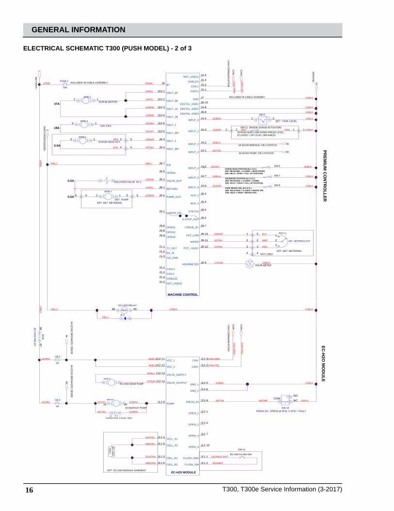
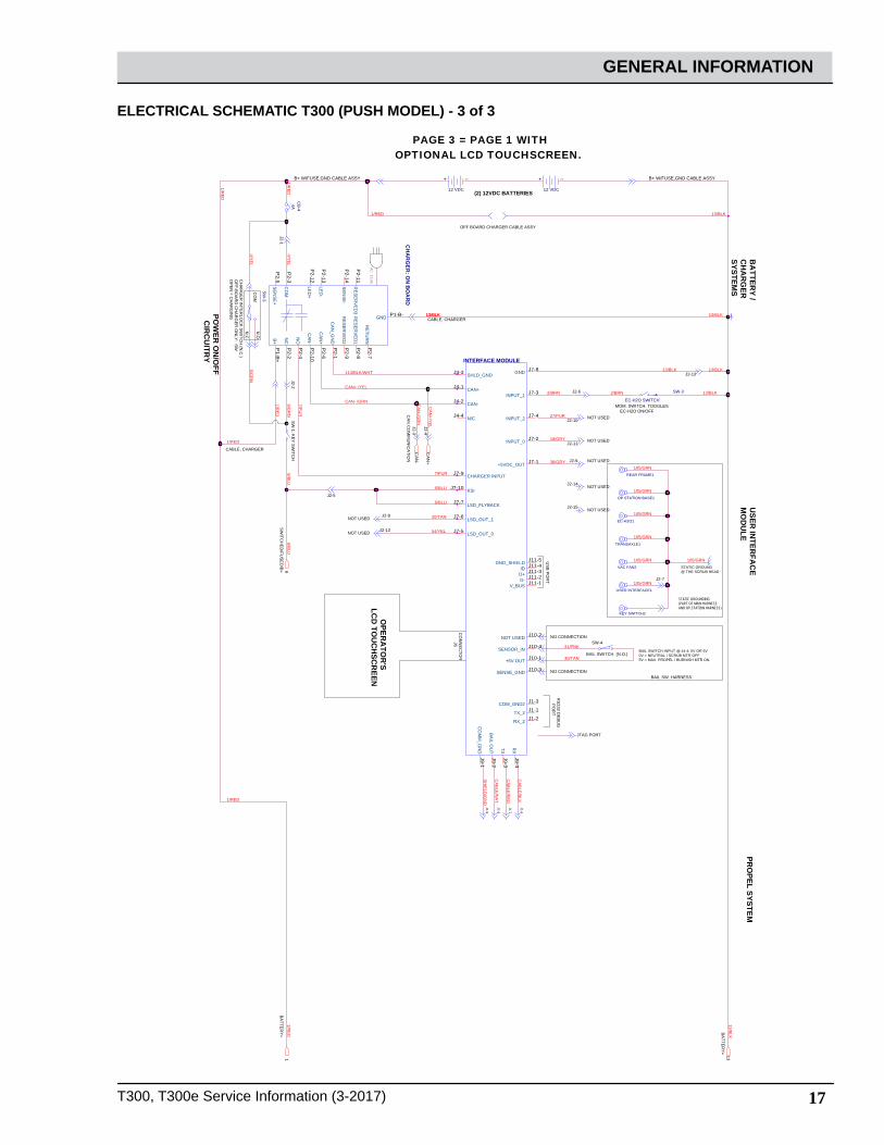
ELECTRICAL SCHEMATIC T300 (PUSH MODEL) - 3 of 3
STATIC GROUNDING (PART OF MAIN HARNESSAND OP.STATION HARNESS)
J2-7
STATIC GROUND @ THE SCRUB HEAD
USER
INTER
FAC
E M
OD
ULE
PRO
PEL SYSTEM
SW
ITCH
ED
/FUS
ED
/B+
CH
AR
GE
R IN
TER
LOC
K S
WITC
H (N
.C.)
OFF-B
OA
RD
CH
AR
GE
R O
NLY
: SW
OP
EN
= CH
AR
GIN
G
N.O
.
N.C
.
CO
M
BA
TTER
Y+
CA
N C
OM
MU
NIC
ATIO
N
BA
TTER
Y+
AC PLUG
RS
232 DE
BU
G P
OR
T
J1-6
J1-7
J1-8
J1-9
NO CONNECTION
BAIL SWITCH (N.O.)
SW-4
NO CONNECTIONBAIL SW. HARNESS
BAIL SWITCH INPUT @ J4-4: 0V OR 5V0V = NEUTRAL / SCRUB MTR OFF.5V = MAX. PROPEL / BURNISH MTR ON.
JTAG PORT
J2-12
B+ W/FUSE,GND CABLE ASSY B+ W/FUSE,GND CABLE ASSY
(2) 12VDC BATTERIES
J2-9 NOT USED
J2-8NOT USED
J2-10
J2-11NOT USED
NOT USED
CABLE, CHARGER
J2-1
J2-5
J2-3
J2-4
CABLE, CHARGER
J2-6
MOM. SWITCH. TOGGLES EC-H2O ON/OFF
BA
TTERY /
CH
AR
GER
SYSTEMS
NOT USED
NOT USED
J2-14
J2-15
J2-13NOT USED
J2-2S
W-1: K
EY
SW
ITCH
OFF BOARD CHARGER CABLE ASSY
US
B P
OR
T
POW
ER O
N/O
FF C
IRC
UITR
Y
PAGE 3 = PAGE 1 WITHOPTIONAL LCD TOUCHSCREEN.
OPER
ATO
R'S
LCD
TOU
CH
SCR
EEN
CO
NN
EC
TOR
J6
13/BLK 13/BLK13/BLK
105/GRN
105/GRN
105/GRN
105/GRN
105/GRN
105/GRN
105/GRN
CAN+ /YEL
5/GR
N
1/RE
D
CA
BLE
/BLK
CA
BLE
/RE
D
CA
BLE
/NA
T.
SH
IELD
/GN
D
30/TAN
31/PNK
13/BLK13/BLK
CA
N+/Y
EL
CA
N-/G
RN
13/BLK
CAN- /GRN
13/BLK1/RED
38/GRY
7/PU
R
1/RED
1/RE
D
7/PUR
20/TAN
27/PUR
18/GRY
1/RED
4/YE
L
2/BRN2/BRN 13/BLK
54/YEL
1/RE
D
4/YE
L
5/GR
N
6/BLU
6/BLU
6/BLU
6/BLU
1/RE
D
113/BLK/WHT
61
CA
N+
CA
N-
13
SW-3
EC-H2O SWITCH
TRANSAXLE1
SW
-3
CH
AR
GER
: ON
BO
AR
D
NC
P2-2
GND P1-B-
B+P
1-B+
CO
MP
2-3
CAN
+P
2-6
CAN
-P
2-10
NO
P2-4
CAN
_GN
DP
2-1
SENSE+
P2-5
SENSE-
P2-14
RESER
VED3
P2-11
LED+
P2-12
LED-
P2-13
RESER
VED1
P2-8
RESER
VED2
P2-9
RETU
RN
P2-7
INTERFACE MODULE
+5V OUT J10-1
CAN-J4-2
CAN+J4-1
CHARGER INPUTJ7-9
KSIJ7-10
SENSE_GND J10-3
CO
MM
_GN
DJ9-1
TXJ9-3
RX
J9-4
V_BUS J11-1
SHLD_GNDJ4-3
N/CJ4-4
SENSOR_IN J10-4
BAIL OU
TJ9-2
GND J7-8
COM_GND2 J1-3
TX_2 J1-1
RX_2 J1-2
+5VDC_OUT J7-1
D- J11-2D+ J11-3ID J11-4GND_SHIELD J11-5
LSD_OUT_0J7-5
LSD_OUT_1J7-6
LSD_FLYBACKJ7-7
INPUT_0 J7-2
INPUT_1 J7-3
INPUT_2 J7-4
NOT USED J10-2
USER INTERFACE1
REAR FRAME1
CB
-44A
12 VDC
+ --
OP.STATION BASE1
KEY SWITCH2
EC-H2O1
VAC FAN2
12 VDC
+ --
18 T300, T300e Service Information (3-2017)
GENERAL INFORMATION
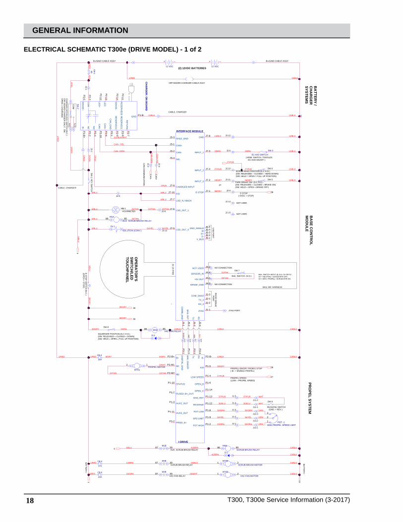
ELECTRICAL SCHEMATIC T300e (DRIVE MODEL) - 1 of 2
BA
TTERY /
CH
AR
GER
SYSTEMS
CABLE, CHARGER
CH
AR
GE
R IN
TER
LOC
K S
WITC
H (N
.C.)
OFF-B
OA
RD
CH
AR
GE
R O
NLY
: SW
.O
PE
N = C
HA
RG
ING
N.O
.
N.C
.
CO
M
(2) 12VDC BATTERIES
AC PLUG
SCRUB BRUSH RELAY
VAC FAN RELAY
BA
SE CO
NTR
OL
MO
DU
LEPR
OPEL SYSTEM
BA
TTER
Y+
BA
TTER
Y+
SW
-1: KE
Y S
WITC
HJTAG PORT
NO CONNECTION
BAIL SW. HARNESS
BAIL SWITCH INPUT @ J4-4: 0V OR 5V0V = NEUTRAL / SCRUB MTR OFF.5V = MAX. PROPEL / SCRUB MTR ON.
BAIL SWITCH (N.O.)
SW-7
NO CONNECTION
RS
232 DE
BU
G P
OR
TCABLE, CHARGER
B+/GND CABLE ASSY B+/GND CABLE ASSY
CA
N C
OM
MU
NIC
ATIO
N
AUX. SCRUB BRUSH RELAY
HOURMETERHM-1
J2-1
J2-8
J2-4
J2-3
J2-12
J1-6
J1-7
J1-8
J1-9
RE
D
NA
T.
SH
IELD
J10-1
J2-5
J2-2 J2-6
PROPEL SPEED(LOW = PROPEL SPEED)
OFF BOARD CHARGER CABLE ASSY
J2-10
5-WS11-2J
SW-6
REVERSE SWITCH (GND. = REV.)
SW-9
J1-5
J1-4
J1-3
J1-2
J1-1J10-2
J10-3
J11-1
J11-2
US
B P
OR
T
OPER
ATO
R'S
SWITC
H/LED
TOU
CH
PAN
EL
J9: 20 PIN
S
SCRUB HEAD POSITION (N.C.H.O.)(SW. RELEASED = CLOSED = HEAD DOWN)(SW. HELD = OPEN = FULL UP POSITION)
PARK BRAKE SW. (N.C.H.O.)(SW. RELEASED = CLOSED = BRAKE ON)(SW. HELD = OPEN = BRAKE OFF)
E-STOP( 0VDC = STOP)
SW-8
PROPEL ON/OFF FROM E-STOP( B+ = ENABLE PROPEL)
E-S
TOP
SW
ITCH
(N.C
.)(O
PE
N = S
TOP
)
J2-9
( MOM. SWITCH. TOGGLES EC-H2O ON/OFF )
J2-13
J2-14
J2-15
NOT USED
NOT USED
SQUEEGEE POSITION (N.C.H.O.)(SW. RELEASED = CLOSED = DOWN)(SW. HELD = OPEN = FULL UP POSITION)
1/RE
D
4/YE
L5/G
RN
13/BLK 13/BLK
26/BLU
29/WHT
13/BLK
1/RED
9/WHT
10/TAN10/TAN
1/RED 1/RED
38/GRY
30/TAN
31/PNK
12/BRN
15/GRN
8/GRY8/GRY
1/RE
D
13/BLK
2/BRN
113/BLK/WHT
CAN+ /YEL
CAN- /GRN
13/BLK
7/PUR
20/TAN
7/PU
R
6/BLU
6/BLU 42/BRN 13/BLK
13/BLK13/BLK
CA
N+/Y
EL
CA
N-/G
RN
6/BLU
BLK
20/TAN
6/BLU
6/BLU
5/GR
N
1/RE
D
4/YE
L
2/BRN
27/PUR
13/BLK1/RED
13/BLK
20/TAN6/BLU
13/BLK27/PUR
13/BLK18/GRY 18/GRY
27/PUR
27/PUR
1/RED
35/GRN
34/YEL
33/ORA
37/PUR
36/BLU
37/PUR
36/BLU
34/YEL
35/GRN
GRN
GRN
GRN
WHT
WHT
33/ORA
38/GRY
38/GRY
38/GRY
38/GRY 3/ORA 13/BLK13/BLK13/BLK
6/BLU
6/BLU
38/GR
Y
20/TAN
42/BRN 13/BLK
54/YEL6/BLU
13/BLK
54/YEL
1
13
38
CA
N+
CA
N-
27
27
6
38
38
38
6
CB-6
20A
CB-4
30A
100K PROPEL SPEED LIMITPOT.-11
2
3
M3A VAC FAN RELAY8586
MTR1PROPEL MOTOR
2 1
SW-3
EC-H2O SWITCH
12 VDC
+ --
M4B3087
D-2
M1A
AUX. SCRUB BRUSH RELAY8586
MTR2
SCRUB BRUSH MOTOR21
INTERFACE MODULE
+5V OUT J4-1
CAN-J3-2
CAN+J3-1
CHARGER INPUTJ7-9
KSIJ7-10
SENSE_GND J4-3
CO
MM
_GN
DJ5-1
TXJ5-3
RX
J5-4
V_BUS J6-1
SHLD_GNDJ3-3
N/CJ3-4
SENSOR_IN J4-4
BAIL OU
TJ5-2
GND J7-8
COM_GND2 J2-3
TX_2 J2-1
RX_2 J2-2
E-STOP J7-1
D- J6-2D+ J6-3ID J6-4GND_SHIELD J6-5LSD_OUT_0J7-5
LSD_OUT_1J7-6
LSD_FLYBACKJ7-7
INPUT_0 J7-2
INPUT_1 J7-3
INPUT_2 J7-4
NOT USED J4-2
JTAG J1-1
M4A
SCRUB BRUSH RELAY8586
I-DRIVE
B+P2-B+
KSI P1-5
M2P2-M2
M1P2-M1
GND_REF P1-13
B- P2-B-
AUX2_OUTP1-3
FUSED, B+_OUTP1-7
STATUSP1-10
POT LOW P1-8
REVERSE P1-12
SPD LIMIT P1-9
POT HIGH P1-2
AUX3_OUTP1-11
PROG_B+P3-2
LOW SPEED P1-4
DIG
ITAL_GN
DP
3-1
TXP
3-3
RX
P3-4
BAIL ON
/OFF
P1-1
OPEN_B P1-6
OPEN_C P1-14
CB
-14A
M3B3087
12 VDC
+ --
M1B3087
CB-5
37A
+ -
SV-1
SOLUTION (CONV.)
D-1
MTR3
VAC FAN MOTOR21
SW
-2
CH
AR
GER
: ON
BO
AR
D
NC
P2-2
GND P1-B-
B+P
1-B+
CO
MP
2-3
CAN
+P
2-6
CAN
-P
2-10
NO
P2-4
CAN
_GN
DP
2-1
SENSE+
P2-5
SENSE-
P2-14
RESER
VED3
P2-11
LED+
P2-12
LED-
P2-13
RESER
VED1
P2-8
RESER
VED2
P2-9
RETU
RN
P2-7

T300, T300e Service Information (3-2017) 19
GENERAL INFORMATION
ELECTRICAL SCHEMATIC T300e (DRIVE MODEL) - 2 of 2
BA
TTER
Y+
GR
OU
ND
CA
N C
OM
MU
NIC
ATIO
N
(A) (B)EC-H2O/FAST PUMP
EC-H
2O M
OD
ULE
STATIC GROUNDING (PART OF MAIN HARNESSAND OP.STATION HARNESS)
J2-7
STATIC GROUND @ THE SCRUB HEAD
SW
ITCH
ED
/FUS
ED
/B+
OPT. EC-H2O MODULE HARNESS
SW-11
EC-H20 FLUSH SW.
EC
-H2O
CE
LL
EC-H2O WCM PUMP
52/BRN
52/BRN50/TAN
50/TAN43/ORA
43/ORA
CA
N+/Y
EL
CA
N-/G
RN
13/BLKNAT/06NAT/06
CA
N+/Y
EL
CA
N-/G
RN
46/BLU
46/BLU
105/GRN
105/GRN
105/GRN
105/GRN
105/GRN
105/GRN
105/GRN
6/BLU
13/BLK13/BLK6/BLU
1/RE
D
3EB/ORA 9EA/WHT
13EA/BLK-WHT
4EA/YEL
4EB/YEL
3EA/ORA
66/BLU
13/BLK13/BLK67/PUR
1
13
CA
N-
CA
N+
6
TRANSAXLE
USER INTERFACE
M2B
EC
-H2O
RE
LAY
3087
EC-H20 MODULE
VCC_1J12-11
GND_1 J12-5
VALVE_SUPPLYJ12-13
VALVE_OUTPUTJ12-14
VCC_2J12-12
GND_2 J12-6
CELL_A1J11-4
CELL_A2J11-5
CELL_B1J11-3
CELL_B2J11-6
FLUSH_GND J11-1
FLUSH_SW J11-2
PRESS_IN J12-9
CAN+ J12-2
CAN- J12-3
PUMPJ12-8
OPEN_1 J12-1
OPEN_2 J12-4
OPEN_3 J12-7
OPEN_4 J12-10
REAR FRAME
R-1
(LOCATED IN HARNESS)
120 OHM
+ -C-1CAPACITOR, 0.01UF, 200V
OP.STATION BASE
MTR-5
VAC FAN1
D-3
M2A
EC-H2O RELAY8586
MTR-6
KEY SWITCH1
SW-10PRESS NC, OPENS @ 6PSI +/-2PSI = FAULT
COMNC
NO
CB-2
4A
EC-H2O
CB-3
4A
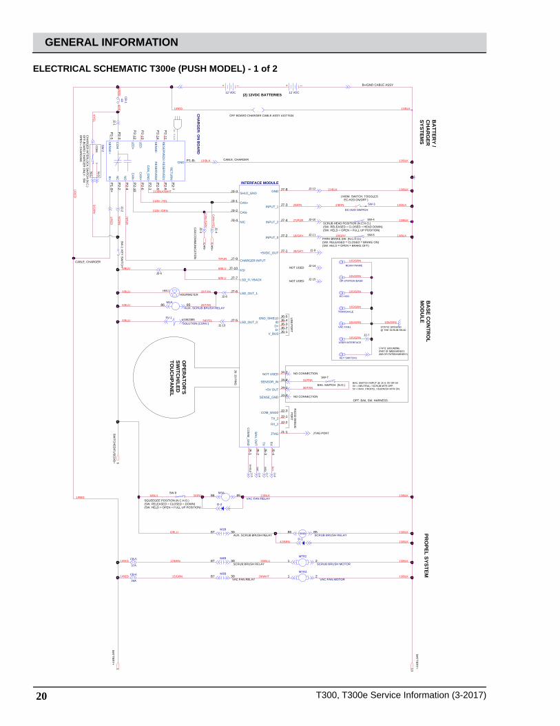
20 T300, T300e Service Information (3-2017)
GENERAL INFORMATION
ELECTRICAL SCHEMATIC T300e (PUSH MODEL) - 1 of 2
BA
TTERY /
CH
AR
GER
SYSTEMS
CABLE, CHARGER
N.O
.
N.C
.
CO
M
AC PLUG
BA
SE CO
NTR
OL
MO
DU
LEPR
OPEL SYSTEM
BA
TTER
Y+
BA
TTER
Y+
SW
-1: KE
Y S
WITC
H
JTAG PORT
NO CONNECTION
OPT: BAIL SW. HARNESS
BAIL SWITCH INPUT @ J4-4: 0V OR 5V0V = NEUTRAL / SCRUB MTR OFF.5V = MAX. PROPEL / BURNISH MTR ON.
BAIL SWITCH (N.O.)
SW-7
NO CONNECTION
RS
232 DE
BU
G P
OR
T
CABLE, CHARGER
SW-8
CA
N C
OM
MU
NIC
ATIO
N
HOURMETERHM-1
J2-1
J2-8
J2-4
J2-3
J2-12
J1-6
J1-7
J1-8
J1-9
RE
D
NA
T.
SH
IELD
J2-5
J2-2
SCRUB BRUSH RELAY
YALER NAF CAV
AUX. SCRUB BRUSH RELAY
B+/GND CABLE ASSY
(2) 12VDC BATTERIES
OFF BOARD CHARGER CABLE ASSY #1077634
US
B P
OR
T
STATIC GROUNDING (PART OF MAIN HARNESSAND OP.STATION HARNESS)
J2-7
STATIC GROUND @ THE SCRUB HEAD
OPER
ATO
R'S
SWITC
H/LED
TOU
CH
PAN
EL
J9: 20 PIN
S
#1062385
SW
ITCH
ED
/FUS
ED
/B+
J2-10
J2-11
J2-9
SW-4
SW-5
( MOM. SWITCH. TOGGLES EC-H2O ON/OFF )
J2-13
J2-14
J2-15
NOT USED
NOT USED
SCRUB HEAD POSITION (N.C.H.O.)(SW. RELEASED = CLOSED = HEAD DOWN)(SW. HELD = OPEN = FULL UP POSITION)
PARK BRAKE SW. (N.C.H.O.)(SW. RELEASED = CLOSED = BRAKE ON)(SW. HELD = OPEN = BRAKE OFF)
SQUEEGEE POSITION (N.C.H.O.)(SW. RELEASED = CLOSED = DOWN)(SW. HELD = OPEN = FULL UP POSITION)
CH
AR
GE
R IN
TER
LOC
K S
WITC
H (N
.C.)
OFF-B
OA
RD
CH
AR
GE
R O
NLY
: SW
OP
EN
= CH
AR
GIN
G
1/RE
D
4/YE
L5/G
RN
1/RED
30/TAN
31/PNK
1/RE
D
13/BLK
3/ORA
113/BLK/WHT
CAN+ /YEL
CAN- /GRN
13/BLK
7/PUR
7/PU
R
6/BLU
KLB/31KLB/31
CA
N+/Y
EL
CA
N-/G
RN
20/TAN6/BLU
20/TAN
BLK
6/BLU
6/BLU
6/BLU
6/BLU
5/GR
N
1/RE
D
4/YE
L
26/BLU
29/WHT 13/BLK
13/BLK
6/BLU
1/RED
12/BRN
15/GRN
13/BLK1/RED
1/RED
105/GRN
105/GRN
105/GRN
105/GRN
105/GRN
105/GRN
105/GRN
42/BRN 13/BLK
13/BLK
54/YEL6/BLU
38/GRY
13/BLK27/PUR
18/GRY 13/BLK18/GRY
2/BRN2/BRN 13/BLK
13/BLK13/BLK
1 13
CA
N+
CA
N-
6
M1B3087
VAC FAN1
INTERFACE MODULE
+5V OUT J4-1
CAN-J3-2
CAN+J3-1
CHARGER INPUTJ7-9
KSIJ7-10
SENSE_GND J4-3
CO
MM
_GN
DJ5-1
TXJ5-3
RX
J5-4
V_BUS J6-1
SHLD_GNDJ3-3
N/CJ3-4
SENSOR_IN J4-4
BAIL OU
TJ5-2
GND J7-8
COM_GND2 J2-3
TX_2 J2-1
RX_2 J2-2
+5VDC_OUT J7-1
D- J6-2D+ J6-3ID J6-4GND_SHIELD J6-5
LSD_OUT_0J7-5
LSD_OUT_1J7-6
LSD_FLYBACKJ7-7
INPUT_0 J7-2
INPUT_1 J7-3
INPUT_2 J7-4
NOT USED J4-2
JTAG J1-1
CB-5
37A
KEY SWITCH1
M4A SCRUB BRUSH RELAY8586
MTR2
SCRUB BRUSH MOTOR21
OP.STATION BASE
12 VDC
+ --
D-1
MTR3
VAC FAN MOTOR21
REAR FRAME
USER INTERFACE
TRANSAXLE
CB
-14A
EC-H2O
SW-3
EC-H2O SWITCH
12 VDC
+ --
+ -
CB-6
20A
M1A
AUX. SCRUB BRUSH RELAY8586
D-2
SV-1
SOLUTION (CONV.)
SW
-2
CH
AR
GER
: ON
BO
AR
D
NC
P2-2
GND P1-B-
B+P
1-B+
CO
MP
2-3
CAN
+P
2-6
CAN
-P
2-10
NO
P2-4
CAN
_GN
DP
2-1
SENSE+
P2-5
SENSE-
P2-14
RESER
VED3
P2-11
LED+
P2-12
LED-
P2-13
RESER
VED1
P2-8
RESER
VED2
P2-9
RETU
RN
P2-7
M3B3087
M3A
VAC FAN RELAY8586
M4B3087

T300, T300e Service Information (3-2017) 21
GENERAL INFORMATION
ELECTRICAL SCHEMATIC T300e (PUSH MODEL) - 2 of 2
EC-H
2O M
OD
ULE
BA
TTER
Y+
GR
OU
ND
CA
N C
OM
MU
NIC
ATIO
N
(A) (B)
EC-H2O/FAST PUMP
SW
ITCH
ED
/FUS
ED
/B+
SW-11
EC-H20 FLUSH SW.
OPT. EC-H2O MODULE HARNESS
EC
-H2O
CE
LL
EC-H2O WCM PUMP
46/BLU
46/BLU
13/BLK13/BLK
13/BLK52/BRN
52/BRN50/TAN
50/TAN43/ORA
43/ORA
CA
N+/Y
EL
CA
N-/G
RN
NAT/06NAT/06
CA
N+/Y
EL
CA
N-/G
RN
6/BLU
13/BLK13/BLK6/BLU
1/RE
D
3EB/ORA 9EA/WHT
13EA/BLK-WHT
4EA/YEL
4EB/YEL
3EA/ORA
66/BLU
67/PUR
1
13
CA
N-
CA
N+
6
CB-3
4A
CB-2
4A
EC-H20 MODULE
VCC_1J12-11
GND_1 J12-5
VALVE_SUPPLYJ12-13
VALVE_OUTPUTJ12-14
VCC_2J12-12
GND_2 J12-6
CELL_A1J11-4
CELL_A2J11-5
CELL_B1J11-3
CELL_B2J11-6
FLUSH_GND J11-1
FLUSH_SW J11-2
PRESS_IN J12-9
CAN+ J12-2
CAN- J12-3
PUMPJ12-8
OPEN_1 J12-1
OPEN_2 J12-4
OPEN_3 J12-7
OPEN_4 J12-10
+ -C-1CAPACITOR, 0.01UF, 200V
M2A
EC-H2O RELAY8586
R-1
(LOCATED IN HARNESS)
120 OHM
MTR-5
M2B
EC
-H2O
RE
LAY
3087
D-3
MTR-6
SW-10PRESS NC, OPENS @ 6PSI +/-2PSI = FAULT
COMNC
NO

22 T300, T300e Service Information (3-2017)
GENERAL INFORMATION
FUNCTION ENABLED
OPERATIONAL MATRIX
DISABLED
Vacuum Fan • Squeegee Lowered • Squeegee Raised• Low Battery Voltage (Wet < 21.9 V, AGM < 22.7 V)• Fault• Battery Charger ON Interlock
Main Scrub Motor • Head Lowered - Foot Pedal• Fwd/Rev Throttle Command or Bail activated on non-propel models.
• Head Raised - Foot Pedal• Neutral - Ready State or bail released on non-propel models.• Low Battery Voltage (Wet < 21.9 V, AGM < 22.7 V)• Fault• Battery Charger ON Interlock
Scrub Head Actuator (option)
• Head Lowered - Foot Pedal
• Head Raised - Foot Pedal• Low Battery Voltage (Wet < 21.9 V, AGM < 22.7 V)• Fault• Battery Charger ON Interlock
MOM001_1
Propel (drive option) • Fwd/Rev Throttle Command• Fwd/Rev Switch Input
• Neutral - Ready State• Propel Motor Controller Fault• Battery Charger ON Interlock
Solution Control(ec-H2O NanoClean - option)
• Head Lowered - Foot Pedal• Solution Control ON• ecH2O Switch ON• Fwd/Rev Throttle Command or Bail activated on non-propel models.
• Head Raised - Foot Pedal• Solution Control OFF• ecH2O Switch OFF• Neutral - Ready State or bail released on non-propel models.• Low Battery Voltage (Wet < 21.9 V, AGM < 22.7 V)• ecH2O System Fault• Battery Charger ON Interlock
Solution Control(Conventional)
• Head Lowered - Foot Pedal• Solution Control ON• Fwd/Rev Throttle Command or Bail activated on non-propel models.
• Head Raised - Foot Pedal• Solution Control OFF• Neutral - Ready State or bail released on non-propel models.• Low Battery Voltage (Wet < 21.9 V, AGM < 22.7 V)• Fault• Battery Charger ON Interlock
Severe Environment Detergent Pump
• Head Lowered - Foot Pedal• Severe Environment On (30 seconds or continuous )• Fwd/Rev Throttle Command or Bail activated on non-propel models.• Detergent Tank Not Empty
• Head Raised - Foot Pedal• Solution Control OFF• Neutral - Ready State or bail released on non-propel models.• Detergent Tank Empty• Low Battery Voltage (Wet < 21.9 V, AGM < 22.7 V)• Fault• Battery Charger ON Interlock
T300, T300e Service Information (3-2017) 23
GENERAL INFORMATION
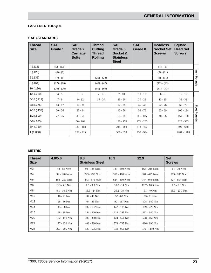
FASTENER TORQUE
Thread Size
SAE Grade 1
SAE Grade 2Carriage Bolts
Thread CuttingThreadRolling
SAEGrade 5Socket & Stainless Steel
SAEGrade 8
HeadlessSocket SetScrews
Square Head SetScrews
4 (.112) (5) - (6.5) (4) - (6) Inch Pounds
5 (.125) (6) - (8) (9) - (11)
6 (.138) (7) - (9) (20) - (24) (9) - (11)
8 (.164) (12) - (16) (40) - (47) (17) - (23)
10 (.190) (20) - (26) (50) - (60) (31) - (41)
1/4 (.250) 4 - 5 5 - 6 7 - 10 7 - 10 10 - 13 6 - 8 17 - 19
Foot Pounds
5/16 (.312) 7 - 9 9 - 12 15 - 20 15 - 20 20 - 26 13 - 15 32 - 38
3/8 (.375) 13 - 17 16 - 21 27 - 35 36 - 47 22 - 26 65 - 75
7/16 (.438) 20 - 26 26 - 34 43 - 56 53 - 76 33 - 39 106 - 124
1/2 (.500) 27 - 35 39 - 51 65 - 85 89 - 116 48 - 56 162 - 188
5/8 (.625) 80 - 104 130 - 170 171 - 265 228 - 383
3/4 (.750) 129 - 168 215 - 280 313 - 407 592 - 688
1 (1.000) 258 - 335 500 - 650 757 - 984 1281 - 1489
Thread Size
4.8/5.6 8.8Stainless Steel
10.9 12.9 SetScrews
M3 43 - 56 Ncm 99 - 128 Ncm 139 - 180 Ncm 166 - 215 Ncm 61 - 79 Ncm
M4 99 - 128 Ncm 223 - 290 Ncm 316 - 410 Ncm 381 - 495 Ncm 219 - 285 Ncm
M5 193 - 250 Ncm 443 - 575 Ncm 624 - 810 Ncm 747 - 970 Ncm 427 - 554 Ncm
M6 3.3 - 4.3 Nm 7.6 - 9.9 Nm 10.8 - 14 Nm 12.7 - 16.5 Nm 7.5 - 9.8 Nm
M8 8.1 - 10.5 Nm 18.5 - 24 Nm 26.2 - 34 Nm 31 - 40 Nm 18.3 - 23.7 Nm
M10 16 - 21 Nm 37 - 48 Nm 52 - 67 Nm 63 - 81 Nm
M12 28 - 36 Nm 64 - 83 Nm 90 - 117 Nm 108 - 140 Nm
M14 45 - 58 Nm 102 - 132 Nm 142 - 185 Nm 169 - 220 Nm
M16 68 - 88 Nm 154 - 200 Nm 219 - 285 Nm 262 - 340 Nm
M20 132 - 171 Nm 300 - 390 Nm 424 - 550 Nm 508 - 660 Nm
M22 177 - 230 Nm 409 - 530 Nm 574 - 745 Nm 686 - 890 Nm
M24 227 - 295 Nm 520 - 675 Nm 732 - 950 Nm 879 - 1140 Nm
METRIC
SAE (STANDARD)

24 T300, T300e Service Information (3-2017)
GENERAL INFORMATION
MODEL 17 in / 43 cm Disk(Push)
20 in / 50 cm Disk(Push)
17 in / 43 cm Disk(Drive)
20 in / 50 cm Disk(Drive)
Length 51.25 in / 1302 mm 54 in / 1372 mm 51.25 in / 1302 mm 54 in / 1372 mm
Width 21 in / 508 mm 22 in / 559 mm 21 in / 508 mm 22 in / 559 mm
Height 43.1 in / 1095 mm 43.1 in / 1095 mm 43.1 in / 1095 mm 43.1 in / 1095 mm
Weight 220 lb / 98 kg 230 lb / 104 kg 230 lb / 104 kg 240 lb / 109 kg
Weight (with batteries) 366 lb / 166 kg 376 lb / 171 kg 390 lb / 177 kg 400 lb / 181 kg
GVW 457 lb / 207 kg 467 lb / 212 kg 482 lb / 219 kg 492 lb / 223 kg
Squeegee width 30.4 in / 772 mm
Recovery tank capacity 14 gal / 53 L
Solution tank capacity 11 gal / 42 L
Severe environment tank capacity 0.4 gal / 1.5 L
Scrubbing path width 16.9 in / 430 mm 19.9 in/ 505 mm 16.9 in / 430 mm 19.9 in / 505 mm
Down pressure - T300 Low: 47 lbs / 21.3 kgMed: 73 lbs / 33 kgHigh: 88 lbs / 40 kg
Low: 52 lbs / 23.5 kgMed: 77 lbs / 35 kgHigh: 92 lbs / 41.7 kg
Low: 47 lbs / 21.3 kgMed: 71 lbs / 32 kgHigh: 86 lbs / 39 kg
Low: 51 lbs / 23 kgMed: 76 lbs / 34.5 kgHigh: 90 lbs / 41 kg
Down pressure - T300e 47 lbs / 21.3 kg 52 lbs / 23.5 kg 47 lbs / 21.3 kg 51 lbs / 23 kg
Dual down pressure - T300e 88 lbs / 40 kg 92 lbs / 41.7 kg 86 lbs / 39 kg 90 lbs / 41 kg
Scrubbing speed Pad assist 200 fpm / 61 mpm
Transport speed n/a n/a 240 fpm / 73 mpm
Reverse speed n/a n/a 144 fpm / 44 mpm
Productivity rate - estimated actual 9,340ft2/hr / 868m2/hr 11,208ft2/hr / 1041m2/hr
12,453ft2/hr / 1157m2/hr
14,943ft2/hr / 1,388m2/hr
ec-H2O productivity rate - est. actual 9,668ft2/hr / 898m2/hr 11,602ft2/hr / 1078m2/hr
12,891ft2/hr / 1198m2/hr
15,469ft2/hr / 1,437m2/hr
Aisle turnaround width 52 in / 1321 mm 54.5 in / 1384 mm 52 in / 1321 mm 54.5 in / 1384 mm
Ramp incline for scrubbing 9% maximum
Ramp incline for transporting 21% maximum
Ramp incline for loading - empty tanks
21% maximum
Solution flow rate Low: 0.15 gpm / 0.57 L/min, Med: 0.35 gpm / 1.3 L/min, High: 0.5 gpm / 1.9 L/min
ec-H2O solution flow rate Low: 0.12 gpm / 0.45 L/min, Med: 0.25 gpm / 0.94 L/min, High: 0.35 gpm / 1.3 L/min
Brush motor 24 VDC, 1hp / 0.75kW
Propel motor n/a n/a 24 VDC, 0.23 hp / 0.175 kW
Vacuum motor 24 VDC, 0.6 hp / 0.47 kW
Water lift 42 in / 1067 mm
Water lift - Quiet Mode 28 in / 711 mm
ec-H2O solution pump 24 VDC, 1.0 gpm / 3.8 L/min, min open flow
Machine voltage 24 VDC
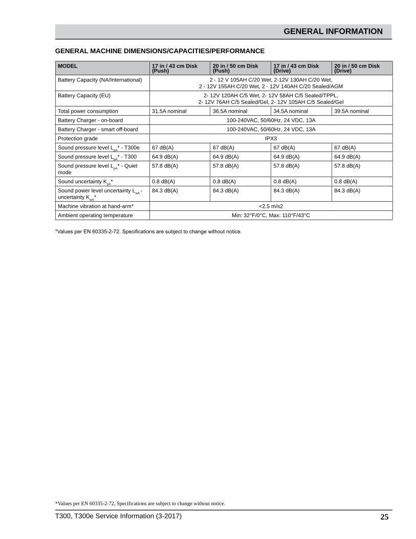
GENERAL MACHINE DIMENSIONS/CAPACITIES/PERFORMANCE
T300, T300e Service Information (3-2017) 25
GENERAL INFORMATION
GENERAL MACHINE DIMENSIONS/CAPACITIES/PERFORMANCE
*Values per EN 60335-2-72, Specifications are subject to change without notice.
*Values per EN 60335-2-72. Specifications are subject to change without notice.
MODEL 17 in / 43 cm Disk(Push)
20 in / 50 cm Disk(Push)
17 in / 43 cm Disk(Drive)
20 in / 50 cm Disk(Drive)
Battery Capacity (NA/International) 2 - 12 V 105AH C/20 Wet, 2-12V 130AH C/20 Wet, 2 - 12V 155AH C/20 Wet, 2 - 12V 140AH C/20 Sealed/AGM
Battery Capacity (EU) 2- 12V 120AH C/5 Wet, 2- 12V 58AH C/5 Sealed/TPPL,2- 12V 76AH C/5 Sealed/Gel, 2- 12V 105AH C/5 Sealed/Gel
Total power consumption 31.5A nominal 36.5A nominal 34.5A nominal 39.5A nominal
Battery Charger - on-board 100-240VAC, 50/60Hz, 24 VDC, 13A
Battery Charger - smart off-board 100-240VAC, 50/60Hz, 24 VDC, 13A
Protection grade IPX3
Sound pressure level LpA* - T300e 67 dB(A) 67 dB(A) 67 dB(A) 67 dB(A)
Sound pressure level LpA* - T300 64.9 dB(A) 64.9 dB(A) 64.9 dB(A) 64.9 dB(A)
Sound pressure level LpA* - Quiet mode
57.8 dB(A) 57.8 dB(A) 57.8 dB(A) 57.8 dB(A)
Sound uncertainty KpA* 0.8 dB(A) 0.8 dB(A) 0.8 dB(A) 0.8 dB(A)
Sound power level uncertainty LwA - uncertainty KwA*
84.3 dB(A) 84.3 dB(A) 84.3 dB(A) 84.3 dB(A)
Machine vibration at hand-arm* <2.5 m/s2
Ambient operating temperature Min: 32°F/0°C, Max: 110°F/43°C

26 T300, T300e Service Information (3-2017)
GENERAL INFORMATION
MODEL 24 in / 60 cm Dual Disk
20 in / 50 cm Cylindrical Brush
20 in / 50 cmOrbital
Length 51.75 in / 1314 mm 50.5 in / 1283 mm 49 in / 1245 mm
Width 26 in / 660 mm 25 in / 635 mm 20.5 in / 521 mm
Height 43.1 in / 1095 mm 43.1 in / 1095 mm 43.1 in / 1095 mm
Weight 250 lb / 113 kg 250 lb / 113 kg 255 lb / 116 kg
Weight (with batteries) 410 lb / 186 kg 410 lb / 186 kg 415 lb / 188 kg
GVW 502 lb / 228 kg 502 lb / 228 kg 507 lb / 230 kg
Squeegee width 30.4 in / 772 mm
Recovery tank capacity 14 gal / 53 L
Solution tank capacity 11 gal / 42 L
Severe environment tank capacity 0.4 gal / 1.5 L
Scrubbing path width 23.6 in / 600 mm 19.7 in/ 500 mm 19.7 in / 500 mm
Down pressure - T300 Low: 57 lbs / 26 kgMed: 81 lbs / 36.7 kgHigh: 97 lbs / 44 kg
Low: 53 lbs / 24 kgMed: 60 lbs / 27 kgHigh: 64 lbs / 29 kg
Low: 63 lbs / 28.5 kgMed: 92 lbs / 42 kgHigh: 109 lbs / 49.5 kg
Down pressure - T300e 57 lbs / 26 kg 53 lbs / 24 kg 63 lbs / 28.5 kg
Dual down pressure - T300e 97 lbs / 44 kg 64 lbs / 29 kg 109 lbs / 49.5 kg
Scrubbing speed 200 fpm / 61 mpm
Transport speed 240 fpm / 73 mpm
Reverse speed 144 fpm / 44 mpm
Productivity rate - estimated actual 18,264ft2/hr / 1697m2/hr 14,943ft2/hr / 1388m2/hr 14,943ft2/hr / 1388m2/hr
ec-H2O productivity rate - est. actual 18,906ft2/hr / 1756m2/hr 15,469ft2/hr / 1437m2/hr 15,469ft2/hr / 1437m2/hr
Aisle turnaround width 53.5 in / 1346 mm 52 in / 1321 mm 49 in / 1245 mm
Ramp incline for scrubbing 9% maximum
Ramp incline for transporting 21% maximum
Ramp incline for loading - empty tanks
21% maximum
Solution flow rate Low: 0.15 gpm / 0.57 L/min, Med: 0.35 gpm / 1.3 L/min, High: 0.5 gpm / 1.9 L/min
ec-H2O solution flow rate Low: 0.12 gpm / 0.45 L/min, Med: 0.25 gpm / 0.94 L/min, High: 0.35 gpm / 1.3 L/min
Brush motor 24 VDC, 1hp / 0.75kW
Propel motor 24 VDC, 0.23 hp / 0.175 kW
Vacuum motor 24 VDC, 0.6 hp / 0.47 kW
Water lift 42 in / 1067 mm
Water lift - Quiet Mode 28 in / 711 mm
ec-H2O solution pump 24 VDC, 1.0 gpm / 3.8 L/min, min open flow
Machine voltage 24 VDC
GENERAL MACHINE DIMENSIONS/CAPACITIES/PERFORMANCE
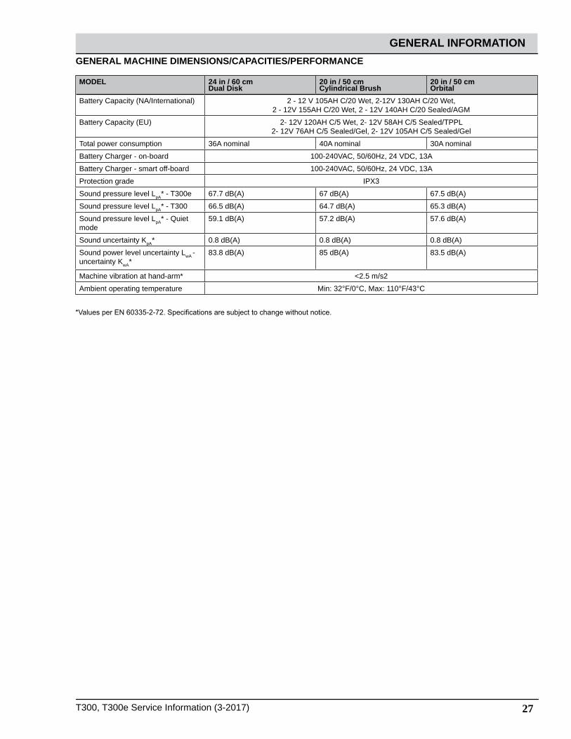
T300, T300e Service Information (3-2017) 27
GENERAL INFORMATION
MODEL 24 in / 60 cm Dual Disk
20 in / 50 cm Cylindrical Brush
20 in / 50 cmOrbital
Battery Capacity (NA/International) 2 - 12 V 105AH C/20 Wet, 2-12V 130AH C/20 Wet, 2 - 12V 155AH C/20 Wet, 2 - 12V 140AH C/20 Sealed/AGM
Battery Capacity (EU) 2- 12V 120AH C/5 Wet, 2- 12V 58AH C/5 Sealed/TPPL2- 12V 76AH C/5 Sealed/Gel, 2- 12V 105AH C/5 Sealed/Gel
Total power consumption 36A nominal 40A nominal 30A nominal
Battery Charger - on-board 100-240VAC, 50/60Hz, 24 VDC, 13A
Battery Charger - smart off-board 100-240VAC, 50/60Hz, 24 VDC, 13A
Protection grade IPX3
Sound pressure level LpA* - T300e 67.7 dB(A) 67 dB(A) 67.5 dB(A)
Sound pressure level LpA* - T300 66.5 dB(A) 64.7 dB(A) 65.3 dB(A)
Sound pressure level LpA* - Quiet mode
59.1 dB(A) 57.2 dB(A) 57.6 dB(A)
Sound uncertainty KpA* 0.8 dB(A) 0.8 dB(A) 0.8 dB(A)
Sound power level uncertainty LwA - uncertainty KwA*
83.8 dB(A) 85 dB(A) 83.5 dB(A)
Machine vibration at hand-arm* <2.5 m/s2
Ambient operating temperature Min: 32°F/0°C, Max: 110°F/43°C
*Values per EN 60335-2-72. Specifications are subject to change without notice.
GENERAL MACHINE DIMENSIONS/CAPACITIES/PERFORMANCE

28 T300, T300e Service Information (3-2017)
GENERAL INFORMATION
MACHINE DIMENSIONS
43.1 in1095 mm
30.4 in772 mm
SINGLE DISK MODEL
51.25 in1302 mm
17 in / 43 cmModel54 in
1372 mm
20 in / 50 cmModel
20 in508 mm
17 in / 43 cmModel22 in
559 mm
20 in / 50 cmModel

T300, T300e Service Information (3-2017) 29
GENERAL INFORMATION
43.1 in1095 mm
30.4 in772 mm
DUAL DISK MODEL
51.25 in1314 mm
26 in660 mm
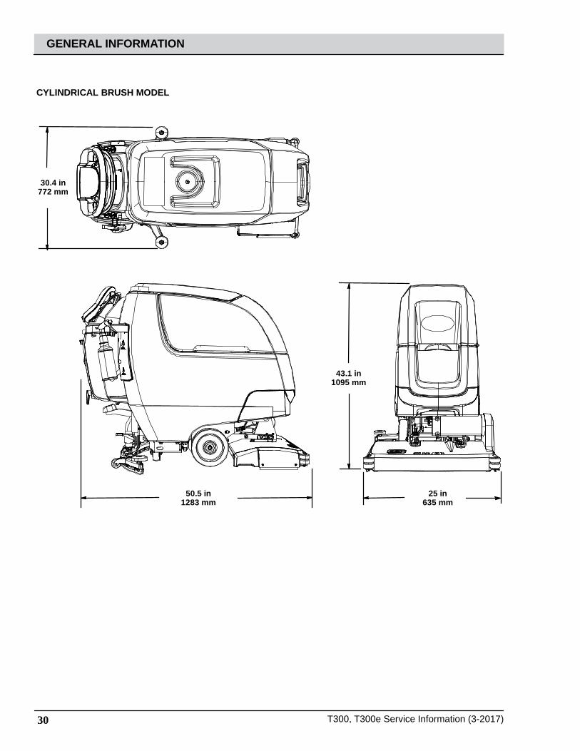
30 T300, T300e Service Information (3-2017)
GENERAL INFORMATION
43.1 in1095 mm
30.4 in772 mm
CYLINDRICAL BRUSH MODEL
50.5 in1283 mm
25 in635 mm
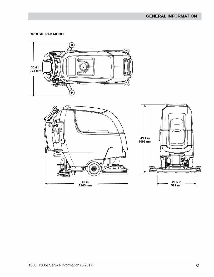
T300, T300e Service Information (3-2017) 31
GENERAL INFORMATION
43.1 in1095 mm
30.4 in772 mm
ORBITAL PAD MODEL
49 in1245 mm
20.5 in521 mm

32 T300, T300e Service Information (3-2017)
MAINTENANCE
MAINTENANCE
MAINTENANCE CHART
6
14
5
4
1
3
2
7
18
14
13
9
14
12
10
15
15
12
1
9
11
IntervalPersonResp. Key Description Procedure
Dailey O 1 Pad(s) Check, flip or replace
O 1 Brush(es) Check, clean
O 2 Cylindrical Brushes Check, clean
O 3 Recovery tank Drain, rinse, clean float shut-off screenand debris tray if equipped
O 4 Solution tank Drain, rinse
O 5 Severe environment tank (option) Check, refill
O 6 Squeegee Clean, check for damage and wear
O 7 Batteries Charge if necessary
O 8 Debris trough Clean
O 9 Scrub head skirt Check for damage and wear
Weekly O 7 Battery cells Check electrolyte level
O 6 Squeegee assembly drip trap reservoir Check, clean
50 Hours O 2 Cylindrical brushes. Rotate brushes. Check for wear
O 2 Cylindrical scrub head Clean underside of scrub head
O 3 Recovery tank lid seal Check for wear
O 10 Solution tank filter Clean
100 Hours O 7 Battery watering system (option) Check hoses for damage and wear
200 Hours O 7 Batteries, terminals and cables Check and clean
500 Hours T 11 Lower orbital isolators Replace (4 qty)
750 Hours T 12 Vacuum motor Replace carbon brushes
1250 Hours
T 13 Propel motor Replace carbon brushes
T 14 Brush motor Replace carbon brushes
T 15 Brush belt Replace belt

T300, T300e Service Information (3-2017) 33
MAINTENANCE
MACHINE MAINTENANCE
To keep the machine in good working condition, simply perform the following maintenance procedures.FOR SAFETY: Before leaving or servicing machine, stop on level surface, turn off machine, remove key and set parking brake if equipped.
FOR SAFETY: When servicing machine wear personal protection equipment as needed. All repairs must be performed by trained personnel.
AFTER DAILY USE
1. Drain and rinse out the recovery tank (Fig. 86). See DRAINING TANKS.
Fig. 86
2. Remove the debris tray and empty (Fig. 87).
Fig. 87
3. Remove and clean the float shut-off screen (Fig. 88).
Fig. 88
4. Drain and rinse out the solution tank (Fig. 89).
Fig. 89
5. 5. Disk scrub head - Turn pad over or replace when worn (Fig. 90).
Fig. 90
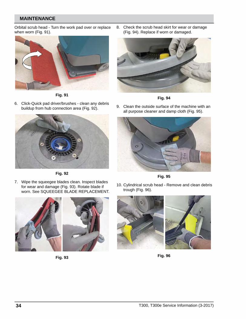
34 T300, T300e Service Information (3-2017)
MAINTENANCE
Orbital scrub head - Turn the work pad over or replace when worn (Fig. 91).
Fig. 91
6. Click-Quick pad driver/brushes - clean any debris buildup from hub connection area (Fig. 92).
Fig. 92
7. Wipe the squeegee blades clean. Inspect blades for wear and damage (Fig. 93). Rotate blade if worn. See SQUEEGEE BLADE REPLACEMENT.
Fig. 93
8. Check the scrub head skirt for wear or damage (Fig. 94). Replace if worn or damaged.
Fig. 94
9. Clean the outside surface of the machine with an all purpose cleaner and damp cloth (Fig. 95).
Fig. 95
10. Cylindrical scrub head - Remove and clean debris trough (Fig. 96).
Fig. 96

T300, T300e Service Information (3-2017) 35
MAINTENANCE
11. Severe environment option - Refill the severe environment tank with a recommended cleaning detergent at full concentration (Fig. 97). Replace cap.
Fig. 97
12. Charge batteries (Fig. 98). See BATTERIES.
Fig. 98
AFTER WEEKLY USE
1. Check the electrolyte level in all batteries (Fig. 99). See BATTERIES.
Fig. 99
2. Remove the drip tray cover from the squeegee assembly and clean reservoir (Fig. 100).
Fig. 100

36 T300, T300e Service Information (3-2017)
MAINTENANCE
AFTER EVERY 50 HOURS OF USE
1. Remove the solution tank filter and clean screen (Fig. 101). Turn the filter bowl counter-clockwise to remove. Make sure to drain solution tank before removing filter.
Fig. 101
2. Cylindrical brushes - Rotate brushes from front to rear (Fig. 102). Replace brushes when they no longer clean effectively.
Fig. 102
3. Cylindrical scrub head - Remove debris buildup from underside of scrub head (Fig. 103).
Fig. 103
4. Inspect and clean the seal on the recovery tank lid (Figure 104). Replace seal if damaged.
Fig. 104
AFTER EVERY 100 HOURS OF USE
If machine is equipped with the optional battery water-ing system, check the watering hoses and connec-tions for damage and wear (Figure 105). Replace system if damaged.
FOR SAFETY: When servicing batteries, wear personal protection equipment as needed. Avoid contact with battery acid.
Fig. 105
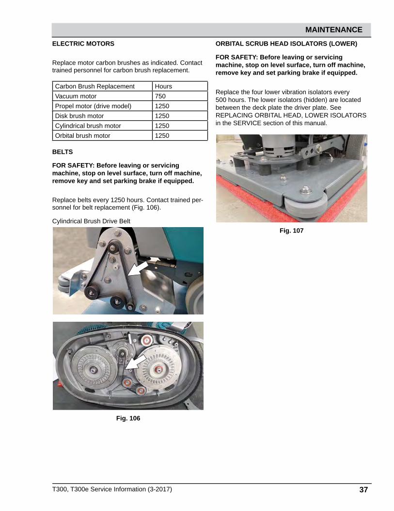
T300, T300e Service Information (3-2017) 37
MAINTENANCE
ELECTRIC MOTORS
Replace motor carbon brushes as indicated. Contact trained personnel for carbon brush replacement.
Carbon Brush Replacement HoursVacuum motor 750Propel motor (drive model) 1250Disk brush motor 1250Cylindrical brush motor 1250Orbital brush motor 1250
BELTS
FOR SAFETY: Before leaving or servicing machine, stop on level surface, turn off machine, remove key and set parking brake if equipped.
Replace belts every 1250 hours. Contact trained per-sonnel for belt replacement (Fig. 106).
Cylindrical Brush Drive Belt
Fig. 106
ORBITAL SCRUB HEAD ISOLATORS (LOWER)
FOR SAFETY: Before leaving or servicing machine, stop on level surface, turn off machine, remove key and set parking brake if equipped.
Replace the four lower vibration isolators every 500 hours. The lower isolators (hidden) are located between the deck plate the driver plate. See REPLACING ORBITAL HEAD, LOWER ISOLATORS in the SERVICE section of this manual.
Fig. 107
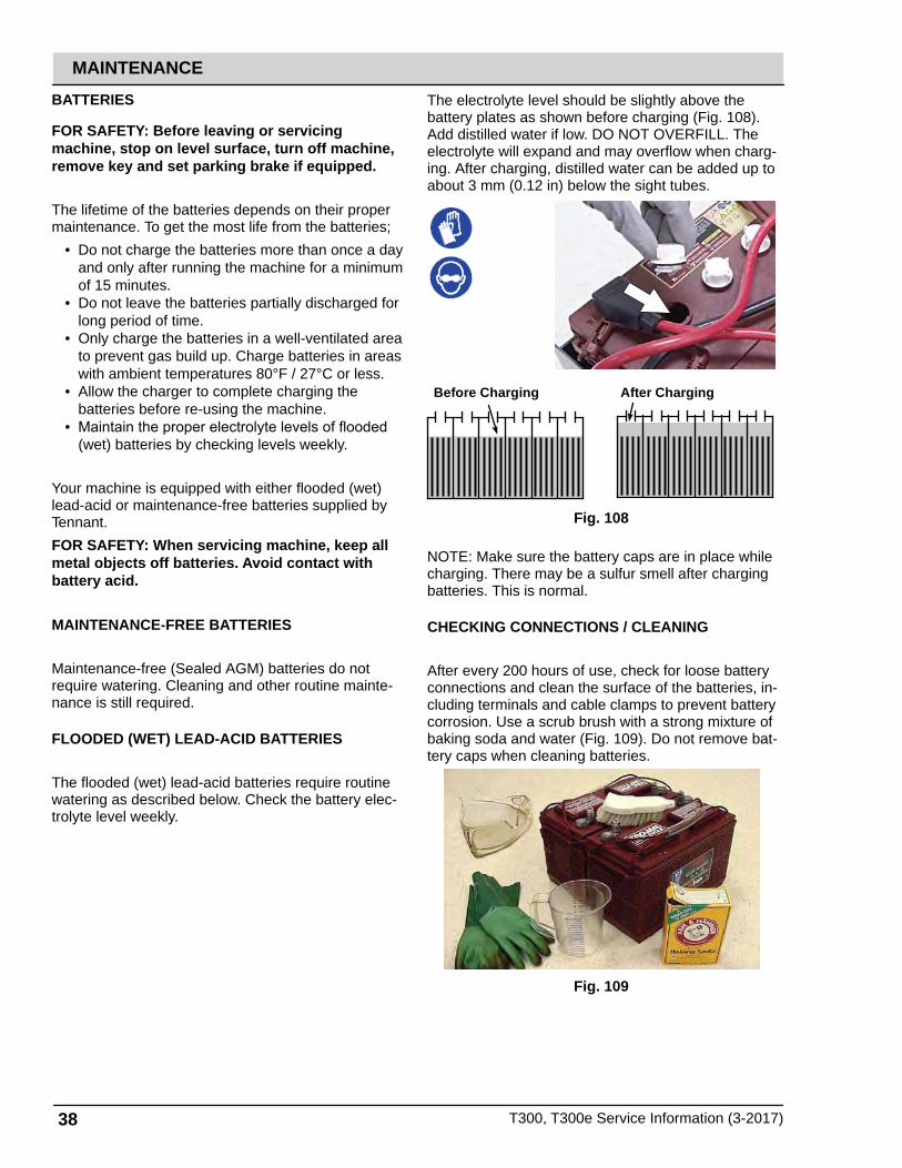
38 T300, T300e Service Information (3-2017)
MAINTENANCE
BATTERIES
FOR SAFETY: Before leaving or servicing machine, stop on level surface, turn off machine, remove key and set parking brake if equipped.
The lifetime of the batteries depends on their proper maintenance. To get the most life from the batteries;
• Do not charge the batteries more than once a day and only after running the machine for a minimum of 15 minutes.
• Do not leave the batteries partially discharged for long period of time.
• Only charge the batteries in a well-ventilated area to prevent gas build up. Charge batteries in areas with ambient temperatures 80°F / 27°C or less.
• Allow the charger to complete charging the batteries before re-using the machine.
• Maintain the proper electrolyte levels of flooded (wet) batteries by checking levels weekly.
Your machine is equipped with either flooded (wet) lead-acid or maintenance-free batteries supplied by Tennant.
FOR SAFETY: When servicing machine, keep all metal objects off batteries. Avoid contact with battery acid.
MAINTENANCE-FREE BATTERIES
Maintenance-free (Sealed AGM) batteries do not require watering. Cleaning and other routine mainte-nance is still required.
FLOODED (WET) LEAD-ACID BATTERIES
The flooded (wet) lead-acid batteries require routine watering as described below. Check the battery elec-trolyte level weekly.
The electrolyte level should be slightly above the battery plates as shown before charging (Fig. 108). Add distilled water if low. DO NOT OVERFILL. The electrolyte will expand and may overflow when charg-ing. After charging, distilled water can be added up to about 3 mm (0.12 in) below the sight tubes.
Before Charging After Charging
Fig. 108
NOTE: Make sure the battery caps are in place while charging. There may be a sulfur smell after charging batteries. This is normal.
CHECKING CONNECTIONS / CLEANING
After every 200 hours of use, check for loose battery connections and clean the surface of the batteries, in-cluding terminals and cable clamps to prevent battery corrosion. Use a scrub brush with a strong mixture of baking soda and water (Fig. 109). Do not remove bat-tery caps when cleaning batteries.
Fig. 109
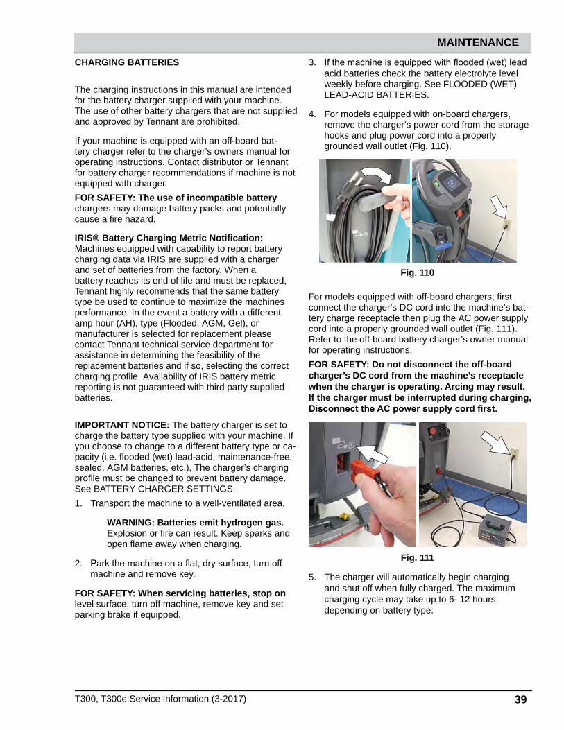
T300, T300e Service Information (3-2017) 39
MAINTENANCE
CHARGING BATTERIES
The charging instructions in this manual are intended for the battery charger supplied with your machine. The use of other battery chargers that are not supplied and approved by Tennant are prohibited.
If your machine is equipped with an off-board bat-tery charger refer to the charger’s owners manual for operating instructions. Contact distributor or Tennant for battery charger recommendations if machine is not equipped with charger.
FOR SAFETY: The use of incompatible battery chargers may damage battery packs and potentially cause a fire hazard.
IRIS® Battery Charging Metric Notification: Machines equipped with capability to report battery charging data via IRIS are supplied with a charger and set of batteries from the factory. When a battery reaches its end of life and must be replaced, Tennant highly recommends that the same battery type be used to continue to maximize the machines performance. In the event a battery with a different amp hour (AH), type (Flooded, AGM, Gel), or manufacturer is selected for replacement please contact Tennant technical service department for assistance in determining the feasibility of the replacement batteries and if so, selecting the correct charging profile. Availability of IRIS battery metric reporting is not guaranteed with third party supplied batteries.
IMPORTANT NOTICE: The battery charger is set to charge the battery type supplied with your machine. If you choose to change to a different battery type or ca-pacity (i.e. flooded (wet) lead-acid, maintenance-free, sealed, AGM batteries, etc.), The charger’s charging profile must be changed to prevent battery damage. See BATTERY CHARGER SETTINGS.
1. Transport the machine to a well-ventilated area.
WARNING: Batteries emit hydrogen gas. Explosion or fire can result. Keep sparks and open flame away when charging.
2. Park the machine on a flat, dry surface, turn off machine and remove key.
FOR SAFETY: When servicing batteries, stop on level surface, turn off machine, remove key and set parking brake if equipped.
3. If the machine is equipped with flooded (wet) lead acid batteries check the battery electrolyte level weekly before charging. See FLOODED (WET) LEAD-ACID BATTERIES.
4. For models equipped with on-board chargers, remove the charger’s power cord from the storage hooks and plug power cord into a properly grounded wall outlet (Fig. 110).
Fig. 110
For models equipped with off-board chargers, first connect the charger’s DC cord into the machine’s bat-tery charge receptacle then plug the AC power supply cord into a properly grounded wall outlet (Fig. 111). Refer to the off-board battery charger’s owner manual for operating instructions.
FOR SAFETY: Do not disconnect the off-board charger’s DC cord from the machine’s receptacle when the charger is operating. Arcing may result. If the charger must be interrupted during charging, Disconnect the AC power supply cord first.
Fig. 111
5. The charger will automatically begin charging and shut off when fully charged. The maximum charging cycle may take up to 6- 12 hours depending on battery type.

40 T300, T300e Service Information (3-2017)
MAINTENANCE
On-board battery charger: The battery discharge indicator lights will ripple back and forth during the charging cycle. When all five lights repeatedly flash two times, the charging cycle is complete (Fig. 112).
T300e/T300 T300 LCD
Fig. 112
6. After charging batteries unplug the power supply cord and wrap cord around the cord hooks (Fig. 113). For models equipped with an off-board charger, Always disconnect the AC power supply cord first before disconnecting charger from machine.
Fig. 113
SQUEEGEE BLADE REPLACEMENT
FOR SAFETY: Before leaving or servicing machine, stop on level surface, turn off machine, remove key and set parking brake if equipped.
Each squeegee blade has four wiping edges. When the blades become worn, simply rotate the blades end-for-end or top-to-bottom for a new wiping edge. Replace blade if all four edges are worn.
1. Remove the squeegee assembly from the machine.
2. Fully loosen the two outside knobs on squeegee assembly. This will separate the spring loaded blade retainer from squeegee frame (Fig. 114). To loosen the knobs quickly, squeeze the blade retainer and squeegee frame together.
Fig. 114
3. Remove worn blade(s) from the blade retainer (Fig. 115)
Fig. 115

T300, T300e Service Information (3-2017) 41
MAINTENANCE
4. 4. Rotate the rear blade to a new wiping edge (Fig. 116). Make sure to align the slots in the blade with retainer tabs.
Fig. 116
5. 5. Squeeze the squeegee frame and blade retainer together and re-tighten the two outside knobs (Fig. 117).
Fig. 117
ec-H2O NanoClean WATER CONDITIONING CARTRIDGE REPLACEMENT
FOR SAFETY: Before leaving or servicing machine, stop on level surface, turn off machine, remove key and set parking brake if equipped.
The water conditioning cartridge is required to be replaced when it reaches its maximum water usage or expiration time of when the cartridge was activated, which ever comes first. The control panel will signal a code when it’s time to replace cartridge.
Depending on machine usage, on average, a new cartridge can last anywhere from 12 months for heavy machine usage to 24 months for light machine usage.
ATTENTION: During first time use and after replacing the water conditioning cartridge, the ec-H2O system will automatically override the selected solution flow rate for up to 75 minutes.
1. Park the machine on a level surface, remove the key and set parking brake, if equipped.
2. Lift the recovery tank to access the ec-H2O water conditioning cartridge (Fig. 118). Drain recovery tank before lifting tank.
Fig. 118
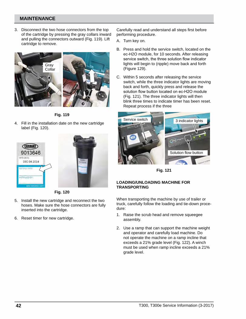
42 T300, T300e Service Information (3-2017)
MAINTENANCE
3. Disconnect the two hose connectors from the top of the cartridge by pressing the gray collars inward and pulling the connectors outward (Fig. 119). Lift cartridge to remove.
GrayCollar
Fig. 119
4. Fill in the installation date on the new cartridge label (Fig. 120).
Fig. 120
5. Install the new cartridge and reconnect the two hoses. Make sure the hose connectors are fully inserted into the cartridge.
6. Reset timer for new cartridge.
Carefully read and understand all steps first before performing procedure.
A. Turn key on.
B. Press and hold the service switch, located on the ec-H2O module, for 10 seconds. After releasing service switch, the three solution flow indicator lights will begin to (ripple) move back and forth (Figure 129).
C. Within 5 seconds after releasing the service switch, while the three indicator lights are moving back and forth, quickly press and release the solution flow button located on ec-H2O module (Fig. 121). The three indicator lights will then blink three times to indicate timer has been reset. Repeat process if the three
Service switch 3 indicator lights
Solution flow button
Fig. 121
LOADING/UNLOADING MACHINE FOR TRANSPORTING
When transporting the machine by use of trailer or truck, carefully follow the loading and tie-down proce-dure:
1. Raise the scrub head and remove squeegee assembly.
2. Use a ramp that can support the machine weight and operator and carefully load machine. Do not operate the machine on a ramp incline that exceeds a 21% grade level (Fig. 122). A winch must be used when ramp incline exceeds a 21% grade level.

T300, T300e Service Information (3-2017) 43
MAINTENANCE
FOR SAFETY: When loading/unloading machine onto/off truck or trailer, use a ramp that can support the machine weight and operator.
FOR SAFETY: Do not operate the machine on a ramp incline that exceeds a 21% grade level.
Fig. 122
3. Once loaded, position the front of the machine up against the front of the trailer or truck. Lower the scrub head, turn key off and set parking brake, if equipped (Figure 131).
4. Place a block behind each wheel (Figure 131).
5. Using tie-down straps, secure the machine using the four tie-down brackets located on the machine frame (Figure 131). It may be necessary to install tie-down brackets to the floor of your trailer or truck.
ATTENTION: Do not use control console area or accessory storage rails for tie-down locations, damage may occur.
Fig. 123
STORING MACHINE
The following steps should be taken when storing the machine for extended periods of time.
1. Charge the batteries before storing machine to prolong the life of the batteries. Recharge batteries every 3 months.
2. Drain and rinse recovery tank and solution tank.
3. Store the machine in a dry area with squeegee and scrub head in the up position.
ATTENTION: Do not expose machine to rain, store indoors.
4. 4. Open the recovery tank lid to promote air circulation.
NOTE: To prevent potential machine damage store machine in a rodent and insect free environment.
FREEZE PROTECTION
Storing machine in freezing temperatures.1. Completely drain solution tank and recovery tank.
2. Empty the water from the solution tank filter located under machine. Replace filter.
3. Pour 1 gallon / 4 liters of propylene glycol based recreational vehicle (RV) antifreeze into the solution tank.
Models equipped with optional Severe Environment detergent tank - Lift out the tank and empty the detergent from tank. Pour a 1/4 gallon / 1 liter of propylene glycol based recreational vehicle (RV) antifreeze into the detergent tank.4. Turn machine on and operate the solution flow
system. Turn the machine off when the antifreeze is visible on floor.
Models equipped with ec-H2O option - Operate ec-H2O scrubbing to cycle antifreeze through system.
Models equipped with Severe Environment mode op-tion - Press the Severe Environment button to cycle antifreeze through system.5. After storing machine in freezing temperatures,
drain any remaining antifreeze from the solution tank and from the optional Severe Environment detergent tank. Add clean water to solution tank and to optional detergent tank and operate the machine to flush system.
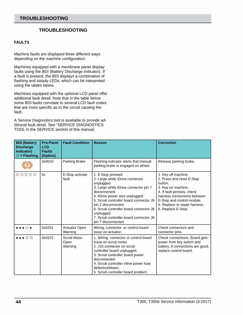
44 T300, T300e Service Information (3-2017)
TROUBLESHOOTING
TROUBLESHOOTING
FAULTS
Machine faults are displayed three different ways depending on the machine configuration:
Machines equipped with a membrane panel display faults using the BDI (Battery Discharge Indicator). If a fault is present, the BDI displays a combination of flashing and steady LEDs, which can be interpreted using the tables below.
Machines equipped with the optional LCD panel offer additional fault detail. Note that in the table below some BDI faults correlate to several LCD fault codes that are more specific as to the circuit causing the fault.
A Service Diagnostics tool is available to provide ad-ditional fault detail. See “SERVICE DIAGNOSTICS TOOL in the SERVICE section of this manual.
BDI (BatteryDischargeIndicator) = Flashing
Pro-PanelLCD Faults(Option)
Fault Condition Reason Correction
0x0010 Parking Brake Flashing indicator alerts that manual parking brake is engaged on wheel.
Release parking brake.
0x E-Stop activate fault
1. E-Stop pressed. 2. Large white iDrive connector unplugged.3. Large white iDrive connector pin 7 disconnected.4. IDrive power wire unplugged.5. Scrub controller board connector J9 pin 2 disconnected.6. Scrub controller board connector J8 unplugged.7. Scrub controller board connector J8 pin 7 disconnected.
1. Key off machine.2. Press and reset E-Stop button.3. Key on machine.4. If fault persists, check harness connections between E-Stop and control module.5. Replace or repair harness.6. Replace E-Stop.
0x0201 Actuator OpenWarning
Wiring, connector, or control boardissue on actuator.
Check connectors and connector pins.
0x0101 Scrub Motor OpenWarning
1. Wiring, connector or control board issue on scrub motor.2. J10 connector on scrubcontroller board unplugged.3. Scrub controller board powerdisconnected.4. Scrub controller inline power fuse defective/blown.5. Scrub controller board problem.
Check connections. Board gets power from key switch and battery. If connections are good, replace control board.
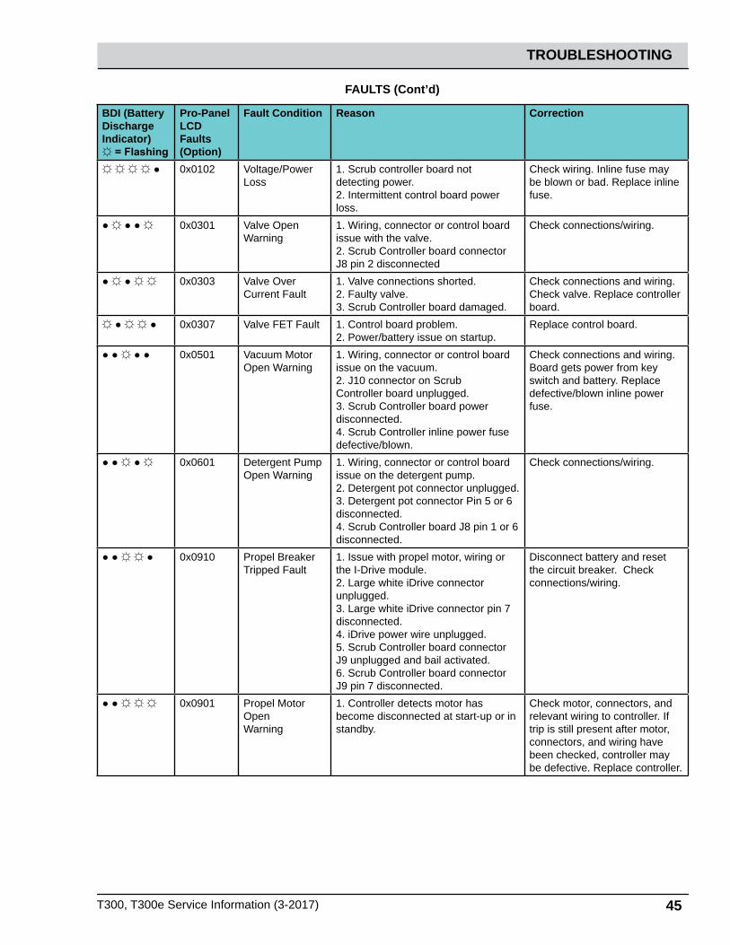
T300, T300e Service Information (3-2017) 45
TROUBLESHOOTING
FAULTS (Cont’d)
BDI (BatteryDischargeIndicator) = Flashing
Pro-PanelLCD Faults(Option)
Fault Condition Reason Correction
0x0102 Voltage/Power Loss
1. Scrub controller board notdetecting power.2. Intermittent control board powerloss.
Check wiring. Inline fuse may be blown or bad. Replace inline fuse.
0x0301 Valve Open Warning
1. Wiring, connector or control board issue with the valve.2. Scrub Controller board connector J8 pin 2 disconnected
Check connections/wiring.
0x0303 Valve Over Current Fault
1. Valve connections shorted.2. Faulty valve.3. Scrub Controller board damaged.
Check connections and wiring. Check valve. Replace controller board.
0x0307 Valve FET Fault 1. Control board problem.2. Power/battery issue on startup.
Replace control board.
0x0501 Vacuum Motor Open Warning
1. Wiring, connector or control board issue on the vacuum.2. J10 connector on ScrubController board unplugged.3. Scrub Controller board powerdisconnected.4. Scrub Controller inline power fuse defective/blown.
Check connections and wiring.Board gets power from key switch and battery. Replace defective/blown inline power fuse.
0x0601 Detergent Pump Open Warning
1. Wiring, connector or control board issue on the detergent pump.2. Detergent pot connector unplugged.3. Detergent pot connector Pin 5 or 6 disconnected.4. Scrub Controller board J8 pin 1 or 6 disconnected.
Check connections/wiring.
0x0910 Propel Breaker Tripped Fault
1. Issue with propel motor, wiring or the I-Drive module. 2. Large white iDrive connector unplugged.3. Large white iDrive connector pin 7 disconnected.4. iDrive power wire unplugged.5. Scrub Controller board connector J9 unplugged and bail activated.6. Scrub Controller board connector J9 pin 7 disconnected.
Disconnect battery and reset the circuit breaker. Check connections/wiring.
0x0901 Propel Motor OpenWarning
1. Controller detects motor has become disconnected at start-up or in standby.
Check motor, connectors, and relevant wiring to controller. If trip is still present after motor, connectors, and wiring have been checked, controller may be defective. Replace controller.
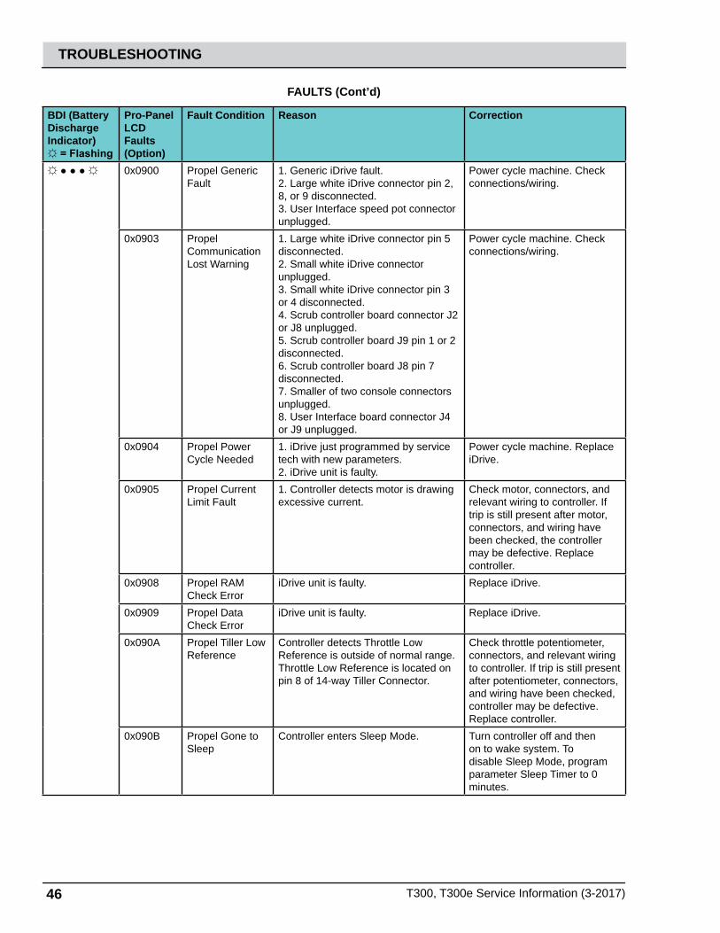
46 T300, T300e Service Information (3-2017)
TROUBLESHOOTING
FAULTS (Cont’d)
BDI (BatteryDischargeIndicator) = Flashing
Pro-PanelLCD Faults(Option)
Fault Condition Reason Correction
0x0900 Propel Generic Fault
1. Generic iDrive fault.2. Large white iDrive connector pin 2, 8, or 9 disconnected.3. User Interface speed pot connector unplugged.
Power cycle machine. Check connections/wiring.
0x0903 Propel Communication Lost Warning
1. Large white iDrive connector pin 5 disconnected. 2. Small white iDrive connector unplugged. 3. Small white iDrive connector pin 3 or 4 disconnected.4. Scrub controller board connector J2 or J8 unplugged.5. Scrub controller board J9 pin 1 or 2 disconnected.6. Scrub controller board J8 pin 7 disconnected.7. Smaller of two console connectors unplugged.8. User Interface board connector J4 or J9 unplugged.
Power cycle machine. Check connections/wiring.
0x0904 Propel Power Cycle Needed
1. iDrive just programmed by service tech with new parameters. 2. iDrive unit is faulty.
Power cycle machine. Replace iDrive.
0x0905 Propel Current Limit Fault
1. Controller detects motor is drawing excessive current.
Check motor, connectors, and relevant wiring to controller. If trip is still present after motor, connectors, and wiring have been checked, the controller may be defective. Replace controller.
0x0908 Propel RAM Check Error
iDrive unit is faulty. Replace iDrive.
0x0909 Propel Data Check Error
iDrive unit is faulty. Replace iDrive.
0x090A Propel Tiller Low Reference
Controller detects Throttle Low Reference is outside of normal range. Throttle Low Reference is located on pin 8 of 14-way Tiller Connector.
Check throttle potentiometer, connectors, and relevant wiring to controller. If trip is still present after potentiometer, connectors, and wiring have been checked, controller may be defective. Replace controller.
0x090B Propel Gone to Sleep
Controller enters Sleep Mode. Turn controller off and then on to wake system. To disable Sleep Mode, program parameter Sleep Timer to 0 minutes.

T300, T300e Service Information (3-2017) 47
TROUBLESHOOTING
FAULTS (Cont’d)
BDI (BatteryDischargeIndicator) = Flashing
Pro-PanelLCD Faults(Option)
Fault Condition Reason Correction
0x090C Propel EEPROM Write Error
iDrive unit is faulty. Replace iDrive.
0x090D Propel EEPROM Write Timeout
iDrive unit is faulty. Replace iDrive.
0x090E Propel EEPROM Busy at Startup
iDrive unit is faulty. Replace iDrive.
0x090F Propel EEPROM Address Range
iDrive unit is faulty. Replace iDrive.
0x0911 Propel Forward ISO Test Fail
Controller detects Series Speed Limit Potentiometer Wiper is shorted to one of throttle references, either high or low. Series Speed Limit Potentiometer Wiper input is located on pin 1 of 14-way Tiller Connector.
Trip is only applicable if an ISO-test resistor is fitted and programmed correctly. Check throttle potentiometer, programming, connectors, and relevant wiring to controller. If trip is still present after potentiometer, programming, connectors, and wiring have been checked, controller may be defective. Replace controller.
0x0912 Propel Forward Input Range
Controller detects an error with Throttle Wiper. Throttle Wiper input is located on pin 1 of 14-way Tiller Connector.
Check throttle potentiometer, programming, connectors, and relevant wiring to controller. If trip is still present after potentiometer, programming, connectors, and wiring have been checked, controller may be defective. Replace controller.
0x0913 Propel Joystick Error Right 2
iDrive unit is faulty. Replace iDrive.
0x0914 Propel Solenoid Brake
Controller detects a short circuit in solenoid brake.
Check solenoid brake, connectors and relevant wiring to controller. If trip is still present after brake, connectors, and wiring have been checked, controller may be defective. Replace controller.
0x0915 Propel Brake Status Low
iDrive unit is faulty. Replace iDrive.
0x0916 Propel Brake Not Connected
Controller detects an open circuit in solenoid brake at start-up or in standby.
Check solenoid brake, connectors, and relevant wiring to controller. If trip is still present after brake, connectors, and wiring have been checked, controller may be defective. Replace controller.
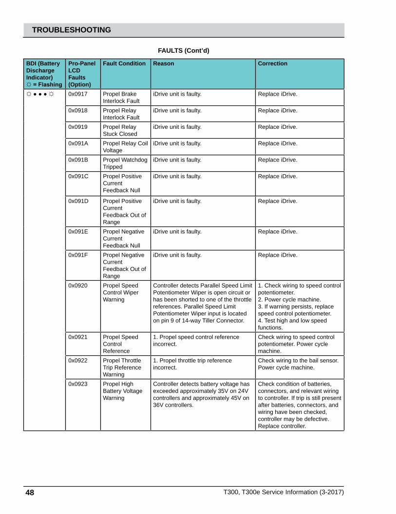
48 T300, T300e Service Information (3-2017)
TROUBLESHOOTING
FAULTS (Cont’d)
BDI (BatteryDischargeIndicator) = Flashing
Pro-PanelLCD Faults(Option)
Fault Condition Reason Correction
0x0917 Propel Brake Interlock Fault
iDrive unit is faulty. Replace iDrive.
0x0918 Propel Relay Interlock Fault
iDrive unit is faulty. Replace iDrive.
0x0919 Propel Relay Stuck Closed
iDrive unit is faulty. Replace iDrive.
0x091A Propel Relay Coil Voltage
iDrive unit is faulty. Replace iDrive.
0x091B Propel Watchdog Tripped
iDrive unit is faulty. Replace iDrive.
0x091C Propel Positive Current Feedback Null
iDrive unit is faulty. Replace iDrive.
0x091D Propel Positive Current Feedback Out of Range
iDrive unit is faulty. Replace iDrive.
0x091E Propel Negative Current Feedback Null
iDrive unit is faulty. Replace iDrive.
0x091F Propel Negative Current Feedback Out of Range
iDrive unit is faulty. Replace iDrive.
0x0920 Propel Speed Control Wiper Warning
Controller detects Parallel Speed Limit Potentiometer Wiper is open circuit or has been shorted to one of the throttle references. Parallel Speed Limit Potentiometer Wiper input is located on pin 9 of 14-way Tiller Connector.
1. Check wiring to speed control potentiometer. 2. Power cycle machine. 3. If warning persists, replace speed control potentiometer.4. Test high and low speed functions.
0x0921 Propel Speed Control Reference
1. Propel speed control reference incorrect.
Check wiring to speed control potentiometer. Power cycle machine.
0x0922 Propel Throttle Trip Reference Warning
1. Propel throttle trip reference incorrect.
Check wiring to the bail sensor. Power cycle machine.
0x0923 Propel High Battery Voltage Warning
Controller detects battery voltage has exceeded approximately 35V on 24V controllers and approximately 45V on 36V controllers.
Check condition of batteries, connectors, and relevant wiring to controller. If trip is still present after batteries, connectors, and wiring have been checked, controller may be defective. Replace controller.

T300, T300e Service Information (3-2017) 49
TROUBLESHOOTING
BDI (BatteryDischargeIndicator) = Flashing
Pro-PanelLCD Faults(Option)
Fault Condition Reason Correction
0x0924 Propel High Battery Voltage 2 Warning
Controller detects battery voltage has exceeded approximately 45V on 24V controllers and approximately 49.5V on 36V controllers.
Check condition of batteries, connectors, and relevant wiring to controller. If trip is still present after the batteries, connectors, and wiring have been checked, controller may be defective. Replace controller.
0x0925 Propel Inhibit 1 Warning
Controller detects Inhibit 1 input is active, Inhibit 1 Speed has been set to ‘0’ and Inhibit 1 Operation has been set to ‘Latched’.
Check state of input, Inhibit 1 programming, connectors, and relevant wiring to controller. If trip is still present after state of input, programming, connectors, and wiring have been checked, controller may be defective. Replace controller.
0x0926 Propel Inhibit 2 Warning
Controller detects Inhibit 2 input is active, Inhibit 2 Speed has been set to ‘0’ and Inhibit 2 Operation has been set to ‘Latched’.
Check state of input, Inhibit 2 programming, connectors, and relevant wiring to controller. If trip is still present after state of the input, programming, connectors, and wiring have been checked, controller may be defective. Replace controller.
0x0927 Propel Inhibit 3 Warning
Controller detects Inhibit 3 input is active, Inhibit 3 Speed has been set to ‘0’ and Inhibit 3 Operation has been set to ‘Latched’.
Check state of input, Inhibit 3 programming, connectors, and relevant wiring to controller. If trip is still present after state of the input, programming, connectors, and wiring have been checked, controller may be defective. Replace controller.
0x0928 Propel Watchdog Warning
1. Propel controller watchdog tripped. Power cycle machine.
0x0929 Propel Bad Setting Warning
1. Bad setting programmed to iDrive. Reprogram iDrive.
0x092A Propel Direction Inputs Disagree
iDrive unit is faulty. Replace iDrive.
0x092B Propel Positive Feedback Voltage Null
iDrive unit is faulty. Replace iDrive.
0x092C Propel Positive Feedback Voltage Out of Range
iDrive unit is faulty. Replace iDrive.
FAULTS (Cont’d)
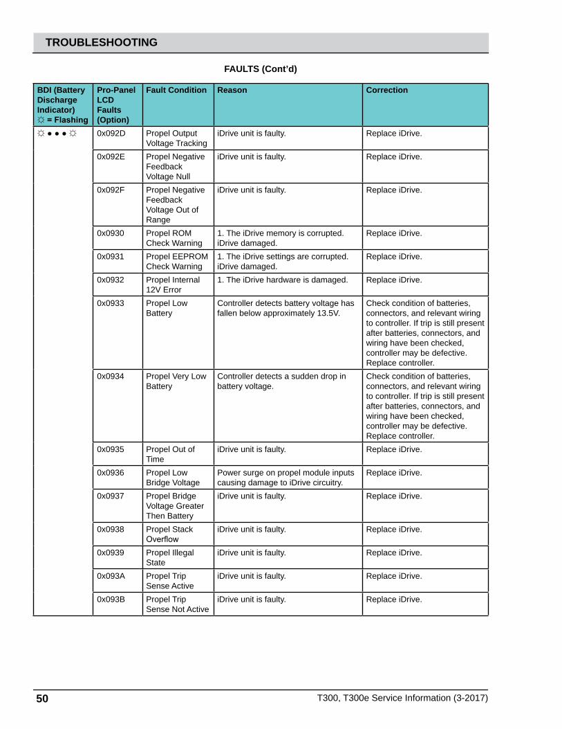
50 T300, T300e Service Information (3-2017)
TROUBLESHOOTING
BDI (BatteryDischargeIndicator) = Flashing
Pro-PanelLCD Faults(Option)
Fault Condition Reason Correction
0x092D Propel Output Voltage Tracking
iDrive unit is faulty. Replace iDrive.
0x092E Propel Negative Feedback Voltage Null
iDrive unit is faulty. Replace iDrive.
0x092F Propel Negative Feedback Voltage Out of Range
iDrive unit is faulty. Replace iDrive.
0x0930 Propel ROM Check Warning
1. The iDrive memory is corrupted. iDrive damaged.
Replace iDrive.
0x0931 Propel EEPROM Check Warning
1. The iDrive settings are corrupted. iDrive damaged.
Replace iDrive.
0x0932 Propel Internal 12V Error
1. The iDrive hardware is damaged. Replace iDrive.
0x0933 Propel Low Battery
Controller detects battery voltage has fallen below approximately 13.5V.
Check condition of batteries, connectors, and relevant wiring to controller. If trip is still present after batteries, connectors, and wiring have been checked, controller may be defective. Replace controller.
0x0934 Propel Very Low Battery
Controller detects a sudden drop in battery voltage.
Check condition of batteries, connectors, and relevant wiring to controller. If trip is still present after batteries, connectors, and wiring have been checked, controller may be defective. Replace controller.
0x0935 Propel Out of Time
iDrive unit is faulty. Replace iDrive.
0x0936 Propel Low Bridge Voltage
Power surge on propel module inputs causing damage to iDrive circuitry.
Replace iDrive.
0x0937 Propel Bridge Voltage Greater Then Battery
iDrive unit is faulty. Replace iDrive.
0x0938 Propel Stack Overflow
iDrive unit is faulty. Replace iDrive.
0x0939 Propel Illegal State
iDrive unit is faulty. Replace iDrive.
0x093A Propel Trip Sense Active
iDrive unit is faulty. Replace iDrive.
0x093B Propel Trip Sense Not Active
iDrive unit is faulty. Replace iDrive.
FAULTS (Cont’d)
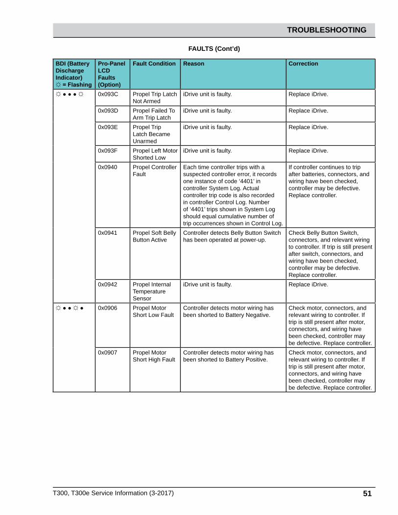
T300, T300e Service Information (3-2017) 51
TROUBLESHOOTING
BDI (BatteryDischargeIndicator) = Flashing
Pro-PanelLCD Faults(Option)
Fault Condition Reason Correction
0x093C Propel Trip Latch Not Armed
iDrive unit is faulty. Replace iDrive.
0x093D Propel Failed To Arm Trip Latch
iDrive unit is faulty. Replace iDrive.
0x093E Propel Trip Latch Became Unarmed
iDrive unit is faulty. Replace iDrive.
0x093F Propel Left Motor Shorted Low
iDrive unit is faulty. Replace iDrive.
0x0940 Propel Controller Fault
Each time controller trips with a suspected controller error, it records one instance of code ‘4401’ incontroller System Log. Actual controller trip code is also recorded in controller Control Log. Number of ‘4401’ trips shown in System Log should equal cumulative number of trip occurrences shown in Control Log.
If controller continues to trip after batteries, connectors, and wiring have been checked, controller may be defective. Replace controller.
0x0941 Propel Soft Belly Button Active
Controller detects Belly Button Switch has been operated at power-up.
Check Belly Button Switch, connectors, and relevant wiring to controller. If trip is still present after switch, connectors, and wiring have been checked, controller may be defective. Replace controller.
0x0942 Propel Internal Temperature Sensor
iDrive unit is faulty. Replace iDrive.
0x0906 Propel Motor Short Low Fault
Controller detects motor wiring has been shorted to Battery Negative.
Check motor, connectors, and relevant wiring to controller. If trip is still present after motor, connectors, and wiring have been checked, controller may be defective. Replace controller.
0x0907 Propel Motor Short High Fault
Controller detects motor wiring has been shorted to Battery Positive.
Check motor, connectors, and relevant wiring to controller. If trip is still present after motor, connectors, and wiring have been checked, controller may be defective. Replace controller.
FAULTS (Cont’d)

52 T300, T300e Service Information (3-2017)
TROUBLESHOOTING
BDI (BatteryDischargeIndicator) = Flashing
Pro-PanelLCD Faults(Option)
Fault Condition Reason Correction
0x0103 Scrub Motor Over Current Fault
1. Current draw higher than expected.2. Higher current draw than hardware design limit.
Verify floor, pad, and down pressure combination are appropriate for machine.Check actuator.
0x0104 Scrub Motor Over Current 1 Fault
1. Current draw higher than expected. Verify floor, pad, and down pressure combination are appropriate for machine.Check actuator.
0x0105 Scrub Motor Over Current 2 Fault
1. Current draw higher than expected. Verify floor, pad, and down pressure combination are appropriate for machine.Check actuator.
0x0902 Propel High Throttle Fault
1. Bail is activated before turning on machine.2. Bail did not release to full rest position due to obstruction.Controller detects Throttle Potentiometer has been displaced at start-up and parameter Throttle Operated At Power-Up has been set to ‘Trip’.
1. Release bail.2. Key off and on.3. If error persists, check for obstruction or damaged bail switch.4. Replace switch or bail handle if damaged.
0x0107 Scrub Motor FET Fault
1. Power/battery issue on startup.2. Control board problem.
1. Check harness/module power and ground connections.2. Replace Control board.
0x0207 Actuator FET Fault
1. Control board problem.2. Power/battery issue on startup.
Replace control board. FET detection includes motor, actuator, detergent pump, vacuum, and battery watering pump.
0x0507 Vacuum FET Fault
1. Control board problem.2. Power/battery issue on startup.
Replace control board. FET detection includes motor, actuator, detergent pump, vacuum, and battery watering pump.
0x0607 Detergent Pump FET Fault
1. Control board problem.2. Power/battery issue on startup.
Replace control board. FET detection includes motor, actuator, detergent pump, vacuum, and battery watering pump.
FAULTS (Cont’d)
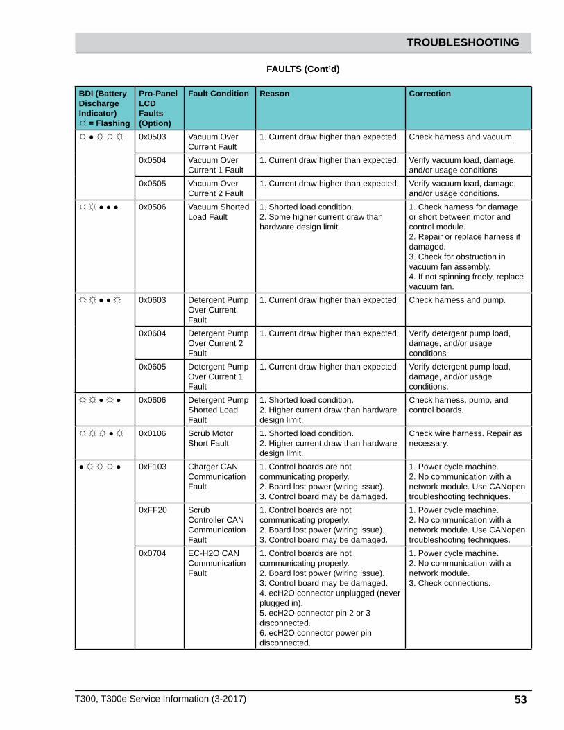
T300, T300e Service Information (3-2017) 53
TROUBLESHOOTING
BDI (BatteryDischargeIndicator) = Flashing
Pro-PanelLCD Faults(Option)
Fault Condition Reason Correction
0x0503 Vacuum Over Current Fault
1. Current draw higher than expected. Check harness and vacuum.
0x0504 Vacuum Over Current 1 Fault
1. Current draw higher than expected. Verify vacuum load, damage, and/or usage conditions
0x0505 Vacuum Over Current 2 Fault
1. Current draw higher than expected. Verify vacuum load, damage, and/or usage conditions.
0x0506 Vacuum Shorted Load Fault
1. Shorted load condition.2. Some higher current draw than hardware design limit.
1. Check harness for damage or short between motor and control module.2. Repair or replace harness if damaged.3. Check for obstruction in vacuum fan assembly.4. If not spinning freely, replace vacuum fan.
0x0603 Detergent Pump Over Current Fault
1. Current draw higher than expected. Check harness and pump.
0x0604 Detergent Pump Over Current 2 Fault
1. Current draw higher than expected. Verify detergent pump load, damage, and/or usage conditions
0x0605 Detergent Pump Over Current 1 Fault
1. Current draw higher than expected. Verify detergent pump load, damage, and/or usage conditions.
0x0606 Detergent Pump Shorted Load Fault
1. Shorted load condition.2. Higher current draw than hardware design limit.
Check harness, pump, and control boards.
0x0106 Scrub Motor Short Fault
1. Shorted load condition.2. Higher current draw than hardware design limit.
Check wire harness. Repair as necessary.
0xF103 Charger CAN Communication Fault
1. Control boards are not communicating properly.2. Board lost power (wiring issue).3. Control board may be damaged.
1. Power cycle machine. 2. No communication with a network module. Use CANopen troubleshooting techniques.
0xFF20 Scrub Controller CAN Communication Fault
1. Control boards are not communicating properly.2. Board lost power (wiring issue).3. Control board may be damaged.
1. Power cycle machine.2. No communication with a network module. Use CANopen troubleshooting techniques.
0x0704 EC-H2O CAN Communication Fault
1. Control boards are not communicating properly.2. Board lost power (wiring issue).3. Control board may be damaged.4. ecH2O connector unplugged (never plugged in).5. ecH2O connector pin 2 or 3 disconnected.6. ecH2O connector power pin disconnected.
1. Power cycle machine. 2. No communication with a network module.3. Check connections.
FAULTS (Cont’d)

54 T300, T300e Service Information (3-2017)
TROUBLESHOOTING
BDI (BatteryDischargeIndicator) = Flashing
Pro-PanelLCD Faults(Option)
Fault Condition Reason Correction
0xF100 Charger Generic Warning
1. Error condition has occurred with charger unit.
Replace charger.
0xF101 Charger No Load Warning
1. Battery pack may not be plugged into charger.2. Charger is bad.
1. Verify batteries are connected properly.2. Verify wire harness continuity.3. Replace charger.
0xF102 Charger Overheat Warning
1. Charger environment is not cool enough and cannot complete charge.2. Charger is faulty.
1. Move machine to well-ventilated area.2. Replace charger
0xF104 Charger Timer Phase I Warning
1. Batteries not charging correctly. Check for low battery voltage.
0x0703 EC-H2O Breaker Tripped Warning
1. Detected module circuit breaker trip.2. Scrub Controller board J4 connector unplugged.3. Scrub Controller board J4 connector pin 2 disconnected.
Power cycle machine. Check connections.
0x0712 EC-H2O Pump Breaker Tripped Warning
1. Detected module circuit breaker trip.2. Scrub Controller board J4 connector unplugged.3. Scrub Controller board J4 connector pin 1 disconnected.
Power cycle machine. Check connections.
0x0711 EC-H2O Pump Open Warning
1. Wiring, connector, or control board issue on ec-H2O pump.
Control board is not detecting pump current. Check connections for voltage and verify pump is operating.
0x0713 EC-H2O Pump Over Current Warning
1. Current draw higher than expected. Check pump operating current.
0x0717 EC-H2O Control board failure / damage
1. EC Module control board is damaged.
Replace the NanoClean Controller kit.
FAULTS (Cont’d)
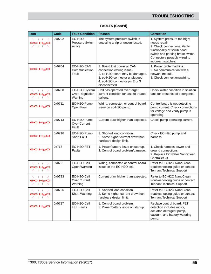
T300, T300e Service Information (3-2017) 55
TROUBLESHOOTING
Icon Code Fault Condition Reason Correction0x0702 EC-H2O
Pressure Switch Active
The system pressure switch is detecting a trip or unconnected.
1. System pressure too high; needs repair. 2. Check connections. Verify functionality of scrub head switch and parking brake switch. Connectors possibly wired to incorrect switches.
0x0704 EC-H2O CAN Communication Fault
1. Board lost power or CAN connection (wiring issue).2. ec-H2O board may be damaged.3. ec-H2O connector unplugged.4. ec-H2O connector pin 2 or 3 disconnected.
1. Power cycle machine. 2. No communication with a network module.3. Check connections/wiring.
0x0708 EC-H2O System Over Regulation Warning
Cell has operated over target current condition for last 50 treated gallons.
Check water condition in solution tank for presence of detergents.
0x0711 EC-H2O Pump Open Fault
Wiring, connector, or control board issue on ec-H2O pump.
Control board is not detecting pump current. Check connections for voltage and verify pump is operating.
0x0713 EC-H2O Pump Over Current Fault
Current draw higher than expected. Check pump operating current.
0x0716 EC-H2O Pump Short Fault
1. Shorted load condition.2. Some higher current draw than hardware design limit.
Check EC-H2o pump and harness
0x717 EC-H2O FET Faults
1. Power/battery issue on startup.2. Control board problem/damage.
1. Check harness power and ground connections.2. Replace EC water NanoClean Controller kit.
0x0721 EC-H2O Cell Open Warning
Wiring, connector, or control board issue on the EC-H2O cell.
Refer to EC-H2O NanoClean troubleshooting guide or contact Tennant Technical Support
0x0723 EC-H2O Cell Over Current Warning
Current draw higher than expected. Refer to EC-H2O NanoClean troubleshooting guide or contact Tennant Technical Support
0x0726 EC-H2O Cell Short Warning
1. Shorted load condition.2. Some higher current draw than hardware design limit.
Refer to EC-H2O NanoClean troubleshooting guide or contact Tennant Technical Support
0x0727 EC-H2O Cell FET Faults
1. Control board problem.2. Power/battery issue on startup.
Replace control board. FET detection includes motor, actuator, detergent pump, vacuum, and battery watering pump.
FAULTS (Cont’d)

56 T300, T300e Service Information (3-2017)
TROUBLESHOOTING
Icon Code Fault Condition Reason Correction0x072A EC-H2O Cell
Electrode FaultCell current is operating below allowed operating condition.
See the NanoClean troubleshooting guide. Replace plumbing half of ec-H2O module.
0x0726 EC-H2O E-Cell Short load Fault
1. Module damage.2. Metal debris inside e-call3. Electronic event
Repair harness if possible. Replace EC-H2O NanoClean Module plumbing kit.Replace EC-H2O NanoClean controller kit.
0x0741 EC-H2O WCM Pump Open Warning
Wiring, connector or control board issue on ec-H2O pump.
Check if Water Conditioning Module micro pump is connected to machine harness and verify pump is operable.
0x0746 EC-H2O WCM Pump Short Warning
1. Shorted load condition.2. Some higher current draw than hardware design limit.
Check harness and verify Water Conditioning Module micro pump is operable.
0x0747 EC-H2O WCM Pump FET Fault
1. Control board problem.2. Power/battery issue on startup.
Replace control board. FET detection includes motor, actuator, detergent pump, vacuum, and battery watering pump.
0x0781 Detergent Tank Empty
1. Flashing icon indicates detergent tank level is too low to operate correctly. 2. Detergent tank switch connector unplugged. 3. Scrub Controller connector J4 unplugged. 4. Scrub Controller connector J4 pin 4 disconnected.
Refi ll detergent tank to clear indicator. If fault persists, check connections/wiring.
FAULTS (Cont’d)

T300, T300e Service Information (3-2017) 57
TROUBLESHOOTING
ERROR CODE REASON CORRECTIONSrt:IBIBmax
Output current has exceeded nominal cur-rent value by more than 10%.
Ensure there are no short circuits on bat-tery or battery cables or there is an active load on battery that draws more currant than charger can provide.
E01:Open Circuit
Current suddenly went to zero unexpect-edly.
Check connection of clamps to battery and check voltage of battery elements to ensure there are no elements in an open circuit condition. Charger starts again after 5 seconds.
E02:Temperature
Internal thermic sensor has detected high temperature.
Operate charger in a well ventilated area.
E03: Timer Safety timer of one of the phases has been activated.
Ensure charging current is set suitably for battery capacity and that selected volt-age corresponds to battery voltage. Also, ensure that there are no elements in short circuit and that battery is not sulphated.
FAULTS - OFF BOARD BATTERY CHARGER
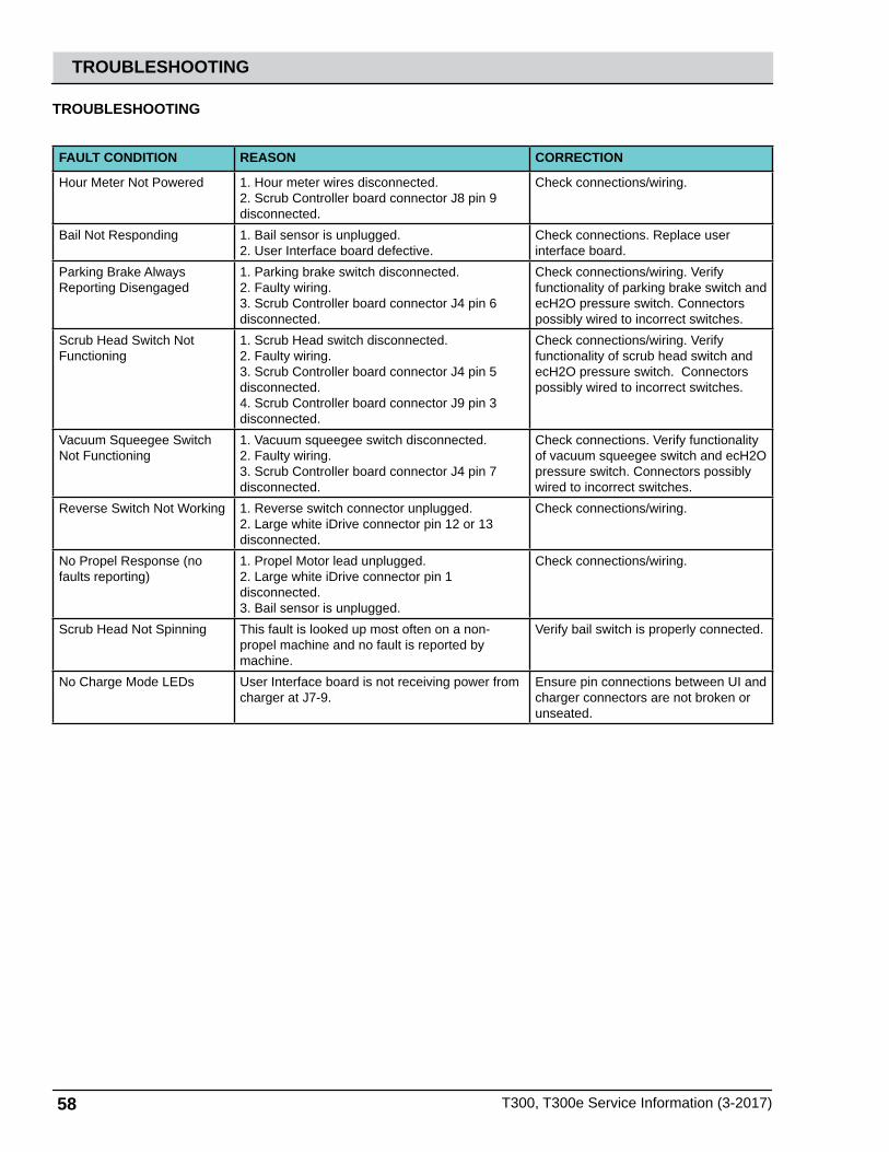
58 T300, T300e Service Information (3-2017)
TROUBLESHOOTING
TROUBLESHOOTING
FAULT CONDITION REASON CORRECTION
Hour Meter Not Powered 1. Hour meter wires disconnected.2. Scrub Controller board connector J8 pin 9 disconnected.
Check connections/wiring.
Bail Not Responding 1. Bail sensor is unplugged.2. User Interface board defective.
Check connections. Replace user interface board.
Parking Brake Always Reporting Disengaged
1. Parking brake switch disconnected.2. Faulty wiring.3. Scrub Controller board connector J4 pin 6 disconnected.
Check connections/wiring. Verify functionality of parking brake switch and ecH2O pressure switch. Connectors possibly wired to incorrect switches.
Scrub Head Switch Not Functioning
1. Scrub Head switch disconnected.2. Faulty wiring. 3. Scrub Controller board connector J4 pin 5 disconnected.4. Scrub Controller board connector J9 pin 3 disconnected.
Check connections/wiring. Verify functionality of scrub head switch and ecH2O pressure switch. Connectors possibly wired to incorrect switches.
Vacuum Squeegee Switch Not Functioning
1. Vacuum squeegee switch disconnected.2. Faulty wiring. 3. Scrub Controller board connector J4 pin 7 disconnected.
Check connections. Verify functionality of vacuum squeegee switch and ecH2O pressure switch. Connectors possibly wired to incorrect switches.
Reverse Switch Not Working 1. Reverse switch connector unplugged. 2. Large white iDrive connector pin 12 or 13 disconnected.
Check connections/wiring.
No Propel Response (no faults reporting)
1. Propel Motor lead unplugged.2. Large white iDrive connector pin 1 disconnected.3. Bail sensor is unplugged.
Check connections/wiring.
Scrub Head Not Spinning This fault is looked up most often on a non-propel machine and no fault is reported by machine.
Verify bail switch is properly connected.
No Charge Mode LEDs User Interface board is not receiving power from charger at J7-9.
Ensure pin connections between UI and charger connectors are not broken or unseated.

T300, T300e Service Information (3-2017) 59
TROUBLESHOOTING

60 T300, T300e Service Information (3-2017)
TROUBLESHOOTING
AC Power Cord
BLACK Cable
Onboard Battery Charger
(2) 12VDC Batteries
P2-3 P2-4
P2-2
P2-6CAN +
B +
B -
CAN -P2-10
CAN GROUND
N.O.COM
N.C.
P2-1 113/BLK/WHT
GRN
YEL
5/GRN
7/PUR
4/YEL
1/RED
1/RED
6/BLU
CB1 4A
+ - + -12 Volt 12 Volt
KeySwitch
Battery Positive +
Battery Negative -
PMC021
AC Volts
CAN-bus +
CAN-bus -
J3-3 InterfaceModule
J7-10, J7-7InterfaceModule
J8-7Machine ControlModule (option)
M1Aec-H2O Relay
(option)
J7-9 InterfaceModule
ONBOARD BATTERY CHARGING ON (Option)
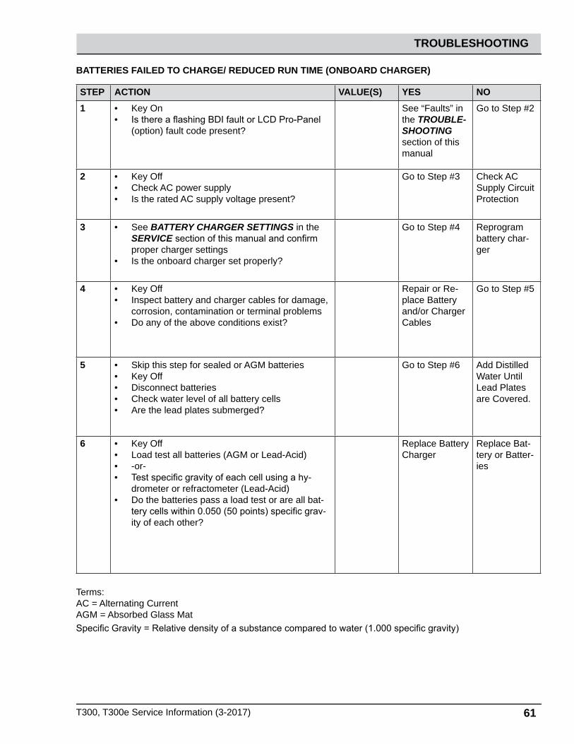
T300, T300e Service Information (3-2017) 61
TROUBLESHOOTING
BATTERIES FAILED TO CHARGE/ REDUCED RUN TIME (ONBOARD CHARGER)
STEP ACTION VALUE(S) YES NO1 • Key On
• Is there a flashing BDI fault or LCD Pro-Panel (option) fault code present?
See “Faults” in the TROUBLE-SHOOTING section of this manual
Go to Step #2
2 • Key Off• Check AC power supply• Is the rated AC supply voltage present?
Go to Step #3 Check AC Supply Circuit Protection
3 • See BATTERY CHARGER SETTINGS in the SERVICE section of this manual and confirm proper charger settings
• Is the onboard charger set properly?
Go to Step #4 Reprogram battery char-ger
4 • Key Off• Inspect battery and charger cables for damage,
corrosion, contamination or terminal problems• Do any of the above conditions exist?
Repair or Re-place Battery and/or Charger Cables
Go to Step #5
5 • Skip this step for sealed or AGM batteries• Key Off• Disconnect batteries• Check water level of all battery cells• Are the lead plates submerged?
Go to Step #6 Add Distilled Water Until Lead Plates are Covered.
6 • Key Off• Load test all batteries (AGM or Lead-Acid)• -or-• Test specific gravity of each cell using a hy-
drometer or refractometer (Lead-Acid)• Do the batteries pass a load test or are all bat-
tery cells within 0.050 (50 points) specific grav-ity of each other?
Replace Battery Charger
Replace Bat-tery or Batter-ies
Terms:AC = Alternating CurrentAGM = Absorbed Glass MatSpecific Gravity = Relative density of a substance compared to water (1.000 specific gravity)
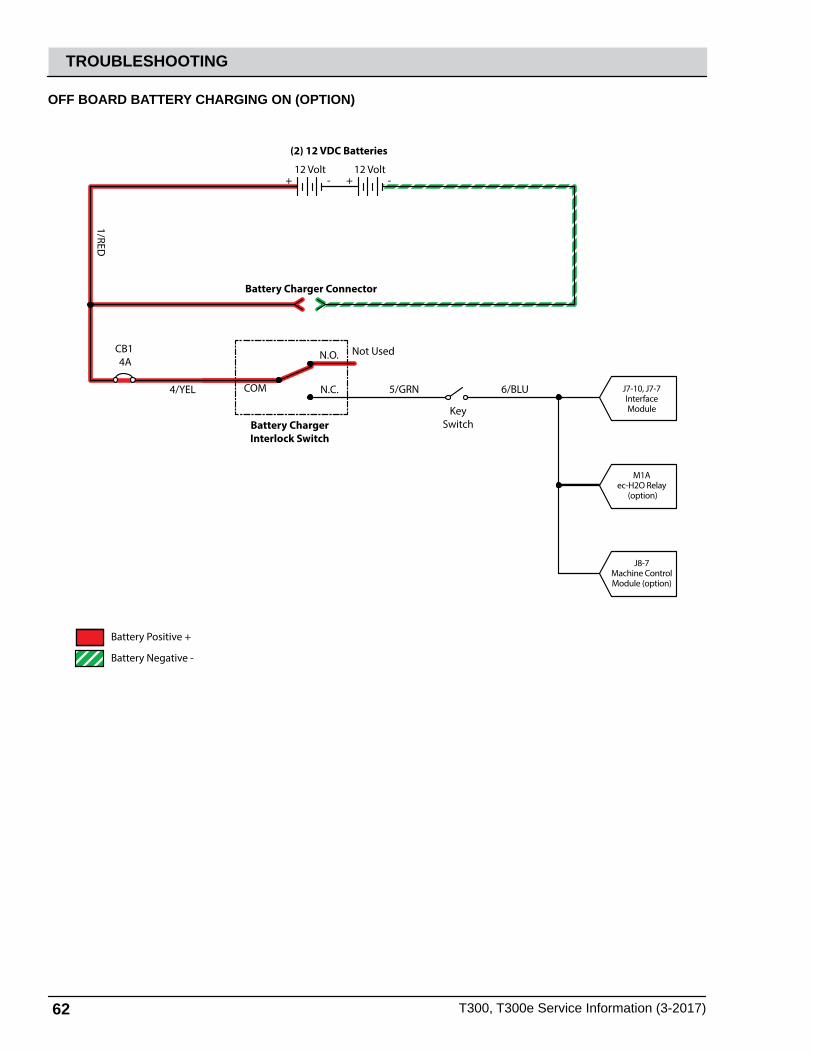
62 T300, T300e Service Information (3-2017)
TROUBLESHOOTING
Battery Charger Connector
Battery ChargerInterlock Switch
(2) 12 VDC Batteries
N.O.
COM N.C.
CB1 4A
+ - + -12 Volt 12 Volt
Not Used
KeySwitch
Battery Positive +
Battery Negative -
PMC021
J7-10, J7-7InterfaceModule
1/RED
4/YEL 5/GRN 6/BLU
J8-7Machine ControlModule (option)
M1Aec-H2O Relay
(option)
OFF BOARD BATTERY CHARGING ON (OPTION)

T300, T300e Service Information (3-2017) 63
TROUBLESHOOTING
BATTERIES FAILED TO CHARGE/ REDUCED RUN TIME (OFF BOARD CHARGER)
STEP ACTION VALUE(S) YES NO1 • Key On
• Is there an LCD fault present on the Off Board Charger?
See “Off Board Battery Char-ger Faults” in the TROUBLE-SHOOTING section of this manual
Go to Step #2
2 • Key Off• Check AC power supply• Is the rated AC supply voltage present?
Go to Step #3 Check AC Supply Circuit Protection
3 • Key Off• Inspect battery and charger cables for damage,
corrosion, contamination or terminal problems• Do any of the above conditions exist?
Repair or Re-place Battery and/or Charger Cables
Go to Step #4
4 • Skip this step for sealed or AGM batteries• Key Off• Disconnect batteries• Check water level of all battery cells• Are the lead plates submerged?
Go to Step #4 Add Distilled Water Until Lead Plates are Covered.
5 • Key Off• Load test all batteries (AGM or Lead-Acid)• -or-• Test specific gravity of each cell using a hydrom-
eter or refractometer ((Lead-Acid)• Do the batteries pass a load test or are all bat-
tery cells within 0.050 (50 points) specific gravity of each other?
Replace Bat-tery Charger
Replace Battery or Batteries
Terms:AC = Alternating CurrentAGM = Absorbed Glass MatSpecific Gravity = Relative density of a substance compared to water (water = 1.000 specific gravity)
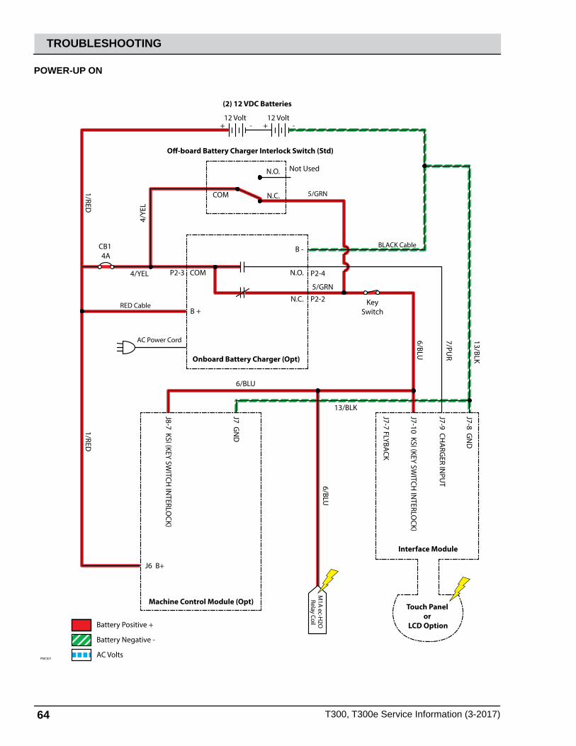
64 T300, T300e Service Information (3-2017)
TROUBLESHOOTING
POWER-UP ON
AC Power Cord
RED Cable
BLACK Cable
Onboard Battery Charger (Opt)
Interface Module
Touch Panel or
LCD Option
Machine Control Module (Opt)
O-board Battery Charger Interlock Switch (Std)
(2) 12 VDC Batteries
P2-3 P2-4
P2-2
J7-10 KSI (KEY SWITCH
INTERLO
CK)
J8-7 KSI (KEY SWITCH
INTERLO
CK)
J7-7 FLYBACK
J7-9 CHA
RGER IN
PUT
J7-8 GN
D
J7 GN
D
J6 B+
B +
B -
N.O.COM
N.C.
5/GRN
7/PUR
13/BLK
13/BLK
4/YE
L
4/YEL
1/RED1/RED
6/BLU
6/BLU
6/BLUCB1 4A
+ - + -12 Volt 12 Volt
KeySwitch
Battery Positive +
Battery Negative -
PMC021AC Volts
5/GRN
M1A ec-H
2O
Relay Coil
N.O.
COM N.C.
Not Used

T300, T300e Service Information (3-2017) 65
TROUBLESHOOTING
MACHINE FAILED TO POWER UP
STEP ACTION VALUE(S) YES NO1 • Key On
• Test the total battery voltage using a voltmeter• Is the total battery voltage greater than 20
VDC?
Go to Step #2 Recharge Batteries and Test Power-Up Circuit Operation
2 • Key Off• Firmly press circuit breaker #1 to reset• Is circuit breaker #1 tripped?
Reset and Test Power-Up Circuit Operation
Go to Step #3
3 • Key On• Test voltage applied to the power-up subsys-
tem as shown on the electrical schematic• Are the electrical circuits operating as shown
on the electrical schematic?
Go Back to Step #1
Identify Volt-age Drop Location and Repair or Replace Necessary Components
Terms:VDC = DC Voltage
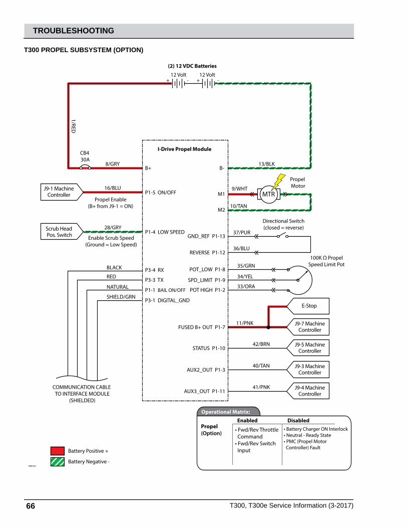
66 T300, T300e Service Information (3-2017)
TROUBLESHOOTING
T300 PROPEL SUBSYSTEM (OPTION)
J9-1 MachineController MTR
I-Drive Propel Module
(2) 12 VDC Batteries
B+
P1-5 ON/OFFPropel Enable
(B+ from J9-1 = ON)
B-
M1
M2
GND_REF P1-13
REVERSE P1-12
8/GRY
16/BLU 9/WHT
10/TAN
37/PUR
36/BLU
13/BLK
1/RED
CB4 30A
+ - + -12 Volt 12 Volt
Directional Switch(closed = reverse)
Propel Motor
Battery Positive +
Battery Negative - PMC021
POT_LOW P1-8
SPD_LIMIT P1-9
35/GRN
34/YEL
POT HIGH P1-2
FUSED B+ OUT P1-7
33/ORA
100K Ω PropelSpeed Limit Pot
Scrub Head Pos. Switch
J9-7 MachineController
E-Stop
P1-4 LOW SPEED
P3-4 RX
P3-3 TX
P1-1 BAIL ON/OFF
P3-1 DIGITAL_GND
COMMUNICATION CABLE TO INTERFACE MODULE
(SHIELDED)
Enable Scrub Speed(Ground = Low Speed)
28/GRY
BLACK
RED
NATURAL
SHIELD/GRN
11/PNK
STATUS P1-10J9-5 Machine
Controller42/BRN
AUX2_OUT P1-3J9-3 Machine
Controller40/TAN
AUX3_OUT P1-11J9-4 Machine
Controller41/PNK
Propel(Option)
Enabled
• Fwd/Rev Throttle Command• Fwd/Rev Switch Input
DisabledOperational Matrix:
• Battery Charger ON Interlock• Neutral - Ready State• PMC (Propel Motor Controller) Fault

T300, T300e Service Information (3-2017) 67
TROUBLESHOOTING
T300 FAILED TO PROPEL
STEP ACTION VALUE(S) YES NO1 • Key On
• Enable propel• Is there a flashing BDI fault or LCD Pro-Panel
(option) fault code present?
See “Faults” in the TROUBLE-SHOOTING sec-tion of this manual
Go to Step #2
2 • See SERVICE DIAGNOSTICS TOOL in the SERVICE section of this manual and confirm the software is properly configured to enable the propel feature
• Is the software configured properly?
Go to Step #3 Reprogram software
3 • Key Off• Place machine on blocks so drive wheels are
lifted off the floor• Key On• Enable propel• Test voltage applied to the propel subsystem
as shown on the electrical schematic• Are the electrical circuits operating as shown
on the electrical schematic?
Go Back to Step #1
Identify Volt-age Drop Location and Repair or Replace Necessary Components
Terms:BDI = Battery Discharge Indicator

68 T300, T300e Service Information (3-2017)
TROUBLESHOOTING
T300e PROPEL SUBSYSTEM (Option)
E-Stop Switch MTR
I-Drive Propel Module
(2) 12 VDC Batteries
B+
P1-5 ON/OFFPropel Enable
(B+ from J9-1 = ON)
B-
M1
M2
GND_REF P1-13
REVERSE P1-12
8/GRY
38/GRY 9/WHT
10/TAN
37/PUR
36/BLU
13/BLK
1/RED
CB4 30A
+ - + -12 Volt 12 Volt
Directional Switch(closed = reverse)
Propel Motor
Battery Positive +
Battery Negative - PMC021
POT_LOW P1-8
SPD_LIMIT P1-9
35/GRN
34/YEL
POT HIGH P1-233/ORA
100K Ω PropelSpeed Limit Pot
Scrub Head Pos. Switch P1-4 LOW SPEED
P3-4 RX
P3-3 TX
P1-1 BAIL ON/OFF
P3-1 DIGITAL_GND
COMMUNICATION CABLE TO INTERFACE MODULE
(SHIELDED)
Enable Scrub Speed(Ground = Low Speed)
27/PUR
BLACK
RED
NATURAL
SHIELD/GRN
Propel(Option)
Enabled
• Fwd/Rev Throttle Command• Fwd/Rev Switch Input
DisabledOperational Matrix:
• Battery Charger ON Interlock• Neutral - Ready State• PMC (Propel Motor Controller) Fault

T300, T300e Service Information (3-2017) 69
TROUBLESHOOTING
T300e FAILED TO PROPEL
STEP ACTION VALUE(S) YES NO1 • Key On
• Enable propel• Is there a flashing BDI fault code present?
See “Faults” in the TROUBLE-SHOOTING sec-tion of this manual
Go to Step #2
2 • See SERVICE DIAGNOSTICS TOOL in the SERVICE section of this manual and confirm the software is properly configured to enable the propel feature
• Is the software configured properly?
Go to Step #3 Reprogram software
3 • Key Off• Place machine on blocks so drive wheels are
lifted off the floor• Key On• Enable forward propel• Test voltage applied to the propel subsystem
as shown on the electrical schematic• Are the electrical circuits operating as shown
on the electrical schematic?
Go Back to Step #1
Identify Volt-age Drop Location and Repair or Replace Necessary Components
Terms:BDI = Battery Discharge Indicator
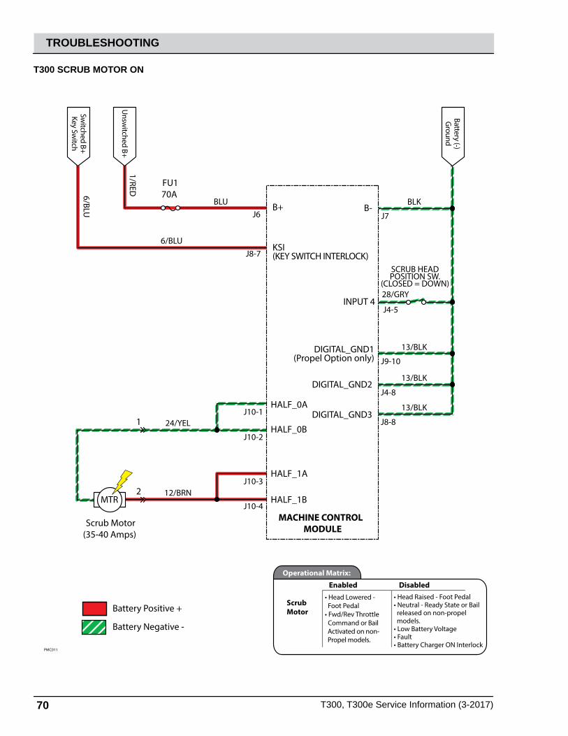
70 T300, T300e Service Information (3-2017)
TROUBLESHOOTING
T300 SCRUB MOTOR ON
Battery Positive +
Battery Negative -
PMC011
28/GRY
SCRUB HEADPOSITION SW.
(CLOSED = DOWN)
MTR
Scrub Motor(35-40 Amps)
MACHINE CONTROL MODULE
B+
KSI(KEY SWITCH INTERLOCK)
HALF_0B
HALF_0A
HALF_1B
HALF_1A
1
2
DIGITAL_GND1(Propel Option only)
DIGITAL_GND2
DIGITAL_GND3
Unsw
itched B+
Battery (-)G
round
1/RED
Switched B+
Key Switch
6/BLU
6/BLU
BLUJ6
J8-7
J10-2
J10-1
J10-4
J10-3
J9-10
J4-8
J8-8
13/BLK
INPUT 4J4-5
B- J7
BLK
13/BLK
13/BLK
24/YEL
12/BRN
FU170A
Scrub Motor
Enabled• Head Lowered - Foot Pedal• Fwd/Rev Throttle Command or Bail Activated on non- Propel models.
DisabledOperational Matrix:
• Head Raised - Foot Pedal• Neutral - Ready State or Bail released on non-propel models.• Low Battery Voltage• Fault• Battery Charger ON Interlock
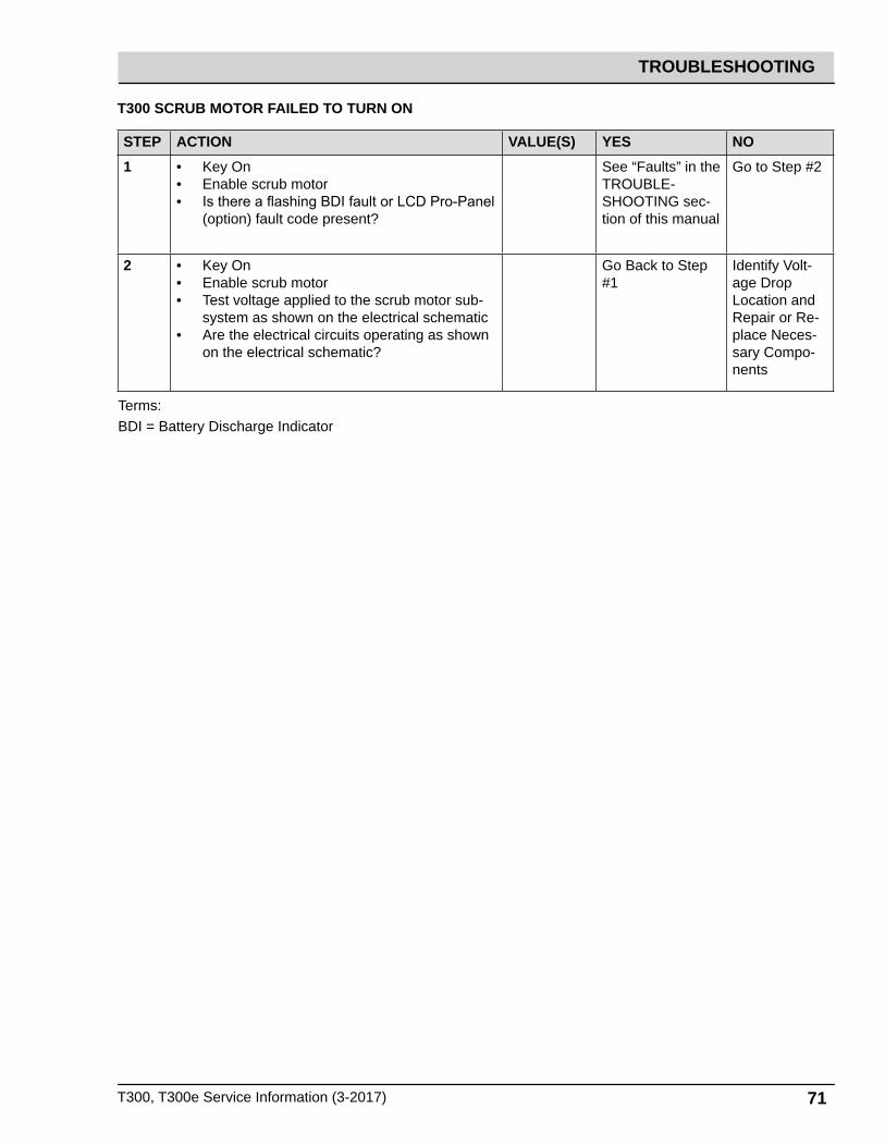
T300, T300e Service Information (3-2017) 71
TROUBLESHOOTING
T300 SCRUB MOTOR FAILED TO TURN ON
STEP ACTION VALUE(S) YES NO1 • Key On
• Enable scrub motor• Is there a flashing BDI fault or LCD Pro-Panel
(option) fault code present?
See “Faults” in the TROUBLE-SHOOTING sec-tion of this manual
Go to Step #2
2 • Key On• Enable scrub motor• Test voltage applied to the scrub motor sub-
system as shown on the electrical schematic• Are the electrical circuits operating as shown
on the electrical schematic?
Go Back to Step #1
Identify Volt-age Drop Location and Repair or Re-place Neces-sary Compo-nents
Terms:BDI = Battery Discharge Indicator

72 T300, T300e Service Information (3-2017)
TROUBLESHOOTING
T300e SCRUB MOTOR ON
From Key
Switch B+
J7-6 InterfaceModule
D-1
M1B
3087
(2) 12 VDC Batteries
1/RED1/RED
12/BRN 26/BLU 13/BLK
13/BLK
6/BLU 20/TAN
6/BLU 42/BRN
6/BLU
13/BLK
13/BLK
+ - + -12 Volt 12 Volt
Battery Positive +
Battery Negative -
PMC021
CB5 (37A) ScrubMotor
MTR
M1A 86 85
Auxiliary ScrubBrush Relay
NOTE: The scrub motor system uses two relays (stepped) because the M4A coil exceeds the max. current rating of the J7-6 output circuit.
Auxiliary ScrubBrush Relay
M4B
3087
Scrub Brush Relay
M4A 86 85
ScrubBrush Relay
Scrub Motor
Enabled• Head Lowered - Foot Pedal• Fwd/Rev Throttle Command or Bail Activated on non- Propel models.
DisabledOperational Matrix:
• Head Raised - Foot Pedal• Neutral - Ready State or Bail released on non-propel models.• Low Battery Voltage• Fault• Battery Charger ON Interlock

T300, T300e Service Information (3-2017) 73
TROUBLESHOOTING
T300e SCRUB MOTOR FAILED TO TURN ON
STEP ACTION VALUE(S) YES NO1 • Key On
• Enable scrub motor• Is there a flashing BDI fault code present?
See “Faults” in the TROUBLE-SHOOTING sec-tion of this manual
Go to Step #2
2 • Key On• Enable scrub motor• Test voltage applied to the scrub motor sub-
system as shown on the electrical schematic• Are the electrical circuits operating as shown
on the electrical schematic?
Go Back to Step #1
Identify Volt-age Drop Location and Repair or Replace Necessary Components
Terms:BDI = Battery Discharge Indicator
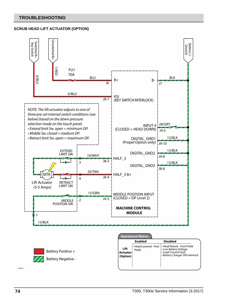
74 T300, T300e Service Information (3-2017)
TROUBLESHOOTING
28/GRY
Battery Positive +
Battery Negative -
PMC011
MTR
Lift Actuator(3-5 Amps)
NOTE: The lift actuator adjusts to one of three pre-set internal switch conditions (seebelow) based on the down pressure selection made on the touch panel. • Extend limit Sw. open = minimum DP.• Middle Sw. closed = medium DP. • Retract limit Sw. open = maximum DP.
MACHINE CONTROL MODULE
B+
KSI(KEY SWITCH INTERLOCK)
HALF_3
HALF_3 B+
DIGITAL_GND1(Propel Option only)
DIGITAL_GND2
DIGITAL_GND3
Unsw
itched B+
Battery (-)G
round
1/RED
Switched B+
Key Switch
6/BLU
6/BLU
BLUJ6
J8-7
J8-3
J8-4
J9-10
J4-8
J8-8
13/BLK
INPUT 4(CLOSED = HEAD DOWN) J4-5
B- J7
BLK
13/BLK
13/BLK
13/BLK
1
2
4
3
19/WHT
RETRACTLIMIT SW.
MIDDLEPOSITION SW.
EXTENDLIMIT SW.
20/TAN
MIDDLE POSITION INPUT(CLOSED = DP Level 2)
15/GRN
J4-3
FU170A
Lift Actuator(Option)
Enabled• Head Lowered - Foot Pedal
DisabledOperational Matrix:
• Head Raised - Foot Pedal• Low Battery Voltage• Load Current Fault• Battery Charger ON Interlock
SCRUB HEAD LIFT ACTUATOR (OPTION)

T300, T300e Service Information (3-2017) 75
TROUBLESHOOTING
SCRUB HEAD FAILED TO RAISE/LOWER
STEP ACTION VALUE(S) YES NO1 • Key On
• Enable lift actuator• Is there a flashing BDI fault or LCD Pro-Panel
(option) fault code present?
See “Faults” in the TROUBLE-SHOOTING sec-tion of this manual
Go to Step #2
2 • See SERVICE DIAGNOSTICS TOOL in the SERVICE section of this manual and confirm the software is properly configured to enable the automated down pressure feature
• Is the software configured properly?
Go to Step #3 Reprogram software
3 • Key On• Enable scrub motor• Test voltage applied to the actuator subsys-
tem as shown on the electrical schematic• Are the electrical circuits operating as shown
on the electrical schematic?
Go Back to Step #1
Identify Volt-age Drop Location and Repair or Replace Necessary Components
Terms:BDI = Battery Discharge Indicator

76 T300, T300e Service Information (3-2017)
TROUBLESHOOTING
T300 VACUUM FAN ON
Battery Positive +
Battery Negative -
PMC011
26/BLU
MTR
Vacuum Fan(18-20 Amps)Approx. 19 Volts Normal ModeApprox. 11 Volts Quiet Mode
MACHINE CONTROL MODULE
B+
KSI(KEY SWITCH INTERLOCK)
HALF_2
HALF_2 B+
DIGITAL_GND1(Propel Option only)
DIGITAL_GND2
DIGITAL_GND3
Unsw
itched B+
Battery (-)G
round
1/RED
Switched B+
Key Switch
6/BLU
6/BLU
BLUJ6
J8-7
J10-6
J10-5
J9-10
J4-8
J8-8
13/BLK
INPUT 5(CLOSED = SQ. DOWN) J4-7
B- J7
BLK
13/BLK
13/BLK
23/ORA
18/GRY
FU170A
Vacuum Fan
Enabled• Squeegee Lowered
DisabledOperational Matrix:
• Squeegee Raised• Low Battery Voltage• Fault• Battery Charger ON Interlock

T300, T300e Service Information (3-2017) 77
TROUBLESHOOTING
T300 VACUUM FAN FAILED TO TURN ON
STEP ACTION VALUE(S) YES NO1 • Key On
• Enable vacuum fan• Is there a flashing BDI fault or LCD Pro-Pan-
el (option) fault code present?
See “Faults” in the TROUBLE-SHOOTING section of this manual
Go to Step #2
2 • Key On• Enable vacuum fan• Test voltage applied to the vacuum fan sub-
system as shown on the electrical schematic• Are the electrical circuits operating as shown
on the electrical schematic?
Go Back to Step #1
Identify Volt-age Drop Location and Repair or Re-place Neces-sary Compo-nents
Terms:BDI = Battery Discharge Indicator

78 T300, T300e Service Information (3-2017)
TROUBLESHOOTING
T300e VACUUM FAN ON
From E-Stop
Switch B+
D-2
M3B
30 87
(2) 12 VDC Batteries
1/RED1/RED
15/GRN 29/WHT 13/BLK
13/BLK
38/GRY 3/ORA
13/BLK+ - + -
12 Volt 12 Volt
Battery Positive +
Battery Negative -
PMC021
CB6 (20A)
Vacuum FanMotor
MTR
M3A 86 85
Vacuum FanRelay
SW-8 SqueegeePosition Switch(Closed= Down)
Vacuum Fan
Enabled• Squeegee Lowered
DisabledOperational Matrix:
• Squeegee Raised• Battery Charger ON Interlock
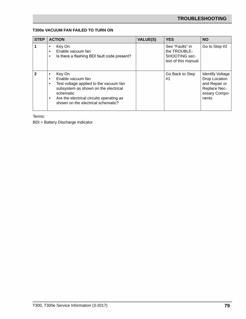
T300, T300e Service Information (3-2017) 79
TROUBLESHOOTING
T300e VACUUM FAN FAILED TO TURN ON
STEP ACTION VALUE(S) YES NO1 • Key On
• Enable vacuum fan• Is there a flashing BDI fault code present?
See “Faults” in the TROUBLE-SHOOTING sec-tion of this manual
Go to Step #2
2 • Key On• Enable vacuum fan• Test voltage applied to the vacuum fan
subsystem as shown on the electrical schematic
• Are the electrical circuits operating as shown on the electrical schematic?
Go Back to Step #1
Identify Voltage Drop Location and Repair or Replace Nec-essary Compo-nents
Terms:BDI = Battery Discharge Indicator

80 T300, T300e Service Information (3-2017)
TROUBLESHOOTING
T300 SOLUTION CONTROL ON (CONVENTIONAL)
Battery Positive +
Battery Negative -
PMC011
28/GRY
NOTE: The detergent pump is part of the SE (Severe Environment) option.See SE troubleshooting for additional system details.
MACHINE CONTROL MODULE
B+
KSI(KEY SWITCH INTERLOCK)
DIGITAL_GND1(Propel Option only)
DIGITAL_GND2
DIGITAL_GND3
Unsw
itched B+
Battery (-)G
round
1/RED
Switched B+
Key Switch
6/BLU
6/BLU
BLUJ6
J8-7
J9-10
J4-8
J8-8
13/BLK
INPUT 4(CLOSED = HEAD DOWN) J4-5
B- J7
BLK
13/BLK
13/BLK
FU170A
SV1 Solution Valve(0.4-0.6 Amps)
MTR
Detergent Pump (Option)(0.4 - 0.6 Amps)
RETURN
PUMP OUT
VALVE OUT J8-2
J8-1
J8-6
14/YEL
21/PNK
22/BRN
SolutionControl
(Conventional)
Enabled• Head Lowered - Foot Pedal• Solution Control ON• Fwd/Rev Throttle Command or Bail activated on non- propel models.
DisabledOperational Matrix:
• Head Raised - Foot Pedal• Solution Control OFF• Neutral - Ready State or bail released on non-propel models.• Low Battery Voltage• Fault• Battery Charger ON Interlock
SV-1 LEVEL
O (No LEDs)
Low (1 LED)
Med (2 LEDs)
High (3 LEDs)
0%
23%
48%
66%
0 S On/ 2.5 S O
0.6 S On/ 1.9 S O
1.2 S On/ 1.3 S O
1.7 S On/ 0.8 S O
ON TIME % PERIOD 2.5 SEC
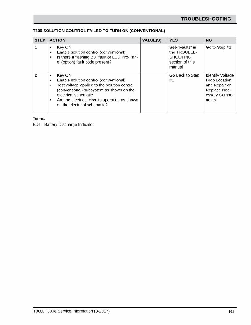
T300, T300e Service Information (3-2017) 81
TROUBLESHOOTING
T300 SOLUTION CONTROL FAILED TO TURN ON (CONVENTIONAL)
STEP ACTION VALUE(S) YES NO1 • Key On
• Enable solution control (conventional)• Is there a flashing BDI fault or LCD Pro-Pan-
el (option) fault code present?
See “Faults” in the TROUBLE-SHOOTING section of this manual
Go to Step #2
2 • Key On• Enable solution control (conventional)• Test voltage applied to the solution control
(conventional) subsystem as shown on the electrical schematic
• Are the electrical circuits operating as shown on the electrical schematic?
Go Back to Step #1
Identify Voltage Drop Location and Repair or Replace Nec-essary Compo-nents
Terms:BDI = Battery Discharge Indicator

82 T300, T300e Service Information (3-2017)
TROUBLESHOOTING
T300e SOLUTION CONTROL ON (CONVENTIONAL)
Operator’s Switch/LEDTouch Panel
(2) 12 VDC Batteries
1/RED 13/BLK
13/BLK
5/GRN
6/BLU
54/YEL
30/TAN
31/PNK
6/BL
U
6/BLU
+ - + -12 Volt 12 Volt
KeySwitch
Battery Positive +
Battery Negative -
PMC021
Bail Switch (N.O)
Bail Switch Harness
P2-2 Onboard
Charger or Inter-lock Sw
itch N.C.
Circuit Breaker 1
Interface Module
J7-10 KSI (KEY SWITCH INTERLOCK)
J7-7 FLYBACK
J7-5 SOLUTION VALVE OUT
GND J7-8
SENSOR_IN J4-4
+5V OUT J4-1
SV1 SolutionValve
SolutionControl
(Conventional)
Enabled• Head Lowered - Foot Pedal• Solution Control ON• Fwd/Rev Throttle Command or Bail activated on non- propel models.
DisabledOperational Matrix:
• Head Raised - Foot Pedal• Solution Control OFF• Neutral - Ready State or bail released on non-propel models.• Low Battery Voltage• Fault• Battery Charger ON Interlock

T300, T300e Service Information (3-2017) 83
TROUBLESHOOTING
T300e SOLUTION CONTROL FAILED TO TURN ON (CONVENTIONAL)
STEP ACTION VALUE(S) YES NO1 • Key On
• Enable solution control (conventional)• Is there a flashing BDI fault code present?
See “Faults” in the TROUBLE-SHOOTING section of this manual
Go to Step #2
2 • Key On• Enable solution control (conventional)• Test voltage applied to the solution control
(conventional) subsystem as shown on the electrical schematic
• Are the electrical circuits operating as shown on the electrical schematic?
Go Back to Step #1
Identify Voltage Drop Location and Repair or Replace Neces-sary Compo-nents
Terms:BDI = Battery Discharge Indicator
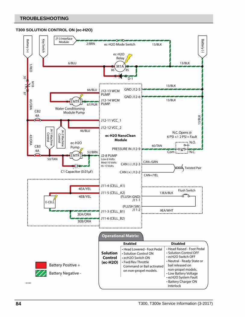
84 T300, T300e Service Information (3-2017)
TROUBLESHOOTING
T300 SOLUTION CONTROL ON (ec-H2O)
Battery (+)
C1 Capacitor (0.01µf ) + -
ec-H2OPump
Water Conditioning Module Pump
Com N.C.
N.O.
N.C. Opens @6 PSI +/- 2 PSI = Fault
4EB/YEL
4EA/YEL
3EA/ORA
3EB/ORA
Battery Positive +
Battery Negative -
CB24A
CB34A
46/BLU
67/PUR
66/BLU
13/BLK
13/B
LK
13/BLK
13/BLK
13/BLK2/BRN
52/BRN
50/TANCAN-/GRN
CAN+/YEL
60/TAN
9EA/WHT
Flush Switch
13EA/BLK
43/ORA
43/ORA
1/RED
6/BLU
ECC001
Twisted Pair
MTR
M1B
3087
D-1
M1A 86 85
ec-H2ORelay
ec-H2O Mode Switch
Key Switch
J4-1 Machine
Control
J4-2 Machine
Control
ec-H2O NanoClean Module
J12-11 VCC_1
GND J12-5
GND J12-6
CAN (+) J12-2
CAN (-) J12-3
PRESSURE IN J12-9
(FLUSH GND)J11-1
(FLUSH SW)J11-2
J12-12 VCC_2
J12-13 WCMPUMP
J12-14 WCM PUMP
J2-8 PUMP
J11-4 (CELL_A1)
J11-5 (CELL_A2)
J11-3 (CELL_B1)
J11-6 (CELL_B2)
MTR
Battery (-)
E-CELL
J7-3 InterfaceModule
Low-6 VoltsMed-10 VoltsHi-13 Volts
Solution Control
(ec-H2O)
Enabled
• Head Lowered - Foot Pedal• Solution Control ON• ecH2O Switch ON• Fwd/Rev Throttle Command or Bail activated on non-propel models.
• Head Raised - Foot Pedal• Solution Control OFF• ecH2O Switch OFF• Neutral - Ready State or bail released on non-propel models.• Low Battery Voltage• ecH2O System Fault• Battery Charger ON Interlock
Disabled
Operational Matrix:
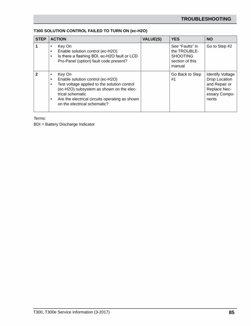
T300, T300e Service Information (3-2017) 85
TROUBLESHOOTING
T300 SOLUTION CONTROL FAILED TO TURN ON (ec-H2O)
STEP ACTION VALUE(S) YES NO1 • Key On
• Enable solution control (ec-H2O)• Is there a flashing BDI, ec-H2O fault or LCD
Pro-Panel (option) fault code present?
See “Faults” in the TROUBLE-SHOOTING section of this manual
Go to Step #2
2 • Key On• Enable solution control (ec-H2O)• Test voltage applied to the solution control
(ec-H2O) subsystem as shown on the elec-trical schematic
• Are the electrical circuits operating as shown on the electrical schematic?
Go Back to Step #1
Identify Voltage Drop Location and Repair or Replace Nec-essary Compo-nents
Terms:BDI = Battery Discharge Indicator

86 T300, T300e Service Information (3-2017)
TROUBLESHOOTING
T300e SOLUTION CONTROL ON (ec-H2O)
Battery (+)
C1 Capacitor (0.01µf ) + -
ec-H2OPump
Water Conditioning Module Pump
Com N.C.
N.O.
N.C. Opens @6 PSI +/- 2 PSI = Fault
4EB/YEL
4EA/YEL
3EA/ORA
3EB/ORA
Battery Positive +
Battery Negative -
CB24A
CB34A
46/BLU
67/PUR
66/BLU
13/BLK
13/B
LK
13/BLK
13/BLK
52/BRN
50/TANCAN-/GRN
CAN+/YEL
R-1 120 Ω(Located in Harness)
60/TAN
9EA/WHT
Flush Switch
13EA/BLK-WHT
43/ORA
43/ORA
1/RED
6/BLU
ECC001
Twisted Pair
MTR
M2B
3087
D-3
M2A 86 85
ec-H2ORelay
Key Switch
ec-H2O NanoClean Module
J12-11 VCC_1
GND J12-5
GND J12-6
CAN (+) J12-2
CAN (-) J12-3
PRESSURE IN J12-9
(FLUSH GND)J11-1
(FLUSH SW)J11-2
J12-12 VCC_2
J12-13 WCMPUMP
J12-14 WCM PUMP
J2-8 PUMP
J11-4 (CELL_A1)
J11-5 (CELL_A2)
J11-3 (CELL_B1)
J11-6 (CELL_B2)
MTR
Battery (-)
E-CELL
13/BLK2/BRN ec-H2O Mode Switch
J7-3 InterfaceModule
Low-6 VoltsMed-10 VoltsHi-13 Volts
Solution Control
(ec-H2O)
Enabled
• Head Lowered - Foot Pedal• Solution Control ON• ecH2O Switch ON• Fwd/Rev Throttle Command or Bail activated on non-propel models.
• Head Raised - Foot Pedal• Solution Control OFF• ecH2O Switch OFF• Neutral - Ready State or bail released on non-propel models.• Low Battery Voltage• ecH2O System Fault• Battery Charger ON Interlock
Disabled
Operational Matrix:

T300, T300e Service Information (3-2017) 87
TROUBLESHOOTING
T300e SOLUTION CONTROL FAILED TO TURN ON (ec-H2O)
STEP ACTION VALUE(S) YES NO1 • Key On
• Enable solution control (ec-H2O)• Is there a flashing BDI or ec-H2O fault pres-
ent?
See “Faults” in the TROUBLE-SHOOTING section of this manual
Go to Step #2
2 • Key On• Enable solution control (ec-H2O)• Test voltage applied to the solution control
(ec-H2O) subsystem as shown on the electri-cal schematic
• Are the electrical circuits operating as shown on the electrical schematic?
Go Back to Step #1
Identify Volt-age Drop Location and Repair or Re-place Neces-sary Compo-nents
Terms:BDI = Battery Discharge Indicator

88 T300, T300e Service Information (3-2017)
TROUBLESHOOTING
Battery Positive +
Battery Negative -
SV1 Solution Valve(0.4-0.6 Amps)
Detergent Tank level Sw.
PMC011
28/GRY
MTR
Detergent Pump (Option)(Pulsed 5 Volts - 20 Volts Continuous)
MACHINE CONTROL MODULE
B+
KSI(KEY SWITCH INTERLOCK)
RETURN
PUMP OUT
VALVE OUT
DIGITAL_GND1(Propel Option only)
DIGITAL_GND2
DIGITAL_GND3
Unsw
itched B+
Battery (-)G
round
1/RED
Switched B+
Key Switch
6/BLU
6/BLU
BLU
J6
J8-7
J8-2
J8-1
J8-6
J9-10
J4-8
J8-8
13/BLK
INPUT 4(CLOSED = HEAD DOWN) J4-5
B- J7
BLK
13/BLK
13/BLK
14/YEL
21/PNK
22/BRN
32/BRNINPUT 0(Open = Empty) J4-4
FU170A
POT_LOW J8-10
WIPER J8-11
29/WHT 1
2
3
30/TAN
POT_+5VDC J8-1231/PNK
5K Ω Detergent Metering Pot.
SE (SevereEnvironment)
Detergent Pump
(Option)
Enabled• Head Lowered - Foot Pedal• Severe Environment On (30 seconds or continuous )• Fwd/Rev Throttle Command or Bail activated on non-propel models.• Detergent Tank Not Empty
Disabled
Operational Matrix:
• Head Raised - Foot Pedal• Solution Control OFF• Neutral - Ready State or bail released on non-propel models.• Detergent Tank Empty• Low Battery Voltage• Fault• Battery Charger ON Interlock
SV-1 LEVEL
O (No LEDs)
Low (1 LED)
Med (2 LEDs)
High (3 LEDs)
0%
23%
48%
66%
0 S On/ 2.5 S O
0.6 S On/ 1.9 S O
1.2 S On/ 1.3 S O
1.7 S On/ 0.8 S O
ON TIME % PERIOD 2.5 SEC
T300 SE (SEVERE ENVIRONMENT) ON

T300, T300e Service Information (3-2017) 89
TROUBLESHOOTING
T300 SE (SEVERE ENVIRONMENT) FAILED TO TURN ON
STEP ACTION VALUE(S) YES NO1 • Key On
• Enable SE (Severe Environment) detergent pump
• Is there a flashing BDI fault or LCD Pro-Panel (option) fault code present?
See “Faults” in the TROUBLE-SHOOTING section of this manual
Go to Step #2
2 • Key On • Enable SE (Severe Environment) detergent
pump• Test voltage applied to the SE subsystem as
shown on the electrical schematic• Are the electrical circuits operating as shown
on the electrical schematic?
Go Back to Step #1
Identify Voltage Drop Location and Repair or Replace Nec-essary Compo-nents
Terms:BDI = Battery Discharge Indicator

90 T300, T300e Service Information (3-2017)
TROUBLESHOOTING
SUN-I/O CIRCUIT BOARD TESTING (UNIVERSAL SCHEMATIC)
MTR
[ll in the blank] Module
(2) 12 VDC Batteries
Unswitched B+
P1-X Switched B+
B-
Input P1-X
Input P1-X
Inpu
t
Circuit Breaker
Key Switch
+ - + -12 Volt 12 Volt
Directional Switch(closed = reverse)
Motor
Battery Positive +
Battery Negative - PMC021
0 V P3-X
WIPER P3-X
5 V P3-X
5K Ω Throttle PotentiometerP2-X Output
P2-X Output
Light
NOTE: The “P1-X” or sometimes “J1-X” format refers to the plug or connector number followed by the pin number within that connector. For example, P1-4 means plug number 1, pin number 4. Use this information to locate and identify proper wires per the actual electrical schematic.
P2-X Output
P2-X Output
S
S = Switched (+)U = Unswitched (+)N = Negative (-)I = InputsO = Outputs
U N
I
I
I
IO
O
O
O

T300, T300e Service Information (3-2017) 91
TROUBLESHOOTING
SUN-I/O CIRCUIT BOARD TESTING PROCEDURE
STEP ACTION VALUE(S) YES NO
1 Switched (+)* • Key On, circuits loaded (preferred)• All electrical components remain con-
nected to wire harness• Use an electrical schematic to identify
all switched (+) power supply wires• Is there switched battery voltage (+)
applied to the circuit board?
Applied Volt-age Must Be Within 1 Volt of Actual Battery Volt-age
Go to Step #2
Identify Volt-age Drop Location and Repair or Replace Necessary Components
2 Unswitched (+)*
• Key On, circuits loaded (preferred)• All electrical components remain con-
nected to wire harness• Use an electrical schematic to identify
all unswitched (+) power supply wires• Is there unswitched battery voltage
(+) applied to the circuit board?
Applied Volt-age Must Be Within 1 Volt of Actual Battery Volt-age
Go to Step #3
Identify Volt-age Drop Location and Repair or Replace Necessary Components
3 Negative (-)* • Key On, circuits loaded (preferred)• All electrical components remain con-
nected to wire harness• Use an electrical schematic to identify
all negative(-)/ground supply wires• Is there battery negative (-) applied to
the circuit board?
Applied Volt-age Must Be Within 1 Volt of Actual Battery Volt-age
Go to Step #4
Identify Volt-age Drop Location and Repair or Replace Necessary Components
4 Inputs • Key On• Manually exercise all input devices
and observe status change using a multimeter
• Use an electrical schematic to identify all input circuits
• Do all inputs function correctly?
Go to Step #5
Repair or Replace Necessary Input Com-ponents
5 Outputs • Key On• Disconnect battery and circuit board
from wire harness and test output cir-cuits for open or shorted circuits using an Ohmmeter.
• Use an electrical schematic to identify all output circuits
• Is there an open or shorted 2 output circuit causing the trouble symptom?
Repair or Replace Necessary Output Cir-cuit Compo-nents
Replace Cir-cuit Board.
1 Wire harnesses are components. 2 An open circuit has infinite resistance “O.L.”. A shorted circuit has “0” resistance. Always test through the entire circuit.* Switched (+) and Unswitched (+) indicate positive battery voltage applied to the circuit board. Negative (-) indicates battery negative (ground) as part of the power supply to the circuit board.

92 T300, T300e Service Information (3-2017)
TROUBLESHOOTING
NETWORK RESISTANCE
The network resistance must be correct for the network to operate correctly. Depending on which node the measurement is taken at and the method of measurment, the resistance may be one of two val-ues: 121 or 61 Ohms. Any value other than these two means something is wrong with the network.
Method 1
6. Turn off machine power.
7. Locate a CAN node location on the machine.
8. Disconnect the connector containing the CAN wires.
9. Measure the resistance between the green and yellow wires.
10. Depending which nodes are still connected, resistance should be 61 or 121 ohm.
Method 2
1. Turn off machine power.
2. Locate a CAN node location on the machine.
3. Carefully push probes into back of connector containing the CAN wires.
4. Since network remains connected in this mode, resistance should measure approximately 61 ohms.
CAN OPEN NETWORK ISSUES
The following items include procedures to help inves-tigate a fault related to a CAN open network on the machine.
CONNECTORS FULLY SEATED
Each node on the network has a connector for the CAN communication wires. A loose connection could cause a fualt code error. Check each board individual-ly to make sure the connectors are fully seated. There may also be other connectors within the harness that should be checked. If the connector is not fully seated, puch in and power cycle the machine to see if the fault clears.
PIN FULLY SEATED
A pin withinthe harness side of the connector may not be fully seated or may come loose over time causing a fault. If the pin is not fully seated, push it back in and power cycle the machine to see if the fault clears.

T300, T300e Service Information (3-2017) 93
TROUBLESHOOTING
NODE (MODULE) RESISTANCE
Each node on the network has a connector for the CAN communication wires. Check each board indi-vidually to make sure the CANH and CANL resistance measurements are > 1M Ω for non-terminating nodes and 122 Ω for terminating nodes. The CAN connec-tions may be on their own connector (pictured below) or combined into another connector. See specific machine schematic for more details.
WIRE CONTINUITY TO NODE
A check can be made between two points on the har-ness verifying continuity of the wire harness. Check the yellow to yellow connections and the green to green.

94 T300, T300e Service Information (3-2017)
TROUBLESHOOTING
MACHINE NODE TABLE
The following table outlines the CAN nodes by ma-chine model. A standard node is one that is always present. Optional nodes are dependent on the customer order. Gray box = Terminating Resistor Locations. If only one box marked on a machine, the second termination is made in the harness.
Machine model NodesMaster/Slave Master Slave
Optional Nodes Standard Standard Standard Standard Standard Standard Optional Optional Optional Optional
T300 User Interface
Scrub Controller
- - - - Charger EC H2O - -
T300e/SS300 User Interface
- - - - - Charger EC H2O - -
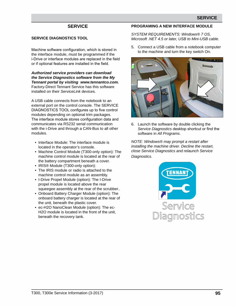
T300, T300e Service Information (3-2017) 95
SERVICE
SERVICE
SERVICE DIAGNOSTICS TOOL
Machine software configuration, which is stored in the interface module, must be programmed if the i-Drive or interface modules are replaced in the field or if optional features are installed in the field.
Authorized service providers can download the Service Diagnostics software from the My Tennant portal by visiting www.tennantco.com. Factory-Direct Tennant Service has this software installed on their ServiceLink devices.
A USB cable connects from the notebook to an external port on the control console. The SERVICE DIAGNOSTICS TOOL configures up to five control modules depending on optional trim packages. The interface module stores configuration data and communicates via RS232 serial communication with the i-Drive and through a CAN-Bus to all other modules.
• Interface Module: The interface module is located in the operator’s console.
• Machine Control Module (T300-only option): The machine control module is located at the rear of the battery compartment beneath a cover.
• IRIS® Module (T300-only option):• The IRIS module or radio is attached to the
machine control module as an assembly.• I-Drive Propel Module (option): The I-Drive
propel module is located above the rear squeegee assembly at the rear of the scrubber..
• Onboard Battery Charger Module (option): The onboard battery charger is located at the rear of the unit, beneath the plastic cover.
• ec-H2O NanoClean Module (option): The ec-H2O module is located in the front of the unit, beneath the recovery tank.
PROGRAMING A NEW INTERFACE MODULE
SYSTEM REQUIREMENTS: Windows® 7 OS, Microsoft .NET 4.5 or later, USB to Mini-USB cable.
5. Connect a USB cable from a notebook computer to the machine and turn the key switch On.
6. Launch the software by double clicking the Service Diagnostics desktop shortcut or find the software in All Programs.
NOTE: Windows® may prompt a restart after installing the machine driver. Decline the restart, close Service Diagnostics and relaunch Service Diagnostics.
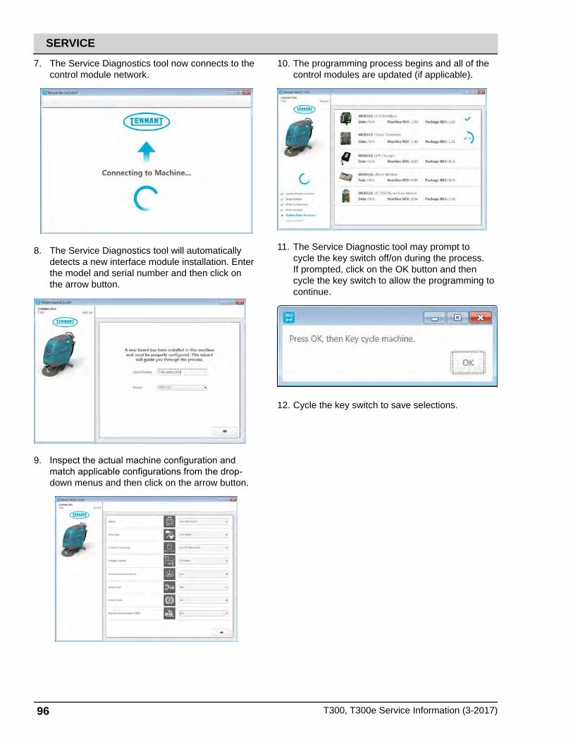
96 T300, T300e Service Information (3-2017)
SERVICE
7. The Service Diagnostics tool now connects to the control module network.
8. The Service Diagnostics tool will automatically detects a new interface module installation. Enter the model and serial number and then click on the arrow button.
9. Inspect the actual machine configuration and match applicable configurations from the drop-down menus and then click on the arrow button.
10. The programming process begins and all of the control modules are updated (if applicable).
11. The Service Diagnostic tool may prompt to cycle the key switch off/on during the process. If prompted, click on the OK button and then cycle the key switch to allow the programming to continue.
12. Cycle the key switch to save selections.

T300, T300e Service Information (3-2017) 97
SERVICE
RE-CONFIGURING EXISTING MODULES
SYSTEM REQUIREMENTS: Windows® 7 OS, Microsoft .NET 4.5 or later, USB to Mini-USB cable.
Machine software configuration, which is stored in the interface module, must be programmed if the i-Drive or interface modules are replaced in the field or if optional features are installed in the field.
Authorized service providers can download the Service Diagnostics software from the My Tennant portal by visiting www.tennantco.com. Factory-Direct Tennant Service has this software installed on their ServiceLink devices.
A USB cable connects from the notebook to an external port on the control console. The SERVICE DIAGNOSTICS TOOL configures up to five control modules depending on optional trim packages. The interface module stores configuration data and communicates via RS232 serial communication with the i-Drive and through a CAN-Bus to all other modules.
1. Connect a USB cable from a notebook computer to the machine and turn the key switch On.
2. Launch the software by double clicking the Service Diagnostics desktop shortcut or find the software in All Programs.
NOTE: Windows® may prompt a restart after installing the machine driver. Decline the restart, close Service Diagnostics and relaunch Service Diagnostics.
3. Check for machine software updates. A yellow highlight surrounding the Firmware button indicates that updates are available. Click on the Firmware button to install updates.
Updates Available(Yellow Highlight)

98 T300, T300e Service Information (3-2017)
SERVICE
4. Click on the Configuration button to display a list of configurable options.
5. Select all of the desired re-configurations that apply from the drop-down menus and then click individual arrow buttons to launch individual module re-programming (this is faster) or the header arrow button to launch all module re-programming (this is slower). Click on the refresh button to display the new configuration following reprogramming.
6. Cycle the key switch to save changes.

T300, T300e Service Information (3-2017) 99
SERVICEPROGRAMMING THE I-DRIVE MODULE (OPTION)
SYSTEM REQUIREMENTS: Windows® 7 OS, Microsoft .NET 4.5 or later, USB to Mini-USB cable.
Machine software configuration, which is stored in the interface module, must be programmed if the i-Drive or interface modules are replaced in the field or if optional features are installed in the field.
Authorized service providers can download the Service Diagnostics software from the My Tennant portal by visiting www.tennantco.com. Factory-Direct Tennant Service has this software installed on their ServiceLink devices.
A USB cable connects from the notebook to an external port on the control console. The SERVICE DIAGNOSTICS TOOL configures up to five control modules depending on optional trim packages. The interface module stores configuration data and communicates via RS232 serial communication with the i-Drive and through a CAN-Bus to all other modules.
1. Connect a USB cable from a notebook computer to the machine and turn the key switch On.
2. Launch the software by double clicking the Service Diagnostics desktop shortcut or find the software in All Programs.
NOTE: Windows® may prompt a restart after installing the machine driver. Decline the restart, close Service Diagnostics and relaunch Service Diagnostics.
3. Check for machine software updates. A yellow highlight surrounding the Firmware button indicates that updates are available. Click on the Firmware button to install updates.
Updates Available(Yellow Highlight)

100 T300, T300e Service Information (3-2017)
SERVICE
4. Click on the I-Drive button.
5. Click on the Program Factory Defaults button to program the I-Drive module.
6. Cycle the key switch to save.
DISPLAYING FAULT CODES
SYSTEM REQUIREMENTS: Windows® 7 OS, Microsoft .NET 4.5 or later, USB to Mini-USB cable.
Authorized service providers can download the Service Diagnostics software from the My Tennant portal by visiting www.tennantco.com. Factory-Direct Tennant Service has this software installed on their ServiceLink devices.
A USB cable connects from the notebook to an external port on the control console. The SERVICE DIAGNOSTICS TOOL configures up to five control modules depending on optional trim packages. The interface module stores configuration data and communicates via RS232 serial communication with the i-Drive and through a CAN-Bus to all other modules.
1. Connect a USB cable from a notebook computer to the machine and turn the key switch On.
2. Launch the software by double clicking the Service Diagnostics desktop shortcut or find the software in All Programs.
NOTE: Windows® may prompt a restart after installing the machine driver. Decline the restart, close Service Diagnostics and relaunch Service Diagnostics.
3. Active faults scroll across the top of the home screen.

T300, T300e Service Information (3-2017) 101
SERVICE
BATTERY CHARGER SETTINGS
The battery charger is set to charge the battery type supplied with your machine. If you choose to change to a different battery type or capacity, the charger’s charging profile must be changed to prevent battery damage.
The machine’s battery discharge indicator (BDI) must also be reprogrammed to match battery type to pre-vent battery damage and/or short run- time.
NOTE: For machines shipped without batteries, the battery discharge indicator and the on- board battery charger are set for GEL batteries as the default. If you choose to use a different battery type, the settings must be changed as described as below.
NOTE: For machines shipped without batteries and supplied with an Off- Board Charger, the off- board battery charger is set for wet lead- acid batteries from the factory. The machine’s battery discharge indicator is set for GEL batteries as the default. The machine’s battery discharge indicator must be reprogrammed to match charger settings (See OFF-BOARD BATTERY CHARGER below).
IRIS MODELS: For models equipped with capability to report battery charging data via IRIS, Tennant rec-ommends using the same battery type. If a different amp hour or battery type is desired, Contact Tennant Technical Support to report the new battery..
OFF-BOARD BATTERY CHARGER:
1. To change the off-board battery charger settings, See CHANGING OFF-BOARD BATTERY CHARGER SETTINGS.
2. To program the machine’s battery discharge indicator (BDI), see below:
Pro/Membrane Models - Service application soft-ware required, contact service.
Pro-Panel Model - See CHANGING ON-BOARD BATTERY CHARGER SETTINGS for Pro- Panel model.
CHANGING OFF-BOARD BATTERY CHARGER SETTINGS
1. Disconnect charger from the machine and plug charger into power supply.
The middle LED will blink upon startup and the screen display “No Battery”.
BLINKING YELLOW
2. Press and hold the two outside arrows for 12 seconds or until the middle lED turns solid yellow.
SOLIDYELLOW

102 T300, T300e Service Information (3-2017)
SERVICE
3. Press the middle button to activate the battery type options (algorithms). The left LED will turn red.
TURNSRED
4. Press the up arrow button to scroll through the battery types (algorithms) until the desired battery type is located.
5. Press the middle button to select the battery type. The red LED light will turn off.
REDTURNS
OFF
6. Press the up arrow button until the “PROGRAMMING SAVE AND EXIT” screen is displayed.
7. Press the middle button to save the new settings. The screen will display “PROGRAMMING PARAMETERS SAVED”.

T300, T300e Service Information (3-2017) 103
SERVICE
ON-BOARD BATTERY CHARGER
Pro/Membrane Models - Service application software required, contact service. As an alternative, the char-ger profile may be manually changed. See CHANG-ING ON- BOARD BATTERY CHARGER SETTINGS for Pro-Membrane model. The battery discharge in-dicator will automatically reprogram to match battery type when the battery charger profile is changed.
Pro-Panel Model - See CHANGING ON-BOARD BATTERY CHARGER SETTINGS for Pro- Panel model. The battery discharge indicator will automati-cally reprogram to match battery selection.
CHANGING ON-BOARD BATTERY CHARGER SETTINGS (Pro-Membrane model)
To manually change the on-board battery charger settings for a different battery type, carefully follow instructions as described below :
NOTE: The manual method is only an alternative if unable to change setting by use of the Service Application Software performed by Service.
1. Disconnect battery cables (Fig. 114).
Fig. 114
2. Unwrap the battery charger power cord from the cord hooks.
3. 3. Using a T25 star screwdriver, remove the two screws located at the bottom of the control console to access battery charger (Fig. 115).
Fig. 115
4. Disconnect the battery cable, power cord and wire harness from charger. Using a T25 star screwdriver, remove the four screws that mount charger to machine (Fig. 116). Remove charger from machine.
Fig. 116
5. Remove the black cap from bottom side of charger to access the profile dial (Fig. 117)
Fig. 117
6. Using a small standard screwdriver, turn the dial to the appropriate battery type according to the following chart (Fig. 118).

104 T300, T300e Service Information (3-2017)
SERVICE
Fig. 118
Dial Position
Battery Description Settings with AH Ranges
0 Factory setting* Programmed via CAN-Bus
1 Wet, Trojan 105- 155 AH2 Wet, Enersys/Tab 105- 155 AH3 AGM, Discover 80- 150 AH4 AGM, Fullriver 80- 150 AH5 AGM, TPPL, Enersys 20- 40 AH6 Gel, Sonnenschein 80- 150 AH
*The CAN-BUS setting, dial position “0”, is the soft-ware setting that is programmed to match battery type supplied with machine. When the dial is manu-ally changed to a different setting, it should not be re-set back to “0” otherwise battery damage may result. Service Application Software is required to reset dial back to “0”. Contact Service.
7. Replace the black cap on charger, reinstall battery charger and replace control console.
8. Reconnect the battery cable connection.
9. To set the BDI for the new battery type, plug the on- board battery charger cord into an electrical outlet. The machine’s software will automatically reprogram the BDI to the new battery type.
CHANGING ON-BOARD BATTERY CHARGER SETTINGS (Pro-Panel model)
NOTE: To perform this procedure, machine must be in supervisor mode. See SUPERVISOR CONTROLS instructions at back of manual.
To change the on-board battery charger settings for a different battery type :
1. Turn the key to the on position.
2. Press the settings button located on the home screen (Fig. 119).
Fig. 119
3. Press the Setup button to access the Setup screen (Fig. 120).
Fig. 120

T300, T300e Service Information (3-2017) 105
SERVICE
4. Press the Battery Type button to select the battery type installed in machine ().
Fig. 121
BATTERY CHARGER OPERATION
Above is a graph representing the I-U-I (constant current-constant voltage-contant current) charging strategy used to charge batteries. For flooded (wet) lead-acid batteries, the finish voltage can rise up to approximately 34 Volts (24 Volt System). The fin-ish phase of the charge cycle causes out gassing bubbles to mix up the electrolyte and prevent sulpha-tion build-up in the battery.
NOTE: Flooded (wet) lead-acid batteries outgas dur-ing a normal charging cycle. Always charge batteries in a well-ventilated area.
The length of charge time for each phase and overall charge time varies based on the size of the battery, size of the charger, and other conditions of the bat-tery such as discharge level, age of battery, tempera-ture, etc.
Equalization Charge Cycle - The equalization charge cycle automatically occurs once every 30 complete charge cycles on (wet) lead-acid batteries only. Charge current increases to higher levels during the equalization charge to mix layers of electrolyte that form as a result of repeated charging/discharg-ing cycles. Maintenance-free batteries can become damaged from an equalization charge, which is why it is important to make sure the Tennant-specified charger is programmed for the battery option used (see BATTERY CHARGER SETTINGS ON BOARD/OFF BOARD in the SERVICE section of this manual maintenance-free batteries, such as AGM and Gel, use slightly lower finish voltages (approximately 31 Volts) to keep the batteries from outgassing. Water can not be added to maintenance-free batteries, so these batteries must be replaced if they are repeat-edly over charged or the cells are dry due to an incompatible charger or charger setting.

106 T300, T300e Service Information (3-2017)
SERVICE
REMOVING SCRUB HEAD ASSEMBLY
FOR SAFETY: Before leaving or servicing machine, stop on level surface, turn off machine, remove key and disconnect batteries.
1. Drain recovery tank, turn off key, and disconnect batteries.
2. Remove debris tray (cylindrical only).
3. Remove scrub brushes and set aside.
4. Lower scrub head to floor.
5. Remove front shroud mounting hardware (2).
6. Pull forward to remove shroud. Set shroud aside.
7. Disconnect motor from wire harness connection.
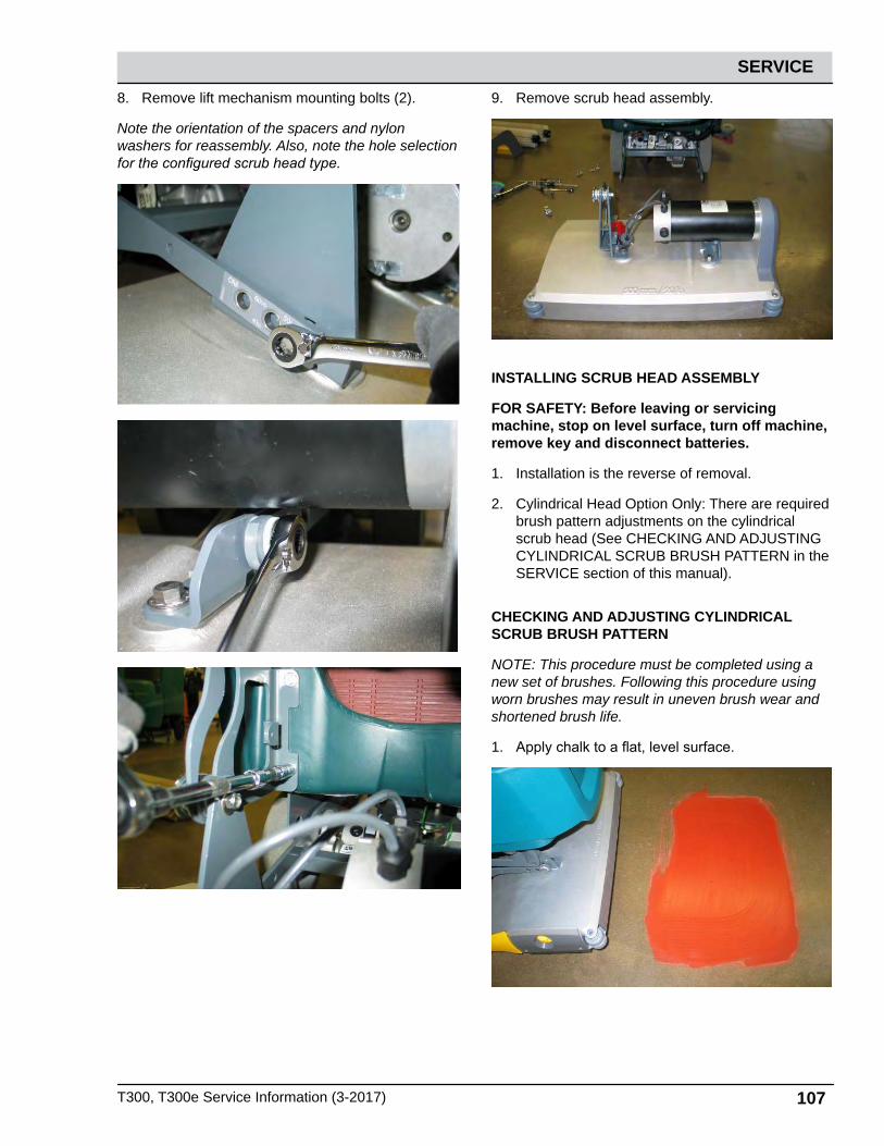
T300, T300e Service Information (3-2017) 107
SERVICE
8. Remove lift mechanism mounting bolts (2).
Note the orientation of the spacers and nylon washers for reassembly. Also, note the hole selection for the configured scrub head type.
9. Remove scrub head assembly.
INSTALLING SCRUB HEAD ASSEMBLY
FOR SAFETY: Before leaving or servicing machine, stop on level surface, turn off machine, remove key and disconnect batteries.
1. Installation is the reverse of removal.
2. Cylindrical Head Option Only: There are required brush pattern adjustments on the cylindrical scrub head (See CHECKING AND ADJUSTING CYLINDRICAL SCRUB BRUSH PATTERN in the SERVICE section of this manual).
CHECKING AND ADJUSTING CYLINDRICAL SCRUB BRUSH PATTERN
NOTE: This procedure must be completed using a new set of brushes. Following this procedure using worn brushes may result in uneven brush wear and shortened brush life.
1. Apply chalk to a flat, level surface.

108 T300, T300e Service Information (3-2017)
SERVICE
2. Disconnect the transaxle motor electrical connection.
NOTE: This must be done to keep the machine stationary during the brush pattern test.
3. Turn off ec-H2O (if equipped) and disconnect the conventional water valve from the wire harness.
NOTE: This must be done in order to keep water from washing away the chalk that has been applied to the floor. Purge any residual water, at another location, by running the brushes for 30 seconds before proceeding to Step 4.
4. Move the scrubber so that the brushes are positioned over the chalk.
5. Set parking brake.
6. Lower the scrub head to the floor and activate scrub brushes for 20 seconds and then release the handle.
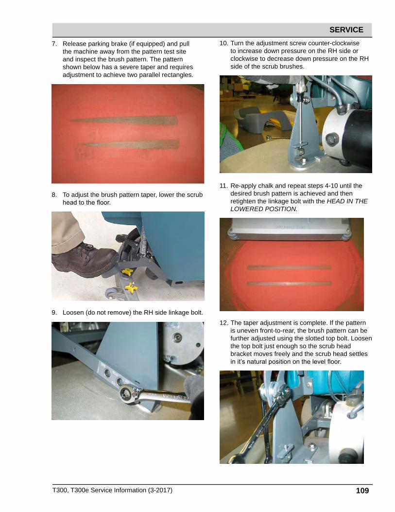
T300, T300e Service Information (3-2017) 109
SERVICE
7. Release parking brake (if equipped) and pull the machine away from the pattern test site and inspect the brush pattern. The pattern shown below has a severe taper and requires adjustment to achieve two parallel rectangles.
8. To adjust the brush pattern taper, lower the scrub head to the floor.
9. Loosen (do not remove) the RH side linkage bolt.
10. Turn the adjustment screw counter-clockwise to increase down pressure on the RH side or clockwise to decrease down pressure on the RH side of the scrub brushes.
11. Re-apply chalk and repeat steps 4-10 until the desired brush pattern is achieved and then retighten the linkage bolt with the HEAD IN THE LOWERED POSITION.
12. The taper adjustment is complete. If the pattern is uneven front-to-rear, the brush pattern can be further adjusted using the slotted top bolt. Loosen the top bolt just enough so the scrub head bracket moves freely and the scrub head settles in it’s natural position on the level floor.
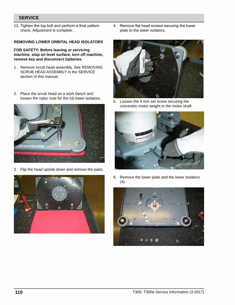
110 T300, T300e Service Information (3-2017)
SERVICE13. Tighten the top bolt and perform a final pattern
check. Adjustment is complete.
REMOVING LOWER ORBITAL HEAD ISOLATORS
FOR SAFETY: Before leaving or servicing machine, stop on level surface, turn off machine, remove key and disconnect batteries.
1. Remove scrub head assembly. See REMOVING SCRUB HEAD ASSEMBLY in the SERVICE section of this manual.
2. Place the scrub head on a work bench and loosen the nyloc nuts for the (4) lower isolators.
3. Flip the head upside down and remove the pads.
4. Remove flat head screws securing the lower plate to the lower isolators.
5. Loosen the 4 mm set screw securing the concentric motor weight to the motor shaft.
6. Remove the lower plate and the lower isolators (4).

T300, T300e Service Information (3-2017) 111
SERVICEINSTALLING LOWER ORBITAL HEAD ISOLATOR
FOR SAFETY: Before leaving or servicing machine, stop on level surface, turn off machine, remove key and disconnect batteries.
1. Installation is the reverse of removal.
2. During reassembly, place a 30 lb weight on the top of the motor while tightening the motor shaft set screw. This weight simulates the actual down force on the scrub head and sets the shaft pre-load. Torque the set screw to 15 ft-lbs (20 Nm).
30 lbs.
Set Screw
REMOVING TRANSAXLE ASSEMBLY (OPTION)
FOR SAFETY: Before leaving or servicing machine, stop on level surface, turn off machine, remove key and disconnect batteries.
1. Drain solution and recovery tanks.
2. Disconnect batteries.
3. Remove batteries and set aside.
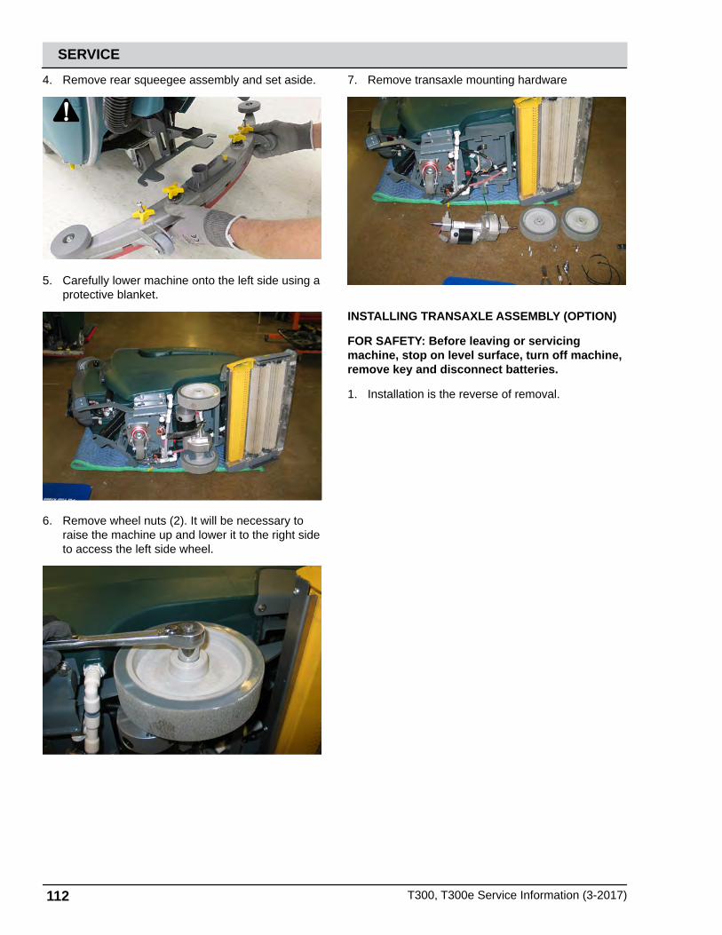
112 T300, T300e Service Information (3-2017)
SERVICE
4. Remove rear squeegee assembly and set aside.
5. Carefully lower machine onto the left side using a protective blanket.
6. Remove wheel nuts (2). It will be necessary to raise the machine up and lower it to the right side to access the left side wheel.
7. Remove transaxle mounting hardware
INSTALLING TRANSAXLE ASSEMBLY (OPTION)
FOR SAFETY: Before leaving or servicing machine, stop on level surface, turn off machine, remove key and disconnect batteries.
1. Installation is the reverse of removal.

T300, T300e Service Information (3-2017) 113
SERVICEPTC (PUSH-TO-CONNECT) FITTINGS
MAKING A CONNECTION
1. Cut the tube square. The outer diameter of the tubing must be free from score marks, burrs or sharp edges.
2. Insert tube. The fitting will grip the hose before it seals. Be sure the tube is completely inserted into the fitting.
3. Push into the tube stop. The collet has stainless steel teeth which hold the tube firmly in position while the o-ring provides a permanent leak-proof seal.
4. Pull on the fitting to check that the connection is secure. Test the system for leaks prior to leaving the site. (Fig. 4)
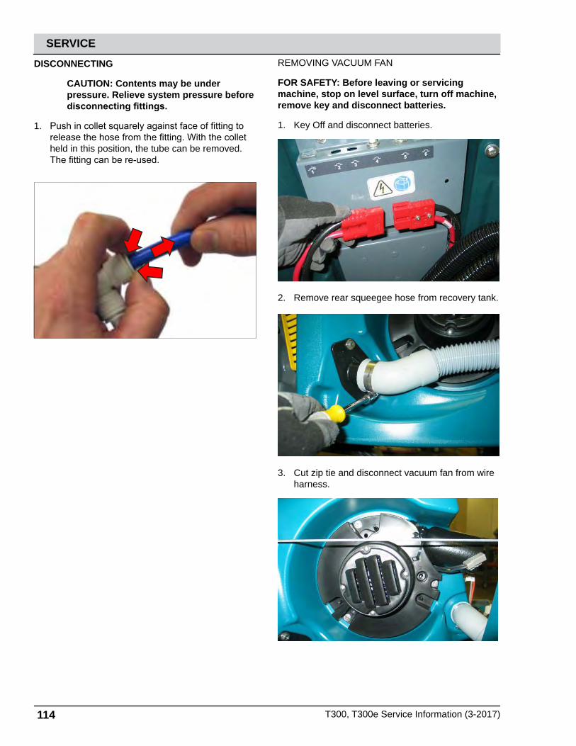
114 T300, T300e Service Information (3-2017)
SERVICE
DISCONNECTING
CAUTION: Contents may be under pressure. Relieve system pressure before disconnecting fittings.
1. Push in collet squarely against face of fitting to release the hose from the fitting. With the collet held in this position, the tube can be removed. The fitting can be re-used.
REMOVING VACUUM FAN
FOR SAFETY: Before leaving or servicing machine, stop on level surface, turn off machine, remove key and disconnect batteries.
1. Key Off and disconnect batteries.
2. Remove rear squeegee hose from recovery tank.
3. Cut zip tie and disconnect vacuum fan from wire harness.

T300, T300e Service Information (3-2017) 115
SERVICE4. Remove vacuum fan mounting hardware (3).
5. Remove vacuum fan assembly.
INSTALLING VACUUM MOTOR
FOR SAFETY: Before leaving or servicing machine, stop on level surface, turn off machine, remove key and disconnect batteries.
1. Installation is the reverse of removal.
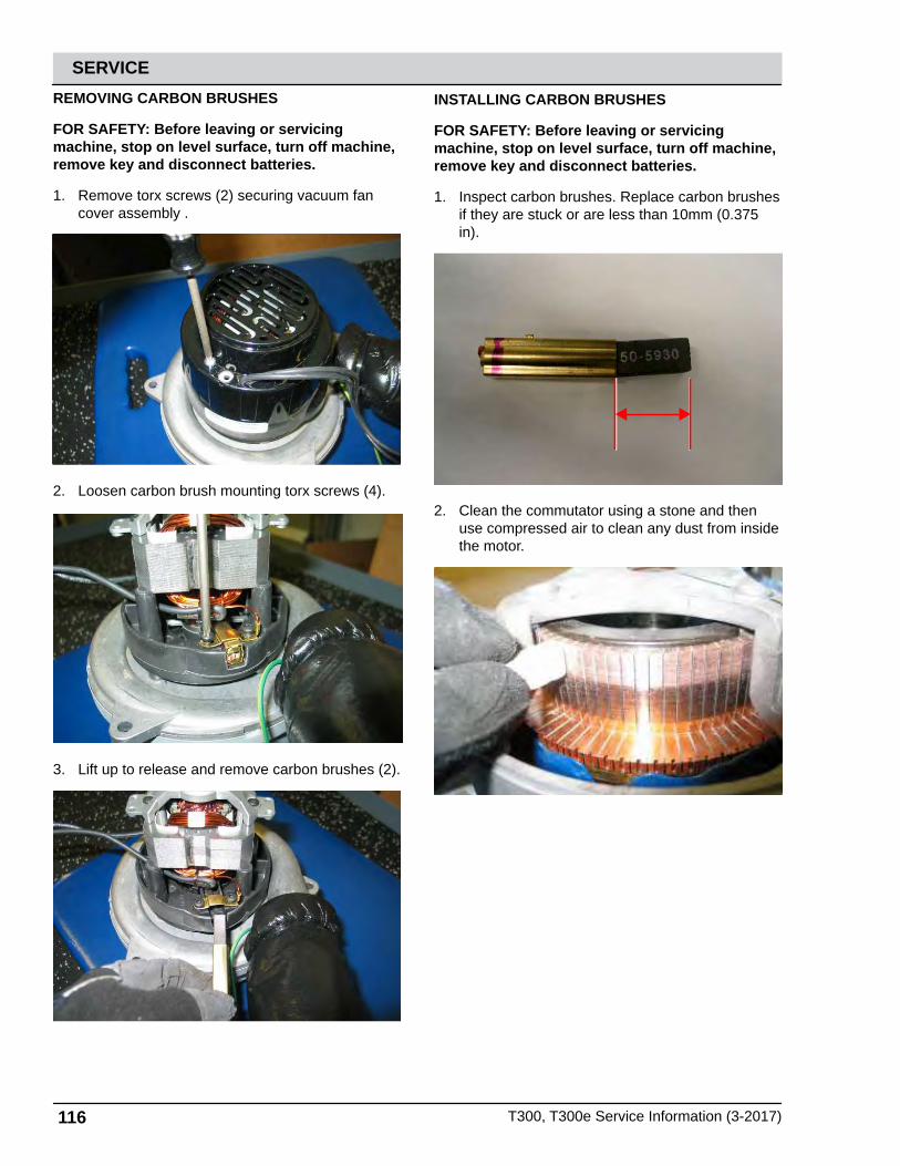
116 T300, T300e Service Information (3-2017)
SERVICEREMOVING CARBON BRUSHES
FOR SAFETY: Before leaving or servicing machine, stop on level surface, turn off machine, remove key and disconnect batteries.
1. Remove torx screws (2) securing vacuum fan cover assembly .
2. Loosen carbon brush mounting torx screws (4).
3. Lift up to release and remove carbon brushes (2).
INSTALLING CARBON BRUSHES
FOR SAFETY: Before leaving or servicing machine, stop on level surface, turn off machine, remove key and disconnect batteries.
1. Inspect carbon brushes. Replace carbon brushes if they are stuck or are less than 10mm (0.375 in).
2. Clean the commutator using a stone and then use compressed air to clean any dust from inside the motor.

T300, T300e Service Information (3-2017) 117
SERVICE
REMOVING WATER SOLENOID (T300E SHOWN)
FOR SAFETY: Before leaving or servicing machine, stop on level surface, turn off machine, remove key and disconnect batteries.
1. Drain solution and recovery tanks.
2. Disconnect batteries.
3. Remove batteries and set aside.
4. Remove rear squeegee assembly and set aside.
5. Carefully lower machine onto the left side using a protective blanket.
6. Proceed to the next step for standard models. Loosen knob set screws and remove knob. Set knob aside.

118 T300, T300e Service Information (3-2017)
SERVICE
7. Disconnect electrical connections and remove T-25 Torx mounting screws (2). Set hardware aside.
8. Disconnect PTC (Push-To-Connect) connections (2) from solenoid. See PTC (PUSH-TO-CONNECT) FITTINGS in the SERVICE section of this manual.
INSTALLING WATER SOLENOID
FOR SAFETY: Before leaving or servicing machine, stop on level surface, turn off machine, remove key and disconnect batteries.
1. Installation is the reverse of removal.
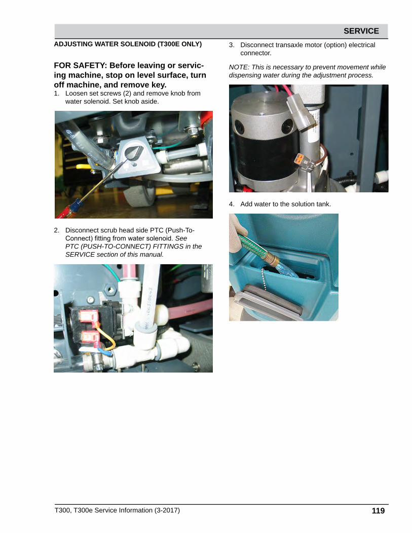
T300, T300e Service Information (3-2017) 119
SERVICEADJUSTING WATER SOLENOID (T300E ONLY)
FOR SAFETY: Before leaving or servic-ing machine, stop on level surface, turn off machine, and remove key.1. Loosen set screws (2) and remove knob from
water solenoid. Set knob aside.
2. Disconnect scrub head side PTC (Push-To-Connect) fitting from water solenoid. See PTC (PUSH-TO-CONNECT) FITTINGS in the SERVICE section of this manual.
3. Disconnect transaxle motor (option) electrical connector.
NOTE: This is necessary to prevent movement while dispensing water during the adjustment process.
4. Add water to the solution tank.

120 T300, T300e Service Information (3-2017)
SERVICE
5. Place a shallow catch basin below the water solenoid, turn on floor scrubber and activate conventional solution flow by squeezing the handle assembly.
NOTE: Attaching a zip tie will assist in holding the handle while making adjustments to the water solenoid.
6. Turn the solenoid valve stem completely counter clockwise for maximum water flow.
7. Slowly turn the valve stem clockwise until water flow stops. Stop immediately when water flow stops. This is the no-flow or clockwise knob setting.
8. Reinstall the adjustment knob against the stop pin as shown below. Tighten set screws (2).
NOTE: Tighten one set screw and then rotate the knob to gain access to the other set screw.
9. Reconnect PTC (Push-To-Connect) fitting to water solenoid valve, cut zip tie securing bail handle, and reconnect transaxle motor connection. Adjustment is complete.

T300, T300e Service Information (3-2017) 121
SERVICE
CONTROL MODULES
REMOVING MACHINE CONTROL MODULE (OPTION)
1. Drain solution and recovery tanks.
2. Disconnect batteries.
3. Remove batteries and set aside.
4. Cut zip ties securing hoses and wire harnesses to cover.
5. Remove the heat sink mounting bolts (2).
6. Carefully lower the heat sink and machine control module assembly and then disconnect all electrical connections.
NOTE: Be careful not to damage the IRIS radio antenna (option) when lowering the assembly.

122 T300, T300e Service Information (3-2017)
SERVICE7. Remove the heat sink and machine control
module assembly from the scrubber.
INSTALLING CONTROL MODULE
FOR SAFETY: When servicing machine, disconnect battery connections before working on machine.
1. Attach a static wrist strap to the battery (-) terminal to prevent ESD damage to the logic board.
2. Installation is reverse of removal.
NOTE: The torque specification for control module electrical cables is 52 in-lbs (6 Nm).
REMOVING i-DRIVE MODULE (OPTION)
FOR SAFETY: When servicing machine, disconnect battery connections before working on machine.
1. Key Off and batteries disconnected.
2. Remove T-25 torx mounting screws (2).
3. Carefully lower access cover.
4. Remove four (4) hex screws to remove the control console plate.

T300, T300e Service Information (3-2017) 123
SERVICE
5. Disconnect electrical connections and remove I-Drive mounting screws (2).
INSTALLING I-DRIVE MODULE (OPTION)
FOR SAFETY: When servicing machine, disconnect battery connections before working on machine.
1. Installation is reverse of removal.
2. The new I-Drive module must be programmed to operate in the scrubber. See SERVICE DIAGNOSTICS TOOL in the SERVICE section of this manual.
REMOVING ONBOARD BATTERY CHARGER (OPTION)
FOR SAFETY: When servicing machine, disconnect battery connections before working on machine.
1. Key Off and batteries disconnected.
2. Remove T-25 torx mounting screws (2).
3. Carefully lower access cover.
4. Disconnect charger electrical connections.

124 T300, T300e Service Information (3-2017)
SERVICE
5. Remove battery charger mounting torx hardware (4).
6. Remove battery charger.
INSTALLING ONBOARD BATTERY CHARGER
FOR SAFETY: When servicing machine, disconnect battery connections before working on machine.
1. Installation is reverse of removal.
NOTE: This battery charger can be programmed for multiple battery configurations. This configuration data is stored in the interface module and will automatically configure a replacement battery charger once installed and following a power-up cycle. Reprogramming is required if the interface module has been replaced, or if a different type of battery is used in the equipment (i.e. other than factory-installed equipment). (See SERVICE DIAGNOSTICS TOOL in the SERVICE section of this manual)
Models equipped with the PRO-Panel LCD Touch Panel can be configured through the touch panel. All other models must be configured using separate configuration software via a mini-USB programming port on the back of the operator’s console. (See SERVICE DIAGNOSTICS TOOL in the SERVICE section of this manual.)

T300, T300e Service Information (3-2017) 125
SERVICE
REMOVING INTERFACE MODULE
FOR SAFETY: When servicing machine, disconnect battery connections before working on machine.
1. Key Off and batteries disconnected.
2. Attach a static wrist strap to the battery (-) terminal to prevent ESD damage to the logic board.
3. Remove T-25 torx mounting screws (2).
4. Carefully lower access cover.
5. Remove T-25 torx mounting screws (2).
6. Lift up on the bottom of the panel and slide downward to remove.
7. Disconnect electrical connections and remove interface module.
INSTALLING INTERFACE MODULE
FOR SAFETY: When servicing machine, disconnect battery connections before working on machine.
1. Installation is reverse of removal.
2. The new interface module must be programmed to operate in the Scrubber. See SERVICE DIAGNOSTICS TOOL in the SERVICE section of this manual.

126 T300, T300e Service Information (3-2017)
SERVICE
REMOVING BAIL SWITCH, SPEED POTENTIOMETER, OR DIRECTIONAL SWITCH
FOR SAFETY: When servicing machine, disconnect battery connections before working on machine.
1. Key Off and batteries disconnected.
2. Remove rear access cover mounting screws (2).
3. Carefully lower access cover.
4. Remove T-25 torx mounting screws (2).
5. Carefully separate the touch panel from the console and disconnect all electrical connections. Set instrument panel aside.
6. Remove T-25 torx mounting screw (1).
7. Remove cover and set aside.
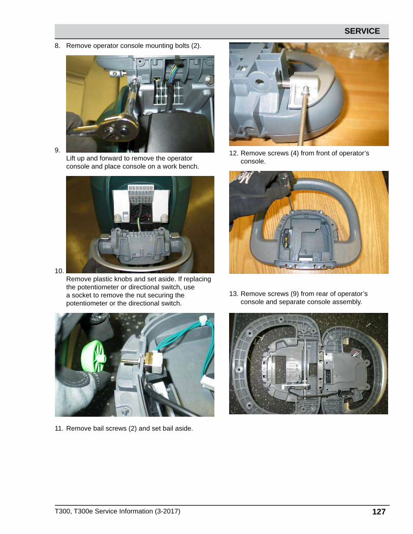
T300, T300e Service Information (3-2017) 127
SERVICE
8. Remove operator console mounting bolts (2).
9. Lift up and forward to remove the operator console and place console on a work bench.
10. Remove plastic knobs and set aside. If replacing the potentiometer or directional switch, use a socket to remove the nut securing the potentiometer or the directional switch.
11. Remove bail screws (2) and set bail aside.
12. Remove screws (4) from front of operator’s console.
13. Remove screws (9) from rear of operator’s console and separate console assembly.

128 T300, T300e Service Information (3-2017)
SERVICE14. Release spring, rotate mechanism towards
bottom of operator console, and slide assembly to the side to remove.
15. Remove bail switch.
INSTALLING BAIL SWITCH, SPEED POTENTIOMETER, OR DIRECTIONAL SWITCH
FOR SAFETY: When servicing machine, disconnect battery connections before working on machine.
1. Installation is reverse of removal.