Embed Size (px)
Citation preview
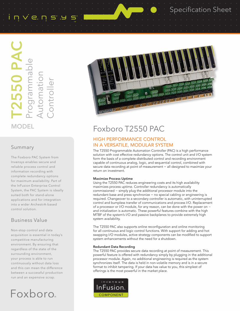
HIGH PERFORMANCE CONTROLIN A VERSATILE, MODULAR SYSTEMThe T2550 Programmable Automation Controller (PAC) is a high performance solution with cost effective redundancy options. The control unit and I/O system form the basis of a complete distributed control and recording environment capable of continuous analog, logic, and sequential control, combined with secure data recording at point of measurement − all designed to maximize your return on investment.
Maximize Process UptimeUsing the T2550 PAC reduces engineering costs and its high availability maximizes process uptime. Controller redundancy is automatically commissioned − simply plug the additional processor module into the redundant base and press synchronize − no special cabling or engineering is required. Changeover to a secondary controller is automatic, with uninterrupted control and bumpless transfer of communications and process I/O. Replacement of a processor or I/O module, for any reason, can be done with the power on − and initialization is automatic. These powerful features combine with the high MTBF of the system’s I/O and passive backplanes to provide extremely high system availability.
The T2550 PAC also supports online reconfiguration and online monitoring for all continuous and logic control functions. With support for adding and hot swapping I/O modules, active strategy components can be modified to support system enhancements without the need for a shutdown.
Redundant Data RecordingThe T2550 PAC provides secure data recording at point of measurement. This powerful feature is offered with redundancy simply by plugging in the additional processor module. Again, no additional engineering is required as the system synchronizes itself. The data is held in non-volatile memory and is in a secure format to inhibit tampering. If your data has value to you, this simplest of offerings is the most powerful in the market place.
Summary
The Foxboro PAC System from
Invensys enables secure and
reliable process control and
information recording with
complete redundancy options
for maximum availability. Part of
the InFusion Enterprise Control
System, the PAC System is ideally
suited both for stand-alone
applications and for integration
into a wider ArchestrA-based
control solution.
Business Value
Non-stop control and data
acquisition is essential in today’s
competitive manufacturing
environment. By ensuring that
regardless of the state of the
surrounding environment,
your process is able to run
continuously without data loss
and this can mean the difference
between a successful production
run and an expensive scrap.
Foxboro T2550 PAC
T25
50
PA
CPr
og
ram
mab
leA
uto
mat
ion
Co
ntro
ller
MODEL
Specification Sheet

Autonomous and Integrated, Scalable, and DistributedThe T2550 PAC provides a comprehensive standalone solution or a powerful addition to a wider system. Communicating over 10/100baseT Ethernet (ELIN), its peer-to-peer communications system can be used for interlocking, signal conditioning, alarm monitoring, remote data acquisition, or devolved control. The T2550 PAC supports Modbus TCP, serial Modbus RTU (both as master or slave), Profibus slave, simple customer specific protocols, and OPC. The T2550 PAC can be used in conjunction with other systems such as PC based SCADA packages, Programmable Logic Controllers, and Eycon Visual Supervisor, or can provide an effective standalone solution.
A range of DIN rail mounting base sizes is available for I/O modules and serial communication interfaces. Multiple bases can be easily interconnected so processors can share interlocking, acquisition, and multi-loop control solutions in distributed and larger scale applications.
Scalable Control Units Match Process HierarchyThe modular nature and seamless interaction of ELIN based control units allow both physical distribution and adoption of a structured control methodology.
T2550 Programmable Automation ControllerEach T2550 PAC base is capable of analog, logic, and sequence control and is self-contained up to a capacity of 128 I/O points. Larger systems can be easily implemented by interconnecting multiple T2550 PAC base units to form a distributed system utilizing the peer-to- peer communications.
Alternative Ethernet and serial communications protocols are available to facilitate simple connection to other equipment.
Devices supporting their own serial protocol can be connected to the T2550 PAC using the open communications (raw communications) option.
T2550 PAC Unit SupervisorLarge systems or complex sequence and batch applications are treated in a ‘layered’ fashion by decoupling the front-end, closedloop control its associated I/O and control modules (logical devices) from the main strategy. This follows the S88.01 standard for batch control and is achieved by assigning the role of strategy coordination to the ‘short’ version of the T2550 PAC. This T2550 PAC, which uses the same processor as the standard controller has no I/O and provides coordination and sequence control of the lower level elements.
Redundant ProcessingUsing the T2550 PAC as a redundant controller pair automatically protects your process against controller or communications failure. If external or field I/O communications to the active controller, or the active controller itself fail, then the secondary controller automatically takes over, providing uninterrupted control and bumpless transfer of the communications, process I/O, and data historian. An alarm warns the operator that the changeover event has occurred.
A processor can be replaced for any reason with the power on. Commissioning a redundant capable processor is simple: Plug the second processor into a redundant base unit and press synchronize − all the rest is automatic. No special cabling is required.
Continuous and Logic ControlThe T2550 PAC supports the level of block structuring normally only found in advanced DCS systems. The continuous strategy is built up by interconnection of function blocks from a rich library of analog and logic elements.
Sequence ControlSequences act in a supervisory role relative to the continuous database and can be loaded and unloaded independently. This is increasingly important for batch sequences, which relate to the process rather than the physical equipment, as these must be changed to meet the requirement of flexible plants. The capacity of the local filing system allows storage of a large number of sequences. Their operation is controlled through specialized blocks in the continuous database.
ELIN System ArchitectureELIN is Ethernet based Local Instrument Network. The ELIN control network is the backbone of the control and data acquisition network that provides peer-to-peer communications between control nodes and seamless access to all data by operator and configuration workstations.
All nodes appear as part of a coherent distributed database. The database in any networked element is accessible to any other network element, allowing complete flexibility in strategy interconnection.
ELIN supports OPC with a readily available server for direct connection to operator and configuration workstations. It also supports Eycon visual supervisor and other Eurotherm control and logging units in which standalone or panel-mounted display and control is needed. Remote monitoring, diagnostics, and application enhancement is available via secure off site communications.

ConfigurationAt the heart of the system is the LINtools configuration and engineering station. LINtools is a comprehensive set of configuration, test, documentation, and commissioning tools for strategy elements distributed over the LIN control backbone.
The LINtools suite includes graphical configuration of block structured continuous control, sequence control SFCs, ladder, and graphics for any LIN based product. View and Online reconfiguration modes allow dynamic monitoring and editing of running databases and flow charts.
LINtools follows the IEC 61131-3 standard for sequence configuration, while adopting a decoupling of continuous and sequential strategy appropriate to complex process control.
LINtools is designed for simplicity and productivity. Online help, free-format text annotation and area editing are included to make LINtools easy to use and configuration easy to understand and reuse. LINtools runs on a standalone or networked PC.
IEC 61131Languages appropriate for the I/O type and for the application are:• Function Block Diagrams • Structured Text• Sequence Function Charts • Ladder Logic Control
Online ReconfigurationLarge and complex control systems are expected to serve many needs and work well for long periods without shutdown under ever varying workloads. Online reconfiguration provides a useful foundation for enhancement of a deployed control system and allows modification of the systems application software while it is running. It allows active strategy components to be modified, wrapped with additional functionality, or replaced with a different implementation. The T2550 PAC has generic support for adding and hot swapping I/O. Online reconfiguration can use the same
or new I/O interfaces and any internally available variables. You can tentatively add and delete function blocks and wires to create a new or improved control strategy for your application while the process is running. You can then try the strategy to ensure it is correct before final application. A secure file tracking system is provided for version control.
Continuous ControlContinuous strategies are configured graphically on screen using ‘block structured’ techniques implemented across the system. The control configurator supports a comprehensive library of functions together with powerful editing and compound definition facilities. Merging allows the re-use of similar sections of databases, avoiding duplication of effort. Free text can be placed on the screen or attached to function blocks for simple production of descriptive documentation. Context-sensitive help reduces the need of referring to manuals.
SequenceSequences are configured graphically using Sequential Function Charts (SFCs) following the IEC 61131-3 standard. Steps initiate Actions which may be Structured Text statements (ST) or nested SFCs. Transitions determine when control passes from one step to the next. By accessing the continuous control strategy this configurator presents the available points through a menu system thus eliminating the need to remember the names of points and reducing the likelihood of typing errors.
The sequence configurator supports text annotation and context sensitive help. A combination of mapping lists and generic Sequential Function Charts are available to easily duplicate identical SFC models on different units (tags).
Action BlockAction blocks in the continuous control strategy have theirfunctionality defined in Ladder diagrams or Structured Text (ST)within a standard template. These are particularly useful forimplementation of plant control modules.
DocumentationLINtools provides an electronic documentation facility including the graphical representation of the control strategy and a listing of the block parameters and connections. This can be transferred across the network and output can be to a printer, Postscript, or AutoCAD compatible format. Free-format user annotations can be added to complete your documentation requirements.
Multi-Setpoint ProgrammerMany applications need to vary the process value over time: Temperature control is one such application in which it is very common to ‘ramp’ the process value (channel) from one level to another over a set time period using a setpoint program.
The PAC provides support for multiple setpoint programs that can be run simultaneously. Each program is capable of profiling up to eight channels, with up to 32 segments per profiled channel. In addition to controlling the setpoint during each segment of the profile, the controllers can also be used to activate up to 16 digital events during a segment.
The setpoint program feature enables an operator to select and run a pre-configured setpoint program. A preview facility allows the operator to view the selected program before running it. Once the program is running, the setpoint and achieved process values are both plotted on the trend screen.

Setpoint Program WizardFor ease of use, LINtools incorporates a wizard for creating a setpoint program. By following the on screen prompts and editing the parameters as required, a setpoint program can be simply and quickly created with all required blocks automatically created and added to the database.
Setpoint Program EditorIn addition to the setpoint program wizard, programs can be created or edited off–line using the setpoint program editor supplied with LINtools. As an ActiveX, this tool can be inserted into any of your visualization packages.
Redundant Recording and ArchivingProgrammable Automation Controllers (PACs) have internal non-volatile flash memory for secure tamper resistant data storage, and providing for redundant data logging. In addition all PAC processors support Ethernet connectivity. As such, data stored within the internal flash memory can be configured to periodically archive to primary, secondary, and tertiary FTP servers. Archiving files to FTP servers provides a secure, infinite archiving capacity.
Data HistorianData historian is used to store PVs, message and alarm information in the internal flash memory in order to generate historical data in the form of a set of secure, tamper resistant history files. The following example provides estimated memory duration based on an 8-way base logging 16 Parameters to a single group:
Recording Interval Estimated Duration(Update A) Min/Max Off Min/Max On
1s 60 hrs 31 hrs5s 12 days 6 days
10s 25 days 13 days20s 50 days 26 days60s 150 days 77 days
FTP PushFor efficiency, historical data files are automatically deleted on a first in first out (FIFO) basis from the internal flash memory of the PAC (7Mb for history). In order to ensure longevity of data the PAC is able to push historical data files (.uhh) to primary, secondary, or tertiary FTP servers at user defined intervals. Thus, depending on the archive strategy chosen, data is never lost.
Data ArchivingData archiving is used to copy selected parts of the history, i.e. one or more history files (.uhh) to primary, secondary, or tertiary FTP Servers.
Historian Store and Forward‘Store and Forward’ is a self healing 21 CFR Part 11 data archiving system which automatically stores data during a communication failure in the T2550 PAC hardware and then forwards this data to the configured data historian server once communication is reinstated.
The T2550 PAC provides dual redundant data acquisition using Secure.uhh files created at the local level, which results in a secure electronic recording system with total data integrity.
Alarm ManagementAlarms are managed and collected within the T2550 PAC to provide features such as alarm status and priority, acknowledgement, date and time stamping at the source, as well as suppression and local message historian storage.
Open CommunicationsThe PAC provides a special function block to define any simple serial communications protocol. This function block can be used to integrate many 3rd party devices which use ASCII communications, such as bar code readers and particle counters. Direct control over transmit and receive also allows multi-node connections.
HMI ReportsHMI Reports provides an intuitive reporting package to develop and print reports using the secure data from the T2550 PAC. The package includes a report studio for configuring report projects and a run-time execution module to generate and print reports in many different formats to printers file servers, and via e-mail. HMI Reports is also optionally available as a web portal.

255BF: BASE UNITThe base unit is fitted with the T2550 PAC I/O controller modules plus additional I/O modules. These modules plug onto terminal units, which provide the wiring interface between the plant or machine and the I/O modules. Bases are available in 5 sizes to suit the number of modules required in a particular system.
Communication between the I/O modules and the processor is effected by the use of a passive internal module I/O bus running the width of the base.
Each module position is tracked separately for additional security during live replacement of I/O modules.
The base consists of an aluminium extrusion, the internal I/O bus, and mounting supports. It is designed to be DIN rail mounted or directly fixed to a bulkhead or mounting plate. Both base and modules can be installed horizontally or vertically.
MechanicalControl Loops: Up to 8 control blocksI/O Module capacity 0 8 16Width (mm) 3 264 467Weight no modules (Kg) 0.2 0.7 1.2Weight all modules (Kg) 0.5 2.1 3.7Height: 180mmDepth: 102.9-132.9mm with retaining lever raisedMounting: DIN rail or Bulkhead, can be mounted horizontally or verticallyDIN rail: Use symmetrical DIN rail to EN50022-35 x 7.5 or 35 x 15Casing: Without additional protection IP20Ventilation space: 25mm free space above and below
Termination UnitsThe I/O modules are mounted on the base using terminal assemblies. Terminal assemblies provide the interface between the input and output signals and the I/O modules. Terminal assemblies and I/O modules are keyed to inhibit insertion of the incorrect module to prevent damage to both equipment and plant.
Individual termination units provide for easy module replacement leaving the field wiring connected. Modules are inserted and removed from the termination unit using a unique, tool-less, locking lever system.
Test Disconnect UnitsTerminal assemblies have an optional fuse or link (isolator or disconnect). This provides a series of connections between the customer terminals and the I/O module, permitting pluggable fuse or link units to be placed in series with the signal. Fuse and link units are not interchangeable.
T2550 PAC: GENERAL SPECIFICATIONSSupply voltage range: 19.2 to 28.8V dcVA requirements: < 80W maximum for fully loaded rackFuse rating: 4A time lag (Not customer replaceable)IOC warm start time: 1 hours without external batteriesIOC power consumption: 1.5W maximumSurge current: 8A maximumModule power consumption: See individual module specification
EnvironmentalOperating temperature: 0 to 55°CStorage temperature: -25 to 85°CRelative humidity: 5 to 95% (non-condensing)
RFIEMC emissions: BS EN61326 2002-02EMC immunity: BS EN61326 2002-02
Safety BS EN61010-1/A2;19931995 Installation cat II, Pollution degree 2 Safety earth and screen connections are made to clearly marked earth terminals at the bottom of the base
Vibration EN60068-2 test FCVibration: IEC1131-2 section 2.1.3 0.075mm peak amplitude 10-57Hz; 1g, 57-150HzShock: 20g static shock
Diagnostic LEDsDiagnostic LEDs indicate module diagnostic status.
All modules: A green LED at the top indicates the module is powered and operating correctlyPAC analog modules: Have red LEDs for each channel to indicate channel failure PAC digital modules: Have Yellow LEDs for each channel to indicate the channel state
Processor modulePrimary processor and communications diagnostics are available from the LEDs on the front of the processor module. More advanced diagnostics are available remotely using LINtools monitor online over Ethernet to review the diagnostic blocks.
PAC Controller module: A green LED at the top indicates the module is powered and operating correctlyInternal diagnostics: A red LED indicates failure of the internal self diagnostic routinesBattery (if installed): A green LED indicates battery healthSerial communications: A yellow LED indicates communications activityDuplex: Indicates inter processor communicationsPrimary/Standby: Two LEDs indicate status informationIP address: A yellow LED indicates if the unit has resolved its IP address for Ethernet communicationsEthernet: Two LEDs indicate link activityLink speed: 10/100baseTPower On self tests: On power up the T2550 PAC automatically performs Power On Self Tests. These are a series of diagnostic tests used to assess the instrument. The above LEDs indicate module
SPECIFICATIONS
ORDER CODE — Redundant Base255BF-16R/C16/CDM/-/- 16 module base with earth clamps255BF-08R/C08/CDM/-/- 8 module base with earth clamps255BF-06R/C06/CDM/-/- 6 module base with earth clamps255BF-04R/C04/CDM/-/- 4 module base with earth clamps255BF-16R/NON/CDM/-/- 16 module base without earth clamps255BF-08R/NON/CDM/-/- 8 module base without earth clamps255BF-06R/NON/CDM/-/- 6 module base without earth clamps255BF-04R/NON/CDM/-/- 4 module base without earth clamps255BF-00S/NON/CDM/-/- 0 module base for additional processors and comms

CPU RedundancyProcessor redundancy is available for continuous, logic, and sequence control. A pair of processors operate in primary / secondary configuration with a high speed data link between them providing exact tracking of the control, logic, and sequence databases. Transfer from the primary to secondary processor is bumpless. The non-active processor can be replaced while the system is running and on synchronization it loads its strategy from the active primary processor.
Redundant: < 0.6s bumpless transfer for processor and I/OChangeover time: dependant on application sizeSynchronisation time: dependant on application size
Processor SwitchoverDuring a processor switch over all outputs remain at the last value. The new primary processor begins executing is application from precisely the same point as the original processor. Each processor has its own Ethernet IP address and each redundant pair uses two neighboring node addresses on the ELIN network. This enables the system to communicate with the primary while still continuously testing communications to both processors. On processor switchover the ELIN node address is dynamically swapped to allow SCADA applications to display and log uninterrupted data. Switchover amongst LIN nodes is transparent.
The following conditions can cause the processor to switch over:
Hardware Failure: Failure of primary controller internal health checks.
Hardware Removal: Removing the primary processor will cause the secondary to take immediate control. Removing the secondary will have no effect on control but will cause a system alarm on redundant configured systems.
Internal Communications: Primary and secondary controllers continually monitor the communications to the I/O on the local base. Should the primary controller not be able to communicate with the I/O and the secondary can still communicate with the I/O switchover will occur. If the secondary processor observes a fault in the primary communications or can see more I/O modules the secondary processor will request a switchover.
External Communications: monitors external controller communications. Should the primary controller not be able to communicate with other declared nodes on the LIN network and the secondary can still communicate with the declared nodes a switchover will occur. If the secondary processor observes that it can see more declared nodes, the secondary processor will request a changeover.
Manual Request: A user can request a switchover if a secondary processor is running, synchronized and healthy.
Removable SD Memory Card: The storage of the cold start application files, the processor firmware and software licence code is on a secure SD flash card to enable easy transfer from one processor to a replacement.
PhysicalCPU: Motorola MPC852TBus size: 32 bitSystem clock: 66 MHzRemovable Flash card size: 32 Mbytes
Control SwitchesProcessor front panel Watchdog reset. Processor synchronization/push button switches: switchover. Processor resynchronization.
Power Supply ConnectionThe duplex terminal unit supports dual power supply connection. In the event of a single power supply failure both processors are still supplied allowing redundant operation to continue uninterrupted.
To facilitate hot start of the processors. A super capacitor maintains memory for up to 12 hours in the event of complete power failure. An external battery can be fitted to extend this backup time on the redundant system.
Super cap (Processor): Maintains memory/real time clock and enables hot start for up to 1 hours in absence of battery backup input
Simplex (O base): Battery support for data in SRAM and the Real-Time Clock for a minimum of 72 hour continuous (5 year intermittent use)Redundant: Additional terminals for an external battery connection to support SRAM and the Real-Time ClockExternal rechargeable battery: Use S9537Battery charger: Use S9538
Watchdog RelaysEach processor is fitted with a single watchdog relay.Watchdog relay: SPST, 1 per CPU, connectable in parallel or seriesContact rating (resistive): 24V ac/dc at 0.5AIsolation: 30V ac rms or 60V dc
Live plug-inProcessors and I/O modules can be replaced while powered without any disturbance to the field wiring or other inputs and outputs – reducing downtime and minimizing disturbance to other signal conditioning strategies.
T2550 PAC—Order CodeBasic product255F Programmable Automation Controller1 - IOC and software L = Standard License D = Data Logging Foundation Standard Control AdvancedL10/D10 Unbounded 0 0 offL20/D20 Unbounded 50 4 offL30/D30 Unbounded 100 8 offL40/D40 Unbounded Unbounded 12 offL50/D50 Unbounded Unbounded 16 offL60/D60 Unbounded Unbounded 24 offL70/D70 Unbounded Unbounded 32 offL80/D80 Unbounded Unbounded Unbounded offL90/D90 Unbounded Unbounded Unbounded on2 - Flash Card SizeF32 32M Flash card (standard)NONE None fitted3 - Ethernet Communications ProtocolELIN Ethernet Local Instrument Network (LIN) peer-to-peerMBTM Modbus-TCP Master communications (includes LIN peer-to-peer)4 - Serial Communications ProtocolSER0 HMI communications (non isolated)MOD0 Modbus master communications (non isolated) and Raw communicationsPBUS Profibus DP slave communications (9 pin D connector)

Control SpecificationsContinuous Database ResourcesMaximum database size . . . . . . . . . . . . . . . . . . . . . . . . default max values 210k bytesDatabase ResourcesNumber of database blocks . . . . . . . . . . . . . . . . . . . . . . . . . . . . . . . . . . . . . . . . . . . . 630Number of database templates . . . . . . . . . . . . . . . . . . . . . . . . . . . . . . . . . . . . . . . . . . .50Number of template libraries . . . . . . . . . . . . . . . . . . . . . . . . . . . . . . . . . . . . . . . . . . . . .32Number of external databases . . . . . . . . . . . . . . . . . . . . . . . . . . . . . . . . . . . . . . . . . . .32Number blocks in local Dbase cached elsewhere . . . . . . . . . . . . . . . . . . . . . . . . 1260Number blocks in remote Dbases cached locally . . . . . . . . . . . . . . . . . . . . . . . . . 315Number of server tasks . . . . . . . . . . . . . . . . . . . . . . . . . . . . . . . . . . . . . . . . . . . . . . . . . . .6Number of field-to-field connections . . . . . . . . . . . . . . . . . . . . . . . . . . . . . . . . . . . 1260Sequence Control ResourcesSequence memory Programme data . . . . . . . . . . . . . . . . . . . . . . . . . . . . . . 105k bytesSFC ResourcesNumber of root SFCs loadable . . . . . . . . . . . . . . . . . . . . . . . . . . . . . . . . . . . . . . . . . . .31Number of steps loadable . . . . . . . . . . . . . . . . . . . . . . . . . . . . . . . . . . . . . . . . . . . . . 420Number of ‘wires’ permitted going into and out of step . . . . . . . . . . . . . . . . . . . 1407Number of transitions . . . . . . . . . . . . . . . . . . . . . . . . . . . . . . . . . . . . . . . . . . . . . . . . . 630Number of ‘wires’ permitted going into transitions . . . . . . . . . . . . . . . . . . . . . . . . 840Number of action associations. . . . . . . . . . . . . . . . . . . . . . . . . . . . . . . . . . . . . . . . . 1680Number of actions . . . . . . . . . . . . . . . . . . . . . . . . . . . . . . . . . . . . . . . . . . . . . . . . . . . . 840User TasksMultiple tasks are available to the user to tune the update rate of I/O response and the control function.User Tasks . . . . . . . . . . . . . . . . . . . . . . . . . . . . . . . . . . . . . . . . . . . . . . . . . . . . . . . . . . . . . .4User Task Update RatesTask I − Synchronous to Fast I/O . . . . . . . . . . . . . . . . . . . . . . . . . . . . . 10ms or N*10msOnly version 2 10ms I/O types can be assigned to this task (see table)Task 2 − Auxiliary task to task1 . . . . . . . . . . . . . . . . . . . . . . . . . . . . . . . 10ms or N*10msRuns at task 1 rate or integer multiple of task 1 rateTask 3 − Synchronous to Standard I/O . . . . . . . . . . . . . . . . . . . . . .110ms or N*110msAll analog and digital I/O types can be assigned to this taskTask 4 − Auxiliary task to task3 . . . . . . . . . . . . . . . . . . . . . . . . . . . . .110ms or N*110msRuns at task 3 rate or integer multiple of task 3 rate
Supported I/O Module TypesThe T2750 PAC shares I/O modules with the T2550PAC and 2500 I/O.
Type Description Maximum Original Version Update Speed Modules 2 AI2 Analog Input 2 channels (all I/O types) 110ms -AI3 Analog Input 3 channels (mA + Tx PSU) 110ms -AI4 Analog Input 4 channels (TC, mV, mA) 1 10ms -AO2 Analog Output 2 channels (mA or V) 110ms 110ms/10ms*DI4 Digital Input 4 channels (logic) 110ms -DI6_MV Digital Input 6 channels (115V ac rms) 110ms -DI6_HV Digital Input 6 channels (230V ac rms) 110ms -DI8_LG Digital Input 8 channels (logic) 110ms 10msDI8_CO Digital Input 8 channels (contact) 110ms 10msDO4_LG Digital Output 4 channels (10mA) 110ms† 10msDO4_24 Digital Output 4 channels (100mA) 110ms† 10msRLY4 Relay Output 4 channels (3 n/o, 1 c/o) 110ms† 10msDO8 Digital Output 8 channels (1A per ch) 10ms -FI2 Frequency Input 2 channels 10ms -ZI Zirconia Input Module 110ms -
Notes: †The T2750 PAC supports only Version 2
Setpoint programmer (V5.0 or higher) Resources (max no.)Programs Limited by available database memoryProfiled Channels per Program 8Digital Events per Program 128User Values per Program 32Segments per Program 32
No. of Programs No. of Channels No. of Digital Events No. of Users /per prog (max) /per prog (max) /per prog (max) /per prog (max) 1 Program 8 128 32 2 Programs 4 64 16 4 Programs 2 32 8 8 Programs 1 16 4
Continuous Strategy Function Blocks CategoriesF = Foundation, S = Standard, C = Control, A = Advanced
SOFTWARE LICENSE CATEGORYI/O Block F S C A DescriptionAI_UIO, AO_IUO ü Universal I/O & Time-proportioning O/PDI_UIO, DO_UIO FI_UIO, MOD_UIO MOD_DI_UIO, MOD_DO_UIO TPO_UIO, VP_UIO CALIB_UIO Analog calibrationCommunications GW_CON, GWPROFS_CON ü Gateway configuration blockGW_TBL ü Gateway table blockRAW_COM ü Open communicationConditioning CHAR, UCHAR, FILECHAR ü CharacterisationAN_ALARM, DIGALARM ü Analog alarmINVERT ü Analog Inversion FILTER, LEAD_LAG ü FilterRANGE ü Range FLOWCOMP ü Compensated flowZIRCONIA ü Zirconia Function BlockGASCONC ü Natural gas concentration data blockAGA8DATA ü AGA8 calculationControl AN_CONN, DG_CONN ü Analog & Digital connection blockANMS, DGMS ü Analog & Digital manual stationsSIM ü SimulationSETPOINT ü SetpointTC_SEL ü Thermocouple SelectTC_LIFE ü Thermocouple LifeMAN_STAT ü Manual stationMODE ü Mode blockPID_LINK, TUNE_SET ü PID linking block, Tune set blockPID, 3_TERM, LOOP_PID ü Control blockTiming TIMER, TIMEDATE ü Timer & Time/date eventDELAY ü DelayTPO ü Time-proportioning outputRATE_ALM ü Rate alarmRATE_LMT ü Rate limitTOTAL, TOTAL2, TOT_CON ü TotalizationDTIME ü Dead-timeSEQE ü SequenceSEQ ü SequenceSelector ALC ü Alarm collectionSELECT, SWITCH ü Selector, Switch2OF3VOTE ü Best-averageLogic PULSE, LATCH, COUNT ü Pulse & Latch & Count blockAND4, OR4, XOR4 NOT, ü AND, OR, Exclusive-OR, NOTCOMPARE ü CompareMathsADD2, SUB2, MUL2, DIV2 ü Add, Subtract, Multiply, DivideEXPR, ACT_2A2W3T ü ExpressionACTION, DIGACT, ü Action blocksACT15A3W, ACTUI818 ü Control Module VLV1IN, VLV2IN, VLV3WAY ü Valve control modulesMTR3IN ü Control moduleDUTYSTBY, AN_ALM_2 ü Control moduleDiagnostic ALL Diag Blocks ü Diagnostic blockRecorder RGROUP ü Recording groupProgrammer PROGCHAN, SEGMENT ü PROGCTRL ü SPP_RAMP ü Batch RECORD, DISCREP ü Record & Discrepancy blockSFC_MON, SFC_DISP ü SFC monitor & display blocksSFC_CON ü SFC control

Ethernet CommunicationsThe PAC supports Ethernet LIN (ELIN) protocol that provides secure peer-to-peer communications between bases and to other Ethernet devices over 10/100baseT Ethernet from each processor. Simultaneously it can support Modbus-TCP Master or Slave to other Modbus-TCP devices.
ELIN portConnectors: Shielded RJ45 connector per processorNetwork medium: Ethernet Cat5Network type: LIN over EthernetSpeed: 10/100baseTNetwork topology: Star connection to a switchLine length (maximum): 100 metres, extendible by repeaterAllocation of IP address: Fixed, DHCP, Link-Local, BootPBroadcast storm protection: Integrated in the processorLIN address: 8-way switch-bank − Duplex (bits SW2-8) 10-way switch-bank − SimplexMax numbers of slaves: 16 Modbus TCP slaves
Serial communicationsThird-party devices such as PLCs supporting Modbus can be readily integrated into the ELIN based architecture by direct connection to T2550 PAC control units. The Modbus communications allows a T2550 PAC to be used as a gateway providing access to database elements in any ELIN node.
RS422/485 serial communicationsConnector: 2x RJ45 connectorComms medium: RS422 (5-wire) or RS485 (3-wire), jumper selectLine impedance: 120Ω-240Ω twisted pairLine length: 1220m maximum at 9600 bits/secUnits per line: 16 maximum (electrical loading) expandable by use of buffersMax number of slaves: 64 serial slave devices
Note: Use of a communications buffer/isolator is recommended.
Modbus/J-BUSProtocol: Modbus/J-BUS RTU configurable master or slaveData rate: Selectable 600-38.4k bits/secData format: 8 bit, selectable parity 1/2 stop bitsModbus data tables: 64, configurable as registers or bitsMaximum table length: 200 registers or 999 bitsRedundancy: Modbus communications are supported by the PAC in simplex and redundant mode 3 GWF may be run simultaneously 1x Modbus TCP master 1x TCP slave 1x Modbus RTU slave or master Max (GWF) file size: 20k bytes
Open communicationProtocol: Device drivenData rate: 1200 to 38.4k bits/secData format: 7 or 8 data bits, none/even/odd parity
Cut away of case showing Compact Flash Card location

2500MF-A: Two channel analog inputThis analog input module is used to monitor analog signals from a wide range of plant sensors. The mA and TC inputs each require the appropriate terminal unit. The second channel of the AI2 has a special high impedance range for use with zirconia probe inputs.
No of channels: 2Input types: TC, RTD, Volts, mA, mV, Potentiometer, Pyrometer, Zirconia probe, mV range: -150mV to +150mV at input impedance >100MΩmA range: -22mA to +22mA with 5Ω burden in the terminal unitVolts range: -10.2V to +10.2V at input impedance 303kΩRTD support: Support for 2, 3 and 4 wire resistance thermometer devicesOhms range: 0 to 640Ω 2, 3 or 4-wire lead compensationHi Ohms range: 0 to 5kΩ 2, 3 or 4-wire lead compensationPot range: 5% to 95% ‘rotation’ of 100Ω to 5kΩ potResolution: Better than 0.001% of rangeLinearity: Better than 0.003% of rangeInput filtering: OFF to 999.9 secondsInput accuracy: Electrical input factory calibrated to better than 0.1% of readingSystem isolation: Reinforced, 264V ac maximumChannel isolation: Reinforced, 264V ac maximum between thermocouple channelsFunctional: 264V ac maximum between RTD, volts and mASeries mode rejection: 60dB (50-60Hz)Common mode rejection: 120dB (50-5kHz)Power consumption: 2W maximumTC Input specificationLinearization types: J, K, L, R, B, N, T, S, C, PL2, PT100, Linear, SqRoot, plus customCJC system: Measured by RTD fitted on terminal unitInitial CJC accuracy: ±0.5°C typical (±1°C maximum)CJC rejection: Better than 30:1 over -10°C to +70°C
Note: User calibration options can improve performance, limited only by noise and non-linearity.
2500MF-C: Three channel analog inputProvides three isolated current input channels specifically designed to meet the requirements of modern two wire transmitters. Each channel has its own isolated 24V supply for transmitter excitation. Each channel’s 24V dc supply is protected against short circuit and utilizes a sophisticated trip and try system in which the module senses over current and cuts the power. After a period the circuit checks for continued circuit malfunction. The module can be optionally fitted with disconnects to allow isolation of an individual input and allow work on the loop to continue safely.
No of channels: 3Input range: -28mA to +28mAResolution: Better than 1uA (16 bits with 1.6 sec filter time)Linearity: Better than 10uAInitial accuracy: Factory calibrated to better than ±0.1% of readingInput filtering: OFF to 999.9 secondsBurden resistance: 60Ω nominal, 50mA max currentChannel PSU: 22-25V dc, current limited 30mA nominal, self-resettingSystem isolation: Reinforced, 264V ac maximumChannel isolation: Functional, 50V ac maximumPower consumption: 4W maximum
Notes:1. User calibration options can improve performance, limited only by noise and non-linearity.2. Total burden can be increased to 250Ω or HART by removing a link track on the terminal unit.
AI2 − ORDER CODEModule2500MF-A000 Two Channel – isolated universal input
Terminal Unit2500TF-AT00 Terminal unit for TC with CJC2500TF-AT00 Terminal unit for Mv, V, PT100, Hiz inputs2500TF-AT20 Terminal unit for 5 ohm shunt fitted for mA
AI3 − ORDER CODEModule2500MF-C000 Three channel – isolated 4-20mA analog input with Isolated 24V Tx PSU
Terminal Unit2500TF-DU00 Terminal unit with dummy cover fitted2500TF-DU30 Terminal unit with disconnect

2500MF-D: Four channel analog inputThis analog input module is used to monitor analog signals from a wide range of plant sensors. The mA and TC inputs each require the appropriate Terminal Unit.
No of channels: 4Input types: TC, mV, mA, Pyrometer mV range: -150 - +150mV at input impedance >100MΩ mA range: -22 - +22mA with 5Ω burden in the terminal unitResolution: Better than 0.001% of rangeInput filtering: OFF to 999.9 secondsInitial input accuracy: Electrical Input Factory Calibrated to better than 0.1% of reading. mA range with 5Ω burden in the terminal unit, better than 0.2% of reading.System Isolation: Reinforced, 264V ac maximumChannel isolation: Functional, 264V ac maximum separating Ch1 and Ch2 from Ch3 and Ch4Series mode rejection: 60dB (50-60Hz, 1mA rms)Common mode rejection: 120dB (50-5kHz, 50V rms)Power consumption: 2W maximum
TC Input specificationLinearization types: J, K, L, R, B, N, T, S, C, PL2,linear, SqRoot, plus customCJC system: Measured by RTD fitted on terminal unitInitial CJC accuracy: ±0.5°C typical (±1°C maximum)CJC rejection: Better than 30:1 over -10°C to +70°C
Notes:1. User calibration options can improve performance, limited only by noise and non-linearity.2. Wiring care and sensor choice should be used to prevent ground loops when using non-isolated TCs.
2500MF-E: Two channel analog outputThis analog output module provides two isolated analog output channels. Each output can be independently configured for current or voltage mode. The module can be optionally fitted with disconnects to allow isolation of an individual output and allow work on the individual loop to continue safely.
No of channels: 2Current output: -0.1 to 20.5mA; 10V dc max. Compliance with total burden less than 500ΩVoltage output: -0.1V to 10.1V dc; 20mA max. compliance with total load greater than 500ohms -0.3 to 10.3 V dc; 8mA max. compliance with total load greater than 1500ΩResolution: Better than 1 part in 10,000 (15 bit typical)System isolation: Reinforced, 264V acChannel isolation: Functional, 264V ac maximumPower consumption: 2.2W maximum
AI4 − ORDER CODEModule2500MF-D000 Four channel – T/C, mV, mA input
Terminal Unit2500TF-FT00 Terminal unit for 4 channel TC with CJC2500TF-FM00 Terminal unit for 4 channel mV2500TF-FV00 Terminal unit for 4 channel mA
AO2 − ORDER CODEModule2500MF-E000 Two channel isolated mA, volts
Terminal Unit2500TF-NU00 Terminal unit2500TF-NU30 Terminal unit with disconnect

2500MF-G: Four channel digital inputThis analog input module is used to monitor analog signals from a wide range of plant sensors. The mA and TC inputs each require the appropriate Terminal Unit.
No of channels: 4Input types: TC, mV, mA, PyrometermV range: -150 - +150mV at input impedance >100MΩmA range: -22 - +22mA with 5Ω burden in the terminal unitResolution: Better than 0.001% of rangeInput filtering: OFF to 999.9 secondsInitial input accuracy: Electrical Input Factory Calibrated to better than 0.1% of readingSystem Isolation: Reinforced, 264V ac maximumChannel isolation: Functional, 264V ac maximum separating Ch1 and Ch2 from Ch3 and Ch4Series mode rejection: 60dB (50-60Hz, 1mA rms)Common mode rejection: 120dB (50-5kHz, 50V rms)Power consumption: 2W maximum
TC Input specificationLinearization types: J, K, L, R, B, N, T, S, C, PL2, linear, SqRt, customCJC system: Measured by RTD fitted on terminal unitInitial CJC accuracy: ±0.5°C typical (±1°C maximum)CJC rejection: Better than 30:1 over -10°C to +70°C
Notes:1. User calibration can improve performance, limited only by noise and non-linearity.2. Wiring care and sensor choice should be used to prevent ground loops when using non-isolated TCs.
2500MF-L/-M: Eight Channel Logic/Contact InputThis eight channel digital input module accepts eight logic inputs and is available in two factory option formats for voltage or contact-closure input.
No of channels: 8Input functions: On/Off pulse and de-bounce inputs with input invertSystem isolation: Reinforced, 264V ac maximumChannel isolation: 50V ac functional isolation, 4 pairs of channelsPower consumption Logic: 1W maximumContact: 2.5W maximum
‘Contact’ VariantContact closure: ON state: Input resistance threshold 100Ω (<1KΩ typical) OFF state: Input resistance threshold 10KΩ (>7KΩ typical)Wetting current: 4mA typical
‘Logic’ VariantLogic inputs: ON state: Input voltage threshold >10.8V dc, 30V max. OFF state: Input voltage threshold <5.0V dc non-overlappingInput impedance: 5KΩ approx. (>2mA drive required for ‘ON’)
DI4 − ORDER CODEModule2500MF-GE00 Four channel – input
Terminal Unit2500TF-JU00 Terminal unit with dummy cover fitted2500TF-JU30 Terminal unit with disconnects
DI8 − ORDER CODEModule2500MF-L000 Eight channel – Logic input2500MF-M000 Eight channel – Logic input
Terminal Unit2500TF-MU00 Terminal unit with dummy cover fitted2500TF-MU30 Terminal unit with disconnects
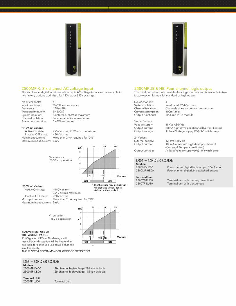
2500MF-K: Six channel AC voltage inputThe six channel digital input module accepts AC voltage inputs and is available in two factory options optimized for 115V ac or 230V ac ranges.
No of channels: 6Input functions: On/Off or de-bounceFrequency: 47Hz-63HzTransient immunity: EN50082System isolation: Reinforced, 264V ac maximumChannel isolation: Functional, 264V ac maximumPower consumption: 0.45W maximum
‘115V ac’ Variant Active On state: >95V ac rms, 132V ac rms maximum Inactive OFF state: <30V ac rmsMain input current: More than 2mA required for ‘ON’Maximum input current: 8mA
V-I curve for 230V ac operation
‘230V ac’ Variant Active ON state: >180V ac rms, 264V ac rms maximum Inactive OFF state: <60V ac rmsMin input current: More than 2mA required for ‘ON’Maximum input current: 9mA
V-I curve for 115V ac operation
INADVERTENT USE OF THE WRONG RANGE115V type on 230V ac No damage willresult. Power dissipation will be higher than desirable for continued use on all 6 channels simultaneously. THIS IS NOT A RECOMMENDED MODE OF OPERATION
2500MF-JE & HE: Four channel logic outputThis diital output module provides four logic outputs and is available in two factory option formats for standard or high output.
No. of channels: 4System isolation: Reinforced, 264V ac maxChannel isolation: Channels share a common connectionCurrent assumption: 100mA maxOutput functions: TPO and VP in module
‘Logic’ VariantVoltage supply: 18<Vs <30V dcOutput current: >8mA high drive per channel (Current limited)Output voltage: At least Voltage supply (Vs) -3V switch drop
24’VariantExternal supply: 12 <Vs <30V dcOutput current: 100mA maximum high drive per channel (Current & Temperature limted)Output voltage: At least Voltage supply (Vs) -3V switch drop
DI6 − ORDER CODEModule2500MF-KA00 Six channel high voltage 230 volt ac logic2500MF-KB00 Six channel high voltage 115 volt ac logic
Terminal Unit2500TF-LU00 Terminal unit
D04 − ORDER CODEModule2500MF-JE00 Four channel digital logic output 10mA max2500MF-HE00 Four channel digital 24d switched output
Terminal Unit2500TF-RU00 Terminal unit with dummy cover fitted2500TF-RU30 Terminal unit with disconnects

2500MF-N: Eight channel digital output moduleThe DO8 provides higher packing density and lower cost per channel. The eight digital output module provides eight logic outputs which are typically used for control, alarms, or events outputs.
Each channel has a 24V output with 0.75A capability (subject to a maximum of 4A total per module) and can be used for driving solenoids, relays, lamps, fans, thyristor units, single phase Solid State Relays (SSRs), or some three phase SSRs.
Voltage supply (external): 18-30V dcLeakage current off state: <0.1mACurrent output:Channel maximum: 0.75A/channelModule maximum: 4A total (500mA/channel, all channels ON)
Output voltage: >Voltage supply (Vs.) less 3VSystem isolation: Reinforced, 264V ac maximumChannel isolation: Channels share a common connectionPower consumption: 0.6W maximum
2500MF-F: Four channel relay outputThis digital output module provides four relay outputs. The relay contacts are all fitted with removable snubber circuits to reduce contact arcing and prolong contact life.No of channels: 4 (3 normally open + 1 changeover)Max current rating: 2A at up to 240V ac; 0.5A at 200V dc, increasing to 2A at 50V dc (resistive)Min ratings: AgCdO contacts offer best operating life switching more than 100mA 12VFuse (option): 3.15A, 20mm ceramic, time lag (T), in terminal unitSystem isolation: Reinforced, 264V ac maximumChannel isolation: Functional, 264V ac maximumContact life: >10million operations @ 250V ac, 1A rms >600,000 operations @ 250V ac, 2A rmsDe-rating: The above ratings summarize the performance with resistive loads. With complex loads further derating may be requiredPower consumption: 1.1W maximum
Relay De-rating
AC VoltageAs the AC load becomes more “difficult” a more significant de-rating factor is required. The graph opposite shows the derating to be applied in terms of contact life, assuming the load requirement is predefined. F1: Worst case F2 : Typical
DC voltageDC operation is also limited for difficult loads, particularly where there is significant inductance. Here the working current must be limited as shown where the load time constant (L/R, in ms) is the significant factor.
10
1
10 20 30 40 50 100 2000.1
0.5
5
DC voltage (Volts)
DC
cu
rren
t (A
mp
s)
a = resistive b = 20ms c = 40ms d = 60ms
Max dc load breaking capacity
a
bc
d
DO8 − ORDER CODEModule2500MF-NE00 Eight channel digital output 1A/channel; Max 4A/module
Terminal Unit2500T/DI4/UNIV/NONE Terminal unit with dummy cover fitted
RLY4 − ORDER CODEModule2500MF-F000 Four channel isolated relay output
Terminal Unit2500TF-T000 Terminal unit2500TF-T040 Terminal unit with four 3.15a fuses

2500MF-P: Two channel Frequency inputProvides two isolated frequency input channels and selectable voltage output for loop wetting current or sensor supply. Each input channel may be independently configured for magnetic, voltage, current, or contact sensor types.
No of channels: 2Channel isolation: Functional, 100V ac maximumSystem isolation: Reinforced, 264V ac maximumPower consumption: 3.6W maximum
Frequency measurementsRange: Logic: 0.01Hz-40KHz, debounce offMagnetic: 10Hz-40KHzResolution: 60ppmAccuracy: ±100ppm, reference. ±160ppm overall ±0.05% drift over 5 yearsPulse countingRange: Logic: dc- 40KHz, debounce offMagnetic: 10Hz-40KHz
Magnetic sensor input specificationInput range: 10mV-80V p-pAbsolute maximum input: ±100VInput impedance: >30KΩ
Logic input specificationVOLTAGE Input range: 0-20VAbsolute maximum input: 50VInput impedance: >30KΩThreshold: 0-20V (0.5V steps), ±0.2V hysteresis <5V = ±0.4V accuracy, >5V = ±0.7% accuracySensor break level: 50-350mVSensor short circuit: N/A
CURRENT Input range: 0-20mAAbsolute maximum input: 30mAInput impedance: 1KΩThreshold: 0-20mA (0.5mA steps), ±0.2mA hysteresis <5mA = ±0.4V accuracy, >5mA = ±0.7% accuracySensor break level: 0.05-0.350mASensor short circuit detect: when <100Ω; restored when >350Ω
CONTACT Input range: N/AAbsolute maximum input: N/AInput impedance: 5KΩThreshold: 0-20V (0.5V steps), ±0.2V hysteresis <5V = ±0.4V accuracy, >5V = ±0.7% accuracyDebounce: 5, 10, 20, 50mS
Note: with debounce on, max frequency is limit and resolution is 600ppm
Output specification Voltage: Selectable, 8, 12, or 24V dcMaximum current: 25mAVoltage drop at full load: 1V @ 25mAAccuracy: ±20%
2500M-R: Zirconia input Input Types: Analog voltage, Channel 1 - mV (TC), and Channel 2 - 2V (Zirconia probe)
Thermocouple Input Specification (Ch1 ONLY)Input Range: -77mV to +100mVCalibration Accuracy: ±0.1% of electrical input, ± 10μVNoise: 5μV p-p with 1.6s FilterResolution: <2μV with 1.6s FilterSensor Break Detect: 250nA break high, low or offInput Impedance: 10MΩ
Cold Junction Sensor Specification (Ch1 ONLY)Temperature Range: -10°C to +70°CCJ Rejection: < 30:1CJ Accuracy: ± 1.3°C, ±0.5°C typ. (‘Automatic’ cold junction compensation)
Zirconia Input Specification (Ch2 ONLY)Input Range: -10mV to +1800mVCalibration Accuracy: ± 0.2% of electrical inputNoise: 0.1mV p-p with 1.6s FilterResolution: <50μV with 1.6s FilterSensor Impedance Measurement: 0.1kΩ to 100kΩ ± 2%Input Impedance: >500MΩInput Leakage Current: ±4.0nA, max ±1nA typical General SpecificationsPower consumption: 1.8W maximumCommon mode rejection: >80db, 48 - 62HzSeries mode rejection: >60db, 48 - 62HzIsolation channel - channel: Functional (basic insulation), 264V ac maxIsolation to system: Reinforced (double insulation), 264V ac max
FI2 − ORDER CODEModule2500MF-P000 Two channel digital Frequency input
Terminal Unit2500TF-U000 Terminal unit with dummy cover fitted
ZI − ORDER CODEModule2500MF-R000 Zirconia Input
Terminal Unit2500TF-Z000 Terminal unit

Basic Product
255RF Dual processor - redundant capable base and I/O
255SF Single processor - redundant ready base and I/O
1 Basic Size
-A 2 IOC position for redundant operation 16 I/O module position
-C 2 IOC position for redundant operation 8 I/O module position
-F 2 IOC position for redundant operation 6 I/O module position
-G 2 IOC position for redundant operation 4 I/O module position
-E 2 IOC position for redundant operation 0 I/O module position
2 Earthing System
0 Two earth clamps fitted
2 Earthing clamp for a 16 I/O module base
1 Earthing clamp for an 8 I/O module base
3 Earthing clamp for a 6 I/O module base
4 Earthing clamp for a 4 I/O module base
3 IOC and software (standard license)/(data logging)
Foundation Standard Control Advanced
A/U Unbounded 0 0 off
B/L Unbounded 50 4 off
C/M Unbounded 100 8 off
D/N Unbounded Unbounded 12 off
E/P Unbounded Unbounded 16 off
F/Q Unbounded Unbounded 24 off
G/R Unbounded Unbounded 32 off
H/S Unbounded Unbounded Unbounded off
J/T Unbounded Unbounded Unbounded on
4 Ethernet communications protocol
1 LIN peer-to-peer
2 Modbus-TCP master comms (includes LIN peer-to-peer)
5 Serial communications protocol
A HMI comms (non isolated)
B Modbus master comms (non isolated) and raw comms
E Profibus DP slave comms (9 pin D connector)
C* HMI comms (isolated)
D* Modbus master comms (isolated) and raw comms* Consult factory
6 Terminal unit connector
1 RJ45 connector for Modbus
2 9 pin D type connector for Profibus only
7-22 Module and Terminations
B 2 ch — isol universal analog I/P with CJC for T/C
C 2 ch — isol universal analog I/P for PT100, Hiz inputs
D 2 ch — isol universal analog I/P - 5 shunt fitted for mA inputs
E 3 ch — isol 4-20mA analog I/P with 24V Tx PSU
F 3 ch — isol 4-20mA analog I/P with 24V Tx PSU with disconnects
G 4 ch — non isol T/C, with CJC
H 4 ch — non isol mV I/P
J 4 ch — non isol mA I/P
K 2 ch — isol analog O/P mA, volts
L 2 ch — isol analog O/P mA, volts with disconnects
M 4 ch — digital I/P
N 4 ch — digital I/P with disconnects
P 6 ch — 230 volt ac logic I/P
Q 6 ch — 115 volt ac logic I/P
R 8 ch — non isol digital I/P (logic I/P only)
1 8 ch — non isol digital I/P (logic I/P only) with disconnects
S 8 ch — non isol digital I/P (contact I/P only)
2 8 ch — non isol digital I/P (contact I/P only) with disconnects
T 4 ch. digital O/P logic O/P 10mA max
U 4 ch. digital O/P logic O/P 10mA max with disconnects
V 4 ch. digital O/P 24V dc switched O/P
W 4 ch. digital O/P 24V dc switched O/P with disconnects
Z 8 ch — digital O/P rated 1A per channel, max 4A per module
X 4 ch — isol relay O/P rated 2A ac
Y 4 ch — isol relay O/P rated 2A ac, with 4 off 3.15A fuses
3 2 ch — frequency I/P
4 2 ch — frequency I/P with disconnects
5 Zirconia I/P
A Blank terminal unit
0 No terminal unit or blank fitted
23 Application
0 No application loaded
1 Pre-configured application loaded
24 Manuals
0 CD with manuals
1 Manuals on processor flash card
2 Paper copy of manuals
25 Language
N/A N/A
ORDERING CODESPAC Series Composite Coding
237-22 24 25

ORDERING CODES, continued237-22 24 25 237-22 24 25
PAC series license upgrade coding PAC series base unit coding
Basic Product
255UF1 Programmable Automation Controller (PAC)
1 IOC existing license
Foundation Standard Control Advanced
L10/D10 Unbounded 0 0 off
L20/D20 Unbounded 50 4 off
L30/D30 Unbounded 100 8 off
L40/D40 Unbounded Unbounded 12 off
L50/D50 Unbounded Unbounded 16 off
L60/D60 Unbounded Unbounded 24 off
L70/D70 Unbounded Unbounded 32 off
L80/D80 Unbounded Unbounded Unbounded off
L90/D90 Unbounded Unbounded Unbounded on
2 Existing communications license
L Modbus master communications not enabled
U Modbus master communications
3 IOC required new license
Foundation Standard Control Advanced
L10/D10 Unbounded 0 0 off
L20/D20 Unbounded 50 4 off
L30/D30 Unbounded 100 8 off
L40/D40 Unbounded Unbounded 12 off
L50/D50 Unbounded Unbounded 16 off
L60/D60 Unbounded Unbounded 24 off
L70/D70 Unbounded Unbounded 32 off
L80/D80 Unbounded Unbounded Unbounded off
L90/D90 Unbounded Unbounded Unbounded on
4 Required new communications license
NON Modbus master communications not enabled
MBM Modbus master communications
Basic Product
255BF Programmable Automation Controller (PAC) base unit
1 IOC existing license
DEFAULT Default
2 Base Size
16R 2 IOC position for redundant operation 16 I/O module position
08R 2 IOC position for redundant operation 8 I/O module position
06R 2 IOC position for redundant operation 6 I/O module position
04R 2 IOC position for redundant operation 4 I/O module position
00S 1 IOC position for redundant operation 0 I/O module position
3 Earthing System
NON Two earth clamps fitted
C16 Earthing clamp for a 16 I/O module base
C08* Earthing clamp for a 8 I/O module base
C06* Earthing clamp for a 6 I/O module base
C04* Earthing clamp for a 4 I/O module base* Consult factory
4 Manuals
CDM CD with manuals
NON Manuals on processor flash card
MAN Paper copy of manuals
255UF1 255BF DEFAULT
Invensys, the Invensys logo, ArchestrA, Avantis, Eurotherm, Foxboro, IMServ, InFusion, SimSci-Esscor, Skelta, Triconex, and Wonderware are trademarks of Invensys plc, its subsidiaries or affiliates. All other brands and product names may be the trademarks or service marks of their representative owners.
© 2011 Invensys Systems, Inc. All rights reserved. No part of the material protected by this copyright may be reproduced or utilized in any form or by any means, electronic or mechanical, including photocopying, recording, broadcasting, or by any information storage and retrieval system, without permission in writing from Invensys Systems, Inc.
Invensys Operations Management • 5601 Granite Parkway III, #1000, Plano, TX 75024 • Tel: (469) 365-6400 • Fax: (469) 365-6401 • iom.invensys.com
Rel. 04/11 PN FX-0176


![FLOW TEMP. CONTROLLER [MASTER] (Cased) PAC-IF051B-E PAC-IF052B-E FLOW TEMP. CONTROLLER ... · 2013. 2. 12. · PAC-IF051B-E PAC-IF052B-E FLOW TEMP. CONTROLLER [SLAVE] (Cased) PAC-SIF051B-E](https://img.pdfslide.us/doc/110x75/612d85651ecc515869423db7/flow-temp-controller-master-cased-pac-if051b-e-pac-if052b-e-flow-temp-controller.jpg)