Embed Size (px)
DESCRIPTION
masinstvo
Citation preview
7/17/2019 T05570_01_Cang
http://slidepdf.com/reader/full/t0557001cang 1/10
Disc brake - Power unit CE8L Technical data
Spare parts No. S09580-01
Installation and maintenance Leaet No. M08555-01
T05570-01-C
17/10/11 1/10
SIME Brakes
Options No. A08555-01
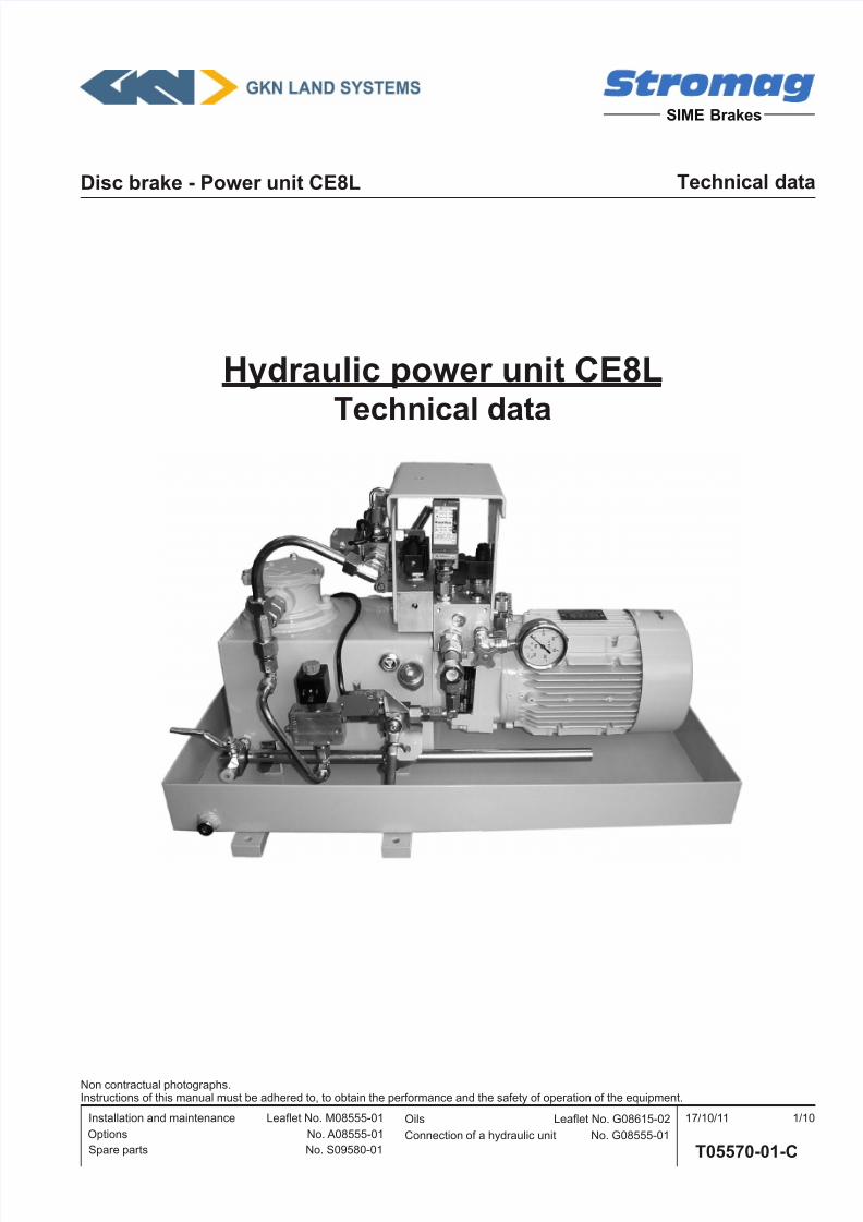
Hydraulic power unit CE8LTechnical data
Non contractual photographs.Instructions of this manual must be adhered to, to obtain the performance and the safety of operation of the equipment.
Connection of a hydraulic unit No. G08555-01
Oils Leaet No. G08615-02
7/17/2019 T05570_01_Cang
http://slidepdf.com/reader/full/t0557001cang 2/10
Disc brake - Power unit CE8L Technical data
Spare parts No. S09580-01
Installation and maintenance Leaet No. M08555-01
T05570-01-C
17/10/11 2/10
SIME Brakes
Options No. A08555-01
Non contractual photographs.Instructions of this manual must be adhered to, to obtain the performance and the safety of operation of the equipment.
Connection of a hydraulic unit No. G08555-01
Oils Leaet No. G08615-02
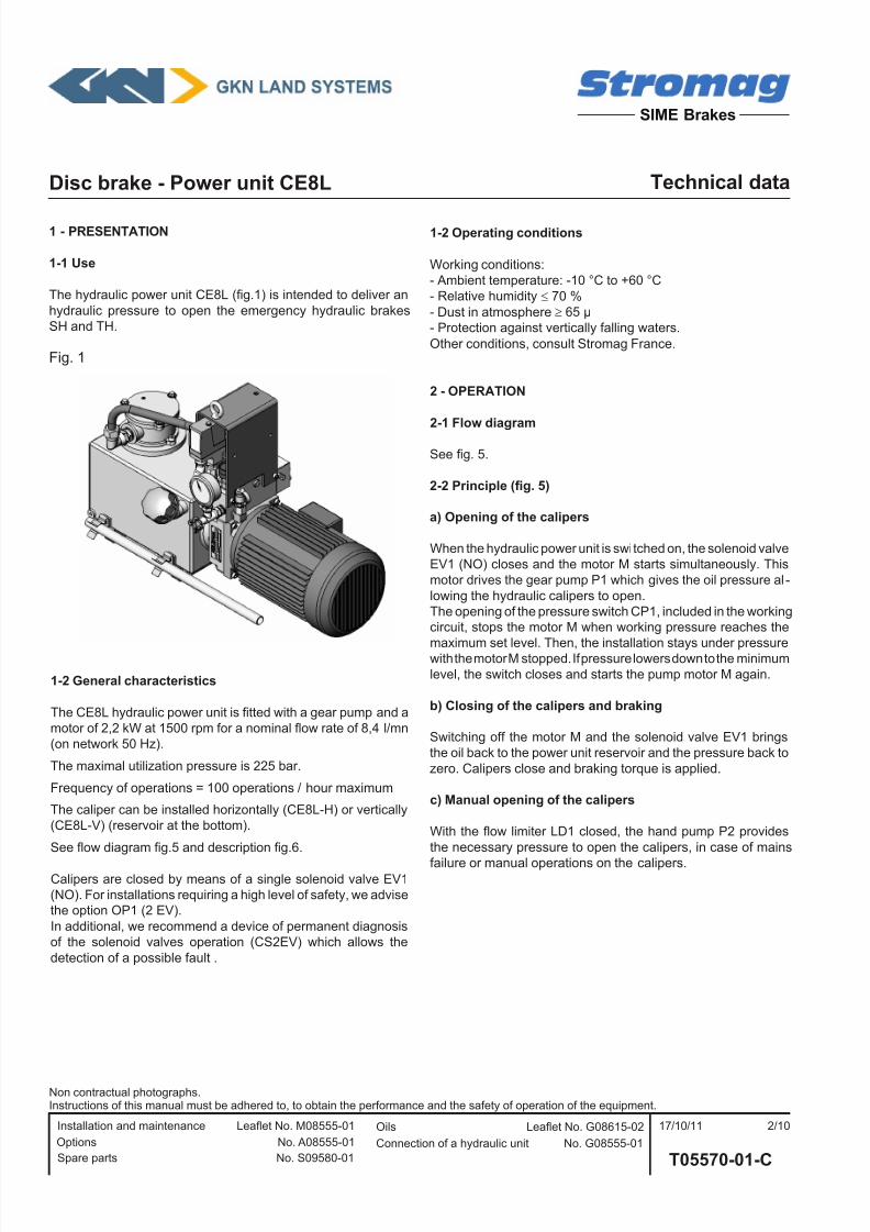
1 - PRESENTATION
1-1 Use
The hydraulic power unit CE8L (g.1) is intended to deliver an
hydraulic pressure to open the emergency hydraulic brakes
SH and TH.
1-2 Operating conditions
Working conditions:
- Ambient temperature: -10 °C to +60 °C
- Relative humidity ≤ 70 %
- Dust in atmosphere ≥ 65 µ
- Protection against vertically falling waters.
Other conditions, consult Stromag France.
2 - OPERATION
2-1 Flow diagram
See g. 5.
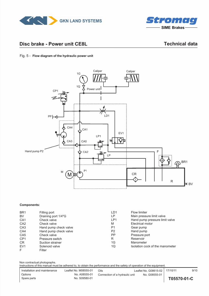
2-2 Principle (g. 5)
a) Opening of the calipers
When the hydraulic power unit is switched on, the solenoid valve
EV1 (NO) closes and the motor M starts simultaneously. This
motor drives the gear pump P1 which gives the oil pressure al-
lowing the hydraulic calipers to open.
The opening of the pressure switch CP1, included in the working
circuit, stops the motor M when working pressure reaches the
maximum set level. Then, the installation stays under pressurewith the motor M stopped. If pressure lowers down to the minimum
level, the switch closes and starts the pump motor M again.
b) Closing of the calipers and braking
Switching off the motor M and the solenoid valve EV1 brings
the oil back to the power unit reservoir and the pressure back to
zero. Calipers close and braking torque is applied.
c) Manual opening of the calipers
With the ow limiter LD1 closed, the hand pump P2 provides
the necessary pressure to open the calipers, in case of mains
failure or manual operations on the calipers.
Fig. 1
1-2 General characteristics
The CE8L hydraulic power unit is tted with a gear pump and a
motor of 2,2 kW at 1500 rpm for a nominal ow rate of 8,4 l/mn
(on network 50 Hz).
The maximal utilization pressure is 225 bar.
Frequency of operations = 100 operations / hour maximum
The caliper can be installed horizontally (CE8L-H) or vertically
(CE8L-V) (reservoir at the bottom).
See ow diagram g.5 and description g.6.
Calipers are closed by means of a single solenoid valve EV1
(NO). For installations requiring a high level of safety, we advisethe option OP1 (2 EV).
In additional, we recommend a device of permanent diagnosis
of the solenoid valves operation (CS2EV) which allows the
detection of a possible fault .
7/17/2019 T05570_01_Cang
http://slidepdf.com/reader/full/t0557001cang 3/10
Disc brake - Power unit CE8L Technical data
Spare parts No. S09580-01
Installation and maintenance Leaet No. M08555-01
T05570-01-C
17/10/11 3/10
SIME Brakes
Options No. A08555-01
Non contractual photographs.Instructions of this manual must be adhered to, to obtain the performance and the safety of operation of the equipment.
Connection of a hydraulic unit No. G08555-01
Oils Leaet No. G08615-02
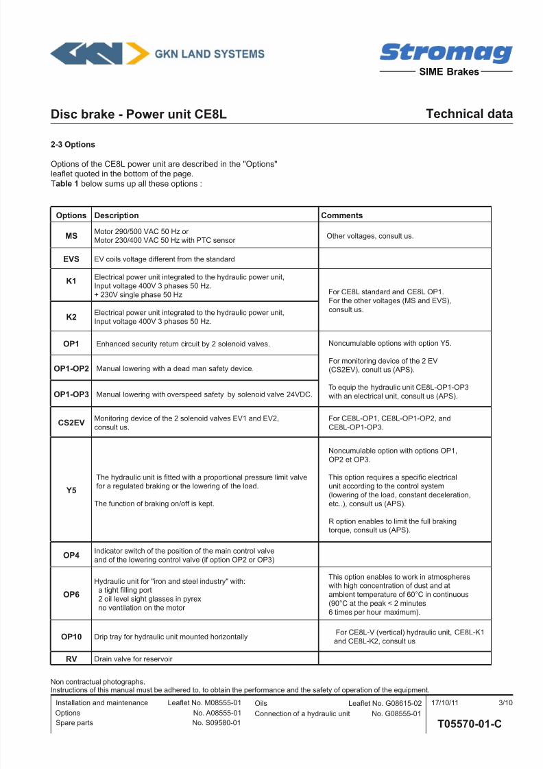
2-3 Options
Options of the CE8L power unit are described in the "Options"
leaet quoted in the bottom of the page.
Table 1 below sums up all these options :
Options Description Comments
MS Motor 290/500 VAC 50 Hz or Motor 230/400 VAC 50 Hz with PTC sensor
Other voltages, consult us.
EVS EV coils voltage different from the standard
K1Electrical power unit integrated to the hydraulic power unit,
Input voltage 400V 3 phases 50 Hz.
+ 230V single phase 50 Hz For CE8L standard and CE8L OP1.
For the other voltages (MS and EVS),
consult us.K2
Electrical power unit integrated to the hydraulic power unit,
Input voltage 400V 3 phases 50 Hz.
OP1 Enhanced security return circuit by 2 solenoid valves. Noncumulable options with option Y5.
For monitoring device of the 2 EV(CS2EV), conult us (APS).
To equip the hydraulic unit CE8L-OP1-OP3
with an electrical unit, consult us (APS).
OP1-OP2 Manual lowering with a dead man safety device.
OP1-OP3 Manual lowering with overspeed safety by solenoid valve 24VDC.
CS2EV Monitoring device of the 2 solenoid valves EV1 and EV2,
consult us.
For CE8L-OP1, CE8L-OP1-OP2, and
CE8L-OP1-OP3.
Y5
The hydraulic unit is tted with a proportional pressure limit valve
for a regulated braking or the lowering of the load.
The function of braking on/off is kept.
Noncumulable option with options OP1,
OP2 et OP3.
This option requires a specic electrical
unit according to the control system
(lowering of the load, constant deceleration,
etc..), consult us (APS).
R option enables to limit the full braking
torque, consult us (APS).
OP4 Indicator switch of the position of the main control valve
and of the lowering control valve (if option OP2 or OP3)
OP6
Hydraulic unit for "iron and steel industry" with:
a tight lling port
2 oil level sight glasses in pyrex
no ventilation on the motor
This option enables to work in atmospheres
with high concentration of dust and at
ambient temperature of 60°C in continuous
(90°C at the peak < 2 minutes
6 times per hour maximum).
OP10 Drip tray for hydraulic unit mounted horizontally For CE8L-V (vertical) hydraulic unit, CE8L-K1
and CE8L-K2, consult us
RV Drain valve for reservoir
7/17/2019 T05570_01_Cang
http://slidepdf.com/reader/full/t0557001cang 4/10
Disc brake - Power unit CE8L Technical data
Spare parts No. S09580-01
Installation and maintenance Leaet No. M08555-01
T05570-01-C
17/10/11 4/10
SIME Brakes
Options No. A08555-01
Non contractual photographs.Instructions of this manual must be adhered to, to obtain the performance and the safety of operation of the equipment.
Connection of a hydraulic unit No. G08555-01
Oils Leaet No. G08615-02
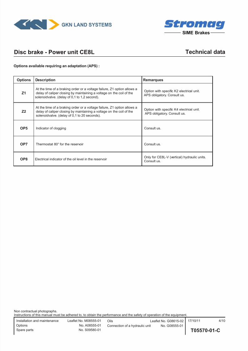
Options available requiring an adaptation (APS) :
Options Description Remarques
Z1 At the time of a braking order or a voltage failure, Z1 option allows a
delay of caliper closing by maintaining a voltage on the coil of the
solenoidvalve. (delay of 0,1 to 1,2 second).
Option with specic K2 electrical unit.
APS obligatory. Consult us.
Z2 At the time of a braking order or a voltage failure, Z1 option allows a
delay of caliper closing by maintaining a voltage on the coil of thesolenoidvalve. (delay of 0,1 to 20 seconds).
Option with specic K4 electrical unit. APS obligatory. Consult us.
OP5 Indicator of clogging Consult us.
OP7 Thermostat 80° for the reservoir Consult us.
OP8 Electrical indicator of the oil level in the reservoir Only for CE8L-V (vertical) hydraulic units. Consult us.
7/17/2019 T05570_01_Cang
http://slidepdf.com/reader/full/t0557001cang 5/10
Disc brake - Power unit CE8L Technical data
Spare parts No. S09580-01
Installation and maintenance Leaet No. M08555-01
T05570-01-C
17/10/11 5/10
SIME Brakes
Options No. A08555-01
Non contractual photographs.Instructions of this manual must be adhered to, to obtain the performance and the safety of operation of the equipment.
Connection of a hydraulic unit No. G08555-01
Oils Leaet No. G08615-02
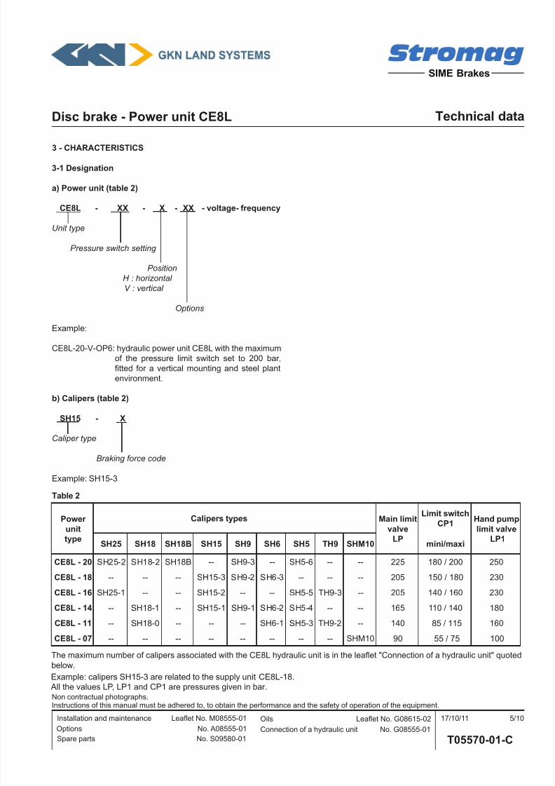
3 - CHARACTERISTICS
3-1 Designation
a) Power unit (table 2)
CE8L - XX - X - XX - voltage- frequency
Unit type
Pressure switch setting
Position
H : horizontal V : vertical
Options
Example:
CE8L-20-V-OP6: hydraulic power unit CE8L with the maximum
of the pressure limit switch set to 200 bar,
tted for a vertical mounting and steel plant
environment.
b) Calipers (table 2)
SH15 - X
Caliper type
Braking force code
Example: SH15-3
Table 2
Example: calipers SH15-3 are related to the supply unit CE8L-18.
All the values LP, LP1 and CP1 are pressures given in bar.
Power
unit
type
Calipers types Main limit
valve
LP
Limit switch
CP1Hand pump
limit valve
LP1SH25 SH18 SH18B SH15 SH9 SH6 SH5 TH9 SHM10 mini/maxi
CE8L - 20 SH25-2 SH18-2 SH18B -- SH9-3 -- SH5-6 -- -- 225 180 / 200 250
CE8L - 18 -- -- -- SH15-3 SH9-2 SH6-3 -- -- -- 205 150 / 180 230
CE8L - 16 SH25-1 -- -- SH15-2 -- -- SH5-5 TH9-3 -- 205 140 / 160 230
CE8L - 14 -- SH18-1 -- SH15-1 SH9-1 SH6-2 SH5-4 -- -- 165 110 / 140 180
CE8L - 11 -- SH18-0 -- -- -- SH6-1 SH5-3 TH9-2 -- 140 85 / 115 160
CE8L - 07 -- -- -- -- -- -- -- -- SHM10 90 55 / 75 100
The maximum number of calipers associated with the CE8L hydraulic unit is in the leaet "Connection of a hydraulic unit" quoted
below.
7/17/2019 T05570_01_Cang
http://slidepdf.com/reader/full/t0557001cang 6/10
Disc brake - Power unit CE8L Technical data
Spare parts No. S09580-01
Installation and maintenance Leaet No. M08555-01
T05570-01-C
17/10/11 6/10
SIME Brakes
Options No. A08555-01
Non contractual photographs.Instructions of this manual must be adhered to, to obtain the performance and the safety of operation of the equipment.
Connection of a hydraulic unit No. G08555-01
Oils Leaet No. G08615-02
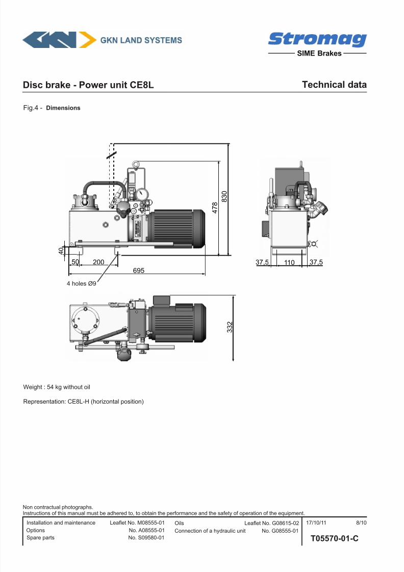
3-2 Dimensions
See g.4.
3-3 Hydraulic characteristics
a) Calipers associated
See table 2.
b) Mineral oil
A mineral oil must be imperatively used.
Characteristics conform to the standard ISO 6743/4.
Choose a type in accordance with the temperatures of utiliza-tion.
Grade L-HM or L-HV.
Avoid to mix oils of types HM and HV.
For oils with other characteristics, consult us.
Refer to the leaet "Oils" quoted in the bottom of the page.
The reservoir capacity is :
Horizontal or vertical installation : - High level = 8 litres
- Low level = 6 litres
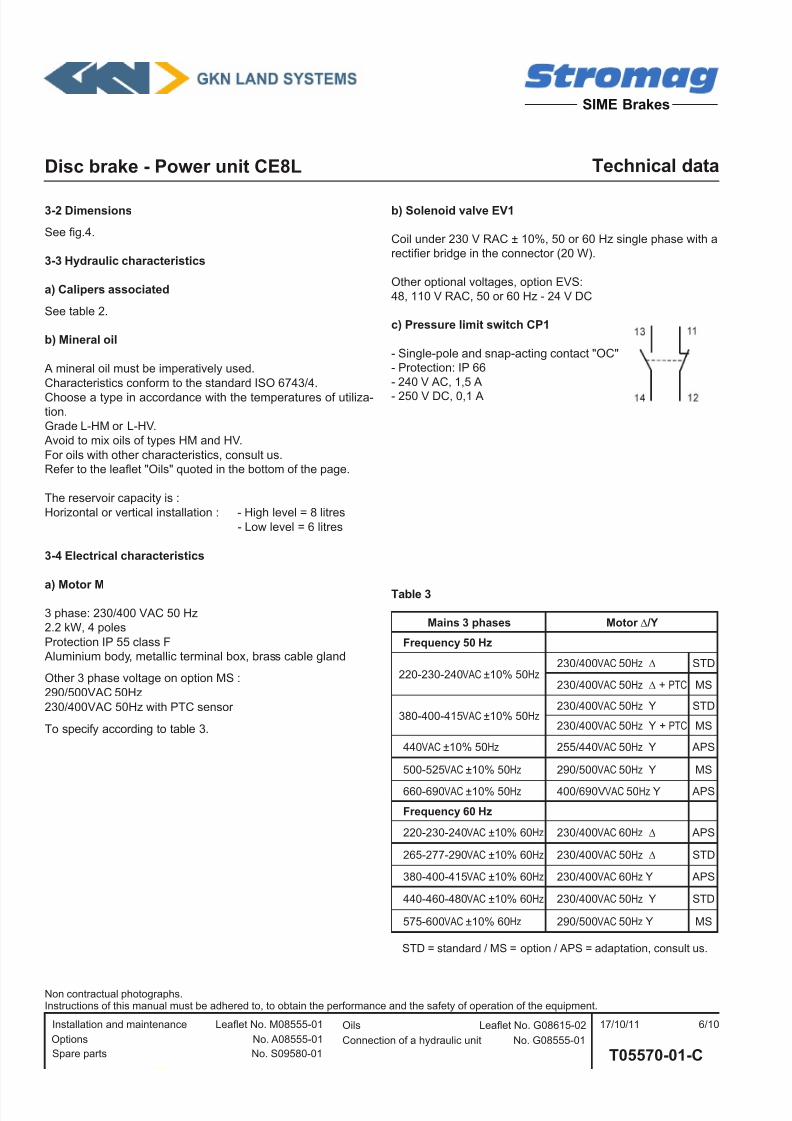
3-4 Electrical characteristics
a) Motor M
3 phase: 230/400 VAC 50 Hz
2.2 kW, 4 poles
Protection IP 55 class F
Aluminium body, metallic terminal box, brass cable gland
Other 3 phase voltage on option MS :
290/500VAC 50Hz
230/400VAC 50Hz with PTC sensor
To specify according to table 3.
b) Solenoid valve EV1
Coil under 230 V RAC ± 10%, 50 or 60 Hz single phase with a
rectier bridge in the connector (20 W).
Other optional voltages, option EVS:
48, 110 V RAC, 50 or 60 Hz - 24 V DC
c) Pressure limit switch CP1
- Single-pole and snap-acting contact "OC"
- Protection: IP 66
- 240 V AC, 1,5 A
- 250 V DC, 0,1 A
Table 3
Mains 3 phases Motor ∆/Y
Frequency 50 Hz
220-230-240VAC ±10% 50Hz230/400VAC 50Hz ∆ STD
230/400VAC 50Hz ∆ + PTC MS
380-400-415VAC ±10% 50Hz230/400VAC 50Hz Y STD
230/400VAC 50Hz Y + PTC MS
440VAC ±10% 50Hz 255/440VAC 50Hz Y APS
500-525VAC ±10% 50Hz 290/500VAC 50Hz Y MS
660-690VAC ±10% 50Hz 400/690VVAC 50Hz Y APS
Frequency 60 Hz
220-230-240VAC ±10% 60Hz 230/400VAC 60Hz ∆ APS
265-277-290VAC ±10% 60Hz 230/400VAC 50Hz ∆ STD
380-400-415VAC ±10% 60Hz 230/400VAC 60Hz Y APS
440-460-480VAC ±10% 60Hz 230/400VAC 50Hz Y STD
575-600VAC ±10% 60Hz 290/500VAC 50Hz Y MS
STD = standard / MS = option / APS = adaptation, consult us.
7/17/2019 T05570_01_Cang
http://slidepdf.com/reader/full/t0557001cang 7/10
Disc brake - Power unit CE8L Technical data
Spare parts No. S09580-01
Installation and maintenance Leaet No. M08555-01
T05570-01-C
17/10/11 7/10
SIME Brakes
Options No. A08555-01
Non contractual photographs.Instructions of this manual must be adhered to, to obtain the performance and the safety of operation of the equipment.
Connection of a hydraulic unit No. G08555-01
Oils Leaet No. G08615-02
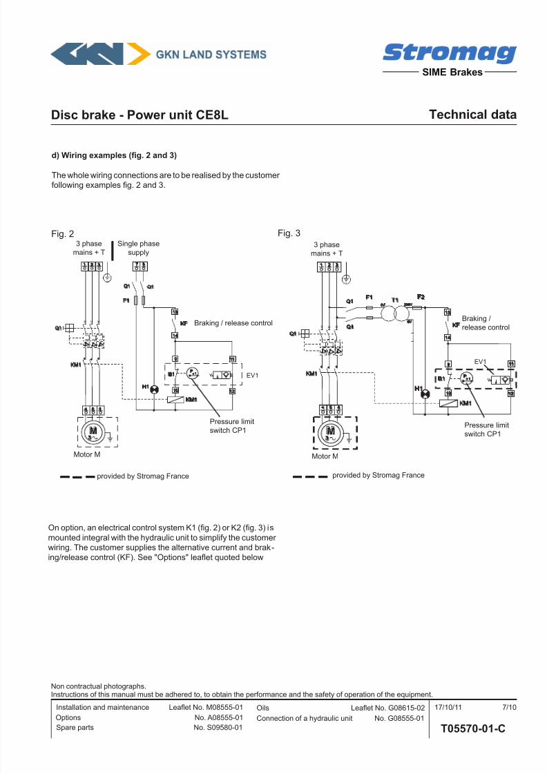
d) Wiring examples (g. 2 and 3)
The whole wiring connections are to be realised by the customer
following examples g. 2 and 3.
Motor M
3 phase
mains + T
Single phase
supply
Braking / release control
Pressure limit
switch CP1
provided by Stromag France
Q1
KF
KM1
KM1x 1
P
1
4
2
5
3
6
11
10
14
9
13
12
M3
0V 230V
0V
I >
T1F1
Q1
Q1
H1
B1
F2
I > I >
F1
KF
KM1
x 1P
87
11
10
14
9
13
12
Q1
KM1
1
4
2
5
3
6
M3
I >
Q1
Q1
I > I >
B1
H1
EV1
Fig. 3Fig. 2
EV1
provided by Stromag France
Motor M
3 phase
mains + T
Braking /
release control
Pressure limit
switch CP1
On option, an electrical control system K1 (g. 2) or K2 (g. 3) is
mounted integral with the hydraulic unit to simplify the customer
wiring. The customer supplies the alternative current and brak-
ing/release control (KF). See "Options" leaet quoted below
7/17/2019 T05570_01_Cang
http://slidepdf.com/reader/full/t0557001cang 8/10
Disc brake - Power unit CE8L Technical data
Spare parts No. S09580-01
Installation and maintenance Leaet No. M08555-01
T05570-01-C
17/10/11 8/10
SIME Brakes
Options No. A08555-01
Non contractual photographs.Instructions of this manual must be adhered to, to obtain the performance and the safety of operation of the equipment.
Connection of a hydraulic unit No. G08555-01
Oils Leaet No. G08615-02
3 3 2
50 37,5 37,5110200
695
4 0
8
3 0
4 7 8
Fig.4 - Dimensions
Weight : 54 kg without oil
Representation: CE8L-H (horizontal position)
4 holes Ø9
7/17/2019 T05570_01_Cang
http://slidepdf.com/reader/full/t0557001cang 9/10
Disc brake - Power unit CE8L Technical data
Spare parts No. S09580-01
Installation and maintenance Leaet No. M08555-01
T05570-01-C
17/10/11 9/10
SIME Brakes
Options No. A08555-01
Non contractual photographs.Instructions of this manual must be adhered to, to obtain the performance and the safety of operation of the equipment.
Connection of a hydraulic unit No. G08555-01
Oils Leaet No. G08615-02
Hand pump P2
Power unit
Caliper Caliper
Fig. 5 - Flow diagram of the hydraulic power unit
1G
CP1
M P1
LP
EV1
LD1
1Q
PP
CA1
CA2
LP1
CA4
CA3
Components:
BR1 Filling port
BV Draining port 1/4"G
CA1 Check valveCA2 Check valve
CA3 Hand pump check valve
CA4 Hand pump check valve
CA5 Check valve
CP1 Pressure switchCR Suction strainer
EV1 Solenoid valve
F Filter
LD1 Flow limiter LP Main pressure limit valve
LP1 Hand pump pressure limit valve
M Electrical motor
P1 Gear pump
P2 Hand pump
PP Pressure portR Reservoir
1G Manometer
1Q Isolation cock of the manometer
F
CA5
BVR
BR1
CR
7/17/2019 T05570_01_Cang
http://slidepdf.com/reader/full/t0557001cang 10/10
Disc brake - Power unit CE8L Technical data
Spare parts No. S09580-01
Installation and maintenance Leaet No. M08555-01
T05570-01-C
17/10/11 10/10
SIME Brakes
Options No. A08555-01
Non contractual photographs.Instructions of this manual must be adhered to, to obtain the performance and the safety of operation of the equipment.
Connection of a hydraulic unit No. G08555-01
Oils Leaet No. G08615-02
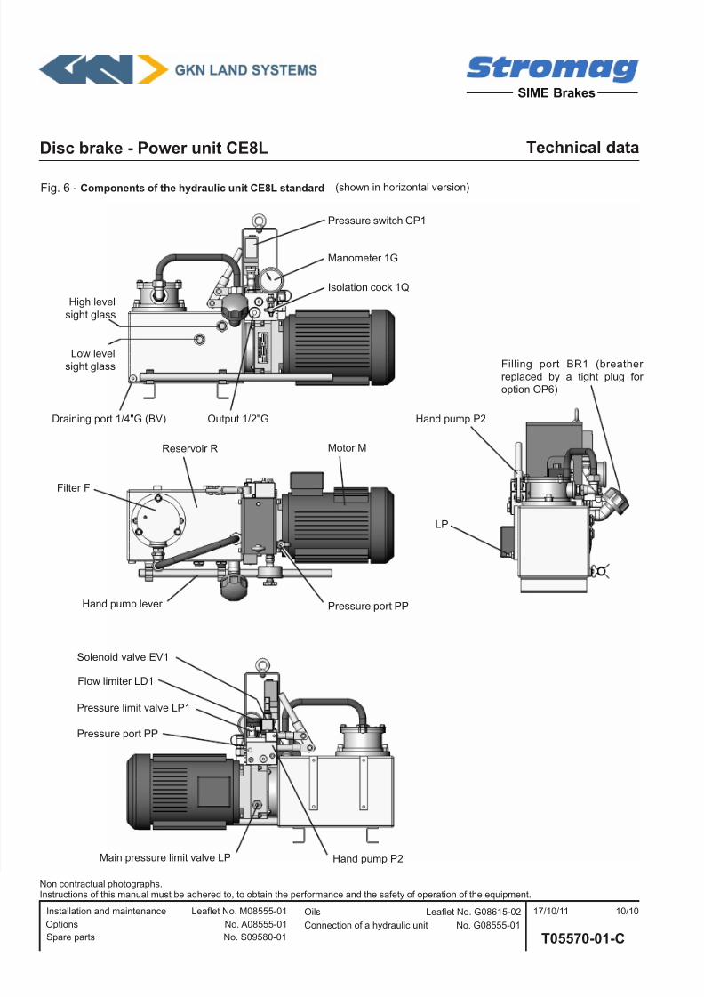
Solenoid valve EV1
Manometer 1G
High level
sight glass
Filling port BR1 (breather
replaced by a tight plug for
option OP6)
Pressure switch CP1
Motor MReservoir R
Low levelsight glass
Fig. 6 - Components of the hydraulic unit CE8L standard
Isolation cock 1Q
Filter F
Flow limiter LD1
Hand pump P2Main pressure limit valve LP
Pressure limit valve LP1
Pressure port PP
Output 1/2"G
Pressure port PPHand pump lever
Draining port 1/4"G (BV)
LP
Hand pump P2
(shown in horizontal version)


