Embed Size (px)
Citation preview
67
T. Zawadzki, D. Kujawa: Shape Metamorphosis – Automatic 3D..., acta graphica 23(2013)3-4, 67-78
original scientific paperreceived: 16-04-2013
accepted: 30-08-2013acta graphica 218
Shape Metamorphosis – Automatic 3D Mesh Generation, Topology Verification and Analysis
Authors
Tomasz Zawadzki*, Dominik Kujawa
University of Zielona GóraInstitute of Control & Computation EngineeringPolandE.-mail: [email protected]
Abstract:
The objective of this paper is a 3D shape construction that benefits from discrete and continuous modelling approaches. The proposed solution addresses the prob-lem of automated modelling of virtual structures such as caves, buildings and clouds and presents an alternative solution in the form of a hybrid system. Parallel realizations of these solutions are tested on various processors of graphic cards with the use of NVIDIA ‘CUDA’ technology. This paper describes the implemen-tation of algorithms (approaches) and their parallel speedup, efficiency, through-put. Modelled structures are geometrically complex, with an inner graph structure more optimized than in the classical CSG approach. Moreover, they can be ren-dered up to very high levels of visual realism. In this paper we mainly focus on the description of the algorithm. We also propose very useful measures that can be used to verify the model geometry.
Keywords: Procedural Modelling, Shape Grammar, Morphing, Hybrid Measures·
1. Introduction
Complex structures of buildings (Wonka et al., 2003), whole urban structures (Parish et al., 2001, Greuter et al., 2003), terrains (Peytavie et al, 2009, Warszawski et al., 2009), clouds (Bouthors et al., 2004, Schpok et al., 2003, Dobashi et al., 2000, Ebert et al., 1997, Elinas et al., 2000, Ni-shita et al., 1996), plants (Prusinkiewicz et al., 1991) or caves (Am Ende et al., 2001, Boggus et
al., 2009, Schuchardt et al., 2007, Johnson et al., 2010) can be modelled with systems based on automated shape formation. The algorithms that enable full automation of this process also help to achieve large savings of the digital me-dia production time. We can observe a constant development of new methods i.e. merging tech-nology and dynamical systems (Clempner et
68
T. Zawadzki, D. Kujawa: Shape Metamorphosis – Automatic 3D..., acta graphica 23(2013)3-4, 67-78
al., 2011, Di Trapani et al., 2010). As we can see clearly, the problem of automated shape model-ling constitutes an important area of computer graphics activity and has drawn attention of digital media industry for several years. Digital movies have created constant demand for pleas-ing visual effects in three-dimensional graphics. Apart from the pure entertainment purposes, shape modelling has the practical use ranging from CAD engineering applications through scientific visualization to advanced game pro-gramming and Virtual Environments.
2. Shape grammar and morphing - introduction
Stiny and Gips are the precursors of shape grammars. Their research was aimed at sup-porting the design process using a “linguistic model of the generational system” (Stiny et al., 1972, 1975). The definition of shape grammars is analogous to the formal grammars and is graphically expressed in the language of words composed of symbols with different grammati-cal rules (Stiny, 1980).
Generally, morphing is usually defined as the continuous and smooth process of transforma-tion of one shape into another. The so-called key shapes (by analogy to key-framed animation) may have different topologies and the smooth-ness of transformation does not have to be the case of homeomorphism (Martyn, 2004).
There is a number of metamorphosis meth-ods for 2D shapes represented mostly by poly-gons (Alexa et al., 2000), but also by images (Wolberg, 1998). The problem has also been investigated in the 3D domain and according to Lazarus (Lazarus et al., 1998), it spans the methods based on polygonal mesh representa-tion (Kent et al., 1992, Lee et al., 1999) and the methods utilizing voxel representations (Turk et al., 1999).
3. Parallelization level estimating indicators
System architecture can be adapted to a par-ticular computational task in itself is not a de-terminant of performance or efficiency.
))((||...||))((||))(()( 11 puFpuFpuFpy kkl
kl
k−= (1)
where:y – number of cubes inside, k – quantity of sequential cubes inside,u – cube edgep – the point with coordinates (x, y, z) in Eu-
clidean R3| – executing operations simultaneouslyFδ – operator, δ ∈ {1,...,l}.
Many operations can be performed simulta-neously during the position points calculation for different productions. The dedicated com-puting parallelism is also used, although there are no streams of instructions. The paralleliza-tion is significantly facilitated by eliminating the communication overhead for the acquisition of stream commands.
m
m TTS 1= (2)
where:Sm – the speedup ,S1 – the execution time of the sequential
algorithm,Tm – the execution time of the parallel algo-
rithm with m processors
For the evaluation of computational tasks performance in multi-core systems speedup formula was used (4).
In multiprocessor systems, the actual value of the speedup is smaller than the theoreti-cal (based on the number of processors) due to communication overheads and the need to share resources such as memory and buses. This property describes a model of efficiency, which is a measure of the concurrent use of resources
mS
E mm = (3)
69
T. Zawadzki, D. Kujawa: Shape Metamorphosis – Automatic 3D..., acta graphica 23(2013)3-4, 67-78
Table 2. Evaluation of the parallel algorithm – efficiency for m=255
Efficiency (m = 255)
Stage A B C
0.028 0.015 0.027
Table 3. Evaluation of the parallel algorithm – throughput for m=255
Throughput (m = 255)
Sequential algorithm Parallel algorithm
0.8[GFlop/s] 20.61[GFlop/s]
The algorithms were tested on a PC comput-er with Genuine Intel ® CPU T2300 @ 1.66 GHz, and 2512 MB RAM NVIDIA GTX 460 graphic card.
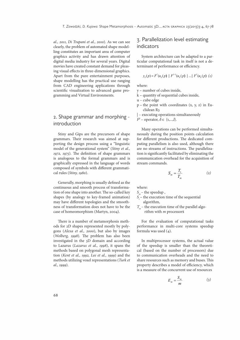
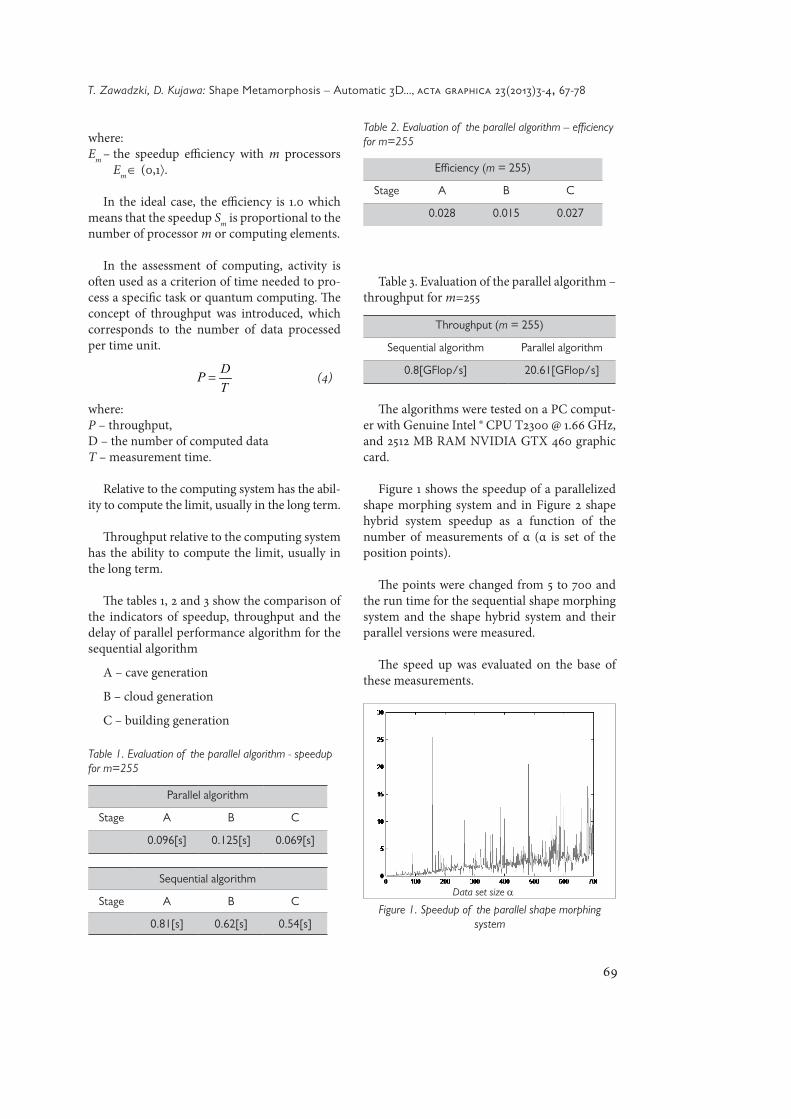
Figure 1 shows the speedup of a parallelized shape morphing system and in Figure 2 shape hybrid system speedup as a function of the number of measurements of α (α is set of the position points).
The points were changed from 5 to 700 and the run time for the sequential shape morphing system and the shape hybrid system and their parallel versions were measured.
The speed up was evaluated on the base of these measurements.
where:Em – the speedup efficiency with m processors
Em ∈ (0,1⟩.
In the ideal case, the efficiency is 1.0 which means that the speedup Sm is proportional to the number of processor m or computing elements.
In the assessment of computing, activity is often used as a criterion of time needed to pro-cess a specific task or quantum computing. The concept of throughput was introduced, which corresponds to the number of data processed per time unit.
TDP = (4)
where:P – throughput,D – the number of computed data T – measurement time.
Relative to the computing system has the abil-ity to compute the limit, usually in the long term.
Throughput relative to the computing system has the ability to compute the limit, usually in the long term.
The tables 1, 2 and 3 show the comparison of the indicators of speedup, throughput and the delay of parallel performance algorithm for the sequential algorithm
A – cave generation
B – cloud generation
C – building generation
Table 1. Evaluation of the parallel algorithm - speedup for m=255
Parallel algorithm
Stage A B C
0.096[s] 0.125[s] 0.069[s]
Sequential algorithm
Stage A B C
0.81[s] 0.62[s] 0.54[s]
Data set size α
Figure 1. Speedup of the parallel shape morphing system
70
T. Zawadzki, D. Kujawa: Shape Metamorphosis – Automatic 3D..., acta graphica 23(2013)3-4, 67-78
Speedups, shown in Figure 1 and 2, are equal to formally calculated speedups of parallel algo-rithms. Parallel implementations run about 5-6 times faster than their sequential versions.
4. The idea of morphic rules
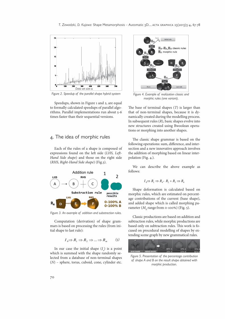
Each of the rules of a shape is composed of expressions found on the left side (LHS, Left -Hand Side shape) and those on the right side (RHS, Right-Hand Side shape) (Fig.3).
Computation (derivation) of shape gram-mars is based on processing the rules (from ini-tial shape to last rule):
mRRRI ⇒⇒⇒⇒ ...210 (5)
In our case the initial shape (I0) is a point which is summed with the shape randomly se-lected from a database of non-terminal shapes (N) – sphere, torus, cuboid, cone, cylinder etc.
Th e base of terminal shapes (T) is larger than that of non-terminal shapes, because it is dy-namically created during the modelling process. In subsequent rules (R), basic shapes evolve into new structures created using Bwoolean opera-tions or morphing into another shapes.
Th e classic shape grammar is based on the following operations: sum, diff erence, and inter-section and a new innovative approach involves the addition of morphing based on linear inter-polation (Fig. 4.).
We can describe the above example as follows:
410 RRI ⇒⇒ , 432 RRR ⇒+
Shape deformation is calculated based on morphic rules, which are estimated on percent-age contributions of the current (base shape), and added shape which is called morphing pa-rameter (MP, range from 0-100%) (Fig. 5).
Classic productions are based on addition and subtraction rules, while morphic productions are based only on subtraction rules. Th is work is fo-cused on procedural modelling of shapes by ex-tending scene graph by new grammatical rules.
Data set size α
Figure 2. Speedup of the parallel shape hybrid system
A B C
Addition rule RHS LHS
1 2
Figure 3. An example of addition and substraction rules.
Figure 4. Example of realization classic and morphic rules (one variant).
Figure 5. Presentation of the percentage contribution of shape A and B on the result shape obtained with
morphic production.
71
T. Zawadzki, D. Kujawa: Shape Metamorphosis – Automatic 3D..., acta graphica 23(2013)3-4, 67-78
Definition 4. The total sum of all rules is giv-en by:
MCT RRR += (6)
where:RT – all rules, RC – classic rules, RM – morphic rules.
5. Shape grammar and morphing hybrid - introduction
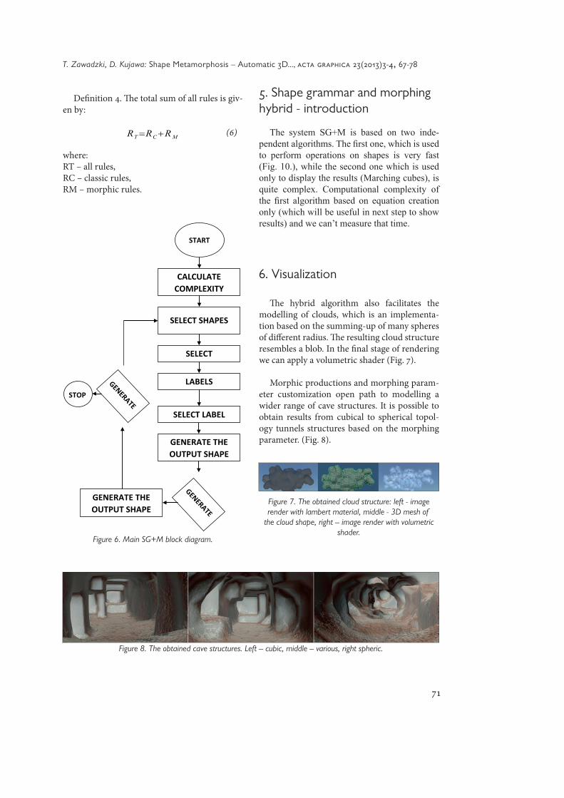
The system SG+M is based on two inde-pendent algorithms. The first one, which is used to perform operations on shapes is very fast (Fig. 10.), while the second one which is used only to display the results (Marching cubes), is quite complex. Computational complexity of the first algorithm based on equation creation only (which will be useful in next step to show results) and we can’t measure that time.
6. Visualization
The hybrid algorithm also facilitates the modelling of clouds, which is an implementa-tion based on the summing-up of many spheres of different radius. The resulting cloud structure resembles a blob. In the final stage of rendering we can apply a volumetric shader (Fig. 7).
Morphic productions and morphing param-eter customization open path to modelling a wider range of cave structures. It is possible to obtain results from cubical to spherical topol-ogy tunnels structures based on the morphing parameter. (Fig. 8).
Figure 6. Main SG+M block diagram.
Figure 7. The obtained cloud structure: left - image render with lambert material, middle - 3D mesh of
the cloud shape, right – image render with volumetric shader.
Figure 8. The obtained cave structures. Left – cubic, middle – various, right spheric.
72
T. Zawadzki, D. Kujawa: Shape Metamorphosis – Automatic 3D..., acta graphica 23(2013)3-4, 67-78
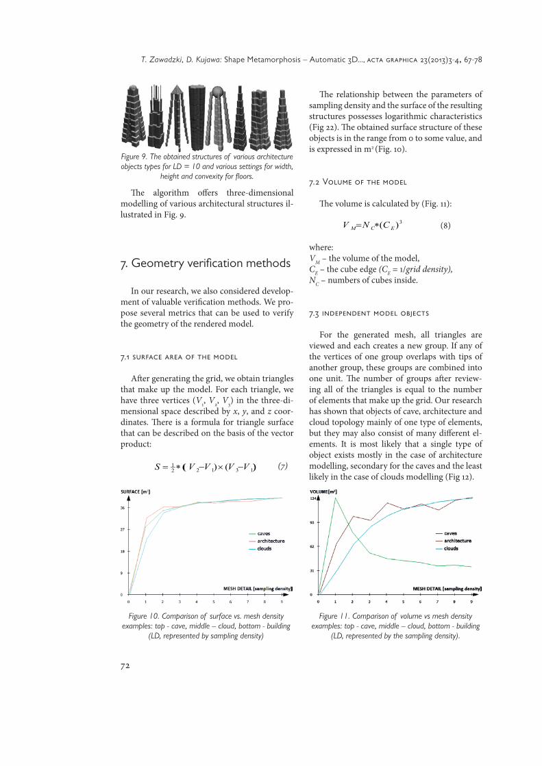
The algorithm offers three-dimensional modelling of various architectural structures il-lustrated in Fig. 9.
7. Geometry verification methods
In our research, we also considered develop-ment of valuable verification methods. We pro-pose several metrics that can be used to verify the geometry of the rendered model.
7.1 surface area of the model
After generating the grid, we obtain triangles that make up the model. For each triangle, we have three vertices (V1, V2, V3) in the three-di-mensional space described by x, y, and z coor-dinates. There is a formula for triangle surface that can be described on the basis of the vector product:
))()(( 131221 VVVVS −×−∗= (7)
The relationship between the parameters of sampling density and the surface of the resulting structures possesses logarithmic characteristics (Fig 22). The obtained surface structure of these objects is in the range from 0 to some value, and is expressed in m2 (Fig. 10).
7.2 Volume of the model
The volume is calculated by (Fig. 11):
3)( ECM CNV ∗= (8)
where:VM – the volume of the model, CE – the cube edge (CE = 1/grid density), NC – numbers of cubes inside.
7.3 independent model objects
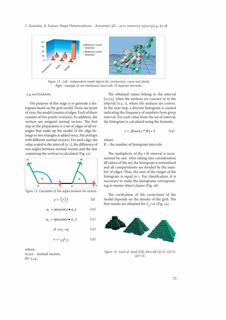
For the generated mesh, all triangles are viewed and each creates a new group. If any of the vertices of one group overlaps with tips of another group, these groups are combined into one unit. The number of groups after review-ing all of the triangles is equal to the number of elements that make up the grid. Our research has shown that objects of cave, architecture and cloud topology mainly of one type of elements, but they may also consist of many different el-ements. It is most likely that a single type of object exists mostly in the case of architecture modelling, secondary for the caves and the least likely in the case of clouds modelling (Fig 12).
Figure 9. The obtained structures of various architecture objects types for LD = 10 and various settings for width,
height and convexity for floors.
Figure 10. Comparison of surface vs. mesh density examples: top - cave, middle – cloud, bottom - building
(LD, represented by sampling density)
Figure 11. Comparison of volume vs mesh density examples: top - cave, middle – cloud, bottom - building
(LD, represented by the sampling density).
73
T. Zawadzki, D. Kujawa: Shape Metamorphosis – Automatic 3D..., acta graphica 23(2013)3-4, 67-78
7.4 histograms
The purpose of this stage is to generate a his-togram based on the grid model. From our point of view, the model consists of edges. Each of them consists of two points (vertices). In addition, the vertices are assigned normal vectors. The first step in the preparation is a set of edges of all tri-angles that make up the model (if the edge be-longs to two triangles is added twice, but perhaps with different normal vectors). For each edge, the value scaled to the interval [0, 1], the difference of two angles between normal vectors and the line containing the vertices is calculated (Fig. 13).
||)(
12
12VVVVe −
−= (9)
)arccos( 11 nea •= (10)
)arccos( 22 nea •= (11)
12 aad −= (12)
)1(2 += PIdv (13)
where:n1,n2 – normal vectors,PI~3.14.
The obtained values belong to the interval [0,0.5), when the surfaces are concave or to the interval (0.5, 1], where the surfaces are convex. In the next step, a discrete histogram is created indicating the frequency of numbers from given interval. For each value from the set of interval, the histogram is calculated using the formula:
1)*( += Rvfloori (14)
where:R – the number of histogram intervals.
The multiplicity of the i-th interval is incre-mented by one. After taking into consideration all values of the set, the histogram is normalized and all compartments are divided by the num-ber of edges. Thus, the sum of the ranges of the histogram is equal to 1. For classification, it is necessary to make the histograms correspond-ing to master object classes (Fig. 28).
The verification of the correctness of the model depends on the density of the grid. The best results are obtained for LD=10 (Fig. 14).
Figure 12. Left - independent model objects for: architecture, caves and clouds. Right - example of the distributed cloud with 10 separate elements.
Figure 13. Calculation of the angles between the vertices.
Figure 14. Level of detail (LD), from left LD=2, LD=5, LD=10.

74
T. Zawadzki, D. Kujawa: Shape Metamorphosis – Automatic 3D..., acta graphica 23(2013)3-4, 67-78
When density is large, the histogram is re-duced to a single bar, the most common value of angle.
The classification is based on the generation of a class histogram for new objects and its com-parison to the master-histogram from the base, for which the mean square error is the smallest.
8. Time complexity
Computational complexity is the depend-ence of the algorithm execution time T (or the number of operations necessary to execute the algorithm) on the data set of position points (P), is the sphere radius (r), is a top radius (a), is a bottom radius (b)
T=f(P,r,a,b) (15)
It is difficult to determine the exact form of this function, which is why we use its asymp-totic form.
The total number of basic operations - the number of assignments, sums, differences, in-tersections, comparisons that make up the complexity of the individual elements of the al-gorithm. The total computational complexity is composed of computational complexities:
• classical production
• morphing production
Computational complexity of the shapes morphing system:
Computational complexity of the hybrid system shapes:
One of the most important aspects in the analysis of the results, shown in Fig. 18, is the time complexity or performance of the pro-posed method (Fig. 16):
All simulations were performed on nVidia GeForce GTX 460M GPU, i7-2630QM CPU and 12 GB RAM.
Figure 15. Histograms for the main classes of results.
Figure 16. Time vs. mesh detail (LD, represented by sampling density) and number of triangles for the cave
example shown in Figure 18.
75
T. Zawadzki, D. Kujawa: Shape Metamorphosis – Automatic 3D..., acta graphica 23(2013)3-4, 67-78
9. Conclusion
Nowadays, we observe a noticeable trend of applying new methods of modelling 3D objects in real-time computer graphics systems. This is forced mainly by the market demand created in areas of digital entertainment and simulation for 3D gaming. This paper presents an innova-tive method for real-time procedural modelling of three-dimensional geometry of caves, clouds,
and buildings. By adding to the formalism of shape grammars an additional feature – mor-phing – we obtain a greater variety and geo-metric complexity of synthesized objects, highly influencing visual realism. This method is ad-vantageous comparing it to other procedural methods.
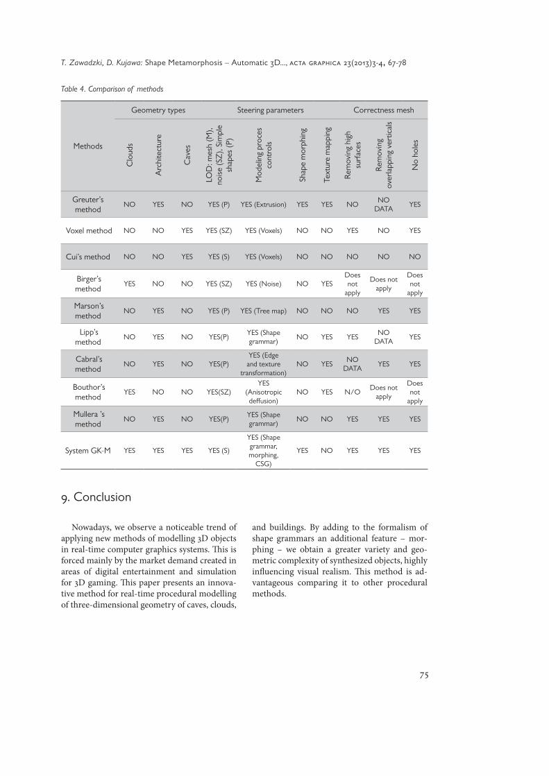
Table 4. Comparison of methods
Methods
Geometry types Steering parameters Correctness mesh
Clo
uds
Arc
hite
ctur
e
Cav
es
LOD
: mes
h (M
), no
ise (S
Z),
Sim
ple
shap
es (P
)
Mod
elin
g pr
oces
co
ntro
ls
Shap
e m
orph
ing
Text
ure
map
ping
Rem
ovin
g hi
gh
surf
aces
Rem
ovin
g ov
erla
ppin
g ve
rtic
als
No
hole
s
Greuter’s method
NO YES NO YES (P) YES (Extrusion) YES YES NONO
DATAYES
Voxel method NO NO YES YES (SZ) YES (Voxels) NO NO YES NO YES
Cui’s method NO NO YES YES (S) YES (Voxels) NO NO NO NO NO
Birger’s method
YES NO NO YES (SZ) YES (Noise) NO YESDoes not
apply
Does not apply
Does not
apply
Marson’s method
NO YES NO YES (P) YES (Tree map) NO NO NO YES YES
Lipp’s method
NO YES NO YES(P)YES (Shape grammar)
NO YES YESNO
DATAYES
Cabral’s method
NO YES NO YES(P)YES (Edge
and texture transformation)
NO YESNO
DATAYES YES
Bouthor’s method
YES NO NO YES(SZ)YES
(Anisotropic deffusion)
NO YES N/ODoes not
apply
Does not
apply
Mullera ’s method
NO YES NO YES(P)YES (Shape grammar)
NO NO YES YES YES
System GK-M YES YES YES YES (S)
YES (Shape grammar, morphing,
CSG)
YES NO YES YES YES
76
T. Zawadzki, D. Kujawa: Shape Metamorphosis – Automatic 3D..., acta graphica 23(2013)3-4, 67-78
References:
alexa m, cohen-or d, levin d. As rigid as pos-sible polygon morphing. Computers Graphics (SIGGRAPH ‘2000) 2000;34:157-64.
am ende ba. 3D Mapping of Underwater Caves, IEEE Computer Graphics Applications 2001; 21(2):14-20.
boggus m, crawfis r. Procedural Creation of 3D Solution Cave Models, Proceedings of the 20th IASTED International Conference on Model-ling and Simulation, 2009: 180-186.
boggus m, crawfis r. Explicit Generation of 3D Models of Solution Caves for Virtual Environ-ments, Proceedings of the 2009 International Conference on Computer Graphics and Virtual Reality, 2009: 85-90.
bouthors a, neyret f. Modelling Clouds Shape, Proceedings EUROGRAPHICS, 2004.
clempner jb, poznyak as. Convergence method, properties and computational complexity for Lyapunov games, The international journal of Applied Mathematics and Computer Science, 2011; 21(2): 349-361.
di trapani lj, inanc t. NTGsim: A graphical user interface and a 3D simulator for nonlinear trajectory generation methodology, The inter-national journal of Applied Mathematics and Computer, 2010; 20(2): 305-316.
dobashi y, kaneda k, yamashita h, okita t, nishita t. A simple, efficient method for real-istic animation of clouds. Proceedings of ACM SIGGRAPH 2000, 2000; 19-28.
ebert ds. Volumetric procedural implicit func-tions: A cloud is born. SIGGRAPH 97 Tech-nical Sketches Program, Whitted T., (Ed.), ACM SIGGRAPH, Addison Wesley, 1997, ISBN 0-89791-896-7.
77
T. Zawadzki, D. Kujawa: Shape Metamorphosis – Automatic 3D..., acta graphica 23(2013)3-4, 67-78
elinas p, sturzlinger w. Real-time rendering of 3D clouds. Journal of Graphics Tools. 2000; 5(4):33-45.
greuter s, parker j, stewart n, leach g. Re-al-time procedural generation of pseudo infi-nite cities. Proceedings (GRAPHITE’03), ACM Press, 2003; 87-95.
johnson l, yannakakis gn, togelius j. Cel-lular Automata for Real-time Generation of Infinite Cave Levels, Proceedings of the 2010 Workshop on Procedural Content Generation in Games (PC Games, 10), 2010: 1-4.
kent jr, carlson we, parent re. Shape trans-formation for polyhedral objects. Computer Graphics (SIGGRAPH ’92) 1992;26:47-54.
lazarus f, verrous a. Three-dimensional meta-morphosis: a survey. The Visual Computer 1998;14(8-9):373-89.
lee awf, dobkin d, sweldens w, shroeder p. Multiresolution mesh morphing. Computer Graphics (SIGGRAPH ’99) 1999;26:43-6.
martyn t. A new approach to morphing 2D aff-ine IFS fractals. Computers & Graphics 2004; 28:249-72.
nishita t, nakamae e, dobashi y. Display of clouds taking into account multiple anisotropic scattering and sky light. SIGGRAPH 96 Confer-ence Proceedings, Rushmeier H., (Ed.), ACM SIGGRAPH, Addison Wesley, 1996; 379-386.
parish yih, muller p. Procedural modeling of cities. Proceedings (SIGGRAPH’01), ACM Press, E. Fiume, 2001; 301–308.
peytavie a, galin e, grosjean j, merrilou s. Arches: a Framework for Modelling Complex Terrains, Computer Graphics Forum, Proceed-ings EUROGRAPHICS, 2009; 28(2):457-467.
78
T. Zawadzki, D. Kujawa: Shape Metamorphosis – Automatic 3D..., acta graphica 23(2013)3-4, 67-78
prusinkiewicz p, lindenmayer a. The Algo-rithmic Beauty of Plants. Springer-Verlag, 1991: 101–107. ISBN 978-0387972978.
schuchardt p, bowman da. The Benefits of Im-mersion for Spatial Understanding of Complex Underground Cave Systems, Proceedings of the 2007 ACM Symposium on Virtual Reality Software and Technology (VRST ’07), 2007: 121-124.
schpok j, simons j, ebert ds, hansen c. A real-time cloud modeling, rendering, and ani-mation system. Symposium on Computer Ani-mation’03, 2003; 160-166.
stiny g, gips j. Shape grammars and the genera-tive specification of painting and sculpture. In-formation Processing 71, North-Holland Pub-lishing Company, 1972: 1460-1465.
stiny g. Pictorial and Formal Aspects of Shape and Shape Grammars. Birkhauser Verlag, Basel, 1975.
stiny g. Introduction to shape and shape gram-mars. In Environment Planning B. 1980; 7(3): 343–361.
Turk g, o’brien jf. Shape Transformation us-ing variational implicit functions. Computer Graphics (SIGGRAPH ’99) 1999;33:335-42.
warszawski, k., nikiel, s. A proposition of par-ticle system-based technique for automated ter-rain surface modeling. In Proceedings of the 5th International North American Conference on Intelligent Games and Simulation (Game-On-NA ‘09), 2009; 17-19, ISBN 978-9077381-49-6.
velho l, gomes j, figueiredo lh. Implicit Ob-jects in Computer Graphics. Springer, 2002, ISBN: 978-0387984247.
wolberg g. Image morphing: a survey. The Visual Computer 1998;14(8-9):360-72.
wonka p, wimmer m, sillion f, ribarsky w. Instant architecture. ACM Transactions on Graphics 2003; 22(3):669–77.