Embed Size (px)
Citation preview
t
Report No. BMI-1403 --__-
UC-25 Metallurgy and Ceramics (TID-4500, 15th Ed.)
Contract No. W-7405-eng-92
PROGRESS RELATING TO CIVILIAN APPLICATIONS DURING DECEMBER, 1959
Russell MT. Dayton Clyde R. Tipton, J r .
January 1 , 1960
BATTELLE MEIMORIAL INSTITUTE 505 King Avenue
Columbus 1, Ohio
DISCLAIMER
This report was prepared as an account of work sponsored by an agency of the United States Government. Neither the United States Government nor any agency Thereof, nor any of their employees, makes any warranty, express or implied, or assumes any legal liability or responsibility for the accuracy, completeness, or usefulness of any information, apparatus, product, or process disclosed, or represents that its use would not infringe privately owned rights. Reference herein to any specific commercial product, process, or service by trade name, trademark, manufacturer, or otherwise does not necessarily constitute or imply its endorsement, recommendation, or favoring by the United States Government or any agency thereof. The views and opinions of authors expressed herein do not necessarily state or reflect those of the United States Government or any agency thereof.

DISCLAIMER Portions of this document may be illegible in electronic image products. Images are produced from the best available original document.
3
P
1 TABLE C I F CONTENTS
Page ~
5 REPORTS KELXTING TO CIVILLAN APPLlCATIONS ISSUED DURING DECEMBER, 1959 . . . . . . . . . .
. . . . . . . . . . . . . . . . . . . . . . . . . . . . . 7
Mechanical P r o p e r t i e s of Zirconium Alloys . . . . . . . . . . . . . . . . . . . . 7 Development of a Fuel-Element Leak Detector The rma l - Neutron-Flux Monitoring Sys t em . . . . . . . . . . . . . . . . . . . . .
A , ASSISTANCE TO H A P 0
7 10
. . . . . . . . . . . . . . . . . . .
Development of Corrosion- Resis tant Welding Alloys fo r Use With Hastelloy F to Contain Decladding Solutions . . . . . . . . . . . . . . . . . . . . . . . . . . . 11
R, DEVELOPMENTS FOR ALUMINUM- CLAD FUEL ELEMENTS . . . . . . . . . . . . . . . . . 13
P repa ra t ion of Aluminum-Uranium Alloys . . . . . . . . . . . . . . . . . . . . 13
. . . . . . . . . . . . . . . . . . . . 17 C . RADIOISOTOPE AND RADIATION APPLICATIONS.
Development of Radioact ive-Tracer Quality-Control Sys t ems . . . . . . . . . . . . . . 18
Gra f t - Polymerizat ion Studies . . . . . . . . . . . . . . . . . . . . . . . . . 20 Nitration of Hydrocarbons . . . . . . . . . . . . . . . . . . . . . . . . . . 21
Use of Intr insic Radioactive T r a c e r s for P r o c e s s Con t ro l . . . . . . . . . . . . . . . . 19
25
F. RESEARCH FOR AEC REACTOR DEVELOPMENT DIVXION PROGRAM . . . . . . . . . . . . . 27
REACTOR MATERIALS AND COMPONENTS . . . . . . . . . . . . . . . . . . . . . . 27
Valence Effects of Oxide Additions to Uranium Ilioxide . . . . . . . . . . . . . . . . . 28
D. VARIABLE-MODERATOR REACTOR CRITICAL-ASSEMBLY STUDIES . . . . . . . . . . . . . .
High-p res su re High-Temperature Solid-state Studies . . . . . . . . . . . . . . . . . 28 Irradiat ion-Survei l lance P r o g r a m on Type 347 Stainless Steel . . . . . . . . . . . . . . 29 Development of Niobium-Base Alloys . . . . . . . . . . . . . . . . . . . . . . 30 Development of Corrosion- Resis tant Niobium Alloys . . . . . . . . . . . . . . . . 33 Investigation of the Creep P rope r t i e s of Zircaloy-2 During Irradiat ion a t Elevated Tempera tu res . . 38 Determinat ion of Oxygen in Sodium a t Concentrations Below 10 P P M . . . . . . . . . . . . 39
S T U D I E S O F A L L O Y F U E L S . . . . . . . . . . . . . . . . . . . . . . . . . . . 41
Development of Niobium-Uranium Alloys . . . . . . . . . . . . . . . . . . . . . 41 Development of Thorium-Uranium Alloys . . . . . . . . . . . . . . . . . . . . . 43
FISSION-GAS RELEASE FROM REFRACTORY FUELS . . . . . . . . . . . . . . . . . . 44
44
P repa ra t ion f o r In-Pile Study . . . . . . . . . . . . . . . . . . . . . . . . . . 46
Character izat ion of Sintered UOz and Model of G a s Release Diffusion In UO2 . . . . . . . . . . . . . . . . . . . . . . . . . . . . . 45
GENERALFUEL-ELEMEN*TDEVELOPMENT . . . . . . . . . . . . . . . . . . . . . 47
Fabricat ion of C e r m e t Fuel Elements . . . . . . . . . . . . . . . . . . . . . . 47 G a s - P r e s s u r e Bonding of Molybdenum- and Niohium-Clad Fue l E lemen t s . . . . . . . . . . 49 F a c t o r s Affecting P r e s s u r e Bonding . . . . . . . . . . . . . . . . . . . . . . . 50
. . . . . . . . . . . . . . .
FF. FUEL-CYCLE PROGRAM STUDIES. . . . . . . . . . . . . . . . . . . . . . . . . . 51
51 GAS-PRESSURE BONDING O F CERAMIC, CERMET, AND DISPERSION F U E L ELEMENTS
DEVELOPMENT O F URANIUM CARBIDE-TYPE FUEL MATERIALS . . . . . . . . . . . . . . 56
. . . . . .
Alternate Fabricat ion Methods f o r UC . . . . . . . . . . . . . . . . . . . . . . 58 Melting and Casting Techniques fo r Uranium-Carbon Alloys . . . . . . . . . . . . . . . 60 Metal lurgical and Engineering P rope r t i e s of Uranium Monocarbide . . . . . . . . . . . . 60 U r a n i u m Monocarbide Diffusion Studies . . . . . . . . . . . . . . . . . . . . . . 61 Irradiat ion Effects i n UC . . . . . . . . . . . . . . . . . . . . . . . . . . 62
GG. VOID-DISTRIBUTION AND HEAT-TRANSFER STUDIES . . . . . . . . . . . . . . . . . . . 63
4
TABLE O F CONTENTS (Continued) *
. . . . . . . . . . . . . . . . . . . . . . . . . . . . . . H . PHYSICAL RESEARCH 65
65
67
I . SOLID HOMOGENEOUS FUELED REACTORS 69
Niobium-Gas Reactlons . . . . . . . . . . . . . . . . . . . . . . . . . . . Growth of U 0 2 Crys t a l s F r o m the Vapor Phase . . . . . . . . . . . . . . . . . . . 66 Fusion Methods to P r e p a r e Single Crys t a l s of UO2 . . . . . . . . . . . . . . . . . .
. . . . . . . . . . . . . . . . . . . . . . LABORATORY EVALUATIONS O F FUELED-GRAPHITE SPHERES . . . . . . . . . . . . . . 69
FABRICATION DEVELOPMENT O F AlZ03-CLAD U 0 2 F U E L PARTICLES . . . . . . . . . . . 69
FISSION- PRODUCT RELEASE FROM FUELED-GRAPHITE SPHERES . . . . . . . . . . . . . . 70
Neutron-Activatlon Studies . . . . . . . . . . . . . . . . . . . . . . . . . . 70 In-Pi le Capsule Experiments . . . . . . . . . . . . . . . . . . . . . . . . . 71
J . PROBLEMS ASSOCIATED WITH THE RECOVERY O F SPENT REACTOR F U E L ELEMENTS . . . . . . 73
CORROSION STUDIES O F THE FLUORIDE-VOLATILITY PROCESS . . . . . . . . . . . . . . 73
STUDY OF THE EFFECTS OF IRRADIATION ON CLADDING- AND CORE-DISSOLUTION PROCESSES . . 73
Sulfex P r o c e s s . . . . . . . . . . . . . . . . . . . . . . . . . . . . . . 73
K . DEVELOPMENTSFORSRE . . . . . . . . . . . . . . . . . . . . . . . . . . . . 75
D a r e x Process . . . . . . . . . . . . . . . . . . . . . . . . . . . . . . . 74
EVALUATION O F URANIUM MONOCARBIDE AS A REACTOR F U E L . . . . . . . . . . . . . . 75
Irradiat ion of Uranium Monocarbide . . . . . . . . . . . . . . . . . . . . . . . . 75 Post i r radiat ion Examination of I r r ad ia t ed Uranium Monocarbide . . . . . . . . . . . . . 75
. . . . . . . . . . . . . . . . . . . . . . . . . L TANTALUM AND TANTALUM ALLOYS 79
Development of Container Mate r i a l s for L a m p r e Applications . . . . . . . . . . . . . . 79 Effect of I r radiat ion Damage of Tantalum . . . . . . . . . . . . . . . . . . . . . 79
M . DEVELOPMENTAL STUDIES FOR THE PWR . . . . . . . . . . . . . . . . . . . . . . 81
Fabricat ion of Large-Scale PWR-Type Fuel P l a t e s . . . . . . . . . . . . . . ; . . . 81
N . DEVELOPMENTSFORTHEMGCR . . . . . . . . . . . . . . . . . . . . . . . . . . 8 3
FABRICATION AND CHARACTERIZATION OF FUEL MATERIALS . . . . . . . . . . . . . . 8 3
HIGH-BURNUP IRRADIATION E F F E C T S IN FUEL MATERIALS . . . . . . . . . . . . . . . 8 3
DIFFUSION O F FISSION PRODUCTS IN CLADDING MATERIALS . . . . . . . . . . . . . . . 8 4
Precipi ta te Phase Identification and Inters t i t ia l -Type Solid Solubility i n Tantalum . . . . . . . 80
CARBON-TRANSPORT CORROSION STUDIES . . . . . . . . . . . . . . . . . . . . . . . 8 4
P . DEVELOPMENTAL STUDIES FOR THE SM- 2 . . . . . . . . . . . . . . . . . . . . . . 87
Mate r i a l s Development . . . . . . . . . . . . . . . . . . . . . . . . . . 87 Encapsulation Studies . . . . . . . . . . . . . . . . . . . . . . . . . . . . 90
Q . CAS-COOLEDREACTORPROGRAM 93 . . . . . . . . . . . . . . . . . . . . . . . . . . MATERIALS DEVELOPMENT PROGRAM . . . . . . . . . . . . . . . . . . . . . . . 93
Fabricat ion of BeO-UOZ Fue l Pe l l e t s . . . . . . . . . . . . . . . . . . . . . . 93 Encapsulation Studies . . . . . . . . . . . . . . . . . . . . . . . . . . . . 94 Effects of I r radiat ion . . . . . . . . . . . . . . . . . . . . . . . . . . . . 95 GCRE Cri t ical-Assembly Exper imen t s . . . . . . . . . . . . . . . . . . . . . . 97
IN-PILE-LOOP PROGRAM . . . . . . . . . . . . . . . . . . . . . . . . . . . . 98
BRR Loop P r o g r a m . . . . . . . . . . . . . . . . . . . . . . . . . . . . 98 ETR Loop P r o g r a m . . . . . . . . . . . . . . . . . . . . . . . . . . . . 99
BMI- 1376
BMI- 1386
6 1 BMI-,l390
BMI-,1398
5 anti 6
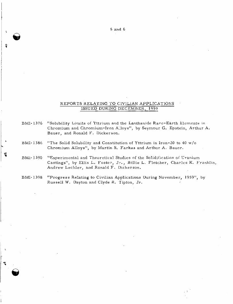
REPORTS RELATING TO CIVILIAN APPLICATIONS ISSUED DURING DECEMBER. 1959
"Solubility Limits of Yttrium and the Lanthanide Rare-Earth Elements in Chromium and Chromium-Iron Al.loys", by Seymour G. Epstein, Arthur A. Bauer, and Ronald F. Dickerson.
"The Solid Solubility and Constitution of Yttrium in Iron-20 to 40 w/o Chromium Alloys", by Martin S. Farkas and Arthur A. Bauer.
"Experimental and Theoretical Studies of the Solidification of Uranium Castings", by Ellis L. Foster , JT., Billie L. Fletcher , Charles K. Franklin, Andrew Lechler, and Ronald F. Dickerson.
"Progress Relating to Civilian Applications During November, 1959", by Russel l W. Dayton and Clyde R. 'Tipton, Jr.
7
A- 1
A. ASSISTANCE TO HAP0
F. R. Shober
The creep and s t ress - rupture propert ies of annealed and of 15 per cent cold- woxked Zircaloy-2 a r e being determined at 290, 345, and 400 C. in curation a r e expected. tector for use in water-cooled reac tors , it appears that the gamma-ray background on an .SgBr column would be undesirably high after several days of normal operations. past work period has been spent investigating ways of preventing the buildup of undesir- ablr: fission products on the AgBr column. t int ed attempts to reduce fission-product absorption and with in-pile t e s t s of the leak detc:ctor at the ETR.
Creep tes t s 12,000 h r In further studies to develop a AgBr fuel-element leak de-
The
Future work wil l be concerned with con-
The development of a thermal-neutron -flux monitoring system has been directed toward extending the sensing-probe l ife, increasing the effective instrument range, and imylroving the instrument reliability. has been determined to investigate the effects of MoSi2 proportion and of extrusion p r e s - sures . In the development of corrosion-resis tant welding alloys for use with Hastelloy F, a number of alloys a r e being exposed in 'boiling Sulfex and Niflex solutions to deter- m i r e corrosion resis tance to these liquids.
Resistivity of A1203-MoSi2-UO2 ceramic tubes
Mechanical ProDertie s of Zirconium Allovs
L. P. Rice and J. A. VanEcho
The determination of c reep and s t ress-rupture propert ies of Zircaloy-2 sheet mater ia l has been under way for several years. woiked (15 per cent) mater ia l at temperatures of 290, 345, and 400 C.
This has included annealed and cold-
The report (BMI-1398) for November summarized the s t r e s s -rupture behavior of the cur ren t batch of annealed and cold-worklzd Zircaloy-2 material .
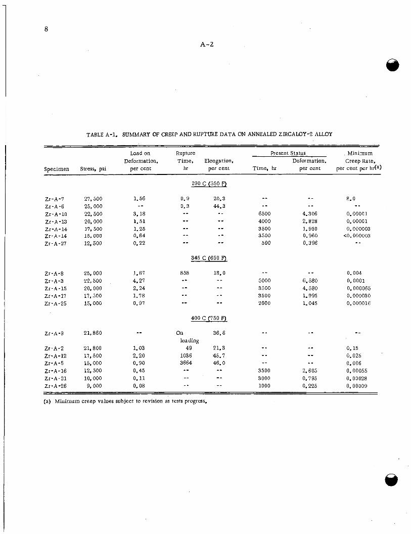
At the end of December there were 19 t e s t s still in progress . The c reep behavior in t i e current tes t s on the annealed Zircaloy-2 i s summarized in Table A-1.
Development of a Fuel -Element Leak Detector
J. E. Howes, J r . , T. S . Elleman, and D. N. Sunderman
1 This report summarizes the resul ts obtained during December on the development
r; of a AgBr fuel-elemelit leak detector. 7
Previous progress reports have indicated that a successful leak detector can be constructed f rom a AgBr column operated in conjunction with a delayed-neutron monitor.
8
A-2
TABLE A-1. SUMMARY OF CREEP AND RUPTURE DATA ON ANNEALED ZIRCALOY-2 ALLOY
Load on Rupture Present Status Minimum Deformation, Time, Elongation, Deformation, Creep Rate,
Specimen Stress, psi per cent hI per cent Time, hr per cent per cent per hda)
Zr-A-7 27,500 Zr -A -6 25,000 Zr-A-10 22,500 Zr -A - 13 20,000 Zr -A- 14 17,500 Zr-A-14 15 ,000 Zr - A -27 12,500
Zr-A-8 25,000 Zr-A-3 22,500 Zr-A-15 20,000 Zr-A-17 17,500 Zr - A - 25 15,000
Zr-A-9 21,860
Zr-A-2 21,800 Zr-A-12 17,500 Zr-A-5 15,000 Zr -A - 16 12,500 Zr -A - 21 10,000 Zr -A -26 9,000
1.56
3.18 1.51 1.25 0.64
- -
0.22
1.67 4.27 2.24 1.78 0.97
1.03 2.20 0.90 0.45 0.11 0.08
290 C (550 F)
8.0 _ _ - - 0.9 20.3 0.3 44.3 -- - - 6500 4.306 0.00001 -- -- 4000 2.828 0.00001 _ _ -- 3500 1.950
500 0.396
- - - - - -
0.000003 - - 3500 0.960 <O. 000003 _-
- - - - -- 345 C (650 F)
400 C (750 F)
_ - 0.004 - - 5000 6.580 0.0001
0.000065 3500 4.580 0.000030 3500 1.995
2000 1.045 0.000016
On 36.6 - - - - - - loading - - 0.15 1036 45. 7 - - 0.025
- - 0.006
49 21.3 - - 3664 46.0 --
- - -- - - 3500 2.605 0.00055 -- 3000 0.795 0.00028
_ - 1000 0.225 0.00009
-- - -
(a) Minimum creep values subject to revision as tests progress.
9
A- 3
c
9 @ Dui-ing a fuel-element failure, delayed-neutron-emitting halide fission products in the
reactor coolant a r e selectively absorbed on the AgBr column, and the delayed neutrons trij;ger the detector attached to the column. The use of a gross gamma-ray detector in pla'1-e of the neutron detector i s hampered by adsorption of gamma-ray-emitting fission products on the AgBr. background on the AgBr would be undesirably high after several days of normal operation.
It appears f rom the experimental resul ts that the gamma-ray
Since the intended operation of the leak detector is best suited to a gross gamma- detl?ction system, the past month has been sipent investigating ways of preventing the buildup of undesirable fission products on the AgBr column. A number of experiments wei-e ca r r i ed out in which fission-product solutions were passed through a column con- tairiing ethylenediaminetetraacetic acid pellets before the solution was passed into the Agl3r column. uct,: before they reached the AgBr and thus prevent deposition of the column. technique reduced the fission-product absorption by a factor of two or so but the reduc- tiorl was not sufficient. witli an excess of dissolved complexing agent before passage through the AgBr also yie! ded significant fission-product absorpticm on the column. satiirate the AgBr with nonradioactive f is sicin-product c a r r i e r s before the AgBr was contacted with fission products, but this approach did not appear to reduce the fission- p r o duct ab s o r pt i on.
The purpose of this experiment was to complex the cationic fission prod- This
Experiments in which the fission products were equilibrated
Attempts were made to
In another experiment, lanthanum and zirconium c a r r i e r s were addedto the fission' products immediately before they were passed through the AgBr column. preciable deposition of fission products on the AgBr was observed. t ra l ion of c a r r i e r was many t imes higher than the fission-product concentration, the continued deposition of fission products suggests that the fission products were absorbed on ])articulate mat te r and did not rapidly exchange with the c a r r i e r cations.
Again, ap- Since the concen-
Future work on this program wil l be concerned with continued attempts to reduce fission-product absorption on the AgBr column and with in-pile t e s t s of the leak detector at the ETR.
The experiments performed on fis sion-product absorption indicate that the fission
A number of experiments will be ca r r i ed out to t e s t the effect products which deposit on the AgBr column a re themselves deposited on microscopic par t ic les in the solution. of \ arious f i l ters in removing this particulate mat te r before it reaches the AgBr column.
In the ETR loop experiments, fuel elements will be intentionally ruptured to relt?ase fission products to the coolant. saniple the coolant, and the t ime required to detect a leak, the signal-to-noise ratio, the normal coolant background, the rate of f'is sion-product buildup, and other quantities of importance to leak-detector operation will be determined.
Silver bromide columns wil l be set up to
10
Thermal-Neutron-Flux Monitoring System
J. W. Lennon, M. J. Snyder, D. R. Gr i e se r , P. M. Steinback, and W. H. Goldthwaite
Ceramic tubes of A1203-MoSi2-U02 containing enriched uranium for the fission- power elements and depleted uranium for the matching electric-heating elements a r e the p r imary components of the thermal-neutron-flux measuring instrument previously developed by Battelle (BMI-1083). The thermal neutron flux i s determined directly f r o m the measured electr ic power developed in the power matching electric-heating element.
Ext-eAdin P s en sin P - D r ob e life and i n c r e a s i n d h e effcciixe i n s 3 r-ume ntxr an e e - u
12
A- 6
L3 Severe attack occurred on all of the weldments exposed to the Niflex solutions. Attack also was severe in the heat-affected zones adjacent to the weldments. the alloys seemed much bet ter than Hastelloy F as a f i l l e r material . with Alloys 1, 2, 7 , 8, and 9 were perforated by the end of th ree periods. all contain niobium additions which, on f i r s t appraisal , seem to be detrimental to the corrosion resis tance of the weldment.
None of
These alloys Weldments made
I
All of the exposures have been conducted using Allihn condensers to which f ree access of air has been hindered. The next s e r i e s of experiments in boiling Sulfex solutions will be run with air sparged through the solutions. reported to increase the corrosion ra tes by a factor of ten, and may help point out differences in weld-metal attack by the Sulfex solution. alloys welded with their own f i l l e r mater ia ls . res is tance over s imilar welds made on Hastelloy F.
Such a condition has been
This next s e r i e s involves the Possibly such welds may show improved
11
A- 5
*
i-
a
@ P r e l i m i n a r y room-tempera ture data f r o m the specimens present ly in p r o c e s s will be obtained. recent work, and sufficient definitive t e s t s w i l l be designed and completed t o permi t a mo3:e c l e a r evaluation of the p r o g r e s s to date and to a id in a r eappra i sa l of the scope of the program.
All of the data obtained thus f a r will be re-evaluated in the light of the
This work will be completed by the end of the next r epor t period.
Development of Corrosion-Resis tant Welding Alloys fo r Use With Hastellov F t o Contain Decladding Solutions
C. L. Pe te r son , J. D. Jackson, A. M. Hall, R. E. Monroe, and W . K. Boyd
Machined, coupon-type specimens of unwelded vacuum-melted Hastelloy F and of the 12 unwelded, rol led experimental alloys desc r ibed in BMI-1391 and BMI-1398 have beejn exposed t o boiling Sulfex and Niflex solutions. Five 24-hr per iods of exposure to the vapor and to the liquid of each solution w e r e completed f o r duplicate specimens of all ma te r i a l s .
In the Sulfex solution all of the experirnental alloys behaved s imi l a r ly to vacuum- mel ted Hastelloy F with co r ros ion r a t e s in the liquid ranging f r o m 1 t o 4 m i l s p e r month (Hastelloy F was 2 mils p e r month) over the five periods. however, the r a t e s fo r all the experimental alloys and f o r Hastelloy F va r i ed consider- ablj-, being high ( 3 to 10 mils p e r month) fo r some per iods and l e s s than 1 mil p e r month during others . This indicates that all of these m a t e r i a l s exhibit borderl ine p a s - sivity i n th i s solution. The over-al l co r ros ion r a t e s w e r e always lower for the vapor- pha:je specimens.
F r o m period to per iod,
In the m o r e aggres s ive Niflex solutions all of the specimens w e r e active during each period. but all cor roded at a uniform ra t e af ter the first 24-hr period. vacuum-melted Hastelloy F, fo r which the r a t e constantly inc reased during the five exposure periods. the liquid had reached 110 m i l s p e r month and showed signs of fu r the r i nc rease . cor::osion r a t e s of Alloys 3 , 4, 10, and 11 had leveled off in the 30 to 40 mils-per-month range; Alloys 9 and 12 in the 50 t o 60; Alloyfj 1, 5, and 6 in the 60 to 70; and Alloys 2, 7 , znd 8 w e r e in the 70 to 100 mils-per-month range. supe r io r to vacuum-melted Hastelloy F, some by a substantial amount, but all w e r e con 3iderably attacked by the Niflex solution.
A few of the experimental alloys appeared to have shor t induction per iods, This was not t r u e of the
During the last per iod the r a t e fo r Hastelloy F specimens exposed to The
Thus, all of the alloys w e r e
Similar s e r i e s of exposures have been conducted on specimens of vacuum-melted Hastelloy F which were butt welded with each of the experimental alloys a s f i l l e r m a t e - rial. Five 24-hr per iods in boiling Sulfex solution w e r e not sufficient to br ing about any significant differences in the co r ros ion of any of the weldments. T h e r e appeared t o be a slight attack on the weldments of the liquid specimens welded with Alloys 3 and 4 and with Hastelloy F a s f i l l e r mater ia ls . A l s o , some of the liquid-phase specimens w e r e lightly etched while o the r s w e r e not. Other than th i s , t he re was l i t t le difference in the specimens at the end of the exposure. The co r ros ion r a t e s again va r i ed f r o m pe r iod to per1 od, indicating borderl ine passivity.
@
12
A- 6
Severe attack occur red on all of the weldments exposed to the Niflex solutions. @ Attack a l so w a s seve re in the heat-affected zones adjacent to the weldments. the alloys seemed much be t te r than Hastelloy F a s a f i l l e r mater ia l . with Alloys 1, 2 , 7, 8, and 9 were per fora ted by the end of th ree periods. all contain niobium additions which, on f i r s t appra isa l , s eem to be detrimental to the co r ros ion res i s tance of the weldment.
None of
These alloys Weldments made
I
All of the exposures have been conducted using Allihn condensers to which f r e e a c c e s s of air has been hindered. The next s e r i e s of exper iments in boiling Sulfex solutions will be run with air sparged through the solutions. r epor t ed to increase the co r ros ion r a t e s by a factor of ten, and may help point out differences i n weld-metal attack by the Sulfex solution. alloys welded with the i r own f i l ler mater ia l s . res i s tance over s imi la r welds made on Hastelloy F.
Such a condition has been
This next s e r i e s involves the Possibly such welds may show improved
... . .
13
Et- 1
B. DEVELOPMENTS FOR ALIUMINUM-CLAD FUEL ELEMENTS
N. E. Daniel
Corrosion tes t s in 200 C water for 30 days have shown that the aluminum-35 w/o uranium alloys containing tin o r zirconium additives a r e equivalent to the binary aluininum-35 w / o uranium and superior to 2,s aluminum in their res is tance to the corro- sioji attack of 200 C water . have been made containing 2. 5 to 3 w/o tin o r zirconium. i n these billets varied l e s s than 1 w/o from top to bottom. and 400 C have been conducted on selected alloys.
‘
Six full-size ali~minum-35 w/o uranium extrusion billets The uranium concentrations Tensile tes t s a t 100, 250,
Preoarat ion of Aluminum-Uranium Allovs
N . E. Daniel, E. L. Fos,ter, and R. F. Dickerson
Aluminum-uranium alloys in the form of hollow cylindrical tubes clad inside and The proposed fabrication outgide with aluminum a r e desired for use E I S reactor fuels.
tecliniques employ a hollow cylindrical casting containing 35 w/o uranium. This casting is c.oextruded with the aluminum cladding. Therefore, it is desirable that the casting be dense and sound with good end-to-end homogeneity. ma’:erial possess extrusion character is t ics as close as possible to those of the aluminum clallding. acter is t ics of the alloy is through the use of selected te rnary additions. stullies have shown that tin and zirconium will inhibit the UA13-to-UA14 peritectic re- action, thereby increasing the quantity of f ree aluminum present in the alloys. stullies also indicated that the casting character is t ics of the alloy could be improved by the use of te rnary additions on the order of 3 w/o.
It is also desirable that the cas t
One possible method of enhancing both the castability and the extrusion char- Previous
The
Corrosion tes t s have been conducted with aluminurn-35 w / o uranium alloys con- tairting additions of 0. 5, 1. 0 , 1. 5, 2 . 0 , and 3.0 w/o tin o r zirconium in 200 G demin- eralized water for periods up to 30 days of total exposure. Specimens were examined afttbr 1, 5, 10, 20 , and 30 days. Control specimens of 2s aluminum and of the binary aluninum-35 w/o uranium alloy were run in the autoclaves with the alloys containing t e r i a r y additions. After 30 days of exposure, all of the alloys exhibited weight gains l e s s than that exhibited by the 2s aluminum. The weight gains exhibited by the as -cas t and the extruded ma te r i a l obtained from vacuum-melted alloys were comparable. The weight gains exhibited by the air-melted mater ia l were grea te r in the as-cast condition t h a i in the extruded condition. This may be attributed to the closing of porosity that may have existed in the as-cast mater ia l . alloys containing tin in the as -cas t condition were 0 . 7 9 to 1. 15 g pe r cm2 and for the s a r i e alloys in the extruded condition the weight gains were 0. 57 to 0 . 67 mg per cm2. Tht: weight gains exhibited by the air-melted alloys containing zirconium in the as -cas t condition were from 0 . 7 9 to 3 . 52 mg p e r cm2, and were from 0.44 to 0 .58 mg p e r cm2 for the alloys in the extruded condition.
The weight gains exhibited by the air-melted
B-2
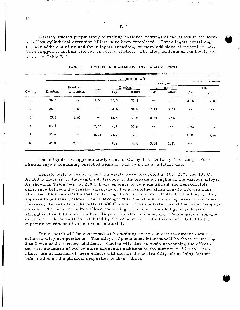
Casting studies preparatory to making enriched castings of the alloys in the form of hollow cylindrical extrusion billets have been completed.
been shipped toanother si te for extrusion studies. shown in Table B- 1.
Three ingots containing ternary additions of tin and three ingots containing te rnary additions of zirconium have
t The alloy contents of the ingots a r e
TABLE B-1. COMPOSITION OF ALUMINUM-URANIUM ALLOY INGOTS
Composition, w/o Analyzed
Nominal Uranium Zirconium Tin Casting Uranium Zirconium Tin TOP Bottom TOP Bottom TOP Bottom
- - 2.99 2. 91 1 35. 0 - _ 3.00 34.5 35.3 --
2 35. 0 2. 50 - - 34 .4 34.8 2.13 2.23 -- - _ -- - - 3 35.0 3.00 - - 33. 6 34. 6 2.80 3.26
2.72 2. 64 - - -_ 4 35 .6 - _ 2.75 36.2 35.8
2 .72 2. 68 - - --- 5 35. 0 - - 2.75 34. 2 33.9
-- - _ 6 35. 0 2.75 -- 33.7 33.4 3.16 2.71
These ingots a r e approximately 6 in. in OD by 4 in. in ID by 7 in. long. Four similar ingots containing enriched uranium will be made at a future date.
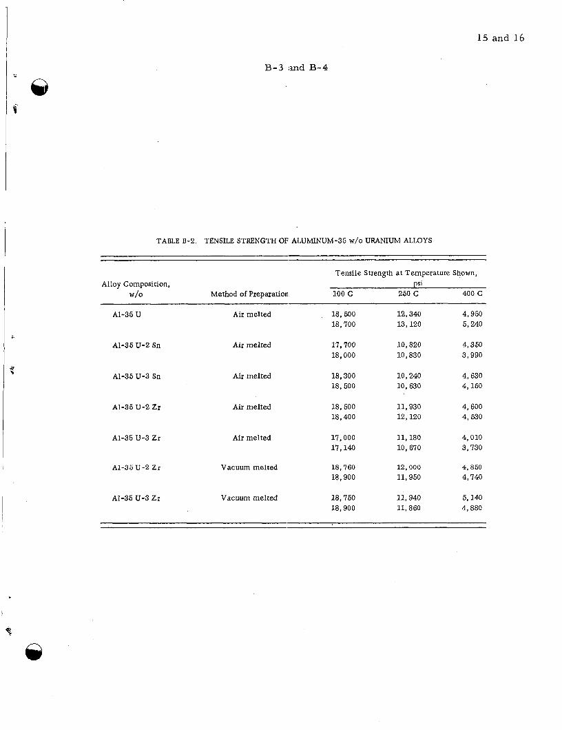
Tensile tes ts of the extruded mater ia l s were conducted a t 100, 250, and 400 C. At 100 C there is no discernible difference in the tensile strengths of the various alloys. As shown in Table B-2, at 250 C there appears to be a significant and reproducible difference between the tensile strengths of the air-melted aluminum-35 w/o uranium alloy and the air-melted alloys containing tin o r zirconium. appears to possess grea te r tensile strength than the alloys containing te rnary additions; however, the resul ts of the tes ts at 400 C were not as consistent a s at the lower temper- a tures . strengths than did the air-melted alloys of s imi la r composition. ority in tensile propert ies exhibited by the vacuum-melted alloys i s attributed to the superior soundness of vacuum-cast mater ia l .
At 400 C , the binary alloy
The vacuum-melted alloys containing zirconium exhibited grea te r tensile This apparent superi-
Future work will be concerned with obtaining c reep and s t ress-rupture data on selected alloy compositions. The alloys of paramount interest will be those containing 2 to 3 w/o of the te rnary additions. Studies will also be made concerning the effect on the cast s t ructure of two o r more elemental additions to the aluminum-35 w/o uranium alloy, information on the physical propert ies of these alloys.
An evaluation of these effects will dictate the desirabil i ty of obtaining fur ther
15 and 16
B-3 i-tnd B-4
TABLE B-2. TENSILE STRENGTH OF ALUMINUM-35 W/O URANIUM ALLOYS
Tensile Strength at Temperature Shown, Alloy Composition, ps1
w/o Method of Preparation 100 c 250 C 400 C
A1-35 U
AI-35 U-2 Sn
A1-35 U-3 Sn
A1-35 U-2 Zr
AI-35 U-3 ZI
A1-35 U-2 Zr
AI-35 U-3 Zr
Air melted 18,500 18,700
12,340 13,120
4,950 5,240
Air melted 17,700 18,000
10,820 10,830
4,350 3,990
Air melted 18,300 18,500
10,240 10,630
4,630 4,150
Aiz melted 18,500 18,400
11,930 12,120
4,600 4,530
Air melted 17,000 17,140
11,180 10,670
4,010 3,730
Vacuum melted 18,760 18,900
12,000 11,950
4,850 4,740
Vacuum melted 18,750 18,900
11,940 11,860
5,140 4,880

17
c- 1
C. RADIOISOTOPE AND RADIATION APPLICATIONS
D. N. Su:nderman
Research is continuing on a se r i e s of programs for the Office of Isotopes Develop- me i t . control, the use of intrinsic t r a c e r s in process control, a study of the effect of s t ructure on radiation-induced graft polymerization, and the radiation-induc ed nitration of hydrocarbons.
These programs involve the application of radioisotopes to industrial quality
Further experimentation on the sequential determination of i ron and aluminum in the same solution show that the presence of aluminum increases the solubility of the Y2()1(CzO4)3 indicator prematurely, giving a t i tration curve which i s difficult to in- t e r pret quantitatively. promising, but further experimentation i s necessary to establish its accuracy and p re - c i s ton. stu3ied. addition of phosphate ion tagged with phosphorus-32 and back-titration of the excess E D r A with barium. A radioassay of the solution provides a measure of the amount of phcsphate consumed in the precipitation of 13a3(P3204)2 and, therefore , a measu re of the excess EDTA.
The t i tration of iron alone using a similar procedure appears
A somewhat different technique for the determination of aluminum is being This technique involves the addition of an excess of EDTA followed by the
The determination of detector sensitivity by batch studies has been confirmed
Results u s i ig a circulating-loop system. The effeci; of salt concentration on detector sensitivity has been evaluated over the range of interest in the i ron-removal process . indicate the effect of salt concentration will not be significant. Other aFplications of the i r o 1-removal process have been found in thls electrolytic process for the preparation of niccel and zinc. These applications a r e very similar to the ammonia-leach nickel sys- tent and could be demonstrated in similar equipment.
The effect of radiation dose on active-site formation has been determined for poljmethyl-, polyethyl-, and polybutylmethacrylates. The number of active si tes was fouid to increase to a maximum value and then decrease with increased radiation dose. Several explanations a r e suggested for this phenomenon. fluidity of the polymer system, the formation of two separate f ree-radical species , o r the existence of highly radiation sensitive points in the polymer s t ructure . The G- v a h e s have been determined for active- si te formation, and good agreement was obtained wit 1 l i terature values where available.
These include a change in
The effect of radiation on the nitration of cyclohexane has been studied over the range of 15 to 70 w/o nitric acid with a 10-to-1 rat io of organic to acid. firrned ear l ie r findings that radiation inhibits the nitration of this mater ia l under the conditions studied. agents other than ni t r ic acid.
Results con-
Further work will be directed toward an evaluation of nitrating
18
c-2
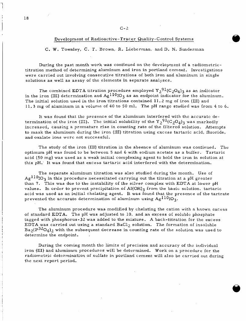
DeveloDment of Radioactive - Trac e r Qualitv-Control Svstems
C. W. Townley, C. T. Brown, R. Lieberman, andD. N. Sunderman
During the past month work was continued on the development of a radiometric- Investigations t i tration method of determining aluminum and i ron in portland cement.
were ca r r i ed out involving consecutive t i trations of both iron and aluminum in single solutions as well as assay of the elements in separate analyses.
The combined EDTA titration procedure employed Y291(c204)3 as an indicator in the i ron (111) determination and Ag1lOIO3 as an endpoint indicator for the aluminum. The initial solution used in the i ron t i trations contained 11.2 mg of iron (III) and 11.3 mg of aluminum in a volume of 40 to 50 ml. The pH range studied was f rom 4 to 6.
It was found that the presence of the aluminum interfered with the accurate de- termination of the i ron (III). increased, causing a premature r i s e in counting ra te of the fi l tered solution. Attempts to mask the aluminum during the iron (111) ti tration using excess ta r ta r ic acid, fluoride, and oxalate ions were not successful.
The initial solubility of the Y291(c204)3 was markedly
The study of the i ron (111) ti tration in the absence of aluminum was continued. The optimum pH was found to be between 5 and 6 with sodium acetate as a buffer. acid (50 mg) was used a s a weak initial complexing agent to hold the i ron in solution at this pH.' It was found that excess t a r t a r i c acid interfered with the determination.
Tar ta r ic
The separate aluminum ti tration was also studied during the month. Use of Ag1loI03 in this procedure necessitated carrying out the t i tration at a pH grea te r than 7. values. acid was used as an initial chelating agent. prevented the accurate determination of aluminum using Agl loIO3.
This was due to the instability of the s i lver complex with EDTA at lower pH In order to prevent precipitation of Al(OH)3 f rom the basic solution, t a r t a r i c
It was found that the presence of the t a r t r a t e
The aluminum procedure was modified by chelating the cation with a known excess of standard EDTA. tagged with phosphorus-32 was added to the mixture. A back-titration for the excess EDTA was ca r r i ed out using a standard BaC12 solution. The formation of insoluble B a ~ ( P ~ ~ 0 4 ) 2 with the subsequent decrease in counting r a t e of the solution was used to determine the endpoint.
The pH was adjusted to 10, and an excess of soluble phosphate
During the coming month the limits of precision and accuracy of the individual i ron (111) and aluminum procedures will be determined. radiometric determination of sulfate in portland cement will a lso be ca r r i ed out during the next report period.
Work on a procedure for the
19
c - , 3
n Use of Intrinsic Radioactive ‘Tracers for P rocess Control
J. L. McFarling, J. F. Kircher , andD. N. Sunderman
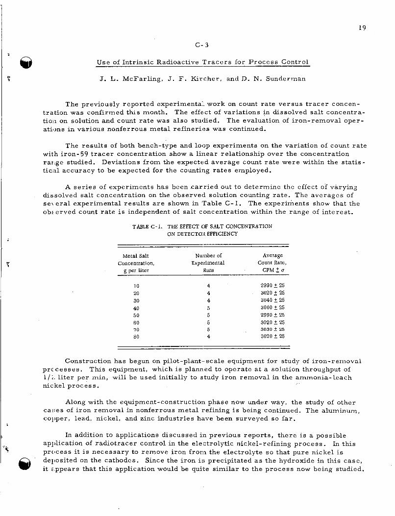
The previously reported experimental work on count ra te versus t r ace r concen- t ra t ion was confirmed this month. tioii on solution and count ra te was also studied. atilms in various nonferrous metal ref iner ies was continued.
The effect of variations in dissolved salt concentra- The evaluation of iron-removal oper-
The resu l t s of both bench-type and loop experiments on the variation of count ra te
Deviations f rom the expected average count r a t e were within the statis- with iron-59 t r a c e r concentration show a l inear relationship over the concentration rartge studied. ticid accuracy to be expected for the counting ra tes employed.
A se r i e s of experiments has been ca r r i ed out to determine the effect of varying dissolved salt concentration on the observed solution counting rate . The averages of se\ .eral experimental resul ts a r e shown in Table C-1. ob:,erved count ra te is independent of salt concentration within the range of interest .
The experiments show that the
TABLE C-1. THE EFFECT OF S a T CONCENTRATION ON DETECTOR EFFICIENCY
Metal Salt Number of Average Concentration, Experimental Count Rate,
g per liter Runs CPM 2 u
10 20 30 40 50 60 IO 80
2990 2 25 3020 2 25 3040 2 25 3000 5 25 2990 2 25 3020 2 25 3030 2 25 3020 2 25
Construction has begun on pilot-plant- scale equipment for study of i ron-removal prclcesses. This equipment, which i s planned to operate at a solution throughput of l / i : l i t e r per min, will be used initially to study i ron removal in the ammonia-leach nickel process . r
Along with the equipment-construction phase now under way, the study of other caiies of i ron removal in nonferrous meta l refining is being continued. The aluminum, col’per, lead, nickel, and zinc industries have been surveyed so far.
In addition to applications discussed i n previous repor t s , there is a possible apl’lication of radiotracer control in the electrolytic nickel-refining process . prcicess it is necessary to remove i ron f rom the electrolyte so that pure nickel is deI’osited on the cathodes. Since the i ron is precipitated as the hydroxide in this case , it 2,ppears that this application would be quite similar to the process now being studied.
In this
1
I Graft -Polym erization Studies
I 20
c-4
Another application which is being investigated is in electrolytic zinc refining where one step of the process removes by precipitation i ron and aluminum hydroxide plus other impuri t ies . This potential application will be studied in more detail.
Next month emphasis will be placed on construction of the model process equip- ment. permi ts .
The l i terature survey of other potential p rocesses will be continued as t ime
I. S. Ungar, J. F. Kircher , W. B. Gager, and R. I. Leininger
During December the investigation of the formation and decay of radiation-induced f r e e radicals was continued. dose on site formation. polyethyl- (PEMA), and polybutylmethacrylates (PBMA) have been completed. A com- parison of the curves of dose versus s i tes for the three polymers reveals that in each case the number of total s i tes increases to a maximum and then decreases with in- c reased dosage. As a further indication that some change has occurred, an examination of the E P R spec t ra after the maximum has been reached shows that the spectra have changed f rom a relatively simple form to a complex nine-line s t ructure usually found in commercial PMMA or PMMA contaminated with monomer.
Data a r e being obtained to determine the effect of total Thus far, the experiments with polymethyl- (PMMA),
Several possible reasons for the decrease in active s i tes at high dosages a r e possible. Among these a re :
(1) There is a physical o r chemical change in the polymer caused by radiation. Fo r example, an increase in fluidity (decrease in rigidity) caused by the formation of monomer could allow an in- c r ease in the ra te of disappearance of the f r ee radicals , or the amount of polymer present could be decreased by the formation of monomer. of monomer a r e formed and the change in fluidity does not seem important because PBMA, which is much l e s s rigid than PMMA, also shows this effect.
Both seem unlikely because very small amounts
( 2 ) There seems to be a possibility that two f ree- rad ica l species a r e formed during the irradiation. In the initial stages, the f r ee radical resul ts f rom the irradiation of the pure polymer which gives the diffuse, unresolved spectrum. As the irradiation pro- ceeds, monomer is formed and the resultant nine-peak spectrum resul ts f rom an interaction between the i r radiated polymer and monomer. If the second species formed has a shorter half-life, i t would lead to a decrease in f r ee radicals at some large dose.
( 3 ) If there a r e highly radiation-sensitive points in the polymer these would be affected first by the radiation, leaving more resis tant groups during the latter stages of the irradiation. This could also
account for the decrease in number of s i tes af ter longer irradiations. Branching in the polymer could lead to s i tes more vulnerable to radiation.
A study of Gsites for different dosages indicates that the G-value decreases with Extrapolation of the curve to zero dose permi ts the determination increasing dosage.
of ,;he initial value for GSite formation at a t ime when the decay reaction is small . values obtained for s i te formation were Gsite = 22 (PMMA), Gsite = 12 (PEMA), and Gs:te = 10 (PBMA). Prevost-Bernas and co-workers who reporlsed Gradical = 22.5. they employed a very low dose in determining the ra te of radical formation.
The
The values reported far PMMA is in very good agreement with It should be noted that
The investigation is continuing along the lines indicated above. The effect of dose on s i te concentration is being determined fo r selected polymethacrylates in an attempt to elucidate the mechanism of si te formation. i r radiated to different dosages to determine if the half-lives of the radicals formed at 10vr dosages a r e different f rom those of radicals formed at high dosages. Samples of Ph[MA of different molecular weights a r e being i r radiated to determine i f a molecular- weight effect exists.
Other polymer samples a r e being
Nitration of Hydrocarbons
M. J. Oestmann, G. A.. Lutz, E . J. Kahler, and J. F. Kircher
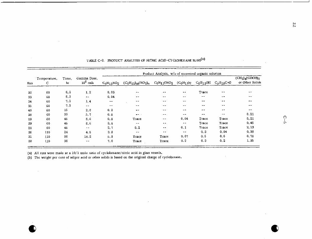
During December, 12 irradiation and thermal runs were completed with nitric acid-cyclohexane in the liquid phase. chi.omatography and a r e reported in Table 'C-2.
Analytical resu l t s were obtained chiefly by gas
Glass reaction vessels were used in all runs to contain the 10-to-1 mole rat io of cyc:lohexane to nitric acid. h the i r radiat ion runs the,gamma doses ranged f r o m 1 x l o 6 to 1.8 x lo7 rads .
Samples were heated at 60 o r 110 C from 6. 5 to 96 hr.
To investigate the effect of ni t r ic acid dilution on the nitration reaction, Runs 32 ant1 33 were made at 60 C with a 70 w/o nitric acid solution and Runs 34 and 35 with about 35 w/o acid. At 110 C Run 3 6 was made with a 35 w/o nitric acid solution for coinparison with Run 15 reported last month in BMI-1398. of C-C6HlZ/HN03 was kept constant at 10-to-1. At both temperatures , the yield of nitrocyclohexane was smaller in the dilute nitric acid. measurable products at all. agiiinst 3.8 w/o in the dilute acid Run 35.
In all runs, the mole rat io
Runs 34 and 35 yielded no In Run 15, 4.5 w/o of nitrocyclohexane was produced a s
Several explosions occurred during dilute ni t r ic acid runs at 110 C , and runs a t 140 C. plc sions in ni t r ic acid-cyclohexane systems. liniited to 100 C.
The l i terature suggests that formation of a cyclic ketone is responsible for ex- In all future runs temperatures will be
N N
TABLE c-2 . PRODUCT ANALYSIS OF NITRIC ACID-CYCLOHEXANE R U N S ( ~ )
Product Analysis, w/o of recovered organic solution Temperature, Time, Gamma Dose, (CH2)4( coo%?
lo6 rads C6H11N02 (C6Hll)m(NOZ)n C6H11ON02 (CgH11)2 C6HllOH C ~ H ~ O C ' O or Other Solids -- Run C hr
32 60 6,5 33 60 34 60 7.5 1.4 35 60 40 60 15 2.8 38 60 30 5. I 0.6 _ - - - - - -- -- 0.21 29 60 45 8.6 0.8 Trace - - 0.04 Trace Trace 0.21 39 60 45 8.6 0.8 -- - - - - Trace Trace 0.45
- - -- - _ - - Trace 1 .2 0.03 -- 6.5 - - 0.04 --
7. 5 - -
- _ - - - - -- - - - - - - -- -- - - _ - --
- - - - -- -- -- - - - - -- - - - - - - - - 0. 2 - -
28 60 45 - - 2.7 0.2 -- 0.1 Trace Trace 2. 13 36 110 24 4.5 3. 8 -- - - -- 0.3 0.04 0.38 31 110 96 18.2 5.9 Trace Trace 0.07 0.5 0.6 0. 76 30 110 96 - - 7.0 Trace Trace 0.2 0.3 0.2 1.35
-- - (a) All runs were made at a 10/1 mole ratio of cyclohexane/nitric acid in glass vessels. (b) The weight per cent of adipic acid or other solids is based on the original charge of cyclohexane.

23 and 24
C-7 and C-8
A review of runs in Table C-2 and those reported last month in BMI-1398 con- fiiems the general inhibitory effect of radiation at all temperatures investigated. ever , at or near 20-hr exposures, radiation produces a slight increase in the amount of ni7;ration (nitrocyclohexane) at all temperamres .
How-
This radiation effect is not understood.
A few additional runs with the ni t r ic acid-cyclohexane system will be conducted in January. thi3 retarding effect of radiation on nitration. 20-hr exposures will be confirmed, and thl? stability of nitrocyclohexane in this system will be investigated.
It is hoped that analyses of gaseous products in these runs will help clarify The apparent increase in nitration at
A few exploratory runs with the N02-cyclohexane system a r e planned. pose of this s e r i e s of experiments is to determine whether the inhibitory effect of radiation depends on the type of nitrating agent.
The pur-
25 and 26
D-1 and D-2
D. VARIABLE-MODERATOR REACTOR CRITICAL-ASSEMBLY STUDIES
R. A. Egkn, D. A. Dingee, and J. W. Chastain
Critical-assembly studies will be pe.rformed by Battelle for the Advanced Tech- nology Laboratories of the American Standard Corporation to aid in the development of the Variable-Moderator Reactor.
Preparat ion for the cri t ical-assembly studies have been in progress since During December the Hazards Summary Report was completed. November, 1959. The
crit ical-assembly support stand was constructed, and construction of the core vessel , base plate, and liquid-storage facilities w a s begun. wc:re ordered.
Most of the remaining components
All of the components should be available for assembly before the end of January. Tliese include core components f rom the Advanced Technology Laboratories which a r e scheduled to a r r i v e la te in the month. F(:bruary.
The fuel is not expected to a r r i v e until ear ly
c
27
F- 1
F. RESEARCH FOR AEC REACTOR DEVELOPMENT DIVISION PROGRAM
S. J. Paprocki and R. F. Dickerson
REACTOR MATERIALS AND COMPONENTS
R. F. Dickerson
In an attempt to reduce the amount of La203 o r Y2O3 additive needed to stabilize U 0 2 in high-temperature air, bodies have heen prepared with te rnary additions of CaO. Tht:se mater ia l s , as s intered in vacuum at 1700 C, initially have a low electr ical con- duc tivity. Oxidation, produced by heating in air, causes a rapid increase in this con- ductivity. Bodies of u 3 0 8 containing 40, 50, and 60 mole per cent La203 a r e being prciduced s o that information with respect to e lectr ical character is t ics and thermal coriductivity of fully oxidized solid solutions can be obtained. cornbined high p res su re and high temperature on the uranium oxides and on the reaction of iiranium oxides with other oxide systems a r e still in progress .
Studies of the effects of
The i r radiat ion of tensile, cyclic- s t ra in fatigue, and impact specimens of Type 34;' s ta inless s teel continues, Estimated exposures a s high as 4 .5 x 10" nvt have been acllieved to date, with the ultimate exposure goal at 1.8 x nvt. At present there i s a 1 ;xk of correlat ion between the fast-flux data obtained as a resul t of spot checks at the E T R and dosimetry data obtained by BMI. Attempts a r e being made to resolve this ap- palsent difference in flux values. garnma-heat capsules in the WTR.
Negotiations a r e in progress to obtain space for the
In order to determine the weldability of niobium-base binary alloys containing 1. f14 o r 3. 21 W / O chromium, o r 4.33 w/o zirconium and niobium-base ternary alloys corttaining chromium, tantalum, and titanium, welding studies on 0.010-in. sheet a r e in progress . Adllitional ingots of the alloys have been made in order to obtain more sheet mater ia l for tensile testing. coi~rosion-resis tant niobium alloys has been completed, and data are being evaluated pr ior to the preparation of a topical report .
Quality of welds w i l l be evaluated by bend testing and tensile testing.
Experimental work concerned with the development of water-
The design of the testing device for u(3e in the study of the in-pile c reep of Ziitcaloy-2 i s being completed. mocouples located between a s t r e s sed sheel:-type specimen and an identical unstressed spc:cimen paral le l with it, e lectr ic heaters cast into aluminum blocks designed for uni- f o r m heat dissipation, and a stainless steel bellows which, when compressed by helium prc:ssure inside the capsule, will apply s t r e s s to the specimen. Four of these tes t de- vices w i l l be constructed; two w i l l be used :for out-of-pile tes t s , and two w i l l be in- s e i t e d in the WTR. s t r a in aging in the mater ia l at elevated temperatures .
Pr incipal features of the design include severa l ther -
Internal-friction studies have been continued in an attempt to detect
The studies concerned with the develcbpment of techniques capable of determining the amount of oxygen in sodium at levels below 10 ppm have been continued.

28
F - 2
Valence Effects of Oxide Additions to Uranium Dioxide
W . B. Wilson and C . M. Schwartz
An investigation is being conducted on the effect of oxide additions to uranium oxide. stabilization of uranium oxide by appropriate additions of La203 and Y 2 0 3 .
Previous research has been directed toward determination of the mechanism of
Recent work has been directed toward reduction of the amount of oxide addition required to achieve a stable mater ia l with respec t to high-temperature-air oxidation. In conjunction with this phase of the work, conductivity and thermoelectric-power stud- i e s were conducted on the following solid solutions, for which oxidation behavior w a s previously reported :
Composition, mole per cent
UO2-20 La203-20 CaO
UO2-20 Y2O3-20 CaO
These mater ia l s , as sintered in vacuum at 1700 C, initially have a very low con-
Thermoelectr ic power for these stabilized solid solutions was low with i ts sign ductivity. tivity. changing reversibly f r o m p-type to n-type with increasing temperature . havior has previously been observed to be associated with the more stable composi-. tions exhibiting the smallest vapor pressure .
Oxidation, produced by heating i n air, caused a rapid increase in conduc-
Such be-
Final preparation of compositions of U308 containing 40, 50, and 60 mole per cent La203 a r e in process . respect to the electr ical character is t ics and thermal conductivity of the fully oxidized solid solutions. The solid solution of U 0 2 containing 2 mole per cent La203 has been resintered and reprepared for thermal-conductivity studies.
These w i l l be utilized to obtain additional information with
Hi crh- Pr es su re Hieh- Temoerature Solid-state Studies
W. B. Wilson and C. M. Schwartz
An investigation is being conducted on the effects of combined high pressure and high temperature on the uranium oxides and on the reaction of uranium oxides with other oxide systems. effects of pressure on U308.
In previous work emphasis has been placed on the study of the
A new modification, designated gamma U3O8, w a s produced at p re s su res above 16,000 atm at temperatures above 400 C. Structural studies were continued in an
29
F-3
attempt to index the X-ray diffraction pattern obtained by powder techniques. tivz indexing was established based upon a n hexagonal (rhombohedral) cel l with a = 8.78 A and c = 9. 19 A. smal le r , than that of the other modifications of U308, it w a s assumed to contain the saine number of U3O8 molecules. gainma u 3 0 8 at p = 9. 15 g per cm3. obtained by vacuum pycnometric technique, averaged p = 9.25 g per cm3. from stoichiometry and e r r o r s inherent in the la t t ice-parameter and pycnometric data coitld well account for the small difference obtained between the theoretical and meas- urt:d density.
A tenta-
Since the volume of this unit cel l is similar, although
On this b a s i s a theoretical density was obtained for Measured density of the g a m m a modification,
Deviation
The density of both the alpha and beta modifications of U3O8, which occur at noi-mal pressure , is known to be 8.38 g pel. cm3. t i o i with a value of 9. 15 g per crn3 exhibits an increase in density of about 10 per cent.
Thus, the high-pressure modifica-
In previous work, resul ts were obtained indicating the possible p re s su re de- coinposition of U40q, which is believed to be cubic of fluorite s t ruc ture with a lattice pal-ameter slightly smal le r than U02. oxide of uranium, its p re s su re decomposition appears anomalous. o r disprove the previous resul ts , U4O9 samples were subjected to pressure and tem- peibature.
Since U409 is assumed to be the most dense In order to confirm
Results a r e not as yet available.
In order to extend the ultimate p re s su re obtainable in the high-pressure equip- ment, minor design modifications were introduced. ha ti been initiated.
Evaluation of these modifications
Irradiation-Surveillance P r o e r a m on TvDe 347 Stainless Steel
W. E. Murr , F. R. Shober, R . Ritzman, and J. I?. Lagedrost
An irradiation surveillance program on AIS1 Type 347 stainless steel is continuing in ,support of the KAPL C-33 loop and other loops using this mater ia l i n their construc- tioii. The program consists of irradiation ,md postirradiation mechanical testing of Tylle 347 s ta inless steel . t e s t s , cyclic-strain fatigue tes t s , and impact tes ts . A considerable fast-neutron ex- poEure range and three irradiation-tempera.ture pa rame te r s w i l l be explored by the prc 'gram. Included a r e a group of specimens to be i r radiated at process-water tem- pera ture (120 F), a group of specimens to he i r radiated "hot" (600 F), and a group of specimens to be i r radiated at 120 F and annealed after i r radiat ion pr ior to mechanical testing. It is thought that postirradiation annealing represents an intermediate condi- tioii between that produced by irradiation at 120 and 600 F. for an estimated 3 yea r s at tempera tures near 570 F, during this time accumulating a fast-neutron flux (above 1 MeV) exposure of between 1 .4 and 1.8 x 10²² nvt. thiis p rogram is to provide information on mechanical propert ies of Type 347 s ta inless s tee l at exposures between 3.76 x 10²¹ nvt (the maximum exposure level reported in l i t e ra ture) and the ultimate level to be reached by the loop.
Mechanical-property determinations w i l l include tensile
The KAPL loop w i l l operate
The aim of
30
F -4
Eight capsules have been i r radiated in ETR core process water since June, 1958. Three capsules to be annealed pr ior to postirradiation testing have been in the ETR since August, 1959. routinely.
The i r radiat ion of these two groups of specimens is proceeding
The capsules to be i r radiated near 600 F have not been inserted in the reactor as yet since suitable space has not been available. 20 w pe r g of gamma heating to maintain the specimen design temperature.
The capsules require approximately
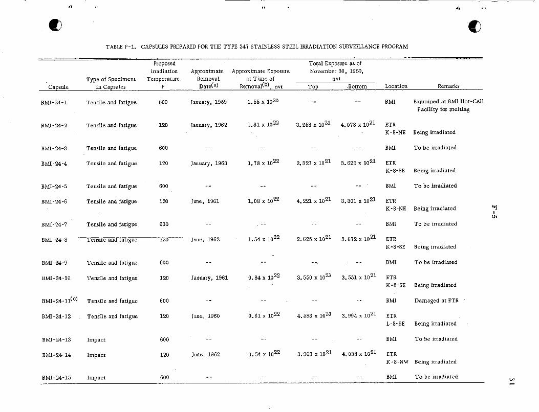
Total neutron exposures obtained by the eleven capsules in the ETR as of the end of Cycle 23 (November 30, 1959) a r e reported in Table F-1. megawatt-days at an average power level of 163 megawatts. posures reported in Table F-1 a r e based on flux maps obtained during Cycle 13. checks made at the ETR of the fast fluxes in K and L positions during Cycle 18 indicate that the fast flux was f rom 4 to 22 per cent higher than that used for calculating the ex- posures reported in Table F-1. The BMI dosimetry data obtained f rom these positions during these and subsequent cycles indicate that the flux was considerably lower. tempts a r e being made to determine the reasons for this difference.
Cycle 23 w a s for 1660 The accumulated ex-
Spot
At-
Negotiations are in progress to inser t the l'hot" capsules in core positions of the Westinghouse Tes t Reactor i n late January. thermocouples and wi l l monitor temperatures of the t e s t specimens at power levels of f r o m 20 to 60 megawatts i n order that the additional seven capsules can be most judiciously located in the reac tor .
The initial capsule w i l l be provided with
Development of Niobium-Base Alloys
J . A. De Mastry, F. R. Shober, and R. F. Dickerson
Utilization of a niobium-base alloy as an al ternate cladding mater ia l i n future core designs for the EBR requires evaluation of the fabricability and of selected mechanical propert ies of these alloys. developed are to be compared with the propert ies of a vanadium-10 w/o titanium-1 w/o niobium alloy which has demonstrated propert ies acceptable for the EBR application. The alloys which a r e being investigated include unalloyed niobium, niobium- 1. 84 w/o chromium, niobium-3. 21 w/o chromium, niobium-4.33 w/o zirconium, niobium-9.95 w/o tantalum-3. 31 w/o chromium, niobium-39.8 w/o titanium-10.6 w / o aluminum, niobium- 20.5 w /o titanium-4.28 w /o chromium, and vanadium- 11.7 w /o titanium- 3.07 w / o niobium.
The propert ies of the niobium-base alloys being
All alloys being investigated were reduced f rom 70 to 80 per cent by forging at 2500 F in evacuated molybdenum cans. at 75 F. 20.5 w/o titanium-4. 28 w/o chromium, and vanadium-11.7 w/o titanium-3.07 w/o niobium alloys were reduced approximately 80 per cent at 75 F, but developed severe edge c racks and surface defects. The tensile strengths at 1470 F of specimens cut f r o m the cold worked niobium-base alloys were superior to that of the vanadium-base alloy.
After reduction at 2500 F rolling was attempted The niobium-1.84 w/o chromium, niobium-4. 33 w/o zirconium, niobium-
1
Ill .* ..
TABLE F-1. CAPSULES PREPARED FOR THE TYPE 347 STAINLESS STEEL IRRADIATION SURVEILLANCE PROGRAM
Proposed Total Exposure as of Irradiation Approximate Approximate Exposure November 30, 1959,
Type of Specimens Temperature, Removal at Time of nvt Capsule in Capsules F Date(a) Removal(b), nvt Top Bottom Location Remarks
BMI-24-1 '
BMI-24-2
BMI - 24-3
BMI-24-4
BMI-24-5
BMI-24-6
BMI-24-7
BMI-24-8
BMI - 24-9
B MI - 24- 10
Tensile and fatigue 600
Tensile and fatigue 120
Tensile and fatigue 600
Tensile and fatigue 120
Tensile and fatigue 600
Tensile and fatigue 120
Tensile and fatigue 600
Tensile and fatigue 600
Tensile and fatigue 120
January, 1959
January, 1962
- -
January, 1963
- _
June, 1961
- -
June , 1962
_ _
January, 1961
1.55 x 10²⁰
1.31 x
- -
1.78 x
- -
1.08 x
- -
1.54 x 10²²
- -
0.84 x
--
3.258 x lo2'
_ -
2.327 x 10²¹
- -
4.221 x 10²¹
_ _
2.625 x 10²¹
_ _
3.550 x 10²¹
--
4.078 x 10²¹
--
3.625 x 10²¹
--
3.301 x 10²¹
--
3.672 x 10²¹
--
3.551 x 10²¹
BMI
ETR K-8-NE
BMI
ETR K-8-SE
BMI
ETR K-8-NE
BMI
ETR K-8-SE
BMI
ETR K-8-SE
Examined at BMI Hot-Cell Facility for melting
Being irradiated
To be irradiated
Being irradiated
To be irradiated
Being irradiated
To be irradiated
Being irradiated
To be irradiated
Being irradiated
r I ul
BMI-24-11(') Tensile and fatigue 600 - _ - _ - - - - BMI Damaged at ETR
BMI-24-12 Tensile and fatigue 120 June, 1960 0.61 x 4.583 x 1021 3.994 x 10²¹ ETR L-8-SE Being irradiated
- - - - - - -- BMI To be irradiated BMI-24-13 Impact 600
BMI-24-14 Impact 120 June, 1962 1.54 x 3.963 x loz1 4.038 x 10²¹ ETR K-8-NW Being irradiated
- - _ _ - - - - BMI To be irradiated w BMI-24-15 Impact 600 CI
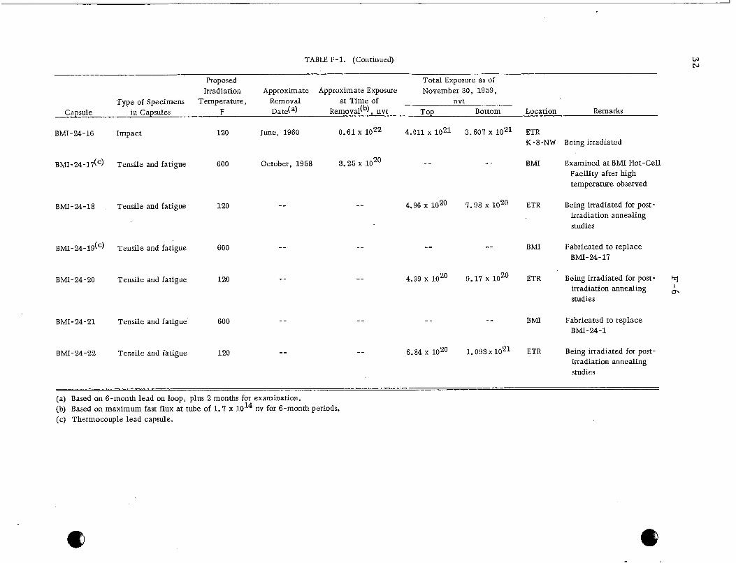
TABLE F-1. (Continued)
Proposed Total Exposure as of Irradiation Approximate Approximate Exposure November 30, 1959,
Type of Specimens Temperature, Removal at Time of nvt Capsule in Capsules F Date(a) Removadb), nvt Top Bottom Location Remarks
BMI-24-16 Impact 120 June, 1960
BMI-24-17(') Tensile and fatigue 600 October, 1958
-- BMI-24-18 Tensile and fatigue 120
- - BMI-24-19(') Tensile and fatigue 600
- - BMI-24-20 Tensile and fatigue 120
- - BMI-24-21 Tensile and fatigue 600
- - BMI-24-22 Tensile and fatigue 120
0.61 x 4.011 x loz1
3.25 x lo2' _ -
4.96 x 10²⁰
--
4.99 x 10²⁰
3.607 x 10²¹
--
7.98 x 10²⁰
--
9.17 x lo2'
--
1.093 x 10²¹
ETR K- 8-N W Being irradiated
B M I
ETR
BMI
ETR
BMI
ETR
Examined at B M I Hot-Cell Facility after high temperature observed
Being irradiated for post- irradiation annealing studies
Fabricated to replace BMI-24-17
Being irradiated for post- hj irradiation annealing & studies
Fabricated t o replace BMI-24-1
Being irradiated for post- irradiation annealing studies
(a) Based on 6-month lead on loop, plus 2 months for examination. (b) Based on maximum fast flux at tube of 1.7 x 10¹⁴ nv for 6-month periods. (c) Thermocouple lead capsule.
. . . . -. . . __. . - . . . . . -
33
F - 7
Sections cut f r o m all of the forged slabs (2500 F) were rolled at 800 F in air to 0. 150-in. sheet. tit;:nium-lO. 6 w/o aluminum alloy and the niobium-9.95 w/o tantalum-3.31 w/o chro- miiim alloy, both of which fractured during rolling. the rolled sheet was sectioned, and a rolling .study was conducted at 75 F. Sections wh!ch were belt sanded to remove defects and annealed at 2550 F fo r 1 h r were cold rolled to 0. 030-in. sheet. faces . edites.
All alloys rolled satisfactorily except for the niobium-39. 8 w/o
After this warm-roll ing operation,
The fabricated sheet had smooth edges and defect-free su r - Alloys rolled at 75 F without belt sanding o r annealing had rough surfaces and
Pieces of the above-mentioned cold-rolled sheet prepared f r o m stock that was
Two methods a r e being utilized for evaluation of the weldability of the niobium- belt sanded and annealed were then fur ther reduced to 0,010-in. sheet for welding stud- ies . baric alloys. 0. 010-in. mater ia l longitudinally and bending the welded sheet paral le l with the direc- t i o i of the weld in a bench vise. welding two 0.010-in. -thick sheets of mater ia l together and then pulling the welds apztrt in a tensile machine. p r 6:pared.
The ductility of the welds is being tes ted by welding two sheets of
The strength of the welds w i l l be determined by spot
Specimens for both of the above-mentioned t e s t s a r e being
Duplicate ingots of unalloyed niobium, niobium- 1 w/o chromium, niobium-3 w/o zirconium, niobium- 10 w/o titanium-3 w /o chromium, and niobium-4.5 w/o molyb- deitum alloys have been prepared by double consumable-electrode a r c melting. The ingots prepared w i l l be sectioned into 3/4-in. wafers. Forging of these wafers wi l l be attgsmpted at 800 F. If fabrication at 800 F is not successful, higher temperatures w i l l be employed until a satisfactory fabrication temperature is determined. that fabrication temperatures near 800 F can be used, so that protection f rom oxidation w i l l not be required. forged slabs w i l l be rolled to sheet.
It is hoped
After sufficient working of the metal has been accomplished, the
After obtaining fabricated mater ia l , the tensile strengths of the alloys w i l l be determined at 1470 F, and additional welda'bility studies w i l l be performed.
Development of Corrosion -Resistant Niobium Alloys
D. J. Maykuth, W. D. Klopp, E. F. Adkins, R. I. Jaffee, W. E . Eierry, a n d F . W . Fink
The selection and fabrication of niobium-base alloys for possible service in pros surized-water reac tors have been completed. P r i o r work indicated that binary adtlitions of 7 to 12 a /o vanadium offer optimum combinations of low neutron c ross set:tion, high-temperature strength, and corrosion resis tance. The objective of the mcst recent work is to determine whether lower alloying levels, which resul t i n im- proved fabricability, can be used without seriously affecting the alloy's corrosion beliavior.
Fabrication of the four double consumable-electrode arc-melted alloy ingots l is ted below w a s ca r r i ed out using pack-rolling techniques. Each ingot was cut into
34
F-8
two s labs which were weld-sealed in evacuated s ta inless s tee l cans and flat rolled at 1800 F. grinding, each was vacuum annealed 1 h r at 1200 C and cut into samples for corrosion testing.
All of the ingots rolled to excellent-quality sheet. After surface cleaning by
Nominal Alloy Content Annealed Hardness, Alloy (Balance Niobium), a/o VHN
NL-11 7 . 5 v NL-12 I. 5 V-0.19 N(a) NL-13 I. 5 V-2 .5 T i NL-14 7.5 V-2.5 MO
(a) Equivalent to 0 .03 w/o nitrogen.
176 20 7 1 9 3 20 5
The resu l t s of corrosion tes t s i n 600 and 680 F water and 750 F 1500-psi s team continue to indicate that:
( 1 ) Unalloyed niobium is not sufficiently corrosion resis tant for use a s a cladding mater ia l in pressurized-water reac tors .
( 2 ) Additions of titanium, vanadium, and zirconium singly or in combina- tion markedly improve the corrosion resis tance of niobium.
( 3 ) The most corrosion-resis tant alloys a r e binar ies o r te rnar ies con- taining more than 45 a / o zirconium o r a te rnary containing 28 a / o titanium-6 a / o chromium.
(4) A 12.6 a / o vanadium alloy possesses the optimum combination of high-temperature strength, low c r o s s section, and adequate corrosion resis tance.
(5) Ternary additions on the order of 2.5 a / o of aluminum, chromium, i ron, molybdenum, nickel, titanium, o r zirconium to niobium- 2.5 a / o vanadium alloys do not resul t in increased corrosion resis tance.
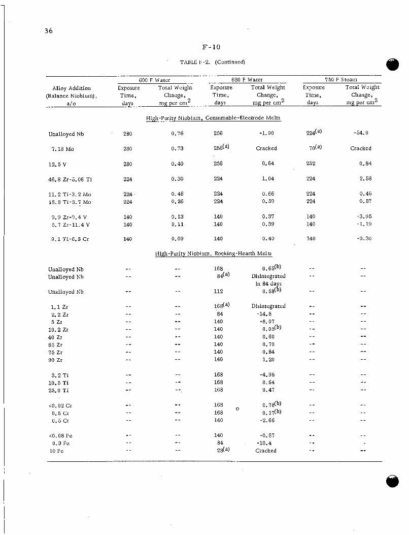
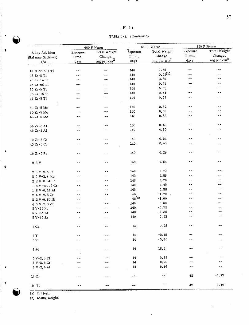
Corrosion resul ts obtained to date for exposure t imes ranging up to 280 days a r e sum- mar ized in Table F - 2 .
The corrosion tes t s with unalloyed niobium, which a r e being performed i n co- operation with the Bettis and Knolls Laboratories, have been suspended af ter 120 days of total exposure. The average weight change for groups of six specimens w a s t 6 4 . 1 m g per dm2 for exposure to 680 F water and -1675 m g per dm2 for exposure to 750 F steam. per dm2 at 42 days of exposure. e r r a t i c ra te after 28 days of exposure.
Specimens in 680 F water slowly lost weight after a peak weight gain of 121 mg Those exposed to 750 F s team lost weight at an
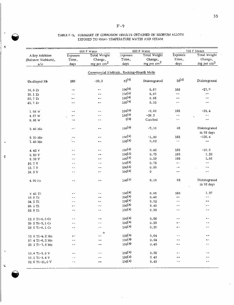
35
TABLE F-2. SUMMARY OF CORROSION IESULTS OBTAINED ON NIOBIUM ALLOYS EXPOSED TO HIGH-TEMPERATURE WATER AND STEAM
. - - 600 F Water 680 F Water 750 F Steam
A llov Addition Exposure Total Weight Exposure Total Weight Exposure Total Weight - (Balance Niobium), Time, Change, Time, Change, Time, Change,
a/o days mg per cm2 days mg per cm 2 days mg per cm2
Commercial Niobium, Rocking-Hearth Melts
Undloyed Nb 280 -39.9 42(a) Disintegrated 2da) Disintegrated
10. 5 Zr 26.1 Zr 35.7 Zr 45.7 Zr
1 .08 W 4. 67 W 9. 56 W
2.45 Mo
5. 20 Mo 7.40 Mo
4 . 4 2 V 6, 59 V 8. 93 V
.:
1 0 . 7 v 13. 7 V 24. 2 V
4.90 F e
9 4 1 T i 18. 8 T i 24, 3 T i 30. 5 T i 33. 8 T i
_ _ -- 196(a) -7.10 98 Disintegrated in 98 days
- - _ - 196(a) -1.30 168 -126.4 - - -- - - - - 196(a) 0.62
- - -- 196(a) 0.10 98 Disintegrated in 98 days
- - 12. 0 Ti-0.5 Cr - - - - 196(a) 0.66 20. 2 Ti-2.1 Cr _ _ - - 196(a) 0.39 - -
- - -- 196(a) 0.64 - -
- - - - 196(a) 0.45 --
- - 28 2 Ti-6.1 Cr _ - - - 196(a) 0.20
0 12 0 Ti-4.2 Mo 17. 4 Ti-6.2 Mo - _ -- 196(a) 0.54 23 1 Ti-7.8 Mo
- -
1.27 - -
-- - - 10..4 Ti-5.0 V - - - - 196(a) 0.56 16,. 1 Ti-8.4 V _ _ -- 196(a) 0.40 22, 6 Ti-11.0 V - - -- 196(a) 0.48
-- -- - - -- -
b -
36
F - 1 0
TABLE F-2. (Continued)
600 F Water 680 F Water 750 F Steam Exposure Total Weight Exposure Total Weight Expo sur e Total Weight Alloy Addition
Change, (Balance Niobium), Time, Change, Time, Change, Time, a/o days mg per cm 2 days mg per cm2 days mg per cm2
Unalloyed Nb
7.18 Mo
12.5 v
46.8 Zr-5.06 Ti
11.2 Ti-3.2 Mo 18.8 Ti-8.7 Mo
9.9 Zr-9.4 V 5.7 Zr-11.4 V
9 .1 Ti-6.3 Cr
Unalloyed Nb Unalloyed Nb
Unalloyed Nb
1.1 Zr 2.2 Zr 5 Zr
10.2 Zr 40 Zr 65 Zr 7 5 Zr 90 Zr
3.2 Ti 10.5 Ti 25.0 Ti
<o. 02 Cr 0.5 Cr 0.5 Cr
<O. 08 F e 0.3 F e
10 F e
High-Purity Niobium, Consumable-Electrode Melts
0.76 256 -1.90
0.73 256(a) Cracked
0.40 256 0.64
0.30 224 1.04
0.46 224 0.66 0.26 224 0.59
0.13 140 0.37 0.11 140 0.39
0.09 140 0.40
High-Purity Niobium, Rocking-Hearth Melts
112 - -
0.6db) Disintegrated
in 84 0.58(
Disintegrated -14.8
0. 0.60 0.70 0.84 1.20
-8.07
-4.98 0.64 0.47
0. 7db) 0. 17(b)
0
-2.66
-0.87 -10.4
Cracked
37
F- 1 1
TABLE F-2. (Continued)
- - 600 F Water 680 F Water 750 F Steam
Time, Change, Time, Change, Time, Change, Total Weight Exposure Total Weight A Lloy Addition Exposure Total Weight Exposure
days mg per cm2 days mg per cm 2 days mg per cm2 (Balance Niobium),
a lo - l o . 9 Zr-5.1 T i 25 Zr-5 Ti 25 Zr-15 Ti
35 Zr-5 Ti 35 Zr-15 Ti 45 Zr-5 T i
25 Zr-25 T i
10 Zr-5 MO 35 Zr-5 MO 45 Zr-5 MO
35 Zr-5 A1 45 Zr-5 A1
10 Zr-5 Cr 45 Zr-5 Cr
10 Zr-5 F e
2 , 5 V
2,O V-2.5 Ti
2 , 2 V-0.54 Fe 2,O V-2.3 MO
1 , 8 V-<O. 02 Cr 1 , 8 V-0.14 A1 2 , 5 v-2.5 Zr 2 , 2 V-0.87 N i 4 .0 v-2.3 Zr 5 V-25 Zr 5 v-35 Zr 5 v-45 Zr
1 Ce
1 Y 5 Y
1 Pd
5 V-2.5 T i 5 V-2.5 Cr E V-2.5 A1
1( Zr
1(1 Ti
140 140 140 140 140 140 140
140 140 140
140 140
140 140
140
168
140 140 140 140 140
56 28(a)
140 140 140 140
14
14 14
14
14 14 14
-- --
0.59
0.60 0.51 0.58 0.51 0.72
0. Odb)
0.32 0.53 0.63
0.46 0.60
0.54 0.46
0.29
0.64
0.79 0.89 0.70 0.49 0.88
-1.70 -1.00 0.60
-0.72 -1.38 0.52
0.75
-2.19 -5.75
16.2
0.19 0.20 0.16
42 -0.77
42 0.40
@ Off test. (b) Losmg weight.
38
F- 12
Corrosion tes t s have been s tar ted on the alloys described below. No resul ts a r e available to date.
Exposure Conditions Composition (Balance Niobium), a/o
Consumable-electrode melts exposed I. 5 vanadium 7.5 vanadium-0.19 nitrogen 7.5 vanadium-2.5 titanium 7.5 vanadium-2.5 molybdenum
to 600 and 680 F water and 750 F steam
Rocking-hearth melts (50-g ingots) 1, 2.5, and 5 nickel 5 vanadium 5 vanadium-2.5 iron, -nickel, or -molybdenum 0.5 carbon-2.5 and -5 vanadium 0.5 carbon-0.5 titanium-2.5 and -5 vanadium 0.5 carbon-0.5 zirconium-2.5 and -5 vanadium 0.5 oxygen-0.25 titanium-2.5 and -5 vanadium 0.5 oxygen-0.25 zirconium-2.5 and - 5 vanadium
exposed to 680 F water
A topical report , summarizing all of the resul ts of the r e sea rch which have been obtained to date, is being prepared.
Investigation of the Creep Proper t ies of Zircaloy-2 Durine Irradiation at Elevated Temneratures
F. R. Shober, P. B. Shumaker, A. P. Young, M. F. Amateau, a n d R . F. Dickerson
The effect of i r radiat ion on the c reep properties of Zircaloy-2 at elevated tem- pera tures is to be studied by comparing total elongation obtained f rom creep tes t s in reac tor under a fast neutron flux with those obtained f rom an identical out-of-reactor tes t . in Zircaloy-2 is planned if t es t s for its detection show positive resul ts . microscopy on thin-films and internal-friction tes t s a r e being employed to aid in the strain-aging studies.
The initial temperature to be investigated w i l l be 650 F. A study of s t ra in aging Electron
The design of capsules for the c reep testing of Zircaloy-2 at 650 F during i r r ad i - ation is partially complete. f lux of 1 x 10¹⁴ nv for approximately 500 h r . ranging f rom 15,000 to 23,000 psi a r e to be investigated. design include severa l thermocouples located between a s t r e s sed sheet-type specimen and an identical unstressed specimen paral le l with it, e lec t r ic heaters cast into alumi- num blocks designed for uniform heat dissipation, a stainless s teel bellows which, when compressed by helium p res su re inside the capsule, w i l l apply a tensile s t r e s s to the specimen, and a magnesium oxide powder annulus as a heat-transfer ba r r i e r .
Specimens a r e to be exposed to a fast-neutron ( > 1 MeV) Creep character is t ics under s t r e s ses
Pr incipal features of the
A total of at leas t four capsules w i l l be built: two for in-reactor tes t s and two for out-of-reactor control tests. fabrication of par t s w i l l start during January. and of the electr ic hea te rs is expected in February.
Detail drawings of components a r e being prepared; Delivery of the s ta inless s teel bellows
39
F- 13
Internal-friction studies have been continued in an effort to detect s t ra in aging in Zi2-caloy-2 at elevated temperatures . termine if any internal-friction effects resulting f rom aging after smal l s t ra ins could be deiected. ap l~ara tus at a likely strain-aging temperature . urc:d as a function of t ime after straining. 37?, and 400 C. f r ic t ion decreasing with t ime. ated with a redistribution of dislocations. sm all temperature changes. seiisitive and should be superimposed on the curves showing the Koster effect. The cu:'ves obtained at the above tes t temperatures did show the decrease of internal f r i c - tion with t ime associated with the Koster effect, but nothing related to s t ra in aging. Sirnilar t e s t s w i l l be performed at lower temperatures . A new lot of mater ia l w i l l be usc:d to repeat some of the internal-friction experiments.
A se r i e s of experiments was performed to de-
Specimens were s t ra ined about 1 per cent in tors ion in the internal-friction The internal-friction was then meas -
The temperatures investigated were 350, Experiments employing this technique w i l l generally show the internal
The Koster effect is relatively insensitive to Any effects of' s t ra in aging should be strongly temperature
This is called the Koster effect and is apparently assoc i -
A new lot of Zircaloy-2 has been received and w i l l be fabricated. It is planned to USI : this mater ia l for all c reep experiments and for all strain-aging experiments.
Determination of Oxygen in Sodium at Concentrations Below 10 P P M
D. Ensminger, D. R. Gr i e se r , E. H. Hall, J. W. Kissel, J . McCallum, and W. H. Goldthwaite
Feasibil i ty studies a r e in progress to evaluate new methods for the detection of ox>'gen in sodium. of rapidly determining the oxygen concentration of a large sodium sys tem to a sensi- tivity of *1 ppm at levels below 10 ppm. lack the necessary sensitivity.
The objective is to develop a detection technique with the capability
Present-day techniques a r e either too slow o r
Because of the difficulties inherent in handling extremely pure sodium without corttamination, the first round of studies are being conducted with oxygen concentrations in ,:he 20 to 100-ppm range. dif rerences in this range wi l l receive further study with sodium containing lower oxygen cortcentrations. Although the first round of studies a r e in progress , no definitive anc'wers have been obtained as yet. Difficulties i n production, t ransferr ing techniques, ant1 needed equipment modifications have delayed the f i r s t studies; however, it i s anticipated that most of them wi l l have been completed during the next repor t period.
Techniques which show promise in resolving oxygen level
E 11 ip some t r y -
Prel iminary polarizing-spectrometer runs have been held up in par t by the un-
This wi l l eliminate the need for optical satisfactory optical quality of the cel l windows. the flat window w i l l be replaced by a p r i s m , coiipling between the sampling ce l l and an auxiliary p r i s m as required by the previous dermign. epclxy resin. with sodium samples.
New cells a r e being prepared in which
The p r i s m will be supported mechanically and sealed with a high-temperature The study w i l l resume when the new cells have been completed and loaded
40
F- 14
Elec t r ica l Resistivity
The electrical-resist ivity device is in the fabrication stage. Because the r e - sistivity of sodium i s quite low and only very small changes in res is tance a r e antici- pated for small changes in oxygen content of the sodium, a very small , thin tubing is being used to gain sufficient sensitivity. The present design uses a 4-ft length of 28 gage stainless s teel hypodermic-needle tubing which has a 0.014-in. OD and a 0.006-in. ID. into a small, evenly heated unit which can be inser ted into the sodium-purification loop. It is expected that this device w i l l be completed and tested during the next report period.
Considerable difficulty has been experienced in fabricating this tubing
Polarographic Studies
During December a capillary sys tem w a s checked out with NaK. Observed r e - sults were predictable within about 3 per cent experimental e r r o r . showed that a redesign of the p re s su re sys tem was necessary to minimize oxygen con- tamination. study a r e now on hand. A delay in receiving suitable sodium samples has necessitated a 1-month extension of experimental t ime.
The NaK t e s t s
All the necessary apparatus and chemicals to complete this feasibility
During January it is expected that the feasibility of measuring oxygen content i n sodium by two methods w i l l be evaluated:
( 1 ) Simple measurement of drop-time a s a function of temperature
( 2 ) Polarographic reduction or oxidation.
Mass Spectrographic Study
The incorporation of an electron multiplier in the mass spectrometer is in prog-
The preliminary resul ts of this study should be completed ress. t rometer is being designed. within the next report period.
Simultaneously, a system for metering known sodium samples into the spec-
Plugging-Indicator Studies and Purification-Loop Operation
The sodium-purification loop, employing a wire-mesh-filled cold t r ap , is op- erating and has provided a number of sodium samples containing a moderate level of oxygen. Considerable difficulty has been experienced, however, in maintaining ade - quate flow ra tes throughout the loop. procedure a r e being made to improve the system behavior.
Modifications in construction and in operating
Following a period of cold-trapping at 450 F (which corresponds to an oxygen
The vacuum- saturation level of 42 ppm), single sodium samples were obtained for the ell ipsometry and polarographic studies and a vacuum-distillation calibration run. distillation s ampling was accompli shed without difficulty, but the spectrographic
41
F - 1 5
8 anzdysis of the residue is not yet available. indicator analyses were made. tween about 45 and 64 ppm, however, fully satisfactory runs were not made because of f1o.w difficulties. It is expected that elimination of helium gas pockets f rom the lines will resu l t in more reliable plugging-indicator runs. sy:item is also being constructed to facilitate the recording of plugging -indicator flow velocity. Mcsely llX-Y1l plotter; the two inputs a r e the temperature of the orifice plate and the f lou r a t e through it.
In addition to these runs, severa l plugging- The resu l t s of the la t ter indicate oxygen content be-
A specially designed amplification
The data a r e being recorded on standard graph paper through the use of a
STUDIES O F A L L O Y F U E L S
R. F. D’ickerson
Niobium-base binary alloys containing f rom 10 to 60 w/o uranium are being stud- iec to determine the applicability of these alloys as high-temperature reactor fuels. Data obtained to date indicate that oxygen in amounts up to 0.07 w/o and zirconium in amounts up to 0 .74 w/o do not affect corroc;ion behavior in air, water, s team, C 0 2 , anci NaK. Attempts have been made to rol l alloys containing 30, 40, 50, and 60 w,’o uranium alloys in molten glass at 2500 F. Although this technique has been successful with chromium it w a s unsuccessful with these niobium alloys. ru1)ture tests have been run at 1600 F on alloys containing 20 w / o uranium and 10 w/o urzinium. while the 10 w/o uranium alloy has not ruptured af ter 264 hr under a s t r e s s of 40 ,000 psi .
Corrosion in 600 F water is still in process .
Material is now ready for initial breakdown at 3000 F. St ress -
The 20 w/o uranium alloy ruptured after 197 h r under a s t r e s s of 63,000 psi
Corrosion testing of various thorium-uranium-base alloys in 200 C water has bec:n completed. beiter than that of unalloyed thorium. thzt carbon is an effective strengthener at low temperatures; however, this effect due to carbon is lost at about 600 C. fo ie , improves the strength of the thorium-uranium alloys at temperatures above 600 C. Tensile and creep t e s t s at 600 and 700 C a r e in progress , and heat-treatment studies arc: in progress . a c ynamic atmosphere of nitrogen maintained at a pres sure of 2- 1 / 2 atm. product was very near the stoichiometric composition of ThN. extimination showed a two -phase s t ructure , indicating inhomogeneity.
The corrosion resis tance of the best alloys is about three t imes Hot-hardness measurements reconfirm the fact
Yttrium Flrovides solid-solution hardening and, there-
Thorium-10 and -20 w/o uranium alloys have been arc-melted under The result ing
However, metallographic
DeveloDment of Niobium-Uranium Allovs
J . A. DeMastry, S. G. Epstein, A. A. Bauer, and R. F. Dickerson
The fabrication character is t ics , mechanical and physical propert ies , and cor -
@ r o ;ion behavior in various environments of niobium-uranium alloys a r e being studied to de.xermine the applicability of these alloys i I S reac tor fuels.
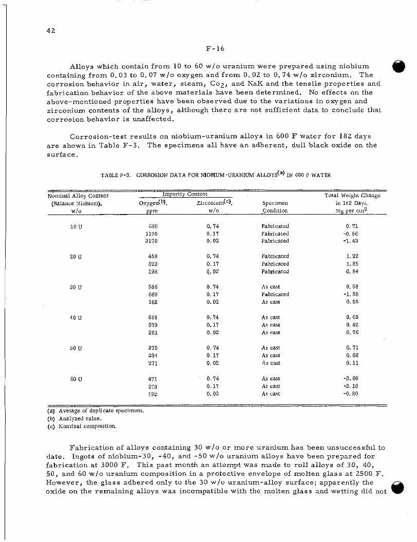
42
F-16
Alloys which contain f rom 10 to 60 w/o uranium were prepared using niobium containing f rom 0.03 to 0.07 w/o oxygen and f r o m 0.02 to 0.74 w/o zirconium. corrosion behavior in air, water , s team, C02, and NaK and the tensile propert ies and fabrication behavior of the above mater ia ls have been determined. above-mentioned properties have been observed due to the variations in oxygen and zirconium contents of the alloys, although there a r e not sufficient data to conclude that corrosion behavior is unaffected.
The
No effects on the
Corrosion-test resul ts on niobium-uranium alloys in 600 F water for 182 days a r e shown in Table F-3. surface.
The specimens all have an adherent, dull black oxide on the
TABLE F-3 . CORROSION DATA FOR NIOBIUM-URANIUM ALLOYda) IN 600 F WATER
Nominal Alloy Content Impurity Content Total Weight Change (Balance Niobium), Oxygen(b), Zirconium(c), Specimen in 182 Days,
W/O PPm W/O Condition mg per cm2
10 u
20 u
30 U
40 U
50 U
60 U
680 1190 3170
458 523 198
586 669 165
661 579 261
375 334 271
47 1 273 192
0. 74 Fabricated 0.17 Fabricated 0.02 Fabricated
0.74 Fabricated 0.17 Fabricated Q. 02 Fabricated
0.74 As cast 0.17 Fabricated 0.02 As cast
0.74 As cast As cast 0.17
0.02 As cast
As cast 0. 74 0.17 As cast 0.02 As cast
0.74 As cast 0.17 As cast 0. 02 As cast
0. 7 1 -0.56 -1.43
1.22 1. 85 Q. 84
0. 58 -1.38 0.55
0. 63 0. 42 0.76
0. 7 1 0.68 0.11
-3.60 -3.10 -0.80
(a) Average of duplicate specimens. (b) Analyzed value. (c) Nominal composition.
Fabrication of alloys containing 30 w/o o r more uranium has been unsuccessful to date. Ingots of niobium-30, -40, and -50 W / O uranium alloys have been prepared for fabrication at 3000 F. This past month an attempt was made to rol l alloys of 30, 40, 50, and 60 w/o uranium composition in a protective envelope of molten glass at 2500 F. However, the glass adhered only to the 30 w/o uranium-alloy surface; apparently the oxide on the remaining alloys was incompatible with the molten glass and wetting did not
43
F--17
occ:ur. nolle of the alloys was fabricable under these conditions.
While the 30 w /o uranium alloy und.erwent slight reductions before cracking,
Specimens of each alloy composition a r e also being tested for compatibility with The specimens have been encapsulated with sodium i n stain- liquid sodium at 1500 F.
l e s s s tee l tubes and w i l l be examined after a 500-hr exposure.
Stress-rupture testing of a niobium-20 w/o uranium alloy at 1600 F has been completed. oc1:urred after 197 h r . 26.i h r on tes t at 1600 F under a s t r e s s of 4:0,000 psi. niclbium-10 and -20 w/o uranium alloys w i l l be tes ted at 2200 F.
The tes t w a s run in a vacuum under a s t r e s s of 63,000 psi. Rupture A specimen of niobium-10 w/o uranium has not ruptured af ter
Additional specimens of the
The homogenization of alloy wire b a r s for an investigation of the effects of oxygen on the composition limits of the gamma loop in the niobium-uranium system is nearly co:mpleted. Specimens for equilibrium heat treatments a r e being sealed in evacuated qu;i.rtz capsules. Each specimen is wrapped in tantalum foil, and zirconium chips a r e bejng included in the capsules to ac t a s getliering agents. p repared w i l l be heat t rea ted at various ternperatures selected on the basis of com- position and then metallographically examined.
Sets of the specimens thus
Development of Thorium-Uranium Alloys
M. S. Farkas , A. A. Bauer, a n d R . F. Dickerson
Thorium-uranium and thorium-uranium-base alloys are being investigated with the aim of improving their irradiation stabxlity and corrosion resis tance. thorium purity, casting methods, and fabrication on the s ize and distribution of the ur<i.niurn-rich par t ic les is being investigated. Thorium-5 to 25 w /o uranium-base teimary alloys that have been and a r e now being studied contain either 5 to 25 w/o x i r - co iium o r small amounts of niobium o r molybdenum; quaternary alloys containing zii-conium and niobium additions a r e also being investigated.
The effect of
Corrosion tes t s in 200 C w a t e r have been completed. Thorium alloys heat t r f :a ted at 1000 C and either furnace cooled o r water quenched were tes ted for 504 h r . Of the group that w a s furnace cooled, thorium-15 w/o uranium-25 w / o zirconium and thorium- 20 w / o uranium-20 w/o zirconium alloys performed well with corrosion r a t e s under 0 . 9 mg/(crn2)(hr) . w /o uranium- 25 w /o zirconium and thorium- 15 w /o uranium- 25 w/o zirconium alloys corroded at r a t e s of about 0.5 mg/(cm2)(hr ) , while a thorium-10 w/o uranium-25 w/o zii-conium alloy corroded at a r a t e of about 0. 65 mg/(cm2)(hr ) . siiitance of the best alloys is about three ti:mes better than that of thorium, which i s r e - ported to corrode at a r a t e of 1 . 5 mg/(cm2)(hr ) in 200 C water.
Of the alloys water quenched f rom 1000 C, the thorium-10
The corrosion r e -
Hot-hardness measurements were performed on thorium- 10 w/o uranium-base alloys with additions of 0. 2 w/o carbon, 1 . 5 w/o molybdenum-0. 2 w/o carbon, 2 w/o niobium-0. 2 w/o carbon, and 10 w/o yttrium. stjqengthener at low temperatures . However, at about 600 C the strengthening effect
It was found that carbon is an effective
44
F- 18
due to carbon is lost . sulted in solid-solution hardening of the thorium matrix. above that of the base alloy, w a s obtained above 600 C with yttrium. temperature of all these alloys is about 600 C.
The addition of 10 W / O yt t r ium to thorium-10 w/o uranium re - Improvement in hot strength,
The softening
Tensile and creep t e s t s at 600 and 700 C a r e being performed on thorium-5, -10, and -20 w/o uranium alloys and on thorium-10 w/o uranium-1.5 w / o molybdenum, - 2 w/o niobium, -10 w/o zirconium, and -10 w/o zirconium-2 w/o niobium alloys. These t e s t s a r e being performed to obtain quantitative strength data which w i l l permit an evaluation of the resis tance of these alloys to radiation swelling. quaternary alloys of this group were chosen because of their excellent hot hardness .
The te rnary and
Fur ther investigations to be conducted on thorium-uranium-base alloys include studies of the effect of heat treatment on microstructure and recrystallation behavior,
Thorium-10 w/o and -20 w/o uranium alloys have been a r c melted under a dy- namic atmosphere of nitrogen maintained at a p re s su re of 2- 1 /2 atm absolute. ca l analyses of the resultant buttons show that 5 .4 W / O nitrogen was present in the thorium-10 w / o uranium alloy and 5.7 W / O nitrogen was present in the thorium-20 w / o uranium alloy. pared is very near the stoichiometric proportions. nitr ides, however, shows a two-phase s t ructure that indicates inhomogeneity.
Chemi-
Since stoichiometric ThN contains 5.7 w/O nitrogen the (Th,U)N pre- Metallographic examination of these
FISSION-GAS RELEASE FROM REFRACTORY FUELS
J. B. Melehan, D. A. Vaughan, R. H. Barnes, H. Sheets, S. D. Beck, and F. A. Rough
The objective of this program is to develop an understanding of the important causes of fission-gas re lease in UOz. of diffusion coefficients on single c rys ta l s of uranium has been operated succes sfully . A se r i e s of tes t s on single crystals is to follow. of irradiation on single-crystal and s intered U02 surfaces is a lso under way. ra tus for in-pile study of fission-gas release is nearing the point where in-pile experi- ments can be initiated.
Apparatus for the postirradiation determination
A supporting experiment on the effects Appa-
Characterization of Sintered UO;, and Model of Gas Release
To aid in understanding fission-gas re lease f rom U 0 2 bodies during irradiation and postirradiation heat t reatments , the surface s t ructure of various preparations i s being examined before and after irradiation. Metallographic specimens were charac- ter ized by light- and electron-microscopy techniques and i r radiated in the BRR for 1 h r in a flux of 3.53 to 3.59 x 1 0 l 2 nv. capsule filled with helium.
The specimens were sealed in a n aluminum
45
F-. 19
During the past month the i r radiated specimens were examined by light and elec- Identical areas were compared with the preirradiat ion micrographs. t r cn microscopy.
Alihough the i r radiat ion was low (5.5 x 10⁻⁶ a / o burnup), a number of s t ructural ch:inges occurred. deiisity (91 per cent of theoretical) body than could be observed in the 95 per cent dense bo(iy o r in large single crystals . growth of la rge pores and the annihilation of small pores and/or etch pits and ( 2 ) the enJargement of some grain boundaries and annihilation of o thers , lovr-density body, a new grain boundary appeared which encompassed a group of grains whDse original grain boundaries became l e s s distinct. tur e was detected at 18, OOOX magnification. roiighening of the U 0 2 crystals or grains 011 a submicron scale which was essentially the same regard less of body density o r orientation. t u re may be related to fission-fragment t raxes . plenned for the next period. tion t imes, in order to better isolate the resu l t s of individual f ission events,
More changes were apparent in the gross s t ructure of the low-
These g r o s s changes may be described as (1) the
In the case of the
In all specimens, a fine s t ruc- This may be described as a surface
It is possible that this fine s t ruc- Further study of the fine s t ruc ture is
Also, new specimens w i l l be prepared for shorter i r rad ia-
Experiments a r e also in progress to quantitatively evaluate the pore distribution in s intered U 0 2 having var ied his tor ies and to re la te the observed distributions to su.rface-area determinations made by gas a.dsorption.
Diffusion in UO2
Measurements of fission- gas diffusion f rom single-crystal uranium dioxide during postirradiation heating were initiated during December. 0. 75-g flat plate of i r radiated single-crystal uranium dioxide w a s heat t reated for about 1 lir at 1245 C has been completed. a p , n r a t u s and scintillation counting system for continuous measurement of fission-gas re lease . radiated f o r 6 h r in an estimated unperturbed thermal-neutron flux of about 4 x 10¹³ nv, to permit a continuous measurement of the release rate.
An initial run in which a
The major purpose of this run was to check the
Sufficient f ission gas was released f rom the specimen, which had been ir-
At present , a few minor changes a r e being made in the apparatus. Measurements of the r e l ease rates of f ission gases f rom additional plates of single-crystal uranium dioxide at temperatures of 1200 and 1400 C a r e scheduled to follow. In these tes t s , it is planned to emphasize the effects of various surface conditions upon the diffusion r e - su'lts. duzed at 600 C, and vacuum t rea ted at about 1800 C. In o rde r to fur ther establish the surface character is t ics of these c rys ta l s , surface-area measurements by gas adsorp- t icn a r e being made upon both plates and spheres . is questionable, but additional t e s t s a r e to be made.
Initially, diffusion tes t s w i l l be macle upon specimens as polished, hydrogen r e -
So far, interpretation of the resul ts
Experimental studies on the fusion of' UO2 powder in a plasma-jet f lame have sh3wn that vacuum degassing the UO2 feed and fusing it in a well-purged apparently leiiktight sys tem does not prevent the formation of higher oxides of uranium. contamination evidently a r i s e s f rom strongly adsorbed oxygen-containing gases on the U 0 2 feed, preoxidation of the feed before i t is charged to the fusion apparatus, and/or degas sing of the equipment during operation.
Oxygen
@
46
F- 20
The amount of higher oxides w a s decreased by almost 50 per cent when the fusions were performed in a plasma containing 15 per cent of hydrogen. w i l l be directed toward increasing the powder-retention t ime in the reducing plasma. After some equipment modifications, it may be possible to operate the plasma genera- tor with hydrogen g a s as the only working fluid. It i s believed that this process modi- fication w i l l essentially eliminate oxidation of the uranium dioxide. However, experi- ments a r e being temporarily suspended.
Future efforts
Preparat ion for In-Pile Study
The in-pile apparatus for study of fission-gas re lease i s undergoing f i n a l details of checking and calibration preparatory to insertion of the induction-heating unit into a n 8-in. beam tube of the BRR. The apparatus consists of the beam-tube heating unit, a gas-purification system, a fission-gas-collection t ra in , and accessory equipment.
In the study of sintered UO2 for in-pile study of gas re lease, a se r i e s of 24 specimens, designated Group 58, was prepared. ball milling Davison U 0 2 for 15 hr in methanol, p ress ing in a s teel die at 40,000 psi , and sintering in hydrogen for 1 h r at 3000 F. of 9 .42 g per cm3 (85.9 per cent of theoretical) , 0 . 1 per cent of open porosity, and an oxygen-to-uranium ratio of about 2.08. gen, the high oxygen-to-uranium rat io was quite unexpected. A second se r i e s of speci- mens, designated Group 65, w a s fabricated by the same procedure. mens were found to have a bulk density of 9.30 g per cm3 (84.7 per cent of theoretical) , 7. 2 per cent of open porosity, and an oxygen-to-uranium rat io of 2.03. that the Group 58 specimens inadvertently were oxidized slightly in the sintering fur- nace during cooling.
The specimens were fabricated by
The s intered specimens had a bulk density
Since the specimens were sintered in hydro-
The new speci-
It i s concluded
Previously, Davison U 0 2 powder w a s oxidized at 400, 932, 1200, or 1500 F. The
The oxidized powders then were pressed and sintered in hydrogen for 1 hr at 3000 F. s intered density of all these pellets was between 95 and 97 per cent of theoretical. oxygen-to-uranium rat io of s intered pellets made f r o m all the oxidized powders w a s between 2. 01 and 2. 02. Examination of polished surfaces indicated that the s t ructures of the U 0 2 ceramics made f r o m oxidized Davison U 0 2 were considerably more uniform than the s t ructure of those made f rom powder which had not been oxidized. The s t ruc- tu re of specimens made f rom unoxidized powder have had isolated a reas of high poros- i ty. The grain s ize of the specimens made f rom the oxidized powders was about 10 p, compared with a grain s ize of about 20 p for control specimens made f rom unoxidized U 0 2 . significant. increased sintering t ime in hydrogen. nonuniform distribution of pores w i l l be compared with these specimens by gas- adsorption surface-area measurements .
The
It is felt that the increased uniformity of the pore s t ructure of these specimens i s The apparently high oxygen-to-uranium ratios, if rea l , can be adjusted by
Specimens of similar density but with a typical
47
F-* 2 1
GENERAL FUEL-ELE MENT DEVELOPMENT
S. J . Paprocki
Fuel mater ia ls containing 60 to 90 volume per cent of U 0 2 dispersed i n stainless The study s teel , chromium, molybdenum, and niobium matr ices a r e being developed.
ha:; included the development of fabrication techniques, determination of thermal con- dui:tivity and thermal expansivity, and evaluation of thermal stability. apl’ear extremely promising for high-temperature applications requiring a relatively high fuel concentration.
These mater ia ls
Solid-phase bonding techniques have been developed for the self-bonding of nicbium. delermined by ductility and grain growth ac ross the original bond interface has not been coinparable with bonds achieved with niobium. f r a ctory metals is especially applicable for reactor application as the usual brit t leness enc:ountered with fusion welding and brazing i s minimized o r eliminated.
Bonding of molybdenum has also been achieved; however, the bond quality as
The solid-phase bonding of these re-
A fundamental study is being conductc:d to determine the mechanism of solid- phiise bonding produced through the use of p re s su re and temperature . of time, temperature , p ressure , and grain orientation is being established for the ini- tial phase of the bonding cycle involving the attainment of intimate contact between the b~i id ing components and the advance phase involving diffusion and grain growth ac ross the bond interface.
A relationship
Fabrication of Cermet Fuel Elements
S. J . Paprocki, D. L. Keller, G. W. Cunningham, and D. E. Kieer
Methods of producing cermets of 90 per cent of theoretical density o r better con- Evaluations of taining 60 to 9 0 volume per cent of ceramic fuel a r e being investigated.
fakr icated cermets a r e being made on the bas i s of microstructure and physical and mechanical propert ies .
Linear-thermal-expansion measurements have been made on three UO2- coiitaining cermets , and the resul ts a r e reported in Table F-4. a rominal composition of 80 volume per cent U02-Type 302B stainless steel , Speci- men A contained a nominal composition of 70 volume per cent UO2-Type 302B stainless s teel , and Specimen B contained a nominal composition of 70 volume per cent U 0 2 - mc,lybdenum. mctal-UO2 powders in a V-mixer and cold compacting at 30 tsi before p re s su re bonding foi 3 h r at 10,000 psi at temperatures ranging f r o m 2100 to 2300 F. ra iged f rom 91.7 to 97 per cent of theoretical. mc nts were made in a ver t ical quartz-tube recording dilatometer with the specimen prtltected by a vacuum of approximately 5 x. 10-5 mm of mercury. giiren two thermal cycles f rom room temperature to 950 C and back to room tempera- t u l e at a maximum heating and cooling r a t e of 3 C per minute. the rmal-expansion values is estimated to not exceed 2 per cent.
Specimen C contained
All specimens were prepared by mixing the cor rec t proportion of
The densities Linear-thermal-expansion measure-
The specimens were
The e r r o r of the l inear- @

TABLE F -4. MEAN LINEAR-THERMAL-EXPANSION COEFFICIENTS FOR. THREE U02 CERMETd a)
Mean Linear-Thermal-Expansion Coefficients Over Temperature Ranges Shown, 10-6 per C
First Thermal Second Thermal Second Thermal Third Thermal First Thermal Second Thermal Specimen C Specimen A@) Specimen B
Temperature Cycle Cycle Cycle Cycle Cycle Cycle Range, C Heating Cooling Heating Cooling Heating Cooling Heating Cooling Cooling Heating Cooling Heating
20-100 10.2 9.0 9.7 8.3 9.6 8.7 10.4 8.8 6.5 6.6 6.6 6.3
20-200 10.2 9.0 9.9 8.7 9.7 8.9 10.5 8.8 6.7 6.7 6.7 6.3
20-300 10.3 9.1 10.0 9.1 10.0 9.3 10.7 8.9 6.9 6.8 6.8 6.4
20-400 10.4 9.3 10.2 9.3 10.3 9.6 10.9 9.2 7.1 6.9 6.9 6.6
20-500 10.6 9.5 10.4 9.5 10.6 9.9 11.1 9.5 7.3 7.1 7.0 6.8 q
20-600 10.7 9.8 10.6 9.8 10.8 10.2 11.3 9.9 7.5 7.3 7.2 7.0 N
I N
20 -700 10.8 10.1 10.7 10.2 11.0 10.7 11.4 10.4 7.7 7.5 7.4 7.2
20-800 10.9 10.5 ' 10.8 10.5 11.1 11.1 11.5 10.9 7.9 7.8 7.7 7.5
20-900 11.0 10.8 11.0 10.9 11.3 11.4 11.6 11.4 8.2 8.0 7.9 7.8
20-950 11.0 11.0 11.2 11.0 11.3 11.6 11.6 11.7 8.3 8.1 8.0 7.9
(a) Compositions:
Specimen A Specimen B Specimen C
70 volume per cent UOg-Type 3028 stainless steel 70 volume per cent U02-molybdenum 80 volume per cent U02-Type 3028 stainless steel.
(b) Due to malfunction in the recording dilatometer, the first thermal cycle was not used.
49
F- 23
Three cermet rods of 80 volume per cent U02 dispersed in s ta inless s tee l and chromium have been fabricated. s tz inless s tee l cermet and the chromium cermet . ce :met contained high-fired U 0 2 . he hum gas p re s su re of 10,000 psi, measured densities were, respectively, 97.2, 9 7 , 1, and 98.4 per cent of theoretical .
Spherical U 0 2 w a s used in preparing one U 0 2 - The second UO2-stainless s tee l
After p re s su re bonding 3 hr at 2300 F under a
The three specimens a r e currently being prepared for thermal-conductivity me asurements . dis.persed in molybdenum was pressure bonded for 3 hr at 2400 F under a helium gas prt:ssure of 10,000 psi. During the pressure-bonding run, melting of the stainless stc e l cladding occurred, resulting in a can failure. prt:pared for possible thermal-conductivity measurements.
An additional cermet rod containing 80 volume per cent spherical U 0 2
An additional specimen is being
Gas-Pressur e Bonding of Mo1ybdenu.m- and Niobium-Clad Fuel Elements
S. J. Paprocki, E. S. Hodge, a n d P . J. Gripshover
Molybdenum and niobium retain their strengths at elevated temperatures and These character is t ics make them potential
The po:;sess favorable nuclear propert ies . cls dding and s t ruc tura l materials for high-,temperature-reactor applications. gair-pressure-bonding process is being investigated as a method of cladding ceramic ancl cermet-type fuels with molybdenum and niobium.
Evaluation of two niobium-clad compartmentalized flat-plate fuel elements previ- ou:;ly fabricated by bonding at 2100 F for 3 hr at 10,000 ps i has been completed. One spr:cimen measuring 0.060 by 1.370 by 3.860 in. and containing three cores w a s clad wiih 0.010 in. of niobium and the other, s imilar , specimen w a s clad with 0.020 in. of nicbium. Metallographic examination revealed excellent bonding in most a r eas of these specimens. During burst testing, however, it was observed that par t of the cladding over the cores w a s brittle while the cladding over the niobium frame was duc:tile. crt :ased 800 ppm in a r e a s over the uranium dioxide-17 W / O alumina cores . This ver i - f ied that the niobium is reacting with the alumina contained in the core during p res su re bortding. cladding over the core a reas . An additional compartmented specimen is being bonded whtch contains only uranium dioxide cores . This specimen w i l l be burst tes ted to de- termine bond integrity between compartments and deflection properties of the cladding aft1:r p re s su re bonding.
Chemical analysis of the cladding revealed that the oxygen content had in-
The presence of the high oxygen content explains the brit t le f rac ture of the
Molybdenum-clad specimens have to be bonded at 2300 F to achieve a metallurgi- All of the can mater ia ls investigated for p re s su re bonding of molybdenum at
Several molybdenum-
cal bond. this temperature alloyed with the cladding; consequently, edge welding of molybdenum enlpelopes that do not require an outer can is being investigated. clad specimens were fusion edge welded between copper blocks in a helium atmosphere. Thl: edge-welded envelopes were tes ted for leaks subsequent to p re s su re bonding at 2300 F at 10,000 ps i for 3 h r . Evaluation clf these specimens revealed some entrapped helium along the bond interface in the f o r m of small spherical voids. The observed
50
F- 24
voids were anticipated; however , the specimens did yield an opportunity to evaluate the ductility of molybdenum-clad specimens bonded at these conditions. ductile after bonding; however, it exhibited directional properties.
The cladding was
A series of both molybdenum- and niobium-clad specimens is being prepared by edge welding in an electron-beam welding unit. welded in three s ides in a helium tank with the fourth side sealed during evacuation by electron-beam welding. This should produce specimens suitable for evaluating an op- t imum bonding procedure with a minimum introduction of contamination during welding and bonding of the specimens.
These specimens a r e being fusion edge
Fac tors Affecting P r e s s u r e Bonding
G. W. Cunningham and J. W . Spretnak
The mechanism and kinetics of solid-phase bonding of metals under application of heat and p res su re is being studied pr imari ly by conducting experiments on self-bonding characteristics of copper. lationship may be established between hot hardness and the p re s su re required to place the meta l surfaces in intimate contact at any particular temperature . a r e being prepared to study the effect of grain orientation on grain growth ac ross the interface.
At the present t ime, data a r e being obtained so-that a r e -
Also, specimens
In a se r i e s of specimens run at 1400 F, p res su res as low as 4000 psi were found to be sufficient to place the metal surface in intimate contact. Additional specimens run at lower p re s su res wi l l be required to establish the relationship between the ap- plied p re s su re and the fraction of the interface which is in intimate contact. s e r i e s a r e planned to be run at temperatures of 600, 800, and 1200 F.
Other
The method of bonding large-grained specimens to study the effect of grain orientation on grain growth ac ross the interface appears very promising. order of 1 /8 in. in diameter were obtained when plates previously annealed 2 h r at 1800 F were bonded at 1800 F and 3000 psi for 5 min. growth ac ross the interface was complete and, therefore, could not be related to a particular orientation, but, by varying conditions of p re s su re and temperature , one should be able to obtain satisfactory specimens for studies of grain-orientation effects. Additional specimens a r e being prepared.
Grains on the
Under these conditions, grain
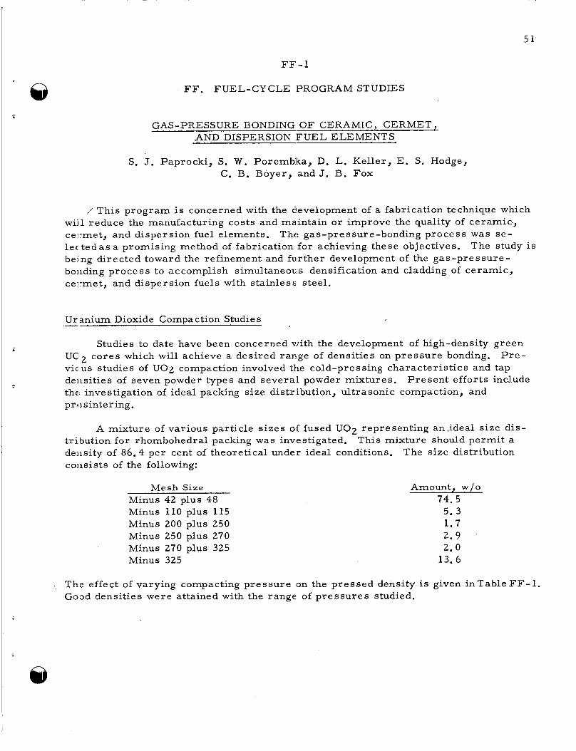
5 1'
FF-1
G. -
FF. FUEL-CY CLE PROGRAM STUDIES
S-PRESSURE BONDING OF CERAMIC, CERMET, +4ND DISPERSION F U E L ELEMENTS
S. J. Paprocki, S. W. Porembka, D. L. Keller, E. S. Hodge, C. B. Boyer, and J. B. Fox
*' This program is concerned with the development of a fabrication technique which wij1 reduce the manufacturing costs and maintain o r improve the quality of ceramic, ce :met, and dispersion fuel elements. The gas-pressure-bonding process w a s se- lec t e d a s a promising method of fabrication for achieving these objectives. bejng directed toward the refinement and fu.rther development of the gas-pressure- boiiding process to accomplish simultaneous densification and cladding of ceramic, ce -met, and dispersion fuels with stainles: steel.
The study is
Uranium Dioxide Compaction Studies .-
Studies to date have been concerned with the development of high-density green P r e - UC12 co res which will achieve a desired range of densit ies on p res su re bonding.
viclus studies of UO2 compaction involved the cold-pressing character is t ics and tap deiisities of seven powder types and severa l powder mixtures , the investigation of ideal packing size distribution, ultrasonic compaction, and prf: sintering.
P resen t efforts include
A mixture of various particle s izes of fused U 0 2 representing an, ideal s ize dis- tribution for rhombohedral packing was investigated. deiisity of 86.4 pe r cent of theoretical under ideal conditions. coiisists of the following:
This mixture should permi t a The s ize distribution
Mesh Size Minus 42 plus 48 Minus 110 plus 115 Minus 200 plus 250 Minus 250 plus 270 Minus 270 plus 325 Minus 325
Amount, w /o 74.5
5 . 3 1.7 2.9 2.0
13.6
Amount, w /o 74.5
5 . 3 1.7 2.9 2.0
13.6
The effect of varying compacting p res su re on the p re s sed density is given inTab leFF-1 . Good densit ies were attained with the range of p re s su res studied.
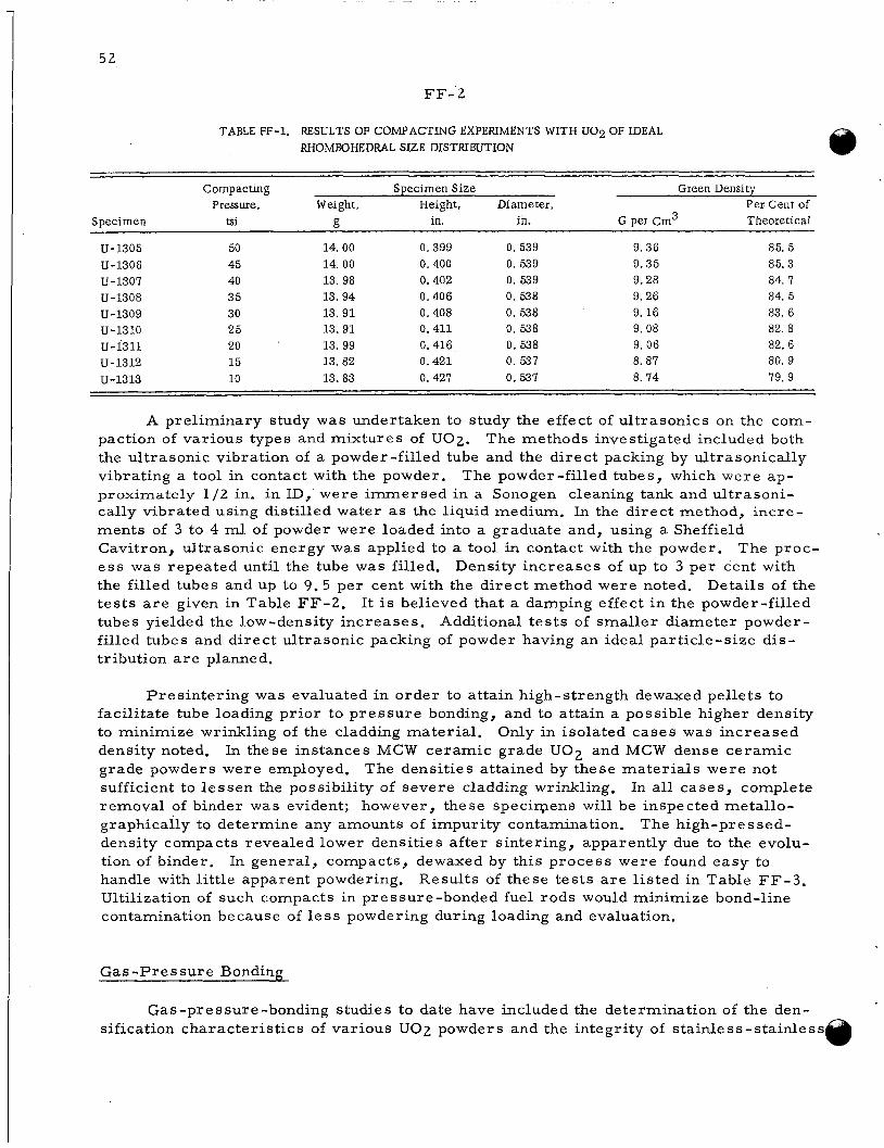
5 2
FF- 2
TABLE FF-1. RESULTS OF COMPACTING EXPERIMENTS WITH U02 OF IDEAL RHOMBOHEDRAL SIZE DISTRIBUTION
Compacting Specimen Size Green Density Pressure, Weight, Height, Diameter, Per Cent of
Specimen tsi R in. in. G per c m 3 Theoretical ~~
U-1305 50 14.00 0.399 0.539 9. 36 85. 5 U-1306 45 14. 00 0.400 0. 539 9.35 85. 3 U-1307 40 13. 98 0.402 0. 539 9.28 84. 7 U-1308 35 13.94 0.406 0. 538 9.26 84. 5 U-1309 30 13.91 0.408 0. 538 9. 16 83. 6 U-1310 25 13.91 0.411 0. 538 9. 08 82. 8 u-i311 20 13.99 0.416 0. 538 9. 06 82. 6 U-1312 15 13.82 0.421 0. 537 8. 87 80. 9 U-1313 10 13.83 0.427 0.537 8.74 79. 9
A preliminary study w a s undertaken to study the effect of ultrasonics on the com- paction of various types and mixtures of UO2. The methods investigated included both the ultrasonic vibration of a powder-filled tube and the direct packing by ultrasonically vibrating a tool in contact with the powder. The powder-filled tubes, which were ap- proximately 1 / 2 in. in ID,' were immersed in a Sonogen cleaning tank and ultrasoni- cally vibrated using distilled water as the liquid medium. In the direct method, incre- ments of 3 to 4 ml of powder were loaded into a graduate and, using a Sheffield Cavitron, ultrasonic energy was applied to a tool in contact with the powder. e s s w a s repeated until the tube w a s filled. the filled tubes and up to 9.5 per cent with the d i rec t method were noted. t e s t s a r e given in Table FF-2. tubes yielded the low-density increases . filled tubes and direct ultrasonic packing of powder having an ideal particle-size dis- tribution a r e planned.
The proc-
Details of the It is believed that a damping effect in the powder-filled
Additional t e s t s of smal le r diameter powder -
Density increases of up to 3 per cent with
Pres in te r ing was evaluated in order to attain high-strength dewaxed pellets to facilitate tube loading prior to p re s su re bonding, and to attain a possible higher density to minimize wrinkling of the cladding material . density noted. grade powders were employed. The densities attained by these mater ia l s were not sufficient to l e s sen the possibility of severe cladding wrinkling. removal of binder was evident; however, these spec iqens w i l l be inspected metallo- graphically to determine any amounts of impurity contamination. The high-pressed- density compacts revealed lower densities after sintering, apparently due to the evolu- tion of binder. handle with little apparent powdering. Results of these tes t s a r e l isted in Table FF-3. Ultilization of such compacts in pressure-bonded fuel rods would minimize bond-line contamination because of l e s s powdering during loading and evaluation.
Only in isolated cases w a s increased In these instances MCW ceramic grade UO2 and MCW dense ceramic
In all cases, complete
In general, compacts, dewaxed by this process were found easy to
Gas - P r e s sure Bonding
Gas-pressure-bonding studies to date have included the determination of the den- sification characterist ics of various UOz powders and the integrity of stainless-stainless

,
TABLE FF-2. RESULTS OF EXPERIMENTAL ULTRASONIC COMPACTION OF U02
__ - -
Compaction Produced by Tap Paclung Compacuon Produced by Ultrasomc Vibration Density Density
Volume, Per Cent of Ultrasomc Volume, Per Cent of Theoretical 3 G per Cm Material ml G per c m 3 Theoretical Method a) ml
MCW ceramic grade U02
MCW dense ceramic grade UOp
NLJMEC high-fired U 0 2
MCW high-fired U02
MCW spherical U02
MCW special dense U 0 2
Spencer fused U02
75 w/o MCW special dense U02 and 25 w/o MCW ceramic grade U02
75 w/o Spencer fused U 0 2 and 25 w/o ceramic grade U 0 2
15 w/o Spencer fused U02 and 25 w/o MCW high-fired U02
5. I
6. I
5.6
5. 8
7.4
6. 9
7. 6
6 .3
5. 2
7.0
2.73
3. 54
5. 68
6.02
5. 64
6. 75
6. 34
5. 57
5.48
7.32
24. 9
32.3
51. 8
54. 9
51. 4
61. 6
57.8
50. 9
50.0
66. 7
1
1
1 3
1 3
1 2 3
1 ‘L 3
1 2 3
1 2 3
3
1 2 3
5.8
6. 7
5. 6 4.4
5. 8 5.3
I. 3 7. 25 7.2
6.7 6.7 6. 2
7.3 7.2 6. 9
6.3 6 .3 5.3
4.9
6.8 6.7 6.4
2. 68
3. 54
5. 68 5.86
6. 02 6. 58
5. 72 5.77 5. 81
6.96 6.96 7. 65
6. 60 6. 70 7.13
5. 57 5. 57 6. 61
5. 82
7. 54 7. 64 8.00
24. 4
32.3
51. 8 53. 6
54.9 60. 1
52. 2 52. 7 53.1
r 63. 6 q 63. 6 ;J 69.8
60.2 61. 2 65. 1
50. 9 50. 9 60.4
53.2
69. 0 69. I 13. 0
(a) Ultrasonic compaction methods were as follows:
(1) Powder in graduate was immersed in Sonogen cleaning tank under 100 F water. Power: 75 ma for 4min a t 39 kc. (2) Powder in graduate was immersed in Sonogen cleaning tank under 100 F water. Power: 90 ma for 5 min at 39 kc. (3) Direct application of ultrasonic energy from a 1000-w Sheffield Cavitron was made to a tool in contact with the povder. Power: 20 kc, 10 per cent setting, 100 to
Ul w
150 w , 6-amp bias setting. ,
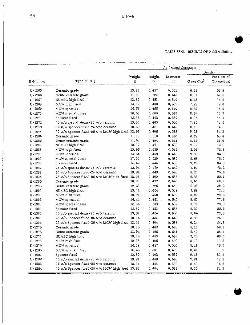
54 FF-4
TABLE FF-3. RESULTS OF PRESINTERING
As-Pressed Compacts
Weight, Height, Diameter, Per Cent of U-Number Type of U02 g in. in. G per Cm3 Theoretical
Density
U-1265 U-1266 U-1267 U-1268 U-1269 U-1270 U-1271 U-1272 U-1273 U-1274 U-1285 U-1286 U-1287 U-1288 U-1289 U-1290 U-1291 U-1292 U-1293 U-1294 U-1295 U-1296 U-1297 U-1298 U-1299 U-1300 U-1301 U-1302 U-1303 U-1304 U-1275 U-1276 U-1277 U-1278 U-1279 U-1280 U-1281 U-1282 U-1283 U-1284
Ceramic grade 13.27
NUMEC high fired 13. 81 MCW high fired 14.37 MCW spherical 14.56 MCW special dense 16.56 Spencer fused 15.36 75 w/o special dense-25 w/o ceramic 13.90 75 w/o Spencer fused-25 w/o ceramic 13. 89 75 w/o Spencer fused-25 w/o MCW high fired 13.91 Ceramic grade 11.89 Dense ceramic grade 11. 92 NUMEC high fired 13.70 MCW high fired 13.95 MC W spherical 14. 64 MCW special dense 17.50 Spencer fused 15.42 75 w/o special dense-25 w/o ceramic 13.94 15 w/o Spencer fused-25 w/o ceramic 13.94 75 w/o Spencer fused-25 w/o MCW high fired 13.93
Dense ceramic grade 12. 63 NUMEC high fired 13.71 MCW high fired 13. 91 MCW spherical 14. 44 MCW special dense 16.35 Spencer fused 15.80 75 w/o special dense-25 w/o ceramic 13. 97 75 w/o Spencer fused-25 w/o ceramic 13. 94 75 w/o Spencer fused-25 w/o MCW high fired 13.92 Ceramic grade 10.85
NUMEC high fired 13.38 MCW high fired 12.28 MCW spherical 14.39 MCW special dense 16.26 Spencer fused 13.80 75 w/o special dense-25 w/o ceramic 13. 91 75 w/o Spencer fused-25 w/o ceramic 13.94 75 w/o Spencer fused-25 w/o MCW high fired 13.93
Dense ceramic grade 11.93
Ceramic grade 10.93
Dense ceramic grade 11.94
0. em 0. 500 0.453 0.486 0.465 0.509 0.442 0.465 0.451 0.406 0. 516 0.494 0.471 0.459 0.468 0. 539 0.445 0.470 0.449 0.400 0.472 0. 526 0.464 0.462 0.451 0. 503 0.453 0.464 0.444 0.404 0.468 0.496 0.453 0.405 0.457 0.501 0.402 0.468 0.444 0.404
0.501 0. 541 0. 540 0.539 0.540 0. 539 0.539 0.540 0.540 0. 538 0.540 0. 541 0. 539 0.539 0. 540 0.539 0.538 0. 540 0. 540 0. 538 0. 540 0. 540 0.539 0. 539 0. 540 0. 539 0. 538 0.540 0. 540 0. 538 0.540 0. 541 0.539 0.539 0.540 0. 539 0. 539 0. 540 0.539 0. 538
6. 24 6. 31 8. 13 7.92 8.32 8. 69 9.25 7.94 8. 18 9. 23 6. 12 5. 83 7.77 8. 09 9.30 8. 66 9.29 7.91 8. 27 9.33 5. 51 6. 38 7. 89 8. 07 8. 50 8. 76 9.37 8. 04 8.33 9.24 6. 15 6.40 7.29 8. 09 8.41 8. 65 9. 16 7. 91 8. 40 9. 25
56. 9 57. 6 74. 2 72. 3 75. 9 79. 3 84. 4 72. 4 74. 6 84. 2 55. 8 5 3 . 2 70.9 73. 8 84. 9 79.0 84. 8 72. 2 75. 5 85. 1 50.3 58.2 72. 0 73.6 77. 6 79. 9 85. 5 13.3 76. 0 84.3 56. 1 58. 4 66.5 73.8 76. 7 78. 9 83. 5 72.2 76. 6 84.3
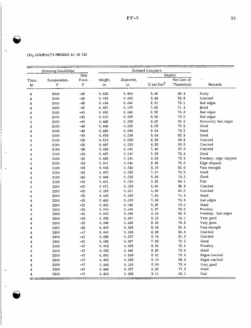
FF-5 55
U 0 2 COMPACTS PRESSED AT 40 TSI
Sintering Conditions Sintered Compacts - Dew Density
Tim-, Temperature, Point, Height, Diameter , Per Cent of hr F F in. in . G per Cm3 Theoretical Remarks - 4 4 4 4 4 4 4 4 4 4 4 4 4 4 4 4 4 4 4 4 4 4 4 4 4 4
4 4 4 4 4 4 4 4 4 4 4 4 4 4
2000 2000 2000 2000 2000 2000 2000 2000 2000 2000 2100 2100 2100 2100 2100 2100 2100 2100 2100 2100 2200 2200 2200 2200 2200 2200 2200 2200 2200 2200 2300 2300 2300 2300 2300 2300 2300 2300 2300 2300
- 49 -49 -49 -49 - 49, - 49 -49 -49 -49 -49 -26 -26 -26 -26 -26 -26 -26 -26 -26 -32 -32 -32 -32 -32 -32 -32 -32 -32 -32 -32 -47 - 47 -47 -47 -47 - 47 -41 - 41 -47 -47
0.655 0.498 0.454 0.487 0.466 0.510 0.442 0.464 0.450 0.406 0.516 0.497 0.485 0.461 0.469 0. 541 0.446 0.470 0.448 0.401 0.411 0. 526 0.466 0.465 0.451 0. 506 0.454 0.463 0.443 0.409 0.460 0.493 0.453 0.405 0.422 0. 502 0.403 0.466 0.442 0.405
0.495 0. 536 0. 540 0.539 0.540 0. E39 0. E39 0. 538 0.638 0. E39 0. E29 0.235 0. E40 0.540 0. E41 0.540 0. E140 0. E38 0.238 0. E99 0. 528 0. 531 0. E99 0. 5139 0. 540 0. E140 0. E140 0. :97 0. X38 0. :I39 0. ti25 0. ti27 0.537 0. :a9 0. :I40 0. :I39 0. :a9 0. h36 0. :97 0. :,39
6. 40 6.45 8. 0 1 7.82 8.28 8. 66 9.20 8. 02 8.24 9. 08 6.38 6. 52 7.43 I . 93 8.29 8. 58 9. 16 7.91 8.35 9. 22 6.40 6. 58 7.85 7. 98 8. 55 8. 51 9. 18 8. 12 8. 42 9.06 6. 63 6. 74 7.95 8. 03 8. 32 8. 61 9. 14 8. 04 8. 50 9. 11
58. 4 58. 9 13. 1 71. 4 75. 5 79. 0 83.9 13. 2 75. 2 82. 8 58. 2 59. 5 67. 8 72.4 15. 6 78. 3 83. 6 72. 2 76. 2 84. 1 58.4 60.0 71. 6 72. 8 78. 0 78.2 83. 8 14. 1 76. 8 82. 6 60. 5 61. 5 12. 5 73.3 75. 9 18. 6 83.4 73.4 77. 6 83. 1
Scaly Cracked Bad edges Food Bad edges Bad edges Extremely bad edges Good Good Good Cracked Cracked Cracked Good Powdery, edge chipped Edge chipped Poor strength Good Good Fair Cracked Cracked Good Bad edges Good Powdery Powdery, bad edges Very good Very good Poor strength Cracked Cracked Good Powdery Good Edges cracked Edges cracked Very good Good Fair
56
FF-6
bond after gas-pressure bonding at 1900 to 2200 F. sional nonuniformity experienced with low-density U 0 2 in ea r l i e r work, present efforts a r e directed to the utilization of high-density U 0 2 and element designs other than the cylindrical rod. pre s sur e -bonded U02.
In view of the warpage and dimen-
P resen t studies also include a m o r e complete evaluation of gas-
Eight tubes containing U02 powders of various types prepared both with and with- out binders were p re s su re bonded to establish the effects of bonding conditions upon the stoichiometry of the different types of U 0 2 . to 600 F in vacuum. Table FF-4. stoichiometry under the bonding conditions studied. noted beween those tubes initially containing binders and those without binders. possible slight tendency to off-stoichiometry is indicated in the resu l t s for tubes con- taining MCW special dense U02.
Those tubes containing binders were heated Bonding details and stoichiometry resu l t s a r e reported in
It was noted that the ceramic grade of uranium dioxide tends to re turn to No significant differences were
A
Of the various element designs that a r e being considered to minimize surface roughness, warpage, and dimensional nonuniformity which occur when p r e s sure bond- ing elements containing tapped powders o r cores of a low density, the corrugated rod or tube appears mos t promising. a r e being prepared.
Additional specimens of this type and also other designs
A preliminary investigation w a s conducted to demonstrate the feasibility of p re s - s u r e bonding an edge-welded stainless steel-clad U02 compartmentalized flat plate. Type 304 stainless steel components were machined f rom 10 to 100-mil as-rolled sheet. The U 0 2 cores possessed a high initial density. The over-all plate dimensions were 0.120 by 1.875 by 5.500 in. 1. 500 in. sional control and good bonds. tests.
It contained nine cores measuring 0.100 by 0.2495 by Pre l iminary examination of the bonded specimen revealed excellent dimen-
Compartmental integrity wi l l be established by burst
Future work will concern a m o r e complete evaluation of the fuel-element designs selected for p re s su re bonding and permeability and thermal-conductivity t e s t s of p re s sure -bonded U 0 2 .
DEVELOPMENT OF URANIUM CARBIDE-TYPE FUEL MATERLALS
F. A. Rough and W. Chubb
In an effort to reduce the cost of electrical power produced f rom nuclear energy, the AEC has sponsored a s e r i e s of r e sea rch programs designed to investigate and develop uranium carbides as reactor fuels. Battelle, and involves development of techniques for production of carbide shapes, determination of the physical and mechanical properties of uranium carbides, deter - mination of the chemical behavior of uranium carbides in contact with various solids, liquids, and gases, and investigation of the mechanism by which neutron irradiation and fission produce damage in the carbides.
A portion of this work is in progress a t
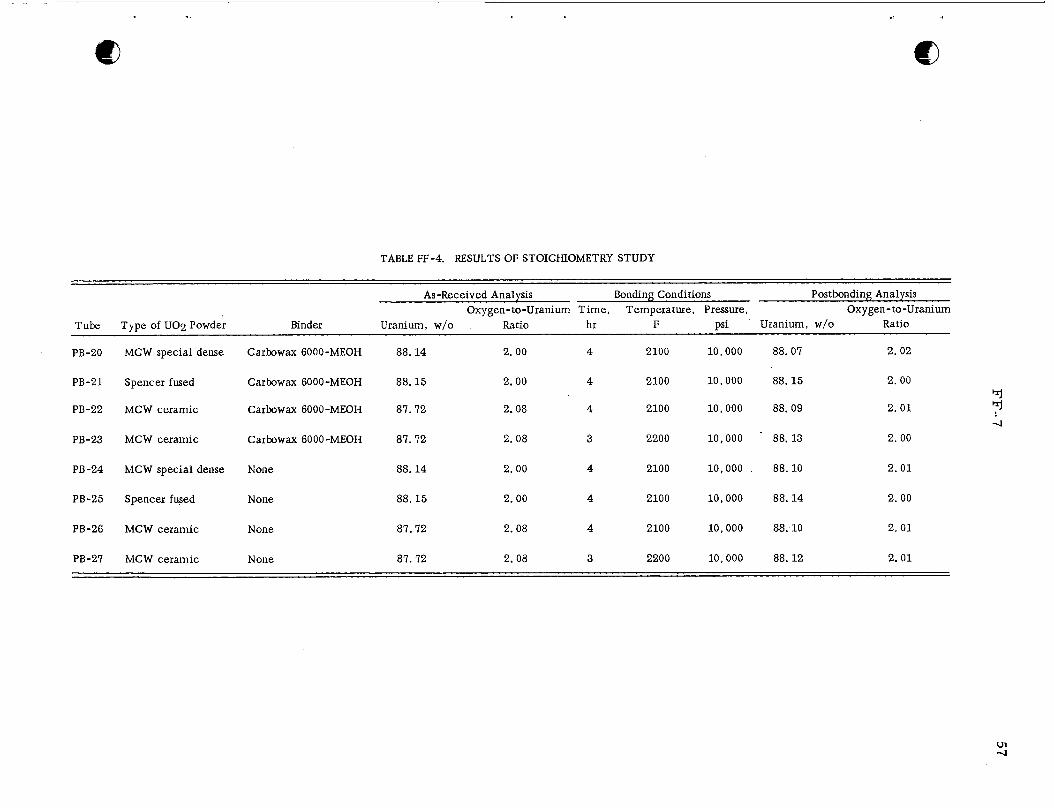
TABLE FF-4. RESULTS OF STOICHIOMETRY STUDY
As-Received Analysis Bonding Conditions Postbonding Analysis Oxygen-to-Uranium Time, Temperature, Pressure, Oxygen- to -Uranium
Tube Type of U02 Powder Binder Uranium, w/o Ratio hr F psi Uranium, w/o Ratio
PB-20 MCW special dense Carbowax 6000-MEOH 88.14 2. 00 4 2100 10,000 88.07 2.02
PB-21 Spencer fused Carbowax 6000-MEOH 88.15 2.00 4 2100 10 ,000 88.15 2.00
PB-22 MCW ceramic Carbowax 6000-MEOH 87.72 2.08 4 2100 10,000 88.09 2.01
PB-23 MCW ceramic Carbowax 6000-MEOH 87.72 2. 08 3 2200 10,000 88.13 2.00
PB-24 MCW special dense None 88.14 2.00 4 2100 10,000 88.10 2.01
PB-25 Spencer fused None 88.15 2.00 4 2100 10,000 88.14 2.00
PB-26 MCW ceramic None 87.72 2.08 4 2100 10,000 88:lO 2.01
PB-27 MCW ceramic None 87.72 2. 08 3 2200 10.000 88.12 2.01
58
FF-8
P a s t work has resulted in scaling up the skull-melting process to produce right- Work is continuing in cylindrical shapes having cross-sectional a r e a s of over 6 sq in.
an effor t to make the process m o r e versat i le and reliable. in determination of the electr ical res is t ivi t ies , the densities, the rupture strength, corrosion ra tes , and interdiffusion r a t e s of the various uranium carbides. data have also been obtained with respec t to the compatibility of uranium monocarbide with Inconel, steel, stainless steel, aluminum, copper, molybdenum, and tantalum. Much of these data were summarized in a topical r epor t (BMI-1370) covering the f i rs t 6 months of r e sea rch on this program.
Other studies have resulted
Pre l iminary
Work during recent weeks has reshlted in a n increase in the reliability of certain data on the physical propert ies of uranium carbides. samples of as -cas t uranium-4.8 w/o carbon specimens was 1. 35 g per cm3, and ave r - age density of sixteen samples of as -cas t uranium-7.0 w/o carbon specimens w a s 12.4 g per cm3. BMI-1370. 50 microhm-cm, respectively. ported in BMI- 1370; this increase in conductivity probably represents a n improvement in the internal quality of the castings. It has been observed that the addition of certain metals , such as niobium, to uranium monocarbide resu l t s in a marked improvement in the metall ic lus te r of the specimens. If such specimens prove to be cast cermets , the improvement in propert ies could be of considerable significance.
The average density of sixteen
These values a r e not significantly different f rom those reported in The average resis t ivi t ies of the same specimens were 38 microhm-cm and
These resis t ivi t ies a r e slightly lower than those r e -
Alternate Fabrication Methods for UC
S. J. Paprocki, D. L. Keller, D. E. Kizer , and J. M. Fackelmann
Various methods of producing dense UC by powder -metallurgy techniques are being investigated. by different procedures such as the reaction of uranium metal and U02 with carbon o r the reaction of uranium metal and methane, as well as studies of hot-pressing tech- nique s which involve simultaneous reaction and densification.
The methods being considered include sintering of UC powder made
Several compacts of 4 .8 w/o carbon (Morite Type A activated charcoal)-95.2 w/o uranium meta l powder were hot pressed a t temperatures ranging f rom 1050 to 1150 C. Densities var ied f rom 71.5 to 78. 5 per cent of theoretical - the la t ter value having been obtained af te r holding at 1150 C for 4 h r . sisted of UC, uranium, U% , and two unidentified phases. metal powder used was minus 325 mesh, surface reactions may have contaminated the metal with U02 o r other impurit ies and prevented the complete formation of UC. Similar compacts a r e being prepared with uranium hydride substituted for uranium in an attempt to provide an active clean metal surface during the hot-pressing operation. In addition, uranium metal shot has been ordered and will be used for additional hot- pressing studies of uranium-carbon mixes.
The microstructure of these specimens con- Since the size of the uranium
Compacts of UC that were pressed at 15 tsi were sintered a t temperatures of 1900 to 2120 C for time periods of 5 to 30 min. Densities showed no significant variation,
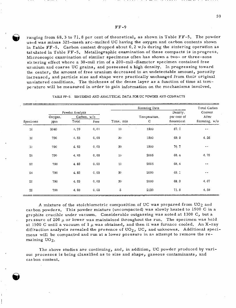
59
FF -9
raiiging f rom 68. 3 to 71.8 per cent of theoretical, as shown in Table FF-5. usc:d was minus 325-mesh arc-melted UC h.aving the oxygen and carbon contents shown in Table FF-5. tabulated in Table FF-5 . Microscopic examination of similar specimens often has shown a two- or three-zone sir tering effect where a 30-mil rim of a 200-mil-diameter specimen contained f r ee uranium and coarse UC grains, and possessed a high density. thc center, the amount of f r ee uranium decreased to an undetectable amount, porosity increased, and particle size and shape were practically unchanged f rom their original unsintered conditions. pe::ature will be measured in order to gain information on the mechanisms involved.
The powder
Carbon content dropped about 0 . 2 w/o during the sintering operation as Metallographic examination of these compacts is in progress.
In progressing toward
The thickness of tht: dense layer as a function of time at tem-
TABLE FF-5. SINTERING AND ANALYTICAL DATA FOR UC POWDER AND COMPACTS
I_
Sintering Data Total Carbon Densj ty , Content Powder Analysis
Oxygen, Carbon, w/o Temperature, per cent of After Specii nen PPm Total Free Time, min C theoretical Sintering, w/o -
-- It 3040 4.79 0 .01 1(1 1900 67. 7
1E 790 4. 83 0. 03 30 1900 69. 9 4. 56
- - 1 E 790 4. 83 0. 03 30 1900 70. 7
2Cl 790 4. 83 0.03 1(1 2005 68. 4 4. 72
21 790 4. 83 0. 03 10 2005 68.4 --
4. 83 0. 03 3(1 2000 69. 1 - _ 24 790
2: 790 4. 83 0. 03 30 2000 68.3 4. 67
2:: 790 4. 83 0. 03 5 2120 71. 8 4. 59
A mixture of the stoichiometric composition of UC w a s prepared f rom U 0 2 and
Considerable outgassing was noted a t 1300 C, but a carbon powders. grzphite crucible under vacuum. prc s su re of 200 p or lower w a s maintained throughout the run, at 1500 C until a vacuum of 1 p w a s obtained, and then it was furnace cooled. diffraction analysis revealed the presence of U 0 2 , UC, and unknowns. mens will be compacted and run a t a lower p re s su re in an attempt to remove the r e - maining U02.
This powder mixture (uncompacted) w a s slowly heated to 1500 C in a
The specimen w a s held An X-ray
Additional speci-
The above studies a r e continuing, and, in addition, UC powder produced by var i - ous, p rocesses is being classified as to size and shape, gaseous contaminants, and car bon content.

60
FF-10
Melting and Casting Techniques for Uranium-Carbon Alloys
B. L. Boesser, W. M. Phillips, E. L. Fos te r , and R. F. Dickerson
Reliable techniques for the production of high-quality cast shapes of uranium ca r - bide a r e being developed. uranium carbide by skull-type arc-melting procedures was continued. have a s a specific objective the establishment of techniques for the control of composi- tion and the preparation of cas t shapes containing about 5.0 w/o carbon. small carbide skull contained in a graphite crucible l iner was removed, and l iner and skull were replaced by a solid carbide skull prepared in the following manner:
During the past month, the preparation of cas t shapes of These efforts
To this end, a
(1) The bottom portion of the skull was melted in place using prealloyed UC containing approximately 5 w /o carbon.
(2 ) The balance of the skull w a s melted in place f rom charges of metall ic uranium and 4 w / o carbon.
Only two castings have been melted and poured f r o m this skull. The resulting castings, while they were exceptionally homogeneous (end-to-end variations along the 7-in. length were l e s s than 0 . 1 w/o carbon) and sound, contained about 6 w/o carbon. The graphite electrode lo s ses do not account for this gain in carbon over that of the charge composition. that in melting that portion of the skull made f rom uranium and carbon ( 4 w/o), the melted uranium metal segregated by settling before complete alloying with the carbon was accomplished. of the skull in carbon.
Unreacted chunks of graphite found in the top of the skull indicate
This effect would resu l t in enrichment of the mater ia l near the top
Immediate plans wi l l involve an adjustment of the composition of the skull l iner by addition of uranium and preparation of cas t shapes containing 5 .0 w /o carbon. monstration of compositional control will be established by preparing a s e r i e s of cast- ings 3/4 in. in diameter and 8 in. long. mold-heating device that can be used to produce a number of cylindrical cas t shapes with one pouring a r e also in progress .
De-
The design and preparation of molds and a
Metallurgical and Enpineering ProDerties of Uranium Monocarbide
W. M. Phillips, E. L. Fos t e r , and R. F. Dickerson
A study of the properties of uranium carbides is in progress to determine and enhance the properties of these mater ia l s . tivity, thermal conductivity, strength, and corrosion resistance. variables a s impurity content, carbon content, alloy content, and heat treatment a r e being evaluated in t e r m s of the above properties.
Proper t ies of in te res t a r e density, r e s i s - The effects of such
61
FF-- 11
Work on the effect of carbon content, of annealing temperature, and of a s -cas t diameter has been inprogres s during the past month. The data obtained up to the p r e s - en1 \ time indicate little effect of annealing temperatures up to 1800 Cy on the r e s i s - tivity and density of the material . Sixteen specimens containing 4. 8 w/o carbon had an avc:rage density of 13.5 g per cm3 and an average resist ivity of 38 microhm-cm. A sirnilar number of 7.0 w/o carbon alloys had a n average density of 12.4 g per cm3 and an average resist ivity of 50 microhm-cm.
@
In an attempt to improve the corrosion resistance of UC, additions of 0.5 and 10, 0 w/o chromium, iron, molybdenum, nj ckel, niobium, tantalum, tungsten, o r z i r - coiiium have been made to uranium monocarbide. mdybdenum, niobium, or tantalum have a more silvery metall ic appearance, indicating po:;sible improved properties.
The alloys containing 10 w/o iron,
Testing of these specimens is presently in progress .
Additional work on the compatibility of uranium monocarbide with Inconel, mild s k e l , niobium, stainless steel, and zirconium is planned to determine the lowest tem- pe:.ature at which reaction between UC and these mater ia l s can be observed after an ex l~osure of 100 h r . of U2C3 and additional work on the effects of binary additions to uranium carbide.
Future work wi l l a l so include a study of the kinetics of formation
Uranium Monocarbide Diffusion Studies
W. Chubb, R. W. Getz, and F. A. Rough
Uranium monocarbide is being considered as a fuel for nuclear r eac to r s operating at high temperatures. Certain characterist ics of this material , such as creep strength anll res i s tance to radiation damage, a r e closely related to the ra te of interdiffusion of ur ,mium and carbon and to the r a t e s of self-diffusion of uranium and carbon in uranium mcmocarbide. were determined and reported ea r l i e r ; the self-diffusion of uranium in uranium mono- carbide is presently being investigated. fully, and the techniques necessary for determining the extent of self-diffusion of u ra - niiim in uranium carbide have been developed. coliple is being sampled in preparation for neutron activation and analysis.
The r a t e s of interdiffusion cif uranium and carbon at various tempera tures
D,.ffusion couples have been bonded success-
Currently, a preliminary diffusion
The diffusion couples a r e made by placing a 0.001-in. -thick foil of enriched u ra - nirim ( 9 3 per cent uranium-235) between two 0.25-in.-lengths of depleted uranium (0.04 per cent uranium-235) monocarbide rod. 0.002-in. -thick tantalum foil, placed in a graphite jig, and bonded in vacuum for 4 h r a t 1400 C. Two bonded couples have been diffusion annealed, one for 1.5 h r a t 1800 C and one for 7 h r at 1600 C. Metallographic inspection of the bonds indicated that the fo rmer w a s satisfactorily bonded and annealed and that the la t te r was unsatisfactory.
The couple is then wrapped in a
The couple diffusion annealed at 1800 C is being prepared for neutron activation in
These samples a r e obtained by grinding the couple on 600-grit silicon tho BRR. along the couple. carbide powder in the presence of a small amount of 0. 1 N n i t r ic acid solution. The gamma activity of the neutron-activated saimples will be used to determine the amounts
An aluminum dish is being used in taking samples at 0.001-in. intervals
@
62
I
FF-12
of uranium-235 and uranium-238 present in the samples. w i l l be possible to calculate the ra te of self-diffusion of uranium in uranium monocarbide.
F r o m the resultant data it
Future work will include the preparation of additional diffusion couples and the neutron activation of samples f rom these diffusion couples in the BRR.
Irradiation Effects in UC
A. E. Austin and C. M. Schwartz
The changes in structure of UC with irradiationand fission a r e being studied. Electron-microscope examination has been made of specimens with estimated burnups of 0,05 and 0.2 a / o uranium. The specimen with lower burnup was irradiated at a cal- culated temperature of 600 F, while the specimen with 0 . 2 a / o burnup w a s irradiated at about 1300 F. report.
The specimens were replicated as described in a previous p rogres s
The electron micrographs show a fine pit s t ruc ture tending to concentrate in long t r aces which may indicate incipient cracks. sisted of the normal UC grain s t ruc ture containing the straight UC2 needle precipitate, apparently unchanged. The specimen with 0.05 a / o burnup contained deformed warped UC2 needles with cracks along their sides. these specimens may be due to the differences in temperature of irradiation. higher temperature, 1300 F, self-annealing of the s t ra ins resulting f rom fission may occur. ated material .
The specimen with 0 .2 a / o burnup con-
This difference in the micros t ruc ture of At the
Fur the r work i s in p rogres s on comparing the fine pit structure with unirradi-
The deformation of UC2 needles o r plates in carbides having UC as a matrix des- cribed above and apparent disappearance of the UC2 phase in the center portion of speci- mens irradiated for Atomics International indicate a need for study of the effects of irradiation upon s t r a in in this material . Equipment has been modified and techniques developed to prepare suitable samples for studies of lattice s t ra in by X-ray diffraction . methods on irradiated samples. A s e r i e s of specimens having burnups f rom 0.01 a / o uranium or l e s s up to 0.5 a / o uranium is to be studied. for preparation of the specimens is expected momentarily.
Delivery of enriched uranium
a
63 and 64
GG- 1 and GG- 2
GG. VOID-DISTRIBUTION AND HEAT -TRANSFER STUDIES
D. V. Grillot, R . Wooten, H. M. Epstein, and J. W. Chastain
During the month, a stable void-detection sys tem was attained by adding a voltage rc:gulator to the circuit , in stalled to aid detector stability. temperature sensitive and will have to be calibrated for temperature r i se .
Magnetic shielding and forced-convection cooling also were Despite these modifications, the detector is st i l l
Continued problems have been encountered in maintaining a satisfactory tes t st:ction. The l a s t t es t section lasted for severa l weeks while a number of calibration runs were made. h n g e r life.
Electr ical shor t circuits o r p re s su re leaks occur around the p re s su re taps.
Welding personnel a r e optimistic about making tes t sections which will have
A tes t section without p re s su re taps is being us'ed to investigate two-phase flow i n stabilities. Two-phase flow instability was not anticipated in the present experiment. A previous experiment performed a t Battelle using a n almost identical system resul ted i n no flow instabilities. aitributed to higher operating p res su res .
The lack of instability in this previous experiment has been
Originally, instability in the present experiment was such that the system was ir-capable of reaching the subcooled-boiling region. This violent flow instability was altributed to insufficient cooling of the steam-liquid mixture emerging f rom the tes t stxtion. With additional cooling the loop has performed m o r e satisfactorily. cooled conditions have been attained, but oscillation in the flow have caused variations i n the position of the subcooled-boiling region in the t e s t section. hitve prevented measuring void fraction.
Sub-
These fluctuations
It is believed that collapsing s team bubbles in the condenser cause fluctuations in pi-essures which, in turn, cause changes in flow rate , water temperature , and in void dj stribution within the tes t section.
A possible solution is to throttle the sys tem a t the inlet to the tes t section. The dimiving force, v iz . , the p re s su re preceding the tes t section, will then be la rge enough to overcome p res su re changes which exist. in the condenser. Possibly a m o r e feasible solution is to install a s team separator a t the test-section exit. A s team separator wlmld eliminate two-phase flow f rom a major portion of the loop, and i t would a l so function as a surge tank in that pa r t of the loop which is experiencing the grea tes t pi-essure and flow fluctuations.
This la t ter solution is being t r ied presently. Solution of flow instability should eliminate the l a s t major difficulty and per:mit meaningful data to be obtained.

65
H-1
H. PHYS1CA.L RESEARCH
F. A. Rough
Studies of physical r e sea rch on niobium-gas reactions and on growth of UO2 single cr;rstals a r e under way for the AEC Division of Research.
In the study of niobium-gas reactions , consistent kinetic experiments have been obiained at 200 to 600 C by f i r s t vacuum he,ating at 1100 C to establish uniform surface coiiditions. Equations describing the reaction ra tes a r e given.
In the preparation of UO2 single c rys ta l s f rom the vapor phase, procedures in- volving both direct vaporization of UO2 and reaction of UF4 and H20 a r e being studied. Fusion methods for growth of single crysta:ls a r e a lso being studied, including floating- zoiie and other methods.
Niobium-Ga s Reactions
W. M. Albrecht and W. D. Goode
A fundamental study of the reactions of nitrogen with niobium is being made. The stl dy consists of determinations of reaction kinetics and mechanisms and includes de - te1,mination of diffusion coefficients and solubility of nitrogen in niobium.
Reaction r a t e s , diffusion coefficients , and solubility of nitrogen in niobium in the raiige 675 to 1600 C were presented in BMI-1360.
Kinetic experiments have been made at 200 to 600 C. The samples used in these experiments were vacuum annealed at 1100 C for 45 min. foLnd t o follow the logarithmic law:%
The reaction ra tes were
w (p g p e r cm2) = k log (a t t l ) ,
where w i s the weight gain and t i s time. shown in Table H-1. enl i re temperature range, the average value being 4.1 x was found to va ry with temperature , T , according to the equation
The values for the constants k and a are It is seen that the value of a remains practically constant over the
sec - l . The value of k
k ( p g pe r cm2) = 2.17 exp [ -(5,160 f 98)/RT].
X-ray diffraction examination of the surface ,of samples reacted at 300 and 500 C showed the presence of Nb2N and NbN.
A paper describing all the work in the niobium-nitrogen sys tem i s being prepared.
*Kubaschewski, O., a n d Hopkins, B. E., Oxidat ion of Metals m d Alloys, Academic Press Inc., New York (1953), p 38.
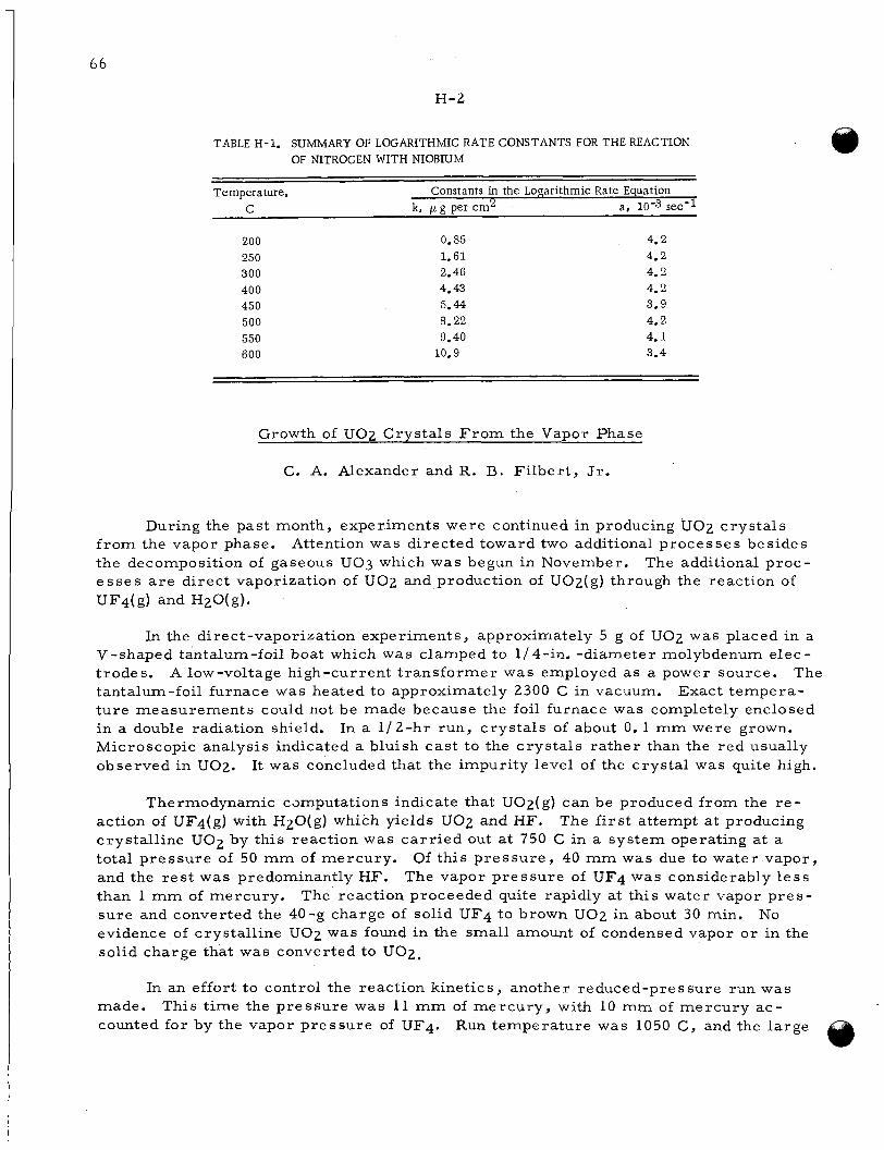
66
H-2
TABLE H-1. SUMMARY OF LOGARiTHMIC RATE CONSTANTS FOR THE REACTION OF NITROGEN WITH NIOBIUM
Temperature, C
Constants in the Logarithmic Rate Equation k, p g per ern' a, 10-3 sec-1
200 250 300 400 450 500 550 600
0.85 1.61 2.46 4.43 5.44 8.22 9.40
10.9
4.2 4.2 4.2 4.2 3.9 4.2 4.1 3.4
Growth of UO7 Crvstals F r o m the VaBor Phase
C. A. Alexander and R. B. Fi lber t , Jr.
During the past month, experiments were continued in producing U 0 2 c rys ta l s f rom the vapor phase. the decomposition of gaseous U03 which was begun in November. e s s e s a r e direct vaporization of U 0 2 and production of U02(g) through the reaction of
Attention was directed toward two additional processes besides The additional proc-
UF4(g) and HZO(g)*
In the direct-vaporization experiments, approximately 5 g of U 0 2 was placed in a V-shaped tantalum-foil boat which w a s clamped to 1/ 4-in. -diameter molybdenum elec- trodes. tantalum-foil furnace was heated to approximately 2300 C in vacuum. ture measurements could not be made because the foil furnace was completely enclosed in a double radiation shield. Microscopic analysis indicated a bluish cast to the c rys ta l s ra ther than the red usually observed in UOz.
A low-voltage high-current t ransformer was employed a s a power source. The Exact tempera-
In a 1 /2-hr run, c rys ta l s of about 0. 1 mm were grown.
It was concluded that the impurity level of the crystal was quite high.
Thermodynamic camputations indicate that UO2( g) can be produced f rom the r e - The f i r s t attempt a t producing action of UF4(g) with H2O(g) which yields UO2 and HF.
crystall ine UO2 by this reaction was ca r r i ed out at 750 C in a system operating at a total p ressure of 50 mm of mercury. Of this p re s su re , 40 mm was due to water vapor, and the r e s t w a s predominantly HF. The vapor p re s su re of UF4 was considerably l e s s than 1 mm of mercury. The reaction proceeded quite rapidly at this water vapor p r e s - sure and converted the 40-g charge of solid UF4 to brown U 0 2 in about 30 min. evidence of crystall ine U02 w a s found in the small amount of condensed vapor or in the solid charge that was converted to U 0 2 ,
No
In an effort to control the reaction kinetics, another reduced-pressure run was This t ime the pressure was 11 mm of mercury , with 10 m m of mercury ac- made.
counted for by the vapor pressure of UF4. Run temperature was 1050 C, and the large
6 7
H - 3
U F 4 p res su re was employed in an effort to insure that the reaction in the vapor phase woiild remove the water vapor before the l a t t e r could reach the a r e a containing the molten UF4. dicated that nearly all of the c rys ta l s produced were UF4. size of U 0 2 were found. The reaction had progressed only to the extent of about 10 p e r cerlt completion when it was terminated. was that UF4 condensed on the tube bringing the water vapor into the furnace and effec- tivlAy stopped the flow of water vapor into the reaction zone. ch:.rge showed a few smal l c rys ta l s of U 0 2 in it. It is not known whether these grew in the fluoride o r whether they dropped f r o m the condenser into the mel t when the cooldown belian. The possibility of growing U 0 2 c rys ta l s f rom a molten fluoride solution will be chcLcked in future months.
Microscopic examination of the condensed vapor at the end of the run in- A few crys ta l s of about 5 0 - p
The reason for the slowness of the reaction
Examination of the UF4
F o r the coming month, it i s planned to make additional runs using the UF4-water vaxbor reaction. i s n o r e controllable than the vacuum that has been employed in previous runs. fluoride reaction has advantages over the congruent vaporization of U 0 2 in that the t em- pel a tu re s for the fluoride reaction can easily be reached in conventional resistance fu r - naces. in i,he high-temperature runs. p o ~ i t i o n of gaseous U03 i s that the fluoride reaction can give a stoichiometric U 0 2 , wh le this i s not possible in the u 0 3 reaction.
The use of a c a r r i e r gas f ( > r the two reactants will be t r ied since this The
This does not introduce the possibi!.ity of a cation impurity that i s so prevalent The advantage of the fluoride reaction over the decom-
F o r these reasons an effort will be made to establish conditions that will produce cr)rstalline U 0 2 f rom UF4.
Fusion Methods to PreDare Single Crvs ta l s of UO:,
W. P. Allred and B. P a r i s 4
During December r e sea rch was continued to develop a process by which la rge single c rys ta l s of U 0 2 can be grown. zorte technique for growing the c rys ta l s . the U 0 2 has been alleviated to some extent by use of silver paint. However, some a r c - ing occurred between the molybdenum holders and the UO2 rod, producing e r r a t i c heat- ing and hence f rac ture of the rod due to fasl; and uneven heating o r cooling. saiisfactory contact wi l l ultimately be requi.red. Therefore, i t is planned to use ele- mental uranium by mixing it in the portions of the UO2 rod which a r e in contact with the mc'lybdenum chucks. It i s expected that this procedure will increase the conductivity of the end portion of the rods and thus decrease the arcing.
The major emphasis w a s placed upon the floating- The problem of a high-resistance contact to
A m o r e
Use of a current-limiiing device has helped to provide more even resistance heat- ing of the U 0 2 samples. Samples have also been shaped to help provide even heating.
Lower frequency is being used in attempts to reduce o r eliminate arcing between the rf coils and the U 0 2 samples.
Additional methods of melting the U 0 2 in a fashion suitable for c rys ta l growth has It i s felt that a r c or plasirna melting could be used to successfuly mel t betm considered.
1
68
H - 4
the U 0 2 and still produce desirable conditions for c rys ta l growth. this process the UO2 could be used as the crucible, thus eliminating contamination from the crucible. titanium, and zirconium. rials. crystals .
Fur thermore , in
Cabane* has used a high-intensity a r c to zone refine silicon, thorium, A water-cooled copper boat w a s used to contain these mate-
This method might a lso be used to purify the U 0 2 as well as to grow large single
Experimental equipment is now *being constructed to study the possibility of using a r c and plasma melting to grow single crystals of U 0 2 . in growing the crystals by pulling f rom the melt and by growing in a horizontal boat.
The a r c w i l l be studied for use
Experiments on floating-zone melting wil l be continued also.
I
OCabane, G. J . , Nuclear Energy, 5, 269 (1958).
- . . . . . . . . . . . . . . . . . . . . . . . . - . . . . . . . . . . . . . . . . . . .
69
I- 1.
I. SOLID HOMOGENEOUS FUELED REACTORS
W. S. Diethorn and W. H. Goldthwaite
Battelle i s investigating the propert ies , irradiation damage, and fission-gas reten- tion of fueled-graphite spheres in support of the Pebble-Bed Reactor program.
LABORATORY EVALUATIONS OF FUELED-GRAPHITE SPHERES
J. F. Lynch, M. C. Brockway, S. Rubin, and W. H. Duckworth
Fueled-graphite spheres supplied by commercial vendors a r e being investigated in
No spheres were examined in the phase of the program concerned imx'act and compression tes ts . schsduled this month. witli the permeability of sphere coatings at high, internal gas pressures .
Self-welding experiments with coated spheres were not
In the high-temperature study of the permeability of Sic-coated spheres, m a s s spectrometric analysis of the argon purge gas in runs at 1400 and 1850 F reveals some evic€ence for the re lease of gas, absorbed 0x1 the graphite mat r ix and released f rom the coating. In this study argon gas i s passed over a heated specimen and analyzed for the presence of nitrogen, oxygen, carbon monoxide, and carbon dioxide. A sphere with a def(:cted coating wil l be studied to supply information for the interpretation of the 1400 and 1850 F runs.
FABRICATION DEVELOPMENT OF A.l?O?-CLAD UO;, FUEL PARTICLES
A. K. Smalley and A. F. Gerds
The oxidation-resistance testing and rnetallographic examination of Al2O3- clad UO,?, prepared f r o m two different start ing mater ia l s , were continued this month.
Three separate batches, made with Ut33 seed, were heated in air at 1200 F for 5 h r . Batches made fro,n UO2-10 w/o Du Pont F powder seed sh.owed large weight gains a f t e r this treatment.
Weight gains correspond to oxidation of 1, 2, and 4 w/o of the fuel.
Metallographic examination of these batches revealed the following:
(1) Fuel par t ic les made f r o m seed U 0 3 contained gross porosity and were surrounded by prominent annular voids.
(2) The UO2-Du Pont F powder fuel par t ic les contained little gross porosity, and appeared to be about 75 to 80 per cent of theoretical density. were no annular voids between fuel par t ic les and cladding.
There
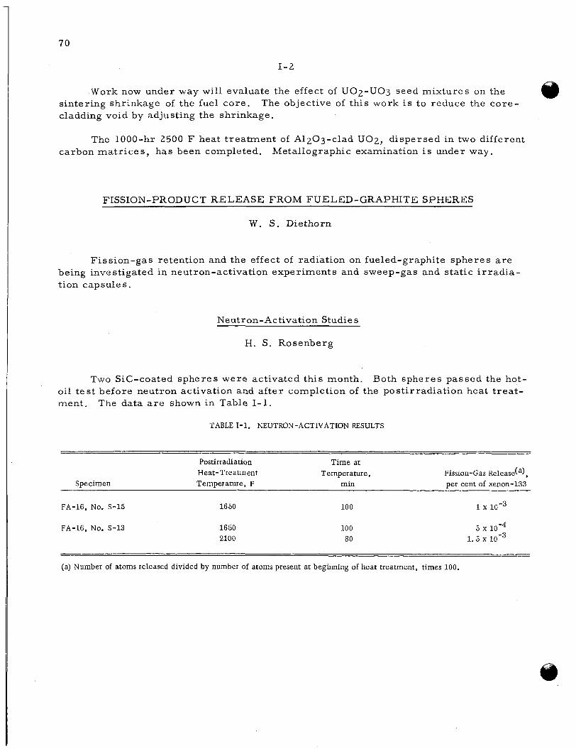
70
1-2
Work now under way will evaluate the effect of UO2-UO3 seed mixtures on the sintering shrinkage of the fuel core . cladding void by adjusting the shrinkage.
The objective of this work i s to reduce the core-
The 1000-hr 2500 F heat t reatment of A1203-clad U 0 2 , dispersed in two different carbon mat r ices , has been completed. Metallographic examination is under way.
FISSION-PRODUCT RELEASE FROM FUELED-GRAPHITE SPHERES
W. S. Diethorn
Fission-gas retention and the effect of radiation on fueled-graphite spheres a r e being investigated in neutron-activation experiments and sweep-gas and static i r r ad ia - tion capsules.
Neutron-Activation Studies
H. S. Rosenberg
Two Sic-coated spheres were activated this month. Both spheres passed the hot- oil t e s t before neutron activation and a f t e r completion of the postirradiation heat t reat- ment. The data a r e shown in Table I- 1.
TABLE 1-1. NEUTRON -ACTIVATION RESULTS
- Postirradiation Time at Heat- Treatment Temperature, Fission-Gas Release(a),
Specimen Temperature, F min per cent of xenon-133 -
FA-16, NO. S-15 1650 100 1 10-3
FA-16, NO. S-13 1650 2100
100 80
5 1.5
(a) Number of atoms released divided by number of atoms present at beginning of heat treatment, times 100.
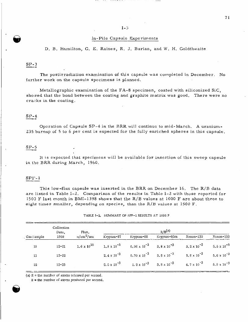
. . . - . . - . . . - . . . . . . - . . . -
7 1
1-3
In-Pile Capsule Experiments
D. B. Hamilton, G. E. Raines, R. J. Burian, and W. H. Goldthwaite
SP- 3 -- The postirradiation examination of this capsule was completed in December. No
fur ther work on the capsule specimens i s planned.
Metallographic examination of the FA-8 specimen, coated with siliconized S ic , sholcled that the bond between the coating and graphite mat r ix was good. c r a sks in the coating.
There were no
SP-4 -- Operation of Capsule SP-4 in the BRR w i l l continue to mid-March. A uranium-
235 burnup of 5 to 6 pe r cent is expected for the fully enriched spheres in this capsule.
SP-5 -- It is expected that specimens will be available for insertion of this sweep capsule
in t5e BRR during March, 1960.
SPI'- 1
This low-flux capsule was inser ted in the BRR on December 16. The R / B data are l is ted in Table 1-2. 1500 F las t month in BMI-1398 shows that the R / B values a t 1000 F a r e about three to eiglit t imes smaller, depending on species, than the R /B values at 1500 F.
Comparison of the results in Table 1-2 with those reported fo r
TABLE 1-2. SUMMARY OF SPF-1 RESULTS AT 1000 F
Collection Date, Flux, R/B(~)
- Gas :;ample 1959 n/cm2/sec Krypton-87 Krypton-88 Krypton-85m Xenon-135 xenon-133 -
LO 12-21 1.6 io1O 1.9 0.96 3.8 10-3 3.2 5.5
I1 12-22 2.4 x 0.70 x 3.8 3.8 x 5.6
12 12-23 2.5 1 .2 10-3 3.8 x 4.7 5.9 10-3
-- ~
(a) R = the number of atoms released per second. B J the number of atoms produced per second.
7 2
1-4
Following’the runs at 1000 F, the capsule was operated a t 1900 F for several days. These la t te r data a r e now being analyzed. This completes the SPF-1 experiment.
SPF-2
This second capsule in the SPF se r i e s i s being loaded with a fueled-graphite specimen, FA-16, No. 15. in Table 1-1.
Neutron activation resu l t s for this specimen a r e reported Target data for BRR irradiation of this capsule is February 1, 1960.
73
J. PROBLEMS ASSOCIATED WITH THE RECOVERY O F SPENT REACTOR FUEL ELEMENTS
CORROSION STUDLES OF THE FLUORIDE -VOLATILITY PROCESS
P. D. Miller, C; L. Pe terson W. N. Stiegelmeyer, and F. W. Fink
The corrosion of components f rom the Unit Operations INOR-8 Fluoride-Volatil- ity dissolver a t ORNL has been examined as par t of a program of ass is tance to the Chemical Technology Division. Re - ceiit metallographic examinations of grain s ize have shown variations f rom ASTM-3 to ASTM-9, apparently randomly distributed 1:hroughout the vessel. The corrosion did no1 appear to be directly re la ted to grain s ize* The accelerated corrosion and large grilin s ize in a salt-inlet line was believed to have been caused by excessive tempera- tur es reached a t the point where electrodes were attached fo r autoresistance heating.
The major resul ts have been reported earlier.
STUDY O F THE EFFECTS OF 1RI.UDIATION ON CLADDING- AND CORE -DISSOLUTION PROCESSES
R. A. Ewing, H. B. Brugger, a n d D . N. Sunderman
Sulfex F'rocess
First tests of the Sulfex process a r e being conducted on 7-in. prototype Consoli- daled Edison fuel pins which had been i r radiated to a low level (300 to 500 MWD/T) at ORNL. pleted, and the third and fourth pins were cleclad and dissolved.
Dissolution of the core of the second fuel pin (previously declad) was com-
Test HS-2 (P in A-117) - This pin had been declad in the previous hot-cell campaign. The 42.2-g residue
was returned to the dissolver and digested with 155 ml of 1 3 M HNO3 core dissolvent for 5 hr . were covered with a white coating, presumably thorium sulfate, and had been attacked 0n:l.y slightly. 100 ml of water; evidently this was insufficient to satisfactorily eliminate sulfate con- tarnination. ) Approximately 50 ml of water was added to the dissolver, and the core pellets were digested for 3 hr, which removed the white coating. After this washing dir,solution proceeded smoothly with a second 155-ml charge of f r e sh core dissolvent, and was complete in 5 h r . bel:n dissolved by the prolonged decladding period necessary because of passivation.
Upon removal of the core dissolvent i t was observed that the core pellets
(The core pellets had been washed after decladding only with the standard
There was no end-cap residue f rom this tes t ; these had
7 4
J - 2
Test HS-3 (Pin A-108)
The surface of this pin appeared to be generally dull, but passivation was absent. The decladding solution was sampled after 3 h r and withdrawn and fi l tered after 6 hr . The declad core pellets appeared to be entirely whole, and no indications of shattering were apparent.
To prevent a recurrence of sulfate inhibition of core dissolution, as in the p re - With this ad- vious test , the core pellets were soaked overnight in 100 ml of water.
ditional washing; no difficulties were encountered; dissolution w a s satisfactorily com- pleted in the standard 8 h r .
Tes t HS-4 (P in A-1961
This tes t was conducted by the same procedure used for Test HS-3, and proceeded routinely to completion.
Future Work
Samples f r o m the first four runs a r e current ly being analyzed and resul ts will be reported next month. pins. i r rad ia ted (-4000 MWD/T) prototype Consolidated Edison pins.
This wi l l complete the Sulfex tes t of the ORNL-irradiated fuel Following similar Darex tes ts , additional Sulfex tes t s a r e planned on MTR-
Darex P r o c e s s
No Darex dissolution t e s t s were conducted during the month. Darex-process tes t s a r e scheduled for January on the two remaining ORNL-irradiated fuel pins.
K- 1
75
.
K. DEVELOPMIENTS FOR SRE
UATION O F URANIUM MONOCARBIDE AS A REACTOR FUEL
F. A. .Rough
Examination of two capsules of i r radiated specimens of a rc -cas t uranium monocarbide current ly in the hot cel l is largely completed. obtained for burnup est imates and on the fission gas contained in the capsules. adc.itiona1 capsules of specimens a r e undergoing i r radiat ion, one of them to an estimated 20,000 MWD/ T burnup.
Additional data have been Two
Irradiation of Uranium Monocarbide h
D. Stahl, J. H. Stang, and W. H. Goldthwaite
Capsule BMI-23-6, containing cylindrical specimens of UC, has been discharged f rom MTR the A- 13-NE position after an i r radiat ion of six MTR cycles, and is being returned to the Battelle Hot-Cell Facility. the final i r radiat ion cycle, Cycle 131, were in the 1300 to 1400 F range. estimated that the burnup for the specimens: is approximately 5000 MWDIT of uranium.
Specimen center-line temperatures during I t is
The i r radiat ion of Capsule BMI-23-4 is continuing in the A-27-SE position of the M?'R for a target burnup of 20,000 MWD/T of uranium; this will require that the capsule be under i r radiat ion until ear ly summer , 1960. De4:ember were in the 1100 to 1200 F range.
Specimen center-line temperatures for
Post i r radiat ion Examination of I r radiated Uranium Monocarbide
S. Alfant and R. F. Dickerson
The pr imary objectives of this program a r e to study the effects of i r radiat ion on ur:.nium monocarbide, and to evaluate i t as a fuel mater ia l for sodium-cooled reac tors . Ser.en capsules were designed and fabricated to conduct radiation tes ts on uranium monocarbide. To date, three capsules witkt specimens containing uranium monocarbide harre been i r radiated and examined.
The examination of specimens f rom Capsules BMI-23-3 and BMI-23-5 is now in prclgress. As reported previously, the postirradiation macroexamination and measure- ments of the density and dimensions of specimens f rom both capsules have been cornpleted. Rallial and t ransverse cracking with some breaking off a t the ends was observed in the 4.0 w/o carbon specimens f rom Capsule BIVII- 23-5, which experienced burnups
Only smal l changes in density and diameter occurred during irradiation.

7 6
K- 2
(est imates based on reactor-quoted fluxes) of approximately 0. 66 a / o uranium (4940 MWD/T of uranium) and 0.70 a / o (5270 MWD/T of uranium) fo r the top and bottom specimens, respectively. The same type of cracking but i n slightly grea te r amounts was observed on the 5.0 w/o carbon specimens f rom Capsule BMI-23-3 which experienced burnups of approximately 1.75 a / o uranium (13,000 MWD/T of uranium) and 1. 93 a / o uranium (14,300 MWD/T of uranium) fo r the top and bottom specimens, respectively. not severe , when compared with the cracking observed i n specimens f rom the previously i r radiated capsules , BMI- 23- 1 and BMI-23- 2. tion of the specimens and the higher burnups experienced i n Capsule BMI- 23- 3 did not appear to have an appreciable effect on the type of cracking but more cracking did occur a t its higher burnup.
Generally, the cracking observed in specimens f rom both capsules was
The differences in composi-
During the pas t month, work was completed on fission-gas analyses, and on burnup calculations based on dosimetry. The fission gas re leased f rom the carbide was determined by analyzing gas samples f r o m the capsules for Krypton-85. no activity was detected in the vials containing the samples of fission gas re leased f rom Capsule BMI-23-3. the samples for Capsule BMI-23-3 were faulty,
However,
The resu l t s of the fission-gas analyses are given below. Obviously,
Capsule Krypton-85 Activity, lo5 dps Total Krypton-85, loo5 an3
B mi .. 23 -3
Bh4I-23-5
No activity detected No activity detected No activity detected
1.06 1.01 1.10
8.22 8.22 8.22
Based on estimated burnup data for Capsule BMI-23-5, the total amount of Krypton 85 produced in the carbide was calculated to be 20. 4 x i t was assumed that the recoi l range of Krypton-85is 8 p , and that the release was one- fourth of the gas generated in the surface layer of 8-p depth. The calculated volume of Krypton-85 gas re leased by recoi l is 8.7 x value of the Kryptonand the amount re leased due to recoil , i t can be seen that the two values a r e practically equal.
cm3. F o r recoi l losses ,
cm3, Upon comparing the measured
Burnup determinations by analysis of the dos imeters which were wound around the specimens have been completed. Table K- 1.
The resu l t s of these analyses a r e given in
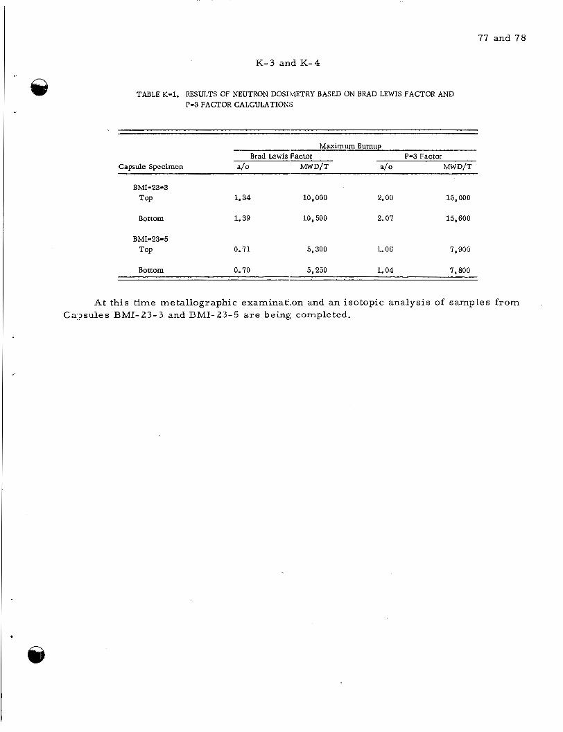
77 and 78
K-3 and K - 4
TABLE K-1. RESULTS OF NEUTRON DOSIMETRY BASED ON BRAD LEWIS FACTOR AND P-3 FACTOR CALCULATION:;
- Maximum Burnup
Brad Lewis Factor P-3 Factor Capsule Specimen a/o MWD/T a/o MWD/T
BMI-23-3 TOP 1.34 10,000 2.00 15,000
Bottom 1.39 10,500 2.07 15,600
BMI-23-5 0.71 5,300 1.06 7,900 TOP
Bottom 0.70 5,250 1.04 7,800
At this time metallographic examinat:ion and an isotopic analysis of samples f rom Ca?sules BMI-23-3 and BMI-23-5 a r e being completed.
7 9
L- 1
L. TANTALUM AND TANTALUM ALLOYS
J. H. !;tang
Studies reported in this section a r e in conjunction with the LAMPRE program at Lo? Alamos Scientific Laboratory. During December, melting of binary tantalum allclys resumed (after a r eces s f rom October to mid-November), but a problem of elet-trode erosion necessitated an interruption in the schedule. plaiining were completed for the execution of a new program directed toward identifica- tiori of phases and determination of solid- solubility l imits of impurit ies in tantalum. F i n a l plans for mechanical-property tes ts of i r radiated tantalum specimens were conipleted, and initial data were obtained on unirradiated control specimens.
Several facets of
Development of Container Materials for Lampre Applications
D. E. Drennan, M. E. Langston, 12.. J. Slunder, and J. G. Dunleavy
During most of December i t was necessary to discontinue temporarily the a r c me lting of binary- tantalum-alloy buttons and concentrate effort on solving a difficulty encountered with particularly severe erosion of the tungsten electrode during melting. In :levera1 melts made ear ly in December, ):his erosion was sufficient to produce intolerable contamination with tungsten. To date, attempts to solve the problem have me: with some success , and i t is expected that a continuing effort can point the way to a complete solution, perhaps by mid-January. I t is hoped that, by the end of January, the arc-melting schedule can be resumed.
Effect of Irradiation Damage of Tantalum
C. K. Franklin, F. R. Shober, and R. F. Dickerson
This program involves a study of the (effect of i r radiat ion on the mechanical propert ies (particularly ductility) of tantalum. Two capsules containing sheet specimens of tantalum were i r radiated a t the MTR, receiving thermal-neutron exposures estimated to tie sufficient to produce tantalum-to-tungsten conversions of 1. 5 and 3. 0 w / o , respectively. These capsules have been opened a t the Battelle Hot-Cell Faci l i ty , and various specimen property evaluations a r e scheduled to be made during January. addition to determination of tensile propert ies , hardness and bend tes ts wi l l be made, the la t ter to obtain a qualitative measure of ductility. will be fixed in a vise and an attempt will bc: made to bend through a 90-deg arc .
In
In this tes t , one specimen end
Various property evaluations a r e being made on unirradiated tantalum and a r c - me lted tantalum-tungsten alloys to obtain baseline data for the evaluation of i r radiat ion effocts. Room- temperature tensile tests completed on four specimens of unirradiated
80
L- 2
annealed tantalum indicated an average ultimate tensile strength of approximately 42,000 psi. was about 50 p e r cent.
The total elongation in 1 in. was 40 p e r cent, and the reduction in a r e a
Precipitate Phase Identification and Interstitial- Type Solid Solubility In Tantalum
D. A. Vaughan and C. M. Schwartz
The composition and distribution of the h i t i a l precipitate phases caused by inters t i t ia l (carbon, nitrogen, and oxygen) impuri t ies i n tantalum are being investigated to aid in understanding the corrosion of tantalum by plutonium fuel mixtures. The solid-solubility l imits of these impuri t ies in tantalum will be determined a t 500, 1000, and 1500 C. should be employed in this investigation in o rde r to avoid metall ic impuri t ies which might modify the solubility study.
Pre l iminary studies have shown that one source of pedigreed tantalum stock
During the past month, a supply of Temesca l tantalum f rom LASL stock (K556-5) This mater ia l is being degassed pr ior to introduction of known amounts was obtained.
of nigrogen o r oxygen by gas-solid reaction. s e r i e s f i r s t , with additions of 1 , 3 , and 5 a / o intersti t ial . examined microscopically and by X-ray diffraction af ter quench annealing f rom 1500 C and af ter heat treating a t 1000 C and a t 500 C.
I t is planned to study the tantalum-oxygen These specimens will be
Also during the l a s t period, the published l i terature was reviewed to aid in the selection of compositions for the initial solubility studies, and to consider the composi- tions of the f i r s t compounds to f o r m in the various systems. compounds a r e reported for both oxides and nitrides of tantalum, there a r e no data on their thermal stabilities o r mode of precipitation. i n the present program.
Although a number of
This information will be obtained
81
M:-1
M. DEVELOPMENTAL STUDIES FOR THE PWR
R. W. Dayton
A 33-in. -long fuel element containing U 0 2 platelets has been examined. The
A 40-in. fuel element was corrosion resis tant and did not exhibit intercompartmental leakage. eirer, metallographic examination showed evidence of contamination. element, made f rom a machined-receptacle plate, warped during bonding.
How-
Fabrication of Large-Scale PWR-Type Fuel P la tes
S. J. Paprocki, E. S . Hodge, and C. C. Simons
The preparation of Zircaloy-2-clad 'compartmented uranium dioxide fuel ele- ments for PWR Core 2 on a production basis is being considered by Bettis. bility of fabricating this type of fuel element by gas-pressure bonding was established f a r small-size fuel plates approximately 15 in. long containing 15 core compartments a ( : ross the width of the fuel plate. In the f i r s t scale-up, the length of the fuel element wil l be increased f rom 15 in. to 33 or 40 in. The width wil l remain constant.
The feasi-
The corrosion testing and metallogr,aphic examination of a Zircaloy-clad com-
The resu l t s of the corrosion testing revealed that, pztrtmented uranium dioxide fuel plate 33 in. long that was bonded 4 hr a t 1550 F at 10,000 ps i have been completed. a i te r a 3-day exposure to 680 F water, there was no growth of the defected compart- ments. a i te r the 680 F corrosion tes t , and no intercompartmental failure was observed. Z trcaloy-2 cladding possessed the character is t ic shiny black film of good quality Z trcaloy-2. wsre generally good, with some evidence (of spotty contamination at the bond interface. It was noted that in several instances grain growth had occurred around spots of con- tamination located at the original bond interface. It was necessary to assemble this slbecimen twice. During the initial assembly, an attempt was made to employ oversize r ibs produced by a production machining process . The r ibs did not permi t a proper a!;sembly of the element; consequently, the element was reassembled with r ib s pro- diiced by another machining process . Contamination of the surfaces during the f i r s t aiisembly that was not completely removed during washing pr ior to the second assembly may have produced the contamination a t the bond interface.
The compartments were tested a t 700 ps i for intercompartmental leakage The
The resu l t s of the metallographic examination revealed that the bonds
Four large-scale PWR Core 2-type specimens measuring 0 . 150 by 4.218 by 40 in. aiid containing 330 compartmented core inser t s were bonded a t 1550 F for evaluation at Bettis and Battelle. t c f i l l both the longitudinal and t ransverse void space in the fuel-element receptacle b1:tween the core and r ibs , while the fourth specimen was assembled without any at- tempt to f i l l void space. All of the specimens were fabricated using a integral cover plate and machined receptacle; consequently, the longitudinal r ibs were not f r ee to rrxove during assembly to take up void space between the cores and r ibs .
Three of these four specimens were assembled using shim stock
A visual
82
M-2
examination of the specimen which was assembled without shims to f i l l longitudinal o r t ranverse void space in the assembled fuel plate disclosed that the side r ibs had moved in toward the cores during bonding and eliminated all the longitudinal void space. however, produced warpage of the specimen. The t ransverse void space wa.s partially filled by the cladding flowing into it, producing cladding depressions. Final evaluation of all of the fuel plates wi l l be based on burs t tes ts , leak tes ts , corrosion tes ts , and metallographic examinations.
This,
a 3
N .-
N. DEVELOPMENTS FOR THE MGCR
W. C. Riley
Research on core mater ia l s in suppo1.t of the MGCR program is in progress a t
Currently, the evaluation Battelle. B e 3 o r A1203 and dispersions of UC and U C 2 in graphite. coiisists mainly of static-capsule irradiation in the MTR and BRR.
The major effort is on the development and evaluation of UO2 dispersions in
A study of carbon-transport corrosion studies has been completed, and a topical rel)ort is being prepared.
FABRICATION AND CHARACTEFLIZATION OF FUEL MATERJALS
A. B. Tr ip le r , Jr .
Work on fabrication and characterization of fuel mater ia l s w a s recessed during December.
HIGH-BURNUP IRRADIATION EFFECTS IN F U E L MATERIALS
W. E . Murr , N. E . Miller, J. E. Gates, a n d R . F. Dickerson
Ceramic-type fuels composed of about 20 volume per cent uranium dioxide in be::yllium oxide, 20 volume per cent uranium dioxide in aluminum oxide, 20 volume pe:: cent uranium monocarbide in graphite, and 20 volume per cent uranium dicarbide in graphite a r e being considered as potential fuels for the MGCR. A program to study the stability of these mater ia l s after various radiation exposures at specimen-surface ternperatures of about 1500 F is in progress . The evaluation of beryllium oxide- and grirphite -matr ix specimens includes the irrmadiation and examination of 24 specimens in 4 instrumented capsules. Each of the four capsules contains six specimens, two of eal:h fuel composition. Each specimen is composed of four fuel pellets, approximately 0. ,!22 in. in diameter by 0. 250 in. long, sealed in Type 316 stainless steel tubing under a itrote ctive helium atmosphere.
The first capsule of this s e r i e s was i r radiated in the Battelle Research Reactor to a specimen burnup of about 1. 1 to 1.7 a / 'o of the contained uranium a t surface ternperatures ranging f rom 1300 to 1550 F. co idition after .irradiation. BAII-1366 and BMI-1377.
The specimens were in good physical The resu l t s of the hot-cell examination a r e reported in
The remaining three capsules, BMI-.31-1, BMI-31-2, and BMI-31-3, have been in the MTR since the beginning of cycle 125 and a r e operating satisfactorily in their
84
N-2
eighth reac tor cycle. Capsule BMI-31-1 experienced an uranium burnup of approximately 9 a/o, those in Capsule BMI-31-2 f rom 3 . 1 to 4.2 a / o burnup, and those in Capsule BMI-31-3 f rom 2.0 to 2.2 a /o. The above values a r e es t imates based on fission power generation calculated f rom fuel temperatures and the heat-transfer character is t ics of each capsule.
During the first six cycles of operation, the specimens in
A summary of the temperature and heater-power requirements of each capsule .during MTR Cycle 131 is shown in Table N-1. couple 2 f rom Capsule BMI-31-1 has failed, leaving three of the six thermocouples still in operation in this capsule. the other two capsules. e lectr ical power necessary to maintain the temperature near 1500 F has increased for Capsules BMI-31-2 and BMI-31-3.
Since issuance of BMI-1398, Thermo-
Four thermocouples a r e still in operation in each of All three hea ters a r e operating in each capsule, although the
TABLE N-1. TEMPERATURE AND ELECTRICAL-HEATER POWER CONSUMPTION FOR CAPSULES BMI-31-1, BMI-31-2, AND BMI-31-3, DURING MTR CYCLE 131
Electrical-Heater Power Consumption, Thermocouple Readinha)
Capsule W No. 1 No. 2 No. 3 No. 4 No. 5 No. 6
M I - 3 1 -1 810 - - - - 148db) 1465 1255 - -
BMI-31-2
BMI-31-3
2340
2720
1395 -- 144o(b) -- 1480 1455
1440 -_ 1450 1430 1495(b) - _ ~~~~~ ~ ~
(a) Specimen-surfaces temperatures are calculated to be 25 to 30 F higher. (b) Designates controlling thermocouple.
A decision has been made to hold Capsule BMI-31-1 in the reac tor and allow i t to accumulate approximately 20 a / o uranium burnup, ra ther than remove it f rom the reactor at the 12 a / o burnup level originally planned.
Exposure of a single capsule in the BRR containing U02-A1203 samples has been completed. examination.
Specimens wi l l be sent to the cooperating laboratory for hot-cell
DIFFUSION OF FISSION PRODUCTS IN CLADDING MATERIALS
S . G. Epstein, A. A. Bauer, a n d R . E. Dickerson
Work on this program has been recessed.
85 amd 86
N - 3 and N-4
CARBON-TRANSPORT CORROSION STUDLES
N. E. Miller, D. J . Hamman, .J. E. Gates, and W. S. Diethorn
Selected metal and graphite specimens have been exposed to radiation in helium- filled quartz to r i designed to promote convective flow of the helium and gaseous im- purities pas t the specimens. repor t is being prepared.
All experimental work has been completed and a topical
87
P .-
P. DEVELOPMENTAL STUDIES FOR THE SM-2
S . J. Paprocki
Studies a r e being conducted in ass is tance to Alco Products to develop fuel, ab- so,:ber, and suppressor mater ia l s for the SIM-2.
Fabrication var iables have been explored and techniques a r e being developed for the fabrication of a reference fuel plate consisting of spherical UO2 fuel and ZrB2 bu:'mable poison dispersed in stainless steel. Use of high-purity ZrB2 and control of the sintering and fabrication process has reduced boron lo s ses to an average value of about 5 per cent. The effect of coatings of niobium and tungsten on ZrBZ in reducing reilction r a t e s and fur ther decreasing boron loss i s being investigated.
Reference and alternate fuel specimens a r e being i r radiated in the MTR and ETR. It j s planned to continue the t e s t s to about mid-February, when the average calculated f iss ion burnup will vary f rom about 30 to 6!5 per cent of the contained uranium-235.
Materials Development
S . J. Paprocki, D. L. K d l e r , G. W. Cunningham, A. K. Fould's, and D. E. Lozier
Fabrication techniques a r e being eval.uated for use in preparing fuel plates, sup- p re s so r components, and absorber plates for the SM-2 reactor. ha-re been selected, and specifications will be established on the bas i s of fabrication s tt .di e s .
Reference mater ia l s
F u e l Materials - The reference fuel element contains a core of approximate r 26 w / o UO, anc 1.
w / o ZrB2 dispersed in Type 347 prealloyecl stainless steel plus a short (1/ 2 in.) end L
- sei-tion of suppressor mater ia l containing approximately 17 w/o Eu203 dispersed in an e1c:mental 18-9 stainless matr ix . thick Type 347 stainless steel. a r e being fabricated for welding studies. 15 plates a r e in various stages of completion. These plates a r e not being prepared by a iitandard procedure, but include minor variations which will provide useful informa- tic.n for establishing fabrication specifications. Small-scale specimens a r e a lso being u s ad to evaluate fabrication techniques.
This 0.030-in. -thick core is clad with 0'. 005-in. - For ty fuel plates containing natural o r depleted U 0 2
Ten of these plates have been completed, and
The fabrication of 28 fuel plates cont(3ining fully enriched UO2 has been previously re?orted. eiltht of the plates were retained at Battelle for evaluation studies.
Twenty of these plates were sent to Alco for cri t ical-assembly tes t s , and Three of these
88
P - 2
plates were sectioned for boron and uranium analyses, with five 1-in. - s q sections be- ing obtained f rom each plate for boron analyses and five s imi la r specimens being ob- tained for uranium analyses. l i s ted in Table P-1. been completed. than the 10 pe r cent excess boron added; thus, based on these values, boron content could be readily maintained within *5 per cent of the total boron. It should also be pointed out that, with no boron loss , l a rge deviations (*lo per cent) a r e possible f rom specimen to specimen even though dimensional variations a r e maintained within tolerance.
The boron analyses and estimated boron losses a r e The uranium analyses and metallographic examination have not
It should be noted that, in general , the boron loss i s considerably l e s s
As previously reported, boron lo s ses can be prevented o r maintained at a very low level during sintering, but boron lo s ses during roll cladding have not been com- pletely eliminated. been prepared, and boron analyses and metallographic specimens a r e being obtained. Another s e r i e s of specimens which will be annealed for various lengths of t ime after roll cladding, and a specimen pickled af ter each hot pass will be prepared and boron analyses obtained. These data will be used to correlate with diffusion data in an at- tempt to propose the mechanism for boron loss.
A se r i e s of specimens roll clad to various stages of completion has
Other than close control of fabrication procedures , it may be also possible to con- t ro l boron loss by the use of metal-coated ZrB2 particles. with coatings of 2 to 3, 4 to 5, and 7 to 8-p-thick niobium have been prepared by the fluidized-bed process , and fuel specimens containing these powders have been prepared for roll cladding. The coated powders a r e being tes ted by X-ray diffraction, metallog- raphy, and chemical and vacuum-fusion analyses. action occurred between the niobium and the ZrB2, and l i t t le o r no oxygen o r other im- puri t ies were picked up during the process . prepared.
Three batches of ZrB2
The first batch showed that no r e -
Powder with tungsten coatings is now being
Other studies in progress include the evaluation and specification of stainless steel powder. vendor have been prepared -but have not been evaluated.
Specimens containing several special powders produced by a commercial
Development of Control and Suppressor Materials
A dispersion of Type 347 stainless steel and Eu2O3 i s presently being considered 3 s a control and suppressor mater ia l for the SM-2. An evaluation study is being con- ducted to determine the optimum method of preparing the E11203 particle s izes and the optimum fabrication techniques for the dispersion. The specimens prepared a r e being evaluated by corrosion testing and metallographic examination. containing 33 w / o Eu2O3 prepared by the KAPL method of sizing par t ic les and dis- persed in a 71-18-11 matrix, was corrosion tes ted at Alco Products, Inc. , and failed within a 24-hr tes t period. same process was fabricated. through the cladding and were corrosion tes ted in 600 F static degassed water at Bat- telle. This set of specimens also failed within a 24-hr tes t period, verifying the p r e - vious results. and the dispersion w a s encased with a low-silicon, stainless steel b a r r i e r foil to
A corrosion specimen,
A duplicate set of specimens containing Eu203 sized by the These specimens were defected by a 0. 040-in. hole
The Eu2O3 incorporated in these specimens contained 0. 01 w /o silicon,
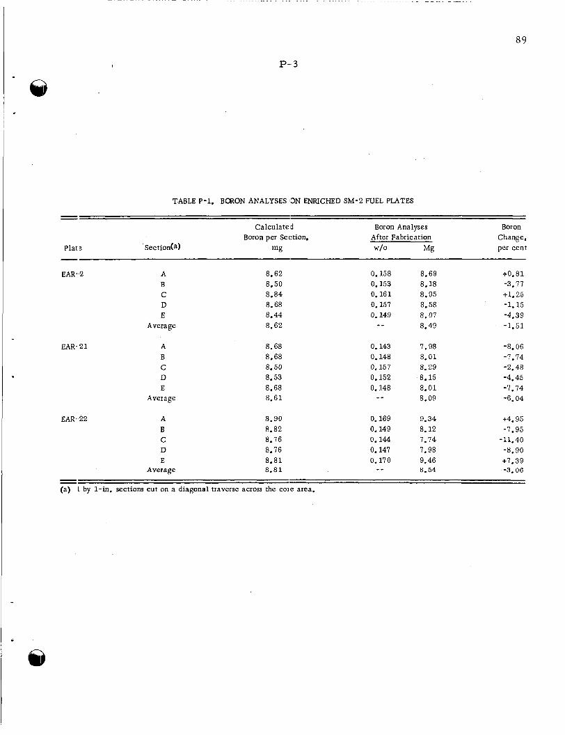
P-,3
. . . . . . . . . . . . . . . . . . . . . . . . . . . . - - . . . - -.
89
TABLE P-1. BORON ANALYSES ON ENRICHED SM-2 FUEL PLATES
- -
Plat e
Calculated Boron per Section.
mg
Boron Analyses After Fabrication
w/o Mg
Boron Change, per cent
EAR-,2
EAR. 2 1
EAR. 22
A B C D E
Average
A B C D E
Average
A B C D E
Average
a. 62 a. 50
8.68 8.44
8.84
8.62
a. 68 a. 68 a. 50 8.53 8.68 8.61
a. 90 a. a2 8.16 8.76 8.81 8.81
0.158 8.69 0.153 a. 18 0.161 8.95 0.157 a. 58 0.149 a. 01
- _ 8.49
0.143 I. 98 0.148 a. 01 0.157 a. 29 0.152 a. 15 0.148 a. 01
a. 09 - -
0.169 9.34 0.149 a. 12
0.147 7.98 0.144 7.14
0.170 9.46 - - 8.54
+o.ai -3.77 +l. 25 -1.15
-1.51 -4.39
-a. 06
-2.48 -4.45 -1.74 -6.04
-1.14
+4.95 -1.95
-11.40
+7.39 -a. 90
-3.06 - - (a) 1 by 1-in. sections cut on a diagonal traverse across the cole area.
90
P -4 I
prevent possible reaction with the wrought Type 347 stainless steel cladding. specimens were also fabricated containing Eu2O3 contaminated with approximately 10 w/o silicon. silicon specimens. taining commercially available minus 100-mesh air-f i red Eu2O3 have shown no weight gain o r dimensional changes after a 24-hr corrosion test . Similar specimens a r e be- ing prepared for corrosion testing at Alco. These t e s t s will be more elaborate than the prel iminary screening t e s t s run at Battelle. All specimens to date have contained an 18-1 1 chromium-nickel-iron matrix and were sintered in a hydrogen-atmosphere furnace. Additional specimens a r e presently being prepared to evaluate the use of a prealloyed Type 347 stainless steel matrix mater ia l and a vacuum sinter.
Corrosion
These specimens failed at approximately the same rate as did the low- Additional specimens fabricated by the same techniques but con-
Encapsulation Studies
J. F. Lagedrost, W. E. Murr , and J. H. Stang
Reference subsize SM-2 fuel specimens and alternate fuel mater ia l s contained in nickel capsules are being i r radiated in the MTR and ETR test facilities. instrumented capsules a r e current ly being i r radiated in core positions of the MTR. of an anticipated total of seven instrumented-capsules i s being i r radiated in the 0 - 6 position in the ETR beryll ium reflector.
Three non- One
The three noninstrumented capsules, designated BMI-32-1 , BMI-32-2, and BMI- 32-3, were inser ted in core positions of the MTR for Cycles 126, 127, and 128, r e - spectively. As of the end of Cycle 131 (December 14), BMI-32-1 had accumulated a total of 2905 MWD and an est imated average specimen fission burnup of 35 per cent, BMI-32-2 had accumulated 2524 MWD and an estimated average specimen fission burnup of 33 per cent, and BMI-32-3 had accumulated 1614 MWD and an estimated average specimen fission burnup of 20 pe r cent. quoted fluxes. February. the cur ren t f iscal year and to draft mater ia l specifications.
These burnups a r e based on reac tor - It i s planned to continue i r radiat ion of these capsules until about mid-
This will then allow sufficient t ime to fully evaluate the specimens during
The first instrumented capsule, BMI-32-4, was inser ted in an ETR beryll ium- reflector position for Cycle 20, which s tar ted on September 12. e lectr ic hea te rs have failed, specimen temperatures at full reactor power have r e - mained close to 600 to 650 F (calculated, based on thermocouple temperatures of 400 F). One of the original four thermocouples i s st i l l operative. During December, the ETR did not operate until the la t te r pa r t of the month. Cycle 24 accumulated 975 MWD and Cycle 25, which s tar ted about December 24, is scheduled to continue until January 10, 1960. es t imated average specimen fission burnup of 17 pe r cent, based on quoted fluxes.
Although the auxiliary
At the end of Cycle 24, Capsule BMI-32-4 had accumulated 5842 MWD and an
The second instrumented capsule, BMI-32-5, is near ly assembled and ready for preshipment checkout of the hea ters and thermocouples. all respects except that a revised heater element-to-lead out wire connector i s used. It i s believed that this connector eliminates some of the possible causes of heater failure in BMI-32-4.
It i s similar to BMI-32-4 in
91 and 92
P - 5 a.nd P - 6
Results of the nuclear-mock-up capsules which were run in the MTR and the ETR to determine flux-perturbation factors a r e being evaluated. Correlation of dosimeter analyses and reactor power-time information is expected to supply the necessary flux data.
A theoretical analysis of heat t ransfer and temperature distribution in the BMI-32 capsule design is also in progress . out at the IBM-704 data-processing installiikion at New York University. he re is to check the original design calcula.tions, which were based pr imari ly on el1:ctrical -analog simulation.
The computational work involved is being ca r r i ed The purpose

93
Q- 1
Q. GAS-COOLED REiACTOR PROGRAM
D. L. Keller
Studies for Aerojet-General Nucleonics (AGN) directed toward the development of The activit ies on the various conkpact gas-cooled reac tors a r e reported i n this section.
t a s l ~ s a r e reported under "Materials Development Program" and "In-Pile-Loop P r c gram".
MATERIALS DEVELOP ME NT PROGRAM
D. L. Keller
Fuel pellets of Be-UO2 containing 25 volume per cent U 0 2 have been successfully fabj-icated for capsule-irradiation tests. sinlered to a density of approximately 98 per cent of theoretical in 2 h r a t 2800 F. The se pellets will be canned in Hastelloy X and a r e scheduled fo r insertion in the BRR for the January 12 startup.
The fuel pellets made f rom LOH grade B e 0
Examination and, evaluation of the U 0 2 , specimens clad with Inconel in Capsules BM[-29- 1 and BMI-29-2 a r e essentially completed. As a resul t of extensive spectro- gra,phic and chemical analyses of the Inconel cladding in the region adjacent to, and including, the melted regions, the cause for melting at low recorded temperatures has been attributed pr imar i ly to excessive s u l f u r contamination of the cladding.
0
Fabrication of BeO-UO2 Fuel Pe l le t s
H. D. Sheets and A. K. Smalley
The objective of this program is to prepare UO2-containing B e 0 pellets for both 1001) and capsule exposures.
During December, 24 pellets about 1 / 16 in. in diameter and 3/32 in. high were prepared for capsule irradiation in the BRR. 25 trolume per cent of MCW ceramic grade minus 325-mesh fully enriched U 0 2 with 75 vrolume per cent of LOH grade B e 0 and suitable binders, cold pressing pellets in a stet:l die, and sintering for 2 h r a t 2800 F in a hydrogen atmosphere. of the sintered pellets ranged f rom 5. 06 to 5. 1 1 g pe r cm3 (about 98 per cent of theoret i - ca l density). pellets a r e not yet complete.
The specimens were prepared by mixing
The bulk density
Chemical analyses and micrographic examinations of representative
Fabrication of about 2500 pellets for a loop-irradiation experiment will be s tar ted as soon as the necessary mater ia l s a r e received.

Q- 2
Encapsulation Studies
J. H. Stang, J. F. Lagedrost , G. E. Raines and D. W Nicholson
Irradiation of Clad Pin- Type Specimens Containing Dense U02
At present , limited heat- t ransfer analyses are continuing to devise reasons for the damage experienced by the clad pin- type specimens in Capsules BMI- 27- 1 and BMI-27-2. A s discussed in BMI- 1398, i t was found that high local cladding tempera- tu res (above 2000 F in some cases) could have been sustained i f fission-heating r a t e s a t the ends of the fueled regions had been unusually high owing to minimum self- shielding effects. undamaged specimens i r radiated in Capsule BMI- 27- 2 were forwarded to NRTS for burnup analyses by mass spectrometry. resu l t s recently received indicate that:
In pursuing this situation fur ther , U 0 2 pellets removed f rom
A total of four pellets was submitted. Burnup
(1) The burnup of a pellet a t the end of a stack (six pellets were stacked in each pin) was only about 10 pe r cent higher than that of a central pellet.
( 2 ) Burnups calculated on the bas i s of change of uranium-235 content were lower by a factor of about 2 than those calculated on the basis of irradiation-history data (capsule temperatures , reactor-quoted fluxes, e tc . )
(3) Burnups calculated on. the bas i s of increase i n uranium- 236 content 0
compare well with those calculated f rom irradiat ion history.
At present , the data involved a r e being studied to appraise various uncertainties associated with them. It s eems , however, that end pellet-central pellet burnup ra t ios are not appreciably different, regard less of method of calculation,. This would indicate that the fission-heat-generation r a t e s along the specimen axes were not variable enough during i r radiat ion to cause substantial thermal gradients on the cladding surfaces.
Irradiation of Specimens Containing MCW Spherical U 0 2 Dispersed i n Stainless Steel
This program involves the i r radiat ion of stainless steel-clad specimens of MCW spherical and ORNL hydrothermal U02 (30 w/o , highly enriched) dispersed in stainless steel . Two specimens of each type a r e contained in Capsules BMI-33-1 and BMI-33-2.
Capsule BMI-33-1 was inser ted in the MTR A-40-SW position fo r Cycle 131, which s tar ted on November 25. maximum adjacent to the specimen surfaces during this f i r s t cycle indicated that the core center-line temperatures were approximately 300 F below the design value of 1650 F. design level.
Thermocouple temperatures of approximately 1200 F
This is in p a r t attributed to the f ac t that the flux is somewhat lower than the In o rde r to provide data mos t useful for the comparative evaluation of
95
, Q- 3
spherical and hydrothermal U 0 2 , the scheduled i r radiat ion of this capsule has been extc:nded f rom three to six MTR cycles. bur iup of 15 per cent instead of the previously specified 9 pe r cent should be reached. Wit11 this revised schedule, the capsule wil l be discharged f rom the reactor about Mal-ch 28, 1960.
In the longer exposure, a specimen fission
Capsule BMI-33-2 has been requested for insertion in an MTR position having a the]-mal-neutron flux about 25 per cent higher than that of the BMI-33- 1 position, This should resul t in specimen-core temperatures near the 1650 F level. The desired 9 per cent f ission burnup of the specimens in this capsule wi l l require three MTR cycles. P r e s e n t information indicates that insertion will take place during Cycle 133 o r 134 shu';down (January 4 o r 25).
1rrz.diation of UO2-Graphite Specimens With an Integral Corr o sion- Gas- Flow S v s tem
As pointed out in previous repor t s of this s e r i e s , this program originally involved a high- temperature capsule-irradiation experiment to be conducted a t the Battelle Research Reactor. notj ce , but a par t ia l effort continued to complete cer ta in laboratory heat- transfer experiments and to complete the capsule design. been completed and have confirmed the feasibility of the design. Until authorization i s givc:n to initiate the assembly of a system for irradiation, fur ther work is not planned.
During October, the actual experiment was postponed until further
These phases of the program have now
Irrztdiation of Specimens Containing; UO? DisDersed in B e 0
This project i s concerned with an investigation of the i r radiat ion stability a t 1725 F of €[astelloy X-clad U 0 2 specimens dispersed in BeO. in an instrumented (hea ters and thermocouples) double-wall capsule. Each specimen contains a 1-in. -long fueled section consisting of six 0. 16-in. -diameter fueled pellets. Each end pellet is 1 / 8 in. long and contains 17 volume per cent U 0 2 (highly enriched); the four central pellets a r e each 3/16 in. long and contain 25 volume per cent U 0 2 (highly enriched).
Six specimens a r e to be contained
During December, the hazards analysis and the design and fabrication of capsule corr'ponents were completed. The present schedule calls for capsule assembly during the f i r s t week of January, and insertion in BRR Posit ion 12 for the January 12 startup. The i r radiat ion will require four 2-week rea.ctor cycles.
Effects of Irradiation
J. H. Saling, W. E. Ivlurr, J. E . Gates, and R. F. Dickerson
A study of the radiation stability of fuel-element mater ia l s fo r compact gas-cooled reac:tors includes (1) the evaluation of encapsulated solid and annularly loaded U 0 2
P
Q- 4
specimens clad with Inconel, and (2) the evaluation of encapsulated specimens of U 0 2 dispersed in graphite and clad with Inconel 702, Hastelloy X, o r Carpenter 20 Cb, and (3 ) the evaluation of in-pile-loop subassemblies containing PWR- type fuel pins of solid U 0 2 clad with Inconel.
Capsule P r o g r a m
Analyses of the cladding mater ia l of specimens f rom Capsule BMI-27- 1 by emis- sion spectrographic techniques have been completed, and prel iminary resul ts of analy- s e s of the cladding mater ia l by wet-chemistry techniques have been obtained. analyses indicate that the cladding mater ia l is principally Inconel, with some contami- nants present in relatively la rge quantities. The emission spectrographic analyses indicate that 3 to 7 w/o boron was present i n the cladding f rom each of the annularly loaded fuel pins, and that approximately 2 W / O boron was present in the cladding of Specimen GE-Solid 8, which was the top specimen in Capsule BMI-27- 1. of the other specimens f rom this capsule contained f rom 0. 1 to 0. 5 w /o boron. quantities of the following elements were also found in the cladding mater ia l : aluminum, calcium, chromium, cobalt, copper, i ron, magnesium, manganese, molybdenum, nickel, silicon, sodium, titanium, uranium, and zirconium, such as aluminum, copper, and titanium were present i n quantities la rger than would be normally expected. indicate that sulfur was also present in the cladding mater ia l . In some cases i t appears that the quantity of sulfur present was g rea t e r than 10 w/o. i n the Inconel would account for the melting of the cladding mater ia l a t the measured i r radiat ion temperatures .
The
The cladding Trace
Some of these elements
The prel iminary resu l t s of wet- chemistry analyses for sulfur
This amount of sulfur
Resul ts of the isotopic analyses of the fuel mater ia l f rom specimens i r radiated in Capsule BMI- 27- 2 have been received, and burnups are presently being calculated f r o m these data. a re completed.
Fission-gas- re lease data will be revised when these calculations
The examination of specimens i r radiated in Capsule BMI- 29- 1 is continuing. This fully instrumented ( three hea ters and six thermocouples) capsule contained six specimens of 8 w/o U 0 2 dispersed i n a graphite mat r ix , each approximately 1. 0 in. long by 0. 260 in. i n diameter . Hastelloy X, Carpenter 20 Cb, o r Inconel 702 tubing. The capsule was i r radiated in the MTR to a n estimated specimen burnup of about 8 a / o of the uranium a t specimen surface temperatures between 1600 and 1775 F. obtained on the s ix specimens were reported l a s t month i n BMI- 1398. specimens showed no change in appearance o r physical dimensions.
In groups of two, the specimens were clad either with 0. 025-in. -thick
Density and dimensional measurements In general , the
Samples of gas obtained f rom inside Capsule BMI- 29- 1 were analyzed with a gamma- r a y spectrometer to determine whether a cladding failure had occurred in any of the specimens during irradiation. samples , indicating that the cladding of all specimens was intact. Quantities as small as 1. 9 x
No radioactivity was detected in any of the gas
microcurie of krypton-85 could have been detected with the spectrometer .
A postirradiation metallographic examination was performed on two specimens, 5X and 6 X , f rom Capsule BMI-29- 1, both clad with Hastelloy X. were sectioned for longitudinal and t ransverse examination of both the core and cladding,
These specimens
97
Q- 5
and were examined metallographically both in the polished and etched conditions. objective of the examination was mainly to determine the condition of the silicon- silj con carbide coating on the graphite fuel specimens and the condition of the Hastelloy X cladding. I t was observed that a considerable reaction zone was present at the silj con carbide-Hastelloy X interface. Presumably, the Hastelloy X los t nickel by preferent ia l diffusion into the silicon coating, resulting in the formation of numerous smal l voids in the Hastelloy cladding. As the nickel content increased in the silicon- r ich coating to about 50 w/o , a nickel-silicon eutectic was formed, permitting melting to occur at about 1760 F. Similar conditions were observed in an unirradiated control spc cimen that was heated for 10 weeks a t li300 F.
The
Additional examinations planned for specimens i r radiated in Capsule BMI- 29- 1 include sampling the gas collected inside the Carpenter 20 Cb cladding on one specimen, macroscopic examination of longitudinal sections of all four remaining specimens, and a niicroscopic examination of one specimen clad with Inconel 702 and one clad with Ca:rpenter 20 Cb.
An analysis of the dosimeter wires removed f rom Capsule BMI-29- 1 i s inprogress . It is not planned to determine the burnup of these specimens by radiochemical analysis.
In- Pile- LOOD Subassemblies
The metallographic examination of sections f rom Subassembly 1B- lyT and chemical analysis of the spacer f rom P i n 1 6 a r e being continued. exzminations will be reported as soon as they become available.
The resul ts of these
GCRE Crit ical- As siembly Experiments
R. A. Egen, D. A. Dingee, W . S. Hogan, and J. W. Chastain
The cr i t ical assembly i s being modified to conduct experiments with a mock-up of
Sixty-one fuel-element positions will be surrounded by a The spacing between adjacent fuel elements in the core wil l
the ML- 1- 1B reactor . 22 in. in diameter and height. 4-in. -thick lead reflector. be nonuniform to produce a radially flattened power distribution.
When completed the active core wi l l approximate a right cylinder
Uranium dioxide dispersed in alumina. and jacketed with Inconel X will be used to fuel the reactor. The inner 7 pins will siniulate 35 volume per cent dispersion of I J 0 2 i n BeO; the outer 12 pins will simulate a 70 volume per cent dispersion.
Nineteen pins will make u.p each fuel element.
During the pas t month many of the core components were fabricated. These in- clude the fuel-element-positioning grid plates, scissor-act ing control blades , and lead reflector. It is expected that the remaining i tems wil l be completed next month to allow the core framework to be assembled.
@ in March. The fuel is expected to a r r ive f rom AGN early
9 8
Q - 6
IN-PILE-LOOP PROGRAM
G. A. F ranc i s
An in-pile recirculating-gas-loop p rogram is being conducted to per form the i r radiat ion of fuel subassemblies for Aerojet General Nucleonics. The program began about 3- 1 / 2 years ago with design of a loop for use in the Battelle Research Reactor. Subsequently, the design of a loop for installation in the Engineering Tes t Reactor was s tar ted.
The loop a t the BRR is between experiments, with irradiation of the sixth subassembly scheduled to begin by mid-February. reinstalled, and the system is now being operated in a final checkout before a specimen is inserted. under the following headings.
The ETR loop blowers have been
The progress on the different phases of the loop program i s reported
BRR Loop P r o g r a m
S. J. Basham and W. H. Goldthwaite
P lans call for a flux run with an AGN specimen designated 1B-2aT during the f i r s t reac tor shutdown in February and the s t a r t of a 4-month irradiation of a specimen desig- nated 1B-2T-1 by mid-February. This schedule is based on the receipt of experiment hazards information in ear ly January and the receipt of the specimens by the middle of the first week in February.
Prepara t ion for the i r radiat ions continued during this repor t period. As a resu l t
The of corrosion which was discussed i n a previous repor t , the decision had been made to replace aluminum tubing in both the p r imary coolant and instrument air systems. change f rom aluminum to stainless s tee l tubing was completed during the regular reac tor shutdown on December 28, 1959.
Near the middle of December, the loop was operated in-pile for a 24-hr period
Gas samples which were taken periodically during the run were analyzed by without a fuel specimen to check for the presence of fuel par t ic les i n the loop tes t section. gamma-ray spectrometry. p resent in quantities measurable by the experimental method being utilized. tes t , i t was concluded that the loop contamination, if any, is too low to be a source of fission-gas-activity problems during future specimen irradiations.
The resu l t s showed that argon-41 was the only isotope F r o m this
The continuous loop-gas-monitoring system was received late i n December. The installation and calibration of the system should be completed during the next r epor t period.
99
Q- 7
ETR Loop P r o g r a m
E. 0. F r o m m , S. L. Cosgrove, J. V. Baum, D. E. Roop, and G. A. F ranc i s
Blower Modification and Tes ts
Subsequent to the installation of the loop and blowers a t the reac tor , the three blo.;vers i n the loop system and the spare blower had been returned to Battelle for mollification to improve their reliability.
A s described in BMI- 1398, one blower was modified and operated a t Battelle for Two other blowers have been modified and a new impeller has
Blowers designated B and C have been returned approximately 800 hr . been machined for the fourth blower. to the site. s i t € and that Blower D will be put on a n extended life tes t a t Battelle.
During January i t i s expected that Blower A will a lso be returned to the
On November 27, Blower B was stopped after operating for 305 hr . This operating period was obtained with the use of Andok 11(711 grease. At the s t a r t of the run, Andok I1C1 grease was forced into the bearings with the manual g r e a s e r s on the blower. blo-ver was s tar ted on November 14, stopped briefly for a n examination of the belt on Nokember 19, and then operated until November 27. froin 189 to 197 F. ins1)ected on November 27, but the impel ler shaft and bearings were not removed f rom the housing. operation.
The
Inlet-gas temperatures ranged Inlet p re s su re was 177 to 189 psig. This blower was partially
The belt was found to have stretched slightly during the f i r s t 100 h r of After readjustment on Novembei. 19, no fur ther s t re tch was noted.
On November 27 Blower C was placed on the tes t stand and operated. This bloiver was operated under the same conditions as Blower B except that the bearings of Blower C were packed with GE Special, an experimental g rease supplied by Shell Oil Company. Blower C was s tar ted and stopped more than 30 t imes a t the s t a r t of the test. coast-down interval. readjusted and checked with a mechanical belt- tension indicator, and then the unit was pressur ized and operated. frorn 191 to 208 F, inlet p re s su res of 184 to 191 psig, and outlet-gas temperatures frorn 220 to 234 F. p m until 8:30 pm some e r r a t i c bearing temperatures were experienced. higltest temperature recorded for Bearing 1 was 173 F. temperature of Bearing 1 was up to 190 F. able: change in temperature during this period. af ter 8:30 pm, the temperature dropped back to 176 F for Bearing 1. othcir operating conditions could be determined during the t ime of the bearing- temperature changes. Blower C was operated until December 10 ai; 8:OO am for a total time of 302 hr.
Each cycle included a power-on interval of approximately 3 sec followed by a The belt stretched only a very small-amount. The belt was
Operating temperatures included inlet-gas temperatures
This unit operated without incident until December 1. F r o m 4:05 At 2:OO p m the
Between 4:OO and 8:30 p m the Bearings 3 and 4 did not show any appreci-
The blower was not stopped, and, No change in
Inlet temperature , p re s su re , and coolant flow remained steady.
Blowers B and C were then dismantled and examined. The details of the grease ana.ysis a r e summarized in a subsequent section of this report.
These units were then crated.
Blowers B and C were @ therl regreased with Shell GE Special g rease , and each was operated approximately 24 hr . On December 20 they were shipped to the ETR.
100
Q- 8
On December 1 7 , Blower A was lubricated with GE Special g rease and assembled fo r operation. af ter a total running time of 151 h r .
This blower operated without incident until December 23. I t was stopped
During the operating periods for Blowers A, B , and C , the operating character is- t i cs of gas-flow ra te versus blower p re s su re r i s e were obtained. that Blower A , before modification of the impel ler and housing, had a p res su re r i s e of approximately 23. 7 ps i compared with a p re s su re r i s e of 21 psi for the modified unit a t a flow ra te of 0. 9 lb p e r s ec and approximately 100 F inlet-gas temperature. impel ler and housing modifications have resulted in a decrease of approximately 11. 4 p e r cent fo r the blower-pressure generation. were exhibited by Blowers B and C.
The resul ts showed
The
Similar changes in character is t ics
The impel ler and housing modifications for all three blowers included 15 holes through the impel ler to balance the operating p r e s s u r e s on the impeller faces , and increased operating clearance for both faces of the impeller. obtained were as follows:
The impeller clearances
Clearance, in. Blower A
Front 0.021 Rear 0.021
Blower B Front 0.025 Rear 0.022
Blower C Front 0.021 Rear 0.017
Other modifications were the same as previously reported for Blower B.
Blower D is being prepared fo r operation a t Battelle during January. It is planned that this unit will be operated fo r a t l eas t 1000 h r to determine the life of a single packing of the GE Special grease.
Analysis of Blower Bearing Grease
When Blowers B and C were dismantled and examined, the GE special g rease ap- peared to be nea re r i t s unused condition than the Andok IrC". this observation, four grease samples were subjected to laboratory examination. samples were designated as:
In o rde r to substantiate The
Sample Description 1 2 3
4
Andok "C" (Standard Oil of N. J . ) , unused Andok "C" after 300 hr in blower bearing GE Special (Shell Oil Sample 1185, ILC
GE Special after 300 hr in blower bearing. SampleX9-1169), unused

101 and 102
Q-9 and Q-10
Analytical data are summarized in the following tabulation:
Oil Soap Content, Loss During Residue(a) - Content,
Sample Amount, w/o Description per cent per cent Analysidb). W/O
1 0.043 Black nonmagnetic: 64.0 34.7 powder
partially magnetic 2 0.272 Black, fibrous material, 63.5 36.1
3 0.171 Brown gum 87.3 9 .5 4 0.342 Gray powder, 87.4 11.4
partially magnetic
(a) That material insoluble in both hexane ancl aqueous isopropanol. (b) Soap is the most likely component to be lost during analysis.
1.3
0.1
3.0 0.9
The insoluble residue in unused Andok 'IC" grease (Sample 1) was probably co itamination resulting f rom the use of contaminated components o r dir ty processing eqliipment. probably an additive component (this greast? is suspected to contain an antibleeding additive).
The brown, gummy residue f rom unused GE Special g rease (Sample 3) was
The following conclusions may be drawn f rom these data:
(1) Both g reases permitted a small, approximately equal amount of wear during bearing operation.
(2) Neither grease showed significant bleeding under the conditions of use.
In view of these conclusions, the GE Special g rease , because of i t s much higher oil content, was selected for use in this bearing application.
LOOD Checkout and Testing a t the Reactor
The pref i l ter and d rye r to t rea t plant air for use as emergency in-pile-tube coolant ha:j been installed and used. a t the reac tor si te, installed in the loop, and put into operation.
Late in the repor t period, Blowers B and C were received
The change of the loop control of a variable-flow basis was completed. The testing of the new control system cannot be completed until the e lectr ical preheater is opera- tional. At present the e r r a t i c heater control is being studied by the supplier, the manu- fac turer , the reac tor operator , and the experimenter. The inser t ion of the f i r s t experi- ment i n the loop during January could be delayed if the heater is not available for both flow- control tes ts and the experiment itself'.
R VrD : CR T / all z