Embed Size (px)
Citation preview

SYSWINSoftware Programming Tool forOMRON Programmable Logic Controllers
VERSION 3.4
For use with IBM compatible 486 and Pentium computerswith Microsoft Windows

II User Manual OMRON SYSWIN
OMRON SYSWIN User Manual Published October 1999Document Reference SYSWIN-EMAN-3.4
The information in this document has been checked carefully and is believed to be entirely reliable. However, noresponsibility is assumed for inaccuracies. Furthermore, OMRON reserves the right to make changes to any productdescribed herein to improve reliability, functionality and design. OMRON does not assume any liability arising out of theapplications or use of the product described herein, neither does it convey any licence under its patent rights or the rights ofothers.
Copyright © 1996-1999 OMRON Europe B.V. All rights reserved.
OMRON is a registered trademark of OMRON Manufacturing of the Netherlands BV. IBM, PC/AT are registeredtrademarks of International Business Machines Corporation. Microsoft is a registered trademark and Windows is atrademark of Microsoft Corporation.

CONTENTS
User Manual OMRON SYSWIN III
1. GETTING STARTED WITH SYSWIN......................1-1Welcome to SYSWIN................................................1-1Contacting Technical Support...................................1-2Licence Registration Information ..............................1-2About this Manual .....................................................1-3SYSWIN Features.....................................................1-4Introduction to Controller Link ...................................1-4System Requirements...............................................1-5Token Copy Protection .............................................1-6Installation.................................................................1-8Starting SYSWIN ......................................................1-9Configuring the SYSWIN Environment ...................1-10SYSWIN Help System ............................................1-10
2. WORKING WITH PLC PROJECTS.........................2-1Program Structure.....................................................2-1Setting Up a Project ..................................................2-2Project Setup ............................................................2-3Project Information....................................................2-4Creating Ladder Programs........................................2-4Ladder Programming Workspace .............................2-6Creating a Network ...................................................2-7Editing Networks .....................................................2-11Saving and Loading Projects ..................................2-13Editors.....................................................................2-14Statement List Editor...............................................2-15Address Symbol Editor ...........................................2-16Network Symbol Editor ...........................................2-18Block / Network Manager........................................2-19Block Symbol Editor................................................2-20Checking the Program ............................................2-21Global Editing - Find and Replace ..........................2-21On-Screen Cross Reference...................................2-23Printing the Project..................................................2-24
3. TESTING WHILE CONNECTED .............................3-1Working While Connected ........................................3-1Checking Project Parameters ...................................3-2PLC Modes of Operation ..........................................3-3Downloading PLC Programs.....................................3-3Verifying PLC Programs ...........................................3-4Uploading PLC Programs .........................................3-5
PLC Status................................................................3-6I/O Generate.............................................................3-6Executing and Monitoring Programs ........................3-7Online Editing ...........................................................3-8Ladder Monitoring Checks........................................3-9Data Set Bar ...........................................................3-10Setting Data Values................................................3-11Forcing Address Bits ..............................................3-12Other Functions ......................................................3-14
4. DATA DISPLAY EDITOR ........................................4-1Setting Up the Data Display Editor ...........................4-3Editing Data Items ....................................................4-4
5. DATA TRACE AND TIME CHART MONITORING..5-1Configuring the Trace ...............................................5-2Recording the Trace .................................................5-3Reviewing the Trace.................................................5-3
6. CONFIGURING PLC SPECIFIC FEATURES..........6-1Function Mapping .....................................................6-1Memory Allocation ....................................................6-2I/O Table Editing.......................................................6-2PLC Setup ................................................................6-9
7. ADVANCED PROJECTS.........................................7-1Project Setup Dialog.................................................7-1Conversion to Other PLCs........................................7-3Project Preferences ..................................................7-3Project Password......................................................7-5Processing the Program ...........................................7-6
8. ADVANCED COMMUNICATIONS ..........................8-1Connection Guide.....................................................8-1Information Guide .....................................................8-7Procedures Guide...................................................8-13Bridging Guide........................................................8-19Dialogs Guide .........................................................8-22

CONTENTS
IV User Manual OMRON SYSWIN
9. ADVANCED FUNCTIONS ...................................... 9-1Function Plan Editor ................................................. 9-1Importing a Project From Disk.................................. 9-2Maintaining Libraries ................................................ 9-2Templates................................................................. 9-3Producing EPROMs ................................................. 9-4Saving to PMF File Format....................................... 9-4Converting Projects From Other Packages.............. 9-5
10. CONFIGURING THE ENVIRONMENT ............... 10-1Global Preferences - Ladder Diagram /Function Plan ......................................................... 10-1Global Preferences - Data Display ......................... 10-5Global Preferences - Data Trace / Time ChartMonitoring............................................................... 10-6.INI File Preferences............................................... 10-6
11. ADVANCED INSTALLATIONS........................... 11-1Operating System Installation Guide...................... 11-2Connection Guide................................................... 11-7Procedure Guide .................................................... 11-9
APPENDIX A - SYSWIN FILE TYPES........................A-1
APPENDIX B - FORMAT SPECIFIERS......................B-1
APPENDIX C - FILE FORMATS.................................C-1PMF Files ................................................................ C-1Section Types and Descriptions.............................. C-2ADR Files ................................................................ C-5
APPENDIX D - SCREEN REFERENCE......................D-1
APPENDIX E - PLC INTERFACE CABLECONNECTIONS ..........................................................E-1
INDEX

1 GETTING STARTED WITH SYSWIN
User Manual OMRON SYSWIN 1-1
1 GETTING STARTED WITH SYSWIN
Welcome to SYSWIN
The OMRON SYSWIN software is designed for use withSYSMAC C and CV series Programmable LogicControllers (PLCs). It provides a straightforward method ofcreating and maintaining programs and testing theiroperation, either offline or connected to a PLC.
SYSWIN offers a comprehensive range of facilities for thePLC programmer, from program editing to full symbolicand network debugging, including:
■ New program creation
■ Program storage and editing
■ Uploading and downloading code to a PLC
■ Program status during execution by PLC
■ Commenting programs:Symbolic addressesSymbolic block and network namesComments
■ Maintenance of library files
■ Printing program and documentation
■ Conversion from other packages
SYSWIN runs in the Microsoft Windows environment(version 3.1 or greater) on standard IBM and compatible486 and Pentium-based desktop computers. SYSWIN isintuitive to use, and allows the programmer to rapidlyconfigure a specific project and enter network and programdata. PLC programs can be constructed in either ladder orfunction plan format, and previously tested networks can berecalled from libraries. A special statement list editor allowsPLC programs to be viewed and checked in their mnemonicformat.
These features are designed to enable users to easily adaptPLC programs to changing requirements. Additionalfeatures allow the testing of new networks in a supportiveand safe environment.
The SYSWIN software can communicate with both C andCV series PLC. Serial communications with the PLC can bethrough RS-232C or RS-422 serial interfaces with orwithout a modem. Network Service Boards can be used inthe PC to attach to the PLCs using SYSMAC-LINK orSYSMAC-NET networking.
Communications are handled transparently, leaving theprogrammer free to focus on the coding aspects of aparticular PLC project.
NOTE! It is very important that you register your copyof the SYSWIN software with your localOMRON Sales Office, in order to qualify fortechnical support. OMRON is not able to helpyou unless you have registered.

1 GETTING STARTED WITH SYSWIN
1-2 User Manual OMRON SYSWIN
Contacting Technical Support
If you follow the installation instructions for the copyprotection system in this chapter and in the AdvancedInstallations chapter you should not encounter anydifficulties. However, if you have a problem, then contactCustomer Services.
If you have a problem, it is important that you check that itdoes not relate to a fault outside SYSWIN. It is essentialthat you check the following:
■ The PC is working correctly
■ The PLC is working correctly
■ The communications system is set up correctly
■ The errors are cleared in the PLC
When you need to contact Customer Services, fill in thedetails in the form below. A clear and concise description ofthe problem is required, together with the exact text of anyerror messages.
Version number of SYSWIN
Licence Number of software
Registration Number of software
Operating system and version number
PLC type, model and CPU details
Type of communications in use
Serial
SYSMAC-LINK
SYSMAC-NET
Controller Link
Ethernet
Licence Registration Information
SYSWIN V3.4 takes advantage of a different method ofLicence Registration, which replaces the Software Tokenand Hardlock (Dongle), which were used on previousversions.
On the back of the CD-ROM box, and incorporated in thelabel of Diskette 1, is a“Licence Number”.e.g. 11111-22222-33333-44444-55555You will be asked to enter this during installation of thesoftware. The number must be entered exactly as it isprinted.
After installation of the software, a“Registration Number”is displayed in the software information under the“Help”dropdown menu.e.g. aaa-bbb-ccc-ddd-eee
When the“Software Registration Card” is filled in, boththe“Licence Number” and the“Registration Number”are required. Support for your software may not beavailable if it is not registered.
If an existing Token or Hardlock are present on a PC, andSYSWIN is installed over a previous version, you will notbe asked to enter the licence number. After installation a“Licence Number” can be entered by selecting“ActivateSYSWIN” from the“Help” dropdown menu.
1 GETTING STARTED WITH SYSWIN
User Manual OMRON SYSWIN 1-3
About this Manual
This User Manual will help you to get started withSYSWIN, by describing the software installation andcomputer configuration, and by leading you through thebasics of SYSWIN programming. It also provides a detailedreference for all of the on-screen SYSWIN functions.
Separate OMRON manuals describe the PLC programmingstructure and instruction set in detail. Some small exampleprograms are included with the SYSWIN software, todemonstrate some of the most commonly used features, andif you are new to PLC programming, you can work throughthese to familiarise yourself with the software.
SYSWIN comes with a comprehensive context-sensitiveonline help system, which is designed to complement thismanual, and provide a quick reference at any point in theSYSWIN application when the manual is not to hand. Thisgeneral help system allows you to obtain progressively moreinformation about any topic by selecting keywords withinthe descriptive text. In addition, quick help is provided forall PLC instructions.
Throughout this manual, it is assumed that you have aworking knowledge of Microsoft Windows, and know howto:
■ Use the keyboard and mouse
■ Select options from Windows menus
■ Operate dialog boxes
■ Locate, open and save data files
■ Edit, cut and paste text
■ Use the Program Manager or taskbar
If you have not used Windows before, it is recommendedthat you spend some time working with it using theMicrosoft documentation, before using SYSWIN.
This introductory section deals with several importantaspects of installing and setting up SYSWIN. Werecommend that you read the entire section, especially thenotes on copy protection, before installing the software.
Manual Conventions
For quick reference on how to do certain tasks, instructionsequences are in bold type and arrowed (for example ➧ Click onthe OK button).Words in bold capitals (for example: File|Open) refer to commandsin the SYSWIN menus.Words in italics (for example: Save Program) are used for optionssuch as check boxes and buttons in dialogs.Keyboard combinations are indicated by the key names to bepressed together, for example Shift+F6.
Special Symbols
The ➧ character points to an instruction
Special instructions for C series PLCs
Special instructions for CV series PLCs

1 GETTING STARTED WITH SYSWIN
1-4 User Manual OMRON SYSWIN
SYSWIN Features
This new version of SYSWIN V3.4 offers increasedfunctionality for the creation and testing of PLC programsand increases the range of PLCs it supports.
Features in SYSWIN V3.4
■ Support for the SYSMAC ALPHA PLCs with 3digit Expansion Functions
■ Controller Link Protocol Support
■ Communications with C-series PLCs usingEthernet via the PCMCIA interface
■ Communications with a CV-series PLC usingEthernet
■ Communications with a PLC via a C200H�Bridge using SYSLINK
■ Import and export of data between SYSMAC-CDMand SYSMAC-SCS
■ CV Memory Card support
■ Error history log
■ Project password protection
■ Program Password protection
■ Unit Setup
■ Advanced Installations
■ Support for updates to C200HX(CPU65 andCPU85)
■ Additional PLC set up for C Series PLCs
■ Additional CV I/O Table support
■ C Series I/O Table support
■ Memory Card Support for CV Series PLCs toallow for partial download
New features in SYSWIN V3.4:
■ Support for the CQM1H PLC type
■ Additional PLC setup support: High Speed CounterSettings for CPM1, CPM1A, CQM1, and CPM2PLC types; Analogue settings for CQM1 (CPU45only).
Introduction to Controller Link
SYSWIN additionally supports the Controller Linknetwork. The Controller Link is an FA network that cansend and receive large data packets flexibly and easilyamong the OMRON C200HX/HG/HE PLCs, CV seriesPLCs and IBM PC/AT or compatible computers.
The Controller Link supports data links that enable datasharing and a message service that enables sending andreceiving data when required. Data link areas can be freelyset to create a flexible data link system and effectively usedata areas.
The network is connected using shielded twisted-pair cable,and high-volume data transmissions at high speed enableconstruction of a wide range of networks, from low levelsystems to high.

1 GETTING STARTED WITH SYSWIN
User Manual OMRON SYSWIN 1-5
System Requirements
SYSWIN operates on IBM and compatible personalcomputers with 80486 or better central processors,including Pentiums. It should be possible to fully installSYSWIN on any computer that can run Windows 3.1software.
The following configuration is recommended as a minimumsystem for running SYSWIN effectively:
■ 50 MHz 80486 or better CPU, running in enhancedmode (90 MHz Pentium Processor isrecommended)
■ At least 8 Mbytes RAM(16 Mbytes RAM recommended or 32 Mbytes forMicrosoft Windows NT users)
■ Hard disk storage with at least 10 Mbytes of freespace
■ VGA or better display system (800 x 600 SVGA orhigher resolution is recommended)
■ Microsoft Windows 3.1 or higher (MicrosoftWindows 3.11 for Workgroups is recommended)
■ Mouse
It is possible to run SYSWIN in CPM1 or Demonstrationmode on any machine that can run Windows software.
If you intend to connect a PLC to the computer forexecuting program code and testing, you will require:
■ RS-232C connection via a standard serial port onthe computer (COM1 etc.), or
■ RS-422 connection, or
■ SYSMAC-LINK Network Service Board, or
■ SYSMAC-NET Network Service Board, or
■ Controller Link Service Board, or
■ Ethernet
Refer to the appropriate hardware system manuals for fullinformation about connecting and configuring these devicesfor your environment. The Advanced Communicationschapter in this manual provides detailed guidance on how touse SYSWIN for setting up communications. Generalinformation about cabling requirements is given inAppendix E.
NOTE! Windows 3.1 is not compatible with Ethernetconnections unless this service is provided by athird party package

1 GETTING STARTED WITH SYSWIN
1-6 User Manual OMRON SYSWIN
Token Copy Protection
A copy protection mechanism within SYSWIN preventsillegal use of the software by locking it to a specific harddisk. The mechanism consists of an operation token, whichmust be installed on your system before you use thesoftware. When SYSWIN is running, it looks for anoperation token, and runs in demonstration mode if it is notfound.
PLEASE READ THIS SECTION CAREFULLY! There aresome important points to note about this copy protectionsystem and how it might affect your computer.
InstallationIf you are installing on a non-standard configuration, that is,not using either Windows 3.1, Windows 3.11, Windows 95,Windows 98 or Windows NT , you should read theAdvanced Installations chapter before attempting to installthe operation token.
When you install the operation token that protects yoursoftware, certain files are created on your system that arenot normally visible. It is important that these hidden filesare not moved or deleted. If they are, the operation tokenwill be damaged, and SYSWIN will not work.
If you ever see the names of the hidden files on your screen,be careful: you may be about to invalidate your valuableSYSWIN software!
RestrictionsYour operation token must be transferred back to the masterdiskette, for example, if you need to move SYSWIN to adifferent computer, or in certain other situations. The tokencan only be transferred to or from an operation tokendiskette. You cannot install the token to a RAM disk.
System BackupMost backup utilities do not touch the hidden files createdby the protection mechanism. However, some utilities allowyou to backup and restore hidden files. This option shouldnot normally be used, because it would cause the protectionmechanism to consider the token invalid. The hidden filesused by the protection mechanism do not have the Archivefile attribute set, so it may be possible to restrict a backup tofiles with this attribute set.
File MaintenanceSome file management utilities (for example: Xtree, andNorton Utilities) list hidden files, and can move them toother directories, or remove them from the system. Usingthis type of software, you may delete the SYSWIN copyprotection files accidentally. If any software mentions thesefiles during a maintenance operation that removes files,immediately STOP what you are doing, and move the tokenback to the SYSWIN master token diskette, using the TokenMover. Re-install the token after all maintenance has beendone.
Disk Cache OperationCertain disk caching software interferes with the installationof SYSWIN, and should be disabled temporarily during theinstallation process. The /d option of MultisoftCorporation’s PC-Kwik utility should be disabled, forexample. HyperCache has a non-standard option foraccessing diskettes, which should also be disabled duringinstallation.

1 GETTING STARTED WITH SYSWIN
User Manual OMRON SYSWIN 1-7
Disk CompressionThe copy protection mechanism is compatible with disksthat have been compressed with programs such asSuperStor, Stacker, DoubleSpace and DriveSpace.However, SYSWIN must be moved back to the masterdiskette when installing any of these compression systems,as mentioned in their manuals. Failure to do so can causethe protection mechanism to consider the token invalid.
Disk DefragmentersSYSWIN’s copy protection mechanism is compatible withand not affected by disk defragmenters such as CentralPoint’sCompress, Digital Research’sDiskopt, Stac’sSdefragand Microsoft’sDefrag.
Backing Up SYSWIN Token DiskettesThe token diskettes each contain a ‘fingerprint,’ which iswritten to a non-standard track. This prevents them frombeing copied, even by advanced disk copying programs.You cannot, therefore, copy these diskettes for backuppurposes. If the masters become damaged or lost, you mustcontact Customer Services for a replacement.
The SYSWIN program diskettes can be backed up,however, to allow the masters to be stored in a safe place.
NOTE! If you are in any doubt about whether any of theactions you may perform could cause you tolose tokens, move the token back to the tokendisk.

1 GETTING STARTED WITH SYSWIN
1-8 User Manual OMRON SYSWIN
Installation
Installing the SYSWIN Software
This section deals with the installation of SYSWIN on astandard workstation. For installations related non-standardworkstations please refer to Chapter 11.
The SYSWIN software is supplied on CD-ROM or on high-density 3.5” diskettes, and is installed easily from withinWindows.
Installing from CD-ROMStart Windows and insert the SYSWIN CD-ROM in the CDdrive. If Autorun is enabled (Microsoft Windows 95,Windows 98 or Windows NT only), the setup programstarts automatically. The setup program can be startedmanually, by following the instructions in theREADME.TXT in the root directory of the CD.
Installing from Floppy DiskStart Windows and insert SYSWIN Program Diskette #1 ina suitable diskette drive (our example uses Drive A:). Toinstall SYSWIN:
➧ Launch the Run dialogChoose Run... from the Start button from the taskbar(Windows 95, Windows 98 or Windows NT only) orfrom the Program Manager File menu (Windows 3.1 orWindows 3.11 for Workgroups only). The Run dialogappears.
➧ Enter the installation command lineType the diskette drive letter and the SYSWIN Setupprogram (for example: A:\SETUP).
➧ Start the Setup programClick on the OK button. The installation begins.
Further dialogs appear during the installation:
■ Select your desired language for SYSWINoperation.
■ Enter a path name under which to store theSYSWIN program files.
■ Select the operation mode as instructed. To fullyactivate SYSWIN type in the Licence Numberexactly as shown on the CD-ROM or Diskette. Thisdialog is not shown if SYSWIN has already beenfully activated with a token or valid LicenceNumber.
Once these are completed, the appropriate files are copied toyour hard drive or the network drive. If necessary, you areprompted to insert other Program Diskettes when thesoftware requires it.
SYSWIN V3.4 is fully activated by entering the LicenceNumber shown on the CD-ROM or Diskette. SYSWINV3.4 can also be fully activated using a token or donglefrom previous version of SYSWIN. For details on usingtokens and dongles, consult the original documentationshipped with the previous version, and chapter 11 of thismanual.

1 GETTING STARTED WITH SYSWIN
User Manual OMRON SYSWIN 1-9
Starting SYSWIN
Initial Screen
After the software installation, a new group window forSYSWIN is created. The software is ready to run, and canbe started by double-clicking on the SYSWIN icon.
If the default preferences have been used, theAutomaticallyconnect to thePLC facility will be set and SYSWIN startsby checking that the selected communications port isavailable. It then attempts to connect to the PLC. If the portis not available it displays an error message but stillcontinues.
When SYSWIN first starts up, it displays a window similarto the one shown below. The SYSWIN window offers manyfeatures to ease the process of programming, using themouse or keyboard or both. You can configure the displayfor any size monitor so that you have as much or as littleinformation as you need, using options from thePreferencesmenu (see Chapter 10). Any changes you makeare saved in the SYSWIN.INI file and are restored next timeyou run SYSWIN.
Use this section to familiarise yourself with the layout of theSYSWIN display, and to set it up as you desire forprogramming.
1 GETTING STARTED WITH SYSWIN
1-10 User Manual OMRON SYSWIN
Configuring the SYSWINEnvironment
SYSWIN is supplied with default settings that are suitablefor the first time user and there is no requirement for theseto be changed when starting the system. These are globalsettings and apply to all projects. These settings, for theDrawing, Window, Editing and Options, are listed inConfiguring the Environment chapter where all the optionsare described. All settings may be viewed by selectingPreferencesfrom the Menu Bar and selecting theappropriate item.
Project Preferences, which are local settings for eachproject, are discussed in the Working with PLC Projectschapter and are detailed in the Advanced Projects chapter.
SYSWIN Help System
SYSWIN comes with a detailed context-sensitive helpsystem. At any time while using the software, you can gethelp on the particular point at which you are working, or ongeneral aspects of SYSWIN. This system is intended tocomplement the manual, by providing online reference tospecific functions of the software and how to use them. Themanual is designed to provide more tutorial information anddiscuss the various facilities offered by SYSWIN.
Three levels of help are provided in the software: GeneralHelp, for dialogs, messages and menus; Quick Reference,for programming reference; Instant Help, providing briefdescriptions of commonly used commands.
= GENERAL HELP
General help is obtained by pressing theF1 key or byselecting an option from theHelp menu. This providesdescriptive help on SYSWIN menus and dialogs, as well asguidance on messages. It can be used at any point in thesoftware, to take you straight to the topic on which you needhelp. The Help menu can be accessed from the main screeneditors, and is best used when you are browsing for help onthe use of SYSWIN.
+ = QUICK REFERENCE
Detailed help on programming elements - functions, timersand counters, editing and function selection dialogs - can beobtained by pressingCtrl+F1 while the desired element ishighlighted. This is termed Quick Reference, since itdisplays a summary of the necessary programminginformation for any specific item.
If there is not a valid instruction highlighted then QuickReference starts up on the contents page and allows you toclick on any item to have help information displayed.
In the Statement List EditorCtrl+F1 can also be used in thesame way if you place the cursor over an instruction.

1 GETTING STARTED WITH SYSWIN
User Manual OMRON SYSWIN 1-11
When the bubble help facility (see the Configuring theEnvironment chapter) is switched on, a brief description ofeach button is displayed when the cursor is positioned overit for a few seconds.
Status Bar
There is a general status bar at the bottom of the SYSWINscreen. This provides several helpful pieces of informationwhile programming:
Instant Help A brief message appears in the StatusBar as menu commands and buttons areselected. This field normally shows thecurrent block and network information.
Step Number This is the step number of the firstinstruction in the network.
Cursor position The point in the ladder program wherethe cursor is currently located.
Online Editstatus
The online status.
PLC mode When connected to a PLC, this showsthe current PLC mode. Connectionerrors are also displayed here.
PLC scan time This field is only shown when the PLCmonitoring is active, and indicates thescan time for the currently executingprogram.
The SYSWIN status bar can be enabled and disabled withthePreferences|Windowdialog.

1 GETTING STARTED WITH SYSWIN
1-12 User Manual OMRON SYSWIN

2 WORKING WITH PLC PROJECTS
User Manual OMRON SYSWIN 2-1
2 WORKING WITH PLC PROJECTS
Program Structure
Although it is possible to create a program that consists of asimple series of networks, SYSWIN encourages you tobreak down a program into groups of networks, which formfunctional blocks.
The concept of programming in blocks is designed not onlyto make it easier for you to work through a program, bysplitting it into manageable chunks, but also to maintain theprogram after it has been in use for a while. Programming inblocks also eases the process of creating library modulesthat can be incorporated into future programs.
SYSWIN encourages the creation of groups of networkswithin blocks, again promoting the concept of working in astructured manner, as shown in this example:
Typical SYSWIN program hierarchy
2 WORKING WITH PLC PROJECTS
2-2 User Manual OMRON SYSWIN
With CV series PLCs, interrupt routines are held in separateblocks, and main blocks are sequential and joined together.For both C and CV series, the last block in the mainprogram must contain the END instruction, as normal.
Way of Working
Normally you would not be connected to the PLC whenpreparing the main structure of a program. Afterprogramming you would check the program carefully beforeconnecting and downloading it to the PLC. Checking ofprogram syntax and validity of functions is done bySYSWIN at various times as a protective mechanism, butany logical checking that you do speeds up the debuggingprocess.
The use of theProject|Program Checkfeature describedlater in this chapter should be noted to ensure that theprogram you are creating is compatible with the PLC youpropose to use.
However, SYSWIN’s editing features make it very practicalfor you to program more interactively while connected,especially if the PLC has no critical outputs connected. Thisway, your program is verified as each new network isentered, and the project is kept constantly up to date as aworking system.
Setting Up a Project
When planning a PLC programming project, various itemsneed to be considered and set up within SYSWIN beforebeginning to lay down program instructions. For example, itis important for SYSWIN to know the model andconfiguration of the PLC you wish to program, so that it canestablish the correct program checking and communicationsfor that PLC. Programming should, wherever possible, bedone for the PLC that is to be used. Once set for a project, itis not advisable to change the PLC, and preparation of aninitial specification for the program is thereforerecommended.
Project Checklist
Before programming, it is recommended that you make up achecklist of the important program aspects, including itsstructure and PLC parameters. To start a new project inSYSWIN, you should follow these steps in addition to thebasic procedure outlined in your PLC programming manual:
➧ Determine essential parameters of the PLCThe SYSWIN project setup needs to know:
PLC series (C or CV)PLC type (C200H, CQM1, etc.)CPU (where applicable)Type of communications interfaceYour choice of editor and project type.
➧ Assign specific project informationText information should be provided at least for:
Company name or originatorProject and version number.
➧ Check the project preferencesDetermine how you want the project to be displayed,and how the statement list code is to be generated.
➧ Allocate PLC memory (where applicable)Work out the balance required between programmemory and expansion data memory.
2 WORKING WITH PLC PROJECTS
User Manual OMRON SYSWIN 2-3
➧ Establish the PLC setup parametersConfigure the parameters necessary for the desired wayof running the PLC. Some C Series PLCs do notsupport this function.
➧ Create the appropriate I/O tableList all I/O devices and addresses related to them. SomeC Series PLCs do not support this function.
➧ Create a basic structure for the programNote how you plan to group functional networks tomake up program blocks (for example: startup, control,shutdown).
➧ Decide how to input and edit the programSYSWIN offers two main methods of working on aprogram: ladder diagram and function plan. TheStatement List Editor allows you to view and checkprograms at the instruction level, once a diagram hasbeen created.
NOTE! While you can switch between ladder andfunction plan editing as you work, it is stronglyrecommended that you choose one method andcontinue with it for best progress.
Project Setup
This dialog, accessed with theProject|Project Setupcommand, establishes the PLC type, so that SYSWIN canperform proper checks while you work. It also appearsautomatically when you select theFile|New command.
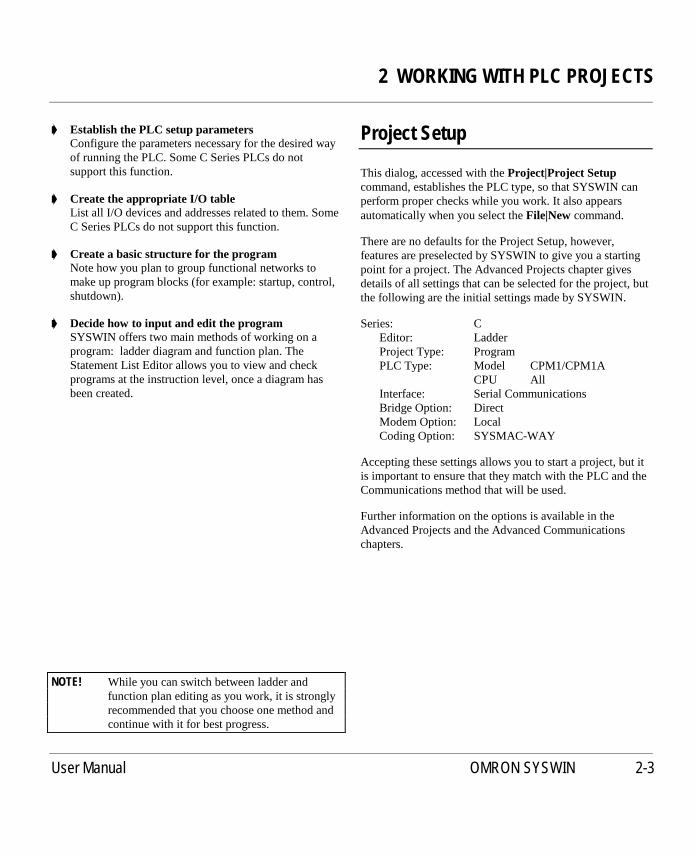
There are no defaults for the Project Setup, however,features are preselected by SYSWIN to give you a startingpoint for a project. The Advanced Projects chapter givesdetails of all settings that can be selected for the project, butthe following are the initial settings made by SYSWIN.
Series: CEditor: LadderProject Type: ProgramPLC Type: Model CPM1/CPM1A
CPU AllInterface: Serial CommunicationsBridge Option: DirectModem Option: LocalCoding Option: SYSMAC-WAY
Accepting these settings allows you to start a project, but itis important to ensure that they match with the PLC and theCommunications method that will be used.
Further information on the options is available in theAdvanced Projects and the Advanced Communicationschapters.

2 WORKING WITH PLC PROJECTS
2-4 User Manual OMRON SYSWIN
Project Information
Though not essential when starting, it is good practice to setup the project front page information before programming.This information is printed when the front page option isselected at printing time, and can be viewed any time toverify that you are working on the correct project. It can bechanged at any time without affecting the program.
CompanyInsert your company or organisation name here.
PlantThe site where the program is to operate, or the equipmentwith which the PLC is to be attached.
ProjectA name for the overall project. This could include the PLCtype and model number for completeness.
VersionCurrent version of the software. This should be updatedevery time the program is changed after it has been firstreleased. Until the program has been tested and debugged, itshould be clearly indicated as unfinished.
PromotionThis field can contain a release number or date, indicatingwhen the program was issued and went live, or be used as acomment field.
Creating Ladder Programs
This section describes in a tutorial style the process ofpreparing ladder programs with SYSWIN, and how to usethe various tools to improve your productivity. SYSWINoffers many methods of working with its tools: you can useeither the mouse or the keyboard to prepare a program, andexperimentation with both is worthwhile if you are new tothis software. In general, instructions here are given forkeyboard usage.
Use theFile|New project command to start up a newproject. The Project Setup dialog appears, to enable you toset up the basic parameters as described in the previoussection. You are then returned to the programmingworkspace, ready to input instructions into the first network.
The example program that is used in this section is for aC200HPLC. If you wish to work through the example,select thisPLC type and model in the Project Setup dialog.

2 WORKING WITH PLC PROJECTS
User Manual OMRON SYSWIN 2-5
About the Keyboard
Navigating through the SYSWIN screen is straightforwardwith the keyboard, using function and editing keys asappropriate. The function keys select SYSWIN operationsfrom the toolbar at the top of the screen. For the drawingtools, you use keys that look like the symbol they draw, forexample - the ‘-’ key for a horizontal short.
SYSWIN dialogs work in the same way as in otherWindows applications: you can use the mouse to select afield or button, and to make selections from list boxes.
The keyboard can be faster, however, especially if you arein the habit of using it during your general programmingwork.
Selecting options and fields is done by holding down theAlt key while pressing the letter that is underlined in thefield name, or by using theTab key to move from field tofield in sequence.Shift+Tab moves backwards througheach one.
Toolbar Programming Functions
TheEnter key normally accepts the dialog. TheEscapekey closes the dialog if there is aClosebutton on the dialog,or cancels if there is aCancelbutton displayed.

2 WORKING WITH PLC PROJECTS
2-6 User Manual OMRON SYSWIN
Ladder Programming Workspace
The main area of the SYSWIN screen is devoted to theladder program display, as a window covering part of thetotal programming workspace. To view a larger portion ofthe workspace, you can usePreferences|Overview Modecommand - selecting this same command again switchesback to normal mode.
When first running SYSWIN, or opening a program, youwill always see the lefthand ‘rail’, from which ladderprogram networks always begin. A righthand rail exists inthe workspace, at its extreme right, but this is normally offthe screen. When you complete a network, outputs aredrawn showing a small vertical bar to indicate the right rail.This saves having to scroll the display to see the righthandside of your networks.
NOTE! Within a network it is possible to create morespace at the bottom of the network by pressingthe space bar as many times as necessary.
Navigating Networks
The currently selected network is generally displayed at thetop left of the workspace window. The lefthand side of thepower rail is highlighted and the program scrolls as youmove up and down between networks. SYSWIN has akeyboard interface that allows theUp andDown arrow keysto roll up and down between networks.PageUpandPageDownkeys scroll the screen by full pages. TheBlock|Insert network command (Alt+Insert ) enables youto create a new network, above or below the selected one.Using the mouse, double-clicking on the left side of thecurrent network bar, if visible, inserts a new network aboveit.
Within a network, the current position is indicated by ahighlighted rectangular block, called the cursor. As youmove around a network, using the arrow keys, the cursormoves with you. You can go directly to any point in theprogram by clicking the mouse on the desired location. Thecursor is actually highlighting the element or space at thatpoint, and if you enter an element, itreplacesthe onedisplayed. To insert elements between others, you must firstuse theEdit|Insert row or Edit|Insert column command(Alt+Down andAlt+Right ) to create a space into which thenew element can be entered.
You can place elements anywhere within the workspace of anetwork, but the network is not considered complete untilyou link elements together. If a network check issatisfactory, the network is automatically redrawn and tidiedup, bringing everything to the left rail, with the minimumdistance between each element. A network is checked whenyou move to or insert a network after an edit, when youchange any of the PLC parameters, when you select theStatement List Editor, and at other times when SYSWINrequires a network to be complete before continuing. Toforce a check at any time, pressAlt+Enter or Shift+F8.
The maximum network size in SYSWIN is 100 rows by 25columns.

2 WORKING WITH PLC PROJECTS
User Manual OMRON SYSWIN 2-7
Creating a Network
Bearing in mind that individual networks should be kept assimple as is practical, they can be entered rapidly. In thesimple example below, there are three elements in the firstnetwork. The elements are placed in sequence, workingfrom left to right, following these keystrokes (the functionkey equivalents can be used if preferred):
➧ Press the ‘"’ (double quote) key to place an opencontact
The Contact Dialog appears, to allow you toenter more information.
➧ Enter ‘253.13’ as the address, then press EnterThe address identification is displayed above thesymbol in the program.
➧ Press the ‘"’ (double quote) key again to placeanother contact
The Contact Dialog appears again.
➧ Enter ‘HR1’ as the address, then press EnterThe address is displayed as before. Notice that it isexpanded into its full bit format - HR00.01.
➧ Press ‘-’ two or three timesThe connecting horizontal line moves to theright.
➧ Press ‘O’ to place an outputThe Output Dialog appears.
➧ Enter ‘200’ as the address, then press EnterThe symbol is displayed with its expanded addressshown as 2.00. Since it is an output, it has a righthand‘rail’ attached. This network is now complete.
➧ Press Alt+S, to move to the address Symbol fieldEnter a symbolic name for this output, then pressEnter.The cursor returns to the network and shows the namebelow the output.
➧ Press Alt+Enter to check the networkThe network is redrawn. Notice how it has beencompacted to eliminate the redundant horizontallines that were entered.
NOTE! Keys used together withAlt andCtrl keys maybe different for implementations in differentlanguages.
The key points to note from this small exercise are:
■ Simple keystrokes are used to place elements
■ Addresses can be entered in abbreviated form
■ Redundancy is automatically removed on check
■ Symbolic names can be entered later if desired,although it is good practice to create them as theprogram is entered.
About Addresses
It is important to use the standard form of addresses inSYSWIN. Addresses may have two components - a channelnumber and a bit number - and these should be separated bya dot. In the example above, the address ‘200’ has beeninterpreted by SYSWIN as ‘2.00’. If we had meant to usebit zero at address 200, it would have been necessary toenter it as ‘20000’ or (preferably) ‘200.00’. Note that in thesecond step of the example, we used ‘253.13’ to illustratethis, where we mean bit 13 in channel 253.

2 WORKING WITH PLC PROJECTS
2-8 User Manual OMRON SYSWIN
Adding to a Network
Any network can be expanded with simple editingfunctions. For example, to create a simple OR instruction atthe start of the network just entered:
➧ Position the cursor on the leftmost elementUse the arrow keys to move it there.
➧ Press the space bar to create a new element lineThe network expands downward, and the cursor is at theleft rail. Press the down arrow and you are ready toinsert a new element.
➧ Press the ‘"’ (double quote) key to place an opencontact
The Contact Dialog appears as before.
➧ Enter ‘HR0’ as the address, then press EnterThe window closes and the address is expanded toHR00.00 above the drawn symbol.
➧ Press the Up arrow to move up to the top lineThe cursor is positioned ready to insert a new verticalconnecting line. Note that the line is inserted on the leftside of the cursor.
➧ Press ‘|’ or ‘!’ to insert a vertical connecting lineThe first and second lines are now connected.
The network is now complete as everything is connected.PressAlt+Enter to check it is valid and to redraw thenetwork.
To view the actual instructions generated by thisnetwork, use the Statement List Editor. Select the
editor via theEditors menu, or by clicking on its button onthe toolbar (Ctrl+F8 ). The instructions are listed inmnemonic format, and can be edited in the normal way. Ifeverything is correct, then the ladder is redrawn; if errorsare detected, then you are warned. The Statement ListEditor is described in detail later in this chapter.
Adding Comments to a Network
It is recommended that you add comments tonetworks as they are written, so that it is easier to
understand their functions when reviewing the programlater. You use the Network Symbol Editor to name anetwork and add suitable comments. Start the editor byselecting it from theEditors menu, by selecting theNetwork Symbol Editorbutton on the toolbar (Ctrl+F7 ), orby simply double-clicking the mouse on the networkcomment bar (if it is visible).
In the Network Symbol Editor, a network can be given aname up to 15 characters long, and up to 30,000 charactersof text as a description or comment. Note that text can bewrapped to fit onto the display screen.
The Network Symbol Editor is described in more detail laterin this chapter.

2 WORKING WITH PLC PROJECTS
User Manual OMRON SYSWIN 2-9
Adding More Networks
After the initial entry of a program, you usuallyneed to add further networks. Use theBlock|Insert
network command to open a new network (the preferredshortcut isAlt+Insert ). Alternatively, select the button onthe toolbar (Shift+F6). You are asked to specify whetheryou want the new network to be above or below thecurrently selected one.
A new network area appears in the workspace, and you canbegin entering the new network immediately.
NOTE! Individual networks must be entered separately,and all elements must be joined together in anetwork.
Blocks and Networks
At the top of the program that you have entered, there is ablock header above the first network. This is automaticallycreated by SYSWIN when a new program is started.Although a program can be produced within a single block,it is strongly recommended that you break up the programinto small manageable groups of networks within separateblocks.
You use the Block/Network Manager to form groups ofnetworks, and to provide names and comments for theblocks you have created. The Block Symbol Editor isstarted through theEditors menu, or through theBlock|Block / network manager, which has its own toolbarbutton (Ctrl+F5 ). Double-clicking on the block header baralso opens the Block Symbol editor.
Block information is entered in the same way as with theNetwork Symbol Editor, and once accepted, it is displayedon the block header in the ladder workspace.
You are always working within a single block, andwhile in that block you have access only to the
networks it contains. To move to another block of networks,you must use theBlock|Select block / networkcommand,accessible with a toolbar button (Shift+F5). This dialogallows you to go directly to a specific block or networkanywhere in the program - it also provides a search-by-name facility for networks.
NOTE! You can also switch between blocks by usingtheCtrl+Shift+PageUp andCtrl+Shift+PageDown keys.
A detailed description of the Block/Network Manager isprovided later in this section.
Entering Functions, Timers and Counters
All ladder programs use functions in addition to the basicinstructions, and most use timers and counters. These areentered in much the same way as symbols, but because mostof them require data parameters on which to operate, theprocess involves different dialogs.
FunctionsSYSWIN uses your setting of the PLC type, together withyour function mapping parameters (where they apply) todetermine which functions are available to use. When afunction is selected, a dialog box is displayed requesting thenecessary data.
If you know which function you wish to insert in a network,the easiest way to enter it is to use the ‘F’ key. This displaysthe function dialog box, and you can type in the name ornumber of the function.
2 WORKING WITH PLC PROJECTS
2-10 User Manual OMRON SYSWIN
SYSWIN follows your typing, and as soon as it identifies avalid function, its complete name is displayed for you, andthe parameter fields are displayed. When entering a functionthat may be ambiguous, enter a space after the last character(for example:MOV<space>to force identification of aMOV(21) function, and not a MOVD).
When you are unsure about a function name, press theSelectbutton. This displays the function group list box andthe functions in the highlighted group. Move the cursor tothe group you require and select the appropriate functionfrom the list. Exit the selection dialog, and complete thefunction parameters. Pressing theReferencebutton orCtrl+F1 displays Quick Reference on any specific functionthat is highlighted.
Enter the appropriate values in each data field, using theTab key to move between them. SYSWIN validates the datathat you have entered when you accept the dialog. If youhave entered an incorrect parameter, an error messageappears, telling you which one is incorrect, and why.
When a function is drawn, its inputs (and occasionallyoutput) are indicated by unterminated lines. These need tobe connected to other parts of the network before thenetwork is complete.
Differentiated FunctionsMost functions are available in differentiated and non-differentiated forms. They are identified by special symbolsin front of the name. When a function can have more thanone form, the dialog provides extra check boxes.Alternatively, you can use special characters when typing afunction name, and SYSWIN converts the function asappropriate:
@ Differentiate UP% Differentiate DOWN! Immediate refresh
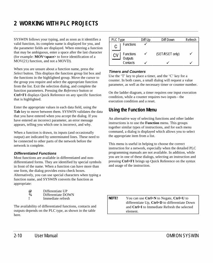
The availability of differentiated functions, contacts andoutputs depends on the PLC type, as shown in the tablehere.
PLC Type Diff Up Diff Down RefreshFunctions �
FunctionsOutputsContacts
�
�
(SET/RSET only)
�
�
�
Timers and CountersUse the ‘T’ key to place a timer, and the ‘C’ key for acounter. In both cases, a small dialog will request a valueparameter, as well as the necessary timer or counter number.
On the ladder diagram, a timer requires one input executioncondition, while a counter requires two inputs - theexecution condition and a reset.
Using the Function Menu
An alternative way of selecting functions and other ladderinstructions is to use theFunction menu. This groupstogether similar types of instructions, and for each menucommand, a dialog is displayed which allows you to selectthe appropriate item from a list.
This menu is useful in helping to choose the correctinstruction for a network, especially when the detailed PLCprogramming manuals are not available. In addition, whileyou are in one of these dialogs, selecting an instruction andpressingCtrl+F1 brings up Quick Reference on the syntaxand usage of the instruction.
NOTE! You can useCtrl+N to Negate,Ctrl+U todifferentiate Up,Ctrl+D to differentiate DownandCtrl+I to Immediate Refresh the selectedelement.

2 WORKING WITH PLC PROJECTS
User Manual OMRON SYSWIN 2-11
Editing Networks
Networks can be edited at any time, even while connectedto a PLC, and each edit is verified by SYSWIN as it isentered. Some of the editing controls can be used to speedup programming, for example by cutting and pastingbetween networks.
Once a function, timer or counter has been drawn, itsparameters can be changed. To do this, select the instructionby moving the cursor onto it and pressEnter, or double-click on the instruction with the mouse. If you double-clickon one of the parameters in the ladder diagram, that one ishighlighted in the editing dialog when it opens.
Using the Address Bar
The addresses, symbol names and comments assigned toeach symbol can be changed easily. The quickest way to addsymbolic information is to useAlt+S to move to the Symbolfield in the address bar at the bottom of the screen. Afterentering a name, use theTab key to move to the Commentfield. After entering a comment, theEnter key stores thesymbol and takes you back into the ladder diagram.
NOTE! Keys used withAlt andCtrl keys may bedifferent in implementations in other languages.
Alternatively, you can use theTab key to move the editingcursor out of the diagram to the address bar. Then you canjust tab through each of the fields back into the diagram.You can useShift+Tab to move in the opposite direction.While the editing cursor is outside the ladder diagram, thecursor over the element turns grey. It returns to black whenyou move the cursor back into the ladder diagram.
For global editing and manipulation of symbol information,use the Address Symbol Editor as described later in thischapter.
Manipulation of elements and networks is done with a widerange of editing commands. These allow you to select, copy,move and delete elements.
Selecting Network Elements
To select an element anywhere in the program, use the pagekeys or scroll bars to locate the network, and move to theelement with the arrow keys, or just click on it.
Once the editing cursor is positioned over an element, ablock of elements can be selected by holding down theShiftkey while using the arrow keys to move around and add tothe block - the highlighted area grows as you do so. Havingselected an area with theShift key still held down, if youmove back into it with an arrow key, the appropriateelements are de-selected. With the mouse, it is necessaryonly to click and drag from a start point to select and de-select elements. In all cases, the selection remains activeuntil you move the editing cursor with the mouse or thekeyboard arrow keys.
If you wish to select a specific path through a network, andnot a simple block, hold down theControl key whileclicking on the items you require. To deselect a path, releasetheControl key and click on any of the elements in thesame network.
Deleting Network Elements
A single selected element in a network can be deleted withtheBackspaceor Del key, but to delete group selectionsyou must use theDel key. Note that theDel key deleteswithout moving the cursor, whileBackspacemoves thecursor to the next element to the left. If you use thesecontrols to delete the entire contents of a network, thenetwork is still open (keeping its name and comments), andyou can re-program it.
To delete a network completely, removing it fromits parent block, use theBlock|Delete Network
command (Alt+Delete), or click the delete button on theToolbar (Shift+F7). Note that once deleted, a networkcannot be restored, using Undo.

2 WORKING WITH PLC PROJECTS
2-12 User Manual OMRON SYSWIN
Copying Network Elements
Elements and networks can be copied to other parts of aprogram, or to another program, with the normal Windowscut-and-paste facility. For example, to copy part of anetwork from one place to another in a program, first selectthe section to be copied.
Use theEdit|Copy command (Ctrl+C ), or click onthe copy button on the Toolbar. The selected
elements are copied into the internal clipboard. Now youcan move to another part of the program, or even open adifferent program, before pasting the copied elements.
To paste the elements, position the editing cursor atthe point where the elements are to be pasted. If you
are copying an entire network, you need to insert a newnetwork ready to receive the elements. Use theEdit|Pastecommand (Ctrl+V ), or click on the paste button on theToolbar.
Moving Network Elements
The procedure to move an element or group to anotherlocation in the program is the same as for copying,described above, except that theCut command from theEdit menu (Ctrl+X ) is used in place of the Copy command.
TheCut command, and its button equivalent in theToolbar, deletes the selected elements from the
current network after making a copy in the internalclipboard. To insert the selection elsewhere in the program,use thePastecommand (Ctrl+V ).
Restoring Networks
A networks can be restored to its earlier state, regardless ofthe number of changes made in the ladder workspace. Thereare two types of restore command in SYSWIN:
TheEdit|Undo command (Ctrl+Z ), or its toolbarbutton equivalent, restores the current network to
the state it was before the most recent operation.
The undo command can be used repeatedly to step backthrough a sequence of operations. Only those operationsthat can be reversed are undone.
TheBlock|Restore networkcommand restores the networkto its most recent state, that is, either when last tested bySYSWIN, or last opened.

2 WORKING WITH PLC PROJECTS
User Manual OMRON SYSWIN 2-13
Saving and Loading Projects
Maintaining project files on disk is done in the same way asin other Windows applications. TheFile menu provides thenecessary options for working with files, and some of theseare also available as buttons on the SYSWIN toolbar forconvenience.
SYSWIN project files are stored in a dedicated format, andcan be read only by the SYSWIN software. Several types offile are used, according to the method of programming usedto create a project, and the version of SYSWIN that wasused to create them. Project files are identified by afilename extension added to the project name, as follows:
Project.SWP SYSWIN 2.x/3.x ProgramProject.SWL SYSWIN 2.x/3.x LibraryProject.SWT SYSWIN 3.x TemplateProject.SWB SYSWIN 2.x/3.x Backup FileProject.SWN SYSWIN 1.x ProgramProject.PRG PMD Program
You can save the project at any time. During testing, andespecially when working while connected, it isrecommended that you create copies as the project proceeds,which allow you to restore a previous version more easily.However, when a project is saved, the previous version ofthe file is renamed to become a backup file (.SWB), so thatyou can easily move back one version by copying thebackup into the current file.
Whenever you make changes to a project, SYSWINreminds you to save your project if you wish to openanother project, or if you exit from the application.
Saving a Project to Disk
TheFile|Save projectcommand stores a project ondisk, and if it has already been saved once,
overwrites the file with the latest version. You can use thetoolbar button (Shift+F3) as an alternative to the menuselection. With a saved project, this option simply updatesthe files on disk, with no further prompting.
When you first save a new project, a standard Windows filesave dialog appears, allowing you to locate and name thefile. Follow these steps to save the project:
➧ Locate the directory in which to create the fileUse theDirectoriesandDrivesfields to navigate to thedesired location. Any existing files in the directory youchoose are listed, but greyed out.
➧ Enter a name for the projectSelect theFile Namefield, and enter a suitable projectname (up to 8 characters long).
➧ Check the format in which the file is to be savedThe program is saved either as a project file (.SWP), alibrary file (.SWL) or as a template file (.SWT)depending on how it is defined in theProject Setupdialog.
➧ Click on OK to save the file
Saving a Copy of a Project
TheSave project ascommand, enables you to save thecurrent project in a new file. It can be used the first time aproject is to be saved or when you want to change the filename or its location. When selected, it displays the standardsave dialog box, as described above, and you should followthe same steps to create the new file.

2 WORKING WITH PLC PROJECTS
2-14 User Manual OMRON SYSWIN
Loading a Project From Disk
A saved project can be opened for further work withtheFile|Open project command (or you can use the
toolbar button -Shift+F2). If a project is already open whenyou select this command, you are asked if you wish to savethe current project before proceeding. The Open Projectdialog is similar to the Save Project dialog. Follow thesesteps to open the project:
➧ Locate the directory in which the project residesUse theDirectoriesandDrivesfields to navigate to thedesired location. All existing files in the directory youchoose are listed.
➧ Select the formats you wish to have listedTheList Files of Typefield provides a list box showingformats available for viewing.
➧ Select and open the desired projectDouble-click on the name of the file you wish to open,or click once on it, then click onOK.
Alternatively, if you know the name and location of theproject you wish to open, you can enter its completepathname in theFile Namefield.
When you accept the dialog, the project file is opened anddisplayed in the programming workspace. All of theparameters relating to the project are set automatically.
Editors
Editors are supplied in SYSWIN to perform functionsadditional to the basic Ladder Editing. The followingsections in this Chapter describe those editing functions thatare provided in the Statement List Editor, the AddressSymbol Editor, the Network Symbol Editor, the BlockNetwork Manager and the Block Symbol Editor.

2 WORKING WITH PLC PROJECTS
User Manual OMRON SYSWIN 2-15
Statement List Editor
The actual PLC instruction code which underlies any ladderprogram can be viewed and edited with the Statement ListEditor. It allows you to verify the contents of networks ininstruction format, and make changes as necessary. You canuse the Statement List Editor to create an entire program,though the features of SYSWIN encourage a more intuitiveprogramming method using ladder diagrams. This editor isintended to enable the viewing and modification ofnetworks when the need arises.
The Statement List Editor is opened with acommand from theEditors menu, or by clicking on
the Statement List Editing button on the Toolbar (Ctrl+F8 ).This dialog operates with the ladder display, so that whenyou move between networks, the ladder display moves too,and always shows the same network as selected in theeditor. Use thePreviousandNextbuttons to step from onenetwork to the next.
TheNetworkandNamefields from the current networkheader are displayed - the name field can be changed withthe Network Symbol Editor.
Statement List Display
The instruction list can be displayed in either address orsymbolic format, depending on your selection for theDisplayoption. If you have used the other editors to createsymbol names for addresses, the information displayed herein Symbol mode makes it easier to follow the instructionlisting. You can only change between display modes whenthe instructions are valid.
Editing a Statement List
Instructions are entered as normal text, similar to Notepad.You can use the Windows cut, copy and paste tools(Ctrl+X, Ctrl+C andCtrl+V ) in the usual way to edit thelist, and the mouse to select items for copying or deleting.Ctrl+Z can also be used to undo the last change.
When entering instructions, you can use upper or lower casecharacters. SYSWIN automatically converts to upper casewhen the network is next tested. You should separateinstructions from operands with a space or a tab (entered asCtrl+Tab ), and allow the editor to correctly format the list.
While normal instructions can be edited within the ladderdiagram, block programming statements must always beedited using the Statement List Editor.
Verifying a Statement List
Several instructions can be entered in sequence - nochecking of syntax or network completeness is done untilrequested. TheTestbutton allows you to verify the listwhile staying within the current network. TheNextandPreviousbuttons at the bottom of the dialog also force acheck, as SYSWIN does not allow you to close the editor ormove to another network without checking the current one.
If an instruction cannot be understood by SYSWIN, thatinstruction is highlighted in the list, and you must correct itbefore leaving the editor.
Some sequences of instructions may result inSYSWIN being unable to draw the network. In this
case, you are able to leave the editor, but the ladder diagramshows a special symbol, replacing the network display, toshow that it cannot be drawn. This situation should beavoided wherever possible.
There are two situations that cause this to happen:instructions that cannot be sequenced properly and blockprogramming instructions. Block programming instructionscannot be drawn in the ladder diagram, because theyrepresent sequences of instructions rather than a powerflownetwork.

2 WORKING WITH PLC PROJECTS
2-16 User Manual OMRON SYSWIN
RestoreUse this button to return the list to its original state whenyou entered the editor, or to the last tested version. Thecomplete list is restored, regardless of the number ofchanges you have made.
BrowseThis button allows you to choose a symbol or address fromthe Address Symbol Editor without leaving the StatementList Editor.
CloseTheClosebutton forces a network check, and you arereturned to the ladder display, with the network redrawn toreflect the changed situation.
As described above, any inconsistencies in the networkcause an error to be generated, and although you cancontinue and ignore it, it is recommended that it isthoroughly checked before closing the dialog.
Address Symbol Editor
The addresses used within the program can be given symbolnames to make it easier to read and understand a program.These names can be entered and edited directly with theAddress Bar at the bottom of the screen at the time whenelements are placed in the network. The Address SymbolEditor provides a straightforward way of entering thisinformation as a separate task, allowing you to assignsymbol names to any address.
The Address Symbol Editor is accessed through theEditors menu, or by clicking on the Address
Symbol Editor button on the Toolbar (Ctrl+F6 ). The dialogdisplays all addresses and symbols that have been created inthe project, and offers several editing facilities. Symbolicinformation is displayed at the bottom of the dialog, in theediting fields.
When you enter the dialog, theFind field is highlighted, sothat you can immediately enter part of an address or symbolname that you wish to search for.
The list of addresses is given in numeric or symbolicsequence. You can use theSort Orderoptions to switchbetween them. The page and arrow keys can be used tolocate any address. You can also use the mouse to directlyselect an address by clicking on it.
If the editor has been started as a Browser from anothereditor, thenOK enters the selected address back into theprevious editor.
StoreAfter editing each address symbol, use theStorebutton tosave it into the project. When you are editing addresssymbols in the bottom section of the dialog, theEnter keywill store the information.
NewUse theNewbutton to add an address and symbol name tothe table. The cursor moves into theAddressfield, so thatyou can enter the number of the address you wish to add.

2 WORKING WITH PLC PROJECTS
User Manual OMRON SYSWIN 2-17
FindTheFind field allows you to enter a partial or completeaddress or symbol name to be found. As you type, addressesmatching that name are searched for in the list and the firstname that matches is highlighted. Then, to edit the nameand comment, just pressEnter or click on theEdit button.
EditHaving highlighted an address, either by searching or bydirect selection, theEdit button takes you into theSymbolfield ready to change the symbol. Alternatively, you can usetheEnter or Tab keys to move to theSymbolfield.
DeleteThis button deletes the selected entry from the symbol list.Deleting an entry does not affect the program itself, just theinformation associated with an address.
LoadAddress Symbol information can be imported from anotherSYSWIN project. Use theLoadoption to open a file andhave the address information automatically brought into thecurrent program. When the file to load is selected, SYSWINgives you three options. The first option is to Merge the filewith the present one overwriting ones with the same name.The second option Merges the file but does not overwriteAddress Symbols and the third option Loads the file andreplaces all Address Symbols currently loaded.
PurgeAfter intensive editing operations, the program may containsymbolic information which is not attached to any elementof the program. ThePurgeoption scans the program forunattached symbols, and deletes them from the symboltable.
The current network must have been tested before anyunused addresses are purged from the list.
ScanThis option scans through the program for addresses thathave been used, but which have not had symbols assignedto them. These are then listed, and you can select eachaddress in turn to enter the appropriate information in theSymbolandCommentfields. Note that this option isavailable only when the display is sorted by Address.
The current network must have been tested before any newaddresses appear in the list.
AutoSYSWIN provides theAutooption for adding comments tosequential addresses. When this is enabled, typing anaddress such as HR1, starts the auto-numbering. After youhave entered a symbol and comment, pressingEnter causesthe next unallocated address (for example, HR2) to appearautomatically, ready to be given a symbol.
SaveThis button saves the Address Symbol information in .PMFformat via a standard save dialog.
CloseThis button closes the dialog - alternatively you can presstheEscapekey. Any changes not saved with theStorebutton are lost.

2 WORKING WITH PLC PROJECTS
2-18 User Manual OMRON SYSWIN
Network Symbol Editor
To add comments to networks, you use the Network SymbolEditor. With this editor, networks can be located and givena name, and comments can be added. The information isdisplayed in the network header, and can be used in place ofthe network number during searching operations.
The Network Symbol Editor is accessed through theEditors menu, or by clicking on theNetwork
Symbol Editorbutton on the SYSWIN Toolbar (Ctrl+F7 ).A useful shortcut is to double-click on the comment in thenetwork header bar. This displays the dialog to enter andchange information.
The dialog operates in conjunction with the display. As youmove between networks with thePreviousandNextbuttons, the appropriate network is displayed in theprogramming workspace, so that you can see which networkyou are working on.
The Network Symbol Editor can be started from within theBlock/Network Manager by pressing theNamebutton.
RestoreUse this button to restore theNameandCommentfields. Allchanges done to the current network will be discarded.
Insert and RemoveTheInsertandRemovebuttons are normally used to realigncomments after a program has been uploaded from a PLC.
TheInsertbutton pushes all the following comments downby one network. It allows you to open a gap in the networklist to accept a new name and comment. All network namesand comments after the insertion point are shifted down.The comments on the last network will be pushed off theend and lost.
TheRemovebutton removes the current Name andComment and pulls those below up by one network. Thelast network therefore does not have a name and comment.
Making Network Groups
When theShow Network Groupsoption is switched on(using the Project Preferences), the Network Header displayappears on a ladder workspace only if the network has beengiven a name. If the networks below the current one are notgiven names, then the networks appear to form a group.
2 WORKING WITH PLC PROJECTS
User Manual OMRON SYSWIN 2-19
Block / Network Manager
Using the Block / Network Manager, you can structure andadd comments to PLC programs. The Manager consists of amain dialog which is used to gather networks into blocks,and provide access to general block and networkmaintenance such as selection, insert, modify and comment.
The Manager is started from theBlock menu, orwith its toolbar button (Ctrl+F5 ). Blocks and
networks are displayed as lists of numbers and names. Notethat the list of networks are only shown for the currentlyselected block.
As you move up and down with the arrow keys or themouse, the workspace behind changes so that the selectednetwork is at the top of the window. You can then checkthat you are at the correct point in the program. TheNamebutton then starts either the Block or the Network SymbolEditor as appropriate. Double-clicking on an item in a listalso starts the editor.
The buttons at the bottom of the dialog perform standardediting functions on a block or network. They provide aconvenient way of doing globally many of the tasks that canalso be done as you program.
FindTheFind field allows you to enter a partial or completenetwork name for searching. As you type, networksmatching that name are looked up in the list and the firstname that matches are highlighted. Then, to edit the nameand comment, press theNamebutton.
Find NextThis option searches for the next item that matches thename entered in theFind field.
InsertA new block or network can be inserted in the program,above the current position in either list. Either the Block orNetwork Symbol editing dialog appears, and you can addcomments to it before entering networks into the program.
NameAllows any block or network name and comment to bedisplayed and modified, again by displaying the necessarydialog.
DeleteThis option removes the currently selected block(s) ornetwork(s) from the program. A warning message is givenbefore the selection will be deleted. TheDel keystroke canbe used as a shortcut for this operation.
Cut, Copy, PasteThese options operate like the standard Windows editingcommands from theEdit menu, and provide a shortcutmechanism for copying items, moving them, and changingthe sequence of blocks and networks within a program. Forthese operations, you can also use the standard keyboardshortcuts:Ctrl+X (Cut),Ctrl+C (Copy) andCtrl+V(Paste).
Load Blocks / NetworksBlocks and networks can be imported from SYSWINlibraries and other programs. Use theLoadoption to open alibrary file. If the Block side of the dialog box is highlightedthenLoad Blockswill appear and if the Network side of thedialog is highlighted then theLoad Networksbutton isdisplayed.
Select this option and the Import Blocks / Networks dialogis displayed. This gives you the opportunity to select fromthe displayed list of blocks or networks. You can change toanother library if necessary by using theSelectbutton. Theselected project blocks or networks are automatically loadedinto the current project.
When the project is opened, the blocks it contains are listedin theBlocksarea of the dialog. To select blocks forinsertion, use the mouse to click on single items,Ctrl +clickto select several, orShift+click to insert a range orShift+End to insert the entire project.

2 WORKING WITH PLC PROJECTS
2-20 User Manual OMRON SYSWIN
When inserting networks, you need to press theLoadNetworksbutton. You can then use the same methods as forblocks to select networks for insertion.
Note that insertion in the project takes place above thecurrent selection point, and that to add an item to the end, itis necessary to select the blank line that follows the last itemin a list.
Load CommentsProgram comments can be loaded from an existing projector library file with this button. The standard file open dialogis displayed, which allows you to locate and open theappropriate file. Only block and network comments areimported, and these are added to the current program in thesame sequence as they were originally saved.
If you need to realign the block or network comments usetheInsertor Removebutton in the Network Symbol Editor.
PrintThe currently selected block(s) or network(s) can be printedfrom within this dialog.
CloseThis button closes the Block / Network Manager. PressingtheEscapeor Enter keys also closes it.
Block Symbol Editor
While working in the Block / Network Manager, this editoris started by using theInsertandNameoptions. When youare in the ladder workspace, it is selected from theEditorsmenu, or double-click on the block header bar.
The Block Symbol Editor displays the current block numberand any information that has been already entered. Use theTab key to move between theNameandCommentfields,and edit them as necessary. TheRestorebutton loses anychanges that have been made.
TheBlock Typemenu is used only with CV series PLCs. Itlists the fixed block types that are used with this series.
TheBlock Typealso serves to avoid possible duplication ofinterrupt routines. Note that it is only through using thisdialog that interrupt routines can be changed.
When you accept the dialog, the block name and commentsare displayed in the block header above the first network inthe programming workspace.

2 WORKING WITH PLC PROJECTS
User Manual OMRON SYSWIN 2-21
Checking the Program
TheProject|Program checkoption allows you to ensure, atany stage, that your program is valid. The dialog which isdisplayed has several options that can be selected beforeexecuting the check. These may include Subroutines,Instructions and Interlocks and an Assembly check.
By using theScopefeature you can choose to check thecurrent network, the current block or all blocks.
When the options are chosen, press theExecutebutton anda report may be displayed. This report contains any errorswhich have been found in the program and warnings to bechecked. You can step through the list of errors by movingthe highlight bar in the list box. If you press theGo toNetworkbutton, the Statement List Editor opens and theline in error will be highlighted. The error can then becorrected and another error chosen from the report dialog.
If this information needs to be kept, then theCopybuttoncopies the report to the Windows clipboard to be used byother programs.
TheClosebutton closes the dialog.
Global Editing - Find and Replace
SYSWIN gives you powerful global searching and editingfacilities with theEdit|Find andEdit|Replacecommands.These allow you to scan a program for all occurrences ofany label, address, bit, channel, register or instruction and tochange them globally.
Searching for Data
If you wish to look at a program, or part of it, withoutmaking any changes, use theEdit|Find command. Thedialog allows you to narrow the search in several ways.Similar options exist in theEdit|Replacedialog.
TypeYou can search byAddressor its symbol name (forexample: ‘AR5.05’ or ‘SwitchOn’),Label(for example:‘23’) or Instruction(for example: ‘MOV’). The type youselect affects the validity of the information you enter intotheFind fields.
DirectionFor searching purposes, the starting point is taken from thecursor in the current network, and from here you can begina searchUp or Down the program.
ScopeYou can choose to search just the current block or allblocks. When theScopeis set toAll Blocks, Go To Topmoves the start position to the top of the program andsearchesDown. When theScopeis set toCurrent Block, GoTo Topmoves to the start of the current block and searchesDown.
Find From / ToUse these fields to specify the range of items that you aresearching for. Enter address symbol names in full for asuccessful match. Other data can be partially entered, suchas searching for generic addresses. If you are looking foronly one item, it is not necessary to enter anything in theFind To field. Neither field is case-sensitive.

2 WORKING WITH PLC PROJECTS
2-22 User Manual OMRON SYSWIN
Exact MatchIn a complex program, you often want to be very specificabout both the name and type of item that you are searchingfor. TheExact Matchoption forces a search only for theitems you have entered in theFind fields. This isparticularly relevant when you wish to replace items, as it ispossible without exact matching to change somethingunintentionally.
To help with specifying items to match, the table belowgives examples and notes for each type of item.
Item type Items searched ExamplesBit Bits 0.00 AR5.05Channel Channels &
Bits†0 AR5
Indirect Channels *DM0 *EM9Const16 Channels #0000 #9999Const32 Channels #00000000 #99999999Indexed Channels & Bits IR0, IR1+(+) -(-), IR2 +/-
1234, IR0 DR1, IR1Data Register Channels DR0 DR2Index Register Channels IR0 IR2Label Labels†† 0 99
Notes: † When Exact Matching is NOT used, thechannel part of a bit address would be replacedwith the new channel address: for example,changing AR2 to AR4 would also changeAR2.05 to AR4.05.†† A label is the number of a subroutine, as usedin JMP, JME, SBS, and SBM instructions.
1. Searching for a channel will match channels, bits andindirect channels: Exact Match will match only channels, forexample, AR2 will only match AR2, and not AR2.05.
2. Searching Const16 will match Const16 and Const32, ifConst32 values are only 4 digits long, for example, #5555will match #5555 and #00005555.
Examples of matching possibilities
Replacing Data
The dialog for theEdit|Replacecommand is similar to thatfor Edit|Find, but there are some additional options.
Replace OptionsUse theFind Nextbutton to locate the next matching itemfrom your specification. The appropriate element ishighlighted in the ladder workspace. TheReplacebuttonchanges just that element, and you must then use theFindNextbutton again to move on. If you are satisfied that thecorrect element has been located, and you then want tomake a global change, pressingReplace Allchanges alloccurrences of that address, from that point to the end of theScope.
Prompt ReplaceWhen you select theReplace Alloption, you can choose tobe prompted each time the specified symbol is found. Thisis a safer way of doing global replacements, especially withcomplex searches.
Prompt Replaceis forced on automatically if you requestReplace Allwhile working connected to the PLC in OnlineEdit.
NOTE! Bit addresses in the Find/Replace dialog mustbe entered in the SYSWIN format, using a dotto separate the channel and bit address. Forexample: use ‘253.13’ instead of ‘25313’.
Move SymbolsWhen you select theMove Symbolsoption, the addresssymbol information is moved when the address is firstfound and then replaced. For example, if HR05 has anaddress symbol ‘Relay1’ and you replace HR05 with HR07with the Move Symbols option selected, then the ‘Relay1’address symbol is assigned to HR07.
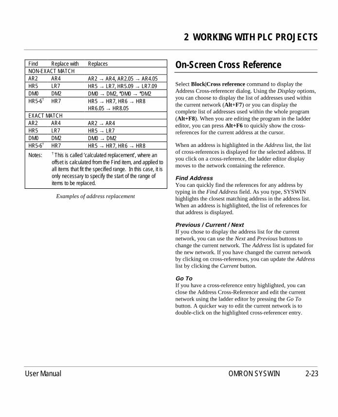
2 WORKING WITH PLC PROJECTS
User Manual OMRON SYSWIN 2-23
Find Replace with ReplacesNON-EXACT MATCHAR2 AR4 AR2 → AR4, AR2.05 → AR4.05HR5 LR7 HR5 → LR7, HR5.09 → LR7.09DM0 DM2 DM0 → DM2, *DM0 → *DM2HR5-6† HR7 HR5 → HR7, HR6 → HR8
HR6.05 → HR8.05EXACT MATCHAR2 AR4 AR2 → AR4HR5 LR7 HR5 → LR7DM0 DM2 DM0 → DM2HR5-6† HR7 HR5 → HR7, HR6 → HR8
Notes: † This is called ‘calculated replacement’, where anoffset is calculated from the Find item, and applied toall items that fit the specified range. In this case, it isonly necessary to specify the start of the range ofitems to be replaced.
Examples of address replacement
On-Screen Cross Reference
SelectBlock|Cross referencecommand to display theAddress Cross-referencer dialog. Using theDisplayoptions,you can choose to display the list of addresses used withinthe current network (Alt+F7 ) or you can display thecomplete list of addresses used within the whole program(Alt+F8 ). When you are editing the program in the laddereditor, you can pressAlt+F6 to quickly show the cross-references for the current address at the cursor.
When an address is highlighted in theAddresslist, the listof cross-references is displayed for the selected address. Ifyou click on a cross-reference, the ladder editor displaymoves to the network containing the reference.
Find AddressYou can quickly find the references for any address bytyping in theFind Addressfield. As you type, SYSWINhighlights the closest matching address in the address list.When an address is highlighted, the list of references forthat address is displayed.
Previous / Current / NextIf you chose to display the address list for the currentnetwork, you can use theNextandPreviousbuttons tochange the current network. TheAddresslist is updated forthe new network. If you have changed the current networkby clicking on cross-references, you can update theAddresslist by clicking theCurrentbutton.
Go ToIf you have a cross-reference entry highlighted, you canclose the Address Cross-Referencer and edit the currentnetwork using the ladder editor by pressing theGo Tobutton. A quicker way to edit the current network is todouble-click on the highlighted cross-referencer entry.
2 WORKING WITH PLC PROJECTS
2-24 User Manual OMRON SYSWIN
CloseThis button closes the Address Cross-Referencer and returnyou to the original network that you were editing before youstarted the Address Cross-Referencer.
NOTE! SYSWIN detects multiple addresses used withinfixed-lengthparameters. For example: addresses100 and 101 are detected in aCMPL #12345678 100 instruction.SYSWIN does not detect multiple addressesused withincalculatedparameters. For example:addresses 101 and 102 are not detected in aBSET #1234 100 103 instruction.
Printing the Project
Periodic hard copy printing may be necessary during projectdevelopment, and the print options provided by SYSWINare designed to make this easy and flexible. Projects can beprinted in a range of formats, with as much or as littleadditional information as you require, giving you assistancewith debugging and testing, as well as providing apermanent file record.
Use theFile|Print command to select sections andprint the current project, or click on the toolbar print
button (Shift+F4). This displays a dialog with several printoptions, which allow you to build up the layout of yourreport. Unless you need a full listing for delivery or archivepurposes, it is best to select only the briefer listings that arenecessary.
Print Sections
Front PageThe front page information for the project is printed if thisoption is selected. The date and time of the printout areincluded.
Block OverviewThis allows you to print an overview of the structure of theprogram by printing the block and network names. Networkcomments can be optionally included.
Ladder Diagram / Function PlanThe network may be printed in ladder form or function planform depending on the editor that was selected with ProjectSetup. Options are available to allow you to choose todisplay only those features you require.
Network comments may be included between networks andeach network or group may be separated as required.
Step numbers may be printed in the margins, and theStatement List and the Address List for the current networkmay be also printed.

2 WORKING WITH PLC PROJECTS
User Manual OMRON SYSWIN 2-25
The printout can include the Cross References of theinstructions and either a Full or Compact format may bechosen.
In order to structure your output to suit yourself, pagebreaks may be forced before every network, group or block.
Statement ListThe Statement list can be printed out without the ladderdiagram/function plan being printed. The options are similarto the ladder diagram/function plan options describedabove.
Symbol ListsSymbol table listings can form part of the printout and canbe sorted by alphabetical name and numeric address. ThePurgeoption causes only those symbols that are actuallyused in the program to be printed.
Cross ReferencesThis option provides listings which detail all symbols andaddresses, showing where they are used in the program. Thelisting can be sorted alphabetically and numerically.Symbols assigned to outputs will have an asterisk ‘*’printed beside them. If theOutputsoption is selected, alladdresses used as outputs are listed in address sequence.The cross reference listing is most useful during debugging.
Expansion FunctionsThe list of expansion function mappings as used inthe project can be printed. The printout shows the
function number that have been allocated to each expansionslot.
PLC SetupThe settings in the PLC Setup area can be printed. SomeC Series PLCs do not support this function.
I/O TableThe I/O slots and Special I/O units assignments in the I/OTable can also be printed. Some C Series PLCs do notsupport this function.
Selecting a Range of Networks
You can select specific blocks and networks for printing bypressing theRangebutton. This helps to reduce the amountof printing time when you wish to focus on particular areasof a program.
TheAddress I/Ofield allows you to request that everynetwork containing a specified address is printed. You canprint named networks by specifying the name in theNetwork Namefield.
You may find it easier to print selected networks by usingthe Block manager, marking the blocks or networks andthen pressing thePrint button.
Setting Up SYSWIN’s Printing
SYSWIN can print to the current printer using severaldifferent methods. You can press theSetupbutton to reviewthe settings and change them if necessary.
Output OptionsIf you are using a laser printer, selectGraphics Mode,otherwiseText Modemay be more appropriate. If youchoose text mode you must specify the number of rows andcolumns available on a page (the defaults assume A4-sizepaper). If you do not wish to print the report immediately, itcan be saved to a file using theText to Fileoption; in thiscase, you need to specify the path and name for the file.
Text Modeprinting is designed for faster printing to dot-matrix and other slow types of printer. It is not suitable foroutput to PostScript or GDI printers. This mode bypassesmost of the Windows Print Setup settings, except for theselected printer port.
Note also that inText Mode, accented characters are notdisplayed correctly in a basic DOS editor because thecharacter sets in DOS and Windows are different. Thisdifference also affects printing, although it may be possibleto select an appropriate character set on the printer itself.
2 WORKING WITH PLC PROJECTS
2-26 User Manual OMRON SYSWIN
Text OptionsWhen eitherText Modeor Text to Fileis selected, theseoptions specify how to draw lines in the text. TheASCII/DOS Charactersoption uses standard ASCIIcharacters, such as the escape bar ‘|’ and minus sign ‘-’. TheBox Charactersoption uses the extended ASCII/DOScharacters to provide an improved appearance.
FontThis allows you to choose which Font type, size and style touse for the output for graphics mode printing. It displays astandard Windows Font setup dialog box including asample box so that you can preview the type of text youhave selected.
Setting Up the Printer
You can check the settings of the printer by pressing thePrinter Setupbutton. This starts the standard WindowsPrint Setup dialog and is the same as selecting theFile|Print setup command. It allows you to select theprinter to be used, the paper size and its orientation. YourWindows manuals describe in detail the various options foryour particular printing environment.

3 TESTING WHILE CONNECTED
User Manual OMRON SYSWIN 3-1
3 TESTING WHILE CONNECTED
Working While Connected
When working connected to a PLC, you havecontrol over all aspects of transferring programs and
data between the PLC and computer. You are able tomonitor the operation of a program, including the memorydata areas being modified by it, and interactively changeinstructions and data while the program is running orstopped. These features of SYSWIN significantly speed upthe commissioning of new equipment and the updating ofexisting projects.
There are six elements of programming while connectedwhich are covered in this section:
■ Connection setup, including communications
■ Program downloading and execution
■ Program monitoring
■ Online program editing
■ Editing the PLC memory areas
■ Data trace and time chart monitoring
To ensure the most productive use of your time, you shouldhave a clear plan for setting up the environment andworking with the intended device before you connect to thePLC.
Checklist for Connected Operation
This checklist will help you create a plan for a connectionsession with the PLC:
➧ Determine essential parameters of the PLCCheck that the project is appropriate for the PLC withwhich you will be working. Note any importantcharacteristics of the PLC which may affect theconnected environment (for example - memory, I/Osetup).
➧ Establish the type of communications to be usedMake sure that your computer is correctly configured tocommunicate with the PLC, and that you have thenecessary cables to make the connection.
➧ Check the project for accuracy and completenessUse the program check feature for verifying your projectand the networks it contains, and make a safe copy of it,before making any changes while connected.
➧ Make a note of the appropriate I/O assignmentsList all I/O devices and assignments to be made to them,including the PLC I/O bit allocated to each.
➧ Establish PLC parametersUse theProject|PLC Setupcommand to set theappropriate environment in the PLC.
➧ Create a map for PLC memory area usageNote the variables that your program uses, and wherethese can be found in PLC memory for monitoring.

3 TESTING WHILE CONNECTED
3-2 User Manual OMRON SYSWIN
Checking Project Parameters
When you create a project, you have to specify the type andmodel of PLC for which the project is intended. Otherparameters, such as I/O mapping, PLC Setup andcommunications, are optional at that stage. These must bespecified, however, before connecting to the PLC andrunning a program.
TheProject|Project Setupdialog should be reviewed toensure that it is correct and that it matches the PLC actuallybeing used. You should also select the appropriate interfacetype for the connected session.
Setting Up PLC Communications
Communicating with the PLC requires the appropriatehardware and software setup. You should switch on thePLC only after it has been physically connected to thecomputer. Detailed information about the types ofconnecting cable for your computer, and the advancedsoftware setup, are provided in the reference manuals foryour PLC and its associated communications hardware.
This section is concerned with establishing communicationsfor a SYSMAC-WAY local connection. If you areconnecting to a remote PLC using a modem or bridge, usingSYSMAC-LINK or SYSMAC-NET, or using ethernet Cbridge, there are sections in Chapter 8 which describe indetail how to set up the communications parameters.
Having made the necessary cabling connection, you canswitch on the PLC, and use theProject|Communicationscommand to set up the parameters and test the connection.In this dialog, use the list boxes to select each parameter.
PortSelect the name of the port to which you have attached thePLC communications cable.
UnitEnter the unit number of the PLC receiver.
BaudSelect the desired communications speed (bits per second)which must match the speed set up in the PLC.
ProtocolSelect the desired type of communications protocol, againmatching that set up in the PLC.
Testing the LinkAfter setting these parameters, click on theTestPLC buttonto see if the link operates. If the link is working, theStatusfield will display “Connected”, and you are ready to beginother online operations.
If the Statusfield displays “Not Connected”, check theparameters again, and try different speed and protocolsettings, each time clicking onTestPLC to check theinterface. In most situations, it is not difficult to achieve aconnection, but if nothing seems to work, use theProtocolsbutton to access a more detailed setup of communications.
You should remember that when programming libraries,you are not able to connect to the PLC. If theProject|Communicationscommand is greyed out, checkthe Project Setup dialog to make sure that you are notworking on a library or a template.
The PLC’s on-board RS232C/RS422 Hostlinkinterface settings can be changed with the
Project|Hostlink Settingscommand, which is described inthe Advanced Communications chapter.

3 TESTING WHILE CONNECTED
User Manual OMRON SYSWIN 3-3
PLC Modes of Operation
Before proceeding with downloading and execution,it is important to note the modes in which the PLC
can be set when working online, because some softwareoperations are possible only in certain modes. The currentmode can be set and altered with theOnline|Modecommand, or with the toolbar button (Shift+F10).
Selecting a new mode changes the PLC’s state immediatelyyou accept the dialog. To ensure that you do not change thePLC’s mode by accident, you should switch on theConfirmall operations that affect the PLCoption from thePreferences|Optionsmenu. SYSWIN then prompts youbefore any operation which changes the PLC’s state cantake place.
Monitor ModeAllows a running program to be edited and monitored whileconnected during development.This is the most usual modewhen working connected to aPLC.
Run ModeSets the PLC to execute the current program, as a liveoperation. This mode is generally used for final testing, aftera program has been thoroughly tested and debugged.SYSWIN cannot write to the PLC while it is in this mode.
Debug ModeThis option is available on CV series PLCs, but isnot used by SYSWIN in ladder editing.
Stop / Program ModeSelecting this mode simply stops the PLC running, and isused to download a program and data to the PLC.
Downloading PLC Programs
To transfer a program from the computer to the PLC, usetheOnline|Downloadcommand. The PLC must be inStop/Programmode to enable the download, but thesoftware automatically switches fromMonitor mode intoStop/Programmode before downloading, and returns to theoriginal mode afterwards. You are reminded that the PLCwill be stopped for the download, and asked to confirm thatyou wish to continue.
The Download dialog provides options according to thetype of PLC in use - not all options may be available at onetime. All items that you check in the dialog are downloadedto the PLC. The setting up of these items is described indetail in the Configuring PLC Specific Features chapter.
Expansion FunctionsThe current mapping of the expansion function isdownloaded. This is configured by using the
Project|Function mapping command.
Memory AllocationThe PLC’s Expansion DM areas is set up inaccordance with the allocation chosen with the
Project|Allocate memorycommand.
Clear Program Memory (Default ON)This option clears the PLC’s program memory area beforedownloading. If you intend to use the online edit facility,this option should be set on.
I/O TableThis option downloads the table set up with theProject|Edit I/O table command. Some C Series PLCs donot support this function.
PLC SetupThe parameters established with theProject|PLC setupcommand are downloaded. Some C Series PLCs do notsupport this function.

3 TESTING WHILE CONNECTED
3-4 User Manual OMRON SYSWIN
Accepting the Download dialog initiates the transfer of codeand data to the PLC. A status window then indicatesprogress, showing the percentage completed as the transferproceeds, and a success or failure message. You must closethis window by pressingEnter before continuing.
Block MarkersIn order to preserve the block structure of a program,SYSWIN can download special marker instructions, whichseparate blocks within the PLC. These markers arerecognised during the upload process, so that uploadedprograms are separated into blocks. You can select blockmarkers using theProject|Preferencescommand - seeAdvanced Projects in Chapter 7.
A block marker appears as a CMP #DEAD #DEAD, whichis a valid instruction, and this of course is visible on aprogramming console if one is used. Markers appear onlybetween blocks, so there is not one at the start or end of theprogram.
Verifying PLC Programs
You will sometimes want to check that a program in thePLC is the same as the one currently open in SYSWIN. TheOnline|Verify program command compares the twoprograms and if they are the same, a message is displayed,and you can continue.
If there are differences between the program in the PLC andthe program in SYSWIN, the Statement List Editor isdisplayed, showing the first instruction where a differencehas been found.
Another command that can be used to examine the overallprogram status is theProject|Program checkcommand.See the Advanced Projects chapter for details of thiscommand.
3 TESTING WHILE CONNECTED
User Manual OMRON SYSWIN 3-5
Uploading PLC Programs
To test or modify a program that is already resident in thePLC, use theOnline|Upload program command. Thistransfers the program and parameters from the PLC to thecomputer, and displays the ladder diagram in theprogramming workspace, as though it had been loaded fromdisk. You can upload at any time, regardless of the PLCmode.
A program is always uploaded into anexistingproject, evenif the project is empty. The program symbols are thenavailable in the SYSWIN workspace, ready to be matchedagainst the code uploaded from the PLC. Although it maybe necessary to realign the network names and comments(using theInsertandRemovebuttons in the NetworkSymbol Editor), the general program structure is there touse.
The Upload dialog allows you to select which parametersare to be transferred. The range of options depends on thePLC type. The setting up and maintenance of theseparameters are described in detail in the Advanced Projectschapter of this manual.
Expansion FunctionsThe current mapping of the expansion functions willbe uploaded. These settings can then be edited with
theProject|Function mapping command.
Memory AllocationThe PLC’s Expansion DM area is set up in thesoftware, and can be edited with the
Project|Allocate memorycommand.
Detect NOPs (default ON)This option causes SYSWIN to stop uploading whena block of NOP instructions (normally at the end of a
program) is detected.
I/O TableThis option uploads the table normally set up with theProject|Edit I/O table command. Some C Series PLCs donot support this function.
PLC SetupThe PLC parameters that can be edited with theProject|PLC setupcommand are uploaded. Some C SeriesPLCs do not support this function.

3 TESTING WHILE CONNECTED
3-6 User Manual OMRON SYSWIN
PLC Status
At any time while the program is executing, the PLC can beinterrogated for its current status. The information dialog isdisplayed using theOnline|Statuscommand. It tells you thecharacteristics of the PLC, and the current execution status,including a list of any error messages generated by the PLC.
TheClear Errorsbutton attempts to clear errors within thePLC that are listed in the dialog. Not all errors can becleared without operator attention. A reset or a regenerationof the I/O table may be required (see opposite).
For CV series PLCs it may be necessary to reset thePLC setup to the defaults and regenerate the I/O
table. Power down and restart the PLC in order to ensurethat the errors are cleared.
ModeWhile viewing the current status, you can change the PLCoperating mode with this button.
CloseSelecting this button closes the dialog box.
I/O Generate
The I/O table can be created with theProject|Edit I/O tablecommand. The setting up and maintenance of the I/O tableis described in detail in the Configuring PLC SpecificFeatures chapter. Some C Series PLCs do not support thisfunction.
NOTE! This command may not be available for theparticular PLC with which you are working.
Certain C series PLCs require the I/O table to be setup within the PLC before executing programs. The
Online|I/O generatecommand is used for this purpose, andcopies the actual I/O allocations to the PLC’s registered set.

3 TESTING WHILE CONNECTED
User Manual OMRON SYSWIN 3-7
Executing and Monitoring Programs
Understanding how to use SYSWIN while connected is bestdone by example, and a small sample project supplied withthe software can be used for this purpose. Although theexample project is designed for a CPM1 PLC, it also workswith most other PLCs.
Begin by preparing for online working, and downloadingthe program to the PLC:
➧ Open the sample project fileUsing theFile|Opencommand, select and open the fileDEMO1C.SWP† = in the SAMPLES sub-directory ofthe SYSWIN directory.
➧ If you haven’t got a CPM1 PLC, change the PLCtype to match the unitIn theProject|Project setupdialog, check and set thecorrect PLC type for your hardware. The program asksif you want to convert your data - chooseYesand thenExecutewith theMove System Variablesoptionchecked. You may see a Process Program dialog screen.If so pressExecute.
➧ Check that the program is correctSelect theProject|Program checkcommand with allfeatures switched on. PressExecute.
➧ Check the PLC communicationsUse theProject|Communicationsdialog to make surethat the computer and PLC are communicating properly.
➧ Download the program to the PLCUse theOnline|Download program to PLC commandand transfer the program to the PLC.
† Several sample programs are supplied, includingDEMO1C.SWP for C series PLCs and DEMO1CV.SWPfor CV series PLCs.
➧ Set the PLC mode to MonitorIn theOnline|Mode dialog, make sure this is selected.
Press theMonitoring button on the toolbar(Ctrl+F11 ) or select theOnline|Monitoring
command. Parts of the program in the workspace shouldthen be highlighted to show the flow of execution. To viewa larger portion of the program while monitoring, you canuse thePreferences|Overview modecommand(Shift+F12).
With the sample program running, the monitoring featurehighlights sections of the program showing the executionsequence. The data elements of appropriate instructions (forexample - the INC instruction in the example) are alsohighlighted, showing the data values changing. However,remember that, because the communications link isconsiderably slower than the execution speed of the PLC,only a sample of the program’s execution is displayed.
The SYSWIN monitoring continues to show the progress ofprogram execution visually in the workspace, even whileother dialogs are open in front of it. The monitoring isactive until a network is edited, at which point themonitoring stops until the changed network has beenverified and downloaded.
If Show full powerflow monitoringis switched on in theMonitoring section of thePreferences|Drawingmenu, thenthe power flow is highlighted on the display.

3 TESTING WHILE CONNECTED
3-8 User Manual OMRON SYSWIN
Online Editing
NOTE! It is usual to have the PLC running inMonitormode while using online editing functions.Online editing is not possible inRun mode.
Working on networks while the PLC is connectedand being able to easily change the program is one
of the quickest ways to complete and check a project. Withthe PLC running in monitor mode, you are able to make anychanges to the program, as if you were working while notconnected. The difference is that once a network has beencompleted, it is downloaded automatically to the PLC (ifnecessary replacing the previous version) while the programis running.
Certain parts of SYSWIN are not available while onlineediting is active: the Block Manager is the main functionthat cannot be used, which in turn means that library importis not possible.
In order to use SYSWIN’s online editing feature, theOnline|Online edit command must be enabled - this menuoption is a toggle, so each time it is selected, it alternatelyswitches online editing on or off.
If, in the Preferences|Drawingcommand the option toautomatically start monitoring after Online Edit is switchedon, then monitoring automatically restarts after a network isdownloaded.
NOTE! When working with a C200H PLC, anddownloading during online edit, the error lighton the PLC will indicate that the scan time hasexceeded100ms. This error can be cleared usingtheOnline|Statusdialog, but it is not necessaryto do so.
Changing Networks
Any change that you would normally make to a networkwhile not connected can also be made while connected. IfConfirm all operations that affect the PLCis enabled, youare warned if you do anything that changes criticalparameters within the PLC.
Use the normal workspace controls to edit theprogram. The editing cursor changes to red as soon
as you start changing the network. When you are ready toupdate the PLC, use theTest Network toolbar button(Shift+F8), or pressAlt+Enter . This verifies that theoriginal network is the same in the PLC and if so the newnetwork will be downloaded to the PLC. IfAutomaticallystart monitoring after online editis enabled from thePreferences|Drawingmenu, the monitoring restarts. As analternative to usingTest Network or Alt+Enter , you canmove to a different network and it has the same effect.
NOTE! This command may not be available for theparticular PLC with which you are working.

3 TESTING WHILE CONNECTED
User Manual OMRON SYSWIN 3-9
Ladder Monitoring Checks
When ladder monitoring is activated, you can use the right-hand mouse button to click on contacts, outputs andfunction parameters.
When a bit address is right-clicked, such as on a contact,output or function with bit parameters, a small floatingmenu will appear. Two types of floating menus aredisplayed depending on the currently selected PLC.
On older C series PLCs, it is only possible, on a single bitaddress, to:
Force SetForce Reset or,Force Cancel All
However, on the newer PLCs, it is possible on multiple bits,to:
Force SetForce ResetForce CancelRelease Force then SetRelease Force then Reset or,Force Cancel All
The diagram below demonstrates the effect of right-clickingon a contact:
When a channel address is right-clicked, as found on mostfunction parameters, you can enter a new value which iswritten down to the PLC. When the monitoring values arebeing interpreted, it is assumed that the value that has beentyped is the same format as is being displayed. For example:if ‘0.02’ is being displayed, then you can type ‘1.23’directly without entering the format specifier. When themonitoring values are not being interpreted, it is assumedthat the typed value is hexadecimal. See Appendix B forinformation on the Format Specifiers.
The diagram below demonstrates right-clicking on aparameter:
When you are setting values in the PLC, you can directlywrite text messages up to 20 characters long by usingquotes, for example: “switch on the boiler”. It is notpossible to change the values of immediate parameters; youmust use online editing to do this.
If the Displayoption in thePreferences|Drawingmenu isenabled, then a pair of arrows is shown on the ladderdiagram showing that the bit address is forced. Note that theinformation on which addresses are being forced isdiscarded at the end of the current editing session. Thisinformation is displayed only for guidance.

3 TESTING WHILE CONNECTED
3-10 User Manual OMRON SYSWIN
Data Set Bar
The Data Set Bar area at the bottom of the screen allowsyou to monitor and view memory areas within the PLC. It isused during the testing of a program to change values of bitsand channels in the PLC. It is enabled in the Windowssection of the Preferences. When enabled it can displayeither 2 or 4 rows of data.
➧ Move the cursor to the Data BarPress theTab key to move the cursor to the Data Set bar(or you can click the mouse on a box in the Data Setarea). This allows you to input data in this area.
➧ Enter an address to monitorPress theEnter key or double-click the mouse. A dialogis opened into which you can enter the address that youwish to monitor.
If a bit address is entered (for example: ‘253.13’), then theAction field is displayed with options for you to:
Read the value of the AddressForce Set the addressForce Reset the addressForce CancelSet(1) the address to ONReset(0) the address to OFFCancel All
If you enter a channel address and type in theValue,SYSWIN automatically tries to recognise the numberformat. If it is incorrect you can change the format using theFormat list.
A Browsebutton is available so that you can select anaddress to monitor from the list displayed in the AddressSymbol Editor.
If no value is entered in theAddressfield then when youpressEnter the value is read from the PLC. If a value isentered then the value is written to the PLC when you pressEnter.
If monitoring is enabled, then the values change as theprogram is executed. If monitoring is not enabled then thevalues are as displayed.
NOTE! Bit addresses must be entered in the SYSWINformat, using a dot to separate the channel andbit address.

3 TESTING WHILE CONNECTED
User Manual OMRON SYSWIN 3-11
Setting Data Values
TheOnline|Setcommand allows you to view andchange specific addresses and their contents while
the program is resident in the PLC, even while it is running.This means that you can examine in detail how the programis performing, and quickly find out if a data value is beingincorrectly changed. The Set command has a button on thetoolbar (Ctrl+F3 ).
To gain a quick overview of how the Set command can beused, follow the steps given here with the sample programthat was downloaded earlier:
➧ Set the PLC into Monitor modeIn theOnline|Mode dialog, selectMonitor.
➧ Start the Set dialogSelect theOnline|Setcommand.
➧ Enter an address to examineGo to the firstAddressfield and enter ‘253.13’ (forexample: for a C200H and some other PLCs this is theAlways On flag) which is at the start of the program.Then click onRead. TheValuefor that address shouldappear as ‘1’.
➧ Enter a second addressIn the nextAddress/Namefield, enter ‘HR1’ - this is theaddress that is incremented by the INC instruction at thebottom of the program. A number appears in theValuefield (for example: ‘2087’).
➧ Change the data value and write it backSelect theValuenext to the HR1 address, and overwriteit with ‘0’. Then click on theWrite checkbox to theright of the value. Click on theWrite button todownload this new value to the PLC.
➧ Monitor the data valuesClick on Start Monitoring. The data value against HR1will now start changing as the program executes.
Through this simple example, you can see how to changedata conveniently while still in the main SYSWINprogramming environment, and how to monitor data values.
NOTE! Bit addresses in the Set dialog must be enteredin the SYSWIN format, using a dot to separatethe channel and bit address, for example: use‘253.13’ and not ‘25313’.
NOTE! Timer and counter flag bits must be entered witha ‘.F’ suffix, for example: TIM002.F. UsingTIM002 would only refer to the channel.
DisplayAddresses can be displayed in their absolute form or bytheir symbol name assigned with the Address SymbolEditor.
FormatData values can be displayed in either hexadecimal orbinary. The latter may be preferred when viewing statusflags, logically altered data and I/O bits in a channel.
ReadThis causes SYSWIN to read the data values from the PLCfor the list of specified addresses. Using this button whilemonitoring is in progress stops the monitor and effectively‘freezes’ the values on-screen. The program continues torun.
WriteData values in the list with theWrite attribute checked arewritten back to the PLC. However, this is possible only intheMonitor andStop/Programmodes, and if you attemptto write while the PLC is inRun mode, an error message isdisplayed, and monitoring stops.

3 TESTING WHILE CONNECTED
3-12 User Manual OMRON SYSWIN
Save DataThe list of address and data values can be saved to a diskfile for later use. This option is useful if you wish to createor store particular test data sets for verifying the correctoperation of a program after modification. A standardWindows file saving dialog allows you select a directory forthe file and name it. By default, SYSWIN gives data setfiles an extension of .DST.
Load DataData sets previously saved can be restored with this option.A Windows open file dialog allows you to locate a file andread it into SYSWIN. For the data to become effective inthe PLC, you must use theWrite button to download thenew values.
Clear FieldsUse this button with some caution, as it clears the entire listof addresses and data values. No change takes place in thePLC, but the information being viewed is cleared. With along list, you may wish to save it to a disk file beforeclearing it, so that it can be restored quickly another time.
Start / Stop MonitoringThis button switches data monitoring within the Set dialogon and off, without affecting the status of the PLC. This isindependent of the program monitoring.
Forcing Address Bits
TheOnline|Forcecommand is used to force addressbit status, and can be used only while the PLC is in
Monitor mode. For older C series PLCs, it is possible toforce a single address, while later PLCs support the forcingof multiple addresses.
Once an address bit has been forced, it is locked in that stateuntil explicitly cancelled, or the PLC restarted.
The Force dialog for multiple addresses provides for thechanging of up to ten address bits at once, and is used in asimilar way to the Set dialog described above. Addressesand actions are selected, then executed by writing to thePLC; execution status is shown in theStatusfield at thebottom of the dialog.
ReadYou can display the Forced Set/Reset addresses from thePLC by selecting theReadbutton. If a large range isselected, this may take a few minutes.
DisplayAddresses can be displayed in their absolute form or by asymbol name assigned with the Address Symbol Editor.
AddressEnter here only bit addresses that can be written to. Asymbol can be used if it refers to a valid bit address.
NOTE! Bit addresses in the Force dialog must beentered in the SYSWIN format, using a dot toseparate the channel and bit address.

3 TESTING WHILE CONNECTED
User Manual OMRON SYSWIN 3-13
ActionA choice of several actions is provided in a list box:
Cancel Releases a forced bit from its lockedcondition
Force Reset Forces a bit low(0) and locks it - the resetstate
Force Set Forces a bit high(1) and locks it - the setstate
Reset (0) Sets a bit low(0) until changed by programexecution
Set (1) Sets a bit high(1) until changed by programexecution
WriteAddresses in the list with theWrite attribute checked arewritten back to the PLC. However, this is possible only intheMonitor mode. If you attempt to write while the PLC isin Run mode, an error message is displayed.
Cancel AllThis provides a quick way of releasing all forced states inthe PLC. It writes to the PLC immediately for execution,but the selections in theAction fields do not change.
Save DataThe list of address and data values can be saved to a diskfile for later use. This option is useful for creating test datasets for verifying the operation of a program aftermodification. A standard Windows file save dialog allowsyou select a directory for the file and name it. By default,SYSWIN gives data set files an extension of .DFC.
Load DataTest data sets previously saved can be restored with thisoption. A Windows open file dialog allows you to locate afile and read it into SYSWIN. For the data to becomeeffective in the PLC, you must use theWrite button todownload the new values.
Clear FieldsThis button should be used with some caution, as it clearsthe entire list of addresses and actions. No change takesplace in the PLC, so any addresses that have been forcedwill remain so until you re-enter and cancel them. If youhave created a list of several items, you may wish to save itto a disk file before clearing it, so that it can be restoredeasily another time.
Forced AddressesForced addresses when read display a list of current forceset addresses and their state.
NOTE! This list is current only at the time of being readand does not reflect changes made by otherdevices or software packages.
ReadThis button supplies a selectable list of memory areas toscan for Forced Addresses. If any Forced Addresses arefound they are appended to theForced Addresseslist box.
ClearThis button clears the list of Forced Addresses.

3 TESTING WHILE CONNECTED
3-14 User Manual OMRON SYSWIN
Other Functions
Setting the Clock
On all CV series and some of the CH series PLCs, there is areal time clock. The commandOnline|Set clockopens adialog that shows the clock settings on the PLC and the PC.If these are different then by pressing theSynchronisebutton, the time in the PLC is set to the same time as thePC.
If you wish to set the time to anything other than the PCtime then use theNew time and datefields to enter thevalues and press the Set button.
TheClosebutton closes the dialog.
Clearing PLC Memory
All CV series and some CH series PLCs can have areas oftheir memory cleared quickly. TheOnline|Clear memorycommand will open a dialog showing memory areas for youto select to clear. Selecting theOK button accepts thesettings and clear the selected areas.
Memory Card Support
For CV series PLCs, memory cards can be used toattach File Memory to the CPU. The
Online|Memory Card command opens a dialog allowingyou to transfer files between the CPU and Memory Card.TheClosebutton accepts the settings and closes the dialog.
Format CardA Memory Card must be formatted before use. TheFormat Cardbutton formats the Memory Card so files canbe transferred. TheLabel Cardbutton can be used to assigna name to the Memory card.
DiskThe Disk portion of the Memory Card dialog shows thefiles, drive and directory which can be amended asnecessary to transfer files to the Memory Card.
CardThe Card portion of the Memory Card dialog lists the filestransferred to the Memory Card.
CopyThe>> Copy >> button copies the selected file from theDisk portion of the dialog to the Memory Card. The<< Copy << button copies the selected file from the Cardportion of the display from the Memory Card to the selecteddrive and directory in the Disk portion of the dialog.
CompareThe> Compare <button compares identically named filesfrom the disk and Memory Card to make sure the filesthemselves are identical. The files must be selected firstfrom both the Disk portion and Card portion of the display.
ChecksumTheChecksumbutton checks the checksum of the selectedfile in the Memory Card.
Rename and DeleteTheRenamebutton and Delete button allow you to renameor delete files from the disk or Memory Card.
RefreshThe Refresh button updates the display with the filescurrently on the Memory Card.
PLC MemoryMemory areas on the PLC can be copied to a file on theMemory Card and visa versa using theTo Cardbutton andFrom Cardbutton. Select an area of memory and enter avalid range. TheComparebutton compares the informationon the PLC and Memory Card. An Action No. must beentered if Program Area is selected.

3 TESTING WHILE CONNECTED
User Manual OMRON SYSWIN 3-15
Password Protection
For particular C series PLCs, password protectioncan be applied to the program.
The program must first be set up with an open contact withthe address ‘AR10.01’ applied. The password protectioncan then be applied. The password can be any four digitnumber. To set the password, selectOnline|Protectprogram to display the dialog and press theSetbutton. Theprotection can be released by pressing theReleasebutton.The following example illustrates the functionality of thepassword protection, with the password of ‘1111’.
When enabled, the password is required every time theprogram is accessed. Projects can also be protected with apassword; refer to the Advanced Projects chapter.
Error Log
An Error Log can be accessed on all PLCs that have a real-time clock. SelectOnline|Error Log to display the ErrorLog dialog. TheReadbutton refreshes the Error Logdisplay and theClear button resets the display.
TheEnable/Disable Error Logsettings and theShuffle When Full/Stop When Fullsettings are
appropriate for C series PLCs only.
TheEnable/Disable Error Logsetting controls thefunctioning of the Error Log. If this option is set, the ErrorLog is enabled.
TheShuffle When Full/Stop When Fullsettings refreshes theError Log according to the limit of the Error Log entries. IftheShuffle When Fulloption is set when the Error Log isfull, the next Error Log entry replaces the oldest. If theStopWhen Fulloption is set when the Error Log is full, the nextError Log entry is discarded.
For CV series PLCs, the Error Log settings arecontrolled in the PLC set up.

3 TESTING WHILE CONNECTED
3-16 User Manual OMRON SYSWIN

4 DATA DISPLAY EDITOR
User Manual OMRON SYSWIN 4-1
4 DATA DISPLAY EDITOR
SYSWIN provides a special full screen editor for viewing,monitoring and changing blocks of data from the PLC. TheData Display Editor enables you to upload and downloadsections of PLC memory, and manipulate the data values asrequired. This editor is started from theEditors menu, or bystarting it from the Choose Editors button (Ctrl+F4 ).
When you switch to the Data Display Editor, the SYSWINscreen changes to provide new toolbar options and modifiedmenus. The selection buttons that are displayed reflect thefeatures of the PLC that you have selected. Many of thecommands used in normal SYSWIN operation can still beused, however, including the file and online commands.
When you open the Data Display Editor for the first time ina project the screen is blank. However, each time it isopened thereafter it displays the last area viewed.
At all times, the status bar at the bottom of your screenindicates the mode of the PLC, and whether SYSWINmonitoring is enabled.
To return to the ladder workspace, use theFile|Exit datadisplay editor command, or the Choose Editor button(Ctrl+F4 ).
The data formats that can be used in the Data Display Editorare shown in the diagram below.
4 DATA DISPLAY EDITOR
4-2 User Manual OMRON SYSWIN
While working within the Data Display Editor, you can usetheFile|Save dataandFile|Load data commands, to createand open data files respectively. These are helpful increating sample data for testing programs and loadingdifferent sets of data. TheFile|Print command provides youwith printout of the current data area.
Keyboard for Data Display Editor
Using the keyboard during data display editing is asintuitive as when programming. The area selection buttonsat the left of the screen, or their shortcut keystrokes, can beused to select a memory or data area to be examined andmonitored. Individual locations can be selected by clickingthe mouse or navigating with the arrow keys.
The Data Display Editor has its own toolbar and while someof the standard functions are provided, there are specialfunctions for selecting the format of the data display andcontrolling online operations. The display formats offergreat flexibility in the way in which you can view PLC data.
Status Bar
The status bar at the bottom of the screen provides thefollowing helpful pieces of information:
Instant Help A brief message appears in the StatusBar as menu commands are selected. Atother times, a description of the dataarea being edited is displayed.
Cursor address The address in the memory area wherethe cursor is currently located.
Online status The current status of the connection tothe PLC.
PLC mode When connected to a PLC, this showsthe current PLC mode. Connectionerrors are also displayed here.
Progress When reading from or writing data tothe PLC, the percentage completed isdisplayed here.
The status bar can be enabled and disabled with a commandin thePreferences|Windowmenu.

4 DATA DISPLAY EDITOR
User Manual OMRON SYSWIN 4-3
Memory Holes
Some C series PLCs have memory holes, for example, theCPM1 PLC has a hole in the I/O area. Memory holes areareas in the address space that do not contain any memory.In the Data Display Editor, the holes appear on the screen asred dashes (“----”). These addresses cannot be edited.
NOTE! The OMRON floating point format is not usedon the CVM1-V2 PLCs; these use the IEEEfloating point format instead.
NOTE! BCD display is a subset of hexadecimal, andshows values in the range 0-9999. Hex valuesare in the range 0-FFFF, and the decimal valuesare between 0 and 65535.
Setting Up the Data Display Editor
When you first enter the Data Display Editor, the mainworkspace on the screen is blank. You need to begin byselecting the area of PLC memory that you wish to examine,as follows:
➧ Select the data area to editUse theData|Area command to display the selectiondialog, or just click on the appropriate area button onthe toolbar. Notice that each one has a single keystroke,as in SYSWIN’s programming mode.
➧ Specify the range of locations within that areaA dialog appears, asking you to select the entire area orpart of it for display. For the moment chooseAll andpressEnter.
➧ Select a suitable display modeUse theData|Format command to bring up a dialog, orjust click on the appropriate format in the toolbar (forexample, DEC to display in decimal).
➧ Upload the selected data area from the PLCUse theOnline|Upload command, or its toolbarbutton (Ctrl+F9 ), to read the PLC’s memory. Ifthe PLC is connected, however, this is doneautomatically.
➧ Switch on the SYSWIN monitorUse theOnline|Monitoring command, or itsbutton in the toolbar (Ctrl+F11 ).
NOTE! Only thedisplayedarea of the PLC’s memory ismonitored in the Data Display Editor, and thecursor changes to indicate when monitoring is inprogress.

4 DATA DISPLAY EDITOR
4-4 User Manual OMRON SYSWIN
Multiple Windows
You can display up to eight separate data display windowson the screen at the same time. When you select a newmemory area, you are given the option to display the data ina new window. If you choose not to open a new window,the data in the current window is replaced.
When selecting a new memory area, you can choose todisplay only a part of the area. This feature is most usefulwhen editing large memory areas, for example, the DataMemory Area.
The current window will be displayed with a highlightedtitle bar. Using the mouse, you can change the currentwindow by clicking inside any part of the window you wishto edit. You can pressTab to go down to the next window,Shift+Tab takes you up to the previous window, andEscapetakes you to the window at the top of the screen.
When you have finished editing a memory area, you canclose the current window using theFile|Close current datawindow command. TheFile|Close all data windowscommand removes all the windows from the workspace.
Editing Data Items
To change an item, use the arrow keys to navigate aroundthe data area displayed, and pressEnter when the item youwant is highlighted. Alternatively, you can double-click onthe item directly with the mouse.
The data item is then displayed in its own dialog, giving youthe opportunity to change it. You can change the format ofdisplay and entry with theFormatoptions. The value isdisplayed in three comparable formats for reference at thebottom of the dialog.
If you are editing a few adjacent addresses, you can move tothe next and previous data items with the buttons at thebottom of the dialog box, and the cursor in the data areabehind moves with you. Any changes that you make arerecorded as you move to another memory location and whenyou click onOK to close the dialog.
TheCancelbutton (or theEscapekey) closes the dialog,ignoring the last change that you made, provided you havenot moved to another item.
Monitoring is switched off when you enter anediting dialog, and changed items should be
downloaded to the PLC before re-enabling monitoring(otherwise data items you have changed are overwrittenwith data read by the monitor). Use theWrite toolbarbutton (Ctrl+F10 ) to do this. Then switch monitoring on(Ctrl+F11 ).
NOTE! When you use the Write command to update thePLC’s memory,all locations are written,including those that may have been scrolled outof the Data Display window.

5 DATA TRACE AND TIME CHART MONITORING
User Manual OMRON SYSWIN 5-1
5 DATA TRACE AND TIME CHART MONITORING
Data Trace and Time Chart Monitoring allow you to analysethe execution of the program in the PLC. The values ofseveral memory addresses can be recorded and thenanalysed on screen. Trigger conditions and trigger delayscan also be configured which assist debugging by allowingyou to pinpoint specific events.
Data Trace is available on all CV series PLCs and it is alsoavailable on some of the newer C series PLCs. You can useTime Chart Monitoring on all PLCs.
The editors are started with theEditors|Data tracing andtheEditors|Time chart monitoring commands. You canalso change the editor using theChoose Editorbutton(Ctrl+F4 ).
While a Data Trace is executing, the PLC records the datavalues and holds them in an internal buffer. When the traceis complete, the values are uploaded from the PLC intoSYSWIN and are then displayed on the screen. DataTracing provides very fast and accurate data capture.
When executing a Time Chart Monitor, SYSWIN uses thecommunications link to directly read the data values as theyare required. The display is updated aseach sample is readfrom the PLC. Time Chart Monitoring provides slower andless accurate data capture; however, the sampling intervalranges from 0.5 second up to 60 seconds.
SYSWIN retains the trace information after you have closedthe editors; this allows you analyse the trace whileexamining the program. You can change editor while a DataTrace is executing, but you may need to explicitly uploadthe trace from the PLC when you return to the Data Traceeditor. If you are using the Time Chart Monitoring,sampling automatically stops when you close the editor.
You can use theFile|Load trace file andFile|Save tracefile commands to access stored trace files. If you are notconnected to a PLC, you can still review trace informationthat has been stored previously.

5 DATA TRACE AND TIME CHART MONITORING
5-2 User Manual OMRON SYSWIN
Configuring the Trace
You need to configure the trace parameters by usingtheTrace|Configure command before recording the
trace. The configuration dialogs are slightly different for Cand CV series PLCs for Data Trace.
TriggerYou can set a trigger condition to occur when either achannel reaches a preset value or a bit address changesstate. When the trigger condition occurs, the samples arerecorded until the buffers are full.
NOTE! When using Data Trace on C series PLCs, youmust program the trigger bit to stay high (1)after the trigger occurs. SYSWIN forces thetrigger low (0) immediately before samplingstarts. You can use a latching circuit to achievethis.
Trigger DelayYou can optionally add a trigger delay to the configuration.If a positivedelay is entered, then the specified number ofsamples are discardedafter the trigger condition occurs. If anegativedelay is entered, then the specified number ofsamples are keptbeforethe trigger condition occurs. Anegative trigger is useful for analysing events leading up tothe trigger condition.
SamplingWhen you are configuring Time Chart Monitoring, you willneed to specify a sampling interval. The minimum allowablesampling interval is 100ms.
When configuring a Data Trace for C series, you can eitherspecify the samples to be taken at aFixed Intervalor underProgram Control. If you chooseProgram Control, then youwould use the TRSM instruction in your ladder program. Ifyou selectProgram Controland do not have any TRSMinstructions in the ladder program, then the samples aretaken at the end of every cycle.
If you are configuring a CV series Data Trace, you caneither specify the samples to be taken at aFixed Interval,Once Per Cycleor On TRSM instruction.

5 DATA TRACE AND TIME CHART MONITORING
User Manual OMRON SYSWIN 5-3
Recording the Trace
Record and PausePress theRecordbutton (F11) to startsamplingthe trace.The Record button will change to red and will staydepressed. ThePausebutton will also be automaticallydepressed.
When the trigger condition occurs, thePausebutton willpop back up and the samples will then berecorded. Youcan manually trigger the recording by releasing the Pausebutton (F10).
Stop and UploadWhen the trace buffer is full, the recording stops and theRecord button pops back up. When executing a Data Trace,the trace is automatically uploaded when the recordingstops.
You can manually stop the recording by pressing theStopbutton (F9). When executing a Data Trace, you need toupload the trace by pressing theUploadbutton (F12).
Reviewing the Trace
The screen display of the Trace shows a bit trace in theupper part of the screen and channel trace in the lowersection. The cursor aligns the bit and channel samples.
At the top of the screen the Time or Sample number isdisplayed above the data.
Moving Around the Data TraceYou can use the cursor keys to move the screen cursor by asingle sample.PageUpandPageDownmove you by a pageof channel samples (about 10 samples).Shift+PageUpandShift+PageDownmove you by a page of bit samples (about40 samples). TheHome andEnd keys move you to the startand end of the trace respectively.

5 DATA TRACE AND TIME CHART MONITORING
5-4 User Manual OMRON SYSWIN
The Data Trace and Time Chart Monitoring toolbar havevideo style function keys which can be used to movequickly around a trace.
This moves the cursor to the start of the trace (F2).
The cursor scrolls back through the bitsdisplay of the trace (F3).
The cursor scrolls back through the channel displayof the trace (F4).
The cursor moves to the trigger point (F5).
The cursor scrolls forward through the channeldisplay of the trace (F6).
The cursor scrolls forward through the bit display ofthe trace (F7).
The cursor moves to the end of the trace (F8).

6 CONFIGURING PLC SPECIFIC FEATURES
User Manual OMRON SYSWIN 6-1
6 CONFIGURING PLC SPECIFIC FEATURES
Function Mapping
Some C series PLCs have expansion functions.These can be edited with theProject|Function
mapping command.
The PLCs that support function mapping have additionalbuilt-in functions. There is a default set of functions. Thesecan be exchanged for other functions that would nototherwise be available.
TheFunction Mappingdialog lists the current mapping ofthe functions, together with a second list of functions thatcan replace them. A function cannot be allocated to morethan one expansion slot.
All the function slots must be filled before writing orclosing the dialog. However, on the CPM1 PLC, up to 7slots may be left empty.
NOTE! Functions that have been used in the ladderprogram, but not assigned to expansion slotswill be drawn in red. These must be correctedbefore downloading the program to the PLC.You can use theProject|Program checkcommand to find these.
Adding and Removing FunctionsTheRemovebutton below the list of PLC expansion slotstakes a selected function from that list and adds it to theFunctions list, freeing the slot. TheAddbutton at thebottom of the function list moves a selected function to theexpansion list. Double-clicking on an item in theFunctionslist automatically exchanges the two sides at that position inthe list.
DefaultsUse this button to restore the default functions to theexpansion slot list. It only affects the display in the dialog,so to set the defaults in the PLC, you must also use theWrite button.
LoadUse theLoadbutton to bring into the current project thefunction mapping parameters used in another project.
ReadThis button reads the list of functions currently set in thePLC’s mapping, and can be used to read it again afterwriting a new list.
WriteUse theWrite button to download changes to the PLC. Theexpansion functions are usually downloaded to the PLCwhen the program is downloaded.
VerifyTheVerify button compares the contents of the PLC’sexpansion area with the displayed list, without changinganything.
RestoreThis button returns both function lists to the state they werewhen you entered the dialog, or last wrote to the PLC.
CloseUse this button to exit the dialog.
NOTE! This command may not be available for theparticular PLC with which you are working.
6 CONFIGURING PLC SPECIFIC FEATURES
6-2 User Manual OMRON SYSWIN
Memory Allocation
Some C series PLCs have a memory map that can beedited with theProject|Allocate memorycommand,
to provide more space for data memory, while reducingprogram memory. The extended data memory can beaccessed with the XDMR instruction.
The dialog for this command shows you the maximumprogram size for the PLC that is selected for the project, andallows you to allocate a section of the program memory todata expansion memory. The amount of memory that youallocate is chosen from theExpansion DM Sizelist box.When you choose an amount by which the data memory isto be increased, theMaximum Program Sizefield reducesby that amount.
Regardless of when the memory allocation is changed, itonly becomes effective in the PLC when theOnline|Downloadcommand is next used.
NOTE! This command may not be available for theparticular PLC with which you are working.
I/O Table Editing
The input/output map for PLCs can be edited with theProject|Edit I/O table command.
The I/O table in SYSWIN is used to maintain a desiredconfiguration of racks, slots and units within the PLC.
With SYSWIN, there are three versions of the I/O table, allof which should ideally have the same contents. I/O tableediting allows you to manipulate an internal version of thetable, and modify the PLC’s view of how the hardware isconfigured.
ACTUAL The real hardware configuration of thePLC units and slots.
REGISTERED The internal PLC table: this is the oneused by the PLC when running,regardless of the state of the actualhardware. It can be read and, for CVSeries PLCs, written by the SYSWINsoftware.
SYSWIN The I/O configuration understood bySYSWIN. It can be created and modifieddirectly, independently from the PLC,and can be downloaded with a program.

6 CONFIGURING PLC SPECIFIC FEATURES
User Manual OMRON SYSWIN 6-3
The Registered Table and SYSWIN’s table can be changedfrom your computer, but the actual configuration requiresthe physical manipulation of the PLC hardware.
Setting up the I/O table is done by allocating slot and unitoptions to a list of actual slots and units. The dialog allowsyou to add or remove options as required.
Editing the I/O Table
The Edit PLC I/O Table dialog allows the correctconfiguration of Racks, Slots and Units. Some C SeriesPLCs do not support this function.
IO TableTheIO Tablefield displays the hierarchical structure of thePLC for the configuration of Racks and Slots, using theavailable hardware as reference. The hierarchy can betraversed by selecting the+ button or the– button, or theSpace Bar, to expose or hide appropriate portions of thehierarchy.
The icons associated with the PLC, racks and Slots assistwith the identification of the position within the hierarchy.The Rack icon also identifies whether any of the Slotswithin the Rack are used (the Rack entry is alsoemboldened).
Rack IO OptionsWhen a Slot is displayed, theRack IO Optionsfield isenabled with a list of Unit options that can be applied to theRack. Use the<<Add<< button or double-click on anoption to allocate the IO Option to the Slot in the Rack. Usethe>>Remove>>button or double-click on a used Slot todeallocate the IO option.
NOTE! In CV Series PLCs, only 10 slots are displayedfor Rack 0, since one slot is permanentlyallocated to the PLC’s CPU.
Some IO Options require additional configurationinformation. In such instances, the Choose Unit Numberdialog is displayed for you to enter the extra details.
If the SYSMAC-BUS or SYSMAC-BUS/2 Master (RM)IOOption is selected, the hierarchy in theIO Tablefield can befurther expanded to expose the Remote Terminals and I/OTerminals that form part of the SYSMAC-BUS option. Seelater in this chapter for information regarding SYSMAC-BUS and Remote Terminals.
CreateCreaterequests the PLC to examine the actual I/Oconfiguration, and establish it in both the registered tableand the SYSWIN table. Thus, all three versions of the I/Otable are made the same. You would normally use thisbutton when you first enter the dialog, to ensure a stablestarting point. To use this button, the PLC needs to beonline.
NOTE! For C1000H and C2000H PLCs, you may berequired to enter Word multipliers to set thebase address of I/O Terminals on eachSYSMAC-BUS Remote Master.
CompareThis button compares the registered table in the PLC withthe actual hardware configuration, and displays a message ifthere are any differences. This is helpful to confirm that atable that has been set up in SYSWIN and downloaded tothe PLC agrees with how the hardware is set up. To use thisbutton, the PLC needs to be online.

6 CONFIGURING PLC SPECIFIC FEATURES
6-4 User Manual OMRON SYSWIN
ReadThe PLC’s registered table is uploaded to SYSWIN withthis button, replacing the currently displayed setup. Thisfunction can also be done as part of a general upload. Touse this button, the PLC needs to be online.
WriteYou can download the SYSWIN I/O table to thePLC with this button at any time while connected.
Alternatively, you can wait until other configuration dialogsare complete (for example, PLC Setup) and download all ofthe configuration with the program. To use this button, thePLC needs to be online.
VerifyUse theVerify button after writing or downloading to thePLC, to check that the registered I/O table is the same as theSYSWIN table. A message is displayed if there are anydifferences. To use this button, the PLC needs to be online.
ClearTheClear button clears all allocations in the current slot orunit list, requesting confirmation before doing so.
LoadInstead of entering all of the I/O allocations, you can loadan I/O table from another project file. TheLoadbuttongives you a standard file selection dialog, in which you canspecify a project from which to read in the table. Havingloaded in a table in this way, it can be changed, written tothe PLC and verified in the usual way.
CheckTheCheckbutton performs checks on the I/O table shownin SYSWIN such as address overlaps or overflows.
RestoreThis button returns all of the SYSWIN I/O table to its statewhen you first entered the dialog, or when the table was lastdownloaded to the PLC.
CloseUse this button to exit the dialog.
Editing SIO Units
SIO Units within the Rack are located following thelast Slot. When a Unit is displayed, theSIO Options
field is enabled with a list of SIO options that can beapplied to the Rack. TheSIO Optionsfield is identical infunction to theRack IO Optionsfield for Slots.
Software SwitchesYou can set software switches for the Unit number that ishighlighted. This can only be done when connected to thePLC.
Software switches give status information on each SIO uniton the PLC. It may be necessary for you to configure them.See later in this chapter for details on setting the softwareswitches.
Unit SetupYou can set unit information for the Unit number that ishighlighted. This can only be done when connected to thePLC. See later in this chapter for details on setting up Units.
Editing Remote I/O via SYSMAC-BUS
TheSYSMAC-BUS Master (RM)IO Option consists of afurther level for the configuration of Remote Terminals(Racks). As with Racks, Remote Terminals are made up ofSlots which, when selected, invoke the display of options.
When a Remote Terminal Slot is displayed, theRemote IOOptionsfield is enabled with a list of Remote IO optionsthat can be applied to the Remote Terminal. TheRemote IOOptionsfield is identical in function to theRack IO Optionsfield for Slots, except certain units are not available forremote use.
The IO Terminals are located following the last RemoteTerminal in the hierarchy.

6 CONFIGURING PLC SPECIFIC FEATURES
User Manual OMRON SYSWIN 6-5
For C Series PLCs C200H/HS/HX/HG/HE, if theSYSMAC-BUS Master (RM)IO Option is added, a
unit number must be specified, either 0 or 1. A mixture ofC500 and C200H Remote Terminals can be added, up to alimit of five units.
NOTE! The C500 Remote Terminal option occupiestwo remote slots.
For C Series PLCs C1000H/C2000H, if theSYSMAC-BUS Master (RM)IO Option is added, the
required Remote Terminals will need to be added. A wordmultiplier to define the base address for all attached I/OTerminals can also be specified.
SYSMAC-BUS/2 SIO Unit
TheSYSMAC-BUS/2 Master (RM)SIO Optionconsists of a further level for the configuration of
Remote I/O, made up of three Groups. Group 1 andGroup 2 support 32 and 16 I/O Units respectively. Group 3is reserved for Racks and supports eight Racks,each ofwhich supports eleven slots.
When a Slot is displayed, theGroup IO Optionsfield isenabled with a list of Remote IO options that can be appliedto the Slot. TheRemote IO Optionsfield is identical infunction to theRack IO Optionsfield.
See later in this section for a description of the softwareswitches associated with SYSMAC-BUS/2.
Software Switches
The following paragraphs describe the SoftwareSwitches settings that can be specified for a SIO
Unit.
Special I/O Unit InformationThis shows the unit you are communicating with. The CIOaddress range and the DM address range show where thesoftware switches for that unit are. Not all of the areas areused by all communication settings. As well as havingdialogs related to the communications settings, each has thefollowing standard buttons:
ReadPressing this uploads the Software Switches from the PLC.
WriteThis downloads the current settings to the SoftwareSwitches in the PLC.
VerifyThis compares the settings in the display with those in thePLC. It displays a message if there are any differences. Thisbutton should be used after you have downloaded settingsto check that the table has been correctly set in the PLC.
CloseThis closes the dialog.

6 CONFIGURING PLC SPECIFIC FEATURES
6-6 User Manual OMRON SYSWIN
Hostlink Software SwitchesOne of four views can be selected:
■ General SetupThis allows you to specify the local node numberyou are downloading from and the setting errorsthat occur in the Hostlink unit. These may becleared from the PLC.
■ Port 1 SetupThis allows you to set details of thecommunications settings and protocol details forthe port, and displays any errors which haveoccurred during data transmission.
■ Port 2 SetupThis is identical to the setup information for Port 1but the settings may be different.
■ Communications TestThe dialog for this view allows you to select thetest port and its type from the lists. Select the testbaud rate and a list of the communications errorsthat occurred in the Unit is displayed. These maybe cleared.
SYSMAC-LINK Software SwitchesOne of three views may be selected:
■ General SetupThis allows you to start the Node and/or the DataLink Test and stop it to read the current settings.The Status of the Node Test and the Power settingsmay be displayed and any errors that have occurredin the Unit are displayed.
■ Network StatusThis displays the Node and Network informationgiving the local network, node and unit numbers aswell as the polling node number. The status of allnodes that are connected to the network is shown.
■ Data Link StatusThis displays status information abouteachnode.
SYSMAC-NET Software SwitchesOne of three views may be selected:
■ General SetupThe Node Address is displayed together with thenumber and list of errors that occur in the Unit. Thestatus of the network regarding the power supply,the network status and the loop condition aredisplayed.
■ Node Test SetupYou may choose Start to run the node test and thenStop to read the current settings. The test resultsshowing the number of Tests executed, the numberof Timeout errors, the number of times the systemwas Busy, the Response errors and the number ofTokens lost are displayed in the Results area.The current errors are displayed in the Status areaand all of the current errors are shown in the Errorarea.
■ Data Link StatusIf you choose Start Data links, the link status isdisplayed and if you choose Stop Data links thesettings are displayed. The current status is shownand the Active and Error status is displayed foreach Node in the CIO address range.

6 CONFIGURING PLC SPECIFIC FEATURES
User Manual OMRON SYSWIN 6-7
Ethernet Software SwitchesThe following settings can be set for the Ethenet SoftwareSwitches:
■ Internode TestChooseOn to run the test andOff to stop the test(the settings must be written to the PLC for them totake action).
■ Target Network NumberThe network number the internode test uses.
■ Target Node NumberThe node number the internode test uses.
■ Send Data LengthThe length of the data the internode test uses.
■ Response Monitor TimeThe response time in milliseconds the internodetest monitors.
■ Online StatusThe read/write status of the dialog and any errorsthat might occur.
Controller Link Software SwitchesThe following settings can be set for the Controller LinkSoftware Switches:
■ Polling (Server)This indicates whether this is a polling or polledunit.
■ Clear EPROMThis indicates whether to clear the Controller Linkunit EPROM.
■ Online StatusThis displays the read/write status of the dialog andany errors that might occur.
SYSMAC-BUS/2 Software SwitchesThe following settings can be set for the SYSMAC-BUS/2Software Switches:
■ General SetupTheTypefield displays the Unit type: this can beeither Wired or Optical. TheStatusfield displaysgeneral unit status and specifies error flags. TheTerminatorfield displays the Status, Group andUnit of the terminating node.
■ Communications TestA communications test can be set up from thesesettings. A test can only be executed if theTestpossiblefield indicates so.
■ Communications ControlCommunication settings for SYSMAC-BUS/2 canbe enabled and disabled from these settings.
■ Slave StatusThese settings displays the status of all Unitsconnected to the SYSMAC-BUS/2 Remote Master.
All Other SIOU UnitsThe Unit number, CIO and DM address range values aredisplayed together with a message informing you to use theData Display editor to change these settings. Refer to theSIOU Unit System Manuals for further information.

6 CONFIGURING PLC SPECIFIC FEATURES
6-8 User Manual OMRON SYSWIN
Unit Setup
The following paragraphs describe the Unit settingsthat can be specified for a SIO Unit.
Special I/O Unit InformationThis shows the unit you are communicating with. The CIOaddress range and the DM address range show where thesoftware switches for that unit are. Not all of the areas areused by all communication settings. As well as havingdialogs related to the communications settings, each has thefollowing standard buttons:
ReadPressing this uploads the unit setup from the PLC.
WriteThis downloads the current settings to the unit setup in thePLC.
VerifyThis compares the settings in the display with those in thePLC. It displays a message if there are any differences. Thisbutton should be used after you have downloaded settingsto check that the table has been correctly set in the PLC.
CloseThis closes the dialog.
Hostlink Unit SetupFor each Port, the following information can be set:
■ Baud rate, Stop bits, Duplex control, Parity,Data length and Xon / Xoff controlSelect the appropriate options to define thecommunications protocol that you require.
■ Transmission delay timeExpressed in ms.
SYSMAC-NET Unit SetupThe SYSMAC-NET unit setup consists of selection of theappropriate C or CV series command mode and the form ofcoding, ASCII or Binary.
SYSMAC-LINK Unit SetupThe polling unit, which controls communications in thenetwork, should be set to the lowest unit number to be thepolling unit.
Ethernet Unit SetupThe following settings can be set for the Ethernet unit setup:
■ General settingsThe IP Address Setting, Broadcast Address Setting,IP Address Conversion method and FINS UDPPort number can be set.
■ Local Node IP addressInsert the IP address into the four fields.
■ Sub-net MaskInsert into the four fields.
■ UDP PortEnter the UDP Port number in this field.
■ FTP LoginEnter the FTP login name and password in therelevant fields.
■ IP Ad TableThe IP Address Table can be edited by selectingtheEdit button.
■ IP Router TableThe IP Router Table can be edited by selecting theEdit button.
■ Online StatusThe read/write status of the dialog and any errorsthat might occur.

6 CONFIGURING PLC SPECIFIC FEATURES
User Manual OMRON SYSWIN 6-9
PLC Setup
A wide range of PLC parameters can be set with theProject|PLC setupcommand. All of the main internalprocedures and PLC CPU configuration can be establishedand downloaded with this command. While using the PLCSetup dialog, you need to have your PLC operationalmanual available for reference. Some C Series PLCs do notsupport this function. The parameters available aredependant on the PLC selected. For instance, the 'HighSpeed Counter Settings' parameter can only be set for PLCtypes CPM1, CPM2 and CQM1.
For CV Series PLCs, the dialog is split into threesections. At the top is a list box of PLC parameters
that can be set. You can move up and down the list with thearrow keys, or just click on an item with the mouse, to havethe option fields displayed. The centre section of the dialogis used to sub-divide a parameter where necessary (forexample, rack numbers and addresses). Use this to selectmore detail as required. In the bottom section, the optionsappropriate for the selected parameter are displayed.
For C Series PLCs, the dialog is split into twosections. At the top is a list box containing the
available parameters. You can move up and down the listwith the arrow keys, or just click on an item with the mouse,to have the option fields displayed. In the bottom section,the options appropriate for the selected view are displayed.These are check boxes and buttons for simple options, orfields in which you must enter a suitable value, such as anaddress or timing value. Your operational manual providesguidance on the options and values to use.
LoadInstead of specifying all of the PLC configurationitem by item, you can load a setup from another
project file. TheLoadbutton gives you a standard file opendialog, in which you specify a project from which to loadthe information. Having brought in a table in this way, itcan be changed, written to the PLC and verified.
DefaultTheDefaultbutton resets the value of the PLC setup to theoriginal settings.
ReadThis button uploads the current configuration from the PLCand sets the dialog with the appropriate options and values.
WriteUse this button to download the new configuration to thePLC. You can also download it as part of the generalOnline|Downloadcommand, along with other PLCconfiguration data.
VerifyThis button compares the current settings with those in thePLC and will display a message if they are different. It isrecommended to use this button after writing values to thePLC to ensure that the table has been correctly set.
RestoreThis button returns the PLC configuration to its state whenyou first entered this dialog, or when it was last downloadedto the PLC.
CloseUse this button to exit the dialog.
To change the settings for the on-board RS232/422Hostlink interface, you must use theProject|Hostlinksettingscommand, described in the AdvancedCommunications chapter.

6 CONFIGURING PLC SPECIFIC FEATURES
6-10 User Manual OMRON SYSWIN

7 ADVANCED PROJECTS
User Manual OMRON SYSWIN 7-1
7 ADVANCED PROJECTS
Project Setup Dialog
It is possible to start a trial project with those selections thatSYSWIN defines in the Project Setup dialog as described inthe Working with PLC Projects chapter. This chapter givesa detailed description of all of the features that can be usedwithin a project and how they are set up.
A dialog is displayed when starting a new project. Select theFile|New project menu. This screen is the same as theProject|Project setupone. For a new project it is titled‘New Project Setup’, whereas when Project Setup is used, itis titled ‘Change Project Setup’.Newcreates an emptyproject andChangeallows you to modify an existing one.
Project
When a new project is created SYSWIN automaticallyinserts preselected values for the project features. Theseinitial settings allow you to start a project but you maychange any or all of these values.
PLC SeriesSelect the basic C or CV series of OMRON PLCs. Thechoice you make here will affect a number of otherparameters that may need to be set up. For example, the CVseries requires setting up the I/O table, and using the PLCSetup dialog to establish specific PLC characteristics.
PLC Type: Model and CPUChoose the appropriate PLC model from the list box for thisitem. SYSWIN uses your selection to determine the PLCcharacteristics for checking and online working. For somePLC models (the CQM1, for example), a further choice ofCPU will need to be made. In these cases, the list box to theright of the model selector becomes active so that you canmake a selection. For the CQM1H, CPU51 or CPU61, twomore list boxes appear for the inner board settings.
EditorChoose between theLadder DiagramandFunction PlanEditor methods of preparing a program. Ladderprogramming is the standard method. From either mode,you can use the Statement List Editor to work at instructionlevel. Function Plan editing is covered in detail in theAdvanced Functions chapter.
Project TypeTypically you prepare a program that can be downloadedand executed by the PLC. However, selectLibrary if youwish to create modules for insertion in a SYSWIN library,working exclusively off-line or chooseTemplateif you areediting a template for future use with a particular PLC.
The Advanced Functions chapter deals with Libraries andTemplates and gives guidance on the way to structure aSYSWIN program to make best use of the facilities.
The types of file that are created by each of theProject Typeoptions are shown in Appendix A.

7 ADVANCED PROJECTS
7-2 User Manual OMRON SYSWIN
Communications
InterfaceWhen you are connected to a PLC, you use a particularcommunications method. You need to specify the type ofcommunications interface to be used to connect to the PLC,as follows:
SYSWIN supports two basic methods of communicationbetween the PC on which the program is being developedand the PLC that is attached. These are:
Serial Communications or Networked Communicationswhich can be either SYSMAC-LINK, SYSMAC-NET,Ethernet or Controller Link. Note that the networkedcommunications are not available on all PLCs.
Network communications have no further options to selectexcept for Ethernet which has Bridge Options (see below),but serial communication has options that you need tounderstand in order to ensure correct communicationbetween the two pieces of hardware.
Bridge OptionChoose betweenDirect andCV bridge. Direct means thatyou are connected to the PLC on which the program runs.
C Bridgemeans that you are using a C series PLC to‘bridge’ onto a network on which the target PLC isconnected.
CV Bridgemeans that you are using a CV series PLC to‘bridge’ onto a network on which the target PLC isconnected.
Modem OptionChoose the appropriate option to be either connecteddirectly to the PLC, or connected over telephone lineswhich require you to use a modem.
Coding OptionIf you are connected to the RS232 interface on the PLC,selectSYSMAC-WAY. If you are connected to the peripheralport on a CV series PLC, selectToolbus.
Descriptions of communications connections are shown inthe Advanced Communications chapter. Before setting upcommunications with a PLC it is important that this chapteris read and understood.
Closing SetupWhen you accept the setup, you are returned to theprogramming window. If you are changing the PLC type forthe project and have already entered program steps,SYSWIN asks if you wish to convert the program. If youchoose to do so then you must confirm the conversion fromone PLC to another (see the next section in this chapter).SYSWIN then checks the program, and any addresses orfunctions that are invalid for the PLC that you havespecified are highlighted in red. These items need to becorrected before you can download and execute theprogram. You can useOverview Modeto scan the programfor such items more quickly before continuing.
When a new project is being created and ifAutomaticallyLoad Templateis selected inPreferences|Optionsthen theAddress Symbol Template file for the chosen PLC isloaded. This template contains a standardised set of addresssymbols for the system variables.

7 ADVANCED PROJECTS
User Manual OMRON SYSWIN 7-3
Conversion to Other PLCs
If the Project|Project setupcommand is used to change thePLC type that is selected for the project then SYSWINstarts the Convert Program dialog if you choose.
The PLC type that is included in the program to convert,and the PLC type that has now been selected is displayed ina confirmation dialog.
ConversionSYSWIN uses the templates to match up system variablesbetween different PLCs.
NOTE! The symbol names for the system variables mustbe the same in all template files for this featureto work.
When converting from a C Series to another C series PLC,the system variables can be moved.
When converting from a C to a CV series PLC, systemvariables can be moved as before and the option of movingHR and LR addresses to addresses in the CIO area is given.Default addresses are shown, but the default values may beedited by you.
When converting from a CV to a C series PLC, systemvariables can be moved and the option of moving specificCIO addresses to HR and LR areas is given. Defaultaddresses are shown, but the default values may be editedby you.
To start the conversion, selectExecuteor selectCancelifyou choose not to do it.
ProcessDepending on the two PLC types, you may need to Processthe program.
Project Preferences
These preferences are saved with each project and arereloaded when the project is loaded. They are not Globalpreferences. These preferences are selected by choosing theProject|Project preferencescommand. Some options maybe disabled depending on the selection of PLC in theProject Setup.
Display
Show Network Groupings (Default ON)When enabled, this indicates that network separators willonly be displayed when the network has a name. It allowsgroups of networks to be formed in the ladder diagram andfunction plan display. When disabled, every networkseparator is displayed.
Wrap Block and Network Comments (Default ON)The comment areas in the Block and Network Header Barsare approximately 30,000 characters in length.
When enabled, using the Block and Network SymbolEditor, it is only necessary to pressEnter at the end of theparagraph. SYSWIN wraps the information to suit theoutput so that it appears in a legible form on the networkdisplay. However only three lines of the display are shownon the screen.
When disabled, the comments are unwrapped and you mustpressEnter at the end of each line. This option ensuresbackwards compatibility with previous versions ofSYSWIN.

7 ADVANCED PROJECTS
7-4 User Manual OMRON SYSWIN
Ladder
Draw CMP / CMPL as Non-Intermediate By Default(Default ON)The CVM1-V2 PLC supports both intermediate and non-intermediate forms of the CMP and CMPL instructions.CMP(20) and CMPL(21) are the CV-compatibleintermediate forms and CMP(28) and CMPL(29) are the C-compatible non-intermediate forms.
Note that for the CVM1-V2, the CMP/CMPL instructionwill appear in the statement list editor with the functionnumber after it.
It is advisable to select this option so that the CMPinstructions are drawn as non-intermediate as the instructiondoes not actually alter the powerflow. Use it deselected ifyou are trying to maintain compatibility with older CVseries PLCs.
Download
Use Block Marker Instructions (Default ON)In order to preserve the block structure of a program,SYSWIN can download special marker instructions, whichseparate blocks within the PLC. These markers arerecognised during the upload process, so that uploadedprograms can be separated into blocks.
A block marker appears as a CMP #DEAD #DEADinstruction, which is a valid instruction, and this is visibleon a programming console if one is used. Markers appearonly between blocks, so there is not one at the start or endof the program.
When enabled it allows SYSWIN to correctly break up theprogram when it is uploaded.
Note that the feature is not available on the C20 type PLCs.
NOTE! The CMP instruction mentioned above can alterthe status of flags in the PLC. However, youshould not carry flag status over blocks within aprogram, since blocks should be unrelated oncethey have been assembled into PLC code.
Use Double END(01) Instructions (Default ON)When enabled, SYSWIN downloads a double END(01)instruction at the end of the program. When disabled,SYSWIN only downloads a single END(01) instruction atthe end of the program.
When uploading the program with this feature enabled, itallows SYSWIN to detect the real end of the program whenit finds a double END(01) instruction. If the feature isdisabled then SYSWIN detects the end of the program whena single END(01) instruction is found.
Note that you can insert END instructions in the middle of aprogram for debugging purposes and still upload the wholeprogram if you have this option enabled.

7 ADVANCED PROJECTS
User Manual OMRON SYSWIN 7-5
Optimise
Re-use TR Registers Within Networks(Default OFF)When this option is selected, the network optimisergenerates statement list code that can reuse TemporaryRelays within the network. This allows the creation of evenlarger networks. SYSWIN internally can handle up to 32Temporary Relays which are then optimised down to thestandard 8 Temporary Relays.
Note that if theOptimise Temporary Relaysoption isselected in the Process section of the Process Programdialog, then the reuse of TRs is taken into account.
DefaultsThis button sets all the defaults shown above.
OKThis accepts the options chosen.
CancelThis cancels all the selections and revert to the previouslystored ones.
Project Password
This dialog allows you to protect your project by assigninga password to it. A password can be applied to a project bychoosingProject|Project password. The password mustbe entered twice for confirmation. You must save theproject for the password to take effect. If you load a newproject before saving the current project, you do not receivea prompt to save the current project.
The password for a project can be changed by choosingProject|Project passwordand typing the old passwordfirst. The password can also be removed by replacing thecurrent password with an empty field. A password can bebetween 1 and 19 characters.

7 ADVANCED PROJECTS
7-6 User Manual OMRON SYSWIN
Processing the Program
This dialog allows the user to process the program. Anyinformation that is output from it is displayed in the ReportDialog so that the user may browse through it.
Optimise Temporary RelaysWhen this option is selected, the program may be shortenedand may consequently execute quicker. This option is usefulfor optimising other programs that use too many temporaryrelays in a network.
Convert CMP/CMPL From Intermediate (CV) TypeUntil the introduction of the CVM1-V2, the CV series ofPLCs only supported the intermediate form of theCMP/CMPL instruction. When this option is enabled,SYSWIN processes networks and, where possible, convertsintermediate CMP/CMPL instructions to the non-intermediate forms as found on the C series.
This feature is useful when converting programs from CVseries to C series. Note, however, that not all networks canbe converted.
Fix CMP/CMPL Instructions on CV SeriesWhen an old SYSWIN 2.0 CV series program is loaded, amessage appears prompting you to ‘fix CMP/CMPLinstructions’. When importing blocks or networks from aSYSWIN 2.0 library file, it is necessary to fix theCMP/CMPL instructions.
When the program is processed, all CMP/CMPLinstructions that now appear in their non-intermediate formand that are drawn in red, are corrected and arranged backto the intermediate form.
ScopeYou can choose to search just the current block or allblocks. When theScopeis set toAll Blocks, Go To Topmoves the start position to the top of the program andsearchesDown. When theScopeis set toCurrent Block, GoTo Topmoves to the start of the current block and searchesDown.
When the options have been selected, start the processingby selectingExecuteor selectCancelif you choose not todo so.
The following CV network will be converted from: To the C series from:

8 ADVANCED COMMUNICATIONS
User Manual OMRON SYSWIN 8-1
8 ADVANCED COMMUNICATIONS
Chapter 3 included a section that described standard serialcommunications between the computer and the PLC.SYSWIN can communicate with PLCs using severaldifferent types of connection.
This chapter is divided into separate guides that containadditional guidelines for getting your communicationsworking.
■ Connection GuideUse the diagrams in theConnection Guidetoidentify the type of connection that you wish tomake, then configure the Project Setup dialog withthe settings provided. The instructions in thisguide direct you to other sections within thischapter.
■ Information GuideYou may need to read parts of theInformationGuide before attempting to connect to the PLCusing SYSWIN.
■ Procedures GuideThe instructions in theProcedures Guidethatguide you through the various Communicationsdialogs.
■ Bridging GuideWhen using networked PLCs, it is possible to useCV series PLCs as bridges so that you cancommunicate across networks. The validcombinations are shown in theBridging Guide.
■ Dialogs GuideWhen you are using networked PLCs, you may alsoneed to configure the PLC Routing Tables and theirData Link Tables. When using the RS-232 port ona CV series PLC, you may also wish to configurethe protocol settings using the Host Link InterfaceSettings dialog. These are described in theDialogsGuide.
If you have problems that you can not resolve after usingthe information within this chapter, you should contactCustomer Services.
Connection Guide
SYSWIN supports the following types of connection:
■ Serial connection
■ Serial connection with modem
■ Serial connection to C Bridge
■ Serial connection to CV Bridge
■ Serial connection with modem to CV Bridge
■ Network connection using a SYSMAC-LINKNetwork Service Board
■ Network connection using a SYSMAC-NETNetwork Service Board
■ Network connection using a Controller LinkNetwork Service Board
■ Ethernet connection
■ Ethernet connection to C Bridge
■ Ethernet connection to CV Bridge
Use the diagrams to identify the type of connection that youwish to make, then configure the Project Setup dialog withthe settings provided.

8 ADVANCED COMMUNICATIONS
8-2 User Manual OMRON SYSWIN
Serial Connection
This is the most common connection where the PLC isdirectly connected to your computer. You communicatedirectly from the computer, through the COM port to theTarget PLC.
➧ Complete the Project Settings dialog as follows:
■ Interface:Serial communications
■ Bridge Option:Direct
■ Modem Option:Local
■ Coding Option:SYSMAC-WAY or Toolbus forCV peripheral port.
➧ Do the following steps:
■ Read theSerial Connectionssection in theInformation Guide.
■ Check theCable Connectionsin Appendix E.
■ Follow theStandard Communications Procedurein theProcedures Guide.
Serial Connection With Modem
When the PLC is remote, you can use a modem tocommunicate with the PLC.
➧ Complete the Project Settings dialog as follows:
■ Interface:Serial communications
■ Bridge Option:Direct
■ Modem Option:Modem
■ Coding Option:SYSMAC-WAY or Toolbus forCV peripheral port
➧ Do the following steps:
■ Read theSerial Connectionsin theInformationGuide.
■ Check theCable Connectionsin Appendix E.
■ Follow theStandard Modem CommunicationsProcedurein theProcedures Guide.

8 ADVANCED COMMUNICATIONS
User Manual OMRON SYSWIN 8-3
Serial Connection to C Bridge
By using a C series PLC as a bridge, you can communicatewith other PLCs on SYSMAC-LINK and Controller Linknetworks.
➧ Complete the Project Settings dialog as follows:
■ Interface:Serial communications
■ Bridge Option:C Bridge
■ Modem Option:Direct
■ Coding Option:Toolbus for peripheral port.
➧ Do the following steps:
■ Read theSerial Connectionsin theInformationGuide.
■ Check theCable Connectionsin Appendix E.
■ Check the network in theBridging Guide.
■ Follow theBridged Communications ProcedureintheProcedures Guide.
NOTE! For Controller Link to work with C Bridging,the Routing Tables need to be set up.
Serial Connection to CV Bridge
By using a CV series PLC as a bridge, you cancommunicate with other PLCs on SYSMAC-LINK,Controller Link and SYSMAC-NET networks.
➧ Complete the Project Settings dialog as follows:
■ Interface:Serial communications
■ Bridge Option:CV Bridge
■ Modem Option:Direct
■ Coding Option:SYSMAC-WAY or Toolbus forCV peripheral port.
➧ Do the following steps:
■ Read theSerial Connectionsin theInformationGuide.
■ Check theCable Connectionsin Appendix E.
■ Check the network in theBridging Guide.
■ Follow theBridged Communications ProcedureintheProcedures Guide.
NOTE! For Controller Link to work with CV Bridging,the Routing Tables need to be set up.

8 ADVANCED COMMUNICATIONS
8-4 User Manual OMRON SYSWIN
Serial Connection With Modem to CV Bridge
You can use a modem, through a CV series PLC acting as abridge and communicate with remote PLCs on SYSMAC-LINK, Controller Link and SYSMAC-NET networks.
➧ Complete the Project Settings dialog as follows:
■ Interface:Serial communications
■ Bridge Option:CV Bridge
■ Modem Option:Modem
■ Coding Option:SYSMAC-WAY or Toolbus forCV peripheral port
➧ Do the following steps:
■ Read theSerial Connectionsin theInformationGuide.
■ Check theCable Connectionsin Appendix E.
■ Check the network in theBridging Guide.
■ Follow theBridged Modem CommunicationsProcedurein theProcedures Guide.
Network Connection Using a SYSMAC-LINKNetwork Service Board
By using a SYSMAC-LINK Network Service Board, youcan communicate at high speed with networked PLCs. Youcan also communicate to PLCs on other networks using CVseries PLCs acting as network bridges.
➧ Complete the Project Settings dialog as follows:
■ Interface: SYSMAC-LINK
➧ Do the following steps:
■ Read theSYSMAC-LINK Connectionsin theInformation Guide.
■ Check the network in theBridging Guide.
■ Follow theSYSMAC-LINK CommunicationsProcedurein theProcedures Guide.

8 ADVANCED COMMUNICATIONS
User Manual OMRON SYSWIN 8-5
Network Connection Using a SYSMAC-NETNetwork Service Board
By using a SYSMAC-NET Network Service Board, you cancommunicate at high speed with networked PLCs. You canalso communicate to PLCs on other networks using CVseries PLCs acting as network bridges.
➧ Complete the Project Settings dialog as follows:
■ Interface: SYSMAC-NET
➧ Do the following steps:
■ Read theSYSMAC-NET Connectionsin theInformation Guide.
■ Check the network in theBridging Guide
■ Follow theSYSMAC-NET CommunicationsProcedurein theProcedures Guide.
Network Connection Using a Controller LinkNetwork Service Board
By using a Controller Link Network Service Board, you cancommunicate at high speed with networked PLCs. You canalso communicate to PLCs on other networks using CVseries PLCs acting as network bridges.
➧ Complete the Project Settings dialog as follows:
■ Interface: Controller Link
➧ Do the following steps:
■ Read theController Link Connectionsin theInformation Guide.
■ Check the network in theBridging Guide.
■ Follow theController Link CommunicationsProcedurein theProcedures Guide.

8 ADVANCED COMMUNICATIONS
8-6 User Manual OMRON SYSWIN
Ethernet Connection
A direct Ethernet connection allows you to communicatedirectly with CV series or Alpha series PLCs.Communication is possible for those users who haveinstalled TCP/IP on their PC. You can communicate to theAlpha PLC through the NIC port on the computer to theTarget PLC.
➧ Complete the Project Settings dialog as follows:
■ Interface:Ethernet communications
■ Bridge Option:Direct
➧ Do the following steps:
■ Read theEthernet Connectionssection in theInformation Guide.
■ Follow theStandard Communications Procedurein theProcedures Guide.
Ethernet Connection to C Bridge
By using a C series PLC as a bridge, you can communicatewith other PLCs on an Ethernet network.
➧ Complete the Project Settings dialog as follows:
■ Interface:Ethernet communications
■ Bridge Option:C Bridge
➧ Do the following steps:
■ Read theEthernet Connectionsin theInformationGuide.
■ Check the network in theBridging Guide.
■ Follow theBridged Communications ProcedureintheProcedures Guide.

8 ADVANCED COMMUNICATIONS
User Manual OMRON SYSWIN 8-7
Ethernet Connection to CV Bridge
By using a CV series PLC as a bridge, you cancommunicate with other PLCs on an Ethernet network.
➧ Complete the Project Settings dialog as follows:
■ Interface:Ethernet communications
■ Bridge Option:CV Bridge
➧ Do the following steps:
■ Read theEthernet Connectionsin theInformationGuide.
■ Check the network in theBridging Guide.
■ Follow theBridged Communications ProcedureintheProcedures Guide.
Information Guide
This guide contains the following sections:
■ Serial connections
■ SYSMAC-LINK connections
■ SYSMAC-NET connections
■ Controller Link connections
■ Ethernet connections
■ CV series Peripheral Port connections
■ CV series Peripheral Port Modem connections
■ Network, Node and Unit numbers
Serial Connections
Your computer probably has at least one serial(RS-232) port; the first port is called COM1. You can onlyconnect to a single PLC using an RS-232 port.
If you wish to use a serial connection to several PLCs, youneed to use Link Adapters that convert fromRS-232 to RS-422 and Optical Fibre. A diagram showingthe use of Link Adapters is shown in the description ofSerial Networks in theNetwork, Node and Unit numberssection. The rest of the diagrams within this chapter do notshow Link Adapters being used, but they would beconnected in the serial line between the computer and thePLC or between the remote modem and the PLC.
C series PLCs have several different points of connection:
■ CPU-mounted Host Link unit
■ Rack-mounted Host Link unit
■ Direct CPU RS-232 port
■ Direct CPU Peripheral port
When connecting to the Peripheral port on C series PLCs,you need to use a special CIF cable.

8 ADVANCED COMMUNICATIONS
8-8 User Manual OMRON SYSWIN
CV series PLCs have several different points of connection:
■ Rack-mounted Host Link unit
■ Direct CPU RS-232 port
■ Direct CPU Peripheral port
■ Remote SYSBUS/2 Peripheral port
When connecting to Peripheral ports on CV series PLCs,you need to use a special CIF cable and you must alsospecify the Toolbus protocol in the Project Setup.
You need to check the various Baud rate, Protocol settingsand Handshaking settings in order to get a workingconnection. These can be configured by the DIP switches,Rotary switches, PLC Setup settings and Software Switches.
The standard protocol settings are 9600 baud, 7 data bits,even parity and 2 stop bits. SYSWIN supports 1: N linktype and the CTS line on the PLC needs to be forced to 0V.If you are connecting to a single PC, you would normallyset the PLC to be Unit 0. On some host link units, you needto set the Command Level to 3 so that you can downloadprograms to the PLC.
When using a CPU-mounted Host Link unit, you will needto ensure that you are using the correct Host Link unit forthe correct PLC:
3G2A6-LK201 CxxH, C200H, C120, C250, C500,C1000H, C2000H
3G2C7-LK201 C20, CxxK
If you are experiencing problems making a serialconnection, you should check that the serial port on yourcomputer is enabled and that you do not have a mousedriver loaded or connected to the same port.
For PLCs with direct serial connections on the CPU, youcan also set the default communications settings bychanging the DIP switches on the front of the CPU. Thedefault protocol settings are 9600 baud, 7 data bits, evenparity and 2 stop bits. Older PLCs have a default baud rateof 2400.
If you are using a CV series Peripheral Port connection, youshould refer to theCV series Peripheral Port connectionsdescription.
If you are using modems, you should refer toSetting UpModem Connectionsin theProcedures Guide.
SYSMAC-LINK Connections
You need to install a SYSMAC-LINK Network ServiceBoard inside your computer. You also need to add theSYSMAC-LINK drivers into the CONFIG.SYS file.Windows NT does not support the use of MS-DOS driverstherefore SYSMAC-LINK cannot be used with WindowsNT.
CONFIG.SYS example:
DEVICE = C:\SLK\SLKBSIB.SYS /IA /T05/AD800
DEVICE = C:\SLK\SLKDVIB.SYS /E
where:
/IA Interrupt number, here it isIRQ10 (A in hex)
/AD800 Card address, here it is D800
Refer to the SYSMAC-LINK Network Support Boardmanual for further details on installation
You need to check the various Addressing and Protocolsettings in order to get a working connection. These can beconfigured by the DIP switches, Rotary switches andRouting Tables.
You can mix both C and CV series PLCs on a SYSMAC-LINK network.

8 ADVANCED COMMUNICATIONS
User Manual OMRON SYSWIN 8-9
SYSMAC-NET Connections
You need to install a SYSMAC-LINK Network ServiceBoard inside your computer. You also need to add theSYSMAC-NET drivers into the CONFIG.SYS file.Windows NT does not support the use of MS-DOS driverstherefore SYSMAC-NET cannot be used with WindowsNT.
CONFIG.SYS example:
DEVICE = C:\SYSNET\CP_3200.SYS /IO0300H,NET00H, M1, LO
DEVICE = C:\SYSNET\DGIOX.SYS /R2000,03,A00
where:
/I00300 Port address, here it is 0300NET00 Network number, here it is 00
Refer to the SYSMAC-NET Network Support Boardmanual for further details on installation.
You need to check the various Addressing and Protocolsettings in order to get a working connection. These can beconfigured by the DIP switches, Rotary switches andRouting Tables.
You can mix both C and CV series PLCs on a SYSMAC-NET network, however, you have to select the correctCommand Mode for all the SYSMAC-NET units and theSYSMAC-NET Network Service Board. The followingdiagrams show the most common configurations:
C series only networks
CV series only networks

8 ADVANCED COMMUNICATIONS
8-10 User Manual OMRON SYSWIN
Mixed C and CV series networks
Controller Link Connection
You need to install a Controller Link Network ServiceBoard inside your computer. You also need to add theassociated Controller Link software into the computer: theseare Windows files that update the content of SYS.INI.
Refer to the Controller Link operation manual for furtherdetails on installation.
You need to check the various Addressing and Protocolsettings in order to get a working connection. These can beconfigured by the DIP switches and Rotary switches.
You can mix both C and CV series PLCs on a ControllerLink network.
Ethernet Connection
You will need to install an NIC board inside your computer.You will also need to add and configure TCP/IP protocols.The Ethernet connections cannot be used on a Windows 3.1system, unless third party software is providing the ethernetservice.
Refer to the Ethernet System Manual for furtherinformation.
CV Series Peripheral Port Connections
If you wish to connect to the Peripheral Port on a CV seriesPLC, you need to use a special CIF cable. You can also usethe CIF cable to connect to the Peripheral Port on remoteSYSBUS/2 racks. When you connect to the CPU using aCIF cable, communications are much quicker than thestandard RS232 connection. However, if you connect to aSYSBUS/2 remote rack using a CIF cable, communicationswill be slower than using a CIF cable to the CPU.
While you are changing the baud rate or protocol of thePeripheral Port, the communications may become “latchedup” and you are not able to connect to the PLC. You needto reset the communications by unplugging the connectorfrom the Peripheral Port and plugging it back in again.
You can connect to the PLC at the 4.8, 9.6 and 19.2 kbs(4800, 9600 and 19200 baud) by changing the DIP switcheson the front of the CPU. SYSWIN does not communicateat 50 kbs rate. The protocol is fixed at 8 data bits, oddparity and 1 stop bit.
If you are using a modem with a CV series Peripheral Portconnection, you should refer to theCV series PeripheralModem Port connections description.

8 ADVANCED COMMUNICATIONS
User Manual OMRON SYSWIN 8-11
CV Series Peripheral Port ModemConnections
You can use a modem connection to the Peripheral Port ona CV series PLC; however, communications setup may bedifficult as many modems do not support the unusual fixed11-bit protocol.
You must set up the remote modem that is connected to thePLC, so that it communicates with the PLC at a fixed baudrate (4.8, 9.6 or 19.2). To reduce time-out problems, youshould set the baud rate between SYSWIN and the modemto the same rate.
Toolbus communications uses a fixed protocol of 8 databits, odd parity, 1 stop bit. You can set the protocolbetween SYSWIN and the modem to be different, but theprotocol must still have 8 data bits. You must not configurethe modem to use Xon/Xoff handshaking as the Toolbusprotocol is binary. Normally you would not need to use anyhandshaking between the modem and the PLC.
Ideally your remote modem should support “Quiet Answer”,which is sometimes called “Dumb Answer”. If you can usethe Hayes command set to configure your modem, youwould normally select “Quiet Answer” with an ATQ2command. You should also use an AT&D0 command thatwill make the modem ignore the DTR input signal which isnot generated by the CIF cable. You can also use anATS0=1 command to enable auto-answer mode on theremote modem.
When you have got a basic communications link working,you may want to enable error correction and datacompression on both modems. The modems must be able tocommunicate at a rate higher than the modem to remotePLC rate. If you are using a 19.2k transfer rate, you shoulduse V34 modems, for 9.6k use V32bis modems and for 4.8kuse V32 modems.
You should refer to theSetting up Modem connectionsdescription in theProcedures Guide.
Network, Node and Unit Numbers
Serial NetworksWhen connecting a computer to a serial network of PLCs,you need to configure each PLC to have a different Unitnumber, as shown below.
You need to configure the Unit number for C series PLCs asfollows:
CPU-mountedHost Link unit
DIP switches on back of unit
Rack-mountedHost Link unit
Rotary switches on front of unit
Direct CPURS-232 port
Internal DM settings
Direct CPUPeripheral port
Internal DM settings

8 ADVANCED COMMUNICATIONS
8-12 User Manual OMRON SYSWIN
You need to configure the Unit number for CV series PLCsas follows:
Rack-mountedHost Link unit
Unit Setup dialog
Direct CPURS-232 port
Hostlink settings dialog
Direct CPUPeripheral port
Fixed as Unit 0
RemoteSYSBUS/2Peripheral port
Fixed as Unit 0
NOTE! The unit number rotary switches on the top ofCV series SIO units is the unit number of thatSpecial I/O Unit on that PLC rack and not theUnit number of the PLC on the serial network.
SYSMAC-LINK, Controller Link and SYSMAC-NETNetworksWhen you have SYSMAC-LINK, Controller Link andSYSMAC-NET networks, you need to configure each PLCon each network to have different Node numbers. If youhave two or more networks joined together and wish tocommunicate between them, you need to create RoutingTables and give each network a unique Network number.
In the diagram below, there are two networks,Network 1andNetwork 2. Network 1has three nodes, a NetworkService Board inPC 2on Node 10and two PLCs onNode 1andNode 2. Network 2 also has three nodes, aNetwork Service Board inPC 3on Node 1and two PLCson Node 1andNode 3.

8 ADVANCED COMMUNICATIONS
User Manual OMRON SYSWIN 8-13
When the Routing Tables have been set up, you are able tocommunicate from all the computers to all PLCs. Althougheach network is given a specific number, you can alwaysaddress the local network as network 0. If youcommunicate usingPC 2, you can also addressPLC 1asNode 1on Network 0. If you have a serial connection to aCV series PLC, network 0 refers to the network that isconnected to the lowest numbered Special I/O Unit, so ifyou communicate usingPC 1, you are able to addressPLC 2asNode 2on Network 0.
Each node on a network must have a specific number;however you can always address the local node as node 0.When you have a serial connection to a CV series PLC, youcan address the local PLC as Node 0, so if youcommunicate usingPC 1, you are able to addressPLC 1asNode 0 on Network 0.
When communicating fromPC 1using the serialconnection toPLC 1, you need to specify Unit 0 as the unitnumber. Remember that the Unit number that is specifiedin the communications dialog is not related to the SpecialI/O Unit number as set by the rotary switches on the top ofCV series SIO units.
Procedures Guide
When you have set up the Project Settings dialog, you willneed to use the Communications dialogs to make the linkbetween SYSWIN and the PLC.
This guide contains the following procedures for theCommunications dialogs:
■ Standard Communications Procedure
■ Standard Modem Communications Procedure
■ Bridged Communications Procedure
■ Bridged Modem Communications Procedure
■ SYSMAC-LINK Communications Procedure
■ SYSMAC-NET Communications Procedure
■ Controller Link Communications Procedure
■ Ethernet Communications Procedure
■ Setting up Modem Connections Procedure
While trying to connect to a PLC, you will receive statusmessages in the dialog. The more common messages are:
■ Checking connectionSYSWIN is attempting to connect to the PLC.
■ Connect failedSYSWIN did not connect a PLC.
■ Incompatible PLCSYSWIN found a PLC, but it was not the same aswas specified in the Project Setup dialog.

8 ADVANCED COMMUNICATIONS
8-14 User Manual OMRON SYSWIN
Standard Communications Procedure,
Follow this procedure to connect to a local PLC:
➧ Check the port on the computer for the connection tothe PLC.
➧ Check theBaudandProtocol fields for thecommunications link.
➧ If the protocol you require is not available, press theProtocolsbutton.
➧ Check theUnit number; this is usually 00 if you areconnecting to a single PLC.
➧ Press theTest PLCbutton to check the link to the PLC.
➧ When successfully connected, press theClosebutton.
Standard Modem Communications Procedure
The following procedures apply when connecting to a PLCusing a modem:
Testing the link from the computer to the modem:
➧ Check theport on the computer for the connection tothe modem.
➧ Check theBaudandProtocol fields for thecommunications link.
➧ If the protocol you require is not available, press theProtocolsbutton.
➧ Check the Modem configuration by pressing theConfigurationbutton. Further details can be found inModem Configuration in theDialogs Guide.
➧ Press theTest Modembutton; the modem shouldrespond with OK.
Testing the link from the modem to the PLC:
➧ Check thePhone Numberand press theConnectbutton.
➧ Check theUnit number; this is usually 00 if you areconnecting to a single PLC.
➧ Press theTest PLCbutton to check the link to the PLC.
➧ When successfully connected, press theClosebutton.
Bridged Communications Procedure
The following procedures apply when connecting a PLCthrough a bridge.
Testing the link from the computer to the Bridge PLC:
➧ Check the port on the computer for the connection tothe bridge PLC.
➧ Check theBaudandProtocol fields for thecommunications link.
➧ If the protocol you require is not available, press theProtocolsbutton.
➧ Press theTest Bridgebutton to check the link to theBridge PLC.
Testing the link from the Bridge PLC to the Target PLC:
➧ Check theNetworkandNodeaddresses for the TargetPLC.
➧ Press theTest PLCbutton to check the link to theTarget PLC.
➧ When successfully connected, press theClosebutton.

8 ADVANCED COMMUNICATIONS
User Manual OMRON SYSWIN 8-15
Bridged Modem Communications Procedure
The following procedures apply when connecting a PLCthrough a bridge using a modem.
Testing the link from the computer to the modem:
➧ Check the port on the computer for the connection tothe modem.
➧ Check theBaudandProtocol fields for thecommunications link.
➧ If the protocol you require is not available, press theProtocolsbutton.
➧ Check the Modem configuration by pressing theConfigurationbutton. Further details can be found inModem Configuration in theDialogs Guide.
➧ Press theTest Modembutton; the modem shouldrespond with OK.
Testing the link from the modem to the Bridge PLC:
➧ Check thePhone Numberand press theConnectbutton.
➧ Check theUnit number; this is usually 00 if you areconnecting to a single PLC.
➧ Press theTest Bridgebutton to check the link to theBridge PLC.
Testing the link from the Bridge PLC to the Target PLC:
➧ Check theNetworkandNodeaddresses for the TargetPLC.
➧ Press theTest PLCbutton to check the link to theTarget PLC.
➧ When successfully connected, press theClosebutton.
SYSMAC-LINK Communications Procedure
Follow this procedure to connect to a PLC using aSYSMAC-LINK Network Service Board:
➧ Check theNetworkandNodeaddresses for the PLC.
➧ Press theTest PLCbutton to check the link to the PLC.
➧ When successfully connected, press theClosebutton.
Controller Link Communications Procedure
Follow this procedure to connect to a PLC using aController Link Network Service Board:
➧ Check theNetworkandNodeaddresses for the PLC.
➧ Press theTest PLCbutton to check the link to the PLC.
➧ When successfully connected, press theClosebutton.

8 ADVANCED COMMUNICATIONS
8-16 User Manual OMRON SYSWIN
SYSMAC-NET Communications Procedure
Follow this procedure to connect to a PLC using aSYSMAC-NET Network Service Board:
➧ Check theCommand ModeandCodingfields for thenetwork.
➧ Check theNetworkandNodeaddresses for the PLC.
➧ Press theTest PLCbutton to check the link to the PLC.
➧ When successfully connected, press theClosebutton.
Ethernet Communications Procedure
Follow this procedure to connect to a PLC using aSYSMAC-LINK Network Service Board:
➧ Check theFins UDP Port NumberandWorkstationAddress.
➧ Check theSource Networkfor the source code networkaddress.
➧ Check theIP addressfor the PLC.
➧ Check theNetworkandNodeaddresses for the PLC.
➧ Press theTest PLCbutton to check the link to the PLC.
➧ When successfully connected, press theClosebutton.

8 ADVANCED COMMUNICATIONS
User Manual OMRON SYSWIN 8-17
Setting Up Modem Connections Procedure
SYSWIN, by default, uses the Hayes command set tocontrol theLocal Modem. You should read theModemConfiguration Dialog description in theDialog Guide inorder to configure SYSWIN correctly. You need themanuals for your modem available.
Modems usually need to be configured by setting registersinside the modem; these registers are typically referred to asS-registers. You need to configure the S-registers in boththeLocal Modemand theRemote Modem. You need toconfigure theLocal ModemusingPC 1.
You need another PC, shown here asPC 2, at the remotesite in order to configure theRemote Modem. Generally,you are not able to configure theRemote Modemfrom PC 1.
You can use Windows Terminal, or an equivalent program,to configure the modems.
The diagram below shows the typical modem arrangement.
Some useful Hayes commands used to configure modemsare:
AT gets attention of modemATS? displays S-registersATS0=1 set S-register 0 to a value of 1AT&V displays configurationAT&F get default factory configurationATZ get configuration from modem memoryAT&W save configuration to modem memory
8 ADVANCED COMMUNICATIONS
8-18 User Manual OMRON SYSWIN
You need to take care when configuring the followingparameters on theRemote Modem:
■ Auto-answer mode
■ Quiet/Dumb answer mode
■ Baud rate and Protocol settings
■ Handshaking settings
Follow this procedure to configure the modem link:
➧ Using Terminal onPC 1, check the S-registers on theLocal Modem.
➧ Using SYSWIN onPC 1, use the Communicationsdialog:
Check thePort, BaudandProtocol fields.Press theConfigurationbutton to check theLocalModemconfiguration.Press theTest Modembutton to check the link totheLocal Modem:theLocal Modemshouldrespond “OK”.
➧ Attach theRemote Modemto PC 2.
➧ Using Terminal onPC 2, check the S-registers on theRemote Modem.
➧ LeavePC 2attached and running Terminal; do nottouchPC 2keyboard.
➧ Switch theRemote ModemOFF and ON again; do nottouchPC 2keyboard.
➧ Using SYSWIN onPC 1, use the Communicationsdialog:
Press theTest Modembutton to check the link to theLocal Modem:
The Local Modem should respond “OK”.Check the Phone Number field.
Press theConnectbutton to dial up the RemoteModem:
The message “CONNECT” should appear inSYSWIN.
Check the Unit number field.Press theTest PLCbutton:
C series: The message “@00MM40*”should appear onPC 2.CV series: The message“@00FA00000FC00050178*” shouldappear onPC 2. The message is notreadable when trying a CVPeripheral Port connection.
Press theDisconnectbutton to break the link to theRemote Modem.
➧ Switch the Remote Modem OFF.
➧ Attach the Remote Modem to the Target PLC.
➧ Switch the Remote Modem ON again.
➧ Using SYSWIN onPC 1, attempt to connect to theTarget PLC.
➧ If you fail:Check the Baud rate and Protocol settings in thetarget PLC.Check the cable from theRemote Modemto the targetPLC.Re-check the S-registers in theRemote Modem.

8 ADVANCED COMMUNICATIONS
User Manual OMRON SYSWIN 8-19
Bridging Guide
You can use this guide to check if your proposedcommunications link is permissible. Remember that youare able to use modems on the serial links between yourcomputer and the bridge PLC.
You may wish to refer to theNetwork, Node and Unitnumbers description in theInformation Guide .
This guide contains the following sections (sinceSYSMAC-LINK and Controller Link are similar, they aredescribed together):
■ Simple SYSMAC-LINK / Controller Linknetworks
■ From SYSMAC-LINK / Controller Link toSYSMAC-LINK networks
■ From SYSMAC-LINK / Controller Link toSYSMAC-NET networks
■ Simple SYSMAC-NET networks
■ From SYSMAC-NET to SYSMAC-NET networks
■ From SYSMAC-NET to SYSMAC-LINK /Controller Link networks
NOTE! The following sections assume that the RoutingTables have been correctly set up.
Simple SYSMAC-LINK and Controller LinkNetworks
Using a serial connection, you can jump onto a SYSMAC-LINK / Controller Link network through a CV series PLCacting as a bridge.

8 ADVANCED COMMUNICATIONS
8-20 User Manual OMRON SYSWIN
From SYSMAC-LINK / Controller Link toSYSMAC-LINK / Controller Link Networks
Using a serial connection fromPC 1, you can jump ontoSYSMAC-LINK / Controller Link Network 1withBridge 1, then throughBridge 2to both C and CV seriesPLCs on SYSMAC-LINK / Controller Link Network 2.
Using a SYSMAC-LINK / Controller Link Network ServiceBoard fromPC 2, you can jump through a CV SYSMAC-LINK / Controller Link bridge to talk to other C and CVPLCs on another SYSMAC-LINK / Controller Linknetwork.
From SYSMAC-LINK / Controller Link toSYSMAC-NET Networks
Using a serial connection fromPC 1, you can jump ontoSYSMAC-LINK / Controller Link Network 1with Bridge1, then throughBridge 2to CV series PLCs on SYSMAC-NET Network 2.
Using a SYSMAC-LINK / Controller Link Network ServiceBoard fromPC 2, you can jump through a CV SYSMAC-LINK / Controller Link bridge to talk to other CV seriesPLCs on a SYSMAC-NET network.

8 ADVANCED COMMUNICATIONS
User Manual OMRON SYSWIN 8-21
Simple SYSMAC-NET Networks
Using a serial connection, you can jump onto aSYSMAC-NET network and communicate to CV seriesPLCs through a CV series PLC acting as a bridge.
From SYSMAC-NET to SYSMAC-NETNetworks
Using a serial connection fromPC 1, you can jump ontoSYSMAC- NETNetwork 1with Bridge 1, then throughBridge 2to CV series PLCs on SYSMAC-NETNetwork 2.
Using a SYSMAC-NET Network Service Board fromPC 2,you can jump through a CV SYSMAC-NET bridge to talkto other CV series PLCs on another SYSMAC-NETnetwork.
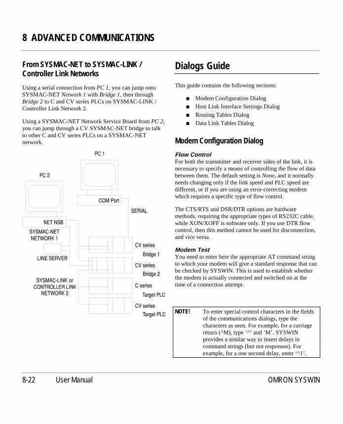
8 ADVANCED COMMUNICATIONS
8-22 User Manual OMRON SYSWIN
From SYSMAC-NET to SYSMAC-LINK /Controller Link Networks
Using a serial connection fromPC 1, you can jump ontoSYSMAC-NETNetwork 1with Bridge 1, then throughBridge 2to C and CV series PLCs on SYSMAC-LINK /Controller Link Network 2.
Using a SYSMAC-NET Network Service Board fromPC 2,you can jump through a CV SYSMAC-NET bridge to talkto other C and CV series PLCs on a SYSMAC-NETnetwork.
Dialogs Guide
This guide contains the following sections:
■ Modem Configuration Dialog
■ Host Link Interface Settings Dialog
■ Routing Tables Dialog
■ Data Link Tables Dialog
Modem Configuration Dialog
Flow ControlFor both the transmitter and receiver sides of the link, it isnecessary to specify a means of controlling the flow of databetween them. The default setting isNone, and it normallyneeds changing only if the link speed and PLC speed aredifferent, or if you are using an error-correcting modemwhich requires a specific type of flow control.
The CTS/RTS and DSR/DTR options are hardwaremethods, requiring the appropriate types of RS232C cable,while XON/XOFF is software only. If you use DTR flowcontrol, then this method cannot be used for disconnection,and vice versa.
Modem TestYou need to enter here the appropriate AT command stringto which your modem will give a standard response that canbe checked by SYSWIN. This is used to establish whetherthe modem is actually connected and switched on at thetime of a connection attempt.
NOTE! To enter special control characters in the fieldsof the communications dialogs, type thecharacters as seen. For example, for a carriagereturn (^M), type ‘^’ and ‘M’. SYSWINprovides a similar way to insert delays incommand strings (but not responses). Forexample, for a one second delay, enter ‘^1’.

8 ADVANCED COMMUNICATIONS
User Manual OMRON SYSWIN 8-23
DialThis section is used to establish the parameters used whenattempting to connect to the remote PLC.
■ InitialiseThe command string entered here is used toinitialise the modem before dialling. It may includecommands to set software protocols and errorcorrection levels, and so forth.
■ PrefixThis is the dialling command that precedes theconnection number. It is usually ‘ATDP’ (for pulsemode dialling), or ‘ATDT’ (for digital tonedialling).
If you are dialling from within a local exchange(PABX or similar), it may be necessary to prefixthe number with a ‘dial-out’ code, such as ‘9’. Thismay need to be followed by a delay to allow theexchange to provide an open line. If you are using aHayes compatible modem, use the comma character‘,’ to cause the modem to insert a short delaybefore dialling.
■ SuffixThis string is placed after the connection number,to complete the dialling command. Usually, areturn character (^M) is all that is used.
■ TimeoutSpecify here the time that you wish the modem towait for a connection. After the number of secondsspecified, if there is no proper response, the modemautomatically disconnects the telephone line. If ano Failure message is indicated (see below), thesoftware always waits for the full timeout beforedisconnecting.
■ Number of RetriesThis is the number of times you wish the modem toattempt to connect to the remote PLC if it is notsuccessful on the first attempt. For example, theline may be busy, or the responding modem maynot connect properly.
■ Carrier DetectCheck this option if you wish SYSWIN to use themodem’s carrier detect feature when connecting.SYSWIN uses the modem’s DCD signal. Thisrequires a modem cable with the appropriate lineconnected.
ResponsesWhen the modem connects to the remote PLC, it issuesstatus messages which must be recognised by SYSWIN tokeep you informed of status.
■ SuccessA successful connection results in a message suchas ‘CONNECT 9600’. The string required in thisfield is the main status word which is common toany successful connection - the default is‘CONNECT’. If a success string is used in additionto theCarrier Detectfeature (see above), then bothare required to achieve a good connection.
■ FailuresSeveral messages may be required to indicatevarious reasons why a connection failed, such as‘BUSY’, or ‘NO DIALTONE’. Your modemmanual lists the possible responses, and there isprovision in this dialog for up to five suchmessages.
DisconnectThis sets up the method which SYSWIN will use to end aconnection and disconnect the telephone line. Two methodsare available - DTR (hardware signal) and modemcommand. If the DTR method is chosen, then you cannotuse DTR for flow control, and vice versa.
The appropriate command string usually consists of aspecial character sequence to place the modem into ATcommand mode, followed by the disconnect command.
NOTE! There is no automatic disconnection after atimeout. You must explicitly disconnect withtheOnline/Disconnectcommand.

8 ADVANCED COMMUNICATIONS
8-24 User Manual OMRON SYSWIN
DefaultsThis button resets all of the fields and settings in theConfiguration dialog to their initial default values.
General NotesThe CPU-mounting LK201, LK201 (C200H/HS RS232C)and 3G2A5 (C500 RS232C) host link units honour the CTSsignal from the modem if the CTS selector switch is set toExternal. (By default, this switch is set to 0V, which meansthat the PLC ignores CTS from the modem.)
For CV series PLCs, the CV500-LK201 unit can beconfigured for either CTS or XON/XOFF transmitter flowcontrol.
The SYSWIN to local modem link can use different flowcontrol from the PLC to remote modem link. The modemsuse their own methods betweeneach other, regardless of thecommunications method.
Hostlink Interface Settings
TheProject|Hostlink Settingscommand allows you tochange the communications settings in the PLC for the on-board RS232/422 Hostlink Interface (the 9-pin connectoron the CPU module). Although these parameters areactually part of the PLC setup area in the PLC itself, theyare not set with theProject/PLC Setupcommand.
When using SYSMAC-WAY (the Hostlink itself), acommunications fault could arise when writing newparameter values, because the action of writing themchanges the settings for the channel through which thewriting is being performed. TheHostlink Settingscommand attempts to deal with this problem by resetting theSYSWIN communications parameters after writing the newvalues; this may take a few seconds. When using SYSMAC-LINK, no delay is incurred.
For these reasons, it is good practice to establish anychanges required to the Hostlink Settings early in theproject development.
TheHostlink Settings dialog allows you to read from andwrite to the PLC, and to change the communicationsparameters.
Parameter SetTheDefaultoption sets the on-board Hostlink to 9600baud, 7-bit data, even parity, 2 stop bits, and selects Unit 0.Use theCustomoption if you wish to use a different set ofparameters.
UnitSelect here the PLC unit number that you wish to use whileconnected.
Baud, Byte Size, Parity, Stop BitsSelect the appropriate options from these fields to define thecommunications protocol you require.

8 ADVANCED COMMUNICATIONS
User Manual OMRON SYSWIN 8-25
ReadThis button reads the current Hostlink Settings from thePLC, and changes the settings in the dialog to match them.
WriteThe settings are written to the PLC with this button, tochange the on-board Hostlink Settings. SYSWIN thendisconnects from the PLC, and attempts to re-connect; amessage appears if re-connection is not successful.
NOTE! For modem connection, theWrite button is notavailable, thus preventing possibly irretrievablecommunication failures.
RestoreThis button sets the Hostlink Settings to the state they werewhen you entered the dialog.
CloseUse this button to exit the dialog.
Routing Tables Dialog
The Routing Table Setup dialog allows you to configurenetworked PLCs so that they can communicate with eachother through bridges between networks. It is onlynecessary to set up Routing Tables if two or moreSYSMAC-LINK, Controller Link or SYSMAC-NETnetworks are connected together and you wish tocommunicate between them. The dialog allows you to setup Routing Tables for both C and CV series PLCs and alsofor the SYSMAC-LINK, Controller Link and SYSMAC-NET Network Service Boards (NSBs).
You start the Routing Table Setup dialog by using theProject|Routing tablescommand. When you areconnected to a PLC, you are able to read and write theRouting Table information in the PLC. You can changeconnection on the network so that you can edit the RoutingTables for other PLCs. When a Routing Table has beenwritten, you may need to activate it. You can then checkyour Routing Table by testing connections to remote nodes.
There are six types of Routing Table:
CV PLC for CV PLCs on SYSMAC-LINK andSYSMAC-NET networks
C PLC NET for C PLCs on SYSMAC-NET networksLINK NSB for SYSMAC-LINK Network Service
BoardsNET NSB for SYSMAC-NET Network Service
BoardsC-LINK NSB for Controller Link Network Service
BoardsC PLC C-LINK for C PLCs on Controller Link Network
Important Points to RememberA bridge PLC is a C or CV series PLC that has two or morenetwork cards. If Routing Tables are created for that PLC,communications messages can cross from one network toanother. Although C series PLCs do have Routing Tablesfor Controller Link networks, they do not have RoutingTables for SYSMAC-LINK networks.
8 ADVANCED COMMUNICATIONS
8-26 User Manual OMRON SYSWIN
When configuring SYSMAC-NET Network Service BoardRouting Tables, SYSWIN cannot directlyaccess theRouting Table on the Network Service Board, however youcan read and write the ROUTE.DAT file. This file isusually loaded by the SYSMAC-NET DOS utilities whenyour computer is restarted.
When using Routing Tables on SYSMAC-LINK andController Link Network Service Boards, the SYSMAC-LINK DOS utilities allow you to read and write .DATrouting files. The Routing Table information is typicallyloaded from the ROUTING.DAT file when your computeris restarted. SYSWIN will only create .SWR files and thesecannot be used by the SYSMAC-LINK utilities. However,you can read and write the Routing Tables directly from theNetwork Service Board. You then need to use theSYSMAC-LINK utilities to read the Routing Tableinformation from the Network Service Board using theSYSMAC-LINK utilities, and save it to a .DAT file.
When you have a direct serial connection, you can onlycreate the Routing Tables in the local PLC. To createRouting Tables in remote PLCs on a network, you need touse a serial CV bridge connection, a SYSMAC-LINKconnection or a SYSMAC-NET connection.
You should giveeach network a specific number. However,you can refer to the local network as network 0. If you areusing a Network Service Board, network 0 always refers tothe local network directly attached to your NSB. If youhave a serial connection to a CV PLC, network 0 refers tothe network that is connected to the lowest numberedSpecial I/O Unit.
You must give eachnode a specific number. However, youcan refer to the local node as node 0. If you are using aNetwork Service Board, node 0 always refers to the localNetwork Service Board. When you have a serial connectionto a CV PLC, node 0 refers to the local PLC.
Using the DialogWhen the dialog starts, theNetworknumber,Nodenumberand PLC information are displayed for the currentlyconnected PLC. If you wish to connect to another PLC onthe network, change theNetworkandNodefields, thenpress theConnectbutton. If the connection is successful,the information on the new PLC is displayed. The correcttype of Routing Table is automatically chosen for the newPLC. You can then configure the Routing Table for thatPLC.
When you have written the Routing Table to a PLC, youmay need to press theActivatebutton for the new settings totake effect. You can test a Routing Table to aRemote Nodeby entering aRemote Networknumber, aNodenumber andthen pressing theTestbutton.
To test a Routing Table on a CV PLC, it is usual to use aserial connection to the PLC and bridge onto a SYSMAC-LINK, Controller Link or SYSMAC-NET network. If theremote node test succeeds, then you will have tested theRouting Table in the bridge PLC.
The status field displays messages from SYSWIN thatindicate the current status of the communications.
CV Series SYSMAC-LINK, Controller Link andSYSMAC-NET Routing TablesFor each of the SYSMAC-LINK or SYSMAC-NET unitson the PLC, enter their Special I/O Unit numbers. You thenneed to enter the Local Network number to which the unit isdirectly attached.
To access PLCs on a Remote Network, you need to specifythe Relay Network, which must be one of the LocalNetworks attached to the local Special I/O Units. You mustalso specify the Relay Node on the Relay Network that isthe bridge to the Remote Network.
C Series SYSMAC-NET Routing TablesFor both theLevel 0 Networkand theLevel 1 Network, entertheNetwork numberthat is attached to that SYSMAC-NETUnit.
To access PLCs on aRemote Network, you need to specifythe Relay Node that is the bridge to the Remote Network.

8 ADVANCED COMMUNICATIONS
User Manual OMRON SYSWIN 8-27
SYSMAC-LINK NSB Routing TablesEnter the Local Network number to which the NSB isdirectly attached.
To access PLCs on a Remote Network, you need to specifythe Relay Network, which must be the same as the LocalNetwork. You must also specify the Relay Node on theRelay Network that is the bridge to the Remote Network.
C Series Controller Link Routing TablesEnter for each Level, the Level and Local Network numberthat is attached to the Controller Link unit. To access PLCson a remote network, you need to specify the RelayNetwork which must be the same as the Local Network.You must also specify the Relay Node on the RelayNetwork that is the bridge to the Remote Network. TheRouting Table Enable bit must be set.
Controller Link NSB Routing TablesEnter the Local Network number to which the NSB isdirectly attached. To access PLCs on a remote network, youneed to specify the Relay Network which must be the sameas the Local Network. You must also specify the RelayNode on the Relay Network that is the bridge to the RemoteNetwork.
SYSMAC-NET NSB Routing TablesTo access PLCs on a Remote Network, you need to specifythe Relay Node that is the bridge to the Remote Network.
The following section describes the operation of the buttonson the dialog:
ConnectWhen theConnectbutton is pressed, SYSWIN attempts toconnect to another PLC/NSB as specified by the Networkand Node fields in the Connected Node section. You canthen edit the Routing Table information for that newconnection.
TestAfter you have written a new Routing Table to a PLC/NSB,you can press theTestbutton. SYSWIN attempts tocommunicate with the PLC/NSB as specified by theNetwork and Node fields in the Remote Node section.
LoadFor many PLCs on a network, the Routing Tables aresimilar. You canLoadan existing Routing (.SWR) file andthen change it for the new PLC/NSB. You need toWritethe table to the PLC/NSB in order for the new table tobecome effective.

8 ADVANCED COMMUNICATIONS
8-28 User Manual OMRON SYSWIN
SaveYou canSavethe current Routing Table to a Routing(.SWR) file. This should be done as a backup precaution asRouting Table information is not stored as part of theSYSWIN project.
ClearPress theClear button to empty out the current settings inthe dialog. This does not affect the Routing Table in thecurrently connected PLC/NSB.
ReadWhen theReadbutton is pressed, the Routing Table isuploaded from the currently connected PLC or SYSMAC-LINK Network Service Board.
If you are configuring a Routing Table for SYSMAC-NETNetwork Service Board, theReadbutton opens the standardFile Open dialog. You would normally read theROUTE.DAT file that is used by the SYSMAC-NET DOSutilities.
WritePress theWrite button to download the Routing Table to thecurrently connected PLC or SYSMAC-LINK NetworkService Board. You may need to press theActivatebuttonto make the new table become active.
When configuring SYSMAC-NET Network Service Board,theWrite button opens the standard File Save dialog. Youwould normally save the file as ROUTE.DAT and then usethe SYSMAC-NET DOS utilities to write the table to theNetwork Service Board.
VerifyAfter writing a new Routing Table to the PLC/NSB, it isuseful to check that the information held in the dialog andthe actual settings in the PLC/NSB are the same. Simplypress theVerify button and if there are any differences, amessage is displayed.
ActivateAfter you have written a new Routing Table to some PLCs,you may need to press theActivatebutton. This makes thePLC use the new Routing Table that you have downloaded.
RestoreIf you wish to discard any editing changes that you havemade, press theRestorebutton. The Routing Tableinformation in the dialog is returned to the state when thetable was last downloaded to the PLC/NSB.
CloseThis closes the Routing Table Setup dialog. Any changesthat have not been saved or written down to the PLC/NSBare lost.
Data Link Tables Dialog
The Data Link Table dialog allows you to configure a PLCto participate in one or more automatic data sharingschemes, over SYSMAC-LINK, Controller Link andSYSMAC-NET networks, without the need for specialprogramming. Words of I/O and DM can be set aside foruse as data link words, which are allocated to various nodesin the network. Limits on the amount of data and number ofnodes varies with network and PLC types. The allocation ofwords to nodes is defined by one or more data link tables,created using this facility.
You start the dialog by using theProject|Data link tablescommand. Note that if you wish to read, write or verifytables from/to a PLC, you will need to have previouslyconnected to it before starting the dialog.
Data link words can be allocated either automatically, wheredata is shared equally between all participating nodes, ormanually if greater flexibility is required. Automaticallocation splits a fixed amount of I/O and DM equallybetween the number of participating nodes. For C seriesPLCs, automatic data links are configured using DIPswitches on the network units. Use manual allocation wherethe amount of data read or written byeachnode varieswidely.

8 ADVANCED COMMUNICATIONS
User Manual OMRON SYSWIN 8-29
Important Points to RememberSYSWIN can only set up data link tables for a single PLC.It will be necessary to repeat the process for each PLC onthe SYSLINK / Controller Link network.
Data can only be shared on a single physical network. Abridge cannot be used to pass information from one networkto another.
SYSMAC-NET data links can be configured so that both Cand CV series PLCs can share data. However, it is alimitation that in these mixed configurations the mastermust be a C series PLC. There are no such restrictions forSYSMAC-LINK and Controller Link networks.
Using the DialogWhen the dialog starts, it displays the I/O Unit number(Levelfor C series PLCs) and networkTypefor that unit.You may change theUnit andTypeto select the data linktable that you require. SelectNoneif there is no data linktable to be set.
After selecting the required data link table you should setthe type ofAllocation to be one of:
■ Automatic I/O only
■ Automatic DM only
■ Automatic I/O and DM
■ Manual
If you select one of the automatic modes, it is thennecessary to set theAuto Sizeto the appropriate number ofparticipating nodes.
SYSMAC-LINK Manual Data Link TablesThe table is split into two distinct sections:
TheCommon Areadefines the amount of I/O and DMtransmitted by eachnode and should be identical for allPLCs in the network. You should specify the number ofwords of I/O and DM where 0 indicates that a node receivesdata but does not send any. Leave both fields blank to showthat a node does not participate in the data link at all. SettheCycle Timeto between 5 and 255ms or 0 for automaticselection.
TheRefresh Tabledefines the data received by thisparticular node and needs to be set individually foreachPLC. Specify the node numbers which supply dataincluding an entry for the local node.
Controller Link Manual Data Link TablesThe Controller Link data link table requires a StatusAddress (CIO / LR / DM / EM) to be specified where thestatus to the data link resides. There are two areasassociated with the Controller Link manual data link table.Each area has a Data Link Status Address (CIO / LR / DM /EM), for eachnode specified in an area. The number ofwords and the offset from the area Start Address can bespecified.
SYSMAC-NET Manual Data Link TablesSYSMAC-NET data links require a single co-ordinatingmaster which controls all data exchange amongst a numberof slaves. It is only necessary to set a table for the masterwhich can either participate in or simply control the datalink.
Enter aDelay Timeappropriate for the network loadconditions of either 5, 10, 20 or 30 ms.
You should then make an entry foreach participatingnodespecifying the amount of I/O and DM which it will providein the data link. Set the I/O and DM base addresses at whichthe shared data will start within the PLC.
The following section describes the operation of the buttonson the dialog:
■ LoadFor many PLCs on the network, the data link tableswill be similar. Existing tables can be loaded fromother project files and modified for the new PLC bypressing this button. You need toWrite the newtable to the PLC in order for it to become effective.The new table is saved as part of the current projectfile.
■ ReadWhen theReadbutton is pressed, the data linktable for the selectedUnit is uploaded from theconnected PLC and displayed in the dialog.

8 ADVANCED COMMUNICATIONS
8-30 User Manual OMRON SYSWIN
■ WritePress theWrite button to download the data linktable for the currently selectedUnit to theconnected PLC. For some PLCs you may need torestart the Unit for the data to become active.
■ VerifyAfter writing the table to the PLC it is often usefulto check that the information in the dialog and thesettings in theUnit are the same. Simply press theVerify button and if there are any differences, amessage is displayed.
■ Start / StopPress this button toStart the data link in theselectedUnit. Once active, a second press of thebutton will Stopthe data link.
■ ClearTheClear button allows you to clear the contentsof the table shown in the dialog. Note that this doesnot affect any table in the connected PLC.
■ RestoreIf you wish to discard any editing changes that youhave made, press theRestorebutton. Theinformation in the dialog is returned to the statewhen the table was last downloaded to the PLC orthe dialog was closed.
■ CloseThis will Closethe Data Link Tables dialog.Remember to save the project otherwise anychanges will be lost.

9 ADVANCED FUNCTIONS
User Manual OMRON SYSWIN 9-1
9 ADVANCED FUNCTIONS
Function Plan Editor
Many PLC programmers are familiar with the function planmethod of creating PLC programs, and SYSWIN providesthe necessary facilities for using this in place of ladderdiagrams. Using the Function Plan Editor is essentially thesame as ladder programming, except that AND and ORgates are used to join contacts. The SYSWIN controls areused as described in Section 2 -CreatingPLC Programs.
The selection of function plan editing is usually done whena project is created, and although you can switch from oneediting method to the other at any time, this is notrecommended. However, it is helpful in situations whereyou might create a program using ladder diagrams, thenpass it to someone else who finds the function plan editormore convenient.
To set the project in function plan editing mode, use theProject|Project setupcommand and select the FunctionPlan Editor under theEditor options.

9 ADVANCED FUNCTIONS
9-2 User Manual OMRON SYSWIN
Importing a Project From Disk
TheFile|Import command allows you to load wholeprojects or parts of them into an existing project. It isgenerally used to import complete sections of files, but canalso be used to import specific parts of PMD files.
Programs and parameters imported with this commandreplace the existing project details, and therefore a dialogallows you to select only those details that you wish toimport, from the following list:
■ Block and networks
■ Block/network comments
■ Address symbols
■ Expansion Functions
■ I/O table
■ PLC setup
If a particular item does not apply to the PLC series forwhich the current project has been set up, it will be greyedout and unavailable.
The only usefully editable files are .PMF and .ADR files.Appendix C contains details and examples of these files.Refer to that chapter for a full description.
Maintaining Libraries
By using libraries created in SYSWIN, you can greatlyspeed up program development, re-using blocks andnetworks in different projects. SYSWIN libraries canconsist of complete programs or just individual blocks,according to the level of detail that you wish to use.Libraries can only be created and maintained while notconnected to a PLC, and it is therefore necessary to testnetworks while they are part of a normal SYSWIN project,before extracting them into a library file.
Editing Library Files
The recommended method of creating and working with alibrary is to follow this general sequence:
➧ Create and test a block within an existing projectMake sure that the block is complete and operatescorrectly within the PLC.
➧ Save the project as usual
➧ Create or load a library fileFor a new library, select theLibrary option in theProject Setupdialog, otherwise open an existing libraryfile.
➧ Import blocks from the saved programUse theLoadbutton in theBlock / Network Managerto copy the tested blocks into the current library.
➧ Save the library file to disk
➧ Create a new PLC program, or open an existing oneOpen a project in the normal way, ready to acceptblocks from the library.
➧ Load the library with the Block / Network Manager

9 ADVANCED FUNCTIONS
User Manual OMRON SYSWIN 9-3
Saving Library Files
Saving a library file to disk follows the same procedure asfor other SYSWIN files. If you are saving the library for thefirst time, use theFile|Save projectcommand; otherwiseuse theFile|Save project ascommand to display the savingdialog box.
The workspace is saved as a library only if theLibrary onlyoption in theProject Setupdialog was selected when theprogram was created.
Recalling Library Files
There are two ways of recalling library files whileprogramming.Importinga file brings a library into theworkspace, replacing whatever was there previously.Loadinga library (from within the Block/NetworkManager) inserts the library module into an existingprogram.
Importing a LibraryUse theFile|Import command to replace completely thecurrent program with one from a library file. This dialog issimilar to the one for theFile|Open project command, andallows you to select from a list of standard SYSWIN filetypes. SelectLibrary File (SWL) - or V1 Library File (LIB)if you wish to import an older version file - to list the filesavailable.
Loading a LibraryFrom theBlock/Network manager, you can load a libraryor program file and insert it within the list of blocks ornetworks. Insertion is always done at the point above thecurrently selected item, so to append a library, you mustselect the blank line below the last entry in a list for it to beinserted correctly.
Templates
Each PLC that is supported by SYSWIN is supplied with astandard set of address symbol definitions. Address symbolsare stored in .SWT files in the TEMPLATE sub-directory.
Standard system addresses have been given symbols. If youset the option toAutomatically Load Template for NewProject in thePreferences|Optionsdialog, when you start anew project, the template for the PLC that you have selectedis loaded. These templates are not a definitive list; they arejust a starting point. You can add to them as you wish.
The template files are also used during project conversionfrom one PLC to another. If you alter a standard symbolname in one template then you must alter it in all the othertemplates. In a C200H for example, 253.13 is the ON Flag.If you change to, say, a CV series, the symbol name must beidentical. If you are in any doubt about the use of thecorresponding symbol names, it is advisable not to alter thesymbol template files.
During conversion your existing symbols are not replacedby the ones in the templates and your original symbols aremoved to their new addresses.

9 ADVANCED FUNCTIONS
9-4 User Manual OMRON SYSWIN
Producing EPROMs
Several C series PLCs can have EPROMs. Whenyou use theFile|Save EPROM Imagecommand to
generate an EPROM image, a dialog is displayed giving youthe choice of file type. There are three possibilities:
■ .BIN for straight Binary format
■ .IHX for Intel Hexadecimal format
■ .MOT for Motorola 5 format
The file name should be entered and, where required, theappropriate directory in which you wish the file to be saved.
The program is checked and if there are any faults theStatement List Editor will start and the first error ishighlighted. Use the functions of the Statement List Editorto correct these errors.
Another dialog box is displayed showing the PLC modeland CPU type for you to check. The program size and theamount of memory required are shown. If the actualprogram size is greater than the maximum program size thenthe EPROM type should be changed to another one in thelist. Note that it may not be possible to change the EPROMtype depending on the PLC that you have selected. Ifnecessary you may have to use theProject|Allocatememory command to change the expansion DM size.
If you wish to include initial DM settings, then enable thebox. The range of addresses which are included in theEPROM image are displayed. PressSelectto open therequired .DDM file. Data files must have been preparedusing the Data Display Editor. The range of addresses in thedata is displayed; only the relevant DM addresses areincluded.
To include the I/O Table in the EPROM image, check theInclude I/O Tableoption.
To enable the detection and indication of a low battery,enable theInclude detect batterycheck box.
Accept the dialog, and the EPROM image file is created.
Saving to PMF File Format
PMF files are the text-based form of information within aproject. They are designed to allow SYSWIN project files tobe used by other applications. SYSWIN allows the savingof both projects and Address Symbol Tables as PMF files.
The PMF file feature is also used internally by SYSWINwhen converting projects from other packages. It is anintermediate file before the SYSWIN files are produced.Note that the .PMF file is left in the original directory aftera conversion is completed. For detailed information on thelayout of a PMF file, see Appendix C.
Saving Projects as PMF Files
Not all information in the project is included in the PMFfile. The feature should not be used on a regular basis toSaveandOpen project files. It should only be used whenthe project is to be imported from or exported to anotherapplication.
To save project as a .PMF file, selectFile|Save project asand choose PMF as the file format in the ListFiles of typefield.
Saving Address Symbol Information as PMFFiles
Address Symbol information within the Address SymbolEditor can be saved in the .PMF file format. Within theAddress Symbol Editor, select theSavebutton and type avalid file name in theFile namefield. SelectOK to save thefile.

9 ADVANCED FUNCTIONS
User Manual OMRON SYSWIN 9-5
Converting Projects From OtherPackages
Files can be converted from other packages for use inSYSWIN. Use theFile|Convert from command to set upthe parameters for conversion. The Select File forConversion dialog is displayed. This is a standard WindowsFile Open dialog with the possible file types as .DAT forLSS library files or .COD for CVSS program files. Choosethe file from the list or change the directory to the locationof the file to be converted.
If the LSS file type is chosen, then select the LSS programfrom the library you have selected and the correct PLC andCPU for the program.
If you choose CVSS, select the correct PLC and CPU forthe program.
The network comments, address symbol comments andprogram are converted. A .PMF file is created in the samedirectory as the original .DAT or .COD file. Any errors thatSYSWIN detects during the conversion process are writtento a report file (.REP) that you can look at with any texteditor.
Be certain to check that the conversion is done correctly.

9 ADVANCED FUNCTIONS
9-6 User Manual OMRON SYSWIN

10 CONFIGURING THE ENVIRONMENT
User Manual OMRON SYSWIN 10-1
10 CONFIGURING THE ENVIRONMENT
The system starts with a series of default preferences. Theseare the most commonly used settings. You may alter theseto suit your own particular requirements. Note that theGlobal Preferences affect the working environment of allprojects and Project Preferences affect the individualproject. This chapter describes the preferences that areavailable when creating ladder diagram or function plannetworks, using the Data Display Editor, Data Trace andTime Chart Monitoring.
Global Preferences -Ladder Diagram / Function Plan
The main purpose of configuring the SYSWIN display is tomake as much space as possible for working with ladderdiagrams while retaining the appropriate controls to suityour way of working.
ThePreferencesmenu allows you to change the globalsettings for your working environment. Selecting this menugives further selections.
Window
This command changes the screen format altering theregions of the screen that are affected by each option.
As options are selected or deselected the screen changesimmediately. The SYSWIN window itself can be manuallyresized by click-dragging the bottom right-hand corner, orby using the normal Windows controls in the system menu.The default settings for each region are designed to give anacceptable programming environment for first time users.
Toolbar (Default ON)The SYSWIN toolbar contains quick ‘push-button’alternatives to the most commonly used menu commands.Each button has a key equivalent to allow fast access, if youprefer to use the keyboard. When not selected, the buttonsand the keys are not shown.
Keys (Default - Function Keys)If you prefer to use the mouse to select the toolbarcommands, or if you are familiar with the keystrokes forthem, the strip showing the keys can be disabled. Thisselection is only available if the Toolbar is switched ON.

10 CONFIGURING THE ENVIRONMENT
10-2 User Manual OMRON SYSWIN
Drawing Tools (Default ON)These are the main tools used to create ladder diagrams (asimilar set is available for function plan editing). When theShow Drawing tools is selected, the tools can be displayedeither vertically (the default) or horizontally.
Keys (Default - Alpha Keys)If you prefer to use the mouse to select the drawing tools, orif you are familiar with their keystrokes, these can beremoved from the display. Click theNo keysoption to turnthem off. You can choose to display eitherAlphaorFunctionkeys.
Data Set Bar (Default ON)This controls the display of the area at the bottom of thescreen where values for data items may be displayed. Whenselected you can choose to have either2 rowsor 4 rowsofinformation displayed.
Other WindowsShow Network bar (Default OFF)This displays the header and comments relating to thecurrently selected network.
Show Address bar(Default ON)The Address Bar shows the address and name of thecurrently selected element, and allows editing of thisinformation and the addition of comments.
Show Status bar(Default ON)This is used to show the current address position in aprogram, the PLC monitor mode, online status and instanthelp for menu commands.
Drawing
TheDrawing Preferencesdialog allows you to configurethe ladder diagram view to suit your needs. It shows areaswhere you may modify the display and also gives theopportunity to select the fonts to be used in both standardand overview display.
Network DisplayShow grid marks (Default ON)Each element of a ladder diagram is placed on a notionalgrid in the display. This menu option specifies whether youwish the grid itself to be displayed for reference. A smalldot is displayed at each intersection of the grid, providingminimal interference with the ladder diagram.
Show descriptions after Functions(Default ON)A description of the function is displayed on the network ifthis is selected.
Show comments after Outputs and Functions(Default ON)This displays the address symbol comments after Outputsand Functions when selected.
Show differentiation mark on Contacts or Inputs(Default ON)The differentiation mark is displayed if this is selected. IfDIFU or DIFD instructions are used within the program, asmall differentiation mark is displayed on contacts andinputs.
Ladder (Default - Show Both)Show addressesWhen selected, only the addresses on the ladder diagram areshown.
Show symbolsWhen selected, the symbols on each ladder step in thenetwork are displayed.
Show Both(the Default)This displays both the address and the symbol on eachladder element.
Network SeparatorsShow network comments on separators(Default ON)Each network is separated in the program display by aheader which shows the network number. When enabled,the first three lines of the network comments are displayed.

10 CONFIGURING THE ENVIRONMENT
User Manual OMRON SYSWIN 10-3
MonitoringAutomatically start monitoring after online-edit(Default ON)When selected, monitoring restarts automatically after aprogram is changed online, accepted and downloaded to thePLC. See theTesting While Connectedchapter for detailedinformation about monitoring.
Interpret values when monitoring (Default ON)When enabled, values are interpreted when monitoring.Parameters within functions are interpreted and displayed inan appropriate format. For example, parameters 1 and 2 ofthe FDIV instruction are displayed in long BCD andparameter 3 is displayed in floating point format.
Display forced state of bit addresses(Default OFF)All bit addresses that have been forced are displayed withmarkers on the elements within the network.
Show full powerflow monitoring (Default ON)When enabled and running online, the display of the fullpowerflow throughout the network is shown. Whendisabled, the state of the contacts, outputs and values offunction parameters only are displayed.
FontsPressing theStandard Fontor theOverview Fontbuttondisplays a list of supported fonts that the user may select.
Standard FontThe font you choose here is used for all text in the ladderdisplay, including headers, symbols and comments.Normally, this is set to a point size of 9 or greater,depending on the resolution of your screen.
A standard Windows font selection dialog is used, and anychanges made become effective as soon as the dialog isaccepted.
Overview FontSYSWIN’s overview mode allows you to view a program atreduced size, showing much more than would be displayedin standard mode. This is useful to locate networks quickly.
The font size used for text should be significantly smaller,though still readable. Point sizes of 8 or less are generallyused for overview mode.

10 CONFIGURING THE ENVIRONMENT
10-4 User Manual OMRON SYSWIN
Editing
FunctionsDirect entry of function names from ladder (DefaultOFF)When selected it is not necessary to press the‘F’ or F8 keyto start the editing dialog. Simply type the mnemonicdirectly; for example, typeMOV .
Note that timers and counters can be entered by typingTIMandCNT directly.
Accept 3 digit functions for all PLCs (Default OFF)If you wish to enter function numbers as 3 digits for allPLCs, select this option.
Keyboard OptionsRoll over network separators(Default ON)When enabled, if the cursor reaches the top or the bottom ofthe current network it rolls over to the next network. Toextend a network, press theSpace Bar.
When disabled, you have to press thePageUporPageDownkey to change network.
Automatically select ladder drawing tool (Default OFF)When enabled, any tool selected by the keyboard remainsactive allowing successive placement of symbols bypressing theEnter key. If disabled, the default condition,Enter, allows editing of the symbol.
Editing DialogsShow all buttons on large dialogs(Default ON)This is used in the ladder editing dialogs and, when enabled,shows the OK,CancelandReferencebuttons on thesedialogs. TheReferencebutton starts the correct quickreference guide (the same as pressingCtrl+F1 ).
Display symbol information be default (Default OFF)When editing ladder diagrams, the symbol name isdisplayed instead of the address in the ladder editingdialogs.
Options
StartupAutomatically open last project (Default OFF)If you enable this, SYSWIN automatically opens the lastused project file, and restores the project status. This savesyou having to explicitly open a file that you were workingon when last using SYSWIN.
Automatically connect to PLC (Default ON)When enabled, this option automatically connects to thePLC whenever a project file is opened. A message appearson each attempt to connect, informing you of the connectionstatus.
Automatically load template for new project (DefaultON)If this is enabled, the address symbols for the PLC areloaded from the appropriate template file when a newproject is started.
CommunicationsThe number of times that SYSWIN will try to reconnectcommunications to the PLC before timing out. The defaultvalue is 3, but may be amended as required by theNumberof reconnection attempts:field.
SafetyConfirm all operations that affect the PLC (Default OFF)Changing programs while online can have serious effects onthe operation of the equipment controlled by a PLC.SYSWIN’s Safety Mode warns you before undertaking anycritical operation that can affect the state of the PLC. It doesnot interfere with your ability to go ahead and do thatoperation, but merely tells you that it is potentially critical.The recommended usage of safety mode is as follows:
■ Connected with outputs active: ON
■ No outputs connected to PLC: OFF
■ Advanced user: OFF
HelpDisplay bubble help on toolbar buttons(Default ON)When selected, a short description of the button’s functionis displayed on the screen as the cursor is held over it. If it isnot selected, then the description is displayed in the StatusBar when the toolbar button is pressed.

10 CONFIGURING THE ENVIRONMENT
User Manual OMRON SYSWIN 10-5
Global Preferences - Data Display
When you switch to theData Display Editor, the SYSWINscreen changes to provide additional toolbar options andmodified menus. Many of the commands used in normalSYSWIN operation can still be used, however, includingthe file and online commands. Preferences for the DataDisplay Editor can be set by selecting Preferences from theMenu Bar and then choosing Font, Window or Options.
Window
Toolbar (Default ON)Show ToolbarIf selected, the Toolbar shows the buttons and function keyselections that are available. They are not displayed if this isnot selected.
Keys (Default - function keys)You have the option of not displaying the function keyswhen the toolbar is displayed. For those users who areexperienced in the use of SYSWIN, the function keys maybe switched off, giving a greater area for the display of thedata areas.
Area Tools (Default - ON)The Area Tools, showing the data areas that can be edited,are controlled by this option. When selected, they can bepositioned either vertically or horizontally.
Keys (Default - Area Keys)The keyboard equivalents may also be displayed alongsideby selecting the Keys switches. For those users who areexperienced in the use of SYSWIN, the keys may beswitched off, giving a greater area for the display of the dataareas.
Other WindowsShow Status Bar (Default ON)This displays the Status Bar, the PLC monitor mode, onlinestatus and instant help for menu commands at the bottom ofthe screen if selected.
Options
The two features on this display are described in theprevious section: Global Preferences - Ladder Diagram /Function Plan.
Font
The font type, size and style in which you wish the dataareas to be displayed are selected with this option.

10 CONFIGURING THE ENVIRONMENT
10-6 User Manual OMRON SYSWIN
Global Preferences -Data Trace / Time Chart Monitoring
When you selectData Traceor Time Chart Monitoringyoucan set preferences for the screen layout.
Window
ToolbarShow Toolbar (Default ON)The toolbar shows the buttons and function keys that areavailable during Data Trace / Time Chart Monitoring. Itmay be disabled to give you more display area.
Keys (Default - function keys)If the Toolbar is selected then you can choose to have thefunction keys displayed or not. For those users who areexperienced in the use of SYSWIN, the function keys maybe switched off, giving a greater area for the display of thetraces.
Options
The two features on this display are described in theprevious section: Global Preferences - LadderDiagram/Function Plan.
Font
The font type, size and style in which you wish the dataareas to be displayed are selected with this option.
.INI File Preferences
Display Colours
Certain Windows display configurations can make itdifficult to view the standard SYSWIN window. The defaultcolours used for SYSWIN can be changed to suit yourenvironment.
The global preferences for running SYSWIN are saved in aspecial file - SYSWIN.INI - in your Windows directory.This is a text file, which can be edited with any standardtext editor. You must edit this file to change the coloursused for the SYSWIN display.
In the SYSWIN.INI file, a section headed ‘[Prefs] ’contains several environment settings. Add the followingstatements to specify the appropriate screen colours:
GreyColour=192,192,192RedColour=255,0,0
The default values have been given here. Colours areentered as RGB (red, green, blue) values in the range 0 to255 (no colour to full colour). For example, to change thered to blue, you would enter:
RedColour=0,0,255
10 CONFIGURING THE ENVIRONMENT
User Manual OMRON SYSWIN 10-7
Help Colours
The colour used to highlight ‘hypertext’ words in theSYSWIN help system (usually green) can also be changed.This requires editing the Windows initialisation fileWIN.INI in your Windows directory. The followingstatement can be added to the ‘[Windows Help] ’ sectionof this file:
JumpColor=255,0,0
This example changes the colour to red. Note the differentspelling used here.
Startup Options
In the SYSWIN.INI file the section[Setup] containsvarious startup options.
Project LoadingIf you have problems starting SYSWIN, change thefollowing options:
Autostart = 0Autoconnect = 0
CPM1 ProgrammingIf you do not have a token, SYSWIN usually runs indemonstration mode. However, if you wish to program inCPM1 mode, change the following:
CPM1OnlyMode = 1
NOTE! Be very careful when editing the SYSWIN.INIfile! Do not change or remove any items otherthan the ones described above.

10 CONFIGURING THE ENVIRONMENT
10-8 User Manual OMRON SYSWIN

11 ADVANCED INSTALLATIONS
User Manual OMRON SYSWIN 11-1
11 ADVANCED INSTALLATIONS
Chapter 1 described the standard installation of SYSWINon Windows 3.1, Windows 3.11, Windows 95, Windows 98and Windows NT 4.0 operating systems. SYSWIN can alsobe installed on computers using different operating systems,but some features of SYSWIN may not be available.
The following chapter gives you detailed information aboutinstalling SYSWIN on different operating systems. It willalso help you to overcome any problems activatingSYSWIN when using the Token Mover or Dongle.
To use SYSWIN, you need to install the program using theSETUP.EXE program on the CD-ROM or Program Disk 1.You need to activate SYSWIN before you can fullyprogram all PLCs by entering the Serial Number, or byinstalling a Token Disk or a Dongle from a previousversion. If SYSWIN is not fully activated, then you can runSYSWIN in either Demonstration Mode or CPM1 Mode.You are given this choice during the installation.
Operating System Compatibility
OMRON does not guarantee that SYSWIN will work onany other hardware other than 100% industry-standard PC-compatible hardware, and it does not guarantee that it willwork under any operating system other than Windows 3.1,Windows 3.11 or Windows 95, Window 98 and WindowsNT 4.0. The following information is provided forcompleteness. However, SYSWIN still may not workcorrectly even though the procedures given here arefollowed.
You will always be able to run SYSWIN in CPM1 Mode orDemonstration Mode. If you have a Token Disk, you needa PC with a 100% compatible floppy disk system which isalso able to run MS-DOS in order to activate SYSWIN.Tokens may be lost or damaged during activation whenusing non-standard systems.
NOTE! You will not be able to use your SYSMAC-LINK and SYSMAC-NET Network ServiceBoards under Windows NT as SYSWINrequires MS-DOS device drivers to be loadedwhich are not supported by Windows NT.

11 ADVANCED INSTALLATIONS
11-2 User Manual OMRON SYSWIN
Installing and Activating SYSWIN
The next three sections in this chapter give information onthe installation and activation of SYSWIN with TokenDisks and Dongles. It is necessary to follow theinstructions in the Operating System Installation Guidewhich then point you to further information in theConnection Guide and Procedure Guide.
NOTE! If you are installing using the Dongle, refer tothe README.TXT file located in the DONGLEsubdirectory for more detailed information.
Operating System Installation Guide
You can install SYSWIN either to your own workstation, orto a dedicated file server so that several people can use it.You can often ‘share’ your own hard disk on yourworkstation so that others can also use SYSWIN. You needa multi-user licence if more than one person is to useSYSWIN at the same time.
If you are using a Token mover or Dongle, choose a methodbelow and follow the steps to install and activate SYSWIN:
■ Installing to Your Own Windows 3.1, Windows3.11, Windows 95, Windows 98 and Windows NT4.0 Workstation
■ Installing to Your Own Windows NT Workstation
Additional topics in this section are:
■ Installing to Another Workstation Across aNetwork or Serial Link
■ Installing to a Dedicated File Server
■ Activating Across a Network

11 ADVANCED INSTALLATIONS
User Manual OMRON SYSWIN 11-3
Installing to Your Own Windows 3.1, 3.11,Windows 95, Windows 98 and Windows NT 4.0Workstation (Token)
➧ Refer to theLocal Drive Connection in the ConnectionGuide.
➧ Start up Windows.
➧ Run SETUP.EXE; this installs the SYSWIN files to theLocal Drive.
➧ Use theToken Mover Procedureto activate SYSWIN.If successfully activated, you can use SYSWIN.
➧ If Token Mover failed:Reboot to DOS prompt.Use theToken Manual Installation Procedureto activate SYSWIN.
➧ If Token Mover failed again:Use theToken Manual Check Procedureonanother computer.If succeeded, go toActivating Across aNetwork (Token).If failed, contact Customer Services.
Installing to Your Own Windows 3.1, 3.11,Windows 95, Windows 98 and Windows NT 4.0Workstation (Dongle)
➧ Refer to theLocal Drive Connection in the ConnectionGuide.
➧ Attach the SYSWIN Dongle to the parallel printer porton the PC. You can re-attach your printer to the Donglelater when you are sure that the Dongle is workingcorrectly.
➧ Turn on the computer and start Windows.
➧ Run SETUP.EXE; this installs the SYSWIN files to theLocal Drive.
➧ Use the Dongle installer.If successfully activated, you can run SYSWIN.
➧ If Dongle install failed:Check the port settings are correct for your PCUse the Dongle installer.
➧ If Dongle install failed again:Contact Customer Services.
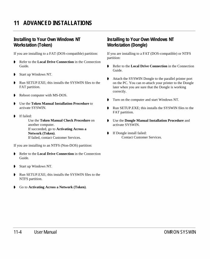
11 ADVANCED INSTALLATIONS
11-4 User Manual OMRON SYSWIN
Installing to Your Own Windows NTWorkstation (Token)
If you are installing to a FAT (DOS-compatible) partition:
➧ Refer to theLocal Drive Connection in the ConnectionGuide.
➧ Start up Windows NT.
➧ Run SETUP.EXE; this installs the SYSWIN files to theFAT partition.
➧ Reboot computer with MS-DOS.
➧ Use theToken Manual Installation Procedure toactivate SYSWIN.
➧ If failed:Use theToken Manual Check Procedureonanother computer.If succeeded, go toActivating Across aNetwork (Token).If failed, contact Customer Services.
If you are installing to an NTFS (Non-DOS) partition:
➧ Refer to theLocal Drive Connection in the ConnectionGuide.
➧ Start up Windows NT.
➧ Run SETUP.EXE; this installs the SYSWIN files to theNTFS partition.
➧ Go toActivating Across a Network (Token).
Installing to Your Own Windows NTWorkstation (Dongle)
If you are installing to a FAT (DOS-compatible) or NTFSpartition:
➧ Refer to theLocal Drive Connection in the ConnectionGuide.
➧ Attach the SYSWIN Dongle to the parallel printer porton the PC. You can re-attach your printer to the Donglelater when you are sure that the Dongle is workingcorrectly.
➧ Turn on the computer and start Windows NT.
➧ Run SETUP.EXE; this installs the SYSWIN files to theFAT partition.
➧ Use theDongle Manual Installation Procedureandactivate SYSWIN.
➧ If Dongle install failed:Contact Customer Services.

11 ADVANCED INSTALLATIONS
User Manual OMRON SYSWIN 11-5
Installing to Another Workstation Across aNetwork or Serial Link (Token only)
This is most easily achieved when the Client is a standardDOS/Windows computer:
➧ Refer to theRemote Workstation Connectionin theConnection Guide.
➧ Start up both Client and Server Workstations.
On the Client Workstation:
➧ Check that the Client can fully access the Server’s harddisk across the network.
➧ Run SETUP.EXE; this installs the SYSWIN files to theNetwork Drive.
➧ Use theToken Mover Procedureto activate SYSWIN.
➧ If Token Mover failed:Reboot the computer with MS-DOS.Use theToken Manual Installation Procedureto activate SYSWIN.
➧ If Token Mover failed again:Use theToken Manual Check Procedureonanother computer.If succeeded, go toActivating Across aNetwork (Token).If failed, contact Customer Services.
On the Server Workstation:
➧ When successfully activated:Use theGroups Procedureto register SYSWIN.You can then use SYSWIN.
Installing to a Dedicated File Server (Token)
➧ Refer to theRemote File Server Connectionin theConnection Guide.
➧ Start up both Client Workstation and File Server.
On the Client Workstation:
➧ Check that the Client can fully access the Server’s harddisk across the network.
➧ Run SETUP.EXE; this installs the SYSWIN files to theNetwork Drive.
➧ Use theToken Mover Procedureto activate SYSWIN.
➧ If Token Mover failed:Reboot the computer with MS-DOS.Use theToken Manual Installation Procedureto activate SYSWIN.
➧ If Token Mover failed again:Use theToken Manual Check Procedureonanother computer.If succeeded, use theToken Manual InstallationProcedureto activate SYSWIN.If failed, contact Customer Services.
On other Client Workstations:
➧ When successfully activated:Use theGroups Procedureto register SYSWIN.You can then use SYSWIN.
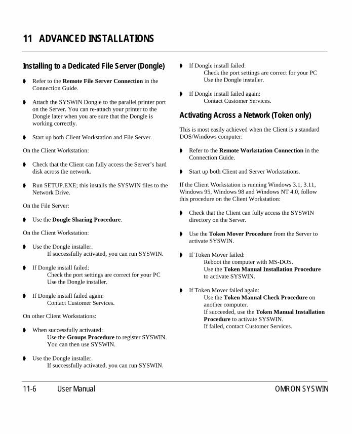
11 ADVANCED INSTALLATIONS
11-6 User Manual OMRON SYSWIN
Installing to a Dedicated File Server (Dongle)
➧ Refer to theRemote File Server Connectionin theConnection Guide.
➧ Attach the SYSWIN Dongle to the parallel printer porton the Server. You can re-attach your printer to theDongle later when you are sure that the Dongle isworking correctly.
➧ Start up both Client Workstation and File Server.
On the Client Workstation:
➧ Check that the Client can fully access the Server’s harddisk across the network.
➧ Run SETUP.EXE; this installs the SYSWIN files to theNetwork Drive.
On the File Server:
➧ Use theDongle Sharing Procedure.
On the Client Workstation:
➧ Use the Dongle installer.If successfully activated, you can run SYSWIN.
➧ If Dongle install failed:Check the port settings are correct for your PCUse the Dongle installer.
➧ If Dongle install failed again:Contact Customer Services.
On other Client Workstations:
➧ When successfully activated:Use theGroups Procedureto register SYSWIN.You can then use SYSWIN.
➧ Use the Dongle installer.If successfully activated, you can run SYSWIN.
➧ If Dongle install failed:Check the port settings are correct for your PCUse the Dongle installer.
➧ If Dongle install failed again:Contact Customer Services.
Activating Across a Network (Token only)
This is most easily achieved when the Client is a standardDOS/Windows computer:
➧ Refer to theRemote Workstation Connectionin theConnection Guide.
➧ Start up both Client and Server Workstations.
If the Client Workstation is running Windows 3.1, 3.11,Windows 95, Windows 98 and Windows NT 4.0, followthis procedure on the Client Workstation:
➧ Check that the Client can fully access the SYSWINdirectory on the Server.
➧ Use theToken Mover Procedurefrom the Server toactivate SYSWIN.
➧ If Token Mover failed:Reboot the computer with MS-DOS.Use theToken Manual Installation Procedureto activate SYSWIN.
➧ If Token Mover failed again:Use theToken Manual Check Procedureonanother computer.If succeeded, use theToken Manual InstallationProcedureto activate SYSWIN.If failed, contact Customer Services.

11 ADVANCED INSTALLATIONS
User Manual OMRON SYSWIN 11-7
Connection Guide
This section provides information on the different ways ofconnecting computers together:
■ Local Drive Connection
■ Remote Workstation Connection
■ Remote File Server Connection
Local Drive Connection
This is the standard connection that you would normally useto install and activate SYSWIN on your local hard disk.
Remote Workstation Connection
You would use this connection to install SYSWIN ontoanother computer across a network or a serial connection.You would use a Client Workstation to install and activateSYSWIN on the remote Server Workstation.
You can use the Remote Workstation Connection when:
■ Your Server Workstation does not have a 100%compatible floppy disk system and you are using atoken.
■ Your Server Workstation does not have a floppydisk drive (Notebook computer).
■ Your Server Workstation is not runningWindows 3.1, 3.11, Windows 95, Windows 98 andWindows NT 4.0.
■ Your Server Workstation is not an 80x86/ Pentiumbased CPU.
If you need to install SYSWIN by running SETUP.EXE,then the Client Workstation must be able to run Windowsprograms.
If you need to activate SYSWIN with a Token, then theClient Workstation must have a 100% compatible floppydisk system.
If you are using Windows 3.1, 3.11, Windows 95,Windows 98 and Windows NT 4.0 on the ClientWorkstation, you can use theToken Mover Procedureorthe Dongle installer.
If you are using any other operating system, you need toreboot your Client Workstation using MS-DOS and thenuse theToken Manual Installation Procedure or theDongle Manual Installation Procedure.
You must let the remote Server Workstation “share” its harddrive so that your local Client Workstation can “attach” tothe Server Workstation. Your Client Workstation will needfull read/write access to the SYSWIN directory on theServer Workstation.
You can use the following networks:
■ MS-DOS based INTERLINK RS232 serial/parallelnetworks

11 ADVANCED INSTALLATIONS
11-8 User Manual OMRON SYSWIN
■ MS-DOS based “Peer to Peer” networks, forexample “Netware Lite”
■ Windows for Workgroups networks and othernetworks
If you have a notebook PC that does not have any expansionslots for network cards and does not have a compatiblefloppy disk system, setting up an INTERLINK networkusing a 3-wire serial port connection is the ideal solution.
When installed and activated, you will be able to runSYSWIN on the Server Workstation. If you have apermanent network connection between the ClientWorkstation and the Server Workstation, then you will alsobe able to run SYSWIN on the Client Workstation.Remember that only one user may run SYSWIN at a time,unless a multi-user network version is being used.
Remote File Server Connection
You would normally use this connection to install a multi-user version of SYSWIN onto a file server. The ClientWorkstations then runs SYSWIN over the network directlyfrom the remote file server.
You can use the Remote Workstation Connection when:
■ You wish to share your copy of SYSWIN withother users
■ You have a multi-user network version ofSYSWIN
■ You do not have enough space on your local drive
■ Your File Server is not running Windows 3.1, 3.11,Windows 95, Windows 98 and Windows NT 4.0.
■ Your File Server is not an 80x86/Pentium basedCPU
If you need to install SYSWIN by running SETUP.EXE,then the Client Workstation must be able to run Windowsprograms.
As you need to activate SYSWIN, the Client Workstationmust have a 100% compatible floppy disk system if you areinstalling a token. If you are using Windows 3.1, 3.11,Windows 95, Windows 98, and Windows NT 4.0 on theClient Workstation, you are able to use theToken MoverProcedureor Dongle installer. If you are using any otheroperating system, you need to reboot your ClientWorkstation using MS-DOS and then use theTokenManual Installation Procedure or theDongle ManualInstallation Procedure.
You must let the remote File Server “share” its hard driveso that your local Client Workstation can “attach” to theFile Server. Your Client Workstation needs full read/writeaccess to the SYSWIN directory on the File Server. If youare experiencing problems, check with your NetworkAdministrator.
You can use the following network servers:
■ Netware
■ LAN Manager
■ Banyan Vines
■ LANtastic
■ DECnet
■ Sun PC-NFS
■ Windows NT
■ and other networks
When installed and activated, you can run SYSWIN on theClient Workstation. You are also able to run SYSWIN onthe File Server if it can run Windows programs. Rememberthat only one user may run SYSWIN at a time, unless amulti-user network version is being used.

11 ADVANCED INSTALLATIONS
User Manual OMRON SYSWIN 11-9
Procedure Guide
This section provides information on the followingprocedures:
■ Token Mover Procedure
■ Token Manual Installation Procedure
■ Dongle Manual Installation Procedure
■ Token Manual Check Procedure
■ Dongle Manual Check Procedure
■ Dongle Sharing Procedure
■ Groups Procedure
Token Mover Procedure
The Token Mover is a Windows program, however, if youare running the Token Mover on operating systems otherthan Windows 3.1, 3.11, Windows 95, Windows 98 orWindows NT 4.0 you may only be able to scan the harddisk.
You can use the Token Mover to scan both the Token Disksand Installed Copy on the hard disk. Whenscanning, theToken Mover checks the disks for valid tokens. When youhave found valid tokens, you can activate SYSWIN bymoving a token from the Token Disk to the Installed Copy.When you want to use the token on another computer, youcandeactivateSYSWIN by moving the Token from theInstalled Copy back to the Token Disk.
The Token Mover guides you through both theactivationanddeactivationprocesses. You should follow the standardsequence by checking the details and pressing the flashingbutton. Useful hints are also given in the window at thebottom of the dialog.
Checking the Token Disk➧ Start the Token Mover program.
➧ Put the Token Disk in the floppy drive.
➧ Check the details in theFloppy Drivefield.
➧ Press the flashing ScanFloppy Diskbutton.
➧ The Token Report Dialog should be displayed givingdetails of the Tokens.
➧ If there are memory errors:Reboot Windows and start the Token Moverprogram again.
➧ If there are problems with floppy disk drive:You may have toActivate across a Networkinstead.
➧ If there are other problems:You may have a damaged Token Disk.You may have to use theToken ManualInstallation Procedure instead.

11 ADVANCED INSTALLATIONS
11-10 User Manual OMRON SYSWIN
Checking the Installed Copy➧ Check the details in theInstalledPath field.
➧ Press the flashingScan Installed Copybutton.
➧ If there are Tokens on the Installed Copy:The Token Report Dialog is displayedgiving details of the Token.
➧ If there are no Tokens on the Installed Copy:A message is displayed saying that noTokens were found.
➧ If there are problems:You may not have SYSWIN installed in thedirectory.You may have a damaged Token on the InstalledCopy.You may have insufficient access rights on anetwork drive.
Activating SYSWINIf there are no Tokens on the Installed Copy, you areprompted toActivateSYSWIN:
➧ Press the flashingActivateSYSWIN button.
➧ If there are problems:You may have insufficient access rights on anetwork drive.You may have to use theToken ManualInstallation Procedure instead.
➧ Otherwise, press the flashingScan Installed Copybutton.
➧ The Token Report Dialog should be displayed givingdetails of the Token.
➧ You can press theExit button and run SYSWIN.
Deactivating SYSWINIf there are Tokens on the Installed Copy, you are promptedto DeactivateSYSWIN:
➧ Press the flashingDeactivateSYSWIN button.
➧ If there are problems:You may have insufficient access rights on anetwork drive.You may have to use theToken ManualInstallation Procedure instead.
➧ Otherwise, press the flashingScan Installed Copybutton.
➧ The message should be displayed saying that no Tokenswere found.
➧ You can press theExit button and run SYSWIN inDemonstration mode.
Token Manual Installation Procedure
The Manual Installation uses two MS-DOS programs,CCLOOK.EXE and CCMOVE.EXE. You should not runthese programs in a DOS-compatible window. The twoMS-DOS programs are on the Token Disk. You shouldnormally run the programs directly from the Token Disk inpreference to running other copies.
You can use CCLOOK.EXE toscanboth the Token Disksand Installed Copy on the hard disk. Whenscanning, thedisks are checked for valid tokens. When you have foundvalid tokens, you can use CCMOVE.EXE toactivateSYSWIN by moving a token from the Token disk to theInstalled Copy. When you want to use the token on anothercomputer, you candeactivateSYSWIN by moving theToken from the Installed Copy back to the Token Disk.
NOTE! After you have done a Manual Installation, youshould run the Token Mover program on yourtarget computer before using SYSWIN.

11 ADVANCED INSTALLATIONS
User Manual OMRON SYSWIN 11-11
When you run the Token Mover, you may need to ignorethe flashing buttons and directly press theScan InstalledCopybutton to check the Token while running Windows.
■ For Windows 3.1 and Windows 3.11 reboot thecomputer and do not go directly into Windows.
■ For Windows 95, Windows 98 and Windows NT4.0, reboot the computer in DOS Mode.
■ For other operating systems reboot the computerwith MS-DOS.
If you want to move a Token across a network, you need tostart the network drivers and connect to the remote networkdrive.
The following sequence assumes that the floppy disk driveis A: and that SYSWIN is installed in the C:\SYSWINdirectory. You may need to change the drive and directorynames for your particular computer.
Checking the Token DiskPut the Token Disk in the floppy drive.
➧ At the DOS prompt, type:A: {change to drive A:}CD \ {move to the root directory}CCLOOK A:{scan the Token Disk for Tokens}
➧ If there is a problem:Reboot MS-DOS without a CONFIG.SYS andAUTOEXEC.BAT file and try to use theCCLOOK program again.
➧ If there are problems with the floppy disk drive:You may have toActivate Across a Networkinstead.
➧ If there are other problems:You may have no Tokens on the Token Disk.You may have a damaged Token Disk.
➧ If you are successful, a screen appears with thefollowing information:
TheNumber of copies left on masterfield tellsyou how many Tokens you have on the TokenDisk.TheNumber of concurrent network usersfieldtells you how many Users can use the sametoken at the same time.
➧ PressEscapeto leave the program.
Checking the Installed Copy➧ At the DOS prompt, type:
C: {change to the hard disk C:}CD \SYSWIN {move to the SYSWIN
directory}DIR SYSWIN.EXE {check if SYSWIN is installed
there}A: {change back to the floppy
disk}CCLOOK C: {scan the Installed Copy for
Tokens}➧ If there is a problem:
Reboot MS-DOS without a CONFIG.SYS andAUTOEXEC.BAT file and try to use theCCLOOK program again.
➧ If there are problems:You may have no Tokens on the Installed Copy.You may have a damaged Token on the InstalledCopy.You may be using the wrong version of theCCLOOK program.
➧ If you are successful, a screen appears with thefollowing information:
TheNumber of concurrent network usersfieldtells you how many Users can use the same tokenat the same time.
➧ PressEscapeto leave the program.

11 ADVANCED INSTALLATIONS
11-12 User Manual OMRON SYSWIN
Activating SYSWINIf there are no Tokens on the Installed Copy, you can thenactivate SYSWIN:
➧ At the DOS prompt, type:CC MOVE A: C: {move the Token to the
Installed Copy}
➧ If there is a problem:Reboot MS-DOS without a CONFIG.SYS andAUTOEXEC.BAT file and try to use theCCMOVE program again.
➧ If there are problems with the floppy disk drive:You may have toActivate Across a Networkinstead.
➧ If there are other problems:You may be using the wrong version of theCCMOVE program.You may have insufficient access rights on anetwork drive.
➧ If you are successful:No error message is displayed.
➧ At the DOS prompt, type:CC LOOK C: {scan the Installed Copy for
Tokens}
➧ You should find a Token.
➧ Reboot Windows and you should be able to runSYSWIN.
Deactivating SYSWINIf there are Tokens on the Installed Copy, you can thendeactivate SYSWIN:
➧ At the DOS prompt, type:CC MOVE C: A:{move the Token to the Token
Disk}
➧ If there is a problem:Reboot MS-DOS without a CONFIG.SYS andAUTOEXEC.BAT file and try to use theCCMOVE program again.
➧ If there are other problems:You may be using the wrong version of theCCMOVE program.You may have insufficient access rights on anetwork drive.
➧ If you are successful:No error message is displayed.
➧ At the DOS prompt, type:CC LOOK C: {scan the Installed Copy for
Tokens}
➧ You should not find a Token.Reboot Windows and you should be able to runSYSWIN in Demonstration mode.

11 ADVANCED INSTALLATIONS
User Manual OMRON SYSWIN 11-13
Dongle Manual Installation Procedure
The Dongle Manual Installation Procedure installs specificDongle drivers for Windows NT only. The device driverHARDLOCK.SYS and support library HLVDD.DLL mustbe installed on the system.
HLINST.EXE is a command shell utility which can be usedto install the Dongle driver. If an older version of theDongle driver has already been installed, it must be un-installed.
➧ At the DOS prompt, go to the directory containingdevice driver HARDLOCK.SYS and support libraryHLVDD.DLL.
➧ Type the following to remove an existing version of thedevice driver and library:
HLINST -d
➧ Type the following to install a new version of the devicedriver and library:
HLINST
➧ Edit the SYSWIN.INI file and ensure the following lineexists in the [Setup] section:
CheckDongle=1
Token Manual Check Procedure
The Manual Check uses an MS-DOS program,CCLOOK.EXE. You should not run the program in a DOS-compatible window. The correct version of CCLOOK.EXEis on the Token Disk. You should normally run the programdirectly from the Token Disk in preference to runninganother copy.
You can use CCLOOK.EXE to scan the Token Disks tocheck for valid tokens.
➧ For Windows 3.1 and Windows 3.11:Reboot the computer and do not go directly intoWindows.
➧ For Windows 95 or Windows 98 and Windows NT 4.0:Reboot the computer in DOS Mode.
➧ For other operating systems:Reboot the computer with MS-DOS.
The following sequence assumes that you are using A: foryour floppy disk drive. You may need to change the driveletter for your particular computer.

11 ADVANCED INSTALLATIONS
11-14 User Manual OMRON SYSWIN
Checking the Token Disk➧ Put the Token Disk in the floppy drive.
➧ At the DOS prompt, type:A: {change to drive A:}CD \ {move to the root directory}CCLOOK A:{scan the Token Disk for Tokens}
➧ If there is a problem:Reboot MS-DOS without a CONFIG.SYS andAUTOEXEC.BAT file and try to use theCCLOOK program again.
➧ If there are problems with the floppy disk drive:You may have to use CCLOOK on anothercomputer.
➧ If there are other problems:You may have no Tokens on the Token Disk.You may have a damaged Token Disk.
➧ If you are successful, a screen appears with thefollowing information:
TheNumber of copies left on masterfield tellsyou how many Tokens you have on the TokenDisk.TheNumber of concurrent network usersfieldtells you how many Users can use the same tokenat the same time.
➧ PressEscapeto leave the program.
Dongle Manual Check Procedure
The Dongle Manual Check Procedure allows you to specifya Dongle port search order if the Dongle cannot be located.This is achieved using a DOS environment variable forWindows 3.1, 3.11, Windows 95, Windows 98 andWindows NT 4.0. For Windows NT, the Dongle portsearch order is specified using the Windows NT registry.
Windows 3.1, 3.11, Windows 95, Windows 98 andWindows NT 4.0➧ At the DOS Prompt, type:
SET HL_SEARCH=port address
Whereport addressis the I/O address of the localprinter port. For example:
SET HL_SEARCH=378p
The environment variable is set to the I/O address0x378 for the Dongle on the local printer port.
SET HL_SEARCH=378p,278p,3BCp,IPX,NETBIOS
The environment variable is set to the automaticsearch order if the HL_SEARCH is not currentlypresent.
By manually setting the port address, non standardhardware can be supported. If you specify a port numberwhich is not supported by your system, the Dongle will fail.
Windows NTThe recognised registry entries for HARDLOCK.SYS canbe found in:
HKEY_LOCAL_MACHINE/SYSTEM/CurrentControlSet/Services/HardLock/Parameters

11 ADVANCED INSTALLATIONS
User Manual OMRON SYSWIN 11-15
The driver looks for the following optional values:
■ DisableDPA:REG_DWORD
If present, the support for direct portaccess to theDongle ports is disabled. This affects only DOSand Win16 programs with API versions prior to3.20. If you are a system administrator on a multi-user machine you may want to enable this featureto prohibit the users from running the program(which also run only very slow), because they mayinterfere with the print system. The actual valueentered is ignored, only the presence of the entry ischecked.
■ NT31Mode:REG_DWORD
Disable NT extensions to behave like the previousdriver versions. This should be only enabled ifproblems occur. The actual value entered isignored, only the presence of the entry is checked.
■ IoPortAddressX:REG_DWORD andIoPortCountX:REG_DWORD
Replace the ‘X’ with 0, 1, 2... (up to 9). IfNT31Mode is not enabled and the default NT portdriver does not detect a particular port/card youneed to specify the port address with this entry. TheIoPortCount is optional, it defaults to 4.
NOTE! Only specify addresses you definitely know.Only specify addresses of parallel port interfacecards. Specifying a port address of any otherdevice will cause unexpected system behaviouror even shutdown the system.

11 ADVANCED INSTALLATIONS
11-16 User Manual OMRON SYSWIN
Dongle Sharing Procedure
The Dongle Sharing Procedure allows you to share aDongle across a Dedicated File Server using HL-Server.
Windows 3.1➧ Use the DOS TSR ‘HLSERVER.EXE’. You can load
this automatically by checking theSharingoption in theDongle installer.
For Windows for Workgroups andMicrosoft TCP/IP 32➧ Add the command line option ‘-x1’ to remove problems
arising when using NetBIOS over the MS-TCP/IPtransport, for example:
HLSERVER -m20552 -x1
NOTE! If HL-Server was once started WITHOUT the ‘-x1’ option, the computer must be rebooted toallow a working installation of HL-ServerWITH the ‘-x1’ command line option.
➧ Recommended settings for the HL-Server PIF file are asfollows:
First page of settings:Ensure theBackgroundoption is set.Advanced:Set the Background Priority option to ‘100’.Set the Foreground Priority option to ‘100’.Ensure theDetect Idle Timeoption is NOT set.
Windows NTThe HL-Server runs in the NT DOS box. Due to WindowsNT’s special handling for idle programs in DOS boxes, youmust start HL-Server via HLS_NT.EXE: this calls theoriginal HLSERVER.EXE file. HL-Server does notterminate resident, but shows the HL-Server menu surface.If this is terminated, HL-Server also terminates.HARDLOCK.SYS and HLVDD.DLL must be installed onthe same machine. To assure HL-Server working even insituations with a high CPU load, it should be started withhigh priority. For example:
start /high /min hls_nt -m20552
HLSERVER Version DOS TSRObserve the following:
■ The NetWare Bindery is no longer used to find HL-Servers on different network segments, so HL-Servers may be used network-wide without aNovell file server. An NLM version of the HL-Server is included, with identical functionality.
■ An HL-Server can be accessed across bridges usingIPX for Multi-segment communications usingSAP.
■ In the HL-Server menu surface, the networkprotocols for the listed HL-Servers in the displayfor Remote/Select and Remote/Rescan areabbreviated to the first letter (i = IPX, s = SAP andn = NetBIOS).
■ HLSERVER.HLP can be found inHLSERVER.OVL
■ Adjustable mailbox sizeAll data packets HL-Server receives through thenetwork are passed to a queue (‘mailbox’), which isread out by the Dongle process. The default size ofthis mailbox is 16 entries, this will be the bestvalue in most environments. If you are using HL-Server with a very small or a very large number ofclients, you may change this value. Each additionalmailbox entry increases the resident size byapproximately 400 bytes. The setting of themailbox size must be specified at installation time.The value may range from 6 to 128. For example,for very few users:
HLSERVER -I -t:0 -m20552 -b:6
Or, for a great number of users:
HLSERVER -i -t:0 -m20552 -b:40
Normally, you should not change the defaultsetting unless you run into performance problems.

11 ADVANCED INSTALLATIONS
User Manual OMRON SYSWIN 11-17
■ Optional midnight time correctionOptional midnight time correction may be enabledby -MTC or -MIDNIGHT switch at the commandline. You should not use it unless it is absolutelynecessary.
■ ‘Current Usage’ display in the Status/MainmenuThe displayed percentage should not be used as alinear growing value. When using HL-Server on aslow machine, there will be a threshold where morepackets are received than could be processed. Inthis situation, the HL-Server packet buffers will befilled up in a short time and produce an overloadsituation. This threshold depends on the load putonto the HL-Server computer by any specificforeground application, so it cannot be determinedby HL-Server.
HLSERVER Netware VersionThe HL-Server NLM provides the same functionality as theHL-Server TSR, and an application using HL-Server cannotrecognise any difference between them. Moreover, theDongles used are the same, so you can select the HL-Serverthat fits best into your network environment.
All applications using the Dongle network routinessupporting the Service Advertising Protocol (SAP) can usethe HL-Server NLM without any changes.
In this version of the NLM, the HL-Server access cannot belimited to a single network segment, because all NUM’sreside on a virtual LAN segment in the file server and mustalways be accessible via segmentboundaries.
Starting HL-ServerHLSERVER.NLM is started at the file server console (orRCONSOLE) by the following:
LOAD HLSERVERoptions
The changes in command line options versus the HL-ServerTSR are listed on the next page:
Example of loading the HL-Server NLM:
LOAD HLSERVER -i -t:0 -M:20552 -AUTO
The HL-Server NLM is loaded to serve Dongle 20552. Theoption -AUTO switches back to the system console afterinitialisation of HL-Server.
All command line options may be specified in theconfiguration file SYS:SYSTEM/HLSERVER.CFG. Thesyntax is identical to the command line, but the options maybe split into several lines. Refer to the exampleconfiguration file HLSERVER.CFG.

11 ADVANCED INSTALLATIONS
11-18 User Manual OMRON SYSWIN
Option TSR NLM-? Shows all available command line options. Shows all available command line options.-install Installs HL-Server (this option may be omitted). Installs HL-Server (this option may be omitted).-uninstall Stops HL-Server and removes it from memory. Not available for NLM. HLSERVER.NLM may be unloaded
by "UNLOAD HLSERVER" or through the HL-Server mainmenu.
-module:n[,m] Module addresses of Dongles to be served This may befollowed by a comma and a login limit, where the limitcannot exceed any other limitations (HL-Server licence orapplication licence). This parameter may be repeated up tothree times, for different application Dongles.
Module addresses of Dongles to be served This may befollowed by a comma and a login limit, where the limitcannot exceed any other limitations (HL-Server licence orapplication licence). This parameter may be repeated up tothree times, for different application Dongles.
-display Enables the status line display in the first screen line. Not available for NLM. Status information can be obtainedfrom the HL-Server screen. (switch between the file serverscreen with ALT-ESC or CTRL-ESC).
-comm:n Selects network protocols to be used. Not available for NLM. There is no NetBIOS available on aNetWare file server, so IPX/SAP is used.
-name:s HL-Server name to be displayed on the local and remotemenu screens. The default value for this option is‘HLServer’.
HL-Server name to be displayed on the local and remotemenu screens. The default value for this option is the fileserver name.
-logindisable Disables new logins into the HL-Server. This option may beswitched via the command line even if HL-Server isrunning.
Disables new logins into the HL-Server. This option canonly be specified when starting HL-Server. For switchingwhile it is running, use the ‘Options’ menu entry at the HL-Server console screen.
-timeout:n Timeout in Minutes (0 = no timeout, default = 15). Thisvalue may be changed from the command line even if HL-Server is running.
Timeout in Minutes (0 = no timeout, default = 15). Thisvalue can only be specified when starting HL-Server. Forchanging it while running, use the ‘Options’ menu entry atthe HL-Server console Screen.
-password:s Specifies the password for remote deletion of login entrieswith the HL-Server menu surface.
Specifies the password for remote deletion of login entrieswith the HL-Server menu surface.
-boxsize:n Adjusts the receive buffer size. Not available for NLM. Since memory consumption is notcritical on the file server, this (critical) option is notnecessary here.
-quickoff Disables quick Dongle memory access (cache). Disables quick Dongle memory access (cache).-auto - Automatic return to system console screen. This is an NLM-
only option. The active screen is switched back to thesystem console after initialising HL-Server.
-search:n,n, ... Specifies the LPT ports (278, 378, 3BC) where to searchfor the HL-Server Dongles. The addresses must be enteredhexadecimal (default = all).
Specifies the LPT ports (278, 378, 3BC) where to searchfor the HL-Server Dongles. The addresses must be enteredhexadecimal (default = all).
-forcecolor-forcemono
- Disables monitor detection and forces use ofcolour/monochrome screen attributes.
NLM versus the HL-Server TSR command line options

11 ADVANCED INSTALLATIONS
User Manual OMRON SYSWIN 11-19
HL-Server Menu SurfaceThe menu surface of HL-Server TSR can be used to monitorand test the HL-Server NLM. There are no differencesbetween monitoring an HL-Server TSR and the NLM. TheNLM itself uses a status screen and functions formanipulation the login tables and some parameters.
HL-Server LevelWith HL-Server NLM, the term ‘HL-Server Level’ isintroduced. While the version number denotes theimplementation status of a product, the level describes thefunctionality that is presented to the client applications.
HL-Servers with the same level (TSR, NLM, or others)provide identical functions. In older versions of the TSRwithout an explicit level, the version number also expressesthe level.
Requirements and HintsOn very fast heavily-loaded file servers, the message‘Process xxxx did not relinquish control frequently’ mayappear for NetWare 4.0x (when running HL-Server, andwith NetWare build in tools). This message is not critical,and may be turned off by ‘SET RELINQUISH CONTROLALERTS OFF’.
Groups Procedure
The GROUPS.EXE program is a Windows program andyou will find it in the SYSWIN directory.
You generally run the GROUPS.EXE program when youcan access and run SYSWIN.EXE across a network, but donot have the SYSWIN groups present in Program Manager(or equivalent).
When you run the program, the two SYSWIN ProgramManager groups are created for you. The installation pathinformation is also added to the WIN.INI file so that youcan start SYSWIN by directly clicking on the Program(.SWP) and Library (.SWL) files.

11 ADVANCED INSTALLATIONS
11-20 User Manual OMRON SYSWIN

APPENDIX A - SYSWIN FILE TYPES
User Manual OMRON SYSWIN A-1
A APPENDIX A - SYSWIN FILE TYPES
SYSWIN will recognise a variety of file types. They arerecognised by the DOS type file extension. The followingare a list of the standard extensions that are used bySYSWIN.
Current Program Files.SWP SYSWIN 2.x/3.x Program.SWL SYSWIN 2.x/3.x Library.SWT SYSWIN 3.x Template.SWB SYSWIN 2.x/3.x Backup file.PMF Program Metafile.PMB Program Metafile Backup file.REP File Conversion Report file
Old Program Files.SWN SYSWIN 1.x Program.PMD PMD Program.PRG SYSWIN 1.x/PMD network comment file.ASF SYSWIN 1.x/PMD address symbol file.MAP SYSWIN 1.x/PMD function mapping file.AHD SYSWIN 1.x/PMD address index file (not
used by SYSWIN 3)
General Data Files.DSB Data bar.DST Data set.DFC Data force.SDT Data trace.STC Time chart.SWR Routing table.ADR Text Address Symbols
C Series Data Files.DIO I/O and internal relays.DLR Link relays.DHR Holding relays.DAR Auxiliary relays.DTV Timer/counter values.DTB Timer/counter flag bits.DDM Data memory area.DEM Expansion DM area
CV Series Data Files.DIO I/O and internal relays.DAR Auxiliary data area.DCP CPU data.DIV Timer values.DIB Timer flag bits.DCV Counter values.DCB Counter flag bits.DSP Step flags.DTN Transition flags.DDM Data memory area.DEM Expansion DM area
Import Files.DAT CSS library file.COD CVSS program file

APPENDIX A - SYSWIN FILE TYPES
A-2 User Manual OMRON SYSWIN

APPENDIX B - FORMAT SPECIFIERS
User Manual OMRON SYSWIN B-1
B APPENDIX B - FORMAT SPECIFIERS
When entering # parameters in the ladder, or when settingvalues directly while monitoring, it is possible to type avalue in a form other than hexadecimal. This is especiallyuseful when dealing with the IEEE floating point found inthe newer CV series PLCs.
The table below shows the specifiers that are recognised.
The format specifier is entered at the end of the value andshould be separated with either a space or a semi-colon, forexample:
#100 d or #110;d will be interpreted as #0064
#100.35 i or #100.35;i will be interpreted as #42C8B333
When entering # values in the Function dialog in the laddereditor, the default format is hexadecimal (or longhexadecimal) and the maximum number of characters thatcan be input is 4.
In the Statement List Editor, the default format ishexadecimal (or Long hexadecimal), semi-colons must beused when a format specifier is used, and up to 4 charactersmay be entered in text input.
When entering values in the Set Values dialog duringmonitoring, the default is the format shown in the functionand the maximum number of characters for text input is 20.
The OMRON floating point format is specifically used withthe FDIV instruction.
Specifier Range - short Range - long
h hexadecimal 0000 to FFFF 00000000 to FFFFFFFF
b BCD 0000 to 9999 00000000 to 99999999
d decimal 0 to 65535 0 to 4294967295
s signed decimal -32768 to 32767 -2147483648 to 2147483647
f OMRON floating point 0.0000001e-7 to 0.9999999e+7
i IEEE floating point +/-1.2e-38 to +/-3.4e+38
“abcd” - direct ANSI text input

APPENDIX B - FORMAT SPECIFIERS
B-2 User Manual OMRON SYSWIN

APPENDIX C - FILE FORMATS
User Manual OMRON SYSWIN C-1
C APPENDIX C - FILE FORMATS
PMF Files
PMF is a text-based interchange format of SYSWINprogram files and is used for conversion between SYSWINand other packages.
A PMF file consists of a header giving informationregarding the basis of the file, followed by any or all of thefollowing sections:
■ Program information
■ Structured statement list code
■ Address symbols
■ CV series PLC setup data
■ CV series I/O table
■ C series expansion function mapping table
Address FormatsAddresses within the file are in a standard format, andfollow the standard SYSWIN conventions especially withthe format of bit addresses. All constants are inhexadecimal or BCD and are preceded by the hash (#)symbol.
Word addresses consist of a prefix specifying the memoryarea and an address. Indirect DM/EM consists of a leadingasterisk (*) followed by the DM/EM address.
Bit addresses consist of a prefix followed by a wordaddress, a dot (.) and a two digit bit number. Typicalexamples of the data representation are shown in the table.
Text FieldsAll descriptive text is contained with quotes ("). If the textneeds to continue on to a new line in the .PMF file then thetext will need to be closed with a quote ("), followed by acomma (,) used at the end of a line. The next line will startwith a quote (") and the text will continue. For example:
"This is one","line of text"

APPENDIX C - FILE FORMATS
C-2 User Manual OMRON SYSWIN
Area Word BitInternal Relays 0 253 0.00 0.15 253.15Link Relays LR0 LR63 LR0.00 LR54.12Holding Relays HR0 HR99 HR0.00 HR99.15Auxiliary Relays AR0 AR27 AR0.01 AR27.09Timers TIM123 T12 TIM123 T12Counters CNT15 C250 CNT15 C250DM/EM memory DM0 D123 E32000Indirect DM/EM memory *DM12 *D1234 *E5423CV Aux Relays A240 A511 A500.13 A200.07CV CPU Data area G1 G127 G3.01 G90.15CV Step/Transition ST0 TN511Constant #1234 #89ED #11223344Temporary Relays TR0 TR7CV Registers IR0 DR1CV Indexed Addresses IR0 +31,IR1 -30,IR2
Return characters that may appear at the end of aparagraph in the Network Symbol Editor comment mustbe entered as ‘\n’, for example:
“End of paragraph \n”
Quote (“) and (\) characters are always preceded by aslash (\), for example:
“he said \”hello\” to me”“this is a slash character \\”
Section Types and Descriptions
Refer to the PMF file example shown overleaf whilstreading this section.
HEADER Section
The HEADER section must always be present and mustbe the first section of the PMF file.
Version fieldThis specifies the file format version and should be setto 1.0.
Character fieldThis specifies the character set used for strings in the file.It should be set to ANSI.
PROGRAM Section
The program section begins a program description andmust be followed by one or more BLOCK sections.Attributes include program description strings and thePLC model and CPU.
PLC typeThis specifies the PLC model for the file. Typicalexamples of this are:
C20, CxxK, CxxH, C500, C200H, CQM1, C200HS,C200HX, CV500, CV2000, CVM1, CVM1-V2.
CPU TypeThis information is optional and specifies the CPUnumber. It will be in a format ‘CPUnn’. IF the specifiedCPU-number is not supported, the closest supported oneshould be selected.

APPENDIX C - FILE FORMATS
User Manual OMRON SYSWIN C-3
Memory AllocationThis identifies the memory-allocation value and shouldbe present for example on the C2000HS and C200Hxfamily of PLCs.
EditorThis specifies the editor used to generate and displaynetworks. It can have the value of either LADDER orFUNCTION.
Project DescriptionThis information (Company, Plant, Project, Version,Author, Date and Promotion) describes the project. It isin string form and is between quotes (").
BLOCK section
A BLOCK section must come after a PROGRAMsection. A main program BLOCK section must appearfirst, followed by the NETWORK sections that itcontains. This may be optionally followed by additionalmain program BLOCK sections, which are then followedby any interrupt BLOCK sections.
TypeThis identifies the block type. It may be one of thefollowing:
MAIN Main program blockINTnn CV interrupt program block (nn=0 to 31)CYCLICn CV cyclic interrupt program block
(n=0 to 2)POWERON CV power on interrupt program blockPOWEROFF CV power off interrupt program block
NameThis optional attribute gives a block name of up to 15characters in length.
CommentThis optional attribute gives a block comment. It can beup to approximately 32,000 characters in length.
NETWORK Section
One or more NETWORK sections must appear after aBLOCK section. A STATEMENTLIST section mustappear directly after a NETWORK section.
NameThis is optional and gives a network name of up to 15characters in length
CommentThis optional attribute gives a block comment. It can beup to approximately 32,000 characters in length.
STATEMENTLIST Section
A STATEMENTLIST section consists of lines ofstatement list code, one statement on each line. Thesequence of statements should constitute a logicalnetwork or rung of ladder. Parameters should beseparated by one or more spaces or tabs.
ADDRESSES Section
The ADDRESSES section contains lines which mapsymbols and comments to addresses. The format is inthe form of an assignment to the address. Each line ofinformation consists of the address, followed by anequals sign and a string, enclosed in quotes, of up to 15characters in length. This is the symbol used for thataddress. This may be optionally followed by a commaand a comment of up to 59 characters in length.
EXPANSIONFUNCTIONS Section
The EXPANSIONFUNCTIONS section, whereapplicable, consists of a sequence of lines of the formnumber= function, where the number identifies anexpansion slot and the function mapped into that slot.

APPENDIX C - FILE FORMATS
C-4 User Manual OMRON SYSWIN
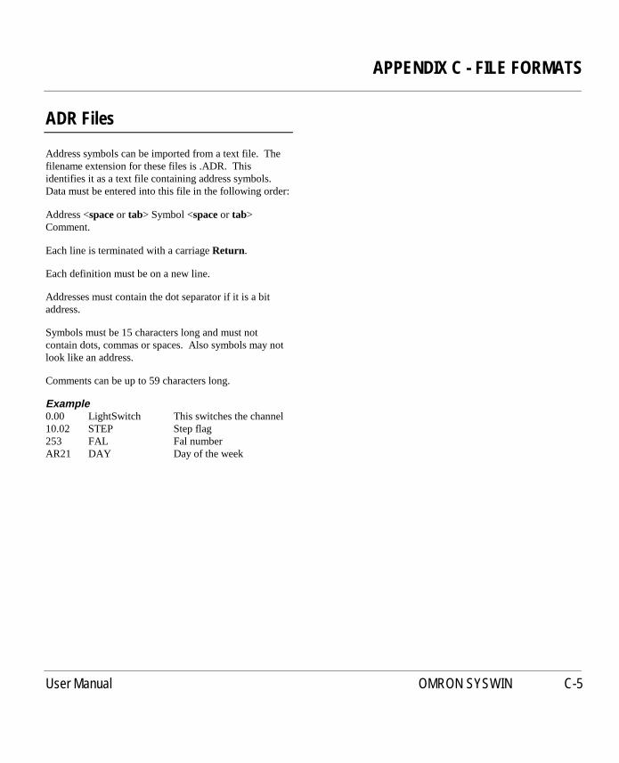
APPENDIX C - FILE FORMATS
User Manual OMRON SYSWIN C-5
ADR Files
Address symbols can be imported from a text file. Thefilename extension for these files is .ADR. Thisidentifies it as a text file containing address symbols.Data must be entered into this file in the following order:
Address <spaceor tab> Symbol <spaceor tab>Comment.
Each line is terminated with a carriageReturn.
Each definition must be on a new line.
Addresses must contain the dot separator if it is a bitaddress.
Symbols must be 15 characters long and must notcontain dots, commas or spaces. Also symbols may notlook like an address.
Comments can be up to 59 characters long.
Example0.00 LightSwitch This switches the channel10.02 STEP Step flag253 FAL Fal numberAR21 DAY Day of the week

APPENDIX C - FILE FORMATS
C-6 User Manual OMRON SYSWIN

APPENDIX D - SCREEN REFERENCE
User Manual OMRON SYSWIN D-1
D APPENDIX D - SCREEN REFERENCE
Data Trace / Time Chart Monitoring Buttons / Toolbar

APPENDIX D - SCREEN REFERENCE
D-2 User Manual OMRON SYSWIN
Ladder Diagram / Function Plan Toolbars and Drawing Tools

APPENDIX D - SCREEN REFERENCE
User Manual OMRON SYSWIN D-3
Data Display Editor Toolbar Buttons

APPENDIX D - SCREEN REFERENCE
D-4 User Manual OMRON SYSWIN
SYSWIN Programming Keystrokes
Keystroke Command/Function
F1 General help on menus, dialogboxes and messages
Control+F1 Quick reference on functiontimer and counter parameters
Movement KeystrokesCursor keys Move around the networkHome Move to left side, then topEnd Move to right side, then
bottomPageUp Movers up a full pagePageDown Moves down a full pageShift+PageUp Move up a full pageShift+PageDown Move down a full pageAlt+PageUp Change to first networkAlt+PageDown Change to last networkControl+Shift+PageUp Move to previous blockControl+Shift+PageDown Move to next block
Marking KeystrokesShift+Cursor keys Mark a blockShift+Home Mark to left, then topShift+End Mark to right, then bottomControl+Cursor keys Mark items
Editing KeystrokesReturn Edit elementDelete Delete elementBackspace Delete element and move leftEscape Change to normal cursorAlt+Right Insert column (to network)Alt+Down Insert row (to network)Alt+Left Delete column (from network)Alt+Up Delete row (from network)Spacebar Insert row at bottom of
network
Keystroke Command/Function
Clipboard keystrokesShift+DeleteControl+X Cut marked area to clipboardControl+C, Copy marked area to clipboardControl+InsertControl+V, Paste area from clipboardShift+InsertControl+Z, Undo changesAlt+Backspace
Network ManagementAlt+Return Test current networkAlt+Insert Insert a new networkAlt+Delete Delete current networkControl+PageUp Insert new network, above
currentControl+PageDown Insert new network, below
current
Address Bar KeysAlt+A Enter addressAlt+S Enter symbolAlt+C Enter commentAlt+O, Return Store detailsTab Move to next fieldShift+Tab Move to previous fieldEscape Return to main editor
DATA DISPLAYEDITOR
Movement KeystrokesCursor keys Move around areaHome Move to left column, then topEnd Move to right column, then
bottomPageUp Move up a pagePageDown Move down a page
Editing KeystrokesReturn Edit element

APPENDIX D - SCREEN REFERENCE
User Manual OMRON SYSWIN D-5
Menu Command Shortcuts
Keystroke Command/Function Menu Selection
F1 Help Help/Index
File FunctionsShift+F2, Control+O Open project File|Open ProjectShift+F3, Control+S Save project File|Save ProjectShift+F4, Control+P Print project File|Print Project
Editing FunctionsControl+Z Undo previous operation Edit|UndoControl+C Copy selection to clipboard Edit|CopyControl+X Cut selection to clipboard Edit|CutControl+V Paste from clipboard Edit|PasteDelete Delete selection Edit|DeleteAlt+Right Insert column (to network) Edit|Insert ColumnAlt+Down Insert row (to network) Edit|Insert RowAlt+Left Delete column (to network) Edit|Delete ColumnAlt+Up Delete row (to network) Edit|Delete RowSpacebar Insert row at end of network
Block/Network ManagerControl+F5 Block / Network Manager Block|Block/Network ManagerShift+F5 Select network Block|Select Block/NetworkAlt+Insert or Shift+F6 Insert network below current Block|Insert NetworkAlt+Delete or Shift+F7 Delete current network Block|Delete NetworkAlt+Enter or Shift+F8 Test current network Block|Test Network
Editor SelectionControl+F4 Choose Editor Editors|(select from list)Control+F6 Address Symbol Editor Editors|Address Symbol EditorControl+F7 Network Symbol Editor Editors|Network Symbol EditorControl+F8 Statement List Editor Editors|Statement List Editor
Connection FunctionsShift+F9 Connector or disconnect PLC Online|Connect/DisconnectShift+F10 Mode change in PLC Online|ModeShift+F11 Online edit mode on/off Online|Online EditControl+F2 Force bit in PLC Online|ForceControl+F11 Monitoring on/off Online|MonitoringControl+F3 Set bit in PLC Online|Set
Shift+F12 Overview mode on/off Preferences|Overview Mode

APPENDIX D - SCREEN REFERENCE
D-6 User Manual OMRON SYSWIN
Data Display Editor Shortcuts
These keyboard shortcuts replace some functions andadd other keys when operating the Data Display editor.
Keystroke Command/Function Menu Selection
File FunctionsShift+F2, Control+O Open data from file File|Load Data FileShift+F3, Control+S Save data to file File|Save Data FileShift+F4, Control+P Print project File|PrintControl+F4 Change to another editor File|Exit Data Display Editor
Data Formatting FunctionsF2 Display in hexadecimal format Data|FormatF3 Display in decimal format Data|FormatF4 Display in binary format Data|FormatF5 Display in ASCII format Data|FormatF6 Display in long hexadecimal format Data|FormatF7 Display in long decimal format Data|FormatF8 Display in floating point format Data|FormatF9 Display in signed decimal format Data|FormatF10 Display in signed long decimal format Data|FormatF11 Display in IEEE floating point format Data|Format
Connection FunctionsControl+F9 Read data from PLC Online|Upload DataControl+F10 Write data to PLC Online|Download DataControl+F11 Abort data transfer to/from PLC Online|Abort Transfer

APPENDIX D - SCREEN REFERENCE
User Manual OMRON SYSWIN D-7
Data Trace / Time Chart MonitoringShortcuts
These keyboard shortcuts replace some functions andadd other keys when operating the Data Trace / TimeChart Monitoring.
Keystroke Command/Function Menu Selection
SetupShift+F2, Control+O Open trace from file File|Load TraceShift+F3, Control+S Save trace to file File|Save TraceShift+F4, Control+P Print trace File|PrintAlt+F5 Configure trace Trace|Configure
Trace ControlF2 Go to start of traceF3 Fast RewindF4 RewindF5 Trigger ControlF6 ForwardF7 Fast ForwardF8 Go to endF9 Stop recording Online|AbortF10 Pause Online|Manual TriggerF11 Record traceF12 Read trace Online|Read Trace

APPENDIX D - SCREEN REFERENCE
D-8 User Manual OMRON SYSWIN

APPENDIX E - PLC INTERFACE CABLE CONNECTIONS
User Manual OMRON SYSWIN E-1
E APPENDIX E - PLC INTERFACE CABLE CONNECTIONS
This section illustrates the various cable configurationsthat should be used when connecting your computer or amodem to the PLC. It shows the connections for theinstances where the connection is to the serial port on thePLC and also where the connection is to the peripheralport on the CV series PLC.
SYSMAC-WAY (Local)RS232C Host Computer to PLC SerialConnection
1. Most PLC models with DB9 connectors use pin 9for SG. However, the DB9 connector on C20H,C28H, C40H and C60H CPUs uses pin 7 for SG.Therefore when constructing an interface cable forthese models, connect the SG line from thecomputer to pin 7 on the PLC. You may take ageneric cable for all DB9 PLC sockets byconnecting both pin 7 and pin 9 on the PLC to SG.
RS232C Host Computer to AL004 Connection

APPENDIX E - PLC INTERFACE CABLE CONNECTIONS
E-2 User Manual OMRON SYSWIN
SYSMAC WAY (Modem)
RS232C Host Computer to Modem Connection
1. SYSWIN does not use the RI signal, but othermodem control software does.
RS232C Modem to PLC Connection (DB25connector)
RS232C Modem to PLC Connection (DB9connector)
2. For C20H, C28H and C60H, use pin 7 for SG.
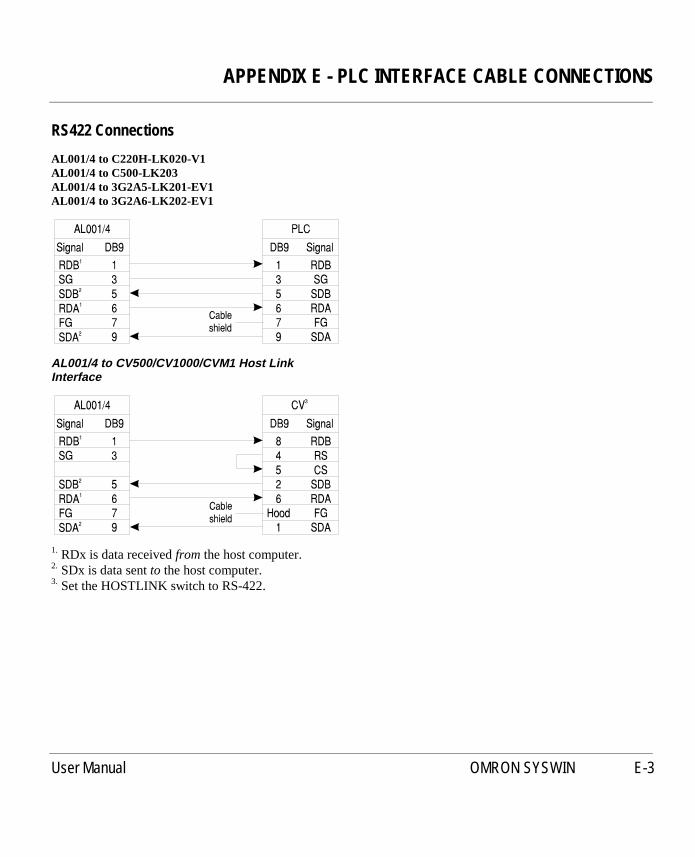
APPENDIX E - PLC INTERFACE CABLE CONNECTIONS
User Manual OMRON SYSWIN E-3
RS422 Connections
AL001/4 to C220H-LK020-V1AL001/4 to C500-LK203AL001/4 to 3G2A5-LK201-EV1AL001/4 to 3G2A6-LK202-EV1
AL001/4 to CV500/CV1000/CVM1 Host LinkInterface
1. RDx is data receivedfrom the host computer.2. SDx is data sentto the host computer.3. Set the HOSTLINK switch to RS-422.

APPENDIX E - PLC INTERFACE CABLE CONNECTIONS
E-4 User Manual OMRON SYSWIN
Toolbus Connections
RS232C Host Computer to CV CIF01 ToolbusConnection
When using SYSWIN, it is, however, possible to simply usea “gender-changer” instead as SYSWIN does not use thehandshaking lines on the serial port.
Remote Modem to CV CIF01 Toolbus Connection See the next page for a table describing the terminologyused in these diagrams.
NOTE! A standard “Null-modem” cable is not suitable -it may damage your modem.

APPENDIX E - PLC INTERFACE CABLE CONNECTIONS
User Manual OMRON SYSWIN E-5
Communications Terminology
Term Name Alternate Names Description Source
DTE Data TerminalEquipment
Originally denoted terminals/computers, etc. thatwould be connected to a modem. To connect DTEto DTE, the signal lines generally have to beswapped, as shown in the diagrams.
DCE Data CommunicationsEquipment
Mainly modems, but note that the AL004 is alsoconfigured as DCE.
FG Frame Ground PG, Positive Ground Used to connect the shielding around the signallines, to reduce external interference. Problems cansometimes occur if the shielding is connected toboth devices.
Both
TxD Transmitted Data TD Serial data sent from the DTE to the DCE. DTE
RxD Received data RD Serial data sent from the DCE to the DTE. DCE
RTS Request To Send RS DTE asserts this to allow data flow from the DCE. DTE
CTS Clear To Send CS DCE asserts this to allow data flow from the DTE. DCE
SG Signal Ground GND, Data Ground Common zero volts line for the other signals. Both
DSR Data Set Ready MR, Modem Ready DCE asserts this to indicate it is ready to operate. DCE
DCD Data Carrier Detect CD, Carrier DetectRLSD, Received LineSignal Detect
Modem asserts this to indicate that the connectionto a remote modem is working.
DCE
DTR Data Terminal Ready TR, Terminal ReadyER, Equipment Ready
The DTE asserts this when it is ready tocommunicate. When de-asserted, many modemswill hang up the telephone line.
DTE
RI Ring Indicator R, Ring Modem toggles this line when receiving incomingringing signal.
DCE
SDA Send Data A SD- Transmitted data signal is sent across those twolines.
SDB Send Data B SD+
RDA Receive Data A RD- Received data signal is read across these two lines.
RDB Receive Data B RD+

APPENDIX E - PLC INTERFACE CABLE CONNECTIONS
E-6 User Manual OMRON SYSWIN

INDEX
OMRON SYSWIN User Manual
Aactivating across a Network
token 11-6Address Symbol Editor
2-16 to 2-17, 9-4
BBlock / Network Manager 2-19 to 2-20Block Symbol Editor 2-20bridged communications procedure
8-14bridged Modem communications
procedure 8-15Bridging Guide 8-19 to 8-22
Ccommunications procedure, standard
8-14compatibility, SYSWIN 11-1configure SYSWIN 1-10
See also preferencesConnection Guides
8-1 to 8-6, 11-7 to 11-8Controller Link communications
procedure 8-15Controller Link connection information
8-10Controller Link network bridging 8-19Controller Link to Controller Link
network bridging 8-20Controller Link to SYSMAC-NET
network bridging 8-20Controller Link, an overview 1-4conventions, document 1-3CV series peripheral port connection
information 8-10
CV series peripheral port modemconnection information 8-11
DData Display Editor 4-1 to 4-4
data items 4-4keyboard shortcuts 4-2memory holes 4-3set up 4-3 to 4-4toolbar 15-3
data link tables 8-22 to 8-30Controller Link 8-29SYSMAC-LINK 8-29SYSMAC-NET 8-29
data set bar 3-10Dialogs Guide 8-22 to 8-30document conventions 1-3Dongle installation 1-8
installing to a Dedicated File Server11-6
installing to user’s Windows NTworkstation 11-4
installing to user’s Windowsworkstation 11-3
installing, manually 11-13manual check 11-14sharing procedure 11-16
Eeditors
Address Symbol EditorSee Address Symbol Editor
Block / Network ManagerSee Block / Network Manager
Block Symbol EditorSee Block Symbol Editor
Data Display EditorSee Data Display Editor
Function Plan EditorSee Function Plan Editor
Network Symbol EditorSee Network Symbol Editor
Statement List EditorSee Statement List Editor
EPROM 9-4ethernet communications procedure
8-16ethernet connection 8-6Ethernet connection information 8-10ethernet connection to C Bridge guide
8-6ethernet connection to CV Bridge
guide 8-7exporting files 9-4
Address Symbol information 9-4projects 9-4
Ffile types 12-1, 14-1find data 2-21 to 2-22find network address 2-23 to 2-24Function Plan Editor 9-1
toolbar 15-2
Ggetting started 1-9 to 1-10groups procedure 11-19

INDEX
User Manual OMRON SYSWIN
Hhelp 1-11Hostlink interface settings 8-24 to 8-25
II/O table editing 6-2 to 6-7
configuration, actual 6-2configuration, SYSWIN 6-2display 6-3Rack IO options 6-3registered 6-2remote terminals 6-4SIO units 6-4SIO Units, SYSMAC-BUS/2 6-5software switches 6-4, 6-5SYSMAC-BUS 6-4
importing files 9-2, 9-3Information Guide 8-6 to 8-13INI file 10-6Installation Guide 11-2 to 11-6installing SYSWIN 1-6, 1-8
See also token copy protectioninstalling the SYSWIN Dongle 1-8installing to a Dedicated File Server
Dongle 11-6token 11-5
installing to a workstation across anetwork or serial linktoken 11-5
installing to user’s Windows NTworkstationDongle 11-4token 11-4
installing to user’s WindowsworkstationDongle 11-3token 11-3
Kkeyboard short-cuts 15-4 to 15-7
Llocal drive connection 11-7
Mmemory cards 3-14Modem communications procedure,
bridged 8-15Modem communications procedure,
standard 8-14Modem configuration 8-22 to 8-24Modem connections procedure, set up
8-17mouse functions, right-click 3-9
Nnetwork
activating across a 11-6adding a network 2-9adding to a network 2-8address bar 2-11addresses 2-7bridging 8-19 to 8-22changing 3-8commenting 2-8copying elements 2-12creating a network 2-7 to 2-10cross reference
See network, find addressdelete elements 2-11editing a network 2-11 to 2-12elements 2-11elements, selecting 2-11
find address 2-23 to 2-24groups, making 2-18information 8-11moving elements 2-12navigating using the workspace 2-6printing
See print, networks, range ofrestoring 2-12
network connection using a ControllerLink NSB guide 8-5
network connection using a SYSMAC-LINK NSB guide 8-4
network connection using a SYSMAC-NET NSB guide 8-5
Network Symbol Editor 2-18node information 8-11
Oonline help 1-11 to 1-12
PPLC
clearing memory 3-14clock setting 3-14communications 7-2connected operation 3-1conversion 7-3data monitoring 3-12debug mode 3-3downloading programs 3-3 to 3-4error log 3-15interface connections 16-1 to 16-5memory allocation 3-5, 6-2memory card support 3-14modes of operation 3-3monitor mode 3-3

INDEX
OMRON SYSWIN User Manual
operating mode 3-6parameters, project 3-2program mode 3-3run mode 3-3series 7-1set up 3-5, 6-9setting up communications 3-2status 3-6stop mode 3-3types 7-1upload programs to computer 3-5verifying programs 3-4
preferences 1-10, 1-12, 3-3, 3-8,7-3 to 7-5, 9-3, 10-1 to 10-7
printblock overview 2-24cross references 2-25expansion functions 2-25front page 2-24function plan 2-24I/O table 2-25ladder diagram 2-24networks, range of 2-25PLC setup 2-25project 2-24 to 2-26sections 2-24setup 2-25 to 2-26statement list 2-25symbol list 2-25
Procedure Guides8-13 to 8-18, 11-9 to 11-19
program security 3-15, 7-5programming
address setting 3-11 to 3-12block markers 3-4blocks 2-9counters 2-10creating ladder programs 2-4 to 2-5data setting 3-11 to 3-12
downloading to the PLC 3-3 to 3-4executing 3-7expansion functions 3-5forcing bits 3-12 to 3-13format specifiers 13-1function menu 2-10functions 2-9 to 2-10functions, differentiated 2-10monitoring 3-7mouse functions, right-click 3-9networks 2-6. See also networkpassword protection 3-15processing 7-5 to 7-6save addresses and data values
3-12, 3-13structure 2-1 to 2-2timers 2-10upload from PLC 3-5verification 3-4workspace 2-6
projectallocate memory 3-5, 6-2check program 2-21checklist 2-2 to 2-3communications 3-2communications, advanced
8-1 to 8-30file conversion 9-5file types 2-13function mapping 6-1functions, adding and removing 6-1I/O table, edit See I/O table editingimporting from disk 9-2, 9-3information 2-4libraries 9-2 to 9-3networks See networkopen project 2-14parameters, PLC 3-2password 7-5
PLC set up 6-9preferences 7-3 to 7-5printing 2-24 to 2-26
See also printprogramming See programmingsave project 2-13, 9-3save project as 2-13save project as PMF file 9-4set up 2-2 to 2-3, 7-1types 7-1
Rremote file server connection 11-8remote workstation connection 11-7replace data 2-22 to 2-23right-click mouse functions 3-9routing tables 8-25 to 8-28
Controller Link C Series 8-27Controller Link CV series 8-26Controller Link NSB 8-27SYSMAC-LINK CV series 8-26SYSMAC-LINK NSB 8-27SYSMAC-NET C series 8-26SYSMAC-NET CV series 8-26SYSMAC-NET NSB 8-27
Ssearching data
See find data and replace dataserial connection guide 8-2serial connection information 8-7serial connection to C Bridge guide 8-3serial connection to CV Bridge guide
8-3serial connection with Modem guide
8-2

INDEX
User Manual OMRON SYSWIN
serial connection with Modem to CVBridge guide 8-4
software switches 6-4, 6-5Controller Link 6-6ethernet 6-6Hostlink 6-5special unit information 6-5, 6-7SYSMAC-BUS 6-7SYSMAC-LINK 6-6SYSMAC-NET 6-6
starting SYSWIN 1-9 to 1-10, 11-12Statement List Editor 2-15 to 2-16
display 2-15editing statement list 2-15verifying the statement list 2-15
SYSMAC-LINK communicationsprocedure 8-15
SYSMAC-LINK connection information8-8
SYSMAC-LINK network bridging 8-19SYSMAC-LINK to SYSMAC-LINK
network bridging 8-20SYSMAC-LINK to SYSMAC-NET
network bridging 8-20SYSMAC-NET communications
procedure 8-16SYSMAC-NET connection information
8-9SYSMAC-NET network bridging 8-21SYSMAC-NET to Controller Link
network bridging 8-22SYSMAC-NET to SYSMAC-LINK
network bridging 8-22SYSMAC-NET to SYSMAC-NET
network bridging 8-21system requirements 1-5 to 1-6SYSWIN.INI 10-6
Ttechnical support 1-2templates 9-3token copy protection
1-6 to 1-7, 1-8, 11-9, 11-11, 11-14activating across a Network 11-6installing to a Dedicated File Server
11-5installing to a workstation across a
network or serial link 11-5installing to user’s Windows NT
workstation 11-4installing to user’s Windows
workstation 11-3installing, manually 11-10
token copy protection, manual check11-13
traceconfigure 5-1 to 5-2record 5-3review 5-3 to 5-4toolbar 15-1
Uunit information 8-11unit setup 6-7 to 6-8
ethernet 6-8Hostlink 6-7special unit information 6-7SYSMAC-LINK 6-8SYSMAC-NET 6-7


