Embed Size (px)
Citation preview
Systems Engineering Department
Title: Systems Life Cycle Process Models – Vee Diagram Document No: Rev.: 1.0
1
Systems Engineering Guide: System Life Cycle Process Models – Vee
Diagram
Systems Engineering Department
Title: Systems Life Cycle Process Models – Vee Diagram Document No: Rev.: 1.0
2
Contents Introduction ........................................................................................................... 3
1.0 The Vee Model ................................................................................................ 4
2.0 Application of the Vee Model .......................................................................... 8
3.0 Fundamentals of Life Cycle Stages and Program Management .......................10
3.1 Program Management Stages .......................................................................11
3.2 Life Cycle Stages .........................................................................................11
3.3 Life Cycle Reviews ......................................................................................12
4.0 References ......................................................................................................12
Systems Engineering Department
Title: Systems Life Cycle Process Models – Vee Diagram Document No: Rev.: 1.0
3
System Life Cycle Process Models – Vee Diagram
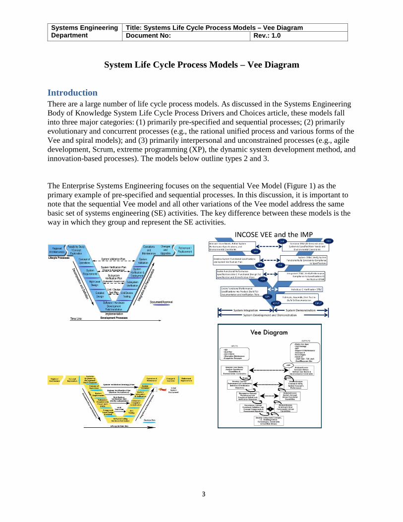
Introduction There are a large number of life cycle process models. As discussed in the Systems Engineering Body of Knowledge System Life Cycle Process Drivers and Choices article, these models fall into three major categories: (1) primarily pre-specified and sequential processes; (2) primarily evolutionary and concurrent processes (e.g., the rational unified process and various forms of the Vee and spiral models); and (3) primarily interpersonal and unconstrained processes (e.g., agile development, Scrum, extreme programming (XP), the dynamic system development method, and innovation-based processes). The models below outline types 2 and 3. The Enterprise Systems Engineering focuses on the sequential Vee Model (Figure 1) as the primary example of pre-specified and sequential processes. In this discussion, it is important to note that the sequential Vee model and all other variations of the Vee model address the same basic set of systems engineering (SE) activities. The key difference between these models is the way in which they group and represent the SE activities.
Systems Engineering Department
Title: Systems Life Cycle Process Models – Vee Diagram Document No: Rev.: 1.0
4
1.0 The Vee Model The Enterprise sequential version of the Vee Model is shown in Figure 1. Its core involves a sequential progression of plans, specifications, and products that are baselined and put under configuration management.. The Vee Model encompasses all system life cycle stages listed in the "Generic Life Cycle Stages" table of the INCOSE Systems Engineering Handbook. (INCOSE 2012). The “V” represents the sequence of steps in a project life cycle development. It describes the activities to be performed and the results that have to be produced during product development. The left side of the "V" represents the decomposition of requirements, and creation of system specifications. The right side of the “V” represents integration of parts and their validation. The Vee Model provides guidance for the planning and realization of projects. The following objectives are intended to be achieved by a project execution:
1. Minimization of Project Risks: The Vee Model improves project transparency and project control by specifying standardized approaches and describing the corresponding results and responsible roles. It permits an early recognition of planning deviations and risks and improves process management, thus reducing the project risk.
2. Improvement and Guarantee of Quality: As a standardized process model, the Vee Model ensures that the results to be provided are complete and have the desired quality. Defined interim results can be checked at an early stage. Uniform product contents will improve readability, understandability and verifiability.
3. Reduction of Total Cost over the Entire Project and System Life Cycle: The effort for the development, production, operation and maintenance of a system can be calculated, estimated and controlled in a transparent manner by applying a standardized process model. The results obtained are uniform and easily retraced. This reduces the acquirers’ dependency on the supplier and the effort for subsequent activities and projects.
4. Improvement of Communication between all Stakeholders: The standardized and uniform description of all relevant elements and terms is the basis for the mutual understanding between all stakeholders. Thus, the frictional loss between user, acquirer, supplier and developer is reduced
The Vee model involves early and comprehensive identification of goals, a concept of operations that describes user needs and the operating environment, thorough and testable system requirements, detailed design, implementation, rigorous acceptance testing of the implemented system to ensure it meets the stated requirements (system verification), measuring its effectiveness in addressing goals (system validation), on-going operation and maintenance, system upgrades over time, and eventual retirement. The Vee model process emphasizes requirements-driven design and testing. All design elements and acceptance tests must be traceable to one or more system requirements and every requirement must be addressed by at least one design element and acceptance test. Such rigor ensures nothing is done unnecessarily and everything that is necessary is accomplished.
Systems Engineering Department
Title: Systems Life Cycle Process Models – Vee Diagram Document No: Rev.: 1.0
5
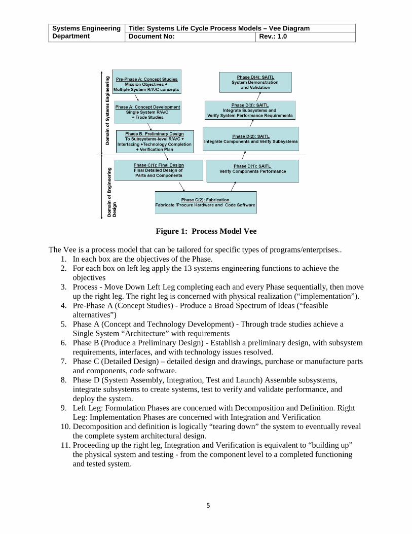
Figure 1: Process Model Vee
The Vee is a process model that can be tailored for specific types of programs/enterprises..
1. In each box are the objectives of the Phase. 2. For each box on left leg apply the 13 systems engineering functions to achieve the
objectives 3. Process - Move Down Left Leg completing each and every Phase sequentially, then move
up the right leg. The right leg is concerned with physical realization (“implementation”). 4. Pre-Phase A (Concept Studies) - Produce a Broad Spectrum of Ideas (“feasible
alternatives”) 5. Phase A (Concept and Technology Development) - Through trade studies achieve a
Single System “Architecture” with requirements 6. Phase B (Produce a Preliminary Design) - Establish a preliminary design, with subsystem
requirements, interfaces, and with technology issues resolved. 7. Phase C (Detailed Design) – detailed design and drawings, purchase or manufacture parts
and components, code software. 8. Phase D (System Assembly, Integration, Test and Launch) Assemble subsystems,
integrate subsystems to create systems, test to verify and validate performance, and deploy the system.
9. Left Leg: Formulation Phases are concerned with Decomposition and Definition. Right Leg: Implementation Phases are concerned with Integration and Verification
10. Decomposition and definition is logically “tearing down” the system to eventually reveal the complete system architectural design.
11. Proceeding up the right leg, Integration and Verification is equivalent to “building up” the physical system and testing - from the component level to a completed functioning and tested system.
Systems Engineering Department
Title: Systems Life Cycle Process Models – Vee Diagram Document No: Rev.: 1.0
6
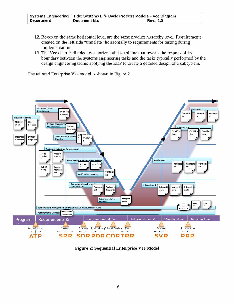
12. Boxes on the same horizontal level are the same product hierarchy level. Requirements created on the left side “translate” horizontally to requirements for testing during implementation.
13. The Vee chart is divided by a horizontal dashed line that reveals the responsibility boundary between the systems engineering tasks and the tasks typically performed by the design engineering teams applying the EDP to create a detailed design of a subsystem.
The tailored Enterprise Vee model is shown in Figure 2.
Figure 2: Sequential Enterprise Vee Model
Program Planning System Requirements Development
Qualification & Validation Planning
System Architecture Development
Product Requirements Development
Component Requirements Development
Integration & Test Planning
Integration & Test
Verification
Qualification
Validation
Verification Planning
Customer / User Requirements
Requirements Management Technical Risk Management and Quantitative Measurement (QM)
Program Pl i
Requirements & A hi
Implementation Integration & Verificatio Production
Preliminary Design
PDR
Production Readiness
PRR
System Verification
SVR
Test Readiness
TRR
Critical Design Review
CDR
System Design
SDR
System Requirements
SRR
Authority to Proceed ATP
Statement of
Integration & Test
Integration & Test
Integration & Test
Verification Procedur
Verification Software
Verification Reports
Qualification Procedur
Qualification Build(s)
Qualification Reports
Validation P d
Validation B ild( )
Validation R t
Software Reqmnts
Product Specs
Verification
Work Breakdo
Integrated Master
System Engineer
Technical Requireme
Tech. Risk
QM Report
Component S
Qualificat- I
Validation
Use Case Analysis
System Reqmnts
Trade Studies &
Product Structure
DoDAF Views System
Architecture
Integration &
Interface Control
Systems Engineering Department
Title: Systems Life Cycle Process Models – Vee Diagram Document No: Rev.: 1.0
7
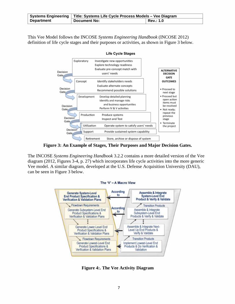
This Vee Model follows the INCOSE Systems Engineering Handbook (INCOSE 2012) definition of life cycle stages and their purposes or activities, as shown in Figure 3 below.
Figure 3: An Example of Stages, Their Purposes and Major Decision Gates.
The INCOSE Systems Engineering Handbook 3.2.2 contains a more detailed version of the Vee diagram (2012, Figures 3-4, p. 27) which incorporates life cycle activities into the more generic Vee model. A similar diagram, developed at the U.S. Defense Acquisition University (DAU), can be seen in Figure 3 below.
Figure 4:. The Vee Activity Diagram
Systems Engineering Department
Title: Systems Life Cycle Process Models – Vee Diagram Document No: Rev.: 1.0
8
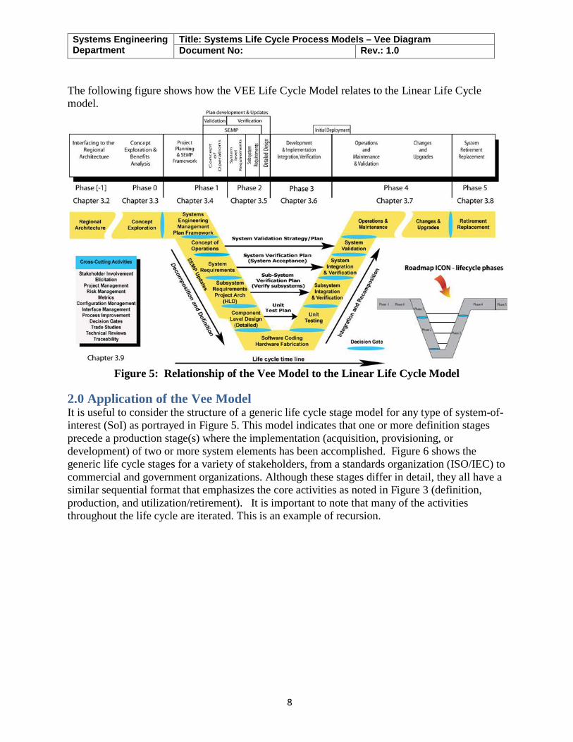
The following figure shows how the VEE Life Cycle Model relates to the Linear Life Cycle model.
Figure 5: Relationship of the Vee Model to the Linear Life Cycle Model
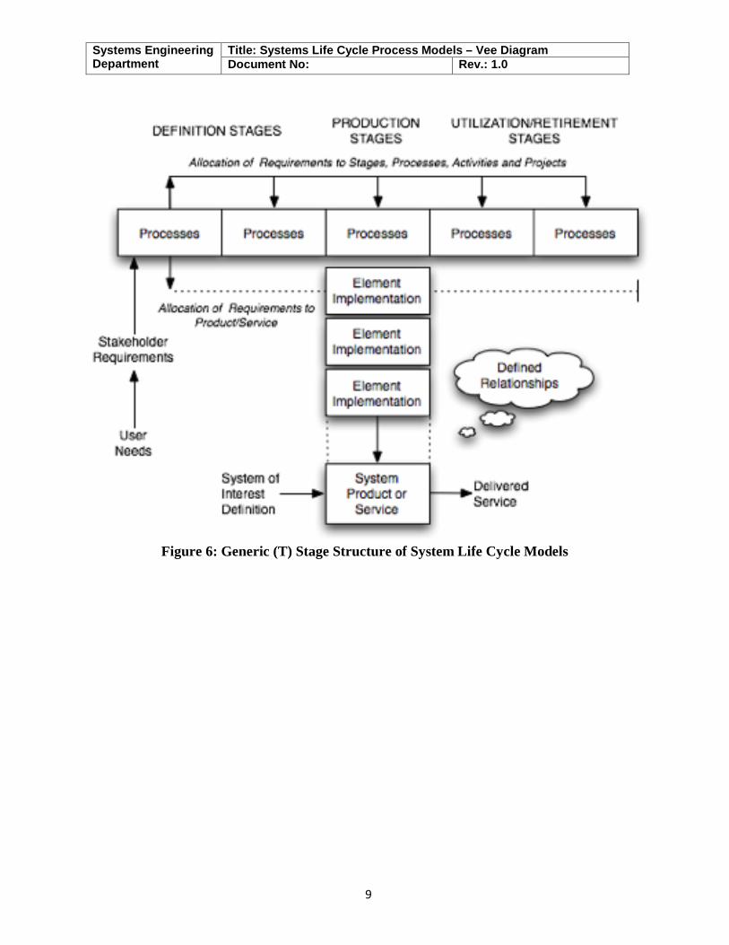
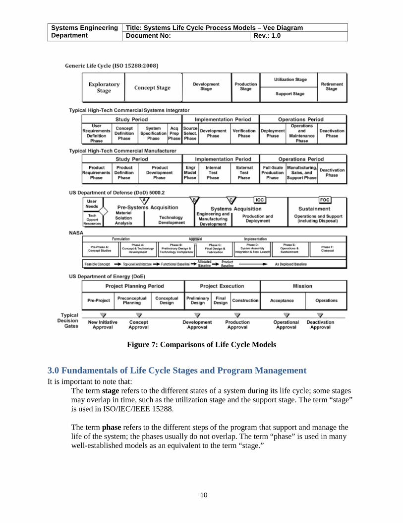
2.0 Application of the Vee Model It is useful to consider the structure of a generic life cycle stage model for any type of system-of-interest (SoI) as portrayed in Figure 5. This model indicates that one or more definition stages precede a production stage(s) where the implementation (acquisition, provisioning, or development) of two or more system elements has been accomplished. Figure 6 shows the generic life cycle stages for a variety of stakeholders, from a standards organization (ISO/IEC) to commercial and government organizations. Although these stages differ in detail, they all have a similar sequential format that emphasizes the core activities as noted in Figure 3 (definition, production, and utilization/retirement). It is important to note that many of the activities throughout the life cycle are iterated. This is an example of recursion.
Systems Engineering Department
Title: Systems Life Cycle Process Models – Vee Diagram Document No: Rev.: 1.0
9
Figure 6: Generic (T) Stage Structure of System Life Cycle Models
Systems Engineering Department
Title: Systems Life Cycle Process Models – Vee Diagram Document No: Rev.: 1.0
10
Figure 7: Comparisons of Life Cycle Models
3.0 Fundamentals of Life Cycle Stages and Program Management It is important to note that:
The term stage refers to the different states of a system during its life cycle; some stages may overlap in time, such as the utilization stage and the support stage. The term “stage” is used in ISO/IEC/IEEE 15288.
The term phase refers to the different steps of the program that support and manage the life of the system; the phases usually do not overlap. The term “phase” is used in many well-established models as an equivalent to the term “stage.”
Systems Engineering Department
Title: Systems Life Cycle Process Models – Vee Diagram Document No: Rev.: 1.0
11
3.1 Program Management Stages Program management employs phases, milestones, and decision gates which are used to assess the evolution of a system through its various stages. The stages contain the activities performed to achieve goals and serve to control and manage the sequence of stages and the transitions between each stage. For each project, it is essential to define and publish the terms and related definitions used on respective projects to minimize confusion. A typical program is composed of the following phases:
1. The pre-study phase, which identifies potential opportunities to address user needs with new solutions that make business sense.
2. The feasibility phase consists of studying the feasibility of alternative concepts to reach a second decision gate before initiating the execution stage. During the feasibility phase, stakeholders' requirements and system requirements are identified, viable solutions are identified and studied, and virtual prototypes can be implemented. During this phase, the decision to move forward is based on
a. Whether a concept is feasible and is considered able to counter an identified threat or exploit an opportunity;
b. Whether a concept is sufficiently mature to warrant continued development of a new product or line of products; and
c. Whether to approve a proposal generated in response to a request for proposal. 3. The execution phase includes activities related to four stages of the system life cycle:
development, production, utilization, and support. Typically, there are two decision gates and two milestones associated with execution activities. The first milestone provides the opportunity for management to review the plans for execution before giving the go-ahead. The second milestone provides the opportunity to review progress before the decision is made to initiate production. The decision gates during execution can be used to determine whether to produce the developed SoI and whether to improve it or retire it.
These program management views apply not only to the SoI, but also to its elements and structure.
3.2 Life Cycle Stages Variations of the Vee model deal with the same general stages of a life cycle:
1. New projects typically begin with an exploratory research phase which generally includes the activities of concept definition, specifically the topics of business or mission analysis and the understanding of stakeholder needs and requirements. These mature as the project goes from the exploratory stage to the concept stage to the development stage.
2. The production phase includes the activities of system definition and system realization, as well as the development of the system requirements and architecture through verification and validation.
3. The utilization phase includes the activities of system deployment and system operation. 4. The support phase includes the activities of system maintenance, logistics, and product
and service life management, which may include activities such as service life extension or capability updates, upgrades, and modernization.
Systems Engineering Department
Title: Systems Life Cycle Process Models – Vee Diagram Document No: Rev.: 1.0
12
5. The retirement phase includes the activities of disposal and retirement, though in some models, activities such as service life extension or capability updates, upgrades, and modernization are grouped into the "retirement" phase.
3.3 Life Cycle Reviews To control the progress of a project, different types of reviews are planned (see bottom of Figure 1). The most commonly used are listed as follows:
1. The system requirements review (SRR) is planned to verify and validate the set of system requirements before starting the detailed design activities.
2. The preliminary design review (PDR) is planned to verify and validate the set of system requirements, the design artifacts, and justification elements at the end of the first engineering loop (also known as the "design-to" gate).
3. The critical design review (CDR) is planned to verify and validate the set of system requirements, the design artifacts, and justification elements at the end of the last engineering loop (the “build-to” and “code-to” designs are released after this review).
4. The integration, verification, and validation reviews are planned as the components are assembled into higher level subsystems and elements. A sequence of reviews is held to ensure that everything integrates properly and that there is objective evidence that all requirements have been met. There should also be an in-process validation that the system, as it is evolving, will meet the stakeholders’ requirements (see Figure 7).
5. The final validation review is carried out at the end of the integration phase. Other management related reviews can be planned and conducted in order to control the correct progress of work, based on the type of system and the associated risks.
4.0 References 1. INCOSE. 2012. Systems Engineering Handbook: A Guide for System Life Cycle
Processes and Activities, version 3.2.2. San Diego, CA, USA: International Council on Systems Engineering (INCOSE), INCOSE-TP-2003-002-03.2.2.
2. ISO/IEC. 2010. Systems and Software Engineering, Part 1: Guide for Life Cycle Management. Geneva, Switzerland: International Organization for Standardization (ISO)/International Electrotechnical Commission (IEC), ISO/IEC 24748-1:2010.
3. ISO/IEC 2008. Systems and Software Engineering -- System Life Cycle Processes. Geneva, Switzerland: International Organization for Standardization / International Electrotechnical Commissions. ISO/IEC/IEEE 15288:2008.
4. ISO/IEC. 2003. Systems Engineering — A Guide for The Application of ISO/IEC 15288 System Life Cycle Processes. Geneva, Switzerland: International Organization for Standardization (ISO)/International Electrotechnical Commission (IEC), ISO/IEC 19760:2003 (E).
5. National Research Council of the National Academies (USA). 2008. Pre-Milestone A and Early-Phase Systems Engineering. Washington, DC, USA: The National Academies Press.