Embed Size (px)
Citation preview
System Automation for z/OSVersion 3 Release 4
Operator's Commands
SC34-2649-00
���
Note!Before using this information and the product it supports, read the information in Appendix C, “Notices,” on page 539.
This edition applies to IBM Tivoli System Automation for z/OS (5698-SA3), Version 3 Release 4, an IBM licensedprogram, and to all subsequent releases and modifications until otherwise indicated in new editions.
This edition replaces SC34-2575-02.
IBM welcomes your comments. You may forward your comments electronically, or address your comments to:IBM Deutschland Research & Development GmbHDepartment 3248Schoenaicher Strasse 22071032 BoeblingenGermany
FAX: (Germany): 07031 16-3456FAX: (Other countries): +49 7031 16-3456
Internet e-mail: [email protected]
When you send information to IBM, you grant IBM a nonexclusive right to use or distribute the information in anyway it believes appropriate without incurring any obligation to you.
© Copyright IBM Corporation 1996, 2012.US Government Users Restricted Rights – Use, duplication or disclosure restricted by GSA ADP Schedule Contractwith IBM Corp.
|
|||||||||||
Contents
Figures . . . . . . . . . . . . . . vii
Tables . . . . . . . . . . . . . . . ix
Accessibility . . . . . . . . . . . . xiUsing assistive technologies . . . . . . . . . xiKeyboard navigation of the user interface . . . . xiz/OS information . . . . . . . . . . . . xi
Dotted decimal syntax diagrams . . . xiii
How to send your comments to IBM . . xvIf you have a technical problem . . . . . . . xv
About This Book . . . . . . . . . . xviiWho Should Use This Book . . . . . . . . xviiWhere to Find More Information. . . . . . . xvii
The System Automation for z/OS Library. . . xviiRelated Product Information . . . . . . . xviiiUsing LookAt to look up message explanations xviii
Summary of Changes for SC34-2649-00 . . . . xviiiNew Information . . . . . . . . . . . xviiiChanged Information . . . . . . . . . . xixDeleted Information . . . . . . . . . . xxi
Part 1. Introduction . . . . . . . . . 1
Chapter 1. Introduction . . . . . . . . 3Overview of Commands . . . . . . . . . . 3Understanding Terms . . . . . . . . . . . 3
Resource. . . . . . . . . . . . . . . 3Format of Syntax Diagrams . . . . . . . . . 5
Part 2. SA z/OS System OperationsCommands . . . . . . . . . . . . . 7
Chapter 2. System OperationsCommands . . . . . . . . . . . . . 9Using System Operations Commands . . . . . . 9
General Information . . . . . . . . . . . 9Overview of Commands that Operate Sysplexwide 9Additional Parameters for System OperationsCommands . . . . . . . . . . . . . 10Varying the Format of the Command Output . . 13
ACF . . . . . . . . . . . . . . . . . 15AOCHELP . . . . . . . . . . . . . . 22AOCTRACE . . . . . . . . . . . . . . 23ASF . . . . . . . . . . . . . . . . . 28ASFUSER . . . . . . . . . . . . . . . 30DISPACF . . . . . . . . . . . . . . . 32DISPAOPS. . . . . . . . . . . . . . . 34DISPAPG . . . . . . . . . . . . . . . 36
DISPASF . . . . . . . . . . . . . . . 38DISPAUTO . . . . . . . . . . . . . . 39DISPERRS . . . . . . . . . . . . . . . 40DISPEVT . . . . . . . . . . . . . . . 42DISPEVTS . . . . . . . . . . . . . . . 44DISPFLGS . . . . . . . . . . . . . . . 46DISPGW . . . . . . . . . . . . . . . 49DISPINFO . . . . . . . . . . . . . . . 51DISPMSGS . . . . . . . . . . . . . . 53DISPMTR . . . . . . . . . . . . . . . 54DISPSCHD . . . . . . . . . . . . . . 57DISPSFLT . . . . . . . . . . . . . . . 59DISPSTAT . . . . . . . . . . . . . . . 62DISPSYS . . . . . . . . . . . . . . . 66DISPTREE . . . . . . . . . . . . . . . 68DISPTRG . . . . . . . . . . . . . . . 69DRAINJES. . . . . . . . . . . . . . . 71EXPLAIN . . . . . . . . . . . . . . . 72INGAMS . . . . . . . . . . . . . . . 73INGAUTO. . . . . . . . . . . . . . . 85INGCF . . . . . . . . . . . . . . . . 89
INGCF DRAIN . . . . . . . . . . . . 96INGCF ENABLE . . . . . . . . . . . 100INGCF MAINT. . . . . . . . . . . . 103INGCF PATH . . . . . . . . . . . . 104INGCF STRUCTURE . . . . . . . . . . 105
INGCFG . . . . . . . . . . . . . . . 107Purpose . . . . . . . . . . . . . . 107Syntax. . . . . . . . . . . . . . . 107Parameters . . . . . . . . . . . . . 107
INGCFL . . . . . . . . . . . . . . . 107Purpose . . . . . . . . . . . . . . 107Syntax. . . . . . . . . . . . . . . 108Parameters . . . . . . . . . . . . . 108Return Codes . . . . . . . . . . . . 108Restrictions and Limitations . . . . . . . 109
INGCICS . . . . . . . . . . . . . . . 109INGDB2 . . . . . . . . . . . . . . . 113INGDLA . . . . . . . . . . . . . . . 116INGEVENT . . . . . . . . . . . . . . 118INGFILT . . . . . . . . . . . . . . . 119INGGROUP . . . . . . . . . . . . . . 125INGHIST . . . . . . . . . . . . . . . 132INGHWSRV . . . . . . . . . . . . . . 134INGIMS . . . . . . . . . . . . . . . 135INGINFO . . . . . . . . . . . . . . 141INGLIST . . . . . . . . . . . . . . . 144INGLKUP . . . . . . . . . . . . . . 152INGMDFY . . . . . . . . . . . . . . 156INGMOVE . . . . . . . . . . . . . . 159INGMSGS . . . . . . . . . . . . . . 164INGNTFY . . . . . . . . . . . . . . 167INGPLEX . . . . . . . . . . . . . . 170
INGPLEX CDS . . . . . . . . . . . . 175INGPLEX SYStem . . . . . . . . . . . 181INGPLEX CONsole . . . . . . . . . . 183
© Copyright IBM Corp. 1996, 2012 iii
||||||||
INGPLEX IPL . . . . . . . . . . . . 186INGPLEX SDUMP. . . . . . . . . . . 187INGPLEX SVCdump . . . . . . . . . . 189INGPLEX SLIP . . . . . . . . . . . . 193
INGRELS. . . . . . . . . . . . . . . 194INGREQ . . . . . . . . . . . . . . . 197INGRPT . . . . . . . . . . . . . . . 207INGRUN . . . . . . . . . . . . . . . 210INGSCHED . . . . . . . . . . . . . . 214INGSEND . . . . . . . . . . . . . . 221INGSESS . . . . . . . . . . . . . . . 225INGSET . . . . . . . . . . . . . . . 229INGSTR . . . . . . . . . . . . . . . 233INGTHRES . . . . . . . . . . . . . . 239INGTOPO . . . . . . . . . . . . . . 243INGTRIG. . . . . . . . . . . . . . . 244INGTWS . . . . . . . . . . . . . . . 246INGVOTE . . . . . . . . . . . . . . 255MONITOR . . . . . . . . . . . . . . 258OPCAQRY . . . . . . . . . . . . . . 259RESTART. . . . . . . . . . . . . . . 262RESYNC . . . . . . . . . . . . . . . 263SETHOLD . . . . . . . . . . . . . . 265SETSTATE . . . . . . . . . . . . . . 267SETTIMER . . . . . . . . . . . . . . 270
Part 3. SA z/OS I/O OperationsCommands. . . . . . . . . . . . 275
Chapter 3. I/O Operations Commands 277Using I/O Operations Commands . . . . . . 277Consensus Processing . . . . . . . . . . 277Safe Switching . . . . . . . . . . . . . 277FICON Switches . . . . . . . . . . . . 278FICON Cascaded Switches . . . . . . . . . 278ALLOW . . . . . . . . . . . . . . . 279BLOCK . . . . . . . . . . . . . . . 281CHAIN . . . . . . . . . . . . . . . 283CONNECT . . . . . . . . . . . . . . 285DISCONNECT . . . . . . . . . . . . . 287DISPLAY CHANGECHECK . . . . . . . . 288DISPLAY CHP . . . . . . . . . . . . . 288DISPLAY DEV . . . . . . . . . . . . . 290DISPLAY HOST . . . . . . . . . . . . 292DISPLAY NAME . . . . . . . . . . . . 295DISPLAY PORT . . . . . . . . . . . . 298DISPLAY RESULTS . . . . . . . . . . . 300DISPLAY SWITCH . . . . . . . . . . . 304DISPLAY TIMEOUT . . . . . . . . . . . 307DISPLAY VARY . . . . . . . . . . . . 308GETLOCK . . . . . . . . . . . . . . 310LOGREC . . . . . . . . . . . . . . . 311PROHIBIT . . . . . . . . . . . . . . 312REMOVE CHP . . . . . . . . . . . . . 313REMOVE SWITCH . . . . . . . . . . . 316RESET CHANGECHECK . . . . . . . . . 318RESET HOST . . . . . . . . . . . . . 318RESET SWITCH . . . . . . . . . . . . 321RESET TIMEOUT . . . . . . . . . . . . 322RESTORE CHP . . . . . . . . . . . . . 323
RESTORE SWITCH . . . . . . . . . . . 325SYNC SWITCH. . . . . . . . . . . . . 326UNBLOCK . . . . . . . . . . . . . . 327UNCHAIN . . . . . . . . . . . . . . 329UNLOCK . . . . . . . . . . . . . . 330WRITE . . . . . . . . . . . . . . . 331
Part 4. SA z/OS ProcessorOperations Commands . . . . . . 333
Chapter 4. Using ProcessorOperations Commands . . . . . . . 335General Information . . . . . . . . . . . 335Host-Based Commands . . . . . . . . . . 335Common Commands . . . . . . . . . . . 335Ensemble Commands . . . . . . . . . . 336PSM Commands . . . . . . . . . . . . 336
Chapter 5. Host-based Commands 337ISQCCMD . . . . . . . . . . . . . . 337ISQCHK . . . . . . . . . . . . . . . 340ISQCMON . . . . . . . . . . . . . . 341ISQECMD . . . . . . . . . . . . . . 342ISQEXEC . . . . . . . . . . . . . . . 344ISQHELP. . . . . . . . . . . . . . . 346ISQIPSWT . . . . . . . . . . . . . . 347ISQOVRD . . . . . . . . . . . . . . 348ISQROUTE . . . . . . . . . . . . . . 349ISQSEND. . . . . . . . . . . . . . . 351ISQSTART . . . . . . . . . . . . . . 353ISQSTOP . . . . . . . . . . . . . . . 355ISQVARS . . . . . . . . . . . . . . . 356ISQXCLS . . . . . . . . . . . . . . . 370ISQXCON . . . . . . . . . . . . . . 372ISQXDRL. . . . . . . . . . . . . . . 374ISQXDST . . . . . . . . . . . . . . . 376ISQXIII . . . . . . . . . . . . . . . 395ISQXLOC . . . . . . . . . . . . . . 397ISQXMON . . . . . . . . . . . . . . 399ISQXOPT. . . . . . . . . . . . . . . 401ISQXPSM. . . . . . . . . . . . . . . 403ISQXUNL . . . . . . . . . . . . . . 405
Chapter 6. Common Commands . . . 407ACTIVATE . . . . . . . . . . . . . . 407CBU . . . . . . . . . . . . . . . . 410CCNTL . . . . . . . . . . . . . . . 412CONDATA . . . . . . . . . . . . . . 414CPCDATA . . . . . . . . . . . . . . 416CTRLCONS . . . . . . . . . . . . . . 417DEACTIVATE . . . . . . . . . . . . . 419EXTINT . . . . . . . . . . . . . . . 421GETCLUSTER . . . . . . . . . . . . . 422GETIINFO . . . . . . . . . . . . . . 423GETISTAT . . . . . . . . . . . . . . 424GETSDGR . . . . . . . . . . . . . . 425GETSINFO . . . . . . . . . . . . . . 427GETSSTAT . . . . . . . . . . . . . . 428ICNTL . . . . . . . . . . . . . . . 429
iv System Automation for z/OS: Operator's Commands
||
||
||
||
||
LOAD . . . . . . . . . . . . . . . . 435OOCOD . . . . . . . . . . . . . . . 438POWERMOD . . . . . . . . . . . . . 440PROFILE . . . . . . . . . . . . . . . 442RESERVE. . . . . . . . . . . . . . . 454RESTART. . . . . . . . . . . . . . . 456SECLOG . . . . . . . . . . . . . . . 457START . . . . . . . . . . . . . . . 458STOP . . . . . . . . . . . . . . . . 459STP. . . . . . . . . . . . . . . . . 460STPDATA . . . . . . . . . . . . . . 462SYSRESET . . . . . . . . . . . . . . 464TCDATA . . . . . . . . . . . . . . . 466TCM . . . . . . . . . . . . . . . . 467
Chapter 7. Ensemble Commands . . . 471ACTIVATE . . . . . . . . . . . . . . 471BCDATA . . . . . . . . . . . . . . . 473BLDATA . . . . . . . . . . . . . . . 474CONDATA . . . . . . . . . . . . . . 476DEACTIVATE . . . . . . . . . . . . . 477DISCOVERY . . . . . . . . . . . . . 479DROP . . . . . . . . . . . . . . . . 481ENSDATA . . . . . . . . . . . . . . 482GETBCSTAT. . . . . . . . . . . . . . 483GETBLSTAT . . . . . . . . . . . . . . 484GETESTAT . . . . . . . . . . . . . . 486GETVHSTAT . . . . . . . . . . . . . 487GETVSSTAT . . . . . . . . . . . . . . 488LIST . . . . . . . . . . . . . . . . 490SUBSCRIBE . . . . . . . . . . . . . . 493UNSUBSCRIBE. . . . . . . . . . . . . 495VHDATA. . . . . . . . . . . . . . . 497VSDATA . . . . . . . . . . . . . . . 499WLDATA. . . . . . . . . . . . . . . 500ZBXDATA . . . . . . . . . . . . . . 502
Chapter 8. PSM Commands - SpecialRequests . . . . . . . . . . . . . 503ISQACT . . . . . . . . . . . . . . . 503ISQCLEAR . . . . . . . . . . . . . . 503ISQMSG . . . . . . . . . . . . . . . 503
Restrictions and Limitations . . . . . . . 504ISQPSM . . . . . . . . . . . . . . . 504
Restrictions and Limitations . . . . . . . 504ISQQUERY . . . . . . . . . . . . . . 504ISQSTATUS . . . . . . . . . . . . . . 504ISQTRACE . . . . . . . . . . . . . . 505STOPALL. . . . . . . . . . . . . . . 505
Restrictions and Limitations . . . . . . . 505
Appendix A. Definitions for I/OOperations Commands . . . . . . . 507ESCON/FICON Director . . . . . . . . . 507Switch Identifiers . . . . . . . . . . . . 507
Switch Unique Identifier. . . . . . . . . . 508Logical Switch Number (LSN) . . . . . . . . 508Port Addresses . . . . . . . . . . . . . 508Switch Ports . . . . . . . . . . . . . . 508Allow|Prohibit Mask of a Port . . . . . . . 509Switch Port Hardware Status on a DisplayCommand . . . . . . . . . . . . . . 509Logical Tokens . . . . . . . . . . . . . 509Physical Tokens . . . . . . . . . . . . 510Channel Types . . . . . . . . . . . . . 510
A Parallel Channel. . . . . . . . . . . 511An ESCON (CNC) Channel. . . . . . . . 511An ESCON Channel Operating in Converted(CVC) Mode. . . . . . . . . . . . . 511A FICON (FC) Channel . . . . . . . . . 511Coupling Facility Channels . . . . . . . . 511OSA Channels . . . . . . . . . . . . 511
Making Connectivity Changes . . . . . . . . 511NOForce|NOCheck|Force Option Set . . . . 512Backout|Nobackout Option Set . . . . . . 513
When a Command Fails . . . . . . . . . . 513Switching Commands . . . . . . . . . . 514Types Of Channels . . . . . . . . . . . 517Remove (Quiesce) a Switch . . . . . . . . . 518Restore (Enable) a Switch . . . . . . . . . 518Using Port Names as a Tool in SwitchingCommands . . . . . . . . . . . . . . 518Chain and Unchain a Switchable Path (ESCONonly) . . . . . . . . . . . . . . . . 519Chaining a Path (ESCON only) . . . . . . . 519
Two Scenarios for a CH Chain in a CNC Path 521A "Partially-ESCON" Path . . . . . . . . . 522An ESCON-in-Converted-Mode (CVC) Path . . . 523A Parallel Channel in Block (BL) Mode . . . . . 523Processing a Vary Path Request . . . . . . . 524
General Rules . . . . . . . . . . . . 524VTAM Application Name . . . . . . . . . 525TCP/IP Host Name . . . . . . . . . . . 525
Appendix B. General Considerationsfor I/O Operations Commands . . . . 527General Information and Tips for UsingMultisystem Commands. . . . . . . . . . 527General Considerations for Using the QueryEntity|Interface|Relations Commands . . . . . 528Device and Path Status After ConnectivityCommands . . . . . . . . . . . . . . 530
Appendix C. Notices . . . . . . . . 539Programming Interface Information . . . . . . 540Trademarks . . . . . . . . . . . . . . 540
Glossary . . . . . . . . . . . . . 541
Index . . . . . . . . . . . . . . . 563
Contents v
||
||
||||||||||||||||||||||||||||||||||||||||||
|||

vi System Automation for z/OS: Operator's Commands
Figures
1. Resource Selection Panel . . . . . . . . 52. Resource Selection Panel: Non-Sysplexwide 113. Resource Selection Panel 2: Sysplexwide 124. AOCHELP Command Dialog Panel . . . . 235. AOCTRACE Main Command Dialog Panel 266. AOCTRACE Command Dialog Panel for a
Specific REXX Script . . . . . . . . . 277. Display of Automation Control File Settings
for Subsystem (DISPACF SUBSYSTEM) . . . 348. Automation Operators Panel . . . . . . . 369. DISPAPG Panel . . . . . . . . . . . 37
10. Display of Automation Status File Informationfor TSO (DISPASF TSO) . . . . . . . . 39
11. DISPAUTO Command Dialog Panel . . . . 4012. DISPERRS Command Dialog Panel . . . . 4213. DISPEVT Command Dialog Panel . . . . . 4314. DISPEVTS Command Dialog Panel . . . . 4515. DISPEVTS Command Dialog Panel: Setting an
Event . . . . . . . . . . . . . . 4616. DISPFLGS Command Dialog Panel . . . . 4817. DISPGW Command Dialog Panel 1 . . . . 5018. DISPINFO Command Dialog Panel . . . . 5219. Authorized Message Receivers (DISPMSGS)
Panel. . . . . . . . . . . . . . . 5420. DISPMTR Initial Command Dialog Panel 5621. DISPMTR Command Dialog Panel Showing
Details for a Monitor . . . . . . . . . 5722. DISPSCHD Command Dialog Panel . . . . 5923. DISPSFLT Command Dialog Panel . . . . . 6124. Display of Status of All Automated Resources
(DISPSTAT) . . . . . . . . . . . . 6525. DISPSYS Command Dialog Panel . . . . . 6726. DISPTREE Command Dialog Panel . . . . 6927. DISPTRG Command Dialog Panel . . . . . 7028. EXPLAIN Command Dialog Panel . . . . . 7329. INGAMS Command Dialog Panel . . . . . 7730. INGAMS Command Dialog Panel to Control
Secondary Automation Manager Functions . . 7931. INGAMS Command Dialog Panel to Show
Details . . . . . . . . . . . . . . 8132. INGAMS Command Dialog Panel to Refresh
the Configuration . . . . . . . . . . 8233. INGAMS Command Dialog Panel to Manage
Diagnostic Functions . . . . . . . . . 8334. INGAMS Work Item Statistics Display . . . 8435. INGAMS Work Item History Display . . . . 8536. INGAUTO Command Dialog Panel . . . . 8937. INGCF Selection Panel . . . . . . . . . 9638. ENABLE Command Dialog Panel: After
Populating . . . . . . . . . . . . 10239. ENABLE Command Dialog Panel: After
Issuing Command "INGCF E cf_name" . . . 10340. MAINT Command Output . . . . . . . 10441. PATH Command Dialog Panel . . . . . . 10442. STRUCTURE Command Dialog Panel 10543. INGCICS REQ=CMD Command Dialog Panel 111
44. INGCICS REQ=BROADCAST CommandDialog Panel . . . . . . . . . . . . 112
45. INGCICS REQ=INFO Command Dialog Panel 11346. SA z/OS Discovery Library Adapter Report 11847. INGFILT Command Dialog Panel . . . . . 12348. INGGROUP Command Dialog Panel 13049. INGGROUP Command Dialog Selection
Panel . . . . . . . . . . . . . . 13150. INGGROUP Command Dialog Panel Showing
Members' Detail . . . . . . . . . . 13151. INGHIST Command Dialog Panel . . . . 13452. INGIMS Command Dialog Panel . . . . . 13853. INGIMS REQ=BROADCAST Command
Dialog Panel . . . . . . . . . . . . 14054. IMS Dependent Regions Panel . . . . . . 14155. INGINFO Command Dialog Panel . . . . 14356. INGLIST Command Dialog Panel . . . . . 14857. INGLIST Command Dialog Panel To Update
Status . . . . . . . . . . . . . . 15158. INGLKUP Command Dialog Panel . . . . 15559. INGLKUP Command Dialog Panel for the
ANALYSE Option . . . . . . . . . . 15660. INGMDFY Command Dialog Panel . . . . 15861. INGMOVE Command Dialog Panel . . . . 16262. INGMOVE Confirmation Panel . . . . . 16463. INGMSGS Command Dialog Panel . . . . 16664. INGNTFY Command Dialog Panel . . . . 16965. INGPLEX Selection Panel . . . . . . . 17366. INGPLEX CDS Command Dialog Panel 17667. Confirmation Panel for Switching from the
Current Primary CDS to the Alternate CDS . 17768. INGPLEX CDS Command Dialog Panel after
the Switch . . . . . . . . . . . . 17869. CFRM Couple Data Set Information Panel
before Policy Switch . . . . . . . . . 17870. Confirmation Panel for Policy Switch 17971. Channel Path Information for CFRM Couple
Data Sets . . . . . . . . . . . . . 18072. INGPLEX SYSTEM Command Dialog Panel 1 18173. INGPLEX SYSTEM Command Dialog Panel 2 18374. INGPLEX CONS Command Dialog Panel 18475. INGPLEX IPL Main Panel . . . . . . . 18676. INGPLEX Dump Options Panel . . . . . 18777. INGPLEX SDUMP Panel . . . . . . . . 18878. INGPLEX SDUMP Modification Panel 18979. INGPLEX SVCDUMP Target System Selection
Panel . . . . . . . . . . . . . . 19080. INGPLEX SVCDUMP Address Space
Selection Panel . . . . . . . . . . . 19081. INGPLEX SVCDUMP Address Space Detail
Panel . . . . . . . . . . . . . . 19182. INGPLEX SVCDUMP Dump Option Panel 19283. INGPLEX SVC Line Mode Sample . . . . 19384. INGPLEX SLIP Main Panel . . . . . . . 19485. INGRELS Command Dialog Panel . . . . 196
© Copyright IBM Corp. 1996, 2012 vii
||
||
|||
||
|||
||
||||||
|||
||||||||
||
||
|||
||||
|||||||||
|||
|||
||
86. INGRELS Command Dialog Panel with AllDetails Collapsed . . . . . . . . . . 197
87. INGREQ Command Dialog Panel 1 . . . . 20588. INGREQ Command Dialog Panel 2 . . . . 20789. INGRPT Command Dialog Panel . . . . . 20990. INGRUN Command Dialog Panel . . . . 21391. INGSCHED Initial Command Dialog Panel 21792. INGSCHED Command Dialog Panel Showing
Schedule Details . . . . . . . . . . 21893. INGSCHED Command Dialog Panel Showing
Schedule Overrides . . . . . . . . . 21994. INGSCHED Command Dialog Panel Showing
Resources Related to a Schedule . . . . . 22095. INGSCHED Command Dialog Panel Showing
Resource Overrides . . . . . . . . . 22196. INGSEND Command Dialog Panel . . . . 22597. INGSESS Command Dialog Panel. . . . . 22698. INGSESS Command Dialog Detail Panel 22899. The INGSTR Panel without Structure
Conditions. . . . . . . . . . . . . 237100. The INGSTR Panel with Structure Conditions 238101. REALLOCATE Confirmation Panel . . . . 239102. INGSTR Line Command Output . . . . . 239103. Display of Threshold Settings for JES
(INGTHRES JES) . . . . . . . . . . 242104. INGTHRES Command Dialog Panel to Add
Thresholds . . . . . . . . . . . . 243105. INGTRIG Initial Command Dialog Panel 245106. INGTRIG Command Dialog Panel Showing
Resources Associated with a Trigger . . . . 246107. INGTWS Command Dialog Panel . . . . . 251108. INGTWS REQ=LIST TYPE=APPL Command
Dialog Panel . . . . . . . . . . . . 252109. INGTWS REQ=LIST TYPE=OP Command
Dialog Panel . . . . . . . . . . . . 253110. INGTWS REQ=LIST TYPE=SR Command
Dialog Panel . . . . . . . . . . . . 253111. INGTWS REQ=LIST TYPE=WS Command
Dialog Panel . . . . . . . . . . . . 254112. INGTWS REQ=LIST TYPE=CAL Command
Dialog Panel . . . . . . . . . . . . 254113. INGTWS Filter Command Dialog Panel 255114. INGVOTE Command Dialog Panel . . . . 257115. INGVOTE Command Output . . . . . . 258116. OPCAQRY Command Dialog Panel . . . . 260117. OPCAQRY Command Dialog Panel Showing
Details for a Command . . . . . . . . 261118. OPCAQRY Command Dialog Panel Showing
Details for a Command in Error . . . . . 262119. SETSTATE Command Dialog Panel . . . . 270120. SETTIMER Command Dialog Panel: Display
of Scheduled Timers . . . . . . . . . 271121. SETTIMER Command Dialog Panel: Adding
or Changing Timers . . . . . . . . . 272122. ALLOW Command: Sample 1 . . . . . . 281
123. ALLOW Command: Sample 2 . . . . . . 281124. BLOCK Command: Sample 1 . . . . . . 282125. BLOCK Command: Sample 2 . . . . . . 283126. CHAIN Command: Sample 1 . . . . . . 285127. CHAIN Command: Sample 2 . . . . . . 285128. CONNECT Command Sample . . . . . . 287129. DISPLAY CHP Command: Sample 1 . . . . 290130. DISPLAY CHP Command: Sample 2 . . . . 290131. DISPLAY DEV Command Sample. . . . . 292132. DISPLAY HOST Command: Sample 1 295133. DISPLAY NAME Command: Sample 1 297134. DISPLAY NAME Command: Sample 2 297135. DISPLAY NAME Command: Sample 3 298136. DISPLAY PORT Command: Sample 1 300137. DISPLAY PORT Command: Sample 2 300138. DISPLAY RESULTS Command: Scenario 1 302139. DISPLAY RESULTS Command: Scenario 2 303140. DISPLAY SWITCH Command: Sample 1 307141. PROHIBIT Command: Sample 1 . . . . . 313142. PROHIBIT Command: Sample 2 . . . . . 313143. REMOVE SWITCH Command Sample 317144. RESET HOST Command: Scenario 1 . . . . 321145. RESET HOST Command: Scenario 2 . . . . 321146. UNBLOCK Command: Sample 1 . . . . . 328147. UNBLOCK Command: Sample 2 . . . . . 329148. UNCHAIN Command Sample . . . . . . 330149. WRITE Command: Sample 1 . . . . . . 332150. WRITE Command: Sample 2 . . . . . . 332151. ISQXDST Status Summary Panel . . . . . 378152. Target System Summary Panel . . . . . . 380153. Target Hardware Summary Panel for
OCF-Based Processors . . . . . . . . 385154. Ensemble Main View . . . . . . . . . 386155. ISQEZBX cursor sensitive areas . . . . . 390156. zBX Base Operation Blade View . . . . . 391157. Path Detail Panel . . . . . . . . . . 394158. Sample System Options Panel for an
OCF-Based Processor in a Basic-Mode MVSTarget System . . . . . . . . . . . 402
159. Sample System Options Panel for anOCF-Based Processor in LPAR-Mode MVSTarget System . . . . . . . . . . . 403
160. Sample of an ESCON Director Diagram 507161. Switch Port Hardware Status Format 509162. PROHIBIT Command Example . . . . . 515163. CONNECT Command Example . . . . . 515164. BLOCK Command Example . . . . . . 516165. UNBLOCK Command Example . . . . . 516166. DISCONNECT Command Example . . . . 517167. ALLOW Command Example . . . . . . 517168. Examples of Chained Paths . . . . . . . 519169. Chain: Scenario 1 . . . . . . . . . . 521170. Chain: Scenario 2 . . . . . . . . . . 522171. ESCON-in-Converted-Mode Sample . . . . 523172. Parallel Channel in Block Mode Sample 524
viii System Automation for z/OS: Operator's Commands
|||||||
||
|||
|||||||||||||||||
||
||
||
|||||||||

Tables
1. System Automation for z/OS Library xvii2. Overview of Commands . . . . . . . . 33. ISQVARS Keywords Sorted by Keyword
Name . . . . . . . . . . . . . . 3634. Ensemble Connection Status . . . . . . 388
5. Device and Path Status Before and After theREMOVE SWITCH and RESTORE SWITCHCommands . . . . . . . . . . . . 531
6. Path and Device Status Summary . . . . . 537
© Copyright IBM Corp. 1996, 2012 ix
||

x System Automation for z/OS: Operator's Commands
Accessibility
Publications for this product are offered in Adobe Portable Document Format(PDF) and should be compliant with accessibility standards. If you experiencedifficulties when using PDF files, you may view the information through thez/OS® Internet Library website or the z/OS Information Center. If you continue toexperience problems, send an email to [email protected] or write to:
IBM® CorporationAttention: MHVRCFS Reader CommentsDepartment H6MA, Building 7072455 South RoadPoughkeepsie, NY 12601-5400U.S.A.
Accessibility features help a user who has a physical disability, such as restrictedmobility or limited vision, to use software products successfully. The majoraccessibility features in z/OS enable users to:v Use assistive technologies such as screen readers and screen magnifier softwarev Operate specific or equivalent features using only the keyboardv Customize display attributes such as color, contrast, and font size
Using assistive technologiesAssistive technology products, such as screen readers, function with the userinterfaces found in z/OS. Consult the assistive technology documentation forspecific information when using such products to access z/OS interfaces.
Keyboard navigation of the user interfaceUsers can access z/OS user interfaces using TSO/E or ISPF. Refer to z/OS TSO/EPrimer, z/OS TSO/E User's Guide, and z/OS ISPF User's Guide Vol I for informationabout accessing TSO/E and ISPF interfaces. These guides describe how to useTSO/E and ISPF, including the use of keyboard shortcuts or function keys (PFkeys). Each guide includes the default settings for the PF keys and explains how tomodify their functions.
z/OS informationz/OS information is accessible using screen readers with the BookServer or LibraryServer versions of z/OS books in the Internet library at:http://www.ibm.com/systems/z/os/zos/bkserv/
© Copyright IBM Corp. 1996, 2012 xi

xii System Automation for z/OS: Operator's Commands
Dotted decimal syntax diagrams
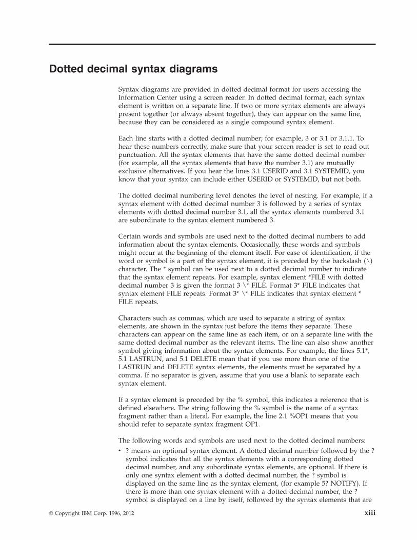
Syntax diagrams are provided in dotted decimal format for users accessing theInformation Center using a screen reader. In dotted decimal format, each syntaxelement is written on a separate line. If two or more syntax elements are alwayspresent together (or always absent together), they can appear on the same line,because they can be considered as a single compound syntax element.
Each line starts with a dotted decimal number; for example, 3 or 3.1 or 3.1.1. Tohear these numbers correctly, make sure that your screen reader is set to read outpunctuation. All the syntax elements that have the same dotted decimal number(for example, all the syntax elements that have the number 3.1) are mutuallyexclusive alternatives. If you hear the lines 3.1 USERID and 3.1 SYSTEMID, youknow that your syntax can include either USERID or SYSTEMID, but not both.
The dotted decimal numbering level denotes the level of nesting. For example, if asyntax element with dotted decimal number 3 is followed by a series of syntaxelements with dotted decimal number 3.1, all the syntax elements numbered 3.1are subordinate to the syntax element numbered 3.
Certain words and symbols are used next to the dotted decimal numbers to addinformation about the syntax elements. Occasionally, these words and symbolsmight occur at the beginning of the element itself. For ease of identification, if theword or symbol is a part of the syntax element, it is preceded by the backslash (\)character. The * symbol can be used next to a dotted decimal number to indicatethat the syntax element repeats. For example, syntax element *FILE with dotteddecimal number 3 is given the format 3 \* FILE. Format 3* FILE indicates thatsyntax element FILE repeats. Format 3* \* FILE indicates that syntax element *FILE repeats.
Characters such as commas, which are used to separate a string of syntaxelements, are shown in the syntax just before the items they separate. Thesecharacters can appear on the same line as each item, or on a separate line with thesame dotted decimal number as the relevant items. The line can also show anothersymbol giving information about the syntax elements. For example, the lines 5.1*,5.1 LASTRUN, and 5.1 DELETE mean that if you use more than one of theLASTRUN and DELETE syntax elements, the elements must be separated by acomma. If no separator is given, assume that you use a blank to separate eachsyntax element.
If a syntax element is preceded by the % symbol, this indicates a reference that isdefined elsewhere. The string following the % symbol is the name of a syntaxfragment rather than a literal. For example, the line 2.1 %OP1 means that youshould refer to separate syntax fragment OP1.
The following words and symbols are used next to the dotted decimal numbers:v ? means an optional syntax element. A dotted decimal number followed by the ?
symbol indicates that all the syntax elements with a corresponding dotteddecimal number, and any subordinate syntax elements, are optional. If there isonly one syntax element with a dotted decimal number, the ? symbol isdisplayed on the same line as the syntax element, (for example 5? NOTIFY). Ifthere is more than one syntax element with a dotted decimal number, the ?symbol is displayed on a line by itself, followed by the syntax elements that are
© Copyright IBM Corp. 1996, 2012 xiii
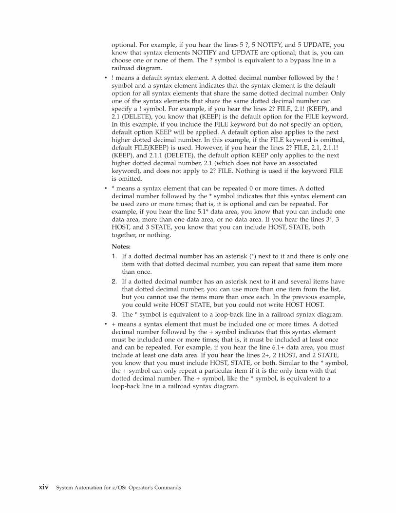
optional. For example, if you hear the lines 5 ?, 5 NOTIFY, and 5 UPDATE, youknow that syntax elements NOTIFY and UPDATE are optional; that is, you canchoose one or none of them. The ? symbol is equivalent to a bypass line in arailroad diagram.
v ! means a default syntax element. A dotted decimal number followed by the !symbol and a syntax element indicates that the syntax element is the defaultoption for all syntax elements that share the same dotted decimal number. Onlyone of the syntax elements that share the same dotted decimal number canspecify a ! symbol. For example, if you hear the lines 2? FILE, 2.1! (KEEP), and2.1 (DELETE), you know that (KEEP) is the default option for the FILE keyword.In this example, if you include the FILE keyword but do not specify an option,default option KEEP will be applied. A default option also applies to the nexthigher dotted decimal number. In this example, if the FILE keyword is omitted,default FILE(KEEP) is used. However, if you hear the lines 2? FILE, 2.1, 2.1.1!(KEEP), and 2.1.1 (DELETE), the default option KEEP only applies to the nexthigher dotted decimal number, 2.1 (which does not have an associatedkeyword), and does not apply to 2? FILE. Nothing is used if the keyword FILEis omitted.
v * means a syntax element that can be repeated 0 or more times. A dotteddecimal number followed by the * symbol indicates that this syntax element canbe used zero or more times; that is, it is optional and can be repeated. Forexample, if you hear the line 5.1* data area, you know that you can include onedata area, more than one data area, or no data area. If you hear the lines 3*, 3HOST, and 3 STATE, you know that you can include HOST, STATE, bothtogether, or nothing.
Notes:
1. If a dotted decimal number has an asterisk (*) next to it and there is only oneitem with that dotted decimal number, you can repeat that same item morethan once.
2. If a dotted decimal number has an asterisk next to it and several items havethat dotted decimal number, you can use more than one item from the list,but you cannot use the items more than once each. In the previous example,you could write HOST STATE, but you could not write HOST HOST.
3. The * symbol is equivalent to a loop-back line in a railroad syntax diagram.v + means a syntax element that must be included one or more times. A dotted
decimal number followed by the + symbol indicates that this syntax elementmust be included one or more times; that is, it must be included at least onceand can be repeated. For example, if you hear the line 6.1+ data area, you mustinclude at least one data area. If you hear the lines 2+, 2 HOST, and 2 STATE,you know that you must include HOST, STATE, or both. Similar to the * symbol,the + symbol can only repeat a particular item if it is the only item with thatdotted decimal number. The + symbol, like the * symbol, is equivalent to aloop-back line in a railroad syntax diagram.
xiv System Automation for z/OS: Operator's Commands
How to send your comments to IBM
We appreciate your input on this publication. Feel free to comment on the clarity,accuracy, and completeness of the information or give us any other feedback thatyou might have.
Use one of the following methods to send us your comments:1. Send an email to [email protected]. Visit the SA z/OS home page at http://www.ibm.com/systems/z/os/zos/
features/system_automation/3. Visit the Contact z/OS web page at http://www.ibm.com/systems/z/os/zos/
webqs.html4. Mail the comments to the following address:
IBM Deutschland Research & Development GmbHDepartment 3248Schoenaicher Str. 220D-71032 BoeblingenFederal Republic of Germany
5. Fax the comments to us as follows:From Germany: 07031-16-3456From all other countries: +(49)-7031-16-3456
Include the following information:v Your name and addressv Your email addressv Your telephone or fax numberv The publication title and order number:
IBM Tivoli System Automation for z/OS V3R40 Operators GuideSC34-2649-00
v The topic and page number related to your commentv The text of your comment.
When you send comments to IBM, you grant IBM a nonexclusive right to use ordistribute your comments in any way it believes appropriate without incurring anyobligation to you.
IBM or any other organizations will only use the personal information that yousupply to contact you about the issues that you submit.
If you have a technical problemDo not use the feedback methods listed above. Instead, do one of the following:v Contact your IBM service representativev Call IBM technical supportv Visit the IBM zSeries support web page at www.ibm.com/systems/z/support/.
© Copyright IBM Corp. 1996, 2012 xv

xvi System Automation for z/OS: Operator's Commands
About This Book
This document provides detailed information and reference material for operatingIBM Tivoli® System Automation for z/OS (SA z/OS).
Throughout this publication references to MVS™ refer either to MVS/ESA, or to theMVS element of z/OS.
Who Should Use This BookThis information is intended primarily for operators and system programmers. Itmay also be useful for others, for example, help desk personnel and customerengineers.
Where to Find More Information
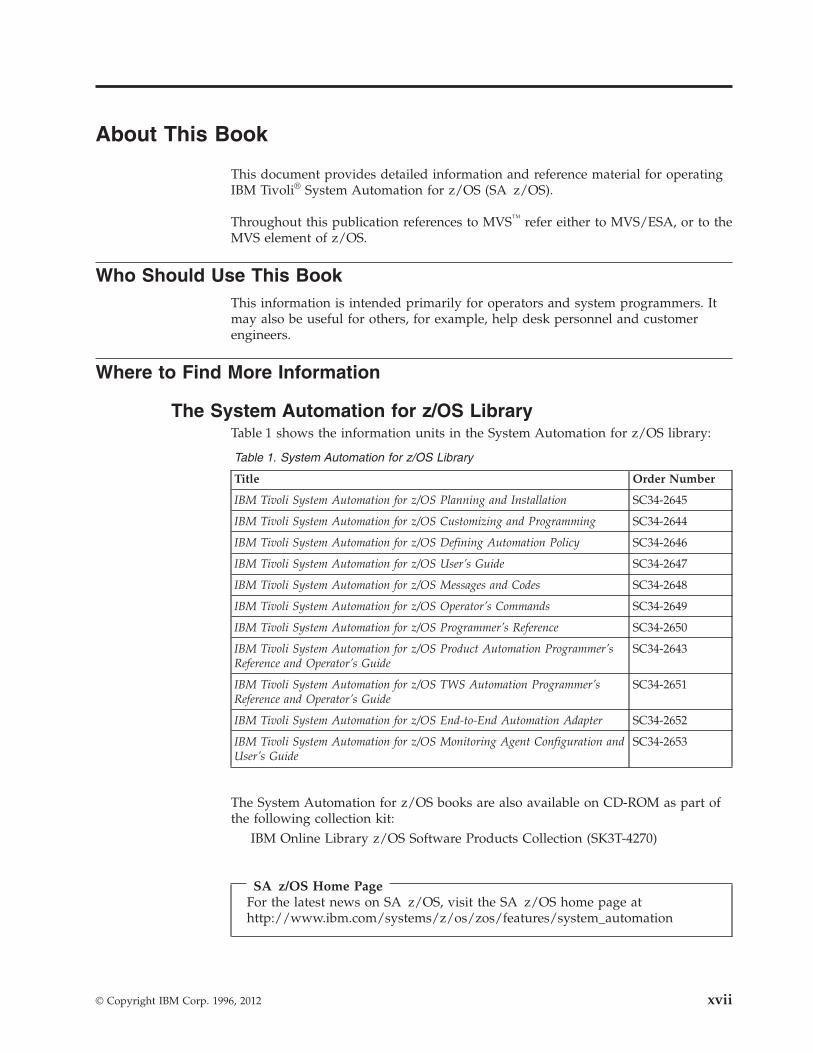
The System Automation for z/OS LibraryTable 1 shows the information units in the System Automation for z/OS library:
Table 1. System Automation for z/OS Library
Title Order Number
IBM Tivoli System Automation for z/OS Planning and Installation SC34-2645
IBM Tivoli System Automation for z/OS Customizing and Programming SC34-2644
IBM Tivoli System Automation for z/OS Defining Automation Policy SC34-2646
IBM Tivoli System Automation for z/OS User’s Guide SC34-2647
IBM Tivoli System Automation for z/OS Messages and Codes SC34-2648
IBM Tivoli System Automation for z/OS Operator’s Commands SC34-2649
IBM Tivoli System Automation for z/OS Programmer’s Reference SC34-2650
IBM Tivoli System Automation for z/OS Product Automation Programmer’sReference and Operator’s Guide
SC34-2643
IBM Tivoli System Automation for z/OS TWS Automation Programmer’sReference and Operator’s Guide
SC34-2651
IBM Tivoli System Automation for z/OS End-to-End Automation Adapter SC34-2652
IBM Tivoli System Automation for z/OS Monitoring Agent Configuration andUser’s Guide
SC34-2653
The System Automation for z/OS books are also available on CD-ROM as part ofthe following collection kit:
IBM Online Library z/OS Software Products Collection (SK3T-4270)
SA z/OS Home PageFor the latest news on SA z/OS, visit the SA z/OS home page athttp://www.ibm.com/systems/z/os/zos/features/system_automation
© Copyright IBM Corp. 1996, 2012 xvii
Related Product InformationYou can find books in related product libraries that may be useful for support ofthe SA z/OS base program by visiting the z/OS Internet Library athttp://www.ibm.com/systems/z/os/zos/bkserv
Using LookAt to look up message explanationsLookAt is an online facility that lets you look up explanations for most of the IBMmessages you encounter, as well as for some system abends and codes. UsingLookAt to find information is faster than a conventional search because in mostcases LookAt goes directly to the message explanation.
You can use LookAt from these locations to find IBM message explanations forz/OS elements and features, z/VM®, z/VSE®, and Clusters for AIX® and Linux:v The Internet. You can access IBM message explanations directly from the LookAt
Website at www.ibm.com/systems/z/os/zos/bkserv/lookat/index.htmlv Your z/OS TSO/E host system. You can install code on your z/OS or z/OS.e
systems to access IBM message explanations using LookAt from a TSO/Ecommand line (for example: TSO/E prompt, ISPF, or z/OS UNIX SystemServices).
v Your Microsoft Windows workstation. You can install LookAt directly from thez/OS Collection (SK3T-4269) or the z/OS and Software Products DVD Collection(SK3T-4271) and use it from the resulting Windows graphical user interface(GUI). The command prompt (also known as the DOS > command line) versioncan still be used from the directory in which you install the Windows version ofLookAt.
v Your wireless handheld device. You can use the LookAt Mobile Edition fromwww.ibm.com/systems/z/os/zos/bkserv/lookat/lookatm.html with a handhelddevice that has wireless access and an Internet browser (for example: InternetExplorer for Pocket PCs, Blazer or Eudora for Palm OS, or Opera for Linuxhandheld devices).
You can obtain code to install LookAt on your host system or Microsoft Windowsworkstation from:v A CD-ROM in the z/OS Collection (SK3T-4269).v The z/OS and Software Products DVD Collection (SK3T-4271).v The LookAt Website (click Download and then select the platform, release,
collection, and location that suit your needs). More information is available inthe LOOKAT.ME files available during the download process.
Summary of Changes for SC34-2649-00This document contains information previously presented in System Automationfor z/OS V3R3.0 Operator's Commands, SC34-2575-02.
New InformationThe following information and commands have been introduced:
System OperationsINGCFG
The INGCFG command for clearing workitem history for resources isadded. See “INGCFG” on page 107.
xviii System Automation for z/OS: Operator's Commands
INGRUNThe INGRUN command allows runmode options to be set for a systemand resources. This command and the related concept of "Runmode"provides for switching from one environment to another, such as a normalmode to a disaster recovery mode. See “INGRUN” on page 210.
Processor OperationsEnsemble Commands
A new chapter is added containing a description of all commandextensions for ISQECMD, that make up the Ensemble command set. Thiscommand set can be used to activate/deactivate Blades and Virtual Serversor to query the settings of the various objects. See Chapter 7, “EnsembleCommands,” on page 471.
ISQECMDThe ISQECMD command shell is used to issue Processor Operationsensemble commands for managing zEnterprise™ Ensemble and zBX (BladeCenter Extension) resources. See “ISQECMD” on page 342.
ISQROUTEThe ISQROUTE command allows you to route a command to a controltask. See “ISQROUTE” on page 349.
ISQXCON commandThe ISQXCON command allows you to manage Processor operationsconnections. See “ISQXCON” on page 372.
POWERMOD commandThe POWERMOD command allows you to query and change the powermode of a CPC. See “POWERMOD” on page 440.
SECLOG commandThe SECLOG command allows you to route security records to theSupport Element (SE) and Hardware Management Console (HMC) logs.See “SECLOG” on page 457.
Changed InformationInformation has been updated for the following commands:
System OperationsACF The syntax diagram is modified to show unified check options for
an automation control file. See “ACF” on page 15.
DISPGW The DISPGW command dialog has been enhanced to showadditional information about the remote systems such as focalpoints used, SMF id and so forth. See “DISPGW” on page 49.
DISPSTAT The syntax has been modified for this command for subsystemdefinition and a default setting for the ALL2CONS parameter.Additional guidance for using wildcards in parameters is provided.See “DISPSTAT” on page 62.
INGFILT The NETVASIS parameter is also added for entering commands inlower and mixed case. The SUBTYPE parameter has been updatedto include wildcards. The DESCR, JOBNAME and RUNTOKENparameters are added with wildcard support as filter criteria. See“INGFILT” on page 119.
INGLIST The NETVASIS parameter is added for entering commands in
About This Book xix
lower and mixed case. The SUBTYPE parameter has been updatedto include wildcards. The DESCR, JOBNAME and RUNTOKENparameters are added with wildcard support as filter criteria. See“INGLIST” on page 144.
INGHIST The INGHIST command has been enhanced with the WIMAXparameter to allow the maximum number of work item records tobe shown after work item expansion. See “INGHIST” on page 132.
INGIMS The INGIMS command is enhanced to show information about thedependent regions associated with the IMS™ control region andTime Controlled Options (TCO) details. The values TCO and DEPare added for the REQ parameter. The OUTDSN parameter isadded. See “INGIMS” on page 135.
INGGROUP The INGGROUP command has been enhanced with the CHUNKparameter in the ACTION options to specify the number of servergroup members for recycling in parallel. See “INGGROUP” onpage 125.
INGMOVE The VERIFY parameter is added for this command, to specifywhether a confirmation is required for the requested action. See“INGMOVE” on page 159.
INGREQ The INGREQ command has been enhanced to include the JOBparameter to indicate whether the resource is a jobname ratherthan a system automation resource name. The NETVASISparameter is added for entering commands in lower and mixedcase. See “INGREQ” on page 197.
INGSEND The NETVASIS parameter is added for entering commands inlower and mixed case. See “INGSEND” on page 221.
INGSET The EXPIRED parameter has been added for this command. Thisparameter allows the cancellation of start/stop requests when theyreach a certain time limit. See “INGSET” on page 229.
INGTHRES The INGTHRES command is enhanced to allow the deletion ofthresholds from an automation script. The REQ parameter has beenadded to submit a deletion request. See “INGTHRES” on page 239.
INGTWS All references to INGOPC are standardized to INGTWS. Thenames are synonymous. See “INGTWS” on page 246.
PSM Commands - Special RequestsThe previous chapter title now includes the subtitle "SpecialRequests" for all these requests that can be executed by theProcOps Service Machine (PSM) Command Server. See Chapter 8,“PSM Commands - Special Requests,” on page 503.
RESYNC An additional range of user exits is verified. The OUTMODEparameter is added. See “RESYNC” on page 263.
SETSTATE The EVT and the TRG parameters have been combined. See“SETSTATE” on page 267.
Processor OperationsCBU Restrictions. The SE Workplace Version number and its related IBM
System name is updated. See “CBU” on page 410.
xx System Automation for z/OS: Operator's Commands
ICNTL Requirements and processor type AAP. New value GRPCAP(Group Capacity) added for VAR parameter. See “ICNTL” on page429.
ISQOVRD A parameter for entering the ProcOps name of a zBX ensemble isadded. See “ISQOVRD” on page 348.
ISQSTART The ACFCLEAN parameters is added for calling the INGLEANroutine to a clean up of the in-storage data model on the ProcOpsfocal point NetView® domain. See “ISQSTART” on page 353.
ISQVARS Parameters for addressing zEnsemble information are added. See“ISQVARS” on page 356.
ISQXCLS Parameters for entering the ProcOps name of a zBX ensemble andtarget hardware are added. See “ISQXCLS” on page 370.
ISQXDST Additional panels are available for displaying information aboutzBX and blade resources within ProcOps. See “ISQXDST” on page376.
ISQXIII Parameters for entering the ProcOps name of a zBX ensemble andtarget hardware are added. See “ISQXIII” on page 395.
ISQXLOC A parameter for entering the ProcOps name of a zBX ensemble isadded. See “ISQXLOC” on page 397.
ISQXMON A parameter for entering the ProcOps name of a zBX ensemble tobe monitored is added. See “ISQXMON” on page 399.
ISQXUNL A parameter for entering the ProcOps name of a zBX ensemble isadded. See “ISQXUNL” on page 405.
OOCOD The SE Workplace Version number and its related IBM Systemname is updated. See “OOCOD” on page 438.
START Defaults and restrictions. See “START” on page 458.
STOP Restrictions. See “STOP” on page 459.
STP The list of target hardware has been added to. See “STP” on page460.
STPDATA The list of target hardware has been added to. See “STPDATA” onpage 462.
Deleted InformationThe following information has been deleted:
SETSTATEThe SVP parameter has been retired. See “SETSTATE” on page 267.
You may notice changes in the style and structure of some content in thisdocument—for example, headings that use uppercase for the first letter of initialwords only, and procedures that have a different look and format. The changes areongoing improvements to the consistency and retrievability of information in ourdocuments.
This document contains terminology, maintenance, and editorial changes. Technicalchanges or additions to the text and illustrations are indicated by a vertical line tothe left of the change.
About This Book xxi

xxii System Automation for z/OS: Operator's Commands

Part 1. Introduction
Chapter 1. Introduction . . . . . . . . . . 3Overview of Commands . . . . . . . . . . 3Understanding Terms . . . . . . . . . . . 3
Resource. . . . . . . . . . . . . . . 3Specifying Resources . . . . . . . . . 4
Format of Syntax Diagrams . . . . . . . . . 5
This part gives an overview of System Automation for z/OS commands — how toenter them, their format, and the various types of commands.
© Copyright IBM Corp. 1996, 2012 1

2 System Automation for z/OS: Operator's Commands
Chapter 1. Introduction
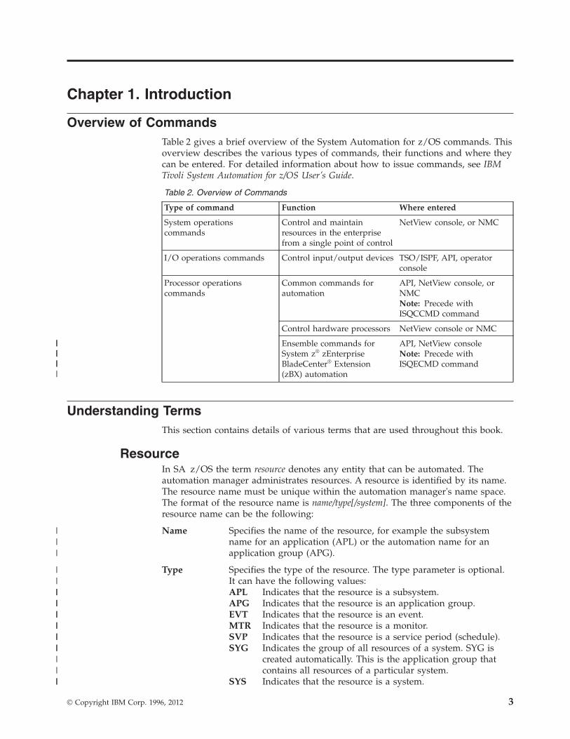
Overview of CommandsTable 2 gives a brief overview of the System Automation for z/OS commands. Thisoverview describes the various types of commands, their functions and where theycan be entered. For detailed information about how to issue commands, see IBMTivoli System Automation for z/OS User’s Guide.
Table 2. Overview of Commands
Type of command Function Where entered
System operationscommands
Control and maintainresources in the enterprisefrom a single point of control
NetView console, or NMC
I/O operations commands Control input/output devices TSO/ISPF, API, operatorconsole
Processor operationscommands
Common commands forautomation
API, NetView console, orNMCNote: Precede withISQCCMD command
Control hardware processors NetView console or NMC
Ensemble commands forSystem z® zEnterpriseBladeCenter® Extension(zBX) automation
API, NetView consoleNote: Precede withISQECMD command
Understanding TermsThis section contains details of various terms that are used throughout this book.
ResourceIn SA z/OS the term resource denotes any entity that can be automated. Theautomation manager administrates resources. A resource is identified by its name.The resource name must be unique within the automation manager's name space.The format of the resource name is name/type[/system]. The three components of theresource name can be the following:
Name Specifies the name of the resource, for example the subsystemname for an application (APL) or the automation name for anapplication group (APG).
Type Specifies the type of the resource. The type parameter is optional.It can have the following values:APL Indicates that the resource is a subsystem.APG Indicates that the resource is an application group.EVT Indicates that the resource is an event.MTR Indicates that the resource is a monitor.SVP Indicates that the resource is a service period (schedule).SYG Indicates the group of all resources of a system. SYG is
created automatically. This is the application group thatcontains all resources of a particular system.
SYS Indicates that the resource is a system.
© Copyright IBM Corp. 1996, 2012 3
||||
|||
|||
||||||||||||||||||
System Specifies the system/image name where the resource is defined.The system parameter is not used for sysplex resources, forexample, sysplex application groups, events or service periods.
Specifying ResourcesThere are various ways of specifying automation manager resources in SystemAutomation for z/OS. The scope of the automation manager is a sysplex orSA z/OS subplex (that a group that shares the same XCF ID).
Using Components of Resource Names: Components are the parts that make upthe name of a resource using automation manager notation.
Here are a few examples of how to specify resource names using components:
TSO All resources that have the name TSO.
TSO/APG All resources that have the name TSO, and the type APG.
TSO/APL All resources that have the name TSO, of the type APL, on allsystems in the sysplex.
Using Wildcards:
You can also use an asterisk (*) to substitute one or more components of afully-qualified resource name. Components are optional and may be replaced by anasterisk (*). For example, a specification for TSO expands with TSO/*/*.
Here are a few examples of how to specify resources using wildcards:
*/APL/SYS1 All resources of type APL, on system SYS1.
TSO/*/SYS1 All resources that have the name TSO, of any type, on systemSYS1.
*/SYS/* All resources of type SYS, on any system in the sysplex.
*/*/* All resources of any type on any system in the sysplex.
You can specify wildcards for a component of the fully-qualified resource name asa leading or trailing character. The following shows a few examples:
TSO*/APL/KEY* All resources starting with TSO, of type APL, onthe systems whose names start with KEY.
*TSO/AP*/* All resources whose names end with TSO, of anytype starting with AP, on any system in thesysplex.
You can use the percentage sign (%) as a placeholder for one character. This meansthat any character in that position of the resource name matches. The followingshows a few examples:
%TSO* All resources whose names contain TSO starting in character two.
TSO/S%S/* All resources whose names start with TSO and where the first andlast character of the type is S, on any system in the sysplex.
If the resource that you specified is not unique within the domain of theautomation manager, a selection panel is displayed where you can select what youwant to work with, as shown in Figure 1 on page 5.
Understanding Terms
4 System Automation for z/OS: Operator's Commands
|||
|
||
|
||
||
|||
|||
|
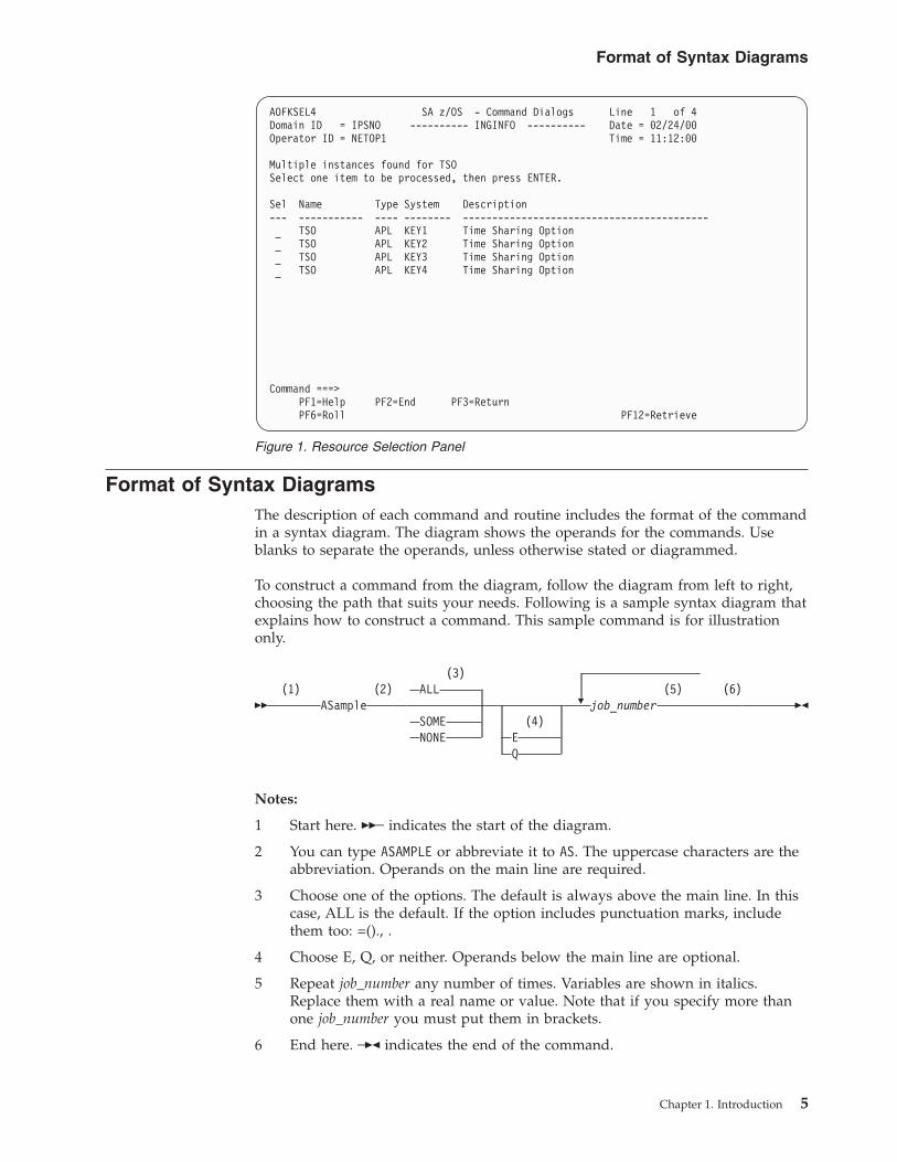
Format of Syntax DiagramsThe description of each command and routine includes the format of the commandin a syntax diagram. The diagram shows the operands for the commands. Useblanks to separate the operands, unless otherwise stated or diagrammed.
To construct a command from the diagram, follow the diagram from left to right,choosing the path that suits your needs. Following is a sample syntax diagram thatexplains how to construct a command. This sample command is for illustrationonly.
��(1) (2)
ASample
(3)ALL
SOMENONE
(4)EQ
�(5) (6)
job_number ��
Notes:
1 Start here. ��─ indicates the start of the diagram.
2 You can type ASAMPLE or abbreviate it to AS. The uppercase characters are theabbreviation. Operands on the main line are required.
3 Choose one of the options. The default is always above the main line. In thiscase, ALL is the default. If the option includes punctuation marks, includethem too: =()., .
4 Choose E, Q, or neither. Operands below the main line are optional.
5 Repeat job_number any number of times. Variables are shown in italics.Replace them with a real name or value. Note that if you specify more thanone job_number you must put them in brackets.
6 End here. ─�� indicates the end of the command.
AOFKSEL4 SA z/OS - Command Dialogs Line 1 of 4Domain ID = IPSNO ---------- INGINFO ---------- Date = 02/24/00Operator ID = NETOP1 Time = 11:12:00
Multiple instances found for TSOSelect one item to be processed, then press ENTER.
Sel Name Type System Description--- ----------- ---- -------- ------------------------------------------
TSO APL KEY1 Time Sharing OptionTSO APL KEY2 Time Sharing OptionTSO APL KEY3 Time Sharing OptionTSO APL KEY4 Time Sharing Option
Command ===>PF1=Help PF2=End PF3=ReturnPF6=Roll PF12=Retrieve
Figure 1. Resource Selection Panel
Format of Syntax Diagrams
Chapter 1. Introduction 5

If a command continues to the next line, you see ─� and �─.├and┤ indicates a fragment for a specific condition or option.
Examples:===> asample none q DAF00821 DAF00832 ELD00824===> as some DLR01445
Format of Syntax Diagrams
6 System Automation for z/OS: Operator's Commands
Part 2. SA z/OS System Operations Commands
Chapter 2. System Operations Commands . . . 9Using System Operations Commands . . . . . . 9
General Information . . . . . . . . . . . 9Overview of Commands that Operate Sysplexwide 9Additional Parameters for System OperationsCommands . . . . . . . . . . . . . 10
TARGET Parameter. . . . . . . . . . 10OUTMODE Parameter. . . . . . . . . 12OUTDSN Parameter . . . . . . . . . 13
Varying the Format of the Command Output . . 13Sorting a List . . . . . . . . . . . . 13Searching for Strings . . . . . . . . . 14
ACF . . . . . . . . . . . . . . . . . 15AOCHELP . . . . . . . . . . . . . . 22AOCTRACE . . . . . . . . . . . . . . 23ASF . . . . . . . . . . . . . . . . . 28ASFUSER . . . . . . . . . . . . . . . 30DISPACF . . . . . . . . . . . . . . . 32DISPAOPS. . . . . . . . . . . . . . . 34DISPAPG . . . . . . . . . . . . . . . 36DISPASF . . . . . . . . . . . . . . . 38DISPAUTO . . . . . . . . . . . . . . 39DISPERRS . . . . . . . . . . . . . . . 40DISPEVT . . . . . . . . . . . . . . . 42DISPEVTS . . . . . . . . . . . . . . . 44DISPFLGS . . . . . . . . . . . . . . . 46DISPGW . . . . . . . . . . . . . . . 49DISPINFO . . . . . . . . . . . . . . . 51DISPMSGS . . . . . . . . . . . . . . 53DISPMTR . . . . . . . . . . . . . . . 54DISPSCHD . . . . . . . . . . . . . . 57DISPSFLT . . . . . . . . . . . . . . . 59DISPSTAT . . . . . . . . . . . . . . . 62DISPSYS . . . . . . . . . . . . . . . 66DISPTREE . . . . . . . . . . . . . . . 68DISPTRG . . . . . . . . . . . . . . . 69DRAINJES. . . . . . . . . . . . . . . 71EXPLAIN . . . . . . . . . . . . . . . 72INGAMS . . . . . . . . . . . . . . . 73INGAUTO. . . . . . . . . . . . . . . 85INGCF . . . . . . . . . . . . . . . . 89
INGCF DRAIN . . . . . . . . . . . . 96INGCF ENABLE . . . . . . . . . . . 100INGCF MAINT. . . . . . . . . . . . 103INGCF PATH . . . . . . . . . . . . 104INGCF STRUCTURE . . . . . . . . . . 105
INGCFG . . . . . . . . . . . . . . . 107Purpose . . . . . . . . . . . . . . 107Syntax. . . . . . . . . . . . . . . 107Parameters . . . . . . . . . . . . . 107
INGCFL . . . . . . . . . . . . . . . 107
Purpose . . . . . . . . . . . . . . 107Syntax. . . . . . . . . . . . . . . 108Parameters . . . . . . . . . . . . . 108Return Codes . . . . . . . . . . . . 108Restrictions and Limitations . . . . . . . 109
INGCICS . . . . . . . . . . . . . . . 109INGDB2 . . . . . . . . . . . . . . . 113INGDLA . . . . . . . . . . . . . . . 116INGEVENT . . . . . . . . . . . . . . 118INGFILT . . . . . . . . . . . . . . . 119INGGROUP . . . . . . . . . . . . . . 125INGHIST . . . . . . . . . . . . . . . 132INGHWSRV . . . . . . . . . . . . . . 134INGIMS . . . . . . . . . . . . . . . 135INGINFO . . . . . . . . . . . . . . 141INGLIST . . . . . . . . . . . . . . . 144INGLKUP . . . . . . . . . . . . . . 152INGMDFY . . . . . . . . . . . . . . 156INGMOVE . . . . . . . . . . . . . . 159INGMSGS . . . . . . . . . . . . . . 164INGNTFY . . . . . . . . . . . . . . 167INGPLEX . . . . . . . . . . . . . . 170
INGPLEX CDS . . . . . . . . . . . . 175INGPLEX SYStem . . . . . . . . . . . 181INGPLEX CONsole . . . . . . . . . . 183INGPLEX IPL . . . . . . . . . . . . 186INGPLEX SDUMP. . . . . . . . . . . 187INGPLEX SVCdump . . . . . . . . . . 189INGPLEX SLIP . . . . . . . . . . . . 193
INGRELS. . . . . . . . . . . . . . . 194INGREQ . . . . . . . . . . . . . . . 197INGRPT . . . . . . . . . . . . . . . 207INGRUN . . . . . . . . . . . . . . . 210INGSCHED . . . . . . . . . . . . . . 214INGSEND . . . . . . . . . . . . . . 221INGSESS . . . . . . . . . . . . . . . 225INGSET . . . . . . . . . . . . . . . 229INGSTR . . . . . . . . . . . . . . . 233INGTHRES . . . . . . . . . . . . . . 239INGTOPO . . . . . . . . . . . . . . 243INGTRIG. . . . . . . . . . . . . . . 244INGTWS . . . . . . . . . . . . . . . 246INGVOTE . . . . . . . . . . . . . . 255MONITOR . . . . . . . . . . . . . . 258OPCAQRY . . . . . . . . . . . . . . 259RESTART. . . . . . . . . . . . . . . 262RESYNC . . . . . . . . . . . . . . . 263SETHOLD . . . . . . . . . . . . . . 265SETSTATE . . . . . . . . . . . . . . 267SETTIMER . . . . . . . . . . . . . . 270
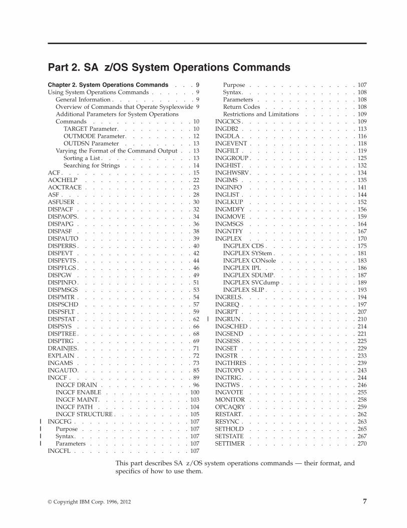
This part describes SA z/OS system operations commands — their format, andspecifics of how to use them.
© Copyright IBM Corp. 1996, 2012 7
||||||||
||

See IBM Tivoli System Automation for z/OS User’s Guide for general informationabout the SA z/OS commands.
8 System Automation for z/OS: Operator's Commands
Chapter 2. System Operations Commands
Using System Operations Commands
General InformationYou can issue any system operations command by typing the command and itsparameters on the command line of any NetView or system operations panel. Youcan also issue system operations commands by entering the command via NMC. Inaddition, System Automation for z/OS provides a menu of command dialogs thatallows you to select a command dialog panel for a specific system operationscommand. For further information on how to issue system operations commands,see IBM Tivoli System Automation for z/OS User’s Guide.
Overview of Commands that Operate SysplexwideThe following system operations commands operate sysplexwide (which meansthat they also operate across an SA z/OS subplex):
DISPEVT/DISPEVTSDISPMTRINGAMSINGCF/INGCFLINGCFGINGCICSINGEVENTINGHISTINGIMSINGINFOINGLISTINGMOVEINGTWSINGPLEXINGRELSINGREQINGRUNINGSCHEDINGSETINGSTRINGTRIGINGVOTE
You can issue sysplexwide commands from any system within the sysplex,regardless of where the resource resides.
If no target is specified, the command that was issued will find the affectedresources in the sysplex.
Specifying the target system parameter is only required when routing thecommand from the focal-point system to a system in another sysplex or to a singleremote system.
For further information about sysplexwide commands, see IBM Tivoli SystemAutomation for z/OS User’s Guide.
© Copyright IBM Corp. 1996, 2012 9
|
||
|
|
Additional Parameters for System Operations CommandsThe following parameters are available for a number of system operationscommands.
TARGET Parameter
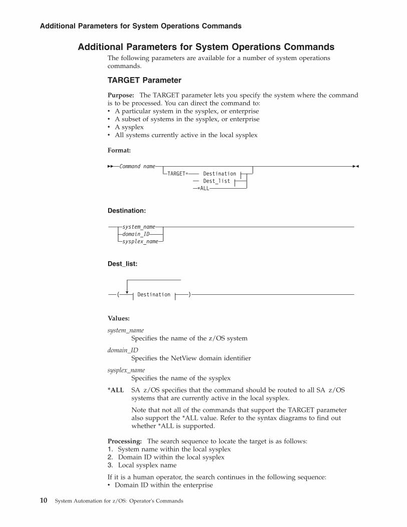
Purpose: The TARGET parameter lets you specify the system where the commandis to be processed. You can direct the command to:v A particular system in the sysplex, or enterprisev A subset of systems in the sysplex, or enterprisev A sysplexv All systems currently active in the local sysplex
Format:
�� Command nameTARGET= Destination
Dest_list*ALL
��
Destination:
system_namedomain_IDsysplex_name
Dest_list:
�( Destination )
Values:
system_nameSpecifies the name of the z/OS system
domain_IDSpecifies the NetView domain identifier
sysplex_nameSpecifies the name of the sysplex
*ALL SA z/OS specifies that the command should be routed to all SA z/OSsystems that are currently active in the local sysplex.
Note that not all of the commands that support the TARGET parameteralso support the *ALL value. Refer to the syntax diagrams to find outwhether *ALL is supported.
Processing: The search sequence to locate the target is as follows:1. System name within the local sysplex2. Domain ID within the local sysplex3. Local sysplex name
If it is a human operator, the search continues in the following sequence:v Domain ID within the enterprise
Additional Parameters for System Operations Commands
10 System Automation for z/OS: Operator's Commands
v System name within the enterprisev Sysplex name within the enterprise
If no value is specified, and the command does not refer to a defined resource, it isprocessed on the local system.
Non-Sysplexwide Commands: If you do not specify the TARGET parameter, and theSA z/OS command refers to a defined resource, SA z/OS processing is as follows:v If the resource is only defined on one active system, the command is routed to
that system.v When processing the command in line mode, SA z/OS checks whether the
resource is defined on the local system. If it is, the command is processed locally.Otherwise, an error message is issued.
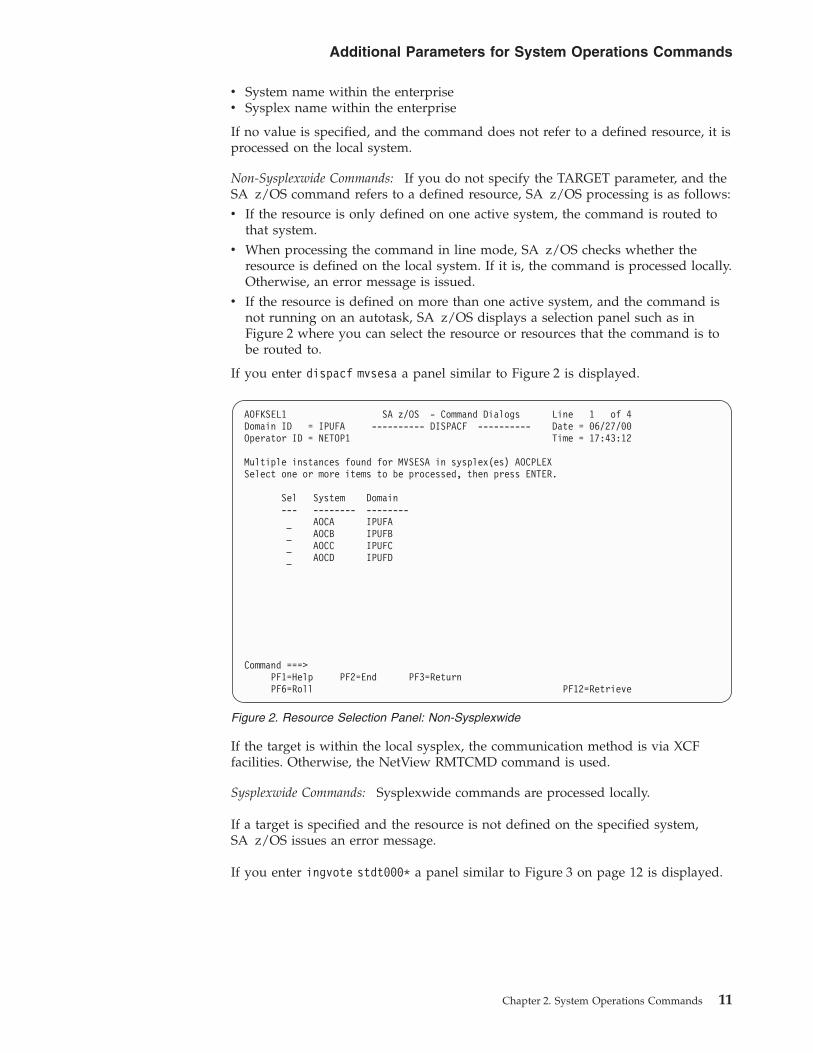
v If the resource is defined on more than one active system, and the command isnot running on an autotask, SA z/OS displays a selection panel such as inFigure 2 where you can select the resource or resources that the command is tobe routed to.
If you enter dispacf mvsesa a panel similar to Figure 2 is displayed.
If the target is within the local sysplex, the communication method is via XCFfacilities. Otherwise, the NetView RMTCMD command is used.
Sysplexwide Commands: Sysplexwide commands are processed locally.
If a target is specified and the resource is not defined on the specified system,SA z/OS issues an error message.
If you enter ingvote stdt000* a panel similar to Figure 3 on page 12 is displayed.
AOFKSEL1 SA z/OS - Command Dialogs Line 1 of 4Domain ID = IPUFA ---------- DISPACF ---------- Date = 06/27/00Operator ID = NETOP1 Time = 17:43:12
Multiple instances found for MVSESA in sysplex(es) AOCPLEXSelect one or more items to be processed, then press ENTER.
Sel System Domain--- -------- --------
AOCA IPUFAAOCB IPUFBAOCC IPUFCAOCD IPUFD
Command ===>PF1=Help PF2=End PF3=ReturnPF6=Roll PF12=Retrieve
Figure 2. Resource Selection Panel: Non-Sysplexwide
Additional Parameters for System Operations Commands
Chapter 2. System Operations Commands 11
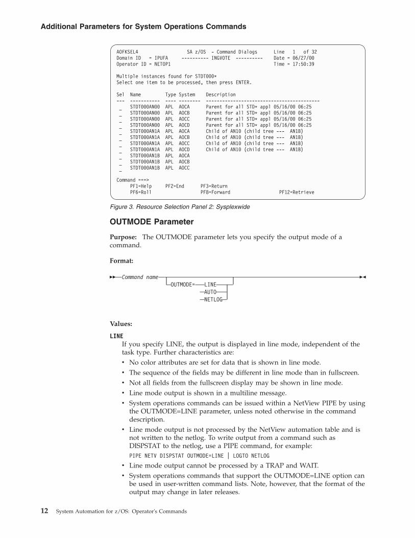
OUTMODE Parameter
Purpose: The OUTMODE parameter lets you specify the output mode of acommand.
Format:
�� Command nameOUTMODE= LINE
AUTONETLOG
��
Values:
LINEIf you specify LINE, the output is displayed in line mode, independent of thetask type. Further characteristics are:v No color attributes are set for data that is shown in line mode.v The sequence of the fields may be different in line mode than in fullscreen.v Not all fields from the fullscreen display may be shown in line mode.v Line mode output is shown in a multiline message.v System operations commands can be issued within a NetView PIPE by using
the OUTMODE=LINE parameter, unless noted otherwise in the commanddescription.
v Line mode output is not processed by the NetView automation table and isnot written to the netlog. To write output from a command such asDISPSTAT to the netlog, use a PIPE command, for example:PIPE NETV DISPSTAT OUTMODE=LINE | LOGTO NETLOG
v Line mode output cannot be processed by a TRAP and WAIT.v System operations commands that support the OUTMODE=LINE option can
be used in user-written command lists. Note, however, that the format of theoutput may change in later releases.
AOFKSEL4 SA z/OS - Command Dialogs Line 1 of 32Domain ID = IPUFA ---------- INGVOTE ---------- Date = 06/27/00Operator ID = NETOP1 Time = 17:50:39
Multiple instances found for STDT000*Select one item to be processed, then press ENTER.
Sel Name Type System Description--- ----------- ---- -------- ------------------------------------------
STDT000AN00 APL AOCA Parent for all STD* appl 05/16/00 06:25STDT000AN00 APL AOCB Parent for all STD* appl 05/16/00 06:25STDT000AN00 APL AOCC Parent for all STD* appl 05/16/00 06:25STDT000AN00 APL AOCD Parent for all STD* appl 05/16/00 06:25STDT000AN1A APL AOCA Child of AN10 (child tree --- AN1B)STDT000AN1A APL AOCB Child of AN10 (child tree --- AN1B)STDT000AN1A APL AOCC Child of AN10 (child tree --- AN1B)STDT000AN1A APL AOCD Child of AN10 (child tree --- AN1B)STDT000AN1B APL AOCASTDT000AN1B APL AOCBSTDT000AN1B APL AOCC
Command ===>PF1=Help PF2=End PF3=ReturnPF6=Roll PF8=Forward PF12=Retrieve
Figure 3. Resource Selection Panel 2: Sysplexwide
Additional Parameters for System Operations Commands
12 System Automation for z/OS: Operator's Commands
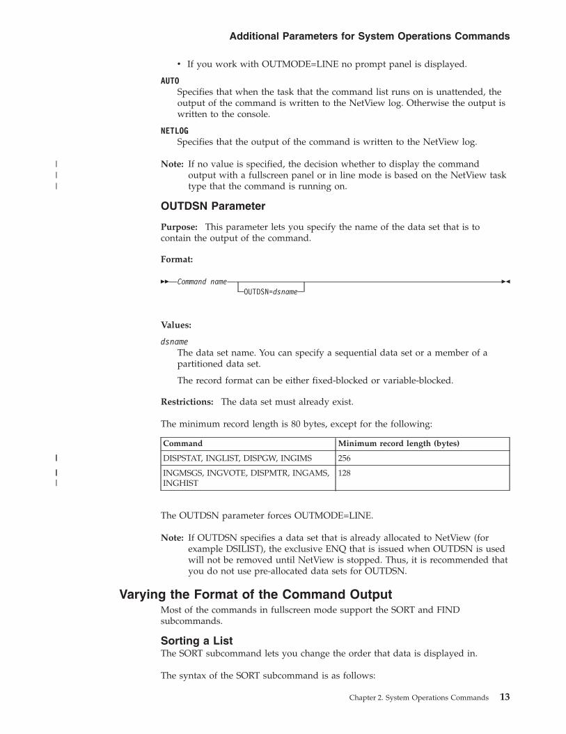
v If you work with OUTMODE=LINE no prompt panel is displayed.
AUTOSpecifies that when the task that the command list runs on is unattended, theoutput of the command is written to the NetView log. Otherwise the output iswritten to the console.
NETLOGSpecifies that the output of the command is written to the NetView log.
Note: If no value is specified, the decision whether to display the commandoutput with a fullscreen panel or in line mode is based on the NetView tasktype that the command is running on.
OUTDSN Parameter
Purpose: This parameter lets you specify the name of the data set that is tocontain the output of the command.
Format:
�� Command nameOUTDSN=dsname
��
Values:
dsnameThe data set name. You can specify a sequential data set or a member of apartitioned data set.
The record format can be either fixed-blocked or variable-blocked.
Restrictions: The data set must already exist.
The minimum record length is 80 bytes, except for the following:
Command Minimum record length (bytes)
DISPSTAT, INGLIST, DISPGW, INGIMS 256
INGMSGS, INGVOTE, DISPMTR, INGAMS,INGHIST
128
The OUTDSN parameter forces OUTMODE=LINE.
Note: If OUTDSN specifies a data set that is already allocated to NetView (forexample DSILIST), the exclusive ENQ that is issued when OUTDSN is usedwill not be removed until NetView is stopped. Thus, it is recommended thatyou do not use pre-allocated data sets for OUTDSN.
Varying the Format of the Command OutputMost of the commands in fullscreen mode support the SORT and FINDsubcommands.
Sorting a ListThe SORT subcommand lets you change the order that data is displayed in.
The syntax of the SORT subcommand is as follows:
Additional Parameters for System Operations Commands
Chapter 2. System Operations Commands 13
|||
||
|||
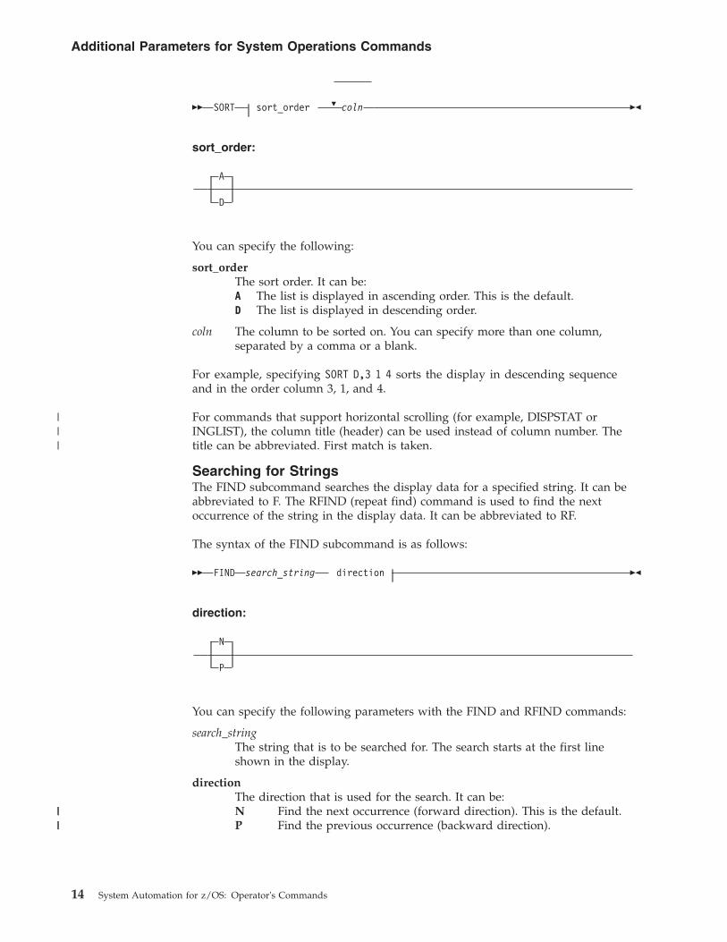
�� SORT �sort_order coln ��
sort_order:
A
D
You can specify the following:
sort_orderThe sort order. It can be:A The list is displayed in ascending order. This is the default.D The list is displayed in descending order.
coln The column to be sorted on. You can specify more than one column,separated by a comma or a blank.
For example, specifying SORT D,3 1 4 sorts the display in descending sequenceand in the order column 3, 1, and 4.
For commands that support horizontal scrolling (for example, DISPSTAT orINGLIST), the column title (header) can be used instead of column number. Thetitle can be abbreviated. First match is taken.
Searching for StringsThe FIND subcommand searches the display data for a specified string. It can beabbreviated to F. The RFIND (repeat find) command is used to find the nextoccurrence of the string in the display data. It can be abbreviated to RF.
The syntax of the FIND subcommand is as follows:
�� FIND search_string direction ��
direction:
N
P
You can specify the following parameters with the FIND and RFIND commands:
search_stringThe string that is to be searched for. The search starts at the first lineshown in the display.
directionThe direction that is used for the search. It can be:N Find the next occurrence (forward direction). This is the default.P Find the previous occurrence (backward direction).
Additional Parameters for System Operations Commands
14 System Automation for z/OS: Operator's Commands
|||
||||
ACF
PurposeThe ACF command loads, displays, and modifies automation control file entries.You can use ACF to refresh data of a particular system if it does not affectautomation manager configuration data.
For modification and display actions to work, the automation control file must beloaded into storage. Once loaded, the displays and modifications affect anin-storage version of the automation control file, allowing you to make temporarychanges. To make permanent changes, change the automation policy using thecustomization dialogs, generate the automation control file member, then reloadthe new version using INGAMS. This ensures that the configuration matches theautomation manager and the automation agents.
Recommendations
1. Use the INGAMS command rather than the ACF command to load orrefresh an automation control file. This ensures that the configurationmatches the automation manager and the automation agents.
2. Changes to automation policy that are made using the SA z/OScommand dialogs or the ACF command are temporary. They modify thecurrent in-storage version of the automation control file directly. They donot modify the automation control file that is stored on disk. To change anautomation policy setting permanently, make sure you also change theautomation policy (using the customization dialogs) that is stored on disk.
3. If the customization dialogs are used to rebuild the automation control fileon disk, the changed data on disk will replace the data in storage at ACFREFRESH.
4. Use scope-checking to limit operator use of ACF to load and displayoperations.
The following syntax diagrams show how to use the ACF command to perform thedifferent functions ACF supports. Do not combine syntax from the separatediagrams in the same ACF call.
Note: The ACF command is freeform:v Commas are optionalv More than one space can separate keywordsv Keywords can be specified in any sequencev Any parameters specified must follow the keyword that they apply to
To replace or add information in the automation control file use the followingsyntax:
ACF
Chapter 2. System Operations Commands 15
|
|||
||||||||
|
|||
||||||
|||
|||||
|||
|
|
|
|
|
||
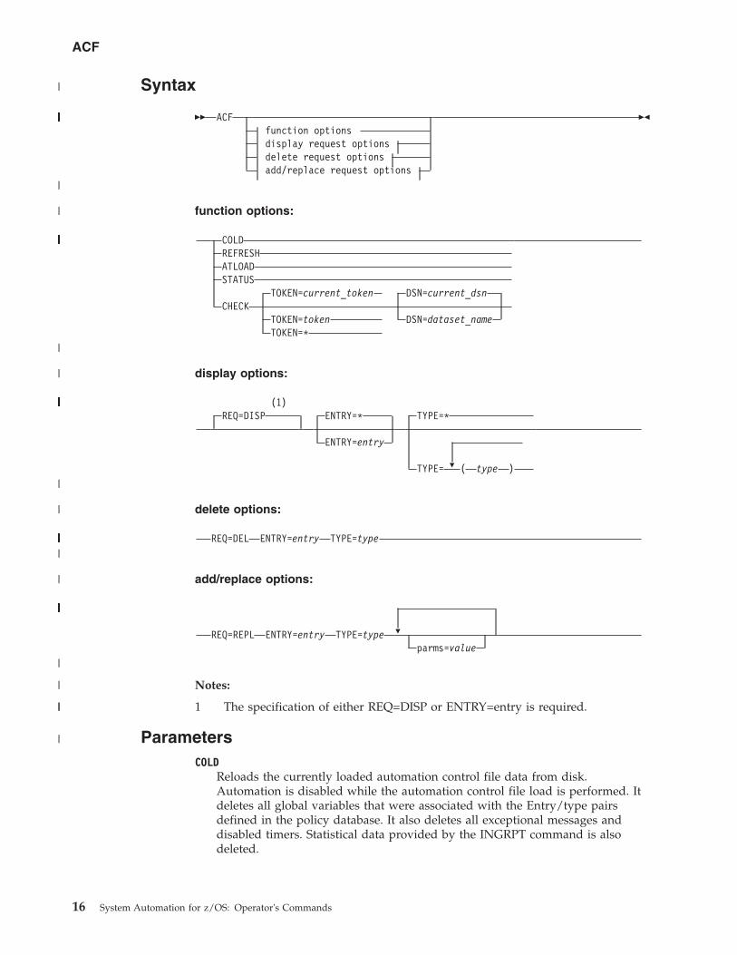
Syntax
�� ACFfunction optionsdisplay request optionsdelete request optionsadd/replace request options
��
function options:
COLDREFRESHATLOADSTATUS
TOKEN=current_token DSN=current_dsnCHECK
TOKEN=token DSN=dataset_nameTOKEN=*
display options:
(1)REQ=DISP ENTRY=*
ENTRY=entry
�
TYPE=*
TYPE= ( type )
delete options:
REQ=DEL ENTRY=entry TYPE=type
add/replace options:
REQ=REPL ENTRY=entry TYPE=type �
parms=value
Notes:
1 The specification of either REQ=DISP or ENTRY=entry is required.
ParametersCOLD
Reloads the currently loaded automation control file data from disk.Automation is disabled while the automation control file load is performed. Itdeletes all global variables that were associated with the Entry/type pairsdefined in the policy database. It also deletes all exceptional messages anddisabled timers. Statistical data provided by the INGRPT command is alsodeleted.
ACF
16 System Automation for z/OS: Operator's Commands
|
|||||||||||||||||||||||||||||||||||
|
|
||||||||||||||||||||||||||||||||||||||||||||
|
|
|||||||||||||||||||||||||||||||||||||||||||||
|
|
||||||||||||||
|
||||||||||||||||||||||||
|
|
||
|
Note: It is not recommended to use ACF COLD. Especially for cleanups, usethe INGCLEAN command. For further details, refer to the INGCLEANcommand reference in IBM Tivoli System Automation for z/OSProgrammer’s Reference.
REFRESHUpdates the currently loaded automation control file data. Automation is notdisabled while the automation control file load is performed. Only data thathas been changed will be loaded, everything else remains the same as before.This is the safe way to update the automation control file. Refresh will not loaddata of a subsystem that is currently in the process of being started or stoppedby SA z/OS. SA z/OS will automatically retry the refresh five minutes laterfor the data that cannot currently be processed.
Note: ACF REFRESH will not delete global variables that were associated withEntry/Type pairs, that were deleted from the policy database before thelast build was done, if those Entry/Types were not associated with asubsystem, a monitor resource, or an application group. However, if akeyword/value is removed from the Entry/Type, this is a change to theEntry/Type, and consequently an ACF REFRESH will rebuild theEntry/Type with the result that the deleted keyword/value pair isremoved from the global variables. All deleted Entry/Types and theirassociated global variables will be reset during the next SA z/OSNetView restart or during ACF COLD processing or by using theINGCLEAN command. For further details, refer to the INGCLEANcommand reference in IBM Tivoli System Automation for z/OSProgrammer’s Reference.
ATLOADReloads the NetView automation tables that are specified in the System Infopolicy item and the message revision table, depending on the value ofAOFSMARTMAT.
STATUSDisplays information about the automation control file that is currently instorage.
CHECKVerifies the ACF for validity and tests the automation tables that are specifiedin the System Info policy and also the message revision table, depending onthe value of AOFSMARTMAT.
TOKENThe configuration token that the ACF should be validated against.
current_tokenThe token that is currently in use (displayed with ACF STATUS). This isthe default.
tokenThe configuration token used as the reference.
* Specifying an asterisk (*) means that the token validation should beomitted.
DSNThe data set name that contains the ACF data.
current_dsnThe data set that is currently in use (displayed via ACF STATUS). This isthe default.
ACF
Chapter 2. System Operations Commands 17
||||
|||||||||||||
dataset_nameThe configuration data set name containing the ACF data.
REQThe type of request for automation control file information the ACF commandperforms. This value can be one of the following:DISP Displays information in the automation control file. This value is the
default if this parameter is not coded.DEL Deletes information in the automation control file. This value must be
coded when using ACF to delete automation control file information.REPL Replaces or adds information in the automation control file. This value
must be coded when using ACF to replace automation control fileinformation. REPL adds the entry specified on the ENTRY parameter ifthe entry does not already exist in the automation control file.
REQ=REPL will update data in place. That is, only data that is to bereplaced needs to be specified in the command. All other existing datawill be retained.
ENTRY The entry field of the automation control file. This value can be up to32 characters long, without imbedded blanks, commas, or quotes.
If information in the automation control file is displayed (REQ=DISP),and no value is specified in the entry field, ENTRY=* is used.
TYPE The type field in the automation control file. The following values canbe specified:* Specifying * returns all type fields that are associated with a given
entry, for example, all SUBSYSTEM or NTFYOP entries. * is thedefault value when REQ=DISP (display). REQ=DISP supports theuse of * as a wildcard character when specifying type names, withthe following restrictions:v The wildcard character, *, must be the last character in the type
name. If an asterisk appears in any other position in a typename then it will be treated as a literal. If an asterisk appears inany other position in a type name with an asterisk as the lastcharacter then no wildcard processing occurs and both asterisksare treated as literals.
v If you update an entry, you must specify the ENTRY= operandwithout a wildcard.
v If no matches are found, a final search is performed with a typename of DEFAULTS.
For other ACF request types (delete and replace), you must specifyan actual type name.
typeThe name of the type field. REQ=REPL requests allow you to enteronly one type.
When ENTRY=SUBSYSTEM, type can be up to 11 bytes long. In allother cases, type can be up to 32 characters long, withoutimbedded blanks, commas, or quotes.
(type,type,...)Multiple types may be specified for DISP and DEL requests. Typenames should be enclosed in parentheses and separated bycommas. For REQ=DISP, only the first type name found isdisplayed. For REQ=DEL requests, all the type names will bedeleted.
parms=valueThe data associated with the specified ENTRY and TYPE fields. This
ACF
18 System Automation for z/OS: Operator's Commands
|||
||
|||
|||||||||
field is valid only with the REQ=REPL option. Specify this field as theparameter value, an equal (=) sign, and the value, without any spacesin between; for example, AUTO=NO.
The value can be any character data. It can have imbedded quotes,commas, and blanks, provided that single quotes or parentheses framethe value.
SA z/OS defines several ENTRY, TYPE, and parms=value fields. Aparms=value example is the JOB=jobname parameter in theSUBSYSTEM automation control file entry.
Note: REQ=REPL will update data in place. That is, only modifieddata is updated. All data will be retained.
Restrictions and Limitationsv If you use the COLD parameter, automation is disabled while the ACF LOAD is
in progress. If you use the REFRESH parameter, automation continues.v An automation control file cannot be loaded by an operator using the ACF
command if the automation flag for major resource MVSESA is set to ‘N’. If theautomation flag for the MVSESA.RELOAD.CONFIRM minor resource is set to‘Y’, the operator can reload the ACF.
v ACF must comply with the automation manager configuration, otherwisemessage AOF618I is issued.
v The ACF command should be used with care to change or delete automationpolicy settings. All changes are only temporary changes and may get lost duringthe next configuration refresh. The changes are definitely lost during an ACFCOLD or after processing the INGCLEAN command.
v The number of entries in the automation control file is limited only by theamount of storage in the SA z/OS address space or region. If you have a verylarge configuration, you may have to increase the REGION size in the SA z/OSprocedure.
v Not all data can be changed using ACF REQ=REPL, for example, serviceperiods, events, triggers, and dependencies cannot be changed. ACF REQ=DELand ACF REQ=REPL cannot be used to add or delete an application(subsystem), an application class, an application group or a monitor resource. Itis NOT recommended to change data of existing applications, application groupsand monitor resources via ACF REQ=REPL to avoid data mismatch betweenautomation agent and automation manager. Use the customization dialogs todefine these items and/or change those data.
v Changes to System Defaults and Application Defaults policy items are notpropagated to the instances that have inherited this data.
Return Codes0 Function completed successfully.1 Control file inactive.3 ACF token mismatch.4 Invalid parameters were used in the call.12 No valid ACF member available.20 ACF reload not allowed by automation flag settings.100 Other error.
ACF
Chapter 2. System Operations Commands 19
||||
||||||||
Usagev ACF performs two flag checks when the automation control file is reloaded. The
checks are of the Automation flags for MVSESA.RELOAD.CONFIRM andMVSESA.RELOAD.ACTION. The action flag is checked only if the reload is tocontinue.
MVSESA.RELOAD.CONFIRMThis lets you:– Turn the flag off and thus disable an automation control file reload by
an operator.– Tell SA z/OS to ask for confirmation by setting the AOFCONFIRM
TGLOBAL to YES in a flag exit.– Use a flag exit to perform additional checks and processing before
deciding to either cancel or proceed with the reload.
If the flag is found to be off, the operator cannot reload the automationcontrol file.
Note: You need to be aware of this if you turn the MVSESA automationflag off.
If the flag is on, the AOFCONFIRM task global is checked. If it is set toYES, SA z/OS will post a message requesting confirmation of the reloadrequest. If AOFCONFIRM is null, SA z/OS will proceed with the reload.
MVSESA.RELOAD.ACTIONThis provides an opportunity for you to do your own processing onceSA z/OS is committed to reloading or restoring the automation controlfile. You can use a flag exit to call your own code. Your exit shouldreturn 0, indicating that the flag is turned on. If you return a nonzeroreturn code, subsequent exits defined for the flag will not be invoked.
Note that there is no way of preventing the reload from an exit on thisflag. See IBM Tivoli System Automation for z/OS Defining Automation Policyand IBM Tivoli System Automation for z/OS Customizing and Programmingfor further information.
v When you use ACF REQ=DISP to request a certain ENTRY value with one ormore specific TYPE values, ACF searches for those types in the order specifiedin the command. When the first match is found, the information is returned tothe requester as a multiline message. If there are no matches, it performs a finalsearch with a type of DEFAULTS for that ENTRY value. If there is still no match,a message is returned to the requester. If the type DEFAULTS is found, thatinformation is returned to the requester.
v If, when ACF is used to display an automation control file entry, a specific TYPEis found, it is treated as a complete entry. Only that specific entry is displayed.
MessagesThe following lists the messages that are issued during the operation of ACF.
For the load function (COLD/REFRESH):AOF042I MEMBER ACFZ999 NOT FOUNDAOF100I 16:05:09 : ’ACF REFRESH’ COMMAND ISSUEDAOF618I NO VALID ACF FOUND FOR sysname - detail descriptionAOF782I AUTOMATION CONTROL FILE PROCESSING COMPLETED
For the status function (STATUS):
ACF
20 System Automation for z/OS: Operator's Commands
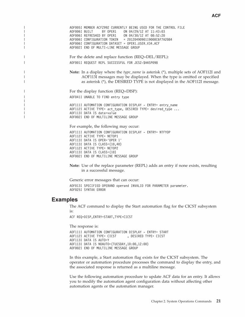
AOF005I MEMBER ACFZ992 CURRENTLY BEING USED FOR THE CONTROL FILEAOF006I BUILT BY OPER1 ON 04/29/12 AT 11:43:03AOF006I REFRESHED BY OPER1 ON 04/30/12 AT 08:52:20AOF006I CONFIGURATION TOKEN = 2012049090119000C6F7A2084AOF006I CONFIGURATION DATASET = OPER1.USER.V34.ACFAOF002I END OF MULTI-LINE MESSAGE GROUP
For the delete and replace function (REQ=DEL/REPL):AOF001I REQUEST REPL SUCCESSFUL FOR JES2-$HASP098
Note: In a display where the type_name is asterisk (*), multiple sets of AOF112I andAOF113I messages may be displayed. When the type is omitted or specifiedas asterisk (*), the DESIRED TYPE is not displayed in the AOF112I message.
For the display function (REQ=DISP):AOF041I UNABLE TO FIND entry type
AOF111I AUTOMATION CONFIGURATION DISPLAY - ENTRY= entry_nameAOF112I ACTIVE TYPE= act_type, DESIRED TYPE= desired_type ...AOF113I DATA IS data=valueAOF002I END OF MULTILINE MESSAGE GROUP
For example, the following may occur:AOF111I AUTOMATION CONFIGURATION DISPLAY - ENTRY= NTFYOPAOF112I ACTIVE TYPE= NETOP1AOF113I DATA IS OPER=’OPER 1’AOF113I DATA IS CLASS=(10,40)AOF112I ACTIVE TYPE= NETOP2AOF113I DATA IS CLASS=(10)AOF002I END OF MULTILINE MESSAGE GROUP
Note: Use of the replace parameter (REPL) adds an entry if none exists, resultingin a successful message.
Generic error messages that can occur:AOF013I SPECIFIED OPERAND operand INVALID FOR PARAMETER parameter.AOF025I SYNTAX ERROR
ExamplesThe ACF command to display the Start automation flag for the CICST subsystemis:ACF REQ=DISP,ENTRY=START,TYPE=CICST
The response is:AOF111I AUTOMATION CONFIGURATION DISPLAY - ENTRY= STARTAOF112I ACTIVE TYPE= CICST , DESIRED TYPE= CICSTAOF113I DATA IS AUTO=YAOF113I DATA IS NOAUTO=(TUESDAY,10:00,12:00)AOF002I END OF MULTILINE MESSAGE GROUP
In this example, a Start automation flag exists for the CICST subsystem. Theoperator or automation procedure processes the command to display the entry, andthe associated response is returned as a multiline message.
Use the following automation procedure to update ACF data for an entry. It allowsyou to modify the automation agent configuration data without affecting otherautomation agents or the automation manager.
ACF
Chapter 2. System Operations Commands 21
||||||
|
|
|||
|
||||||
/* ************************************************* **** Function: **** - Read ACF Fragment **** - Modify ACF entries **** ***************************************************/’PIPE (NAME ACFREPL)’,’QSAM (DSN) -dataset-’, /* read ACF fragment */’! NLOC 1.1 /*/’, /* skip comments */’! COLLECT’, /* collect to multiline */’! NETV ACF REQ=REPL’, /* call ACF command */’! CONS’ /* issue msgs to console */
AOCHELP
PurposeAOCHELP displays information about SA z/OS commands, and enables you toexecute them.
Syntax
�� AOCHELPcommandname
��
Parameterscommandname
Specifies the SA z/OS system operations command that you requireinformation about. The result is the same as if you had specified helpcommandname.
Restrictions and Limitationsv Some commands may not be executed from the AOCHELP command dialog.
Attempts to execute these commands produce SA z/OS message AOF129I.v Help is available only in fullscreen mode.v The AOCHELP command can only be used when SA z/OS has initialized.
UsageIf you type aochelp by itself, you see a list of commands to choose from, as shownin Figure 4 on page 23. From this panel you can ask for help on a command byentering its item number.
ExamplesTo get help, specify the associated number of the command.
ACF
22 System Automation for z/OS: Operator's Commands
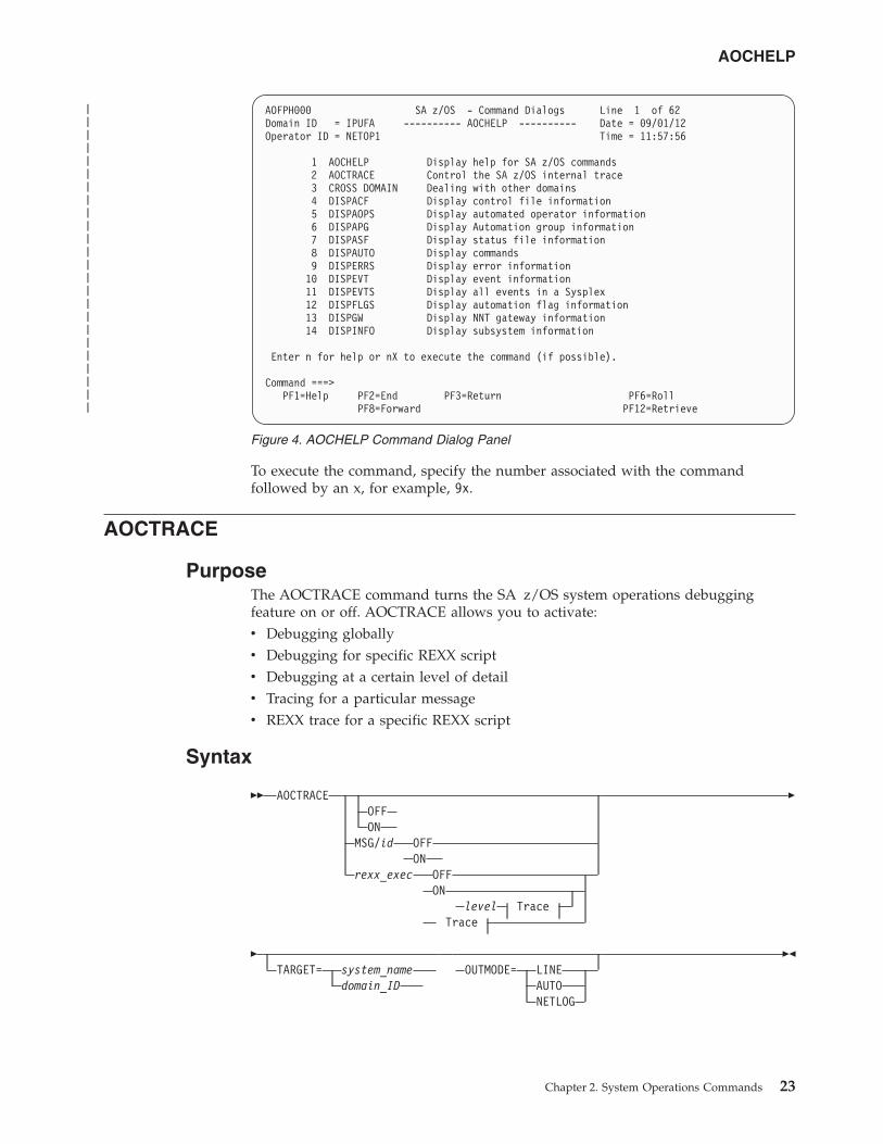
To execute the command, specify the number associated with the commandfollowed by an x, for example, 9x.
AOCTRACE
PurposeThe AOCTRACE command turns the SA z/OS system operations debuggingfeature on or off. AOCTRACE allows you to activate:v Debugging globallyv Debugging for specific REXX scriptv Debugging at a certain level of detailv Tracing for a particular messagev REXX trace for a specific REXX script
Syntax
�� AOCTRACEOFFON
MSG/id OFFON
rexx_exec OFFON
level TraceTrace
�
�TARGET= system_name
domain_IDOUTMODE= LINE
AUTONETLOG
��
AOFPH000 SA z/OS - Command Dialogs Line 1 of 62Domain ID = IPUFA ---------- AOCHELP ---------- Date = 09/01/12Operator ID = NETOP1 Time = 11:57:56
1 AOCHELP Display help for SA z/OS commands2 AOCTRACE Control the SA z/OS internal trace3 CROSS DOMAIN Dealing with other domains4 DISPACF Display control file information5 DISPAOPS Display automated operator information6 DISPAPG Display Automation group information7 DISPASF Display status file information8 DISPAUTO Display commands9 DISPERRS Display error information10 DISPEVT Display event information11 DISPEVTS Display all events in a Sysplex12 DISPFLGS Display automation flag information13 DISPGW Display NNT gateway information14 DISPINFO Display subsystem information
Enter n for help or nX to execute the command (if possible).
Command ===>PF1=Help PF2=End PF3=Return PF6=Roll
PF8=Forward PF12=Retrieve
Figure 4. AOCHELP Command Dialog Panel
AOCHELP
Chapter 2. System Operations Commands 23
||||||||||||||||||||||||
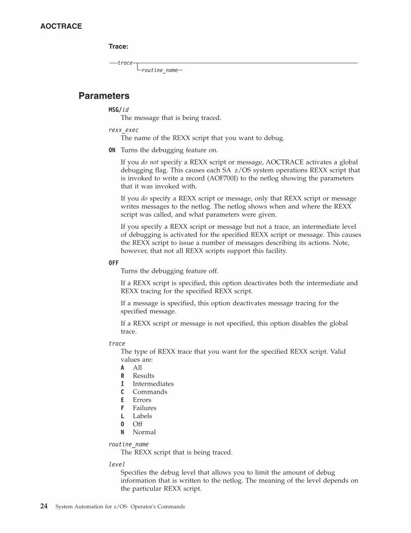
Trace:
traceroutine_name
ParametersMSG/id
The message that is being traced.
rexx_execThe name of the REXX script that you want to debug.
ON Turns the debugging feature on.
If you do not specify a REXX script or message, AOCTRACE activates a globaldebugging flag. This causes each SA z/OS system operations REXX script thatis invoked to write a record (AOF700I) to the netlog showing the parametersthat it was invoked with.
If you do specify a REXX script or message, only that REXX script or messagewrites messages to the netlog. The netlog shows when and where the REXXscript was called, and what parameters were given.
If you specify a REXX script or message but not a trace, an intermediate levelof debugging is activated for the specified REXX script or message. This causesthe REXX script to issue a number of messages describing its actions. Note,however, that not all REXX scripts support this facility.
OFFTurns the debugging feature off.
If a REXX script is specified, this option deactivates both the intermediate andREXX tracing for the specified REXX script.
If a message is specified, this option deactivates message tracing for thespecified message.
If a REXX script or message is not specified, this option disables the globaltrace.
traceThe type of REXX trace that you want for the specified REXX script. Validvalues are:A AllR ResultsI IntermediatesC CommandsE ErrorsF FailuresL LabelsO OffN Normal
routine_nameThe REXX script that is being traced.
levelSpecifies the debug level that allows you to limit the amount of debuginformation that is written to the netlog. The meaning of the level depends onthe particular REXX script.
AOCTRACE
24 System Automation for z/OS: Operator's Commands
NORMThis is the default. Control flow and important data area is written tothe netlog.
MAX Extensive logging of control flow and data areas and structures.
/AM Indicates that data received from the automation manager is nottraced.
/SLAVEIndicates that data received from the command slave is not traced.
TARGETFor information on the TARGET parameter, see “TARGET Parameter” on page10.
OUTMODEFor information on the OUTMODE parameter, see “OUTMODE Parameter” onpage 12.
For further information about AOCTRACE command usage, see "Appendix C -Problem Determination" of IBM Tivoli System Automation for z/OS User’s Guide.
Restrictions and LimitationsThe trace operand can only be used on interpreted REXX scripts.
Using the trace on certain REXX scripts can cause execution problems, particularlywith REXX scripts that trap messages.
The REXX trace setting of S (Scan) is not available.
Message tracing only works from the command line.
Note: The debugging facility is not active if REXX traces A, R, or I are used.
ExamplesIf you enter aoctrace on you see a message indicating that the debugging facilityhas been enabled. While the debugging facility is enabled, message AOF700I iswritten to the netlog for each procedure being processed.
If no parameter is specified Figure 5 on page 26 is displayed.
AOCTRACE
Chapter 2. System Operations Commands 25
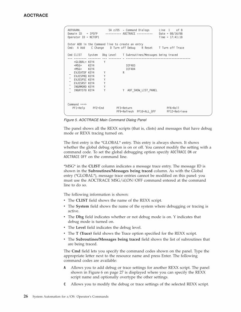
The panel shows all the REXX scripts (that is, clists) and messages that have debugmode or REXX tracing turned on.
The first entry is the *GLOBAL* entry. This entry is always shown. It showswhether the global debug option is on or off. You cannot modify the setting with acommand code. To set the global debugging option specify AOCTRACE ON orAOCTRACE OFF on the command line.
*MSG* in the CLIST column indicates a message trace entry. The message ID isshown in the Subroutines/Messages being traced column. As with the Globalentry (*GLOBAL*), message trace entries cannot be modified on this panel: youmust use the AOCTRACE MSG/id,ON|OFF command entered at the commandline to do so.
The following information is shown:v The CLIST field shows the name of the REXX script.v The System field shows the name of the system where debugging or tracing is
active.v The Dbg field indicates whether or not debug mode is on. Y indicates that
debug mode is turned on.v The Level field indicates the debug level.v The T (Trace) field shows the Trace option specified for the REXX script.v The Subroutines/Messages being traced field shows the list of subroutines that
are being traced.
The Cmd field lets you specify the command codes shown on the panel. Type theappropriate letter next to the resource name and press Enter. The followingcommand codes are available:
A Allows you to add debug or trace settings for another REXX script. The panelshown in Figure 6 on page 27 is displayed where you can specify the REXXscript name and optionally overtype the other settings.
C Allows you to modify the debug or trace settings of the selected REXX script.
AOFKAANL SA z/OS - Command Dialogs Line 1 of 8Domain ID = IPSFP ---------- AOCTRACE ---------- Date = 08/16/08Operator ID = NETOP1 Time = 17:41:18
Enter ADD in the Command line to create an entryCmd: A Add C Change D Turn off Debug R Reset T Turn off Trace
Cmd CLIST System Dbg Level T Subroutines/Messages being traced--- -------- -------- --- -------- - -----------------------------------------
*GLOBAL* KEY4 Y*MSG* KEY4 IEF403*MSG* KEY4 IEF404EVJEATDF KEY4 Y REVJESPRQ KEY4 YEVJESPSC KEY4 YEVJESRST KEY4 YINGRMORD KEY4 YINGRYST0 KEY4 Y Y AOF_SHOW_LIST_PANEL
Command ===>PF1=Help PF2=End PF3=Return PF6=Roll
PF9=Refresh PF10=ALL_OFF PF12=Retrieve
Figure 5. AOCTRACE Main Command Dialog Panel
AOCTRACE
26 System Automation for z/OS: Operator's Commands
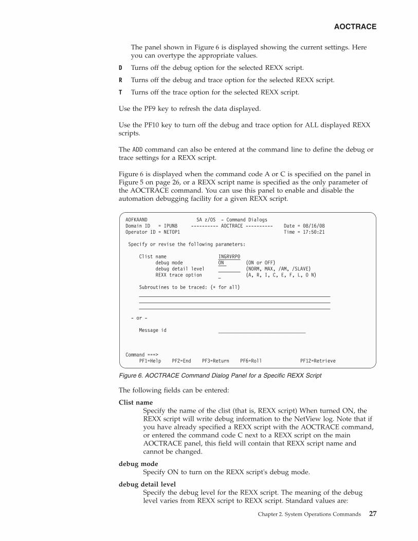
The panel shown in Figure 6 is displayed showing the current settings. Hereyou can overtype the appropriate values.
D Turns off the debug option for the selected REXX script.
R Turns off the debug and trace option for the selected REXX script.
T Turns off the trace option for the selected REXX script.
Use the PF9 key to refresh the data displayed.
Use the PF10 key to turn off the debug and trace option for ALL displayed REXXscripts.
The ADD command can also be entered at the command line to define the debug ortrace settings for a REXX script.
Figure 6 is displayed when the command code A or C is specified on the panel inFigure 5 on page 26, or a REXX script name is specified as the only parameter ofthe AOCTRACE command. You can use this panel to enable and disable theautomation debugging facility for a given REXX script.
The following fields can be entered:
Clist nameSpecify the name of the clist (that is, REXX script) When turned ON, theREXX script will write debug information to the NetView log. Note that ifyou have already specified a REXX script with the AOCTRACE command,or entered the command code C next to a REXX script on the mainAOCTRACE panel, this field will contain that REXX script name andcannot be changed.
debug modeSpecify ON to turn on the REXX script's debug mode.
debug detail levelSpecify the debug level for the REXX script. The meaning of the debuglevel varies from REXX script to REXX script. Standard values are:
AOFKAAND SA z/OS - Command DialogsDomain ID = IPUN8 ---------- AOCTRACE ---------- Date = 08/16/08Operator ID = NETOP1 Time = 17:50:21
Specify or revise the following parameters:
Clist name INGRVRP0debug mode ON (ON or OFF)debug detail level (NORM, MAX, /AM, /SLAVE)REXX trace option (A, R, I, C, E, F, L, O N)
Subroutines to be traced: (* for all)
- or -
Message id ________________________________
Command ===>PF1=Help PF2=End PF3=Return PF6=Roll PF12=Retrieve
Figure 6. AOCTRACE Command Dialog Panel for a Specific REXX Script
AOCTRACE
Chapter 2. System Operations Commands 27
NORMThis is the default. Control flow and important data area is writtento the netlog.
MAX Extensive logging of control flow and data areas and structures.
/AM Indicates that data received from the automation manager is nottraced.
/SLAVEIndicates that data received from the command slave is not traced.
REXX trace optionSpecify the trace setting for the REXX script. It can be one of the following:A AllR ResultsI IntermediatesC CommandsE ErrorsF FailuresL LabelsO OffN Normal_ Default
For more information about trace settings, see TRACE in z/OS TSO/EREXX Reference.
Notes:
1. The REXX script debug setting need not be ON to use REXX scripttrace.
2. Specifying REXX trace option A, I, or R makes individual REXX scriptdebugging ineffective.
Subroutines to be tracedSpecify the list of subroutines to be traced. By default, only the REXXscript main routine will be traced. You can specify more than onesubroutine name separated by a blank character. Specify '*' to trace allsubroutines.
Message idSpecify the message identifier to be traced.
ASF
PurposeThe ASF command is a file manager command that displays records from theautomation status file. The automation status file records are maintained in aVSAM data set. ASF interfaces with the VSAM file to obtain control informationthat is vital to SA z/OS, such as:v Automation statusv Time and date information for specific events within the lifecycle of an
applicationv Whether an error threshold has been exceededv Time and date information for error conditions
AOCTRACE
28 System Automation for z/OS: Operator's Commands
||
You can also use the ASF command to reset occurrences of threshold errors byupdating records in the automation status file.
SyntaxTo display single or multiple records use the following syntax:
�� ASFREQ=DISP
ID=resourceFROM=resource
TO=resource
��
To reset occurrences of threshold errors use the following syntax:
�� ASF REQ=REPL ID=resource ERRORDT='' THRSHLD='' ��
ParametersREQ
The type of request for automation status file information that the ASFcommand performs. This value may be:
DISPDisplays information in the automation status file. This value is the defaultif the REQ parameter is not coded.
REPLResets a record in the automation status file.
ID The resource ID that is the key to the automation status file record. This ID isthe application name for application records. This value can be from 1 through64 characters long.
FROMThe resource ID that is the starting key when displaying multiple automationstatus file records. This resource is the application name for applicationrecords. This value can be from 1 through 64 characters long.
TO The resource ID that is the ending key when displaying multiple automationstatus file records. If not specified, the value defaults to the FROM parametervalue. This resource is the application name for application records. This valuecan be from 1 through 64 characters long.
If a resource ID is specified, the records that are to be displayed are resolvedalphabetically.
ERRORDTSpecify ERRORDT=’’ THRSHLD=’’ with REQ=REPL to reset occurrences ofthreshold errors for a resource.
THRSHLDSpecify ERRORDT=’’ THRSHLD=’’ with REQ=REPL to reset occurrences ofthreshold errors for a resource.
UsageTo modify automation status file fields that are reserved for your data, use theASFUSER command. See “ASFUSER” on page 30 for details.
ASF
Chapter 2. System Operations Commands 29
||
Error conditionsTo display status information about subsystem JES2, enter:ASF REQ=DISP ID=JES2
To reset the occurrences of threshold errors for the application APPC, enter:ASF ID=APPC REQ=REPL ERRORDT=’’ THRSHLD=’’
ASFUSER
PurposeThe ASFUSER command is a file manager command that updates the 40 user fieldsin the automation status file. The ASFUSER command has different formatsdepending on whether it is used to:v Display multiple recordsv Display, delete, or replace (update) a single record
The ASFUSER command is pipeable.
SyntaxTo display single or multiple records use the following syntax:
�� ASFUSERREQ=DISP
ID=resourceFROM=resourceTO=resource
��
To delete a single record use the following syntax:
�� ASFUSER REQ=DEL ID=resource ��
To replace (update) a record use the following syntax:
�� ASFUSER REQ=REPL ID=resource �
(1)USERn=data
��
Notes:
1 n can be a number from 1 through 40
ParametersREQ
The type of request for automation status file record information the ASFUSERcommand performs. This value may be one of the following:
ValueDescription
ASF
30 System Automation for z/OS: Operator's Commands
||
|
|
DISPDisplays a record in the automation status file. This value is the default ifthe REQ parameter is not coded.
DELDeletes a record in the automation status file.
REPLReplaces or adds a record in the automation status file.
If this parameter is specified, other parameters that describe the data to bedisplayed, deleted, or updated must be specified.
FROMThe resource ID that is the starting key when displaying multiple automationstatus file records. This value can be from 1 through 64 characters long.
TO The resource ID that is the ending key when displaying multiple records. If notspecified, the value defaults to the same key as the FROM parameter. Thisvalue can be from 1 through 64 characters long.
ID The resource ID that is the key to the automation status file record. This ID isthe application name for application records. This ID can be from 1 through 64characters long.
USER1=data–USER40=dataThese parameters specify data that is stored in each of the 40 fields in theautomation status file that are reserved for your information. All theseparameters are optional. The specified data can be 1 through 20 characterslong. These parameters are only used with ASFUSER replace requests(REQ=REPL). The data must be enclosed in parenthesis or quotes if it containsblanks or a comma.
Restrictions and LimitationsNone.
UsageIf your automation procedure performs a replace or update function, only thosefields that need replacing must be specified. No change occurs to other automationstatus file fields.
Examples
Example 1This example shows a command to create an automation status file record for aresource with a resource ID of DASD.
The ASFUSER command to create the record is:ASFUSER REQ=REPL ID=DASD USER1=3390 USER2=SITE1
The response to the ASFUSER command is:AOF001I REQUEST "REPLACE" WAS SUCCESSFUL FOR "DASD"
Example 2This example shows a command to display an automation status file record forDASD.
ASFUSER
Chapter 2. System Operations Commands 31
||
|
The ASFUSER command to display the record is:ASFUSER ID=DASD
The response to the ASFUSER command is:AOF150I STATISTICS DISPLAY REQUESTED FOR DASD THRU DASDAOF151I ID=DASD , TYPE= N/A , STATUS= N/AAOF152I LAST UPDATED BY OPERATOR OPER1AOF158I USER1 = 3390AOF158I USER2 = SITE1AOF002I END OF MULTILINE MESSAGE GROUP
Example 3This example shows a command to update the DASD automation status file recordto add a new DASD device type.
The ASFUSER command to add a new field to the existing record is:ASFUSER REQ=REPL,id=DASD,USER3=3990
The response to the ASFUSER command is:AOF001I REQUEST "REPLACE" WAS SUCCESSFUL FOR "DASD"
Note: Other values in record DASD remain as they were before the ASFUSERcommand was issued.
DISPACF
PurposeThe DISPACF command displays resource information and automation policysettings for a specific entry or entry-type pair in the automation control file.
Syntax
�� DISPACF entry_name*
entry_type TARGET= DestinationDest_list
*ALL
�
�OUTMODE= LINE
AUTONETLOG
��
Destination:
system_namedomain_IDsysplex_name
ASFUSER
32 System Automation for z/OS: Operator's Commands
|
||||||
Dest_list:
�( Destination )
Parametersentry_name
Specifies the name of the entry in the automation control file.
If you specify *, all entry names are displayed.
entry_typeSpecifies the type within the entry in the automation control file. If you specifya particular type-name, only that type-name (and its data fields) for theentry-name is displayed.
If you specify *, all of the type-names and their data fields for the entry-nameare displayed. This is the default. Wildcard is supported.
TARGETFor information on the TARGET parameter, see “TARGET Parameter” on page10.
OUTMODEFor information on the OUTMODE parameter, see “OUTMODE Parameter” onpage 12.
Restrictions and LimitationsThe DISPACF command can only be used when SA z/OS is initialized.
ExamplesIf you enter dispacf subsystem, you will see a fullscreen display similar toFigure 7 on page 34.
DISPACF
Chapter 2. System Operations Commands 33
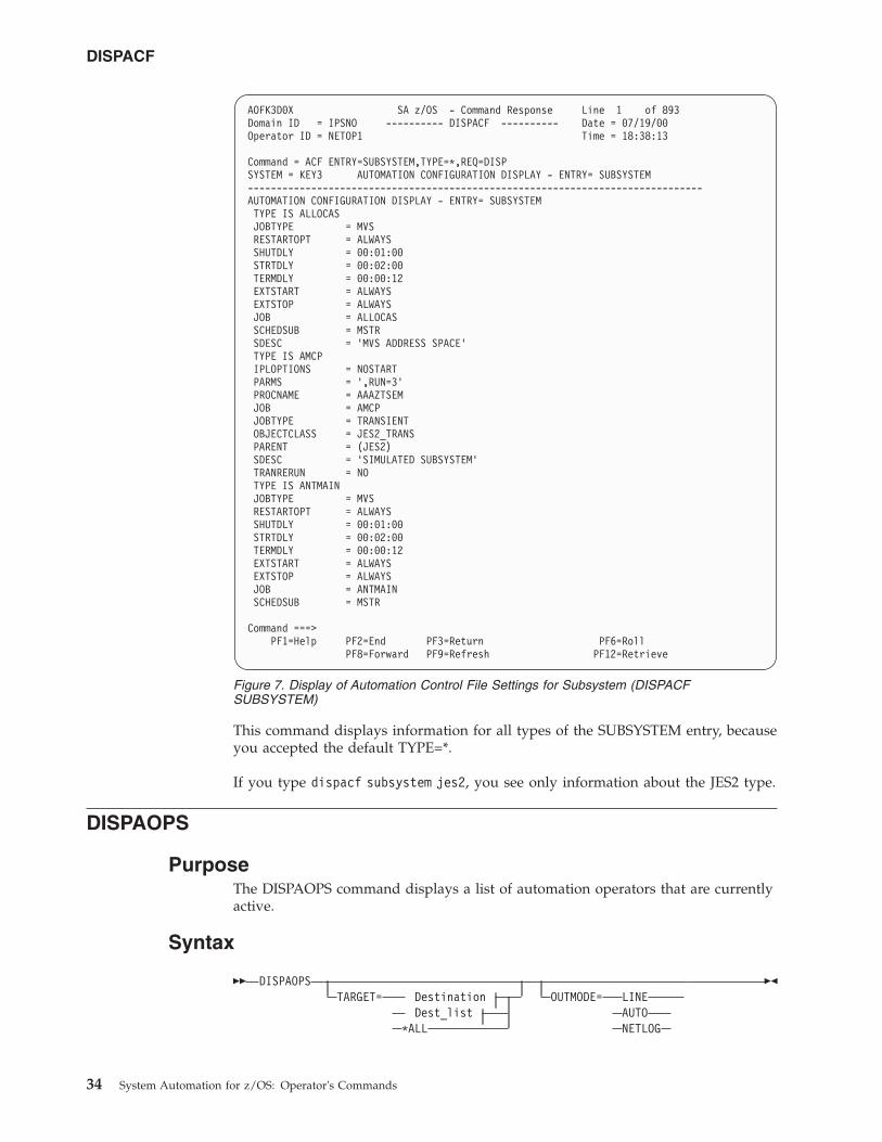
This command displays information for all types of the SUBSYSTEM entry, becauseyou accepted the default TYPE=*.
If you type dispacf subsystem jes2, you see only information about the JES2 type.
DISPAOPS
PurposeThe DISPAOPS command displays a list of automation operators that are currentlyactive.
Syntax
�� DISPAOPSTARGET= Destination
Dest_list*ALL
OUTMODE= LINEAUTONETLOG
��
AOFK3D0X SA z/OS - Command Response Line 1 of 893Domain ID = IPSNO ---------- DISPACF ---------- Date = 07/19/00Operator ID = NETOP1 Time = 18:38:13
Command = ACF ENTRY=SUBSYSTEM,TYPE=*,REQ=DISPSYSTEM = KEY3 AUTOMATION CONFIGURATION DISPLAY - ENTRY= SUBSYSTEM-------------------------------------------------------------------------------AUTOMATION CONFIGURATION DISPLAY - ENTRY= SUBSYSTEMTYPE IS ALLOCASJOBTYPE = MVSRESTARTOPT = ALWAYSSHUTDLY = 00:01:00STRTDLY = 00:02:00TERMDLY = 00:00:12EXTSTART = ALWAYSEXTSTOP = ALWAYSJOB = ALLOCASSCHEDSUB = MSTRSDESC = ’MVS ADDRESS SPACE’TYPE IS AMCPIPLOPTIONS = NOSTARTPARMS = ’,RUN=3’PROCNAME = AAAZTSEMJOB = AMCPJOBTYPE = TRANSIENTOBJECTCLASS = JES2_TRANSPARENT = (JES2)SDESC = ’SIMULATED SUBSYSTEM’TRANRERUN = NOTYPE IS ANTMAINJOBTYPE = MVSRESTARTOPT = ALWAYSSHUTDLY = 00:01:00STRTDLY = 00:02:00TERMDLY = 00:00:12EXTSTART = ALWAYSEXTSTOP = ALWAYSJOB = ANTMAINSCHEDSUB = MSTR
Command ===>PF1=Help PF2=End PF3=Return PF6=Roll
PF8=Forward PF9=Refresh PF12=Retrieve
Figure 7. Display of Automation Control File Settings for Subsystem (DISPACFSUBSYSTEM)
DISPACF
34 System Automation for z/OS: Operator's Commands
Destination:
system_namedomain_IDsysplex_name
Dest_list:
�( Destination )
ParametersTARGET
For information on the TARGET parameter, see “TARGET Parameter” on page10.
OUTMODEFor information on the OUTMODE parameter, see “OUTMODE Parameter” onpage 12.
Restrictions and LimitationsThe DISPAOPS command can only be used when SA z/OS is initialized.
ExamplesType dispaops on any command line and press the Enter key. You will see a panelsimilar to Figure 8 on page 36.
DISPAOPS
Chapter 2. System Operations Commands 35
||
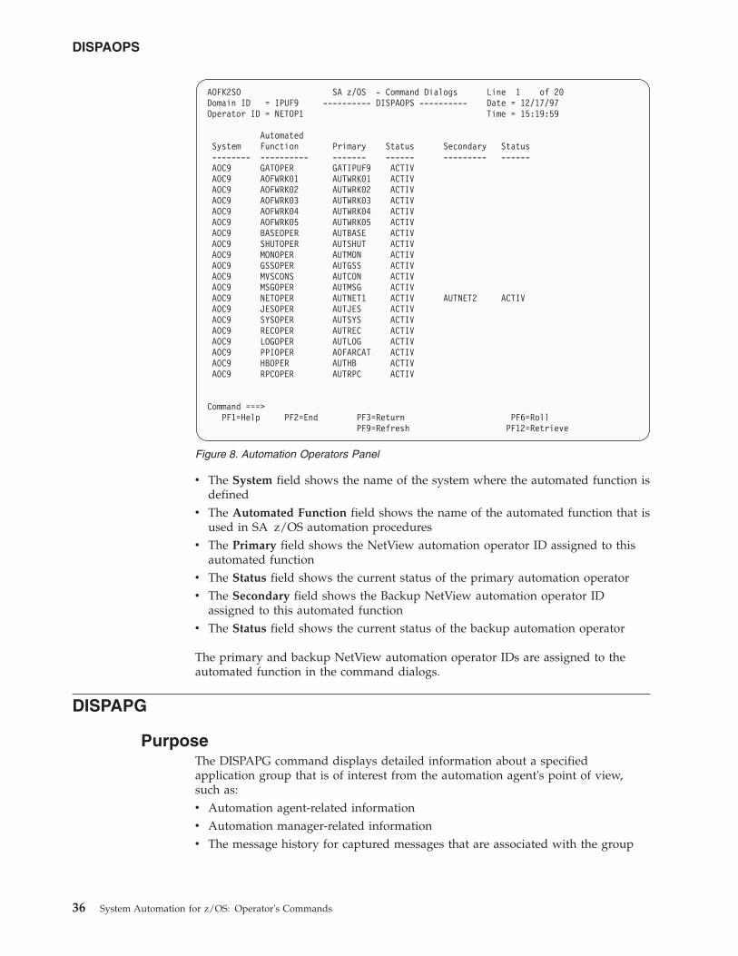
v The System field shows the name of the system where the automated function isdefined
v The Automated Function field shows the name of the automated function that isused in SA z/OS automation procedures
v The Primary field shows the NetView automation operator ID assigned to thisautomated function
v The Status field shows the current status of the primary automation operatorv The Secondary field shows the Backup NetView automation operator ID
assigned to this automated functionv The Status field shows the current status of the backup automation operator
The primary and backup NetView automation operator IDs are assigned to theautomated function in the command dialogs.
DISPAPG
PurposeThe DISPAPG command displays detailed information about a specifiedapplication group that is of interest from the automation agent's point of view,such as:v Automation agent-related informationv Automation manager-related informationv The message history for captured messages that are associated with the group
AOFK2SO SA z/OS - Command Dialogs Line 1 of 20Domain ID = IPUF9 ---------- DISPAOPS ---------- Date = 12/17/97Operator ID = NETOP1 Time = 15:19:59
AutomatedSystem Function Primary Status Secondary Status-------- ---------- ------- ------ --------- ------AOC9 GATOPER GATIPUF9 ACTIVAOC9 AOFWRK01 AUTWRK01 ACTIVAOC9 AOFWRK02 AUTWRK02 ACTIVAOC9 AOFWRK03 AUTWRK03 ACTIVAOC9 AOFWRK04 AUTWRK04 ACTIVAOC9 AOFWRK05 AUTWRK05 ACTIVAOC9 BASEOPER AUTBASE ACTIVAOC9 SHUTOPER AUTSHUT ACTIVAOC9 MONOPER AUTMON ACTIVAOC9 GSSOPER AUTGSS ACTIVAOC9 MVSCONS AUTCON ACTIVAOC9 MSGOPER AUTMSG ACTIVAOC9 NETOPER AUTNET1 ACTIV AUTNET2 ACTIVAOC9 JESOPER AUTJES ACTIVAOC9 SYSOPER AUTSYS ACTIVAOC9 RECOPER AUTREC ACTIVAOC9 LOGOPER AUTLOG ACTIVAOC9 PPIOPER AOFARCAT ACTIVAOC9 HBOPER AUTHB ACTIVAOC9 RPCOPER AUTRPC ACTIV
Command ===>PF1=Help PF2=End PF3=Return PF6=Roll
PF9=Refresh PF12=Retrieve
Figure 8. Automation Operators Panel
DISPAOPS
36 System Automation for z/OS: Operator's Commands
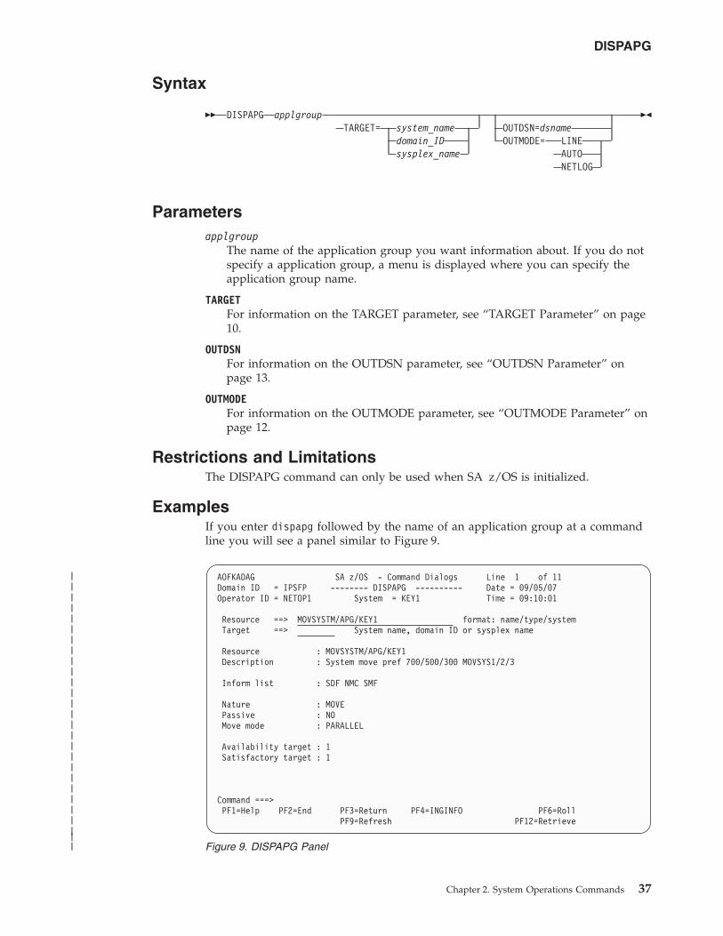
Syntax
�� DISPAPG applgroupTARGET= system_name
domain_IDsysplex_name
OUTDSN=dsnameOUTMODE= LINE
AUTONETLOG
��
Parametersapplgroup
The name of the application group you want information about. If you do notspecify a application group, a menu is displayed where you can specify theapplication group name.
TARGETFor information on the TARGET parameter, see “TARGET Parameter” on page10.
OUTDSNFor information on the OUTDSN parameter, see “OUTDSN Parameter” onpage 13.
OUTMODEFor information on the OUTMODE parameter, see “OUTMODE Parameter” onpage 12.
Restrictions and LimitationsThe DISPAPG command can only be used when SA z/OS is initialized.
ExamplesIf you enter dispapg followed by the name of an application group at a commandline you will see a panel similar to Figure 9.
AOFKADAG SA z/OS - Command Dialogs Line 1 of 11Domain ID = IPSFP -------- DISPAPG ---------- Date = 09/05/07Operator ID = NETOP1 System = KEY1 Time = 09:10:01
Resource ==> MOVSYSTM/APG/KEY1 format: name/type/systemTarget ==> System name, domain ID or sysplex name
Resource : MOVSYSTM/APG/KEY1Description : System move pref 700/500/300 MOVSYS1/2/3
Inform list : SDF NMC SMF
Nature : MOVEPassive : NOMove mode : PARALLEL
Availability target : 1Satisfactory target : 1
Command ===>PF1=Help PF2=End PF3=Return PF4=INGINFO PF6=Roll
PF9=Refresh PF12=Retrieve
Figure 9. DISPAPG Panel
DISPAPG
Chapter 2. System Operations Commands 37
|||||||||||||||||||||||||||
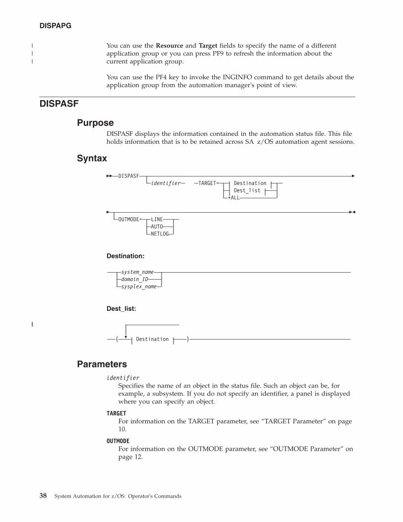
You can use the Resource and Target fields to specify the name of a differentapplication group or you can press PF9 to refresh the information about thecurrent application group.
You can use the PF4 key to invoke the INGINFO command to get details about theapplication group from the automation manager's point of view.
DISPASF
PurposeDISPASF displays the information contained in the automation status file. This fileholds information that is to be retained across SA z/OS automation agent sessions.
Syntax
�� DISPASFidentifier TARGET= Destination
Dest_list*ALL
�
�OUTMODE= LINE
AUTONETLOG
��
Destination:
system_namedomain_IDsysplex_name
Dest_list:
�( Destination )
Parametersidentifier
Specifies the name of an object in the status file. Such an object can be, forexample, a subsystem. If you do not specify an identifier, a panel is displayedwhere you can specify an object.
TARGETFor information on the TARGET parameter, see “TARGET Parameter” on page10.
OUTMODEFor information on the OUTMODE parameter, see “OUTMODE Parameter” onpage 12.
DISPAPG
38 System Automation for z/OS: Operator's Commands
|||
||
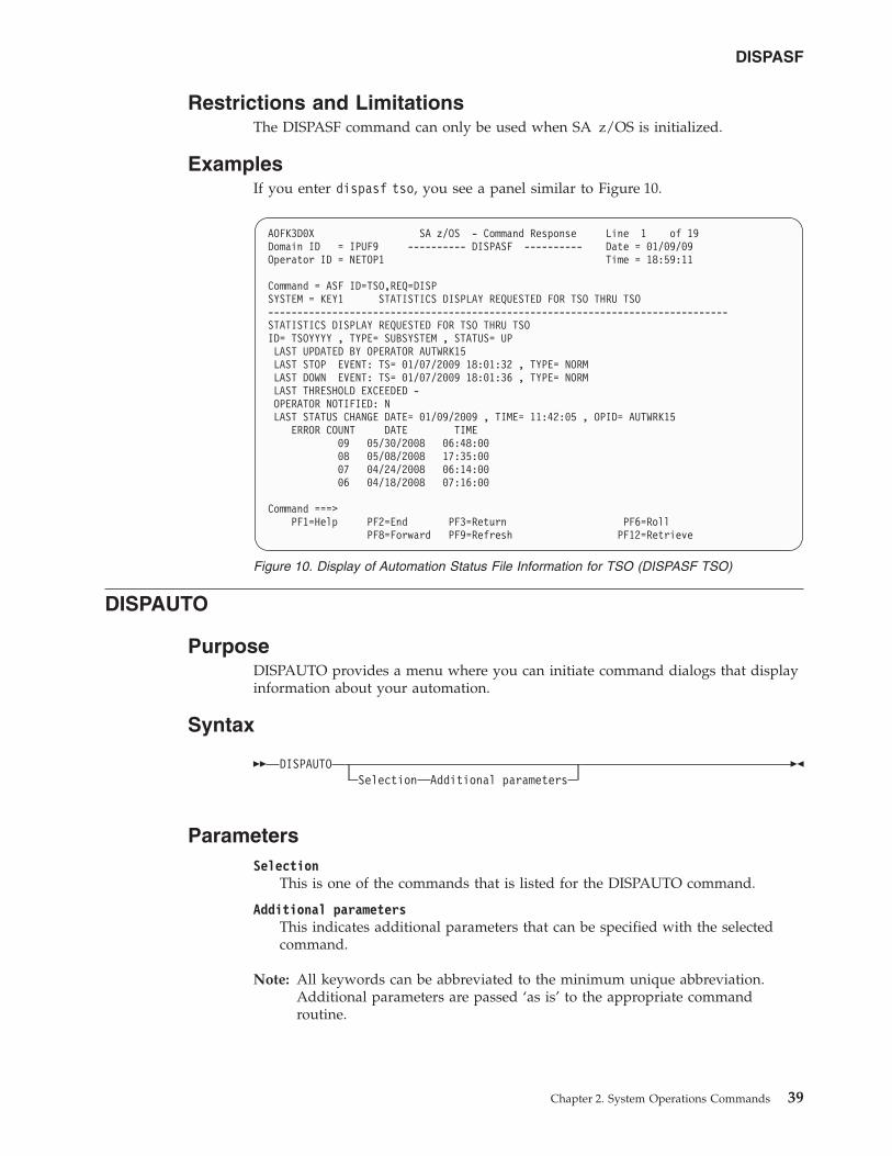
Restrictions and LimitationsThe DISPASF command can only be used when SA z/OS is initialized.
ExamplesIf you enter dispasf tso, you see a panel similar to Figure 10.
DISPAUTO
PurposeDISPAUTO provides a menu where you can initiate command dialogs that displayinformation about your automation.
Syntax
�� DISPAUTOSelection Additional parameters
��
ParametersSelection
This is one of the commands that is listed for the DISPAUTO command.
Additional parametersThis indicates additional parameters that can be specified with the selectedcommand.
Note: All keywords can be abbreviated to the minimum unique abbreviation.Additional parameters are passed ‘as is’ to the appropriate commandroutine.
AOFK3D0X SA z/OS - Command Response Line 1 of 19Domain ID = IPUF9 ---------- DISPASF ---------- Date = 01/09/09Operator ID = NETOP1 Time = 18:59:11
Command = ASF ID=TSO,REQ=DISPSYSTEM = KEY1 STATISTICS DISPLAY REQUESTED FOR TSO THRU TSO-------------------------------------------------------------------------------STATISTICS DISPLAY REQUESTED FOR TSO THRU TSOID= TSOYYYY , TYPE= SUBSYSTEM , STATUS= UPLAST UPDATED BY OPERATOR AUTWRK15LAST STOP EVENT: TS= 01/07/2009 18:01:32 , TYPE= NORMLAST DOWN EVENT: TS= 01/07/2009 18:01:36 , TYPE= NORMLAST THRESHOLD EXCEEDED -OPERATOR NOTIFIED: NLAST STATUS CHANGE DATE= 01/09/2009 , TIME= 11:42:05 , OPID= AUTWRK15
ERROR COUNT DATE TIME09 05/30/2008 06:48:0008 05/08/2008 17:35:0007 04/24/2008 06:14:0006 04/18/2008 07:16:00
Command ===>PF1=Help PF2=End PF3=Return PF6=Roll
PF8=Forward PF9=Refresh PF12=Retrieve
Figure 10. Display of Automation Status File Information for TSO (DISPASF TSO)
DISPASF
Chapter 2. System Operations Commands 39
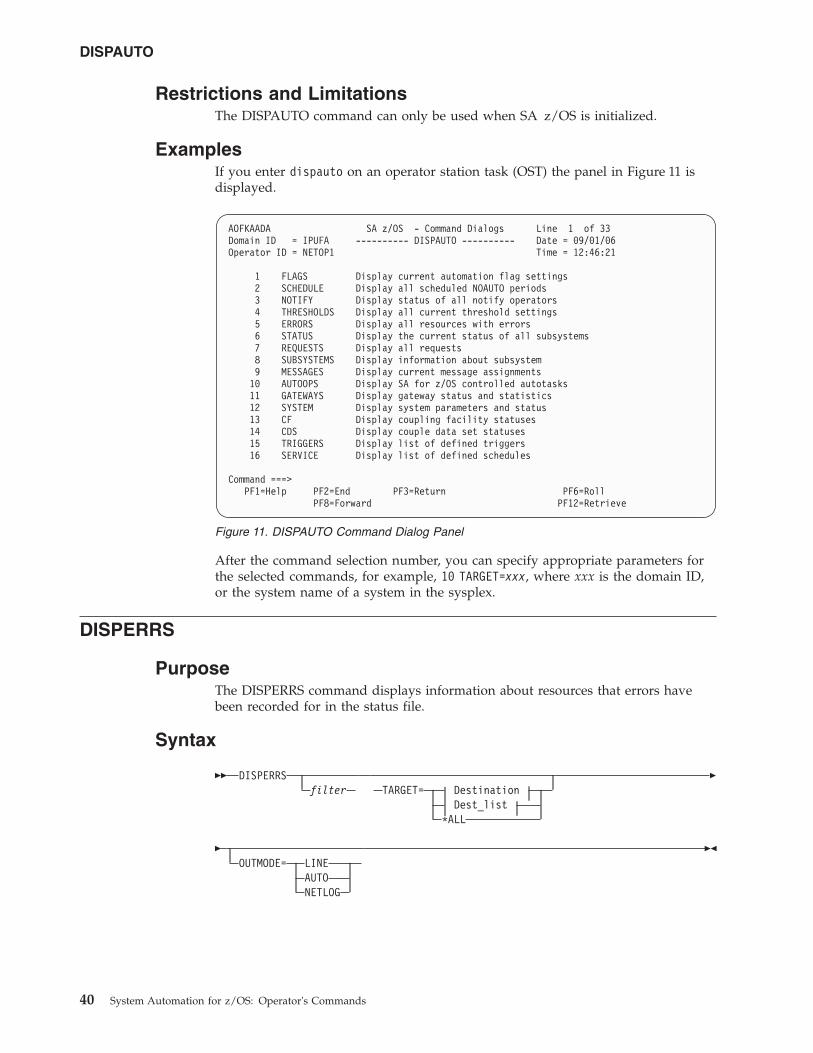
Restrictions and LimitationsThe DISPAUTO command can only be used when SA z/OS is initialized.
ExamplesIf you enter dispauto on an operator station task (OST) the panel in Figure 11 isdisplayed.
After the command selection number, you can specify appropriate parameters forthe selected commands, for example, 10 TARGET=xxx, where xxx is the domain ID,or the system name of a system in the sysplex.
DISPERRS
PurposeThe DISPERRS command displays information about resources that errors havebeen recorded for in the status file.
Syntax
�� DISPERRSfilter TARGET= Destination
Dest_list*ALL
�
�OUTMODE= LINE
AUTONETLOG
��
AOFKAADA SA z/OS - Command Dialogs Line 1 of 33Domain ID = IPUFA ---------- DISPAUTO ---------- Date = 09/01/06Operator ID = NETOP1 Time = 12:46:21
1 FLAGS Display current automation flag settings2 SCHEDULE Display all scheduled NOAUTO periods3 NOTIFY Display status of all notify operators4 THRESHOLDS Display all current threshold settings5 ERRORS Display all resources with errors6 STATUS Display the current status of all subsystems7 REQUESTS Display all requests8 SUBSYSTEMS Display information about subsystem9 MESSAGES Display current message assignments10 AUTOOPS Display SA for z/OS controlled autotasks11 GATEWAYS Display gateway status and statistics12 SYSTEM Display system parameters and status13 CF Display coupling facility statuses14 CDS Display couple data set statuses15 TRIGGERS Display list of defined triggers16 SERVICE Display list of defined schedules
Command ===>PF1=Help PF2=End PF3=Return PF6=Roll
PF8=Forward PF12=Retrieve
Figure 11. DISPAUTO Command Dialog Panel
DISPAUTO
40 System Automation for z/OS: Operator's Commands
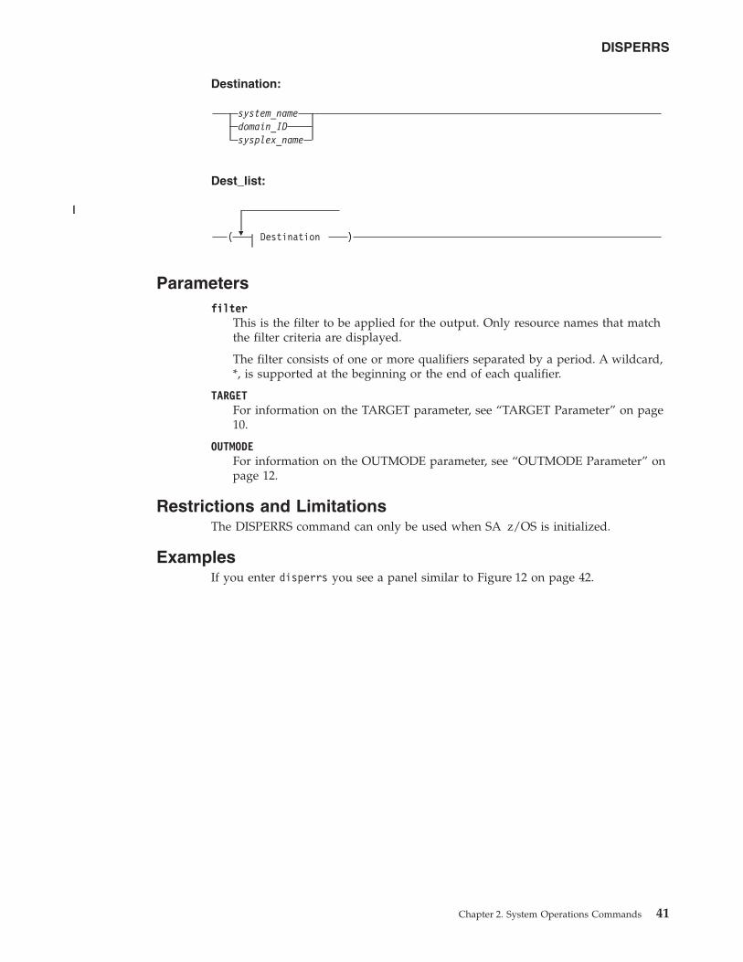
Destination:
system_namedomain_IDsysplex_name
Dest_list:
�( Destination )
Parametersfilter
This is the filter to be applied for the output. Only resource names that matchthe filter criteria are displayed.
The filter consists of one or more qualifiers separated by a period. A wildcard,*, is supported at the beginning or the end of each qualifier.
TARGETFor information on the TARGET parameter, see “TARGET Parameter” on page10.
OUTMODEFor information on the OUTMODE parameter, see “OUTMODE Parameter” onpage 12.
Restrictions and LimitationsThe DISPERRS command can only be used when SA z/OS is initialized.
ExamplesIf you enter disperrs you see a panel similar to Figure 12 on page 42.
DISPERRS
Chapter 2. System Operations Commands 41
||
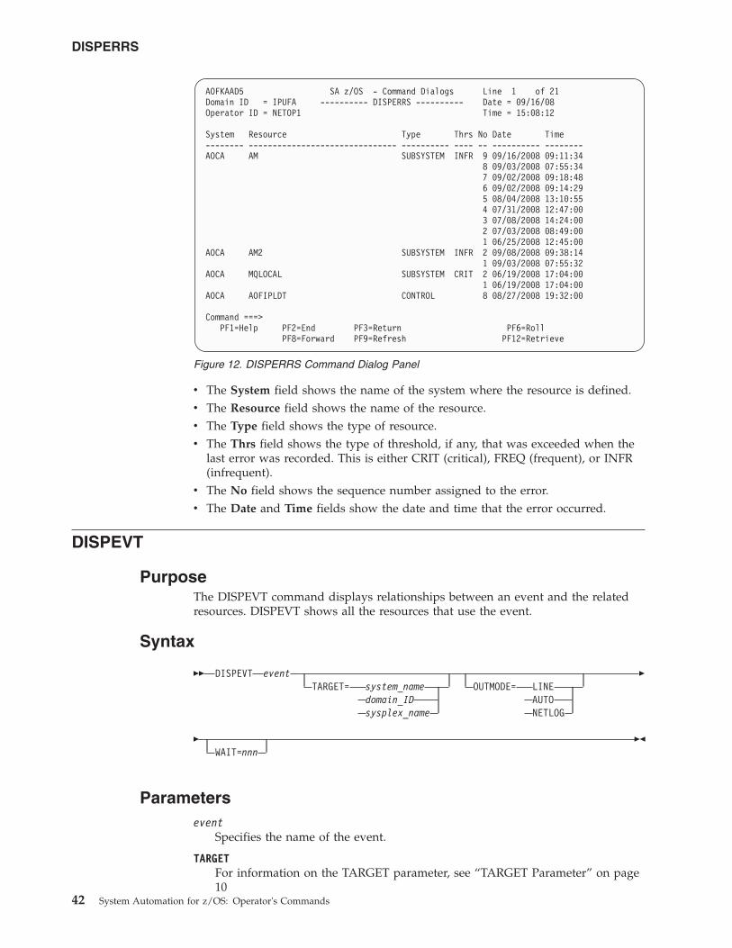
v The System field shows the name of the system where the resource is defined.v The Resource field shows the name of the resource.v The Type field shows the type of resource.v The Thrs field shows the type of threshold, if any, that was exceeded when the
last error was recorded. This is either CRIT (critical), FREQ (frequent), or INFR(infrequent).
v The No field shows the sequence number assigned to the error.v The Date and Time fields show the date and time that the error occurred.
DISPEVT
PurposeThe DISPEVT command displays relationships between an event and the relatedresources. DISPEVT shows all the resources that use the event.
Syntax
�� DISPEVT eventTARGET= system_name
domain_IDsysplex_name
OUTMODE= LINEAUTONETLOG
�
�WAIT=nnn
��
Parametersevent
Specifies the name of the event.
TARGETFor information on the TARGET parameter, see “TARGET Parameter” on page10
AOFKAAD5 SA z/OS - Command Dialogs Line 1 of 21Domain ID = IPUFA ---------- DISPERRS ---------- Date = 09/16/08Operator ID = NETOP1 Time = 15:08:12
System Resource Type Thrs No Date Time-------- ------------------------------- ---------- ---- -- ---------- --------AOCA AM SUBSYSTEM INFR 9 09/16/2008 09:11:34
8 09/03/2008 07:55:347 09/02/2008 09:18:486 09/02/2008 09:14:295 08/04/2008 13:10:554 07/31/2008 12:47:003 07/08/2008 14:24:002 07/03/2008 08:49:001 06/25/2008 12:45:00
AOCA AM2 SUBSYSTEM INFR 2 09/08/2008 09:38:141 09/03/2008 07:55:32
AOCA MQLOCAL SUBSYSTEM CRIT 2 06/19/2008 17:04:001 06/19/2008 17:04:00
AOCA AOFIPLDT CONTROL 8 08/27/2008 19:32:00
Command ===>PF1=Help PF2=End PF3=Return PF6=Roll
PF8=Forward PF9=Refresh PF12=Retrieve
Figure 12. DISPERRS Command Dialog Panel
DISPERRS
42 System Automation for z/OS: Operator's Commands
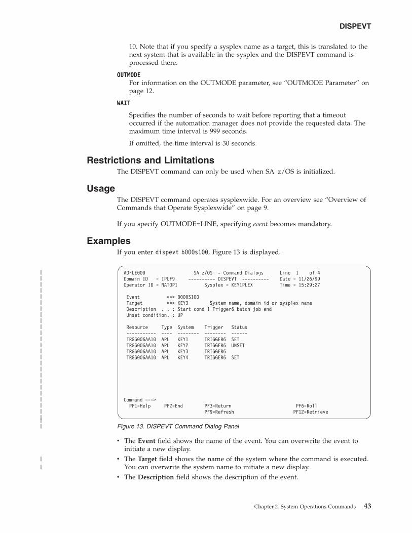
10. Note that if you specify a sysplex name as a target, this is translated to thenext system that is available in the sysplex and the DISPEVT command isprocessed there.
OUTMODEFor information on the OUTMODE parameter, see “OUTMODE Parameter” onpage 12.
WAIT
Specifies the number of seconds to wait before reporting that a timeoutoccurred if the automation manager does not provide the requested data. Themaximum time interval is 999 seconds.
If omitted, the time interval is 30 seconds.
Restrictions and LimitationsThe DISPEVT command can only be used when SA z/OS is initialized.
UsageThe DISPEVT command operates sysplexwide. For an overview see “Overview ofCommands that Operate Sysplexwide” on page 9.
If you specify OUTMODE=LINE, specifying event becomes mandatory.
ExamplesIf you enter dispevt b000s100, Figure 13 is displayed.
v The Event field shows the name of the event. You can overwrite the event toinitiate a new display.
v The Target field shows the name of the system where the command is executed.You can overwrite the system name to initiate a new display.
v The Description field shows the description of the event.
AOFLE000 SA z/OS - Command Dialogs Line 1 of 4Domain ID = IPUF9 ---------- DISPEVT ---------- Date = 11/26/99Operator ID = NATOP1 Sysplex = KEY1PLEX Time = 15:29:27
Event ==> B000S100Target ==> KEY3 System name, domain id or sysplex nameDescription . . : Start cond 1 Trigger6 batch job endUnset condition. : UP
Resource Type System Trigger Status----------- ---- -------- -------- ------TRGG006AA10 APL KEY1 TRIGGER6 SETTRGG006AA10 APL KEY2 TRIGGER6 UNSETTRGG006AA10 APL KEY3 TRIGGER6TRGG006AA10 APL KEY4 TRIGGER6 SET
Command ===>PF1=Help PF2=End PF3=Return PF6=Roll
PF9=Refresh PF12=Retrieve
Figure 13. DISPEVT Command Dialog Panel
DISPEVT
Chapter 2. System Operations Commands 43
|||||||||||||||||||||||||||
||
v The Unset condition field shows the status that an application must have toreset an event.
v The Resource field shows the name of the resource where the event is defined.v The Type field shows the type of the resource.v The System field shows the name of the system where the resource is defined.v The Trigger field shows the trigger that the resource is linked to.v The Status field shows the status of the event for that particular resource. It can
contain the following values:
SET The event is set. It is shown in white.
UNSET The event is unset. It is shown in red.
If the status of the event is neither SET nor UNSET, the event isin an unknown state. This is treated as UNSET.
DISPEVTS
PurposeDISPEVTS displays all events defined in a sysplex. From the fullscreen panel youcan set or reset an event or display the related resources of an event.
Syntax
�� DISPEVTSTARGET= system_name
domain_IDsysplex_name
OUTMODE= LINEAUTONETLOG
�
�WAIT=nnn
��
ParametersTARGET
For information on the TARGET parameter, see “TARGET Parameter” on page10. Note that if you specify a sysplex name as a target, this is translated to thenext system that is available in the sysplex and the DISPEVTS command isprocessed there.
OUTMODEFor information on the OUTMODE parameter, see “OUTMODE Parameter” onpage 12.
WAIT
Specifies the number of seconds to wait before reporting that a timeoutoccurred if the automation manager does not provide the requested data. Themaximum time interval is 999 seconds.
If omitted, the time interval is 30 seconds.
Restrictions and LimitationsThe DISPEVTS command can only be used when SA z/OS is initialized.
DISPEVT
44 System Automation for z/OS: Operator's Commands
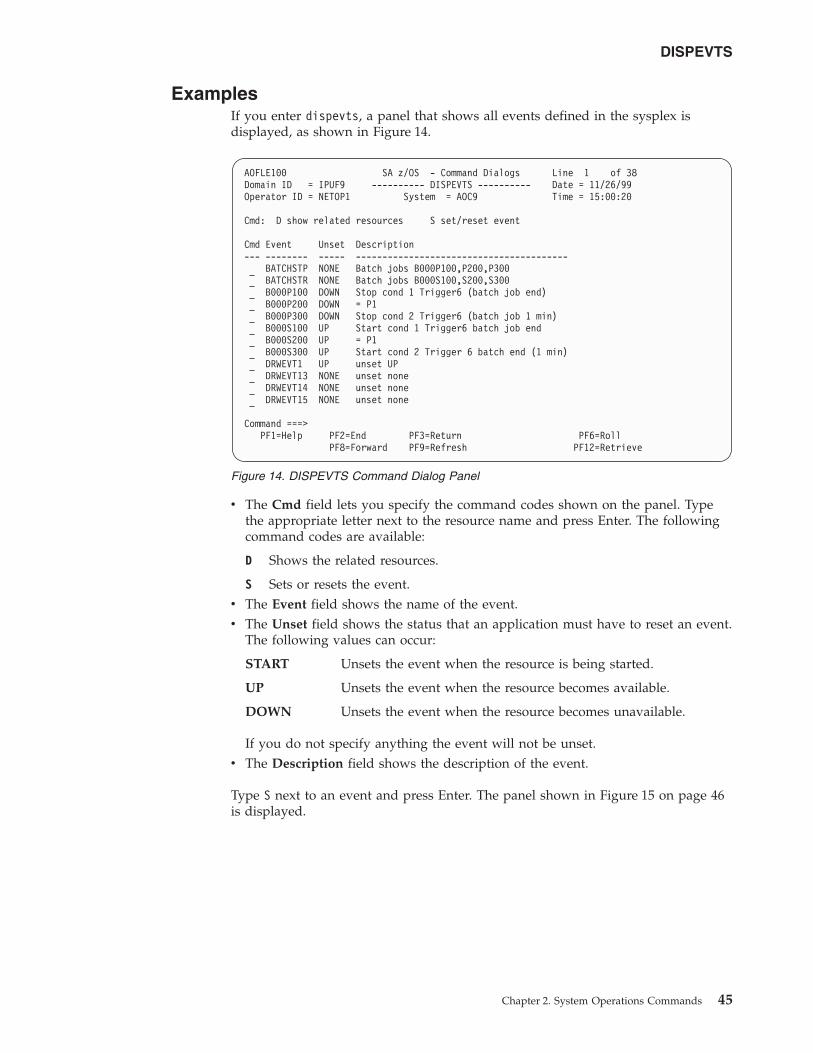
ExamplesIf you enter dispevts, a panel that shows all events defined in the sysplex isdisplayed, as shown in Figure 14.
v The Cmd field lets you specify the command codes shown on the panel. Typethe appropriate letter next to the resource name and press Enter. The followingcommand codes are available:
D Shows the related resources.
S Sets or resets the event.v The Event field shows the name of the event.v The Unset field shows the status that an application must have to reset an event.
The following values can occur:
START Unsets the event when the resource is being started.
UP Unsets the event when the resource becomes available.
DOWN Unsets the event when the resource becomes unavailable.
If you do not specify anything the event will not be unset.v The Description field shows the description of the event.
Type S next to an event and press Enter. The panel shown in Figure 15 on page 46is displayed.
AOFLE100 SA z/OS - Command Dialogs Line 1 of 38Domain ID = IPUF9 ---------- DISPEVTS ---------- Date = 11/26/99Operator ID = NETOP1 System = AOC9 Time = 15:00:20
Cmd: D show related resources S set/reset event
Cmd Event Unset Description--- -------- ----- ----------------------------------------
BATCHSTP NONE Batch jobs B000P100,P200,P300BATCHSTR NONE Batch jobs B000S100,S200,S300B000P100 DOWN Stop cond 1 Trigger6 (batch job end)B000P200 DOWN = P1B000P300 DOWN Stop cond 2 Trigger6 (batch job 1 min)B000S100 UP Start cond 1 Trigger6 batch job endB000S200 UP = P1B000S300 UP Start cond 2 Trigger 6 batch end (1 min)DRWEVT1 UP unset UPDRWEVT13 NONE unset noneDRWEVT14 NONE unset noneDRWEVT15 NONE unset none
Command ===>PF1=Help PF2=End PF3=Return PF6=Roll
PF8=Forward PF9=Refresh PF12=Retrieve
Figure 14. DISPEVTS Command Dialog Panel
DISPEVTS
Chapter 2. System Operations Commands 45
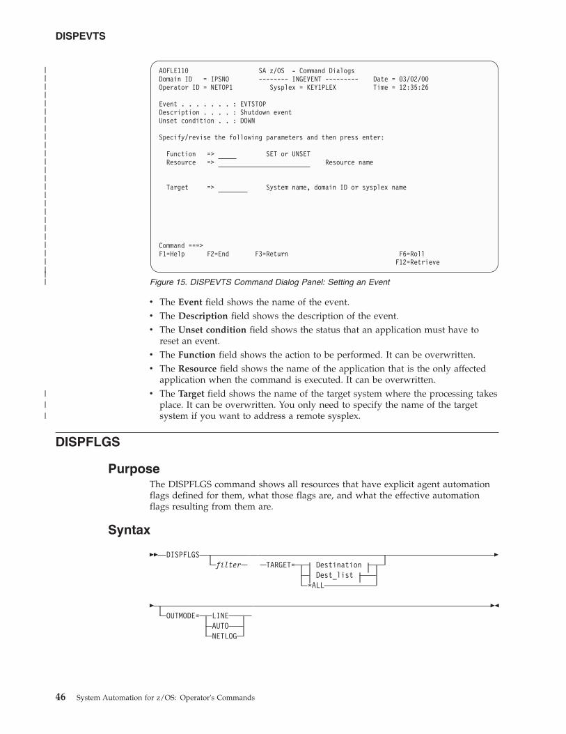
v The Event field shows the name of the event.v The Description field shows the description of the event.v The Unset condition field shows the status that an application must have to
reset an event.v The Function field shows the action to be performed. It can be overwritten.v The Resource field shows the name of the application that is the only affected
application when the command is executed. It can be overwritten.v The Target field shows the name of the target system where the processing takes
place. It can be overwritten. You only need to specify the name of the targetsystem if you want to address a remote sysplex.
DISPFLGS
PurposeThe DISPFLGS command shows all resources that have explicit agent automationflags defined for them, what those flags are, and what the effective automationflags resulting from them are.
Syntax
�� DISPFLGSfilter TARGET= Destination
Dest_list*ALL
�
�OUTMODE= LINE
AUTONETLOG
��
AOFLE110 SA z/OS - Command DialogsDomain ID = IPSNO -------- INGEVENT --------- Date = 03/02/00Operator ID = NETOP1 Sysplex = KEY1PLEX Time = 12:35:26
Event . . . . . . . : EVTSTOPDescription . . . . : Shutdown eventUnset condition . . : DOWN
Specify/revise the following parameters and then press enter:
Function => SET or UNSETResource => Resource name
Target => System name, domain ID or sysplex name
Command ===>F1=Help F2=End F3=Return F6=Roll
F12=Retrieve
Figure 15. DISPEVTS Command Dialog Panel: Setting an Event
DISPEVTS
46 System Automation for z/OS: Operator's Commands
|||||||||||||||||||||||||||
|||
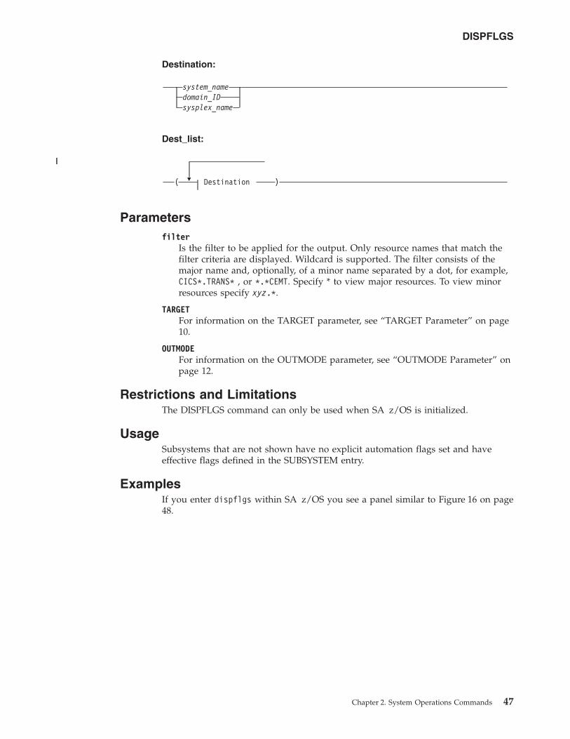
Destination:
system_namedomain_IDsysplex_name
Dest_list:
�( Destination )
Parametersfilter
Is the filter to be applied for the output. Only resource names that match thefilter criteria are displayed. Wildcard is supported. The filter consists of themajor name and, optionally, of a minor name separated by a dot, for example,CICS*.TRANS* , or *.*CEMT. Specify * to view major resources. To view minorresources specify xyz.*.
TARGETFor information on the TARGET parameter, see “TARGET Parameter” on page10.
OUTMODEFor information on the OUTMODE parameter, see “OUTMODE Parameter” onpage 12.
Restrictions and LimitationsThe DISPFLGS command can only be used when SA z/OS is initialized.
UsageSubsystems that are not shown have no explicit automation flags set and haveeffective flags defined in the SUBSYSTEM entry.
ExamplesIf you enter dispflgs within SA z/OS you see a panel similar to Figure 16 on page48.
DISPFLGS
Chapter 2. System Operations Commands 47
||
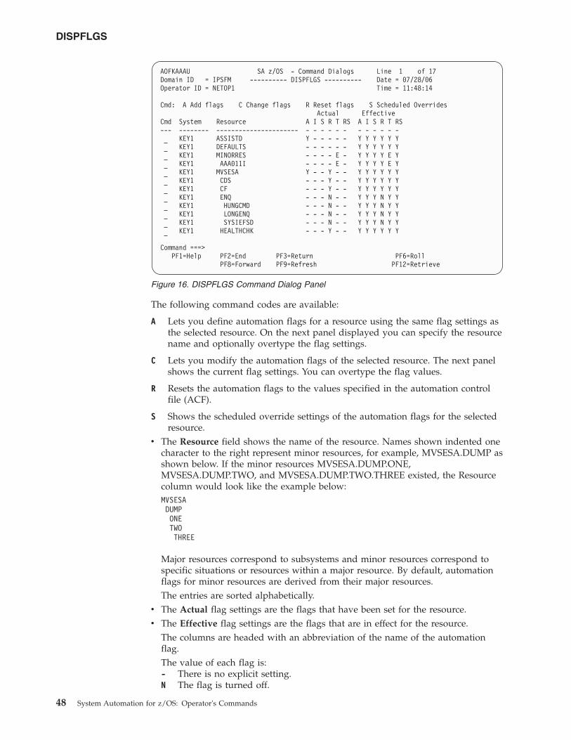
The following command codes are available:
A Lets you define automation flags for a resource using the same flag settings asthe selected resource. On the next panel displayed you can specify the resourcename and optionally overtype the flag settings.
C Lets you modify the automation flags of the selected resource. The next panelshows the current flag settings. You can overtype the flag values.
R Resets the automation flags to the values specified in the automation controlfile (ACF).
S Shows the scheduled override settings of the automation flags for the selectedresource.
v The Resource field shows the name of the resource. Names shown indented onecharacter to the right represent minor resources, for example, MVSESA.DUMP asshown below. If the minor resources MVSESA.DUMP.ONE,MVSESA.DUMP.TWO, and MVSESA.DUMP.TWO.THREE existed, the Resourcecolumn would look like the example below:MVSESADUMPONETWOTHREE
Major resources correspond to subsystems and minor resources correspond tospecific situations or resources within a major resource. By default, automationflags for minor resources are derived from their major resources.The entries are sorted alphabetically.
v The Actual flag settings are the flags that have been set for the resource.v The Effective flag settings are the flags that are in effect for the resource.
The columns are headed with an abbreviation of the name of the automationflag.The value of each flag is:- There is no explicit setting.N The flag is turned off.
AOFKAAAU SA z/OS - Command Dialogs Line 1 of 17Domain ID = IPSFM ---------- DISPFLGS ---------- Date = 07/28/06Operator ID = NETOP1 Time = 11:48:14
Cmd: A Add flags C Change flags R Reset flags S Scheduled OverridesActual Effective
Cmd System Resource A I S R T RS A I S R T RS--- -------- ---------------------- - - - - - - - - - - - -
KEY1 ASSISTD Y - - - - - Y Y Y Y Y YKEY1 DEFAULTS - - - - - - Y Y Y Y Y YKEY1 MINORRES - - - - E - Y Y Y Y E YKEY1 AAA011I - - - - E - Y Y Y Y E YKEY1 MVSESA Y - - Y - - Y Y Y Y Y YKEY1 CDS - - - Y - - Y Y Y Y Y YKEY1 CF - - - Y - - Y Y Y Y Y YKEY1 ENQ - - - N - - Y Y Y N Y YKEY1 HUNGCMD - - - N - - Y Y Y N Y YKEY1 LONGENQ - - - N - - Y Y Y N Y YKEY1 SYSIEFSD - - - N - - Y Y Y N Y YKEY1 HEALTHCHK - - - Y - - Y Y Y Y Y Y
Command ===>PF1=Help PF2=End PF3=Return PF6=Roll
PF8=Forward PF9=Refresh PF12=Retrieve
Figure 16. DISPFLGS Command Dialog Panel
DISPFLGS
48 System Automation for z/OS: Operator's Commands
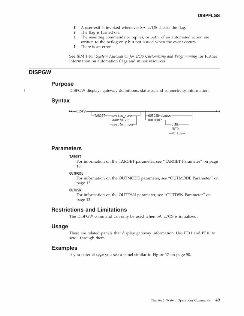
E A user exit is invoked whenever SA z/OS checks the flag.Y The flag is turned on.L The resulting commands or replies, or both, of an automated action are
written to the netlog only but not issued when the event occurs.? There is an error.
See IBM Tivoli System Automation for z/OS Customizing and Programming for furtherinformation on automation flags and minor resources.
DISPGW
PurposeDISPGW displays gateway definitions, statuses, and connectivity information.
Syntax
�� DISPGWTARGET= system_name
domain_IDsysplex_name
OUTDSN=dsnameOUTMODE=
LINEAUTONETLOG
��
ParametersTARGET
For information on the TARGET parameter, see “TARGET Parameter” on page10.
OUTMODEFor information on the OUTMODE parameter, see “OUTMODE Parameter” onpage 12.
OUTDSNFor information on the OUTDSN parameter, see “OUTDSN Parameter” onpage 13.
Restrictions and LimitationsThe DISPGW command can only be used when SA z/OS is initialized.
UsageThere are related panels that display gateway information. Use PF11 and PF10 toscroll through them.
ExamplesIf you enter dispgw you see a panel similar to Figure 17 on page 50.
DISPFLGS
Chapter 2. System Operations Commands 49
|
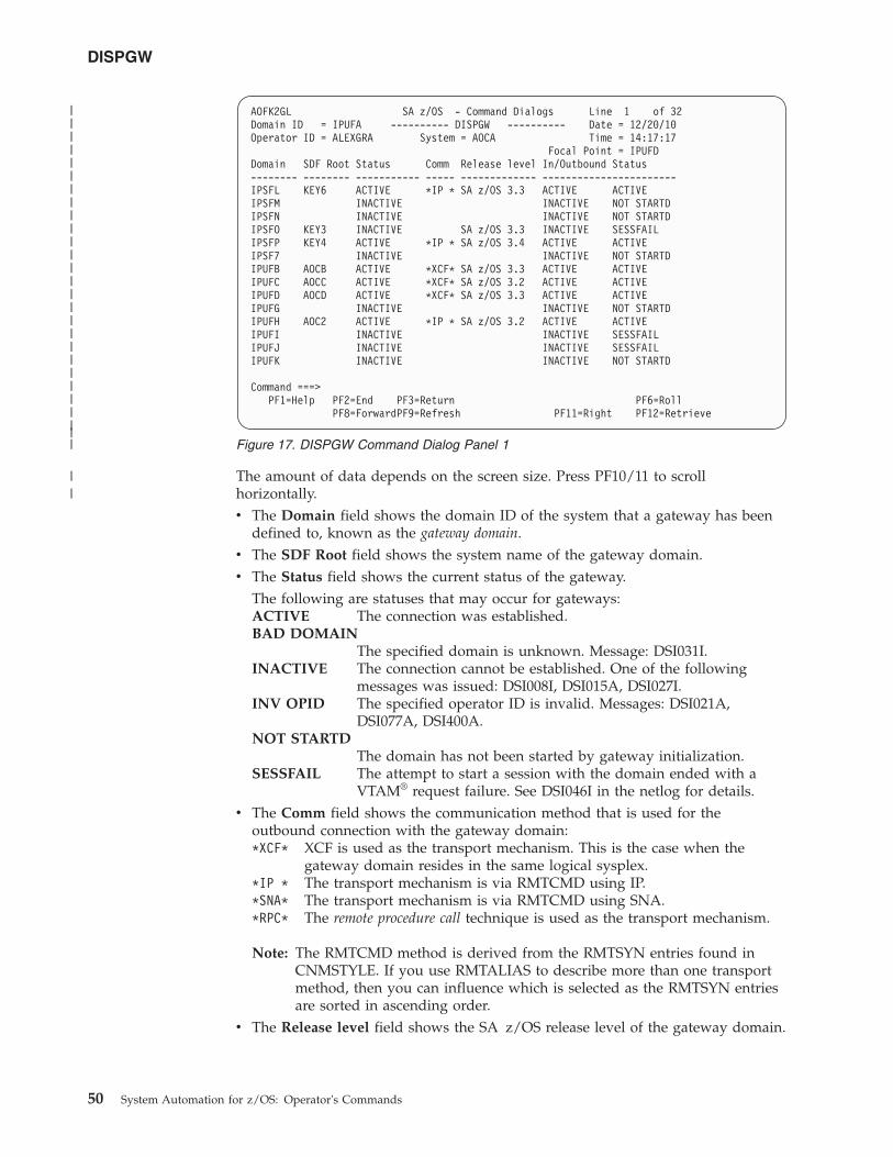
The amount of data depends on the screen size. Press PF10/11 to scrollhorizontally.v The Domain field shows the domain ID of the system that a gateway has been
defined to, known as the gateway domain.v The SDF Root field shows the system name of the gateway domain.v The Status field shows the current status of the gateway.
The following are statuses that may occur for gateways:ACTIVE The connection was established.BAD DOMAIN
The specified domain is unknown. Message: DSI031I.INACTIVE The connection cannot be established. One of the following
messages was issued: DSI008I, DSI015A, DSI027I.INV OPID The specified operator ID is invalid. Messages: DSI021A,
DSI077A, DSI400A.NOT STARTD
The domain has not been started by gateway initialization.SESSFAIL The attempt to start a session with the domain ended with a
VTAM® request failure. See DSI046I in the netlog for details.v The Comm field shows the communication method that is used for the
outbound connection with the gateway domain:*XCF* XCF is used as the transport mechanism. This is the case when the
gateway domain resides in the same logical sysplex.*IP * The transport mechanism is via RMTCMD using IP.*SNA* The transport mechanism is via RMTCMD using SNA.*RPC* The remote procedure call technique is used as the transport mechanism.
Note: The RMTCMD method is derived from the RMTSYN entries found inCNMSTYLE. If you use RMTALIAS to describe more than one transportmethod, then you can influence which is selected as the RMTSYN entriesare sorted in ascending order.
v The Release level field shows the SA z/OS release level of the gateway domain.
AOFK2GL SA z/OS - Command Dialogs Line 1 of 32Domain ID = IPUFA ---------- DISPGW ---------- Date = 12/20/10Operator ID = ALEXGRA System = AOCA Time = 14:17:17
Focal Point = IPUFDDomain SDF Root Status Comm Release level In/Outbound Status-------- -------- ----------- ----- ------------- -----------------------IPSFL KEY6 ACTIVE *IP * SA z/OS 3.3 ACTIVE ACTIVEIPSFM INACTIVE INACTIVE NOT STARTDIPSFN INACTIVE INACTIVE NOT STARTDIPSFO KEY3 INACTIVE SA z/OS 3.3 INACTIVE SESSFAILIPSFP KEY4 ACTIVE *IP * SA z/OS 3.4 ACTIVE ACTIVEIPSF7 INACTIVE INACTIVE NOT STARTDIPUFB AOCB ACTIVE *XCF* SA z/OS 3.3 ACTIVE ACTIVEIPUFC AOCC ACTIVE *XCF* SA z/OS 3.2 ACTIVE ACTIVEIPUFD AOCD ACTIVE *XCF* SA z/OS 3.3 ACTIVE ACTIVEIPUFG INACTIVE INACTIVE NOT STARTDIPUFH AOC2 ACTIVE *IP * SA z/OS 3.2 ACTIVE ACTIVEIPUFI INACTIVE INACTIVE SESSFAILIPUFJ INACTIVE INACTIVE SESSFAILIPUFK INACTIVE INACTIVE NOT STARTD
Command ===>PF1=Help PF2=End PF3=Return PF6=Roll
PF8=ForwardPF9=Refresh PF11=Right PF12=Retrieve
Figure 17. DISPGW Command Dialog Panel 1
DISPGW
50 System Automation for z/OS: Operator's Commands
|||||||||||||||||||||||||||
||
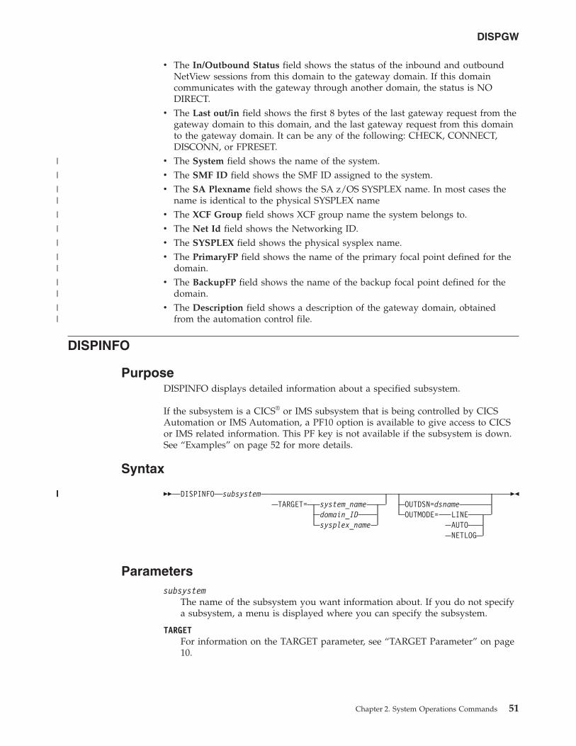
v The In/Outbound Status field shows the status of the inbound and outboundNetView sessions from this domain to the gateway domain. If this domaincommunicates with the gateway through another domain, the status is NODIRECT.
v The Last out/in field shows the first 8 bytes of the last gateway request from thegateway domain to this domain, and the last gateway request from this domainto the gateway domain. It can be any of the following: CHECK, CONNECT,DISCONN, or FPRESET.
v The System field shows the name of the system.v The SMF ID field shows the SMF ID assigned to the system.v The SA Plexname field shows the SA z/OS SYSPLEX name. In most cases the
name is identical to the physical SYSPLEX namev The XCF Group field shows XCF group name the system belongs to.v The Net Id field shows the Networking ID.v The SYSPLEX field shows the physical sysplex name.v The PrimaryFP field shows the name of the primary focal point defined for the
domain.v The BackupFP field shows the name of the backup focal point defined for the
domain.v The Description field shows a description of the gateway domain, obtained
from the automation control file.
DISPINFO
PurposeDISPINFO displays detailed information about a specified subsystem.
If the subsystem is a CICS® or IMS subsystem that is being controlled by CICSAutomation or IMS Automation, a PF10 option is available to give access to CICSor IMS related information. This PF key is not available if the subsystem is down.See “Examples” on page 52 for more details.
Syntax
�� DISPINFO subsystemTARGET= system_name
domain_IDsysplex_name
OUTDSN=dsnameOUTMODE= LINE
AUTONETLOG
��
Parameterssubsystem
The name of the subsystem you want information about. If you do not specifya subsystem, a menu is displayed where you can specify the subsystem.
TARGETFor information on the TARGET parameter, see “TARGET Parameter” on page10.
DISPGW
Chapter 2. System Operations Commands 51
|
|
||
|
|
|
||
||
||
|||||
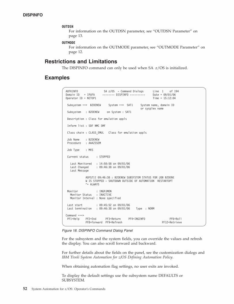
OUTDSNFor information on the OUTDSN parameter, see “OUTDSN Parameter” onpage 13.
OUTMODEFor information on the OUTMODE parameter, see “OUTMODE Parameter” onpage 12.
Restrictions and LimitationsThe DISPINFO command can only be used when SA z/OS is initialized.
Examples
For the subsystem and the system fields, you can override the values and refreshthe display. You can also scroll forward and backward.
For further details about the fields on the panel, see the customization dialogs andIBM Tivoli System Automation for z/OS Defining Automation Policy.
When obtaining automation flag settings, no user exits are invoked.
To display the default settings use the subsystem name DEFAULTS orSUBSYSTEM.
AOFKINFO SA z/OS - Command Dialogs Line 1 of 194Domain ID = IPUFA -------- DISPINFO ---------- Date = 09/01/06Operator ID = NETOP1 Time = 15:12:04
Subsystem ==> BZOENEW System ==> SAT1 System name, domain IDor sysplex name
Subsystem : BZOENEW on System : SAT1
Description : Class for emulation appls
Inform list : SDF NMC SMF
Class chain : CLASS_EMUL Class for emulation appls
Job Name : BZOENEWProcedure : AAAZSSEM
Job Type : MVS
Current status : STOPPED
Last Monitored : 14:50:58 on 09/01/06Last Changed : 09:46:38 on 09/01/06Last Message
AOF571I 09:46:38 : BZOENEW SUBSYSTEM STATUS FOR JOB BZOENEW IS STOPPED - SHUTDOWN OUTSIDE OF AUTOMATION RESTARTOPT^= ALWAYS
Monitor : INGPJMONMonitor Status : INACTIVEMonitor Interval : None specified
Last start : 09:45:52 on 09/01/06Last termination : 09:46:38 on 09/01/06 Type : NORM
Command ===>PF1=Help PF2=End PF3=Return PF4=INGINFO PF6=Roll
PF8=Forward PF9=Refresh PF12=Retrieve
Figure 18. DISPINFO Command Dialog Panel
DISPINFO
52 System Automation for z/OS: Operator's Commands
PF4 lets you toggle to the automation manager command INGINFO.
If PF10 is shown the DISPINFO command invokes the INGCICS or INGIMScommands. For more information see “INGCICS” on page 109 or “INGIMS” onpage 135.
DISPMSGS
PurposeThe DISPMSGS command displays a list of automation operators that receiveautomated messages.
Syntax
�� DISPMSGSTARGET= system_name
domain_IDsysplex_name
OUTMODE= LINEAUTONETLOG
��
ParametersTARGET
For information on the TARGET parameter, see “TARGET Parameter” on page10.
OUTMODEFor information on the OUTMODE parameter, see “OUTMODE Parameter” onpage 12.
Restrictions and LimitationsThe DISPMSGS command can only be used when SA z/OS is initialized.
ExamplesEnter dispmsgs on a command line to display the Authorized Message Receiverspanel, as shown in Figure 19 on page 54.
DISPINFO
Chapter 2. System Operations Commands 53
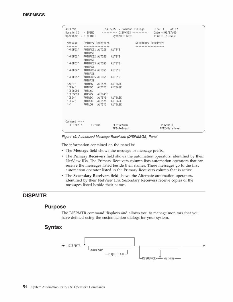
The information contained on the panel is:v The Message field shows the message or message prefix.v The Primary Receivers field shows the automation operators, identified by their
NetView IDs. The Primary Receivers column lists automation operators that canreceive the messages listed beside their names. These messages go to the firstautomation operator listed in the Primary Receivers column that is active.
v The Secondary Receivers field shows the Alternate automation operators,identified by their NetView IDs. Secondary Receivers receive copies of themessages listed beside their names.
DISPMTR
PurposeThe DISPMTR command displays and allows you to manage monitors that youhave defined using the customization dialogs for your system.
Syntax
�� DISPMTR �
monitorREQ=DETAIL
�RESOURCE= resname
�
AOFK2SM SA z/OS - Command Dialogs Line 1 of 17Domain ID = IPSNO ---------- DISPMSGS ---------- Date = 06/27/00Operator ID = NETOP1 System = KEY3 Time = 15:05:53
Message Primary Receivers Secondary Receivers------- ----------------- -------------------’*AOF01’ AUTWRK01 AUTGSS AUTSYS
AUTBASE’*AOF02’ AUTWRK02 AUTGSS AUTSYS
AUTBASE’*AOF03’ AUTWRK03 AUTGSS AUTSYS
AUTBASE’*AOF04’ AUTWRK04 AUTGSS AUTSYS
AUTBASE’*AOF05’ AUTWRK05 AUTGSS AUTSYS
AUTBASE’AOF*’ AUTMSG AUTSYS AUTBASE’IEA*’ AUTREC AUTSYS AUTBASE’IEE600I AUTSYS’IEE889I AUTSYS AUTBASE’IEE*’ AUTREC AUTSYS AUTBASE’IOS*’ AUTREC AUTSYS AUTBASE’*’ AUTLOG AUTSYS AUTBASE
Command ===>PF1=Help PF2=End PF3=Return PF6=Roll
PF9=Refresh PF12=Retrieve
Figure 19. Authorized Message Receivers (DISPMSGS) Panel
DISPMSGS
54 System Automation for z/OS: Operator's Commands
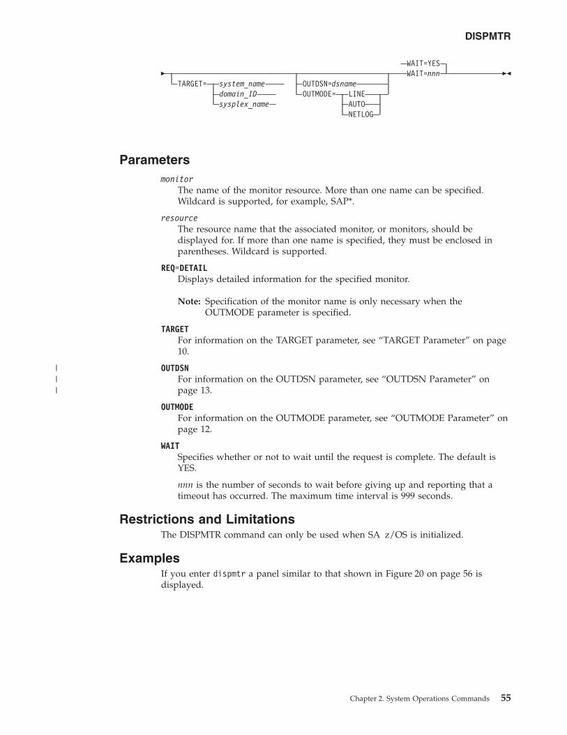
�TARGET= system_name
domain_IDsysplex_name
OUTDSN=dsnameOUTMODE= LINE
AUTONETLOG
WAIT=YESWAIT=nnn ��
Parametersmonitor
The name of the monitor resource. More than one name can be specified.Wildcard is supported, for example, SAP*.
resourceThe resource name that the associated monitor, or monitors, should bedisplayed for. If more than one name is specified, they must be enclosed inparentheses. Wildcard is supported.
REQ=DETAILDisplays detailed information for the specified monitor.
Note: Specification of the monitor name is only necessary when theOUTMODE parameter is specified.
TARGETFor information on the TARGET parameter, see “TARGET Parameter” on page10.
OUTDSNFor information on the OUTDSN parameter, see “OUTDSN Parameter” onpage 13.
OUTMODEFor information on the OUTMODE parameter, see “OUTMODE Parameter” onpage 12.
WAITSpecifies whether or not to wait until the request is complete. The default isYES.
nnn is the number of seconds to wait before giving up and reporting that atimeout has occurred. The maximum time interval is 999 seconds.
Restrictions and LimitationsThe DISPMTR command can only be used when SA z/OS is initialized.
ExamplesIf you enter dispmtr a panel similar to that shown in Figure 20 on page 56 isdisplayed.
DISPMTR
Chapter 2. System Operations Commands 55
|||
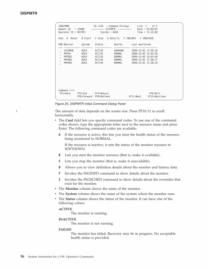
The amount of data depends on the screen size. Press PF10/11 to scrollhorizontally.v The Cmd field lets you specify command codes. To use one of the command
codes shown, type the appropriate letter next to the resource name and pressEnter. The following command codes are available:
A If the resource is active, this lets you reset the health status of the resourcebeing monitored to NORMAL.
If the resource is inactive, it sets the status of the monitor resource toSOFTDOWN.
B Lets you start the monitor resource (that is, make it available).
C Lets you stop the monitor (that is, make it unavailable).
D Allows you to view definition details about the monitor and history data.
F Invokes the INGINFO command to show details about the monitor.
I Invokes the INGSCHED command to show details about the overrides thatexist for the monitor.
v The Monitor column shows the name of the monitor.v The System column shows the name of the system where the monitor runs.v The Status column shows the status of the monitor. It can have one of the
following values:
ACTIVEThe monitor is running.
INACTIVEThe monitor is not running.
FAILEDThe monitor has failed. Recovery may be in progress. No acceptablehealth status is provided.
INGKYMN0 SA z/OS - Command Dialogs Line 1 of 2Domain ID = IPUN8 ---------- DISPMTR ---------- Date = 01/02/03Operator ID = NETOP1 System = AOC8 Time = 13:15:00
Cmd: A Reset B Start C Stop D Details F INGINFO I INGSCHED
CMD Monitor System Status Health Last monitored--- ------------ -------- ------------ ------------ -------------------_ JES2MON AOCA ACTIVE UNKNOWN 2009-12-01 17:28:16_ PMTRA AOCA ACTIVE NORMAL 2009-12-02 15:03:39_ PMTRB1 AOCA ACTIVE NORMAL 2009-12-02 15:03:40_ PMTRB2 AOCA ACTIVE NORMAL 2009-12-01 17:28:17_ PMTRB3 AOCA ACTIVE NORMAL 2009-12-01 17:28:16
Command ===>PF1=Help PF2=End PF3=Return PF6=Roll
PF8=Forward PF9=Refresh PF11=Next PF12=Retrieve
Figure 20. DISPMTR Initial Command Dialog Panel
DISPMTR
56 System Automation for z/OS: Operator's Commands
|
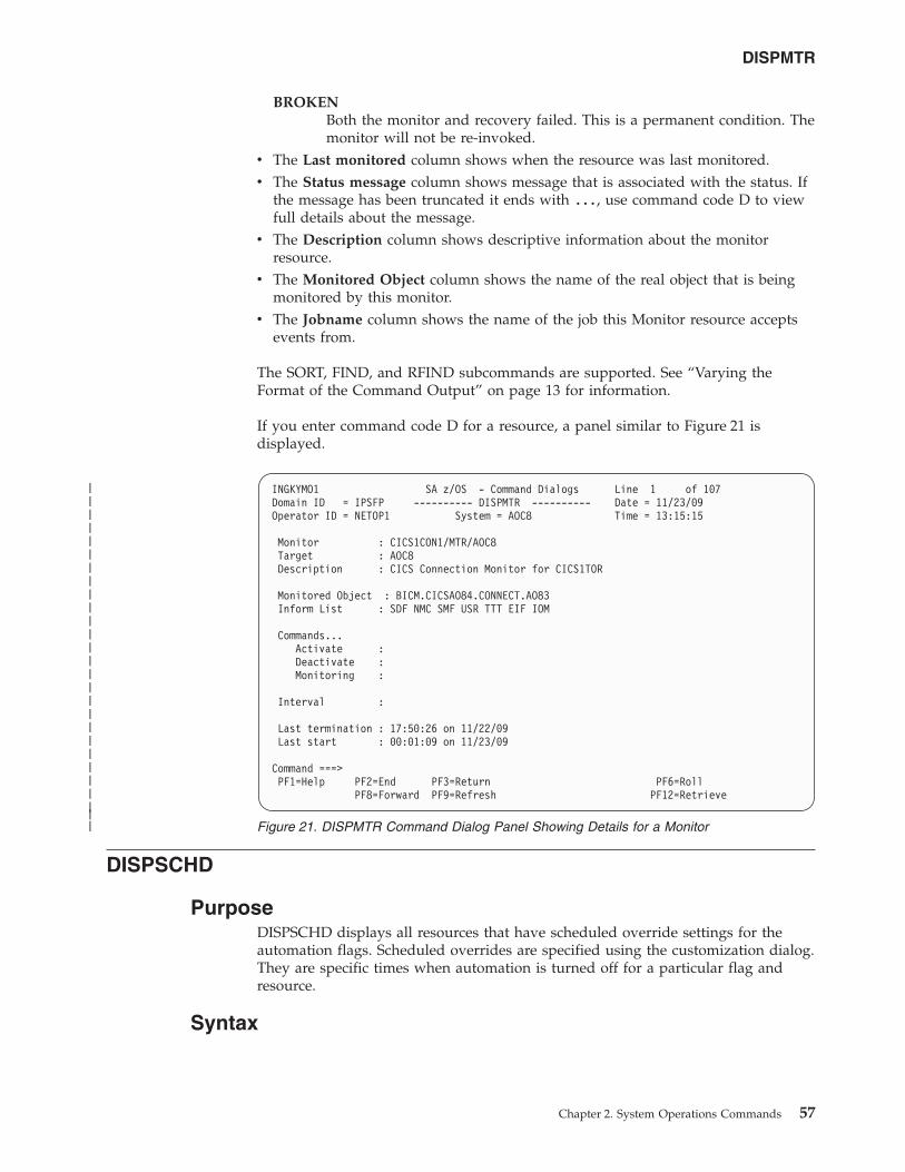
BROKENBoth the monitor and recovery failed. This is a permanent condition. Themonitor will not be re-invoked.
v The Last monitored column shows when the resource was last monitored.v The Status message column shows message that is associated with the status. If
the message has been truncated it ends with ..., use command code D to viewfull details about the message.
v The Description column shows descriptive information about the monitorresource.
v The Monitored Object column shows the name of the real object that is beingmonitored by this monitor.
v The Jobname column shows the name of the job this Monitor resource acceptsevents from.
The SORT, FIND, and RFIND subcommands are supported. See “Varying theFormat of the Command Output” on page 13 for information.
If you enter command code D for a resource, a panel similar to Figure 21 isdisplayed.
DISPSCHD
PurposeDISPSCHD displays all resources that have scheduled override settings for theautomation flags. Scheduled overrides are specified using the customization dialog.They are specific times when automation is turned off for a particular flag andresource.
Syntax
INGKYMO1 SA z/OS - Command Dialogs Line 1 of 107Domain ID = IPSFP ---------- DISPMTR ---------- Date = 11/23/09Operator ID = NETOP1 System = AOC8 Time = 13:15:15
Monitor : CICS1CON1/MTR/AOC8Target : AOC8Description : CICS Connection Monitor for CICS1TOR
Monitored Object : BICM.CICSAO84.CONNECT.AO83Inform List : SDF NMC SMF USR TTT EIF IOM
Commands...Activate :Deactivate :Monitoring :
Interval :
Last termination : 17:50:26 on 11/22/09Last start : 00:01:09 on 11/23/09
Command ===>PF1=Help PF2=End PF3=Return PF6=Roll
PF8=Forward PF9=Refresh PF12=Retrieve
Figure 21. DISPMTR Command Dialog Panel Showing Details for a Monitor
DISPMTR
Chapter 2. System Operations Commands 57
|||||||||||||||||||||||||||
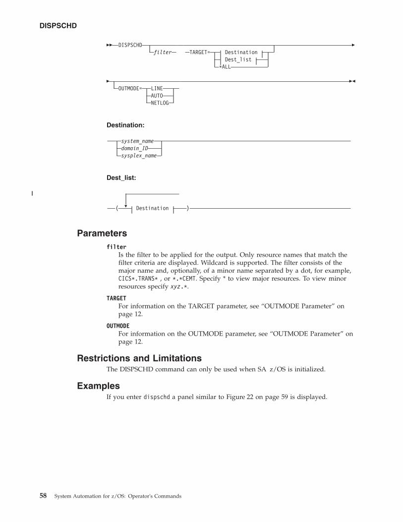
�� DISPSCHDfilter TARGET= Destination
Dest_list*ALL
�
�OUTMODE= LINE
AUTONETLOG
��
Destination:
system_namedomain_IDsysplex_name
Dest_list:
�( Destination )
Parametersfilter
Is the filter to be applied for the output. Only resource names that match thefilter criteria are displayed. Wildcard is supported. The filter consists of themajor name and, optionally, of a minor name separated by a dot, for example,CICS*.TRANS* , or *.*CEMT. Specify * to view major resources. To view minorresources specify xyz.*.
TARGETFor information on the TARGET parameter, see “OUTMODE Parameter” onpage 12.
OUTMODEFor information on the OUTMODE parameter, see “OUTMODE Parameter” onpage 12.
Restrictions and LimitationsThe DISPSCHD command can only be used when SA z/OS is initialized.
ExamplesIf you enter dispschd a panel similar to Figure 22 on page 59 is displayed.
DISPSCHD
58 System Automation for z/OS: Operator's Commands
||
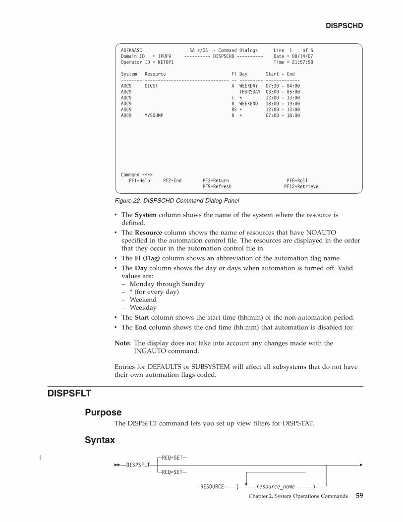
v The System column shows the name of the system where the resource isdefined.
v The Resource column shows the name of resources that have NOAUTOspecified in the automation control file. The resources are displayed in the orderthat they occur in the automation control file in.
v The Fl (Flag) column shows an abbreviation of the automation flag name.v The Day column shows the day or days when automation is turned off. Valid
values are:– Monday through Sunday– * (for every day)– Weekend– Weekday
v The Start column shows the start time (hh:mm) of the non-automation period.v The End column shows the end time (hh:mm) that automation is disabled for.
Note: The display does not take into account any changes made with theINGAUTO command.
Entries for DEFAULTS or SUBSYSTEM will affect all subsystems that do not havetheir own automation flags coded.
DISPSFLT
PurposeThe DISPSFLT command lets you set up view filters for DISPSTAT.
Syntax
�� DISPSFLTREQ=GET
REQ=SET
�RESOURCE= ( resource_name )
�
AOFKAASC SA z/OS - Command Dialogs Line 1 of 6Domain ID = IPUF9 ---------- DISPSCHD ---------- Date = 08/14/07Operator ID = NETOP1 Time = 21:57:58
System Resource Fl Day Start - End-------- -------------------------------- -- --------- -------------AOC9 CICST A WEEKDAY 07:30 - 04:00AOC9 THURSDAY 03:00 - 05:00AOC9 I * 12:00 - 13:00AOC9 R WEEKEND 18:00 - 19:00AOC9 RS * 12:00 - 13:00AOC9 MVSDUMP R * 07:00 - 18:00
Command ===>PF1=Help PF2=End PF3=Return PF6=Roll
PF9=Refresh PF12=Retrieve
Figure 22. DISPSCHD Command Dialog Panel
DISPSCHD
Chapter 2. System Operations Commands 59
|
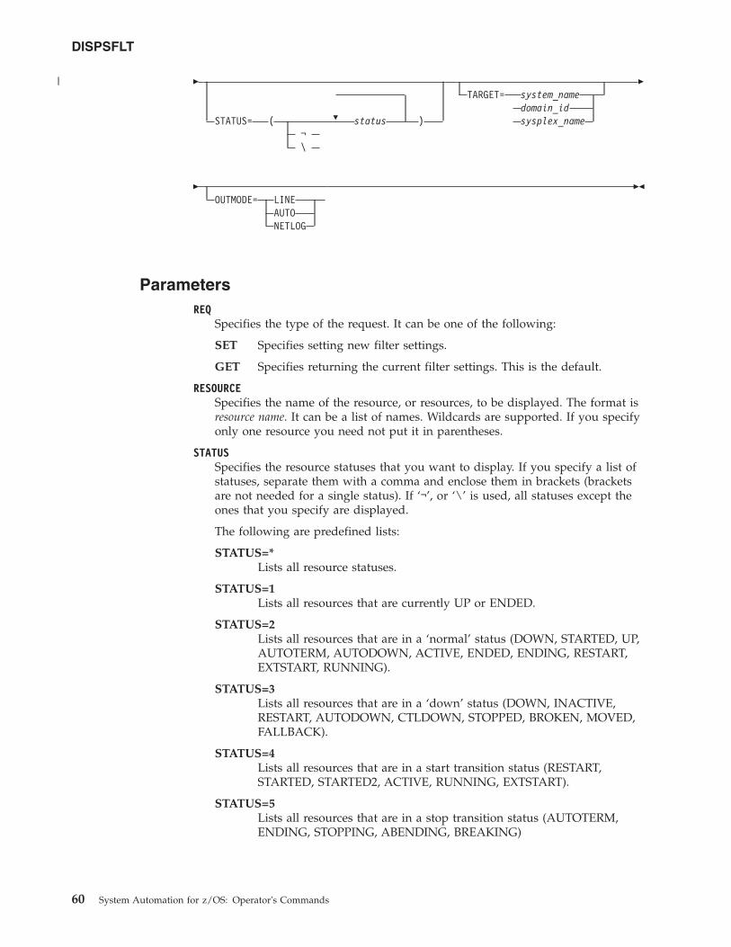
�
�STATUS= ( status )¬\
TARGET= system_namedomain_idsysplex_name
�
�OUTMODE= LINE
AUTONETLOG
��
ParametersREQ
Specifies the type of the request. It can be one of the following:
SET Specifies setting new filter settings.
GET Specifies returning the current filter settings. This is the default.
RESOURCESpecifies the name of the resource, or resources, to be displayed. The format isresource name. It can be a list of names. Wildcards are supported. If you specifyonly one resource you need not put it in parentheses.
STATUSSpecifies the resource statuses that you want to display. If you specify a list ofstatuses, separate them with a comma and enclose them in brackets (bracketsare not needed for a single status). If ‘¬’, or ‘\’ is used, all statuses except theones that you specify are displayed.
The following are predefined lists:
STATUS=*Lists all resource statuses.
STATUS=1Lists all resources that are currently UP or ENDED.
STATUS=2Lists all resources that are in a ‘normal’ status (DOWN, STARTED, UP,AUTOTERM, AUTODOWN, ACTIVE, ENDED, ENDING, RESTART,EXTSTART, RUNNING).
STATUS=3Lists all resources that are in a ‘down’ status (DOWN, INACTIVE,RESTART, AUTODOWN, CTLDOWN, STOPPED, BROKEN, MOVED,FALLBACK).
STATUS=4Lists all resources that are in a start transition status (RESTART,STARTED, STARTED2, ACTIVE, RUNNING, EXTSTART).
STATUS=5Lists all resources that are in a stop transition status (AUTOTERM,ENDING, STOPPING, ABENDING, BREAKING)
DISPSFLT
60 System Automation for z/OS: Operator's Commands
|
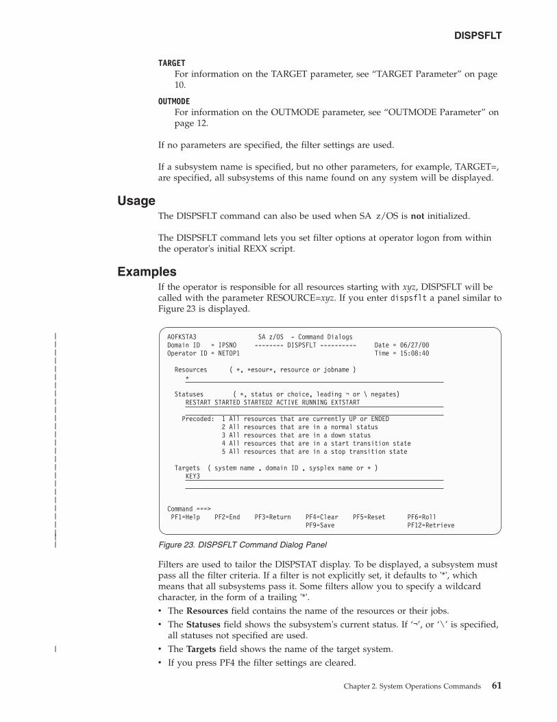
TARGETFor information on the TARGET parameter, see “TARGET Parameter” on page10.
OUTMODEFor information on the OUTMODE parameter, see “OUTMODE Parameter” onpage 12.
If no parameters are specified, the filter settings are used.
If a subsystem name is specified, but no other parameters, for example, TARGET=,are specified, all subsystems of this name found on any system will be displayed.
UsageThe DISPSFLT command can also be used when SA z/OS is not initialized.
The DISPSFLT command lets you set filter options at operator logon from withinthe operator's initial REXX script.
ExamplesIf the operator is responsible for all resources starting with xyz, DISPSFLT will becalled with the parameter RESOURCE=xyz. If you enter dispsflt a panel similar toFigure 23 is displayed.
Filters are used to tailor the DISPSTAT display. To be displayed, a subsystem mustpass all the filter criteria. If a filter is not explicitly set, it defaults to '*', whichmeans that all subsystems pass it. Some filters allow you to specify a wildcardcharacter, in the form of a trailing '*'.v The Resources field contains the name of the resources or their jobs.v The Statuses field shows the subsystem's current status. If ‘¬’, or ‘\’ is specified,
all statuses not specified are used.v The Targets field shows the name of the target system.v If you press PF4 the filter settings are cleared.
AOFKSTA3 SA z/OS - Command DialogsDomain ID = IPSNO -------- DISPSFLT ---------- Date = 06/27/00Operator ID = NETOP1 Time = 15:08:40
Resources ( *, *esour*, resource or jobname )*
Statuses ( *, status or choice, leading ¬ or \ negates)RESTART STARTED STARTED2 ACTIVE RUNNING EXTSTART
Precoded: 1 All resources that are currently UP or ENDED2 All resources that are in a normal status3 All resources that are in a down status4 All resources that are in a start transition state5 All resources that are in a stop transition state
Targets ( system name , domain ID , sysplex name or * )KEY3
Command ===>PF1=Help PF2=End PF3=Return PF4=Clear PF5=Reset PF6=Roll
PF9=Save PF12=Retrieve
Figure 23. DISPSFLT Command Dialog Panel
DISPSFLT
Chapter 2. System Operations Commands 61
|||||||||||||||||||||||||||
|
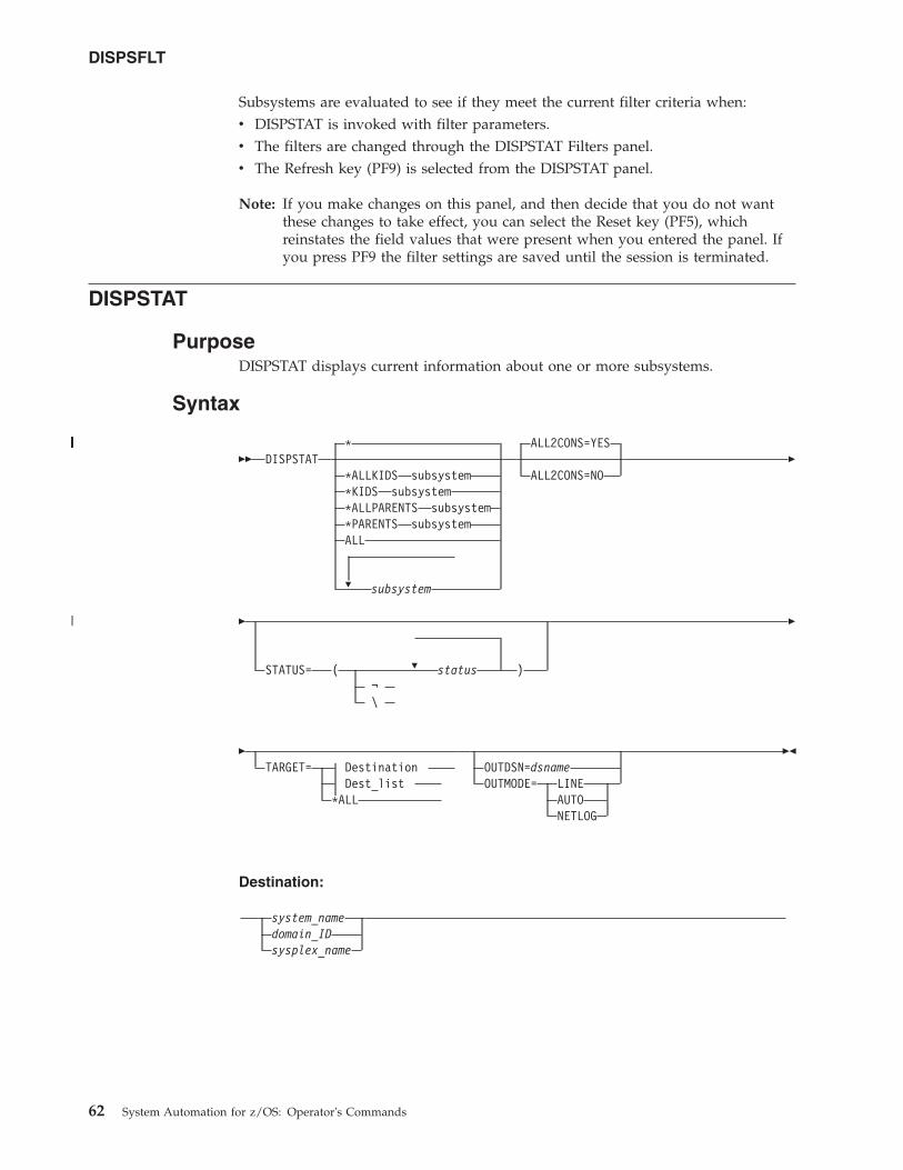
Subsystems are evaluated to see if they meet the current filter criteria when:v DISPSTAT is invoked with filter parameters.v The filters are changed through the DISPSTAT Filters panel.v The Refresh key (PF9) is selected from the DISPSTAT panel.
Note: If you make changes on this panel, and then decide that you do not wantthese changes to take effect, you can select the Reset key (PF5), whichreinstates the field values that were present when you entered the panel. Ifyou press PF9 the filter settings are saved until the session is terminated.
DISPSTAT
PurposeDISPSTAT displays current information about one or more subsystems.
Syntax
�� DISPSTAT
�
*
*ALLKIDS subsystem*KIDS subsystem*ALLPARENTS subsystem*PARENTS subsystemALL
subsystem
ALL2CONS=YES
ALL2CONS=NO�
�
�STATUS= ( status )¬\
�
�TARGET= Destination
Dest_list*ALL
OUTDSN=dsnameOUTMODE= LINE
AUTONETLOG
��
Destination:
system_namedomain_IDsysplex_name
DISPSFLT
62 System Automation for z/OS: Operator's Commands
||||||||||
|
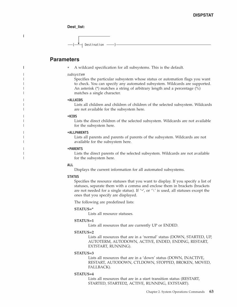
Dest_list:
�( Destination )
Parameters* A wildcard specification for all subsystems. This is the default.
subsystemSpecifies the particular subsystem whose status or automation flags you wantto check. You can specify any automated subsystem. Wildcards are supported.An asterisk (*) matches a string of arbitrary length and a percentage (%)matches a single character.
*ALLKIDSLists all children and children of children of the selected subsystem. Wildcardsare not available for the subsystem here.
*KIDSLists the direct children of the selected subsystem. Wildcards are not availablefor the subsystem here.
*ALLPARENTSLists all parents and parents of parents of the subsystem. Wildcards are notavailable for the subsystem here.
*PARENTSLists the direct parents of the selected subsystem. Wildcards are not availablefor the subsystem here.
ALLDisplays the current information for all automated subsystems.
STATUSSpecifies the resource statuses that you want to display. If you specify a list ofstatuses, separate them with a comma and enclose them in brackets (bracketsare not needed for a single status). If ‘¬’, or ‘\’ is used, all statuses except theones that you specify are displayed.
The following are predefined lists:
STATUS=*Lists all resource statuses.
STATUS=1Lists all resources that are currently UP or ENDED.
STATUS=2Lists all resources that are in a ‘normal’ status (DOWN, STARTED, UP,AUTOTERM, AUTODOWN, ACTIVE, ENDED, ENDING, RESTART,EXTSTART, RUNNING).
STATUS=3Lists all resources that are in a ‘down’ status (DOWN, INACTIVE,RESTART, AUTODOWN, CTLDOWN, STOPPED, BROKEN, MOVED,FALLBACK).
STATUS=4Lists all resources that are in a start transition status (RESTART,STARTED, STARTED2, ACTIVE, RUNNING, EXTSTART).
DISPSTAT
Chapter 2. System Operations Commands 63
||
||
|||||
|||
|||
|||
|||
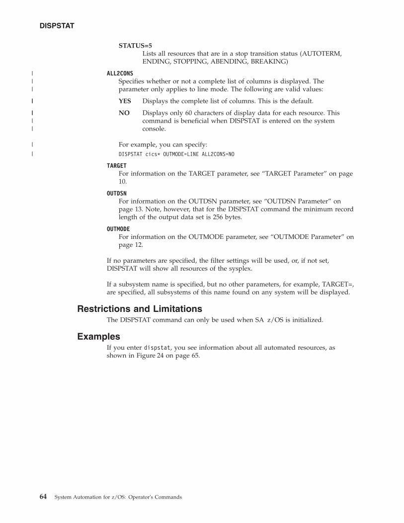
STATUS=5Lists all resources that are in a stop transition status (AUTOTERM,ENDING, STOPPING, ABENDING, BREAKING)
ALL2CONSSpecifies whether or not a complete list of columns is displayed. Theparameter only applies to line mode. The following are valid values:
YES Displays the complete list of columns. This is the default.
NO Displays only 60 characters of display data for each resource. Thiscommand is beneficial when DISPSTAT is entered on the systemconsole.
For example, you can specify:DISPSTAT cics* OUTMODE=LINE ALL2CONS=NO
TARGETFor information on the TARGET parameter, see “TARGET Parameter” on page10.
OUTDSNFor information on the OUTDSN parameter, see “OUTDSN Parameter” onpage 13. Note, however, that for the DISPSTAT command the minimum recordlength of the output data set is 256 bytes.
OUTMODEFor information on the OUTMODE parameter, see “OUTMODE Parameter” onpage 12.
If no parameters are specified, the filter settings will be used, or, if not set,DISPSTAT will show all resources of the sysplex.
If a subsystem name is specified, but no other parameters, for example, TARGET=,are specified, all subsystems of this name found on any system will be displayed.
Restrictions and LimitationsThe DISPSTAT command can only be used when SA z/OS is initialized.
ExamplesIf you enter dispstat, you see information about all automated resources, asshown in Figure 24 on page 65.
DISPSTAT
64 System Automation for z/OS: Operator's Commands
|||
||
||||
|
|
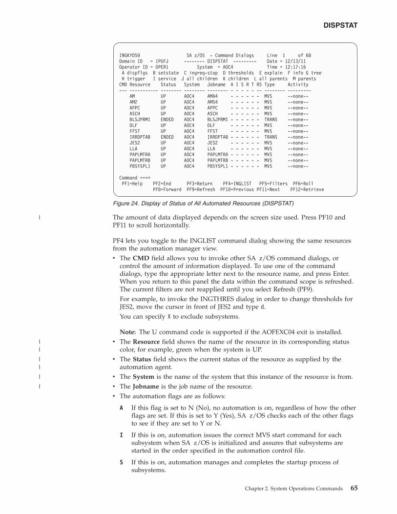
The amount of data displayed depends on the screen size used. Press PF10 andPF11 to scroll horizontally.
PF4 lets you toggle to the INGLIST command dialog showing the same resourcesfrom the automation manager view.v The CMD field allows you to invoke other SA z/OS command dialogs, or
control the amount of information displayed. To use one of the commanddialogs, type the appropriate letter next to the resource name, and press Enter.When you return to this panel the data within the command scope is refreshed.The current filters are not reapplied until you select Refresh (PF9).For example, to invoke the INGTHRES dialog in order to change thresholds forJES2, move the cursor in front of JES2 and type d.You can specify X to exclude subsystems.
Note: The U command code is supported if the AOFEXC04 exit is installed.v The Resource field shows the name of the resource in its corresponding status
color, for example, green when the system is UP.v The Status field shows the current status of the resource as supplied by the
automation agent.v The System is the name of the system that this instance of the resource is from.v The Jobname is the job name of the resource.v The automation flags are as follows:
A If this flag is set to N (No), no automation is on, regardless of how the otherflags are set. If this is set to Y (Yes), SA z/OS checks each of the other flagsto see if they are set to Y or N.
I If this is on, automation issues the correct MVS start command for eachsubsystem when SA z/OS is initialized and assures that subsystems arestarted in the order specified in the automation control file.
S If this is on, automation manages and completes the startup process ofsubsystems.
INGKYDS0 SA z/OS - Command Dialogs Line 1 of 68Domain ID = IPUFJ -------- DISPSTAT --------- Date = 12/13/11Operator ID = OPER1 System = AOC4 Time = 12:17:16A dispflgs B setstate C ingreq-stop D thresholds E explain F info G treeH trigger I service J all children K children L all parents M parentsCMD Resource Status System Jobname A I S R T RS Type Activity--- ----------- -------- -------- -------- - - - - - -- -------- ---------
AM UP AOC4 AMA4 - - - - - - MVS --none--AM2 UP AOC4 AMS4 - - - - - - MVS --none--APPC UP AOC4 APPC - - - - - - MVS --none--ASCH UP AOC4 ASCH - - - - - - MVS --none--BLSJPRMI ENDED AOC4 BLSJPRMI - - - - - - TRANS --none--DLF UP AOC4 DLF - - - - - - MVS --none--FFST UP AOC4 FFST - - - - - - MVS --none--IRRDPTAB ENDED AOC4 IRRDPTAB - - - - - - TRANS --none--JES2 UP AOC4 JES2 - - - - - - MVS --none--LLA UP AOC4 LLA - - - - - - MVS --none--PAPLMTRA UP AOC4 PAPLMTRA - - - - - - MVS --none--PAPLMTRB UP AOC4 PAPLMTRB - - - - - - MVS --none--PBSYSPL1 UP AOC4 PBSYSPL1 - - - - - - MVS --none--
Command ===>PF1=Help PF2=End PF3=Return PF4=INGLIST PF5=Filters PF6=Roll
PF8=Forward PF9=Refresh PF10=Previous PF11=Next PF12=Retrieve
Figure 24. Display of Status of All Automated Resources (DISPSTAT)
DISPSTAT
Chapter 2. System Operations Commands 65
|
||
||
|
|
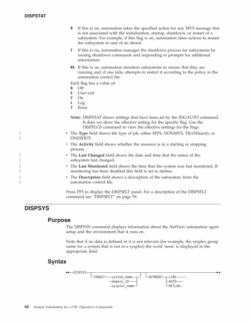
R If this is on, automation takes the specified action for any MVS message thatis not associated with the initialization, startup, shutdown, or restart of asubsystem. For example, if this flag is on, automation takes actions to restartthe subsystem in case of an abend.
T If this is on, automation manages the shutdown process for subsystems byissuing shutdown commands and responding to prompts for additionalinformation.
RS If this is on, automation monitors subsystems to ensure that they arerunning and, if one fails, attempts to restart it according to the policy in theautomation control file.
Each flag has a value of:N OffE User exitY OnL Log? Error
Note: DISPSTAT shows settings that have been set by the INGAUTO command.It does not show the effective setting for the specific flag. Use theDISPFLGS command to view the effective settings for the flags.
v The Type field shows the type of job, either MVS, NONMVS, TRANS(ient), orONESHOT.
v The Activity field shows whether the resource is in a starting or stoppingprocess.
v The Last Changed field shows the date and time that the status of thesubsystem last changed.
v The Last Monitored field shows the time that the system was last monitored. Ifmonitoring has been disabled this field is set to dashes.
v The Description field shows a description of the subsystem, from theautomation control file.
Press PF5 to display the DISPSFLT panel. For a description of the DISPSFLTcommand see “DISPSFLT” on page 59.
DISPSYS
PurposeThe DISPSYS command displays information about the NetView automation agentsetup and the environment that it runs on.
Note that if no data is defined or it is not relevant (for example, the sysplex groupname for a system that is not in a sysplex) the word 'none' is displayed in theappropriate field.
Syntax
�� DISPSYSTARGET= system_name
domain_IDsysplex_name
OUTMODE= LINEAUTONETLOG
��
DISPSTAT
66 System Automation for z/OS: Operator's Commands
||
||
||
||
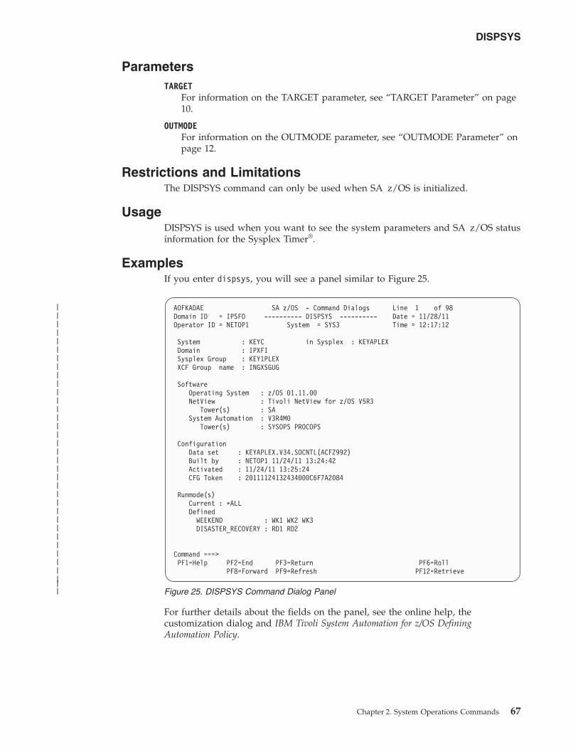
ParametersTARGET
For information on the TARGET parameter, see “TARGET Parameter” on page10.
OUTMODEFor information on the OUTMODE parameter, see “OUTMODE Parameter” onpage 12.
Restrictions and LimitationsThe DISPSYS command can only be used when SA z/OS is initialized.
UsageDISPSYS is used when you want to see the system parameters and SA z/OS statusinformation for the Sysplex Timer®.
ExamplesIf you enter dispsys, you will see a panel similar to Figure 25.
For further details about the fields on the panel, see the online help, thecustomization dialog and IBM Tivoli System Automation for z/OS DefiningAutomation Policy.
AOFKADAE SA z/OS - Command Dialogs Line 1 of 98Domain ID = IPSFO ---------- DISPSYS ---------- Date = 11/28/11Operator ID = NETOP1 System = SYS3 Time = 12:17:12
System : KEYC in Sysplex : KEYAPLEXDomain : IPXFISysplex Group : KEY1PLEXXCF Group name : INGXSGUG
SoftwareOperating System : z/OS 01.11.00NetView : Tivoli NetView for z/OS V5R3
Tower(s) : SASystem Automation : V3R4M0
Tower(s) : SYSOPS PROCOPS
ConfigurationData set : KEYAPLEX.V34.SOCNTL(ACFZ992)Built by : NETOP1 11/24/11 13:24:42Activated : 11/24/11 13:25:24CFG Token : 20111124132434000C6F7A2084
Runmode(s)Current : *ALLDefined
WEEKEND : WK1 WK2 WK3DISASTER_RECOVERY : RD1 RD2
Command ===>PF1=Help PF2=End PF3=Return PF6=Roll
PF8=Forward PF9=Refresh PF12=Retrieve
Figure 25. DISPSYS Command Dialog Panel
DISPSYS
Chapter 2. System Operations Commands 67
|||||||||||||||||||||||||||||||||||
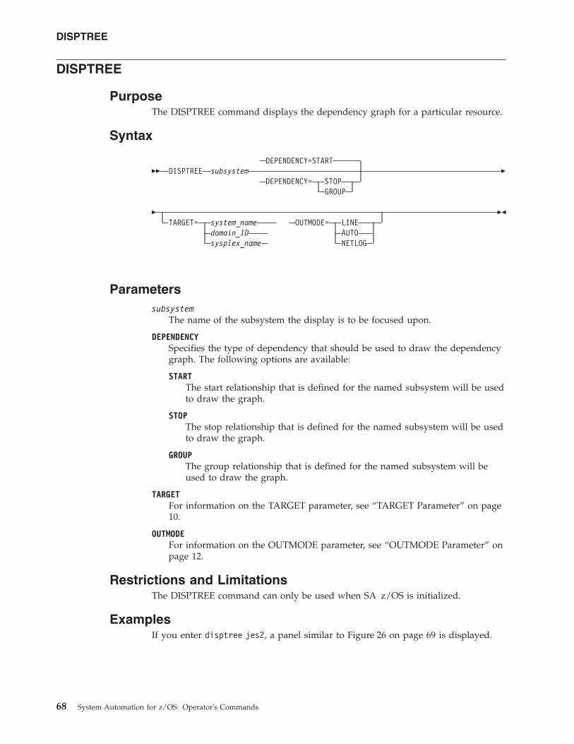
DISPTREE
PurposeThe DISPTREE command displays the dependency graph for a particular resource.
Syntax
�� DISPTREE subsystemDEPENDENCY=START
DEPENDENCY= STOPGROUP
�
�TARGET= system_name
domain_IDsysplex_name
OUTMODE= LINEAUTONETLOG
��
Parameterssubsystem
The name of the subsystem the display is to be focused upon.
DEPENDENCYSpecifies the type of dependency that should be used to draw the dependencygraph. The following options are available:
STARTThe start relationship that is defined for the named subsystem will be usedto draw the graph.
STOPThe stop relationship that is defined for the named subsystem will be usedto draw the graph.
GROUPThe group relationship that is defined for the named subsystem will beused to draw the graph.
TARGETFor information on the TARGET parameter, see “TARGET Parameter” on page10.
OUTMODEFor information on the OUTMODE parameter, see “OUTMODE Parameter” onpage 12.
Restrictions and LimitationsThe DISPTREE command can only be used when SA z/OS is initialized.
ExamplesIf you enter disptree jes2, a panel similar to Figure 26 on page 69 is displayed.
DISPTREE
68 System Automation for z/OS: Operator's Commands
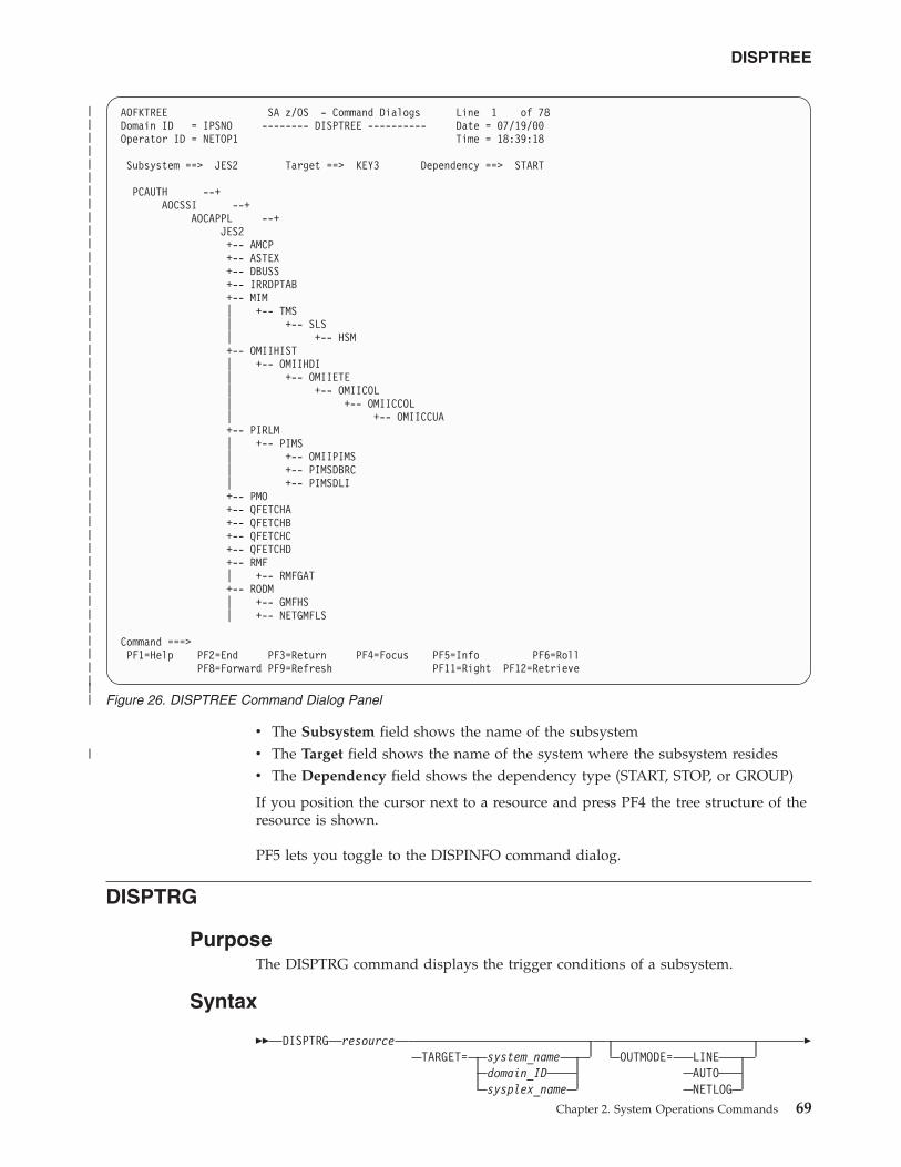
v The Subsystem field shows the name of the subsystemv The Target field shows the name of the system where the subsystem residesv The Dependency field shows the dependency type (START, STOP, or GROUP)
If you position the cursor next to a resource and press PF4 the tree structure of theresource is shown.
PF5 lets you toggle to the DISPINFO command dialog.
DISPTRG
PurposeThe DISPTRG command displays the trigger conditions of a subsystem.
Syntax
�� DISPTRG resourceTARGET= system_name
domain_IDsysplex_name
OUTMODE= LINEAUTONETLOG
�
AOFKTREE SA z/OS - Command Dialogs Line 1 of 78Domain ID = IPSNO -------- DISPTREE ---------- Date = 07/19/00Operator ID = NETOP1 Time = 18:39:18
Subsystem ==> JES2 Target ==> KEY3 Dependency ==> START
PCAUTH --+AOCSSI --+
AOCAPPL --+JES2+-- AMCP+-- ASTEX+-- DBUSS+-- IRRDPTAB+-- MIM| +-- TMS| +-- SLS| +-- HSM+-- OMIIHIST| +-- OMIIHDI| +-- OMIIETE| +-- OMIICOL| +-- OMIICCOL| +-- OMIICCUA+-- PIRLM| +-- PIMS| +-- OMIIPIMS| +-- PIMSDBRC| +-- PIMSDLI+-- PMO+-- QFETCHA+-- QFETCHB+-- QFETCHC+-- QFETCHD+-- RMF| +-- RMFGAT+-- RODM| +-- GMFHS| +-- NETGMFLS
Command ===>PF1=Help PF2=End PF3=Return PF4=Focus PF5=Info PF6=Roll
PF8=Forward PF9=Refresh PF11=Right PF12=Retrieve
Figure 26. DISPTREE Command Dialog Panel
DISPTREE
Chapter 2. System Operations Commands 69
||||||||||||||||||||||||||||||||||||||||||||||
|
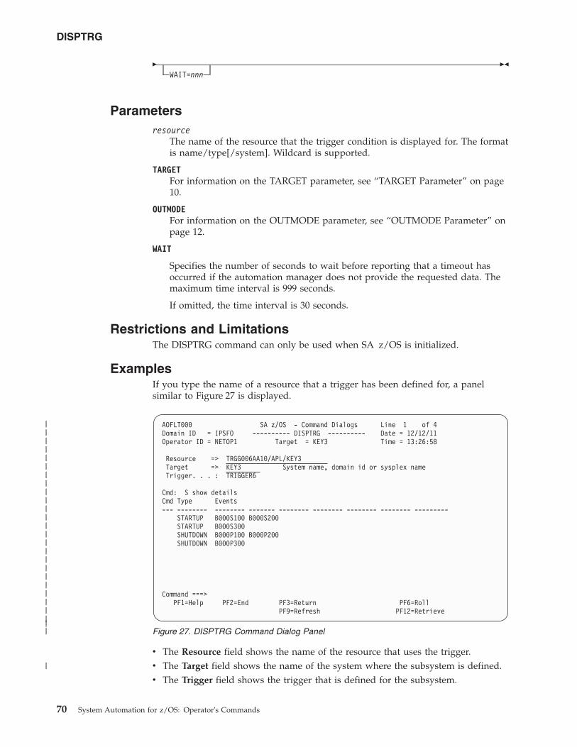
�WAIT=nnn
��
Parametersresource
The name of the resource that the trigger condition is displayed for. The formatis name/type[/system]. Wildcard is supported.
TARGETFor information on the TARGET parameter, see “TARGET Parameter” on page10.
OUTMODEFor information on the OUTMODE parameter, see “OUTMODE Parameter” onpage 12.
WAIT
Specifies the number of seconds to wait before reporting that a timeout hasoccurred if the automation manager does not provide the requested data. Themaximum time interval is 999 seconds.
If omitted, the time interval is 30 seconds.
Restrictions and LimitationsThe DISPTRG command can only be used when SA z/OS is initialized.
ExamplesIf you type the name of a resource that a trigger has been defined for, a panelsimilar to Figure 27 is displayed.
v The Resource field shows the name of the resource that uses the trigger.v The Target field shows the name of the system where the subsystem is defined.v The Trigger field shows the trigger that is defined for the subsystem.
AOFLT000 SA z/OS - Command Dialogs Line 1 of 4Domain ID = IPSFO ---------- DISPTRG ---------- Date = 12/12/11Operator ID = NETOP1 Target = KEY3 Time = 13:26:58
Resource => TRGG006AA10/APL/KEY3Target => KEY3 System name, domain id or sysplex nameTrigger. . . : TRIGGER6
Cmd: S show detailsCmd Type Events--- -------- -------- ------- -------- -------- -------- -------- ---------
STARTUP B000S100 B000S200STARTUP B000S300SHUTDOWN B000P100 B000P200SHUTDOWN B000P300
Command ===>PF1=Help PF2=End PF3=Return PF6=Roll
PF9=Refresh PF12=Retrieve
Figure 27. DISPTRG Command Dialog Panel
DISPTRG
70 System Automation for z/OS: Operator's Commands
||||||||||||||||||||||||||
|
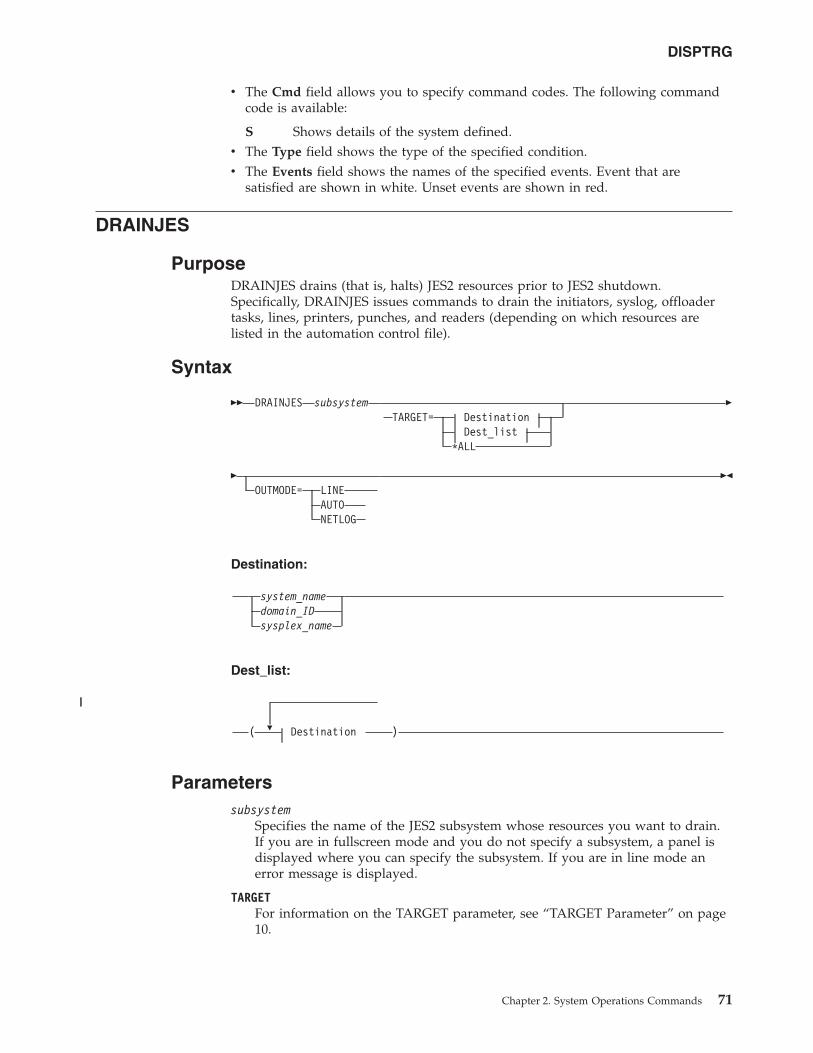
v The Cmd field allows you to specify command codes. The following commandcode is available:
S Shows details of the system defined.v The Type field shows the type of the specified condition.v The Events field shows the names of the specified events. Event that are
satisfied are shown in white. Unset events are shown in red.
DRAINJES
PurposeDRAINJES drains (that is, halts) JES2 resources prior to JES2 shutdown.Specifically, DRAINJES issues commands to drain the initiators, syslog, offloadertasks, lines, printers, punches, and readers (depending on which resources arelisted in the automation control file).
Syntax
�� DRAINJES subsystemTARGET= Destination
Dest_list*ALL
�
�OUTMODE= LINE
AUTONETLOG
��
Destination:
system_namedomain_IDsysplex_name
Dest_list:
�( Destination )
Parameterssubsystem
Specifies the name of the JES2 subsystem whose resources you want to drain.If you are in fullscreen mode and you do not specify a subsystem, a panel isdisplayed where you can specify the subsystem. If you are in line mode anerror message is displayed.
TARGETFor information on the TARGET parameter, see “TARGET Parameter” on page10.
DISPTRG
Chapter 2. System Operations Commands 71
||
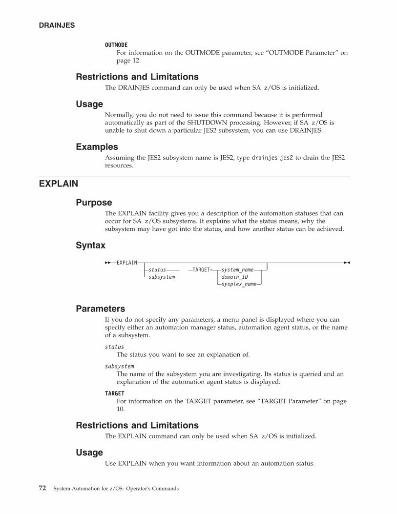
OUTMODEFor information on the OUTMODE parameter, see “OUTMODE Parameter” onpage 12.
Restrictions and LimitationsThe DRAINJES command can only be used when SA z/OS is initialized.
UsageNormally, you do not need to issue this command because it is performedautomatically as part of the SHUTDOWN processing. However, if SA z/OS isunable to shut down a particular JES2 subsystem, you can use DRAINJES.
ExamplesAssuming the JES2 subsystem name is JES2, type drainjes jes2 to drain the JES2resources.
EXPLAIN
PurposeThe EXPLAIN facility gives you a description of the automation statuses that canoccur for SA z/OS subsystems. It explains what the status means, why thesubsystem may have got into the status, and how another status can be achieved.
Syntax
�� EXPLAINstatussubsystem
TARGET= system_namedomain_IDsysplex_name
��
ParametersIf you do not specify any parameters, a menu panel is displayed where you canspecify either an automation manager status, automation agent status, or the nameof a subsystem.
statusThe status you want to see an explanation of.
subsystemThe name of the subsystem you are investigating. Its status is queried and anexplanation of the automation agent status is displayed.
TARGETFor information on the TARGET parameter, see “TARGET Parameter” on page10.
Restrictions and LimitationsThe EXPLAIN command can only be used when SA z/OS is initialized.
UsageUse EXPLAIN when you want information about an automation status.
DRAINJES
72 System Automation for z/OS: Operator's Commands
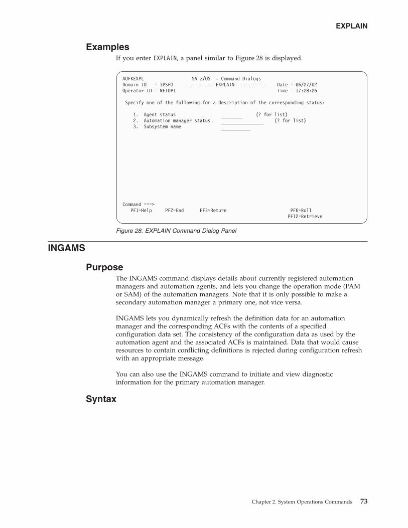
ExamplesIf you enter EXPLAIN, a panel similar to Figure 28 is displayed.
INGAMS
PurposeThe INGAMS command displays details about currently registered automationmanagers and automation agents, and lets you change the operation mode (PAMor SAM) of the automation managers. Note that it is only possible to make asecondary automation manager a primary one, not vice versa.
INGAMS lets you dynamically refresh the definition data for an automationmanager and the corresponding ACFs with the contents of a specifiedconfiguration data set. The consistency of the configuration data as used by theautomation agent and the associated ACFs is maintained. Data that would causeresources to contain conflicting definitions is rejected during configuration refreshwith an appropriate message.
You can also use the INGAMS command to initiate and view diagnosticinformation for the primary automation manager.
Syntax
AOFKEXPL SA z/OS - Command DialogsDomain ID = IPSFO ---------- EXPLAIN ---------- Date = 06/27/02Operator ID = NETOP1 Time = 17:28:26
Specify one of the following for a description of the corresponding status:
1. Agent status (? for list)2. Automation manager status (? for list)3. Subsystem name
Command ===>PF1=Help PF2=End PF3=Return PF6=Roll
PF12=Retrieve
Figure 28. EXPLAIN Command Dialog Panel
EXPLAIN
Chapter 2. System Operations Commands 73
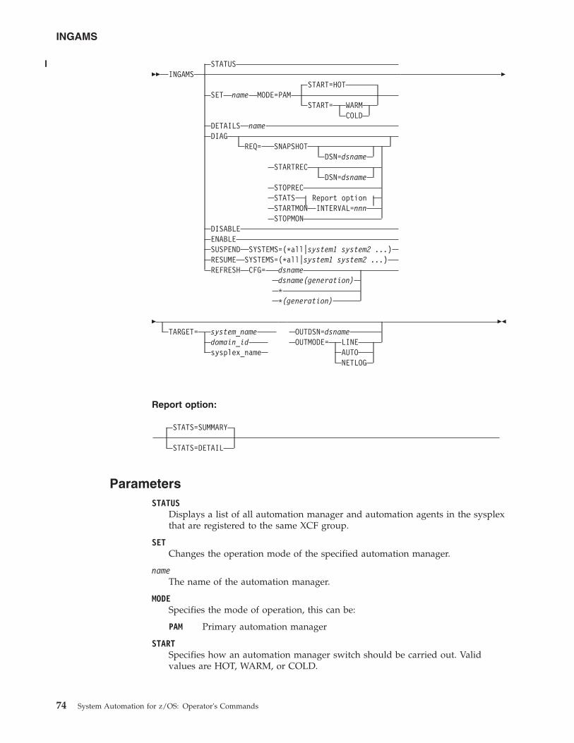
�� INGAMSSTATUS
START=HOTSET name MODE=PAM
START= WARMCOLD
DETAILS nameDIAG
REQ= SNAPSHOTDSN=dsname
STARTRECDSN=dsname
STOPRECSTATS Report optionSTARTMON INTERVAL=nnnSTOPMON
DISABLEENABLESUSPEND SYSTEMS=(*all|system1 system2 ...)RESUME SYSTEMS=(*all|system1 system2 ...)REFRESH CFG= dsname
dsname(generation)**(generation)
�
�TARGET= system_name
domain_idsysplex_name
OUTDSN=dsnameOUTMODE= LINE
AUTONETLOG
��
Report option:
STATS=SUMMARY
STATS=DETAIL
ParametersSTATUS
Displays a list of all automation manager and automation agents in the sysplexthat are registered to the same XCF group.
SETChanges the operation mode of the specified automation manager.
nameThe name of the automation manager.
MODESpecifies the mode of operation, this can be:
PAM Primary automation manager
STARTSpecifies how an automation manager switch should be carried out. Validvalues are HOT, WARM, or COLD.
INGAMS
74 System Automation for z/OS: Operator's Commands
||||
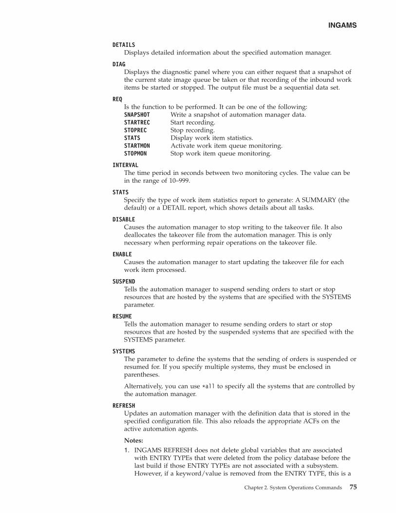
DETAILSDisplays detailed information about the specified automation manager.
DIAGDisplays the diagnostic panel where you can either request that a snapshot ofthe current state image queue be taken or that recording of the inbound workitems be started or stopped. The output file must be a sequential data set.
REQIs the function to be performed. It can be one of the following:SNAPSHOT Write a snapshot of automation manager data.STARTREC Start recording.STOPREC Stop recording.STATS Display work item statistics.STARTMON Activate work item queue monitoring.STOPMON Stop work item queue monitoring.
INTERVALThe time period in seconds between two monitoring cycles. The value can bein the range of 10–999.
STATSSpecify the type of work item statistics report to generate: A SUMMARY (thedefault) or a DETAIL report, which shows details about all tasks.
DISABLECauses the automation manager to stop writing to the takeover file. It alsodeallocates the takeover file from the automation manager. This is onlynecessary when performing repair operations on the takeover file.
ENABLECauses the automation manager to start updating the takeover file for eachwork item processed.
SUSPENDTells the automation manager to suspend sending orders to start or stopresources that are hosted by the systems that are specified with the SYSTEMSparameter.
RESUMETells the automation manager to resume sending orders to start or stopresources that are hosted by the suspended systems that are specified with theSYSTEMS parameter.
SYSTEMSThe parameter to define the systems that the sending of orders is suspended orresumed for. If you specify multiple systems, they must be enclosed inparentheses.
Alternatively, you can use *all to specify all the systems that are controlled bythe automation manager.
REFRESHUpdates an automation manager with the definition data that is stored in thespecified configuration file. This also reloads the appropriate ACFs on theactive automation agents.
Notes:
1. INGAMS REFRESH does not delete global variables that are associatedwith ENTRY TYPEs that were deleted from the policy database before thelast build if those ENTRY TYPEs are not associated with a subsystem.However, if a keyword/value is removed from the ENTRY TYPE, this is a
INGAMS
Chapter 2. System Operations Commands 75
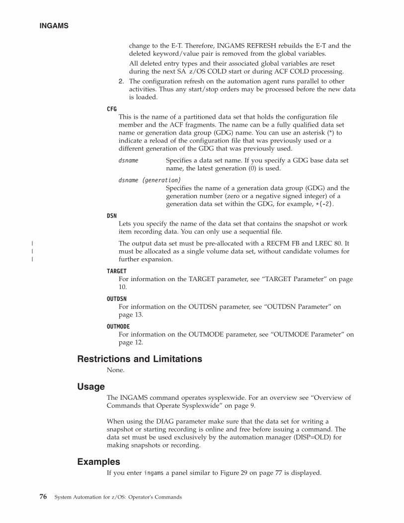
change to the E-T. Therefore, INGAMS REFRESH rebuilds the E-T and thedeleted keyword/value pair is removed from the global variables.All deleted entry types and their associated global variables are resetduring the next SA z/OS COLD start or during ACF COLD processing.
2. The configuration refresh on the automation agent runs parallel to otheractivities. Thus any start/stop orders may be processed before the new datais loaded.
CFGThis is the name of a partitioned data set that holds the configuration filemember and the ACF fragments. The name can be a fully qualified data setname or generation data group (GDG) name. You can use an asterisk (*) toindicate a reload of the configuration file that was previously used or adifferent generation of the GDG that was previously used.
dsname Specifies a data set name. If you specify a GDG base data setname, the latest generation (0) is used.
dsname (generation)Specifies the name of a generation data group (GDG) and thegeneration number (zero or a negative signed integer) of ageneration data set within the GDG, for example, *(-2).
DSNLets you specify the name of the data set that contains the snapshot or workitem recording data. You can only use a sequential file.
The output data set must be pre-allocated with a RECFM FB and LREC 80. Itmust be allocated as a single volume data set, without candidate volumes forfurther expansion.
TARGETFor information on the TARGET parameter, see “TARGET Parameter” on page10.
OUTDSNFor information on the OUTDSN parameter, see “OUTDSN Parameter” onpage 13.
OUTMODEFor information on the OUTMODE parameter, see “OUTMODE Parameter” onpage 12.
Restrictions and LimitationsNone.
UsageThe INGAMS command operates sysplexwide. For an overview see “Overview ofCommands that Operate Sysplexwide” on page 9.
When using the DIAG parameter make sure that the data set for writing asnapshot or starting recording is online and free before issuing a command. Thedata set must be used exclusively by the automation manager (DISP=OLD) formaking snapshots or recording.
ExamplesIf you enter ingams a panel similar to Figure 29 on page 77 is displayed.
INGAMS
76 System Automation for z/OS: Operator's Commands
|||
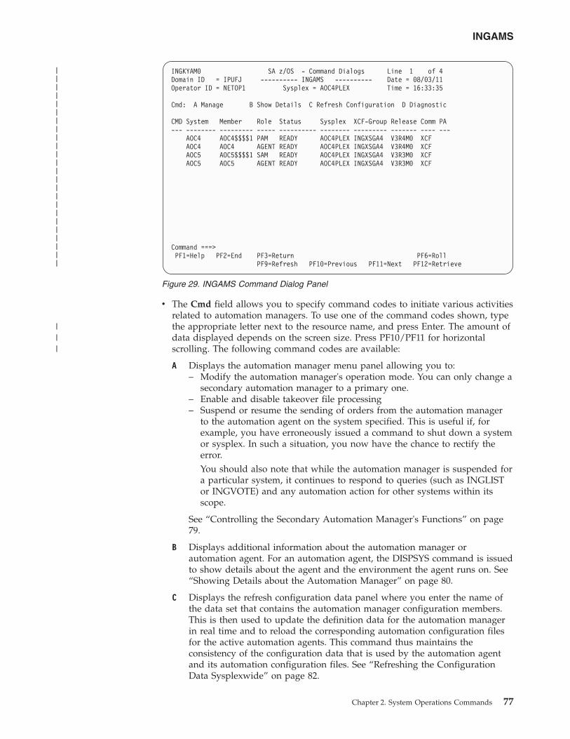
v The Cmd field allows you to specify command codes to initiate various activitiesrelated to automation managers. To use one of the command codes shown, typethe appropriate letter next to the resource name, and press Enter. The amount ofdata displayed depends on the screen size. Press PF10/PF11 for horizontalscrolling. The following command codes are available:
A Displays the automation manager menu panel allowing you to:– Modify the automation manager's operation mode. You can only change a
secondary automation manager to a primary one.– Enable and disable takeover file processing– Suspend or resume the sending of orders from the automation manager
to the automation agent on the system specified. This is useful if, forexample, you have erroneously issued a command to shut down a systemor sysplex. In such a situation, you now have the chance to rectify theerror.You should also note that while the automation manager is suspended fora particular system, it continues to respond to queries (such as INGLISTor INGVOTE) and any automation action for other systems within itsscope.
See “Controlling the Secondary Automation Manager's Functions” on page79.
B Displays additional information about the automation manager orautomation agent. For an automation agent, the DISPSYS command is issuedto show details about the agent and the environment the agent runs on. See“Showing Details about the Automation Manager” on page 80.
C Displays the refresh configuration data panel where you enter the name ofthe data set that contains the automation manager configuration members.This is then used to update the definition data for the automation managerin real time and to reload the corresponding automation configuration filesfor the active automation agents. This command thus maintains theconsistency of the configuration data that is used by the automation agentand its automation configuration files. See “Refreshing the ConfigurationData Sysplexwide” on page 82.
INGKYAM0 SA z/OS - Command Dialogs Line 1 of 4Domain ID = IPUFJ ---------- INGAMS ---------- Date = 08/03/11Operator ID = NETOP1 Sysplex = AOC4PLEX Time = 16:33:35
Cmd: A Manage B Show Details C Refresh Configuration D Diagnostic
CMD System Member Role Status Sysplex XCF-Group Release Comm PA--- -------- --------- ----- ---------- -------- --------- ------- ---- ---
AOC4 AOC4$$$$1 PAM READY AOC4PLEX INGXSGA4 V3R4M0 XCFAOC4 AOC4 AGENT READY AOC4PLEX INGXSGA4 V3R4M0 XCFAOC5 AOC5$$$$1 SAM READY AOC4PLEX INGXSGA4 V3R3M0 XCFAOC5 AOC5 AGENT READY AOC4PLEX INGXSGA4 V3R3M0 XCF
Command ===>PF1=Help PF2=End PF3=Return PF6=Roll
PF9=Refresh PF10=Previous PF11=Next PF12=Retrieve
Figure 29. INGAMS Command Dialog Panel
INGAMS
Chapter 2. System Operations Commands 77
||||||||||||||||||||||||
|||
D Displays the utility panel where you can perform the following diagnosticfunctions:– Write snapshot.– Start or stop recording.– Display work item statistics– Start or stop monitoring of the work item queue.
For further information, see “Diagnostic Functions” on page 83 and “How toUse the Diagnostic Option of INGAMS” in IBM Tivoli System Automation forz/OS User’s Guide.
v The System field shows the name of the system where an instance of theautomation manager or automation agent runs.
v The Member field shows the name of the agent or manager. The name must beunique within the XCF group. The member name for an automation manager isautomatically generated and consists of the z/OS system name plus a1-character suffix running from 1 to 9. The z/OS system name is padded with '$'to create an 8-character system name before appending the suffix.
Note: The member name of an automation agent is equal to the z/OS systemname.
v The Role field shows the type of the system. It can be one of the following:AGENT An automation agent.PAM The primary automation manager.SAM The secondary automation manager. There can be more than
one.v The Status field shows the status of the member. It can be one of the following:
COMM Is the type of communication being used between theautomation manager and the automation agent.
NOT READY The automation agent or manager is initializing.PENDING The automation manager is in the process of initializing as a
primary automation manager (PAM).READY The member is completely initialized.REFRESH The automation manager is performing a configuration refresh.SELECTED The automation manager is selected to become the next primary
automation manager (PAM).STOPPING The automation manager is terminating.SUSPENDED The automation agent has been placed in suspended mode.
v The Sysplex field shows the name of the sysplex.v The XCF-Group field shows the name of the associated XCF-Group.v The Release field shows the SA z/OS Version and Release of the automation
manager or automation agent.v The Comm field shows the type of communication in use between the
automation manager and the automation agent.v The PA field shows if this is a primary agent (PA) communicating with a higher
level automation manager.v The Runmode field shows the Runmode assigned to this system (agents only).v The Pref field shows the preference value assigned to various automation
instances.
The FIND/RFIND/SORT commands are supported. See “Varying the Format ofthe Command Output” on page 13 for information.
INGAMS
78 System Automation for z/OS: Operator's Commands
||
||
|
||
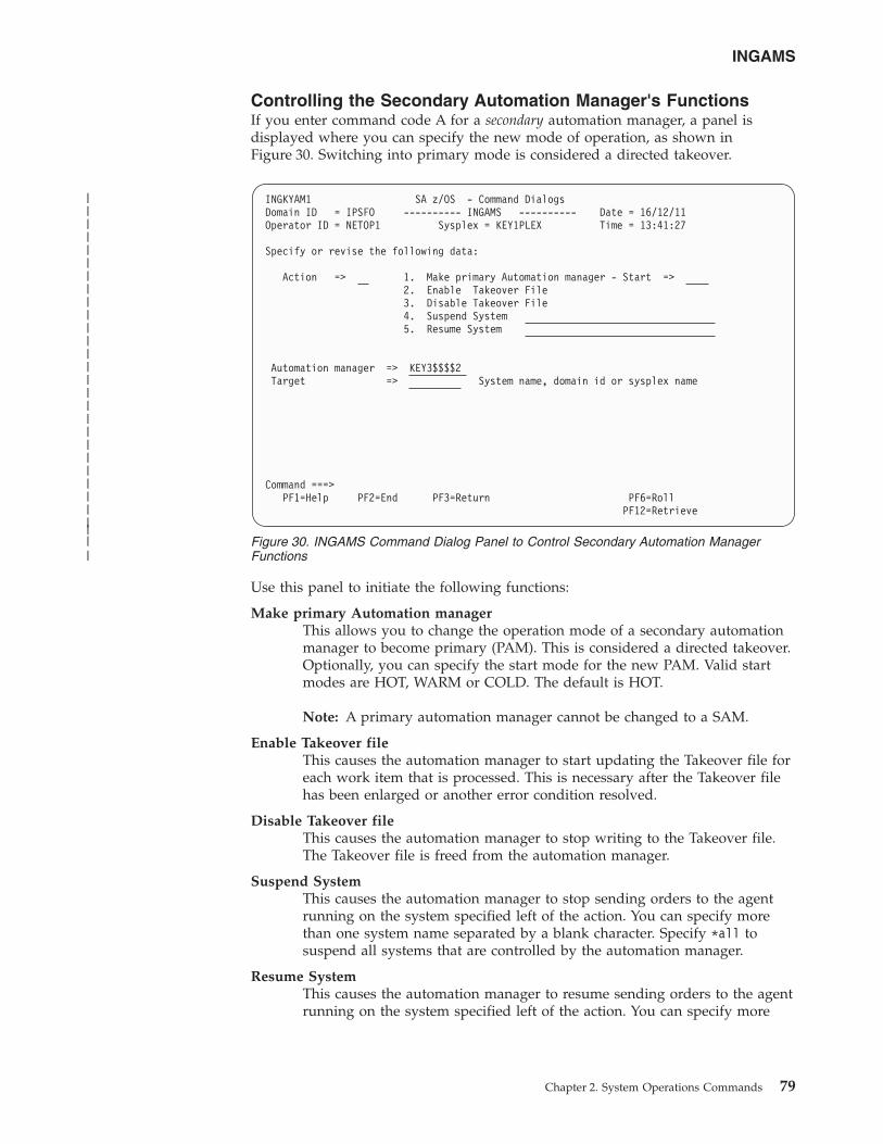
Controlling the Secondary Automation Manager's FunctionsIf you enter command code A for a secondary automation manager, a panel isdisplayed where you can specify the new mode of operation, as shown inFigure 30. Switching into primary mode is considered a directed takeover.
Use this panel to initiate the following functions:
Make primary Automation managerThis allows you to change the operation mode of a secondary automationmanager to become primary (PAM). This is considered a directed takeover.Optionally, you can specify the start mode for the new PAM. Valid startmodes are HOT, WARM or COLD. The default is HOT.
Note: A primary automation manager cannot be changed to a SAM.
Enable Takeover fileThis causes the automation manager to start updating the Takeover file foreach work item that is processed. This is necessary after the Takeover filehas been enlarged or another error condition resolved.
Disable Takeover fileThis causes the automation manager to stop writing to the Takeover file.The Takeover file is freed from the automation manager.
Suspend SystemThis causes the automation manager to stop sending orders to the agentrunning on the system specified left of the action. You can specify morethan one system name separated by a blank character. Specify *all tosuspend all systems that are controlled by the automation manager.
Resume SystemThis causes the automation manager to resume sending orders to the agentrunning on the system specified left of the action. You can specify more
INGKYAM1 SA z/OS - Command DialogsDomain ID = IPSFO ---------- INGAMS ---------- Date = 16/12/11Operator ID = NETOP1 Sysplex = KEY1PLEX Time = 13:41:27
Specify or revise the following data:
Action => 1. Make primary Automation manager - Start =>2. Enable Takeover File3. Disable Takeover File4. Suspend System5. Resume System
Automation manager => KEY3$$$$2Target => System name, domain id or sysplex name
Command ===>PF1=Help PF2=End PF3=Return PF6=Roll
PF12=Retrieve
Figure 30. INGAMS Command Dialog Panel to Control Secondary Automation ManagerFunctions
INGAMS
Chapter 2. System Operations Commands 79
|||||||||||||||||||||||||||||
than one system name separated by a blank character. Specify *all toresume all systems that are controlled by the automation manager.
Fill in the following fields:
Automation managerSpecify the name of the automation manager.
Target The name of the system where the automation manager resides. This isonly necessary when the automation manager is not within the localsysplex. You can specify either the system name, the domain ID or thesysplex name.
Showing Details about the Automation ManagerIf you enter command code B for an automation manager, a panel similar toFigure 31 on page 81 is displayed.
INGAMS
80 System Automation for z/OS: Operator's Commands
|||||
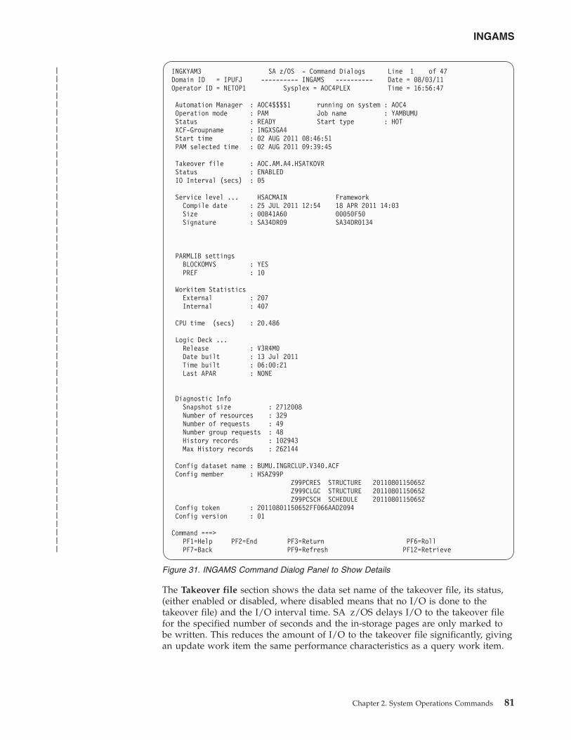
The Takeover file section shows the data set name of the takeover file, its status,(either enabled or disabled, where disabled means that no I/O is done to thetakeover file) and the I/O interval time. SA z/OS delays I/O to the takeover filefor the specified number of seconds and the in-storage pages are only marked tobe written. This reduces the amount of I/O to the takeover file significantly, givingan update work item the same performance characteristics as a query work item.
INGKYAM3 SA z/OS - Command Dialogs Line 1 of 47Domain ID = IPUFJ ---------- INGAMS ---------- Date = 08/03/11Operator ID = NETOP1 Sysplex = AOC4PLEX Time = 16:56:47
Automation Manager : AOC4$$$$1 running on system : AOC4Operation mode : PAM Job name : YAMBUMUStatus : READY Start type : HOTXCF-Groupname : INGXSGA4Start time : 02 AUG 2011 08:46:51PAM selected time : 02 AUG 2011 09:39:45
Takeover file : AOC.AM.A4.HSATKOVRStatus : ENABLEDIO Interval (secs) : 05
Service level ... HSACMAIN FrameworkCompile date : 25 JUL 2011 12:54 18 APR 2011 14:03Size : 00B41A60 00050F50Signature : SA34DR09 SA34DR0134
PARMLIB settingsBLOCKOMVS : YESPREF : 10
Workitem StatisticsExternal : 207Internal : 407
CPU time (secs) : 20.486
Logic Deck ...Release : V3R4M0Date built : 13 Jul 2011Time built : 06:00:21Last APAR : NONE
Diagnostic InfoSnapshot size : 2712008Number of resources : 329Number of requests : 49Number group requests : 48History records : 102943Max History records : 262144
Config dataset name : BUMU.INGRCLUP.V340.ACFConfig member : HSAZ99P
Z99PCRES STRUCTURE 20110801150652Z999CLGC STRUCTURE 20110801150652Z99PCSCH SCHEDULE 20110801150652
Config token : 20110801150652FF066AAD2094Config version : 01
Command ===>PF1=Help PF2=End PF3=Return PF6=RollPF7=Back PF9=Refresh PF12=Retrieve
Figure 31. INGAMS Command Dialog Panel to Show Details
INGAMS
Chapter 2. System Operations Commands 81
||||||||||||||||||||||||||||||||||||||||||||||||||||||||||
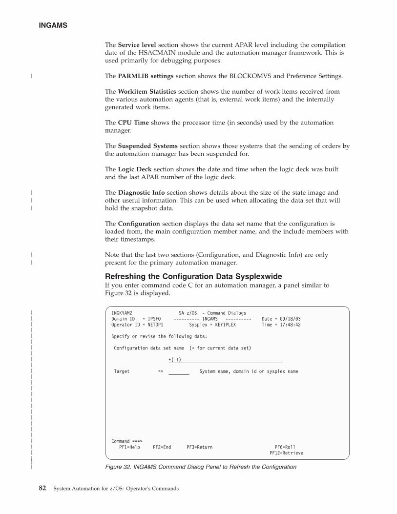
The Service level section shows the current APAR level including the compilationdate of the HSACMAIN module and the automation manager framework. This isused primarily for debugging purposes.
The PARMLIB settings section shows the BLOCKOMVS and Preference Settings.
The Workitem Statistics section shows the number of work items received fromthe various automation agents (that is, external work items) and the internallygenerated work items.
The CPU Time shows the processor time (in seconds) used by the automationmanager.
The Suspended Systems section shows those systems that the sending of orders bythe automation manager has been suspended for.
The Logic Deck section shows the date and time when the logic deck was builtand the last APAR number of the logic deck.
The Diagnostic Info section shows details about the size of the state image andother useful information. This can be used when allocating the data set that willhold the snapshot data.
The Configuration section displays the data set name that the configuration isloaded from, the main configuration member name, and the include members withtheir timestamps.
Note that the last two sections (Configuration, and Diagnostic Info) are onlypresent for the primary automation manager.
Refreshing the Configuration Data SysplexwideIf you enter command code C for an automation manager, a panel similar toFigure 32 is displayed.
INGKYAM2 SA z/OS - Command DialogsDomain ID = IPSFO ---------- INGAMS ---------- Date = 09/18/03Operator ID = NETOP1 Sysplex = KEY1PLEX Time = 17:48:42
Specify or revise the following data:
Configuration data set name (* for current data set)
*(-1)
Target => System name, domain id or sysplex name
Command ===>PF1=Help PF2=End PF3=Return PF6=Roll
PF12=Retrieve
Figure 32. INGAMS Command Dialog Panel to Refresh the Configuration
INGAMS
82 System Automation for z/OS: Operator's Commands
||||||||||||||||||||||||||||
|
|||
||
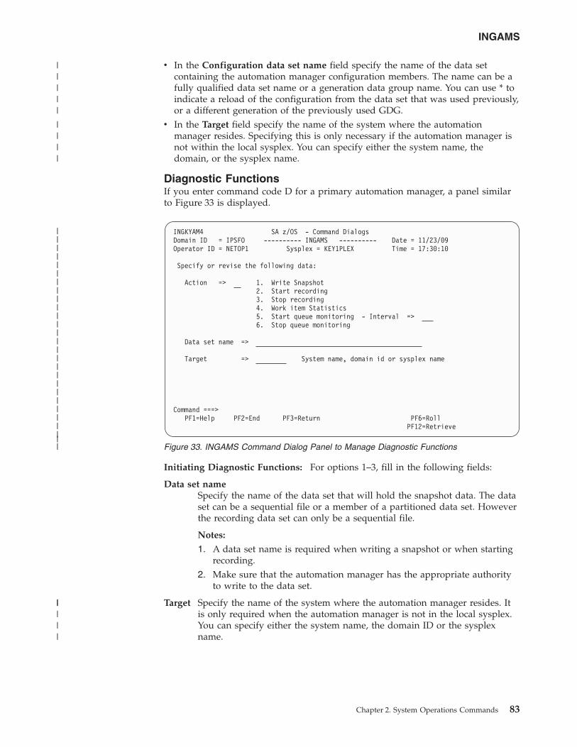
v In the Configuration data set name field specify the name of the data setcontaining the automation manager configuration members. The name can be afully qualified data set name or a generation data group name. You can use * toindicate a reload of the configuration from the data set that was used previously,or a different generation of the previously used GDG.
v In the Target field specify the name of the system where the automationmanager resides. Specifying this is only necessary if the automation manager isnot within the local sysplex. You can specify either the system name, thedomain, or the sysplex name.
Diagnostic FunctionsIf you enter command code D for a primary automation manager, a panel similarto Figure 33 is displayed.
Initiating Diagnostic Functions: For options 1–3, fill in the following fields:
Data set nameSpecify the name of the data set that will hold the snapshot data. The dataset can be a sequential file or a member of a partitioned data set. Howeverthe recording data set can only be a sequential file.
Notes:
1. A data set name is required when writing a snapshot or when startingrecording.
2. Make sure that the automation manager has the appropriate authorityto write to the data set.
Target Specify the name of the system where the automation manager resides. Itis only required when the automation manager is not in the local sysplex.You can specify either the system name, the domain ID or the sysplexname.
INGKYAM4 SA z/OS - Command DialogsDomain ID = IPSFO ---------- INGAMS ---------- Date = 11/23/09Operator ID = NETOP1 Sysplex = KEY1PLEX Time = 17:30:10
Specify or revise the following data:
Action => 1. Write Snapshot2. Start recording3. Stop recording4. Work item Statistics5. Start queue monitoring - Interval =>6. Stop queue monitoring
Data set name =>
Target => System name, domain id or sysplex name
Command ===>PF1=Help PF2=End PF3=Return PF6=Roll
PF12=Retrieve
Figure 33. INGAMS Command Dialog Panel to Manage Diagnostic Functions
INGAMS
Chapter 2. System Operations Commands 83
|||||||||||||||||||||||||||
|||||
||||
|||||
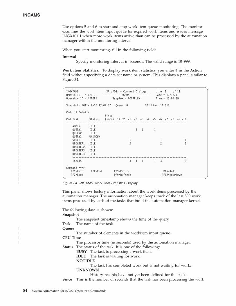
Use options 5 and 6 to start and stop work item queue monitoring. The monitorexamines the work item input queue for expired work items and issues messageINGX1011I when more work items arrive than can be processed by the automationmanager within the monitoring interval.
When you start monitoring, fill in the following field:
IntervalSpecify monitoring interval in seconds. The valid range is 10–999.
Work item Statistics: To display work item statistics, you enter 4 in the Actionfield without specifying a data set name or system. This displays a panel similar toFigure 34.
This panel shows history information about the work items processed by theautomation manager. The automation manager keeps track of the last 500 workitems processed by each of the tasks that build the automation manager kernel.
The following data is shown:Snapshot
The snapshot timestamp shows the time of the query.Task The name of the task.Queue
The number of elements in the workitem input queue.CPU Time
The processor time (in seconds) used by the automation manager.Status The status of the task. It is one of the following:
BUSY The task is processing a work item.IDLE The task is waiting for work.NOTIDLE
The task has completed work but is not waiting for work.UNKNOWN
History records have not yet been defined for this task.Since This is the number of seconds that the task has been processing the work
INGKYAM5 SA z/OS - Command Dialogs Line 1 of 11Domain ID = IPUFJ ---------- INGAMS ---------- Date = 12/16/11Operator ID = NETOP1 Sysplex = AOC4PLEX Time = 17:02:39
Snapshot: 2011-12-16 17:02:37 Queue: 0 CPU time: 11.617
Cmd: S DetailsSince
Cmd Task Status (secs) 17:02 -1 -2 -3 -4 -5 -6 -7 -8 -9 -10--- ---------- -------- -------- ----- --- --- --- --- --- --- --- --- --- ---
ADMIN IDLEQUERY1 IDLE 4 1 1QUERY2 IDLEQUERY3 UNKNOWNSCHED IDLE 1 1 1UPDATER1 IDLE 2 2 2UPDATER2 IDLEUPDATER3 IDLEUPDATER4 IDLE--------------------------------------------------------------------------Totals 3 4 1 1 3 3
Command ===>PF1=Help PF2=End PF3=Return PF6=RollPF7=Back PF9=Refresh PF12=Retrieve
Figure 34. INGAMS Work Item Statistics Display
INGAMS
84 System Automation for z/OS: Operator's Commands
||||||||||||||||||||||||||||
||||
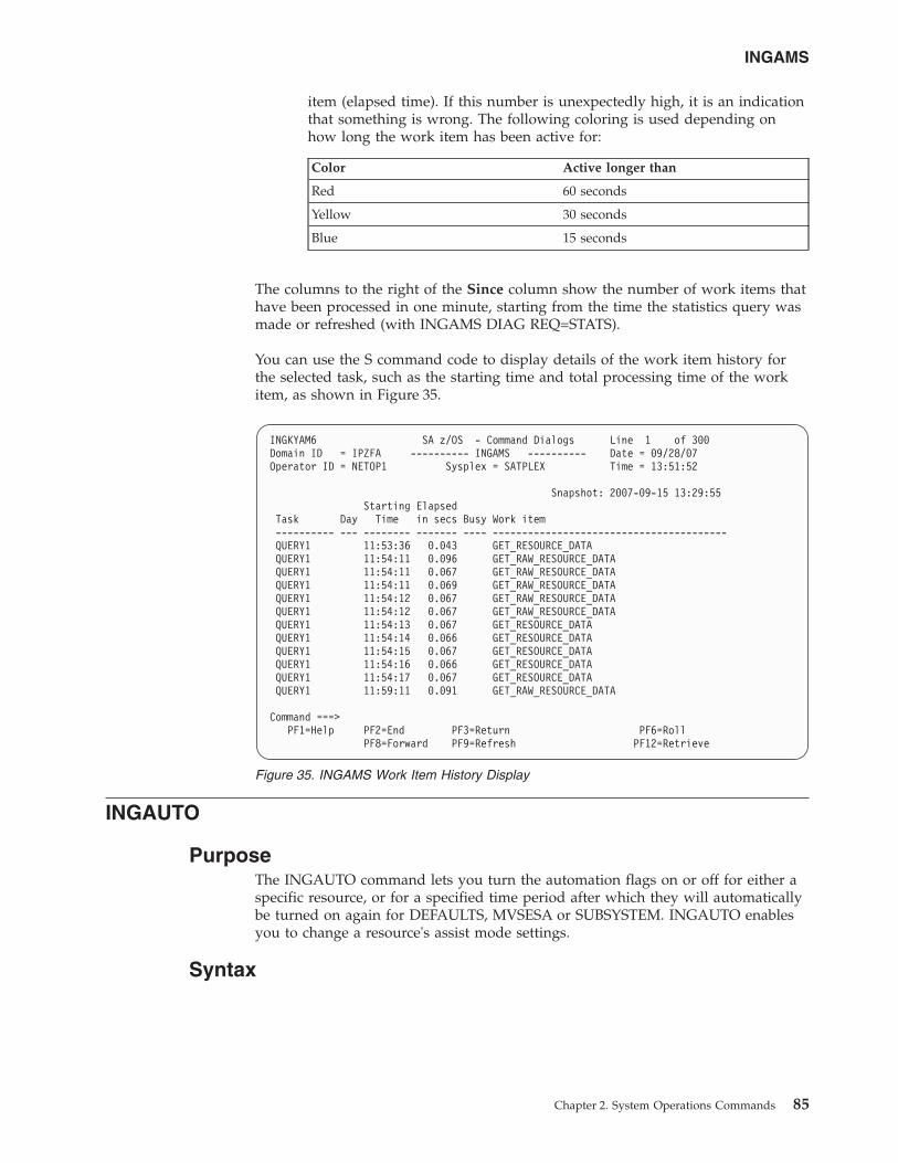
item (elapsed time). If this number is unexpectedly high, it is an indicationthat something is wrong. The following coloring is used depending onhow long the work item has been active for:
Color Active longer than
Red 60 seconds
Yellow 30 seconds
Blue 15 seconds
The columns to the right of the Since column show the number of work items thathave been processed in one minute, starting from the time the statistics query wasmade or refreshed (with INGAMS DIAG REQ=STATS).
You can use the S command code to display details of the work item history forthe selected task, such as the starting time and total processing time of the workitem, as shown in Figure 35.
INGAUTO
PurposeThe INGAUTO command lets you turn the automation flags on or off for either aspecific resource, or for a specified time period after which they will automaticallybe turned on again for DEFAULTS, MVSESA or SUBSYSTEM. INGAUTO enablesyou to change a resource's assist mode settings.
Syntax
INGKYAM6 SA z/OS - Command Dialogs Line 1 of 300Domain ID = IPZFA ---------- INGAMS ---------- Date = 09/28/07Operator ID = NETOP1 Sysplex = SATPLEX Time = 13:51:52
Snapshot: 2007-09-15 13:29:55Starting Elapsed
Task Day Time in secs Busy Work item---------- --- -------- ------- ---- ----------------------------------------QUERY1 11:53:36 0.043 GET_RESOURCE_DATAQUERY1 11:54:11 0.096 GET_RAW_RESOURCE_DATAQUERY1 11:54:11 0.067 GET_RAW_RESOURCE_DATAQUERY1 11:54:11 0.069 GET_RAW_RESOURCE_DATAQUERY1 11:54:12 0.067 GET_RAW_RESOURCE_DATAQUERY1 11:54:12 0.067 GET_RAW_RESOURCE_DATAQUERY1 11:54:13 0.067 GET_RESOURCE_DATAQUERY1 11:54:14 0.066 GET_RESOURCE_DATAQUERY1 11:54:15 0.067 GET_RESOURCE_DATAQUERY1 11:54:16 0.066 GET_RESOURCE_DATAQUERY1 11:54:17 0.067 GET_RESOURCE_DATAQUERY1 11:59:11 0.091 GET_RAW_RESOURCE_DATA
Command ===>PF1=Help PF2=End PF3=Return PF6=Roll
PF8=Forward PF9=Refresh PF12=Retrieve
Figure 35. INGAMS Work Item History Display
INGAMS
Chapter 2. System Operations Commands 85
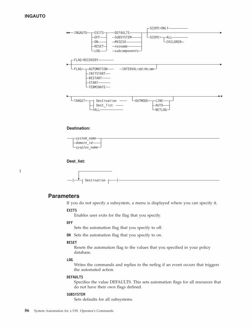
�� INGAUTO EXITSOFFONRESETLOG
DEFAULTSSUBSYSTEMMVSESAresnamesubcomponents
SCOPE=ONLY
SCOPE= ALLCHILDREN
�
�FLAG=RECOVERY
FLAG= AUTOMATIONINITSTARTRESTARTSTARTTERMINATE
INTERVAL=dd:hh:mm�
�TARGET= Destination
Dest_list*ALL
OUTMODE= LINEAUTONETLOG
��
Destination:
system_namedomain_idsysplex_name
Dest_list:
�( Destination )
ParametersIf you do not specify a subsystem, a menu is displayed where you can specify it.
EXITSEnables user exits for the flag that you specify.
OFFSets the automation flag that you specify to off.
ON Sets the automation flag that you specify to on.
RESETResets the automation flag to the values that you specified in your policydatabase.
LOGWrites the commands and replies to the netlog if an event occurs that triggersthe automated action.
DEFAULTSSpecifies the value DEFAULTS. This sets automation flags for all resources thatdo not have their own flags defined.
SUBSYSTEMSets defaults for all subsystems.
INGAUTO
86 System Automation for z/OS: Operator's Commands
||
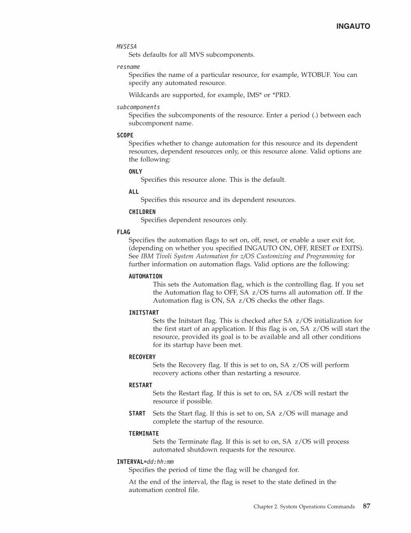
MVSESASets defaults for all MVS subcomponents.
resnameSpecifies the name of a particular resource, for example, WTOBUF. You canspecify any automated resource.
Wildcards are supported, for example, IMS* or *PRD.
subcomponentsSpecifies the subcomponents of the resource. Enter a period (.) between eachsubcomponent name.
SCOPESpecifies whether to change automation for this resource and its dependentresources, dependent resources only, or this resource alone. Valid options arethe following:
ONLYSpecifies this resource alone. This is the default.
ALLSpecifies this resource and its dependent resources.
CHILDRENSpecifies dependent resources only.
FLAGSpecifies the automation flags to set on, off, reset, or enable a user exit for,(depending on whether you specified INGAUTO ON, OFF, RESET or EXITS).See IBM Tivoli System Automation for z/OS Customizing and Programming forfurther information on automation flags. Valid options are the following:
AUTOMATIONThis sets the Automation flag, which is the controlling flag. If you setthe Automation flag to OFF, SA z/OS turns all automation off. If theAutomation flag is ON, SA z/OS checks the other flags.
INITSTARTSets the Initstart flag. This is checked after SA z/OS initialization forthe first start of an application. If this flag is on, SA z/OS will start theresource, provided its goal is to be available and all other conditionsfor its startup have been met.
RECOVERYSets the Recovery flag. If this is set to on, SA z/OS will performrecovery actions other than restarting a resource.
RESTARTSets the Restart flag. If this is set to on, SA z/OS will restart theresource if possible.
START Sets the Start flag. If this is set to on, SA z/OS will manage andcomplete the startup of the resource.
TERMINATESets the Terminate flag. If this is set to on, SA z/OS will processautomated shutdown requests for the resource.
INTERVAL=dd:hh:mmSpecifies the period of time the flag will be changed for.
At the end of the interval, the flag is reset to the state defined in theautomation control file.
INGAUTO
Chapter 2. System Operations Commands 87
If no interval is specified, the flag is changed indefinitely.
TARGETFor information on the TARGET parameter, see “TARGET Parameter” on page10.
OUTMODEFor information on the OUTMODE parameter, see “OUTMODE Parameter” onpage 12.
Restrictions and LimitationsThe INGAUTO command can only be used when SA z/OS is initialized.
A flag cannot be reset for an interval.
UsageIf the Automation flag is currently set to off, and you have changed one of theother flags, your change will not be effective until the Automation flag is set to on.Occurrences will be detailed in the netlog.
If you have selected EXITS for an automation flag, and none have been specified inyour automation control file, automation will be set to on. Occurrences will bedetailed in the netlog.
SCOPE=ONLY is the only valid scope for DEFAULTS, a resource type, andsubcomponents. ALL and CHILDREN are not valid.
Make sure you specify the correct subcomponent name. Even if you specify asubcomponent that does not exist, the message FUNCTION SUCCESSFULLYCOMPLETED will appear.
ExamplesTo turn all automation on in SA z/OS for TSO and for 2 hours only, enter thefollowing:ingauto on,tso,flag=automation,interval=00:02:00
To turn all automation on for the WTOR buffer shortage recovery, enter thefollowing:ingauto on,mvsesa.wto
INGAUTO
88 System Automation for z/OS: Operator's Commands
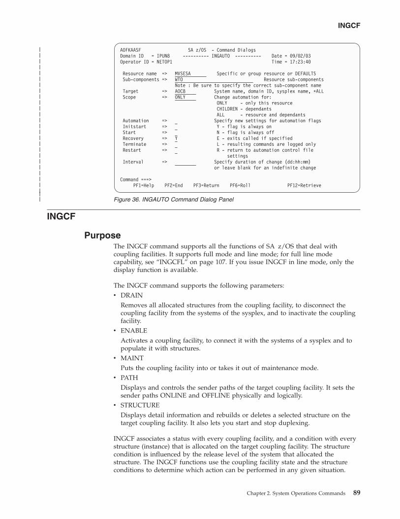
INGCF
PurposeThe INGCF command supports all the functions of SA z/OS that deal withcoupling facilities. It supports full mode and line mode; for full line modecapability, see “INGCFL” on page 107. If you issue INGCF in line mode, only thedisplay function is available.
The INGCF command supports the following parameters:v DRAIN
Removes all allocated structures from the coupling facility, to disconnect thecoupling facility from the systems of the sysplex, and to inactivate the couplingfacility.
v ENABLEActivates a coupling facility, to connect it with the systems of a sysplex and topopulate it with structures.
v MAINTPuts the coupling facility into or takes it out of maintenance mode.
v PATHDisplays and controls the sender paths of the target coupling facility. It sets thesender paths ONLINE and OFFLINE physically and logically.
v STRUCTUREDisplays detail information and rebuilds or deletes a selected structure on thetarget coupling facility. It also lets you start and stop duplexing.
INGCF associates a status with every coupling facility, and a condition with everystructure (instance) that is allocated on the target coupling facility. The structurecondition is influenced by the release level of the system that allocated thestructure. The INGCF functions use the coupling facility state and the structureconditions to determine which action can be performed in any given situation.
AOFKAASF SA z/OS - Command DialogsDomain ID = IPUN8 ---------- INGAUTO ---------- Date = 09/02/03Operator ID = NETOP1 Time = 17:23:40
Resource name => MVSESA Specific or group resource or DEFAULTSSub-components => WTO Resource sub-components
Note : Be sure to specify the correct sub-component nameTarget => AOC8 System name, domain ID, sysplex name, *ALLScope => ONLY Change automation for:
ONLY - only this resourceCHILDREN - dependantsALL - resource and dependants
Automation => Specify new settings for automation flagsInitstart => Y - flag is always onStart => N - flag is always offRecovery => Y E - exits called if specifiedTerminate => L - resulting commands are logged onlyRestart => R - return to automation control file
settingsInterval => Specify duration of change (dd:hh:mm)
or leave blank for an indefinite change
Command ===>PF1=Help PF2=End PF3=Return PF6=Roll PF12=Retrieve
Figure 36. INGAUTO Command Dialog Panel
INGCF
Chapter 2. System Operations Commands 89
|||||||||||||||||||||||||||
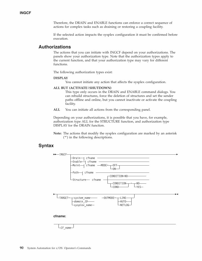
Therefore, the DRAIN and ENABLE functions can enforce a correct sequence ofactions for complex tasks such as draining or restoring a coupling facility.
If the selected action impacts the sysplex configuration it must be confirmed beforeexecution.
AuthorizationsThe actions that you can initiate with INGCF depend on your authorizations. Thepanels show your authorization type. Note that the authorization types apply tothe current function, and that your authorization type may vary for differentfunctions.
The following authorization types exist:
DISPLAYYou cannot initiate any action that affects the sysplex configuration.
ALL BUT (ACTIVATE|SHUTDOWN)This type only occurs in the DRAIN and ENABLE command dialogs. Youcan rebuild structures, force the deletion of structures and set the senderpaths offline and online, but you cannot inactivate or activate the couplingfacility.
ALL You can initiate all actions from the corresponding panel.
Depending on your authorizations, it is possible that you have, for example,authorization type ALL for the STRUCTURE function, and authorization typeDISPLAY for the DRAIN function.
Note: The actions that modify the sysplex configuration are marked by an asterisk('*') in the following descriptions.
Syntax
�� INGCFDrain cfnameEnable cfnameMaint cfname MODE= OFF
ONPath cfname
CONDITION=NOStructure cfname
CONDITION = NOCOND YES
�
�TARGET= system_name
domain_IDsysplex_name
OUTMODE= LINEAUTONETLOG
��
cfname:
CF_name
INGCF
90 System Automation for z/OS: Operator's Commands
ParametersDrain
Prepares a coupling facility for removal from the sysplex.
EnableIntegrates or reintegrates a coupling facility into a sysplex.
MaintControls the maintenance mode of a coupling facility.
PathControls the sender paths of a coupling facility.
StructureOffers manipulation of individual structures (detail information, rebuild,deletion).
CF_nameThe name of the target coupling facility for the specified function. The defaultis a selection panel that shows all available coupling facilities of the sysplex.
CONDITIONSpecify YES if you want to get the current condition for each structure.Selecting this option increases the response time required to build the display.The default is NO.
MODESpecify ON if you want to put the coupling facility into maintenance mode, orOFF to take it out of maintenance mode.
TARGETFor information on the TARGET parameter, refer to “TARGET Parameter” onpage 10.
OUTMODEFor information on the OUTMODE parameter, refer to “OUTMODEParameter” on page 12.
Restrictions and LimitationsThe ENABLE and the PATH functions require that the active IODF is catalogued.Otherwise, sender path information cannot be retrieved in certain situations.
INGCF ENABLE assumes that the receiver paths from the coupling facility to thesystems of the sysplex have been defined and activated. This requires a POR of theCPC that the coupling facility resides on.
Coupling Facility StatesThe status of a coupling facility can be as follows:
ACTIVATINGThe coupling facility is being activated and will then become DRAINED.
DEACTIVATINGThe coupling facility is being deactivated and will then become INACTIVE.
DRAININGThe coupling facility is being disconnected from the connected systems.
DRAINEDThe coupling facility does not have a connection to any system and can beremoved from the sysplex.
INGCF
Chapter 2. System Operations Commands 91
DRAINED NOHWACCThe coupling facility does not have a connection to any system, but cannotbe removed from the sysplex because the BCP (Basic Control Program)internal interface is not available.
Note: This status is also displayed when the coupling facility has beendeactivated from the HMC (Hardware Management Console) butthe XCF display commands still return the name of the couplingfacility.
ENABLINGThe coupling facility is being connected to the systems of the sysplex thatuse it.
FORCINGAllocated structures are being deleted from the coupling facility. This onlyhappens with structures that have no active connectors, and with theseonly when they cannot be rebuilt by system-managed rebuild.
INACTIVEThe coupling facility is not active.
INACTIVE NOHWACCThe coupling facility is not active and cannot be activated because the BCPInternal Interface does not have access to the appropriate Support Element.
MAINTMODEThe coupling facility is in maintenance mode and has not allocated anystructures. It can now be removed from the configuration or deactivatedwithout touching the sender paths. If you want to move structures back tothe coupling facility you need to take it out of maintenance mode beforepopulating it.
MAINTMODE OFFLINEThe coupling facility is in maintenance mode and may have allocatedstructures. At least one system has set all its sender paths to the couplingfacility to OFFLINE. XCF will reject any rebuild command to the couplingfacility.
MAINTMODE NOHWACCThe coupling facility is in maintenance mode and has not allocated anystructures. It can now be removed from the configuration without touchingthe sender paths. However, this must be done manually becauseautomation does not have access to the appropriate Support Element. Ifyou want to move structures back to the coupling facility you need to takeit out of maintenance mode before populating it.
NORMALThe coupling facility may have allocated structures and is connected to allsystems.
NORMAL MAINTMODEThe coupling facility is in maintenance mode but has allocated one or morestructures. The coupling facility is no longer eligible for structureallocations.
NORMAL OFFLINEThe coupling facility may have allocated structures. At least one systemhas set all its sender paths to this coupling facility to OFFLINE. XES willreject any rebuild request for this coupling facility.
INGCF
92 System Automation for z/OS: Operator's Commands
NOTINPOLICYThe coupling facility is active but not defined in the active CFRM policy.
POPULATINGThe coupling facility is being populated with all those structures that haveit on the first place in their preference list.
REBUILDINGEither all allocated structures that can be rebuilt are being removed fromthe coupling facility by the XES rebuild process (initiated by DRAIN), orone particular such structure is being removed (initiated by theSTRUCTURE).
Structure ConditionsThe condition of an allocated structure can be:
Rebuild is not supported.The structure can neither be rebuilt, nor can its deletion be forced.
The structure has at least one active connector that does not supportuser-managed rebuild, and at least one active connector that does notsupport system-managed rebuild.
System-managed processes not supported.The structure cannot be rebuilt, nor can its deletion be forced.
System-managed rebuild, which is a system-managed process, is notpossible for one of the following reasons:v The structure was allocated from a system with OS/390 V2.7 or earlier.v The CFRM couple data sets have not been formatted to support
system-managed processes (ITEM NAME(SMREBLD) NUMBER(1) was notspecified).
Note: In certain rare cases system-managed processes are not supportedalthough the condition that is displayed on the DRAIN panel seemsto indicate the contrary. Then, the rebuild will be initiated, but willfail with message IXC367I indicating that system-managed processesare not supported for the structure.
No alternate coupling facility defined or available.The structure can neither be rebuilt, nor can its deletion be forced.
The structure has an active connector and supports rebuild but does nothave an alternate coupling facility defined in its preference list, or thealternate coupling facilities that are defined in the preference list arecurrently unavailable.
Insufficient space detected for rebuild.The structure cannot or could not be rebuilt. Its deletion cannot be forced.
No alternate coupling facility has enough space to rebuild the structure.
Preference list is empty.The structure cannot be rebuilt because its preference list is currentlyempty. A possible reason for this is a pending policy change, see “Pcolumn” on page 107.
Structure is pending deallocation.XES accepted a forced deletion of the structure but does the realdeallocation later.
INGCF
Chapter 2. System Operations Commands 93
Note: This status can only occur when MVS APAR OW39404 has not beeninstalled.
Structure is being rebuilt.The structure is being rebuilt to another coupling facility.
Duplex rebuild is being stopped.Two instances of the structure were maintained on different couplingfacilities. The application is being disconnected from that instance that isallocated on the target coupling facility. After disconnecting, the instance isdeleted.
No connection exists.The structure cannot be rebuilt, but you can force its deletion.
The structure does not have any connections and cannot be rebuilt withsystem-managed rebuild.
No alternate coupling facility for structure with no connections.The structure cannot be rebuilt, but you can force its deletion.
The structure does not have any connections. It could be rebuilt withsystem-managed rebuild, but no alternate coupling facility is defined in itspreference list or available.
No alternate coupling facility for structure with no active connections.The structure cannot be rebuilt, but you can force its deletion.
The structure has only DISCONNECTING, FAILED, orFAILED-PERSISTENT connections. It could be rebuilt withsystem-managed rebuild, but no alternate coupling facility is defined in itspreference list or available.
The structure’s initial size is less than its actual size.The structure can be rebuilt, but this can lead to loss of data.
An initial size is specified for the structure in the active CFRM policy. Thisinitial size was used for the allocation of the structure. Afterwards, the sizeof the structure was increased either by the application itself or an operatorcommand. However, the structure will only be rebuilt with its initial size.Subsequently, INGCF will expand the structure to its actual size again, butthis will happen after the data have been transferred. To avoid a potentialloss of data, the application has to change the initial size to the actual size.
No active connection exists.The structure cannot be rebuilt, but you can force its deletion.
The structure has only DISCONNECTING, FAILED, orFAILED-PERSISTENT connections and cannot be rebuilt withsystem-managed rebuild.
Note: INGCF DRAIN deallocates structures with this condition as part ofthe REBUILD action (see “REBUILD (F10)” on page 97). INGCFSTRUCTURE accepts a rebuild request for structures with thiscondition, but deallocates them (see “Rebuild (R)” on page 105).
No connections. System-managed rebuild supported.The structure can be rebuilt.
The structure does not have any connections, but can be rebuilt withsystem-managed rebuild.
INGCF
94 System Automation for z/OS: Operator's Commands
No active connections. System-managed rebuild supported.The structure can be rebuilt with system-managed rebuild.
User-managed rebuild is not possible for the structure because it has onlyDISCONNECTING, FAILED, or FAILED-PERSISTENT connections.
System-managed rebuild is supportedThe structure can be rebuilt.
The structure has active connectors. At least one active connector does notsupport user-managed rebuild, but all active connectors supportsystem-managed rebuild.
Duplex rebuild is active.The application is connected to two instances of the same structure ondifferent coupling facilities.
[No condition]When no condition is displayed, the structure can be rebuilt.
The structure has at least one active connection, and all its activeconnectors support user-managed rebuild.
Structure is awaiting rebuild.The structure has been selected for rebuild but has not been processed yet.
Structure is currently allocated on cf_name.The structure can be rebuilt on the target coupling facility with thePOPULATE action of the ENABLE function. It is currently allocated on thecf_name coupling facility, but the target coupling facility precedes cf_namein the structure's preference list. This condition is displayed only in theENABLE command dialog.
Structure allocated in cf_name cannot be rebuilt to this CF.The structure can probably not be rebuilt on the target coupling facilitywith the POPULATE action of the ENABLE function. It is currentlyallocated in the cf_name coupling facility, but the target coupling facilityprecedes cf_name in the structure’s preference list. And, the actual size ofthe structure is greater than the free space of the target coupling facility.This condition is displayed only in the ENABLE command dialog.
ExampleIf you issue INGCF without any parameters, a panel with all coupling facilities ofthe sysplex is displayed, as shown in Figure 37 on page 96.
INGCF
Chapter 2. System Operations Commands 95
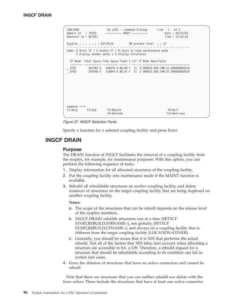
Specify a function for a selected coupling facility and press Enter.
INGCF DRAIN
PurposeThe DRAIN function of INGCF facilitates the removal of a coupling facility fromthe sysplex, for example, for maintenance purposes. With this option, you canperform the following sequence of tasks:1. Display information for all allocated structures of the coupling facility.2. Put the coupling facility into maintenance mode if the MAINT function is
available.3. Rebuild all rebuildable structures on another coupling facility, and delete
instances of structures on the target coupling facility that are being duplexed onanother coupling facility.
Notes:
a. The scope of the structures that can be rebuilt depends on the release levelof the sysplex members.
b. INGCF DRAIN rebuilds structures one at a time (SETXCFSTART,REBUILD,STRNAME=), not globally (SETXCFSTART,REBUILD,CFNAME=), and always on a coupling facility that isdifferent from the target coupling facility (LOCATION=OTHER).
c. Generally, you should be aware that it is XES that performs the actualrebuild. Not all of the factors that XES takes into account when allocating astructure are accessible to SA z/OS. Therefore, a rebuild request for astructure that should be rebuildable according to its condition can fail incertain rare cases.
4. Force the deletion of structures that have no active connectors and cannot berebuilt.
Note that there are structures that you can neither rebuild nor delete with theforce action. These include the structures that have at least one active connector
INGLX900 SA z/OS - Command Dialogs Line 1 of 2Domain Id = IPSFO ---------- INGCF ---------- Date = 02/23/03Operator Id = NETOP1 Time = 13:42:35
Sysplex . . . . . . : KEY1PLEX SM process level . : 12- - - - - - - - - - - - - - - - - - - - - - - - - - - - - - - - - - - - - - - -Cmds: D drain CF / E enable CF / M start or stop maintenance mode
P display sender paths / S display structures
CF Name Total Space Free Space Free% V Lvl LP Node Descriptor-------- ----------- ---------- ----- - --- -- ------------------------------
_ CF01 507392 K 446976 K 88.09 Y 11 D 009672.RX6.IBM.51.000000064516_ CF02 245248 K 210944 K 86.01 Y 11 E 009672.RX6.IBM.51.000000064516
Command ===>F1=Help F2=End F3=Return F6=Roll
F9=Refresh F12=Retrieve
Figure 37. INGCF Selection Panel
INGCF DRAIN
96 System Automation for z/OS: Operator's Commands
and do not support rebuild. To remove such structures first disconnect all activeconnectors, and then delete the structure manually if it is persistent or haspersistent connections.5. When the coupling facility is not in maintenance mode, disconnect the coupling
facility from the systems that it is connected to.6. Inactivate the target coupling facility.
INGCF DRAIN ensures that these actions are performed in the correct order, asspecified above.
ActionsThe following F-keys are supported:
*REBUILD (F10)Starts the rebuild of structures that can be rebuilt on another couplingfacility. Thus, a rebuild is only initiated for structures whose preference listcontains more than one coupling facility.
There are two methods for rebuild, user-managed and system-managedrebuild. User-managed rebuild is supported for all release levels.System-managed rebuild is only available with systems that have beenenabled by formatting the CFRM couple data sets with the specification:ITEM NAME(SMREBLD) NUMBER(1)
System-managed rebuild is only performed when the requirements foruser-managed rebuild are not met. This applies, for example, to structureswithout active connectors.
The REBUILD action also deletes all structure instances on the targetcoupling facility that are being duplexed on another coupling facility.
Note: The REBUILD action deallocates structures with the condition Noactive connection exists.. See “No active connection exists” onpage 94.
*FORCE (F5)Forces the deallocation of structures with one of the following conditions:v No connection exists.
v No alternate coupling facility for structure with no activeconnections.
v No alternate coupling facility for structure with no connections.
This action is only made available after all structures that can be rebuilthave been rebuilt.
*MAINTON (F5)Puts the coupling facility into maintenance mode.
Note that this function is only available before you start the rebuildprocess. Once you have started the rebuild process and you want to putthe coupling facility into maintenance mode you need to issue thecommand INGCF MAINT cf_name MODE=ON.
*DRAIN (F4)Disconnects the coupling facility from its connected systems by setting thesender paths OFFLINE.
This action is only enabled after all structures of the target coupling facilityhave been removed to another coupling facility or deallocated. Note that
INGCF DRAIN
Chapter 2. System Operations Commands 97
structures that have active connectors but do not support rebuild cannot beremoved with F10 or F5. They must be deallocated manually beforeexecuting this step is enabled.
*SHUTDOWN (F11)This action inactivates the coupling facility. It is only made available whenall connections between the coupling facility and the systems of thesysplex have been disconnected.
Note: This function key is unavailable when running on a z/OS imagethat runs under z/VM.
Note that these actions can only be performed if INGCF DRAIN is issued in fullmode. In line mode, only the display function is available.
To avoid performance degradation due to multiple rebuild processes, orunpredictable results due to multiple executions of an action, all actions are locked.Therefore, an action is rejected if any lock exists even if the action does not affectthe action currently being performed. Because the action can take a long time it isalso executed asynchronously on a dedicated autotask, preventing the operatorfrom being blocked. To check progress, use the refresh function (F9).
Example
Example not Using MAINTMODE: In the following example, a coupling facilityis drained:1. All of its structures that can be rebuilt are rebuilt on another coupling facility,
and duplexing is stopped.2. For all structures that have no active connector and cannot be rebuilt deletion is
forced.3. All systems that are connected with the coupling facility are disconnected.4. The coupling facility is inactivated.
When you issue INGCF with the DRAIN option, you can specify the couplingfacility to be drained, for example by entering INGCF DRAIN CF01. If you do notspecify a coupling facility name, INGCF displays a selection panel with allcoupling facilities that are defined in the sysplex.
The status of the coupling facility (NORMAL) and the authorization type of theoperator (ALL) are displayed on the right side of the panel header. The main partof the panel consists of a list containing the structures allocated in CF01 and theirconditions. The conditions are classified by color and an asterisk. The asterisksignifies that a structure cannot be rebuilt.
Depending on the availability of the MAINT function, either the two actions,MAINTON with F5 and REBUILD with F10, are enabled, or only REBUILD withF10, is enabled. Pressing F10 calls the confirmation panel of the rebuild process.
After F10 has been pressed on the confirmation panel and the rebuild is completethe command dialog can be refreshed with F9.
One structure could not be rebuilt because no alternate coupling facility isspecified in its preference list. The REBUILD action is no longer available. Instead,the FORCE action (F5) is available because the structure that could not be rebuilthas a condition that allows forcing the deallocation of the structure. Pressing F5
INGCF DRAIN
98 System Automation for z/OS: Operator's Commands
calls a confirmation panel similar to that for REBUILD. Pressing F10 on theconfirmation panel and refreshing the command dialog after the action has beencompleted results in an empty panel.
No more structures are allocated in the coupling facility and the coupling facility isnot in maintenance mode, so that the coupling facility can be released from theconnections with the systems of the sysplex. Consequently, INGCF DRAIN enablesthe DRAIN action (F4). After completion of that action, the status of the couplingfacility changes to DRAINED.
Because the coupling facility is no longer connected to any system, it can beinactivated. After pressing F11 and confirming the action the status of the couplingfacility changes to INACTIVE.
Example Using MAINTMODE: In the following example, a coupling facility isdrained:1. The coupling facility is put into maintenance mode.2. All of its structures that can be rebuilt are rebuilt on another coupling facility,
and duplexing is stopped.3. Deletion is forced for all structures that have no active connector and cannot be
rebuilt.4. The coupling facility is made inactivate.
Note: It is no longer necessary to turn the sender paths offline when thecoupling facility is in maintenance mode, regardless of whether or not allsystems in the sysplex run z/OS 1.9 or later.
When you issue INGCF with the DRAIN option, you can specify the couplingfacility to be drained, for example, by entering INGCF DRAIN CF02. If you do notspecify a coupling facility name, INGCF displays a selection panel with allcoupling facilities that are defined in the sysplex.
The status of the coupling facility (NORMAL) and the authorization type of theoperator (ALL) are displayed on the right side of the panel header. The main partof the panel consists of a list containing the structures allocated in CF02 and theirconditions. The conditions are classified by color and an asterisk. The asterisksignifies that a structure cannot be rebuilt.
Two actions are enabled, MAINTON with F5 and REBUILD with F10. Pressing F5calls the confirmation panel for starting the maintenance mode.
After pressing F10 on the confirmation panel, the main panel shows the new status(NORMAL MAINTMODE) and leaves only F10 for the rebuild process. PressingF10 calls the confirmation panel for the rebuild process.
After pressing F10 on the confirmation panel and the rebuild is complete, you canrefresh the command dialog with F9.
One structure could not be rebuilt because no alternate coupling facility isspecified in its preference list. The REBUILD action is no longer available. Instead,the FORCE action (F5) is available because the structure that could not be rebuilthas a condition that allows forcing the deallocation of the structure.
INGCF DRAIN
Chapter 2. System Operations Commands 99
Pressing F5 calls a confirmation panel similar to that for REBUILD. Pressing F10 onthe confirmation panel and refreshing the command dialog after the action hasbeen completed results in an empty panel and the status of the coupling facilityhas changed to MAINTMODE.
Because no more structures are allocated in the coupling facility, it can beinactivated. After pressing F11 the status of the coupling facility changes toINACTIVE.
INGCF ENABLE
PurposeThe ENABLE function of the INGCF command is intended to support theintegration AND re-integration of a coupling facility into a sysplex. With thisoption, you can:1. Activate the target coupling facility.2. Connect the systems of the sysplex with the coupling facility.3. Take the coupling facility out of maintenance mode when it is in this mode and
the MAINT function is supported.4. Switch to another CFRM policy if the target coupling facility is not defined in
the active policy and a suitable policy is available.A suitable CFRM policy must contain:v A definition of the target coupling facilityv Appropriate definitions for every active coupling facility and every allocated
structure5. Rebuild all structures on the target coupling facility whose preference list starts
with this coupling facility, unless this is excluded by other requirements.
INGCF ENABLE ensures that these actions are performed in the correct order, asspecified above.
ActionsThe possible actions and the associated F-keys are:
*ACTIVATE (F11)This action activates the CFCC (Coupling Facility Control Code) throughthe BCP Internal Interface by an ACTIVATE command.
Note: This function key is unavailable when running on a z/OS imagethat runs under z/VM.
*ENABLE (F4)Sets the sender paths of all systems of the sysplex to ONLINE. This actionis enabled when the coupling facility is active.
*MAINTOFF (F5)Takes the coupling facility out of maintenance mode.
*SWITCH (F5)Switches to another CFRM policy when the target coupling facility is notdefined in the active CFRM policy and a suitable policy is available. Whenthere is more than one suitable policy you can choose one of these from aselection panel.
A CFRM policy is suitable when it contains:v A definition of the target coupling facility
INGCF DRAIN
100 System Automation for z/OS: Operator's Commands
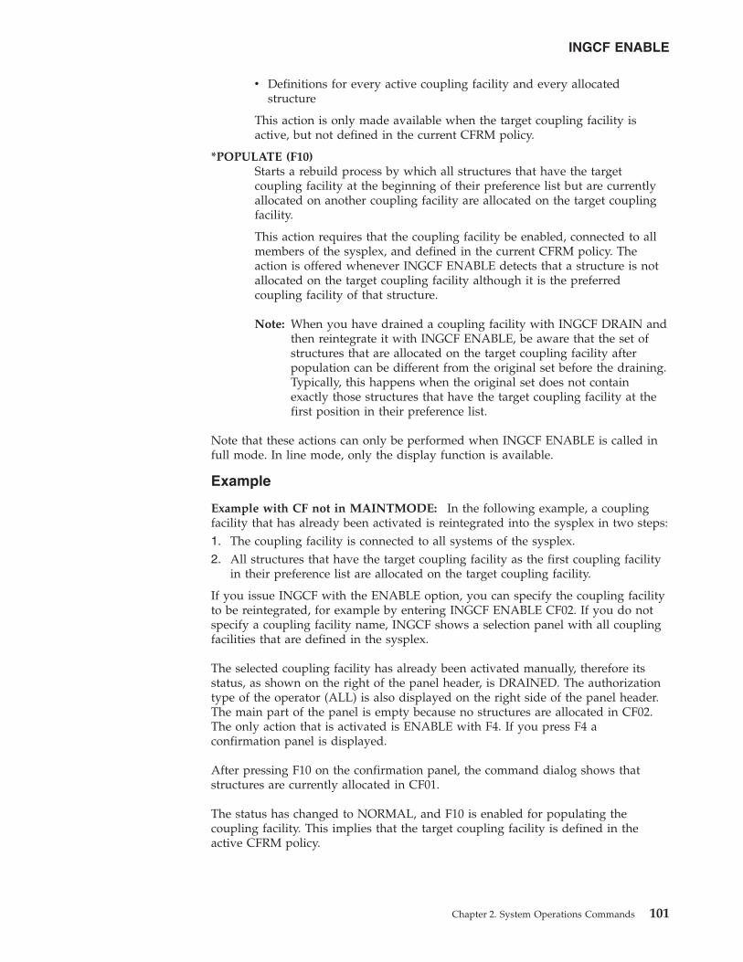
v Definitions for every active coupling facility and every allocatedstructure
This action is only made available when the target coupling facility isactive, but not defined in the current CFRM policy.
*POPULATE (F10)Starts a rebuild process by which all structures that have the targetcoupling facility at the beginning of their preference list but are currentlyallocated on another coupling facility are allocated on the target couplingfacility.
This action requires that the coupling facility be enabled, connected to allmembers of the sysplex, and defined in the current CFRM policy. Theaction is offered whenever INGCF ENABLE detects that a structure is notallocated on the target coupling facility although it is the preferredcoupling facility of that structure.
Note: When you have drained a coupling facility with INGCF DRAIN andthen reintegrate it with INGCF ENABLE, be aware that the set ofstructures that are allocated on the target coupling facility afterpopulation can be different from the original set before the draining.Typically, this happens when the original set does not containexactly those structures that have the target coupling facility at thefirst position in their preference list.
Note that these actions can only be performed when INGCF ENABLE is called infull mode. In line mode, only the display function is available.
Example
Example with CF not in MAINTMODE: In the following example, a couplingfacility that has already been activated is reintegrated into the sysplex in two steps:1. The coupling facility is connected to all systems of the sysplex.2. All structures that have the target coupling facility as the first coupling facility
in their preference list are allocated on the target coupling facility.
If you issue INGCF with the ENABLE option, you can specify the coupling facilityto be reintegrated, for example by entering INGCF ENABLE CF02. If you do notspecify a coupling facility name, INGCF shows a selection panel with all couplingfacilities that are defined in the sysplex.
The selected coupling facility has already been activated manually, therefore itsstatus, as shown on the right of the panel header, is DRAINED. The authorizationtype of the operator (ALL) is also displayed on the right side of the panel header.The main part of the panel is empty because no structures are allocated in CF02.The only action that is activated is ENABLE with F4. If you press F4 aconfirmation panel is displayed.
After pressing F10 on the confirmation panel, the command dialog shows thatstructures are currently allocated in CF01.
The status has changed to NORMAL, and F10 is enabled for populating thecoupling facility. This implies that the target coupling facility is defined in theactive CFRM policy.
INGCF ENABLE
Chapter 2. System Operations Commands 101
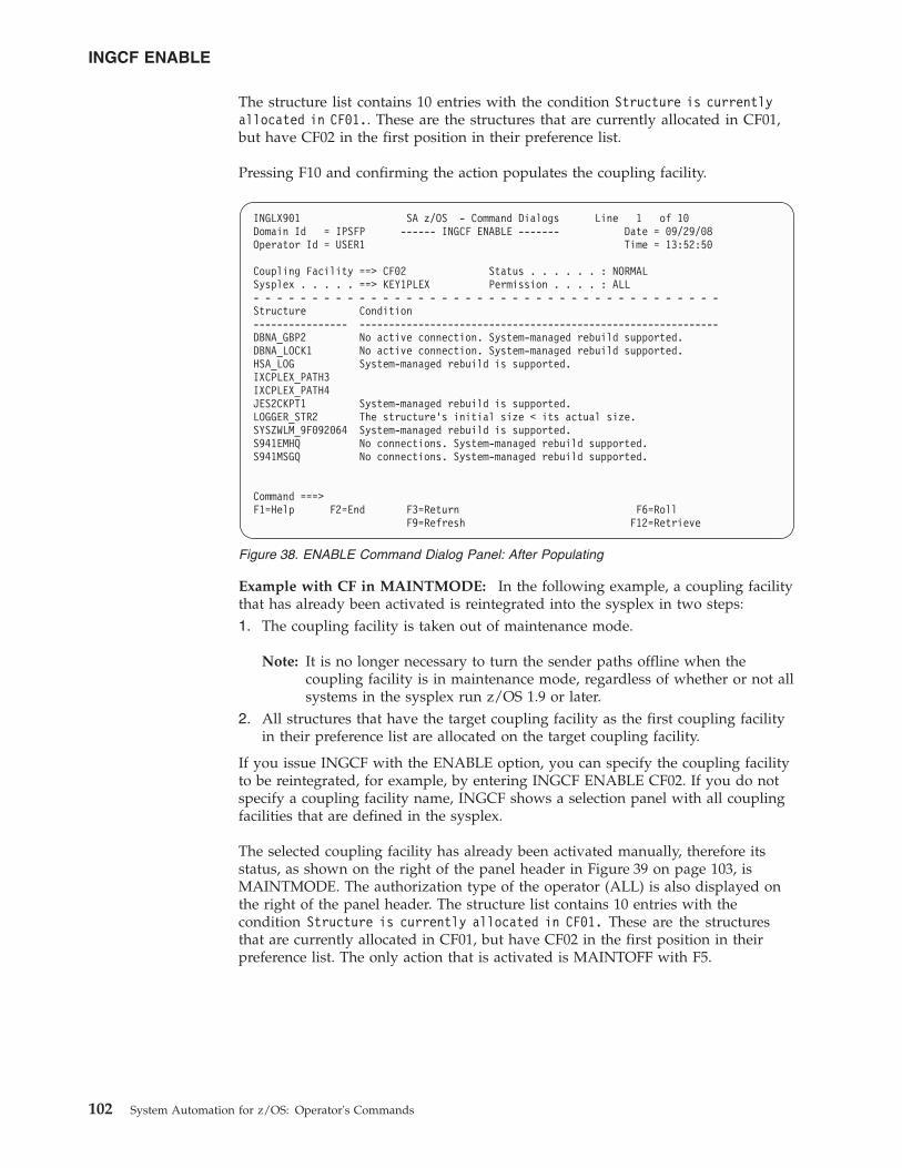
The structure list contains 10 entries with the condition Structure is currentlyallocated in CF01.. These are the structures that are currently allocated in CF01,but have CF02 in the first position in their preference list.
Pressing F10 and confirming the action populates the coupling facility.
Example with CF in MAINTMODE: In the following example, a coupling facilitythat has already been activated is reintegrated into the sysplex in two steps:1. The coupling facility is taken out of maintenance mode.
Note: It is no longer necessary to turn the sender paths offline when thecoupling facility is in maintenance mode, regardless of whether or not allsystems in the sysplex run z/OS 1.9 or later.
2. All structures that have the target coupling facility as the first coupling facilityin their preference list are allocated on the target coupling facility.
If you issue INGCF with the ENABLE option, you can specify the coupling facilityto be reintegrated, for example, by entering INGCF ENABLE CF02. If you do notspecify a coupling facility name, INGCF shows a selection panel with all couplingfacilities that are defined in the sysplex.
The selected coupling facility has already been activated manually, therefore itsstatus, as shown on the right of the panel header in Figure 39 on page 103, isMAINTMODE. The authorization type of the operator (ALL) is also displayed onthe right of the panel header. The structure list contains 10 entries with thecondition Structure is currently allocated in CF01. These are the structuresthat are currently allocated in CF01, but have CF02 in the first position in theirpreference list. The only action that is activated is MAINTOFF with F5.
INGLX901 SA z/OS - Command Dialogs Line 1 of 10Domain Id = IPSFP ------ INGCF ENABLE ------- Date = 09/29/08Operator Id = USER1 Time = 13:52:50
Coupling Facility ==> CF02 Status . . . . . . : NORMALSysplex . . . . . ==> KEY1PLEX Permission . . . . : ALL- - - - - - - - - - - - - - - - - - - - - - - - - - - - - - - - - - - - - - - -Structure Condition---------------- -------------------------------------------------------------DBNA_GBP2 No active connection. System-managed rebuild supported.DBNA_LOCK1 No active connection. System-managed rebuild supported.HSA_LOG System-managed rebuild is supported.IXCPLEX_PATH3IXCPLEX_PATH4JES2CKPT1 System-managed rebuild is supported.LOGGER_STR2 The structure’s initial size < its actual size.SYSZWLM_9F092064 System-managed rebuild is supported.S941EMHQ No connections. System-managed rebuild supported.S941MSGQ No connections. System-managed rebuild supported.
Command ===>F1=Help F2=End F3=Return F6=Roll
F9=Refresh F12=Retrieve
Figure 38. ENABLE Command Dialog Panel: After Populating
INGCF ENABLE
102 System Automation for z/OS: Operator's Commands
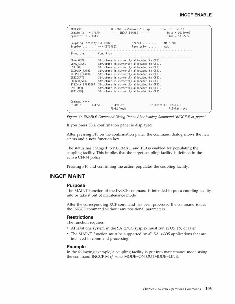
If you press F5 a confirmation panel is displayed.
After pressing F10 on the confirmation panel, the command dialog shows the newstatus and a new function key.
The status has changed to NORMAL, and F10 is enabled for populating thecoupling facility. This implies that the target coupling facility is defined in theactive CFRM policy.
Pressing F10 and confirming the action populates the coupling facility.
INGCF MAINT
PurposeThe MAINT function of the INGCF command is intended to put a coupling facilityinto or take it out of maintenance mode.
After the corresponding XCF command has been processed the command issuesthe INGCF command without any positional parameters.
RestrictionsThe function requires:v At least one system in the SA z/OS sysplex must run z/OS 1.9, or later.v The MAINT function must be supported by all SA z/OS applications that are
involved in command processing.
ExampleIn the following example, a coupling facility is put into maintenance mode usingthe command INGCF M cf_name MODE=ON OUTMODE=LINE:
INGLX901 SA z/OS - Command Dialogs Line 1 of 10Domain Id = IPSFP ------ INGCF ENABLE ------- Date = 09/29/08Operator Id = USER1 Time = 13:55:52
Coupling Facility ==> CF02 Status . . . . . . : MAINTMODESysplex . . . . . ==> KEY1PLEX Permission . . . . : ALL- - - - - - - - - - - - - - - - - - - - - - - - - - - - - - - - - - - - - - - -Structure Condition---------------- -------------------------------------------------------------DBNA_GBP2 Structure is currently allocated in CF01.DBNA_LOCK1 Structure is currently allocated in CF01.HSA_LOG Structure is currently allocated in CF01.IXCPLEX_PATH3 Structure is currently allocated in CF01.IXCPLEX_PATH4 Structure is currently allocated in CF01.JES2CKPT1 Structure is currently allocated in CF01.LOGGER_STR2 Structure is currently allocated in CF01.SYSZWLM_9F092064 Structure is currently allocated in CF01.S941EMHQ Structure is currently allocated in CF01.S941MSGQ Structure is currently allocated in CF01.
Command ===>F1=Help F2=End F3=Return F5=MaintOFF F6=Roll
F9=Refresh F12=Retrieve
Figure 39. ENABLE Command Dialog Panel: After Issuing Command "INGCF E cf_name"
INGCF ENABLE
Chapter 2. System Operations Commands 103
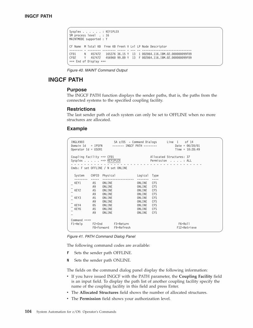
INGCF PATH
PurposeThe INGCF PATH function displays the sender paths, that is, the paths from theconnected systems to the specified coupling facility.
RestrictionsThe last sender path of each system can only be set to OFFLINE when no morestructures are allocated.
Example
The following command codes are available:
F Sets the sender path OFFLINE.
N Sets the sender path ONLINE.
The fields on the command dialog panel display the following information:v If you have issued INGCF with the PATH parameter, the Coupling Facility field
is an input field. To display the path list of another coupling facility specify thename of the coupling facility in this field and press Enter.
v The Allocated Structures field shows the number of allocated structures.v The Permission field shows your authorization level.
Sysplex . . . . . . : KEY1PLEXSM process level . : 16MAINTMODE supported : Y
CF Name M Total KB Free KB Free% V Lvl LP Node Descriptor-------- - -------- -------- ----- - --- -- ------------------------------CF01 N 457472 165376 36.15 Y 13 1 002064.116.IBM.02.000000099F09CF02 Y 457472 456960 99.89 Y 13 F 002064.116.IBM.02.000000099F09*** End of Display ***
Figure 40. MAINT Command Output
INGLX903 SA z/OS - Command Dialogs Line 1 of 14Domain Id = IPSFN ------- INGCF PATH -------- Date = 06/20/01Operator Id = USER1 Time = 10:28:49
Coupling Facility ==> CF01 Allocated Structures: 37Sysplex . . . . . ==> KEY1PLEX Permission . . . . : ALL- - - - - - - - - - - - - - - - - - - - - - - - - - - - - - - - - - - - - - - -Cmds: F set OFFLINE / N set ONLINE
System CHPID Physical Logical Type-------- ----- ------------------- ------- ----KEY1 A5 ONLINE ONLINE CFS
A9 ONLINE ONLINE CFSKEY2 A5 ONLINE ONLINE CFS
A9 ONLINE ONLINE CFSKEY3 A5 ONLINE ONLINE CFS
A9 ONLINE ONLINE CFSKEY4 05 ONLINE ONLINE CFSKEY6 A5 ONLINE ONLINE CFS
A9 ONLINE ONLINE CFS
Command ===>F1=Help F2=End F3=Return F6=Roll
F8=Forward F9=Refresh F12=Retrieve
Figure 41. PATH Command Dialog Panel
INGCF PATH
104 System Automation for z/OS: Operator's Commands
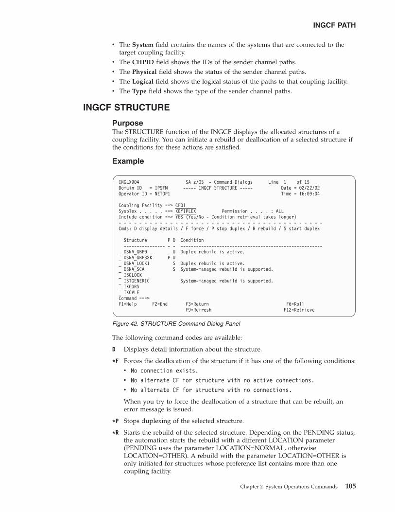
v The System field contains the names of the systems that are connected to thetarget coupling facility.
v The CHPID field shows the IDs of the sender channel paths.v The Physical field shows the status of the sender channel paths.v The Logical field shows the logical status of the paths to that coupling facility.v The Type field shows the type of the sender channel paths.
INGCF STRUCTURE
PurposeThe STRUCTURE function of the INGCF displays the allocated structures of acoupling facility. You can initiate a rebuild or deallocation of a selected structure ifthe conditions for these actions are satisfied.
Example
The following command codes are available:
D Displays detail information about the structure.
*F Forces the deallocation of the structure if it has one of the following conditions:v No connection exists.
v No alternate CF for structure with no active connections.
v No alternate CF for structure with no connections.
When you try to force the deallocation of a structure that can be rebuilt, anerror message is issued.
*P Stops duplexing of the selected structure.
*R Starts the rebuild of the selected structure. Depending on the PENDING status,the automation starts the rebuild with a different LOCATION parameter(PENDING uses the parameter LOCATION=NORMAL, otherwiseLOCATION=OTHER). A rebuild with the parameter LOCATION=OTHER isonly initiated for structures whose preference list contains more than onecoupling facility.
INGLX904 SA z/OS - Command Dialogs Line 1 of 15Domain ID = IPSFM ----- INGCF STRUCTURE ----- Date = 02/22/02Operator ID = NETOP1 Time = 16:09:04
Coupling Facility ==> CF01Sysplex . . . . . ==> KEY1PLEX Permission . . . . : ALLInclude condition ==> YES (Yes/No - Condition retrieval takes longer)- - - - - - - - - - - - - - - - - - - - - - - - - - - - - - - - - - - - - - - -Cmds: D display details / F force / P stop duplex / R rebuild / S start duplex
Structure P D Condition---------------- - - -------------------------------------------------------DSNA_GBP0 U Duplex rebuild is active.DSNA_GBP32K P UDSNA_LOCK1 S Duplex rebuild is active.DSNA_SCA S System-managed rebuild is supported.ISGLOCKISTGENERIC System-managed rebuild is supported.IXCGRSIXCVLF
Command ===>F1=Help F2=End F3=Return F6=Roll
F9=Refresh F12=Retrieve
Figure 42. STRUCTURE Command Dialog Panel
INGCF PATH
Chapter 2. System Operations Commands 105
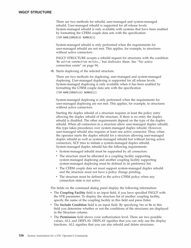
There are two methods for rebuild, user-managed and system-managedrebuild. User-managed rebuild is supported for all release levels.System-managed rebuild is only available with systems that have been enabledby formatting the CFRM couple data sets with the specification:ITEM NAME(SMREBLD) NUMBER(1)
System-managed rebuild is only performed when the requirements foruser-managed rebuild are not met. This applies, for example, to structureswithout active connectors.
INGCF STRUCTURE accepts a rebuild request for structures with the condition'No active connection exists.,' but deallocates them. See “No activeconnection exists” on page 94.
*S Starts duplexing of the selected structure.
There are two methods for duplexing, user-managed and system-managedduplexing. User-managed duplexing is supported for all release levels.System-managed duplexing is only available when it has been enabled byformatting the CFRM couple data sets with the specificationITEM NAME(SMDUPLEX) NUMBER(1)
System-managed duplexing is only performed when the requirements foruser-managed duplexing are not met. This applies, for example, to structureswithout active connectors.
Starting the duplex rebuild of a structure requires at least the policy entryallowing the duplex rebuild of the structure. If there is no entry the duplexrebuild is disabled. The other requirements depend on the type of the duplexrebuild. When all connectors to a structure allow user-managed duplex rebuild,this type takes precedence over system-managed duplex rebuild. However,user-managed rebuild also requires at least one active connector. Thus, whenthe operator starts the duplex rebuild for a structure allowing user-managedduplex rebuild as well as system-managed rebuild but without having activeconnectors, XCF tries to initiate a system-managed duplex rebuild.System-managed duplex rebuild has the following requirements:v System-managed rebuild must be supported by all connectors.v The structure must be allocated in a coupling facility supporting
system-managed duplexing and another coupling facility supportingsystem-managed duplexing must be defined in its preference list.
v The CFRM couple data set must support system-managed duplex rebuildand the structure must not have a policy change pending.
v The structure must be defined in the active CFRM policy when anyconnection state is not active.
The fields on the command dialog panel display the following information:v The Coupling Facility field is an input field, if you have specified INGCF with
the STR parameter. To display the structure list of another coupling facility,specify the name of the coupling facility in this field and press Enter.
v The Include Condition field is an input field. By specifying Yes or No in thisfield you determine whether or not the conditions of the structures are displayedin the Structure column.
v The Permission field shows your authorization level. There are two possiblevalues, ALL and DISPLAY. DISPLAY signifies that you can only use the displayfunctions. ALL signifies that you can also rebuild and delete structures.
INGCF STRUCTURE
106 System Automation for z/OS: Operator's Commands
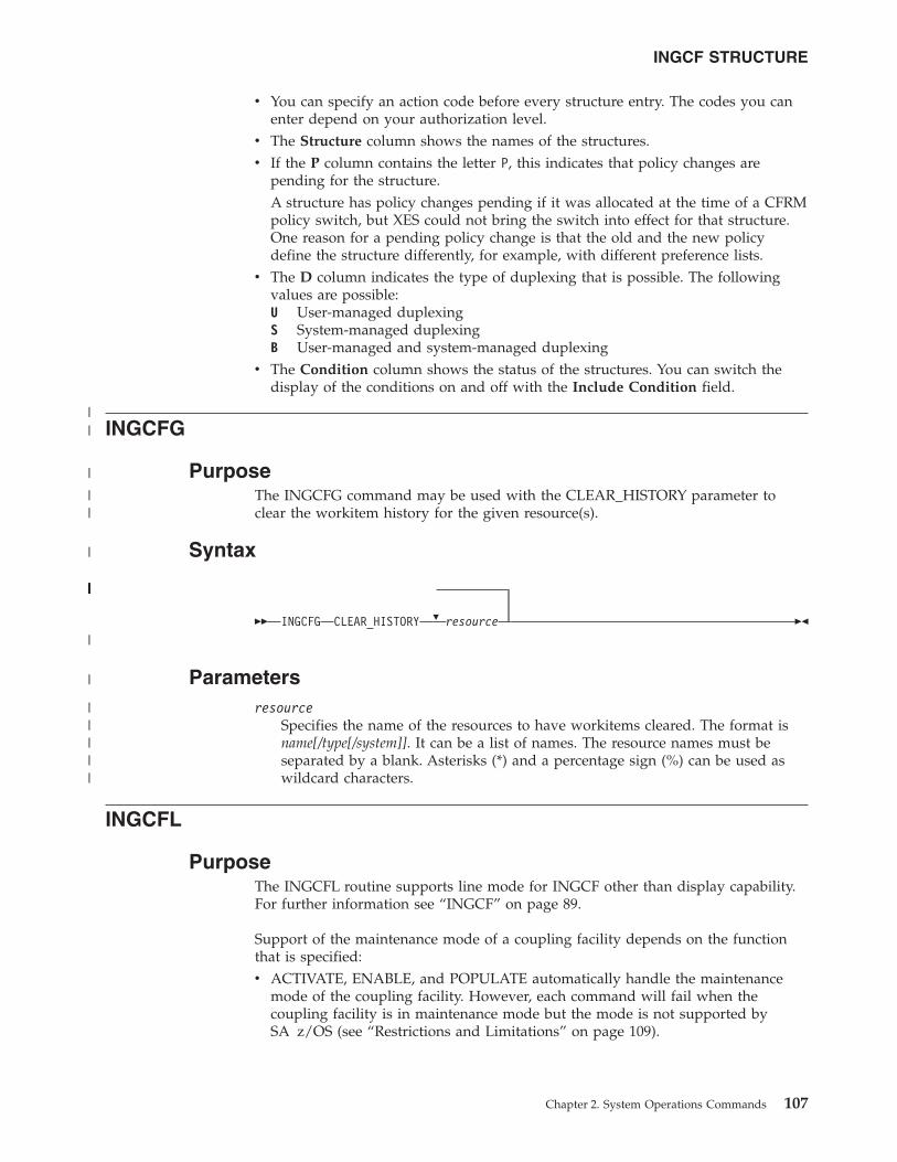
v You can specify an action code before every structure entry. The codes you canenter depend on your authorization level.
v The Structure column shows the names of the structures.v If the P column contains the letter P, this indicates that policy changes are
pending for the structure.A structure has policy changes pending if it was allocated at the time of a CFRMpolicy switch, but XES could not bring the switch into effect for that structure.One reason for a pending policy change is that the old and the new policydefine the structure differently, for example, with different preference lists.
v The D column indicates the type of duplexing that is possible. The followingvalues are possible:U User-managed duplexingS System-managed duplexingB User-managed and system-managed duplexing
v The Condition column shows the status of the structures. You can switch thedisplay of the conditions on and off with the Include Condition field.
INGCFG
PurposeThe INGCFG command may be used with the CLEAR_HISTORY parameter toclear the workitem history for the given resource(s).
Syntax
�� INGCFG CLEAR_HISTORY � resource ��
Parametersresource
Specifies the name of the resources to have workitems cleared. The format isname[/type[/system]]. It can be a list of names. The resource names must beseparated by a blank. Asterisks (*) and a percentage sign (%) can be used aswildcard characters.
INGCFL
PurposeThe INGCFL routine supports line mode for INGCF other than display capability.For further information see “INGCF” on page 89.
Support of the maintenance mode of a coupling facility depends on the functionthat is specified:v ACTIVATE, ENABLE, and POPULATE automatically handle the maintenance
mode of the coupling facility. However, each command will fail when thecoupling facility is in maintenance mode but the mode is not supported bySA z/OS (see “Restrictions and Limitations” on page 109).
INGCF STRUCTURE
Chapter 2. System Operations Commands 107
||
|
||
|
|||||||||||||||||
|
|
|||||
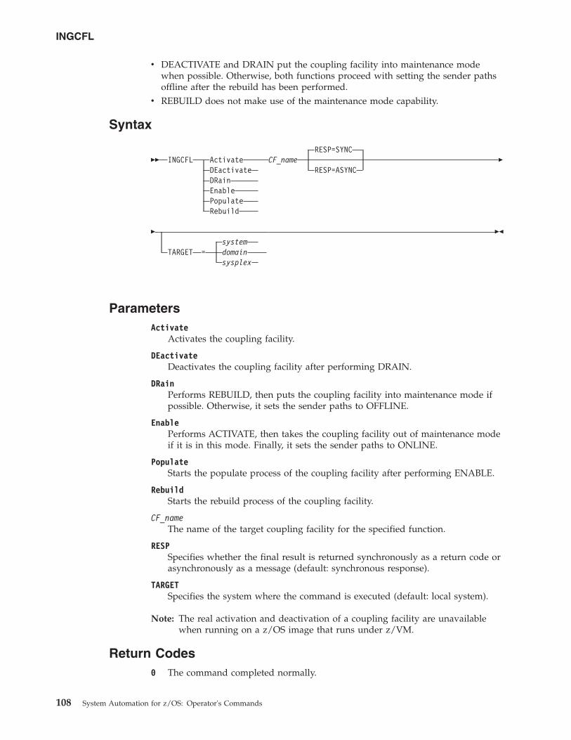
v DEACTIVATE and DRAIN put the coupling facility into maintenance modewhen possible. Otherwise, both functions proceed with setting the sender pathsoffline after the rebuild has been performed.
v REBUILD does not make use of the maintenance mode capability.
Syntax
��RESP=SYNC
INGCFL Activate CF_nameDEactivate RESP=ASYNCDRainEnablePopulateRebuild
�
�system
TARGET = domainsysplex
��
ParametersActivate
Activates the coupling facility.
DEactivateDeactivates the coupling facility after performing DRAIN.
DRainPerforms REBUILD, then puts the coupling facility into maintenance mode ifpossible. Otherwise, it sets the sender paths to OFFLINE.
EnablePerforms ACTIVATE, then takes the coupling facility out of maintenance modeif it is in this mode. Finally, it sets the sender paths to ONLINE.
PopulateStarts the populate process of the coupling facility after performing ENABLE.
RebuildStarts the rebuild process of the coupling facility.
CF_nameThe name of the target coupling facility for the specified function.
RESPSpecifies whether the final result is returned synchronously as a return code orasynchronously as a message (default: synchronous response).
TARGETSpecifies the system where the command is executed (default: local system).
Note: The real activation and deactivation of a coupling facility are unavailablewhen running on a z/OS image that runs under z/VM.
Return Codes0 The command completed normally.
INGCFL
108 System Automation for z/OS: Operator's Commands
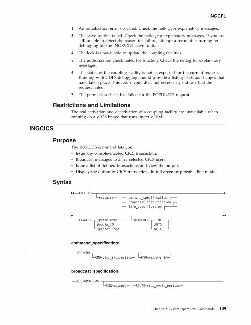
1 An initialization error occurred. Check the netlog for explanatory messages.
3 The slave routine failed. Check the netlog for explanatory messages. If you arestill unable to detect the reason for failure, attempt a rerun after turning ondebugging for the INGRVX92 slave routine.
4 The lock is unavailable to update the coupling facilities.
5 The authorization check failed for function. Check the netlog for explanatorymessages.
6 The status of the coupling facility is not as expected for the current request.Running with GDPS debugging should provide a listing of status changes thathave taken place. This return code does not necessarily indicate that therequest failed.
7 The permission check has failed for the POPULATE request.
Restrictions and LimitationsThe real activation and deactivation of a coupling facility are unavailable whenrunning on a z/OS image that runs under z/VM.
INGCICS
PurposeThe INGCICS command lets you:v Issue any console-enabled CICS transaction.v Broadcast messages to all or selected CICS users.v Issue a list of defined transactions and view the output.v Display the output of CICS transactions in fullscreen or pipeable line mode.
Syntax
�� INGCICSresource command_specification
broadcast_specificationinfo_specification
�
�TARGET= system_name
domain_IDsysplex_name
OUTMODE= LINEAUTONETLOG
��
command_specification:
REQ=CMDCMD=cics_transaction MSG=message ID
broadcast_specification:
REQ=BROADCASTMSG=message ROUTE=cics_route_options
INGCFL
Chapter 2. System Operations Commands 109
||||
|
info_specification:
REQ=INFO
Parametersresource
The resource specifies the name of the CICS subsystem that the command willbe issued to. The format is subsystem[/APL[/system]], where the subsystem isthe specific name of the desired CICS subsystem and system is the name of thesystem that the CICS is running on.
Note: You need not specify the fully qualified name of the resource. However,the command requires enough information to execute the requestagainst a unique CICS subsystem. The command does not supportissuing requests to multiple CICS subsystems at the same time.
REQSpecifies the request to be issued to the CICS subsystem. It can be one of thefollowing:
CMD Issues a CICS transaction and displays the results.
BROADCASTIssues a CICS broadcast to all or selected users.
INFO Issues a set of predefined commands and displays the results. The listof commands is obtained from the CICSINFO user message policy ofthe subsystem specified by the resource name.
CMDSpecifies the CICS transaction and its parameters to be executed for aREQ=CMD type request. If the command and parameters contain spaces,enclose the command in quotation marks (single or double). For CEMTtransactions INGCICS waits up to twice the period that is defined by thesystem wait time parameter for a result.
MSGSpecifies the message to be sent to all or selected CICS terminals or users forthe REQ=BROADCAST request.
For REQ=CMD the MSG command can be used to contain a list of words thatwill be used to end processing if they are received anywhere in the outputresults. The words will normally be a required message ID and when enteredINGCICS waits up to the period that is defined by the system wait timeparameter for a result. If no words are entered, CMD is processed until anyresult is received.
ROUTESpecifies the CICS routing information that is used to select the CICS terminalsor users are to receive the message for a REQ=BROADCAST request. Thecontents of the ROUTE= parameter are the parameters to be supplied to theCMSG transaction to route messages to CICS terminals or users. See the CMSGtransaction for the details of the parameters for that transaction.
TARGETFor information on the TARGET parameter, see “TARGET Parameter” on page10.
INGCICS
110 System Automation for z/OS: Operator's Commands
||||||
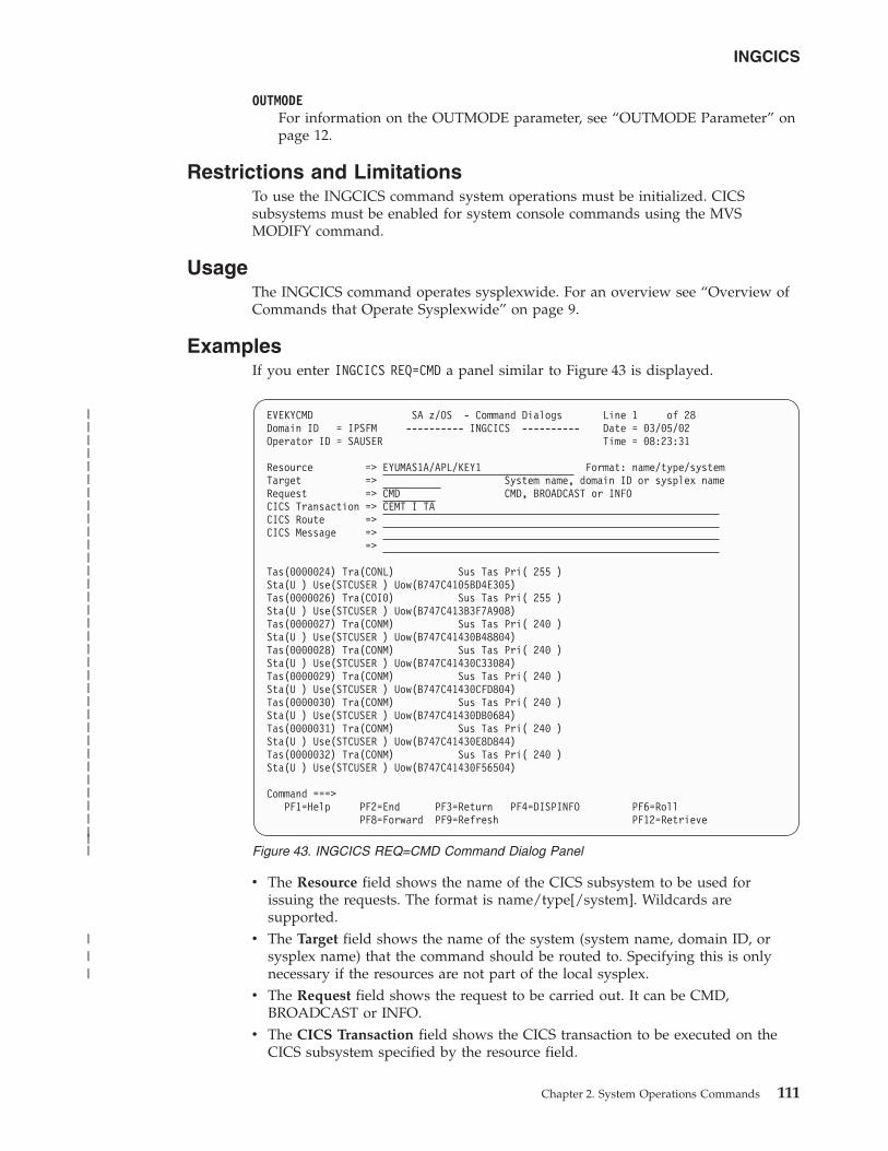
OUTMODEFor information on the OUTMODE parameter, see “OUTMODE Parameter” onpage 12.
Restrictions and LimitationsTo use the INGCICS command system operations must be initialized. CICSsubsystems must be enabled for system console commands using the MVSMODIFY command.
UsageThe INGCICS command operates sysplexwide. For an overview see “Overview ofCommands that Operate Sysplexwide” on page 9.
ExamplesIf you enter INGCICS REQ=CMD a panel similar to Figure 43 is displayed.
v The Resource field shows the name of the CICS subsystem to be used forissuing the requests. The format is name/type[/system]. Wildcards aresupported.
v The Target field shows the name of the system (system name, domain ID, orsysplex name) that the command should be routed to. Specifying this is onlynecessary if the resources are not part of the local sysplex.
v The Request field shows the request to be carried out. It can be CMD,BROADCAST or INFO.
v The CICS Transaction field shows the CICS transaction to be executed on theCICS subsystem specified by the resource field.
EVEKYCMD SA z/OS - Command Dialogs Line 1 of 28Domain ID = IPSFM ---------- INGCICS ---------- Date = 03/05/02Operator ID = SAUSER Time = 08:23:31
Resource => EYUMAS1A/APL/KEY1 Format: name/type/systemTarget => System name, domain ID or sysplex nameRequest => CMD CMD, BROADCAST or INFOCICS Transaction => CEMT I TACICS Route =>CICS Message =>
=>
Tas(0000024) Tra(CONL) Sus Tas Pri( 255 )Sta(U ) Use(STCUSER ) Uow(B747C4105BD4E305)Tas(0000026) Tra(COI0) Sus Tas Pri( 255 )Sta(U ) Use(STCUSER ) Uow(B747C413B3F7A908)Tas(0000027) Tra(CONM) Sus Tas Pri( 240 )Sta(U ) Use(STCUSER ) Uow(B747C41430B48804)Tas(0000028) Tra(CONM) Sus Tas Pri( 240 )Sta(U ) Use(STCUSER ) Uow(B747C41430C33084)Tas(0000029) Tra(CONM) Sus Tas Pri( 240 )Sta(U ) Use(STCUSER ) Uow(B747C41430CFD804)Tas(0000030) Tra(CONM) Sus Tas Pri( 240 )Sta(U ) Use(STCUSER ) Uow(B747C41430DB0684)Tas(0000031) Tra(CONM) Sus Tas Pri( 240 )Sta(U ) Use(STCUSER ) Uow(B747C41430E8D844)Tas(0000032) Tra(CONM) Sus Tas Pri( 240 )Sta(U ) Use(STCUSER ) Uow(B747C41430F56504)
Command ===>PF1=Help PF2=End PF3=Return PF4=DISPINFO PF6=Roll
PF8=Forward PF9=Refresh PF12=Retrieve
Figure 43. INGCICS REQ=CMD Command Dialog Panel
INGCICS
Chapter 2. System Operations Commands 111
|||||||||||||||||||||||||||||||||||
|||
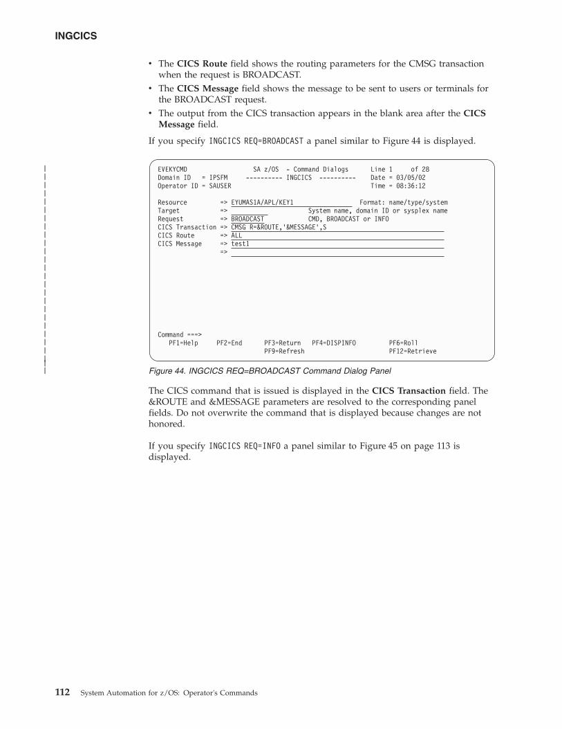
v The CICS Route field shows the routing parameters for the CMSG transactionwhen the request is BROADCAST.
v The CICS Message field shows the message to be sent to users or terminals forthe BROADCAST request.
v The output from the CICS transaction appears in the blank area after the CICSMessage field.
If you specify INGCICS REQ=BROADCAST a panel similar to Figure 44 is displayed.
The CICS command that is issued is displayed in the CICS Transaction field. The&ROUTE and &MESSAGE parameters are resolved to the corresponding panelfields. Do not overwrite the command that is displayed because changes are nothonored.
If you specify INGCICS REQ=INFO a panel similar to Figure 45 on page 113 isdisplayed.
EVEKYCMD SA z/OS - Command Dialogs Line 1 of 28Domain ID = IPSFM ---------- INGCICS ---------- Date = 03/05/02Operator ID = SAUSER Time = 08:36:12
Resource => EYUMAS1A/APL/KEY1 Format: name/type/systemTarget => System name, domain ID or sysplex nameRequest => BROADCAST CMD, BROADCAST or INFOCICS Transaction => CMSG R=&ROUTE,'&MESSAGE',SCICS Route => ALLCICS Message => test1
=>
Command ===>PF1=Help PF2=End PF3=Return PF4=DISPINFO PF6=Roll
PF9=Refresh PF12=Retrieve
Figure 44. INGCICS REQ=BROADCAST Command Dialog Panel
INGCICS
112 System Automation for z/OS: Operator's Commands
||||||||||||||||||||||||||
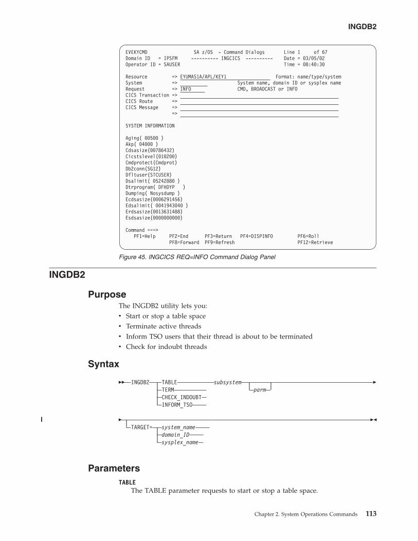
INGDB2
PurposeThe INGDB2 utility lets you:v Start or stop a table spacev Terminate active threadsv Inform TSO users that their thread is about to be terminatedv Check for indoubt threads
Syntax
�� INGDB2 TABLE subsystemTERM parmCHECK_INDOUBTINFORM_TSO
�
�TARGET= system_name
domain_IDsysplex_name
��
ParametersTABLE
The TABLE parameter requests to start or stop a table space.
EVEKYCMD SA z/OS - Command Dialogs Line 1 of 67Domain ID = IPSFM ---------- INGCICS ---------- Date = 03/05/02Operator ID = SAUSER Time = 08:40:30
Resource => EYUMAS1A/APL/KEY1 Format: name/type/systemSystem => System name, domain ID or sysplex nameRequest => INFO CMD, BROADCAST or INFOCICS Transaction =>CICS Route =>CICS Message =>
=>
SYSTEM INFORMATION
Aging( 00500 )Akp( 04000 )Cdsasize(00786432)Cicstslevel(010200)Cmdprotect(Cmdprot)Db2conn(SG12)Dfltuser(STCUSER)Dsalimit( 05242880 )Dtrprogram( DFHDYP )Dumping( Nosysdump )Ecdsasize(0006291456)Edsalimit( 0041943040 )Erdsasize(0013631488)Esdsasize(0000000000)
Command ===>PF1=Help PF2=End PF3=Return PF4=DISPINFO PF6=Roll
PF8=Forward PF9=Refresh PF12=Retrieve
Figure 45. INGCICS REQ=INFO Command Dialog Panel
INGDB2
Chapter 2. System Operations Commands 113
||||
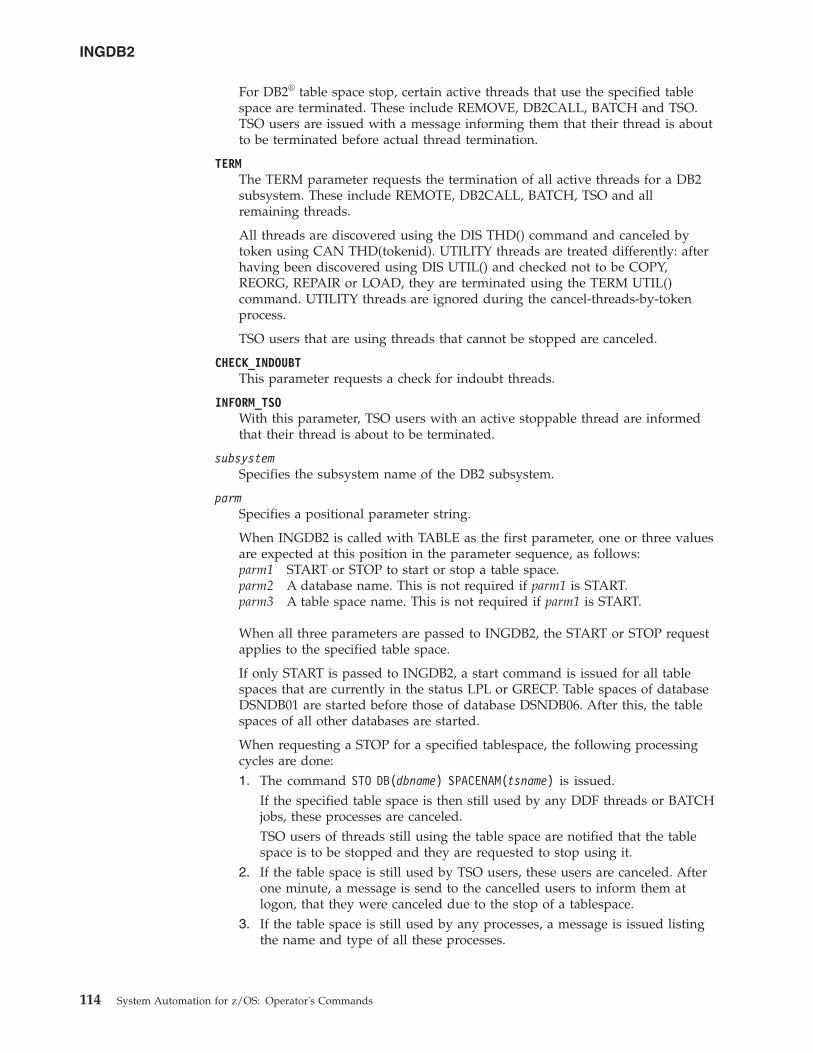
For DB2® table space stop, certain active threads that use the specified tablespace are terminated. These include REMOVE, DB2CALL, BATCH and TSO.TSO users are issued with a message informing them that their thread is aboutto be terminated before actual thread termination.
TERMThe TERM parameter requests the termination of all active threads for a DB2subsystem. These include REMOTE, DB2CALL, BATCH, TSO and allremaining threads.
All threads are discovered using the DIS THD() command and canceled bytoken using CAN THD(tokenid). UTILITY threads are treated differently: afterhaving been discovered using DIS UTIL() and checked not to be COPY,REORG, REPAIR or LOAD, they are terminated using the TERM UTIL()command. UTILITY threads are ignored during the cancel-threads-by-tokenprocess.
TSO users that are using threads that cannot be stopped are canceled.
CHECK_INDOUBTThis parameter requests a check for indoubt threads.
INFORM_TSOWith this parameter, TSO users with an active stoppable thread are informedthat their thread is about to be terminated.
subsystemSpecifies the subsystem name of the DB2 subsystem.
parmSpecifies a positional parameter string.
When INGDB2 is called with TABLE as the first parameter, one or three valuesare expected at this position in the parameter sequence, as follows:parm1 START or STOP to start or stop a table space.parm2 A database name. This is not required if parm1 is START.parm3 A table space name. This is not required if parm1 is START.
When all three parameters are passed to INGDB2, the START or STOP requestapplies to the specified table space.
If only START is passed to INGDB2, a start command is issued for all tablespaces that are currently in the status LPL or GRECP. Table spaces of databaseDSNDB01 are started before those of database DSNDB06. After this, the tablespaces of all other databases are started.
When requesting a STOP for a specified tablespace, the following processingcycles are done:1. The command STO DB(dbname) SPACENAM(tsname) is issued.
If the specified table space is then still used by any DDF threads or BATCHjobs, these processes are canceled.TSO users of threads still using the table space are notified that the tablespace is to be stopped and they are requested to stop using it.
2. If the table space is still used by TSO users, these users are canceled. Afterone minute, a message is send to the cancelled users to inform them atlogon, that they were canceled due to the stop of a tablespace.
3. If the table space is still used by any processes, a message is issued listingthe name and type of all these processes.
INGDB2
114 System Automation for z/OS: Operator's Commands
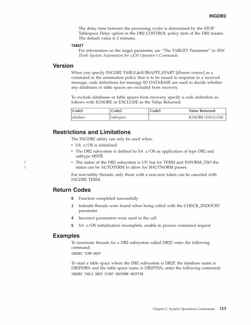
The delay time between the processing cycles is determined by the STOPTablespace Delay option in the DB2 CONTROL policy item of the DB2 master.The default value is 2 minutes.
TARGETFor information on the target parameter, see “The TARGET Parameter” in IBMTivoli System Automation for z/OS Operator’s Commands.
VersionWhen you specify INGDB2 TABLE,&SUBSAPPL,START [dbname tsname] as acommand in the automation policy that is to be issued in response to a receivedmessage, code definitions for message ID DATABASE are used to decide whetherany databases or table spaces are excluded from recovery.
To exclude databases or table spaces from recovery, specify a code definition asfollows with IGNORE or EXCLUDE as the Value Returned.
Code1 Code2 Code3 Value Returned
database tablespace IGNORE|EXCLUDE
Restrictions and LimitationsThe INGDB2 utility can only be used when:v SA z/OS is initializedv The DB2 subsystem is defined to SA z/OS as application of type DB2 and
subtype MSTRv The status of the DB2 subsystem is UP, but for TERM and INFORM_TSO the
status can be AUTOTERM to allow for SHUTNORM passes.
For non-utility threads, only those with a non-zero token can be canceled withINGDB2 TERM.
Return Codes0 Function completed successfully
1 Indoubt threads were found when being called with the CHECK_INDOUBTparameter
4 Incorrect parameters were used in the call
6 SA z/OS initialization incomplete, unable to process command request
ExamplesTo terminate threads for a DB2 subsystem called DB2P, enter the followingcommand:INGDB2 TERM DB2P
To start a table space where the DB2 subsystem is DB2P, the database name isDB2PDBN and the table space name is DB2PTSN, enter the following command:INGDB2 TABLE DB2P START DB2PDBN DB2PTSN
INGDB2
Chapter 2. System Operations Commands 115
||
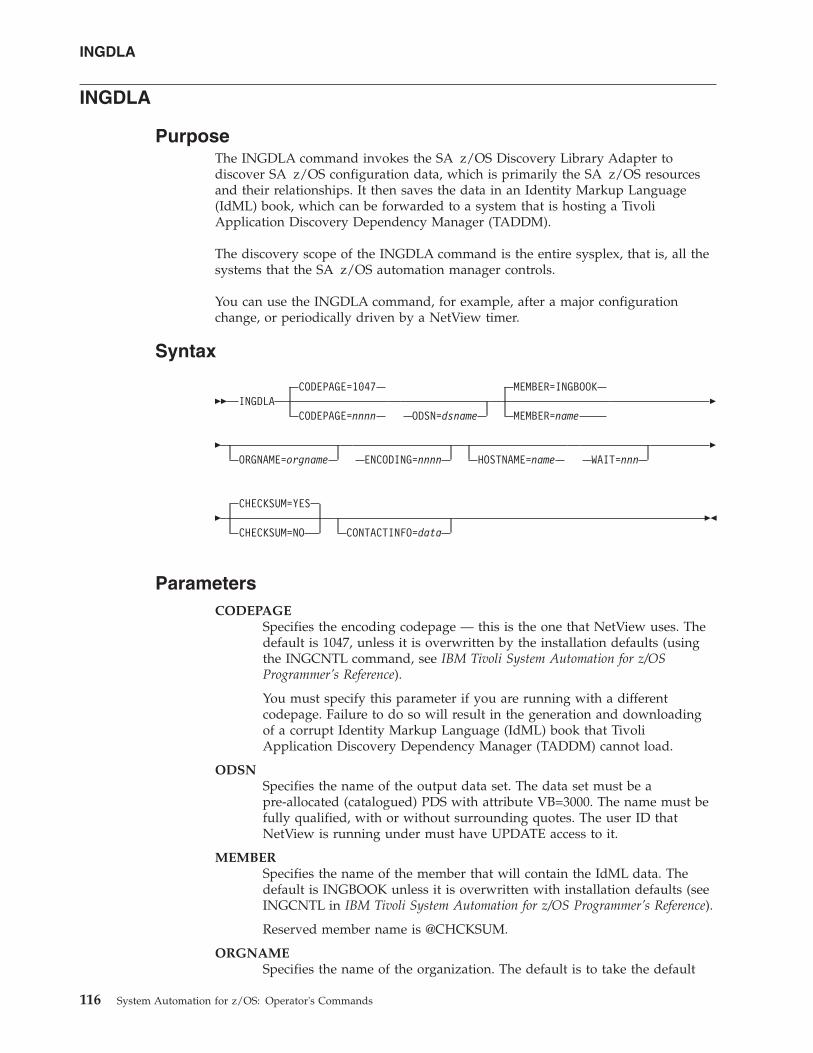
INGDLA
PurposeThe INGDLA command invokes the SA z/OS Discovery Library Adapter todiscover SA z/OS configuration data, which is primarily the SA z/OS resourcesand their relationships. It then saves the data in an Identity Markup Language(IdML) book, which can be forwarded to a system that is hosting a TivoliApplication Discovery Dependency Manager (TADDM).
The discovery scope of the INGDLA command is the entire sysplex, that is, all thesystems that the SA z/OS automation manager controls.
You can use the INGDLA command, for example, after a major configurationchange, or periodically driven by a NetView timer.
Syntax
�� INGDLACODEPAGE=1047
CODEPAGE=nnnn ODSN=dsname
MEMBER=INGBOOK
MEMBER=name�
�ORGNAME=orgname ENCODING=nnnn HOSTNAME=name WAIT=nnn
�
�CHECKSUM=YES
CHECKSUM=NO CONTACTINFO=data��
ParametersCODEPAGE
Specifies the encoding codepage — this is the one that NetView uses. Thedefault is 1047, unless it is overwritten by the installation defaults (usingthe INGCNTL command, see IBM Tivoli System Automation for z/OSProgrammer’s Reference).
You must specify this parameter if you are running with a differentcodepage. Failure to do so will result in the generation and downloadingof a corrupt Identity Markup Language (IdML) book that TivoliApplication Discovery Dependency Manager (TADDM) cannot load.
ODSNSpecifies the name of the output data set. The data set must be apre-allocated (catalogued) PDS with attribute VB=3000. The name must befully qualified, with or without surrounding quotes. The user ID thatNetView is running under must have UPDATE access to it.
MEMBERSpecifies the name of the member that will contain the IdML data. Thedefault is INGBOOK unless it is overwritten with installation defaults (seeINGCNTL in IBM Tivoli System Automation for z/OS Programmer’s Reference).
Reserved member name is @CHCKSUM.
ORGNAMESpecifies the name of the organization. The default is to take the default
INGDLA
116 System Automation for z/OS: Operator's Commands
name from the IBM Tivoli Change and Configuration ManagementDatabase (CCMDB) unless it is overwritten by the installation defaults (seeINGCNTL in IBM Tivoli System Automation for z/OS Programmer’s Reference).
Place quotes around the organization name in order to maintain mixedcase names.
ENCODINGSpecifies the encoding option. Valid values are EBCDIC, ASCII and UTF-8.The default is UTF-8 unless overwritten by the installation defaults (seeINGCNTL in IBM Tivoli System Automation for z/OS Programmer’s Reference).
HOSTNAMESpecifies the name of the host of the management software system (that is,SA z/OS). It is used to address SA z/OS. If specified, it takes precedenceover a discovered host name.
WAIT Specifies the maximum number of seconds to wait for the automationmanager query to respond. The maximum time interval is 999 seconds. Thedefault is 30 seconds.
CHECKSUMSpecifies whether to skip generating the SA z/OS DLA book if thechecksum matches:
YESSkip generation if the checksum matches. This is the default.
NO Ignore checksum results.
CONTACTINFOProvides details of ports and security keys that are needed to establish asession with NetView over TCP/IP when used in conjunction with the hostname.
Return Codes0 Successful completion.
8 Error occurred, such as a bad return code received from the automationmanager.
12 Bad input parameters or allocation failed.
16 Fatal error.
UsageThe INGDLA command can be invoked from the NetView command line on anysystem in the sysplex.
The INGDLA command operates sysplexwide. For an overview see “Overview ofCommands that Operate Sysplexwide” on page 9.
ExamplesIf you enter ingdla at the command line, SA z/OS displays a report that informsyou of the progress of the DLA.
INGDLA
Chapter 2. System Operations Commands 117
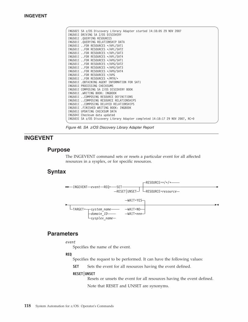
INGEVENT
PurposeThe INGEVENT command sets or resets a particular event for all affectedresources in a sysplex, or for specific resources.
Syntax
�� INGEVENT eventRESOURCE=*/*/*
REQ= SETRESET|UNSET RESOURCE=resource
�
�TARGET= system_name
domain_IDsysplex_name
WAIT=YES
WAIT=NOWAIT=nnn
��
Parametersevent
Specifies the name of the event.
REQSpecifies the request to be performed. It can have the following values:
SET Sets the event for all resources having the event defined.
RESET|UNSETResets or unsets the event for all resources having the event defined.
Note that RESET and UNSET are synonyms.
ING502I SA z/OS Discovery Library Adapter started 14:18:05 29 NOV 2007ING501I DRIVING SA Z/OS DISCOVERYING501I .QUERYING RESOURCESING501I .QUERYING RELATIONSHIP DATAING501I ..FOR RESOURCES */APL/SAT1ING501I ..FOR RESOURCES */APL/SAT2ING501I ..FOR RESOURCES */APL/SAT3ING501I ..FOR RESOURCES */APL/SAT4ING501I ..FOR RESOURCES */APG/SAT1ING501I ..FOR RESOURCES */APG/SAT2ING501I ..FOR RESOURCES */APG/SAT3ING501I ..FOR RESOURCES */APG/SAT4ING501I ..FOR RESOURCES */APGING501I ..FOR RESOURCES */MTR/*ING501I .OBTAINING AGENT INFORMATION FOR SAT1ING501I PROCESSING CHECKSUMSING501I COMPOSING SA Z/OS DISCOVERY BOOKING501I .WRITING BOOK: INGBOOKING501I ..COMPOSING RESOURCE DEFINITIONSING501I ..COMPOSING RESOURCE RELATIONSHIPSING501I ..COMPOSING DELAYED RELATIONSHIPSING501I .FINISHED WRITING BOOK: INGBOOKING501I UPDATING CHECKSUM DATAING504I Checksum data updatedING503I SA z/OS Discovery Library Adapter completed 14:18:17 29 NOV 2007, RC=0
Figure 46. SA z/OS Discovery Library Adapter Report
INGEVENT
118 System Automation for z/OS: Operator's Commands
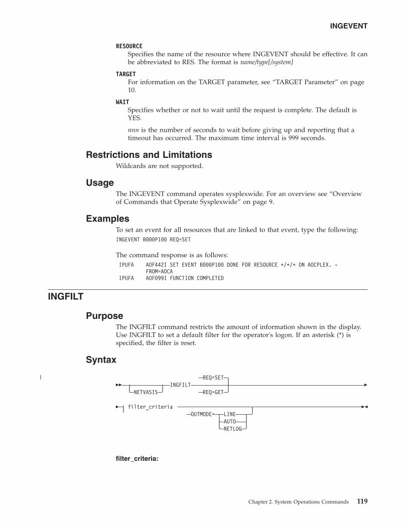
RESOURCESpecifies the name of the resource where INGEVENT should be effective. It canbe abbreviated to RES. The format is name/type[/system]
TARGETFor information on the TARGET parameter, see “TARGET Parameter” on page10.
WAITSpecifies whether or not to wait until the request is complete. The default isYES.
nnn is the number of seconds to wait before giving up and reporting that atimeout has occurred. The maximum time interval is 999 seconds.
Restrictions and LimitationsWildcards are not supported.
UsageThe INGEVENT command operates sysplexwide. For an overview see “Overviewof Commands that Operate Sysplexwide” on page 9.
ExamplesTo set an event for all resources that are linked to that event, type the following:INGEVENT B000P100 REQ=SET
The command response is as follows:IPUFA AOF442I SET EVENT B000P100 DONE FOR RESOURCE */*/* ON AOCPLEX. -
FROM=AOCAIPUFA AOF099I FUNCTION COMPLETED
INGFILT
PurposeThe INGFILT command restricts the amount of information shown in the display.Use INGFILT to set a default filter for the operator's logon. If an asterisk (*) isspecified, the filter is reset.
Syntax
��NETVASIS
INGFILTREQ=SET
REQ=GET�
� filter_criteriaOUTMODE= LINE
AUTONETLOG
��
filter_criteria:
INGEVENT
Chapter 2. System Operations Commands 119
|
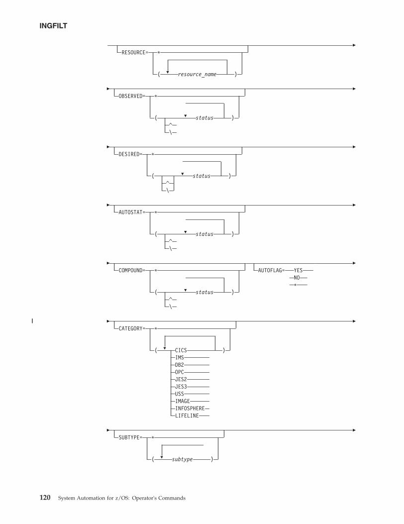
�
RESOURCE= *
( resource_name )
�
�
�
OBSERVED= *
( status )^\
�
�
�
DESIRED= *
( status )^\
�
�
�
AUTOSTAT= *
( status )^\
�
�
�
COMPOUND= *
( status )^\
AUTOFLAG= YESNO*
�
�
�
CATEGORY= *
( CICS )IMSDB2OPCJES2JES3USSIMAGEINFOSPHERELIFELINE
�
�
�
SUBTYPE= *
( subtype )
�
INGFILT
120 System Automation for z/OS: Operator's Commands
||
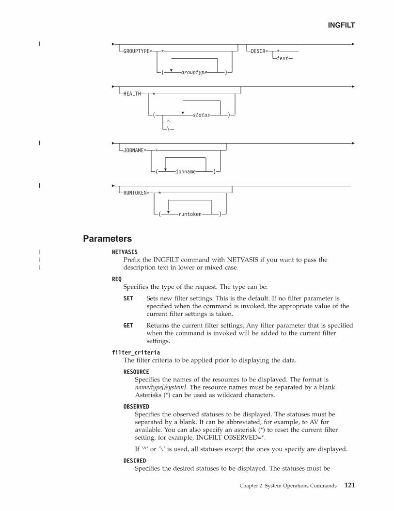
�
�
GROUPTYPE= *
( grouptype )
DESCR= *text
�
�
�
HEALTH= *
( status )^\
�
�
�
JOBNAME= *
( jobname )
�
�
�
RUNTOKEN= *
( runtoken )
ParametersNETVASIS
Prefix the INGFILT command with NETVASIS if you want to pass thedescription text in lower or mixed case.
REQSpecifies the type of the request. The type can be:
SET Sets new filter settings. This is the default. If no filter parameter isspecified when the command is invoked, the appropriate value of thecurrent filter settings is taken.
GET Returns the current filter settings. Any filter parameter that is specifiedwhen the command is invoked will be added to the current filtersettings.
filter_criteriaThe filter criteria to be applied prior to displaying the data.
RESOURCESpecifies the names of the resources to be displayed. The format isname/type[/system]. The resource names must be separated by a blank.Asterisks (*) can be used as wildcard characters.
OBSERVEDSpecifies the observed statuses to be displayed. The statuses must beseparated by a blank. It can be abbreviated, for example, to AV foravailable. You can also specify an asterisk (*) to reset the current filtersetting, for example, INGFILT OBSERVED=*.
If '^' or '\' is used, all statuses except the ones you specify are displayed.
DESIREDSpecifies the desired statuses to be displayed. The statuses must be
INGFILT
Chapter 2. System Operations Commands 121
|||
|||||
|||||
|||
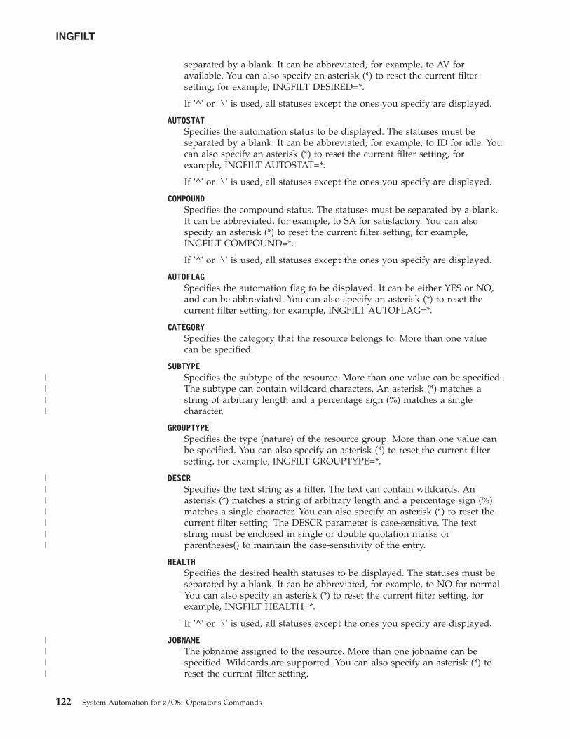
separated by a blank. It can be abbreviated, for example, to AV foravailable. You can also specify an asterisk (*) to reset the current filtersetting, for example, INGFILT DESIRED=*.
If '^' or '\' is used, all statuses except the ones you specify are displayed.
AUTOSTATSpecifies the automation status to be displayed. The statuses must beseparated by a blank. It can be abbreviated, for example, to ID for idle. Youcan also specify an asterisk (*) to reset the current filter setting, forexample, INGFILT AUTOSTAT=*.
If '^' or '\' is used, all statuses except the ones you specify are displayed.
COMPOUNDSpecifies the compound status. The statuses must be separated by a blank.It can be abbreviated, for example, to SA for satisfactory. You can alsospecify an asterisk (*) to reset the current filter setting, for example,INGFILT COMPOUND=*.
If '^' or '\' is used, all statuses except the ones you specify are displayed.
AUTOFLAGSpecifies the automation flag to be displayed. It can be either YES or NO,and can be abbreviated. You can also specify an asterisk (*) to reset thecurrent filter setting, for example, INGFILT AUTOFLAG=*.
CATEGORYSpecifies the category that the resource belongs to. More than one valuecan be specified.
SUBTYPESpecifies the subtype of the resource. More than one value can be specified.The subtype can contain wildcard characters. An asterisk (*) matches astring of arbitrary length and a percentage sign (%) matches a singlecharacter.
GROUPTYPESpecifies the type (nature) of the resource group. More than one value canbe specified. You can also specify an asterisk (*) to reset the current filtersetting, for example, INGFILT GROUPTYPE=*.
DESCRSpecifies the text string as a filter. The text can contain wildcards. Anasterisk (*) matches a string of arbitrary length and a percentage sign (%)matches a single character. You can also specify an asterisk (*) to reset thecurrent filter setting. The DESCR parameter is case-sensitive. The textstring must be enclosed in single or double quotation marks orparentheses() to maintain the case-sensitivity of the entry.
HEALTHSpecifies the desired health statuses to be displayed. The statuses must beseparated by a blank. It can be abbreviated, for example, to NO for normal.You can also specify an asterisk (*) to reset the current filter setting, forexample, INGFILT HEALTH=*.
If '^' or '\' is used, all statuses except the ones you specify are displayed.
JOBNAMEThe jobname assigned to the resource. More than one jobname can bespecified. Wildcards are supported. You can also specify an asterisk (*) toreset the current filter setting.
INGFILT
122 System Automation for z/OS: Operator's Commands
||||
|||||||
||||
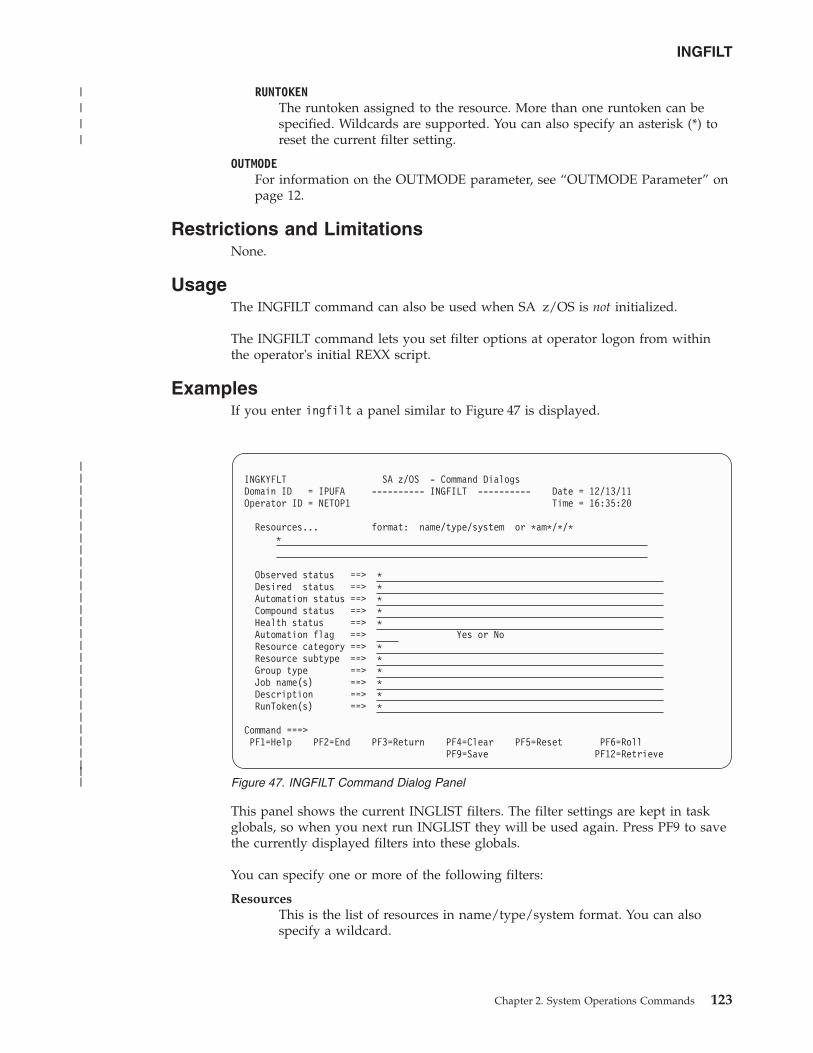
RUNTOKENThe runtoken assigned to the resource. More than one runtoken can bespecified. Wildcards are supported. You can also specify an asterisk (*) toreset the current filter setting.
OUTMODEFor information on the OUTMODE parameter, see “OUTMODE Parameter” onpage 12.
Restrictions and LimitationsNone.
UsageThe INGFILT command can also be used when SA z/OS is not initialized.
The INGFILT command lets you set filter options at operator logon from withinthe operator's initial REXX script.
ExamplesIf you enter ingfilt a panel similar to Figure 47 is displayed.
This panel shows the current INGLIST filters. The filter settings are kept in taskglobals, so when you next run INGLIST they will be used again. Press PF9 to savethe currently displayed filters into these globals.
You can specify one or more of the following filters:
ResourcesThis is the list of resources in name/type/system format. You can alsospecify a wildcard.
INGKYFLT SA z/OS - Command DialogsDomain ID = IPUFA ---------- INGFILT ---------- Date = 12/13/11Operator ID = NETOP1 Time = 16:35:20
Resources... format: name/type/system or *am*/*/**
Observed status ==> *Desired status ==> *Automation status ==> *Compound status ==> *Health status ==> *Automation flag ==> Yes or NoResource category ==> *Resource subtype ==> *Group type ==> *Job name(s) ==> *Description ==> *RunToken(s) ==> *
Command ===>PF1=Help PF2=End PF3=Return PF4=Clear PF5=Reset PF6=Roll
PF9=Save PF12=Retrieve
Figure 47. INGFILT Command Dialog Panel
INGFILT
Chapter 2. System Operations Commands 123
||||||||||||||||||||||||||||
||||
Observed statusThis is the list of observed statuses. You can abbreviate the status, forexample, "av for Available. Any resources whose observed status is in thelist is eligible for the display.
Desired statusThis is the list of desired statuses. You can abbreviate the status. Anyresources whose desired status is in the list is eligible for the display.
Automation statusThis is the list of automation statuses. You can abbreviate the status. Anyresource whose automation status is in the list is eligible for the display.
Compound statusThis is the list of compound statuses. You can abbreviate the status. Anyresources whose compound status is in the list is eligible for the display.
Health statusThis is the list of health statuses. You can abbreviate the status. Anyresource whose health status is in the list is eligible for the display.
Automation flagThis is the automation flag for the resource. Specify either YES or NO.
Resource categoryThis is the list of categories that the resource belongs to. It is one of CICS,IMS, DB2, OPC, USS, IMAGE, JES2, JES3, INFOSPHERE or LIFELINE.
Resource subtypeThis is the subtype that is defined for the resource. You can specify morethan one subtype.
Group typeThis is the type (nature) of the resource group. You can specify more thanone group type.
Job NameThe job name assigned to the resource. You can specify more than one jobname. Wildcards are supported.
DescriptionThe description of the resource. Wildcards are supported.
Runtoken(s)The runtoken assigned to the resource. You can specify more than oneruntoken. Wildcards are supported.
In order to be eligible for the display, a resource must match all filter criteria. Anasterisk indicates that the filter has not been set.
Use the PF4 key to clear the currently established filter settings. The filter willcontain an asterisk, meaning that the filter not set, or a blank.
Use the PF5 key to go back to the currently established filter settings.
Note: If INGFILT was called from INGLIST, the filters that are displayed takeeffect when you press Enter. If you press PF9 first, the filters will be saved.
INGFILT
124 System Automation for z/OS: Operator's Commands
||
|||
||
|||
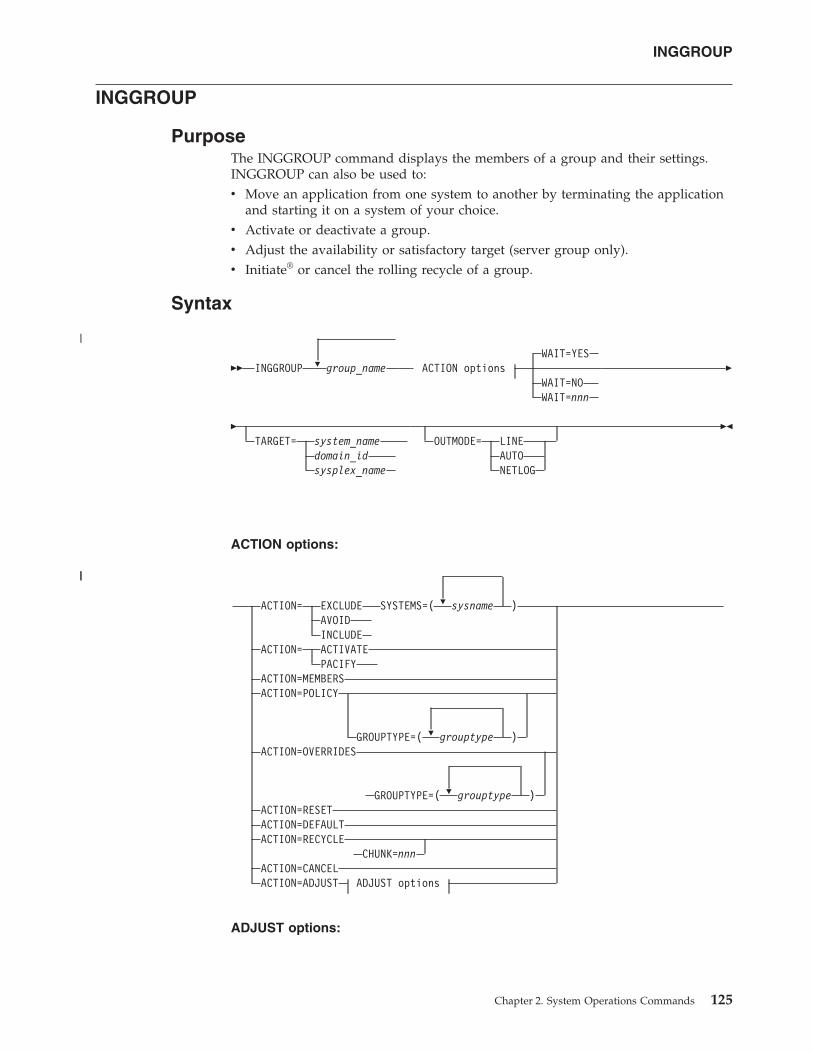
INGGROUP
PurposeThe INGGROUP command displays the members of a group and their settings.INGGROUP can also be used to:v Move an application from one system to another by terminating the application
and starting it on a system of your choice.v Activate or deactivate a group.v Adjust the availability or satisfactory target (server group only).v Initiate® or cancel the rolling recycle of a group.
Syntax
�� INGGROUP � group_nameWAIT=YES
ACTION optionsWAIT=NOWAIT=nnn
�
�TARGET= system_name
domain_idsysplex_name
OUTMODE= LINEAUTONETLOG
��
ACTION options:
�
�
�
ACTION= EXCLUDE SYSTEMS=( sysname )AVOIDINCLUDE
ACTION= ACTIVATEPACIFY
ACTION=MEMBERSACTION=POLICY
GROUPTYPE=( grouptype )ACTION=OVERRIDES
GROUPTYPE=( grouptype )ACTION=RESETACTION=DEFAULTACTION=RECYCLE
CHUNK=nnnACTION=CANCELACTION=ADJUST ADJUST options
ADJUST options:
INGGROUP
Chapter 2. System Operations Commands 125
|
||
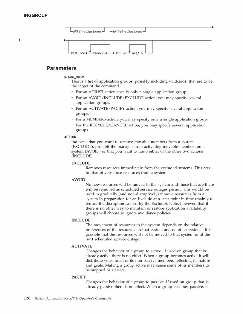
AVTGT=adjustment SATTGT=adjustment�
�
� �MEMBERS=( member_n ) PREF=( pref_n )
Parametersgroup_name
This is a list of application groups, possibly including wildcards, that are to bethe target of the command.v For an ADJUST action specify only a single application group.v For an AVOID/INCLUDE/EXCLUDE action, you may specify several
application groups.v For an ACTIVATE/PACIFY action, you may specify several application
groups.v For a MEMBERS action, you may specify only a single application group.v For the RECYCLE/CANCEL action, you may specify several application
groups.
ACTIONIndicates that you want to remove movable members from a system(EXCLUDE), prohibit the manager from activating movable members on asystem (AVOID) or that you want to undo either of the other two actions(INCLUDE).
EXCLUDERemoves resources immediately from the excluded systems. This actsto disruptively force resources from a system.
AVOIDNo new resources will be moved to the system and those that are therewill be removed as scheduled service outages permit. This would beused to gradually (and non-disruptively) remove resources from asystem in preparation for an Exclude at a later point in time (mainly toreduce the disruption caused by the Exclude). Note, however, that ifthere is no other way to maintain or restore application availability,groups will choose to ignore avoidance policies.
INCLUDEThe movement of resources to the system depends on the relativepreferences of the resources on that system and on other systems. It ispossible that the resources will not be moved to that system until thenext scheduled service outage.
ACTIVATEChanges the behavior of a group to active. If used on group that isalready active there is no effect. When a group becomes active it willdistribute votes to all of its non-passive members reflecting its natureand goals. Making a group active may cause some of its members tobe stopped or started.
PACIFYChanges the behavior of a group to passive. If used on group that isalready passive there is no effect. When a group becomes passive, it
INGGROUP
126 System Automation for z/OS: Operator's Commands
||
withdraws all votes that it has propagated to its members. Making agroup passive may cause some of its members to either start or stop,depending upon the votes that it had propagated.
MEMBERSDisplays the group members and their settings.
POLICYDisplays the policies for the specified resource groups.
OVERRIDESDisplays the overrides for the specified resource groups that have beenmade with the INGGROUP command.
RESETSets the preference assigned to the members of the application groupto its initial value. Applies only to MOVE and SERVER groups.
DEFAULTSets the following group policies to the values that are defined in thepolicy database:v Availability and satisfactory targetv Preference value of group membersv Group passive attribute
RECYCLECauses a rolling recycle to be initiated for each selected server or movegroup.
Note: If you specify more than one group and any of them havecommon members, only one of the groups can be involved in acomplete rolling recycle. The other groups are flagged as beinginvolved in a partial recycle, that is, some of their members(possibly all of them) are being or have been recycled.
Specify CHUNK to indicate the number of server group members torecycle in parallel. Refer to 128 for further details.
If the systems in a Server group all have the same preference value, thesystem that is active after a rolling recycle has completed may not bethe same one as before the rolling recycle. Thus, triggering a rollingrecycle always results in a move occurring. If you set the preference ofthe original system more than 250 points higher than that of any othersystem, the rolling recycle is followed by a second move to return theapplication to that system. This leads to an increase in the applicationdown time.
Note: Preference values do not influence the order in which resourcesare recycled. The resources of the group are recycled from last tofirst as they are displayed in the list of group members.
CANCELCauses any rolling recycles amongst the selected groups to be canceled.
ADJUSTIndicates that you want to temporarily adjust a group's policy.
SYSTEMSIs the list of systems to be excluded or included. If no groups are specified, allapplication groups with resources in these systems are affected.
INGGROUP
Chapter 2. System Operations Commands 127
|||||
||
|||
This parameter must be specified for INCLUDE, AVOID and EXCLUDEactions.
GROUPTYPESpecifies the type (nature) of the resource group. More than one value can bespecified.
CHUNKIndicates the number of server group members to recycle in parallel.
Note: SA z/OS adjusts the chunk size to ensure that at least one groupmember is active at any time to avoid an application outage. This is thecase when the chunk size is greater or equal to the number of activegroup members.
AVTGTSpecifies the availability target that is to be set for the group. The value, n, is apositive number. It specifies the number of group members that should bemade available when the group has to be available.
You can also specify *, which resets the AVTGT parameter to the value that isspecified in the policy database.
This parameter may only be specified for an ADJUST action.
SATTGTSpecifies the number of members in the group that must be active before theautomation manager treats the group as being in a satisfactory state. The valuemust be a positive, decimal number. The parameter will be ignored for groupsother than server groups.
You can also specify *, which resets the SATTGT parameter to the valuespecified in the policy database.
This parameter may only be specified for the ADJUST action.
MEMBERSSpecifies a list of group members that the preference value should be set for.Wildcards may not be used.
This parameter may only be specified on an ADJUST action.
PREFSpecifies a preference value that is to be used for each specified member. Thenumber of values specified should be the same as the number of membersspecified. Each preference is an integer value that replaces the member'scurrent preference value. You can also specify *, which resets the PREFparameter to the value that is specified in the policy database.
Preference values are used to determine which members in the group areselected to make the group active.
This parameter may only be specified on an ADJUST action when a list ofmembers has been specified.
Changes to preference values, as set by the PREF parameter, apply in thefollowing manner:v The preference value in the automation policy is not affected.v An adjustment value is calculated that, when applied to the preference value
in the automation policy, produces the "result" value.v The "result" preference value is then used by the automation when a
preference value is required.
INGGROUP
128 System Automation for z/OS: Operator's Commands
||
||||
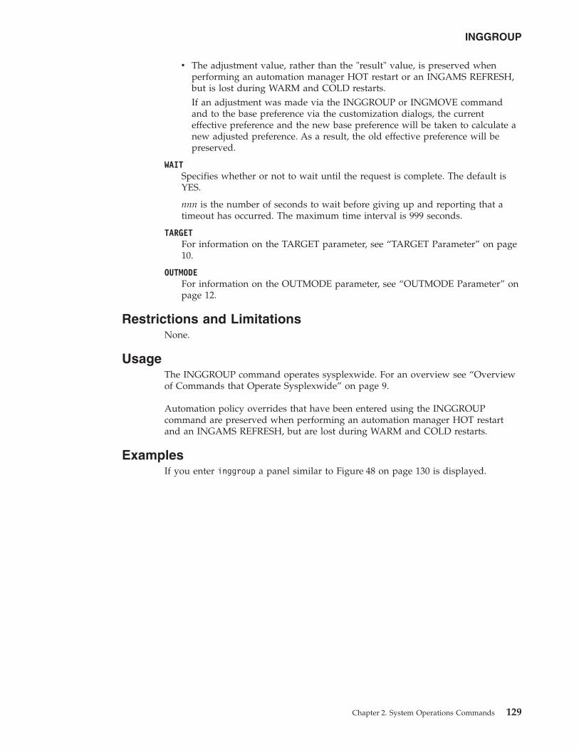
v The adjustment value, rather than the "result" value, is preserved whenperforming an automation manager HOT restart or an INGAMS REFRESH,but is lost during WARM and COLD restarts.If an adjustment was made via the INGGROUP or INGMOVE commandand to the base preference via the customization dialogs, the currenteffective preference and the new base preference will be taken to calculate anew adjusted preference. As a result, the old effective preference will bepreserved.
WAITSpecifies whether or not to wait until the request is complete. The default isYES.
nnn is the number of seconds to wait before giving up and reporting that atimeout has occurred. The maximum time interval is 999 seconds.
TARGETFor information on the TARGET parameter, see “TARGET Parameter” on page10.
OUTMODEFor information on the OUTMODE parameter, see “OUTMODE Parameter” onpage 12.
Restrictions and LimitationsNone.
UsageThe INGGROUP command operates sysplexwide. For an overview see “Overviewof Commands that Operate Sysplexwide” on page 9.
Automation policy overrides that have been entered using the INGGROUPcommand are preserved when performing an automation manager HOT restartand an INGAMS REFRESH, but are lost during WARM and COLD restarts.
ExamplesIf you enter inggroup a panel similar to Figure 48 on page 130 is displayed.
INGGROUP
Chapter 2. System Operations Commands 129
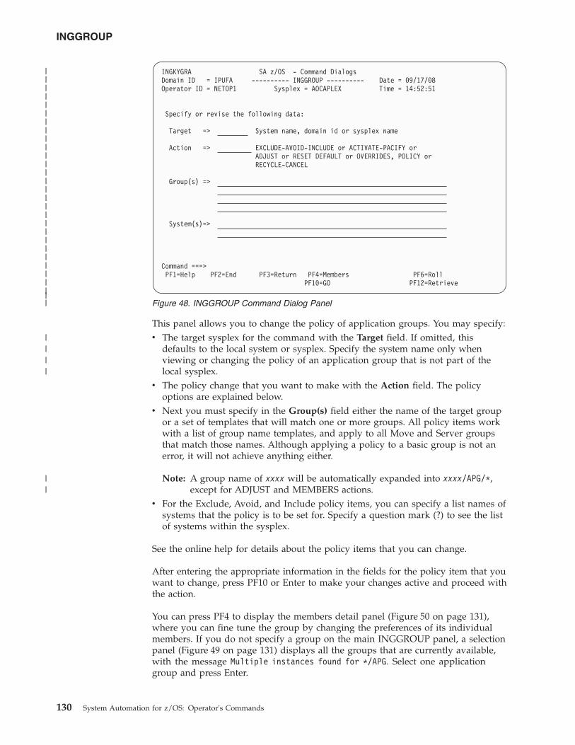
This panel allows you to change the policy of application groups. You may specify:v The target sysplex for the command with the Target field. If omitted, this
defaults to the local system or sysplex. Specify the system name only whenviewing or changing the policy of an application group that is not part of thelocal sysplex.
v The policy change that you want to make with the Action field. The policyoptions are explained below.
v Next you must specify in the Group(s) field either the name of the target groupor a set of templates that will match one or more groups. All policy items workwith a list of group name templates, and apply to all Move and Server groupsthat match those names. Although applying a policy to a basic group is not anerror, it will not achieve anything either.
Note: A group name of xxxx will be automatically expanded into xxxx/APG/*,except for ADJUST and MEMBERS actions.
v For the Exclude, Avoid, and Include policy items, you can specify a list names ofsystems that the policy is to be set for. Specify a question mark (?) to see the listof systems within the sysplex.
See the online help for details about the policy items that you can change.
After entering the appropriate information in the fields for the policy item that youwant to change, press PF10 or Enter to make your changes active and proceed withthe action.
You can press PF4 to display the members detail panel (Figure 50 on page 131),where you can fine tune the group by changing the preferences of its individualmembers. If you do not specify a group on the main INGGROUP panel, a selectionpanel (Figure 49 on page 131) displays all the groups that are currently available,with the message Multiple instances found for */APG. Select one applicationgroup and press Enter.
INGKYGRA SA z/OS - Command DialogsDomain ID = IPUFA ---------- INGGROUP ---------- Date = 09/17/08Operator ID = NETOP1 Sysplex = AOCAPLEX Time = 14:52:51
Specify or revise the following data:
Target => System name, domain id or sysplex name
Action => EXCLUDE-AVOID-INCLUDE or ACTIVATE-PACIFY orADJUST or RESET DEFAULT or OVERRIDES, POLICY orRECYCLE-CANCEL
Group(s) =>
System(s)=>
Command ===>PF1=Help PF2=End PF3=Return PF4=Members PF6=Roll
PF10=GO PF12=Retrieve
Figure 48. INGGROUP Command Dialog Panel
INGGROUP
130 System Automation for z/OS: Operator's Commands
|||||||||||||||||||||||||||||
||||
||
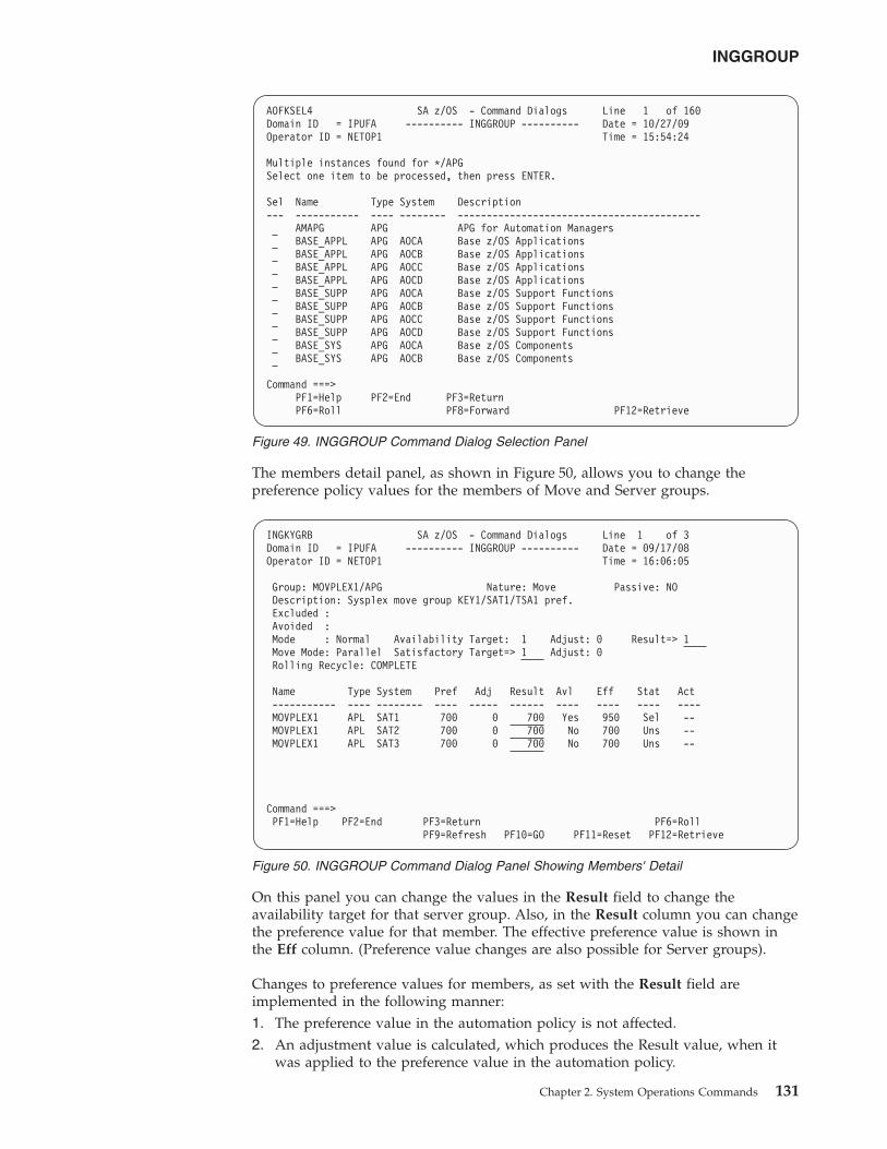
The members detail panel, as shown in Figure 50, allows you to change thepreference policy values for the members of Move and Server groups.
On this panel you can change the values in the Result field to change theavailability target for that server group. Also, in the Result column you can changethe preference value for that member. The effective preference value is shown inthe Eff column. (Preference value changes are also possible for Server groups).
Changes to preference values for members, as set with the Result field areimplemented in the following manner:1. The preference value in the automation policy is not affected.2. An adjustment value is calculated, which produces the Result value, when it
was applied to the preference value in the automation policy.
AOFKSEL4 SA z/OS - Command Dialogs Line 1 of 160Domain ID = IPUFA ---------- INGGROUP ---------- Date = 10/27/09Operator ID = NETOP1 Time = 15:54:24
Multiple instances found for */APGSelect one item to be processed, then press ENTER.
Sel Name Type System Description--- ----------- ---- -------- ------------------------------------------
AMAPG APG APG for Automation ManagersBASE_APPL APG AOCA Base z/OS ApplicationsBASE_APPL APG AOCB Base z/OS ApplicationsBASE_APPL APG AOCC Base z/OS ApplicationsBASE_APPL APG AOCD Base z/OS ApplicationsBASE_SUPP APG AOCA Base z/OS Support FunctionsBASE_SUPP APG AOCB Base z/OS Support FunctionsBASE_SUPP APG AOCC Base z/OS Support FunctionsBASE_SUPP APG AOCD Base z/OS Support FunctionsBASE_SYS APG AOCA Base z/OS ComponentsBASE_SYS APG AOCB Base z/OS Components
Command ===>PF1=Help PF2=End PF3=ReturnPF6=Roll PF8=Forward PF12=Retrieve
Figure 49. INGGROUP Command Dialog Selection Panel
INGKYGRB SA z/OS - Command Dialogs Line 1 of 3Domain ID = IPUFA ---------- INGGROUP ---------- Date = 09/17/08Operator ID = NETOP1 Time = 16:06:05
Group: MOVPLEX1/APG Nature: Move Passive: NODescription: Sysplex move group KEY1/SAT1/TSA1 pref.Excluded :Avoided :Mode : Normal Availability Target: 1 Adjust: 0 Result=> 1Move Mode: Parallel Satisfactory Target=> 1 Adjust: 0Rolling Recycle: COMPLETE
Name Type System Pref Adj Result Avl Eff Stat Act----------- ---- -------- ---- ----- ------ ---- ---- ---- ----MOVPLEX1 APL SAT1 700 0 700 Yes 950 Sel --MOVPLEX1 APL SAT2 700 0 700 No 700 Uns --MOVPLEX1 APL SAT3 700 0 700 No 700 Uns --
Command ===>PF1=Help PF2=End PF3=Return PF6=Roll
PF9=Refresh PF10=GO PF11=Reset PF12=Retrieve
Figure 50. INGGROUP Command Dialog Panel Showing Members' Detail
INGGROUP
Chapter 2. System Operations Commands 131
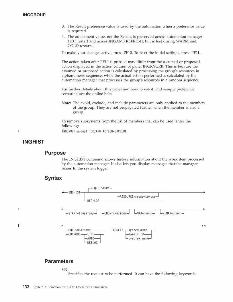
3. The Result preference value is used by the automation when a preference valueis required.
4. The adjustment value, not the Result, is preserved across automation managerHOT restart and across INGAMS REFRESH, but is lost during WARM andCOLD restarts.
To make your changes active, press PF10. To reset the initial settings, press PF11.
The action taken after PF10 is pressed may differ from the assumed or proposedaction displayed in the action column of panel INGKYGRB. This is because theassumed or proposed action is calculated by processing the group's resources inalphanumeric sequence, while the actual action performed is calculated by theautomation manager that processes the group's resources in a random sequence.
For further details about this panel and how to use it, and sample preferencescenarios, see the online help.
Note: The avoid, exclude, and include parameters are only applied to the membersof the group. They are not propagated further when the member is also agroup.
To remove subsystems from the list of members that can be used, enter thefollowing:INGGROUP group1 TSO/APG ACTION=EXCLUDE
INGHIST
PurposeThe INGHIST command shows history information about the work item processedby the automation manager. It also lets you display messages that the managerissues to the system logger.
Syntax
�� INGHISTREQ=HISTORY
RESOURCE=resourcenameREQ=LOG
�
�START=timestamp END=timestamp MAX=nnnnn WIMAX=nnnnn
�
�OUTDSN=dsnameOUTMODE= LINE
AUTONETLOG
TARGET= system_namedomain_idsysplex_name
��
ParametersREQ
Specifies the request to be performed. It can have the following keywords:
INGGROUP
132 System Automation for z/OS: Operator's Commands
|
|
|||||
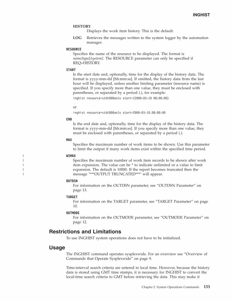
HISTORYDisplays the work item history. This is the default.
LOG Retrieves the messages written to the system logger by the automationmanager.
RESOURCESpecifies the name of the resource to be displayed. The format isname/type[/system]. The RESOURCE parameter can only be specified ifREQ=HISTORY.
STARTIs the start date and, optionally, time for the display of the history data. Theformat is yyyy-mm-dd [hh:mm:ss]. If omitted, the history data from the lasthour will be displayed, unless another limiting parameter (resource name) isspecified. If you specify more than one value, they must be enclosed withparentheses, or separated by a period (.), for example:inghist resource=stdt000an1x start=(2000-03-10 08:00:00)
oringhist resource=stdt000an1x start=2000-03-10.08:00:00
ENDIs the end date and, optionally, time for the display of the history data. Theformat is yyyy-mm-dd [hh:mm:ss]. If you specify more than one value, theymust be enclosed with parentheses, or separated by a period (.).
MAXSpecifies the maximum number of work items to be shown. Use this parameterto limit the output if many work items exist within the specified time period.
WIMAXSpecifies the maximum number of work item records to be shown after workitem expansion. The value can be * to indicate unlimited or a value to limitexpansion. The default is 10000. If the report becomes truncated then themessage "***OUTPUT TRUNCATED***" will appear.
OUTDSNFor information on the OUTDSN parameter, see “OUTDSN Parameter” onpage 13.
TARGETFor information on the TARGET parameter, see “TARGET Parameter” on page10.
OUTMODEFor information on the OUTMODE parameter, see “OUTMODE Parameter” onpage 12.
Restrictions and LimitationsTo use INGHIST system operations does not have to be initialized.
UsageThe INGHIST command operates sysplexwide. For an overview see “Overview ofCommands that Operate Sysplexwide” on page 9.
Time-interval search criteria are entered in local time. However, because the historydata is stored using GMT time stamps, it is necessary for INGHIST to convert thelocal-time search criteria to GMT before retrieving the data. This may make it
INGHIST
Chapter 2. System Operations Commands 133
|||||
necessary for the operator to make a manual adjustment to the time-interval searchcriteria after a daylight-saving-time change has been set. The local-time-to-GMTconversion calculation will be one hour different after a daylight-saving-timechange. Data written after a daylight-saving-time change will be retrieved asexpected but data written before will be offset by one hour.
ExamplesIf you enter inghist resource=stdt000an1x/apl/aoc7 a panel similar to Figure 51is displayed.
The FIND/RFIND subcommands are supported. See “Varying the Format of theCommand Output” on page 13 for information.
INGHWSRV
PurposeThe INGHWSRV command lets you:v Terminate all BCP internal interface connections and disable the BCP internal
interfacev Display Processor Operations and BCP internal interface NetView common
global variables (CGLOBALS)v Display specific target hardware or system NetView common global variables
(CGLOBALs)v Free control blocks that are associated with abended hardware system
connection
INGKYHI0 SA z/OS - Command Dialogs Line 1 of 15Domain ID = IPUFM ---------- INGHIST ---------- Date = 07/24/00Operator ID = AFRANCK Sysplex = AOC7PLEX Time = 14:20:46
Start time ==> format: yyyy-mm-dd hh:mm:ssEnd time ==> Resource ==> STDT000AN1X/APL/AOC7
Cmd: + Expand workitem (e) - Collapse workitem (c)Cmd Date Time Footprint--- ---------- -------- -------------------------------------------------------
2000-07-24 14:18:32 Termination processing for STDT000AN1X/APL/AOC7completed
2000-07-24 14:18:30 Agent status for STDT000AN1X/APL/AOC7 = RESTART2000-07-24 14:18:29 No PRESTART commands to issue2000-07-24 14:18:29 Agent status for STDT000AN1X/APL/AOC7 = AUTODOWN2000-07-24 14:18:27 Shutdown in progress2000-07-24 14:18:25 Startup for STDT000AN1X/APL/AOC7 in progress2000-07-24 14:18:24 Agent status for STDT000AN1X/APL/AOC7 = AUTOTERM2000-07-24 14:18:23 Agent status for STDT000AN1X/APL/AOC7 = STARTED2000-07-24 14:18:20 No SHUTINIT commands to issue
Command ===>PF1=Help PF2=End PF3=Return PF6=Roll
PF9=Refresh PF12=Retrieve
Figure 51. INGHIST Command Dialog Panel
INGHIST
134 System Automation for z/OS: Operator's Commands
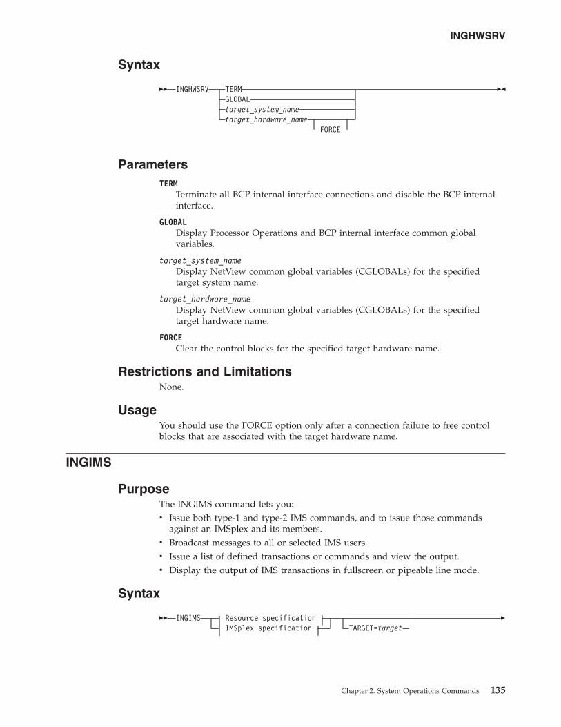
Syntax
�� INGHWSRV TERMGLOBALtarget_system_nametarget_hardware_name
FORCE
��
ParametersTERM
Terminate all BCP internal interface connections and disable the BCP internalinterface.
GLOBALDisplay Processor Operations and BCP internal interface common globalvariables.
target_system_nameDisplay NetView common global variables (CGLOBALs) for the specifiedtarget system name.
target_hardware_nameDisplay NetView common global variables (CGLOBALs) for the specifiedtarget hardware name.
FORCEClear the control blocks for the specified target hardware name.
Restrictions and LimitationsNone.
UsageYou should use the FORCE option only after a connection failure to free controlblocks that are associated with the target hardware name.
INGIMS
PurposeThe INGIMS command lets you:v Issue both type-1 and type-2 IMS commands, and to issue those commands
against an IMSplex and its members.v Broadcast messages to all or selected IMS users.v Issue a list of defined transactions or commands and view the output.v Display the output of IMS transactions in fullscreen or pipeable line mode.
Syntax
�� INGIMS Resource specificationIMSplex specification TARGET=target
�
INGHWSRV
Chapter 2. System Operations Commands 135
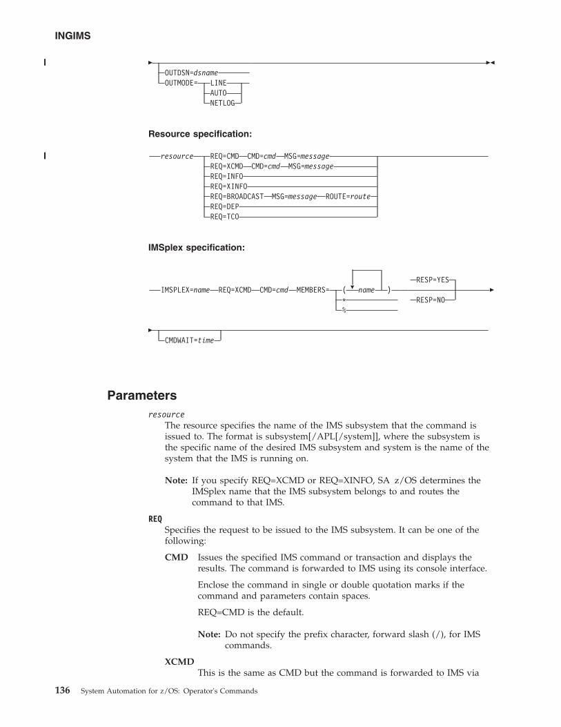
�OUTDSN=dsnameOUTMODE= LINE
AUTONETLOG
��
Resource specification:
resource REQ=CMD CMD=cmd MSG=messageREQ=XCMD CMD=cmd MSG=messageREQ=INFOREQ=XINFOREQ=BROADCAST MSG=message ROUTE=routeREQ=DEPREQ=TCO
IMSplex specification:
IMSPLEX=name REQ=XCMD CMD=cmd �MEMBERS= ( name )*%
RESP=YES
RESP=NO�
�CMDWAIT=time
Parametersresource
The resource specifies the name of the IMS subsystem that the command isissued to. The format is subsystem[/APL[/system]], where the subsystem isthe specific name of the desired IMS subsystem and system is the name of thesystem that the IMS is running on.
Note: If you specify REQ=XCMD or REQ=XINFO, SA z/OS determines theIMSplex name that the IMS subsystem belongs to and routes thecommand to that IMS.
REQSpecifies the request to be issued to the IMS subsystem. It can be one of thefollowing:
CMD Issues the specified IMS command or transaction and displays theresults. The command is forwarded to IMS using its console interface.
Enclose the command in single or double quotation marks if thecommand and parameters contain spaces.
REQ=CMD is the default.
Note: Do not specify the prefix character, forward slash (/), for IMScommands.
XCMDThis is the same as CMD but the command is forwarded to IMS via
INGIMS
136 System Automation for z/OS: Operator's Commands
|||||
||||||||
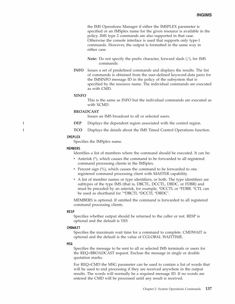
the IMS Operations Manager if either the IMSPLEX parameter isspecified or an IMSplex name for the given resource is available in thepolicy. IMS type 2 commands are also supported in that case.Otherwise the console interface is used that supports only type-1commands. However, the output is formatted in the same way ineither case.
Note: Do not specify the prefix character, forward slash (/), for IMScommands.
INFO Issues a set of predefined commands and displays the results. The listof commands is obtained from the user-defined keyword-data pairs forthe IMSINFO message ID in the policy of the subsystem that isspecified by the resource name. The individual commands are executedas with CMD.
XINFOThis is the same as INFO but the individual commands are executed aswith XCMD.
BROADCASTIssues an IMS broadcast to all or selected users.
DEP Displays the dependent region associated with the control region.
TCO Displays the details about the IMS Timed Control Operations function.
IMSPLEXSpecifies the IMSplex name.
MEMBERSIdentifies a list of members where the command should be executed. It can be:v Asterisk (*), which causes the command to be forwarded to all registered
command processing clients in the IMSplex.v Percent sign (%), which causes the command to be forwarded to one
registered command processing client with MASTER capability.v A list of member names or type identifiers, or both. The type identifiers are
subtypes of the type IMS (that is, DBCTL, DCCTL, DBDC, or FDBR) andmust be preceded by an asterisk, for example, *DCCTL or *FDBR. *CTL canbe used as shorthand for "*DBCTL *DCCTL *DBDC".
MEMBERS is optional. If omitted the command is forwarded to all registeredcommand processing clients.
RESPSpecifies whether output should be returned to the caller or not. RESP isoptional and the default is YES
CMDWAITSpecifies the maximum wait time for a command to complete. CMDWAIT isoptional and the default is the value of CGLOBAL WAITTIME.
MSGSpecifies the message to be sent to all or selected IMS terminals or users forthe REQ=BROADCAST request. Enclose the message in single or doublequotation marks.
For REQ=CMD the MSG parameter can be used to contain a list of words thatwill be used to end processing if they are received anywhere in the outputresults. The words will normally be a required message ID. If no words areentered the CMD will be processed until any result is received.
INGIMS
Chapter 2. System Operations Commands 137
||
||
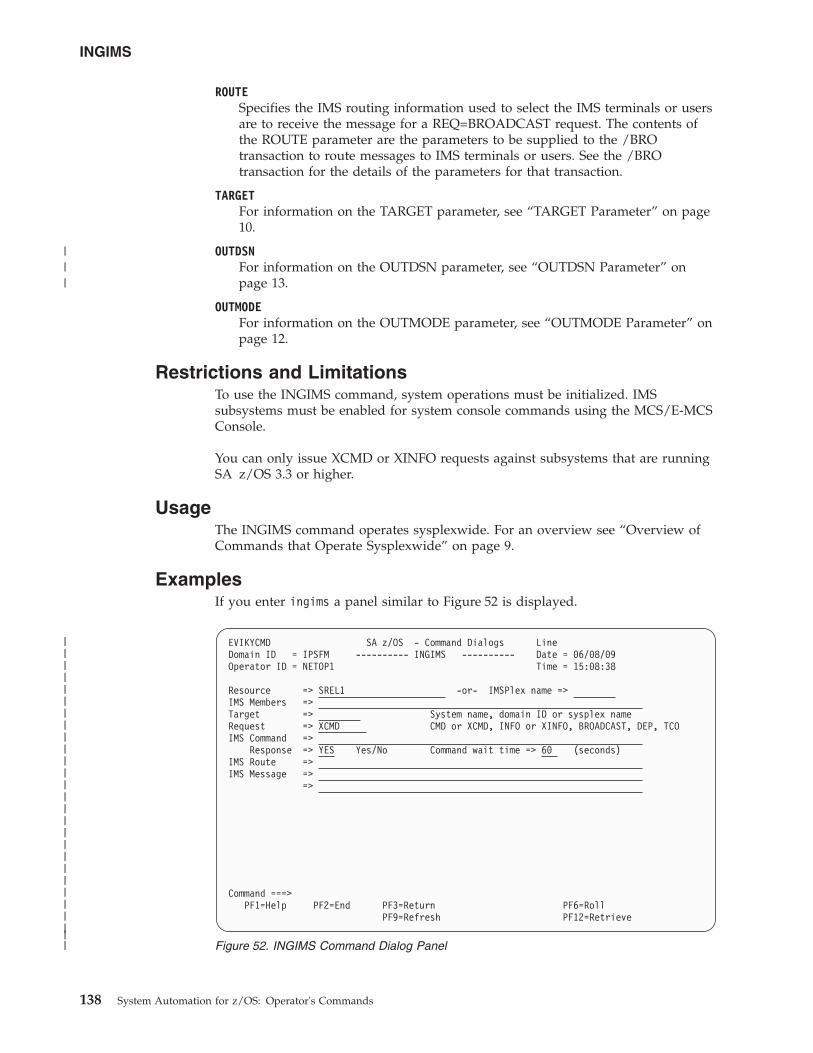
ROUTESpecifies the IMS routing information used to select the IMS terminals or usersare to receive the message for a REQ=BROADCAST request. The contents ofthe ROUTE parameter are the parameters to be supplied to the /BROtransaction to route messages to IMS terminals or users. See the /BROtransaction for the details of the parameters for that transaction.
TARGETFor information on the TARGET parameter, see “TARGET Parameter” on page10.
OUTDSNFor information on the OUTDSN parameter, see “OUTDSN Parameter” onpage 13.
OUTMODEFor information on the OUTMODE parameter, see “OUTMODE Parameter” onpage 12.
Restrictions and LimitationsTo use the INGIMS command, system operations must be initialized. IMSsubsystems must be enabled for system console commands using the MCS/E-MCSConsole.
You can only issue XCMD or XINFO requests against subsystems that are runningSA z/OS 3.3 or higher.
UsageThe INGIMS command operates sysplexwide. For an overview see “Overview ofCommands that Operate Sysplexwide” on page 9.
ExamplesIf you enter ingims a panel similar to Figure 52 is displayed.
EVIKYCMD SA z/OS - Command Dialogs LineDomain ID = IPSFM ---------- INGIMS ---------- Date = 06/08/09Operator ID = NETOP1 Time = 15:08:38
Resource => SREL1 -or- IMSPlex name =>IMS Members =>Target => System name, domain ID or sysplex nameRequest => XCMD CMD or XCMD, INFO or XINFO, BROADCAST, DEP, TCOIMS Command =>
Response => YES Yes/No Command wait time => 60 (seconds)IMS Route =>IMS Message =>
=>
Command ===>PF1=Help PF2=End PF3=Return PF6=Roll
PF9=Refresh PF12=Retrieve
Figure 52. INGIMS Command Dialog Panel
INGIMS
138 System Automation for z/OS: Operator's Commands
|||||||||||||||||||||||||||
|||
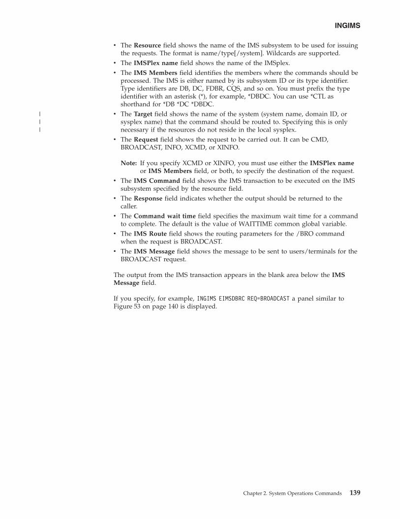
v The Resource field shows the name of the IMS subsystem to be used for issuingthe requests. The format is name/type[/system]. Wildcards are supported.
v The IMSPlex name field shows the name of the IMSplex.v The IMS Members field identifies the members where the commands should be
processed. The IMS is either named by its subsystem ID or its type identifier.Type identifiers are DB, DC, FDBR, CQS, and so on. You must prefix the typeidentifier with an asterisk (*), for example, *DBDC. You can use *CTL asshorthand for *DB *DC *DBDC.
v The Target field shows the name of the system (system name, domain ID, orsysplex name) that the command should be routed to. Specifying this is onlynecessary if the resources do not reside in the local sysplex.
v The Request field shows the request to be carried out. It can be CMD,BROADCAST, INFO, XCMD, or XINFO.
Note: If you specify XCMD or XINFO, you must use either the IMSPlex nameor IMS Members field, or both, to specify the destination of the request.
v The IMS Command field shows the IMS transaction to be executed on the IMSsubsystem specified by the resource field.
v The Response field indicates whether the output should be returned to thecaller.
v The Command wait time field specifies the maximum wait time for a commandto complete. The default is the value of WAITTIME common global variable.
v The IMS Route field shows the routing parameters for the /BRO commandwhen the request is BROADCAST.
v The IMS Message field shows the message to be sent to users/terminals for theBROADCAST request.
The output from the IMS transaction appears in the blank area below the IMSMessage field.
If you specify, for example, INGIMS EIMSDBRC REQ=BROADCAST a panel similar toFigure 53 on page 140 is displayed.
INGIMS
Chapter 2. System Operations Commands 139
|||
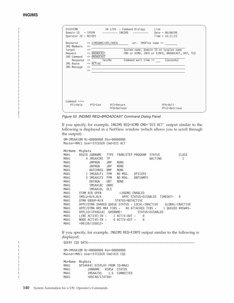
If you specify, for example, INGIMS REQ=XCMD CMD=’DIS ACT’ output similar to thefollowing is displayed in a NetView window (which allows you to scroll throughthe output):OM=IMSAA1OM Rc=00000000 Rsn=00000000Master=MAC1 User=STCUSER Cmd=DIS ACT
MbrName MsgDataMAA1 REGID JOBNAME TYPE TRAN/STEP PROGRAM STATUS CLASSMAA1 4 IMSAA1M1 TP WAITING 1MAA1 JMPRGN JMP NONEMAA1 JBPRGN JBP NONEMAA1 BATCHREG BMP NONEMAA1 1 IMSAA1F1 FPM NO MSG. DFSIVP4MAA1 3 IMSAA1F3 FPM NO MSG. DBFSAMP3MAA1 DBTRGN DBT NONEMAA1 IMSAA1RC DBRCMAA1 IMSAA1DL DLSMAA1 VTAM ACB OPEN -LOGONS ENABLEDMAA1 IMSLU=N/A.N/A APPC STATUS=DISABLED TIMEOUT= 0MAA1 OTMA GROUP=N/A STATUS=NOTACTIVEMAA1 APPC/OTMA SHARED QUEUE STATUS - LOCAL=INACTIVE GLOBAL=INACTIVEMAA1 APPC/OTMA RRS MAX TCBS - 40 ATTACHED TCBS - 1 QUEUED RRSWKS-MAA1 APPLID=IPXAGIA1 GRSNAME= STATUS=DISABLEDMAA1 LINE ACTIVE-IN - 1 ACTIV-OUT - 0MAA1 NODE ACTIVE-IN - 0 ACTIV-OUT - 0MAA1 *09139/155812*
If you specify, for example, INGIMS REQ=XINFO output similar to the following isdisplayed:QUERY CQS DATA--------------------------------------------------------------
OM=IMSAA1OM Rc=00000000 Rsn=00000000Master=MAC1 User=STCUSER Cmd=DIS CQS
MbrName MsgDataMAA1 DFS4444I DISPLAY FROM ID=MAA1MAA1 JOBNAME VERS# STATUSMAA1 IMSAA1SQ 1.5 CONNECTEDMAA1 *09148/174750*
EVIKYCMD SA z/OS - Command Dialogs LineDomain ID = IPSFM ---------- INGIMS ---------- Date = 06/08/09Operator ID = NETOP1 Time = 15:11:23
Resource => EIMSDBRC/APL/AOC8 -or- IMSPlex name =>IMS Members =>Target => System name, domain ID or sysplex nameRequest => BROADCAST CMD or XCMD, INFO or XINFO, BROADCAST, DEP, TCOIMS Command => BROADCAST
Response => Yes/No Command wait time => (seconds)IMS Route => ACTIVEIMS Message =>
=>
Command ===>PF1=Help PF2=End PF3=Return PF6=Roll
PF9=Refresh PF12=Retrieve
Figure 53. INGIMS REQ=BROADCAST Command Dialog Panel
INGIMS
140 System Automation for z/OS: Operator's Commands
|||||||||||||||||||||||||||
||||||||||
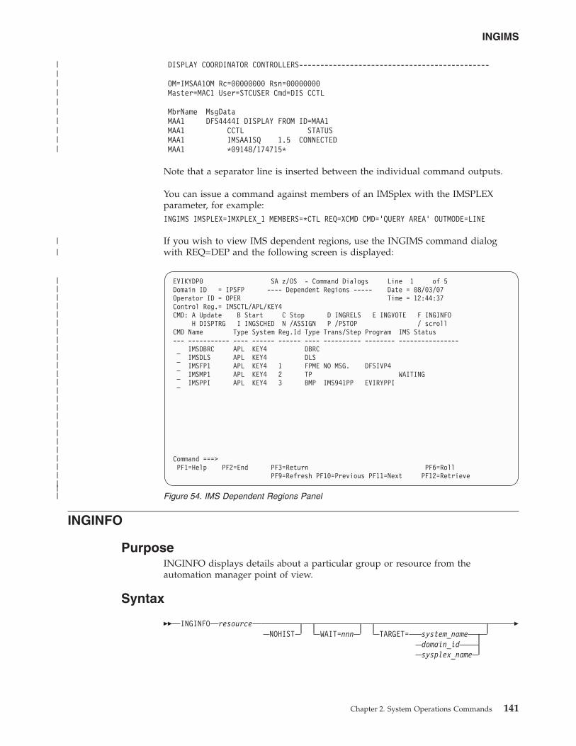
DISPLAY COORDINATOR CONTROLLERS---------------------------------------------
OM=IMSAA1OM Rc=00000000 Rsn=00000000Master=MAC1 User=STCUSER Cmd=DIS CCTL
MbrName MsgDataMAA1 DFS4444I DISPLAY FROM ID=MAA1MAA1 CCTL STATUSMAA1 IMSAA1SQ 1.5 CONNECTEDMAA1 *09148/174715*
Note that a separator line is inserted between the individual command outputs.
You can issue a command against members of an IMSplex with the IMSPLEXparameter, for example:INGIMS IMSPLEX=IMXPLEX_1 MEMBERS=*CTL REQ=XCMD CMD=’QUERY AREA’ OUTMODE=LINE
If you wish to view IMS dependent regions, use the INGIMS command dialogwith REQ=DEP and the following screen is displayed:
INGINFO
PurposeINGINFO displays details about a particular group or resource from theautomation manager point of view.
Syntax
�� INGINFO resourceNOHIST WAIT=nnn TARGET= system_name
domain_idsysplex_name
�
EVIKYDP0 SA z/OS - Command Dialogs Line 1 of 5Domain ID = IPSFP ---- Dependent Regions ----- Date = 08/03/07Operator ID = OPER Time = 12:44:37Control Reg.= IMSCTL/APL/KEY4CMD: A Update B Start C Stop D INGRELS E INGVOTE F INGINFO
H DISPTRG I INGSCHED N /ASSIGN P /PSTOP / scrollCMD Name Type System Reg.Id Type Trans/Step Program IMS Status--- ----------- ---- ------ ------ ---- ---------- -------- ----------------
IMSDBRC APL KEY4 DBRCIMSDLS APL KEY4 DLSIMSFP1 APL KEY4 1 FPME NO MSG. DFSIVP4IMSMP1 APL KEY4 2 TP WAITINGIMSPPI APL KEY4 3 BMP IMS941PP EVIRYPPI
Command ===>PF1=Help PF2=End PF3=Return PF6=Roll
PF9=Refresh PF10=Previous PF11=Next PF12=Retrieve
Figure 54. IMS Dependent Regions Panel
INGIMS
Chapter 2. System Operations Commands 141
|||||||||||||||||||||||||||
||||||||||
||
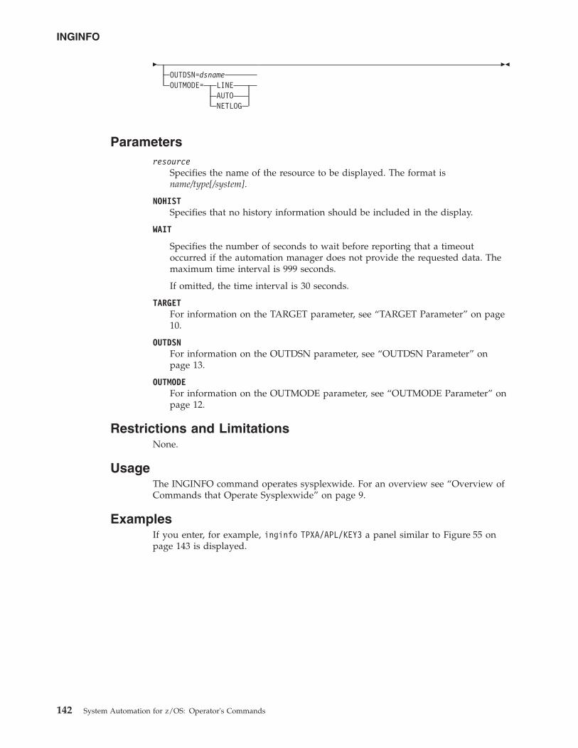
�OUTDSN=dsnameOUTMODE= LINE
AUTONETLOG
��
Parametersresource
Specifies the name of the resource to be displayed. The format isname/type[/system].
NOHISTSpecifies that no history information should be included in the display.
WAIT
Specifies the number of seconds to wait before reporting that a timeoutoccurred if the automation manager does not provide the requested data. Themaximum time interval is 999 seconds.
If omitted, the time interval is 30 seconds.
TARGETFor information on the TARGET parameter, see “TARGET Parameter” on page10.
OUTDSNFor information on the OUTDSN parameter, see “OUTDSN Parameter” onpage 13.
OUTMODEFor information on the OUTMODE parameter, see “OUTMODE Parameter” onpage 12.
Restrictions and LimitationsNone.
UsageThe INGINFO command operates sysplexwide. For an overview see “Overview ofCommands that Operate Sysplexwide” on page 9.
ExamplesIf you enter, for example, inginfo TPXA/APL/KEY3 a panel similar to Figure 55 onpage 143 is displayed.
INGINFO
142 System Automation for z/OS: Operator's Commands
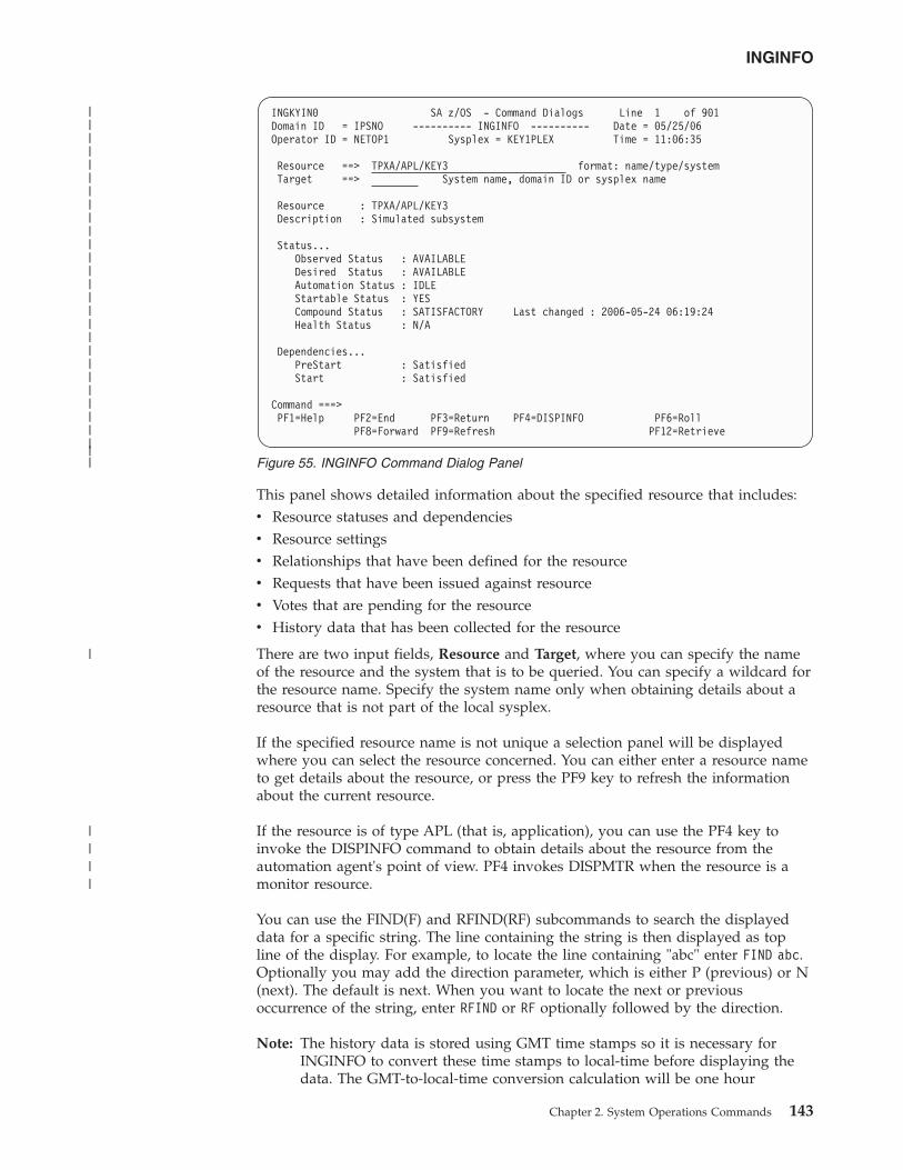
This panel shows detailed information about the specified resource that includes:v Resource statuses and dependenciesv Resource settingsv Relationships that have been defined for the resourcev Requests that have been issued against resourcev Votes that are pending for the resourcev History data that has been collected for the resource
There are two input fields, Resource and Target, where you can specify the nameof the resource and the system that is to be queried. You can specify a wildcard forthe resource name. Specify the system name only when obtaining details about aresource that is not part of the local sysplex.
If the specified resource name is not unique a selection panel will be displayedwhere you can select the resource concerned. You can either enter a resource nameto get details about the resource, or press the PF9 key to refresh the informationabout the current resource.
If the resource is of type APL (that is, application), you can use the PF4 key toinvoke the DISPINFO command to obtain details about the resource from theautomation agent's point of view. PF4 invokes DISPMTR when the resource is amonitor resource.
You can use the FIND(F) and RFIND(RF) subcommands to search the displayeddata for a specific string. The line containing the string is then displayed as topline of the display. For example, to locate the line containing "abc" enter FIND abc.Optionally you may add the direction parameter, which is either P (previous) or N(next). The default is next. When you want to locate the next or previousoccurrence of the string, enter RFIND or RF optionally followed by the direction.
Note: The history data is stored using GMT time stamps so it is necessary forINGINFO to convert these time stamps to local-time before displaying thedata. The GMT-to-local-time conversion calculation will be one hour
INGKYIN0 SA z/OS - Command Dialogs Line 1 of 901Domain ID = IPSNO ---------- INGINFO ---------- Date = 05/25/06Operator ID = NETOP1 Sysplex = KEY1PLEX Time = 11:06:35
Resource ==> TPXA/APL/KEY3 format: name/type/systemTarget ==> System name, domain ID or sysplex name
Resource : TPXA/APL/KEY3Description : Simulated subsystem
Status...Observed Status : AVAILABLEDesired Status : AVAILABLEAutomation Status : IDLEStartable Status : YESCompound Status : SATISFACTORY Last changed : 2006-05-24 06:19:24Health Status : N/A
Dependencies...PreStart : SatisfiedStart : Satisfied
Command ===>PF1=Help PF2=End PF3=Return PF4=DISPINFO PF6=Roll
PF8=Forward PF9=Refresh PF12=Retrieve
Figure 55. INGINFO Command Dialog Panel
INGINFO
Chapter 2. System Operations Commands 143
||||||||||||||||||||||||||||
|
||||
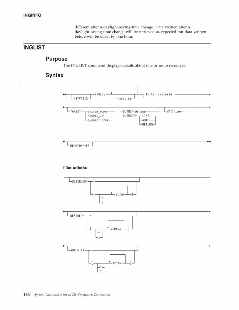
different after a daylight-saving-time change. Data written after adaylight-saving-time change will be retrieved as expected but data writtenbefore will be offset by one hour.
INGLIST
PurposeThe INGLIST command displays details about one or more resources.
Syntax
��NETVASIS
�INGLIST filter criteriaresource
�
�TARGET= system_name
domain_idsysplex_name
OUTDSN=dsnameOUTMODE= LINE
AUTONETLOG
WAIT=nnn�
�MEMBERS=YES
��
filter criteria:
�
OBSERVED= *
( status )^\
�
�
�
DESIRED= *
( status )^\
�
�
�
AUTOSTAT= *
( status )^\
�
INGINFO
144 System Automation for z/OS: Operator's Commands
|
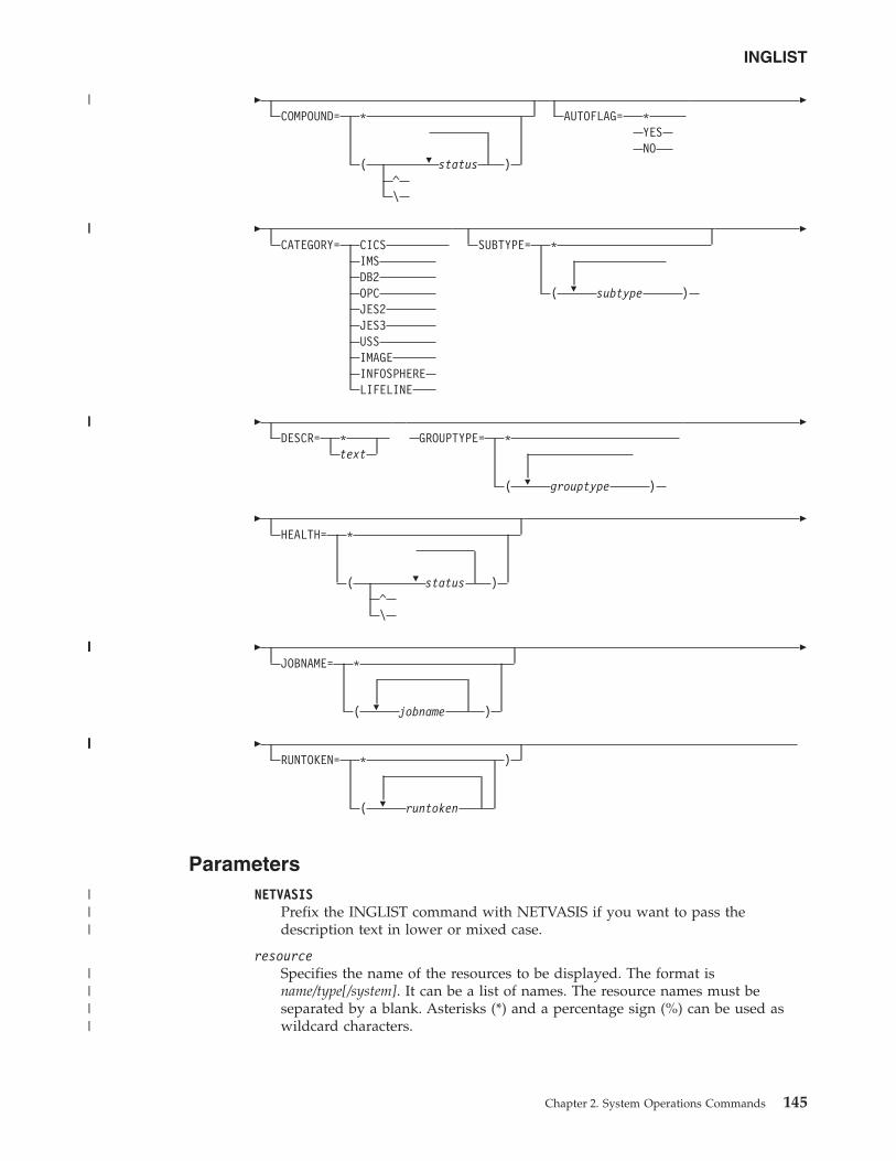
�
�
COMPOUND= *
( status )^\
AUTOFLAG= *YESNO
�
�CATEGORY= CICS
IMSDB2OPCJES2JES3USSIMAGEINFOSPHERELIFELINE
�
SUBTYPE= *
( subtype )
�
�DESCR= *
text
�
GROUPTYPE= *
( grouptype )
�
�
�
HEALTH= *
( status )^\
�
�
�
JOBNAME= *
( jobname )
�
�
�
RUNTOKEN= * )
( runtoken
ParametersNETVASIS
Prefix the INGLIST command with NETVASIS if you want to pass thedescription text in lower or mixed case.
resourceSpecifies the name of the resources to be displayed. The format isname/type[/system]. It can be a list of names. The resource names must beseparated by a blank. Asterisks (*) and a percentage sign (%) can be used aswildcard characters.
INGLIST
Chapter 2. System Operations Commands 145
|
||
|||
|||||
|||||
|||
||||
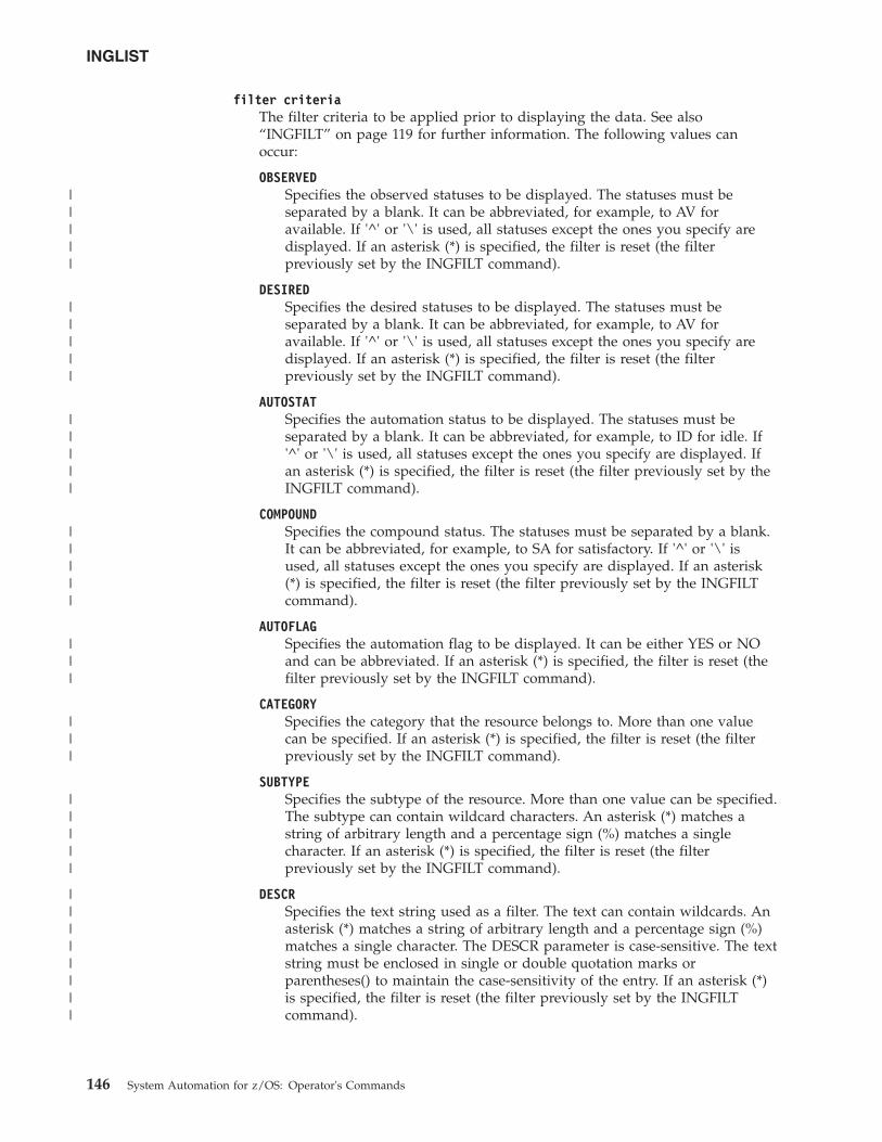
filter criteriaThe filter criteria to be applied prior to displaying the data. See also“INGFILT” on page 119 for further information. The following values canoccur:
OBSERVEDSpecifies the observed statuses to be displayed. The statuses must beseparated by a blank. It can be abbreviated, for example, to AV foravailable. If '^' or '\' is used, all statuses except the ones you specify aredisplayed. If an asterisk (*) is specified, the filter is reset (the filterpreviously set by the INGFILT command).
DESIREDSpecifies the desired statuses to be displayed. The statuses must beseparated by a blank. It can be abbreviated, for example, to AV foravailable. If '^' or '\' is used, all statuses except the ones you specify aredisplayed. If an asterisk (*) is specified, the filter is reset (the filterpreviously set by the INGFILT command).
AUTOSTATSpecifies the automation status to be displayed. The statuses must beseparated by a blank. It can be abbreviated, for example, to ID for idle. If'^' or '\' is used, all statuses except the ones you specify are displayed. Ifan asterisk (*) is specified, the filter is reset (the filter previously set by theINGFILT command).
COMPOUNDSpecifies the compound status. The statuses must be separated by a blank.It can be abbreviated, for example, to SA for satisfactory. If '^' or '\' isused, all statuses except the ones you specify are displayed. If an asterisk(*) is specified, the filter is reset (the filter previously set by the INGFILTcommand).
AUTOFLAGSpecifies the automation flag to be displayed. It can be either YES or NOand can be abbreviated. If an asterisk (*) is specified, the filter is reset (thefilter previously set by the INGFILT command).
CATEGORYSpecifies the category that the resource belongs to. More than one valuecan be specified. If an asterisk (*) is specified, the filter is reset (the filterpreviously set by the INGFILT command).
SUBTYPESpecifies the subtype of the resource. More than one value can be specified.The subtype can contain wildcard characters. An asterisk (*) matches astring of arbitrary length and a percentage sign (%) matches a singlecharacter. If an asterisk (*) is specified, the filter is reset (the filterpreviously set by the INGFILT command).
DESCRSpecifies the text string used as a filter. The text can contain wildcards. Anasterisk (*) matches a string of arbitrary length and a percentage sign (%)matches a single character. The DESCR parameter is case-sensitive. The textstring must be enclosed in single or double quotation marks orparentheses() to maintain the case-sensitivity of the entry. If an asterisk (*)is specified, the filter is reset (the filter previously set by the INGFILTcommand).
INGLIST
146 System Automation for z/OS: Operator's Commands
|||||
|||||
|||||
|||||
|||
|||
|||||
||||||||
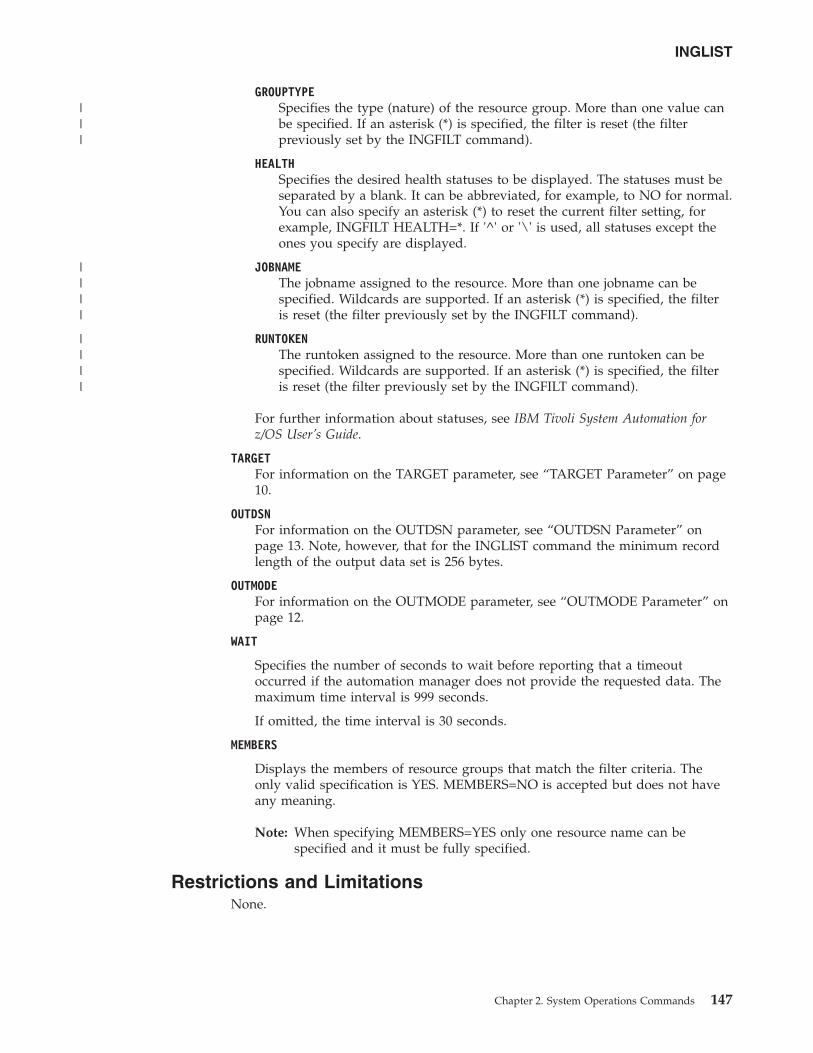
GROUPTYPESpecifies the type (nature) of the resource group. More than one value canbe specified. If an asterisk (*) is specified, the filter is reset (the filterpreviously set by the INGFILT command).
HEALTHSpecifies the desired health statuses to be displayed. The statuses must beseparated by a blank. It can be abbreviated, for example, to NO for normal.You can also specify an asterisk (*) to reset the current filter setting, forexample, INGFILT HEALTH=*. If '^' or '\' is used, all statuses except theones you specify are displayed.
JOBNAMEThe jobname assigned to the resource. More than one jobname can bespecified. Wildcards are supported. If an asterisk (*) is specified, the filteris reset (the filter previously set by the INGFILT command).
RUNTOKENThe runtoken assigned to the resource. More than one runtoken can bespecified. Wildcards are supported. If an asterisk (*) is specified, the filteris reset (the filter previously set by the INGFILT command).
For further information about statuses, see IBM Tivoli System Automation forz/OS User’s Guide.
TARGETFor information on the TARGET parameter, see “TARGET Parameter” on page10.
OUTDSNFor information on the OUTDSN parameter, see “OUTDSN Parameter” onpage 13. Note, however, that for the INGLIST command the minimum recordlength of the output data set is 256 bytes.
OUTMODEFor information on the OUTMODE parameter, see “OUTMODE Parameter” onpage 12.
WAIT
Specifies the number of seconds to wait before reporting that a timeoutoccurred if the automation manager does not provide the requested data. Themaximum time interval is 999 seconds.
If omitted, the time interval is 30 seconds.
MEMBERS
Displays the members of resource groups that match the filter criteria. Theonly valid specification is YES. MEMBERS=NO is accepted but does not haveany meaning.
Note: When specifying MEMBERS=YES only one resource name can bespecified and it must be fully specified.
Restrictions and LimitationsNone.
INGLIST
Chapter 2. System Operations Commands 147
|||
||||
||||

UsageThe INGLIST command operates sysplexwide. For an overview see “Overview ofCommands that Operate Sysplexwide” on page 9.
ExamplesIf you enter inglist, you will see information about all automated resources, asshown in Figure 56.
The amount of data depends on the screen size. Press PF10/11 to scrollhorizontally.
Use the PF5 key to restrict the list of resources to be displayed. This causes theINGFILT panel to be displayed, where you specify the filter criteria to be used forthe display.
You can use the PF4 key to toggle to the DISPSTAT panel to view the sameresources, but now from the automation agent viewpoint. To return to the INGLISTpanel press the PF3 key on the DISPSTAT panel. Note that pressing PF4 on theDISPSTAT panel displays the INGLIST panel for all resources shown in theDISPSTAT panel. However, this might not be the same as the original INGLISTdisplay because the DISPSTAT display might be modified due to filtering orsuppressing of resources that the automation agent does not handle, such asapplication groups.
This panel displays the following information:v The CMD field lets you specify command codes. To use one of the command
codes shown, type the appropriate letter next to the resource name and pressEnter. The following command codes are available:
A Resets the status of the resource or application group (observed status,automation status). Sets or resets attributes that are assigned to the resource.
INGKYST0 SA z/OS - Command Dialogs Line 1 of 383Domain ID = IPSNO -------- INGLIST --------- Date = 11/23/09Operator ID = NETOP1 Sysplex = KEY1PLEX Time = 17:27:19A Update B Start C Stop D INGRELS E INGVOTE F INGINFO G MembersH DISPTRG I INGSCHED J INGGROUP K INGCICS L INGIMS M DISPMTR T INGTWSU User X INGLKUP / scrollCMD Name Type System Compound Desired Observed Nature--- ------------ ---- -------- ------------ ----------- ---------- --------
ALLOCAS APL KEY1 INHIBITED AVAILABLE UNKNOWNALLOCAS APL KEY2 INHIBITED AVAILABLE UNKNOWNALLOCAS APL KEY3 SATISFACTORY AVAILABLE AVAILABLEALLOCAS APL KEY4 INHIBITED AVAILABLE UNKNOWNAMCP APL KEY1 INHIBITED AVAILABLE UNKNOWNAMCP APL KEY2 INHIBITED AVAILABLE UNKNOWNAMCP APL KEY3 PROBLEM AVAILABLE HARDDOWNAMCP APL KEY4 INHIBITED AVAILABLE UNKNOWNANTMAIN APL KEY1 INHIBITED AVAILABLE UNKNOWNANTMAIN APL KEY2 INHIBITED AVAILABLE UNKNOWNANTMAIN APL KEY3 SATISFACTORY AVAILABLE AVAILABLEANTMAIN APL KEY4 INHIBITED AVAILABLE UNKNOWNAOCAPPL APL KEY1 INHIBITED AVAILABLE UNKNOWN
Command ===>PF1=Help PF2=End PF3=Return PF4=DISPSTAT PF5=Filters PF6=Roll
PF8=Forward PF9=Refresh PF10=Previous PF11=Next PF12=Retrieve
Figure 56. INGLIST Command Dialog Panel
INGLIST
148 System Automation for z/OS: Operator's Commands
||
The automation agent status can also be updated if you enter this commandcode. See “Setting the Status or Attribute of a Resource or ApplicationGroup” on page 151.
B Start. Calls the INGREQ command dialog to make the resource available.See “INGREQ” on page 197 for further information.
C Stop. Calls the INGREQ command dialog to make the resource unavailable.See “INGREQ” on page 197 for further information.
D Displays dependency information and its evaluation for the resource.
E Invokes the INGVOTE command, showing all requests currently present forthe resource. Allows the operator to cancel a request.
F Shows details about the resource by invoking the INGINFO command.
G Shows all members for the selected application group or processor in a newwindow.
H Invokes the DISPTRG command to show the trigger definitions for theselected resource.
I Invokes the INGSCHED command to show the resource overrides for theselected resource.
J Invokes the INGGROUP ACTION=MEMBERS command to show memberdetails.
K Invokes the INGCICS command using the selected resource.
L Invokes the INGIMS command using selected resource.
M Invokes the DISPMTR command to show the monitors that have beendefined for the selected resource.
T Invokes the INGTWS command using selected resource.
U Invokes the AOFEXC04 user exit if it has been installed.
X Invokes the INGKLUP REQ=ANALYSE command. The X character examinesthe automation manager and automation agent for the selected resource toprovide information about why the resource could not be brought into thedesired state. The display lists all of the potential problems that might stopthat action from succeeding. The display simply shows the resourcesconcerned and a note of the potential problems that have been detected withthem.
v The Name field shows the name of the resource.v The Type field shows the type of the resource.v The System field shows where the resource is defined.v The Compound field shows the compound status of the resource. This is a
summary of all statuses of the resource and provides a single value to check thestatus of a resource.
v The Desired field shows the status that the automation manager is trying tomove the resource to. It can either be available or unavailable.
v The Nature field applies to group resources only and defines the type of thegroup. It can have the following values:
BASICIndicates that the group contains a number of different resources, all ofwhich perform different roles to constitute a complete application.
INGLIST
Chapter 2. System Operations Commands 149
||||||||
MOVEIndicates that the group contains alternate instances of the sameresource.
SERVERIndicates that the group contains a number of readily interchangeableresources. The group has a target that tells the automation manager howmany of them should be made available for the group to be available.
v The Automation field shows the status representing the automation agents'automation for the resource.
v The Startable field indicates whether or not it is possible to start the resource ifthe automation manager is asked to do so at this point in time.
v The Health field shows the health status of the resource.v The Auto field shows the automation flag that is maintained by the automation
manager. No automation is performed for the resource by the automationmanager if the flag is off.
v The Hold field shows the hold flag that is maintained by the automationmanager.
v The Description field shows descriptive information about the resource.v The Starttype field shows the preset start type to be used the next time the
resource is made available (started). This value is set by INGSET and willoverride any TYPE value specified (or defaulted) on the next INGREQ startrequest.
v The Stoptype field shows the preset stop type to be used the next time theresource is made unavailable (shutdown). This value is set by INGSET and willoverride any TYPE value specified (or defaulted) on the next INGREQ stoprequest. However, a stop type of FORCE, wherever specified, will always behonored.
v The Trigger field shows the trigger that is associated with the resource.v The Schedule field shows the schedule (service period) that the resource is
linked to.v The Category field shows the category of the resource, such as CICS, DB2, or
IMS.v The Subtype field shows the subtype of the resource. This applies to resources
of category CICS, DB2, IMS, INFOSHERE, LIFELINE and OPC.v The Jobname field shows the job name assigned to the resource.v The Qual field indicates how a resource qualifies for the current runmode. There
are three indicators:
G Resource qualifies because it is in one or more groups that qualify.
R Resource qualifies because it was explicitly added via the INGRUNcommand.
T Resource qualifies because of its runtokens
Different colors are used to indicate when a particular status is regarded asabnormal:v A desired status of UNAVAILABLE is shown in blue.v A compound status of PROBLEM is shown in red, DENIED and INHIBITED are
shown in pink, while a compound status of DEGRADED is shown in yellow.v An observed status of HARDDOWN or PROBLEM is shown in red, while an
observed status that is not in line with the desired status is shown in yellow.
INGLIST
150 System Automation for z/OS: Operator's Commands
||
|
||
||
|||
||
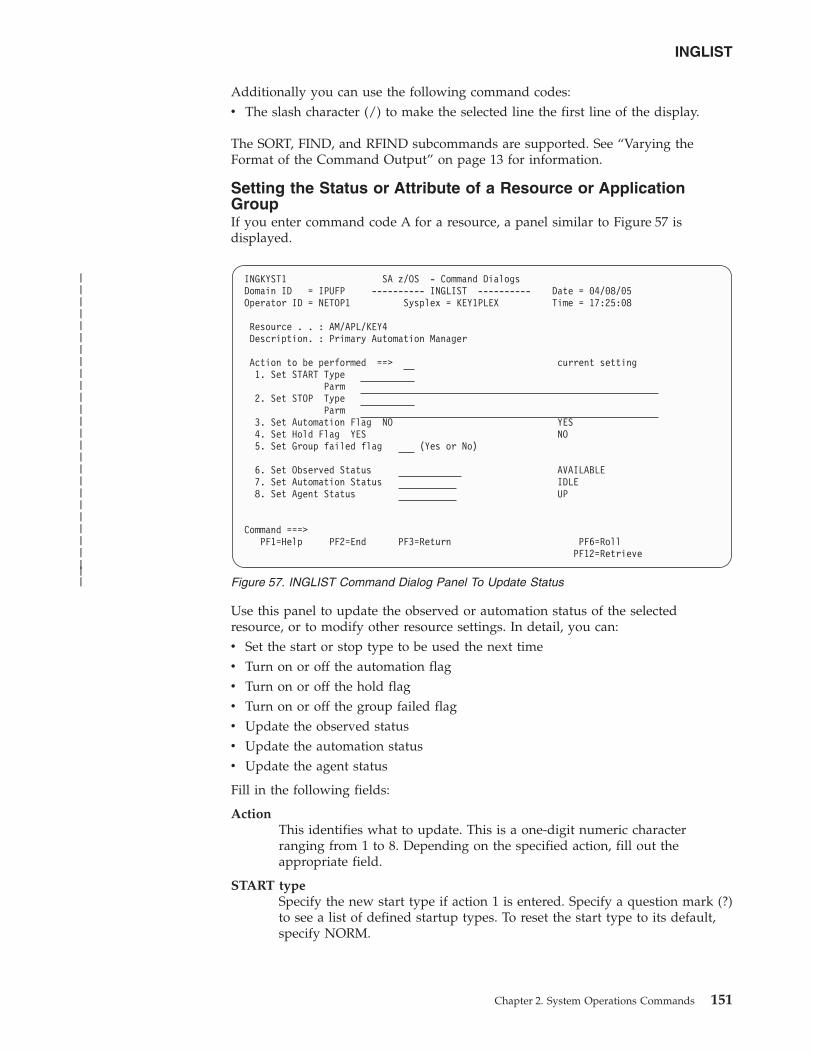
Additionally you can use the following command codes:v The slash character (/) to make the selected line the first line of the display.
The SORT, FIND, and RFIND subcommands are supported. See “Varying theFormat of the Command Output” on page 13 for information.
Setting the Status or Attribute of a Resource or ApplicationGroupIf you enter command code A for a resource, a panel similar to Figure 57 isdisplayed.
Use this panel to update the observed or automation status of the selectedresource, or to modify other resource settings. In detail, you can:v Set the start or stop type to be used the next timev Turn on or off the automation flagv Turn on or off the hold flagv Turn on or off the group failed flagv Update the observed statusv Update the automation statusv Update the agent status
Fill in the following fields:
ActionThis identifies what to update. This is a one-digit numeric characterranging from 1 to 8. Depending on the specified action, fill out theappropriate field.
START typeSpecify the new start type if action 1 is entered. Specify a question mark (?)to see a list of defined startup types. To reset the start type to its default,specify NORM.
INGKYST1 SA z/OS - Command DialogsDomain ID = IPUFP ---------- INGLIST ---------- Date = 04/08/05Operator ID = NETOP1 Sysplex = KEY1PLEX Time = 17:25:08
Resource . . : AM/APL/KEY4Description. : Primary Automation Manager
Action to be performed ==> current setting1. Set START Type
Parm2. Set STOP Type
Parm3. Set Automation Flag NO YES4. Set Hold Flag YES NO5. Set Group failed flag (Yes or No)
6. Set Observed Status AVAILABLE7. Set Automation Status IDLE8. Set Agent Status UP
Command ===>PF1=Help PF2=End PF3=Return PF6=Roll
PF12=Retrieve
Figure 57. INGLIST Command Dialog Panel To Update Status
INGLIST
Chapter 2. System Operations Commands 151
|||||||||||||||||||||||||||
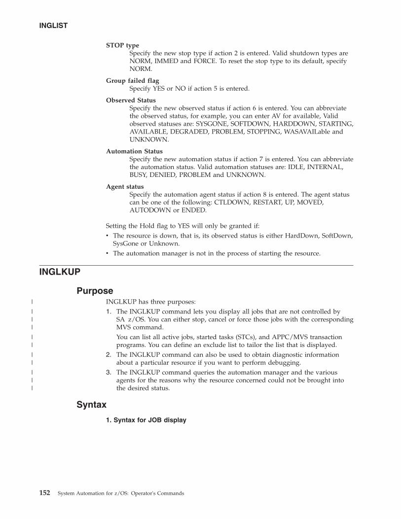
STOP typeSpecify the new stop type if action 2 is entered. Valid shutdown types areNORM, IMMED and FORCE. To reset the stop type to its default, specifyNORM.
Group failed flagSpecify YES or NO if action 5 is entered.
Observed StatusSpecify the new observed status if action 6 is entered. You can abbreviatethe observed status, for example, you can enter AV for available, Validobserved statuses are: SYSGONE, SOFTDOWN, HARDDOWN, STARTING,AVAILABLE, DEGRADED, PROBLEM, STOPPING, WASAVAILable andUNKNOWN.
Automation StatusSpecify the new automation status if action 7 is entered. You can abbreviatethe automation status. Valid automation statuses are: IDLE, INTERNAL,BUSY, DENIED, PROBLEM and UNKNOWN.
Agent statusSpecify the automation agent status if action 8 is entered. The agent statuscan be one of the following: CTLDOWN, RESTART, UP, MOVED,AUTODOWN or ENDED.
Setting the Hold flag to YES will only be granted if:v The resource is down, that is, its observed status is either HardDown, SoftDown,
SysGone or Unknown.v The automation manager is not in the process of starting the resource.
INGLKUP
PurposeINGLKUP has three purposes:1. The INGLKUP command lets you display all jobs that are not controlled by
SA z/OS. You can either stop, cancel or force those jobs with the correspondingMVS command.You can list all active jobs, started tasks (STCs), and APPC/MVS transactionprograms. You can define an exclude list to tailor the list that is displayed.
2. The INGLKUP command can also be used to obtain diagnostic informationabout a particular resource if you want to perform debugging.
3. The INGLKUP command queries the automation manager and the variousagents for the reasons why the resource concerned could not be brought intothe desired status.
Syntax
1. Syntax for JOB display
INGLIST
152 System Automation for z/OS: Operator's Commands
|
|||
||
||
|||
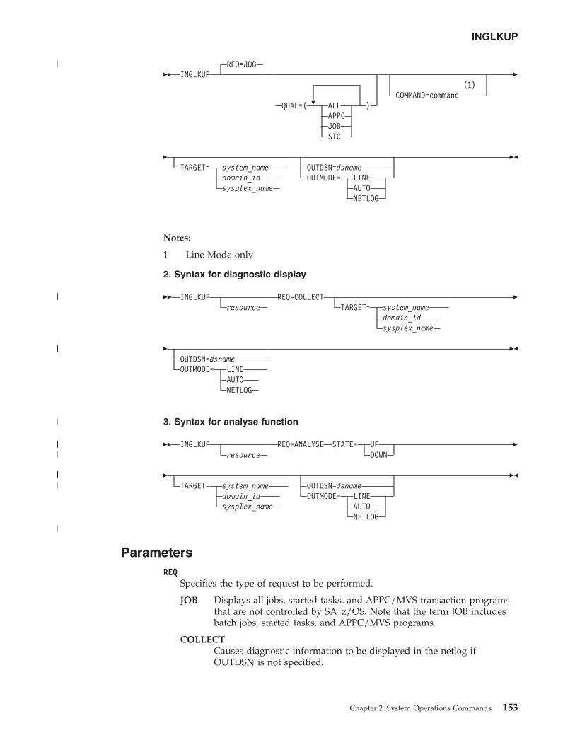
�� INGLKUPREQ=JOB
�QUAL=( ALL )APPCJOBSTC
(1)COMMAND=command
�
�TARGET= system_name
domain_idsysplex_name
OUTDSN=dsnameOUTMODE= LINE
AUTONETLOG
��
Notes:
1 Line Mode only
2. Syntax for diagnostic display
�� INGLKUPresource
REQ=COLLECTTARGET= system_name
domain_idsysplex_name
�
�OUTDSN=dsnameOUTMODE= LINE
AUTONETLOG
��
3. Syntax for analyse function
�� INGLKUPresource
REQ=ANALYSE STATE= UPDOWN
�
�TARGET= system_name
domain_idsysplex_name
OUTDSN=dsnameOUTMODE= LINE
AUTONETLOG
��
ParametersREQ
Specifies the type of request to be performed.
JOB Displays all jobs, started tasks, and APPC/MVS transaction programsthat are not controlled by SA z/OS. Note that the term JOB includesbatch jobs, started tasks, and APPC/MVS programs.
COLLECTCauses diagnostic information to be displayed in the netlog ifOUTDSN is not specified.
INGLKUP
Chapter 2. System Operations Commands 153
|
||||
|||||
|
||||||||||||||||||||||||
|||||||||||||||||||||||||||||||||||||||||||
|
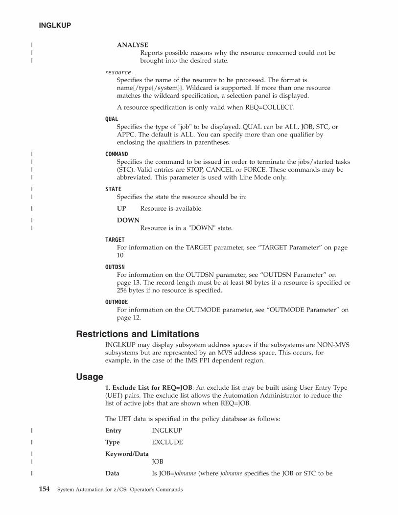
ANALYSEReports possible reasons why the resource concerned could not bebrought into the desired state.
resourceSpecifies the name of the resource to be processed. The format isname{/type{/system}}. Wildcard is supported. If more than one resourcematches the wildcard specification, a selection panel is displayed.
A resource specification is only valid when REQ=COLLECT.
QUALSpecifies the type of "job" to be displayed. QUAL can be ALL, JOB, STC, orAPPC. The default is ALL. You can specify more than one qualifier byenclosing the qualifiers in parentheses.
COMMANDSpecifies the command to be issued in order to terminate the jobs/started tasks(STC). Valid entries are STOP, CANCEL or FORCE. These commands may beabbreviated. This parameter is used with Line Mode only.
STATESpecifies the state the resource should be in:
UP Resource is available.
DOWNResource is in a "DOWN" state.
TARGETFor information on the TARGET parameter, see “TARGET Parameter” on page10.
OUTDSNFor information on the OUTDSN parameter, see “OUTDSN Parameter” onpage 13. The record length must be at least 80 bytes if a resource is specified or256 bytes if no resource is specified.
OUTMODEFor information on the OUTMODE parameter, see “OUTMODE Parameter” onpage 12.
Restrictions and LimitationsINGLKUP may display subsystem address spaces if the subsystems are NON-MVSsubsystems but are represented by an MVS address space. This occurs, forexample, in the case of the IMS PPI dependent region.
Usage1. Exclude List for REQ=JOB: An exclude list may be built using User Entry Type(UET) pairs. The exclude list allows the Automation Administrator to reduce thelist of active jobs that are shown when REQ=JOB.
The UET data is specified in the policy database as follows:
Entry INGLKUP
Type EXCLUDE
Keyword/DataJOB
Data Is JOB=jobname (where jobname specifies the JOB or STC to be
INGLKUP
154 System Automation for z/OS: Operator's Commands
|||
||||
||
||
||
||
||
||
||
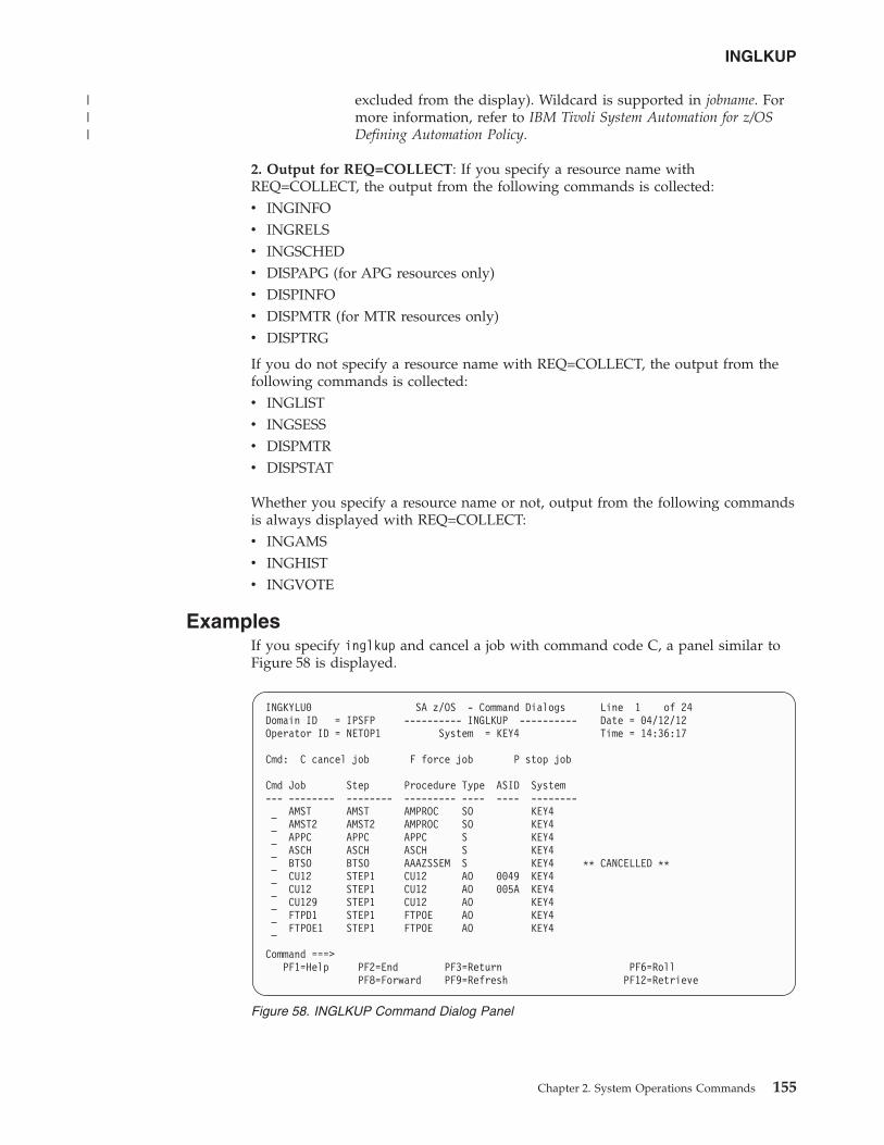
excluded from the display). Wildcard is supported in jobname. Formore information, refer to IBM Tivoli System Automation for z/OSDefining Automation Policy.
2. Output for REQ=COLLECT: If you specify a resource name withREQ=COLLECT, the output from the following commands is collected:v INGINFOv INGRELSv INGSCHEDv DISPAPG (for APG resources only)v DISPINFOv DISPMTR (for MTR resources only)v DISPTRG
If you do not specify a resource name with REQ=COLLECT, the output from thefollowing commands is collected:v INGLISTv INGSESSv DISPMTRv DISPSTAT
Whether you specify a resource name or not, output from the following commandsis always displayed with REQ=COLLECT:v INGAMSv INGHISTv INGVOTE
ExamplesIf you specify inglkup and cancel a job with command code C, a panel similar toFigure 58 is displayed.
INGKYLU0 SA z/OS - Command Dialogs Line 1 of 24Domain ID = IPSFP ---------- INGLKUP ---------- Date = 04/12/12Operator ID = NETOP1 System = KEY4 Time = 14:36:17
Cmd: C cancel job F force job P stop job
Cmd Job Step Procedure Type ASID System--- -------- -------- --------- ---- ---- --------
AMST AMST AMPROC SO KEY4AMST2 AMST2 AMPROC SO KEY4APPC APPC APPC S KEY4ASCH ASCH ASCH S KEY4BTSO BTSO AAAZSSEM S KEY4 ** CANCELLED **CU12 STEP1 CU12 AO 0049 KEY4CU12 STEP1 CU12 AO 005A KEY4CU129 STEP1 CU12 AO KEY4FTPD1 STEP1 FTPOE AO KEY4FTPOE1 STEP1 FTPOE AO KEY4
Command ===>PF1=Help PF2=End PF3=Return PF6=Roll
PF8=Forward PF9=Refresh PF12=Retrieve
Figure 58. INGLKUP Command Dialog Panel
INGLKUP
Chapter 2. System Operations Commands 155
|||
This panel displays all active jobs, started tasks (STC) and APPC/MVS transactionprograms that are not controlled by SA z/OS. You can either stop or cancel oreven force the job (or jobs).
For each job the following information is shown:v The Cmd field lets you specify the command codes shown on the panel. Type
the appropriate letter next to the job name and press Enter. The followingcommand codes are available:
C Cancel the job.
F Force the job.
P Stop the job.v The Job field shows the job name.v The Step field the step name.v The Procedure field shows the procedure step name.v The Type field shows the job type.v The ASID field shows the address space ID (this is only present if the job name
is not unique).v The System field shows the name of the system that the job is running on.
The SORT, FIND, and RFIND subcommands are supported. See “Varying theFormat of the Command Output” on page 13 for information.
If you specify REQ=ANALYSE for the INGLKUP command, the following panel isdisplayed:
INGKYLU2 SA z/OS - Command Dialogs LineDomain ID = IPUNA ---------- INGLKUP ---------- Date = 12/14/11Operator ID = OPER1 Sysplex = AOCAPLEX Time = 14:13:25
Resource => PMTRB3/MTR/AOC5 Examined State ==> UPTarget => System name, domain ID or sysplex name
Name Type System Cat Problem----------- ---- -------- --- ----------------------------------------------PMTRB3 MTR AOC5 Pot AM Observed status is UNKNOWNPMTRB3 MTR AOC5 Pot AM Automation status is UNKNOWNPAPLMTRA APL AOC5 Pot AM Observed status is UNKNOWNPAPLMTRA APL AOC5 Pot AM Automation status is UNKNOWNPAPLMTRB APL AOC5 Pot AM Observed status is UNKNOWNPAPLMTRB APL AOC5 Pot AM Automation status is UNKNOWN
Command ===>PF1=Help PF2=End PF3=Return PF6=Roll
PF9=Refresh PF12=Retrieve
INGMDFY
PurposeThe INGMDFY command displays the defined actions for the startup or shutdownof a subsystem that are currently loaded and allows you to modify them for thenext startup or shutdown.
Figure 59. INGLKUP Command Dialog Panel for the ANALYSE Option
INGLKUP
156 System Automation for z/OS: Operator's Commands
||
|||
|||||||||||||||||||||||
INGMDFY also allows you to define additional actions or to delete defined actionsfor the startup or shutdown of a subsystem.
Syntax
�� INGMDFY subsystem phasejobname
��
Parameterssubsystem
The name of the subsystem that the defined actions are to be displayed for.
jobnameThe job name of the subsystem that the defined actions are to be displayed for.
phaseThis parameter is used to specify whether startup or shutdown actions are tobe displayed.
STARTStartup actions are to be displayed.
STOPShutdown actions are to be displayed.
Restrictions and Limitationsv The INGMDFY command can only be used when SA z/OS is initialized.v The INGMDFY command is provided for fullscreen mode.v To ensure consistency during the startup or shutdown process of an application,
the save and reset functions are not applicable during startup or shutdownprocessing of the related application.
v Persistence of modifications:– NetView Recycle
Both the modified start/stop definitions in storage and the previously loadedACF data in the KEEP are lost. At restart, SA z/OS initializes with theautomation policy data from disk.
– ACF COLDBoth the modified start/stop definitions in storage and the previously loadedACF data in the KEEP are lost. The ACF data is reloaded from disk.
– ACF SAVESaves the currently loaded, modified ACF data using the NetView SAVEfacility. When restoring the saved data via ACF WARM, an existing KEEP isdeleted.
– Configuration RefreshIf the configuration data for a subsystem has been changed in the automationpolicy, both the modified start/stop definitions in storage and the previouslyloaded ACF data in the KEEP are lost during the configuration refresh. Thenew ACF data is loaded from disk.
– Temporarily Changing ACF Data with ACF REQ=REPLWhen using ACF REQ=REPL, only the currently loaded ACF data ismodified. An existing KEEP remains untouched so that previously loadedACF data is restored after the next start/stop or after INGMDFY expires.
INGMDFY
Chapter 2. System Operations Commands 157
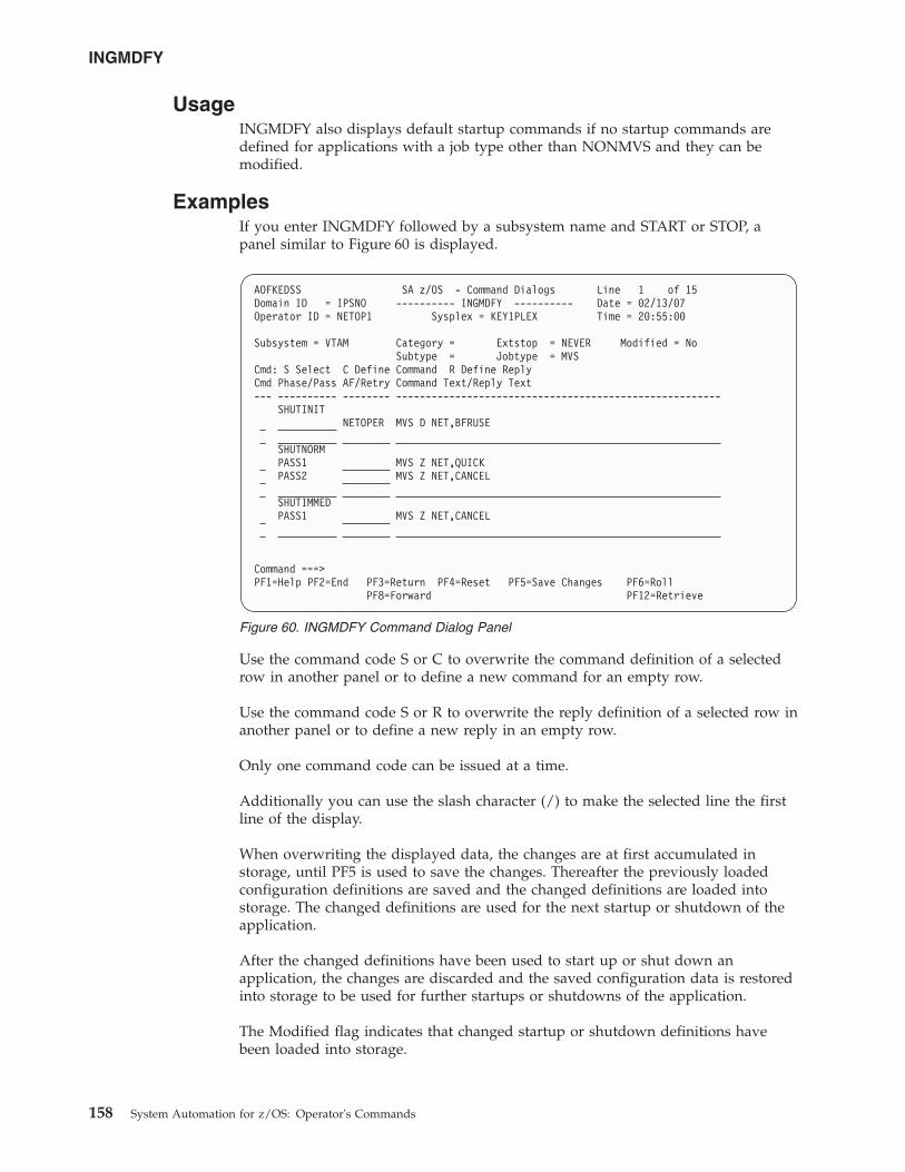
UsageINGMDFY also displays default startup commands if no startup commands aredefined for applications with a job type other than NONMVS and they can bemodified.
ExamplesIf you enter INGMDFY followed by a subsystem name and START or STOP, apanel similar to Figure 60 is displayed.
Use the command code S or C to overwrite the command definition of a selectedrow in another panel or to define a new command for an empty row.
Use the command code S or R to overwrite the reply definition of a selected row inanother panel or to define a new reply in an empty row.
Only one command code can be issued at a time.
Additionally you can use the slash character (/) to make the selected line the firstline of the display.
When overwriting the displayed data, the changes are at first accumulated instorage, until PF5 is used to save the changes. Thereafter the previously loadedconfiguration definitions are saved and the changed definitions are loaded intostorage. The changed definitions are used for the next startup or shutdown of theapplication.
After the changed definitions have been used to start up or shut down anapplication, the changes are discarded and the saved configuration data is restoredinto storage to be used for further startups or shutdowns of the application.
The Modified flag indicates that changed startup or shutdown definitions havebeen loaded into storage.
AOFKEDSS SA z/OS - Command Dialogs Line 1 of 15Domain ID = IPSNO ---------- INGMDFY ---------- Date = 02/13/07Operator ID = NETOP1 Sysplex = KEY1PLEX Time = 20:55:00
Subsystem = VTAM Category = Extstop = NEVER Modified = NoSubtype = Jobtype = MVS
Cmd: S Select C Define Command R Define ReplyCmd Phase/Pass AF/Retry Command Text/Reply Text--- ---------- -------- -------------------------------------------------------
SHUTINITNETOPER MVS D NET,BFRUSE
SHUTNORMPASS1 MVS Z NET,QUICKPASS2 MVS Z NET,CANCEL
SHUTIMMEDPASS1 MVS Z NET,CANCEL
Command ===>PF1=Help PF2=End PF3=Return PF4=Reset PF5=Save Changes PF6=Roll
PF8=Forward PF12=Retrieve
Figure 60. INGMDFY Command Dialog Panel
INGMDFY
158 System Automation for z/OS: Operator's Commands
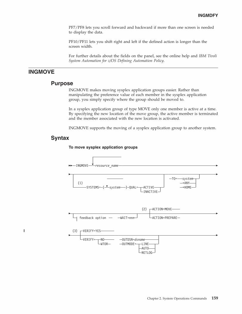
PF7/PF8 lets you scroll forward and backward if more than one screen is neededto display the data.
PF10/PF11 lets you shift right and left if the defined action is longer than thescreen width.
For further details about the fields on the panel, see the online help and IBM TivoliSystem Automation for z/OS Defining Automation Policy.
INGMOVE
PurposeINGMOVE makes moving sysplex application groups easier. Rather thanmanipulating the preference value of each member in the sysplex applicationgroup, you simply specify where the group should be moved to.
In a sysplex application group of type MOVE only one member is active at a time.By specifying the new location of the move group, the active member is terminatedand the member associated with the new location is activated.
INGMOVE supports the moving of a sysplex application group to another system.
Syntax
To move sysplex application groups
�� INGMOVE � resource_name �
�
�(1)
SYSTEMS= ( system ) QUAL= ACTIVEINACTIVE
TO= system*ANY*HOME
�
�feedback option WAIT=nnn
(2) ACTION=MOVE
ACTION=PREPARE�
�(3) VERIFY=YES
VERIFY= NOWTOR
OUTDSN=dsnameOUTMODE= LINE
AUTONETLOG
�
INGMDFY
Chapter 2. System Operations Commands 159
||||
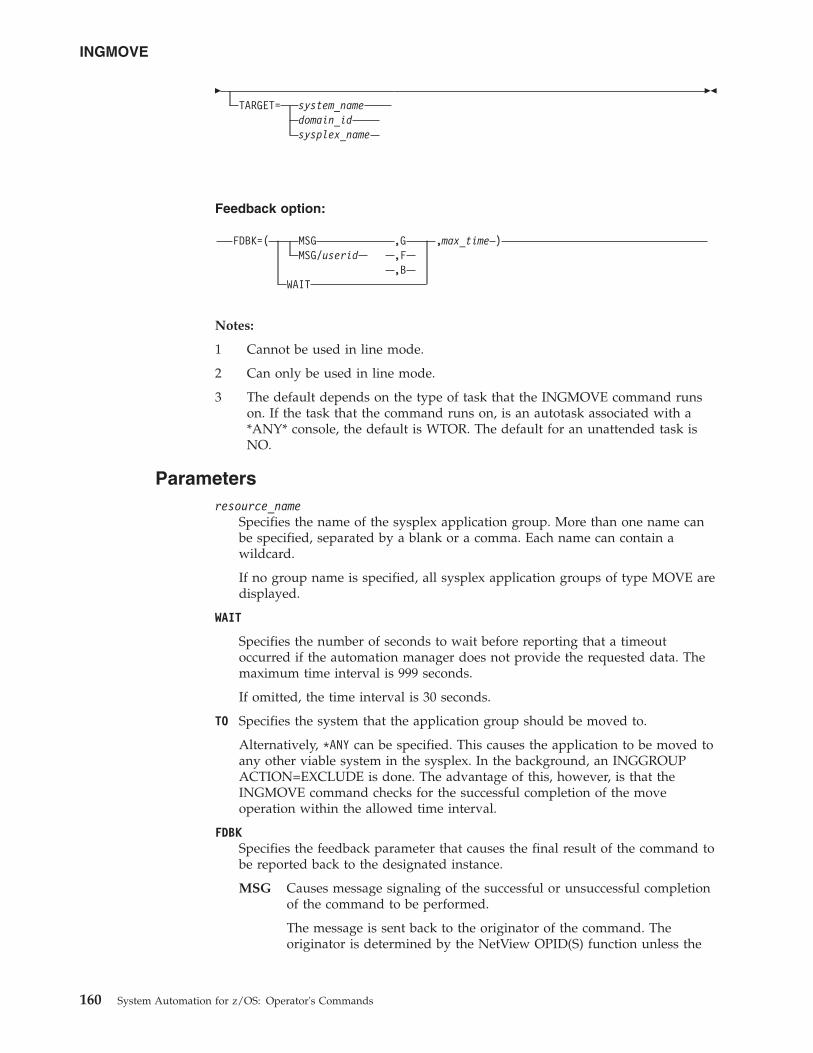
�TARGET= system_name
domain_idsysplex_name
��
Feedback option:
FDBK=( MSG ,G ,max_time )MSG/userid ,F
,BWAIT
Notes:
1 Cannot be used in line mode.
2 Can only be used in line mode.
3 The default depends on the type of task that the INGMOVE command runson. If the task that the command runs on, is an autotask associated with a*ANY* console, the default is WTOR. The default for an unattended task isNO.
Parametersresource_name
Specifies the name of the sysplex application group. More than one name canbe specified, separated by a blank or a comma. Each name can contain awildcard.
If no group name is specified, all sysplex application groups of type MOVE aredisplayed.
WAIT
Specifies the number of seconds to wait before reporting that a timeoutoccurred if the automation manager does not provide the requested data. Themaximum time interval is 999 seconds.
If omitted, the time interval is 30 seconds.
TO Specifies the system that the application group should be moved to.
Alternatively, *ANY can be specified. This causes the application to be moved toany other viable system in the sysplex. In the background, an INGGROUPACTION=EXCLUDE is done. The advantage of this, however, is that theINGMOVE command checks for the successful completion of the moveoperation within the allowed time interval.
FDBKSpecifies the feedback parameter that causes the final result of the command tobe reported back to the designated instance.
MSG Causes message signaling of the successful or unsuccessful completionof the command to be performed.
The message is sent back to the originator of the command. Theoriginator is determined by the NetView OPID(S) function unless the
INGMOVE
160 System Automation for z/OS: Operator's Commands
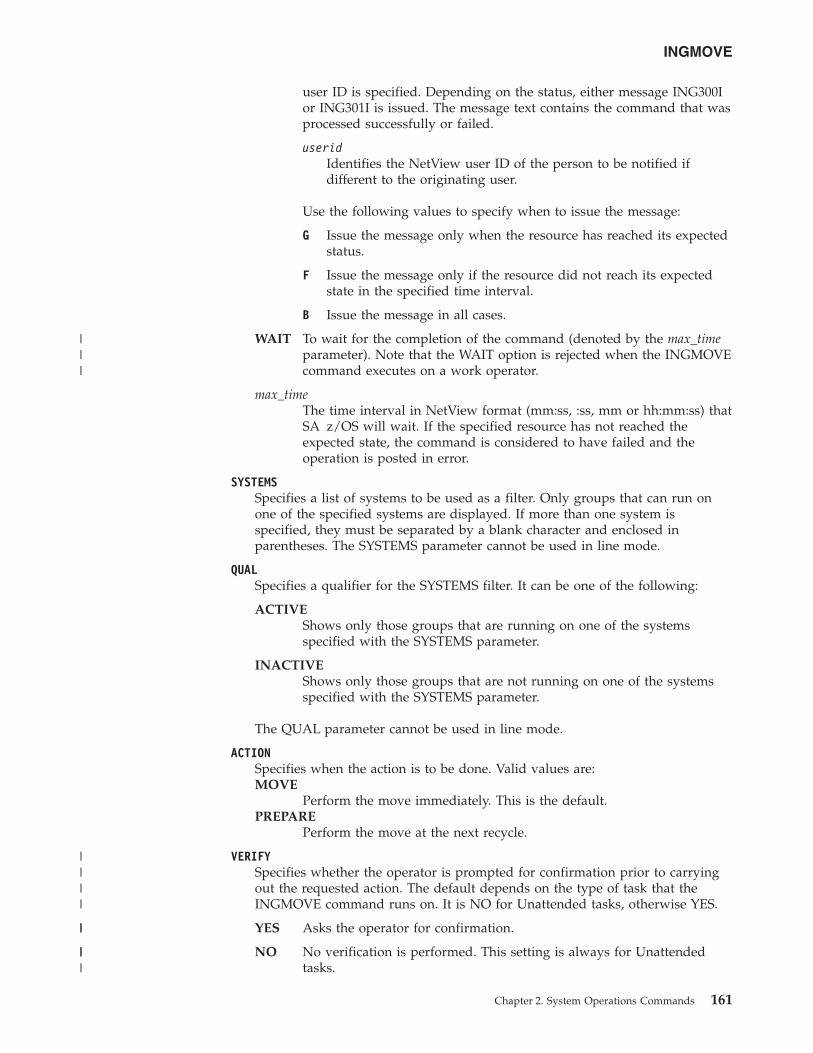
user ID is specified. Depending on the status, either message ING300Ior ING301I is issued. The message text contains the command that wasprocessed successfully or failed.
useridIdentifies the NetView user ID of the person to be notified ifdifferent to the originating user.
Use the following values to specify when to issue the message:
G Issue the message only when the resource has reached its expectedstatus.
F Issue the message only if the resource did not reach its expectedstate in the specified time interval.
B Issue the message in all cases.
WAIT To wait for the completion of the command (denoted by the max_timeparameter). Note that the WAIT option is rejected when the INGMOVEcommand executes on a work operator.
max_timeThe time interval in NetView format (mm:ss, :ss, mm or hh:mm:ss) thatSA z/OS will wait. If the specified resource has not reached theexpected state, the command is considered to have failed and theoperation is posted in error.
SYSTEMSSpecifies a list of systems to be used as a filter. Only groups that can run onone of the specified systems are displayed. If more than one system isspecified, they must be separated by a blank character and enclosed inparentheses. The SYSTEMS parameter cannot be used in line mode.
QUALSpecifies a qualifier for the SYSTEMS filter. It can be one of the following:
ACTIVEShows only those groups that are running on one of the systemsspecified with the SYSTEMS parameter.
INACTIVEShows only those groups that are not running on one of the systemsspecified with the SYSTEMS parameter.
The QUAL parameter cannot be used in line mode.
ACTIONSpecifies when the action is to be done. Valid values are:MOVE
Perform the move immediately. This is the default.PREPARE
Perform the move at the next recycle.
VERIFYSpecifies whether the operator is prompted for confirmation prior to carryingout the requested action. The default depends on the type of task that theINGMOVE command runs on. It is NO for Unattended tasks, otherwise YES.
YES Asks the operator for confirmation.
NO No verification is performed. This setting is always for Unattendedtasks.
INGMOVE
Chapter 2. System Operations Commands 161
|||
||||
||
|||
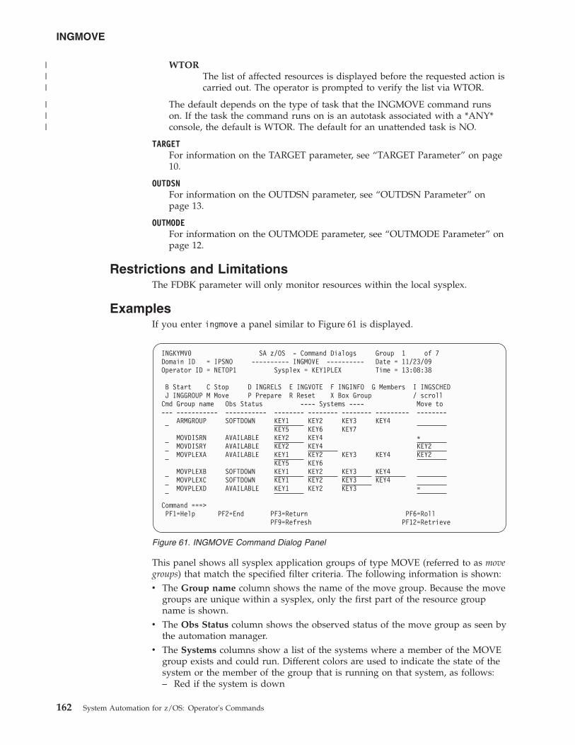
WTORThe list of affected resources is displayed before the requested action iscarried out. The operator is prompted to verify the list via WTOR.
The default depends on the type of task that the INGMOVE command runson. If the task the command runs on is an autotask associated with a *ANY*console, the default is WTOR. The default for an unattended task is NO.
TARGETFor information on the TARGET parameter, see “TARGET Parameter” on page10.
OUTDSNFor information on the OUTDSN parameter, see “OUTDSN Parameter” onpage 13.
OUTMODEFor information on the OUTMODE parameter, see “OUTMODE Parameter” onpage 12.
Restrictions and LimitationsThe FDBK parameter will only monitor resources within the local sysplex.
ExamplesIf you enter ingmove a panel similar to Figure 61 is displayed.
This panel shows all sysplex application groups of type MOVE (referred to as movegroups) that match the specified filter criteria. The following information is shown:v The Group name column shows the name of the move group. Because the move
groups are unique within a sysplex, only the first part of the resource groupname is shown.
v The Obs Status column shows the observed status of the move group as seen bythe automation manager.
v The Systems columns show a list of the systems where a member of the MOVEgroup exists and could run. Different colors are used to indicate the state of thesystem or the member of the group that is running on that system, as follows:– Red if the system is down
INGKYMV0 SA z/OS - Command Dialogs Group 1 of 7Domain ID = IPSNO ---------- INGMOVE ---------- Date = 11/23/09Operator ID = NETOP1 Sysplex = KEY1PLEX Time = 13:08:38
B Start C Stop D INGRELS E INGVOTE F INGINFO G Members I INGSCHEDJ INGGROUP M Move P Prepare R Reset X Box Group / scrollCmd Group name Obs Status ---- Systems ---- Move to--- ----------- ----------- -------- -------- -------- --------- --------
ARMGROUP SOFTDOWN KEY1 KEY2 KEY3 KEY4KEY5 KEY6 KEY7
MOVDISRN AVAILABLE KEY2 KEY4 *MOVDISRY AVAILABLE KEY2 KEY4 KEY2MOVPLEXA AVAILABLE KEY1 KEY2 KEY3 KEY4 KEY2
KEY5 KEY6MOVPLEXB SOFTDOWN KEY1 KEY2 KEY3 KEY4MOVPLEXC SOFTDOWN KEY1 KEY2 KEY3 KEY4MOVPLEXD AVAILABLE KEY1 KEY2 KEY3 =
Command ===>PF1=Help PF2=End PF3=Return PF6=Roll
PF9=Refresh PF12=Retrieve
Figure 61. INGMOVE Command Dialog Panel
INGMOVE
162 System Automation for z/OS: Operator's Commands
|||
|||
– Yellow if the member of the group that is running on that system is notstartable
– Green if a member of the group is currently active on that system– Pink if the system is excluded– White if the system is avoided– Turquoise in all other cases
The home system, or systems, which are those that have the highest preferencevalue, are underlined.The system that has the highest actual preference is shown in reverse video,unless it is a home system. Note that this can be more than one system.
v The Move to column is an input field where you can specify the system that thegroup should be moved to. Moving a sysplex application move group meansterminating the member that is currently active and starting the member on thedesignated system.Initially, SA z/OS shows the best system to be used for a move operation in thisfield, based on the state of the group members and their preference points. Theproposed system is shown in blue.You can designate the system by specifying in the Move to field:– The name of the system.– An asterisk (*). This means that the group is moved back to its home system,
which is the one with the highest base preference value. If more than onehome system exists, it is moved to the first one in the list.
– An equals sign (=). This is a shorthand form that means to take the valuefrom the nearest field above with a value specified in it.
You can enter the following action codes in the Cmd field to launch othercommands:
B Start. Calls the INGREQ command dialog to make the resource available. See“INGREQ” on page 197 for further information.
C Stop. Calls the INGREQ command dialog to make the resource unavailable.See “INGREQ” on page 197 for further information.
D Invokes the INGRELS command to display dependency information and itsevaluation for the resource.
E Invokes the INGVOTE command, showing all requests currently present forthe resource. Allows the operator to cancel a request.
F Shows details about the resource by invoking the INGINFO command.
G Invokes the INGLIST MEMBERS=YES command to show all members for theselected application group in a new window.
I Invokes the INGSCHED command to show the resource overrides for theselected resource.
J Invokes the INGGROUP ACTION=MEMBERS command to show memberdetails.
M Moves the group to the designated system.
P Moves the group to the designated system when the group is next recycled.
R Resets the preference values of the group members to the values that aredefined in the policy database.
INGMOVE
Chapter 2. System Operations Commands 163
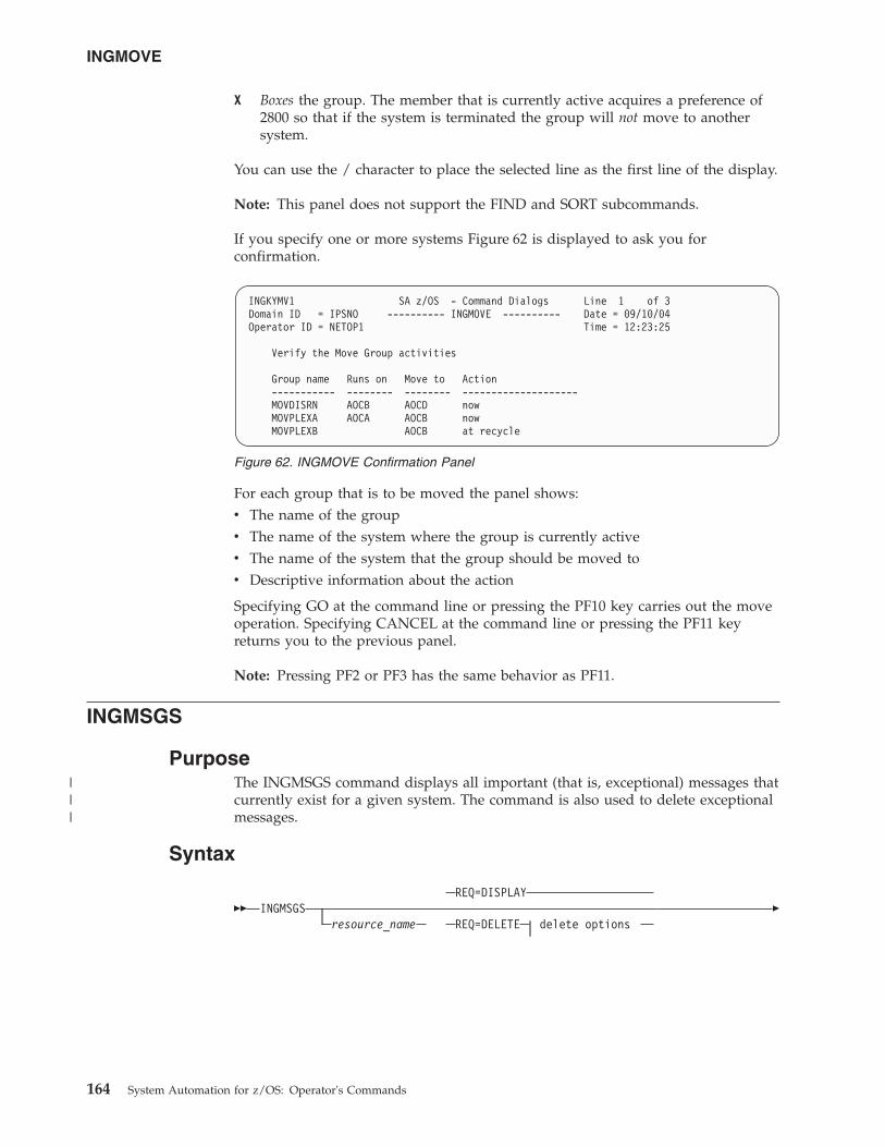
X Boxes the group. The member that is currently active acquires a preference of2800 so that if the system is terminated the group will not move to anothersystem.
You can use the / character to place the selected line as the first line of the display.
Note: This panel does not support the FIND and SORT subcommands.
If you specify one or more systems Figure 62 is displayed to ask you forconfirmation.
For each group that is to be moved the panel shows:v The name of the groupv The name of the system where the group is currently activev The name of the system that the group should be moved tov Descriptive information about the action
Specifying GO at the command line or pressing the PF10 key carries out the moveoperation. Specifying CANCEL at the command line or pressing the PF11 keyreturns you to the previous panel.
Note: Pressing PF2 or PF3 has the same behavior as PF11.
INGMSGS
PurposeThe INGMSGS command displays all important (that is, exceptional) messages thatcurrently exist for a given system. The command is also used to delete exceptionalmessages.
Syntax
��REQ=DISPLAY
INGMSGSresource_name REQ=DELETE delete options
�
INGKYMV1 SA z/OS - Command Dialogs Line 1 of 3Domain ID = IPSNO ---------- INGMOVE ---------- Date = 09/10/04Operator ID = NETOP1 Time = 12:23:25
Verify the Move Group activities
Group name Runs on Move to Action----------- -------- -------- --------------------MOVDISRN AOCB AOCD nowMOVPLEXA AOCA AOCB nowMOVPLEXB AOCB at recycle
Figure 62. INGMOVE Confirmation Panel
INGMOVE
164 System Automation for z/OS: Operator's Commands
|||
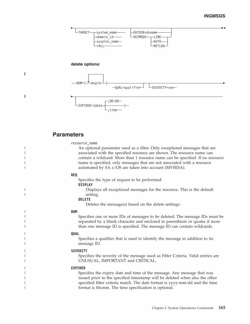
�TARGET= system_name
domain_idsysplex_name*ALL
OUTDSN=dsnameOUTMODE= LINE
AUTONETLOG
��
delete options:
�DOM=( msgid )QUAL=qualifier SEVERITY=sev
�
�,00:00
EXPIRED=(date ),time
Parametersresource_name
An optional parameter used as a filter. Only exceptional messages that areassociated with the specified resource are shown. The resource name cancontain a wildcard. More than 1 resource name can be specified. If no resourcename is specified, only messages that are not associated with a resourceautomated by SA z/OS are taken into account (MVSESA).
REQSpecifies the type of request to be performed:DISPLAY
Displays all exceptional messages for the resource. This is the defaultsetting.
DELETEDeletes the message(s) based on the delete settings:
DOMSpecifies one or more IDs of messages to be deleted. The message IDs must beseparated by a blank character and enclosed in parenthesis or quotes if morethan one message ID is specified. The message ID can contain wildcards.
QUALSpecifies a qualifier that is used to identify the message in addition to itsmessage ID.
SEVERITYSpecifies the severity of the message used as Filter Criteria. Valid entries areUNUSUAL, IMPORTANT and CRITICAL.
EXPIREDSpecifies the expiry date and time of the message. Any message that wasissued prior to the specified timestamp will be deleted when also the otherspecified filter criteria match. The date format is yyyy-mm-dd and the timeformat is hh:mm. The time specification is optional.
INGMSGS
Chapter 2. System Operations Commands 165
|||||
||||
|||||
||
||||
|||
|||
|||||
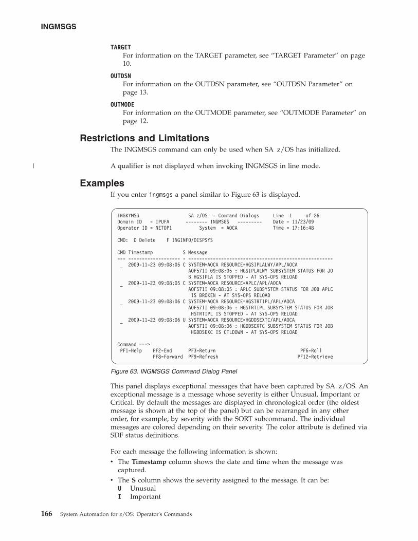
TARGETFor information on the TARGET parameter, see “TARGET Parameter” on page10.
OUTDSNFor information on the OUTDSN parameter, see “OUTDSN Parameter” onpage 13.
OUTMODEFor information on the OUTMODE parameter, see “OUTMODE Parameter” onpage 12.
Restrictions and LimitationsThe INGMSGS command can only be used when SA z/OS has initialized.
A qualifier is not displayed when invoking INGMSGS in line mode.
ExamplesIf you enter ingmsgs a panel similar to Figure 63 is displayed.
This panel displays exceptional messages that have been captured by SA z/OS. Anexceptional message is a message whose severity is either Unusual, Important orCritical. By default the messages are displayed in chronological order (the oldestmessage is shown at the top of the panel) but can be rearranged in any otherorder, for example, by severity with the SORT subcommand. The individualmessages are colored depending on their severity. The color attribute is defined viaSDF status definitions.
For each message the following information is shown:v The Timestamp column shows the date and time when the message was
captured.v The S column shows the severity assigned to the message. It can be:
U UnusualI Important
INGKYMSG SA z/OS - Command Dialogs Line 1 of 26Domain ID = IPUFA -------- INGMSGS --------- Date = 11/23/09Operator ID = NETOP1 System = AOCA Time = 17:16:48
CMD: D Delete F INGINFO/DISPSYS
CMD Timestamp S Message--- ------------------- - -----------------------------------------------------
2009-11-23 09:08:05 C SYSTEM=AOCA RESOURCE=HGSIPLALWY/APL/AOCAAOF571I 09:08:05 : HGSIPLALWY SUBSYSTEM STATUS FOR JOB HGSIPLA IS STOPPED - AT SYS-OPS RELOAD
2009-11-23 09:08:05 C SYSTEM=AOCA RESOURCE=APLC/APL/AOCAAOF571I 09:08:05 : APLC SUBSYSTEM STATUS FOR JOB APLCIS BROKEN - AT SYS-OPS RELOAD
2009-11-23 09:08:06 C SYSTEM=AOCA RESOURCE=HGSTRTIPL/APL/AOCAAOF571I 09:08:06 : HGSTRTIPL SUBSYSTEM STATUS FOR JOBHSTRTIPL IS STOPPED - AT SYS-OPS RELOAD
2009-11-23 09:08:06 U SYSTEM=AOCA RESOURCE=HGDDSEXTC/APL/AOCAAOF571I 09:08:06 : HGDDSEXTC SUBSYSTEM STATUS FOR JOBHGDDSEXC IS CTLDOWN - AT SYS-OPS RELOAD
Command ===>PF1=Help PF2=End PF3=Return PF6=Roll
PF8=Forward PF9=Refresh PF12=Retrieve
Figure 63. INGMSGS Command Dialog Panel
INGMSGS
166 System Automation for z/OS: Operator's Commands
|
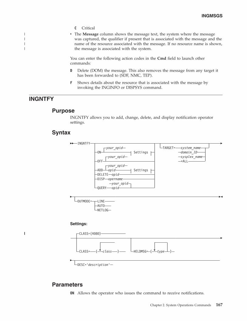
C Criticalv The Message column shows the message text, the system where the message
was captured, the qualifier if present that is associated with the message and thename of the resource associated with the message. If no resource name is shown,the message is associated with the system.
You can enter the following action codes in the Cmd field to launch othercommands:
D Delete (DOM) the message. This also removes the message from any target ithas been forwarded to (SDF, NMC, TEP).
F Shows details about the resource that is associated with the message byinvoking the INGINFO or DISPSYS command.
INGNTFY
PurposeINGNTFY allows you to add, change, delete, and display notification operatorsettings.
Syntax
�� INGNTFYyour_opid
ON Settingsyour_opid
OFFyour_opid
ADD opid SettingsDELETE opidDISP opername
your_opidQUERY opid
TARGET= system_namedomain_IDsysplex_name*ALL
�
�OUTMODE= LINE
AUTONETLOG
��
Settings:
�
CLASS=(4080)
CLASS= ( class ) �HELDMSG= ( type )
�
�DESC='description'
ParametersON Allows the operator who issues the command to receive notifications.
INGMSGS
Chapter 2. System Operations Commands 167
||||
|||
OFFTurns off notifications for the operator who issues the command.
ADDAdds the operator specified in opid to the list of notification operators, orchanges the definition of the existing operator specified in opid.
Note: Use of the ADD function to change the definition of an existing operatorcompletely deletes the old definition. It is necessary to re-specify allmessage classes and held message types that you want this operator toretain. This allows you to remove unwanted message classes and heldmessage types from an existing operator.
DELETERemoves the operator specified in opid from the list of notification operators.
DISPDisplays information about the operator that is specified in opername, whichcan also contain a wildcard, such as *abc, abc*, or *abc*.
QUERYDisplays information about the operator that is specified in opid.
opidThe ID of the operator to add, change, delete, or query.
your_opidThe ID of the operator issuing the command.
CLASSThe classes of messages the operator is to receive. See IBM Tivoli SystemAutomation for z/OS Messages and Codes for information about which classes arevalid. Up to ten comma-delimited classes, enclosed in parentheses, can bedefined for an operator. The default classes are 40 and 80, unless definedotherwise in the automation control file.
DESCAn optional description of the operator. If the description contains blanks,commas, or other punctuation characters it must be enclosed in singlequotation marks.
HELDMSGThe type or types of messages to hold on the operator's screen. If more thanone type is specified, the types should be separated by commas and enclosedin parentheses. The types are:
Type Meaning
A Immediate Action
D Immediate Decision
E Eventual Action
I Information
W System Wait
TARGETFor information on the TARGET parameter, see “TARGET Parameter” on page10.
INGNTFY
168 System Automation for z/OS: Operator's Commands
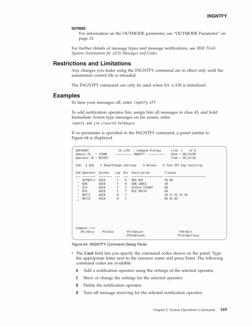
OUTMODEFor information on the OUTMODE parameter, see “OUTMODE Parameter” onpage 12.
For further details of message types and message notifications, see IBM TivoliSystem Automation for z/OS Messages and Codes.
Restrictions and LimitationsAny changes you make using the INGNTFY command are in effect only until theautomation control file is reloaded.
The INGNTFY command can only be used when SA z/OS is initialized.
ExamplesTo turn your messages off, enter ingntfy off
To add notification operator Jim, assign him all messages in class 43, and holdImmediate Action type messages on his screen, enter:ingntfy add jim class=43 heldmsg=a
If no parameter is specified in the INGNTFY command, a panel similar toFigure 64 is displayed.
v The Cmd field lets you specify the command codes shown on the panel. Typethe appropriate letter next to the resource name and press Enter. The followingcommand codes are available:
A Add a notification operator using the settings of the selected operator.
C Show or change the settings for the selected operator.
D Delete the notification operator.
O Turn off message receiving for the selected notification operator.
AOFKAANT SA z/OS - Command Dialogs Line 1 of 6Domain ID = IPUN8 ---------- INGNTFY ---------- Date = 06/19/09Operator ID = NETOP1 Time = 20:12:52
Cmd: A Add C Show/Change settings D Delete O Turn OFF msg receiving
Cmd Operator System Log Rcv Description Classes--- -------- -------- --- --- ------------------- ----------------------–--
AUTNOTI1 AOC8 Y N MSG AOP 40 80DON AOC8 Y N DON JONES 40GIS AOC8 Y Y GISELA STUART 80MIK AOC8 Y Y MIK SMITH 60NOTI1 AOC8 N Y 40 41 42 43 44NOTI2 AOC8 N Y 80 81 82
Command ===>PF1=Help PF2=End PF3=Return PF6=Roll
PF9=Refresh PF12=Retrieve
Figure 64. INGNTFY Command Dialog Panel
INGNTFY
Chapter 2. System Operations Commands 169
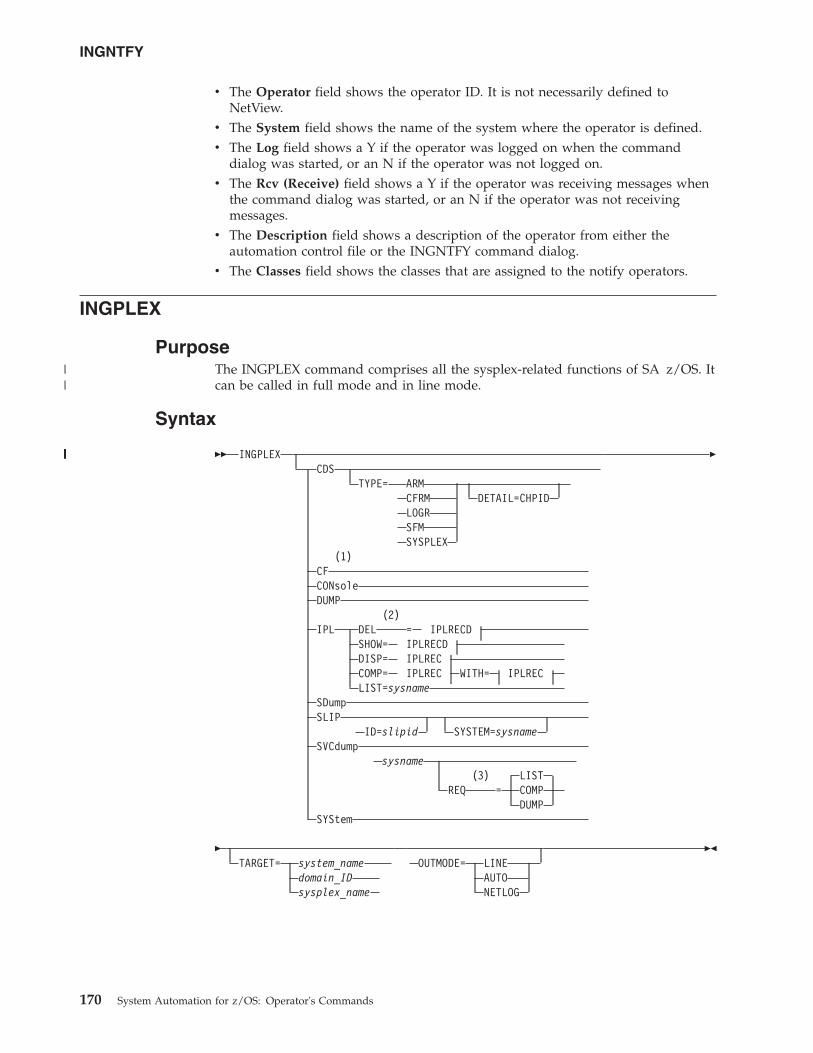
v The Operator field shows the operator ID. It is not necessarily defined toNetView.
v The System field shows the name of the system where the operator is defined.v The Log field shows a Y if the operator was logged on when the command
dialog was started, or an N if the operator was not logged on.v The Rcv (Receive) field shows a Y if the operator was receiving messages when
the command dialog was started, or an N if the operator was not receivingmessages.
v The Description field shows a description of the operator from either theautomation control file or the INGNTFY command dialog.
v The Classes field shows the classes that are assigned to the notify operators.
INGPLEX
PurposeThe INGPLEX command comprises all the sysplex-related functions of SA z/OS. Itcan be called in full mode and in line mode.
Syntax
�� INGPLEXCDS
TYPE= ARMCFRM DETAIL=CHPIDLOGRSFMSYSPLEX
(1)CFCONsoleDUMP
(2)IPL DEL = IPLRECD
SHOW= IPLRECDDISP= IPLRECCOMP= IPLREC WITH= IPLRECLIST=sysname
SDumpSLIP
ID=slipid SYSTEM=sysnameSVCdump
sysname(3) LIST
REQ = COMPDUMP
SYStem
�
�TARGET= system_name
domain_IDsysplex_name
OUTMODE= LINEAUTONETLOG
��
INGNTFY
170 System Automation for z/OS: Operator's Commands
||
||||||||
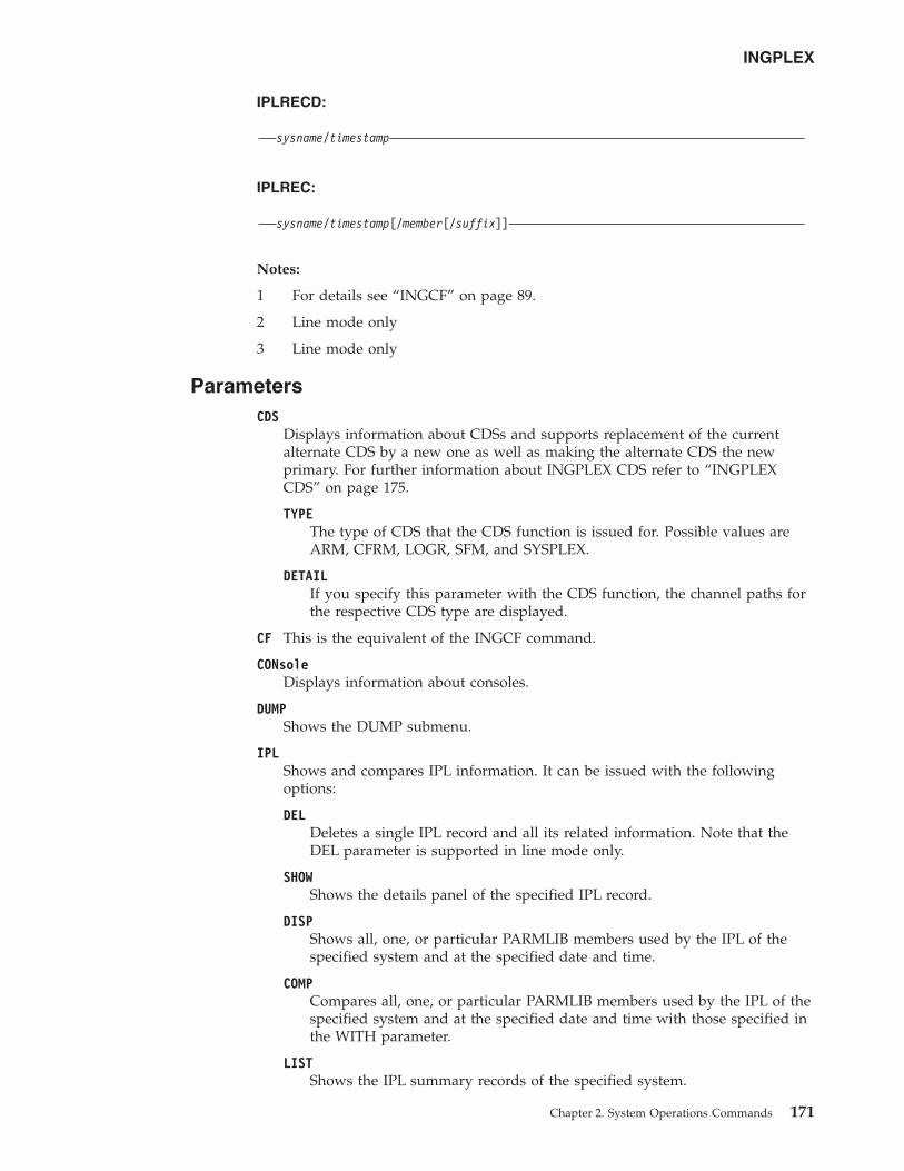
IPLRECD:
sysname/timestamp
IPLREC:
sysname/timestamp[/member[/suffix]]
Notes:
1 For details see “INGCF” on page 89.
2 Line mode only
3 Line mode only
ParametersCDS
Displays information about CDSs and supports replacement of the currentalternate CDS by a new one as well as making the alternate CDS the newprimary. For further information about INGPLEX CDS refer to “INGPLEXCDS” on page 175.
TYPEThe type of CDS that the CDS function is issued for. Possible values areARM, CFRM, LOGR, SFM, and SYSPLEX.
DETAILIf you specify this parameter with the CDS function, the channel paths forthe respective CDS type are displayed.
CF This is the equivalent of the INGCF command.
CONsoleDisplays information about consoles.
DUMPShows the DUMP submenu.
IPLShows and compares IPL information. It can be issued with the followingoptions:
DELDeletes a single IPL record and all its related information. Note that theDEL parameter is supported in line mode only.
SHOWShows the details panel of the specified IPL record.
DISPShows all, one, or particular PARMLIB members used by the IPL of thespecified system and at the specified date and time.
COMPCompares all, one, or particular PARMLIB members used by the IPL of thespecified system and at the specified date and time with those specified inthe WITH parameter.
LISTShows the IPL summary records of the specified system.
INGPLEX
Chapter 2. System Operations Commands 171
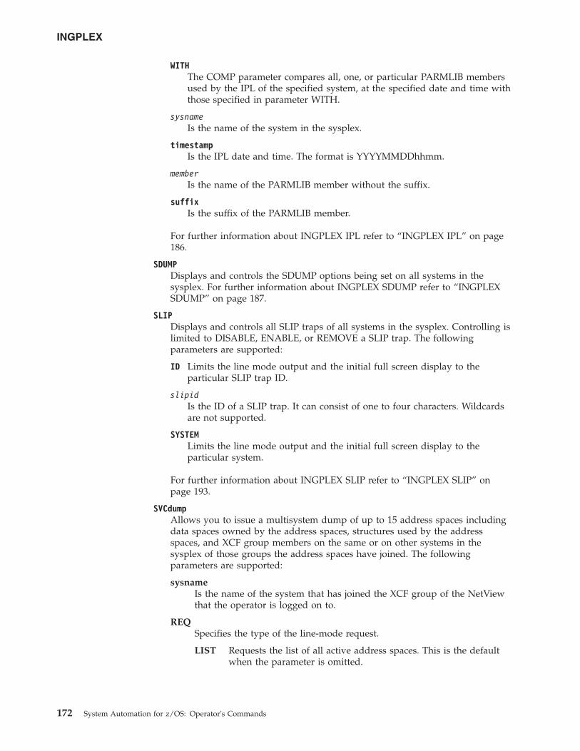
WITHThe COMP parameter compares all, one, or particular PARMLIB membersused by the IPL of the specified system, at the specified date and time withthose specified in parameter WITH.
sysnameIs the name of the system in the sysplex.
timestampIs the IPL date and time. The format is YYYYMMDDhhmm.
memberIs the name of the PARMLIB member without the suffix.
suffixIs the suffix of the PARMLIB member.
For further information about INGPLEX IPL refer to “INGPLEX IPL” on page186.
SDUMPDisplays and controls the SDUMP options being set on all systems in thesysplex. For further information about INGPLEX SDUMP refer to “INGPLEXSDUMP” on page 187.
SLIPDisplays and controls all SLIP traps of all systems in the sysplex. Controlling islimited to DISABLE, ENABLE, or REMOVE a SLIP trap. The followingparameters are supported:
ID Limits the line mode output and the initial full screen display to theparticular SLIP trap ID.
slipidIs the ID of a SLIP trap. It can consist of one to four characters. Wildcardsare not supported.
SYSTEMLimits the line mode output and the initial full screen display to theparticular system.
For further information about INGPLEX SLIP refer to “INGPLEX SLIP” onpage 193.
SVCdumpAllows you to issue a multisystem dump of up to 15 address spaces includingdata spaces owned by the address spaces, structures used by the addressspaces, and XCF group members on the same or on other systems in thesysplex of those groups the address spaces have joined. The followingparameters are supported:
sysnameIs the name of the system that has joined the XCF group of the NetViewthat the operator is logged on to.
REQSpecifies the type of the line-mode request.
LIST Requests the list of all active address spaces. This is the defaultwhen the parameter is omitted.
INGPLEX
172 System Automation for z/OS: Operator's Commands
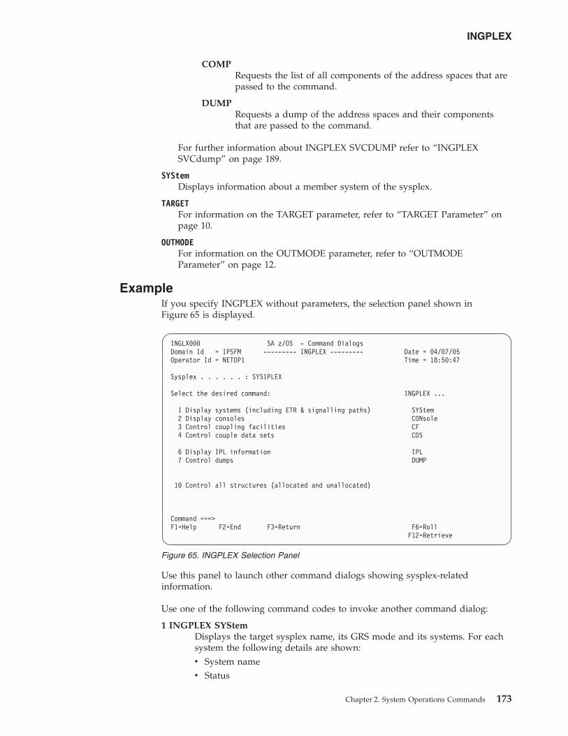
COMPRequests the list of all components of the address spaces that arepassed to the command.
DUMPRequests a dump of the address spaces and their componentsthat are passed to the command.
For further information about INGPLEX SVCDUMP refer to “INGPLEXSVCdump” on page 189.
SYStemDisplays information about a member system of the sysplex.
TARGETFor information on the TARGET parameter, refer to “TARGET Parameter” onpage 10.
OUTMODEFor information on the OUTMODE parameter, refer to “OUTMODEParameter” on page 12.
ExampleIf you specify INGPLEX without parameters, the selection panel shown inFigure 65 is displayed.
Use this panel to launch other command dialogs showing sysplex-relatedinformation.
Use one of the following command codes to invoke another command dialog:
1 INGPLEX SYStemDisplays the target sysplex name, its GRS mode and its systems. For eachsystem the following details are shown:v System namev Status
INGLX000 SA z/OS - Command DialogsDomain Id = IPSFM --------- INGPLEX --------- Date = 04/07/05Operator Id = NETOP1 Time = 18:50:47
Sysplex . . . . . . : SYS1PLEX
Select the desired command: INGPLEX ...
1 Display systems (including ETR & signalling paths) SYStem2 Display consoles CONsole3 Control coupling facilities CF4 Control couple data sets CDS
6 Display IPL information IPL7 Control dumps DUMP
10 Control all structures (allocated and unallocated)
Command ===>F1=Help F2=End F3=Return F6=Roll
F12=Retrieve
Figure 65. INGPLEX Selection Panel
INGPLEX
Chapter 2. System Operations Commands 173
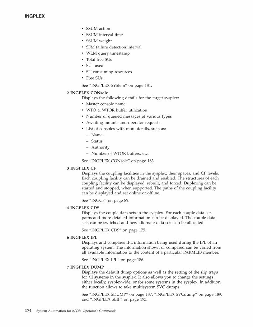
v SSUM actionv SSUM interval timev SSUM weightv SFM failure detection intervalv WLM query timestampv Total free SUsv SUs usedv SU-consuming resourcesv Free SUs
See “INGPLEX SYStem” on page 181.
2 INGPLEX CONsoleDisplays the following details for the target sysplex:v Master console namev WTO & WTOR buffer utilizationv Number of queued messages of various typesv Awaiting mounts and operator requestsv List of consoles with more details, such as:
– Name– Status– Authority– Number of WTOR buffers, etc.
See “INGPLEX CONsole” on page 183.
3 INGPLEX CFDisplays the coupling facilities in the sysplex, their spaces, and CF levels.Each coupling facility can be drained and enabled. The structures of eachcoupling facility can be displayed, rebuilt, and forced. Duplexing can bestarted and stopped, when supported. The paths of the coupling facilitycan be displayed and set online or offline.
See “INGCF” on page 89.
4 INGPLEX CDSDisplays the couple data sets in the sysplex. For each couple data set,paths and more detailed information can be displayed. The couple datasets can be switched and new alternate data sets can be allocated.
See “INGPLEX CDS” on page 175.
6 INGPLEX IPLDisplays and compares IPL information being used during the IPL of anoperating system. The information shown or compared can be varied fromall available information to the content of a particular PARMLIB member.
See “INGPLEX IPL” on page 186.
7 INGPLEX DUMPDisplays the default dump options as well as the setting of the slip trapsfor all systems in the sysplex. It also allows you to change the settingseither locally, sysplexwide, or for some systems in the sysplex. In addition,the function allows to take multisystem SVC dumps.
See “INGPLEX SDUMP” on page 187, “INGPLEX SVCdump” on page 189,and “INGPLEX SLIP” on page 193.
INGPLEX
174 System Automation for z/OS: Operator's Commands
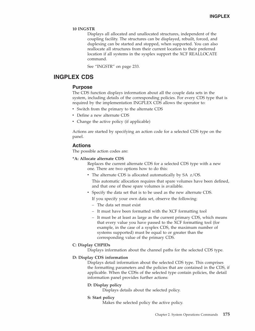
10 INGSTRDisplays all allocated and unallocated structures, independent of thecoupling facility. The structures can be displayed, rebuilt, forced, andduplexing can be started and stopped, when supported. You can alsoreallocate all structures from their current location to their preferredlocation if all systems in the sysplex support the XCF REALLOCATEcommand.
See “INGSTR” on page 233.
INGPLEX CDS
PurposeThe CDS function displays information about all the couple data sets in thesystem, including details of the corresponding policies. For every CDS type that isrequired by the implementation INGPLEX CDS allows the operator to:v Switch from the primary to the alternate CDSv Define a new alternate CDSv Change the active policy (if applicable)
Actions are started by specifying an action code for a selected CDS type on thepanel.
ActionsThe possible action codes are:
*A: Allocate alternate CDSReplaces the current alternate CDS for a selected CDS type with a newone. There are two options how to do this:v The alternate CDS is allocated automatically by SA z/OS.
This automatic allocation requires that spare volumes have been defined,and that one of these spare volumes is available.
v Specify the data set that is to be used as the new alternate CDS.If you specify your own data set, observe the following:– The data set must exist– It must have been formatted with the XCF formatting tool– It must be at least as large as the current primary CDS, which means
that every value you have passed to the XCF formatting tool (forexample, in the case of a sysplex CDS, the maximum number ofsystems supported) must be equal to or greater than thecorresponding value of the primary CDS.
C: Display CHPIDsDisplays information about the channel paths for the selected CDS type.
D: Display CDS informationDisplays detail information about the selected CDS type. This comprisesthe formatting parameters and the policies that are contained in the CDS, ifapplicable. When the CDSs of the selected type contain policies, the detailinformation panel provides further actions:
D: Display policyDisplays details about the selected policy.
S: Start policyMakes the selected policy the active policy.
INGPLEX
Chapter 2. System Operations Commands 175
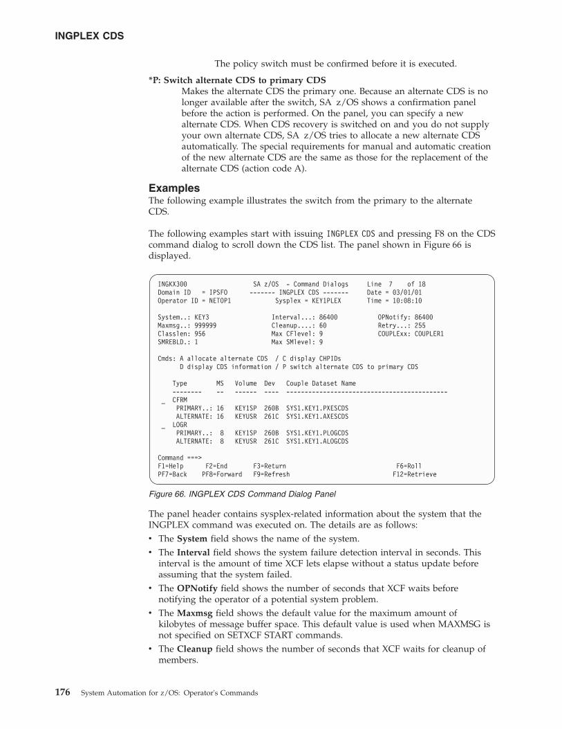
The policy switch must be confirmed before it is executed.
*P: Switch alternate CDS to primary CDSMakes the alternate CDS the primary one. Because an alternate CDS is nolonger available after the switch, SA z/OS shows a confirmation panelbefore the action is performed. On the panel, you can specify a newalternate CDS. When CDS recovery is switched on and you do not supplyyour own alternate CDS, SA z/OS tries to allocate a new alternate CDSautomatically. The special requirements for manual and automatic creationof the new alternate CDS are the same as those for the replacement of thealternate CDS (action code A).
ExamplesThe following example illustrates the switch from the primary to the alternateCDS.
The following examples start with issuing INGPLEX CDS and pressing F8 on the CDScommand dialog to scroll down the CDS list. The panel shown in Figure 66 isdisplayed.
The panel header contains sysplex-related information about the system that theINGPLEX command was executed on. The details are as follows:v The System field shows the name of the system.v The Interval field shows the system failure detection interval in seconds. This
interval is the amount of time XCF lets elapse without a status update beforeassuming that the system failed.
v The OPNotify field shows the number of seconds that XCF waits beforenotifying the operator of a potential system problem.
v The Maxmsg field shows the default value for the maximum amount ofkilobytes of message buffer space. This default value is used when MAXMSG isnot specified on SETXCF START commands.
v The Cleanup field shows the number of seconds that XCF waits for cleanup ofmembers.
INGKX300 SA z/OS - Command Dialogs Line 7 of 18Domain ID = IPSFO ------- INGPLEX CDS ------- Date = 03/01/01Operator ID = NETOP1 Sysplex = KEY1PLEX Time = 10:08:10
System..: KEY3 Interval...: 86400 OPNotify: 86400Maxmsg..: 999999 Cleanup....: 60 Retry...: 255Classlen: 956 Max CFlevel: 9 COUPLExx: COUPLER1SMREBLD.: 1 Max SMlevel: 9
Cmds: A allocate alternate CDS / C display CHPIDsD display CDS information / P switch alternate CDS to primary CDS
Type MS Volume Dev Couple Dataset Name-------- -- ------ ---- --------------------------------------------
_ CFRMPRIMARY..: 16 KEY1SP 260B SYS1.KEY1.PXESCDSALTERNATE: 16 KEYUSR 261C SYS1.KEY1.AXESCDS
_ LOGRPRIMARY..: 8 KEY1SP 260B SYS1.KEY1.PLOGCDSALTERNATE: 8 KEYUSR 261C SYS1.KEY1.ALOGCDS
Command ===>F1=Help F2=End F3=Return F6=RollPF7=Back PF8=Forward F9=Refresh F12=Retrieve
Figure 66. INGPLEX CDS Command Dialog Panel
INGPLEX CDS
176 System Automation for z/OS: Operator's Commands
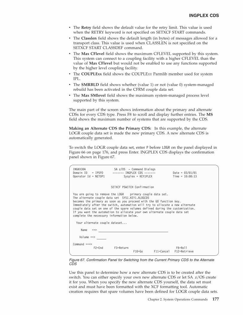
v The Retry field shows the default value for the retry limit. This value is usedwhen the RETRY keyword is not specified on SETXCF START commands.
v The Classlen field shows the default length (in bytes) of messages allowed for atransport class. This value is used when CLASSLEN is not specified on theSETXCF START CLASSDEF command.
v The Max CFlevel field shows the maximum CFLEVEL supported by this system.This system can connect to a coupling facility with a higher CFLEVEL than thevalue of Max CFlevel but would not be enabled to use any functions supportedby the higher level coupling facility.
v The COUPLExx field shows the COUPLExx Parmlib member used for systemIPL.
v The SMRBLD field shows whether (value 1) or not (value 0) system-managedrebuild has been activated in the CFRM couple data set.
v The Max SMlevel field shows the maximum system-managed process levelsupported by this system.
The main part of the screen shows information about the primary and alternateCDSs for every CDS type. Press F8 to scroll and display further entries. The MSfield shows the maximum number of systems that are supported by the CDS.
Making an Alternate CDS the Primary CDS: In this example, the alternateLOGR couple data set is made the new primary CDS. A new alternate CDS isautomatically generated.
To switch the LOGR couple data set, enter P before LOGR on the panel displayed inFigure 66 on page 176, and press Enter. INGPLEX CDS displays the confirmationpanel shown in Figure 67.
Use this panel to determine how a new alternate CDS is to be created after theswitch. You can either specify your own new alternate CDS or let SA z/OS createit for you. When you specify the new alternate CDS yourself, the data set mustexist and must have been formatted with the XCF formatting tool. Automaticcreation requires that spare volumes have been defined for LOGR couple data sets.
INGKX30A SA z/OS - Command DialogsDomain ID = IPSFO ------- INGPLEX CDS ------- Date = 03/01/01Operator Id = NETOP1 Sysplex = KEY1PLEX Time = 10:08:13
SETXCF PSWITCH Confirmation
You are going to remove the LOGR primary couple data set.The alternate couple data set SYS1.KEY1.ALOGCDSbecomes the primary as soon as you proceed with the GO function key.Immediately after the switch, automation will try to allocate a new alternatecouple data set on one of the spare volumes defined during the customization.If you want the automation to allocate your own alternate couple data setcomplete the necessary information below.
Your alternate couple dataset...
Name ==>
Volume ==>
Command ===>F2=End F3=Return F6=Roll
F10=Go F11=Cancel F12=Retrieve
Figure 67. Confirmation Panel for Switching from the Current Primary CDS to the AlternateCDS
INGPLEX CDS
Chapter 2. System Operations Commands 177
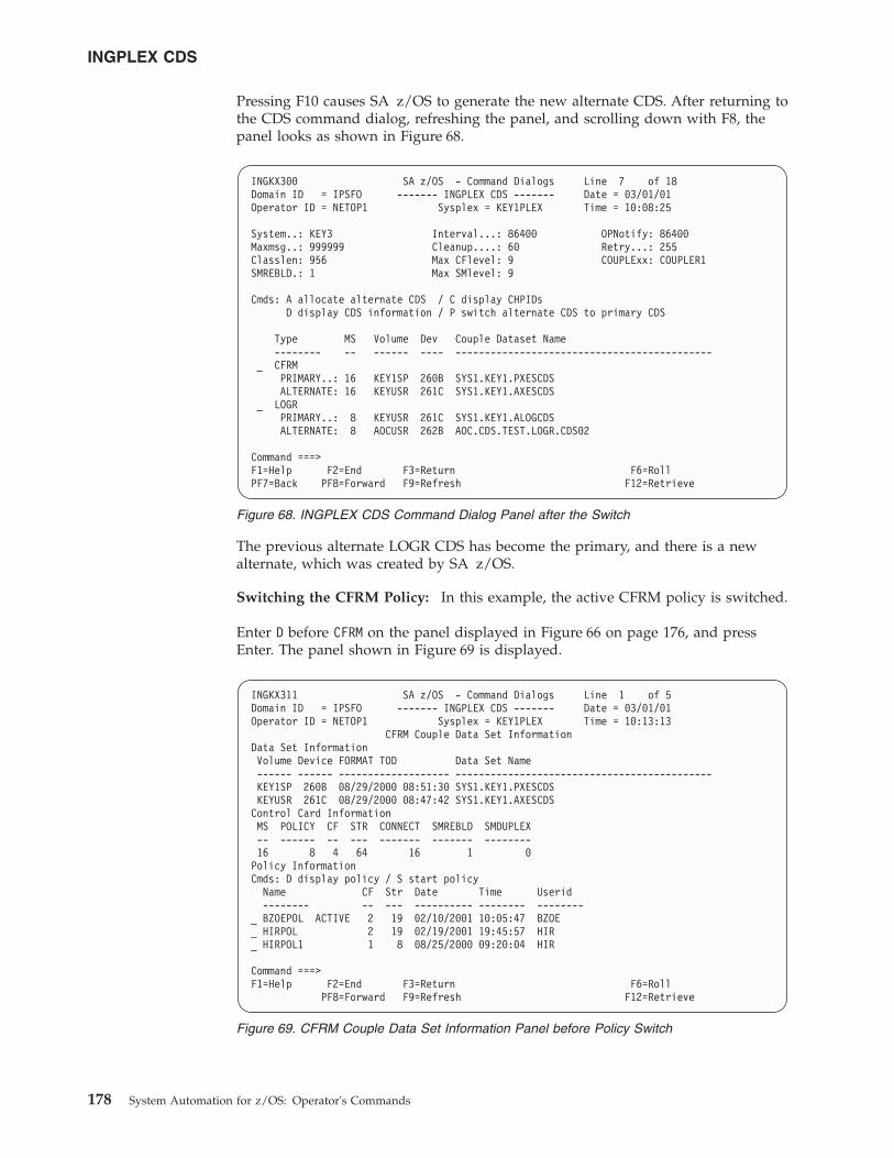
Pressing F10 causes SA z/OS to generate the new alternate CDS. After returning tothe CDS command dialog, refreshing the panel, and scrolling down with F8, thepanel looks as shown in Figure 68.
The previous alternate LOGR CDS has become the primary, and there is a newalternate, which was created by SA z/OS.
Switching the CFRM Policy: In this example, the active CFRM policy is switched.
Enter D before CFRM on the panel displayed in Figure 66 on page 176, and pressEnter. The panel shown in Figure 69 is displayed.
INGKX300 SA z/OS - Command Dialogs Line 7 of 18Domain ID = IPSFO ------- INGPLEX CDS ------- Date = 03/01/01Operator ID = NETOP1 Sysplex = KEY1PLEX Time = 10:08:25
System..: KEY3 Interval...: 86400 OPNotify: 86400Maxmsg..: 999999 Cleanup....: 60 Retry...: 255Classlen: 956 Max CFlevel: 9 COUPLExx: COUPLER1SMREBLD.: 1 Max SMlevel: 9
Cmds: A allocate alternate CDS / C display CHPIDsD display CDS information / P switch alternate CDS to primary CDS
Type MS Volume Dev Couple Dataset Name-------- -- ------ ---- --------------------------------------------
_ CFRMPRIMARY..: 16 KEY1SP 260B SYS1.KEY1.PXESCDSALTERNATE: 16 KEYUSR 261C SYS1.KEY1.AXESCDS
_ LOGRPRIMARY..: 8 KEYUSR 261C SYS1.KEY1.ALOGCDSALTERNATE: 8 AOCUSR 262B AOC.CDS.TEST.LOGR.CDS02
Command ===>F1=Help F2=End F3=Return F6=RollPF7=Back PF8=Forward F9=Refresh F12=Retrieve
Figure 68. INGPLEX CDS Command Dialog Panel after the Switch
INGKX311 SA z/OS - Command Dialogs Line 1 of 5Domain ID = IPSFO ------- INGPLEX CDS ------- Date = 03/01/01Operator ID = NETOP1 Sysplex = KEY1PLEX Time = 10:13:13
CFRM Couple Data Set InformationData Set InformationVolume Device FORMAT TOD Data Set Name------ ------ ------------------- --------------------------------------------KEY1SP 260B 08/29/2000 08:51:30 SYS1.KEY1.PXESCDSKEYUSR 261C 08/29/2000 08:47:42 SYS1.KEY1.AXESCDSControl Card InformationMS POLICY CF STR CONNECT SMREBLD SMDUPLEX-- ------ -- --- ------- ------- --------16 8 4 64 16 1 0Policy InformationCmds: D display policy / S start policy
Name CF Str Date Time Userid-------- -- --- ---------- -------- --------
_ BZOEPOL ACTIVE 2 19 02/10/2001 10:05:47 BZOE_ HIRPOL 2 19 02/19/2001 19:45:57 HIR_ HIRPOL1 1 8 08/25/2000 09:20:04 HIR
Command ===>F1=Help F2=End F3=Return F6=Roll
PF8=Forward F9=Refresh F12=Retrieve
Figure 69. CFRM Couple Data Set Information Panel before Policy Switch
INGPLEX CDS
178 System Automation for z/OS: Operator's Commands
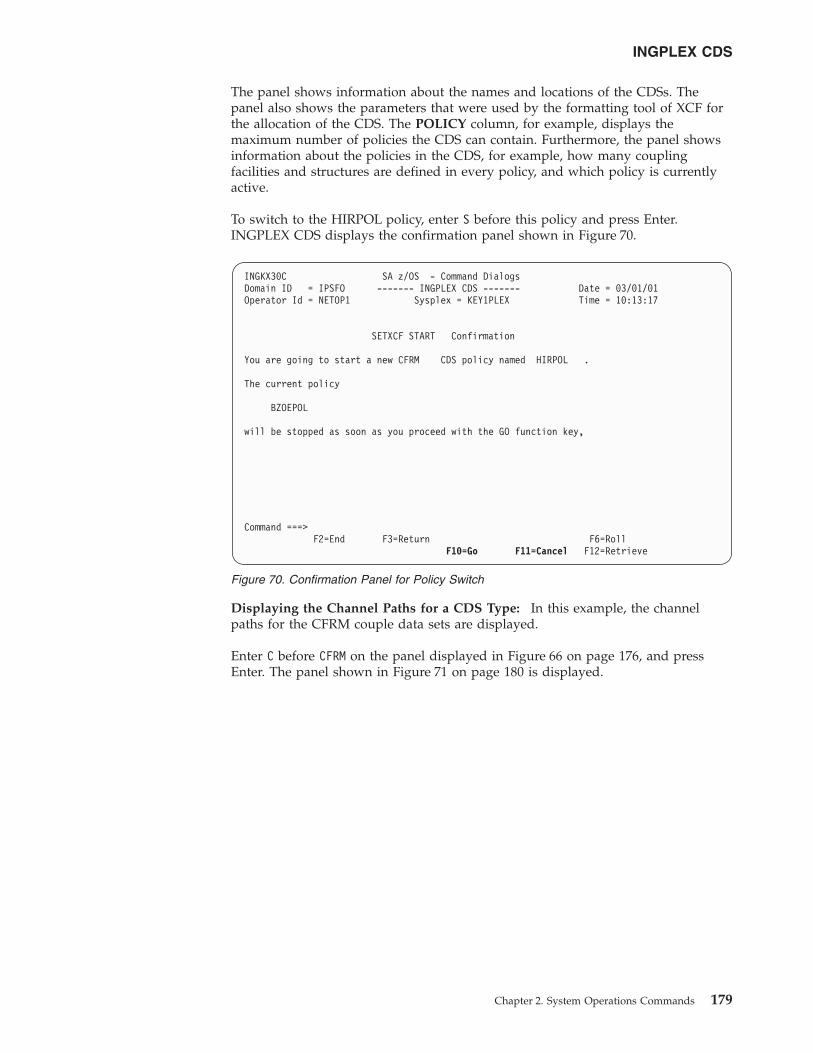
The panel shows information about the names and locations of the CDSs. Thepanel also shows the parameters that were used by the formatting tool of XCF forthe allocation of the CDS. The POLICY column, for example, displays themaximum number of policies the CDS can contain. Furthermore, the panel showsinformation about the policies in the CDS, for example, how many couplingfacilities and structures are defined in every policy, and which policy is currentlyactive.
To switch to the HIRPOL policy, enter S before this policy and press Enter.INGPLEX CDS displays the confirmation panel shown in Figure 70.
Displaying the Channel Paths for a CDS Type: In this example, the channelpaths for the CFRM couple data sets are displayed.
Enter C before CFRM on the panel displayed in Figure 66 on page 176, and pressEnter. The panel shown in Figure 71 on page 180 is displayed.
INGKX30C SA z/OS - Command DialogsDomain ID = IPSFO ------- INGPLEX CDS ------- Date = 03/01/01Operator Id = NETOP1 Sysplex = KEY1PLEX Time = 10:13:17
SETXCF START Confirmation
You are going to start a new CFRM CDS policy named HIRPOL .
The current policy
BZOEPOL
will be stopped as soon as you proceed with the GO function key,
Command ===>F2=End F3=Return F6=Roll
F10=Go F11=Cancel F12=Retrieve
Figure 70. Confirmation Panel for Policy Switch
INGPLEX CDS
Chapter 2. System Operations Commands 179
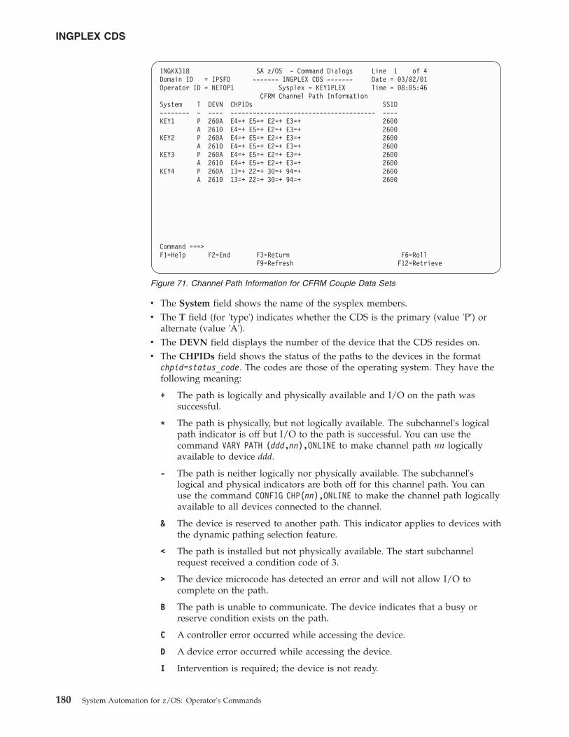
v The System field shows the name of the sysplex members.v The T field (for 'type') indicates whether the CDS is the primary (value 'P') or
alternate (value 'A').v The DEVN field displays the number of the device that the CDS resides on.v The CHPIDs field shows the status of the paths to the devices in the format
chpid=status_code. The codes are those of the operating system. They have thefollowing meaning:
+ The path is logically and physically available and I/O on the path wassuccessful.
* The path is physically, but not logically available. The subchannel's logicalpath indicator is off but I/O to the path is successful. You can use thecommand VARY PATH (ddd,nn),ONLINE to make channel path nn logicallyavailable to device ddd.
- The path is neither logically nor physically available. The subchannel'slogical and physical indicators are both off for this channel path. You canuse the command CONFIG CHP(nn),ONLINE to make the channel path logicallyavailable to all devices connected to the channel.
& The device is reserved to another path. This indicator applies to devices withthe dynamic pathing selection feature.
< The path is installed but not physically available. The start subchannelrequest received a condition code of 3.
> The device microcode has detected an error and will not allow I/O tocomplete on the path.
B The path is unable to communicate. The device indicates that a busy orreserve condition exists on the path.
C A controller error occurred while accessing the device.
D A device error occurred while accessing the device.
I Intervention is required; the device is not ready.
INGKX318 SA z/OS - Command Dialogs Line 1 of 4Domain ID = IPSFO ------- INGPLEX CDS ------- Date = 03/02/01Operator ID = NETOP1 Sysplex = KEY1PLEX Time = 08:05:46
CFRM Channel Path InformationSystem T DEVN CHPIDs SSID-------- - ---- --------------------------------------- ----KEY1 P 260A E4=+ E5=+ E2=+ E3=+ 2600
A 2610 E4=+ E5=+ E2=+ E3=+ 2600KEY2 P 260A E4=+ E5=+ E2=+ E3=+ 2600
A 2610 E4=+ E5=+ E2=+ E3=+ 2600KEY3 P 260A E4=+ E5=+ E2=+ E3=+ 2600
A 2610 E4=+ E5=+ E2=+ E3=+ 2600KEY4 P 260A 13=+ 22=+ 30=+ 94=+ 2600
A 2610 13=+ 22=+ 30=+ 94=+ 2600
Command ===>F1=Help F2=End F3=Return F6=Roll
F9=Refresh F12=Retrieve
Figure 71. Channel Path Information for CFRM Couple Data Sets
INGPLEX CDS
180 System Automation for z/OS: Operator's Commands
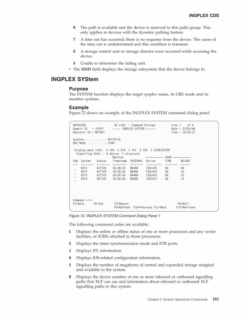
R The path is available and the device is reserved to this path/group. Thisonly applies to devices with the dynamic pathing feature.
T A time out has occurred; there is no response from the device. The cause ofthe time out is undetermined and this condition is transient.
U A storage control unit or storage director error occurred while accessing thedevice.
X Unable to determine the failing unit.v The SSID field displays the storage subsystem that the device belongs to.
INGPLEX SYStem
PurposeThe SYSTEM function displays the target sysplex name, its GRS mode and itsmember systems.
ExampleFigure 72 shows an example of the INGPLEX SYSTEM command dialog panel.
The following command codes are available:
C Displays the online or offline status of one or more processors and any vectorfacilities, or ICRFs attached to those processors.
E Displays the timer synchronization mode and ETR ports.
I Displays IPL information.
O Displays IOS-related configuration information.
S Displays the number of megabytes of central and expanded storage assignedand available to the system.
D Displays the device number of one or more inbound or outbound signallingpaths that XCF can use and information about inbound or outbound XCFsignalling paths to this system.
AOFKX100 SA z/OS - Command Dialogs Line 1 of 4Domain ID = IPSFP ----- INGPLEX SYSTEM ------ Date = 27/01/06Operator ID = NETOP1 Time = 16:29:12
Sysplex . . . . . . : KEY1PLEXGRS Mode . . . . . : STAR
Display more info: C CPU E ETR I IPL O IOS S STOR/ESTORSignalling Path : D device T structure
Monitor ----------- SSUM -----------Cmd System Status Timestamp INTERVAL Action TIME WEIGHT--- -------- -------- --------- -------- ---------- -------- ------
KEY1 ACTIVE 16:28:34 86400 ISOLATE 50 50KEY2 ACTIVE 16:28:35 86400 ISOLATE 50 15KEY3 ACTIVE 16:28:34 86400 ISOLATE 50 15KEY4 ACTIVE 16:28:36 86400 ISOLATE 50 15
Command ===>F1=Help F2=End F3=Return F6=Roll
F9=Refresh F10=Previous F11=Next F12=Retrieve
Figure 72. INGPLEX SYSTEM Command Dialog Panel 1
INGPLEX CDS
Chapter 2. System Operations Commands 181
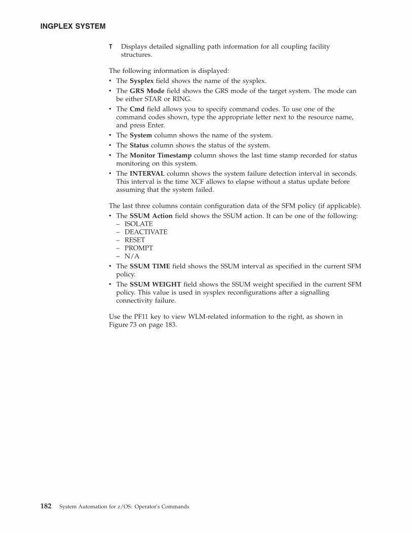
T Displays detailed signalling path information for all coupling facilitystructures.
The following information is displayed:v The Sysplex field shows the name of the sysplex.v The GRS Mode field shows the GRS mode of the target system. The mode can
be either STAR or RING.v The Cmd field allows you to specify command codes. To use one of the
command codes shown, type the appropriate letter next to the resource name,and press Enter.
v The System column shows the name of the system.v The Status column shows the status of the system.v The Monitor Timestamp column shows the last time stamp recorded for status
monitoring on this system.v The INTERVAL column shows the system failure detection interval in seconds.
This interval is the time XCF allows to elapse without a status update beforeassuming that the system failed.
The last three columns contain configuration data of the SFM policy (if applicable).v The SSUM Action field shows the SSUM action. It can be one of the following:
– ISOLATE– DEACTIVATE– RESET– PROMPT– N/A
v The SSUM TIME field shows the SSUM interval as specified in the current SFMpolicy.
v The SSUM WEIGHT field shows the SSUM weight specified in the current SFMpolicy. This value is used in sysplex reconfigurations after a signallingconnectivity failure.
Use the PF11 key to view WLM-related information to the right, as shown inFigure 73 on page 183.
INGPLEX SYSTEM
182 System Automation for z/OS: Operator's Commands
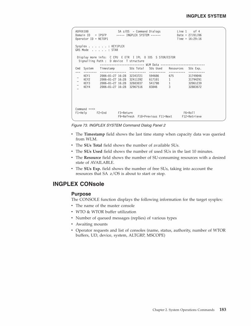
v The Timestamp field shows the last time stamp when capacity data was queriedfrom WLM.
v The SUs Total field shows the number of available SUs.v The SUs Used field shows the number of used SUs in the last 10 minutes.v The Resource field shows the number of SU-consuming resources with a desired
state of AVAILABLE.v The SUs Exp. field shows the number of free SUs, taking into account the
resources that SA z/OS is about to start or stop.
INGPLEX CONsole
PurposeThe CONSOLE function displays the following information for the target sysplex:v The name of the master consolev WTO & WTOR buffer utilizationv Number of queued messages (replies) of various typesv Awaiting mountsv Operator requests and list of consoles (name, status, authority, number of WTOR
buffers, UD, device, system, ALTGRP, MSCOPE)
AOFKX100 SA z/OS - Command Dialogs Line 1 of 4Domain ID = IPSFP ----- INGPLEX SYSTEM ------ Date = 27/01/06Operator ID = NETOP1 Time = 16:29:16
Sysplex . . . . . . : KEY1PLEXGRS Mode . . . . . : STAR
Display more info: C CPU E ETR I IPL O IOS S STOR/ESTORSignalling Path : D device T structure
--------------------------- WLM Data ---------------------------Cmd System Timestamp SUs Total SUs Used Resources SUs Exp.--- -------- ---------------- ---------- ---------- ---------- ----------
KEY1 2006-01-27 16:28 32343721 594686 675 31749046KEY2 2006-01-27 16:28 32411392 617101 1 31794291KEY3 2006-01-27 16:28 32603037 541798 1 32061239KEY4 2006-01-27 16:28 32967516 83846 3 32883672
Command ===>F1=Help F2=End F3=Return F6=Roll
F9=Refresh F10=Previous F11=Next F12=Retrieve
Figure 73. INGPLEX SYSTEM Command Dialog Panel 2
INGPLEX SYSTEM
Chapter 2. System Operations Commands 183
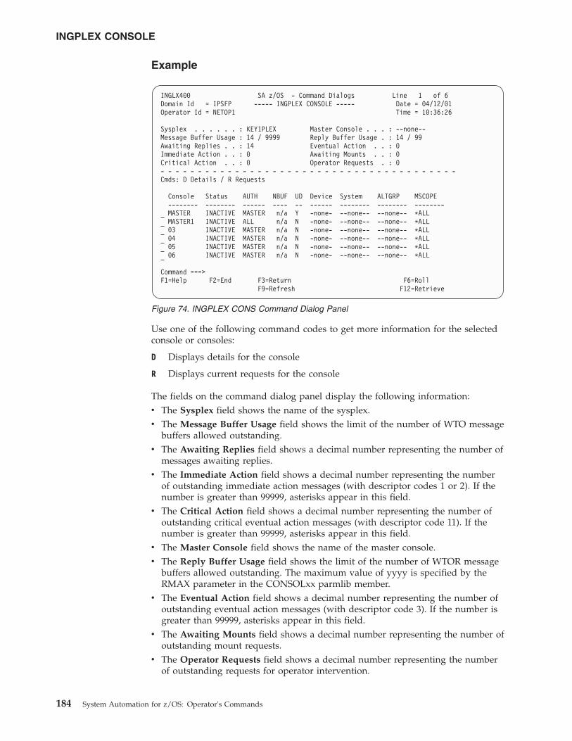
Example
Use one of the following command codes to get more information for the selectedconsole or consoles:
D Displays details for the console
R Displays current requests for the console
The fields on the command dialog panel display the following information:v The Sysplex field shows the name of the sysplex.v The Message Buffer Usage field shows the limit of the number of WTO message
buffers allowed outstanding.v The Awaiting Replies field shows a decimal number representing the number of
messages awaiting replies.v The Immediate Action field shows a decimal number representing the number
of outstanding immediate action messages (with descriptor codes 1 or 2). If thenumber is greater than 99999, asterisks appear in this field.
v The Critical Action field shows a decimal number representing the number ofoutstanding critical eventual action messages (with descriptor code 11). If thenumber is greater than 99999, asterisks appear in this field.
v The Master Console field shows the name of the master console.v The Reply Buffer Usage field shows the limit of the number of WTOR message
buffers allowed outstanding. The maximum value of yyyy is specified by theRMAX parameter in the CONSOLxx parmlib member.
v The Eventual Action field shows a decimal number representing the number ofoutstanding eventual action messages (with descriptor code 3). If the number isgreater than 99999, asterisks appear in this field.
v The Awaiting Mounts field shows a decimal number representing the number ofoutstanding mount requests.
v The Operator Requests field shows a decimal number representing the numberof outstanding requests for operator intervention.
INGLX400 SA z/OS - Command Dialogs Line 1 of 6Domain Id = IPSFP ----- INGPLEX CONSOLE ----- Date = 04/12/01Operator Id = NETOP1 Time = 10:36:26
Sysplex . . . . . . : KEY1PLEX Master Console . . . : --none--Message Buffer Usage : 14 / 9999 Reply Buffer Usage . : 14 / 99Awaiting Replies . . : 14 Eventual Action . . : 0Immediate Action . . : 0 Awaiting Mounts . . : 0Critical Action . . : 0 Operator Requests . : 0- - - - - - - - - - - - - - - - - - - - - - - - - - - - - - - - - - - - - - - -Cmds: D Details / R Requests
Console Status AUTH NBUF UD Device System ALTGRP MSCOPE-------- -------- ------ ---- -- ------ -------- -------- --------MASTER INACTIVE MASTER n/a Y -none- --none-- --none-- *ALLMASTER1 INACTIVE ALL n/a N -none- --none-- --none-- *ALL03 INACTIVE MASTER n/a N -none- --none-- --none-- *ALL04 INACTIVE MASTER n/a N -none- --none-- --none-- *ALL05 INACTIVE MASTER n/a N -none- --none-- --none-- *ALL06 INACTIVE MASTER n/a N -none- --none-- --none-- *ALL
Command ===>F1=Help F2=End F3=Return F6=Roll
F9=Refresh F12=Retrieve
Figure 74. INGPLEX CONS Command Dialog Panel
INGPLEX CONSOLE
184 System Automation for z/OS: Operator's Commands
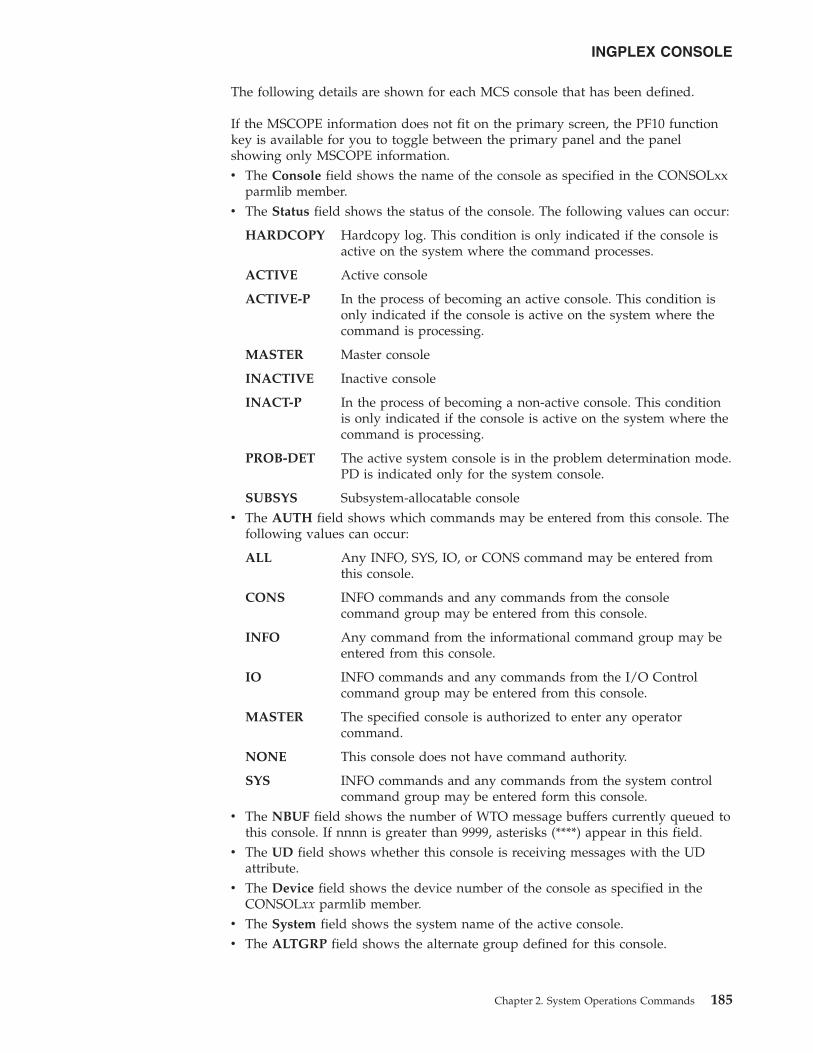
The following details are shown for each MCS console that has been defined.
If the MSCOPE information does not fit on the primary screen, the PF10 functionkey is available for you to toggle between the primary panel and the panelshowing only MSCOPE information.v The Console field shows the name of the console as specified in the CONSOLxx
parmlib member.v The Status field shows the status of the console. The following values can occur:
HARDCOPY Hardcopy log. This condition is only indicated if the console isactive on the system where the command processes.
ACTIVE Active console
ACTIVE-P In the process of becoming an active console. This condition isonly indicated if the console is active on the system where thecommand is processing.
MASTER Master console
INACTIVE Inactive console
INACT-P In the process of becoming a non-active console. This conditionis only indicated if the console is active on the system where thecommand is processing.
PROB-DET The active system console is in the problem determination mode.PD is indicated only for the system console.
SUBSYS Subsystem-allocatable consolev The AUTH field shows which commands may be entered from this console. The
following values can occur:
ALL Any INFO, SYS, IO, or CONS command may be entered fromthis console.
CONS INFO commands and any commands from the consolecommand group may be entered from this console.
INFO Any command from the informational command group may beentered from this console.
IO INFO commands and any commands from the I/O Controlcommand group may be entered from this console.
MASTER The specified console is authorized to enter any operatorcommand.
NONE This console does not have command authority.
SYS INFO commands and any commands from the system controlcommand group may be entered form this console.
v The NBUF field shows the number of WTO message buffers currently queued tothis console. If nnnn is greater than 9999, asterisks (****) appear in this field.
v The UD field shows whether this console is receiving messages with the UDattribute.
v The Device field shows the device number of the console as specified in theCONSOLxx parmlib member.
v The System field shows the system name of the active console.v The ALTGRP field shows the alternate group defined for this console.
INGPLEX CONSOLE
Chapter 2. System Operations Commands 185
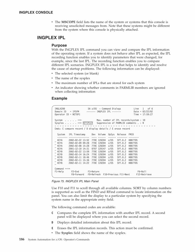
v The MSCOPE field lists the name of the system or systems that this console isreceiving unsolicited messages from. Note that these systems might be differentfrom the system where this console is physically attached.
INGPLEX IPL
PurposeWith the INGPLEX IPL command you can view and compare the IPL informationof the operating system. If a system does not behave after IPL as expected, the IPLrecording function enables you to identify parameters that were changed, forexample, since the last IPL. The recording function enables you to comparedifferent IPL scenarios. INGPLEX IPL is a tool that helps to identify and resolvethe cause of startup problems. The following information can be displayed:v The selected system (or blank)v The name of the sysplexv The maximum number of IPLs that are stored for each systemv An indicator showing whether comments in PARMLIB members are ignored
when collecting information
Example
Use F10 and F11 to scroll through all available columns. SORT by column numbersis supported as well as the FIND and RFind command to locate information on thepanel. You can also limit the display to a particular system by specifying thesystem name in the appropriate entry field.
The following command codes are available:
C Compares the complete IPL information with another IPL record. A secondpanel will be displayed where you can select the second record.
D Displays detailed information about this IPL record.
E Erases the IPL information records. This action must be confirmed.v The Sysplex field shows the name of the sysplex.
INGLX200 SA z/OS - Command Dialogs Line 1 of 6Domain ID = IPSFM ------- INGPLEX IPL ------- Date = 02/22/02Operator ID = NETOP1 Time = 17:59:27
System . . . . . ==> Max. number of IPL records/system : 10Sysplex . . . . . ==> KEY1PLEX Suppression of PARMLIB comments . : N- - - - - - - - - - - - - - - - - - - - - - - - - - - - - - - - - - - - - - - -Cmds: C compare record / D display details / E erase record
System IPL Timestamp Dev Volume OpSys Release FMID-------- ---------------- ---- ------ ------ -------- --------KEYA 2002-02-22 13:52 770E 120204 z/OS SP7.0.2 HBB7705KEYA 2002-02-09 09:28 770E 120204 z/OS SP7.0.2 HBB7705KEYA 2002-02-08 15:28 770E 120204 z/OS SP7.0.2 HBB7705KEYA 2001-12-10 14:31 0707 120147 z/OS SP7.0.2 HBB7705KEYB 2002-02-22 13:59 770E 120204 z/OS SP7.0.2 HBB7705KEYB 2002-02-14 16:24 770E 120204 z/OS SP7.0.2 HBB7705KEYB 2002-02-11 18:46 770E 120204 z/OS SP7.0.2 HBB7705KEYB 2002-02-11 15:36 770E 120204 z/OS SP7.0.2 HBB7705KEYB 2002-02-11 14:22 770E 120204 z/OS SP7.0.2 HBB7705
Command ===>F1=Help F2=End F3=Return F6=Roll
F8=Forward F9=Refresh F10=Previous F11=Next F12=Retrieve
Figure 75. INGPLEX IPL Main Panel
INGPLEX CONSOLE
186 System Automation for z/OS: Operator's Commands
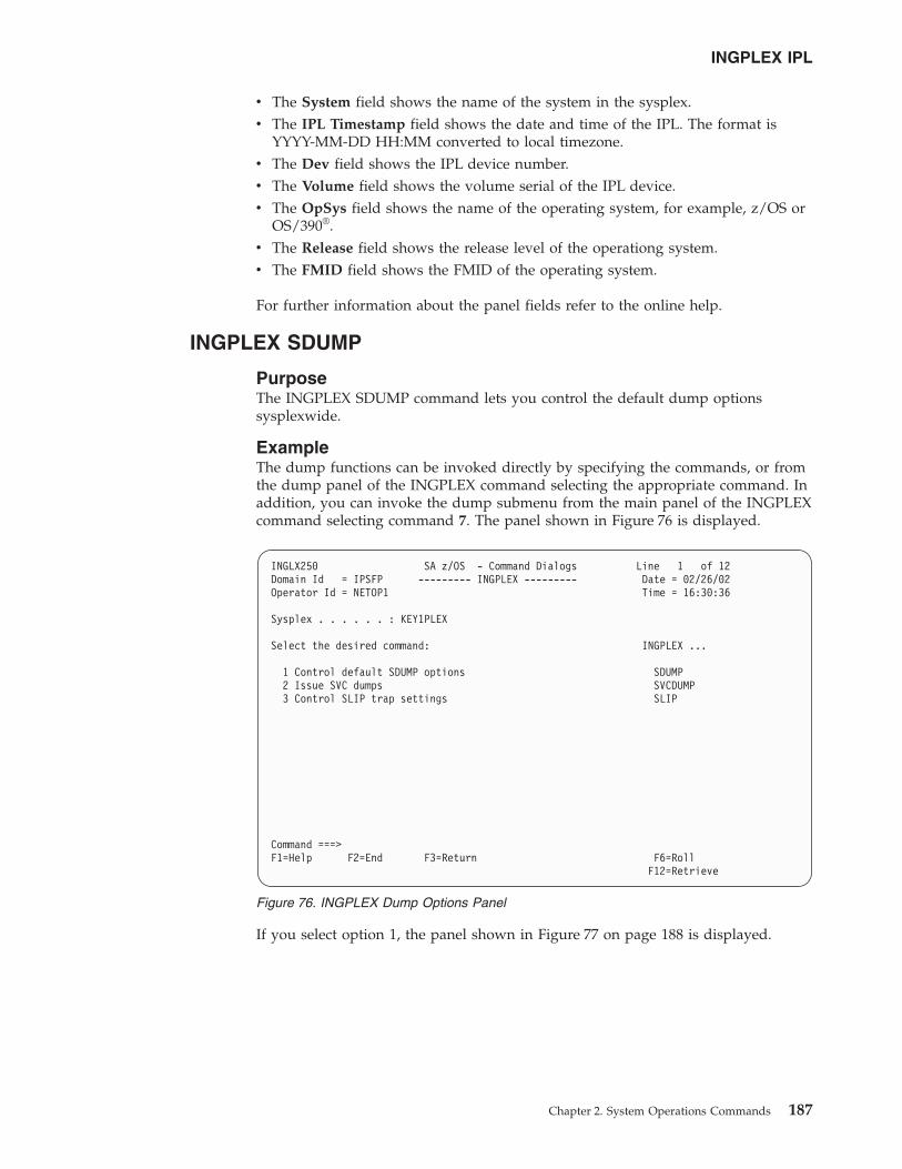
v The System field shows the name of the system in the sysplex.v The IPL Timestamp field shows the date and time of the IPL. The format is
YYYY-MM-DD HH:MM converted to local timezone.v The Dev field shows the IPL device number.v The Volume field shows the volume serial of the IPL device.v The OpSys field shows the name of the operating system, for example, z/OS or
OS/390®.v The Release field shows the release level of the operationg system.v The FMID field shows the FMID of the operating system.
For further information about the panel fields refer to the online help.
INGPLEX SDUMP
PurposeThe INGPLEX SDUMP command lets you control the default dump optionssysplexwide.
ExampleThe dump functions can be invoked directly by specifying the commands, or fromthe dump panel of the INGPLEX command selecting the appropriate command. Inaddition, you can invoke the dump submenu from the main panel of the INGPLEXcommand selecting command 7. The panel shown in Figure 76 is displayed.
If you select option 1, the panel shown in Figure 77 on page 188 is displayed.
INGLX250 SA z/OS - Command Dialogs Line 1 of 12Domain Id = IPSFP --------- INGPLEX --------- Date = 02/26/02Operator Id = NETOP1 Time = 16:30:36
Sysplex . . . . . . : KEY1PLEX
Select the desired command: INGPLEX ...
1 Control default SDUMP options SDUMP2 Issue SVC dumps SVCDUMP3 Control SLIP trap settings SLIP
Command ===>F1=Help F2=End F3=Return F6=Roll
F12=Retrieve
Figure 76. INGPLEX Dump Options Panel
INGPLEX IPL
Chapter 2. System Operations Commands 187
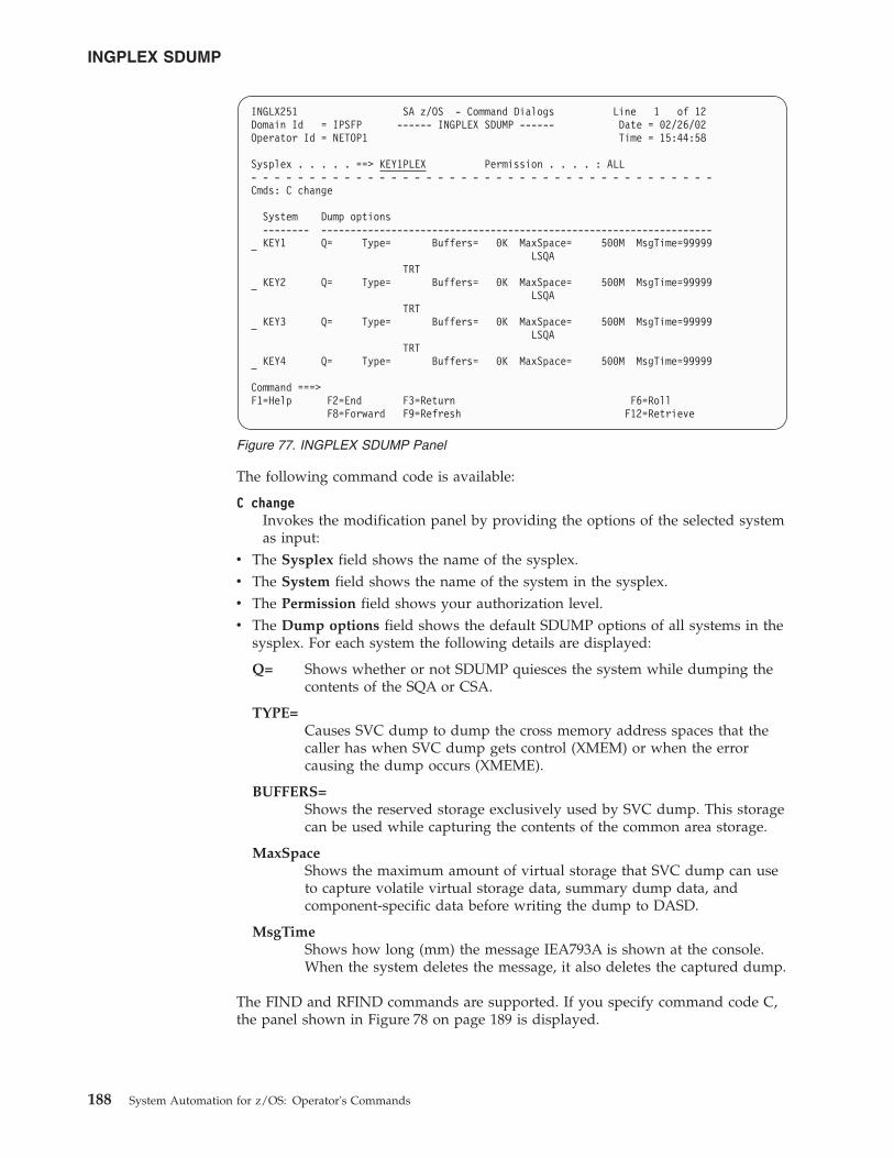
The following command code is available:
C changeInvokes the modification panel by providing the options of the selected systemas input:
v The Sysplex field shows the name of the sysplex.v The System field shows the name of the system in the sysplex.v The Permission field shows your authorization level.v The Dump options field shows the default SDUMP options of all systems in the
sysplex. For each system the following details are displayed:
Q= Shows whether or not SDUMP quiesces the system while dumping thecontents of the SQA or CSA.
TYPE=Causes SVC dump to dump the cross memory address spaces that thecaller has when SVC dump gets control (XMEM) or when the errorcausing the dump occurs (XMEME).
BUFFERS=Shows the reserved storage exclusively used by SVC dump. This storagecan be used while capturing the contents of the common area storage.
MaxSpaceShows the maximum amount of virtual storage that SVC dump can useto capture volatile virtual storage data, summary dump data, andcomponent-specific data before writing the dump to DASD.
MsgTimeShows how long (mm) the message IEA793A is shown at the console.When the system deletes the message, it also deletes the captured dump.
The FIND and RFIND commands are supported. If you specify command code C,the panel shown in Figure 78 on page 189 is displayed.
INGLX251 SA z/OS - Command Dialogs Line 1 of 12Domain Id = IPSFP ------ INGPLEX SDUMP ------ Date = 02/26/02Operator Id = NETOP1 Time = 15:44:58
Sysplex . . . . . ==> KEY1PLEX Permission . . . . : ALL- - - - - - - - - - - - - - - - - - - - - - - - - - - - - - - - - - - - - - - -Cmds: C change
System Dump options-------- -------------------------------------------------------------------KEY1 Q= Type= Buffers= 0K MaxSpace= 500M MsgTime=99999
LSQATRT
KEY2 Q= Type= Buffers= 0K MaxSpace= 500M MsgTime=99999LSQA
TRTKEY3 Q= Type= Buffers= 0K MaxSpace= 500M MsgTime=99999
LSQATRT
KEY4 Q= Type= Buffers= 0K MaxSpace= 500M MsgTime=99999
Command ===>F1=Help F2=End F3=Return F6=Roll
F8=Forward F9=Refresh F12=Retrieve
Figure 77. INGPLEX SDUMP Panel
INGPLEX SDUMP
188 System Automation for z/OS: Operator's Commands
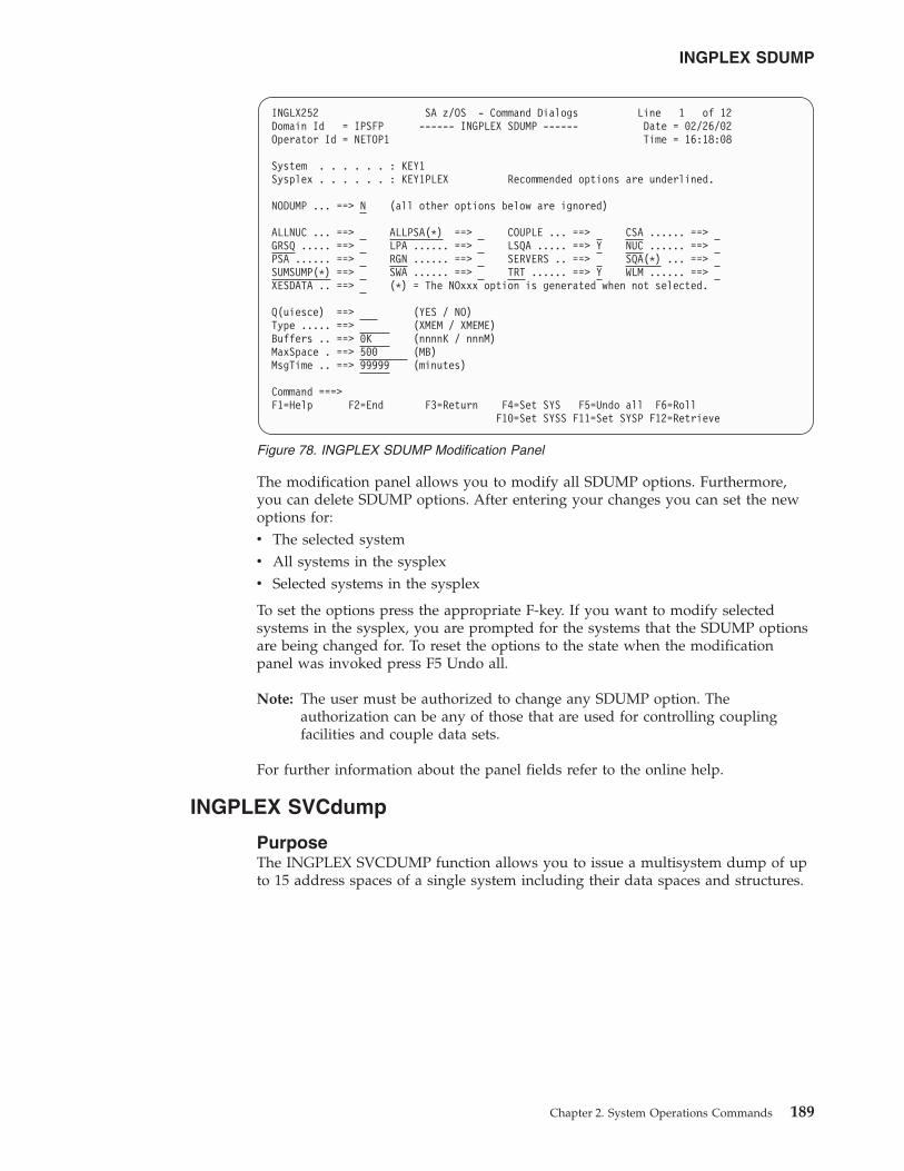
The modification panel allows you to modify all SDUMP options. Furthermore,you can delete SDUMP options. After entering your changes you can set the newoptions for:v The selected systemv All systems in the sysplexv Selected systems in the sysplex
To set the options press the appropriate F-key. If you want to modify selectedsystems in the sysplex, you are prompted for the systems that the SDUMP optionsare being changed for. To reset the options to the state when the modificationpanel was invoked press F5 Undo all.
Note: The user must be authorized to change any SDUMP option. Theauthorization can be any of those that are used for controlling couplingfacilities and couple data sets.
For further information about the panel fields refer to the online help.
INGPLEX SVCdump
PurposeThe INGPLEX SVCDUMP function allows you to issue a multisystem dump of upto 15 address spaces of a single system including their data spaces and structures.
INGLX252 SA z/OS - Command Dialogs Line 1 of 12Domain Id = IPSFP ------ INGPLEX SDUMP ------ Date = 02/26/02Operator Id = NETOP1 Time = 16:18:08
System . . . . . . : KEY1Sysplex . . . . . . : KEY1PLEX Recommended options are underlined.
NODUMP ... ==> N (all other options below are ignored)
ALLNUC ... ==> ALLPSA(*) ==> COUPLE ... ==> CSA ...... ==>GRSQ ..... ==> LPA ...... ==> LSQA ..... ==> Y NUC ...... ==>PSA ...... ==> RGN ...... ==> SERVERS .. ==> SQA(*) ... ==>SUMSUMP(*) ==> SWA ...... ==> TRT ...... ==> Y WLM ...... ==>XESDATA .. ==> (*) = The NOxxx option is generated when not selected.
Q(uiesce) ==> (YES / NO)Type ..... ==> (XMEM / XMEME)Buffers .. ==> 0K (nnnnK / nnnM)MaxSpace . ==> 500 (MB)MsgTime .. ==> 99999 (minutes)
Command ===>F1=Help F2=End F3=Return F4=Set SYS F5=Undo all F6=Roll
F10=Set SYSS F11=Set SYSP F12=Retrieve
Figure 78. INGPLEX SDUMP Modification Panel
INGPLEX SDUMP
Chapter 2. System Operations Commands 189
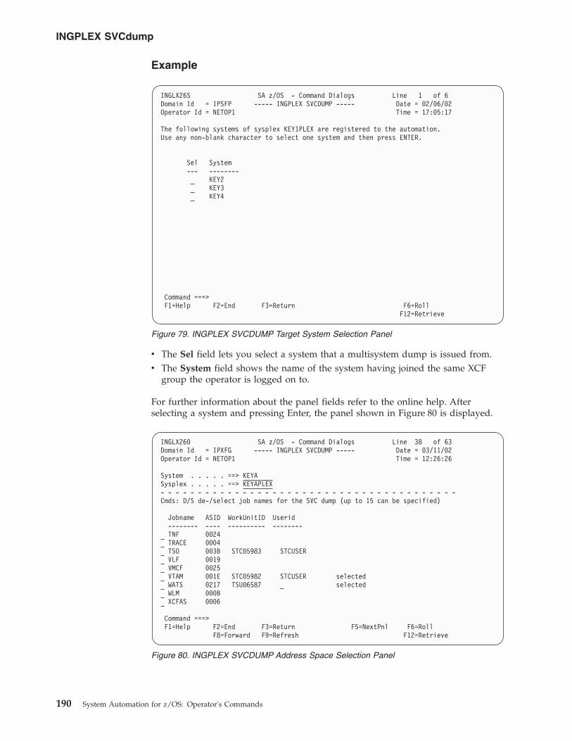
Example
v The Sel field lets you select a system that a multisystem dump is issued from.v The System field shows the name of the system having joined the same XCF
group the operator is logged on to.
For further information about the panel fields refer to the online help. Afterselecting a system and pressing Enter, the panel shown in Figure 80 is displayed.
INGLX26S SA z/OS - Command Dialogs Line 1 of 6Domain Id = IPSFP ----- INGPLEX SVCDUMP ----- Date = 02/06/02Operator Id = NETOP1 Time = 17:05:17
The following systems of sysplex KEY1PLEX are registered to the automation.Use any non-blank character to select one system and then press ENTER.
Sel System--- --------
KEY2KEY3KEY4
Command ===>F1=Help F2=End F3=Return F6=Roll
F12=Retrieve
Figure 79. INGPLEX SVCDUMP Target System Selection Panel
INGLX260 SA z/OS - Command Dialogs Line 38 of 63Domain Id = IPXFG ----- INGPLEX SVCDUMP ----- Date = 03/11/02Operator Id = NETOP1 Time = 12:26:26
System . . . . . ==> KEYASysplex . . . . . ==> KEYAPLEX- - - - - - - - - - - - - - - - - - - - - - - - - - - - - - - - - - - - - - - -Cmds: D/S de-/select job names for the SVC dump (up to 15 can be specified)
Jobname ASID WorkUnitID Userid-------- ---- ---------- --------TNF 0024TRACE 0004TSO 003B STC05983 STCUSERVLF 0019VMCF 0025VTAM 001E STC05982 STCUSER selectedWATS 0217 TSU06587 _ selectedWLM 000BXCFAS 0006
Command ===>F1=Help F2=End F3=Return F5=NextPnl F6=Roll
F8=Forward F9=Refresh F12=Retrieve
Figure 80. INGPLEX SVCDUMP Address Space Selection Panel
INGPLEX SVCdump
190 System Automation for z/OS: Operator's Commands
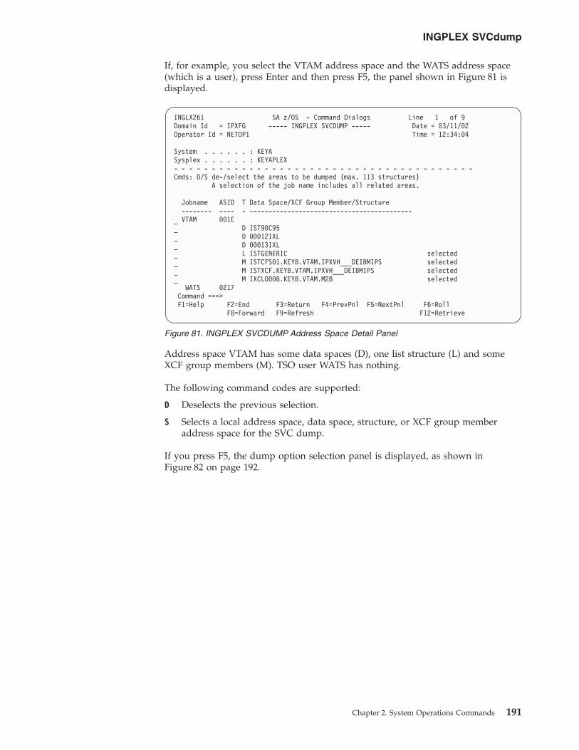
If, for example, you select the VTAM address space and the WATS address space(which is a user), press Enter and then press F5, the panel shown in Figure 81 isdisplayed.
Address space VTAM has some data spaces (D), one list structure (L) and someXCF group members (M). TSO user WATS has nothing.
The following command codes are supported:
D Deselects the previous selection.
S Selects a local address space, data space, structure, or XCF group memberaddress space for the SVC dump.
If you press F5, the dump option selection panel is displayed, as shown inFigure 82 on page 192.
INGLX261 SA z/OS - Command Dialogs Line 1 of 9Domain Id = IPXFG ----- INGPLEX SVCDUMP ----- Date = 03/11/02Operator Id = NETOP1 Time = 12:34:04
System . . . . . . : KEYASysplex . . . . . . : KEYAPLEX- - - - - - - - - - - - - - - - - - - - - - - - - - - - - - - - - - - - - - - -Cmds: D/S de-/select the areas to be dumped (max. 113 structures)
A selection of the job name includes all related areas.
Jobname ASID T Data Space/XCF Group Member/Structure-------- ---- - -------------------------------------------VTAM 001E
D IST90C95D 00012IXLD 00013IXLL ISTGENERIC selectedM ISTCFS01.KEYB.VTAM.IPXVH___DEIBMIPS selectedM ISTXCF.KEYB.VTAM.IPXVH___DEIBMIPS selectedM IXCLO008.KEYB.VTAM.M28 selected
WATS 0217Command ===>F1=Help F2=End F3=Return F4=PrevPnl F5=NextPnl F6=Roll
F8=Forward F9=Refresh F12=Retrieve
Figure 81. INGPLEX SVCDUMP Address Space Detail Panel
INGPLEX SVCdump
Chapter 2. System Operations Commands 191
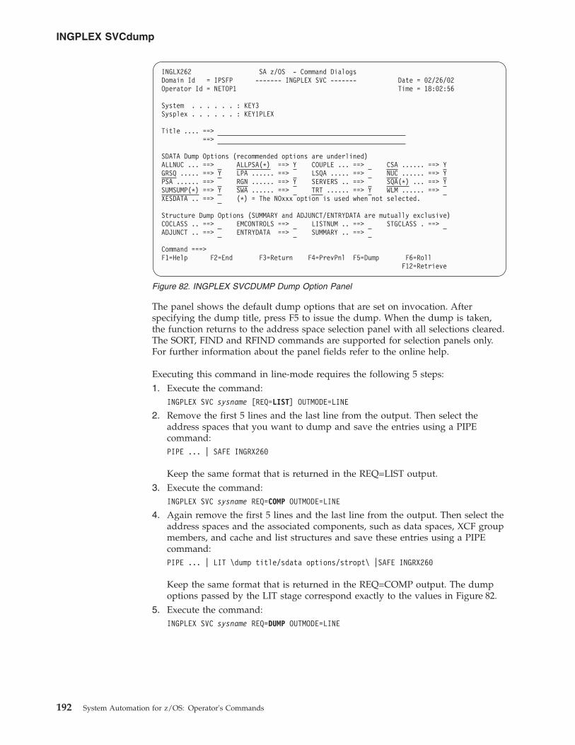
The panel shows the default dump options that are set on invocation. Afterspecifying the dump title, press F5 to issue the dump. When the dump is taken,the function returns to the address space selection panel with all selections cleared.The SORT, FIND and RFIND commands are supported for selection panels only.For further information about the panel fields refer to the online help.
Executing this command in line-mode requires the following 5 steps:1. Execute the command:
INGPLEX SVC sysname [REQ=LIST] OUTMODE=LINE
2. Remove the first 5 lines and the last line from the output. Then select theaddress spaces that you want to dump and save the entries using a PIPEcommand:PIPE ... | SAFE INGRX260
Keep the same format that is returned in the REQ=LIST output.3. Execute the command:
INGPLEX SVC sysname REQ=COMP OUTMODE=LINE
4. Again remove the first 5 lines and the last line from the output. Then select theaddress spaces and the associated components, such as data spaces, XCF groupmembers, and cache and list structures and save these entries using a PIPEcommand:PIPE ... | LIT \dump title/sdata options/stropt\ |SAFE INGRX260
Keep the same format that is returned in the REQ=COMP output. The dumpoptions passed by the LIT stage correspond exactly to the values in Figure 82.
5. Execute the command:INGPLEX SVC sysname REQ=DUMP OUTMODE=LINE
INGLX262 SA z/OS - Command DialogsDomain Id = IPSFP ------- INGPLEX SVC ------- Date = 02/26/02Operator Id = NETOP1 Time = 18:02:56
System . . . . . . : KEY3Sysplex . . . . . . : KEY1PLEX
Title .... ==>==>
SDATA Dump Options (recommended options are underlined)ALLNUC ... ==> ALLPSA(*) ==> Y COUPLE ... ==> CSA ...... ==> YGRSQ ..... ==> Y LPA ...... ==> LSQA ..... ==> NUC ...... ==> YPSA ...... ==> RGN ...... ==> Y SERVERS .. ==> SQA(*) ... ==> YSUMSUMP(*) ==> Y SWA ...... ==> TRT ...... ==> Y WLM ...... ==>XESDATA .. ==> (*) = The NOxxx option is used when not selected.
Structure Dump Options (SUMMARY and ADJUNCT/ENTRYDATA are mutually exclusive)COCLASS .. ==> EMCONTROLS ==> LISTNUM .. ==> STGCLASS . ==>ADJUNCT .. ==> ENTRYDATA ==> SUMMARY .. ==>
Command ===>F1=Help F2=End F3=Return F4=PrevPnl F5=Dump F6=Roll
F12=Retrieve
Figure 82. INGPLEX SVCDUMP Dump Option Panel
INGPLEX SVCdump
192 System Automation for z/OS: Operator's Commands
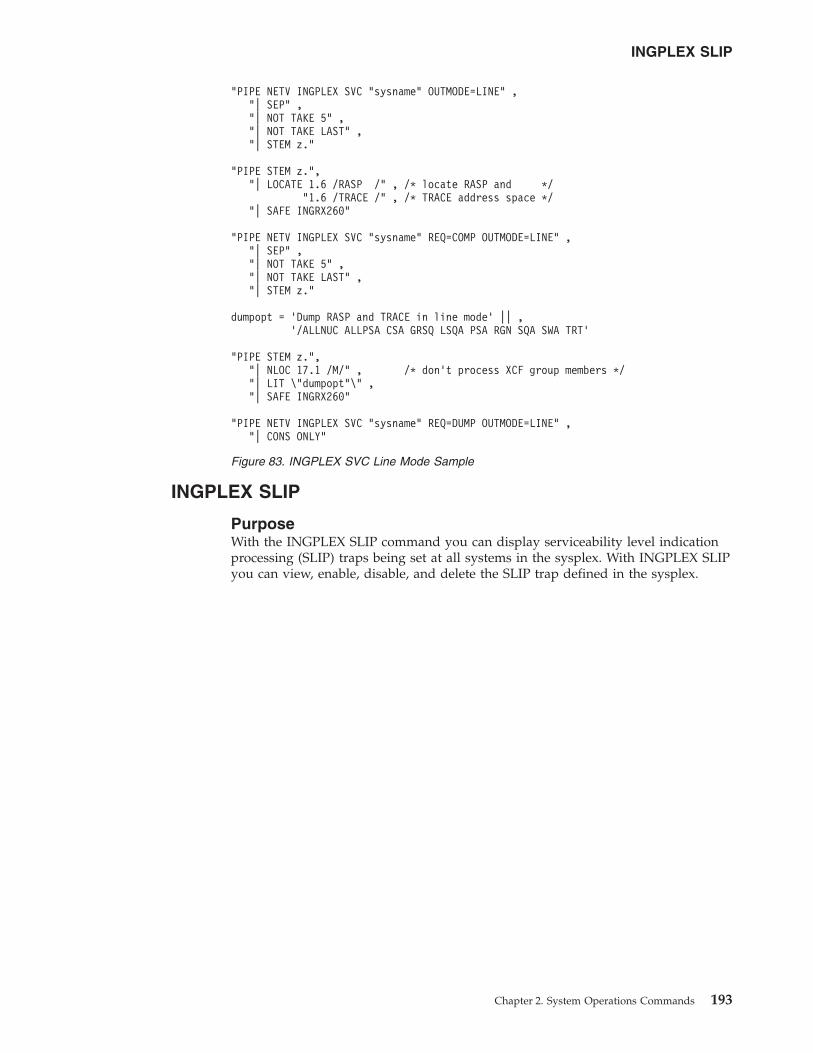
INGPLEX SLIP
PurposeWith the INGPLEX SLIP command you can display serviceability level indicationprocessing (SLIP) traps being set at all systems in the sysplex. With INGPLEX SLIPyou can view, enable, disable, and delete the SLIP trap defined in the sysplex.
"PIPE NETV INGPLEX SVC "sysname" OUTMODE=LINE" ,"| SEP" ,"| NOT TAKE 5" ,"| NOT TAKE LAST" ,"| STEM z."
"PIPE STEM z.","| LOCATE 1.6 /RASP /" , /* locate RASP and */
"1.6 /TRACE /" , /* TRACE address space */"| SAFE INGRX260"
"PIPE NETV INGPLEX SVC "sysname" REQ=COMP OUTMODE=LINE" ,"| SEP" ,"| NOT TAKE 5" ,"| NOT TAKE LAST" ,"| STEM z."
dumpopt = ’Dump RASP and TRACE in line mode’ || ,’/ALLNUC ALLPSA CSA GRSQ LSQA PSA RGN SQA SWA TRT’
"PIPE STEM z.","| NLOC 17.1 /M/" , /* don’t process XCF group members */"| LIT \"dumpopt"\" ,"| SAFE INGRX260"
"PIPE NETV INGPLEX SVC "sysname" REQ=DUMP OUTMODE=LINE" ,"| CONS ONLY"
Figure 83. INGPLEX SVC Line Mode Sample
INGPLEX SLIP
Chapter 2. System Operations Commands 193
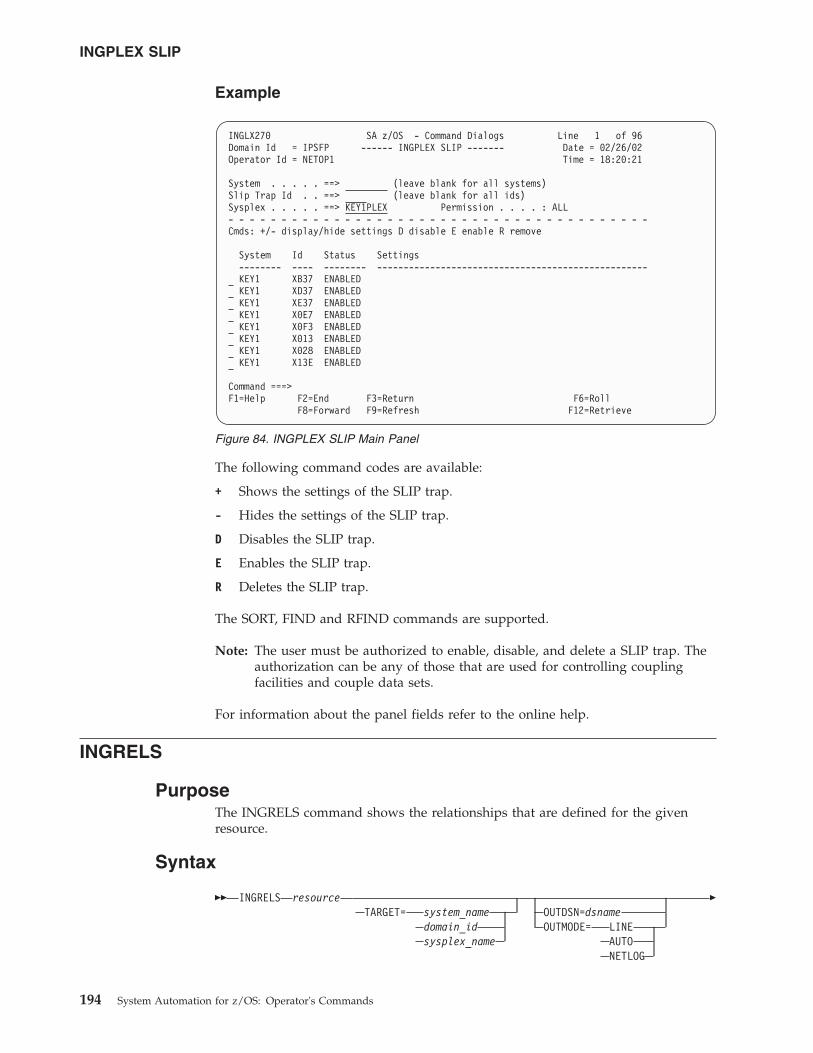
Example
The following command codes are available:
+ Shows the settings of the SLIP trap.
- Hides the settings of the SLIP trap.
D Disables the SLIP trap.
E Enables the SLIP trap.
R Deletes the SLIP trap.
The SORT, FIND and RFIND commands are supported.
Note: The user must be authorized to enable, disable, and delete a SLIP trap. Theauthorization can be any of those that are used for controlling couplingfacilities and couple data sets.
For information about the panel fields refer to the online help.
INGRELS
PurposeThe INGRELS command shows the relationships that are defined for the givenresource.
Syntax
�� INGRELS resourceTARGET= system_name
domain_idsysplex_name
OUTDSN=dsnameOUTMODE= LINE
AUTONETLOG
�
INGLX270 SA z/OS - Command Dialogs Line 1 of 96Domain Id = IPSFP ------ INGPLEX SLIP ------- Date = 02/26/02Operator Id = NETOP1 Time = 18:20:21
System . . . . . ==> (leave blank for all systems)Slip Trap Id . . ==> (leave blank for all ids)Sysplex . . . . . ==> KEY1PLEX Permission . . . . : ALL- - - - - - - - - - - - - - - - - - - - - - - - - - - - - - - - - - - - - - - -Cmds: +/- display/hide settings D disable E enable R remove
System Id Status Settings-------- ---- -------- ---------------------------------------------------KEY1 XB37 ENABLEDKEY1 XD37 ENABLEDKEY1 XE37 ENABLEDKEY1 X0E7 ENABLEDKEY1 X0F3 ENABLEDKEY1 X013 ENABLEDKEY1 X028 ENABLEDKEY1 X13E ENABLED
Command ===>F1=Help F2=End F3=Return F6=Roll
F8=Forward F9=Refresh F12=Retrieve
Figure 84. INGPLEX SLIP Main Panel
INGPLEX SLIP
194 System Automation for z/OS: Operator's Commands
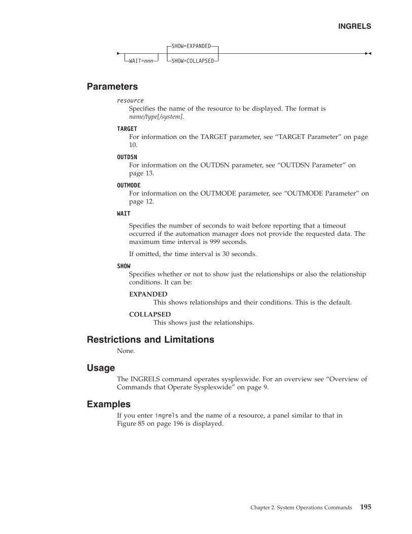
�WAIT=nnn
SHOW=EXPANDED
SHOW=COLLAPSED��
Parametersresource
Specifies the name of the resource to be displayed. The format isname/type[/system].
TARGETFor information on the TARGET parameter, see “TARGET Parameter” on page10.
OUTDSNFor information on the OUTDSN parameter, see “OUTDSN Parameter” onpage 13.
OUTMODEFor information on the OUTMODE parameter, see “OUTMODE Parameter” onpage 12.
WAIT
Specifies the number of seconds to wait before reporting that a timeoutoccurred if the automation manager does not provide the requested data. Themaximum time interval is 999 seconds.
If omitted, the time interval is 30 seconds.
SHOWSpecifies whether or not to show just the relationships or also the relationshipconditions. It can be:
EXPANDEDThis shows relationships and their conditions. This is the default.
COLLAPSEDThis shows just the relationships.
Restrictions and LimitationsNone.
UsageThe INGRELS command operates sysplexwide. For an overview see “Overview ofCommands that Operate Sysplexwide” on page 9.
ExamplesIf you enter ingrels and the name of a resource, a panel similar to that inFigure 85 on page 196 is displayed.
INGRELS
Chapter 2. System Operations Commands 195
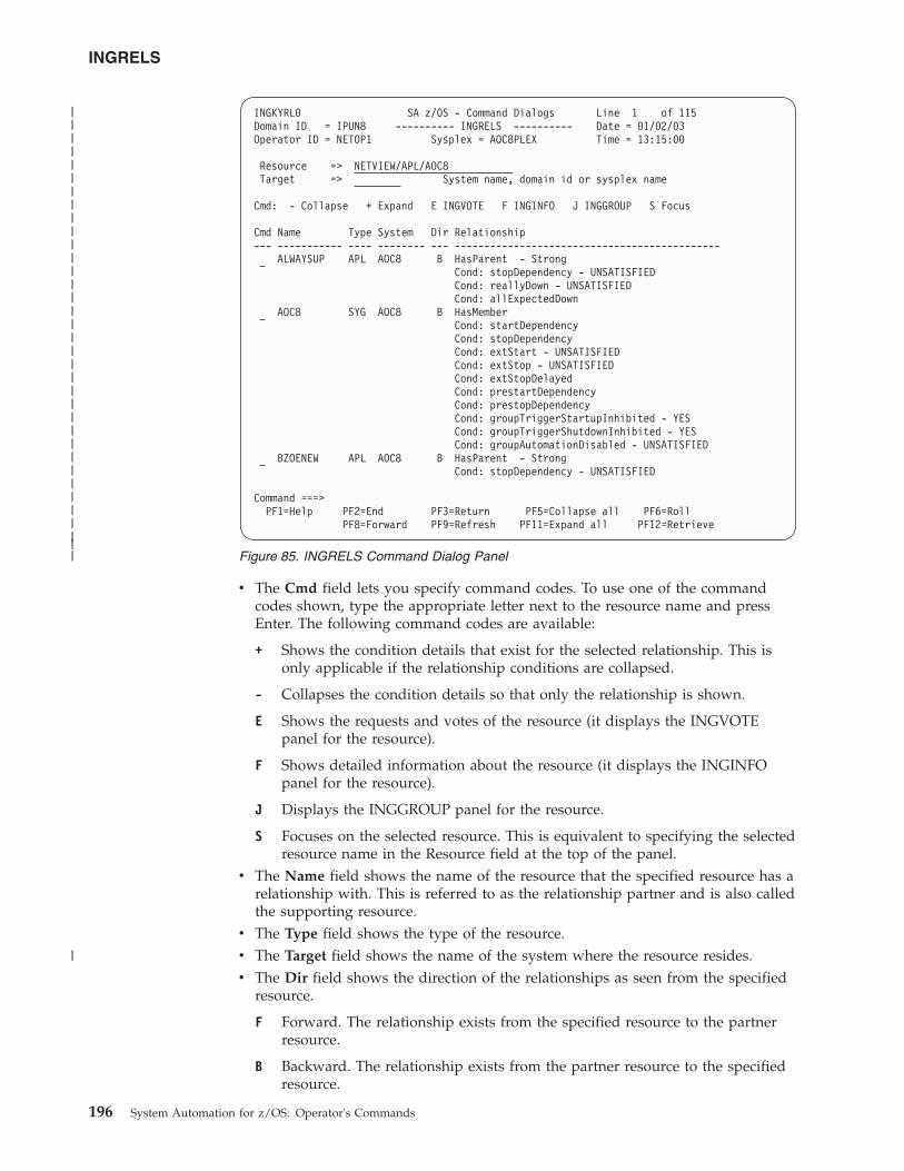
v The Cmd field lets you specify command codes. To use one of the commandcodes shown, type the appropriate letter next to the resource name and pressEnter. The following command codes are available:
+ Shows the condition details that exist for the selected relationship. This isonly applicable if the relationship conditions are collapsed.
- Collapses the condition details so that only the relationship is shown.
E Shows the requests and votes of the resource (it displays the INGVOTEpanel for the resource).
F Shows detailed information about the resource (it displays the INGINFOpanel for the resource).
J Displays the INGGROUP panel for the resource.
S Focuses on the selected resource. This is equivalent to specifying the selectedresource name in the Resource field at the top of the panel.
v The Name field shows the name of the resource that the specified resource has arelationship with. This is referred to as the relationship partner and is also calledthe supporting resource.
v The Type field shows the type of the resource.v The Target field shows the name of the system where the resource resides.v The Dir field shows the direction of the relationships as seen from the specified
resource.
F Forward. The relationship exists from the specified resource to the partnerresource.
B Backward. The relationship exists from the partner resource to the specifiedresource.
INGKYRL0 SA z/OS - Command Dialogs Line 1 of 115Domain ID = IPUN8 ---------- INGRELS ---------- Date = 01/02/03Operator ID = NETOP1 Sysplex = AOC8PLEX Time = 13:15:00
Resource => NETVIEW/APL/AOC8Target => System name, domain id or sysplex name
Cmd: - Collapse + Expand E INGVOTE F INGINFO J INGGROUP S Focus
Cmd Name Type System Dir Relationship--- ----------- ---- -------- --- ---------------------------------------------
ALWAYSUP APL AOC8 B HasParent - StrongCond: stopDependency - UNSATISFIEDCond: reallyDown - UNSATISFIEDCond: allExpectedDown
AOC8 SYG AOC8 B HasMemberCond: startDependencyCond: stopDependencyCond: extStart - UNSATISFIEDCond: extStop - UNSATISFIEDCond: extStopDelayedCond: prestartDependencyCond: prestopDependencyCond: groupTriggerStartupInhibited - YESCond: groupTriggerShutdownInhibited - YESCond: groupAutomationDisabled - UNSATISFIED
BZOENEW APL AOC8 B HasParent - StrongCond: stopDependency - UNSATISFIED
Command ===>PF1=Help PF2=End PF3=Return PF5=Collapse all PF6=Roll
PF8=Forward PF9=Refresh PF11=Expand all PF12=Retrieve
Figure 85. INGRELS Command Dialog Panel
INGRELS
196 System Automation for z/OS: Operator's Commands
|||||||||||||||||||||||||||||||||||
|
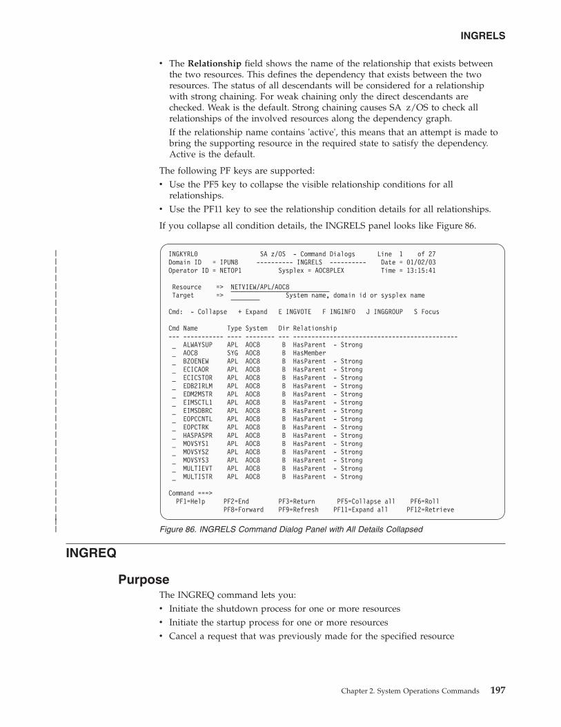
v The Relationship field shows the name of the relationship that exists betweenthe two resources. This defines the dependency that exists between the tworesources. The status of all descendants will be considered for a relationshipwith strong chaining. For weak chaining only the direct descendants arechecked. Weak is the default. Strong chaining causes SA z/OS to check allrelationships of the involved resources along the dependency graph.If the relationship name contains 'active', this means that an attempt is made tobring the supporting resource in the required state to satisfy the dependency.Active is the default.
The following PF keys are supported:v Use the PF5 key to collapse the visible relationship conditions for all
relationships.v Use the PF11 key to see the relationship condition details for all relationships.
If you collapse all condition details, the INGRELS panel looks like Figure 86.
INGREQ
PurposeThe INGREQ command lets you:v Initiate the shutdown process for one or more resourcesv Initiate the startup process for one or more resourcesv Cancel a request that was previously made for the specified resource
INGKYRL0 SA z/OS - Command Dialogs Line 1 of 27Domain ID = IPUN8 ---------- INGRELS ---------- Date = 01/02/03Operator ID = NETOP1 Sysplex = AOC8PLEX Time = 13:15:41
Resource => NETVIEW/APL/AOC8Target => System name, domain id or sysplex name
Cmd: - Collapse + Expand E INGVOTE F INGINFO J INGGROUP S Focus
Cmd Name Type System Dir Relationship--- ----------- ---- -------- --- ---------------------------------------------_ ALWAYSUP APL AOC8 B HasParent - Strong_ AOC8 SYG AOC8 B HasMember_ BZOENEW APL AOC8 B HasParent - Strong_ ECICAOR APL AOC8 B HasParent - Strong_ ECICSTOR APL AOC8 B HasParent - Strong_ EDB2IRLM APL AOC8 B HasParent - Strong_ EDM2MSTR APL AOC8 B HasParent - Strong_ EIMSCTL1 APL AOC8 B HasParent - Strong_ EIMSDBRC APL AOC8 B HasParent - Strong_ EOPCCNTL APL AOC8 B HasParent - Strong_ EOPCTRK APL AOC8 B HasParent - Strong_ HASPASPR APL AOC8 B HasParent - Strong_ MOVSYS1 APL AOC8 B HasParent - Strong_ MOVSYS2 APL AOC8 B HasParent - Strong_ MOVSYS3 APL AOC8 B HasParent - Strong_ MULTIEVT APL AOC8 B HasParent - Strong_ MULTISTR APL AOC8 B HasParent - Strong
Command ===>PF1=Help PF2=End PF3=Return PF5=Collapse all PF6=Roll
PF8=Forward PF9=Refresh PF11=Expand all PF12=Retrieve
Figure 86. INGRELS Command Dialog Panel with All Details Collapsed
INGRELS
Chapter 2. System Operations Commands 197
|||||||||||||||||||||||||||||||||||
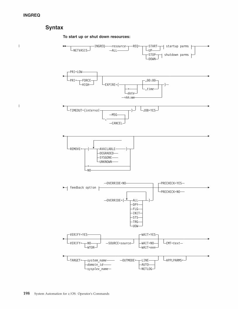
Syntax
To start up or shut down resources:
��NETVASIS
INGREQ resourceALL
REQ= START startup parmsUPSTOP shutdown parmsDOWN
�
�PRI=LOW
PRI= FORCEHIGH
,00:00EXPIRE=( )
* ,timedate
+hh:mm
�
�TIMEOUT=(interval )
MSG,
CANCEL
JOB=YES�
�
�REMOVE= ( AVAILABLE )DEGRADEDSYSGONEUNKNOWN
*NO
�
�
�
OVERRIDE=NOfeedback option
OVERRIDE=( ALL )DPYFLGINITSTSTRGUOW
PRECHECK=YES
PRECHECK=NO�
�VERIFY=YES
VERIFY= NOWTOR
SOURCE=source
WAIT=YES
WAIT=NOWAIT=nnn
CMT=text�
�TARGET= system_name
domain_idsysplex_name
OUTMODE= LINEAUTONETLOG
APPLPARMS=�
INGREQ
198 System Automation for z/OS: Operator's Commands
|
|

�MULT=YES
��
Startup parms:
SCOPE=ONLY
SCOPE=ALL
TYPE=NORM
TYPE=user
Shutdown parms:
SCOPE=ALL
SCOPE= ONLYCHILDREN
TYPE=NORM
TYPE= IMMEDFORCE
RESTART=NO
RESTART=YES�
�INTERRUPT=NO
INTERRUPT=YES
To cancel a request:
�� INGREQ resource REQ=CANCELSOURCE=source
VERIFY=YES
VERIFY= NOWTOR
�
�WAIT=YES
WAIT=NOWAIT=nnn
TARGET= system_namedomain_idsysplex_name
OUTMODE= LINEAUTONETLOG
�
� feedback option ��
Feedback option:
FDBK=( MSG ,G ,max_time )MSG/userid ,F ,exp_status
,BWAIT
ParametersNETVASIS
Prefix the INGLIST command with NETVASIS if you want to pass thedescription text in lower or mixed case.
resourceSpecifies the name of the resource to be processed. The format isname[/type[/system]]. Wildcards are supported. In fullscreen mode, if more thanone resource matches the wildcard specification, a selection panel is displayed.
INGREQ
Chapter 2. System Operations Commands 199
|||
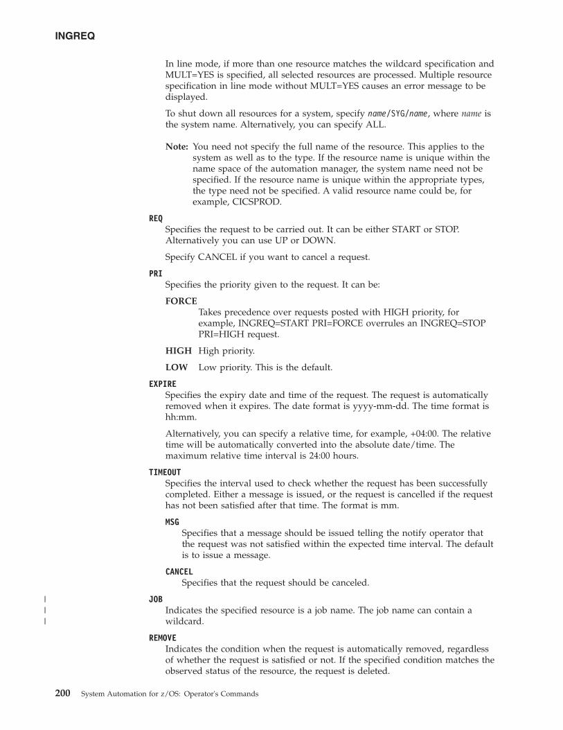
In line mode, if more than one resource matches the wildcard specification andMULT=YES is specified, all selected resources are processed. Multiple resourcespecification in line mode without MULT=YES causes an error message to bedisplayed.
To shut down all resources for a system, specify name/SYG/name, where name isthe system name. Alternatively, you can specify ALL.
Note: You need not specify the full name of the resource. This applies to thesystem as well as to the type. If the resource name is unique within thename space of the automation manager, the system name need not bespecified. If the resource name is unique within the appropriate types,the type need not be specified. A valid resource name could be, forexample, CICSPROD.
REQSpecifies the request to be carried out. It can be either START or STOP.Alternatively you can use UP or DOWN.
Specify CANCEL if you want to cancel a request.
PRISpecifies the priority given to the request. It can be:
FORCETakes precedence over requests posted with HIGH priority, forexample, INGREQ=START PRI=FORCE overrules an INGREQ=STOPPRI=HIGH request.
HIGH High priority.
LOW Low priority. This is the default.
EXPIRESpecifies the expiry date and time of the request. The request is automaticallyremoved when it expires. The date format is yyyy-mm-dd. The time format ishh:mm.
Alternatively, you can specify a relative time, for example, +04:00. The relativetime will be automatically converted into the absolute date/time. Themaximum relative time interval is 24:00 hours.
TIMEOUTSpecifies the interval used to check whether the request has been successfullycompleted. Either a message is issued, or the request is cancelled if the requesthas not been satisfied after that time. The format is mm.
MSGSpecifies that a message should be issued telling the notify operator thatthe request was not satisfied within the expected time interval. The defaultis to issue a message.
CANCELSpecifies that the request should be canceled.
JOBIndicates the specified resource is a job name. The job name can contain awildcard.
REMOVEIndicates the condition when the request is automatically removed, regardlessof whether the request is satisfied or not. If the specified condition matches theobserved status of the resource, the request is deleted.
INGREQ
200 System Automation for z/OS: Operator's Commands
|||
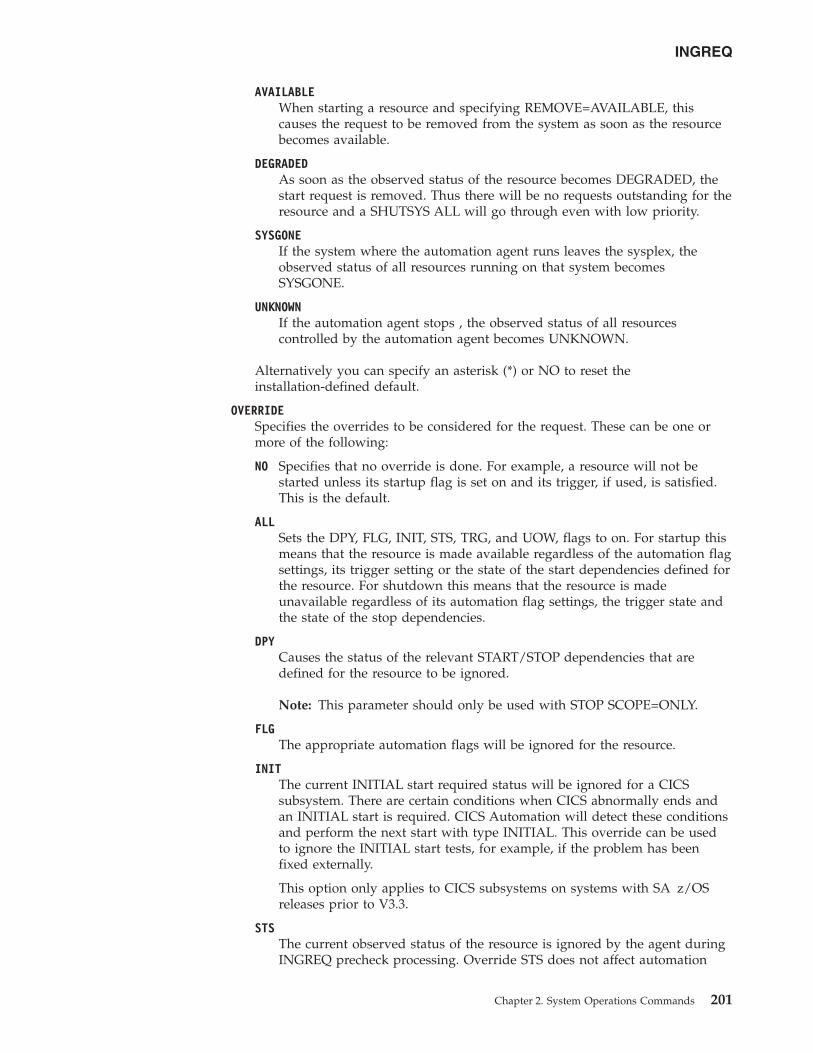
AVAILABLEWhen starting a resource and specifying REMOVE=AVAILABLE, thiscauses the request to be removed from the system as soon as the resourcebecomes available.
DEGRADEDAs soon as the observed status of the resource becomes DEGRADED, thestart request is removed. Thus there will be no requests outstanding for theresource and a SHUTSYS ALL will go through even with low priority.
SYSGONEIf the system where the automation agent runs leaves the sysplex, theobserved status of all resources running on that system becomesSYSGONE.
UNKNOWNIf the automation agent stops , the observed status of all resourcescontrolled by the automation agent becomes UNKNOWN.
Alternatively you can specify an asterisk (*) or NO to reset theinstallation-defined default.
OVERRIDESpecifies the overrides to be considered for the request. These can be one ormore of the following:
NO Specifies that no override is done. For example, a resource will not bestarted unless its startup flag is set on and its trigger, if used, is satisfied.This is the default.
ALLSets the DPY, FLG, INIT, STS, TRG, and UOW, flags to on. For startup thismeans that the resource is made available regardless of the automation flagsettings, its trigger setting or the state of the start dependencies defined forthe resource. For shutdown this means that the resource is madeunavailable regardless of its automation flag settings, the trigger state andthe state of the stop dependencies.
DPYCauses the status of the relevant START/STOP dependencies that aredefined for the resource to be ignored.
Note: This parameter should only be used with STOP SCOPE=ONLY.
FLGThe appropriate automation flags will be ignored for the resource.
INITThe current INITIAL start required status will be ignored for a CICSsubsystem. There are certain conditions when CICS abnormally ends andan INITIAL start is required. CICS Automation will detect these conditionsand perform the next start with type INITIAL. This override can be usedto ignore the INITIAL start tests, for example, if the problem has beenfixed externally.
This option only applies to CICS subsystems on systems with SA z/OSreleases prior to V3.3.
STSThe current observed status of the resource is ignored by the agent duringINGREQ precheck processing. Override STS does not affect automation
INGREQ
Chapter 2. System Operations Commands 201
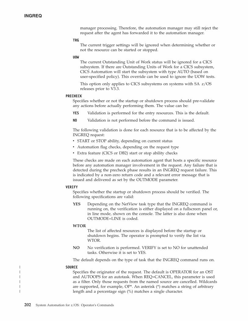
manager processing. Therefore, the automation manager may still reject therequest after the agent has forwarded it to the automation manager.
TRGThe current trigger settings will be ignored when determining whether ornot the resource can be started or stopped.
UOWThe current Outstanding Unit of Work status will be ignored for a CICSsubsystem. If there are Outstanding Units of Work for a CICS subsystem,CICS Automation will start the subsystem with type AUTO (based onuser-specified policy). This override can be used to ignore the UOW tests.
This option only applies to CICS subsystems on systems with SA z/OSreleases prior to V3.3.
PRECHECKSpecifies whether or not the startup or shutdown process should pre-validateany actions before actually performing them. The value can be:
YES Validation is performed for the entry resources. This is the default.
NO Validation is not performed before the command is issued.
The following validation is done for each resource that is to be affected by theINGREQ request:v START or STOP ability, depending on current statusv Automation flag checks, depending on the request typev Extra feature (CICS or DB2) start or stop ability checks
These checks are made on each automation agent that hosts a specific resourcebefore any automation manager involvement in the request. Any failure that isdetected during the precheck phase results in an INGREQ request failure. Thisis indicated by a non-zero return code and a relevant error message that isissued and delivered as set by the OUTMODE parameter.
VERIFYSpecifies whether the startup or shutdown process should be verified. Thefollowing specifications are valid:
YES Depending on the NetView task type that the INGREQ command isrunning on, the verification is either displayed on a fullscreen panel or,in line mode, shown on the console. The latter is also done whenOUTMODE=LINE is coded.
WTORThe list of affected resources is displayed before the startup orshutdown begins. The operator is prompted to verify the list viaWTOR.
NO No verification is performed. VERIFY is set to NO for unattendedtasks. Otherwise it is set to YES.
The default depends on the type of task that the INGREQ command runs on.
SOURCESpecifies the originator of the request. The default is OPERATOR for an OSTand AUTOOPS for an autotask. When REQ=CANCEL, this parameter is usedas a filter. Only those requests from the named source are cancelled. Wildcardsare supported, for example, OP*. An asterisk (*) matches a string of arbitrarylength and a percentage sign (%) matches a single character.
INGREQ
202 System Automation for z/OS: Operator's Commands
||||||
WAITSpecifies whether or not to wait until the request is complete. The default isYES.
The variable nnn is the number of seconds to wait before giving up andreporting that a timeout has occurred. The maximum time interval is 999seconds.
CMTSpecifies descriptive information about the request. The maximum length is120 characters. If the text contains embedded blanks, it must be enclosed inquotation marks or parentheses.
TARGETFor information on the TARGET parameter, see “TARGET Parameter” on page10.
OUTMODEFor information on the OUTMODE parameter, see “OUTMODE Parameter” onpage 12.
APPLPARMSThe content of APPLPARMS is put into the &APPLPARMS variable.
MULTSpecifies that more than one resource will be accepted when running in linemode, if the resource wildcard specification results in multiple resources.
SCOPESpecifies whether the startup or shutdown affects a resource or its descendants,or both. Valid options are:
ONLYSpecifies that only the specified resource is started or stopped. This is thedefault for startup.
ALLSpecifies that the resource and its descendants are started or stopped. Thisis the default for shutdown.
CHILDREN (shutdown only)Specifies that only the descendants of the resource are stopped.
TYPESpecifies the type of the startup or shutdown. Each type must be defined inthe policy database. Valid options are:
NORM (startup or shutdown)Specifies a normal startup or shutdown. This is the default.
IMMED (shutdown only)Specifies an immediate shutdown.
FORCE (shutdown only)Specifies a forced shutdown.
user (startup only)Specifies a user-defined startup type.
Note: If no startup commands are defined for the specified start type, thestartup commands for start type NORM are issued.
INGREQ
Chapter 2. System Operations Commands 203
Note: The value specified here will be overridden by the INGSETSTARTTYPE/STOPTYPE value if previously specified. However, a stoptype of FORCE, wherever specified, will always be honored.
Use the VERIFY option to view the TYPE value that will be used for thisrequest.
Once a shutdown has got to a PROBLEM or DENIED state, you cansubmit another shutdown request against the resource, specifying adifferent shutdown type or override parameters or both.
If you want to escalate the shutdown of a child subsystem, you canissue the INGREQ directly against it, but you must use a higher prioritythan the shutdown request against the parent was made with.
RESTART (shutdown only)Specifies whether the resource should be restarted automatically when it hasbeen shutdown completely. Valid options are:
NO Specifies that no restart is performed. This is the default.
YESSpecifies that a restart is performed.
INTERRUPT (shutdown only)Specifies whether or not to interrupt the startup or shutdown phase of theresource. Valid options are:
NO If the resource is starting, the automation manager waits for the resource'sUP message before proceeding with the shutdown.
If the resource is shutting down, the automation manager waits until theshutdown is complete. This is the default.
YESIf the resource is starting, the automation manager interrupts the startupprocess and starts shutting down the resource.
Interrupting the shutdown process means breaking the former stop requestthat is in a locked state because the agent has not yet indicated that theshutdown is complete. A typical scenario where the INTERRUPT=YESoption is used is when escalating to a higher stop type.
FDBKSpecifies the feedback parameter that causes the final result of the command tobe reported back to the designated instance.
MSG Causes message signaling of the successful or unsuccessful completionof the command to be performed.
The message is sent back to the originator of the command. Theoriginator is determined by the NetView OPID(S) function unless theuser ID is specified. Depending on the status, either message ING300Ior ING301I is issued. The message text contains the command that wasprocessed successfully or failed.
useridIdentifies the NetView user ID of the person to be notified ifdifferent to the originating user.
Use the following values to specify when to issue the message:
INGREQ
204 System Automation for z/OS: Operator's Commands
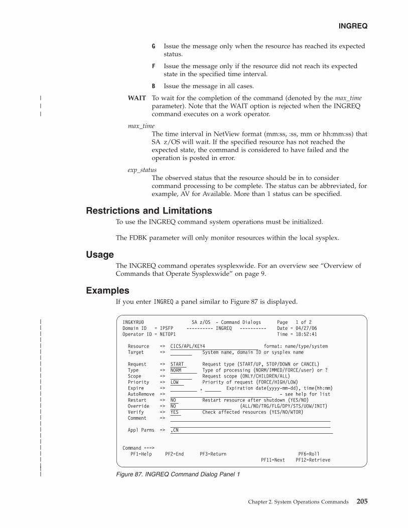
G Issue the message only when the resource has reached its expectedstatus.
F Issue the message only if the resource did not reach its expectedstate in the specified time interval.
B Issue the message in all cases.
WAIT To wait for the completion of the command (denoted by the max_timeparameter). Note that the WAIT option is rejected when the INGREQcommand executes on a work operator.
max_timeThe time interval in NetView format (mm:ss, :ss, mm or hh:mm:ss) thatSA z/OS will wait. If the specified resource has not reached theexpected state, the command is considered to have failed and theoperation is posted in error.
exp_statusThe observed status that the resource should be in to considercommand processing to be complete. The status can be abbreviated, forexample, AV for Available. More than 1 status can be specified.
Restrictions and LimitationsTo use the INGREQ command system operations must be initialized.
The FDBK parameter will only monitor resources within the local sysplex.
UsageThe INGREQ command operates sysplexwide. For an overview see “Overview ofCommands that Operate Sysplexwide” on page 9.
ExamplesIf you enter INGREQ a panel similar to Figure 87 is displayed.
INGKYRU0 SA z/OS - Command Dialogs Page 1 of 2Domain ID = IPSFP ---------- INGREQ ---------- Date = 04/27/06Operator ID = NETOP1 Time = 18:52:41
Resource => CICS/APL/KEY4 format: name/type/systemTarget => System name, domain ID or sysplex name
Request => START Request type (START/UP, STOP/DOWN or CANCEL)Type => NORM Type of processing (NORM/IMMED/FORCE/user) or ?Scope => Request scope (ONLY/CHILDREN/ALL)Priority => LOW Priority of request (FORCE/HIGH/LOW)Expire => , Expiration date(yyyy-mm-dd), time(hh:mm)AutoRemove => - see help for listRestart => NO Restart resource after shutdown (YES/NO)Override => NO (ALL/NO/TRG/FLG/DPY/STS/UOW/INIT)Verify => YES Check affected resources (YES/NO/WTOR)Comment =>
Appl Parms => ,CN
Command ===>PF1=Help PF2=End PF3=Return PF6=Roll
PF11=Next PF12=Retrieve
Figure 87. INGREQ Command Dialog Panel 1
INGREQ
Chapter 2. System Operations Commands 205
|||||||||||||||||||||||||||
|||
v The Resource field shows the name of the resource to be processed. The formatis name/type[/system]. Wildcard is supported.
v The Target field shows the name of the system (system name, domain ID, orsysplex name) that the command should be routed to. Specifying this is onlynecessary if the resources are not part of the local sysplex.
v The Request field shows the request to be carried out. This is either START orSTOP. Alternatively you can use UP or DOWN. To remove a previously maderequest from the same source specify CANCEL.
v The Type field shows the type of the startup or shutdown. Valid shutdowntypes are NORM, IMMED and FORCE as well as any other type defined in thepolicy database for the resource. Specify a question mark (?) to display the list ofdefined startup types.
v The Scope field shows whether the startup or shutdown affects this resource orits descendants, or both.
v The Priority field shows the priority given to the request.v The Expire field shows the expiry date and time when the request will be
removed.v The AutoRemove field shows the condition when the request is automatically
removed regardless of whether the request is satisfied or not.v The Restart field shows whether the resource should be restarted automatically
when it has been shutdown completely. This applies only when requesting ashutdown of a resource.
v The Override field shows the overrides to be considered for the request. Theparameter can be used to bypass the conditions or settings that would otherwiseprevent a resource, or resources, from starting or shutting down.
v The Verify field shows whether the startup or shutdown process should beverified. If YES or WTOR is entered, the list of affected resources is displayedbefore the startup or shutdown begins. You will be prompted to verify the list. IfWTOR is specified, you will be prompted via a WTOR. If NO is entered, thestartup or shutdown begins immediately. The default is YES.
v The Comment field lets you specify descriptive information, for example, whythe request was made.
v The Appl Parms field shows modifications or parameters to the START or STOPrequest.
If you press PF11 a panel similar to Figure 88 on page 207 is displayed.
INGREQ
206 System Automation for z/OS: Operator's Commands
|||
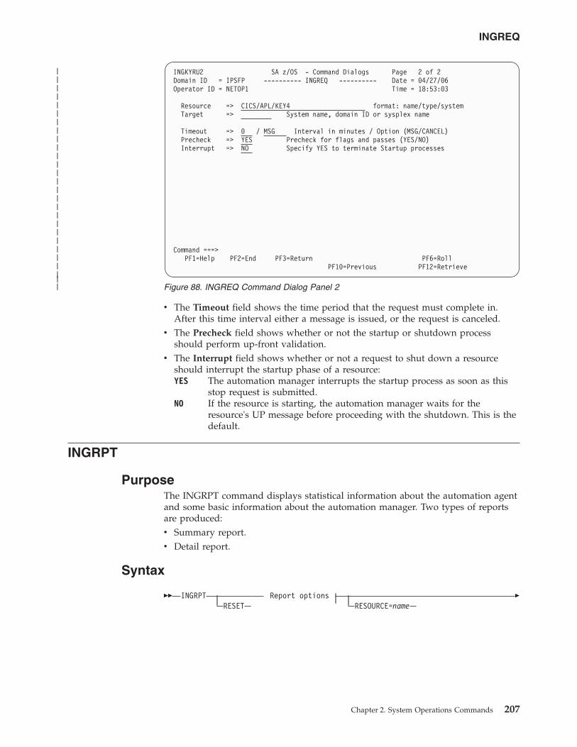
v The Timeout field shows the time period that the request must complete in.After this time interval either a message is issued, or the request is canceled.
v The Precheck field shows whether or not the startup or shutdown processshould perform up-front validation.
v The Interrupt field shows whether or not a request to shut down a resourceshould interrupt the startup phase of a resource:YES The automation manager interrupts the startup process as soon as this
stop request is submitted.NO If the resource is starting, the automation manager waits for the
resource's UP message before proceeding with the shutdown. This is thedefault.
INGRPT
PurposeThe INGRPT command displays statistical information about the automation agentand some basic information about the automation manager. Two types of reportsare produced:v Summary report.v Detail report.
Syntax
�� INGRPTRESET
Report optionsRESOURCE=name
�
INGKYRU2 SA z/OS - Command Dialogs Page 2 of 2Domain ID = IPSFP ---------- INGREQ ---------- Date = 04/27/06Operator ID = NETOP1 Time = 18:53:03
Resource => CICS/APL/KEY4 format: name/type/systemTarget => System name, domain ID or sysplex name
Timeout => 0 / MSG Interval in minutes / Option (MSG/CANCEL)Precheck => YES Precheck for flags and passes (YES/NO)Interrupt => NO Specify YES to terminate Startup processes
Command ===>PF1=Help PF2=End PF3=Return PF6=Roll
PF10=Previous PF12=Retrieve
Figure 88. INGREQ Command Dialog Panel 2
INGREQ
Chapter 2. System Operations Commands 207
|||||||||||||||||||||||||||
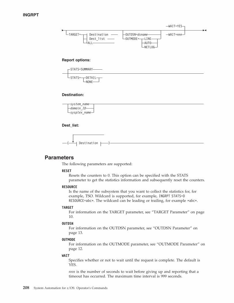
�TARGET= Destination
Dest_list*ALL
OUTDSN=dsnameOUTMODE= LINE
AUTONETLOG
WAIT=YES
WAIT=nnn��
Report options:
STATS=SUMMARY
STATS= DETAILNONE
Destination:
system_namedomain_IDsysplex_name
Dest_list:
�( Destination )
ParametersThe following parameters are supported:
RESETResets the counters to 0. This option can be specified with the STATSparameter to get the statistics information and subsequently reset the counters.
RESOURCEIs the name of the subsystem that you want to collect the statistics for, forexample, TSO. Wildcard is supported, for example, INGRPT STATS=DRESOURCE=abc*. The wildcard can be leading or trailing, for example *abc*.
TARGETFor information on the TARGET parameter, see “TARGET Parameter” on page10.
OUTDSNFor information on the OUTDSN parameter, see “OUTDSN Parameter” onpage 13.
OUTMODEFor information on the OUTMODE parameter, see “OUTMODE Parameter” onpage 12.
WAITSpecifies whether or not to wait until the request is complete. The default isYES.
nnn is the number of seconds to wait before giving up and reporting that atimeout has occurred. The maximum time interval is 999 seconds.
INGRPT
208 System Automation for z/OS: Operator's Commands
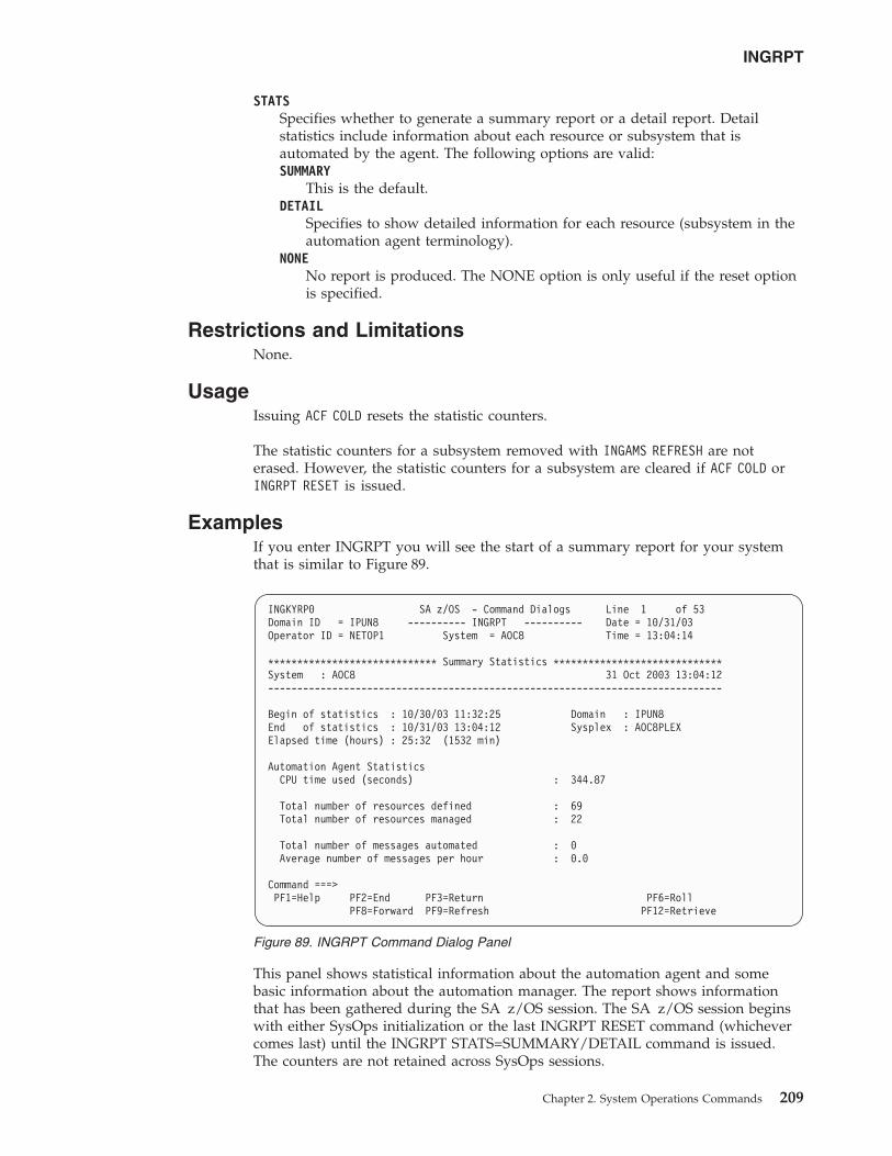
STATSSpecifies whether to generate a summary report or a detail report. Detailstatistics include information about each resource or subsystem that isautomated by the agent. The following options are valid:SUMMARY
This is the default.DETAIL
Specifies to show detailed information for each resource (subsystem in theautomation agent terminology).
NONENo report is produced. The NONE option is only useful if the reset optionis specified.
Restrictions and LimitationsNone.
UsageIssuing ACF COLD resets the statistic counters.
The statistic counters for a subsystem removed with INGAMS REFRESH are noterased. However, the statistic counters for a subsystem are cleared if ACF COLD orINGRPT RESET is issued.
ExamplesIf you enter INGRPT you will see the start of a summary report for your systemthat is similar to Figure 89.
This panel shows statistical information about the automation agent and somebasic information about the automation manager. The report shows informationthat has been gathered during the SA z/OS session. The SA z/OS session beginswith either SysOps initialization or the last INGRPT RESET command (whichevercomes last) until the INGRPT STATS=SUMMARY/DETAIL command is issued.The counters are not retained across SysOps sessions.
INGKYRP0 SA z/OS - Command Dialogs Line 1 of 53Domain ID = IPUN8 ---------- INGRPT ---------- Date = 10/31/03Operator ID = NETOP1 System = AOC8 Time = 13:04:14
***************************** Summary Statistics *****************************System : AOC8 31 Oct 2003 13:04:12------------------------------------------------------------------------------
Begin of statistics : 10/30/03 11:32:25 Domain : IPUN8End of statistics : 10/31/03 13:04:12 Sysplex : AOC8PLEXElapsed time (hours) : 25:32 (1532 min)
Automation Agent StatisticsCPU time used (seconds) : 344.87
Total number of resources defined : 69Total number of resources managed : 22
Total number of messages automated : 0Average number of messages per hour : 0.0
Command ===>PF1=Help PF2=End PF3=Return PF6=Roll
PF8=Forward PF9=Refresh PF12=Retrieve
Figure 89. INGRPT Command Dialog Panel
INGRPT
Chapter 2. System Operations Commands 209
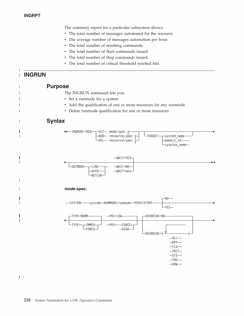
The summary report for a particular subsystem shows:v The total number of messages automated for the resource.v The average number of messages automation per hour.v The total number of resulting commands.v The total number of Start commands issued.v The total number of Stop commands issued.v The total number of critical threshold reached hits.
INGRUN
PurposeThe INGRUN command lets you:v Set a runmode for a systemv Add the qualification of one or more resources for any runmodev Delete runmode qualification for one or more resources
Syntax
�� INGRUN REQ= SET mode-specADD resource-specDEL resource-spec
TARGET= system_namedomain_idsysplex_name
�
�OUTMODE= LINE
AUTONETLOG
WAIT=YES
WAIT=NOWAIT=nnn
��
mode-spec:
SYSTEM = system RUNMODE=runmodeNO
PERSISTENT =YES
�
�TYPE=NORM
TYPE= IMMEDFORCE
PRI=LOW
PRI= FORCEHIGH
�
OVERRIDE=NO
OVERRIDE=( )ALLDPYFLGINITSTSTRGUOW
�
INGRPT
210 System Automation for z/OS: Operator's Commands
||
|
|
|
|
|
|
|||||||||||||||||||||||||||||||||||||||||||||
||||||||||||||||||||||||||||||||||||
|
|
|||||||||||||||||||||||||||
||||||||||||||||||||||||||||||||||||||||||||||||||||||||||||||||||||||||||||||
||
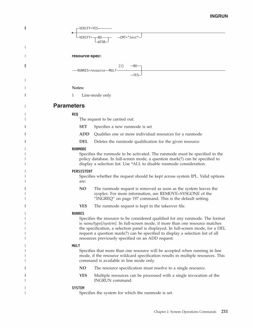
�VERIFY=YES
VERIFY= NOWTOR
CMT="text"
resource-spec:
RUNRES=resource(1) NO
MULT =YES
Notes:
1 Line-mode only
ParametersREQ
The request to be carried out.
SET Specifies a new runmode is set
ADD Qualifies one or more individual resources for a runmode
DEL Deletes the runmode qualification for the given resource
RUNMODESpecifies the runmode to be activated. The runmode must be specified in thepolicy database. In full-screen mode, a question mark(?) can be specified todisplay a selection list. Use *ALL to disable runmode consideration.
PERSISTENTSpecifies whether the request should be kept across system IPL. Valid optionsare:
NO The runmode request is removed as soon as the system leaves thesysplex. For more information, see REMOVE=SYSGONE of the“INGREQ” on page 197 command. This is the default setting.
YES The runmode request is kept in the takeover file.
RUNRESSpecifies the resource to be considered qualified for any runmode. The formatis name/type[/system]. In full-screen mode, if more than one resource matchesthe specification, a selection panel is displayed. In full-screen mode, for a DELrequest a question mark(?) can be specified to display a selection list of allresources previously specified on an ADD request.
MULTSpecifies that more than one resource will be accepted when running in linemode, if the resource wildcard specification results in multiple resources. Thiscommand is available in line mode only.
NO The resource specification must resolve to a single resource.
YES Multiple resources can be processed with a single invocation of theINGRUN command.
SYSTEMSpecifies the system for which the runmode is set.
INGRUN
Chapter 2. System Operations Commands 211
|||||||||||||||||||||||||||||
|
|
|||||||||||||||||||||||
|
|
||
|
||
||
||
||
||||
|||
||||
||
||||||
||||
||
|||
||
TYPESpecifies the type of shutdown to be used for resources that do not qualify forthe new runmode. For more information, see the “INGREQ” on page 197command.
PRI / PRIORITYSpecifies the priority for the shutdown of the resources that do not qualify forthe new runmode. For more information, see the “INGREQ” on page 197command.
OVERRIDESpecifies the overrides that are to be considered when shutting down resourcesthat do not qualify for the new runmode. For more information, see the“INGREQ” on page 197 command.
VERIFYSpecifies if the shutdown process of resources that do not qualify for the newrunmode should be verified.
CMT / COMMENTSpecifies descriptive information, for example, why the request was made.
TARGETFor information on the TARGET parameter, see “TARGET Parameter” on page10
OUTMODEFor information on the OUTMODE parameter, see “OUTMODE Parameter” onpage 12.
WAITSpecifies whether to wait or not for the request to complete. The default isYES.
nnn is the number of seconds to wait before giving up and reporting that atimeout has occurred. The maximum time interval is 999 seconds. For moreinformation, see the “INGREQ” on page 197 command.
Restrictions and LimitationsTo use the INGRUN command, system operations must be initialized.
UsageThe INGRUN command operates sysplexwide.
ExamplesIf you enter ingrun a panel similar to Figure 90 on page 213 is displayed.
INGRUN
212 System Automation for z/OS: Operator's Commands
||||
||||
||||
|||
||
|||
|||
|||
|||
|
|
|
|
|
||
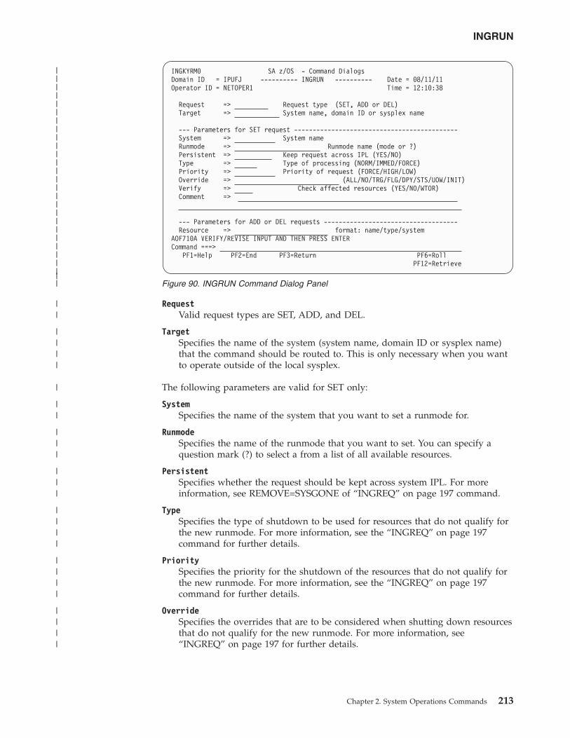
RequestValid request types are SET, ADD, and DEL.
TargetSpecifies the name of the system (system name, domain ID or sysplex name)that the command should be routed to. This is only necessary when you wantto operate outside of the local sysplex.
The following parameters are valid for SET only:
SystemSpecifies the name of the system that you want to set a runmode for.
RunmodeSpecifies the name of the runmode that you want to set. You can specify aquestion mark (?) to select a from a list of all available resources.
PersistentSpecifies whether the request should be kept across system IPL. For moreinformation, see REMOVE=SYSGONE of “INGREQ” on page 197 command.
TypeSpecifies the type of shutdown to be used for resources that do not qualify forthe new runmode. For more information, see the “INGREQ” on page 197command for further details.
PrioritySpecifies the priority for the shutdown of the resources that do not qualify forthe new runmode. For more information, see the “INGREQ” on page 197command for further details.
OverrideSpecifies the overrides that are to be considered when shutting down resourcesthat do not qualify for the new runmode. For more information, see“INGREQ” on page 197 for further details.
INGKYRM0 SA z/OS - Command DialogsDomain ID = IPUFJ ---------- INGRUN ---------- Date = 08/11/11Operator ID = NETOPER1 Time = 12:10:38
Request => Request type (SET, ADD or DEL)Target => System name, domain ID or sysplex name
--- Parameters for SET request --------------------------------------------System => System nameRunmode => Runmode name (mode or ?)Persistent => Keep request across IPL (YES/NO)Type => Type of processing (NORM/IMMED/FORCE)Priority => Priority of request (FORCE/HIGH/LOW)Override => (ALL/NO/TRG/FLG/DPY/STS/UOW/INIT)Verify => Check affected resources (YES/NO/WTOR)Comment =>
--- Parameters for ADD or DEL requests ------------------------------------Resource => format: name/type/system
AOF710A VERIFY/REVISE INPUT AND THEN PRESS ENTERCommand ===>
PF1=Help PF2=End PF3=Return PF6=RollPF12=Retrieve
Figure 90. INGRUN Command Dialog Panel
INGRUN
Chapter 2. System Operations Commands 213
|||||||||||||||||||||||||||
||
||||
|
||
|||
|||
||||
||||
||||
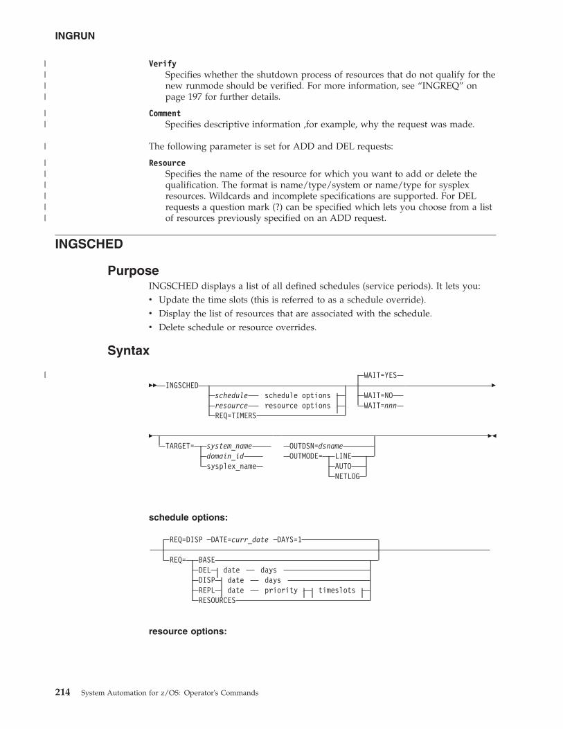
VerifySpecifies whether the shutdown process of resources that do not qualify for thenew runmode should be verified. For more information, see “INGREQ” onpage 197 for further details.
CommentSpecifies descriptive information ,for example, why the request was made.
The following parameter is set for ADD and DEL requests:
ResourceSpecifies the name of the resource for which you want to add or delete thequalification. The format is name/type/system or name/type for sysplexresources. Wildcards and incomplete specifications are supported. For DELrequests a question mark (?) can be specified which lets you choose from a listof resources previously specified on an ADD request.
INGSCHED
PurposeINGSCHED displays a list of all defined schedules (service periods). It lets you:v Update the time slots (this is referred to as a schedule override).v Display the list of resources that are associated with the schedule.v Delete schedule or resource overrides.
Syntax
�� INGSCHEDschedule schedule optionsresource resource optionsREQ=TIMERS
WAIT=YES
WAIT=NOWAIT=nnn
�
�TARGET= system_name
domain_idsysplex_name
OUTDSN=dsnameOUTMODE= LINE
AUTONETLOG
��
schedule options:
REQ=DISP DATE=curr_date DAYS=1
REQ= BASEDEL date daysDISP date daysREPL date priority timeslotsRESOURCES
resource options:
INGRUN
214 System Automation for z/OS: Operator's Commands
||||
||
|
||||||
|
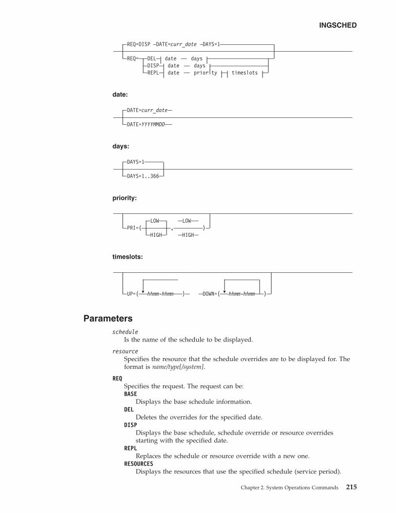
REQ=DISP DATE=curr_date DAYS=1
REQ= DEL date daysDISP date daysREPL date priority timeslots
date:
DATE=curr_date
DATE=YYYYMMDD
days:
DAYS=1
DAYS=1..366
priority:
LOW LOWPRI=( , )
HIGH HIGH
timeslots:
�UP=( hhmm-hhmm ) �DOWN=( hhmm-hhmm )
Parametersschedule
Is the name of the schedule to be displayed.
resourceSpecifies the resource that the schedule overrides are to be displayed for. Theformat is name/type[/system].
REQSpecifies the request. The request can be:BASE
Displays the base schedule information.DEL
Deletes the overrides for the specified date.DISP
Displays the base schedule, schedule override or resource overridesstarting with the specified date.
REPLReplaces the schedule or resource override with a new one.
RESOURCESDisplays the resources that use the specified schedule (service period).
INGSCHED
Chapter 2. System Operations Commands 215
TIMERSDisplays the list of timers that are currently scheduled.
DATESpecifies the date in yyyymmdd format that the delete or replace of theoverride should be done for.
curr_dateThe current date.
DAYSSpecifies the number of days for which the overrides should be displayed ordeleted.
PRIORITYSpecifies the priority to be assigned to the override. The first value is the UPpriority and the second value is the DOWN priority. Valid values are:HIGH High priority.LOW Low priority.
Both priorities are optional. The default is LOW. The priority values can beabbreviated.
UP Specifies the UP start and stop times in the format hhmm-hhmm. Up to fivetime slots can be specified separated by a comma. The UP time slots define thetime windows where the resource must or should be available. A priority ofHIGH means that the resource must be available, while a priority of LOWmeans that the resource should be available.
DOWNSpecifies the DOWN start and stop times. The format is hhmm-hhmm. Up tofive time slots can be specified separated by a comma. The DOWN time slotsdefine the time window where the resource must or should be not available(that is, unavailable). A priority of HIGH means that the resource must beunavailable, while a priority of LOW means that the resource should beunavailable. If you specify DOWN, specifying the UP priority becomesmandatory.
WAITSpecifies whether or not to wait until the request is complete. The default isYES.
nnn is the number of seconds to wait before giving up and reporting that atimeout has occurred. The maximum time interval is 999 seconds.
TARGETFor information on the TARGET parameter, see “TARGET Parameter” on page10.
OUTDSNFor information on the OUTDSN parameter, see “OUTDSN Parameter” onpage 13.
OUTMODEFor information on the OUTMODE parameter, see “OUTMODE Parameter” onpage 12.
Restrictions and LimitationsThe INGSCHED command can only be used when system operations is initialized.
INGSCHED
216 System Automation for z/OS: Operator's Commands
||
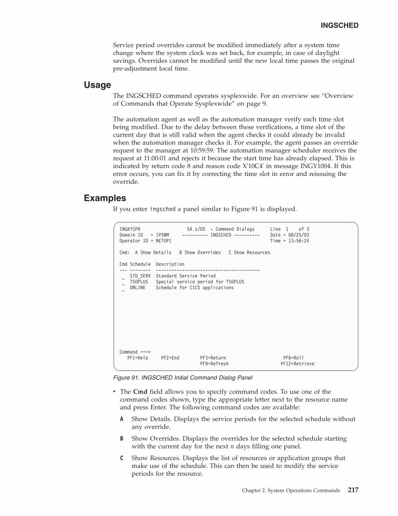
Service period overrides cannot be modified immediately after a system timechange where the system clock was set back, for example, in case of daylightsavings. Overrides cannot be modified until the new local time passes the originalpre-adjustment local time.
UsageThe INGSCHED command operates sysplexwide. For an overview see “Overviewof Commands that Operate Sysplexwide” on page 9.
The automation agent as well as the automation manager verify each time slotbeing modified. Due to the delay between these verifications, a time slot of thecurrent day that is still valid when the agent checks it could already be invalidwhen the automation manager checks it. For example, the agent passes an overriderequest to the manager at 10:59:59. The automation manager scheduler receives therequest at 11:00:01 and rejects it because the start time has already elapsed. This isindicated by return code 8 and reason code X'10C4' in message INGY1004. If thiserror occurs, you can fix it by correcting the time slot in error and reissuing theoverride.
ExamplesIf you enter ingsched a panel similar to Figure 91 is displayed.
v The Cmd field allows you to specify command codes. To use one of thecommand codes shown, type the appropriate letter next to the resource nameand press Enter. The following command codes are available:
A Show Details. Displays the service periods for the selected schedule withoutany override.
B Show Overrides. Displays the overrides for the selected schedule startingwith the current day for the next n days filling one panel.
C Show Resources. Displays the list of resources or application groups thatmake use of the schedule. This can then be used to modify the serviceperiods for the resource.
INGKYSP0 SA z/OS - Command Dialogs Line 1 of 3Domain ID = IPSNM ---------- INGSCHED ---------- Date = 08/25/03Operator ID = NETOP1 Time = 13:56:24
Cmd: A Show Details B Show Overrides C Show Resources
Cmd Schedule Description--- -------- ----------------------------------------
STD_SERV Standard Service PeriodTSOPLUS Special service period for TSOPLUSONLINE Schedule for CICS applications
Command ===>PF1=Help PF2=End PF3=Return PF6=Roll
PF9=Refresh PF12=Retrieve
Figure 91. INGSCHED Initial Command Dialog Panel
INGSCHED
Chapter 2. System Operations Commands 217
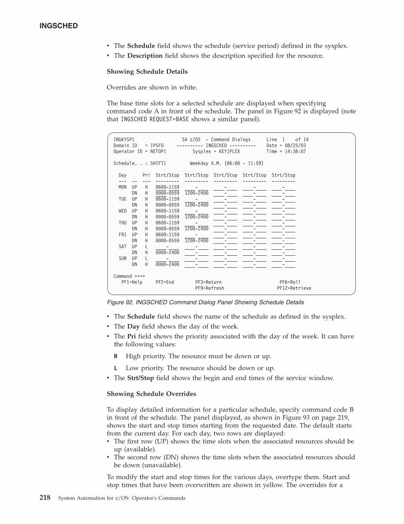
v The Schedule field shows the schedule (service period) defined in the sysplex.v The Description field shows the description specified for the resource.
Showing Schedule Details
Overrides are shown in white.
The base time slots for a selected schedule are displayed when specifyingcommand code A in front of the schedule. The panel in Figure 92 is displayed (notethat INGSCHED REQUEST=BASE shows a similar panel).
v The Schedule field shows the name of the schedule as defined in the sysplex.v The Day field shows the day of the week.v The Pri field shows the priority associated with the day of the week. It can have
the following values:
H High priority. The resource must be down or up.
L Low priority. The resource should be down or up.v The Strt/Stop field shows the begin and end times of the service window.
Showing Schedule Overrides
To display detailed information for a particular schedule, specify command code Bin front of the schedule. The panel displayed, as shown in Figure 93 on page 219,shows the start and stop times starting from the requested date. The default startsfrom the current day. For each day, two rows are displayed:v The first row (UP) shows the time slots when the associated resources should be
up (available).v The second row (DN) shows the time slots when the associated resources should
be down (unavailable).
To modify the start and stop times for the various days, overtype them. Start andstop times that have been overwritten are shown in yellow. The overrides for a
INGKYSP1 SA z/OS - Command Dialogs Line 1 of 14Domain ID = IPSFO ---------- INGSCHED ---------- Date = 08/25/03Operator ID = NETOP1 Sysplex = KEY1PLEX Time = 14:36:07
Schedule. . : SHIFT1 Weekday A.M. (06:00 - 11:59)
Day Pri Strt/Stop Strt/Stop Strt/Stop Strt/Stop Strt/Stop--- -- --- --------- --------- --------- --------- ---------MON UP H 0600-1159 - - - -
DN H 0000-0559 1200-2400 - - -TUE UP H 0600-1159 - - - -
DN H 0000-0559 1200-2400 - - -WED UP H 0600-1159 - - - -
DN H 0000-0559 1200-2400 - - -THU UP H 0600-1159 - - - -
DN H 0000-0559 1200-2400 - - -FRI UP H 0600-1159 - - - -
DN H 0000-0559 1200-2400 - - -SAT UP L - - - - -
DN H 0000-2400 - - - -SUN UP L - - - - -
DN H 0000-2400 - - - -
Command ===>PF1=Help PF2=End PF3=Return PF6=Roll
PF9=Refresh PF12=Retrieve
Figure 92. INGSCHED Command Dialog Panel Showing Schedule Details
INGSCHED
218 System Automation for z/OS: Operator's Commands
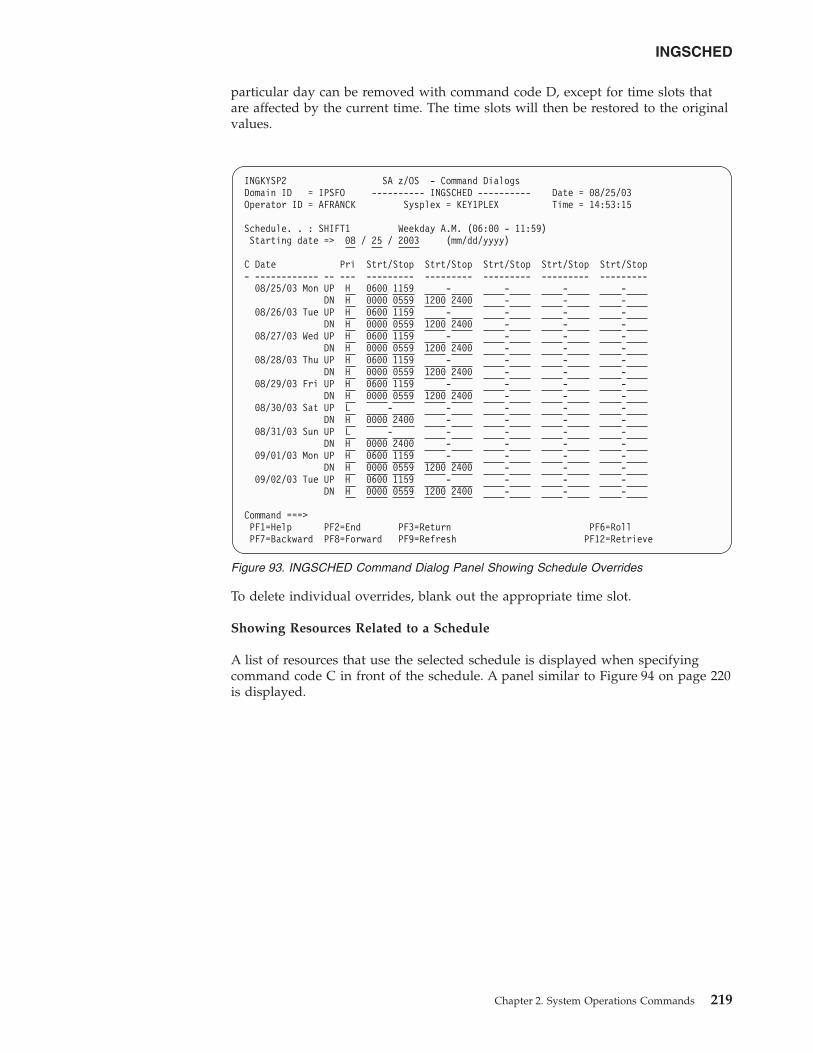
particular day can be removed with command code D, except for time slots thatare affected by the current time. The time slots will then be restored to the originalvalues.
To delete individual overrides, blank out the appropriate time slot.
Showing Resources Related to a Schedule
A list of resources that use the selected schedule is displayed when specifyingcommand code C in front of the schedule. A panel similar to Figure 94 on page 220is displayed.
INGKYSP2 SA z/OS - Command DialogsDomain ID = IPSFO ---------- INGSCHED ---------- Date = 08/25/03Operator ID = AFRANCK Sysplex = KEY1PLEX Time = 14:53:15
Schedule. . : SHIFT1 Weekday A.M. (06:00 - 11:59)Starting date => 08 / 25 / 2003 (mm/dd/yyyy)
C Date Pri Strt/Stop Strt/Stop Strt/Stop Strt/Stop Strt/Stop- ------------ -- --- --------- --------- --------- --------- ---------
08/25/03 Mon UP H 0600 1159 - - - -DN H 0000 0559 1200 2400 - - -
08/26/03 Tue UP H 0600 1159 - - - -DN H 0000 0559 1200 2400 - - -
08/27/03 Wed UP H 0600 1159 - - - -DN H 0000 0559 1200 2400 - - -
08/28/03 Thu UP H 0600 1159 - - - -DN H 0000 0559 1200 2400 - - -
08/29/03 Fri UP H 0600 1159 - - - -DN H 0000 0559 1200 2400 - - -
08/30/03 Sat UP L - - - - -DN H 0000 2400 - - - -
08/31/03 Sun UP L - - - - -DN H 0000 2400 - - - -
09/01/03 Mon UP H 0600 1159 - - - -DN H 0000 0559 1200 2400 - - -
09/02/03 Tue UP H 0600 1159 - - - -DN H 0000 0559 1200 2400 - - -
Command ===>PF1=Help PF2=End PF3=Return PF6=RollPF7=Backward PF8=Forward PF9=Refresh PF12=Retrieve
Figure 93. INGSCHED Command Dialog Panel Showing Schedule Overrides
INGSCHED
Chapter 2. System Operations Commands 219
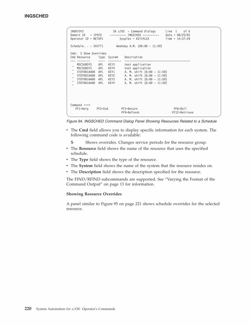
v The Cmd field allows you to display specific information for each system. Thefollowing command code is available:
S Shows overrides. Changes service periods for the resource group.v The Resource field shows the name of the resource that uses the specified
schedule.v The Type field shows the type of the resource.v The System field shows the name of the system that the resource resides on.v The Description field shows the description specified for the resource.
The FIND/RFIND subcommands are supported. See “Varying the Format of theCommand Output” on page 13 for information.
Showing Resource Overrides
A panel similar to Figure 95 on page 221 shows schedule overrides for the selectedresource.
INGKYSP3 SA z/OS - Command Dialogs Line 1 of 6Domain ID = IPSFO ---------- INGSCHED ---------- Date = 08/25/03Operator ID = NETOP1 Sysplex = KEY1PLEX Time = 14:57:29
Schedule. . : SHIFT1 Weekday A.M. (06:00 - 11:59)
Cmd: S Show OverridesCmd Resource Type System Description--- -------- ---- -------- ----------------------------------------
MSCSUBSYS APL KEY3 test applicationMSCSUBSYS APL KEY4 test applicationSTDT001AA00 APL KEY1 A. M. shift (6:00 - 11:59)STDT001AA00 APL KEY2 A. M. shift (6:00 - 11:59)STDT001AA00 APL KEY3 A. M. shift (6:00 - 11:59)STDT001AA00 APL KEY4 A. M. shift (6:00 - 11:59)
Command ===>PF1=Help PF2=End PF3=Return PF6=Roll
PF9=Refresh PF12=Retrieve
Figure 94. INGSCHED Command Dialog Panel Showing Resources Related to a Schedule
INGSCHED
220 System Automation for z/OS: Operator's Commands
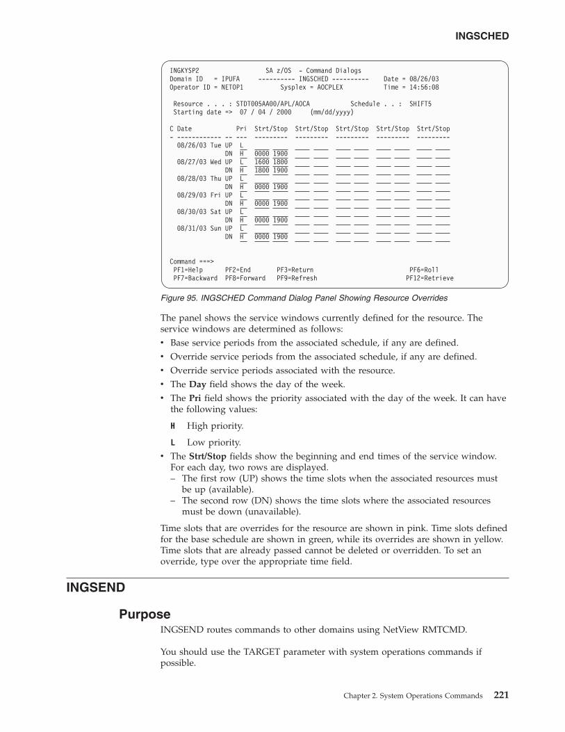
The panel shows the service windows currently defined for the resource. Theservice windows are determined as follows:v Base service periods from the associated schedule, if any are defined.v Override service periods from the associated schedule, if any are defined.v Override service periods associated with the resource.v The Day field shows the day of the week.v The Pri field shows the priority associated with the day of the week. It can have
the following values:
H High priority.
L Low priority.v The Strt/Stop fields show the beginning and end times of the service window.
For each day, two rows are displayed.– The first row (UP) shows the time slots when the associated resources must
be up (available).– The second row (DN) shows the time slots where the associated resources
must be down (unavailable).
Time slots that are overrides for the resource are shown in pink. Time slots definedfor the base schedule are shown in green, while its overrides are shown in yellow.Time slots that are already passed cannot be deleted or overridden. To set anoverride, type over the appropriate time field.
INGSEND
PurposeINGSEND routes commands to other domains using NetView RMTCMD.
You should use the TARGET parameter with system operations commands ifpossible.
INGKYSP2 SA z/OS - Command DialogsDomain ID = IPUFA ---------- INGSCHED ---------- Date = 08/26/03Operator ID = NETOP1 Sysplex = AOCPLEX Time = 14:56:08
Resource . . . : STDT005AA00/APL/AOCA Schedule . . : SHIFT5Starting date => 07 / 04 / 2000 (mm/dd/yyyy)
C Date Pri Strt/Stop Strt/Stop Strt/Stop Strt/Stop Strt/Stop- ------------ -- --- --------- --------- --------- --------- ---------
08/26/03 Tue UP LDN H 0000 1900
08/27/03 Wed UP L 1600 1800DN H 1800 1900
08/28/03 Thu UP LDN H 0000 1900
08/29/03 Fri UP LDN H 0000 1900
08/30/03 Sat UP LDN H 0000 1900
08/31/03 Sun UP LDN H 0000 1900
Command ===>PF1=Help PF2=End PF3=Return PF6=RollPF7=Backward PF8=Forward PF9=Refresh PF12=Retrieve
Figure 95. INGSCHED Command Dialog Panel Showing Resource Overrides
INGSCHED
Chapter 2. System Operations Commands 221
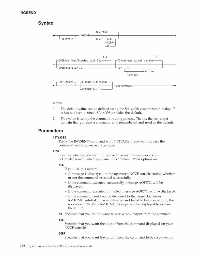
Syntax
��NETVASIS
INGSENDRESP=YES
RESP= ACKCORRNO
�
�
(1)OPER=defined/issuing_task_ID,
OPER=operator_ID
(2)TO=current target domain
TO= FPdomain
netid.
�
�CRM=RMTCMD CORRWAIT=defined/10
CORRWAIT=valueCMD=command ��
Notes:
1 The default value can be defined using the SA z/OS customization dialog. Ifit has not been defined, SA z/OS provides the default.
2 This value is set by the command routing process. That is, the last targetdomain that you sent a command to is remembered and used as the default.
ParametersNETVASIS
Prefix the INGSEND command with NETVASIS if you want to pass thecommand text in lower or mixed case.
RESPSpecifies whether you want to receive an asynchronous response oracknowledgement when you issue the command. Valid options are:
ACKIf you use this option:v A message is displayed on the operator's NCCF console stating whether
or not the command executed successfully.v If the command executed successfully, message AOF672I will be
displayed.v If the command executed but failed, message AOF671I will be displayed.v If the command could not be delivered to the target domain or
RMTCMD autotask, or was delivered and failed to begin execution, theappropriate NetView RMTCMD message will be displayed to explainthe failure.
NO Specifies that you do not want to receive any output from the command.
YESSpecifies that you want the output from the command displayed on yourNCCF console.
CORRSpecifies that you want the output from the command to be displayed by
INGSEND
222 System Automation for z/OS: Operator's Commands
|
|||
the NetView WINDOW command. See “Restrictions and Limitations” oncorrelating command output.
OPERSpecifies the operator to use to issue the command.
operator_ID can be defined using the customization dialog for each domain. Ifnot defined, it will default to the issuing task ID.
Notes:
1. If the operator alias GATOPER or BASEOPER is specified, the operator IDwill default to the issuing task ID.
2. If orig.operid = target.operid in the OPER keyword, the command will beissued.
TO Specifies the domain that the command is being issued to.
[netid].domainSpecifies the domain that the command is being issued to. It can bedefined using the customization dialog. Netid is optional.
FP Specifies that the command is to be routed to the current focal point.
Notes:
1. When INGSEND is issued on the current focal point, and TO=FP isspecified, the command will be issued.
2. If this parameter (TO=) is omitted, the current target domain (that is, thelast domain you sent a command to) is used, if one is set. If none is set,error message AOF102I will be issued.
CRMSpecifies that the command routing mechanism to be used is the NetViewRMTCMD command. Only CRM=RMTCMD is valid. The parameter is forcompatibility only.
CORRWAITSpecifies the CORRWAIT value (in seconds) to be used when INGSEND usesNetView PIPES. The Corrwait PIPE stage is necessary to trap asynchronouscommand output. A default for this value can be predefined for each targetsystem, using the customization dialog. If not predefined, the default is 10seconds. For more information on the use of this value, see the discussion ofthe PIPE command in NetView Operation.
CMDSpecifies the command to be executed. The length of the command can be upto 280 characters.
Restrictions and Limitationsv The INGSEND command will not execute under the primary POI task (PPT).v INGSEND uses the NetView PIPE command to trap the message output from
the routed command. Not all commands are PIPE-enabled, which means that thecommand may not be treated as requested in the RESP keyword. Some examplesof commands that are not PIPE-enabled are:– MVS commands on a NetView not exploiting EMCS.– Commands that produce fullscreen output.– A NetView command that is not PIPE-enabled.
INGSEND
Chapter 2. System Operations Commands 223
|||
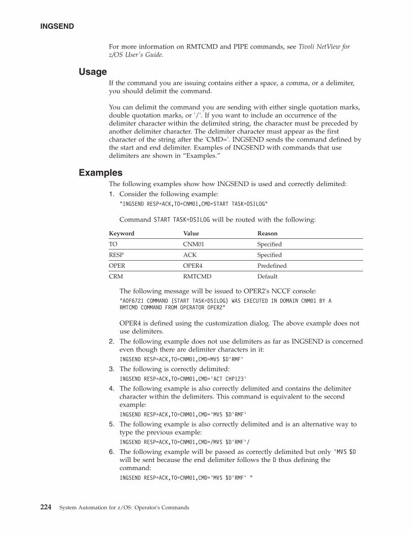
For more information on RMTCMD and PIPE commands, see Tivoli NetView forz/OS User's Guide.
UsageIf the command you are issuing contains either a space, a comma, or a delimiter,you should delimit the command.
You can delimit the command you are sending with either single quotation marks,double quotation marks, or '/'. If you want to include an occurrence of thedelimiter character within the delimited string, the character must be preceded byanother delimiter character. The delimiter character must appear as the firstcharacter of the string after the 'CMD='. INGSEND sends the command defined bythe start and end delimiter. Examples of INGSEND with commands that usedelimiters are shown in “Examples.”
ExamplesThe following examples show how INGSEND is used and correctly delimited:1. Consider the following example:
"INGSEND RESP=ACK,TO=CNM01,CMD=START TASK=DSILOG"
Command START TASK=DSILOG will be routed with the following:
Keyword Value Reason
TO CNM01 Specified
RESP ACK Specified
OPER OPER4 Predefined
CRM RMTCMD Default
The following message will be issued to OPER2's NCCF console:"AOF672I COMMAND (START TASK=DSILOG) WAS EXECUTED IN DOMAIN CNM01 BY ARMTCMD COMMAND FROM OPERATOR OPER2"
OPER4 is defined using the customization dialog. The above example does notuse delimiters.
2. The following example does not use delimiters as far as INGSEND is concernedeven though there are delimiter characters in it:INGSEND RESP=ACK,TO=CNM01,CMD=MVS $D’RMF’
3. The following is correctly delimited:INGSEND RESP=ACK,TO=CNM01,CMD=’ACT CHP123’
4. The following example is also correctly delimited and contains the delimitercharacter within the delimiters. This command is equivalent to the secondexample:INGSEND RESP=ACK,TO=CNM01,CMD=’MVS $D’RMF’
5. The following example is also correctly delimited and is an alternative way totype the previous example:INGSEND RESP=ACK,TO=CNM01,CMD=/MVS $D’RMF’/
6. The following example will be passed as correctly delimited but only ’MVS $Dwill be sent because the end delimiter follows the D thus defining thecommand:INGSEND RESP=ACK,TO=CNM01,CMD=’MVS $D’RMF’ "
INGSEND
224 System Automation for z/OS: Operator's Commands
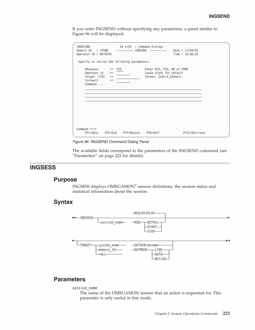
If you enter INGSEND without specifying any parameters, a panel similar toFigure 96 will be displayed.
The available fields correspond to the parameters of the INGSEND command (see“Parameters” on page 222 for details).
INGSESS
PurposeINGSESS displays OMEGAMON® session definitions, the session status andstatistical information about the session.
Syntax
�� INGSESSsession_name
REQ=DISPLAY
REQ= DETAILSTARTSTOP
�
�TARGET= system_name
domain_ID*ALL
OUTDSN=dsnameOUTMODE= LINE
AUTONETLOG
��
Parameterssession_name
The name of the OMEGAMON session that an action is requested for. Thisparameter is only useful in line mode.
INGKYSND SA z/OS - Command DialogsDomain ID = IPUN8 ---------- INGSEND ---------- Date = 11/04/03Operator ID = NETOPER Time = 16:58:22
Specify or revise the following parameters:
Response => YES Enter ACK, YES, NO or CORROperator id => Leave blank for defaultTarget (TO) => format: [netid.]domainCorrwait =>Command ...
Command ===>PF1=Help PF2=End PF3=Return PF6=Roll PF12=Retrieve
Figure 96. INGSEND Command Dialog Panel
INGSEND
Chapter 2. System Operations Commands 225
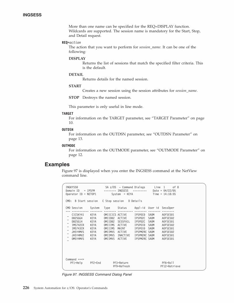
More than one name can be specified for the REQ=DISPLAY function.Wildcards are supported. The session name is mandatory for the Start, Stop,and Detail request.
REQ=actionThe action that you want to perform for session_name. It can be one of thefollowing:
DISPLAYReturns the list of sessions that match the specified filter criteria. Thisis the default.
DETAILReturns details for the named session.
STARTCreates a new session using the session attributes for session_name.
STOP Destroys the named session.
This parameter is only useful in line mode.
TARGETFor information on the TARGET parameter, see “TARGET Parameter” on page10.
OUTDSNFor information on the OUTDSN parameter, see “OUTDSN Parameter” onpage 13.
OUTMODEFor information on the OUTMODE parameter, see “OUTMODE Parameter” onpage 12.
ExamplesFigure 97 is displayed when you enter the INGSESS command at the NetViewcommand line.
INGKYSS0 SA z/OS - Command Dialogs Line 1 of 8Domain ID = IPSFM -------- INGSESS --------- Date = 04/22/05Operator ID = NETOP1 System = KEYA Time = 14:18:55
CMD: B Start session C Stop session D Details
CMD Session System Type Status Appl-id User id SessOper--- ----------- -------- -------- ---------- -------- -------- --------
CICSKY41 KEYA OMIICICS ACTIVE IPSPOC0 SAOM AOFSES01DB2SGG4 KEYA OMIIDB2 ACTIVE IPSPD2C SAOM AOFSES02DB2SG14 KEYA OMIIDB2 SESSFAIL IPSPD2C SAOM AOFSES01IMS742CR KEYA OMIIIMS ACTIVE IPSPOI0 SAOM AOFSES02IMS743CR KEYA OMIIIMS MAINT IPSPOI0 SAOM AOFSES01JHSY4MVS KEYA OMIIMVS ACTIVE IPSPM2RC SAOM AOFSES02JHSY4MV2 KEYA OMIIMVS INACTIVE IPSPM2RC SAOM AOFSES01OMSY4MVS KEYA OMIIMVS ACTIVE IPSPM2RC SAOM AOFSES01
Command ===>PF1=Help PF2=End PF3=Return PF6=Roll
PF9=Refresh PF12=Retrieve
Figure 97. INGSESS Command Dialog Panel
INGSESS
226 System Automation for z/OS: Operator's Commands
v The Cmd field allows you to display specific information for each system. Thefollowing command code is available:
B Creates a new session with the appropriate OMEGAMON, if it does notalready exist, that is, the session status is INACTIVE or MAINT. Aftersuccessful session creation, the session status is ACTIVE. The sessionremains active until it is stopped, either explicitly (using command code C),or implicitly by NetView on behalf of OMEGAMON or session tasktermination.
C Destroys the session with the appropriate OMEGAMON. The session statuswill be changed to MAINT. The session is disabled so as to prevent it frombeing created implicitly again.
D Displays details for the selected session, such as the session attributes fromthe session definition, the current status, and statistical information.
v The Session column shows the name of the session that represents anOMEGAMON monitor.
v The System column shows the system that established the connection toOMEGAMON.
v The Type column shows the type of session, that is, the OS or middleware thatthe OMEGAMON monitor is monitoring.
v The Status column shows the status of the session. It can be ACTIVE,INACTIVE, MAINT, SESSFAIL, or AUTHFAIL.
v The Appl-id column shows the name of the OMEGAMON VTAM application asdefined by the installation during customization of the OMEGAMON product.
v The User id column shows the user that is defined to log on to theOMEGAMON application. The user ID is needed to control access to theOMEGAMON application. It may be blank if product level security is notimplemented for this OMEGAMON application.
v The SessOper column shows the automated function name that was assigned tothe session by SA z/OS during initialization.
If command code D is selected, the detail screen as shown in Figure 98 on page 228is displayed.
INGSESS
Chapter 2. System Operations Commands 227
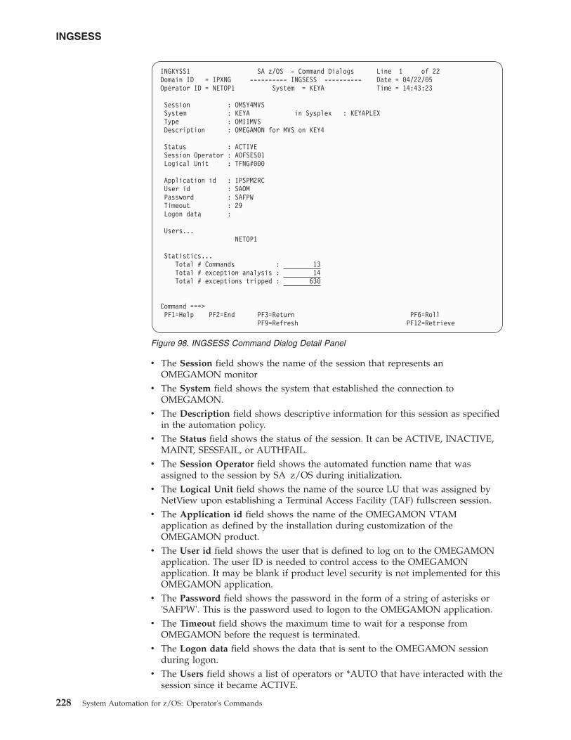
v The Session field shows the name of the session that represents anOMEGAMON monitor
v The System field shows the system that established the connection toOMEGAMON.
v The Description field shows descriptive information for this session as specifiedin the automation policy.
v The Status field shows the status of the session. It can be ACTIVE, INACTIVE,MAINT, SESSFAIL, or AUTHFAIL.
v The Session Operator field shows the automated function name that wasassigned to the session by SA z/OS during initialization.
v The Logical Unit field shows the name of the source LU that was assigned byNetView upon establishing a Terminal Access Facility (TAF) fullscreen session.
v The Application id field shows the name of the OMEGAMON VTAMapplication as defined by the installation during customization of theOMEGAMON product.
v The User id field shows the user that is defined to log on to the OMEGAMONapplication. The user ID is needed to control access to the OMEGAMONapplication. It may be blank if product level security is not implemented for thisOMEGAMON application.
v The Password field shows the password in the form of a string of asterisks or'SAFPW'. This is the password used to logon to the OMEGAMON application.
v The Timeout field shows the maximum time to wait for a response fromOMEGAMON before the request is terminated.
v The Logon data field shows the data that is sent to the OMEGAMON sessionduring logon.
v The Users field shows a list of operators or *AUTO that have interacted with thesession since it became ACTIVE.
INGKYSS1 SA z/OS - Command Dialogs Line 1 of 22Domain ID = IPXNG ---------- INGSESS ---------- Date = 04/22/05Operator ID = NETOP1 System = KEYA Time = 14:43:23
Session : OMSY4MVSSystem : KEYA in Sysplex : KEYAPLEXType : OMIIMVSDescription : OMEGAMON for MVS on KEY4
Status : ACTIVESession Operator : AOFSES01Logical Unit : TFNG#000
Application id : IPSPM2RCUser id : SAOMPassword : SAFPWTimeout : 29Logon data :
Users...NETOP1
Statistics...Total # Commands : 13Total # exception analysis : 14Total # exceptions tripped : 630
Command ===>PF1=Help PF2=End PF3=Return PF6=Roll
PF9=Refresh PF12=Retrieve
Figure 98. INGSESS Command Dialog Detail Panel
INGSESS
228 System Automation for z/OS: Operator's Commands
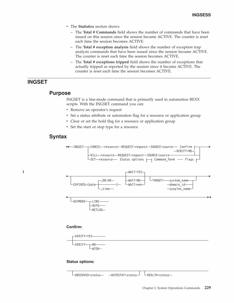
v The Statistics section shows:– The Total # Commands field shows the number of commands that have been
issued on this session since the session became ACTIVE. The counter is reseteach time the session becomes ACTIVE.
– The Total # exception analysis field shows the number of exception trapanalysis commands that have been issued since the session became ACTIVE.The counter is reset each time the session becomes ACTIVE.
– The Total # exceptions tripped field shows the number of exceptions thatactually tripped as reported by the session since it became ACTIVE. Thecounter is reset each time the session becomes ACTIVE.
INGSET
PurposeINGSET is a line-mode command that is primarily used in automation REXXscripts. With the INGSET command you can:v Remove an operator's requestv Set a status attribute or automation flag for a resource or application groupv Clear or set the hold flag for a resource or application groupv Set the start or stop type for a resource
Syntax
�� INGSET CANCEL resource REQUEST=request SOURCE=source ConfirmVERIFY=NO
KILL resource REQUEST=request SOURCE=sourceSET resource Status options Command_Parm Flags
�
�,00:00
EXPIRED=(date ),time
WAIT=YES
WAIT=NOWAIT=nnn
TARGET= system_namedomain_idsysplex_name
�
�OUTMODE= LINE
AUTONETLOG
��
Confirm:
VERIFY=YES
VERIFY= NOWTOR
Status options:
OBSERVED=status AUTOSTAT=status HEALTH=status
INGSESS
Chapter 2. System Operations Commands 229
||||
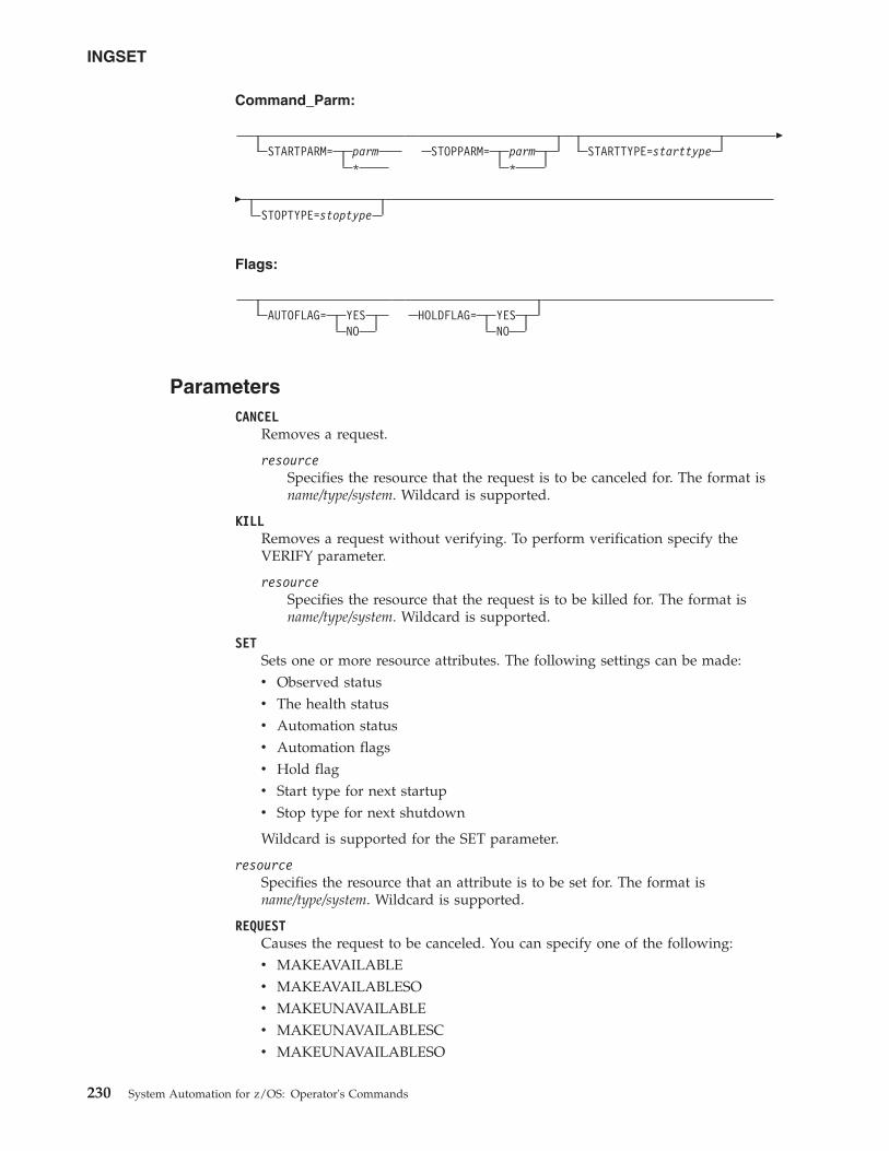
Command_Parm:
STARTPARM= parm*
STOPPARM= parm*
STARTTYPE=starttype�
�STOPTYPE=stoptype
Flags:
AUTOFLAG= YESNO
HOLDFLAG= YESNO
ParametersCANCEL
Removes a request.
resourceSpecifies the resource that the request is to be canceled for. The format isname/type/system. Wildcard is supported.
KILLRemoves a request without verifying. To perform verification specify theVERIFY parameter.
resourceSpecifies the resource that the request is to be killed for. The format isname/type/system. Wildcard is supported.
SETSets one or more resource attributes. The following settings can be made:v Observed statusv The health statusv Automation statusv Automation flagsv Hold flagv Start type for next startupv Stop type for next shutdown
Wildcard is supported for the SET parameter.
resourceSpecifies the resource that an attribute is to be set for. The format isname/type/system. Wildcard is supported.
REQUESTCauses the request to be canceled. You can specify one of the following:v MAKEAVAILABLEv MAKEAVAILABLESOv MAKEUNAVAILABLEv MAKEUNAVAILABLESCv MAKEUNAVAILABLESO
INGSET
230 System Automation for z/OS: Operator's Commands
Wildcard is supported, for example, REQUEST=MAKEUN*
A MakeAvailable vote on a resource reflects an INGREQresource,REQ=UP,SCOPE=ALL. That is, the vote is inherited from the resourcethat it was issued against by all of its dependent resources.
A MakeAvailableSO vote on a resource reflects an INGREQresource,REQ=UP,SCOPE=ONLY. That is, the vote is not inherited from theresource that it was issued against by all of its dependent resources, but onlyby that resource.
A MakeUnavailable vote on a resource reflects an INGREQresource,REQ=DOWN,SCOPE=ALL. That is, the vote is inherited from theresource that it was issued against by the resource and all of its dependentresources.
A MakeUnavailableSC vote on a resource reflects an INGREQresource,REQ=DOWN,SCOPE=CHILDREN. That is, the vote is inherited fromthe resource that it was issued against by all of its dependent resources, but itdoes not affect the resource itself.
A MakeUnavailableSO vote on a resource reflects an INGREQresource,REQ=DOWN,SCOPE=ONLY. That is, the vote is not inherited from theresource that it was issued against by all of its dependent resources, but affectsonly that resource.
SOURCESpecifies the source of the request, for example OPERATOR, or AUTOOPS.Wildcard is supported, for example, SOURCE=*
OBSERVEDSpecifies the observed status to be assigned to the resource. The status can beabbreviated, for example, to AV for available.
AUTOSTATSpecifies the automation status to be assigned to the resource. The status canbe abbreviated, for example, to ID for idle.
HEALTHSpecifies the health status to be assigned to the resource. The status can beabbreviated, for example, to NO for normal.
EXPIREDSpecifies the expiry date and time of the request. Any request older than orequal to the specified timestamp is deleted when the other filter criteria arematched. The date format is yyyy-mm-dd and the time format is hh:mm. Thetime specification is optional.
CautionCare must be taken when using the EXPIRED parameter for a remotesysplex that runs in a different time zone. The local time of the systemwhere INGSET CANCEL/KILL command is issued determines whetheror not the request is expired.
WAITSpecifies whether or not to wait until the request is complete. The default isYES.
nnn is the number of seconds to wait before giving up and reporting that atimeout has occurred. The maximum time interval is 999 seconds.
INGSET
Chapter 2. System Operations Commands 231
||||||
||||||||
|
VERIFYSpecifies whether canceling the request is to be verified. The followingspecifications are valid:
YES Depending on the NetView task type that the INGREQ command isrunning on, the verification is either displayed on a fullscreen panel or,in line mode, shown on the console. The latter is also done whenOUTMODE=LINE is coded.
NO No verification is performed. VERIFY is set to NO for AUTOTASKs.Otherwise it is set to YES.
WTORThe list of affected resources is displayed before the request isremoved. The operator is prompted to verify the list via WTOR.
The default depends on the type of task that the INGREQ command runs on.
TARGETFor information on the TARGET parameter, see “TARGET Parameter” on page10.
OUTMODEFor information on the OUTMODE parameter, see “OUTMODE Parameter” onpage 12.
STARTPARMIs the START parameter that is passed to the next START command. The valuethat is specified here is used only once and takes precedence over the PARMvalue that is specified on the next INGREQ (REQ=START) command. Use * toreset its value.
STOPPARMIs the STOP parameter that is passed to the next STOP command. The valuethat is specified here is used only once and takes precedence over the PARMvalue that is specified on the next INGREQ (REQ=STOP) command. Use * toreset its value.
STARTTYPESpecifies the type of command to be issued for the resource's next startup. Thevalue specified here is used only once and takes precedence over the TYPEvalue specified on the next INGREQ (REQ=START) command.
STOPTYPESpecifies the type of command to be issued for the resource's next shutdown.The value specified here is used only once and takes precedence over the TYPEvalue specified on the next INGREQ (REQ=STOP) command. However, a stoptype of FORCE, wherever specified, will always be honored.
AUTOFLAGSpecifies the automation flag. It can be either YES or NO. It can beabbreviated.
HOLDFLAGSpecifies whether the resource is to be started. It can be either YES or NO. TheHOLD flag can only be set if the resource is down, that is if its observed statusis either HardDown, SoftDown, SysGone or Unknown.
Return CodesThe following return codes can occur:0 The request was processed successfully.
INGSET
232 System Automation for z/OS: Operator's Commands
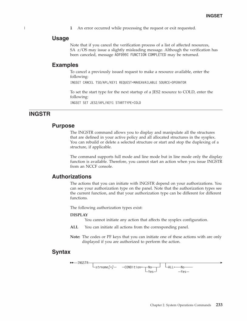
1 An error occurred while processing the request or exit requested.
UsageNote that if you cancel the verification process of a list of affected resources,SA z/OS may issue a slightly misleading message. Although the verification hasbeen canceled, message AOF099I FUNCTION COMPLETED may be returned.
ExamplesTo cancel a previously issued request to make a resource available, enter thefollowing:INGSET CANCEL TSO/APL/KEY1 REQUEST=MAKEAVAILABLE SOURCE=OPERATOR
To set the start type for the next startup of a JES2 resource to COLD, enter thefollowing:INGSET SET JES2/APL/KEY1 STARTTYPE=COLD
INGSTR
PurposeThe INGSTR command allows you to display and manipulate all the structuresthat are defined in your active policy and all allocated structures in the sysplex.You can rebuild or delete a selected structure or start and stop the duplexing of astructure, if applicable.
The command supports full mode and line mode but in line mode only the displayfunction is available. Therefore, you cannot start an action when you issue INGSTRfrom an NCCF console.
AuthorizationsThe actions that you can initiate with INGSTR depend on your authorizations. Youcan see your authorization type on the panel. Note that the authorization types seethe current function, and that your authorization type can be different for differentfunctions.
The following authorization types exist:
DISPLAYYou cannot initiate any action that affects the sysplex configuration.
ALL You can initiate all actions from the corresponding panel.
Note: The codes or PF keys that you can initiate one of these actions with are onlydisplayed if you are authorized to perform the action.
Syntax
�� INGSTRstrname[*] CONDition= No
YesALL= No
Yes
�
INGSET
Chapter 2. System Operations Commands 233
|
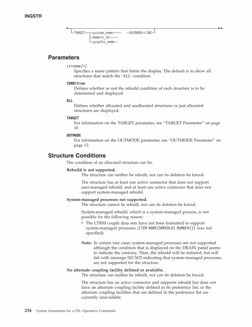
�TARGET= system_name
domain_IDsysplex_name
OUTMODE=LINE��
Parametersstrname[*]
Specifies a name pattern that limits the display. The default is to show allstructures that match the 'ALL' condition.
CONDitionDefines whether or not the rebuild condition of each structure is to bedetermined and displayed.
ALLDefines whether allocated and unallocated structures or just allocatedstructures are displayed.
TARGETFor information on the TARGET parameter, see “TARGET Parameter” on page10.
OUTMODEFor information on the OUTMODE parameter, see “OUTMODE Parameter” onpage 12.
Structure ConditionsThe condition of an allocated structure can be:
Rebuild is not supported.The structure can neither be rebuilt, nor can its deletion be forced.
The structure has at least one active connector that does not supportuser-managed rebuild, and at least one active connector that does notsupport system-managed rebuild.
System-managed processes not supported.The structure cannot be rebuilt, nor can its deletion be forced.
System-managed rebuild, which is a system-managed process, is notpossible for the following reason:v The CFRM couple data sets have not been formatted to support
system-managed processes (ITEM NAME(SMREBLD) NUMBER(1) was notspecified).
Note: In certain rare cases system-managed processes are not supportedalthough the condition that is displayed on the DRAIN panel seemsto indicate the contrary. Then, the rebuild will be initiated, but willfail with message IXC367I indicating that system-managed processesare not supported for the structure.
No alternate coupling facility defined or available.The structure can neither be rebuilt, nor can its deletion be forced.
The structure has an active connector and supports rebuild but does nothave an alternate coupling facility defined in its preference list, or thealternate coupling facilities that are defined in the preference list arecurrently unavailable.
INGSTR
234 System Automation for z/OS: Operator's Commands
Insufficient space detected for rebuild.The structure cannot or could not be rebuilt. Its deletion cannot be forced.
No alternate coupling facility has enough space to rebuild the structure.
Preference list is empty.The structure cannot be rebuilt because its preference list is currentlyempty. A possible reason for this is a pending policy change; for pendingpolicy changes, see “P column” on page 107.
Structure is pending deallocation.XES accepted a forced deletion of the structure but does the realdeallocation later.
Note: This status can only occur when MVS APAR OW39404 has not beeninstalled.
Structure is being rebuilt.The structure is being rebuilt to another coupling facility.
Duplex rebuild is being stopped.Two instances of the structure were maintained on different couplingfacilities. The application is being disconnected from that instance that isallocated on the target coupling facility. After disconnecting, the instance isdeleted.
No connection exists.The structure cannot be rebuilt, but you can force its deletion.
The structure does not have any connections and cannot be rebuilt withsystem-managed rebuild.
No alternate coupling facility for structure with no connections.The structure cannot be rebuilt, but you can force its deletion.
The structure does not have any connections. It could be rebuilt withsystem-managed rebuild, but no alternate coupling facility is defined in itspreference list or available.
No alternate coupling facility for structure with no active connections.The structure cannot be rebuilt, but you can force its deletion.
The structure has only DISCONNECTING, FAILED, orFAILED-PERSISTENT connections. It could be rebuilt withsystem-managed rebuild, but no alternate coupling facility is defined in itspreference list or available.
The structure’s initial size is less than its actual size.The structure can be rebuilt, but this can lead to loss of data.
An initial size is specified for the structure in the active CFRM policy. Thisinitial size was used for the allocation of the structure. Afterwards, the sizeof the structure was increased either by the application itself or an operatorcommand. However, the structure will only be rebuilt with its initial size.Subsequently, INGCF will expand the structure to its actual size again, butthis will happen after the data have been transferred. To avoid a potentialloss of data, the application has to change the initial size to the actual size.
No active connection exists.The structure cannot be rebuilt, but you can force its deletion.
INGSTR
Chapter 2. System Operations Commands 235
The structure has only DISCONNECTING, FAILED, orFAILED-PERSISTENT connections and cannot be rebuilt withsystem-managed rebuild.
Note: INGCF STRUCTURE accepts a rebuild request for structures withthis condition, but deallocates them.
No connections. System-managed rebuild supported.The structure can be rebuilt.
The structure does not have any connections, but can be rebuilt withsystem-managed rebuild.
No active connections. System-managed rebuild supported.The structure can be rebuilt with system-managed rebuild.
User-managed rebuild is not possible for the structure because it has onlyDISCONNECTING, FAILED, or FAILED-PERSISTENT connections.
System-managed rebuild is supportedThe structure can be rebuilt.
The structure has active connectors. At least one active connector does notsupport user-managed rebuild, but all active connectors supportsystem-managed rebuild.
Duplex rebuild is active.The application is connected to two instances of the same structure ondifferent coupling facilities.
[No condition]When no condition is displayed, the structure can be rebuilt.
The structure has at least one active connection, and all its activeconnectors support user-managed rebuild.
Structure is awaiting rebuild.The structure has been selected for rebuild but has not been processed yet.
Structure is currently allocated on cf_name.The structure can be rebuilt on the target coupling facility with thePOPULATE action of the ENABLE function. It is currently allocated on thecf_name coupling facility, but the target coupling facility precedes cf_namein the structure's preference list. This condition is displayed only in theENABLE command dialog.
Structure allocated in cf_name cannot be rebuilt to this CF.The structure can probably not be rebuilt on the target CF with thePOPULATE action of the ENABLE function. It is currently allocated in thecf_name CF, but the target CF precedes cf_name in the structure's preferencelist. And, the actual size of the structure is greater than the free space ofthe target CF. This condition is displayed only in the ENABLE commanddialog.
ExamplesIf you enter ingstr without any parameters, a panel with all coupling facilities ofthe sysplex is displayed, as shown in Figure 99 on page 237.
INGSTR
236 System Automation for z/OS: Operator's Commands
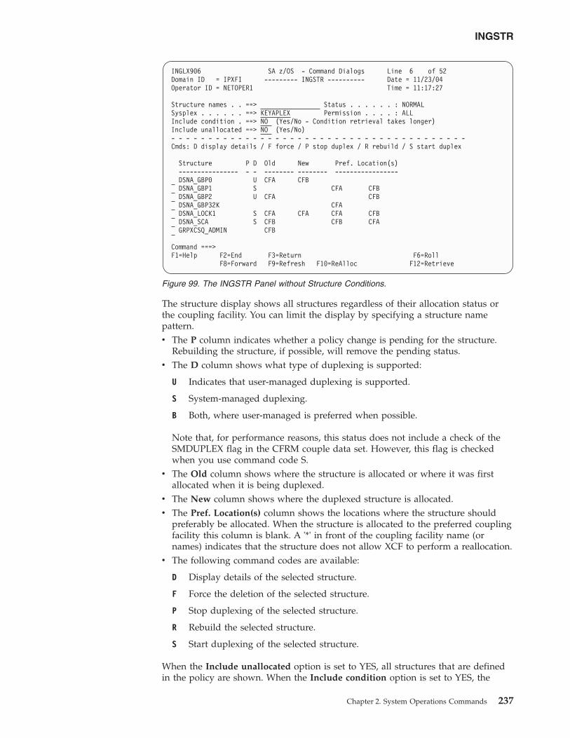
The structure display shows all structures regardless of their allocation status orthe coupling facility. You can limit the display by specifying a structure namepattern.v The P column indicates whether a policy change is pending for the structure.
Rebuilding the structure, if possible, will remove the pending status.v The D column shows what type of duplexing is supported:
U Indicates that user-managed duplexing is supported.
S System-managed duplexing.
B Both, where user-managed is preferred when possible.
Note that, for performance reasons, this status does not include a check of theSMDUPLEX flag in the CFRM couple data set. However, this flag is checkedwhen you use command code S.
v The Old column shows where the structure is allocated or where it was firstallocated when it is being duplexed.
v The New column shows where the duplexed structure is allocated.v The Pref. Location(s) column shows the locations where the structure should
preferably be allocated. When the structure is allocated to the preferred couplingfacility this column is blank. A '*' in front of the coupling facility name (ornames) indicates that the structure does not allow XCF to perform a reallocation.
v The following command codes are available:
D Display details of the selected structure.
F Force the deletion of the selected structure.
P Stop duplexing of the selected structure.
R Rebuild the selected structure.
S Start duplexing of the selected structure.
When the Include unallocated option is set to YES, all structures that are definedin the policy are shown. When the Include condition option is set to YES, the
INGLX906 SA z/OS - Command Dialogs Line 6 of 52Domain ID = IPXFI --------- INGSTR ---------- Date = 11/23/04Operator ID = NETOPER1 Time = 11:17:27
Structure names . . ==> Status . . . . . . : NORMALSysplex . . . . . . ==> KEYAPLEX Permission . . . . : ALLInclude condition . ==> NO (Yes/No - Condition retrieval takes longer)Include unallocated ==> NO (Yes/No)- - - - - - - - - - - - - - - - - - - - - - - - - - - - - - - - - - - - - - - -Cmds: D display details / F force / P stop duplex / R rebuild / S start duplex
Structure P D Old New Pref. Location(s)---------------- - - -------- -------- -----------------DSNA_GBP0 U CFA CFBDSNA_GBP1 S CFA CFBDSNA_GBP2 U CFA CFBDSNA_GBP32K CFADSNA_LOCK1 S CFA CFA CFA CFBDSNA_SCA S CFB CFB CFAGRPXCSQ_ADMIN CFB
Command ===>F1=Help F2=End F3=Return F6=Roll
F8=Forward F9=Refresh F10=ReAlloc F12=Retrieve
Figure 99. The INGSTR Panel without Structure Conditions.
INGSTR
Chapter 2. System Operations Commands 237
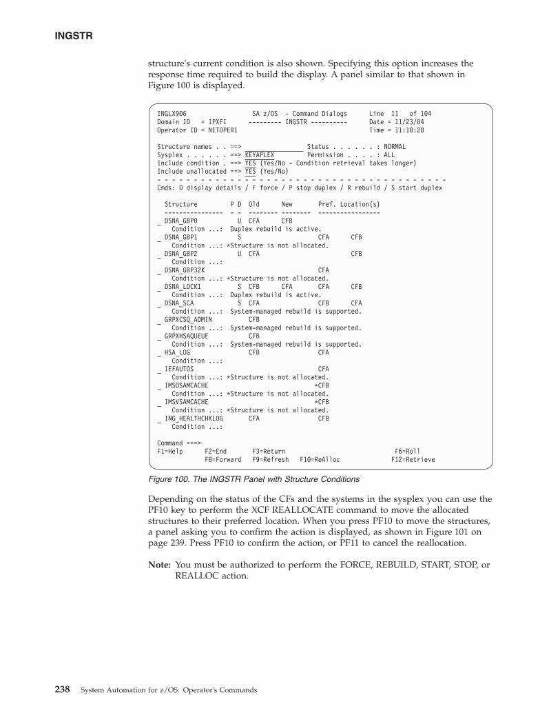
structure's current condition is also shown. Specifying this option increases theresponse time required to build the display. A panel similar to that shown inFigure 100 is displayed.
Depending on the status of the CFs and the systems in the sysplex you can use thePF10 key to perform the XCF REALLOCATE command to move the allocatedstructures to their preferred location. When you press PF10 to move the structures,a panel asking you to confirm the action is displayed, as shown in Figure 101 onpage 239. Press PF10 to confirm the action, or PF11 to cancel the reallocation.
Note: You must be authorized to perform the FORCE, REBUILD, START, STOP, orREALLOC action.
INGLX906 SA z/OS - Command Dialogs Line 11 of 104Domain ID = IPXFI --------- INGSTR ---------- Date = 11/23/04Operator ID = NETOPER1 Time = 11:18:28
Structure names . . ==> Status . . . . . . : NORMALSysplex . . . . . . ==> KEYAPLEX Permission . . . . : ALLInclude condition . ==> YES (Yes/No - Condition retrieval takes longer)Include unallocated ==> YES (Yes/No)- - - - - - - - - - - - - - - - - - - - - - - - - - - - - - - - - - - - - - - -Cmds: D display details / F force / P stop duplex / R rebuild / S start duplex
Structure P D Old New Pref. Location(s)---------------- - - -------- -------- -----------------DSNA_GBP0 U CFA CFB
Condition ...: Duplex rebuild is active.DSNA_GBP1 S CFA CFB
Condition ...: *Structure is not allocated.DSNA_GBP2 U CFA CFB
Condition ...:DSNA_GBP32K CFA
Condition ...: *Structure is not allocated.DSNA_LOCK1 S CFB CFA CFA CFB
Condition ...: Duplex rebuild is active.DSNA_SCA S CFA CFB CFA
Condition ...: System-managed rebuild is supported.GRPXCSQ_ADMIN CFB
Condition ...: System-managed rebuild is supported.GRPXHSAQUEUE CFB
Condition ...: System-managed rebuild is supported.HSA_LOG CFB CFA
Condition ...:IEFAUTOS CFA
Condition ...: *Structure is not allocated.IMSOSAMCACHE *CFB
Condition ...: *Structure is not allocated.IMSVSAMCACHE *CFB
Condition ...: *Structure is not allocated.ING_HEALTHCHKLOG CFA CFB
Condition ...:
Command ===>F1=Help F2=End F3=Return F6=Roll
F8=Forward F9=Refresh F10=ReAlloc F12=Retrieve
Figure 100. The INGSTR Panel with Structure Conditions
INGSTR
238 System Automation for z/OS: Operator's Commands
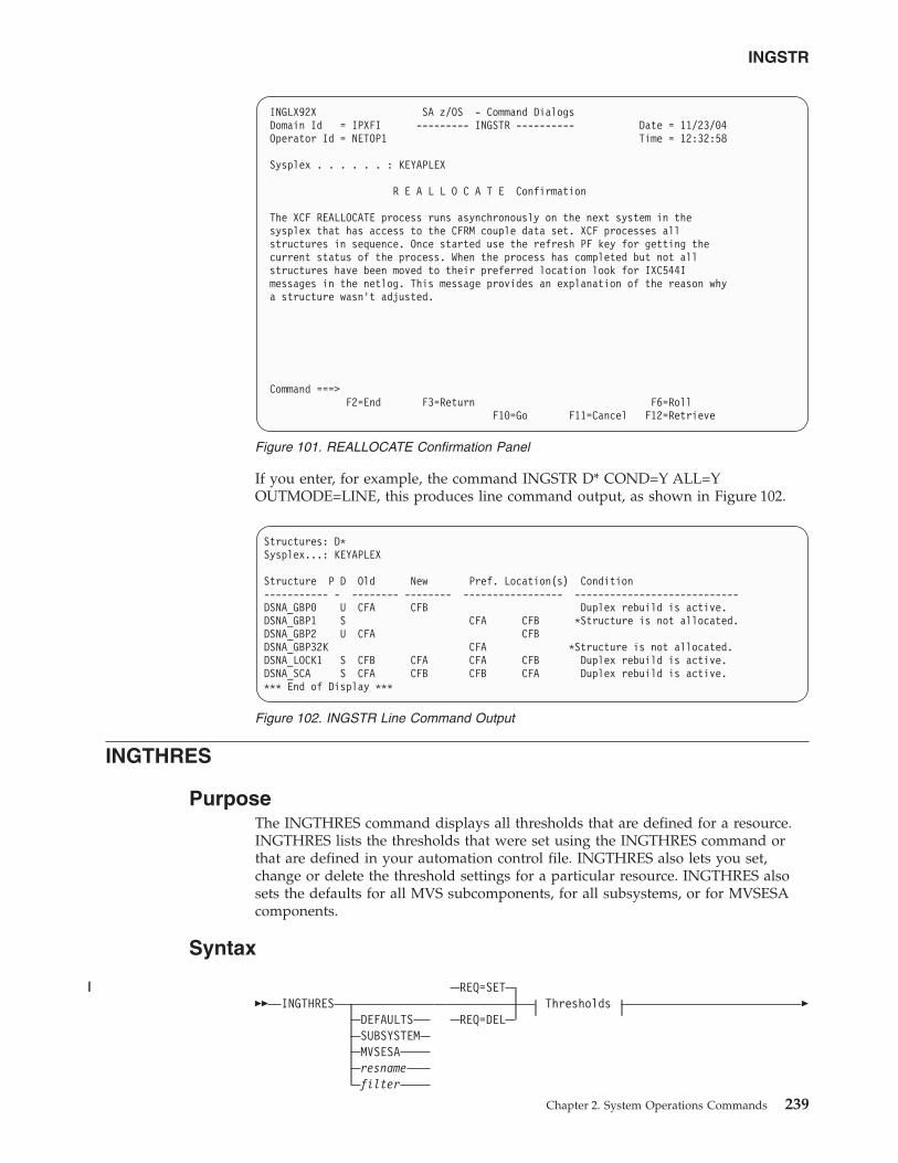
If you enter, for example, the command INGSTR D* COND=Y ALL=YOUTMODE=LINE, this produces line command output, as shown in Figure 102.
INGTHRES
PurposeThe INGTHRES command displays all thresholds that are defined for a resource.INGTHRES lists the thresholds that were set using the INGTHRES command orthat are defined in your automation control file. INGTHRES also lets you set,change or delete the threshold settings for a particular resource. INGTHRES alsosets the defaults for all MVS subcomponents, for all subsystems, or for MVSESAcomponents.
Syntax
�� INGTHRESDEFAULTSSUBSYSTEMMVSESAresnamefilter
REQ=SET
REQ=DELThresholds �
INGLX92X SA z/OS - Command DialogsDomain Id = IPXFI --------- INGSTR ---------- Date = 11/23/04Operator Id = NETOP1 Time = 12:32:58
Sysplex . . . . . . : KEYAPLEX
R E A L L O C A T E Confirmation
The XCF REALLOCATE process runs asynchronously on the next system in thesysplex that has access to the CFRM couple data set. XCF processes allstructures in sequence. Once started use the refresh PF key for getting thecurrent status of the process. When the process has completed but not allstructures have been moved to their preferred location look for IXC544Imessages in the netlog. This message provides an explanation of the reason whya structure wasn’t adjusted.
Command ===>F2=End F3=Return F6=Roll
F10=Go F11=Cancel F12=Retrieve
Figure 101. REALLOCATE Confirmation Panel
Structures: D*Sysplex...: KEYAPLEX
Structure P D Old New Pref. Location(s) Condition----------- - -------- -------- ----------------- ----------------------------DSNA_GBP0 U CFA CFB Duplex rebuild is active.DSNA_GBP1 S CFA CFB *Structure is not allocated.DSNA_GBP2 U CFA CFBDSNA_GBP32K CFA *Structure is not allocated.DSNA_LOCK1 S CFB CFA CFA CFB Duplex rebuild is active.DSNA_SCA S CFA CFB CFB CFA Duplex rebuild is active.*** End of Display ***
Figure 102. INGSTR Line Command Output
INGSTR
Chapter 2. System Operations Commands 239
||
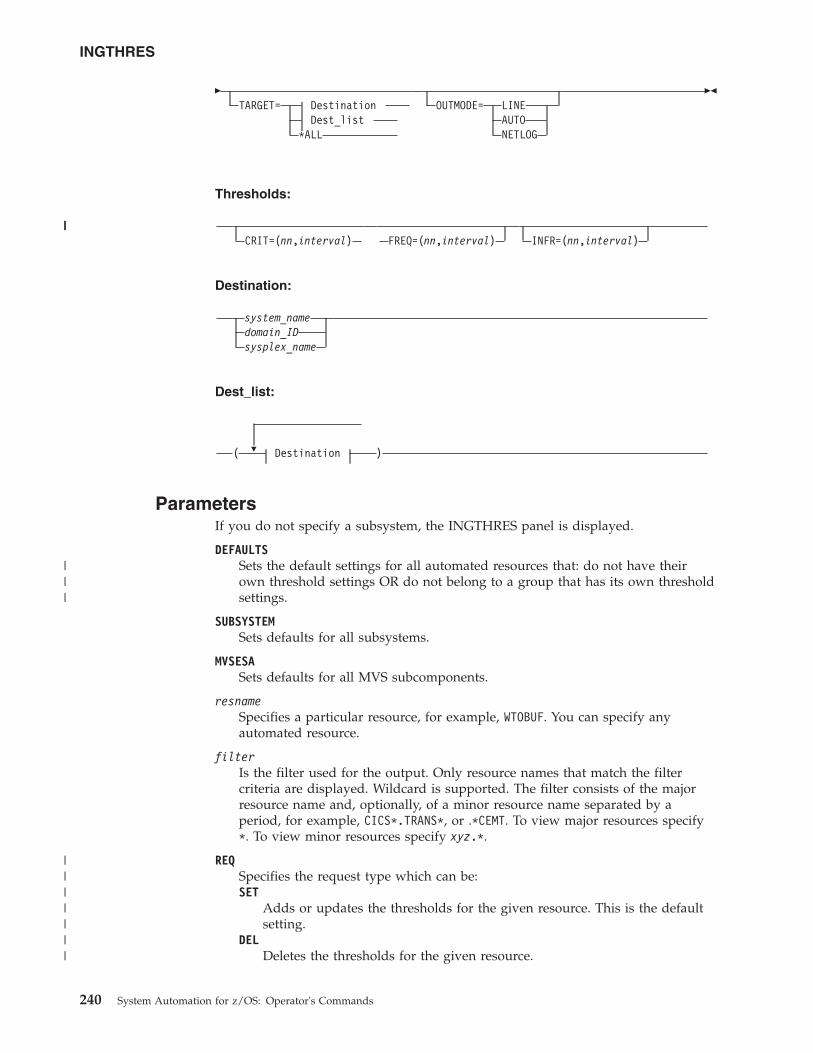
�TARGET= Destination
Dest_list*ALL
OUTMODE= LINEAUTONETLOG
��
Thresholds:
CRIT=(nn,interval) FREQ=(nn,interval) INFR=(nn,interval)
Destination:
system_namedomain_IDsysplex_name
Dest_list:
�( Destination )
ParametersIf you do not specify a subsystem, the INGTHRES panel is displayed.
DEFAULTSSets the default settings for all automated resources that: do not have theirown threshold settings OR do not belong to a group that has its own thresholdsettings.
SUBSYSTEMSets defaults for all subsystems.
MVSESASets defaults for all MVS subcomponents.
resnameSpecifies a particular resource, for example, WTOBUF. You can specify anyautomated resource.
filterIs the filter used for the output. Only resource names that match the filtercriteria are displayed. Wildcard is supported. The filter consists of the majorresource name and, optionally, of a minor resource name separated by aperiod, for example, CICS*.TRANS*, or .*CEMT. To view major resources specify*. To view minor resources specify xyz.*.
REQSpecifies the request type which can be:SET
Adds or updates the thresholds for the given resource. This is the defaultsetting.
DELDeletes the thresholds for the given resource.
INGTHRES
240 System Automation for z/OS: Operator's Commands
|||
|||
|||||||
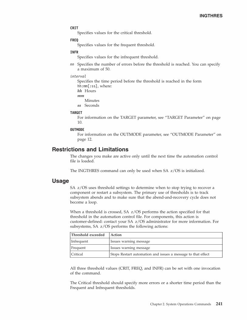
CRITSpecifies values for the critical threshold.
FREQSpecifies values for the frequent threshold.
INFRSpecifies values for the infrequent threshold.
nn Specifies the number of errors before the threshold is reached. You can specifya maximum of 50.
intervalSpecifies the time period before the threshold is reached in the formhh:mm[:ss], where:hh Hoursmm
Minutesss Seconds
TARGETFor information on the TARGET parameter, see “TARGET Parameter” on page10.
OUTMODEFor information on the OUTMODE parameter, see “OUTMODE Parameter” onpage 12.
Restrictions and LimitationsThe changes you make are active only until the next time the automation controlfile is loaded.
The INGTHRES command can only be used when SA z/OS is initialized.
UsageSA z/OS uses threshold settings to determine when to stop trying to recover acomponent or restart a subsystem. The primary use of thresholds is to tracksubsystem abends and to make sure that the abend-and-recovery cycle does notbecome a loop.
When a threshold is crossed, SA z/OS performs the action specified for thatthreshold in the automation control file. For components, this action iscustomer-defined: contact your SA z/OS administrator for more information. Forsubsystems, SA z/OS performs the following actions:
Threshold exceeded Action
Infrequent Issues warning message
Frequent Issues warning message
Critical Stops Restart automation and issues a message to that effect
All three threshold values (CRIT, FREQ, and INFR) can be set with one invocationof the command.
The Critical threshold should specify more errors or a shorter time period than theFrequent and Infrequent thresholds.
INGTHRES
Chapter 2. System Operations Commands 241
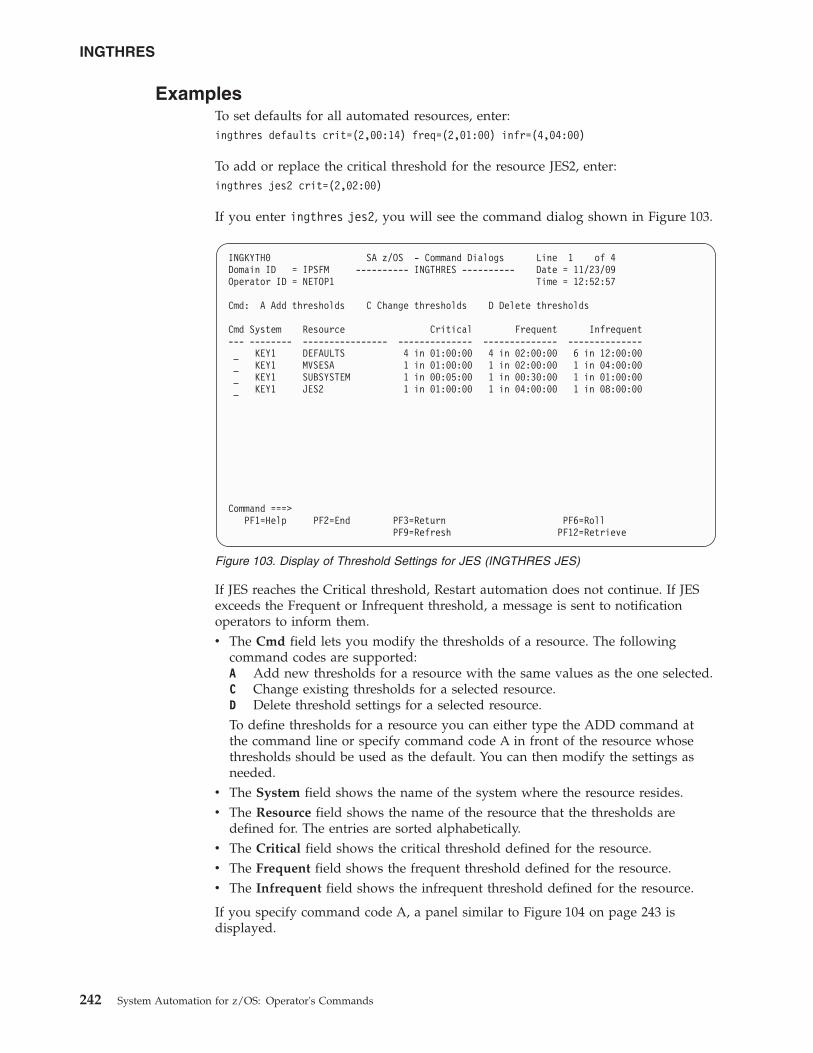
ExamplesTo set defaults for all automated resources, enter:ingthres defaults crit=(2,00:14) freq=(2,01:00) infr=(4,04:00)
To add or replace the critical threshold for the resource JES2, enter:ingthres jes2 crit=(2,02:00)
If you enter ingthres jes2, you will see the command dialog shown in Figure 103.
If JES reaches the Critical threshold, Restart automation does not continue. If JESexceeds the Frequent or Infrequent threshold, a message is sent to notificationoperators to inform them.v The Cmd field lets you modify the thresholds of a resource. The following
command codes are supported:A Add new thresholds for a resource with the same values as the one selected.C Change existing thresholds for a selected resource.D Delete threshold settings for a selected resource.To define thresholds for a resource you can either type the ADD command atthe command line or specify command code A in front of the resource whosethresholds should be used as the default. You can then modify the settings asneeded.
v The System field shows the name of the system where the resource resides.v The Resource field shows the name of the resource that the thresholds are
defined for. The entries are sorted alphabetically.v The Critical field shows the critical threshold defined for the resource.v The Frequent field shows the frequent threshold defined for the resource.v The Infrequent field shows the infrequent threshold defined for the resource.
If you specify command code A, a panel similar to Figure 104 on page 243 isdisplayed.
INGKYTH0 SA z/OS - Command Dialogs Line 1 of 4Domain ID = IPSFM ---------- INGTHRES ---------- Date = 11/23/09Operator ID = NETOP1 Time = 12:52:57
Cmd: A Add thresholds C Change thresholds D Delete thresholds
Cmd System Resource Critical Frequent Infrequent--- -------- ---------------- -------------- -------------- --------------
KEY1 DEFAULTS 4 in 01:00:00 4 in 02:00:00 6 in 12:00:00KEY1 MVSESA 1 in 01:00:00 1 in 02:00:00 1 in 04:00:00KEY1 SUBSYSTEM 1 in 00:05:00 1 in 00:30:00 1 in 01:00:00KEY1 JES2 1 in 01:00:00 1 in 04:00:00 1 in 08:00:00
Command ===>PF1=Help PF2=End PF3=Return PF6=Roll
PF9=Refresh PF12=Retrieve
Figure 103. Display of Threshold Settings for JES (INGTHRES JES)
INGTHRES
242 System Automation for z/OS: Operator's Commands
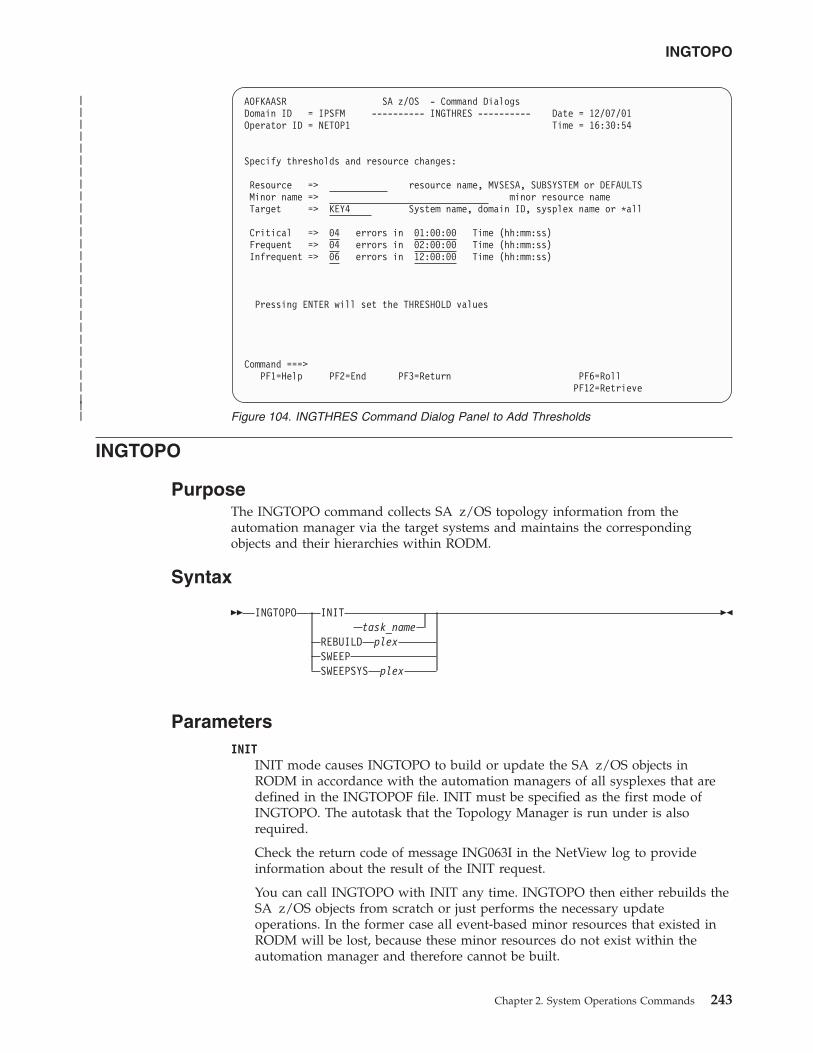
INGTOPO
PurposeThe INGTOPO command collects SA z/OS topology information from theautomation manager via the target systems and maintains the correspondingobjects and their hierarchies within RODM.
Syntax
�� INGTOPO INITtask_name
REBUILD plexSWEEPSWEEPSYS plex
��
ParametersINIT
INIT mode causes INGTOPO to build or update the SA z/OS objects inRODM in accordance with the automation managers of all sysplexes that aredefined in the INGTOPOF file. INIT must be specified as the first mode ofINGTOPO. The autotask that the Topology Manager is run under is alsorequired.
Check the return code of message ING063I in the NetView log to provideinformation about the result of the INIT request.
You can call INGTOPO with INIT any time. INGTOPO then either rebuilds theSA z/OS objects from scratch or just performs the necessary updateoperations. In the former case all event-based minor resources that existed inRODM will be lost, because these minor resources do not exist within theautomation manager and therefore cannot be built.
AOFKAASR SA z/OS - Command DialogsDomain ID = IPSFM ---------- INGTHRES ---------- Date = 12/07/01Operator ID = NETOP1 Time = 16:30:54
Specify thresholds and resource changes:
Resource => resource name, MVSESA, SUBSYSTEM or DEFAULTSMinor name => minor resource nameTarget => KEY4 System name, domain ID, sysplex name or *all
Critical => 04 errors in 01:00:00 Time (hh:mm:ss)Frequent => 04 errors in 02:00:00 Time (hh:mm:ss)Infrequent => 06 errors in 12:00:00 Time (hh:mm:ss)
Pressing ENTER will set the THRESHOLD values
Command ===>PF1=Help PF2=End PF3=Return PF6=Roll
PF12=Retrieve
Figure 104. INGTHRES Command Dialog Panel to Add Thresholds
INGTOPO
Chapter 2. System Operations Commands 243
||||||||||||||||||||||||||||
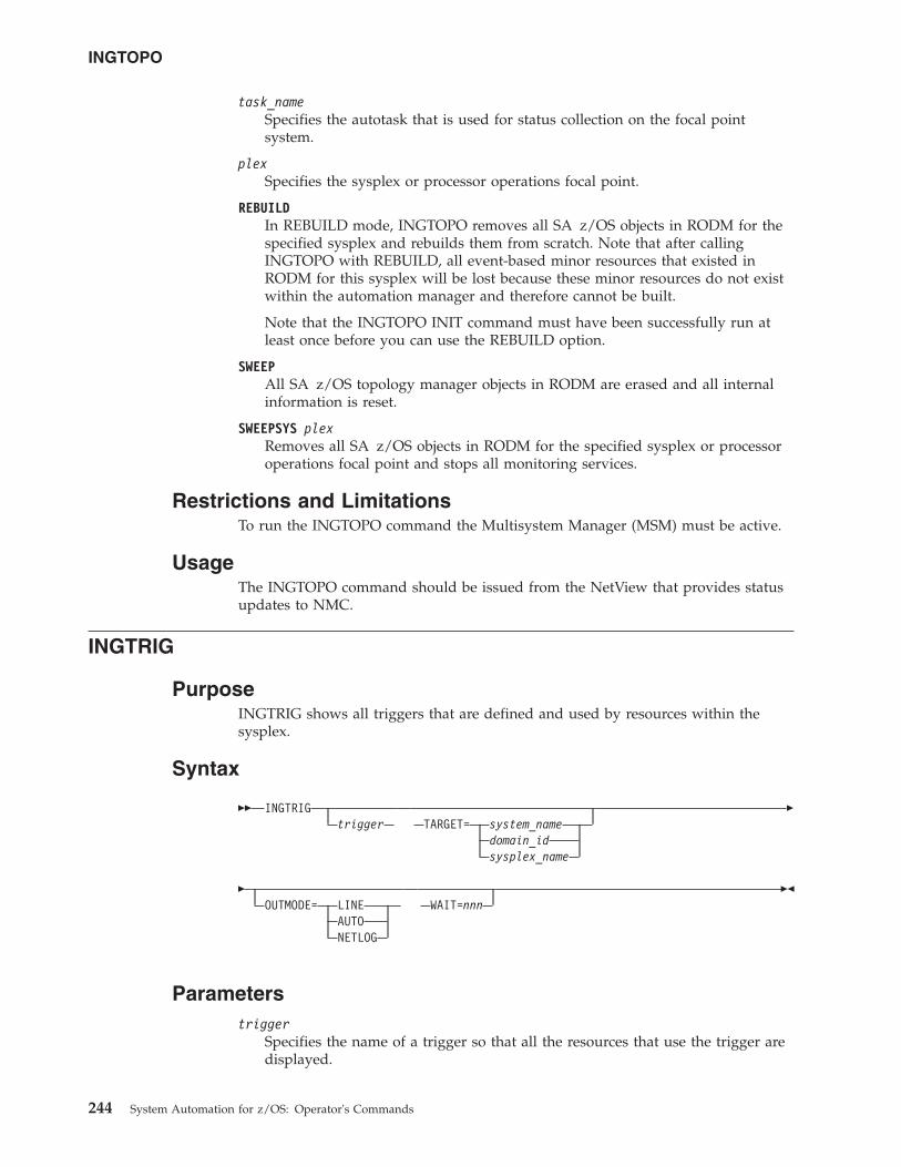
task_nameSpecifies the autotask that is used for status collection on the focal pointsystem.
plexSpecifies the sysplex or processor operations focal point.
REBUILDIn REBUILD mode, INGTOPO removes all SA z/OS objects in RODM for thespecified sysplex and rebuilds them from scratch. Note that after callingINGTOPO with REBUILD, all event-based minor resources that existed inRODM for this sysplex will be lost because these minor resources do not existwithin the automation manager and therefore cannot be built.
Note that the INGTOPO INIT command must have been successfully run atleast once before you can use the REBUILD option.
SWEEPAll SA z/OS topology manager objects in RODM are erased and all internalinformation is reset.
SWEEPSYS plexRemoves all SA z/OS objects in RODM for the specified sysplex or processoroperations focal point and stops all monitoring services.
Restrictions and LimitationsTo run the INGTOPO command the Multisystem Manager (MSM) must be active.
UsageThe INGTOPO command should be issued from the NetView that provides statusupdates to NMC.
INGTRIG
PurposeINGTRIG shows all triggers that are defined and used by resources within thesysplex.
Syntax
�� INGTRIGtrigger TARGET= system_name
domain_idsysplex_name
�
�OUTMODE= LINE
AUTONETLOG
WAIT=nnn��
Parameterstrigger
Specifies the name of a trigger so that all the resources that use the trigger aredisplayed.
INGTOPO
244 System Automation for z/OS: Operator's Commands
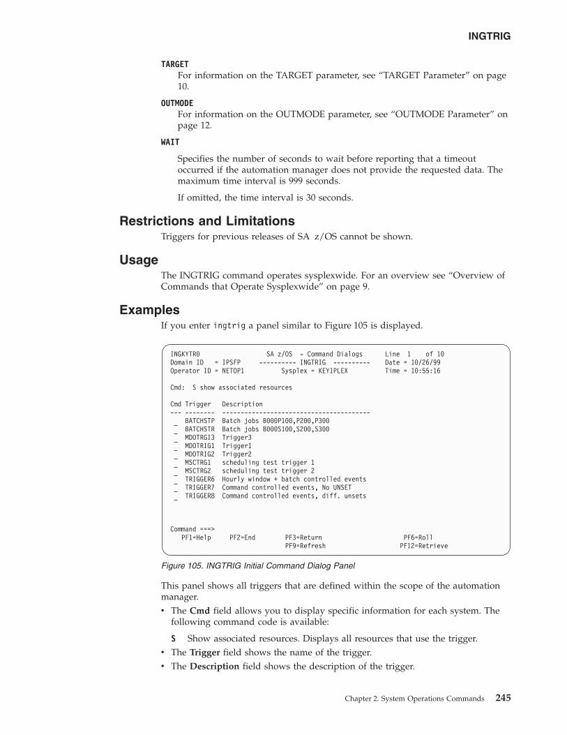
TARGETFor information on the TARGET parameter, see “TARGET Parameter” on page10.
OUTMODEFor information on the OUTMODE parameter, see “OUTMODE Parameter” onpage 12.
WAIT
Specifies the number of seconds to wait before reporting that a timeoutoccurred if the automation manager does not provide the requested data. Themaximum time interval is 999 seconds.
If omitted, the time interval is 30 seconds.
Restrictions and LimitationsTriggers for previous releases of SA z/OS cannot be shown.
UsageThe INGTRIG command operates sysplexwide. For an overview see “Overview ofCommands that Operate Sysplexwide” on page 9.
ExamplesIf you enter ingtrig a panel similar to Figure 105 is displayed.
This panel shows all triggers that are defined within the scope of the automationmanager.v The Cmd field allows you to display specific information for each system. The
following command code is available:
S Show associated resources. Displays all resources that use the trigger.v The Trigger field shows the name of the trigger.v The Description field shows the description of the trigger.
INGKYTR0 SA z/OS - Command Dialogs Line 1 of 10Domain ID = IPSFP ---------- INGTRIG ---------- Date = 10/26/99Operator ID = NETOP1 Sysplex = KEY1PLEX Time = 10:55:16
Cmd: S show associated resources
Cmd Trigger Description--- -------- ----------------------------------------
BATCHSTP Batch jobs B000P100,P200,P300BATCHSTR Batch jobs B000S100,S200,S300MDOTRGI3 Trigger3MDOTRIG1 Trigger1MDOTRIG2 Trigger2MSCTRG1 scheduling test trigger 1MSCTRG2 scheduling test trigger 2TRIGGER6 Hourly window + batch controlled eventsTRIGGER7 Command controlled events, No UNSETTRIGGER8 Command controlled events, diff. unsets
Command ===>PF1=Help PF2=End PF3=Return PF6=Roll
PF9=Refresh PF12=Retrieve
Figure 105. INGTRIG Initial Command Dialog Panel
INGTRIG
Chapter 2. System Operations Commands 245
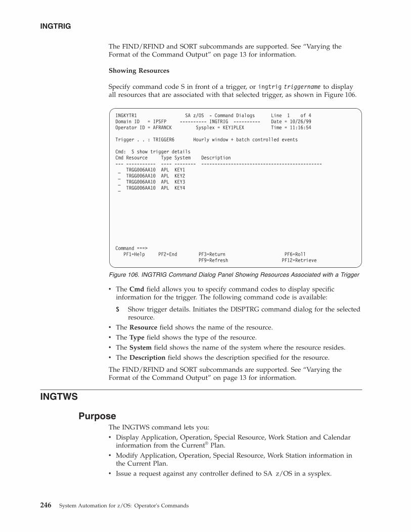
The FIND/RFIND and SORT subcommands are supported. See “Varying theFormat of the Command Output” on page 13 for information.
Showing Resources
Specify command code S in front of a trigger, or ingtrig triggername to displayall resources that are associated with that selected trigger, as shown in Figure 106.
v The Cmd field allows you to specify command codes to display specificinformation for the trigger. The following command code is available:
S Show trigger details. Initiates the DISPTRG command dialog for the selectedresource.
v The Resource field shows the name of the resource.v The Type field shows the type of the resource.v The System field shows the name of the system where the resource resides.v The Description field shows the description specified for the resource.
The FIND/RFIND and SORT subcommands are supported. See “Varying theFormat of the Command Output” on page 13 for information.
INGTWS
PurposeThe INGTWS command lets you:v Display Application, Operation, Special Resource, Work Station and Calendar
information from the Current® Plan.v Modify Application, Operation, Special Resource, Work Station information in
the Current Plan.v Issue a request against any controller defined to SA z/OS in a sysplex.
INGKYTR1 SA z/OS - Command Dialogs Line 1 of 4Domain ID = IPSFP ---------- INGTRIG ---------- Date = 10/26/99Operator ID = AFRANCK Sysplex = KEY1PLEX Time = 11:16:54
Trigger . . : TRIGGER6 Hourly window + batch controlled events
Cmd: S show trigger detailsCmd Resource Type System Description--- ----------- ---- -------- ---------------------------------------------
TRGG006AA10 APL KEY1TRGG006AA10 APL KEY2TRGG006AA10 APL KEY3TRGG006AA10 APL KEY4
Command ===>PF1=Help PF2=End PF3=Return PF6=Roll
PF9=Refresh PF12=Retrieve
Figure 106. INGTRIG Command Dialog Panel Showing Resources Associated with a Trigger
INGTRIG
246 System Automation for z/OS: Operator's Commands
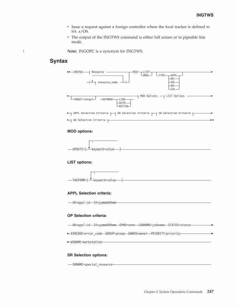
v Issue a request against a foreign controller where the local tracker is defined toSA z/OS.
v The output of the INGTWS command is either full screen or in pipeable linemode.
Note: INGOPC is a synonym for INGTWS.
Syntax
�� INGTWS
�
Resource
( resource_name )
REQ= LISTMOD TYPE= APPL
OPSRWSCAL
�
�TARGET=target OUTMODE= LINE
AUTONETLOG
MOD Options LIST Options �
� APPL Selection Criteria OR Selection Criteria SR Selection Criteria �
� WS Selection Criteria ��
MOD options:
�
;
UPDATE=( keyword=value )
LIST options:
�
;
TWSPARM=( keyword=value )
APPL Selection criteria:
AD=appl-id IA=yymmddhhmm
OP Selection criteria:
AD=appl-id IA=yymmddhhmm OPNO=nnnn JOBNAME=jobname STATUS=status �
� ERRCODE=error_code GROUP=group OWNER=owner PRIORITY=priority �
� WSNAME=workstation
SR Selection options:
SRNAME=special_resource
INGTWS
Chapter 2. System Operations Commands 247
|
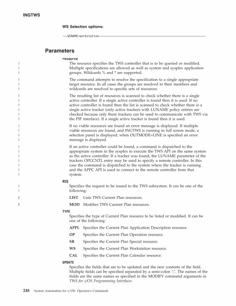
WS Selection options:
WSNAME=workstation
Parametersresource
The resource specifies the TWS controller that is to be queried or modified.Multiple specifications are allowed as well as system and sysplex applicationgroups. Wildcards % and * are supported.
The command attempts to resolve the specification to a single appropriatetarget resource. In all cases the groups are resolved to their members andwildcards are resolved to specific sets of resources.
The resulting list of resources is scanned to check whether there is a singleactive controller. If a single active controller is found then it is used. If noactive controller is found then the list is scanned to check whether there is asingle active tracker (only active trackers with LUNAME policy entries arechecked because only these trackers can be used to communicate with TWS viathe PIF interface). If a single active tracker is found then it is used.
If no viable resources are found an error message is displayed. If multipleviable resources are found, and INGTWS is running in full screen mode, aselection panel is displayed; when OUTMODE=LINE is specified an errormessage is displayed.
If an active controller could be found, a command is dispatched to theappropriate system in the sysplex to execute the TWS API on the same systemas the active controller. If a tracker was found, the LUNAME parameter of thetrackers OPCCNTL entry may be used to specify a remote controller. In thiscase the command is dispatched to the system where the tracker is runningand the APPC API is used to connect to the remote controller from thatsystem.
REQSpecifies the request to be issued to the TWS subsystem. It can be one of thefollowing:
LIST Lists TWS Current Plan resources.
MOD Modifies TWS Current Plan resources.
TYPESpecifies the type of Current Plan resource to be listed or modified. It can beone of the following:
APPL Specifies the Current Plan Application Description resource.
OP Specifies the Current Plan Operation resource.
SR Specifies the Current Plan Special resource.
WS Specifies the Current Plan Workstation resource.
CAL Specifies the Current Plan Calendar resource.
UPDATESpecifies the fields that are to be updated and the new contents of the field.Multiple fields can be specified separated by a semi-colon ";". The names of thefields are the same names as specified in the MODIFY command arguments inTWS for z/OS Programming Interfaces.
INGTWS
248 System Automation for z/OS: Operator's Commands
|||
|||
||||||
||||
|||||||
||
||
||
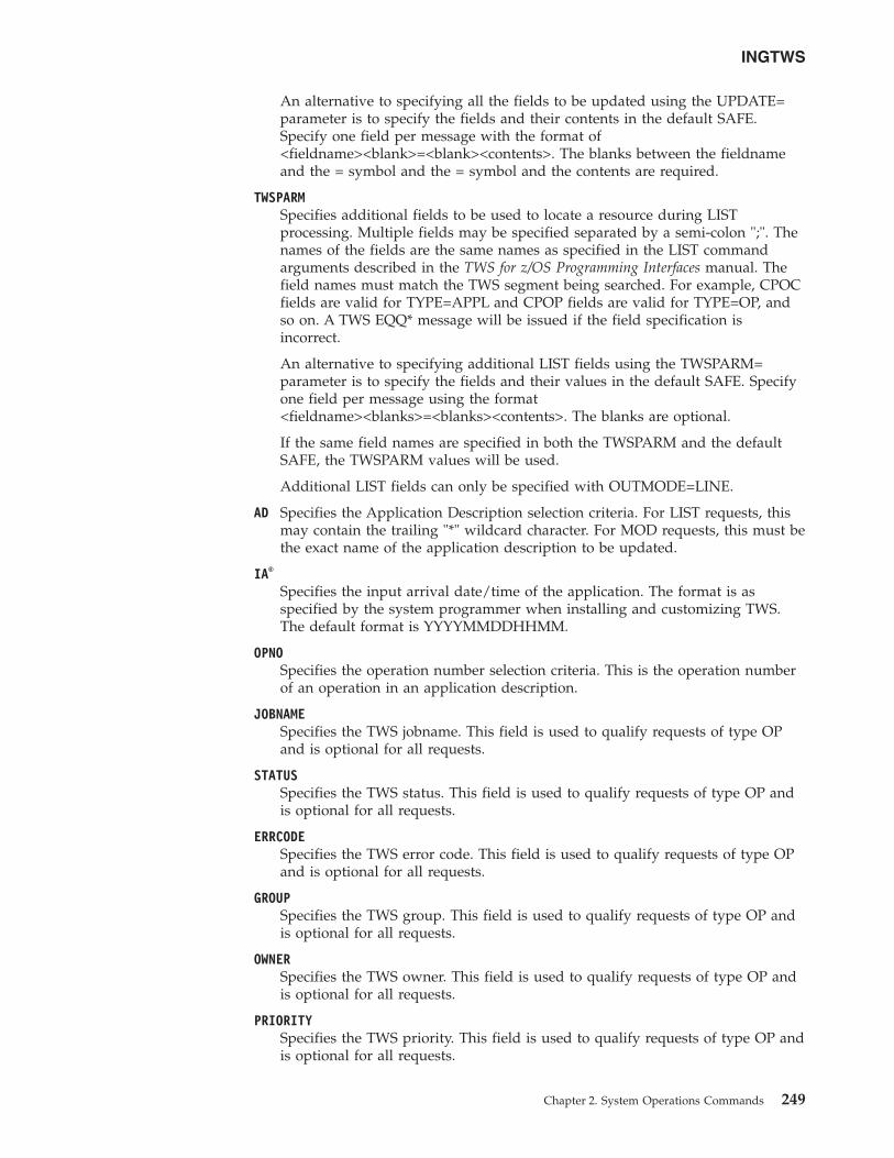
An alternative to specifying all the fields to be updated using the UPDATE=parameter is to specify the fields and their contents in the default SAFE.Specify one field per message with the format of<fieldname><blank>=<blank><contents>. The blanks between the fieldnameand the = symbol and the = symbol and the contents are required.
TWSPARMSpecifies additional fields to be used to locate a resource during LISTprocessing. Multiple fields may be specified separated by a semi-colon ";". Thenames of the fields are the same names as specified in the LIST commandarguments described in the TWS for z/OS Programming Interfaces manual. Thefield names must match the TWS segment being searched. For example, CPOCfields are valid for TYPE=APPL and CPOP fields are valid for TYPE=OP, andso on. A TWS EQQ* message will be issued if the field specification isincorrect.
An alternative to specifying additional LIST fields using the TWSPARM=parameter is to specify the fields and their values in the default SAFE. Specifyone field per message using the format<fieldname><blanks>=<blanks><contents>. The blanks are optional.
If the same field names are specified in both the TWSPARM and the defaultSAFE, the TWSPARM values will be used.
Additional LIST fields can only be specified with OUTMODE=LINE.
AD Specifies the Application Description selection criteria. For LIST requests, thismay contain the trailing "*" wildcard character. For MOD requests, this must bethe exact name of the application description to be updated.
IA®
Specifies the input arrival date/time of the application. The format is asspecified by the system programmer when installing and customizing TWS.The default format is YYYYMMDDHHMM.
OPNOSpecifies the operation number selection criteria. This is the operation numberof an operation in an application description.
JOBNAMESpecifies the TWS jobname. This field is used to qualify requests of type OPand is optional for all requests.
STATUSSpecifies the TWS status. This field is used to qualify requests of type OP andis optional for all requests.
ERRCODESpecifies the TWS error code. This field is used to qualify requests of type OPand is optional for all requests.
GROUPSpecifies the TWS group. This field is used to qualify requests of type OP andis optional for all requests.
OWNERSpecifies the TWS owner. This field is used to qualify requests of type OP andis optional for all requests.
PRIORITYSpecifies the TWS priority. This field is used to qualify requests of type OP andis optional for all requests.
INGTWS
Chapter 2. System Operations Commands 249
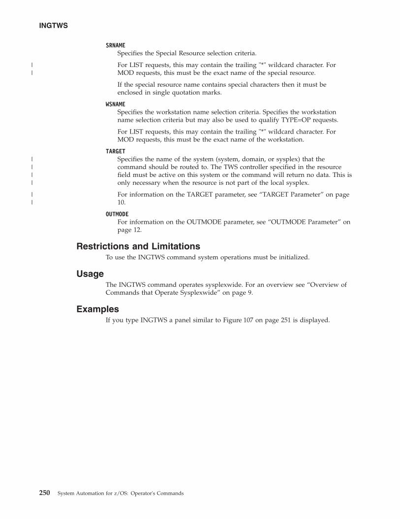
SRNAMESpecifies the Special Resource selection criteria.
For LIST requests, this may contain the trailing "*" wildcard character. ForMOD requests, this must be the exact name of the special resource.
If the special resource name contains special characters then it must beenclosed in single quotation marks.
WSNAMESpecifies the workstation name selection criteria. Specifies the workstationname selection criteria but may also be used to qualify TYPE=OP requests.
For LIST requests, this may contain the trailing "*" wildcard character. ForMOD requests, this must be the exact name of the workstation.
TARGETSpecifies the name of the system (system, domain, or sysplex) that thecommand should be routed to. The TWS controller specified in the resourcefield must be active on this system or the command will return no data. This isonly necessary when the resource is not part of the local sysplex.
For information on the TARGET parameter, see “TARGET Parameter” on page10.
OUTMODEFor information on the OUTMODE parameter, see “OUTMODE Parameter” onpage 12.
Restrictions and LimitationsTo use the INGTWS command system operations must be initialized.
UsageThe INGTWS command operates sysplexwide. For an overview see “Overview ofCommands that Operate Sysplexwide” on page 9.
ExamplesIf you type INGTWS a panel similar to Figure 107 on page 251 is displayed.
INGTWS
250 System Automation for z/OS: Operator's Commands
||
||||
||
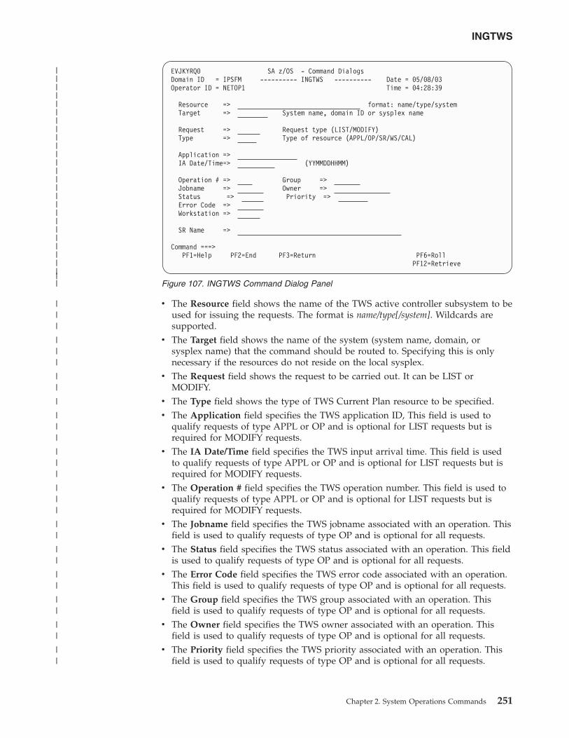
v The Resource field shows the name of the TWS active controller subsystem to beused for issuing the requests. The format is name/type[/system]. Wildcards aresupported.
v The Target field shows the name of the system (system name, domain, orsysplex name) that the command should be routed to. Specifying this is onlynecessary if the resources do not reside on the local sysplex.
v The Request field shows the request to be carried out. It can be LIST orMODIFY.
v The Type field shows the type of TWS Current Plan resource to be specified.v The Application field specifies the TWS application ID, This field is used to
qualify requests of type APPL or OP and is optional for LIST requests but isrequired for MODIFY requests.
v The IA Date/Time field specifies the TWS input arrival time. This field is usedto qualify requests of type APPL or OP and is optional for LIST requests but isrequired for MODIFY requests.
v The Operation # field specifies the TWS operation number. This field is used toqualify requests of type APPL or OP and is optional for LIST requests but isrequired for MODIFY requests.
v The Jobname field specifies the TWS jobname associated with an operation. Thisfield is used to qualify requests of type OP and is optional for all requests.
v The Status field specifies the TWS status associated with an operation. This fieldis used to qualify requests of type OP and is optional for all requests.
v The Error Code field specifies the TWS error code associated with an operation.This field is used to qualify requests of type OP and is optional for all requests.
v The Group field specifies the TWS group associated with an operation. Thisfield is used to qualify requests of type OP and is optional for all requests.
v The Owner field specifies the TWS owner associated with an operation. Thisfield is used to qualify requests of type OP and is optional for all requests.
v The Priority field specifies the TWS priority associated with an operation. Thisfield is used to qualify requests of type OP and is optional for all requests.
EVJKYRQ0 SA z/OS - Command DialogsDomain ID = IPSFM ---------- INGTWS ---------- Date = 05/08/03Operator ID = NETOP1 Time = 04:28:39
Resource => format: name/type/systemTarget => System name, domain ID or sysplex name
Request => Request type (LIST/MODIFY)Type => Type of resource (APPL/OP/SR/WS/CAL)
Application =>IA Date/Time=> (YYMMDDHHMM)
Operation # => Group =>Jobname => Owner =>Status => Priority =>Error Code =>Workstation =>
SR Name =>
Command ===>PF1=Help PF2=End PF3=Return PF6=Roll
PF12=Retrieve
Figure 107. INGTWS Command Dialog Panel
INGTWS
Chapter 2. System Operations Commands 251
|||||||||||||||||||||||||||
|||
|||
||
|
|||
|||
|||
||
||
||
||
||
||
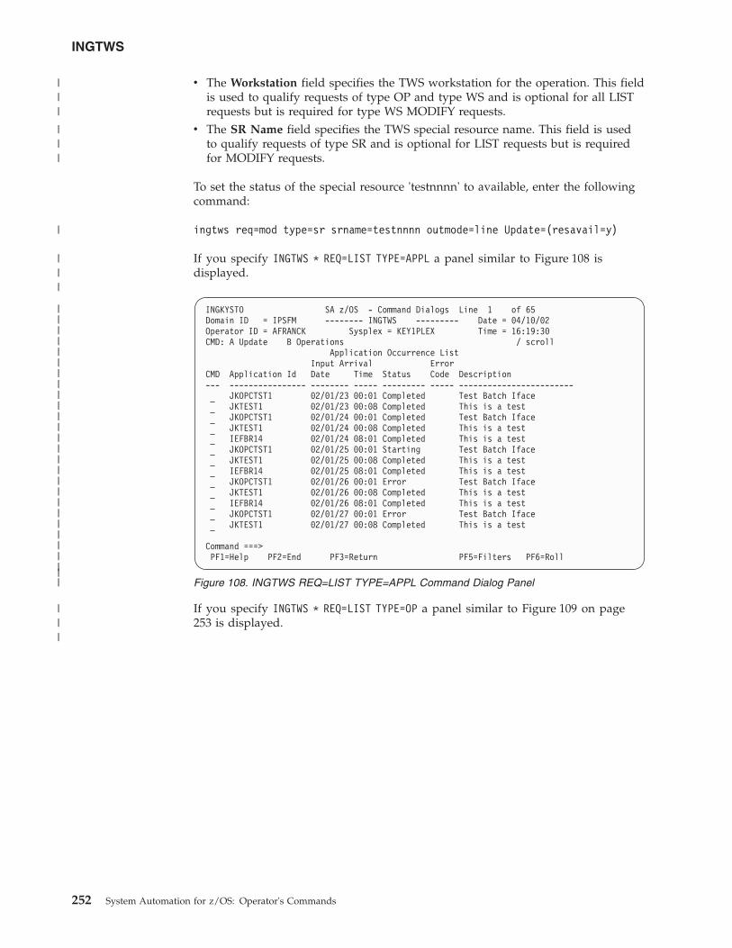
v The Workstation field specifies the TWS workstation for the operation. This fieldis used to qualify requests of type OP and type WS and is optional for all LISTrequests but is required for type WS MODIFY requests.
v The SR Name field specifies the TWS special resource name. This field is usedto qualify requests of type SR and is optional for LIST requests but is requiredfor MODIFY requests.
To set the status of the special resource 'testnnnn' to available, enter the followingcommand:
ingtws req=mod type=sr srname=testnnnn outmode=line Update=(resavail=y)
If you specify INGTWS * REQ=LIST TYPE=APPL a panel similar to Figure 108 isdisplayed.
If you specify INGTWS * REQ=LIST TYPE=OP a panel similar to Figure 109 on page253 is displayed.
INGKYSTO SA z/OS - Command Dialogs Line 1 of 65Domain ID = IPSFM -------- INGTWS --------- Date = 04/10/02Operator ID = AFRANCK Sysplex = KEY1PLEX Time = 16:19:30CMD: A Update B Operations / scroll
Application Occurrence ListInput Arrival Error
CMD Application Id Date Time Status Code Description--- ---------------- -------- ----- --------- ----- ------------------------
JKOPCTST1 02/01/23 00:01 Completed Test Batch IfaceJKTEST1 02/01/23 00:08 Completed This is a testJKOPCTST1 02/01/24 00:01 Completed Test Batch IfaceJKTEST1 02/01/24 00:08 Completed This is a testIEFBR14 02/01/24 08:01 Completed This is a testJKOPCTST1 02/01/25 00:01 Starting Test Batch IfaceJKTEST1 02/01/25 00:08 Completed This is a testIEFBR14 02/01/25 08:01 Completed This is a testJKOPCTST1 02/01/26 00:01 Error Test Batch IfaceJKTEST1 02/01/26 00:08 Completed This is a testIEFBR14 02/01/26 08:01 Completed This is a testJKOPCTST1 02/01/27 00:01 Error Test Batch IfaceJKTEST1 02/01/27 00:08 Completed This is a test
Command ===>PF1=Help PF2=End PF3=Return PF5=Filters PF6=Roll
Figure 108. INGTWS REQ=LIST TYPE=APPL Command Dialog Panel
INGTWS
252 System Automation for z/OS: Operator's Commands
|||||||||||||||||||||||||||
|||
|||
|
|||
|||
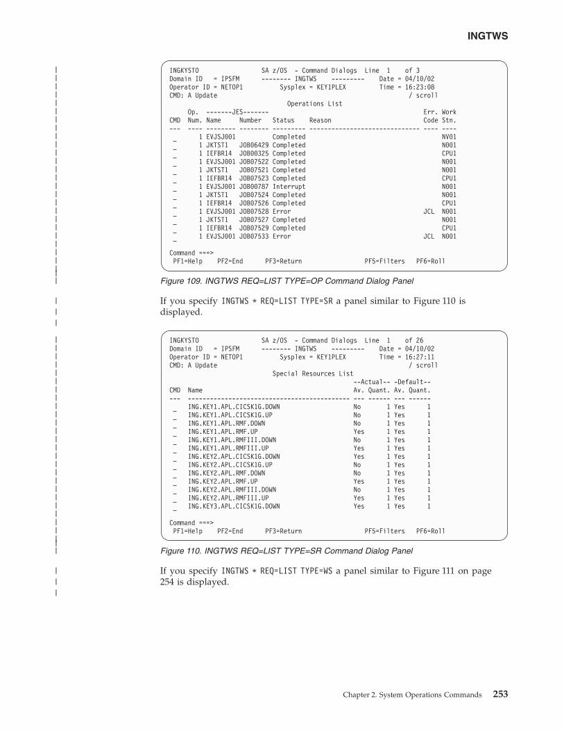
If you specify INGTWS * REQ=LIST TYPE=SR a panel similar to Figure 110 isdisplayed.
If you specify INGTWS * REQ=LIST TYPE=WS a panel similar to Figure 111 on page254 is displayed.
INGKYSTO SA z/OS - Command Dialogs Line 1 of 3Domain ID = IPSFM -------- INGTWS --------- Date = 04/10/02Operator ID = NETOP1 Sysplex = KEY1PLEX Time = 16:23:08CMD: A Update / scroll
Operations ListOp. -------JES------- Err. Work
CMD Num. Name Number Status Reason Code Stn.--- ---- -------- -------- --------- ------------------------------ ---- ----
1 EVJSJ001 Completed NV011 JKTST1 JOB06429 Completed N0011 IEFBR14 JOB00325 Completed CPU11 EVJSJ001 JOB07522 Completed N0011 JKTST1 JOB07521 Completed N0011 IEFBR14 JOB07523 Completed CPU11 EVJSJ001 JOB00787 Interrupt N0011 JKTST1 JOB07524 Completed N0011 IEFBR14 JOB07526 Completed CPU11 EVJSJ001 JOB07528 Error JCL N0011 JKTST1 JOB07527 Completed N0011 IEFBR14 JOB07529 Completed CPU11 EVJSJ001 JOB07533 Error JCL N001
Command ===>PF1=Help PF2=End PF3=Return PF5=Filters PF6=Roll
Figure 109. INGTWS REQ=LIST TYPE=OP Command Dialog Panel
INGKYSTO SA z/OS - Command Dialogs Line 1 of 26Domain ID = IPSFM -------- INGTWS --------- Date = 04/10/02Operator ID = NETOP1 Sysplex = KEY1PLEX Time = 16:27:11CMD: A Update / scroll
Special Resources List--Actual-- -Default--
CMD Name Av. Quant. Av. Quant.--- -------------------------------------------- --- ------ --- ------
ING.KEY1.APL.CICSK1G.DOWN No 1 Yes 1ING.KEY1.APL.CICSK1G.UP No 1 Yes 1ING.KEY1.APL.RMF.DOWN No 1 Yes 1ING.KEY1.APL.RMF.UP Yes 1 Yes 1ING.KEY1.APL.RMFIII.DOWN No 1 Yes 1ING.KEY1.APL.RMFIII.UP Yes 1 Yes 1ING.KEY2.APL.CICSK1G.DOWN Yes 1 Yes 1ING.KEY2.APL.CICSK1G.UP No 1 Yes 1ING.KEY2.APL.RMF.DOWN No 1 Yes 1ING.KEY2.APL.RMF.UP Yes 1 Yes 1ING.KEY2.APL.RMFIII.DOWN No 1 Yes 1ING.KEY2.APL.RMFIII.UP Yes 1 Yes 1ING.KEY3.APL.CICSK1G.DOWN Yes 1 Yes 1
Command ===>PF1=Help PF2=End PF3=Return PF5=Filters PF6=Roll
Figure 110. INGTWS REQ=LIST TYPE=SR Command Dialog Panel
INGTWS
Chapter 2. System Operations Commands 253
|||||||||||||||||||||||||||
|||||||||||||||||||||||||||
|||
|||
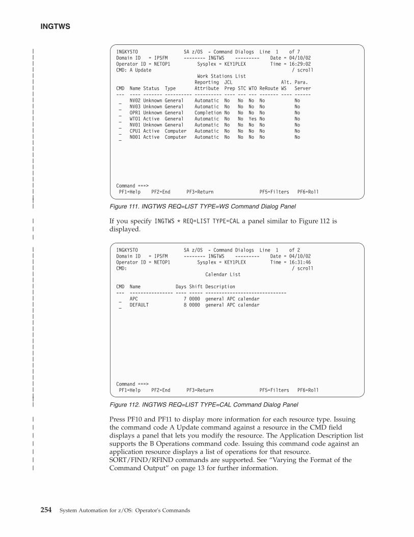
If you specify INGTWS * REQ=LIST TYPE=CAL a panel similar to Figure 112 isdisplayed.
Press PF10 and PF11 to display more information for each resource type. Issuingthe command code A Update command against a resource in the CMD fielddisplays a panel that lets you modify the resource. The Application Description listsupports the B Operations command code. Issuing this command code against anapplication resource displays a list of operations for that resource.SORT/FIND/RFIND commands are supported. See “Varying the Format of theCommand Output” on page 13 for further information.
INGKYSTO SA z/OS - Command Dialogs Line 1 of 7Domain ID = IPSFM -------- INGTWS --------- Date = 04/10/02Operator ID = NETOP1 Sysplex = KEY1PLEX Time = 16:29:02CMD: A Update / scroll
Work Stations ListReporting JCL Alt. Para.
CMD Name Status Type Attribute Prep STC WTO ReRoute WS Server--- ---- ------- ---------- ---------- ---- --- --- ------- ---- ------
NV02 Unknown General Automatic No No No No NoNV03 Unknown General Automatic No No No No NoOPR1 Unknown General Completion No No No No NoWTO1 Active General Automatic No No Yes No NoNV01 Unknown General Automatic No No No No NoCPU1 Active Computer Automatic No No No No NoN001 Active Computer Automatic No No No No No
Command ===>PF1=Help PF2=End PF3=Return PF5=Filters PF6=Roll
Figure 111. INGTWS REQ=LIST TYPE=WS Command Dialog Panel
INGKYSTO SA z/OS - Command Dialogs Line 1 of 2Domain ID = IPSFM -------- INGTWS --------- Date = 04/10/02Operator ID = NETOP1 Sysplex = KEY1PLEX Time = 16:31:46CMD: / scroll
Calendar List
CMD Name Days Shift Description--- ---------------- ---- ----- ------------------------------
APC 7 0000 general APC calendarDEFAULT 8 0000 general APC calendar
Command ===>PF1=Help PF2=End PF3=Return PF5=Filters PF6=Roll
Figure 112. INGTWS REQ=LIST TYPE=CAL Command Dialog Panel
INGTWS
254 System Automation for z/OS: Operator's Commands
|||||||||||||||||||||||||||
|||||||||||||||||||||||||||
|||
|||||||
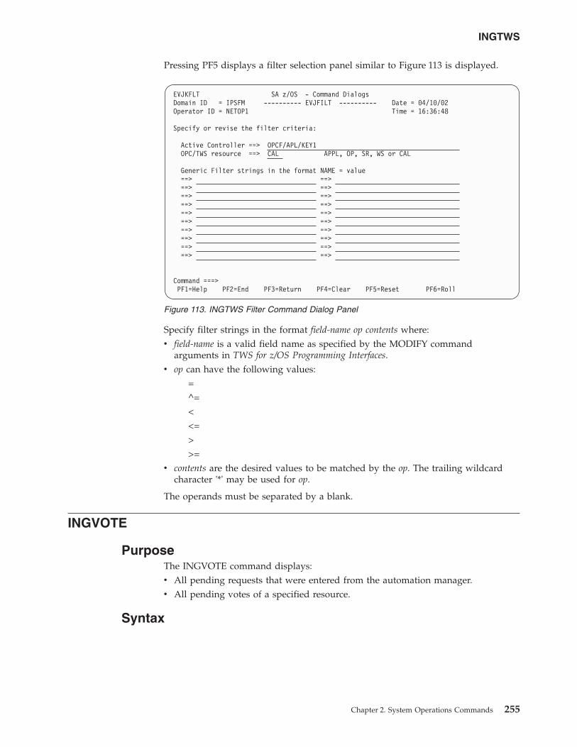
Pressing PF5 displays a filter selection panel similar to Figure 113 is displayed.
Specify filter strings in the format field-name op contents where:v field-name is a valid field name as specified by the MODIFY command
arguments in TWS for z/OS Programming Interfaces.v op can have the following values:
=^=<<=>>=
v contents are the desired values to be matched by the op. The trailing wildcardcharacter '*' may be used for op.
The operands must be separated by a blank.
INGVOTE
PurposeThe INGVOTE command displays:v All pending requests that were entered from the automation manager.v All pending votes of a specified resource.
Syntax
EVJKFLT SA z/OS - Command DialogsDomain ID = IPSFM ---------- EVJFILT ---------- Date = 04/10/02Operator ID = NETOP1 Time = 16:36:48
Specify or revise the filter criteria:
Active Controller ==> OPCF/APL/KEY1OPC/TWS resource ==> CAL APPL, OP, SR, WS or CAL
Generic Filter strings in the format NAME = value==> ==>==> ==>==> ==>==> ==>==> ==>==> ==>==> ==>==> ==>==> ==>==> ==>
Command ===>PF1=Help PF2=End PF3=Return PF4=Clear PF5=Reset PF6=Roll
Figure 113. INGTWS Filter Command Dialog Panel
INGTWS
Chapter 2. System Operations Commands 255
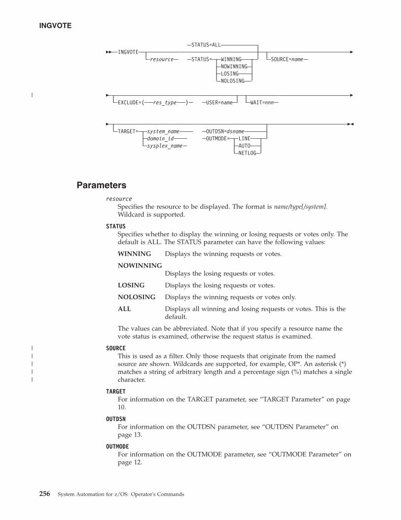
�� INGVOTEresource
STATUS=ALL
STATUS= WINNINGNOWINNINGLOSINGNOLOSING
SOURCE=name�
�EXCLUDE=( res_type ) USER=name WAIT=nnn
�
�TARGET= system_name
domain_idsysplex_name
OUTDSN=dsnameOUTMODE= LINE
AUTONETLOG
��
Parametersresource
Specifies the resource to be displayed. The format is name/type[/system].Wildcard is supported.
STATUSSpecifies whether to display the winning or losing requests or votes only. Thedefault is ALL. The STATUS parameter can have the following values:
WINNING Displays the winning requests or votes.
NOWINNINGDisplays the losing requests or votes.
LOSING Displays the losing requests or votes.
NOLOSING Displays the winning requests or votes only.
ALL Displays all winning and losing requests or votes. This is thedefault.
The values can be abbreviated. Note that if you specify a resource name thevote status is examined, otherwise the request status is examined.
SOURCEThis is used as a filter. Only those requests that originate from the namedsource are shown. Wildcards are supported, for example, OP*. An asterisk (*)matches a string of arbitrary length and a percentage sign (%) matches a singlecharacter.
TARGETFor information on the TARGET parameter, see “TARGET Parameter” on page10.
OUTDSNFor information on the OUTDSN parameter, see “OUTDSN Parameter” onpage 13.
OUTMODEFor information on the OUTMODE parameter, see “OUTMODE Parameter” onpage 12.
INGVOTE
256 System Automation for z/OS: Operator's Commands
|
|||||
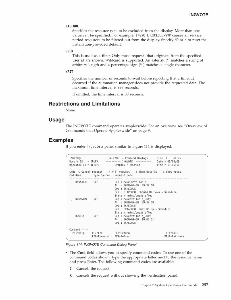
EXCLUDESpecifies the resource type to be excluded from the display. More than onevalue can be specified. For example, INGVOTE EXCLUDE=SVP causes all serviceperiod resources to be filtered out from the display. Specify NO or * to reset theinstallation-provided default.
USERThis is used as a filter. Only those requests that originate from the specifieduser id are shown. Wildcard is supported. An asterisk (*) matches a string ofarbitrary length and a percentage sign (%) matches a single character.
WAIT
Specifies the number of seconds to wait before reporting that a timeoutoccurred if the automation manager does not provide the requested data. Themaximum time interval is 999 seconds.
If omitted, the time interval is 30 seconds.
Restrictions and LimitationsNone.
UsageThe INGVOTE command operates sysplexwide. For an overview see “Overview ofCommands that Operate Sysplexwide” on page 9.
ExamplesIf you enter ingvote a panel similar to Figure 114 is displayed.
v The Cmd field allows you to specify command codes. To use one of thecommand codes shown, type the appropriate letter next to the resource nameand press Enter. The following command codes are available:
C Cancels the request.
K Cancels the request without showing the verification panel.
INGKYRQ2 SA z/OS - Command Dialogs Line 1 of 25Domain ID = IPUFA ---------- INGVOTE ---------- Date = 09/08/08Operator ID = NETOP1 Sysplex = AOCPLEX Time = 19:05:50
Cmd: C Cancel request K Kill request S Show details V Show votesCmd Name Type System Request Data--- ----------- ---- -------- ------ ------------------------------------------
BNKNACHT SVP Req : MakeUnAvailableAt : 2008-09-08 09:39:58Org : SCHEDULEPri : 01120000 Should Be Down - ScheduleStat: Winning/Unsatisfied
BZOMSCMV SVP Req : MakeAvailable_OnlyAt : 2008-09-08 09:39:58Org : SCHEDULEPri : 02140000 Must Be Up - ScheduleStat: Winning/Unsatisfied
HOURLY SVP Req : MakeAvailable_OnlyAt : 2008-09-08 10:00:01Org : SCHEDULE
Command ===>PF1=Help PF2=End PF3=Return PF6=Roll
PF8=Forward PF9=Refresh PF12=Retrieve
Figure 114. INGVOTE Command Dialog Panel
INGVOTE
Chapter 2. System Operations Commands 257
||||
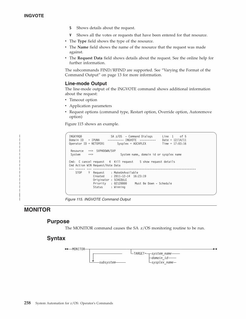
S Shows details about the request.
V Shows all the votes or requests that have been entered for that resource.v The Type field shows the type of the resource.v The Name field shows the name of the resource that the request was made
against.v The Request Data field shows details about the request. See the online help for
further information.
The subcommands FIND/RFIND are supported. See “Varying the Format of theCommand Output” on page 13 for more information.
Line-mode OutputThe line-mode output of the INGVOTE command shows additional informationabout the request:v Timeout optionv Application parametersv Request options (command type, Restart option, Override option, Autoremove
option)
Figure 115 shows an example.
MONITOR
PurposeThe MONITOR command causes the SA z/OS monitoring routine to be run.
Syntax
�� MONITOR
� subsystem
TARGET= system_namedomain_idsysplex_name
��
INGKYRQ0 SA z/OS - Command Dialogs Line 1 of 5Domain ID = IPUNA ---------- INGVOTE ---------- Date = 12/14/11Operator ID = NETOPER1 Sysplex = AOCAPLEX Time = 17:03:16
Resource ==> SVPHDOWN/SVPSystem ==> System name, domain id or sysplex name
Cmd: C cancel request K Kill request S show request detailsCmd Action WIN Request/Vote Data--- ------ --- ----------------------------------------------------------------
STOP Y Request : MakeUnAvailableCreated : 2011-12-14 16:23:19Originator : SCHEDULEPriority : 02120000 Must Be Down - ScheduleStatus : Winning
Figure 115. INGVOTE Command Output
INGVOTE
258 System Automation for z/OS: Operator's Commands
|||||||||||||||||||
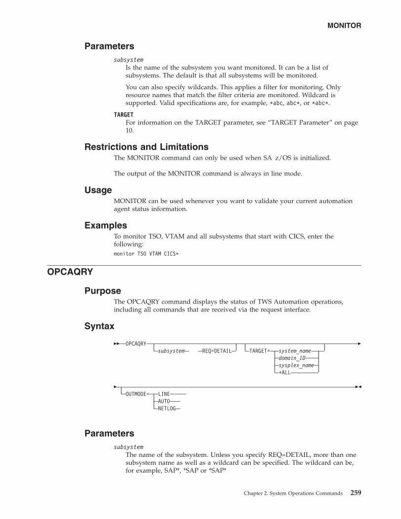
Parameterssubsystem
Is the name of the subsystem you want monitored. It can be a list ofsubsystems. The default is that all subsystems will be monitored.
You can also specify wildcards. This applies a filter for monitoring. Onlyresource names that match the filter criteria are monitored. Wildcard issupported. Valid specifications are, for example, *abc, abc*, or *abc*.
TARGETFor information on the TARGET parameter, see “TARGET Parameter” on page10.
Restrictions and LimitationsThe MONITOR command can only be used when SA z/OS is initialized.
The output of the MONITOR command is always in line mode.
UsageMONITOR can be used whenever you want to validate your current automationagent status information.
ExamplesTo monitor TSO, VTAM and all subsystems that start with CICS, enter thefollowing:monitor TSO VTAM CICS*
OPCAQRY
PurposeThe OPCAQRY command displays the status of TWS Automation operations,including all commands that are received via the request interface.
Syntax
�� OPCAQRYsubsystem REQ=DETAIL TARGET= system_name
domain_IDsysplex_name*ALL
�
�OUTMODE= LINE
AUTONETLOG
��
Parameterssubsystem
The name of the subsystem. Unless you specify REQ=DETAIL, more than onesubsystem name as well as a wildcard can be specified. The wildcard can be,for example, SAP*, *SAP or *SAP*
MONITOR
Chapter 2. System Operations Commands 259
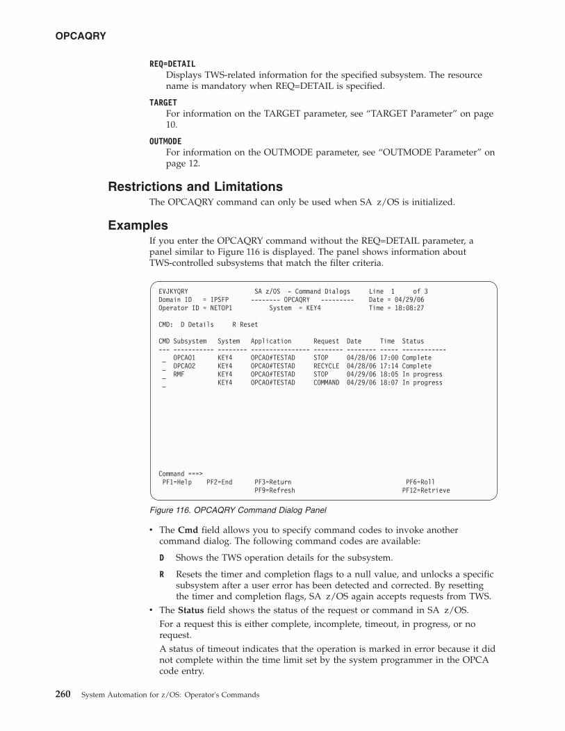
REQ=DETAILDisplays TWS-related information for the specified subsystem. The resourcename is mandatory when REQ=DETAIL is specified.
TARGETFor information on the TARGET parameter, see “TARGET Parameter” on page10.
OUTMODEFor information on the OUTMODE parameter, see “OUTMODE Parameter” onpage 12.
Restrictions and LimitationsThe OPCAQRY command can only be used when SA z/OS is initialized.
ExamplesIf you enter the OPCAQRY command without the REQ=DETAIL parameter, apanel similar to Figure 116 is displayed. The panel shows information aboutTWS-controlled subsystems that match the filter criteria.
v The Cmd field allows you to specify command codes to invoke anothercommand dialog. The following command codes are available:
D Shows the TWS operation details for the subsystem.
R Resets the timer and completion flags to a null value, and unlocks a specificsubsystem after a user error has been detected and corrected. By resettingthe timer and completion flags, SA z/OS again accepts requests from TWS.
v The Status field shows the status of the request or command in SA z/OS.For a request this is either complete, incomplete, timeout, in progress, or norequest.A status of timeout indicates that the operation is marked in error because it didnot complete within the time limit set by the system programmer in the OPCAcode entry.
EVJKYQRY SA z/OS - Command Dialogs Line 1 of 3Domain ID = IPSFP -------- OPCAQRY --------- Date = 04/29/06Operator ID = NETOP1 System = KEY4 Time = 18:08:27
CMD: D Details R Reset
CMD Subsystem System Application Request Date Time Status--- ----------- -------- ---------------- -------- -------- ----- ------------
OPCAO1 KEY4 OPCAO#TESTAD STOP 04/28/06 17:00 CompleteOPCAO2 KEY4 OPCAO#TESTAD RECYCLE 04/28/06 17:14 CompleteRMF KEY4 OPCAO#TESTAD STOP 04/29/06 18:05 In progress
KEY4 OPCAO#TESTAD COMMAND 04/29/06 18:07 In progress
Command ===>PF1=Help PF2=End PF3=Return PF6=Roll
PF9=Refresh PF12=Retrieve
Figure 116. OPCAQRY Command Dialog Panel
OPCAQRY
260 System Automation for z/OS: Operator's Commands
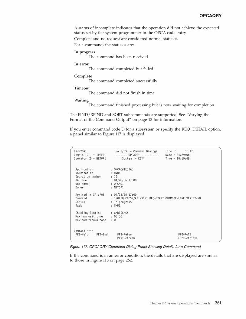
A status of incomplete indicates that the operation did not achieve the expectedstatus set by the system programmer in the OPCA code entry.Complete and no request are considered normal statuses.For a command, the statuses are:
In progressThe command has been received
In errorThe command completed but failed
CompleteThe command completed successfully
TimeoutThe command did not finish in time
WaitingThe command finished processing but is now waiting for completion
The FIND/RFIND and SORT subcommands are supported. See “Varying theFormat of the Command Output” on page 13 for information.
If you enter command code D for a subsystem or specify the REQ=DETAIL option,a panel similar to Figure 117 is displayed.
If the command is in an error condition, the details that are displayed are similarto those in Figure 118 on page 262.
EVJKYQR1 SA z/OS - Command Dialogs Line 1 of 17Domain ID = IPSFP -------- OPCAQRY --------- Date = 04/29/06Operator ID = NETOP1 System = KEY4 Time = 18:10:48
Application : OPCAO#TESTADWorkstation : NV04Operation number : 10IA Time : 04/28/06 17:00Job Name : OPCAO1Owner : NETOP1
Arrived in SA z/OS : 04/28/06 17:00Command : INGREQ CICS2/APl/SYS1 REQ=START OUTMODE=LINE VERIFY=NOStatus : In progressTask : CMD1
Checking Routine : CMD1$CHCKMaximum wait time : 00:30Maximum return code : 0
Command ===>PF1=Help PF2=End PF3=Return PF6=Roll
PF9=Refresh PF12=Retrieve
Figure 117. OPCAQRY Command Dialog Panel Showing Details for a Command
OPCAQRY
Chapter 2. System Operations Commands 261
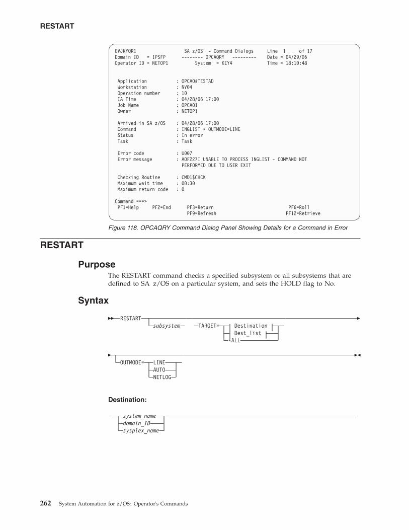
RESTART
PurposeThe RESTART command checks a specified subsystem or all subsystems that aredefined to SA z/OS on a particular system, and sets the HOLD flag to No.
Syntax
�� RESTARTsubsystem TARGET= Destination
Dest_list*ALL
�
�OUTMODE= LINE
AUTONETLOG
��
Destination:
system_namedomain_IDsysplex_name
EVJKYQR1 SA z/OS - Command Dialogs Line 1 of 17Domain ID = IPSFP -------- OPCAQRY --------- Date = 04/29/06Operator ID = NETOP1 System = KEY4 Time = 18:10:48
Application : OPCAO#TESTADWorkstation : NV04Operation number : 10IA Time : 04/28/06 17:00Job Name : OPCAO1Owner : NETOP1
Arrived in SA z/OS : 04/28/06 17:00Command : INGLIST * OUTMODE=LINEStatus : In errorTask : Task
Error code : U007Error message : AOF227I UNABLE TO PROCESS INGLIST - COMMAND NOT
PERFORMED DUE TO USER EXIT
Checking Routine : CMD1$CHCKMaximum wait time : 00:30Maximum return code : 0
Command ===>PF1=Help PF2=End PF3=Return PF6=Roll
PF9=Refresh PF12=Retrieve
Figure 118. OPCAQRY Command Dialog Panel Showing Details for a Command in Error
RESTART
262 System Automation for z/OS: Operator's Commands
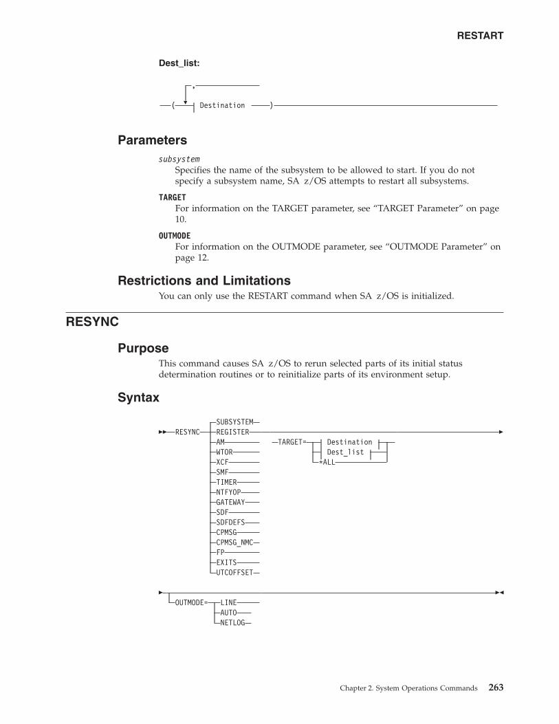
Dest_list:
�
,
( Destination )
Parameterssubsystem
Specifies the name of the subsystem to be allowed to start. If you do notspecify a subsystem name, SA z/OS attempts to restart all subsystems.
TARGETFor information on the TARGET parameter, see “TARGET Parameter” on page10.
OUTMODEFor information on the OUTMODE parameter, see “OUTMODE Parameter” onpage 12.
Restrictions and LimitationsYou can only use the RESTART command when SA z/OS is initialized.
RESYNC
PurposeThis command causes SA z/OS to rerun selected parts of its initial statusdetermination routines or to reinitialize parts of its environment setup.
Syntax
�� RESYNCSUBSYSTEMREGISTERAMWTORXCFSMFTIMERNTFYOPGATEWAYSDFSDFDEFSCPMSGCPMSG_NMCFPEXITSUTCOFFSET
TARGET= DestinationDest_list
*ALL
�
�OUTMODE= LINE
AUTONETLOG
��
RESTART
Chapter 2. System Operations Commands 263
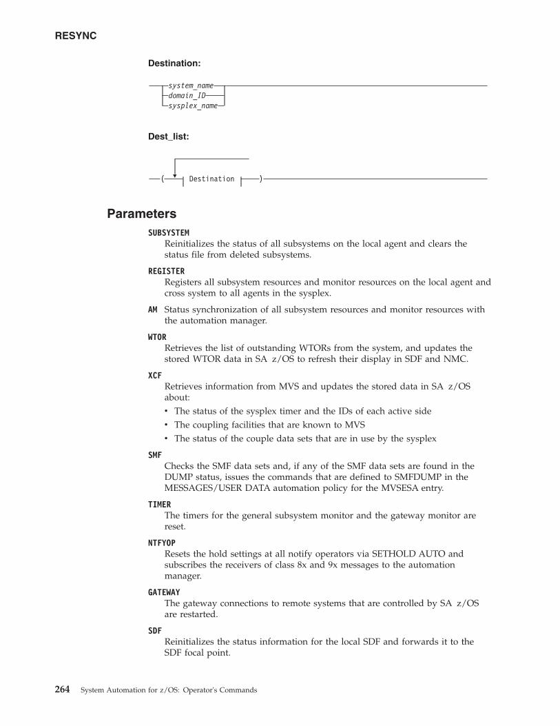
Destination:
system_namedomain_IDsysplex_name
Dest_list:
�( Destination )
ParametersSUBSYSTEM
Reinitializes the status of all subsystems on the local agent and clears thestatus file from deleted subsystems.
REGISTERRegisters all subsystem resources and monitor resources on the local agent andcross system to all agents in the sysplex.
AM Status synchronization of all subsystem resources and monitor resources withthe automation manager.
WTORRetrieves the list of outstanding WTORs from the system, and updates thestored WTOR data in SA z/OS to refresh their display in SDF and NMC.
XCFRetrieves information from MVS and updates the stored data in SA z/OSabout:v The status of the sysplex timer and the IDs of each active sidev The coupling facilities that are known to MVSv The status of the couple data sets that are in use by the sysplex
SMFChecks the SMF data sets and, if any of the SMF data sets are found in theDUMP status, issues the commands that are defined to SMFDUMP in theMESSAGES/USER DATA automation policy for the MVSESA entry.
TIMERThe timers for the general subsystem monitor and the gateway monitor arereset.
NTFYOPResets the hold settings at all notify operators via SETHOLD AUTO andsubscribes the receivers of class 8x and 9x messages to the automationmanager.
GATEWAYThe gateway connections to remote systems that are controlled by SA z/OSare restarted.
SDFReinitializes the status information for the local SDF and forwards it to theSDF focal point.
RESYNC
264 System Automation for z/OS: Operator's Commands
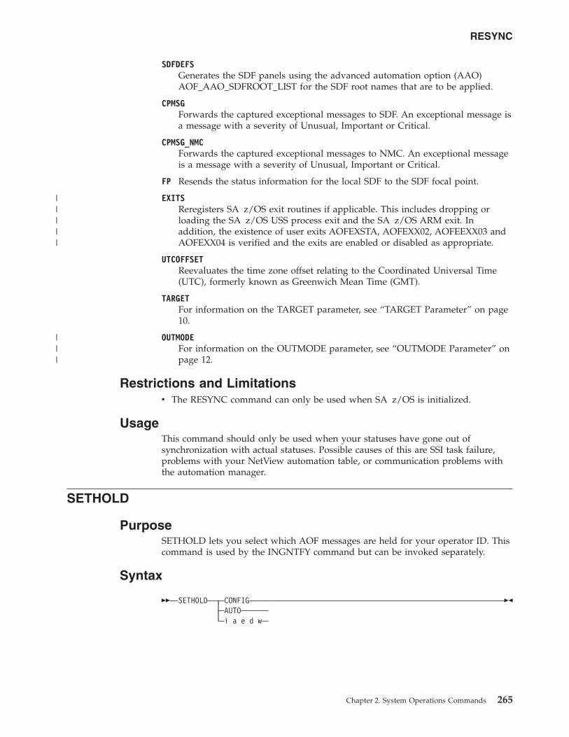
SDFDEFSGenerates the SDF panels using the advanced automation option (AAO)AOF_AAO_SDFROOT_LIST for the SDF root names that are to be applied.
CPMSGForwards the captured exceptional messages to SDF. An exceptional message isa message with a severity of Unusual, Important or Critical.
CPMSG_NMCForwards the captured exceptional messages to NMC. An exceptional messageis a message with a severity of Unusual, Important or Critical.
FP Resends the status information for the local SDF to the SDF focal point.
EXITSReregisters SA z/OS exit routines if applicable. This includes dropping orloading the SA z/OS USS process exit and the SA z/OS ARM exit. Inaddition, the existence of user exits AOFEXSTA, AOFEXX02, AOFEEXX03 andAOFEXX04 is verified and the exits are enabled or disabled as appropriate.
UTCOFFSETReevaluates the time zone offset relating to the Coordinated Universal Time(UTC), formerly known as Greenwich Mean Time (GMT).
TARGETFor information on the TARGET parameter, see “TARGET Parameter” on page10.
OUTMODEFor information on the OUTMODE parameter, see “OUTMODE Parameter” onpage 12.
Restrictions and Limitationsv The RESYNC command can only be used when SA z/OS is initialized.
UsageThis command should only be used when your statuses have gone out ofsynchronization with actual statuses. Possible causes of this are SSI task failure,problems with your NetView automation table, or communication problems withthe automation manager.
SETHOLD
PurposeSETHOLD lets you select which AOF messages are held for your operator ID. Thiscommand is used by the INGNTFY command but can be invoked separately.
Syntax
�� SETHOLD CONFIGAUTOi a e d w
��
RESYNC
Chapter 2. System Operations Commands 265
|||||
|||
ParametersCONFIG
Specifying this option changes your hold settings to match the settingsspecified for your operator ID in the automation control file. If your operatorID is not defined as a notification operator, no messages will be held.
AUTOSpecifying this option changes your hold settings to match the settingsINGNTFY has currently defined for your operator ID. If your operator ID isnot a notification operator, or its definition as a notification operator has beendeleted, no messages will be held.
i a e d wEach character specifies the hold setting for the corresponding type of message.If a Y is specified, messages of that type will be held, if any other character isspecified, messages of that type will not be held. A character must be specifiedfor each type.
Restrictions and LimitationsThe SETHOLD command is only useful on an OST task. If issued on an NNT orRMT task, the message-holding flags in the remote domain will be ignored,because the automation table on the OST task will override whatever messageattributes may have been specified in the remote domain.
SETHOLD does not update the INGNTFY globals, so if you use it with anythingother than the AUTO parameter, the hold settings shown by INGNTFY QUERYmay not reflect reality.
UsageSA z/OS issues SETHOLD at SA z/OS initialization, when you log on to NetViewinterface, and when INGNTFY is used.
When you log on, an entry in the sample automation table (in memberAOFMSGMS) will invoke SETHOLD AUTO for your operator ID. When INGNTFY isused to change an operator's HOLD settings, SETHOLD AUTO will be issued on theappropriate OST task after the global information has been updated.
A more efficient usage would be to modify your initial REXX scripts to issueSETHOLD with specific settings and to not have any hold settings specified in theautomation control file or through INGNTFY. If you choose to do this, you willneed to remove the automation table entry for the OST (in member AOFMSGMS)and set the AOFLOCALHOLD advanced automation option to 1. Doing this willstop INGNTFY from using EXCMD to issue SETHOLD AUTO, which can disrupt thehold settings specified from your profiles.
Note that the attributes for held messages are defined as automation tablesynonyms in the AOFMSGSY member.
It is recommended that you do not hold information messages because SA z/OScan generate quite a few of them. If you do hold them, use the CLRHELDcommand to remove them. You may want to modify the attributes for heldinformation messages (held in the AOFMSGSY ACF member) so that heldinformation messages will not actually be held.
SETHOLD
266 System Automation for z/OS: Operator's Commands
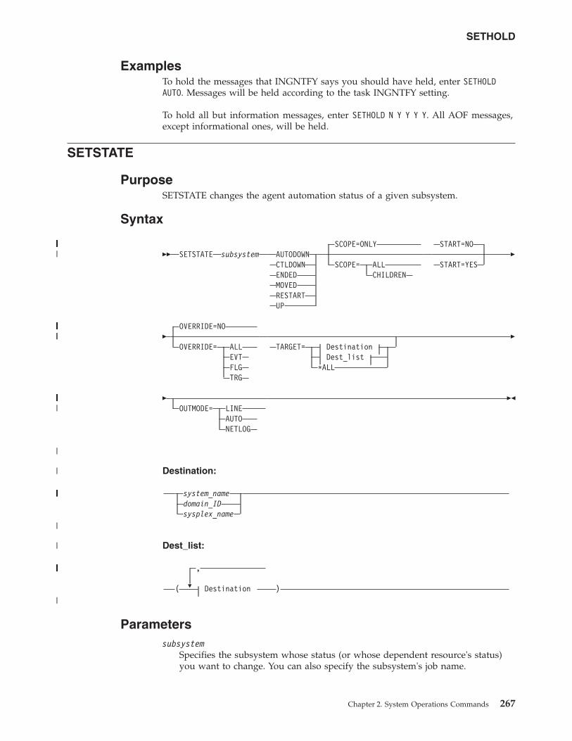
ExamplesTo hold the messages that INGNTFY says you should have held, enter SETHOLDAUTO. Messages will be held according to the task INGNTFY setting.
To hold all but information messages, enter SETHOLD N Y Y Y Y. All AOF messages,except informational ones, will be held.
SETSTATE
PurposeSETSTATE changes the agent automation status of a given subsystem.
Syntax
�� SETSTATE subsystem AUTODOWNCTLDOWNENDEDMOVEDRESTARTUP
SCOPE=ONLY
SCOPE= ALLCHILDREN
START=NO
START=YES�
�OVERRIDE=NO
OVERRIDE= ALLEVTFLGTRG
TARGET= DestinationDest_list
*ALL
�
�OUTMODE= LINE
AUTONETLOG
��
Destination:
system_namedomain_IDsysplex_name
Dest_list:
�
,
( Destination )
Parameterssubsystem
Specifies the subsystem whose status (or whose dependent resource's status)you want to change. You can also specify the subsystem's job name.
SETHOLD
Chapter 2. System Operations Commands 267
||||||||||||||||||||||||||||||||||||||||||||||||||||||||
||||||||||||||||||||||||||||||||||||||||||||||||
|||||||||||||||||||||||
|
|
|||||||||||||||||||
|
|
|||||||||||||||||||||
|
AUTODOWNChanges the status from CTLDOWN, STOPPED, BROKEN, MOVED orFALLBACK to AUTODOWN. It is primarily used to return the resource toautomation control after the operator has fixed the problem.
CTLDOWNChanges the status to CTLDOWN so that the subsystem cannot be started byautomation.
ENDEDChanges the status to ENDED.
MOVEDThe effect of this parameter depends on how the subsystem is defined:v If the subsystem does not have any secondary system associations, the effect
of the MOVED operand is the same as the effect of the CTLDOWN operand:the status of the subsystem is changed to CTLDOWN.
v If the subsystem does have secondary system associations:– If the command is issued on one of the subsystem's primary systems, the
subsystem's status is changed to MOVED– If the command is issued on one of the subsystem's secondary systems,
the subsystem's status is changed to FALLBACK.
RESTARTChanges the status to RESTART so that the subsystem can be restarted. Specifythis if your Initstart flag is set to No. This can only be used when:v SCOPE=ONLY or SCOPE=ALLv The application monitor status of the subsystem is INACTIVE
UP Changes the status to UP/RUNNING if the subsystem's UPMSG has beenmissed. This can only be used when:v SCOPE=ONLYv The application monitor status of the subsystem is ACTIVEv If the subsystem is enabled for automatic restart management, its automatic
restart management status must be AVAILABLE or AVAILABLE-TO.
Note: For transient subsystems, UP becomes RUNNING.
SCOPESpecifies what is affected by this command:
ONLY Changes the status of this resource only. This is the default.
ALL Changes the status of this resource and its dependent resources.
CHILDRENChanges the status of the dependent resources only.
OVERRIDESpecifies the overrides to be considered for the request. It can be one of thefollowing:
NO Specifies that no override will be done. This is the default.
ALL Sets the FLG, TRG as well as DPY and STS overrides on. For DPY andSTS see the “INGREQ” on page 197 command for more details.
EVT | TRGThe startup or shutdown trigger conditions will be ignored.
FLG The appropriate automation flags will be ignored for the resource.
SETSTATE
268 System Automation for z/OS: Operator's Commands
|||
||
STARTSpecifies whether the resource is started after the status has been updated.
NO No request is sent to the automation manager. The automation agentstatus is updated. This is the default.
YES A default start request is sent to the automation manager.
TARGETFor information on the TARGET parameter, see “TARGET Parameter” on page10.
OUTMODEFor information on the OUTMODE parameter, see “OUTMODE Parameter” onpage 12.
Restrictions and LimitationsThe SETSTATE command will not execute under the primary POI task (PPT).
The SETSTATE command can only be used when SA z/OS is initialized.
UsageUse SETSTATE to:v Resume handling an application after a manual operator shutdown or after any
other event that causes an application to get into a non-automatable status (forexample STOPPED, CTLDOWN, BROKEN, ACTIVE)
v Prevent automation from restarting an application if you specify CTLDOWN.v Alert the automation that an application that was shut down will be moved to
another system.v The SETSTATE command issues an automation manager request with a priority
of HIGH (unless overridden by the advanced automation global INGREQ_PRI).Because requests entered by the operator are persistent, it may be necessary tomanually remove the associated vote before subsequent requests are activated.
ExamplesIf you enter setstate TSO a panel similar to Figure 119 on page 270 is displayed.
SETSTATE
Chapter 2. System Operations Commands 269
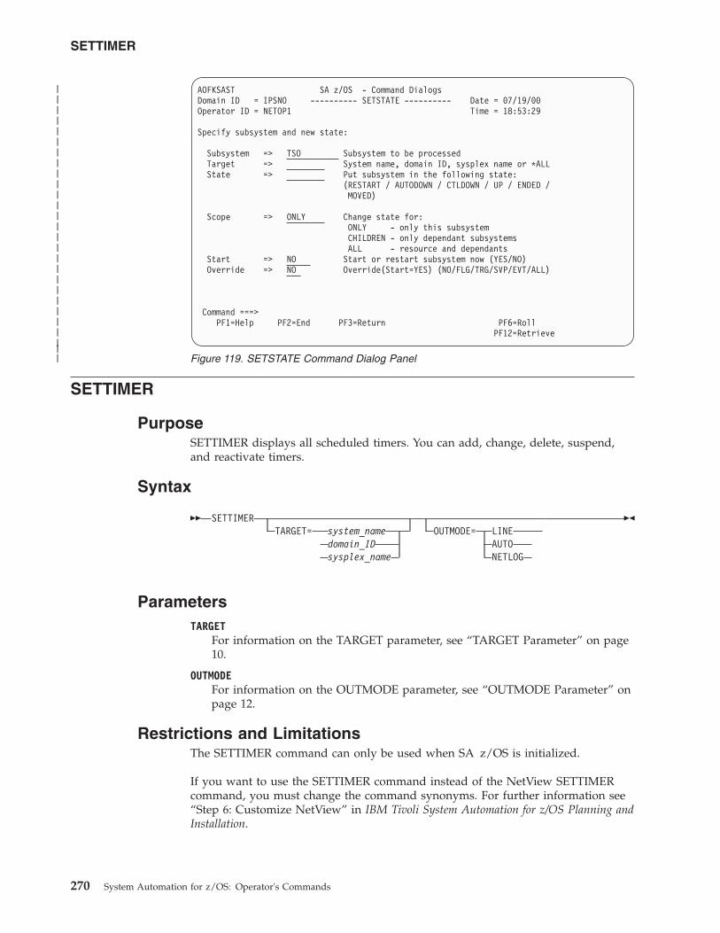
SETTIMER
PurposeSETTIMER displays all scheduled timers. You can add, change, delete, suspend,and reactivate timers.
Syntax
�� SETTIMERTARGET= system_name
domain_IDsysplex_name
OUTMODE= LINEAUTONETLOG
��
ParametersTARGET
For information on the TARGET parameter, see “TARGET Parameter” on page10.
OUTMODEFor information on the OUTMODE parameter, see “OUTMODE Parameter” onpage 12.
Restrictions and LimitationsThe SETTIMER command can only be used when SA z/OS is initialized.
If you want to use the SETTIMER command instead of the NetView SETTIMERcommand, you must change the command synonyms. For further information see“Step 6: Customize NetView” in IBM Tivoli System Automation for z/OS Planning andInstallation.
AOFKSAST SA z/OS - Command DialogsDomain ID = IPSNO ---------- SETSTATE ---------- Date = 07/19/00Operator ID = NETOP1 Time = 18:53:29
Specify subsystem and new state:
Subsystem => TSO Subsystem to be processedTarget => System name, domain ID, sysplex name or *ALLState => Put subsystem in the following state:
(RESTART / AUTODOWN / CTLDOWN / UP / ENDED /MOVED)
Scope => ONLY Change state for:ONLY - only this subsystemCHILDREN - only dependant subsystemsALL - resource and dependants
Start => NO Start or restart subsystem now (YES/NO)Override => NO Override(Start=YES) (NO/FLG/TRG/SVP/EVT/ALL)
Command ===>PF1=Help PF2=End PF3=Return PF6=Roll
PF12=Retrieve
Figure 119. SETSTATE Command Dialog Panel
SETTIMER
270 System Automation for z/OS: Operator's Commands
|||||||||||||||||||||||||||
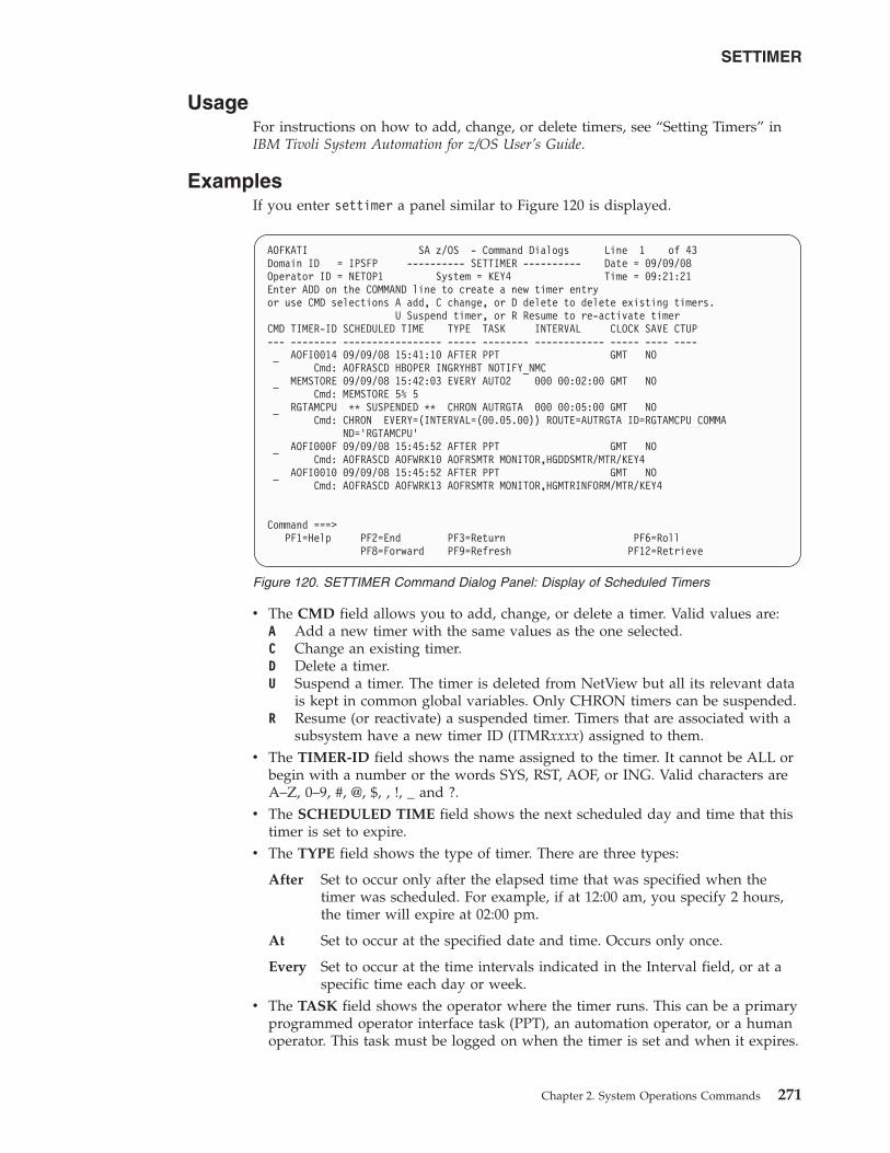
UsageFor instructions on how to add, change, or delete timers, see “Setting Timers” inIBM Tivoli System Automation for z/OS User’s Guide.
ExamplesIf you enter settimer a panel similar to Figure 120 is displayed.
v The CMD field allows you to add, change, or delete a timer. Valid values are:A Add a new timer with the same values as the one selected.C Change an existing timer.D Delete a timer.U Suspend a timer. The timer is deleted from NetView but all its relevant data
is kept in common global variables. Only CHRON timers can be suspended.R Resume (or reactivate) a suspended timer. Timers that are associated with a
subsystem have a new timer ID (ITMRxxxx) assigned to them.v The TIMER-ID field shows the name assigned to the timer. It cannot be ALL or
begin with a number or the words SYS, RST, AOF, or ING. Valid characters areA–Z, 0–9, #, @, $, , !, _ and ?.
v The SCHEDULED TIME field shows the next scheduled day and time that thistimer is set to expire.
v The TYPE field shows the type of timer. There are three types:
After Set to occur only after the elapsed time that was specified when thetimer was scheduled. For example, if at 12:00 am, you specify 2 hours,the timer will expire at 02:00 pm.
At Set to occur at the specified date and time. Occurs only once.
Every Set to occur at the time intervals indicated in the Interval field, or at aspecific time each day or week.
v The TASK field shows the operator where the timer runs. This can be a primaryprogrammed operator interface task (PPT), an automation operator, or a humanoperator. This task must be logged on when the timer is set and when it expires.
AOFKATI SA z/OS - Command Dialogs Line 1 of 43Domain ID = IPSFP ---------- SETTIMER ---------- Date = 09/09/08Operator ID = NETOP1 System = KEY4 Time = 09:21:21Enter ADD on the COMMAND line to create a new timer entryor use CMD selections A add, C change, or D delete to delete existing timers.
U Suspend timer, or R Resume to re-activate timerCMD TIMER-ID SCHEDULED TIME TYPE TASK INTERVAL CLOCK SAVE CTUP--- -------- ----------------- ----- -------- ------------ ----- ---- ----
AOFI0014 09/09/08 15:41:10 AFTER PPT GMT NOCmd: AOFRASCD HBOPER INGRYHBT NOTIFY_NMC
MEMSTORE 09/09/08 15:42:03 EVERY AUTO2 000 00:02:00 GMT NOCmd: MEMSTORE 5% 5
RGTAMCPU ** SUSPENDED ** CHRON AUTRGTA 000 00:05:00 GMT NOCmd: CHRON EVERY=(INTERVAL=(00.05.00)) ROUTE=AUTRGTA ID=RGTAMCPU COMMA
ND=’RGTAMCPU’AOFI000F 09/09/08 15:45:52 AFTER PPT GMT NO
Cmd: AOFRASCD AOFWRK10 AOFRSMTR MONITOR,HGDDSMTR/MTR/KEY4AOFI0010 09/09/08 15:45:52 AFTER PPT GMT NO
Cmd: AOFRASCD AOFWRK13 AOFRSMTR MONITOR,HGMTRINFORM/MTR/KEY4
Command ===>PF1=Help PF2=End PF3=Return PF6=Roll
PF8=Forward PF9=Refresh PF12=Retrieve
Figure 120. SETTIMER Command Dialog Panel: Display of Scheduled Timers
SETTIMER
Chapter 2. System Operations Commands 271
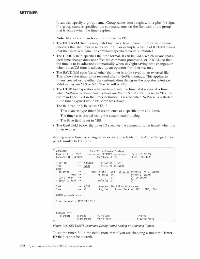
It can also specify a group name. Group names must begin with a plus (+) sign.If a group name is specified, the command runs on the first task in the groupthat is active when the timer expires.
Note: Not all commands can run under the PPT.v The INTERVAL field is only valid for Every type timers. It indicates the time
intervals that the timer is set to occur at. For example, a value of 00:30:00 meansthat the timer will issue the command specified every 30 minutes.
v The CLOCK field specifies the time format. It can be GMT, which means that alocal time change does not affect the command processing, or LOCAL, so thatthe time is to be adjusted automatically when daylight saving time changes, orwhen the z/OS time is adjusted by an operator for other reasons.
v The SAVE field specifies whether the timer is to be saved to an external file.This allows the timer to be restored after a NetView outage. This applies totimers created using either the customization dialog or the operator interface.Valid values are YES or NO. The default is YES.
v The CTUP field specifies whether to activate the timer if it occurs at a timewhen NetView is down. Valid values are Yes or No. If CTUP is set to YES, thecommand specified in the timer definition is issued when NetView is restarted,if the timer expired while NetView was down.The field can only be set to YES if:– This is an At type timer (it occurs once at a specific time and date).– The timer was created using the customization dialog.– The Save field is set to YES.
v The Cmd field below the timer ID specifies the command to be issued when thetimer expires.
Adding a new timer or changing an existing one leads to the Add/Change Timerpanel, similar to Figure 121.
To set the timer, fill in the fields (note that if you are changing a timer the TimerID field cannot be altered).
AOFKATIR SA z/OS - Command DialogsDomain ID = IPSFP ---------- SETTIMER ---------- Date = 11/27/06Operator ID = NETOP1 Add/Change Timer Time = 12:38:41
Timer ID => MEMSTORE on System : SAT1Type => EVERY AFTER, AT or EVERYWhen?- Interval => days 0-365 and 00:02:00 hh:mm:ss (AFTER EVERY)
From => hh:mm:ss To hh:mm:ss (EVERY)- Day of Week => at (AT or EVERY)- Specific date => mm/dd/yy at (AT)
Task => AUTO2 Operator ID, PPT or Group nameSave => NO No, Yes Timer clock => GMT GMT, LOCAL
CHRON parameters =>
Timer command => MEMSTORE 5% 5
Command ===>PF1=Help PF2=End PF3=Return PF6=Roll
PF8=Forward PF9=Refresh PF12=Retrieve
Figure 121. SETTIMER Command Dialog Panel: Adding or Changing Timers
SETTIMER
272 System Automation for z/OS: Operator's Commands
Use the following fields on this panel to define when the different types of timersare to expire:
Timer Type Fields
AFTER Interval: The number of days (0–365) to elapse before the timer is run.
AT Day of Week: Specify the day of the week (Monday through Sunday).Only the first three characters are required (for example, FRI forFRIDAY).
Specific date: Specify the date (in mm/dd/yy notation) and time (inhh:mm:ss notation). Hours and seconds default to zero if not entered. Ifthe time begins with an X or multiple Xs instead of a number, thecommand is set to begin at the next increment of time.
EVERY Interval: The number of days (0–365) to elapse before the timer is run.
From/To: You can also specify the date and time that the interval is tostart and to end. If omitted, the timer runs from midnight to midnight.
Day of Week: Specify the day of the week (Monday through Sunday).Only the first three characters are required (for example, FRI forFRIDAY). You can also specify DAILY for every day of the week,WEEKDAY, or WEEKEND.
Use the CHRON Parameters field to specify additional CHRON parameters, suchas REFRESH or NOTIFY. You can also specify suboptions of the EVERY parametersuch as REMOVE, REMAFTER, DAYSMON, CALENDAR, MXREPEAT, OFF, orFOR.
Enter the command that is to be run when the timer expires in the Timercommand field. The command can span the three input fields, which are protectedif the timer command does not fit in the fields. You can use the PF4 key to clearthe command fields.
SETTIMER
Chapter 2. System Operations Commands 273

SETTIMER
274 System Automation for z/OS: Operator's Commands
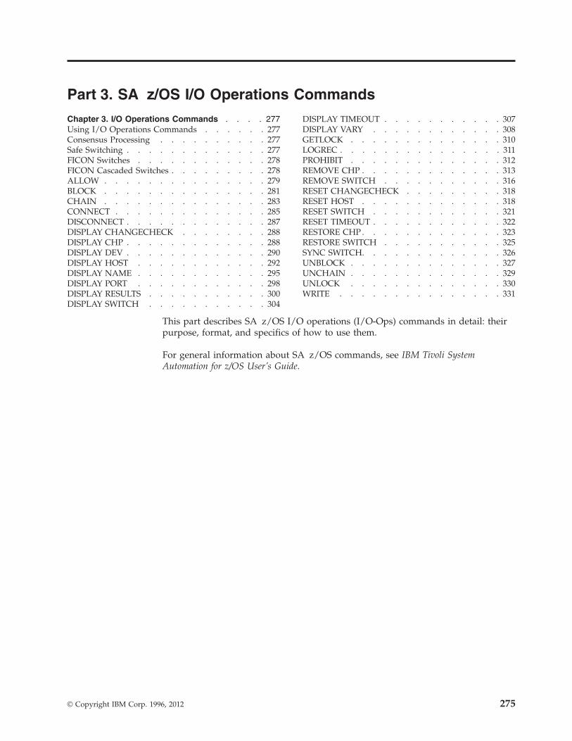
Part 3. SA z/OS I/O Operations Commands
Chapter 3. I/O Operations Commands . . . . 277Using I/O Operations Commands . . . . . . 277Consensus Processing . . . . . . . . . . 277Safe Switching . . . . . . . . . . . . . 277FICON Switches . . . . . . . . . . . . 278FICON Cascaded Switches . . . . . . . . . 278ALLOW . . . . . . . . . . . . . . . 279BLOCK . . . . . . . . . . . . . . . 281CHAIN . . . . . . . . . . . . . . . 283CONNECT . . . . . . . . . . . . . . 285DISCONNECT . . . . . . . . . . . . . 287DISPLAY CHANGECHECK . . . . . . . . 288DISPLAY CHP . . . . . . . . . . . . . 288DISPLAY DEV . . . . . . . . . . . . . 290DISPLAY HOST . . . . . . . . . . . . 292DISPLAY NAME . . . . . . . . . . . . 295DISPLAY PORT . . . . . . . . . . . . 298DISPLAY RESULTS . . . . . . . . . . . 300DISPLAY SWITCH . . . . . . . . . . . 304
DISPLAY TIMEOUT . . . . . . . . . . . 307DISPLAY VARY . . . . . . . . . . . . 308GETLOCK . . . . . . . . . . . . . . 310LOGREC . . . . . . . . . . . . . . . 311PROHIBIT . . . . . . . . . . . . . . 312REMOVE CHP . . . . . . . . . . . . . 313REMOVE SWITCH . . . . . . . . . . . 316RESET CHANGECHECK . . . . . . . . . 318RESET HOST . . . . . . . . . . . . . 318RESET SWITCH . . . . . . . . . . . . 321RESET TIMEOUT . . . . . . . . . . . . 322RESTORE CHP . . . . . . . . . . . . . 323RESTORE SWITCH . . . . . . . . . . . 325SYNC SWITCH. . . . . . . . . . . . . 326UNBLOCK . . . . . . . . . . . . . . 327UNCHAIN . . . . . . . . . . . . . . 329UNLOCK . . . . . . . . . . . . . . 330WRITE . . . . . . . . . . . . . . . 331
This part describes SA z/OS I/O operations (I/O-Ops) commands in detail: theirpurpose, format, and specifics of how to use them.
For general information about SA z/OS commands, see IBM Tivoli SystemAutomation for z/OS User’s Guide.
© Copyright IBM Corp. 1996, 2012 275

276 System Automation for z/OS: Operator's Commands
Chapter 3. I/O Operations Commands
Using I/O Operations CommandsYou can issue I/O operations commands by entering the command through:v ISPF dialogsv The operator console
Not all commands can be issued in both ways. For detailed information aboutwhere the commands can be used and about the authorization levels they require,see Appendix B, “General Considerations for I/O Operations Commands,” on page527.
Note that the LSN in all output messages will show "- -" when this value is notvalid. This can happen only to cascaded switches that have no channel attachment,which is normally the case. For this reason, it is recommended that all switches aredefined to Hardware Configuration Definition (HCD) including their devicenumbers. This allows I/O Operations to resolve the LSN also for theabove-mentioned switches.
Consensus ProcessingConsensus processing means a connectivity command is routed to all I/O operationsapplications that are affected by the command and the results are rated andaccumulated until all of them have been received or the timeout value has expiredwhichever occurs first.
Unless the command is being forced any vote against the command causes theissuing I/O operations application to fail the command. A vote against thecommand is assumed when:v a remote I/O operations application has not been excluded from consensus
processing (see “"Reset Host" command”) while the communication to it couldnot be established or is interrupted.
v the timeout value expires and a response is still missing.v an I/O operations application responds with a negative vote.
For backout processing see “Making Connectivity Changes” on page 511.
Safe SwitchingI/O-Ops varies paths online or offline when, because of port manipulation, thepath from a channel to a device either becomes valid or is no longer valid.
The term safe-switching means that all vary path offline requests due to anI/O-Ops connectivity command are backed out if one of these requests fails andBACKOUT was specified at command invocation. All requests means thoserequests on all systems that have access to the switch (or switches) that are affectedby the command.
For FICON® switches, safe-switching also includes the entire vary process forconnectivity commands that affect Inter-Switch-Link ports (E-ports). BecauseI/O-Ops does not know the topology between the entry switch and the destination
© Copyright IBM Corp. 1996, 2012 277
switch of a path, paths that go through an ISL link will not be varied when anE-port is the target of a connectivity command.
The following conditions result in the failure of a request:v A vary path offline request fails when the request would disable the last path
to a device that is currently in use.v If no VTAM connection could be established between two systems that have
access to a switch and run I/O-Ops, I/O-Ops on the local system (that is, wherethe command is entered) assumes that the command fails on the remote system.To avoid this, exclude this system from consensus processing using thecommand RESET HOST vtamname PURGE.
v For other reasons refer to “Making Connectivity Changes” on page 511.
FICON SwitchesFICON switches allow imbedded space characters on port names. Consequently,I/O-Ops will not issue message IHVD106I when detecting imbedded blanks inport names of FICON switches.
However, I/O-Ops does not support imbedded blanks on port names, either in theISPF dialogs or in the console command interface. The reason is that generic namesand port names must not contain imbedded blanks when used in I/O-Ops consolecommands.
FICON Cascaded SwitchesI/O-Ops supports cascaded switches with some restrictions:1. For CTC connections on cascaded switches, I/O-Ops can neither display CTC
control unit data nor manage CTC devices. The reason for this is that whenI/O-Ops attempts to determine the attached NDs of such a device, it can getstuck behind a never-ending channel program on the device.
2. The Block command is not supported on Inter-Switch-Link ports (E_Ports).When an E_Port is affected by the command, it is rejected with return code 8and reason code X'49'. In addition, the message IHVC913I is issued, showingthe first or only port that is affected by the command.
3. All other I/O-Ops commands affecting E_Ports (Allow, Prohibit, Unblock, andWRITEPORT) must specify the command option IGNore when an E_Port isinvolved. Otherwise the command is rejected with return code 8 and reasoncode X'49'. In addition, the message IHVC913I is issued, showing the first oronly port that is affected by the command.The IGNore option makes the issuer of the command aware that safe-switchingcan no longer be guaranteed.
4. If an attached Node Descriptor of a device cannot be determined because thepath or channel is offline, the Display Device command does not show anycontrol unit data for the particular channel path id.
5. A dynamic configuration change that results in the allocation or dealloction of acascaded switch is currently not supported.
Note: It is recommended that all switches are defined to the HardwareConfiguration Definition (HCD) including their device numbers. This allowsI/O-Ops to also show the LSN for cascaded switches.
278 System Automation for z/OS: Operator's Commands
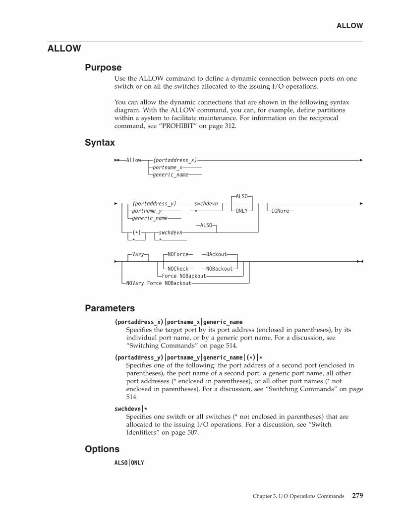
ALLOW
PurposeUse the ALLOW command to define a dynamic connection between ports on oneswitch or on all the switches allocated to the issuing I/O operations.
You can allow the dynamic connections that are shown in the following syntaxdiagram. With the ALLOW command, you can, for example, define partitionswithin a system to facilitate maintenance. For information on the reciprocalcommand, see “PROHIBIT” on page 312.
Syntax
�� Allow (portaddress_x)portname_xgeneric_name
�
�ALSO
(portaddress_y) swchdevnportname_y * ONLYgeneric_name
ALSO(*) swchdevn* *
IGNore�
�Vary NOForce BAckout
NOCheck NOBackoutForce NOBackout
NOVary Force NOBackout
��
Parameters(portaddress_x)|portname_x|generic_name
Specifies the target port by its port address (enclosed in parentheses), by itsindividual port name, or by a generic port name. For a discussion, see“Switching Commands” on page 514.
(portaddress_y)|portname_y|generic_name|(*)|*Specifies one of the following: the port address of a second port (enclosed inparentheses), the port name of a second port, a generic port name, all otherport addresses (* enclosed in parentheses), or all other port names (* notenclosed in parentheses). For a discussion, see “Switching Commands” on page514.
swchdevn|*Specifies one switch or all switches (* not enclosed in parentheses) that areallocated to the issuing I/O operations. For a discussion, see “SwitchIdentifiers” on page 507.
OptionsALSO|ONLY
ALLOW
Chapter 3. I/O Operations Commands 279
ALSO (default) specifies that the ports affected by the command will connectdynamically to each other, regardless of whether they connect dynamically toother ports on the same switch.
ONLY specifies that the ports affected by the command will connectdynamically to each other, but each port is disallowed a dynamic connection toany other port on the switch.
IGNoreYou must specify this option when an Inter-Switch-Link port (E_Port) isinvolved. Otherwise the command is rejected with return code 8 and reasoncode X'49'. The reason is I/O operations can no longer guarantee"safe-switching" when an E_Port is involved.
Connectivity options
For a discussion on Vary|NOVary, NOForce|NOCheck|Force, andBAckout|NOBAckout see “Making Connectivity Changes” on page 511.
For a discussion of why it sometimes isn't obvious that the status of a path ora device has changed after an operator has issued a connectivity command, see“Device and Path Status After Connectivity Commands” on page 530.
Usagev If you specify an individual or generic port name, all the switches involved must
have at least 1 port implemented with an applicable port name.v If you specify the same port in both operands and do not specify a generic
name, the command will fail because I/O operations will not allow that port tohave a dynamic connection with itself.
v If you specify 1 or 2 generic names and at least 1 port in each operand is uniqueand valid, the command will succeed. I/O operations will allow the validdynamic connections and disallow a port to connect to itself.
v Although you cannot use the ONLY option and specify either all port addresses(*) or all port names *, you can specify a generic port name. Assume, forexample, that all the ports on switch 100 are named and the names start with F:FC1, FC2, FC3, and so on. Although you cannot specify A * * 100, you canspecify A F* F* 100.
v When you specify the ONLY option, all paths to the specified ports are variedoffline. The dynamic path between the two ports is varied online.
v If a parallel channel and CV converter are involved, you should consider theinformation provided in “A Parallel Channel in Block (BL) Mode” on page 523.
ExamplesIn the following example, port FB is allowed to have a dynamic connection onlywith port D6 on switch 100. The dynamic connections that port FB had with otherports are now prohibited.
A (FB) (D6) 100 ONLYIHVC000I ALLOW command successful
ALLOW
280 System Automation for z/OS: Operator's Commands
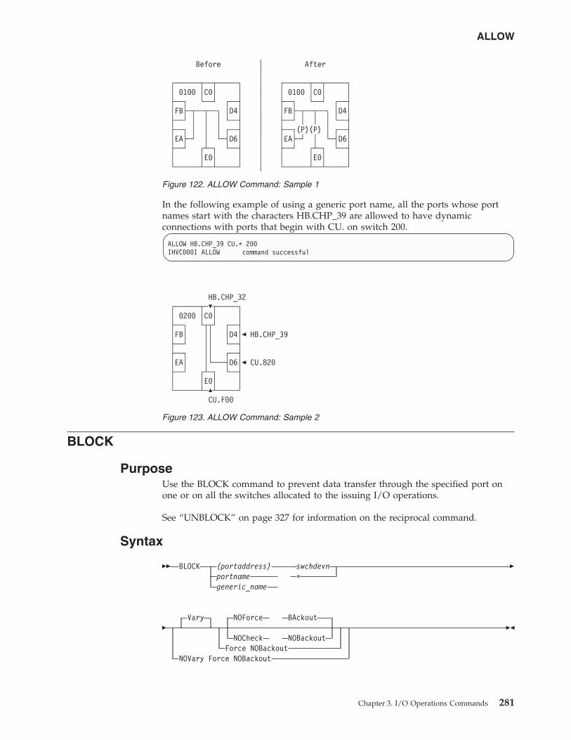
In the following example of using a generic port name, all the ports whose portnames start with the characters HB.CHP_39 are allowed to have dynamicconnections with ports that begin with CU. on switch 200.
ALLOW HB.CHP_39 CU.* 200IHVC000I ALLOW command successful
BLOCK
PurposeUse the BLOCK command to prevent data transfer through the specified port onone or on all the switches allocated to the issuing I/O operations.
See “UNBLOCK” on page 327 for information on the reciprocal command.
Syntax
�� BLOCK (portaddress)portnamegeneric_name
swchdevn*
�
�Vary NOForce BAckout
NOCheck NOBackoutForce NOBackout
NOVary Force NOBackout
��
Before │ After│
┌──────┬──┬─────┐ │ ┌──────┬──┬─────┐│ 0100 │C0│ │ │ │ 0100 │C0│ │├──┐ └──┘ ┌──┤ │ ├──┐ └──┘ ┌──┤│FB├─┬──┬──┐ │D4│ │ │FB├─┬──┬──┐ │D4│├──┘ │ │ │ └──┤ │ ├──┘ │ │ │ └──┤├──┐ │ │ │ ┌──┤ │ ├──┐(P)(P) │ ┌──┤│EA├─┘ │ └─┤D6│ │ │EA├─┘ │ └─┤D6│├──┘ ┌┴─┐ └──┤ │ ├──┘ ┌┴─┐ └──┤│ │E0│ │ │ │ │E0│ │└──────┴──┴─────┘ │ └──────┴──┴─────┘
Figure 122. ALLOW Command: Sample 1
HB.CHP_32┌──────┬─�┬─────┐│ 0200 │C0│ │├──┐ └┬┬┘ ┌──┤│FB│ ││ │D4│� HB.CHP_39├──┘ ││ └──┤├──┐ ││ ┌──┤│EA│ │└───┤D6│� CU.820├──┘ ┌┴─┐ └──┤│ │E0│ │└──────┴─�┴─────┘
CU.F00
Figure 123. ALLOW Command: Sample 2
ALLOW
Chapter 3. I/O Operations Commands 281
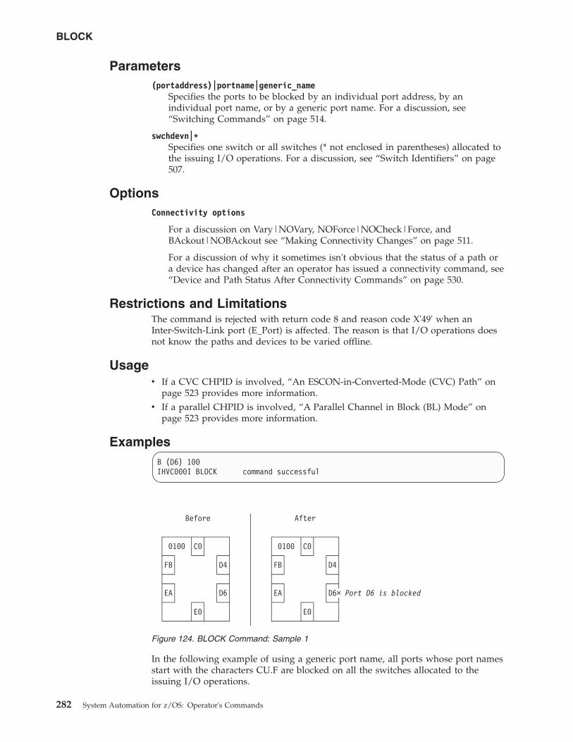
Parameters(portaddress)|portname|generic_name
Specifies the ports to be blocked by an individual port address, by anindividual port name, or by a generic port name. For a discussion, see“Switching Commands” on page 514.
swchdevn|*Specifies one switch or all switches (* not enclosed in parentheses) allocated tothe issuing I/O operations. For a discussion, see “Switch Identifiers” on page507.
OptionsConnectivity options
For a discussion on Vary|NOVary, NOForce|NOCheck|Force, andBAckout|NOBAckout see “Making Connectivity Changes” on page 511.
For a discussion of why it sometimes isn't obvious that the status of a path ora device has changed after an operator has issued a connectivity command, see“Device and Path Status After Connectivity Commands” on page 530.
Restrictions and LimitationsThe command is rejected with return code 8 and reason code X'49' when anInter-Switch-Link port (E_Port) is affected. The reason is that I/O operations doesnot know the paths and devices to be varied offline.
Usagev If a CVC CHPID is involved, “An ESCON-in-Converted-Mode (CVC) Path” on
page 523 provides more information.v If a parallel CHPID is involved, “A Parallel Channel in Block (BL) Mode” on
page 523 provides more information.
ExamplesB (D6) 100IHVC000I BLOCK command successful
In the following example of using a generic port name, all ports whose port namesstart with the characters CU.F are blocked on all the switches allocated to theissuing I/O operations.
Before │ After│
┌──────┬──┬─────┐ │ ┌──────┬──┬─────┐│ 0100 │C0│ │ │ │ 0100 │C0│ │├──┐ └──┘ ┌──┤ │ ├──┐ └──┘ ┌──┤│FB│ │D4│ │ │FB│ │D4│├──┘ └──┤ │ ├──┘ └──┤├──┐ ┌──┤ │ ├──┐ ┌──┤│EA│ │D6│ │ │EA│ │D6× Port D6 is blocked├──┘ ┌──┐ └──┤ │ ├──┘ ┌──┐ └──┤│ │E0│ │ │ │ │E0│ │└──────┴──┴─────┘ │ └──────┴──┴─────┘
Figure 124. BLOCK Command: Sample 1
BLOCK
282 System Automation for z/OS: Operator's Commands
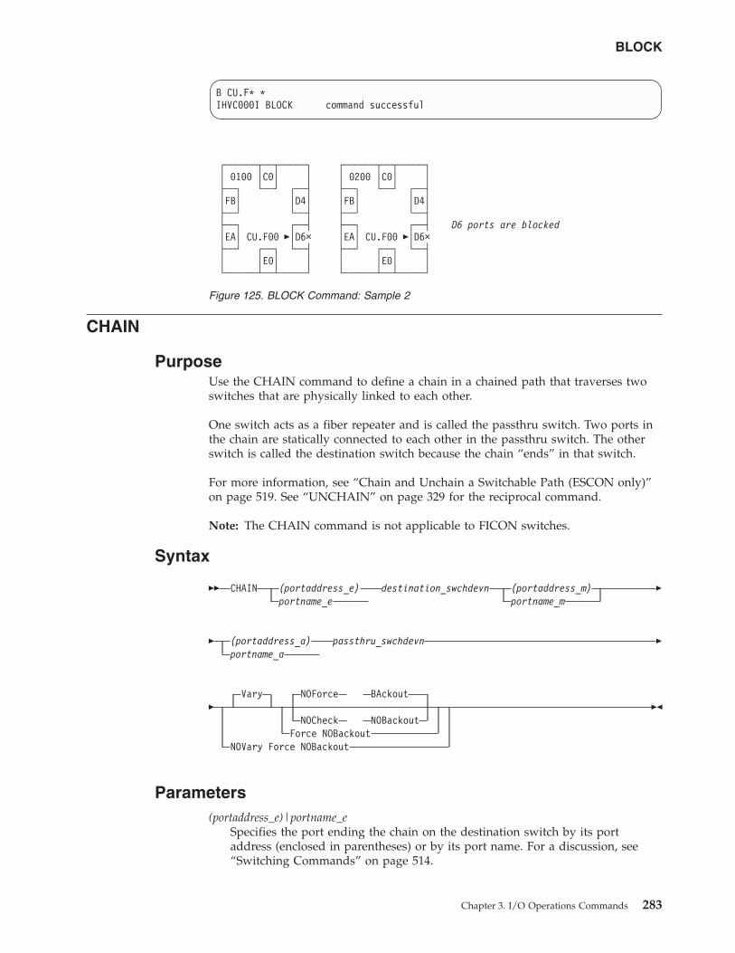
B CU.F* *IHVC000I BLOCK command successful
CHAIN
PurposeUse the CHAIN command to define a chain in a chained path that traverses twoswitches that are physically linked to each other.
One switch acts as a fiber repeater and is called the passthru switch. Two ports inthe chain are statically connected to each other in the passthru switch. The otherswitch is called the destination switch because the chain “ends” in that switch.
For more information, see “Chain and Unchain a Switchable Path (ESCON only)”on page 519. See “UNCHAIN” on page 329 for the reciprocal command.
Note: The CHAIN command is not applicable to FICON switches.
Syntax
�� CHAIN (portaddress_e)portname_e
destination_swchdevn (portaddress_m)portname_m
�
� (portaddress_a)portname_a
passthru_swchdevn �
�Vary NOForce BAckout
NOCheck NOBackoutForce NOBackout
NOVary Force NOBackout
��
Parameters(portaddress_e)|portname_e
Specifies the port ending the chain on the destination switch by its portaddress (enclosed in parentheses) or by its port name. For a discussion, see“Switching Commands” on page 514.
┌──────┬──┬─────┐ ┌──────┬──┬─────┐│ 0100 │C0│ │ │ 0200 │C0│ │├──┐ └──┘ ┌──┤ ├──┐ └──┘ ┌──┤│FB│ │D4│ │FB│ │D4│├──┘ └──┤ ├──┘ └──┤├──┐ ┌──┤ ├──┐ ┌──┤ D6 ports are blocked│EA│ CU.F00 �│D6× │EA│ CU.F00 �│D6×├──┘ ┌──┐ └──┤ ├──┘ ┌──┐ └──┤│ │E0│ │ │ │E0│ │└──────┴──┴─────┘ └──────┴──┴─────┘
Figure 125. BLOCK Command: Sample 2
BLOCK
Chapter 3. I/O Operations Commands 283
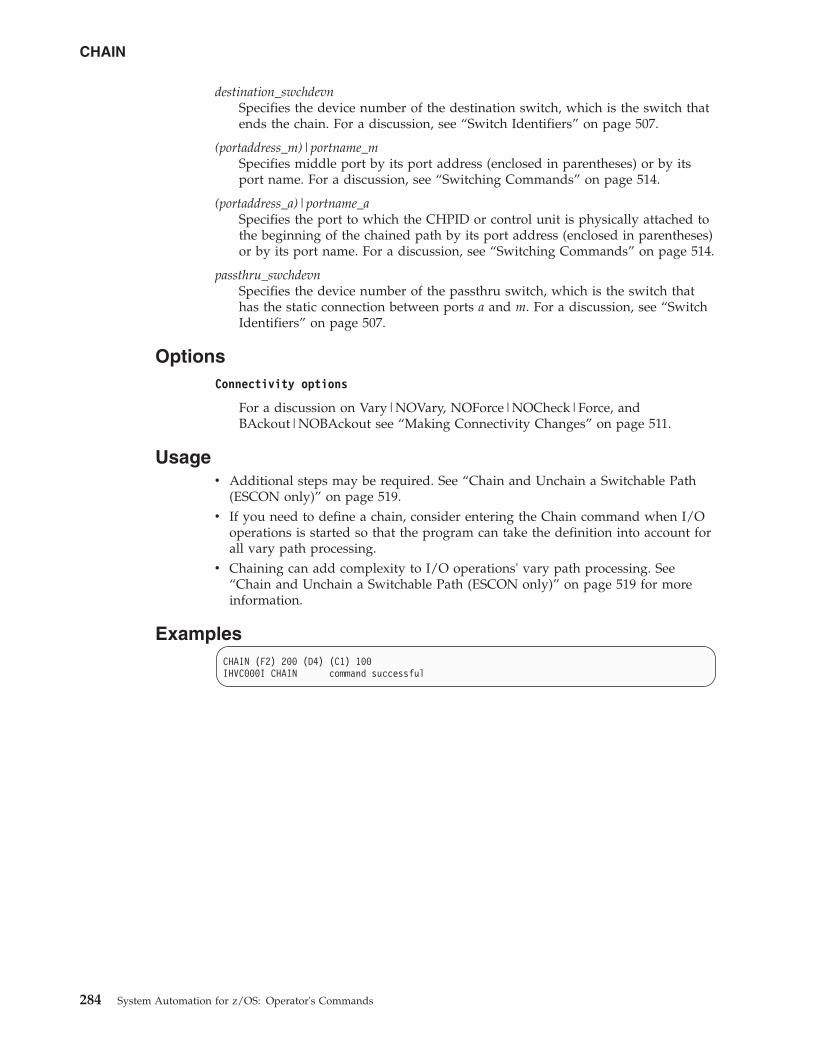
destination_swchdevnSpecifies the device number of the destination switch, which is the switch thatends the chain. For a discussion, see “Switch Identifiers” on page 507.
(portaddress_m)|portname_mSpecifies middle port by its port address (enclosed in parentheses) or by itsport name. For a discussion, see “Switching Commands” on page 514.
(portaddress_a)|portname_aSpecifies the port to which the CHPID or control unit is physically attached tothe beginning of the chained path by its port address (enclosed in parentheses)or by its port name. For a discussion, see “Switching Commands” on page 514.
passthru_swchdevnSpecifies the device number of the passthru switch, which is the switch thathas the static connection between ports a and m. For a discussion, see “SwitchIdentifiers” on page 507.
OptionsConnectivity options
For a discussion on Vary|NOVary, NOForce|NOCheck|Force, andBAckout|NOBAckout see “Making Connectivity Changes” on page 511.
Usagev Additional steps may be required. See “Chain and Unchain a Switchable Path
(ESCON only)” on page 519.v If you need to define a chain, consider entering the Chain command when I/O
operations is started so that the program can take the definition into account forall vary path processing.
v Chaining can add complexity to I/O operations' vary path processing. See“Chain and Unchain a Switchable Path (ESCON only)” on page 519 for moreinformation.
ExamplesCHAIN (F2) 200 (D4) (C1) 100IHVC000I CHAIN command successful
CHAIN
284 System Automation for z/OS: Operator's Commands
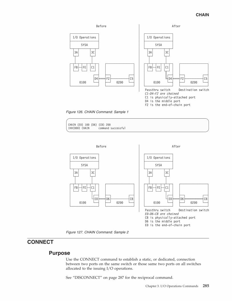
CHAIN (E0) 100 (D6) (CB) 200IHVC000I CHAIN command successful
CONNECT
PurposeUse the CONNECT command to establish a static, or dedicated, connectionbetween two ports on the same switch or those same two ports on all switchesallocated to the issuing I/O operations.
See “DISCONNECT” on page 287 for the reciprocal command.
Before │ After│
┌────────────────┐ │ ┌────────────────┐│ I/O Operations │ │ │ I/O Operations │├────────────────┤ │ ├────────────────┤│ SYSA │ │ │ SYSA │└─┬──┬──────┬──┬─┘ │ └─┬──┬──────┬──┬─┘
│3A│ │3C│ │ │3A│ │3C│└┬─┘ └┬─┘ │ └┬─┘ └┬─┘│ │ │ │ │
┌─┬┴─┬─┬──┬─┬┴─┬─┐ ┌────────────────┐ │ ┌─┬┴─┬─┬──┬─┬┴─┬─┐ ┌────────────────┐│ │FB├─┤FE│ │C1│ │ │ │ │ │ │FB├─┤FE│ │C1│ │ │ ││ └──┘ └──┘ └──┘ │ │ │ │ │ └──┘ └──┘ └╥─┘ │ │ ││ ┌──┤ ├──┐ ┌──┤ │ │ ║┌──┤ ├──┐ ┌──┤│ │D4╞═══╡F2├──────────┤C5│ │ │ ╚╡D4╞═══╡F2├──────────┤C5││ 0100 └──┤ ├──┘ 0200 └──┤ │ │ 0100 └──┤ ├──┘ 0200 └──┤└────────────────┘ └────────────────┘ │ └────────────────┘ └────────────────┘
│ Passthru switch Destination switchC1-D4-F2 are chainedC1 is physically-attached portD4 is the middle portF2 is the end-of-chain port
Figure 126. CHAIN Command: Sample 1
Before │ After│
┌────────────────┐ │ ┌────────────────┐│ I/O Operations │ │ │ I/O Operations │├────────────────┤ │ ├────────────────┤│ SYSA │ │ │ SYSA │└─┬──┬──────┬──┬─┘ │ └─┬──┬──────┬──┬─┘
│3A│ │3C│ │ │3A│ │3C│└┬─┘ └┬─┘ │ └┬─┘ └┬─┘│ │ │ │ │
┌─┬┴─┬─┬──┬─┬┴─┬─┐ ┌────────────────┐ │ ┌─┬┴─┬─┬──┬─┬┴─┬─┐ ┌────────────────┐│ │FB├─┤FE├─┤C1│ │ │ │ │ │ │FB├─┤FE├─┤C1│ │ │ ││ └──┘ └──┘ └┬─┘ │ │ │ │ │ └──┘ └──┘ └┬─┘ │ │ ││ │┌──┤ ├──┐ ┌──┤ │ │ │┌──┤ ├──┐ ┌──┤│ └┤E0╞═══╡D6├──────────┤CB│ │ │ └┤E0╞═══╡D6╞══════════╡CB││ 0100 └──┤ ├──┘ 0200 └──┤ │ │ 0100 └──┤ ├──┘ 0200 └──┤└────────────────┘ └────────────────┘ │ └────────────────┘ └────────────────┘
│ Passthru switch Destination switchE0-D6-CB are chainedCB is physically-attached portD6 is the middle portE0 is the end-of-chain port
Figure 127. CHAIN Command: Sample 2
CHAIN
Chapter 3. I/O Operations Commands 285
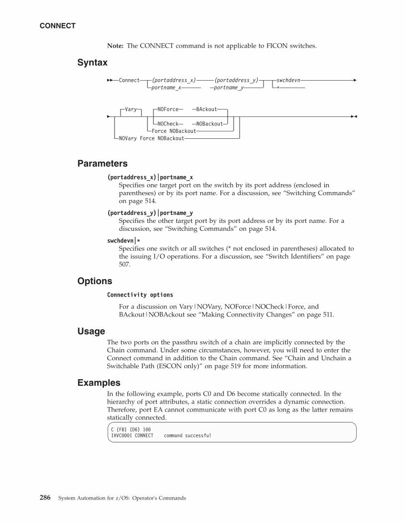
Note: The CONNECT command is not applicable to FICON switches.
Syntax
�� Connect (portaddress_x)portname_x
(portaddress_y)portname_y
swchdevn*
�
�Vary NOForce BAckout
NOCheck NOBackoutForce NOBackout
NOVary Force NOBackout
��
Parameters(portaddress_x)|portname_x
Specifies one target port on the switch by its port address (enclosed inparentheses) or by its port name. For a discussion, see “Switching Commands”on page 514.
(portaddress_y)|portname_ySpecifies the other target port by its port address or by its port name. For adiscussion, see “Switching Commands” on page 514.
swchdevn|*Specifies one switch or all switches (* not enclosed in parentheses) allocated tothe issuing I/O operations. For a discussion, see “Switch Identifiers” on page507.
OptionsConnectivity options
For a discussion on Vary|NOVary, NOForce|NOCheck|Force, andBAckout|NOBAckout see “Making Connectivity Changes” on page 511.
UsageThe two ports on the passthru switch of a chain are implicitly connected by theChain command. Under some circumstances, however, you will need to enter theConnect command in addition to the Chain command. See “Chain and Unchain aSwitchable Path (ESCON only)” on page 519 for more information.
ExamplesIn the following example, ports C0 and D6 become statically connected. In thehierarchy of port attributes, a static connection overrides a dynamic connection.Therefore, port EA cannot communicate with port C0 as long as the latter remainsstatically connected.
C (FB) (D6) 100IHVC000I CONNECT command successful
CONNECT
286 System Automation for z/OS: Operator's Commands
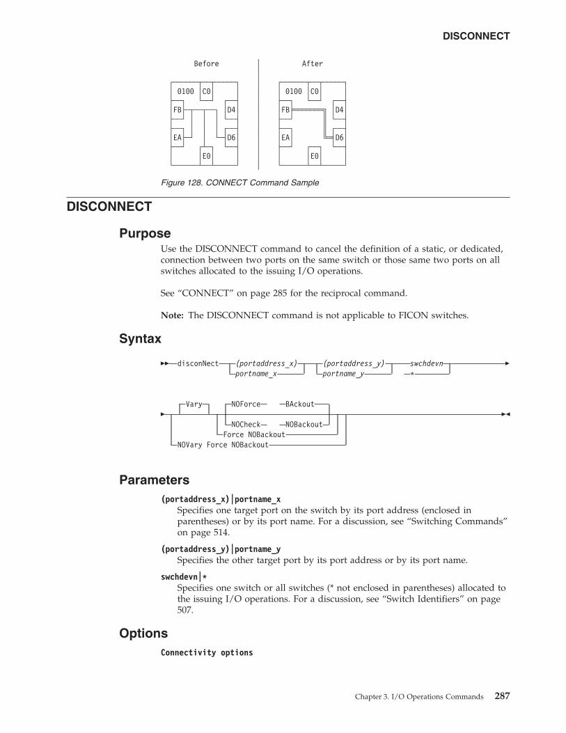
DISCONNECT
PurposeUse the DISCONNECT command to cancel the definition of a static, or dedicated,connection between two ports on the same switch or those same two ports on allswitches allocated to the issuing I/O operations.
See “CONNECT” on page 285 for the reciprocal command.
Note: The DISCONNECT command is not applicable to FICON switches.
Syntax
�� disconNect (portaddress_x)portname_x
(portaddress_y)portname_y
swchdevn*
�
�Vary NOForce BAckout
NOCheck NOBackoutForce NOBackout
NOVary Force NOBackout
��
Parameters(portaddress_x)|portname_x
Specifies one target port on the switch by its port address (enclosed inparentheses) or by its port name. For a discussion, see “Switching Commands”on page 514.
(portaddress_y)|portname_ySpecifies the other target port by its port address or by its port name.
swchdevn|*Specifies one switch or all switches (* not enclosed in parentheses) allocated tothe issuing I/O operations. For a discussion, see “Switch Identifiers” on page507.
OptionsConnectivity options
Before │ After│
┌──────┬──┬─────┐ │ ┌──────┬──┬─────┐│ 0100 │C0│ │ │ │ 0100 │C0│ │├──┐ └──┘ ┌──┤ │ ├──┐ └──┘ ┌──┤│FB├─┬──┬──┐ │D4│ │ │FB╞═══════╗ │D4│├──┘ │ │ │ └──┤ │ ├──┘ ║ └──┤├──┐ │ │ │ ┌──┤ │ ├──┐ ║ ┌──┤│EA├─┘ │ └─┤D6│ │ │EA│ ╚═╡D6│├──┘ ┌┴─┐ └──┤ │ ├──┘ ┌──┐ └──┤│ │E0│ │ │ │ │E0│ │└──────┴──┴─────┘ │ └──────┴──┴─────┘
Figure 128. CONNECT Command Sample
DISCONNECT
Chapter 3. I/O Operations Commands 287
For a discussion on Vary|NOVary, NOForce|NOCheck|Force, andBAckout|NOBAckout see “Making Connectivity Changes” on page 511.
UsageIf a CVC CHPID is involved, “An ESCON-in-Converted-Mode (CVC) Path” onpage 523 provides more information.
ExamplesN (FB) (D6) 100IHVC000I DISCONNECT command successful
DISPLAY CHANGECHECK
PurposeUse the DISPLAY CHANGECHECK command to display the current setting of theoption which indicates whether all opened switches (ON) are checked for a datachange prior to a connectivity command or only those (OFF) that are actuallyaffected by a connectivity command. The default setting on the startup of I/OOperations is ON.
Syntax
DISPLAY CHANGECHECK
�� Display ChangeCheck ��
ExamplesD CCIHVC861I Option CHANGECHECK is set to ON.
DISPLAY CHP
PurposeUse the DISPLAY CHP command to display data about one or all of the channelpath identifiers (CHPIDs) online to the operating system (host) image that theissuing I/O operations is running on.
Syntax
�� Display Chp chpid*
��
Parameterschpid
Specifies a single channel path identifier (CHPID).
* All CHPIDs that are known to the issuing I/O operations.
DISCONNECT
288 System Automation for z/OS: Operator's Commands
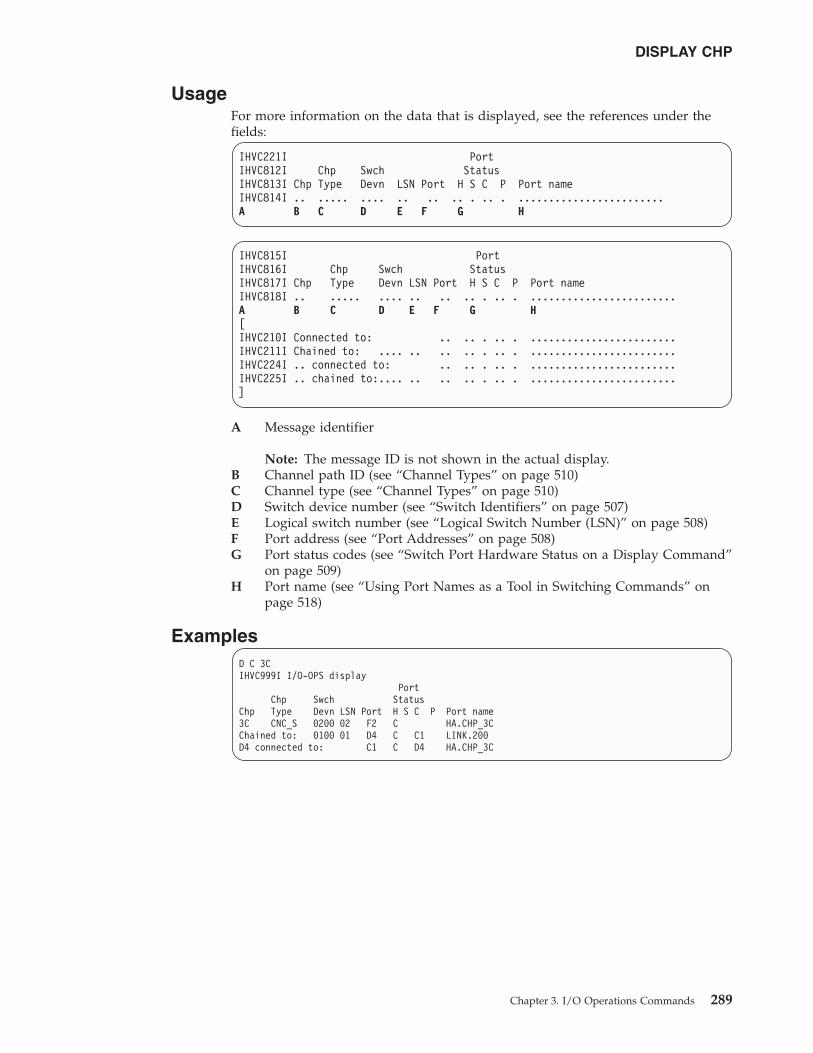
UsageFor more information on the data that is displayed, see the references under thefields:
IHVC221I PortIHVC812I Chp Swch StatusIHVC813I Chp Type Devn LSN Port H S C P Port nameIHVC814I .. ..... .... .. .. .. . .. . ........................A B C D E F G H
IHVC815I PortIHVC816I Chp Swch StatusIHVC817I Chp Type Devn LSN Port H S C P Port nameIHVC818I .. ..... .... .. .. .. . .. . ........................A B C D E F G H[IHVC210I Connected to: .. .. . .. . ........................IHVC211I Chained to: .... .. .. .. . .. . ........................IHVC224I .. connected to: .. .. . .. . ........................IHVC225I .. chained to:.... .. .. .. . .. . ........................]
A Message identifier
Note: The message ID is not shown in the actual display.B Channel path ID (see “Channel Types” on page 510)C Channel type (see “Channel Types” on page 510)D Switch device number (see “Switch Identifiers” on page 507)E Logical switch number (see “Logical Switch Number (LSN)” on page 508)F Port address (see “Port Addresses” on page 508)G Port status codes (see “Switch Port Hardware Status on a Display Command”
on page 509)H Port name (see “Using Port Names as a Tool in Switching Commands” on
page 518)
ExamplesD C 3CIHVC999I I/O-OPS display
PortChp Swch Status
Chp Type Devn LSN Port H S C P Port name3C CNC_S 0200 02 F2 C HA.CHP_3CChained to: 0100 01 D4 C C1 LINK.200D4 connected to: C1 C D4 HA.CHP_3C
DISPLAY CHP
Chapter 3. I/O Operations Commands 289
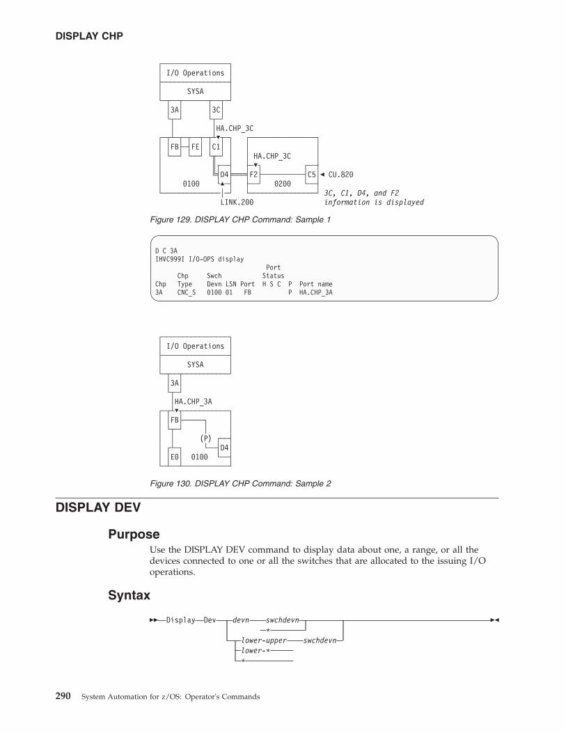
D C 3AIHVC999I I/O-OPS display
PortChp Swch Status
Chp Type Devn LSN Port H S C P Port name3A CNC_S 0100 01 FB P HA.CHP_3A
DISPLAY DEV
PurposeUse the DISPLAY DEV command to display data about one, a range, or all thedevices connected to one or all the switches that are allocated to the issuing I/Ooperations.
Syntax
�� Display Dev devn swchdevn*
lower-upper swchdevnlower-**
��
┌────────────────┐│ I/O Operations │├────────────────┤│ SYSA │└─┬──┬──────┬──┬─┘
│3A│ │3C│└┬─┘ └┬─┘│ │HA.CHP_3C
┌─┬┴─┬─┬──┬─┬┴�┬─┐ ┌────────────────┐│ │FB├─┤FE│ │C1│ │ │ ││ └──┘ └──┘ └╥─┘ │ │ HA.CHP_3C ││ ║┌──┤ ├─�┐ ┌──┤│ ╚╡D4╞═══╡F2├──────────┤C5│� CU.820│ 0100 └�─┤ ├──┘ 0200 └──┤└──────────────│─┘ └────────────────┘ 3C, C1, D4, and F2
LINK.200 information is displayed
Figure 129. DISPLAY CHP Command: Sample 1
┌────────────────┐│ I/O Operations │├────────────────┤│ SYSA │└─┬──┬───────────┘
│3A│└┬─┘│HA.CHP_3A
┌─┬┴�┬───────────┐│ │FB├─────┐ ││ └┬─┘ │ ││ │ (P) ┌──┤│ ┌┴─┐ └──┤D4││ │E0│ 0100 └──┤└─┴──┴───────────┘
Figure 130. DISPLAY CHP Command: Sample 2
DISPLAY CHP
290 System Automation for z/OS: Operator's Commands
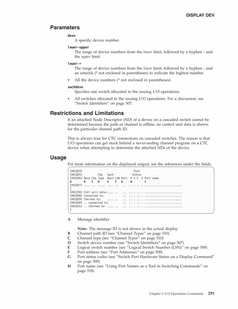
Parametersdevn
A specific device number.
lower-upperThe range of device numbers from the lower limit, followed by a hyphen - andthe upper limit.
lower-*The range of device numbers from the lower limit, followed by a hyphen - andan asterisk (* not enclosed in parentheses) to indicate the highest number.
* All the device numbers (* not enclosed in parentheses).
swchdevnSpecifies one switch allocated to the issuing I/O operations.
* All switches allocated to the issuing I/O operations. For a discussion, see“Switch Identifiers” on page 507.
Restrictions and LimitationsIf an attached Node Descriptor (ND) of a device on a cascaded switch cannot bedetermined because the path or channel is offline, no control unit data is shownfor the particular channel path ID.
This is always true for CTC connections on cascaded switches. The reason is thatI/O operations can get stuck behind a never-ending channel program on a CTCdevice when attempting to determine the attached NDs of the device.
UsageFor more information on the displayed output, see the references under the fields.
IHVC824I PortIHVC825I Chp Swch StatusIHVC826I Devn Chp Type Devn LSN Port H S C P Port nameA B C D E F G H IIHVC827I .... .. ..... .... .. .. .. . .. . ........................[IHVC220I Cntl unit data:.... .. .. .. . .. . ........................IHVC828I Connected to: .. .. . .. . ........................IHVC829I Chained to: .... .. .. .. . .. . ........................IHVC830I .. connected to: .. .. . .. . ........................IHVC831I .. chained to: .... .. .. .. . .. . ........................]
A Message identifier
Note: The message ID is not shown in the actual display.B Channel path ID (see “Channel Types” on page 510)C Channel type (see “Channel Types” on page 510)D Switch device number (see “Switch Identifiers” on page 507)E Logical switch number (see “Logical Switch Number (LSN)” on page 508)F Port address (see “Port Addresses” on page 508)G Port status codes (see “Switch Port Hardware Status on a Display Command”
on page 509)H Port name (see “Using Port Names as a Tool in Switching Commands” on
page 518)
DISPLAY DEV
Chapter 3. I/O Operations Commands 291
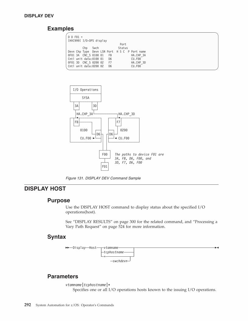
ExamplesD D F01 *IHVC999I I/O-OPS display
PortChp Swch Status
Devn Chp Type Devn LSN Port H S C P Port name0F01 3A CNC_S 0100 01 FB HA.CHP_3ACntl unit data:0100 01 D6 CU.F000F01 3D CNC_S 0200 02 F7 HA.CHP_3DCntl unit data:0200 02 D6 CU.F00
DISPLAY HOST
PurposeUse the DISPLAY HOST command to display status about the specified I/Ooperations(host).
See “DISPLAY RESULTS” on page 300 for the related command, and “Processing aVary Path Request” on page 524 for more information.
Syntax
�� Display Host vtamnametcphostname*
swchdevn
��
Parametersvtamname|tcphostname|*
Specifies one or all I/O operations hosts known to the issuing I/O operations.
┌────────────────┐│ I/O Operations │├────────────────┤│ SYSA │└─┬──┬──────┬──┬─┘
│3A│ │3D│└┬─┘ └┬─┘│HA.CHP_3A└────────────┐HA.CHP_3D
┌─┬┴�┬───────────┐ ┌───┬┴�┬─────────┐│ │FB├──────┐ │ │ │F7│ ││ └──┘ │ │ │ └┬─┘ ││ 0100 │ ┌──┤ ├──┐ │ 0200 ││ └─┤D6├┐ ┌┤D6├─┘ ││ CU.F00 �└──┤│ │├──┘� CU.F00 │└────────────────┘│ │└────────────────┘
│ │┌─┴─┴─┐│ F00 │ The paths to device F01 are└──┬──┘ 3A, FB, D6, F00, and┌─┴─┐ 3D, F7, D6, F00│F01│└───┘
Figure 131. DISPLAY DEV Command Sample
DISPLAY DEV
292 System Automation for z/OS: Operator's Commands
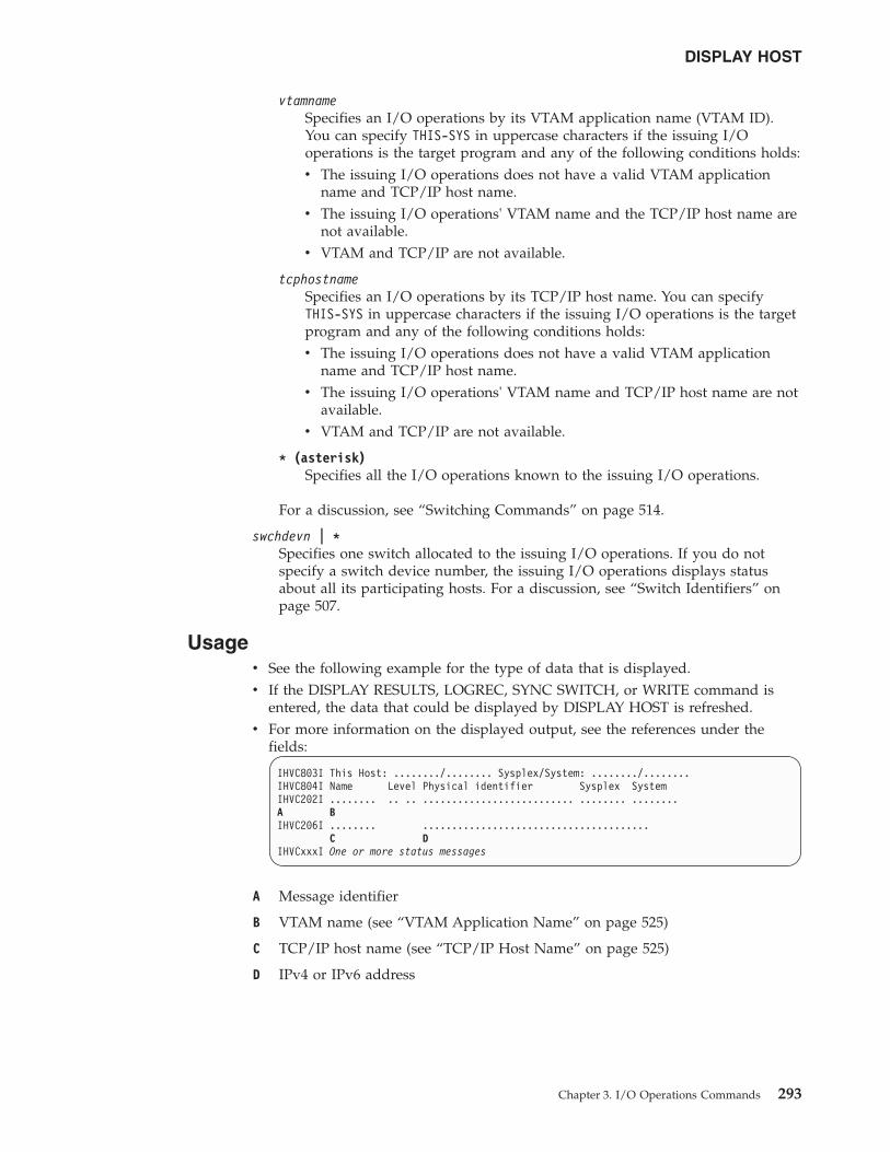
vtamnameSpecifies an I/O operations by its VTAM application name (VTAM ID).You can specify THIS-SYS in uppercase characters if the issuing I/Ooperations is the target program and any of the following conditions holds:v The issuing I/O operations does not have a valid VTAM application
name and TCP/IP host name.v The issuing I/O operations' VTAM name and the TCP/IP host name are
not available.v VTAM and TCP/IP are not available.
tcphostnameSpecifies an I/O operations by its TCP/IP host name. You can specifyTHIS-SYS in uppercase characters if the issuing I/O operations is the targetprogram and any of the following conditions holds:v The issuing I/O operations does not have a valid VTAM application
name and TCP/IP host name.v The issuing I/O operations' VTAM name and TCP/IP host name are not
available.v VTAM and TCP/IP are not available.
* (asterisk)Specifies all the I/O operations known to the issuing I/O operations.
For a discussion, see “Switching Commands” on page 514.
swchdevn | *Specifies one switch allocated to the issuing I/O operations. If you do notspecify a switch device number, the issuing I/O operations displays statusabout all its participating hosts. For a discussion, see “Switch Identifiers” onpage 507.
Usagev See the following example for the type of data that is displayed.v If the DISPLAY RESULTS, LOGREC, SYNC SWITCH, or WRITE command is
entered, the data that could be displayed by DISPLAY HOST is refreshed.v For more information on the displayed output, see the references under the
fields:
IHVC803I This Host: ......../........ Sysplex/System: ......../........IHVC804I Name Level Physical identifier Sysplex SystemIHVC202I ........ .. .. .......................... ........ ........A BIHVC206I ........ .......................................
C DIHVCxxxI One or more status messages
A Message identifier
B VTAM name (see “VTAM Application Name” on page 525)
C TCP/IP host name (see “TCP/IP Host Name” on page 525)
D IPv4 or IPv6 address
DISPLAY HOST
Chapter 3. I/O Operations Commands 293
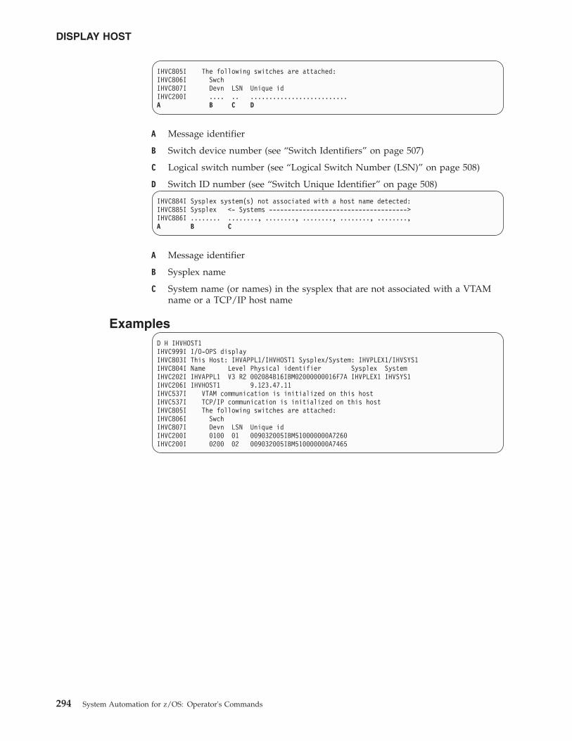
IHVC805I The following switches are attached:IHVC806I SwchIHVC807I Devn LSN Unique idIHVC200I .... .. ..........................A B C D
A Message identifier
B Switch device number (see “Switch Identifiers” on page 507)
C Logical switch number (see “Logical Switch Number (LSN)” on page 508)
D Switch ID number (see “Switch Unique Identifier” on page 508)
IHVC884I Sysplex system(s) not associated with a host name detected:IHVC885I Sysplex <- Systems ------------------------------------->IHVC886I ........ ........, ........, ........, ........, ........,A B C
A Message identifier
B Sysplex name
C System name (or names) in the sysplex that are not associated with a VTAMname or a TCP/IP host name
ExamplesD H IHVHOST1IHVC999I I/O-OPS displayIHVC803I This Host: IHVAPPL1/IHVHOST1 Sysplex/System: IHVPLEX1/IHVSYS1IHVC804I Name Level Physical identifier Sysplex SystemIHVC202I IHVAPPL1 V3 R2 002084B16IBM02000000016F7A IHVPLEX1 IHVSYS1IHVC206I IHVHOST1 9.123.47.11IHVC537I VTAM communication is initialized on this hostIHVC537I TCP/IP communication is initialized on this hostIHVC805I The following switches are attached:IHVC806I SwchIHVC807I Devn LSN Unique idIHVC200I 0100 01 009032005IBM510000000A7260IHVC200I 0200 02 009032005IBM510000000A7465
DISPLAY HOST
294 System Automation for z/OS: Operator's Commands
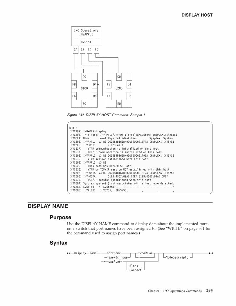
D H *IHVC999I I/O-OPS displayIHVC803I This Host: IHVAPPL1/IHVHOST1 Sysplex/System: IHVPLEX1/IHVSYS1IHVC804I Name Level Physical identifier Sysplex SystemIHVC202I IHVAPPL1 V3 R2 002084B16IBM02000000016F7A IHVPLEX1 IHVSYS1IHVC206I IHVHOST1 9.123.47.11IHVC537I VTAM communication is initialized on this hostIHVC537I TCP/IP communication is initialized on this hostIHVC202I IHVAPPL2 V3 R1 002084B16IBM0200000001795A IHVPLEX1 IHVSYS2IHVC535I VTAM session established with this hostIHVC202I IHVAPPL3 V3 R1IHVC525I This host has been RESET offIHVC516I VTAM or TCP/IP session NOT established with this hostIHVC202I IHVHOSTA V3 R2 002084B16IBM02000000016F7A IHVPLEXA IHVSYSAIHVC206I IHVHOSTA 0123:4567:89AB:CDEF:0123:4567:89AB:CDEFIHVC535I TCP/IP session established with this hostIHVC884I Sysplex system(s) not associated with a host name detected:IHVC885I Sysplex <- Systems ------------------------------------->IHVC886I IHVPLEX1 IHVSYS5, IHVSYS8, , , ,
DISPLAY NAME
PurposeUse the DISPLAY NAME command to display data about the implemented portson a switch that port names have been assigned to. (See “WRITE” on page 331 forthe command used to assign port names.)
Syntax
�� Display Name portname swchdevngeneric_name *
* swchdevnBlockConnect
NodeDescriptor��
┌────────────────┐│ I/O Operations ││ IHVAPPL1 │├────────────────┤│ IHVSYS1 │└┬──┬┬──┬┬──┬┬──┬┘│3A││3B││3C││3D│└┬─┘└┬─┘└┬─┘└┬─┘│ │ │ └────────────┐│ │ └───────┐ ││ └─────────┐ │ │└────┐ │ │ │
┌─────┬┴─┬─────┐│ │ ┌─────┬┴─┬─────┐│ │C0│ ││ │ │ │C0│ │├──┐ └──┘ ┌──┤│ │ ├──┐ └──┘ ┌──┤│FB│ │D4├┘ │ │FB│ │D4│├──┘ 0100 └──┤ │ ├──┘ 0200 └──┤├──┐ ┌──┤ │ ├──┐ ┌──┤│EA│ │D6│ └─┤EA│ │D6│├──┘ ┌──┐ └──┤ ├──┘ ┌──┐ └──┤│ │E0│ │ │ │E0│ │└─────┴──┴─────┘ └─────┴──┴─────┘
Figure 132. DISPLAY HOST Command: Sample 1
DISPLAY HOST
Chapter 3. I/O Operations Commands 295
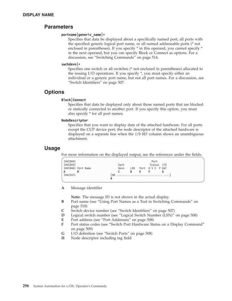
Parametersportname|generic_name|*
Specifies that data be displayed about a specifically named port, all ports withthe specified generic logical port name, or all named addressable ports (* notenclosed in parentheses). If you specify * in this operand, you cannot specify *in the next operand, but you can specify Block or Connect as options. For adiscussion, see “Switching Commands” on page 514.
swchdevn|*Specifies one switch or all switches (* not enclosed in parentheses) allocated tothe issuing I/O operations. If you specify *, you must specify either anindividual or a generic port name, but not all port names. For a discussion, see“Switch Identifiers” on page 507.
OptionsBlock|Connect
Specifies that data be displayed only about those named ports that are blockedor statically connected to another port. If you specify this option, you mustalso specify * for all port names.
NodeDescriptorSpecifies that you want to display data of the attached hardware. For all portsexcept the CUP device port, the node descriptor of the attached hardware isdisplayed on a separate line when the I/O DEF column shows an unambiguousattachment.
UsageFor more information on the displayed output, see the references under the fields.
IHVC844I PortIHVC845I Swch Status I/OIHVC846I Port Name Devn LSN Port H S C P DefA B C D E F GIHVC247I [ND .............................. ....]
H
A Message identifier
Note: The message ID is not shown in the actual display.B Port name (see “Using Port Names as a Tool in Switching Commands” on
page 518)C Switch device number (see “Switch Identifiers” on page 507)D Logical switch number (see “Logical Switch Number (LSN)” on page 508)E Port address (see “Port Addresses” on page 508)F Port status codes (see “Switch Port Hardware Status on a Display Command”
on page 509)G I/O definition (see “Switch Ports” on page 508)H Node descriptor including tag field
DISPLAY NAME
296 System Automation for z/OS: Operator's Commands
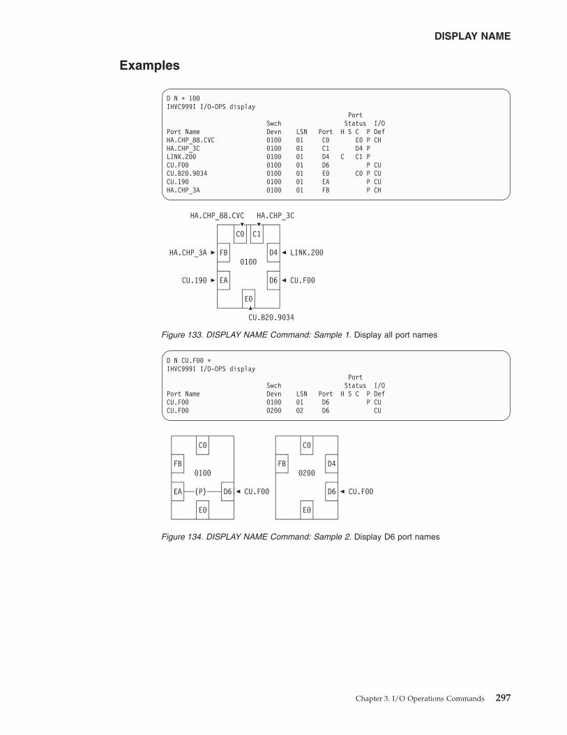
Examples
D N * 100IHVC999I I/O-OPS display
PortSwch Status I/O
Port Name Devn LSN Port H S C P DefHA.CHP_88.CVC 0100 01 C0 E0 P CHHA.CHP_3C 0100 01 C1 D4 PLINK.200 0100 01 D4 C C1 PCU.F00 0100 01 D6 P CUCU.B20.9034 0100 01 E0 C0 P CUCU.190 0100 01 EA P CUHA.CHP_3A 0100 01 FB P CH
HA.CHP_88.CVC HA.CHP_3C┌───┬─�┬┬─�┬───┐│ │C0││C1│ │├──┐└──┘└──┘┌──┤
HA.CHP_3A �│FB│ │D4│� LINK.200├──┘ 0100 └──┤├──┐ ┌──┤
CU.190 �│EA│ │D6│� CU.F00├──┘ ┌──┐ └──┤│ │E0│ │└─────┴─�┴─────┘
CU.B20.9034
Figure 133. DISPLAY NAME Command: Sample 1. Display all port names
D N CU.F00 *IHVC999I I/O-OPS display
PortSwch Status I/O
Port Name Devn LSN Port H S C P DefCU.F00 0100 01 D6 P CUCU.F00 0200 02 D6 CU
┌─────┬──┬─────┐ ┌─────┬──┬─────┐│ │C0│ │ │ │C0│ │├──┐ └──┘ │ ├──┐ └──┘ ┌──┤│FB│ │ │FB│ │D4│├──┘ 0100 │ ├──┘ 0200 └──┤├──┐ ┌──┤ │ ┌──┤│EA├──(P)───┤D6|� CU.F00 │ │D6│� CU.F00├──┘ ┌──┐ └──┤ │ ┌──┐ └──┤│ │E0│ │ │ │E0│ │└─────┴──┴─────┘ └─────┴──┴─────┘
Figure 134. DISPLAY NAME Command: Sample 2. Display D6 port names
DISPLAY NAME
Chapter 3. I/O Operations Commands 297
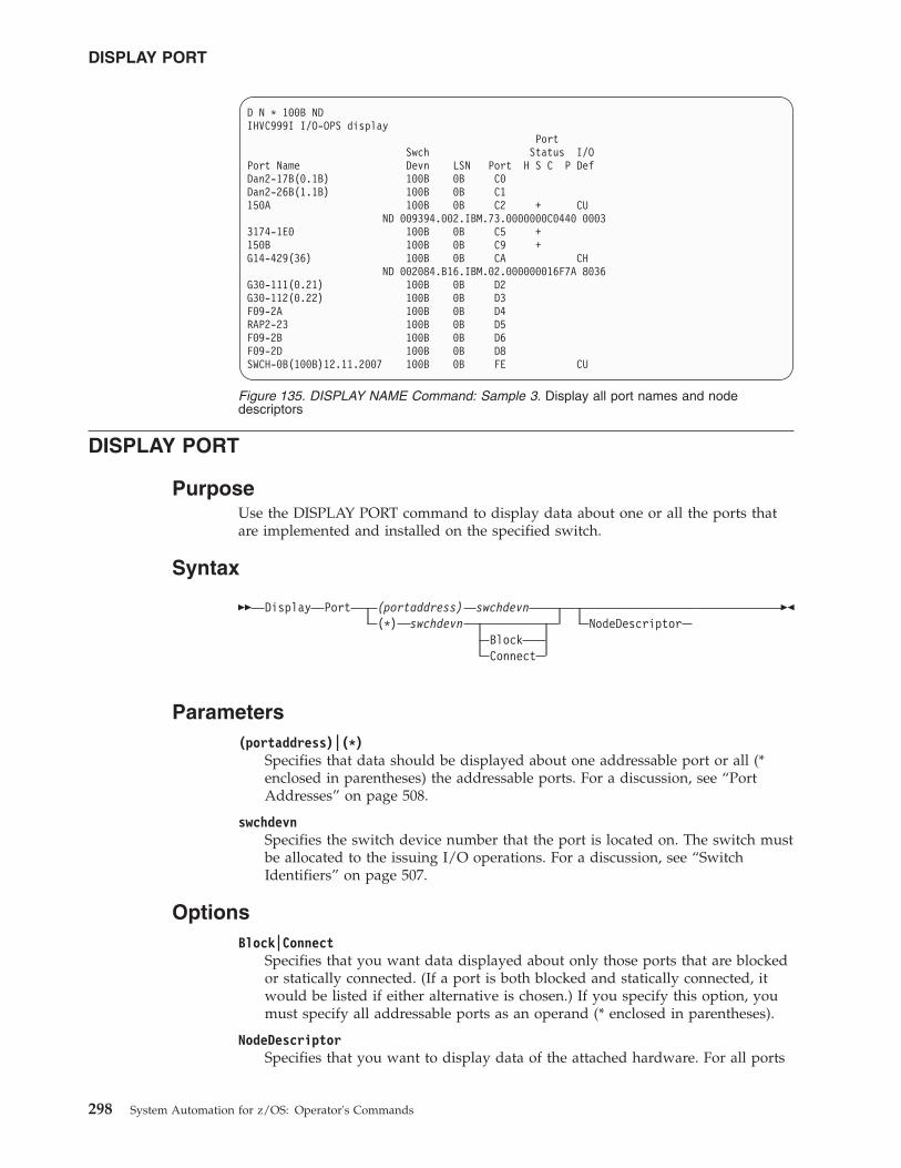
DISPLAY PORT
PurposeUse the DISPLAY PORT command to display data about one or all the ports thatare implemented and installed on the specified switch.
Syntax
�� Display Port (portaddress) swchdevn(*) swchdevn
BlockConnect
NodeDescriptor��
Parameters(portaddress)|(*)
Specifies that data should be displayed about one addressable port or all (*enclosed in parentheses) the addressable ports. For a discussion, see “PortAddresses” on page 508.
swchdevnSpecifies the switch device number that the port is located on. The switch mustbe allocated to the issuing I/O operations. For a discussion, see “SwitchIdentifiers” on page 507.
OptionsBlock|Connect
Specifies that you want data displayed about only those ports that are blockedor statically connected. (If a port is both blocked and statically connected, itwould be listed if either alternative is chosen.) If you specify this option, youmust specify all addressable ports as an operand (* enclosed in parentheses).
NodeDescriptorSpecifies that you want to display data of the attached hardware. For all ports
D N * 100B NDIHVC999I I/O-OPS display
PortSwch Status I/O
Port Name Devn LSN Port H S C P DefDan2-17B(0.1B) 100B 0B C0Dan2-26B(1.1B) 100B 0B C1150A 100B 0B C2 + CU
ND 009394.002.IBM.73.0000000C0440 00033174-1E0 100B 0B C5 +150B 100B 0B C9 +G14-429(36) 100B 0B CA CH
ND 002084.B16.IBM.02.000000016F7A 8036G30-111(0.21) 100B 0B D2G30-112(0.22) 100B 0B D3F09-2A 100B 0B D4RAP2-23 100B 0B D5F09-2B 100B 0B D6F09-2D 100B 0B D8SWCH-0B(100B)12.11.2007 100B 0B FE CU
Figure 135. DISPLAY NAME Command: Sample 3. Display all port names and nodedescriptors
DISPLAY PORT
298 System Automation for z/OS: Operator's Commands
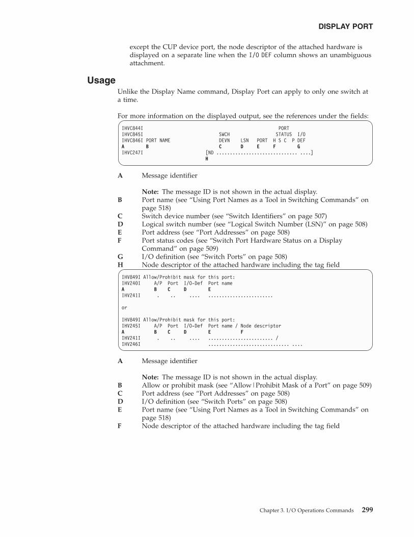
except the CUP device port, the node descriptor of the attached hardware isdisplayed on a separate line when the I/O DEF column shows an unambiguousattachment.
UsageUnlike the Display Name command, Display Port can apply to only one switch ata time.
For more information on the displayed output, see the references under the fields:
IHVC844I PORTIHVC845I SWCH STATUS I/OIHVC846I PORT NAME DEVN LSN PORT H S C P DEFA B C D E F GIHVC247I [ND .............................. ....]
H
A Message identifier
Note: The message ID is not shown in the actual display.B Port name (see “Using Port Names as a Tool in Switching Commands” on
page 518)C Switch device number (see “Switch Identifiers” on page 507)D Logical switch number (see “Logical Switch Number (LSN)” on page 508)E Port address (see “Port Addresses” on page 508)F Port status codes (see “Switch Port Hardware Status on a Display
Command” on page 509)G I/O definition (see “Switch Ports” on page 508)H Node descriptor of the attached hardware including the tag field
IHV849I Allow/Prohibit mask for this port:IHV240I A/P Port I/O-Def Port nameA B C D EIHV241I . .. .... ........................
or
IHV849I Allow/Prohibit mask for this port:IHV245I A/P Port I/O-Def Port name / Node descriptorA B C D E FIHV241I . .. .... ........................ /IHV246I .............................. ....
A Message identifier
Note: The message ID is not shown in the actual display.B Allow or prohibit mask (see “Allow|Prohibit Mask of a Port” on page 509)C Port address (see “Port Addresses” on page 508)D I/O definition (see “Switch Ports” on page 508)E Port name (see “Using Port Names as a Tool in Switching Commands” on
page 518)F Node descriptor of the attached hardware including the tag field
DISPLAY PORT
Chapter 3. I/O Operations Commands 299
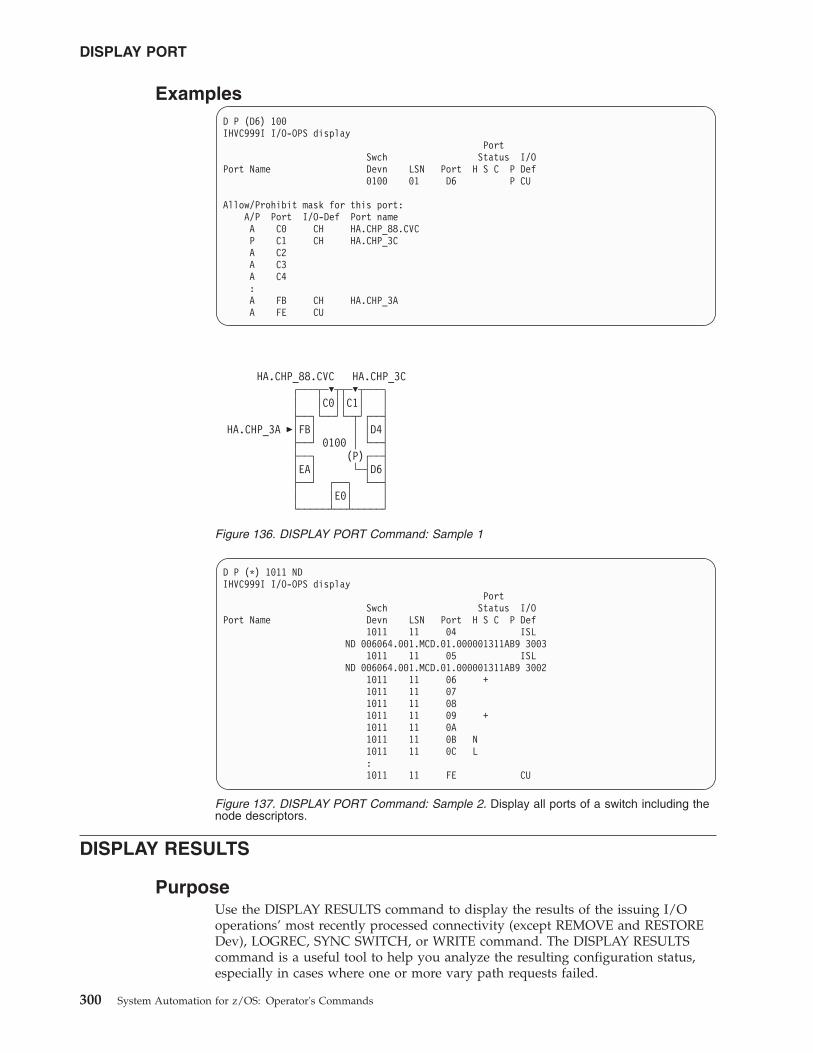
ExamplesD P (D6) 100IHVC999I I/O-OPS display
PortSwch Status I/O
Port Name Devn LSN Port H S C P Def0100 01 D6 P CU
Allow/Prohibit mask for this port:A/P Port I/O-Def Port nameA C0 CH HA.CHP_88.CVCP C1 CH HA.CHP_3CA C2A C3A C4:A FB CH HA.CHP_3AA FE CU
DISPLAY RESULTS
PurposeUse the DISPLAY RESULTS command to display the results of the issuing I/Ooperations’ most recently processed connectivity (except REMOVE and RESTOREDev), LOGREC, SYNC SWITCH, or WRITE command. The DISPLAY RESULTScommand is a useful tool to help you analyze the resulting configuration status,especially in cases where one or more vary path requests failed.
HA.CHP_88.CVC HA.CHP_3C┌───┬─�┬┬─�┬───┐│ │C0││C1│ │├──┐└──┘└─┬┘┌──┤
HA.CHP_3A �│FB│ │ │D4│├──┘ 0100 │ └──┤├──┐ (P)┌──┤│EA│ └─┤D6│├──┘ ┌──┐ └──┤│ │E0│ │└─────┴──┴─────┘
Figure 136. DISPLAY PORT Command: Sample 1
D P (*) 1011 NDIHVC999I I/O-OPS display
PortSwch Status I/O
Port Name Devn LSN Port H S C P Def1011 11 04 ISL
ND 006064.001.MCD.01.000001311AB9 30031011 11 05 ISL
ND 006064.001.MCD.01.000001311AB9 30021011 11 06 +1011 11 071011 11 081011 11 09 +1011 11 0A1011 11 0B N1011 11 0C L:1011 11 FE CU
Figure 137. DISPLAY PORT Command: Sample 2. Display all ports of a switch including thenode descriptors.
DISPLAY PORT
300 System Automation for z/OS: Operator's Commands
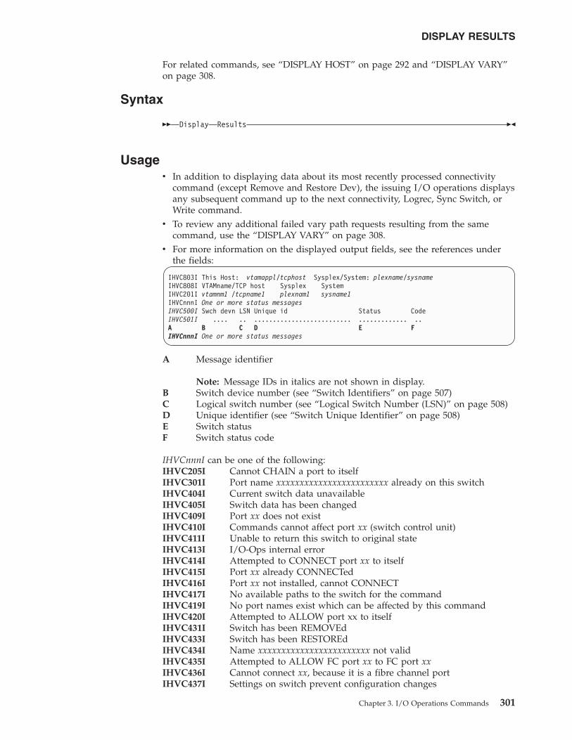
For related commands, see “DISPLAY HOST” on page 292 and “DISPLAY VARY”on page 308.
Syntax
�� Display Results ��
Usagev In addition to displaying data about its most recently processed connectivity
command (except Remove and Restore Dev), the issuing I/O operations displaysany subsequent command up to the next connectivity, Logrec, Sync Switch, orWrite command.
v To review any additional failed vary path requests resulting from the samecommand, use the “DISPLAY VARY” on page 308.
v For more information on the displayed output fields, see the references underthe fields:
IHVC803I This Host: vtamappl/tcphost Sysplex/System: plexname/sysnameIHVC808I VTAMname/TCP host Sysplex SystemIHVC201I vtamnm1 /tcpname1 plexnam1 sysname1IHVCnnnI One or more status messagesIHVC500I Swch devn LSN Unique id Status CodeIHVC501I .... .. .......................... ............. ..A B C D E FIHVCnnnI One or more status messages
A Message identifier
Note: Message IDs in italics are not shown in display.B Switch device number (see “Switch Identifiers” on page 507)C Logical switch number (see “Logical Switch Number (LSN)” on page 508)D Unique identifier (see “Switch Unique Identifier” on page 508)E Switch statusF Switch status code
IHVCnnnI can be one of the following:IHVC205I Cannot CHAIN a port to itselfIHVC301I Port name xxxxxxxxxxxxxxxxxxxxxxxx already on this switchIHVC404I Current switch data unavailableIHVC405I Switch data has been changedIHVC409I Port xx does not existIHVC410I Commands cannot affect port xx (switch control unit)IHVC411I Unable to return this switch to original stateIHVC413I I/O-Ops internal errorIHVC414I Attempted to CONNECT port xx to itselfIHVC415I Port xx already CONNECTedIHVC416I Port xx not installed, cannot CONNECTIHVC417I No available paths to the switch for the commandIHVC419I No port names exist which can be affected by this commandIHVC420I Attempted to ALLOW port xx to itselfIHVC431I Switch has been REMOVEdIHVC433I Switch has been RESTOREdIHVC434I Name xxxxxxxxxxxxxxxxxxxxxxxx not validIHVC435I Attempted to ALLOW FC port xx to FC port xxIHVC436I Cannot connect xx, because it is a fibre channel portIHVC437I Settings on switch prevent configuration changes
DISPLAY RESULTS
Chapter 3. I/O Operations Commands 301
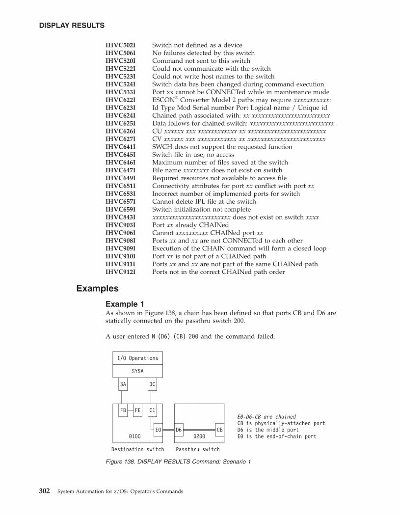
IHVC502I Switch not defined as a deviceIHVC506I No failures detected by this switchIHVC520I Command not sent to this switchIHVC522I Could not communicate with the switchIHVC523I Could not write host names to the switchIHVC524I Switch data has been changed during command executionIHVC533I Port xx cannot be CONNECTed while in maintenance modeIHVC622I ESCON® Converter Model 2 paths may require xxxxxxxxxxx:IHVC623I Id Type Mod Serial number Port Logical name / Unique idIHVC624I Chained path associated with: xx xxxxxxxxxxxxxxxxxxxxxxxxIHVC625I Data follows for chained switch: xxxxxxxxxxxxxxxxxxxxxxxxxxIHVC626I CU xxxxxx xxx xxxxxxxxxxxx xx xxxxxxxxxxxxxxxxxxxxxxxxIHVC627I CV xxxxxx xxx xxxxxxxxxxxx xx xxxxxxxxxxxxxxxxxxxxxxxxIHVC641I SWCH does not support the requested functionIHVC645I Switch file in use, no accessIHVC646I Maximum number of files saved at the switchIHVC647I File name xxxxxxxx does not exist on switchIHVC649I Required resources not available to access fileIHVC651I Connectivity attributes for port xx conflict with port xxIHVC653I Incorrect number of implemented ports for switchIHVC657I Cannot delete IPL file at the switchIHVC659I Switch initialization not completeIHVC843I xxxxxxxxxxxxxxxxxxxxxxxx does not exist on switch xxxxIHVC903I Port xx already CHAINedIHVC906I Cannot xxxxxxxxxx CHAINed port xxIHVC908I Ports xx and xx are not CONNECTed to each otherIHVC909I Execution of the CHAIN command will form a closed loopIHVC910I Port xx is not part of a CHAINed pathIHVC911I Ports xx and xx are not part of the same CHAINed pathIHVC912I Ports not in the correct CHAINed path order
Examples
Example 1As shown in Figure 138, a chain has been defined so that ports CB and D6 arestatically connected on the passthru switch 200.
A user entered N (D6) (CB) 200 and the command failed.
┌────────────────┐│ I/O Operations │├────────────────┤│ SYSA │└─┬──┬──────┬──┬─┘
│3A│ │3C│└┬─┘ └┬─┘│ │
┌─┬┴─┬─┬──┬─┬┴─┬─┐ ┌────────────────┐│ │FB├─┤FE│ │C1│ │ │ ││ └──┘ └──┘ └┬─┘ │ │ │ E0-D6-CB are chained│ │┌──┤ ├──┐ ┌──┤ CB is physically-attached port│ └┤E0╞═══╡D6╞══════════╡CB│ D6 is the middle port│ 0100 └──┤ ├──┘ 0200 └──┤ E0 is the end-of-chain port└────────────────┘ └────────────────┘Destination switch Passthru switch
Figure 138. DISPLAY RESULTS Command: Scenario 1
DISPLAY RESULTS
302 System Automation for z/OS: Operator's Commands
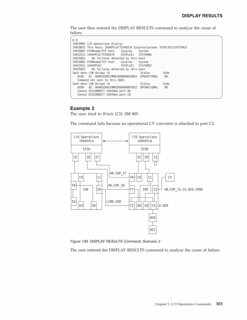
The user then entered the DISPLAY RESULTS command to analyze the cause offailure.
D RIHVC999I I/O operations displayIHVC803I This Host: IHVAPPLA/TCPHOSTA Sysplex/System: SYSPLEX1/SYSTEM12IHVC808I VTAMname/TCP host Sysplex SystemIHVC201I IHVAPPLA/TCPHOSTA SYSPLEX1 SYSTEM66IHVC505I No failures detected by this hostIHVC808I VTAMname/TCP host Sysplex SystemIHVC201I IHVAPPLB/ SYSPLEX1 SYSTEM22IHVC505I No failures detected by this hostSwch devn LSN Unique id Status Code
0100 01 009032002IBM01000000034893 OPERATIONAL 00Command not sent to this SWCH
Swch devn LSN Unique id Status Code0200 02 009032002IBM02000000093622 OPERATIONAL 00Cannot DISCONNECT CHAINed port D6Cannot DISCONNECT CHAINed port CB
Example 2The user tried to Block (C3) 200 NOF.
The command fails because an operational CV converter is attached to port C3.
The user entered the DISPLAY RESULTS command to analyze the cause of failure.
┌────────────────┐ ┌────────────────┐│ I/O Operations │ │ I/O Operations ││ IHVAPPLA │�────────────�│ IHVAPPLB │├────────────────┤ ├────────────────┤│ SYSA │ │ SYSB │└┬──┬───┬──┬─┬──┬┘ └───┬──┬┬──┬─┬──┬┘│3C│ │3D│ │27│ │32││39│ │15│└┬─┘ └┬─┘ └┬─┘ └┬─┘└┬─┘ └┬┬┘│ │ └──────┐ │ │ └┘│ └──────────┐│ │ └─┐
┌─┴─┬──┬──────┬──┐ ││HA.CHP_27 ┌──┬┬┴─┬──┬┴─┬──┐ ┌────┐│ │C0│ │C1│ │└──────────┤FB├┤C0│ │C1│ │ ┌─┤ CV │├──┐└┬─┘ └┬─┤ │ ├──┘└──┘ └┬┬┘ │ │ └────┘│FB├─┼──────┐ ┌┴─┤ │HA.CHP_3D ├──┐ ┌────┘│┌──┤ │├┬─┘ │ 100 │ │D4├─┐└───────────┤F7├─┐│ 200 ││C3├─┘ HB.CHP_15.CV.820.3990││ │ │ └──┤ │ ├──┘ ││ ┌──┘└┬─┤├┴─┐ │ │ │ │ │┌───┼┼──┼───┐│ ││EA│┌┴─┐ ┌┴─┐ │ │LINK.200 ├┴─┐┌┴┴┐┌┴─┐┌┴┴┐│├──┘│E0│ │D6│ │ └────────────┤F2││D6││CB││C5│CU.820└───┴──┴───┴──┴──┘ └──┴┴──┴┴──┴┴┬─┴┘
┌─┴─┐│820│└─┬─┘┌─┴─┐│821│└───┘
Figure 139. DISPLAY RESULTS Command: Scenario 2
DISPLAY RESULTS
Chapter 3. I/O Operations Commands 303
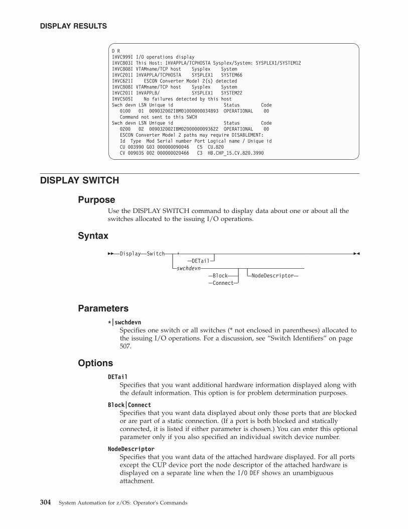
D RIHVC999I I/O operations displayIHVC803I This Host: IHVAPPLA/TCPHOSTA Sysplex/System: SYSPLEX1/SYSTEM12IHVC808I VTAMname/TCP host Sysplex SystemIHVC201I IHVAPPLA/TCPHOSTA SYSPLEX1 SYSTEM66IHVC621I ESCON Converter Model 2(s) detectedIHVC808I VTAMname/TCP host Sysplex SystemIHVC201I IHVAPPLB/ SYSPLEX1 SYSTEM22IHVC505I No failures detected by this hostSwch devn LSN Unique id Status Code
0100 01 009032002IBM01000000034893 OPERATIONAL 00Command not sent to this SWCH
Swch devn LSN Unique id Status Code0200 02 009032002IBM02000000093622 OPERATIONAL 00ESCON Converter Model 2 paths may require DISABLEMENT:Id Type Mod Serial number Port Logical name / Unique idCU 003990 G03 000000090046 C5 CU.820CV 009035 002 000000020466 C3 HB.CHP_15.CV.820.3990
DISPLAY SWITCH
PurposeUse the DISPLAY SWITCH command to display data about one or about all theswitches allocated to the issuing I/O operations.
Syntax
�� Display Switch *DETail
swchdevnBlock NodeDescriptorConnect
��
Parameters*|swchdevn
Specifies one switch or all switches (* not enclosed in parentheses) allocated tothe issuing I/O operations. For a discussion, see “Switch Identifiers” on page507.
OptionsDETail
Specifies that you want additional hardware information displayed along withthe default information. This option is for problem determination purposes.
Block|ConnectSpecifies that you want data displayed about only those ports that are blockedor are part of a static connection. (If a port is both blocked and staticallyconnected, it is listed if either parameter is chosen.) You can enter this optionalparameter only if you also specified an individual switch device number.
NodeDescriptorSpecifies that you want data of the attached hardware displayed. For all portsexcept the CUP device port the node descriptor of the attached hardware isdisplayed on a separate line when the I/O DEF shows an unambiguousattachment.
DISPLAY RESULTS
304 System Automation for z/OS: Operator's Commands
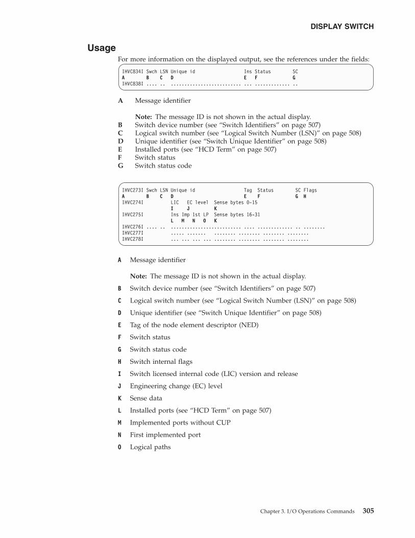
UsageFor more information on the displayed output, see the references under the fields:
IHVC834I Swch LSN Unique id Ins Status SCA B C D E F GIHVC838I .... .. .......................... ... ............. ..
A Message identifier
Note: The message ID is not shown in the actual display.B Switch device number (see “Switch Identifiers” on page 507)C Logical switch number (see “Logical Switch Number (LSN)” on page 508)D Unique identifier (see “Switch Unique Identifier” on page 508)E Installed ports (see “HCD Term” on page 507)F Switch statusG Switch status code
IHVC273I Swch LSN Unique id Tag Status SC FlagsA B C D E F G HIHVC274I LIC EC level Sense bytes 0-15
I J KIHVC275I Ins Imp 1st LP Sense bytes 16-31
L M N O KIHVC276I .... .. .......................... .... ............. .. ........IHVC277I ..... ....... ........ ........ ........ ........IHVC278I ... ... ... ... ........ ........ ........ ........
A Message identifier
Note: The message ID is not shown in the actual display.
B Switch device number (see “Switch Identifiers” on page 507)
C Logical switch number (see “Logical Switch Number (LSN)” on page 508)
D Unique identifier (see “Switch Unique Identifier” on page 508)
E Tag of the node element descriptor (NED)
F Switch status
G Switch status code
H Switch internal flags
I Switch licensed internal code (LIC) version and release
J Engineering change (EC) level
K Sense data
L Installed ports (see “HCD Term” on page 507)
M Implemented ports without CUP
N First implemented port
O Logical paths
DISPLAY SWITCH
Chapter 3. I/O Operations Commands 305
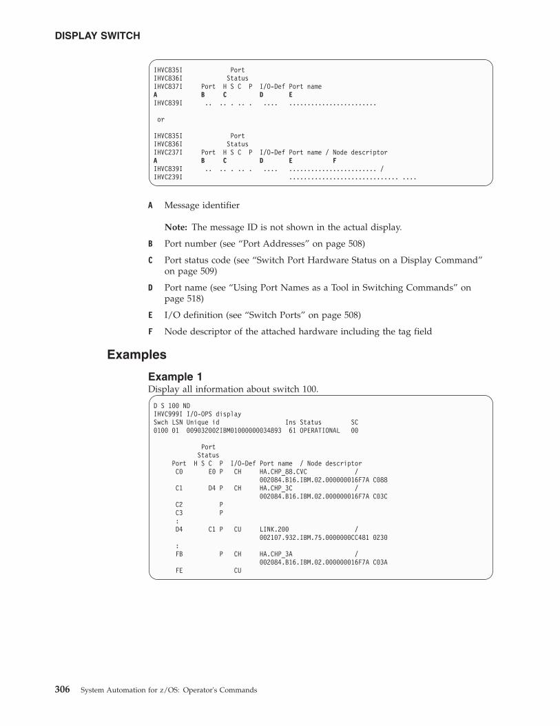
IHVC835I PortIHVC836I StatusIHVC837I Port H S C P I/O-Def Port nameA B C D EIHVC839I .. .. . .. . .... ........................
or
IHVC835I PortIHVC836I StatusIHVC237I Port H S C P I/O-Def Port name / Node descriptorA B C D E FIHVC839I .. .. . .. . .... ........................ /IHVC239I .............................. ....
A Message identifier
Note: The message ID is not shown in the actual display.
B Port number (see “Port Addresses” on page 508)
C Port status code (see “Switch Port Hardware Status on a Display Command”on page 509)
D Port name (see “Using Port Names as a Tool in Switching Commands” onpage 518)
E I/O definition (see “Switch Ports” on page 508)
F Node descriptor of the attached hardware including the tag field
Examples
Example 1Display all information about switch 100.
D S 100 NDIHVC999I I/O-OPS displaySwch LSN Unique id Ins Status SC0100 01 009032002IBM01000000034893 61 OPERATIONAL 00
PortStatus
Port H S C P I/O-Def Port name / Node descriptorC0 E0 P CH HA.CHP_88.CVC /
002084.B16.IBM.02.000000016F7A C088C1 D4 P CH HA.CHP_3C /
002084.B16.IBM.02.000000016F7A C03CC2 PC3 P:D4 C1 P CU LINK.200 /
002107.932.IBM.75.0000000CC481 0230:FB P CH HA.CHP_3A /
002084.B16.IBM.02.000000016F7A C03AFE CU
DISPLAY SWITCH
306 System Automation for z/OS: Operator's Commands
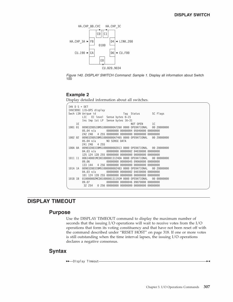
Example 2Display detailed information about all switches.
IHV D S * DETIHVC999I I/O-OPS displaySwch LSN Unique id Tag Status SC Flags
LIC EC level Sense bytes 0-15Ins Imp 1st LP Sense bytes 16-31
1E NOT OPEN 1C1001 01 009032005IBM510000000A7260 0000 OPERATIONAL 00 20000000
05.04 n/a 00000000 00000004 05040000 00000000242 248 4 255 00000000 00000000 00000000 00000000
1002 02 009032005IBM510000000A7465 0000 OPERATIONAL 00 2000000005.04 n/a NO SENSE DATA241 248 4 255
100A 0A 009032003IBM51000000002013 0000 OPERATIONAL 00 2000000004.03 n/a 00000000 00000002 04030000 00000000125 124 128 255 00000000 00000000 00000000 00000000
1011 11 006140001MCD010000013124DA 0000 OPERATIONAL 00 0000000009.06 00000000 00000045 09060000 00000000133 144 4 256 00000000 00000000 00000000 00000000
101A 1A 009032003IBM51000000002483 0000 OPERATIONAL 00 2000000004.03 n/a 00000000 00000002 04030000 00000000101 124 128 255 00000000 00000000 00000000 00000000
101B 1B 010000002MCD0100000131191M 0000 OPERATIONAL 00 0000000009.07 00000000 00000046 09070000 0000000032 254 0 256 00000000 00000000 00000000 00000000
DISPLAY TIMEOUT
PurposeUse the DISPLAY TIMEOUT command to display the maximum number ofseconds that the issuing I/O operations will wait to receive votes from the I/Ooperations that form its voting constituency and that have not been reset off withthe command described under “RESET HOST” on page 318. If one or more votesis still outstanding when the time interval lapses, the issuing I/O operationsdeclares a negative consensus.
Syntax
�� Display Timeout ��
HA.CHP_88.CVC HA.CHP_3C┌───┬─�┬┬─�┬───┐│ │C0││C1│ │├──┐└──┘└──┘┌──┤
HA.CHP_3A �│FB│ │D4│� LINK.200├──┘ 0100 └──┤├──┐ ┌──┤
CU.190 �│EA│ │D6│� CU.F00├──┘ ┌──┐ └──┤│ │E0│ │└─────┴─�┴─────┘
CU.B20.9034
Figure 140. DISPLAY SWITCH Command: Sample 1. Display all information about Switch100
DISPLAY SWITCH
Chapter 3. I/O Operations Commands 307
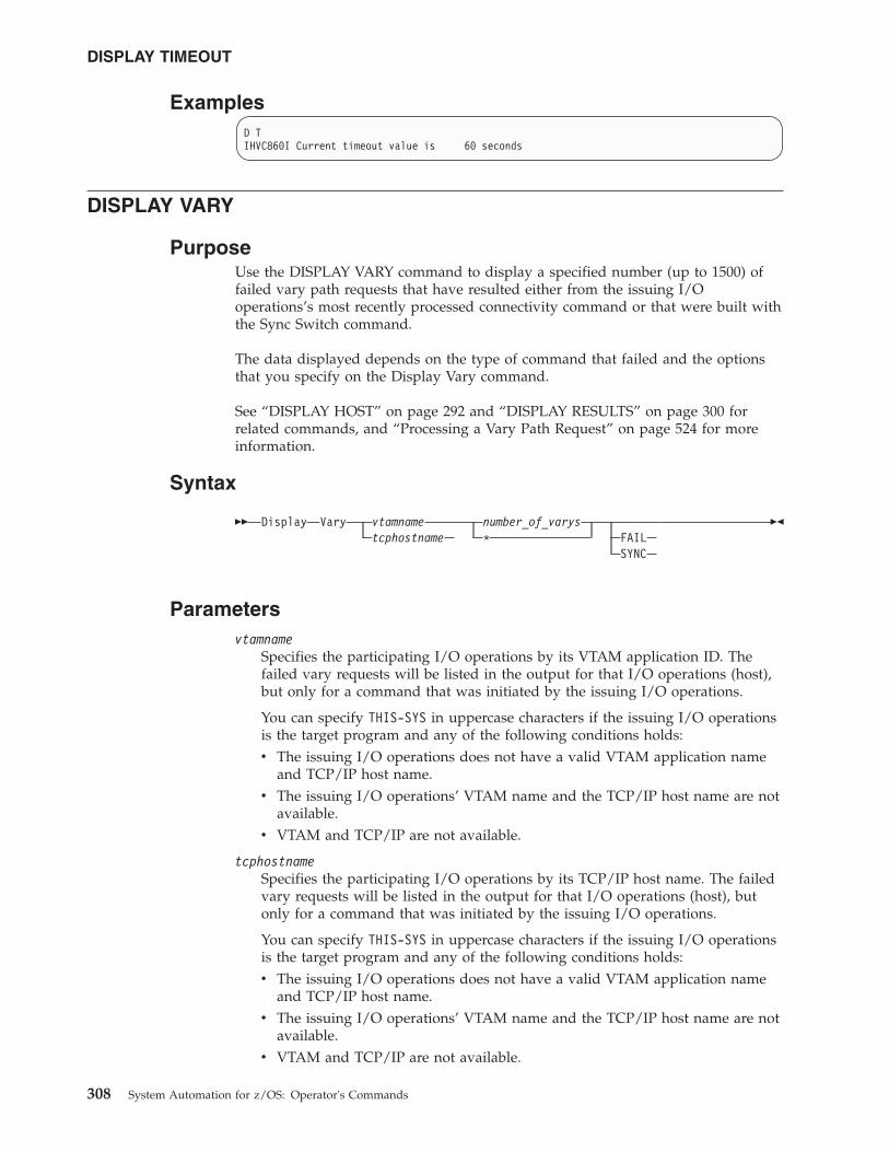
ExamplesD TIHVC860I Current timeout value is 60 seconds
DISPLAY VARY
PurposeUse the DISPLAY VARY command to display a specified number (up to 1500) offailed vary path requests that have resulted either from the issuing I/Ooperations’s most recently processed connectivity command or that were built withthe Sync Switch command.
The data displayed depends on the type of command that failed and the optionsthat you specify on the Display Vary command.
See “DISPLAY HOST” on page 292 and “DISPLAY RESULTS” on page 300 forrelated commands, and “Processing a Vary Path Request” on page 524 for moreinformation.
Syntax
�� Display Vary vtamname number_of_varystcphostname * FAIL
SYNC
��
Parametersvtamname
Specifies the participating I/O operations by its VTAM application ID. Thefailed vary requests will be listed in the output for that I/O operations (host),but only for a command that was initiated by the issuing I/O operations.
You can specify THIS-SYS in uppercase characters if the issuing I/O operationsis the target program and any of the following conditions holds:v The issuing I/O operations does not have a valid VTAM application name
and TCP/IP host name.v The issuing I/O operations’ VTAM name and the TCP/IP host name are not
available.v VTAM and TCP/IP are not available.
tcphostnameSpecifies the participating I/O operations by its TCP/IP host name. The failedvary requests will be listed in the output for that I/O operations (host), butonly for a command that was initiated by the issuing I/O operations.
You can specify THIS-SYS in uppercase characters if the issuing I/O operationsis the target program and any of the following conditions holds:v The issuing I/O operations does not have a valid VTAM application name
and TCP/IP host name.v The issuing I/O operations’ VTAM name and the TCP/IP host name are not
available.v VTAM and TCP/IP are not available.
DISPLAY TIMEOUT
308 System Automation for z/OS: Operator's Commands
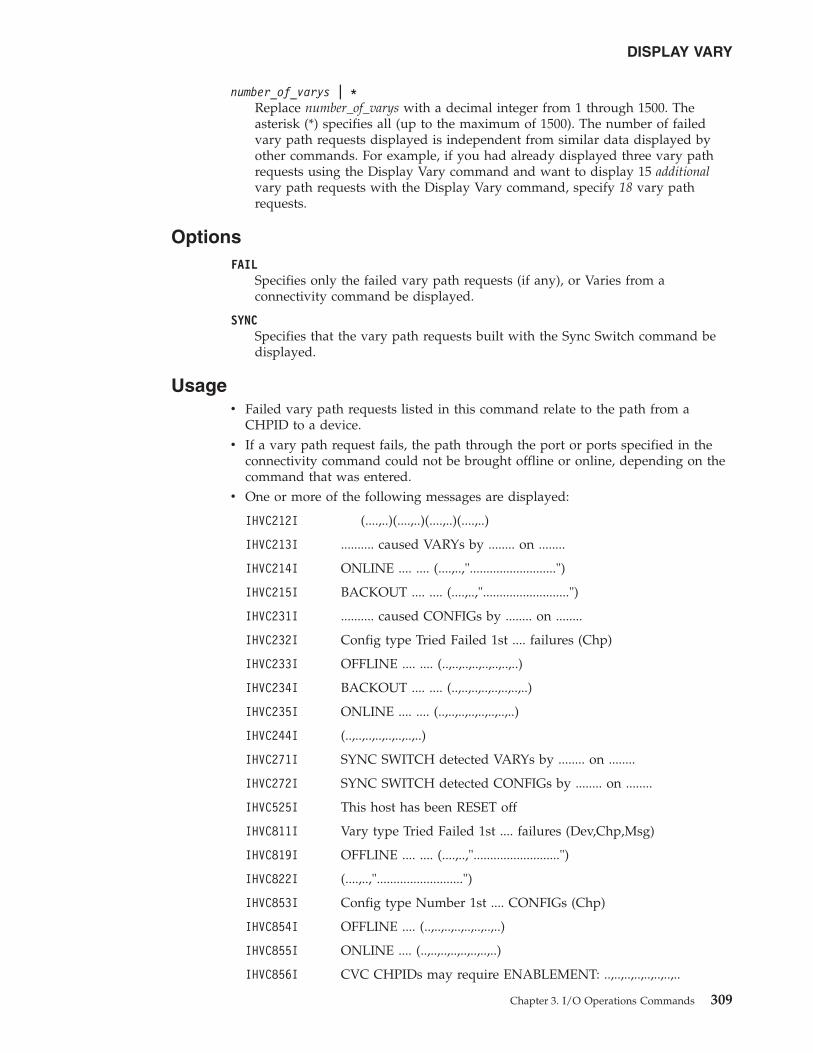
number_of_varys | *Replace number_of_varys with a decimal integer from 1 through 1500. Theasterisk (*) specifies all (up to the maximum of 1500). The number of failedvary path requests displayed is independent from similar data displayed byother commands. For example, if you had already displayed three vary pathrequests using the Display Vary command and want to display 15 additionalvary path requests with the Display Vary command, specify 18 vary pathrequests.
OptionsFAIL
Specifies only the failed vary path requests (if any), or Varies from aconnectivity command be displayed.
SYNCSpecifies that the vary path requests built with the Sync Switch command bedisplayed.
Usagev Failed vary path requests listed in this command relate to the path from a
CHPID to a device.v If a vary path request fails, the path through the port or ports specified in the
connectivity command could not be brought offline or online, depending on thecommand that was entered.
v One or more of the following messages are displayed:
IHVC212I (....,..)(....,..)(....,..)(....,..)
IHVC213I .......... caused VARYs by ........ on ........
IHVC214I ONLINE .... .... (....,..,"..........................")
IHVC215I BACKOUT .... .... (....,..,"..........................")
IHVC231I .......... caused CONFIGs by ........ on ........
IHVC232I Config type Tried Failed 1st .... failures (Chp)
IHVC233I OFFLINE .... .... (..,..,..,..,..,..,..,..)
IHVC234I BACKOUT .... .... (..,..,..,..,..,..,..,..)
IHVC235I ONLINE .... .... (..,..,..,..,..,..,..,..)
IHVC244I (..,..,..,..,..,..,..,..)
IHVC271I SYNC SWITCH detected VARYs by ........ on ........
IHVC272I SYNC SWITCH detected CONFIGs by ........ on ........
IHVC525I This host has been RESET off
IHVC811I Vary type Tried Failed 1st .... failures (Dev,Chp,Msg)
IHVC819I OFFLINE .... .... (....,..,"..........................")
IHVC822I (....,..,"..........................")
IHVC853I Config type Number 1st .... CONFIGs (Chp)
IHVC854I OFFLINE .... (..,..,..,..,..,..,..,..)
IHVC855I ONLINE .... (..,..,..,..,..,..,..,..)
IHVC856I CVC CHPIDs may require ENABLEMENT: ..,..,..,..,..,..,..,..
DISPLAY VARY
Chapter 3. I/O Operations Commands 309
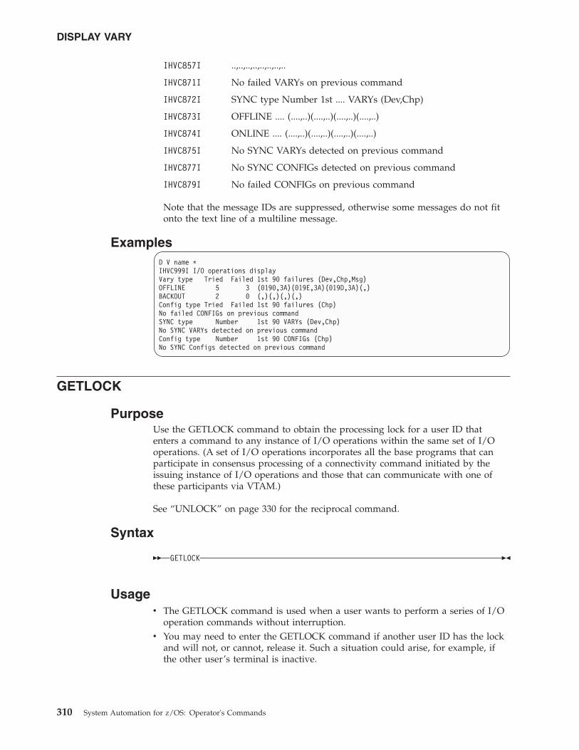
IHVC857I ..,..,..,..,..,..,..,..
IHVC871I No failed VARYs on previous command
IHVC872I SYNC type Number 1st .... VARYs (Dev,Chp)
IHVC873I OFFLINE .... (....,..)(....,..)(....,..)(....,..)
IHVC874I ONLINE .... (....,..)(....,..)(....,..)(....,..)
IHVC875I No SYNC VARYs detected on previous command
IHVC877I No SYNC CONFIGs detected on previous command
IHVC879I No failed CONFIGs on previous command
Note that the message IDs are suppressed, otherwise some messages do not fitonto the text line of a multiline message.
ExamplesD V name *IHVC999I I/O operations displayVary type Tried Failed 1st 90 failures (Dev,Chp,Msg)OFFLINE 5 3 (0190,3A)(019E,3A)(019D,3A)(,)BACKOUT 2 0 (,)(,)(,)(,)Config type Tried Failed 1st 90 failures (Chp)No failed CONFIGs on previous commandSYNC type Number 1st 90 VARYs (Dev,Chp)No SYNC VARYs detected on previous commandConfig type Number 1st 90 CONFIGs (Chp)No SYNC Configs detected on previous command
GETLOCK
PurposeUse the GETLOCK command to obtain the processing lock for a user ID thatenters a command to any instance of I/O operations within the same set of I/Ooperations. (A set of I/O operations incorporates all the base programs that canparticipate in consensus processing of a connectivity command initiated by theissuing instance of I/O operations and those that can communicate with one ofthese participants via VTAM.)
See “UNLOCK” on page 330 for the reciprocal command.
Syntax
�� GETLOCK ��
Usagev The GETLOCK command is used when a user wants to perform a series of I/O
operation commands without interruption.v You may need to enter the GETLOCK command if another user ID has the lock
and will not, or cannot, release it. Such a situation could arise, for example, ifthe other user’s terminal is inactive.
DISPLAY VARY
310 System Automation for z/OS: Operator's Commands
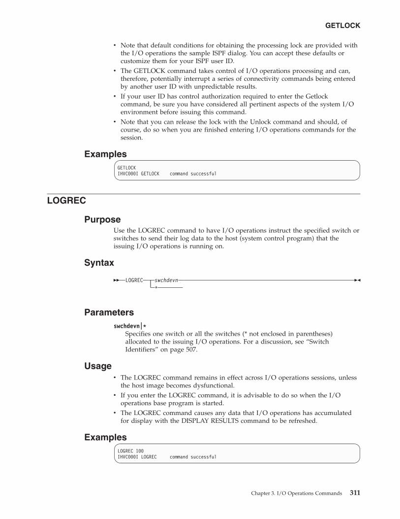
v Note that default conditions for obtaining the processing lock are provided withthe I/O operations the sample ISPF dialog. You can accept these defaults orcustomize them for your ISPF user ID.
v The GETLOCK command takes control of I/O operations processing and can,therefore, potentially interrupt a series of connectivity commands being enteredby another user ID with unpredictable results.
v If your user ID has control authorization required to enter the Getlockcommand, be sure you have considered all pertinent aspects of the system I/Oenvironment before issuing this command.
v Note that you can release the lock with the Unlock command and should, ofcourse, do so when you are finished entering I/O operations commands for thesession.
ExamplesGETLOCKIHVC000I GETLOCK command successful
LOGREC
PurposeUse the LOGREC command to have I/O operations instruct the specified switch orswitches to send their log data to the host (system control program) that theissuing I/O operations is running on.
Syntax
�� LOGREC swchdevn*
��
Parametersswchdevn|*
Specifies one switch or all the switches (* not enclosed in parentheses)allocated to the issuing I/O operations. For a discussion, see “SwitchIdentifiers” on page 507.
Usagev The LOGREC command remains in effect across I/O operations sessions, unless
the host image becomes dysfunctional.v If you enter the LOGREC command, it is advisable to do so when the I/O
operations base program is started.v The LOGREC command causes any data that I/O operations has accumulated
for display with the DISPLAY RESULTS command to be refreshed.
ExamplesLOGREC 100IHVC000I LOGREC command successful
GETLOCK
Chapter 3. I/O Operations Commands 311
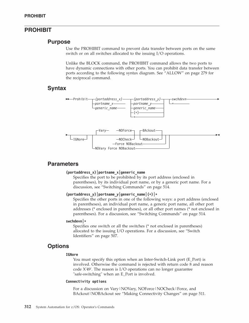
PROHIBIT
PurposeUse the PROHIBIT command to prevent data transfer between ports on the sameswitch or on all switches allocated to the issuing I/O operations.
Unlike the BLOCK command, the PROHIBIT command allows the two ports tohave dynamic connections with other ports. You can prohibit data transfer betweenports according to the following syntax diagram. See “ALLOW” on page 279 forthe reciprocal command.
Syntax
�� Prohibit (portaddress_x)portname_xgeneric_name
(portaddress_y)portname_ygeneric_name(*)*
swchdevn*
�
�IGNore
Vary NOForce BAckout
NOCheck NOBackoutForce NOBackout
NOVary Force NOBackout
��
Parameters(portaddress_x)|portname_x|generic_name
Specifies the port to be prohibited by its port address (enclosed inparentheses), by its individual port name, or by a generic port name. For adiscussion, see “Switching Commands” on page 514.
(portaddress_y)|portname_y|generic_name|(*)|*Specifies the other ports in one of the following ways: a port address (enclosedin parentheses), an individual port name, a generic port name, all other portaddresses (* enclosed in parentheses), or all other port names (* not enclosed inparentheses). For a discussion, see “Switching Commands” on page 514.
swchdevn|*Specifies one switch or all the switches (* not enclosed in parentheses)allocated to the issuing I/O operations. For a discussion, see “SwitchIdentifiers” on page 507.
OptionsIGNore
You must specify this option when an Inter-Switch-Link port (E_Port) isinvolved. Otherwise the command is rejected with return code 8 and reasoncode X'49'. The reason is I/O operations can no longer guarantee"safe-switching" when an E_Port is involved.
Connectivity options
For a discussion on Vary|NOVary, NOForce|NOCheck|Force, andBAckout|NOBAckout see “Making Connectivity Changes” on page 511.
PROHIBIT
312 System Automation for z/OS: Operator's Commands
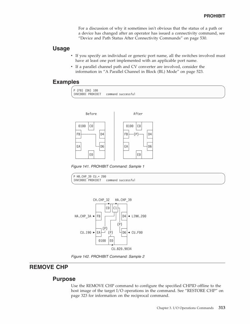
For a discussion of why it sometimes isn't obvious that the status of a path ora device has changed after an operator has issued a connectivity command, see“Device and Path Status After Connectivity Commands” on page 530.
Usagev If you specify an individual or generic port name, all the switches involved must
have at least one port implemented with an applicable port name.v If a parallel channel path and CV converter are involved, consider the
information in “A Parallel Channel in Block (BL) Mode” on page 523.
ExamplesP (FB) (D6) 100IHVC000I PROHIBIT command successful
P HB.CHP_39 CU.* 200IHVC000I PROHIBIT command successful
REMOVE CHP
PurposeUse the REMOVE CHP command to configure the specified CHPID offline to thehost image of the target I/O operations in the command. See “RESTORE CHP” onpage 323 for information on the reciprocal command.
Before │ After│
┌──────┬──┬─────┐ │ ┌──────┬──┬─────┐│ 0100 │C0│ │ │ │ 0100 │C0│ │├──┐ └──┘ ┌──┤ │ ├──┐ └──┘ ┌──┤│FB├───────┐ │D4│ │ │FB├──(P)──┐ │D4│├──┘ │ └──┤ │ ├──┘ │ └──┤├──┐ │ ┌──┤ │ ├──┐ │ ┌──┤│EA│ └─┤D6│ │ │EA│ └─┤D6│├──┘ ┌──┐ └──┤ │ ├──┘ ┌──┐ └──┤│ │E0│ │ │ │ │E0│ │└──────┴──┴─────┘ │ └──────┴──┴─────┘
Figure 141. PROHIBIT Command: Sample 1
CH.CHP_32 HA.CHP_39┌────┬─�┬┬─�┬────┐│ │C0││C1├┐ │├──┐ └──┘└┬┬┘│┌──┤
HA.CHP_3A �│FB│ ┌────┘│ ││D4│� LINK.200├──┘ │ ┌──┘ │└──┤│ │ │ (P) │├──┐(P) │ │┌──┤
CU.190 �│EA├─┘ (P) └┤D6│� CU.F00├──┘ ┌┴─┐ └──┤│ 0100 │E0│ │└──────┴─�┴──────┘
CU.B20.9034
Figure 142. PROHIBIT Command: Sample 2
PROHIBIT
Chapter 3. I/O Operations Commands 313
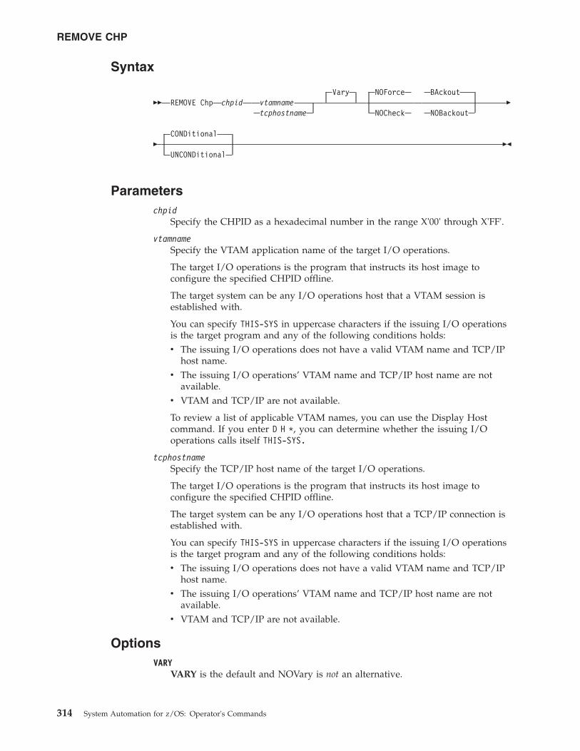
Syntax
�� REMOVE Chp chpid vtamnametcphostname
Vary NOForce
NOCheck
BAckout
NOBackout�
�CONDitional
UNCONDitional��
Parameterschpid
Specify the CHPID as a hexadecimal number in the range X'00' through X'FF'.
vtamnameSpecify the VTAM application name of the target I/O operations.
The target I/O operations is the program that instructs its host image toconfigure the specified CHPID offline.
The target system can be any I/O operations host that a VTAM session isestablished with.
You can specify THIS-SYS in uppercase characters if the issuing I/O operationsis the target program and any of the following conditions holds:v The issuing I/O operations does not have a valid VTAM name and TCP/IP
host name.v The issuing I/O operations’ VTAM name and TCP/IP host name are not
available.v VTAM and TCP/IP are not available.
To review a list of applicable VTAM names, you can use the Display Hostcommand. If you enter D H *, you can determine whether the issuing I/Ooperations calls itself THIS-SYS.
tcphostnameSpecify the TCP/IP host name of the target I/O operations.
The target I/O operations is the program that instructs its host image toconfigure the specified CHPID offline.
The target system can be any I/O operations host that a TCP/IP connection isestablished with.
You can specify THIS-SYS in uppercase characters if the issuing I/O operationsis the target program and any of the following conditions holds:v The issuing I/O operations does not have a valid VTAM name and TCP/IP
host name.v The issuing I/O operations’ VTAM name and TCP/IP host name are not
available.v VTAM and TCP/IP are not available.
OptionsVARY
VARY is the default and NOVary is not an alternative.
REMOVE CHP
314 System Automation for z/OS: Operator's Commands
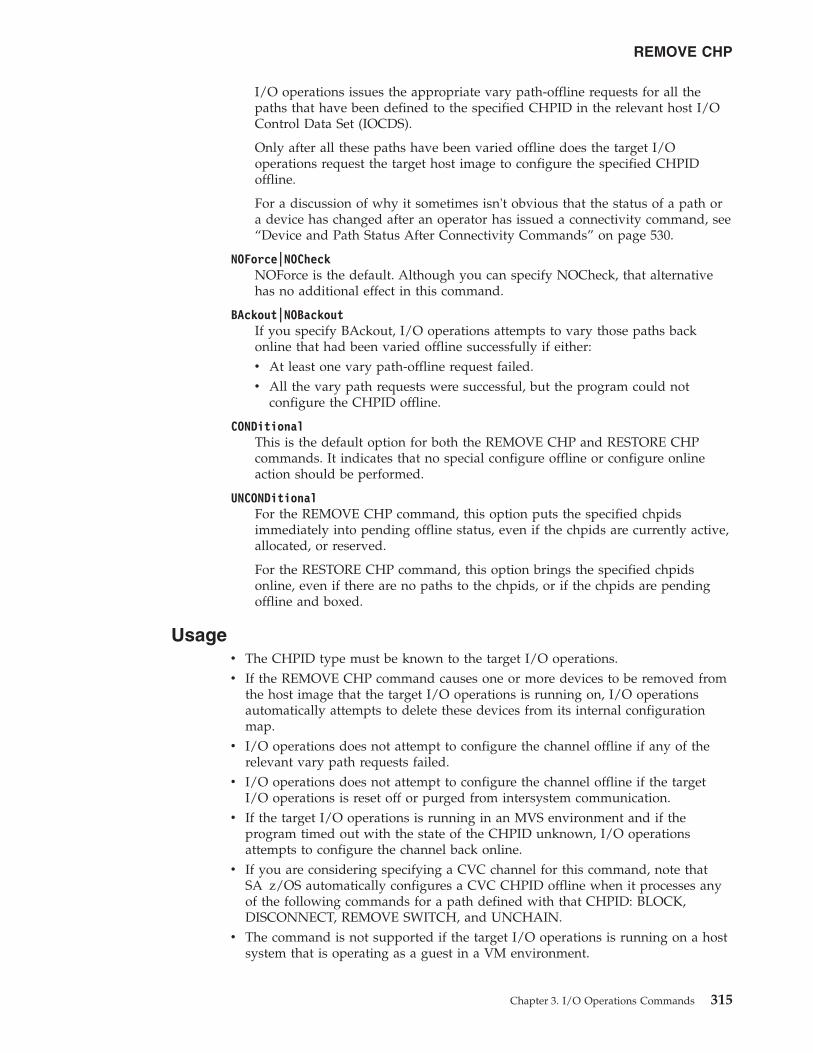
I/O operations issues the appropriate vary path-offline requests for all thepaths that have been defined to the specified CHPID in the relevant host I/OControl Data Set (IOCDS).
Only after all these paths have been varied offline does the target I/Ooperations request the target host image to configure the specified CHPIDoffline.
For a discussion of why it sometimes isn't obvious that the status of a path ora device has changed after an operator has issued a connectivity command, see“Device and Path Status After Connectivity Commands” on page 530.
NOForce|NOCheckNOForce is the default. Although you can specify NOCheck, that alternativehas no additional effect in this command.
BAckout|NOBackoutIf you specify BAckout, I/O operations attempts to vary those paths backonline that had been varied offline successfully if either:v At least one vary path-offline request failed.v All the vary path requests were successful, but the program could not
configure the CHPID offline.
CONDitionalThis is the default option for both the REMOVE CHP and RESTORE CHPcommands. It indicates that no special configure offline or configure onlineaction should be performed.
UNCONDitionalFor the REMOVE CHP command, this option puts the specified chpidsimmediately into pending offline status, even if the chpids are currently active,allocated, or reserved.
For the RESTORE CHP command, this option brings the specified chpidsonline, even if there are no paths to the chpids, or if the chpids are pendingoffline and boxed.
Usagev The CHPID type must be known to the target I/O operations.v If the REMOVE CHP command causes one or more devices to be removed from
the host image that the target I/O operations is running on, I/O operationsautomatically attempts to delete these devices from its internal configurationmap.
v I/O operations does not attempt to configure the channel offline if any of therelevant vary path requests failed.
v I/O operations does not attempt to configure the channel offline if the targetI/O operations is reset off or purged from intersystem communication.
v If the target I/O operations is running in an MVS environment and if theprogram timed out with the state of the CHPID unknown, I/O operationsattempts to configure the channel back online.
v If you are considering specifying a CVC channel for this command, note thatSA z/OS automatically configures a CVC CHPID offline when it processes anyof the following commands for a path defined with that CHPID: BLOCK,DISCONNECT, REMOVE SWITCH, and UNCHAIN.
v The command is not supported if the target I/O operations is running on a hostsystem that is operating as a guest in a VM environment.
REMOVE CHP
Chapter 3. I/O Operations Commands 315
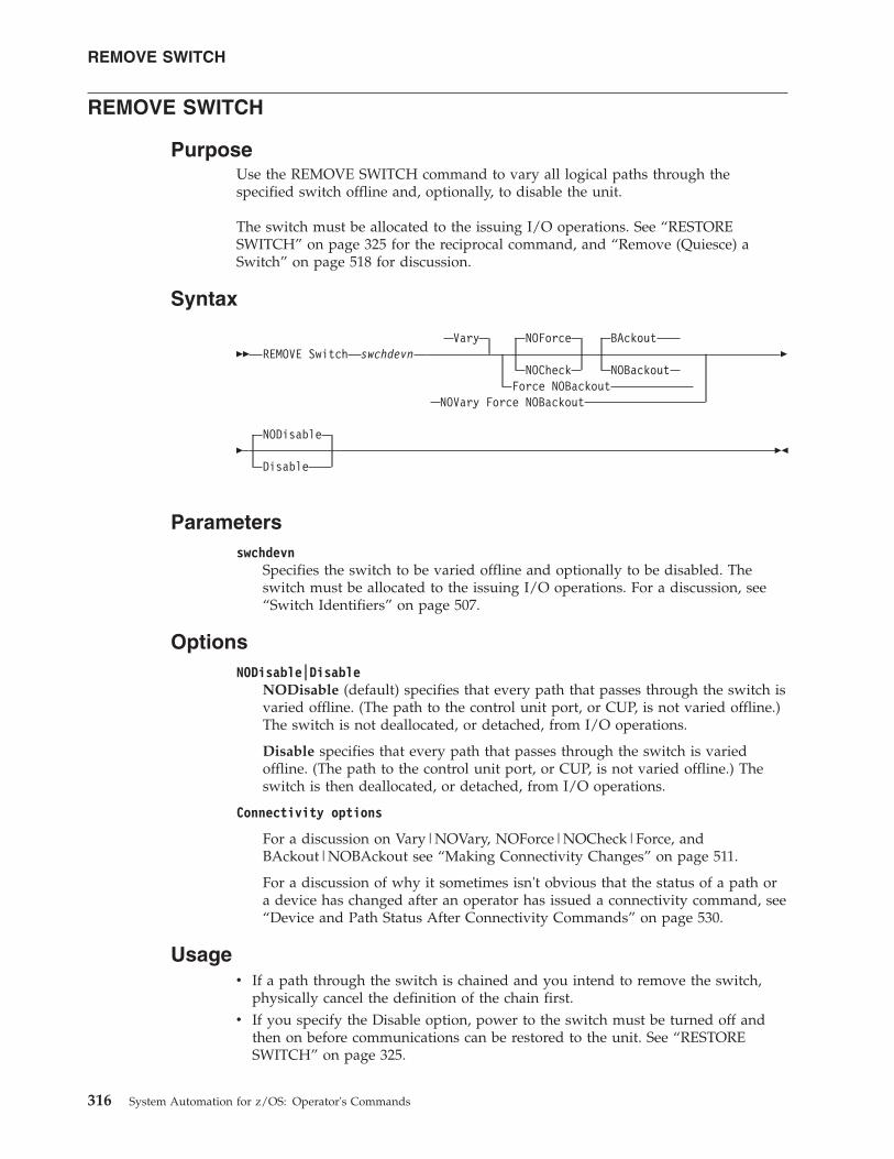
REMOVE SWITCH
PurposeUse the REMOVE SWITCH command to vary all logical paths through thespecified switch offline and, optionally, to disable the unit.
The switch must be allocated to the issuing I/O operations. See “RESTORESWITCH” on page 325 for the reciprocal command, and “Remove (Quiesce) aSwitch” on page 518 for discussion.
Syntax
�� REMOVE Switch swchdevnVary NOForce BAckout
NOCheck NOBackoutForce NOBackout
NOVary Force NOBackout
�
�NODisable
Disable��
Parametersswchdevn
Specifies the switch to be varied offline and optionally to be disabled. Theswitch must be allocated to the issuing I/O operations. For a discussion, see“Switch Identifiers” on page 507.
OptionsNODisable|Disable
NODisable (default) specifies that every path that passes through the switch isvaried offline. (The path to the control unit port, or CUP, is not varied offline.)The switch is not deallocated, or detached, from I/O operations.
Disable specifies that every path that passes through the switch is variedoffline. (The path to the control unit port, or CUP, is not varied offline.) Theswitch is then deallocated, or detached, from I/O operations.
Connectivity options
For a discussion on Vary|NOVary, NOForce|NOCheck|Force, andBAckout|NOBAckout see “Making Connectivity Changes” on page 511.
For a discussion of why it sometimes isn't obvious that the status of a path ora device has changed after an operator has issued a connectivity command, see“Device and Path Status After Connectivity Commands” on page 530.
Usagev If a path through the switch is chained and you intend to remove the switch,
physically cancel the definition of the chain first.v If you specify the Disable option, power to the switch must be turned off and
then on before communications can be restored to the unit. See “RESTORESWITCH” on page 325.
REMOVE SWITCH
316 System Automation for z/OS: Operator's Commands
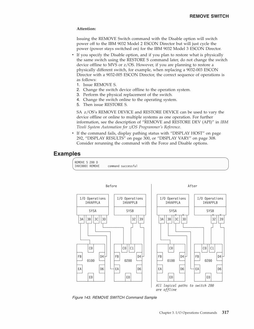
Attention:
Issuing the REMOVE Switch command with the Disable option will switchpower off to the IBM 9032 Model 2 ESCON Director but will just cycle thepower (power stays switched on) for the IBM 9032 Model 3 ESCON Director.
v If you specify the Disable option, and if you plan to restore what is physicallythe same switch using the RESTORE S command later, do not change the switchdevice offline to MVS or z/OS. However, if you are planning to restore aphysically different switch, for example, when replacing a 9032-003 ESCONDirector with a 9032-005 ESCON Director, the correct sequence of operations isas follows:1. Issue REMOVE S.2. Change the switch device offline to the operation system.3. Perform the physical replacement of the switch.4. Change the switch online to the operating system.5. Then issue RESTORE S.
SA z/OS’s REMOVE DEVICE and RESTORE DEVICE can be used to vary thedevice offline or online to multiple systems as one operation. For furtherinformation, see the description of “REMOVE and RESTORE DEV (API)” in IBMTivoli System Automation for z/OS Programmer’s Reference.
v If the command fails, display pathing status with “DISPLAY HOST” on page292, “DISPLAY RESULTS” on page 300, or “DISPLAY VARY” on page 308.Consider rerunning the command with the Force and Disable options.
ExamplesREMOVE S 200 DIHVC000I REMOVE command successful
Before │ After│
┌────────────────┐ ┌────────────────┐ │ ┌────────────────┐ ┌────────────────┐│ I/O Operations │ │ I/O Operations │ │ │ I/O Operations │ │ I/O Operations ││ IHVAPPLA │ │ IHVAPPLB │ │ │ IHVAPPLA │ │ IHVAPPLB │├────────────────┤ ├────────────────┤ │ ├────────────────┤ ├────────────────┤│ SYSA │ │ SYSB │ │ │ SYSA │ │ SYSB │└┬──┬┬──┬┬──┬┬──┬┘ └────────┬──┬┬──┬┘ │ └┬──┬┬──┬┬×─┬┬×─┬┘ └────────┬×─┬┬×─┬┘│3A││3B││3C││3D│ │32││39│ │ │3A││3B││3C││3D│ │32││39│└┬─┘└┬─┘└┬─┘└┬─┘ └┬─┘└┬─┘ │ └┬─┘└┬─┘└┬─┘└┬─┘ └┬─┘└┬─┘│ │ │ └──────────┐ ┌┘ └─┐ │ │ │ │ └──────────┐ ┌┘ └─┐│ │ └───────┐ │ │ │ │ │ │ └───────┐ │ │ ││ └─────────┐ │ │ │ │ │ │ └─────────┐ │ │ │ │└────┐ │ │ │ │ │ │ └────┐ │ │ │ │ │
┌─────┬┴─┬─────┐│ │ ┌───┬┴─┬┬┴─┬───┐│ │ ┌─────┬┴─┬─────┐│ │ ┌───┬┴─┬┬┴─┬───┐││ │C0│ ││ │ │ │C0││C1│ ││ │ │ │C0│ ││ │ │ │C0││C1│ ││├──┐ └──┘ ┌──┤│ │ ├──┐└──┘└──┘┌──┤│ │ ├──┐ └──┘ ┌──┤│ │ ├──┐└──┘└──┘┌──┤││FB│ │D4├┘ │ │FB│ │D4├┘ │ │FB│ │D4├┘ │ │FB│ │D4├┘├──┘ 0100 └──┤ │ ├──┘ 0200 └──┤ │ ├──┘ 0100 └──┤ │ ├──┘ 0200 └──┤├──┐ ┌──┤ │ ├──┐ ┌──┤ │ ├──┐ ┌──┤ │ ├──┐ ┌──┤│EA│ │D6│ └─┤EA│ │D6│ │ │EA│ │D6│ └─┤EA│ │D6│├──┘ ┌──┐ └──┤ ├──┘ ┌──┐ └──┤ │ ├──┘ ┌──┐ └──┤ ├──┘ ┌──┐ └──┤│ │E0│ │ │ │E0│ │ │ │ │E0│ │ │ │E0│ │└─────┴──┴─────┘ └─────┴──┴─────┘ │ └─────┴──┴─────┘ └─────┴──┴─────┘
│ All logical paths to switch 200are offline
Figure 143. REMOVE SWITCH Command Sample
REMOVE SWITCH
Chapter 3. I/O Operations Commands 317
RESET CHANGECHECK
PurposeUse the RESET CHANGECHECK command to limit the check for data changes ina switch or not when processing a connectivity command. Normally, all openedswitches are checked for a data change prior to the execution of a connectivitycommand. If any switch responds with a data change indication or cannot respondto the check the connectivity command is rejected. Limiting the check to theswitches that are actually affected by the connectivity command avoids therejection of the command by any other switch.
Syntax
RESET CHANGECHECK
��ON
Reset ChangeCheck OFF ��
ParametersOFF Specifies that only those switches are checked for a data change prior to a
connectivity command which are actually affected by the command.
ON Specifies that all opened switches are checked for a data change prior to aconnectivity command. This is the default setting on the startup of I/OOperations.
UsagePrior to a connectivity command all opened switches are checked for a datachange. If any switch responds with a data change indication or cannot respond tothe check for whatever reason the connectivity command is rejected. In case theswitch causing the rejection of the command is actually not affected by theconnectivity command you can turn off the CHANGECHECK option forcing I/OOperations only to check the switches that are affected by the command.
ExamplesR CC OFFIHVC000I RESET command successful.
RESET HOST
PurposeUse the RESET HOST command to include or exclude any participant in theissuing I/O operations's consensus processing.
With this command, you can avoid having the issuing I/O operations stop thecommand from completing because, for example, a participant could not return avote.
See “DISPLAY HOST” on page 292 for the related command.
RESET CHANGECHECK
318 System Automation for z/OS: Operator's Commands
Syntax
�� Reset Host vtamnametcphostname
ON
OFFPURGE
��
Parametersvtamname
Specifies the VTAM application name, or VTAM ID, of the I/O operationstargeted in the command.
When I/O operations is started, it writes its VTAM ID and the TCP/IP hostname to all the switches allocated to it. Should the I/O configuration have nouse or restricted use of switches, dynamic communication between I/Ooperations may not be achieved, in which case the RESET HOST command isused. The RESET HOST command allows an operator or automated programto declare the VTAM IDs of peers to I/O operations. I/O operations that areparticipating in consensus processing use these VTAM IDs to communicatewith each other.
tcphostnameSpecifies the TCP/IP host name of the I/O operations targeted in thecommand.
When I/O operations is started, it writes its VTAM application name and theTCP/IP host name to all the switches allocated to it. Should the I/Oconfiguration have no or restricted use of switches, dynamic communicationbetween I/O operations may not be achieved, in which case, the RESET HOSTcommand is used. The RESET HOST command allows an operator orautomated program to declare the TCP/IP host name of peers to I/Ooperations. I/O operations that are participating in consensus processing usethese TCP/IP host names to communicate with each other.
ON Is the default. It specifies that the issuing I/O operations will include the targetI/O operations in its consensus processing. (The issuing I/O operations caninclude itself.) Should the VTAM ID or TCP/IP host name not be recognized,I/O operations records the name and attempts to establish a communicationsession with the peer. The new peer is included in all subsequent consensusprocessing. If the name resolves to a TCP/IP host name, I/O operationsattempts to establish a TCP/IP connection to the host. Otherwise, a VTAMapplication name is assumed and I/O operations attempts to establish a VTAMsession.
OFFSpecifies that the issuing I/O operations will exclude the target I/O operationsin consensus processing. (The issuing I/O operations can exclude itself.)
PURGESpecifies that the issuing I/O operations will exclude the targeted I/Ooperations from participating in its consensus processing until the target hostre-registers its VTAM name or TCP/IP host name when it sends a command toone of the switches allocated to both the purged I/O operations and the I/Ooperations that issued the purge, when the purged I/O operations is restarted,or when a RESET HOST command with the ON operand is issued. Use thisoption to exclude systems that have ended abnormally or when an incorrect
RESET HOST
Chapter 3. I/O Operations Commands 319
VTAM ID or TCP/IP host name was entered using the RESET HOST commandwith the ON operand. (The issuing I/O operations cannot purge itself.)
UsageThe RESET HOST command affects an I/O operations’s participation only inconsensus processing initiated by the issuing I/O operations. It does not affectconsensus vary path processing initiated by any other I/O operations, including abroadcast initiated by a host that has been reset off.
When the VTAM ID or TCP/IP host name is not known command processing forRESET HOST name ON is as follows:1. The VTAM ID or TCP/IP host name is recorded by I/O operations and is
included in subsequent consensus processing. Should the name not besuccessfully recorded the following messages are issued:IHVC002I Reset command failed. RC = 8 Reas= 5000000AIHVC401I Host(s) unable to process the RESET command
2. If the name resolves to a TCP/IP host name an attempt is made to establish aTCP/IP connection. Otherwise, an attempt to establish a VTAM session ismade. If the session is successfully established with the peer its VTAM ID orTCP/IP host name is automatically passed to other I/O operations in thedomain. Then each I/O operations dynamically establishes its own session tothe peer. The following message is issued:IHVC000I RESET command successful
3. If the TCP/IP connection or the VTAM session is not successfully establishedthe TCP/IP host name or VTAM ID is retained by I/O operations, but thename is not broadcast to other peers. This can be caused, for example, by thespecification of an incorrect TCP/IP host name or VTAM ID. Should this occurthe following messages are issued:IHVC001I Reset command successful. RC = 4 Reas= 5000000AIHVC401I Host(s) unable to process the RESET command
Additional information is presented in the Display Results output that indicatesthe VTAM session was not established.
ExamplesR H IHVAPPLB OFFIHVC000I RESET command successful
R H IHVAPPLB ONIHVC000I RESET command successful
R H IHVAPPLB PURGEIHVC000I RESET command successful
Examples of Using RESET HOST to Declare Peer I/O Operations
No Switch Configuration:
RESET HOST
320 System Automation for z/OS: Operator's Commands
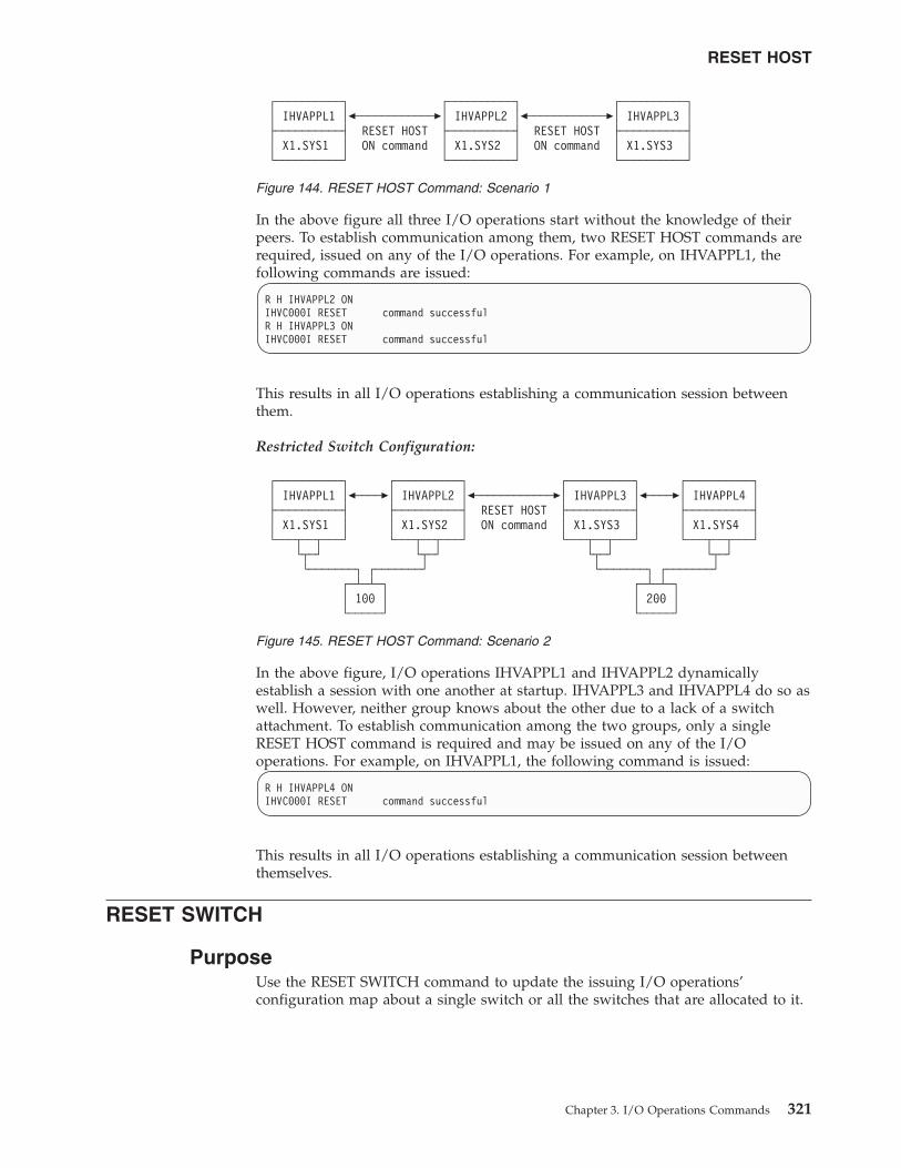
In the above figure all three I/O operations start without the knowledge of theirpeers. To establish communication among them, two RESET HOST commands arerequired, issued on any of the I/O operations. For example, on IHVAPPL1, thefollowing commands are issued:
R H IHVAPPL2 ONIHVC000I RESET command successfulR H IHVAPPL3 ONIHVC000I RESET command successful
This results in all I/O operations establishing a communication session betweenthem.
Restricted Switch Configuration:
In the above figure, I/O operations IHVAPPL1 and IHVAPPL2 dynamicallyestablish a session with one another at startup. IHVAPPL3 and IHVAPPL4 do so aswell. However, neither group knows about the other due to a lack of a switchattachment. To establish communication among the two groups, only a singleRESET HOST command is required and may be issued on any of the I/Ooperations. For example, on IHVAPPL1, the following command is issued:
R H IHVAPPL4 ONIHVC000I RESET command successful
This results in all I/O operations establishing a communication session betweenthemselves.
RESET SWITCH
PurposeUse the RESET SWITCH command to update the issuing I/O operations’configuration map about a single switch or all the switches that are allocated to it.
┌──────────┐ ┌──────────┐ ┌──────────┐│ IHVAPPL1 │�────────────�│ IHVAPPL2 │�────────────�│ IHVAPPL3 │├──────────┤ RESET HOST ├──────────┤ RESET HOST ├──────────┤│ X1.SYS1 │ ON command │ X1.SYS2 │ ON command │ X1.SYS3 │└──────────┘ └──────────┘ └──────────┘
Figure 144. RESET HOST Command: Scenario 1
┌──────────┐ ┌──────────┐ ┌──────────┐ ┌──────────┐│ IHVAPPL1 │�────�│ IHVAPPL2 │�────────────�│ IHVAPPL3 │�────�│ IHVAPPL4 │├──────────┤ ├──────────┤ RESET HOST ├──────────┤ ├──────────┤│ X1.SYS1 │ │ X1.SYS2 │ ON command │ X1.SYS3 │ │ X1.SYS4 │└───┬──┬───┘ └───┬──┬───┘ └───┬──┬───┘ └───┬──┬───┘
└┬─┘ └┬─┘ └┬─┘ └┬─┘└───────┐ ┌───────┘ └───────┐ ┌───────┘
┌─┴─┴─┐ ┌─┴─┴─┐│ 100 │ │ 200 │└─────┘ └─────┘
Figure 145. RESET HOST Command: Scenario 2
RESET HOST
Chapter 3. I/O Operations Commands 321
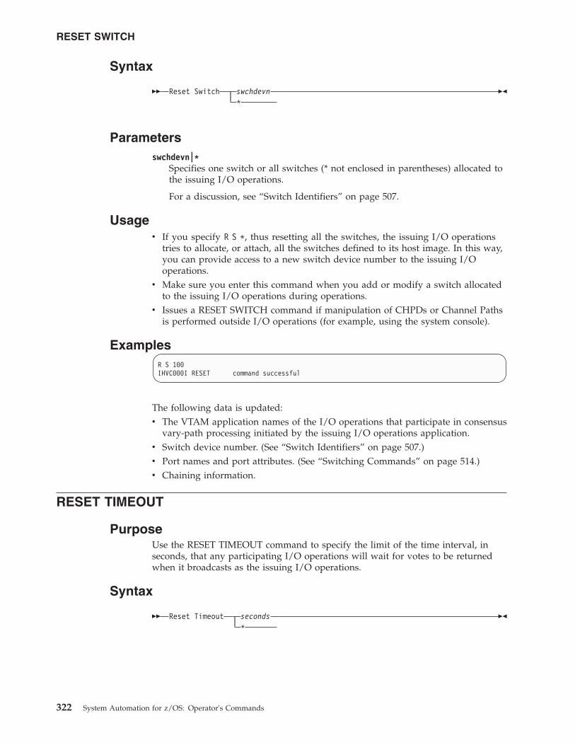
Syntax
�� Reset Switch swchdevn*
��
Parametersswchdevn|*
Specifies one switch or all switches (* not enclosed in parentheses) allocated tothe issuing I/O operations.
For a discussion, see “Switch Identifiers” on page 507.
Usagev If you specify R S *, thus resetting all the switches, the issuing I/O operations
tries to allocate, or attach, all the switches defined to its host image. In this way,you can provide access to a new switch device number to the issuing I/Ooperations.
v Make sure you enter this command when you add or modify a switch allocatedto the issuing I/O operations during operations.
v Issues a RESET SWITCH command if manipulation of CHPDs or Channel Pathsis performed outside I/O operations (for example, using the system console).
ExamplesR S 100IHVC000I RESET command successful
The following data is updated:v The VTAM application names of the I/O operations that participate in consensus
vary-path processing initiated by the issuing I/O operations application.v Switch device number. (See “Switch Identifiers” on page 507.)v Port names and port attributes. (See “Switching Commands” on page 514.)v Chaining information.
RESET TIMEOUT
PurposeUse the RESET TIMEOUT command to specify the limit of the time interval, inseconds, that any participating I/O operations will wait for votes to be returnedwhen it broadcasts as the issuing I/O operations.
Syntax
�� Reset Timeout seconds*
��
RESET SWITCH
322 System Automation for z/OS: Operator's Commands
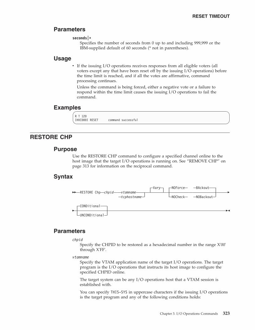
Parametersseconds|*
Specifies the number of seconds from 0 up to and including 999,999 or theIBM-supplied default of 60 seconds (* not in parentheses).
Usagev If the issuing I/O operations receives responses from all eligible voters (all
voters except any that have been reset off by the issuing I/O operations) beforethe time limit is reached, and if all the votes are affirmative, commandprocessing continues.Unless the command is being forced, either a negative vote or a failure torespond within the time limit causes the issuing I/O operations to fail thecommand.
ExamplesR T 120IHVC000I RESET command successful
RESTORE CHP
PurposeUse the RESTORE CHP command to configure a specified channel online to thehost image that the target I/O operations is running on. See “REMOVE CHP” onpage 313 for information on the reciprocal command.
Syntax
�� RESTORE Chp chpid vtamnametcphostname
Vary NOForce
NOCheck
BAckout
NOBackout�
�CONDitional
UNCONDitional��
Parameterschpid
Specify the CHPID to be restored as a hexadecimal number in the range X'00'through X'FF'.
vtamnameSpecify the VTAM application name of the target I/O operations. The targetprogram is the I/O operations that instructs its host image to configure thespecified CHPID online.
The target system can be any I/O operations host that a VTAM session isestablished with.
You can specify THIS-SYS in uppercase characters if the issuing I/O operationsis the target program and any of the following conditions holds:
RESET TIMEOUT
Chapter 3. I/O Operations Commands 323
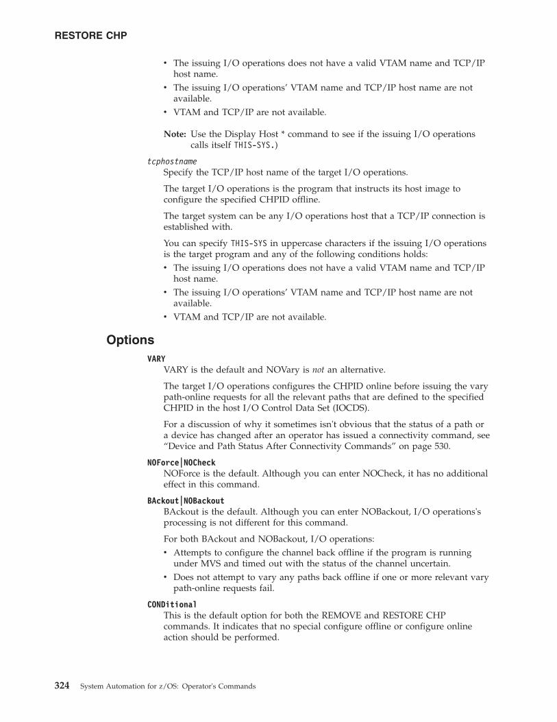
v The issuing I/O operations does not have a valid VTAM name and TCP/IPhost name.
v The issuing I/O operations’ VTAM name and TCP/IP host name are notavailable.
v VTAM and TCP/IP are not available.
Note: Use the Display Host * command to see if the issuing I/O operationscalls itself THIS-SYS.)
tcphostnameSpecify the TCP/IP host name of the target I/O operations.
The target I/O operations is the program that instructs its host image toconfigure the specified CHPID offline.
The target system can be any I/O operations host that a TCP/IP connection isestablished with.
You can specify THIS-SYS in uppercase characters if the issuing I/O operationsis the target program and any of the following conditions holds:v The issuing I/O operations does not have a valid VTAM name and TCP/IP
host name.v The issuing I/O operations’ VTAM name and TCP/IP host name are not
available.v VTAM and TCP/IP are not available.
OptionsVARY
VARY is the default and NOVary is not an alternative.
The target I/O operations configures the CHPID online before issuing the varypath-online requests for all the relevant paths that are defined to the specifiedCHPID in the host I/O Control Data Set (IOCDS).
For a discussion of why it sometimes isn't obvious that the status of a path ora device has changed after an operator has issued a connectivity command, see“Device and Path Status After Connectivity Commands” on page 530.
NOForce|NOCheckNOForce is the default. Although you can enter NOCheck, it has no additionaleffect in this command.
BAckout|NOBackoutBAckout is the default. Although you can enter NOBackout, I/O operations'sprocessing is not different for this command.
For both BAckout and NOBackout, I/O operations:v Attempts to configure the channel back offline if the program is running
under MVS and timed out with the status of the channel uncertain.v Does not attempt to vary any paths back offline if one or more relevant vary
path-online requests fail.
CONDitionalThis is the default option for both the REMOVE and RESTORE CHPcommands. It indicates that no special configure offline or configure onlineaction should be performed.
RESTORE CHP
324 System Automation for z/OS: Operator's Commands
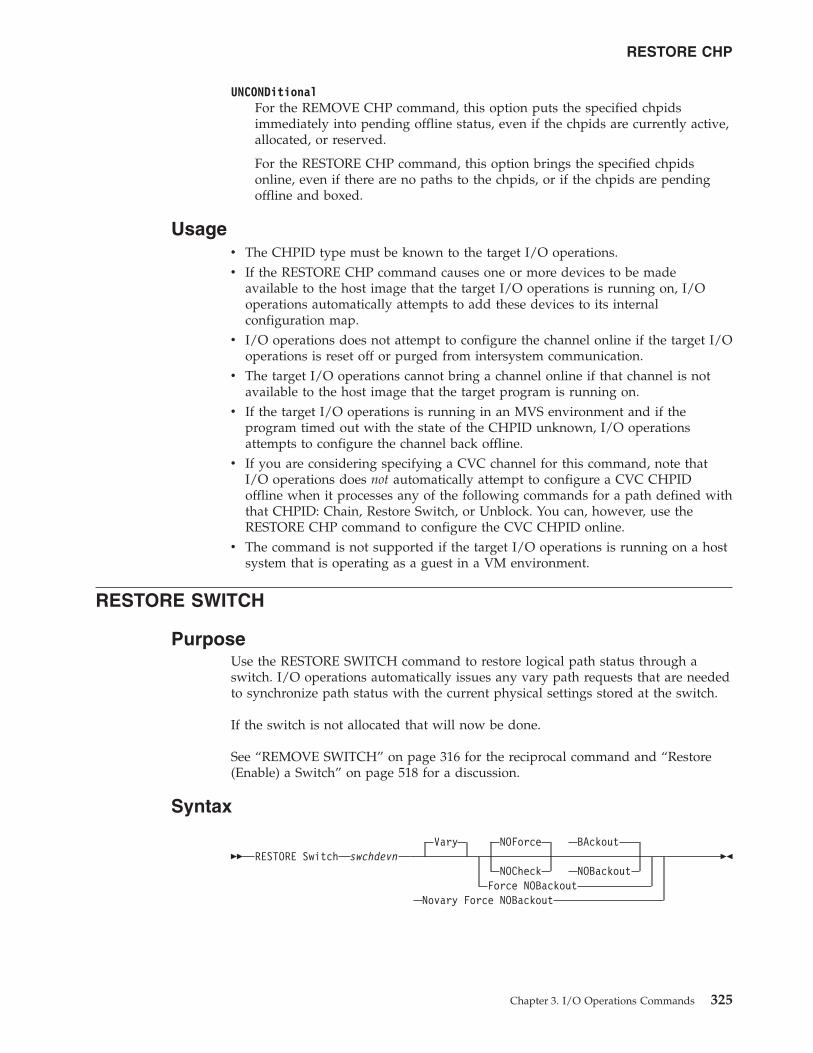
UNCONDitionalFor the REMOVE CHP command, this option puts the specified chpidsimmediately into pending offline status, even if the chpids are currently active,allocated, or reserved.
For the RESTORE CHP command, this option brings the specified chpidsonline, even if there are no paths to the chpids, or if the chpids are pendingoffline and boxed.
Usagev The CHPID type must be known to the target I/O operations.v If the RESTORE CHP command causes one or more devices to be made
available to the host image that the target I/O operations is running on, I/Ooperations automatically attempts to add these devices to its internalconfiguration map.
v I/O operations does not attempt to configure the channel online if the target I/Ooperations is reset off or purged from intersystem communication.
v The target I/O operations cannot bring a channel online if that channel is notavailable to the host image that the target program is running on.
v If the target I/O operations is running in an MVS environment and if theprogram timed out with the state of the CHPID unknown, I/O operationsattempts to configure the channel back offline.
v If you are considering specifying a CVC channel for this command, note thatI/O operations does not automatically attempt to configure a CVC CHPIDoffline when it processes any of the following commands for a path defined withthat CHPID: Chain, Restore Switch, or Unblock. You can, however, use theRESTORE CHP command to configure the CVC CHPID online.
v The command is not supported if the target I/O operations is running on a hostsystem that is operating as a guest in a VM environment.
RESTORE SWITCH
PurposeUse the RESTORE SWITCH command to restore logical path status through aswitch. I/O operations automatically issues any vary path requests that are neededto synchronize path status with the current physical settings stored at the switch.
If the switch is not allocated that will now be done.
See “REMOVE SWITCH” on page 316 for the reciprocal command and “Restore(Enable) a Switch” on page 518 for a discussion.
Syntax
�� RESTORE Switch swchdevnVary NOForce BAckout
NOCheck NOBackoutForce NOBackout
Novary Force NOBackout
��
RESTORE CHP
Chapter 3. I/O Operations Commands 325
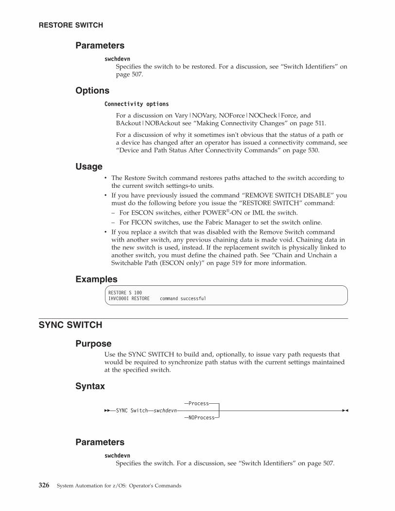
Parametersswchdevn
Specifies the switch to be restored. For a discussion, see “Switch Identifiers” onpage 507.
OptionsConnectivity options
For a discussion on Vary|NOVary, NOForce|NOCheck|Force, andBAckout|NOBAckout see “Making Connectivity Changes” on page 511.
For a discussion of why it sometimes isn't obvious that the status of a path ora device has changed after an operator has issued a connectivity command, see“Device and Path Status After Connectivity Commands” on page 530.
Usagev The Restore Switch command restores paths attached to the switch according to
the current switch settings-to units.v If you have previously issued the command “REMOVE SWITCH DISABLE” you
must do the following before you issue the “RESTORE SWITCH” command:– For ESCON switches, either POWER®-ON or IML the switch.– For FICON switches, use the Fabric Manager to set the switch online.
v If you replace a switch that was disabled with the Remove Switch commandwith another switch, any previous chaining data is made void. Chaining data inthe new switch is used, instead. If the replacement switch is physically linked toanother switch, you must define the chained path. See “Chain and Unchain aSwitchable Path (ESCON only)” on page 519 for more information.
ExamplesRESTORE S 100IHVC000I RESTORE command successful
SYNC SWITCH
PurposeUse the SYNC SWITCH to build and, optionally, to issue vary path requests thatwould be required to synchronize path status with the current settings maintainedat the specified switch.
Syntax
�� SYNC Switch swchdevnProcess
NOProcess��
Parametersswchdevn
Specifies the switch. For a discussion, see “Switch Identifiers” on page 507.
RESTORE SWITCH
326 System Automation for z/OS: Operator's Commands
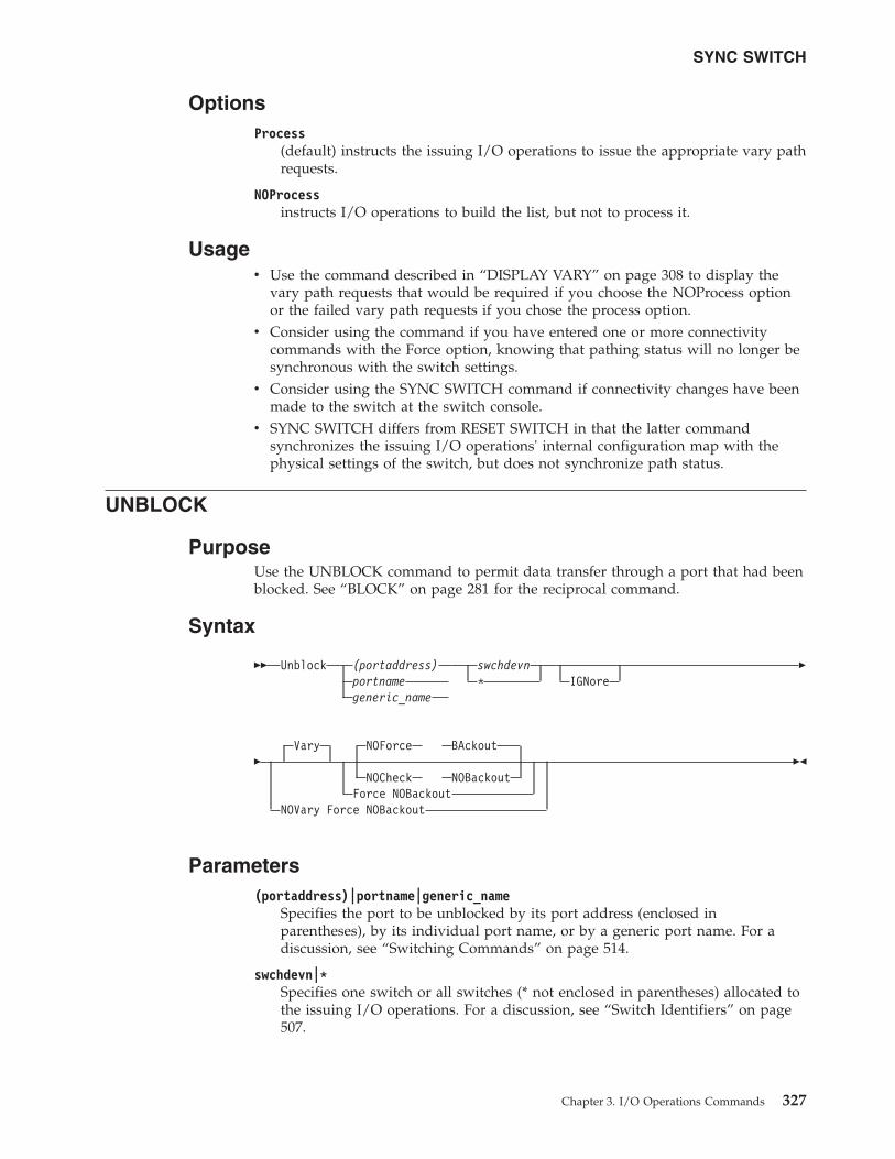
OptionsProcess
(default) instructs the issuing I/O operations to issue the appropriate vary pathrequests.
NOProcessinstructs I/O operations to build the list, but not to process it.
Usagev Use the command described in “DISPLAY VARY” on page 308 to display the
vary path requests that would be required if you choose the NOProcess optionor the failed vary path requests if you chose the process option.
v Consider using the command if you have entered one or more connectivitycommands with the Force option, knowing that pathing status will no longer besynchronous with the switch settings.
v Consider using the SYNC SWITCH command if connectivity changes have beenmade to the switch at the switch console.
v SYNC SWITCH differs from RESET SWITCH in that the latter commandsynchronizes the issuing I/O operations' internal configuration map with thephysical settings of the switch, but does not synchronize path status.
UNBLOCK
PurposeUse the UNBLOCK command to permit data transfer through a port that had beenblocked. See “BLOCK” on page 281 for the reciprocal command.
Syntax
�� Unblock (portaddress)portnamegeneric_name
swchdevn* IGNore
�
�Vary NOForce BAckout
NOCheck NOBackoutForce NOBackout
NOVary Force NOBackout
��
Parameters(portaddress)|portname|generic_name
Specifies the port to be unblocked by its port address (enclosed inparentheses), by its individual port name, or by a generic port name. For adiscussion, see “Switching Commands” on page 514.
swchdevn|*Specifies one switch or all switches (* not enclosed in parentheses) allocated tothe issuing I/O operations. For a discussion, see “Switch Identifiers” on page507.
SYNC SWITCH
Chapter 3. I/O Operations Commands 327
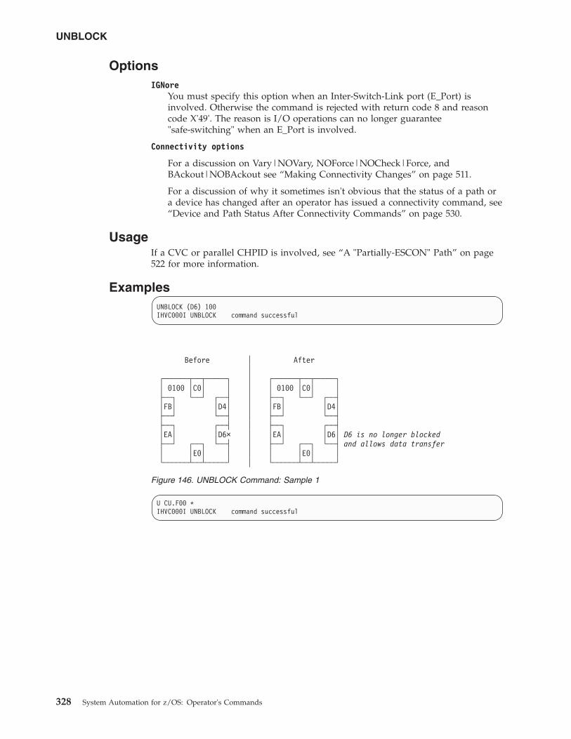
OptionsIGNore
You must specify this option when an Inter-Switch-Link port (E_Port) isinvolved. Otherwise the command is rejected with return code 8 and reasoncode X'49'. The reason is I/O operations can no longer guarantee"safe-switching" when an E_Port is involved.
Connectivity options
For a discussion on Vary|NOVary, NOForce|NOCheck|Force, andBAckout|NOBAckout see “Making Connectivity Changes” on page 511.
For a discussion of why it sometimes isn't obvious that the status of a path ora device has changed after an operator has issued a connectivity command, see“Device and Path Status After Connectivity Commands” on page 530.
UsageIf a CVC or parallel CHPID is involved, see “A "Partially-ESCON" Path” on page522 for more information.
ExamplesUNBLOCK (D6) 100IHVC000I UNBLOCK command successful
U CU.F00 *IHVC000I UNBLOCK command successful
Before │ After│
┌──────┬──┬─────┐ │ ┌──────┬──┬─────┐│ 0100 │C0│ │ │ │ 0100 │C0│ │├──┐ └──┘ ┌──┤ │ ├──┐ └──┘ ┌──┤│FB│ │D4│ │ │FB│ │D4│├──┘ └──┤ │ ├──┘ └──┤├──┐ ┌──┤ │ ├──┐ ┌──┤│EA│ │D6× │ │EA│ │D6│ D6 is no longer blocked├──┘ ┌──┐ └──┤ │ ├──┘ ┌──┐ └──┤ and allows data transfer│ │E0│ │ │ │ │E0│ │└──────┴──┴─────┘ │ └──────┴──┴─────┘
Figure 146. UNBLOCK Command: Sample 1
UNBLOCK
328 System Automation for z/OS: Operator's Commands
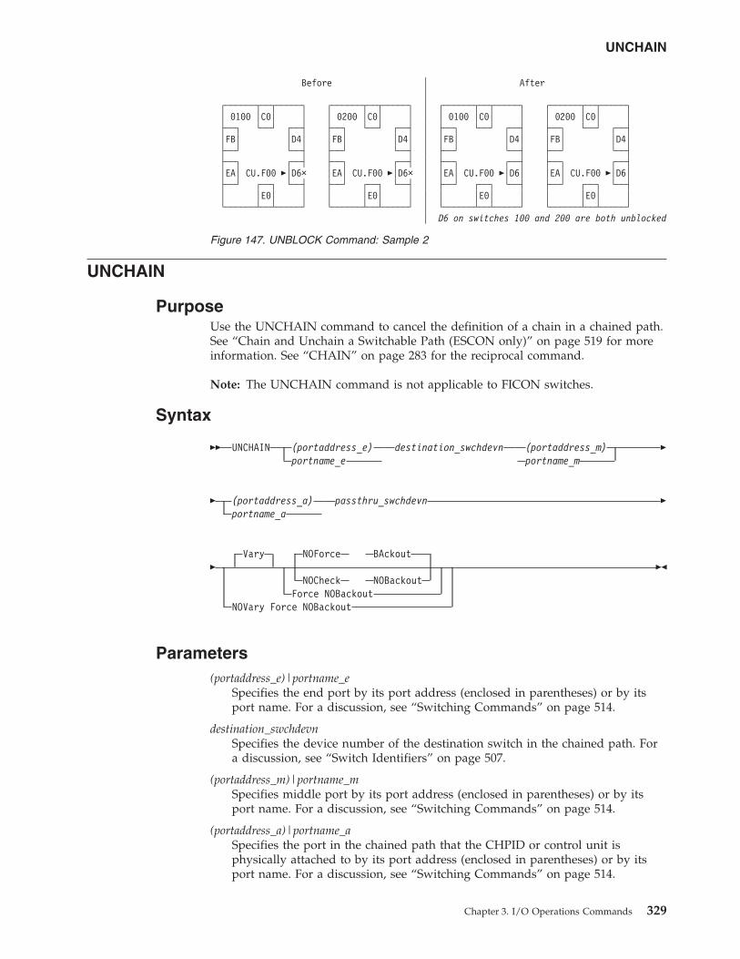
UNCHAIN
PurposeUse the UNCHAIN command to cancel the definition of a chain in a chained path.See “Chain and Unchain a Switchable Path (ESCON only)” on page 519 for moreinformation. See “CHAIN” on page 283 for the reciprocal command.
Note: The UNCHAIN command is not applicable to FICON switches.
Syntax
�� UNCHAIN (portaddress_e)portname_e
destination_swchdevn (portaddress_m)portname_m
�
� (portaddress_a)portname_a
passthru_swchdevn �
�Vary NOForce BAckout
NOCheck NOBackoutForce NOBackout
NOVary Force NOBackout
��
Parameters(portaddress_e)|portname_e
Specifies the end port by its port address (enclosed in parentheses) or by itsport name. For a discussion, see “Switching Commands” on page 514.
destination_swchdevnSpecifies the device number of the destination switch in the chained path. Fora discussion, see “Switch Identifiers” on page 507.
(portaddress_m)|portname_mSpecifies middle port by its port address (enclosed in parentheses) or by itsport name. For a discussion, see “Switching Commands” on page 514.
(portaddress_a)|portname_aSpecifies the port in the chained path that the CHPID or control unit isphysically attached to by its port address (enclosed in parentheses) or by itsport name. For a discussion, see “Switching Commands” on page 514.
Before │ After│
┌──────┬──┬─────┐ ┌──────┬──┬─────┐ │ ┌──────┬──┬─────┐ ┌──────┬──┬─────┐│ 0100 │C0│ │ │ 0200 │C0│ │ │ │ 0100 │C0│ │ │ 0200 │C0│ │├──┐ └──┘ ┌──┤ ├──┐ └──┘ ┌──┤ │ ├──┐ └──┘ ┌──┤ ├──┐ └──┘ ┌──┤│FB│ │D4│ │FB│ │D4│ │ │FB│ │D4│ │FB│ │D4│├──┘ └──┤ ├──┘ └──┤ │ ├──┘ └──┤ ├──┘ └──┤├──┐ ┌──┤ ├──┐ ┌──┤ │ ├──┐ ┌──┤ ├──┐ ┌──┤│EA│ CU.F00 �│D6× │EA│ CU.F00 �│D6× │ │EA│ CU.F00 �│D6│ │EA│ CU.F00 �│D6│├──┘ ┌──┐ └──┤ ├──┘ ┌──┐ └──┤ │ ├──┘ ┌──┐ └──┤ ├──┘ ┌──┐ └──┤│ │E0│ │ │ │E0│ │ │ │ │E0│ │ │ │E0│ │└──────┴──┴─────┘ └──────┴──┴─────┘ │ └──────┴──┴─────┘ └──────┴──┴─────┘
│ D6 on switches 100 and 200 are both unblocked
Figure 147. UNBLOCK Command: Sample 2
UNCHAIN
Chapter 3. I/O Operations Commands 329
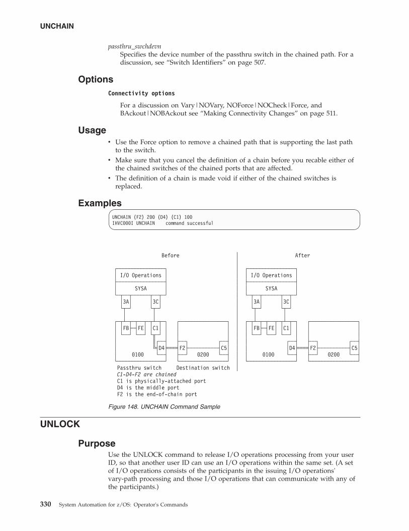
passthru_swchdevnSpecifies the device number of the passthru switch in the chained path. For adiscussion, see “Switch Identifiers” on page 507.
OptionsConnectivity options
For a discussion on Vary|NOVary, NOForce|NOCheck|Force, andBAckout|NOBAckout see “Making Connectivity Changes” on page 511.
Usagev Use the Force option to remove a chained path that is supporting the last path
to the switch.v Make sure that you cancel the definition of a chain before you recable either of
the chained switches of the chained ports that are affected.v The definition of a chain is made void if either of the chained switches is
replaced.
ExamplesUNCHAIN (F2) 200 (D4) (C1) 100IHVC000I UNCHAIN command successful
UNLOCK
PurposeUse the UNLOCK command to release I/O operations processing from your userID, so that another user ID can use an I/O operations within the same set. (A setof I/O operations consists of the participants in the issuing I/O operations'vary-path processing and those I/O operations that can communicate with any ofthe participants.)
Before │ After│
┌────────────────┐ │ ┌────────────────┐│ I/O Operations │ │ │ I/O Operations │├────────────────┤ │ ├────────────────┤│ SYSA │ │ │ SYSA │└─┬──┬──────┬──┬─┘ │ └─┬──┬──────┬──┬─┘
│3A│ │3C│ │ │3A│ │3C│└┬─┘ └┬─┘ │ └┬─┘ └┬─┘│ │ │ │ │
┌─┬┴─┬─┬──┬─┬┴─┬─┐ ┌────────────────┐ │ ┌─┬┴─┬─┬──┬─┬┴─┬─┐ ┌────────────────┐│ │FB├─┤FE│ │C1│ │ │ │ │ │ │FB├─┤FE│ │C1│ │ │ ││ └──┘ └──┘ └╥─┘ │ │ │ │ │ └──┘ └──┘ └──┘ │ │ ││ ║┌──┤ ├──┐ ┌──┤ │ │ ┌──┤ ├──┐ ┌──┤│ ╚╡D4╞═══╡F2├──────────┤C5│ │ │ │D4╞═══╡F2├──────────┤C5││ 0100 └──┤ ├──┘ 0200 └──┤ │ │ 0100 └──┤ ├──┘ 0200 └──┤└────────────────┘ └────────────────┘ │ └────────────────┘ └────────────────┘Passthru switch Destination switch │C1-D4-F2 are chainedC1 is physically-attached portD4 is the middle portF2 is the end-of-chain port
Figure 148. UNCHAIN Command Sample
UNCHAIN
330 System Automation for z/OS: Operator's Commands
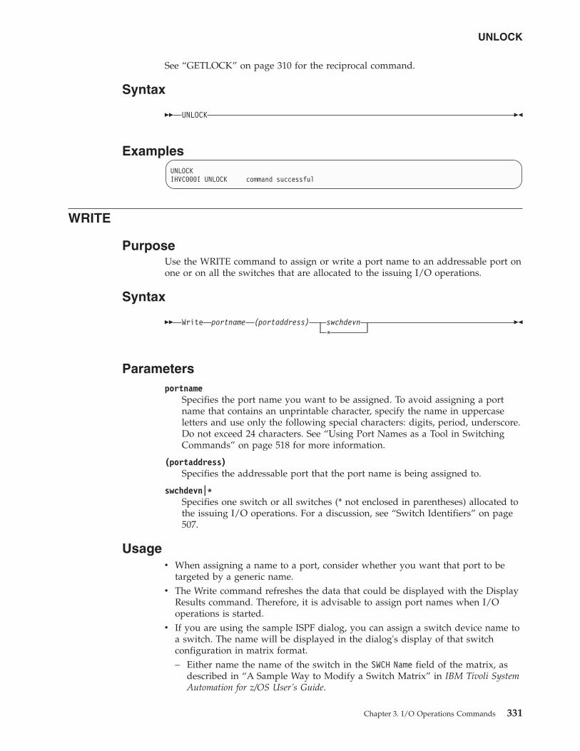
See “GETLOCK” on page 310 for the reciprocal command.
Syntax
�� UNLOCK ��
ExamplesUNLOCKIHVC000I UNLOCK command successful
WRITE
PurposeUse the WRITE command to assign or write a port name to an addressable port onone or on all the switches that are allocated to the issuing I/O operations.
Syntax
�� Write portname (portaddress) swchdevn*
��
Parametersportname
Specifies the port name you want to be assigned. To avoid assigning a portname that contains an unprintable character, specify the name in uppercaseletters and use only the following special characters: digits, period, underscore.Do not exceed 24 characters. See “Using Port Names as a Tool in SwitchingCommands” on page 518 for more information.
(portaddress)Specifies the addressable port that the port name is being assigned to.
swchdevn|*Specifies one switch or all switches (* not enclosed in parentheses) allocated tothe issuing I/O operations. For a discussion, see “Switch Identifiers” on page507.
Usagev When assigning a name to a port, consider whether you want that port to be
targeted by a generic name.v The Write command refreshes the data that could be displayed with the Display
Results command. Therefore, it is advisable to assign port names when I/Ooperations is started.
v If you are using the sample ISPF dialog, you can assign a switch device name toa switch. The name will be displayed in the dialog's display of that switchconfiguration in matrix format.– Either name the name of the switch in the SWCH Name field of the matrix, as
described in “A Sample Way to Modify a Switch Matrix” in IBM Tivoli SystemAutomation for z/OS User’s Guide.
UNLOCK
Chapter 3. I/O Operations Commands 331
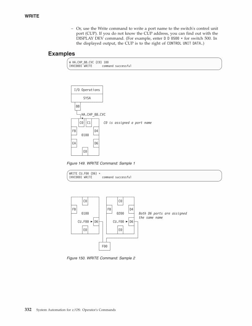
– Or, use the Write command to write a port name to the switch's control unitport (CUP). If you do not know the CUP address, you can find out with theDISPLAY DEV command. (For example, enter D D 0500 * for switch 500. Inthe displayed output, the CUP is to the right of CONTROL UNIT DATA.)
ExamplesW HA.CHP_88.CVC (C0) 100IHVC000I WRITE command successful
WRITE CU.F00 (D6) *IHVC000I WRITE command successful
┌────────────────┐│ I/O Operations │├────────────────┤│ SYSA │└─┬──┬───────────┘
│88│└┬─┘└─┐HA.CHP_88.CVC
┌───┬┴�┬┬──┬───┐│ │C0││C1│ │ C0 is assigned a port name├──┐└──┘└──┘┌──┤│FB│ │D4│├──┘ 0100 └──┤├──┐ ┌──┤│EA│ │D6│├──┘ ┌──┐ └──┤│ │E0│ │└─────┴──┴─────┘
Figure 149. WRITE Command: Sample 1
┌─────┬──┬─────┐ ┌─────┬──┬─────┐│ │C0│ │ │ │C0│ │├──┐ └──┘ │ ├──┐ └──┘ ┌──┤│FB│ │ │FB│ │D4│├──┘ 0100 │ ├──┘ 0200 └──┤ Both D6 ports are assigned│ ┌──┤ │ ┌──┤ the same name│ CU.F00 �│D6├─┐ │ CU.F00 �│D6├─┐│ ┌──┐ └──┤ │ │ ┌──┐ └──┤ ││ │E0│ │ │ │ │E0│ │ │└─────┴──┴─────┘ │ └─────┴──┴─────┘ │
│ ┌────────────────┘┌─┴─┴─┐│ F00 │└─────┘
Figure 150. WRITE Command: Sample 2
WRITE
332 System Automation for z/OS: Operator's Commands
Part 4. SA z/OS Processor Operations Commands
Chapter 4. Using Processor OperationsCommands. . . . . . . . . . . . . . 335General Information . . . . . . . . . . . 335Host-Based Commands . . . . . . . . . . 335Common Commands . . . . . . . . . . . 335Ensemble Commands . . . . . . . . . . 336PSM Commands . . . . . . . . . . . . 336
Chapter 5. Host-based Commands . . . . . 337ISQCCMD . . . . . . . . . . . . . . 337ISQCHK . . . . . . . . . . . . . . . 340ISQCMON . . . . . . . . . . . . . . 341ISQECMD . . . . . . . . . . . . . . 342ISQEXEC . . . . . . . . . . . . . . . 344ISQHELP. . . . . . . . . . . . . . . 346ISQIPSWT . . . . . . . . . . . . . . 347ISQOVRD . . . . . . . . . . . . . . 348ISQROUTE . . . . . . . . . . . . . . 349ISQSEND. . . . . . . . . . . . . . . 351ISQSTART . . . . . . . . . . . . . . 353ISQSTOP . . . . . . . . . . . . . . . 355ISQVARS . . . . . . . . . . . . . . . 356ISQXCLS . . . . . . . . . . . . . . . 370ISQXCON . . . . . . . . . . . . . . 372ISQXDRL. . . . . . . . . . . . . . . 374ISQXDST . . . . . . . . . . . . . . . 376ISQXIII . . . . . . . . . . . . . . . 395ISQXLOC . . . . . . . . . . . . . . 397ISQXMON . . . . . . . . . . . . . . 399ISQXOPT. . . . . . . . . . . . . . . 401ISQXPSM. . . . . . . . . . . . . . . 403ISQXUNL . . . . . . . . . . . . . . 405
Chapter 6. Common Commands . . . . . . 407ACTIVATE . . . . . . . . . . . . . . 407CBU . . . . . . . . . . . . . . . . 410CCNTL . . . . . . . . . . . . . . . 412CONDATA . . . . . . . . . . . . . . 414CPCDATA . . . . . . . . . . . . . . 416CTRLCONS . . . . . . . . . . . . . . 417DEACTIVATE . . . . . . . . . . . . . 419EXTINT . . . . . . . . . . . . . . . 421GETCLUSTER . . . . . . . . . . . . . 422GETIINFO . . . . . . . . . . . . . . 423GETISTAT . . . . . . . . . . . . . . 424GETSDGR . . . . . . . . . . . . . . 425GETSINFO . . . . . . . . . . . . . . 427GETSSTAT . . . . . . . . . . . . . . 428ICNTL . . . . . . . . . . . . . . . 429
LOAD . . . . . . . . . . . . . . . . 435OOCOD . . . . . . . . . . . . . . . 438POWERMOD . . . . . . . . . . . . . 440PROFILE . . . . . . . . . . . . . . . 442RESERVE. . . . . . . . . . . . . . . 454RESTART. . . . . . . . . . . . . . . 456SECLOG . . . . . . . . . . . . . . . 457START . . . . . . . . . . . . . . . 458STOP . . . . . . . . . . . . . . . . 459STP. . . . . . . . . . . . . . . . . 460STPDATA . . . . . . . . . . . . . . 462SYSRESET . . . . . . . . . . . . . . 464TCDATA . . . . . . . . . . . . . . . 466TCM . . . . . . . . . . . . . . . . 467
Chapter 7. Ensemble Commands . . . . . . 471ACTIVATE . . . . . . . . . . . . . . 471BCDATA . . . . . . . . . . . . . . . 473BLDATA . . . . . . . . . . . . . . . 474CONDATA . . . . . . . . . . . . . . 476DEACTIVATE . . . . . . . . . . . . . 477DISCOVERY . . . . . . . . . . . . . 479DROP . . . . . . . . . . . . . . . . 481ENSDATA . . . . . . . . . . . . . . 482GETBCSTAT. . . . . . . . . . . . . . 483GETBLSTAT . . . . . . . . . . . . . . 484GETESTAT . . . . . . . . . . . . . . 486GETVHSTAT . . . . . . . . . . . . . 487GETVSSTAT . . . . . . . . . . . . . . 488LIST . . . . . . . . . . . . . . . . 490SUBSCRIBE . . . . . . . . . . . . . . 493UNSUBSCRIBE. . . . . . . . . . . . . 495VHDATA. . . . . . . . . . . . . . . 497VSDATA . . . . . . . . . . . . . . . 499WLDATA. . . . . . . . . . . . . . . 500ZBXDATA . . . . . . . . . . . . . . 502
Chapter 8. PSM Commands - Special Requests 503ISQACT . . . . . . . . . . . . . . . 503ISQCLEAR . . . . . . . . . . . . . . 503ISQMSG . . . . . . . . . . . . . . . 503
Restrictions and Limitations . . . . . . . 504ISQPSM . . . . . . . . . . . . . . . 504
Restrictions and Limitations . . . . . . . 504ISQQUERY . . . . . . . . . . . . . . 504ISQSTATUS . . . . . . . . . . . . . . 504ISQTRACE . . . . . . . . . . . . . . 505STOPALL. . . . . . . . . . . . . . . 505
Restrictions and Limitations . . . . . . . 505
This part describes SA z/OS processor operations commands in detail — theirpurpose, their format, and specifics of how to use them.
For general information about the SA z/OS commands, see IBM Tivoli SystemAutomation for z/OS User’s Guide.
© Copyright IBM Corp. 1996, 2012 333
||
||
||
||
||
||
||||||||||||||||||||||||||||||||||||||||||
||

334 System Automation for z/OS: Operator's Commands
Chapter 4. Using Processor Operations Commands
General InformationProcessor operations commands consist of the following basic types:v Host-based commandsv Common commands
You generally issue processor operations commands at a NetView console from thefocal-point system. Alternatively, you can use an NMC, customized for SA z/OSexploitation to issue context-sensitive processor operations commands for targethardware or target system objects by supplementing the prepared commandtemplates.
Commands that start with ISQ are issued as shown in the syntax diagrams,starting with the command name.
Except for the common commands, processor operations commands whose namesdo not start with ISQ are preceded by the ISQSEND command.
Host-Based CommandsThe ISQSEND command sends the command to a target operating system forprocessing, using the processor operations connection to the processor hardware.Processor operations connections from the focal-point to the target hardware useeither the support element of the addressed target hardware or can be customizedto use an HMC, connected to the target hardware LAN for communication.Because the connection to a target hardware and the operating systems running onthat hardware is available at target system initialization time or system shutdowntime, the ISQSEND command can be used to respond to IPL prompt messages orto answer outstanding replies at system shutdown time.
The ISQSEND command addresses the operating system running on a processorhardware. The command ISQCCMD addresses the processor hardware or aprocessor hardware image (logical partion). The processor hardware that can bemonitored and controlled by processor operations provide the OCF (operationscommand facility). This system management interface is called by ISQCCMD toperform hardware commands, for example, ACTIVATE or SYSRESET.
Other host-based processor operations commands control the start and the stop ofthe processor operations component of SA z/OS, invoke the status display system,control the monitoring of messages from the target systems, and allow the displayand modification of processor operations configuration information.
Common CommandsCommon commands are preceded by the ISQCCMD command (described in detailon page 337). Use common commands in APIs whenever possible because theyprovide a single product image across various hardware and softwareimplementations. Regardless of the processor type or the operating system runningat your target system, the common command is the same. This can potentially
© Copyright IBM Corp. 1996, 2012 335
minimize the need for future modifications to your automation routines shouldyou modify or upgrade your processor hardware or operating system type.
Ensemble CommandsEnsemble commands are preceded by the ISQECMD command (described in detailin Chapter 7, “Ensemble Commands,” on page 471). They provide a single operatorinterface and API for the System zEnterprise Blade Extension (zBX) and itsresources, like blades or virtual servers.
In a zEnterprise mainframe environment, up to 8 zEnterprise CPCs, with orwithout a zBX attachment can be defined as zEnterprise ensemble nodes. You canuse the ISQECMD to monitor, control, and automate the zBX resources in thisenvironment.
For the zEnterprise CPC itself, its logical partitions, and the operating systemsrunning in the LPARs, use the ISQCCMD common command and ISQSENDcommands for monitoring, control and automation.
PSM CommandsA special VM service machine, the ProcOps Service Machine (PSM) is required tomonitor and control VM guest systems, which are defined as ProcOps targetsystems. For problem determination and maintenance purposes a set of PSMcommands is provided.
If a VM user is logged on as PSM, these commands can be entered from the PSM'sterminal. Because a PSM normally runs in VM disconnected mode, a subset of thePSM commands can be routed from a ProcOps focal point NetView to the PSM,using command ISQXPSM. See “ISQXPSM” on page 403 for more informationabout the ISQXPSM command.
336 System Automation for z/OS: Operator's Commands
|
||||
||||
|||
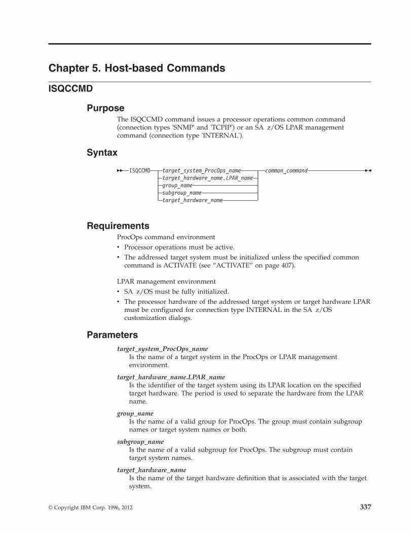
Chapter 5. Host-based Commands
ISQCCMD
PurposeThe ISQCCMD command issues a processor operations common command(connection types 'SNMP' and 'TCPIP') or an SA z/OS LPAR managementcommand (connection type 'INTERNAL').
Syntax
�� ISQCCMD target_system_ProcOps_nametarget_hardware_name.LPAR_namegroup_namesubgroup_nametarget_hardware_name
common_command ��
RequirementsProcOps command environmentv Processor operations must be active.v The addressed target system must be initialized unless the specified common
command is ACTIVATE (see “ACTIVATE” on page 407).
LPAR management environmentv SA z/OS must be fully initialized.v The processor hardware of the addressed target system or target hardware LPAR
must be configured for connection type INTERNAL in the SA z/OScustomization dialogs.
Parameterstarget_system_ProcOps_name
Is the name of a target system in the ProcOps or LPAR managementenvironment.
target_hardware_name.LPAR_nameIs the identifier of the target system using its LPAR location on the specifiedtarget hardware. The period is used to separate the hardware from the LPARname.
group_nameIs the name of a valid group for ProcOps. The group must contain subgroupnames or target system names or both.
subgroup_nameIs the name of a valid subgroup for ProcOps. The subgroup must containtarget system names.
target_hardware_nameIs the name of the target hardware definition that is associated with the targetsystem.
© Copyright IBM Corp. 1996, 2012 337
common_commandRepresents the common command and any associated parameters to beprocessed. Multiple parameters are separated from each other by a blankspace.
DefaultsNone.
UsageUse the ISQCCMD command to issue a HW common command to the specifiedtarget object of a ProcOps or LPAR management environment.
Restrictions and LimitationsProcOps environmentv Target_hardware_name is valid for the common commands CBU, CCNTL,
CONDATA, CPCDATA, CTRLCONS, DEACTIVATE, GETCLUSTER, GETSDGR,GETSINFO, GETSSTAT, OOCOD, PROFILE, TCDATA, TCM, STPDATA, STP,and POWERMOD.
v Group_name or subgroup_name must be processor operations-enabled as definedin the SA z/OS customization dialogs to be a valid parameter.
LPAR management environmentv Target_hardware_name is valid for the common commands CCNTL, CONDATA,
CPCDATA, CTRLCONS, GETCLUSTER, GETSDGR, GETSINFO, GETSSTAT,PROFILE, TCDATA and STPDATA.
Using LPAR management and ProcOps for processors definedwith multiple connection protocols.With the SA configuration dialogs you can specify ProcOps SNMP andINTERNAL(BCPii) connections in a single processor entry. If both connections areconfigured as active, you can no longer use the ISQCCMD target_system_nameform for LPAR Management commands; instead you must use the ISQCCMDtarget_hardware_name.LPAR_name form.
Failure to do so will result in always executing the LPAR Management requestover the SNMP connection. If the system name is not defined to SA, messageISQ400I will be issued, informing you that the target system name is not known.
The dual protocol selection allows only using the target hardware names that haveto be specified for each protocol, as the differentiator between the protocols, butnot the target system name.
If you still want to use the target system name to differentiate between the LPARmanagement and ProcOps common commands for a single processor, you mustdefine separate processor entries and associate system entries to them through theSA dialogs. Define one processor-system set for the ProcOps SNMP connection,and the other set for the INTERNAL connection protocol.
Specifying an SNMP Timeout ValueThe default timeout value can be modified by setting the NetView task globalvariable ISQ.SNMP.WAIT to another value. The timeout format is hh:mm:ss, where'hh' represents the hours of the timeout, 'mm' the minutes and 'ss' of the period towait for hardware command completion before terminating ISQCCMD. The value
ISQCCMD
338 System Automation for z/OS: Operator's Commands
||||
of the variable is checked each time before a ISQCCMD request is performed. Ifthe timeout variable is not set, or it has an invalid format, the default value of thecorresponding command is used.
In the following REXX example a timeout value of 8 minutes and 30 seconds is setprior calling ISQCCMD to perform an EXTERNAL interrupt hardware command:tme = ’ISQ.SNMP.WAIT’ // SNMP timout varname //mytgt = ’KEY6’ // our TGT system name //Interpret tme"= ’00:08:30’" // Set timeout to use //’GLOBALV PUTT ’tme // Update task variable//Say ’SNMP Timeout value set to ’Tglobal(tme) // Send info msg //’ISQCCMD ’mytgt’ EXTINT’ // External irpt to Sys//If RC > 0 Then Do // Error occured //End // ...more to add //Else Do // All went well //End // ...more to add //
Using Immediate ISQCCMD Common Command ResponsesThe immediate command responses cannot be captured with TRAP and WAIT inprograms that issue the ISQCCMD command. You can retrieve the immediate HWresponses by using a PIPE KEEP stage in your programs. Use 'ISQ.SNMP' as theKEEP name. Note that this command set is also the LPAR management commandset and that the KEEP ISQ.SNMP is valid for the LPAR management commands:v CCNTLv CONDATAv CPCDATAv ICNTLv GETCLUSTERv GETIINFOv GETIPSWv GETISTATv GETSDGRv GETSINFOv GETSSTATv PROFILEv STPDATAv TCDATA
In the following REXX example, the maximum weight that is allowed for asystem's LPAR is retrieved and the HW response report containing thisinformation is displayed:mytgt = ’KEY4’ // our TGT system name //’ISQCCMD ’mytgt’ ICNTL CMD(READ) VAR(PWMX)’ // Max weight //If RC > 0 Then Do // Error occurred //End // ...more to add //Else Do // All went well //
’PIPE KEEP ISQ.SNMP | CONS ONLY’ // ...display HW report//End // ...more to add //
Return Codes0 Command completed execution.8 Command processing has been rejected.12 Command processing has failed.32 The required environment for processor operations or LPAR Management does
not exist. The ISQCCMD command was not processed.
ISQCCMD
Chapter 5. Host-based Commands 339
|
ISQCHK
PurposeThe ISQCHK command checks whether processor operations is active.
Syntax
�� ISQCHKcommand_name
��
RequirementsNone.
Parameterscommand_name
Is the name of an automation procedure.
DefaultsNone.
UsageThis command is intended for use in automation procedures to determine whetherprocessor operations is active. It provides a method of exiting from the automationprocedure cleanly when processor operations is not active. If you issue ISQCHKfrom an operator station and processor operations is running, you will receive noresponse.
The optional command_name parameter is placed in the text of the error messagegenerated when processor operations is not active. This identifies the automationprocedure that cannot run because processor operations is not active.
For example, place the following statements near the beginning of a processoroperations automation procedure that is written in REXX:’ISQCHK STARTALL’If RC<>0 then; Exit;
If you issue the STARTALL command when processor operations is not active, theerror message will inform you that “the STARTALL command” cannot be run untilprocessor operations is active, rather than simply informing you “the command”cannot be run until processor operations is active.
You can issue ISQCHK from an operator station task (OST) or from automation.
Restrictions and LimitationsNone.
Return Codes0 Processor operations is active.32 Processor operations is not active.
ISQCHK
340 System Automation for z/OS: Operator's Commands
ISQCMON
PurposeThe ISQCMON command causes the current NetView task to be added to orremoved from the list of tasks to receive processor operations communicationsmanagement messages.
Syntax
�� ISQCMONON
OFF��
RequirementsNone.
ParametersON Adds the current NetView task to the list of tasks to receive processor
operations communications management messages. This is the default.
OFFRemoves the current NetView task from the list of tasks to receive processoroperations communications management messages.
DefaultsISQCMON defaults to ON, adding you to the list.
UsageYou can issue ISQCMON when processor operations is not running to add ordelete yourself from the interested operators list for messages relating to thecontrol of processor operations-managed resources. These messages are notassociated with a specific target system.
Messages not associated with a specific target system are sent only to operatorswho used ISQCMON to place themselves on the interested operators list for suchmessages. These messages are not sent to the ISQXMON interested operator list.You are automatically added to the ISQCMON interested operator list when youissue the ISQSTART command (see “ISQSTART” on page 353).
See IBM Tivoli System Automation for z/OS User’s Guide for further informationabout these two types of messages and interested operator lists.
Restrictions and LimitationsDo not issue this command with ISQEXEC.
Return Codes0 The ISQCMON command completed successfully.8 You used incorrect command syntax.
ISQCMON
Chapter 5. Host-based Commands 341
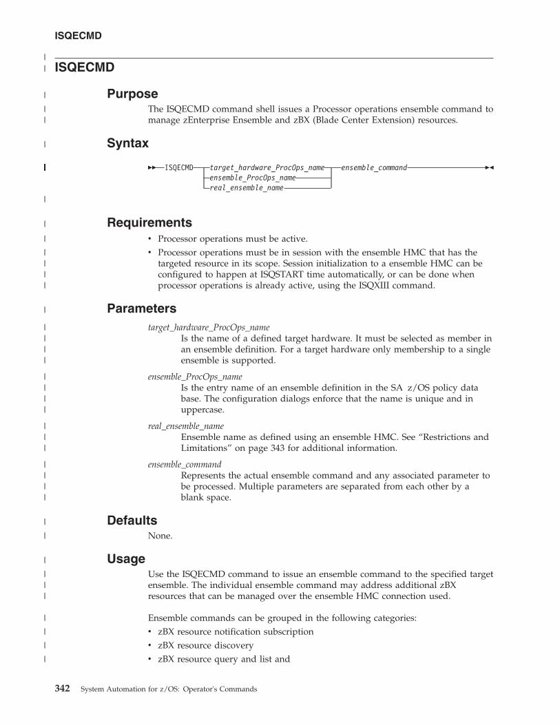
ISQECMD
PurposeThe ISQECMD command shell issues a Processor operations ensemble command tomanage zEnterprise Ensemble and zBX (Blade Center Extension) resources.
Syntax
�� ISQECMD target_hardware_ProcOps_nameensemble_ProcOps_namereal_ensemble_name
ensemble_command ��
Requirementsv Processor operations must be active.v Processor operations must be in session with the ensemble HMC that has the
targeted resource in its scope. Session initialization to a ensemble HMC can beconfigured to happen at ISQSTART time automatically, or can be done whenprocessor operations is already active, using the ISQXIII command.
Parameterstarget_hardware_ProcOps_name
Is the name of a defined target hardware. It must be selected as member inan ensemble definition. For a target hardware only membership to a singleensemble is supported.
ensemble_ProcOps_nameIs the entry name of an ensemble definition in the SA z/OS policy database. The configuration dialogs enforce that the name is unique and inuppercase.
real_ensemble_nameEnsemble name as defined using an ensemble HMC. See “Restrictions andLimitations” on page 343 for additional information.
ensemble_commandRepresents the actual ensemble command and any associated parameter tobe processed. Multiple parameters are separated from each other by ablank space.
DefaultsNone.
UsageUse the ISQECMD command to issue an ensemble command to the specified targetensemble. The individual ensemble command may address additional zBXresources that can be managed over the ensemble HMC connection used.
Ensemble commands can be grouped in the following categories:v zBX resource notification subscriptionv zBX resource discoveryv zBX resource query and list and
ISQECMD
342 System Automation for z/OS: Operator's Commands
||
|
||
|
|||||||||||||||||||||
|
|
|
||||
|
||||
||||
|||
||||
|
|
|
|||
|
|
|
|
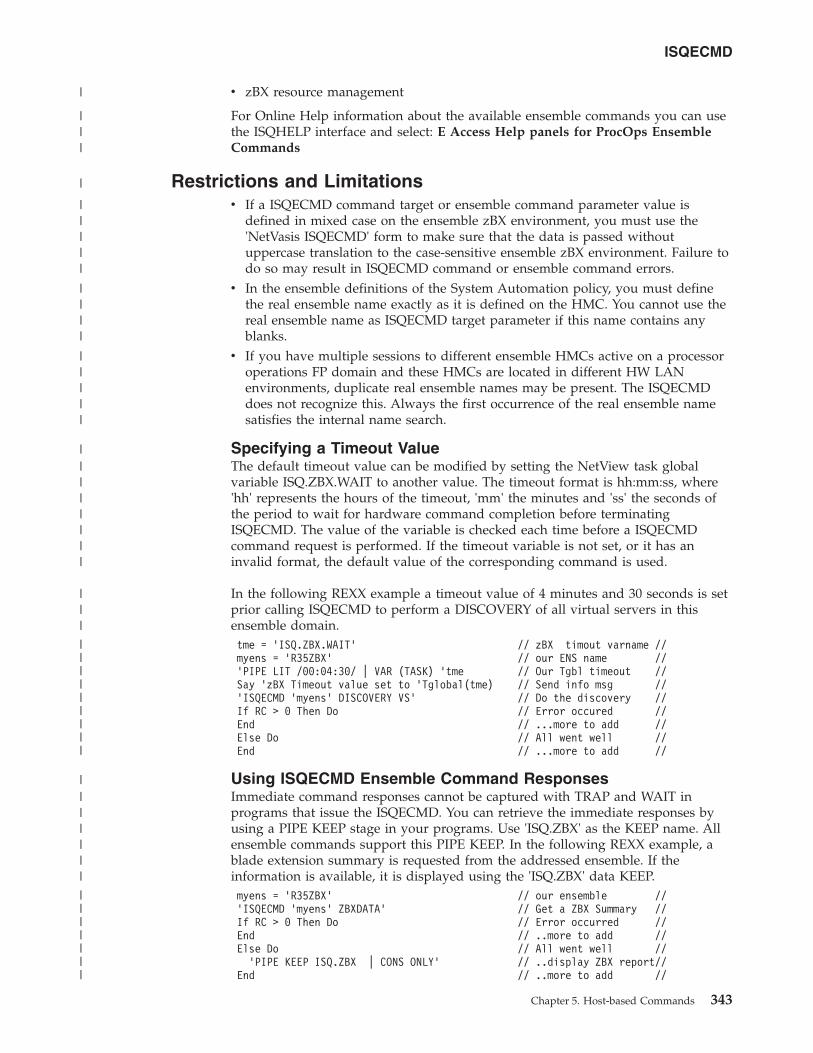
v zBX resource management
For Online Help information about the available ensemble commands you can usethe ISQHELP interface and select: E Access Help panels for ProcOps EnsembleCommands
Restrictions and Limitationsv If a ISQECMD command target or ensemble command parameter value is
defined in mixed case on the ensemble zBX environment, you must use the'NetVasis ISQECMD' form to make sure that the data is passed withoutuppercase translation to the case-sensitive ensemble zBX environment. Failure todo so may result in ISQECMD command or ensemble command errors.
v In the ensemble definitions of the System Automation policy, you must definethe real ensemble name exactly as it is defined on the HMC. You cannot use thereal ensemble name as ISQECMD target parameter if this name contains anyblanks.
v If you have multiple sessions to different ensemble HMCs active on a processoroperations FP domain and these HMCs are located in different HW LANenvironments, duplicate real ensemble names may be present. The ISQECMDdoes not recognize this. Always the first occurrence of the real ensemble namesatisfies the internal name search.
Specifying a Timeout ValueThe default timeout value can be modified by setting the NetView task globalvariable ISQ.ZBX.WAIT to another value. The timeout format is hh:mm:ss, where'hh' represents the hours of the timeout, 'mm' the minutes and 'ss' the seconds ofthe period to wait for hardware command completion before terminatingISQECMD. The value of the variable is checked each time before a ISQECMDcommand request is performed. If the timeout variable is not set, or it has aninvalid format, the default value of the corresponding command is used.
In the following REXX example a timeout value of 4 minutes and 30 seconds is setprior calling ISQECMD to perform a DISCOVERY of all virtual servers in thisensemble domain.tme = ’ISQ.ZBX.WAIT’ // zBX timout varname //myens = ’R35ZBX’ // our ENS name //’PIPE LIT /00:04:30/ | VAR (TASK) ’tme // Our Tgbl timeout //Say ’zBX Timeout value set to ’Tglobal(tme) // Send info msg //’ISQECMD ’myens’ DISCOVERY VS’ // Do the discovery //If RC > 0 Then Do // Error occured //End // ...more to add //Else Do // All went well //End // ...more to add //
Using ISQECMD Ensemble Command ResponsesImmediate command responses cannot be captured with TRAP and WAIT inprograms that issue the ISQECMD. You can retrieve the immediate responses byusing a PIPE KEEP stage in your programs. Use 'ISQ.ZBX' as the KEEP name. Allensemble commands support this PIPE KEEP. In the following REXX example, ablade extension summary is requested from the addressed ensemble. If theinformation is available, it is displayed using the 'ISQ.ZBX' data KEEP.myens = ’R35ZBX’ // our ensemble //’ISQECMD ’myens’ ZBXDATA’ // Get a ZBX Summary //If RC > 0 Then Do // Error occurred //End // ..more to add //Else Do // All went well //
’PIPE KEEP ISQ.ZBX | CONS ONLY’ // ..display ZBX report//End // ..more to add //
ISQECMD
Chapter 5. Host-based Commands 343
|
|||
|
|||||
||||
|||||
||||||||
|||
|||||||||
|||||||
|||||||
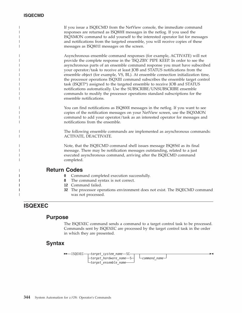
If you issue a ISQECMD from the NetView console, the immediate commandresponses are returned as ISQ800I messages in the netlog. If you used theISQXMON command to add yourself to the interested operator list for messagesand notifications from the targeted ensemble, you will receive copies of thesemessages as ISQ801I messages on the screen.
Asynchronous ensemble command responses (for example, ACTIVATE) will notprovide the complete response in the 'ISQ.ZBX' PIPE KEEP. In order to see theasynchronous parts of an ensemble command response you must have subscribedyour operator/task to receive at least JOB and STATUS notifications from theensemble object (for example, VS, BL). At ensemble connection initialization time,the processor operations ISQXIII command subscribes the ensemble target controltask (ISQET*) assigned to the targeted ensemble to receive JOB and STATUSnotifications automatically. Use the SUBSCRIBE/UNSUBSCRIBE ensemblecommands to modify the processor operations standard subscriptions for theensemble notifications.
You can find notifications as ISQ800I messages in the netlog. If you want to seecopies of the notification messages on your NetView screen, use the ISQXMONcommand to add your operator/task as an interested operator for messages andnotifications from the ensemble.
The following ensemble commands are implemented as asynchronous commands:ACTIVATE, DEACTIVATE.
Note, that the ISQECMD command shell issues message ISQ856I as its finalmessage. There may be notification messages outstanding, related to a justexecuted asynchronous command, arriving after the ISQECMD commandcompleted.
Return Codes0 Command completed execution successfully.8 The command syntax is not correct.12 Command failed.32 The processor operations environment does not exist. The ISQECMD command
was not processed.
ISQEXEC
PurposeThe ISQEXEC command sends a command to a target control task to be processed.Commands sent by ISQEXEC are processed by the target control task in the orderin which they are presented.
Syntax
�� ISQEXEC target_system_name SCtarget_hardware_name Starget_ensemble_name
command_name��
ISQECMD
344 System Automation for z/OS: Operator's Commands
|||||
||||||||||
||||
||
||||
||||||||||
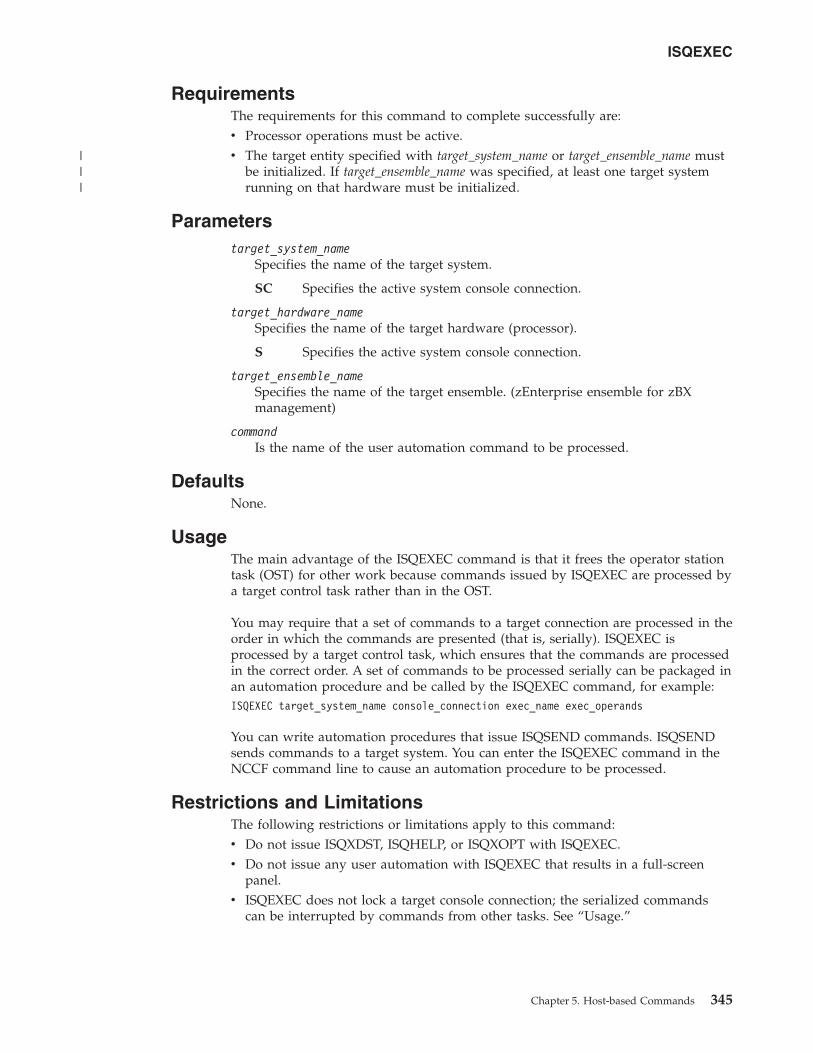
RequirementsThe requirements for this command to complete successfully are:v Processor operations must be active.v The target entity specified with target_system_name or target_ensemble_name must
be initialized. If target_ensemble_name was specified, at least one target systemrunning on that hardware must be initialized.
Parameterstarget_system_name
Specifies the name of the target system.
SC Specifies the active system console connection.
target_hardware_nameSpecifies the name of the target hardware (processor).
S Specifies the active system console connection.
target_ensemble_nameSpecifies the name of the target ensemble. (zEnterprise ensemble for zBXmanagement)
commandIs the name of the user automation command to be processed.
DefaultsNone.
UsageThe main advantage of the ISQEXEC command is that it frees the operator stationtask (OST) for other work because commands issued by ISQEXEC are processed bya target control task rather than in the OST.
You may require that a set of commands to a target connection are processed in theorder in which the commands are presented (that is, serially). ISQEXEC isprocessed by a target control task, which ensures that the commands are processedin the correct order. A set of commands to be processed serially can be packaged inan automation procedure and be called by the ISQEXEC command, for example:ISQEXEC target_system_name console_connection exec_name exec_operands
You can write automation procedures that issue ISQSEND commands. ISQSENDsends commands to a target system. You can enter the ISQEXEC command in theNCCF command line to cause an automation procedure to be processed.
Restrictions and LimitationsThe following restrictions or limitations apply to this command:v Do not issue ISQXDST, ISQHELP, or ISQXOPT with ISQEXEC.v Do not issue any user automation with ISQEXEC that results in a full-screen
panel.v ISQEXEC does not lock a target console connection; the serialized commands
can be interrupted by commands from other tasks. See “Usage.”
ISQEXEC
Chapter 5. Host-based Commands 345
|||
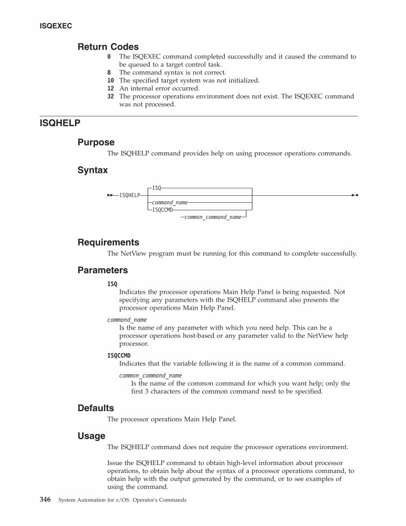
Return Codes0 The ISQEXEC command completed successfully and it caused the command to
be queued to a target control task.8 The command syntax is not correct.10 The specified target system was not initialized.12 An internal error occurred.32 The processor operations environment does not exist. The ISQEXEC command
was not processed.
ISQHELP
PurposeThe ISQHELP command provides help on using processor operations commands.
Syntax
�� ISQHELPISQ
command_nameISQCCMD
common_command_name
��
RequirementsThe NetView program must be running for this command to complete successfully.
ParametersISQ
Indicates the processor operations Main Help Panel is being requested. Notspecifying any parameters with the ISQHELP command also presents theprocessor operations Main Help Panel.
command_nameIs the name of any parameter with which you need help. This can be aprocessor operations host-based or any parameter valid to the NetView helpprocessor.
ISQCCMDIndicates that the variable following it is the name of a common command.
common_command_nameIs the name of the common command for which you want help; only thefirst 3 characters of the common command need to be specified.
DefaultsThe processor operations Main Help Panel.
UsageThe ISQHELP command does not require the processor operations environment.
Issue the ISQHELP command to obtain high-level information about processoroperations, to obtain help about the syntax of a processor operations command, toobtain help with the output generated by the command, or to see examples ofusing the command.
ISQEXEC
346 System Automation for z/OS: Operator's Commands
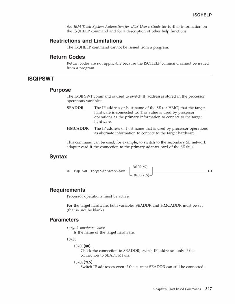
See IBM Tivoli System Automation for z/OS User’s Guide for further information onthe ISQHELP command and for a description of other help functions.
Restrictions and LimitationsThe ISQHELP command cannot be issued from a program.
Return CodesReturn codes are not applicable because the ISQHELP command cannot be issuedfrom a program.
ISQIPSWT
PurposeThe ISQIPSWT command is used to switch IP addresses stored in the processoroperations variables:
SEADDR The IP address or host name of the SE (or HMC) that the targethardware is connected to. This value is used by processoroperations as the primary information to connect to the targethardware.
HMCADDR The IP address or host name that is used by processor operationsas alternate information to connect to the target hardware.
This command can be used, for example, to switch to the secondary SE networkadapter card if the connection to the primary adapter card of the SE fails.
Syntax
��FORCE(NO)
ISQIPSWT target-hardware-nameFORCE(YES)
��
RequirementsProcessor operations must be active.
For the target hardware, both variables SEADDR and HMCADDR must be set(that is, not be blank).
Parameterstarget-hardware-name
Is the name of the target hardware.
FORCE
FORCE(NO)Check the connection to SEADDR; switch IP addresses only if theconnection to SEADDR fails.
FORCE(YES)Switch IP addresses even if the current SEADDR can still be connected.
ISQHELP
Chapter 5. Host-based Commands 347
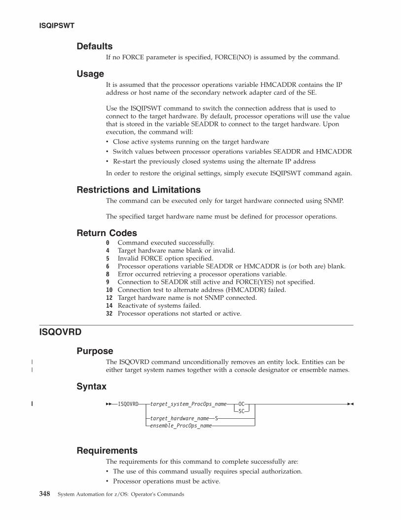
DefaultsIf no FORCE parameter is specified, FORCE(NO) is assumed by the command.
UsageIt is assumed that the processor operations variable HMCADDR contains the IPaddress or host name of the secondary network adapter card of the SE.
Use the ISQIPSWT command to switch the connection address that is used toconnect to the target hardware. By default, processor operations will use the valuethat is stored in the variable SEADDR to connect to the target hardware. Uponexecution, the command will:v Close active systems running on the target hardwarev Switch values between processor operations variables SEADDR and HMCADDRv Re-start the previously closed systems using the alternate IP address
In order to restore the original settings, simply execute ISQIPSWT command again.
Restrictions and LimitationsThe command can be executed only for target hardware connected using SNMP.
The specified target hardware name must be defined for processor operations.
Return Codes0 Command executed successfully.4 Target hardware name blank or invalid.5 Invalid FORCE option specified.6 Processor operations variable SEADDR or HMCADDR is (or both are) blank.8 Error occurred retrieving a processor operations variable.9 Connection to SEADDR still active and FORCE(YES) not specified.10 Connection test to alternate address (HMCADDR) failed.12 Target hardware name is not SNMP connected.14 Reactivate of systems failed.32 Processor operations not started or active.
ISQOVRD
PurposeThe ISQOVRD command unconditionally removes an entity lock. Entities can beeither target system names together with a console designator or ensemble names.
Syntax
�� ISQOVRD target_system_ProcOps_name OCSC
target_hardware_name Sensemble_ProcOps_name
��
RequirementsThe requirements for this command to complete successfully are:v The use of this command usually requires special authorization.v Processor operations must be active.
ISQIPSWT
348 System Automation for z/OS: Operator's Commands
||
|||
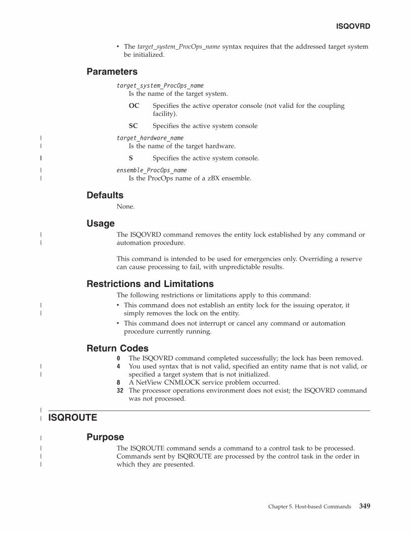
v The target_system_ProcOps_name syntax requires that the addressed target systembe initialized.
Parameterstarget_system_ProcOps_name
Is the name of the target system.
OC Specifies the active operator console (not valid for the couplingfacility).
SC Specifies the active system console
target_hardware_nameIs the name of the target hardware.
S Specifies the active system console.
ensemble_ProcOps_nameIs the ProcOps name of a zBX ensemble.
DefaultsNone.
UsageThe ISQOVRD command removes the entity lock established by any command orautomation procedure.
This command is intended to be used for emergencies only. Overriding a reservecan cause processing to fail, with unpredictable results.
Restrictions and LimitationsThe following restrictions or limitations apply to this command:v This command does not establish an entity lock for the issuing operator, it
simply removes the lock on the entity.v This command does not interrupt or cancel any command or automation
procedure currently running.
Return Codes0 The ISQOVRD command completed successfully; the lock has been removed.4 You used syntax that is not valid, specified an entity name that is not valid, or
specified a target system that is not initialized.8 A NetView CNMLOCK service problem occurred.32 The processor operations environment does not exist; the ISQOVRD command
was not processed.
ISQROUTE
PurposeThe ISQROUTE command sends a command to a control task to be processed.Commands sent by ISQROUTE are processed by the control task in the order inwhich they are presented.
ISQOVRD
Chapter 5. Host-based Commands 349
||
||
||
||
||
||
||
|
|||
Syntax
�� ISQROUTE entity_name command_name ��
System environmentThe requirements for this command to complete successfully are:v Processor operations must be active.
Parametersentity_name
Target hardware name:Specifies the name of the target hardware.
Target system name:Specifies the name of the target system.
Ensemble name:Specifies the name of the ensemble.
commandIs the name of the user automation command to be processed.
DefaultsNone.
UsageThe main advantage of the ISQROUTE command is that it frees the operatorstation task (OST) for other work because commands issued by ISQROUTE areprocessed by a processor operations control task rather than in the OST.
This is similar to the ISQEXEC command, however ISQROUTE accepts targetsystem, target hardware, or ensemble names for control task selection. In addition,the entity needs not to be in a required status as this is the case for ISQEXEC,where target systems must have a status of INITIALIZED.
You can require that a set of commands to a target entity are processed in theorder in which the commands are presented (that is, serially). ISQROUTE isprocessed by a control task, which ensures that the commands are processed in thecorrect order. A set of commands to be processed serially can be packaged in anautomation procedure and be called by the ISQROUTE command, for example:ISQROUTE target_system_name exec_name exec_operands
You can write automation procedures that issue ISQSEND commands. ISQSENDsends commands to a target system. You can enter the ISQROUTE command in theNCCF command line to cause an automation procedure to be processed.
Restrictions and LimitationsThe following restrictions or limitations apply to this command:v Do not issue ISQXDST, ISQHELP, or ISQXOPT with ISQROUTEv Do not issue any user automation with ISQROUTE that results in a full-screen
panel.
ISQROUTE
350 System Automation for z/OS: Operator's Commands
|
||||||||||||
|
|
|
|
|
||
||
||
||
|
|
|
|||
||||
|||||
|
|||
|
|
|
||
v ISQROUTE does not lock a target console connection; the serialized commandscan be interrupted by commands from other tasks. See “Usage” on page 350.
Return Codes0 The ISQROUTE command completed successfully and it caused the command
to be queued to a control task.8 The command syntax is not correct or entity name is not defined.12 An internal error occurred.32 The processor operations environment does not exist. The ISQROUTE
command was not processed.
ISQSEND
PurposeThe ISQSEND command sends a command to a target system for execution, usingthe processor operations target hardware connection and the console integrationfacility.
Note: This is an Application Programming Interface.
Syntax
��NETVASIS
ISQSEND target_system_ProcOps_nametarget_hwname.Lparname
OCSC
command ��
RequirementsThe requirements for this command to complete successfully are:v Processor operations must be active.v The addressed target system connection must have been initialized.
ParametersNETVASIS
Prefix the ISQSEND command with NETVASIS if you want to pass thecommand text in lower or mixed case.
target_system_ProcOps_nameThe name of the target system.
target_hwname.LparnameThe target hardware name and logical partition name, separated by a period.This is an alternative to the target system name notation, for all operatingsystems running on a target hardware activated in LPAR mode.
OC Specifies the active operator console function as the target for an operatingsystem command.
SC Specifies the active system console function as the target for an operatingmanagement command.
commandThe command that is to be processed and any parameters that are associatedwith that command. Use the ISQSEND command to send operating system
ISQROUTE
Chapter 5. Host-based Commands 351
||
|||||||||||
commands or operations management commands. If you want to pass thecommand text in lower or mixed case, prefix the ISQSEND command withNETVASIS.
Note that if you omit the command parameter, a nullstring is sent to thehardware, which is received and may be acknowledged by the target operatingsystem or hardware. See your hardware or operating system documentationfor more information.
Operating System CommandsThis ISQSEND command type is valid for all ProcOps connections. Thefollowing operating systems are supported: MVS (z/OS),VM(z/VM),VSE (z/VSE),LINUX (Linux on System z), and CF (CouplingFacility Control Code). In addition, Standalone Utility programsrunning on System z or CMOS/390 hardware, such as SADump(Standalone Dump).
Operations Management CommandsThis type of ISQSEND commands is valid only for ProcOps TCPIPconnections. For ProcOps SNMP connections, ISQCCMD must be usedto perform Operations Management functions.
Operations management commands using TCPIP means that VM/CPcommands can be sent to the virtual machine of a ProcOps targetsystem, which is running as a VM guest. Only CP Query commandsare supported. For all other operations management functions, use theISQCCMD command.
DefaultsNone.
UsageFor target systems running on processors supported by processor operations,operating system commands can be entered through ISQSEND. The commands aretransmitted to the operating system through console integration, an interfaceprovided by the operating system and the processor hardware support element(SE) or hardware management console (HMC).
Specifying an SNMP Timeout ValueFor target hardware connections of type SNMP, the default timeout value of oneminute can be modified by setting the NetView task global variableISQ.SNMP.WAIT to another value. The timeout format is hh:mm:ss, where 'hh'represents the hours of the timeout, 'mm' the minutes and 'ss' the seconds of theperiod to wait for HW command completion before terminating ISQSEND. Thevalue of the variable is checked each time a ISQSEND request for an SNMPconnected target system is performed. If the timeout variable is not set, or it has aninvalid format, the default value of one minute is used.
In the following REXX example a timeout value of 8 minutes and 30 seconds is setprior calling ISQSEND:tme = ’ISQ.SNMP.WAIT’ // SNMP timout varname //mytgt = ’KEY6’ // our TGT system name //Interpret tme"= ’00:08:30’" // Set timeout to use //’GLOBALV PUTT ’tme // Update task variable//Say ’SNMP Timeout value set to ’Tglobal(tme) // Send msg //’ISQSEND ’mytgt’ D T’ // External irpt to Sys//If RC > 0 Then Do // Error occured //
ISQSEND
352 System Automation for z/OS: Operator's Commands
End // ...more to add //Else Do // All went well //End // ...more to add //
Restrictions and LimitationsThe following restrictions or limitations apply to this command:v With SA z/OS, the ISQSEND command is the only way to send data to the
operating system of a target through the console integration connection. Theinformation that is passed to the target system is not interpreted by SA z/OS.
v Successful ISQSEND completion does not indicate successful completion of thecommand itself. It only indicates that the command was successfully deliveredto the receiver. Your automation routines should interpret the asynchronousmessage responses of the command to determine the command executionresults.
v Note that the operating systems supporting console integration may havecommands to activate or deactivate this function, or may provide facilities andcommands to prevent response messages from being routed to consoleintegration. For MVS operating systems, the VARY CN(*),DEACTIVATE and VARYCN(*),ACTIVATE commands are available for the deactivation and reactivation ofconsole integration.
Return Codes0 The ISQSEND command completed successfully and the message was sent.8 Either the message was not sent, the message was sent with errors, or the
specified target system was not initialized.32 The processor operations environment does not exist. The ISQSEND command
was not processed.
ISQSTART
PurposeThe ISQSTART command starts processor operations. It establishes the processoroperations environment with the NetView program and permits the control oftarget resources with processor operations commands. Such resources are: Targetsystems or virtual systems, mainframe processors or virtual machines, andzEnterprise BladeCenter Extensions. This command can be issued from anautomation routine.
Syntax
�� ISQSTARTACF DEBUGACFCLEANOptionfile
��
RequirementsIf you specify:v With parameter ACF or ACFCLEAN, SA z/OS initialization must be complete
before ISQSTART can be usedv With the Optionfile parameter, the NetView program must have at least read
authority to the dataset
ISQSEND
Chapter 5. Host-based Commands 353
||||||
|
||
||
You may need special authorization to use this command.
ParametersACF
If specified, processor operations is started, taking the required configurationinformation from the current active automation control file (ACF).
ACFCLEANIf specified, the INGCLEAN command is called to perform a clean up of thein-storage data model on the processor operations focal point NetView domain,before the ISQSTART ACF processing starts.
The processor operations configuration information is stored in ACF entrytypes like: PROCESSOR, SYSTEM, AOF?ENS, and GROUP. Since none of theseentry types is associated with type SUBSYSTEM, a delete or rename of aprocessor operations related ACF entry will not result in an automatic cleanupof the no longer valid associated global variables during a System Automationrefresh.
This can cause problems or ISQSTART time for processor operations runtime,especially when no longer available HW resources are still present in theprocessor operations data model.
Using the INGCLEAN before starting processor operations is one way to avoidsuch problems.
OptionfileAn additional debug or configuration source. This parameter is for IBM Servicesupport only.
DEBUGProvides additional diagnostics that are written to the NetView log.
DefaultsThere are no defaults for this command when processor operations is first started:you must specify the ACF, ACFCLEAN or Optionfile parameter. When restarting,the command defaults to the parameter used for the previous initial start.
UsageTo perform an initial start, use the ACF or ACFCLEAN parameter. For a restart(warmstart), this parameter is not needed.
An initial start loads the processor operations configuration data from the activeACF and starts all processor operations tasks to establish the processor operationstask environment. The configuration data also indicates which, if any, target systemor ensemble connection should be initialized (not the IPL process).
The initial start with the ACF parameter takes the available configuration data forprocessor operations from the loaded ACF to build the processor operationsruntime environment. In case processor operations configuration data was changedusing the configuration dialogs and a new ACF file was built, you first refresh theACF on the processor operations FP system with the new user configuration,before this new configuration data is available for processor operations. Use theISQSTOP command to processor operations before issuing the ISQSTART ACF orISQSTART ACFCLEAN command to activate the changes in the ProcOps runtimeenvironment.
ISQSTART
354 System Automation for z/OS: Operator's Commands
||||
||||||
|||
||
|
|||
||
||||
|||||||||
You usually perform a restart after a processor operations task has failed to restartall processor operations tasks to reestablish the processor operations taskingenvironment. If the processor operations environment has not already beenestablished by a previous ISQSTART command that specified ACF/ACFCLEAN orOptionfile, the restart will fail.
When you issue ISQSTART, it adds you to the interested operators list that isaccessed by the ISQCMON command. This list is for messages that are notassociated with a specific target system. The messages relate to the control ofprocessor operations-managed resources.
Restrictions and LimitationsThe following restrictions or limitations apply to this command:v If the ACF or ACFCLEAN start parameters are used, SA z/OS on the processor
operations focal point system must be fully initialized, otherwise ISQSTARTprocessing will fail.Note that this restriction also applies if ISQSTART is issued while an ACFREFRESH is in progress on the processor operations focal point system.
v A restart re-establishes the previous configuration. The processor operationsenvironment must exist (an initial start must have already been performed)before a restart can be performed.
v Processor operations must be stopped before an initial start can be performed.v The XML_config_file name cannot be DEBUG.v The specified XML_config_file must be a sequential data set.
Return Codes0 Command accepted.4 You used incorrect syntax.8 An internal command error occurred.
ISQSTOP
PurposeThe ISQSTOP command stops processor operations. It can be issued in anautomation routine.
Syntax
�� ISQSTOPDEBUG
��
RequirementsYou may require special authorization to use this command.
Processor operations must be active.
ParametersDEBUG
Provides additional diagnostics, which are written to the NetView log.
ISQSTART
Chapter 5. Host-based Commands 355
|||||
|
|||
|
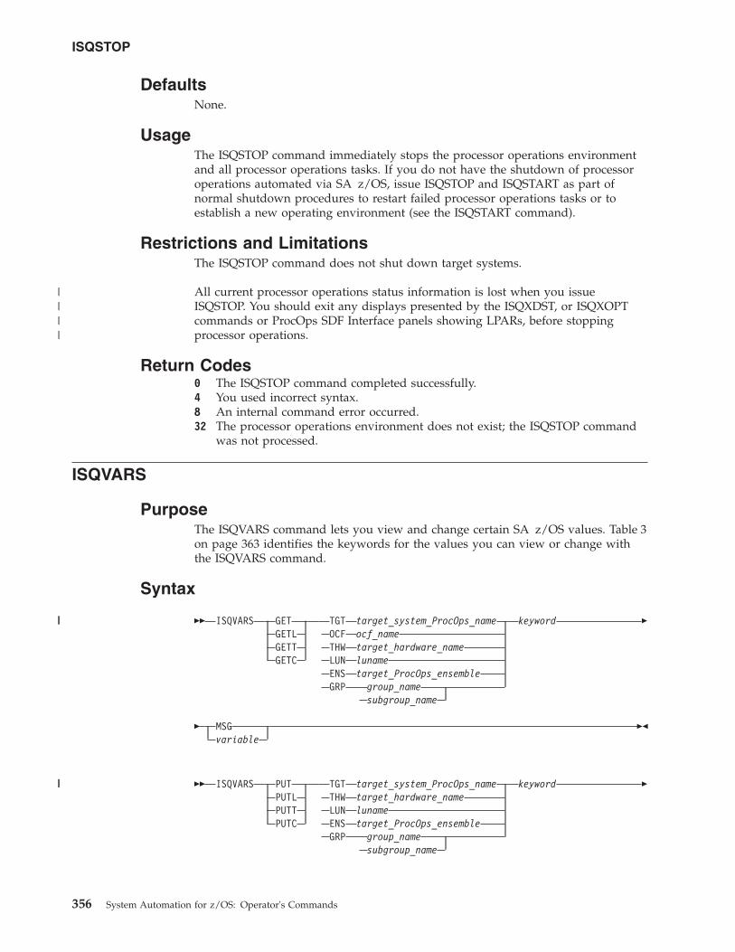
DefaultsNone.
UsageThe ISQSTOP command immediately stops the processor operations environmentand all processor operations tasks. If you do not have the shutdown of processoroperations automated via SA z/OS, issue ISQSTOP and ISQSTART as part ofnormal shutdown procedures to restart failed processor operations tasks or toestablish a new operating environment (see the ISQSTART command).
Restrictions and LimitationsThe ISQSTOP command does not shut down target systems.
All current processor operations status information is lost when you issueISQSTOP. You should exit any displays presented by the ISQXDST, or ISQXOPTcommands or ProcOps SDF Interface panels showing LPARs, before stoppingprocessor operations.
Return Codes0 The ISQSTOP command completed successfully.4 You used incorrect syntax.8 An internal command error occurred.32 The processor operations environment does not exist; the ISQSTOP command
was not processed.
ISQVARS
PurposeThe ISQVARS command lets you view and change certain SA z/OS values. Table 3on page 363 identifies the keywords for the values you can view or change withthe ISQVARS command.
Syntax
�� ISQVARS GETGETLGETTGETC
TGT target_system_ProcOps_nameOCF ocf_nameTHW target_hardware_nameLUN lunameENS target_ProcOps_ensembleGRP group_name
subgroup_name
keyword �
� MSGvariable
��
�� ISQVARS PUTPUTLPUTTPUTC
TGT target_system_ProcOps_nameTHW target_hardware_nameLUN lunameENS target_ProcOps_ensembleGRP group_name
subgroup_name
keyword �
ISQSTOP
356 System Automation for z/OS: Operator's Commands
||||
||
||
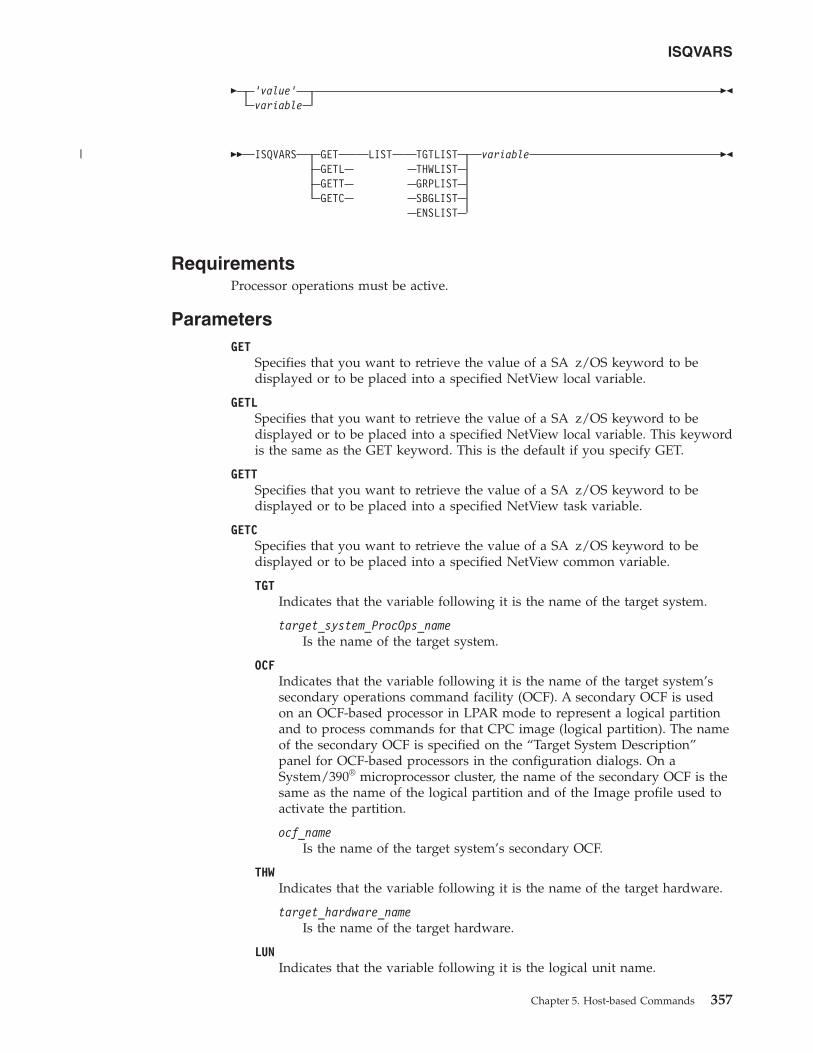
� ‘value’variable
��
�� ISQVARS GETGETLGETTGETC
LIST TGTLISTTHWLISTGRPLISTSBGLISTENSLIST
variable ��
RequirementsProcessor operations must be active.
ParametersGET
Specifies that you want to retrieve the value of a SA z/OS keyword to bedisplayed or to be placed into a specified NetView local variable.
GETLSpecifies that you want to retrieve the value of a SA z/OS keyword to bedisplayed or to be placed into a specified NetView local variable. This keywordis the same as the GET keyword. This is the default if you specify GET.
GETTSpecifies that you want to retrieve the value of a SA z/OS keyword to bedisplayed or to be placed into a specified NetView task variable.
GETCSpecifies that you want to retrieve the value of a SA z/OS keyword to bedisplayed or to be placed into a specified NetView common variable.
TGTIndicates that the variable following it is the name of the target system.
target_system_ProcOps_nameIs the name of the target system.
OCFIndicates that the variable following it is the name of the target system’ssecondary operations command facility (OCF). A secondary OCF is usedon an OCF-based processor in LPAR mode to represent a logical partitionand to process commands for that CPC image (logical partition). The nameof the secondary OCF is specified on the “Target System Description”panel for OCF-based processors in the configuration dialogs. On aSystem/390® microprocessor cluster, the name of the secondary OCF is thesame as the name of the logical partition and of the Image profile used toactivate the partition.
ocf_nameIs the name of the target system’s secondary OCF.
THWIndicates that the variable following it is the name of the target hardware.
target_hardware_nameIs the name of the target hardware.
LUNIndicates that the variable following it is the logical unit name.
ISQVARS
Chapter 5. Host-based Commands 357
|
lunameIs the logical unit name.
GRPIndicates that the variable following is a group or subgroup name.
group_nameIs the name of the group of which the subgroup is a member.
subgroup_nameIs the name of the subgroup of which the target system is a member.
ENSIndicates that the variable following it is the name of an ensemble.
target_ProcOps_ensembleIs the name of the ensemble.
keywordIs the name of the SA z/OS value to be retrieved or set. Table 3 on page 363identifies the SA z/OS values that can be read or changed by the ISQVARScommand.
MSGIndicates the SA z/OS value is to be displayed on the console as line-modeoutput.
variableIs the name of the NetView variable whose value is to be set to that of thespecified SA z/OS keyword. Local variable names are most commonly usedwhen values are being read and written from within automation procedures.The names of the SA z/OS values are defined in Table 3 on page 363.
PUTSpecifies that you want to set the value of a SA z/OS keyword to either thecurrent value of a specified NetView local variable or to a value specified inthe command string.
PUTLSpecifies that you want to set the value of a SA z/OS keyword to either thecurrent value of a specified NetView local variable or to a value specified inthe command string. This keyword is the same as the PUT keyword. This isthe default if you specify PUT.
PUTTSpecifies that you want to set the value of a SA z/OS keyword to either thecurrent value of a specified NetView task variable or to a value specified in thecommand string.
PUTCSpecifies that you want to set the value of a SA z/OS keyword to either thecurrent value of a specified NetView common variable or to a value specifiedin the command string.
TGTIndicates that the variable following it is the name of the target system.
target_system_ProcOps_nameIs the name of the target system.
THWIndicates that the variable following it is the name of the target hardware.
ISQVARS
358 System Automation for z/OS: Operator's Commands
||
||
target_hardware_nameIs the name of the target hardware.
LUNIndicates that the variable following it is the logical unit name.
lunameIs the logical unit name.
GRPIndicates that the variable following is a group or subgroup name.
group_nameIs the name of the group of which the subgroup is a member.
subgroup_nameIs the name of the subgroup of which the target system is a member.
ENSIndicates that the variable following it is the name of an ensemble.
target_ProcOps_ensembleIs the name of the ensemble.
keywordIs the name of the SA z/OS keyword whose value is to be retrieved or set.Table 3 on page 363 identifies the values that can be read or changed by theISQVARS command.
'value'Is the value to be assigned to the SA z/OS keyword. The straight singlequotation marks are required.
variableIs the name of the NetView variable which contains the value to which theSA z/OS keyword is to be set (PUT). Local variable names are mostcommonly used when SA z/OS values are being read and written from withinautomation procedures. The keywords used for SA z/OS values are defined inTable 3 on page 363.
LISTIndicates the keyword following it identifies which list is being referenced.This keyword is valid from automation programming only.
TGTLISTRefers to the list of defined target system names.
THWLISTRefers to the list of defined target hardware names.
GRPLISTRefers to the list of defined target group names.
SBGLISTRefers to the list of defined target subgroup names.
ENSLISTRefers to the list of defined target ensemble names.
variableIs the name of the NetView variable whose value is to be set to that of thespecified SA z/OS keyword. Local variable names are most commonly usedwhen values are being read and written from within automation procedures.The names of the SA z/OS values are defined in Table 3 on page 363.
ISQVARS
Chapter 5. Host-based Commands 359
||
||
||
DefaultsNone.
UsageThere are several ways to specify the desired information:
Target system nameget|put TGT target_system_ProcOps_name keyword...
Target hardware nameget|put THW target_hardware_name keyword...
Group nameget|put GRP group_name keyword...
Subgroup nameget|put GRP subgroup_name keyword...
LU nameget|put LUN luname keyword...
Ensemble nameget|put ENS ensemble_name keyword...
OCF nameget OCF ocf_name keyword...
Return a listget LIST keyword...
You can display (on the NetView console) the value of a NetView variable byusing the MSG keyword.
The ISQVARS command allows access to SA z/OS values. Values relating to targetsystems or ports require the name of the component (target system processoroperations name or port name). The keyword is a processor operations-definedcharacter string identifying the name of the processor operations value.
If issued from a program, a NetView variable is specified to contain the SA z/OSvalue.v In the GET case, the specified NetView variable (variable) is set to the specified
SA z/OS value (keyword).v In the PUT case, the specified SA z/OS value is set to the current value of the
specified NetView variable, or to the value specified within straight singlequotation marks.
For example, assume target system names system1, system2, and system3 have beendefined. The following command:ISQVARS GET LIST TGTLIST TARGETS
will place the following character string into the NetView local variable targets:system1 system2 system3
Restrictions and LimitationsThe following restrictions or limitations apply to this command:
ISQVARS
360 System Automation for z/OS: Operator's Commands
||
v SA z/OS values are defined through the use of configuration panels duringinstallation. Not all of these values can be changed by the ISQVARS command.Table 3 on page 363 identifies the SA z/OS values that can be changed by theISQVARS command.
v Any changes you make to a SA z/OS value with the ISQVARS commandremain in effect only for the current session of SA z/OS. Stopping and thenstarting SA z/OS resets the variables.
v GET LIST is valid only from within automation programming. You cannot issueGET LIST from an OST.
v GET LIST has the following length restrictions:– The NetView variable is restricted to 32767 bytes when a REXX command
processor calls the ISQVARS command using the NetView local variable form(GET|GETL LIST). The ISQVARS command truncates the data to this lengthif necessary.
– The NetView variable is restricted to 255 bytes when a REXX commandprocessor, high-level language, or NetView command list calls the ISQVARScommand using the NetView task variable form or NetView common variableform (GETT|GETC LIST). The ISQVARS command truncates the data to thislength if necessary.
Caution: Use ISQVARS with care. Value changes are made immediately and mayseriously affect the running of SA z/OS.
Return Codes0 Processed without errors.30 The processor operations environment does not exist; the ISQVARS
command was not processed.32 The processor operations environment does not exist; the ISQVARS
command was not processed.131 You did not enter enough parameters.132 The second argument you specified is unknown.133 You specified a form of the command that is not valid with the list option.134 msg and list options are mutually exclusive.135 Neither get nor put were specified.136 You used an uneven number of single straight quotation marks.137 You used single straight quotation marks other than for the last argument.138 Unable to write to the specified variable.139 Unable to read the specified variable.141 msg is a keyword and cannot be used as a variable name.142 Variable answer could not contain all of the data, variable truncated to 255
bytes.143 Variable answer could not contain all of the data, variable truncated to
32767 bytes.144 Addressed port not initialized to a target system.145 System console not defined for addressed target system.161 You specified a target hardware name that is not valid.162 You specified an unknown keyword.163 You specified a target system name that is not valid.166 You specified a keyword restricted to LPAR systems.167 The specified port is not connected to an operator console.168 The specified port is not connected to a system console.169 IOCDS cannot be located, system is in LPAR mode.
ISQVARS
Chapter 5. Host-based Commands 361
170 The port definition and the target hardware definition in the SA z/OSconfiguration panels conflict with one another — the system consolecannot be found.
171 The port definition and the target hardware definition in the SA z/OSconfiguration panels conflict with one another — the operator consolecannot be found.
172 You specified a keyword that is not valid for the PUT function.173 NetView CNMLOCK failure.174 Internal locking sequence error.175 Unable to obtain lock for PUT function.176 You specified a PUT function with non-hexadecimal characters for a
keyword field that can contain only hexadecimal characters; the commandis ignored.
177 You specified a PUT function with non-integer characters for a keywordfield that can contain only integer characters; the command is ignored.
178 Unknown operating system type for specified target system.179 The specified keyword only valid if the addressed target system is running
the MVS or VM operating systems.182 You tried to write (PUT) values to a keyword field that are not valid
values for that field.183 You tried to write (PUT) a value that is too large for the keyword field to
which it is being written.184 You tried to write (PUT) a time offset value that is not valid.185 You specified a parameter that cannot be used with the keyword you
specified (the parameter values that can be specified are list, tgt, ens orthw).
186 It is not valid to change the internal variable you specified from its currentstatus value to the status value you specified.
188 It indicates that the status of the target system or logical partition cannotbe identified.
189 You specified a logical partition name that is not valid.191 You specified a variable that requires a qualified name (such as target.lpar),
but the qualified name you provided is not valid.192 Logical partition name missing. You specified a target hardware name, but
it was not followed by a logical partition name (such as target.lpar).193 The memory requested is larger than the maximum that can be installed.194 The system name entered is not a valid target system name, but it is a
valid target hardware name.195 You specified a target ensemble name that is not valid.
ISQVARS KeywordsSA z/OS provides keywords you can use to define your configuration and todetermine the status of the elements in your configuration.
When you develop automation routines, you need to read these keyword valuesand perhaps write to them as well. For example, a routine may change the primaryIPL address used by automation. Assuming the old address was 03FE, thefollowing command changes the address to 0123:ISQVARS PUT TGT SILVER pipla ’0123’
This section explains the keywords and the valid values each keyword accepts. Italso identifies the SA z/OS messages that trigger SA z/OS automation to updatethe keyword values. You may want to use these status messages to begin yourown automation routines.
ISQVARS
362 System Automation for z/OS: Operator's Commands
|||
||
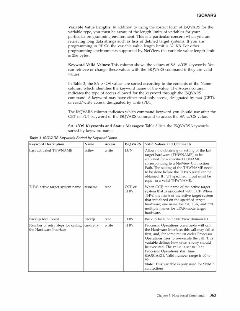
Variable Value Lengths: In addition to using the correct form of ISQVARS for thevariable type, you must be aware of the length limits of variables for yourparticular programming environment. This is a particular concern when you areretrieving long data strings such as lists of defined target systems. If you areprogramming in REXX, the variable value length limit is 32 KB. For otherprogramming environments supported by NetView, the variable value length limitis 256 bytes.
Keyword Valid Values: This column shows the values of SA z/OS keywords. Youcan retrieve or change these values with the ISQVARS command if they are validvalues.
In Table 3, the SA z/OS values are sorted according to the contents of the Namecolumn, which identifies the keyword name of the value. The Access columnindicates the type of access allowed for the keyword through the ISQVARScommand. A keyword may have either read-only access, designated by read (GET),or read/write access, designated by write (PUT).
The ISQVARS column indicates which command keyword you should use after theGET or PUT keyword of the ISQVARS command to access the SA z/OS value.
SA z/OS Keywords and Status Messages: Table 3 lists the ISQVARS keywordssorted by keyword name.
Table 3. ISQVARS Keywords Sorted by Keyword Name
Keyword Description Name Access ISQVARS Valid Values and Comments
Last activated THWNAME acthw write LUN Allows the obtaining or setting of the lasttarget hardware (THWNAME) to beactivated for a specified LUNAMEcorresponding to a NetView ConnectionPath. The setting of the THWNAME needsto be done before the THWNAME can beobtained. If PUT specified, input must beequal to a valid THWNAME.
THW: active target system name atsname read OCF orTHW
When OCF, the name of the active targetsystem that is associated with OCF. WhenTHW, the name of the active target systemthat initialized on the specified targethardware; one name for XA, ESA, and 370,multiple names for LPAR-mode targethardware.
Backup focal point backfp read THW Backup focal point NetView domain ID.
Number of retry steps for callingthe Hardware Interface
cmdretry write THW Processor Operations commands will callthe Hardware Interface; this call may fail atfirst, and, for some return codes ProcessorOperations tries to re-execute the call. Thisvariable defines how often a retry shouldbe executed. The value is set to 10 atProcessor Operations start time(ISQSTART). Valid number range is 00 to99.Note: This variable is only used for SNMPconnections.
ISQVARS
Chapter 5. Host-based Commands 363
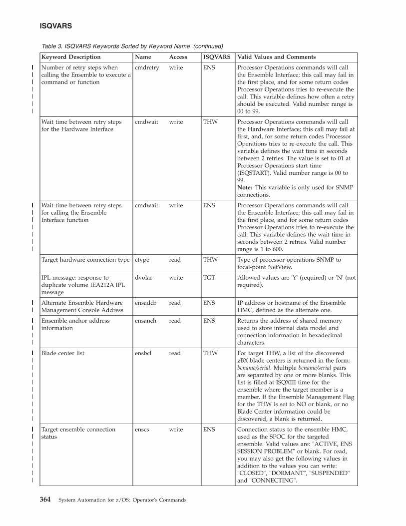
Table 3. ISQVARS Keywords Sorted by Keyword Name (continued)
Keyword Description Name Access ISQVARS Valid Values and Comments
Number of retry steps whencalling the Ensemble to execute acommand or function
cmdretry write ENS Processor Operations commands will callthe Ensemble Interface; this call may fail inthe first place, and for some return codesProcessor Operations tries to re-execute thecall. This variable defines how often a retryshould be executed. Valid number range is00 to 99.
Wait time between retry stepsfor the Hardware Interface
cmdwait write THW Processor Operations commands will callthe Hardware Interface; this call may fail atfirst, and, for some return codes ProcessorOperations tries to re-execute the call. Thisvariable defines the wait time in secondsbetween 2 retries. The value is set to 01 atProcessor Operations start time(ISQSTART). Valid number range is 00 to99.Note: This variable is only used for SNMPconnections.
Wait time between retry stepsfor calling the EnsembleInterface function
cmdwait write ENS Processor Operations commands will callthe Ensemble Interface; this call may fail inthe first place, and for some return codesProcessor Operations tries to re-execute thecall. This variable defines the wait time inseconds between 2 retries. Valid numberrange is 1 to 600.
Target hardware connection type ctype read THW Type of processor operations SNMP tofocal-point NetView.
IPL message: response toduplicate volume IEA212A IPLmessage
dvolar write TGT Allowed values are 'Y' (required) or 'N' (notrequired).
Alternate Ensemble HardwareManagement Console Address
ensaddr read ENS IP address or hostname of the EnsembleHMC, defined as the alternate one.
Ensemble anchor addressinformation
ensanch read ENS Returns the address of shared memoryused to store internal data model andconnection information in hexadecimalcharacters.
Blade center list ensbcl read THW For target THW, a list of the discoveredzBX blade centers is returned in the form:bcname/serial. Multiple bcname/serial pairsare separated by one or more blanks. Thislist is filled at ISQXIII time for theensemble where the target member is amember. If the Ensemble Management Flagfor the THW is set to NO or blank, or noBlade Center information could bediscovered, a blank is returned.
Target ensemble connectionstatus
enscs write ENS Connection status to the ensemble HMC,used as the SPOC for the targetedensemble. Valid values are: "ACTIVE, ENSSESSION PROBLEM" or blank. For read,you may also get the following values inaddition to the values you can write:"CLOSED", "DORMANT", "SUSPENDED"and "CONNECTING".
ISQVARS
364 System Automation for z/OS: Operator's Commands
|||
||||||||||
|||
||||||||||
|||||||
|||||||||
||||||||||||||
|||||||||||||
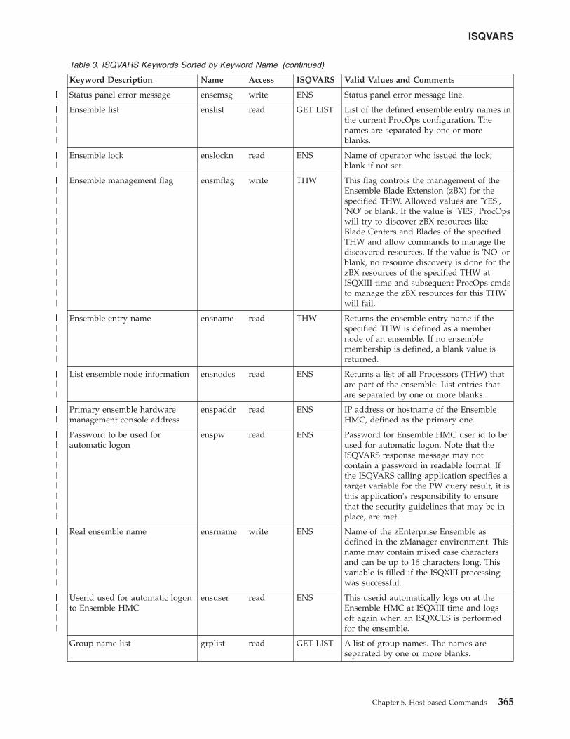
Table 3. ISQVARS Keywords Sorted by Keyword Name (continued)
Keyword Description Name Access ISQVARS Valid Values and Comments
Status panel error message ensemsg write ENS Status panel error message line.
Ensemble list enslist read GET LIST List of the defined ensemble entry names inthe current ProcOps configuration. Thenames are separated by one or moreblanks.
Ensemble lock enslockn read ENS Name of operator who issued the lock;blank if not set.
Ensemble management flag ensmflag write THW This flag controls the management of theEnsemble Blade Extension (zBX) for thespecified THW. Allowed values are 'YES','NO' or blank. If the value is 'YES', ProcOpswill try to discover zBX resources likeBlade Centers and Blades of the specifiedTHW and allow commands to manage thediscovered resources. If the value is 'NO' orblank, no resource discovery is done for thezBX resources of the specified THW atISQXIII time and subsequent ProcOps cmdsto manage the zBX resources for this THWwill fail.
Ensemble entry name ensname read THW Returns the ensemble entry name if thespecified THW is defined as a membernode of an ensemble. If no ensemblemembership is defined, a blank value isreturned.
List ensemble node information ensnodes read ENS Returns a list of all Processors (THW) thatare part of the ensemble. List entries thatare separated by one or more blanks.
Primary ensemble hardwaremanagement console address
enspaddr read ENS IP address or hostname of the EnsembleHMC, defined as the primary one.
Password to be used forautomatic logon
enspw read ENS Password for Ensemble HMC user id to beused for automatic logon. Note that theISQVARS response message may notcontain a password in readable format. Ifthe ISQVARS calling application specifies atarget variable for the PW query result, it isthis application's responsibility to ensurethat the security guidelines that may be inplace, are met.
Real ensemble name ensrname write ENS Name of the zEnterprise Ensemble asdefined in the zManager environment. Thisname may contain mixed case charactersand can be up to 16 characters long. Thisvariable is filled if the ISQXIII processingwas successful.
Userid used for automatic logonto Ensemble HMC
ensuser read ENS This userid automatically logs on at theEnsemble HMC at ISQXIII time and logsoff again when an ISQXCLS is performedfor the ensemble.
Group name list grplist read GET LIST A list of group names. The names areseparated by one or more blanks.
ISQVARS
Chapter 5. Host-based Commands 365
|||||
||||||||
||||||
|||||||||||||||||
|||||||||
|||||||
|||||||
||||||||||||||
||||||||||
|||||||||
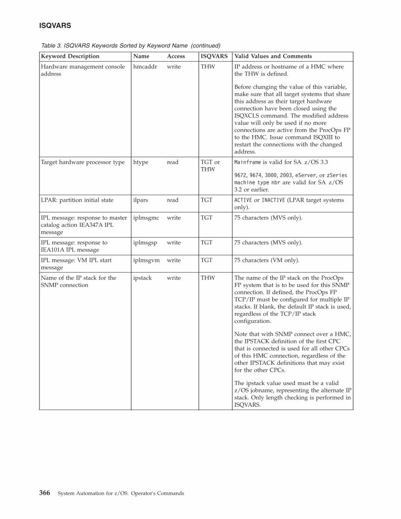
Table 3. ISQVARS Keywords Sorted by Keyword Name (continued)
Keyword Description Name Access ISQVARS Valid Values and Comments
Hardware management consoleaddress
hmcaddr write THW IP address or hostname of a HMC wherethe THW is defined.
Before changing the value of this variable,make sure that all target systems that sharethis address as their target hardwareconnection have been closed using theISQXCLS command. The modified addressvalue will only be used if no moreconnections are active from the ProcOps FPto the HMC. Issue command ISQXIII torestart the connections with the changedaddress.
Target hardware processor type htype read TGT orTHW
Mainframe is valid for SA z/OS 3.3
9672, 9674, 3000, 2003, eServer, or zSeriesmachine type nbr are valid for SA z/OS3.2 or earlier.
LPAR: partition initial state ilpars read TGT ACTIVE or INACTIVE (LPAR target systemsonly).
IPL message: response to mastercatalog action IEA347A IPLmessage
iplmsgmc write TGT 75 characters (MVS only).
IPL message: response toIEA101A IPL message
iplmsgsp write TGT 75 characters (MVS only).
IPL message: VM IPL startmessage
iplmsgvm write TGT 75 characters (VM only).
Name of the IP stack for theSNMP connection
ipstack write THW The name of the IP stack on the ProcOpsFP system that is to be used for this SNMPconnection. If defined, the ProcOps FPTCP/IP must be configured for multiple IPstacks. If blank, the default IP stack is used,regardless of the TCP/IP stackconfiguration.
Note that with SNMP connect over a HMC,the IPSTACK definition of the first CPCthat is connected is used for all other CPCsof this HMC connection, regardless of theother IPSTACK definitions that may existfor the other CPCs.
The ipstack value used must be a validz/OS jobname, representing the alternate IPstack. Only length checking is performed inISQVARS.
ISQVARS
366 System Automation for z/OS: Operator's Commands
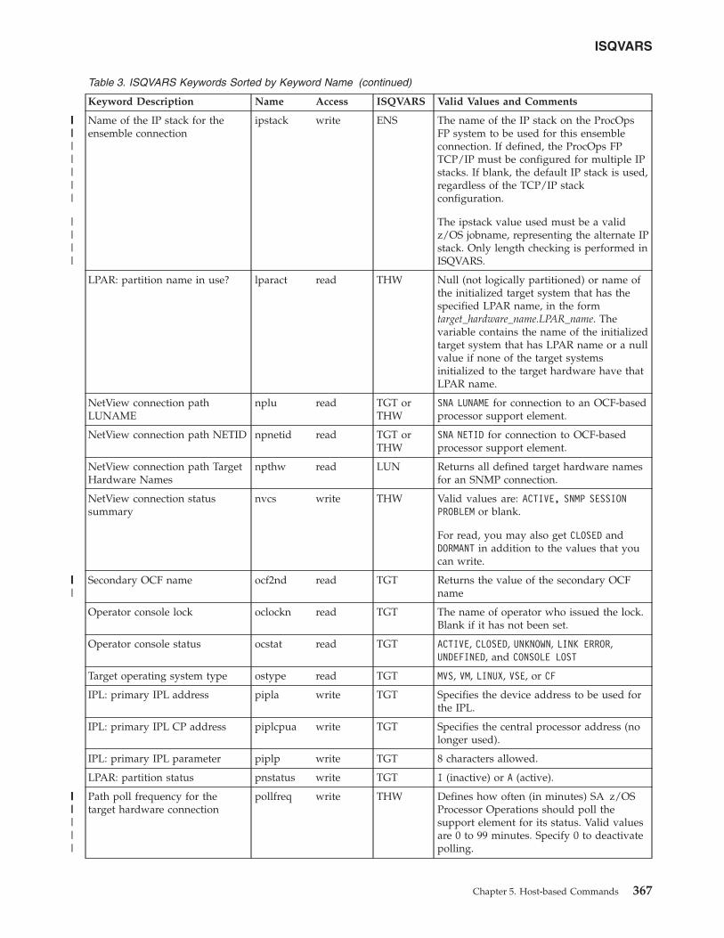
Table 3. ISQVARS Keywords Sorted by Keyword Name (continued)
Keyword Description Name Access ISQVARS Valid Values and Comments
Name of the IP stack for theensemble connection
ipstack write ENS The name of the IP stack on the ProcOpsFP system to be used for this ensembleconnection. If defined, the ProcOps FPTCP/IP must be configured for multiple IPstacks. If blank, the default IP stack is used,regardless of the TCP/IP stackconfiguration.
The ipstack value used must be a validz/OS jobname, representing the alternate IPstack. Only length checking is performed inISQVARS.
LPAR: partition name in use? lparact read THW Null (not logically partitioned) or name ofthe initialized target system that has thespecified LPAR name, in the formtarget_hardware_name.LPAR_name. Thevariable contains the name of the initializedtarget system that has LPAR name or a nullvalue if none of the target systemsinitialized to the target hardware have thatLPAR name.
NetView connection pathLUNAME
nplu read TGT orTHW
SNA LUNAME for connection to an OCF-basedprocessor support element.
NetView connection path NETID npnetid read TGT orTHW
SNA NETID for connection to OCF-basedprocessor support element.
NetView connection path TargetHardware Names
npthw read LUN Returns all defined target hardware namesfor an SNMP connection.
NetView connection statussummary
nvcs write THW Valid values are: ACTIVE, SNMP SESSIONPROBLEM or blank.
For read, you may also get CLOSED andDORMANT in addition to the values that youcan write.
Secondary OCF name ocf2nd read TGT Returns the value of the secondary OCFname
Operator console lock oclockn read TGT The name of operator who issued the lock.Blank if it has not been set.
Operator console status ocstat read TGT ACTIVE, CLOSED, UNKNOWN, LINK ERROR,UNDEFINED, and CONSOLE LOST
Target operating system type ostype read TGT MVS, VM, LINUX, VSE, or CF
IPL: primary IPL address pipla write TGT Specifies the device address to be used forthe IPL.
IPL: primary IPL CP address piplcpua write TGT Specifies the central processor address (nolonger used).
IPL: primary IPL parameter piplp write TGT 8 characters allowed.
LPAR: partition status pnstatus write TGT I (inactive) or A (active).
Path poll frequency for thetarget hardware connection
pollfreq write THW Defines how often (in minutes) SA z/OSProcessor Operations should poll thesupport element for its status. Valid valuesare 0 to 99 minutes. Specify 0 to deactivatepolling.
ISQVARS
Chapter 5. Host-based Commands 367
||||||||||||
||||
||||||
||||||||||
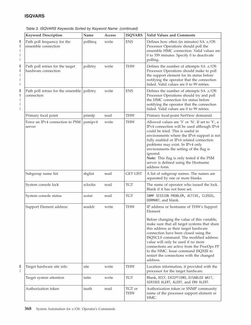
Table 3. ISQVARS Keywords Sorted by Keyword Name (continued)
Keyword Description Name Access ISQVARS Valid Values and Comments
Path poll frequency for theensemble connection
pollfreq write ENS Defines how often (in minutes) SA z/OSProcessor Operations should poll theensemble HMC connection. Valid values are0 to 359 minutes. Specify 0 to deactivatepolling.
Path poll retries for the targethardware connection
pollrtry write THW Defines the number of attempts SA z/OSProcessor Operations should make to pollthe support element for its status beforenotifying the operator that the connectionfailed. Valid values are 0 to 99 retries.
Path poll retries for the ensembleconnection
pollrtry write ENS Defines the number of attempts SA z/OSProcessor Operations should try and pollthe HMC connection for status beforenotifying the operator that the connectionfailed. Valid values are 0 to 99 retries.
Primary focal point primfp read THW Primary focal-point NetView domainid.
Force an IPv4 connection to PSMserver
psmipv4 write THW Allowed values are 'Y' or 'N'. If set to 'Y', aIPv4 connection will be used although IPv6could be tried. This is useful inenvironments where the IPv6 support is notfully enabled or IPv6 related connectionproblems may exist. In IPv4 onlyenvironments the setting of the flag isignored.Note: This flag is only tested if the PSMserver is defined using the Hostnameaddress form.
Subgroup name list sbglist read GET LIST A list of subgroup names. The names areseparated by one or more blanks.
System console lock sclockn read TGT The name of operator who issued the lock.Blank if it has not been set.
System console status scstat read TGT SNMP SESSION PROBLEM, ACTIVE, CLOSED,DORMANT, and blank.
Support Element address seaddr write THW IP address or hostname of THW's SupportElement
Before changing the value of this variable,make sure that all target systems that sharethis address as their target hardwareconnection have been closed using theISQXCLS command. The modified addressvalue will only be used if no moreconnections are active from the ProcOps FPto the HMC. Issue command ISQXIII torestart the connections with the changedaddress.
Target hardware site info site write THW Location information, if provided with theprocessor for the target hardware.
Target system attention tattn write TGT Blank, DCCF, EXCEPTIONS, DISABLED WAIT,SERIOUS ALERT, ALERT, and ENV ALERT.
Authorization token tauth read TGT orTHW
Authorization token or SNMP communityname of the processor support element orHMC.
ISQVARS
368 System Automation for z/OS: Operator's Commands
||||||||||
||||||||||
||||||||||
||||||
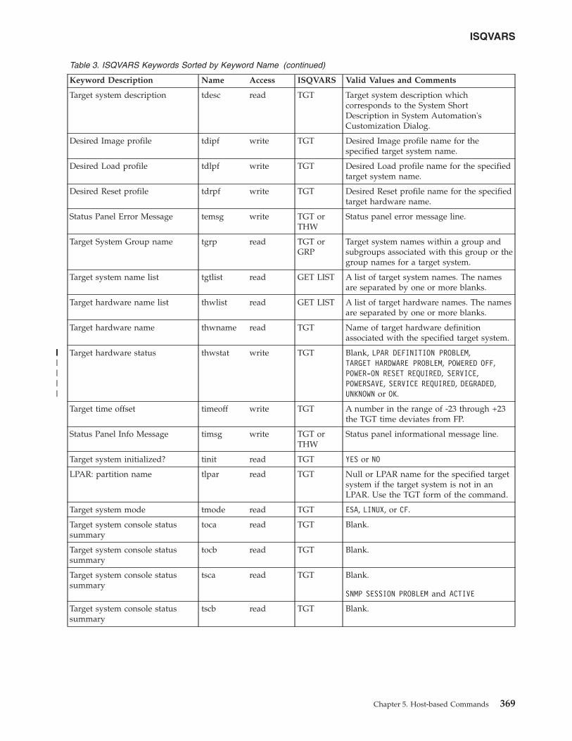
Table 3. ISQVARS Keywords Sorted by Keyword Name (continued)
Keyword Description Name Access ISQVARS Valid Values and Comments
Target system description tdesc read TGT Target system description whichcorresponds to the System ShortDescription in System Automation'sCustomization Dialog.
Desired Image profile tdipf write TGT Desired Image profile name for thespecified target system name.
Desired Load profile tdlpf write TGT Desired Load profile name for the specifiedtarget system name.
Desired Reset profile tdrpf write TGT Desired Reset profile name for the specifiedtarget hardware name.
Status Panel Error Message temsg write TGT orTHW
Status panel error message line.
Target System Group name tgrp read TGT orGRP
Target system names within a group andsubgroups associated with this group or thegroup names for a target system.
Target system name list tgtlist read GET LIST A list of target system names. The namesare separated by one or more blanks.
Target hardware name list thwlist read GET LIST A list of target hardware names. The namesare separated by one or more blanks.
Target hardware name thwname read TGT Name of target hardware definitionassociated with the specified target system.
Target hardware status thwstat write TGT Blank, LPAR DEFINITION PROBLEM,TARGET HARDWARE PROBLEM, POWERED OFF,POWER-ON RESET REQUIRED, SERVICE,POWERSAVE, SERVICE REQUIRED, DEGRADED,UNKNOWN or OK.
Target time offset timeoff write TGT A number in the range of -23 through +23the TGT time deviates from FP.
Status Panel Info Message timsg write TGT orTHW
Status panel informational message line.
Target system initialized? tinit read TGT YES or NO
LPAR: partition name tlpar read TGT Null or LPAR name for the specified targetsystem if the target system is not in anLPAR. Use the TGT form of the command.
Target system mode tmode read TGT ESA, LINUX, or CF.
Target system console statussummary
toca read TGT Blank.
Target system console statussummary
tocb read TGT Blank.
Target system console statussummary
tsca read TGT Blank.
SNMP SESSION PROBLEM and ACTIVE
Target system console statussummary
tscb read TGT Blank.
ISQVARS
Chapter 5. Host-based Commands 369
|||||||||
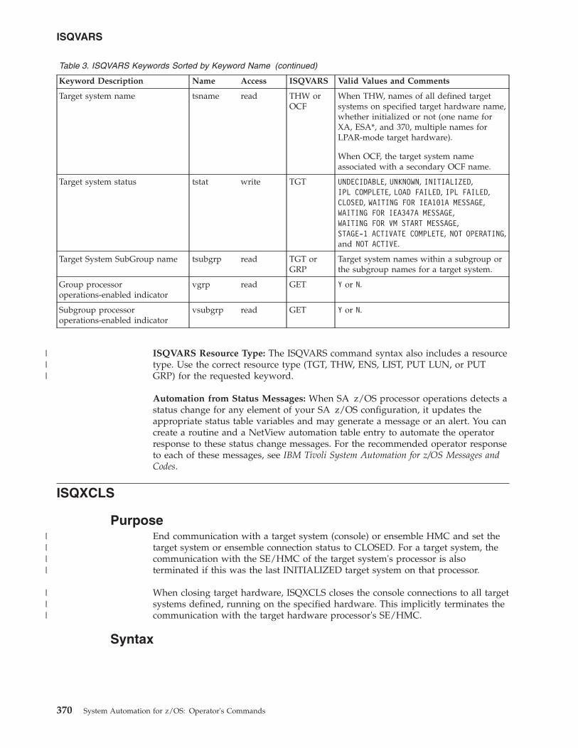
Table 3. ISQVARS Keywords Sorted by Keyword Name (continued)
Keyword Description Name Access ISQVARS Valid Values and Comments
Target system name tsname read THW orOCF
When THW, names of all defined targetsystems on specified target hardware name,whether initialized or not (one name forXA, ESA*, and 370, multiple names forLPAR-mode target hardware).
When OCF, the target system nameassociated with a secondary OCF name.
Target system status tstat write TGT UNDECIDABLE, UNKNOWN, INITIALIZED,IPL COMPLETE, LOAD FAILED, IPL FAILED,CLOSED, WAITING FOR IEA101A MESSAGE,WAITING FOR IEA347A MESSAGE,WAITING FOR VM START MESSAGE,STAGE-1 ACTIVATE COMPLETE, NOT OPERATING,and NOT ACTIVE.
Target System SubGroup name tsubgrp read TGT orGRP
Target system names within a subgroup orthe subgroup names for a target system.
Group processoroperations-enabled indicator
vgrp read GET Y or N.
Subgroup processoroperations-enabled indicator
vsubgrp read GET Y or N.
ISQVARS Resource Type: The ISQVARS command syntax also includes a resourcetype. Use the correct resource type (TGT, THW, ENS, LIST, PUT LUN, or PUTGRP) for the requested keyword.
Automation from Status Messages: When SA z/OS processor operations detects astatus change for any element of your SA z/OS configuration, it updates theappropriate status table variables and may generate a message or an alert. You cancreate a routine and a NetView automation table entry to automate the operatorresponse to these status change messages. For the recommended operator responseto each of these messages, see IBM Tivoli System Automation for z/OS Messages andCodes.
ISQXCLS
PurposeEnd communication with a target system (console) or ensemble HMC and set thetarget system or ensemble connection status to CLOSED. For a target system, thecommunication with the SE/HMC of the target system's processor is alsoterminated if this was the last INITIALIZED target system on that processor.
When closing target hardware, ISQXCLS closes the console connections to all targetsystems defined, running on the specified hardware. This implicitly terminates thecommunication with the target hardware processor's SE/HMC.
Syntax
ISQVARS
370 System Automation for z/OS: Operator's Commands
|||
||||
|||
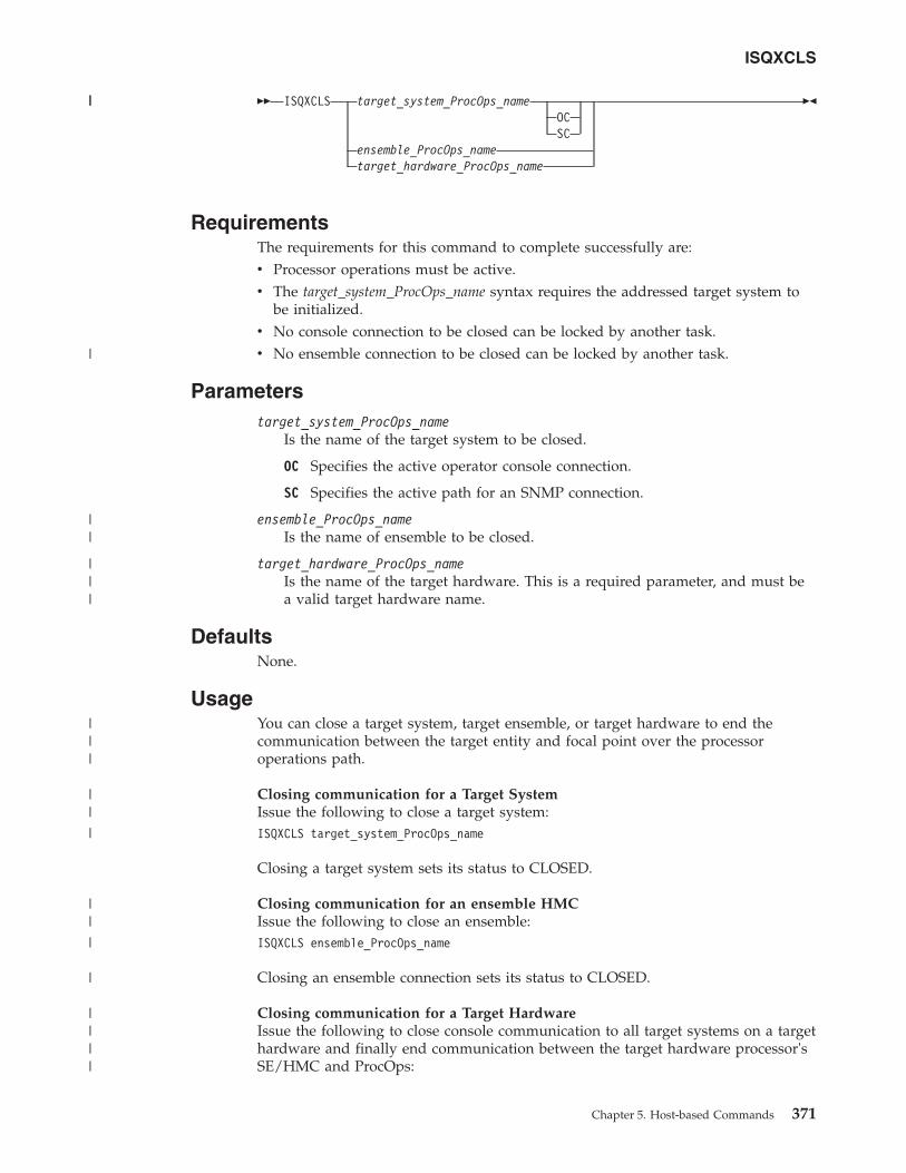
�� ISQXCLS target_system_ProcOps_nameOCSC
ensemble_ProcOps_nametarget_hardware_ProcOps_name
��
RequirementsThe requirements for this command to complete successfully are:v Processor operations must be active.v The target_system_ProcOps_name syntax requires the addressed target system to
be initialized.v No console connection to be closed can be locked by another task.v No ensemble connection to be closed can be locked by another task.
Parameterstarget_system_ProcOps_name
Is the name of the target system to be closed.
OC Specifies the active operator console connection.
SC Specifies the active path for an SNMP connection.
ensemble_ProcOps_nameIs the name of ensemble to be closed.
target_hardware_ProcOps_nameIs the name of the target hardware. This is a required parameter, and must bea valid target hardware name.
DefaultsNone.
UsageYou can close a target system, target ensemble, or target hardware to end thecommunication between the target entity and focal point over the processoroperations path.
Closing communication for a Target SystemIssue the following to close a target system:ISQXCLS target_system_ProcOps_name
Closing a target system sets its status to CLOSED.
Closing communication for an ensemble HMCIssue the following to close an ensemble:ISQXCLS ensemble_ProcOps_name
Closing an ensemble connection sets its status to CLOSED.
Closing communication for a Target HardwareIssue the following to close console communication to all target systems on a targethardware and finally end communication between the target hardware processor'sSE/HMC and ProcOps:
ISQXCLS
Chapter 5. Host-based Commands 371
||
|
||
|||
|||
||
|
||
|
|
||||
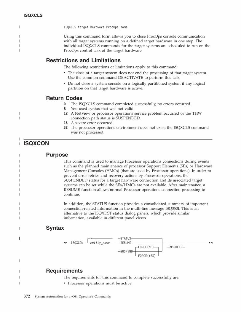
ISQXCLS target_hardware_ProcOps_name
Using this command form allows you to close ProcOps console communicationwith all target systems running on a defined target hardware in one step. Theindividual ISQXCLS commands for the target systems are scheduled to run on theProcOps control task of the target hardware.
Restrictions and LimitationsThe following restrictions or limitations apply to this command:v The close of a target system does not end the processing of that target system.
Use the common command DEACTIVATE to perform this task.v Do not close a system console on a logically partitioned system if any logical
partition on that target hardware is active.
Return Codes0 The ISQXCLS command completed successfully, no errors occurred.8 You used syntax that was not valid.12 A NetView or processor operations service problem occurred or the THW
connection path status is SUSPENDED.16 A severe error occurred.32 The processor operations environment does not exist; the ISQXCLS command
was not processed.
ISQXCON
PurposeThis command is used to manage Processor operations connections during eventssuch as the planned maintenance of processor Support Elements (SEs) or HardwareManagement Consoles (HMCs) (that are used by Processor operations). In order toprevent error retries and recovery actions by Processor operations, theSUSPENDED status for a target hardware connection and its associated targetsystems can be set while the SEs/HMCs are not available. After maintenance, aRESUME function allows normal Processor operations connection processing tocontinue.
In addition, the STATUS function provides a consolidated summary of importantconnection-related information in the multi-line message ISQ350I. This is analternative to the ISQXDST status dialog panels, which provide similarinformation, available in different panel views.
Syntax
��*
ISQXCON entity_nameSTATUSRESUME
FORCE(NO)SUSPEND
FORCE(YES)
MSGKEEP��
RequirementsThe requirements for this command to complete successfully are:v Processor operations must be active.
ISQXCLS
372 System Automation for z/OS: Operator's Commands
|
||||
||
||
|
||||||||
||||
|
||||||||||||||||||||||||||||||||||||||||||
|
|
|
|
v The SUSPEND/RESUME functions of this command make use of the NetViewDSISVRT VSAM DB to save status variables. If your NetView is not customizedto use this facility, the ISQXCON SUSPEND/RESUME functions cannot be used,only the STATUS function will work.
Parametersentity_name
Is the name of a configured target hardware (processor) in your activeProcessor operations policy.
or
Is the name of a configured zEnterprise ensemble (zBX) in your activeProcessor operations policy.
You can use the '*' wildcard as the last character in your thwname specificationto let ISQXCON select all target hardware names, which match the partialstring preceding the '*' for processing.
Using only the '*' wildcard character as entity_name selects all configured targethardware and ensemble names.
STATUSGenerates an ISQ350I multi-line message status report for the selected targetentity name(s).
SUSPENDFor the selected entity name(s), the active connections are first CLOSED to endcommunication. Then the connection path status is changed to SUSPENDED.This status is saved in the DSISVRT to keep it available across NetViewrecycles. For target hardware, each configured target system of that targethardware is also set to SUSPENDED. In a SUSPENDED state, Processoroperations commands that use this connection will not work. Use theISQXCON RESUME function to re-enable the entity name connection again fornormal Processor operations.
RESUMEFor the selected entity name(s), the connection path status is first checked tosee if it is currently SUSPENDED. If so, it is set to DORMANT. For targethardware connections the configured target system status is set to CLOSED.This enables normal Processor operations for them. In order to re-establishcommunication to an entity name, use the ISQXIII command.
FORCE(opt)The parameter of the SUSPEND function request.
The supported options are YES | NO. With Force Option NO, the SUSPENDrequest is only processed if no active target system sessions exist to the targethardware over the connection path to be suspended. If Force Option YES isspecified, existing target sessions are closed before the connection path issuspended.
For ensembles, force option YES must be specified to suspend an activeconnection.
MSGKEEPThe Message Output option. If specified, the message output of the commandis written to a PIPE KEEP with the name ISQXCON. For compatibility reasonswith other Processor operations commands, the successful completion responseISQ017I is not written to the message KEEP. Use a PIPE with KEEP ISQXCON
ISQXCON
Chapter 5. Host-based Commands 373
||||
|
|
||
|
||
|||
||
|||
|||||||||
||||||
||
|||||
||
|||||
as its first stage to analyse the message ouput. Each time the commandISQXCON is executed with the MSGKEEP option, the PIPE KEEP isre-initialized. If the MSGKEEP option is not specified, all ISQXCON messagesare written to the NetView console.
DefaultsIf no parameters are specified for ISQXCON, this will result in a STATUS requestfor all configured entity name connections. The resulting messages are written tothe NetView console.
If the SUSPEND function is used, the FORCE(NO) option is in effect to prevent anunintended close of active target system or ensemble sessions.
Please note that for SUSPENDED connections, no Processor operations sessionpolling is limited.
UsageWhen using ISQXCON to manage a single or multiple entity name connections, itis recommended to use the ISQXCON STATUS function first, before suspending orresuming a connection.
Please note that for SUSPENDED connections, no Processor operations sessionpolling is done.
Restrictions and LimitationsThe SUSPEND and the RESUME functions of ISQXCON currently accept only theSNMP connection protocol for target hardware names and the HTTP connectionprotocol for ensemble names. TCP/IP connections to PSMs are not supported.
If multiple target hardware connections are processed in a request, the ISQXCONreturn code is always 0.
Return Codes0 The command completed successfully. If multiple entity name connections are
processed, but one or more connections have set return codes 6,8,10 and 16,use the responded messages ISQ357I - ISQ359I to determine which of theconnections failed and the reason.
2 Function/option parameter invalid or missing. The ISQXCON command is notexecuted.
4 The entity name parameter is not specified or could not be resolved. TheISQXCON command is not executed.
6 Session is active, FORCE (YES) option is required.8 Connection protocol is not supported.10 Status is not SUSPENDED.16 Suspend/Resume HW command failed.32 The Processor operations environment does not exist; the ISQXCON command
was not processed.
ISQXDRL
PurposeThe ISQXDRL command displays the outstanding MVS requests from a targetsystem; the command is rejected for operating systems other than MVS. ISQXDRL
ISQXCON
374 System Automation for z/OS: Operator's Commands
||||
|
|||
||
||
|
|||
||
|
|||
||
|||||||||||||||||||||||
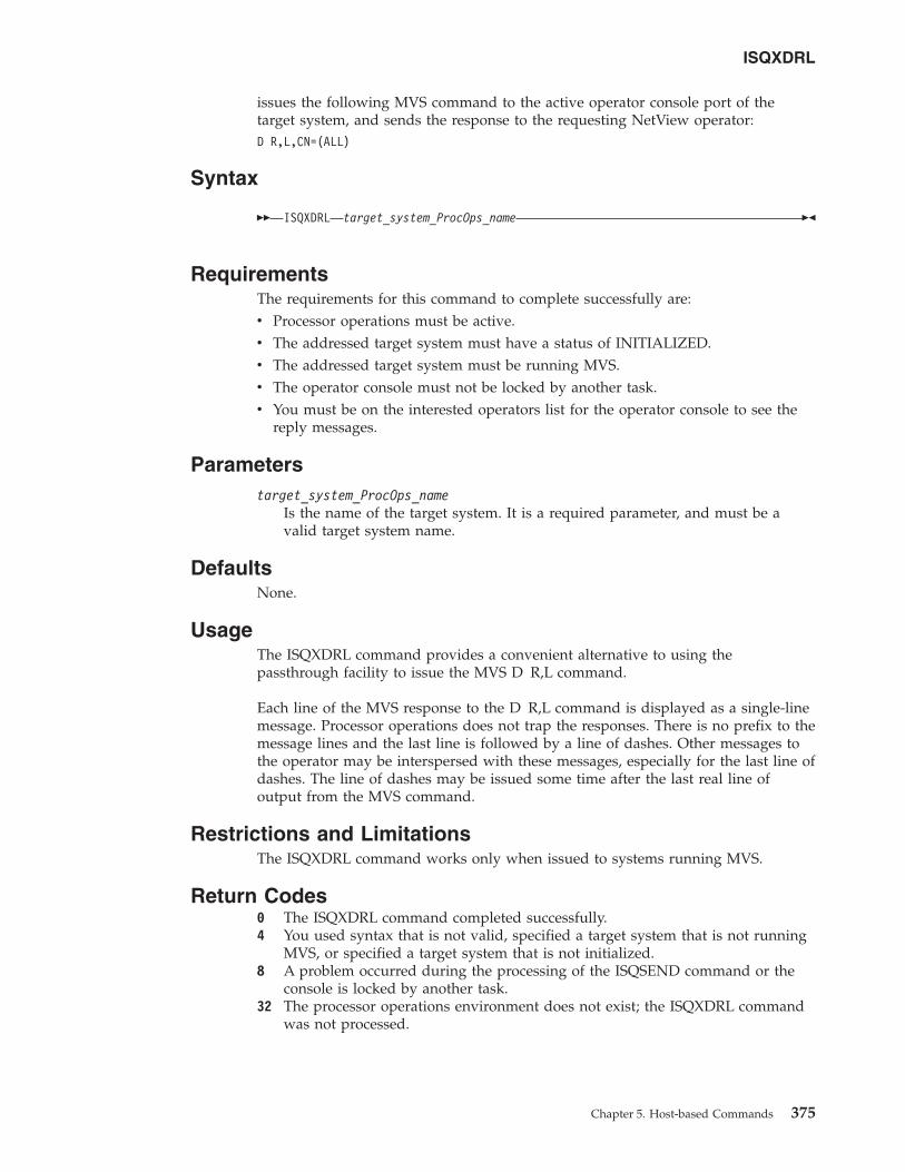
issues the following MVS command to the active operator console port of thetarget system, and sends the response to the requesting NetView operator:D R,L,CN=(ALL)
Syntax
�� ISQXDRL target_system_ProcOps_name ��
RequirementsThe requirements for this command to complete successfully are:v Processor operations must be active.v The addressed target system must have a status of INITIALIZED.v The addressed target system must be running MVS.v The operator console must not be locked by another task.v You must be on the interested operators list for the operator console to see the
reply messages.
Parameterstarget_system_ProcOps_name
Is the name of the target system. It is a required parameter, and must be avalid target system name.
DefaultsNone.
UsageThe ISQXDRL command provides a convenient alternative to using thepassthrough facility to issue the MVS D R,L command.
Each line of the MVS response to the D R,L command is displayed as a single-linemessage. Processor operations does not trap the responses. There is no prefix to themessage lines and the last line is followed by a line of dashes. Other messages tothe operator may be interspersed with these messages, especially for the last line ofdashes. The line of dashes may be issued some time after the last real line ofoutput from the MVS command.
Restrictions and LimitationsThe ISQXDRL command works only when issued to systems running MVS.
Return Codes0 The ISQXDRL command completed successfully.4 You used syntax that is not valid, specified a target system that is not running
MVS, or specified a target system that is not initialized.8 A problem occurred during the processing of the ISQSEND command or the
console is locked by another task.32 The processor operations environment does not exist; the ISQXDRL command
was not processed.
ISQXDRL
Chapter 5. Host-based Commands 375
ISQXDST
PurposeThe ISQXDST command displays status panels, which provide the followinginformation:v Status summary (all target systems)v Status summary (all blades of a zBX)v Individual ensemble connection statusv Individual target hardware statusv Individual target hardware connection statusv Individual target system statusv Interested operator list
Syntax
�� ISQXDSTISQXDSTI target_entity_name
��
RequirementsProcessor operations must be active.
Parameterstarget_entity_name
This can be:
target_system_nameIs the name of a valid target system for which you want to seeindividual target system status. If omitted, the summary status of alltarget systems is displayed.
target_hardware_nameIs the name of a valid target hardware for which you want to seeindividual hardware information in ProcOps. If the hardware has azBX attached, you can enter the zBX blade view from here.
ensemble_nameIs the name of a valid zEnterprise ensemble for which you want to seeindividual information and connection status.
DefaultsIf your ProcOps configuration has target systems and the associated targethardware (processors) defined, issuing the ISQXDST command without a targetentity parameter will show the overall status of all target systems.
If your ProcOps configuration has only ensemble definitions, but no target systemsand no associated target hardware definitions, issuing the ISQXDST commandwithout a target entity will show the ensemble selection panel.
While in the ISQXDST status sytem, the NetView OVERRIDE=NO option is ineffect, which suppresses immediate messages sent to your NCCF screen, so thepanel navigation is not interrupted. Note, that if you perform the NetView ROLLfunction, the DISPLAY=NO option is temporarily changed to DISPLAY=DEFAULT.
ISQXDST
376 System Automation for z/OS: Operator's Commands
||
|
||
|
||
||||
||||
|||
|
|||
|||
||||
If you invoke the ProcOps status system using the ISQXDSTI command, thedisplay option currently in effect for you, is not changed. As a result messagesdirected to your operator ID may interrupt the panel navigation flow.
UsageIssue the ISQXDST command from an operator console to access the processoroperations status facility. If you issue the command to access the status summarypanel, you will be able to use the status facility to view multiple panels formultiple ProcOps entities without exiting the status facility. Refer to IBM TivoliSystem Automation for z/OS Defining Automation Policy and IBM Tivoli SystemAutomation for z/OS User’s Guide for more information about how to set up and usethe status facility.
To display the Status Summary, issue:ISQXDST
This will invoke the target system summary.
To display the status of a specific target entity, issue:ISQXDST target_entity_name
If you enter the status facility by issuing the ISQXDST command with no otherparameters, all of the status panels give you access to the other status panels thatare supported by the status facility, including the zBX blade and ensemble views.Some of these status panels cannot be directly accessed by command. Refer to IBMTivoli System Automation for z/OS User’s Guide for further information about how touse the status panels.
To display the status of a specific target entity, issue:ISQXDST ensemble_name
From the displayed ensemble status screen, you can navigate to the views of theother ensembles you may have configured.
Restrictions and LimitationsThe following restrictions or limitations apply to this command:v Do not issue this command with ISQEXEC, ISQROUTE or from an automation
procedure.v You can issue the ISQXDST command only from an operator console.
Return CodesReturn codes are not applicable because the ISQXDST command cannot be issuedfrom a program.
ExamplesFigure 151 on page 378 shows an example of the ProcOps Ensemble view panelISQEENS that is displayed when you enter the command ISQXCMD and you haveensembles defined in your ProcOps configuration, but no target systems.
Figure 154 on page 386 shows an example of the ProcOps Ensemble view panelISQEENS that is displayed when you enter the command ISQXDST and you haveensembles defined in your ProcOps configuration, but no target systems.
ISQXDST
Chapter 5. Host-based Commands 377
|||
|
|||||||
|
|
|
|
|
||||||
|
|
||
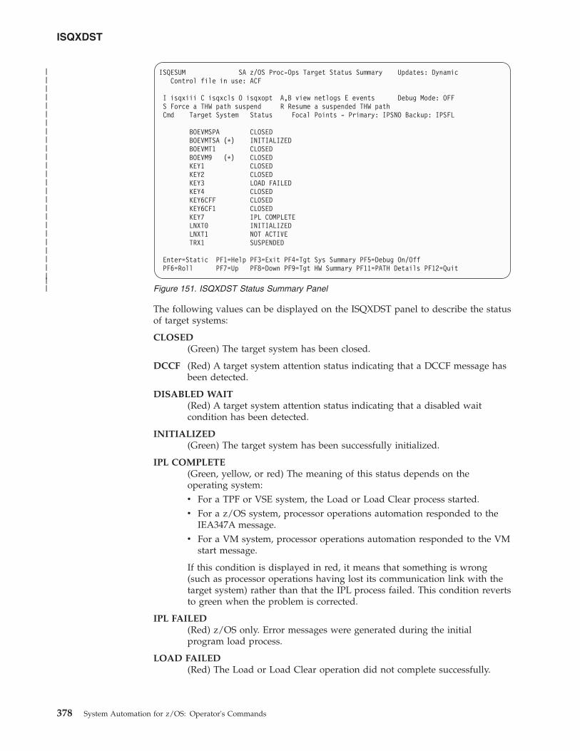
The following values can be displayed on the ISQXDST panel to describe the statusof target systems:
CLOSED(Green) The target system has been closed.
DCCF (Red) A target system attention status indicating that a DCCF message hasbeen detected.
DISABLED WAIT(Red) A target system attention status indicating that a disabled waitcondition has been detected.
INITIALIZED(Green) The target system has been successfully initialized.
IPL COMPLETE(Green, yellow, or red) The meaning of this status depends on theoperating system:v For a TPF or VSE system, the Load or Load Clear process started.v For a z/OS system, processor operations automation responded to the
IEA347A message.v For a VM system, processor operations automation responded to the VM
start message.
If this condition is displayed in red, it means that something is wrong(such as processor operations having lost its communication link with thetarget system) rather than that the IPL process failed. This condition revertsto green when the problem is corrected.
IPL FAILED(Red) z/OS only. Error messages were generated during the initialprogram load process.
LOAD FAILED(Red) The Load or Load Clear operation did not complete successfully.
ISQESUM SA z/OS Proc-Ops Target Status Summary Updates: DynamicControl file in use: ACF
I isqxiii C isqxcls O isqxopt A,B view netlogs E events Debug Mode: OFFS Force a THW path suspend R Resume a suspended THW pathCmd Target System Status Focal Points - Primary: IPSNO Backup: IPSFL
BOEVMSPA CLOSEDBOEVMTSA (*) INITIALIZEDBOEVMT1 CLOSEDBOEVM9 (*) CLOSEDKEY1 CLOSEDKEY2 CLOSEDKEY3 LOAD FAILEDKEY4 CLOSEDKEY6CFF CLOSEDKEY6CF1 CLOSEDKEY7 IPL COMPLETELNXT0 INITIALIZEDLNXT1 NOT ACTIVETRX1 SUSPENDED
Enter=Static PF1=Help PF3=Exit PF4=Tgt Sys Summary PF5=Debug On/OffPF6=Roll PF7=Up PF8=Down PF9=Tgt HW Summary PF11=PATH Details PF12=Quit
Figure 151. ISQXDST Status Summary Panel
ISQXDST
378 System Automation for z/OS: Operator's Commands
|||||||||||||||||||||||||||
NOT ACTIVE(Yellow) Activate response was received from the target and did notindicate that stage 1 activation was completed. If the target is running inan LPAR, the logical partition found is not activated.
NOT OPERATING(Red) Target hardware indicates a not operating condition for the image.No CP status is available for problem determination.
POWER-ON RESET REQUIRED(Red) A POWER-ON RESET of the target system hardware is requiredbefore a BCP load.
POWERED OFF(Red) The target hardware is physically powered off.
POWERSAVE(Red) SNMP Path Only: Power® utility for the target hardware failed.Target hardware put in power save state.
SERIOUS ALERT(Red) SNMP Path Only: Target system attention status indicating a seriousalert has been detected.
SERVICE(Red) SNMP Path Only: Service status enabled for the target hardware.
SNMP SESSION PROBLEM(Red) SNMP Path Only: An attempt to use the SNMP Connection returnedan error.
STAGE-1 ACTIVATE COMPLETE(Yellow) The support element power-on reset has occurred but the load isnot yet complete.
SUSPENDED(Yellow) The connection path to the target hardware of the target systemhas been suspended. All defined target systems using the suspendedconnection path cannot be operated with Proc-Ops until the connectionpath is resumed again. For suspend/resume operation you can use thecommand characters of the ISQXDST panel ISQESUM or the ISQXCONcommand.
UNDECIDABLE(Yellow) SNMP Path Only: The target hardware is not communicating withthe support element or the support element is not communicating with theHMC.
UNKNOWN(Green) No attempt has been made to initialize or activate this targetsystem. This status can be set only by a cold start of processor operations.
WAITING FOR IEA101A START MESSAGE(Yellow or red) MVS only: ACTIVATE, ISQXIPL, or ISQXLOD commandprocessing has completed for an MVS system and processor operations iswaiting for the IEA101A message on the operator console. If this conditionis displayed in red, it means that something is wrong (such as processoroperations having lost its communication link with the target system)rather than that processor operations has been waiting for the message toolong.
ISQXDST
Chapter 5. Host-based Commands 379
|||||||
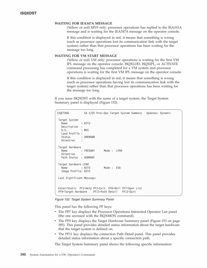
WAITING FOR IEA347A MESSAGE(Yellow or red) MVS only: processor operations has replied to the IEA101Amessage and is waiting for the IEA347A message on the operator console.
If this condition is displayed in red, it means that something is wrong(such as processor operations lost its communication link with the targetsystem) rather than that processor operations has been waiting for themessage too long.
WAITING FOR VM START MESSAGE(Yellow or red) VM only: processor operations is waiting for the first VMIPL message on the operator console. ISQXLOD, ISQXIPL, or ACTIVATEcommand processing has completed for a VM system and processoroperations is waiting for the first VM IPL message on the operator console.
If this condition is displayed in red, it means that something is wrong(such as processor operations having lost its communication link with thetarget system) rather than that processor operations has been waiting forthe message too long.
If you issue ISQXDST with the name of a target system, the Target SystemSummary panel is displayed (Figure 152).
This panel has the following PF keys:v The PF7 key displays the Processor Operations Interested Operator List panel
(the one accessed with the ISQXMON command).v The PF9 key displays the Target Hardware Summary panel (Figure 153 on page
385). This panel provides detailed status information about the target hardwarethat the target system is defined on.
v The PF11 key displays the connection Path Detail panel. This panel providesdetailed status information about a specific connection path.
The Target System Summary panel shows the following specific information:
ISQETARG SA z/OS Proc-Ops Target System Summary Updates: Dynamic
Target SystemName : KEY3Description :O.S. : MVSLoad Profile :Status : UNKNOWNAttention :
Target HardwareName : FREEWAY Mode : LPARAttention :Path Status : DORMANT
Target Hardware LPARName : KEY3 Mode : ESAImage Profile: KEY3
Last Significant Message:
Enter=Static PF1=Help PF3=Exit PF6=Roll PF7=Oper ListPF9=Target Hardware PF11=Path Detail PF12=Quit
Figure 152. Target System Summary Panel
ISQXDST
380 System Automation for z/OS: Operator's Commands
Target System NameThe name assigned in the customization dialog to this target system.
Target System DescriptionShort textual description of this target system, defined in the customizationdialog.
Status (Updated dynamically) The current value of the processor operationsinternal variable tstat.
You can change this status from INITIALIZED, LOAD FAILED, orIPL FAILED to IPL COMPLETE by issuing the ISQVARS command tochange the internal variable tstat. (For more information about specifyingtstat as a keyword on the ISQVARS command, see the description of theISQVARS command in IBM Tivoli System Automation for z/OS Operator’sCommands). You would want to do this when you perform a cold start ofprocessor operations while a target system is already running.
After the cold start, you issue the ISQXIII command to the target systemthat is already running so that its status becomes INITIALIZED, then youchange the value of tstat to IPL COMPLETE.
You may also want to change the status manually if the cause of theLOAD FAILED status was corrected by using the pass-through facility ofprocessor operations, or if it was corrected locally at the site of the targetsystem.
You can also issue the ISQVARS command to change the internal variabletstat from IPL COMPLETE to IPL FAILED. Processor operations sets astatus of IPL COMPLETE when it initiates a load of a target system andreceives an operating system specific message that indicates that theoperating system received a level where it is ready to work. However,neither of these operating systems provide a sufficient indication that theload process failed, preventing processor operations from changing thetarget system status appropriately.
Valid values for this status field are as follows:
CLOSED(Green) The target system has been closed.
INITIALIZED(Green) The target system has been successfully initialized.
IPL COMPLETE(Green, yellow, or red) For a TPF or VSE system, the Load or LoadClear process started. For an z/OS system, processor operationsautomation responded to the IEA347A message. For a VM system,processor operations automation responded to the VM startmessage. If this condition is displayed in red, this is done to getyour attention to inform you that something is wrong (such asprocessor operations lost its communication link with the targetsystem) rather than that the IPL process failed. This condition willrevert to being displayed in green when the problem is corrected.
IPL FAILED(Red) z/OS only: Error messages were generated during the initialprogram load process.
LOAD FAILED(Red) The Load or Load Clear operation did not completesuccessfully.
ISQXDST
Chapter 5. Host-based Commands 381
NOT ACTIVE(Yellow) Activate response was received from the target and didnot indicate that stage-1 activation was complete. If the target isrunning in an LPAR, the logical partition is found not activated.
NOT OPERATING(Red) Target hardware indicates a not operating condition for theimage. No CP status is available for problem determination.
STAGE-1 ACTIVATE COMPLETE(Yellow) The Support Element power-on reset has occurred but theload is not yet complete.
UNDECIDABLE(Yellow) SNMP Path Only: The target hardware is notcommunicating with the support element or the support element isnot communicating with the HMC.
UNKNOWN(Green) No attempt has been made to initialize or activate thistarget system. This status can be set only by a cold start ofprocessor operations.
WAITING FOR IEA101A START MESSAGE(Yellow or red) z/OS only: ACTIVATE, ISQXIPL, or ISQXLODcommand processing has completed for an z/OS system andprocessor operations is waiting for the IEA101A message on theoperator console. If this condition is displayed in red, it is to getyour attention to inform you that something is wrong (such asprocessor operations lost its communication link with the targetsystem) rather than that processor operations has been waiting forthe message too long.
WAITING FOR IEA347A MESSAGE(Yellow or red) z/OS only: processor operations has replied to theIEA101A message and is waiting for the IEA347A message on theoperator console. If this condition is displayed in red, this is doneto get your attention to inform you that something is wrong (suchas processor operations lost its communication link with the targetsystem) rather than that processor operations has been waiting forthe message too long.
WAITING FOR VM START MESSAGE(Yellow or red) VM only: processor operations is waiting for thefirst VM IPL message on the Support Element CI. The ACTIVATEor LOAD command processing has completed for a VM systemand processor operations is waiting for the first VM IPL message.If this condition is displayed in red, it is to get your attention toinform you that something is wrong (such as processor operationslost its communication link with the target system) rather than thatprocessor operations has been waiting for the message too long.
Target Hardware(Updated dynamically) The current value of the processor operationsinternal variable thwstat. Valid values are as follows:
blank (Not highlighted) No problem has been reported for the targethardware. You can also use the ISQVARS command to changethwstat to blanks after correcting an error condition reflected in thisfield.
ISQXDST
382 System Automation for z/OS: Operator's Commands
DEGRADED(Yellow) SNMP Path Only: Target hardware runs with degradedperformance (specific hardware types only).
POWERED OFF(Red) The CPC is physically powered off.
POWERSAVE(Red) SNMP Path Only: Power utility for the target hardwarefailed. Target hardware put in power save state.
SERVICE(Red) SNMP Path Only: Service status enabled for the targethardware.
SERVICE REQUIRED(Yellow) SNMP Path Only: The next disruption in the targethardware will result in degraded capacity or will fail.
TARGET HARDWARE PROBLEM(Red) The Support Element of the processor (CPC) reported atarget hardware problem.
Attention(Updated dynamically) The current value of the processor operationsinternal variable tattn. Valid values are as follows:
blank (Not highlighted) The target system has not encountered any of thefollowing conditions. You can also use the ISQVARS command tochange tattn to blanks after correcting an error condition reflectedin this field.
ALERT(Yellow) SNMP Path Only: Target system attention status indicatingan alert has been detected.
DCCF (Red) z/OS only: Processor operations has detected a DCCFmessage.
DISABLED WAIT(Red) Processor operations has detected a Disabled Wait condition.
ENV ALERT(Yellow) SNMP Path Only: Target system attention status indicatingan environment alert has been detected.
SERIOUS ALERT(Red) SNMP Path Only: Target system attention status indicating aserious alert has been detected.
Target HardwareThe name of the target hardware that this target system is running on.
O.S. MVS, VM, VSE, LINUX, or CF
Mode LPAR, ESA, 370
LPAR nameThe name of the logical partition that this target system is running in.
Connection Path InformationIdentifies the connection type and current status of the connection betweenthe processor operations focal point and the CPC support element orHMC.
ISQXDST
Chapter 5. Host-based Commands 383
Type NVC (SNA-based NetView connection), SNMP (IP-based Simple NetworkManagement Protocol connection).
Status (Updated dynamically) The current value of the processor operationsinternal variable scstat.
blank (Not highlighted) Either the target system has not encountered anyof the following conditions, or the condition has been resolved.
PATH PROBLEM(Red) The focal point system cannot communicate with theSupport Element on the NetView connection. View the Path Detailpanel for more information (see Figure 157 on page 394).
ACTIVE(Green) The path is ready for communications.
SNMP SESSION BUSY(Red) Processor operations cannot presently communicate with thetarget Support Element, the problem appears to be recoverable.
SNMP SESSION PROBLEM(Red) Processor operations cannot communicate with the targetSupport Element.
SUSPENDED(Red) The connection path to the target hardware has beensuspended. No ISQXIII command that is using this connection pathwill work until it is resumed again. For suspend/resume operationyou can use the command characters of ISQXDST panel ISQESUMor the ISQXCON command. Note that this status is propagated toall affected target systems.
Lock Holder(Updated dynamically) The current NetView operator that owns the lockfor the target system and the connection path. Locks can be set using theISQXLOC and ISQXUNL commands. Locks grant the exclusive use of theconnection path of a target hardware and its associated target systems.
Last Significant Message(Updated dynamically) The text of the last command response or reportreceived from the target system. The date and time of the message is alsodisplayed. The text of the message is truncated to 79 characters, includingthe message identifier but not including the time stamp. The message isnot removed from the panel when the condition that generated themessage is resolved.
Displaying Processor Resource Information (SNMP Connections)To view target hardware summary of a processor, select PF9 from the TargetSystem Summary panel (Figure 152 on page 380) or from the Status Summarypanel (Figure 151 on page 378) on a NetView console.
ISQXDST
384 System Automation for z/OS: Operator's Commands
|||||||
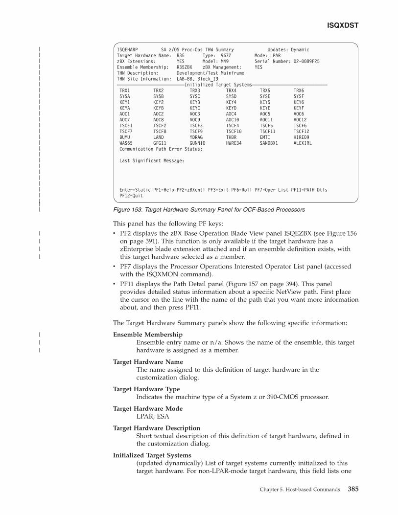
This panel has the following PF keys:v PF2 displays the zBX Base Operation Blade View panel ISQEZBX (see Figure 156
on page 391). This function is only available if the target hardware has azEnterprise blade extension attached and if an ensemble definition exists, withthis target hardware selected as a member.
v PF7 displays the Processor Operations Interested Operator List panel (accessedwith the ISQXMON command).
v PF11 displays the Path Detail panel (Figure 157 on page 394). This panelprovides detailed status information about a specific NetView path. First placethe cursor on the line with the name of the path that you want more informationabout, and then press PF11.
The Target Hardware Summary panels show the following specific information:
Ensemble MembershipEnsemble entry name or n/a. Shows the name of the ensemble, this targethardware is assigned as a member.
Target Hardware NameThe name assigned to this definition of target hardware in thecustomization dialog.
Target Hardware TypeIndicates the machine type of a System z or 390-CMOS processor.
Target Hardware ModeLPAR, ESA
Target Hardware DescriptionShort textual description of this definition of target hardware, defined inthe customization dialog.
Initialized Target Systems(updated dynamically) List of target systems currently initialized to thistarget hardware. For non-LPAR-mode target hardware, this field lists one
ISQEHARP SA z/OS Proc-Ops THW Summary Updates: DynamicTarget Hardware Name: R35 Type: 9672 Mode: LPARzBX Extensions: YES Model: M49 Serial Number: 02-0089F25Ensemble Membership: R35ZBX zBX Management: YESTHW Description: Development/Test MainframeTHW Site Information: LAB-BB, Block_19––––––––––––––––––––––––––Initialized Target Systems–––––––––––––––––––––––––––––TRX1 TRX2 TRX3 TRX4 TRX5 TRX6SYSA SYSB SYSC SYSD SYSE SYSFKEY1 KEY2 KEY3 KEY4 KEY5 KEY6KEYA KEYB KEYC KEYD KEYE KEYFAOC1 AOC2 AOC3 AOC4 AOC5 AOC6AOC7 AOC8 AOC9 AOC10 AOC11 AOC12TSCF1 TSCF2 TSCF3 TSCF4 TSCF5 TSCF6TSCF7 TSCF8 TSCF9 TSCF10 TSCF11 TSCF12BUMU LAND YDRAG THBR EMTI HIRE09WAS65 GFG11 GUNN10 HWRE34 SANDBX1 ALEXIRLCommunication Path Error Status:
Last Significant Message:
Enter=Static PF1=Help PF2=zBXcntl PF3=Exit PF6=Roll PF7=Oper List PF11=PATH DtlsPF12=Quit
Figure 153. Target Hardware Summary Panel for OCF-Based Processors
ISQXDST
Chapter 5. Host-based Commands 385
|||||||||||||||||||||||||||||
||||
|||
or none. For LPAR-mode target hardware, this field can list multiple targetsystems. This field is blank if no target systems are initialized to this targethardware.
Communication Path Error Status(updated dynamically) Status information in case of a communicationproblem between the NetView focal point and the target hardware.
Valid values for the status of the NetView connection path are:
SNMP SESSION BUSY(red) Processor operations cannot presently communicate with thetarget support element, the problem appears recoverable.
SNMP SESSION PROBLEM(red) Processor operations cannot communicate with the targetsupport element.
Last Significant MessageThe last significant message or alert associated with this target hardware.
THW Site InformationTHW location information for this target hardware as defined in the PolicyDatabase.
ZBX ExtensionsYES or NO. Indicates if the target hardware has a blade extension unitattached.
ZBX ManagementYES, NO, n/a. If the target hardware has a zBX attached and is alsodefined as an ensemble member, the value is YES. If the target hardwarehas no zBX attached, the value is n/a. If a zBX is attached, but noensemble membership is defined, the value is NO.
How to Monitor and Control Ensemble connections and zBXresourcesIf you have defined ensemble connections together with target hardware that has azBX unit attached, you can use the ProcOps ISQXDST status system to monitorand control the following zEnterprise blade extension resources: blade centers,blades, the zBX unit, and the connection to the ensemble HMC, which is thecommunication end point for the ProcOps.
For a standard ProcOps configuration, with target systems and a ensembleconnection to a target hardware with a zBX attachment, use the command form:ISQXDST <ensemble_name> to display the ensemble main selection panel ISQEENS.
For a ProcOps configuration with no target system definitions, the ISQXDSTcommand entered without a parameter is sufficient to display the ensemble mainselection panel ISQEENS.
Figure 154. Ensemble Main View
ISQXDST
386 System Automation for z/OS: Operator's Commands
||
|||
|||
|||
|||
|||||
|||||||
|||
|||
|
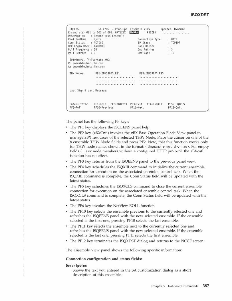
ISQEENS SA z/OS - Proc-Ops Ensemble View Updates: DynamicEnsemble(s) 001 to 003 of 003: GRY2ZBX �HYDRA� R35ZBX ........ ........Description : Remote test EnsembleReal EnsName : Hydra Connection Type : HTTPConn Status : ACTIVE IP Stack : TCPIP7HMC Login User : TADDM03 Lock Holder :Poll Frequency : 30 Cmd Retries : 3Poll Retries : 3 Cmd Wait : 15
(P)rimary, (A)lternate HMC:P: ensemble.hmc.ibm.comA: ensemble.hmca.ibm.com
THW Nodes: R91:IBM390PS.R91 R93:IBM390PS.R93.......................... .................................................... .................................................... ..........................
Last Significant Message:
Enter=Static PF1=Help PF2=zBXCntl PF3=Exit PF4=ISQXIII PF5=ISQXCLSPF6=Roll PF10=Previous PF11=Next PF12=Quit
The panel has the following PF keys:v The PF1 key displays the ISQEENS panel help.v The PF2 key (zBXCntl) invokes the zBX Base Operation Blade View panel to
manage zBX resources of the selected THW Node. Place the cursor on one of the8 ensemble THW Node fields and press PF2. Note, that this function works onlyfor THW node names shown in the format: <thwname>:<netid>.<nau>. For emptyfields (....) or node members without a configured HTTP protocol, the zBXcntlfunction has no effect.
v The PF3 key returns from the ISQEENS panel to the previous panel view.v The PF4 key schedules the ISQXIII command to initialize the current ensemble
connection for execution on the associated ensemble control task. When theISQXIII command is complete, the Conn Status field will be updated with thelatest status.
v The PF5 key schedules the ISQXCLS command to close the current ensembleconnection for execution on the associated ensemble control task. When theISQXCLS command is complete, the Conn Status field will be updated with thelatest status.
v The PF6 key invokes the NetView ROLL function.v The PF10 key selects the ensemble previous to the currently selected one and
refreshes the ISQEENS panel with the new selected ensemble. If the ensembleselected is the first one, pressing PF10 selects the last ensemble.
v The PF11 key selects the ensemble next to the currently selected one andrefreshes the ISQEENS panel with the new selected ensemble. If the ensembleselected is the last one, pressing PF11 selects the first ensemble.
v The PF12 key terminates the ISQXDST dialog and returns to the NCCF screen.
The Ensemble View panel shows the following specific information:
Connection configuration and status fields:
DescriptionShows the text you entered in the SA customization dialog as a shortdescription of this ensemble.
ISQXDST
Chapter 5. Host-based Commands 387
||||||||||||||||||||||||||
|
|
||||||
|
||||
||||
|
|||
|||
|
|
|
|||
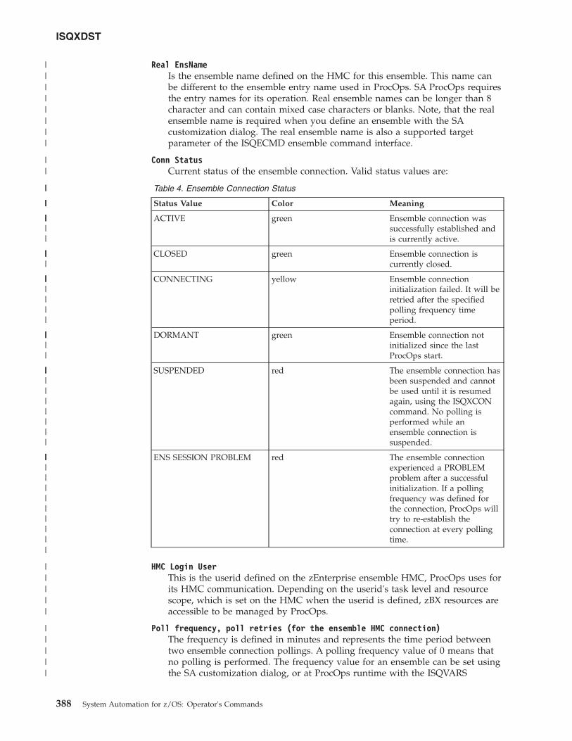
Real EnsNameIs the ensemble name defined on the HMC for this ensemble. This name canbe different to the ensemble entry name used in ProcOps. SA ProcOps requiresthe entry names for its operation. Real ensemble names can be longer than 8character and can contain mixed case characters or blanks. Note, that the realensemble name is required when you define an ensemble with the SAcustomization dialog. The real ensemble name is also a supported targetparameter of the ISQECMD ensemble command interface.
Conn StatusCurrent status of the ensemble connection. Valid status values are:
Table 4. Ensemble Connection Status
Status Value Color Meaning
ACTIVE green Ensemble connection wassuccessfully established andis currently active.
CLOSED green Ensemble connection iscurrently closed.
CONNECTING yellow Ensemble connectioninitialization failed. It will beretried after the specifiedpolling frequency timeperiod.
DORMANT green Ensemble connection notinitialized since the lastProcOps start.
SUSPENDED red The ensemble connection hasbeen suspended and cannotbe used until it is resumedagain, using the ISQXCONcommand. No polling isperformed while anensemble connection issuspended.
ENS SESSION PROBLEM red The ensemble connectionexperienced a PROBLEMproblem after a successfulinitialization. If a pollingfrequency was defined forthe connection, ProcOps willtry to re-establish theconnection at every pollingtime.
HMC Login UserThis is the userid defined on the zEnterprise ensemble HMC, ProcOps uses forits HMC communication. Depending on the userid's task level and resourcescope, which is set on the HMC when the userid is defined, zBX resources areaccessible to be managed by ProcOps.
Poll frequency, poll retries (for the ensemble HMC connection)The frequency is defined in minutes and represents the time period betweentwo ensemble connection pollings. A polling frequency value of 0 means thatno polling is performed. The frequency value for an ensemble can be set usingthe SA customization dialog, or at ProcOps runtime with the ISQVARS
ISQXDST
388 System Automation for z/OS: Operator's Commands
||||||||
||
||
|||
|||||
||||
|||||||
|||||
||||||||||
||||||||||||
|||||
|||||
command. The polling retry value is used by the polling routine to determineif and how often a failing ensemble communication command should beretried before giving up the polling.
Cmd retries, cmd wait (the ensemble HMC connection)These are general ensemble command control values to define how often afailing ensemble command should be retried before reporting it as failed andhow long to wait for a command response from the HMC before reporting atimeout condition. The command retry and command wait values for ensemblecommands can be set using the SA customization dialog, or at ProcOpsruntime with the ISQVARS command.
Connection TypeAlways set to HTTP. ProcOps exploits the System z HMC Web Services APIwhich is a HTTP based IP Stack (alternate to the default stack). If you want touse a different IP stack on the ProcOps FP system for the HTTPcommunication with the zEnterprise ensemble HMC, you can define this usingthe SA customization dialog, or at ProcOps runtime with the ISQVARScommand. Note, that after you have specified an alternate IP stack at ProcOpsruntime, you must recycle the HMC connection to activate this change.
Lock HolderWith ProcOps you can use the ISQXLOC/ISQXUNL commands to lock anensemble connection, so that only your operator tasks can use it. Otheroperators or autotasks cannot use the ensemble connection while it is locked.The Lock Holder field shows the name of the operator or autotask, currentlyholding the lock. Note, that normally locks are set only for a short time period,to gain exclusive control for important ensemble work.
HMC AddressesIn a zEnterprise ensemble environment a primary and an alternate HMC mustbe configured. The primary HMC's IP address or hostname is required whenyou define an ensemble in the SA customization dialog. If an alternate HMCaddress is specified, the ProcOps ensemble connection polling will PING bothHMC addresses and report bad results. Note, that in case of an HMC switch(primary becomes alternate) the IP address of the 'old' primary HMC willremain the IP address of the 'new' HMC.
THW Node informationIn a zEnterprise ensemble, up to 8 nodes can be defined as members. A node isa IBM zEnterprise (TM) System, with or without a zEnterprise BladeCenterExtension (zBX) attached. In ProcOps, a node is a target hardware (processor)with a membership to an ensemble. The processor and the ensemblemembership can be defined using the SA customization dialog.
Panel ISQEENS lists the THW ensemble member nodes in two columns each withfour fields. Unused member fields are marked: '........'. If a node is listed in theformat <thw>:<netid>.<nau>, means that a zBX is expected to be attached and thatmanagement for the zBX resources is intended. This is configured by adding'HTTP' to the connection protocol list for a processor with the SA configurationdialog. If only the <thw> target hardware name is displayed, the processor targethardware has an ensemble membership defined, however the zBX support protocol'HTTP' is not configured.
How to Monitor and Control zBX resourcesThe ISQEZBX panel can be used to query information of the following zBX objects:v The blade extension unit,v The associated ensemble,
ISQXDST
Chapter 5. Host-based Commands 389
|||
|||||||
||||||||
|||||||
||||||||
||||||
||||||||
||
|
|
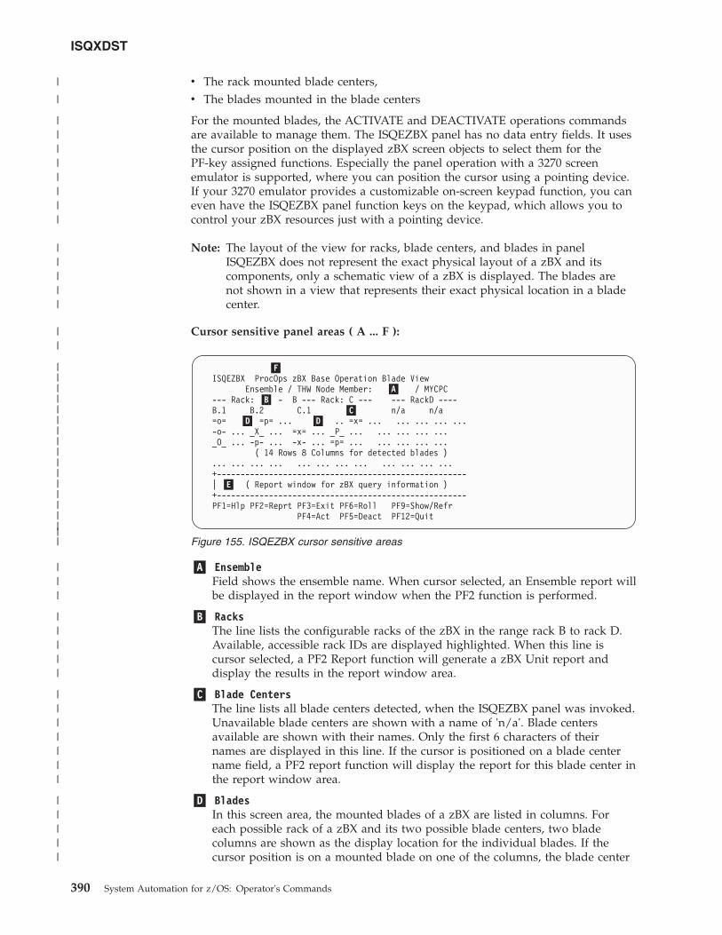
v The rack mounted blade centers,v The blades mounted in the blade centers
For the mounted blades, the ACTIVATE and DEACTIVATE operations commandsare available to manage them. The ISQEZBX panel has no data entry fields. It usesthe cursor position on the displayed zBX screen objects to select them for thePF-key assigned functions. Especially the panel operation with a 3270 screenemulator is supported, where you can position the cursor using a pointing device.If your 3270 emulator provides a customizable on-screen keypad function, you caneven have the ISQEZBX panel function keys on the keypad, which allows you tocontrol your zBX resources just with a pointing device.
Note: The layout of the view for racks, blade centers, and blades in panelISQEZBX does not represent the exact physical layout of a zBX and itscomponents, only a schematic view of a zBX is displayed. The blades arenot shown in a view that represents their exact physical location in a bladecenter.
Cursor sensitive panel areas ( A ... F ):
�A� EnsembleField shows the ensemble name. When cursor selected, an Ensemble report willbe displayed in the report window when the PF2 function is performed.
�B� RacksThe line lists the configurable racks of the zBX in the range rack B to rack D.Available, accessible rack IDs are displayed highlighted. When this line iscursor selected, a PF2 Report function will generate a zBX Unit report anddisplay the results in the report window area.
�C� Blade CentersThe line lists all blade centers detected, when the ISQEZBX panel was invoked.Unavailable blade centers are shown with a name of 'n/a'. Blade centersavailable are shown with their names. Only the first 6 characters of theirnames are displayed in this line. If the cursor is positioned on a blade centername field, a PF2 report function will display the report for this blade center inthe report window area.
�D� BladesIn this screen area, the mounted blades of a zBX are listed in columns. Foreach possible rack of a zBX and its two possible blade centers, two bladecolumns are shown as the display location for the individual blades. If thecursor position is on a mounted blade on one of the columns, the blade center
�F�ISQEZBX ProcOps zBX Base Operation Blade View
Ensemble / THW Node Member: �A� / MYCPC--- Rack: �B� - B --- Rack: C --- --- RackD ----B.1 B.2 C.1 �C� n/a n/a=o= �D� =p= ... �D� .. =x= ... ... ... ... ...-o- ... _X_ ... =x= ... _P_ ... ... ... ... ..._O_ ... -p- ... -x- ... =p= ... ... ... ... ...
( 14 Rows 8 Columns for detected blades )... ... ... ... ... ... ... ... ... ... ... ...+-----------------------------------------------------| �E� ( Report window for zBX query information )+-----------------------------------------------------PF1=Hlp PF2=Reprt PF3=Exit PF6=Roll PF9=Show/Refr
PF4=Act PF5=Deact PF12=Quit
Figure 155. ISQEZBX cursor sensitive areas
ISQXDST
390 System Automation for z/OS: Operator's Commands
||||||||||||||||||
|
|
||||||||
|||||
||
|||
|||||
|||||||
|||||
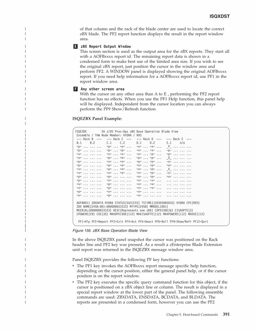
of that column and the rack of the blade center are used to locate the correctzBX blade. The PF2 report function displays the result in the report windowarea.
�E� zBX Report Output WindowThis screen section is used as the output area for the zBX reports. They start allwith a AOFBxxxx report id. The remaining report data is shown in acondensed form to make best use of the limited area size. If you wish to seethe original zBX report, just position the cursor in the window area andperform PF2. A WINDOW panel is displayed showing the original AOFBxxxxreport. If you need help information for a AOFBxxxx report id, use PF1 in thereport window area.
�F� Any other screen areaWith the cursor on any other area than A to E , performing the PF2 reportfunction has no effects. When you use the PF1 Help function, this panel helpwill be displayed. Independent from the cursor location you can alwaysperform the PF9 Show/Refresh function.
ISQEZBX Panel Example:
In the above ISQEZBX panel snapshot the cursor was positioned on the Rackheader line and PF2 key was pressed. As a result a zEnterprise Blade Extensionunit report was returned in the ISQEZBX message window area.
Panel ISQEZBX provides the following PF key functions:v The PF1 key invokes the AOFBxxxx report message specific help function,
depending on the cursor position, either the general panel help, or if the cursorposition is on the report window.
v The PF2 key executes the specific query command function for this object, if thecursor is positioned on a zBX object line or column. The result is displayed in aspecial report window at the lower part of the panel. The following ensemblecommands are used: ZBXDATA, ENSDATA, BCDATA, and BLDATA. Thereports are presented in a condensed form, however you can use the PF2
ISQEZBX SA z/OS Proc-Ops zBX Base Operation Blade ViewEnsemble / THW Node Member: HYDRA / R93--- Rack B --- --- Rack C --- --- Rack D --- --- Rack E ---B.1 B.2 C.1 C.2 D.1 D.2 E.1 n/a=p= ... ... ... =p= ... =o= ... =x= ... =x= ... _P_ ... ... ...=p= ... ... ... =p= ... =p= ... =x= ... =x= ... -p- ... ... ...=x= ... ... ... =x= ... =x= ... =x= ... =p= ... =p= ... ... ...=x= ... ... ... =p= ... =o= ... =p= ... =p= ... _O_ ... ... ...=p= ... ... ... =x= ... =o= ... =p= ... =p= ... -o- ... ... ...=p= ... ... ... =p= ... =o= ... =x= ... =p= ... =o= ... ... ...=x= ... ... ... =p= ... =o= ... =x= ... =p= ... _X_ ... ... ...=x= ... ... ... =x= ... =o= ... =x= ... =p= ... -x- ... ... ...=p= ... ... ... =p= ... ... ... =x= ... =p= ... =x= ... ... ...=p= ... ... ... =x= ... ... ... =x= ... =x= ... ... ... ... ...=x= ... ... ... =p= ... ... ... =x= ... =x= ... ... ... ... ...=x= ... ... ... =p= ... ... ... =x= ... =x= ... ... ... ... ...=p= ... ... ... =x= ... ... ... =x= ... ... ... ... ... ... ...=x= ... ... ... =p= ... ... ... =x= ... ... ... ... ... ... ...
AOFB0011 ZBXDATA HYDRA STATUS(SUCCESS) TSTIME(120303085035) HYDRA CPC(R93)ZBX NAME(2458-001-000000033333) MTYPE(2458) MMODEL(001)MSERIAL(000000033333) DESC(Represents one zBX) CDPXI50E(6) CISAOPTE(3)CPOWERE(29) CXE(35) MAXDPXI50E(112) MAXISAOPTE(112) MAXPOWERE(112) MAXXE(112)
PF1=Hlp PF2=Report PF3=Exit PF4=Act PF5=Deact PF6=Roll PF9=Show/Refr PF12=Quit
Figure 156. zBX Base Operation Blade View
ISQXDST
Chapter 5. Host-based Commands 391
||||||||||||||||||||||||||||
|||
||||||||
|||||
||
|||
|
|||
|||||
function again with the cursor positioned in the report window area to display anew panel with the original report messages. With BCDATA and BLDATAprocessing, the panel status of the selected blade or blade center object willautomatically change to the new status shown in the report if there was a statuschange. Note, that when you place the cursor on an empty (...) blade columnposition, an empty report window is shown.
v The PF3 key returns from this panel to the next higher level in the ISQXDSTpanel hierarchy.
v The PF4 key ACTIVATEs a blade, before the function starts, you must confirm it(PF10) to proceed or cancel (PF11) the request. This function activates theselected blade unit which is located in a Blade Center Chassis of a zBX rack.After a successful activation, the blade status of a BLDATA report (PF2) shows'operating'. Note, that the zBX VH (virtual host) related to this blade will beautomatically activated. The VS (virtual server) objects related to the VH mustbe extra configured for automatic activation. VSs not configured for automaticactivation have a status of 'not-operating' after a successful blade activation.Activating a blade while the blade is still active and work is still running on thevirtual servers of that blade, will interrupt this work because the blade isdeactivated before it is activated again. The PF4 blade activation calls theISQROUTE ProcOps function to schedule a ISQECMD with the blade activateensemble command. This allows the user to perform other ISQEZBX functionsimmediately after the blade activation has been scheduled. You must use eitherPF9 or PF2 with the cursor on the blade position to get any blade status changeinformation displayed on the panel.
v The PF5 key DEACTIVATEs a blade, before the function starts, you mustconfirm it (PF10) to proceed or cancel (PF11) the request. This functiondeactivates the selected blade unit which is located in a Blade Center Chassis ofa zBX rack. After a successful deactivation, the blade status of a BLDATA report(PF2) shows 'no-power'. Note, that the zBX VH (virtual host) related to thisblade will be automatically deactivated. The VS (virtual server) objects related tothe VH will automatically be deactivated and any work running is disrupted.After successful deactivation of a blade, the related VS objects have a status of'not-operating'. The PF5 blade deactivation calls the ISQROUTE ProcOpsfunction to schedule a ISQECMD with the blade deactivate ensemble command.This allows the user to perform other ISQEZBX functions immediately after theblade activation has been scheduled. You must use either PF9 or PF2 with thecursor on the blade position to get any blade status change informationdisplayed on the panel.
v The PF6 key invokes the NetView ROLL functionv The PF9 key invokes the zBX Show/Refresh function. When panel ISQEZBX is
initially displayed in a panel session, the list of the mounted blades on the zBXis empty. The initial panel display shows the available racks highlighted withtheir available blade center names displayed. The PF9 function must beperformed first to fill the blades columns with the available mounted bladeinformation. The PF9 function can also be used to refresh all blade columns.
v The PF12 key (Quit) returns from ISQEZBX panel and exit ISQXDST. Thisreturns you to the NCCF screen.
Acceptable status properties for blades: With the exception of racks andworkloads, the possible status values of other zBX objects can be configured to bean 'ACCEPTED' status. zBX objects with this status attribute set can be consideredas not requiring special attention, regardless of their actual status. In fact, the HMCuser interface marks all zBX objects in an acceptable status with a green status
ISQXDST
392 System Automation for z/OS: Operator's Commands
||||||
||
||||||||||||||||
||||||||||||||
|
||||||
||
|||||
indicator. You can use the HMC Ensemble Management task and set/unset theaccepted status marker for a status value using the zBX object's Details view. Pressthe apply button to activate the changes.
The ISQEZBX panel displays all blades with the accepted status property set ingreen. The accepted status properties for blades are also shown in the AOFB0016BLDATA reports. Acceptable status properties for other zBX objects than blades arecurrently ignored by the ISQEZBX panel display, but can be determined in thereports.
Blade type and status indicators: The following blade status indicators are shownin the rows/columns reserved for the zBX blades:v Indicates an empty place, no blade is mounted:
... (color blue)v Indicators for a mounted blade of type 'system-x':
=x= (color green, status is accepted)-x- (color yellow reverse, status is transient)_X_ (color red reverse, status is unaccepted)
v Indicators for a mounted blade of type 'power':=p= (color green, status is accepted)-p- (color yellow reverse, status is transient)_P_ (color red reverse, status is unaccepted)
v Indicators for a mounted optimizer hardware component of type 'isaopt' or'dpxi50z':
=o= (color green, status is accepted)-o- (color yellow reverse, status is transient)_O_ (color red reverse, status is unaccepted)
How to Monitor Communications Path StatusThe communications paths from the processor operations focal point system totarget systems are of two types: NVC and SNMP. You can display details of theconnection for these types of path.
Display Path Details: Press PF11 on the Target System Summary panel or TargetHardware Summary panel to display the Path Detail Panel, as shown in Figure 157on page 394.
ISQXDST
Chapter 5. Host-based Commands 393
|||
|||||
||
|
|
|
|
|
|
|
|
|
|
||
|
|
|
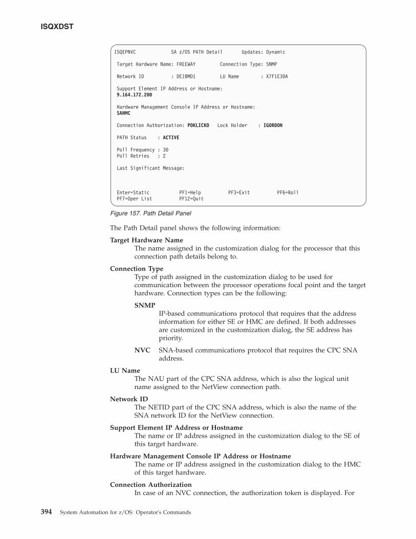
The Path Detail panel shows the following information:
Target Hardware NameThe name assigned in the customization dialog for the processor that thisconnection path details belong to.
Connection TypeType of path assigned in the customization dialog to be used forcommunication between the processor operations focal point and the targethardware. Connection types can be the following:
SNMPIP-based communications protocol that requires that the addressinformation for either SE or HMC are defined. If both addressesare customized in the customization dialog, the SE address haspriority.
NVC SNA-based communications protocol that requires the CPC SNAaddress.
LU NameThe NAU part of the CPC SNA address, which is also the logical unitname assigned to the NetView connection path.
Network IDThe NETID part of the CPC SNA address, which is also the name of theSNA network ID for the NetView connection.
Support Element IP Address or HostnameThe name or IP address assigned in the customization dialog to the SE ofthis target hardware.
Hardware Management Console IP Address or HostnameThe name or IP address assigned in the customization dialog to the HMCof this target hardware.
Connection AuthorizationIn case of an NVC connection, the authorization token is displayed. For
ISQEPNVC SA z/OS PATH Detail Updates: Dynamic
Target Hardware Name: FREEWAY Connection Type: SNMP
Network ID : DEIBMD1 LU Name : X7F1E30A
Support Element IP Address or Hostname:9.164.172.200
Hardware Management Console IP Address or Hostname:SAHMC
Connection Authorization: POKLICKO Lock Holder : IGORDON
PATH Status : ACTIVE
Poll Frequency : 30Poll Retries : 2
Last Significant Message:
Enter=Static PF1=Help PF3=Exit PF6=RollPF7=Oper List PF12=Quit
Figure 157. Path Detail Panel
ISQXDST
394 System Automation for z/OS: Operator's Commands
SNMP connections the community value is shown. The authorizationvalues are defined in the customization dialog for a selected targethardware.
Lock Holder(Updated dynamically) The current NetView operator owning the lock forthe connection path. Locks can be set and unset using the ISQXLOC andISQXUNL command. Locks grant the exclusive use of a connection path.
Path Status(Updated dynamically) The status of the NetView path. Valid values are:
UNKNOWN(Green) No command was ever issued to this path name.
ACTIVE(Green) The path is ready for communications.
PATH PROBLEM(Red) The focal point system cannot communicate with theSupport Element on the NetView connection. This status isaccompanied by a Last Significant Message.
Poll FrequencyThe time (in minutes) that processor operations should poll the SupportElement for status.
Poll Retries(Updated dynamically) The number of attempts to retry that should occurbefore processor operations notifies the operator that the connection failed.
Last Significant Message(Updated dynamically) The text of the last command response or reportreceived from the target system. The text of the message is truncated to 79characters, including the message identifier but not including the timestamp. The message is not removed from the panel when the conditionthat generated the message is resolved.
ISQXIII
PurposeThe ISQXIII command initializes (or re-initializes) a target system, or a targetsystem connection. When initializing a target system, ISQXIII establishes aconnection to the target processor and enables its console connections.
When initializing a target hardware, ISQXIII establishes a connection to the targetprocessor and enables the console connection for all target systems defined thatrun on the specified target hardware.
In addition, this command can be used to establish a session to an Ensemble HMC,which is required to manage zBX Blade resources with ProcOps.
ISQXDST
Chapter 5. Host-based Commands 395
|||
||
Syntax
�� ISQXIII target_system_ProcOps_nameOCSC
ensemble_ProcOps_nametarget_hardware_ProcOps_name
��
RequirementsThe requirements for this command to complete successfully are:v Processor operations must be active.v The addressed target system must have a status of UNKNOWN or CLOSED.v The addressed target system must be initialized if you use the
target_system_ProcOps_name console_designator syntax.v No associated console or ensemble connection can be locked by another task.
Parameterstarget_system_ProcOps_name
Is the name of the target system. This is a required parameter, and must be avalid target system name.
OC Specifies the active operator console (not valid for the couplingfacility).
SC Specifies the system console connection.
ensemble_ProcOps_nameIs the ProcOps name of a zBX Ensemble.
target_hardware_ProcOps_nameIs the name of the target hardware. This is a required parameter, and must bea valid target hardware name.
DefaultsNone.
UsageIssue the ISQXIII command to a target system to prepare it for processoroperations monitoring and control.
Issue the ISQXIII command to a zBX ensemble HMC to prepare it for processoroperations monitoring and control.
Issue the ISQXIII command to a target hardware to prepare it and all definedtarget systems for processor operations monitoring and control.
Initializing a Target SystemInitializing a target system starts communication with the target hardware andenables the console connections. It also updates the interested operator lists forconsoles at the target system. The interested operator lists are updated because anoperator can join an interested operator list by issuing the ISQXMON commandafter processor operations has been started but before the target system has beeninitialized.
ISQXIII
396 System Automation for z/OS: Operator's Commands
||
|
||
|||
||
||
Initializing an Ensemble HMC ConnectionInitializing this connection starts by logging in at the addressed Ensemble HMC. Itthen starts to discover the zBX base resources such as blades, available formonitoring and control, using this ensemble connection. The defined userid for thisensemble remains connected to the HMC, until an ISQXCLS is performed orprocessor operations is eliminated.
Operators can use the ISQXMON command to join/leave the interested operatorgroup of an ensemble to get notifications and reports from the ensemble and itsresources.
Initializing a Target HardwareUsing this command form allows you to initialize target systems of a targethardware defined to ProcOps in one step. The individual ISQXIII commands fortarget systems are scheduled to run on the ProcOps control task of the targethardware. When a target system is already INITIALIZED while ISQXIII for a targethardware is running, it is ignored.
Restrictions and LimitationsThe following restrictions or limitations apply:v To re-initialize a target system, you must first close it with the ISQXCLS
command (see “ISQXCLS” on page 370).v To initialize a console connection, the target system must have been initialized
previously.v To re-initialize an ensemble session, you must first close it with the ISQXCLS
command.
Return Codes0 The ISQXIII command processed successfully and the processor operations
environment for the specified target system or ensemble has been initialized orre-initialized.
4 During initialization of a target system or ensemble one or more of thefollowing problems occurred:v No system consoles could be contacted.v No operator consoles could be contacted.v No ensemble HMC could be contacted.
8 You used syntax that is not valid, specified a target system that is notinitialized, or specified an invalid ensemble name.
12 An internal error occurred or connection path status is SUSPENDED to eitherthe processor hardware (SE/HMC) or ensemble HMC.
16 A severe error occurred.32 The processor operations environment does not exist; the ISQXIII command
was not processed.
ISQXLOC
PurposeThe ISQXLOC command locks access to a ProcOps entity to serialize operations tothat console with other operator tasks. Entities can be either target system namestogether with a console designator or ensemble names.
ISQXIII
Chapter 5. Host-based Commands 397
||||||
|||
||||||
||
||||||||||||
|||
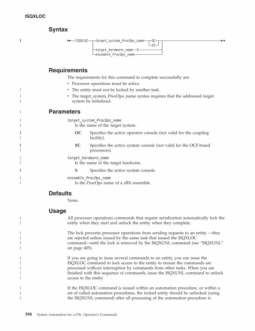
Syntax
�� ISQXLOC target_system_ProcOps_name OCSC
target_hardware_name Sensemble_ProcOps_name
��
RequirementsThe requirements for this command to complete successfully are:v Processor operations must be active.v The entity must not be locked by another task.v The target_system_ProcOps_name syntax requires that the addressed target
system be initialized.
Parameterstarget_system_ProcOps_name
Is the name of the target system.
OC Specifies the active operator console (not valid for the couplingfacility).
SC Specifies the active system console (not valid for the OCF-basedprocessors).
target_hardware_nameIs the name of the target hardware.
S Specifies the active system console.
ensemble_ProcOps_nameIs the ProcOps name of a zBX ensemble.
DefaultsNone.
UsageAll processor operations commands that require serialization automatically lock theentity when they start and unlock the entity when they complete.
The lock prevents processor operations from sending requests to an entity —theyare rejected unless issued by the same task that issued the ISQXLOCcommand—until the lock is removed by the ISQXUNL command (see “ISQXUNL”on page 405).
If you are going to issue several commands to an entity, you can issue theISQXLOC command to lock access to the entity to ensure the commands areprocessed without interruption by commands from other tasks. When you arefinished with this sequence of commands, issue the ISQXUNL command to unlockaccess to the entity.
If the ISQXLOC command is issued within an automation procedure, or within aset of called automation procedures, the locked entity should be unlocked (usingthe ISQXUNL command) after all processing of the automation procedure is
ISQXLOC
398 System Automation for z/OS: Operator's Commands
|||
|
||
|
||
|||
|||
||
||
||
||
||||
|||||
|||
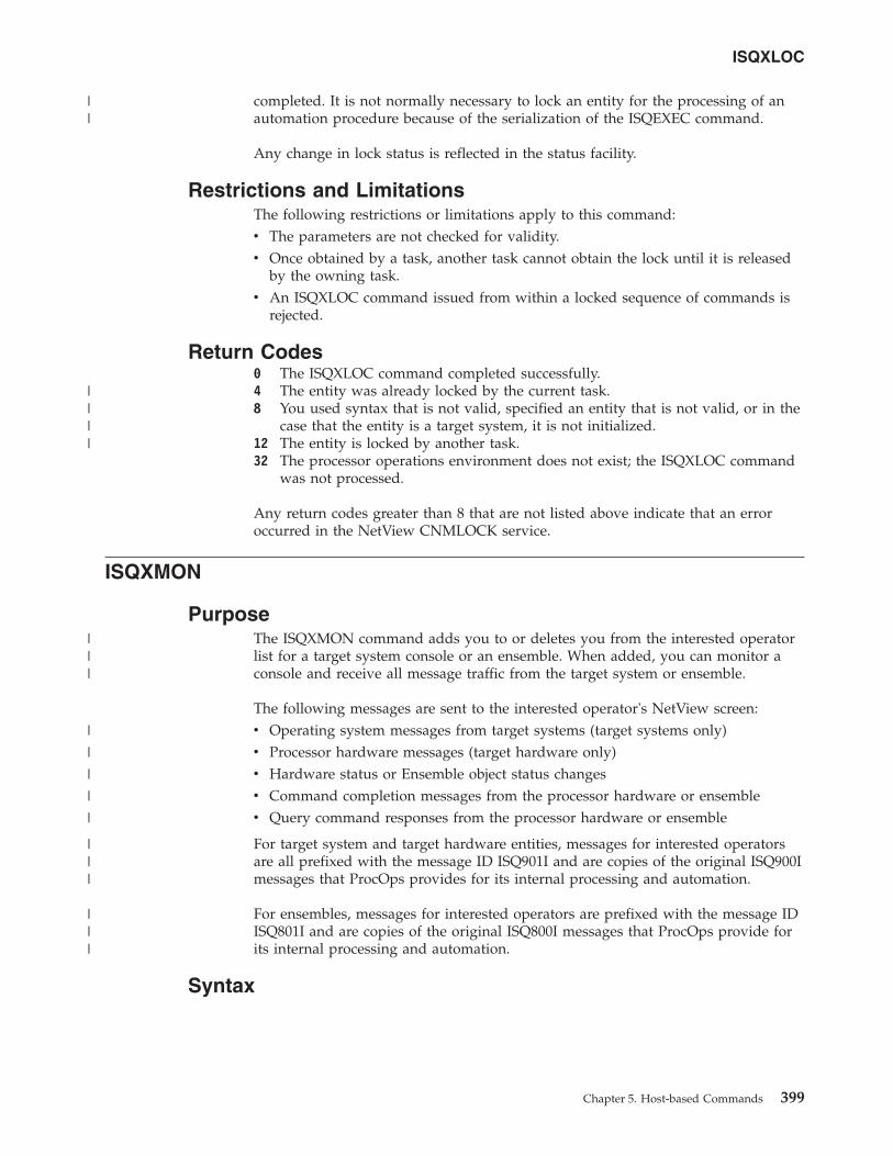
completed. It is not normally necessary to lock an entity for the processing of anautomation procedure because of the serialization of the ISQEXEC command.
Any change in lock status is reflected in the status facility.
Restrictions and LimitationsThe following restrictions or limitations apply to this command:v The parameters are not checked for validity.v Once obtained by a task, another task cannot obtain the lock until it is released
by the owning task.v An ISQXLOC command issued from within a locked sequence of commands is
rejected.
Return Codes0 The ISQXLOC command completed successfully.4 The entity was already locked by the current task.8 You used syntax that is not valid, specified an entity that is not valid, or in the
case that the entity is a target system, it is not initialized.12 The entity is locked by another task.32 The processor operations environment does not exist; the ISQXLOC command
was not processed.
Any return codes greater than 8 that are not listed above indicate that an erroroccurred in the NetView CNMLOCK service.
ISQXMON
PurposeThe ISQXMON command adds you to or deletes you from the interested operatorlist for a target system console or an ensemble. When added, you can monitor aconsole and receive all message traffic from the target system or ensemble.
The following messages are sent to the interested operator's NetView screen:v Operating system messages from target systems (target systems only)v Processor hardware messages (target hardware only)v Hardware status or Ensemble object status changesv Command completion messages from the processor hardware or ensemblev Query command responses from the processor hardware or ensemble
For target system and target hardware entities, messages for interested operatorsare all prefixed with the message ID ISQ901I and are copies of the original ISQ900Imessages that ProcOps provides for its internal processing and automation.
For ensembles, messages for interested operators are prefixed with the message IDISQ801I and are copies of the original ISQ800I messages that ProcOps provide forits internal processing and automation.
Syntax
ISQXLOC
Chapter 5. Host-based Commands 399
||
||||
|||
|
|
|
|
|
|||
|||
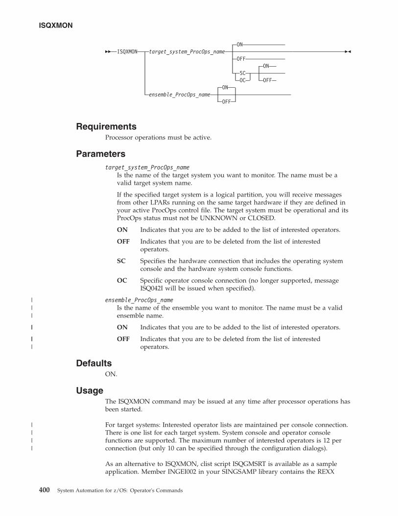
��ON
ISQXMON target_system_ProcOps_nameOFF
ONSCOC OFF
ONensemble_ProcOps_name
OFF
��
RequirementsProcessor operations must be active.
Parameterstarget_system_ProcOps_name
Is the name of the target system you want to monitor. The name must be avalid target system name.
If the specified target system is a logical partition, you will receive messagesfrom other LPARs running on the same target hardware if they are defined inyour active ProcOps control file. The target system must be operational and itsProcOps status must not be UNKNOWN or CLOSED.
ON Indicates that you are to be added to the list of interested operators.
OFF Indicates that you are to be deleted from the list of interestedoperators.
SC Specifies the hardware connection that includes the operating systemconsole and the hardware system console functions.
OC Specific operator console connection (no longer supported, messageISQ042I will be issued when specified).
ensemble_ProcOps_nameIs the name of the ensemble you want to monitor. The name must be a validensemble name.
ON Indicates that you are to be added to the list of interested operators.
OFF Indicates that you are to be deleted from the list of interestedoperators.
DefaultsON.
UsageThe ISQXMON command may be issued at any time after processor operations hasbeen started.
For target systems: Interested operator lists are maintained per console connection.There is one list for each target system. System console and operator consolefunctions are supported. The maximum number of interested operators is 12 perconnection (but only 10 can be specified through the configuration dialogs).
As an alternative to ISQXMON, clist script ISQGMSRT is available as a sampleapplication. Member INGEI002 in your SINGSAMP library contains the REXX
ISQXMON
400 System Automation for z/OS: Operator's Commands
|||
||
|||
||||
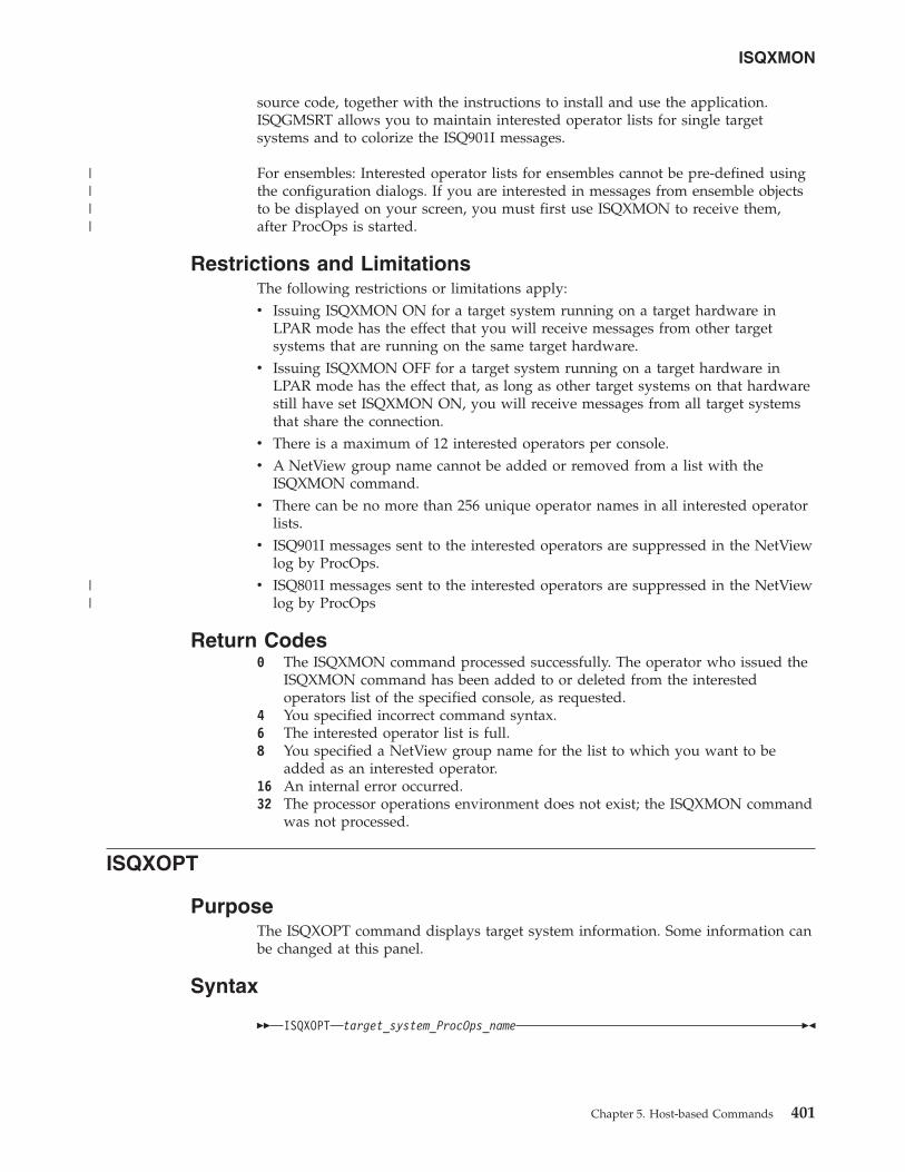
source code, together with the instructions to install and use the application.ISQGMSRT allows you to maintain interested operator lists for single targetsystems and to colorize the ISQ901I messages.
For ensembles: Interested operator lists for ensembles cannot be pre-defined usingthe configuration dialogs. If you are interested in messages from ensemble objectsto be displayed on your screen, you must first use ISQXMON to receive them,after ProcOps is started.
Restrictions and LimitationsThe following restrictions or limitations apply:v Issuing ISQXMON ON for a target system running on a target hardware in
LPAR mode has the effect that you will receive messages from other targetsystems that are running on the same target hardware.
v Issuing ISQXMON OFF for a target system running on a target hardware inLPAR mode has the effect that, as long as other target systems on that hardwarestill have set ISQXMON ON, you will receive messages from all target systemsthat share the connection.
v There is a maximum of 12 interested operators per console.v A NetView group name cannot be added or removed from a list with the
ISQXMON command.v There can be no more than 256 unique operator names in all interested operator
lists.v ISQ901I messages sent to the interested operators are suppressed in the NetView
log by ProcOps.v ISQ801I messages sent to the interested operators are suppressed in the NetView
log by ProcOps
Return Codes0 The ISQXMON command processed successfully. The operator who issued the
ISQXMON command has been added to or deleted from the interestedoperators list of the specified console, as requested.
4 You specified incorrect command syntax.6 The interested operator list is full.8 You specified a NetView group name for the list to which you want to be
added as an interested operator.16 An internal error occurred.32 The processor operations environment does not exist; the ISQXMON command
was not processed.
ISQXOPT
PurposeThe ISQXOPT command displays target system information. Some information canbe changed at this panel.
Syntax
�� ISQXOPT target_system_ProcOps_name ��
ISQXMON
Chapter 5. Host-based Commands 401
||||
||
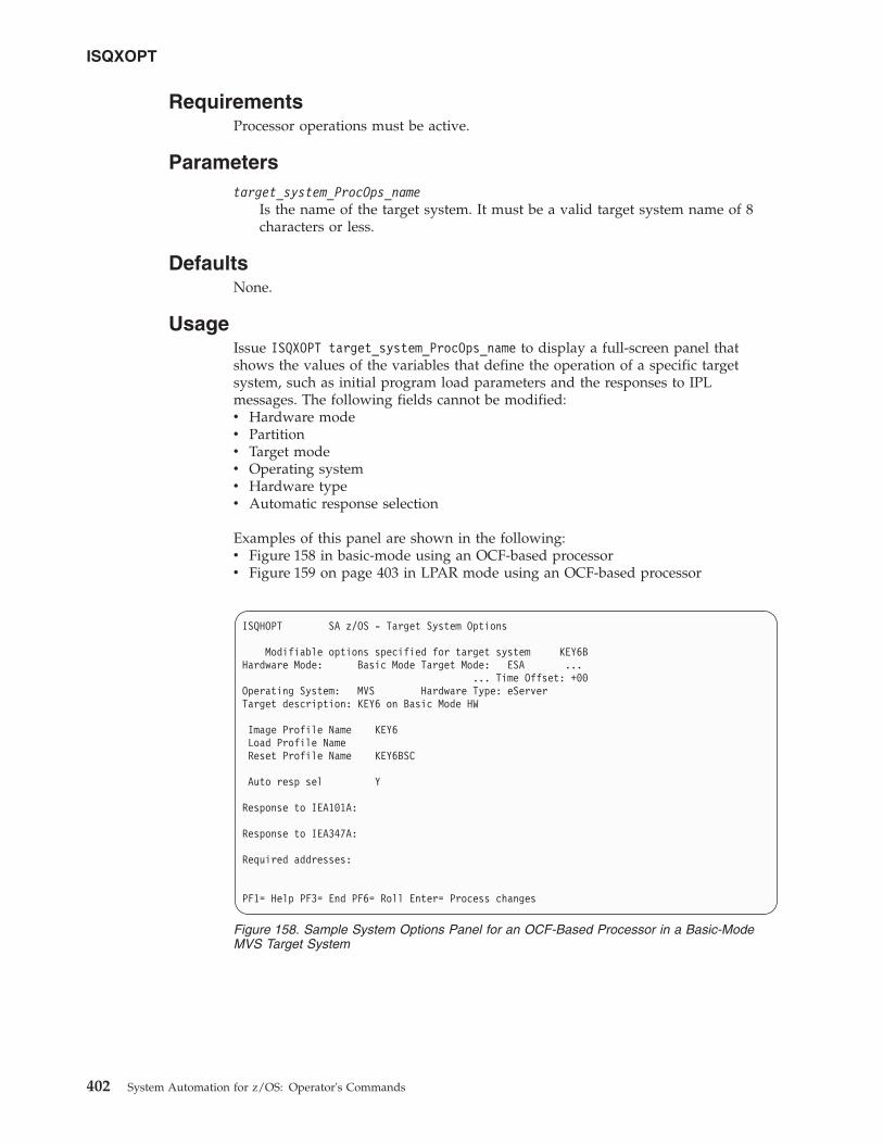
RequirementsProcessor operations must be active.
Parameterstarget_system_ProcOps_name
Is the name of the target system. It must be a valid target system name of 8characters or less.
DefaultsNone.
UsageIssue ISQXOPT target_system_ProcOps_name to display a full-screen panel thatshows the values of the variables that define the operation of a specific targetsystem, such as initial program load parameters and the responses to IPLmessages. The following fields cannot be modified:v Hardware modev Partitionv Target modev Operating systemv Hardware typev Automatic response selection
Examples of this panel are shown in the following:v Figure 158 in basic-mode using an OCF-based processorv Figure 159 on page 403 in LPAR mode using an OCF-based processor
ISQHOPT SA z/OS - Target System Options
Modifiable options specified for target system KEY6BHardware Mode: Basic Mode Target Mode: ESA ...
... Time Offset: +00Operating System: MVS Hardware Type: eServerTarget description: KEY6 on Basic Mode HW
Image Profile Name KEY6Load Profile NameReset Profile Name KEY6BSC
Auto resp sel Y
Response to IEA101A:
Response to IEA347A:
Required addresses:
PF1= Help PF3= End PF6= Roll Enter= Process changes
Figure 158. Sample System Options Panel for an OCF-Based Processor in a Basic-ModeMVS Target System
ISQXOPT
402 System Automation for z/OS: Operator's Commands
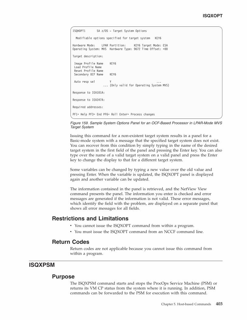
Issuing this command for a non-existent target system results in a panel for aBasic-mode system with a message that the specified target system does not exist.You can recover from this condition by simply typing in the name of the desiredtarget system in the first field of the panel and pressing the Enter key. You can alsotype over the name of a valid target system on a valid panel and press the Enterkey to change the display to that for a different target system.
Some variables can be changed by typing a new value over the old value andpressing Enter. When the variable is updated, the ISQXOPT panel is displayedagain and another variable can be updated.
The information contained in the panel is retrieved, and the NetView Viewcommand presents the panel. The information you enter is checked and errormessages are generated if the information is not valid. These error messages,which identify the field with the problem, are displayed on a separate panel thatshows all error messages for all fields.
Restrictions and Limitationsv You cannot issue the ISQXOPT command from within a program.v You must issue the ISQXOPT command from an NCCF command line.
Return CodesReturn codes are not applicable because you cannot issue this command fromwithin a program.
ISQXPSM
PurposeThe ISQXPSM command starts and stops the ProcOps Service Machine (PSM) orreturns its VM CP status from the system where it is running. In addition, PSMcommands can be forwarded to the PSM for execution with this command.
ISQHOPT1 SA z/OS - Target System Options
Modifiable options specified for target system KEY6
Hardware Mode: LPAR Partition: KEY6 Target Mode: ESAOperating System: MVS Hardware Type: 9672 Time Offset: +00
Target description:
Image Profile Name KEY6Load Profile NameReset Profile NameSecondary OCF Name KEY6
Auto resp sel Y ...... (Only valid for Operating System MVS)
Response to IEA101A:
Response to IEA347A:
Required addresses:
PF1= Help PF3= End PF6= Roll Enter= Process changes
Figure 159. Sample System Options Panel for an OCF-Based Processor in LPAR-Mode MVSTarget System
ISQXOPT
Chapter 5. Host-based Commands 403
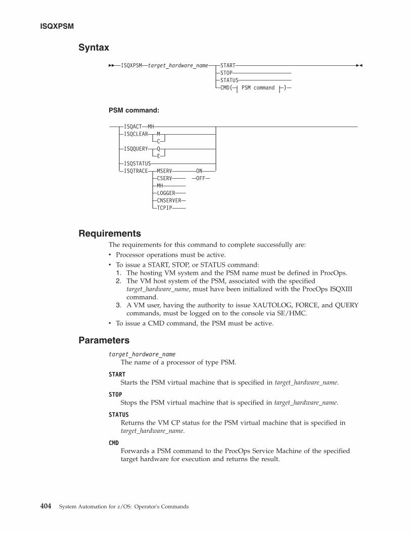
Syntax
�� ISQXPSM target_hardware_name STARTSTOPSTATUSCMD( PSM command )
��
PSM command:
ISQACT MHISQCLEAR M
CISQQUERY Q
EISQSTATUSISQTRACE MSERV ON
CSERV OFFMHLOGGERCNSERVERTCPIP
RequirementsThe requirements for this command to complete successfully are:v Processor operations must be active.v To issue a START, STOP, or STATUS command:
1. The hosting VM system and the PSM name must be defined in ProcOps.2. The VM host system of the PSM, associated with the specified
target_hardware_name, must have been initialized with the ProcOps ISQXIIIcommand.
3. A VM user, having the authority to issue XAUTOLOG, FORCE, and QUERYcommands, must be logged on to the console via SE/HMC.
v To issue a CMD command, the PSM must be active.
Parameterstarget_hardware_name
The name of a processor of type PSM.
STARTStarts the PSM virtual machine that is specified in target_hardware_name.
STOPStops the PSM virtual machine that is specified in target_hardware_name.
STATUSReturns the VM CP status for the PSM virtual machine that is specified intarget_hardware_name.
CMDForwards a PSM command to the ProcOps Service Machine of the specifiedtarget hardware for execution and returns the result.
ISQXPSM
404 System Automation for z/OS: Operator's Commands
PSM commandOne of the PSM diagnosis and service commands that is listed in the syntaxfragment, see Chapter 8, “PSM Commands - Special Requests,” on page 503 formore details.
DefaultsNone.
UsageSee Chapter 8, “PSM Commands - Special Requests,” on page 503 for informationabout the PSM commands that are available.
Restrictions and LimitationsOnly a subset of the available PSM commands can be used with the CMD optionof ISQXPSM. To use the full set of commands, a VM user must be logged on asPSM and enter the commands at the PSM console.
The following commands can only be entered from the PSM console directly:v ISQMSGv ISQPSMv STOPALL
Return Codes0 The ISQXPSM command completed successfully.4 One of the following occurred:v No VM host system has been defined for this PSM.v The PSM's VM host target system has not initialized.v The PSM has not been defined for the specified target hardware.v The specified target hardware type is not PSM.v There is an error in the parameter list.
6 Authorization error. Either the user ID that was checked to access the specifiedtarget hardware has not been authorized, or the allowed access level is notsufficient.
8 One of the following occurred:v ISQSEND returned an error while processing a START, STOP, or STATUS
request.v An error occurred while waiting for the response of a START, STOP, or
STATUS request.32 The ProcOps environment does not exist; the ISQXPSM command was not
processed.
ISQXUNL
PurposeThe ISQXUNL command cancels a ProcOps entity lock instituted by the ISQXLOCcommand. Entities can be either target system names together with a consoledesignator or ensemble names.
ISQXPSM
Chapter 5. Host-based Commands 405
|||
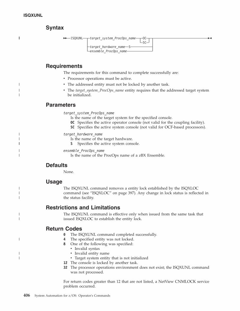
Syntax
�� ISQXUNL target_system_ProcOps_name OCSC
target_hardware_name Sensemble_ProcOps_name
��
RequirementsThe requirements for this command to complete successfully are:v Processor operations must be active.v The addressed entity must not be locked by another task.v The target_system_ProcOps_name entity requires that the addressed target system
be initialized.
Parameterstarget_system_ProcOps_name
Is the name of the target system for the specified console.OC Specifies the active operator console (not valid for the coupling facility).SC Specifies the active system console (not valid for OCF-based processors).
target_hardware_nameIs the name of the target hardware.S Specifies the active system console.
ensemble_ProcOps_nameIs the name of the ProcOps name of a zBX Ensemble.
DefaultsNone.
UsageThe ISQXUNL command removes a entity lock established by the ISQXLOCcommand (see “ISQXLOC” on page 397). Any change in lock status is reflected inthe status facility.
Restrictions and LimitationsThe ISQXUNL command is effective only when issued from the same task thatissued ISQXLOC to establish the entity lock.
Return Codes0 The ISQXUNL command completed successfully.4 The specified entity was not locked.8 One of the following was specified:v Invalid syntaxv Invalid entity namev Target system entity that is not initialized
12 The console is locked by another task.32 The processor operations environment does not exist; the ISQXUNL command
was not processed.
For return codes greater than 12 that are not listed, a NetView CNMLOCK serviceproblem occurred.
ISQXUNL
406 System Automation for z/OS: Operator's Commands
|||
|
||
||||
||
|||
||
|
||
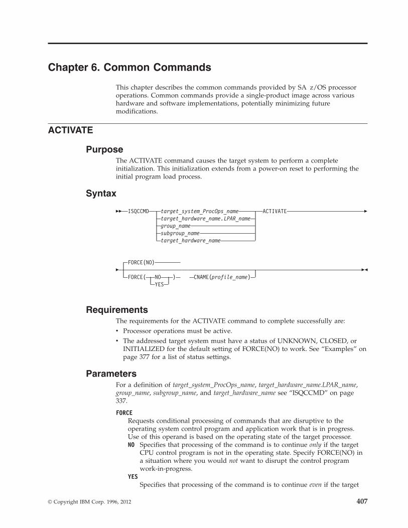
Chapter 6. Common Commands
This chapter describes the common commands provided by SA z/OS processoroperations. Common commands provide a single-product image across varioushardware and software implementations, potentially minimizing futuremodifications.
ACTIVATE
PurposeThe ACTIVATE command causes the target system to perform a completeinitialization. This initialization extends from a power-on reset to performing theinitial program load process.
Syntax
�� ISQCCMD target_system_ProcOps_nametarget_hardware_name.LPAR_namegroup_namesubgroup_nametarget_hardware_name
ACTIVATE �
�FORCE(NO)
FORCE( NO )YES
CNAME(profile_name)��
RequirementsThe requirements for the ACTIVATE command to complete successfully are:v Processor operations must be active.v The addressed target system must have a status of UNKNOWN, CLOSED, or
INITIALIZED for the default setting of FORCE(NO) to work. See “Examples” onpage 377 for a list of status settings.
ParametersFor a definition of target_system_ProcOps_name, target_hardware_name.LPAR_name,group_name, subgroup_name, and target_hardware_name see “ISQCCMD” on page337.
FORCERequests conditional processing of commands that are disruptive to theoperating system control program and application work that is in progress.Use of this operand is based on the operating state of the target processor.NO Specifies that processing of the command is to continue only if the target
CPU control program is not in the operating state. Specify FORCE(NO) ina situation where you would not want to disrupt the control programwork-in-progress.
YESSpecifies that processing of the command is to continue even if the target
© Copyright IBM Corp. 1996, 2012 407
CPU control program is in the operating state. Specify FORCE(YES) in asituation where disruption of the control program work-in-progress is notimportant, such as in recovery situations.
FORCE(NO) requires that the associated command fails when useful work istaking place. For ACTIVATE, fail states occur if an operating mode is detectedand FORCE(NO) is specified, or when FORCE defaults to NO. The commandfails whenever the processor is in those states.
CNAMESpecifies the name of an image or reset profile to be sent to the processor'ssupport element.
For image activation, it is recommended to let processor operations select theprofile name automatically rather than overriding processor operations'sselection with the profile_name parameter. If specified, the operand must matchthe target_hardware_name.LPAR_name.
For CPC activation, as indicated by target_hardware_name, SA z/OS uses thereset profile in the ACTIVATE operations management command that is sent tothe support element. If this keyword is not used, SA z/OS selects theactivation reset profile that is specified in the configuration dialog fortarget_hardware_name. If an activation reset profile was not specified in theconfiguration dialog, SA z/OS selects the default activation reset profile that isspecified with the CCNTL common command or on the support elementdirectly.
profile_nameIndicates the name of the image or reset profile. It is recommended thatyou let processor operations select the profile name automatically ratherthan overriding processor operations' selection with the profile_nameparameter.
Usage
Caution: The ACTIVATE command can be very disruptive when you specifyFORCE(YES), so use this command carefully. The SA z/OS processoroperations status facility only knows about status changes that areperformed from within SA z/OS. If you load and start a target system’soperating system outside of SA z/OS (such as from the SA z/OSprocessor operations passthru facility or from the console at the remotetarget system) rather than by using the SA z/OS commands, SA z/OSdoes not know that the status of the target system has changed.
The effect of the ACTIVATE FORCE keyword applies only to target systems thatare defined to SA z/OS. Because SA z/OS does not know that the target systemwas activated from outside of SA z/OS, it considers the target system status to beUNKNOWN. The functions performed by the ACTIVATE common command willdisrupt the operating system even if you specify the FORCE(NO) option, because theSA z/OS status facility does not indicate that the target system is alreadyinitialized and running.
If you do not specify FORCE(YES):v The ACTIVATE command checks whether the same logical partition name is in
use by another target system. If so, the ACTIVATE command is rejected; if not,processing continues.
ACTIVATE
408 System Automation for z/OS: Operator's Commands
v The ACTIVATE command also checks target hardware that is not logicallypartitioned to see if the target hardware is in use by another target system. If so,the ACTIVATE command is rejected; if not, processing continues.
ACTIVATE processing can also produce the result that more target systems areaffected than the one explicitly specified in the command or those included in atarget group or subgroup specified in the command. The additional target systemsare CPC images on a processor in LPAR mode. These additional target systems areactivated when a Reset or Image profile specifies additional profile names in theAUTOACT operand. To avoid unintended activations, operators should be keptaware of the linkages between profiles.
Using either scheduled requests or auto-activated logical partitions causesSA z/OS to receive "unsolicited" responses from one or more target systems.SA z/OS uses these responses to update its status information and to attempt toinitialize the corresponding target systems.
When you specify FORCE(YES):v The ACTIVATE command overrules the requirement that a target system must
have a status of UNKNOWN, CLOSED, or INITIALIZED.v Processing of the ACTIVATE command is performed even if the target system
has a status condition of IPL COMPLETE, IPL FAILED, LOAD FAILED, or oneof the WAITING FOR...MESSAGE conditions.
The ACTIVATE command performs only the processing that is required. Forexample, it performs a power-on reset only when required, and it does notinitialize a target system that is already initialized correctly.
ACTIVATE of VM Guest Systems
Purpose: If a target system running on a guest machine is part of an ACTIVATErequest, this results in an XAUTOLOG command being issued to the VM system.This starts the guest machine using the profile defined for it in VM. This profileusually causes a guest operating system (MVS, LINUX, VSE, VM) to be loaded, butit is possible that no IPL command is executed. This corresponds to the use of ahardware profile where no automatic IPL is done. For an MVS target system theRUN state of the VM guest machine is set to ON.
Parameters:
FORCE(YES)A CP FORCE command is issued to the VM system to stop the guest, if theguest is currently active. Then CP XAUTOLOG is issued to start the guestagain.
FORCE(NO)Guest status is checked. If the guest is known to be NOT OPERATING then aCP FORCE command is issued to stop the guest.
CP XAUTOLOG is issued. This means if the guest is already started (loggedon) and known to be processing normally, the ACTIVATE command is rejected.
Restrictions and Limitations: The CNAME parameter is not supported.
Remark:
ACTIVATE
Chapter 6. Common Commands 409
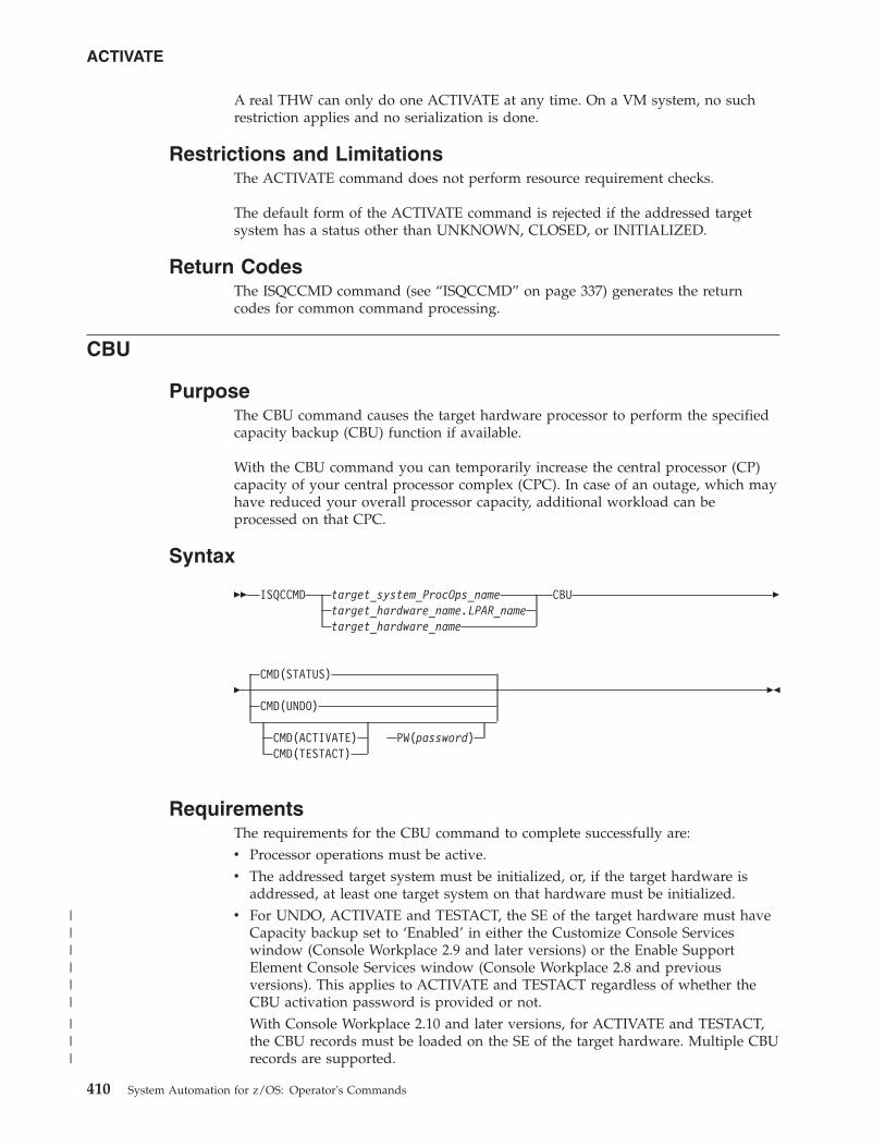
A real THW can only do one ACTIVATE at any time. On a VM system, no suchrestriction applies and no serialization is done.
Restrictions and LimitationsThe ACTIVATE command does not perform resource requirement checks.
The default form of the ACTIVATE command is rejected if the addressed targetsystem has a status other than UNKNOWN, CLOSED, or INITIALIZED.
Return CodesThe ISQCCMD command (see “ISQCCMD” on page 337) generates the returncodes for common command processing.
CBU
PurposeThe CBU command causes the target hardware processor to perform the specifiedcapacity backup (CBU) function if available.
With the CBU command you can temporarily increase the central processor (CP)capacity of your central processor complex (CPC). In case of an outage, which mayhave reduced your overall processor capacity, additional workload can beprocessed on that CPC.
Syntax
�� ISQCCMD target_system_ProcOps_nametarget_hardware_name.LPAR_nametarget_hardware_name
CBU �
�CMD(STATUS)
CMD(UNDO)
CMD(ACTIVATE) PW(password)CMD(TESTACT)
��
RequirementsThe requirements for the CBU command to complete successfully are:v Processor operations must be active.v The addressed target system must be initialized, or, if the target hardware is
addressed, at least one target system on that hardware must be initialized.v For UNDO, ACTIVATE and TESTACT, the SE of the target hardware must have
Capacity backup set to ‘Enabled’ in either the Customize Console Serviceswindow (Console Workplace 2.9 and later versions) or the Enable SupportElement Console Services window (Console Workplace 2.8 and previousversions). This applies to ACTIVATE and TESTACT regardless of whether theCBU activation password is provided or not.With Console Workplace 2.10 and later versions, for ACTIVATE and TESTACT,the CBU records must be loaded on the SE of the target hardware. Multiple CBUrecords are supported.
ACTIVATE
410 System Automation for z/OS: Operator's Commands
||||||
|||
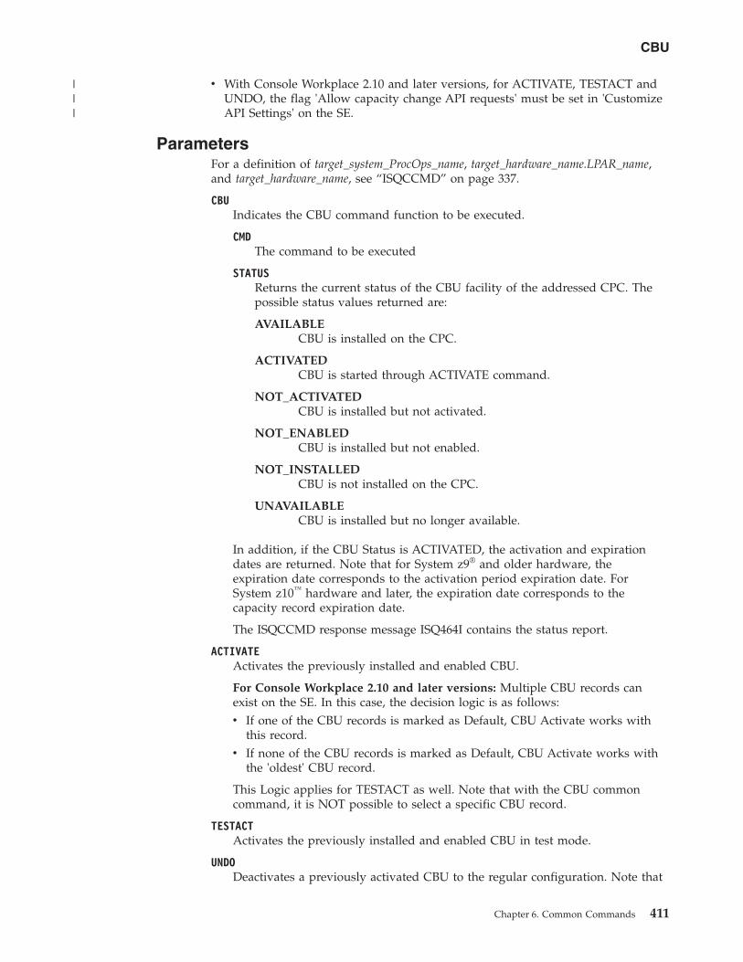
v With Console Workplace 2.10 and later versions, for ACTIVATE, TESTACT andUNDO, the flag 'Allow capacity change API requests' must be set in 'CustomizeAPI Settings' on the SE.
ParametersFor a definition of target_system_ProcOps_name, target_hardware_name.LPAR_name,and target_hardware_name, see “ISQCCMD” on page 337.
CBUIndicates the CBU command function to be executed.
CMDThe command to be executed
STATUSReturns the current status of the CBU facility of the addressed CPC. Thepossible status values returned are:
AVAILABLECBU is installed on the CPC.
ACTIVATEDCBU is started through ACTIVATE command.
NOT_ACTIVATEDCBU is installed but not activated.
NOT_ENABLEDCBU is installed but not enabled.
NOT_INSTALLEDCBU is not installed on the CPC.
UNAVAILABLECBU is installed but no longer available.
In addition, if the CBU Status is ACTIVATED, the activation and expirationdates are returned. Note that for System z9® and older hardware, theexpiration date corresponds to the activation period expiration date. ForSystem z10™ hardware and later, the expiration date corresponds to thecapacity record expiration date.
The ISQCCMD response message ISQ464I contains the status report.
ACTIVATEActivates the previously installed and enabled CBU.
For Console Workplace 2.10 and later versions: Multiple CBU records canexist on the SE. In this case, the decision logic is as follows:v If one of the CBU records is marked as Default, CBU Activate works with
this record.v If none of the CBU records is marked as Default, CBU Activate works with
the 'oldest' CBU record.
This Logic applies for TESTACT as well. Note that with the CBU commoncommand, it is NOT possible to select a specific CBU record.
TESTACTActivates the previously installed and enabled CBU in test mode.
UNDODeactivates a previously activated CBU to the regular configuration. Note that
CBU
Chapter 6. Common Commands 411
|||
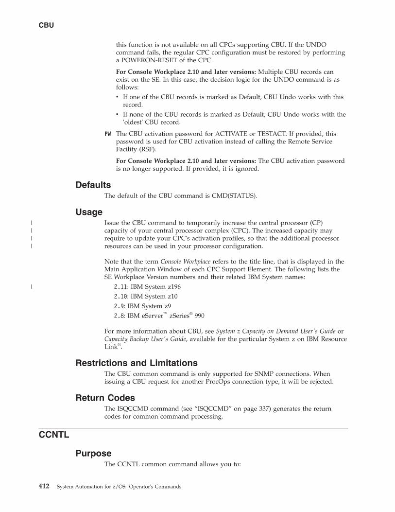
this function is not available on all CPCs supporting CBU. If the UNDOcommand fails, the regular CPC configuration must be restored by performinga POWERON-RESET of the CPC.
For Console Workplace 2.10 and later versions: Multiple CBU records canexist on the SE. In this case, the decision logic for the UNDO command is asfollows:v If one of the CBU records is marked as Default, CBU Undo works with this
record.v If none of the CBU records is marked as Default, CBU Undo works with the
'oldest' CBU record.
PW The CBU activation password for ACTIVATE or TESTACT. If provided, thispassword is used for CBU activation instead of calling the Remote ServiceFacility (RSF).
For Console Workplace 2.10 and later versions: The CBU activation passwordis no longer supported. If provided, it is ignored.
DefaultsThe default of the CBU command is CMD(STATUS).
UsageIssue the CBU command to temporarily increase the central processor (CP)capacity of your central processor complex (CPC). The increased capacity mayrequire to update your CPC's activation profiles, so that the additional processorresources can be used in your processor configuration.
Note that the term Console Workplace refers to the title line, that is displayed in theMain Application Window of each CPC Support Element. The following lists theSE Workplace Version numbers and their related IBM System names:
2.11: IBM System z1962.10: IBM System z102.9: IBM System z92.8: IBM eServer™ zSeries® 990
For more information about CBU, see System z Capacity on Demand User's Guide orCapacity Backup User's Guide, available for the particular System z on IBM ResourceLink®.
Restrictions and LimitationsThe CBU common command is only supported for SNMP connections. Whenissuing a CBU request for another ProcOps connection type, it will be rejected.
Return CodesThe ISQCCMD command (see “ISQCCMD” on page 337) generates the returncodes for common command processing.
CCNTL
PurposeThe CCNTL common command allows you to:
CBU
412 System Automation for z/OS: Operator's Commands
||||
|
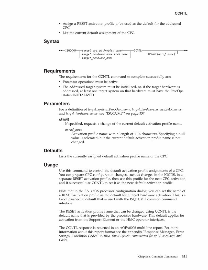
v Assign a RESET activation profile to be used as the default for the addressedCPC
v List the current default assignment of the CPC.
Syntax
�� ISQCCMD target_system_ProcOps_nametarget_hardware_name.LPAR_nametarget_hardware_name
CCNTLAPNAME(aprof_name)
��
RequirementsThe requirements for the CCNTL command to complete successfully are:v Processor operations must be active.v The addressed target system must be initialized, or, if the target hardware is
addressed, at least one target system on that hardware must have the ProcOpsstatus INITIALIZED.
ParametersFor a definition of target_system_ProcOps_name, target_hardware_name.LPAR_name,and target_hardware_name, see “ISQCCMD” on page 337.
APNAMEIf specified, requests a change of the current default activation profile name.
aprof_nameActivation profile name with a length of 1-16 characters. Specifying a nullvalue is tolerated, but the current default activation profile name is notchanged.
DefaultsLists the currently assigned default activation profile name of the CPC.
UsageUse this command to control the default activation profile assignments of a CPC.You can prepare CPC configuration changes, such as changes in the IOCDS, in aseparate RESET activation profile, then use this profile for the next CPC activation,and if successful use CCNTL to set it as the new default activation profile.
Note that in the SA z/OS processor configuration dialog, you can set the name ofa RESET activation profile as the default for a target hardware activation. This is aProcOps-specific default that is used with the ISQCCMD common commandinterface.
The RESET activation profile name that can be changed using CCNTL is thedefault name that is provided by the processor hardware. This default applies foractivation from the Support Element or the HMC operator interfaces.
The CCNTL response is returned in an AOFA0006 multi-line report. For moreinformation about this report format see the appendix "Response Messages, ErrorStrings, Condition Codes" in IBM Tivoli System Automation for z/OS Messages andCodes.
CCNTL
Chapter 6. Common Commands 413
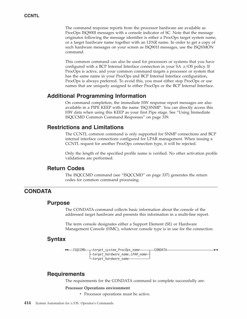
The command response reports from the processor hardware are available asProcOps ISQ900I messages with a console indicator of SC. Note that the messageoriginator following the message identifier is either a ProcOps target system name,or a target hardware name together with an LPAR name. In order to get a copy ofsuch hardware messages on your screen as ISQ901I messages, use the ISQXMONcommand.
This common command can also be used for processors or systems that you haveconfigured with a BCP Internal Interface connection in your SA z/OS policy. IfProcOps is active, and your common command targets a processor or system thathas the same name in your ProcOps and BCP Internal Interface configuration,ProcOps is always preferred. To avoid this, you must either stop ProcOps or usenames that are uniquely assigned to either ProcOps or the BCP Internal Interface.
Additional Programming InformationOn command completion, the immediate HW response report messages are alsoavailable in a PIPE KEEP with the name 'ISQ.SNMP'. You can directly access thisHW data when using this KEEP as your first Pipe stage. See “Using ImmediateISQCCMD Common Command Responses” on page 339.
Restrictions and LimitationsThe CCNTL common command is only supported for SNMP connections and BCPinternal interface connections configured for LPAR management. When issuing aCCNTL request for another ProcOps connection type, it will be rejected.
Only the length of the specified profile name is verified. No other activation profilevalidations are performed.
Return CodesThe ISQCCMD command (see “ISQCCMD” on page 337) generates the returncodes for common command processing.
CONDATA
PurposeThe CONDATA command collects basic information about the console of theaddressed target hardware and presents this information in a multi-line report.
The term console designates either a Support Element (SE) or HardwareManagement Console (HMC), whatever console type is in use for the connection.
Syntax
�� ISQCCMD target_system_ProcOps_nametarget_hardware_name.LPAR_nametarget_hardware_name
CONDATA ��
RequirementsThe requirements for the CONDATA command to complete successfully are:
Processor Operations environment
v Processor operations must be active.
CCNTL
414 System Automation for z/OS: Operator's Commands
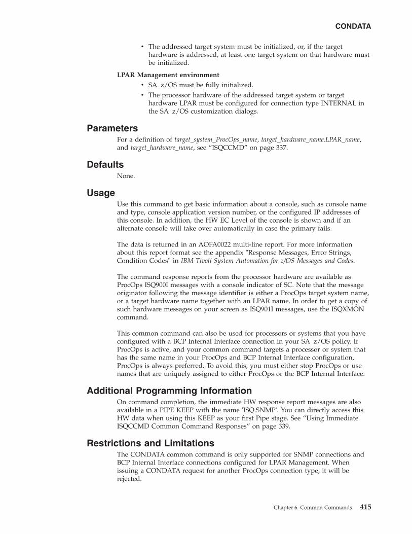
v The addressed target system must be initialized, or, if the targethardware is addressed, at least one target system on that hardware mustbe initialized.
LPAR Management environment
v SA z/OS must be fully initialized.v The processor hardware of the addressed target system or target
hardware LPAR must be configured for connection type INTERNAL inthe SA z/OS customization dialogs.
ParametersFor a definition of target_system_ProcOps_name, target_hardware_name.LPAR_name,and target_hardware_name, see “ISQCCMD” on page 337.
DefaultsNone.
UsageUse this command to get basic information about a console, such as console nameand type, console application version number, or the configured IP addresses ofthis console. In addition, the HW EC Level of the console is shown and if analternate console will take over automatically in case the primary fails.
The data is returned in an AOFA0022 multi-line report. For more informationabout this report format see the appendix "Response Messages, Error Strings,Condition Codes" in IBM Tivoli System Automation for z/OS Messages and Codes.
The command response reports from the processor hardware are available asProcOps ISQ900I messages with a console indicator of SC. Note that the messageoriginator following the message identifier is either a ProcOps target system name,or a target hardware name together with an LPAR name. In order to get a copy ofsuch hardware messages on your screen as ISQ901I messages, use the ISQXMONcommand.
This common command can also be used for processors or systems that you haveconfigured with a BCP Internal Interface connection in your SA z/OS policy. IfProcOps is active, and your common command targets a processor or system thathas the same name in your ProcOps and BCP Internal Interface configuration,ProcOps is always preferred. To avoid this, you must either stop ProcOps or usenames that are uniquely assigned to either ProcOps or the BCP Internal Interface.
Additional Programming InformationOn command completion, the immediate HW response report messages are alsoavailable in a PIPE KEEP with the name 'ISQ.SNMP'. You can directly access thisHW data when using this KEEP as your first Pipe stage. See “Using ImmediateISQCCMD Common Command Responses” on page 339.
Restrictions and LimitationsThe CONDATA common command is only supported for SNMP connections andBCP Internal Interface connections configured for LPAR Management. Whenissuing a CONDATA request for another ProcOps connection type, it will berejected.
CONDATA
Chapter 6. Common Commands 415
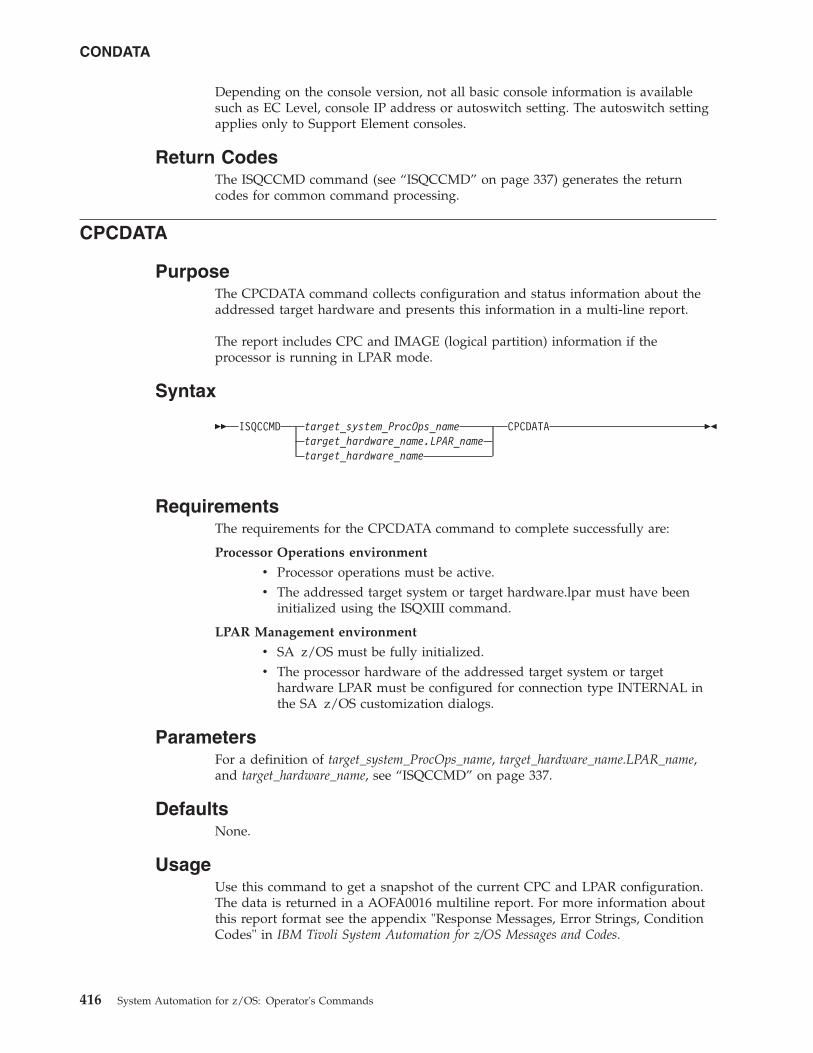
Depending on the console version, not all basic console information is availablesuch as EC Level, console IP address or autoswitch setting. The autoswitch settingapplies only to Support Element consoles.
Return CodesThe ISQCCMD command (see “ISQCCMD” on page 337) generates the returncodes for common command processing.
CPCDATA
PurposeThe CPCDATA command collects configuration and status information about theaddressed target hardware and presents this information in a multi-line report.
The report includes CPC and IMAGE (logical partition) information if theprocessor is running in LPAR mode.
Syntax
�� ISQCCMD target_system_ProcOps_nametarget_hardware_name.LPAR_nametarget_hardware_name
CPCDATA ��
RequirementsThe requirements for the CPCDATA command to complete successfully are:
Processor Operations environment
v Processor operations must be active.v The addressed target system or target hardware.lpar must have been
initialized using the ISQXIII command.
LPAR Management environment
v SA z/OS must be fully initialized.v The processor hardware of the addressed target system or target
hardware LPAR must be configured for connection type INTERNAL inthe SA z/OS customization dialogs.
ParametersFor a definition of target_system_ProcOps_name, target_hardware_name.LPAR_name,and target_hardware_name, see “ISQCCMD” on page 337.
DefaultsNone.
UsageUse this command to get a snapshot of the current CPC and LPAR configuration.The data is returned in a AOFA0016 multiline report. For more information aboutthis report format see the appendix "Response Messages, Error Strings, ConditionCodes" in IBM Tivoli System Automation for z/OS Messages and Codes.
CONDATA
416 System Automation for z/OS: Operator's Commands
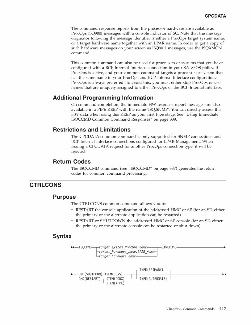
The command response reports from the processor hardware are available asProcOps ISQ900I messages with a console indicator of SC. Note that the messageoriginator following the message identifier is either a ProcOps target system name,or a target hardware name together with an LPAR name. In order to get a copy ofsuch hardware messages on your screen as ISQ901I messages, use the ISQXMONcommand.
This common command can also be used for processors or systems that you haveconfigured with a BCP Internal Interface connection in your SA z/OS policy. IfProcOps is active, and your common command targets a processor or system thathas the same name in your ProcOps and BCP Internal Interface configuration,ProcOps is always preferred. To avoid this, you must either stop ProcOps or usenames that are uniquely assigned to either ProcOps or the BCP Internal Interface.
Additional Programming InformationOn command completion, the immediate HW response report messages are alsoavailable in a PIPE KEEP with the name 'ISQ.SNMP'. You can directly access thisHW data when using this KEEP as your first Pipe stage. See “Using ImmediateISQCCMD Common Command Responses” on page 339.
Restrictions and LimitationsThe CPCDATA common command is only supported for SNMP connections andBCP Internal Interface connections configured for LPAR Management. Whenissuing a CPCDATA request for another ProcOps connection type, it will berejected.
Return CodesThe ISQCCMD command (see “ISQCCMD” on page 337) generates the returncodes for common command processing.
CTRLCONS
PurposeThe CTRLCONS common command allows you to:v RESTART the console application of the addressed HMC or SE (for an SE, either
the primary or the alternate application can be restarted)v RESTART or SHUTDOWN the addressed HMC or SE console (for an SE, either
the primary or the alternate console can be restarted or shut down)
Syntax
�� ISQCCMD target_system_ProcOps_nametarget_hardware_name.LPAR_nametarget_hardware_name
CTRLCONS �
� CMD(SHUTDOWN) ITEM(CONS)CMD(RESTART) ITEM(CONS)
ITEM(APPL)
TYPE(PRIMARY)
TYPE(ALTERNATE)��
CPCDATA
Chapter 6. Common Commands 417
RequirementsThe requirement for the CTRLCONS command to complete successfully is:v Processor operations must be active.
ParametersFor a definition of target_system_ProcOps_name, target_hardware_name.LPAR_name,and target_hardware_name, see “ISQCCMD” on page 337.
CMDThe command to be executed. Can be either RESTART or SHUTDOWN.
Note: SHUTDOWN is only allowed with ITEM(CONS). If it used withITEM(APPL), the CTRLCONS command will be rejected.
ITEMThe target of the command. Specify either:v CONS for the SE or HMC consolev APPL for the SE or HMC console application
TYPEThe type of console or console application.
PRIMARYRefers to the primary SE or HMC console or console application.
ALTERNATERefers to the secondary SE console or console application.
Note: ALTERNATE can only be used for SE connections; if it is used for anHMC connection, the CTRLCONS command will fail.
DefaultsThe CTRLCONS command defaults to TYPE(PRIMARY).
UsageUse this command to shut down or restart the HMC or SE Console or to restart theHMC or SE console application. On command execution, all ProcOps connectionsto that console or console application that are still active will be closed beforeexecuting the Shutdown or Restart itself in order to avoid uncontrolled connectionloss as a consequence of the Shutdown or Restart command.
Note: If a console SHUTDOWN is performed, the console must be restartedmanually.
Restrictions and LimitationsThe CTRLCONS common command is only supported for SNMP connections.When issuing a CTRLCONS request for another ProcOps connection type, it willbe rejected.
All required command parameters are checked if provided with the CTRLCONScommand. All command parameters are checked for valid content.
Due to technical limitations on the SE console side, an SE Application Restart willactually be executed as a SE Console Restart.
CTRLCONS
418 System Automation for z/OS: Operator's Commands
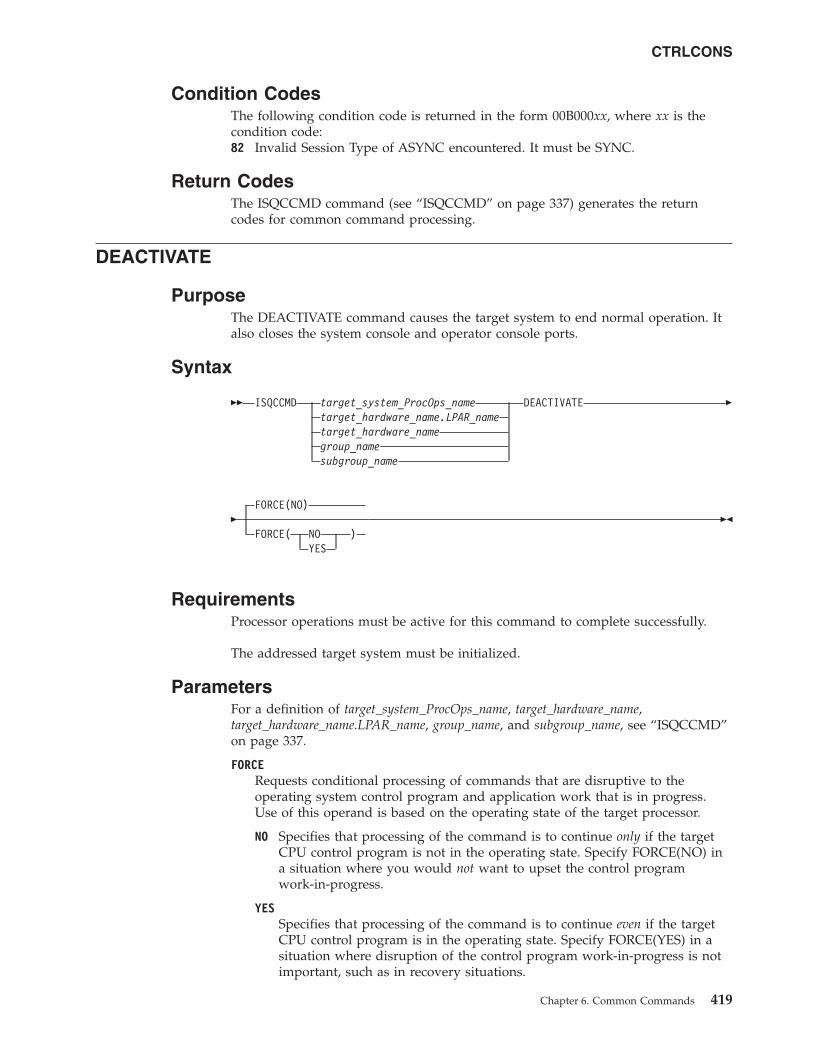
Condition CodesThe following condition code is returned in the form 00B000xx, where xx is thecondition code:82 Invalid Session Type of ASYNC encountered. It must be SYNC.
Return CodesThe ISQCCMD command (see “ISQCCMD” on page 337) generates the returncodes for common command processing.
DEACTIVATE
PurposeThe DEACTIVATE command causes the target system to end normal operation. Italso closes the system console and operator console ports.
Syntax
�� ISQCCMD target_system_ProcOps_nametarget_hardware_name.LPAR_nametarget_hardware_namegroup_namesubgroup_name
DEACTIVATE �
�FORCE(NO)
FORCE( NO )YES
��
RequirementsProcessor operations must be active for this command to complete successfully.
The addressed target system must be initialized.
ParametersFor a definition of target_system_ProcOps_name, target_hardware_name,target_hardware_name.LPAR_name, group_name, and subgroup_name, see “ISQCCMD”on page 337.
FORCERequests conditional processing of commands that are disruptive to theoperating system control program and application work that is in progress.Use of this operand is based on the operating state of the target processor.
NO Specifies that processing of the command is to continue only if the targetCPU control program is not in the operating state. Specify FORCE(NO) ina situation where you would not want to upset the control programwork-in-progress.
YESSpecifies that processing of the command is to continue even if the targetCPU control program is in the operating state. Specify FORCE(YES) in asituation where disruption of the control program work-in-progress is notimportant, such as in recovery situations.
CTRLCONS
Chapter 6. Common Commands 419
The default, if FORCE is not explicitly stated, is FORCE(NO).
FORCE(NO) requires that the associated command fail when useful work istaking place. The DEACTIVATE command’s formal fail criteria whenFORCE(NO) is specified or when FORCE defaults to NO is operating.
DefaultsThe DEACTIVATE command defaults to FORCE(NO).
UsageUse this common command to close a target system. Closing a target system doesthe following:v Ends any active sessions with the target systemv Disables the target systemv Performs any required end-of-day activitiesv Quiesces the target system
If this command is directed to a target hardware name rather than to a targetsystem ProcOps name, the entire processor complex is brought to a power-off state.
If you do not specify FORCE(YES), the DEACTIVATE command checks to makesure it will not be disruptive by performing the following processing:v If the target system runs in a logical partition and the same logical partition
name is initialized to another target system in the same target hardware, theDEACTIVATE command is rejected and processing of the command halts.
v On a non-partitioned target system, if the target hardware has another targetsystem initialized to it, the DEACTIVATE command is rejected and processing ofthe command halts.
DEACTIVATE of VM Guest Systems
Purpose: If a target system running in a guest machine is part of a DEACTIVATErequest, a CP FORCE command is issued by the PSM for that guest machine. TheVM host system is not affected.
Parameters:
FORCE(NO)If FORCE(NO) is specified for a guest machine, the guest status is checked. Ifit is NOT OPERATING then a CP FORCE command is issued to stop theguest. If the status is any other value, the CP FORCE command is not issuedand the DEACTIVATE request is rejected.
FORCE(YES)If FORCE(YES) is specified for a guest machine, a CP FORCE command isissued for the guest. If there is an active operating system running in the guestmachine, it is first stopped using the appropriate QUIESCE processing for theoperating system.
For LINUX systems, the use of CP FORCE command means that a shutdownsignal is sent to the operating system. This, in turn, allows the LINUX systemto initiate its own controlled shutdown process.
Restrictions and Limitations: DEACTIVATE is not supported fortarget_hardware_names. (The PSM cannot be powered off.)
DEACTIVATE
420 System Automation for z/OS: Operator's Commands
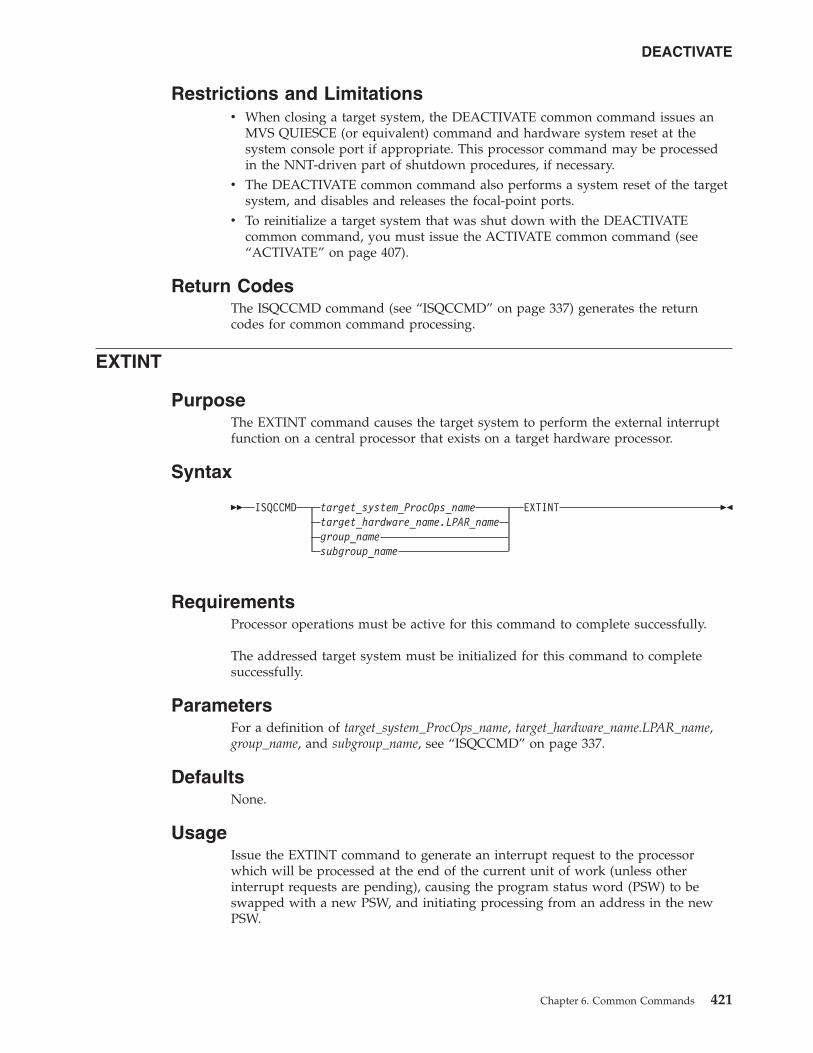
Restrictions and Limitationsv When closing a target system, the DEACTIVATE common command issues an
MVS QUIESCE (or equivalent) command and hardware system reset at thesystem console port if appropriate. This processor command may be processedin the NNT-driven part of shutdown procedures, if necessary.
v The DEACTIVATE common command also performs a system reset of the targetsystem, and disables and releases the focal-point ports.
v To reinitialize a target system that was shut down with the DEACTIVATEcommon command, you must issue the ACTIVATE common command (see“ACTIVATE” on page 407).
Return CodesThe ISQCCMD command (see “ISQCCMD” on page 337) generates the returncodes for common command processing.
EXTINT
PurposeThe EXTINT command causes the target system to perform the external interruptfunction on a central processor that exists on a target hardware processor.
Syntax
�� ISQCCMD target_system_ProcOps_nametarget_hardware_name.LPAR_namegroup_namesubgroup_name
EXTINT ��
RequirementsProcessor operations must be active for this command to complete successfully.
The addressed target system must be initialized for this command to completesuccessfully.
ParametersFor a definition of target_system_ProcOps_name, target_hardware_name.LPAR_name,group_name, and subgroup_name, see “ISQCCMD” on page 337.
DefaultsNone.
UsageIssue the EXTINT command to generate an interrupt request to the processorwhich will be processed at the end of the current unit of work (unless otherinterrupt requests are pending), causing the program status word (PSW) to beswapped with a new PSW, and initiating processing from an address in the newPSW.
DEACTIVATE
Chapter 6. Common Commands 421
EXTINT for a VM Guest System
Purpose: This causes a CP EXTERNAL KEY command to be issued for the guestmachine.
Restrictions and Limitationsv This command is not supported for coupling facility target systems.
Return CodesThe ISQCCMD command (see “Return Codes” on page 339) generates the returncodes for common command processing.
GETCLUSTER
PurposeThe command returns a list of the CPC addresses that are in the scope of control inthe current CPC environment. If the ProcOps SNMP connection is to a SupportElement, the list represents the defined CPCs of the so called Master HMC, whichhas the LIC Change function enabled. If the ProcOps SNMP is to a HMC, theGETCLUSTER command returns the CPC addresses of the Defined CPCs Group ofthis HMC.
Use the GETCLUSTER command to get basic information about all CPCs in theneighborhood of your CPC, regardless if the processors are defined to SystemAutomation, or not.
Syntax
�� ISQCCMD target_system_ProcOps_nametarget_hardware_name.LPAR_nametarget_hardware_name
GETCLUSTER ��
RequirementsThe requirements for the GETCLUSTER command to complete successfully are:
Processor Operations environment
v Processor operations must be active.v The addressed target system or target hardware.lpar must have been
initialized using the ISQXIII command.
LPAR Management environment
v SA z/OS must be fully initialized.v The processor hardware of the addressed target system or target
hardware LPAR must be configured for connection type INTERNAL inthe SA z/OS customization dialogs.
ParametersFor a definition of target_system_ProcOps_name, target_hardware_name.LPAR_name,and target_hardware_name, see “ISQCCMD” on page 337.
EXTINT
422 System Automation for z/OS: Operator's Commands
DefaultsNone.
UsageThis common command can also be used for processors or systems that you haveconfigured with a BCP Internal Interface connection in your SA z/OS policy. IfProcOps is active, and your common command targets a processor or system thathas the same name in your ProcOps and BCP Internal Interface configuration,ProcOps is always preferred. To avoid this, you must either stop ProcOps or usenames that are uniquely assigned to either ProcOps or the BCP Internal Interface.
Additional Programming InformationOn command completion, the immediate HW response report messages are alsoavailable in a Pipe KEEP with the name 'ISQ.SNMP'. When using this KEEP asyour first Pipe stage, you can directly access this HW data.
Restrictions and LimitationsThe GETCLUSTER common command is only supported for SNMP connectionsand BCP Internal Interface connections configured for LPAR Management. Whenissuing this request for another ProcOps connection type, it will be rejected.
Return CodesThe ISQCCMD command (see “Return Codes” on page 339) generates the returncodes for common command processing.
GETIINFO
PurposeThe GETIINFO command returns a subset of the CPCDATA command response. Itallows you to retrieve the status and mode of the specified target system LPARtogether with the defined LPAR number. If available, OS-related information suchas operating system name or version data is returned.
Use the GETIINFO command if you know the LPAR name or system name andyou are interested only in HW information for this LPAR or system. Forperformance reasons you are not recommended to use CPCDATA in such cases.
Syntax
�� ISQCCMD target_system_ProcOps_nametarget_hardware_name.LPAR_name
GETIINFO ��
RequirementsThe requirements for the GETIINFO command to complete successfully are:
Processor Operations environment
v Processor operations must be active.v The addressed target system or target hardware.lpar must have been
initialized using the ISQXIII command.
LPAR Management environment
GETCLUSTER
Chapter 6. Common Commands 423
v SA z/OS must be fully initialized.v The processor hardware of the addressed target system or target
hardware LPAR must be configured for connection type INTERNAL inthe SA z/OS customization dialogs.
ParametersNone.
DefaultsNone.
UsageThis common command can also be used for processors or systems that you haveconfigured with a BCP Internal Interface connection in your SA z/OS policy. IfProcOps is active, and your common command targets a processor or system thathas the same name in your ProcOps and BCP Internal Interface configuration,ProcOps is always preferred. To avoid this, you must either stop ProcOps or usenames that are uniquely assigned to either ProcOps or the BCP Internal Interface.
Additional Programming InformationOn command completion, the immediate HW response report messages are alsoavailable in a Pipe KEEP with the name 'ISQ.SNMP'. When using this KEEP asyour first Pipe stage, you can directly access this HW data.
Restrictions and LimitationsThe GETIINFO common command is only supported for SNMP connections andBCP Internal Interface connections configured for LPAR Management. Whenissuing this request for another ProcOps connection type, it will be rejected.
Return CodesThe ISQCCMD command (see “Return Codes” on page 339) generates the returncodes for common command processing.
GETISTAT
PurposeThe GETISTAT command returns a subset of the CPCDATA command response. Itallows you to retrieve the current HW status of a target system LPAR.
Use the GETISTAT command if you know the LPAR name or system name andyou are interested only in HW information for this LPAR or system. Forperformance reasons you are not recommended to use CPCDATA in such cases.
Syntax
�� ISQCCMD target_system_ProcOps_nametarget_hardware_name.LPAR_name
GETISTAT ��
GETIINFO
424 System Automation for z/OS: Operator's Commands
RequirementsThe requirements for the GETISTAT command to complete successfully are:
Processor Operations environment
v Processor operations must be active.v The addressed target system or target hardware.lpar must have been
initialized using the ISQXIII command.
LPAR Management environment
v SA z/OS must be fully initialized.v The processor hardware of the addressed target system or target
hardware LPAR must be configured for connection type INTERNAL inthe SA z/OS customization dialogs.
ParametersNone.
DefaultsNone.
UsageThis common command can also be used for processors or systems that you haveconfigured with a BCP Internal Interface connection in your SA z/OS policy. IfProcOps is active, and your common command targets a processor or system thathas the same name in your ProcOps and BCP Internal Interface configuration,ProcOps is always preferred. To avoid this, you must either stop ProcOps or usenames that are uniquely assigned to either ProcOps or the BCP Internal Interface.
Additional Programming InformationOn command completion, the immediate HW response report messages are alsoavailable in a Pipe KEEP with the name 'ISQ.SNMP'. When using this KEEP asyour first Pipe stage, you can directly access this HW data.
Restrictions and LimitationsThe GETISTAT common command is only supported for SNMP connections andBCP Internal Interface connections configured for LPAR Management. Whenissuing this request for another ProcOps connection type, it will be rejected.
Return CodesThe ISQCCMD command (see “Return Codes” on page 339) generates the returncodes for common command processing.
GETSDGR
PurposeThe command returns the reason details available from target hardware processorsthat operate in DEGRADED state.
Use the GETSDGR command if you need information about the reason of theDEGRADED status.
GETISTAT
Chapter 6. Common Commands 425
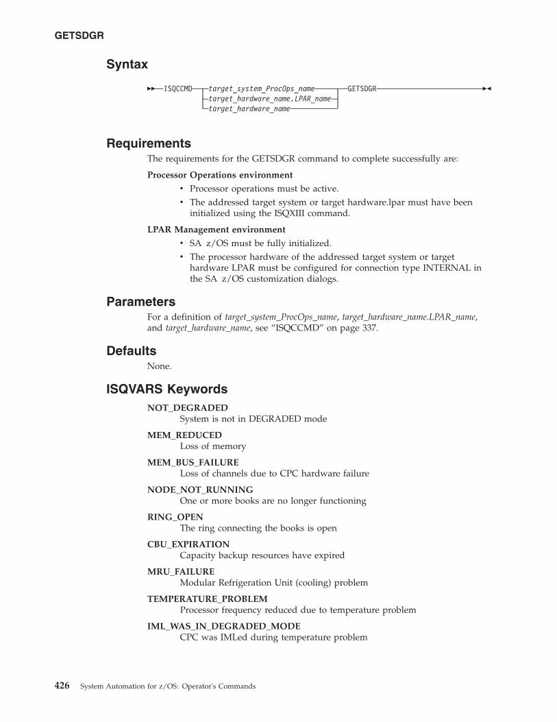
Syntax
�� ISQCCMD target_system_ProcOps_nametarget_hardware_name.LPAR_nametarget_hardware_name
GETSDGR ��
RequirementsThe requirements for the GETSDGR command to complete successfully are:
Processor Operations environment
v Processor operations must be active.v The addressed target system or target hardware.lpar must have been
initialized using the ISQXIII command.
LPAR Management environment
v SA z/OS must be fully initialized.v The processor hardware of the addressed target system or target
hardware LPAR must be configured for connection type INTERNAL inthe SA z/OS customization dialogs.
ParametersFor a definition of target_system_ProcOps_name, target_hardware_name.LPAR_name,and target_hardware_name, see “ISQCCMD” on page 337.
DefaultsNone.
ISQVARS KeywordsNOT_DEGRADED
System is not in DEGRADED mode
MEM_REDUCEDLoss of memory
MEM_BUS_FAILURELoss of channels due to CPC hardware failure
NODE_NOT_RUNNINGOne or more books are no longer functioning
RING_OPENThe ring connecting the books is open
CBU_EXPIRATIONCapacity backup resources have expired
MRU_FAILUREModular Refrigeration Unit (cooling) problem
TEMPERATURE_PROBLEMProcessor frequency reduced due to temperature problem
IML_WAS_IN_DEGRADED_MODECPC was IMLed during temperature problem
GETSDGR
426 System Automation for z/OS: Operator's Commands
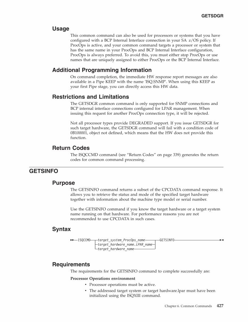
UsageThis common command can also be used for processors or systems that you haveconfigured with a BCP Internal Interface connection in your SA z/OS policy. IfProcOps is active, and your common command targets a processor or system thathas the same name in your ProcOps and BCP Internal Interface configuration,ProcOps is always preferred. To avoid this, you must either stop ProcOps or usenames that are uniquely assigned to either ProcOps or the BCP Internal Interface.
Additional Programming InformationOn command completion, the immediate HW response report messages are alsoavailable in a Pipe KEEP with the name 'ISQ.SNMP'. When using this KEEP asyour first Pipe stage, you can directly access this HW data.
Restrictions and LimitationsThe GETSDGR common command is only supported for SNMP connections andBCP internal interface connections configured for LPAR management. Whenissuing this request for another ProcOps connection type, it will be rejected.
Not all processor types provide DEGRADED support. If you issue GETSDGR forsuch target hardware, the GETSDGR command will fail with a condition code of0B100001, object not defined, which means that the HW does not provide thisfunction.
Return CodesThe ISQCCMD command (see “Return Codes” on page 339) generates the returncodes for common command processing.
GETSINFO
PurposeThe GETSINFO command returns a subset of the CPCDATA command response. Itallows you to retrieve the status and mode of the specified target hardwaretogether with information about the machine type model or serial number.
Use the GETSINFO command if you know the target hardware or a target systemname running on that hardware. For performance reasons you are notrecommended to use CPCDATA in such cases.
Syntax
�� ISQCCMD target_system_ProcOps_nametarget_hardware_name.LPAR_nametarget_hardware_name
GETSINFO ��
RequirementsThe requirements for the GETSINFO command to complete successfully are:
Processor Operations environment
v Processor operations must be active.v The addressed target system or target hardware.lpar must have been
initialized using the ISQXIII command.
GETSDGR
Chapter 6. Common Commands 427
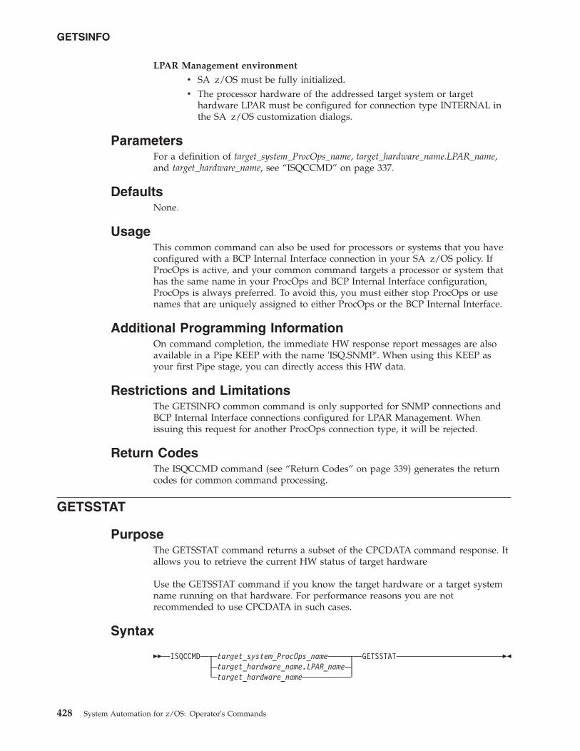
LPAR Management environment
v SA z/OS must be fully initialized.v The processor hardware of the addressed target system or target
hardware LPAR must be configured for connection type INTERNAL inthe SA z/OS customization dialogs.
ParametersFor a definition of target_system_ProcOps_name, target_hardware_name.LPAR_name,and target_hardware_name, see “ISQCCMD” on page 337.
DefaultsNone.
UsageThis common command can also be used for processors or systems that you haveconfigured with a BCP Internal Interface connection in your SA z/OS policy. IfProcOps is active, and your common command targets a processor or system thathas the same name in your ProcOps and BCP Internal Interface configuration,ProcOps is always preferred. To avoid this, you must either stop ProcOps or usenames that are uniquely assigned to either ProcOps or the BCP Internal Interface.
Additional Programming InformationOn command completion, the immediate HW response report messages are alsoavailable in a Pipe KEEP with the name 'ISQ.SNMP'. When using this KEEP asyour first Pipe stage, you can directly access this HW data.
Restrictions and LimitationsThe GETSINFO common command is only supported for SNMP connections andBCP Internal Interface connections configured for LPAR Management. Whenissuing this request for another ProcOps connection type, it will be rejected.
Return CodesThe ISQCCMD command (see “Return Codes” on page 339) generates the returncodes for common command processing.
GETSSTAT
PurposeThe GETSSTAT command returns a subset of the CPCDATA command response. Itallows you to retrieve the current HW status of target hardware
Use the GETSSTAT command if you know the target hardware or a target systemname running on that hardware. For performance reasons you are notrecommended to use CPCDATA in such cases.
Syntax
�� ISQCCMD target_system_ProcOps_nametarget_hardware_name.LPAR_nametarget_hardware_name
GETSSTAT ��
GETSINFO
428 System Automation for z/OS: Operator's Commands
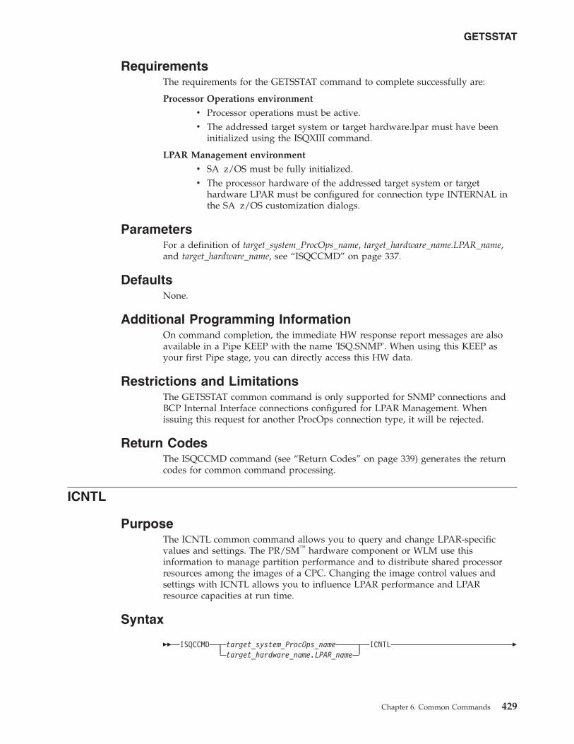
RequirementsThe requirements for the GETSSTAT command to complete successfully are:
Processor Operations environment
v Processor operations must be active.v The addressed target system or target hardware.lpar must have been
initialized using the ISQXIII command.
LPAR Management environment
v SA z/OS must be fully initialized.v The processor hardware of the addressed target system or target
hardware LPAR must be configured for connection type INTERNAL inthe SA z/OS customization dialogs.
ParametersFor a definition of target_system_ProcOps_name, target_hardware_name.LPAR_name,and target_hardware_name, see “ISQCCMD” on page 337.
DefaultsNone.
Additional Programming InformationOn command completion, the immediate HW response report messages are alsoavailable in a Pipe KEEP with the name 'ISQ.SNMP'. When using this KEEP asyour first Pipe stage, you can directly access this HW data.
Restrictions and LimitationsThe GETSSTAT common command is only supported for SNMP connections andBCP Internal Interface connections configured for LPAR Management. Whenissuing this request for another ProcOps connection type, it will be rejected.
Return CodesThe ISQCCMD command (see “Return Codes” on page 339) generates the returncodes for common command processing.
ICNTL
PurposeThe ICNTL common command allows you to query and change LPAR-specificvalues and settings. The PR/SM™ hardware component or WLM use thisinformation to manage partition performance and to distribute shared processorresources among the images of a CPC. Changing the image control values andsettings with ICNTL allows you to influence LPAR performance and LPARresource capacities at run time.
Syntax
�� ISQCCMD target_system_ProcOps_nametarget_hardware_name.LPAR_name
ICNTL �
GETSSTAT
Chapter 6. Common Commands 429
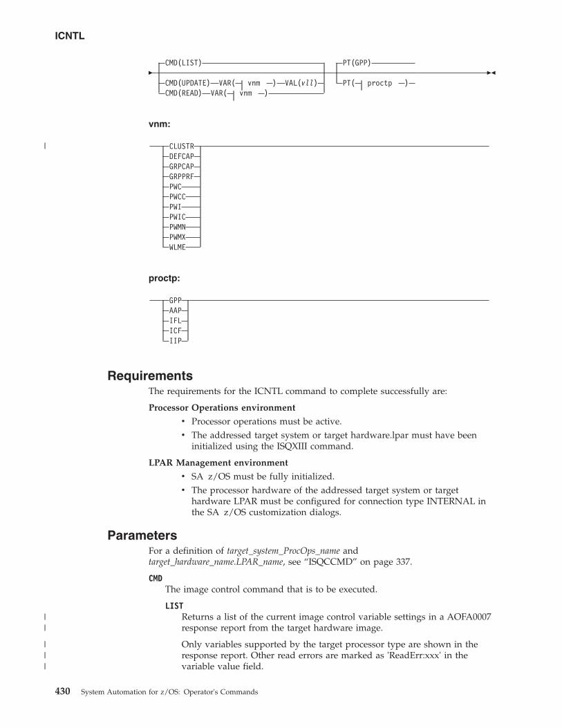
�CMD(LIST)
CMD(UPDATE) VAR( vnm ) VAL(vll)CMD(READ) VAR( vnm )
PT(GPP)
PT( proctp )��
vnm:
CLUSTRDEFCAPGRPCAPGRPPRFPWCPWCCPWIPWICPWMNPWMXWLME
proctp:
GPPAAPIFLICFIIP
RequirementsThe requirements for the ICNTL command to complete successfully are:
Processor Operations environment
v Processor operations must be active.v The addressed target system or target hardware.lpar must have been
initialized using the ISQXIII command.
LPAR Management environment
v SA z/OS must be fully initialized.v The processor hardware of the addressed target system or target
hardware LPAR must be configured for connection type INTERNAL inthe SA z/OS customization dialogs.
ParametersFor a definition of target_system_ProcOps_name andtarget_hardware_name.LPAR_name, see “ISQCCMD” on page 337.
CMDThe image control command that is to be executed.
LISTReturns a list of the current image control variable settings in a AOFA0007response report from the target hardware image.
Only variables supported by the target processor type are shown in theresponse report. Other read errors are marked as 'ReadErr:xxx' in thevariable value field.
ICNTL
430 System Automation for z/OS: Operator's Commands
|
||
|||
Refer to the appendix section "Data Exchange Services "0B100xxx" in IBMTivoli System Automation for z/OS Messages and Codes, if you receive'ReadErr:xxx' responses for additional information.
UPDATEChanges the value of the specified image control variable and returns anAOFA0007 response report.
READReturns the current setting of the specified image control variable in anAOFA0007 response report.
VARImage control variable name vnm.
CLUSTRName of the CPC LPAR cluster that the LPAR belongs to.
This is a READONLY variable.
Value information: Cluster of one or more LPARs, running on one zSeries900 or later CPC, that are in the same sysplex and are running z/OS 1.1 orlater in z/Architecture® mode. The scope of an LPAR Cluster is currentlythe same as the scope of an I/O Cluster, however the term LPAR Cluster isalso used in relation to WLM LPAR CPU Management and ChannelSubsystem I/O Priority Queuing. LPAR clusters are used for z/OSIntelligent Resource Director (IRD) capabilities. Cluster names can bedefined using HCD.
DEFCAPDefined capacity.
Value information:0 No defined capacity for the LPAR.1–2147483647
Amount of defined LPAR capacity.
Note that the maximum value represents the highest value accepted bythe SE/HMC, which may not represent the correct capacity limit inyour environment.
The defined capacity expressed in terms of Millions of Service Units(MSUs) per hour. MSUs is a measure of processor resource consumption.The amount of MSUs that a logical partition consumes is dependent on themodel, the number of logical processors that are available to the partition,and the amount of time that the logical partition is dispatched. The definedcapacity value specifies how much of the logical partition capacity is to bemanaged by Workload Manager (WLM) for the purpose of softwarepricing.
GRPCAPDefined group capacity.
Value information:0 No defined group capacity for the LPAR.1-2147483647
Amount of defined group capacity the LPAR belongs to.
Note that the maximum value represents the highest value accepted bythe SE/HMC, which may not represent the correct capacity limit inyour environment.
ICNTL
Chapter 6. Common Commands 431
|||
||
|||||
|||
The defined capacity expressed in terms of Millions of Service Units(MSUs) per hour. MSUs is a measure of processor resource consumption.
GRPPRFCapacity Group Profile name where the addressed target system or logicalpartition is a member. Members of capacity groups share a common MSUvalue. This is an alternative to the DEFCAP specification, where the MSUvalue is partition-specific. You can change the MSU CAPACITY value of agroup profile using the PROFILE common command.
Value information:
nnnnnnnnThe name of the group profile. The name must be alphanumeric and amaximum of 8 characters. If you specify a name that does not exist asan activation profile of type GROUP, the ICNTL command fails with acondition code of 0B100005.
Note that GRPPRF is available on System z processors or later. ReadingGRPPRF on older processors will return GRPPRF without a value.Updating GRPPRF on older processors fails with a condition code of0B100001.
PWCCurrent processing weight.
This is a READONLY variable.
Value information:0 The CPC image does not represent a logical partition, or the LPAR
has only dedicated processors assigned to it.1–999 Represents the relative amount of shared processor resources that
is currently allocated to the LPAR.
PWCCCurrent processing weight capped indicator.
This is a READONLY variable.
Value information:YES The current processing weight for the LPAR is capped. It
represents the maximum share of processor resources regardless ofthe availability of excess processor resources.
NO The current processing weight for the LPAR is not capped. Itrepresents the share of resources that is guaranteed to the LPARwhen all CP resources are in use. When excess processor resourcesare available, the LPAR can use them if necessary.
PWIInitial processing weight.
Value information:0 The CPC image does not represent a logical partition, or the LPAR
has only dedicated processors assigned to it. This value is not validfor UPDATE.
1–999 Represents the relative amount of shared processor resources thatis initially allocated to the LPAR.
Note: If the WLME flag has a value of YES, the PWI value must be in therange from PWMN to PWMX.
ICNTL
432 System Automation for z/OS: Operator's Commands
||
PWICInitial processing weight capped indicator.
Value information:YES The initial processing weight for the LPAR is capped. It represents
the maximum share of processor resources regardless of theavailability of excess processor resources.
NO The initial processing weight for the LPAR is not capped. Itrepresents the share of resources that is guaranteed to the LPARwhen all CP resources are in use. When excess processor resourcesare available, the LPAR can use them if necessary.
PWMNMinimum processing weight.
The guaranteed minimum share of non-dedicated processor weight, whenall processing resources are in use.
Value information:0 The CPC image does not represent a logical partition, or the LPAR
has only dedicated processors assigned to it. This value is not validfor UPDATE.
1–999 A value that is less than or equal to the initial processing weightthat is used to define the minimum relative amount of sharedprocessor resources that is allocated to the LPAR.
Note: This value is only applied if the WLME flag has a value of YES.
PWMXMaximum processing weight.
Maximum relative amount of shared processor resources for this LPAR.
Value information:0 The CPC image does not represent a logical partition, or the LPAR
has only dedicated processors assigned to it. This value is not validfor UPDATE.
1–999 A value that is greater than or equal to the initial processingweight that is used to define the maximum relative amount ofshared processor resources that is allocated to the LPAR.
Note: This value is only applied if the WLME flag has a value of YES.
WLMEWorkload Manager Enabled flag.
Value information:YES z/OS Workload Manager is used to manage shared processor
resources for a logical partition, according to the settings of theminimum and maximum weight specifications.
NO PR/SM is managing the processing weight. The PWMN andPWMX values do not apply.
VALValue specification for variable UPDATE operation.
vllSee the value information for the “VAR parameter” on page 431.
PT The Processor Type parameter allows you to specify which processor type thecorresponding Image Control information should be read or updated for.
ICNTL
Chapter 6. Common Commands 433
proctp The processor type:GPP General Purpose ProcessorAAP Application Assist ProcessorIFL Integrated Facility for LINUX processorICF Internal Coupling Facility processorIIP z9 Integrated Information Processor
Notes:
1. The IFA processor type (Integrated Facility for Application processor) hasbeen replaced by AAP.
2. You cannot specify special purpose processors (AAP, IFL, ICF, IIP) for theCLUSTR, DEFCAP, GRPCAP, GRPPRF or WLME command parameters.
DefaultsIf no ICNTL parameters are specified, a CMD(LIST) is executed.
If no processor type is specified with the PT parameter, the default value of GPP(general purpose processor) is used.
UsageThe ICNTL common command can be used to set LPAR performance relatedparameters, such as an LPAR's initial processing weight, PWI, or the DefinedCapacity, DEFCAP.
For example, DEFCAP can be used to automate the lowering and raising of theMSU value (defined capacity, soft-cap). This LPAR value is important whenSub-Capacity License charging for software is in place. An optimized setting of theDEFCAP value can help to control software cost.
The equivalent to the ICNTL common command can be performed on the HMCusing the CPC Operational Customization tasks: Change LPAR Controls andChange LPAR Group Controls.
The command response reports from the processor hardware are available asProcOps ISQ900I messages with a console indicator of SC. Note that the messageoriginator following the message identifier is either a ProcOps target system name,or a target hardware name together with an LPAR name. In order to get a copy ofsuch hardware messages on your screen as ISQ901I messages, use the ISQXMONcommand.
This common command can also be used for processors or systems that you haveconfigured with a BCP Internal Interface connection in your SA z/OS policy. IfProcOps is active, and your common command targets a processor or system thathas the same name in your ProcOps and BCP Internal Interface configuration,ProcOps is always preferred. To avoid this, you must either stop ProcOps or usenames that are uniquely assigned to either ProcOps or the BCP Internal Interface.
Additional Programming InformationOn command completion, the immediate HW response report messages are alsoavailable in a PIPE KEEP with the name 'ISQ.SNMP'. You can directly access thisHW data when using this KEEP as your first Pipe stage. See “Using ImmediateISQCCMD Common Command Responses” on page 339.
ICNTL
434 System Automation for z/OS: Operator's Commands
|
||
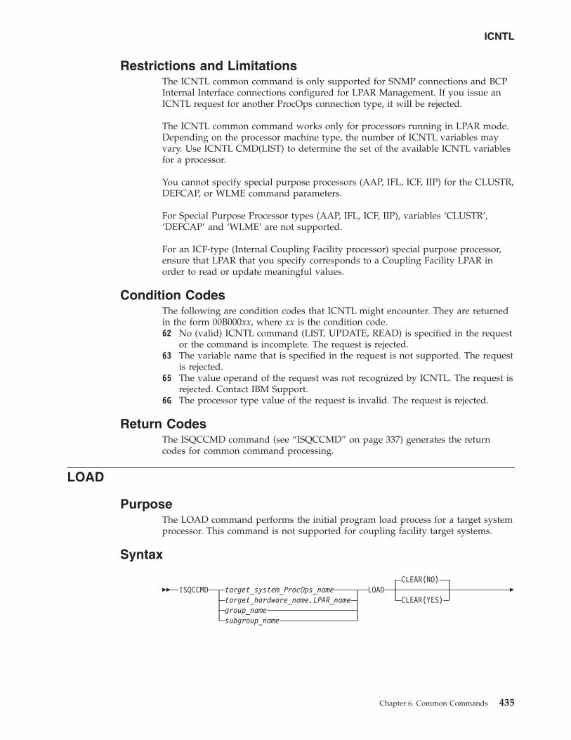
Restrictions and LimitationsThe ICNTL common command is only supported for SNMP connections and BCPInternal Interface connections configured for LPAR Management. If you issue anICNTL request for another ProcOps connection type, it will be rejected.
The ICNTL common command works only for processors running in LPAR mode.Depending on the processor machine type, the number of ICNTL variables mayvary. Use ICNTL CMD(LIST) to determine the set of the available ICNTL variablesfor a processor.
You cannot specify special purpose processors (AAP, IFL, ICF, IIP) for the CLUSTR,DEFCAP, or WLME command parameters.
For Special Purpose Processor types (AAP, IFL, ICF, IIP), variables ‘CLUSTR’,‘DEFCAP’ and ‘WLME’ are not supported.
For an ICF-type (Internal Coupling Facility processor) special purpose processor,ensure that LPAR that you specify corresponds to a Coupling Facility LPAR inorder to read or update meaningful values.
Condition CodesThe following are condition codes that ICNTL might encounter. They are returnedin the form 00B000xx, where xx is the condition code.62 No (valid) ICNTL command (LIST, UPDATE, READ) is specified in the request
or the command is incomplete. The request is rejected.63 The variable name that is specified in the request is not supported. The request
is rejected.65 The value operand of the request was not recognized by ICNTL. The request is
rejected. Contact IBM Support.6G The processor type value of the request is invalid. The request is rejected.
Return CodesThe ISQCCMD command (see “ISQCCMD” on page 337) generates the returncodes for common command processing.
LOAD
PurposeThe LOAD command performs the initial program load process for a target systemprocessor. This command is not supported for coupling facility target systems.
Syntax
�� ISQCCMD target_system_ProcOps_nametarget_hardware_name.LPAR_namegroup_namesubgroup_name
LOADCLEAR(NO)
CLEAR(YES)�
ICNTL
Chapter 6. Common Commands 435
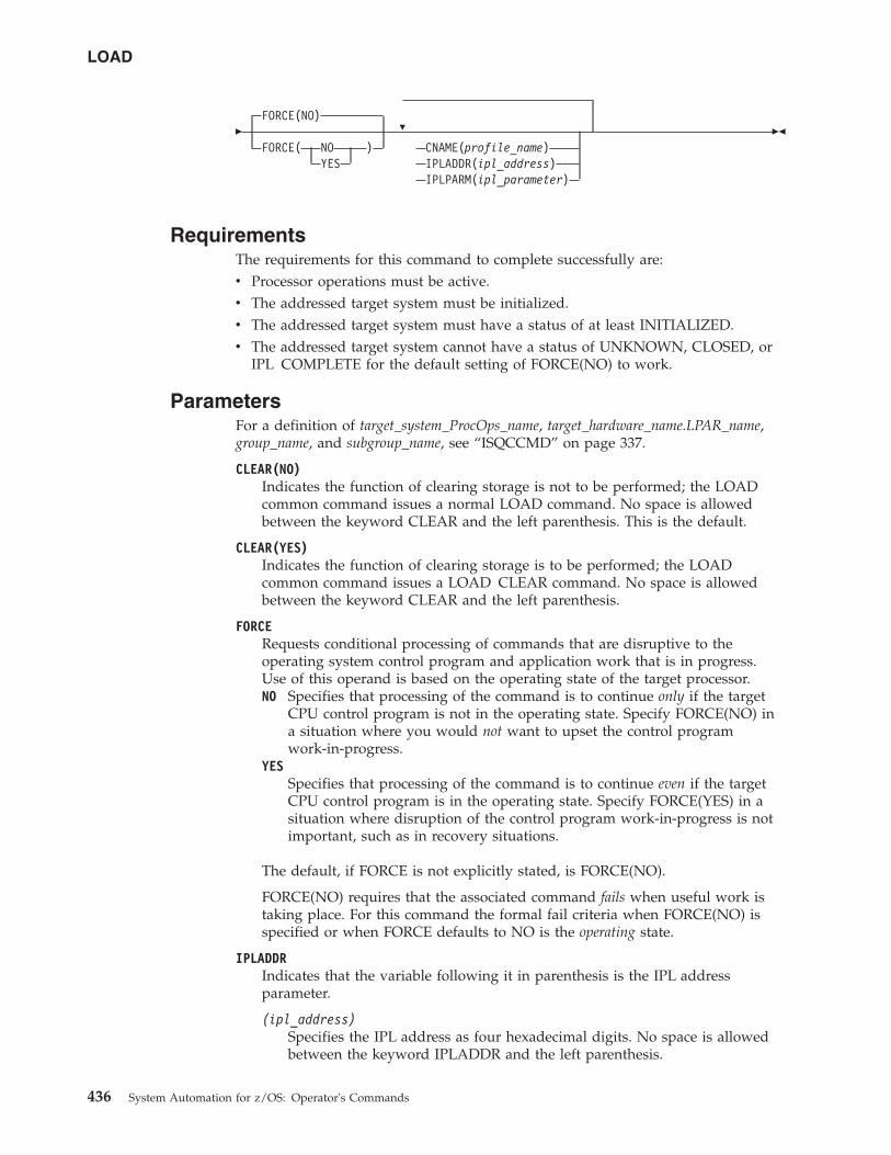
�FORCE(NO)
FORCE( NO )YES
�
CNAME(profile_name)IPLADDR(ipl_address)IPLPARM(ipl_parameter)
��
RequirementsThe requirements for this command to complete successfully are:v Processor operations must be active.v The addressed target system must be initialized.v The addressed target system must have a status of at least INITIALIZED.v The addressed target system cannot have a status of UNKNOWN, CLOSED, or
IPL COMPLETE for the default setting of FORCE(NO) to work.
ParametersFor a definition of target_system_ProcOps_name, target_hardware_name.LPAR_name,group_name, and subgroup_name, see “ISQCCMD” on page 337.
CLEAR(NO)Indicates the function of clearing storage is not to be performed; the LOADcommon command issues a normal LOAD command. No space is allowedbetween the keyword CLEAR and the left parenthesis. This is the default.
CLEAR(YES)Indicates the function of clearing storage is to be performed; the LOADcommon command issues a LOAD CLEAR command. No space is allowedbetween the keyword CLEAR and the left parenthesis.
FORCERequests conditional processing of commands that are disruptive to theoperating system control program and application work that is in progress.Use of this operand is based on the operating state of the target processor.NO Specifies that processing of the command is to continue only if the target
CPU control program is not in the operating state. Specify FORCE(NO) ina situation where you would not want to upset the control programwork-in-progress.
YESSpecifies that processing of the command is to continue even if the targetCPU control program is in the operating state. Specify FORCE(YES) in asituation where disruption of the control program work-in-progress is notimportant, such as in recovery situations.
The default, if FORCE is not explicitly stated, is FORCE(NO).
FORCE(NO) requires that the associated command fails when useful work istaking place. For this command the formal fail criteria when FORCE(NO) isspecified or when FORCE defaults to NO is the operating state.
IPLADDRIndicates that the variable following it in parenthesis is the IPL addressparameter.
(ipl_address)Specifies the IPL address as four hexadecimal digits. No space is allowedbetween the keyword IPLADDR and the left parenthesis.
LOAD
436 System Automation for z/OS: Operator's Commands
IPLPARMIndicates that the variable following it in parenthesis is an IPL parameter.
(ipl_parameter)Specifies an IPL parameter to be issued with the Load command. Thisparameter can be 1 through 8 characters long. Lowercase letters aretranslated to uppercase letters. No space is allowed between the keywordIPLPARM and the left parenthesis.
CNAMESpecifies the name of a Load profile to be sent to the processor's supportelement. If this keyword is not used, the LOAD operations managementcommand that SA z/OS sends to the support element has a CNAME operandwith the Load profile name that was specified in the configuration dialogs.
If this keyword is not used and no Load profile name was specified in theconfiguration dialogs, SA z/OS omits the CNAME operand from the LOADcommand sent to the support element. In this latter case, the support elementuses the load parameters that were saved from the last LOAD command forthe corresponding target image.
profile_nameIndicates the name of the Load profile. IBM recommends that you letSA z/OS select the profile name automatically rather than overridingSA z/OS's selection with the profile_name parameter.
DefaultsThe LOAD command defaults to CLEAR(NO) and to FORCE(NO).
The ipl_address and ipl_parameter parameter default to the values defined in theconfiguration dialogs, unless they have been changed with the ISQVARS orISQXOPT command, see “ISQXOPT” on page 401, in which case the valuesdefined by the ISQVARS or ISQXOPT command are used.
For OCF-based processors, the ipl_address and ipl_parameter parameters default tothe values specified in the Load profile.
UsageThis common command assumes that the processor operations environment hasbeen established and that the system console function has been assigned. For atarget system operating on an LPAR-mode processor, it also assumes that thelogical partition is active and that any required channels are online to the partition.If these assumptions are not correct, other initialization commands should be runfirst. These functions of the LOAD common command are all performed by theACTIVATE common command.
If you do not specify FORCE(YES), the LOAD common command checks to makesure it will not be disruptive by performing the following processing:v If the target system runs in a logical partition and the same logical partition
name is initialized to another target system in the same target hardware, theLOAD command is rejected and processing of the command halts.
v On a non-partitioned target system, if the target hardware has another targetsystem initialized to it, the LOAD command is rejected and processing of thecommand halts.
LOAD
Chapter 6. Common Commands 437
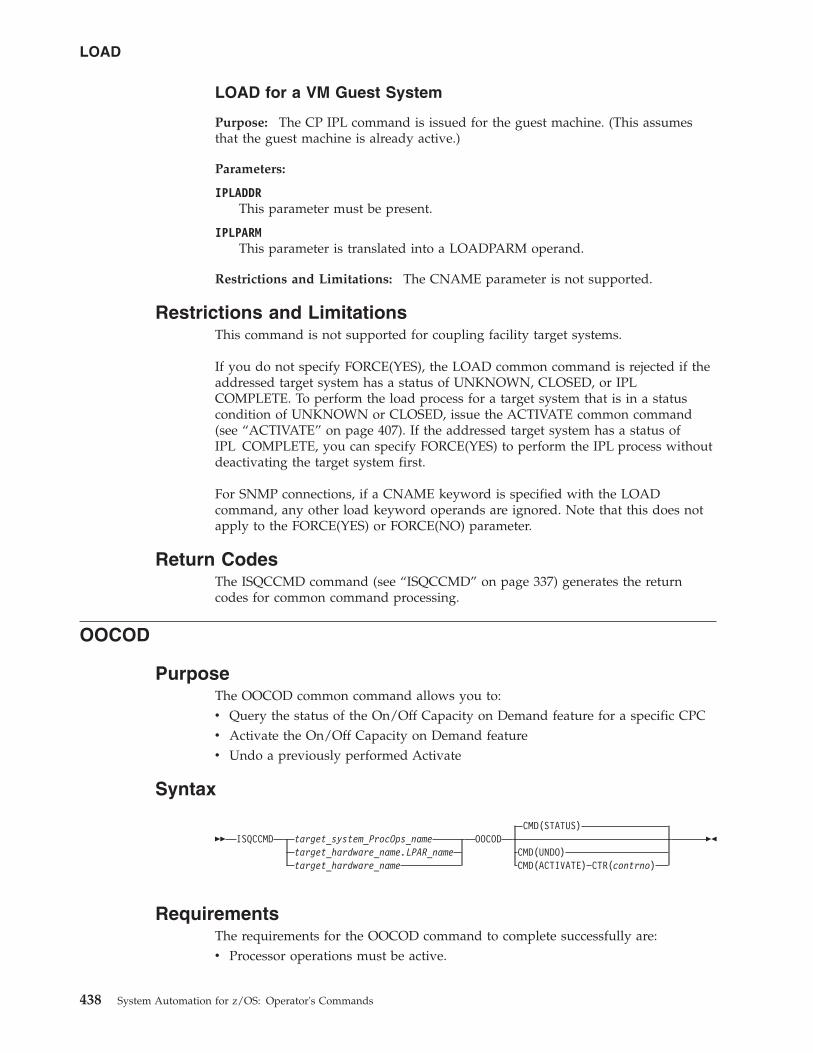
LOAD for a VM Guest System
Purpose: The CP IPL command is issued for the guest machine. (This assumesthat the guest machine is already active.)
Parameters:
IPLADDRThis parameter must be present.
IPLPARMThis parameter is translated into a LOADPARM operand.
Restrictions and Limitations: The CNAME parameter is not supported.
Restrictions and LimitationsThis command is not supported for coupling facility target systems.
If you do not specify FORCE(YES), the LOAD common command is rejected if theaddressed target system has a status of UNKNOWN, CLOSED, or IPLCOMPLETE. To perform the load process for a target system that is in a statuscondition of UNKNOWN or CLOSED, issue the ACTIVATE common command(see “ACTIVATE” on page 407). If the addressed target system has a status ofIPL COMPLETE, you can specify FORCE(YES) to perform the IPL process withoutdeactivating the target system first.
For SNMP connections, if a CNAME keyword is specified with the LOADcommand, any other load keyword operands are ignored. Note that this does notapply to the FORCE(YES) or FORCE(NO) parameter.
Return CodesThe ISQCCMD command (see “ISQCCMD” on page 337) generates the returncodes for common command processing.
OOCOD
PurposeThe OOCOD common command allows you to:v Query the status of the On/Off Capacity on Demand feature for a specific CPCv Activate the On/Off Capacity on Demand featurev Undo a previously performed Activate
Syntax
�� ISQCCMD target_system_ProcOps_nametarget_hardware_name.LPAR_nametarget_hardware_name
OOCODCMD(STATUS)
CMD(UNDO)CMD(ACTIVATE) CTR(contrno)
��
RequirementsThe requirements for the OOCOD command to complete successfully are:v Processor operations must be active.
LOAD
438 System Automation for z/OS: Operator's Commands
v The addressed target system must be initialized, or, if the target hardware isaddressed, at least one target system on that hardware must be initialized.
v For the STATUS command: No further requirements.v For the ACTIVATE command: The On/Off Capacity on Demand feature must be
enabled and installed and be in a status of not activated.v For UNDO: This is only applicable after a successful ACTIVATE.v With Console Workplace 2.10 and later versions, for ACTIVATE and UNDO, the
flag 'Allow capacity change API requests' must be set in 'Customize APISettings' on the SE.
ParametersFor a definition of target_system_ProcOps_name, target_hardware_name.LPAR_name,and target_hardware_name, see “ISQCCMD” on page 337.
CMDThe OOCOD command that is to be executed. This can be:STATUS
Query the status of the On/Off Capacity on Demand feature and issue areport. If activated, the activation date is also provided.
Note: The INSTALLED status is set when an On/Off Capacity on Demandcontract is activated. If no contract is active, the status is NOTINSTALLED.
ACTIVATEPut the On/Off Capacity on Demand feature in an active state. Thiscommand requires a valid contract number for successful execution.
UNDOPut the On/Off Capacity on Demand feature in an inactive state.
CTROnly required for the ACTIVATE command. The order number (contrno) mustcorrespond to a valid contract number for the hardware that has the On/OffCapacity on Demand feature implemented.
Note: For SE Console Workplace 2.10 and later versions, contrno correspondsto the record ID of one of the On/Off Capacity on Demand records thathave already been loaded on the processor hardware.
DefaultsThe OOCOD command defaults to STATUS.
UsageUse the OOCOD command to activate and deactivate the On/Off Capacity onDemand feature. You can retrieve the current On/Off Capacity on Demand featuresettings with the STATUS command.
Note that the term Console Workplace refers to the title line that is displayed in theMain Application Window of each CPC Support Element. The following lists theSE Workplace Version numbers and their related IBM System names:
2.11: IBM System z1962.10: IBM System z102.9: IBM System z92.8: IBM eServer zSeries 990
OOCOD
Chapter 6. Common Commands 439
|||
|
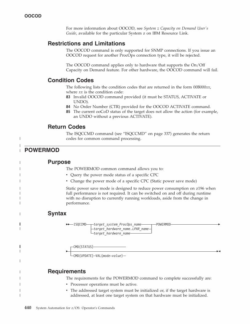
For more information about OOCOD, see System z Capacity on Demand User'sGuide, available for the particular System z on IBM Resource Link.
Restrictions and LimitationsThe OOCOD command is only supported for SNMP connections. If you issue anOOCOD request for another ProcOps connection type, it will be rejected.
The OOCOD command applies only to hardware that supports the On/OffCapacity on Demand feature. For other hardware, the OOCOD command will fail.
Condition CodesThe following lists the condition codes that are returned in the form 00B000xx,where xx is the condition code:83 Invalid OOCOD command provided (it must be STATUS, ACTIVATE or
UNDO).84 No Order Number (CTR) provided for the OOCOD ACTIVATE command.85 The current ooCoD status of the target does not allow the action (for example,
an UNDO without a previous ACTIVATE).
Return CodesThe ISQCCMD command (see “ISQCCMD” on page 337) generates the returncodes for common command processing.
POWERMOD
PurposeThe POWERMOD common command allows you to:v Query the power mode status of a specific CPCv Change the power mode of a specific CPC (Static power save mode)
Static power save mode is designed to reduce power consumption on z196 whenfull performance is not required. It can be switched on and off during runtimewith no disruption to currently running workloads, aside from the change inperformance.
Syntax
�� ISQCCMD target_system_ProcOps_nametarget_hardware_name.LPAR_nametarget_hardware_name
POWERMOD �
�CMD(STATUS)
CMD(UPDATE) VAL(mode-value)��
RequirementsThe requirements for the POWERMOD command to complete successfully are:v Processor operations must be active.v The addressed target system must be initialized or, if the target hardware is
addressed, at least one target system on that hardware must be initialized.
OOCOD
440 System Automation for z/OS: Operator's Commands
|
||
|
|
|
|
||||
|
||||||||||||||||||||
||||||||||||||||||
|
|
|
|
||
v Hardware Console Workplace must be version 2.11 or higher.v For the STATUS command: No further requirements.v For the UPDATE command: The CPC must be allowed or entitled to perform a
power mode change.
ParametersFor a definition of target_system_ProcOps_name, target_hardware_name.LPAR_name,and target_hardware_name, see “ISQCCMD” on page 337.
CMDThe POWERMOD command that is to be executed. This can be:STATUS
Query the power mode status of the CPC. The report issued by thecommand contains the following information:v Current power mode settingv Supported power mode valuesv Power mode change allowed (Y/N)
UPDATEChange the CPC's power mode, for example, from 100 (High Performance)to one of the supported Power Save values.
VALOnly required for the UPDATE command. Contains the power mode the CPCshould be changed to.
DefaultsThe POWERMOD command defaults to STATUS.
UsageUse the POWERMOD command to query and the change the CPC's power mode.
Note that the term 'Console Workplace' refers to the title line, displayed on theMain Application Window of each CPC Support Element (SE) or on the HardwareManagement Console (HMC).
The following lists the SE/HMC Workplace Versions numbers and their relatedIBM System names:
2.11 - IBM System z1962.10 - IBM System z102.9 - IBM System z92.8 - IBM eServer zSeries 990
Restrictions and LimitationsThe POWERMOD command applies only to hardware that supports the PowerManagement feature. For other hardware, the POWERMOD command will fail.
The POWERMOD command is only supported for SNMP connections. If you issuea POWERMOD request for another Processor operations connection type, it will berejected.
On air-cooled models, Static power save mode can be entered only once in acalendar day.
POWERMOD
Chapter 6. Common Commands 441
|
|
||
|
||
|||||||||||
|||
|
|
|
|
|||
||
|
|
|
|
|
||
|||
||
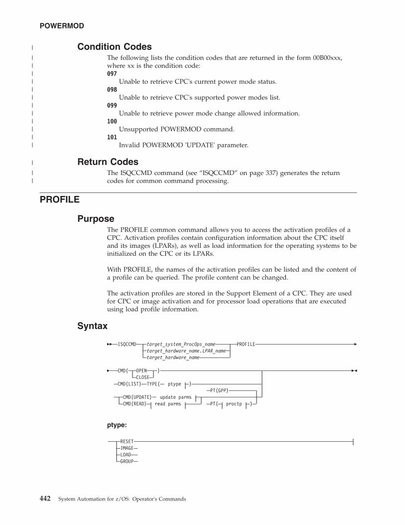
Condition CodesThe following lists the condition codes that are returned in the form 00B00xxx,where xx is the condition code:097
Unable to retrieve CPC's current power mode status.098
Unable to retrieve CPC's supported power modes list.099
Unable to retrieve power mode change allowed information.100
Unsupported POWERMOD command.101
Invalid POWERMOD 'UPDATE' parameter.
Return CodesThe ISQCCMD command (see “ISQCCMD” on page 337) generates the returncodes for common command processing.
PROFILE
PurposeThe PROFILE common command allows you to access the activation profiles of aCPC. Activation profiles contain configuration information about the CPC itselfand its images (LPARs), as well as load information for the operating systems to beinitialized on the CPC or its LPARs.
With PROFILE, the names of the activation profiles can be listed and the content ofa profile can be queried. The profile content can be changed.
The activation profiles are stored in the Support Element of a CPC. They are usedfor CPC or image activation and for processor load operations that are executedusing load profile information.
Syntax
�� ISQCCMD target_system_ProcOps_nametarget_hardware_name.LPAR_nametarget_hardware_name
PROFILE �
� CMD( OPEN )CLOSE
CMD(LIST) TYPE( ptype )PT(GPP)
CMD(UPDATE) update parmsCMD(READ) read parms PT( proctp )
��
ptype:
RESETIMAGELOADGROUP
POWERMOD
442 System Automation for z/OS: Operator's Commands
|
||||||||||||
|
||
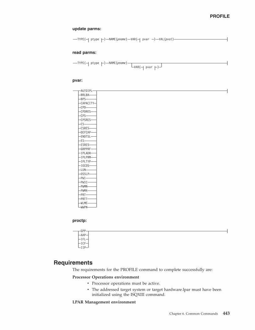
update parms:
TYPE( ptype ) NAME(pname) VAR( pvar ) VAL(pval)
read parms:
TYPE( ptype ) NAME(pname)VAR( pvar )
pvar:
AUTOIPLBRLBABPSCAPACITYCPDCPDRESCPSCPSRESCSCSRESDEFCAPENDTSLESESRESGRPPRFIPLADRIPLPRMIPLTYPIOCDSLUNOSSLPPWIPWICPWMNPWMXPRTPRTTWLMEWWPN
proctp:
GPPAAPIFLICFIIP
RequirementsThe requirements for the PROFILE command to complete successfully are:
Processor Operations environment
v Processor operations must be active.v The addressed target system or target hardware.lpar must have been
initialized using the ISQXIII command.
LPAR Management environment
PROFILE
Chapter 6. Common Commands 443
v SA z/OS must be fully initialized.v The processor hardware of the addressed target system or target
hardware LPAR must be configured for connection type INTERNAL inthe SA z/OS customization dialogs.
ParametersFor a definition of target_system_ProcOps_name, target_hardware_name.LPAR_name,and target_hardware_name, see “ISQCCMD” on page 337.
CMDThe profile command that is to be executed. This can be:OPEN
This command must be executed as the first profile access command. Itbuilds an internal list of the available profiles names for faster profileaccess. On successful completion an AOFA0020 report is returned, with thenumber of the available activation profiles for each of the profile types.
CLOSEThis command should be executed when your profile access is complete. Itclears the internal profile name list. If the CLOSE is omitted, you canre-access the profiles without performing an OPEN command, however theinternal profile list may no longer be current. On completion, anAOFA0020 report is returned.
LISTReturns a list of the profile names for the specified profile TYPE in anAOFA0020 response report.
UPDATEThe content of the specified profile variable is changed to the valuedefined with the VAL parameter. The update response is returned in anAOFA0020 report. The update fails or is rejected if the hardware detects aninvalid value.
READReturns the contents of the specified profile NAME and TYPE in anAOFA0020 response report. If a VAR parameter is added, only the contentof the specified profile variable is returned.
Note that if the profile content is retrieved, variable names without a valuemay be listed. If this is the case, either the CPC does not support thisprofile variable, or a supported variable is not initialized.
You can use the HMC's CPC Operational Customization Task:Customize/Delete Activation Profiles to determine which profile variablesare supported by a CPC's machine type.
TYPEThe activation profile type, ptype, which can be one of the following:RESET
This profile type is used to activate a CPC. The following profile variablesare supported: IOCDS, ENDTSL, PRT, PRTT.
IMAGEThis profile type is used to activate images (LPARs). The following profilevariables are supported: AUTOIPL, BRLBA, BPS, CS, CSRES, CPD,CPDRES, DEFCAP, ES, ESRES, GRPPRF, IPLADR, IPLPRM, IPLTYP, LUN,OSSLP, PWI, PWIC, PWMN, PWMX, WLME, WWPN.
LOADThis profile type is used to load a CPC or an image. The following profilevariables are supported: BRLBA, BPS, IPLADR, IPLPRM, IPLTYP, LUN,OSSLP, WWPN.
PROFILE
444 System Automation for z/OS: Operator's Commands
GROUPThis profile type is used to define capacity limits for a group of logicalpartitions. The CAPACITY profile variable is supported.
NAMEThe activation profile name.
pnameName, 1-16 alphanumeric characters, without blanks. The named profilemust be available on the Support Element.
VARThe activation profile variable name pvar. The following is a list of variablenames and their associated values.
AUTOIPLThis flag indicates if a automatic LOAD should be performed as part of theLPAR activation. The variable is valid for IMAGE profile only.
Value information:YES Perform an automatic LOAD after LPAR activation is complete,
using the IPLTYP, IPLADR, and IPLPRM information that is storedin the IMAGE profile.
NO Do not perform a LOAD after LPAR activation.
BRLBAThe boot record logical block address that is used for IPLs from a SCSIdevice. Valid for profile types IMAGE and LOAD.
Value information:pval The eight-byte (16 hexadecimal digit) boot record logical block
address specifies the logical block address (LBA) of the bootrecord. (A boot record is used to locate an OS loader on an IPLdisk. Normally, this boot record is located at LBA 0. The SCSI IPLfunction allows the boot record to be located at a different LBA.)
* When an asterisk (*) is specified as the UPDATE value, the actualdata value is copied from the NetView Task Global variableBRLBA.
BPSThe boot partition specification that is used for IPLs from a SCSI device.Valid for profile types IMAGE and LOAD.
Value information:pval The boot program selector, a decimal value between 0 and 30, is
used to select the section of the IPL disk on which the desired OSresides. (The SCSI IPL function allows up to 31 different operatingsystems to reside on one IPL disk.)
* When an asterisk (*) is specified as the UPDATE value, the actualdata value is copied from the NetView Task Global variable BPS.
CAPACITYThe defined capacity limit not only for a single LPAR (see “The DEFCAPparameter” on page 447), but for a group of LPARs running on the sameCPC, known as a capacity group. It represents the number of workloadunits (WLUs) a capacity group has assigned as its limit. Valid for profiletype GROUP only.
Value information:0 No group capacity limit defined.
PROFILE
Chapter 6. Common Commands 445
1–2147483647Note that the maximum value represents the highest value accepted bythe SE/HMC, which may not represent the correct capacity limit inyour environment.
For more information about Group Capacity settings and howworkload management and workload license charges are related, seez/OS MVS Planning: Workload Management, SA22-7602.
CPDThe number of logical central processors assigned to the partition for itsdedicated use. The assignment occurs at partition activation time.
Value information:
n The number of logical processors. For processor type GPP, 1 is theallowed minimum. For other processor types 0 is allowed. Themaximum number of logical processors possible depends on yourphysical processor configuration.
CPDRESThe number of logical central processors assigned to the partition for itsdedicated use. The logical processors are reserved to be used after partitionactivation, when needed.
Value information:
n The number of logical processors. For processor type GPP, 1 is theallowed minimum. For other processor types 0 is allowed. Themaximum number of logical processors possible depends on yourphysical processor configuration.
CPSThe number of logical central processors assigned to the partition, butshared with other partitions. The assignment occurs at partition activationtime.
Value information:
n The number of logical processors. For processor type GPP, 1 is theallowed minimum. For other processor types 0 is allowed. Themaximum number of logical processors possible depends on yourphysical processor configuration.
CPSRESThe number of logical central processors assigned to the partition, butshared with other partitions. The logical processors are reserved to be usedafter partition activation, if needed.
Value information:
n The number of logical processors. For processor type GPP, 1 is theallowed minimum. For other processor types 0 is allowed. Themaximum number of logical processors possible depends on yourphysical processor configuration.
CS The amount of Central Storage, in megabytes, allocated at partitionactivation time for its exclusive use.
Value information:
n Enter a value that is compatible with the storage granularity supportedby your CPC.
PROFILE
446 System Automation for z/OS: Operator's Commands
For storage granularity information, see the Processor Resource/SystemsManager Planning Guide, available for your CPC on IBM Resource Link.
CSRESThe amount of Central Storage, in megabytes, that can be allocateddynamically to the partition after activation.
Reserved storage provides the logical partition with an additional amountof storage that can be used only if it is not already being used by anotheractive logical partition.
There is no minimum for reserved storage. Zero megabytes (0 MB) is avalid amount of reserved storage.
Value information:
0–n Enter a value that is compatible with the storage granularitysupported by your CPC.
For storage granularity information, see the ProcessorResource/Systems Manager Planning Guide, available for your CPC onIBM Resource Link.
DEFCAPThe logical partition's defined capacity. Valid for profile type IMAGE.
Value information:0 No defined capacity for the LPAR.1–2147483647
Amount of defined LPAR capacity.
Note that the maximum value represents the highest value accepted bythe SE/HMC, which may not represent the correct capacity limit inyour environment.
The defined capacity expressed in terms of Millions of Service Units(MSUs) per hour. MSUs is a measure of processor resource consumption.The amount of MSUs that a logical partition consumes is dependent on themodel, the number of logical processors that are available to the partition,and the amount of time that the logical partition is allocated. The definedcapacity value specifies how much of the logical partition capacity is to bemanaged by Workload Manager (WLM) for the purpose of softwarepricing.
ENDTSLThe end time slice if the CPC image enters a wait state. Valid for theRESET profile type.
Value information:YES Indicates that a CPC Image should lose its share of running time
when it enters a wait state.NO Indicates that a CPC Image should not lose its share of running
time when it enters a wait state.
Note: This value can only be set if the processor running time type is setto 1, that is, set to a constant value (see “The PRTT Parameter” onpage 450).
ES The amount of Central Storage, in megabytes, allocated at partitionactivation time for use as expanded storage.
PROFILE
Chapter 6. Common Commands 447
There is no minimum for expanded storage. Zero megabytes (0 MB) is avalid amount of expanded storage.
Value information:
0–n Enter a value that is compatible with the storage granularitysupported by your CPC.
For storage granularity information, see the ProcessorResource/Systems Manager Planning Guide, available for your CPC onIBM Resource Link.
ESRESThe amount of Expanded Storage, in megabytes, that can be allocateddynamically to the partition after activation. This variable applies only ifthe partition mode is ESA/390 or ESA/390 TPF.
Reserved storage provides the logical partition with an additional amountof storage that can be used only if it is not already being used by anotheractive logical partition.
There is no minimum for reserved storage. Zero megabytes (0 MB) is avalid amount of reserved storage.
Value information:
0–n Enter a value that is compatible with the storage granularitysupported by your CPC.
For storage granularity information, see the ProcessorResource/Systems Manager Planning Guide, available for your CPC onIBM Resource Link.
GRPPRFThe name of the LPAR capacity group that the LPAR is a member of. Thisvariable is valid for IMAGE profiles only.
Value information:pval An alphanumeric name with a maximum length of 8 characters.* If you specify an asterisk as the UPDATE value, the actual data
value is copied from the NetView task global variable GRPPRF.
IPLADRThe IPL address (load address) for IPLs from a channel attached device.(IPLTYP NORMAL) Valid for profile types IMAGE and LOAD.
Value information:pval Hexadecimal device number of a channel attached load device.NEXT Indicates that the IPLPRM value that is supplied by HCD through
its hardware interface is to be used.* When an asterisk (*) is specified as the UPDATE value, the actual
data value is copied from the NetView Task Global variableIPLADR.
Note: Depending on the CPC hardware type, a device number of '0000' isaccepted as IPLADR by the hardware. Do not use this value, eitherwith SA z/OS ProcOps, or when using the HMC to specify a LOADaddress. Unpredictable results may occur.
IPLPRMThe IPL parameter (load parm) for IPLs from a channel attached device.(IPLTYP NORMAL) Valid for profile types IMAGE and LOAD.
PROFILE
448 System Automation for z/OS: Operator's Commands
Value information:pval OS-supported, 8-character load parameter field of CMOS S/390®
and zSeries hardware. See the OS documentation for informationabout the IPL parameters that it supports.
NEXT Indicates that the IPLPRM value that is supplied by HCD throughits hardware interface is to be used.
* When an asterisk (*) is specified as the UPDATE value, the actualdata value is copied from the NetView Task Global variableIPLPRM.
IPLTYPThe type of IPL.
Value information:NORMAL
Use a channel attached device address to load a basic control program(OS). When this IPL type is used, IPLADR must be specified. IPLPRMis optional.
SCSILOADUses the address of a SAN-attached SCSI device to load a BCP (OS).
When this IPL type is used, the following profile variables must bespecified: BRLBA, BPS, LUN, WWPN. OSSLP is optional.
SCSIDUMPUses the address of a SAN-attached SCSI device to load a StandaloneDump Utility. The utility uses a dump area on the same SCSI device tostore the main storage content.
When this IPL type is used, the following profile variables must bespecified: BRLBA, BPS, LUN, WWPN. OSSLP is optional.
* When an asterisk (*) is specified as the UPDATE value, the actual datavalue is copied from the NetView Task Global variable IPLTYP.
IOCDSThe input/output configuration data set identifier. Valid for profile typeRESET.
Value information:pval Two-character identifier of the IOCDS that is to be used for CPC
activation with this profile.* When an asterisk (*) is specified as the UPDATE value, the actual
data value is copied from the NetView Task Global variableIOCDS.
LUNThe logical unit number of the SCSI IPL boot device. Valid for profiletypes: IMAGE, LOAD.
Value information:pval Eight-byte identifier (16 hexadecimal digits) of the logical unit
representing the SCSI IPL device.* When an asterisk (*) is specified as the UPDATE value, the actual
data value is copied from the NetView Task Global variable LUN.
OSSLPThe operating-system-specific load parameter for IPL from SCSI device.Valid for profile types: IMAGE, LOAD.
For a READ operation, the data that is returned in the AOFA0020 responsereport is split into 8 lines. If OSSLP is not set, a string of 256 blanks is
PROFILE
Chapter 6. Common Commands 449
returned from the hardware. If not all OSSLP bytes are used, the stringreturned is always padded with blanks.
Value information:pval The operating system specific load parameters to be used for the
SCSILOAD or SCSIDUMP. The character string can be up to 256bytes long.
The OS-specific load parameter is optionally used to pass a stringof characters to the program that is being loaded. Neither thesystem nor the machine loader interprets or uses these parameters.For example, the OS-specific load parameter can be used toidentify additional I/O devices and related storage addresses thatare required by the OS being loaded.
* When an asterisk (*) is specified as the UPDATE value, the actualdata value is copied from the NetView Task Global variable OSSLP.
Use this method if you want to copy a mixed case character string,or if the string contains multiple blank separated words.
PRTProcessor Running Time. Valid for the RESET profile type.
Value information:
1–100 User-defined processor running time.
Defines the amount of continuous time allowed for logicalprocessors to perform jobs on shared processors for the DefinedCPC object.
Notes:
1. This value can only be set if the processor running time type isset to 1, that is, set to a constant value (see “The PRTTParameter”).
2. If the processor running time type is set to 0, the value forprocessor running time displayed with the READ commandwill always be 0.
PRTTProcessor Running Time Type. Valid for the RESET profile type.
Value information:0 The processor running time is dynamically determined by the system.1 The processor running time is set to a constant value.
Defines whether the processor running time is dynamically determined bythe system or set to a constant value for the Defined CPC object.
PWIThe initial processing weight. Valid for profile type IMAGE.
Value information:0 The CPC image does not represent a logical partition, or the LPAR
has only dedicated processors assigned to it. This value is not validfor UPDATE.
1-999 Represents the relative amount of shared processor resources thatis initially allocated to the LPAR.
* When an asterisk (*) is specified as the UPDATE value, the actualdata value is copied from the NetView Task Global variable PWI.
PROFILE
450 System Automation for z/OS: Operator's Commands
|||
Note: If the WLME flag has a value of YES, the PWI value must be in therange from PWMN to PWMX.
PWICThe initial processing weight capped indicator. Valid for profile typeIMAGE.
Value information:YES The initial processing weight for the LPAR is capped. It represents
the maximum share of processor resources regardless of theavailability of excess processor resources.
NO The initial processing weight for the LPAR is not capped. Itrepresents the share of resources that is guaranteed to the LPARwhen all CP resources are in use. When excess processor resourcesare available, the LPAR can use them if necessary.
* When an asterisk (*) is specified as the UPDATE value, the actualdata value is copied from the NetView Task Global variable PWIC.
PWMNThe minimum processing weight. Valid for profile type IMAGE.
The guaranteed minimum share of non-dedicated processor weight, whenall processing resources are in use.
Value information:0 The CPC image does not represent a logical partition, or the LPAR
has only dedicated processors assigned to it. This value is not validfor UPDATE.
1-999 A value that is less than or equal to the initial processing weightthat is used to define the minimum relative amount of sharedprocessor resources that is allocated to the LPAR.
* When an asterisk (*) is specified as the UPDATE value, the actualdata value is copied from the NetView Task Global variablePWMN.
Note: This value is only applied if the WLME flag has a value of YES.
PWMXThe maximum processing weight. Valid for profile type IMAGE.
Maximum relative amount of shared processor resources for this LPAR.
Value information:0 The CPC image does not represent a logical partition, or the LPAR
has only dedicated processors assigned to it. This value is not validfor UPDATE.
1-999 A value that is greater than or equal to the initial processingweight that is used to define the maximum relative amount ofshared processor resources that is allocated to the LPAR.
* When an asterisk (*) is specified as the UPDATE value, the actualdata value is copied from the NetView Task Global variablePWMX.
Note: This value is only applied if the WLME flag has a value of YES.
WLMEThe Workload Manager enabled flag. Valid for profile type IMAGE.
Value information:YES z/OS Workload Manager is used to manage shared processor
PROFILE
Chapter 6. Common Commands 451
resources for a logical partition, according to the settings of theminimum and maximum weight specifications.
NO PR/SM is managing the processing weight. The PWMN andPWMX values do not apply.
* When an asterisk (*) is specified as the UPDATE value, the actualdata value is copied from the NetView Task Global variableWLME.
WWPNThe worldwide port name of the disk controller for the SCSI IPL. Valid forprofile type IMAGE.
Value information:pval The worldwide port name is the eight-byte permanent name (16
hexadecimal digits) that is assigned to the FC (fibre channel)adapter port of the SCSI target device containing the logical unitserving as the IPL device. The FC fabric must be configured insuch a way that the FCP channel that is used for the IPL operationhas access to this port.
* When an asterisk (*) is specified as the UPDATE value, the actualdata value is copied from the NetView Task Global variableWWPN.
VALThe value specification for an UPDATE operation.
pval See the value information for the VAR parameter.
PT The Processor Type parameter allows you to specify which processor type thecorresponding activation profile information should be read or updated for.
proctp The processor type:GPP General Purpose ProcessorAAP Application Assist ProcessorIFL Integrated Facility for LINUX processorICF Internal Coupling Facility processorIIP z9 Integrated Information Processor
Notes:
1. The IFA processor type (Integrated Facility for Application processor) hasbeen replaced by AAP.
2. Processor types other than GPP are only applicable for the IMAGE profiletype and the activation profile variables PWI, PWIC, PWMN or PWMX.
DefaultsFor UPDATE and READ actions, if a processor type is not specified with the PTparameter, the default value of GPP (general purpose processor) is used.
UsageThe PROFILE common command for SNMP connected processors can be used tomanage important CPC and LPAR activation and operating system loadinformation.
The supported set of profile variables can be queried and modified using theISQCCMD PROFILE common command with automation procedures.
Automation of IPLs from SCSI devices can be performed using LOAD or IMAGEactivation profiles.
PROFILE
452 System Automation for z/OS: Operator's Commands
The command response reports from the processor hardware are available asProcOps ISQ900I messages with a console indicator of SC. Note that the messageoriginator following the message identifier is either a ProcOps target system name,or a target hardware name together with an LPAR name. In order to get a copy ofsuch hardware messages on your screen as ISQ901I messages, use the ISQXMONcommand.
This common command can also be used for processors or systems that you haveconfigured with a BCP Internal Interface connection in your SA z/OS policy. IfProcOps is active, and your common command targets a processor or system thathas the same name in your ProcOps and BCP Internal Interface configuration,ProcOps is always preferred. To avoid this, you must either stop ProcOps or usenames that are uniquely assigned to either ProcOps or the BCP Internal Interface.
Additional Programming InformationOn command completion, the immediate HW response report messages are alsoavailable in a PIPE KEEP with the name 'ISQ.SNMP'. You can directly access thisHW data when using this KEEP as your first Pipe stage. See “Using ImmediateISQCCMD Common Command Responses” on page 339.
Restrictions and LimitationsThe PROFILE common command is only supported for SNMP connections andBCP Internal Interface connections configured for LPAR Management. If you issuea PROFILE request for another ProcOps connection type, it will be rejected.
The PROFILE common command cannot be used to create or delete activationprofiles; use the HMC to perform these tasks. The PROFILE command supports asubset of the available activation profile variables.
Processor types other than GPP are only applicable for the IMAGE profile type andthe activation profile variables PWI, PWIC, PWMN or PWMX.
Condition CodesThe PROFILE common command uses the internal APROF service to process therequests. The following lists the condition codes that are returned in the form00B000xx, where xx is the condition code:62 The variable name that is specified in the request is not supported. The request
is rejected.63 The variable name that is specified in the request is not supported. The request
is rejected.64 The request was not recognized by the APROF service. The request is rejected.
Contact IBM Support.65 The value operand of the request was not recognized by APROF. The request is
rejected. Contact IBM Support.66 OPEN error. APROF could not allocate the profile list storage. The request is
rejected. Contact IBM Support.67 OPEN error. Profile was already opened. The request is rejected. Issue a
CLOSE request first.68 Profile TYPE error. Allowed types are RESET, IMAGE, and LOAD. The request
is rejected.69 Profile is not open. Issue an OPEN request first. The request is rejected.6A Profile not found error. If the named profile was created since the last OPEN,
issue a CLOSE and reopen the profiles to access the new list of profiles. Therequest is rejected.
PROFILE
Chapter 6. Common Commands 453
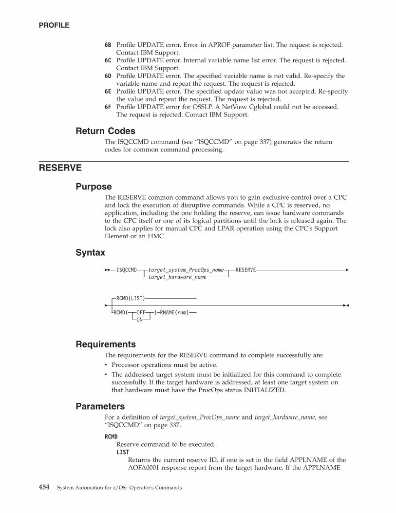
6B Profile UPDATE error. Error in APROF parameter list. The request is rejected.Contact IBM Support.
6C Profile UPDATE error. Internal variable name list error. The request is rejected.Contact IBM Support.
6D Profile UPDATE error. The specified variable name is not valid. Re-specify thevariable name and repeat the request. The request is rejected.
6E Profile UPDATE error. The specified update value was not accepted. Re-specifythe value and repeat the request. The request is rejected.
6F Profile UPDATE error for OSSLP. A NetView Cglobal could not be accessed.The request is rejected. Contact IBM Support.
Return CodesThe ISQCCMD command (see “ISQCCMD” on page 337) generates the returncodes for common command processing.
RESERVE
PurposeThe RESERVE common command allows you to gain exclusive control over a CPCand lock the execution of disruptive commands. While a CPC is reserved, noapplication, including the one holding the reserve, can issue hardware commandsto the CPC itself or one of its logical partitions until the lock is released again. Thelock also applies for manual CPC and LPAR operation using the CPC's SupportElement or an HMC.
Syntax
�� ISQCCMD target_system_ProcOps_nametarget_hardware_name
RESERVE �
�RCMD(LIST)
RCMD( OFF ) RNAME(rnm)ON
��
RequirementsThe requirements for the RESERVE command to complete successfully are:v Processor operations must be active.v The addressed target system must be initialized for this command to complete
successfully. If the target hardware is addressed, at least one target system onthat hardware must have the ProcOps status INITIALIZED.
ParametersFor a definition of target_system_ProcOps_name and target_hardware_name, see“ISQCCMD” on page 337.
RCMDReserve command to be executed.LIST
Returns the current reserve ID, if one is set in the field APPLNAME of theAOFA0001 response report from the target hardware. If the APPLNAME
PROFILE
454 System Automation for z/OS: Operator's Commands
field that is returned is empty, no reserve condition exists for the CPC. Theformat 'majorname.minorname' is used if the APPLNAME field indicates areserve condition. The majorname '0AUTOOPS' is used if a reserve is setby ProcOps or other applications using the z900 API. The minornamereturned is the reserve ID that is specified by an application.
ON Sets a CPC reserve using the name that is specified with the RNAMEparameter keyword.
OFFReleases a previously set CPC reserve condition using the name that isspecified with the RNAME parameter keyword.
RNAMEReserve identification minor name.
rnmReserve ID minor name. The maximum length that is allowed is eightcharacters.
DefaultsIf no RESERVE parameters are specified, an RCMD(LIST) is executed.
UsageLocking a CPC with the RESERVE command for disruptive command executionshould only be performed in recovery situations, where access to the CPC or itsLPARs has to be controlled. The operator or recovery application can issue theISQCCMD RESERVE to isolate and release a CPC.
Note that the hardware commands issue a reserve internally to indicate a busycondition to the HMC operator or to other applications for the duration of acommand. This internal reserve is object specific (CPC, image) and is differentfrom the ISQCCMD RESERVE in ProcOps.
The RESERVE command can be used to determine whether a Support Element hasexclusive control enabled. Usually hardware service sets this control to make sureno hardware command can disrupt SE service activity. After service, exclusivecontrol is usually reset to disable.
Issue a RESERVE RCMD(LIST) common command to determine whether exclusivecontrol has been set from the CPC's Support Element. The AOFA0001 report that isreturned shows an application name in the format APPLNAME(netid.nau), wherenetid is the CPC's netid, and nau is the CPC's nau.
The command response reports from the processor hardware are available asProcOps ISQ900I messages with a console indicator of SC. Note that the messageoriginator following the message identifier is either a ProcOps target system name,or a target hardware name together with an LPAR name. In order to get a copy ofsuch hardware messages on your screen as ISQ901I messages, use the ISQXMONcommand.
Restrictions and LimitationsThe RESERVE common command is only supported for SNMP connections. Whenissuing a RESERVE for other ProcOps connection types, it will be rejected.
RESERVE
Chapter 6. Common Commands 455
The RESERVE hardware command works only for ProcOps sessions to the SupportElement of the addressed CPC. ProcOps sessions to an HMC are not supportedand the RESERVE command will fail.
The RESERVE hardware command is available for machine types from 2064onwards.
The RESERVE hardware command is not available for machine types 967x or olderS/390 CMOS processor types. For these machine types the RESERVE commandwill fail.
Return CodesThe ISQCCMD command (see “ISQCCMD” on page 337) generates the returncodes for common command processing.
RESTART
PurposeThe RESTART command causes the target system processor to perform the restartfunction. This function consists of loading the restart program status word (PSW).
Syntax
�� ISQCCMD target_system_ProcOps_nametarget_hardware_name.LPAR_namegroup_namesubgroup_name
RESTART ��
RequirementsProcessor operations must be active for this command to complete successfully.
The addressed target system must be initialized for this command to completesuccessfully.
ParametersFor a definition of target_system_ProcOps_name, target_hardware_name.LPAR_name,group_name, and subgroup_name, see “ISQCCMD” on page 337.
DefaultsNone.
UsageThe RESTART command is normally used to return the processor to an activeprocessing state from a QUIESCE or SHUTDOWN condition.
The RESTART command can also be used to recover from various systemproblems.
RESTART of a VM Guest System
Purpose: For a guest machine a CP SYSTEM RESTART command is sent.
RESERVE
456 System Automation for z/OS: Operator's Commands
Restrictions and LimitationsNone.
Return CodesThe ISQCCMD command (see “ISQCCMD” on page 337) generates the returncodes for common command processing.
SECLOG
PurposeThe SECLOG command provides routing for security records as they are written inthe Support Element (SE) or Hardware Management Console (HMC) logs ofProcessor operations for automation. The routing can be turned ON or OFF andthe current routing STATUS can be determined. Depending on the sessionendpoint, the Security Log of an SE or HMC can be monitored.
Syntax
�� ISQCCMD target_system_ProcOps_nametarget_hardware_name
SECLOGCMD(STATUS)
CMD(slopt)��
RequirementsThe requirements for the SECLOG command to complete successfully are:v Processor operations must be activev The addressed target system must be initialized, or, if the target hardware is
addressed, at least one target system on that hardware must be initialized.
ParametersFor a definition of target_system_ProcOps_name and target_hardware_name, see“ISQCCMD” on page 337.
CMDPrefix for sub-command/Options.
sloptThe following sub-commands/Options are supported:
StatusReturns the current SECLOG setting.
ON Turns ON the routing of SECLOG messages to Processor operations.
OFFTurns OFF the routing of SECLOG messages to Processor operations.
DefaultsThe default of SECLOG is Sub-command CMD(STATUS).
UsageThe monitoring of Security Log messages in Processor operations exists for consoleevents, such as User Access, Software Updates, Data Mirroring, ConfigurationChanges and additional information about operational commands. Use the task
RESTART
Chapter 6. Common Commands 457
|
||
|
|||||
|
||||||||||||||||||||||||||||
|
|
|
|
||
|
||
||
||
||
||
||
|
|
|
|||
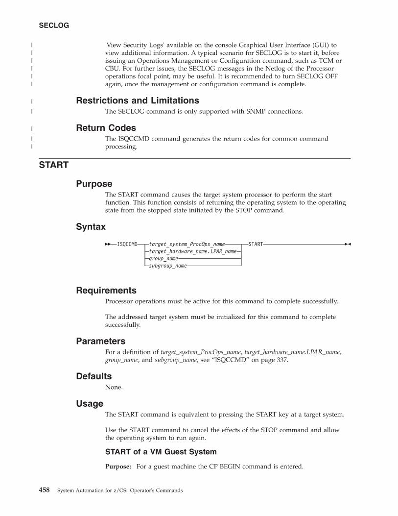
'View Security Logs' available on the console Graphical User Interface (GUI) toview additional information. A typical scenario for SECLOG is to start it, beforeissuing an Operations Management or Configuration command, such as TCM orCBU. For further issues, the SECLOG messages in the Netlog of the Processoroperations focal point, may be useful. It is recommended to turn SECLOG OFFagain, once the management or configuration command is complete.
Restrictions and LimitationsThe SECLOG command is only supported with SNMP connections.
Return CodesThe ISQCCMD command generates the return codes for common commandprocessing.
START
PurposeThe START command causes the target system processor to perform the startfunction. This function consists of returning the operating system to the operatingstate from the stopped state initiated by the STOP command.
Syntax
�� ISQCCMD target_system_ProcOps_nametarget_hardware_name.LPAR_namegroup_namesubgroup_name
START ��
RequirementsProcessor operations must be active for this command to complete successfully.
The addressed target system must be initialized for this command to completesuccessfully.
ParametersFor a definition of target_system_ProcOps_name, target_hardware_name.LPAR_name,group_name, and subgroup_name, see “ISQCCMD” on page 337.
DefaultsNone.
UsageThe START command is equivalent to pressing the START key at a target system.
Use the START command to cancel the effects of the STOP command and allowthe operating system to run again.
START of a VM Guest System
Purpose: For a guest machine the CP BEGIN command is entered.
SECLOG
458 System Automation for z/OS: Operator's Commands
||||||
|
|
|
||
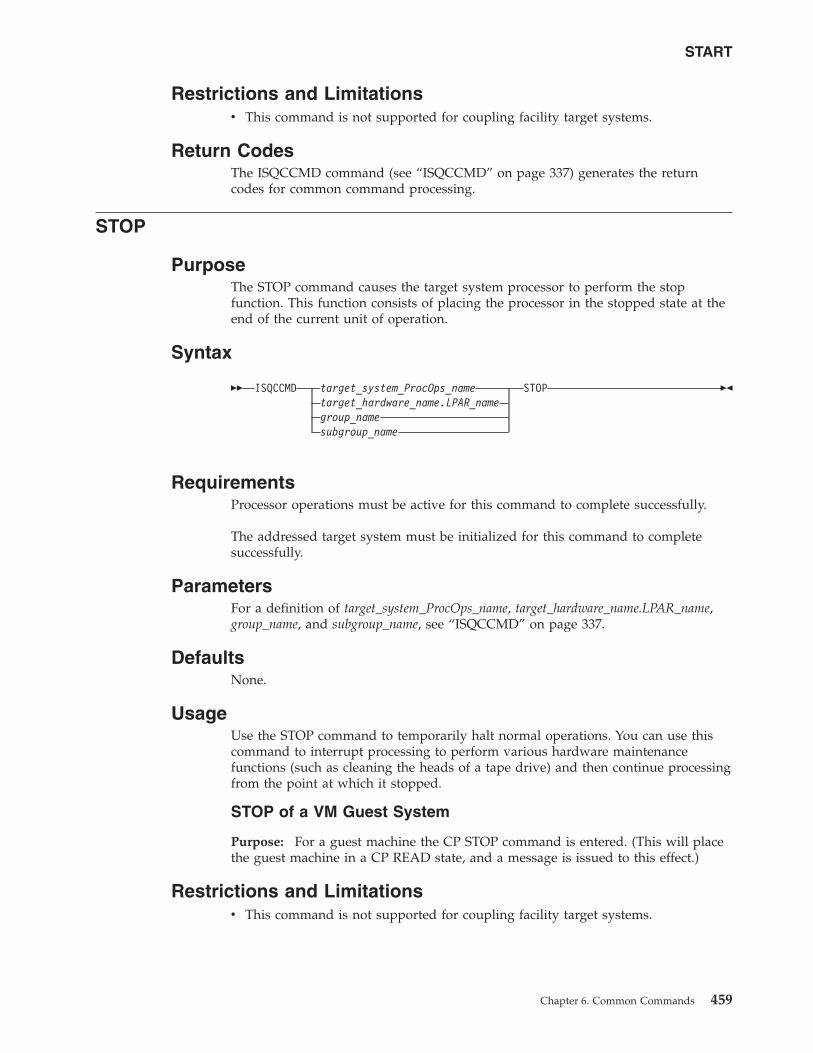
Restrictions and Limitationsv This command is not supported for coupling facility target systems.
Return CodesThe ISQCCMD command (see “ISQCCMD” on page 337) generates the returncodes for common command processing.
STOP
PurposeThe STOP command causes the target system processor to perform the stopfunction. This function consists of placing the processor in the stopped state at theend of the current unit of operation.
Syntax
�� ISQCCMD target_system_ProcOps_nametarget_hardware_name.LPAR_namegroup_namesubgroup_name
STOP ��
RequirementsProcessor operations must be active for this command to complete successfully.
The addressed target system must be initialized for this command to completesuccessfully.
ParametersFor a definition of target_system_ProcOps_name, target_hardware_name.LPAR_name,group_name, and subgroup_name, see “ISQCCMD” on page 337.
DefaultsNone.
UsageUse the STOP command to temporarily halt normal operations. You can use thiscommand to interrupt processing to perform various hardware maintenancefunctions (such as cleaning the heads of a tape drive) and then continue processingfrom the point at which it stopped.
STOP of a VM Guest System
Purpose: For a guest machine the CP STOP command is entered. (This will placethe guest machine in a CP READ state, and a message is issued to this effect.)
Restrictions and Limitationsv This command is not supported for coupling facility target systems.
START
Chapter 6. Common Commands 459
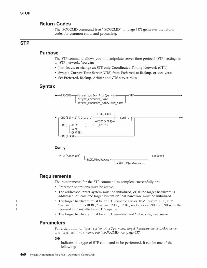
Return CodesThe ISQCCMD command (see “ISQCCMD” on page 337) generates the returncodes for common command processing.
STP
PurposeThe STP command allows you to manipulate server time protocol (STP) settings inan STP network. You can:v Join, leave, or change an STP-only Coordinated Timing Network (CTN)v Swap a Current Time Server (CTS) from Preferred to Backup, or vice versav Set Preferred, Backup, Arbiter and CTS server roles
Syntax
�� ISQCCMD target_system_ProcOps_nametarget_hardware_nametarget_hardware_name.LPAR_name
STP �
�FORCE(NO)
CMD(SET) STPID(stpid) ConfigFORCE(YES)
CMD( JOIN ) STPID(stpid)SWAPCHANGE
CMD(LEAVE)
��
Config:
PREF(nodename) CTS(cts)BACKUP(nodename)
ARBITER(nodename)
RequirementsThe requirements for the STP command to complete successfully are:v Processor operations must be active.v The addressed target system must be initialized, or, if the target hardware is
addressed, at least one target system on that hardware must be initialized.v The target hardware must be an STP-capable server. IBM System z196, IBM
System z10 ECT, z10 BC, System z9 EC, z9 BC, and zSeries 990 and 890 with therequired LIC installed are STP-capable.
v The target hardware must be an STP-enabled and STP-configured server.
ParametersFor a definition of target_system_ProcOps_name, target_hardware_name.LPAR_name,and target_hardware_name, see “ISQCCMD” on page 337.
CMDIndicates the type of STP command to be performed. It can be one of thefollowing:
STOP
460 System Automation for z/OS: Operator's Commands
|||
JOIN This command allows a CPC to join an STP-only CTN.
If the CPC is already participating in an STP-only CTN, it is removedfrom that CTN and joins the specified one.
If the CPC has an external time reference (ETR) ID, it is removed.
The target system cannot be the CTS.LEAVE
This command removes a central processor complex (CPC) from anSTP-only CTN. The target system cannot be the CTS.
CHANGEThis command is sent to the Defined CPC with the role of CTS in anSTP-only CTN and changes the STP ID portion of the CTN ID for theentire STP-only CTN. The target system must be the CTS.
SET This command sets the configuration for an STP-only CoordinatedTiming Network (CTN). The target system must be the system that willbecome the Current Time Server (CTS).
SWAP In a configured STP-only CTN, one CPC has the role of CTS. If theCTN has both a Preferred Time Server and a Backup Time Serverconfigured, either one can be the CTS. This command swaps the role ofCTS from Preferred Time Server to Backup Time Server or vice versa.
The target system must be the system that will become the CTS.
STPIDAn alphanumeric string that represents the current STP identifier for theDefined CPC object. The string must not exceed 8 characters. It is applicablefor the CMD options JOIN, CHANGE, SWAP, and SET.
FORCEThis parameter is only applicable for CMD (SET). It bypasses a number ofvalidity checks on server connectivity, and it allows the configuration ofservers that may not be in POR-complete state or do not yet have couplinglink connectivity to the selected CTS.NO Specifies that various verifications will be made before allowing the
configuration to be set. For example, connections between the PreferredTime Server (CPC), Backup Time Server (CPC), and Arbiter will beverified. If the connections are not there, the configuration will fail.
YESSpecifies that the configuration will be applied without verifications.
ConfigSpecifies the type of server that a configuration is being set for. It is onlyapplicable for CMD(SET). It can be one of the following:
PREF Assigns the Preferred Time Server role (the server that is assigned tobe the Preferred Stratum 1 server) in an STP-only CTN. The PREFparameter is mandatory for the CMD(SET) command.
This is usually also the Current Time Server (CTS).
BACKUPAssigns the Backup Time Server role in an STP-only CTN. This is theserver that is assigned to take over as the CTS, either because of aplanned or unplanned reconfiguration. This is usually a Stratum 2server that should be attached to the Preferred Time Server as well asall the servers that are attached to the Preferred Time Server.
If you do not specify BACKUP for the SET command, the BTS role willbe unset (that is, not configured).
STP
Chapter 6. Common Commands 461
ARBITERAssigns the Arbiter role in an STP-only CTN. This is the server that isassigned to provide additional means for the Backup Time Server todetermine whether it should take over as the Current Time Server.
If you do not specify ARBITER for the SET command, the Arbiter rolewill be unset (that is, not configured). You must configure the BackupTime Server (that is, specify the BACKUP parameter) if you configurean Arbiter.
CTS Assigns the Current Time Server role in an STP-only CTN. This is theserver that is currently the Stratum 1 server for an STP-only CTN. Theonly values that are allowed are Preferred or Backup. The CTSparameter is mandatory for the CMD(SET) command.
nodenameAn alphanumeric string that represents the name of the CPC and must notexceed 8 characters.
DefaultsThe STP command defaults to FORCE(NO).
UsageUse this command to modify the STP configuration in an STP-only CTN.
Restrictions and LimitationsThe STP common command is only supported for SNMP connections. If an STPrequest is issued for another processor operations connection type, it will berejected.
Note: To perform an STP CMD(SET) command, all nodes that are referenced in thecommand should be defined in main HMC console.
Return CodesThe ISQCCMD command (see “ISQCCMD” on page 337) generates the returncodes for common command processing.
STPDATA
PurposeThe STPDATA command allows you to query the Server Time Protocol (STP)configuration for the defined CPC object.
Syntax
�� ISQCCMD target_system_ProcOps_nametarget_hardware_nametarget_hardware_name.LPAR_name
STPDATA ��
RequirementsThe requirements for the STPDATA command to complete successfully are:
STP
462 System Automation for z/OS: Operator's Commands
v The target hardware must be an STP-capable server. IBM System z196, IBMSystem z10 ECT, z10 BC, System z9 EC, z9 BC, and zSeries 990 and 890 with therequired LIC installed are STP-capable.
v The target hardware must be an STP-enabled server.
Processor Operations environment
v Processor operations must be active.v The addressed target system must be initialized, or, if the target
hardware is addressed, at least one target system on that hardware mustbe initialized.
LPAR Management environment
v SA z/OS must be fully initialized.v The processor hardware of the addressed target system or target
hardware LPAR must be configured for connection type INTERNAL inthe SA z/OS customization dialogs.
ParametersFor a definition of target_system_ProcOps_name, target_hardware_name.LPAR_name,and target_hardware_name, see “ISQCCMD” on page 337.
DefaultsNone.
UsageUse this command to query the Server Time Protocol (STP) configuration for aspecific CPC object. The data is returned in an AOFA0024 multiline report. Formore information about this report format see the appendix “Response Messages,Error Strings, Condition Codes” in IBM Tivoli System Automation for z/OS Messagesand Codes.
The command response reports from the processor hardware are available asprocessor operations ISQ900I messages with a console indicator of SC. Note thatthe message originator following the message identifier is either a processoroperations target system name or a target hardware name together with an LPARname. To have a copy of these hardware messages on your screen as ISQ901Imessages, use the ISQXMON command.
This common command can also be used for processors or systems that you haveconfigured with a BCP Internal Interface connection in your SA z/OS policy. Ifprocessor operations is active, and your common command targets a processor orsystem that has the same name in both your processor operations and BCP InternalInterface configuration, processor operations is always preferred. To avoid this, youmust either stop processor operations or use names that are uniquely assigned toeither processor operations or the BCP Internal Interface.
Additional Programming InformationOn command completion, the immediate HW response report messages are alsoavailable in a PIPE KEEP with the name ISQ.SNMP. You can access this HW datadirectly when using this KEEP as your first Pipe stage. See “Using ImmediateISQCCMD Common Command Responses” on page 339.
STPDATA
Chapter 6. Common Commands 463
|||
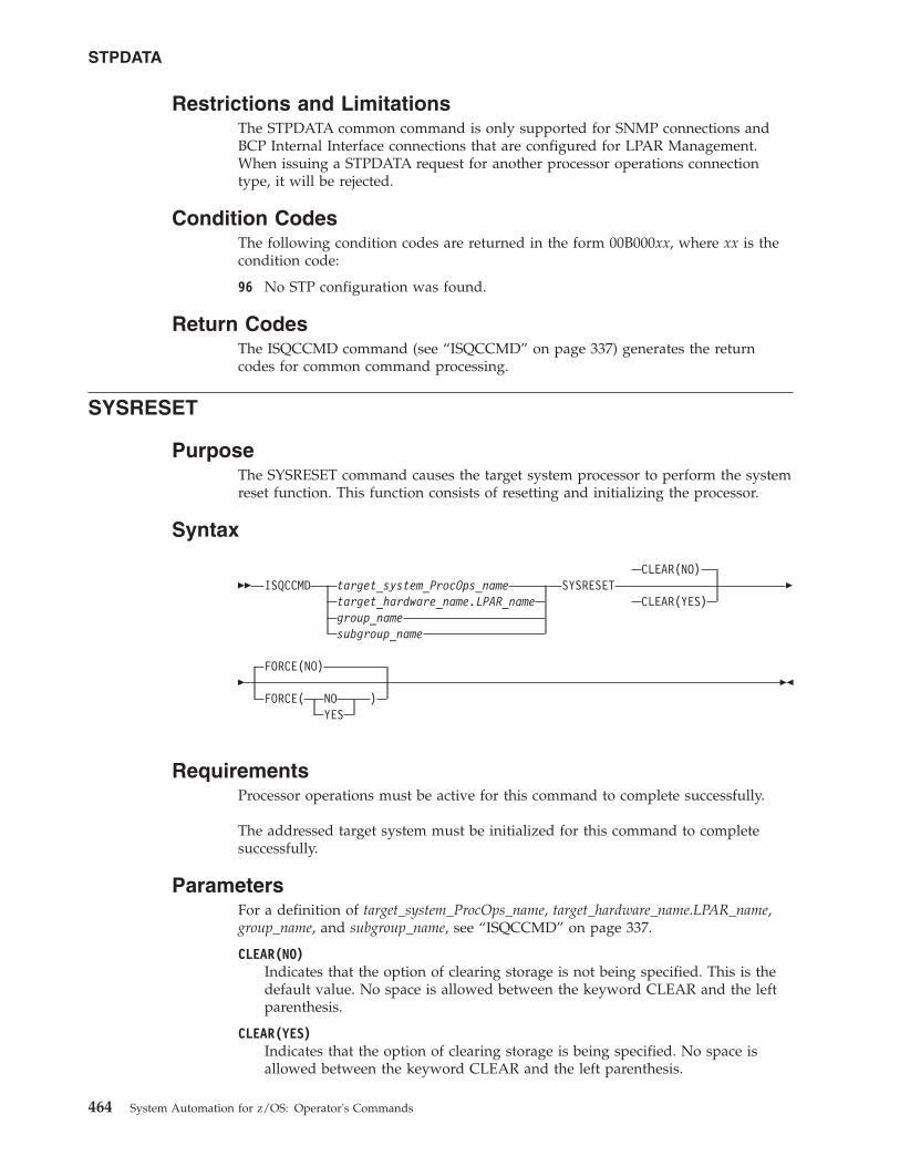
Restrictions and LimitationsThe STPDATA common command is only supported for SNMP connections andBCP Internal Interface connections that are configured for LPAR Management.When issuing a STPDATA request for another processor operations connectiontype, it will be rejected.
Condition CodesThe following condition codes are returned in the form 00B000xx, where xx is thecondition code:
96 No STP configuration was found.
Return CodesThe ISQCCMD command (see “ISQCCMD” on page 337) generates the returncodes for common command processing.
SYSRESET
PurposeThe SYSRESET command causes the target system processor to perform the systemreset function. This function consists of resetting and initializing the processor.
Syntax
�� ISQCCMD target_system_ProcOps_nametarget_hardware_name.LPAR_namegroup_namesubgroup_name
SYSRESETCLEAR(NO)
CLEAR(YES)�
�FORCE(NO)
FORCE( NO )YES
��
RequirementsProcessor operations must be active for this command to complete successfully.
The addressed target system must be initialized for this command to completesuccessfully.
ParametersFor a definition of target_system_ProcOps_name, target_hardware_name.LPAR_name,group_name, and subgroup_name, see “ISQCCMD” on page 337.
CLEAR(NO)Indicates that the option of clearing storage is not being specified. This is thedefault value. No space is allowed between the keyword CLEAR and the leftparenthesis.
CLEAR(YES)Indicates that the option of clearing storage is being specified. No space isallowed between the keyword CLEAR and the left parenthesis.
STPDATA
464 System Automation for z/OS: Operator's Commands
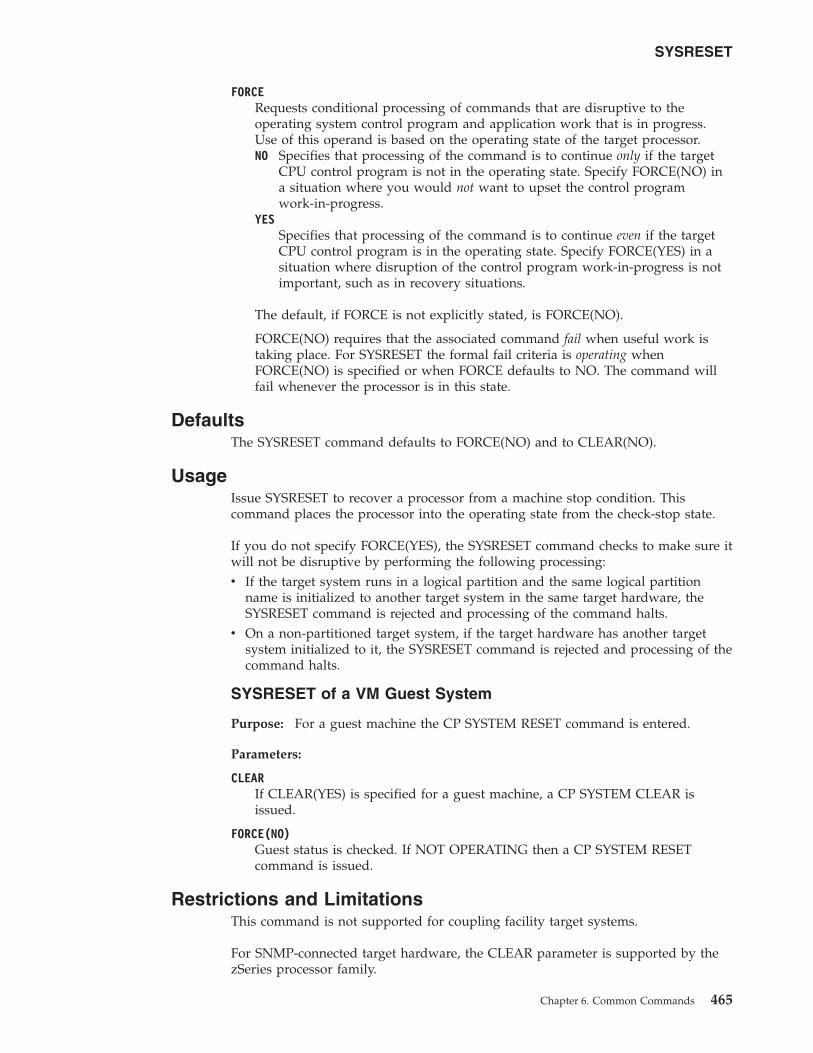
FORCERequests conditional processing of commands that are disruptive to theoperating system control program and application work that is in progress.Use of this operand is based on the operating state of the target processor.NO Specifies that processing of the command is to continue only if the target
CPU control program is not in the operating state. Specify FORCE(NO) ina situation where you would not want to upset the control programwork-in-progress.
YESSpecifies that processing of the command is to continue even if the targetCPU control program is in the operating state. Specify FORCE(YES) in asituation where disruption of the control program work-in-progress is notimportant, such as in recovery situations.
The default, if FORCE is not explicitly stated, is FORCE(NO).
FORCE(NO) requires that the associated command fail when useful work istaking place. For SYSRESET the formal fail criteria is operating whenFORCE(NO) is specified or when FORCE defaults to NO. The command willfail whenever the processor is in this state.
DefaultsThe SYSRESET command defaults to FORCE(NO) and to CLEAR(NO).
UsageIssue SYSRESET to recover a processor from a machine stop condition. Thiscommand places the processor into the operating state from the check-stop state.
If you do not specify FORCE(YES), the SYSRESET command checks to make sure itwill not be disruptive by performing the following processing:v If the target system runs in a logical partition and the same logical partition
name is initialized to another target system in the same target hardware, theSYSRESET command is rejected and processing of the command halts.
v On a non-partitioned target system, if the target hardware has another targetsystem initialized to it, the SYSRESET command is rejected and processing of thecommand halts.
SYSRESET of a VM Guest System
Purpose: For a guest machine the CP SYSTEM RESET command is entered.
Parameters:
CLEARIf CLEAR(YES) is specified for a guest machine, a CP SYSTEM CLEAR isissued.
FORCE(NO)Guest status is checked. If NOT OPERATING then a CP SYSTEM RESETcommand is issued.
Restrictions and LimitationsThis command is not supported for coupling facility target systems.
For SNMP-connected target hardware, the CLEAR parameter is supported by thezSeries processor family.
SYSRESET
Chapter 6. Common Commands 465
Return CodesThe ISQCCMD command (see “ISQCCMD” on page 337) generates the returncodes for common command processing.
TCDATA
PurposeThe TCDATA common command allows you to query the status and settings for aspecific temporary capacity record.
Syntax
�� ISQCCMD target_system_ProcOps_nametarget_hardware_name.LPAR_nametarget_hardware_name
TCDATA RECID(recid) ��
RequirementsThe requirements for the TCDATA command to complete successfully are:v On/Off Capacity on Demand (ooCoD) or Capacity Backup Unit (CBU) records,
or both, must be installed on the addressed target hardware.v The required temporary capacity record must be available on the addressed
target hardware.
Processor Operations environment
v Processor operations must be active.v The addressed target system must be initialized, or, if the target
hardware is addressed, at least one target system on that hardware mustbe initialized.
LPAR Management environment
v SA z/OS must be fully initialized.v The processor hardware of the addressed target system or target
hardware LPAR must be configured for connection type INTERNAL inthe SA z/OS customization dialogs.
ParametersFor a definition of target_system_ProcOps_name, target_hardware_name.LPAR_name,and target_hardware_name, see “ISQCCMD” on page 337.
RECIDDefines the ooCoD or CBU record that TCDATA query should be executed for.If you specify a record ID of 'LIST', the TCDATA command will display a listof the installed capacity record IDs.
DefaultsNone.
UsageUse this command to query the status and settings for a specific temporarycapacity record.
SYSRESET
466 System Automation for z/OS: Operator's Commands
The data is returned in an AOFA0023 multiline report. For more information aboutthis report format, see the appendix, “Response Messages, Error Strings, ConditionCodes” in IBM Tivoli System Automation for z/OS Messages and Codes.
The command response reports from the processor hardware are available asProcOps ISQ900I messages with a console indicator of SC. Note that the messageoriginator following the message identifier is either a ProcOps target system name,or a target hardware name together with an LPAR name. To get a copy of suchhardware messages on your screen as ISQ901I messages, use the ISQXMONcommand.
This common command can also be used for processors or systems that you haveconfigured with a BCP Internal Interface connection in your SA z/OS policy. IfProcOps is active, and your common command targets a processor or system thathas the same name in your ProcOps and BCP Internal Interface configuration,ProcOps is always preferred. To avoid this, you must either stop ProcOps or usenames that are uniquely assigned to either ProcOps or the BCP Internal Interface.
Additional Programming InformationOn command completion, the immediate HW response report messages are alsoavailable in a PIPE KEEP with the name 'ISQ.SNMP'. You can directly access thisHW data when using this KEEP as your first Pipe stage. See “Using ImmediateISQCCMD Common Command Responses” on page 339.
Restrictions and LimitationsThe TCDATA common command applies only to Series z10 hardware and later.The command fails for older hardware.
The TCDATA common command is only supported for SNMP connections andBCP Internal Interface connections configured for LPAR Management. Whenissuing a TCDATA request for another ProcOps connection type, it is rejected.
Condition CodesThe following condition codes are returned in the form 00B000xx, where xx is thecondition code:
90 No temporary capacity record list was found.
91 Object not found. In this case, the temporary capacity record object was notfound.
92 No matching record found for provided record ID.
93 Error found while parsing temporary capacity record XML data.
Return CodesThe ISQCCMD command (see “ISQCCMD” on page 337) generates the returncodes for common command processing.
TCM
PurposeThe TCM common command allows you to add or remove temporary capacityresources (processors) for specific target hardware.
TCDATA
Chapter 6. Common Commands 467
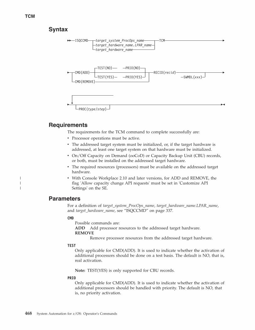
Syntax
�� ISQCCMD target_system_ProcOps_nametarget_hardware_name.LPAR_nametarget_hardware_name
TCM �
�TEST(NO) PRIO(NO)
CMD(ADD)TEST(YES) PRIO(YES)
CMD(REMOVE)
RECID(recid)SWMDL(xxx)
�
� �
PROC(type/step)��
RequirementsThe requirements for the TCM command to complete successfully are:v Processor operations must be active.v The addressed target system must be initialized, or, if the target hardware is
addressed, at least one target system on that hardware must be initialized.v On/Off Capacity on Demand (ooCoD) or Capacity Backup Unit (CBU) records,
or both, must be installed on the addressed target hardware.v The required resources (processors) must be available on the addressed target
hardware.v With Console Workplace 2.10 and later versions, for ADD and REMOVE, the
flag 'Allow capacity change API requests' must be set in 'Customize APISettings' on the SE.
ParametersFor a definition of target_system_ProcOps_name, target_hardware_name.LPAR_name,and target_hardware_name, see “ISQCCMD” on page 337.
CMDPossible commands are:ADD Add processor resources to the addressed target hardware.REMOVE
Remove processor resources from the addressed target hardware.
TESTOnly applicable for CMD(ADD). It is used to indicate whether the activation ofadditional processors should be done on a test basis. The default is NO, that is,real activation.
Note: TEST(YES) is only supported for CBU records.
PRIOOnly applicable for CMD(ADD). It is used to indicate whether the activation ofadditional processors should be handled with priority. The default is NO, thatis, no priority activation.
TCM
468 System Automation for z/OS: Operator's Commands
|||
RECIDDefines the ooCoD or CBU record that the add or remove command should beexecuted for. The value consists of 8 alphanumeric characters.
SWMDLDefines the Software Model that the add or remove command should result in.It is used to add or remove General Purpose Processors. The value consists ofthree alphanumeric characters.
PROCUsed to define up to five Special Purpose Processors, using the followingvariables:
typeDefines the processor type. The following values are allowed:AAP Application Assist ProcessorIFL Integrated Facility for Linux processorICF Internal Coupling Facility processorIIP Integrated Information ProcessorSAP System Assist Processor
stepDefines the number of processors that should be added or removed. Thevalid value range for step is 0–9999.
Note: The two values must be separated with the / character.
DefaultsThe PRIO and TEST parameters for CMD(ADD) default to NO.
Restrictions and LimitationsThe TCM common command applies only to Series z10 hardware and later. Thecommand fails for older hardware. The number of PROC parameters must notexceed five.
The TCM common command is only supported for SNMP connections. If a TCMrequest is issued for another processor operations connection type, it is rejected.
Condition CodesThe following condition code is returned in the form 00B000xx, where xx is thecondition code:
94 Error found while composing temporary capacity add or remove XML data.
Return CodesThe ISQCCMD command (see “ISQCCMD” on page 337) generates the returncodes for common command processing.
TCM
Chapter 6. Common Commands 469

TCM
470 System Automation for z/OS: Operator's Commands
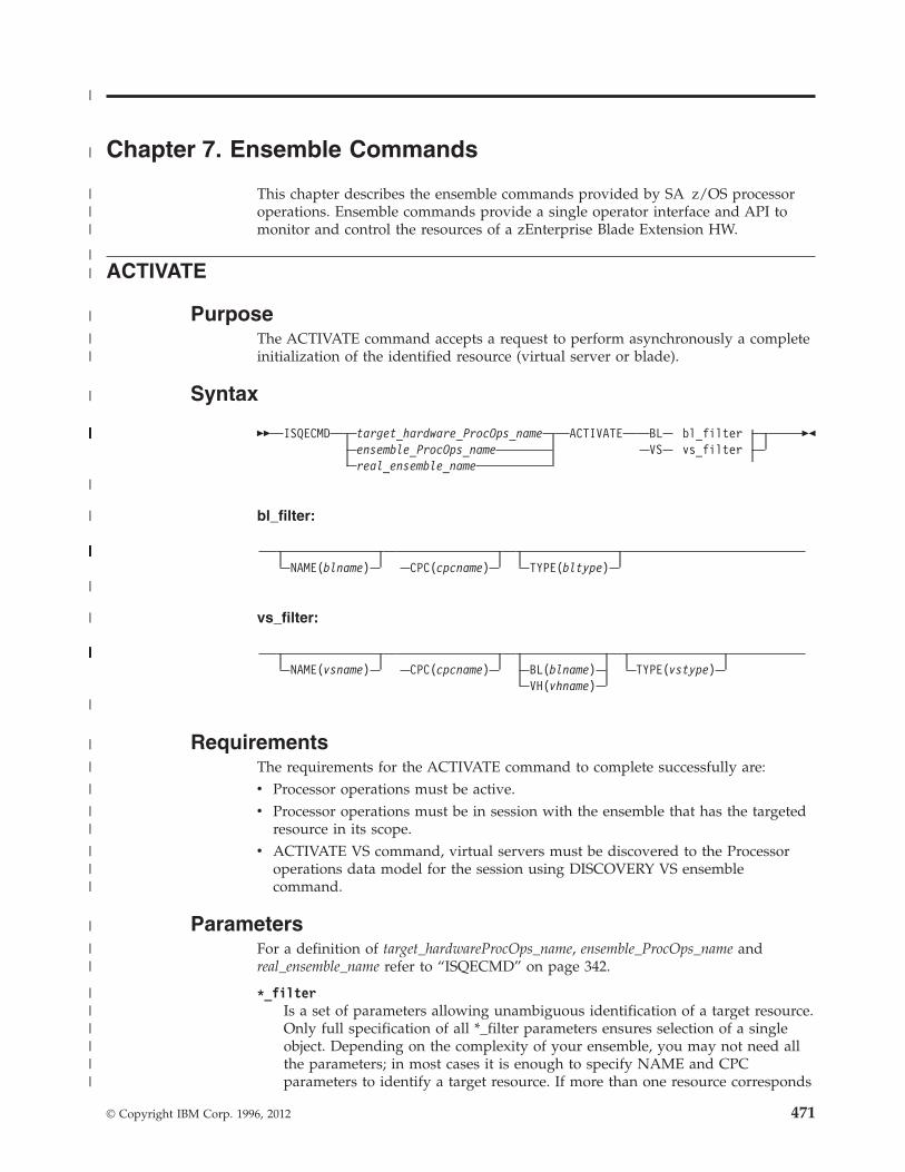
Chapter 7. Ensemble Commands
This chapter describes the ensemble commands provided by SA z/OS processoroperations. Ensemble commands provide a single operator interface and API tomonitor and control the resources of a zEnterprise Blade Extension HW.
ACTIVATE
PurposeThe ACTIVATE command accepts a request to perform asynchronously a completeinitialization of the identified resource (virtual server or blade).
Syntax
�� ISQECMD target_hardware_ProcOps_nameensemble_ProcOps_namereal_ensemble_name
ACTIVATE BL bl_filterVS vs_filter
��
bl_filter:
NAME(blname) CPC(cpcname) TYPE(bltype)
vs_filter:
NAME(vsname) CPC(cpcname) BL(blname)VH(vhname)
TYPE(vstype)
RequirementsThe requirements for the ACTIVATE command to complete successfully are:v Processor operations must be active.v Processor operations must be in session with the ensemble that has the targeted
resource in its scope.v ACTIVATE VS command, virtual servers must be discovered to the Processor
operations data model for the session using DISCOVERY VS ensemblecommand.
ParametersFor a definition of target_hardwareProcOps_name, ensemble_ProcOps_name andreal_ensemble_name refer to “ISQECMD” on page 342.
*_filterIs a set of parameters allowing unambiguous identification of a target resource.Only full specification of all *_filter parameters ensures selection of a singleobject. Depending on the complexity of your ensemble, you may not need allthe parameters; in most cases it is enough to specify NAME and CPCparameters to identify a target resource. If more than one resource corresponds
© Copyright IBM Corp. 1996, 2012 471
|
|
|||
||
|
||
|
||||||||||||||||||||||||||||||||||||
|
|
||||||||||||||||||||||||||||
|
|
||||||||||||||||||||||||||||||||||||||
|
|
|
|
||
|||
|
||
||||||
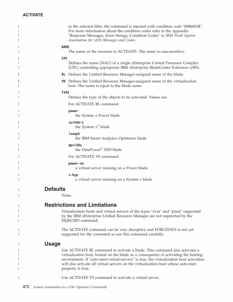
to the selected filter, the command is rejected with condition code "00B6001B".For more information about the condition codes refer to the appendix"Response Messages, Error Strings, Condition Codes" in IBM Tivoli SystemAutomation for z/OS Messages and Codes.
NAMEThe name of the resource to ACTIVATE. The name is case-sensitive.
CPCDefines the name (NAU) of a single zEnterprise Central Processor Complex(CPC) controlling appropriate IBM zEnterprise BladeCenter Extension (zBX).
BL Defines the Unified Resource Manager-assigned name of the blade.
VH Defines the Unified Resource Manager-assigned name of the virtualizationhost. The name is equal to the blade name.
TYPEDefines the type of the objects to be activated. Values are:
For ACTIVATE BL command:
powerthe System z Power blade
system-xthe System x® blade
isaoptthe IBM Smart Analytics Optimizer blade
dpxi50zthe DataPower® XI50 blade
For ACTIVATE VS command:
power-vma virtual server running on a Power blade
x-hypa virtual server running on a System x blade
DefaultsNone.
Restrictions and LimitationsVirtualization hosts and virtual servers of the types "zvm" and "prsm" supportedby the IBM zEnterprise Unified Resource Manager are not supported by theISQECMD command.
The ACTIVATE command can be very disruptive and FORCE(NO) is not yetsupported for the command so use this command carefully.
UsageUse ACTIVATE BL command to activate a blade. This command also activates avirtualization host, hosted on the blade as a consequence of activating the hostingenvironment. If "auto-start-virtual-servers" is true, the virtualization host activationwill also activate all virtual servers on the virtualization host whose auto-startproperty is true.
Use ACTIVATE VS command to activate a virtual server.
ACTIVATE
472 System Automation for z/OS: Operator's Commands
||||
||
|||
||
|||
||
|
||
||
||
||
|
||
||
|
|
|
|||
||
|
|||||
|
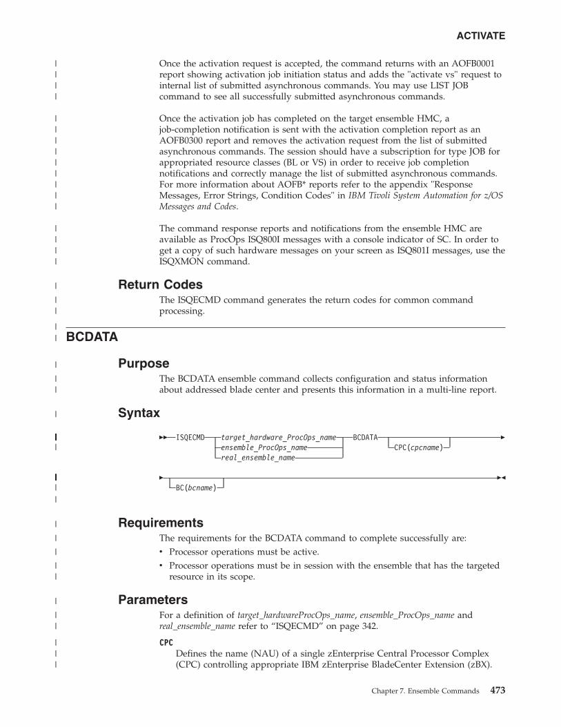
Once the activation request is accepted, the command returns with an AOFB0001report showing activation job initiation status and adds the "activate vs" request tointernal list of submitted asynchronous commands. You may use LIST JOBcommand to see all successfully submitted asynchronous commands.
Once the activation job has completed on the target ensemble HMC, ajob-completion notification is sent with the activation completion report as anAOFB0300 report and removes the activation request from the list of submittedasynchronous commands. The session should have a subscription for type JOB forappropriated resource classes (BL or VS) in order to receive job completionnotifications and correctly manage the list of submitted asynchronous commands.For more information about AOFB* reports refer to the appendix "ResponseMessages, Error Strings, Condition Codes" in IBM Tivoli System Automation for z/OSMessages and Codes.
The command response reports and notifications from the ensemble HMC areavailable as ProcOps ISQ800I messages with a console indicator of SC. In order toget a copy of such hardware messages on your screen as ISQ801I messages, use theISQXMON command.
Return CodesThe ISQECMD command generates the return codes for common commandprocessing.
BCDATA
PurposeThe BCDATA ensemble command collects configuration and status informationabout addressed blade center and presents this information in a multi-line report.
Syntax
�� ISQECMD target_hardware_ProcOps_nameensemble_ProcOps_namereal_ensemble_name
BCDATACPC(cpcname)
�
�BC(bcname)
��
RequirementsThe requirements for the BCDATA command to complete successfully are:v Processor operations must be active.v Processor operations must be in session with the ensemble that has the targeted
resource in its scope.
ParametersFor a definition of target_hardwareProcOps_name, ensemble_ProcOps_name andreal_ensemble_name refer to “ISQECMD” on page 342.
CPCDefines the name (NAU) of a single zEnterprise Central Processor Complex(CPC) controlling appropriate IBM zEnterprise BladeCenter Extension (zBX).
ACTIVATE
Chapter 7. Ensemble Commands 473
||||
|||||||||
||||
|
||
||
|
||
|
|||||||||||||||||||||||||||
|||||||||||||
|
|
|
|
||
|
||
|||
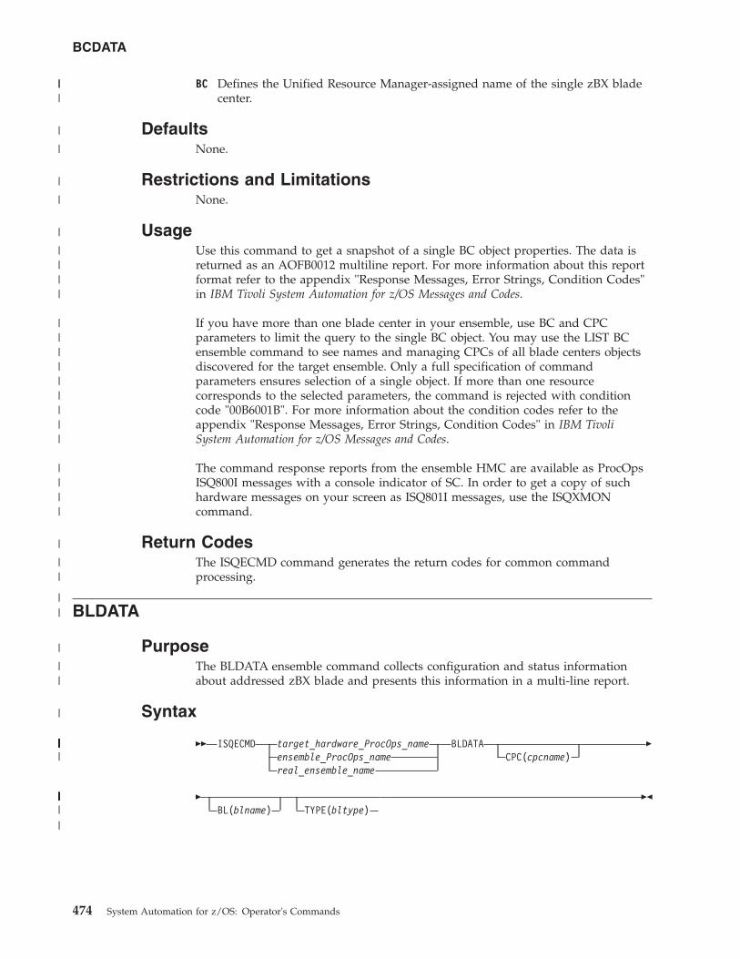
BC Defines the Unified Resource Manager-assigned name of the single zBX bladecenter.
DefaultsNone.
Restrictions and LimitationsNone.
UsageUse this command to get a snapshot of a single BC object properties. The data isreturned as an AOFB0012 multiline report. For more information about this reportformat refer to the appendix "Response Messages, Error Strings, Condition Codes"in IBM Tivoli System Automation for z/OS Messages and Codes.
If you have more than one blade center in your ensemble, use BC and CPCparameters to limit the query to the single BC object. You may use the LIST BCensemble command to see names and managing CPCs of all blade centers objectsdiscovered for the target ensemble. Only a full specification of commandparameters ensures selection of a single object. If more than one resourcecorresponds to the selected parameters, the command is rejected with conditioncode "00B6001B". For more information about the condition codes refer to theappendix "Response Messages, Error Strings, Condition Codes" in IBM TivoliSystem Automation for z/OS Messages and Codes.
The command response reports from the ensemble HMC are available as ProcOpsISQ800I messages with a console indicator of SC. In order to get a copy of suchhardware messages on your screen as ISQ801I messages, use the ISQXMONcommand.
Return CodesThe ISQECMD command generates the return codes for common commandprocessing.
BLDATA
PurposeThe BLDATA ensemble command collects configuration and status informationabout addressed zBX blade and presents this information in a multi-line report.
Syntax
�� ISQECMD target_hardware_ProcOps_nameensemble_ProcOps_namereal_ensemble_name
BLDATACPC(cpcname)
�
�BL(blname) TYPE(bltype)
��
BCDATA
474 System Automation for z/OS: Operator's Commands
|||
|
|
|
|
|
||||
|||||||||
||||
|
||
||
|
||
|
|||||||||||||||||||||||||||
||||||||||||||||||||
|
RequirementsThe requirements for the BLDATA command to complete successfully are:v Processor operations must be active.v Processor operations must be in session with the ensemble that has the targeted
resource in its scope.
ParametersFor a definition of target_hardwareProcOps_name, ensemble_ProcOps_name andreal_ensemble_name refer to “ISQECMD” on page 342.
CPCDefines the name (NAU) of a single zEnterprise Central Processor Complex(CPC) controlling appropriate IBM zEnterprise BladeCenter Extension (zBX).
BL Defines the Unified Resource Manager-assigned name of the blade.
TYPEDefines the type of a blade. Values are:
powerthe System z Power blade
system-xthe System x blade
isaoptthe IBM Smart Analytics Optimizer blade
dpxi50zthe DataPower XI50 blade
DefaultsNone.
Restrictions and LimitationsNone.
UsageUse this command to get a snapshot of the blade properties. The data is returnedas an AOFB0016 multiline report. For more information about this report formatrefer to the appendix "Response Messages, Error Strings, Condition Codes" in IBMTivoli System Automation for z/OS Messages and Codes.
If you have more than one blade in your ensemble, use BL, TYPE and CPCparameters to limit the query to the single blade object. You may use the LIST BLensemble command to see names, types and managing CPCs of all blade objectsdiscovered for the target ensemble. Only a full specification of commandparameters ensures selection of a single object. If more than one resourcecorresponds to the selected parameters, the command is rejected with conditioncode "00B6001B". For more information about the condition codes refer to theappendix "Response Messages, Error Strings, Condition Codes" in IBM TivoliSystem Automation for z/OS Messages and Codes.
BLDATA
Chapter 7. Ensemble Commands 475
|
|
|
||
|
||
|||
||
||
||
||
||
||
|
|
|
|
|
||||
|||||||||
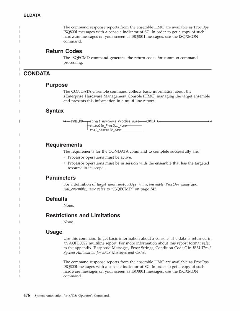
The command response reports from the ensemble HMC are available as ProcOpsISQ800I messages with a console indicator of SC. In order to get a copy of suchhardware messages on your screen as ISQ801I messages, use the ISQXMONcommand.
Return CodesThe ISQECMD command generates the return codes for common commandprocessing.
CONDATA
PurposeThe CONDATA ensemble command collects basic information about thezEnterprise Hardware Management Console (HMC) managing the target ensembleand presents this information in a multi-line report.
Syntax
�� ISQECMD target_hardware_ProcOps_nameensemble_ProcOps_namereal_ensemble_name
CONDATA ��
RequirementsThe requirements for the CONDATA command to complete successfully are:v Processor operations must be active.v Processor operations must be in session with the ensemble that has the targeted
resource in its scope.
ParametersFor a definition of target_hardwareProcOps_name, ensemble_ProcOps_name andreal_ensemble_name refer to “ISQECMD” on page 342.
DefaultsNone.
Restrictions and LimitationsNone.
UsageUse this command to get basic information about a console. The data is returned inan AOFB0022 multiline report. For more information about this report format referto the appendix "Response Messages, Error Strings, Condition Codes" in IBM TivoliSystem Automation for z/OS Messages and Codes.
The command response reports from the ensemble HMC are available as ProcOpsISQ800I messages with a console indicator of SC. In order to get a copy of suchhardware messages on your screen as ISQ801I messages, use the ISQXMONcommand.
BLDATA
476 System Automation for z/OS: Operator's Commands
||||
|
||
||
|
|||
|
|||||||||||||||||||||
|
|
|
|
||
|
||
|
|
|
|
|
||||
||||
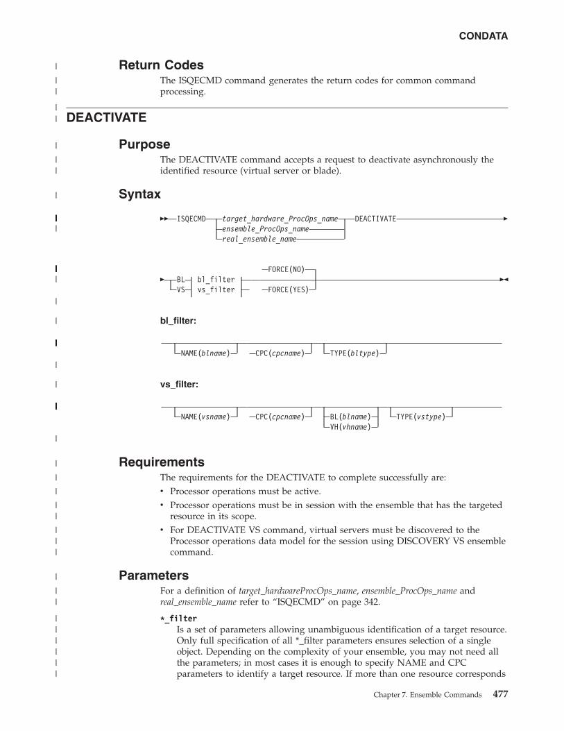
Return CodesThe ISQECMD command generates the return codes for common commandprocessing.
DEACTIVATE
PurposeThe DEACTIVATE command accepts a request to deactivate asynchronously theidentified resource (virtual server or blade).
Syntax
�� ISQECMD target_hardware_ProcOps_nameensemble_ProcOps_namereal_ensemble_name
DEACTIVATE �
� BL bl_filterVS vs_filter
FORCE(NO)
FORCE(YES)��
bl_filter:
NAME(blname) CPC(cpcname) TYPE(bltype)
vs_filter:
NAME(vsname) CPC(cpcname) BL(blname)VH(vhname)
TYPE(vstype)
RequirementsThe requirements for the DEACTIVATE to complete successfully are:v Processor operations must be active.v Processor operations must be in session with the ensemble that has the targeted
resource in its scope.v For DEACTIVATE VS command, virtual servers must be discovered to the
Processor operations data model for the session using DISCOVERY VS ensemblecommand.
ParametersFor a definition of target_hardwareProcOps_name, ensemble_ProcOps_name andreal_ensemble_name refer to “ISQECMD” on page 342.
*_filterIs a set of parameters allowing unambiguous identification of a target resource.Only full specification of all *_filter parameters ensures selection of a singleobject. Depending on the complexity of your ensemble, you may not need allthe parameters; in most cases it is enough to specify NAME and CPCparameters to identify a target resource. If more than one resource corresponds
CONDATA
Chapter 7. Ensemble Commands 477
|
||
||
|
||
|
||||||||||||||||||||
|||||||||||||||||||||||||||||||
|
|
||||||||||||||||||||||||||||
|
|
||||||||||||||||||||||||||||||||||||||
|
|
|
|
||
|||
|
||
||||||
to the selected filter, the command is rejected with condition code "00B6001B".For more information about the condition codes refer to the appendix"Response Messages, Error Strings, Condition Codes" in IBM Tivoli SystemAutomation for z/OS Messages and Codes.
NAMEThe name of the resource to DEACTIVATE. The name is case-sensitive.
CPCDefines the name (NAU) of a single zEnterprise Central Processor Complex(CPC) controlling appropriate IBM zEnterprise BladeCenter Extension (zBX).
BL Defines the Unified Resource Manager-assigned name of the blade.
VH Defines the Unified Resource Manager-assigned name of the virtualizationhost. The name is equal to the blade name.
TYPEDefines the type of the objects to be activated. Values are:
For DEACTIVATE BL command:
powerthe System z Power blade
system-xthe System x blade
isaoptthe IBM Smart Analytics Optimizer blade
dpxi50zthe DataPower XI50 blade
For DEACTIVATE VS command:
power-vma virtual server running on a Power blade
x-hypa virtual server running on a System x blade
FORCERequests conditional processing of commands that are disruptive to theoperating system and application work that is in progress. Use of this operandis based on the operating state of the target resource.
NO Specifies that processing of the command is to continue only if thetarget resource (blade or virtual server) is not in the operating state.Specify FORCE(NO) in a situation where you would not want todisrupt the operating environment.
YES Specifies that processing of the command is to continue even if thetarget resource (blade or virtual server) is in the operating state.Specify FORCE(YES) in a situation where disruption of the operatingenvironment is not important, such as in recovery situations.
DefaultsThe DEACTIVATE command defaults to FORCE(NO).
DEACTIVATE
478 System Automation for z/OS: Operator's Commands
||||
||
|||
||
|||
||
|
||
||
||
||
|
||
||
||||
|||||
|||||
|
|
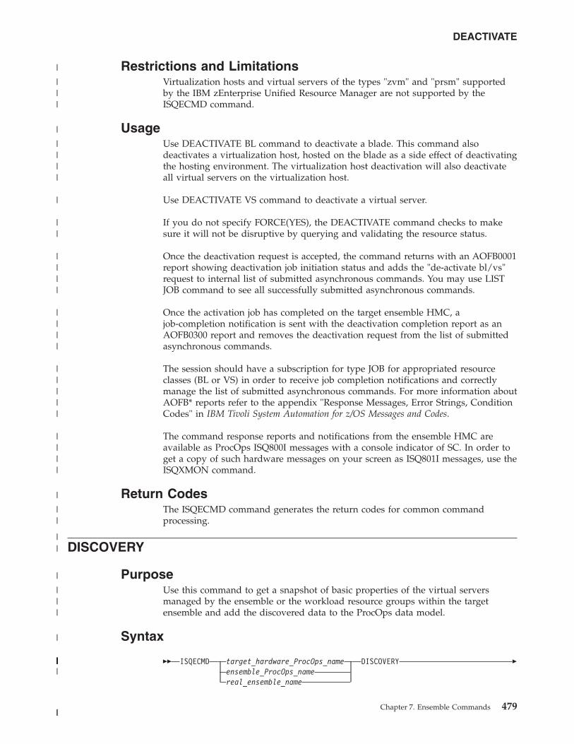
Restrictions and LimitationsVirtualization hosts and virtual servers of the types "zvm" and "prsm" supportedby the IBM zEnterprise Unified Resource Manager are not supported by theISQECMD command.
UsageUse DEACTIVATE BL command to deactivate a blade. This command alsodeactivates a virtualization host, hosted on the blade as a side effect of deactivatingthe hosting environment. The virtualization host deactivation will also deactivateall virtual servers on the virtualization host.
Use DEACTIVATE VS command to deactivate a virtual server.
If you do not specify FORCE(YES), the DEACTIVATE command checks to makesure it will not be disruptive by querying and validating the resource status.
Once the deactivation request is accepted, the command returns with an AOFB0001report showing deactivation job initiation status and adds the "de-activate bl/vs"request to internal list of submitted asynchronous commands. You may use LISTJOB command to see all successfully submitted asynchronous commands.
Once the activation job has completed on the target ensemble HMC, ajob-completion notification is sent with the deactivation completion report as anAOFB0300 report and removes the deactivation request from the list of submittedasynchronous commands.
The session should have a subscription for type JOB for appropriated resourceclasses (BL or VS) in order to receive job completion notifications and correctlymanage the list of submitted asynchronous commands. For more information aboutAOFB* reports refer to the appendix "Response Messages, Error Strings, ConditionCodes" in IBM Tivoli System Automation for z/OS Messages and Codes.
The command response reports and notifications from the ensemble HMC areavailable as ProcOps ISQ800I messages with a console indicator of SC. In order toget a copy of such hardware messages on your screen as ISQ801I messages, use theISQXMON command.
Return CodesThe ISQECMD command generates the return codes for common commandprocessing.
DISCOVERY
PurposeUse this command to get a snapshot of basic properties of the virtual serversmanaged by the ensemble or the workload resource groups within the targetensemble and add the discovered data to the ProcOps data model.
Syntax
�� ISQECMD target_hardware_ProcOps_nameensemble_ProcOps_namereal_ensemble_name
DISCOVERY �
DEACTIVATE
Chapter 7. Ensemble Commands 479
|
|||
|
||||
|
||
||||
||||
|||||
||||
|
||
||
|
|||
|
||||||||||||||||||||
||
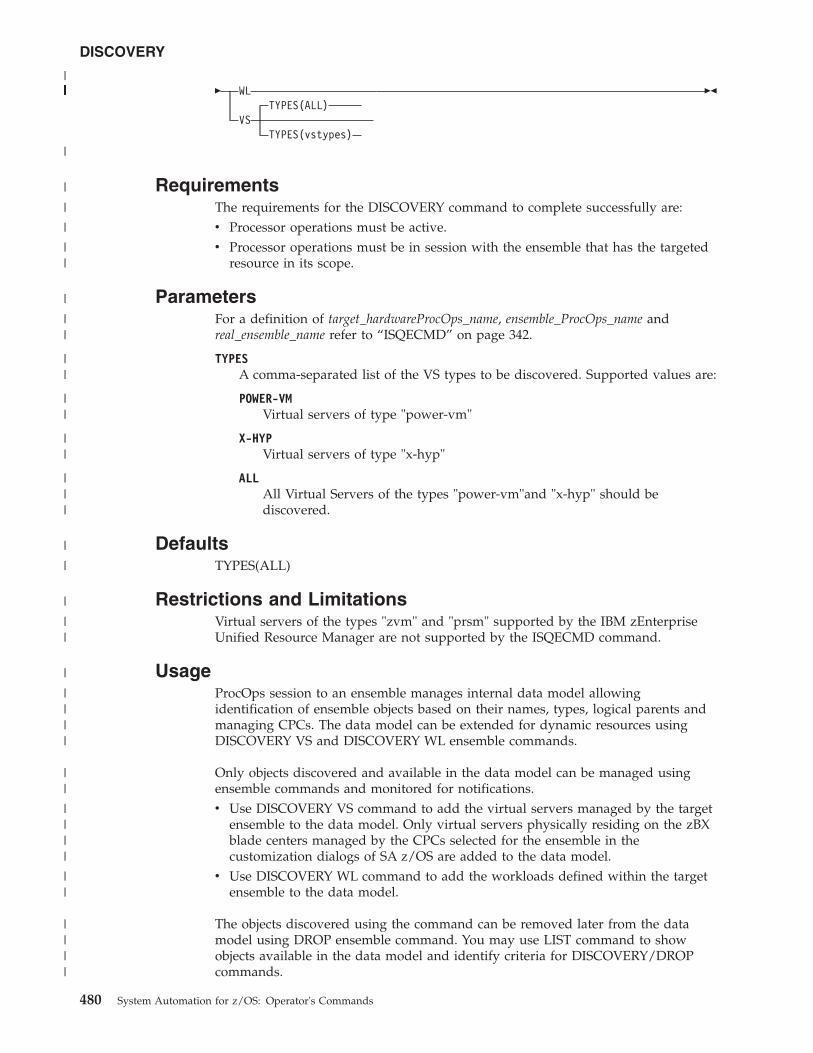
� WLTYPES(ALL)
VSTYPES(vstypes)
��
RequirementsThe requirements for the DISCOVERY command to complete successfully are:v Processor operations must be active.v Processor operations must be in session with the ensemble that has the targeted
resource in its scope.
ParametersFor a definition of target_hardwareProcOps_name, ensemble_ProcOps_name andreal_ensemble_name refer to “ISQECMD” on page 342.
TYPESA comma-separated list of the VS types to be discovered. Supported values are:
POWER-VMVirtual servers of type "power-vm"
X-HYPVirtual servers of type "x-hyp"
ALLAll Virtual Servers of the types "power-vm"and "x-hyp" should bediscovered.
DefaultsTYPES(ALL)
Restrictions and LimitationsVirtual servers of the types "zvm" and "prsm" supported by the IBM zEnterpriseUnified Resource Manager are not supported by the ISQECMD command.
UsageProcOps session to an ensemble manages internal data model allowingidentification of ensemble objects based on their names, types, logical parents andmanaging CPCs. The data model can be extended for dynamic resources usingDISCOVERY VS and DISCOVERY WL ensemble commands.
Only objects discovered and available in the data model can be managed usingensemble commands and monitored for notifications.v Use DISCOVERY VS command to add the virtual servers managed by the target
ensemble to the data model. Only virtual servers physically residing on the zBXblade centers managed by the CPCs selected for the ensemble in thecustomization dialogs of SA z/OS are added to the data model.
v Use DISCOVERY WL command to add the workloads defined within the targetensemble to the data model.
The objects discovered using the command can be removed later from the datamodel using DROP ensemble command. You may use LIST command to showobjects available in the data model and identify criteria for DISCOVERY/DROPcommands.
DISCOVERY
480 System Automation for z/OS: Operator's Commands
||||||||||||||||||||||||
|
|
|
|
||
|
||
||
||
||
|||
|
|
|
||
|
||||
||
||||
||
||||
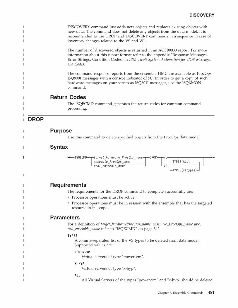
DISCOVERY command just adds new objects and replaces existing objects withnew data. The command does not delete any objects from the data model. It isrecommended to use DROP and DISCOVERY commands in a sequence in case ofinventory changes related to the VS and WL.
The number of discovered objects is returned in an AOFB0030 report. For moreinformation about this report format refer to the appendix "Response Messages,Error Strings, Condition Codes" in IBM Tivoli System Automation for z/OS Messagesand Codes.
The command response reports from the ensemble HMC are available as ProcOpsISQ800I messages with a console indicator of SC. In order to get a copy of suchhardware messages on your screen as ISQ801I messages, use the ISQXMONcommand.
Return CodesThe ISQECMD command generates the return codes for common commandprocessing.
DROP
PurposeUse this command to delete specified objects from the ProcOps data model.
Syntax
�� ISQECMD target_hardware_ProcOps_nameensemble_ProcOps_namereal_ensemble_name
DROP WLTYPES(ALL)
VSTYPES(vstypes)
��
RequirementsThe requirements for the DROP command to complete successfully are:v Processor operations must be active.v Processor operations must be in session with the ensemble that has the targeted
resource in its scope.
ParametersFor a definition of target_hardwareProcOps_name, ensemble_ProcOps_name andreal_ensemble_name refer to “ISQECMD” on page 342.
TYPESA comma-separated list of the VS types to be deleted from data model.Supported values are:
POWER-VMVirtual servers of type "power-vm".
X-HYPVirtual servers of type "x-hyp".
ALLAll Virtual Servers of the types "power-vm" and "x-hyp" should be deleted.
DISCOVERY
Chapter 7. Ensemble Commands 481
||||
||||
||||
|
||
||
|
|
|
||||||||||||||||||||||||||||||||||||||
|
|
|
|
||
|
||
|||
||
||
||
DefaultsTYPES(ALL)
Restrictions and LimitationsVirtual servers of the types "zvm" and "prsm" supported by the IBM zEnterpriseUnified Resource Manager are not supported by the ISQECMD command.
UsageProcOps session to an ensemble manages internal data model allowingidentification of ensemble objects based on their names, types, logical parents andmanaging CPCs.
Only objects discovered and available in the data model can be managed usingensemble commands and monitored for notifications.v Use the DROP VS command to delete the virtual servers from the data model.
The servers deleted from the data model are not available for further ensemblecommands and the session will not receive any further notification related to thedeleted objects.
v Use the DROP WL command to delete the workload resource groups from thedata model. The workloads deleted from the data model are not available forfurther ensemble commands and the session will not receive any furthernotification related to the deleted objects.
The objects deleted with the command can be discovered later again using theDISCOVERY command. You may use the LIST command to show objects availablein the data model and identify criteria for DISCOVERY/DROP commands.
It is recommended to use the DROP and DISCOVERY commands in a sequence incase of inventory changes related to the VS and WL to rediscover the data andkeep the data model in sync with the ensemble definitions on the HMC.
The number of deleted objects is returned in an AOFB0030 report. For moreinformation about this report format refer to the appendix "Response Messages,Error Strings, Condition Codes" in IBM Tivoli System Automation for z/OS Messagesand Codes.
The command response reports from the ensemble HMC are available as ProcOpsISQ800I messages with a console indicator of SC. In order to get a copy of suchhardware messages on your screen as ISQ801I messages, use the ISQXMONcommand.
Return CodesThe ISQECMD command generates the return codes for common commandprocessing.
ENSDATA
PurposeThe ENSDATA ensemble command collects basic information about the targetensemble and presents this information in a multi-line report.
DROP
482 System Automation for z/OS: Operator's Commands
|
|
|
||
|
|||
||
||||
||||
|||
|||
||||
||||
|
||
||
|
||
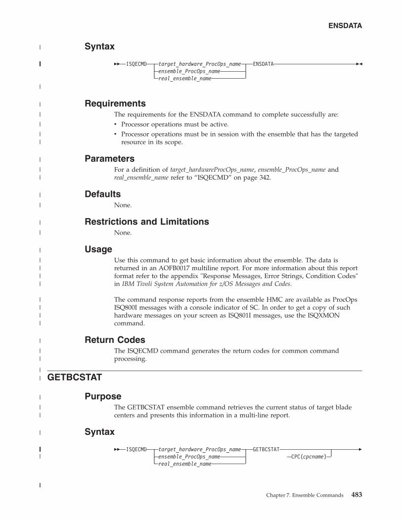
Syntax
�� ISQECMD target_hardware_ProcOps_nameensemble_ProcOps_namereal_ensemble_name
ENSDATA ��
RequirementsThe requirements for the ENSDATA command to complete successfully are:v Processor operations must be active.v Processor operations must be in session with the ensemble that has the targeted
resource in its scope.
ParametersFor a definition of target_hardwareProcOps_name, ensemble_ProcOps_name andreal_ensemble_name refer to “ISQECMD” on page 342.
DefaultsNone.
Restrictions and LimitationsNone.
UsageUse this command to get basic information about the ensemble. The data isreturned in an AOFB0017 multiline report. For more information about this reportformat refer to the appendix "Response Messages, Error Strings, Condition Codes"in IBM Tivoli System Automation for z/OS Messages and Codes.
The command response reports from the ensemble HMC are available as ProcOpsISQ800I messages with a console indicator of SC. In order to get a copy of suchhardware messages on your screen as ISQ801I messages, use the ISQXMONcommand.
Return CodesThe ISQECMD command generates the return codes for common commandprocessing.
GETBCSTAT
PurposeThe GETBCSTAT ensemble command retrieves the current status of target bladecenters and presents this information in a multi-line report.
Syntax
�� ISQECMD target_hardware_ProcOps_nameensemble_ProcOps_namereal_ensemble_name
GETBCSTATCPC(cpcname)
�
ENSDATA
Chapter 7. Ensemble Commands 483
|
|||||||||||||||||||||
|
|
|
|
||
|
||
|
|
|
|
|
||||
||||
|
||
||
|
||
|
|||||||||||||||||||||||||||
||
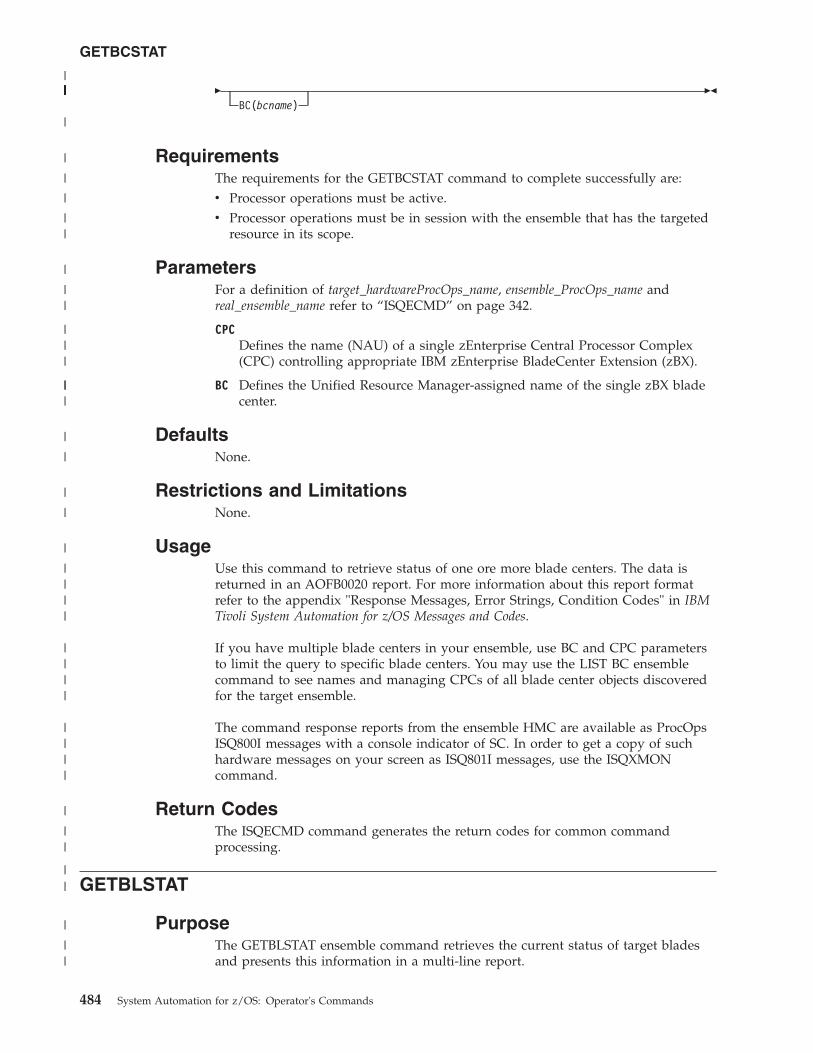
�BC(bcname)
��
RequirementsThe requirements for the GETBCSTAT command to complete successfully are:v Processor operations must be active.v Processor operations must be in session with the ensemble that has the targeted
resource in its scope.
ParametersFor a definition of target_hardwareProcOps_name, ensemble_ProcOps_name andreal_ensemble_name refer to “ISQECMD” on page 342.
CPCDefines the name (NAU) of a single zEnterprise Central Processor Complex(CPC) controlling appropriate IBM zEnterprise BladeCenter Extension (zBX).
BC Defines the Unified Resource Manager-assigned name of the single zBX bladecenter.
DefaultsNone.
Restrictions and LimitationsNone.
UsageUse this command to retrieve status of one ore more blade centers. The data isreturned in an AOFB0020 report. For more information about this report formatrefer to the appendix "Response Messages, Error Strings, Condition Codes" in IBMTivoli System Automation for z/OS Messages and Codes.
If you have multiple blade centers in your ensemble, use BC and CPC parametersto limit the query to specific blade centers. You may use the LIST BC ensemblecommand to see names and managing CPCs of all blade center objects discoveredfor the target ensemble.
The command response reports from the ensemble HMC are available as ProcOpsISQ800I messages with a console indicator of SC. In order to get a copy of suchhardware messages on your screen as ISQ801I messages, use the ISQXMONcommand.
Return CodesThe ISQECMD command generates the return codes for common commandprocessing.
GETBLSTAT
PurposeThe GETBLSTAT ensemble command retrieves the current status of target bladesand presents this information in a multi-line report.
GETBCSTAT
484 System Automation for z/OS: Operator's Commands
||||||||||||||
|
|
|
|
||
|
||
|||
|||
|
|
|
|
|
||||
||||
||||
|
||
||
|
||
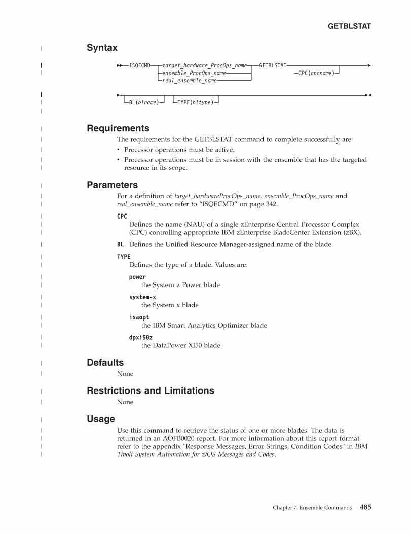
Syntax
�� ISQECMD target_hardware_ProcOps_nameensemble_ProcOps_namereal_ensemble_name
GETBLSTATCPC(cpcname)
�
�BL(blname) TYPE(bltype)
��
RequirementsThe requirements for the GETBLSTAT command to complete successfully are:v Processor operations must be active.v Processor operations must be in session with the ensemble that has the targeted
resource in its scope.
ParametersFor a definition of target_hardwareProcOps_name, ensemble_ProcOps_name andreal_ensemble_name refer to “ISQECMD” on page 342.
CPCDefines the name (NAU) of a single zEnterprise Central Processor Complex(CPC) controlling appropriate IBM zEnterprise BladeCenter Extension (zBX).
BL Defines the Unified Resource Manager-assigned name of the blade.
TYPEDefines the type of a blade. Values are:
powerthe System z Power blade
system-xthe System x blade
isaoptthe IBM Smart Analytics Optimizer blade
dpxi50zthe DataPower XI50 blade
DefaultsNone
Restrictions and LimitationsNone
UsageUse this command to retrieve the status of one or more blades. The data isreturned in an AOFB0020 report. For more information about this report formatrefer to the appendix "Response Messages, Error Strings, Condition Codes" in IBMTivoli System Automation for z/OS Messages and Codes.
GETBLSTAT
Chapter 7. Ensemble Commands 485
|
|||||||||||||||||||||||||||
||||||||||||||||||||
|
|
|
|
||
|
||
|||
||
||
||
||
||
||
|
|
|
|
|
||||
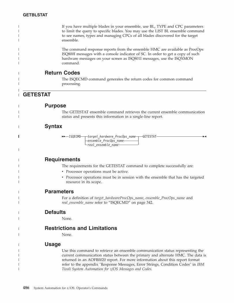
If you have multiple blades in your ensemble, use BL, TYPE and CPC parametersto limit the query to specific blades. You may use the LIST BL ensemble commandto see names, types and managing CPCs of all blades discovered for the targetensemble.
The command response reports from the ensemble HMC are available as ProcOpsISQ800I messages with a console indicator of SC. In order to get a copy of suchhardware messages on your screen as ISQ801I messages, use the ISQXMONcommand.
Return CodesThe ISQECMD command generates the return codes for common commandprocessing.
GETESTAT
PurposeThe GETESTAT ensemble command retrieves the current ensemble communicationstatus and presents this information in a single-line report.
Syntax
�� ISQECMD target_hardware_ProcOps_nameensemble_ProcOps_namereal_ensemble_name
GETESTAT ��
RequirementsThe requirements for the GETESTAT command to complete successfully are:v Processor operations must be active.v Processor operations must be in session with the ensemble that has the targeted
resource in its scope.
ParametersFor a definition of target_hardwareProcOps_name, ensemble_ProcOps_name andreal_ensemble_name refer to “ISQECMD” on page 342.
DefaultsNone.
Restrictions and LimitationsNone.
UsageUse this command to retrieve an ensemble communication status representing thecurrent communication status between the primary and alternate HMC. The data isreturned in an AOFB0020 report. For more information about this report formatrefer to the appendix "Response Messages, Error Strings, Condition Codes" in IBMTivoli System Automation for z/OS Messages and Codes.
GETBLSTAT
486 System Automation for z/OS: Operator's Commands
||||
||||
|
||
||
|
||
|
|||||||||||||||||||||
|
|
|
|
||
|
||
|
|
|
|
|
|||||
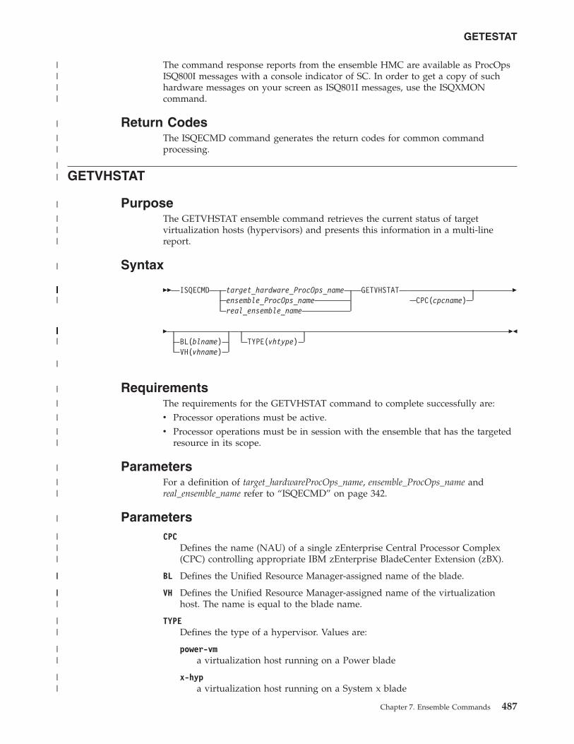
The command response reports from the ensemble HMC are available as ProcOpsISQ800I messages with a console indicator of SC. In order to get a copy of suchhardware messages on your screen as ISQ801I messages, use the ISQXMONcommand.
Return CodesThe ISQECMD command generates the return codes for common commandprocessing.
GETVHSTAT
PurposeThe GETVHSTAT ensemble command retrieves the current status of targetvirtualization hosts (hypervisors) and presents this information in a multi-linereport.
Syntax
�� ISQECMD target_hardware_ProcOps_nameensemble_ProcOps_namereal_ensemble_name
GETVHSTATCPC(cpcname)
�
�BL(blname)VH(vhname)
TYPE(vhtype)��
RequirementsThe requirements for the GETVHSTAT command to complete successfully are:v Processor operations must be active.v Processor operations must be in session with the ensemble that has the targeted
resource in its scope.
ParametersFor a definition of target_hardwareProcOps_name, ensemble_ProcOps_name andreal_ensemble_name refer to “ISQECMD” on page 342.
ParametersCPC
Defines the name (NAU) of a single zEnterprise Central Processor Complex(CPC) controlling appropriate IBM zEnterprise BladeCenter Extension (zBX).
BL Defines the Unified Resource Manager-assigned name of the blade.
VH Defines the Unified Resource Manager-assigned name of the virtualizationhost. The name is equal to the blade name.
TYPEDefines the type of a hypervisor. Values are:
power-vma virtualization host running on a Power blade
x-hypa virtualization host running on a System x blade
GETESTAT
Chapter 7. Ensemble Commands 487
||||
|
||
||
|
|||
|
|||||||||||||||||||||||||||
|||||||||||||||||||||||
|
|
|
|
||
|
||
|
|||
||
|||
||
||
||
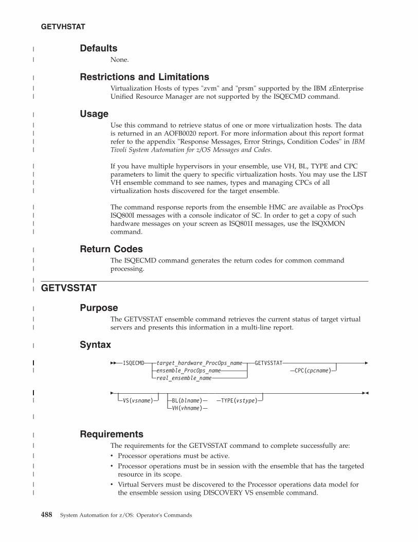
DefaultsNone.
Restrictions and LimitationsVirtualization Hosts of types "zvm" and "prsm" supported by the IBM zEnterpriseUnified Resource Manager are not supported by the ISQECMD command.
UsageUse this command to retrieve status of one or more virtualization hosts. The datais returned in an AOFB0020 report. For more information about this report formatrefer to the appendix "Response Messages, Error Strings, Condition Codes" in IBMTivoli System Automation for z/OS Messages and Codes.
If you have multiple hypervisors in your ensemble, use VH, BL, TYPE and CPCparameters to limit the query to specific virtualization hosts. You may use the LISTVH ensemble command to see names, types and managing CPCs of allvirtualization hosts discovered for the target ensemble.
The command response reports from the ensemble HMC are available as ProcOpsISQ800I messages with a console indicator of SC. In order to get a copy of suchhardware messages on your screen as ISQ801I messages, use the ISQXMONcommand.
Return CodesThe ISQECMD command generates the return codes for common commandprocessing.
GETVSSTAT
PurposeThe GETVSSTAT ensemble command retrieves the current status of target virtualservers and presents this information in a multi-line report.
Syntax
�� ISQECMD target_hardware_ProcOps_nameensemble_ProcOps_namereal_ensemble_name
GETVSSTATCPC(cpcname)
�
�VS(vsname) BL(blname)
VH(vhname)TYPE(vstype)
��
RequirementsThe requirements for the GETVSSTAT command to complete successfully are:v Processor operations must be active.v Processor operations must be in session with the ensemble that has the targeted
resource in its scope.v Virtual Servers must be discovered to the Processor operations data model for
the ensemble session using DISCOVERY VS ensemble command.
GETVHSTAT
488 System Automation for z/OS: Operator's Commands
|
|
|
||
|
||||
||||
||||
|
||
||
|
||
|
|||||||||||||||||||||||||||
||||||||||||||||||||||||||||||
|
|
|
|
||
||
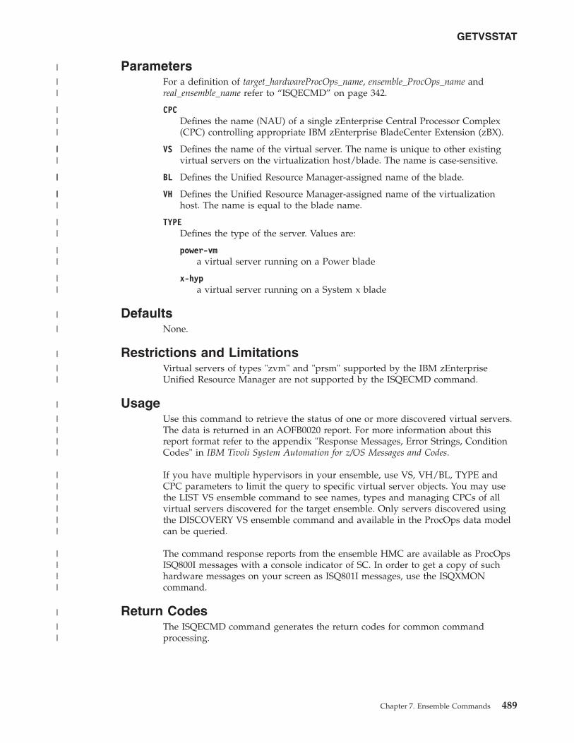
ParametersFor a definition of target_hardwareProcOps_name, ensemble_ProcOps_name andreal_ensemble_name refer to “ISQECMD” on page 342.
CPCDefines the name (NAU) of a single zEnterprise Central Processor Complex(CPC) controlling appropriate IBM zEnterprise BladeCenter Extension (zBX).
VS Defines the name of the virtual server. The name is unique to other existingvirtual servers on the virtualization host/blade. The name is case-sensitive.
BL Defines the Unified Resource Manager-assigned name of the blade.
VH Defines the Unified Resource Manager-assigned name of the virtualizationhost. The name is equal to the blade name.
TYPEDefines the type of the server. Values are:
power-vma virtual server running on a Power blade
x-hypa virtual server running on a System x blade
DefaultsNone.
Restrictions and LimitationsVirtual servers of types "zvm" and "prsm" supported by the IBM zEnterpriseUnified Resource Manager are not supported by the ISQECMD command.
UsageUse this command to retrieve the status of one or more discovered virtual servers.The data is returned in an AOFB0020 report. For more information about thisreport format refer to the appendix "Response Messages, Error Strings, ConditionCodes" in IBM Tivoli System Automation for z/OS Messages and Codes.
If you have multiple hypervisors in your ensemble, use VS, VH/BL, TYPE andCPC parameters to limit the query to specific virtual server objects. You may usethe LIST VS ensemble command to see names, types and managing CPCs of allvirtual servers discovered for the target ensemble. Only servers discovered usingthe DISCOVERY VS ensemble command and available in the ProcOps data modelcan be queried.
The command response reports from the ensemble HMC are available as ProcOpsISQ800I messages with a console indicator of SC. In order to get a copy of suchhardware messages on your screen as ISQ801I messages, use the ISQXMONcommand.
Return CodesThe ISQECMD command generates the return codes for common commandprocessing.
GETVSSTAT
Chapter 7. Ensemble Commands 489
|
||
|||
|||
||
|||
||
||
||
|
|
|
||
|
||||
||||||
||||
|
||
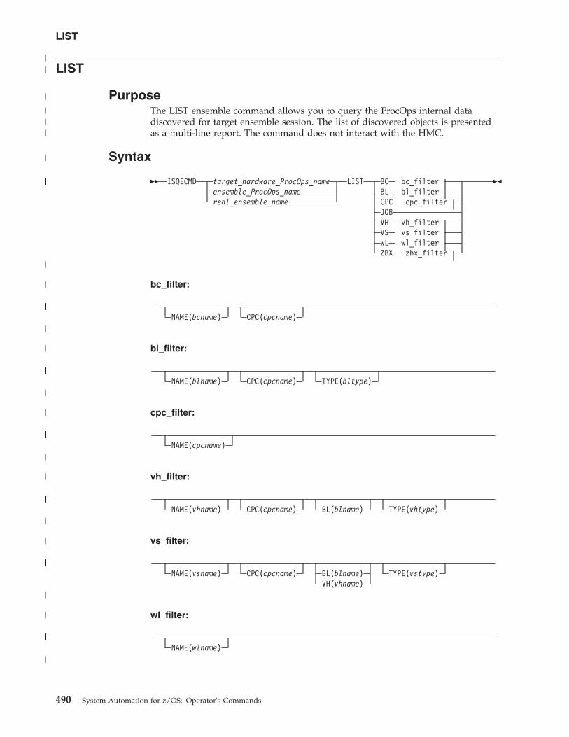
LIST
PurposeThe LIST ensemble command allows you to query the ProcOps internal datadiscovered for target ensemble session. The list of discovered objects is presentedas a multi-line report. The command does not interact with the HMC.
Syntax
�� ISQECMD target_hardware_ProcOps_nameensemble_ProcOps_namereal_ensemble_name
LIST BC bc_filterBL bl_filterCPC cpc_filterJOBVH vh_filterVS vs_filterWL wl_filterZBX zbx_filter
��
bc_filter:
NAME(bcname) CPC(cpcname)
bl_filter:
NAME(blname) CPC(cpcname) TYPE(bltype)
cpc_filter:
NAME(cpcname)
vh_filter:
NAME(vhname) CPC(cpcname) BL(blname) TYPE(vhtype)
vs_filter:
NAME(vsname) CPC(cpcname) BL(blname)VH(vhname)
TYPE(vstype)
wl_filter:
NAME(wlname)
LIST
490 System Automation for z/OS: Operator's Commands
||
|
|||
|
||||||||||||||||||||||||||||||||||||||||||||||||||||||||||||||||||||||
|
|
|||||||||||||||||||||
|
|
||||||||||||||||||||||||||||
|
|
||||||||||||||
|
|
|||||||||||||||||||||||||||||||||||
|
|
||||||||||||||||||||||||||||||||||||||
|
|
||||||||||||||
|
zbx_filter:
NAME(zbxname)
RequirementsThe requirements for the LIST command to complete successfully are:v Processor operations must be active.v Processor operations must be in session with the ensemble that has the targeted
resource in its scope.v For LIST VS and LIST WL commands, Virtual Servers and Workloads must be
discovered to the Processor operations data model for the ensemble sessionusing DISCOVERY VS and DISCOVERY WL ensemble commands.
ParametersFor a definition of target_hardwareProcOps_name, ensemble_ProcOps_name andreal_ensemble_name refer to “ISQECMD” on page 342.
*_filterIs a set of parameters limiting the command to a subset of objects of therequired object type. Only full specification of all *_filter parameters ensuresselection of a single object.
NAMEThe name of the object(s) to be selected for LIST report. The name iscase-sensitive.
CPCDefines the name (NAU) of a single zEnterprise Central Processor Complex(CPC) controlling appropriate IBM zEnterprise BladeCenter Extension (zBX).
BL Defines the Unified Resource Manager-assigned name of the blade.
VH Defines the Unified Resource Manager-assigned name of the virtualizationhost. The name is equal to the blade name.
TYPEDefines the type of the objects(s) to be selected for LIST report. Values are:
For LIST BL command:
powerthe System z Power blade
system-xthe System x blade
isaoptthe IBM Smart Analytics Optimizer blade
dpxi50zthe DataPower XI50 blade
For LIST VH and LIST VS commands:
power-vma virtual server running on a Power blade
x-hypa virtual server running on a System x blade
LIST
Chapter 7. Ensemble Commands 491
|
||||||||||||||
|
|
|
|
||
|||
|
||
||||
|||
|||
||
|||
||
|
||
||
||
||
|
||
||
DefaultsNone.
Restrictions and LimitationsVirtualization hosts and virtual servers of the types "zvm" and "prsm" supportedby the IBM zEnterprise Unified Resource Manager are not supported by theISQECMD command.
UsageProcOps session to an ensemble manages internal data model allowingidentification of ensemble objects based on their names, types, logical parents andmanaging CPCs. The data model is filled in during initialization of the sessionusing ISQXIII command and extended using DISCOVERY VS and DISCOVERYWL ensemble commands.
The following objects are discovered during initialization of the session:v Ensemblev Ensemble nodes (CPCs). Only CPCs selected for the ensemble in the
customization dialogs of SA z/OS are added to the data model.v IBM zEnterprise BladeCenter Extension (zBX) managed by the selected CPCs.v zBX blade centers (BC), blades (BL) and virtualization hosts (VH)
Only objects discovered and available in the data model can be managed usingensemble commands and monitored for notifications. The LIST commands allowyou to query the data model and identify objects for any other ensemblecommands. LIST does not require communication to the ensemble HMC andgenerates no external IP traffic.v Use LIST BC command to see one or more discovered blade centers.v Use LIST BL command to see one or more discovered blades.v Use LIST CPC command to see one or more discovered CPCs.v Use LIST JOB command to see all the active asynchronous commands executed
for the ensemble session using ACTIVATE and DEACTIVATE ensemblecommands which are not yet completed.
v Use LIST VH command to see one or more discovered virtualization hosts(hypervisors).
v Use LIST VS command to see one or more discovered virtual servers discoveredusing DISCOVERY VS commands.
v Use LIST WL command to see one or more discovered workload resourcegroups discovered using DISCOVERY WL commands.
v Use LIST ZBX command to see one or more discovered zBXs.
The data is returned in an AOFB0020 multiline report. If no objects are available inthe data model for specified *_filter, the commands return empty report. For moreinformation about this report format refer to the appendix "Response Messages,Error Strings, Condition Codes" in IBM Tivoli System Automation for z/OS Messagesand Codes.
The command response reports from the ensemble HMC are available as ProcOpsISQ800I messages with a console indicator of SC. In order to get a copy of suchhardware messages on your screen as ISQ801I messages, use the ISQXMONcommand.
LIST
492 System Automation for z/OS: Operator's Commands
|
|
|
|||
|
|||||
|
|
||
|
|
|||||
|
|
|
|||
||
||
||
|
|||||
||||
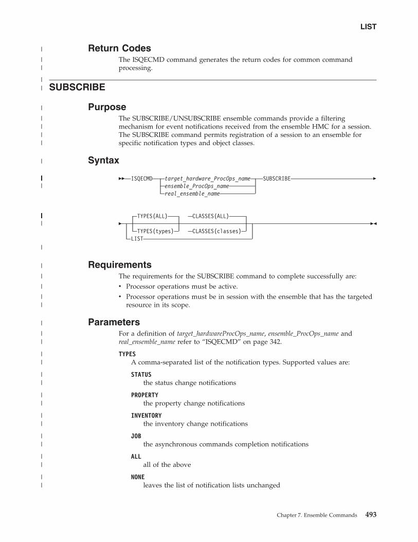
Return CodesThe ISQECMD command generates the return codes for common commandprocessing.
SUBSCRIBE
PurposeThe SUBSCRIBE/UNSUBSCRIBE ensemble commands provide a filteringmechanism for event notifications received from the ensemble HMC for a session.The SUBSCRIBE command permits registration of a session to an ensemble forspecific notification types and object classes.
Syntax
�� ISQECMD target_hardware_ProcOps_nameensemble_ProcOps_namereal_ensemble_name
SUBSCRIBE �
�TYPES(ALL) CLASSES(ALL)
TYPES(types) CLASSES(classes)LIST
��
RequirementsThe requirements for the SUBSCRIBE command to complete successfully are:v Processor operations must be active.v Processor operations must be in session with the ensemble that has the targeted
resource in its scope.
ParametersFor a definition of target_hardwareProcOps_name, ensemble_ProcOps_name andreal_ensemble_name refer to “ISQECMD” on page 342.
TYPESA comma-separated list of the notification types. Supported values are:
STATUSthe status change notifications
PROPERTYthe property change notifications
INVENTORYthe inventory change notifications
JOBthe asynchronous commands completion notifications
ALLall of the above
NONEleaves the list of notification lists unchanged
LIST
Chapter 7. Ensemble Commands 493
|
||
||
|
||||
|
||||||||||||||||||||
|||||||||||||||||||||||||||||
|
|
|
|
||
|
||
||
||
||
||
||
||
||
CLASSESA comma-separated list of the object classes requiring notifications. Supportedvalues are:
ENSthe notifications for the ensemble
CPCthe notifications for the CPCs
ZBXthe notifications for the zBXs
RACKthe notifications for the racks
BC the notifications for the blade centers
BLthe notifications for the blades
VH the notifications for the virtualization hosts (hypervisors)
VS the notifications for the virtual servers
WL the notifications for the workload resource groups
ALLall of the above
NONEleaves the list of object classes unchanged
LISTWhen specified, report AOFB0019, containing the current subscriptioninformation for the selected ensemble session is returned. The parametercannot be combined with TYPES and CLASSES.
DefaultsTYPES(ALL)
CLASSES(ALL)
Restrictions and LimitationsThe TYPES and CLASSES are treated independently, just adding/removingsubscriptions to internal types and classes lists. For example:SUBSCRIBE TYPES(PROPERTY) CLASSES(BC)SUBSCRIBE TYPES(STATUS) CLASSES(BL)
results in a subscription for PROPERTY and STATUS for both BC and BL managedobjects.
UsageThe IBM zEnterprise Unified Resource Manager includes an asynchronousnotification facility by which client applications may subscribe to and receivenotification messages regarding a set of predefined management events. Theseevents include:v Addition and removal of managed objects to/from the inventory of resources
that are managed by the HMC (INVENTORY change notification).
SUBSCRIBE
494 System Automation for z/OS: Operator's Commands
|||
||
||
||
||
||
||
||
||
||
||
||
||||
|
|
|
|
||
||
||
|
||||
||
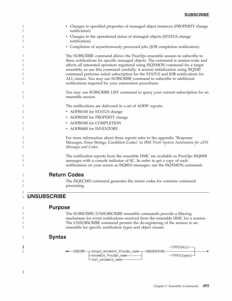
v Changes to specified properties of managed object instances (PROPERTY changenotification).
v Changes to the operational status of managed objects (STATUS changenotification).
v Completion of asynchronously processed jobs (JOB completion notification).
The SUBSCRIBE command allows the ProcOps ensemble session to subscribe tothese notifications for specific managed objects. The command is session-wide andaffects all interested operators registered using ISQXMON command for a targetensemble, so use this command carefully. A session initialization using ISQXIIIcommand performs initial subscription for the STATUS and JOB notifications forALL classes. You may use SUBSCRIBE command to subscribe to additionalnotifications required for your automation procedures.
You may use SUBSCRIBE LIST command to query your current subscription for anensemble session.
The notifications are delivered in a set of AOFB* reports:v AOFB0100 for STATUS changev AOFB0200 for PROPERTY changev AOFB0300 for COMPLETIONv AOFB0400 for INVENTORY
For more information about these reports refer to the appendix "ResponseMessages, Error Strings, Condition Codes" in IBM Tivoli System Automation for z/OSMessages and Codes.
The notification reports from the ensemble HMC are available as ProcOps ISQ800Imessages with a console indicator of SC. In order to get a copy of suchnotifications on your screen as ISQ801I messages, use the ISQXMON command.
Return CodesThe ISQECMD command generates the return codes for common commandprocessing.
UNSUBSCRIBE
PurposeThe SUBSCRIBE/UNSUBSCRIBE ensemble commands provide a filteringmechanism for event notifications received from the ensemble HMC for a session.The UNSUBSCRIBE command permits the de-registering of the session to anensemble for specific notification types and object classes.
Syntax
�� ISQECMD target_hardware_ProcOps_nameensemble_ProcOps_namereal_ensemble_name
UNSUBSCRIBETYPES(ALL)
TYPES(types)�
SUBSCRIBE
Chapter 7. Ensemble Commands 495
||
||
|
|||||||
||
|
|
|
|
|
|||
|||
|
||
||
|
||||
|
||||||||||||||||||||||||||||||
||
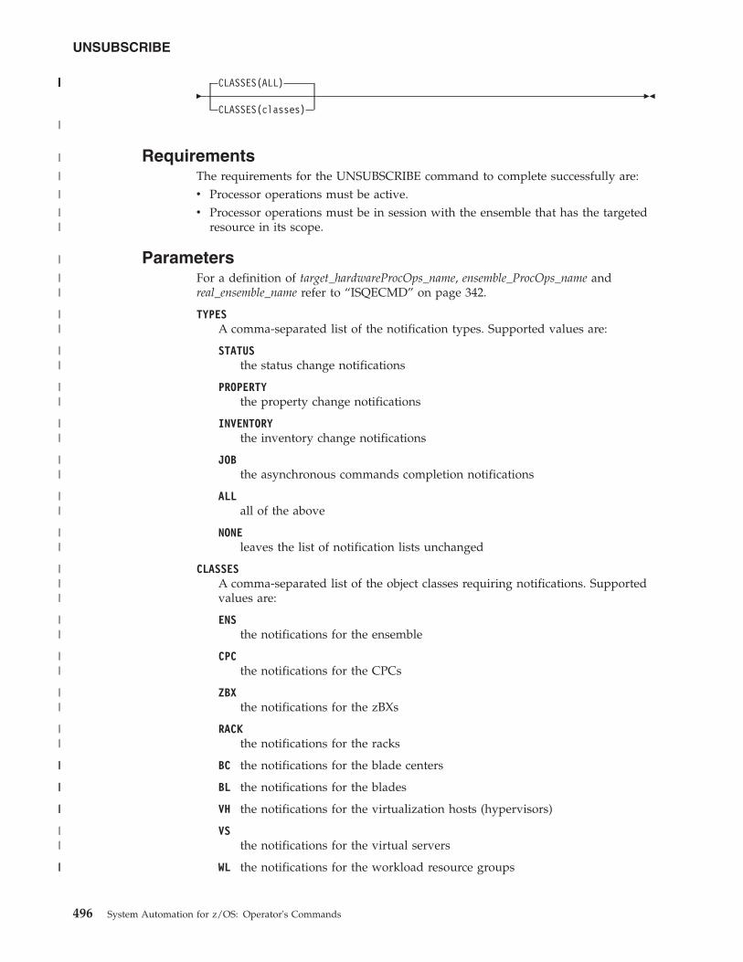
�CLASSES(ALL)
CLASSES(classes)��
RequirementsThe requirements for the UNSUBSCRIBE command to complete successfully are:v Processor operations must be active.v Processor operations must be in session with the ensemble that has the targeted
resource in its scope.
ParametersFor a definition of target_hardwareProcOps_name, ensemble_ProcOps_name andreal_ensemble_name refer to “ISQECMD” on page 342.
TYPESA comma-separated list of the notification types. Supported values are:
STATUSthe status change notifications
PROPERTYthe property change notifications
INVENTORYthe inventory change notifications
JOBthe asynchronous commands completion notifications
ALLall of the above
NONEleaves the list of notification lists unchanged
CLASSESA comma-separated list of the object classes requiring notifications. Supportedvalues are:
ENSthe notifications for the ensemble
CPCthe notifications for the CPCs
ZBXthe notifications for the zBXs
RACKthe notifications for the racks
BC the notifications for the blade centers
BL the notifications for the blades
VH the notifications for the virtualization hosts (hypervisors)
VSthe notifications for the virtual servers
WL the notifications for the workload resource groups
UNSUBSCRIBE
496 System Automation for z/OS: Operator's Commands
|||||||||||||||
|
|
|
|
||
|
||
||
||
||
||
||
||
||
|||
||
||
||
||
||
||
||
||
||
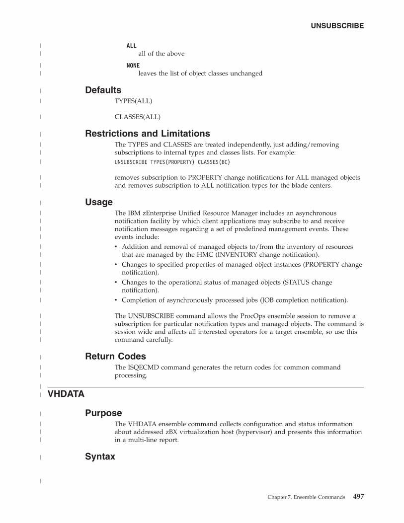
ALLall of the above
NONEleaves the list of object classes unchanged
DefaultsTYPES(ALL)
CLASSES(ALL)
Restrictions and LimitationsThe TYPES and CLASSES are treated independently, just adding/removingsubscriptions to internal types and classes lists. For example:UNSUBSCRIBE TYPES(PROPERTY) CLASSES(BC)
removes subscription to PROPERTY change notifications for ALL managed objectsand removes subscription to ALL notification types for the blade centers.
UsageThe IBM zEnterprise Unified Resource Manager includes an asynchronousnotification facility by which client applications may subscribe to and receivenotification messages regarding a set of predefined management events. Theseevents include:v Addition and removal of managed objects to/from the inventory of resources
that are managed by the HMC (INVENTORY change notification).v Changes to specified properties of managed object instances (PROPERTY change
notification).v Changes to the operational status of managed objects (STATUS change
notification).v Completion of asynchronously processed jobs (JOB completion notification).
The UNSUBSCRIBE command allows the ProcOps ensemble session to remove asubscription for particular notification types and managed objects. The command issession wide and affects all interested operators for a target ensemble, so use thiscommand carefully.
Return CodesThe ISQECMD command generates the return codes for common commandprocessing.
VHDATA
PurposeThe VHDATA ensemble command collects configuration and status informationabout addressed zBX virtualization host (hypervisor) and presents this informationin a multi-line report.
Syntax
UNSUBSCRIBE
Chapter 7. Ensemble Commands 497
||
||
|
|
|
|
||
|
||
|
||||
||
||
||
|
||||
|
||
||
|
|||
|
|
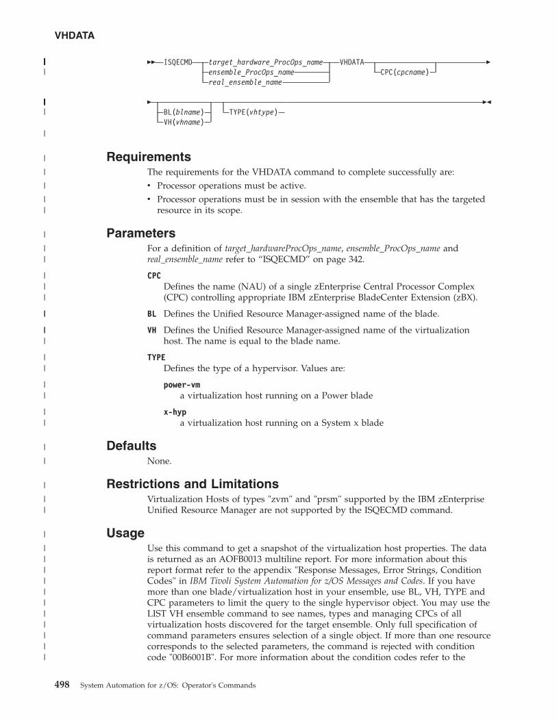
�� ISQECMD target_hardware_ProcOps_nameensemble_ProcOps_namereal_ensemble_name
VHDATACPC(cpcname)
�
�BL(blname)VH(vhname)
TYPE(vhtype)��
RequirementsThe requirements for the VHDATA command to complete successfully are:v Processor operations must be active.v Processor operations must be in session with the ensemble that has the targeted
resource in its scope.
ParametersFor a definition of target_hardwareProcOps_name, ensemble_ProcOps_name andreal_ensemble_name refer to “ISQECMD” on page 342.
CPCDefines the name (NAU) of a single zEnterprise Central Processor Complex(CPC) controlling appropriate IBM zEnterprise BladeCenter Extension (zBX).
BL Defines the Unified Resource Manager-assigned name of the blade.
VH Defines the Unified Resource Manager-assigned name of the virtualizationhost. The name is equal to the blade name.
TYPEDefines the type of a hypervisor. Values are:
power-vma virtualization host running on a Power blade
x-hypa virtualization host running on a System x blade
DefaultsNone.
Restrictions and LimitationsVirtualization Hosts of types "zvm" and "prsm" supported by the IBM zEnterpriseUnified Resource Manager are not supported by the ISQECMD command.
UsageUse this command to get a snapshot of the virtualization host properties. The datais returned as an AOFB0013 multiline report. For more information about thisreport format refer to the appendix "Response Messages, Error Strings, ConditionCodes" in IBM Tivoli System Automation for z/OS Messages and Codes. If you havemore than one blade/virtualization host in your ensemble, use BL, VH, TYPE andCPC parameters to limit the query to the single hypervisor object. You may use theLIST VH ensemble command to see names, types and managing CPCs of allvirtualization hosts discovered for the target ensemble. Only full specification ofcommand parameters ensures selection of a single object. If more than one resourcecorresponds to the selected parameters, the command is rejected with conditioncode "00B6001B". For more information about the condition codes refer to the
VHDATA
498 System Automation for z/OS: Operator's Commands
|||||||||||||||||||||||||||
|||||||||||||||||||||||
|
|
|
|
||
|
||
|||
||
|||
||
||
||
|
|
|
||
|
|||||||||||
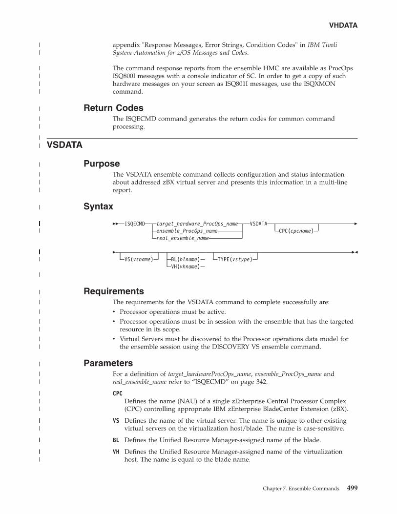
appendix "Response Messages, Error Strings, Condition Codes" in IBM TivoliSystem Automation for z/OS Messages and Codes.
The command response reports from the ensemble HMC are available as ProcOpsISQ800I messages with a console indicator of SC. In order to get a copy of suchhardware messages on your screen as ISQ801I messages, use the ISQXMONcommand.
Return CodesThe ISQECMD command generates the return codes for common commandprocessing.
VSDATA
PurposeThe VSDATA ensemble command collects configuration and status informationabout addressed zBX virtual server and presents this information in a multi-linereport.
Syntax
�� ISQECMD target_hardware_ProcOps_nameensemble_ProcOps_namereal_ensemble_name
VSDATACPC(cpcname)
�
�VS(vsname) BL(blname)
VH(vhname)TYPE(vstype)
��
RequirementsThe requirements for the VSDATA command to complete successfully are:v Processor operations must be active.v Processor operations must be in session with the ensemble that has the targeted
resource in its scope.v Virtual Servers must be discovered to the Processor operations data model for
the ensemble session using the DISCOVERY VS ensemble command.
ParametersFor a definition of target_hardwareProcOps_name, ensemble_ProcOps_name andreal_ensemble_name refer to “ISQECMD” on page 342.
CPCDefines the name (NAU) of a single zEnterprise Central Processor Complex(CPC) controlling appropriate IBM zEnterprise BladeCenter Extension (zBX).
VS Defines the name of the virtual server. The name is unique to other existingvirtual servers on the virtualization host/blade. The name is case-sensitive.
BL Defines the Unified Resource Manager-assigned name of the blade.
VH Defines the Unified Resource Manager-assigned name of the virtualizationhost. The name is equal to the blade name.
VHDATA
Chapter 7. Ensemble Commands 499
||
||||
|
||
||
|
|||
|
|||||||||||||||||||||||||||
||||||||||||||||||||||||||||||
|
|
|
|
||
||
|
||
|||
|||
||
|||
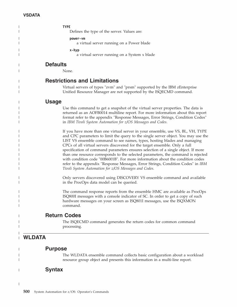
TYPEDefines the type of the server. Values are:
power-vma virtual server running on a Power blade
x-hypa virtual server running on a System x blade
DefaultsNone.
Restrictions and LimitationsVirtual servers of types "zvm" and "prsm" supported by the IBM zEnterpriseUnified Resource Manager are not supported by the ISQECMD command.
UsageUse this command to get a snapshot of the virtual server properties. The data isreturned as an AOFB0014 multiline report. For more information about this reportformat refer to the appendix "Response Messages, Error Strings, Condition Codes"in IBM Tivoli System Automation for z/OS Messages and Codes.
If you have more than one virtual server in your ensemble, use VS, BL, VH, TYPEand CPC parameters to limit the query to the single server object. You may use theLIST VS ensemble command to see names, types, hosting blades and managingCPCs of all virtual servers discovered for the target ensemble. Only a fullspecification of command parameters ensures selection of a single object. If morethan one resource corresponds to the selected parameters, the command is rejectedwith condition code "00B6001B". For more information about the condition codesrefer to the appendix "Response Messages, Error Strings, Condition Codes" in IBMTivoli System Automation for z/OS Messages and Codes.
Only servers discovered using DISCOVERY VS ensemble command and availablein the ProcOps data model can be queried.
The command response reports from the ensemble HMC are available as ProcOpsISQ800I messages with a console indicator of SC. In order to get a copy of suchhardware messages on your screen as ISQ801I messages, use the ISQXMONcommand.
Return CodesThe ISQECMD command generates the return codes for common commandprocessing.
WLDATA
PurposeThe WLDATA ensemble command collects basic configuration about a workloadresource group object and presents this information in a multi-line report.
Syntax
VSDATA
500 System Automation for z/OS: Operator's Commands
||
||
||
|
|
|
||
|
||||
|||||||||
||
||||
|
||
||
|
||
|
|
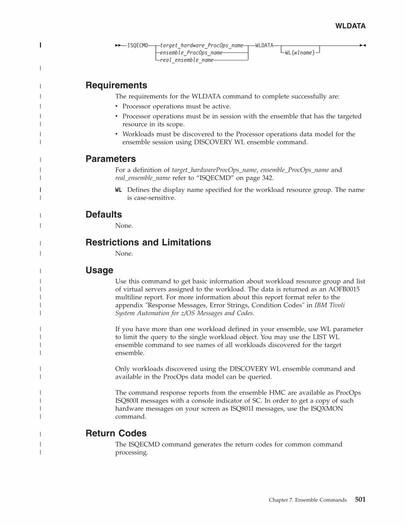
�� ISQECMD target_hardware_ProcOps_nameensemble_ProcOps_namereal_ensemble_name
WLDATAWL(wlname)
��
RequirementsThe requirements for the WLDATA command to complete successfully are:v Processor operations must be active.v Processor operations must be in session with the ensemble that has the targeted
resource in its scope.v Workloads must be discovered to the Processor operations data model for the
ensemble session using DISCOVERY WL ensemble command.
ParametersFor a definition of target_hardwareProcOps_name, ensemble_ProcOps_name andreal_ensemble_name refer to “ISQECMD” on page 342.
WL Defines the display name specified for the workload resource group. The nameis case-sensitive.
DefaultsNone.
Restrictions and LimitationsNone.
UsageUse this command to get basic information about workload resource group and listof virtual servers assigned to the workload. The data is returned as an AOFB0015multiline report. For more information about this report format refer to theappendix "Response Messages, Error Strings, Condition Codes" in IBM TivoliSystem Automation for z/OS Messages and Codes.
If you have more than one workload defined in your ensemble, use WL parameterto limit the query to the single workload object. You may use the LIST WLensemble command to see names of all workloads discovered for the targetensemble.
Only workloads discovered using the DISCOVERY WL ensemble command andavailable in the ProcOps data model can be queried.
The command response reports from the ensemble HMC are available as ProcOpsISQ800I messages with a console indicator of SC. In order to get a copy of suchhardware messages on your screen as ISQ801I messages, use the ISQXMONcommand.
Return CodesThe ISQECMD command generates the return codes for common commandprocessing.
WLDATA
Chapter 7. Ensemble Commands 501
||||||||||||||||||||||||||||
|
|
|
|
||
||
|
||
|||
|
|
|
|
|
|||||
||||
||
||||
|
||
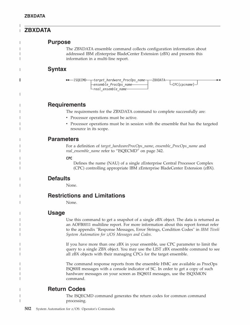
ZBXDATA
PurposeThe ZBXDATA ensemble command collects configuration information aboutaddressed IBM zEnterprise BladeCenter Extension (zBX) and presents thisinformation in a multi-line report.
Syntax
�� ISQECMD target_hardware_ProcOps_nameensemble_ProcOps_namereal_ensemble_name
ZBXDATACPC(cpcname)
��
RequirementsThe requirements for the ZBXDATA command to complete successfully are:v Processor operations must be active.v Processor operations must be in session with the ensemble that has the targeted
resource in its scope.
ParametersFor a definition of target_hardwareProcOps_name, ensemble_ProcOps_name andreal_ensemble_name refer to “ISQECMD” on page 342.
CPCDefines the name (NAU) of a single zEnterprise Central Processor Complex(CPC) controlling appropriate IBM zEnterprise BladeCenter Extension (zBX).
DefaultsNone.
Restrictions and LimitationsNone.
UsageUse this command to get a snapshot of a single zBX object. The data is returned asan AOFB0011 multiline report. For more information about this report format referto the appendix "Response Messages, Error Strings, Condition Codes" in IBM TivoliSystem Automation for z/OS Messages and Codes.
If you have more than one zBX in your ensemble, use CPC parameter to limit thequery to a single ZBX object. You may use the LIST zBX ensemble command to seeall zBX objects with their managing CPCs for the target ensemble.
The command response reports from the ensemble HMC are available as ProcOpsISQ800I messages with a console indicator of SC. In order to get a copy of suchhardware messages on your screen as ISQ801I messages, use the ISQXMONcommand.
Return CodesThe ISQECMD command generates the return codes for common commandprocessing.
ZBXDATA
502 System Automation for z/OS: Operator's Commands
||
|
|||
|
||||||||||||||||||||||||||||
|
|
|
|
||
|
||
|||
|
|
|
|
|
||||
|||
||||
|
||
Chapter 8. PSM Commands - Special Requests
The following special requests can be executed by the ProcOps Service Machine(PSM) Command Server. To issue these requests you must be logged on to thePSM. Requests can either only be entered directly from the PSM console or be usedwith the ISQXPSM command as well as being entered from the PSM console:v PSM commands that operate with ISQXPSM are:
– “ISQACT”– “ISQCLEAR”– “ISQQUERY” on page 504– “ISQSTATUS” on page 504– “ISQTRACE” on page 505
v PSM console commands that can only be entered from the console are:– “ISQMSG”– “ISQPSM” on page 504– “STOPALL” on page 505
ISQACT
�� ISQACT MH ��
ISQACT is used to activate a thread after it has stopped.
MH indicates that the Message Handler thread is to be reactivated. This is usefulin cases where the MH thread fails or terminates itself.
ISQCLEAR
�� ISQCLEAR MC
��
ISQCLEAR empties the Messages Queue or Commands Queue. All entries areemptied. The queue itself is not deleted.
ISQMSG
�� ISQMSG INDENTMSGID ON
OFF
��
ISQMSG is used to change the way that messages are displayed to the console userthat is logged on the PSM. If these messages are also routed to NetView it alsoalters the form of the messages.
If INDENT ON is specified this alters the indentation of each message. Messagesthat are issued by different threads are indented by different amounts. This makesit easier to see the flow of a thread because all its messages are indented by the
© Copyright IBM Corp. 1996, 2012 503
|
|
same amount. Trace messages (activated by an ISQTRACE request) are alsoindented. Messages from the Main Thread are not indented. Messages that areissued as responses to PSM requests are not indented. If an indented messagecontinues on further lines, the continuation lines are not indented.
INDENT OFF causes all non-trace messages to be displayed without indentation.The initial setting for the PSM is INDENT OFF. This initial setting is set each timethe PSM Control Program is started.
If MSGID OFF is specified, this causes each non-trace message to be displayedwithout its message ID. This may be useful when INDENT ON is in effect, becauseit reduces the length of each message and reduces the continuation of message texton subsequent lines.
MSGID ON causes all non-trace messages to be displayed with their message IDs.The initial setting for the PSM is ON. Trace messages do not have message IDs.
Restrictions and LimitationsThe ISQMSG command can only be entered directly from the console of the PSM.
ISQPSM
�� ISQPSM ��
The ISQPSM command starts the PSM server. This command should only beentered after the PSM server has been stopped successfully with a STOPALLcommand and the PSM virtual machine is in CMS mode.
Restrictions and LimitationsThe ISQPSM command can only be entered directly from the console of the PSM.
ISQQUERY
�� ISQQUERYQE
��
ISQQUERY displays:
Q How many entries are in the Message Queue.
E A list of current events and event monitors.
Listing the current events and event monitors is useful in problem determination.
ISQSTATUS
�� ISQSTATUS ��
ISQSTATUS gives the status of important components of the PSM operation.
504 System Automation for z/OS: Operator's Commands
ISQTRACE
�� ISQTRACE component ONOFF
��
ISQTRACE is used to start or stop PSM tracing of a component of the PSM. Tracemessages are always written to the VM console.
The value of component can be one of:
MSERVMessage server thread.
CSERVCommand server thread.
MH Message handler thread.
LOGGERLogger thread.
CNSERVERConsole server thread.
TCPIP Selected TCPIP requests within the Message Server and Command Serverthreads.
If any trace is set on, regular messages issued to the VM console as part of theVMCONIO stream are sent to the VM console and are no longer routed back toProcOps NetView.
Trace settings are maintained when a PSM is stopped. If the PSM is then restarted(without a re-logon of the CMS machine) the previous trace settings are retained.
When a PSM virtual machine is started all traces are set off.
STOPALL
�� STOPALL ��
STOPALL stops all threads and terminates the PSM control program. The PSMvirtual machine remains active.
Restrictions and LimitationsThe STOPALL command can only be entered directly from the console of the PSM.
-
Chapter 8. PSM Commands - Special Requests 505

506 System Automation for z/OS: Operator's Commands
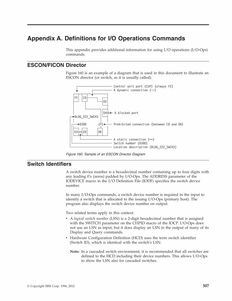
Appendix A. Definitions for I/O Operations Commands
This appendix provides additional information for using I/O operations (I/O-Ops)commands.
ESCON/FICON DirectorFigure 160 is an example of a diagram that is used in this document to illustrate anESCON director (or switch, as it is usually called).
Switch IdentifiersA switch device number is a hexadecimal number containing up to four digits withany leading 0’s (zeros) padded by I/O-Ops. The ADDRESS parameter of theIODEVICE macro in the I/O Definition File (IODF) specifies the switch devicenumber.
In many I/O-Ops commands, a switch device number is required in the input toidentify a switch that is allocated to the issuing I/O-Ops (primary host). Theprogram also displays the switch device number on output.
Two related terms apply in this context:v A logical switch number (LSN) is a 2-digit hexadecimal number that is assigned
with the SWITCH parameter on the CHPID macro of the IOCP. I/O-Ops doesnot use an LSN as input, but it does display an LSN in the output of many of itsDisplay and Query commands.
v Hardware Configuration Definition (HCD) uses the term switch identifier(Switch ID), which is identical with the switch's LSN.
Note: In a cascaded switch environment, it is recommended that all switches aredefined to the HCD including their device numbers. This allows I/O-Opsto show the LSN also for cascaded switches.
┌──────────────────── Control unit port (CUP) (always FE)� ┌─────────── A dynamic connection (──)
┌──┬─┬──┬──�────────┐│FE│ │C0├─────┐ ┌──┤├──┘ └─┬┘ └──┤D2││ │ └──┤│ └────────┐┌──┤│ ││D4⊗�─ A blocked port
┌─�BLDG_222_SWCH3 │└──┤│ │ │ ││┌───�0300 (P)�──── Prohibited connection (between C0 and D6)││├──┐ ┌──┐ ┌─┴┐ ││││EA╞═╡E0│ │D6│ │││└──┴�┴──┴─────┴──┴──┘││ └────────────────── A static connection (══)│└─────────────────────── Switch number (0300)└──────────────────────── Location description (BLDG_222_SWCH3)
Figure 160. Sample of an ESCON Director Diagram
© Copyright IBM Corp. 1996, 2012 507
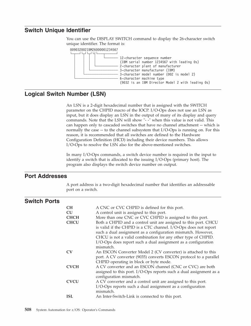
Switch Unique IdentifierYou can use the DISPLAY SWITCH command to display the 26-character switchunique identifier. The format is:
009032002IBM26000001234567└─┬──┘└┬┘└┬┘└┤└───┬──────┘
│ │ │ │ └─────── 12-character sequence number│ │ │ │ (IBM serial number 1234567 with leading 0s)│ │ │ └──────────── 2-character plant of manufacturer│ │ └─────────────── 3-character manufacturer (IBM)│ └────────────────── 3-character model number (002 is model 2)└─────────────────────── 6-character machine type
(9032 is an IBM Director Model 2 with leading 0s)
Logical Switch Number (LSN)
An LSN is a 2-digit hexadecimal number that is assigned with the SWITCHparameter on the CHPID macro of the IOCP. I/O-Ops does not use an LSN asinput, but it does display an LSN in the output of many of its display and querycommands. Note that the LSN will show "- -" when this value is not valid. Thiscan happen only to cascaded switches that have no channel attachment -- which isnormally the case -- to the channel subsystem that I/O-Ops is running on. For thisreason, it is recommended that all switches are defined to the HardwareConfiguration Definition (HCD) including their device numbers. This allowsI/O-Ops to resolve the LSN also for the above-mentioned switches.
In many I/O-Ops commands, a switch device number is required in the input toidentify a switch that is allocated to the issuing I/O-Ops (primary host). Theprogram also displays the switch device number on output.
Port AddressesA port address is a two-digit hexadecimal number that identifies an addressableport on a switch.
Switch PortsCH A CNC or CVC CHPID is defined for this port.CU A control unit is assigned to this port.CHCH More than one CNC or CVC CHPID is assigned to this port.CHCU Both a CHPID and a control unit are assigned to this port. CHCU
is valid if the CHPID is a CTC channel. I/O-Ops does not reportsuch a dual assignment as a configuration mismatch. However,CHCU is not a valid combination for any other type of CHPID.I/O-Ops does report such a dual assignment as a configurationmismatch.
CV An ESCON Converter Model 2 (CV converter) is attached to thisport. A CV converter (9035) converts ESCON protocol to a parallelCHPID operating in block or byte mode.
CVCH A CV converter and an ESCON channel (CNC or CVC) are bothassigned to this port. I/O-Ops reports such a dual assignment as aconfiguration mismatch.
CVCU A CV converter and a control unit are assigned to this port.I/O-Ops reports such a dual assignment as a configurationmismatch.
ISL An Inter-Switch-Link is connected to this port.
508 System Automation for z/OS: Operator's Commands
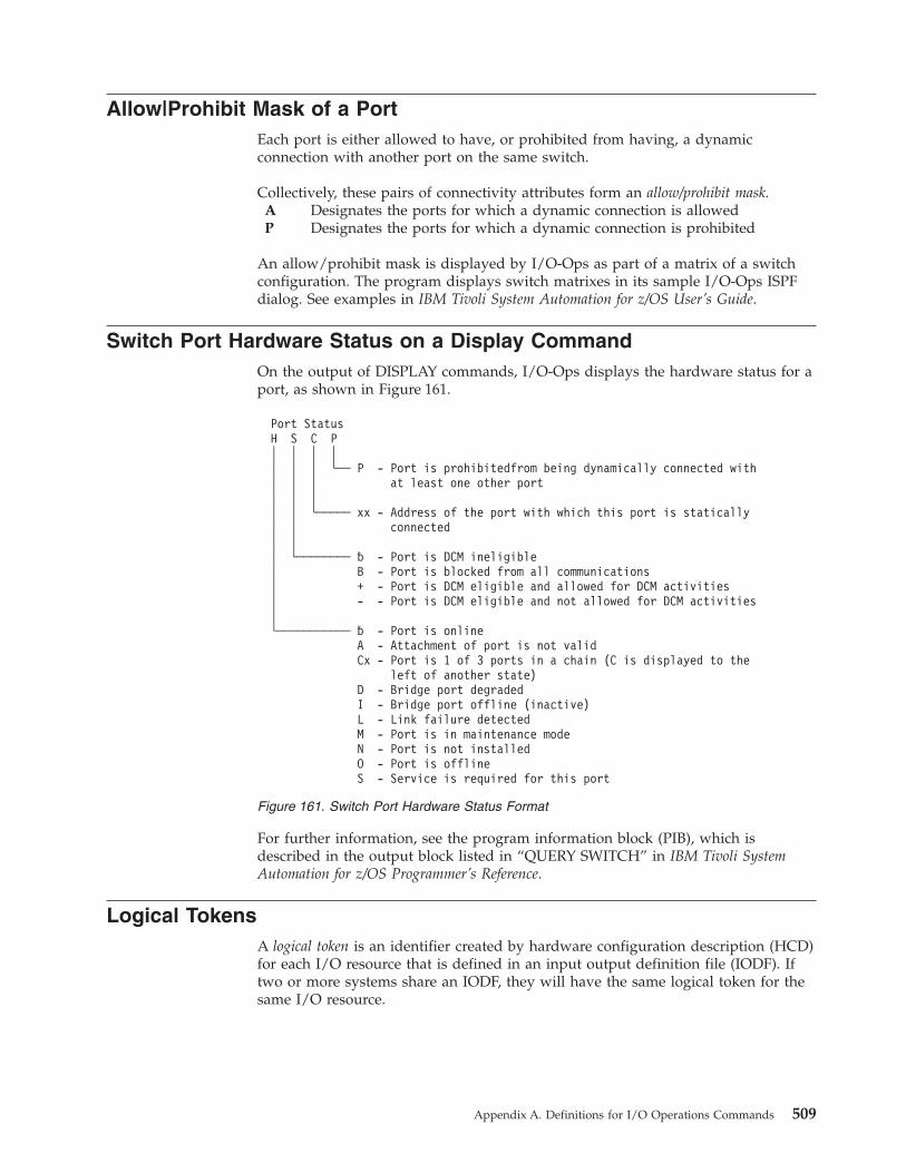
Allow|Prohibit Mask of a PortEach port is either allowed to have, or prohibited from having, a dynamicconnection with another port on the same switch.
Collectively, these pairs of connectivity attributes form an allow/prohibit mask.A Designates the ports for which a dynamic connection is allowedP Designates the ports for which a dynamic connection is prohibited
An allow/prohibit mask is displayed by I/O-Ops as part of a matrix of a switchconfiguration. The program displays switch matrixes in its sample I/O-Ops ISPFdialog. See examples in IBM Tivoli System Automation for z/OS User’s Guide.
Switch Port Hardware Status on a Display CommandOn the output of DISPLAY commands, I/O-Ops displays the hardware status for aport, as shown in Figure 161.
For further information, see the program information block (PIB), which isdescribed in the output block listed in “QUERY SWITCH” in IBM Tivoli SystemAutomation for z/OS Programmer’s Reference.
Logical TokensA logical token is an identifier created by hardware configuration description (HCD)for each I/O resource that is defined in an input output definition file (IODF). Iftwo or more systems share an IODF, they will have the same logical token for thesame I/O resource.
Port StatusH S C P│ │ │ ││ │ │ └── P - Port is prohibitedfrom being dynamically connected with│ │ │ at least one other port│ │ ││ │ └───── xx - Address of the port with which this port is statically│ │ connected│ ││ └──────── � - Port is DCM ineligible│ B - Port is blocked from all communications│ + - Port is DCM eligible and allowed for DCM activities│ - - Port is DCM eligible and not allowed for DCM activities│└─────────── � - Port is online
A - Attachment of port is not validCx - Port is 1 of 3 ports in a chain (C is displayed to the
left of another state)D - Bridge port degradedI - Bridge port offline (inactive)L - Link failure detectedM - Port is in maintenance modeN - Port is not installedO - Port is offlineS - Service is required for this port
Figure 161. Switch Port Hardware Status Format
Appendix A. Definitions for I/O Operations Commands 509
Physical TokensA physical token is a 32-byte field that describes an I/O resource. Information in thephysical token comes from either a node element descriptor (NED) or a nodedescriptor (ND). A NED is a 32-byte field that describes a node element of an I/Oresource. A NED is associated with a physical control unit or device. An ND is a32-byte field that describes a node interface of an I/O resource. An ND identifies aphysical CHPID. When a physical token is input, the first 4 bytes are not used forcomparison.
Channel TypesTypes of channels:BLOCK A parallel channel operating in block modeBYTE A parallel channel operating in byte modeCFR Coupling facility receiverCFS Coupling facility senderCFP Coupling facility peer channelCBR Integrated Cluster Bus receiverCBS Integrated Cluster Bus senderCBP Integrated Cluster Bus peerCBY_P An ESCON to byte converter channelCIB Coupling over InfinibandCNC_P A point-to-point ESCON channelCNC_S A switched ESCON channelCNC_? A switched or point-to-point ESCON channelCTC_P A point-to-point channel-to-channel channelCTC_S A switched channel-to-channel channelCTC_? A switched or point-to-point channel-to-channel channelCVC_P An ESCON to block converter channelDSD Direct system deviceEIO An emulated I/O channelFC A FICON point-to-point channelFC_S A FICON switched channelFC_? A FICON incomplete channelFCP A FCP channelFCV A FICON-to-ESCON bridgeICR Internal coupling receiverICS Internal coupling senderICP Internal coupling peerIQD Internal queued direct communicationISD Internal system deviceNATVE Native interfaceOSA An open systems adapter channelOSC OSA consoleOSD An OSA direct express channelOSE An OSA express channelOSN An OSA NCP channelUNDEF A channel that is not defined
Note: The last character of the DCM managed channels' acronyms is 'M', forexample, FCM or CNCSM.
510 System Automation for z/OS: Operator's Commands

I/O-Ops can display, or return data on, all the channels known to it. For ESCONchannels, FICON channels, and for parallel channels operating in block mode, theprogram can be used to change the connectivity between these resources andothers in their paths.
A Parallel ChannelI/O-Ops can display information about parallel channels that operate in either byte(BY) or block (BL) mode. I/O-Ops can also change connectivity to a parallelchannel operating in block mode.
An ESCON (CNC) ChannelA CNC channel path is used to transfer data between a host system image and anESCON control unit. I/O-Ops can display data about a CNC channel path andchange its connectivity.
An ESCON Channel Operating in Converted (CVC) ModeA CVC channel path transfers data in blocks and a CBY channel path transfersdata by bytes. A CVC or CBY channel path is an ESCON channel that has beenconverted so that it can interface with an ESCON Converter Model 1 (9034), orequivalent, for communication with a parallel control unit.
A CVC or CBY path always resembles a point-to-point parallel path, regardlesswhether it passes through a switch or not. Thus, a switchable CVC or CBY pathmust pass through a switch as a static connection.
A FICON (FC) ChannelAn FC channel path is used to transfer data between a host system image and anFICON control unit. I/O-Ops can display data about an FC channel path andchange its connectivity.
Coupling Facility ChannelsI/O-Ops can display and return data about a Coupling Facility Receiver (CFR)channel and a Coupling Facility Sender (CFS) channel. However, I/O-Ops does notprovide connectivity control for these types of channels.
OSA ChannelsThe OSA channel provides an S/390 internal channel attachment to local areanetworks (LANs) that support Internet protocols such as fiber distributed datainterface (FDDI), token ring, Ethernet, and high speed serial interface (HSSI).
Making Connectivity ChangesYou can use I/O-Ops as the single point of control for I/O connectivity changes inthe active I/O configurations under its management.
In addition to an I/O-Ops base program running on a host, the host must be ableto play a role with a group of hosts.
To develop safe procedures to protect your system’s connectivity, you need tounderstand the functional characteristics of the dynamic switches that you controlwith I/O-Ops. For example, the local console of Switch Directors has a setting thatallows you to choose how the switch is restarted. If your operating procedures areto restart:
Appendix A. Definitions for I/O Operations Commands 511
v From the same configuration that was most recently active on the SwitchDirector, use the Switch Director’s ACTIVE=SAVED setting
v From a fixed IPL file, regardless of what was most recently active on the SwitchDirector, you can set the Switch Director to use that file
But note that your use of I/O-Ops varies accordingly. Changes that you makethrough I/O-Ops are only automatically restored after events like power failures, ifthe Switch Directors are set to ACTIVE=SAVED. If they are not, consider usingI/O-Ops functions to update each Switch Director’s IPL file in accordance withyour updates directly to the active configuration.
Switch resources are self-defining. The relevant data is contained in a nodedescriptor (ND) of a port or an ESCON/FICON channel and in a node elementdescriptor (NED) of a switch device. I/O-Ops uses this data to ensure systemintegrity in its commands. It can also use the serial number of an ESCON/FICONresource to identify it.
When only the channel or the control unit is an ESCON unit, the non-ESCON unitcan impose some limitations on I/O-Ops’s ability to ensure coordination betweenthe logical definition of the unit and its physical presence. (Unlike ESCON units, anon-ESCON unit is not self-defining.)
NOForce|NOCheck|Force Option SetWith your choice among NOForce, NOCheck, and Force, you determine thestringency with which I/O-Ops forces the completion of a switching connectivitycommand under two conditions:v If any of I/O-Ops’s relevant vary path requests fail.v If I/O-Ops checked and detected the presence of a protocol converter (CV)
between the I/O interface of a parallel channel operating in block mode and theport on a dynamic switch. (NOForce is required for the REMOVE CHP andRESTORE CHP commands. NOCheck has an identical effect on these 2commands.)
NOForce: (IBM-supplied default) instructs I/O-Ops to send a connectivitycommand to the specified switch(es) only if all of the following conditions havebeen met:1. The results of consensus vary-path processing results are unanimously
affirmative.2. If a CV converter has been detected in the parallel channel path, completion of
the command will not potentially interrupt dynamic data transfer through thespecified switch(es).
3. If the command is disrupting a CVC channel, that CHPID has been configuredoffline.
If you specify NOForce, you must also specify Vary. NOForce requires theUPDATE level of authorization if I/O-Ops is secured by RACF® or an equivalentprogram.
NOCheck: instructs I/O-Ops to send a connectivity command to the specifiedswitch(es) only if all of the following conditions listed below have been met:1. The results of consensus vary-path processing results are unanimously
affirmative.2. If the command is disrupting a CVC channel, that CHPID has been configured
offline.
512 System Automation for z/OS: Operator's Commands
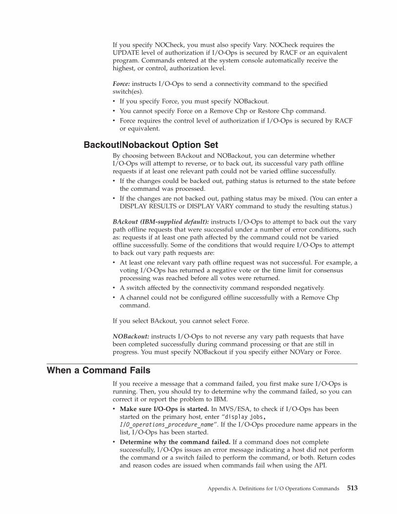
If you specify NOCheck, you must also specify Vary. NOCheck requires theUPDATE level of authorization if I/O-Ops is secured by RACF or an equivalentprogram. Commands entered at the system console automatically receive thehighest, or control, authorization level.
Force: instructs I/O-Ops to send a connectivity command to the specifiedswitch(es).v If you specify Force, you must specify NOBackout.v You cannot specify Force on a Remove Chp or Restore Chp command.v Force requires the control level of authorization if I/O-Ops is secured by RACF
or equivalent.
Backout|Nobackout Option SetBy choosing between BAckout and NOBackout, you can determine whetherI/O-Ops will attempt to reverse, or to back out, its successful vary path offlinerequests if at least one relevant path could not be varied offline successfully.v If the changes could be backed out, pathing status is returned to the state before
the command was processed.v If the changes are not backed out, pathing status may be mixed. (You can enter a
DISPLAY RESULTS or DISPLAY VARY command to study the resulting status.)
BAckout (IBM-supplied default): instructs I/O-Ops to attempt to back out the varypath offline requests that were successful under a number of error conditions, suchas: requests if at least one path affected by the command could not be variedoffline successfully. Some of the conditions that would require I/O-Ops to attemptto back out vary path requests are:v At least one relevant vary path offline request was not successful. For example, a
voting I/O-Ops has returned a negative vote or the time limit for consensusprocessing was reached before all votes were returned.
v A switch affected by the connectivity command responded negatively.v A channel could not be configured offline successfully with a Remove Chp
command.
If you select BAckout, you cannot select Force.
NOBackout: instructs I/O-Ops to not reverse any vary path requests that havebeen completed successfully during command processing or that are still inprogress. You must specify NOBackout if you specify either NOVary or Force.
When a Command FailsIf you receive a message that a command failed, you first make sure I/O-Ops isrunning. Then, you should try to determine why the command failed, so you cancorrect it or report the problem to IBM.v Make sure I/O-Ops is started. In MVS/ESA, to check if I/O-Ops has been
started on the primary host, enter “display jobs,I/O_operations_procedure_name”. If the I/O-Ops procedure name appears in thelist, I/O-Ops has been started.
v Determine why the command failed. If a command does not completesuccessfully, I/O-Ops issues an error message indicating a host did not performthe command or a switch failed to perform the command, or both. Return codesand reason codes are issued when commands fail when using the API.
Appendix A. Definitions for I/O Operations Commands 513
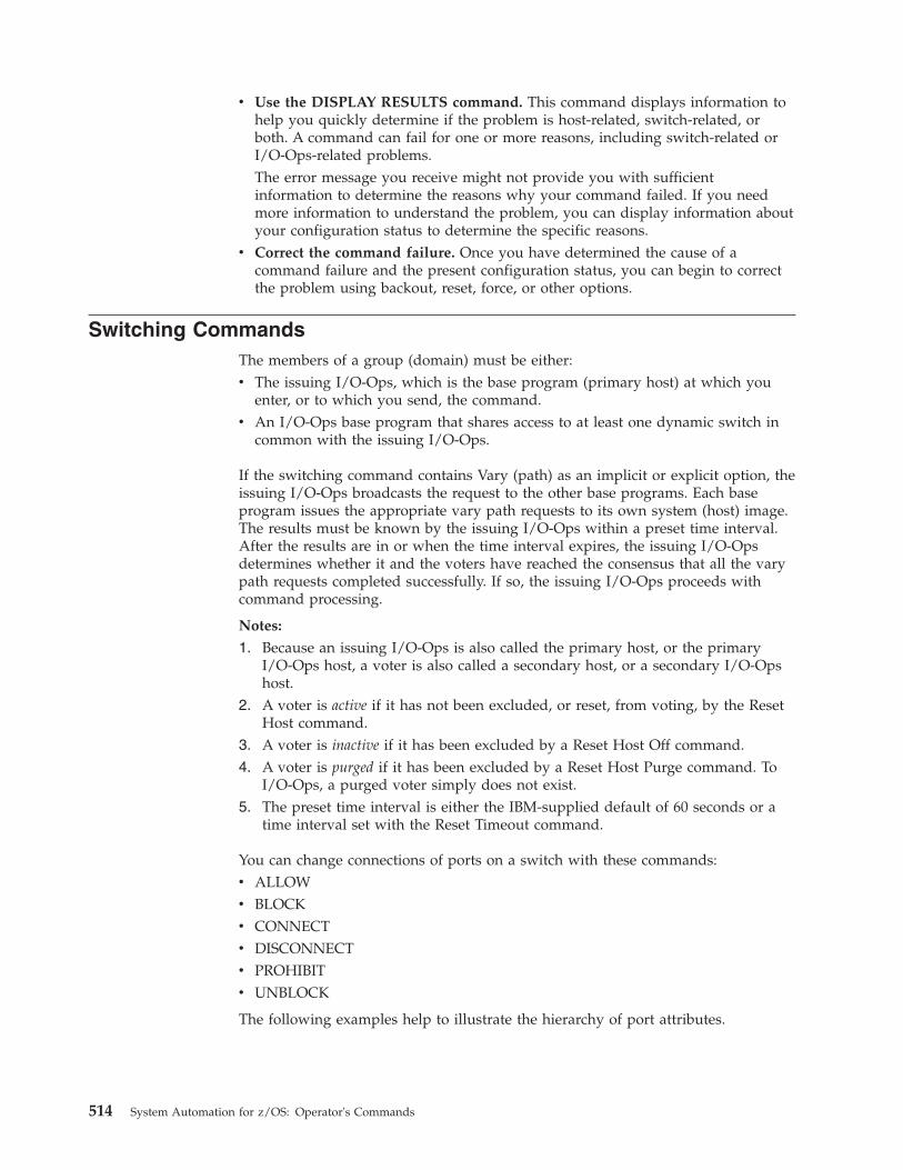
v Use the DISPLAY RESULTS command. This command displays information tohelp you quickly determine if the problem is host-related, switch-related, orboth. A command can fail for one or more reasons, including switch-related orI/O-Ops-related problems.The error message you receive might not provide you with sufficientinformation to determine the reasons why your command failed. If you needmore information to understand the problem, you can display information aboutyour configuration status to determine the specific reasons.
v Correct the command failure. Once you have determined the cause of acommand failure and the present configuration status, you can begin to correctthe problem using backout, reset, force, or other options.
Switching CommandsThe members of a group (domain) must be either:v The issuing I/O-Ops, which is the base program (primary host) at which you
enter, or to which you send, the command.v An I/O-Ops base program that shares access to at least one dynamic switch in
common with the issuing I/O-Ops.
If the switching command contains Vary (path) as an implicit or explicit option, theissuing I/O-Ops broadcasts the request to the other base programs. Each baseprogram issues the appropriate vary path requests to its own system (host) image.The results must be known by the issuing I/O-Ops within a preset time interval.After the results are in or when the time interval expires, the issuing I/O-Opsdetermines whether it and the voters have reached the consensus that all the varypath requests completed successfully. If so, the issuing I/O-Ops proceeds withcommand processing.
Notes:
1. Because an issuing I/O-Ops is also called the primary host, or the primaryI/O-Ops host, a voter is also called a secondary host, or a secondary I/O-Opshost.
2. A voter is active if it has not been excluded, or reset, from voting, by the ResetHost command.
3. A voter is inactive if it has been excluded by a Reset Host Off command.4. A voter is purged if it has been excluded by a Reset Host Purge command. To
I/O-Ops, a purged voter simply does not exist.5. The preset time interval is either the IBM-supplied default of 60 seconds or a
time interval set with the Reset Timeout command.
You can change connections of ports on a switch with these commands:v ALLOWv BLOCKv CONNECTv DISCONNECTv PROHIBITv UNBLOCK
The following examples help to illustrate the hierarchy of port attributes.
514 System Automation for z/OS: Operator's Commands
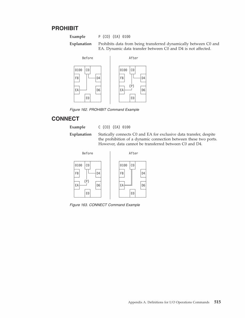
PROHIBITExample P (CO) (EA) 0100
Explanation Prohibits data from being transferred dynamically between C0 andEA. Dynamic data transfer between C0 and D4 is not affected.
CONNECTExample C (CO) (EA) 0100
Explanation Statically connects C0 and EA for exclusive data transfer, despitethe prohibition of a dynamic connection between these two ports.However, data cannot be transferred between C0 and D4.
Before │ After│
┌─────┬──┬─────┐ │ ┌─────┬──┬─────┐│0100 │C0│ │ │ │0100 │C0│ │├──┐ └┬┬┘ ┌──┤ │ ├──┐ └┬┬┘ ┌──┤│FB│ │└───┤D4│ │ │FB│ │└───┤D4│├──┘ │ └──┤ │ ├──┘ │ └──┤├──┐ │ ┌──┤ │ ├──┐ (P) ┌──┤│EA├───┘ │D6│ │ │EA├───┘ │D6│├──┘ ┌──┐ └──┤ │ ├──┘ ┌──┐ └──┤│ │E0│ │ │ │ │E0│ │└─────┴──┴─────┘ │ └─────┴──┴─────┘
Figure 162. PROHIBIT Command Example
Before │ After│
┌─────┬──┬─────┐ │ ┌─────┬──┬─────┐│0100 │C0│ │ │ │0100 │C0│ │├──┐ └┬┬┘ ┌──┤ │ ├──┐ └╥─┘ ┌──┤│FB│ │└───┤D4│ │ │FB│ ║ │D4│├──┘ │ └──┤ │ ├──┘ ║ └──┤├──┐ (P) ┌──┤ │ ├──┐ ║ ┌──┤│EA├───┘ │D6│ │ │EA╞═══╝ │D6│├──┘ ┌──┐ └──┤ │ ├──┘ ┌──┐ └──┤│ │E0│ │ │ │ │E0│ │└─────┴──┴─────┘ │ └─────┴──┴─────┘
Figure 163. CONNECT Command Example
Appendix A. Definitions for I/O Operations Commands 515
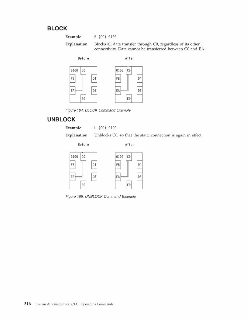
BLOCKExample B (CO) 0100
Explanation Blocks all data transfer through C0, regardless of its otherconnectivity. Data cannot be transferred between C0 and EA.
UNBLOCKExample U (CO) 0100
Explanation Unblocks C0, so that the static connection is again in effect.
Before │ After│
┌─────┬──┬─────┐ │ ┌─────┬×─┬─────┐│0100 │C0│ │ │ │0100 │C0│ │├──┐ └╥─┘ ┌──┤ │ ├──┐ └╥─┘ ┌──┤│FB│ ║ │D4│ │ │FB│ ║ │D4│├──┘ ║ └──┤ │ ├──┘ ║ └──┤├──┐ ║ ┌──┤ │ ├──┐ ║ ┌──┤│EA╞═══╝ │D6│ │ │EA╞═══╝ │D6│├──┘ ┌──┐ └──┤ │ ├──┘ ┌──┐ └──┤│ │E0│ │ │ │ │E0│ │└─────┴──┴─────┘ │ └─────┴──┴─────┘
Figure 164. BLOCK Command Example
Before │ After│
┌─────┬×─┬─────┐ │ ┌─────┬──┬─────┐│0100 │C0│ │ │ │0100 │C0│ │├──┐ └╥─┘ ┌──┤ │ ├──┐ └╥─┘ ┌──┤│FB│ ║ │D4│ │ │FB│ ║ │D4│├──┘ ║ └──┤ │ ├──┘ ║ └──┤├──┐ ║ ┌──┤ │ ├──┐ ║ ┌──┤│EA╞═══╝ │D6│ │ │EA╞═══╝ │D6│├──┘ ┌──┐ └──┤ │ ├──┘ ┌──┐ └──┤│ │E0│ │ │ │ │E0│ │└─────┴──┴─────┘ │ └─────┴──┴─────┘
Figure 165. UNBLOCK Command Example
516 System Automation for z/OS: Operator's Commands
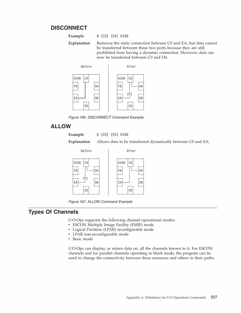
DISCONNECTExample N (CO) (EA) 0100
Explanation Removes the static connection between C0 and EA, but data cannotbe transferred between these two ports because they are stillprohibited from having a dynamic connection. However, data cannow be transferred between C0 and D4.
ALLOWExample A (CO) (EA) 0100
Explanation Allows data to be transferred dynamically between C0 and EA.
Types Of ChannelsI/O-Ops supports the following channel operational modes:v ESCON Multiple Image Facility (EMIF) modev Logical Partition (LPAR) reconfigurable modev LPAR non-reconfigurable modev Basic mode
I/O-Ops can display, or return data on, all the channels known to it. For ESCONchannels and for parallel channels operating in block mode, the program can beused to change the connectivity between these resources and others in their paths.
Before │ After│
┌─────┬──┬─────┐ │ ┌─────┬──┬─────┐│0100 │C0│ │ │ │0100 │C0│ │├──┐ └╥─┘ ┌──┤ │ ├──┐ └┬┬┘ ┌──┤│FB│ ║ │D4│ │ │FB│ │└───┤D4│├──┘ ║ └──┤ │ ├──┘ │ └──┤├──┐ ║ ┌──┤ │ ├──┐ (P) ┌──┤│EA╞═══╝ │D6│ │ │EA├───┘ │D6│├──┘ ┌──┐ └──┤ │ ├──┘ ┌──┐ └──┤│ │E0│ │ │ │ │E0│ │└─────┴──┴─────┘ │ └─────┴──┴─────┘
Figure 166. DISCONNECT Command Example
Before │ After│
┌─────┬──┬─────┐ │ ┌─────┬──┬─────┐│0100 │C0│ │ │ │0100 │C0│ │├──┐ └┬┬┘ ┌──┤ │ ├──┐ └┬┬┘ ┌──┤│FB│ │└───┤D4│ │ │FB│ │└───┤D4│├──┘ │ └──┤ │ ├──┘ │ └──┤├──┐ (P) ┌──┤ │ ├──┐ │ ┌──┤│EA├───┘ │D6│ │ │EA├───┘ │D6│├──┘ ┌──┐ └──┤ │ ├──┘ ┌──┐ └──┤│ │E0│ │ │ │ │E0│ │└─────┴──┴─────┘ │ └─────┴──┴─────┘
Figure 167. ALLOW Command Example
Appendix A. Definitions for I/O Operations Commands 517
Remove (Quiesce) a SwitchWhen a service representative needs to have a switch quiesced and disabled inorder to remove the unit, you can enter the I/O-Ops REMOVE SWITCH commandto vary all the paths to and through the switch offline, including any paths to theswitch (device) from the other hosts in its group and any chained paths leading toanother switch. Optionally, you can specify the Disable option, so the servicerepresentative only has to turn power off to the unit. (You should not use theVARY DEV or the REMOVE DEV commands.)
I/O-Ops issues the appropriate vary path offline requests to the hosts. (It will notvary the path to the control unit port of the switch because it needs tocommunicate with the switch.)
The issuing I/O-Ops then sends the command “SET OFFLINE” to the switch andinforms you that the command completed successfully. If the command completedunsuccessfully (for example, if a vary path request failed) you can analyze the datawith the appropriate display command. If you cannot resolve the situation and theswitch must be removed, you can rerun the REMOVE SWITCH command with theForce option. However, no paths will be varied offline.
For a discussion of why it sometimes isn't obvious that the status of a path or adevice has changed after an operator has issued a connectivity command, see“Device and Path Status After Connectivity Commands” on page 530.
Restore (Enable) a SwitchWhen the system operator completes a maintenance procedure and turns power tothe unit on, you enter the RESTORE SWITCH command and specify the switchdevice number.
The I/O-Ops at which you issued the command (the issuing I/O-Ops) firstallocates, or attaches the switch. Then it activates the configuration for the switchthat the unit is programmed to select whenever power is turned on to it. Finally, itensures all the paths in the selected configuration are varied online.
I/O-Ops informs you the command completed successfully. (If it completedunsuccessfully, you can enter the DISPLAY RESULTS command to obtain moredata.)
For a discussion of why it sometimes isn't obvious that the status of a path or adevice has changed after an operator has issued a connectivity command, see“Device and Path Status After Connectivity Commands” on page 530.
Using Port Names as a Tool in Switching CommandsWhen you enter a switching command, you change the port attributes that controldata transfer on the ports of the switch through which the path passes. The singleswitch or the pair of chained switches in a switchable path must be allocated to theissuing I/O-Ops (primary host) in the command. To facilitate the connectivitymanagement of these switchable paths, I/O-Ops lets you assign, or write, a nameof up to 24 characters to each addressable port on a switch.
518 System Automation for z/OS: Operator's Commands
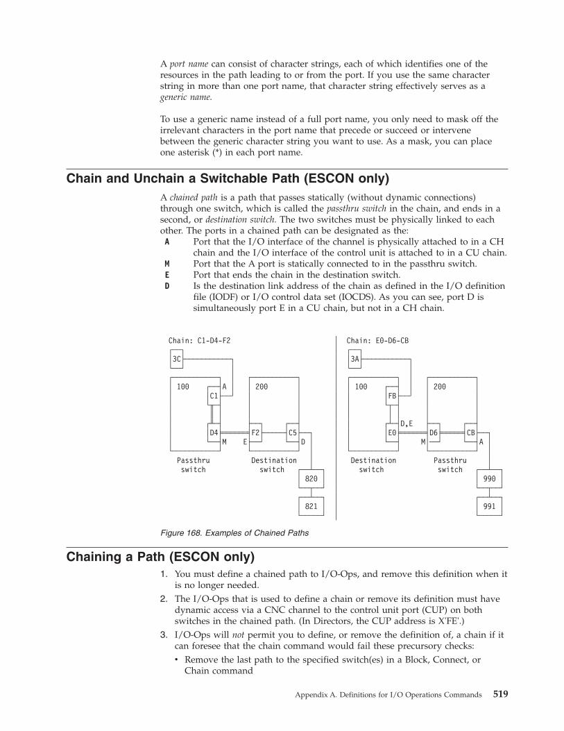
A port name can consist of character strings, each of which identifies one of theresources in the path leading to or from the port. If you use the same characterstring in more than one port name, that character string effectively serves as ageneric name.
To use a generic name instead of a full port name, you only need to mask off theirrelevant characters in the port name that precede or succeed or intervenebetween the generic character string you want to use. As a mask, you can placeone asterisk (*) in each port name.
Chain and Unchain a Switchable Path (ESCON only)A chained path is a path that passes statically (without dynamic connections)through one switch, which is called the passthru switch in the chain, and ends in asecond, or destination switch. The two switches must be physically linked to eachother. The ports in a chained path can be designated as the:A Port that the I/O interface of the channel is physically attached to in a CH
chain and the I/O interface of the control unit is attached to in a CU chain.M Port that the A port is statically connected to in the passthru switch.E Port that ends the chain in the destination switch.D Is the destination link address of the chain as defined in the I/O definition
file (IODF) or I/O control data set (IOCDS). As you can see, port D issimultaneously port E in a CU chain, but not in a CH chain.
Chaining a Path (ESCON only)1. You must define a chained path to I/O-Ops, and remove this definition when it
is no longer needed.2. The I/O-Ops that is used to define a chain or remove its definition must have
dynamic access via a CNC channel to the control unit port (CUP) on bothswitches in the chained path. (In Directors, the CUP address is X'FE'.)
3. I/O-Ops will not permit you to define, or remove the definition of, a chain if itcan foresee that the chain command would fail these precursory checks:v Remove the last path to the specified switch(es) in a Block, Connect, or
Chain command
Chain: C1-D4-F2 │ Chain: E0-D6-CB┌──┐ │ ┌──┐│3C├───────────┐ │ │3A├───────────┐└──┘ │ │ └──┘ │┌───────────┐ │ ┌───────────┐ │ ┌───────────┐ │ ┌───────────┐│ 100 ┌──┤A │ │ 200 │ │ │ 100 ┌──┤ │ │ 200 ││ │C1├──┘ │ │ │ │ │FB├──┘ │ ││ └╥─┤ │ │ │ │ └┬─┤ │ ││ ║ │ │ │ │ │ │ │ │ ││ ┌╨─┤ ├──┐ ┌──┤ │ │ ┌┴─┤D,E ├──┐ ┌──┤│ │D4╞══════╡F2├─────┤C5├──┐ │ │ │E0╞══════╡D6╞═════╡CB├──┐│ └──┤M E├──┘ └──┤D │ │ │ └──┤ M│──┘ └──┤A │└───────────┘ └───────────┘ │ │ └───────────┘ └───────────┘ │
Passthru Destination │ │ Destination Passthru │switch switch ┌──┴──┐ │ switch switch ┌──┴──┐
│ 820 │ │ │ 990 │└──┬──┘ │ └──┬──┘┌──┴──┐ │ ┌──┴──┐│ 821 │ │ │ 991 │└─────┘ │ └─────┘
Figure 168. Examples of Chained Paths
Appendix A. Definitions for I/O Operations Commands 519
v Affect an unimplemented portv Affect the control unit port (CUP) except to assign it a port namev Allow a port to connect dynamically to itselfv Connect a port statically to itself or to more than one other portv Connect a port that is not installed.v Disconnect 2 ports that are not statically connectedv Chain a port that is already part of a different chainv Chain ports so that they would create a loopChaining can affect the vary path requests that I/O-Ops issues. See “Processinga Vary Path Request” on page 524 for more information.
4. If you intend to define a chain that includes a parallel channel operating inblock mode with a CV converter, such as an ESCON Converter Model 2 (9035)attached, use these guidelines for selecting noforce, nocheck, or force. Theguidelines should help you decide whether to select NOForce, NOCheck, orForce as an option in a connectivity command that affects a CV converter.If the path is not chained and the foregoing requirements are met, you can enter aconnectivity command with either the NOForce option or the NOCheck option.v If you specify NOForce, I/O-Ops will check for an operational CV converter
in the path and process the command under the set of rules that apply.a. If the CV converter is operational, I/O-Ops will:
1) Fail a Block, Connect, Remove Switch, or Chain command that affectsthe port.
2) Fail a Prohibit command that affects the path to the CV converter.b. If the CV converter is not operational, I/O-Ops will:
1) Issue a warning if an Unblock, Disconnect, RESTORE SWITCH, orUnchain command is entered that affects the port.
2) Issue a warning if an Allow command is entered that affects the pathto the CV converter.
v If you specify NOCheck, I/O-Ops will not check for a CV, and will processthe command under the set of rules that apply.
If the path is chained and the foregoing requirements are met, you must specifyNOCheck or Force to unchain the path or to block any of the ports in the path.
5. Make sure the channel I/O interface, the control unit I/O interface, and thelink between the two switches are all attached properly. Ports A, M, E, and D inFigure 168 on page 519 are determined by these attachments. Also make surethe destination link address (port D) is defined properly in the IODF or IOCDS.
6. Remember that defining a chain and removing a defined chain can affect all theparticipants in the issuing I/O-Ops’ consensus vary-path processing.
520 System Automation for z/OS: Operator's Commands
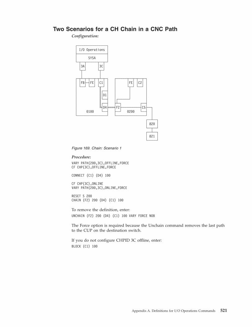
Two Scenarios for a CH Chain in a CNC PathConfiguration:
Procedure:VARY PATH(200,3C),OFFLINE,FORCECF CHP(3C),OFFLINE,FORCE
CONNECT (C1) (D4) 100
CF CHP(3C),ONLINEVARY PATH(200,3C),ONLINE,FORCE
RESET S 200CHAIN (F2) 200 (D4) (C1) 100
To remove the definition, enter:UNCHAIN (F2) 200 (D4) (C1) 100 VARY FORCE NOB
The Force option is required because the Unchain command removes the last pathto the CUP on the destination switch.
If you do not configure CHPID 3C offline, enter:BLOCK (C1) 100
┌────────────────┐│ I/O Operations │├────────────────┤│ SYSA │└─┬──┬──────┬──┬─┘
│3A│ │3C│└┬─┘ └┬─┘│ │
┌─┬┴─┬─┬──┬─┬┴─┬─┐ ┌──────┬──┬─┬──┬─┐│ │FB├─┤FE│ │C1│ │ │ │FE│ │C2│ ││ └──┘ └──┘ └╥─┘ │ │ └┬─┘ └──┘ ││ ║┌──┤ │ │ ││ ║│D1│ │ │ ││ ║└──┤ │┌──────┘ ││ ║┌──┤ ├┴─┐ ┌──┤│ ╚╡D4╞═══╡F2├──────────┤C5├──┐│ 0100 └──┤ ├──┘ 0200 └──┤ │└────────────────┘ └────────────────┘ │
┌──┴──┐│ 820 │└──┬──┘┌──┴──┐│ 821 │└─────┘
Figure 169. Chain: Scenario 1
Appendix A. Definitions for I/O Operations Commands 521
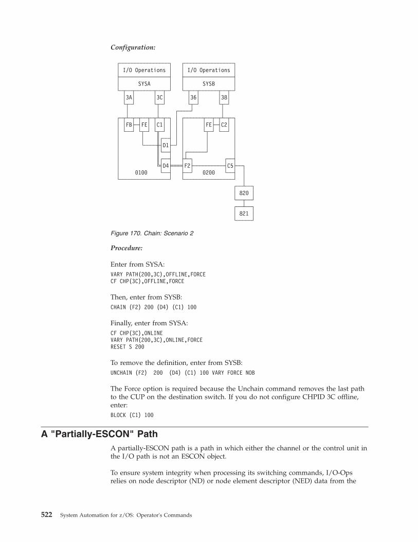
Configuration:
Procedure:
Enter from SYSA:VARY PATH(200,3C),OFFLINE,FORCECF CHP(3C),OFFLINE,FORCE
Then, enter from SYSB:CHAIN (F2) 200 (D4) (C1) 100
Finally, enter from SYSA:CF CHP(3C),ONLINEVARY PATH(200,3C),ONLINE,FORCERESET S 200
To remove the definition, enter from SYSB:UNCHAIN (F2) 200 (D4) (C1) 100 VARY FORCE NOB
The Force option is required because the Unchain command removes the last pathto the CUP on the destination switch. If you do not configure CHPID 3C offline,enter:BLOCK (C1) 100
A "Partially-ESCON" PathA partially-ESCON path is a path in which either the channel or the control unit inthe I/O path is not an ESCON object.
To ensure system integrity when processing its switching commands, I/O-Opsrelies on node descriptor (ND) or node element descriptor (NED) data from the
┌────────────────┐ ┌────────────────┐│ I/O Operations │ │ I/O Operations │├────────────────┤ ├────────────────┤│ SYSA │ │ SYSB │└─┬──┬──────┬──┬─┘ └─┬──┬──────┬──┬─┘
│3A│ │3C│ │36│ │38│└┬─┘ └┬─┘ └┬─┘ └┬─┘│ │ ┌────┘ │
┌─┬┴─┬─┬──┬─┬┴─┬─┐ │ ┌──────┬──┬─┬┴─┬─┐│ │FB├─┤FE│ │C1│ │ │ │ │FE├─┤C2│ ││ └──┘ └┬─┘ └╥─┘ │ │ │ └┬─┘ └──┘ ││ │ ║┌──┤ │ │ │ ││ └────╫┤D1├─┘ │ │ ││ ║└──┤ │┌──────┘ ││ ║┌──┤ ├┴─┐ ┌──┤│ ╚╡D4╞═══╡F2├──────────┤C5├──┐│ 0100 └──┤ ├──┘ 0200 └──┤ │└────────────────┘ └────────────────┘ │
┌──┴──┐│ 820 │└──┬──┘┌──┴──┐│ 821 │└─────┘
Figure 170. Chain: Scenario 2
522 System Automation for z/OS: Operator's Commands
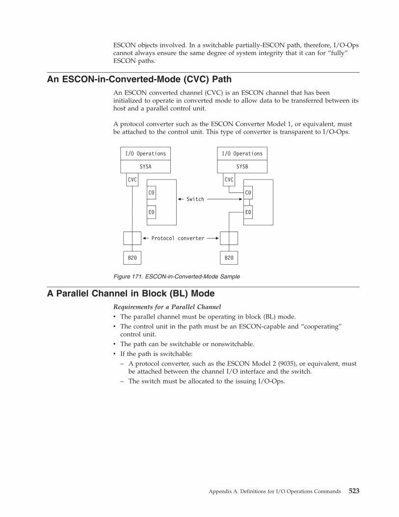
ESCON objects involved. In a switchable partially-ESCON path, therefore, I/O-Opscannot always ensure the same degree of system integrity that it can for “fully”ESCON paths.
An ESCON-in-Converted-Mode (CVC) PathAn ESCON converted channel (CVC) is an ESCON channel that has beeninitialized to operate in converted mode to allow data to be transferred between itshost and a parallel control unit.
A protocol converter such as the ESCON Converter Model 1, or equivalent, mustbe attached to the control unit. This type of converter is transparent to I/O-Ops.
A Parallel Channel in Block (BL) ModeRequirements for a Parallel Channel
v The parallel channel must be operating in block (BL) mode.v The control unit in the path must be an ESCON-capable and “cooperating”
control unit.v The path can be switchable or nonswitchable.v If the path is switchable:
– A protocol converter, such as the ESCON Model 2 (9035), or equivalent, mustbe attached between the channel I/O interface and the switch.
– The switch must be allocated to the issuing I/O-Ops.
┌────────────────┐ ┌────────────────┐│ I/O Operations │ │ I/O Operations │├────────────────┤ ├────────────────┤│ SYSA │ │ SYSB │└─┬───┬──────────┘ └─┬───┬──────────┘
│CVC│ ┌─────────┐ │CVC│ ┌─────────┐└─┬─┘ ├──┐ │ └─┬─┘ ├──┐ │
│ │C0│ │ └────┤C0│ ││ ├──┘ │�─ Switch ───────────�├─┬┘ ││ ├──┐ │ ├─┴┐ ││ │E0│ │ ┌────┤E0│ ││ ├──┘ │ │ ├──┘ ││ └─────────┘ │ └─────────┘
┌──┼──┐ ┌──┼──┐│ │ │�─ Protocol converter ───�│ │ │└──┼──┘ └──┼──┘┌──┴──┐ ┌──┴──┐│ B20 │ │ B20 │└─────┘ └─────┘
Figure 171. ESCON-in-Converted-Mode Sample
Appendix A. Definitions for I/O Operations Commands 523
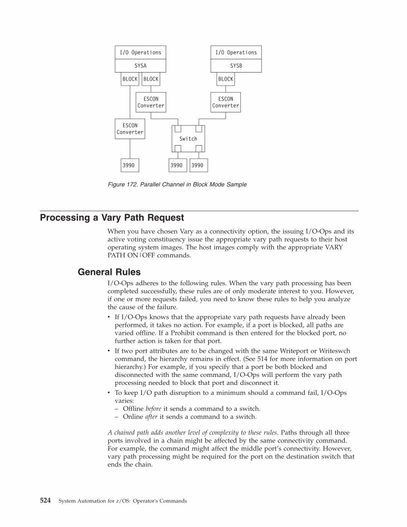
Processing a Vary Path RequestWhen you have chosen Vary as a connectivity option, the issuing I/O-Ops and itsactive voting constituency issue the appropriate vary path requests to their hostoperating system images. The host images comply with the appropriate VARYPATH ON|OFF commands.
General RulesI/O-Ops adheres to the following rules. When the vary path processing has beencompleted successfully, these rules are of only moderate interest to you. However,if one or more requests failed, you need to know these rules to help you analyzethe cause of the failure.v If I/O-Ops knows that the appropriate vary path requests have already been
performed, it takes no action. For example, if a port is blocked, all paths arevaried offline. If a Prohibit command is then entered for the blocked port, nofurther action is taken for that port.
v If two port attributes are to be changed with the same Writeport or Writeswchcommand, the hierarchy remains in effect. (See 514 for more information on porthierarchy.) For example, if you specify that a port be both blocked anddisconnected with the same command, I/O-Ops will perform the vary pathprocessing needed to block that port and disconnect it.
v To keep I/O path disruption to a minimum should a command fail, I/O-Opsvaries:– Offline before it sends a command to a switch.– Online after it sends a command to a switch.
A chained path adds another level of complexity to these rules. Paths through all threeports involved in a chain might be affected by the same connectivity command.For example, the command might affect the middle port’s connectivity. However,vary path processing might be required for the port on the destination switch thatends the chain.
┌────────────────┐ ┌────────────────┐│ I/O Operations │ │ I/O Operations │├────────────────┤ ├────────────────┤│ SYSA │ │ SYSB │└─┬─────┬┬─────┬─┘ └─┬─────┬────────┘
│BLOCK││BLOCK│ │BLOCK│└──┬──┘└──┬──┘ └──┬──┘
│ ┌────┴────┐ ┌────┴────┐│ │ ESCON │ │ ESCON ││ │Converter│ │Converter││ └────┬────┘ └────┬────┘
┌────┴────┐ └────────┐ ┌────────┘│ ESCON │ ┌┬┴┬────┬┴┬┐│Converter│ │└─┘ └─┘│└────┬────┘ │ Switch │
│ │┌─┐ ┌─┐││ └┴┬┴────┴┬┴┘
┌──┴──┐ ┌──┴──┐┌──┴──┐│3990 │ │3990 ││3990 │└─────┘ └─────┘└─────┘
Figure 172. Parallel Channel in Block Mode Sample
524 System Automation for z/OS: Operator's Commands
If a CV converter is in the chained path, you must specify NOCheck or Force as aconnectivity option if you want to block any of the 3 ports involved or you wantto unchain the chain. (If you specify NOForce, the command will fail.)
VTAM Application NameFor communication among I/O-Ops base programs, I/O-Ops uses VTAM orTCP/IP, or both. To participate in this intersystem communication using VTAM, abase program must be defined as an application according to the rules for VTAMdefinitions. For information on these definitions, see the I/O-Ops programdirectory for the host operating system on which you intend to use the application.
VTAM returns the VTAM application name to a base program when it is started,thus identifying that base program. The base program uses its VTAM applicationname and TCP/IP host name as its host names to register itself to the members ofits group when it allocates each dynamic switch.
To get a list of the VTAM (application), or host names known to an issuingI/O-Ops (primary host), enter the Display Host command as D H * or view thepages of that host's online notebook.
To remove or restore a base program (host) from participating in consensusvary-path processing, use the Reset Host command. (This command has threeoptions: Off, Purge, and On.)
TCP/IP Host NameFor communication among I/O-Ops base programs, I/O-Ops uses VTAM and/orTCP/IP. To participate in this intersystem communication using TCP/IP, a baseprogram must have defined the server port and optionally the client port. Forinformation on these definitions, see “Step 18C: Perform TCP/IP Definitions” in“Chapter 9. Installing SA z/OS on Host Systems” of IBM Tivoli System Automationfor z/OS Planning and Installation.
Note: If server port is not defined the base program suppresses the TCP/IPcommunication.
If TCP/IP is configured to run multiple stacks (CINET) you should specify the hostname on the PARM parameter to tell I/O-Ops what stack it has to use. For detailson how to specify the PARM parameter see “Step 33: Customizing I/O-Ops” in“Chapter 9. Installing SA z/OS on Host Systems” of IBM Tivoli System Automationfor z/OS Planning and Installation. If you omit the parameter the base programconnects to the next available stack.
TCP/IP returns its host name after the base program has connected to the stack. Ifthe base program detects that the host name has more than 8 characters it looks foran alias of up to 8 characters. For details on how to specify an alias see Step 17C:Perform TCP/IP Definitions in “Chapter 9. Installing SA z/OS on Host Systems” ofIBM Tivoli System Automation for z/OS Planning and Installation. The base programuses its TCP/IP host name and VTAM application name as its host names toregister itself to the members of its group when it allocates each dynamic switch.
Note: If the host name has more than 8 characters and an appropriate alias cannotbe found the base program suppresses the TCP/IP communication.
Appendix A. Definitions for I/O Operations Commands 525

To get a list of the TCP/IP (application), or host names known to an issuingI/O-Ops (primary host), enter the Display Host command as "D H *".
To remove or restore a base program (host) from participating in consensusvary-path processing, use the Reset Host command. (This command has threeoptions: Off, Purge, and On.)
526 System Automation for z/OS: Operator's Commands
Appendix B. General Considerations for I/O OperationsCommands
I/O operations commands do not require access authorization, although it ishighly advisable. For a cross-reference of the access authorization levels that theyrequire see “Defining an RACF Profile for I/O operations” in “Appendix A.Security and Authorization” of IBM Tivoli System Automation for z/OS Planning andInstallation.
General Information and Tips for Using Multisystem Commands1. If you are entering an array or table, it must be fully contained in a single
variable, by itself, and with no leading blanks (trailing blanks are acceptablebecause they will be ignored). Without this restriction, you could enter an arrayor table that has bytes that look like blanks, will be parsed as blanks, and willmake the results unpredictable.
2. Array elements are checked for validity because they are all character data.Tables are not checked for validity because numeric data is assumed to behexadecimal (and so can never be invalid). Tables are not subject to translationand only the RNUMs are taken from the table.
3. Host application names will be checked for validity. Valid names follow MVSmember name rules.
Query commands only: “HOST()” and “XSYS()” are interpreted as an error (noname is included between the beginning and endingparenthesis).
4. For table input, the responder must be the same as the host targeted to returnthe response.
5. A summary ROW for each host will be returned as the FIRST row for eachresponder host that is returning data (that is, that does not have a commandstart failure). This ROW is marked by RCODE=X'5100FFFF'and contains(currently) status bits.
6. For Query Interface commands (only), when the interface is not found on theentity1 switch/cu, row is marked by RCODE=X'5100 0016'.
7. Query Interface Switch/CntlUnit commands change their output structures tomove the switch/control unit description into every row instead of having itreside in the header. With multi-host responses, there is no way to resolvewhich switch description would have stayed in the command header (each hostcould have a different description of the switch/control unit).
8. Query Interface Switch returns no rows when the switch being queried isclosed. Also, Query Interface CntlUnit returns no rows when the PID for thecontrol unit is not valid.
9. The lock owner field in the QEH command is only valid when the responderhost is the same as the object/entity host. For example, if you issue a QueryEntity Host Value HOST(*) SCOPE Value HOST(*) command, the QEH that isreturned will contain #hosts x #hosts ROWs (because each host will return allthe hosts it knows about) but the only valid lockowner fields will be where:QEH.ROW(i).RESPONDER.APPLNAME = QEH.ROW(i).APPL_NAME.
© Copyright IBM Corp. 1996, 2012 527
General Considerations for Using the Query Entity|Interface|RelationsCommands
1. Input for Query Entity and Query Interface commands: A Query Relationtable can be input for all Query Entity and Query Interface Switch commands.
2. Data returned: For the Query Entity, Query Interface, and Query Relationcommands, use the self-description data (header size, row size, format ID) thatis returned with each output structure to parse the data.
3. Duplicate rows: No duplicate rows will be returned unless an array or table isused as the second entity asking for duplicate information to be returned. Thisimplies that unless complete pathing (host-to-device or CHPID-to-device) isspecified in your command, you could be getting summary data back.For example, assume your configuration contains CHPIDs 10, 11, and 12, eachwith a path to control unit 100. Additionally, control unit 100 has devices100–107 on it.A Query Relation CU 100 Chp Value * (tell me all CHPIDs that access device100) would return 3 data QRO.ROWs to describe the 3 paths (CHPID 10 todevice 100, CHPID 11 to device 100 and CHPID 12 to device 100). These areexamples of complete path definitions.If you issue Query Relation CU 100 Dev Value 100 (tell me whether device100 is defined to be on CU 100), only 1 data QRO.ROW is returned (not 3)indicating that there is a logical relationship between the two entities but notcomplete details (paths) about the relation because the command did not askfor complete pathing.
4. Multiple rows: A single array entry could generate more than one rowreturned. For example, the relation between a device and a host will return asmany rows as there are CHPIDs that access the given device.
5. Rules for columns of data: Although the same structure is returned for everyQuery Relation command, different columns of data are returned for thedifferent variations of the commands. The following rules apply:a. STATBITS are set for every command.b. The columns between HOST and DEVICE are command-dependent; that
is, Query Relation Host-Host commands return only the HOST column,Query Relation Host-Chp commands return both the HOST and CHPIDcolumns, Query Relation Host-Switch commands return HOST, CHPID,PORTIN, SWDEVN, and LSN columns (note that STATBITS are required tovalidate PORTIN and SWDEVN as these might or might not be known),and so on.
c. Like entities are not allowed except host-to-host relations, which indicateVTAM relations, and switch-to-switch relations, which indicate chainingrelations.
d. Data for a secondary host (voting I/O-Ops) will be marked INCOMPLETEbecause data bases are not shared among participating I/O-Ops.
e. When no host is named in a command, the primary host (issuing I/O-Ops)is assumed.
6. Sorting of output: Sorting is done only if you specify Value or Range asoptions for the format of the output. If you specify Array or Table, I/O-Opsreturns data in the same order as the input array or table.
7. Chpid filtering of pathing information is handled as follows:
a. If a channel is reserved to a partition that is not the one you are runningon, the channel will appear as not defined.
528 System Automation for z/OS: Operator's Commands
b. I/O-Ops only returns paths where the Chpid is not reserved to anotherpartition.
8. Reason codes that are related to Return codes:
In addition to the return codes (RCs) and reason codes that are also returnedfor the Display and the Query Switch commands, such as CHSC datarefreshed, lock indicators, switch configurations, and so on, the followingcombinations are unique to the Query commands:v With RC = 4, a reason code of X'51001004' indicates that some host has at
least one summary row bit set.v For RC = 8, a Getmain failure occurred.v With RC = 20, a reason code of X'51xxyyyy' indicates that I/O-Ops has
detected an internal error. You should report this problem to IBM.9. Overflow conditions: In the Query Entity, Query Interface, and Query
Relation commands the header and summary rows of the output contains abit to indicate that an overflow condition was detected in the response buffer.v If you entered a Query Entity or Query Interface command:
Enter another (similar) command to retrieve the subset of data that has notbeen returned.For example, if the command that overflowed was Query Entity Dev Value* and the last device entry returned to you is (device number) 743, the nextcommand you should issue is Query Entity Dev Range 744-*.If you are using an array (or table) as input for a command, you shouldcontinue to use the array/table form of command but adjust yourarray/table input to begin at the (output_num_rows+1) element in your nextarray command.
v If you entered a Query Relation command:
When translating your original command to a new format due to anoverflow return/reason code, you might need to begin your new commandwith the last value returned for the second entity (not the one after the lastvalue returned) or some pathing information could be lost.For example, assume you have the following partial configuration:Host = IHVAPPL1 CHPIDs = 1,2,3,4,5 CntlUnits = 100 (accessed by CHPIDs1,2,3), 200 (accessed by CHPIDs 3,4,5) Devices = 100-10F (off CU 100),200-20F (off CU 200)Assume (for the purposes of this example only) that 7 is the maximumnumber of rows that can be returned with any Query Relation command (inreality this number is more on the order of 2700).You issue Query Relation Host IHVAPPL1 Dev Value * to request all theIOCDS paths defined for this host.I/O-Ops returns 7 rows describing paths (1,100), (2,100), (3,100), (1,101),(2,101), (3,101) and (1,102) with RC and RSN indicating overflow and theMORE_DATA bit in the output table set.Because you only received 1 of 3 rows (paths) back for device 102, youmust now use the command Query Relation Host IHVAPPL1 Dev Range102-* to retrieve the pathing information for this host.
10. Chaining: Chaining is indicated in an AEAM for a port by virtue of thelog_class=switch (port) and the LOGICAL bit being set.If the path is chained, the switch that appears in the row for a path is either:a. The dynamic switch in the chain, or (if there is no dynamic switch)
Appendix B. General Considerations for I/O Operations Commands 529
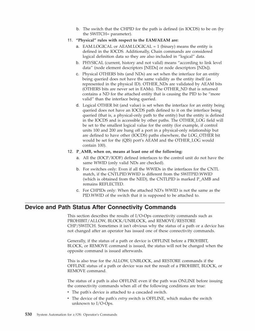
b. The switch that the CHPID for the path is defined (in IOCDS) to be on (bythe SWITCH= parameter).
11. “Physical” rules with respect to the EAM/AEAM are:
a. EAM.LOGICAL or AEAM.LOGICAL = 1 (binary) means the entity isdefined in the IOCDS. Additionally, Chain commands are consideredlogical definition data so they are also included in “logical” data.
b. PHYSICAL (current, history and not valid) means “according to link leveldata” (node element descriptors [NEDs] or node descriptors [NDs]).
c. Physical OTHERS bits (and NDs) are set when the interface for an entitybeing queried does not have the same validity as the entity itself (asrepresented in the physical ID). OTHER_NDs are validated by AEAM bits(OTHERS bits are never set in EAMs). The OTHER_ND that is returnedcontains a ND for the attached entity that is causing the PID to be “morevalid” than the interface being queried.
d. Logical OTHER bit (and value) is set when the interface for an entity beingqueried does not have an IOCDS path defined to it on the interface beingqueried (that is, a physical-only path to the entity) but the entity is definedin the IOCDS and is accessible by other paths. The OTHER_LOG field willbe set to the smallest logical value for the entity (for example, if controlunits 100 and 200 are hung off a port in a physical-only relationship butare defined to have other (IOCDS) paths elsewhere, the LOG_OTHER bitwould be set for the (QIS) port’s AEAM and the OTHER_LOG wouldcontain 100).
12. P_AMB, when on, means at least one of the following:
a. All the (IOCP/IODF) defined interfaces to the control unit do not have thesame WWID (only valid NDs are checked).
b. For switches only: Even if all the WWIDs in the interfaces for the CNTLmatch, if the CNTLPID.WWID is different from the SWITPID.WWID(which is obtained from the NED), the CNTLPID is marked P_AMB andremains REFLECTED.
c. For CHPIDs only: When the attached ND's WWID is not the same as thePID.WWID of the switch that it is supposed to be attached to.
Device and Path Status After Connectivity CommandsThis section describes the results of I/O-Ops connectivity commands such asPROHIBIT/ALLOW, BLOCK/UNBLOCK, and REMOVE/RESTORECHP/SWITCH. Sometimes it isn't obvious why the status of a path or a device hasnot changed after an operator has issued one of these connectivity commands.
Generally, if the status of a path or device is OFFLINE before a PROHIBIT,BLOCK, or REMOVE command is issued, the status will not be changed when theopposite command is issued afterwards.
This is also true for the ALLOW, UNBLOCK, and RESTORE commands if theOFFLINE status of a path or device was not the result of a PROHIBIT, BLOCK, orREMOVE command.
The status of a path is also OFFLINE even if the path was ONLINE before issuingthe connectivity commands when all of the following conditions are true:v The path's device is attached to a cascaded switch.v The device of the path's entry switch is OFFLINE, which makes the switch
unknown to I/O-Ops.
530 System Automation for z/OS: Operator's Commands
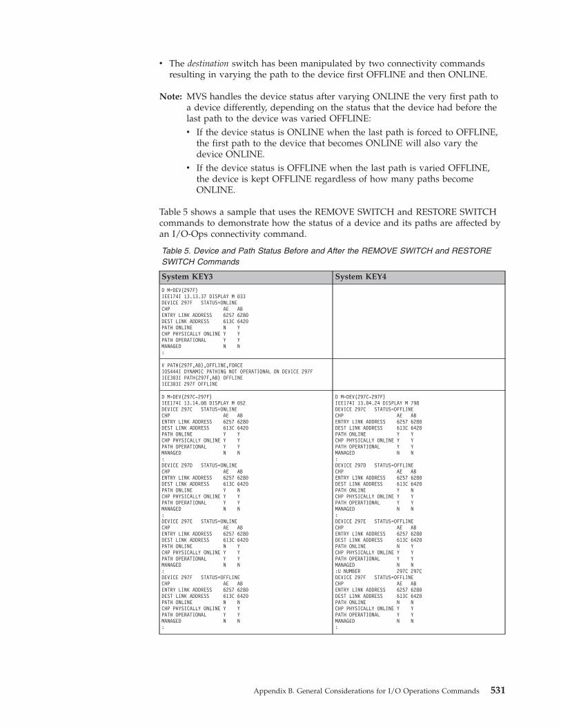
v The destination switch has been manipulated by two connectivity commandsresulting in varying the path to the device first OFFLINE and then ONLINE.
Note: MVS handles the device status after varying ONLINE the very first path toa device differently, depending on the status that the device had before thelast path to the device was varied OFFLINE:v If the device status is ONLINE when the last path is forced to OFFLINE,
the first path to the device that becomes ONLINE will also vary thedevice ONLINE.
v If the device status is OFFLINE when the last path is varied OFFLINE,the device is kept OFFLINE regardless of how many paths becomeONLINE.
Table 5 shows a sample that uses the REMOVE SWITCH and RESTORE SWITCHcommands to demonstrate how the status of a device and its paths are affected byan I/O-Ops connectivity command.
Table 5. Device and Path Status Before and After the REMOVE SWITCH and RESTORESWITCH Commands
System KEY3 System KEY4
D M=DEV(297F)IEE174I 13.13.37 DISPLAY M 033DEVICE 297F STATUS=ONLINECHP AE ABENTRY LINK ADDRESS 6257 6280DEST LINK ADDRESS 613C 6420PATH ONLINE N YCHP PHYSICALLY ONLINE Y YPATH OPERATIONAL Y YMANAGED N N:
V PATH(297F,AB),OFFLINE,FORCEIOS444I DYNAMIC PATHING NOT OPERATIONAL ON DEVICE 297FIEE303I PATH(297F,AB) OFFLINEIEE303I 297F OFFLINE
D M=DEV(297C-297F)IEE174I 13.14.08 DISPLAY M 052DEVICE 297C STATUS=ONLINECHP AE ABENTRY LINK ADDRESS 6257 6280DEST LINK ADDRESS 613C 6420PATH ONLINE Y YCHP PHYSICALLY ONLINE Y YPATH OPERATIONAL Y YMANAGED N N:DEVICE 297D STATUS=ONLINECHP AE ABENTRY LINK ADDRESS 6257 6280DEST LINK ADDRESS 613C 6420PATH ONLINE Y NCHP PHYSICALLY ONLINE Y YPATH OPERATIONAL Y YMANAGED N N:DEVICE 297E STATUS=ONLINECHP AE ABENTRY LINK ADDRESS 6257 6280DEST LINK ADDRESS 613C 6420PATH ONLINE N YCHP PHYSICALLY ONLINE Y YPATH OPERATIONAL Y YMANAGED N N:DEVICE 297F STATUS=OFFLINECHP AE ABENTRY LINK ADDRESS 6257 6280DEST LINK ADDRESS 613C 6420PATH ONLINE N NCHP PHYSICALLY ONLINE Y YPATH OPERATIONAL Y YMANAGED N N:
D M=DEV(297C-297F)IEE174I 13.04.24 DISPLAY M 798DEVICE 297C STATUS=OFFLINECHP AE ABENTRY LINK ADDRESS 6257 6280DEST LINK ADDRESS 613C 6420PATH ONLINE Y YCHP PHYSICALLY ONLINE Y YPATH OPERATIONAL Y YMANAGED N N:DEVICE 297D STATUS=OFFLINECHP AE ABENTRY LINK ADDRESS 6257 6280DEST LINK ADDRESS 613C 6420PATH ONLINE Y NCHP PHYSICALLY ONLINE Y YPATH OPERATIONAL Y YMANAGED N N:DEVICE 297E STATUS=OFFLINECHP AE ABENTRY LINK ADDRESS 6257 6280DEST LINK ADDRESS 613C 6420PATH ONLINE N YCHP PHYSICALLY ONLINE Y YPATH OPERATIONAL Y YMANAGED N N:U NUMBER 297C 297CDEVICE 297F STATUS=OFFLINECHP AE ABENTRY LINK ADDRESS 6257 6280DEST LINK ADDRESS 613C 6420PATH ONLINE N NCHP PHYSICALLY ONLINE Y YPATH OPERATIONAL Y YMANAGED N N:
Appendix B. General Considerations for I/O Operations Commands 531
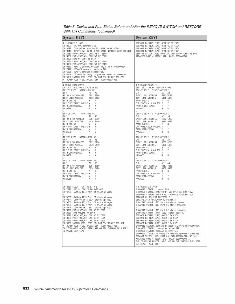
Table 5. Device and Path Status Before and After the REMOVE SWITCH and RESTORESWITCH Commands (continued)
System KEY3 System KEY4
F E,REMOVE S 1013IHVR001I I/O-OPS command 261IHVR010I Command entered by SYS OPER on IPSAOIHV:IHVR011I REMOVE SWITCH 1013 NODISABLE NOFORCE VARY BACKOUTIEE303I PATH(297F,AB) OFFLINE BY ESCMIEE303I PATH(297E,AB) OFFLINE BY ESCMIEE303I 297E OFFLINE BY ESCMIEE303I PATH(297D,AB) OFFLINE BY ESCMIEE303I PATH(297C,AB) OFFLINE BY ESCMIHVR021I REMOVE command successful, RC=0 RSN=40000004.IHVC998I I/O-OPS command response 268IHVC000I REMOVE command successful.IHVO000I I/O-OPS is ready to process operator commands.IEE633I SWITCH 1013, PORT 20, DCM STATUS=OFFLINE 270ATTACHED NODE = 002107.9A2.IBM.75.000000074011
IEE303I PATH(297F,AB) OFFLINE BY ESCMIEE303I PATH(297E,AB) OFFLINE BY ESCMIEE303I PATH(297D,AB) OFFLINE BY ESCMIEE303I PATH(297C,AB) OFFLINE BY ESCMIEE633I SWITCH 1013, PORT 20, DCM STATUS=OFFLINE 992ATTACHED NODE = 002107.9A2.IBM.75.000000074011
D M=DEV(297C-297F)IEE174I 13.27.01 DISPLAY M 272DEVICE 297C STATUS=ONLINECHP AE ABENTRY LINK ADDRESS 6257 6280DEST LINK ADDRESS 613C 6420PATH ONLINE Y NCHP PHYSICALLY ONLINE Y YPATH OPERATIONAL Y YMANAGED N N:DEVICE 297D STATUS=ONLINECHP AE ABENTRY LINK ADDRESS 6257 6280DEST LINK ADDRESS 613C 6420PATH ONLINE Y NCHP PHYSICALLY ONLINE Y YPATH OPERATIONAL Y YMANAGED N N:DEVICE 297E STATUS=OFFLINECHP AE ABENTRY LINK ADDRESS 6257 6280DEST LINK ADDRESS 613C 6420PATH ONLINE N NCHP PHYSICALLY ONLINE Y YPATH OPERATIONAL Y YMANAGED N N:DEVICE 297F STATUS=OFFLINECHP AE ABENTRY LINK ADDRESS 6257 6280DEST LINK ADDRESS 613C 6420PATH ONLINE N NCHP PHYSICALLY ONLINE Y YPATH OPERATIONAL Y YMANAGED N N:
D M=DEV(297C-297F)IEE174I 13.31.05 DISPLAY M 006DEVICE 297C STATUS=OFFLINECHP AE ABENTRY LINK ADDRESS 6257 6280DEST LINK ADDRESS 613C 6420PATH ONLINE Y NCHP PHYSICALLY ONLINE Y YPATH OPERATIONAL Y YMANAGED N N:DEVICE 297D STATUS=OFFLINECHP AE ABENTRY LINK ADDRESS 6257 6280DEST LINK ADDRESS 613C 6420PATH ONLINE Y NCHP PHYSICALLY ONLINE Y YPATH OPERATIONAL Y YMANAGED N N:DEVICE 297E STATUS=OFFLINECHP AE ABENTRY LINK ADDRESS 6257 6280DEST LINK ADDRESS 613C 6420PATH ONLINE N NCHP PHYSICALLY ONLINE Y YPATH OPERATIONAL Y YMANAGED N N:DEVICE 297F STATUS=OFFLINECHP AE ABENTRY LINK ADDRESS 6257 6280DEST LINK ADDRESS 613C 6420PATH ONLINE N NCHP PHYSICALLY ONLINE Y YPATH OPERATIONAL Y YMANAGED N N:
IEF236I ALLOC. FOR IOZPS33H EIEF237I 1013 ALLOCATED TO SWIT1013IHVA201I Switch 1013 Port 04 state changed.:IHVA201I Switch 1013 Port 20 state changed.IHVD344I Control unit 297C status update.IHVA201I Switch 1013 Port 21 state changed.IHVA201I Switch 1013 Port FE state changed.IHVD344I Control unit 1013 status update.IEE302I PATH(297E,AB) ONLINE BY ESCMIEE302I 297E ONLINE BY ESCMIEE302I PATH(297C,AB) ONLINE BY ESCMIEE302I PATH(1013,AB) ONLINE BY ESCMIEE302I PATH(1013,AA) ONLINE BY ESCMIEE633I SWITCH 1013, PORT 20, DCM STATUS=OFFLINE 351ATTACHED NODE = 002107.9A2.IBM.75.000000074011THE FOLLOWING DEVICE PATHS ARE ONLINE THROUGH THIS PORT:(297C,AB),(297E,AB)
F E,RESTORE S 1013IHVR001I I/O-OPS command 024IHVR010I Command entered by SYS OPER on IPSAPIHV:IHVR011I RESTORE SWITCH 1013 NOFORCE VARY BACKOUTIEF236I ALLOC. FOR IOZPS33H EIEF237I 1013 ALLOCATED TO SWIT1013IHVA201I Switch 1013 Port 04 state changed.IHVA201I Switch 1013 Port 05 state changed.:IHVA201I Switch 1013 Port FE state changed.IHVD344I Control unit 1013 status update.IEE302I PATH(297E,AB) ONLINE BY ESCMIEE302I PATH(297C,AB) ONLINE BY ESCMIEE302I PATH(1013,AB) ONLINE BY ESCMIEE302I PATH(1013,AA) ONLINE BY ESCMIHVR021I RESTORE command successful, RC=0 RSN=40000004.IHVC998I I/O-OPS command response 099IHVC000I RESTORE command successful.IHVO000I I/O-OPS is ready to process operator commands.IEE633I SWITCH 1013, PORT 20, DCM STATUS=OFFLINE 101ATTACHED NODE = 002107.9A2.IBM.75.000000074011THE FOLLOWING DEVICE PATHS ARE ONLINE THROUGH THIS PORT:(297C,AB),(297E,AB)
532 System Automation for z/OS: Operator's Commands
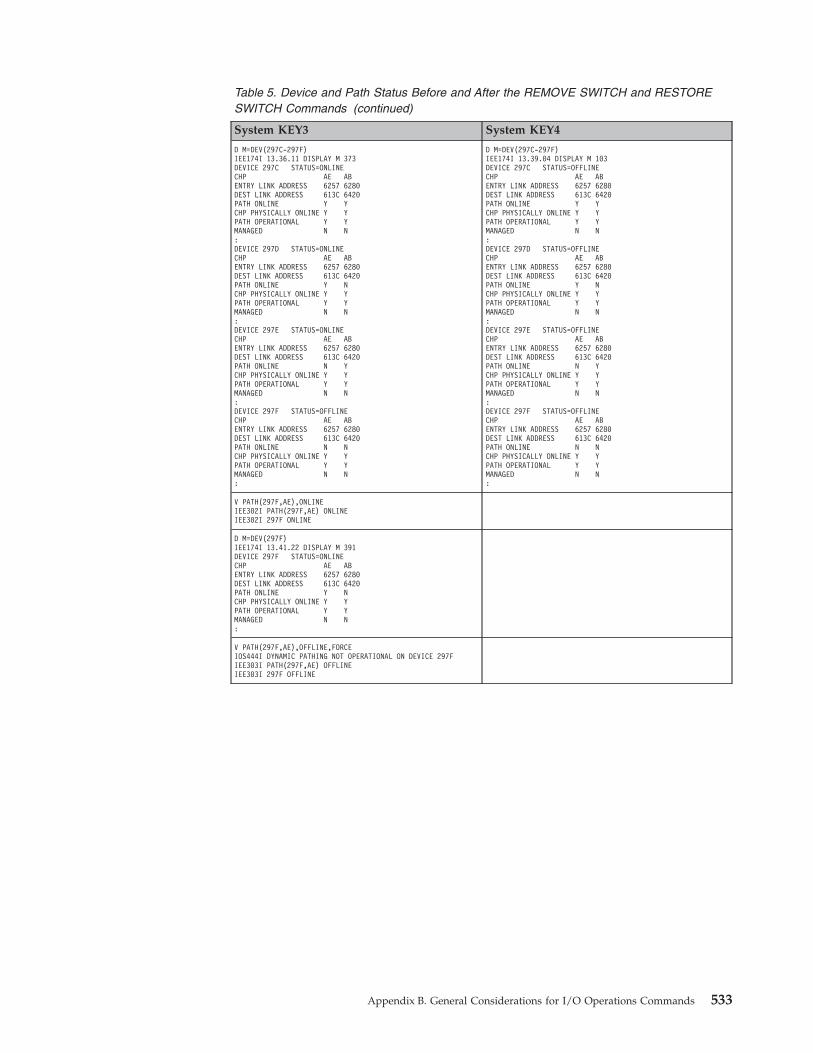
Table 5. Device and Path Status Before and After the REMOVE SWITCH and RESTORESWITCH Commands (continued)
System KEY3 System KEY4
D M=DEV(297C-297F)IEE174I 13.36.11 DISPLAY M 373DEVICE 297C STATUS=ONLINECHP AE ABENTRY LINK ADDRESS 6257 6280DEST LINK ADDRESS 613C 6420PATH ONLINE Y YCHP PHYSICALLY ONLINE Y YPATH OPERATIONAL Y YMANAGED N N:DEVICE 297D STATUS=ONLINECHP AE ABENTRY LINK ADDRESS 6257 6280DEST LINK ADDRESS 613C 6420PATH ONLINE Y NCHP PHYSICALLY ONLINE Y YPATH OPERATIONAL Y YMANAGED N N:DEVICE 297E STATUS=ONLINECHP AE ABENTRY LINK ADDRESS 6257 6280DEST LINK ADDRESS 613C 6420PATH ONLINE N YCHP PHYSICALLY ONLINE Y YPATH OPERATIONAL Y YMANAGED N N:DEVICE 297F STATUS=OFFLINECHP AE ABENTRY LINK ADDRESS 6257 6280DEST LINK ADDRESS 613C 6420PATH ONLINE N NCHP PHYSICALLY ONLINE Y YPATH OPERATIONAL Y YMANAGED N N:
D M=DEV(297C-297F)IEE174I 13.39.04 DISPLAY M 103DEVICE 297C STATUS=OFFLINECHP AE ABENTRY LINK ADDRESS 6257 6280DEST LINK ADDRESS 613C 6420PATH ONLINE Y YCHP PHYSICALLY ONLINE Y YPATH OPERATIONAL Y YMANAGED N N:DEVICE 297D STATUS=OFFLINECHP AE ABENTRY LINK ADDRESS 6257 6280DEST LINK ADDRESS 613C 6420PATH ONLINE Y NCHP PHYSICALLY ONLINE Y YPATH OPERATIONAL Y YMANAGED N N:DEVICE 297E STATUS=OFFLINECHP AE ABENTRY LINK ADDRESS 6257 6280DEST LINK ADDRESS 613C 6420PATH ONLINE N YCHP PHYSICALLY ONLINE Y YPATH OPERATIONAL Y YMANAGED N N:DEVICE 297F STATUS=OFFLINECHP AE ABENTRY LINK ADDRESS 6257 6280DEST LINK ADDRESS 613C 6420PATH ONLINE N NCHP PHYSICALLY ONLINE Y YPATH OPERATIONAL Y YMANAGED N N:
V PATH(297F,AE),ONLINEIEE302I PATH(297F,AE) ONLINEIEE302I 297F ONLINE
D M=DEV(297F)IEE174I 13.41.22 DISPLAY M 391DEVICE 297F STATUS=ONLINECHP AE ABENTRY LINK ADDRESS 6257 6280DEST LINK ADDRESS 613C 6420PATH ONLINE Y NCHP PHYSICALLY ONLINE Y YPATH OPERATIONAL Y YMANAGED N N:
V PATH(297F,AE),OFFLINE,FORCEIOS444I DYNAMIC PATHING NOT OPERATIONAL ON DEVICE 297FIEE303I PATH(297F,AE) OFFLINEIEE303I 297F OFFLINE
Appendix B. General Considerations for I/O Operations Commands 533
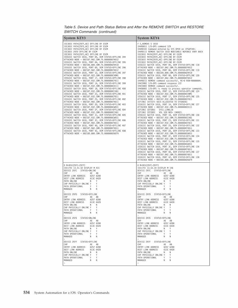
Table 5. Device and Path Status Before and After the REMOVE SWITCH and RESTORESWITCH Commands (continued)
System KEY3 System KEY4
IEE303I PATH(297F,AE) OFFLINE BY ESCMIEE303I PATH(297E,AE) OFFLINE BY ESCMIEE303I PATH(297D,AE) OFFLINE BY ESCMIEE303I 297D OFFLINE BY ESCMIEE303I PATH(297C,AE) OFFLINE BY ESCMIEE633I SWITCH 1010, PORT 05, DCM STATUS=OFFLINE 394ATTACHED NODE = 002107.9A2.IBM.75.000000074012IEE633I SWITCH 1010, PORT 0A, DCM STATUS=OFFLINE 395ATTACHED NODE = 002105.800.IBM.75.000000029410IEE633I SWITCH 1010, PORT 0D, DCM STATUS=OFFLINE 396ATTACHED NODE = 002107.9A2.IBM.75.000000074012IEE633I SWITCH 1010, PORT 12, DCM STATUS=OFFLINE 397ATTACHED NODE = 002107.922.IBM.75.0000000CVBM1IEE633I SWITCH 1010, PORT 17, DCM STATUS=OFFLINE 398ATTACHED NODE = 002107.932.IBM.75.0000000CF811IEE633I SWITCH 1010, PORT 1A, DCM STATUS=OFFLINE 399ATTACHED NODE = 002107.932.IBM.75.0000000CD111IEE633I SWITCH 1010, PORT 1B, DCM STATUS=OFFLINE 400ATTACHED NODE = 002107.932.IBM.75.0000000CC481IEE633I SWITCH 1010, PORT 23, DCM STATUS=OFFLINE 401ATTACHED NODE = 002107.932.IBM.75.0000000CF811IEE633I SWITCH 1010, PORT 25, DCM STATUS=OFFLINE 402ATTACHED NODE = 002107.9A2.IBM.75.000000074011IEE633I SWITCH 1010, PORT 2D, DCM STATUS=OFFLINE 403ATTACHED NODE = 002107.932.IBM.75.0000000CW931IEE633I SWITCH 1010, PORT 2F, DCM STATUS=OFFLINE 404ATTACHED NODE = 002107.932.IBM.75.0000000CC481IEE633I SWITCH 1010, PORT 31, DCM STATUS=OFFLINE 405ATTACHED NODE = 002107.932.IBM.75.0000000CW931IEE633I SWITCH 1010, PORT 3C, DCM STATUS=OFFLINE 406ATTACHED NODE = 002107.9A2.IBM.75.000000074011IEE633I SWITCH 1010, PORT 40, DCM STATUS=OFFLINE 407ATTACHED NODE = 002107.9A2.IBM.75.000000074011IEE633I SWITCH 1010, PORT 42, DCM STATUS=OFFLINE 408ATTACHED NODE = 002105.800.IBM.75.000000026079
F E,REMOVE S 1010IHVR001I I/O-OPS command 129IHVR010I Command entered by SYS OPER on IPSAPIHV:IHVR011I REMOVE SWITCH 1010 NODISABLE NOFORCE VARY BACKIEE303I PATH(297F,AE) OFFLINE BY ESCMIEE303I PATH(297E,AE) OFFLINE BY ESCMIEE303I PATH(297D,AE) OFFLINE BY ESCMIEE303I PATH(297C,AE) OFFLINE BY ESCMIEE633I SWITCH 1010, PORT 05, DCM STATUS=OFFLINE 118ATTACHED NODE = 002107.9A2.IBM.75.000000074012IEE633I SWITCH 1010, PORT 0A, DCM STATUS=OFFLINE 119ATTACHED NODE = 002105.800.IBM.75.000000029410IEE633I SWITCH 1010, PORT 0D, DCM STATUS=OFFLINE 120ATTACHED NODE = 002107.9A2.IBM.75.000000074012IHVR021I REMOVE command successful, RC=0 RSN=40000004.IHVC998I I/O-OPS command response 122IHVC000I REMOVE command successful.IHVO000I I/O-OPS is ready to process operator commands.IEE633I SWITCH 1010, PORT 12, DCM STATUS=OFFLINE 124ATTACHED NODE = 002107.922.IBM.75.0000000CVBM1IEE633I SWITCH 1010, PORT 17, DCM STATUS=OFFLINE 125ATTACHED NODE = 002107.932.IBM.75.0000000CF811IEF196I IEF237I 5015 ALLOCATED TO SYS00261IEE633I SWITCH 1010, PORT 1A, DCM STATUS=OFFLINE 127ATTACHED NODE = 002107.932.IBM.75.0000000CD111IEF196I IEF285I SYS1.LINKLIBIEF196I IEF285I VOL SER NOS= 190923.IEE633I SWITCH 1010, PORT 1B, DCM STATUS=OFFLINE 130ATTACHED NODE = 002107.932.IBM.75.0000000CC481IEE633I SWITCH 1010, PORT 23, DCM STATUS=OFFLINE 131ATTACHED NODE = 002107.932.IBM.75.0000000CF811IEE633I SWITCH 1010, PORT 25, DCM STATUS=OFFLINE 132ATTACHED NODE = 002107.9A2.IBM.75.000000074011IEE633I SWITCH 1010, PORT 2D, DCM STATUS=OFFLINE 133ATTACHED NODE = 002107.932.IBM.75.0000000CW931IEE633I SWITCH 1010, PORT 2F, DCM STATUS=OFFLINE 134ATTACHED NODE = 002107.932.IBM.75.0000000CC481IEE633I SWITCH 1010, PORT 31, DCM STATUS=OFFLINE 135ATTACHED NODE = 002107.932.IBM.75.0000000CW931IEE633I SWITCH 1010, PORT 3C, DCM STATUS=OFFLINE 136ATTACHED NODE = 002107.9A2.IBM.75.000000074011IEE633I SWITCH 1010, PORT 40, DCM STATUS=OFFLINE 137ATTACHED NODE = 002107.9A2.IBM.75.000000074011IEE633I SWITCH 1010, PORT 42, DCM STATUS=OFFLINE 138ATTACHED NODE = 002105.800.IBM.75.000000026079
D M=DEV(297C-297F)IEE174I 13.51.52 DISPLAY M 431DEVICE 297C STATUS=ONLINECHP AE ABENTRY LINK ADDRESS 6257 6280DEST LINK ADDRESS 613C 6420PATH ONLINE N YCHP PHYSICALLY ONLINE Y YPATH OPERATIONAL Y YMANAGED N N:DEVICE 297D STATUS=OFFLINECHP AE ABENTRY LINK ADDRESS 6257 6280DEST LINK ADDRESS 613C 6420PATH ONLINE N NCHP PHYSICALLY ONLINE Y YPATH OPERATIONAL Y YMANAGED N N:DEVICE 297E STATUS=ONLINECHP AE ABENTRY LINK ADDRESS 6257 6280DEST LINK ADDRESS 613C 6420PATH ONLINE N YCHP PHYSICALLY ONLINE Y YPATH OPERATIONAL Y YMANAGED N N:DEVICE 297F STATUS=OFFLINECHP AE ABENTRY LINK ADDRESS 6257 6280DEST LINK ADDRESS 613C 6420PATH ONLINE N NCHP PHYSICALLY ONLINE Y YPATH OPERATIONAL Y YMANAGED N N:
D M=DEV(297C-297F)IEE174I 13.53.34 DISPLAY M 146DEVICE 297C STATUS=OFFLINECHP AE ABENTRY LINK ADDRESS 6257 6280DEST LINK ADDRESS 613C 6420PATH ONLINE N YCHP PHYSICALLY ONLINE Y YPATH OPERATIONAL Y YMANAGED N N:DEVICE 297D STATUS=OFFLINECHP AE ABENTRY LINK ADDRESS 6257 6280DEST LINK ADDRESS 613C 6420PATH ONLINE N NCHP PHYSICALLY ONLINE Y YPATH OPERATIONAL Y YMANAGED N N:DEVICE 297E STATUS=OFFLINECHP AE ABENTRY LINK ADDRESS 6257 6280DEST LINK ADDRESS 613C 6420PATH ONLINE N YCHP PHYSICALLY ONLINE Y YPATH OPERATIONAL Y YMANAGED N N:DEVICE 297F STATUS=OFFLINECHP AE ABENTRY LINK ADDRESS 6257 6280DEST LINK ADDRESS 613C 6420PATH ONLINE N NCHP PHYSICALLY ONLINE Y YPATH OPERATIONAL Y YMANAGED N N:
534 System Automation for z/OS: Operator's Commands
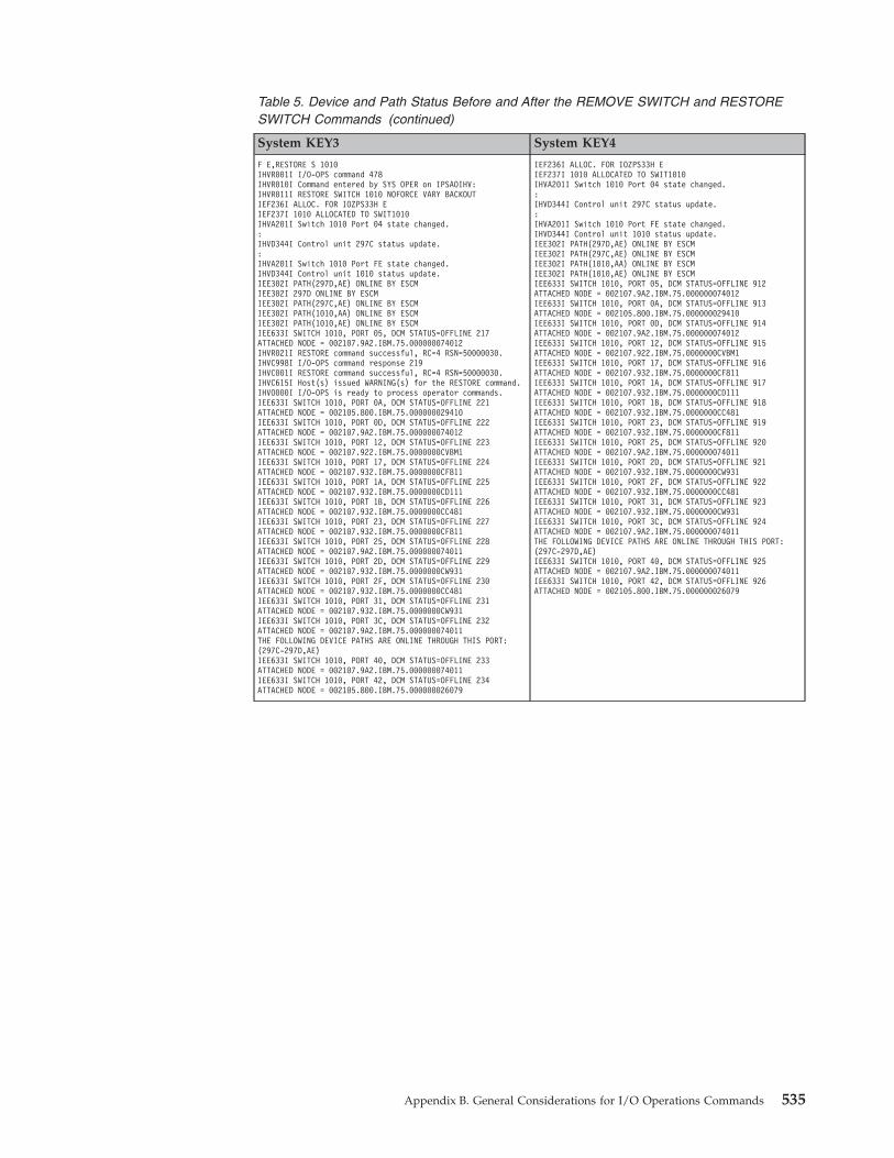
Table 5. Device and Path Status Before and After the REMOVE SWITCH and RESTORESWITCH Commands (continued)
System KEY3 System KEY4
F E,RESTORE S 1010IHVR001I I/O-OPS command 478IHVR010I Command entered by SYS OPER on IPSAOIHV:IHVR011I RESTORE SWITCH 1010 NOFORCE VARY BACKOUTIEF236I ALLOC. FOR IOZPS33H EIEF237I 1010 ALLOCATED TO SWIT1010IHVA201I Switch 1010 Port 04 state changed.:IHVD344I Control unit 297C status update.:IHVA201I Switch 1010 Port FE state changed.IHVD344I Control unit 1010 status update.IEE302I PATH(297D,AE) ONLINE BY ESCMIEE302I 297D ONLINE BY ESCMIEE302I PATH(297C,AE) ONLINE BY ESCMIEE302I PATH(1010,AA) ONLINE BY ESCMIEE302I PATH(1010,AE) ONLINE BY ESCMIEE633I SWITCH 1010, PORT 05, DCM STATUS=OFFLINE 217ATTACHED NODE = 002107.9A2.IBM.75.000000074012IHVR021I RESTORE command successful, RC=4 RSN=50000030.IHVC998I I/O-OPS command response 219IHVC001I RESTORE command successful, RC=4 RSN=50000030.IHVC615I Host(s) issued WARNING(s) for the RESTORE command.IHVO000I I/O-OPS is ready to process operator commands.IEE633I SWITCH 1010, PORT 0A, DCM STATUS=OFFLINE 221ATTACHED NODE = 002105.800.IBM.75.000000029410IEE633I SWITCH 1010, PORT 0D, DCM STATUS=OFFLINE 222ATTACHED NODE = 002107.9A2.IBM.75.000000074012IEE633I SWITCH 1010, PORT 12, DCM STATUS=OFFLINE 223ATTACHED NODE = 002107.922.IBM.75.0000000CVBM1IEE633I SWITCH 1010, PORT 17, DCM STATUS=OFFLINE 224ATTACHED NODE = 002107.932.IBM.75.0000000CF811IEE633I SWITCH 1010, PORT 1A, DCM STATUS=OFFLINE 225ATTACHED NODE = 002107.932.IBM.75.0000000CD111IEE633I SWITCH 1010, PORT 1B, DCM STATUS=OFFLINE 226ATTACHED NODE = 002107.932.IBM.75.0000000CC481IEE633I SWITCH 1010, PORT 23, DCM STATUS=OFFLINE 227ATTACHED NODE = 002107.932.IBM.75.0000000CF811IEE633I SWITCH 1010, PORT 25, DCM STATUS=OFFLINE 228ATTACHED NODE = 002107.9A2.IBM.75.000000074011IEE633I SWITCH 1010, PORT 2D, DCM STATUS=OFFLINE 229ATTACHED NODE = 002107.932.IBM.75.0000000CW931IEE633I SWITCH 1010, PORT 2F, DCM STATUS=OFFLINE 230ATTACHED NODE = 002107.932.IBM.75.0000000CC481IEE633I SWITCH 1010, PORT 31, DCM STATUS=OFFLINE 231ATTACHED NODE = 002107.932.IBM.75.0000000CW931IEE633I SWITCH 1010, PORT 3C, DCM STATUS=OFFLINE 232ATTACHED NODE = 002107.9A2.IBM.75.000000074011THE FOLLOWING DEVICE PATHS ARE ONLINE THROUGH THIS PORT:(297C-297D,AE)IEE633I SWITCH 1010, PORT 40, DCM STATUS=OFFLINE 233ATTACHED NODE = 002107.9A2.IBM.75.000000074011IEE633I SWITCH 1010, PORT 42, DCM STATUS=OFFLINE 234ATTACHED NODE = 002105.800.IBM.75.000000026079
IEF236I ALLOC. FOR IOZPS33H EIEF237I 1010 ALLOCATED TO SWIT1010IHVA201I Switch 1010 Port 04 state changed.:IHVD344I Control unit 297C status update.:IHVA201I Switch 1010 Port FE state changed.IHVD344I Control unit 1010 status update.IEE302I PATH(297D,AE) ONLINE BY ESCMIEE302I PATH(297C,AE) ONLINE BY ESCMIEE302I PATH(1010,AA) ONLINE BY ESCMIEE302I PATH(1010,AE) ONLINE BY ESCMIEE633I SWITCH 1010, PORT 05, DCM STATUS=OFFLINE 912ATTACHED NODE = 002107.9A2.IBM.75.000000074012IEE633I SWITCH 1010, PORT 0A, DCM STATUS=OFFLINE 913ATTACHED NODE = 002105.800.IBM.75.000000029410IEE633I SWITCH 1010, PORT 0D, DCM STATUS=OFFLINE 914ATTACHED NODE = 002107.9A2.IBM.75.000000074012IEE633I SWITCH 1010, PORT 12, DCM STATUS=OFFLINE 915ATTACHED NODE = 002107.922.IBM.75.0000000CVBM1IEE633I SWITCH 1010, PORT 17, DCM STATUS=OFFLINE 916ATTACHED NODE = 002107.932.IBM.75.0000000CF811IEE633I SWITCH 1010, PORT 1A, DCM STATUS=OFFLINE 917ATTACHED NODE = 002107.932.IBM.75.0000000CD111IEE633I SWITCH 1010, PORT 1B, DCM STATUS=OFFLINE 918ATTACHED NODE = 002107.932.IBM.75.0000000CC481IEE633I SWITCH 1010, PORT 23, DCM STATUS=OFFLINE 919ATTACHED NODE = 002107.932.IBM.75.0000000CF811IEE633I SWITCH 1010, PORT 25, DCM STATUS=OFFLINE 920ATTACHED NODE = 002107.9A2.IBM.75.000000074011IEE633I SWITCH 1010, PORT 2D, DCM STATUS=OFFLINE 921ATTACHED NODE = 002107.932.IBM.75.0000000CW931IEE633I SWITCH 1010, PORT 2F, DCM STATUS=OFFLINE 922ATTACHED NODE = 002107.932.IBM.75.0000000CC481IEE633I SWITCH 1010, PORT 31, DCM STATUS=OFFLINE 923ATTACHED NODE = 002107.932.IBM.75.0000000CW931IEE633I SWITCH 1010, PORT 3C, DCM STATUS=OFFLINE 924ATTACHED NODE = 002107.9A2.IBM.75.000000074011THE FOLLOWING DEVICE PATHS ARE ONLINE THROUGH THIS PORT:(297C-297D,AE)IEE633I SWITCH 1010, PORT 40, DCM STATUS=OFFLINE 925ATTACHED NODE = 002107.9A2.IBM.75.000000074011IEE633I SWITCH 1010, PORT 42, DCM STATUS=OFFLINE 926ATTACHED NODE = 002105.800.IBM.75.000000026079
Appendix B. General Considerations for I/O Operations Commands 535
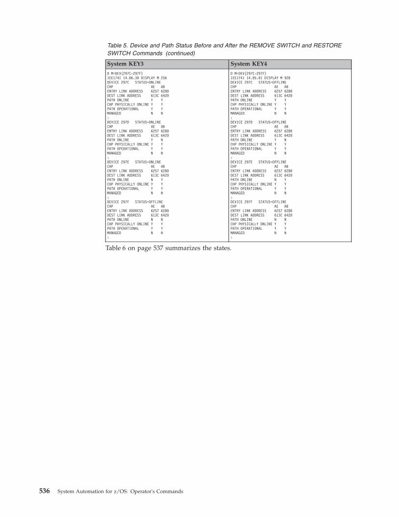
Table 5. Device and Path Status Before and After the REMOVE SWITCH and RESTORESWITCH Commands (continued)
System KEY3 System KEY4
D M=DEV(297C-297F)IEE174I 14.06.30 DISPLAY M 256DEVICE 297C STATUS=ONLINECHP AE ABENTRY LINK ADDRESS 6257 6280DEST LINK ADDRESS 613C 6420PATH ONLINE Y YCHP PHYSICALLY ONLINE Y YPATH OPERATIONAL Y YMANAGED N N:DEVICE 297D STATUS=ONLINECHP AE ABENTRY LINK ADDRESS 6257 6280DEST LINK ADDRESS 613C 6420PATH ONLINE Y NCHP PHYSICALLY ONLINE Y YPATH OPERATIONAL Y YMANAGED N N:DEVICE 297E STATUS=ONLINECHP AE ABENTRY LINK ADDRESS 6257 6280DEST LINK ADDRESS 613C 6420PATH ONLINE N YCHP PHYSICALLY ONLINE Y YPATH OPERATIONAL Y YMANAGED N N:DEVICE 297F STATUS=OFFLINECHP AE ABENTRY LINK ADDRESS 6257 6280DEST LINK ADDRESS 613C 6420PATH ONLINE N NCHP PHYSICALLY ONLINE Y YPATH OPERATIONAL Y YMANAGED N N:
D M=DEV(297C-297F)IEE174I 14.05.01 DISPLAY M 928DEVICE 297C STATUS=OFFLINECHP AE ABENTRY LINK ADDRESS 6257 6280DEST LINK ADDRESS 613C 6420PATH ONLINE Y YCHP PHYSICALLY ONLINE Y YPATH OPERATIONAL Y YMANAGED N N:DEVICE 297D STATUS=OFFLINECHP AE ABENTRY LINK ADDRESS 6257 6280DEST LINK ADDRESS 613C 6420PATH ONLINE Y NCHP PHYSICALLY ONLINE Y YPATH OPERATIONAL Y YMANAGED N N:DEVICE 297E STATUS=OFFLINECHP AE ABENTRY LINK ADDRESS 6257 6280DEST LINK ADDRESS 613C 6420PATH ONLINE N YCHP PHYSICALLY ONLINE Y YPATH OPERATIONAL Y YMANAGED N N:DEVICE 297F STATUS=OFFLINECHP AE ABENTRY LINK ADDRESS 6257 6280DEST LINK ADDRESS 613C 6420PATH ONLINE N NCHP PHYSICALLY ONLINE Y YPATH OPERATIONAL Y YMANAGED N N:
Table 6 on page 537 summarizes the states.
536 System Automation for z/OS: Operator's Commands
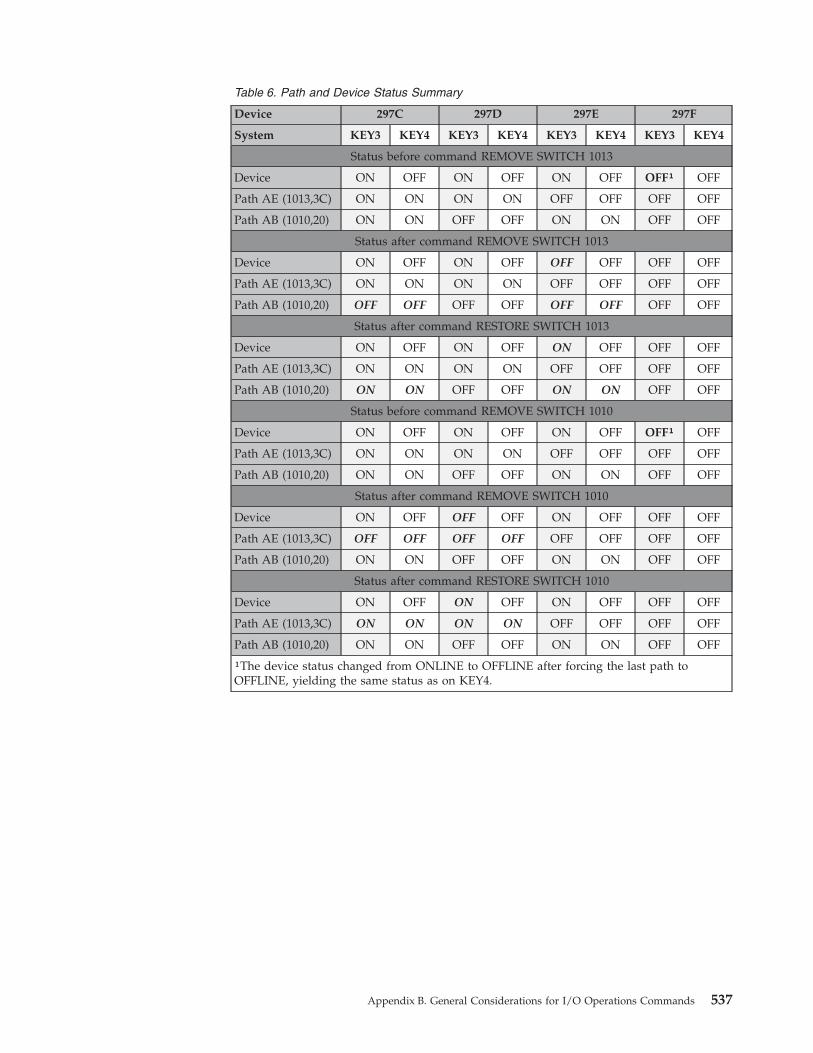
Table 6. Path and Device Status Summary
Device 297C 297D 297E 297F
System KEY3 KEY4 KEY3 KEY4 KEY3 KEY4 KEY3 KEY4
Status before command REMOVE SWITCH 1013
Device ON OFF ON OFF ON OFF OFF¹ OFF
Path AE (1013,3C) ON ON ON ON OFF OFF OFF OFF
Path AB (1010,20) ON ON OFF OFF ON ON OFF OFF
Status after command REMOVE SWITCH 1013
Device ON OFF ON OFF OFF OFF OFF OFF
Path AE (1013,3C) ON ON ON ON OFF OFF OFF OFF
Path AB (1010,20) OFF OFF OFF OFF OFF OFF OFF OFF
Status after command RESTORE SWITCH 1013
Device ON OFF ON OFF ON OFF OFF OFF
Path AE (1013,3C) ON ON ON ON OFF OFF OFF OFF
Path AB (1010,20) ON ON OFF OFF ON ON OFF OFF
Status before command REMOVE SWITCH 1010
Device ON OFF ON OFF ON OFF OFF¹ OFF
Path AE (1013,3C) ON ON ON ON OFF OFF OFF OFF
Path AB (1010,20) ON ON OFF OFF ON ON OFF OFF
Status after command REMOVE SWITCH 1010
Device ON OFF OFF OFF ON OFF OFF OFF
Path AE (1013,3C) OFF OFF OFF OFF OFF OFF OFF OFF
Path AB (1010,20) ON ON OFF OFF ON ON OFF OFF
Status after command RESTORE SWITCH 1010
Device ON OFF ON OFF ON OFF OFF OFF
Path AE (1013,3C) ON ON ON ON OFF OFF OFF OFF
Path AB (1010,20) ON ON OFF OFF ON ON OFF OFF
¹The device status changed from ONLINE to OFFLINE after forcing the last path toOFFLINE, yielding the same status as on KEY4.
Appendix B. General Considerations for I/O Operations Commands 537

538 System Automation for z/OS: Operator's Commands
Appendix C. Notices
This information was developed for products and services offered in the U.S.A.
IBM may not offer the products, services, or features discussed in this document inother countries. Consult your local IBM representative for information on theproducts and services currently available in your area. Any reference to an IBMproduct, program, or service is not intended to state or imply that only that IBMproduct, program, or service may be used. Any functionally equivalent product,program, or service that does not infringe any IBM intellectual property right maybe used instead. However, it is the user’s responsibility to evaluate and verify theoperation of any non-IBM product, program, or service.
IBM may have patents or pending patent applications covering subject matter inthis document. The furnishing of this document does not give you any license tothese patents. You can send license inquiries, in writing, to:
IBM Director of LicensingIBM CorporationNorth Castle DriveArmonk, NY 10504-1785USA
For license inquiries regarding double-byte (DBCS) information, contact the IBMIntellectual Property Department in your country or send inquiries, in writing, to:
Intellectual Property LicensingLegal and Intellectual Property LawIBM Japan, Ltd.1623-14, Shimotsuruma, Yamato-shiKanagawa 242-8502 Japan
The following paragraph does not apply to the United Kingdom or any othercountry where such provisions are inconsistent with local law:INTERNATIONAL BUSINESS MACHINES CORPORATION PROVIDES THISPUBLICATION "AS IS" WITHOUT WARRANTY OF ANY KIND, EITHEREXPRESS OR IMPLIED, INCLUDING, BUT NOT LIMITED TO, THE IMPLIEDWARRANTIES OF NON-INFRINGEMENT, MERCHANTABILITY OR FITNESSFOR A PARTICULAR PURPOSE. Some states do not allow disclaimer of express orimplied warranties in certain transactions, therefore, this statement may not applyto you.
This information could include technical inaccuracies or typographical errors.Changes are periodically made to the information herein; these changes will beincorporated in new editions of the publication. IBM may make improvementsand/or changes in the product(s) and/or the program(s) described in thispublication at any time without notice.
Any references in this information to non-IBM Websites are provided forconvenience only and do not in any manner serve as an endorsement of thoseWebsites. The materials at those Websites are not part of the materials for this IBMproduct and use of those Websites is at your own risk.
© Copyright IBM Corp. 1996, 2012 539
IBM may use or distribute any of the information you supply in any way itbelieves appropriate without incurring any obligation to you.
Licensees of this program who wish to have information about it for the purposeof enabling: (i) the exchange of information between independently createdprograms and other programs (including this one) and (ii) the mutual use of theinformation which has been exchanged, should contact:
IBM Deutschland Research & Development GmbHDepartment 3248Schoenaicher Strasse 220D-71032 BoeblingenFederal Republic of Germany
Such information may be available, subject to appropriate terms and conditions,including in some cases, payment of a fee.
The licensed program described in this document and all licensed materialavailable for it are provided by IBM under terms of the IBM Customer Agreement,IBM International Program License Agreement or any equivalent agreementbetween us.
This information contains examples of data and reports used in daily businessoperations. To illustrate them as completely as possible, the examples include thenames of individuals, companies, brands, and products. All of these names arefictitious and any similarity to the names and addresses used by an actual businessenterprise is entirely coincidental.
If you are viewing this information softcopy, the photographs and colorillustrations may not appear.
Programming Interface InformationThis publication documents information that is not intended to be used as aprogramming interface of IBM Tivoli System Automation for z/OS.
TrademarksIBM, the IBM logo, and ibm.com® are trademarks or registered trademarks ofInternational Business Machines Corp., registered in many jurisdictions worldwide.Other product and service names might be trademarks of IBM or other companies.A current list of IBM trademarks is available on the Web at www.ibm.com/legal/copytrade.shtml.
Linux is a registered trademark of Linus Torvalds in the United States, othercountries, or both.
Microsoft and Windows are trademarks of Microsoft Corporation in the UnitedStates, other countries, or both.
UNIX is a registered trademark of The Open Group in the United States and othercountries.
540 System Automation for z/OS: Operator's Commands
Glossary
This glossary includes terms and definitions from:v The IBM Dictionary of Computing New York:
McGraw-Hill, 1994.v The American National Standard Dictionary for
Information Systems, ANSI X3.172-1990,copyright 1990 by the American NationalStandards Institute (ANSI). Copies can bepurchased from the American NationalStandards Institute, 1430 Broadway, New York,New York 10018. Definitions are identified bythe symbol (A) after the definition.
v The Information Technology Vocabulary developedby Subcommittee 1, Joint Technical Committee1, of the International Organization forStandardization and the InternationalElectrotechnical Commission (ISO/IECJTC1/SC1). Definitions of published parts ofthis vocabulary are identified by the symbol (I)after the definition; definitions taken from draftinternational standards, committee drafts, andworking papers being developed by ISO/IECJTC1/SC1 are identified by the symbol (T) afterthe definition, indicating that final agreementhas not yet been reached among theparticipating National Bodies of SC1.
The following cross-references are used in thisglossary:
Contrast with. This refers to a term that hasan opposed or substantively differentmeaning.Deprecated term for. This indicates that theterm should not be used. It refers to apreferred term, which is defined in its properplace in the glossary.See. This refers the reader to multiple-wordterms in which this term appears.See also. This refers the reader to terms thathave a related, but not synonymous, meaning.Synonym for. This indicates that the term hasthe same meaning as a preferred term, whichis defined in the glossary.Synonymous with. This is a backwardreference from a defined term to all otherterms that have the same meaning.
AACF. See automation configuration file.
ACF/NCP. Advanced Communications Function forthe Network Control Program. See AdvancedCommunications Function and Network ControlProgram.
ACF/VTAM. Advanced Communications Function forthe Virtual Telecommunications Access Method.Synonym for VTAM. See Advanced CommunicationsFunction and Virtual Telecommunications AccessMethod.
active monitoring. In SA z/OSautomation control file,the acquiring of resource status information bysoliciting such information at regular, user-definedintervals. See also passive monitoring.
adapter. Hardware card that enables a device, such asa workstation, to communicate with another device,such as a monitor, a printer, or some other I/O device.
adjacent hosts. Systems connected in a peerrelationship using adjacent NetView sessions forpurposes of monitoring and control.
adjacent NetView. In SA z/OS, the system defined asthe communication path between two SA z/OSsystems that do not have a direct link. An adjacentNetView is used for message forwarding and as acommunication link between two SA z/OS systems.For example, the adjacent NetView is used whensending responses from a focal point to a remotesystem.
Advanced Communications Function (ACF). A groupof IBM licensed programs (principally VTAM, TCAM,NCP, and SSP) that use the concepts of SystemsNetwork Architecture (SNA), including distribution offunction and resource sharing.
advanced program-to-program communication(APPC). A set of inter-program communicationservices that support cooperative transaction processingin a Systems Network Architecture (SNA) network.APPC is the implementation, on a given system, ofSNA's logical unit type 6.2.
alert. (1) In SNA, a record sent to a system problemmanagement focal point or to a collection point tocommunicate the existence of an alert condition. (2) InNetView, a high-priority event that warrants immediateattention. A database record is generated for certainevent types that are defined by user-constructed filters.
alert condition. A problem or impending problem forwhich some or all of the process of problemdetermination, diagnosis, and resolution is expected torequire action at a control point.
© Copyright IBM Corp. 1996, 2012 541
alert focal-point system. See NPDA focal pointsystem.
alert threshold. An application or volume servicevalue that determines the level at which SA z/OSchanges the associated icon in the graphical interface tothe alert color. SA z/OS may also issue an alert. Seewarning threshold.
AMC. (1) See Automation Manager Configuration. (2)The Auto Msg Classes entry type.
American Standard Code for Information Interchange(ASCII). A standard code used for informationexchange among data processing systems, datacommunication systems, and associated equipment.ASCII uses a coded character set consisting of 7-bitcoded characters (8-bit including parity check). TheASCII set consists of control characters and graphiccharacters. See also Extended Binary Coded DecimalInterchange Code.
APF. See authorized program facility.
API. See application programming interface.
APPC. See advanced program-to-programcommunication.
application. In SA z/OS, applications refer to z/OSsubsystems, started tasks, or jobs that are automatedand monitored by SA z/OS. On SNMP-capableprocessors, application can be used to refer to asubsystem or process.
Application entry. A construct, created with thecustomization dialogs, used to represent and containpolicy for an application.
application group. A named set of applications. Anapplication group is part of an SA z/OS enterprisedefinition and is used for monitoring purposes.
application program. (1) A program written for or bya user that applies to the user's work, such as aprogram that does inventory or payroll. (2) A programused to connect and communicate with stations in anetwork, enabling users to perform application-orientedactivities.
application programming interface (API). Aninterface that allows an application program that iswritten in a high-level language to use specific data orfunctions of the operating system or another program.
ApplicationGroup entry. A construct, created with thecustomization dialogs, used to represent and containpolicy for an application group.
ARM. See automatic restart management.
ASCB. Address space control block.
ASCB status. An application status derived bySA z/OS running a routine (the ASCB checker) thatsearches the z/OS address space control blocks(ASCBs) for address spaces with a particular job name.The job name used by the ASCB checker is the jobname defined in the customization dialog for theapplication.
ASCII. See American Standard Code for InformationInterchange.
ASF. See automation status file.
authorized program facility (APF). A facility thatpermits identification of programs that are authorizedto use restricted functions.
automated console operations (ACO). The use of anautomated procedure to replace or simplify the actionthat an operator takes from a console in response tosystem or network events.
automated function. SA z/OS automated functionsare automation operators, NetView autotasks that areassigned to perform specific automation functions.However, SA z/OS defines its own synonyms, orautomated function names, for the NetView autotasks,and these function names are referred to in the samplepolicy databases provided by SA z/OS. For example,the automation operator AUTBASE corresponds to theSA z/OS automated function BASEOPER.
automatic restart management (ARM). A z/OSrecovery function that improves the availability ofspecified subsystems and applications by automaticallyrestarting them under certain circumstances. Automaticrestart management is a function of the Cross-SystemCoupling Facility (XCF) component of z/OS.
automatic restart management element name. In MVS5.2 or later, z/OS automatic restart managementrequires the specification of a unique sixteen charactername for each address space that registers with it. Allautomatic restart management policy is defined interms of the element name, including SA z/OS’sinterface with it.
automation. The automatic initiation of actions inresponse to detected conditions or events. SA z/OSprovides automation for z/OS applications, z/OScomponents, and remote systems that run z/OS.SA z/OS also provides tools that can be used todevelop additional automation.
automation agent. In SA z/OS, the automationfunction is split up between the automation managerand the automation agents. The observing, reacting anddoing parts are located within the NetView addressspace, and are known as the automation agents. Theautomation agents are responsible for:v Recovery processingv Message processing
542 System Automation for z/OS: Operator's Commands
v Active monitoring: they propagate status changes tothe automation manager
automation configuration file. The SA z/OScustomization dialogs must be used to build theautomation configuration file. It consists of:v The automation manager configuration file (AMC)v The NetView automation table (AT)v The NetView message revision table (MRT)v The MPFLSTSA member
automation control file (ACF). In SA z/OS, a file thatcontains system-level automation policy information.There is one master automation control file for eachNetView system that SA z/OS is installed on.Additional policy information and all resource statusinformation is contained in the policy database (PDB).The SA z/OS customization dialogs must be used tobuild the automation control files. They must not beedited manually.
automation flags. In SA z/OS, the automation policysettings that determine the operator functions that areautomated for a resource and the times during whichautomation is active. When SA z/OS is running,automation is controlled by automation flag policysettings and override settings (if any) entered by theoperator. Automation flags are set using thecustomization dialogs.
automation manager. In SA z/OS, the automationfunction is split up between the automation managerand the automation agents. The coordination, decisionmaking and controlling functions are processed by eachsysplex's automation manager.
The automation manager contains a model of all of theautomated resources within the sysplex. Theautomation agents feed the automation manager withstatus information and perform the actions that theautomation manager tells them to.
The automation manager provides sysplex-wideautomation.
Automation Manager Configuration. The AutomationManager Configuration file (AMC) contains an imageof the automated systems in a sysplex or of astandalone system. See also “automation configurationfile.”
Automation NetView. In SA z/OS the NetView thatperforms routine operator tasks with commandprocedures or uses other ways of automating systemand network management, issuing automatic responsesto messages and management services units.
automation operator. NetView automation operatorsare NetView autotasks that are assigned to performspecific automation functions. See also automatedfunction. NetView automation operators may receivemessages and process automation procedures. There areno logged-on users associated with automation
operators. Each automation operator is an operatingsystem task and runs concurrently with other NetViewtasks. An automation operator could be set up tohandle JES2 messages that schedule automationprocedures, and an automation statement could routesuch messages to the automation operator. Similar tooperator station task. SA z/OS message monitor tasksand target control tasks are automation operators.
automation policy. The policy information governingautomation for individual systems. This includesautomation for applications, z/OS subsystems, z/OSdata sets, and z/OS components.
automation policy settings. The automation policyinformation contained in the automation control file.This information is entered using the customizationdialogs. You can display or modify these settings usingthe customization dialogs.
automation procedure. A sequence of commands,packaged as a NetView command list or a commandprocessor written in a high-level language. Anautomation procedure performs automation functionsand runs under NetView.
automation routines. In SA z/OS, a set ofself-contained automation routines that can be calledfrom the NetView automation table, or fromuser-written automation procedures.
automation status file (ASF). In SA z/OS, a filecontaining status information for each automatedsubsystem, component or data set. This information isused by SA z/OS automation when taking action orwhen determining what action to take. In Release 2 andabove of AOC/MVS, status information is alsomaintained in the operational information base.
automation table (AT). See NetView automation table.
autotask. A NetView automation task that receivesmessages and processes automation procedures. Thereare no logged-on users associated with autotasks. Eachautotask is an operating system task and runsconcurrently with other NetView tasks. An autotaskcould be set up to handle JES2 messages that scheduleautomation procedures, and an automation statementcould route such messages to the autotasks. Similar tooperator station task. SA z/OS message monitor tasksand target control tasks are autotasks. Also calledautomation operator.
available. In VTAM programs, pertaining to a logicalunit that is active, connected, enabled, and not at itssession limit.
BBase Control Program (BCP). A program thatprovides essential services for the MVS and z/OSoperating systems. The program includes functions that
Glossary 543
||||
manage system resources. These functions includeinput/output, dispatch units of work, and the z/OSUNIX System Services kernel. See also Multiple VirtualStorage and z/OS.
basic mode. A central processor mode that does notuse logical partitioning. Contrast with logicallypartitioned mode.
BCP. See Base Control Program.
BCP Internal Interface. Processor function ofCMOS-390 and System z processor families. It allowsfor communication between basic control programssuch as z/OS and the processor support element inorder to exchange information or to perform processorcontrol functions. Programs using this function canperform hardware operations such as ACTIVATE orSYSTEM RESET.
beaconing. The repeated transmission of a frame ormessages (beacon) by a console or workstation upondetection of a line break or outage.
blade. A hardware unit that providesapplication-specific services and components. Theconsistent size and shape (or form factor) of each bladeallows it to fit in a BladeCenter chassis.
BladeCenter chassis. A modular chassis that cancontain multiple blades, allowing the individual bladesto share resources such as management, switch, power,and blower modules.
BookManager®. An IBM product that lets users viewsoftcopy documents on their workstations.
Ccentral processor (CP). The part of the computer thatcontains the sequencing and processing facilities forinstruction execution, initial program load (IPL), andother machine operations.
central processor complex (CPC). A physicalcollection of hardware that consists of central storage,one or more central processors, timers, and channels.
central site. In a distributed data processing network,the central site is usually defined as the focal point foralerts, application design, and remote systemmanagement tasks such as problem management.
CFR/CFS and ISC/ISR. I/O operations can displayand return data about integrated system channels (ISC)connected to a coupling facility and coupling facilityreceiver (CFR) channels and coupling facility sender(CFS) channels.
channel. A path along which signals can be sent; forexample, data channel, output channel. See also link.
channel path identifier. A system-unique valueassigned to each channel path.
channel-attached. (1) Attached directly by I/Ochannels to a host processor (for example, achannel-attached device). (2) Attached to a controllingunit by cables, rather than by telecommunication lines.Contrast with link-attached. Synonymous with local.
CHPID. In SA z/OS, channel path ID; the address ofa channel.
CHPID port. A label that describes the system name,logical partitions, and channel paths.
CI. See console integration.
CICS/VS. Customer Information Control System forVirtual Storage. See Customer Information ControlSystem.
CLIST. See command list.
clone. A set of definitions for application instancesthat are derived from a basic application definition bysubstituting a number of different system-specificvalues into the basic definition.
clone ID. A generic means of handling system-specificvalues such as the MVS SYSCLONE or the VTAMsubarea number. Clone IDs can be substituted intoapplication definitions and commands to customize abasic application definition for the system that it is tobe instantiated on.
CNC. A channel path that transfers data between ahost system image and an ESCON control unit. It canbe point-to-point or switchable.
command. A request for the performance of anoperation or the execution of a particular program.
command facility. The component of NetView that isa base for command processors that can monitor,control, automate, and improve the operation of anetwork. The successor to NCCF.
command list (CLIST). (1) A list of commands andstatements, written in the NetView command listlanguage or the REXX language, designed to perform aspecific function for the user. In its simplest form, acommand list is a list of commands. More complexcommand lists incorporate variable substitution andconditional logic, making the command list more like aconventional program. Command lists are typicallyinterpreted rather than being compiled. (2) InSA z/OS, REXX command lists that can be used forautomation procedures.
command procedure. In NetView, either a commandlist or a command processor.
544 System Automation for z/OS: Operator's Commands
||||
||||
command processor. A module designed to perform aspecific function. Command processors, which can bewritten in assembler or a high-level language (HLL),are issued as commands.
command processor control block. An I/O operationsinternal control block that contains information aboutthe command being processed.
Command Tree/2. An OS/2-based program that helpsyou build commands on an OS/2 window, then routesthe commands to the destination you specify (such as a3270 session, a file, a command line, or an applicationprogram). It provides the capability for operators tobuild commands and route them to a specifieddestination.
common commands. The SA z/OS subset of the CPCoperations management commands.
Common User Access (CUA) architecture. Guidelinesfor the dialog between a human and a workstation orterminal.
communication controller. A type of communicationcontrol unit whose operations are controlled by one ormore programs stored and executed in the unit or by aprogram executed in a processor to which the controlleris connected. It manages the details of line control andthe routing of data through a network.
communication line. Deprecated term fortelecommunication line.
connectivity view. In SA z/OS, a display that usesgraphic images for I/O devices and lines to show howthey are connected.
console automation. The process of having NetViewfacilities provide the console input usually handled bythe operator.
console connection. In SA z/OS, the 3270 or ASCII(serial) connection between a PS/2 computer and atarget system. Through this connection, the workstationappears (to the target system) to be a console.
console integration (CI). A hardware facility that ifsupported by an operating system, allows operatingsystem messages to be transferred through an internalhardware interface for display on a system console.Conversely, it allows operating system commandsentered at a system console to be transferred throughan internal hardware interface to the operating systemfor processing.
consoles. Workstations and 3270-type devices thatmanage your enterprise.
Control units. Hardware units that control I/Ooperations for one or more devices. You can viewinformation about control units through I/O
operations, and can start or stop data going to them byblocking and unblocking ports.
controller. A unit that controls I/O operations for oneor more devices.
converted mode (CVC). A channel operating inconverted (CVC) mode transfers data in blocks and aCBY channel path transfers data in bytes. ConvertedCVC or CBY channel paths can communicate with aparallel control unit. This resembles a point-to-pointparallel path and dedicated connection, regardlesswhether it passes through a switch.
couple data set. A data set that is created through theXCF couple data set format utility and, depending onits designated type, is shared by some or all of thez/OS systems in a sysplex. See also sysplex couple datasetand XCF couple data set.
coupling facility. The hardware element that provideshigh-speed caching, list processing, and lockingfunctions in a sysplex.
CP. See central processor.
CPC. See central processor complex.
CPC operations management commands. A set ofcommands and responses for controlling the operationof System/390 CPCs.
CPC subset. All or part of a CPC. It contains theminimum resource to support a single control program.
CPCB. See command processor control block.
CPU. Central processing unit. Deprecated term forprocessor.
cross-system coupling facility (XCF). A component ofz/OS that provides functions to support cooperationbetween authorized programs running within asysplex.
CTC. The channel-to-channel (CTC) channel cancommunicate with a CTC on another host forintersystem communication.
Customer Information Control System (CICS). Ageneral-purpose transactional program that controlsonline communication between terminal users and adatabase for a large number of end users on a real-timebasis.
customization dialogs. The customization dialogs arean ISPF application. They are used to customize theenterprise policy, like, for example, the enterpriseresources and the relationships between resources, orthe automation policy for systems in the enterprise.How to use these dialogs is described in IBM TivoliSystem Automation for z/OS Customizing andProgramming.
Glossary 545
CVC. See converted mode.
DDataPower X150z. See IBM Websphere DataPowerIntegration Appliance X150 for zEnterprise (DataPowerX150z).
DASD. See direct access storage device.
data services task (DST). The NetView subtask thatgathers, records, and manages data in a VSAM file or anetwork device that contains network managementinformation.
data set. The major unit of data storage and retrieval,consisting of a collection of data in one of severalprescribed arrangements and described by controlinformation to which the system has access.
data set members. Members of partitioned data setsthat are individually named elements of a larger filethat can be retrieved by name.
DBCS. See double-byte character set.
DCCF. See disabled console communication facility.
DCF. See Document Composition Facility.
DELAY Report. An RMF report that shows theactivity of each job in the system and the hardware andsoftware resources that are delaying each job.
device. A piece of equipment. Devices can beworkstations, printers, disk drives, tape units, remotesystems or communications controllers. You can seeinformation about all devices attached to a particularswitch, and control paths and jobs to devices.
DEVR Report. An RMF report that presentsinformation about the activity of I/O devices that aredelaying jobs.
dialog. Interactive 3270 panels.
direct access storage device (DASD). A device thatallows storage to be directly accessed, such as a diskdrive.
disabled console communication facility (DCCF). Az/OS component that provides limited-function consolecommunication during system recovery situations.
disk operating system (DOS). (1) An operatingsystem for computer systems that use disks anddiskettes for auxiliary storage of programs and data. (2)Software for a personal computer that controls theprocessing of programs. For the IBM PersonalComputer, the full name is Personal Computer DiskOperating System (PCDOS).
display. (1) To present information for viewing,usually on the screen of a workstation or on ahardcopy device. (2) Deprecated term for panel.
distribution manager. The component of the NetViewprogram that enables the host system to use, send, anddelete files and programs in a network of computers.
Document Composition Facility (DCF). An IBMlicensed program used to format input to a printer.
domain. (1) An access method and its applicationprograms, communication controllers, connecting lines,modems, and attached workstations. (2) In SNA, asystem services control point (SSCP) and the physicalunits (PUs), logical units (LUs), links, link stations, andassociated resources that the SSCP can control withactivation requests and deactivation requests.
double-byte character set (DBCS). A character set,such as Kanji, in which each character is represented bya 2-byte code.
DP enterprise. Data processing enterprise.
DSIPARM. This file is a collection of members ofNetView’s customization.
DST. Data Services Task.
EEBCDIC. See Extended Binary Coded DecimalInterchange Code.
ECB. See event control block.
EMCS. Extended multiple console support. See alsomultiple console support.
ensemble. A collection of one or more zEnterprisenodes (including any attached zBX) that are managedas a single logical virtualized system by the UnifiedResource Manager, through the Hardware ManagementConsole.
ensemble member. A zEnterprise node that has beenadded to an ensemble.
enterprise. The composite of all operational entities,functions, and resources that form the total businessconcern and that require an information system.
enterprise monitoring. Enterprise monitoring is usedby SA z/OS to update the NetView Management Console(NMC) resource status information that is stored in theResource Object Data Manager (RODM). Resource statusinformation is acquired by enterprise monitoring of theResource Measurement Facility (RMF) Monitor III serviceinformation at user-defined intervals. SA z/OS storesthis information in its operational information base,where it is used to update the information presented tothe operator in graphic displays.
546 System Automation for z/OS: Operator's Commands
|||||
||
Enterprise Systems Architecture (ESA). A hardwarearchitecture that reduces the effort required formanaging data sets and extends addressability forsystem, subsystem, and application functions.
entries. Resources, such as processors, entered onpanels.
entry type. Resources, such as processors orapplications, used for automation and monitoring.
environment. Data processing enterprise.
error threshold. An automation policy setting thatspecifies when SA z/OS should stop trying to restartor recover an application, subsystem or component, oroffload a data set.
ESA. See Enterprise Systems Architecture.
eServer. Processor family group designator used bythe SA z/OS customization dialogs to define a targethardware as member of the System z or 390-CMOSprocessor families.
event. (1) In NetView, a record indicating irregularitiesof operation in physical elements of a network. (2) Anoccurrence of significance to a task; for example, thecompletion of an asynchronous operation, such as aninput/output operation. (3) Events are part of a triggercondition, such that if all events of a trigger conditionhave occurred, a startup or shutdown of an applicationis performed.
event control block (ECB). A control block used torepresent the status of an event.
exception condition. An occurrence on a system thatis a deviation from normal operation. SA z/OSmonitoring highlights exception conditions and allowsan SA z/OS enterprise to be managed by exception.
Extended Binary Coded Decimal Interchange Code(EBCDIC). A coded character set of 256 8-bitcharacters developed for the representation of textualdata. See also American Standard Code for InformationInterchange.
extended recovery facility (XRF). A facility thatminimizes the effect of failures in z/OS, VTAM, thehost processor, or high availability applications duringsessions between high availability applications anddesignated terminals. This facility provides an alternatesubsystem to take over sessions from the failingsubsystem.
Ffallback system. See secondary system.
field. A collection of bytes within a record that arelogically related and are processed as a unit.
file manager commands. A set of SA z/OScommands that read data from or write data to theautomation control file or the operational informationbase. These commands are useful in the developmentof automation that uses SA z/OS facilities.
focal point. In NetView, the focal-point domain is thecentral host domain. It is the central control point forany management services element containing control ofthe network management data.
focal point system. (1) A system that can administer,manage, or control one or more target systems. Thereare a number of different focal point system associatedwith IBM automation products. (2) NMC focal pointsystem. The NMC focal point system is a NetViewsystem with an attached workstation server and LANthat gathers information about the state of the network.This focal point system uses RODM to store the data itcollects in the data model. The information stored inRODM can be accessed from any LAN-connectedworkstation with NetView Management Consoleinstalled. (3) NPDA focal point system. This is aNetView system that collects all the NPDA alerts thatare generated within your enterprise. It is supported byNetView. If you have SA z/OS installed the NPDAfocal point system must be the same as your NMCfocal point system. The NPDA focal point system isalso known as the alert focal point system. (4) SA z/OSProcessor Operations focal point system. This is aNetView system that has SA z/OS host code installed.The SA z/OS Processor Operations focal point systemreceives messages from the systems and operatorconsoles of the machines that it controls. It providesfull systems and operations console function for itstarget systems. It can be used to IPL these systems.Note that some restrictions apply to the HardwareManagement Console for an S/390 microprocessorcluster. (5) SA z/OS SDF focal point system. TheSA z/OS SDF focal point system is an SA z/OSNetView system that collects status information fromother SA z/OS NetViews within your enterprise. (6)Status focal point system. In NetView, the system towhich STATMON, VTAM and NLDM send statusinformation on network resources. If you have a NMCfocal point, it must be on the same system as the Statusfocal point. (7) Hardware Management Console.Although not listed as a focal point, the HardwareManagement Console acts as a focal point for theconsole functions of an S/390 microprocessor cluster.Unlike all the other focal points in this definition, theHardware Management Console runs on aLAN-connected workstation,
frame. For a System/390 microprocessor cluster, aframe contains one or two central processor complexes(CPCs), support elements, and AC power distribution.
full-screen mode. In NetView, a form of panelpresentation that makes it possible to display thecontents of an entire workstation screen at once.
Glossary 547
Full-screen mode can be used for fill-in-the-blanksprompting. Contrast with line mode.
Ggateway session. An NetView-NetView Task sessionwith another system in which the SA z/OS outboundgateway operator logs onto the other NetView sessionwithout human operator intervention. Each end of agateway session has both an inbound and outboundgateway operator.
generic alert. Encoded alert information that usescode points (defined by IBM and possibly customizedby users or application programs) stored at an alertreceiver, such as NetView.
group. A collection of target systems defined throughconfiguration dialogs. An installation might set up agroup to refer to a physical site or an organizational orapplication entity.
group entry. A construct, created with thecustomization dialogs, used to represent and containpolicy for a group.
group entry type. A collection of target systemsdefined through the customization dialog. Aninstallation might set up a group to refer to a physicalsite or an organizational entity. Groups can, forexample, be of type STANDARD or SYSPLEX.
HHardware Management Console (HMC). A userinterface through which data center personnelconfigure, control, monitor, and manage System zhardware and software resources. The HMCcommunicates with each central processor complex(CPC) through the Support Element. On an IBMzEnterprise 196 (z196), using the Unified ResourceManager on the HMCs or Support Elements, personnelcan also create and manage an ensemble.
Hardware Management Console Application(HWMCA). A direct-manipulation object-orientedgraphical user interface that provides a single point ofcontrol and single system image for hardware elements.The HWMCA provides grouping support, aggregatedand real-time system status using colors, consolidatedhardware messages support, consolidated operatingsystem messages support, consolidated service support,and hardware commands targeted at a single system,multiple systems, or a group of systems.
heartbeat. In SA z/OS, a function that monitors thevalidity of the status forwarding path between remotesystems and the NMC focal point, and monitors theavailability of remote z/OS systems, to ensure thatstatus information displayed on the SA z/OSworkstation is current.
help panel. An online panel that tells you how to usea command or another aspect of a product.
hierarchy. In the NetView program, the resourcetypes, display types, and data types that make up theorganization, or levels, in a network.
high-level language (HLL). A programming languagethat provides some level of abstraction from assemblerlanguage and independence from a particular type ofmachine.For the NetView program, the high-levellanguages are PL/I and C.
HLL. See high-level language.
host (primary processor). The processor that you entera command at (also known as the issuing processor).
host system. In a coupled system or distributedsystem environment, the system on which the facilitiesfor centralized automation run. SA z/OS publicationsrefer to target systems or focal-point systems instead ofhosts.
HWMCA. See Hardware Management ConsoleApplication.
Hypervisor. A program that allows multiple instancesof operating systems or virtual servers to runsimultaneously on the same hardware device. Ahypervisor can run directly on the hardware, can runwithin an operating system, or can be imbedded inplatform firmware. Examples of hypervisors includePR/SM, z/VM, and PowerVM Enterprise Edition.
IIBM blade. A customer-acquired, customer-installedselect blade to be managed by IBM zEnterprise UnifiedResource Manager. One example of an IBM blade is aPOWER7 blade.
IBM Smart Analyzer for DB2 for z/OS. An optimizerthat processes certain types of data warehouse queriesfor DB2 for z/OS.
IBM System z Application Assist Processor (zAAP).A specialized processor that provides a Java executionenvironment, which enables Java-based webapplications to be integrated with core z/OS businessapplications and backend database systems.
IBM System z Integrated Information Processor(zIIP). A specialized processor that providescomputing capacity for selected data and transactionprocessing workloads and for selected networkencryption workloads.
IBM Websphere DataPower Integration ApplianceX150 for zEnterprise (DataPower X150z). Apurpose-built appliance that simplifies, helps secure,and optimizes XML and Web services processing.
548 System Automation for z/OS: Operator's Commands
|||||||||
|||||||
||||
|||
|||||
|||||
||||
IBM Enterprise 196 (z196). The newest generation ofSystem z family of servers built on a new processorchip, with enhanced memory function and capacity,security, and on demand enhancements to supportexisting mainframe workloads and large scaleconsolidation.
IBM zEnterprise BladeCenter Extension (zBX). Aheterogeneous hardware infrastructure that consists ofa BladeCenter chassis attached to an IBM zEnterprise196 (z196). A BladeCenter chassis can contain IBMblades or optimizers.
IBM zEnterprise BladeCenter Extension (zBX) blade.Generic name for all blade types supported in an IBMzEnterprise BladeCenter Extension (zBX). This termincludes IBM blades and optimizers.
IBM zEnterprise System (zEnterprise). Aheterogeneous hardware infrastructure that can consistof an IBM zEnterprise 196 (z196) and an attached IBMzEnterprise BladeCenter Extension (zBX) Model 002,managed as a single logical virtualized system by theUnified Resource Manager.
IBM zEnterprise Unified Resource Manager. LicensedInternal Code (LIC), also known as firmware, that ispart of the Hardware Management Console. TheUnified Resource Manager provides energy monitoringand management, goal-oriented policy management,increased security, virtual networking, and datamanagement for the physical and logical resources of agiven ensemble.
I/O operations. The part of SA z/OS that providesyou with a single point of logical control for managingconnectivity in your active I/O configurations. I/Ooperations takes an active role in detecting unusualconditions and lets you view and change pathsbetween a processor and an I/O device, using dynamicswitching (the ESCON director). Also known as I/OOps.
I/O Ops. See I/O operations.
I/O resource number. Combination of channel pathidentifier (CHPID), device number, etc. See internaltoken.
images. A grouping of processors and I/O devicesthat you define. You can define a single-image modethat allows a multiprocessor system to function as onecentral processor image.
IMS. See Information Management System.
IMS/VS. See Information Management System/VirtualStorage.
inbound. In SA z/OS, messages sent to thefocal-point system from the PC or target system.
inbound gateway operator. The automation operatorthat receives incoming messages, commands, andresponses from the outbound gateway operator at thesending system. The inbound gateway operator handlescommunications with other systems using a gatewaysession.
Information Management System (IMS). Any ofseveral system environments available with a databasemanager and transaction processing that are capable ofmanaging complex databases and terminal networks.
Information Management System/Virtual Storage(IMS/VS). A database/data communication (DB/DC)system that can manage complex databases andnetworks. Synonymous with Information ManagementSystem.
INGEIO PROC. The I/O operations default procedurename. It is part of the SYS1.PROCLIB.
initial microprogram load. The action of loadingmicroprograms into computer storage.
initial program load (IPL). (1) The initializationprocedure that causes an operating system tocommence operation. (2) The process by which aconfiguration image is loaded into storage at thebeginning of a workday or after a system malfunction.(3) The process of loading system programs andpreparing a system to run jobs.
initialize automation. SA z/OS-provided automationthat issues the correct z/OS start command for eachsubsystem when SA z/OS is initialized. Theautomation ensures that subsystems are started in theorder specified in the automation control files and thatprerequisite applications are functional.
input/output configuration data set (IOCDS). Aconfiguration definition built by the I/O configurationprogram (IOCP) and stored on disk files associatedwith the processor controller.
input/output support processor (IOSP). The hardwareunit that provides I/O support functions for theprimary support processor and maintenance supportfunctions for the processor controller.
Interactive System Productivity Facility (ISPF). AnIBM licensed program that serves as a full-screen editorand dialog manager. Used for writing applicationprograms, it provides a means of generating standardscreen panels and interactive dialogs between theapplication programmer and the terminal user. See alsoTime Sharing Option.
interested operator list. The list of operators who areto receive messages from a specific target system.
internal token. A logical token (LTOK); name by whichthe I/O resource or object is known; stored in IODF.
Glossary 549
||||||
|||||
||||
||||||
||||||||
IOCDS. See input/output configuration data set.
IOSP. See input/output support processor..
IPL. See initial program load.
ISPF. See Interactive System Productivity Facility.
ISPF console. You log on to ISPF from this 3270-typeconsole to use the runtime panels for I/O operationsand SA z/OS customization panels.
issuing host. The base program that you enter acommand for processing with. See primary host.
JJCL. See job control language.
JES. See job entry subsystem.
JES2. An MVS subsystem that receives jobs into thesystem, converts them to internal format, selects themfor execution, processes their output, and purges themfrom the system. In an installation with more than oneprocessor, each JES2 processor independently controlsits job input, scheduling, and output processing. Seealso job entry subsystem and JES3
JES3. An MVS subsystem that receives jobs into thesystem, converts them to internal format, selects themfor execution, processes their output, and purges themfrom the system. In complexes that have several looselycoupled processing units, the JES3 program managesprocessors so that the global processor exercisescentralized control over the local processors anddistributes jobs to them using a common job queue. Seealso job entry subsystem and JES2.
job. (1) A set of data that completely defines a unit ofwork for a computer. A job usually includes allnecessary computer programs, linkages, files, andinstructions to the operating system. (2) An addressspace.
job control language (JCL). A problem-orientedlanguage designed to express statements in a job thatare used to identify the job or describe its requirementsto an operating system.
job entry subsystem (JES). An IBM licensed programthat receives jobs into the system and processes alloutput data that is produced by jobs. In SA z/OSpublications, JES refers to JES2 or JES3, unlessotherwise stated. See also JES2 and JES3.
KKanji. An ideographic character set used in Japanese.See also double-byte character set.
LLAN. See local area network.
line mode. A form of screen presentation in which theinformation is presented a line at a time in the messagearea of the terminal screen. Contrast with full-screenmode.
link. (1) In SNA, the combination of the linkconnection and the link stations joining network nodes;for example, a System/370 channel and its associatedprotocols, a serial-by-bit connection under the controlof synchronous data link control (SDLC). Seesynchronous data link control. (2) In SA z/OS, linkconnection is the physical medium of transmission.
link-attached. Describes devices that are physicallyconnected by a telecommunication line. Contrast withchannel-attached.
Linux on System z. UNIX-like open source operatingsystem conceived by Linus Torvalds and developedacross the internet.
local. Pertaining to a device accessed directly withoutuse of a telecommunication line. Synonymous withchannel-attached.
local area network (LAN). (1) A network in which aset of devices is connected for communication. Theycan be connected to a larger network. See also tokenring. (2) A network that connects several devices in alimited area (such as a single building or campus) andthat can be connected to a larger network.
logical partition (LP). A subset of the processorhardware that is defined to support an operatingsystem. See also logically partitioned mode.
logical switch number (LSN). Assigned with theswitch parameter of the CHPID macro of the IOCP.
logical token (LTOK). Resource number of an objectin the IODF.
logical unit (LU). In SNA, a port through which anend user accesses the SNA network and the functionsprovided by system services control points (SSCPs). AnLU can support at least two sessions, one with an SSCPand one with another LU, and may be capable ofsupporting many sessions with other LUs. See alsophysical unit and system services control point.
logical unit 6.2 (LU 6.2). A type of logical unit thatsupports general communications between programs ina distributed processing environment. LU 6.2 ischaracterized by:v A peer relationship between session partnersv Efficient use of a session for multiple transactionsv A comprehensive end-to-end error processing
550 System Automation for z/OS: Operator's Commands
v A generic application program interface (API)consisting of structured verbs that are mapped to aproduct implementation
Synonym for advanced program-to-programcommunication.
logically partitioned (LPAR) mode. A centralprocessor mode that enables an operator to allocatesystem processor hardware resources among severallogical partitions. Contrast with basic mode.
LOGR. The sysplex logger.
LP. See logical partition.
LPAR. See logically partitioned mode.
LSN. See logical switch number.
LU. See logical unit.
LU 6.2. See logical unit 6.2.
LU 6.2 session. A session initiated by VTAM on behalfof an LU 6.2 application program, or a session initiatedby a remote LU in which the application programspecifies that VTAM is to control the session by usingthe APPCCMD macro. See logical unit 6.2.
LU-LU session. In SNA, a session between two logicalunits (LUs) in an SNA network. It providescommunication between two end users, or between anend user and an LU services component.
MMAT. Deprecated term for NetView automation table.
MCA. See Micro Channel architecture.
MCS. See multiple console support.
member. A specific function (one or more modules orroutines) of a multisystem application that is defined toXCF and assigned to a group by the multisystemapplication. A member resides on one system in thesysplex and can use XCF services to communicate(send and receive data) with other members of thesame group.
message automation table (MAT). Deprecated termfor NetView automation table.
message class. A number that SA z/OS associateswith a message to control routing of the message.During automated operations, the classes associatedwith each message issued by SA z/OS are compared tothe classes assigned to each notification operator. Anyoperator with a class matching one of the message’sclasses receives the message.
message forwarding. The SA z/OS process of sendingmessages generated at an SA z/OS target system to theSA z/OS focal-point system.
message group. Several messages that are displayedtogether as a unit.
message monitor task. A task that starts and isassociated with a number of communications tasks.Message monitor tasks receive inbound messages froma communications task, determine the originating targetsystem, and route the messages to the appropriatetarget control tasks.
message processing facility (MPF). A z/OS table thatscreens all messages sent to the z/OS console. The MPFcompares these messages with a customer-defined listof messages on which to automate, suppress from thez/OS console display, or both, and marks messages toautomate or suppress. Messages are then broadcast onthe subsystem interface (SSI).
message suppression. The ability to restrict theamount of message traffic displayed on the z/OSconsole.
Micro Channel architecture. The rules that definehow subsystems and adapters use the Micro Channelbus in a computer. The architecture defines the servicesthat each subsystem can or must provide.
microprocessor. A processor implemented on one or asmall number of chips.
migration. Installation of a new version or release of aprogram to replace an earlier version or release.
MP. Multiprocessor.
MPF. See message processing facility.
MPFLSTSA. The MPFLST member that is built bySA z/OS.
multi-MVS environment. physical processing systemthat is capable of operating more than one MVS image.See also MVS image.
multiple console support (MCS). A feature of MVSthat permits selective message routing to multipleconsoles.
Multiple Virtual Storage (MVS). An IBM operatingsystem that accesses multiple address spaces in virtualstorage. The predecessor of z/OS.
multiprocessor (MP). A CPC that can be physicallypartitioned to form two operating processor complexes.
multisystem application. An application program thathas various functions distributed across z/OS images ina multisystem environment.
Glossary 551

multisystem environment. An environment in whichtwo or more systems reside on one or more processors.Or one or more processors can communicate withprograms on the other systems.
MVS. See Multiple Virtual Storage.
MVS image. A single occurrence of the MVSoperating system that has the ability to process work.See also multi-MVS environment and single-MVSenvironment.
MVS/ESA. Multiple Virtual Storage/EnterpriseSystems Architecture. See z/OS.
MVS/JES2. Multiple Virtual Storage/Job Entry System2. A z/OS subsystem that receives jobs into the system,converts them to an internal format, selects them forexecution, processes their output, and purges themfrom the system. In an installation with more than oneprocessor, each JES2 processor independently controlsits job input, scheduling, and output processing.
NNAU. (1) See network addressable unit. (2) Seenetwork accessible unit.
NCCF. See Network Communications Control Facility..
NCP. (1) See network control program (general term).(2) See Network Control Program (an IBM licensedprogram). Its full name is Advanced CommunicationsFunction for the Network Control Program.Synonymous with ACF/NCP.
NCP/token ring interconnection. A function used byACF/NCP to support token ring-attached SNA devices.NTRI also provides translation from tokenring-attached SNA devices (PUs) to switched (dial-up)devices.
NetView. An IBM licensed program used to monitor anetwork, manage it, and diagnose network problems.NetView consists of a command facility that includes apresentation service, command processors, automationbased on command lists, and a transaction processingstructure on which the session monitor, hardwaremonitor, and terminal access facility (TAF) networkmanagement applications are built.
NetView (NCCF) console. A 3270-type console forNetView commands and runtime panels for systemoperations and processor operations.
NetView automation procedures. A sequence ofcommands, packaged as a NetView command list or acommand processor written in a high-level language.An automation procedure performs automationfunctions and runs under the NetView program.
NetView automation table (AT). A table againstwhich the NetView program compares incoming
messages. A match with an entry triggers the specifiedresponse. SA z/OS entries in the NetView automationtable trigger an SA z/OS response to target systemconditions. Formerly known as the message automationtable (MAT).
NetView command list language. An interpretivelanguage unique to NetView that is used to writecommand lists.
NetView Graphic Monitor Facility (NGMF).Deprecated term for NetView Management Console.
NetView hardware monitor. The component ofNetView that helps identify network problems, such ashardware, software, and microcode, from a centralcontrol point using interactive display techniques.Formerly called network problem determination application.
NetView log. The log that NetView records eventsrelating to NetView and SA z/OS activities in.
NetView Management Console (NMC). A function ofthe NetView program that provides a graphic,topological presentation of a network that is controlledby the NetView program. It provides the operatordifferent views of a network, multiple levels ofgraphical detail, and dynamic resource status of thenetwork. This function consists of a series of graphicwindows that allows you to manage the networkinteractively. Formerly known as the NetView GraphicMonitor Facility (NGMF).
NetView message table. See NetView automationtable.
NetView paths via logical unit (LU 6.2). A type ofnetwork-accessible port (VTAM connection) thatenables end users to gain access to SNA networkresources and communicate with each other. LU 6.2permits communication between processor operationsand the workstation. See logical unit 6.2.
NetView-NetView task (NNT). The task that across-domain NetView operator session runs under.Each NetView program must have a NetView-NetViewtask to establish one NNT session. See also operatorstation task.
NetView-NetView task session. A session betweentwo NetView programs that runs under aNetView-NetView task. In SA z/OS, NetView-NetViewtask sessions are used for communication between focalpoint and remote systems.
network. (1) An interconnected group of nodes. (2) Indata processing, a user application network. See SNAnetwork.
network accessible unit (NAU). In SNA networking,any device on the network that has a network address,including a logical unit (LU), physical unit (PU), controlpoint (CP), or system services control point (SSCP). It is
552 System Automation for z/OS: Operator's Commands
the origin or the destination of information transmittedby the path control network. Synonymous withnetwork addressable unit.
network addressable unit (NAU). Synonym fornetwork accessible unit.
Network Communications Control Facility (NCCF).The operations control facility for the network. NCCFconsists of a presentation service, command processors,automation based on command lists, and a transactionprocessing structure on which the networkmanagement applications NLDM and NPDA are built.NCCF is a precursor to the NetView command facility.
Network Control Program (NCP). An IBM licensedprogram that provides communication controllersupport for single-domain, multiple-domain, andinterconnected network capability. Its full name isAdvanced Communications Function for the NetworkControl Program.
network control program (NCP). (1) A program thatcontrols the operation of a communication controller.(2) A program used for requests and responsesexchanged between physical units in a network fordata flow control.
Network Problem Determination Application(NPDA). An NCCF application that helps you identifynetwork problems, such as hardware, software, andmicrocode, from a central control point usinginteractive display methods. The alert manager for thenetwork. The precursor of the NetView hardwaremonitor.
Networking NetView. In SA z/OS the NetView thatperforms network management functions, such asmanaging the configuration of a network. In SA z/OSit is common to also route alerts to the NetworkingNetView.
NGMF. Deprecated term for NetView ManagementConsole.
NGMF focal-point system. Deprecated term for NMCfocal point system.
NIP. See nucleus initialization program.
NMC focal point system. See focal point system
NMC workstation. The NMC workstation is theprimary way to dynamically monitor SA z/OSsystems. From the windows, you see messages, monitorstatus, view trends, and react to changes before theycause problems for end users. You can use multiplewindows to monitor multiple views of the system.
NNT. See NetView-NetView task.
notification message. An SA z/OS message sent to ahuman notification operator to provide information
about significant automation actions. Notificationmessages are defined using the customization dialogs.
notification operator. A NetView console operatorwho is authorized to receive SA z/OS notificationmessages. Authorization is made through thecustomization dialogs.
NPDA. See Network Problem DeterminationApplication.
NPDA focal-point system. See focal point system.
NTRI. See NCP/token ring interconnection.
nucleus initialization program (NIP). The programthat initializes the resident control program; it allowsthe operator to request last-minute changes to certainoptions specified during system generation.
Oobjective value. An average Workflow or Using valuethat SA z/OS can calculate for applications from pastservice data. SA z/OS uses the objective value tocalculate warning and alert thresholds when none areexplicitly defined.
OCA. In SA z/OS, operator console A, the activeoperator console for a target system. Contrast withOCB.
OCB. In SA z/OS, operator console B, the backupoperator console for a target system. Contrast withOCA.
OCF. See operations command facility.
OCF-based processor. A central processor complexthat uses an operations command facility for interactingwith human operators or external programs to performoperations management functions on the CPC.
OPC/A. See Operations Planning andControl/Advanced.
OPC/ESA. See Operations Planning andControl/Enterprise Systems Architecture.
Open Systems Adapter (OSA). I/O operations candisplay the Open System Adapter (OSA) channellogical definition, physical attachment, and status. Youcan configure an OSA channel on or off.
operating system (OS). Software that controls theexecution of programs and that may provide servicessuch as resource allocation, scheduling, input/outputcontrol, and data management. Although operatingsystems are predominantly software, partial hardwareimplementations are possible. (T)
operations. The real-time control of a hardware deviceor software function.
Glossary 553
operations command facility (OCF). A facility of thecentral processor complex that accepts and processesoperations management commands.
Operations Planning and Control/Advanced(OPC/A). A set of IBM licensed programs thatautomate, plan, and control batch workload. OPC/Aanalyzes system and workload status and submits jobsaccordingly.
Operations Planning and Control/Enterprise SystemsArchitecture (OPC/ESA). A set of IBM licensedprograms that automate, plan, and control batchworkload. OPC/ESA analyzes system and workloadstatus and submits jobs accordingly. The successor toOPC/A.
operator. (1) A person who keeps a system running.(2) A person or program responsible for managingactivities controlled by a given piece of software suchas z/OS, the NetView program, or IMS. (3) A personwho operates a device. (4) In a language statement, thelexical entity that indicates the action to be performedon operands.
operator console. (1) A functional unit containingdevices that are used for communications between acomputer operator and a computer. (T) (2) A displayconsole used for communication between the operatorand the system, used primarily to specify informationconcerning application programs and I/O operationsand to monitor system operation. (3) In SA z/OS, aconsole that displays output from and sends input tothe operating system (z/OS, LINUX, VM, VSE). Alsocalled operating system console. In the SA z/OS operatorcommands and configuration dialogs, OC is used todesignate a target system operator console.
operator station task (OST). The NetView task thatestablishes and maintains the online session with thenetwork operator. There is one operator station task foreach network operator who logs on to the NetViewprogram.
operator view. A set of group, system, and resourcedefinitions that are associated together for monitoringpurposes. An operator view appears as a graphicdisplay in the graphical interface showing the status ofthe defined groups, systems, and resources.
OperatorView entry. A construct, created with thecustomization dialogs, used to represent and containpolicy for an operator view.
optimizer. A special-purpose hardware component orappliance that can perform a limited set of specificfunctions with optimized performance when comparedto a general-purpose processor. Because of its limitedset of functions, an optimizer is an integrated part of aprocessing environment, rather than a stand-alone unit.One example of an optimizer is the IBM SmartAnalytics Optimizer for DB2 for z/OS.
OS. See operating system.
OSA. See Open Systems Adapter.
OST. See operator station task.
outbound. In SA z/OS, messages or commands fromthe focal-point system to the target system.
outbound gateway operator. The automation operatorthat establishes connections to other systems. Theoutbound gateway operator handles communicationswith other systems through a gateway session. Theautomation operator sends messages, commands, andresponses to the inbound gateway operator at thereceiving system.
Ppage. (1) The portion of a panel that is shown on adisplay surface at one time. (2) To transfer instructions,data, or both between real storage and external page orauxiliary storage.
panel. (1) A formatted display of information thatappears on a terminal screen. Panels are full-screen3270-type displays with a monospaced font, limitedcolor and graphics. (2) By using SA z/OS panels youcan see status, type commands on a command lineusing a keyboard, configure your system, and passthruto other consoles. See also help panel. (3) In computergraphics, a display image that defines the locations andcharacteristics of display fields on a display surface.Contrast with screen.
parallel channels. Parallel channels operate in eitherbyte (BY) or block (BL) mode. You can changeconnectivity to a parallel channel operating in blockmode.
parameter. (1) A variable that is given a constant valuefor a specified application and that may denote theapplication. (2) An item in a menu for which the userspecifies a value or for which the system provides avalue when the menu is interpreted. (3) Data passed toa program or procedure by a user or another program,specifically as an operand in a language statement, asan item in a menu, or as a shared data structure.
partition. (1) A fixed-size division of storage. (2) InVSE, a division of the virtual address area that isavailable for program processing. (3) On an IBMPersonal Computer fixed disk, one of four possiblestorage areas of variable size; one can be accessed byDOS, and each of the others may be assigned toanother operating system.
partitionable CPC. A CPC that can be divided into 2independent CPCs. See also physical partition,single-image mode, MP, and side.
554 System Automation for z/OS: Operator's Commands
||||||||
partitioned data set (PDS). A data set in direct accessstorage that is divided into partitions, called members,each of which can contain a program, part of aprogram, or data.
passive monitoring. In SA z/OS, the receiving ofunsolicited messages from z/OS systems and theirresources. These messages can prompt updates toresource status displays. See also active monitoring
PCE. A processor controller. Also known as thesupport processor or service processor in someprocessor families.
PDB. See policy database.
PDS. See partitioned data set.
physical partition. Part of a CPC that operates as aCPC in its own right, with its own copy of theoperating system.
physical unit (PU). In SNA, the component thatmanages and monitors the resources (such as attachedlinks and adjacent link stations) of a node, as requestedby a system services control point (SSCP) through anSSCP-PU session. An SSCP activates a session with thephysical unit to indirectly manage, through the PU,resources of the node such as attached links.
physically partitioned (PP) configuration. A mode ofoperation that allows a multiprocessor (MP) system tofunction as two or more independent CPCs havingseparate power, water, and maintenance boundaries.Contrast with single-image mode.
POI. See program operator interface.
policy. The automation and monitoring specificationsfor an SA z/OS enterprise. See IBM Tivoli SystemAutomation for z/OS Defining Automation Policy.
policy database. The automation definitions(automation policy) that the automation programmerspecifies using the customization dialog is stored in thepolicy database. Also known as the PDB. See alsoautomation policy.
POR. See power-on reset.
port. (1) System hardware that the I/O devices areattached to. (2) In an ESCON switch, a port is anaddressable connection. The switch routes data throughthe ports to the channel or control unit. Each port has aname that can be entered into a switch matrix, and youcan use commands to change the switch configuration.(3) An access point (for example, a logical unit) for dataentry or exit. (4) A functional unit of a node that datacan enter or leave a data network through. (5) In datacommunication, that part of a data processor that isdedicated to a single data channel for the purpose ofreceiving data from or transmitting data to one or moreexternal, remote devices.
power-on reset (POR). A function that re-initializes allthe hardware in a CPC and loads the internal code thatenables the CPC to load and run an operating system.See initial microprogram load.
PP. See physical partition.
PPI. See program to program interface.
PPT. See primary POI task.
PR/SM. See Processor Resource/Systems Manager.
primary host. The base program that you enter acommand for processing at.
primary POI task (PPT). The NetView subtask thatprocesses all unsolicited messages received from theVTAM program operator interface (POI) and deliversthem to the controlling operator or to the commandprocessor. The PPT also processes the initial commandspecified to execute when NetView is initialized andtimer request commands scheduled to execute underthe PPT.
primary system. A system is a primary system for anapplication if the application is normally meant to berunning there. SA z/OS starts the application on all theprimary systems defined for it.
problem determination. The process of determiningthe source of a problem; for example, a programcomponent, machine failure, telecommunicationfacilities, user or contractor-installed programs orequipment, environment failure such as a power loss,or user error.
processor. (1) A device for processing data fromprogrammed instructions. It may be part of anotherunit. (2) In a computer, the part that interprets andexecutes instructions. Two typical components of aprocessor are a control unit and an arithmetic logicunit.
processor controller. Hardware that provides supportand diagnostic functions for the central processors.
processor operations. The part of SA z/OS thatmonitors and controls processor (hardware) operations.Processor operations provides a connection from afocal-point system to a target system. Through NetViewon the focal-point system, processor operationsautomates operator and system consoles for monitoringand recovering target systems. Also known as ProcOps.
Processor Resource/Systems Manager™ (PR/SM). Thefeature that allows the processor to use severaloperating system images simultaneously and provideslogical partitioning capability. See also logicallypartitioned mode.
ProcOps. See processor operations.
Glossary 555
ProcOps Service Machine (PSM). The PSM is a CMSuser on a VM host system. It runs a CMS multitaskingapplication that serves as "virtual hardware" forProcOps. ProOps communicates via the PSM with theVM guest systems that are defined as target systemswithin ProcOps.
product automation. Automation integrated into thebase of SA z/OS for the products CICS, DB2, IMS,TWS (formerly called features).
program operator interface (POI). A NetView facilityfor receiving VTAM messages.
program to program interface (PPI). A NetViewfunction that allows user programs to send or receivedata buffers from other user programs and to sendalerts to the NetView hardware monitor from systemand application programs.
protocol. In SNA, the meanings of, and thesequencing rules for, requests and responses used formanaging the network, transferring data, andsynchronizing the states of network components.
proxy resource. A resource defined like an entry typeAPL representing a processor operations target system.
PSM. See ProcOps Service Machine.
PU. See physical unit.
RRACF. See Resource Access Control Facility.
remote system. A system that receives resource statusinformation from an SA z/OS focal-point system. AnSA z/OS remote system is defined as part of the sameSA z/OS enterprise as the SA z/OS focal-point systemto which it is related.
requester. A workstation from that user can log on toa domain from, that is, to the servers belonging to thedomain, and use network resources. Users can accessthe shared resources and use the processing capabilityof the servers, thus reducing hardware investment.
resource. (1) Any facility of the computing system oroperating system required by a job or task, andincluding main storage, input/output devices, theprocessing unit, data sets, and control or processingprograms. (2) In NetView, any hardware or softwarethat provides function to the network. (3) In SA z/OS,any z/OS application, z/OS component, job, device, ortarget system capable of being monitored or automatedthrough SA z/OS.
Resource Access Control Facility (RACF). A programthat can provide data security for all your resources.RACF protects data from accidental or deliberateunauthorized disclosure, modification, or destruction.
resource group. A physically partitionable portion of aprocessor. Also known as a side.
Resource Measurement Facility (RMF). A feature ofz/OS that measures selected areas of system activityand presents the data collected in the format of printedreports, System Management Facility (SMF) records, ordisplay reports.
Resource Object Data Manager (RODM). In NetViewfor z/OS, a component that provides an in-memorycache for maintaining real-time data in an addressspace that is accessible by multiple applications. RODMalso allows an application to query an object andreceive a rapid response and act on it.
resource token. A unique internal identifier of anESCON resource or resource number of the object inthe IODF.
restart automation. Automation provided by SA z/OSthat monitors subsystems to ensure that they arerunning. If a subsystem fails, SA z/OS attempts torestart it according to the policy in the automationconfiguration file.
Restructured Extended Executor (REXX). Ageneral-purpose, high-level, programming language,particularly suitable for EXEC procedures or programsfor personal computing, used to write command lists.
return code. A code returned from a program used toinfluence the issuing of subsequent instructions.
REXX. See Restructured Extended Executor.
REXX procedure. A command list written with theRestructured Extended Executor (REXX), which is aninterpretive language.
RMF. See Resource Measurement Facility.
RODM. See Resource Object Data Manager.
SSAF. See Security Authorization Facility.
SA IOM. See System Automation for IntegratedOperations Management.
SAplex. SAplex or "SA z/OS Subplex" is a term usedin conjuction with a sysplex. In fact, a SAplex is asubset of a sysplex. However, it can also be a sysplex.For a detailed description, refer to "Using SA z/OSSubplexes" in IBM Tivoli System Automation for z/OSPlanning and Installation.
SA z/OS. See System Automation for z/OS.
SA z/OS customization dialogs. An ISPF applicationthrough which the SA z/OS policy administrator
556 System Automation for z/OS: Operator's Commands
defines policy for individual z/OS systems and buildsautomation control data and RODM load function files.
SA z/OS customization focal point system. See focalpoint system.
SA z/OS data model. The set of objects, classes andentity relationships necessary to support the function ofSA z/OS and the NetView automation platform.
SA z/OS enterprise. The group of systems andresources defined in the customization dialogs underone enterprise name. An SA z/OS enterprise consistsof connected z/OS systems running SA z/OS.
SA z/OS focal point system. See focal point system.
SA z/OS policy. The description of the systems andresources that make up an SA z/OS enterprise,together with their monitoring and automationdefinitions.
SA z/OS policy administrator. The member of theoperations staff who is responsible for definingSA z/OS policy.
SA z/OS satellite. If you are running two NetViewson an z/OS system to split the automation andnetworking functions of NetView, it is common to routealerts to the Networking NetView. For SA z/OS toprocess alerts properly on the Networking NetView,you must install a subset of SA z/OS code, called anSA z/OS satellite on the Networking NetView.
SA z/OS SDF focal point system. See focal pointsystem.
SCA. In SA z/OS, system console A, the activesystem console for a target hardware. Contrast withSCB.
SCB. In SA z/OS, system console B, the backupsystem console for a target hardware. Contrast withSCA.
screen. Deprecated term for panel.
screen handler. In SA z/OS, software that interpretsall data to and from a full-screen image of a targetsystem. The interpretation depends on the format of thedata on the full-screen image. Every processor andoperating system has its own format for the full-screenimage. A screen handler controls one PS/2 connectionto a target system.
SDF. See status display facility.
SDLC. See synchronous data link control.
SDSF. See System Display and Search Facility.
secondary system. A system is a secondary system foran application if it is defined to automation on thatsystem, but the application is not normally meant to be
running there. Secondary systems are systems to whichan application can be moved in the event that one ormore of its primary systems are unavailable. SA z/OSdoes not start the application on its secondary systems.
Security Authorization Facility (SAF). An MVSinterface with which programs can communicate withan external security manager, such as RACF.
server. A server is a workstation that shares resources,which include directories, printers, serial devices, andcomputing powers.
service language command (SLC). The line-orientedcommand language of processor controllers or serviceprocessors.
service period. Service periods allow the users toschedule the availability of applications. A serviceperiod is a set of time intervals (service windows),during which an application should be active.
service processor (SVP). The name given to aprocessor controller on smaller System/370 processors.
service threshold. An SA z/OS policy setting thatdetermines when to notify the operator of deterioratingservice for a resource. See also alert threshold andwarning threshold.
session. In SNA, a logical connection between twonetwork addressable units (NAUs) that can beactivated, tailored to provide various protocols, anddeactivated, as requested. Each session is uniquelyidentified in a transmission header by a pair ofnetwork addresses identifying the origin anddestination NAUs of any transmissions exchangedduring the session.
session monitor. The component of the NetViewprogram that collects and correlates session-related dataand provides online access to this information. Thesuccessor to NLDM.
shutdown automation. SA z/OS-provided automationthat manages the shutdown process for subsystems byissuing shutdown commands and responding toprompts for additional information.
side. A part of a partitionable CPC that can run as aphysical partition and is typically referred to as theA-side or the B-side.
Simple Network Management Protocol (SNMP). Aset of protocols for monitoring systems and devices incomplex networks. Information about managed devicesis defined and stored in a Management InformationBase (MIB).
single image. A processor system capable of beingphysically partitioned that has not been physicallypartitioned. Single-image systems can be targethardware processors.
Glossary 557
single-MVS environment. An environment thatsupports one MVS image. See also MVS image.
single-image (SI) mode. A mode of operation for amultiprocessor (MP) system that allows it to function asone CPC. By definition, a uniprocessor (UP) operates insingle-image mode. Contrast with physicallypartitioned (PP) configuration.
SLC. See service language command.
SMP/E. See System Modification Program/Extended.
SNA. See Systems Network Architecture.
SNA network. In SNA, the part of a user-applicationnetwork that conforms to the formats and protocols ofsystems network architecture. It enables reliabletransfer of data among end users and providesprotocols for controlling the resources of variousnetwork configurations. The SNA network consists ofnetwork addressable units (NAUs), boundary functioncomponents, and the path control network.
SNMP. See Simple Network Management Protocol.
solicited message. An SA z/OS message that directlyresponds to a command. Contrast with unsolicitedmessage.
SSCP. See system services control point.
SSI. See subsystem interface.
start automation. SA z/OS-provided automation thatmanages and completes the startup process forsubsystems. During this process, SA z/OS replies toprompts for additional information, ensures that thestartup process completes within specified time limits,notifies the operator of problems, if necessary, andbrings subsystems to an UP (or ready) state.
startup. The point in time that a subsystem orapplication is started.
status. The measure of the condition or availability ofthe resource.
status display facility (SDF). The system operationspart of SA z/OS that displays status of resources suchas applications, gateways, and write-to-operatormessages (WTORs) on dynamic color-coded panels.SDF shows spool usage problems and resource datafrom multiple systems.
status focal-point system. See focal point system.
steady state automation. The routine monitoring, bothfor presence and performance, of subsystems,applications, volumes and systems. Steady stateautomation may respond to messages, performanceexceptions and discrepancies between its model of thesystem and reality.
structure. A construct used by z/OS to map andmanage storage on a coupling facility.
subgroup. A named set of systems. A subgroup is partof an SA z/OS enterprise definition and is used formonitoring purposes.
SubGroup entry. A construct, created with thecustomization dialogs, used to represent and containpolicy for a subgroup.
subplex. See SAplex.
subsystem. (1) A secondary or subordinate system,usually capable of operating independent of, orasynchronously with, a controlling system. (2) InSA z/OS, an z/OS application or subsystem defined toSA z/OS.
subsystem interface (SSI). The z/OS interface overwhich all messages sent to the z/OS console arebroadcast.
support element. A hardware unit that providescommunications, monitoring, and diagnostic functionsto a central processor complex (CPC).
support processor. Another name given to a processorcontroller on smaller System/370 processors. Seeservice processor.
SVP. See service processor.
switch identifier. The switch device number(swchdevn), the logical switch number (LSN) and theswitch name
switches. ESCON directors are electronic units withports that dynamically switch to route data to I/Odevices. The switches are controlled by I/O operationscommands that you enter on a workstation.
symbolic destination name (SDN). Used locally at theworkstation to relate to the VTAM application name.
synchronous data link control (SDLC). A disciplinefor managing synchronous, code-transparent,serial-by-bit information transfer over a link connection.Transmission exchanges may be duplex or half-duplexover switched or nonswitched links. The configurationof the link connection may be point-to-point,multipoint, or loop. SDLC conforms to subsets of theAdvanced Data Communication Control Procedures(ADCCP) of the American National Standards Instituteand High-Level Data Link Control (HDLC) of theInternational Standards Organization.
SYSINFO Report. An RMF report that presents anoverview of the system, its workload, and the totalnumber of jobs using resources or delayed forresources.
SysOps. See system operations.
558 System Automation for z/OS: Operator's Commands
|
sysplex. A set of z/OS systems communicating andcooperating with each other through certainmultisystem hardware components (coupling devicesand timers) and software services (couple data sets).
In a sysplex, z/OS provides the coupling services thathandle the messages, data, and status for the parts of amultisystem application that has its workload spreadacross two or more of the connected processors, sysplextimers, coupling facilities, and couple data sets (whichcontains policy and states for automation).
A Parallel Sysplex® is a sysplex that includes a couplingfacility.
sysplex application group. A sysplex applicationgroup is a grouping of applications that can run on anysystem in a sysplex.
sysplex couple data set. A couple data set thatcontains sysplex-wide data about systems, groups, andmembers that use XCF services. All z/OS systems in asysplex must have connectivity to the sysplex coupledata set. See also couple data set.
Sysplex Timer. An IBM unit that synchronizes thetime-of-day (TOD) clocks in multiple processors orprocessor sides. External Time Reference (ETR) is thez/OS generic name for the IBM Sysplex Timer (9037).
system. In SA z/OS, system means a focal pointsystem (z/OS) or a target system (MVS, VM, VSE,LINUX, or CF).
System Automation for Integrated OperationsManagement. (1) An outboard automation solution forsecure remote access to mainframe/distributed systems.Tivoli System Automation for Integrated OperationsManagement, previously Tivoli AF/REMOTE, allowsusers to manage mainframe and distributed systemsfrom any location. (2) The full name for SA IOM.
System Automation for OS/390. The full name forSA OS/390, the predecessor to System Automation forz/OS.
System Automation for z/OS. The full name forSA z/OS.
system console. (1) A console, usually having akeyboard and a display screen, that is used by anoperator to control and communicate with a system. (2)A logical device used for the operation and control ofhardware functions (for example, IPL, alter/display,and reconfiguration). The system console can beassigned to any of the physical displays attached to aprocessor controller or support processor. (3) InSA z/OS, the hardware system console for processorcontrollers or service processors of processorsconnected using SA z/OS. In the SA z/OS operatorcommands and configuration dialogs, SC is used todesignate the system console for a target hardwareprocessor.
System Display and Search Facility (SDSF). An IBMlicensed program that provides information about jobs,queues, and printers running under JES2 on a series ofpanels. Under SA z/OS you can select SDSF from apull-down menu to see the resources’ status, view thez/OS system log, see WTOR messages, and see activejobs on the system.
System entry. A construct, created with thecustomization dialogs, used to represent and containpolicy for a system.
System Modification Program/Extended (SMP/E). AnIBM licensed program that facilitates the process ofinstalling and servicing an z/OS system.
system operations. The part of SA z/OS thatmonitors and controls system operations applicationsand subsystems such as NetView, SDSF, JES, RMF, TSO,RODM, ACF/VTAM, CICS, IMS, and OPC. Also knownas SysOps.
system services control point (SSCP). In SNA, thefocal point within an SNA network for managing theconfiguration, coordinating network operator andproblem determination requests, and providingdirectory support and other session services for endusers of the network. Multiple SSCPs, cooperating aspeers, can divide the network into domains of control,with each SSCP having a hierarchical controlrelationship to the physical units and logical unitswithin its domain.
System/390 microprocessor cluster. A configurationthat consists of central processor complexes (CPCs) andmay have one or more integrated coupling facilities.
Systems Network Architecture (SNA). Thedescription of the logical structure, formats, protocols,and operational sequences for transmitting informationunits through, and controlling the configuration andoperation of, networks.
TTAF. See terminal access facility.
target. A processor or system monitored andcontrolled by a focal-point system.
target control task. In SA z/OS, target control tasksprocess commands and send data to target systems andworkstations through communications tasks. A targetcontrol task (a NetView autotask) is assigned to a targetsystem when the target system is initialized.
target hardware. In SA z/OS, the physical hardwareon which a target system runs. It can be a single-imageor physically partitioned processor. Contrast with targetsystem.
Glossary 559
target system. (1) In a distributed systemenvironment, a system that is monitored and controlledby the focal-point system. Multiple target systems canbe controlled by a single focal-point system. (2) InSA z/OS, a computer system attached to thefocal-point system for monitoring and control. Thedefinition of a target system includes how remotesessions are established, what hardware is used, andwhat operating system is used.
task. (1) A basic unit of work to be accomplished by acomputer. (2) In the NetView environment, an operatorstation task (logged-on operator), automation operator(autotask), application task, or user task. A NetViewtask performs work in the NetView environment. AllSA z/OS tasks are NetView tasks. See also messagemonitor task, and target control task.
telecommunication line. Any physical medium, suchas a wire or microwave beam, that is used to transmitdata.
terminal access facility (TAF). (1) A NetView functionthat allows you to log onto multiple applications eitheron your system or other systems. You can define TAFsessions in the SA z/OS customization panels so youdon't have to set them up each time you want to usethem. (2) In NetView, a facility that allows a networkoperator to control a number of subsystems. In afull-screen or operator control session, operators cancontrol any combination of subsystems simultaneously.
terminal emulation. The capability of amicrocomputer or personal computer to operate as if itwere a particular type of terminal linked to aprocessing unit to access data.
threshold. A value that determines the point at whichSA z/OS automation performs a predefined action. Seealert threshold, warning threshold, and error threshold.
time of day (TOD). Typically refers to the time-of-dayclock.
Time Sharing Option (TSO). An optionalconfiguration of the operating system that providesconversational time sharing from remote stations. It isan interactive service on z/OS, MVS/ESA, andMVS/XA.
Time-Sharing Option/Extended (TSO/E). An optionof z/OS that provides conversational timesharing fromremote terminals. TSO/E allows a wide variety of usersto perform many different kinds of tasks. It can handleshort-running applications that use fewer sources aswell as long-running applications that require largeamounts of resources.
timers. A NetView command that issues a commandor command processor (list of commands) at a specifiedtime or time interval.
Tivoli Workload Scheduler (TWS). A family of IBMlicensed products that plan, execute and track jobs onseveral platforms and environments. The successor toOPC/A.
TOD. Time of day.
token ring. A network with a ring topology thatpasses tokens from one attaching device to another; forexample, the IBM Token-Ring Network product.
TP. See transaction program.
transaction program. In the VTAM program, aprogram that performs services related to theprocessing of a transaction. One or more transactionprograms may operate within a VTAM applicationprogram that is using the VTAM application programinterface (API). In that situation, the transactionprogram would request services from the applicationsprogram using protocols defined by that applicationprogram. The application program, in turn, couldrequest services from the VTAM program by issuingthe APPCCMD macro instruction.
transitional automation. The actions involved instarting and stopping subsystems and applications thathave been defined to SA z/OS. This can includeissuing commands and responding to messages.
translating host. Role played by a host that turns aresource number into a token during a unificationprocess.
trigger. Triggers, in combination with events andservice periods, are used to control the starting andstopping of applications in a single system or a parallelsysplex.
TSO. See Time Sharing Option.
TSO console. From this 3270-type console you arelogged onto TSO or ISPF to use the runtime panels forI/O operations and SA z/OS customization panels.
TSO/E. See Time-Sharing Option/Extended.
TWS. See Tivoli Workload Scheduler.
UUCB. See unit control block.
unit control block (UCB). A control block in commonstorage that describes the characteristics of a particularI/O device on the operating system and that is used forallocating devices and controlling I/O operations.
unsolicited message. An SA z/OS message that is nota direct response to a command.
user task. An application of the NetView programdefined in a NetView TASK definition statement.
560 System Automation for z/OS: Operator's Commands
Using. An RMF Monitor III definition. Jobs gettingservice from hardware resources (processors or devices)are using these resources. The use of a resource by anaddress space can vary from 0% to 100% where 0%indicates no use during a Range period, and 100%indicates that the address space was found using theresource in every sample during that period.
Vview. In the NetView Graphic Monitor Facility, agraphical picture of a network or part of a network. Aview consists of nodes connected by links and may alsoinclude text and background lines. A view can bedisplayed, edited, and monitored for status informationabout network resources.
Virtual Server. A logical construct that appears tocomprise processor, memory, and I/O resourcesconforming to a particular architecture. A virtual servercan support an operating system, associatedmiddleware, and applications. A hypervisor creates andmanages virtual servers.
Virtual Server Collection. A set of virtual servers thatsupports a workload. This set is not necessarily static.The constituents of the collection at any given point aredetermined by virtual servers involved in supportingthe workload at that time.
virtual Server Image. A package containing metadatathat describes the system requirements, virtual storagedrives, and any goals and constraints for the virtualmachine {for example, isolation and availability). TheOpen Virtual Machine Format (OVF) is a DistributedManagement Task Force (DMTF) standard thatdescribes a packaging format for virtual server images.
Virtual Server Image Capture. The ability to storemetadata and disk images of an existing virtual server.The metadata describes the virtual server storage,network needs, goals and constraints. The capturedinformation is stored as a virtual server image that canbe referenced and used to create and deploy othersimilar images.
Virtual Server Image Clone. The ability to create anidentical copy (clone) of a virtual server image that canbe used to create a new similar virtual server.
Virtual Storage Extended (VSE). A system thatconsists of a basic operating system (VSE/AdvancedFunctions), and any IBM supplied and user-writtenprograms required to meet the data processing needs ofa user. VSE and the hardware that it controls form acomplete computing system. Its current version iscalled VSE/ESA.
Virtual Telecommunications Access Method (VTAM).An IBM licensed program that controls communicationand the flow of data in an SNA network. It providessingle-domain, multiple-domain, and interconnected
network capability. Its full name is AdvancedCommunications Function for the VirtualTelecommunications Access Method. Synonymous withACF/VTAM.
VM Second Level Systems Support. With thisfunction, Processor Operations is able to control VMsecond level systems (VM guest systems) in the sameway that it controls systems running on real hardware.
VM/ESA®. Virtual Machine/Enterprise SystemsArchitecture. Its current version is called z/VM.
volume. A direct access storage device (DASD)volume or a tape volume that serves a system in anSA z/OS enterprise.
VSE. See Virtual Storage Extended.
VTAM. See Virtual Telecommunications AccessMethod.
Wwarning threshold. An application or volume servicevalue that determines the level at which SA z/OSchanges the associated icon in the graphical interface tothe warning color. See alert threshold.
workstation. In SA z/OS workstation means thegraphic workstation that an operator uses for day-to-dayoperations.
write-to-operator (WTO). A request to send a messageto an operator at the z/OS operator console. Thisrequest is made by an application and is handled bythe WTO processor, which is part of the z/OSsupervisor program.
write-to-operator-with-reply (WTOR). A request tosend a message to an operator at the z/OS operatorconsole that requires a response from the operator. Thisrequest is made by an application and is handled bythe WTO processor, which is part of the z/OSsupervisor program.
WTO. See write-to-operator.
WTOR. See write-to-operator-with-reply.
WWV. The US National Institute of Standards andTechnology (NIST) radio station that provides standardtime information. A second station, known as WWVB,provides standard time information at a differentfrequency.
XXCF. See cross-system coupling facility.
Glossary 561
||||||
|||||
|||||||
|||||||
|||
XCF couple data set. The name for the sysplex coupledata set prior to MVS/ESA System Product Version 5Release 1. See also sysplex couple data set.
XCF group. A set of related members that amultisystem application defines to XCF. A member is aspecific function, or instance, of the application. Amember resides on one system and can communicatewith other members of the same group across thesysplex.
XRF. See extended recovery facility.
Zz/OS. An IBM mainframe operating system that uses64-bit real storage. See also Base Control Program.
z/OS component. A part of z/OS that performs aspecific z/OS function. In SA z/OS, component refersto entities that are managed by SA z/OS automation.
z/OS subsystem. Software products that augment thez/OS operating system. JES and TSO/E are examplesof z/OS subsystems. SA z/OS includes automation forsome z/OS subsystems.
z/OS system. A z/OS image together with itsassociated hardware, which collectively are oftenreferred to simply as a system, or z/OS system.
z196. See IBM Enterprise 196 (z196).
zAAP. See IBM System z Application Assist Processor(zAAP).
zBX. See IBM zEnterprise BladeCenter Extension(zBX).
zBX blade. See IBM zEnterprise BladeCenterExtension (zBX) blade.
zCPC. The physical collection of main storage, centralprocessors, timers, and channels within a zEnterprisemainframe. Although this collection of hardwareresources is part of the larger zEnterprise centralprocessor complex, you can apply energy managementpolicies to zCPC that are different from those that youapply to any attached IBM zEnterprise BladeCenterExtension (zBX) or blades. See also central processorcomplex.
zIIP. See IBM System z Integrated InformationProcessor (zIIP).
zEnterprise. See IBM zEnterprise System (zEnterprise).
Numerics390-CMOS. Processor family group designator used inthe SA z/OS processor operations documentation andin the online help to identify any of the following
S/390 CMOS processor machine types: 9672, 9674, 2003,3000, or 7060. SA z/OS processor operations uses theOCF facility of these processors to perform operationsmanagement functions. See OCF-based processor.
562 System Automation for z/OS: Operator's Commands
|
||
||
||
|||||||||
||
|
Index
Aaccessibility xiACF command dialog 15ACF file manager command 15ACTIVATE command
description 407of a VM guest system 409status checks 437
active, ACTIVE=SAVED on ESCD 512adding your user ID to the interested
operator list 399additional parameters for system
operations commands 10allocating alternate couple data set
(CDS) 175ALLOW command 279alternate couple data set (CDS)
allocating 175spare volumes 175turn into primary CDS 176
AOCHELP command dialog 22AOCTRACE command dialog 23API
Query command rules 528application
related events 42, 44application group, setting status or
attribute of 151application move, resource aware 182ASF file manager command 28ASFUSER file manager command 30assigning names, WRITE command 331attribute hierarchy 514attribute of a resource or application
group, setting 151attributes 524authorization levels 527automatic connectivity checks 519automation
from status message 370keywords 362turning flags on or off 85
automation control file WARM start 15automation manager
diagnostic functions 83initiating diagnostic functions 83showing details about 80work item statistics 83, 84
automation manager commandsINGAMS 73INGEVENT 118INGFILT 119INGINFO 141INGLIST 144INGMOVE 159INGRELS 194INGREQ 197INGRPT 207INGSCHED 214INGSESS 225INGSET 229
automation manager commands(continued)
INGSTR 233INGTOPO 243INGTRIG 244INGVOTE 255
automation operators, determiningactive 34
Bbackout option 513backout processing 514BLOCK command 281
Ccanceling a console lock
with ISQXUNL 405canceling a console lock with
ISQXUNL 403cascaded switch
FICON 278CBU command 410CCNTL command 412CFRM policy
pending changes 107, 175policy switch 100
chainplanning 519ports 519
CHAIN command 283chained path
examples 519vary path requests 524
changing values with ISQVARS 356channel
CVC 523DISPLAY CHP command 288parallel 523REMOVE CHP command 313
closing a target system withISQXCLS 370
commandauthorization level 527availability 527
command failures 513command output, port I/O
definition 508command routing mechanism 221commands
ACF 15ACTIVATE 407ACTIVATE, of a VM guest
system 409ALLOW 279AOCHELP 22AOCTRACE 23ASF 28ASFUSER 30
commands (continued)BLOCK 281CBU 410CCNTL 412CHAIN 283common 335CONDATA 414CONNECT 285CPCDATA 416CTRLCONS 417DEACTIVATE 419DEACTIVATE, of a VM guest
system 420DISCONNECT 287DISPACF 32DISPAOPS 34DISPAPG 36DISPASF 38DISPAUTO 39DISPERRS 40DISPEVT 42DISPEVTS 44DISPFLGS 46DISPGW 49DISPINFO 51DISPLAY CHANGECHECK 288DISPLAY CHP 288DISPLAY DEV 290DISPLAY HOST 292DISPLAY NAME 295DISPLAY PORT 298DISPLAY RESULTS 300DISPLAY SWITCH 304DISPLAY TIMEOUT 307DISPLAY VARY 308DISPMSGS 53DISPMTR 54DISPSCHD 57DISPSFLT 59DISPSTAT 62DISPSYS 66DISPTREE 68DISPTRG 69DRAINJES 71ensemble 336EXPLAIN 72EXTINT 421EXTINT, for a VM guest system 422GETCLUSTER 422GETIINFO 423GETISTAT 424GETLOCK 310GETSDGR 425GETSINFO 427GETSSTAT 428host-based 335ICNTL 429IDQECMD 342INGAMS 73INGAUTO 85INGCF 89
© Copyright IBM Corp. 1996, 2012 563
commands (continued)INGCF DRAIN 96INGCF ENABLE 100INGCF MAINT 103INGCF PATH 104INGCF STRUCTURE 105INGCFG 107INGCFL 107INGCICS 109INGDLA 116INGEVENT 118INGFILT 119INGGROUP 125INGHIST 132INGHWSRV 134INGIMS 135INGINFO 141INGLIST 144INGLKUP 152INGMDFY 156INGMOVE 159INGMSGS 164INGNTFY 167INGPLEX 170INGPLEX CDS 175INGPLEX CONSOLE 183INGPLEX IPL 186INGPLEX SDUMP 187INGPLEX SLIP 193INGPLEX SVCDUMP 189INGPLEX SYTEM 181INGPLEX SYTEM, WLM-related
data 182INGRELS 194INGREQ 197INGRPT 207INGRUN 210INGSCHED 214INGSEND 221INGSESS 225INGSET 229INGSTR 233INGTHRES 239INGTOPO 243INGTRIG 244INGTWS 246INGVOTE 255ISQACT 503ISQCCMD 337ISQCLEAR 503ISQCMON 341ISQEXEC 344ISQHELP 346ISQIPSWT 347ISQMSG 503ISQOVRD 348ISQPSM 504ISQQUERY 504ISQROUTE 349ISQSEND 351ISQSTART 353ISQSTATUS 504ISQSTOP 355ISQTRACE 505ISQVARS 356, 381, 382, 383ISQXCLS 370ISQXCON 372
commands (continued)ISQXDRL 374ISQXDST 376ISQXIII 395ISQXLOC 397ISQXMON 399ISQXOPT 401ISQXPSM 403ISQXUNL 405LOAD 435LOAD, for a VM guest system 438LOGREC 311MONITOR 258OOCOD 438OPCAQRY 259POWERMOD 440PROFILE 442PROHIBIT 312PSM 336Query rules 528REMOVE CHP 313REMOVE SWITCH 316RESERVE 454RESET CHANGECHECK 318RESET HOST 318RESET SWITCH 321RESET TIMEOUT 322RESTART 262RESTART, of a VM guest system 456RESTORE CHP 323RESTORE SWITCH 325RESYNC 263SECLOG 457SETHOLD 265SETSTATE 267SETTIMER 270START 458START, of a VM guest system 458STOP 459STOP, of a VM guest system 459STOPALL 505STP 460STPDATA 462SYNC SWITCH 326SYSRESET 464SYSRESET, of a VM guest
system 465TCDATA 466TCM 467types 335UNBLOCK 327UNCHAIN 329UNLOCK 330varying paths 524WRITE 331
common commands 335ACTIVATE of a VM guest
system 409CTRLCONS 417DEACTIVATE 419DEACTIVATE of a VM guest
system 420EXTINT 421EXTINT, for a VM guest system 422GETCLUSTER 422GETIINFO 423GETISTAT 424
common commands (continued)GETSDGR 425GETSINFO 427GETSSTAT 428ISQCCMD 337LOAD, for a VM guest system 438processor operations commands 335RESTART 456RESTART, of a VM guest system 456START 458START, of a VM guest system 458STOP 459STOP, of a VM guest system 459SYSRESET 464SYSRESET, of a VM guest
system 465TCDATA 466TCM 467
communications pathmonitoring status 393
CONDATA command 414configuration data, refreshing,
sysplexwide 82CONNECT command 285connectivity
backout option 513chained paths 524force option 513making changes to 511nobackout option 513nocheck option 512noforce|nocheck|force 512port attributes 524UNBLOCK command 327varying paths 524
consensus processing, I/Ooperations 277
consolecanceling a lock with ISQXUNL 403,
405closing with ISQXCLS 370locking access 397
controlling secondary automationmanager functions 79
converter in CVC path 523converter, CVC channel 523couple data set (CDS), alternate
allocating 175spare volumes 175turn into primary CDS 176
coupling facility (CF)channels 511draining 96enabling 100populating 101receiver path 91sender path 97, 100states 91
CPCDATA command 416CRM 221CTRLCONS command 417CU chain 519CV converter, support 523CVC channel 523
564 System Automation for z/OS: Operator's Commands
DD R,L command (MVS) 375DEACTIVATE command
defined 419of a VM guest system 420reinitialize 421
deleting your user ID from the interestedoperator list 399
destination switch 519detail about automation manager,
showing 80device, DISPLAY DEV command 290diagnostic functions
automation manager 83initiating for automation manager 83
disability xidisabling a switch 518DISCONNECT command 287DISPACF command dialog 32DISPAOPS command 34DISPAPG command 36DISPASF command 38DISPAUTO command 39DISPERRS command 40DISPEVT command 42DISPEVTS command 44DISPFLGS command 46DISPGW command 49DISPINFO command 51DISPLAY CHANGECHECK
command 288DISPLAY CHP command 288DISPLAY HOST command 292DISPLAY NAME 295DISPLAY PORT command 298DISPLAY RESULTS command 300display results of commands 300DISPLAY SWITCH command 304DISPLAY TIMEOUT command 307DISPLAY VARY command 308displaying
NetView connection path status 393outstanding MVS requests 374status panels with ISQXDST 376sysplex timer information 66target system information 401
DISPMSGS command 53DISPMTR command 54DISPNTFY command
See INGNTFY commandDISPSCHD command 57DISPSFLT command 59DISPSTAT command 62DISPSYS command
defined 66DISPTREE command 68DISPTRG command 69distributed feature code, starting with
ISQXIII 395DRAINJES command dialog 71duplexing
system-managed 106user-managed 106
dynamic connection, and PROHIBITcommand 312
Eenabling a switch 518ensemble commands 336Ensembles 386enter a console command for
automation 351error recovery 514establish processor operations
environment 353event and related applications 42, 44EXPLAIN command 72EXTINT command
defined 421for a VM guest system 422
Ffailed commands 513FICON cascaded switches 278FICON switches 278file manager commands
ACF 15ASF 28ASFUSER 30
flags 85focal-point ports, disable 421force option 513functions of secondary automation
manager, controlling 79
Ggateway sessions 49GETCLUSTER command 422GETIINFO command 423GETISTAT command 424GETLOCK command 310GETSDGR command 425GETSINFO command 427GETSSTAT command 428getting help, ISQHELP command 346
Hhardware status 509help
EXPLAIN command dialog 72for commands 22, 346ISQHELP 346
hierarchy of port attributes 514host response timeout 322host-based commands 335host, primary 514
II/O operations
consensus processing 277safe switching 277
I/O operations commandsALLOW 279BLOCK 281CHAIN 283CONNECT 285DISCONNECT 287
I/O operations commands (continued)DISPLAY CHANGECHECK 288DISPLAY CHP 288DISPLAY DEV 290DISPLAY HOST 292DISPLAY NAME 295DISPLAY PORT 298DISPLAY RESULTS 300DISPLAY SWITCH 304DISPLAY TIMEOUT 307DISPLAY VARY 308GETLOCK 310LOGREC 311PROHIBIT 312REMOVE CHP 313REMOVE SWITCH 316RESET CHANGECHECK 318RESET HOST 318RESET SWITCH 321RESET TIMEOUT 322RESTORE CHP 323RESTORE SWITCH 325SYNC SWITCH 326UNBLOCK 327UNCHAIN 329UNLOCK 330WRITE 331
I/O operations, inter-I/O operationscommunication 318
ICNTL command 429identifier, switch 508IEA101A message 366, 370IEA212A message 364IEA347A message 366, 370INGAMS command 73INGAUTO command 85INGCF command 89
authorizations 90DRAIN 96ENABLE 100MAINT 103PATH 104STRUCTURE 105
INGCFG commands 107INGCFL command 107INGCICS command 109INGDB2 system utility 113INGDLA command 116INGEVENT command 118INGFILT command 119INGGROUP command 125INGHIST command 132INGHWSRV command 134INGIMS command 135INGINFO command 141INGLIST command 144INGLKUP 152INGMDFY command 156INGMOVE command 159INGMSGS command 164INGNTFY command 167INGPLEX command 170
CDS 175CONSOLE 183IPL 186SDUMP 187SLIP 193
Index 565
INGPLEX command (continued)SVCDUMP 189SYSTEM 181SYSTEM, WLM-related data 182
INGRELS command 194INGREQ command 197INGRPT command 207INGRUN command
INGRUN 210INGSCHED command 214INGSEND command 221INGSEND command dialog 221INGSESS command 225INGSET command 229INGSTR command 233INGTHRES command 239INGTOPO command 243INGTRIG command 244INGTWS command 246INGVOTE command 255initial status determination 263initializing a target system with
ISQXIII 395initiating automation manager diagnostic
functions 83interested operator list
adding or deleting your userid 399ISQSTART command 341viewing 376
intersystem communicationDISPLAY HOST command 292DISPLAY TIMEOUT 307RESET CHANGECHECK 318RESET HOST 318
IODF 91IPL
ACTIVATE common command 407LOAD common command 435
ISQACT command 503ISQCCMD command 337ISQCHK command 340ISQCLEAR command 503ISQCMON command
defined 341issued by ISQSTART 355restrictions 341
ISQECMD command 342ISQEXEC command
defined 344usage with ISQXLOC 399
ISQHELP command 346ISQIPSWT command 347ISQMSG command 503ISQOVRD command 348ISQPSM command 504ISQQUERY command 504ISQROUTE command 349ISQSEND command
defined 351limited by ISQXCLS 371service language commands 352
ISQSTART command 353ISQSTATUS command 504ISQSTOP command
defined 355restrictions 356
ISQTRACE command 505
ISQVARS commandcalled by ISQXOPT 403change status
target hardware 382target system 381target system attention 383
defined 356keywords and status messages 363
ISQXCLS command 370ISQXCON command
managing connections 372ISQXDRL command 374ISQXDST command
defined 376restrictions 377target system status values 377
ISQXIII command 395ISQXIPL command, check status 437ISQXLOC command
defined 397usage with ISQXUNL 406
ISQXMON command 399ISQXOPT command 401ISQXPSM command 403ISQXUNL command
defined 405usage with ISQXLOC 398
JJES2, draining resources 71
Kkeyboard xikeywords
ISQVARS 363sorted by keyword name 363
keywords and status messages 363
LLOAD command
defined 435for a VM guest system 438
locking console access 397locks
canceling a console lock 405locks, canceling a console lock 403logical switch number 507, 508logical tokens 509logical-to-physical coordination 326LOGREC command 311LookAt message retrieval tool xviiiLSN 508
Mmask, allow|prohibit 509message holding parameters 265message retrieval tool, LookAt xviiimessages
IEA101A 366, 370IEA212A 364IEA347A 366, 370
messages (continued)ISQCMON command 341status 362, 363waiting for IEA101A start
message 382waiting for IEA347A start
message 382waiting for VM start message 382
MONITOR command 258monitoring
communications paths 393MVS commands
D R,L command 375QUIESCE 421
MVS, displaying outstandingrequests 374
MVSESA.RELOAD.ACTION flag 20MVSESA.RELOAD.CONFIRM flag 20
Nname
generic 518port 518TCP/IP host 525VTAM 525WRITE command 331
naming a port 518NetView
commands, View 403establishing processor operations 353RMTCMD 221
NetView connection path 393displaying status 393NVC 393SNMP 393
nobackout option 513nocheck option 512noforce option 512
OOOCOD command 438OPCAQRY command 259OUTDSN parameter 13OUTMODE parameter 12
Ppanels
AOCHELP 23AOCTRACE 26, 27authorized message receivers 54Automation Operators 36autoterm status 73Command Dialogs 11, 12Command Response 34, 39DISPAOPS 36DISPAPG 37DISPASF 39DISPAUTO 40DISPERRS 42DISPEVT 43DISPEVTS 45, 46DISPFLGS 48DISPGW 49, 50
566 System Automation for z/OS: Operator's Commands
panels (continued)DISPINFO 52DISPMSGS 54DISPMTR 56DISPSCHD 59DISPSFLT 61DISPSTAT 65DISPSYS 67DISPTREE 69DISPTRG 70EVJFILT 255EXPLAIN 73gateway display 50INGAMS 77, 79, 81, 82, 83INGCICS, REQ=BROADCAST 112INGCICS, REQ=CMD 111INGCICS, REQ=INFO 113INGFILT 123INGHIST 134INGIMS 138, 140INGINFO 143INGLIST 148, 151INGLKUP 155INGMDFY 158INGMOVE 162, 164INGMSGS 166INGNTFY 169INGRELS 196, 197INGREQ 205, 207INGRUN 213INGSCHED 217, 218, 219, 220, 221INGSESS 226, 228INGTHRES 242, 243, 271INGTRIG 245, 246INGTWS 251INGTWS, filter selection 255INGTWS, REQ=LIST
TYPE=APPL 252INGTWS, REQ=LIST TYPE=CAL 254INGTWS, REQ=LIST TYPE=OP 253INGTWS, REQ=LIST TYPE=SR 253INGTWS, REQ=LIST TYPE=WS 254INGVOTE 257ISQXDST 377OPCAQRY 260Path Detail 393RESYNC 263SETSTATE 270SETTIMER 270, 271, 272Target Hardware Summary 384Target System Options 402, 403TIMER 271
parallel channel, support 523parameters, additional, for system
operations commandsOUTDSN 13OUTMODE 12TARGET 10
passthru switch 519path, chain 519pending policy changes 107, 175physical tokens 510policy switch 175port
allow|prohibit mask 509name, in switching commands 518port attributes 524
port (continued)status 509
port address, DISPLAY PORTcommand 298
port attribute hierarchy 514port I/O definition 508port name
assigning (WRITE command) 331DISPLAY NAME command 295in switching commands 518
POWERMOD command 440primary host 514problems
correcting 514issuing ISQSEND with ISQXDRL 375
processing failures 514processing lock, UNLOCK
command 330processing, consensus, I/O
operations 277processor operations
check if active 340issuing commands 335stopping 355
processor operations commandsACTIVATE 407ACTIVATE, of a VM guest
system 409CBU 410CCNTL 412CONDATA 414CPCDATA 416CTRLCONS 417DEACTIVATE 419DEACTIVATE, of a VM guest
system 420EXTINT 421EXTINT, for a VM guest system 422GETCLUSTER 422GETIINFO 423GETISTAT 424GETSDGR 425GETSINFO 427GETSSTAT 428ICNTL 429IDQECMD 342ISQCCMD 337ISQCHK 340ISQCMON 341ISQEXEC 344ISQHELP 346ISQIPSWT 347ISQOVRD 348ISQROUTE 349ISQSEND 351ISQSTART 353ISQSTOP 355ISQVARS 356ISQXCLS 370ISQXCON 372ISQXDRL 374ISQXDST 376ISQXIII 395ISQXLOC 397ISQXMON 399ISQXOPT 401ISQXPSM 403
processor operations commands(continued)
ISQXUNL 405LOAD 435LOAD, for a VM guest system 438OOCOD 438POWERMOD 440PROFILE 442RESERVE 454RESTART 456RESTART, of a VM guest system 456SECLOG 457START 458START, of a VM guest system 458STOP 459STOP, of a VM guest system 459STP 460STPDATA 462SYSRESET 464SYSRESET, of a VM guest
system 465TCDATA 466TCM 467
processor, target hardware summary 384PROFILE command 442program status word (PSW),
loading 456PROHIBIT command 312PSM commands
introduced 336ISQACT 503ISQCLEAR 503ISQMSG 503ISQPSM 504ISQQUERY 504ISQSTATUS 504ISQTRACE 505STOPALL 505
QQuery commands, rules 528QUIESCE command (MVS) 421quiescing an ESCON Director, REMOVE
SWITCH 316
Rrebuild
structure 97, 105system-managed 97, 106user-managed 97, 106
receiver path 91recovery automation flag 85refreshing configuration data
INGAMS 73sysplexwide 82
reload action flag 20reload confirm flag 20RELOAD.ACTION flag 20RELOAD.CONFIRM flag 20REMOVE CHP command 313REMOVE SWITCH command 316removing a switch 518RESERVE command 454RESET CHANGECHECK command 318
Index 567
RESET HOST command 318RESET SWITCH command 321RESET TIMEOUT command 322resetting target processor 464resource
defined 3setting status or attribute of 151
resource aware application move 182resources, specifying 4RESTART command
for processor operations 456for system operations 262of a VM guest system 456
restarting target system processor 456RESTORE CHP command 323RESTORE SWITCH command 325restoring a switch 518restrictions
ISQCMON command 341ISQSTOP command 356ISQXDST command 377
RESYNC command 263ROUTE command 221routine monitor 258routing commands with INGSEND 221
Ssafe switching, I/O operations 277saved, ACTIVE=SAVED on ESCD 512SECLOG command
turning security loggingON/OFF 457
secondary automation manager,controlling functions of 79
security loggingturning security logging
ON/OFF 457sender path 97, 100service language commands, entering
with ISQSEND 352SETHOLD command 265SETSTATE command 267SETTIMER command 270setting
attribute of a resource or applicationgroup 151
status of a resource or applicationgroup 151
shortcut keys xishowing details about the automation
manager 80shutdown procedure 356simulate pressing a console key 351SLIP TRAP 193spare volumes, alternate couple data set
(CDS) 175specifying resources 4START command
defined 458of a VM guest system 458
starting a target processor 458static connections
CONNECT command 285DISCONNECT command 287establishing 285
statusalert 383changing with SETSTATE 267clear to send 395closed
target system 381DCCF 383degraded 383disabled wait 383displaying status panels 376environment alert 383gateways 49initialized 381IPL complete 381IPL failed 381last significant message 395load failed 381NetView connection path 393not active 382not operating 382of a resource or application group,
setting 151path problem 395power save 383powered off 383processor operations
attention status 383path detail 393path status 395target system attention status 383target system status 381
serious alert 383service 383service required 383stage-1 activation complete 382target hardware problem 383target systems 376undecidable 382unknown 382values for target systems 377waiting for IEA101A start
message 382waiting for IEA347A start
message 382waiting for VM start message 382
status messages 370STOP command
defined 459of a VM guest system 459
STOPALL command 505stopping
processor operations 355target processors 459
STP command 460STPDATA command 462structure
conditions 93, 107deallocation 97, 105duplexing
system-managed 106user-managed 106
pending policy changes 107, 175rebuild
system-managed 97, 106user-managed 97, 106
switchchained 519
switch (continued)disabling 518FICON 278FICON cascaded 278logical switch number (LSN) 507,
508port 508removing 518restoring (enabling) 518switch identifier 508
switch chain 283switch data, DISPLAY SWITCH 304switch device number 508switch log, LOGREC command 311switching, safe, I/O operations 277SYNC SWITCH command 326syntax diagrams, format 5sysplex timer, displaying information 66sysplexwide, refreshing configuration
data 82SYSRESET command
defined 464of a VM guest system 465
system operations commandsACF 15additional parameters 10
OUTDSN 13OUTMODE 12TARGET 10
AOCHELP 22AOCTRACE 23DISPACF 32DISPAOPS 34DISPAPG 36DISPASF 38DISPAUTO 39DISPERRS 40DISPEVT 42DISPEVTS 44DISPFLGS 46DISPGW 49DISPINFO 51DISPMSGS 53DISPMTR 54DISPSCHD 57DISPSFLT 59DISPSTAT 62DISPSYS 66DISPTREE 68DISPTRG 69DRAINJES 71EXPLAIN 72general info 9INGAMS 73INGAUTO 85INGCICS 109INGDLA 116INGEVENT 118INGFILT 119INGGROUP 125INGHIST 132INGHWSRV 134INGIMS 135INGINFO 141INGLIST 144INGLKUP 152INGMDFY 156
568 System Automation for z/OS: Operator's Commands
system operations commands (continued)INGMOVE 159INGMSGS 164INGNTFY 167INGRELS 194INGREQ 197INGRPT 207INGRUN 210INGSCHED 214INGSEND 221INGSESS 225INGSET 229INGSTR 233INGTHRES 239INGTOPO 243INGTRIG 244INGTWS 246INGVOTE 255MONITOR 258OPCAQRY 259RESTART 262RESYNC 263SETHOLD 265SETSTATE 267SETTIMER 270
system parameters 66system utility
INGDB2 113system-managed duplexing 106system-managed rebuild 97, 106
Ttarget console lock, removing with
ISQOVRD 348
target control taskISQEXEC 344
target control task, ISQEXEC 344target hardware
status 382target hardware summary 384TARGET parameter 10target processors
resetting 464starting 458stopping 459
target systemstatus 381
target system processor, restarting 456target system, displaying and changing
information 401TCDATA command 466TCM command 467TCP/IP host name 525thresholds, setting 239timeout value, changing 322tokens
logical 509physical 510
trace, with AOCTRACE command 23
UUNBLOCK command 327UNCHAIN command 329UNLOCK command 330updating I/O operations information
about an ESCON Director 321user ID, and interested operator list 399user-managed duplexing 106
user-managed rebuild 97, 106
Vvary path requests
chained path 524displaying failed varys 308port attributes 524viewing failed requests 308
varying paths 524View command (NetView) 403VM guest system
ACTIVATE command 409DEACTIVATE command 420EXTINT command 422LOAD command 438RESTART command 456START command 458STOP command 459SYSRESET command 465
VTAM application name 525
Wwildcards 4WLM-related data
INGPLEX command 182work item statistics 84WRITE command 331
ZzEnterprise Ensembles
ISQECMD command 342
Index 569


![cover-backout [Converted]](https://img.pdfslide.us/doc/110x75/61af8d319308a863d065c5bc/cover-backout-converted.jpg)