Embed Size (px)
Citation preview
3600-4640_00
SystemUser Manual
TOL-O-MATIC, INCExcellence in Motion®
ELECTRIC LINEAR MOTION PRODUCTS

© Copyright 2004 Tol-O-Matic, Incorporated. All rights reserved. Axidyne and Tol-O-Matic are registered trademarks of Tol-O-Matic Incorporated. All other products or brand names are trademarks of their respective holders.
3/04

1: Health and Safety Regulations .................................................1-11.1 General .....................................................................................................1-11.2 Warning for hot surfaces .........................................................................1-11.3 Modifications to equipment...................................................................1-11.4 Requirements regarding personnel .......................................................1-21.5 Packing, transport and unpacking.........................................................1-21.6 Risk area and personnel..........................................................................1-21.7 Repair and maintenance ........................................................................1-2
2: General .............................................................................2-12.1 Intended use ............................................................................................2-1
2.1.1 Weld Axis component system.........................................................2-12.1.2 Weld Axis panel system ..................................................................2-2
2.2 Identification ...........................................................................................2-42.2.1 Actuator identification ..................................................................2-42.2.2 Weld Axis component system.........................................................2-52.2.3 Weld Axis panel system ..................................................................2-5
2.3 Manufacturer ...........................................................................................2-6
3: Function Description .............................................................3-13.1 Weld Axis controls ...................................................................................3-13.2 Hand-held teach pendant ......................................................................3-23.3 Single board computer............................................................................3-23.4 Axiom Plus (PV) .......................................................................................3-2
4: Installation ........................................................................4-14.1 Installing the weld actuator ....................................................................4-14.2 Installing the weld component system..................................................4-14.3 Installing the Weld Axis panel system....................................................4-14.4 Power required for Weld Axis ..................................................................4-14.5 Interface to master controller.................................................................4-24.6 Setup.........................................................................................................4-2
4.6.1 General............................................................................................4-24.6.2 Inspection of mechanical travel limits..........................................4-24.6.3 Axiom Plus controller setup...........................................................4-34.6.4 Axiom Plus PLC program...............................................................4-44.6.5 Axiom Plus sequential program....................................................4-64.6.6 Weld Axis teach pendant / single-board computer.......................4-6
4.6.6.1 Menu Structure .....................................................................4-64.6.6.2 Setup weld data ....................................................................4-8
5: Repair and Maintenance ........................................................5-15.1 Weld actuator ...........................................................................................5-15.2 Weld Axis control panel...........................................................................5-1
5.2.1 Testing of the actuator weld force..................................................5-15.2.2 Changing the caps..........................................................................5-1
i
Contents

ii
6: Appendix ...........................................................................6-16.1 Motor specifications................................................................................6-1
6.1.1 HT12 ...............................................................................................6-16.1.2 HT23 ...............................................................................................6-1
6.2 Connector pinout ....................................................................................6-26.2.1 Motor armature..............................................................................6-26.2.2 Motor encoder ................................................................................6-26.2.3 Teach pendant................................................................................6-3
6.3 Weld Axis base system wiring diagram ..................................................6-46.4 Weld Axis panel system wiring diagram ................................................6-56.5 Axiom Plus standard PLC program ........................................................6-96.6 Axiom Plus standard sequential program ...........................................6-19
LIST OF FIGURES
Figure Description2.1 Weld Axis component system ............................................................2-22.2 Weld Axis panel system.......................................................................2-32.3 HT series weld actuator.......................................................................2.42.4 Actuator identification label...............................................................2-42.5 Control panel label..............................................................................2-53.1 Example Weld Axis control panel.......................................................3-13.2 Hand-held teach pendant ..................................................................3-24.1 Manual operation of HT series actuator ...........................................4-24.2 Axiom Plus setup and configuration screen .....................................4-34.3 Axiom Plus register precision configuration screen.........................4-44.4 I/O table ...............................................................................................4-54.5 Teach pendant menu structure..........................................................4-76.1 Pinout of motor armature connection ..............................................6-26.2 Pinout of motor encoder connection ................................................6-26.3 Pinout of teach pendant connection.................................................6-36.4 Base system wiring..............................................................................6-46.5 Weld Axis HT12 3-phase wiring diagram (1 of 4) ..............................6-56.6 Weld Axis HT12 3-phase wiring diagram (2 of 4) ..............................6-66.7 Weld Axis HT12 3-phase wiring diagram (3 of 4) ..............................6-76.8 Weld Axis HT12 3-phase wiring diagram (4 of 4) ..............................6-8
C O N T E N T S

1.1 General
Read completely through the applicable sections of the manualbefore the equipment/unit is unpacked, installed or operated. Paycareful attention to all of the dangers, warnings, cautions and notesstated in this manual.
Serious injury to persons or damage to the equipment may result ifthe information contained in this manual is not followed.
Items that are specifically marked DANGER!, WARNING!,CAUTION!, OR NOTE!, are arranged in a hierarchical system andhave the following meaning:
DANGER! Indicates a very hazardous situation which, if notavoided, could result in death or serious injury. This signalword is limited to the most extreme situations.
WARNING! Indicates a potentially hazardous situation which,if not avoided, could result in death or serious injury.
CAUTION! Indicates a potentially hazardous situation which, ifnot avoided, this situation may result in property damage orminor or moderate injury.
NOTE! This Information requires special attention.
1.2 Warning for Hot Surfaces
WARNING! Normal operating temperature of weld actuatorcan reach 175 Degrees F.
1.3 Modifi cations to the equipment
WARNING! The manufacturer takes no responsibilitywhatsoever if the equipment is modified or if the equipment isused in any way not intended at the time of delivery.Unauthorized modifications or changes to the equipment arestrictly forbidden.
1 - 1
Health and Safety Regulations 1

1.4 Requirements regarding Personnel
NOTE! All personnel must be completely informed regardingall safety regulations and the function of the equipment.
1.5 Packing, T ransport and Unpacking
NOTE! Anchor and secure actuator in such a way as to preventdamage during transport. Also make sure the actuator is cleanand dry and protected from moisture.
1.6 Risk Area and Personnel
WARNING! When Weld Axis components are installed in a weldgun, pinch points are generated that exert dangerous forcescapable of severe bodily injury. The risk area surrounding theweld actuator must either be enclosed or clearly markedincluding display signage in accordance with all applicablenational and international legal requirements for weldingactuators. The risk area must be protected by a safety systemthat stops the equipment if anyone enters the risk area.Personnel who enter the risk area must be authorized, trainedand qualified for the different tasks inside the risk area.
1.7 Repair and Maintenance
All supply media must be shut OFF (electricity) before any work isbegun on any equipment that is associated with the welding gunapplication.
1 : H E A L T H A N D S A F E T Y R E G U L A T I O N S
1 - 2

2.1 Intended Use
The Weld Axis System is intended to be used as a servo retrofit to anexisting pneumatic actuator on a spot welding gun where inputsfrom a primary controller such as a robot, weld controller, or PLCpoint to a weld schedule(s) and triggers the servo actuator to close.The Weld Axis System is also intended to be a cost-effectivealternative to the 7th axis of robots, as well as in fixture applicationswhere no other motion control exists.
The Weld Axis functions as a motion controller, a motor driver, and aconvenient setup and calibration tool for servo welding. Setup andcalibration is performed using a hand-held teach pendant. Setupinformation is retained within a removable flash card on thecomputer and not in the teach pendant, allowing a single teachpendant to be used with multiple systems.
The Weld Axis System can be supplied as a component system forconvenient integration into existing panels or as a complete systemin its own enclosure
2.1.1 WELD AXIS COMPONENT SYSTEM
The Weld Axis Component System includes the following:• Servo weld actuator • Controller/drive (Axiom Plus PV20 or PV30)• Single board computer• Hand-held teach pendant (one may be used for multiple systems)• 24 VDC Power supply• Cables and Connectors• Schematics/wiring diagrams
Components are integrated into the users panel as shown in Figure 2.1
2 - 1
General Information 2

Figure 2.1 – Weld Axis Component System
2.1.2 WELD AXIS PANEL SYSTEM
The Weld Axis Panel System shown in figure 2.2 includes the itemsfrom the base system plus a control reliable E-stop system allmounted into a NEMA 12 rated enclosure
HH
AA GG
BB
CCDD
EE
FF
SingleBoard Computer
24 Vdc50 WattPowerSupply
MotorArmature
MotorEncoder
SupplyPower
TeachPendant
Connector
COM/SHLDMOT TEMP
ENCODEROUT
ENCODERFOLLOWER
R
S
T
TB3
TB2
TB1
COMM
BRAKE
BRAKE
REGEN COM
EXT REGEN
INT REGEN
COM 13-15INPUT 7INPUT 8INPUT 9
ENC +5VA+A-B+B+I+I-
J7
J6
Out 1+Out 1-Out 2+Out 2-Out 3+Out 3-
+24Vdc24 Vdc RTNOut 4+Out 4-Out 5+Out 5-
Out 6+Out 6-Out 7+Out 7-Out 8+Out 8-
+24Vdc24 Vdc RTN
COM 1-6INPUT 1INPUT 2INPUT 3INPUT 4INPUT 5INPUT 6
+24Vdc24 Vdc RTN
COM 7-12INPUT 7INPUT 8INPUT 9
INPUT 10INPUT 11INPUT 12
J1
J3
J2
J5
J4
Red
White
Black
Green/Yellow
L3
L2
L1
GND
BrownOrange
YellowVioletGrayBlack
WhiteBlue/Grn/Shield
Red
Pin 3Pin 5
Pin 2L3
L2
L1
RXD1
TXD1
TXD2
RXD2 IN0
RA
WG
ND
L1 L2 GND
O VdcGNDNL + 24 Vdc
2 : G E N E R A L I N F O R M A T I O N
2 - 2

Figure 2.2 – Weld Axis Panel System
The following options are available:• Devicenet interface.• Thirty meter motor and encoder cables• Drive isolation transform
WARNING! Before installation and commissioning of theequipment, this manual and all accompanying manufacturerdocuments and manuals MUST be completely read by theconcerned personnel. All warning texts must be given specialattention.
GNDGNDGNDGND
END CVREND CVREND CVREND CVR
GNDGND
CB 2AMP 1PCB 2AMP 1P CB 25AMP 1PCB 25AMP 1P
SSTERMSSTERMSSTERMSSTERMSSTERMSSTERMSSTERMSSTERMSSTERMSSTERMSSTERMSSTERM SSTERMSSTERMSSTERMSSTERMSSTERMSSTERMSSTERMSSTERMSSTERMSSTERMSSTERMSSTERMSSTERMSSTERMSSTERMSSTERMSSTERMSSTERMSSTERMSSTERM SSTERMSSTERMSSTERMSSTERMSSTERMSSTERMSSTERMSSTERM
END CVREND CVRSSTERMSSTERM SSTERMSSTERM SSTERMSSTERM SSTERMSSTERM SSTERMSSTERM
END CVREND CVR
SSTERMSSTERM SSTERMSSTERM SSTERMSSTERM SSTERMSSTERM SSTERMSSTERM SSTERMSSTERMEND CVREND CVR END CVREND CVR
END CVREND CVR
CB 2AMP 1PCB 2AMP 1P CB 25AMP 1PCB 25AMP 1P CB 25AMP 1PCB 25AMP 1P
SSTERMSSTERM SSTERMSSTERM
OUT 6 +OUT 6 -OUT 7 +OUT 7 -OUT 8 +OUT 8 -
+24 Vdc24 Vdc RTNOUT 4 +OUT 4 -OUT 5 +OUT 5 -
+24 Vdc24 Vdc RTN
COM 1-6INPUT 1INPUT 2INPUT 3INPUT 4INPUT 5INPUT 6
+24 Vdc24 Vdc RTN
COM 7-12INPUT 7INPUT 8INPUT 9
INPUT 10INPUT 11INPUT 12
ENC +5VA +A –B +B –I +I –
COM/SHLDMOT TEMP
ENCODEROUT
ENCODERFOLLOWER
BRAKE
BRAKE
REGEN COM
EXT REGEN
INT REGEN
R
S
T
L3
L2
L1
OUT 1 +OUT 1 -OUT 2 +OUT 2 -OUT 3 +OUT 3 -
COMM
WARNING: VOLTAGE EXISTS UP TO 2 MIN.AFTER POWER IS REMOVED
TOL-O-MATICHAMEL, USA
J1
J2
J3
J4
J6
P1
P2
TB2
TB1
TB3
HandheldTeachPendant
HT12Actuator
DS106?
DISCONNECTSWITCH
PS24V50W305
POWERSUPPLY
SAFERELAY314
SAFETYRELAY
SAFETYCONTACTOR
SAFETYCONTACTOR
DEVICENETI/O BOX
POWERDIST
BLOCK
SBCOMPUTER328?
SINGLE BOARDCOMPUTER
2 - 3
G E N E R A L I N F O R M A T I O N : 2

2.2 Identification
2.2.1 ACTUATOR IDENTIFICATION
Figure 2.3 shows an example of a standard Tol-O-Matic, Inc. HTseries actuator.
Figure 2.3 – HT series weld actuator
Figure 2.4 shows a sample label that is affixed to the actuator. Donot remove the actuator identification label and do not make itunreadable!
Figure 2.4 – Actuator identification label
2 : G E N E R A L I N F O R M A T I O N
2 - 4

2.2.2 WELD AXIS COMPONENT SYSTEM
The Weld Axis Component system consists of the following parts:
DESCRIPTION QUANTITY
PWR SUP,24VDC,50W 1
Weld Axis SBC WITH 1
ASSY,CABLE W/CONN,SBC 1
CABLE,RS232 1
CABLE,AXIOM PLUS/SBC 1
AXIOM PLUS,PV20,W/SFT 1
CABLE ASSY,15M,POWER 1
CABLE ASSY,15M,ENCODER 1
The following table shows the proper Axiom Plus(PV) to be use withthe various size weld actuators:
Actuator Model # Axiom Plus Model #
HT7 PV10
HT12 PV20
HT23 PV30
SWxx PV30
2.2.3 WELD AXIS PANEL SYSTEM
In the Weld Axis panel system manufactured by Tol-O-Matic, Inc.there will be a label affixed to the inside of the control panel door(see figure 2.5).
Figure 2.5 – Control Panel Label
2 - 5
G E N E R A L I N F O R M A T I O N : 2

2.3 Manufacturer
Tol-O-Matic, Inc.3800 County Road 116Hamel, MN 55340USA763-478-8000
Perform repairs, maintenance and inspections before storing theactuator to ensure that the gun is in good working order.Make sure the actuator is placed in a suitable storage position toprevent damage to the connectors and electronics. Store the controlcabinet in a clean dry place with humidity between 5% and 95%, non-condensing. Make sure the temperature is between -4° to 158° F (-20°to 70° C).
2 : G E N E R A L I N F O R M A T I O N
2 - 6

3.1 Weld Axis Controls
The Weld Axis controls are used to control the position and force ofthe weld actuator based on the inputs from a master controller. TheI/O structure is designed to mimic a pneumatic system allowing foreasy retrofitting into an existing application. Figure 3-1 shows anexample Weld Axis panel system.
Figure 3.1 – Example Weld Axis control panel
WARNING! High voltage may be present on the terminals ofthe unit. Remove power and disconnect the power cablebefore making or removing any connection.
3 - 1
System Functionality 3

3.2 Hand-held T each Pendant
The hand-held teach pendant is used as the operator interface. Theoperator enters the setup and welding parameters and the values aretransferred to the Single Board Computer/removable flash card. Thesame hand-held teach pendant can be used with multiple systems.If an installation has multiple Weld Axis systems only one hand-heldteach pendant would be needed.
Figure 3.2 – Hand-held teach pendant
3.3 Single Board Computer
The single board computer gets user data from the hand held teachpendant and converts the user data into the register values that theAxiom Plus requires. The single board computer can backup thedata entered by the user and the Axiom Plus program to a removableflash memory card.
3.4 AxiomPlus (PV)
The Axiom Plus controller/drive provides the power to run themotor and the logic to respond to the interface signals. The AxiomPlus runs PLC and Sequential programs to produce the desiredmotion and weld forces. For more information on the Axiom Plussee the Axiom Plus Users Manual (3600-4628).
3 : S Y S T E M F U N C T I O N A L I T Y
3 - 2

4.1 Installing the Weld Actuator
Please refer to your weld gun documentation for mechanicalinstallation
4.2 Installing the Weld Axis Component System
The Weld Axis Component System includes the necessary parts tointegrate a Weld Axis system into an existing enclosure or customerdesigned control panel. A wiring diagram is included in appendix6.3. The heat dissipation of the Axiom Plus for cabinet sizing is:
Actuator Model Axiom Plus Model Heat dissipation
HT7 PV10 28 Watts
HT12 PV20 47 Watts
HT23 PV30 65 Watts
SWxx PV30 65 Watts
4.3 Installing the Weld Axis Control System
Weld Axis enclosures supplied by Tol-O-Matic, Inc. are NEMA 12rated and should be mounted in a location were the environmentdoes not exceed the specifications of the NEMA 12 rating.
4.4 Power required for the Weld Axis
Tol-O-Matic recommends the Weld Axis system be used with threephase 208-230 VAC power. The table below lists the requiredamperage. If a step down transformer is required, it isrecommended a drive isolation type transformer with a deltaprimary and a wye secondary winding be used.
HT23 &HT7 (PV10) HT12 (PV20) SWxx (PV30)
Maximum Input Current Single Phase 12.5 A (rms) 25 A (rms) 37.5 A (rms)
Maximum Input Current Three Phase 7.5 A (rms) 15 A (rms) 22.5 A (rms)
Input Voltage (Single or Three Phase) 190VAC – 250VAC 190VAC – 250VAC 190VAC – 250VAC
Peak Inrush Current 65 A 160 A 160 A
Input Frequency 47 Hz – 63 Hz 47 Hz – 63 Hz 47 Hz – 63 Hz
4 - 1
Installation 4

4.5 Interface to master controller
The Weld Axis is designed to operate as a slave to a master controller.The interface can be customized to work with an existing mastercontroller.
4.6 Setup4.6.1 GENERAL
Before commissioning the weld actuator, there are certaininspections and settings that must be carried out. Also aftermaintenance activities, the gun must be inspected before it isreturned to service.
4.6.2 INSPECTION OF MECHANICAL TRAVEL LIMITS.
The mechanical travel limits of the actuator must be verified toensure the actuator will not reach an internal hard limit duringnormal operation. Turn the controller power off. With the actuatorinstalled on a weld gun, manually rotate the servo gun gear or pullthe gun arms apart, extending the tube until the weld gun tips areclosed and record the distance the rod is extended (d1). Remove onearm and manually rotate the servo gun gear or push the gun armstogether, until the actuator reaches its end of travel and record thedistance the rod is extended (d2). The difference between the twomeasurements, minus the gun deflection (d3) should be greaterthan 5 mm (d2 - d1 - d3 ≥ 5mm).
Figure 4.1 – Manual operation of HT series actuator
4 : I N S T A L L A T I O N
4 - 2

4.6.3 AXIOM PLUS CONTROLLER SETUP
The setup of the Axiom Plus only needs to be verified during initialinstallation. All settings are backed up on the Single BoardComputer (SBC) flash memory card. Using the Axiom Plusprogramming software running on a PC the following selections areverified:
1. Select the correct indexer model being used.2. Select the motor winding being used. This information is
indicated on the actuator label3. Select the register precision. See figure 4.3 for settings.
After the settings have been made, they should be downloaded tothe Axiom Plus using the “Download Parm’s to indexer” button.
Figure 4.2 – Axiom Plus Setup and Configuration Screen
4 - 3
I N S T A L L A T I O N : 4

Figure 4.3 – Axiom Plus Register Precision Configuration Screen
4.6.4 AXIOM PLUS PLC PROGRAM
The Axiom Plus PLC program needs to be set up to match the I/Orequirements and assignment of the supervisory controller. A listingof the Axiom Plus standard PLC program is included in the appendix6.5. The first 12 rungs of the PLC program are used to assignphysical inputs to local flags and the next 3 rungs assign internalflags to physical outputs. Although physical inputs can bereassigned to any of the internal flags, it is recommended that thedefault assignment be used. The PLC program contains the logic todetermine what routine that the sequential program will run basedon the inputs from the master controller. The following table is a listof the I/O in the standard Weld Axis PLC program.
4 : I N S T A L L A T I O N
4 - 4

Physical Input Internal Flag DescriptionIN001 LF001 "Binary 1" - Binary 1-8 input sequence is used to select the weld
schedule 1-15. The binary sequence has to be set before the
close gun command is received for the master controller.
IN002 LF002 "Binary 2"
IN003 LF003 "Binary 4"
IN004 LF004 "Binary 8"
IN005 LF006 "Backup 1" - Backup 1-4 input sequence is used to select the
open positions 0-7 based on the
IN006 LF007 "Backup 2"
IN007 LF008 "Backup 4"
IN008 Spare
IN009 LF005 "Close" - When input is on the actuator will close at the position
and pressure set with binary 1,2,3,4 and remain closed until the
input is removed.
IN010 LF019 "ClearErr" - Clears the position error output.
IN011 LF012 "CheckCap" - Used to check the wear of the caps. When this
input is on and the close signal is received the actuator will close
at a slow speed until the tips touch. If the caps are worn past the
value entered in the TP then the "CapWore" output will be
activated.
IN012 LF017 "ManNewCP" - Used to indicate that new caps have been
installed. When this input is on and the close signal is received
the actuator will close at a slow speed until the tips touch. This
position will become the new cap value.
IN013 spare
IN014 spare
IN015 LF010 "No Estop" - When input is on drive stage will be enabled
OUT1 STP021 "Sig Weld" - Ready to weld signal
OUT2 IS002 "Fault" – The drive is faulted.
OUT3 STP018 "Opened" – Actuator is at an open position.
OUT 4 LF018 "PosError" - When using either the "close position" or the
"dynamic" position checks, this output will turn on if the actuator
stops during a weld move in an invalid position.
OUT 5 STP012 "CapWore" - Indicated that the caps are worn beyond the service
limit entered in the TP. The output will stay on until another cap
check is done and the caps are with the wear limit.
OUT 6 spare
OUT 7 spare
OUT 8 spare
Figure 4.4 – I/O Table
4 - 5
I N S T A L L A T I O N : 4

4.6.5 AXIOM PLUS SEQUENTIAL PROGRAM
The sequential program consists of a main loop that calls thesubroutines associated with each weld schedule and open position.The PLC program sets internal flags that are read by the sequentialprogram. In most applications the Axiom Plus sequential programwill not need to be modified. A listing of the sequential is includedin appendix 6.6.
4.6.6 WELD AXIS TEACH PENDANT/SINGLE BOARD COMPUTERRRRRRRRRRRRRRRRRRRRRRRRRRR
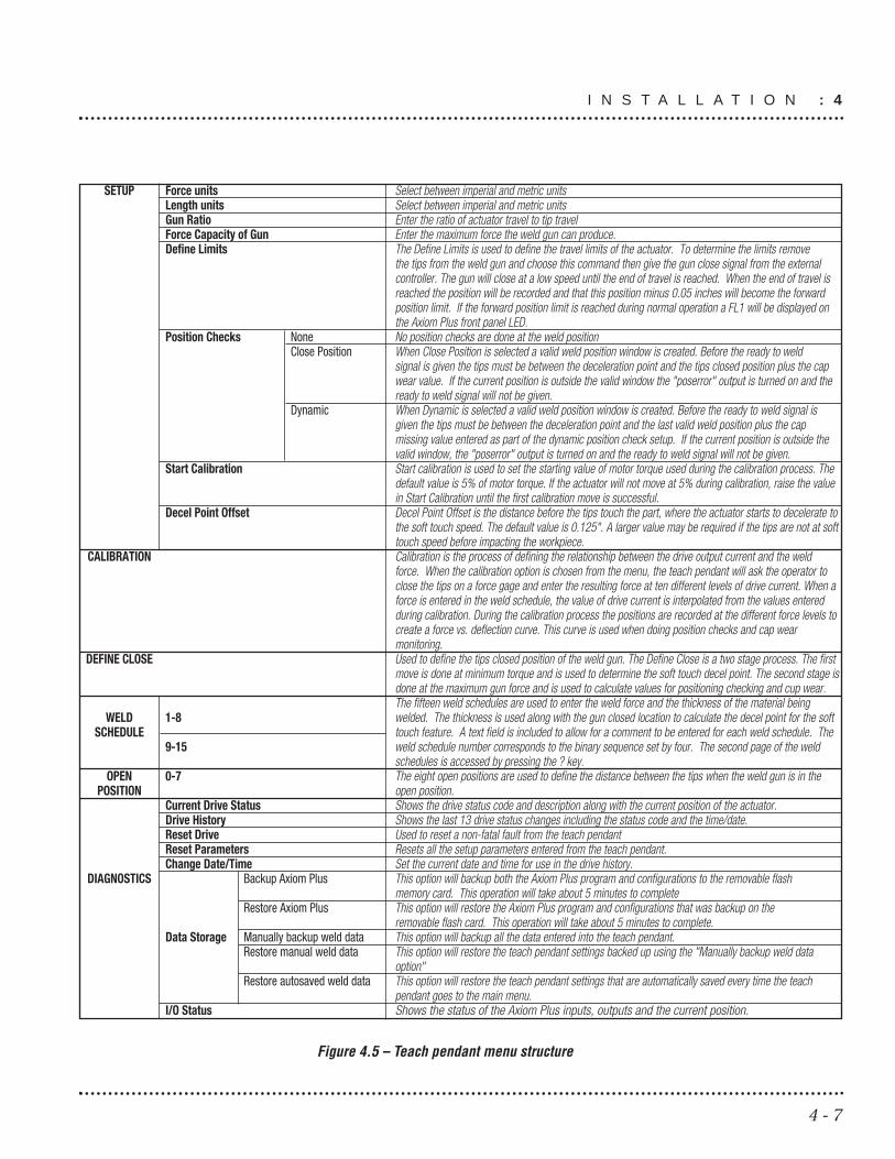
4.6.6.1 Menu StructureThe Weld Axis teach pendant and single board computer areused to provide the user with a simple way to interact with theAxiom Plus controller. All the setup and troubleshooting of thesystem is done from the teach pendant.
Figure 4-5 shows the teach pendant menu structure with adescription of each item.
4 : I N S T A L L A T I O N
4 - 6
SETUP Force units Select between imperial and metric units Length units Select between imperial and metric units Gun Ratio Enter the ratio of actuator travel to tip travelForce Capacity of Gun Enter the maximum force the weld gun can produce.Define Limits The Define Limits is used to define the travel limits of the actuator. To determine the limits remove
the tips from the weld gun and choose this command then give the gun close signal from the external controller. The gun will close at a low speed until the end of travel is reached. When the end of travel is reached the position will be recorded and that this position minus 0.05 inches will become the forward position limit. If the forward position limit is reached during normal operation a FL1 will be displayed on the Axiom Plus front panel LED.
Position Checks None No position checks are done at the weld positionClose Position When Close Position is selected a valid weld position window is created. Before the ready to weld
signal is given the tips must be between the deceleration point and the tips closed position plus the cap wear value. If the current position is outside the valid window the "poserror" output is turned on and the ready to weld signal will not be given.
Dynamic When Dynamic is selected a valid weld position window is created. Before the ready to weld signal is given the tips must be between the deceleration point and the last valid weld position plus the cap missing value entered as part of the dynamic position check setup. If the current position is outside the valid window, the "poserror" output is turned on and the ready to weld signal will not be given.
Start Calibration Start calibration is used to set the starting value of motor torque used during the calibration process. The default value is 5% of motor torque. If the actuator will not move at 5% during calibration, raise the value in Start Calibration until the first calibration move is successful.
Decel Point Offset Decel Point Offset is the distance before the tips touch the part, where the actuator starts to decelerate to the soft touch speed. The default value is 0.125". A larger value may be required if the tips are not at soft touch speed before impacting the workpiece.
CALIBRATION Calibration is the process of defining the relationship between the drive output current and the weld force. When the calibration option is chosen from the menu, the teach pendant will ask the operator to close the tips on a force gage and enter the resulting force at ten different levels of drive current. When a force is entered in the weld schedule, the value of drive current is interpolated from the values entered during calibration. During the calibration process the positions are recorded at the different force levels to create a force vs. deflection curve. This curve is used when doing position checks and cap wear monitoring.
DEFINE CLOSE Used to define the tips closed position of the weld gun. The Define Close is a two stage process. The first move is done at minimum torque and is used to determine the soft touch decel point. The second stage is done at the maximum gun force and is used to calculate values for positioning checking and cup wear.The fifteen weld schedules are used to enter the weld force and the thickness of the material being
WELD 1-8 welded. The thickness is used along with the gun closed location to calculate the decel point for the soft SCHEDULE touch feature. A text field is included to allow for a comment to be entered for each weld schedule. The
9-15 weld schedule number corresponds to the binary sequence set by four. The second page of the weld schedules is accessed by pressing the ? key.
OPEN 0-7 The eight open positions are used to define the distance between the tips when the weld gun is in the POSITION open position.
Current Drive Status Shows the drive status code and description along with the current position of the actuator.Drive History Shows the last 13 drive status changes including the status code and the time/date.Reset Drive Used to reset a non-fatal fault from the teach pendantReset Parameters Resets all the setup parameters entered from the teach pendant.Change Date/Time Set the current date and time for use in the drive history.
DIAGNOSTICS Backup Axiom Plus This option will backup both the Axiom Plus program and configurations to the removable flash memory card. This operation will take about 5 minutes to complete
Restore Axiom Plus This option will restore the Axiom Plus program and configurations that was backup on the removable flash card. This operation will take about 5 minutes to complete.
Data Storage Manually backup weld data This option will backup all the data entered into the teach pendant.Restore manual weld data This option will restore the teach pendant settings backed up using the "Manually backup weld data
option"Restore autosaved weld data This option will restore the teach pendant settings that are automatically saved every time the teach
pendant goes to the main menu.I/O Status Shows the status of the Axiom Plus inputs, outputs and the current position.
Figure 4.5 – Teach pendant menu structure
4 - 7
I N S T A L L A T I O N : 4

4.6.6.2 Setup Weld DataWhen setting up a new Weld Axis system, the following steps shouldbe completed in order.
1) Enter the system of units for the force.
2) Enter the system of units for distance.
3) Enter the gun ratio. The ratio is the actuator travel divided bythe tip travel.
4) Enter the mechanical force limit for the weld gun.
5) Define the position limits. The actuator limit is the forwardtravel limit of the actuator. The limit is found by removing thetips from the weld gun and choosing the define limits optionfrom the setup menu and then giving the gun close signal fromthe external controller. The gun will close at a low speed untilthe end of travel is reached. The end of travel position is thenloaded into the Axiom Plus as the forward position limit.
6) Calibrate the actuator. Calibration is needed to create arelationship between the motor armature current and the forceoutput of the actuator. The user will use a force gage to measurethe force between the tips at ten motor current levels. On theteach pendant select the calibration option. The screen willindicate the percentage torque being used and will wait for theuser to enter the force value measured. To measure the forceplace the gage between the tips and turn on the close guncommand from the master controller. The gun will close at aslow speed until the tips contact the force gage. Once the forcehas been entered it will progress to the next current level untilthe calibration is complete. If the actuator fails to move at thelower levels of motor torque, enter zero for the force. When thecalibration is complete, change the “Start Calibration Value” inthe setup menu to the first value where the actuator closedcorrectly.
7) Define the tips closed position. This position is needed tocalculate the deceleration point for the soft touch feature. Usethe define close position option on the teach pendant, thesystem will wait until the close gun command is turned on from
4 : I N S T A L L A T I O N
4 - 8

the master controller. The gun will then close at a slow speed atminimum motor torque until the tips are closed. The actuatorwill open slightly and close again at gun capacity.
8) Setup the desired weld schedule. The weld schedule is whatspecifies the force for the weld and the stackup of the materialbeing welded. The stackup and the tips closed position are usedto determine the position were the system goes to soft touchspeed. There are 15 possible weld schedules possible. The weldschedule is displayed in two pages, the second page is displayedby pressing the down arrow button. To modify the value for aweld schedule enter the number of the weld schedule, anotherpage is displayed allowing the user to enter a description, theweld force and the max stackup.
9) Determine the desired open position. The open position isdefined as the distance between the weld gun tips. There areeight possible open positions. To modify an open positionnumber to be modified and the choose the comment or theopen distance.
4 - 9
I N S T A L L A T I O N : 4

NOTES:
4 : I N S T A L L A T I O N
4 - 10

5.1 Weld Actuator
NOTE! Before starting any maintenance activities, make surethat the supply voltage is shut OFF.
No lubrication is required during the service life of the weldactuator.
Disassembly of the weld actuator is not recommended. WeldActuators should be returned to Tol-O-Matic for evaluation andrepair. Contact the weldgun manufacturer for instructions on howto return the weld actuator for evaluation.
5.2 Weld Axis Control Panel
5.2.1 TESTING OF THE ACTUATOR WELD FORCE
When the Weld Axis starts to close the gun, it does not limit themotor torque until it transitions to the soft touch speed. Whenchecking weld force, be sure to select a weld schedule that has astackup larger than the force gage being used. If the force measuredis not within specifications for the force set in the weld schedule, thesystem should be re-calibrated.
5.2.2 CHANGING THE CAPS
When changing the caps, the tips closed position will need to beredefined if the new caps are a different style or if the close positionhas been redefined with used caps. If these conditions do not apply,the new caps can be installed without accessing the teach pendant.
5 - 1
Repair and Maintenance5

5.2.3 FAULT CODES
Troubleshooting Guide
Tol-O-Matic Axiom series drives are designed for ease of installationand years of trouble-free operation. If difficulties are encountered inthe setup or in operation, this guide should prove useful indiagnosing and correcting the problem. If problems persist, pleasecontact your Tol-O-Matic distributor for further assistance.
Symptom/F ault Code: Status display not lit.Possib le Causes: No ac power; internal malfunction.
Possib le Solutions: Verify ac power and connections; call your Tol-O-Matic distributor.
Symptom/F ault Code: Digital I/O not working correctly.Possib le Causes: No 5-25Vdc power.
Possib le Solutions: Verify correct connection.
Symptom/F ault Code: F01 - Power selection switch fault.Possib le Causes: Line-power selection switch set incorrectly.
Possib le Solutions: Set to “115 V” for 115 Vac operation or “230 V” for 208 Vac or 230 Vacoperation.
Symptom/F ault Code: F02 - Bridge hardware fault.Possib le Causes: Motor lead short circuit; bus over-voltage; drive’s output bridge
damaged.Possib le Solutions: Check motor cables and motor for shorts; connect internal or external
regen resistor; call your Tol-O-Matic distributor.
Symptom/F ault Code: F03 - Current feedback fault.Possib le Causes: Possible open winding; current feedback circuitry not functioning
correctly.Possib le Solutions: Check motor cable wiring and motor windings; call your Tol-O-Matic
distributor.
Symptom/F ault Code: F04 - Current regulation fault.Possib le Causes: Drive current regulation out of tolerance; current feedback in
“saturation” for 1 second.Possib le Solutions: Check motor cables and motor windings; verify that torque/speed
requirement not greater than motor/drive capability.
5 : R E P A I R A N D M A I N T E N A N C E
5 - 2

Symptom/F ault Code: F05 - Drive over-temperature fault.Possib le Causes: Drive heat sink over 90° C.
Possib le Solutions: Ambient temp above 50° C.; need external regen pack.
Symptom/F ault Code: F06 - Motor over-temperature fault.Possib le Causes: Motor thermostat tripped.
Possib le Solutions: Inadequate motor cooling; motor rating exceeded.
Symptom/F ault Code: F51 - Phasing fault.Possib le Causes: Initial phase estimation routine not executed successfully.
Possib le Solutions: Check encoder and motor wiring; increase phasing torque.
Symptom/F ault Code: F52 - Drive over-current fault.Possib le Causes: Inverse time trip calculated based on the drive’s peak and
continuous rating exceeded.Possib le Solutions: Verify sizing requirements; check tuning; check for mechanical
problems in system.
Symptom/F ault Code: F53 - Motor over-current fault.Possib le Causes: I^2*time protection based on the motor’s peak and continuous
rating exceeded.Possib le Solutions: Verify sizing requirements; check for mechanical problems in system.
Symptom/F ault Code: F54 - Bus under-voltage fault.Possib le Causes: Bus voltage falls below low-limit.
Possib le Solutions: Check line voltage under load (must be at least 90 Vac).
Symptom/F ault Code: F55 - Maximum following-error fault.Possib le Causes: Maximum position following error reached.
Possib le Solutions: Verify correct maximum following error setting; check tuning; checkfor mechanical problems in system.
Symptom/F ault Code: F56 - Velocity regulation fault.Possib le Causes: Velocity regulation out of tolerance.
Possib le Solutions: Check tuning; check for mechanical problems in system.
Symptom/F ault Code: F57 - Serial communication fault.Possib le Causes: Communication cable not connected.
Possib le Solutions: Check communication cable connections.
5 - 3

5 - 4

66.1 Motor Specifications
6.1.1 HT12
Continuous Stall Torque: 3.4 N-mPeak Stall Torque: 16.9 N-mThermal Resistance: 0.58 celsius/wattStall Current: 6.13 A RMSPeak Current: 30.7 A RMSNumber of Poles: 4Kt: 0.58 N-m/Amp per phase RMSKe: 0.332 V/rad/s L-L RMSResistance @ 25 C: 2.0 ohms L-LStator Inductance: 6.1 mH L-LMaximum Bus Voltage: 325 VdcRated Speed @ Maximum Voltage: 4500 RPMDemagnetization Current: 39 AmpsThermal sensor will shut down the motor at 311 degrees F. Howeverthe motor should not perform a duty cycle that repeatedly generatemotor temperatures above 175 degrees F, or premature bearingfailure will result.
6.1.2 HT23
Continuous Stall Torque: 5.0 NmPeak Stall Torque: 24.9 NmThermal Resistance: 0.56 celsius/wattStall Current: 7.55 A RMSPeak Current: 37.8 A RMSNumber of Poles: 4Kt: 0.69 Nm/amp per phase RMSKe: 0.396 V/rad/s L-L RMSResistance @ 25 C: 1.4 ohms L-LStator Inductance: 5.1 mH L-LMaximum Bus Voltage: 325 VdcRated Speed @ Maximum Voltage: 4500 RPMDemagnetization Current: 45 AmpsThermal sensor will shut down the motor at 311 degrees F. Howeverthe motor should not perform a duty cycle that repeatedly generatemotor temperatures above 175 degrees F, or premature bearingfailure will result.
6 - 1
Appendix

6.2 Connector Pinout
6.2.1 MOTOR ARMATURE
Figure 6.1 – Pinout of motor armature connection
6.2.2 MOTOR ENCODER
Figure 6.2: Pinout of motor encoder connection
6 : A P P E N D I X
6 - 2

6.2.3 TEACH PENDANT
HAND-HELD CONNECTOR PINOUTPIN FunctionA Transmit TXD2B +24 VdcC 0 VdcD Receive RXD2E Input #1 on SBCFF O VdcGH
Figure 6.3 – Pinout of teach pendant connection
6 - 3
A P P E N D I X : 6

6.3 Weld Axis Base System wiring diagram
Figure 6.4 – Base System Wiring
PP
RXD1
TXD1
TXD2RXD2
IN0
RAW
GND
Sing
leBo
ard
Com
pute
r
24 Vdc
50 Wat
tPo
wer
Supp
ly
Hand
held
Teac
hPe
ndan
t
HT12
Actu
ator
L1L2
GND
OVdc
GND
NL
+ 24 V
dcx
Out 1
+Ou
t 1-
Out 2
+Ou
t 2-
Out 3
+Ou
t 3-
+24V
dc24
Vdc
RTN
Out 4
+Ou
t 4-
Out 5
+Ou
t 5-
Out 6
+Ou
t 6-
Out 7
+Ou
t 7-
Out 8
+Ou
t 8-
+24V
dc24
Vdc
RTN
COM
1-6
INPU
T 1IN
PUT 2
INPU
T 3IN
PUT 4
INPU
T 5IN
PUT 6
+24V
dc24
Vdc
RTN
COM
7-12
INPU
T 7IN
PUT 8
INPU
T 9IN
PUT 1
0IN
PUT 1
1IN
PUT 1
2
TT BB 33TT BB 22 T B 3T B 2T B 1
J 1 J 3J 2
JJ 77J 7J 6J 5J 4
ENCO
DER
OUT
ENCO
DER
FOLL
OWER C O M M
Pin
3P
in 5
Pin
2
BRAK
E
BRAK
E
REGE
N CO
M
EXT R
EGEN
INT R
EGEN
COM
13-1
5IN
PUT 7
INPU
T 8IN
PUT 9
ENC
+5V A+ A- B+ B+ I+ I-
COM/
SHLD
MOT T
EMP
R S T L3 L2 L1
RE
D
WH
ITE
BL
AC
K
GR
EE
N/Y
EL
LO
W
L3
L2
L1
GN
D
HA
G
B
CD
E
F
BR
OW
NO
RA
NG
EY
EL
LO
WV
IOL
ET
GR
AY
BL
AC
KW
HIT
EB
LU
E/G
RN
/SH
IEL
DR
ED
6 : A P P E N D I X
6 - 4

6.4 Weld Axis Panel System wiring diagram
Figure 6.5 – Weld Axis HT12 3-phase wiring diagram (1 of 4)
141140139138137136135134133132131130129128127126125124123122121120119118117116115114113112111110109108107106105104103102101
107
108
109X1
X2
X3
47
X0
9
58
6
11 KVA DRIVE ISOLATION TRANSFORMER
101102103
104105
106
DS106
T3
T2
T1
L3L3
L2L2
L1L1
AMP30DISCONNECT
30AMP FUSE (1MDC)
CB127
111112
L/233L/234L/235
110
T3
T2
T1
L3
L2
L1
L2
L1
T2
T1
113114
L/303L/304
CB133
25 AMP
TOL-O-MATIC, INC. : WELD-AXIS HT12 3-PHASE DWG#3620-7104, REV 00, PAGE 1
6 - 5
A P P E N D I X : 6

Figure 6.6 – Weld Axis HT12 3-phase wiring diagram (2 of 4)
241240239238237236235234233232231230229228227226225224223222221220219218217216215214213212211210209208207206205204203202201
GNDL1L2L3
GNDTSR
INTREGENEXTREGENREGENCOMBRAKEBRAKE
OUT8-OUT8+OUT7-OUT7+OUT6-OUT6+
OUT5-OUT5+OUT4-OUT4+24VDCRTN+24VDC
OUT3-OUT3+OUT2-OUT2+OUT1-OUT1+
532
MOTTEMPCOM/SHIELD
I-I+B-
B+A-
A+ENCODER+5V
INPUT13
INPUT15INPUT14
COM13-15
INPUT12
INPUT8
INPUT11INPUT10
INPUT9
INPUT7COM7-12
24VDCRTN+24VDC
INPUT6INPUT5INPUT4INPUT3INPUT2INPUT1COM1-6
24VDCRTN+24VDCAXIOMPLUS201
228229
230
110
GND237
L/127L/128L/129
111112
223
332333
300
231232233
234235
236
MRV342223
RELAYSET241.1
L/321
L/332L/333
L/331
P
1
32
GROUND
ABHED
NGFK
INTERGAL MOTOR(MRV342)
BROWNORANGEYELLOWVIOLETGREYBLACKWHITE
REDBLUE/GREEN/SHIELD
RELAYSET241
P2
TB3
J7TB2
J6
TB1
J5
J2
J2
J4
AXIOM PLUSJ1
203 L/321
TOL-O-MATIC, INC: WELD-AXIS HT12 3-PHASE DWG# 3620-7104, PAGE 2
6 : A P P E N D I X
6 - 6

Figure 6.7 – Weld Axis HT12 3-phase wiring diagram (3 of 4)
TOL-O-MATIC, INC.: WELD-AXIS HT12 3-PHASE DWG# 3620-7104, PAGE 3
341340339338337336335334333332331330329328327326325324323322321320319318317316315314313312311310309308307306305304303302301
PS24V50W305
SAFERELAY314
HHTERMINAL337
GND303
E-STOP318EXTRESET319RELAY319
K1COIL323
K2COIL327
SBCOMPUTER327
PLUG338
PLUG339
PLUG340PLUG341
PLUG342PLUG343
TB
L/133L/134
L/203 L/223
L/236L/237
L/238
113114
324
324
324324
324
324
301 302
305203
304 303
223
307
308
334335
G
+ -
NL
48382414
S41S33S22
B2
3747
2313
S21S11S10
B1
GREEN
BLUEYELLOW
WHITE
3TXD24RXD21TXD12RXD1
7IN0
11GND12+RAW
1
EXTERNALE-STOP
EXTERNALRESET
K1 K2
K1 COIL
K2 COIL
24VDC 50 WATTPOWER SUPPLY
(1PS)
ALLEN BRADLEYMSR20D SAFETY RELAY
(1MRS)
HAND HELDTERMINAL
(1HT)
SINGLE BOARDCOMPUTER
(1PC)
J11 PLUG, P/N 3620-9501
B
A
D
C
E
F
B
A
D
C
E
FP/N 3620-9601
333
300
300
300
300
300300
300
332
331
306
6 - 7
A P P E N D I X : 6

Figure 6.8 – Weld Axis HT12 3-phase panel layout (4 of 4)
324
324
324
324
300
324
300
300
300
300
332
333
331
334
335
301
302
303
304
305
306
TOL-O-MATIC, INC. : WELD-AXIS HT12 3-PHASE DWG# 3620-7204, REV 00
DS106?
DISCONNECTSWITCH
CB 2A
MP 1P
CB 25
AMP 1
P
POWERDIST
BLOCK
END
CVR
CB 2A
MP 1P
CB 25
AMP 1
P
CB 25
AMP 1
P
PS24V50W305
POWERSUPPLY
SAFERELAY314
SAFETYRELAY
SAFETYCONTACTOR
SAFETYCONTACTOR
END
CVR
END
CVR
GND
END
CVR
END
CVR
END
CVR
SBCOMPUTER328?
SINGLEBOARD
COMPUTER
END
CVR
21.0
0
21.00
GND
GND
SSTE
RMSS
TERM
SSTE
RMSS
TERM
SSTE
RMSS
TERM
SSTE
RMSS
TERM
SSTE
RMSS
TERM
SSTE
RMSS
TERM
SSTE
RMSS
TERM
SSTE
RMSS
TERM
SSTE
RMSS
TERM
SSTE
RMSS
TERM
SSTE
RMSS
TERM
SSTE
RMSS
TERM
SSTE
RMSS
TERM
SSTE
RMSS
TERM
SSTE
RMSS
TERM
SSTE
RMSS
TERM
SSTE
RMSS
TERM
SSTE
RMSS
TERM
SSTE
RMSS
TERM
SSTE
RMSS
TERM
SSTE
RMSS
TERM
SSTE
RMSS
TERM
SSTE
RMSS
TERM
SSTE
RMSS
TERM
SSTE
RMSS
TERM
SSTE
RMSS
TERM
SSTE
RMSS
TERM
END
CVR
SSTE
RMSS
TERM
SSTE
RMSS
TERM
SSTE
RM
SSTE
RMSS
TERM
SSTE
RMSS
TERM
SSTE
RMSS
TERM
TB 1+24 -24 SP SBC E-STOPSS
TERM
SSTE
RM
K1COIL323 K2COIL327
OUT 6 +OUT 6 -OUT 7 +OUT 7 -OUT 8 +OUT 8 -
+24 Vdc24 Vdc RTNOUT 4 +OUT 4 -OUT 5 +OUT 5 -
+24 Vdc24 Vdc RTN
COM 1-6INPUT 1INPUT 2INPUT 3INPUT 4INPUT 5INPUT 6
+24 Vdc24 Vdc RTN
COM 7-12INPUT 7INPUT 8INPUT 9
INPUT 10INPUT 11INPUT 12
ENC +5VA +A –B +B –I +I –
COM/SHLDMOT TEMP
ENCODEROUT
ENCODERFOLLOWER
BRAKE
BRAKE
REGEN COM
EXT REGEN
INT REGEN
R
S
T
L3
L2
L1
OUT 1 +OUT 1 -OUT 2 +OUT 2 -OUT 3 +OUT 3 -
COMM
WARNING: VOLTAGE EXISTS UP TO 2 MIN.AFTER POWER IS REMOVED
TOL-O-MATICHAMEL, USA
J1
J2
J3
J4
J6
P1
P2
TB2
TB1
TB3
6 : A P P E N D I X
6 - 8

6.5 Axiom Plus Standard PLC Program
RUNG 001 User Rung Comment
| Binary 1 Binary 1 ||----| |----+-----------+-----------+-----------+-----------+----( )----|| IN 001 LF 001 |
RUNG 002 User Rung Comment
| Binary 2 Binary 2 ||----| |----+-----------+-----------+-----------+-----------+----( )----|| IN 002 LF 002 |
RUNG 003 User Rung Comment
| Binary 4 Binary 4 ||----| |----+-----------+-----------+-----------+-----------+----( )----|| IN 003 LF 003 |
RUNG 004 User Rung Comment
| Binary 4 Binary 8 ||----| |----+-----------+-----------+-----------+-----------+----( )----|| IN 004 LF 004 |
RUNG 005 User Rung Comment
| Close Close ||----| |----+-----------+-----------+-----------+-----------+----( )----|| IN 009 LF 005 |
RUNG 006 User Rung Comment
| Backup 1 Backup 1 ||----| |----+-----------+-----------+-----------+-----------+----( )----|| IN 005 LF 006 |
RUNG 007 User Rung Comment
| Backup 2 Backup 2 ||----| |----+-----------+-----------+-----------+-----------+----( )----|| IN 006 LF 007 |
6 - 9
A P P E N D I X : 6

RUNG 008 User Rung Comment
| Backup 4 Backup 4 ||----| |----+-----------+-----------+-----------+-----------+----( )----|| IN 007 LF 008 |
RUNG 009 User Rung Comment
| NO Estop No Estop ||----| |----+-----------+-----------+-----------+-----------+----( )----|| IN 015 LF 010 |
RUNG 010 User Rung Comment
| ClearErr ClearErr ||----| |----+-----------+-----------+-----------+-----------+----( )----|| IN 010 LF 019 |
RUNG 011 User Rung Comment
| CheckCap CapCheck ||----| |----+-----------+-----------+-----------+-----------+----( )----|| IN 011 LF 012 |
RUNG 012 User Rung Comment
| ManNewCp New Cap ||----| |----+-----------+-----------+-----------+-----------+----( )----|| IN 012 LF 017 |
RUNG 013 User Rung Comment
| SigWeld Sig Weld ||----| |----+-----------+-----------+-----------+-----------+----( )----|| STP 021 OUT 001 |
RUNG 014 User Rung Comment
| PosError PosError ||----| |----+-----------+-----------+-----------+-----------+----( )----|| LF 018 OUT 002 |
6 : A P P E N D I X
6 - 10

6 - 11
A P P E N D I X : 6
RUNG 015 User Rung Comment
| CapWore CapWore ||----| |----+-----------+-----------+-----------+-----------+----( )----|| STP 012 OUT 003 |
RUNG 016 User Rung Comment
| opened PosError fault Opened ||----| |----+----|/|----+----|/|----+-----------+-----------+----( )----|| STP 018 LF 018 IS 002 OUT 004 |
RUNG 017 User Rung Comment
| PowerOK ||-----------+-----------+-----------+-----------+-----------+----( )----|| OUT 005 |
RUNG 018 User Rung Comment
| fault Fault ||----| |----+-----------+-----------+-----------+-----------+----( )----|| IS 002 OUT 006 |
RUNG 019 User Rung Comment
| PosError PosError ||----| |----+-----------+-----------+-----------+-----------+----(L)----|| STP 013 LF 018 |
RUNG 020 User Rung Comment
| ClearErr PosError ||----| |----+-----------+-----------+-----------+-----------+----(U)----|| LF 019 LF 018 |
RUNG 021 User Rung Comment
| Close Close ||----| |----+-----------+-----------+-----------+-----------+----( )----|| LF 005 PTS 020 |

6 - 12
RUNG 022 User Rung Comment
| No Estop Estopdly ||----| |----+-----------+-----------+-----------+-----------+--|TMR01|--|| LF 010 ONDL | || P=1.00 |
RUNG 023 User Rung Comment
| Estopdly SftReset Enable ||----| |----+----|/|----+-----------+-----------+-----------+----( )----|| TMR 001 FF 007 ICC 001 |
RUNG 024 User Rung Comment
| No Estop Enabled Phase Dn QuitMove Cyc Strt ||----| |----+----| |----+----| |----+----|/|----+-----------+----( )----|| LF 010 ICS 001 IS 001 FF 005 ICC 002 |
RUNG 025 User Rung Comment
| Homed Home ||----|/|----+-----------+-----------+-----------+-----------+----( )----|| IS 004 PTS 002 |
RUNG 026 User Rung Comment
| IP flag Close IP In Pos ||----|/|----+----| |----+-----------+-----------+-----------+----( )----|| IS 006 | STP 001 | PTS 001 || | | | | | | | Home IP | | +----| |----+ | STP 002
RUNG 027 User Rung Comment
| Delay delay ||----| |----+-----------+-----------+-----------+-----------+--|TMR02|--|| STP 011 ONDL | || P=0.10 |
6 : A P P E N D I X

6 - 13
RUNG 028 User Rung Comment
| delay delay ||----| |----+-----------+-----------+-----------+-----------+----( )----|| TMR 002 PTS 003 |
RUNG 029 User Rung Comment
| Close Manual New Cap CapCheck ManualOR ||----| |----+----|/|----+----|/|----+----|/|----+-----------+----( )----|| LF 005 FF 002 LF 017 LF 012 LF 011 |
RUNG 030 User Rung Comment
| Binary 1 Binary 2 Binary 4 Binary 8 ManualOR Press1 ||----| |----+----|/|----+----|/|----+----|/|----+----| |----+----( )----|| LF 001 LF 002 LF 003 LF 004 LF 011 PTS 005 |
RUNG 031 User Rung Comment
| Binary 1 Binary 2 Binary 4 Binary 8 ManualOR Press2 ||----|/|----+----| |----+----|/|----+----|/|----+----| |----+----( )----|| LF 001 LF 002 LF 003 LF 004 LF 011 PTS 006 |
RUNG 032 User Rung Comment
| Binary 1 Binary 2 Binary 4 Binary 8 ManualOR Press3 ||----| |----+----| |----+----|/|----+----|/|----+----| |----+----( )----|| LF 001 LF 002 LF 003 LF 004 LF 011 PTS 007 |
RUNG 033 User Rung Comment
| Binary 1 Binary 2 Binary 4 Binary 8 ManualOR Press4 ||----|/|----+----|/|----+----| |----+----|/|----+----| |----+----( )----|| LF 001 LF 002 LF 003 LF 004 LF 011 PTS 008 |
RUNG 034 User Rung Comment
| Binary 1 Binary 2 Binary 4 Binary 8 ManualOR Press5 ||----| |----+----|/|----+----| |----+----|/|----+----| |----+----( )----|| LF 001 LF 002 LF 003 LF 004 LF 011 PTS 009 |
A P P E N D I X : 6

6 - 14
RUNG 035 User Rung Comment
| Binary 1 Binary 2 Binary 4 Binary 8 ManualOR Press6 ||----|/|----+----| |----+----| |----+----|/|----+----| |----+----( )----|| LF 001 LF 002 LF 003 LF 004 LF 011 PTS 010 |
RUNG 036 User Rung Comment
| Binary 1 Binary 2 Binary 4 Binary 8 ManualOR Press7 ||----| |----+----| |----+----| |----+----|/|----+----| |----+----( )----|| LF 001 LF 002 LF 003 LF 004 LF 011 PTS 011 |
RUNG 037 User Rung Comment
| Binary 1 Binary 2 Binary 4 Binary 8 ManualOR Press8 ||----|/|----+----|/|----+----|/|----+----| |----+----| |----+----( )----|| LF 001 LF 002 LF 003 LF 004 LF 011 PTS 012 |
RUNG 038 User Rung Comment
| Binary 1 Binary 2 Binary 4 Binary 8 ManualOR Press9 ||----| |----+----|/|----+----|/|----+----| |----+----| |----+----( )----|| LF 001 LF 002 LF 003 LF 004 LF 011 PTS 013 |
RUNG 039 User Rung Comment
| Binary 1 Binary 2 Binary 4 Binary 8 ManualOR Press10 ||----|/|----+----| |----+----|/|----+----| |----+----| |----+----( )----|| LF 001 LF 002 LF 003 LF 004 LF 011 PTS 014 |
RUNG 040 User Rung Comment
| Binary 1 Binary 2 Binary 4 Binary 8 ManualOR Press11 ||----| |----+----| |----+----|/|----+----| |----+----| |----+----( )----|| LF 001 LF 002 LF 003 LF 004 LF 011 PTS 015 |
RUNG 041 User Rung Comment
| Binary 1 Binary 2 Binary 4 Binary 8 ManualOR Press12 ||----|/|----+----|/|----+----| |----+----| |----+----| |----+----( )----|| LF 001 LF 002 LF 003 LF 004 LF 011 PTS 016 |
6 : A P P E N D I X
6 - 15
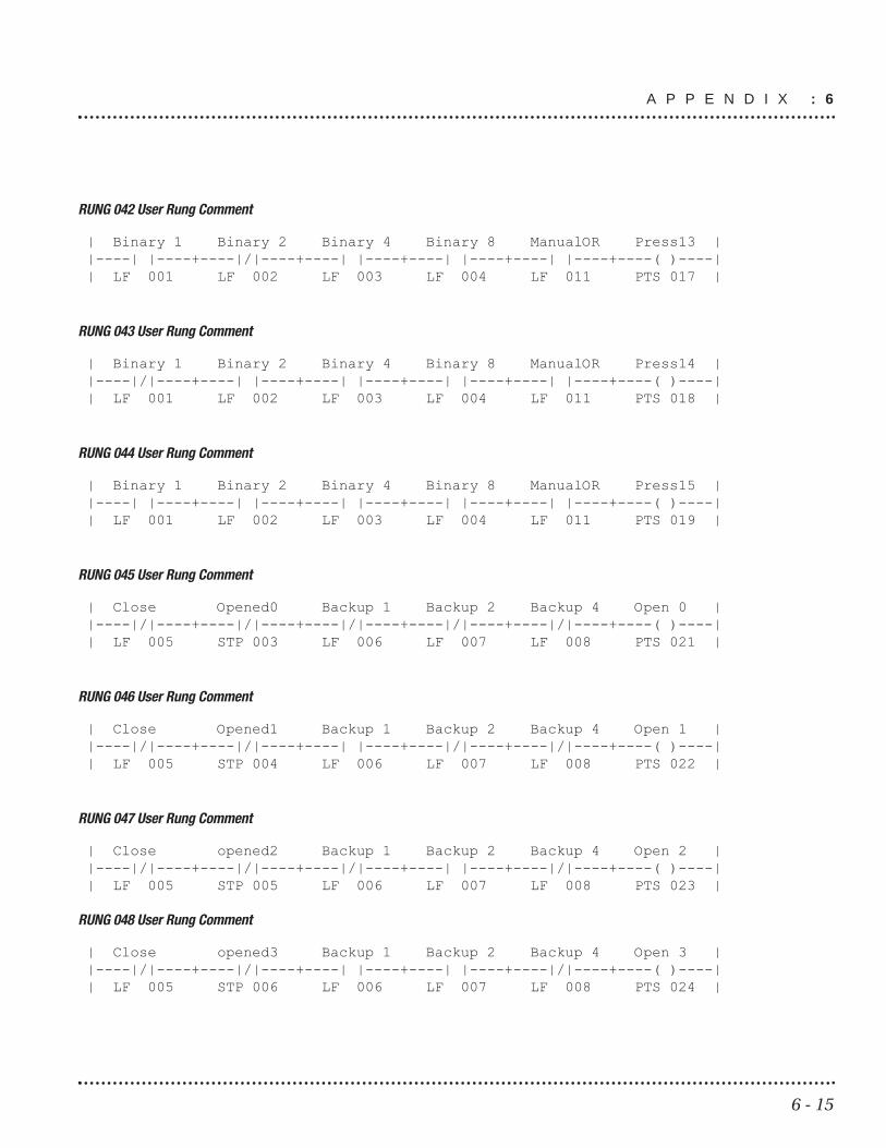
RUNG 042 User Rung Comment
| Binary 1 Binary 2 Binary 4 Binary 8 ManualOR Press13 ||----| |----+----|/|----+----| |----+----| |----+----| |----+----( )----|| LF 001 LF 002 LF 003 LF 004 LF 011 PTS 017 |
RUNG 043 User Rung Comment
| Binary 1 Binary 2 Binary 4 Binary 8 ManualOR Press14 ||----|/|----+----| |----+----| |----+----| |----+----| |----+----( )----|| LF 001 LF 002 LF 003 LF 004 LF 011 PTS 018 |
RUNG 044 User Rung Comment
| Binary 1 Binary 2 Binary 4 Binary 8 ManualOR Press15 ||----| |----+----| |----+----| |----+----| |----+----| |----+----( )----|| LF 001 LF 002 LF 003 LF 004 LF 011 PTS 019 |
RUNG 045 User Rung Comment
| Close Opened0 Backup 1 Backup 2 Backup 4 Open 0 ||----|/|----+----|/|----+----|/|----+----|/|----+----|/|----+----( )----|| LF 005 STP 003 LF 006 LF 007 LF 008 PTS 021 |
RUNG 046 User Rung Comment
| Close Opened1 Backup 1 Backup 2 Backup 4 Open 1 ||----|/|----+----|/|----+----| |----+----|/|----+----|/|----+----( )----|| LF 005 STP 004 LF 006 LF 007 LF 008 PTS 022 |
RUNG 047 User Rung Comment
| Close opened2 Backup 1 Backup 2 Backup 4 Open 2 ||----|/|----+----|/|----+----|/|----+----| |----+----|/|----+----( )----|| LF 005 STP 005 LF 006 LF 007 LF 008 PTS 023 |
RUNG 048 User Rung Comment
| Close opened3 Backup 1 Backup 2 Backup 4 Open 3 ||----|/|----+----|/|----+----| |----+----| |----+----|/|----+----( )----|| LF 005 STP 006 LF 006 LF 007 LF 008 PTS 024 |
A P P E N D I X : 6
6 - 16
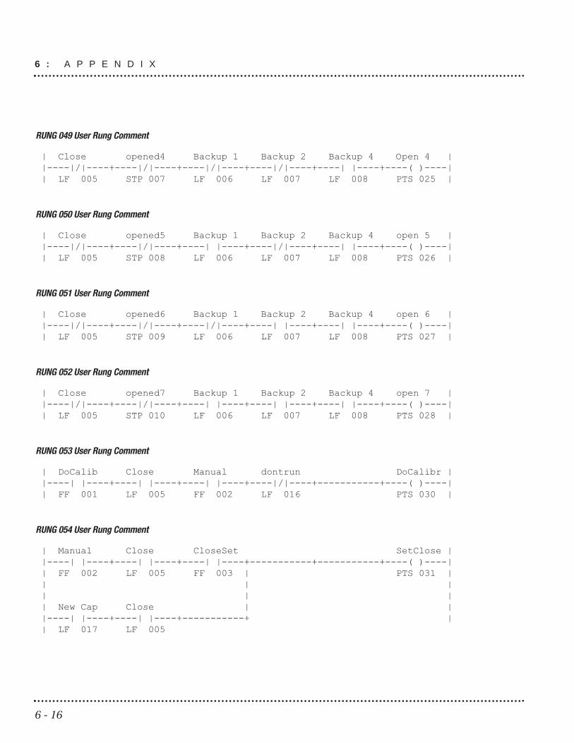
RUNG 049 User Rung Comment
| Close opened4 Backup 1 Backup 2 Backup 4 Open 4 ||----|/|----+----|/|----+----|/|----+----|/|----+----| |----+----( )----|| LF 005 STP 007 LF 006 LF 007 LF 008 PTS 025 |
RUNG 050 User Rung Comment
| Close opened5 Backup 1 Backup 2 Backup 4 open 5 ||----|/|----+----|/|----+----| |----+----|/|----+----| |----+----( )----|| LF 005 STP 008 LF 006 LF 007 LF 008 PTS 026 |
RUNG 051 User Rung Comment
| Close opened6 Backup 1 Backup 2 Backup 4 open 6 ||----|/|----+----|/|----+----|/|----+----| |----+----| |----+----( )----|| LF 005 STP 009 LF 006 LF 007 LF 008 PTS 027 |
RUNG 052 User Rung Comment
| Close opened7 Backup 1 Backup 2 Backup 4 open 7 ||----|/|----+----|/|----+----| |----+----| |----+----| |----+----( )----|| LF 005 STP 010 LF 006 LF 007 LF 008 PTS 028 |
RUNG 053 User Rung Comment
| DoCalib Close Manual dontrun DoCalibr ||----| |----+----| |----+----| |----+----|/|----+-----------+----( )----|| FF 001 LF 005 FF 002 LF 016 PTS 030 |
RUNG 054 User Rung Comment
| Manual Close CloseSet SetClose ||----| |----+----| |----+----| |----+-----------+-----------+----( )----|| FF 002 LF 005 FF 003 | PTS 031 || | || | || New Cap Close | ||----| |----+----| |----+-----------+ || LF 017 LF 005
6 : A P P E N D I X

6 - 17
RUNG 055 User Rung Comment
| CapDone ReadExt ||----| |----+-----------+-----------+-----------+-----------+----( )----|| STP 015 LF 013 |
RUNG 056 User Rung Comment
| CloseLim Manual Close CloseLim ||----| |----+----| |----+----| |----+-----------+-----------+----( )----|| FF 004 FF 002 LF 005 PTS 032 |
RUNG 057 User Rung Comment
| CapCheck Close CapCheck ||----| |----+----| |----+-----------+-----------+-----------+----( )----|| LF 012 LF 005 PTS 029 |
RUNG 058 User Rung Comment
| DoCheck ||-----------+-----------+-----------+-----------+-----------+----( )----|| PTS 033 |
RUNG 059 User Rung Comment
| BegWTim Welding ||----| |----+-----------+-----------+-----------+-----------+--|TMR03|--|| STP 016 PLS | || P=2.75 |
RUNG 060 User Rung Comment
| Welding Close TimeClos ||----| |----+----| |----+-----------+-----------+-----------+----( )----|| TMR 003 LF 005 PTS 035 |
RUNG 061 User Rung Comment
| Welding BegWTim waitcool ||----|/|----+----| |----+-----------+-----------+-----------+--|TMR04|--|| TMR 003 STP 016 |PLS | || P=1.50 |
A P P E N D I X : 6

6 - 18
RUNG 062 User Rung Comment
| waitcool dontrun ||----| |----+-----------+-----------+-----------+-----------+----( )----|| TMR 004 LF 016 |
RUNG 063 User Rung Comment
| GotTor GotTor ||----| |----+-----------+-----------+-----------+-----------+----( )----|| IS 012 PTS 004 |
RUNG 064 User Rung Comment
| CWLimit Homed lim IP CW lim ||---|PVAR|--+----| |----+----|/|----+-----------+-----------+----( )----|| |CMPR| IS 004 STP 014 ICC 011 ||P > PNV 027
RUNG 065 User Rung Comment
| neg lim Homed CCW lim ||----| |----+----| |----+-----------+-----------+-----------+----( )----|| IS 011 IS 004 ICC 012 |
RUNG 066
| Homed Homed ||----| |----+-----------+-----------+-----------+-----------+----( )----|| IS 004 PTS 036 |
6 : A P P E N D I X

6 - 19
6.6 Axiom Plus Standard Sequential Program
Line#001label: comment: user comment for line #0001Assign Register - VEL 001 = 3.00
Line#002label: comment: user comment for line #0002Position Compare - Branch Label: DONE Comparison: Command Position < PNV 027 CWLimit
Line#003label: comment: user comment for line #0003Conditional Branch to Label: DONE Conditional Operand: PLC-to-SEQ PRG FLAG #036 : PTS 036Branch on Logic 1 (normally-open)
Line#004label: comment: user comment for line #0004Assign Register - PNV 027 CWLimit = 999.990
Line#005label: DONE comment: user comment for line #0005Time Delay: 1 seconds
Line#006label: comment: Set the In-Position Band Set In-Position Band = 1500 Encoder Counts,or 0.075 inch
Line#007label: comment: user comment for line #0007Set/Clear Flag Bit -- CLEAR STP 003CLEAR SEQ PRG-to-PLC FLAG #003 : STP 003
Line#008label: comment: user comment for line #0008Set/Clear Flag Bit -- CLEAR STP 004CLEAR SEQ PRG-to-PLC FLAG #004 : STP 004
Line#009label: LOOP1comment: user comment for line #0009Conditional Subroutine Call: HOME Conditional Operand: PLC-to-SEQ PRG FLAG #002 : PTS 002Call Subroutine on Logic 1 (normally-open)
Line#010label: comment: Flag ext computer, move done Set/Clear Flag Bit -- CLEAR STP 015CLEAR SEQ PRG-to-PLC FLAG #015 : STP 015
Line#011label: comment: user comment for line #0011Set/Clear Flag Bit -- CLEAR STP 020CLEAR SEQ PRG-to-PLC FLAG #020 : STP 020
Line#012label: comment: user comment for line #0012Conditional Subroutine Call: CLOSEPOSConditional Operand: PLC-to-SEQ PRG FLAG #031 : PTS 031Call Subroutine on Logic 1 (normally-open)
Line#013label: comment: user comment for line #0013Conditional Subroutine Call: CLOSELIMConditional Operand: PLC-to-SEQ PRG FLAG #032 : PTS 032Call Subroutine on Logic 1 (normally-open)
A P P E N D I X : 6

Line#014label: comment: user comment for line #0014Conditional Subroutine Call: CALIBConditional Operand: PLC-to-SEQ PRG FLAG #030 : PTS 030Call Subroutine on Logic 1 (normally-open)
Line#015label: comment: user comment for line #0015Conditional Subroutine Call: CAPCHECKConditional Operand: PLC-to-SEQ PRG FLAG #029 : PTS 029Call Subroutine on Logic 1 (normally-open)
Line#016label: comment: user comment for line #0016Conditional Subroutine Call: PRESS1 Conditional Operand: PLC-to-SEQ PRG FLAG #005 : PTS 005Call Subroutine on Logic 1 (normally-open)
Line#017label: comment: user comment for line #0017Conditional Subroutine Call: PRESS2 Conditional Operand: PLC-to-SEQ PRG FLAG #006 : PTS 006Call Subroutine on Logic 1 (normally-open)
Line#018label: comment: user comment for line #0018Conditional Subroutine Call: PRESS3 Conditional Operand: PLC-to-SEQ PRG FLAG #007 : PTS 007Call Subroutine on Logic 1 (normally-open)
Line#019label: comment: user comment for line #0019Conditional Subroutine Call: PRESS4 Conditional Operand: PLC-to-SEQ PRG FLAG #008 : PTS 008Call Subroutine on Logic 1 (normally-open)
Line#020label: comment: user comment for line #0020Conditional Subroutine Call: PRESS5 Conditional Operand: PLC-to-SEQ PRG FLAG #009 : PTS 009Call Subroutine on Logic 1 (normally-open)
Line#021label: comment: user comment for line #0021Conditional Subroutine Call: PRESS6 Conditional Operand: PLC-to-SEQ PRG FLAG #010 : PTS 010Call Subroutine on Logic 1 (normally-open)
Line#022label: comment: user comment for line #0022Conditional Subroutine Call: PRESS7 Conditional Operand: PLC-to-SEQ PRG FLAG #011 : PTS 011Call Subroutine on Logic 1 (normally-open)
Line#023label: comment: user comment for line #0023Conditional Subroutine Call: PRESS8 Conditional Operand: PLC-to-SEQ PRG FLAG #012 : PTS 012Call Subroutine on Logic 1 (normally-open)
Line#024label: comment: user comment for line #0024Conditional Subroutine Call: PRESS9 Conditional Operand: PLC-to-SEQ PRG FLAG #013 : PTS 013Call Subroutine on Logic 1 (normally-open)
Line#025label: comment: user comment for line #0025Conditional Subroutine Call: PRESS10 Conditional Operand: PLC-to-SEQ PRG FLAG #014 : PTS 014Call Subroutine on Logic 1 (normally-open)
6 - 20
6 : A P P E N D I X

Line#026label: comment: user comment for line #0026Conditional Subroutine Call: PRESS11 Conditional Operand: PLC-to-SEQ PRG FLAG #015 : PTS 015Call Subroutine on Logic 1 (normally-open)
Line#027label: comment: user comment for line #0027Conditional Subroutine Call: PRESS12 Conditional Operand: PLC-to-SEQ PRG FLAG #016 : PTS 016Call Subroutine on Logic 1 (normally-open)
Line#028label: comment: user comment for line #0028Conditional Subroutine Call: PRESS13 Conditional Operand: PLC-to-SEQ PRG FLAG #017 : PTS 017Call Subroutine on Logic 1 (normally-open)
Line#029label: comment: user comment for line #0029Conditional Subroutine Call: PRESS14 Conditional Operand: PLC-to-SEQ PRG FLAG #018 : PTS 018Call Subroutine on Logic 1 (normally-open)
Line#030label: comment: user comment for line #0030Conditional Subroutine Call: PRESS15 Conditional Operand: PLC-to-SEQ PRG FLAG #019 : PTS 019Call Subroutine on Logic 1 (normally-open)
Line#031label: comment: user comment for line #0031Conditional Subroutine Call: OPEN0Conditional Operand: PLC-to-SEQ PRG FLAG #021 : PTS 021Call Subroutine on Logic 1 (normally-open)
Line#032label: comment: user comment for line #0032Conditional Subroutine Call: OPEN1Conditional Operand: PLC-to-SEQ PRG FLAG #022 : PTS 022Call Subroutine on Logic 1 (normally-open)
Line#033label: comment: user comment for line #0033Conditional Subroutine Call: OPEN2Conditional Operand: PLC-to-SEQ PRG FLAG #023 : PTS 023Call Subroutine on Logic 1 (normally-open)
Line#034label: comment: user comment for line #0034Conditional Subroutine Call: OPEN3Conditional Operand: PLC-to-SEQ PRG FLAG #024 : PTS 024Call Subroutine on Logic 1 (normally-open)
Line#035label: comment: user comment for line #0035Conditional Subroutine Call: OPEN4Conditional Operand: PLC-to-SEQ PRG FLAG #025 : PTS 025Call Subroutine on Logic 1 (normally-open)
Line#036label: comment: user comment for line #0036Conditional Subroutine Call: OPEN5Conditional Operand: PLC-to-SEQ PRG FLAG #026 : PTS 026Call Subroutine on Logic 1 (normally-open)
Line#037label: comment: user comment for line #0037Conditional Subroutine Call: OPEN6Conditional Operand: PLC-to-SEQ PRG FLAG #027 : PTS 027Call Subroutine on Logic 1 (normally-open)
6 - 21
A P P E N D I X : 6

Line#038label: comment: user comment for line #0038Conditional Subroutine Call: OPEN7Conditional Operand: PLC-to-SEQ PRG FLAG #028 : PTS 028Call Subroutine on Logic 1 (normally-open)
Line#039label: comment: user comment for line #0039Branch to Label: LOOP1
Line#040label: OPEN0comment: user comment for line #0040Call Subroutine with Start Label: OPENSTRT
Line#041label: comment: Move to open position Abs Position Move -- Position = PNV 001-Vel = 1.00 Acc = 799.999 Dec = 799.999Trigger #1: PLC-to-PRG Flag #003 Logic OneAction #1 (Trig #1): New Speed = VEL 001 Action #2 (Trig #1): New Torque Limit = 100.0%Trigger #2: No Trigger Event
Line#042label: comment: user comment for line #0042Set/Clear Flag Bit -- CLEAR STP 011CLEAR SEQ PRG-to-PLC FLAG #011 : STP 011
Line#043label: comment: user comment for line #0043Set/Clear Flag Bit -- SET STP 003SET SEQ PRG-to-PLC FLAG #003 : STP 003
Line#044label: comment: user comment for line #0044Set/Clear Flag Bit -- SET STP 018SET SEQ PRG-to-PLC FLAG #018 : STP 018
Line#045label: comment: user comment for line #0045Return from Subroutine
Line#046label: OPEN1comment: user comment for line #0046Call Subroutine with Start Label: OPENSTRT
Line#047label: comment: Move to open position Abs Position Move -- Position = PNV 002-Vel = 1.00 Acc = 500.0 Dec = 500.0Trigger #1: PLC-to-PRG Flag #003 Logic OneAction #1 (Trig #1): New Speed = VEL 001 Action #2 (Trig #1): New Torque Limit = 100.0%Trigger #2: No Trigger Event
Line#048label: comment: user comment for line #0048Set/Clear Flag Bit -- CLEAR STP 011CLEAR SEQ PRG-to-PLC FLAG #011 : STP 011
Line#049label: comment: user comment for line #0049Set/Clear Flag Bit -- SET STP 004SET SEQ PRG-to-PLC FLAG #004 : STP 004
6 - 22
6 : A P P E N D I X

Line#050label: comment: user comment for line #0050Set/Clear Flag Bit -- SET STP 018SET SEQ PRG-to-PLC FLAG #018 : STP 018
Line#051label: comment: user comment for line #0051Return from Subroutine
Line#052label: OPEN2comment: user comment for line #0052Call Subroutine with Start Label: OPENSTRT
Line#053label: comment: Move to open position Abs Position Move -- Position = PNV 003-Vel = 1.00 Acc = 500.0 Dec = 500.0Trigger #1: PLC-to-PRG Flag #003 Logic OneAction #1 (Trig #1): New Speed = VEL 001 Action #2 (Trig #1): New Torque Limit = 100.0%Trigger #2: No Trigger Event
Line#054label: comment: user comment for line #0054Set/Clear Flag Bit -- CLEAR STP 011CLEAR SEQ PRG-to-PLC FLAG #011 : STP 011
Line#055label: comment: user comment for line #0055Set/Clear Flag Bit -- SET STP 005SET SEQ PRG-to-PLC FLAG #005 : STP 005
Line#056label: comment: user comment for line #0056Set/Clear Flag Bit -- SET STP 018SET SEQ PRG-to-PLC FLAG #018 : STP 018
Line#057label: comment: user comment for line #0057Return from Subroutine
Line#058label: OPEN3comment: user comment for line #0058Call Subroutine with Start Label: OPENSTRT
Line#059label: comment: Move to open position Abs Position Move -- Position = PNV 004-Vel = 1.00 Acc = 500.0 Dec = 500.0Trigger #1: PLC-to-PRG Flag #003 Logic OneAction #1 (Trig #1): New Speed = VEL 001 Action #2 (Trig #1): New Torque Limit = 100.0%Trigger #2: No Trigger Event
Line#060label: comment: user comment for line #0060Set/Clear Flag Bit -- CLEAR STP 011CLEAR SEQ PRG-to-PLC FLAG #011 : STP 011
Line#061label: comment: user comment for line #0061Set/Clear Flag Bit -- SET STP 006SET SEQ PRG-to-PLC FLAG #006 : STP 006
Line#062label: comment: user comment for line #0062Set/Clear Flag Bit -- SET STP 018SET SEQ PRG-to-PLC FLAG #018 : STP 018
Line#063label: comment: user comment for line #0063Return from Subroutine
6 - 23
A P P E N D I X : 6

Line#064label: OPEN4comment: user comment for line #0064Call Subroutine with Start Label: OPENSTRT
Line#065label: comment: Move to open position Abs Position Move -- Position = PNV 005-Vel = 1.00 Acc = 500.0 Dec = 500.0Trigger #1: PLC-to-PRG Flag #003 Logic OneAction #1 (Trig #1): New Speed = VEL 001 Action #2 (Trig #1): New Torque Limit = 100.0%Trigger #2: No Trigger Event
Line#066label: comment: user comment for line #0066Set/Clear Flag Bit -- CLEAR STP 011CLEAR SEQ PRG-to-PLC FLAG #011 : STP 011
Line#067label: comment: user comment for line #0067Set/Clear Flag Bit -- SET STP 007SET SEQ PRG-to-PLC FLAG #007 : STP 007
Line#068label: comment: user comment for line #0068Set/Clear Flag Bit -- SET STP 018SET SEQ PRG-to-PLC FLAG #018 : STP 018
Line#069label: comment: user comment for line #0069Return from Subroutine
Line#070label: OPEN5comment: user comment for line #0070Call Subroutine with Start Label: OPENSTRT
Line#071label: comment: Move to open position Abs Position Move -- Position = PNV 006-Vel = 1.00 Acc = 500.0 Dec = 500.0Trigger #1: PLC-to-PRG Flag #003 Logic OneAction #1 (Trig #1): New Speed = VEL 001 Action #2 (Trig #1): New Torque Limit = 100.0%Trigger #2: No Trigger Event
Line#072label: comment: user comment for line #0072Set/Clear Flag Bit -- CLEAR STP 011CLEAR SEQ PRG-to-PLC FLAG #011 : STP 011
Line#073label: comment: user comment for line #0073Set/Clear Flag Bit -- SET STP 008SET SEQ PRG-to-PLC FLAG #008 : STP 008
Line#074label: comment: user comment for line #0074Set/Clear Flag Bit -- SET STP 018SET SEQ PRG-to-PLC FLAG #018 : STP 018
Line#075label: comment: user comment for line #0075Return from Subroutine
Line#076label: OPEN6comment: user comment for line #0076Call Subroutine with Start Label: OPENSTRT
6 - 24
6 : A P P E N D I X

Line#077label: comment: Move to open position Abs Position Move -- Position = PNV 007-Vel = 1.00 Acc = 500.0 Dec = 500.0Trigger #1: PLC-to-PRG Flag #003 Logic OneAction #1 (Trig #1): New Speed = VEL 001 Action #2 (Trig #1): New Torque Limit = 100.0%Trigger #2: No Trigger Event
Line#078label: comment: user comment for line #0078Set/Clear Flag Bit -- CLEAR STP 011CLEAR SEQ PRG-to-PLC FLAG #011 : STP 011
Line#079label: comment: user comment for line #0079Set/Clear Flag Bit -- SET STP 009SET SEQ PRG-to-PLC FLAG #009 : STP 009
Line#080label: comment: user comment for line #0080Set/Clear Flag Bit -- SET STP 018SET SEQ PRG-to-PLC FLAG #018 : STP 018
Line#081label: comment: user comment for line #0081Return from Subroutine
Line#082label: OPEN7comment: user comment for line #0082Call Subroutine with Start Label: OPENSTRT
Line#083label: comment: Move to open position Abs Position Move -- Position = PNV 008-Vel = 1.00 Acc = 500.0 Dec = 500.0Trigger #1: PLC-to-PRG Flag #003 Logic OneAction #1 (Trig #1): New Speed = VEL 001 Action #2 (Trig #1): New Torque Limit = 100.0%Trigger #2: No Trigger Event
Line#084label: comment: user comment for line #0084Set/Clear Flag Bit -- CLEAR STP 011CLEAR SEQ PRG-to-PLC FLAG #011 : STP 011
Line#085label: comment: user comment for line #0085Set/Clear Flag Bit -- SET STP 010SET SEQ PRG-to-PLC FLAG #010 : STP 010
Line#086label: comment: user comment for line #0086Set/Clear Flag Bit -- SET STP 018SET SEQ PRG-to-PLC FLAG #018 : STP 018
Line#087label: comment: user comment for line #0087Return from Subroutine
Line#088label: HOME comment: Low torque for home Set Maximum Torque Limit -- 30.0 %
6 - 25
A P P E N D I X : 6

Line#089label: comment: user comment for line #0089Set/Clear Flag Bit -- SET STP 002SET SEQ PRG-to-PLC FLAG #002 : STP 002
Line#090label: comment: user comment for line #0090Velocity Move -- Velocity = -0.50 inch / secAcc = 20.0 Dec = 100.0Trigger #1: PLC-to-PRG Flag #001 Logic OneAction #1 (Trig #1): Terminate Motion InstructionAction #2 (Trig #1): No ActionTrigger #2: No Trigger Event
Line#091label: comment: user comment for line #0091Set/Clear Flag Bit -- CLEAR STP 002CLEAR SEQ PRG-to-PLC FLAG #002 : STP 002
Line#092label: comment: user comment for line #0092Set Command Position = Actual -- Zero Following Error
Line#093label: comment: user comment for line #0093Inc Position Move -- Distance = 0.125 inchVel = 1.00 Acc = 4.998 Dec = 4.998Trigger #1: No Trigger EventTrigger #2: No Trigger Event
Line#094label: comment: define pos as "Home"Define Present Absolute PositionDefine Absolute COMMAND Position as 0.000 inch
Line#095label: comment: user comment for line #0095Return from Subroutine
Line#096label: PRESS1 comment: user comment for line #0096Call Subroutine with Start Label: CLOSESET
Line#097label: comment: user comment for line #0097Abs Position Move -- Position = PNV 010-Vel = VEL 001- Acc = 500.0 Dec = 500.0Trigger #1: No Trigger EventTrigger #2: No Trigger Event
Line#098label: comment: user comment for line #0098Wait for Input / Flag -- IN 014 -- Logic 1Conditional Operand: PHYSICAL INPUT #014 : IN 014Continue on Logic 1 (normally-open)Do NOT Enable PLC Commanded JOG Motion while Waiting
Line#099label: comment: user comment for line #0099Set Maximum Torque Limit -- TNV 001 %
Line#100label: comment: user comment for line #0100Velocity Move -- Velocity = 1.00 inch / secAcc = 250.0 Dec = 250.0Trigger #1: Incremental Distance = 0.250 inchAction #1 (Trig #1): Set PRG-to-PLC Flag #001Action #2 (Trig #1): No ActionTrigger #2: PLC-to-PRG Flag #001, Logic OneAction #1 (Trig #2): Terminate Motion InstructionAction #2 (Trig #2): No Action
6 - 26
6 : A P P E N D I X

Line#101label: comment: user comment for line #0101Conditional Branch to Label: PR1GOConditional Operand: PLC-to-SEQ PRG FLAG #033 : PTS 033Branch on Logic 0 (normally-closed)
Line#102label: comment: user comment for line #0102Position Compare - Branch Label: PR1STOP Comparison: Actual Position < PNV 010
Line#103label: comment: user comment for line #0103Position Compare - Branch Label: PR1GOComparison: Actual Position < POS 001
Line#104label: PR1STOP comment: user comment for line #0104Call Subroutine with Start Label: NOTPOS
Line#105label: PR1GOcomment: Move to weld position Call Subroutine with Start Label: CLOSEDN
Line#106label: comment: user comment for line #0106Conditional Branch to Label: EXIT1Conditional Operand: SEQ PRG-to-PLC FLAG #020 : STP 020Branch on Logic 1 (normally-open)
Line#107label: comment: user comment for line #0107Store Position to Register: POS 016-Store Absolute ACTUAL Position
Line#108label: EXIT1comment: user comment for line #0108Return from Subroutine
Line#109label: PRESS2 comment: user comment for line #0109Call Subroutine with Start Label: CLOSESET
Line#110label: comment: user comment for line #0110Abs Position Move -- Position = PNV 011-Vel = VEL 001- Acc = 500.0 Dec = 500.0Trigger #1: No Trigger EventTrigger #2: No Trigger Event
Line#111label: comment: user comment for line #0111Set Maximum Torque Limit -- TNV 002 %
Line#112label: comment: user comment for line #0112Velocity Move -- Velocity = 1.00 inch / secAcc = 250.0 Dec = 250.0Trigger #1: Incremental Distance = 0.250 inchAction #1 (Trig #1): Set PRG-to-PLC Flag #001Action #2 (Trig #1): No ActionTrigger #2: PLC-to-PRG Flag #001, Logic OneAction #1 (Trig #2): Terminate Motion InstructionAction #2 (Trig #2): No Action
Line#113label: comment: user comment for line #0113Conditional Branch to Label: PR2GOConditional Operand: PLC-to-SEQ PRG FLAG #033 : PTS 033Branch on Logic 0 (normally-closed)
6 - 27
A P P E N D I X : 6

Line#114label: comment: user comment for line #0114Position Compare - Branch Label: PR2STOP Comparison: Actual Position < PNV 011
Line#115label: comment: user comment for line #0115Position Compare - Branch Label: PR2GOComparison: Actual Position < POS 002
Line#116label: PR2STOP comment: user comment for line #0116Call Subroutine with Start Label: NOTPOS
Line#117label: PR2GOcomment: Move to weld position Call Subroutine with Start Label: CLOSEDN
Line#118label: comment: user comment for line #0118Conditional Branch to Label: EXIT2Conditional Operand: SEQ PRG-to-PLC FLAG #020 : STP 020Branch on Logic 1 (normally-open)
Line#119label: comment: user comment for line #0119Store Position to Register: POS 017-Store Absolute ACTUAL Position
Line#120label: EXIT2comment: user comment for line #0120Return from Subroutine
Line#121label: PRESS3 comment: user comment for line #0121Call Subroutine with Start Label: CLOSESET
Line#122label: comment: user comment for line #0122Abs Position Move -- Position = PNV 012-Vel = VEL 001- Acc = 500.0 Dec = 500.0Trigger #1: No Trigger EventTrigger #2: No Trigger Event
Line#123label: comment: user comment for line #0123Set Maximum Torque Limit -- TNV 003 %
Line#124label: comment: user comment for line #0124Velocity Move -- Velocity = 1.00 inch / secAcc = 250.0 Dec = 250.0Trigger #1: Incremental Distance = 0.250 inchAction #1 (Trig #1): Set PRG-to-PLC Flag #001Action #2 (Trig #1): No ActionTrigger #2: PLC-to-PRG Flag #001, Logic OneAction #1 (Trig #2): Terminate Motion InstructionAction #2 (Trig #2): No Action
Line#125label: comment: user comment for line #0125Conditional Branch to Label: PR3GOConditional Operand: PLC-to-SEQ PRG FLAG #033 : PTS 033Branch on Logic 0 (normally-closed)
Line#126label: comment: user comment for line #0126Position Compare - Branch Label: PR3STOP Comparison: Actual Position < PNV 012
6 - 28
6 : A P P E N D I X

Line#127label: comment: user comment for line #0127Position Compare - Branch Label: PR3GOComparison: Actual Position < POS 003
Line#128label: PR3STOP comment: user comment for line #0128Call Subroutine with Start Label: NOTPOS
Line#129label: PR3GOcomment: Move to weld position Call Subroutine with Start Label: CLOSEDN
Line#130label: comment: user comment for line #0130Conditional Branch to Label: EXIT3Conditional Operand: SEQ PRG-to-PLC FLAG #020 : STP 020Branch on Logic 1 (normally-open)
Line#131label: comment: user comment for line #0131Store Position to Register: POS 018-Store Absolute ACTUAL Position
Line#132label: EXIT3comment: user comment for line #0132Return from Subroutine
Line#133label: PRESS4 comment: user comment for line #0133Call Subroutine with Start Label: CLOSESET
Line#134label: comment: user comment for line #0134Abs Position Move -- Position = PNV 013-Vel = VEL 001- Acc = 500.0 Dec = 500.0Trigger #1: No Trigger EventTrigger #2: No Trigger Event
Line#135label: comment: user comment for line #0135Set Maximum Torque Limit -- TNV 004 %
Line#136label: comment: user comment for line #0136Velocity Move -- Velocity = 1.00 inch / secAcc = 250.0 Dec = 250.0Trigger #1: Incremental Distance = 0.250 inchAction #1 (Trig #1): Set PRG-to-PLC Flag #001Action #2 (Trig #1): No ActionTrigger #2: PLC-to-PRG Flag #001, Logic OneAction #1 (Trig #2): Terminate Motion InstructionAction #2 (Trig #2): No Action
Line#137label: comment: user comment for line #0137Conditional Branch to Label: PR4GOConditional Operand: PLC-to-SEQ PRG FLAG #033 : PTS 033Branch on Logic 0 (normally-closed)
Line#138label: comment: user comment for line #0138Position Compare - Branch Label: PR4STOP Comparison: Actual Position < PNV 013
Line#139label: comment: user comment for line #0139Position Compare - Branch Label: PR4GOComparison: Actual Position < POS 004
6 - 29
A P P E N D I X : 6

Line#140label: PR4STOP comment: user comment for line #0140Call Subroutine with Start Label: NOTPOS
Line#141label: PR4GOcomment: Move to weld position Call Subroutine with Start Label: CLOSEDN
Line#142label: comment: user comment for line #0142Conditional Branch to Label: EXIT4Conditional Operand: SEQ PRG-to-PLC FLAG #020 : STP 020Branch on Logic 1 (normally-open)
Line#143label: comment: user comment for line #0143Store Position to Register: POS 019-Store Absolute ACTUAL Position
Line#144label: EXIT4comment: user comment for line #0144Return from Subroutine
Line#145label: PRESS5 comment: user comment for line #0145Call Subroutine with Start Label: CLOSESET
Line#146label: comment: user comment for line #0146Abs Position Move -- Position = PNV 014-Vel = VEL 001- Acc = 500.0 Dec = 500.0Trigger #1: No Trigger EventTrigger #2: No Trigger Event
Line#147label: comment: user comment for line #0147Set Maximum Torque Limit -- TNV 005 %
Line#148label: comment: user comment for line #0148Velocity Move -- Velocity = 1.00 inch / secAcc = 250.0 Dec = 250.0Trigger #1: Incremental Distance = 0.250 inchAction #1 (Trig #1): Set PRG-to-PLC Flag #001Action #2 (Trig #1): No ActionTrigger #2: PLC-to-PRG Flag #001, Logic OneAction #1 (Trig #2): Terminate Motion InstructionAction #2 (Trig #2): No Action
Line#149label: comment: user comment for line #0149Conditional Branch to Label: PR5GOConditional Operand: PLC-to-SEQ PRG FLAG #033 : PTS 033Branch on Logic 0 (normally-closed)
Line#150label: comment: user comment for line #0150Position Compare - Branch Label: PR5STOP Comparison: Actual Position < PNV 014
Line#151label: comment: user comment for line #0151Position Compare - Branch Label: PR5GOComparison: Actual Position < POS 005
Line#152label: PR5STOP comment: user comment for line #0152Call Subroutine with Start Label: NOTPOS
6 - 30
6 : A P P E N D I X

Line#153label: PR5GOcomment: Move to weld position Call Subroutine with Start Label: CLOSEDN
Line#154label: comment: user comment for line #0154Conditional Branch to Label: EXIT5Conditional Operand: SEQ PRG-to-PLC FLAG #020 : STP 020Branch on Logic 1 (normally-open)
Line#155label: comment: user comment for line #0155Store Position to Register: POS 020-Store Absolute ACTUAL Position
Line#156label: EXIT5comment: user comment for line #0156Return from Subroutine
Line#157label: PRESS6 comment: user comment for line #0157Call Subroutine with Start Label: CLOSESET
Line#158label: comment: user comment for line #0158Abs Position Move -- Position = PNV 015-Vel = VEL 001- Acc = 500.0 Dec = 500.0Trigger #1: No Trigger EventTrigger #2: No Trigger Event
Line#159label: comment: user comment for line #0159Set Maximum Torque Limit -- TNV 006 %
Line#160label: comment: user comment for line #0160Velocity Move -- Velocity = 1.00 inch / secAcc = 250.0 Dec = 250.0Trigger #1: Incremental Distance = 0.250 inchAction #1 (Trig #1): Set PRG-to-PLC Flag #001Action #2 (Trig #1): No ActionTrigger #2: PLC-to-PRG Flag #001, Logic OneAction #1 (Trig #2): Terminate Motion InstructionAction #2 (Trig #2): No Action
Line#161label: comment: user comment for line #0161Conditional Branch to Label: PR6GOConditional Operand: PLC-to-SEQ PRG FLAG #033 : PTS 033Branch on Logic 0 (normally-closed)
Line#162label: comment: user comment for line #0162Position Compare - Branch Label: PR6STOP Comparison: Actual Position < PNV 015
Line#163label: comment: user comment for line #0163Position Compare - Branch Label: PR6GOComparison: Actual Position < POS 006
Line#164label: PR6STOP comment: user comment for line #0164Call Subroutine with Start Label: NOTPOS
Line#165label: PR6GOcomment: Move to weld position Call Subroutine with Start Label: CLOSEDN
6 - 31
A P P E N D I X : 6

Line#166label: comment: user comment for line #0166Conditional Branch to Label: EXIT6Conditional Operand: SEQ PRG-to-PLC FLAG #020 : STP 020Branch on Logic 1 (normally-open)
Line#167label: comment: user comment for line #0167Store Position to Register: POS 021-Store Absolute ACTUAL Position
Line#168label: EXIT6comment: user comment for line #0168Return from Subroutine
Line#169label: PRESS7 comment: user comment for line #0169Call Subroutine with Start Label: CLOSESET
Line#170label: comment: user comment for line #0170Abs Position Move -- Position = PNV 016-Vel = VEL 001- Acc = 500.0 Dec = 500.0Trigger #1: No Trigger EventTrigger #2: No Trigger Event
Line#171label: comment: user comment for line #0171Set Maximum Torque Limit -- TNV 007 %
Line#172label: comment: user comment for line #0172Velocity Move -- Velocity = 1.00 inch / secAcc = 250.0 Dec = 250.0Trigger #1: Incremental Distance = 0.250 inchAction #1 (Trig #1): Set PRG-to-PLC Flag #001Action #2 (Trig #1): No ActionTrigger #2: PLC-to-PRG Flag #001, Logic OneAction #1 (Trig #2): Terminate Motion InstructionAction #2 (Trig #2): No Action
Line#173label: comment: user comment for line #0173Conditional Branch to Label: PR7GOConditional Operand: PLC-to-SEQ PRG FLAG #033 : PTS 033Branch on Logic 0 (normally-closed)
Line#174label: comment: user comment for line #0174Position Compare - Branch Label: PR7STOP Comparison: Actual Position < PNV 016
Line#175label: comment: user comment for line #0175Position Compare - Branch Label: PR7GOComparison: Actual Position < POS 007
Line#176label: PR7STOP comment: user comment for line #0176Call Subroutine with Start Label: NOTPOS
Line#177label: PR7GOcomment: Move to weld position Call Subroutine with Start Label: CLOSEDN
6 - 32
6 : A P P E N D I X

Line#178label: comment: user comment for line #0178Conditional Branch to Label: EXIT7Conditional Operand: SEQ PRG-to-PLC FLAG #020 : STP 020Branch on Logic 1 (normally-open)
Line#179label: comment: user comment for line #0179Store Position to Register: POS 022-Store Absolute ACTUAL Position
Line#180label: EXIT7comment: user comment for line #0180Return from Subroutine
Line#181label: PRESS8 comment: user comment for line #0181Call Subroutine with Start Label: CLOSESET
Line#182label: comment: user comment for line #0182Abs Position Move -- Position = PNV 017-Vel = VEL 001- Acc = 500.0 Dec = 500.0Trigger #1: No Trigger EventTrigger #2: No Trigger Event
Line#183label: comment: user comment for line #0183Set Maximum Torque Limit -- TNV 008 %
Line#184label: comment: user comment for line #0184Velocity Move -- Velocity = 1.00 inch / secAcc = 250.0 Dec = 250.0Trigger #1: Incremental Distance = 0.250 inchAction #1 (Trig #1): Set PRG-to-PLC Flag #001Action #2 (Trig #1): No ActionTrigger #2: PLC-to-PRG Flag #001, Logic OneAction #1 (Trig #2): Terminate Motion InstructionAction #2 (Trig #2): No Action
Line#185label: comment: user comment for line #0185Conditional Branch to Label: PR8GOConditional Operand: PLC-to-SEQ PRG FLAG #033 : PTS 033Branch on Logic 0 (normally-closed)
Line#186label: comment: user comment for line #0186Position Compare - Branch Label: PR8STOP Comparison: Actual Position < PNV 017
Line#187label: comment: user comment for line #0187Position Compare - Branch Label: PR8GOComparison: Actual Position < POS 008
Line#188label: PR8STOP comment: user comment for line #0188Call Subroutine with Start Label: NOTPOS
Line#189label: PR8GOcomment: Move to weld position Call Subroutine with Start Label: CLOSEDN
6 - 33
A P P E N D I X : 6

Line#190label: comment: user comment for line #0190Conditional Branch to Label: EXIT8Conditional Operand: SEQ PRG-to-PLC FLAG #020 : STP 020Branch on Logic 1 (normally-open)
Line#191label: comment: user comment for line #0191Store Position to Register: POS 023-Store Absolute ACTUAL Position
Line#192label: EXIT8comment: user comment for line #0192Return from Subroutine
Line#193label: PRESS9 comment: user comment for line #0193Call Subroutine with Start Label: CLOSESET
Line#194label: comment: user comment for line #0194Abs Position Move -- Position = PNV 018-Vel = VEL 001- Acc = 500.0 Dec = 500.0Trigger #1: No Trigger EventTrigger #2: No Trigger Event
Line#195label: comment: user comment for line #0195Set Maximum Torque Limit -- TNV 009 %
Line#196label: comment: user comment for line #0196Velocity Move -- Velocity = 1.00 inch / secAcc = 250.0 Dec = 250.0Trigger #1: Incremental Distance = 0.250 inchAction #1 (Trig #1): Set PRG-to-PLC Flag #001Action #2 (Trig #1): No ActionTrigger #2: PLC-to-PRG Flag #001, Logic OneAction #1 (Trig #2): Terminate Motion InstructionAction #2 (Trig #2): No Action
Line#197label: comment: user comment for line #0197Conditional Branch to Label: PR9GOConditional Operand: PLC-to-SEQ PRG FLAG #033 : PTS 033Branch on Logic 0 (normally-closed)
Line#198label: comment: user comment for line #0198Position Compare - Branch Label: PR9STOP Comparison: Actual Position < PNV 018
Line#199label: comment: user comment for line #0199Position Compare - Branch Label: PR9GOComparison: Actual Position < POS 009
Line#200label: PR9STOP comment: user comment for line #0200Call Subroutine with Start Label: NOTPOS
Line#201label: PR9GOcomment: Move to weld position Call Subroutine with Start Label: CLOSEDN
6 - 34
6 : A P P E N D I X

Line#202label: comment: user comment for line #0202Conditional Branch to Label: EXIT9Conditional Operand: SEQ PRG-to-PLC FLAG #020 : STP 020Branch on Logic 1 (normally-open)
Line#203label: comment: user comment for line #0203Store Position to Register: POS 024-Store Absolute ACTUAL Position
Line#204label: EXIT9comment: user comment for line #0204Return from Subroutine
Line#205label: PRESS10 comment: user comment for line #0205Call Subroutine with Start Label: CLOSESET
Line#206label: comment: user comment for line #0206Abs Position Move -- Position = PNV 019-Vel = VEL 001- Acc = 500.0 Dec = 500.0Trigger #1: No Trigger EventTrigger #2: No Trigger Event
Line#207label: comment: user comment for line #0207Set Maximum Torque Limit -- TNV 010 %
Line#208label: comment: user comment for line #0208Velocity Move -- Velocity = 1.00 inch / secAcc = 250.0 Dec = 250.0Trigger #1: Incremental Distance = 0.250 inchAction #1 (Trig #1): Set PRG-to-PLC Flag #001Action #2 (Trig #1): No ActionTrigger #2: PLC-to-PRG Flag #001, Logic OneAction #1 (Trig #2): Terminate Motion InstructionAction #2 (Trig #2): No Action
Line#209label: comment: user comment for line #0209Conditional Branch to Label: PR10GO Conditional Operand: PLC-to-SEQ PRG FLAG #033 : PTS 033Branch on Logic 0 (normally-closed)
Line#210label: comment: user comment for line #0210Position Compare - Branch Label: PR10STOPComparison: Actual Position < PNV 019
Line#211label: comment: user comment for line #0211Position Compare - Branch Label: PR10GO Comparison: Actual Position < POS 010
Line#212label: PR10STOPcomment: user comment for line #0212Call Subroutine with Start Label: NOTPOS
Line#213label: PR10GO comment: Move to weld position Call Subroutine with Start Label: CLOSEDN
6 - 35
A P P E N D I X : 6

Line#214label: comment: user comment for line #0214Conditional Branch to Label: EXIT10 Conditional Operand: SEQ PRG-to-PLC FLAG #020 : STP 020Branch on Logic 1 (normally-open)
Line#215label: comment: user comment for line #0215Store Position to Register: POS 025-Store Absolute ACTUAL Position
Line#216label: EXIT10 comment: user comment for line #0216Return from Subroutine
Line#217label: PRESS11 comment: user comment for line #0217Call Subroutine with Start Label: CLOSESET
Line#218label: comment: user comment for line #0218Abs Position Move -- Position = PNV 020-Vel = VEL 001- Acc = 500.0 Dec = 500.0Trigger #1: No Trigger EventTrigger #2: No Trigger Event
Line#219label: comment: user comment for line #0219Set Maximum Torque Limit -- TNV 011 %
Line#220label: comment: user comment for line #0220Velocity Move -- Velocity = 1.00 inch / secAcc = 250.0 Dec = 250.0Trigger #1: Incremental Distance = 0.250 inchAction #1 (Trig #1): Set PRG-to-PLC Flag #001Action #2 (Trig #1): No ActionTrigger #2: PLC-to-PRG Flag #001, Logic OneAction #1 (Trig #2): Terminate Motion InstructionAction #2 (Trig #2): No Action
Line#221label: comment: user comment for line #0221Conditional Branch to Label: PR11GO Conditional Operand: PLC-to-SEQ PRG FLAG #033 : PTS 033Branch on Logic 0 (normally-closed)
Line#222label: comment: user comment for line #0222Position Compare - Branch Label: PR11STOPComparison: Actual Position < PNV 020
Line#223label: comment: user comment for line #0223Position Compare - Branch Label: PR11GO Comparison: Actual Position < POS 011
Line#224label: PR11STOPcomment: user comment for line #0224Call Subroutine with Start Label: NOTPOS
Line#225label: PR11GO comment: Move to weld position Call Subroutine with Start Label: CLOSEDN
6 - 36
6 : A P P E N D I X

Line#226label: comment: user comment for line #0226Conditional Branch to Label: EXIT11 Conditional Operand: SEQ PRG-to-PLC FLAG #020 : STP 020Branch on Logic 1 (normally-open)
Line#227label: comment: user comment for line #0227Store Position to Register: POS 026-Store Absolute ACTUAL Position
Line#228label: EXIT11 comment: user comment for line #0228Return from Subroutine
Line#229label: PRESS12 comment: user comment for line #0229Call Subroutine with Start Label: CLOSESET
Line#230label: comment: user comment for line #0230Abs Position Move -- Position = PNV 021-Vel = VEL 001- Acc = 500.0 Dec = 500.0Trigger #1: No Trigger EventTrigger #2: No Trigger Event
Line#231label: comment: user comment for line #0231Set Maximum Torque Limit -- TNV 012 %
Line#232label: comment: user comment for line #0232Velocity Move -- Velocity = 1.00 inch / secAcc = 250.0 Dec = 250.0Trigger #1: Incremental Distance = 0.250 inchAction #1 (Trig #1): Set PRG-to-PLC Flag #001Action #2 (Trig #1): No ActionTrigger #2: PLC-to-PRG Flag #001, Logic OneAction #1 (Trig #2): Terminate Motion InstructionAction #2 (Trig #2): No Action
Line#233label: comment: user comment for line #0233Conditional Branch to Label: PR12GO Conditional Operand: PLC-to-SEQ PRG FLAG #033 : PTS 033Branch on Logic 0 (normally-closed)
Line#234label: comment: user comment for line #0234Position Compare - Branch Label: PR12STOPComparison: Actual Position < PNV 021
Line#235label: comment: user comment for line #0235Position Compare - Branch Label: PR12GO Comparison: Actual Position < POS 012
Line#236label: PR12STOPcomment: user comment for line #0236Call Subroutine with Start Label: NOTPOS
Line#237label: PR12GO comment: Move to weld position Call Subroutine with Start Label: CLOSEDN
6 - 37
A P P E N D I X : 6

Line#238label: comment: user comment for line #0238Conditional Branch to Label: EXIT12 Conditional Operand: SEQ PRG-to-PLC FLAG #020 : STP 020Branch on Logic 1 (normally-open)
Line#239label: comment: user comment for line #0239Store Position to Register: POS 027-Store Absolute ACTUAL Position
Line#240label: EXIT12 comment: user comment for line #0240Return from Subroutine
Line#241label: PRESS13 comment: user comment for line #0241Call Subroutine with Start Label: CLOSESET
Line#242label: comment: user comment for line #0242Abs Position Move -- Position = PNV 022-Vel = VEL 001- Acc = 500.0 Dec = 500.0Trigger #1: No Trigger EventTrigger #2: No Trigger Event
Line#243label: comment: user comment for line #0243Set Maximum Torque Limit -- TNV 013 %
Line#244label: comment: user comment for line #0244Velocity Move -- Velocity = 1.00 inch / secAcc = 250.0 Dec = 250.0Trigger #1: Incremental Distance = 0.250 inchAction #1 (Trig #1): Set PRG-to-PLC Flag #001Action #2 (Trig #1): No ActionTrigger #2: PLC-to-PRG Flag #001, Logic OneAction #1 (Trig #2): Terminate Motion InstructionAction #2 (Trig #2): No Action
Line#245label: comment: user comment for line #0245Conditional Branch to Label: PR13GO Conditional Operand: PLC-to-SEQ PRG FLAG #033 : PTS 033Branch on Logic 0 (normally-closed)
Line#246label: comment: user comment for line #0246Position Compare - Branch Label: PR13STOPComparison: Actual Position < PNV 022
Line#247label: comment: user comment for line #0247Position Compare - Branch Label: PR13GO Comparison: Actual Position < POS 013
Line#248label: PR13STOPcomment: user comment for line #0248Call Subroutine with Start Label: NOTPOS
Line#249label: PR13GO comment: Move to weld position Call Subroutine with Start Label: CLOSEDN
6 - 38
6 : A P P E N D I X

Line#250label: comment: user comment for line #0250Conditional Branch to Label: EXIT13 Conditional Operand: SEQ PRG-to-PLC FLAG #020 : STP 020Branch on Logic 1 (normally-open)
Line#251label: comment: user comment for line #0251Store Position to Register: POS 028-Store Absolute ACTUAL Position
Line#252label: EXIT13 comment: user comment for line #0252Return from Subroutine
Line#253label: PRESS14 comment: user comment for line #0253Call Subroutine with Start Label: CLOSESET
Line#254label: comment: user comment for line #0254Abs Position Move -- Position = PNV 023-Vel = VEL 001- Acc = 500.0 Dec = 500.0Trigger #1: No Trigger EventTrigger #2: No Trigger Event
Line#255label: comment: user comment for line #0255Set Maximum Torque Limit -- TNV 014 %
Line#256label: comment: user comment for line #0256Velocity Move -- Velocity = 1.00 inch / secAcc = 250.0 Dec = 250.0Trigger #1: Incremental Distance = 0.250 inchAction #1 (Trig #1): Set PRG-to-PLC Flag #001Action #2 (Trig #1): No ActionTrigger #2: PLC-to-PRG Flag #001, Logic OneAction #1 (Trig #2): Terminate Motion InstructionAction #2 (Trig #2): No Action
Line#257label: comment: user comment for line #0257Conditional Branch to Label: PR14GO Conditional Operand: PLC-to-SEQ PRG FLAG #033 : PTS 033Branch on Logic 0 (normally-closed)
Line#258label: comment: user comment for line #0258Position Compare - Branch Label: PR14STOPComparison: Actual Position < PNV 023
Line#259label: comment: user comment for line #0259Position Compare - Branch Label: PR14GO Comparison: Actual Position < POS 014
Line#260label: PR14STOPcomment: user comment for line #0260Call Subroutine with Start Label: NOTPOS
Line#261label: PR14GO comment: Move to weld position Call Subroutine with Start Label: CLOSEDN
6 - 39
A P P E N D I X : 6

Line#262label: comment: user comment for line #0262Conditional Branch to Label: EXIT14 Conditional Operand: SEQ PRG-to-PLC FLAG #020 : STP 020Branch on Logic 1 (normally-open)
Line#263label: comment: user comment for line #0263Store Position to Register: POS 029-Store Absolute ACTUAL Position
Line#264label: EXIT14 comment: user comment for line #0264Return from Subroutine
Line#265label: PRESS15 comment: user comment for line #0265Call Subroutine with Start Label: CLOSESET
Line#266label: comment: user comment for line #0266Abs Position Move -- Position = PNV 024-Vel = VEL 001- Acc = 500.0 Dec = 500.0Trigger #1: No Trigger EventTrigger #2: No Trigger Event
Line#267label: comment: user comment for line #0267Set Maximum Torque Limit -- TNV 015 %
Line#268label: comment: user comment for line #0268Velocity Move -- Velocity = 1.00 inch / secAcc = 250.0 Dec = 250.0Trigger #1: Incremental Distance = 0.250 inchAction #1 (Trig #1): Set PRG-to-PLC Flag #001Action #2 (Trig #1): No ActionTrigger #2: PLC-to-PRG Flag #001, Logic OneAction #1 (Trig #2): Terminate Motion InstructionAction #2 (Trig #2): No Action
Line#269label: comment: user comment for line #0269Conditional Branch to Label: PR15GO Conditional Operand: PLC-to-SEQ PRG FLAG #033 : PTS 033Branch on Logic 0 (normally-closed)
Line#270label: comment: user comment for line #0270Position Compare - Branch Label: PR15STOPComparison: Actual Position < PNV 024
Line#271label: comment: user comment for line #0271Position Compare - Branch Label: PR15GO Comparison: Actual Position < POS 015
Line#272label: PR15STOPcomment: user comment for line #0272Call Subroutine with Start Label: NOTPOS
Line#273label: PR15GO comment: Move to weld position Call Subroutine with Start Label: CLOSEDN
6 - 40
6 : A P P E N D I X

Line#274label: comment: user comment for line #0274Conditional Branch to Label: EXIT15 Conditional Operand: SEQ PRG-to-PLC FLAG #020 : STP 020Branch on Logic 1 (normally-open)
Line#275label: comment: user comment for line #0275Store Position to Register: POS 030-Store Absolute ACTUAL Position
Line#276label: EXIT15 comment: user comment for line #0276Return from Subroutine
Line#277label: CLEARcomment: user comment for line #0277Set/Clear Flag Bit -- CLEAR STP 003CLEAR SEQ PRG-to-PLC FLAG #003 : STP 003
Line#278label: comment: user comment for line #0278Set/Clear Flag Bit -- CLEAR STP 004CLEAR SEQ PRG-to-PLC FLAG #004 : STP 004
Line#279label: comment: user comment for line #0279Set/Clear Flag Bit -- CLEAR STP 001CLEAR SEQ PRG-to-PLC FLAG #001 : STP 001
Line#280label: comment: user comment for line #0280Set/Clear Flag Bit -- CLEAR STP 005CLEAR SEQ PRG-to-PLC FLAG #005 : STP 005
Line#281label: comment: user comment for line #0281Set/Clear Flag Bit -- CLEAR STP 006CLEAR SEQ PRG-to-PLC FLAG #006 : STP 006
Line#282label: comment: user comment for line #0282Set/Clear Flag Bit -- CLEAR STP 007CLEAR SEQ PRG-to-PLC FLAG #007 : STP 007
Line#283label: comment: user comment for line #0283Set/Clear Flag Bit -- CLEAR STP 008CLEAR SEQ PRG-to-PLC FLAG #008 : STP 008
Line#284label: comment: user comment for line #0284Set/Clear Flag Bit -- CLEAR STP 009CLEAR SEQ PRG-to-PLC FLAG #009 : STP 009
Line#285label: comment: user comment for line #0285Set/Clear Flag Bit -- CLEAR STP 010CLEAR SEQ PRG-to-PLC FLAG #010 : STP 010
Line#286label: comment: user comment for line #0286Set/Clear Flag Bit -- CLEAR STP 020CLEAR SEQ PRG-to-PLC FLAG #020 : STP 020
Line#287label: comment: user comment for line #0287Set/Clear Flag Bit -- CLEAR STP 018CLEAR SEQ PRG-to-PLC FLAG #018 : STP 018
6 - 41
A P P E N D I X : 6

Line#288label: comment: user comment for line #0288Return from Subroutine
Line#289label: CLOSESETcomment: user comment for line #0289Set Maximum Torque Limit -- 100.0 %
Line#290label: comment: user comment for line #0290Call Subroutine with Start Label: CLEAR
Line#291label: comment: user comment for line #0291Return from Subroutine
Line#292label: CLOSEDN comment: user comment for line #0292Conditional Subroutine Call: NOTPOS Conditional Operand: PLC-to-SEQ PRG FLAG #004 : PTS 004Call Subroutine on Logic 0 (normally-closed)
Line#293label: comment: user comment for line #0293Conditional Branch to Label: SKIP Conditional Operand: SEQ PRG-to-PLC FLAG #020 : STP 020Branch on Logic 1 (normally-open)
Line#294label: comment: user comment for line #0294Set/Clear Flag Bit -- SET STP 021SET SEQ PRG-to-PLC FLAG #021 : STP 021
Line#295label: SKIP comment: user comment for line #0295Set/Clear Flag Bit -- CLEAR STP 001CLEAR SEQ PRG-to-PLC FLAG #001 : STP 001
Line#296label: comment: user comment for line #0296Wait for Input / Flag -- PTS 020 -- Logic 0Conditional Operand: PLC-to-SEQ PRG FLAG #020 : PTS 020Continue on Logic 0 (normally-closed)Do NOT Enable PLC Commanded JOG Motion while Waiting
Line#297label: comment: user comment for line #0297Set Command Position = Actual -- Zero Following Error
Line#298label: NOTORQUEcomment: user comment for line #0298Return from Subroutine
Line#299label: OPENSTRTcomment: Open Position Binary 0 Set/Clear Flag Bit -- CLEAR STP 021CLEAR SEQ PRG-to-PLC FLAG #021 : STP 021
Line#300label: comment: user comment for line #0300Call Subroutine with Start Label: CLEAR
Line#301label: comment: user comment for line #0301Set/Clear Flag Bit -- SET STP 011SET SEQ PRG-to-PLC FLAG #011 : STP 011
6 - 42
6 : A P P E N D I X

Line#302label: comment: user comment for line #0302Return from Subroutine
Line#303label: CALIBcomment: user comment for line #0303Call Subroutine with Start Label: CLOSESET
Line#304label: comment: user comment for line #0304Set Maximum Torque Limit -- TNV 016 %
Line#305label: comment: user comment for line #0305Velocity Move -- Velocity = 1.00 inch / secAcc = 250.0 Dec = 250.0Trigger #1: Incremental Distance = 3.000 inchAction #1 (Trig #1): Set PRG-to-PLC Flag #001Action #2 (Trig #1): No ActionTrigger #2: PLC-to-PRG Flag #001, Logic OneAction #1 (Trig #2): Terminate Motion InstructionAction #2 (Trig #2): No Action
Line#306label: comment: user comment for line #0306Set/Clear Flag Bit -- SET STP 016SET SEQ PRG-to-PLC FLAG #016 : STP 016
Line#307label: comment: user comment for line #0307Time Delay: 1 seconds
Line#308label: comment: user comment for line #0308Set/Clear Flag Bit -- CLEAR STP 001CLEAR SEQ PRG-to-PLC FLAG #001 : STP 001
Line#309label: comment: user comment for line #0309Wait for Input / Flag -- PTS 035 -- Logic 0Conditional Operand: PLC-to-SEQ PRG FLAG #035 : PTS 035Continue on Logic 0 (normally-closed)Do NOT Enable PLC Commanded JOG Motion while Waiting
Line#310label: comment: user comment for line #0310Set/Clear Flag Bit -- CLEAR STP 016CLEAR SEQ PRG-to-PLC FLAG #016 : STP 016
Line#311label: comment: user comment for line #0311Set Command Position = Actual -- Zero Following Error
Line#312label: comment: user comment for line #0312Store Position to Register: PNV 025-CalibPosStore Absolute ACTUAL Position
Line#313label: comment: user comment for line #0313Inc Position Move -- Distance = -0.250 inchVel = 1.00 Acc = 400.0 Dec = 400.0Trigger #1: No Trigger EventTrigger #2: No Trigger Event
6 - 43
A P P E N D I X : 6

Line#314label: comment: user comment for line #0314Wait for Input / Flag -- PTS 020 -- Logic 0Conditional Operand: PLC-to-SEQ PRG FLAG #020 : PTS 020Continue on Logic 0 (normally-closed)Do NOT Enable PLC Commanded JOG Motion while Waiting
Line#315label: NOTORQU2comment: user comment for line #0315Return from Subroutine
Line#316label: CLOSEPOScomment: user comment for line #0316Call Subroutine with Start Label: CLOSESET
Line#317label: comment: Move to weld position Set Maximum Torque Limit -- TNV 017 %
Line#318label: comment: user comment for line #0318Set/Clear Flag Bit -- SET STP 001SET SEQ PRG-to-PLC FLAG #001 : STP 001
Line#319label: comment: user comment for line #0319Velocity Move -- Velocity = 0.75 inch / secAcc = 250.0 Dec = 250.0Trigger #1: PLC-to-PRG Flag #001 Logic OneAction #1 (Trig #1): Terminate Motion InstructionAction #2 (Trig #1): No ActionTrigger #2: No Trigger Event
Line#320label: comment: user comment for line #0320Store Position to Register: PNV 025-CalibPosStore Absolute ACTUAL Position
Line#321label: comment: user comment for line #0321Time Delay: 0.5 seconds
Line#322label: comment: user comment for line #0322Inc Position Move -- Distance = -0.500 inchVel = 1.00 Acc = 25.0 Dec = 25.0Trigger #1: No Trigger EventTrigger #2: No Trigger Event
Line#323label: comment: user comment for line #0323Time Delay: 0.5 seconds
Line#324label: comment: Move to weld position Set Maximum Torque Limit -- TNV 018 %
Line#325label: comment: user comment for line #0325Velocity Move -- Velocity = 0.75 inch / secAcc = 250.0 Dec = 250.0Trigger #1: PLC-to-PRG Flag #001 Logic OneAction #1 (Trig #1): Terminate Motion InstructionAction #2 (Trig #1): No ActionTrigger #2: No Trigger Event
6 - 44
6 : A P P E N D I X

Line#326label: comment: user comment for line #0326Store Position to Register: PNV 026-Store Absolute ACTUAL Position
Line#327label: comment: user comment for line #0327Set/Clear Flag Bit -- CLEAR STP 001CLEAR SEQ PRG-to-PLC FLAG #001 : STP 001
Line#328label: comment: user comment for line #0328Set/Clear Flag Bit -- SET STP 015SET SEQ PRG-to-PLC FLAG #015 : STP 015
Line#329label: comment: user comment for line #0329Time Delay: 0.5 seconds
Line#330label: comment: user comment for line #0330Wait for Input / Flag -- PTS 020 -- Logic 0Conditional Operand: PLC-to-SEQ PRG FLAG #020 : PTS 020Continue on Logic 0 (normally-closed)Do NOT Enable PLC Commanded JOG Motion while Waiting
Line#331label: comment: user comment for line #0331Return from Subroutine
Line#332label: CLOSELIMcomment: user comment for line #0332Call Subroutine with Start Label: CLOSESET
Line#333label: comment: Move to weld position Set Maximum Torque Limit -- 30.0 %
Line#334label: comment: user comment for line #0334Set/Clear Flag Bit -- SET STP 014SET SEQ PRG-to-PLC FLAG #014 : STP 014
Line#335label: comment: user comment for line #0335Set/Clear Flag Bit -- SET STP 001SET SEQ PRG-to-PLC FLAG #001 : STP 001
Line#336label: comment: user comment for line #0336Velocity Move -- Velocity = 0.75 inch / secAcc = 250.0 Dec = 250.0Trigger #1: PLC-to-PRG Flag #001 Logic OneAction #1 (Trig #1): Terminate Motion InstructionAction #2 (Trig #1): No ActionTrigger #2: No Trigger Event
Line#337label: comment: user comment for line #0337Set/Clear Flag Bit -- CLEAR STP 001CLEAR SEQ PRG-to-PLC FLAG #001 : STP 001
Line#338label: comment: user comment for line #0338Set/Clear Flag Bit -- CLEAR STP 014CLEAR SEQ PRG-to-PLC FLAG #014 : STP 014
6 - 45
A P P E N D I X : 6

Line#339label: comment: user comment for line #0339Time Delay: 0.5 seconds
Line#340label: comment: user comment for line #0340Store Position to Register: PNV 027-CWLimitStore Absolute ACTUAL Position
Line#341label: comment: user comment for line #0341Set/Clear Flag Bit -- SET STP 015SET SEQ PRG-to-PLC FLAG #015 : STP 015
Line#342label: comment: user comment for line #0342Wait for Input / Flag -- PTS 020 -- Logic 0Conditional Operand: PLC-to-SEQ PRG FLAG #020 : PTS 020Continue on Logic 0 (normally-closed)Do NOT Enable PLC Commanded JOG Motion while Waiting
Line#343label: comment: user comment for line #0343Return from Subroutine
Line#344label: CAPCHECKcomment: user comment for line #0344Call Subroutine with Start Label: CLOSESET
Line#345label: comment: user comment for line #0345Set/Clear Flag Bit -- CLEAR STP 012CLEAR SEQ PRG-to-PLC FLAG #012 : STP 012
Line#346label: comment: Move to weld position Set Maximum Torque Limit -- 30.0 %
Line#347label: comment: user comment for line #0347Set/Clear Flag Bit -- SET STP 001SET SEQ PRG-to-PLC FLAG #001 : STP 001
Line#348label: comment: user comment for line #0348Velocity Move -- Velocity = 0.75 inch / secAcc = 250.0 Dec = 250.0Trigger #1: PLC-to-PRG Flag #001 Logic OneAction #1 (Trig #1): Terminate Motion InstructionAction #2 (Trig #1): No ActionTrigger #2: No Trigger Event
Line#349label: comment: user comment for line #0349Set/Clear Flag Bit -- CLEAR STP 001CLEAR SEQ PRG-to-PLC FLAG #001 : STP 001
Line#350label: comment: user comment for line #0350Position Compare - Branch Label: GOODTOGOComparison: Actual Position < PNV 029
Line#351label: comment: user comment for line #0351Set/Clear Flag Bit -- SET STP 012SET SEQ PRG-to-PLC FLAG #012 : STP 012
6 - 46
6 : A P P E N D I X

Line#352label: GOODTOGOcomment: user comment for line #0352Set/Clear Flag Bit -- SET STP 015SET SEQ PRG-to-PLC FLAG #015 : STP 015
Line#353label: comment: user comment for line #0353Time Delay: 0.5 seconds
Line#354label: comment: user comment for line #0354Wait for Input / Flag -- PTS 020 -- Logic 0Conditional Operand: PLC-to-SEQ PRG FLAG #020 : PTS 020Continue on Logic 0 (normally-closed)Do NOT Enable PLC Commanded JOG Motion while Waiting
Line#355label: comment: user comment for line #0355Return from Subroutine
Line#356label: NOTPOS comment: user comment for line #0356Set/Clear Flag Bit -- SET STP 013SET SEQ PRG-to-PLC FLAG #013 : STP 013
Line#357label: comment: user comment for line #0357Time Delay: 0.01 seconds
Line#358label: comment: user comment for line #0358Set/Clear Flag Bit -- CLEAR STP 013CLEAR SEQ PRG-to-PLC FLAG #013 : STP 013
Line#359label: comment: user comment for line #0359Set/Clear Flag Bit -- SET STP 020SET SEQ PRG-to-PLC FLAG #020 : STP 020
Line#360label: comment: user comment for line #0360Return from Subroutine
6 - 47
A P P E N D I X : 6

6 - 48
6 : A P P E N D I X
NOTES


TOL-O-MATIC, INC.3800 County Road 116Hamel, MN 55340763.478.8000 Telephone763.478.8080 Faxhttp://www.tolomatic.com