Embed Size (px)
Citation preview
System Manual P15252
Underwater Laser Communications
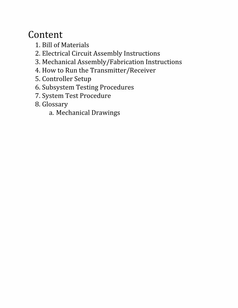
Content 1. Bill of Materials 2. Electrical Circuit Assembly Instructions 3. Mechanical Assembly/Fabrication Instructions 4. How to Run the Transmitter/Receiver 5. Controller Setup 6. Subsystem Testing Procedures 7. System Test Procedure 8. Glossary
a. Mechanical Drawings

1. Bill Of Materials https://edge.rit.edu/edge/P15252/public/Detailed%20Design%20Documents/BOMs2.pdf
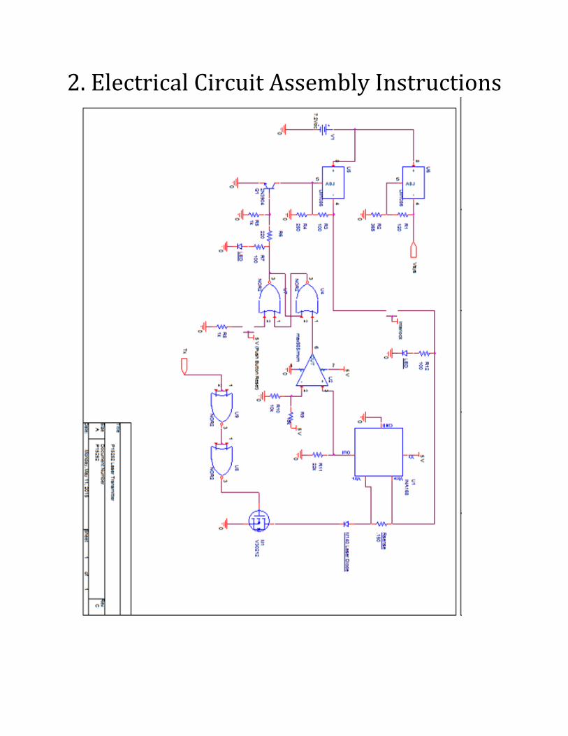
2. Electrical Circuit Assembly Instructions

Transmitter Assembly
Parts List
Part Number Component Quantity
TRS5000 7.2 V Rechargeable Liion 1
LM1086 Power Regulator 2
2N3904 NPN NPN Transistor 1
MAX985 Comparator 1
INA186 Current Monitor 1
P16NF06 NChannel MOSFET 1
58845FR158 .150 Ohm Sense R (3W) 1
CF1/4C101J 100 Ohm R (1/4 W) 2
CF1/4C121J 220 Ohm R (1/4 W) 1
CF1/4C102J 1k Ohm R (1/4 W) 3
LS7402 NOR 2Input Gate IC 1
CF1/4C103J 10k Ohm R (1/4 W) 4
2751556 N.O. Push Button 2
2721013 10 uF Cap 2
2721010 .1 uF Cap 2
SSLLX5093LID Red LED 1
276158 Perf Board 1
Male Header Pins 100
Female Jumper Wires 10
CF1/4C122J 22k Ohm R (1/4 W) 1
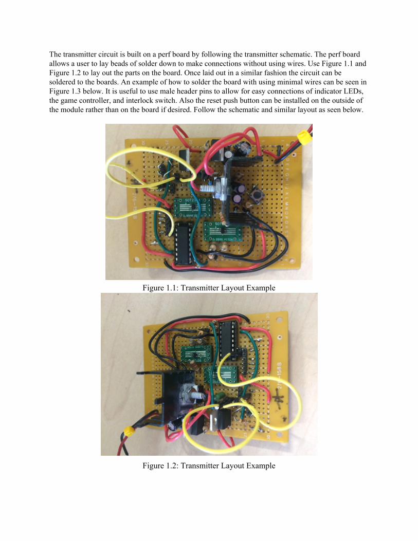
The transmitter circuit is built on a perf board by following the transmitter schematic. The perf board allows a user to lay beads of solder down to make connections without using wires. Use Figure 1.1 and Figure 1.2 to lay out the parts on the board. Once laid out in a similar fashion the circuit can be soldered to the boards. An example of how to solder the board with using minimal wires can be seen in Figure 1.3 below. It is useful to use male header pins to allow for easy connections of indicator LEDs, the game controller, and interlock switch. Also the reset push button can be installed on the outside of the module rather than on the board if desired. Follow the schematic and similar layout as seen below.
Figure 1.1: Transmitter Layout Example
Figure 1.2: Transmitter Layout Example
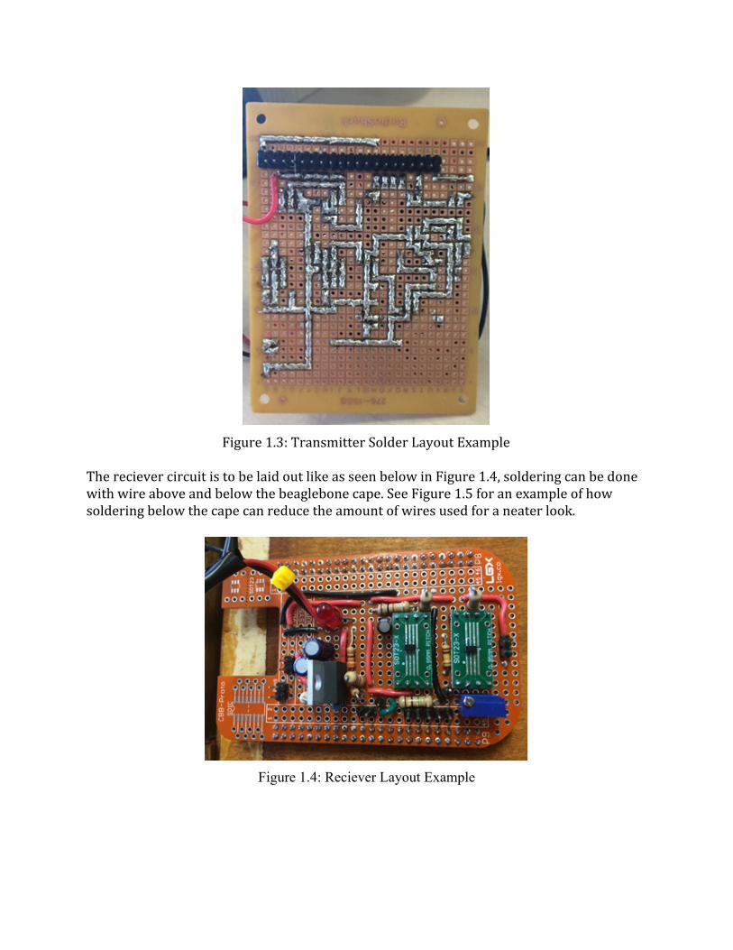
Figure 1.3: Transmitter Solder Layout Example
The reciever circuit is to be laid out like as seen below in Figure 1.4, soldering can be done with wire above and below the beaglebone cape. See Figure 1.5 for an example of how soldering below the cape can reduce the amount of wires used for a neater look.
Figure 1.4: Reciever Layout Example
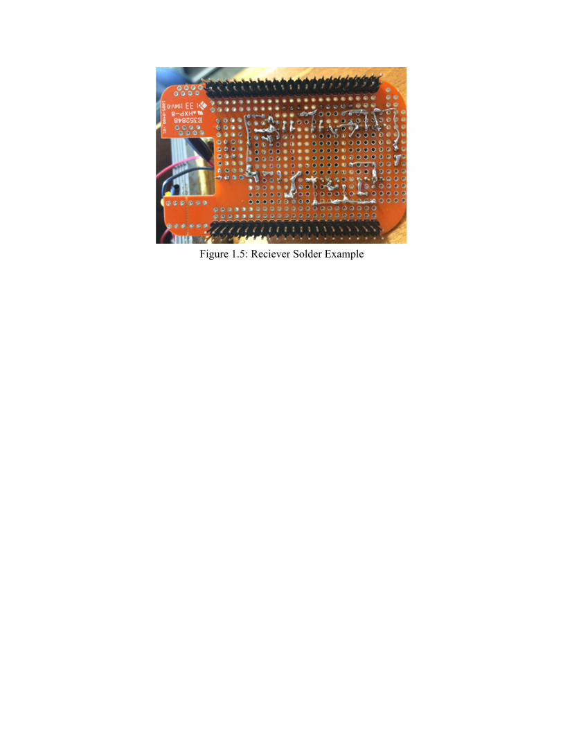
Figure 1.5: Reciever Solder Example

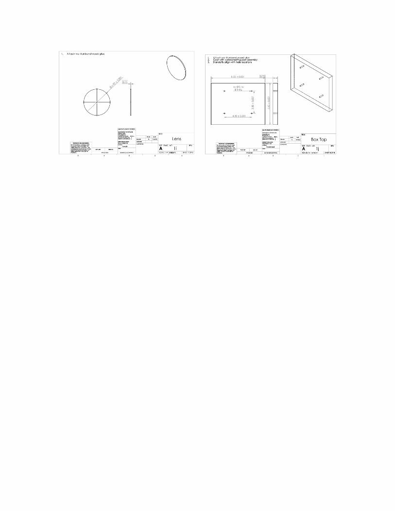
3. Mechanical Fabrication/Assembly Subassembly 1 – Box Externals: 1) Cut hardwood (PN 6216) to appropriate dimensions per drawing 1 2) Drill holes for standoffs (PN4830) per drawing 1 using 9/4” bit size 3) Drill hole for wires using 1in bit per drawing 1 4) Cut butyl rubber (PN8609K11) to dimensions per drawing 1 using box cutter/exacto blade 5) Use titanbond (PN1444) wood glue to adhere the wood pieces to each other. 6) Adhere butyl seal to wood using titanbond (1444) 7) Drill pilot holes into wood for hinge at appropriate locations per drawing 1 8) Screw in both hinges to both top (P1b) and back (P1a) 9) Cut acrylic lens/protector (P1i) using bandsaw and belt sander per drawing 1 10) Glue lens to front of box (P1d) covering front facing hole 11) Cut PVC flange (PN02389K91) according to drawing 1 12) Use PVC Flange as template for drilling pilot holes for flange bolts 12) Bolt down PVC flange using hex bolts of appropriate size (P1d) Subassembly 2 – Box Internals: 1) Cut aluminum (89015K236 ) sheet to correct dimension per drawing 2 2) Cut slots in aluminum using 3/16 inch bit on mill 3) Cut Microcontroller mounting screw (PN90116A147) holes per drawing 1 using 7/64 inch bit 4) Use bandsaw and sander cut the wood arch (P2d) to per drawing 2 5) Drill appropriate screw hole using correct sized bit 6) Slot wood arch (P2d) per drawing 1 7) Cut diode block (P2e) using band saw 8) Drill heat sink (P2f) hole into diode block (P2e) using 51/64inch bit on drill press 9) Drill hole for titanium hex nut (PN90545A009) into diode block (P2e) using 31/64inch bit on drill press 10) Put diode in the heat sink (P2f) 11) Put heat sink in the block (P2e) 12) Screw translation screw (PN90272A296) through arch (P2d) into diode block (P2e) 13) Adhere wood arch to aluminum using polyurethane glue (PN1444) 14) Secure microcontroller (PN1876) to aluminum using mounting screws (PN90116A147) 15) Screw standoffs (PN24430) into base board (P1j) 16) Screw aluminum plate into standoffs using PN94792A517 Subassembly 3 – PVC: 1) Cut PVC into appropriate lengths per drawing 3 2) Cut 2 acrylic lens (P3j) using appropriate bandsaw and belt sander per drawing 3 3) Caulk lenses to inside of 3” couplings (PN23283) 4) Prime (PN23781) and glue (PN23544) all PVC connections except the rubber coupling connection 5) Assemble according to drawing 3 6) Tighten rubber couplings (PN23475) to PVC per drawing 3
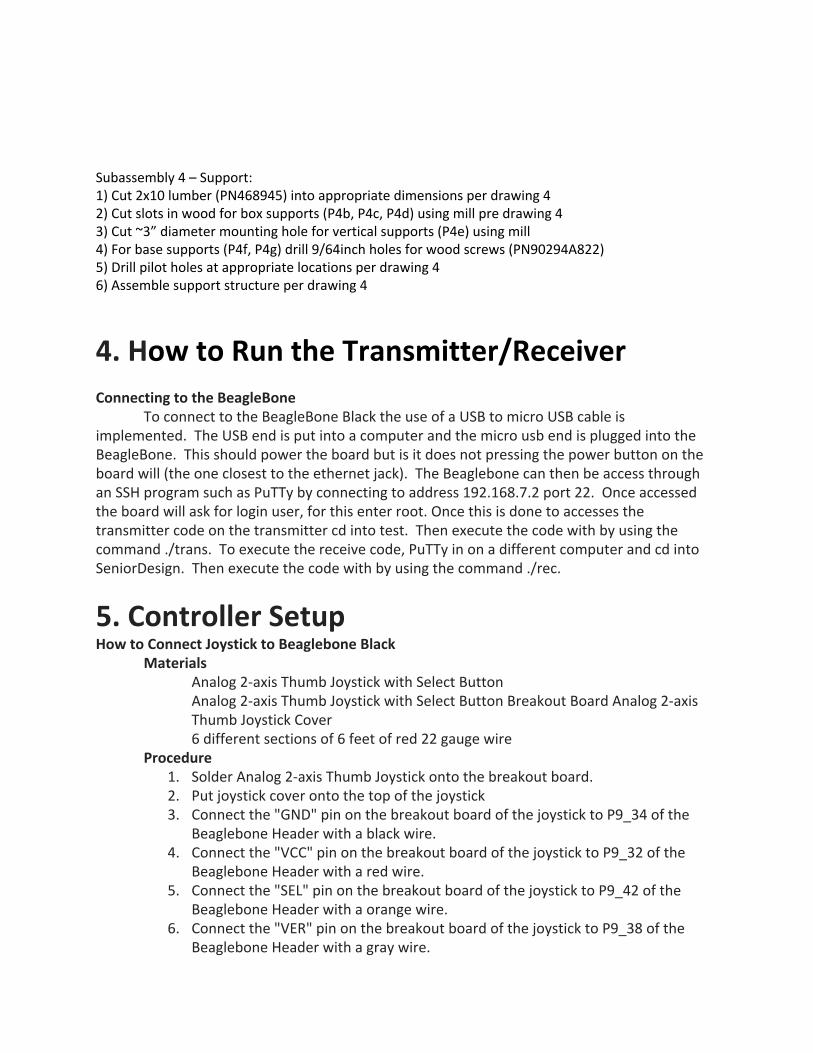
Subassembly 4 – Support: 1) Cut 2x10 lumber (PN468945) into appropriate dimensions per drawing 4 2) Cut slots in wood for box supports (P4b, P4c, P4d) using mill pre drawing 4 3) Cut ~3” diameter mounting hole for vertical supports (P4e) using mill 4) For base supports (P4f, P4g) drill 9/64inch holes for wood screws (PN90294A822) 5) Drill pilot holes at appropriate locations per drawing 4 6) Assemble support structure per drawing 4
4. How to Run the Transmitter/Receiver Connecting to the BeagleBone
To connect to the BeagleBone Black the use of a USB to micro USB cable is implemented. The USB end is put into a computer and the micro usb end is plugged into the BeagleBone. This should power the board but is it does not pressing the power button on the board will (the one closest to the ethernet jack). The Beaglebone can then be access through an SSH program such as PuTTy by connecting to address 192.168.7.2 port 22. Once accessed the board will ask for login user, for this enter root. Once this is done to accesses the transmitter code on the transmitter cd into test. Then execute the code with by using the command ./trans. To execute the receive code, PuTTy in on a different computer and cd into SeniorDesign. Then execute the code with by using the command ./rec.
5. Controller Setup How to Connect Joystick to Beaglebone Black
Materials Analog 2-axis Thumb Joystick with Select Button Analog 2-axis Thumb Joystick with Select Button Breakout Board Analog 2-axis Thumb Joystick Cover 6 different sections of 6 feet of red 22 gauge wire
Procedure 1. Solder Analog 2-axis Thumb Joystick onto the breakout board. 2. Put joystick cover onto the top of the joystick 3. Connect the "GND" pin on the breakout board of the joystick to P9_34 of the
Beaglebone Header with a black wire. 4. Connect the "VCC" pin on the breakout board of the joystick to P9_32 of the
Beaglebone Header with a red wire. 5. Connect the "SEL" pin on the breakout board of the joystick to P9_42 of the
Beaglebone Header with a orange wire. 6. Connect the "VER" pin on the breakout board of the joystick to P9_38 of the
Beaglebone Header with a gray wire.
7. Connect the "HOR" pin on the breakout board of the joystick to P9_36 of the Header Beaglebone with a white wire.
8. Solder all wired connections on the breakout board. 6. Subsystem Test Procedures
Microcontroller Test Procedure:
Subsystem 1: Communication Ports Purpose:
Test Beaglebone Black communication ports. Material:
● 2 Beaglebone Blacks ● 2 USB to USB cables ● Bread Board ● Desktop/Laptop/PC ● 2 USB to microUSB cable
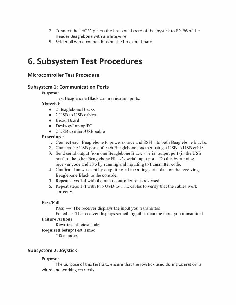
Procedure: 1. Connect each Beaglebone to power source and SSH into both Beaglebone blacks. 2. Connect the USB ports of each Beaglebone together using a USB to USB cable. 3. Send serial output from one Beaglebone Black’s serial output port (in the USB
port) to the other Beaglebone Black’s serial input port. Do this by running receiver code and also by running and inputting to transmitter code.
4. Confirm data was sent by outputting all incoming serial data on the receiving Beaglebone Black to the console.
5. Repeat steps 14 with the microcontroller roles reversed 6. Repeat steps 14 with two USBtoTTL cables to verify that the cables work
correctly. Pass/Fail
Pass → The receiver displays the input you transmitted Failed → The receiver displays something other than the input you transmitted
Failure Actions Rewrite and retest code
Required Setup/Test Time: ~45 minutes
Subsystem 2: Joystick
Purpose: The purpose of this test is to ensure that the joystick used during operation is
wired and working correctly.
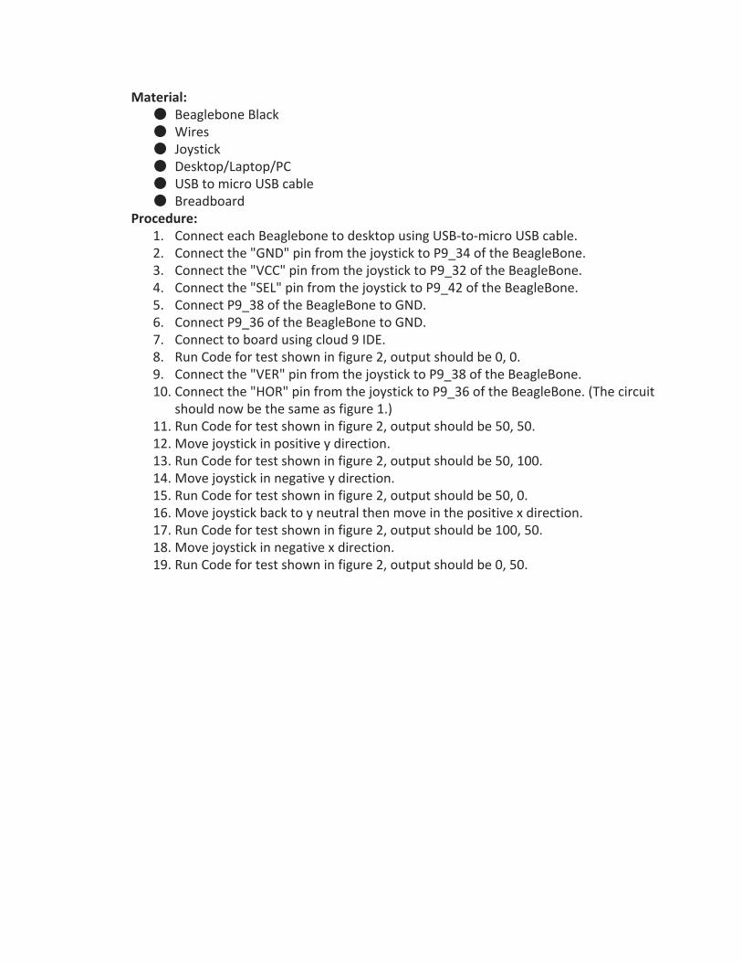
Material: ● Beaglebone Black ● Wires ● Joystick ● Desktop/Laptop/PC ● USB to micro USB cable ● Breadboard
Procedure: 1. Connect each Beaglebone to desktop using USB-to-micro USB cable. 2. Connect the "GND" pin from the joystick to P9_34 of the BeagleBone. 3. Connect the "VCC" pin from the joystick to P9_32 of the BeagleBone. 4. Connect the "SEL" pin from the joystick to P9_42 of the BeagleBone. 5. Connect P9_38 of the BeagleBone to GND. 6. Connect P9_36 of the BeagleBone to GND. 7. Connect to board using cloud 9 IDE. 8. Run Code for test shown in figure 2, output should be 0, 0. 9. Connect the "VER" pin from the joystick to P9_38 of the BeagleBone. 10. Connect the "HOR" pin from the joystick to P9_36 of the BeagleBone. (The circuit
should now be the same as figure 1.) 11. Run Code for test shown in figure 2, output should be 50, 50. 12. Move joystick in positive y direction. 13. Run Code for test shown in figure 2, output should be 50, 100. 14. Move joystick in negative y direction. 15. Run Code for test shown in figure 2, output should be 50, 0. 16. Move joystick back to y neutral then move in the positive x direction. 17. Run Code for test shown in figure 2, output should be 100, 50. 18. Move joystick in negative x direction. 19. Run Code for test shown in figure 2, output should be 0, 50.

Figure 1: Circuit for Joystick Test
Pass/Fail Pass → The joystick values are correctly displayed Failed → The joystick values are incorrectly displayed
Failure Actions Check all wired connection to ensure no two wires are touching and rewrite and
retest code Required Setup/Test Time:
~30 minutes
Subsystem 3: Command Execution
Purpose: The purpose of this test is to ensure that commands on the receiver
microcontroller are executed correctly. Materials:
● Beaglebone Black ● USB to micro USB cable ● Desktop/Laptop/PC
Procedure: 1. Connect Beaglebone Black to desktop using USB-to-micro USB cable 2. Connect a USB cable from the USB port on the Beaglebone to a USB port on your
computer.

3. On the computer, create a file of “fake” packets that represent the desired commands to be tested.
4. Read file into receiver through serial in port (in the USB port). 5. Confirm that the desired commands have been run.
Pass/Fail Pass → The commands are run in the correct order and no commands are lost Failed → Commands are lost or run in an incorrect order
Failure Actions Check the bode rate of both Beaglebones and ensure that the code is written correctly.
Required Time: ~15mintues
Subsystem 4: Packet Creation
Purpose: Capture output from transmitter to ensure packets are created correctly.
Material: ● Beaglebone Black ● Desktop/Laptop/PC ● USB to microUSB cable ● Joystick
Procedure: 1. Connect Beaglebone Black to power source 2. Connect a USB cable from the USB port on the Beaglebone to a USB port on your
computer. 3. Enable packets to be written to file after they are created 4. Move joystick to positive X direction for one second 5. Move joystick to positive Y direction for one second 6. Move joystick to negative X direction for one second 7. Move joystick to negative Y direction for one second 8. Verify the contents of file are the packets that represent the performed actions
Pass/Fail Pass → Packets are created correctly Failed → Packets are created incorrectly
Failure Actions Rewrite the transmitter code until correct results are achieved.
Required Setup/Test Time: ~30 minutes

7. System Test Procedures Safety:
Do not begin testing with laser until all members in the room has equipped the proper eye protection and are not in a potential path of the laser beam.
If any persons enter the test area during testing and are not equipped with the correct laser protection, shut off power to the laser.
If leakage occurs during any time, shut off the laser, and isolate the PCV pipe from the transmitter and receiver, open both modules and check for leakage. Materials: ➢ Transmitter
➢ Receiver
➢ Modular PVC Water Pipe Channel
➢ Access to water / disposal of water ➢ Proper Safety Equipment ➢ Two Laptop with mini USB cables Using Project P15252 Underwater Laser Communication Before using Project 15252 double check transmitter and receiver and PVC water channel for any signs of leaking water. If any sign of leakage are found, remove any electronics before they are potentially damaged. Double check that interlock pushbutton is secure on the transmitter module. If the interlock is not being used, make sure the open circuit is shorted with a female-to-female jumper wire. The to pin are located at positsion (I,22) and (I,23) on the transmitter protoboard. Next, make sure that the Red LED indicator anode is connected to (I,24) and the cathode is connected to (H,24). Double check that the laser diode is properly connected before applying power. (J,24) is connected to the anode of the laser diode (red wire), (K,24) is connected to the cathode if the laser diode (black wire). There is no connection for the white wire from the laser diode. The green LED is connected to pins (X,16) and (X,15), which are the anode and cathode respectivily. This green LED will turn on when the current doing into the the laser diode rises above 700mA, this ensures that the Laser diode will not burn itself out. When the current does reach this threshold, the laser will be shut off and will stay off until the black pushbutton on the transmitter board is pushed to reset.

Double check that the photodiode is flat on the PVC glass, this can be done with decent tape. After the system is checked for leaks, and connections are confirmed the transmitter and receiver modules can be sealed, double check for proper sealing when closing lids. Once the lids are locked the batteries power can be switched on both the receiver and the transmitter. At this point run both the transmitter and receiver code.
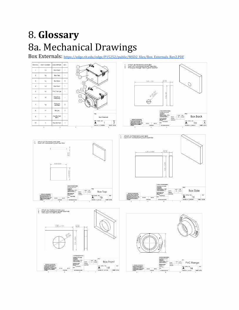
8. Glossary 8a. Mechanical Drawings Box Externals: https://edge.rit.edu/edge/P15252/public/MSD2_files/Box_Externals_Rev2.PDF

Support System: https://edge.rit.edu/edge/P15252/public/MSD2_files/Support_rev2.PDF
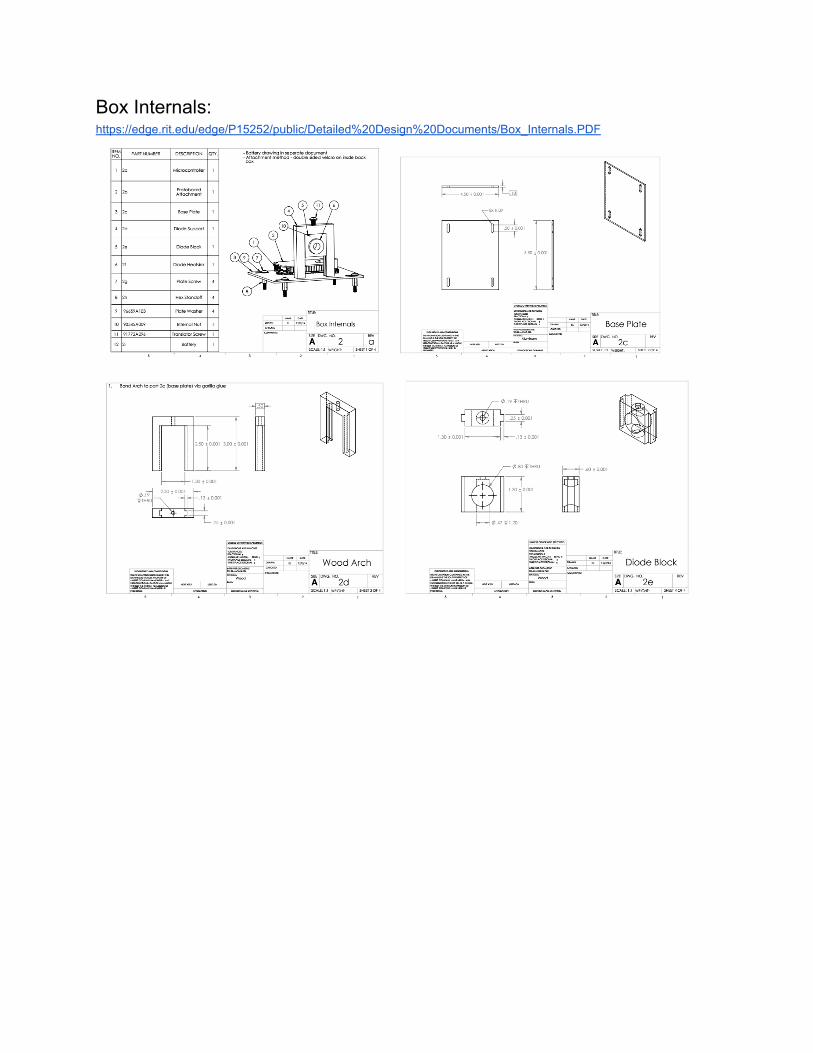
Box Internals: https://edge.rit.edu/edge/P15252/public/Detailed%20Design%20Documents/Box_Internals.PDF
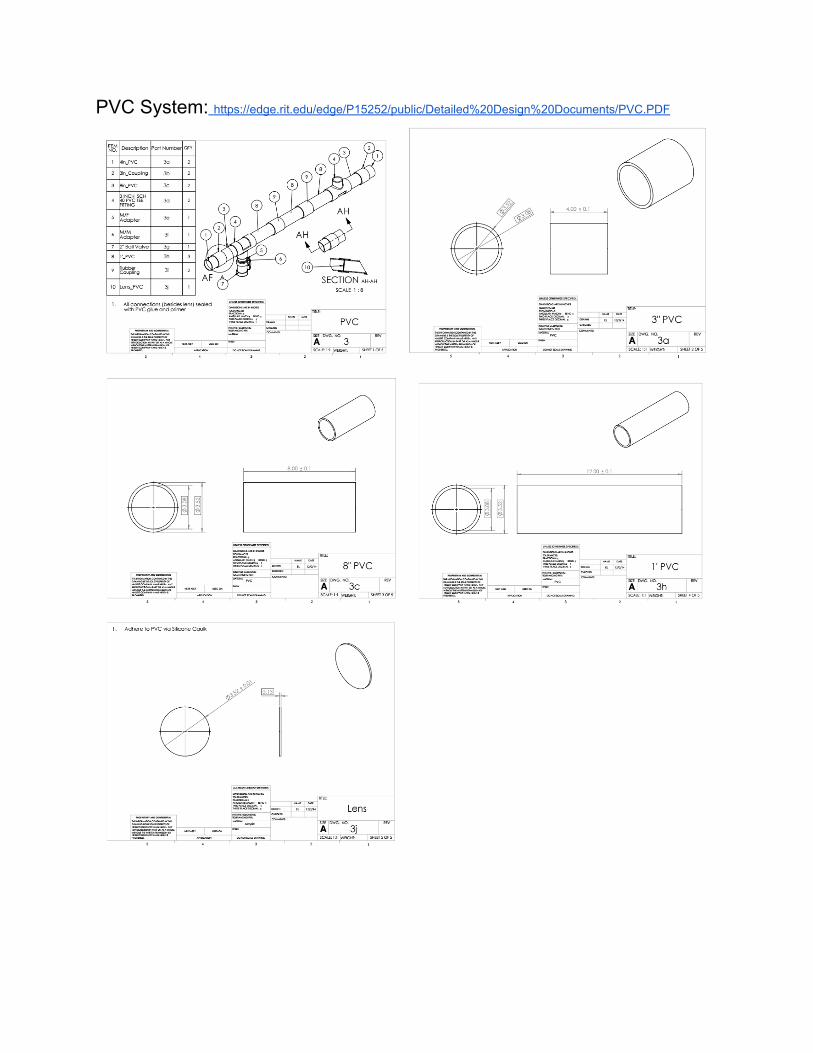
PVC System: https://edge.rit.edu/edge/P15252/public/Detailed%20Design%20Documents/PVC.PDF


![[Number System] - IAS Edge](https://img.pdfslide.us/doc/110x75/61bd08ab61276e740b0ead3b/number-system-ias-edge.jpg)