Embed Size (px)
Citation preview
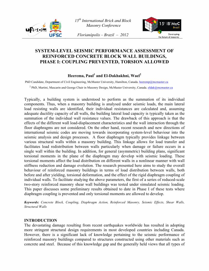
15th International Brick and Block Masonry Conference
Florianópolis – Brazil – 2012
SYSTEM-LEVEL SEISMIC PERFORMANCE ASSESSMENT OF REINFORCED CONCRETE BLOCK WALL BUILDINGS,
PHASE I: COUPLING PREVENTED, TORSION ALLOWED
Heerema, Paul1 and El-Dakhakhni, Wael2 PhD Candidate, Department of Civil Engineering, McMaster University, Hamilton, Canada. [email protected]
2 PhD, Martini, Mascarin and George Chair in Masonry Design, McMaster University, Canada. [email protected]
Typically, a building system is understood to perform as the summation of its individual components. Thus, when a masonry building is analysed under seismic loads, the main lateral load resisting walls are identified, their individual resistances are calculated and, assuming adequate ductility capacity of all walls, the building lateral load capacity is typically taken as the summation of the individual wall resistance values. The drawback of this approach is that the effects of the different wall load-displacement characteristics and the wall interaction through the floor diaphragms are not considered. On the other hand, recent research and new directions of international seismic codes are moving towards incorporating system-level behaviour into the seismic analysis and design processes. A floor diaphragm typically provides linkage between various structural walls within a masonry building. This linkage allows for load transfer and facilitates load redistribution between walls particularly when damage or failure occurs in a single wall within the building. In addition, for general (asymmetric) building plans, significant torsional moments in the plane of the diaphragm may develop with seismic loading. These torsional moments affect the load distribution on different walls in a nonlinear manner with wall stiffness reduction and damage evolution. The research presented here aims to study the overall behaviour of reinforced masonry buildings in terms of load distribution between walls, both before and after yielding, torsional deformation, and the effect of the rigid diaphragm coupling of individual walls. To facilitate studying the above parameters, the first of a series of reduced-scale two-story reinforced masonry shear wall buildings was tested under simulated seismic loading. This paper discusses some preliminary results obtained to date in Phase I of these tests where diaphragm coupling is prevented and only torsional moments are allowed to develop.
Keywords: Concrete Block, Coupling, Diaphragm Action, Reinforced Masonry, Seismic Effects, Shear Walls, Structural Walls
INTRODUCTION The devastating damage resulting from recent earthquakes worldwide has resulted in adopting more stringent structural design requirements in most developed countries including Canada. However, there is a significant lack of knowledge pertaining to the seismic performance of reinforced masonry buildings compared to structures constructed using other materials such as concrete and steel. Because of this knowledge gap and the generally held views that all types of
15th International Brick and Block Masonry Conference
Florianópolis – Brazil – 2012
masonry structures (unreinforced and reinforced) are not ductile, the current Canadian seismic design provisions consider masonry structures as particularly vulnerable under seismic loading (NBCC, 2010). However, adopting such mandatory provisions has resulted in a major negative impact on the Canadian masonry industry and has limited the use of masonry in low-rise construction systems in Canada. Since the conclusion of the test programs carried out by the Joint U.S.-Japan Technical Coordinating Committee on Masonry Research (TCCMAR) during the 1990’s (Seible et al.1994) there has been little progress made on understanding the system-level performance of reinforced masonry buildings. The McMaster Masonry Research Group (MMRG) is currently implementing a multi-year research program funded by the Canadian Government which will provide the needed seismic performance database, pertaining to reinforced masonry, to facilitate developing the next generation of performance-based seismic design codes in Canada. In this regard, the multifaceted research program will cover a wide array of complementary focus areas. These areas include experimental evaluation of complete masonry buildings (system-level testing) under simulated earthquake loadings (for which this paper discusses the first phase), developing of pertaining analytical models, proposing more relevant seismic performance categories, generating different hazard-, performance-, damage- and loss-functions, and integrating the research results into seismic fragility assessment tools for use by Canadian decision makers and stakeholders. The research program is unique in North America in terms of scope and magnitude and the technique adopted to interpret the research results into meaningful information for code developers, design engineer, building owners, and academic researchers. Considering the volume of masonry construction in North America and the impact of adopting very conservative design approaches because of the unavailability of a reinforced masonry seismic performance database, the proposed research is essential to document and improve the resilience of masonry buildings in Canada and for the sustainability of the Canadian masonry industry. RESEARCH RATIONALE There is an urgent need to conduct fundamental research to clearly document the ductility levels of RM buildings. This is particularly relevant since, because of their relatively high elastic rigidity, RM buildings have a lower natural period than other more flexible buildings, which typically results in higher seismic demand. However, as stresses enter the inelastic range and cracking occurs, the building’s period changes, forces are redistributed, hysteretic damping is introduced, and, as a result, seismic demand is significantly reduced. In addition, there is a limit to the information that can be collected from individual RM wall (component-level) tests (Shedid et al., 2008) when the overall building (system-level) performance is the primary concern. In this regard, to adopt a more rational seismic design philosophy, there will be a gradual shift starting in the 2015-NBCC from force- to displacement- and performance-based design approaches (NBCC SCED, 2009) focusing on system-level (whole structure) (NBCC SCED, 2009) performance. The ultimate goal of the research program is to integrate the different performance aspects of RM building systems into fragility assessment tools for adoption in the next generation of seismic design codes in Canada.
15th International Brick and Block Masonry Conference
Florianópolis – Brazil – 2012
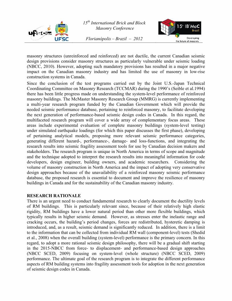
WALL AND BUILDING CONFIGURATIONS The availability of the reduced-scale blocks will facilitate construction of four complete ⅓-scale RM buildings and testing them using the existing quasi-static and dynamic testing capabilities at the Applied Dynamics Laboratory (ADL) at McMaster University. The buildings will be constructed using wall configurations identical to those reported in a companion paper by Siyam et al. (2012) shown in Fig. 1 with their design parameters listed in Table 1.
Figure 1: Building walls layout: (a) W1, (b) W2, (c) W3, (d) W4, (e) W5, (f) W6
All the specification regarding walls dimensions, aspect ratio and reinforcement details are given in Table 1 where φv and φh represent the vertical and horizontal bar diameter of scaled bars, while ρv and ρh represent horizontal and vertical reinforcement ratios, respectively. As noticed from the
15th International Brick and Block Masonry Conference
Florianópolis – Brazil – 2012
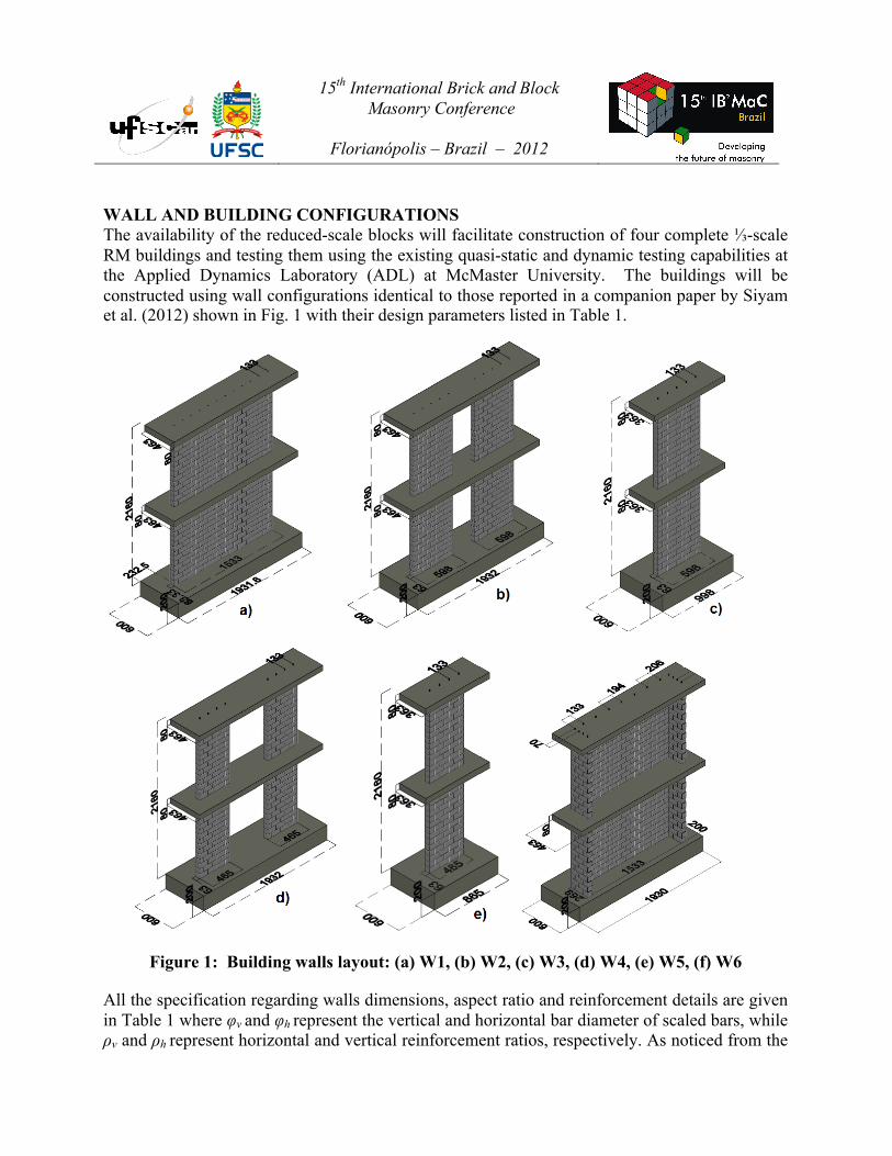
table, the walls were designed to have an aspect ratio higher than 1.0 to produce a flexure dominated behaviour. In addition, the walls have the same vertical and horizontal reinforcement ratios of 0.6% and 0.19% approximately. Walls with such ratio are categorized in CSA S304.1 as moderately ductile reinforced shear walls. Table 1 Wall Details and Specification All the walls except the flanged wall have the same vertical bar spacing of 133mm. Wall 6 is reinforced in every cell in the flanges and in every other block along the wall. All walls have the same horizontal reinforcement spacing configuration, 65 mm in the first floor and 130 mm in the second floor, resulting in a reinforcement ratio of 0.19%. The adoption of reinforcement ratios and spacing was based in accordance to the CSA S304.1. As shown in Figure 1, all walls consist of two storeys separated by reinforced concrete slabs. Two buildings, of the four within the test program, will be tested under displacement-controlled quasi-static loading. In the first building (which is the focus of the current paper), the wall coupling through the concrete diaphragm will be minimized by reducing the RC slab thickness between walls to practically create hinge lines that were identified using a combination of yield line and iterative finite element analyses to optimize the hinge line location selection. (see Figure 2).
Figure 2: Hinge lines in the building roof slab
Wall Type Height (mm)
Length (mm)
Aspect ratio
Vertical reinforcement
Horizontal reinforcement
φv
(mm) ρv
(%) φh
(mm) ρh (%)
1 Rectangular 2,160 1,533 1.41 7.6 0.55 3.8 0.19 2 Coupled 2,160 1,533 1.41 7.6 0.59 3.8 0.19 3 Rectangular 2,160 598 3.61 7.6 0.59 3.8 0.19 4 Coupled 2,160 1,533 1.41 7.6 0.61 3.8 0.19 5 Rectangular 2,160 465 4.64 7.6 0.61 3.8 0.19 6 Flanged 2,160 1,533 1.41 7.6 0.55 3.8 0.19
15th International Brick and Block Masonry Conference
Florianópolis – Brazil – 2012
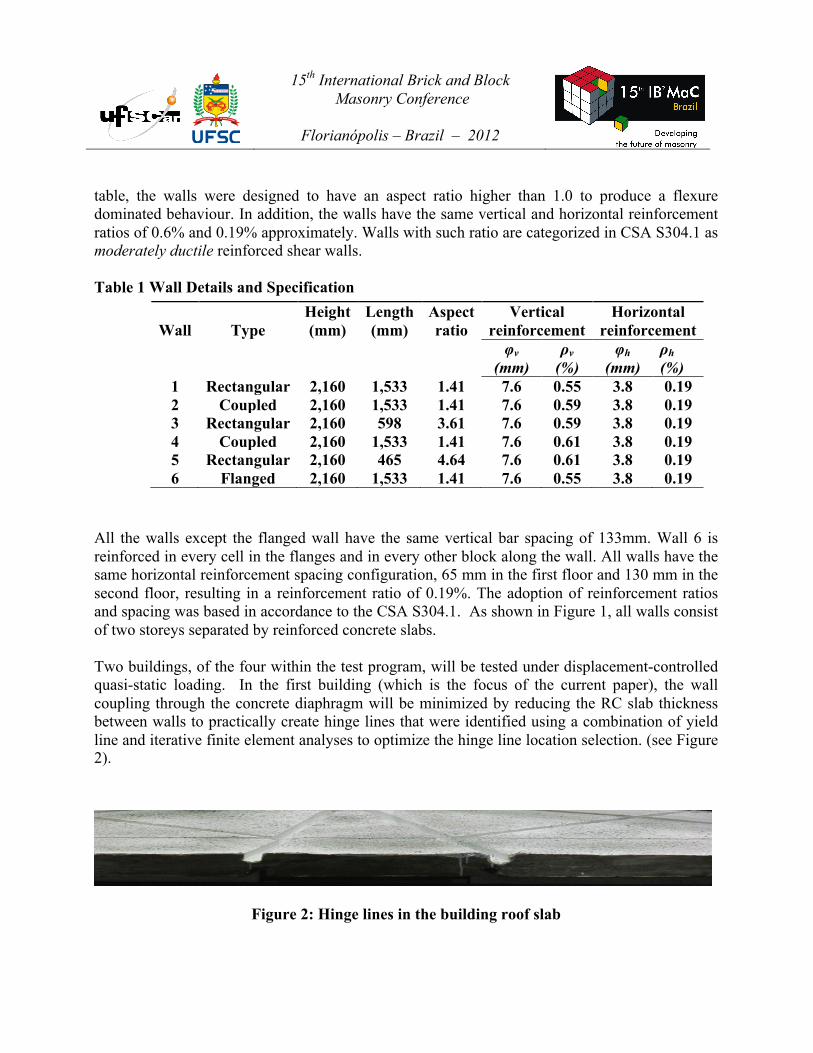
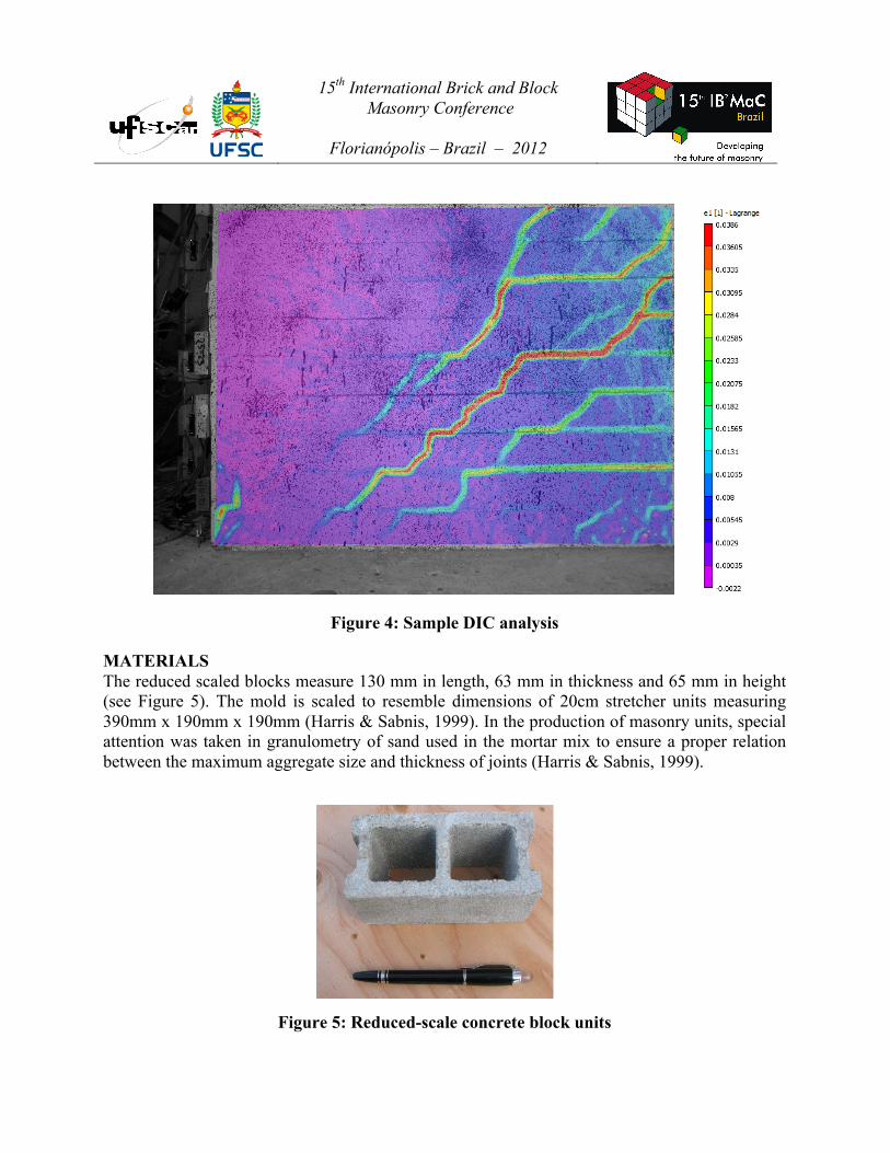
Although such hinge lines represent unrealistic construction detail, this first phase test results will facilitate isolating the effect of the torsion induced by the rigid (in its own plane) diaphragm by minimizing the diaphragm coupling effect (through minimizing its out-of-plane stiffness). In the second phase, another building will be constructed of walls identical to those of the current building but with a regular (constant thickness) diaphragm which will facilitate quantifying the effects of wall coupling on the building response. During tests, the wall displacements and reinforcement strains will be recorded and force redistribution (following wall(s) damage) will be monitored through comparing the wall curvature profiles to those collected from the individual wall tests. Figure 3 shows the building and the quasi-static loading test setup. INSTRUMENTATION In total, 180 displacement transducers and 120 strain gauges were used to record the wall and the overall building deformations. In addition, a High Resolution 3-D Full Strain-field Digital Image Correlation (DIC) System with 31 cameras was utilized to monitor the different strains, displacements, and rotations within the floor diaphragms as well as major portions of the buildings. Such data will be used to monitor the building rotation due to the torsion induced by the change of eccentricity between the centre of mass and the centre of rotation, resulting from the walls’ nonlinear behaviours, throughout the loading history. In addition, the crack evolution images will serve to track the damage process and later on to identify the different wall performance levels within the context of performance-based seismic design (ATC58, 2012). Figure 4 shows a sample result of wall shear crack pattern generated through the DIC analyses.
Figure 3: Building configuration and the quasi-static loading test setup
15th International Brick and Block Masonry Conference
Florianópolis – Brazil – 2012
Figure 4: Sample DIC analysis
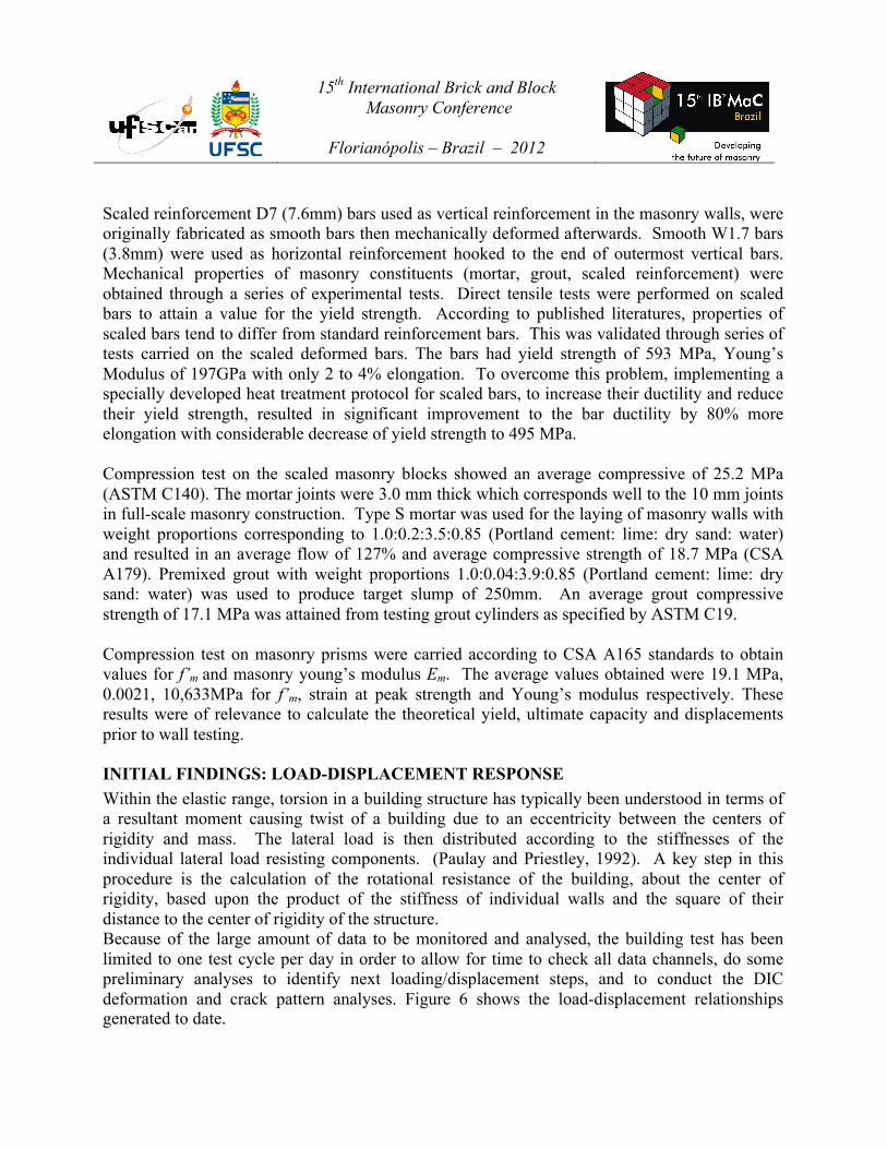
MATERIALS The reduced scaled blocks measure 130 mm in length, 63 mm in thickness and 65 mm in height (see Figure 5). The mold is scaled to resemble dimensions of 20cm stretcher units measuring 390mm x 190mm x 190mm (Harris & Sabnis, 1999). In the production of masonry units, special attention was taken in granulometry of sand used in the mortar mix to ensure a proper relation between the maximum aggregate size and thickness of joints (Harris & Sabnis, 1999).
Figure 5: Reduced-scale concrete block units
15th International Brick and Block Masonry Conference
Florianópolis – Brazil – 2012
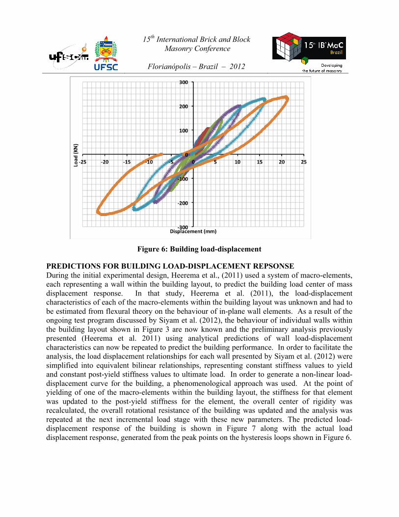
Scaled reinforcement D7 (7.6mm) bars used as vertical reinforcement in the masonry walls, were originally fabricated as smooth bars then mechanically deformed afterwards. Smooth W1.7 bars (3.8mm) were used as horizontal reinforcement hooked to the end of outermost vertical bars. Mechanical properties of masonry constituents (mortar, grout, scaled reinforcement) were obtained through a series of experimental tests. Direct tensile tests were performed on scaled bars to attain a value for the yield strength. According to published literatures, properties of scaled bars tend to differ from standard reinforcement bars. This was validated through series of tests carried on the scaled deformed bars. The bars had yield strength of 593 MPa, Young’s Modulus of 197GPa with only 2 to 4% elongation. To overcome this problem, implementing a specially developed heat treatment protocol for scaled bars, to increase their ductility and reduce their yield strength, resulted in significant improvement to the bar ductility by 80% more elongation with considerable decrease of yield strength to 495 MPa. Compression test on the scaled masonry blocks showed an average compressive of 25.2 MPa (ASTM C140). The mortar joints were 3.0 mm thick which corresponds well to the 10 mm joints in full-scale masonry construction. Type S mortar was used for the laying of masonry walls with weight proportions corresponding to 1.0:0.2:3.5:0.85 (Portland cement: lime: dry sand: water) and resulted in an average flow of 127% and average compressive strength of 18.7 MPa (CSA A179). Premixed grout with weight proportions 1.0:0.04:3.9:0.85 (Portland cement: lime: dry sand: water) was used to produce target slump of 250mm. An average grout compressive strength of 17.1 MPa was attained from testing grout cylinders as specified by ASTM C19. Compression test on masonry prisms were carried according to CSA A165 standards to obtain values for f’m and masonry young’s modulus Em. The average values obtained were 19.1 MPa, 0.0021, 10,633MPa for f’m, strain at peak strength and Young’s modulus respectively. These results were of relevance to calculate the theoretical yield, ultimate capacity and displacements prior to wall testing. INITIAL FINDINGS: LOAD-DISPLACEMENT RESPONSE Within the elastic range, torsion in a building structure has typically been understood in terms of a resultant moment causing twist of a building due to an eccentricity between the centers of rigidity and mass. The lateral load is then distributed according to the stiffnesses of the individual lateral load resisting components. (Paulay and Priestley, 1992). A key step in this procedure is the calculation of the rotational resistance of the building, about the center of rigidity, based upon the product of the stiffness of individual walls and the square of their distance to the center of rigidity of the structure. Because of the large amount of data to be monitored and analysed, the building test has been limited to one test cycle per day in order to allow for time to check all data channels, do some preliminary analyses to identify next loading/displacement steps, and to conduct the DIC deformation and crack pattern analyses. Figure 6 shows the load-displacement relationships generated to date.
15th International Brick and Block Masonry Conference
Florianópolis – Brazil – 2012
Figure 6: Building load-displacement
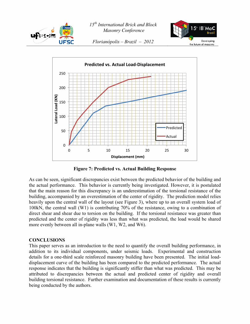
PREDICTIONS FOR BUILDING LOAD-DISPLACEMENT REPSONSE During the initial experimental design, Heerema et al., (2011) used a system of macro-elements, each representing a wall within the building layout, to predict the building load center of mass displacement response. In that study, Heerema et al. (2011), the load-displacement characteristics of each of the macro-elements within the building layout was unknown and had to be estimated from flexural theory on the behaviour of in-plane wall elements. As a result of the ongoing test program discussed by Siyam et al. (2012), the behaviour of individual walls within the building layout shown in Figure 3 are now known and the preliminary analysis previously presented (Heerema et al. 2011) using analytical predictions of wall load-displacement characteristics can now be repeated to predict the building performance. In order to facilitate the analysis, the load displacement relationships for each wall presented by Siyam et al. (2012) were simplified into equivalent bilinear relationships, representing constant stiffness values to yield and constant post-yield stiffness values to ultimate load. In order to generate a non-linear load-displacement curve for the building, a phenomenological approach was used. At the point of yielding of one of the macro-elements within the building layout, the stiffness for that element was updated to the post-yield stiffness for the element, the overall center of rigidity was recalculated, the overall rotational resistance of the building was updated and the analysis was repeated at the next incremental load stage with these new parameters. The predicted load-displacement response of the building is shown in Figure 7 along with the actual load displacement response, generated from the peak points on the hysteresis loops shown in Figure 6.
15th International Brick and Block Masonry Conference
Florianópolis – Brazil – 2012
Figure 7: Predicted vs. Actual Building Response
As can be seen, significant discrepancies exist between the predicted behavior of the building and the actual performance. This behavior is currently being investigated. However, it is postulated that the main reason for this discrepancy is an underestimation of the torsional resistance of the building, accompanied by an overestimation of the center of rigidity. The prediction model relies heavily upon the central wall of the layout (see Figure 3), where up to an overall system load of 100kN, the central wall (W1) is contributing 70% of the resistance, owing to a combination of direct shear and shear due to torsion on the building. If the torsional resistance was greater than predicted and the center of rigidity was less than what was predicted, the load would be shared more evenly between all in-plane walls (W1, W2, and W6).
CONCLUSIONS This paper serves as an introduction to the need to quantify the overall building performance, in addition to its individual components, under seismic loads. Experimental and construction details for a one-third scale reinforced masonry building have been presented. The initial load-displacement curve of the building has been compared to the predicted performance. The actual response indicates that the building is significantly stiffer than what was predicted. This may be attributed to discrepancies between the actual and predicted center of rigidity and overall building torsional resistance. Further examination and documentation of these results is currently being conducted by the authors.
0
50
100
150
200
250
0 5 10 15 20 25 30
Lateral Loa
d (KN)
Displacement (mm)
Predicted vs. Actual Load-‐Displacement
Predicted
Actual
15th International Brick and Block Masonry Conference
Florianópolis – Brazil – 2012
ACKNOWLEDGEMENTS Financial support has been provided by the McMaster University Centre for Effective Design of Structures (CEDS) funded through the Ontario Research and Development Challenge Fund (ORDCF) as well as the Natural Sciences and Engineering Research Council (NSERC) of Canada. Provision of mason time by Ontario Masonry Contractors Association (OMCA) and Canada Masonry Design Centre (CMDC) is appreciated. The provision of the scaled blocks by the Canadian Concrete Masonry Producers Association (CCMPA) is gratefully acknowledged.
REFERENCES Applied Technology Council (ATC). (2012) Guidelines for Seismic Performance Assessment of Buildings: Volume 1 – Methodology, ATC 58-1, Redwood City, CA.
Canadian Standards Association (CSA). (2004c). “Mortar and grout for unit masonry.” CSA A179-04 (R2010), CSA, Mississauga, Canada.
Harris, H. G., & Sabnis, G. M. (1999). Structural Modeling and Experimental Techniques, Second Edition. Boca Raton: CRC Press LLC.
Heerema, P., Siyam, M. And El-Dakhakhni, W.W. (2011), “Proposed System-Level Testing Of Multi-Storey Reinforced Masonry Buildings Under Simulated Seismic Loading”, Proceedings of the 11th North American Masonry Conference, Minneapolis MN.
NBCC 2010: National Research Council of Canada, “National Building Code of Canada”, 2010.
NBCC 2015 Work Plan Agenda, Standing Committee on Earthquake Design (SCED) http://www.nationalcodes.ca/ccbfc/letterballot/346/23.14.9a%20ED%20Report%20and%20request.pdf
Seible, F., Priestley, M. J. N., Kingsley, G. R., and Kürkchübasche, A. G. (1994) “Seismic Response of Full-Scale Five-Story Reinforced-Masonry Building” J. Struct. Eng. 120, (3) 925-947.
Shedid, M.T., Drysdale, R.G. and El-Dakhakhni, W. W. (2008) “Behavior of Fully-grouted Concrete Masonry Shear Walls: Experimental Study”, ASCE J. Struct. Eng. Vol. 134, No. 11, pp. 1754-1767.
Siyam, M., El-Dakhakhni, W.W. and Drysdale, R.G. (2012) “Seismic Behavior of Reduced-scale Two-storey Reinforced Concrete Masonry Shear Walls”, Proceedings of 15th International Brick and Block Masonry Conference, Florianopolis, Brazil.
Paulay, T. and Priestley, M. J. N. (1992). Seismic Design of Reinforced Concrete and Masonry Buildings. John Wiley & Sons, Inc., New York, NY, USA.