Embed Size (px)
Citation preview

2-514-603-12(1)
System Integration2CH Amplifier
SONY TA-MR2ES (US) 2-514-603-12(1)
2004 Sony Corporation
TA-MR2ES
Installation Manual
Owner’s RecordThe model and serial numbers are located on the rear panel. Record the modeland serial numbers in the spaces provided below. Refer to them whenever youcall upon your Sony dealer regarding this product.
Model No. Serial No.
01US01COV-U.p65 11/30/04, 12:55 PM1
2US
SONY TA MR2ES (US) 2 514 603 12(1)
WARNING
To prevent fire or shock hazard, donot expose the unit to rain ormoisture.
To avoid electrical shock, do notopen the cabinet. Refer servicing toqualified personnel only.
This symbol is intended to alert theuser to the presence of uninsulated“dangerous voltage” within theproduct’s enclosure that may be ofsufficient magnitude to constitute arisk of electric shock to persons.
This symbol is intended to alert theuser to the presence of importantoperating and maintenance(servicing) instructions in theliterature accompanying theappliance.
WARNINGThis equipment has been tested and foundto comply with the limits for a Class Bdigital device, pursuant to Part 15 of theFCC Rules. These limits are designed toprovide reasonable protection againstharmful interference in a residentialinstallation. This equipment generates,uses, and can radiate radio frequencyenergy and, if not installed and used inaccordance with the instructions, maycause harmful interference to radiocommunications. However, there is noguarantee that interference will not occurin a particular installation. If thisequipment does cause harmful interferenceto radio or television reception, which canbe determined by turning the equipmentoff and on, the user is encouraged to try tocorrect the interference by one or more ofthe following measures:– Reorient or relocate the receiving
antenna.– Increase the separation between the
equipment and receiver.– Connect the equipment to an outlet on a
circuit different from that to which thereceiver is connected.
– Consult the dealer or an experiencedradio/TV technician for help.
CAUTIONYou are cautioned that any changes ormodification not expressly approved in thismanual could void your authority tooperate this equipment.
If you have any questions about thisproduct, you may call;Sony Customer Information Service Center1-800-222-7669 orhttp://www.sony.com/
Important Safety Instruction1 Read these instructions.2 Keep these instructions.3 Heed all warnings.4 Follow all instructions.5 Do not use this apparatus near water.6 Clean only with dry cloth.7 Do not block any ventilation openings.
Install in accordance with themanufacturer’s instructions.
8 Do not install near any heat sourcessuch as radiators, heat registers, stoves,or other apparatus (includingamplifiers) that produce heat.
9 Do not defeat the safety purpose of thepolarized or grounding-type plug. Apolarized plug has two blades with onewider than the other. A grounding typeplug has two blades and a thirdgrounding prong. The wide blade or thethird prong are provided for yoursafety. If the provided plug does not fitinto your outlet, consult an electricianfor replacement of the obsolete outlet.
10 Protect the power cord from beingwalked on or pinched particularly atplugs, convenience receptacles, and thepoint where they exit from theapparatus.
11 Only use attachments/accessoriesspecified by the manufacturer.
12 Use only with the cart,stand, tripod, bracket, ortable specified by themanufacturer, or sold withthe apparatus. When a cartis used, use caution whenmoving the cart/apparatuscombination to avoid injuryfrom tip-over.
13 Unplug this apparatus during lightningstorms or when unused for long periodsof time.
14 Refer all servicing to qualified servicepersonnel. Servicing is required whenthe apparatus has been damaged in anyway, such as power-supply cord or plugis damaged, liquid has been spilled orobjects have fallen into the apparatus,the apparatus has been exposed to rainor moisture, does not operate normally,or has been dropped.
Welcome!Thank you for purchasing the SystemIntegration 2CH Amplifier. Beforeoperating the unit, please read this manualthoroughly and retain it for futurereference.
01US02TOC-U.p65 11/30/04, 12:56 PM2
3US
SONY TA MR2ES (US) 2 514 603 12(1)
TABLE OF CONTENTS
Chapter 1 Getting StartedFeatures 4
Unpacking 5
Parts and Controls 6
Chapter 2Setting up the amplifierInstalling the amplifier 8
Hooking up the Amplifier 10
Selecting the method to activate the amplifier 11
Setting up the IR ID 12
Chapter 3Operating the amplifierAdjusting the maximum volume level 14
Controlling the amplifier 15
Clearing the amplifier’s memory 15
Chapter 4Other InformationPrecautions 16
Troubleshooting 17
Specifications 18
Index 19
01US02TOC-U.p65 11/30/04, 12:56 PM3

4US
SONY TA MR2ES (US) 2 514 603 12(1)
Chapter 1
GettingStartedThis chapter provides you withinformation on the features and theparts and controls of the amplifier.
Features
The TA-MR2ES amplifier can be integrated into anymulti-room entertainment system.The amplifier allows you to– Create high performance multi-room audio systems
with intelligence control features.– Program universal remotes using the unique IR
programming function on the rear panel.– Trigger the amplifier using one of three methods.– Cascade amplifiers to power multiple zones using the
12-volt trigger outputs.
01US03CH1-U.p65 11/30/04, 1:07 PM4

5US
Gettin
g S
tarte
d
SONY TA-MR2ES (US) 2-514-603-12(1)
Unpacking
The TA-MR2ES amplifier includes the following:• TA-MR2ES amplifier• AC power cord• Installation Manual (this manual)• Rack-mount brackets (2)• Screw (6)
01US03CH1-U.p65 11/30/04, 1:07 PM5
6US
Gettin
g S
tarte
d
SONY TA-MR2ES (US) 2-514-603-12(1)
ONPOWER
IN USE
ATTENUATORL R
+ +
1 2 3 4*
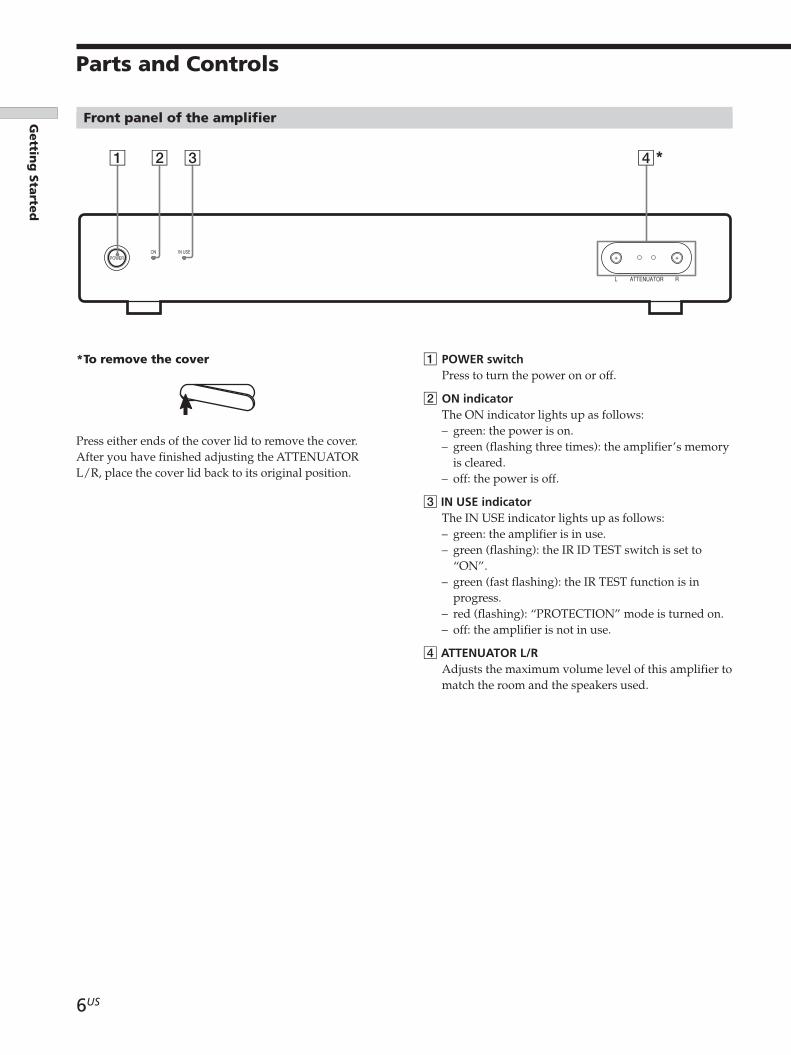
*To remove the cover
Press either ends of the cover lid to remove the cover.After you have finished adjusting the ATTENUATORL/R, place the cover lid back to its original position.
Front panel of the amplifier
Parts and Controls
1 POWER switchPress to turn the power on or off.
2 ON indicatorThe ON indicator lights up as follows:– green: the power is on.– green (flashing three times): the amplifier’s memory
is cleared.– off: the power is off.
3 IN USE indicatorThe IN USE indicator lights up as follows:– green: the amplifier is in use.– green (flashing): the IR ID TEST switch is set to
“ON”.– green (fast flashing): the IR TEST function is in
progress.– red (flashing): “PROTECTION” mode is turned on.– off: the amplifier is not in use.
4 ATTENUATOR L/RAdjusts the maximum volume level of this amplifier tomatch the room and the speakers used.
01US03CH1-U.p65 11/30/04, 1:07 PM6
7US
Gettin
g S
tarte
d
SONY TA-MR2ES (US) 2-514-603-12(1)
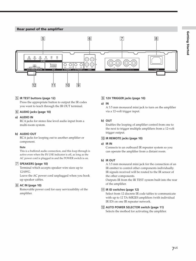
Rear panel of the amplifier
IR TEST
IR IDAUTO POWER SELECTOR 12V TRIGGERIR REMOTE AUDIO
R
R
L
IN OUTINIR IN4321 TEST12V TRIGGER IR IN AUDIO SENSING
OFF
ON
VOL VOLPOWEROFF
POWERON
POWERON / OFF MUTING
IR OUT OUT L
SPEAKERS AC IN
5 6 7 8
9q;qaqs
5 IR TEST buttons (page 12)Press the appropriate button to output the IR codesyou want to teach through the IR OUT terminal.
6 AUDIO jacks (page 10)
a) AUDIO INRCA jacks for stereo line level audio input from amulti-room system.
b) AUDIO OUTRCA jacks for looping out to another amplifier orcomponent.
NoteThis is a buffered audio connection, and this loop-through isactive even when the IN USE indicator is off, as long as theAC power cord is plugged in and the POWER switch is on.
7 SPEAKERS (page 10)Terminal which accepts speaker wire sizes up to12AWG.Leave the AC power cord unplugged when you hookup speaker cables.
8 AC IN (page 10)Removable power cord for easy serviceability of theamplifier.
9 12V TRIGGER jacks (page 10)
a) INA 3.5 mm monaural mini jack to turn on the amplifiervia a 12-volt trigger input.
b) OUTEnables the looping of amplifier control from one tothe next to trigger multiple amplifiers from a 12-volttrigger output.
q; IR REMOTE jacks (page 10)
a) IR INConnects to an outboard IR repeater system so youcan operate the amplifier from a distant room.
b) IR OUTA 3.5 mm monaural mini jack for the connection of anIR emitter to control other components individually.IR signals received will be routed to the IR sensor ofthe other components.Outputs IR from the IR TEST system built into the rearof the amplifier.
qa IR ID switches (page 12)Select from 12 discrete IR code tables to communicatewith up to 12 TA-MR2ES amplifiers (with individualIR ID) on one IR repeater network.
qs AUTO POWER SELECTOR switch (page 11)Selects the method for activating the amplifier.
01US03CH1-U.p65 11/30/04, 1:07 PM7
8US
SONY TA-MR2ES (US) 2-514-603-12(1)
Chapter 2
Setting up theamplifierThis chapter provides you withinformation on the amplifierregarding installation, hookups andsettings.
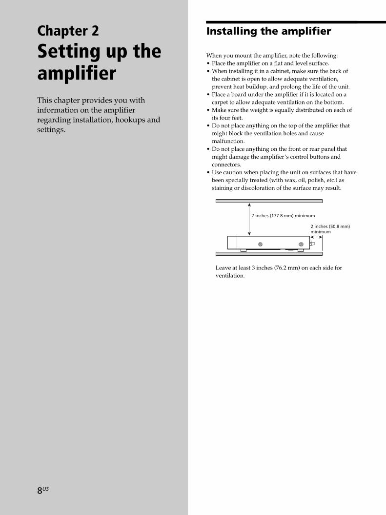
Installing the amplifier
7 inches (177.8 mm) minimum
2 inches (50.8 mm) minimum
When you mount the amplifier, note the following:• Place the amplifier on a flat and level surface.• When installing it in a cabinet, make sure the back of
the cabinet is open to allow adequate ventilation,prevent heat buildup, and prolong the life of the unit.
• Place a board under the amplifier if it is located on acarpet to allow adequate ventilation on the bottom.
• Make sure the weight is equally distributed on each ofits four feet.
• Do not place anything on the top of the amplifier thatmight block the ventilation holes and causemalfunction.
• Do not place anything on the front or rear panel thatmight damage the amplifier’s control buttons andconnectors.
• Use caution when placing the unit on surfaces that havebeen specially treated (with wax, oil, polish, etc.) asstaining or discoloration of the surface may result.
Leave at least 3 inches (76.2 mm) on each side forventilation.
01US04CH2-U.p65 11/30/04, 1:08 PM8
9US
Settin
g u
p th
e a
mp
lifier
SONY TA-MR2ES (US) 2-514-603-12(1)
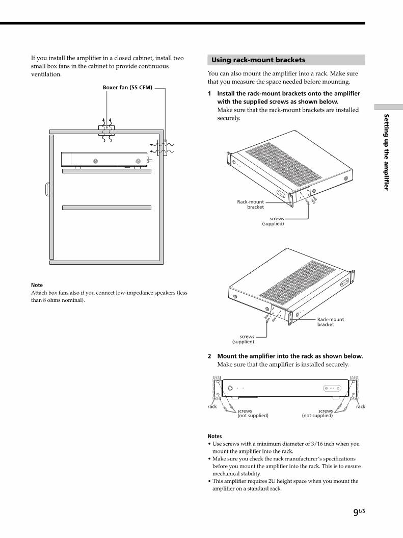
If you install the amplifier in a closed cabinet, install twosmall box fans in the cabinet to provide continuousventilation.
NoteAttach box fans also if you connect low-impedance speakers (lessthan 8 ohms nominal).
Using rack-mount brackets
You can also mount the amplifier into a rack. Make surethat you measure the space needed before mounting.
1 Install the rack-mount brackets onto the amplifierwith the supplied screws as shown below.Make sure that the rack-mount brackets are installedsecurely.
2 Mount the amplifier into the rack as shown below.Make sure that the amplifier is installed securely.
Boxer fan (55 CFM)
Rack-mountbracket
screws(supplied)
Rack-mountbracket
screws(supplied)
+ +
screws(not supplied)
screws(not supplied)
rack rack
Notes• Use screws with a minimum diameter of 3/16 inch when you
mount the amplifier into the rack.• Make sure you check the rack manufacturer’s specifications
before you mount the amplifier into the rack. This is to ensuremechanical stability.
• This amplifier requires 2U height space when you mount theamplifier on a standard rack.
01US04CH2-U.p65 11/30/04, 2:44 PM9
10US
Settin
g u
p th
e a
mp
lifier
SONY TA-MR2ES (US) 2-514-603-12(1)
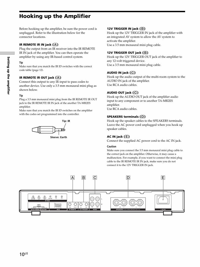
Before hooking up the amplifier, be sure the power cord isunplugged. Refer to the illustration below for theconnector locations.
IR REMOTE IR IN jack (A)Plug the output from an IR receiver into the IR REMOTEIR IN jack of the amplifier. You can then operate theamplifier by using any IR-based control system.
TipMake sure that you match the IR ID switches with the correctcode table (page 12).
IR REMOTE IR OUT jack (A)Connect this output to any IR input to pass codes toanother device. Use only a 3.5 mm monaural mini plug asshown below.
TipPlug a 3.5 mm monaural mini plug from the IR REMOTE IR OUTjack to the IR REMOTE IR IN jack of the another TA-MR2ESamplifier.Make sure that you match the IR ID switches on the amplifierwith the codes set programmed into the controller.
Hooking up the Amplifier
12V TRIGGER IN jack (B)Hook up the 12V TRIGGER IN jack of the amplifier withan integrated AV system to allow the AV system toactivate the amplifier.Use a 3.5 mm monaural mini plug cable.
12V TRIGGER OUT jack (B)Hook up the 12V TRIGGER OUT jack of the amplifier toany 12-volt triggered device.Use a 3.5 mm monaural mini plug cable.
AUDIO IN jack (C)Hook up the audio output of the multi-room system to theAUDIO IN jack of the amplifier.Use RCA audio cables.
AUDIO OUT jack (C)Hook up the AUDIO OUT jack of the amplifier audioinput to any component or to another TA-MR2ESamplifier.Use RCA audio cables.
SPEAKERS terminals (D)Hook up the speaker cables to the SPEAKERS terminals.Leave the AC power cord unplugged when you hook upspeaker cables.
AC IN jack (E)Connect the supplied AC power cord to the AC IN jack.
CautionMake sure you connect the 3.5 mm monaural mini plug cable tothe correct jack on the amplifier. Otherwise, it may cause amalfunction. For example, if you want to connect the mini plugcable to the IR REMOTE IR IN jack, make sure you do notconnect it to the 12V TRIGGER IN jack.
IR TEST
IR IDAUTO POWER SELECTOR 12V TRIGGERIR REMOTE AUDIO
R
R
L
IN OUTINIR IN4321 TEST12V TRIGGER IR IN AUDIO SENSING
OFF
ON
VOL VOLPOWEROFF
POWERON
POWERON / OFF MUTING
IR OUT OUT L
SPEAKERS AC IN
A B C D E
Tip: IR
Sleeve: Earth
01US04CH2-U.p65 11/30/04, 1:08 PM10
11US
Settin
g u
p th
e a
mp
lifier
SONY TA-MR2ES (US) 2-514-603-12(1)
Selecting the method to activate the amplifier
There are three methods to activate the amplifier. Selectthe turn-on method by setting AUTO POWER SELECTORas follows:
– 12V TRIGGERWhen there is no voltage detected at the trigger input,the amplifier remains off. When the sensing circuitrydetects voltage, the amplifier will turn on. When thesensing circuitry detects no voltage, the amplifierturns off instantly.
– IR INWhen the amplifier detects the appropriate “POWERON” IR code through the IR REMOTE IR IN, theamplifier will power on. When the amplifier detectsthe “POWER OFF” IR code, the amplifier turns offinstantly.
– AUDIO SENSINGWhen there is only a small amount or no audio signaldetected at either the left or right input, the amplifierremains off. However, the sensing circuitry is alwayson. When the sensing circuitry detects sufficient audiosignal present at any of the audio inputs, the amplifierwill be turned on automatically. The sensing circuitrywill wait for around three minutes after the audiosignal stops to turn the amplifier off.
TipBe sure to press POWER to turn on the power after completingall the settings for the amplifier. Otherwise, the amplifier cannotbe activated.
01US04CH2-U.p65 11/30/04, 1:08 PM11
12US
Settin
g u
p th
e a
mp
lifier
SONY TA-MR2ES (US) 2-514-603-12(1)
Setting up the IR ID
You can set up the IR ID when the IR ID TEST switch is inthe “ON” or “OFF” position.
When the IR ID TEST is “ON”
Select this setting to teach the six IR codes below to anyIR-based controller.
IR TEST buttons Function
POWER ON/OFF To turn on or off the power.
POWER ON To turn on the power.
POWER OFF To turn off the power.
MUTING To mute the sound.
VOL – To turn down the volume.
VOL + To turn up the volume.
1 Make sure that the ATTENUATOR L/R is adjusted tominimum. For details, refer page 14.
2 Turn on the amplifier.
3 Set the IR ID TEST switch to the “ON” position.The IN USE indicator flashes.
4 To output the IR code, for example ID1, set the IRID 1 switch to the “ON” position and set the rest ofthe IR ID switches (IR ID 2, 3 and 4) to the “OFF”position. To select other IR ID, refer to the tablebelow.
1 2 3 4
ID1 ON OFF OFF OFFID2 OFF ON OFF OFFID3 ON ON OFF OFFID4 OFF OFF ON OFFID5 ON OFF ON OFFID6 OFF ON ON OFFID7 ON ON ON OFFID8 OFF OFF OFF ONID9 ON OFF OFF ONID10 OFF ON OFF ONID11 ON ON OFF ONID12 OFF OFF ON ON
If you set the IR ID other than those listed in the tableabove, the IR ID will automatically be set to ID1.
IR ID4321 TEST
OFF
ON
H X
m M
. >
-
x
PL
O
f
F
G g
IR TEST
IR IDAUTO POWER SELECTOR 12V TRIGGERIR REMOTE AUDIO
R
R
L
IN OUTINIR IN4321 TEST12V TRIGGER IR IN AUDIO SENSING
OFF
ON
VOL VOLPOWEROFF
POWERON
POWERON / OFF MUTING
IR OUT OUT L
SPEAKERS AC IN
IR emitter
Learning remote
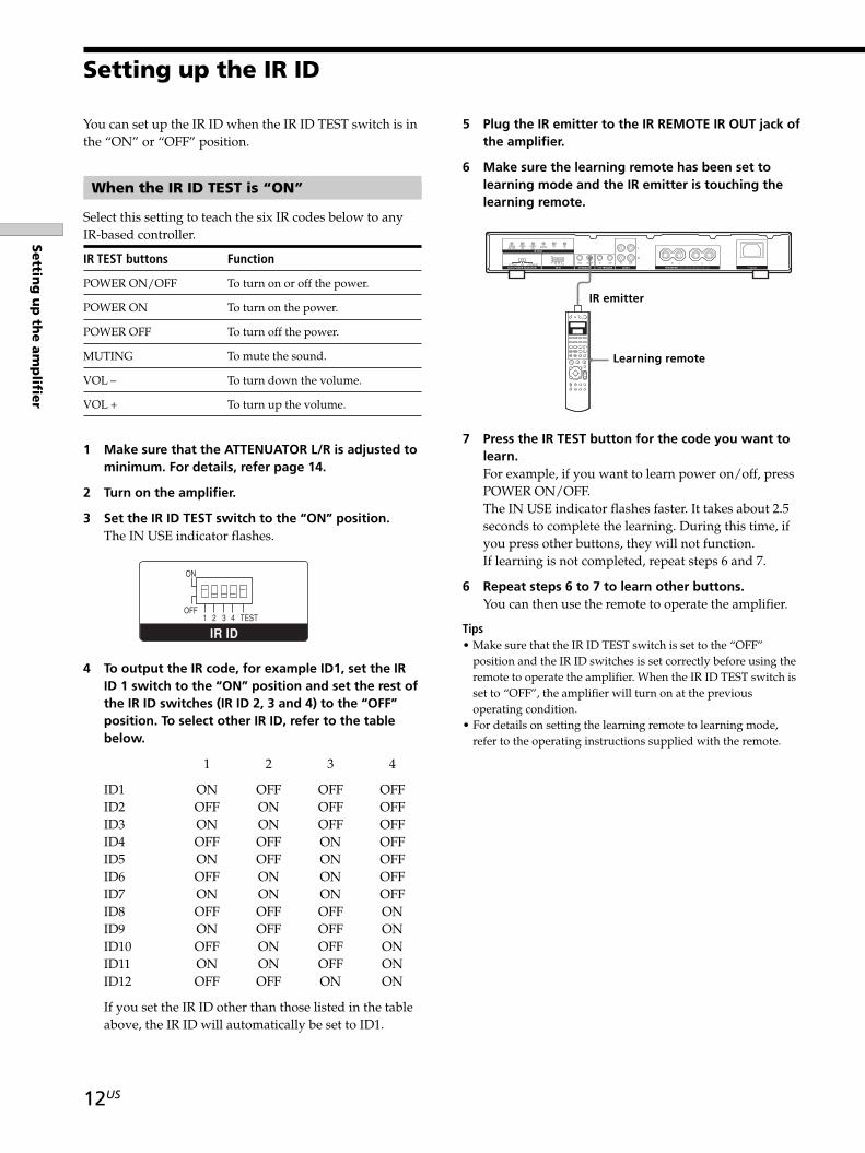
5 Plug the IR emitter to the IR REMOTE IR OUT jack ofthe amplifier.
6 Make sure the learning remote has been set tolearning mode and the IR emitter is touching thelearning remote.
7 Press the IR TEST button for the code you want tolearn.For example, if you want to learn power on/off, pressPOWER ON/OFF.The IN USE indicator flashes faster. It takes about 2.5seconds to complete the learning. During this time, ifyou press other buttons, they will not function.If learning is not completed, repeat steps 6 and 7.
6 Repeat steps 6 to 7 to learn other buttons.You can then use the remote to operate the amplifier.
Tips• Make sure that the IR ID TEST switch is set to the “OFF”
position and the IR ID switches is set correctly before using theremote to operate the amplifier. When the IR ID TEST switch isset to “OFF”, the amplifier will turn on at the previousoperating condition.
• For details on setting the learning remote to learning mode,refer to the operating instructions supplied with the remote.
01US04CH2-U.p65 11/30/04, 1:08 PM12
13US
Settin
g u
p th
e a
mp
lifier
SONY TA-MR2ES (US) 2-514-603-12(1)
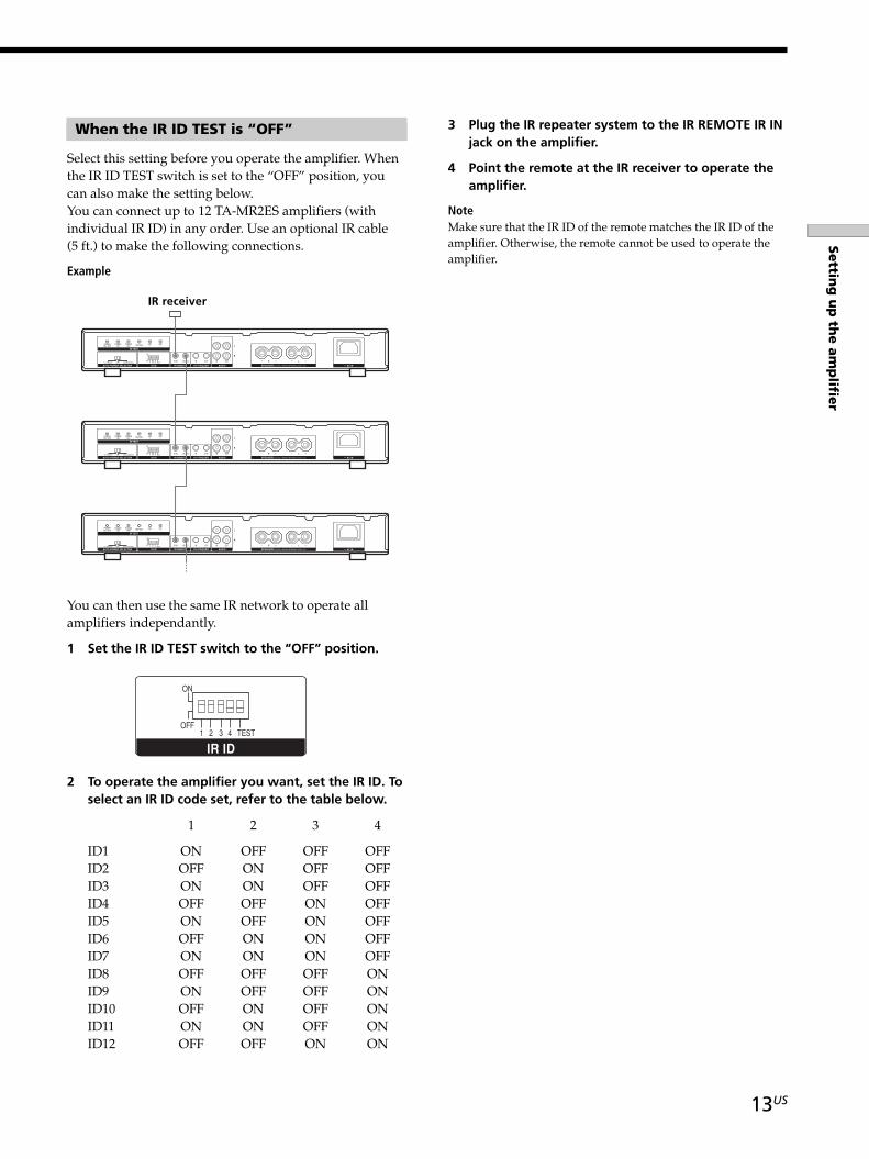
When the IR ID TEST is “OFF”
Select this setting before you operate the amplifier. Whenthe IR ID TEST switch is set to the “OFF” position, youcan also make the setting below.You can connect up to 12 TA-MR2ES amplifiers (withindividual IR ID) in any order. Use an optional IR cable(5 ft.) to make the following connections.
Example
IR receiver
IR TEST
IR IDAUTO POWER SELECTOR 12V TRIGGERIR REMOTE AUDIO
R
R
L
IN OUTINIR IN4321 TEST12V TRIGGER IR IN AUDIO SENSING
OFF
ON
VOL VOLPOWEROFF
POWERON
POWERON / OFF MUTING
IR OUT OUT L
SPEAKERS AC IN
IR TEST
IR IDAUTO POWER SELECTOR 12V TRIGGERIR REMOTE AUDIO
R
R
L
IN OUTINIR IN4321 TEST12V TRIGGER IR IN AUDIO SENSING
OFF
ON
VOL VOLPOWEROFF
POWERON
POWERON / OFF MUTING
IR OUT OUT L
SPEAKERS AC IN
IR TEST
IR IDAUTO POWER SELECTOR 12V TRIGGERIR REMOTE AUDIO
R
R
L
IN OUTINIR IN4321 TEST12V TRIGGER IR IN AUDIO SENSING
OFF
ON
VOL VOLPOWEROFF
POWERON
POWERON / OFF MUTING
IR OUT OUT L
SPEAKERS AC IN
IR ID4321 TEST
OFF
ON
You can then use the same IR network to operate allamplifiers independantly.
1 Set the IR ID TEST switch to the “OFF” position.
2 To operate the amplifier you want, set the IR ID. Toselect an IR ID code set, refer to the table below.
1 2 3 4
ID1 ON OFF OFF OFFID2 OFF ON OFF OFFID3 ON ON OFF OFFID4 OFF OFF ON OFFID5 ON OFF ON OFFID6 OFF ON ON OFFID7 ON ON ON OFFID8 OFF OFF OFF ONID9 ON OFF OFF ONID10 OFF ON OFF ONID11 ON ON OFF ONID12 OFF OFF ON ON
3 Plug the IR repeater system to the IR REMOTE IR INjack on the amplifier.
4 Point the remote at the IR receiver to operate theamplifier.
NoteMake sure that the IR ID of the remote matches the IR ID of theamplifier. Otherwise, the remote cannot be used to operate theamplifier.
01US04CH2-U.p65 11/30/04, 1:08 PM13
14US
SONY TA MR2ES (US) 2 514 603 12(1)
Chapter 3
Operating theamplifierThis chapter provides you withinformation on amplifier operation.
Adjusting the maximumvolume level
You can control the maximum volume level to avoiddamaging your speakers by adjusting the variableattenuator screws behind the cover lid on the front panel.
1 Remove the cover lid. For details, refer page 6.
2 Insert a screw driver into the ATTENUATOR L orATTENUATOR R screws to adjust the maximumoutput level of the amplifier to match your system.To increase the volume, turn the screw driverclockwise and to reduce the volume, turn counter-clockwise. To adjust to maximum or minimum, turnthe screw driver fully.
3 Place the cover lid back to its original position.
Tips• You may adjust the left and right output level independantly.• The default setting for the variable attenuator is set to
minimum.
01US05CH3-U.p65 11/30/04, 1:05 PM14
15US
Op
era
ting
the a
mp
lifier
SONY TA MR2ES (US) 2 514 603 12(1)
Clearing the amplifier’smemory
This procedure is used to return the settings youhave made to their factory defaults. Before clearingthe amplifier’s memory, be sure to set the variableattenuator to minimum.
1 Press POWER to turn off the amplifier.
2 Hold down POWER OFF on the rear paneland press POWER on the front panel to turnon the amplifier.The ON indicator flashes 3 times.The following are reset to their factory settings.
– Volume level adjusted with learned remote.
– The power status is initialized to “POWERON” when IR IN is selected in AUTOPOWER SELECTOR.
Controlling the amplifier
You can use the buttons on the remote or control systemto control the amplifier. Before using the control system,make sure it has the proper code set (page 12).
Adjusting the volume level
Press the VOLUME button on the remote to adjust thevolume level.There are 70 steps to adjust the volume level from zero tofull power.
TipThe default setting for the internal IR volume is set to maximum.Make sure you do the steps correctly to avoid damaging thespeakers.
Activating the amplifier
Press the POWER button on the remote to activate theamplifier.
TipIf you set the AUTO POWER SELECTOR to 12V TRIGGER orAUDIO SENSING, you cannot use the remote to activate theamplifier.
Muting the sound
Press the MUTING button on the remote to set muting onor off.
01US05CH3-U.p65 11/30/04, 1:05 PM15
16US
SONY TA MR2ES (US) 2 514 603 12(1)
Chapter 4
OtherInformationThis chapter provides you withadditional information that will helpyou understand and maintain yoursystem.
Precautions
On safety• Should any solid object or liquid fall into the cabinet, unplug
the amplifier and have it checked by a qualified servicetechnician before operating it any further.
• The unit is not disconnected from the AC power source as longas it is connected to the wall outlet, even if the unit itself hasbeen turned off.
On power sources• Before operating the unit, check that the operating voltage of
the unit is identical to that of your local power supply. Theoperating voltage is indicated on the nameplate on the back ofthe unit.
• If you are not going to use the unit for a long time, be sure todisconnect it from the AC power source. To disconnect thelead, grasp the plug itself; never pull the cord.
On placement• Place the unit in a location with adequate ventilation to
prevent heat build-up in the amplifier.• Do not place the unit on a soft surface such as a rug that might
block the ventilation holes on the bottom.• Do not place the unit in a location near heat sources, or in a
place subject to direct sunlight, excessive dust, or mechanicalshock.
On adjusting the volume• Do not turn up the maximum volume level by adjusting the
ATTENUATOR L/R on the front panel too high whilelistening to very low input levels. If you do, the speakers maybe damaged when high volume source is played.
On cleaning• Clean the cabinet, panel, and controls with a soft cloth slightly
moistened with a mild detergent solution. Do not use any typeof abrasive pad, scouring powder, or solvent, such as alcoholor benzine.
If you have any questions or problems concerning theamplifier, please consult your nearest Sony dealer.
01US06CH4-U.p65 11/30/04, 1:09 PM16
17US
Oth
er In
form
atio
n
SONY TA MR2ES (US) 2 514 603 12(1)
Troubleshooting
If you experience any of the following difficulties whileusing the amplifier, use this troubleshooting guide to helpyou to remedy the problem. Should any problem persist,consult your nearest Sony dealer.
There is no sound, or only a very low-level soundis heard., Check that the amplifier is turned on., Check that the speakers are connected correctly
and securely., Press MUTING to check the muting status., Check to see if the protection circuit on the
amplifier has been activated because of a shortcircuit (the IN USE indicator flashes red). Turn offthe amplifier, eliminate the short-circuit problemand turn the power on again.
, Adjust the ATTENUATOR on the amplifier andthe volume on the learned remote.
, If all steps above cannot remedy the problem, clearthe amplifier’s memory (page 15).
The left and right sounds are unbalanced orreversed., Check that the speakers and components are
connected correctly and securely., Adjust the ATTENUATOR L and R on the front
panel behind the cover lid.
There is severe hum or noise., Check that the speakers are connected securely., Check that the connecting cords are away from a
transformer or motor, and at least 10 feet (3meters) away from a TV set or fluorescent light.
,Move your TV away from the audio components., The plugs and jacks are dirty. Wipe them with a
cloth slightly moistened with alcohol.
The IR Remote Control does not function., Point the Remote Control at the remote sensor
on the IR receiver., Remove any obstacles in the path between the
Remote Control and the IR receiver., Replace both batteries in the Remote Control with
new ones, if they are weak., Check that you have selected the correct function
on the Remote Control.,Make sure the IR code setting is correct.,Make sure the IR ID TEST switch is set to “OFF”.
The POWER switch is on but the IN USE indicatordoes not light up when AUTO POWER SELECTOR isset to IR IN., Clear the amplifier’s memory (page 15).
01US06CH4-U.p65 11/30/04, 1:09 PM17
18US
Oth
er In
form
atio
n
SONY TA MR2ES (US) 2 514 603 12(1)
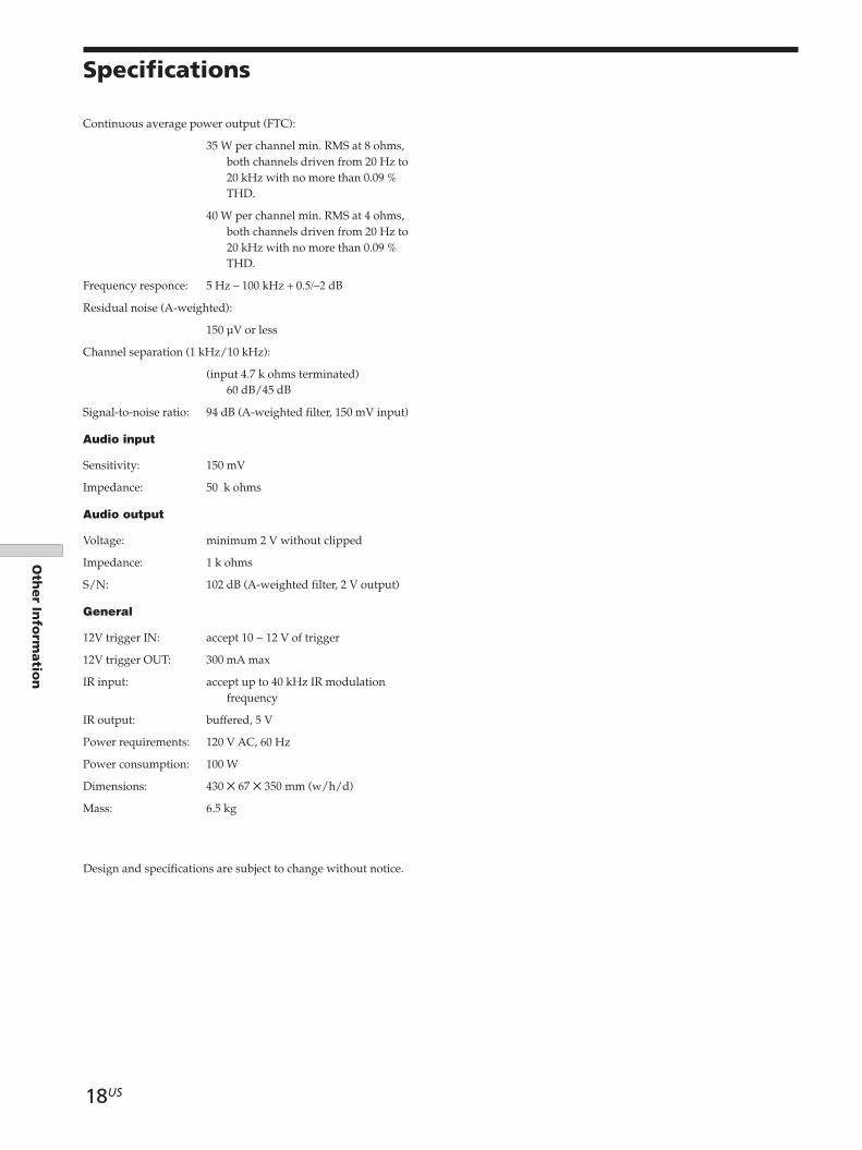
Specifications
Continuous average power output (FTC):
35 W per channel min. RMS at 8 ohms,both channels driven from 20 Hz to20 kHz with no more than 0.09 %THD.
40 W per channel min. RMS at 4 ohms,both channels driven from 20 Hz to20 kHz with no more than 0.09 %THD.
Frequency responce: 5 Hz – 100 kHz + 0.5/–2 dB
Residual noise (A-weighted):
150 µV or less
Channel separation (1 kHz/10 kHz):
(input 4.7 k ohms terminated)60 dB/45 dB
Signal-to-noise ratio: 94 dB (A-weighted filter, 150 mV input)
Audio input
Sensitivity: 150 mV
Impedance: 50 k ohms
Audio output
Voltage: minimum 2 V without clipped
Impedance: 1 k ohms
S/N: 102 dB (A-weighted filter, 2 V output)
General
12V trigger IN: accept 10 ~ 12 V of trigger
12V trigger OUT: 300 mA max
IR input: accept up to 40 kHz IR modulationfrequency
IR output: buffered, 5 V
Power requirements: 120 V AC, 60 Hz
Power consumption: 100 W
Dimensions: 430 ✕ 67 ✕ 350 mm (w/h/d)
Mass: 6.5 kg
Design and specifications are subject to change without notice.
01US06CH4-U.p65 11/30/04, 1:09 PM18
19US
SONY TA MR2ES (US) 2 514 603 12(1)
Oth
er In
form
atio
n
AAC IN 7, 10
AC power cord 7, 10
Adjusting volume 14, 15
ATTENUATOR L/R 6, 14
AUDIO IN jack 7, 10
AUDIO OUT jack 7, 10
AUTO POWER SELECTOR switch 7, 11
H, IHookup
AC power cord 10AUDIO IN 10AUDIO OUT 10IR REMOTE IR IN 10IR REMOTE IR OUT 10SPEAKERS 1012V TRIGGER IN 1012V TRIGGER OUT 10
IN USE indicator 6
Initializing all the settings 15
Installing the amplifier 8–13
IR ID switches 12–13
IR receiver 13
IR Remote Control 12
IR REMOTE IR IN jack 7, 10
IR REMOTE IR OUT jack 7, 10
IR TEST buttons 7, 12
Index
LLearning the remote code 12
O, PON indicator 6
POWER switch 6, 15
Precautions 16
SSelecting the method for activating the amplifer 11
Setting the IR ID 12–13
SPEAKERS terminal 7, 10
Specifications 18
TTroubleshooting 17
Numeral12V TRIGGER jacks 7, 10
01US07CH5-U.p65 11/30/04, 1:15 PM19

20
SONY TA MR2ES (US) 2 514 603 12(1)
Sony Corporation Printed in Malaysia
01US08BCOV-U.p65 11/30/04, 1:14 PM20