Embed Size (px)
Citation preview

PLUG-IN
2ch DIGITAL INDICATING CONTROLLER
WCL-13AINSTRUCTION MANUAL
2
PrefaceThank you for purchasing our WCL-13A Plug-in 2ch Digital Indicating Controller.
This manual contains instructions for the mounting, functions, operations and notes when operating the
WCL-13A. To ensure safe and correct use, thoroughly read and understand this manual before using this
controller.
To prevent accidents arising from the misuse of this controller, please ensure the operator receives this
manual.
Abbreviations used in this manualSymbol Term
PV Process VariableSV Desired ValueMV Output Manipulated VariableAT Auto-tuning
Alarm Temperature Alarm
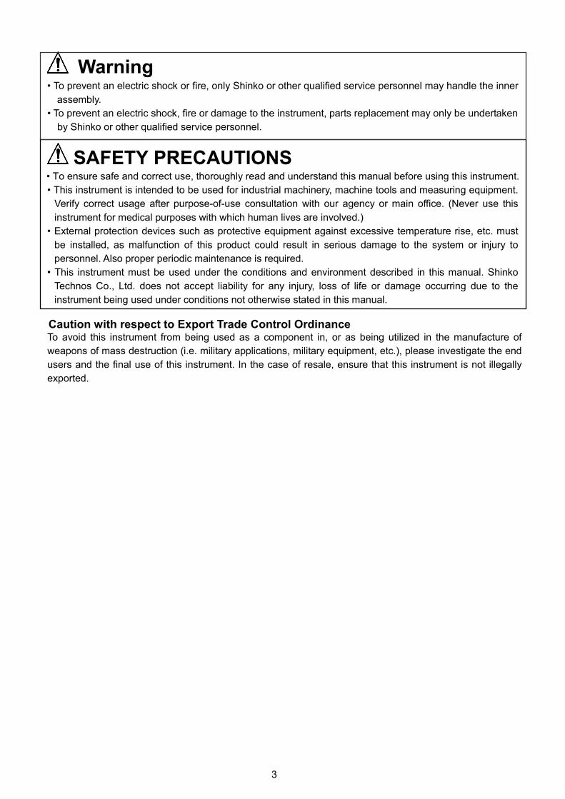
Characters used in this manual
Indication
Number, / -1 0 1 2 3 4 5 6 7 8 9
Indication
Alphabet A B C D E F G H I J K L M
Indication
Alphabet N O P Q R S T U V W X Y Z
Caution• This instrument should be used in accordance with the specifications described in the manual.
If it is not used according to the specifications, it may malfunction or cause a fire.
• Be sure to follow all of the warnings, cautions and notices. If they are not observed, serious injury or malfunction may
occur.
• The contents of this instruction manual are subject to change without notice.
• Care has been taken to assure that the contents of this instruction manual are correct, but if there are any doubts,
mistakes or questions, please inform our sales department.
• This instrument is designed to be installed on a DIN rail within a control panel. If it is not, measures must be taken
to ensure that the operator cannot touch power terminals or other high voltage sections.
• Any unauthorized transfer or copying of this document, in part or in whole, is prohibited.
• Shinko Technos CO., LTD. is not liable for any damage or secondary damage(s) incurred as a result of using
this product, including any indirect damage.
Safety Precautions (Be sure to read these precautions before using our products.)
The safety precautions are classified into 2 categories: “Warning” and “Caution”. Depending on the circumstances,
procedures indicated by Caution may cause serious results, so be sure to follow the directions for usage.
Warning
Caution
Procedures which may lead to dangerous conditions and cause death or serious
injury, if not carried out properly.
Procedures which may lead to dangerous conditions and cause superficial to
medium injury or physical damage or may degrade or damage the product, if not
carried out properly.
3
Warning• To prevent an electric shock or fire, only Shinko or other qualified service personnel may handle the inner
assembly.
• To prevent an electric shock, fire or damage to the instrument, parts replacement may only be undertaken
by Shinko or other qualified service personnel.
SAFETY PRECAUTIONS• To ensure safe and correct use, thoroughly read and understand this manual before using this instrument.
• This instrument is intended to be used for industrial machinery, machine tools and measuring equipment.
Verify correct usage after purpose-of-use consultation with our agency or main office. (Never use this
instrument for medical purposes with which human lives are involved.)
• External protection devices such as protective equipment against excessive temperature rise, etc. must
be installed, as malfunction of this product could result in serious damage to the system or injury to
personnel. Also proper periodic maintenance is required.
• This instrument must be used under the conditions and environment described in this manual. Shinko
Technos Co., Ltd. does not accept liability for any injury, loss of life or damage occurring due to the
instrument being used under conditions not otherwise stated in this manual.
Caution with respect to Export Trade Control OrdinanceTo avoid this instrument from being used as a component in, or as being utilized in the manufacture of
weapons of mass destruction (i.e. military applications, military equipment, etc.), please investigate the end
users and the final use of this instrument. In the case of resale, ensure that this instrument is not illegally
exported.
4
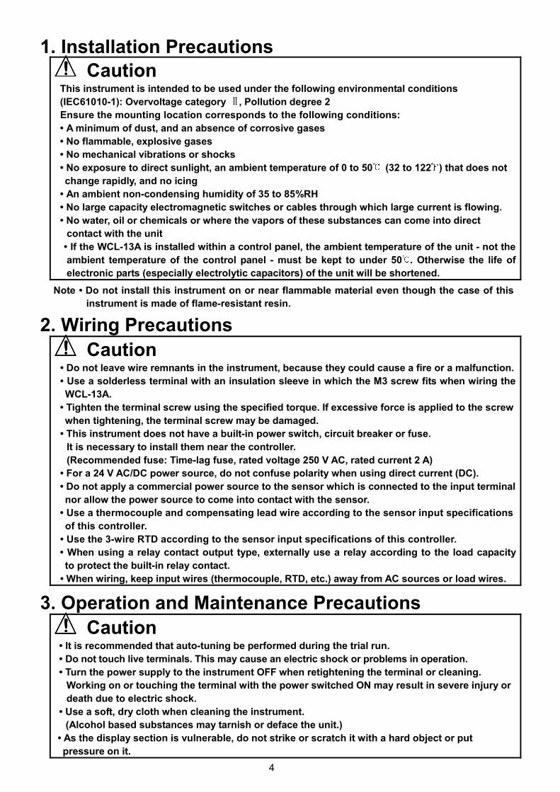
1. Installation Precautions
CautionThis instrument is intended to be used under the following environmental conditions
(IEC61010-1): Overvoltage category , Pollution degree 2
Ensure the mounting location corresponds to the following conditions:
• A minimum of dust, and an absence of corrosive gases
• No flammable, explosive gases
• No mechanical vibrations or shocks
• No exposure to direct sunlight, an ambient temperature of 0 to 50 (32 to 122 ) that does not
change rapidly, and no icing
• An ambient non-condensing humidity of 35 to 85%RH
• No large capacity electromagnetic switches or cables through which large current is flowing.
• No water, oil or chemicals or where the vapors of these substances can come into direct
contact with the unit
• If the WCL-13A is installed within a control panel, the ambient temperature of the unit - not the
ambient temperature of the control panel - must be kept to under 50 . Otherwise the life of
electronic parts (especially electrolytic capacitors) of the unit will be shortened.
Note • Do not install this instrument on or near flammable material even though the case of this
instrument is made of flame-resistant resin.
2. Wiring Precautions
Caution• Do not leave wire remnants in the instrument, because they could cause a fire or a malfunction.
• Use a solderless terminal with an insulation sleeve in which the M3 screw fits when wiring the
WCL-13A.
• Tighten the terminal screw using the specified torque. If excessive force is applied to the screw
when tightening, the terminal screw may be damaged.
• This instrument does not have a built-in power switch, circuit breaker or fuse.
It is necessary to install them near the controller.
(Recommended fuse: Time-lag fuse, rated voltage 250 V AC, rated current 2 A)
• For a 24 V AC/DC power source, do not confuse polarity when using direct current (DC).
• Do not apply a commercial power source to the sensor which is connected to the input terminal
nor allow the power source to come into contact with the sensor.
• Use a thermocouple and compensating lead wire according to the sensor input specifications
of this controller.
• Use the 3-wire RTD according to the sensor input specifications of this controller.
• When using a relay contact output type, externally use a relay according to the load capacity
to protect the built-in relay contact.
• When wiring, keep input wires (thermocouple, RTD, etc.) away from AC sources or load wires.
3. Operation and Maintenance Precautions
Caution• It is recommended that auto-tuning be performed during the trial run.
• Do not touch live terminals. This may cause an electric shock or problems in operation.
• Turn the power supply to the instrument OFF when retightening the terminal or cleaning.
Working on or touching the terminal with the power switched ON may result in severe injury or
death due to electric shock.
• Use a soft, dry cloth when cleaning the instrument.
(Alcohol based substances may tarnish or deface the unit.)
• As the display section is vulnerable, do not strike or scratch it with a hard object or put
pressure on it.
5
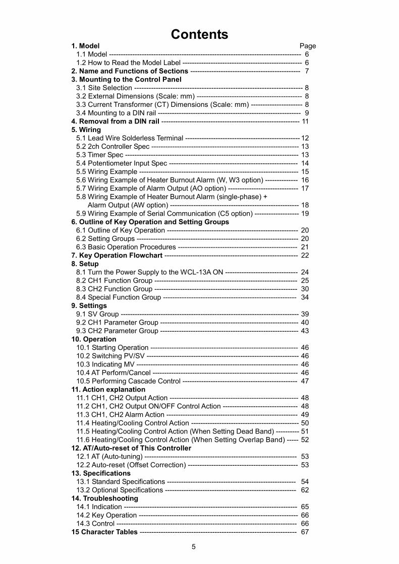
Contents1. Model Page
1.1 Model ---------------------------------------------------------------------------------- 61.2 How to Read the Model Label --------------------------------------------------- 6
2. Name and Functions of Sections ----------------------------------------------- 73. Mounting to the Control Panel
3.1 Site Selection ---------------------------------------------------------------------- 83.2 External Dimensions (Scale: mm) --------------------------------------------- 83.3 Current Transformer (CT) Dimensions (Scale: mm) ---------------------- 83.4 Mounting to a DIN rail ------------------------------------------------------------- 9
4. Removal from a DIN rail ----------------------------------------------------------- 115. Wiring
5.1 Lead Wire Solderless Terminal ------------------------------------------------- 125.2 2ch Controller Spec --------------------------------------------------------------- 135.3 Timer Spec -------------------------------------------------------------------------- 135.4 Potentiometer Input Spec ------------------------------------------------------- 145.5 Wiring Example -------------------------------------------------------------------- 155.6 Wiring Example of Heater Burnout Alarm (W, W3 option) -------------- 165.7 Wiring Example of Alarm Output (AO option) ------------------------------ 175.8 Wiring Example of Heater Burnout Alarm (single-phase) +
Alarm Output (AW option) ------------------------------------------------------- 185.9 Wiring Example of Serial Communication (C5 option) ------------------- 19
6. Outline of Key Operation and Setting Groups6.1 Outline of Key Operation -------------------------------------------------------- 206.2 Setting Groups --------------------------------------------------------------------- 206.3 Basic Operation Procedures --------------------------------------------------- 21
7. Key Operation Flowchart --------------------------------------------------------- 228. Setup
8.1 Turn the Power Supply to the WCL-13A ON ------------------------------- 248.2 CH1 Function Group ------------------------------------------------------------- 258.3 CH2 Function Group ------------------------------------------------------------- 308.4 Special Function Group --------------------------------------------------------- 34
9. Settings9.1 SV Group ---------------------------------------------------------------------------- 399.2 CH1 Parameter Group ----------------------------------------------------------- 409.3 CH2 Parameter Group ----------------------------------------------------------- 43
10. Operation10.1 Starting Operation --------------------------------------------------------------- 4610.2 Switching PV/SV ----------------------------------------------------------------- 4610.3 Indicating MV --------------------------------------------------------------------- 4610.4 AT Perform/Cancel -------------------------------------------------------------- 4610.5 Performing Cascade Control ------------------------------------------------- 47
11. Action explanation11.1 CH1, CH2 Output Action ------------------------------------------------------- 4811.2 CH1, CH2 Output ON/OFF Control Action -------------------------------- 4811.3 CH1, CH2 Alarm Action -------------------------------------------------------- 4911.4 Heating/Cooling Control Action ---------------------------------------------- 5011.5 Heating/Cooling Control Action (When Setting Dead Band) ---------- 5111.6 Heating/Cooling Control Action (When Setting Overlap Band) ----- 52
12. AT/Auto-reset of This Controller12.1 AT (Auto-tuning) ----------------------------------------------------------------- 5312.2 Auto-reset (Offset Correction) ----------------------------------------------- 53
13. Specifications13.1 Standard Specifications ------------------------------------------------------- 5413.2 Optional Specifications -------------------------------------------------------- 62
14. Troubleshooting14.1 Indication -------------------------------------------------------------------------- 6514.2 Key Operation -------------------------------------------------------------------- 6614.3 Control ----------------------------------------------------------------------------- 66
15 Character Tables ------------------------------------------------------------------- 67
6
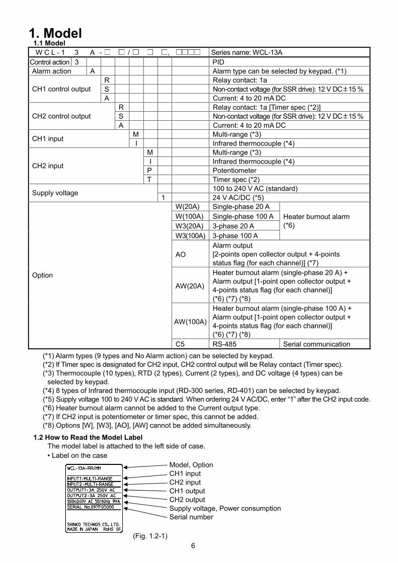
1. Model1.1 Model
W C L - 1 3 A - / , Series name: WCL-13A
Control action 3 PID
Alarm action A Alarm type can be selected by keypad. (*1)
R Relay contact: 1a
S Non-contact voltage (for SSR drive): 12 V DC 15 %CH1 control output
A Current: 4 to 20 mA DC
R Relay contact: 1a [Timer spec (*2)]
S Non-contact voltage (for SSR drive): 12 V DC 15 %CH2 control output
A Current: 4 to 20 mA DC
M Multi-range (*3)CH1 input
I Infrared thermocouple (*4)
M Multi-range (*3)
I Infrared thermocouple (*4)
P PotentiometerCH2 input
T Timer spec (*2)
100 to 240 V AC (standard)Supply voltage
1 24 V AC/DC (*5)
W(20A) Single-phase 20 A
W(100A) Single-phase 100 A
W3(20A) 3-phase 20 A
W3(100A) 3-phase 100 A
Heater burnout alarm(*6)
AO
Alarm output[2-points open collector output + 4-pointsstatus flag (for each channel)] (*7)
AW(20A)
Heater burnout alarm (single-phase 20 A) +Alarm output [1-point open collector output +4-points status flag (for each channel)](*6) (*7) (*8)
AW(100A)
Heater burnout alarm (single-phase 100 A) +Alarm output [1-point open collector output +4-points status flag (for each channel)](*6) (*7) (*8)
Option
C5 RS-485 Serial communication
(*1) Alarm types (9 types and No Alarm action) can be selected by keypad.(*2) If Timer spec is designated for CH2 input, CH2 control output will be Relay contact (Timer spec).(*3) Thermocouple (10 types), RTD (2 types), Current (2 types), and DC voltage (4 types) can be
selected by keypad.(*4) 8 types of Infrared thermocouple input (RD-300 series, RD-401) can be selected by keypad.(*5) Supply voltage 100 to 240 V AC is standard. When ordering 24 V AC/DC, enter “1” after the CH2 input code.(*6) Heater burnout alarm cannot be added to the Current output type.(*7) If CH2 input is potentiometer or timer spec, this cannot be added.(*8) Options [W], [W3], [AO], [AW] cannot be added simultaneously.
1.2 How to Read the Model LabelThe model label is attached to the left side of case.
• Label on the case
(Fig. 1.2-1)
Model, OptionCH1 inputCH2 inputCH1 outputCH2 outputSupply voltage, Power consumptionSerial number
7
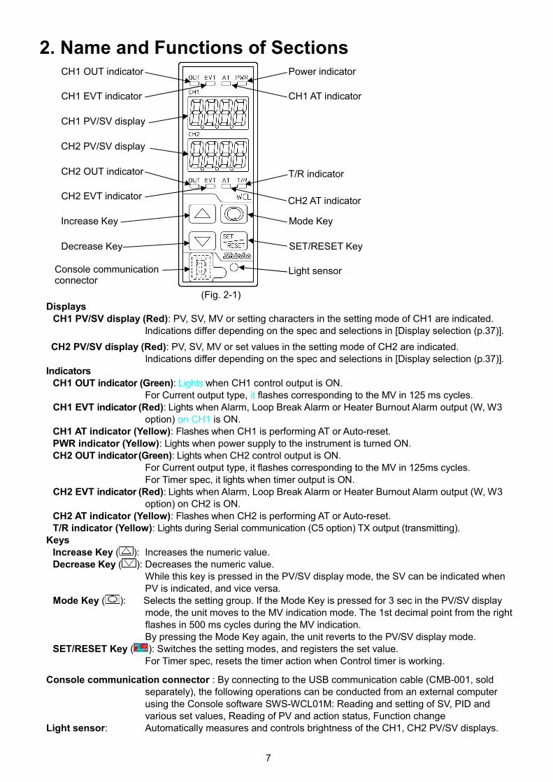
2. Name and Functions of Sections
(Fig. 2-1)Displays
CH1 PV/SV display (Red): PV, SV, MV or setting characters in the setting mode of CH1 are indicated.Indications differ depending on the spec and selections in [Display selection (p.37)].
CH2 PV/SV display (Red): PV, SV, MV or set values in the setting mode of CH2 are indicated.Indications differ depending on the spec and selections in [Display selection (p.37)].
IndicatorsCH1 OUT indicator (Green): Lights when CH1 control output is ON.
For Current output type, it flashes corresponding to the MV in 125 ms cycles.CH1 EVT indicator (Red): Lights when Alarm, Loop Break Alarm or Heater Burnout Alarm output (W, W3
option) on CH1 is ON.CH1 AT indicator (Yellow): Flashes when CH1 is performing AT or Auto-reset.PWR indicator (Yellow): Lights when power supply to the instrument is turned ON.CH2 OUT indicator(Green): Lights when CH2 control output is ON.
For Current output type, it flashes corresponding to the MV in 125ms cycles.For Timer spec, it lights when timer output is ON.
CH2 EVT indicator (Red): Lights when Alarm, Loop Break Alarm or Heater Burnout Alarm output (W, W3option) on CH2 is ON.
CH2 AT indicator (Yellow): Flashes when CH2 is performing AT or Auto-reset.T/R indicator (Yellow): Lights during Serial communication (C5 option) TX output (transmitting).
KeysIncrease Key ( ): Increases the numeric value.Decrease Key ( ): Decreases the numeric value.
While this key is pressed in the PV/SV display mode, the SV can be indicated whenPV is indicated, and vice versa.
Mode Key ( ): Selects the setting group. If the Mode Key is pressed for 3 sec in the PV/SV displaymode, the unit moves to the MV indication mode. The 1st decimal point from the rightflashes in 500 ms cycles during the MV indication.By pressing the Mode Key again, the unit reverts to the PV/SV display mode.
SET/RESET Key ( ): Switches the setting modes, and registers the set value.For Timer spec, resets the timer action when Control timer is working.
Console communication connector : By connecting to the USB communication cable (CMB-001, soldseparately), the following operations can be conducted from an external computerusing the Console software SWS-WCL01M: Reading and setting of SV, PID andvarious set values, Reading of PV and action status, Function change
Light sensor: Automatically measures and controls brightness of the CH1, CH2 PV/SV displays.
CH1 OUT indicator
CH1 EVT indicator
CH1 PV/SV display
CH2 PV/SV display
CH2 OUT indicator
CH2 EVT indicator
Increase Key
Decrease Key
Console communicationconnector
Power indicator
CH1 AT indicator
T/R indicator
CH2 AT indicator
Mode Key
SET/RESET Key
Light sensor
8
3. Mounting to the Control Panel3.1 Site Selection
CautionUse within the following temperature and humidity ranges.Temperature: 0 to 50 (32 to 122 ) (No icing), Humidity: 35 to 85%RH (Non-condensing)If the WCL-13A is installed within a control panel, the ambient temperature of the unit - not the ambienttemperature of the control panel - must be kept to under 50 . Otherwise the life of electronic parts(especially electrolytic capacitors) of the unit will be shortened.
This instrument is intended to be used under the following environmental conditions(IEC61010-1): Overvoltage category , Pollution degree 2Ensure the mounting location corresponds to the following conditions:• A minimum of dust, and an absence of corrosive gases• No flammable, explosive gases• No mechanical vibrations or shocks• No exposure to direct sunlight, an ambient temperature of 0 to 50 (32 to 122 ) that does not change rapidly• An ambient non-condensing humidity of 35 to 85 %RH• No large capacity electromagnetic switches or cables through which large current is flowing• No water, oil or chemicals or where the vapors of these substances can come into direct contact with the unit
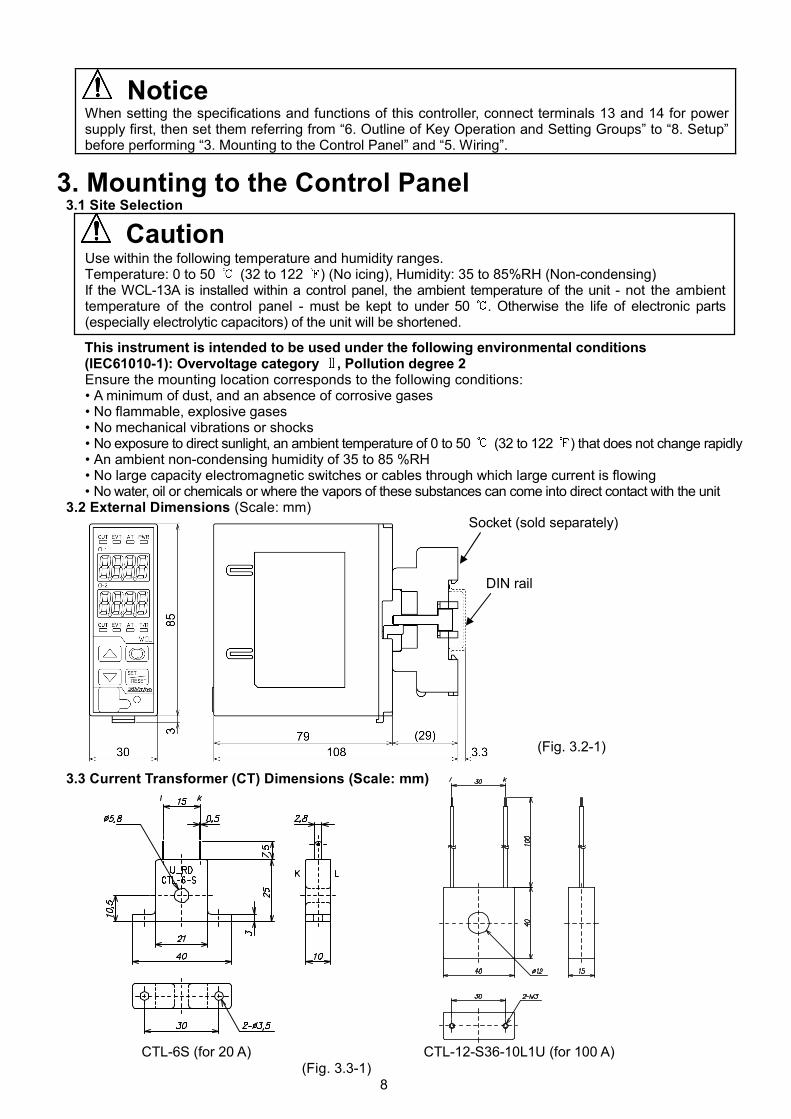
3.2 External Dimensions (Scale: mm)
(Fig. 3.2-1)
3.3 Current Transformer (CT) Dimensions (Scale: mm)
CTL-6S (for 20 A) CTL-12-S36-10L1U (for 100 A)(Fig. 3.3-1)
NoticeWhen setting the specifications and functions of this controller, connect terminals 13 and 14 for powersupply first, then set them referring from “6. Outline of Key Operation and Setting Groups” to “8. Setup”before performing “3. Mounting to the Control Panel” and “5. Wiring”.
DIN rail
Socket (sold separately)
9
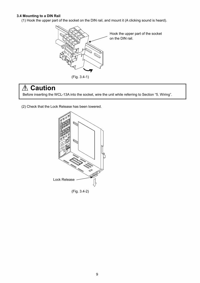
3.4 Mounting to a DIN Rail
(1) Hook the upper part of the socket on the DIN rail, and mount it (A clicking sound is heard).
(Fig. 3.4-1)
CautionBefore inserting the WCL-13A into the socket, wire the unit while referring to Section “5. Wiring”.
(2) Check that the Lock Release has been lowered.
(Fig. 3.4-2)
Hook the upper part of the socket
on the DIN rail.
Lock Release
10
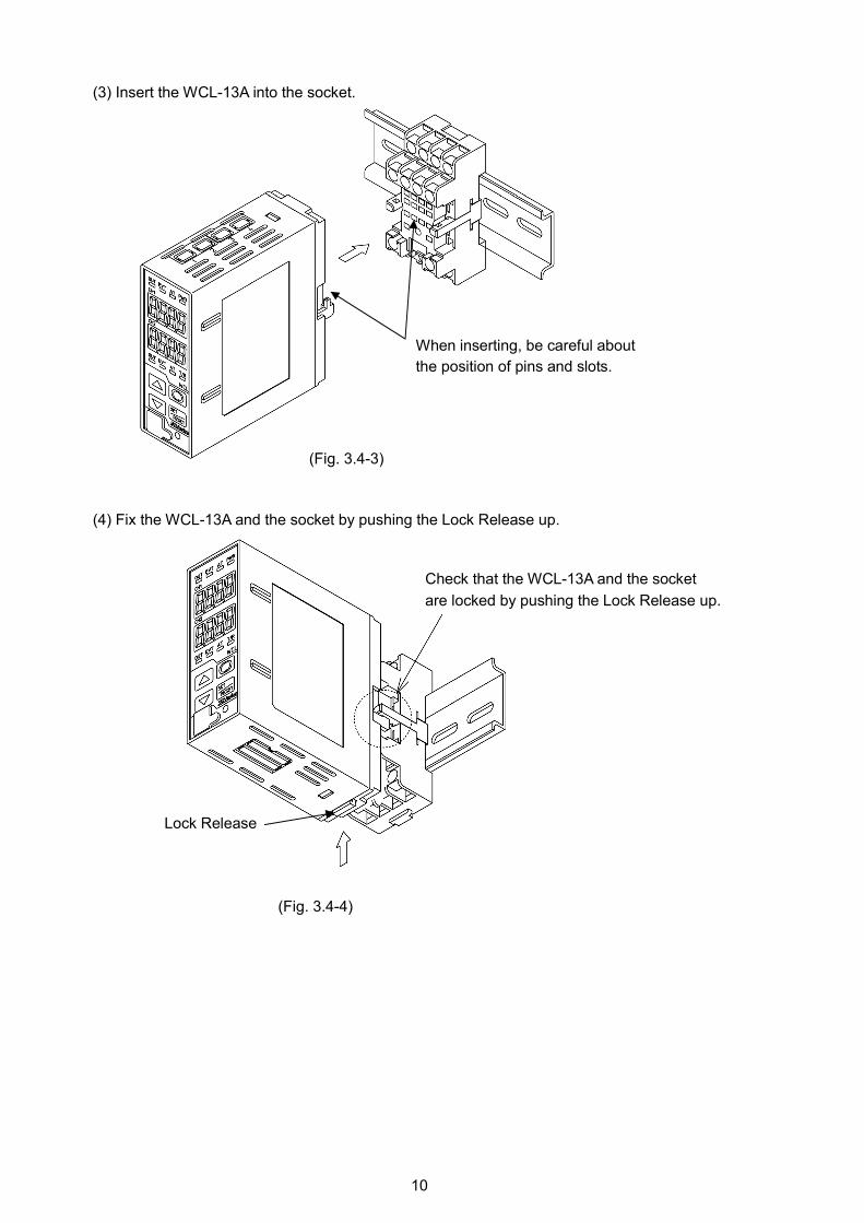
(3) Insert the WCL-13A into the socket.
(Fig. 3.4-3)
(4) Fix the WCL-13A and the socket by pushing the Lock Release up.
(Fig. 3.4-4)
Lock Release
When inserting, be careful about
the position of pins and slots.
Check that the WCL-13A and the socket
are locked by pushing the Lock Release up.
11
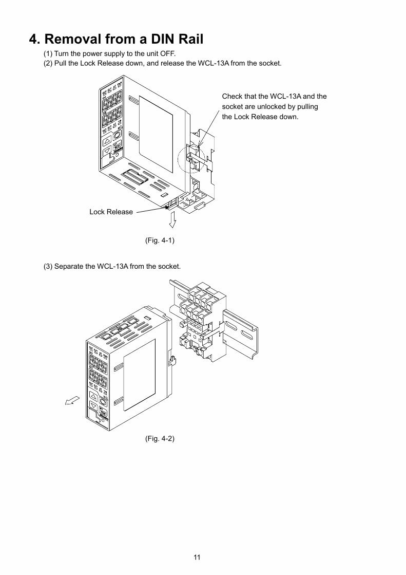
4. Removal from a DIN Rail(1) Turn the power supply to the unit OFF.
(2) Pull the Lock Release down, and release the WCL-13A from the socket.
(Fig. 4-1)
(3) Separate the WCL-13A from the socket.
(Fig. 4-2)
Lock Release
Check that the WCL-13A and the
socket are unlocked by pulling
the Lock Release down.
12
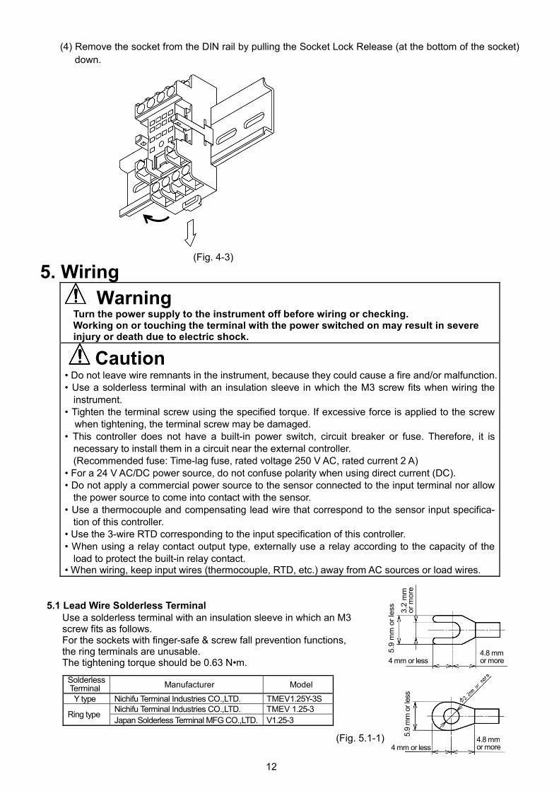
(4) Remove the socket from the DIN rail by pulling the Socket Lock Release (at the bottom of the socket)
down.
(Fig. 4-3)
5. Wiring
WarningTurn the power supply to the instrument off before wiring or checking.Working on or touching the terminal with the power switched on may result in severeinjury or death due to electric shock.
Caution• Do not leave wire remnants in the instrument, because they could cause a fire and/or malfunction.• Use a solderless terminal with an insulation sleeve in which the M3 screw fits when wiring the
instrument.• Tighten the terminal screw using the specified torque. If excessive force is applied to the screw
when tightening, the terminal screw may be damaged.• This controller does not have a built-in power switch, circuit breaker or fuse. Therefore, it is
necessary to install them in a circuit near the external controller.(Recommended fuse: Time-lag fuse, rated voltage 250 V AC, rated current 2 A)
• For a 24 V AC/DC power source, do not confuse polarity when using direct current (DC).• Do not apply a commercial power source to the sensor connected to the input terminal nor allow
the power source to come into contact with the sensor.• Use a thermocouple and compensating lead wire that correspond to the sensor input specifica-
tion of this controller.• Use the 3-wire RTD corresponding to the input specification of this controller.• When using a relay contact output type, externally use a relay according to the capacity of the
load to protect the built-in relay contact.• When wiring, keep input wires (thermocouple, RTD, etc.) away from AC sources or load wires.
5.1 Lead Wire Solderless TerminalUse a solderless terminal with an insulation sleeve in which an M3screw fits as follows.For the sockets with finger-safe & screw fall prevention functions,the ring terminals are unusable.The tightening torque should be 0.63 N•m.
SolderlessTerminal Manufacturer Model
Y type Nichifu Terminal Industries CO.,LTD. TMEV1.25Y-3SNichifu Terminal Industries CO.,LTD. TMEV 1.25-3
Ring typeJapan Solderless Terminal MFG CO.,LTD. V1.25-3
(Fig. 5.1-1) 5.9
mm
orle
ss
4 mm or less4.8 mmor more
3.2
mm
or
more
5.9
mm
or
less
4 mm or less4.8 mmor more
13
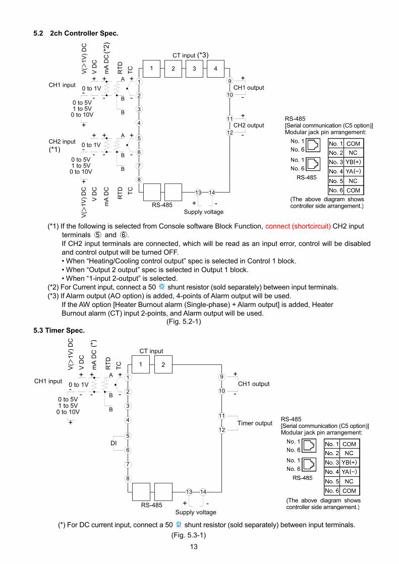
5.2 2ch Controller Spec.
(*1) If the following is selected from Console software Block Function, connect (shortcircuit) CH2 inputterminals ⑤ and ⑥.If CH2 input terminals are connected, which will be read as an input error, control will be disabledand control output will be turned OFF.• When “Heating/Cooling control output” spec is selected in Control 1 block.• When “Output 2 output” spec is selected in Output 1 block.• When “1-input 2-output” is selected.
(*2) For Current input, connect a 50 shunt resistor (sold separately) between input terminals.(*3) If Alarm output (AO option) is added, 4-points of Alarm output will be used.
If the AW option [Heater Burnout alarm (Single-phase) + Alarm output] is added, HeaterBurnout alarm (CT) input 2-points, and Alarm output will be used.
(Fig. 5.2-1)
5.3 Timer Spec.
(*) For DC current input, connect a 50 shunt resistor (sold separately) between input terminals.
(Fig. 5.3-1)
RS-485[Serial communication (C5 option)]Modular jack pin arrangement:
(The above diagram showscontroller side arrangement.)
RS-485[Serial communication (C5 option)]Modular jack pin arrangement:
(The above diagram showscontroller side arrangement.)
1
2
3
4
A
-B
B
++
-
+
--
+T
C
RT
D
mA
DC
VD
C
5
6
7
8
A
-B
B
++
-
+
--
+
TC
RT
D
mA
DC
VD
C
CH1 input
CH2 input
9
10
11
12
-
+
-
+
Supply voltage
CH1 output
CH2 output
0 to 1V
0 to 5V1 to 5V
0 to 10V
RS-485
0 to 1V
0 to 5V1 to 5V0 to 10V
-+
1 2 3 4
CT input
13 14
V(
1V
)D
CV
(1V
)D
C
(*1)
(*3)
(*2
)
1
2
3
4
A
-B
B
++
-
+
--
+
TC
RT
D
mA
DC
VD
C
5
6
7
8
CH1 input
DI
9
10
11
12
-
+CH1 output
Timer output
0 to 1V
0 to 5V1 to 5V
0 to 10V
1 2
CT input
Supply voltageRS-485 -+
13 14
V(
1V
)D
C
(*)
14
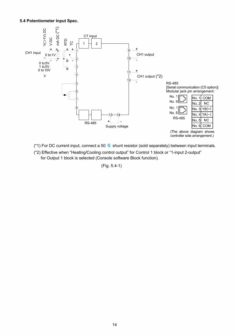
5.4 Potentiometer Input Spec.
(*1) For DC current input, connect a 50 shunt resistor (sold separately) between input terminals.
(*2) Effective when “Heating/Cooling control output” for Control 1 block or “1-input 2-output”
for Output 1 block is selected (Console software Block function).
(Fig. 5.4-1)
RS-485[Serial communication (C5 option)]Modular jack pin arrangement:
(The above diagram showscontroller side arrangement.)
1
2
3
4
A
-B
B
++
-
+
--
+T
C
RT
D
mA
DC
VD
C
5
6
7
8
9
10
11
12
-
+
0 to1V
0 to5V1 to5V
0 to 10V
1 2
CT input
-
+
Supply voltage
-+
13 14
CH1 output
CH1 output
CH1 input
V(
1V
)D
C
RS-485
(*2)
(*1
)
15
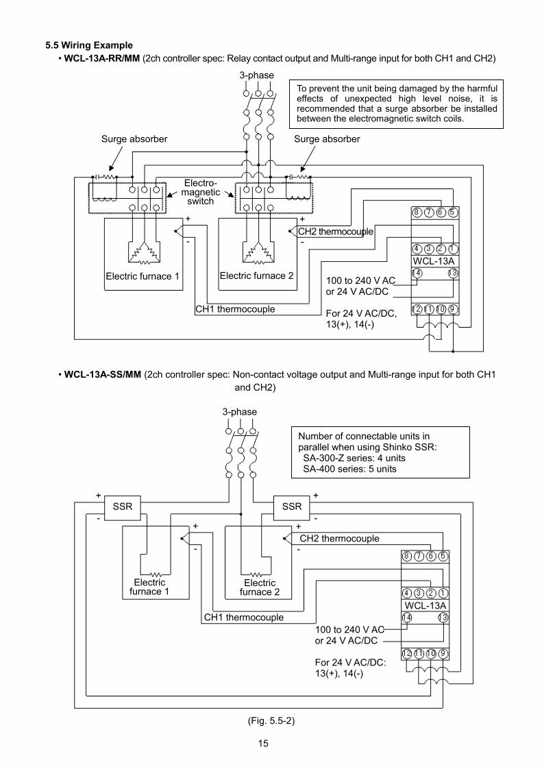
5.5 Wiring Example
• WCL-13A-RR/MM (2ch controller spec: Relay contact output and Multi-range input for both CH1 and CH2)
(Fig. 5.5-1)
• WCL-13A-SS/MM (2ch controller spec: Non-contact voltage output and Multi-range input for both CH1
and CH2)
(Fig. 5.5-2)
3-phase
Surge absorberSurge absorber
Electro-magnetic
switch
Electric furnace 1 Electric furnace 2
CH1 thermocouple
+
-
+
-
100 to 240 V ACor 24 V AC/DC
For 24 V AC/DC,13(+), 14(-)
CH2 thermocouple
WCL-13A
To prevent the unit being damaged by the harmfuleffects of unexpected high level noise, it isrecommended that a surge absorber be installedbetween the electromagnetic switch coils.
3-phase
SSRSSR
Electricfurnace 1
CH1 thermocouple
CH2 thermocouple
+
-
+
-
+
-
+
-
Electricfurnace 2
100 to 240 V ACor 24 V AC/DC
For 24 V AC/DC:13(+), 14(-)
WCL-13A
Number of connectable units inparallel when using Shinko SSR:SA-300-Z series: 4 unitsSA-400 series: 5 units
16
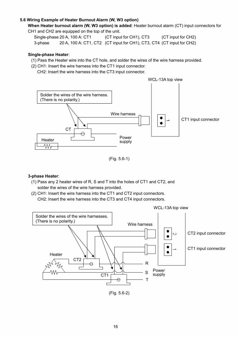
5.6 Wiring Example of Heater Burnout Alarm (W, W3 option)
When Heater burnout alarm (W, W3 option) is added: Heater burnout alarm (CT) input connectors for
CH1 and CH2 are equipped on the top of the unit.
Single-phase 20 A, 100 A: CT1 (CT input for CH1), CT3 (CT input for CH2)
3-phase 20 A, 100 A: CT1, CT2 (CT input for CH1), CT3, CT4 (CT input for CH2)
Single-phase Heater:
(1) Pass the Heater wire into the CT hole, and solder the wires of the wire harness provided.
(2) CH1: Insert the wire harness into the CT1 input connector.
CH2: Insert the wire harness into the CT3 input connector.
(Fig. 5.6-1)
3-phase Heater:
(1) Pass any 2 heater wires of R, S and T into the holes of CT1 and CT2, and
solder the wires of the wire harness provided.
(2) CH1: Insert the wire harness into the CT1 and CT2 input connectors.
CH2: Insert the wire harness into the CT3 and CT4 input connectors.
(Fig. 5.6-2)
CT1 input connector
CT2 input connector
WCL-13A top view
R
S
T
CT2
CT1Powersupply
Wire harness
Solder the wires of the wire harnesses.(There is no polarity.)
Heater
CT
CT1 input connector
WCL-13A top view
Wire harness
Powersupply
Solder the wires of the wire harness.(There is no polarity.)
Heater
17
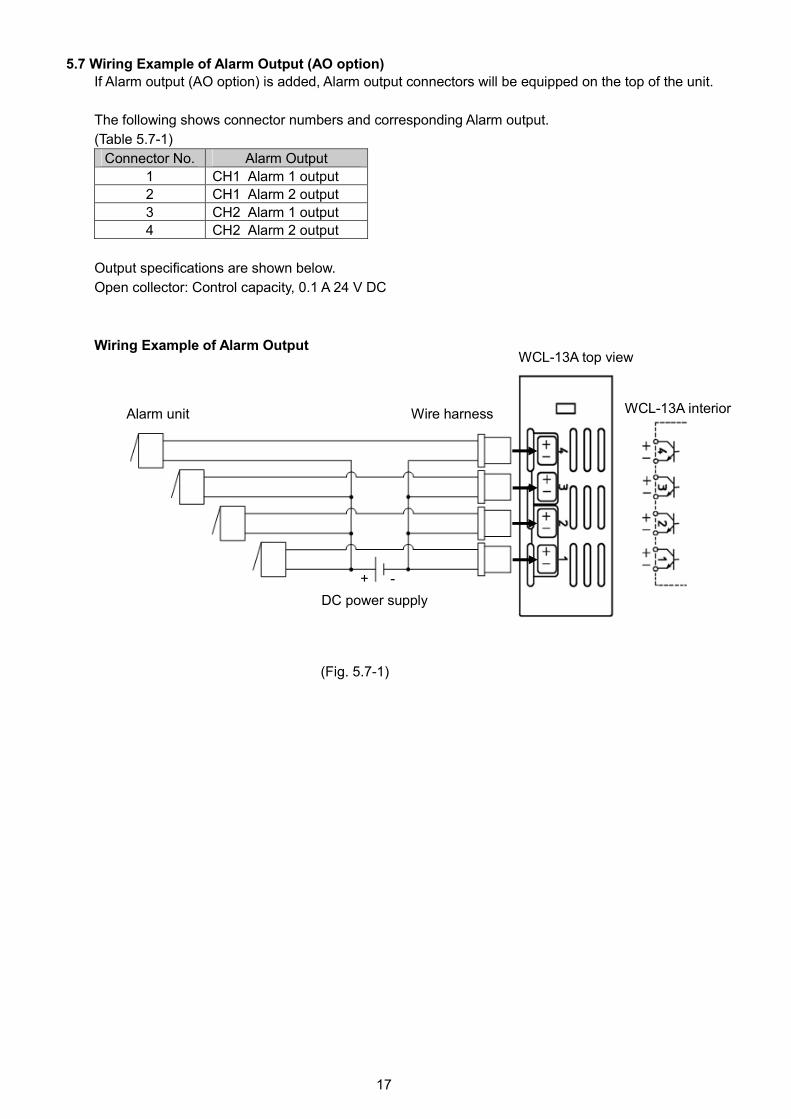
5.7 Wiring Example of Alarm Output (AO option)
If Alarm output (AO option) is added, Alarm output connectors will be equipped on the top of the unit.
The following shows connector numbers and corresponding Alarm output.
(Table 5.7-1)
Connector No. Alarm Output
1 CH1 Alarm 1 output
2 CH1 Alarm 2 output
3 CH2 Alarm 1 output
4 CH2 Alarm 2 output
Output specifications are shown below.
Open collector: Control capacity, 0.1 A 24 V DC
Wiring Example of Alarm Output
(Fig. 5.7-1)
CH2 input
Alarm unit Wire harness
WCL-13A top view
DC power supply
+ -
WCL-13A interior
18
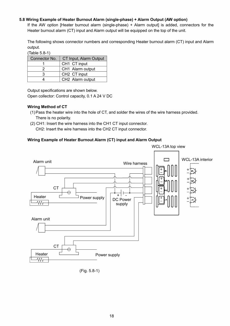
5.8 Wiring Example of Heater Burnout Alarm (single-phase) + Alarm Output (AW option)
If the AW option [Heater burnout alarm (single-phase) + Alarm output] is added, connectors for the
Heater burnout alarm (CT) input and Alarm output will be equipped on the top of the unit.
The following shows connector numbers and corresponding Heater burnout alarm (CT) input and Alarm
output.
(Table 5.8-1)
Connector No. CT Input, Alarm Output
1 CH1 CT input
2 CH1 Alarm output
3 CH2 CT input
4 CH2 Alarm output
Output specifications are shown below.
Open collector: Control capacity, 0.1 A 24 V DC
Wiring Method of CT
(1)Pass the heater wire into the hole of CT, and solder the wires of the wire harness provided.
There is no polarity.
(2) CH1: Insert the wire harness into the CH1 CT input connector.
CH2: Insert the wire harness into the CH2 CT input connector.
Wiring Example of Heater Burnout Alarm (CT) input and Alarm Output
(Fig. 5.8-1)
Alarm unit
Alarm unit
WCL-13A top view
WCL-13A interior
Power supply
CT
Heater
Heater Power supply+ -
DC Powersupply
Wire harness
CT
19
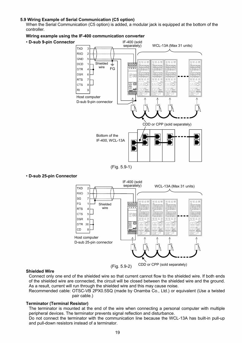
5.9 Wiring Example of Serial Communication (C5 option)When the Serial Communication (C5 option) is added, a modular jack is equipped at the bottom of thecontroller.
Wiring example using the IF-400 communication converter
• D-sub 9-pin Connector
(Fig. 5.9-1)
• D-sub 25-pin Connector
(Fig. 5.9-2)Shielded Wire
Connect only one end of the shielded wire so that current cannot flow to the shielded wire. If both endsof the shielded wire are connected, the circuit will be closed between the shielded wire and the ground.As a result, current will run through the shielded wire and this may cause noise.Recommended cable: OTSC-VB 2PX0.5SQ (made by Onamba Co., Ltd.) or equivalent (Use a twisted
pair cable.)
Terminator (Terminal Resistor)The terminator is mounted at the end of the wire when connecting a personal computer with multipleperipheral devices. The terminator prevents signal reflection and disturbance.Do not connect the terminator with the communication line because the WCL-13A has built-in pull-upand pull-down resistors instead of a terminator.
Host computer
D-sub 9-pin connector
Shieldedwire FG
WCL-13A (Max 31 units)IF-400 (soldseparately)
CDD or CPP (sold separately)
Bottom of the
IF-400, WCL-13A
CDD or CPP (sold separately)
IF-400 (soldseparately) WCL-13A (Max 31 units)
Host computer
D-sub 25-pin connector
Shieldedwire
20
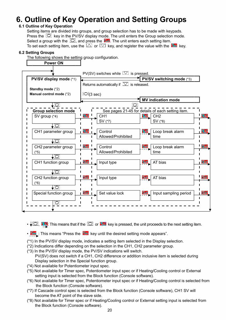
6. Outline of Key Operation and Setting Groups6.1 Outline of Key Operation
Setting items are divided into groups, and group selection has to be made with keypads.Press the key in the PV/SV display mode. The unit enters the Group selection mode.Select a group with the , and press the . The unit enters each setting item.To set each setting item, use the or key, and register the value with the key.
6.2 Setting GroupsThe following shows the setting group configuration.
Power ON
PV(SV) switches while is pressed.
PV/SV switching mode (*3)
Returns automatically if is released.
(3 sec)
PV/SV display mode (*1)
Standby mode (*2)
Manual control mode (*2)
MV indication mode
Group selection mode See pages 21-45 for details of each setting item.
SV group (*4) CH1SV (*7)
CH2SV (*8)
CH1 parameter group ControlAllowed/Prohibited
Loop break alarmtime
CH2 parameter group(*5)
ControlAllowed/Prohibited
Loop break alarmtime
CH1 function group Input type AT bias
CH2 function group(*6)
Input type AT bias
Special function group Set value lock Input sampling period
• , : This means that if the or key is pressed, the unit proceeds to the next setting item.
• : This means “Press the key until the desired setting mode appears”.
(*1) In the PV/SV display mode, indicates a setting item selected in the Display selection.(*2) Indications differ depending on the selection in the CH1, CH2 parameter group.(*3) In the PV/SV display mode, the PV/SV indications will switch.
PV(SV) does not switch if a CH1, CH2 difference or addition inclusive item is selected duringDisplay selection in the Special function group.
(*4) Not available for Potentiometer input spec.(*5) Not available for Timer spec, Potentiometer input spec or if Heating/Cooling control or External
setting input is selected from the Block function (Console software).(*6) Not available for Timer spec, Potentiometer input spec or if Heating/Cooling control is selected from
the Block function (Console software).(*7) If Cascade control spec is selected from the Block function (Console software), CH1 SV will
become the AT point of the slave side.(*8) Not available for Timer spec or if Heating/Cooling control or External setting input is selected from
the Block function (Console software).
21
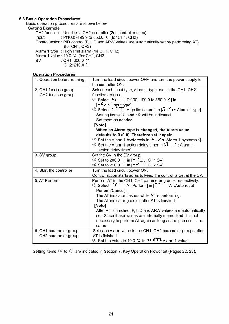
6.3 Basic Operation ProceduresBasic operation procedures are shown below.Setting Example
CH2 function : Used as a CH2 controller (2ch controller spec).Input : Pt100: -199.9 to 850.0 (for CH1, CH2)Control action : PID control (P, I, D and ARW values are automatically set by performing AT)
(for CH1, CH2)Alarm 1 type : High limit alarm (for CH1, CH2)Alarm 1 value : 10.0 (for CH1, CH2)SV : CH1: 200.0
CH2: 210.0
Operation Procedures
1. Operation before running Turn the load circuit power OFF, and turn the power supply tothe controller ON.
2. CH1 function groupCH2 function group
Select each input type, Alarm 1 type, etc. in the CH1, CH2function groups.1 Select [ : Pt100 -199.9 to 850.0 ] in
[ : Input type].2 Select [ : High limit alarm] in [ : Alarm 1 type].
Setting items 3 and 4 will be indicated.Set them as needed.
[Note]When an Alarm type is changed, the Alarm valuedefaults to 0 (0.0). Therefore set it again.
3 Set the Alarm 1 hysteresis in [ : Alarm 1 hysteresis].4 Set the Alarm 1 action delay timer in [ : Alarm 1
action delay timer].
3. SV group Set the SV in the SV group.5 Set to 200.0 in [ : CH1 SV].6 Set to 210.0 in [ : CH2 SV].
4. Start the controller Turn the load circuit power ON.Control action starts so as to keep the control target at the SV.
5. AT Perform Perform AT in the CH1, CH2 parameter groups respectively.7 Select [ : AT Perform] in [ : AT/Auto-reset
Perform/Cancel].The AT indicator flashes while AT is performing.The AT indicator goes off after AT is finished.
[Note]After AT is finished, P, I, D and ARW values are automaticallyset. Since these values are internally memorized, it is notnecessary to perform AT again as long as the process is thesame.
6. CH1 parameter groupCH2 parameter group
Set each Alarm value in the CH1, CH2 parameter groups afterAT is finished.8 Set the value to 10.0 in [ : Alarm 1 value].
Setting items 1 to 8 are indicated in Section 7. Key Operation Flowchart (Pages 22, 23).
22
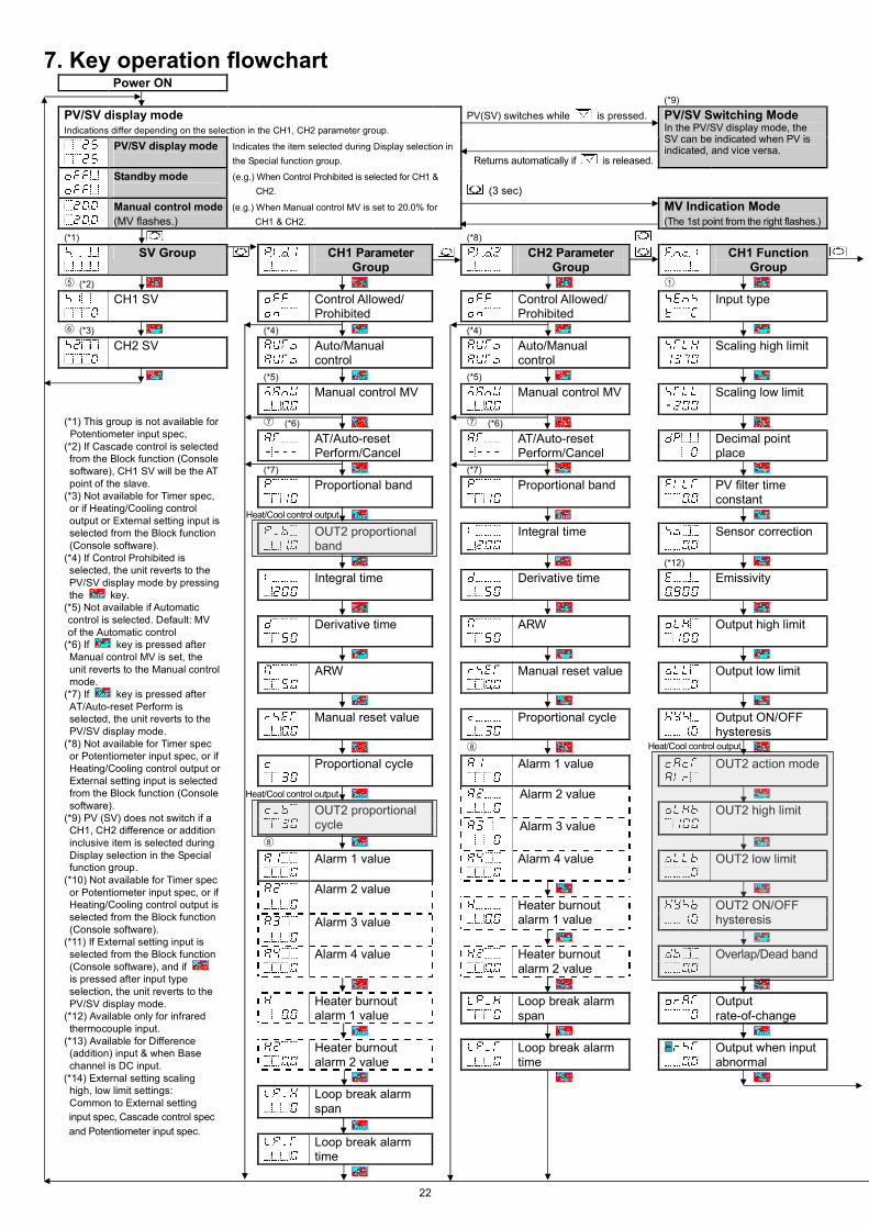
7. Key operation flowchartPower ON
(*9)
PV/SV display modeIndications differ depending on the selection in the CH1, CH2 parameter group.
PV(SV) switches while is pressed.
PV/SV display mode Indicates the item selected during Display selection in
the Special function group. Returns automatically if is released.
PV/SV Switching ModeIn the PV/SV display mode, theSV can be indicated when PV isindicated, and vice versa.
Standby mode (e.g.) When Control Prohibited is selected for CH1 &
CH2. (3 sec)
Manual control mode
(MV flashes.)
(e.g.) When Manual control MV is set to 20.0% for
CH1 & CH2.
MV Indication Mode(The 1st point from the right flashes.)
(*1) (*8)
SV Group CH1 ParameterGroup
CH2 ParameterGroup
CH1 FunctionGroup
5 (*2) 1
CH1 SV Control Allowed/Prohibited
Control Allowed/Prohibited
Input type
6 (*3) (*4) (*4)
CH2 SV Auto/Manualcontrol
Auto/Manualcontrol
Scaling high limit
(*5) (*5)
Manual control MV Manual control MV Scaling low limit
7 (*6) 7 (*6)
AT/Auto-resetPerform/Cancel
AT/Auto-resetPerform/Cancel
Decimal pointplace
(*7) (*7)
Proportional band Proportional band PV filter timeconstant
OUT2 proportionalband
Integral time Sensor correction
(*12)
Integral time Derivative time Emissivity
Derivative time ARW Output high limit
ARW Manual reset value Output low limit
Manual reset value Proportional cycle Output ON/OFFhysteresis
8
Proportional cycle Alarm 1 value OUT2 action mode
Alarm 2 value
OUT2 proportionalcycle
OUT2 high limit
8
Alarm 3 value
Alarm 1 value Alarm 4 value OUT2 low limit
Alarm 2 value
Alarm 3 value
Heater burnoutalarm 1 value
OUT2 ON/OFFhysteresis
Alarm 4 value Heater burnoutalarm 2 value
Overlap/Dead band
Heater burnoutalarm 1 value
Loop break alarmspan
Outputrate-of-change
Heater burnoutalarm 2 value
Loop break alarmtime
Output when inputabnormal
Loop break alarmspan
(*1) This group is not available forPotentiometer input spec,
(*2) If Cascade control is selectedfrom the Block function (Consolesoftware), CH1 SV will be the ATpoint of the slave.
(*3) Not available for Timer spec,or if Heating/Cooling controloutput or External setting input isselected from the Block function(Console software).
(*4) If Control Prohibited isselected, the unit reverts to thePV/SV display mode by pressingthe key.
(*5) Not available if Automaticcontrol is selected. Default: MVof the Automatic control
(*6) If key is pressed afterManual control MV is set, theunit reverts to the Manual controlmode.
(*7) If key is pressed afterAT/Auto-reset Perform isselected, the unit reverts to thePV/SV display mode.
(*8) Not available for Timer specor Potentiometer input spec, or ifHeating/Cooling control output orExternal setting input is selectedfrom the Block function (Consolesoftware).
(*9) PV (SV) does not switch if aCH1, CH2 difference or additioninclusive item is selected duringDisplay selection in the Specialfunction group.
(*10) Not available for Timer specor Potentiometer input spec, or ifHeating/Cooling control output isselected from the Block function(Console software).
(*11) If External setting input isselected from the Block function(Console software), and ifis pressed after input typeselection, the unit reverts to thePV/SV display mode.
(*12) Available only for infraredthermocouple input.
(*13) Available for Difference(addition) input & when Basechannel is DC input.
(*14) External setting scalinghigh, low limit settings:Common to External setting
input spec, Cascade control spec
and Potentiometer input spec.Loop break alarmtime
Heat/Cool control output
Heat/Cool control output
Heat/Cool control output
23
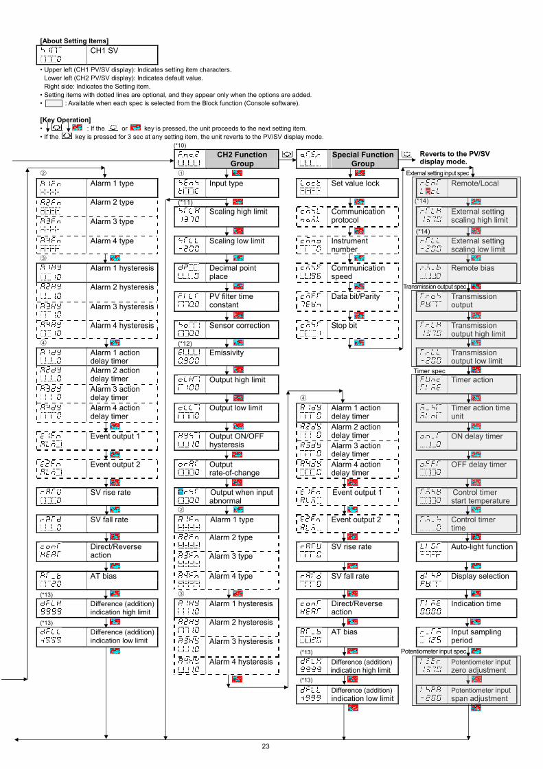
[About Setting Items]
CH1 SV
• Upper left (CH1 PV/SV display): Indicates setting item characters.
Lower left (CH2 PV/SV display): Indicates default value.
Right side: Indicates the Setting item.
• Setting items with dotted lines are optional, and they appear only when the options are added.
• : Available when each spec is selected from the Block function (Console software).
[Key Operation]• , : If the or key is pressed, the unit proceeds to the next setting item.
• If the key is pressed for 3 sec at any setting item, the unit reverts to the PV/SV display mode.
(*10)
CH2 FunctionGroup
Special FunctionGroup
Reverts to the PV/SVdisplay mode.
2 1
Alarm 1 type Input type Set value lock Remote/Local
(*11)Alarm 2 typeScaling high limit Communication
protocolExternal settingscaling high limitAlarm 3 type
Alarm 4 type Scaling low limit Instrumentnumber
External settingscaling low limit
3
Alarm 1 hysteresis Decimal pointplace
Communicationspeed
Remote bias
Alarm 2 hysteresisPV filter timeconstant
Data bit/Parity TransmissionoutputAlarm 3 hysteresis
Alarm 4 hysteresis Sensor correction Stop bit Transmissionoutput high limit
4 (*12)
Alarm 1 actiondelay timer
Emissivity Transmissionoutput low limit
Alarm 2 actiondelay timer Output high limit Timer actionAlarm 3 actiondelay timer 4
Alarm 4 actiondelay timer
Output low limit Alarm 1 actiondelay timer
Timer action timeunit
Alarm 2 actiondelay timerEvent output 1 Output ON/OFF
hysteresisON delay timer
Alarm 3 actiondelay timer
Event output 2 Outputrate-of-change
Alarm 4 actiondelay timer
OFF delay timer
SV rise rate Output when inputabnormal
Event output 1 Control timerstart temperature
2
SV fall rate Alarm 1 type Event output 2 Control timertime
Alarm 2 typeDirect/Reverseaction
SV rise rate Auto-light functionAlarm 3 type
AT bias Alarm 4 type SV fall rate Display selection
(*13) 3
Alarm 1 hysteresisDifference (addition)indication high limit
Direct/Reverseaction
Indication time
(*13) Alarm 2 hysteresisDifference (addition)indication low limit
AT bias Input samplingperiodAlarm 3 hysteresis
(*13)
Alarm 4 hysteresis Difference (addition)indication high limit
Potentiometer inputzero adjustment
(*13)
Difference (addition)indication low limit
Potentiometer inputspan adjustment
External setting input spec
(*14)
Transmission output spec
Timer spec
Potentiometer input spec
(*14)
24
8. SetupSetup should be done before using this controller, to set the input type, Alarm type, and control action, etc.of CH1 and CH2 according to the users’ conditions.Setup can be conducted in the CH1, CH2 function groups and Special function group.If the users’ specification is the same as the default value of the WCL-13A, it is not necessary to set upthe controller. Proceed to Chapter “9. Settings”.
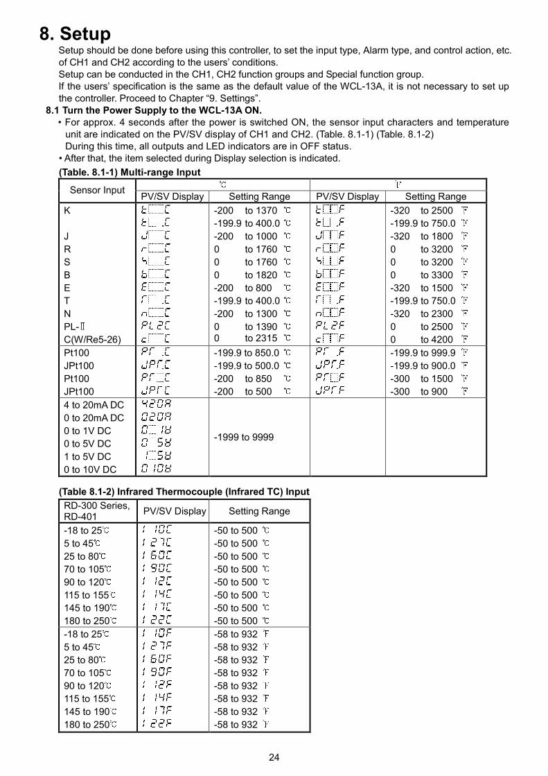
8.1 Turn the Power Supply to the WCL-13A ON.• For approx. 4 seconds after the power is switched ON, the sensor input characters and temperature
unit are indicated on the PV/SV display of CH1 and CH2. (Table. 8.1-1) (Table. 8.1-2)During this time, all outputs and LED indicators are in OFF status.
• After that, the item selected during Display selection is indicated.
(Table. 8.1-1) Multi-range Input
Sensor InputPV/SV Display Setting Range PV/SV Display Setting Range
K
J
R
S
B
E
T
N
PL-
C(W/Re5-26)
-200 to 1370
-199.9 to 400.0
-200 to 1000
0 to 1760
0 to 1760
0 to 1820
-200 to 800
-199.9 to 400.0
-200 to 1300
0 to 13900 to 2315
-320 to 2500
-199.9 to 750.0
-320 to 1800
0 to 3200
0 to 3200
0 to 3300
-320 to 1500
-199.9 to 750.0
-320 to 2300
0 to 2500
0 to 4200
Pt100
JPt100
Pt100
JPt100
-199.9 to 850.0
-199.9 to 500.0
-200 to 850
-200 to 500
-199.9 to 999.9
-199.9 to 900.0
-300 to 1500
-300 to 900
4 to 20mA DC
0 to 20mA DC
0 to 1V DC
0 to 5V DC
1 to 5V DC
0 to 10V DC
-1999 to 9999
(Table 8.1-2) Infrared Thermocouple (Infrared TC) Input
RD-300 Series,RD-401
PV/SV Display Setting Range
-18 to 25
5 to 45
25 to 80
70 to 105
90 to 120
115 to 155
145 to 190
180 to 250
-50 to 500
-50 to 500
-50 to 500
-50 to 500
-50 to 500
-50 to 500
-50 to 500
-50 to 500
-18 to 25
5 to 45
25 to 80
70 to 105
90 to 120
115 to 155
145 to 190
180 to 250
-58 to 932
-58 to 932
-58 to 932
-58 to 932
-58 to 932
-58 to 932
-58 to 932
-58 to 932
25
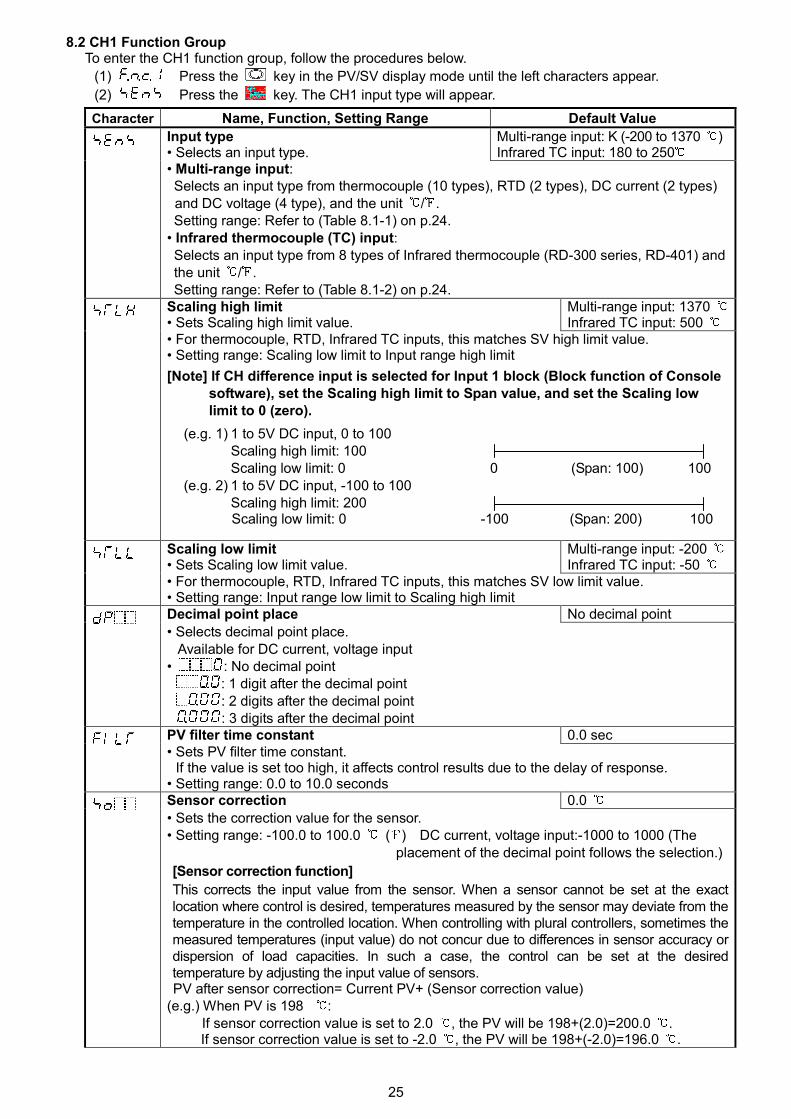
8.2 CH1 Function GroupTo enter the CH1 function group, follow the procedures below.
(1) Press the key in the PV/SV display mode until the left characters appear.
(2) Press the key. The CH1 input type will appear.
Character Name, Function, Setting Range Default Value
Input type• Selects an input type.
Multi-range input: K (-200 to 1370 )Infrared TC input: 180 to 250
• Multi-range input:Selects an input type from thermocouple (10 types), RTD (2 types), DC current (2 types)and DC voltage (4 type), and the unit / .Setting range: Refer to (Table 8.1-1) on p.24.
• Infrared thermocouple (TC) input:Selects an input type from 8 types of Infrared thermocouple (RD-300 series, RD-401) andthe unit / .Setting range: Refer to (Table 8.1-2) on p.24.
Scaling high limit• Sets Scaling high limit value.
Multi-range input: 1370Infrared TC input: 500
• For thermocouple, RTD, Infrared TC inputs, this matches SV high limit value.• Setting range: Scaling low limit to Input range high limit
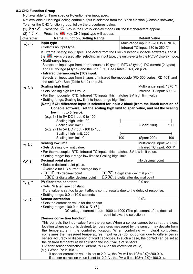
[Note] If CH difference input is selected for Input 1 block (Block function of Consolesoftware), set the Scaling high limit to Span value, and set the Scaling lowlimit to 0 (zero).
(e.g. 1) 1 to 5V DC input, 0 to 100Scaling high limit: 100Scaling low limit: 0 0 (Span: 100) 100
(e.g. 2) 1 to 5V DC input, -100 to 100Scaling high limit: 200Scaling low limit: 0 -100 (Span: 200) 100
Scaling low limit• Sets Scaling low limit value.
Multi-range input: -200Infrared TC input: -50
• For thermocouple, RTD, Infrared TC inputs, this matches SV low limit value.• Setting range: Input range low limit to Scaling high limitDecimal point place No decimal point
• Selects decimal point place.Available for DC current, voltage input
• : No decimal point: 1 digit after the decimal point: 2 digits after the decimal point: 3 digits after the decimal point
PV filter time constant 0.0 sec• Sets PV filter time constant.
If the value is set too high, it affects control results due to the delay of response.• Setting range: 0.0 to 10.0 secondsSensor correction 0.0
• Sets the correction value for the sensor.• Setting range: -100.0 to 100.0 ( ) DC current, voltage input:-1000 to 1000 (The
placement of the decimal point follows the selection.)
[Sensor correction function]
This corrects the input value from the sensor. When a sensor cannot be set at the exactlocation where control is desired, temperatures measured by the sensor may deviate from thetemperature in the controlled location. When controlling with plural controllers, sometimes themeasured temperatures (input value) do not concur due to differences in sensor accuracy ordispersion of load capacities. In such a case, the control can be set at the desiredtemperature by adjusting the input value of sensors.PV after sensor correction= Current PV+ (Sensor correction value)
(e.g.) When PV is 198 :If sensor correction value is set to 2.0 , the PV will be 198+(2.0)=200.0 .If sensor correction value is set to -2.0 , the PV will be 198+(-2.0)=196.0 .
26
SV
OUT2 proportional band
Air cooling
Oil coolingWater cooling
Character Name, Function, Setting Range Default ValueEmissivity 0.900 times• Sets infrared emissivity.Setting characters and PV are alternately indicated on the CH1 PV/SV display.Available only for Infrared thermocouple input.
• Setting range: 0.100 to 1.000 times
Output high limit 100 %
• Sets the output high limit value.Not available if output is in ON/OFF control.If Heating/Cooling control output is selected from the Block function (Console software),CH1 output will be OUT1, and CH2 output will be OUT2.
• Setting range: Output low limit to 100 %(DC current output: Output low limit to 105 %)
Output low limit 0 %
• Sets the output low limit value.Not available if output is in ON/OFF control.If Heating/Cooling control output is selected from the Block function (Console software),CH1 output will be OUT1, and CH2 output will be OUT2.
• Setting range: 0 % to Output high limit(DC current output: -5 % to Output high limit)
Output ON/OFF hysteresis 1.0• Sets the output ON/OFF hysteresis.Available only when output is in ON/OFF controlIf Heating/Cooling control output is selected from the Block function (Console software),CH1 output will be OUT1, and CH2 output will be OUT2.
• Setting range: 0.1 to 100.0 ( ),DC current, voltage input: 1 to 1000 (The placement of the decimal point follows the
selection.)
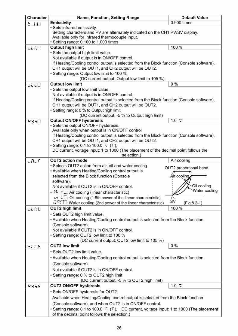
OUT2 action mode Air cooling
• Selects OUT2 action from air, oil and water cooling.• Available when Heating/Cooling control output isselected from the Block function (Consolesoftware).Not available if OUT2 is in ON/OFF control.
• : Air cooling (linear characteristic)
: Oil cooling (1.5th power of the linear characteristic)
: Water cooling (2nd power of the linear characteristic) (Fig.8.2-1)
OUT2 high limit 100 %
• Sets OUT2 high limit value.
• Available when Heating/Cooling control output is selected from the Block function(Console software).Not available if OUT2 is in ON/OFF control.
• Setting range: OUT2 low limit to 100 %(DC current output: OUT2 low limit to 105 %)
OUT2 low limit 0 %
• Sets OUT2 low limit value.
• Available when Heating/Cooling control output is selected from the Block function
(Console software).
Not available if OUT2 is in ON/OFF control.
• Setting range: 0 % to OUT2 high limit(DC current output: -5 % to OUT2 high limit)
OUT2 ON/OFF hysteresis 1.0
• Sets ON/OFF hysteresis for OUT2.
Available when Heating/Cooling control output is selected from the Block function
(Console software), and when OUT2 is in ON/OFF control.
• Setting range: 0.1 to 100.0 ( ), DC current, voltage input: 1 to 1000 (The placementof the decimal point follows the selection.)
27
Character Name, Function, Setting Range Default Value
Overlap band/Dead band 0.0
• Sets the overlap band or dead band for OUT1 and OUT2.
+ Set value: Dead band, –Set value: Overlap band
• Available when Heating/Cooling control output is selected from the Block function
(Console software).
• Setting range: -100.0 to 100.0 ( ),
DC current, voltage input: -1000 to 1000 (The placement of the decimal point follows theselection.)
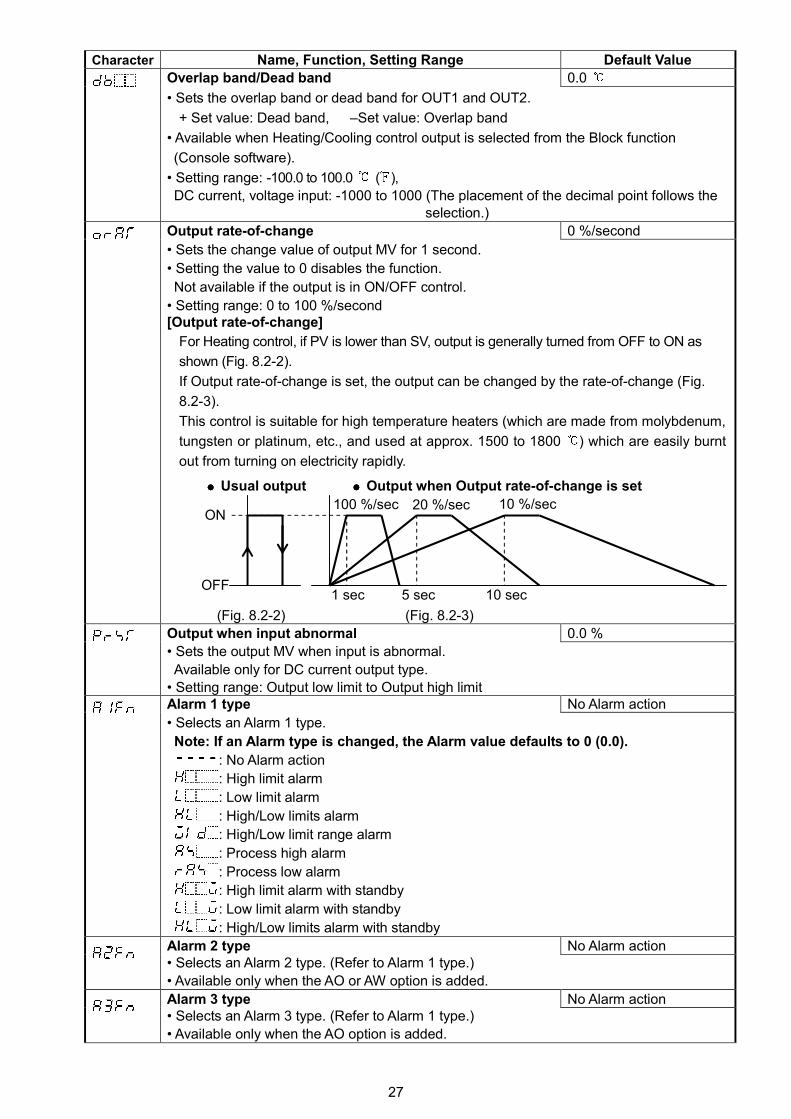
Output rate-of-change 0 %/second
• Sets the change value of output MV for 1 second.
• Setting the value to 0 disables the function.
Not available if the output is in ON/OFF control.
• Setting range: 0 to 100 %/second[Output rate-of-change]
For Heating control, if PV is lower than SV, output is generally turned from OFF to ON as
shown (Fig. 8.2-2).
If Output rate-of-change is set, the output can be changed by the rate-of-change (Fig.
8.2-3).
This control is suitable for high temperature heaters (which are made from molybdenum,
tungsten or platinum, etc., and used at approx. 1500 to 1800 ) which are easily burnt
out from turning on electricity rapidly.
Usual output Output when Output rate-of-change is set
(Fig. 8.2-2) (Fig. 8.2-3)
Output when input abnormal 0.0 %
• Sets the output MV when input is abnormal.
Available only for DC current output type.
• Setting range: Output low limit to Output high limitAlarm 1 type No Alarm action
• Selects an Alarm 1 type.
Note: If an Alarm type is changed, the Alarm value defaults to 0 (0.0).
: No Alarm action
: High limit alarm
: Low limit alarm
: High/Low limits alarm
: High/Low limit range alarm
: Process high alarm
: Process low alarm
: High limit alarm with standby
: Low limit alarm with standby
: High/Low limits alarm with standby
Alarm 2 type No Alarm action• Selects an Alarm 2 type. (Refer to Alarm 1 type.)
• Available only when the AO or AW option is added.
Alarm 3 type No Alarm action• Selects an Alarm 3 type. (Refer to Alarm 1 type.)
• Available only when the AO option is added.
100 %/sec 20 %/sec 10 %/sec
OFF1 sec 5 sec 10 sec
ON
28
Character Name, Function, Setting Range Default Value
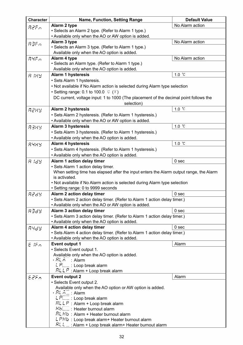
Alarm 4 type No Alarm action
• Selects an Alarm 4 type. (Refer to Alarm 1 type.)
• Available only when the AO option is added.
Alarm 1 hysteresis 1.0
• Sets Alarm 1 hysteresis.
• Not available if No Alarm action is selected during Alarm type selection
• Setting range: 0.1 to 100.0 ( )
DC current, voltage input: 1 to 1000 (The placement of the decimal point
follows the selection.)
Alarm 2 hysteresis 1.0
• Sets Alarm 2 hysteresis. (Refer to Alarm 1 hysteresis.)
• Available only when the AO or AW option is added.
Alarm 3 hysteresis 1.0
• Sets Alarm 3 hysteresis. (Refer to Alarm 1 hysteresis.)
• Available only when the AO option is added.
Alarm 4 hysteresis 1.0
• Sets Alarm 4 hysteresis. (Refer to Alarm 1 hysteresis.)
• Available only when the AO option is added.
Alarm 1 action delay timer 0 sec
• Sets Alarm 1 action delay timer.
When setting time has elapsed after the input enters the Alarm output range, the Alarm
is activated.
• Not available if No Alarm action is selected during Alarm type selection
• Setting range: 0 to 9999 seconds
Alarm 2 action delay timer 0 sec
• Sets Alarm 2 action delay timer. (Refer to Alarm 1 action delay timer.)
• Available only when the AO or AW option is added.
Alarm 3 action delay timer 0 sec
• Sets Alarm 3 action delay timer. (Refer to Alarm 1 action delay timer.)
• Available only when the AO option is added.
Alarm 4 action delay timer 0 sec
• Sets Alarm 4 action delay timer. (Refer to Alarm 1 action delay timer.)
• Available only when the AO option is added.
Event output 1 Alarm
• Selects Event output 1.
Available only when the AO option is added.
• : Alarm
: Loop break alarm
: Alarm + Loop break alarm
Event output 2 Alarm
• Selects Event output 2.
Available only when the AO or AW option is added.
• : Alarm
: Loop break alarm
: Alarm + Loop break alarm
: Heater burnout alarm
: Alarm + Heater burnout alarm
: Loop break alarm + Heater burnout alarm
: Alarm+ Loop break alarm + Heater burnout alarm
29
Character Name, Function, Setting Range Default Value
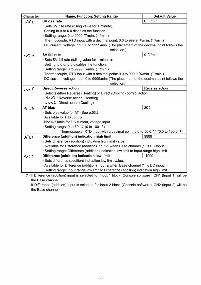
SV rise rate 0 /min.
• Sets SV rise rate (rising value for 1 minute).
Setting to 0 or 0.0 disables the function.
• Setting range: 0 to 9999 /min. ( /min.)
Thermocouple, RTD input with a decimal point: 0.0 to 999.9 /min. ( /min.)
DC current, voltage input: 0 to 9999/min. (The placement of the decimal point follows the
selection.)
SV fall rate 0 /min.
• Sets SV fall rate (falling value for 1 minute).
Setting to 0 or 0.0 disables the function.
• Setting range: 0 to 9999 /min. ( /min.)
Thermocouple, RTD input with a decimal point: 0.0 to 999.9 /min. ( /min.)
DC current, voltage input: 0 to 9999/min. (The placement of the decimal point follows the
selection.)
Direct/Reverse action Reverse action
• Selects either Reverse (Heating) or Direct (Cooling) control action.
• : Reverse action (Heating)
: Direct action (Cooling)
AT bias 20
• Sets bias value for the AT. (See p.53.)
• Available for PID control
Not available for DC current, voltage input.
• Setting range: 0 to 50 (0 to 100 )
Thermocouple, RTD input with a decimal point: 0.0 to 50.0 (0.0 to 100.0 )
Difference (addition) indication high limit 9999
• Sets difference (addition) indication high limit value.
• Available for Difference (addition) input & when Base channel (*) is DC input.
• Setting range: Difference (addition) indication low limit to Input range high limit
Difference (addition) indication low limit -1999
• Sets difference (addition) indication low limit value.
• Available for Difference (addition) input & when Base channel (*) is DC input.
• Setting range: Input range low limit to Difference (addition) indication high limit
(*) If Difference (addition) input is selected for Input 1 block (Console software), CH1 (Input 1) will be the
Base channel.
If Difference (addition) input is selected for Input 2 block (Console software), CH2 (Input 2) will be
the Base channel.
30
8.3 CH2 Function Group
Not available for Timer spec or Potentiometer input spec.
Not available if Heating/Cooling control output is selected from the Block function (Console software).
To enter the CH2 function group, follow the procedures below.
(1) Press the key in the PV/SV display mode until the left characters appear.
(2) Press the key. CH2 input type will appear.
Character Name, Function, Setting Range Default Value
Input type• Selects an input type.
Multi-range input: K (-200 to 1370 )
Infrared TC input: 180 to 250
If External setting input spec is selected from the Block function (Console software), and ifthe key is pressed after selecting an input type, the unit reverts to the PV/SV display mode.• Multi-range input:Selects an input type from thermocouple (10 types), RTD (2 types), DC current (2 types)and DC voltage (4 type), and the unit / . See (Table 8.1-1) on p.24.
• Infrared thermocouple (TC) input:Selects an input type from 8 types of Infrared thermocouple (RD-300 series, RD-401) andthe unit / . See (Table 8.1-2) on p.24.
Scaling high limit
• Sets Scaling high limit value.
Multi-range input: 1370
Infrared TC input: 500
• For thermocouple, RTD, Infrared TC inputs, this matches SV high limit value.• Setting range: Scaling low limit to Input range high limit[Note] If CH difference input is selected for Input 2 block (from the Block function of
Console software), set the scaling high limit to span value, and set the scalinglow limit to 0 (zero).
(e.g. 1) 1 to 5V DC input, 0 to 100Scaling high limit: 100Scaling low limit: 0 0 (Span: 100) 100
(e.g. 2) 1 to 5V DC input, -100 to 100Scaling high limit: 200Scaling low limit: 0 -100 (Span: 200) 100
Scaling low limit• Sets Scaling low limit value.
Multi-range input: -200Infrared TC input: -50
• For thermocouple, RTD, Infrared TC inputs, this matches SV low limit value.• Setting range: Input range low limit to Scaling high limit
Decimal point place No decimal point
• Selects decimal point place.Available for DC current, voltage input
• : No decimal point : 1 digit after decimal point: 2 digits after decimal point : 3 digits after decimal point
PV filter time constant 0.0 sec
• Sets PV filter time constant.If the value is set too large, it affects control results due to the delay of response.
• Setting range: 0.0 to 10.0 secondsSensor correction 0.0• Sets the correction value for the sensor.• Setting range: -100.0 to 100.0 ( ),
DC voltage, current input: -1000 to 1000 (The placement of the decimalpoint follows the selection.)
[Sensor correction function]This corrects the input value from the sensor. When a sensor cannot be set at the exactlocation where control is desired, temperatures measured by the sensor may deviate fromthe temperature in the controlled location. When controlling with plural controllers,sometimes the measured temperatures (input value) do not concur due to differences insensor accuracy or dispersion of load capacities. In such a case, the control can be set atthe desired temperature by adjusting the input value of sensors.PV after sensor correction= Current PV+ (Sensor correction value)
(e.g.) When PV is 198 :If sensor correction value is set to 2.0 , the PV will be 198+(2.0)=200.0 .If sensor correction value is set to -2.0 , the PV will be 198+(-2.0)=196.0 .
31
Character Name, Function, Setting Range Default Value
Emissivity 0.900 times
• Sets infrared emissivity.
Setting characters and PV are alternately indicated on the CH1 PV/SV display.
Available only for Infrared thermocouple input
• Setting range: 0.100 to 1.000 times
Output high limit 100 %
• Sets the output high limit value.
Not available if output is in ON/OFF control.
• Setting range: Output low limit to 100 % (DC current output: Output low limit to 105 %)
Output low limit 0%
• Sets the output low limit value.
Not available if output is in ON/OFF control.
• Setting range: 0 % to Output high limit (DC current output: -5 % to Output high limit)
Output ON/OFF hysteresis 1.0
• Sets the output ON/OFF hysteresis.
Available only when output is in ON/OFF control.
• Setting range: 0.1 to 100.0 ( ), DC current, voltage input: 1 to 1000 (The placement
of the decimal point follows the selection.)
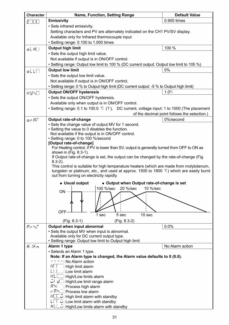
Output rate-of-change 0%/second• Sets the change value of output MV for 1 second.• Setting the value to 0 disables the function.Not available if the output is in ON/OFF control.
• Setting range: 0 to 100 %/second[Output rate-of-change]
For Heating control, if PV is lower than SV, output is generally turned from OFF to ON asshown in (Fig. 8.3-1).If Output rate-of-change is set, the output can be changed by the rate-of-change (Fig.8.3-2).This control is suitable for high temperature heaters (which are made from molybdenum,tungsten or platinum, etc., and used at approx. 1500 to 1800 ) which are easily burntout from turning on electricity rapidly.
Usual output Output when Output rate-of-change is set
(Fig. 8.3-1) (Fig. 8.3-2)
Output when input abnormal 0.0%• Sets the output MV when input is abnormal.Available only for DC current output type.
• Setting range: Output low limit to Output high limit
Alarm 1 type No Alarm action
• Selects an Alarm 1 type.Note: If an Alarm type is changed, the Alarm value defaults to 0 (0.0).
: No Alarm action: High limit alarm: Low limit alarm: High/Low limits alarm: High/Low limit range alarm: Process high alarm: Process low alarm: High limit alarm with standby: Low limit alarm with standby: High/Low limits alarm with standby
100 %/sec 20 %/sec 10 %/sec
OFF1 sec 5 sec 10 sec
ON
32
Character Name, Function, Setting Range Default Value
Alarm 2 type No Alarm action• Selects an Alarm 2 type. (Refer to Alarm 1 type.)
• Available only when the AO or AW option is added.
Alarm 3 type No Alarm action• Selects an Alarm 3 type. (Refer to Alarm 1 type.)
Available only when the AO option is added.
Alarm 4 type No Alarm action• Selects an Alarm type. (Refer to Alarm 1 type.)
Available only when the AO option is added.
Alarm 1 hysteresis 1.0
• Sets Alarm 1 hysteresis.
• Not available if No Alarm action is selected during Alarm type selection
• Setting range: 0.1 to 100.0 ( )
DC current, voltage input: 1 to 1000 (The placement of the decimal point follows the
selection)
Alarm 2 hysteresis 1.0
• Sets Alarm 2 hysteresis. (Refer to Alarm 1 hysteresis.)
• Available only when the AO or AW option is added.
Alarm 3 hysteresis 1.0
• Sets Alarm 3 hysteresis. (Refer to Alarm 1 hysteresis.)
• Available only when the AO option is added.
Alarm 4 hysteresis 1.0
• Sets Alarm 4 hysteresis. (Refer to Alarm 1 hysteresis.)
• Available only when the AO option is added.
Alarm 1 action delay timer 0 sec
• Sets Alarm 1 action delay timer.When setting time has elapsed after the input enters the Alarm output range, the Alarmis activated.
• Not available if No Alarm action is selected during Alarm type selection• Setting range: 0 to 9999 seconds
Alarm 2 action delay timer 0 sec
• Sets Alarm 2 action delay timer. (Refer to Alarm 1 action delay timer.)• Available only when the AO or AW option is added.
Alarm 3 action delay timer 0 sec
• Sets Alarm 3 action delay timer. (Refer to Alarm 1 action delay timer.)• Available only when the AO option is added.
Alarm 4 action delay timer 0 sec
• Sets Alarm 4 action delay timer. (Refer to Alarm 1 action delay timer.)• Available only when the AO option is added.
Event output 1 Alarm
• Selects Event output 1.Available only when the AO option is added.・ : Alarm
: Loop break alarm: Alarm + Loop break alarm
Event output 2 Alarm
• Selects Event output 2.Available only when the AO option or AW option is added.
・ : Alarm: Loop break alarm: Alarm + Loop break alarm: Heater burnout alarm: Alarm + Heater burnout alarm: Loop break alarm+ Heater burnout alarm: Alarm + Loop break alarm+ Heater burnout alarm
33
Character Name, Function, Setting Range Default Value
SV rise rate 0 /min.
• Sets SV rise rate (rising value for 1 minute).
Setting to 0 or 0.0 disables the function.
• Setting range: 0 to 9999 /min. ( /min.)
Thermocouple, RTD input with a decimal point: 0.0 to 999.9 /min. ( /min.)
DC current, voltage input: 0 to 9999/min. (The placement of the decimal point follows the
selection.)
SV fall rate 0 /min.
• Sets SV fall rate (falling value for 1 minute).
Setting to 0 or 0.0 disables the function.
• Setting range: 0 to 9999 /min. ( /min.)
Thermocouple, RTD input with a decimal point: 0.0 to 999.9 /min. ( /min.)
DC current, voltage input: 0 to 9999/min. (The placement of the decimal point follows the
selection.)
Direct/Reverse action Reverse action
• Selects either Reverse (Heating) or Direct (Cooling) control action.
• : Reverse action (Heating)
: Direct action (Cooling)
AT bias 20
• Sets bias value for AT. (See p.53.)
• Available for PID control.
Not available for DC current, voltage input.
• Setting range: 0 to 50 (0 to 100 )
Thermocouple, RTD input with a decimal point: 0.0 to 50.0 (0.0 to 100.0 )
Difference (addition) indication high limit 9999
• Sets difference (addition) indication high limit value.
• Available for Difference (addition) input & when Base channel (*) is DC input.
• Setting range: Difference (addition) indication low limit to Input range high limit
Difference (addition) indication low limit -1999
• Sets difference (addition) indication low limit value.
• Available for Difference (addition) input & when Base channel (*) is DC input.
• Setting range: Input range low limit to Difference (addition) indication high limit
(*) If Difference (addition) input is selected for Input 1 block (Console software), CH1 (Input 1) will be
the Base channel.
If Difference (addition) input is selected for Input 2 block (Console software), CH2 (Input 2) will be
the Base channel.

34
8.4 Special Function Group
To enter the Special function group, follow the procedures below.
(1) Press the key in the PV/SV display mode until the left characters appear.
(2) Press the key. The Set value lock will appear.
Character Name, Function, Setting Range Default Value
Set value lock Unlock
• Locks set values to prevent setting errors.Selects Unlock or Lock.
• When Lock 1 or Lock 2 is selected, AT and Auto-reset cannot be carried out.
• (Unlock) : All set values can be changed.
(Lock 1) : None of the set values can be changed.
(Lock 2) : Only SV can be changed.
(Lock 3) : All set values except input type can be changed.
However, they revert to their previous value after the power is turned
off because they are not saved in the non-volatile memory.
Do not change any setting item in CH1, CH2 function groups. If any item
in CH1, CH2 function groups is changed, it will affect other setting
items such as the SV and Alarm value.
Be sure to select Lock 3 when changing the set value frequently via
communication function. (If the value set by the communication
function is the same as the value before the setting, the value will not
be written in the non-volatile memory.)
Communication protocol Shinko protocol
• Selects communication protocol.
• Available when the Serial communication (C5) option is added.
• : Shinko protocol
: Modbus ASCII mode
: Modbus RTU mode
Instrument number 0
• Sets the instrument number individually to each instrument when communicatingby connecting plural instruments in Serial communication.
• Available when the Serial communication (C5 option) is added.
• Setting range: 0 to 95
Communication speed 9600bps
• Selects a communication speed equal to that of the host computer.• Available when the Serial communication (C5 option) is added.
• : 9600bps
: 19200bps
: 38400bps
Data bit/Parity 7 bits/Even parity
• Selects data bit and parity.
• Available when the Serial communication (C5 option) is added.
• : 8 bits/No parity
: 7 bits/No parity
: 8 bits/Even parity
: 7 bits/Even parity
: 8 bits/Odd parity
: 7 bits/Odd parity
Stop bit 1
• Selects the stop bit.• Available when the Serial communication (C5 option) is added.
• : 1
: 2
35
Character Name, Function, Setting Range Default Value
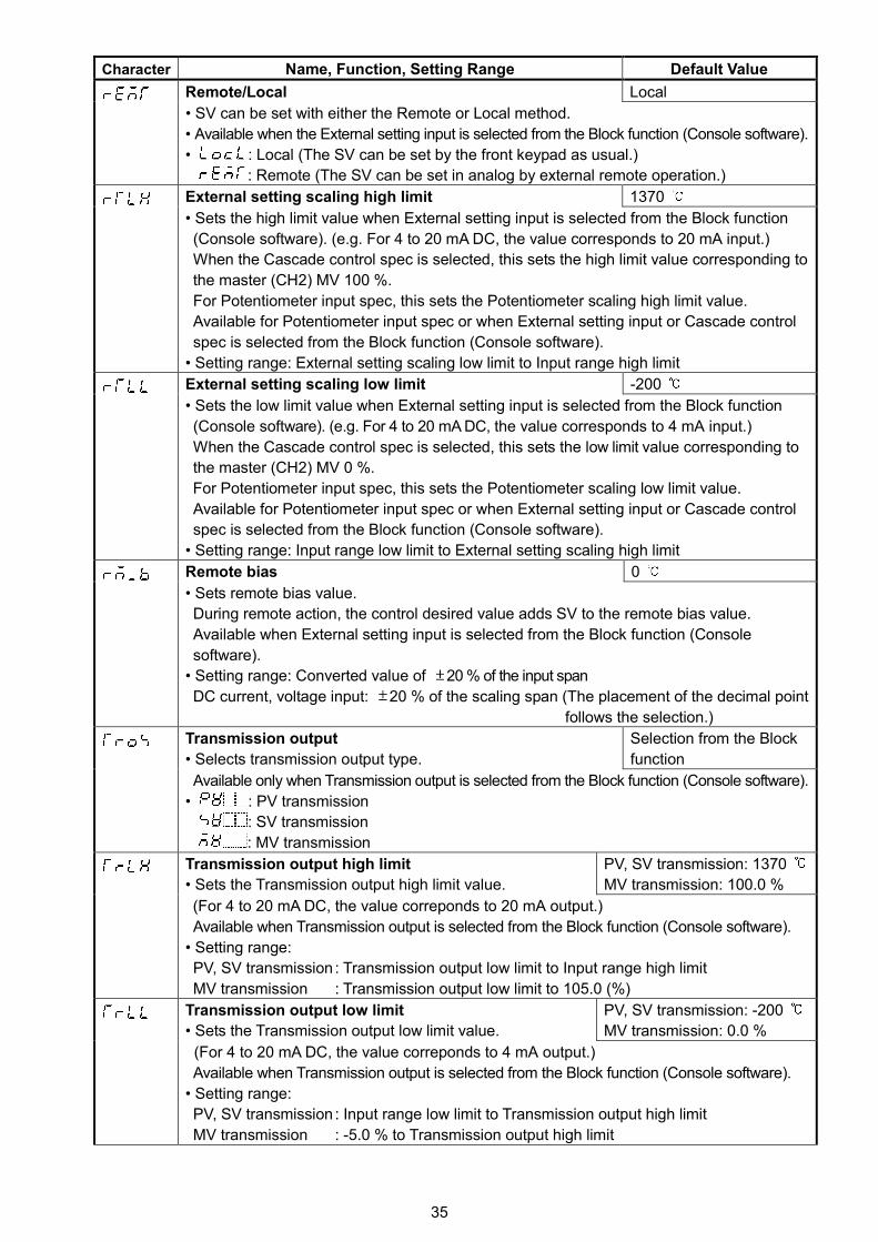
Remote/Local Local
• SV can be set with either the Remote or Local method.
• Available when the External setting input is selected from the Block function (Console software).
• : Local (The SV can be set by the front keypad as usual.)
: Remote (The SV can be set in analog by external remote operation.)
External setting scaling high limit 1370
• Sets the high limit value when External setting input is selected from the Block function
(Console software). (e.g. For 4 to 20 mA DC, the value corresponds to 20 mA input.)
When the Cascade control spec is selected, this sets the high limit value corresponding to
the master (CH2) MV 100 %.
For Potentiometer input spec, this sets the Potentiometer scaling high limit value.
Available for Potentiometer input spec or when External setting input or Cascade control
spec is selected from the Block function (Console software).
• Setting range: External setting scaling low limit to Input range high limit
External setting scaling low limit -200
• Sets the low limit value when External setting input is selected from the Block function
(Console software). (e.g. For 4 to 20 mA DC, the value corresponds to 4 mA input.)
When the Cascade control spec is selected, this sets the low limit value corresponding to
the master (CH2) MV 0 %.
For Potentiometer input spec, this sets the Potentiometer scaling low limit value.
Available for Potentiometer input spec or when External setting input or Cascade control
spec is selected from the Block function (Console software).
• Setting range: Input range low limit to External setting scaling high limit
Remote bias 0
• Sets remote bias value.
During remote action, the control desired value adds SV to the remote bias value.
Available when External setting input is selected from the Block function (Console
software).
• Setting range: Converted value of 20 % of the input span
DC current, voltage input: 20 % of the scaling span (The placement of the decimal point
follows the selection.)
Transmission output
• Selects transmission output type.
Selection from the Block
function
Available only when Transmission output is selected from the Block function (Console software).
• : PV transmission
: SV transmission
: MV transmission
Transmission output high limit
• Sets the Transmission output high limit value.
PV, SV transmission: 1370
MV transmission: 100.0 %
(For 4 to 20 mA DC, the value correponds to 20 mA output.)
Available when Transmission output is selected from the Block function (Console software).
• Setting range:
PV, SV transmission : Transmission output low limit to Input range high limit
MV transmission : Transmission output low limit to 105.0 (%)
Transmission output low limit
• Sets the Transmission output low limit value.
PV, SV transmission: -200
MV transmission: 0.0 %
(For 4 to 20 mA DC, the value correponds to 4 mA output.)
Available when Transmission output is selected from the Block function (Console software).
• Setting range:
PV, SV transmission : Input range low limit to Transmission output high limit
MV transmission : -5.0 % to Transmission output high limit
36
Character Name, Function, Setting Range Default Value
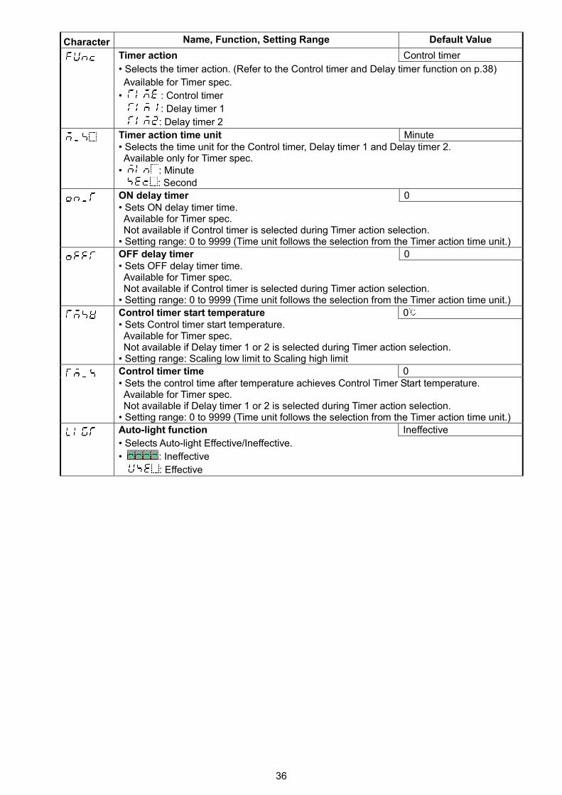
Timer action Control timer
• Selects the timer action. (Refer to the Control timer and Delay timer function on p.38)
Available for Timer spec.
• : Control timer
: Delay timer 1
: Delay timer 2
Timer action time unit Minute• Selects the time unit for the Control timer, Delay timer 1 and Delay timer 2.Available only for Timer spec.
• : Minute: Second
ON delay timer 0• Sets ON delay timer time.Available for Timer spec.Not available if Control timer is selected during Timer action selection.
• Setting range: 0 to 9999 (Time unit follows the selection from the Timer action time unit.)
OFF delay timer 0• Sets OFF delay timer time.Available for Timer spec.Not available if Control timer is selected during Timer action selection.
• Setting range: 0 to 9999 (Time unit follows the selection from the Timer action time unit.)
Control timer start temperature 0• Sets Control timer start temperature.Available for Timer spec.Not available if Delay timer 1 or 2 is selected during Timer action selection.
• Setting range: Scaling low limit to Scaling high limit
Control timer time 0• Sets the control time after temperature achieves Control Timer Start temperature.Available for Timer spec.Not available if Delay timer 1 or 2 is selected during Timer action selection.
• Setting range: 0 to 9999 (Time unit follows the selection from the Timer action time unit.)
Auto-light function Ineffective
• Selects Auto-light Effective/Ineffective.
• : Ineffective
: Effective
37
Character Name, Function, Setting Range Default Value
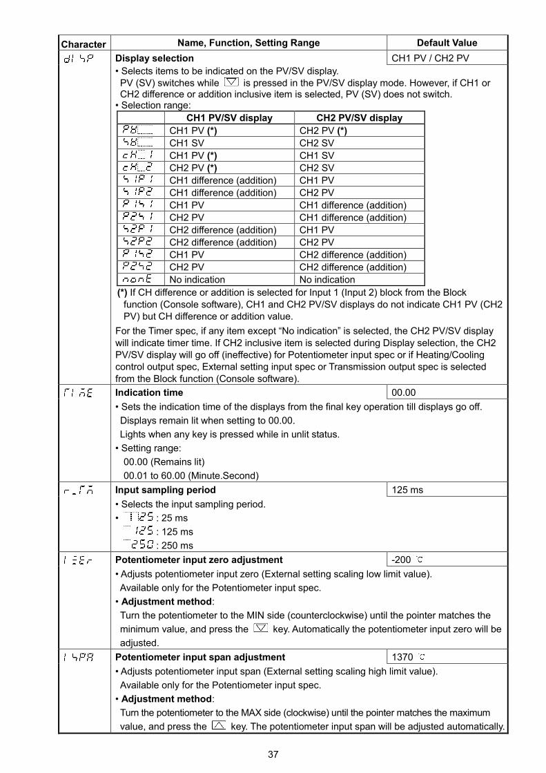
Display selection CH1 PV / CH2 PV
• Selects items to be indicated on the PV/SV display.PV (SV) switches while is pressed in the PV/SV display mode. However, if CH1 orCH2 difference or addition inclusive item is selected, PV (SV) does not switch.
• Selection range:
CH1 PV/SV display CH2 PV/SV display
CH1 PV (*) CH2 PV (*)
CH1 SV CH2 SV
CH1 PV (*) CH1 SV
CH2 PV (*) CH2 SV
CH1 difference (addition) CH1 PV
CH1 difference (addition) CH2 PV
CH1 PV CH1 difference (addition)
CH2 PV CH1 difference (addition)
CH2 difference (addition) CH1 PV
CH2 difference (addition) CH2 PV
CH1 PV CH2 difference (addition)
CH2 PV CH2 difference (addition)
No indication No indication
(*) If CH difference or addition is selected for Input 1 (Input 2) block from the Blockfunction (Console software), CH1 and CH2 PV/SV displays do not indicate CH1 PV (CH2PV) but CH difference or addition value.
For the Timer spec, if any item except “No indication” is selected, the CH2 PV/SV displaywill indicate timer time. If CH2 inclusive item is selected during Display selection, the CH2PV/SV display will go off (ineffective) for Potentiometer input spec or if Heating/Coolingcontrol output spec, External setting input spec or Transmission output spec is selectedfrom the Block function (Console software).
Indication time 00.00
• Sets the indication time of the displays from the final key operation till displays go off.
Displays remain lit when setting to 00.00.
Lights when any key is pressed while in unlit status.
• Setting range:
00.00 (Remains lit)
00.01 to 60.00 (Minute.Second)
Input sampling period 125 ms
• Selects the input sampling period.
• : 25 ms
: 125 ms
: 250 ms
Potentiometer input zero adjustment -200
• Adjusts potentiometer input zero (External setting scaling low limit value).
Available only for the Potentiometer input spec.
• Adjustment method:
Turn the potentiometer to the MIN side (counterclockwise) until the pointer matches the
minimum value, and press the key. Automatically the potentiometer input zero will be
adjusted.
Potentiometer input span adjustment 1370
• Adjusts potentiometer input span (External setting scaling high limit value).
Available only for the Potentiometer input spec.
• Adjustment method:
Turn the potentiometer to the MAX side (clockwise) until the pointer matches the maximum
value, and press the key. The potentiometer input span will be adjusted automatically.
38
Control Timer FunctionControl timer starts if CH1 input exceeds Control timer start temperature, and after Control timer settime has passed, the control (Output low limit value for DC current output) and Alarm action stop.However, for the Direct control action, Control timer starts when CH1 input drops below the CH1 timerstart temperature.CH1 PV/SV display indicates CH1 PV, and CH2 PV/SV display flashes timer remaining time.To start control again after timer time is up, turn the power ON again or press the Key for 1 sec.If the Control timer time is set to 0 (zero), the timer will not work.Even though CH1 input does not reach Control timer start temperature, the Control timer can start bythe DI input ON (Closed) or by pressing the Key for 1 sec.If the Control timer set value has been changed while the Control timer is working, the setting willcome into effect next time.If the Control timer time has passed during AT, the AT will be forcibly stopped, and each parameterreturns to the previous value at which AT was performed.
Delay Timer FunctionWhen Delay timer function 1 is selected:
ON delay timer starts when DI input is ON (Closed), and timer remaining time will be indicated onthe CH2 PV/SV display.Timer output turns on after ON delay timer time has passed.After that, if DI input is turned OFF (Open), OFF delay timer starts, and timer remaining time will beindicated on the CH2 PV/SV display.Timer output turns off after OFF delay timer time has passed.
When Delay timer function 2 is selected:Control and Alarm action start/stop are interlocked with the timer output.If Delay timer is restarted, Alarm action will return to its initial status (for the Alarm with standby, itreturns to standby status again).
Between DI terminals Open : OFFBetween DI terminals Closed: ONCircuit current when closed : 12 mA
Delay timer function 1
ON DLY : ON delay timer setting
OFF DLY: OFF delay timer setting
Delay timer function 2
ON DLY : ON delay timer settingOFF DLY: OFF delay timer setting
DI (digital input)ON
OFF
ON DLY OFF DLY
T.OUT (timer output)ON
OFF
DI (digital input)ON
OFF
ON DLY OFF DLY
T.OUT (timer output)ON
OFF
CH1 control outputSTART
STOP
CH1 Alarm actionSTART
STOP
(Fig. 8.4-3)
(Fig. 8.4-2)
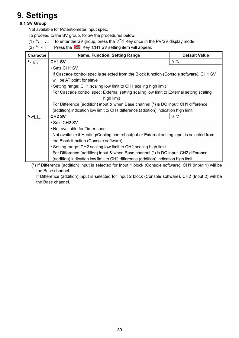
39
9. Settings9.1 SV Group
Not available for Potentiometer input spec.
To proceed to the SV group, follow the procedures below.
(1) To enter the SV group, press the Key once in the PV/SV display mode.
(2) Press the Key. CH1 SV setting item will appear.
Character Name, Function, Setting Range Default Value
CH1 SV 0
• Sets CH1 SV.
If Cascade control spec is selected from the Block function (Console software), CH1 SV
will be AT point for slave
• Setting range: CH1 scaling low limit to CH1 scaling high limit
For Cascade control spec: External setting scaling low limit to External setting scaling
high limit
For Difference (addition) input & when Base channel (*) is DC input: CH1 difference
(addition) indication low limit to CH1 difference (addition) indication high limit
CH2 SV 0
• Sets CH2 SV.
• Not available for Timer spec.
Not available if Heating/Cooling control output or External setting input is selected from
the Block function (Console software).
• Setting range: CH2 scaling low limit to CH2 scaling high limit
For Difference (addition) input & when Base channel (*) is DC input: CH2 difference
(addition) indication low limit to CH2 difference (addition) indication high limit
(*) If Difference (addition) input is selected for Input 1 block (Console software), CH1 (Input 1) will be
the Base channel.
If Difference (addition) input is selected for Input 2 block (Console software), CH2 (Input 2) will be
the Base channel.
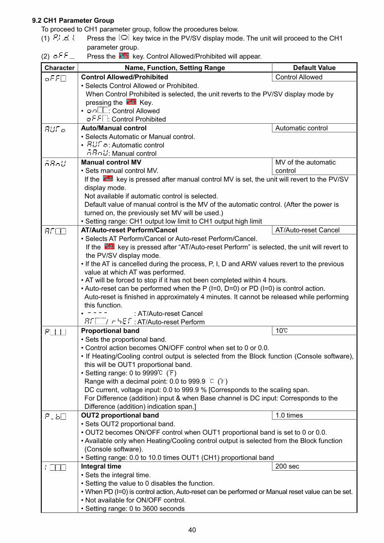
40
9.2 CH1 Parameter Group
To proceed to CH1 parameter group, follow the procedures below.
(1) Press the key twice in the PV/SV display mode. The unit will proceed to the CH1
parameter group.
(2) Press the key. Control Allowed/Prohibited will appear.
Character Name, Function, Setting Range Default Value
Control Allowed/Prohibited Control Allowed
• Selects Control Allowed or Prohibited.When Control Prohibited is selected, the unit reverts to the PV/SV display mode bypressing the Key.
• : Control Allowed: Control Prohibited
Auto/Manual control Automatic control
• Selects Automatic or Manual control.• : Automatic control
: Manual control
Manual control MV• Sets manual control MV.
MV of the automaticcontrol
If the key is pressed after manual control MV is set, the unit will revert to the PV/SVdisplay mode.Not available if automatic control is selected.Default value of manual control is the MV of the automatic control. (After the power isturned on, the previously set MV will be used.)
• Setting range: CH1 output low limit to CH1 output high limit
AT/Auto-reset Perform/Cancel AT/Auto-reset Cancel
• Selects AT Perform/Cancel or Auto-reset Perform/Cancel.If the key is pressed after “AT/Auto-reset Perform” is selected, the unit will revert tothe PV/SV display mode.
• If the AT is cancelled during the process, P, I, D and ARW values revert to the previousvalue at which AT was performed.
• AT will be forced to stop if it has not been completed within 4 hours.• Auto-reset can be performed when the P (I=0, D=0) or PD (I=0) is control action.Auto-reset is finished in approximately 4 minutes. It cannot be released while performingthis function.
• : AT/Auto-reset Cancel/ : AT/Auto-reset Perform
Proportional band 10
• Sets the proportional band.• Control action becomes ON/OFF control when set to 0 or 0.0.• If Heating/Cooling control output is selected from the Block function (Console software),this will be OUT1 proportional band.
• Setting range: 0 to 9999 ( )Range with a decimal point: 0.0 to 999.9 ( )DC current, voltage input: 0.0 to 999.9 % [Corresponds to the scaling span.For Difference (addition) input & when Base channel is DC input: Corresponds to theDifference (addition) indication span.]
OUT2 proportional band 1.0 times
• Sets OUT2 proportional band.• OUT2 becomes ON/OFF control when OUT1 proportional band is set to 0 or 0.0.• Available only when Heating/Cooling control output is selected from the Block function(Console software).
• Setting range: 0.0 to 10.0 times OUT1 (CH1) proportional band
Integral time 200 sec
• Sets the integral time.• Setting the value to 0 disables the function.• When PD (I=0) is control action, Auto-reset can be performed or Manual reset value can be set.• Not available for ON/OFF control.• Setting range: 0 to 3600 seconds
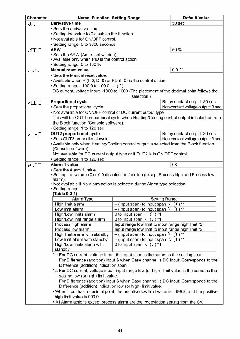
41
Character Name, Function, Setting Range Default Value
Derivative time 50 sec
• Sets the derivative time.• Setting the value to 0 disables the function.• Not available for ON/OFF control.• Setting range: 0 to 3600 seconds
ARW 50 %• Sets the ARW (Anti-reset windup).• Available only when PID is the control action.• Setting range: 0 to 100 %
Manual reset value 0.0
• Sets the Manual reset value.• Available when P (I=0, D=0) or PD (I=0) is the control action.• Setting range: -100.0 to 100.0 ( )DC current, voltage input: -1000 to 1000 (The placement of the decimal point follows the
selection.)
Proportional cycle• Sets the proportional cycle.
Relay contact output: 30 secNon-contact voltage output: 3 sec
• Not available for ON/OFF control or DC current output type.This will be OUT1 proportional cycle when Heating/Cooling control output is selected fromthe Block function (Console software).
• Setting range: 1 to 120 sec
OUT2 proportional cycle• Sets OUT2 proportional cycle.
Relay contact output: 30 secNon-contact voltage output: 3 sec
• Available only when Heating/Cooling control output is selected from the Block function(Console software).Not available for DC current output type or if OUT2 is in ON/OFF control.
• Setting range: 1 to 120 sec
Alarm 1 value 0
• Sets the Alarm 1 value.• Setting the value to 0 or 0.0 disables the function (except Process high and Process lowalarm).
• Not available if No Alarm action is selected during Alarm type selection.• Setting range:(Table 9.2-1)
*1: For DC current, voltage input, the input span is the same as the scaling span.For Difference (addition) input & when Base channel is DC input: Corresponds to theDifference (addition) indication span.
*2: For DC current, voltage input, input range low (or high) limit value is the same as thescaling low (or high) limit value.For Difference (addition) input & when Base channel is DC input: Corresponds to theDifference (addition) indication low (or high) limit value.
• When input has a decimal point, the negative low limit value is –199.9, and the positivehigh limit value is 999.9.
• All Alarm actions except process alarm are the deviation setting from the SV.
Alarm Type Setting RangeHigh limit alarm – (Input span) to input span ( ) *1Low limit alarm – (Input span) to input span ( ) *1High/Low limits alarm 0 to input span ( ) *1High/Low limit range alarm 0 to input span ( ) *1Process high alarm Input range low limit to input range high limit *2Process low alarm Input range low limit to input range high limit *2High limit alarm with standby – (Input span) to input span ( ) *1Low limit alarm with standby – (Input span) to input span ( ) *1High/Low limits alarm withstandby
0 to input span ( ) *1
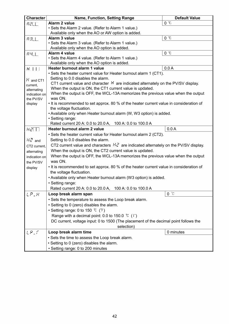
42
Character Name, Function, Setting Range Default Value
Alarm 2 value 0• Sets the Alarm 2 value. (Refer to Alarm 1 value.)Available only when the AO or AW option is added.
Alarm 3 value 0• Sets the Alarm 3 value. (Refer to Alarm 1 value.)Available only when the AO option is added.
Alarm 4 value 0• Sets the Alarm 4 value. (Refer to Alarm 1 value.)Available only when the AO option is added.
Heater burnout alarm 1 value 0.0 A
and CT1
current,
alternating
indication on
the PV/SV
display
• Sets the heater current value for Heater burnout alarm 1 (CT1).Setting to 0.0 disables the alarm.CT1 current value and character are indicated alternately on the PV/SV display.When the output is ON, the CT1 current value is updated.When the output is OFF, the WCL-13A memorizes the previous value when the outputwas ON.
• It is recommended to set approx. 80 % of the heater current value in consideration ofthe voltage fluctuation.
• Available only when Heater burnout alarm (W, W3 option) is added.• Setting range:Rated current 20 A: 0.0 to 20.0 A, 100 A: 0.0 to 100.0 A
Heater burnout alarm 2 value 0.0 A
and
CT2 current,
alternating
indication on
the PV/SV
display
• Sets the heater current value for Heater burnout alarm 2 (CT2).
Setting to 0.0 disables the alarm.
CT2 current value and characters are indicated alternately on the PV/SV display.
When the output is ON, the CT2 current value is updated.
When the output is OFF, the WCL-13A memorizes the previous value when the output
was ON.
• It is recommended to set approx. 80 % of the heater current value in consideration of
the voltage fluctuation.
• Available only when Heater burnout alarm (W3 option) is added.
• Setting range:
Rated current 20 A: 0.0 to 20.0 A, 100 A: 0.0 to 100.0 A
Loop break alarm span 0
• Sets the temperature to assess the Loop break alarm.
• Setting to 0 (zero) disables the alarm.
• Setting range: 0 to 150 ( )
Range with a decimal point: 0.0 to 150.0 ( )
DC current, voltage input: 0 to 1500 (The placement of the decimal point follows the
selection)
Loop break alarm time 0 minutes
• Sets the time to assess the Loop break alarm.
• Setting to 0 (zero) disables the alarm.
• Setting range: 0 to 200 minutes
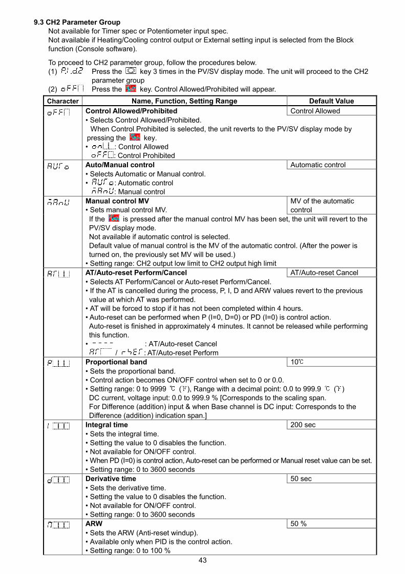
43
9.3 CH2 Parameter GroupNot available for Timer spec or Potentiometer input spec.Not available if Heating/Cooling control output or External setting input is selected from the Blockfunction (Console software).
To proceed to CH2 parameter group, follow the procedures below.(1) Press the key 3 times in the PV/SV display mode. The unit will proceed to the CH2
parameter group(2) Press the key. Control Allowed/Prohibited will appear.
Character Name, Function, Setting Range Default Value
Control Allowed/Prohibited Control Allowed
• Selects Control Allowed/Prohibited.When Control Prohibited is selected, the unit reverts to the PV/SV display mode by
pressing the key.• : Control Allowed
: Control Prohibited
Auto/Manual control Automatic control
• Selects Automatic or Manual control.• : Automatic control
: Manual control
Manual control MV• Sets manual control MV.
MV of the automaticcontrol
If the is pressed after the manual control MV has been set, the unit will revert to thePV/SV display mode.Not available if automatic control is selected.Default value of manual control is the MV of the automatic control. (After the power isturned on, the previously set MV will be used.)
• Setting range: CH2 output low limit to CH2 output high limit
AT/Auto-reset Perform/Cancel AT/Auto-reset Cancel
• Selects AT Perform/Cancel or Auto-reset Perform/Cancel.• If the AT is cancelled during the process, P, I, D and ARW values revert to the previousvalue at which AT was performed.
• AT will be forced to stop if it has not been completed within 4 hours.• Auto-reset can be performed when P (I=0, D=0) or PD (I=0) is control action.Auto-reset is finished in approximately 4 minutes. It cannot be released while performingthis function.
• : AT/Auto-reset Cancel/ : AT/Auto-reset Perform
Proportional band 10
• Sets the proportional band.• Control action becomes ON/OFF control when set to 0 or 0.0.• Setting range: 0 to 9999 ( ), Range with a decimal point: 0.0 to 999.9 ( )DC current, voltage input: 0.0 to 999.9 % [Corresponds to the scaling span.For Difference (addition) input & when Base channel is DC input: Corresponds to theDifference (addition) indication span.]
Integral time 200 sec
• Sets the integral time.• Setting the value to 0 disables the function.• Not available for ON/OFF control.• When PD (I=0) is control action, Auto-reset can be performed or Manual reset value can be set.• Setting range: 0 to 3600 seconds
Derivative time 50 sec
• Sets the derivative time.• Setting the value to 0 disables the function.• Not available for ON/OFF control.• Setting range: 0 to 3600 seconds
ARW 50 %
• Sets the ARW (Anti-reset windup).• Available only when PID is the control action.• Setting range: 0 to 100 %
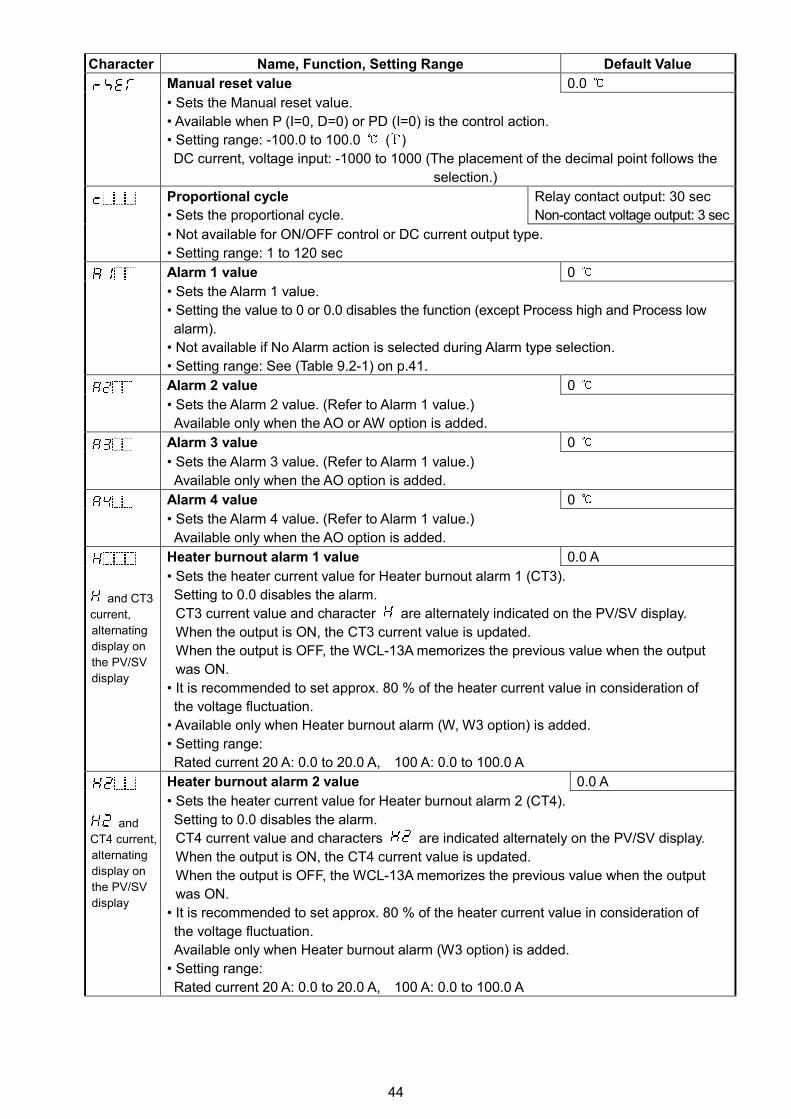
44
Character Name, Function, Setting Range Default Value
Manual reset value 0.0
• Sets the Manual reset value.
• Available when P (I=0, D=0) or PD (I=0) is the control action.
• Setting range: -100.0 to 100.0 ( )
DC current, voltage input: -1000 to 1000 (The placement of the decimal point follows the
selection.)
Proportional cycle
• Sets the proportional cycle.
Relay contact output: 30 sec
Non-contact voltage output: 3 sec
• Not available for ON/OFF control or DC current output type.
• Setting range: 1 to 120 sec
Alarm 1 value 0
• Sets the Alarm 1 value.
• Setting the value to 0 or 0.0 disables the function (except Process high and Process low
alarm).
• Not available if No Alarm action is selected during Alarm type selection.
• Setting range: See (Table 9.2-1) on p.41.
Alarm 2 value 0
• Sets the Alarm 2 value. (Refer to Alarm 1 value.)
Available only when the AO or AW option is added.
Alarm 3 value 0
• Sets the Alarm 3 value. (Refer to Alarm 1 value.)
Available only when the AO option is added.
Alarm 4 value 0
• Sets the Alarm 4 value. (Refer to Alarm 1 value.)
Available only when the AO option is added.
Heater burnout alarm 1 value 0.0 A
and CT3
current,
alternating
display on
the PV/SV
display
• Sets the heater current value for Heater burnout alarm 1 (CT3).
Setting to 0.0 disables the alarm.
CT3 current value and character are alternately indicated on the PV/SV display.
When the output is ON, the CT3 current value is updated.
When the output is OFF, the WCL-13A memorizes the previous value when the output
was ON.
• It is recommended to set approx. 80 % of the heater current value in consideration of
the voltage fluctuation.
• Available only when Heater burnout alarm (W, W3 option) is added.
• Setting range:
Rated current 20 A: 0.0 to 20.0 A, 100 A: 0.0 to 100.0 A
Heater burnout alarm 2 value 0.0 A
and
CT4 current,
alternating
display on
the PV/SV
display
• Sets the heater current value for Heater burnout alarm 2 (CT4).
Setting to 0.0 disables the alarm.
CT4 current value and characters are indicated alternately on the PV/SV display.
When the output is ON, the CT4 current value is updated.
When the output is OFF, the WCL-13A memorizes the previous value when the output
was ON.
• It is recommended to set approx. 80 % of the heater current value in consideration of
the voltage fluctuation.
Available only when Heater burnout alarm (W3 option) is added.
• Setting range:
Rated current 20 A: 0.0 to 20.0 A, 100 A: 0.0 to 100.0 A
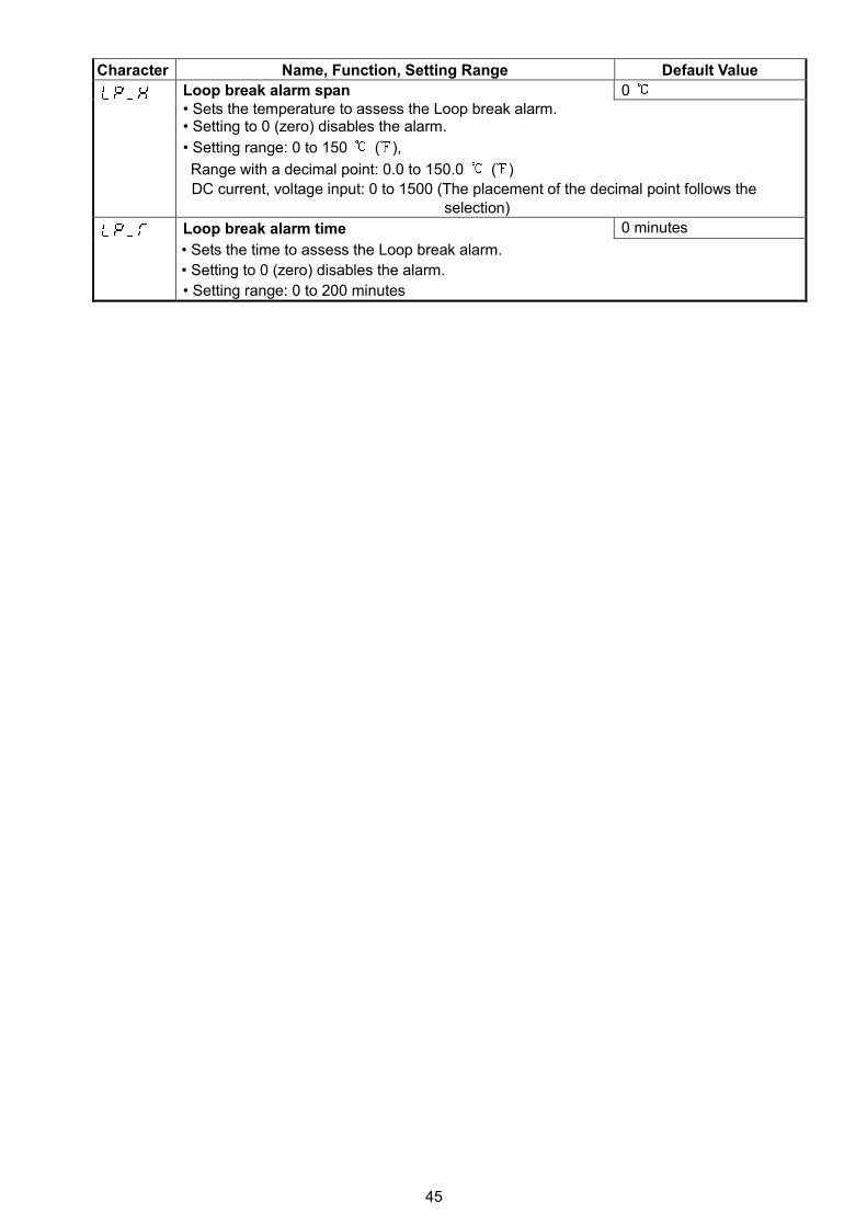
45
Character Name, Function, Setting Range Default Value
Loop break alarm span 0• Sets the temperature to assess the Loop break alarm.• Setting to 0 (zero) disables the alarm.
• Setting range: 0 to 150 ( ),
Range with a decimal point: 0.0 to 150.0 ( )
DC current, voltage input: 0 to 1500 (The placement of the decimal point follows theselection)
Loop break alarm time 0 minutes
• Sets the time to assess the Loop break alarm.
• Setting to 0 (zero) disables the alarm.
• Setting range: 0 to 200 minutes
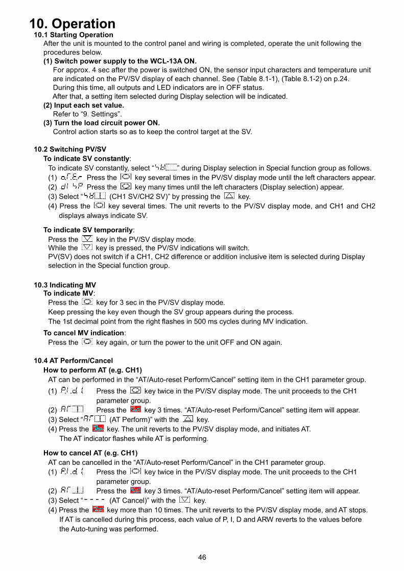
46
10. Operation10.1 Starting Operation
After the unit is mounted to the control panel and wiring is completed, operate the unit following theprocedures below.(1) Switch power supply to the WCL-13A ON.
For approx. 4 sec after the power is switched ON, the sensor input characters and temperature unitare indicated on the PV/SV display of each channel. See (Table 8.1-1), (Table 8.1-2) on p.24.During this time, all outputs and LED indicators are in OFF status.After that, a setting item selected during Display selection will be indicated.
(2) Input each set value.Refer to “9. Settings”.
(3) Turn the load circuit power ON.Control action starts so as to keep the control target at the SV.
10.2 Switching PV/SV
To indicate SV constantly:
To indicate SV constantly, select “ ” during Display selection in Special function group as follows.
(1) Press the key several times in the PV/SV display mode until the left characters appear.
(2) Press the key many times until the left characters (Display selection) appear.
(3) Select “ (CH1 SV/CH2 SV)” by pressing the key.
(4) Press the key several times. The unit reverts to the PV/SV display mode, and CH1 and CH2
displays always indicate SV.
To indicate SV temporarily:
Press the key in the PV/SV display mode.While the key is pressed, the PV/SV indications will switch.PV(SV) does not switch if a CH1, CH2 difference or addition inclusive item is selected during Displayselection in the Special function group.
10.3 Indicating MVTo indicate MV:
Press the key for 3 sec in the PV/SV display mode.
Keep pressing the key even though the SV group appears during the process.
The 1st decimal point from the right flashes in 500 ms cycles during MV indication.
To cancel MV indication:
Press the key again, or turn the power to the unit OFF and ON again.
10.4 AT Perform/Cancel
How to perform AT (e.g. CH1)
AT can be performed in the “AT/Auto-reset Perform/Cancel” setting item in the CH1 parameter group.
(1) Press the key twice in the PV/SV display mode. The unit proceeds to the CH1
parameter group.
(2) Press the key 3 times. “AT/Auto-reset Perform/Cancel” setting item will appear.
(3) Select “ (AT Perform)” with the key.
(4) Press the key. The unit reverts to the PV/SV display mode, and initiates AT.
The AT indicator flashes while AT is performing.
How to cancel AT (e.g. CH1)
AT can be cancelled in the “AT/Auto-reset Perform/Cancel” in the CH1 parameter group.
(1) Press the key twice in the PV/SV display mode. The unit proceeds to the CH1
parameter group.
(2) Press the key 3 times. “AT/Auto-reset Perform/Cancel” setting item will appear.
(3) Select “ (AT Cancel)” with the key.
(4) Press the key more than 10 times. The unit reverts to the PV/SV display mode, and AT stops.
If AT is cancelled during this process, each value of P, I, D and ARW reverts to the values before
the Auto-tuning was performed.
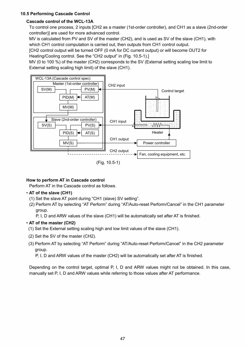
47
10.5 Performing Cascade Control
Cascade control of the WCL-13A
To control one process, 2 inputs [CH2 as a master (1st-order controller), and CH1 as a slave (2nd-order
controller)] are used for more advanced control.
MV is calculated from PV and SV of the master (CH2), and is used as SV of the slave (CH1), with
which CH1 control computation is carried out, then outputs from CH1 control output.
[CH2 control output will be turned OFF (0 mA for DC current output) or will become OUT2 for
Heating/Cooling control. See the “CH2 output” in (Fig. 10.5-1).]
MV (0 to 100 %) of the master (CH2) corresponds to the SV (External setting scaling low limit to
External setting scaling high limit) of the slave (CH1).
(Fig. 10.5-1)
How to perform AT in Cascade control
Perform AT in the Cascade control as follows.
• AT of the slave (CH1)
(1) Set the slave AT point during “CH1 (slave) SV setting”.
(2) Perform AT by selecting “AT Perform” during “AT/Auto-reset Perform/Cancel” in the CH1 parameter
group.
P, I, D and ARW values of the slave (CH1) will be automatically set after AT is finished.
• AT of the master (CH2)
(1) Set the External setting scaling high and low limit values of the slave (CH1).
(2) Set the SV of the master (CH2).
(3) Perform AT by selecting “AT Perform” during “AT/Auto-reset Perform/Cancel” in the CH2 parameter
group.
P, I, D and ARW values of the master (CH2) will be automatically set after AT is finished.
Depending on the control target, optimal P, I, D and ARW values might not be obtained. In this case,
manually set P, I, D and ARW values while referring to those values after AT performance.
Power controller
Control target
Heater
CH2 input
CH1 input
CH1 output
PV(M)SV(M)
PID(M)
MV(M)
AT(M)
PV(S)SV(S)
PID(S)
MV(S)
AT(S)
Master (1st-order controller)
Slave (2nd-order controller)
WCL-13A (Cascade control spec)
Fan, cooling equipment, etc.CH2 output
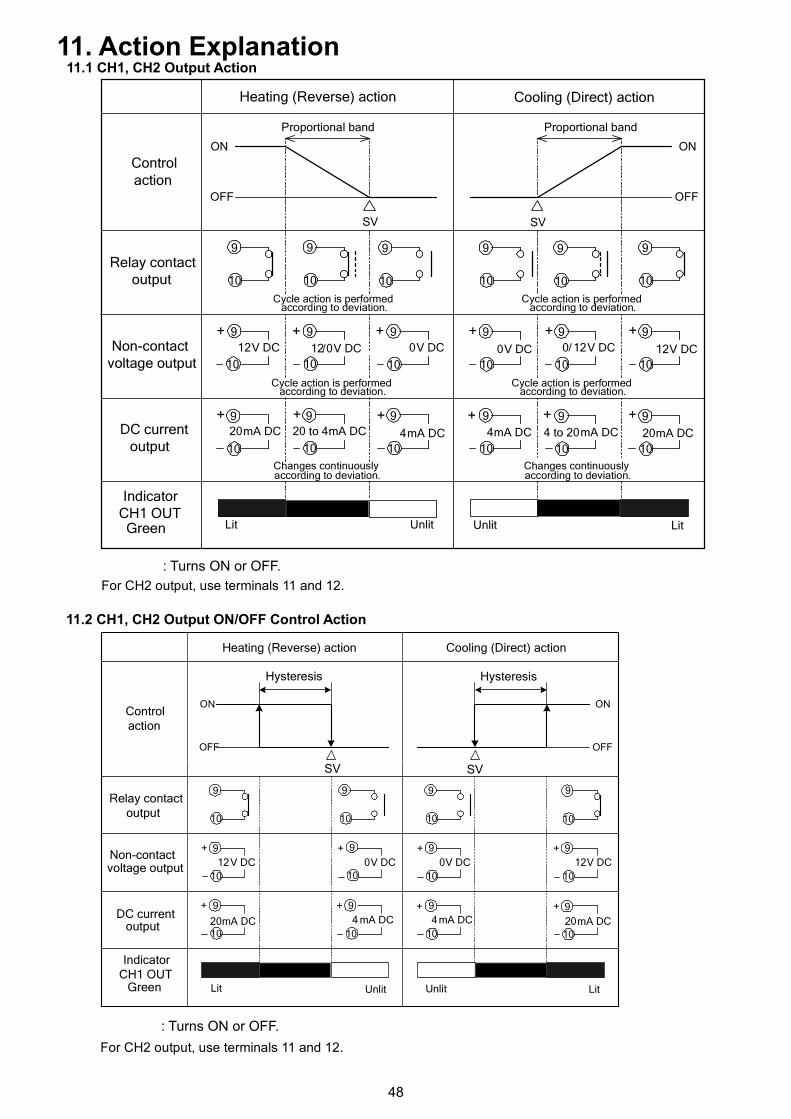
48
Controlaction
Cycle action is performedaccording to deviation.
Changes continuouslyaccording to deviation.
Lit Unlit
ON
OFF
SV
Proportional band
ON
OFF
0V DC 0/12V DC12V DC
+
20mA DC 20 to 4mA DC 4 to 20mA DC
Proportional band
Lit
0V DC 12V DC12/0V DC
20mA DC4mA DC
+ + + + +
++++++
Unlit
4mA DC
10
9
SV
Heating (Reverse) action Cooling (Direct) action
Relay contactoutput
Non-contactvoltage output
DC currentoutput
IndicatorCH1 OUTGreen
10
9
10
9
10
9
10
9
10
9
10
9
10
9
10
9
10
9
10
9
10
9
10
9
10
9
10
9
10
9
10
9
10
9
Cycle action is performedaccording to deviation.
Cycle action is performedaccording to deviation.
Cycle action is performedaccording to deviation.
Changes continuouslyaccording to deviation.
Controlaction
Relay contactoutput
Non-contactvoltage output
DC currentoutput
0V DC12V DC
+
4 mA DC
LitUnlit
ON
OFF
SV
ON
OFF
Hysteresis Hysteresis
0V DC 12V DC
4mA DC 20mA DC
UnlitLit
20mA DC
+
+ +
+
+
+
+
SV
Heating (Reverse) action
IndicatorCH1 OUT
Green
10
9
10
9
10
9
10
9
10
9
10
9
10
9
10
9
10
9
10
9
10
9
10
9
Cooling (Direct) action
11. Action Explanation11.1 CH1, CH2 Output Action
For CH2 output, use terminals 11 and 12.
11.2 CH1, CH2 Output ON/OFF Control Action
For CH2 output, use terminals 11 and 12.
: Turns ON or OFF.
: Turns ON or OFF.
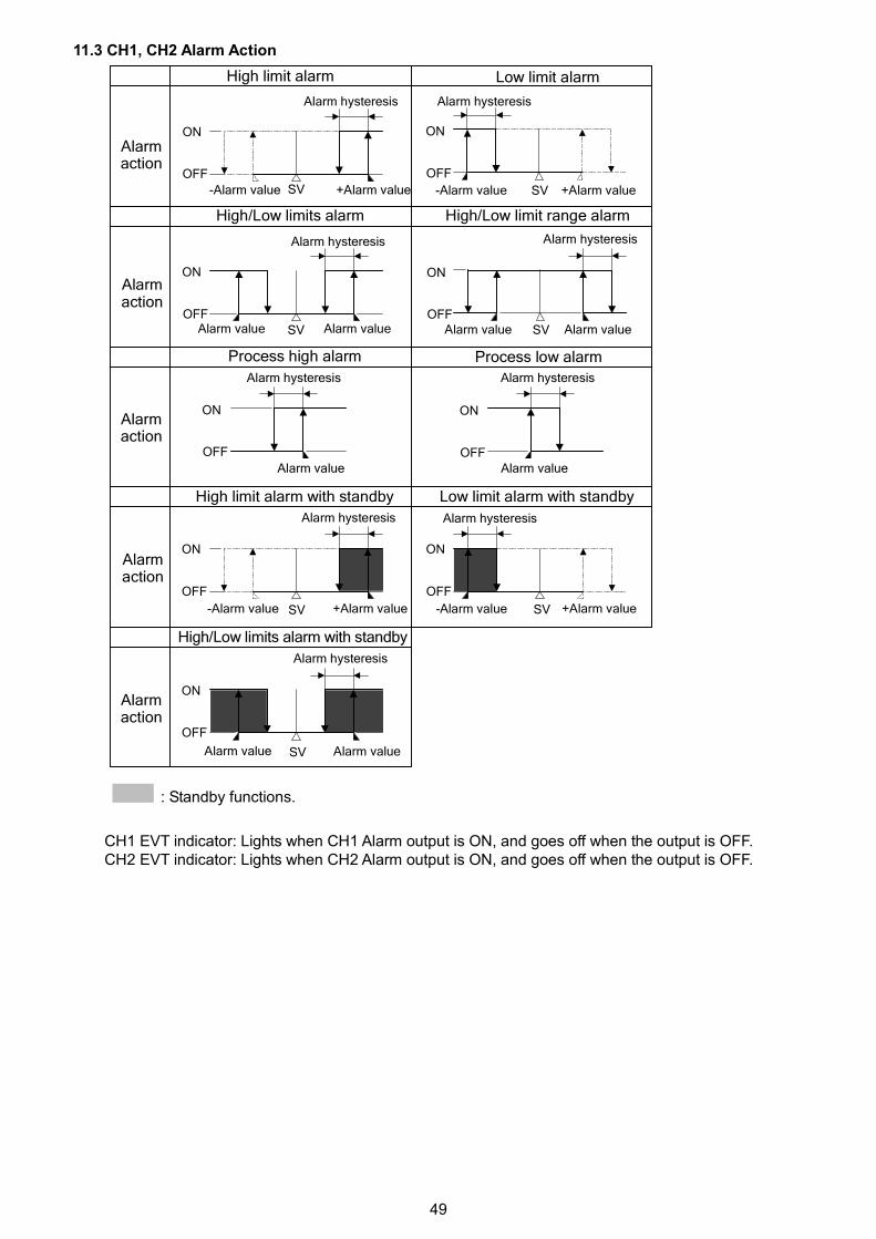
49
OFF
ON
SV SV
SVOFF
ON
SV
OFF
ON
OFF
ON
SV
OFF
ON
SV
OFF
ON
OFF
ON
OFF
ON
SV
OFF
ON
High limit alarm Low limit alarm
High/Low limit range alarm
Process high alarm Process low alarm
High limit alarm with standby
High/Low limits alarm with standby
Low limit alarm with standby
Alarm value
Alarm hysteresis
High/Low limits alarm
Alarm value Alarm value Alarm value
Alarm valueAlarm value
-Alarm value +Alarm value -Alarm value +Alarm value
Alarm valueAlarm value
Alarm hysteresis
Alarm hysteresisAlarm hysteresis
Alarm hysteresis Alarm hysteresis
Alarm hysteresisAlarm hysteresis
Alarm hysteresis
Alarmaction
Alarmaction
Alarmaction
Alarmaction
Alarmaction
-Alarm value +Alarm value -Alarm value +Alarm value
11.3 CH1, CH2 Alarm Action
: Standby functions.
CH1 EVT indicator: Lights when CH1 Alarm output is ON, and goes off when the output is OFF.CH2 EVT indicator: Lights when CH2 Alarm output is ON, and goes off when the output is OFF.
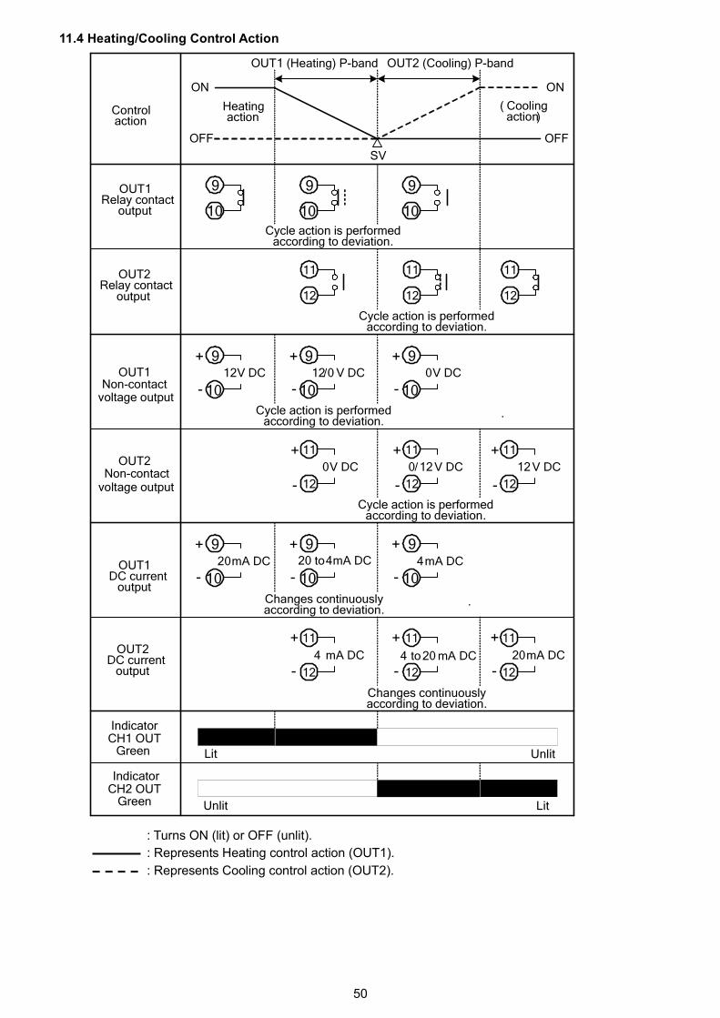
50
OFF
ON
SV
+
-12V DC
+
-12/0 V DC
+
-0V DC
+
-20mA DC
+
-
+
-4mA DC
11
12
11
12
11
12
11+
12-
0V DC
11+
12-
12V DC
11+
12-
0/12V DC
11+
12-4 to20 mA DC
11+
12-4 mA DC
11+
12-20mA DC
OFF
ON
.
Changes continuouslyaccording to deviation.
.
Lit
Lit
Unlit
Unlit
CH2 OUT
Green
Indicator
Indicator
OUT1 (Heating) P-band
Heatingaction
Controlaction
Cycle action is performedaccording to deviation.
OUT1Relay contact
output
OUT2Relay contact
output
OUT1Non-contact
voltage output
OUT1DC current
output
OUT2DC current
output
20 to4mA DC
Green
OUT2
voltage output
( Coolingaction)
9
10
9
10
9
10
9
10
OUT2 (Cooling) P-band
9
10
9
10
9
10
9
10
9
10
CH1 OUT
Non-contact
Cycle action is performedaccording to deviation.
Cycle action is performedaccording to deviation.
Cycle action is performedaccording to deviation.
Changes continuouslyaccording to deviation.
11.4 Heating/Cooling Control Action
: Turns ON (lit) or OFF (unlit).
: Represents Heating control action (OUT1).
: Represents Cooling control action (OUT2).
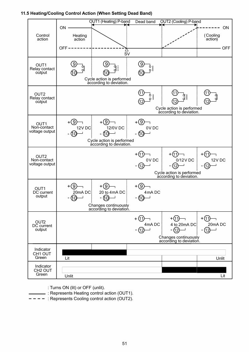
51
( Coolingaction)
OUT2
voltage output
OFF
ON
SV
OFF
ON
9
10
11
12
11
12
11
12
9+
10-12V DC
+
-V DC
+
-0V DC
9+
10-20mA DC
+
-
+
-4mA DC
11+
12-0V DC
11+
12-12V DC
11+
12-V DC
11+
12-
11+
12-4mA DC
11+
12-20mA DC
Controlaction
Heatingaction
Dead band
Cycle action is performedaccording to deviation.
Changes continuouslyaccording to deviation.
mA DC
mA DC
Lit Unlit
Unlit Lit
Indicator
OUT1Relay contact
output
OUT2Relay contact
output
OUT1
voltage output
OUT1DC current
output
OUT2DC current
output
CH1 OUTGreen
Indicator
Green
OUT1 (Heating) P-band OUT2 (Cooling) P-band
Non-contact
Non-contact
9
10
9
10
9
10
9
10
9
10
9
1020 to 4
4 to 20
CH2 OUT
0/12
12/0
Cycle action is performedaccording to deviation.
Cycle action is performedaccording to deviation.
Cycle action is performedaccording to deviation.
Changes continuouslyaccording to deviation.
11.5 Heating/Cooling Control Action (When Setting Dead Band)
: Turns ON (lit) or OFF (unlit).: Represents Heating control action (OUT1).
: Represents Cooling control action (OUT2).
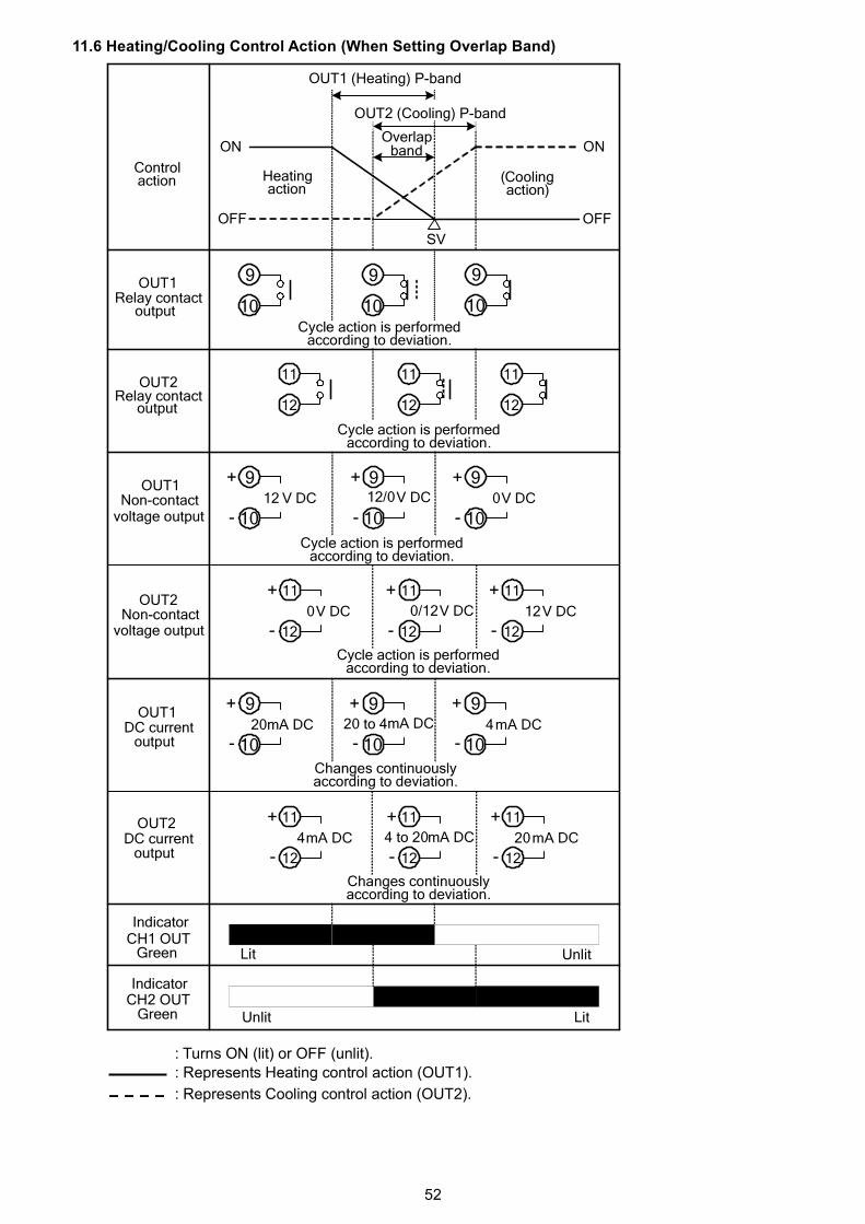
52
OFF
ON
SV
OFF
ON
9
10
11
12
11
12
11
12
9+
10-12 V DC V DC 0V DC
9+
10-20mA DC 4mA DC
11+
12-0V DC 12V DCV DC
11+
12-
11+
12-4mA DC
11+
12-20mA DC
Controlaction Heating
action(Coolingaction)
Cycle action is performedaccording to deviation.
Changes continuouslyaccording to deviation.
Lit
Unlit
IndicatorCH1 OUT
Green
Green
DC currentoutput
DC currentoutput
voltage output
voltage output
Relay contactoutput
Relay contactoutput
mA DC
mA DC
Unlit
Lit
Overlapband
Indicator
OUT1 (Heating) P-band
OUT2 (Cooling) P-band
OUT1
OUT1
OUT2
OUT2
OUT1
OUT2
20 to 4
4 to 20
0/12
12/0
Non-contact
Non-contact
9
10
9
10
9+
10-
9+
10-
11+
12-
11+
12-
9+
10-
9+
10-
CH2 OUT
Cycle action is performedaccording to deviation.
Cycle action is performedaccording to deviation.
Cycle action is performedaccording to deviation.
Changes continuouslyaccording to deviation.
11.6 Heating/Cooling Control Action (When Setting Overlap Band)
: Turns ON (lit) or OFF (unlit).: Represents Heating control action (OUT1).
: Represents Cooling control action (OUT2).
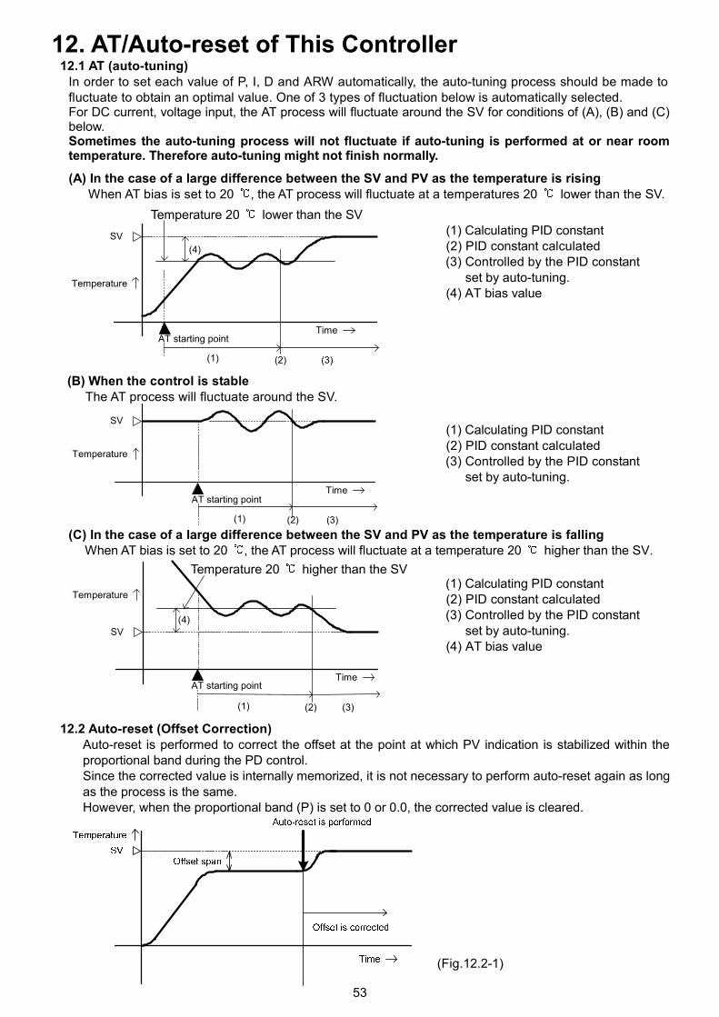
53
12. AT/Auto-reset of This Controller12.1 AT (auto-tuning)
In order to set each value of P, I, D and ARW automatically, the auto-tuning process should be made tofluctuate to obtain an optimal value. One of 3 types of fluctuation below is automatically selected.For DC current, voltage input, the AT process will fluctuate around the SV for conditions of (A), (B) and (C)below.Sometimes the auto-tuning process will not fluctuate if auto-tuning is performed at or near roomtemperature. Therefore auto-tuning might not finish normally.
(A) In the case of a large difference between the SV and PV as the temperature is risingWhen AT bias is set to 20 , the AT process will fluctuate at a temperatures 20 lower than the SV.
(1) Calculating PID constant(2) PID constant calculated(3) Controlled by the PID constant
set by auto-tuning.(4) AT bias value
(B) When the control is stableThe AT process will fluctuate around the SV.
(1) Calculating PID constant(2) PID constant calculated(3) Controlled by the PID constant
set by auto-tuning.
(C) In the case of a large difference between the SV and PV as the temperature is fallingWhen AT bias is set to 20 , the AT process will fluctuate at a temperature 20 higher than the SV.
(1) Calculating PID constant(2) PID constant calculated(3) Controlled by the PID constant
set by auto-tuning.(4) AT bias value
12.2 Auto-reset (Offset Correction)Auto-reset is performed to correct the offset at the point at which PV indication is stabilized within theproportional band during the PD control.Since the corrected value is internally memorized, it is not necessary to perform auto-reset again as longas the process is the same.However, when the proportional band (P) is set to 0 or 0.0, the corrected value is cleared.
(Fig.12.2-1)
(1) (2) (3)
(4)
AT starting point
SV
Temperature
Time
AT starting point
(1) (2) (3)
Temperature
SV
Time
AT starting point
(1) (2) (3)
(4)
Temperature
SV
Time
Temperature 20 higher than the SV
Temperature 20 lower than the SV
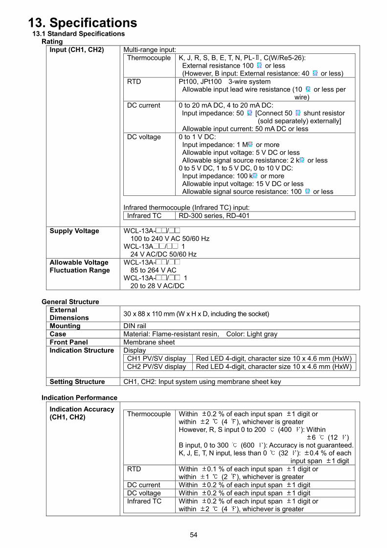
54
13. Specifications13.1 Standard Specifications
RatingInput (CH1, CH2) Multi-range input:
Thermocouple K, J, R, S, B, E, T, N, PL- , C(W/Re5-26):External resistance 100 or less(However, B input: External resistance: 40 or less)
RTD Pt100, JPt100 3-wire systemAllowable input lead wire resistance (10 or less per
wire)DC current 0 to 20 mA DC, 4 to 20 mA DC:
Input impedance: 50 [Connect 50 shunt resistor(sold separately) externally]
Allowable input current: 50 mA DC or lessDC voltage 0 to 1 V DC:
Input impedance: 1 M or moreAllowable input voltage: 5 V DC or lessAllowable signal source resistance: 2 k or less
0 to 5 V DC, 1 to 5 V DC, 0 to 10 V DC:Input impedance: 100 k or moreAllowable input voltage: 15 V DC or lessAllowable signal source resistance: 100 or less
Infrared thermocouple (Infrared TC) input:Infrared TC RD-300 series, RD-401
Supply Voltage WCL-13A- /100 to 240 V AC 50/60 Hz
WCL-13A / 124 V AC/DC 50/60 Hz
Allowable VoltageFluctuation Range
WCL-13A- /85 to 264 V AC
WCL-13A- / 120 to 28 V AC/DC
General StructureExternalDimensions
30 x 88 x 110 mm (W x H x D, including the socket)
Mounting DIN railCase Material: Flame-resistant resin, Color: Light grayFront Panel Membrane sheetIndication Structure Display
CH1 PV/SV display Red LED 4-digit, character size 10 x 4.6 mm (HxW)CH2 PV/SV display Red LED 4-digit, character size 10 x 4.6 mm (HxW)
Setting Structure CH1, CH2: Input system using membrane sheet key
Indication Performance
Indication Accuracy(CH1, CH2) Thermocouple Within 0.2 % of each input span 1 digit or
within 2 (4 ), whichever is greaterHowever, R, S input 0 to 200 (400 ): Within
6 (12 )B input, 0 to 300 (600 ): Accuracy is not guaranteed.K, J, E, T, N input, less than 0 (32 ): 0.4 % of each
input span 1 digitRTD Within 0.1 % of each input span 1 digit or
within 1 (2 ), whichever is greaterDC current Within 0.2 % of each input span 1 digitDC voltage Within 0.2 % of each input span 1 digitInfrared TC Within 0.2 % of each input span 1 digit or
within 2 (4 ), whichever is greater
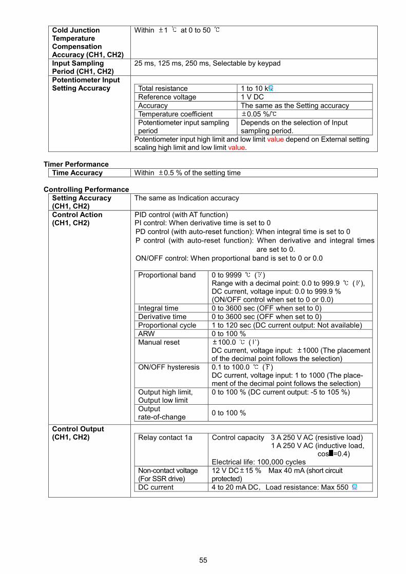
55
Cold JunctionTemperatureCompensationAccuracy (CH1, CH2)
Within 1 at 0 to 50
Input SamplingPeriod (CH1, CH2)
25 ms, 125 ms, 250 ms, Selectable by keypad
Potentiometer InputSetting Accuracy Total resistance 1 to 10 k
Reference voltage 1 V DCAccuracy The same as the Setting accuracyTemperature coefficient 0.05 %/Potentiometer input samplingperiod
Depends on the selection of Inputsampling period.
Potentiometer input high limit and low limit value depend on External settingscaling high limit and low limit value.
Timer PerformanceTime Accuracy Within 0.5 % of the setting time
Controlling PerformanceSetting Accuracy(CH1, CH2)
The same as Indication accuracy
Control Action(CH1, CH2)
PID control (with AT function)PI control: When derivative time is set to 0PD control (with auto-reset function): When integral time is set to 0P control (with auto-reset function): When derivative and integral times
are set to 0.ON/OFF control: When proportional band is set to 0 or 0.0
Proportional band 0 to 9999 ( )Range with a decimal point: 0.0 to 999.9 ( ),DC current, voltage input: 0.0 to 999.9 %(ON/OFF control when set to 0 or 0.0)
Integral time 0 to 3600 sec (OFF when set to 0)Derivative time 0 to 3600 sec (OFF when set to 0)Proportional cycle 1 to 120 sec (DC current output: Not available)ARW 0 to 100 %Manual reset 100.0 ( )
DC current, voltage input: 1000 (The placementof the decimal point follows the selection)
ON/OFF hysteresis 0.1 to 100.0 ( )DC current, voltage input: 1 to 1000 (The place-ment of the decimal point follows the selection)
Output high limit,Output low limit
0 to 100 % (DC current output: -5 to 105 %)
Outputrate-of-change
0 to 100 %
Control Output(CH1, CH2) Relay contact 1a Control capacity 3 A 250 V AC (resistive load)
1 A 250 V AC (inductive load,cos =0.4)
Electrical life: 100,000 cyclesNon-contact voltage(For SSR drive)
12 V DC 15 % Max 40 mA (short circuitprotected)
DC current 4 to 20 mA DC,Load resistance: Max 550
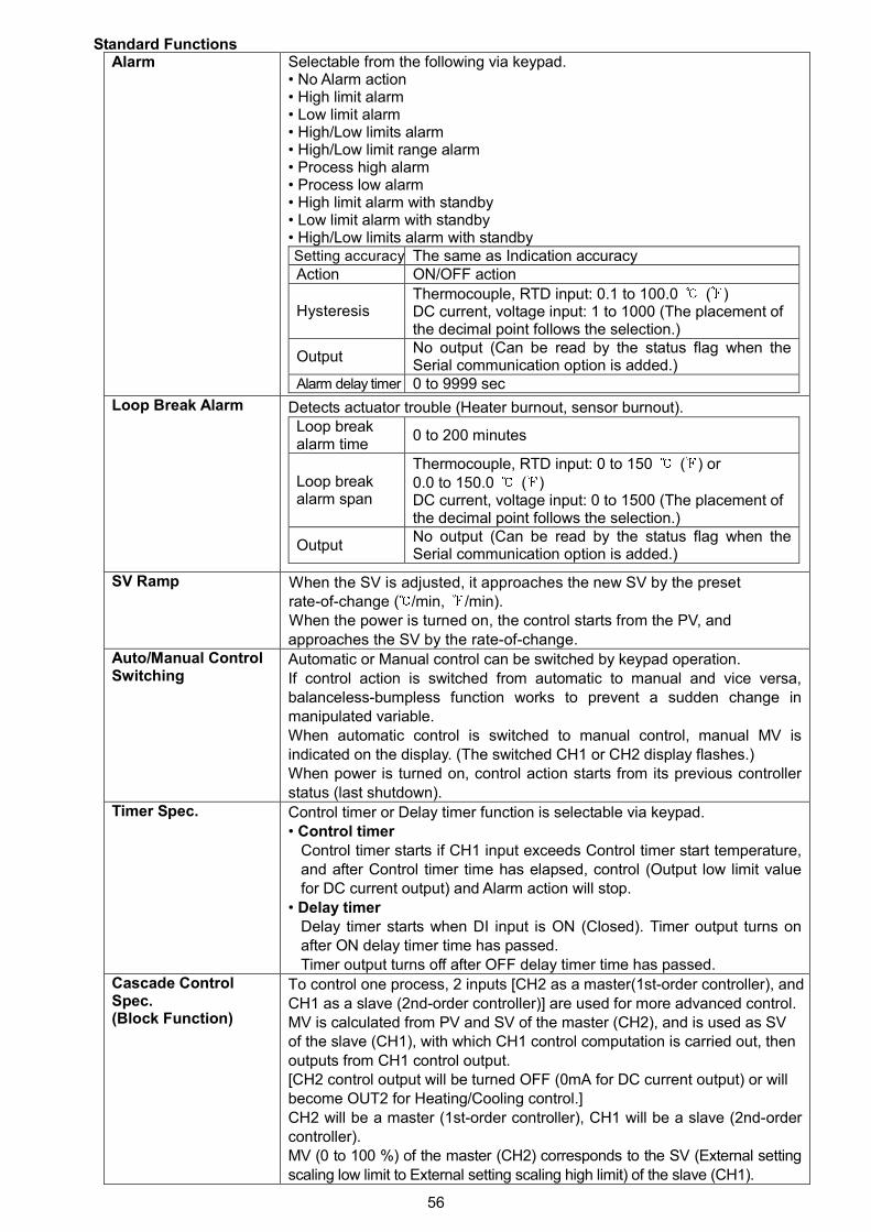
56
Standard FunctionsAlarm Selectable from the following via keypad.
• No Alarm action• High limit alarm• Low limit alarm• High/Low limits alarm• High/Low limit range alarm• Process high alarm• Process low alarm• High limit alarm with standby• Low limit alarm with standby• High/Low limits alarm with standbySetting accuracy The same as Indication accuracyAction ON/OFF action
HysteresisThermocouple, RTD input: 0.1 to 100.0 ( )DC current, voltage input: 1 to 1000 (The placement ofthe decimal point follows the selection.)
OutputNo output (Can be read by the status flag when theSerial communication option is added.)
Alarm delay timer 0 to 9999 sec
Loop Break Alarm Detects actuator trouble (Heater burnout, sensor burnout).Loop breakalarm time
0 to 200 minutes
Loop breakalarm span
Thermocouple, RTD input: 0 to 150 ( ) or0.0 to 150.0 ( )DC current, voltage input: 0 to 1500 (The placement ofthe decimal point follows the selection.)
OutputNo output (Can be read by the status flag when theSerial communication option is added.)
SV Ramp When the SV is adjusted, it approaches the new SV by the presetrate-of-change ( /min, /min).When the power is turned on, the control starts from the PV, andapproaches the SV by the rate-of-change.
Auto/Manual ControlSwitching
Automatic or Manual control can be switched by keypad operation.If control action is switched from automatic to manual and vice versa,balanceless-bumpless function works to prevent a sudden change inmanipulated variable.When automatic control is switched to manual control, manual MV isindicated on the display. (The switched CH1 or CH2 display flashes.)When power is turned on, control action starts from its previous controllerstatus (last shutdown).
Timer Spec. Control timer or Delay timer function is selectable via keypad.• Control timer
Control timer starts if CH1 input exceeds Control timer start temperature,and after Control timer time has elapsed, control (Output low limit valuefor DC current output) and Alarm action will stop.
• Delay timerDelay timer starts when DI input is ON (Closed). Timer output turns onafter ON delay timer time has passed.Timer output turns off after OFF delay timer time has passed.
Cascade ControlSpec.(Block Function)
To control one process, 2 inputs [CH2 as a master(1st-order controller), andCH1 as a slave (2nd-order controller)] are used for more advanced control.MV is calculated from PV and SV of the master (CH2), and is used as SVof the slave (CH1), with which CH1 control computation is carried out, thenoutputs from CH1 control output.[CH2 control output will be turned OFF (0mA for DC current output) or willbecome OUT2 for Heating/Cooling control.]CH2 will be a master (1st-order controller), CH1 will be a slave (2nd-ordercontroller).MV (0 to 100 %) of the master (CH2) corresponds to the SV (External settingscaling low limit to External setting scaling high limit) of the slave (CH1).
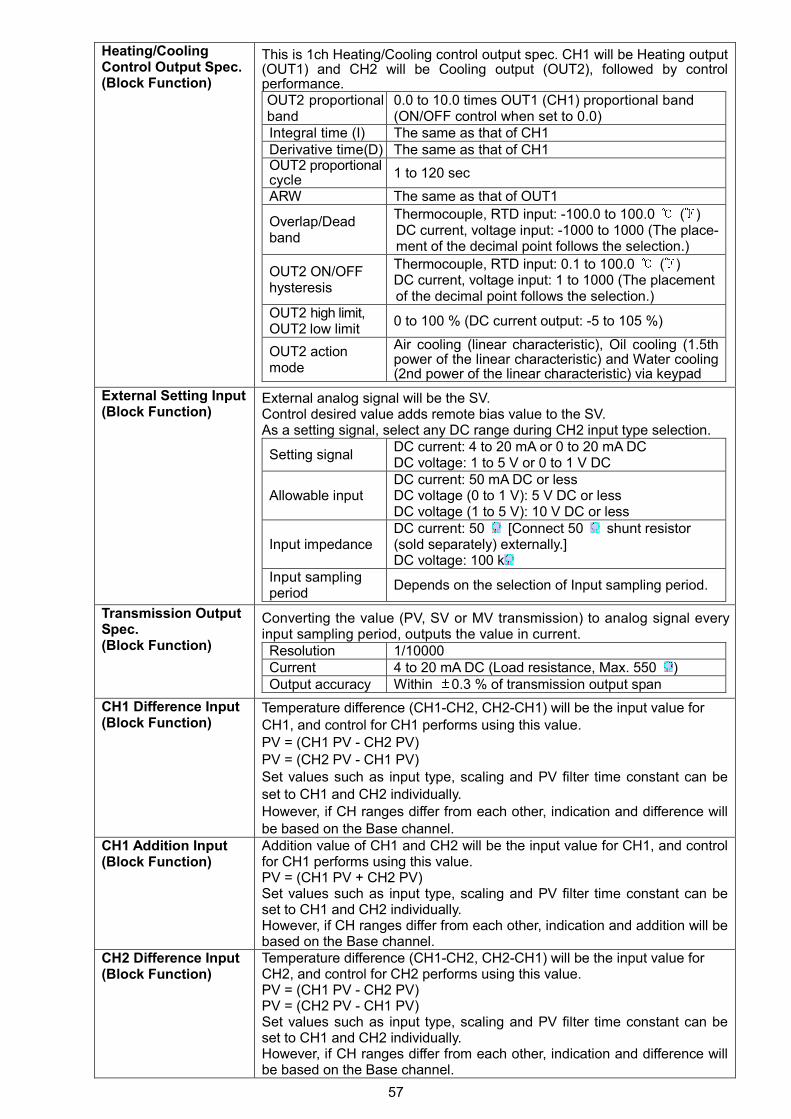
57
Heating/CoolingControl Output Spec.(Block Function)
This is 1ch Heating/Cooling control output spec. CH1 will be Heating output(OUT1) and CH2 will be Cooling output (OUT2), followed by controlperformance.OUT2 proportionalband
0.0 to 10.0 times OUT1 (CH1) proportional band(ON/OFF control when set to 0.0)
Integral time (I) The same as that of CH1Derivative time(D) The same as that of CH1OUT2 proportionalcycle
1 to 120 sec
ARW The same as that of OUT1
Overlap/Deadband
Thermocouple, RTD input: -100.0 to 100.0 ( )DC current, voltage input: -1000 to 1000 (The place-ment of the decimal point follows the selection.)
OUT2 ON/OFFhysteresis
Thermocouple, RTD input: 0.1 to 100.0 ( )DC current, voltage input: 1 to 1000 (The placementof the decimal point follows the selection.)
OUT2 high limit,OUT2 low limit
0 to 100 % (DC current output: -5 to 105 %)
OUT2 actionmode
Air cooling (linear characteristic), Oil cooling (1.5thpower of the linear characteristic) and Water cooling(2nd power of the linear characteristic) via keypad
External Setting Input(Block Function)
External analog signal will be the SV.Control desired value adds remote bias value to the SV.As a setting signal, select any DC range during CH2 input type selection.
Setting signalDC current: 4 to 20 mA or 0 to 20 mA DCDC voltage: 1 to 5 V or 0 to 1 V DC
Allowable inputDC current: 50 mA DC or lessDC voltage (0 to 1 V): 5 V DC or lessDC voltage (1 to 5 V): 10 V DC or less
Input impedanceDC current: 50 [Connect 50 shunt resistor(sold separately) externally.]DC voltage: 100 k
Input samplingperiod
Depends on the selection of Input sampling period.
Transmission OutputSpec.(Block Function)
Converting the value (PV, SV or MV transmission) to analog signal everyinput sampling period, outputs the value in current.Resolution 1/10000Current 4 to 20 mA DC (Load resistance, Max. 550 )Output accuracy Within 0.3 % of transmission output span
CH1 Difference Input(Block Function)
Temperature difference (CH1-CH2, CH2-CH1) will be the input value forCH1, and control for CH1 performs using this value.PV = (CH1 PV - CH2 PV)PV = (CH2 PV - CH1 PV)Set values such as input type, scaling and PV filter time constant can beset to CH1 and CH2 individually.However, if CH ranges differ from each other, indication and difference willbe based on the Base channel.
CH1 Addition Input(Block Function)
Addition value of CH1 and CH2 will be the input value for CH1, and controlfor CH1 performs using this value.PV = (CH1 PV + CH2 PV)Set values such as input type, scaling and PV filter time constant can beset to CH1 and CH2 individually.However, if CH ranges differ from each other, indication and addition will bebased on the Base channel.
CH2 Difference Input(Block Function)
Temperature difference (CH1-CH2, CH2-CH1) will be the input value forCH2, and control for CH2 performs using this value.PV = (CH1 PV - CH2 PV)PV = (CH2 PV - CH1 PV)Set values such as input type, scaling and PV filter time constant can beset to CH1 and CH2 individually.However, if CH ranges differ from each other, indication and difference willbe based on the Base channel.
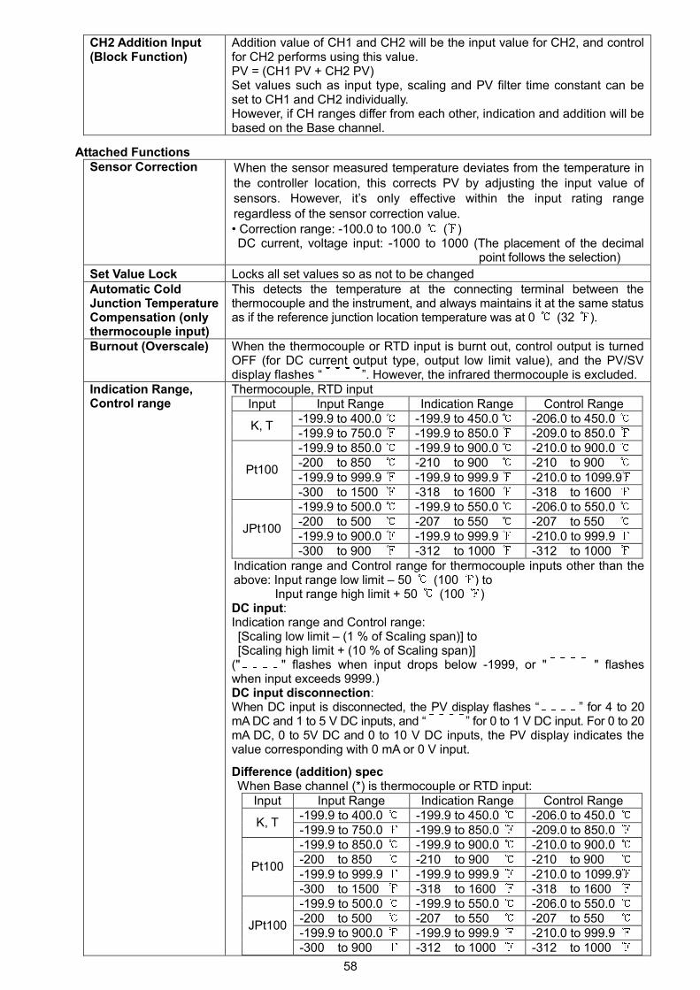
58
CH2 Addition Input(Block Function)
Addition value of CH1 and CH2 will be the input value for CH2, and controlfor CH2 performs using this value.PV = (CH1 PV + CH2 PV)Set values such as input type, scaling and PV filter time constant can beset to CH1 and CH2 individually.However, if CH ranges differ from each other, indication and addition will bebased on the Base channel.
Attached FunctionsSensor Correction When the sensor measured temperature deviates from the temperature in
the controller location, this corrects PV by adjusting the input value ofsensors. However, it’s only effective within the input rating rangeregardless of the sensor correction value.• Correction range: -100.0 to 100.0 ( )DC current, voltage input: -1000 to 1000 (The placement of the decimal
point follows the selection)
Set Value Lock Locks all set values so as not to be changedAutomatic ColdJunction TemperatureCompensation (onlythermocouple input)
This detects the temperature at the connecting terminal between thethermocouple and the instrument, and always maintains it at the same statusas if the reference junction location temperature was at 0 (32 ).
Burnout (Overscale) When the thermocouple or RTD input is burnt out, control output is turnedOFF (for DC current output type, output low limit value), and the PV/SVdisplay flashes “ ”. However, the infrared thermocouple is excluded.
Indication Range,Control range
Thermocouple, RTD inputInput Input Range Indication Range Control Range
-199.9 to 400.0 -199.9 to 450.0 -206.0 to 450.0K, T
-199.9 to 750.0 -199.9 to 850.0 -209.0 to 850.0-199.9 to 850.0 -199.9 to 900.0 -210.0 to 900.0-200 to 850 -210 to 900 -210 to 900-199.9 to 999.9 -199.9 to 999.9 -210.0 to 1099.9
Pt100
-300 to 1500 -318 to 1600 -318 to 1600-199.9 to 500.0 -199.9 to 550.0 -206.0 to 550.0-200 to 500 -207 to 550 -207 to 550-199.9 to 900.0 -199.9 to 999.9 -210.0 to 999.9
JPt100
-300 to 900 -312 to 1000 -312 to 1000Indication range and Control range for thermocouple inputs other than theabove: Input range low limit – 50 (100 ) to
Input range high limit + 50 (100 )DC input:Indication range and Control range:[Scaling low limit – (1 % of Scaling span)] to[Scaling high limit + (10 % of Scaling span)]
(" " flashes when input drops below -1999, or " " flasheswhen input exceeds 9999.)DC input disconnection:When DC input is disconnected, the PV display flashes “ ” for 4 to 20mA DC and 1 to 5 V DC inputs, and “ ” for 0 to 1 V DC input. For 0 to 20mA DC, 0 to 5V DC and 0 to 10 V DC inputs, the PV display indicates thevalue corresponding with 0 mA or 0 V input.
Difference (addition) specWhen Base channel (*) is thermocouple or RTD input:
Input Input Range Indication Range Control Range-199.9 to 400.0 -199.9 to 450.0 -206.0 to 450.0
K, T-199.9 to 750.0 -199.9 to 850.0 -209.0 to 850.0-199.9 to 850.0 -199.9 to 900.0 -210.0 to 900.0-200 to 850 -210 to 900 -210 to 900-199.9 to 999.9 -199.9 to 999.9 -210.0 to 1099.9
Pt100
-300 to 1500 -318 to 1600 -318 to 1600-199.9 to 500.0 -199.9 to 550.0 -206.0 to 550.0-200 to 500 -207 to 550 -207 to 550-199.9 to 900.0 -199.9 to 999.9 -210.0 to 999.9
JPt100
-300 to 900 -312 to 1000 -312 to 1000
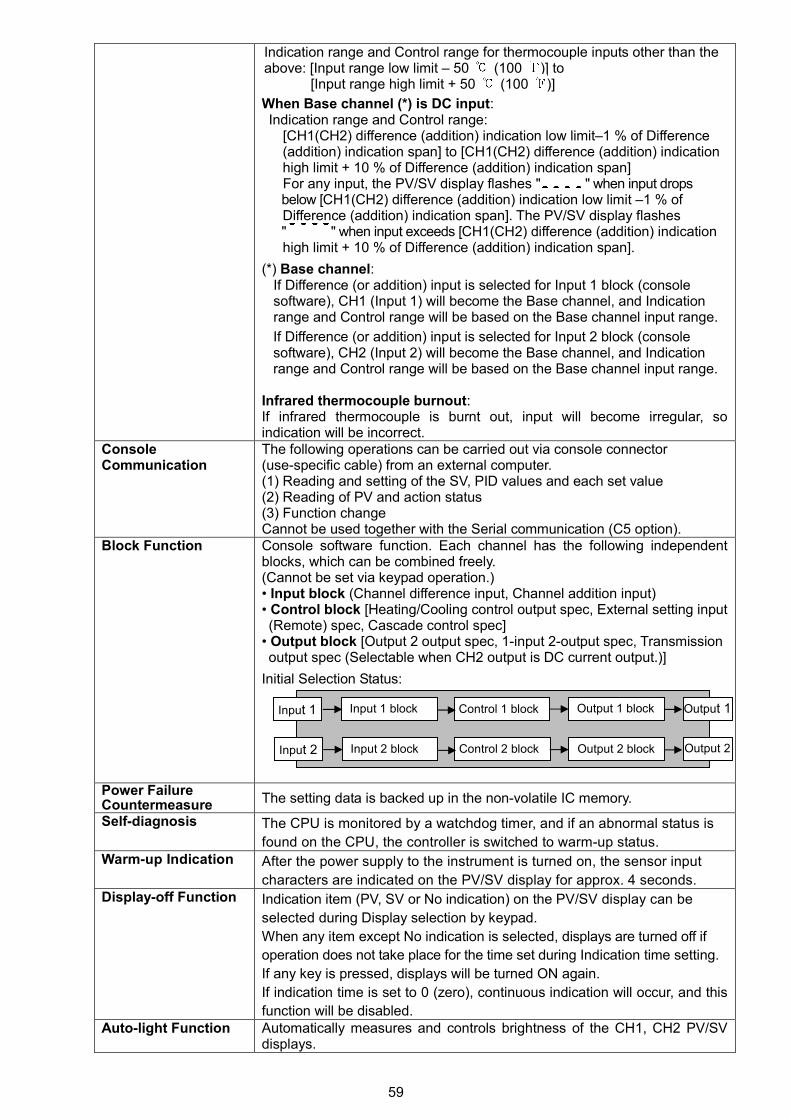
59
Indication range and Control range for thermocouple inputs other than theabove: [Input range low limit – 50 (100 )] to
[Input range high limit + 50 (100 )]
When Base channel (*) is DC input:Indication range and Control range:
[CH1(CH2) difference (addition) indication low limit–1 % of Difference(addition) indication span] to [CH1(CH2) difference (addition) indicationhigh limit + 10 % of Difference (addition) indication span]For any input, the PV/SV display flashes " " when input dropsbelow [CH1(CH2) difference (addition) indication low limit –1 % ofDifference (addition) indication span]. The PV/SV display flashes" " when input exceeds [CH1(CH2) difference (addition) indicationhigh limit + 10 % of Difference (addition) indication span].
(*) Base channel:If Difference (or addition) input is selected for Input 1 block (consolesoftware), CH1 (Input 1) will become the Base channel, and Indicationrange and Control range will be based on the Base channel input range.
If Difference (or addition) input is selected for Input 2 block (consolesoftware), CH2 (Input 2) will become the Base channel, and Indicationrange and Control range will be based on the Base channel input range.
Infrared thermocouple burnout:If infrared thermocouple is burnt out, input will become irregular, soindication will be incorrect.
ConsoleCommunication
The following operations can be carried out via console connector(use-specific cable) from an external computer.(1) Reading and setting of the SV, PID values and each set value(2) Reading of PV and action status(3) Function changeCannot be used together with the Serial communication (C5 option).
Block Function Console software function. Each channel has the following independentblocks, which can be combined freely.(Cannot be set via keypad operation.)• Input block (Channel difference input, Channel addition input)• Control block [Heating/Cooling control output spec, External setting input(Remote) spec, Cascade control spec]
• Output block [Output 2 output spec, 1-input 2-output spec, Transmissionoutput spec (Selectable when CH2 output is DC current output.)]
Initial Selection Status:
Power FailureCountermeasure The setting data is backed up in the non-volatile IC memory.
Self-diagnosis The CPU is monitored by a watchdog timer, and if an abnormal status is
found on the CPU, the controller is switched to warm-up status.Warm-up Indication After the power supply to the instrument is turned on, the sensor input
characters are indicated on the PV/SV display for approx. 4 seconds.Display-off Function Indication item (PV, SV or No indication) on the PV/SV display can be
selected during Display selection by keypad.
When any item except No indication is selected, displays are turned off if
operation does not take place for the time set during Indication time setting.
If any key is pressed, displays will be turned ON again.
If indication time is set to 0 (zero), continuous indication will occur, and this
function will be disabled.Auto-light Function Automatically measures and controls brightness of the CH1, CH2 PV/SV
displays.
Input 1 Input 1 block Control 1 block Output 1 block Output 1
Input 2 Input 2 block Control 2 block Output 2 block Output 2
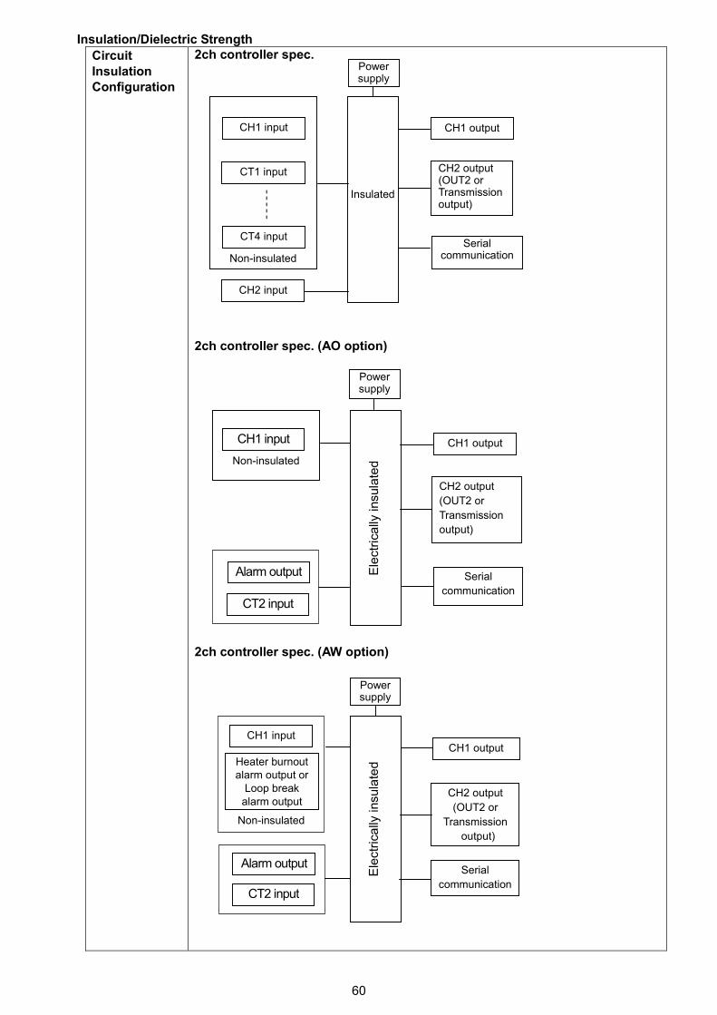
60
Insulation/Dielectric Strength
CircuitInsulationConfiguration
2ch controller spec.
2ch controller spec. (AO option)
2ch controller spec. (AW option)
Non-insulated
Powersupply
CH1 output
CH2 output(OUT2 orTransmissionoutput)
Serialcommunication
CH1 input
CT1 input
CT4 input
CH2 input
Insulated
Non-insulated
Powersupply
CH1 output
CH2 output
(OUT2 or
Transmission
output)
Serial
communication
CH1 input
Ele
ctr
ica
llyin
sula
ted
Powersupply
CH1 output
CH2 output
(OUT2 or
Transmission
output)
Serial
communication
Ele
ctr
ica
llyin
sula
ted
CH1 input
Heater burnoutalarm output or
Loop breakalarm output
Alarm output
CT2 input
Alarm output
CT2 input
Non-insulated
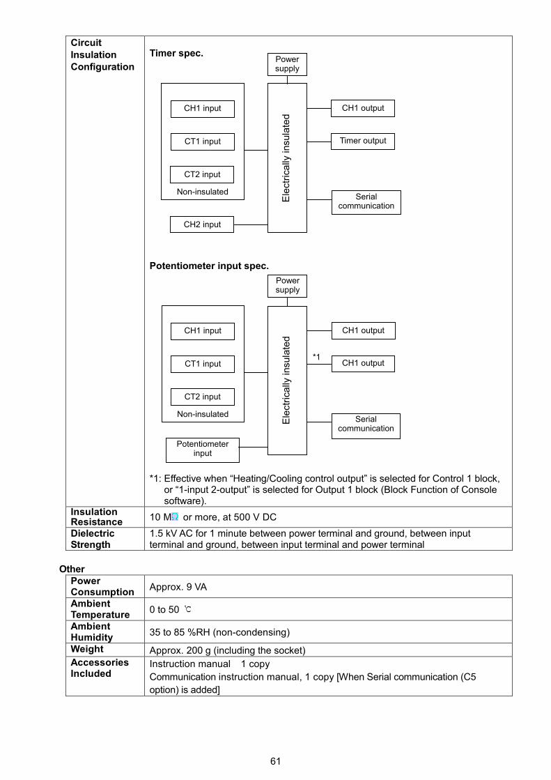
61
CircuitInsulationConfiguration
Timer spec.
Potentiometer input spec.
*1: Effective when “Heating/Cooling control output” is selected for Control 1 block,or “1-input 2-output” is selected for Output 1 block (Block Function of Consolesoftware).
InsulationResistance 10 M or more, at 500 V DC
DielectricStrength
1.5 kV AC for 1 minute between power terminal and ground, between inputterminal and ground, between input terminal and power terminal
OtherPowerConsumption
Approx. 9 VA
AmbientTemperature
0 to 50
AmbientHumidity
35 to 85 %RH (non-condensing)
Weight Approx. 200 g (including the socket)AccessoriesIncluded
Instruction manual 1 copy
Communication instruction manual, 1 copy [When Serial communication (C5
option) is added]
Non-insulated
Powersupply
CH1 output
Timer output
Serialcommunication
CH1 input
CT1 input
CT2 input
CH2 input
Ele
ctr
ica
llyin
sula
ted
Non-insulated
Powersupply
CH1 output
CH1 output
Serialcommunication
CH1 input
CT1 input
CT2 input
Potentiometerinput
Ele
ctr
ica
llyin
sula
ted
*1
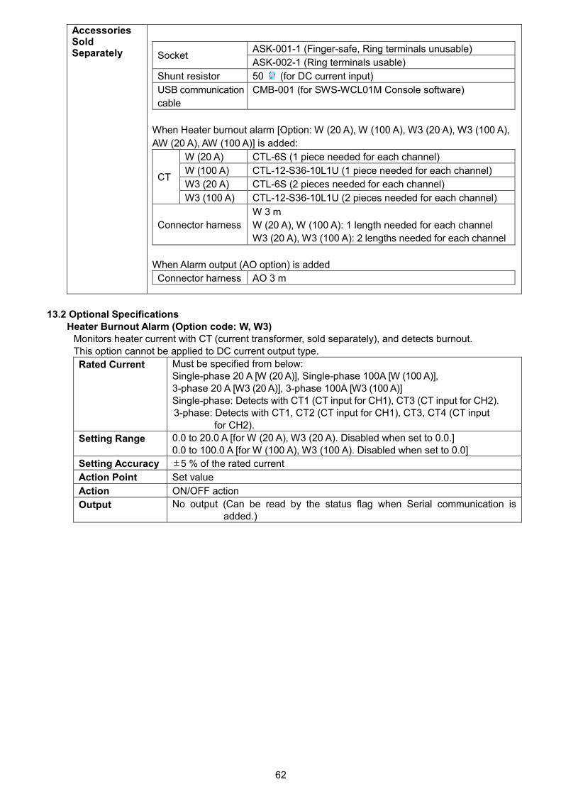
62
AccessoriesSoldSeparately ASK-001-1 (Finger-safe, Ring terminals unusable)
SocketASK-002-1 (Ring terminals usable)
Shunt resistor 50 (for DC current input)
USB communication
cable
CMB-001 (for SWS-WCL01M Console software)
When Heater burnout alarm [Option: W (20 A), W (100 A), W3 (20 A), W3 (100 A),
AW (20 A), AW (100 A)] is added:
W (20 A) CTL-6S (1 piece needed for each channel)
W (100 A) CTL-12-S36-10L1U (1 piece needed for each channel)
W3 (20 A) CTL-6S (2 pieces needed for each channel)CT
W3 (100 A) CTL-12-S36-10L1U (2 pieces needed for each channel)
Connector harness
W 3 m
W (20 A), W (100 A): 1 length needed for each channel
W3 (20 A), W3 (100 A): 2 lengths needed for each channel
When Alarm output (AO option) is added
Connector harness AO 3 m
13.2 Optional SpecificationsHeater Burnout Alarm (Option code: W, W3)
Monitors heater current with CT (current transformer, sold separately), and detects burnout.This option cannot be applied to DC current output type.
Rated Current Must be specified from below:Single-phase 20 A [W (20 A)], Single-phase 100A [W (100 A)],3-phase 20 A [W3 (20 A)], 3-phase 100A [W3 (100 A)]Single-phase: Detects with CT1 (CT input for CH1), CT3 (CT input for CH2).3-phase: Detects with CT1, CT2 (CT input for CH1), CT3, CT4 (CT input
for CH2).
Setting Range 0.0 to 20.0 A [for W (20 A), W3 (20 A). Disabled when set to 0.0.]0.0 to 100.0 A [for W (100 A), W3 (100 A). Disabled when set to 0.0]
Setting Accuracy 5 % of the rated current
Action Point Set value
Action ON/OFF action
Output No output (Can be read by the status flag when Serial communication isadded.)
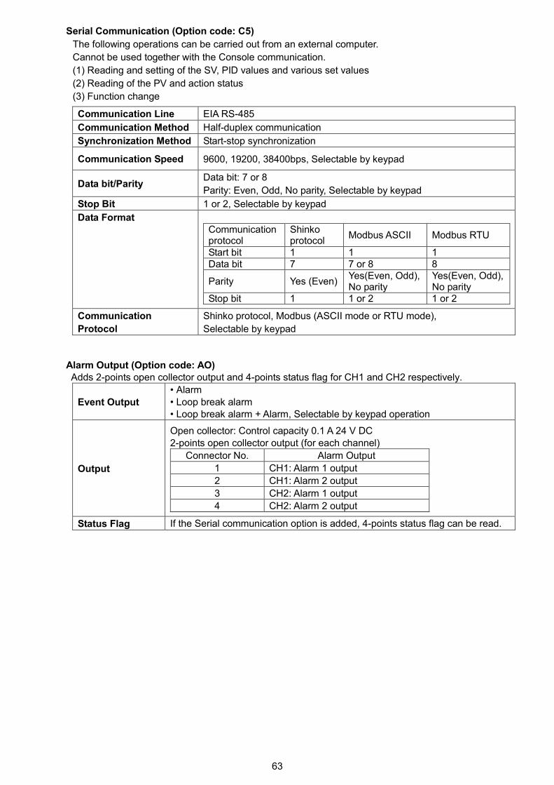
63
Serial Communication (Option code: C5)
The following operations can be carried out from an external computer.
Cannot be used together with the Console communication.
(1) Reading and setting of the SV, PID values and various set values
(2) Reading of the PV and action status
(3) Function change
Communication Line EIA RS-485
Communication Method Half-duplex communication
Synchronization Method Start-stop synchronization
Communication Speed 9600, 19200, 38400bps, Selectable by keypad
Data bit/ParityData bit: 7 or 8
Parity: Even, Odd, No parity, Selectable by keypad
Stop Bit 1 or 2, Selectable by keypad
Data FormatCommunicationprotocol
Shinkoprotocol
Modbus ASCII Modbus RTU
Start bit 1 1 1Data bit 7 7 or 8 8
Parity Yes (Even)Yes(Even, Odd),No parity
Yes(Even, Odd),No parity
Stop bit 1 1 or 2 1 or 2
Communication
Protocol
Shinko protocol, Modbus (ASCII mode or RTU mode),
Selectable by keypad
Alarm Output (Option code: AO)Adds 2-points open collector output and 4-points status flag for CH1 and CH2 respectively.
Event Output
• Alarm• Loop break alarm• Loop break alarm + Alarm, Selectable by keypad operation
Output
Open collector: Control capacity 0.1 A 24 V DC2-points open collector output (for each channel)
Connector No. Alarm Output
1 CH1: Alarm 1 output
2 CH1: Alarm 2 output
3 CH2: Alarm 1 output
4 CH2: Alarm 2 output
Status Flag If the Serial communication option is added, 4-points status flag can be read.
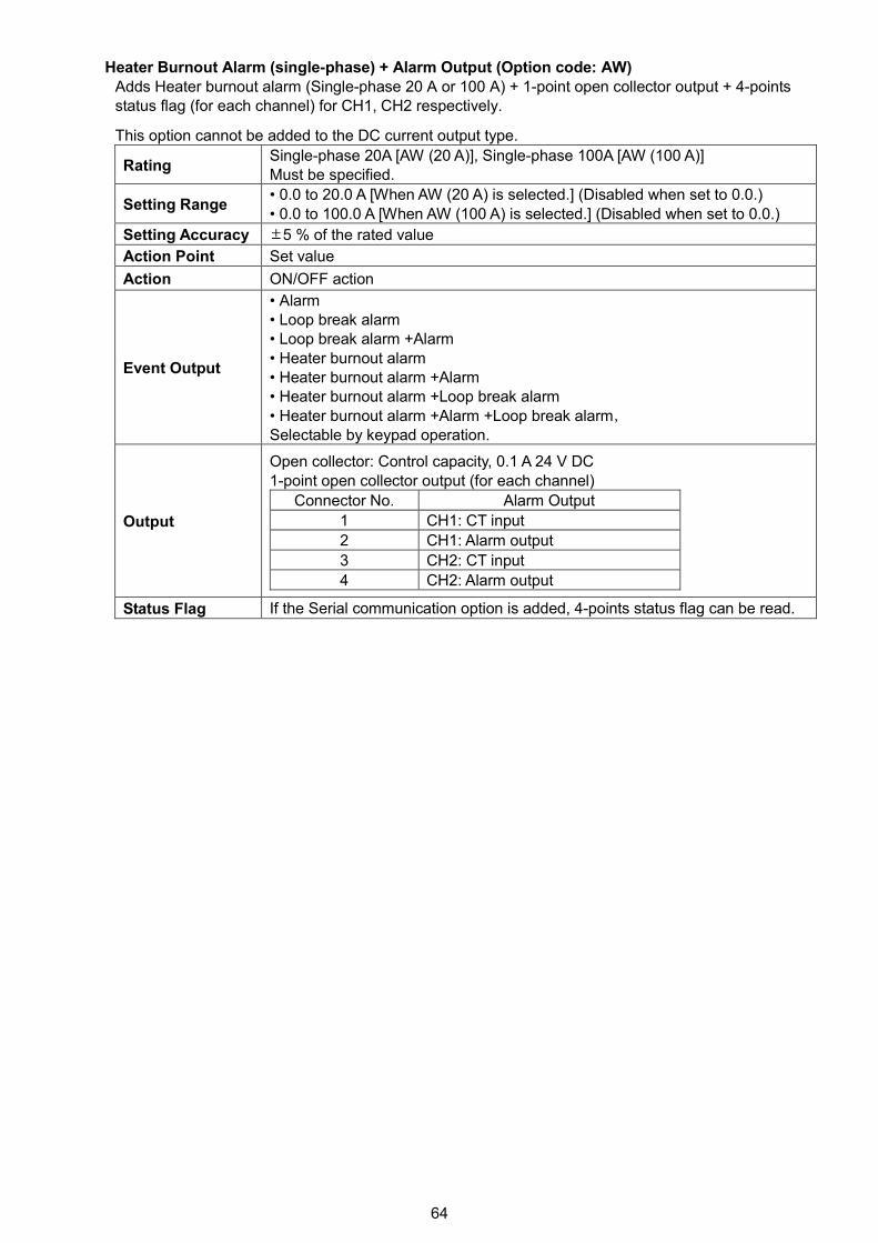
64
Heater Burnout Alarm (single-phase) + Alarm Output (Option code: AW)Adds Heater burnout alarm (Single-phase 20 A or 100 A) + 1-point open collector output + 4-pointsstatus flag (for each channel) for CH1, CH2 respectively.
This option cannot be added to the DC current output type.
RatingSingle-phase 20A [AW (20 A)], Single-phase 100A [AW (100 A)]Must be specified.
Setting Range• 0.0 to 20.0 A [When AW (20 A) is selected.] (Disabled when set to 0.0.)• 0.0 to 100.0 A [When AW (100 A) is selected.] (Disabled when set to 0.0.)
Setting Accuracy 5 % of the rated value
Action Point Set value
Action ON/OFF action
Event Output
• Alarm• Loop break alarm• Loop break alarm +Alarm• Heater burnout alarm• Heater burnout alarm +Alarm• Heater burnout alarm +Loop break alarm• Heater burnout alarm +Alarm +Loop break alarm,Selectable by keypad operation.
Output
Open collector: Control capacity, 0.1 A 24 V DC1-point open collector output (for each channel)
Connector No. Alarm Output
1 CH1: CT input
2 CH1: Alarm output
3 CH2: CT input
4 CH2: Alarm output
Status Flag If the Serial communication option is added, 4-points status flag can be read.
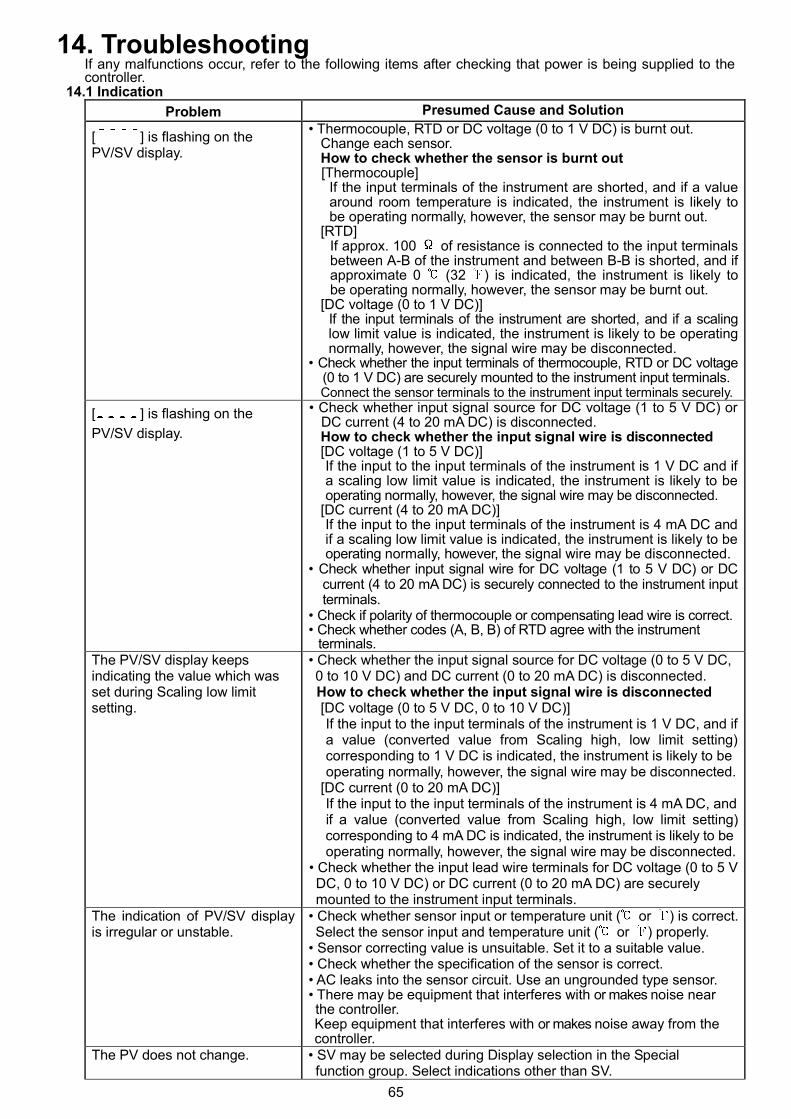
65
14. TroubleshootingIf any malfunctions occur, refer to the following items after checking that power is being supplied to thecontroller.
14.1 Indication
Problem Presumed Cause and Solution
[ ] is flashing on thePV/SV display.
• Thermocouple, RTD or DC voltage (0 to 1 V DC) is burnt out.Change each sensor.How to check whether the sensor is burnt out[Thermocouple]
If the input terminals of the instrument are shorted, and if a valuearound room temperature is indicated, the instrument is likely tobe operating normally, however, the sensor may be burnt out.
[RTD]If approx. 100 of resistance is connected to the input terminalsbetween A-B of the instrument and between B-B is shorted, and ifapproximate 0 (32 ) is indicated, the instrument is likely tobe operating normally, however, the sensor may be burnt out.
[DC voltage (0 to 1 V DC)]If the input terminals of the instrument are shorted, and if a scalinglow limit value is indicated, the instrument is likely to be operatingnormally, however, the signal wire may be disconnected.
• Check whether the input terminals of thermocouple, RTD or DC voltage(0 to 1 V DC) are securely mounted to the instrument input terminals.Connect the sensor terminals to the instrument input terminals securely.
[ ] is flashing on the
PV/SV display.
• Check whether input signal source for DC voltage (1 to 5 V DC) orDC current (4 to 20 mA DC) is disconnected.How to check whether the input signal wire is disconnected[DC voltage (1 to 5 V DC)]If the input to the input terminals of the instrument is 1 V DC and ifa scaling low limit value is indicated, the instrument is likely to beoperating normally, however, the signal wire may be disconnected.
[DC current (4 to 20 mA DC)]If the input to the input terminals of the instrument is 4 mA DC andif a scaling low limit value is indicated, the instrument is likely to beoperating normally, however, the signal wire may be disconnected.
• Check whether input signal wire for DC voltage (1 to 5 V DC) or DCcurrent (4 to 20 mA DC) is securely connected to the instrument inputterminals.
• Check if polarity of thermocouple or compensating lead wire is correct.• Check whether codes (A, B, B) of RTD agree with the instrument
terminals.The PV/SV display keepsindicating the value which wasset during Scaling low limitsetting.
• Check whether the input signal source for DC voltage (0 to 5 V DC,0 to 10 V DC) and DC current (0 to 20 mA DC) is disconnected.How to check whether the input signal wire is disconnected[DC voltage (0 to 5 V DC, 0 to 10 V DC)]If the input to the input terminals of the instrument is 1 V DC, and ifa value (converted value from Scaling high, low limit setting)corresponding to 1 V DC is indicated, the instrument is likely to beoperating normally, however, the signal wire may be disconnected.
[DC current (0 to 20 mA DC)]If the input to the input terminals of the instrument is 4 mA DC, andif a value (converted value from Scaling high, low limit setting)corresponding to 4 mA DC is indicated, the instrument is likely to beoperating normally, however, the signal wire may be disconnected.
• Check whether the input lead wire terminals for DC voltage (0 to 5 VDC, 0 to 10 V DC) or DC current (0 to 20 mA DC) are securelymounted to the instrument input terminals.
The indication of PV/SV displayis irregular or unstable.
• Check whether sensor input or temperature unit ( or ) is correct.Select the sensor input and temperature unit ( or ) properly.
• Sensor correcting value is unsuitable. Set it to a suitable value.• Check whether the specification of the sensor is correct.• AC leaks into the sensor circuit. Use an ungrounded type sensor.• There may be equipment that interferes with or makes noise nearthe controller.Keep equipment that interferes with or makes noise away from thecontroller.
The PV does not change. • SV may be selected during Display selection in the Specialfunction group. Select indications other than SV.
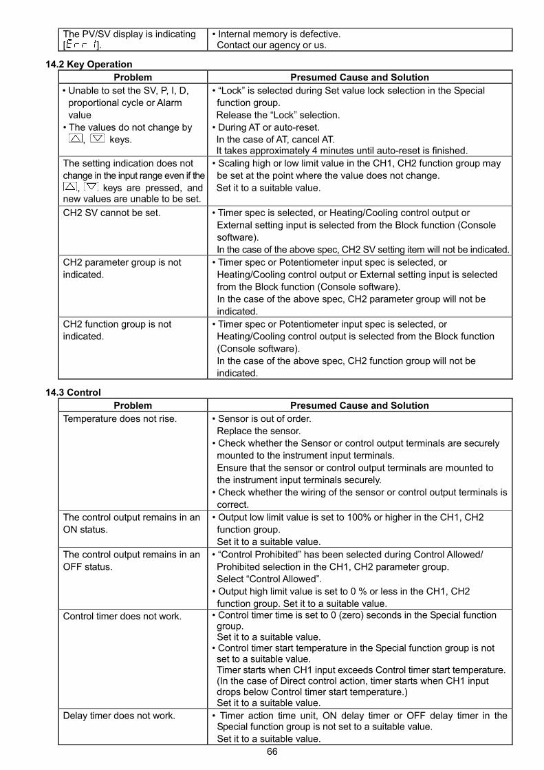
66
The PV/SV display is indicating[ ].
• Internal memory is defective.Contact our agency or us.
14.2 Key Operation
Problem Presumed Cause and Solution
• Unable to set the SV, P, I, D,
proportional cycle or Alarm
value
• The values do not change by
, keys.
• “Lock” is selected during Set value lock selection in the Special
function group.
Release the “Lock” selection.
• During AT or auto-reset.
In the case of AT, cancel AT.It takes approximately 4 minutes until auto-reset is finished.
The setting indication does not
change in the input range even if the
, keys are pressed, andnew values are unable to be set.
• Scaling high or low limit value in the CH1, CH2 function group may
be set at the point where the value does not change.
Set it to a suitable value.
CH2 SV cannot be set. • Timer spec is selected, or Heating/Cooling control output or
External setting input is selected from the Block function (Console
software).
In the case of the above spec, CH2 SV setting item will not be indicated.
CH2 parameter group is not
indicated.
• Timer spec or Potentiometer input spec is selected, or
Heating/Cooling control output or External setting input is selected
from the Block function (Console software).
In the case of the above spec, CH2 parameter group will not be
indicated.
CH2 function group is not
indicated.
• Timer spec or Potentiometer input spec is selected, or
Heating/Cooling control output is selected from the Block function
(Console software).
In the case of the above spec, CH2 function group will not be
indicated.
14.3 Control
Problem Presumed Cause and Solution
Temperature does not rise. • Sensor is out of order.
Replace the sensor.
• Check whether the Sensor or control output terminals are securely
mounted to the instrument input terminals.
Ensure that the sensor or control output terminals are mounted to
the instrument input terminals securely.
• Check whether the wiring of the sensor or control output terminals is
correct.
The control output remains in an
ON status.
• Output low limit value is set to 100% or higher in the CH1, CH2
function group.
Set it to a suitable value.
The control output remains in an
OFF status.
• “Control Prohibited” has been selected during Control Allowed/
Prohibited selection in the CH1, CH2 parameter group.
Select “Control Allowed”.
• Output high limit value is set to 0 % or less in the CH1, CH2
function group. Set it to a suitable value.
Control timer does not work. • Control timer time is set to 0 (zero) seconds in the Special functiongroup.Set it to a suitable value.
• Control timer start temperature in the Special function group is notset to a suitable value.Timer starts when CH1 input exceeds Control timer start temperature.(In the case of Direct control action, timer starts when CH1 inputdrops below Control timer start temperature.)Set it to a suitable value.
Delay timer does not work. • Timer action time unit, ON delay timer or OFF delay timer in theSpecial function group is not set to a suitable value.
Set it to a suitable value.

67
15. Character tablesSV Group
Character Setting Item Default Value Data
CH1 SV 0
CH2 SV 0
CH1 Parameter Group
Character Setting Item Default Value Data
Control Allowed/Prohibited Control Allowed
Auto/Manual control Automatic control
Manual control MV MV of the automatic control
AT/Auto-reset Perform/Cancel AT/ Auto-reset Cancel
Proportional band 10
OUT2 proportional band 1.0 times
Integral time 200 sec
Derivative time 50 sec
ARW (Anti-reset windup) 50 %
Manual reset value 0.0
Proportional cycleRelay contact output: 30 secNon-contact voltage output: 3 sec
OUT2 proportional cycleRelay contact output: 30 secNon-contact voltage output: 3 sec
Alarm 1 value 0
Alarm 2 value 0
Alarm 3 value 0
Alarm 4 value 0
Heater burnout alarm 1 0.0 A
Heater burnout alarm 2 0.0 A
Loop break alarm span 0
Loop break alarm time 0 minutes
CH2 Parameter Group
Character Setting Item Default Value Data
Control Allowed/Prohibited Control Allowed
Auto/Manual control Automatic control
Manual control MV MV of the automatic control
AT/Auto-reset Perform/Cancel AT/Auto-reset Cancel
Proportional band 10
Integral time 200 sec
Derivative time 50 sec
ARW (Anti-reset windup) 50 %
Manual reset value 0.0
Proportional cycleRelay contact output: 30 secNon-contact voltage output: 3 sec
Alarm 1 value 0
Alarm 2 value 0
Alarm 3 value 0
Alarm 4 value 0
Heater burnout alarm 1 0.0 A
Heater burnout alarm 2 0.0 A
Loop break alarm span 0
Loop break alarm time 0 minutes
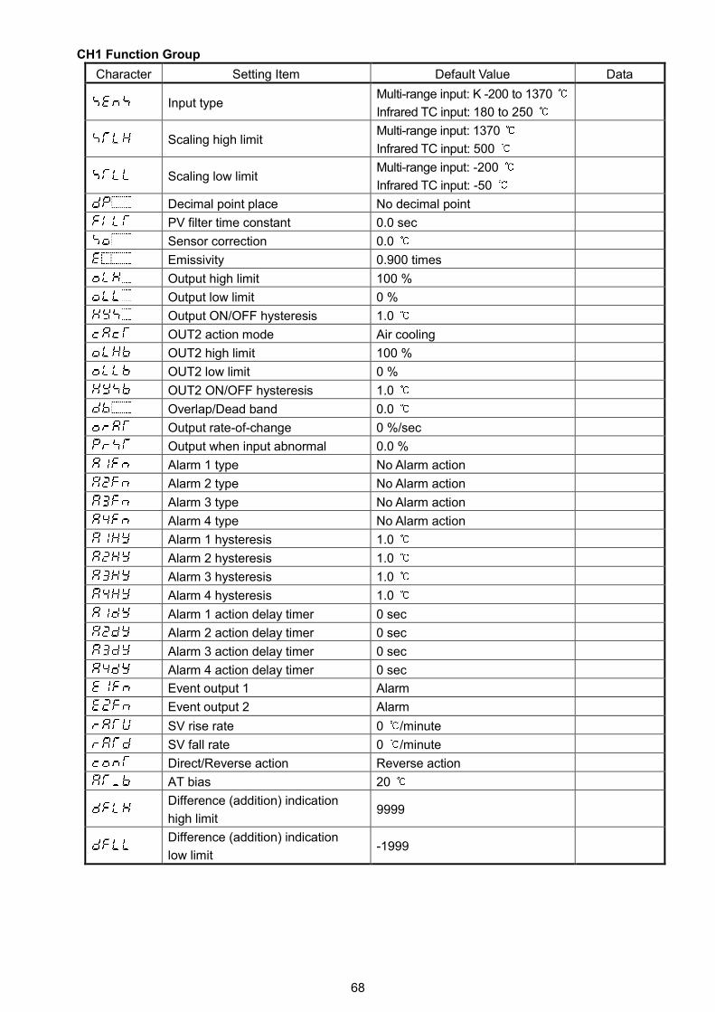
68
CH1 Function Group
Character Setting Item Default Value Data
Input typeMulti-range input: K -200 to 1370
Infrared TC input: 180 to 250
Scaling high limitMulti-range input: 1370
Infrared TC input: 500
Scaling low limitMulti-range input: -200
Infrared TC input: -50
Decimal point place No decimal point
PV filter time constant 0.0 sec
Sensor correction 0.0
Emissivity 0.900 times
Output high limit 100 %
Output low limit 0 %
Output ON/OFF hysteresis 1.0
OUT2 action mode Air cooling
OUT2 high limit 100 %
OUT2 low limit 0 %
OUT2 ON/OFF hysteresis 1.0
Overlap/Dead band 0.0
Output rate-of-change 0 %/sec
Output when input abnormal 0.0 %
Alarm 1 type No Alarm action
Alarm 2 type No Alarm action
Alarm 3 type No Alarm action
Alarm 4 type No Alarm action
Alarm 1 hysteresis 1.0
Alarm 2 hysteresis 1.0
Alarm 3 hysteresis 1.0
Alarm 4 hysteresis 1.0
Alarm 1 action delay timer 0 sec
Alarm 2 action delay timer 0 sec
Alarm 3 action delay timer 0 sec
Alarm 4 action delay timer 0 sec
Event output 1 Alarm
Event output 2 Alarm
SV rise rate 0 /minute
SV fall rate 0 /minute
Direct/Reverse action Reverse action
AT bias 20
Difference (addition) indication
high limit9999
Difference (addition) indication
low limit-1999
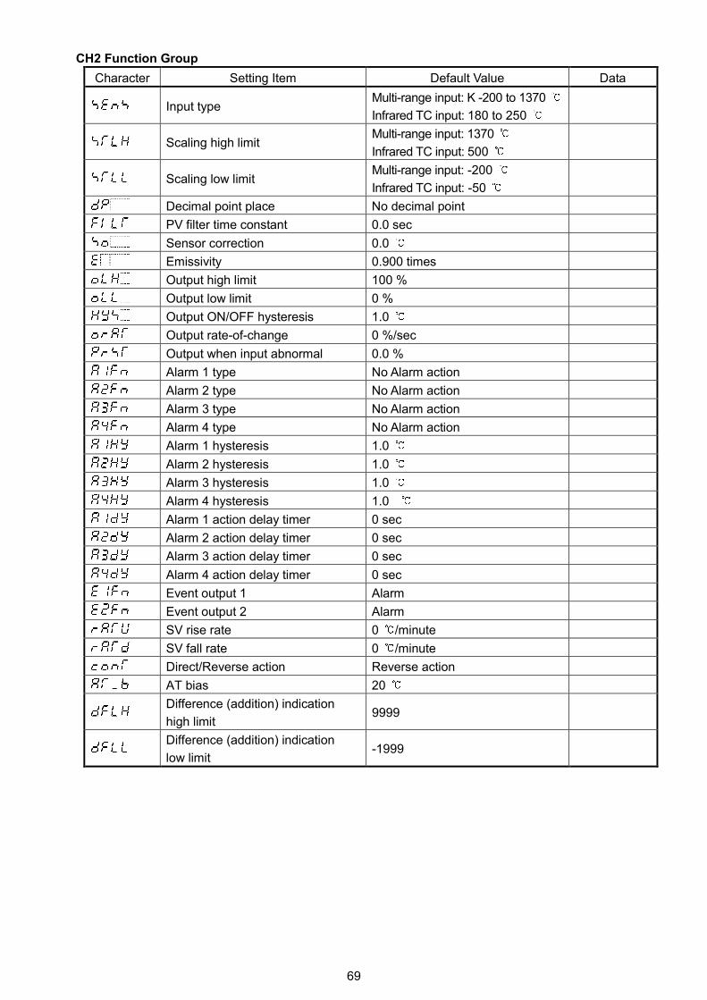
69
CH2 Function Group
Character Setting Item Default Value Data
Input typeMulti-range input: K -200 to 1370
Infrared TC input: 180 to 250
Scaling high limitMulti-range input: 1370
Infrared TC input: 500
Scaling low limitMulti-range input: -200
Infrared TC input: -50
Decimal point place No decimal point
PV filter time constant 0.0 sec
Sensor correction 0.0
Emissivity 0.900 times
Output high limit 100 %
Output low limit 0 %
Output ON/OFF hysteresis 1.0
Output rate-of-change 0 %/sec
Output when input abnormal 0.0 %
Alarm 1 type No Alarm action
Alarm 2 type No Alarm action
Alarm 3 type No Alarm action
Alarm 4 type No Alarm action
Alarm 1 hysteresis 1.0
Alarm 2 hysteresis 1.0
Alarm 3 hysteresis 1.0
Alarm 4 hysteresis 1.0
Alarm 1 action delay timer 0 sec
Alarm 2 action delay timer 0 sec
Alarm 3 action delay timer 0 sec
Alarm 4 action delay timer 0 sec
Event output 1 Alarm
Event output 2 Alarm
SV rise rate 0 /minute
SV fall rate 0 /minute
Direct/Reverse action Reverse action
AT bias 20
Difference (addition) indication
high limit9999
Difference (addition) indication
low limit-1999
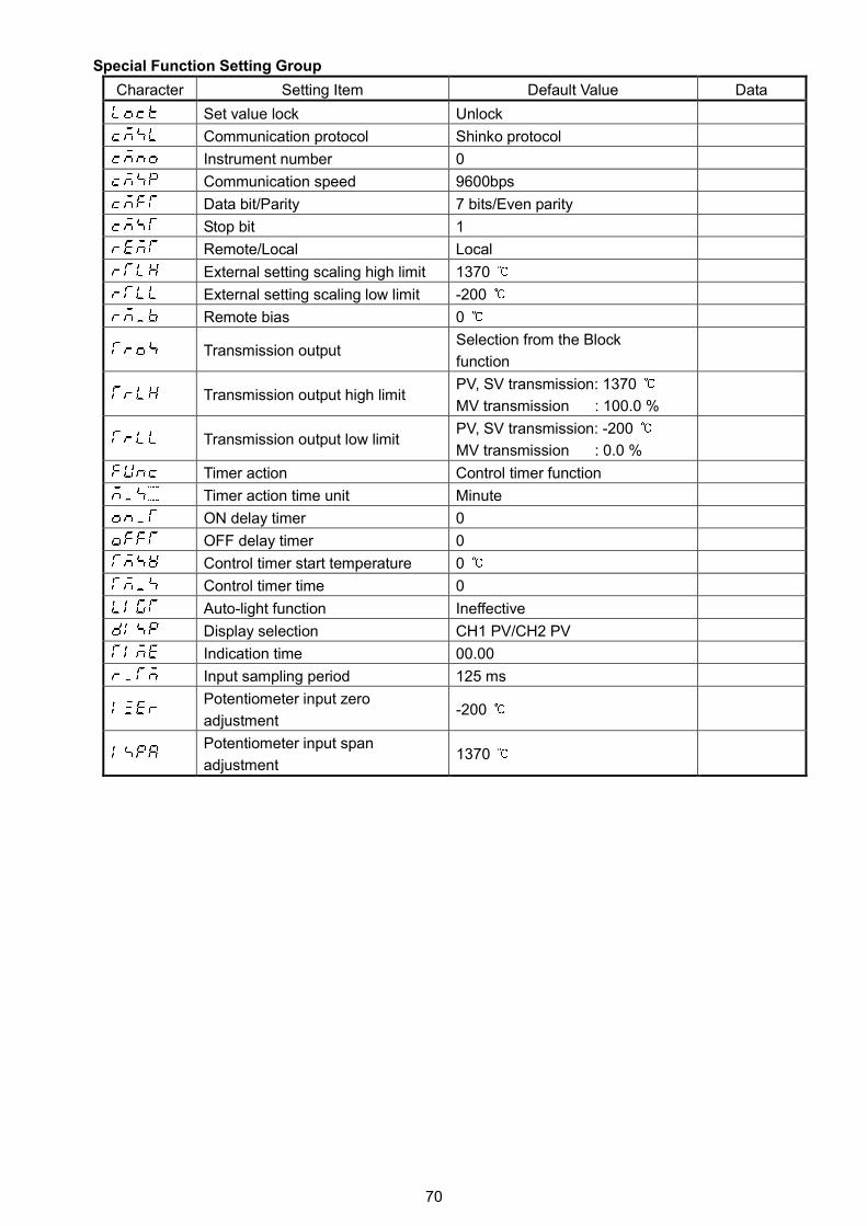
70
Special Function Setting Group
Character Setting Item Default Value Data
Set value lock Unlock
Communication protocol Shinko protocol
Instrument number 0
Communication speed 9600bps
Data bit/Parity 7 bits/Even parity
Stop bit 1
Remote/Local Local
External setting scaling high limit 1370
External setting scaling low limit -200
Remote bias 0
Transmission outputSelection from the Block
function
Transmission output high limitPV, SV transmission: 1370
MV transmission : 100.0 %
Transmission output low limitPV, SV transmission: -200
MV transmission : 0.0 %
Timer action Control timer function
Timer action time unit Minute
ON delay timer 0
OFF delay timer 0
Control timer start temperature 0
Control timer time 0
Auto-light function Ineffective
Display selection CH1 PV/CH2 PV
Indication time 00.00
Input sampling period 125 ms
Potentiometer input zero
adjustment-200
Potentiometer input span
adjustment1370
***** Inquiry *****
For any inquiries about this unit, please contact our agency or the
vendor where you purchased the unit after checking the following.
[Example]
• Model --------------------------- WCL-13A-RR/MM
• Serial number ----------------- No. 094F05000
In addition to the above, please let us know the details of the
malfunction, if any, and the operating conditions.
WCL12E5 2012.08
SHINKO TECHNOS CO., LTD.OVERSEAS DIVISION
:
::
Reg. Office
URLE-mail
2-5-1, Senbahigashi, Minoo, Osaka, Japanhttp://www.shinko-technos.co.jp
[email protected] :Fax:
+81-72-727-6100+81-72-727-7006