Embed Size (px)
Citation preview
11/2010
SIMOTION
System Functions/Variables Device
List Manual
s
Preface, Contents
System Functions - Device1
System Variables - Device2
Siemens Industrial
Siemens AGIndustry SectorPostfach 48 4890026 NürnbergGERMANY
Copyright © Siemens AG 2010.Technical data subject to change.
Legal information
Warning notice system
This manual contains notices you have to observe in order to ensure your personal safety, as well as to prevent damage to property. The notices referring to your personal safety are highlighted in the manual by a safety alert symbol, notices referring only to property damage have no safety alert symbol. These notices shown below are graded according to the degree of danger.
If more than one degree of danger is present, the warning notice representing the highest degree of danger will be used. A notice warning of injury to persons with a safety alert symbol may also include a warning relating to property damage.
Qualified Personnel
The product/system described in this documentation may be operated only by personnel qualified for the specific task in accordance with the relevant documentation for the specific task, in particular its warning notices and safety instructions. Qualified personnel are those who, based on their training and experience, are capable of identifying risks and avoiding potential hazards when working with these products/systems.
Proper use of Siemens products
Note the following:
Trademarks
All names identified by ® are registered trademarks of the Siemens AG. The remaining trademarks in this publication may be trademarks whose use by third parties for their own purposes could violate the rights of the owner.
Disclaimer of Liability
We have reviewed the contents of this publication to ensure consistency with the hardware and software described. Since variance cannot be precluded entirely, we cannot guarantee full consistency. However, the information in this publication is reviewed regularly and any necessary corrections are included in subsequent editions.
DANGER
indicates that death or severe personal injury will result if proper precautions are not taken.
WARNING
indicates that death or severe personal injury may result if proper precautions are not taken.
CAUTION
with a safety alert symbol, indicates that minor personal injury can result if proper precautions are not taken.
CAUTION
without a safety alert symbol, indicates that property damage can result if proper precautions are not taken.
NOTICE
indicates that an unintended result or situation can occur if the corresponding information is not taken into account.
Warning
Siemens products may only be used for the applications described in the catalog and in the relevant technical documentation. If products and components from other manufacturers are used, these must be recommended or approved by Siemens. Proper transport, storage, installation, assembly, commissioning, operation and maintenance are required to ensure that the products operate safely and without any problems. The permissible ambient conditions must be adhered to. The information in the relevant documentation must be observed.
Preface-3SIMOTION System Functions/Variables DeviceList Manual, 11/2010
Preface
Scope and standards
This document is part of the SIMOTION Programming - References documentation package.
Scope of validity
This manual is valid for SIMOTION SCOUT V4.2:
• SIMOTION SCOUT V4.2 (engineering system for the SIMOTION product family),
• SIMOTION Kernel from V3.0 to V4.2
Information Blocks of the Manual
The Manual describes generally valid system functions and system variables for the SIMOTION hardware platforms C, P and D.
• System Functions - Device
• System Variables - Device
Siemens Industrial
Preface
Preface-4 SIMOTION System Functions/Variables DeviceList Manual, 11/2010
SIMOTION Documentation
An overview of the SIMOTION documentation can be found in a separate list of references.
This documentation is included as electronic documentation in the scope of delivery of SIMOTION SCOUT. It comprises 10 documentation packages.
The following documentation packages are available for SIMOTION V4.2.
• SIMOTION Engineering System
• SIMOTION System and Function Descriptions
• SIMOTION Service and Diagnostics
• SIMOTION IT
• SIMOTION Programming
• SIMOTION Programming - References
• SIMOTION C
• SIMOTION P
• SIMOTION D
• SIMOTION Supplementary Documentation
Preface
Preface-5SIMOTION System Functions/Variables DeviceList Manual, 11/2010
Hotline and Internet addresses
Additional information
Click the following link to find information on the the following topics:
• Ordering documentation/overview of documentation
• Additional links to download documents
• Using documentation online (find and search in manuals/information)
http://www.siemens.com/motioncontrol/docu
Please send any questions about the technical documentation (e.g. suggestions for improvement, corrections) to the following e-mail address:
My Documentation Manager
Click the following link for information on how to compile documentation individu-ally on the basis of Siemens content and how to adapt this for the purpose of your own machine documentation:
http://www.siemens.com/mdm
Training
Click the following link for information on SITRAIN - Siemens training courses for automation products, systems and solutions:
www.siemens.com/sitrain
FAQs
You can find Frequently Asked Questions on the Service&Support pages under Product Support:
http://support.automation.siemens.com
Technical Support
Country-specific telephone numbers for technical support are provided on the Internet under Contact:
http://www.siemens.com/automation/service&support
Siemens Industrial

Preface
Preface-6 SIMOTION System Functions/Variables DeviceList Manual, 11/2010
Contents-7SIMOTION System Functions/Variables DeviceList Manual, 11/2010
Contents
Preface. . . . . . . . . . . . . . . . . . . . . . . . . . . . . . . . . . . . . . . . . . . . . . . . . . . . Preface-3
1 System Functions - Device . . . . . . . . . . . . . . . . . . . . . . . . . . . . . . . . . . . . . . . . 1-13
1.1 Alarms and messages. . . . . . . . . . . . . . . . . . . . . . . . . . . . . . . . . . . . . . 1-141.1.1 _getPendingAlarms . . . . . . . . . . . . . . . . . . . . . . . . . . . . . . . . . . . . . . . . 1-141.1.2 _readDiagnosticData. . . . . . . . . . . . . . . . . . . . . . . . . . . . . . . . . . . . . . . 1-151.1.3 _resetAlarmId . . . . . . . . . . . . . . . . . . . . . . . . . . . . . . . . . . . . . . . . . . . . 1-191.1.4 _resetAllAlarmId . . . . . . . . . . . . . . . . . . . . . . . . . . . . . . . . . . . . . . . . . . 1-191.1.5 _sendProcessInterrupt . . . . . . . . . . . . . . . . . . . . . . . . . . . . . . . . . . . . . 1-201.1.6 _writeAndSendMessage . . . . . . . . . . . . . . . . . . . . . . . . . . . . . . . . . . . . 1-23
1.2 Communication . . . . . . . . . . . . . . . . . . . . . . . . . . . . . . . . . . . . . . . . . . . 1-251.2.1 Interface handling - Configuration . . . . . . . . . . . . . . . . . . . . . . . . . . . . . 1-251.2.1.1 _activateDpSlave . . . . . . . . . . . . . . . . . . . . . . . . . . . . . . . . . . . . . . . . . . . . 1-251.2.1.2 _activateDpSlaveAddress . . . . . . . . . . . . . . . . . . . . . . . . . . . . . . . . . . . . . . 1-281.2.1.3 _activateNameOfStation . . . . . . . . . . . . . . . . . . . . . . . . . . . . . . . . . . . . . . . 1-291.2.1.4 _deactivateDpSlave . . . . . . . . . . . . . . . . . . . . . . . . . . . . . . . . . . . . . . . . . . 1-301.2.1.5 _enableDpInterfaceSynchronizationMode . . . . . . . . . . . . . . . . . . . . . . . . . 1-331.2.1.6 _getActiveNameOfStation . . . . . . . . . . . . . . . . . . . . . . . . . . . . . . . . . . . . . . 1-341.2.1.7 _getDeviceId . . . . . . . . . . . . . . . . . . . . . . . . . . . . . . . . . . . . . . . . . . . . . . . . 1-381.2.1.8 _getDoIndexNumberFromLogAddress . . . . . . . . . . . . . . . . . . . . . . . . . . . . 1-391.2.1.9 _getGeoAddressFromLogAddress . . . . . . . . . . . . . . . . . . . . . . . . . . . . . . . 1-411.2.1.10 _getMemoryCardId . . . . . . . . . . . . . . . . . . . . . . . . . . . . . . . . . . . . . . . . . . . 1-431.2.1.11 _getNextLogAddress. . . . . . . . . . . . . . . . . . . . . . . . . . . . . . . . . . . . . . . . . . 1-441.2.1.12 _getPnInterfacePortNeighbour . . . . . . . . . . . . . . . . . . . . . . . . . . . . . . . . . . 1-471.2.1.13 _getSegmentIdentification. . . . . . . . . . . . . . . . . . . . . . . . . . . . . . . . . . . . . . 1-511.2.1.14 _getStationType . . . . . . . . . . . . . . . . . . . . . . . . . . . . . . . . . . . . . . . . . . . . . 1-531.2.1.15 _setDeviceErrorLED . . . . . . . . . . . . . . . . . . . . . . . . . . . . . . . . . . . . . . . . . . 1-551.2.1.16 _setDpSlaveAddress. . . . . . . . . . . . . . . . . . . . . . . . . . . . . . . . . . . . . . . . . . 1-561.2.1.17 _setIPConfig . . . . . . . . . . . . . . . . . . . . . . . . . . . . . . . . . . . . . . . . . . . . . . . . 1-571.2.1.18 _setNameOfStation . . . . . . . . . . . . . . . . . . . . . . . . . . . . . . . . . . . . . . . . . . . 1-581.2.1.19 _synchronizeDpInterfaces. . . . . . . . . . . . . . . . . . . . . . . . . . . . . . . . . . . . . . 1-611.2.1.20 _udpAddMulticastGroupMembership . . . . . . . . . . . . . . . . . . . . . . . . . . . . . 1-641.2.1.21 _udpDropMulticastGroupMembership. . . . . . . . . . . . . . . . . . . . . . . . . . . . . 1-661.2.2 Interface handling - Status . . . . . . . . . . . . . . . . . . . . . . . . . . . . . . . . . . 1-681.2.2.1 _getActiveDpSlaveAddress. . . . . . . . . . . . . . . . . . . . . . . . . . . . . . . . . . . . . 1-681.2.2.2 _getActiveNameOfStation . . . . . . . . . . . . . . . . . . . . . . . . . . . . . . . . . . . . . . 1-691.2.2.3 _getDpStationAddressFromLogDiagnosticAddress . . . . . . . . . . . . . . . . . . 1-731.2.2.4 _getIPConfig . . . . . . . . . . . . . . . . . . . . . . . . . . . . . . . . . . . . . . . . . . . . . . . . 1-761.2.2.5 _getLogDiagnosticAddressFromDpStationAddress . . . . . . . . . . . . . . . . . . 1-771.2.2.6 _getPnInterfacePortNeighbour . . . . . . . . . . . . . . . . . . . . . . . . . . . . . . . . . . 1-801.2.2.7 _getStateOfAllDpSlaves . . . . . . . . . . . . . . . . . . . . . . . . . . . . . . . . . . . . . . . 1-841.2.2.8 _getStateOfAllDpStations . . . . . . . . . . . . . . . . . . . . . . . . . . . . . . . . . . . . . . 1-871.2.2.9 _getStateOfDiagnosticDataCommand . . . . . . . . . . . . . . . . . . . . . . . . . . . . 1-91
Siemens Industrial
Contents
Contents-8 SIMOTION System Functions/Variables DeviceList Manual, 11/2010
1.2.2.10 _getStateOfDpSlave . . . . . . . . . . . . . . . . . . . . . . . . . . . . . . . . . . . . . . . . . . 1-921.2.2.11 _getStateOfIO . . . . . . . . . . . . . . . . . . . . . . . . . . . . . . . . . . . . . . . . . . . . . . . 1-951.2.2.12 _getStateOfProcessInterruptCommand . . . . . . . . . . . . . . . . . . . . . . . . . . 1-1011.2.2.13 _getStateOfRecordCommand . . . . . . . . . . . . . . . . . . . . . . . . . . . . . . . . . . 1-1021.2.2.14 _getStateOfSingleDpSlave . . . . . . . . . . . . . . . . . . . . . . . . . . . . . . . . . . . . 1-1031.2.2.15 _GetStateOfXCommand . . . . . . . . . . . . . . . . . . . . . . . . . . . . . . . . . . . . . . 1-1061.2.2.16 _setNameOfStation . . . . . . . . . . . . . . . . . . . . . . . . . . . . . . . . . . . . . . . . . . 1-1071.2.3 Data transfer . . . . . . . . . . . . . . . . . . . . . . . . . . . . . . . . . . . . . . . . . . . . . 1-1101.2.3.1 _abortReadWriteRecordJobs . . . . . . . . . . . . . . . . . . . . . . . . . . . . . . . . . . 1-1101.2.3.2 _readRecord . . . . . . . . . . . . . . . . . . . . . . . . . . . . . . . . . . . . . . . . . . . . . . . 1-1111.2.3.3 _readVariableDiagnosticData . . . . . . . . . . . . . . . . . . . . . . . . . . . . . . . . . . 1-1171.2.3.4 _readVariableRecord . . . . . . . . . . . . . . . . . . . . . . . . . . . . . . . . . . . . . . . . 1-1201.2.3.5 _tcpCloseConnection . . . . . . . . . . . . . . . . . . . . . . . . . . . . . . . . . . . . . . . . 1-1241.2.3.6 _tcpCloseServer . . . . . . . . . . . . . . . . . . . . . . . . . . . . . . . . . . . . . . . . . . . . 1-1251.2.3.7 _tcpOpenClient . . . . . . . . . . . . . . . . . . . . . . . . . . . . . . . . . . . . . . . . . . . . . 1-1261.2.3.8 _tcpOpenServer . . . . . . . . . . . . . . . . . . . . . . . . . . . . . . . . . . . . . . . . . . . . 1-1281.2.3.9 _tcpReceive. . . . . . . . . . . . . . . . . . . . . . . . . . . . . . . . . . . . . . . . . . . . . . . . 1-1301.2.3.10 _tcpSend . . . . . . . . . . . . . . . . . . . . . . . . . . . . . . . . . . . . . . . . . . . . . . . . . . 1-1321.2.3.11 _udpReceive . . . . . . . . . . . . . . . . . . . . . . . . . . . . . . . . . . . . . . . . . . . . . . . 1-1341.2.3.12 _udpSend . . . . . . . . . . . . . . . . . . . . . . . . . . . . . . . . . . . . . . . . . . . . . . . . . 1-1361.2.3.13 _writeRecord . . . . . . . . . . . . . . . . . . . . . . . . . . . . . . . . . . . . . . . . . . . . . . . 1-1381.2.3.14 _writeVariableRecord . . . . . . . . . . . . . . . . . . . . . . . . . . . . . . . . . . . . . . . . 1-1431.2.3.15 _Xreceive . . . . . . . . . . . . . . . . . . . . . . . . . . . . . . . . . . . . . . . . . . . . . . . . . 1-1471.2.3.16 _Xsend . . . . . . . . . . . . . . . . . . . . . . . . . . . . . . . . . . . . . . . . . . . . . . . . . . . 1-149
1.3 Drives . . . . . . . . . . . . . . . . . . . . . . . . . . . . . . . . . . . . . . . . . . . . . . . . . . 1-1531.3.1 SIMODRIVE . . . . . . . . . . . . . . . . . . . . . . . . . . . . . . . . . . . . . . . . . . . . . 1-1531.3.1.1 _abortAllReadWriteDriveParameterJobs . . . . . . . . . . . . . . . . . . . . . . . . . 1-1531.3.1.2 _POSMOA_control . . . . . . . . . . . . . . . . . . . . . . . . . . . . . . . . . . . . . . . . . . 1-1541.3.1.3 _POSMOA_nControl . . . . . . . . . . . . . . . . . . . . . . . . . . . . . . . . . . . . . . . . . 1-1551.3.1.4 _POSMOA_rwAllParameter . . . . . . . . . . . . . . . . . . . . . . . . . . . . . . . . . . . 1-1561.3.1.5 _POSMOA_rwParameter . . . . . . . . . . . . . . . . . . . . . . . . . . . . . . . . . . . . . 1-1591.3.1.6 _readDriveFaults . . . . . . . . . . . . . . . . . . . . . . . . . . . . . . . . . . . . . . . . . . . . 1-1601.3.1.7 _readDriveMultiParameter . . . . . . . . . . . . . . . . . . . . . . . . . . . . . . . . . . . . 1-1661.3.1.8 _readDriveMultiParameterDescription . . . . . . . . . . . . . . . . . . . . . . . . . . . 1-1731.3.1.9 _readDriveParameter . . . . . . . . . . . . . . . . . . . . . . . . . . . . . . . . . . . . . . . . 1-1801.3.1.10 _readDriveParameterDescription . . . . . . . . . . . . . . . . . . . . . . . . . . . . . . . 1-1871.3.1.11 _RWPAR_cyclic . . . . . . . . . . . . . . . . . . . . . . . . . . . . . . . . . . . . . . . . . . . . 1-1941.3.1.12 _writeDriveMultiParameter . . . . . . . . . . . . . . . . . . . . . . . . . . . . . . . . . . . . 1-1951.3.1.13 _writeDriveParameter . . . . . . . . . . . . . . . . . . . . . . . . . . . . . . . . . . . . . . . . 1-2031.3.2 SIMOVERT . . . . . . . . . . . . . . . . . . . . . . . . . . . . . . . . . . . . . . . . . . . . . . 1-2111.3.2.1 _abortAllReadWriteDriveParameterJobs . . . . . . . . . . . . . . . . . . . . . . . . . 1-2111.3.2.2 _readDriveFaults . . . . . . . . . . . . . . . . . . . . . . . . . . . . . . . . . . . . . . . . . . . . 1-2121.3.2.3 _readDriveMultiParameter . . . . . . . . . . . . . . . . . . . . . . . . . . . . . . . . . . . . 1-2191.3.2.4 _readDriveMultiParameterDescription . . . . . . . . . . . . . . . . . . . . . . . . . . . 1-2261.3.2.5 _readDriveParameter . . . . . . . . . . . . . . . . . . . . . . . . . . . . . . . . . . . . . . . . 1-2331.3.2.6 _readDriveParameterDescription . . . . . . . . . . . . . . . . . . . . . . . . . . . . . . . 1-2401.3.2.7 _RWPAR_cyclic . . . . . . . . . . . . . . . . . . . . . . . . . . . . . . . . . . . . . . . . . . . . 1-2471.3.2.8 _writeDriveMultiParameter . . . . . . . . . . . . . . . . . . . . . . . . . . . . . . . . . . . . 1-2481.3.2.9 _writeDriveParameter . . . . . . . . . . . . . . . . . . . . . . . . . . . . . . . . . . . . . . . . 1-2561.3.3 SINAMICS . . . . . . . . . . . . . . . . . . . . . . . . . . . . . . . . . . . . . . . . . . . . . . . 1-2641.3.3.1 _abortAllReadWriteDriveParameterJobs . . . . . . . . . . . . . . . . . . . . . . . . . 1-2641.3.3.2 _readDriveFaults . . . . . . . . . . . . . . . . . . . . . . . . . . . . . . . . . . . . . . . . . . . . 1-2651.3.3.3 _readDriveMultiParameter . . . . . . . . . . . . . . . . . . . . . . . . . . . . . . . . . . . . 1-272
Contents
Contents-9SIMOTION System Functions/Variables DeviceList Manual, 11/2010
1.3.3.4 _readDriveMultiParameterDescription . . . . . . . . . . . . . . . . . . . . . . . . . . . 1-2791.3.3.5 _readDriveParameter . . . . . . . . . . . . . . . . . . . . . . . . . . . . . . . . . . . . . . . . 1-2861.3.3.6 _readDriveParameterDescription . . . . . . . . . . . . . . . . . . . . . . . . . . . . . . . 1-2931.3.3.7 _resetDriveObjectFault . . . . . . . . . . . . . . . . . . . . . . . . . . . . . . . . . . . . . . . 1-3001.3.3.8 _setDriveObjectSTW. . . . . . . . . . . . . . . . . . . . . . . . . . . . . . . . . . . . . . . . . 1-3011.3.3.9 _writeDriveMultiParameter . . . . . . . . . . . . . . . . . . . . . . . . . . . . . . . . . . . . 1-3031.3.3.10 _writeDriveParameter . . . . . . . . . . . . . . . . . . . . . . . . . . . . . . . . . . . . . . . . 1-3111.3.4 SIMATIC . . . . . . . . . . . . . . . . . . . . . . . . . . . . . . . . . . . . . . . . . . . . . . . . 1-3191.3.4.1 _ET200S_FC_control . . . . . . . . . . . . . . . . . . . . . . . . . . . . . . . . . . . . . . . . 1-319
1.4 I/O modules . . . . . . . . . . . . . . . . . . . . . . . . . . . . . . . . . . . . . . . . . . . . . . 1-3201.4.1 Function modules - FM350-1 . . . . . . . . . . . . . . . . . . . . . . . . . . . . . . . . 1-3201.4.1.1 _FM3501_control2 . . . . . . . . . . . . . . . . . . . . . . . . . . . . . . . . . . . . . . . . . . 1-3201.4.1.2 _FM3501_diagnostic . . . . . . . . . . . . . . . . . . . . . . . . . . . . . . . . . . . . . . . . . 1-3221.4.2 Function modules - FM350-2 . . . . . . . . . . . . . . . . . . . . . . . . . . . . . . . . 1-3231.4.2.1 _FM3502_control . . . . . . . . . . . . . . . . . . . . . . . . . . . . . . . . . . . . . . . . . . . 1-3231.4.2.2 _FM3502_diagnostic . . . . . . . . . . . . . . . . . . . . . . . . . . . . . . . . . . . . . . . . . 1-3251.4.2.3 _FM3502_read . . . . . . . . . . . . . . . . . . . . . . . . . . . . . . . . . . . . . . . . . . . . . 1-3271.4.2.4 _FM3502_write . . . . . . . . . . . . . . . . . . . . . . . . . . . . . . . . . . . . . . . . . . . . . 1-3291.4.3 Function modules - FM352 . . . . . . . . . . . . . . . . . . . . . . . . . . . . . . . . . . 1-3311.4.3.1 _FM352_control . . . . . . . . . . . . . . . . . . . . . . . . . . . . . . . . . . . . . . . . . . . . 1-3311.4.3.2 _FM352_diagnostic . . . . . . . . . . . . . . . . . . . . . . . . . . . . . . . . . . . . . . . . . . 1-3341.4.3.3 _FM352_initialize . . . . . . . . . . . . . . . . . . . . . . . . . . . . . . . . . . . . . . . . . . . 1-3351.4.4 Communication modules - CP340. . . . . . . . . . . . . . . . . . . . . . . . . . . . . 1-3381.4.4.1 _CP340_byteToPrintData . . . . . . . . . . . . . . . . . . . . . . . . . . . . . . . . . . . . . 1-3381.4.4.2 _CP340_dintToPrintData . . . . . . . . . . . . . . . . . . . . . . . . . . . . . . . . . . . . . 1-3391.4.4.3 _CP340_dwordToPrintData . . . . . . . . . . . . . . . . . . . . . . . . . . . . . . . . . . . 1-3401.4.4.4 _CP340_getV24Signals . . . . . . . . . . . . . . . . . . . . . . . . . . . . . . . . . . . . . . 1-3411.4.4.5 _CP340_intToPrintData . . . . . . . . . . . . . . . . . . . . . . . . . . . . . . . . . . . . . . 1-3421.4.4.6 _CP340_printer . . . . . . . . . . . . . . . . . . . . . . . . . . . . . . . . . . . . . . . . . . . . . 1-3431.4.4.7 _CP340_printMsgText. . . . . . . . . . . . . . . . . . . . . . . . . . . . . . . . . . . . . . . . 1-3441.4.4.8 _CP340_realToPrintData . . . . . . . . . . . . . . . . . . . . . . . . . . . . . . . . . . . . . 1-3451.4.4.9 _CP340_receive . . . . . . . . . . . . . . . . . . . . . . . . . . . . . . . . . . . . . . . . . . . . 1-3461.4.4.10 _CP340_send . . . . . . . . . . . . . . . . . . . . . . . . . . . . . . . . . . . . . . . . . . . . . . 1-3471.4.4.11 _CP340_setV24Signals . . . . . . . . . . . . . . . . . . . . . . . . . . . . . . . . . . . . . . 1-3481.4.4.12 _CP340_wordToPrintData . . . . . . . . . . . . . . . . . . . . . . . . . . . . . . . . . . . . 1-3491.4.5 Communication modules - CP341. . . . . . . . . . . . . . . . . . . . . . . . . . . . . 1-3501.4.5.1 _CP341_byteToPrintData . . . . . . . . . . . . . . . . . . . . . . . . . . . . . . . . . . . . . 1-3501.4.5.2 _CP341_dintToPrintData . . . . . . . . . . . . . . . . . . . . . . . . . . . . . . . . . . . . . 1-3511.4.5.3 _CP341_dwordToPrintData . . . . . . . . . . . . . . . . . . . . . . . . . . . . . . . . . . . 1-3521.4.5.4 _CP341_getV24Signals . . . . . . . . . . . . . . . . . . . . . . . . . . . . . . . . . . . . . . 1-3531.4.5.5 _CP341_intToPrintData . . . . . . . . . . . . . . . . . . . . . . . . . . . . . . . . . . . . . . 1-3541.4.5.6 _CP341_printer . . . . . . . . . . . . . . . . . . . . . . . . . . . . . . . . . . . . . . . . . . . . . 1-3551.4.5.7 _CP341_printMsgText. . . . . . . . . . . . . . . . . . . . . . . . . . . . . . . . . . . . . . . . 1-3561.4.5.8 _CP341_realToPrintData . . . . . . . . . . . . . . . . . . . . . . . . . . . . . . . . . . . . . 1-3571.4.5.9 _CP341_receive . . . . . . . . . . . . . . . . . . . . . . . . . . . . . . . . . . . . . . . . . . . . 1-3581.4.5.10 _CP341_send . . . . . . . . . . . . . . . . . . . . . . . . . . . . . . . . . . . . . . . . . . . . . . 1-3591.4.5.11 _CP341_setV24Signals . . . . . . . . . . . . . . . . . . . . . . . . . . . . . . . . . . . . . . 1-3601.4.5.12 _CP341_wordToPrintData . . . . . . . . . . . . . . . . . . . . . . . . . . . . . . . . . . . . 1-3611.4.6 Communication modules - ET200S-SI . . . . . . . . . . . . . . . . . . . . . . . . . 1-3621.4.6.1 _ET200S_SI04_flowRts . . . . . . . . . . . . . . . . . . . . . . . . . . . . . . . . . . . . . . 1-3621.4.6.2 _ET200S_SI04_flowV24 . . . . . . . . . . . . . . . . . . . . . . . . . . . . . . . . . . . . . . 1-3631.4.6.3 _ET200S_SI04_flowXon . . . . . . . . . . . . . . . . . . . . . . . . . . . . . . . . . . . . . . 1-3641.4.6.4 _ET200S_SI04_getV24Sig . . . . . . . . . . . . . . . . . . . . . . . . . . . . . . . . . . . . 1-365
Siemens Industrial
Contents
Contents-10 SIMOTION System Functions/Variables DeviceList Manual, 11/2010
1.4.6.5 _ET200S_SI04_receive . . . . . . . . . . . . . . . . . . . . . . . . . . . . . . . . . . . . . . 1-3661.4.6.6 _ET200S_SI04_send . . . . . . . . . . . . . . . . . . . . . . . . . . . . . . . . . . . . . . . . 1-3671.4.6.7 _ET200S_SI04_setV24Sig . . . . . . . . . . . . . . . . . . . . . . . . . . . . . . . . . . . . 1-3681.4.6.8 _ET200S_SI08_flowRts . . . . . . . . . . . . . . . . . . . . . . . . . . . . . . . . . . . . . . 1-3691.4.6.9 _ET200S_SI08_flowV24 . . . . . . . . . . . . . . . . . . . . . . . . . . . . . . . . . . . . . . 1-3701.4.6.10 _ET200S_SI08_flowXon . . . . . . . . . . . . . . . . . . . . . . . . . . . . . . . . . . . . . . 1-3711.4.6.11 _ET200S_SI08_getV24Sig . . . . . . . . . . . . . . . . . . . . . . . . . . . . . . . . . . . . 1-3721.4.6.12 _ET200S_SI08_receive . . . . . . . . . . . . . . . . . . . . . . . . . . . . . . . . . . . . . . 1-3731.4.6.13 _ET200S_SI08_send . . . . . . . . . . . . . . . . . . . . . . . . . . . . . . . . . . . . . . . . 1-3741.4.6.14 _ET200S_SI08_setV24Sig . . . . . . . . . . . . . . . . . . . . . . . . . . . . . . . . . . . . 1-3751.4.6.15 _ET200S_SI32_flowRts . . . . . . . . . . . . . . . . . . . . . . . . . . . . . . . . . . . . . . 1-3761.4.6.16 _ET200S_SI32_flowV24 . . . . . . . . . . . . . . . . . . . . . . . . . . . . . . . . . . . . . . 1-3771.4.6.17 _ET200S_SI32_flowXon . . . . . . . . . . . . . . . . . . . . . . . . . . . . . . . . . . . . . . 1-3781.4.6.18 _ET200S_SI32_getV24Sig . . . . . . . . . . . . . . . . . . . . . . . . . . . . . . . . . . . . 1-3791.4.6.19 _ET200S_SI32_receive . . . . . . . . . . . . . . . . . . . . . . . . . . . . . . . . . . . . . . 1-3801.4.6.20 _ET200S_SI32_send . . . . . . . . . . . . . . . . . . . . . . . . . . . . . . . . . . . . . . . . 1-3811.4.6.21 _ET200S_SI32_setV24Sig . . . . . . . . . . . . . . . . . . . . . . . . . . . . . . . . . . . . 1-3821.4.7 Weighing technology - SIWAREX FTA . . . . . . . . . . . . . . . . . . . . . . . . . 1-3831.4.7.1 _FTA_control. . . . . . . . . . . . . . . . . . . . . . . . . . . . . . . . . . . . . . . . . . . . . . . 1-3831.4.8 AS-Interface . . . . . . . . . . . . . . . . . . . . . . . . . . . . . . . . . . . . . . . . . . . . . 1-3921.4.8.1 _ASI_cmdInterface . . . . . . . . . . . . . . . . . . . . . . . . . . . . . . . . . . . . . . . . . . 1-3921.4.8.2 _ASI_rdAsiMonDiagnostic. . . . . . . . . . . . . . . . . . . . . . . . . . . . . . . . . . . . . 1-3931.4.9 Ident systems . . . . . . . . . . . . . . . . . . . . . . . . . . . . . . . . . . . . . . . . . . . . 1-3951.4.9.1 _PIB_001KB . . . . . . . . . . . . . . . . . . . . . . . . . . . . . . . . . . . . . . . . . . . . . . . 1-3951.4.9.2 _PIB_016KB . . . . . . . . . . . . . . . . . . . . . . . . . . . . . . . . . . . . . . . . . . . . . . . 1-3971.4.9.3 _PIB_032KB . . . . . . . . . . . . . . . . . . . . . . . . . . . . . . . . . . . . . . . . . . . . . . . 1-398
1.5 Additional system functions. . . . . . . . . . . . . . . . . . . . . . . . . . . . . . . . . . 1-3991.5.1 Operating mode. . . . . . . . . . . . . . . . . . . . . . . . . . . . . . . . . . . . . . . . . . . 1-3991.5.1.1 _changeOperationMode . . . . . . . . . . . . . . . . . . . . . . . . . . . . . . . . . . . . . . 1-3991.5.2 Data storage . . . . . . . . . . . . . . . . . . . . . . . . . . . . . . . . . . . . . . . . . . . . . 1-4001.5.2.1 _checkExistingUnitDataSet . . . . . . . . . . . . . . . . . . . . . . . . . . . . . . . . . . . . 1-4001.5.2.2 _deleteAllUnitDataSets . . . . . . . . . . . . . . . . . . . . . . . . . . . . . . . . . . . . . . . 1-4031.5.2.3 _deleteUnitDataSet . . . . . . . . . . . . . . . . . . . . . . . . . . . . . . . . . . . . . . . . . . 1-4051.5.2.4 _exportUnitDataSet . . . . . . . . . . . . . . . . . . . . . . . . . . . . . . . . . . . . . . . . . . 1-4081.5.2.5 _getStateOfUnitDataSetCommand . . . . . . . . . . . . . . . . . . . . . . . . . . . . . . 1-4111.5.2.6 _importUnitDataSet . . . . . . . . . . . . . . . . . . . . . . . . . . . . . . . . . . . . . . . . . . 1-4121.5.2.7 _loadUnitDataSet . . . . . . . . . . . . . . . . . . . . . . . . . . . . . . . . . . . . . . . . . . . 1-4151.5.2.8 _resetUnitData . . . . . . . . . . . . . . . . . . . . . . . . . . . . . . . . . . . . . . . . . . . . . 1-4181.5.2.9 _saveConfigData. . . . . . . . . . . . . . . . . . . . . . . . . . . . . . . . . . . . . . . . . . . . 1-4201.5.2.10 _savePersistentMemoryData . . . . . . . . . . . . . . . . . . . . . . . . . . . . . . . . . . 1-4211.5.2.11 _saveUnitDataSet . . . . . . . . . . . . . . . . . . . . . . . . . . . . . . . . . . . . . . . . . . . 1-4221.5.3 Modular machines . . . . . . . . . . . . . . . . . . . . . . . . . . . . . . . . . . . . . . . . . 1-4251.5.3.1 _activateConfiguration. . . . . . . . . . . . . . . . . . . . . . . . . . . . . . . . . . . . . . . . 1-4251.5.3.2 _activateDpSlave . . . . . . . . . . . . . . . . . . . . . . . . . . . . . . . . . . . . . . . . . . . 1-4291.5.3.3 _activateDpSlaveAddress . . . . . . . . . . . . . . . . . . . . . . . . . . . . . . . . . . . . . 1-4321.5.3.4 _activateNameOfStation . . . . . . . . . . . . . . . . . . . . . . . . . . . . . . . . . . . . . . 1-4331.5.3.5 _activateTo . . . . . . . . . . . . . . . . . . . . . . . . . . . . . . . . . . . . . . . . . . . . . . . . 1-4341.5.3.6 _deactivateDpSlave . . . . . . . . . . . . . . . . . . . . . . . . . . . . . . . . . . . . . . . . . 1-4361.5.3.7 _deactivateTo . . . . . . . . . . . . . . . . . . . . . . . . . . . . . . . . . . . . . . . . . . . . . . 1-4391.5.3.8 _getActiveDpSlaveAddress. . . . . . . . . . . . . . . . . . . . . . . . . . . . . . . . . . . . 1-4421.5.3.9 _getActiveNameOfStation . . . . . . . . . . . . . . . . . . . . . . . . . . . . . . . . . . . . . 1-4431.5.3.10 _getConfigurationData . . . . . . . . . . . . . . . . . . . . . . . . . . . . . . . . . . . . . . . 1-4471.5.3.11 _getIPConfig . . . . . . . . . . . . . . . . . . . . . . . . . . . . . . . . . . . . . . . . . . . . . . . 1-451
Contents
Contents-11SIMOTION System Functions/Variables DeviceList Manual, 11/2010
1.5.3.12 _getPnInterfacePortNeighbour . . . . . . . . . . . . . . . . . . . . . . . . . . . . . . . . . 1-4521.5.3.13 _getStateOfAllDpSlaves . . . . . . . . . . . . . . . . . . . . . . . . . . . . . . . . . . . . . . 1-4561.5.3.14 _getStateOfAllDpStations . . . . . . . . . . . . . . . . . . . . . . . . . . . . . . . . . . . . . 1-4591.5.3.15 _getStateOfDpSlave . . . . . . . . . . . . . . . . . . . . . . . . . . . . . . . . . . . . . . . . . 1-4631.5.3.16 _getStateOfIO . . . . . . . . . . . . . . . . . . . . . . . . . . . . . . . . . . . . . . . . . . . . . . 1-4661.5.3.17 _getStateOfSingleDpSlave . . . . . . . . . . . . . . . . . . . . . . . . . . . . . . . . . . . . 1-4721.5.3.18 _getStateOfTo . . . . . . . . . . . . . . . . . . . . . . . . . . . . . . . . . . . . . . . . . . . . . . 1-4751.5.3.19 _setDpSlaveAddress. . . . . . . . . . . . . . . . . . . . . . . . . . . . . . . . . . . . . . . . . 1-4781.5.3.20 _setIPConfig . . . . . . . . . . . . . . . . . . . . . . . . . . . . . . . . . . . . . . . . . . . . . . . 1-4791.5.3.21 _setModeSelfAdaptingConfiguration. . . . . . . . . . . . . . . . . . . . . . . . . . . . . 1-4801.5.3.22 _setNameOfStation . . . . . . . . . . . . . . . . . . . . . . . . . . . . . . . . . . . . . . . . . . 1-4811.5.3.23 _synchronizeDpInterfaces. . . . . . . . . . . . . . . . . . . . . . . . . . . . . . . . . . . . . 1-4841.5.4 Controller. . . . . . . . . . . . . . . . . . . . . . . . . . . . . . . . . . . . . . . . . . . . . . . . 1-4861.5.4.1 _CTRL_pid . . . . . . . . . . . . . . . . . . . . . . . . . . . . . . . . . . . . . . . . . . . . . . . . 1-4861.5.4.2 _CTRL_piStep. . . . . . . . . . . . . . . . . . . . . . . . . . . . . . . . . . . . . . . . . . . . . . 1-4871.5.4.3 _CTRL_pwm . . . . . . . . . . . . . . . . . . . . . . . . . . . . . . . . . . . . . . . . . . . . . . . 1-4881.5.5 System time. . . . . . . . . . . . . . . . . . . . . . . . . . . . . . . . . . . . . . . . . . . . . . 1-4891.5.5.1 _getInternalTimeStamp . . . . . . . . . . . . . . . . . . . . . . . . . . . . . . . . . . . . . . . 1-4891.5.5.2 _getPNSyncCounter . . . . . . . . . . . . . . . . . . . . . . . . . . . . . . . . . . . . . . . . . 1-4901.5.5.3 _getTimeDifferenceOfInternalTimeStamps . . . . . . . . . . . . . . . . . . . . . . . . 1-4911.5.6 Device functions . . . . . . . . . . . . . . . . . . . . . . . . . . . . . . . . . . . . . . . . . . 1-4921.5.6.1 _changeOperationMode . . . . . . . . . . . . . . . . . . . . . . . . . . . . . . . . . . . . . . 1-492
1.6 Task system . . . . . . . . . . . . . . . . . . . . . . . . . . . . . . . . . . . . . . . . . . . . . 1-4931.6.1 Diagnostics . . . . . . . . . . . . . . . . . . . . . . . . . . . . . . . . . . . . . . . . . . . . . . 1-4931.6.1.1 _taskTraceStart . . . . . . . . . . . . . . . . . . . . . . . . . . . . . . . . . . . . . . . . . . . . . 1-4931.6.1.2 _taskTraceStop . . . . . . . . . . . . . . . . . . . . . . . . . . . . . . . . . . . . . . . . . . . . . 1-4931.6.1.3 _taskTraceUserEvent . . . . . . . . . . . . . . . . . . . . . . . . . . . . . . . . . . . . . . . . 1-4941.6.1.4 _taskTraceWriteout . . . . . . . . . . . . . . . . . . . . . . . . . . . . . . . . . . . . . . . . . . 1-4941.6.2 _disableScheduler. . . . . . . . . . . . . . . . . . . . . . . . . . . . . . . . . . . . . . . . . 1-4951.6.3 _enableScheduler . . . . . . . . . . . . . . . . . . . . . . . . . . . . . . . . . . . . . . . . . 1-495
1.7 Technology . . . . . . . . . . . . . . . . . . . . . . . . . . . . . . . . . . . . . . . . . . . . . . 1-4961.7.1 Shared functions . . . . . . . . . . . . . . . . . . . . . . . . . . . . . . . . . . . . . . . . . . 1-4961.7.1.1 BEGIN_SYNC . . . . . . . . . . . . . . . . . . . . . . . . . . . . . . . . . . . . . . . . . . . . . . 1-4961.7.1.2 END_SYNC. . . . . . . . . . . . . . . . . . . . . . . . . . . . . . . . . . . . . . . . . . . . . . . . 1-4961.7.1.3 _activateTo . . . . . . . . . . . . . . . . . . . . . . . . . . . . . . . . . . . . . . . . . . . . . . . . 1-4971.7.1.4 _deactivateTo . . . . . . . . . . . . . . . . . . . . . . . . . . . . . . . . . . . . . . . . . . . . . . 1-4991.7.1.5 _getStateOfTo . . . . . . . . . . . . . . . . . . . . . . . . . . . . . . . . . . . . . . . . . . . . . . 1-5021.7.1.6 _resetTechnologicalErrors . . . . . . . . . . . . . . . . . . . . . . . . . . . . . . . . . . . . 1-5041.7.1.7 _startSyncCommands . . . . . . . . . . . . . . . . . . . . . . . . . . . . . . . . . . . . . . . . 1-505
2 System Variables - Device . . . . . . . . . . . . . . . . . . . . . . . . . . . . . . . . . . . . . . . . . 2-507
2.1 systemClock . . . . . . . . . . . . . . . . . . . . . . . . . . . . . . . . . . . . . . . . . . . . . 2-508
2.2 servoControlClock . . . . . . . . . . . . . . . . . . . . . . . . . . . . . . . . . . . . . . . . . 2-508
2.3 servoControlClock_fast . . . . . . . . . . . . . . . . . . . . . . . . . . . . . . . . . . . . . 2-509
2.4 ipoClock. . . . . . . . . . . . . . . . . . . . . . . . . . . . . . . . . . . . . . . . . . . . . . . . . 2-509
2.5 ipoClock_fast. . . . . . . . . . . . . . . . . . . . . . . . . . . . . . . . . . . . . . . . . . . . . 2-510
2.6 servoTaskCycle. . . . . . . . . . . . . . . . . . . . . . . . . . . . . . . . . . . . . . . . . . . 2-510
2.7 servoTaskCycle_fast . . . . . . . . . . . . . . . . . . . . . . . . . . . . . . . . . . . . . . . 2-510
2.8 traceControl. . . . . . . . . . . . . . . . . . . . . . . . . . . . . . . . . . . . . . . . . . . . . . 2-511
Siemens Industrial
Contents
Contents-12 SIMOTION System Functions/Variables DeviceList Manual, 11/2010
2.9 traceState . . . . . . . . . . . . . . . . . . . . . . . . . . . . . . . . . . . . . . . . . . . . . . . 2-512
2.10 TCOFctGenOverride . . . . . . . . . . . . . . . . . . . . . . . . . . . . . . . . . . . . . . . 2-514
2.11 userData . . . . . . . . . . . . . . . . . . . . . . . . . . . . . . . . . . . . . . . . . . . . . . . . 2-515
2.12 taskRuntimeMonitoring . . . . . . . . . . . . . . . . . . . . . . . . . . . . . . . . . . . . . 2-516
2.13 taskRuntime . . . . . . . . . . . . . . . . . . . . . . . . . . . . . . . . . . . . . . . . . . . . . 2-517
2.14 effectiveTaskRuntime . . . . . . . . . . . . . . . . . . . . . . . . . . . . . . . . . . . . . . 2-519
2.15 systemLoad . . . . . . . . . . . . . . . . . . . . . . . . . . . . . . . . . . . . . . . . . . . . . . 2-520
2.16 numberOfSummarizedTaskOverflow . . . . . . . . . . . . . . . . . . . . . . . . . . 2-521
2.17 ipoClock_2. . . . . . . . . . . . . . . . . . . . . . . . . . . . . . . . . . . . . . . . . . . . . . . 2-522
2.18 modeOfDpInterfaceSynchronization . . . . . . . . . . . . . . . . . . . . . . . . . . . 2-523
2.19 stateOfDpInterfaceSynchronization. . . . . . . . . . . . . . . . . . . . . . . . . . . . 2-524
2.20 stateOfDpSlaveSynchronization . . . . . . . . . . . . . . . . . . . . . . . . . . . . . . 2-525
2.21 persistentDataPowerMonitoring . . . . . . . . . . . . . . . . . . . . . . . . . . . . . . 2-526
2.22 _upsData . . . . . . . . . . . . . . . . . . . . . . . . . . . . . . . . . . . . . . . . . . . . . . . . 2-528
2.23 _cpuData . . . . . . . . . . . . . . . . . . . . . . . . . . . . . . . . . . . . . . . . . . . . . . . . 2-529
2.24 _cpuDataRW. . . . . . . . . . . . . . . . . . . . . . . . . . . . . . . . . . . . . . . . . . . . . 2-530
2.25 fanbattery . . . . . . . . . . . . . . . . . . . . . . . . . . . . . . . . . . . . . . . . . . . . . . . 2-531
2.26 _startupData . . . . . . . . . . . . . . . . . . . . . . . . . . . . . . . . . . . . . . . . . . . . . 2-532
2.27 _configurationManagement. . . . . . . . . . . . . . . . . . . . . . . . . . . . . . . . . . 2-533
2.28 modeOfOperation . . . . . . . . . . . . . . . . . . . . . . . . . . . . . . . . . . . . . . . . . 2-534
2.29 dccAuxClock . . . . . . . . . . . . . . . . . . . . . . . . . . . . . . . . . . . . . . . . . . . . . 2-535
2.30 dccAux_2Clock . . . . . . . . . . . . . . . . . . . . . . . . . . . . . . . . . . . . . . . . . . . 2-535
2.31 _imData . . . . . . . . . . . . . . . . . . . . . . . . . . . . . . . . . . . . . . . . . . . . . . . . . 2-536
2.32 _driveStates . . . . . . . . . . . . . . . . . . . . . . . . . . . . . . . . . . . . . . . . . . . . . 2-537
2.33 PCShutdown . . . . . . . . . . . . . . . . . . . . . . . . . . . . . . . . . . . . . . . . . . . . . 2-538■

1-13SIMOTION System Functions/Variables DeviceList manual, 11/2010
System Functions - Device 1
Siemens Industrial
System Functions - Device
1-14 SIMOTION System Functions/Variables DeviceList manual, 11/2010
1.1 Alarms and messages
1.1.1 _getPendingAlarms
NoteAdditional information is available at:Function Manual: Basic Functionsor in the SIMOTION online help
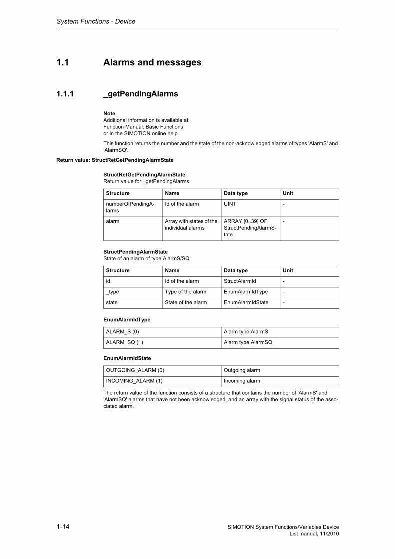
This function returns the number and the state of the non-acknowledged alarms of types 'AlarmS' and 'AlarmSQ'.
Return value: StructRetGetPendingAlarmState
StructRetGetPendingAlarmStateReturn value for _getPendingAlarms
StructPendingAlarmStateState of an alarm of type AlarmS/SQ
EnumAlarmIdType
EnumAlarmIdState
The return value of the function consists of a structure that contains the number of 'AlarmS' and 'AlarmSQ' alarms that have not been acknowledged, and an array with the signal status of the asso-ciated alarm.
Structure Name Data type Unit
numberOfPendingA-larms
Id of the alarm UINT -
alarm Array with states of the individual alarms
ARRAY [0..39] OF StructPendingAlarmS-tate
-
Structure Name Data type Unit
id Id of the alarm StructAlarmId -
_type Type of the alarm EnumAlarmIdType -
state State of the alarm EnumAlarmIdState -
ALARM_S (0) Alarm type AlarmS
ALARM_SQ (1) Alarm type AlarmSQ
OUTGOING_ALARM (0) Outgoing alarm
INCOMING_ALARM (1) Incoming alarm
System Functions - Device
1-15SIMOTION System Functions/Variables DeviceList manual, 11/2010
1.1.2 _readDiagnosticData
NoteAdditional information is available at:SIMOTION Communication System Manualor in the SIMOTION online help
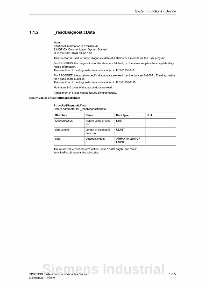
This function is used to output diagnostic data of a station or a module via the user program.
For PROFIBUS, the diagnostics for the slave are fetched, i.e. the slave supplies the complete diag-nostic information.The structure of the diagnostic data is described in IEC 61158-6-3.
For PROFINET, the subslot-specific diagnostics are read (i.e. the data set 0x800A). The diagnostics for a subslot are supplied.The structure of the diagnostic data is described in IEC 61158-6-10.
Maximum 240 bytes of diagnostic data are read.
A maximum of 8 jobs can be issued simultaneously.
Return value: StructRetDiagnosticData
StructRetDiagnosticDataReturn parameter for _readDiagnosticData
The return value consists of 'functionResult,' 'dataLength,' and 'data'.'functionResult' reports the job status.
Structure Name Data type Unit
functionResult Return value of func-tion
DINT -
dataLength Length of diagnostic data read
UDINT -
data Diagnostic data ARRAY [0..239] OF USINT
-
Siemens Industrial
System Functions - Device
1-16 SIMOTION System Functions/Variables DeviceList manual, 11/2010
Description of the return value:16#00000000Data set transfer okay, job completed with positive result.Job okay.
16#00007001Must be repeated in the next program cycle.Initial call, initiation of data transfer okay(only when command is issued asynchronously).
16#00007002Must be repeated in the next program cycle.Intermediate call, data transfer still active.(only when command is issued asynchronously).
16#00007003Data set transfer aborted.Job aborted.
16#FFFF8090Error while reading diagnostic data, job aborted.Specified logical diagnostic address invalid:No assignment is available in the system data blocks (SDBs).The logical diagnostic address does not exist in the project.
16#FFFF8091Error while reading diagnostic data, job aborted.The _readDiagnosticData function cannot reach the specified logical base address.The logical diagnostics address is available in the project, but cannot be reached at the moment (e.g. the station is currently switched off, or the module has been unplugged).
16#FFFF809DError, job aborted.An I slave/I device cannot read diagnostic data of the higher-level master/controller.
16#FFFF809EError, job aborted.Attempt to abort a non-active function.
16#FFFF809FError, job aborted.Function not executable.
16#FFFF80A0Error while reading diagnostic data, job aborted.Negative acknowledgment when reading from the module:- Module was removed during the read operation- Module defective
16#FFFF80A2Error while reading diagnostic data, job aborted.Protocol error in Layer2:- Module not available
16#FFFF80A3Error while reading diagnostic data, job aborted.Protocol error involving user interface/user:- Module not available
16#FFFF80A4-A7Error while reading diagnostic data, job aborted.Error numbers according to IEC 61158 reserved- Query the cause at the module's manufacturer
16#FFFF80A8Error while reading diagnostic data, job aborted.Error because of version conflict.
16#FFFF80A9Error while reading diagnostic data, job aborted.Function not supported by the module.
System Functions - Device
1-17SIMOTION System Functions/Variables DeviceList manual, 11/2010
16#FFFF80AA-AFError while reading diagnostic data, job aborted.Error numbers according to IEC 61158 manufacturer-specific- Query the cause at the module's manufacturer
16#FFFF80B0Error while reading diagnostic data, job aborted.- Protocol error in Layer2- Protocol error involving user interface/user.- System function not supported for this module type
16#FFFF80C2Error while reading diagnostic data, command can be repeated immediately.The module is currently executing the maximum possible jobs for one CPU.
16#FFFF80C3Error while reading diagnostic data, command can be repeated immediately.Required resources are presently occupied:- In the _readDiagnosticData function- In the module
16#FFFF80C4Error while reading diagnostic data, command can be repeated immediately.Communication errors:- Parity error- SW Ready not set- Error in block length administration- Checksum error on CPU side- Checksum error on module side
16#FFFF80C5Error while reading diagnostic data, can be repeated in the next program cycle.Distributed I/O not available at present.
16#FFFF80C6Error while reading diagnostic data, can be repeated in the next program cycle.Reading of diagnostic data was aborted due to priority class abort (restart or background)
16#FFFF80CFError while reading diagnostic data, can be repeated in the next program cycle.Another _readDiagnosticData function call is currently active under this 'commandId'.
'dataLength' reports the length of the diagnostic data read.
'data' contains the read data (byte array, maximum of 240 bytes).
The structure and meaning of the data can be found in the documentation for the relevant DP station or the relevant module.
Parameter: ioId (optional)
EnumIoIdType
Input/output assignment of the logical address. This specification is optional.With INPUT, the logical address is in the input range.With OUTPUT, the logical address is in the output range.Does not have to be specified for diagnostic addresses.
Direction: Input parameter
Data type: EnumIoIdType
Parameter index: 1
System default: INPUT
INPUT (198) Input address
OUTPUT (199) Output address
Siemens Industrial
System Functions - Device
1-18 SIMOTION System Functions/Variables DeviceList manual, 11/2010
logAddress
Specifies the logical address or the diagnostic address of the DP station/module.
nextCommand
EnumNextCommandMode
Specifies condition for transition to next command.With IMMEDIATELY, the transition takes place immediately (asynchronous call of).With WHEN_COMMAND_DONE, the transition takes place when the command has been executed (synchronous call of).With ABORT_CURRENT_COMMAND and the same 'commandId' as in the previous function call with IMMEDIATELY, the active function is aborted.
commandId
CommandIdTypeSystem-wide unique ID
Unique, system-wide 'commandId' to track command status. A 'commandId' is always valid for the duration of a job andan asynchronous job can only be aborted by means of the transition condition ABORT_CURRENT_COMMAND.
Direction: Input parameter
Data type: DINT
Parameter index: 2
Direction: Input parameter
Data type: EnumNextCommandMode
Parameter index: 3
IMMEDIATELY (60) Asynchronous
WHEN_COMMAND_DONE (160) Synchronous
ABORT_CURRENT_COMMAND (260) Abort
Direction: Input parameter
Data type: CommandIdType
Parameter index: 4
Structure Name Data type Unit
SystemId_low Low_part of ID UDINT -
SystemId_high High_part of ID UDINT -
System Functions - Device
1-19SIMOTION System Functions/Variables DeviceList manual, 11/2010
1.1.3 _resetAlarmId
NoteAdditional information is available at:Function Manual: Basic Functionsor in the SIMOTION online help
This function resets a single pending alarm of type 'AlarmS' or 'AlarmSQ'.
Return value: UDINT
Description of the return values:16#00000000Alarm could be reset without errors.
16#FFFFFFFDInternal error.
Parameter: id
ID of the alarm that is to be reset.
1.1.4 _resetAllAlarmId
NoteAdditional information is available at:Function Manual: Basic Functionsor in the SIMOTION online help
This function resets all pending alarms of type 'AlarmS' or 'AlarmSQ'.
Return value: UDINT
Description of the return values:16#00000000Alarm could be reset without errors.
16#FFFFFFFDInternal error.
Direction: Input parameter
Data type: StructAlarmId
Parameter index: 1
Siemens Industrial
System Functions - Device
1-20 SIMOTION System Functions/Variables DeviceList manual, 11/2010
1.1.5 _sendProcessInterrupt
NoteAdditional information is available at:Function Manual: Basic Functionsor in the SIMOTION online help
This function causes the DP slave to trigger a process interrupt on the DP master.
Return value: DINTThe return value reports the job status.
Description of the return value:16#00000000Data set transfer okay, job completed with positive result.Job okay.
16#00007001Must be repeated in the next program cycle.Initial call, initiation of process interrupt okay.
16#00007002Must be repeated in the next program cycle.Intermediate call, the triggered process alarm has not yet been acknowledged by the DP master.
16#00007003Data set transfer aborted.Job aborted.
16#FFFF8090Error: Job aborted.Faulty initial address of address range in transfer memory.
16#FFFF8091Error: Job aborted.Process interrupt disabled by configuration.
16#FFFF809EError: Job aborted.Attempt to abort a non-active function.
16#FFFF809FError: Job aborted.Function not executable.
16#FFFF80B5Error: Job aborted.Call in DP master not permitted.
16#FFFF80C3Error: Can be repeated in the next program cycle.Required resources are presently occupied:- In the _sendProcessInterrupt function- In the module
16#FFFF80C5Error, can be repeated in the next program cycle.Distributed I/O not available at present.
16#FFFF80CFError, can be repeated in the next program cycle.Another _sendProcessInterrupt function call is currently active under this 'commandId'.
System Functions - Device
1-21SIMOTION System Functions/Variables DeviceList manual, 11/2010
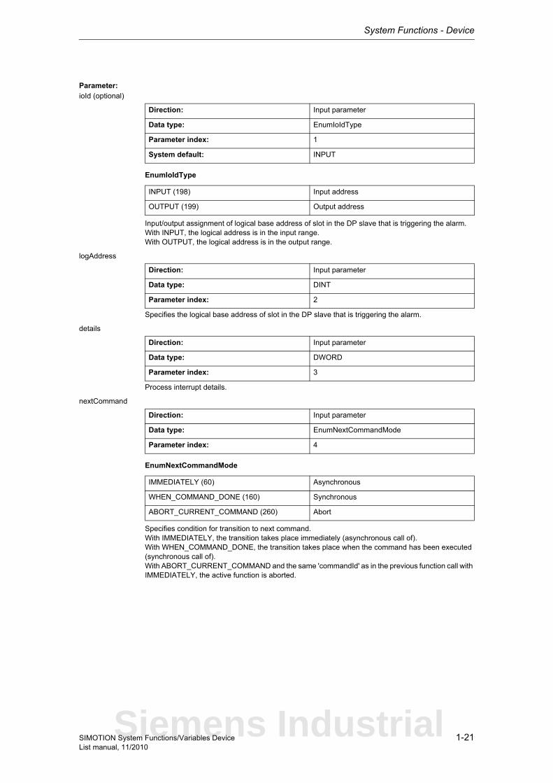
Parameter: ioId (optional)
EnumIoIdType
Input/output assignment of logical base address of slot in the DP slave that is triggering the alarm.With INPUT, the logical address is in the input range.With OUTPUT, the logical address is in the output range.
logAddress
Specifies the logical base address of slot in the DP slave that is triggering the alarm.
details
Process interrupt details.
nextCommand
EnumNextCommandMode
Specifies condition for transition to next command.With IMMEDIATELY, the transition takes place immediately (asynchronous call of).With WHEN_COMMAND_DONE, the transition takes place when the command has been executed (synchronous call of).With ABORT_CURRENT_COMMAND and the same 'commandId' as in the previous function call with IMMEDIATELY, the active function is aborted.
Direction: Input parameter
Data type: EnumIoIdType
Parameter index: 1
System default: INPUT
INPUT (198) Input address
OUTPUT (199) Output address
Direction: Input parameter
Data type: DINT
Parameter index: 2
Direction: Input parameter
Data type: DWORD
Parameter index: 3
Direction: Input parameter
Data type: EnumNextCommandMode
Parameter index: 4
IMMEDIATELY (60) Asynchronous
WHEN_COMMAND_DONE (160) Synchronous
ABORT_CURRENT_COMMAND (260) Abort
Siemens Industrial
System Functions - Device
1-22 SIMOTION System Functions/Variables DeviceList manual, 11/2010
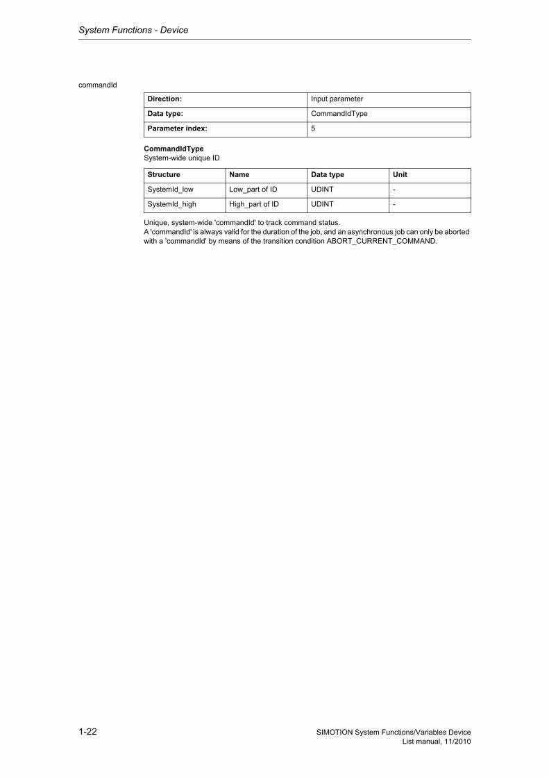
commandId
CommandIdTypeSystem-wide unique ID
Unique, system-wide 'commandId' to track command status.A 'commandId' is always valid for the duration of the job, and an asynchronous job can only be aborted with a 'commandId' by means of the transition condition ABORT_CURRENT_COMMAND.
Direction: Input parameter
Data type: CommandIdType
Parameter index: 5
Structure Name Data type Unit
SystemId_low Low_part of ID UDINT -
SystemId_high High_part of ID UDINT -
System Functions - Device
1-23SIMOTION System Functions/Variables DeviceList manual, 11/2010
1.1.6 _writeAndSendMessage
NoteFurther information about the device diagnostics: Diagnostic buffer can found in the:Overview of Service and Diagnostics Options, Product Informationor in the SIMOTION online help
This function enters an event specified by the 'EventNumber', 'Info1', 'Info2', and 'eventClass' parame-ters in the diagnostics buffer and optionally sends it to all logged-on operator panels (OPs) simultane-ously.
Return value: DINTDescription of the return values:
0 OK
701 No station logged on
-701 Invalid event number
-702 Send buffer full
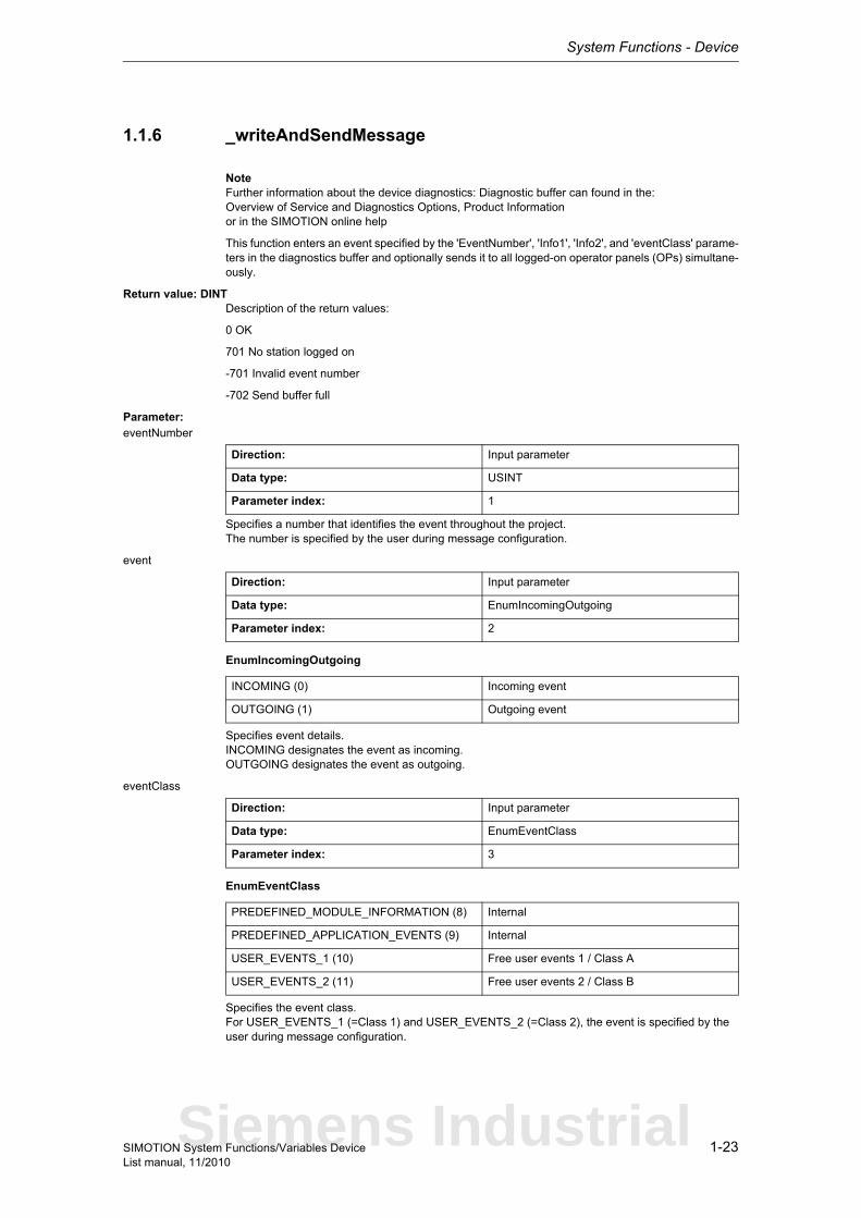
Parameter: eventNumber
Specifies a number that identifies the event throughout the project.The number is specified by the user during message configuration.
event
EnumIncomingOutgoing
Specifies event details.INCOMING designates the event as incoming.OUTGOING designates the event as outgoing.
eventClass
EnumEventClass
Specifies the event class.For USER_EVENTS_1 (=Class 1) and USER_EVENTS_2 (=Class 2), the event is specified by the user during message configuration.
Direction: Input parameter
Data type: USINT
Parameter index: 1
Direction: Input parameter
Data type: EnumIncomingOutgoing
Parameter index: 2
INCOMING (0) Incoming event
OUTGOING (1) Outgoing event
Direction: Input parameter
Data type: EnumEventClass
Parameter index: 3
PREDEFINED_MODULE_INFORMATION (8) Internal
PREDEFINED_APPLICATION_EVENTS (9) Internal
USER_EVENTS_1 (10) Free user events 1 / Class A
USER_EVENTS_2 (11) Free user events 2 / Class B
Siemens Industrial
System Functions - Device
1-24 SIMOTION System Functions/Variables DeviceList manual, 11/2010
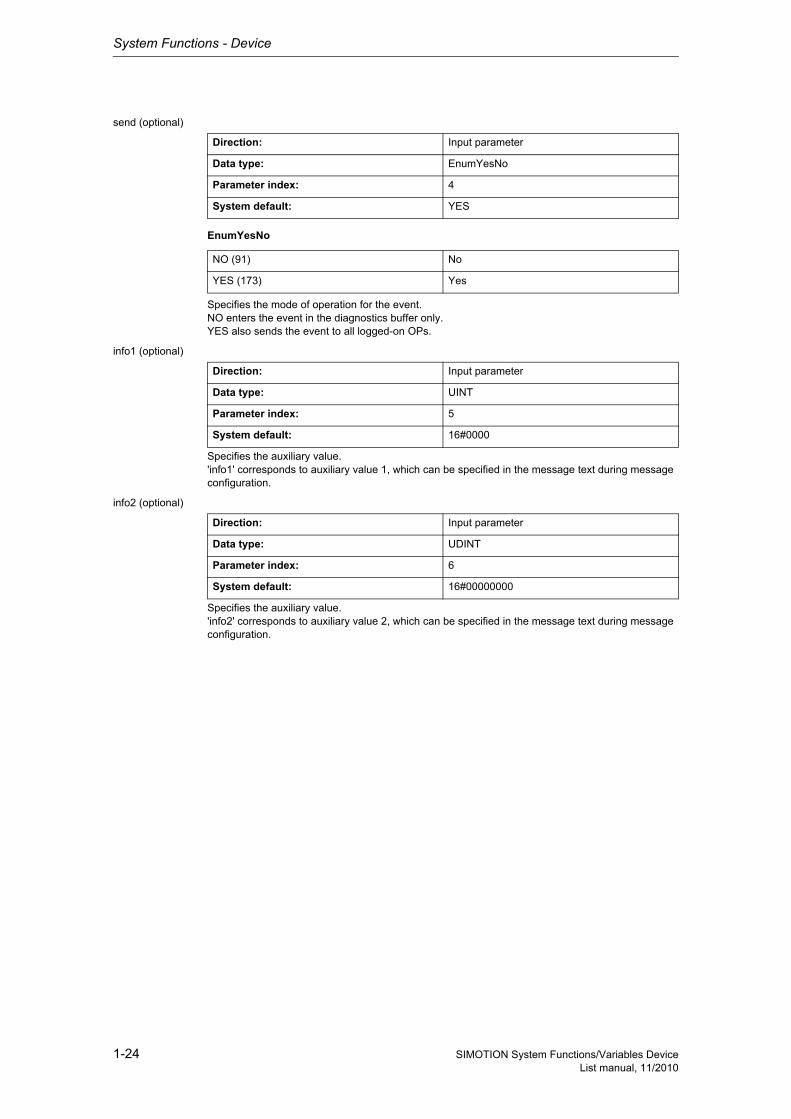
send (optional)
EnumYesNo
Specifies the mode of operation for the event.NO enters the event in the diagnostics buffer only.YES also sends the event to all logged-on OPs.
info1 (optional)
Specifies the auxiliary value.'info1' corresponds to auxiliary value 1, which can be specified in the message text during message configuration.
info2 (optional)
Specifies the auxiliary value.'info2' corresponds to auxiliary value 2, which can be specified in the message text during message configuration.
Direction: Input parameter
Data type: EnumYesNo
Parameter index: 4
System default: YES
NO (91) No
YES (173) Yes
Direction: Input parameter
Data type: UINT
Parameter index: 5
System default: 16#0000
Direction: Input parameter
Data type: UDINT
Parameter index: 6
System default: 16#00000000
System Functions - Device
1-25SIMOTION System Functions/Variables DeviceList manual, 11/2010
1.2 Communication
1.2.1 Interface handling - Configuration
1.2.1.1 _activateDpSlave
NoteAdditional information is available at:SIMOTION Basic Functions for Modular Machines Function ManualSIMOTION Communication System Manualor in the online help
This system function establishes cyclical communication for the entire DP station (slave) or the PRO-FINET station (device), even if the station has multiple logical addresses (diagnostic addresses).
This system function cannot be called when the _deactivateDpSlave system function is active with the same 'logicalAddressOfDpStation'.
This system function applies to both PROFIBUS and PROFINET.
Return value: DINTThe return value reports the job status.
Siemens Industrial
System Functions - Device
1-26 SIMOTION System Functions/Variables DeviceList manual, 11/2010
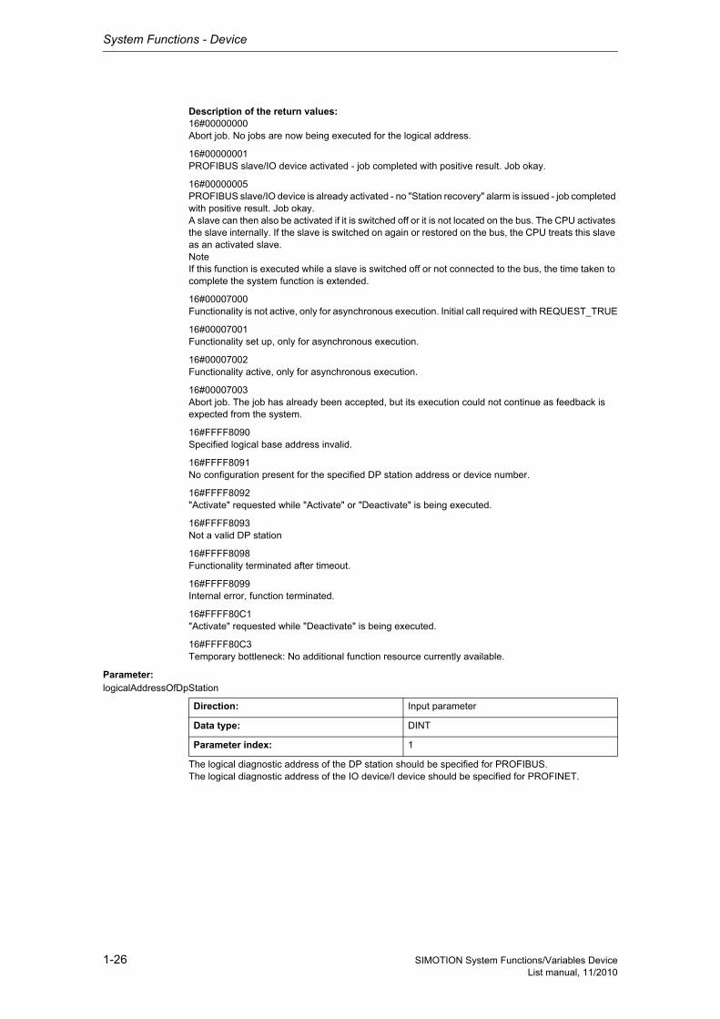
Description of the return values:16#00000000Abort job. No jobs are now being executed for the logical address.
16#00000001PROFIBUS slave/IO device activated - job completed with positive result. Job okay.
16#00000005PROFIBUS slave/IO device is already activated - no "Station recovery" alarm is issued - job completed with positive result. Job okay.A slave can then also be activated if it is switched off or it is not located on the bus. The CPU activates the slave internally. If the slave is switched on again or restored on the bus, the CPU treats this slave as an activated slave.NoteIf this function is executed while a slave is switched off or not connected to the bus, the time taken to complete the system function is extended.
16#00007000Functionality is not active, only for asynchronous execution. Initial call required with REQUEST_TRUE
16#00007001Functionality set up, only for asynchronous execution.
16#00007002Functionality active, only for asynchronous execution.
16#00007003Abort job. The job has already been accepted, but its execution could not continue as feedback is expected from the system.
16#FFFF8090Specified logical base address invalid.
16#FFFF8091No configuration present for the specified DP station address or device number.
16#FFFF8092"Activate" requested while "Activate" or "Deactivate" is being executed.
16#FFFF8093Not a valid DP station
16#FFFF8098Functionality terminated after timeout.
16#FFFF8099Internal error, function terminated.
16#FFFF80C1"Activate" requested while "Deactivate" is being executed.
16#FFFF80C3Temporary bottleneck: No additional function resource currently available.
Parameter: logicalAddressOfDpStation
The logical diagnostic address of the DP station should be specified for PROFIBUS.The logical diagnostic address of the IO device/I device should be specified for PROFINET.
Direction: Input parameter
Data type: DINT
Parameter index: 1
System Functions - Device
1-27SIMOTION System Functions/Variables DeviceList manual, 11/2010
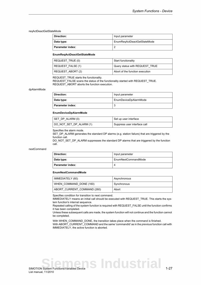
reqActDeactGetStateMode
EnumReqActDeactGetStateMode
REQUEST_TRUE starts the functionality.REQUEST_FALSE scans the status of the functionality started with REQUEST_TRUE.REQUEST_ABORT aborts the function execution.
dpAlarmMode
EnumDeviceDpAlarmMode
Specifies the alarm mode.SET_DP_ALARM generates the standard DP alarms (e.g. station failure) that are triggered by the function call.DO_NOT_SET_DP_ALARM suppresses the standard DP alarms that are triggered by the function call.
nextCommand
EnumNextCommandMode
Specifies condition for transition to next command.IMMEDIATELY means an initial call should be executed with REQUEST_TRUE. This starts the sys-tem function's internal sequence.Repeated calling of the system function is required with REQUEST_FALSE until the function confirms it has been completed.Unless these subsequent calls are made, the system function will not continue and the function cannot be completed.
With WHEN_COMMAND_DONE, the transition takes place when the command is finished.With ABORT_CURRENT_COMMAND and the same 'commandId' as in the previous function call with IMMEDIATELY, the active function is aborted.
Direction: Input parameter
Data type: EnumReqActDeactGetStateMode
Parameter index: 2
REQUEST_TRUE (0) Start functionality
REQUEST_FALSE (1) Query status with REQUEST_TRUE
REQUEST_ABORT (2) Abort of the function execution
Direction: Input parameter
Data type: EnumDeviceDpAlarmMode
Parameter index: 3
SET_DP_ALARM (0) Set up user interface
DO_NOT_SET_DP_ALARM (1) Suppress user interface call
Direction: Input parameter
Data type: EnumNextCommandMode
Parameter index: 4
IMMEDIATELY (60) Asynchronous
WHEN_COMMAND_DONE (160) Synchronous
ABORT_CURRENT_COMMAND (260) Abort
Siemens Industrial
System Functions - Device
1-28 SIMOTION System Functions/Variables DeviceList manual, 11/2010
1.2.1.2 _activateDpSlaveAddress
NoteAdditional information is available at:SIMOTION Basic Functions for Modular Machines Function Manualor in the online help
This system function activates all DP slave addresses set beforehand.
Return value: DINT
Description of the return values:16#FFFF8090Invalid addressOutside of valid range / invalid DP segment adapter
16#FFFF8099Internal error, function terminated.
16#FFFF80C1Resources for executing the functionality are not available.
Parameter: logicalAddressCommunicationAdapter
Specifies the logical diagnostic address of the interface.
Direction: Input parameter
Data type: DINT
Parameter index: 1

System Functions - Device
1-29SIMOTION System Functions/Variables DeviceList manual, 11/2010
1.2.1.3 _activateNameOfStation
NoteAdditional information is available at:SIMOTION Basic Functions for Modular Machines Function Manualor in the online help
This function activates the modified data specified in the parameter. SIMOTION performs internally the restart.
Return value: DINTThe return value returns the job status and name.
Description of the return values:16#00000000System function completed successfully. A restart is performed afterwards.
16#FFFF8090The specified logical diagnostic address is invalid.
16#FFFF8091No valid logical diagnostic address for a PROFINET interface.
16#FFFF8092PROFINET interface is configured, but not available. Can only occur if the PROFINET interface is inserted in SIMOTION via a module.
16#FFFF8095The SIMOTION restart necessary for activation of NameOfStation did not take place.
16#FFFF8096A device name was not set with _setNameOfStation before this system function was called.
16#FFFF8099Internal error. Function terminated.
16#FFFF80C1There are currently no resources available to perform this system function. The user program can con-tinue to call this system function until this return value no longer appears.
16#FFFF80C2A system function call for the relevant PROFINET interface is already in progress. The user program can call this function until this return value no longer appears.
16#FFFF80C3A reactivation of NameOfStation rejected because a function call for activating a NameOfStation on the relevant PROFINET interface is still in progress with an identical CommandId. The user program can call this function until this return value no longer appears.
Parameter: logicalAddressPnInterface
Specifies logical base address of PNIO interface (diagnostic address).
Direction: Input parameter
Data type: DINT
Parameter index: 1
Siemens Industrial

System Functions - Device
1-30 SIMOTION System Functions/Variables DeviceList manual, 11/2010
1.2.1.4 _deactivateDpSlave
NoteAdditional information is available at:SIMOTION Basic Functions for Modular Machines Function ManualSIMOTION Communication System Manualor in the online help
This system function aborts cyclical communication for the entire DP station (slave) or the PROFINET station (device), even if the station has multiple logical addresses (diagnostic addresses).
This system function cannot be called when the _activateDpSlave system function is active with the same 'logicalAddressOfDpStation'.This system function applies to both PROFIBUS and PROFINET.
Return value: DINTThe return value reports the job status.
Description of the return values:16#00000000Abort job. No jobs are now being executed for the logical address.
16#00000002PROFIBUS slave/IO device deactivated. Job completed with positive result. Job okay.
16#00000005PROFIBUS slave/IO device already deactivated. No "station failure" alarm occurs. Job completed with positive result. Job okay.
16#00000006DP station already deactivated: No "station failure" alarm occurs.A slave can be deactivated even if it is switched off or is not located on the bus. The CPU deactivates the slave internally.The function then reports this return value.If the slave is switched on again or restored on the bus, the CPU treats this slave as a deactivated slave.
16#00007000Functionality is not active, only for asynchronous execution.
16#00007001Functionality initiated, only for asynchronous execution.
16#00007002Functionality active, only for asynchronous execution.
16#00007003Abort job. The job has already been accepted, but its execution could not continue as feedback is expected from the system.
16#FFFF8090Specified logical base address invalid.
16#FFFF8091No configuration present for the specified DP station address or device number.
16#FFFF8092"Deactivate" requested while "Activate" or "Deactivate" is being executed.
16#FFFF8093Not a valid DP station
16#FFFF8098Functionality of system function has been terminated with timeout.
System Functions - Device
1-31SIMOTION System Functions/Variables DeviceList manual, 11/2010
16#FFFF8099Internal error, function terminated.
16#FFFF80C1"Activate" requested while "Deactivate" is being executed.
16#FFFF80C3Temporary bottleneck: No additional function resource currently available.
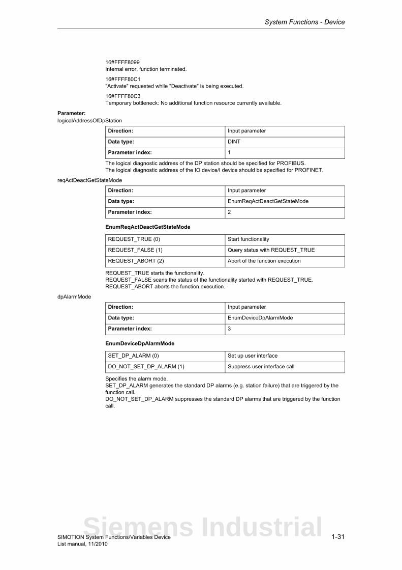
Parameter: logicalAddressOfDpStation
The logical diagnostic address of the DP station should be specified for PROFIBUS.The logical diagnostic address of the IO device/I device should be specified for PROFINET.
reqActDeactGetStateMode
EnumReqActDeactGetStateMode
REQUEST_TRUE starts the functionality.REQUEST_FALSE scans the status of the functionality started with REQUEST_TRUE.REQUEST_ABORT aborts the function execution.
dpAlarmMode
EnumDeviceDpAlarmMode
Specifies the alarm mode.SET_DP_ALARM generates the standard DP alarms (e.g. station failure) that are triggered by the function call.DO_NOT_SET_DP_ALARM suppresses the standard DP alarms that are triggered by the function call.
Direction: Input parameter
Data type: DINT
Parameter index: 1
Direction: Input parameter
Data type: EnumReqActDeactGetStateMode
Parameter index: 2
REQUEST_TRUE (0) Start functionality
REQUEST_FALSE (1) Query status with REQUEST_TRUE
REQUEST_ABORT (2) Abort of the function execution
Direction: Input parameter
Data type: EnumDeviceDpAlarmMode
Parameter index: 3
SET_DP_ALARM (0) Set up user interface
DO_NOT_SET_DP_ALARM (1) Suppress user interface call
Siemens Industrial

System Functions - Device
1-32 SIMOTION System Functions/Variables DeviceList manual, 11/2010
nextCommand
EnumNextCommandMode
Specifies condition for transition to next command.IMMEDIATELY means an initial call should be executed with REQUEST_TRUE. This starts the sys-tem function's internal sequence.Repeated calling of the system function is required with REQUEST_FALSE until the function confirms it has been completed.Unless these subsequent calls are made, the system function will not continue and the function cannot be completed.
With WHEN_COMMAND_DONE, the transition takes place when the command is finished.With ABORT_CURRENT_COMMAND and the same 'commandId' as in the previous function call with IMMEDIATELY, the active function is aborted.
Direction: Input parameter
Data type: EnumNextCommandMode
Parameter index: 4
IMMEDIATELY (60) Asynchronous
WHEN_COMMAND_DONE (160) Synchronous
ABORT_CURRENT_COMMAND (260) Abort
System Functions - Device
1-33SIMOTION System Functions/Variables DeviceList manual, 11/2010
1.2.1.5 _enableDpInterfaceSynchronizationMode
NoteFor additional information on the synchronization of the interfaces, refer to the function manuals:SIMOTION Motion Control, TO followingObject, TO camSIMOTION Basic Functions for Modular Machinesor in the online help
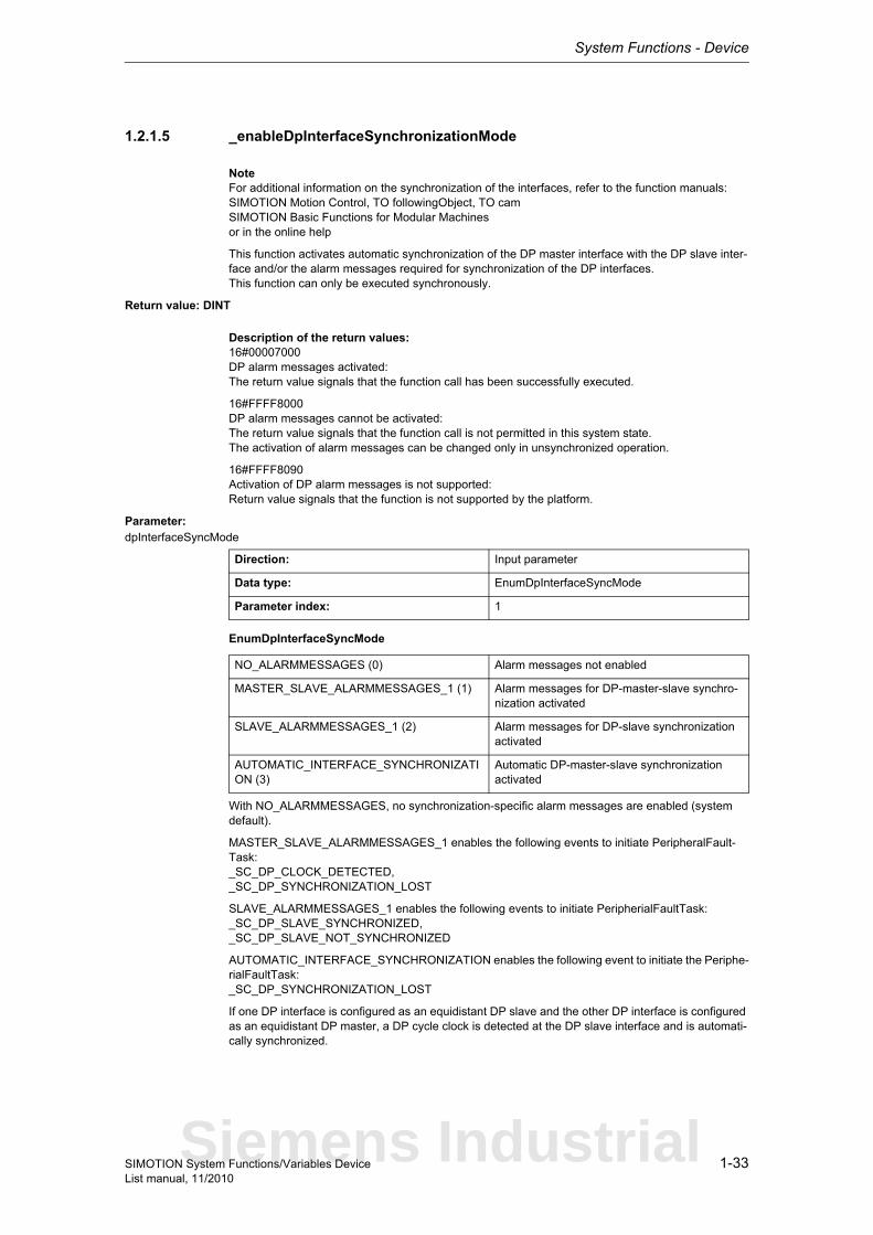
This function activates automatic synchronization of the DP master interface with the DP slave inter-face and/or the alarm messages required for synchronization of the DP interfaces.This function can only be executed synchronously.
Return value: DINT
Description of the return values:16#00007000DP alarm messages activated:The return value signals that the function call has been successfully executed.
16#FFFF8000DP alarm messages cannot be activated:The return value signals that the function call is not permitted in this system state.The activation of alarm messages can be changed only in unsynchronized operation.
16#FFFF8090Activation of DP alarm messages is not supported:Return value signals that the function is not supported by the platform.
Parameter: dpInterfaceSyncMode
EnumDpInterfaceSyncMode
With NO_ALARMMESSAGES, no synchronization-specific alarm messages are enabled (system default).
MASTER_SLAVE_ALARMMESSAGES_1 enables the following events to initiate PeripheralFault-Task:_SC_DP_CLOCK_DETECTED,_SC_DP_SYNCHRONIZATION_LOST
SLAVE_ALARMMESSAGES_1 enables the following events to initiate PeripherialFaultTask:_SC_DP_SLAVE_SYNCHRONIZED,_SC_DP_SLAVE_NOT_SYNCHRONIZED
AUTOMATIC_INTERFACE_SYNCHRONIZATION enables the following event to initiate the Periphe-rialFaultTask:_SC_DP_SYNCHRONIZATION_LOST
If one DP interface is configured as an equidistant DP slave and the other DP interface is configured as an equidistant DP master, a DP cycle clock is detected at the DP slave interface and is automati-cally synchronized.
Direction: Input parameter
Data type: EnumDpInterfaceSyncMode
Parameter index: 1
NO_ALARMMESSAGES (0) Alarm messages not enabled
MASTER_SLAVE_ALARMMESSAGES_1 (1) Alarm messages for DP-master-slave synchro-nization activated
SLAVE_ALARMMESSAGES_1 (2) Alarm messages for DP-slave synchronization activated
AUTOMATIC_INTERFACE_SYNCHRONIZATION (3)
Automatic DP-master-slave synchronization activated
Siemens Industrial
System Functions - Device
1-34 SIMOTION System Functions/Variables DeviceList manual, 11/2010
1.2.1.6 _getActiveNameOfStation
NoteMore detailed information on this system function can be found inSIMOTION Basic Functions for Modular Machines Function Manualor in the online help
The system function reads the currently active NameOfStation. This originates from the configuration or was set with the DCP service using 'TcpIp' or with the _setNameOfStation system function.
A maximum of 239 characters is returned. According to the standard, 240 characters are permitted, but this is not currently supported by SIMOTION.
If NameOfStation is not available, a string with a length of 0 is returned.In pnPortNumber, 16#FFFFFFFF is always returned.In pnSlotNumber, 16#FFFFFFFF is always returned.
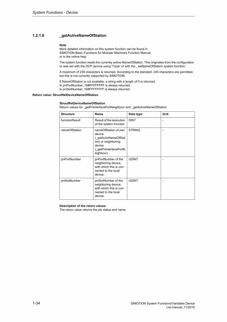
Return value: StructRetDeviceNameOfStation
StructRetDeviceNameOfStationReturn values for _getPnInterfacePortNeighbour and _getActiveNameOfStation
Description of the return values:The return value returns the job status and name.
Structure Name Data type Unit
functionResult Result of the execution of the system function
DINT -
nameOfStation nameOfStation of own device (_getActivNameOfStation) or neighboring device (_getPnInterfacePortNeighbour)
STRING -
pnPortNumber pnPortNumber of the neighboring device, with which this is con-nected to the local device.
UDINT -
pnSlotNumber pnSlotNumber of the neighboring device, with which this is con-nected to the local device.
UDINT -
System Functions - Device
1-35SIMOTION System Functions/Variables DeviceList manual, 11/2010
functionResult16#00000000System function completed successfully. NameOfStation is contained in the return value.
16#00007000The system function is in inactive status. The functionality associated with the system function is not active. An initial call with REQUEST_TRUE is required.
16#00007001The system function is started with REQUEST_TRUE. A new call in the user program until completion of the system function is required with REQUEST_FALSE. This return value is reported only for asyn-chronous execution.
16#00007002The system function is still running. A new call in the user program until completion of the system func-tion is required with REQUEST_FALSE. This return value is reported only for asynchronous execu-tion.
16#00007003System function aborted successfully. If an abort is not possible, the system function returns 16#FFFF8094.
16#FFFF8090The specified logical diagnostic address is invalid.
16#FFFF8091No valid logical diagnostic address for a PROFINET interface.
16#FFFF8092PROFINET interface is configured, but not available. Can only occur if the PROFINET interface is inserted in SIMOTION via a module.
16#FFFF8094An abort is no longer possible in the current system function status.
16#FFFF8097Readout of active device name is not supported by the PROFINET interface.
16#FFFF8099Internal error. Function terminated.
16#FFFF809AThe PROFINET interface does not support this service. Function terminated.
16#FFFF80C1There are currently no resources available to perform this system function. The user program can con-tinue to call this system function until this return value no longer appears.
16#FFFF80C2A system function call for the relevant PROFINET interface is already in progress. The user program can continue to call this system function until this return value no longer appears.
16#FFFF80C3A re-read of the current device name with REQUEST_TRUE was rejected because a function call for reading the current device name on the relevant PROFINET interface is still in progress with an iden-tical CommandId. The user program can call this function until this return value no longer appears.
nameOfStation: Device name of relevant PROFINET interface. A maximum of 239 characters is retur-ned. According to thestandard, 240 characters are permitted, but this is not currently supported by SIMOTION.
If NameOfStation is not available, a string with a length of 0 is returned.
pnPortNumber: 16#FFFFFFFF is always returned.
pnSlotNumber: 16#FFFFFFFF is always returned.
Siemens Industrial
System Functions - Device
1-36 SIMOTION System Functions/Variables DeviceList manual, 11/2010
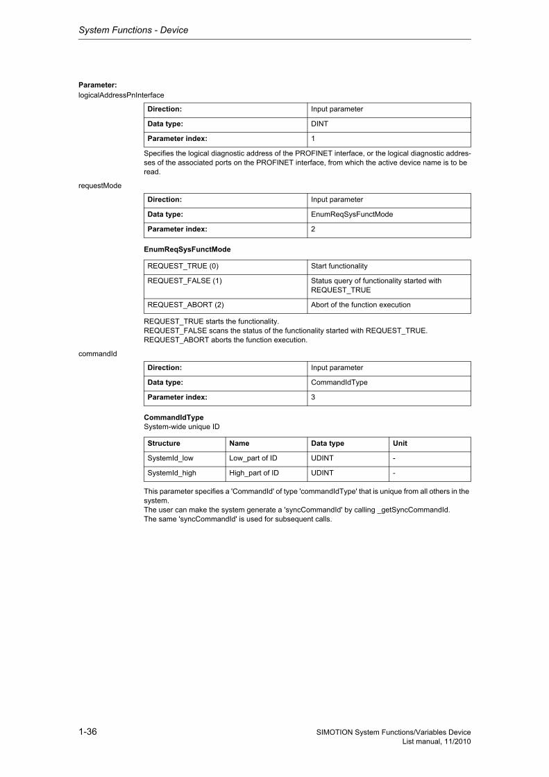
Parameter: logicalAddressPnInterface
Specifies the logical diagnostic address of the PROFINET interface, or the logical diagnostic addres-ses of the associated ports on the PROFINET interface, from which the active device name is to be read.
requestMode
EnumReqSysFunctMode
REQUEST_TRUE starts the functionality.REQUEST_FALSE scans the status of the functionality started with REQUEST_TRUE.REQUEST_ABORT aborts the function execution.
commandId
CommandIdTypeSystem-wide unique ID
This parameter specifies a 'CommandId' of type 'commandIdType' that is unique from all others in the system.The user can make the system generate a 'syncCommandId' by calling _getSyncCommandId.The same 'syncCommandId' is used for subsequent calls.
Direction: Input parameter
Data type: DINT
Parameter index: 1
Direction: Input parameter
Data type: EnumReqSysFunctMode
Parameter index: 2
REQUEST_TRUE (0) Start functionality
REQUEST_FALSE (1) Status query of functionality started with REQUEST_TRUE
REQUEST_ABORT (2) Abort of the function execution
Direction: Input parameter
Data type: CommandIdType
Parameter index: 3
Structure Name Data type Unit
SystemId_low Low_part of ID UDINT -
SystemId_high High_part of ID UDINT -

System Functions - Device
1-37SIMOTION System Functions/Variables DeviceList manual, 11/2010
nextCommand
EnumNextCommandMode
Specifies condition for transition to next command.IMMEDIATELY means an initial call should be executed with REQUEST_TRUE. This starts the sys-tem function's internal sequence.Repeated calling of the system function is required with REQUEST_FALSE until the function confirms it has been completed.Unless these subsequent calls are made, the system function will not continue and the function cannot be completed.
With WHEN_COMMAND_DONE, the transition takes place when the command is finished.With ABORT_CURRENT_COMMAND and the same 'commandId' as in the previous function call with IMMEDIATELY, the active function is aborted.
Direction: Input parameter
Data type: EnumNextCommandMode
Parameter index: 5
IMMEDIATELY (60) Asynchronous
WHEN_COMMAND_DONE (160) Synchronous
ABORT_CURRENT_COMMAND (260) Abort
Siemens Industrial
System Functions - Device
1-38 SIMOTION System Functions/Variables DeviceList manual, 11/2010
1.2.1.7 _getDeviceId
NoteMore detailed information on this system function can be found inFunction Manual: Basic Functionsor in the online help
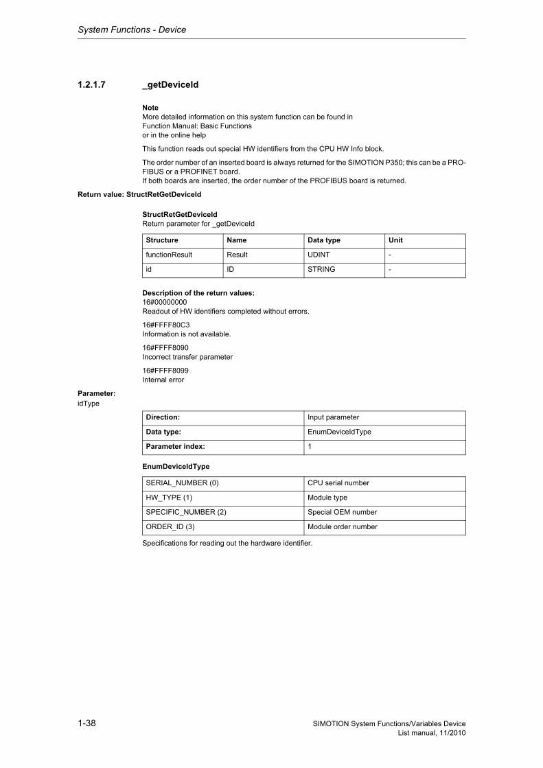
This function reads out special HW identifiers from the CPU HW Info block.
The order number of an inserted board is always returned for the SIMOTION P350; this can be a PRO-FIBUS or a PROFINET board.If both boards are inserted, the order number of the PROFIBUS board is returned.
Return value: StructRetGetDeviceId
StructRetGetDeviceIdReturn parameter for _getDeviceId
Description of the return values:16#00000000Readout of HW identifiers completed without errors.
16#FFFF80C3Information is not available.
16#FFFF8090Incorrect transfer parameter
16#FFFF8099Internal error
Parameter: idType
EnumDeviceIdType
Specifications for reading out the hardware identifier.
Structure Name Data type Unit
functionResult Result UDINT -
id ID STRING -
Direction: Input parameter
Data type: EnumDeviceIdType
Parameter index: 1
SERIAL_NUMBER (0) CPU serial number
HW_TYPE (1) Module type
SPECIFIC_NUMBER (2) Special OEM number
ORDER_ID (3) Module order number
System Functions - Device
1-39SIMOTION System Functions/Variables DeviceList manual, 11/2010
1.2.1.8 _getDoIndexNumberFromLogAddress
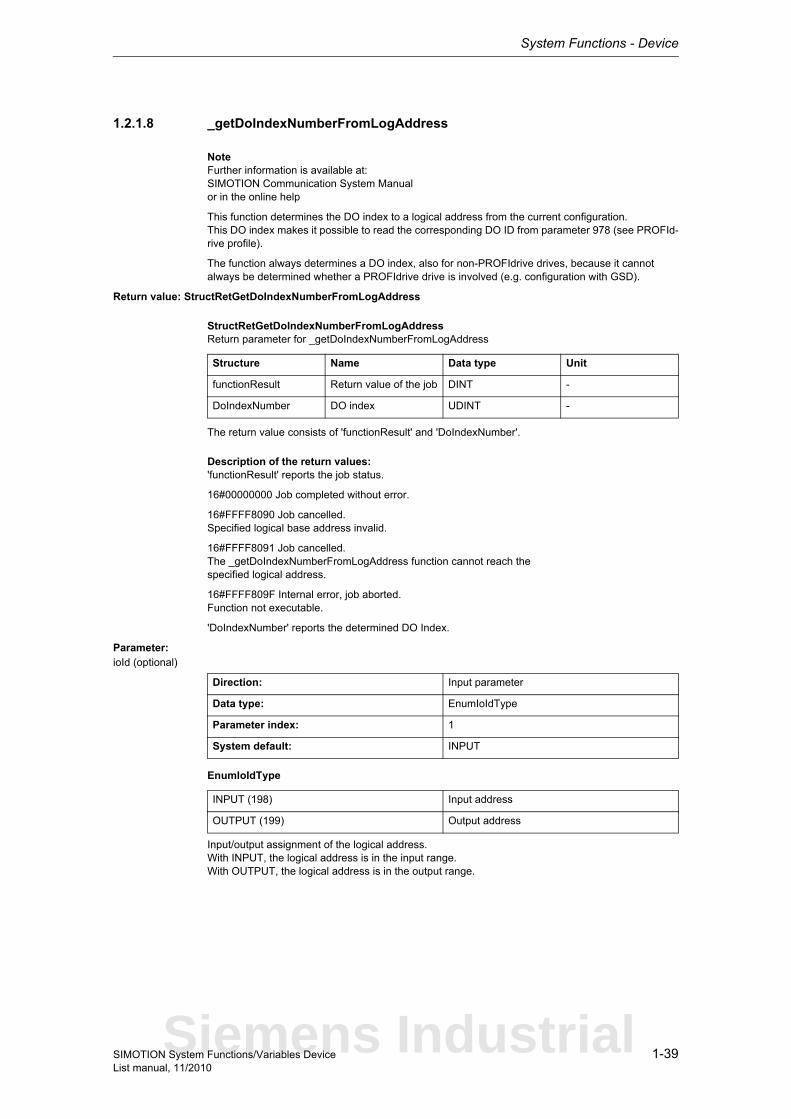
NoteFurther information is available at:SIMOTION Communication System Manualor in the online help
This function determines the DO index to a logical address from the current configuration.This DO index makes it possible to read the corresponding DO ID from parameter 978 (see PROFId-rive profile).
The function always determines a DO index, also for non-PROFIdrive drives, because it cannot always be determined whether a PROFIdrive drive is involved (e.g. configuration with GSD).
Return value: StructRetGetDoIndexNumberFromLogAddress
StructRetGetDoIndexNumberFromLogAddressReturn parameter for _getDoIndexNumberFromLogAddress
The return value consists of 'functionResult' and 'DoIndexNumber'.
Description of the return values:'functionResult' reports the job status.
16#00000000 Job completed without error.
16#FFFF8090 Job cancelled.Specified logical base address invalid.
16#FFFF8091 Job cancelled.The _getDoIndexNumberFromLogAddress function cannot reach thespecified logical address.
16#FFFF809F Internal error, job aborted.Function not executable.
'DoIndexNumber' reports the determined DO Index.
Parameter: ioId (optional)
EnumIoIdType
Input/output assignment of the logical address.With INPUT, the logical address is in the input range.With OUTPUT, the logical address is in the output range.
Structure Name Data type Unit
functionResult Return value of the job DINT -
DoIndexNumber DO index UDINT -
Direction: Input parameter
Data type: EnumIoIdType
Parameter index: 1
System default: INPUT
INPUT (198) Input address
OUTPUT (199) Output address
Siemens Industrial

System Functions - Device
1-40 SIMOTION System Functions/Variables DeviceList manual, 11/2010
logAddress
Specifies a configured logical IO address.
Direction: Input parameter
Data type: DINT
Parameter index: 2
System Functions - Device
1-41SIMOTION System Functions/Variables DeviceList manual, 11/2010
1.2.1.9 _getGeoAddressFromLogAddress
NoteFurther information is available at:SIMOTION Basic Functions for Modular Machines Function Manualor in the online help
This function determines the corresponding geographical address from a logical address.
Return value: StructRetGetGeoAddressFromLogAddress
StructRetGetGeoAddressFromLogAddressReturn parameter for _getGeoAddressFromLogAddress
The return value consists of 'functionResult', 'AREA', 'RACK1', 'RACK2', 'SLOT', 'SUBSLOT' and 'SUBADDR'.
Description of the return values:'functionResult' reports the job status.
16#00000000Job completed without errors.
16#FFFF8090Job aborted. Specified logical base address invalid.
16#FFFF8091Internal error, job aborted. The _getGeoAddressFromLogAddress function cannot reach the specified logical address.
16#FFFF819FInternal error, job aborted. Function not executable.
'AREA' reports the area identifier.
The area identifier indicates how the other return values RACK1, RACK2, SLOT, SUBSLOT and SUB-ADDR are to be interpreted.
AREA = 1 : PBUS• RACK1 -> Module rack no.• RACK2 -> Not relevant, always 0• SLOT -> Slot no.• SUBSLOT -> Not relevant, always 0• SUBADDR -> Difference between logical address and base address
AREA = 2 : PROFIBUS DP• RACK1 -> Station number• RACK2 -> Master system ID• SLOT -> Slot no. inside a station• SUBSLOT -> Not relevant, always 0• SUBADDR -> Difference between logical address and base address
Structure Name Data type Unit
functionResult Return value of the job DINT -
area Area identifier UDINT -
rack1 Rack/station number UDINT -
rack2 Master system ID UDINT -
slot Slot number UDINT -
subSlot Subslot number UDINT -
subAddress Difference to the base address
UDINT -
Siemens Industrial
System Functions - Device
1-42 SIMOTION System Functions/Variables DeviceList manual, 11/2010
AREA = 7 : ONBOARD• RACK1 -> Not relevant, always 0• RACK2 -> Not relevant, always 0• SLOT -> Slot no. of the CPU• SUBSLOT -> Slot no. of a sub-module within a SLOT• SUBADDR -> Difference between logical address and base address
AREA = 8 : PROFINET IO• RACK1 -> Device number, number of the PROFINET IO device containing the relevant subslot• RACK2 -> PROFINET IO system ID, number of the IO system containing the PROFINET IO
device with the relevant subslot; value range 100 - 115• SLOT -> Slot number in the PROFINET IO device containing the relevant subslot• SUBSLOT -> Subslot number of the subslot containing the logical address of the 'logAddress'
input parameter• SUBADDR -> Difference between the logical address of the 'logAddress' input parameter and the
logical base address of the relevant subslot
'RACK1' reports module rack/station number.
'RACK2' reports the master system-Id.
'SLOT' reports the slot number.
'SUBSLOT' reports the subslot number.
'SUBADDR' reports the difference to the basic address.
Parameter: ioId (optional)
EnumIoIdType
Input/output assignment of the logical address.With INPUT, the logical address is in the input range.With OUTPUT, the logical address is in the output range.Diagnostic addresses are always of type INPUT.
logAddress
Specifies a logical IO address or a diagnostic address.
Direction: Input parameter
Data type: EnumIoIdType
Parameter index: 1
System default: INPUT
INPUT (198) Input address
OUTPUT (199) Output address
Direction: Input parameter
Data type: DINT
Parameter index: 2
System Functions - Device
1-43SIMOTION System Functions/Variables DeviceList manual, 11/2010
1.2.1.10 _getMemoryCardId
NoteFurther information is available at:SIMOTION Basic Functions Function Manualor in the online help
This function reads out special HW identifiers from the MemoryCard HW Info block.
Return value: StructRetGetMemoryCardId
StructRetGetMemoryCardIdReturn parameter for getMemoryCardId
Description of the return values:16#00000000 Read-out of the HW identifiers completed without error
16#FFFFFFFD Internal error
16#FFFFFFF8 Incorrect parameter
Parameter: idType
EnumMemoryCardIdType
Specification for reading out the hardware identifier.
Structure Name Data type Unit
functionResult Result UDINT -
id ID STRING -
Direction: Input parameter
Data type: EnumMemoryCardIdType
Parameter index: 1
MEMORY_CARD_SERIAL_NUMBER (0) Memory card serial number
Siemens Industrial
System Functions - Device
1-44 SIMOTION System Functions/Variables DeviceList manual, 11/2010
1.2.1.11 _getNextLogAddress
All configured logical addresses of a segment can be determined using this function.
Return value: StructRetGetNextLogAddress
StructRetGetNextLogAddressReturn parameter for _getNextLogAddress
EnumIoIdType
EnumYesNo
The return value consists of 'functionResult', 'ioIdType', 'diagnosticType', 'logicalAddress', 'length', 'stationAddress', 'slot', 'subslot' and 'nextIndex'.
Description of the return values:
functionResultreports the job status.
16#00000000Job completed without errors. No other addresses are available.
16#00000001Job completed without errors. Other addresses are available.- With a new call, the function can determine the next logical address with the value returned in the return value 'nextIndex'.The return value 'nextIndex' serves here as new input value for 'index'.
16#FFFF8090Job aborted. The specified index is invalid. No logical address could be assigned.
16#FFFF8091Job aborted. IO segment was not found (check area and mastersystemId).
16#FFFF8092Job aborted. The IO segment does not contain any configured addresses.
Structure Name Data type Unit
functionResult Return value of the job DINT -
ioIdType IO type EnumIoIdType -
diagnosticType Information on whe-ther address is a diag-nostics address
EnumYesNo -
logicalAddress Logical address UDINT -
length Length of the logical address
UDINT -
stationAddress Station number/rack UDINT -
slot Slot number UDINT -
subSlot Subslot number UDINT -
nextIndex Index to the next logi-cal address
DINT -
INPUT (198) Input address
OUTPUT (199) Output address
NO (91) No
YES (173) Yes
System Functions - Device
1-45SIMOTION System Functions/Variables DeviceList manual, 11/2010
16#FFFF809FInternal error, job aborted. Function not executable.
ioIdTypereports the Input/output assignment of the logical address.
NoteFor mixed modules, the input and output addresses are reported separately.
diagnosticTypereports whether the address is a diagnostic address.
logicalAddressreports the logical address of the slot or subslot.
lengthreports the length of the logical address.
stationAddressreports the station number/rack number.
slotreports the slot number.
subslotreports the subslot number.
nextIndexreports the index of the next logical address. The function can be called again with this index, depen-ding on the 'functionResult'.
Parameter: index
The index can be used to address a logical address within an IO segment.The index = 0 always points to the first logical address of an IO segment.The nextIndex' passed as return value is used as new 'index' in the subsequent call and addresses the subsequent logical address.
area
Specifies the area identifier of an IO segment. This value can be determined using system function _getSegmentIdentification.AREA = 1 : PBUSAREA = 2 : PROFIBUS DPAREA = 7 : ONBOARDAREA = 8 : PROFINET IO
Direction: Input parameter
Data type: DINT
Parameter index: 1
Direction: Input parameter
Data type: UDINT
Parameter index: 2
Siemens Industrial

System Functions - Device
1-46 SIMOTION System Functions/Variables DeviceList manual, 11/2010
mastersystemId
Specifies the master system ID of an IO segment. This value can be determined using system function _getSegmentIdentification.
Direction: Input parameter
Data type: UDINT
Parameter index: 3
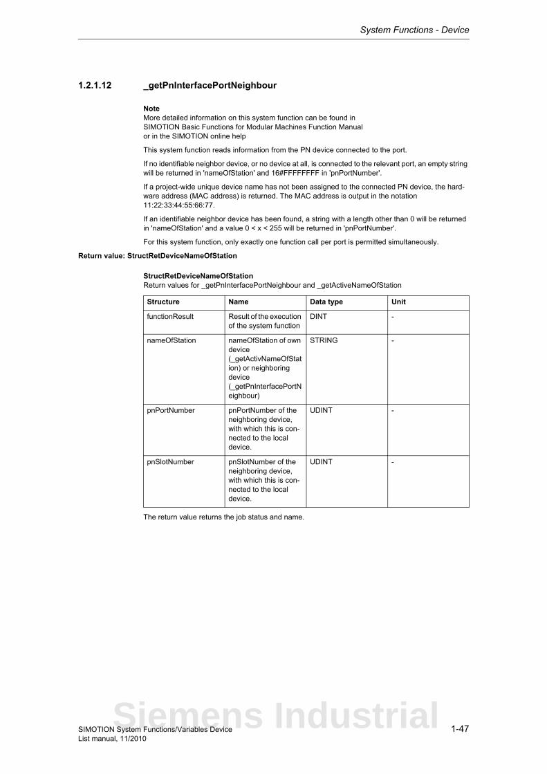
System Functions - Device
1-47SIMOTION System Functions/Variables DeviceList manual, 11/2010
1.2.1.12 _getPnInterfacePortNeighbour
NoteMore detailed information on this system function can be found inSIMOTION Basic Functions for Modular Machines Function Manualor in the SIMOTION online help
This system function reads information from the PN device connected to the port.
If no identifiable neighbor device, or no device at all, is connected to the relevant port, an empty string will be returned in 'nameOfStation' and 16#FFFFFFFF in 'pnPortNumber'.
If a project-wide unique device name has not been assigned to the connected PN device, the hard-ware address (MAC address) is returned. The MAC address is output in the notation 11:22:33:44:55:66:77.
If an identifiable neighbor device has been found, a string with a length other than 0 will be returned in 'nameOfStation' and a value 0 < x < 255 will be returned in 'pnPortNumber'.
For this system function, only exactly one function call per port is permitted simultaneously.
Return value: StructRetDeviceNameOfStation
StructRetDeviceNameOfStationReturn values for _getPnInterfacePortNeighbour and _getActiveNameOfStation
The return value returns the job status and name.
Structure Name Data type Unit
functionResult Result of the execution of the system function
DINT -
nameOfStation nameOfStation of own device (_getActivNameOfStation) or neighboring device (_getPnInterfacePortNeighbour)
STRING -
pnPortNumber pnPortNumber of the neighboring device, with which this is con-nected to the local device.
UDINT -
pnSlotNumber pnSlotNumber of the neighboring device, with which this is con-nected to the local device.
UDINT -
Siemens Industrial
System Functions - Device
1-48 SIMOTION System Functions/Variables DeviceList manual, 11/2010
Description of the return values:16#00000000System function completed successfully. The device name and port number of the relevant neighbor device will be returned if it can be identified.
16#00007000The system function is in inactive status. The functionality of the system function is not active. An initial call with REQUEST_TRUE is required.
16#00007001The system function is started with REQUEST_TRUE. A new call in the user program until completion of the system function is required with REQUEST_FALSE. This return value is reported only for asyn-chronous execution.
16#00007002The system function is still running. A new call in the user program until completion of the system func-tion is required with REQUEST_FALSE. This return value is reported only for asynchronous execu-tion.
16#00007003System function aborted successfully. If an abort is not possible, the system function returns the value 16#FFFF8094.
16#FFFF8090The specified logical diagnostic address is invalid.
16#FFFF8091No valid logical diagnostic address for a PROFINET interface port.
16#FFFF8092PROFINET interface is configured, but not available. Can only occur if the PROFINET interface is inserted in SIMOTION via a module.
16#FFFF8093The STRING returned under 'nameOfStation' is too long. Only 235 characters are permitted. Accor-ding to the standard, 240 characters are permitted, but this is not currently supported by SIMOTION.
16#FFFF8094An abort is no longer possible in the current system function status.
16#FFFF8097Readout of the neighboring port is not supported by the PROFINET interface.
16#FFFF8099Internal error. Function terminated.
16#FFFF809AThe PROFINET interface does not support this service. Function terminated.
16#FFFF80C1There are currently no resources available to perform this system function. The user program can call this function until this return value no longer appears.
16#FFFF80C2A system function call for the relevant PROFINET interface port is already in progress. The user pro-gram can call this function until this return value no longer appears.
16#FFFF80C3A re-querying of the neighboring port with REQUEST_TRUE was rejected because a function call for querying a neighboring port is still in progress on the same port of the relevant PROFINET interface with an identical CommandId. The user program can call this function until this return value no longer appears.
nameOfStationDevice name of neighbor device
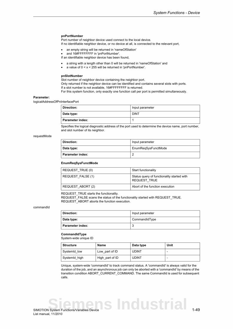
System Functions - Device
1-49SIMOTION System Functions/Variables DeviceList manual, 11/2010
pnPortNumberPort number of neighbor device used connect to the local device.If no identifiable neighbor device, or no device at all, is connected to the relevant port,
• an empty string will be returned in 'nameOfStation'• and 16#FFFFFFFF in 'pnPortNumber'.If an identifiable neighbor device has been found,
• a string with a length other than 0 will be returned in 'nameOfStation' and• a value of 0 < x < 255 will be returned in 'pnPortNumber'.
pnSlotNumberSlot number of neighbor device containing the neighbor port.Only returned if the neighbor device can be identified and contains several slots with ports.If a slot number is not available, 16#FFFFFFFF is returned.For this system function, only exactly one function call per port is permitted simultaneously.
Parameter: logicalAddressOfPnInterfacePort
Specifies the logical diagnostic address of the port used to determine the device name, port number, and slot number of its neighbor.
requestMode
EnumReqSysFunctMode
REQUEST_TRUE starts the functionality.REQUEST_FALSE scans the status of the functionality started with REQUEST_TRUE.REQUEST_ABORT aborts the function execution.
commandId
CommandIdTypeSystem-wide unique ID
Unique, system-wide 'commandId' to track command status. A 'commandId' is always valid for the duration of the job, and an asynchronous job can only be aborted with a 'commandId' by means of the transition condition ABORT_CURRENT_COMMAND. The same CommandId is used for subsequent calls.
Direction: Input parameter
Data type: DINT
Parameter index: 1
Direction: Input parameter
Data type: EnumReqSysFunctMode
Parameter index: 2
REQUEST_TRUE (0) Start functionality
REQUEST_FALSE (1) Status query of functionality started with REQUEST_TRUE
REQUEST_ABORT (2) Abort of the function execution
Direction: Input parameter
Data type: CommandIdType
Parameter index: 3
Structure Name Data type Unit
SystemId_low Low_part of ID UDINT -
SystemId_high High_part of ID UDINT -
Siemens Industrial

System Functions - Device
1-50 SIMOTION System Functions/Variables DeviceList manual, 11/2010
nextCommand
EnumNextCommandMode
Specifies condition for transition to next command.IMMEDIATELY means an initial call should be executed with REQUEST_TRUE. This starts the sys-tem function's internal sequence.Repeated calling of the system function is required with REQUEST_FALSE until the function confirms it has been completed.Unless these subsequent calls are made, the system function will not continue and the function cannot be completed.
With WHEN_COMMAND_DONE, the transition takes place when the command has been executed (synchronous call).With ABORT_CURRENT_COMMAND, the active function is aborted immediately.
Direction: Input parameter
Data type: EnumNextCommandMode
Parameter index: 5
IMMEDIATELY (60) Asynchronous
WHEN_COMMAND_DONE (160) Synchronous
ABORT_CURRENT_COMMAND (260) Abort
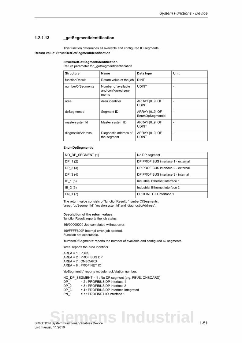
System Functions - Device
1-51SIMOTION System Functions/Variables DeviceList manual, 11/2010
1.2.1.13 _getSegmentIdentification
This function determines all available and configured IO segments.
Return value: StructRetGetSegmentIdentification
StructRetGetSegmentIdentificationReturn parameter for _getSegmentIdentification
EnumDpSegmentId
The return value consists of 'functionResult', 'numberOfSegments','area', 'dpSegmentId', 'mastersystemId' and 'diagnosticAddress'.
Description of the return values:'functionResult' reports the job status.
16#00000000 Job completed without error.
16#FFFF809F Internal error, job aborted.Function not executable.
'numberOfSegments' reports the number of available and configured IO segments.
'area' reports the area identifier.
AREA = 1 : PBUSAREA = 2 : PROFIBUS DPAREA = 7 : ONBOARDAREA = 8 : PROFINET IO
'dpSegmentId' reports module rack/station number.
NO_DP_SEGMENT = 1 : No DP segment (e.g. PBUS, ONBOARD)DP_1 = 2 : PROFIBUS DP interface 1DP_2 = 3 : PROFIBUS DP interface 2DP_3 = 4 : PROFIBUS DP interface IntegratedPN_1 = 7 : PROFINET IO interface 1
Structure Name Data type Unit
functionResult Return value of the job DINT -
numberOfSegments Number of available and configured seg-ments
UDINT -
area Area identifier ARRAY [0..9] OF UDINT
-
dpSegmentId Segment ID ARRAY [0..9] OF EnumDpSegmentId
-
mastersystemId Master system ID ARRAY [0..9] OF UDINT
-
diagnosticAddress Diagnostic address of the segment
ARRAY [0..9] OF UDINT
-
NO_DP_SEGMENT (1) No DP segment
DP_1 (2) DP PROFIBUS interface 1 - external
DP_2 (3) DP PROFIBUS interface 2 - external
DP_3 (4) DP PROFIBUS interface 3 - internal
IE_1 (5) Industrial Ethernet interface 1
IE_2 (6) Industrial Ethernet interface 2
PN_1 (7) PROFINET IO interface 1
Siemens Industrial

System Functions - Device
1-52 SIMOTION System Functions/Variables DeviceList manual, 11/2010
NoteThe interfaces IE_1 and IE_2 are not IO segments and are not supported.
'mastersystemId' reports the master system ID.
NotePROFIBUS and ONBOARD have no master system ID. It is assigned the value 0.
'diagnosticAddress' reports the diagnostic address of the IO segment.
NotePROFIBUS and ONBOARD do not have their own diagnostic address. It is assigned the value INVALID_ADDRESS.
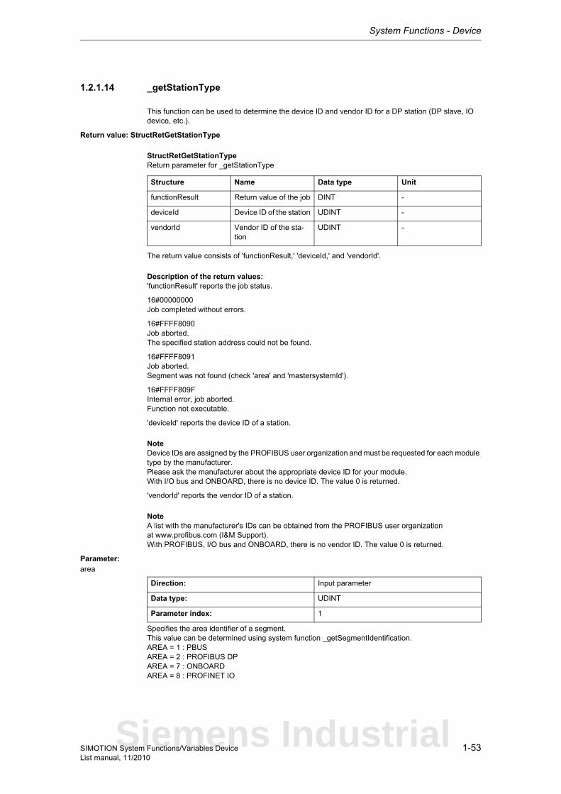
System Functions - Device
1-53SIMOTION System Functions/Variables DeviceList manual, 11/2010
1.2.1.14 _getStationType
This function can be used to determine the device ID and vendor ID for a DP station (DP slave, IO device, etc.).
Return value: StructRetGetStationType
StructRetGetStationTypeReturn parameter for _getStationType
The return value consists of 'functionResult,' 'deviceId,' and 'vendorId'.
Description of the return values:'functionResult' reports the job status.
16#00000000Job completed without errors.
16#FFFF8090Job aborted.The specified station address could not be found.
16#FFFF8091Job aborted.Segment was not found (check 'area' and 'mastersystemId').
16#FFFF809FInternal error, job aborted.Function not executable.
'deviceId' reports the device ID of a station.
NoteDevice IDs are assigned by the PROFIBUS user organization and must be requested for each module type by the manufacturer.Please ask the manufacturer about the appropriate device ID for your module.With I/O bus and ONBOARD, there is no device ID. The value 0 is returned.
'vendorId' reports the vendor ID of a station.
NoteA list with the manufacturer's IDs can be obtained from the PROFIBUS user organizationat www.profibus.com (I&M Support).With PROFIBUS, I/O bus and ONBOARD, there is no vendor ID. The value 0 is returned.
Parameter: area
Specifies the area identifier of a segment.This value can be determined using system function _getSegmentIdentification.AREA = 1 : PBUSAREA = 2 : PROFIBUS DPAREA = 7 : ONBOARDAREA = 8 : PROFINET IO
Structure Name Data type Unit
functionResult Return value of the job DINT -
deviceId Device ID of the station UDINT -
vendorId Vendor ID of the sta-tion
UDINT -
Direction: Input parameter
Data type: UDINT
Parameter index: 1
Siemens Industrial
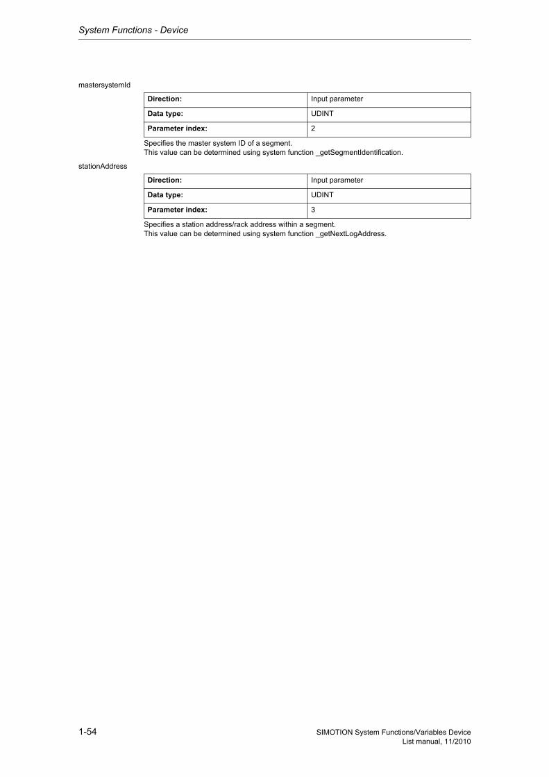
System Functions - Device
1-54 SIMOTION System Functions/Variables DeviceList manual, 11/2010
mastersystemId
Specifies the master system ID of a segment.This value can be determined using system function _getSegmentIdentification.
stationAddress
Specifies a station address/rack address within a segment.This value can be determined using system function _getNextLogAddress.
Direction: Input parameter
Data type: UDINT
Parameter index: 2
Direction: Input parameter
Data type: UDINT
Parameter index: 3

System Functions - Device
1-55SIMOTION System Functions/Variables DeviceList manual, 11/2010
1.2.1.15 _setDeviceErrorLED
Note"Further information can be found in the SIMOTION Basic Functions Function Manual and in SIMO-TION online help."
This function serves to set the error sublicensing (LED-flashing).
Return value: DINT
Description of the return values:16#00000000 LED set without error
16#FFFFFFFD Internal error
Siemens Industrial

System Functions - Device
1-56 SIMOTION System Functions/Variables DeviceList manual, 11/2010
1.2.1.16 _setDpSlaveAddress
NoteFurther information is available at:SIMOTION Basic Functions for Modular Machines Function Manualor in the online help
This system function sets a new DP address (node number) of a DP interface on a SIMOTION device.
Return value: DINT
Description of the return values:16#00000000The system function is successfully completed
16#FFFF8090Invalid addressOutside of valid range / invalid DP segment adapter
16#FFFF8091Invalid DP slave address.
16#FFFF8092DP adapter is not configured as a slave.
16#FFFF8093DP adapter is not configured passively.
16#FFFF8094Requested slave address not stored.
16#FFFF8099Internal error, function terminated.
16#FFFF80C1Resources for implementing the functionality are occupied.
Parameter: logicalAddressCommunicationAdapter
Specifies the logical diagnostic address of the interface.
dpSlaveAddress
Communication address.
Direction: Input parameter
Data type: DINT
Parameter index: 1
Direction: Input parameter
Data type: SINT
Parameter index: 2

System Functions - Device
1-57SIMOTION System Functions/Variables DeviceList manual, 11/2010
1.2.1.17 _setIPConfig
NoteFurther information is available at:SIMOTION Basic Functions for Modular Machines Function Manualor in the online help
This function resets the IP configuration of a selected Ethernet interface.The parameters are not permanently saved.The configured IP address data are not backed up with RamtoRom.
Return value: UDINT
Description of the return values:16#00000000IP configuration was set successfully
16#FFFF80C1Resource bottleneck
16#FFFF8099Internal error
16#FFFF8090Incorrect value in the 'ethernetInterface' transfer parameter
Parameter: ethernetInterface
EnumInterfaceID
Selected Ethernet interface
ipAddress
Ethernet interface IP address to be transferred
subnetMask
Ethernet interface subnet screen form to be transferred
gatewayAddress
Ethernet interface gateway address to be transferred
Direction: Input parameter
Data type: EnumInterfaceID
Parameter index: 1
IE_01 (0) Ethernet interface 1: All platforms
IE_02 (1) Ethernet interface 2: All platforms
Direction: Input parameter
Data type: ARRAY [0..5] OF USINT
Parameter index: 2
Direction: Input parameter
Data type: ARRAY [0..5] OF USINT
Parameter index: 3
Direction: Input parameter
Data type: ARRAY [0..5] OF USINT
Parameter index: 4
Siemens Industrial
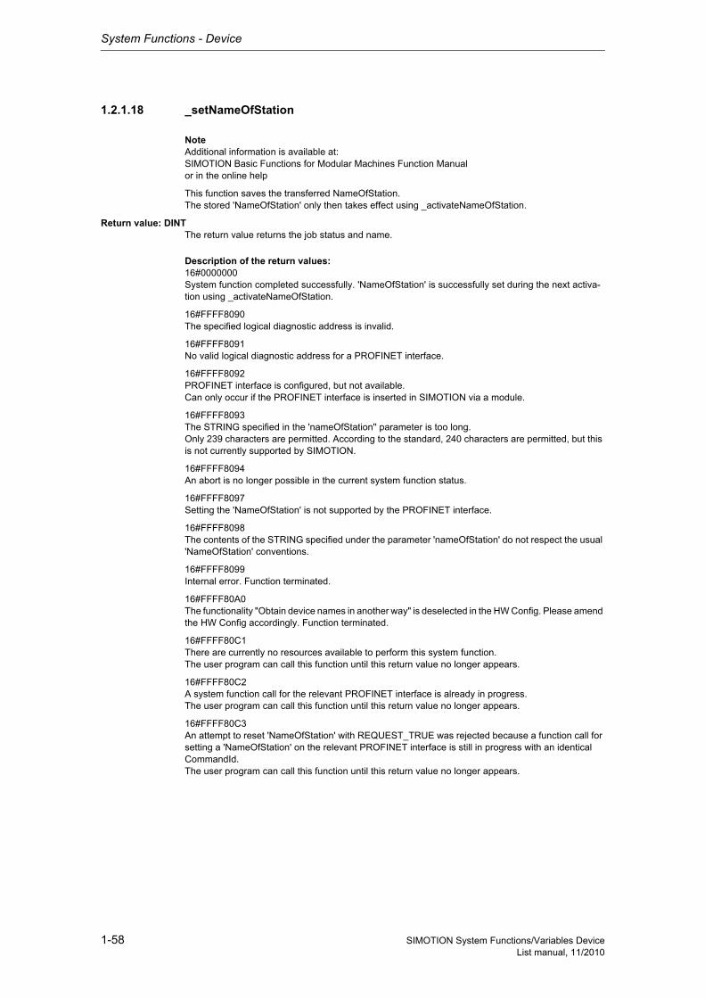
System Functions - Device
1-58 SIMOTION System Functions/Variables DeviceList manual, 11/2010
1.2.1.18 _setNameOfStation
NoteAdditional information is available at:SIMOTION Basic Functions for Modular Machines Function Manualor in the online help
This function saves the transferred NameOfStation.The stored 'NameOfStation' only then takes effect using _activateNameOfStation.
Return value: DINTThe return value returns the job status and name.
Description of the return values:16#0000000System function completed successfully. 'NameOfStation' is successfully set during the next activa-tion using _activateNameOfStation.
16#FFFF8090The specified logical diagnostic address is invalid.
16#FFFF8091No valid logical diagnostic address for a PROFINET interface.
16#FFFF8092PROFINET interface is configured, but not available.Can only occur if the PROFINET interface is inserted in SIMOTION via a module.
16#FFFF8093The STRING specified in the 'nameOfStation'' parameter is too long.Only 239 characters are permitted. According to the standard, 240 characters are permitted, but this is not currently supported by SIMOTION.
16#FFFF8094An abort is no longer possible in the current system function status.
16#FFFF8097Setting the 'NameOfStation' is not supported by the PROFINET interface.
16#FFFF8098The contents of the STRING specified under the parameter 'nameOfStation' do not respect the usual 'NameOfStation' conventions.
16#FFFF8099Internal error. Function terminated.
16#FFFF80A0The functionality "Obtain device names in another way" is deselected in the HW Config. Please amend the HW Config accordingly. Function terminated.
16#FFFF80C1There are currently no resources available to perform this system function.The user program can call this function until this return value no longer appears.
16#FFFF80C2A system function call for the relevant PROFINET interface is already in progress.The user program can call this function until this return value no longer appears.
16#FFFF80C3An attempt to reset 'NameOfStation' with REQUEST_TRUE was rejected because a function call for setting a 'NameOfStation' on the relevant PROFINET interface is still in progress with an identical CommandId.The user program can call this function until this return value no longer appears.
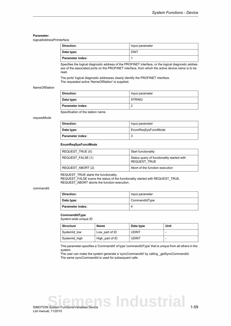
System Functions - Device
1-59SIMOTION System Functions/Variables DeviceList manual, 11/2010
Parameter: logicalAddressPnInterface
Specifies the logical diagnostic address of the PROFINET interface, or the logical diagnostic addres-ses of the associated ports on the PROFINET interface, from which the active device name is to be read.
The ports' logical diagnostic addresses clearly identify the PROFINET interface.The requested active 'NameOfStation' is supplied.
NameOfStation
Specification of the station name.
requestMode
EnumReqSysFunctMode
REQUEST_TRUE starts the functionality.REQUEST_FALSE scans the status of the functionality started with REQUEST_TRUE.REQUEST_ABORT aborts the function execution.
commandId
CommandIdTypeSystem-wide unique ID
This parameter specifies a 'CommandId' of type 'commandIdType' that is unique from all others in the system.The user can make the system generate a 'syncCommandId' by calling _getSyncCommandId.The same syncCommandId is used for subsequent calls.
Direction: Input parameter
Data type: DINT
Parameter index: 1
Direction: Input parameter
Data type: STRING
Parameter index: 2
Direction: Input parameter
Data type: EnumReqSysFunctMode
Parameter index: 3
REQUEST_TRUE (0) Start functionality
REQUEST_FALSE (1) Status query of functionality started with REQUEST_TRUE
REQUEST_ABORT (2) Abort of the function execution
Direction: Input parameter
Data type: CommandIdType
Parameter index: 4
Structure Name Data type Unit
SystemId_low Low_part of ID UDINT -
SystemId_high High_part of ID UDINT -
Siemens Industrial

System Functions - Device
1-60 SIMOTION System Functions/Variables DeviceList manual, 11/2010
nextCommand
EnumNextCommandMode
Specifies condition for transition to next command.IMMEDIATELY means an initial call should be executed with REQUEST_TRUE. This starts the sys-tem function's internal sequence.Repeated calling of the system function is required with REQUEST_FALSE until the function confirms it has been completed.Unless these subsequent calls are made, the system function will not continue and the function cannot be completed.
With WHEN_COMMAND_DONE, the transition takes place when the command is finished.With ABORT_CURRENT_COMMAND and the same 'commandId' as in the previous function call with IMMEDIATELY, the active function is aborted.
Direction: Input parameter
Data type: EnumNextCommandMode
Parameter index: 6
IMMEDIATELY (60) Asynchronous
WHEN_COMMAND_DONE (160) Synchronous
ABORT_CURRENT_COMMAND (260) Abort
System Functions - Device
1-61SIMOTION System Functions/Variables DeviceList manual, 11/2010
1.2.1.19 _synchronizeDpInterfaces
NoteAdditional information is available at:SIMOTION Basic Functions for Modular Machines Function Manualor in the online help
This function synchronizes the DP master interface with the DP slave interface.This requires a corresponding interface configuration.
The function is complete when the interfaces are synchronous or if synchronization is not possible.This function can be called multiple times (using the same 'commandId') to scan the execution status.
This function can only be active once at any given time. Multiple starts (multiple calls using a different 'commandId') cause an error message.
If the operating mode is switched from RUN to STOP while the function is being executed, the function is aborted. After the transition from STOP to RUN, the function can be called again.
Return value: DINT
Description of the return values:Asynchronous start:
(in addition to return values for synchronous call)
16#00007000DP synchronization started:Return value signals that the function has been started.
Synchronous call:
16#00007010DP interfaces synchronized:The return value signals that the interfaces are synchronized.The internal state machine is advanced to DP_INTERFACES_SYNCHRONIZED.NoteWith PROFIBUS, the function must be started when RUN is reached, with PROFINET, the call for PROFINET can be made during startup.With PROFINET, the call only functions when the system variable StateOfDpInterfaceSynchronization is at DP_CLOCK_DETECTED when the function is called.
16#00007080DP synchronization active:Return value signals that the function is still being executed.
16#FFFF805xDP synchronization not enabled:Return value signals that synchronization was ended unsuccessfully.The internal state machine is advanced to WAIT_FOR_DP_CLOCK.Details x:0 This error is set if the _enableDpInterfaceSynchronizationMode function was not called with para-meter MASTER_SLAVE_ALARMMESSAGES_1.1 This error is set if the interfaces could not be synchronized. One possible cause is interference in the clock signal.2 Temporary internal synchronization problem. The user state machine must be advanced.
Siemens Industrial
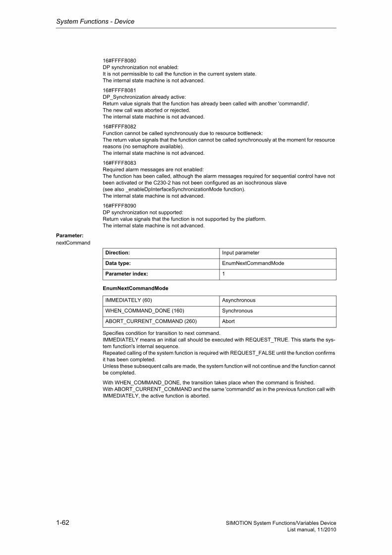
System Functions - Device
1-62 SIMOTION System Functions/Variables DeviceList manual, 11/2010
16#FFFF8080DP synchronization not enabled:It is not permissible to call the function in the current system state.The internal state machine is not advanced.
16#FFFF8081DP_Synchronization already active:Return value signals that the function has already been called with another 'commandId'.The new call was aborted or rejected.The internal state machine is not advanced.
16#FFFF8082Function cannot be called synchronously due to resource bottleneck:The return value signals that the function cannot be called synchronously at the moment for resource reasons (no semaphore available).The internal state machine is not advanced.
16#FFFF8083Required alarm messages are not enabled:The function has been called, although the alarm messages required for sequential control have not been activated or the C230-2 has not been configured as an isochronous slave(see also _enableDpInterfaceSynchronizationMode function).The internal state machine is not advanced.
16#FFFF8090DP synchronization not supported:Return value signals that the function is not supported by the platform.The internal state machine is not advanced.
Parameter: nextCommand
EnumNextCommandMode
Specifies condition for transition to next command.IMMEDIATELY means an initial call should be executed with REQUEST_TRUE. This starts the sys-tem function's internal sequence.Repeated calling of the system function is required with REQUEST_FALSE until the function confirms it has been completed.Unless these subsequent calls are made, the system function will not continue and the function cannot be completed.
With WHEN_COMMAND_DONE, the transition takes place when the command is finished.With ABORT_CURRENT_COMMAND and the same 'commandId' as in the previous function call with IMMEDIATELY, the active function is aborted.
Direction: Input parameter
Data type: EnumNextCommandMode
Parameter index: 1
IMMEDIATELY (60) Asynchronous
WHEN_COMMAND_DONE (160) Synchronous
ABORT_CURRENT_COMMAND (260) Abort
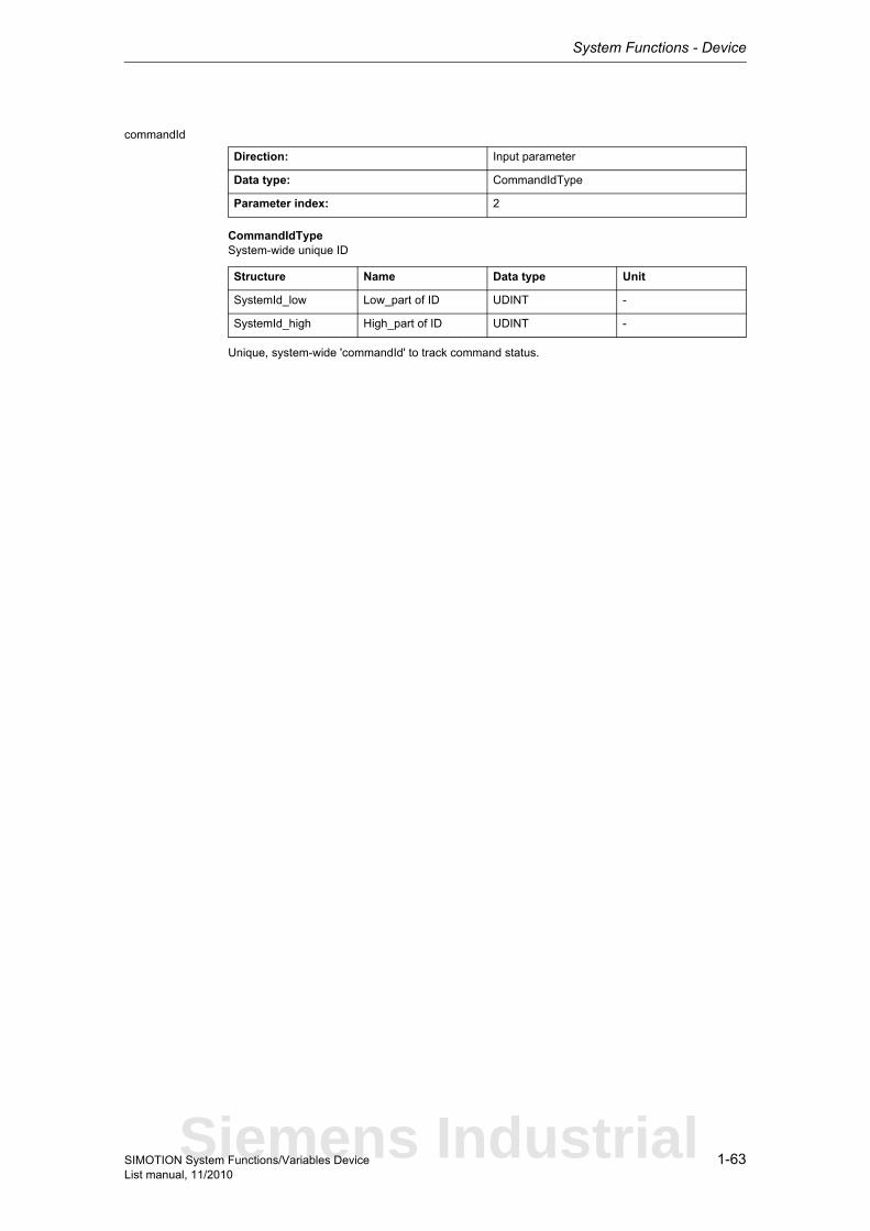
System Functions - Device
1-63SIMOTION System Functions/Variables DeviceList manual, 11/2010
commandId
CommandIdTypeSystem-wide unique ID
Unique, system-wide 'commandId' to track command status.
Direction: Input parameter
Data type: CommandIdType
Parameter index: 2
Structure Name Data type Unit
SystemId_low Low_part of ID UDINT -
SystemId_high High_part of ID UDINT -
Siemens Industrial
System Functions - Device
1-64 SIMOTION System Functions/Variables DeviceList manual, 11/2010
1.2.1.20 _udpAddMulticastGroupMembership
This function is used to join a multicast group on a selected Ethernet interface.A maximum of three multicast groups can be created on an Ethernet interface. These can occupy the same port or different ports.
The function can only be called of from motion tasks or the background task.
NoteIn the case of 'UDP Multicast' communications, the '_multicastPort' must correspond to the 'source-Port' for function _udpSend.
Return value: DINT
Description of the return values:16#00000000Communication on this port completed without errors
16#00007001Communication on this port started
16#00007002Communication on this port active
16#00007003Communication on this port aborted
16#FFFFFFFFResource bottleneck
16#FFFFFFFDInternal error.
16#FFFFFFFCReceive function already active on this port
16#FFFFFFFBReception errors
16#FFFFFFF9Error occurred while sending
16#FFFFFFF8Invalid parameter
16#FFFFFFF7Result not available
16#FFFFFFF6Multicast IP address not valid
16#FFFFFFF5IP address not valid
16#FFFFFFF4Multicast IP address already entered
16#FFFFFFF3Multicast IP address could not be entered
16#FFFFFFF2No available resources for entering the multicast IP address in the Ethernet controller
Parameter: multicastIPAddress
IP address for multicasts
Direction: Input parameter
Data type: ARRAY [0..3] OF USINT
Parameter index: 1
System Functions - Device
1-65SIMOTION System Functions/Variables DeviceList manual, 11/2010
interfaceIPAddress
IP address of multicast interface
multicastPort
Port number of multicast socket
multicastTTL (optional)
Time To Live for multicast message frames
multicastLOOP (optional)
Copies of the multicast message frames to itself if value is greater than 0.The parameter applies to all multicast groups that are set on one interface.
nextCommand
EnumNextCommandMode
Specifies the command transition.At present, only synchronous execution is supported.
Direction: Input parameter
Data type: ARRAY [0..3] OF USINT
Parameter index: 2
Direction: Input parameter
Data type: UINT
Parameter index: 3
Direction: Input parameter
Data type: UINT
Parameter index: 4
System default: 1
Direction: Input parameter
Data type: UINT
Parameter index: 5
System default: 1
Direction: Input parameter
Data type: EnumNextCommandMode
Parameter index: 6
IMMEDIATELY (60) Asynchronous
WHEN_COMMAND_DONE (160) Synchronous
ABORT_CURRENT_COMMAND (260) Abort
Siemens Industrial
System Functions - Device
1-66 SIMOTION System Functions/Variables DeviceList manual, 11/2010
1.2.1.21 _udpDropMulticastGroupMembership
This system function is used to exit a multicast group on a selected Ethernet interface.
The function can only be called of from motion tasks or the background task.
Return value: DINT
Description of the return values:16#00000000Communication on this port completed without errors
16#00007001Communication on this port started
16#00007002Communication on this port active
16#00007003Communication on this port aborted
16#FFFFFFFFResource bottleneck
16#FFFFFFFDInternal error
16#FFFFFFFCReceive function already active on this port
16#FFFFFFFBReception errors
16#FFFFFFF9Error while sending
16#FFFFFFF8Invalid parameter
16#FFFFFFF7Result not available
16#FFFFFFF6Multicast IP address not valid
16#FFFFFFF5IP address not valid
16#FFFFFFF4Multicast IP address already entered
16#FFFFFFF3Multicast IP address could not be entered
16#FFFFFFF2No available resources for entering the multicast IP address in the Ethernet controller
16#FFFFFFF1Multicast IP address does not exist on the controller.
16#FFFFFFF0Error when enabling the multicast IP address in the Ethernet controller.
Parameter: multicastIPAddress
IP address for multicasts
Direction: Input parameter
Data type: ARRAY [0..3] OF USINT
Parameter index: 1
System Functions - Device
1-67SIMOTION System Functions/Variables DeviceList manual, 11/2010
interfaceIPAddress
IP address of multicast interface
multicastPort
Port number of multicast socket
nextCommand
EnumNextCommandMode
Specifies the command transition. At present only synchronous execution is supported.
Direction: Input parameter
Data type: ARRAY [0..3] OF USINT
Parameter index: 2
Direction: Input parameter
Data type: UINT
Parameter index: 3
Direction: Input parameter
Data type: EnumNextCommandMode
Parameter index: 4
IMMEDIATELY (60) Asynchronous
WHEN_COMMAND_DONE (160) Synchronous
ABORT_CURRENT_COMMAND (260) Abort
Siemens Industrial
System Functions - Device
1-68 SIMOTION System Functions/Variables DeviceList manual, 11/2010
1.2.2 Interface handling - Status
1.2.2.1 _getActiveDpSlaveAddress
NoteMore detailed information on this system function can be found inSIMOTION Basic Functions for Modular Machines Function Manualor in the SIMOTION online help
This system function reads the active communication address of the specified interface.
Return value: StructRetDpSlaveAddress
StructRetDpSlaveAddressDisplay structure of the system function _getActiveDpSlaveAddress
Description of the return values:Return value "functionResult" has the following meaning:
16#00000000Function terminated successfully.
16#FFFF8090Invalid address, outside of valid range/invalid DP segment adapter
16#FFFF8091Invalid DP slave address.
16#FFFF8092DP adapter is not configured as a slave.
16#FFFF8093DP adapter is not configured passively.
16#FFFF8094Requested slave address not stored.
16#FFFF8099Internal error, function terminated.
16#FFFF80C1Resources for implementing the functionality are occupied.
Parameter: logicalAddressCommunicationAdapter
Specifies the logical diagnostic address of the interface.
Structure Name Data type Unit
functionResult Result of the function execution
DINT -
dpSlaveAddress DP slave address SINT -
Direction: Input parameter
Data type: DINT
Parameter index: 1
System Functions - Device
1-69SIMOTION System Functions/Variables DeviceList manual, 11/2010
1.2.2.2 _getActiveNameOfStation
NoteMore detailed information on this system function can be found inSIMOTION Basic Functions for Modular Machines Function Manualor in the online help
The system function reads the currently active NameOfStation. This originates from the configuration or was set with the DCP service using 'TcpIp' or with the _setNameOfStation system function.
A maximum of 239 characters is returned. According to the standard, 240 characters are permitted, but this is not currently supported by SIMOTION.
If NameOfStation is not available, a string with a length of 0 is returned.In pnPortNumber, 16#FFFFFFFF is always returned.In pnSlotNumber, 16#FFFFFFFF is always returned.
Return value: StructRetDeviceNameOfStation
StructRetDeviceNameOfStationReturn values for _getPnInterfacePortNeighbour and _getActiveNameOfStation
Description of the return values:The return value returns the job status and name.
Structure Name Data type Unit
functionResult Result of the execution of the system function
DINT -
nameOfStation nameOfStation of own device (_getActivNameOfStation) or neighboring device (_getPnInterfacePortNeighbour)
STRING -
pnPortNumber pnPortNumber of the neighboring device, with which this is con-nected to the local device.
UDINT -
pnSlotNumber pnSlotNumber of the neighboring device, with which this is con-nected to the local device.
UDINT -
Siemens Industrial
System Functions - Device
1-70 SIMOTION System Functions/Variables DeviceList manual, 11/2010
functionResult16#00000000System function completed successfully. NameOfStation is contained in the return value.
16#00007000The system function is in inactive status. The functionality associated with the system function is not active. An initial call with REQUEST_TRUE is required.
16#00007001The system function is started with REQUEST_TRUE. A new call in the user program until completion of the system function is required with REQUEST_FALSE. This return value is reported only for asyn-chronous execution.
16#00007002The system function is still running. A new call in the user program until completion of the system func-tion is required with REQUEST_FALSE. This return value is reported only for asynchronous execu-tion.
16#00007003System function aborted successfully. If an abort is not possible, the system function returns 16#FFFF8094.
16#FFFF8090The specified logical diagnostic address is invalid.
16#FFFF8091No valid logical diagnostic address for a PROFINET interface.
16#FFFF8092PROFINET interface is configured, but not available. Can only occur if the PROFINET interface is inserted in SIMOTION via a module.
16#FFFF8094An abort is no longer possible in the current system function status.
16#FFFF8097Readout of active device name is not supported by the PROFINET interface.
16#FFFF8099Internal error. Function terminated.
16#FFFF809AThe PROFINET interface does not support this service. Function terminated.
16#FFFF80C1There are currently no resources available to perform this system function. The user program can con-tinue to call this system function until this return value no longer appears.
16#FFFF80C2A system function call for the relevant PROFINET interface is already in progress. The user program can continue to call this system function until this return value no longer appears.
16#FFFF80C3A re-read of the current device name with REQUEST_TRUE was rejected because a function call for reading the current device name on the relevant PROFINET interface is still in progress with an iden-tical CommandId. The user program can call this function until this return value no longer appears.
nameOfStation: Device name of relevant PROFINET interface. A maximum of 239 characters is retur-ned. According to thestandard, 240 characters are permitted, but this is not currently supported by SIMOTION.
If NameOfStation is not available, a string with a length of 0 is returned.
pnPortNumber: 16#FFFFFFFF is always returned.
pnSlotNumber: 16#FFFFFFFF is always returned.
System Functions - Device
1-71SIMOTION System Functions/Variables DeviceList manual, 11/2010
Parameter: logicalAddressPnInterface
Specifies the logical diagnostic address of the PROFINET interface, or the logical diagnostic addres-ses of the associated ports on the PROFINET interface, from which the active device name is to be read.
requestMode
EnumReqSysFunctMode
REQUEST_TRUE starts the functionality.REQUEST_FALSE scans the status of the functionality started with REQUEST_TRUE.REQUEST_ABORT aborts the function execution.
commandId
CommandIdTypeSystem-wide unique ID
This parameter specifies a 'CommandId' of type 'commandIdType' that is unique from all others in the system.The user can make the system generate a 'syncCommandId' by calling _getSyncCommandId.The same 'syncCommandId' is used for subsequent calls.
Direction: Input parameter
Data type: DINT
Parameter index: 1
Direction: Input parameter
Data type: EnumReqSysFunctMode
Parameter index: 2
REQUEST_TRUE (0) Start functionality
REQUEST_FALSE (1) Status query of functionality started with REQUEST_TRUE
REQUEST_ABORT (2) Abort of the function execution
Direction: Input parameter
Data type: CommandIdType
Parameter index: 3
Structure Name Data type Unit
SystemId_low Low_part of ID UDINT -
SystemId_high High_part of ID UDINT -
Siemens Industrial

System Functions - Device
1-72 SIMOTION System Functions/Variables DeviceList manual, 11/2010
nextCommand
EnumNextCommandMode
Specifies condition for transition to next command.IMMEDIATELY means an initial call should be executed with REQUEST_TRUE. This starts the sys-tem function's internal sequence.Repeated calling of the system function is required with REQUEST_FALSE until the function confirms it has been completed.Unless these subsequent calls are made, the system function will not continue and the function cannot be completed.
With WHEN_COMMAND_DONE, the transition takes place when the command is finished.With ABORT_CURRENT_COMMAND and the same 'commandId' as in the previous function call with IMMEDIATELY, the active function is aborted.
Direction: Input parameter
Data type: EnumNextCommandMode
Parameter index: 5
IMMEDIATELY (60) Asynchronous
WHEN_COMMAND_DONE (160) Synchronous
ABORT_CURRENT_COMMAND (260) Abort
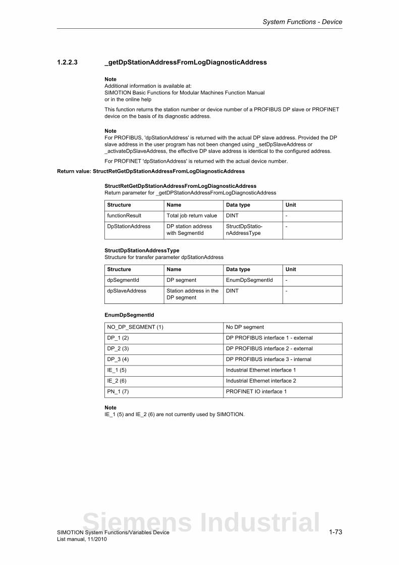
System Functions - Device
1-73SIMOTION System Functions/Variables DeviceList manual, 11/2010
1.2.2.3 _getDpStationAddressFromLogDiagnosticAddress
NoteAdditional information is available at:SIMOTION Basic Functions for Modular Machines Function Manualor in the online help
This function returns the station number or device number of a PROFIBUS DP slave or PROFINET device on the basis of its diagnostic address.
NoteFor PROFIBUS, 'dpStationAddress' is returned with the actual DP slave address. Provided the DP slave address in the user program has not been changed using _setDpSlaveAddress or _activateDpSlaveAddress, the effective DP slave address is identical to the configured address.
For PROFINET 'dpStationAddress' is returned with the actual device number.
Return value: StructRetGetDpStationAddressFromLogDiagnosticAddress
StructRetGetDpStationAddressFromLogDiagnosticAddressReturn parameter for _getDPStationAddressFromLogDiagnosticAddress
StructDpStationAddressTypeStructure for transfer parameter dpStationAddress
EnumDpSegmentId
NoteIE_1 (5) and IE_2 (6) are not currently used by SIMOTION.
Structure Name Data type Unit
functionResult Total job return value DINT -
DpStationAddress DP station address with SegmentId
StructDpStatio-nAddressType
-
Structure Name Data type Unit
dpSegmentId DP segment EnumDpSegmentId -
dpSlaveAddress Station address in the DP segment
DINT -
NO_DP_SEGMENT (1) No DP segment
DP_1 (2) DP PROFIBUS interface 1 - external
DP_2 (3) DP PROFIBUS interface 2 - external
DP_3 (4) DP PROFIBUS interface 3 - internal
IE_1 (5) Industrial Ethernet interface 1
IE_2 (6) Industrial Ethernet interface 2
PN_1 (7) PROFINET IO interface 1
Siemens Industrial
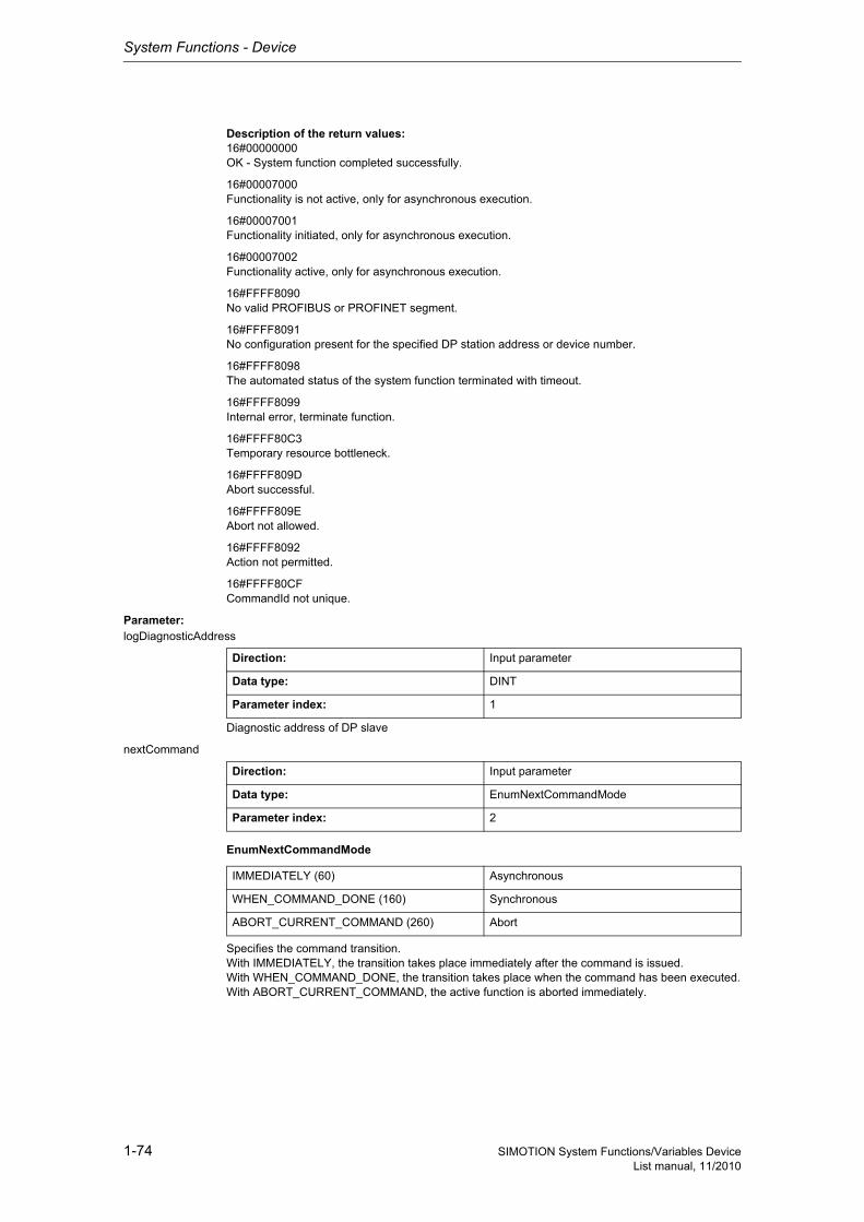
System Functions - Device
1-74 SIMOTION System Functions/Variables DeviceList manual, 11/2010
Description of the return values:16#00000000OK - System function completed successfully.
16#00007000Functionality is not active, only for asynchronous execution.
16#00007001Functionality initiated, only for asynchronous execution.
16#00007002Functionality active, only for asynchronous execution.
16#FFFF8090No valid PROFIBUS or PROFINET segment.
16#FFFF8091No configuration present for the specified DP station address or device number.
16#FFFF8098The automated status of the system function terminated with timeout.
16#FFFF8099Internal error, terminate function.
16#FFFF80C3Temporary resource bottleneck.
16#FFFF809DAbort successful.
16#FFFF809EAbort not allowed.
16#FFFF8092Action not permitted.
16#FFFF80CFCommandId not unique.
Parameter: logDiagnosticAddress
Diagnostic address of DP slave
nextCommand
EnumNextCommandMode
Specifies the command transition.With IMMEDIATELY, the transition takes place immediately after the command is issued.With WHEN_COMMAND_DONE, the transition takes place when the command has been executed.With ABORT_CURRENT_COMMAND, the active function is aborted immediately.
Direction: Input parameter
Data type: DINT
Parameter index: 1
Direction: Input parameter
Data type: EnumNextCommandMode
Parameter index: 2
IMMEDIATELY (60) Asynchronous
WHEN_COMMAND_DONE (160) Synchronous
ABORT_CURRENT_COMMAND (260) Abort

System Functions - Device
1-75SIMOTION System Functions/Variables DeviceList manual, 11/2010
commandId
CommandIdTypeSystem-wide unique ID
Unique, system-wide 'commandId' to track command status.
Direction: Input parameter
Data type: CommandIdType
Parameter index: 3
Structure Name Data type Unit
SystemId_low Low_part of ID UDINT -
SystemId_high High_part of ID UDINT -
Siemens Industrial
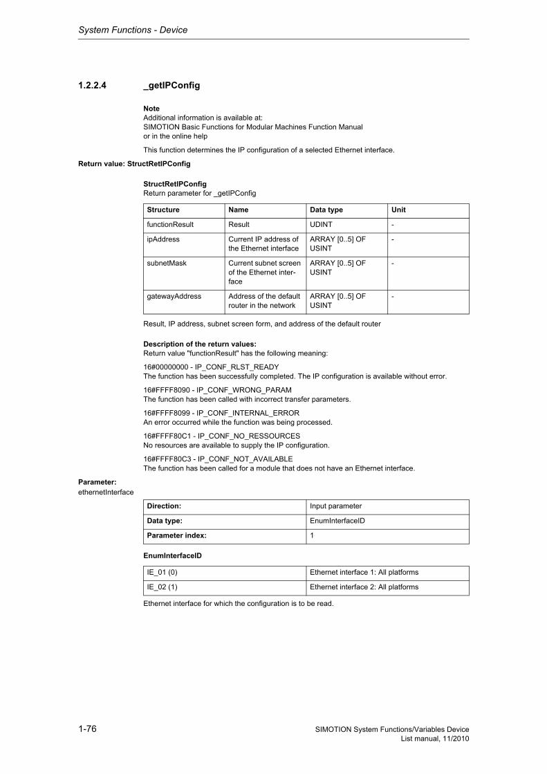
System Functions - Device
1-76 SIMOTION System Functions/Variables DeviceList manual, 11/2010
1.2.2.4 _getIPConfig
NoteAdditional information is available at:SIMOTION Basic Functions for Modular Machines Function Manualor in the online help
This function determines the IP configuration of a selected Ethernet interface.
Return value: StructRetIPConfig
StructRetIPConfigReturn parameter for _getIPConfig
Result, IP address, subnet screen form, and address of the default router
Description of the return values:Return value "functionResult" has the following meaning:
16#00000000 - IP_CONF_RLST_READYThe function has been successfully completed. The IP configuration is available without error.
16#FFFF8090 - IP_CONF_WRONG_PARAMThe function has been called with incorrect transfer parameters.
16#FFFF8099 - IP_CONF_INTERNAL_ERRORAn error occurred while the function was being processed.
16#FFFF80C1 - IP_CONF_NO_RESSOURCESNo resources are available to supply the IP configuration.
16#FFFF80C3 - IP_CONF_NOT_AVAILABLEThe function has been called for a module that does not have an Ethernet interface.
Parameter: ethernetInterface
EnumInterfaceID
Ethernet interface for which the configuration is to be read.
Structure Name Data type Unit
functionResult Result UDINT -
ipAddress Current IP address of the Ethernet interface
ARRAY [0..5] OF USINT
-
subnetMask Current subnet screen of the Ethernet inter-face
ARRAY [0..5] OF USINT
-
gatewayAddress Address of the default router in the network
ARRAY [0..5] OF USINT
-
Direction: Input parameter
Data type: EnumInterfaceID
Parameter index: 1
IE_01 (0) Ethernet interface 1: All platforms
IE_02 (1) Ethernet interface 2: All platforms
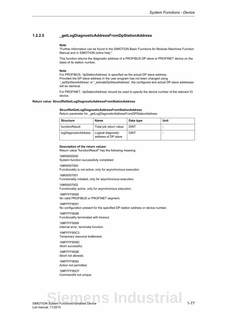
System Functions - Device
1-77SIMOTION System Functions/Variables DeviceList manual, 11/2010
1.2.2.5 _getLogDiagnosticAddressFromDpStationAddress
Note"Further information can be found in the SIMOTION Basic Functions for Modular Machines Function Manual and in SIMOTION online help."
This function returns the diagnostic address of a PROFIBUS DP slave or PROFINET device on the basis of its station number.
NoteFor PROFIBUS, 'dpStationAddress' is specified as the actual DP slave address.Provided the DP slave address in the user program has not been changed using '_setDpSlaveAddress' or '_activateDpSlaveAddress', the configured and actual DP slave addresses will be identical.
For PROFINET, 'dpStationAddress' should be used to specify the device number of the relevant IO device.
Return value: StructRetGetLogDiagnosticAddressFromStationAddress
StructRetGetLogDiagnosticAddressFromStationAddressReturn parameter for _getLogDiagnosticAddressFromDPStationAddress
Description of the return values:Return value "functionResult" has the following meaning:
16#00000000System function successfully completed
16#00007000Functionality is not active, only for asynchronous execution.
16#00007001Functionality initiated, only for asynchronous execution.
16#00007002Functionality active, only for asynchronous execution.
16#FFFF8090No valid PROFIBUS or PROFINET segment.
16#FFFF8091No configuration present for the specified DP station address or device number.
16#FFFF8098Functionality terminated with timeout
16#FFFF8099Internal error, terminate function.
16#FFFF80C3Temporary resource bottleneck.
16#FFFF809DAbort successful.
16#FFFF809EAbort not allowed.
16#FFFF8092Action not permitted.
16#FFFF80CFCommandId not unique.
Structure Name Data type Unit
functionResult Total job return value DINT -
logDiagnosticAddress Logical diagnostic address of DP slave
DINT -
Siemens Industrial
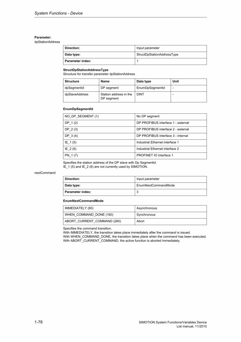
System Functions - Device
1-78 SIMOTION System Functions/Variables DeviceList manual, 11/2010
Parameter: dpStationAddress
StructDpStationAddressTypeStructure for transfer parameter dpStationAddress
EnumDpSegmentId
Specifies the station address of the DP slave with Dp SegmentId.IE_1 (5) and IE_2 (6) are not currently used by SIMOTION.
nextCommand
EnumNextCommandMode
Specifies the command transition.With IMMEDIATELY, the transition takes place immediately after the command is issued.With WHEN_COMMAND_DONE, the transition takes place when the command has been executed.With ABORT_CURRENT_COMMAND, the active function is aborted immediately.
Direction: Input parameter
Data type: StructDpStationAddressType
Parameter index: 1
Structure Name Data type Unit
dpSegmentId DP segment EnumDpSegmentId -
dpSlaveAddress Station address in the DP segment
DINT -
NO_DP_SEGMENT (1) No DP segment
DP_1 (2) DP PROFIBUS interface 1 - external
DP_2 (3) DP PROFIBUS interface 2 - external
DP_3 (4) DP PROFIBUS interface 3 - internal
IE_1 (5) Industrial Ethernet interface 1
IE_2 (6) Industrial Ethernet interface 2
PN_1 (7) PROFINET IO interface 1
Direction: Input parameter
Data type: EnumNextCommandMode
Parameter index: 3
IMMEDIATELY (60) Asynchronous
WHEN_COMMAND_DONE (160) Synchronous
ABORT_CURRENT_COMMAND (260) Abort

System Functions - Device
1-79SIMOTION System Functions/Variables DeviceList manual, 11/2010
commandId
CommandIdTypeSystem-wide unique ID
Unique, system-wide 'commandId' to track command status.
Direction: Input parameter
Data type: CommandIdType
Parameter index: 4
Structure Name Data type Unit
SystemId_low Low_part of ID UDINT -
SystemId_high High_part of ID UDINT -
Siemens Industrial

System Functions - Device
1-80 SIMOTION System Functions/Variables DeviceList manual, 11/2010
1.2.2.6 _getPnInterfacePortNeighbour
NoteMore detailed information on this system function can be found inSIMOTION Basic Functions for Modular Machines Function Manualor in the SIMOTION online help
This system function reads information from the PN device connected to the port.
If no identifiable neighbor device, or no device at all, is connected to the relevant port, an empty string will be returned in 'nameOfStation' and 16#FFFFFFFF in 'pnPortNumber'.
If a project-wide unique device name has not been assigned to the connected PN device, the hard-ware address (MAC address) is returned. The MAC address is output in the notation 11:22:33:44:55:66:77.
If an identifiable neighbor device has been found, a string with a length other than 0 will be returned in 'nameOfStation' and a value 0 < x < 255 will be returned in 'pnPortNumber'.
For this system function, only exactly one function call per port is permitted simultaneously.
Return value: StructRetDeviceNameOfStation
StructRetDeviceNameOfStationReturn values for _getPnInterfacePortNeighbour and _getActiveNameOfStation
The return value returns the job status and name.
Structure Name Data type Unit
functionResult Result of the execution of the system function
DINT -
nameOfStation nameOfStation of own device (_getActivNameOfStation) or neighboring device (_getPnInterfacePortNeighbour)
STRING -
pnPortNumber pnPortNumber of the neighboring device, with which this is con-nected to the local device.
UDINT -
pnSlotNumber pnSlotNumber of the neighboring device, with which this is con-nected to the local device.
UDINT -

System Functions - Device
1-81SIMOTION System Functions/Variables DeviceList manual, 11/2010
Description of the return values:16#00000000System function completed successfully. The device name and port number of the relevant neighbor device will be returned if it can be identified.
16#00007000The system function is in inactive status. The functionality of the system function is not active. An initial call with REQUEST_TRUE is required.
16#00007001The system function is started with REQUEST_TRUE. A new call in the user program until completion of the system function is required with REQUEST_FALSE. This return value is reported only for asyn-chronous execution.
16#00007002The system function is still running. A new call in the user program until completion of the system func-tion is required with REQUEST_FALSE. This return value is reported only for asynchronous execu-tion.
16#00007003System function aborted successfully. If an abort is not possible, the system function returns the value 16#FFFF8094.
16#FFFF8090The specified logical diagnostic address is invalid.
16#FFFF8091No valid logical diagnostic address for a PROFINET interface port.
16#FFFF8092PROFINET interface is configured, but not available. Can only occur if the PROFINET interface is inserted in SIMOTION via a module.
16#FFFF8093The STRING returned under 'nameOfStation' is too long. Only 235 characters are permitted. Accor-ding to the standard, 240 characters are permitted, but this is not currently supported by SIMOTION.
16#FFFF8094An abort is no longer possible in the current system function status.
16#FFFF8097Readout of the neighboring port is not supported by the PROFINET interface.
16#FFFF8099Internal error. Function terminated.
16#FFFF809AThe PROFINET interface does not support this service. Function terminated.
16#FFFF80C1There are currently no resources available to perform this system function. The user program can call this function until this return value no longer appears.
16#FFFF80C2A system function call for the relevant PROFINET interface port is already in progress. The user pro-gram can call this function until this return value no longer appears.
16#FFFF80C3A re-querying of the neighboring port with REQUEST_TRUE was rejected because a function call for querying a neighboring port is still in progress on the same port of the relevant PROFINET interface with an identical CommandId. The user program can call this function until this return value no longer appears.
nameOfStationDevice name of neighbor device
Siemens Industrial

System Functions - Device
1-82 SIMOTION System Functions/Variables DeviceList manual, 11/2010
pnPortNumberPort number of neighbor device used connect to the local device.If no identifiable neighbor device, or no device at all, is connected to the relevant port,
• an empty string will be returned in 'nameOfStation'• and 16#FFFFFFFF in 'pnPortNumber'.If an identifiable neighbor device has been found,
• a string with a length other than 0 will be returned in 'nameOfStation' and• a value of 0 < x < 255 will be returned in 'pnPortNumber'.
pnSlotNumberSlot number of neighbor device containing the neighbor port.Only returned if the neighbor device can be identified and contains several slots with ports.If a slot number is not available, 16#FFFFFFFF is returned.For this system function, only exactly one function call per port is permitted simultaneously.
Parameter: logicalAddressOfPnInterfacePort
Specifies the logical diagnostic address of the port used to determine the device name, port number, and slot number of its neighbor.
requestMode
EnumReqSysFunctMode
REQUEST_TRUE starts the functionality.REQUEST_FALSE scans the status of the functionality started with REQUEST_TRUE.REQUEST_ABORT aborts the function execution.
commandId
CommandIdTypeSystem-wide unique ID
Unique, system-wide 'commandId' to track command status. A 'commandId' is always valid for the duration of the job, and an asynchronous job can only be aborted with a 'commandId' by means of the transition condition ABORT_CURRENT_COMMAND. The same CommandId is used for subsequent calls.
Direction: Input parameter
Data type: DINT
Parameter index: 1
Direction: Input parameter
Data type: EnumReqSysFunctMode
Parameter index: 2
REQUEST_TRUE (0) Start functionality
REQUEST_FALSE (1) Status query of functionality started with REQUEST_TRUE
REQUEST_ABORT (2) Abort of the function execution
Direction: Input parameter
Data type: CommandIdType
Parameter index: 3
Structure Name Data type Unit
SystemId_low Low_part of ID UDINT -
SystemId_high High_part of ID UDINT -
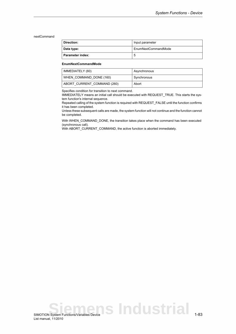
System Functions - Device
1-83SIMOTION System Functions/Variables DeviceList manual, 11/2010
nextCommand
EnumNextCommandMode
Specifies condition for transition to next command.IMMEDIATELY means an initial call should be executed with REQUEST_TRUE. This starts the sys-tem function's internal sequence.Repeated calling of the system function is required with REQUEST_FALSE until the function confirms it has been completed.Unless these subsequent calls are made, the system function will not continue and the function cannot be completed.
With WHEN_COMMAND_DONE, the transition takes place when the command has been executed (synchronous call).With ABORT_CURRENT_COMMAND, the active function is aborted immediately.
Direction: Input parameter
Data type: EnumNextCommandMode
Parameter index: 5
IMMEDIATELY (60) Asynchronous
WHEN_COMMAND_DONE (160) Synchronous
ABORT_CURRENT_COMMAND (260) Abort
Siemens Industrial
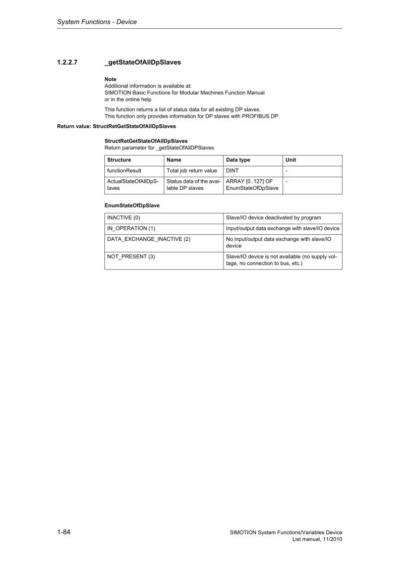
System Functions - Device
1-84 SIMOTION System Functions/Variables DeviceList manual, 11/2010
1.2.2.7 _getStateOfAllDpSlaves
NoteAdditional information is available at:SIMOTION Basic Functions for Modular Machines Function Manualor in the online help
This function returns a list of status data for all existing DP slaves.This function only provides information for DP slaves with PROFIBUS DP.
Return value: StructRetGetStateOfAllDpSlaves
StructRetGetStateOfAllDpSlavesReturn parameter for _getStateOfAllDPSlaves
EnumStateOfDpSlave
Structure Name Data type Unit
functionResult Total job return value DINT -
ActualStateOfAllDpS-laves
Status data of the avai-lable DP slaves
ARRAY [0..127] OF EnumStateOfDpSlave
-
INACTIVE (0) Slave/IO device deactivated by program
IN_OPERATION (1) Input/output data exchange with slave/IO device
DATA_EXCHANGE_INACTIVE (2) No input/output data exchange with slave/IO device
NOT_PRESENT (3) Slave/IO device is not available (no supply vol-tage, no connection to bus, etc.)
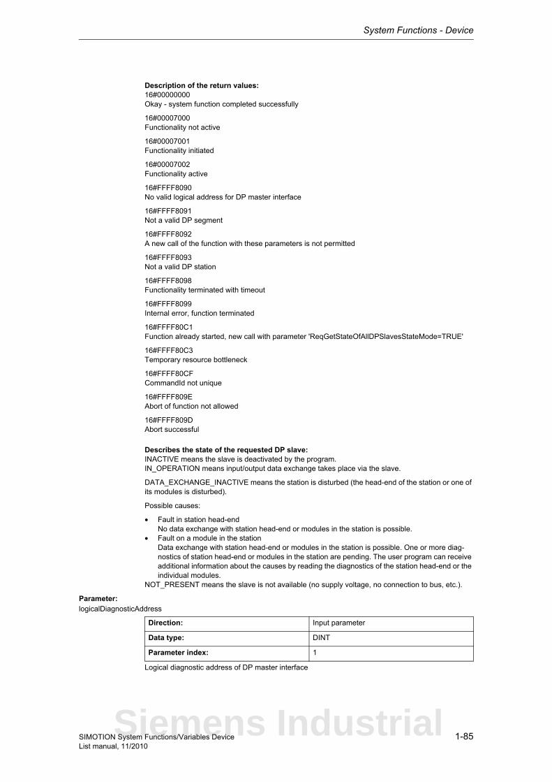
System Functions - Device
1-85SIMOTION System Functions/Variables DeviceList manual, 11/2010
Description of the return values:16#00000000Okay - system function completed successfully
16#00007000Functionality not active
16#00007001Functionality initiated
16#00007002Functionality active
16#FFFF8090No valid logical address for DP master interface
16#FFFF8091Not a valid DP segment
16#FFFF8092A new call of the function with these parameters is not permitted
16#FFFF8093Not a valid DP station
16#FFFF8098Functionality terminated with timeout
16#FFFF8099Internal error, function terminated
16#FFFF80C1Function already started, new call with parameter 'ReqGetStateOfAllDPSlavesStateMode=TRUE'
16#FFFF80C3Temporary resource bottleneck
16#FFFF80CFCommandId not unique
16#FFFF809EAbort of function not allowed
16#FFFF809DAbort successful
Describes the state of the requested DP slave:INACTIVE means the slave is deactivated by the program.IN_OPERATION means input/output data exchange takes place via the slave.
DATA_EXCHANGE_INACTIVE means the station is disturbed (the head-end of the station or one of its modules is disturbed).
Possible causes:
• Fault in station head-endNo data exchange with station head-end or modules in the station is possible.
• Fault on a module in the stationData exchange with station head-end or modules in the station is possible. One or more diag-nostics of station head-end or modules in the station are pending. The user program can receive additional information about the causes by reading the diagnostics of the station head-end or the individual modules.
NOT_PRESENT means the slave is not available (no supply voltage, no connection to bus, etc.).
Parameter: logicalDiagnosticAddress
Logical diagnostic address of DP master interface
Direction: Input parameter
Data type: DINT
Parameter index: 1
Siemens Industrial
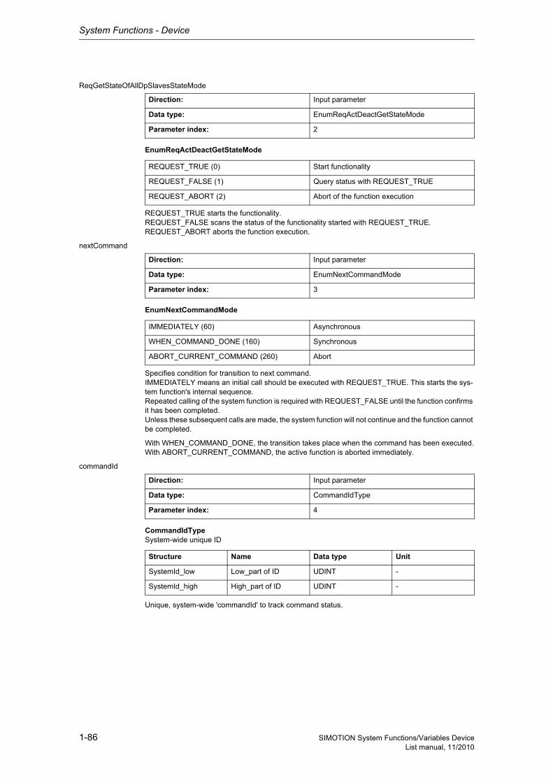
System Functions - Device
1-86 SIMOTION System Functions/Variables DeviceList manual, 11/2010
ReqGetStateOfAllDpSlavesStateMode
EnumReqActDeactGetStateMode
REQUEST_TRUE starts the functionality.REQUEST_FALSE scans the status of the functionality started with REQUEST_TRUE.REQUEST_ABORT aborts the function execution.
nextCommand
EnumNextCommandMode
Specifies condition for transition to next command.IMMEDIATELY means an initial call should be executed with REQUEST_TRUE. This starts the sys-tem function's internal sequence.Repeated calling of the system function is required with REQUEST_FALSE until the function confirms it has been completed.Unless these subsequent calls are made, the system function will not continue and the function cannot be completed.
With WHEN_COMMAND_DONE, the transition takes place when the command has been executed.With ABORT_CURRENT_COMMAND, the active function is aborted immediately.
commandId
CommandIdTypeSystem-wide unique ID
Unique, system-wide 'commandId' to track command status.
Direction: Input parameter
Data type: EnumReqActDeactGetStateMode
Parameter index: 2
REQUEST_TRUE (0) Start functionality
REQUEST_FALSE (1) Query status with REQUEST_TRUE
REQUEST_ABORT (2) Abort of the function execution
Direction: Input parameter
Data type: EnumNextCommandMode
Parameter index: 3
IMMEDIATELY (60) Asynchronous
WHEN_COMMAND_DONE (160) Synchronous
ABORT_CURRENT_COMMAND (260) Abort
Direction: Input parameter
Data type: CommandIdType
Parameter index: 4
Structure Name Data type Unit
SystemId_low Low_part of ID UDINT -
SystemId_high High_part of ID UDINT -
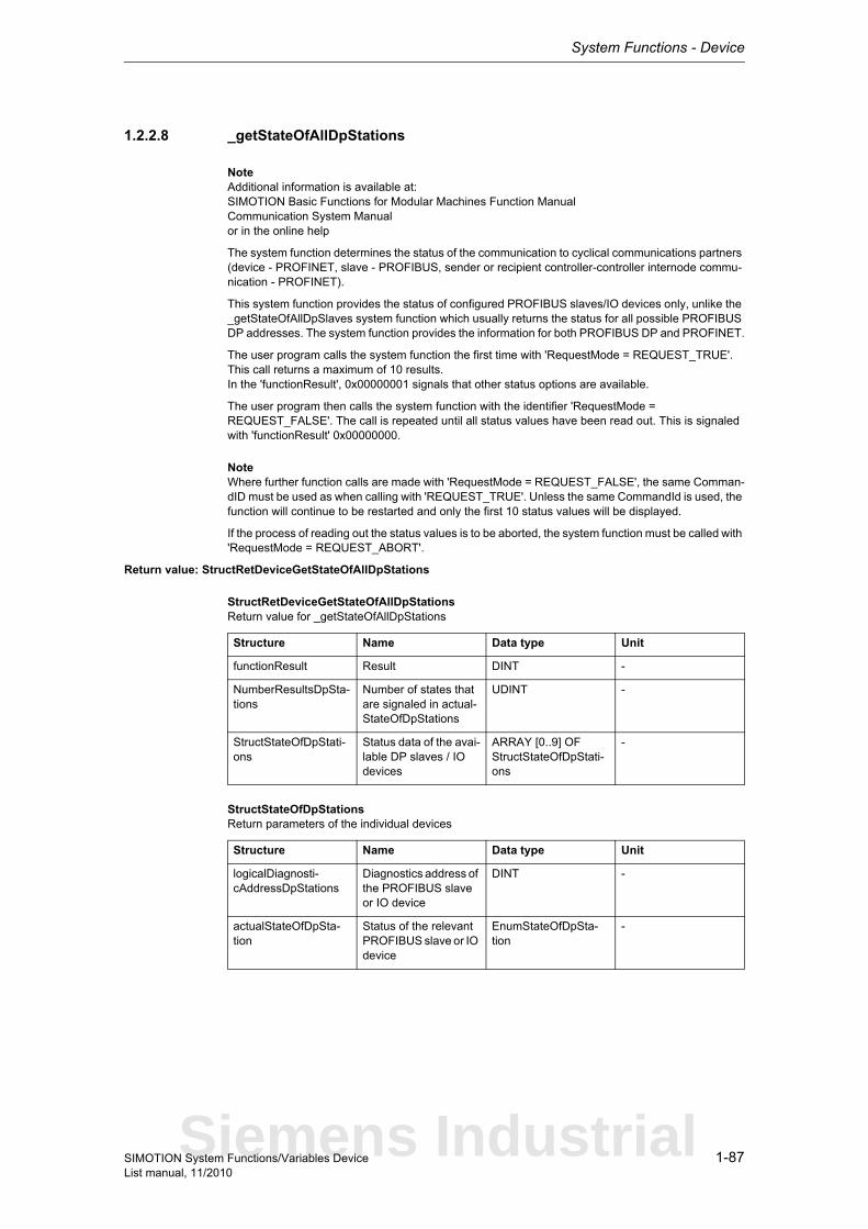
System Functions - Device
1-87SIMOTION System Functions/Variables DeviceList manual, 11/2010
1.2.2.8 _getStateOfAllDpStations
NoteAdditional information is available at:SIMOTION Basic Functions for Modular Machines Function ManualCommunication System Manualor in the online help
The system function determines the status of the communication to cyclical communications partners (device - PROFINET, slave - PROFIBUS, sender or recipient controller-controller internode commu-nication - PROFINET).
This system function provides the status of configured PROFIBUS slaves/IO devices only, unlike the _getStateOfAllDpSlaves system function which usually returns the status for all possible PROFIBUS DP addresses. The system function provides the information for both PROFIBUS DP and PROFINET.
The user program calls the system function the first time with 'RequestMode = REQUEST_TRUE'. This call returns a maximum of 10 results.In the 'functionResult', 0x00000001 signals that other status options are available.
The user program then calls the system function with the identifier 'RequestMode = REQUEST_FALSE'. The call is repeated until all status values have been read out. This is signaled with 'functionResult' 0x00000000.
NoteWhere further function calls are made with 'RequestMode = REQUEST_FALSE', the same Comman-dID must be used as when calling with 'REQUEST_TRUE'. Unless the same CommandId is used, the function will continue to be restarted and only the first 10 status values will be displayed.
If the process of reading out the status values is to be aborted, the system function must be called with 'RequestMode = REQUEST_ABORT'.
Return value: StructRetDeviceGetStateOfAllDpStations
StructRetDeviceGetStateOfAllDpStationsReturn value for _getStateOfAllDpStations
StructStateOfDpStationsReturn parameters of the individual devices
Structure Name Data type Unit
functionResult Result DINT -
NumberResultsDpSta-tions
Number of states that are signaled in actual-StateOfDpStations
UDINT -
StructStateOfDpStati-ons
Status data of the avai-lable DP slaves / IO devices
ARRAY [0..9] OF StructStateOfDpStati-ons
-
Structure Name Data type Unit
logicalDiagnosti-cAddressDpStations
Diagnostics address of the PROFIBUS slave or IO device
DINT -
actualStateOfDpSta-tion
Status of the relevant PROFIBUS slave or IO device
EnumStateOfDpSta-tion
-
Siemens Industrial
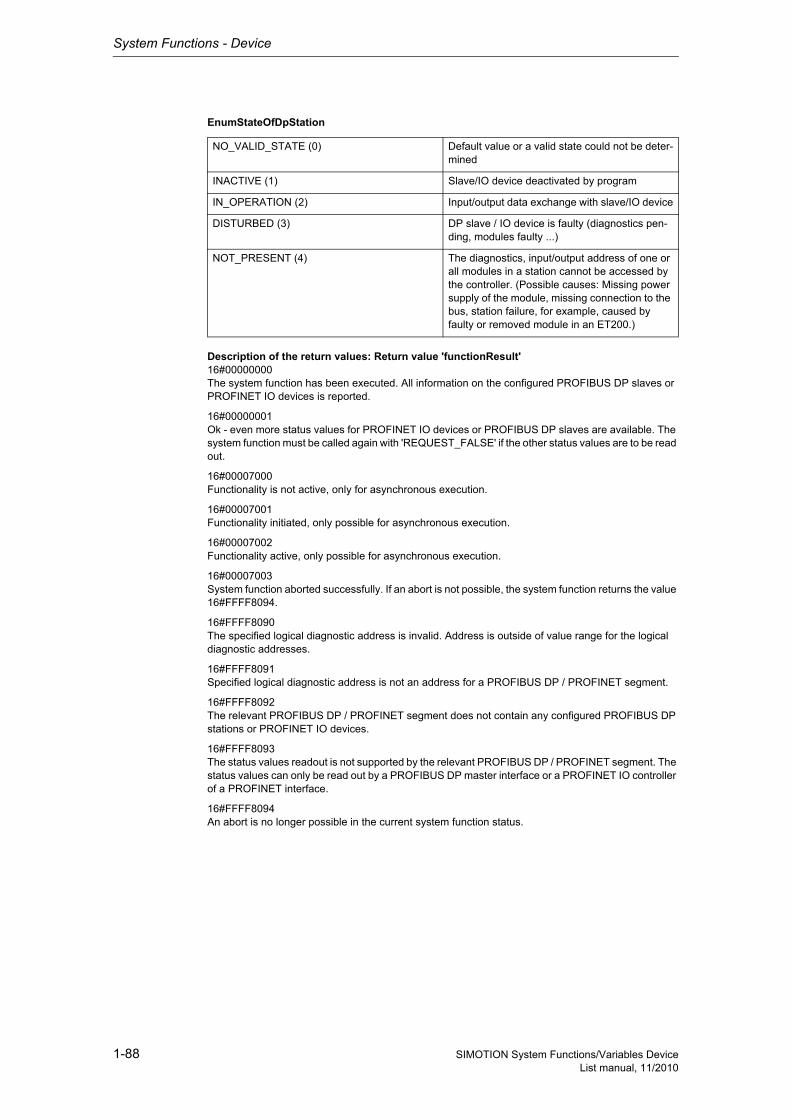
System Functions - Device
1-88 SIMOTION System Functions/Variables DeviceList manual, 11/2010
EnumStateOfDpStation
Description of the return values: Return value 'functionResult'16#00000000The system function has been executed. All information on the configured PROFIBUS DP slaves or PROFINET IO devices is reported.
16#00000001Ok - even more status values for PROFINET IO devices or PROFIBUS DP slaves are available. The system function must be called again with 'REQUEST_FALSE' if the other status values are to be read out.
16#00007000Functionality is not active, only for asynchronous execution.
16#00007001Functionality initiated, only possible for asynchronous execution.
16#00007002Functionality active, only possible for asynchronous execution.
16#00007003System function aborted successfully. If an abort is not possible, the system function returns the value 16#FFFF8094.
16#FFFF8090The specified logical diagnostic address is invalid. Address is outside of value range for the logical diagnostic addresses.
16#FFFF8091Specified logical diagnostic address is not an address for a PROFIBUS DP / PROFINET segment.
16#FFFF8092The relevant PROFIBUS DP / PROFINET segment does not contain any configured PROFIBUS DP stations or PROFINET IO devices.
16#FFFF8093The status values readout is not supported by the relevant PROFIBUS DP / PROFINET segment. The status values can only be read out by a PROFIBUS DP master interface or a PROFINET IO controller of a PROFINET interface.
16#FFFF8094An abort is no longer possible in the current system function status.
NO_VALID_STATE (0) Default value or a valid state could not be deter-mined
INACTIVE (1) Slave/IO device deactivated by program
IN_OPERATION (2) Input/output data exchange with slave/IO device
DISTURBED (3) DP slave / IO device is faulty (diagnostics pen-ding, modules faulty ...)
NOT_PRESENT (4) The diagnostics, input/output address of one or all modules in a station cannot be accessed by the controller. (Possible causes: Missing power supply of the module, missing connection to the bus, station failure, for example, caused by faulty or removed module in an ET200.)
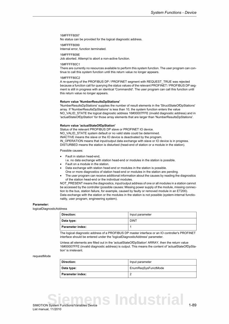
System Functions - Device
1-89SIMOTION System Functions/Variables DeviceList manual, 11/2010
16#FFFF8097No status can be provided for the logical diagnostic address.
16#FFFF8099Internal error, function terminated.
16#FFFF809EJob aborted. Attempt to abort a non-active function.
16#FFFF80C1There are currently no resources available to perform this system function. The user program can con-tinue to call this system function until this return value no longer appears.
16#FFFF80C2A re-querying of the PROFIBUS DP / PROFINET segment with REQUEST_TRUE was rejected because a function call for querying the status values of the relevant PROFINET / PROFIBUS DP seg-ment is still in progress with an identical 'CommandId'. The user program can call this function until this return value no longer appears.
Return value 'NumberResultsDpStations''NumberResultsDpStations' supplies the number of result elements in the 'StructStateOfDpStations' array. If 'NumberResultsDpStations' is less than 10, the system function enters the value NO_VALID_STATE the logical diagnostic address 16#00007FFE (invalid diagnostic address) and in 'actualStateOfDpStation' for those array elements that are larger than 'NumberResultsDpStations'.
Return value 'actualStateOfDpStation'Status of the relevant PROFIBUS DP slave or PROFINET IO device.NO_VALID_STATE system default or no valid state could be determined.INACTIVE means the slave or the IO device is deactivated by the program.IN_OPERATION means that input/output data exchange with slave or IO device is in progress.DISTURBED means the station is disturbed (head-end of station or a module in the station).
Possible causes:
• Fault in station head-end,i.e. no data exchange with station head-end or modules in the station is possible.
• Fault on a module in the station.• Data exchange with station head-end or modules in the station is possible.
One or more diagnostics of station head-end or modules in the station are pending.• The user program can receive additional information about the causes by reading the diagnostics
of the station head-end or the individual modules.NOT_PRESENT means the diagnostics, input/output address of one or all modules in a station cannot be accessed by the controller (possible causes: Missing power supply of the module, missing connec-tion to the bus, station failure, for example, caused by faulty or removed module in an ET200).Data exchange with the station or the modules in the station is not possible (system-internal functio-nality, user program, engineering system).
Parameter: logicalDiagnosticAddress
The logical diagnostic address of a PROFIBUS DP master interface or an IO controller's PROFINET interface should be entered under the 'logicalDiagnosticAddress' parameter.
Unless all elements are filled out in the 'actualStateOfDpStation' ARRAY, then the return value 16#00007FFE (invalid diagnostic address) is output. This means the content of 'actualStateOfDpSta-tion' is irrelevant.
requestMode
Direction: Input parameter
Data type: DINT
Parameter index: 1
Direction: Input parameter
Data type: EnumReqSysFunctMode
Parameter index: 2
Siemens Industrial
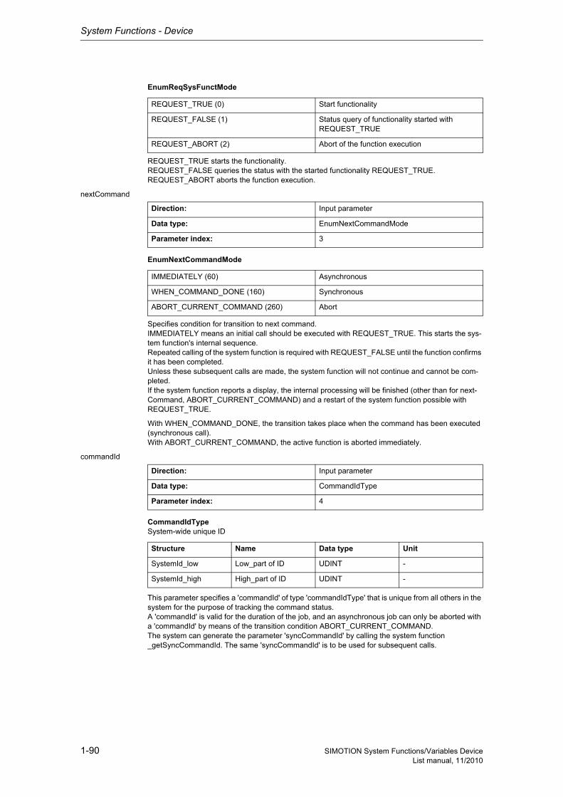
System Functions - Device
1-90 SIMOTION System Functions/Variables DeviceList manual, 11/2010
EnumReqSysFunctMode
REQUEST_TRUE starts the functionality.REQUEST_FALSE queries the status with the started functionality REQUEST_TRUE.REQUEST_ABORT aborts the function execution.
nextCommand
EnumNextCommandMode
Specifies condition for transition to next command.IMMEDIATELY means an initial call should be executed with REQUEST_TRUE. This starts the sys-tem function's internal sequence.Repeated calling of the system function is required with REQUEST_FALSE until the function confirms it has been completed.Unless these subsequent calls are made, the system function will not continue and cannot be com-pleted.If the system function reports a display, the internal processing will be finished (other than for next-Command, ABORT_CURRENT_COMMAND) and a restart of the system function possible with REQUEST_TRUE.
With WHEN_COMMAND_DONE, the transition takes place when the command has been executed (synchronous call).With ABORT_CURRENT_COMMAND, the active function is aborted immediately.
commandId
CommandIdTypeSystem-wide unique ID
This parameter specifies a 'commandId' of type 'commandIdType' that is unique from all others in the system for the purpose of tracking the command status.A 'commandId' is valid for the duration of the job, and an asynchronous job can only be aborted with a 'commandId' by means of the transition condition ABORT_CURRENT_COMMAND.The system can generate the parameter 'syncCommandId' by calling the system function _getSyncCommandId. The same 'syncCommandId' is to be used for subsequent calls.
REQUEST_TRUE (0) Start functionality
REQUEST_FALSE (1) Status query of functionality started with REQUEST_TRUE
REQUEST_ABORT (2) Abort of the function execution
Direction: Input parameter
Data type: EnumNextCommandMode
Parameter index: 3
IMMEDIATELY (60) Asynchronous
WHEN_COMMAND_DONE (160) Synchronous
ABORT_CURRENT_COMMAND (260) Abort
Direction: Input parameter
Data type: CommandIdType
Parameter index: 4
Structure Name Data type Unit
SystemId_low Low_part of ID UDINT -
SystemId_high High_part of ID UDINT -
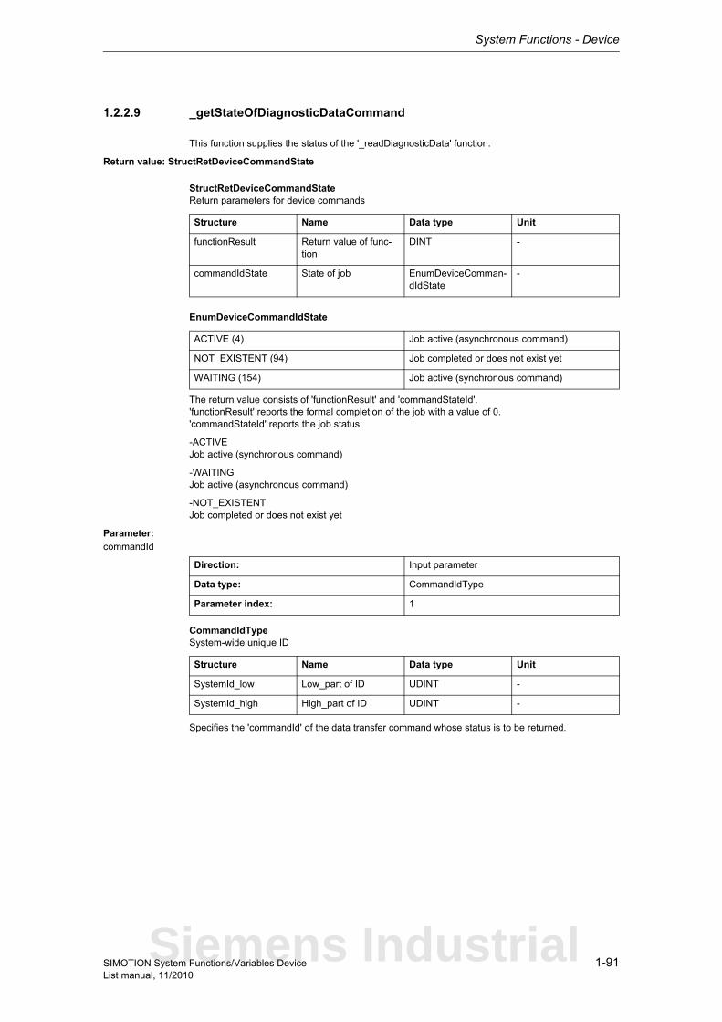
System Functions - Device
1-91SIMOTION System Functions/Variables DeviceList manual, 11/2010
1.2.2.9 _getStateOfDiagnosticDataCommand
This function supplies the status of the '_readDiagnosticData' function.
Return value: StructRetDeviceCommandState
StructRetDeviceCommandStateReturn parameters for device commands
EnumDeviceCommandIdState
The return value consists of 'functionResult' and 'commandStateId'.'functionResult' reports the formal completion of the job with a value of 0.'commandStateId' reports the job status:
-ACTIVEJob active (synchronous command)
-WAITINGJob active (asynchronous command)
-NOT_EXISTENTJob completed or does not exist yet
Parameter: commandId
CommandIdTypeSystem-wide unique ID
Specifies the 'commandId' of the data transfer command whose status is to be returned.
Structure Name Data type Unit
functionResult Return value of func-tion
DINT -
commandIdState State of job EnumDeviceComman-dIdState
-
ACTIVE (4) Job active (asynchronous command)
NOT_EXISTENT (94) Job completed or does not exist yet
WAITING (154) Job active (synchronous command)
Direction: Input parameter
Data type: CommandIdType
Parameter index: 1
Structure Name Data type Unit
SystemId_low Low_part of ID UDINT -
SystemId_high High_part of ID UDINT -
Siemens Industrial
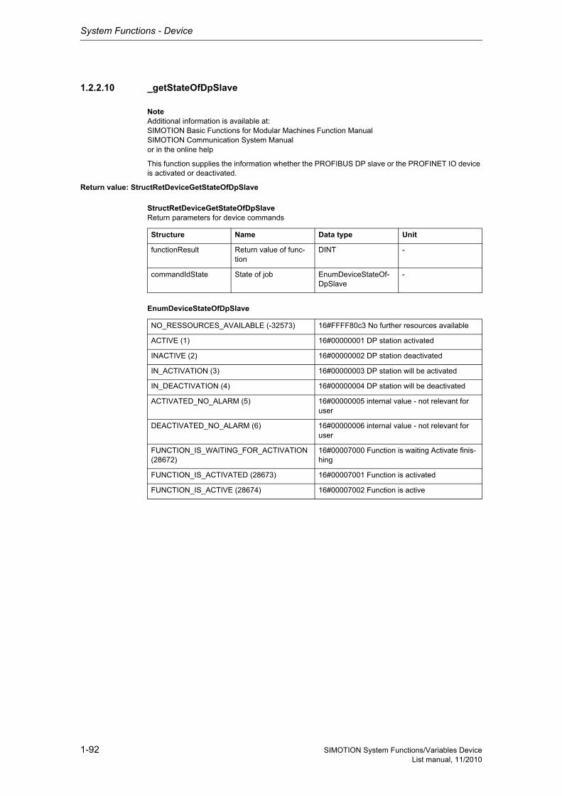
System Functions - Device
1-92 SIMOTION System Functions/Variables DeviceList manual, 11/2010
1.2.2.10 _getStateOfDpSlave
NoteAdditional information is available at:SIMOTION Basic Functions for Modular Machines Function ManualSIMOTION Communication System Manualor in the online help
This function supplies the information whether the PROFIBUS DP slave or the PROFINET IO device is activated or deactivated.
Return value: StructRetDeviceGetStateOfDpSlave
StructRetDeviceGetStateOfDpSlaveReturn parameters for device commands
EnumDeviceStateOfDpSlave
Structure Name Data type Unit
functionResult Return value of func-tion
DINT -
commandIdState State of job EnumDeviceStateOf-DpSlave
-
NO_RESSOURCES_AVAILABLE (-32573) 16#FFFF80c3 No further resources available
ACTIVE (1) 16#00000001 DP station activated
INACTIVE (2) 16#00000002 DP station deactivated
IN_ACTIVATION (3) 16#00000003 DP station will be activated
IN_DEACTIVATION (4) 16#00000004 DP station will be deactivated
ACTIVATED_NO_ALARM (5) 16#00000005 internal value - not relevant for user
DEACTIVATED_NO_ALARM (6) 16#00000006 internal value - not relevant for user
FUNCTION_IS_WAITING_FOR_ACTIVATION (28672)
16#00007000 Function is waiting Activate finis-hing
FUNCTION_IS_ACTIVATED (28673) 16#00007001 Function is activated
FUNCTION_IS_ACTIVE (28674) 16#00007002 Function is active
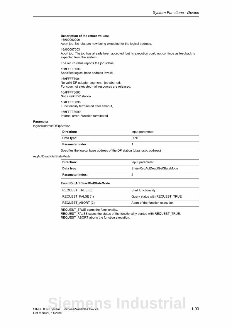
System Functions - Device
1-93SIMOTION System Functions/Variables DeviceList manual, 11/2010
Description of the return values:16#00000000Abort job. No jobs are now being executed for the logical address.
16#00007003Abort job. The job has already been accepted, but its execution could not continue as feedback is expected from the system.
The return value reports the job status.
16#FFFF8090Specified logical base address invalid.
16#FFFF8091No valid DP adapter segment - job aborted:Function not executed - all resources are released.
16#FFFF8093Not a valid DP station
16#FFFF8098Functionality terminated after timeout,
16#FFFF8099Internal error: Function terminated
Parameter: logicalAddressOfDpStation
Specifies the logical base address of the DP station (diagnostic address)
reqActDeactGetStateMode
EnumReqActDeactGetStateMode
REQUEST_TRUE starts the functionality.REQUEST_FALSE scans the status of the functionality started with REQUEST_TRUE.REQUEST_ABORT aborts the function execution.
Direction: Input parameter
Data type: DINT
Parameter index: 1
Direction: Input parameter
Data type: EnumReqActDeactGetStateMode
Parameter index: 2
REQUEST_TRUE (0) Start functionality
REQUEST_FALSE (1) Query status with REQUEST_TRUE
REQUEST_ABORT (2) Abort of the function execution
Siemens Industrial
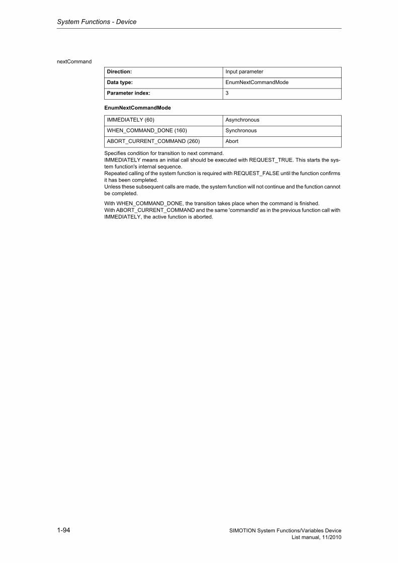
System Functions - Device
1-94 SIMOTION System Functions/Variables DeviceList manual, 11/2010
nextCommand
EnumNextCommandMode
Specifies condition for transition to next command.IMMEDIATELY means an initial call should be executed with REQUEST_TRUE. This starts the sys-tem function's internal sequence.Repeated calling of the system function is required with REQUEST_FALSE until the function confirms it has been completed.Unless these subsequent calls are made, the system function will not continue and the function cannot be completed.
With WHEN_COMMAND_DONE, the transition takes place when the command is finished.With ABORT_CURRENT_COMMAND and the same 'commandId' as in the previous function call with IMMEDIATELY, the active function is aborted.
Direction: Input parameter
Data type: EnumNextCommandMode
Parameter index: 3
IMMEDIATELY (60) Asynchronous
WHEN_COMMAND_DONE (160) Synchronous
ABORT_CURRENT_COMMAND (260) Abort
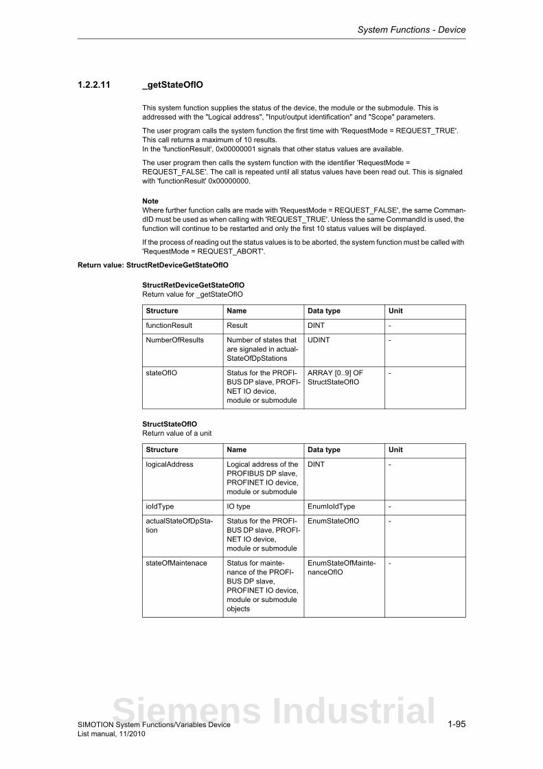
System Functions - Device
1-95SIMOTION System Functions/Variables DeviceList manual, 11/2010
1.2.2.11 _getStateOfIO
This system function supplies the status of the device, the module or the submodule. This is addressed with the "Logical address", "Input/output identification" and "Scope" parameters.
The user program calls the system function the first time with 'RequestMode = REQUEST_TRUE'. This call returns a maximum of 10 results.In the 'functionResult', 0x00000001 signals that other status values are available.
The user program then calls the system function with the identifier 'RequestMode = REQUEST_FALSE'. The call is repeated until all status values have been read out. This is signaled with 'functionResult' 0x00000000.
NoteWhere further function calls are made with 'RequestMode = REQUEST_FALSE', the same Comman-dID must be used as when calling with 'REQUEST_TRUE'. Unless the same CommandId is used, the function will continue to be restarted and only the first 10 status values will be displayed.
If the process of reading out the status values is to be aborted, the system function must be called with 'RequestMode = REQUEST_ABORT'.
Return value: StructRetDeviceGetStateOfIO
StructRetDeviceGetStateOfIOReturn value for _getStateOfIO
StructStateOfIOReturn value of a unit
Structure Name Data type Unit
functionResult Result DINT -
NumberOfResults Number of states that are signaled in actual-StateOfDpStations
UDINT -
stateOfIO Status for the PROFI-BUS DP slave, PROFI-NET IO device, module or submodule
ARRAY [0..9] OF StructStateOfIO
-
Structure Name Data type Unit
logicalAddress Logical address of the PROFIBUS DP slave, PROFINET IO device, module or submodule
DINT -
ioIdType IO type EnumIoIdType -
actualStateOfDpSta-tion
Status for the PROFI-BUS DP slave, PROFI-NET IO device, module or submodule
EnumStateOfIO -
stateOfMaintenace Status for mainte-nance of the PROFI-BUS DP slave, PROFINET IO device, module or submodule objects
EnumStateOfMainte-nanceOfIO
-
Siemens Industrial
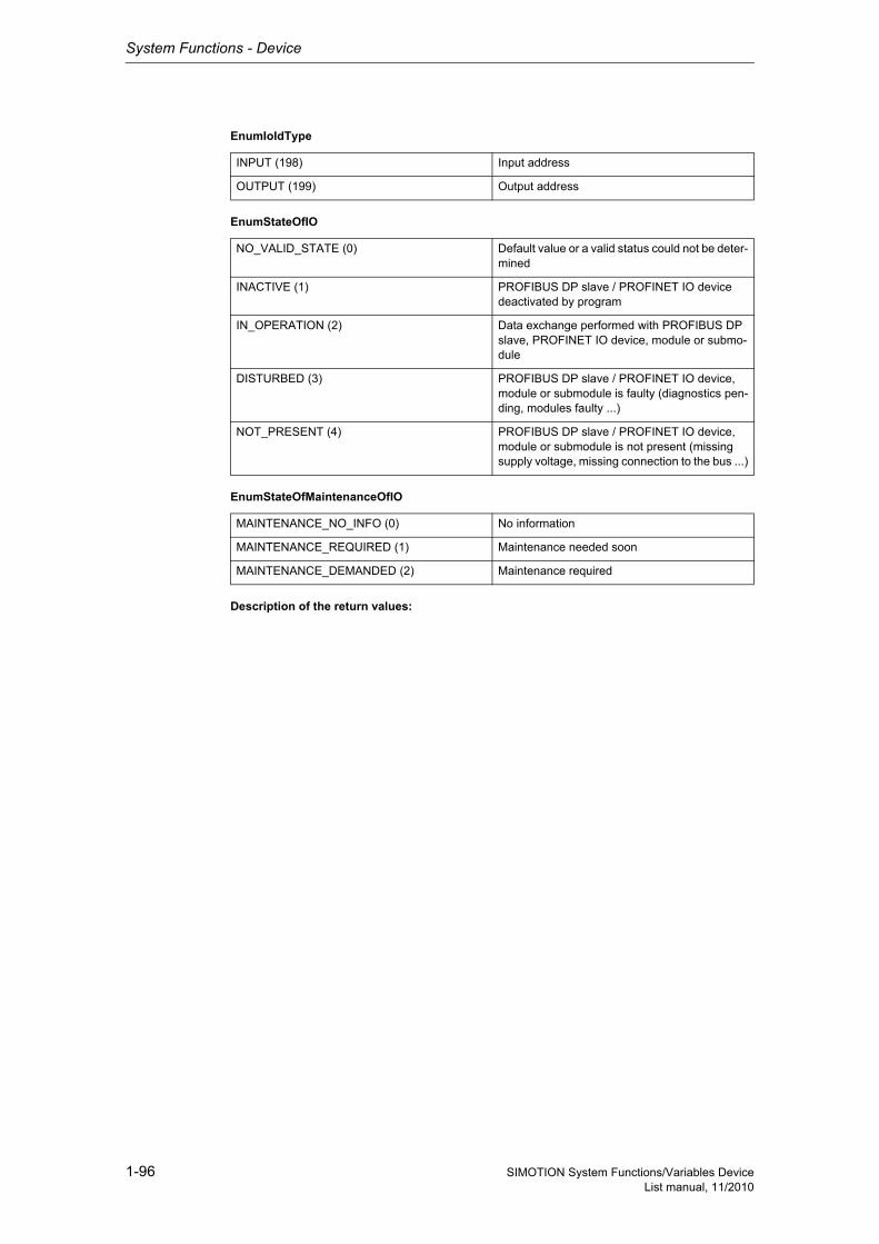
System Functions - Device
1-96 SIMOTION System Functions/Variables DeviceList manual, 11/2010
EnumIoIdType
EnumStateOfIO
EnumStateOfMaintenanceOfIO
Description of the return values:
INPUT (198) Input address
OUTPUT (199) Output address
NO_VALID_STATE (0) Default value or a valid status could not be deter-mined
INACTIVE (1) PROFIBUS DP slave / PROFINET IO device deactivated by program
IN_OPERATION (2) Data exchange performed with PROFIBUS DP slave, PROFINET IO device, module or submo-dule
DISTURBED (3) PROFIBUS DP slave / PROFINET IO device, module or submodule is faulty (diagnostics pen-ding, modules faulty ...)
NOT_PRESENT (4) PROFIBUS DP slave / PROFINET IO device, module or submodule is not present (missing supply voltage, missing connection to the bus ...)
MAINTENANCE_NO_INFO (0) No information
MAINTENANCE_REQUIRED (1) Maintenance needed soon
MAINTENANCE_DEMANDED (2) Maintenance required
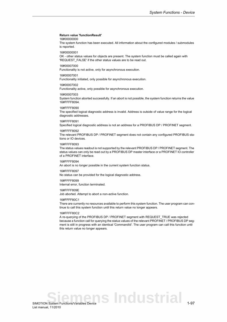
System Functions - Device
1-97SIMOTION System Functions/Variables DeviceList manual, 11/2010
Return value 'functionResult'16#00000000The system function has been executed. All information about the configured modules / submodules is reported.
16#00000001OK - other status values for objects are present. The system function must be called again with 'REQUEST_FALSE' if the other status values are to be read out.
16#00007000Functionality is not active, only for asynchronous execution.
16#00007001Functionality initiated, only possible for asynchronous execution.
16#00007002Functionality active, only possible for asynchronous execution.
16#00007003System function aborted successfully. If an abort is not possible, the system function returns the value 16#FFFF8094.
16#FFFF8090The specified logical diagnostic address is invalid. Address is outside of value range for the logical diagnostic addresses.
16#FFFF8091Specified logical diagnostic address is not an address for a PROFIBUS DP / PROFINET segment.
16#FFFF8092The relevant PROFIBUS DP / PROFINET segment does not contain any configured PROFIBUS sta-tions or IO devices.
16#FFFF8093The status values readout is not supported by the relevant PROFIBUS DP / PROFINET segment. The status values can only be read out by a PROFIBUS DP master interface or a PROFINET IO controller of a PROFINET interface.
16#FFFF8094An abort is no longer possible in the current system function status.
16#FFFF8097No status can be provided for the logical diagnostic address.
16#FFFF8099Internal error, function terminated.
16#FFFF809EJob aborted. Attempt to abort a non-active function.
16#FFFF80C1There are currently no resources available to perform this system function. The user program can con-tinue to call this system function until this return value no longer appears.
16#FFFF80C2A re-querying of the PROFIBUS DP / PROFINET segment with REQUEST_TRUE was rejected because a function call for querying the status values of the relevant PROFINET / PROFIBUS DP seg-ment is still in progress with an identical 'CommandId'. The user program can call this function until this return value no longer appears.
Siemens Industrial
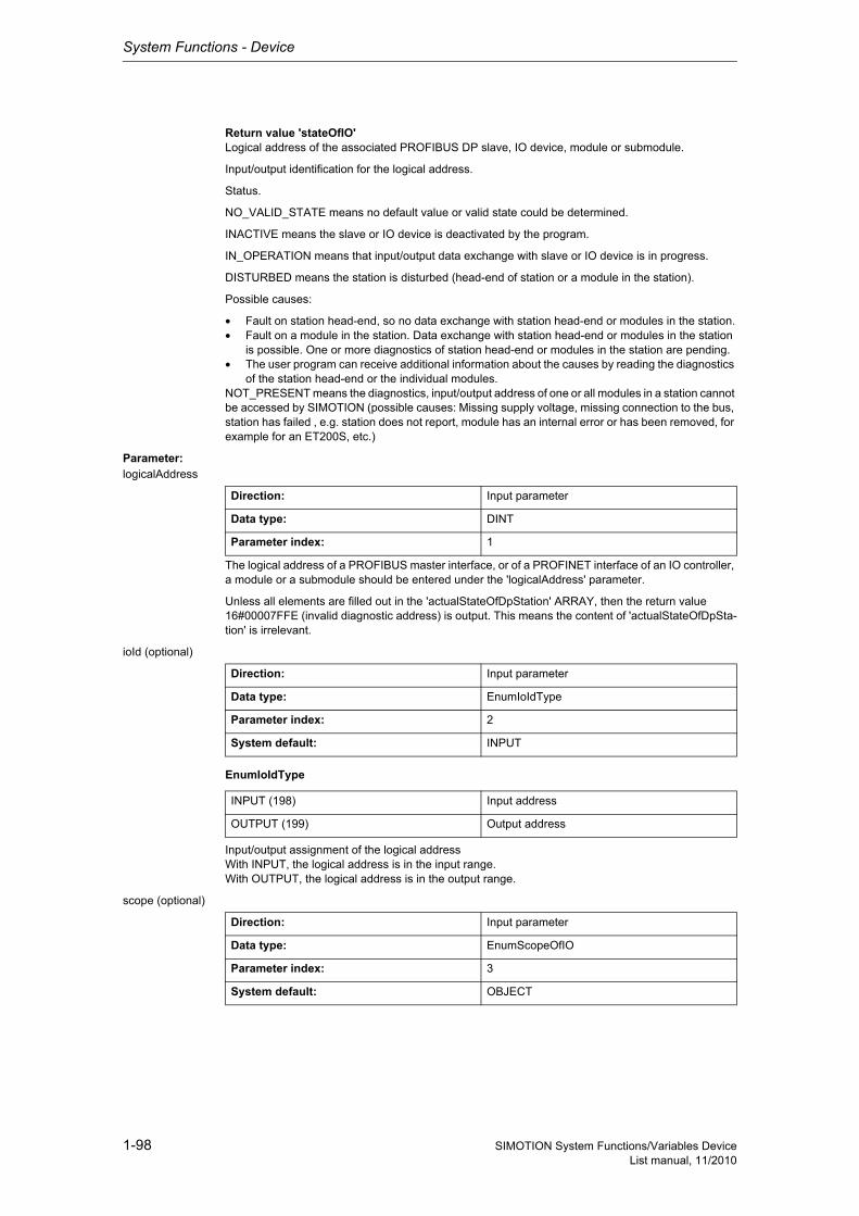
System Functions - Device
1-98 SIMOTION System Functions/Variables DeviceList manual, 11/2010
Return value 'stateOfIO'Logical address of the associated PROFIBUS DP slave, IO device, module or submodule.
Input/output identification for the logical address.
Status.
NO_VALID_STATE means no default value or valid state could be determined.
INACTIVE means the slave or IO device is deactivated by the program.
IN_OPERATION means that input/output data exchange with slave or IO device is in progress.
DISTURBED means the station is disturbed (head-end of station or a module in the station).
Possible causes:
• Fault on station head-end, so no data exchange with station head-end or modules in the station.• Fault on a module in the station. Data exchange with station head-end or modules in the station
is possible. One or more diagnostics of station head-end or modules in the station are pending.• The user program can receive additional information about the causes by reading the diagnostics
of the station head-end or the individual modules.NOT_PRESENT means the diagnostics, input/output address of one or all modules in a station cannot be accessed by SIMOTION (possible causes: Missing supply voltage, missing connection to the bus, station has failed , e.g. station does not report, module has an internal error or has been removed, for example for an ET200S, etc.)
Parameter: logicalAddress
The logical address of a PROFIBUS master interface, or of a PROFINET interface of an IO controller, a module or a submodule should be entered under the 'logicalAddress' parameter.
Unless all elements are filled out in the 'actualStateOfDpStation' ARRAY, then the return value 16#00007FFE (invalid diagnostic address) is output. This means the content of 'actualStateOfDpSta-tion' is irrelevant.
ioId (optional)
EnumIoIdType
Input/output assignment of the logical addressWith INPUT, the logical address is in the input range.With OUTPUT, the logical address is in the output range.
scope (optional)
Direction: Input parameter
Data type: DINT
Parameter index: 1
Direction: Input parameter
Data type: EnumIoIdType
Parameter index: 2
System default: INPUT
INPUT (198) Input address
OUTPUT (199) Output address
Direction: Input parameter
Data type: EnumScopeOfIO
Parameter index: 3
System default: OBJECT
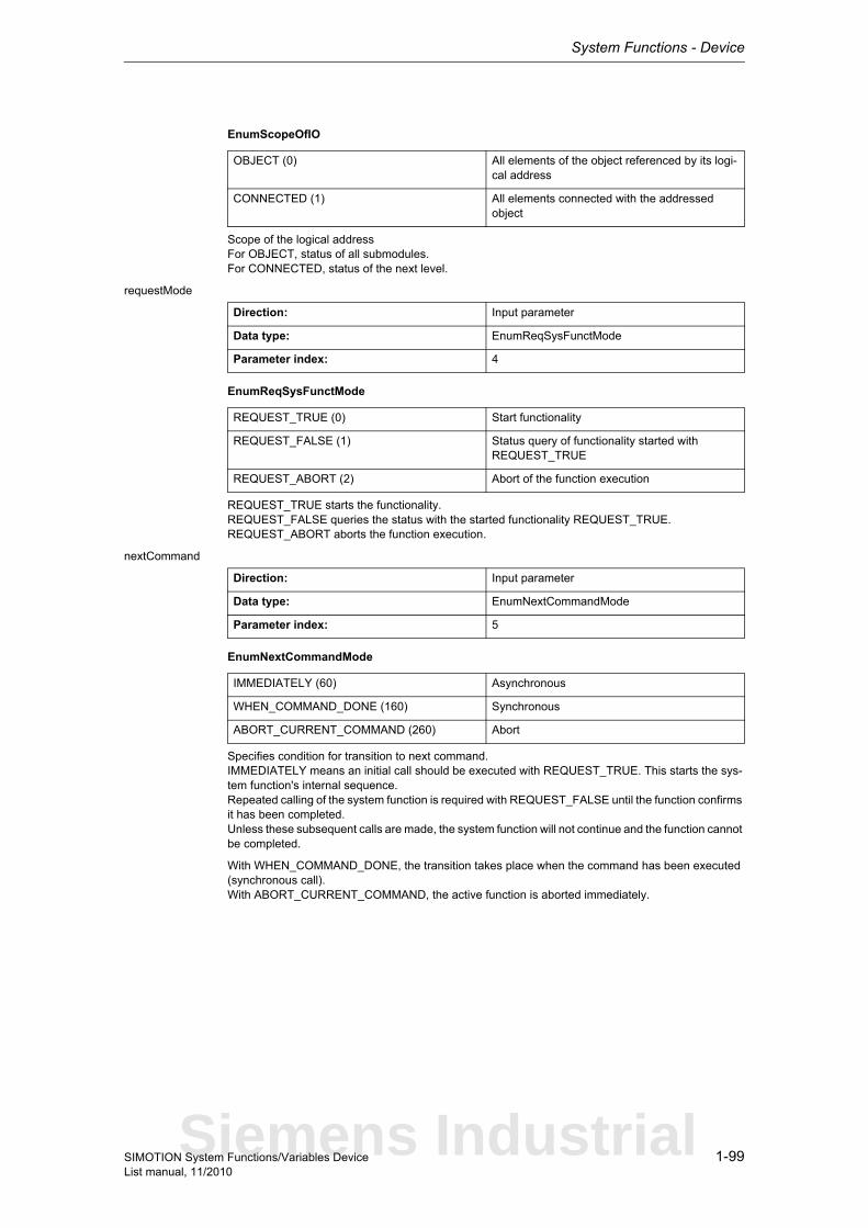
System Functions - Device
1-99SIMOTION System Functions/Variables DeviceList manual, 11/2010
EnumScopeOfIO
Scope of the logical addressFor OBJECT, status of all submodules.For CONNECTED, status of the next level.
requestMode
EnumReqSysFunctMode
REQUEST_TRUE starts the functionality.REQUEST_FALSE queries the status with the started functionality REQUEST_TRUE.REQUEST_ABORT aborts the function execution.
nextCommand
EnumNextCommandMode
Specifies condition for transition to next command.IMMEDIATELY means an initial call should be executed with REQUEST_TRUE. This starts the sys-tem function's internal sequence.Repeated calling of the system function is required with REQUEST_FALSE until the function confirms it has been completed.Unless these subsequent calls are made, the system function will not continue and the function cannot be completed.
With WHEN_COMMAND_DONE, the transition takes place when the command has been executed (synchronous call).With ABORT_CURRENT_COMMAND, the active function is aborted immediately.
OBJECT (0) All elements of the object referenced by its logi-cal address
CONNECTED (1) All elements connected with the addressed object
Direction: Input parameter
Data type: EnumReqSysFunctMode
Parameter index: 4
REQUEST_TRUE (0) Start functionality
REQUEST_FALSE (1) Status query of functionality started with REQUEST_TRUE
REQUEST_ABORT (2) Abort of the function execution
Direction: Input parameter
Data type: EnumNextCommandMode
Parameter index: 5
IMMEDIATELY (60) Asynchronous
WHEN_COMMAND_DONE (160) Synchronous
ABORT_CURRENT_COMMAND (260) Abort
Siemens Industrial
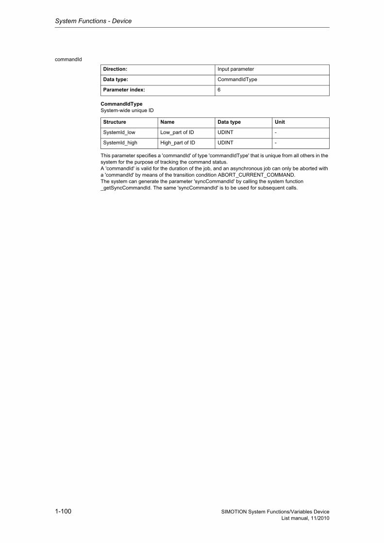
System Functions - Device
1-100 SIMOTION System Functions/Variables DeviceList manual, 11/2010
commandId
CommandIdTypeSystem-wide unique ID
This parameter specifies a 'commandId' of type 'commandIdType' that is unique from all others in the system for the purpose of tracking the command status.A 'commandId' is valid for the duration of the job, and an asynchronous job can only be aborted with a 'commandId' by means of the transition condition ABORT_CURRENT_COMMAND.The system can generate the parameter 'syncCommandId' by calling the system function _getSyncCommandId. The same 'syncCommandId' is to be used for subsequent calls.
Direction: Input parameter
Data type: CommandIdType
Parameter index: 6
Structure Name Data type Unit
SystemId_low Low_part of ID UDINT -
SystemId_high High_part of ID UDINT -
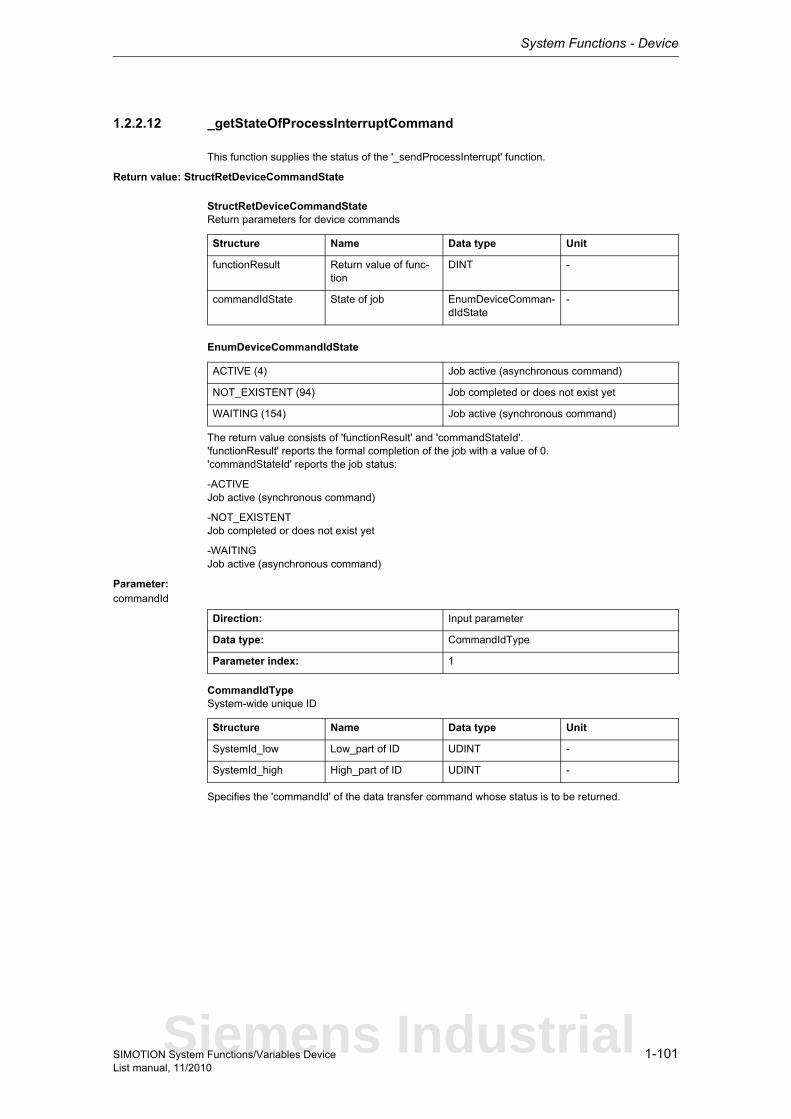
System Functions - Device
1-101SIMOTION System Functions/Variables DeviceList manual, 11/2010
1.2.2.12 _getStateOfProcessInterruptCommand
This function supplies the status of the '_sendProcessInterrupt' function.
Return value: StructRetDeviceCommandState
StructRetDeviceCommandStateReturn parameters for device commands
EnumDeviceCommandIdState
The return value consists of 'functionResult' and 'commandStateId'.'functionResult' reports the formal completion of the job with a value of 0.'commandStateId' reports the job status:
-ACTIVEJob active (synchronous command)
-NOT_EXISTENTJob completed or does not exist yet
-WAITINGJob active (asynchronous command)
Parameter: commandId
CommandIdTypeSystem-wide unique ID
Specifies the 'commandId' of the data transfer command whose status is to be returned.
Structure Name Data type Unit
functionResult Return value of func-tion
DINT -
commandIdState State of job EnumDeviceComman-dIdState
-
ACTIVE (4) Job active (asynchronous command)
NOT_EXISTENT (94) Job completed or does not exist yet
WAITING (154) Job active (synchronous command)
Direction: Input parameter
Data type: CommandIdType
Parameter index: 1
Structure Name Data type Unit
SystemId_low Low_part of ID UDINT -
SystemId_high High_part of ID UDINT -
Siemens Industrial
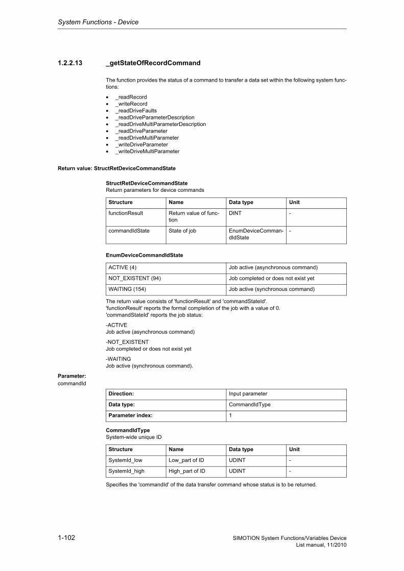
System Functions - Device
1-102 SIMOTION System Functions/Variables DeviceList manual, 11/2010
1.2.2.13 _getStateOfRecordCommand
The function provides the status of a command to transfer a data set within the following system func-tions:
• _readRecord• _writeRecord• _readDriveFaults• _readDriveParameterDescription• _readDriveMultiParameterDescription• _readDriveParameter• _readDriveMultiParameter• _writeDriveParameter• _writeDriveMultiParameter
Return value: StructRetDeviceCommandState
StructRetDeviceCommandStateReturn parameters for device commands
EnumDeviceCommandIdState
The return value consists of 'functionResult' and 'commandStateId'.'functionResult' reports the formal completion of the job with a value of 0.'commandStateId' reports the job status:
-ACTIVEJob active (asynchronous command)
-NOT_EXISTENTJob completed or does not exist yet
-WAITINGJob active (synchronous command).
Parameter: commandId
CommandIdTypeSystem-wide unique ID
Specifies the 'commandId' of the data transfer command whose status is to be returned.
Structure Name Data type Unit
functionResult Return value of func-tion
DINT -
commandIdState State of job EnumDeviceComman-dIdState
-
ACTIVE (4) Job active (asynchronous command)
NOT_EXISTENT (94) Job completed or does not exist yet
WAITING (154) Job active (synchronous command)
Direction: Input parameter
Data type: CommandIdType
Parameter index: 1
Structure Name Data type Unit
SystemId_low Low_part of ID UDINT -
SystemId_high High_part of ID UDINT -
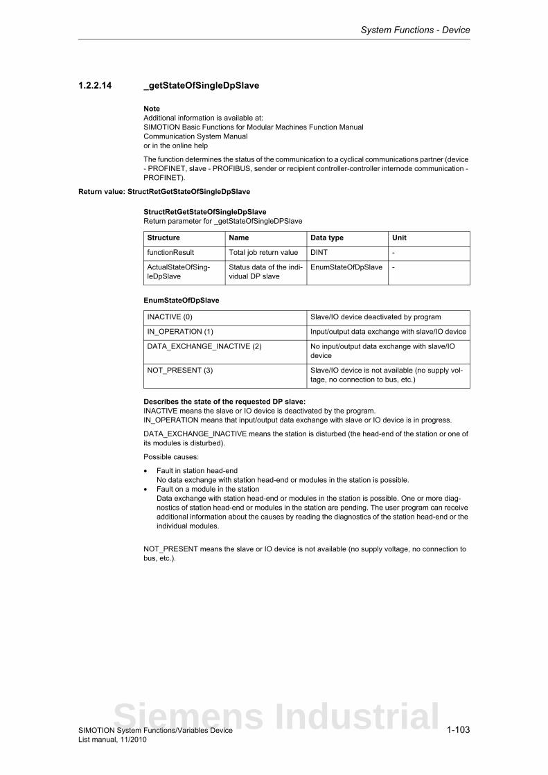
System Functions - Device
1-103SIMOTION System Functions/Variables DeviceList manual, 11/2010
1.2.2.14 _getStateOfSingleDpSlave
NoteAdditional information is available at:SIMOTION Basic Functions for Modular Machines Function ManualCommunication System Manualor in the online help
The function determines the status of the communication to a cyclical communications partner (device - PROFINET, slave - PROFIBUS, sender or recipient controller-controller internode communication - PROFINET).
Return value: StructRetGetStateOfSingleDpSlave
StructRetGetStateOfSingleDpSlaveReturn parameter for _getStateOfSingleDPSlave
EnumStateOfDpSlave
Describes the state of the requested DP slave:INACTIVE means the slave or IO device is deactivated by the program.IN_OPERATION means that input/output data exchange with slave or IO device is in progress.
DATA_EXCHANGE_INACTIVE means the station is disturbed (the head-end of the station or one of its modules is disturbed).
Possible causes:
• Fault in station head-endNo data exchange with station head-end or modules in the station is possible.
• Fault on a module in the stationData exchange with station head-end or modules in the station is possible. One or more diag-nostics of station head-end or modules in the station are pending. The user program can receive additional information about the causes by reading the diagnostics of the station head-end or the individual modules.
NOT_PRESENT means the slave or IO device is not available (no supply voltage, no connection to bus, etc.).
Structure Name Data type Unit
functionResult Total job return value DINT -
ActualStateOfSing-leDpSlave
Status data of the indi-vidual DP slave
EnumStateOfDpSlave -
INACTIVE (0) Slave/IO device deactivated by program
IN_OPERATION (1) Input/output data exchange with slave/IO device
DATA_EXCHANGE_INACTIVE (2) No input/output data exchange with slave/IO device
NOT_PRESENT (3) Slave/IO device is not available (no supply vol-tage, no connection to bus, etc.)
Siemens Industrial
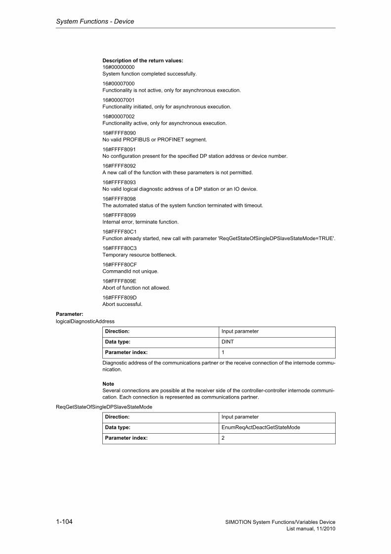
System Functions - Device
1-104 SIMOTION System Functions/Variables DeviceList manual, 11/2010
Description of the return values:16#00000000System function completed successfully.
16#00007000Functionality is not active, only for asynchronous execution.
16#00007001Functionality initiated, only for asynchronous execution.
16#00007002Functionality active, only for asynchronous execution.
16#FFFF8090No valid PROFIBUS or PROFINET segment.
16#FFFF8091No configuration present for the specified DP station address or device number.
16#FFFF8092A new call of the function with these parameters is not permitted.
16#FFFF8093No valid logical diagnostic address of a DP station or an IO device.
16#FFFF8098The automated status of the system function terminated with timeout.
16#FFFF8099Internal error, terminate function.
16#FFFF80C1Function already started, new call with parameter 'ReqGetStateOfSingleDPSlaveStateMode=TRUE'.
16#FFFF80C3Temporary resource bottleneck.
16#FFFF80CFCommandId not unique.
16#FFFF809EAbort of function not allowed.
16#FFFF809DAbort successful.
Parameter: logicalDiagnosticAddress
Diagnostic address of the communications partner or the receive connection of the internode commu-nication.
NoteSeveral connections are possible at the receiver side of the controller-controller internode communi-cation. Each connection is represented as communications partner.
ReqGetStateOfSingleDPSlaveStateMode
Direction: Input parameter
Data type: DINT
Parameter index: 1
Direction: Input parameter
Data type: EnumReqActDeactGetStateMode
Parameter index: 2
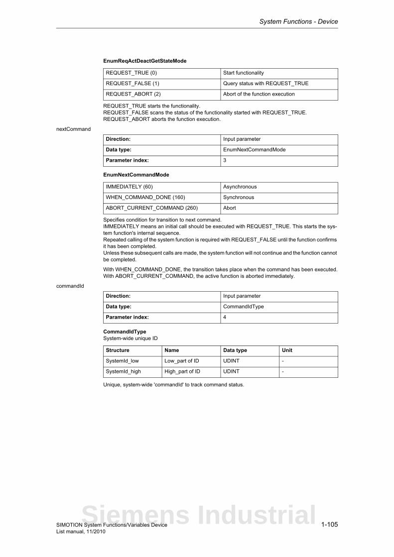
System Functions - Device
1-105SIMOTION System Functions/Variables DeviceList manual, 11/2010
EnumReqActDeactGetStateMode
REQUEST_TRUE starts the functionality.REQUEST_FALSE scans the status of the functionality started with REQUEST_TRUE.REQUEST_ABORT aborts the function execution.
nextCommand
EnumNextCommandMode
Specifies condition for transition to next command.IMMEDIATELY means an initial call should be executed with REQUEST_TRUE. This starts the sys-tem function's internal sequence.Repeated calling of the system function is required with REQUEST_FALSE until the function confirms it has been completed.Unless these subsequent calls are made, the system function will not continue and the function cannot be completed.
With WHEN_COMMAND_DONE, the transition takes place when the command has been executed.With ABORT_CURRENT_COMMAND, the active function is aborted immediately.
commandId
CommandIdTypeSystem-wide unique ID
Unique, system-wide 'commandId' to track command status.
REQUEST_TRUE (0) Start functionality
REQUEST_FALSE (1) Query status with REQUEST_TRUE
REQUEST_ABORT (2) Abort of the function execution
Direction: Input parameter
Data type: EnumNextCommandMode
Parameter index: 3
IMMEDIATELY (60) Asynchronous
WHEN_COMMAND_DONE (160) Synchronous
ABORT_CURRENT_COMMAND (260) Abort
Direction: Input parameter
Data type: CommandIdType
Parameter index: 4
Structure Name Data type Unit
SystemId_low Low_part of ID UDINT -
SystemId_high High_part of ID UDINT -
Siemens Industrial
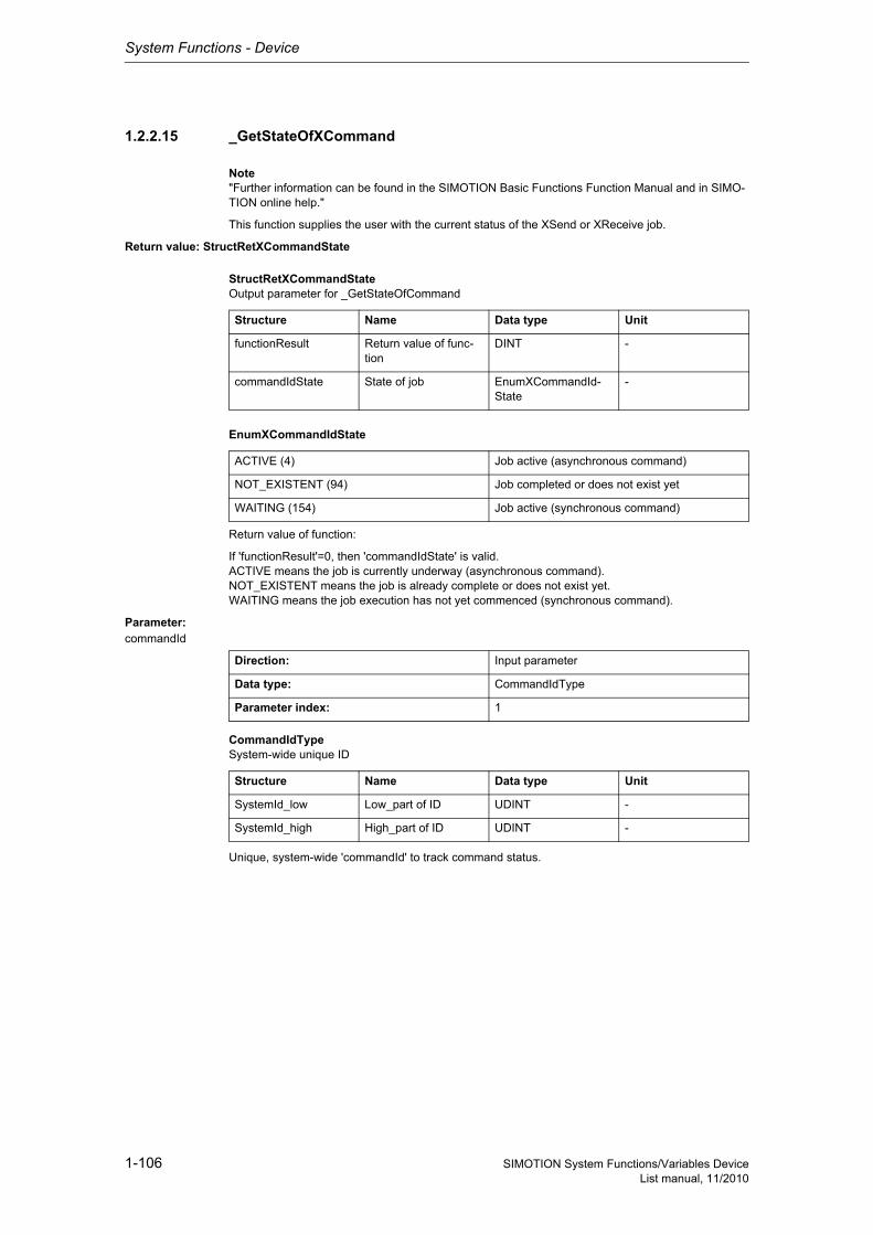
System Functions - Device
1-106 SIMOTION System Functions/Variables DeviceList manual, 11/2010
1.2.2.15 _GetStateOfXCommand
Note"Further information can be found in the SIMOTION Basic Functions Function Manual and in SIMO-TION online help."
This function supplies the user with the current status of the XSend or XReceive job.
Return value: StructRetXCommandState
StructRetXCommandStateOutput parameter for _GetStateOfCommand
EnumXCommandIdState
Return value of function:
If 'functionResult'=0, then 'commandIdState' is valid.ACTIVE means the job is currently underway (asynchronous command).NOT_EXISTENT means the job is already complete or does not exist yet.WAITING means the job execution has not yet commenced (synchronous command).
Parameter: commandId
CommandIdTypeSystem-wide unique ID
Unique, system-wide 'commandId' to track command status.
Structure Name Data type Unit
functionResult Return value of func-tion
DINT -
commandIdState State of job EnumXCommandId-State
-
ACTIVE (4) Job active (asynchronous command)
NOT_EXISTENT (94) Job completed or does not exist yet
WAITING (154) Job active (synchronous command)
Direction: Input parameter
Data type: CommandIdType
Parameter index: 1
Structure Name Data type Unit
SystemId_low Low_part of ID UDINT -
SystemId_high High_part of ID UDINT -
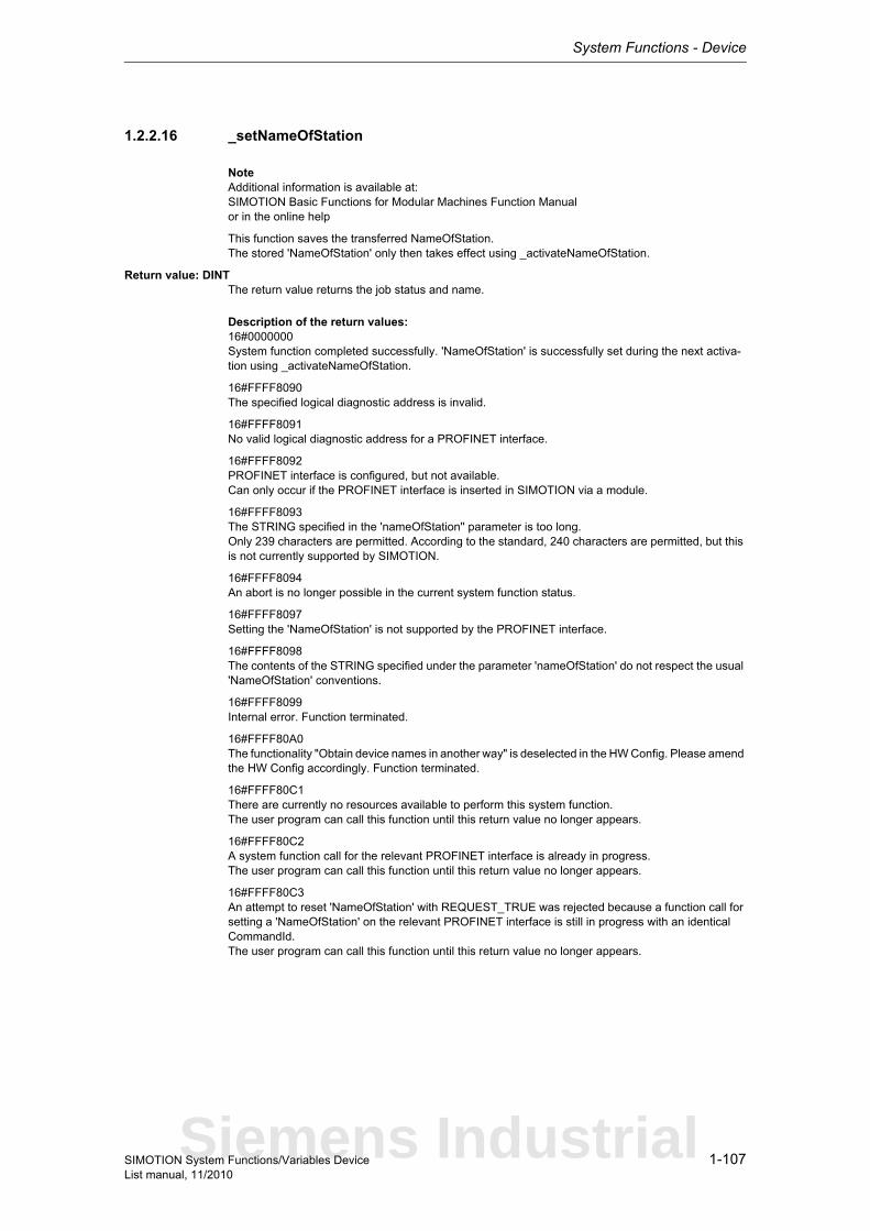
System Functions - Device
1-107SIMOTION System Functions/Variables DeviceList manual, 11/2010
1.2.2.16 _setNameOfStation
NoteAdditional information is available at:SIMOTION Basic Functions for Modular Machines Function Manualor in the online help
This function saves the transferred NameOfStation.The stored 'NameOfStation' only then takes effect using _activateNameOfStation.
Return value: DINTThe return value returns the job status and name.
Description of the return values:16#0000000System function completed successfully. 'NameOfStation' is successfully set during the next activa-tion using _activateNameOfStation.
16#FFFF8090The specified logical diagnostic address is invalid.
16#FFFF8091No valid logical diagnostic address for a PROFINET interface.
16#FFFF8092PROFINET interface is configured, but not available.Can only occur if the PROFINET interface is inserted in SIMOTION via a module.
16#FFFF8093The STRING specified in the 'nameOfStation'' parameter is too long.Only 239 characters are permitted. According to the standard, 240 characters are permitted, but this is not currently supported by SIMOTION.
16#FFFF8094An abort is no longer possible in the current system function status.
16#FFFF8097Setting the 'NameOfStation' is not supported by the PROFINET interface.
16#FFFF8098The contents of the STRING specified under the parameter 'nameOfStation' do not respect the usual 'NameOfStation' conventions.
16#FFFF8099Internal error. Function terminated.
16#FFFF80A0The functionality "Obtain device names in another way" is deselected in the HW Config. Please amend the HW Config accordingly. Function terminated.
16#FFFF80C1There are currently no resources available to perform this system function.The user program can call this function until this return value no longer appears.
16#FFFF80C2A system function call for the relevant PROFINET interface is already in progress.The user program can call this function until this return value no longer appears.
16#FFFF80C3An attempt to reset 'NameOfStation' with REQUEST_TRUE was rejected because a function call for setting a 'NameOfStation' on the relevant PROFINET interface is still in progress with an identical CommandId.The user program can call this function until this return value no longer appears.
Siemens Industrial
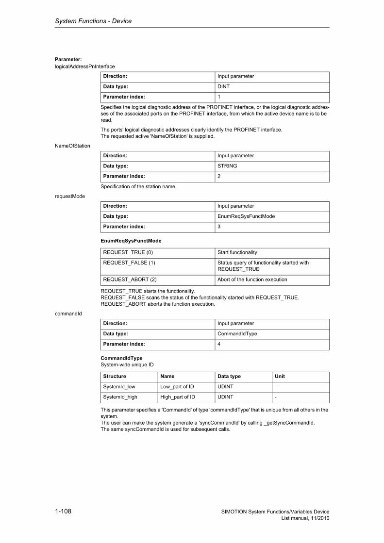
System Functions - Device
1-108 SIMOTION System Functions/Variables DeviceList manual, 11/2010
Parameter: logicalAddressPnInterface
Specifies the logical diagnostic address of the PROFINET interface, or the logical diagnostic addres-ses of the associated ports on the PROFINET interface, from which the active device name is to be read.
The ports' logical diagnostic addresses clearly identify the PROFINET interface.The requested active 'NameOfStation' is supplied.
NameOfStation
Specification of the station name.
requestMode
EnumReqSysFunctMode
REQUEST_TRUE starts the functionality.REQUEST_FALSE scans the status of the functionality started with REQUEST_TRUE.REQUEST_ABORT aborts the function execution.
commandId
CommandIdTypeSystem-wide unique ID
This parameter specifies a 'CommandId' of type 'commandIdType' that is unique from all others in the system.The user can make the system generate a 'syncCommandId' by calling _getSyncCommandId.The same syncCommandId is used for subsequent calls.
Direction: Input parameter
Data type: DINT
Parameter index: 1
Direction: Input parameter
Data type: STRING
Parameter index: 2
Direction: Input parameter
Data type: EnumReqSysFunctMode
Parameter index: 3
REQUEST_TRUE (0) Start functionality
REQUEST_FALSE (1) Status query of functionality started with REQUEST_TRUE
REQUEST_ABORT (2) Abort of the function execution
Direction: Input parameter
Data type: CommandIdType
Parameter index: 4
Structure Name Data type Unit
SystemId_low Low_part of ID UDINT -
SystemId_high High_part of ID UDINT -

System Functions - Device
1-109SIMOTION System Functions/Variables DeviceList manual, 11/2010
nextCommand
EnumNextCommandMode
Specifies condition for transition to next command.IMMEDIATELY means an initial call should be executed with REQUEST_TRUE. This starts the sys-tem function's internal sequence.Repeated calling of the system function is required with REQUEST_FALSE until the function confirms it has been completed.Unless these subsequent calls are made, the system function will not continue and the function cannot be completed.
With WHEN_COMMAND_DONE, the transition takes place when the command is finished.With ABORT_CURRENT_COMMAND and the same 'commandId' as in the previous function call with IMMEDIATELY, the active function is aborted.
Direction: Input parameter
Data type: EnumNextCommandMode
Parameter index: 6
IMMEDIATELY (60) Asynchronous
WHEN_COMMAND_DONE (160) Synchronous
ABORT_CURRENT_COMMAND (260) Abort
Siemens Industrial
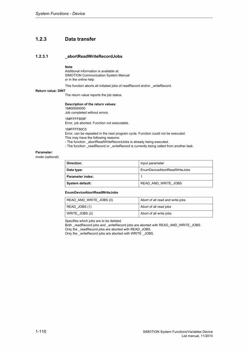
System Functions - Device
1-110 SIMOTION System Functions/Variables DeviceList manual, 11/2010
1.2.3 Data transfer
1.2.3.1 _abortReadWriteRecordJobs
NoteAdditional information is available at:SIMOTION Communication System Manualor in the online help
This function aborts all initiated jobs of readRecord and/or _writeRecord.
Return value: DINTThe return value reports the job status.
Description of the return values:16#00000000Job completed without errors.
16#FFFF809FError, job aborted. Function not executable.
16#FFFF80C5Error, can be repeated in the next program cycle. Function could not be executed.This may have the following reasons:- The function _abortReadWriteRecordJobs is already being executed.- The function _readRecord or _writeRecord is currently being called from another task.
Parameter: mode (optional)
EnumDeviceAbortReadWriteJobs
Specifies which jobs are to be deleted.Both _readRecord jobs and _writeRecord jobs are aborted with READ_AND_WRITE_JOBS.Only the _readRecord jobs are aborted with READ_JOBS.Only the _writeRecord jobs are aborted with WRITE _JOBS.
Direction: Input parameter
Data type: EnumDeviceAbortReadWriteJobs
Parameter index: 1
System default: READ_AND_WRITE_JOBS
READ_AND_WRITE_JOBS (0) Abort of all read and write jobs
READ_JOBS (1) Abort of all read jobs
WRITE_JOBS (2) Abort of all write jobs
System Functions - Device
1-111SIMOTION System Functions/Variables DeviceList manual, 11/2010
1.2.3.2 _readRecord
NoteAdditional information is available at:SIMOTION Communication System Manualor in the online help
This function causes a data set to be transferred from an I/O module to the user program.
It is used for CP and FM and dynamic parameter assignment of analog and digital modules and to read/write parameters from a drive.
A maximum of 8 jobs can be issued simultaneously.
NoteOnly one job should be issued per peripheral module in order to ensure processing.
Return value: StructRetReadRecord
StructRetReadRecordReturn parameter for _readRecord
Description of the return values:The return value consists of 'functionResult,' 'dataLength,' and 'data'.
In an error situation, the documentation for the associated module should be consulted for the specific error analysis.
Structure Name Data type Unit
functionResult Return value DINT -
dataLength Length of data read UDINT -
data User data ARRAY [0..239] OF USINT
-
Siemens Industrial
System Functions - Device
1-112 SIMOTION System Functions/Variables DeviceList manual, 11/2010
'functionResult'reports the job status.
16#00000000Data set transfer okay, job completed with positive result. Job okay.
16#00007001Must be repeated in the next program cycle.Initial call, initiation of data transfer okay(only when command is issued asynchronously).
16#00007002Must be repeated in the next program cycle.Intermediate call, data transfer still active.(only when command is issued asynchronously).
16#00007003Data set transfer aborted.Job aborted.
16#FFFF8090Error during data set transfer, job aborted.Specified logical base address invalid:No assignment is available in SDBs, or there is no base address.
16#FFFF8091Error during data set transfer, job aborted.The '_readRecord' function cannot reach the specified logical base address.
16#FFFF809CError, job aborted.Internal temporary collision of DPV1 jobs. The parameter job previously issued with _writeRecord is no longer valid.- after a wait time of several 100 ms, use _writeRecord to reissue the parameter job- Then use _readRecord to read out the requested data.
16#FFFF809DError, job aborted.An I slave/I device interface is unable to read data sets from the higher-level master/controller.
16#FFFF809EError, job aborted.Attempt to abort a non-active function.
16#FFFF809FError, job aborted.Function not executable.
16#FFFF80A0Error during data set transfer, job aborted.Negative acknowledgment when reading from the module:- Module was removed during the read operation- Module defective
16#FFFF80A2Error during data set transfer, job aborted.Protocol error in Layer2:- Module not available
16#FFFF80A3Error during data set transfer, job aborted.Protocol error involving user interface/user:- Module not available
16#FFFF80A4-A7Error during data set transfer, job aborted.Error numbers according to IEC 61158 reserved- Query the cause at the module's manufacturer
System Functions - Device
1-113SIMOTION System Functions/Variables DeviceList manual, 11/2010
16#FFFF80A8Error during data set transfer, job aborted.Error because of version conflict.
16#FFFF80A9Error during data set transfer, job aborted.Function not supported by the module.
16#FFFF80AA-AFError during data set transfer, job aborted.Error numbers according to IEC 61158 manufacturer-specific- Query the cause at the module's manufacturer
16#FFFF80B0Error during data set transfer, job aborted.- System function not supported for this module type- Module does not recognize the data set
16#FFFF80B1Error during data set transfer, job aborted.Incorrect length specified in 'dataLength' parameter.
16#FFFF80B2Error during data set transfer, job aborted.Module reports access to an invalid slot/subslot.
16#FFFF80B3Error during data set transfer, job aborted.Module reports type conflict.
16#FFFF80B4Error during data set transfer, job aborted.Module reports access to an invalid area.
16#FFFF80B5Error during data set transfer, job aborted.Module is not ready.Within the PROFIdrive profile (parameter model), this value has the following meaning:- Access is temporarily denied due to an internal processing status- A write request was not issued before a read request- A write and read request is already pending- A read request is already pending
16#FFFF80B6Error during data set transfer, job aborted.Module rejects access.
16#FFFF80B7Error during data set transfer, job aborted.Module reports an illegal range for a parameter or value.
16#FFFF80B8Error during data set transfer, job aborted.Module reports an invalid parameter.
16#FFFF80B9Error during data set transfer, job aborted.Module reports an invalid type.
16#FFFF80BA-BFError during data set transfer, job aborted.Error numbers according to IEC 61158 manufacturer-specific- Query the cause at the module's manufacturer
16#FFFF80C0Error during data set transfer, can be repeated in the next program cycle.The module is feeding the data record, but the module does not yet have any read data.
16#FFFF80C2Error during data set transfer, command can be repeated immediately.The module is currently executing the maximum possible jobs for one CPU.
Siemens Industrial
System Functions - Device
1-114 SIMOTION System Functions/Variables DeviceList manual, 11/2010
16#FFFF80C3Error during data set transfer, command can be repeated immediately.Required resources are presently occupied:- In the _readRecord function- In the module
16#FFFF80C4Error during data set transfer, command can be repeated immediately.Communication errors:- Parity error- SW Ready not set- Error in block length administration- Checksum error on CPU side- Checksum error on module side
16#FFFF80C5Error during data set transfer,Can be repeated in the next program cycle.Distributed I/O not available.
16#FFFF80C6Error during data set transfer, can be repeated in the next program cycle.Data record transfer has been aborted due to priority class abort (restart or background).
16#FFFF80CFError during data set transfer, can be repeated in the next program cycle.Another _readRecord function call is currently active under this 'commandId'.
'dataLength'reports the length of the data read.
'data'contains the read data (byte array, maximum of 240 bytes).
Parameter: ioId (optional)
EnumIoIdType
Input/output assignment of logical base address of the I/O module.With INPUT, the logical address of the I/O module is in the input range.With OUTPUT, the logical address of the I/O module is in the output range.
logAddress
Specifies the logical base address of the I/O module.
NoteYou can used both an input and an output address when hybrid modules are used.
Direction: Input parameter
Data type: EnumIoIdType
Parameter index: 1
System default: INPUT
INPUT (198) Input address
OUTPUT (199) Output address
Direction: Input parameter
Data type: DINT
Parameter index: 2
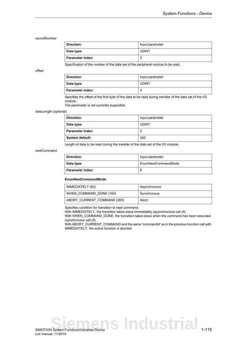
System Functions - Device
1-115SIMOTION System Functions/Variables DeviceList manual, 11/2010
recordNumber
Specification of the number of the data set of the peripheral module to be read.
offset
Specifies the offset of the first byte of the data to be read during transfer of the data set of the I/O module.The parameter is not currently supported.
dataLength (optional)
Length of data to be read during the transfer of the data set of the I/O module.
nextCommand
EnumNextCommandMode
Specifies condition for transition to next command.With IMMEDIATELY, the transition takes place immediately (asynchronous call of).With WHEN_COMMAND_DONE, the transition takes place when the command has been executed (synchronous call of).With ABORT_CURRENT_COMMAND and the same 'commandId' as in the previous function call with IMMEDIATELY, the active function is aborted.
Direction: Input parameter
Data type: UDINT
Parameter index: 3
Direction: Input parameter
Data type: UDINT
Parameter index: 4
Direction: Input parameter
Data type: UDINT
Parameter index: 5
System default: 240
Direction: Input parameter
Data type: EnumNextCommandMode
Parameter index: 6
IMMEDIATELY (60) Asynchronous
WHEN_COMMAND_DONE (160) Synchronous
ABORT_CURRENT_COMMAND (260) Abort
Siemens Industrial

System Functions - Device
1-116 SIMOTION System Functions/Variables DeviceList manual, 11/2010
commandId
CommandIdTypeSystem-wide unique ID
Unique, system-wide 'commandId' to track command status. A 'commandId' is always valid for the duration of a job andan asynchronous job can only be aborted by means of the transition condition ABORT_CURRENT_COMMAND.
Direction: Input parameter
Data type: CommandIdType
Parameter index: 7
Structure Name Data type Unit
SystemId_low Low_part of ID UDINT -
SystemId_high High_part of ID UDINT -
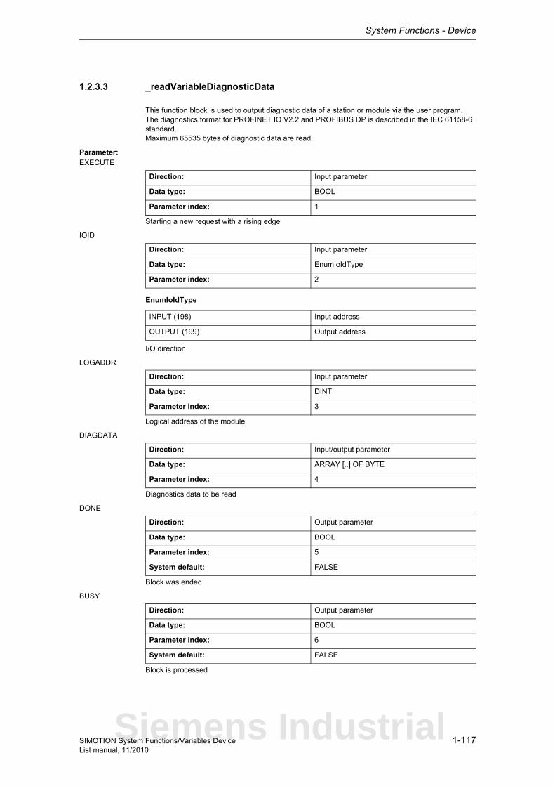
System Functions - Device
1-117SIMOTION System Functions/Variables DeviceList manual, 11/2010
1.2.3.3 _readVariableDiagnosticData
This function block is used to output diagnostic data of a station or module via the user program.The diagnostics format for PROFINET IO V2.2 and PROFIBUS DP is described in the IEC 61158-6 standard.Maximum 65535 bytes of diagnostic data are read.
Parameter: EXECUTE
Starting a new request with a rising edge
IOID
EnumIoIdType
I/O direction
LOGADDR
Logical address of the module
DIAGDATA
Diagnostics data to be read
DONE
Block was ended
BUSY
Block is processed
Direction: Input parameter
Data type: BOOL
Parameter index: 1
Direction: Input parameter
Data type: EnumIoIdType
Parameter index: 2
INPUT (198) Input address
OUTPUT (199) Output address
Direction: Input parameter
Data type: DINT
Parameter index: 3
Direction: Input/output parameter
Data type: ARRAY [..] OF BYTE
Parameter index: 4
Direction: Output parameter
Data type: BOOL
Parameter index: 5
System default: FALSE
Direction: Output parameter
Data type: BOOL
Parameter index: 6
System default: FALSE
Siemens Industrial
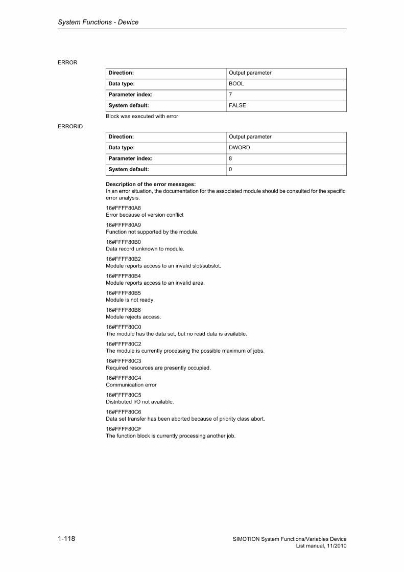
System Functions - Device
1-118 SIMOTION System Functions/Variables DeviceList manual, 11/2010
ERROR
Block was executed with error
ERRORID
Description of the error messages:In an error situation, the documentation for the associated module should be consulted for the specific error analysis.
16#FFFF80A8Error because of version conflict
16#FFFF80A9Function not supported by the module.
16#FFFF80B0Data record unknown to module.
16#FFFF80B2Module reports access to an invalid slot/subslot.
16#FFFF80B4Module reports access to an invalid area.
16#FFFF80B5Module is not ready.
16#FFFF80B6Module rejects access.
16#FFFF80C0The module has the data set, but no read data is available.
16#FFFF80C2The module is currently processing the possible maximum of jobs.
16#FFFF80C3Required resources are presently occupied.
16#FFFF80C4Communication error
16#FFFF80C5Distributed I/O not available.
16#FFFF80C6Data set transfer has been aborted because of priority class abort.
16#FFFF80CFThe function block is currently processing another job.
Direction: Output parameter
Data type: BOOL
Parameter index: 7
System default: FALSE
Direction: Output parameter
Data type: DWORD
Parameter index: 8
System default: 0

System Functions - Device
1-119SIMOTION System Functions/Variables DeviceList manual, 11/2010
LEN
Length of the read data set in bytes
Direction: Output parameter
Data type: UDINT
Parameter index: 9
System default: 0
Siemens Industrial
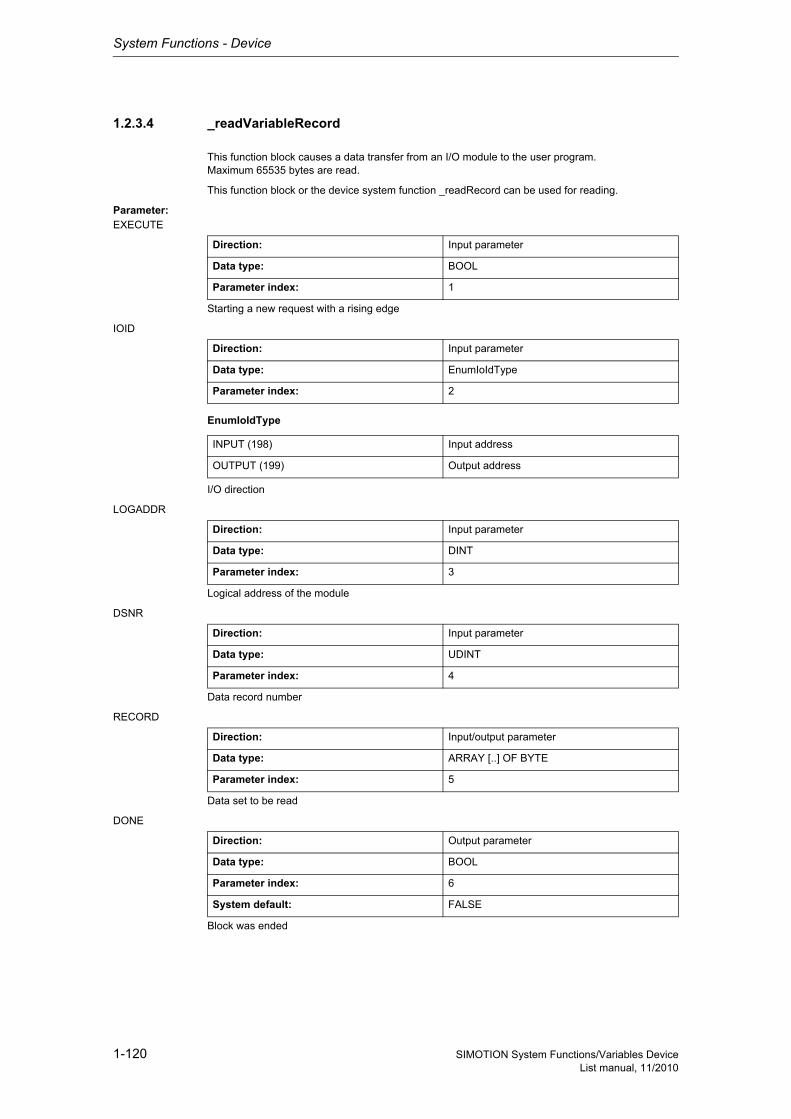
System Functions - Device
1-120 SIMOTION System Functions/Variables DeviceList manual, 11/2010
1.2.3.4 _readVariableRecord
This function block causes a data transfer from an I/O module to the user program.Maximum 65535 bytes are read.
This function block or the device system function _readRecord can be used for reading.
Parameter: EXECUTE
Starting a new request with a rising edge
IOID
EnumIoIdType
I/O direction
LOGADDR
Logical address of the module
DSNR
Data record number
RECORD
Data set to be read
DONE
Block was ended
Direction: Input parameter
Data type: BOOL
Parameter index: 1
Direction: Input parameter
Data type: EnumIoIdType
Parameter index: 2
INPUT (198) Input address
OUTPUT (199) Output address
Direction: Input parameter
Data type: DINT
Parameter index: 3
Direction: Input parameter
Data type: UDINT
Parameter index: 4
Direction: Input/output parameter
Data type: ARRAY [..] OF BYTE
Parameter index: 5
Direction: Output parameter
Data type: BOOL
Parameter index: 6
System default: FALSE
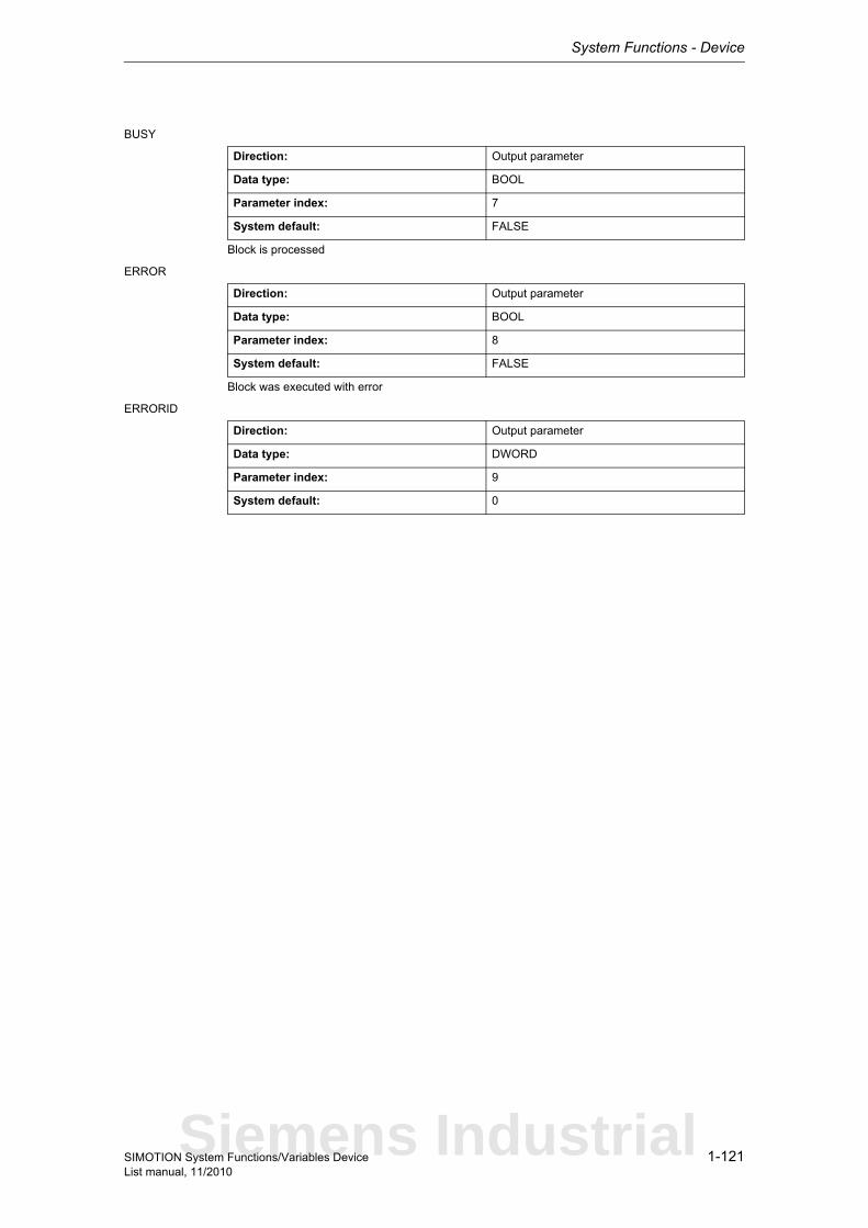
System Functions - Device
1-121SIMOTION System Functions/Variables DeviceList manual, 11/2010
BUSY
Block is processed
ERROR
Block was executed with error
ERRORID
Direction: Output parameter
Data type: BOOL
Parameter index: 7
System default: FALSE
Direction: Output parameter
Data type: BOOL
Parameter index: 8
System default: FALSE
Direction: Output parameter
Data type: DWORD
Parameter index: 9
System default: 0
Siemens Industrial
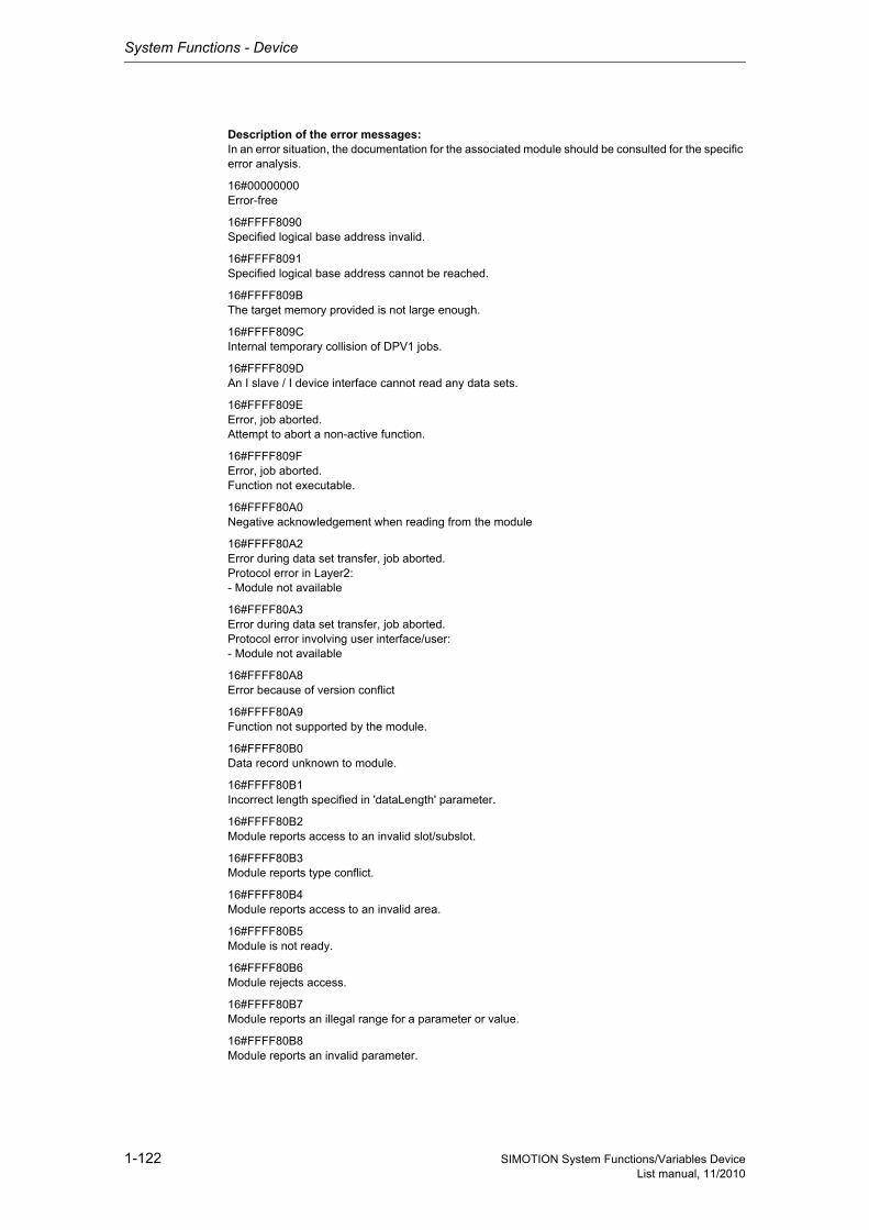
System Functions - Device
1-122 SIMOTION System Functions/Variables DeviceList manual, 11/2010
Description of the error messages:In an error situation, the documentation for the associated module should be consulted for the specific error analysis.
16#00000000Error-free
16#FFFF8090Specified logical base address invalid.
16#FFFF8091Specified logical base address cannot be reached.
16#FFFF809BThe target memory provided is not large enough.
16#FFFF809CInternal temporary collision of DPV1 jobs.
16#FFFF809DAn I slave / I device interface cannot read any data sets.
16#FFFF809EError, job aborted.Attempt to abort a non-active function.
16#FFFF809FError, job aborted.Function not executable.
16#FFFF80A0Negative acknowledgement when reading from the module
16#FFFF80A2Error during data set transfer, job aborted.Protocol error in Layer2:- Module not available
16#FFFF80A3Error during data set transfer, job aborted.Protocol error involving user interface/user:- Module not available
16#FFFF80A8Error because of version conflict
16#FFFF80A9Function not supported by the module.
16#FFFF80B0Data record unknown to module.
16#FFFF80B1Incorrect length specified in 'dataLength' parameter.
16#FFFF80B2Module reports access to an invalid slot/subslot.
16#FFFF80B3Module reports type conflict.
16#FFFF80B4Module reports access to an invalid area.
16#FFFF80B5Module is not ready.
16#FFFF80B6Module rejects access.
16#FFFF80B7Module reports an illegal range for a parameter or value.
16#FFFF80B8Module reports an invalid parameter.
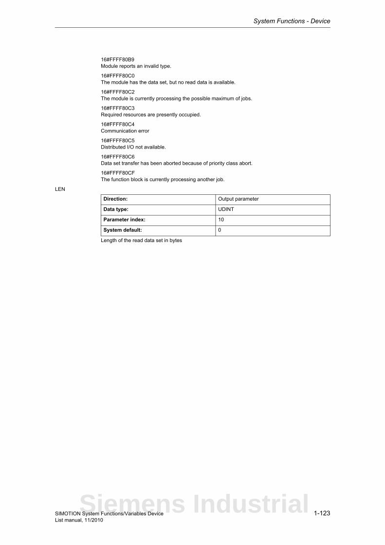
System Functions - Device
1-123SIMOTION System Functions/Variables DeviceList manual, 11/2010
16#FFFF80B9Module reports an invalid type.
16#FFFF80C0The module has the data set, but no read data is available.
16#FFFF80C2The module is currently processing the possible maximum of jobs.
16#FFFF80C3Required resources are presently occupied.
16#FFFF80C4Communication error
16#FFFF80C5Distributed I/O not available.
16#FFFF80C6Data set transfer has been aborted because of priority class abort.
16#FFFF80CFThe function block is currently processing another job.
LEN
Length of the read data set in bytes
Direction: Output parameter
Data type: UDINT
Parameter index: 10
System default: 0
Siemens Industrial
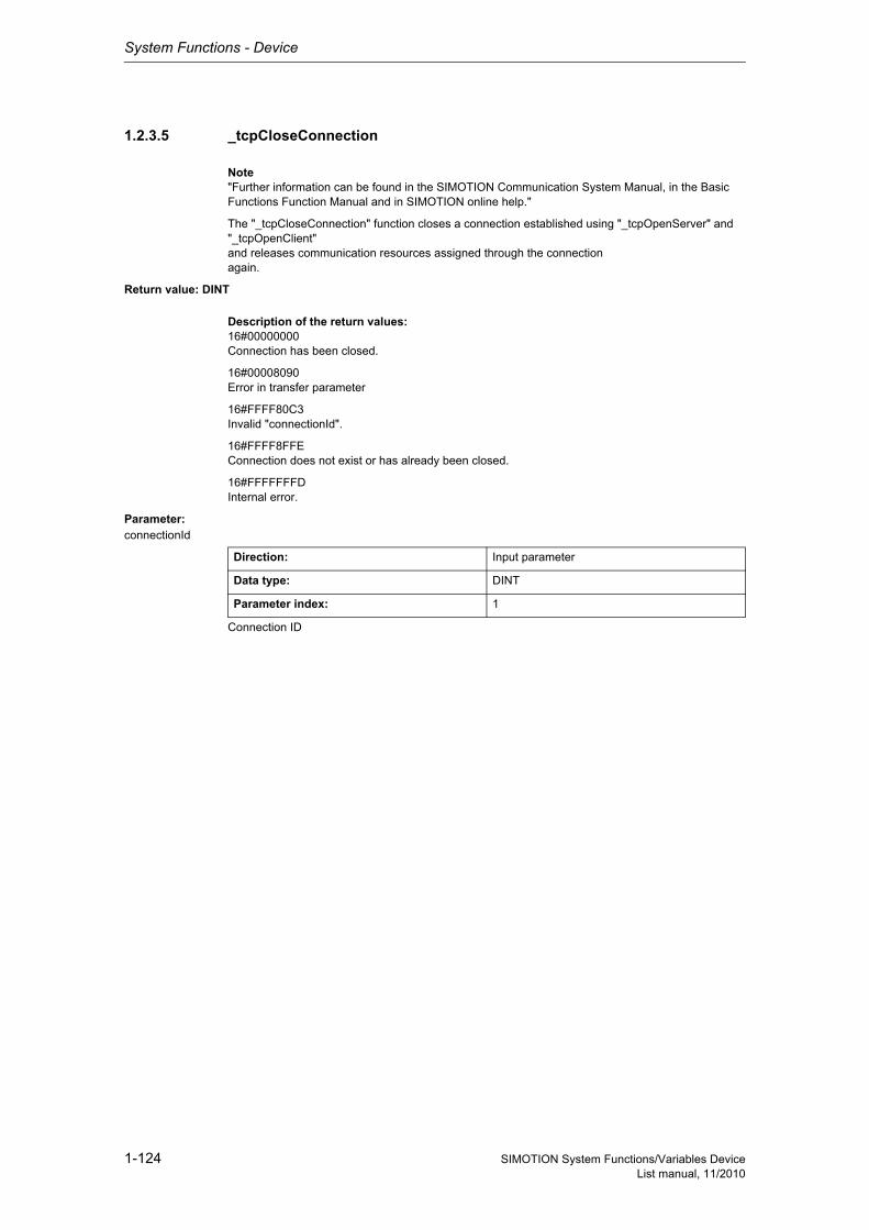
System Functions - Device
1-124 SIMOTION System Functions/Variables DeviceList manual, 11/2010
1.2.3.5 _tcpCloseConnection
Note"Further information can be found in the SIMOTION Communication System Manual, in the Basic Functions Function Manual and in SIMOTION online help."
The "_tcpCloseConnection" function closes a connection established using "_tcpOpenServer" and "_tcpOpenClient"and releases communication resources assigned through the connectionagain.
Return value: DINT
Description of the return values:16#00000000Connection has been closed.
16#00008090Error in transfer parameter
16#FFFF80C3Invalid "connectionId".
16#FFFF8FFEConnection does not exist or has already been closed.
16#FFFFFFFDInternal error.
Parameter: connectionId
Connection ID
Direction: Input parameter
Data type: DINT
Parameter index: 1
System Functions - Device
1-125SIMOTION System Functions/Variables DeviceList manual, 11/2010
1.2.3.6 _tcpCloseServer
Note"Further information can be found in the SIMOTION Communication System Manual, in the Basic Functions Function Manual and in SIMOTION online help."
The function is called if no more new connections are to be accepted. (However, it does not abort exis-ting connections.)
Return value: DINTDescription of the return values:
16#00000000Waiting state ended.
16#FFFF8090Error in transfer parameter
16#FFFF80C3Invalid port number.
Parameter: port
Port that is waiting for a connection request.
Direction: Input parameter
Data type: UINT
Parameter index: 1
Siemens Industrial
System Functions - Device
1-126 SIMOTION System Functions/Variables DeviceList manual, 11/2010
1.2.3.7 _tcpOpenClient
Note"Further information can be found in the Communication System Manual, in the Basic Functions Func-tion Manual and in SIMOTION online help."
The _tcpOpenClient system function submits a connection request to a server addressed via the para-meters 'serverAddress' and 'serverPort'. Once a connection has been successfully established, the function provides a connection ID which is required for subsequent write and read calls (_tcpsend, _tcpReceive).
The function can only be called of from motion tasks or the background task.
Return value: StructRetTcpOpenClient
StructRetTcpOpenClientReturn parameter for _tcpOpenClient
Description of the return values:16#00000000Connection successfully established
16#00007001Function started (only with nextCommand = IMMEDIATELY)
16#00007002Function active (only with nextCommand = IMMEDIATELY)
16#00008090Error in transfer parameter
16#FFFF8FFFAddress combination of own port, destination IP address and destination port multiply assigned
16#FFFF8FFBConnection partner refuses connection
16#FFFF8FFANo connection partner available
16#FFFFFFFDInternal error
16#FFFFFFFFResource bottleneck
Parameter: port
Own port number.
serverAddress
IP address of server.
Structure Name Data type Unit
functionResult Result DINT -
connectionId New connection Id DINT -
Direction: Input parameter
Data type: UINT
Parameter index: 1
Direction: Input parameter
Data type: ARRAY [0..3] OF USINT
Parameter index: 2
System Functions - Device
1-127SIMOTION System Functions/Variables DeviceList manual, 11/2010
serverPort
Port number of the server.
nextCommand
EnumTcpNextCommandMode
Specifies condition for transition to next command.With IMMEDIATELY, the transition takes place immediately.With WHEN_COMMAND_DONE, the transition takes place when the command is finished.
Direction: Input parameter
Data type: UINT
Parameter index: 3
Direction: Input parameter
Data type: EnumTcpNextCommandMode
Parameter index: 4
IMMEDIATELY (60) Asynchronous
WHEN_COMMAND_DONE (160) Synchronous
Siemens Industrial
System Functions - Device
1-128 SIMOTION System Functions/Variables DeviceList manual, 11/2010
1.2.3.8 _tcpOpenServer
Note"Further information can be found in the Communication System Manual, in the Basic Functions Func-tion Manual and in SIMOTION online help."
The '_tcpOpenServer' function waits at the port specified by the 'port' parameter for connection requests from one or more clients.Once a connection has been successfully established, the function provides a connection ID which is required for subsequent write and read calls (_tcpsend, _tcpReceive).After this, the function becomes available again so that further connections can be established.
If no further connection is to be established, the resources used by '_tcpOpenServer' can be released again by calling '_tcpCloseServer'.
This does not automatically close any previously established connections; they have to be disconnec-ted by calling _tcpCloseConnection.
The function can only be called of from motion tasks or the background task.
Return value: StructRetTcpOpenServer
StructRetTcpOpenServerReturn parameter for _tcpOpenServer
Description of the return values:16#00000000Connection successfully established
16#00007001Function started
16#00007002Function active
16#FFFF8090Error in transfer parameter
16#FFFF8FFFServer port multiply assigned
16#FFFFFFFDInternal error
16#FFFFFFFFResource bottleneck (for example, connection requests exceed amount permitted in the 'backlog' parameter)
Parameter: port
Port at which the function is waiting for a connection request.
Structure Name Data type Unit
functionResult Result DINT -
connectionId New connection Id DINT -
clientAddress IP address of the con-necting client
ARRAY [0..3] OF USINT
-
clientPort Port number of the connecting client
UINT -
Direction: Input parameter
Data type: UINT
Parameter index: 1
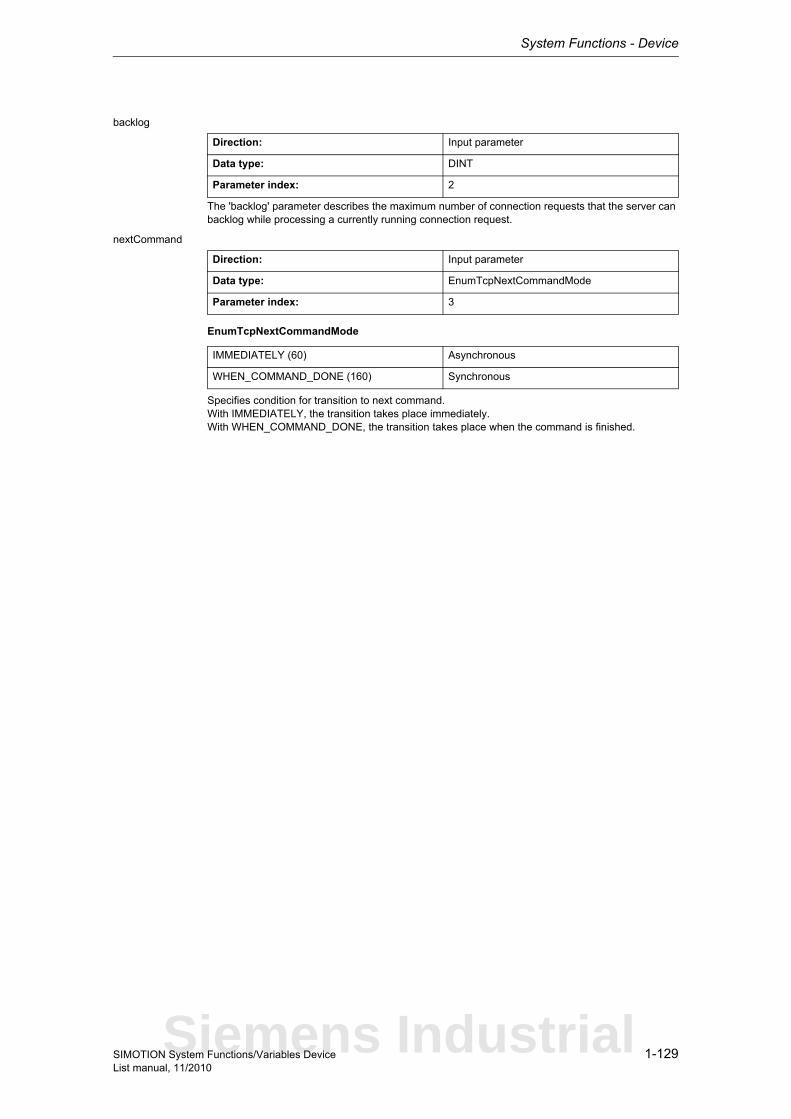
System Functions - Device
1-129SIMOTION System Functions/Variables DeviceList manual, 11/2010
backlog
The 'backlog' parameter describes the maximum number of connection requests that the server can backlog while processing a currently running connection request.
nextCommand
EnumTcpNextCommandMode
Specifies condition for transition to next command.With IMMEDIATELY, the transition takes place immediately.With WHEN_COMMAND_DONE, the transition takes place when the command is finished.
Direction: Input parameter
Data type: DINT
Parameter index: 2
Direction: Input parameter
Data type: EnumTcpNextCommandMode
Parameter index: 3
IMMEDIATELY (60) Asynchronous
WHEN_COMMAND_DONE (160) Synchronous
Siemens Industrial
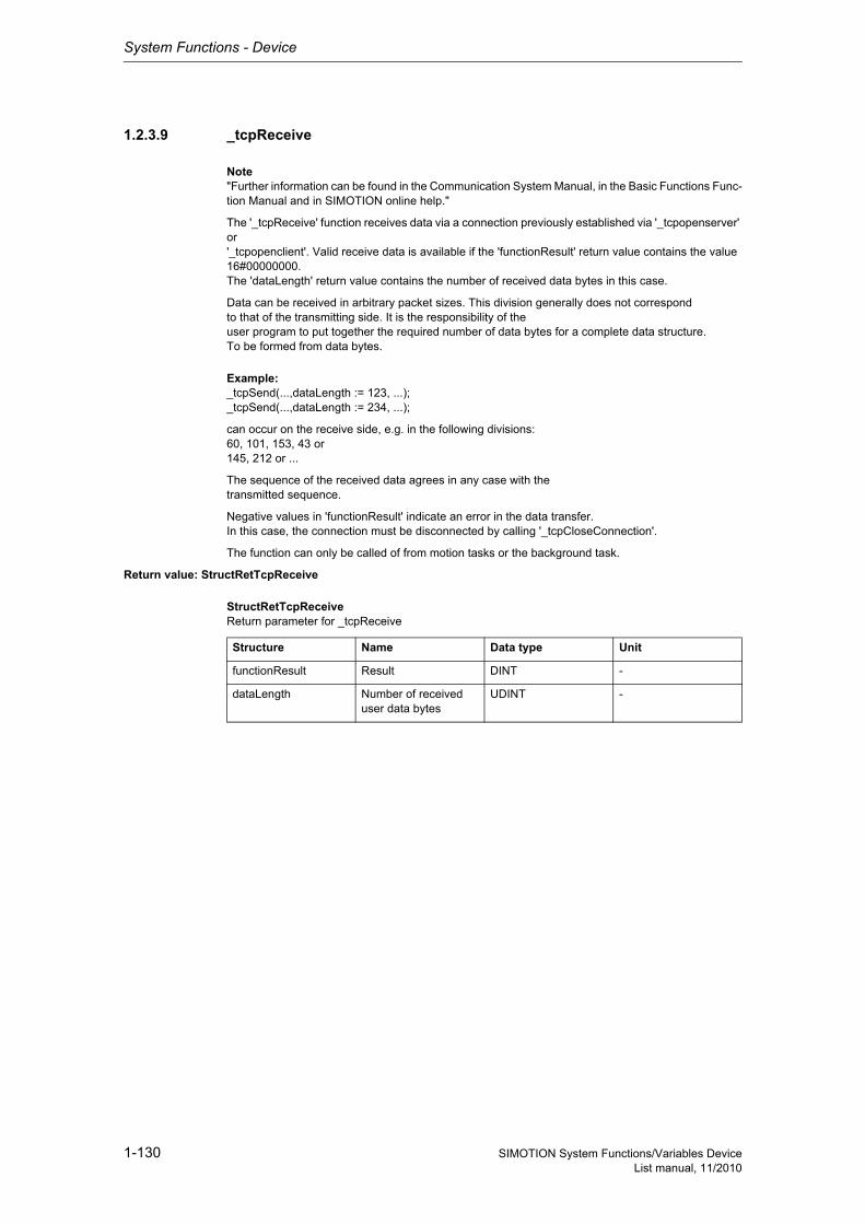
System Functions - Device
1-130 SIMOTION System Functions/Variables DeviceList manual, 11/2010
1.2.3.9 _tcpReceive
Note"Further information can be found in the Communication System Manual, in the Basic Functions Func-tion Manual and in SIMOTION online help."
The '_tcpReceive' function receives data via a connection previously established via '_tcpopenserver' or'_tcpopenclient'. Valid receive data is available if the 'functionResult' return value contains the value 16#00000000.The 'dataLength' return value contains the number of received data bytes in this case.
Data can be received in arbitrary packet sizes. This division generally does not correspondto that of the transmitting side. It is the responsibility of theuser program to put together the required number of data bytes for a complete data structure.To be formed from data bytes.
Example:_tcpSend(...,dataLength := 123, ...);_tcpSend(...,dataLength := 234, ...);
can occur on the receive side, e.g. in the following divisions:60, 101, 153, 43 or145, 212 or ...
The sequence of the received data agrees in any case with thetransmitted sequence.
Negative values in 'functionResult' indicate an error in the data transfer.In this case, the connection must be disconnected by calling '_tcpCloseConnection'.
The function can only be called of from motion tasks or the background task.
Return value: StructRetTcpReceive
StructRetTcpReceiveReturn parameter for _tcpReceive
Structure Name Data type Unit
functionResult Result DINT -
dataLength Number of received user data bytes
UDINT -
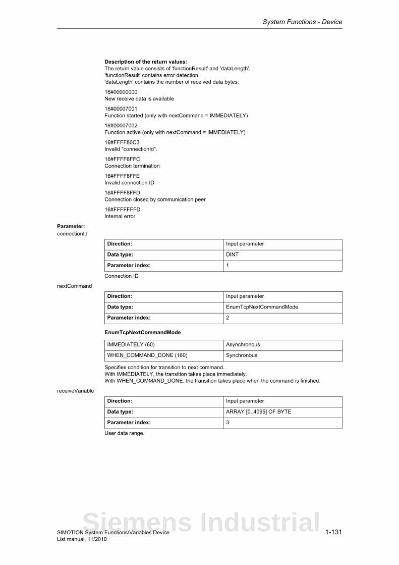
System Functions - Device
1-131SIMOTION System Functions/Variables DeviceList manual, 11/2010
Description of the return values:The return value consists of 'functionResult' and 'dataLength'.'functionResult' contains error detection.'dataLength' contains the number of received data bytes:
16#00000000New receive data is available
16#00007001Function started (only with nextCommand = IMMEDIATELY)
16#00007002Function active (only with nextCommand = IMMEDIATELY)
16#FFFF80C3Invalid "connectionId".
16#FFFF8FFCConnection termination
16#FFFF8FFEInvalid connection ID
16#FFFF8FFDConnection closed by communication peer
16#FFFFFFFDInternal error
Parameter: connectionId
Connection ID
nextCommand
EnumTcpNextCommandMode
Specifies condition for transition to next command.With IMMEDIATELY, the transition takes place immediately.With WHEN_COMMAND_DONE, the transition takes place when the command is finished.
receiveVariable
User data range.
Direction: Input parameter
Data type: DINT
Parameter index: 1
Direction: Input parameter
Data type: EnumTcpNextCommandMode
Parameter index: 2
IMMEDIATELY (60) Asynchronous
WHEN_COMMAND_DONE (160) Synchronous
Direction: Input parameter
Data type: ARRAY [0..4095] OF BYTE
Parameter index: 3
Siemens Industrial
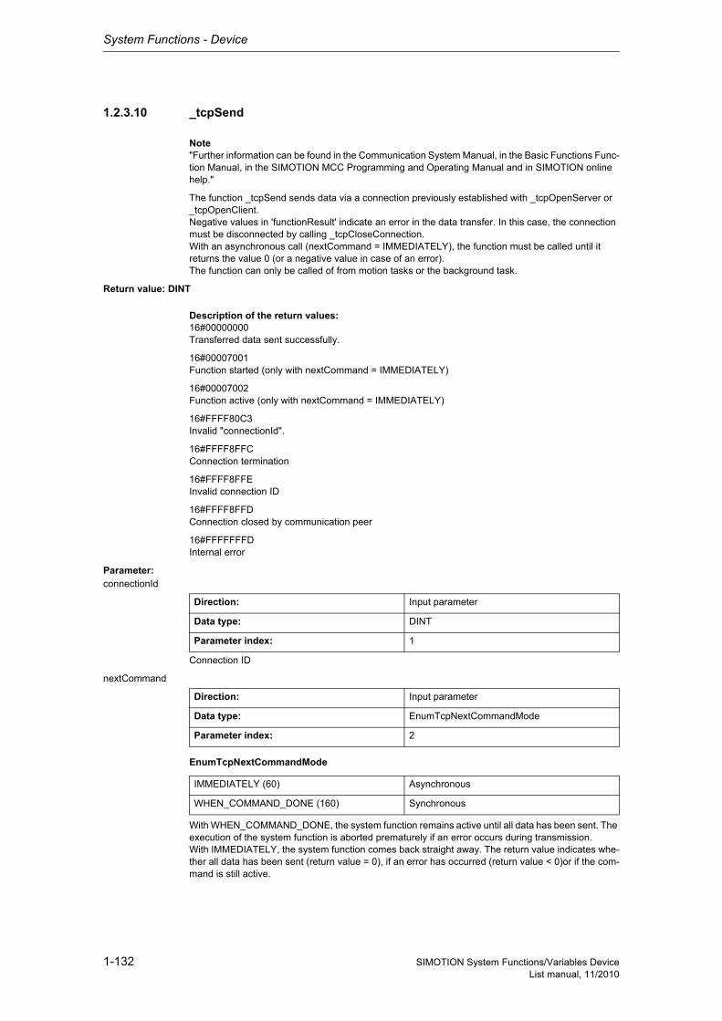
System Functions - Device
1-132 SIMOTION System Functions/Variables DeviceList manual, 11/2010
1.2.3.10 _tcpSend
Note"Further information can be found in the Communication System Manual, in the Basic Functions Func-tion Manual, in the SIMOTION MCC Programming and Operating Manual and in SIMOTION online help."
The function _tcpSend sends data via a connection previously established with _tcpOpenServer or _tcpOpenClient.Negative values in 'functionResult' indicate an error in the data transfer. In this case, the connection must be disconnected by calling _tcpCloseConnection.With an asynchronous call (nextCommand = IMMEDIATELY), the function must be called until it returns the value 0 (or a negative value in case of an error).The function can only be called of from motion tasks or the background task.
Return value: DINT
Description of the return values:16#00000000Transferred data sent successfully.
16#00007001Function started (only with nextCommand = IMMEDIATELY)
16#00007002Function active (only with nextCommand = IMMEDIATELY)
16#FFFF80C3Invalid "connectionId".
16#FFFF8FFCConnection termination
16#FFFF8FFEInvalid connection ID
16#FFFF8FFDConnection closed by communication peer
16#FFFFFFFDInternal error
Parameter: connectionId
Connection ID
nextCommand
EnumTcpNextCommandMode
With WHEN_COMMAND_DONE, the system function remains active until all data has been sent. The execution of the system function is aborted prematurely if an error occurs during transmission.With IMMEDIATELY, the system function comes back straight away. The return value indicates whe-ther all data has been sent (return value = 0), if an error has occurred (return value < 0)or if the com-mand is still active.
Direction: Input parameter
Data type: DINT
Parameter index: 1
Direction: Input parameter
Data type: EnumTcpNextCommandMode
Parameter index: 2
IMMEDIATELY (60) Asynchronous
WHEN_COMMAND_DONE (160) Synchronous

System Functions - Device
1-133SIMOTION System Functions/Variables DeviceList manual, 11/2010
dataLength
Number of user data bytes to be sent.
data
User data range.
Direction: Input parameter
Data type: UDINT
Parameter index: 3
Direction: Input parameter
Data type: ARRAY [0..4095] OF BYTE
Parameter index: 4
Siemens Industrial
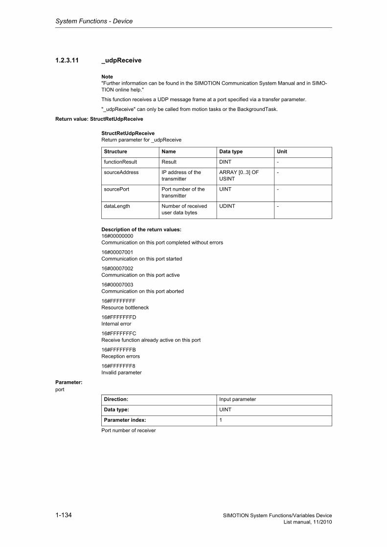
System Functions - Device
1-134 SIMOTION System Functions/Variables DeviceList manual, 11/2010
1.2.3.11 _udpReceive
Note"Further information can be found in the SIMOTION Communication System Manual and in SIMO-TION online help."
This function receives a UDP message frame at a port specified via a transfer parameter.
"_udpReceive" can only be called from motion tasks or the BackgroundTask.
Return value: StructRetUdpReceive
StructRetUdpReceiveReturn parameter for _udpReceive
Description of the return values:16#00000000Communication on this port completed without errors
16#00007001Communication on this port started
16#00007002Communication on this port active
16#00007003Communication on this port aborted
16#FFFFFFFFResource bottleneck
16#FFFFFFFDInternal error
16#FFFFFFFCReceive function already active on this port
16#FFFFFFFBReception errors
16#FFFFFFF8Invalid parameter
Parameter: port
Port number of receiver
Structure Name Data type Unit
functionResult Result DINT -
sourceAddress IP address of the transmitter
ARRAY [0..3] OF USINT
-
sourcePort Port number of the transmitter
UINT -
dataLength Number of received user data bytes
UDINT -
Direction: Input parameter
Data type: UINT
Parameter index: 1
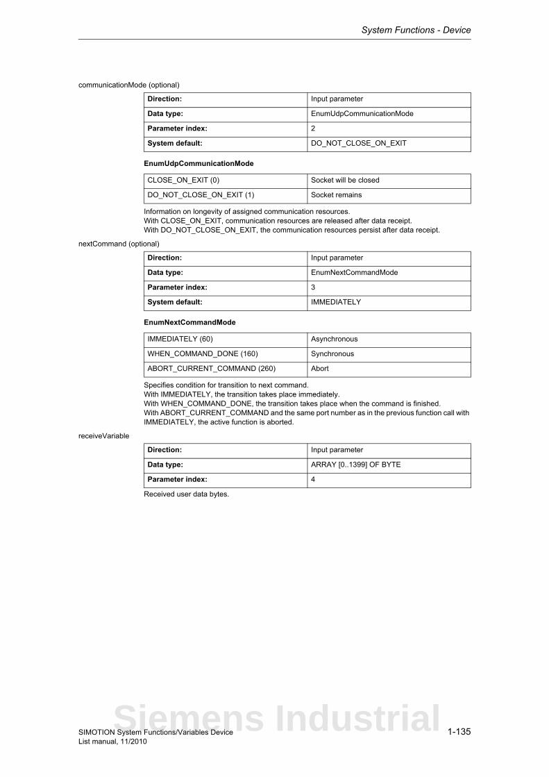
System Functions - Device
1-135SIMOTION System Functions/Variables DeviceList manual, 11/2010
communicationMode (optional)
EnumUdpCommunicationMode
Information on longevity of assigned communication resources.With CLOSE_ON_EXIT, communication resources are released after data receipt.With DO_NOT_CLOSE_ON_EXIT, the communication resources persist after data receipt.
nextCommand (optional)
EnumNextCommandMode
Specifies condition for transition to next command.With IMMEDIATELY, the transition takes place immediately.With WHEN_COMMAND_DONE, the transition takes place when the command is finished.With ABORT_CURRENT_COMMAND and the same port number as in the previous function call with IMMEDIATELY, the active function is aborted.
receiveVariable
Received user data bytes.
Direction: Input parameter
Data type: EnumUdpCommunicationMode
Parameter index: 2
System default: DO_NOT_CLOSE_ON_EXIT
CLOSE_ON_EXIT (0) Socket will be closed
DO_NOT_CLOSE_ON_EXIT (1) Socket remains
Direction: Input parameter
Data type: EnumNextCommandMode
Parameter index: 3
System default: IMMEDIATELY
IMMEDIATELY (60) Asynchronous
WHEN_COMMAND_DONE (160) Synchronous
ABORT_CURRENT_COMMAND (260) Abort
Direction: Input parameter
Data type: ARRAY [0..1399] OF BYTE
Parameter index: 4
Siemens Industrial
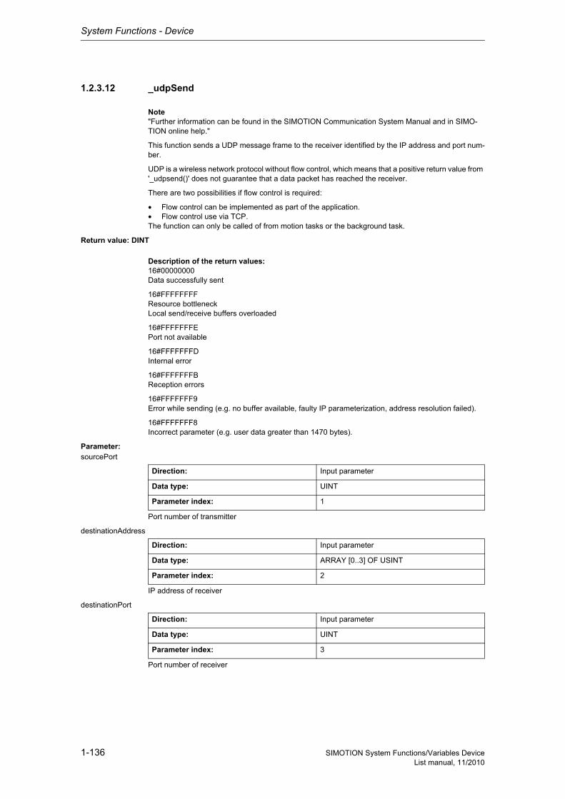
System Functions - Device
1-136 SIMOTION System Functions/Variables DeviceList manual, 11/2010
1.2.3.12 _udpSend
Note"Further information can be found in the SIMOTION Communication System Manual and in SIMO-TION online help."
This function sends a UDP message frame to the receiver identified by the IP address and port num-ber.
UDP is a wireless network protocol without flow control, which means that a positive return value from '_udpsend()' does not guarantee that a data packet has reached the receiver.
There are two possibilities if flow control is required:
• Flow control can be implemented as part of the application.• Flow control use via TCP.The function can only be called of from motion tasks or the background task.
Return value: DINT
Description of the return values:16#00000000Data successfully sent
16#FFFFFFFFResource bottleneckLocal send/receive buffers overloaded
16#FFFFFFFEPort not available
16#FFFFFFFDInternal error
16#FFFFFFFBReception errors
16#FFFFFFF9Error while sending (e.g. no buffer available, faulty IP parameterization, address resolution failed).
16#FFFFFFF8Incorrect parameter (e.g. user data greater than 1470 bytes).
Parameter: sourcePort
Port number of transmitter
destinationAddress
IP address of receiver
destinationPort
Port number of receiver
Direction: Input parameter
Data type: UINT
Parameter index: 1
Direction: Input parameter
Data type: ARRAY [0..3] OF USINT
Parameter index: 2
Direction: Input parameter
Data type: UINT
Parameter index: 3
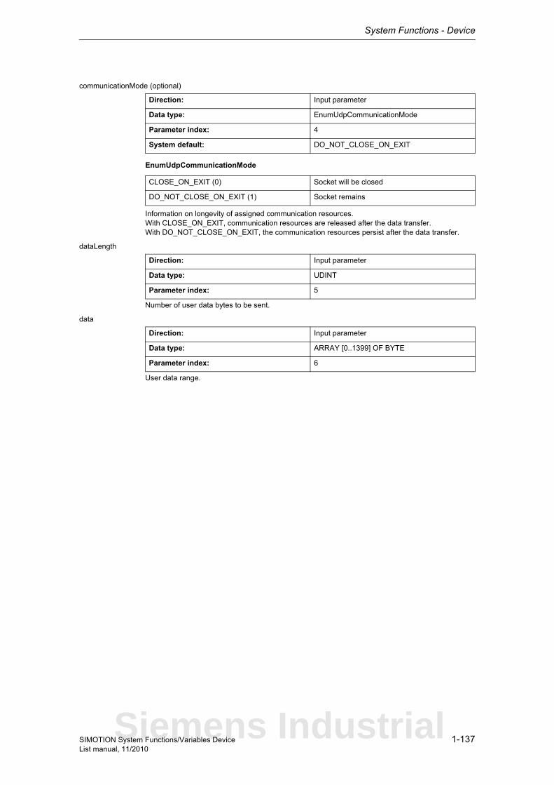
System Functions - Device
1-137SIMOTION System Functions/Variables DeviceList manual, 11/2010
communicationMode (optional)
EnumUdpCommunicationMode
Information on longevity of assigned communication resources.With CLOSE_ON_EXIT, communication resources are released after the data transfer.With DO_NOT_CLOSE_ON_EXIT, the communication resources persist after the data transfer.
dataLength
Number of user data bytes to be sent.
data
User data range.
Direction: Input parameter
Data type: EnumUdpCommunicationMode
Parameter index: 4
System default: DO_NOT_CLOSE_ON_EXIT
CLOSE_ON_EXIT (0) Socket will be closed
DO_NOT_CLOSE_ON_EXIT (1) Socket remains
Direction: Input parameter
Data type: UDINT
Parameter index: 5
Direction: Input parameter
Data type: ARRAY [0..1399] OF BYTE
Parameter index: 6
Siemens Industrial
System Functions - Device
1-138 SIMOTION System Functions/Variables DeviceList manual, 11/2010
1.2.3.13 _writeRecord
Note"Further information can be found in the SIMOTION Communication System Manual and in SIMO-TION online help."
This function causes a data set to be transferred from the ST program to an I/O module.It is used for CP and FM and dynamic parameter assignment of analog and digital modules and to read/write parameters from a drive.
A maximum of 8 jobs can be issued simultaneously.
NoteOnly one job should be issued per peripheral module in order to ensure processing.
Return value: DINTThe return value reports the job status.
In an error situation, the documentation for the associated module should be consulted for the specific error analysis.
Description of the return values:16#00000000Data set transfer okay, job completed with positive result.Job okay.
16#00007001Must be repeated in the next program cycle.Initial call, initiation of data transfer okay.
16#00007002Must be repeated in the next program cycle.Intermediate call, data transfer still active.
16#00007003Data set transfer aborted.Job aborted.
16#FFFF8090Error during data set transfer, job aborted.Specified logical base address invalid:No assignment is available in SDBs, or there is no base address.
16#FFFF8091Error during data set transfer, job aborted.The _writeRecord function cannot reach the specified logical base address.
16#FFFF809DError, job aborted.An I slave/I device interface is unable to write data sets to the higher-level master/controller.
16#FFFF809EError, job aborted.Attempt to abort a non-active function.
16#FFFF809FError, job aborted.Function not executable.
16#FFFF80A1Error during data set transfer, job aborted.Negative acknowledgment when writing to module:- Module removed during write operation- Module defective
System Functions - Device
1-139SIMOTION System Functions/Variables DeviceList manual, 11/2010
16#FFFF80A2Error during data set transfer, job aborted.Protocol error in Layer2:- Module not available
16#FFFF80A3Error during data set transfer, job aborted.Protocol error involving user interface/user:- Module not available
16#FFFF80A4-A7Error during data set transfer, job aborted.Error numbers according to IEC 61158 reserved- Query the cause at the module's manufacturer
16#FFFF80A8Error during data set transfer, job aborted.Error because of version conflict.
16#FFFF80A9Error during data set transfer, job aborted.Function not supported by the module.
16#FFFF80AA-AFError during data set transfer, job aborted.Error numbers according to IEC 61158 manufacturer-specific- Query the cause at the module's manufacturer
16#FFFF80B0Error during data set transfer, job aborted.- System function not supported for this module type- Module does not recognize the data set- Writing of data sets with static data (e.g. DS0, DS1) not permitted.
16#FFFF80B1Error during data set transfer, job aborted.Incorrect length specified in 'dataLength' parameter.
16#FFFF80B2Error during data set transfer, job aborted.Module reports access to an invalid slot/subslot.
16#FFFF80B3Error during data set transfer, job aborted.Module reports type conflict.
16#FFFF80B4Error during data set transfer, job aborted.Module reports access to an invalid area.
16#FFFF80B5Error during data set transfer, job aborted.Module is not ready.Within the PROFIdrive profile (parameter model), this value has the following meaning:- Access is temporarily denied due to an internal processing status
16#FFFF80B6Error during data set transfer, job aborted.Module rejects access.
16#FFFF80B7Error during data set transfer, job aborted.Module reports an illegal range for a parameter or value.Within the PROFIdrive profile (parameter model), this value has the following meaning:- Error in write-request header
16#FFFF80B8Error during data set transfer, job aborted.Module reports an invalid parameter.
Siemens Industrial
System Functions - Device
1-140 SIMOTION System Functions/Variables DeviceList manual, 11/2010
16#FFFF80B9Error during data set transfer, job aborted.Module reports an invalid type.
16#FFFF80BA-BFError during data set transfer, job aborted.Error numbers according to IEC 61158 manufacturer-specific- Query the cause at the module's manufacturer
16#FFFF80C1Error during data set transfer, command can be repeated immediately.Data of the preceding write job on the module for the same data set has not yet been processed by the module.
16#FFFF80C2Error during data set transfer, command can be repeated immediately.The module is currently executing the maximum possible jobs for one CPU.
16#FFFF80C3Error during data set transfer, command can be repeated immediately.Required resources are presently occupied:- In the _writeRecord function- In the module
16#FFFF80C4Error during data set transfer, command can be repeated immediately.Communication errors:- Parity error- SW Ready not set- Error in block length administration- Checksum error on CPU side- Checksum error on module side
16#FFFF80C5Error during data set transfer, can be repeated in the next program cycle.Distributed I/O not available.
16#FFFF80C6Error during data set transfer, can be repeated in the next program cycle.Data record transfer has been aborted due to priority class abort (restart or background).
16#FFFF80CFError during data set transfer, can be repeated in the next program cycle.Another _writeRecord function call is currently active under this 'commandId'.
Parameter: ioId
EnumIoIdType
Input/output assignment of logical base address of the I/O module.With INPUT, the logical address of the I/O module is in the input range.With OUTPUT, the logical address of the I/O module is in the output range.
Direction: Input parameter
Data type: EnumIoIdType
Parameter index: 1
INPUT (198) Input address
OUTPUT (199) Output address
System Functions - Device
1-141SIMOTION System Functions/Variables DeviceList manual, 11/2010
logAddress
Specifies the logical base address of the I/O module.
NoteYou can used both an input and an output address when hybrid modules are used.
recordNumber
Specification of the number of the data set of the peripheral module to be written.
offset
Specifies the offset of the first byte of the data to be read during transfer of the data set of the I/O module.The parameter is not currently supported.
dataLength
Specifies the length of data to be written [bytes].
data
Specifies the start address of the data to be written (byte array).
nextCommand
EnumNextCommandMode
Specifies condition for transition to next command.With IMMEDIATELY, the transition takes place immediately (asynchronous call of).With WHEN_COMMAND_DONE, the transition takes place when the command has been executed (synchronous call of).With ABORT_CURRENT_COMMAND and the same 'commandId' as in the previous function call with IMMEDIATELY, the active function is aborted.
Direction: Input parameter
Data type: DINT
Parameter index: 2
Direction: Input parameter
Data type: UDINT
Parameter index: 3
Direction: Input parameter
Data type: UDINT
Parameter index: 4
Direction: Input parameter
Data type: UDINT
Parameter index: 5
Direction: Input parameter
Data type: ARRAY [0..239] OF USINT
Parameter index: 6
Direction: Input parameter
Data type: EnumNextCommandMode
Parameter index: 7
IMMEDIATELY (60) Asynchronous
WHEN_COMMAND_DONE (160) Synchronous
ABORT_CURRENT_COMMAND (260) Abort
Siemens Industrial

System Functions - Device
1-142 SIMOTION System Functions/Variables DeviceList manual, 11/2010
commandId
CommandIdTypeSystem-wide unique ID
Unique, system-wide 'commandId' to track command status. A 'commandId' is always valid for the duration of a job andan asynchronous job can only be aborted by means of the transition condition ABORT_CURRENT_COMMAND.
Direction: Input parameter
Data type: CommandIdType
Parameter index: 8
Structure Name Data type Unit
SystemId_low Low_part of ID UDINT -
SystemId_high High_part of ID UDINT -
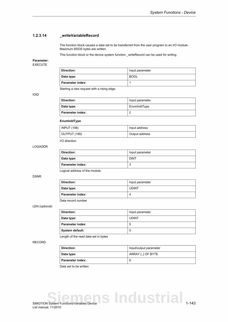
System Functions - Device
1-143SIMOTION System Functions/Variables DeviceList manual, 11/2010
1.2.3.14 _writeVariableRecord
The function block causes a data set to be transferred from the user program to an I/O module.Maximum 65535 bytes are written.
This function block or the device system function _writeRecord can be used for writing.
Parameter: EXECUTE
Starting a new request with a rising edge.
IOID
EnumIoIdType
I/O direction
LOGADDR
Logical address of the module.
DSNR
Data record number
LEN (optional)
Length of the read data set in bytes
RECORD
Data set to be written
Direction: Input parameter
Data type: BOOL
Parameter index: 1
Direction: Input parameter
Data type: EnumIoIdType
Parameter index: 2
INPUT (198) Input address
OUTPUT (199) Output address
Direction: Input parameter
Data type: DINT
Parameter index: 3
Direction: Input parameter
Data type: UDINT
Parameter index: 4
Direction: Input parameter
Data type: UDINT
Parameter index: 5
System default: 0
Direction: Input/output parameter
Data type: ARRAY [..] OF BYTE
Parameter index: 6
Siemens Industrial
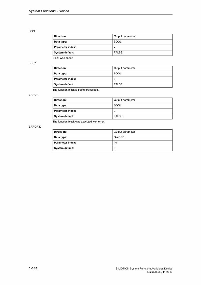
System Functions - Device
1-144 SIMOTION System Functions/Variables DeviceList manual, 11/2010
DONE
Block was ended
BUSY
The function block is being processed.
ERROR
The function block was executed with error.
ERRORID
Direction: Output parameter
Data type: BOOL
Parameter index: 7
System default: FALSE
Direction: Output parameter
Data type: BOOL
Parameter index: 8
System default: FALSE
Direction: Output parameter
Data type: BOOL
Parameter index: 9
System default: FALSE
Direction: Output parameter
Data type: DWORD
Parameter index: 10
System default: 0
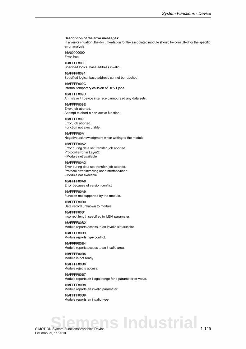
System Functions - Device
1-145SIMOTION System Functions/Variables DeviceList manual, 11/2010
Description of the error messages:In an error situation, the documentation for the associated module should be consulted for the specific error analysis.
16#00000000Error-free
16#FFFF8090Specified logical base address invalid.
16#FFFF8091Specified logical base address cannot be reached.
16#FFFF809CInternal temporary collision of DPV1 jobs.
16#FFFF809DAn I slave / I device interface cannot read any data sets.
16#FFFF809EError, job aborted.Attempt to abort a non-active function.
16#FFFF809FError, job aborted.Function not executable.
16#FFFF80A1Negative acknowledgment when writing to the module.
16#FFFF80A2Error during data set transfer, job aborted.Protocol error in Layer2:- Module not available
16#FFFF80A3Error during data set transfer, job aborted.Protocol error involving user interface/user:- Module not available
16#FFFF80A8Error because of version conflict
16#FFFF80A9Function not supported by the module.
16#FFFF80B0Data record unknown to module.
16#FFFF80B1Incorrect length specified in 'LEN' parameter.
16#FFFF80B2Module reports access to an invalid slot/subslot.
16#FFFF80B3Module reports type conflict.
16#FFFF80B4Module reports access to an invalid area.
16#FFFF80B5Module is not ready.
16#FFFF80B6Module rejects access.
16#FFFF80B7Module reports an illegal range for a parameter or value.
16#FFFF80B8Module reports an invalid parameter.
16#FFFF80B9Module reports an invalid type.
Siemens Industrial
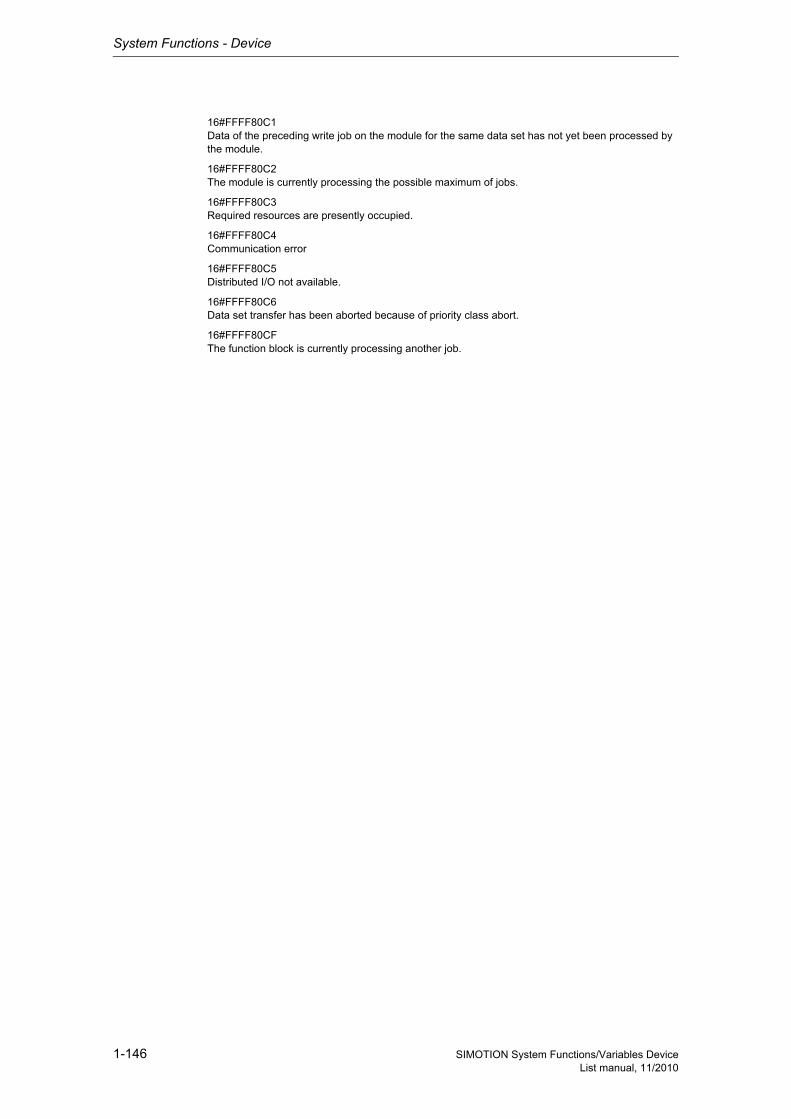
System Functions - Device
1-146 SIMOTION System Functions/Variables DeviceList manual, 11/2010
16#FFFF80C1Data of the preceding write job on the module for the same data set has not yet been processed by the module.
16#FFFF80C2The module is currently processing the possible maximum of jobs.
16#FFFF80C3Required resources are presently occupied.
16#FFFF80C4Communication error
16#FFFF80C5Distributed I/O not available.
16#FFFF80C6Data set transfer has been aborted because of priority class abort.
16#FFFF80CFThe function block is currently processing another job.
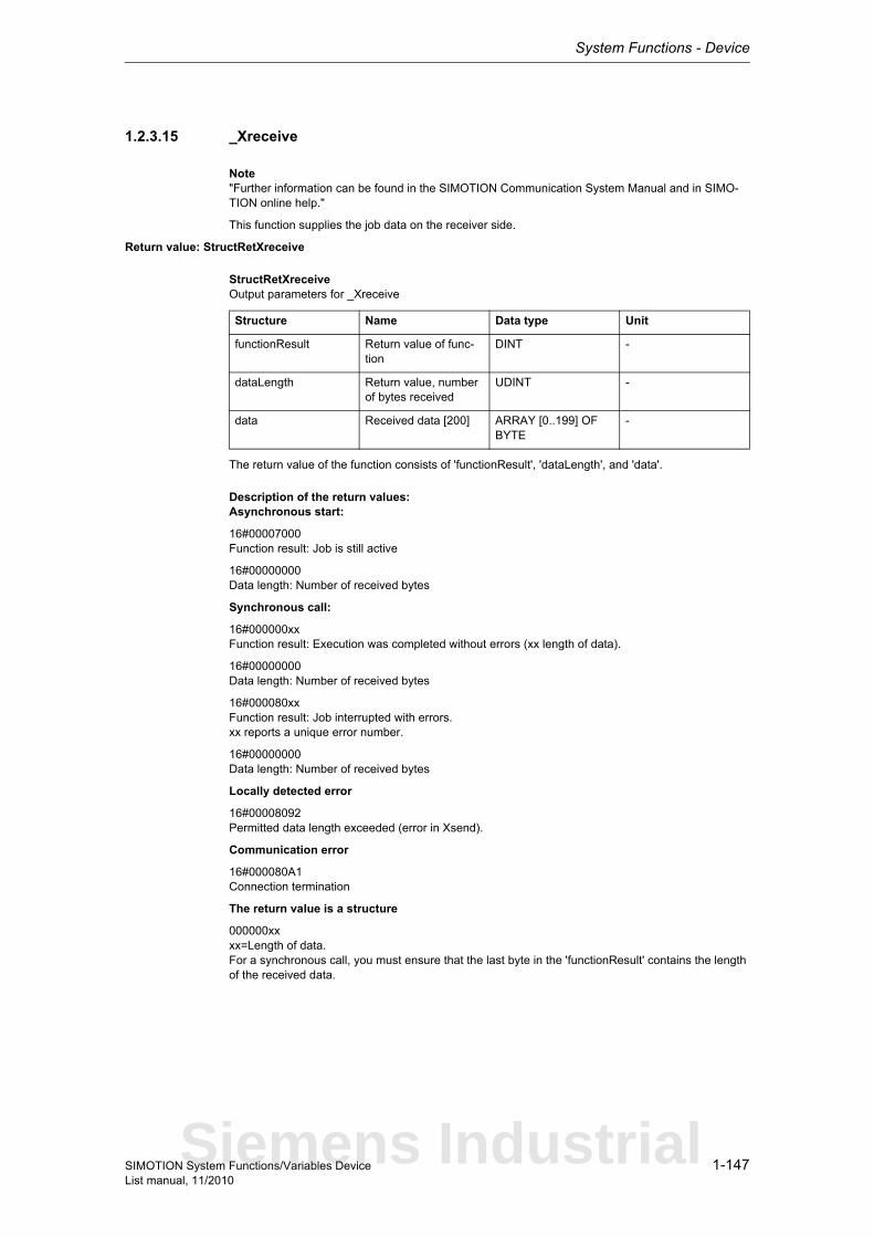
System Functions - Device
1-147SIMOTION System Functions/Variables DeviceList manual, 11/2010
1.2.3.15 _Xreceive
Note"Further information can be found in the SIMOTION Communication System Manual and in SIMO-TION online help."
This function supplies the job data on the receiver side.
Return value: StructRetXreceive
StructRetXreceiveOutput parameters for _Xreceive
The return value of the function consists of 'functionResult', 'dataLength', and 'data'.
Description of the return values:Asynchronous start:
16#00007000Function result: Job is still active
16#00000000Data length: Number of received bytes
Synchronous call:
16#000000xxFunction result: Execution was completed without errors (xx length of data).
16#00000000Data length: Number of received bytes
16#000080xxFunction result: Job interrupted with errors.xx reports a unique error number.
16#00000000Data length: Number of received bytes
Locally detected error
16#00008092Permitted data length exceeded (error in Xsend).
Communication error
16#000080A1Connection termination
The return value is a structure
000000xxxx=Length of data.For a synchronous call, you must ensure that the last byte in the 'functionResult' contains the length of the received data.
Structure Name Data type Unit
functionResult Return value of func-tion
DINT -
dataLength Return value, number of bytes received
UDINT -
data Received data [200] ARRAY [0..199] OF BYTE
-
Siemens Industrial
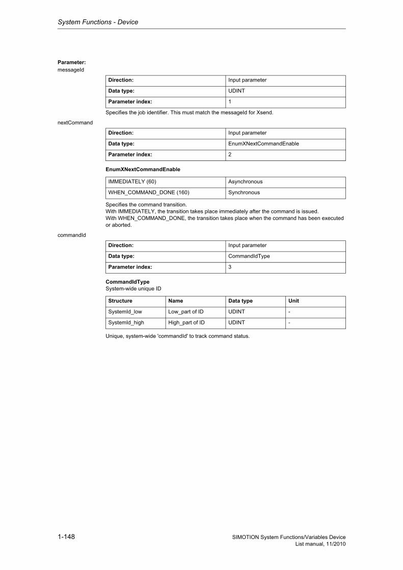
System Functions - Device
1-148 SIMOTION System Functions/Variables DeviceList manual, 11/2010
Parameter: messageId
Specifies the job identifier. This must match the messageId for Xsend.
nextCommand
EnumXNextCommandEnable
Specifies the command transition.With IMMEDIATELY, the transition takes place immediately after the command is issued.With WHEN_COMMAND_DONE, the transition takes place when the command has been executed or aborted.
commandId
CommandIdTypeSystem-wide unique ID
Unique, system-wide 'commandId' to track command status.
Direction: Input parameter
Data type: UDINT
Parameter index: 1
Direction: Input parameter
Data type: EnumXNextCommandEnable
Parameter index: 2
IMMEDIATELY (60) Asynchronous
WHEN_COMMAND_DONE (160) Synchronous
Direction: Input parameter
Data type: CommandIdType
Parameter index: 3
Structure Name Data type Unit
SystemId_low Low_part of ID UDINT -
SystemId_high High_part of ID UDINT -
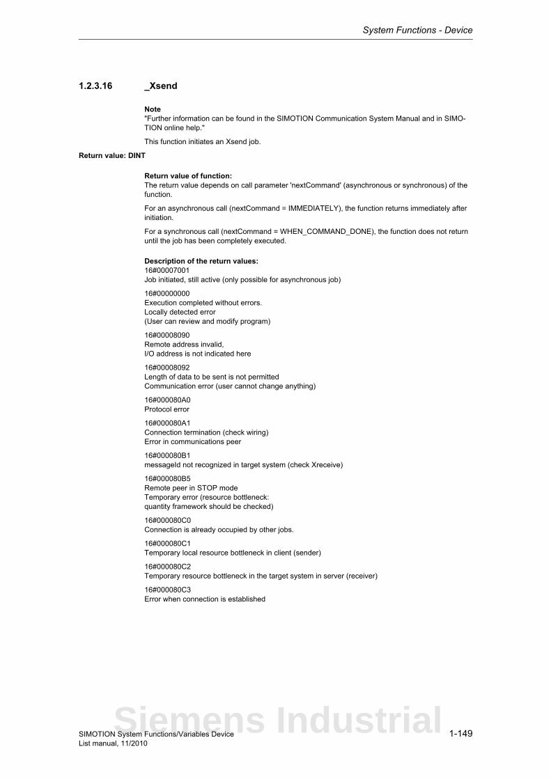
System Functions - Device
1-149SIMOTION System Functions/Variables DeviceList manual, 11/2010
1.2.3.16 _Xsend
Note"Further information can be found in the SIMOTION Communication System Manual and in SIMO-TION online help."
This function initiates an Xsend job.
Return value: DINT
Return value of function:The return value depends on call parameter 'nextCommand' (asynchronous or synchronous) of the function.
For an asynchronous call (nextCommand = IMMEDIATELY), the function returns immediately after initiation.
For a synchronous call (nextCommand = WHEN_COMMAND_DONE), the function does not return until the job has been completely executed.
Description of the return values:16#00007001Job initiated, still active (only possible for asynchronous job)
16#00000000Execution completed without errors.Locally detected error(User can review and modify program)
16#00008090Remote address invalid,I/O address is not indicated here
16#00008092Length of data to be sent is not permittedCommunication error (user cannot change anything)
16#000080A0Protocol error
16#000080A1Connection termination (check wiring)Error in communications peer
16#000080B1messageId not recognized in target system (check Xreceive)
16#000080B5Remote peer in STOP modeTemporary error (resource bottleneck:quantity framework should be checked)
16#000080C0Connection is already occupied by other jobs.
16#000080C1Temporary local resource bottleneck in client (sender)
16#000080C2Temporary resource bottleneck in the target system in server (receiver)
16#000080C3Error when connection is established
Siemens Industrial
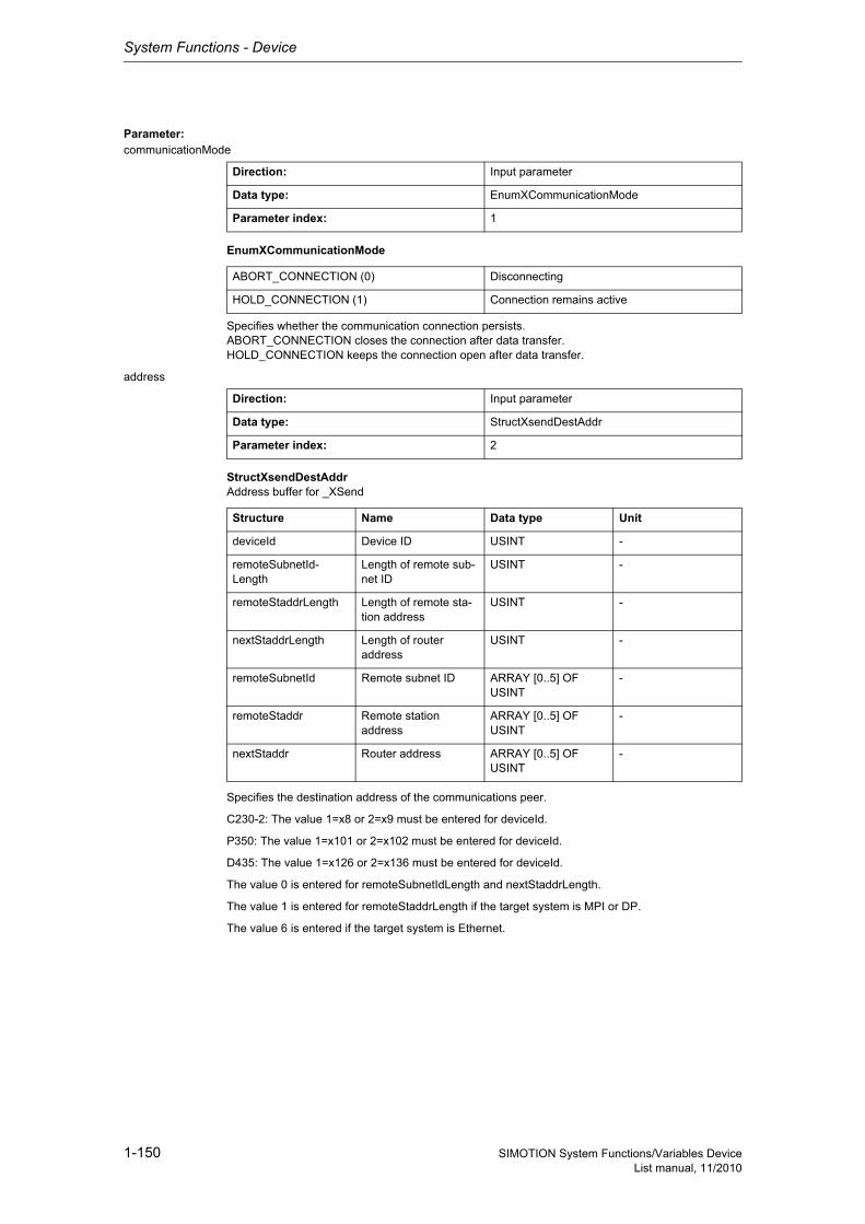
System Functions - Device
1-150 SIMOTION System Functions/Variables DeviceList manual, 11/2010
Parameter: communicationMode
EnumXCommunicationMode
Specifies whether the communication connection persists.ABORT_CONNECTION closes the connection after data transfer.HOLD_CONNECTION keeps the connection open after data transfer.
address
StructXsendDestAddrAddress buffer for _XSend
Specifies the destination address of the communications peer.
C230-2: The value 1=x8 or 2=x9 must be entered for deviceId.
P350: The value 1=x101 or 2=x102 must be entered for deviceId.
D435: The value 1=x126 or 2=x136 must be entered for deviceId.
The value 0 is entered for remoteSubnetIdLength and nextStaddrLength.
The value 1 is entered for remoteStaddrLength if the target system is MPI or DP.
The value 6 is entered if the target system is Ethernet.
Direction: Input parameter
Data type: EnumXCommunicationMode
Parameter index: 1
ABORT_CONNECTION (0) Disconnecting
HOLD_CONNECTION (1) Connection remains active
Direction: Input parameter
Data type: StructXsendDestAddr
Parameter index: 2
Structure Name Data type Unit
deviceId Device ID USINT -
remoteSubnetId-Length
Length of remote sub-net ID
USINT -
remoteStaddrLength Length of remote sta-tion address
USINT -
nextStaddrLength Length of router address
USINT -
remoteSubnetId Remote subnet ID ARRAY [0..5] OF USINT
-
remoteStaddr Remote station address
ARRAY [0..5] OF USINT
-
nextStaddr Router address ARRAY [0..5] OF USINT
-
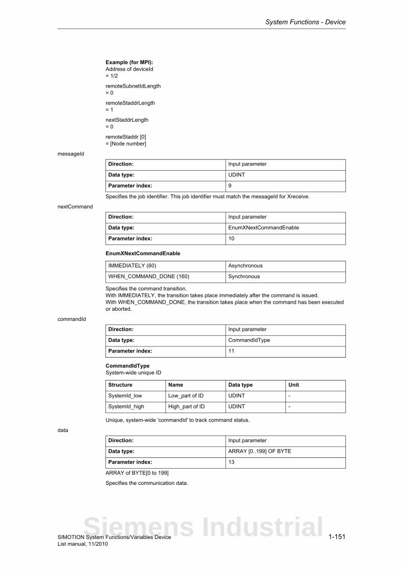
System Functions - Device
1-151SIMOTION System Functions/Variables DeviceList manual, 11/2010
Example (for MPI):Address of deviceId= 1/2
remoteSubnetIdLength= 0
remoteStaddrLength= 1
nextStaddrLength= 0
remoteStaddr [0]= [Node number]
messageId
Specifies the job identifier. This job identifier must match the messageId for Xreceive.
nextCommand
EnumXNextCommandEnable
Specifies the command transition.With IMMEDIATELY, the transition takes place immediately after the command is issued.With WHEN_COMMAND_DONE, the transition takes place when the command has been executed or aborted.
commandId
CommandIdTypeSystem-wide unique ID
Unique, system-wide 'commandId' to track command status.
data
ARRAY of BYTE[0 to 199]
Specifies the communication data.
Direction: Input parameter
Data type: UDINT
Parameter index: 9
Direction: Input parameter
Data type: EnumXNextCommandEnable
Parameter index: 10
IMMEDIATELY (60) Asynchronous
WHEN_COMMAND_DONE (160) Synchronous
Direction: Input parameter
Data type: CommandIdType
Parameter index: 11
Structure Name Data type Unit
SystemId_low Low_part of ID UDINT -
SystemId_high High_part of ID UDINT -
Direction: Input parameter
Data type: ARRAY [0..199] OF BYTE
Parameter index: 13
Siemens Industrial
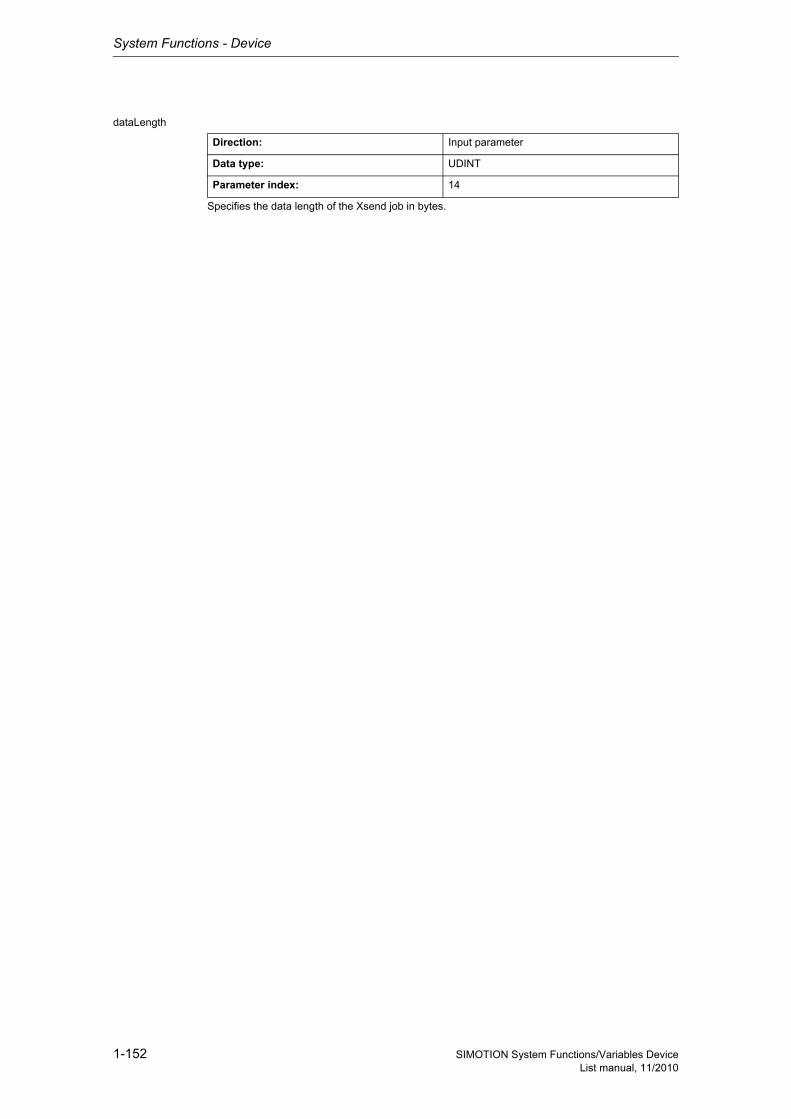
System Functions - Device
1-152 SIMOTION System Functions/Variables DeviceList manual, 11/2010
dataLength
Specifies the data length of the Xsend job in bytes.
Direction: Input parameter
Data type: UDINT
Parameter index: 14
System Functions - Device
1-153SIMOTION System Functions/Variables DeviceList manual, 11/2010
1.3 Drives
1.3.1 SIMODRIVE
1.3.1.1 _abortAllReadWriteDriveParameterJobs
Note"Further information can be found in the SIMOTION Communication System Manual (_readDrive and _writeDrive section) and in SIMOTION online help."
This function aborts all parameter jobs currently being processed.The term "parameter job" refers to the functions _readDrive(Multi)ParameterDescription, _readDrive(Multi)Parameter, _writeDrive(Multi)Parameter and _readDriveFaults.
Return value: DINT
Description of the return values:16#00000000Job completed without errors.
16#FFFF819FError, job aborted. Function not executable.
16#FFFF81C5Error, can be repeated in the next program cycle. Function could not be executed.This may have the following reasons:- The function _abortAllReadWriteDriveParameterJobs is already being executed.- A parameter job is currently being called from another task.
Siemens Industrial
System Functions - Device
1-154 SIMOTION System Functions/Variables DeviceList manual, 11/2010
1.3.1.2 _POSMOA_control
The _POSMOA_control function block can be used to control the connected SIMODRIVE POSMO A in positioning mode (p700=1). The functions are as follows: initializing, homing, jogging, program exe-cution, MDI, fault acknowledgement, automatic single block mode/automatic
Hardware and software requirements :SIMOTION as of V4.1Hardware release status POSMO A 75W : As of OSoftware release status POSMO A 75W : As of V3.0Hardware release status POSMO A 300W : As of GSoftware release status POSMO A 300W : As of V3.0SIMOTION <=V4.0Hardware release status POSMO A 75W : As of JSoftware release status POSMO A 75W : As of V1.3Hardware release status POSMO A 300W : As of ASoftware release status POSMO A 300W : As of V1.4Restrictions:- the functions of software release POSMO A V1.3 are supported
Detailed information
ST: Note:You can import the following program segments into the ST program using Drag & Drop. Additions must be made for executability (see manual, e.g. creating variables, etc.).An executable application example can be found on the "SIMOTION Utilities & Applications" CD-ROM.The "SIMOTION Utilities & Applications" CD-ROM is provided free of charge and is supplied with SIMOTION SCOUT.
// myPOSMOA_control : _POSMOA_control; // instance of FB (_POSMOA_control)myPOSMOA_control(pkwIn := myPkwIn, // [IN] byte array device (ARRAY[0..7] OF BYTE)pzdIn := myPzdIn, // [IN] byte array device (ARRAY[0..3] OF BYTE)enable := myEnable, // [IN] Sets the drive into the errory condition (BOOL)homing := myHoming, // [IN] Sets the reference point (BOOL)releaseBrake := myReleaseBrake, // [IN] release the brake (BOOL)jog1 := myJog1, // [IN] Select jogging 1 (anticlockwise) (BOOL)jog2 := myJog2, // [IN] Select jogging 2 (clockwise) (BOOL)jogOverride := myJogOverride, // [IN] speed override in per cent, jogging (INT)start := myStart, // [IN] 0->1: start traversing block (block number) (BOOL)singleBlock := mySingleBlock, // [IN] TRUE: single block mode active (BOOL)enableRdIn := myEnableRdIn, // [IN] TRUE: the following program block can be start (BOOL)extBlockChange := myExtBlockChange, // [IN] TRUE: the acktive block is canceled and the next block will started (BOOL)noStopIntermediate := myNoStopIntermediate, // [IN] =1: No i-Stop =0: i-Stop (BOOL)noStop := myNoStop, // [IN] =1: No Stop =0: Stop (BOOL)resetError := myResetError, // [IN] reset Error from drive (BOOL)blockNumber := myBlockNumber, // [IN] traversing block numbers 3...27 (BYTE)veloOverride := myVeloOverride, // [IN] velocityOverride [%] for traversing movement (INT)setStartInformation := mySetStartInformation, // [IN] Bitcombination, which is transfered to drive (BYTE)mdiMode := myMdiMode, // [IN] =1: MDI relative, =0: MDI absolut (BOOL)mdiVelocity := myMdiVelocity, // [IN] velocity, MDI traversing (0-100%) (INT)mdiAcceleration := myMdiAcceleration, // [IN] Acceleration, MDI traversing (0-100%) (INT)mdiPosition := myMdiPosition, // [IN] Target Position, MDI traversing (REAL)reqControl := myReqControl, // [IN] TRUE: POSMO A is controled by automation device (BOOL)busy := myBusy, // [IN_OUT] Coordination of the drive FB's (BOOL)pkwOut := myPkwOut, // [IN_OUT] byte array device (ARRAY[0..7] OF BYTE)pzdOut := myPzdOut // [IN_OUT] byte array device (ARRAY[0..3] OF BYTE));
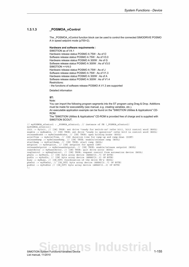
System Functions - Device
1-155SIMOTION System Functions/Variables DeviceList manual, 11/2010
1.3.1.3 _POSMOA_nControl
The _POSMOA_nControl function block can be used to control the connected SIMODRIVE POSMO A in speed setpoint mode (p700=2).
Hardware and software requirements :SIMOTION as of V4.1Hardware release status POSMO A 75W : As of OSoftware release status POSMO A 75W : As of V3.0Hardware release status POSMO A 300W : As of GSoftware release status POSMO A 300W : As of V3.0SIMOTION <=V4.0Hardware release status POSMO A 75W : As of JSoftware release status POSMO A 75W : As of V1.3Hardware release status POSMO A 300W : As of ASoftware release status POSMO A 300W : As of V1.4Restrictions:- the functions of software release POSMO A V1.3 are supported
Detailed information
ST: Note:You can import the following program segments into the ST program using Drag & Drop. Additions must be made for executability (see manual, e.g. creating variables, etc.).An executable application example can be found on the "SIMOTION Utilities & Applications" CD-ROM.The "SIMOTION Utilities & Applications" CD-ROM is provided free of charge and is supplied with SIMOTION SCOUT.
// myPOSMOA_nControl : _POSMOA_nControl; // instance of FB (_POSMOA_nControl)myPOSMOA_nControl(init := myInit, // [IN] TRUE: set drive "ready for switch-on" refer bit1, bit2 control word (BOOL)enable := myEnable, // [IN] TRUE: set drive "ready to operation" refer bit0 in control word (BOOL)releaseBrake := myReleaseBrake, // [IN] TRUE: open holding brake (BOOL)accelTime := myAccelTime, // [IN] duration time for ramp-up and ramp-down (DINT)releaseRamp := myReleaseRamp, // [IN] TRUE: enable/release ramp (BOOL)startRamp := myStartRamp, // [IN] TRUE: start ramp (BOOL)setpoint := mySetpoint, // [IN] setpoint for speed (INT)releaseSetpoint := myReleaseSetpoint, // [IN] TRUE: enable/release setpoint (BOOL)resetError := myResetError, // [IN] TRUE: quit drive error (BOOL)reqControl := myReqControl, // [IN] TRUE: request control from automation device (BOOL)pkwIn := myPkwIn, // [IN] byte array device (ARRAY[0..7] OF BYTE)pzdIn := myPzdIn, // [IN] byte array device (ARRAY[0..3] OF BYTE)busy := myBusy, // [IN_OUT] Coordination of the drive FB's (BOOL)pkwOut := myPkwOut, // [IN_OUT] byte array device (ARRAY[0..7] OF BYTE)pzdOut := myPzdOut // [IN_OUT] byte array device (ARRAY[0..3] OF BYTE));
Siemens Industrial
System Functions - Device
1-156 SIMOTION System Functions/Variables DeviceList manual, 11/2010
1.3.1.4 _POSMOA_rwAllParameter
The _POSMOA_rwAllParameter function block can be used to read and write the parameter set of the connected SIMODRIVE POSMO A.
Hardware and software requirements :SIMOTION as of V4.1Hardware release status POSMO A 75W : As of OSoftware release status POSMO A 75W : As of V3.0Hardware release status POSMO A 300W : As of GSoftware release status POSMO A 300W : As of V3.0SIMOTION <=V4.0Hardware release status POSMO A 75W : As of JSoftware release status POSMO A 75W : As of V1.3Hardware release status POSMO A 300W : As of ASoftware release status POSMO A 300W : As of V1.4Restrictions:- the functions of software release POSMO A V1.3 are supported
Detailed information
ST: Note:You can import the following program segments into the ST program using Drag & Drop. Additions must be made for executability (see manual, e.g. creating variables, etc.).An executable application example can be found on the "SIMOTION Utilities & Applications" CD-ROM.The "SIMOTION Utilities & Applications" CD-ROM is provided free of charge and is supplied with SIMOTION SCOUT.
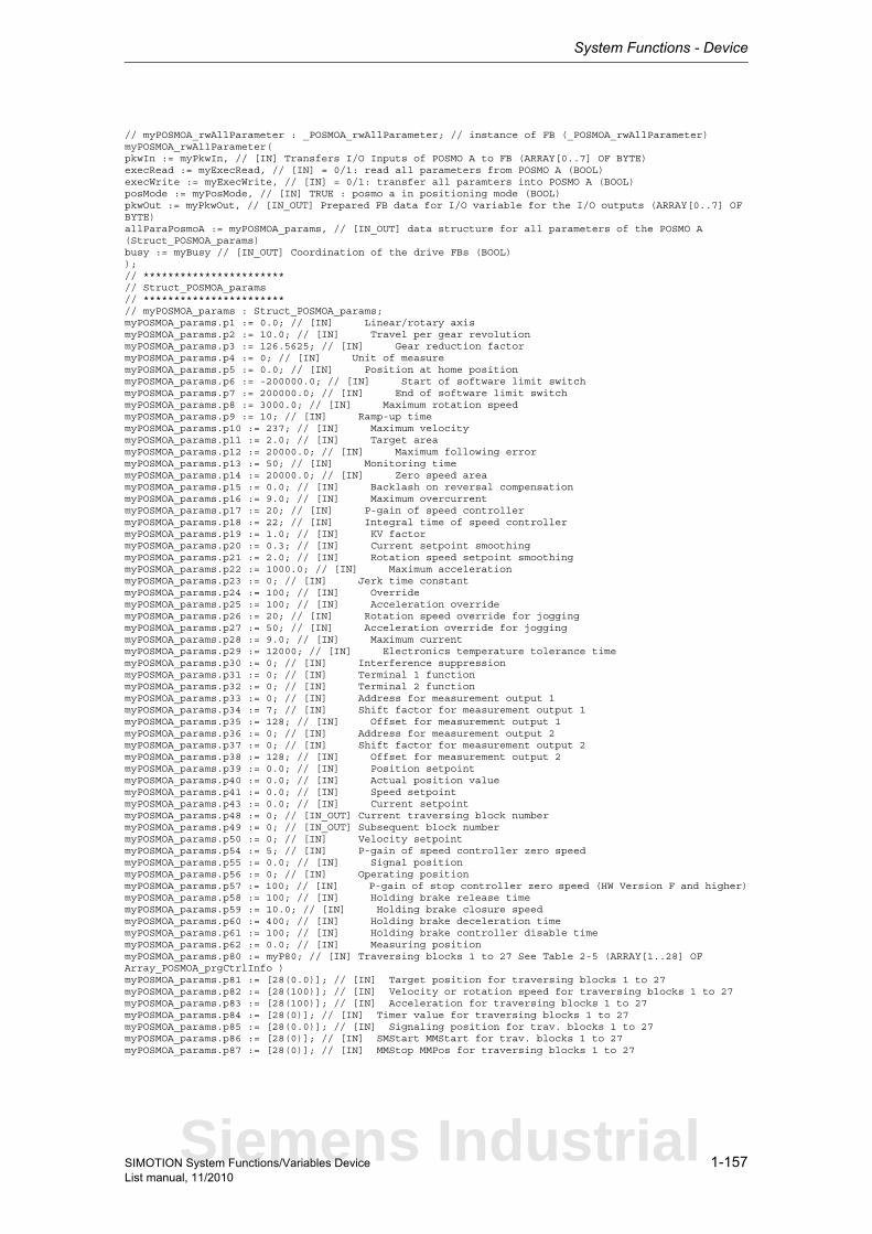
System Functions - Device
1-157SIMOTION System Functions/Variables DeviceList manual, 11/2010
// myPOSMOA_rwAllParameter : _POSMOA_rwAllParameter; // instance of FB (_POSMOA_rwAllParameter)myPOSMOA_rwAllParameter(pkwIn := myPkwIn, // [IN] Transfers I/O Inputs of POSMO A to FB (ARRAY[0..7] OF BYTE)execRead := myExecRead, // [IN] = 0/1: read all parameters from POSMO A (BOOL)execWrite := myExecWrite, // [IN] = 0/1: transfer all paramters into POSMO A (BOOL)posMode := myPosMode, // [IN] TRUE : posmo a in positioning mode (BOOL)pkwOut := myPkwOut, // [IN_OUT] Prepared FB data for I/O variable for the I/O outputs (ARRAY[0..7] OF BYTE)allParaPosmoA := myPOSMOA_params, // [IN_OUT] data structure for all parameters of the POSMO A (Struct_POSMOA_params)busy := myBusy // [IN_OUT] Coordination of the drive FBs (BOOL));// ***********************// Struct_POSMOA_params// ***********************// myPOSMOA_params : Struct_POSMOA_params;myPOSMOA_params.p1 := 0.0; // [IN] Linear/rotary axismyPOSMOA_params.p2 := 10.0; // [IN] Travel per gear revolutionmyPOSMOA_params.p3 := 126.5625; // [IN] Gear reduction factormyPOSMOA_params.p4 := 0; // [IN] Unit of measuremyPOSMOA_params.p5 := 0.0; // [IN] Position at home positionmyPOSMOA_params.p6 := -200000.0; // [IN] Start of software limit switchmyPOSMOA_params.p7 := 200000.0; // [IN] End of software limit switchmyPOSMOA_params.p8 := 3000.0; // [IN] Maximum rotation speedmyPOSMOA_params.p9 := 10; // [IN] Ramp-up timemyPOSMOA_params.p10 := 237; // [IN] Maximum velocitymyPOSMOA_params.p11 := 2.0; // [IN] Target areamyPOSMOA_params.p12 := 20000.0; // [IN] Maximum following errormyPOSMOA_params.p13 := 50; // [IN] Monitoring timemyPOSMOA_params.p14 := 20000.0; // [IN] Zero speed areamyPOSMOA_params.p15 := 0.0; // [IN] Backlash on reversal compensationmyPOSMOA_params.p16 := 9.0; // [IN] Maximum overcurrentmyPOSMOA_params.p17 := 20; // [IN] P-gain of speed controllermyPOSMOA_params.p18 := 22; // [IN] Integral time of speed controllermyPOSMOA_params.p19 := 1.0; // [IN] KV factormyPOSMOA_params.p20 := 0.3; // [IN] Current setpoint smoothingmyPOSMOA_params.p21 := 2.0; // [IN] Rotation speed setpoint smoothingmyPOSMOA_params.p22 := 1000.0; // [IN] Maximum accelerationmyPOSMOA_params.p23 := 0; // [IN] Jerk time constantmyPOSMOA_params.p24 := 100; // [IN] OverridemyPOSMOA_params.p25 := 100; // [IN] Acceleration overridemyPOSMOA_params.p26 := 20; // [IN] Rotation speed override for joggingmyPOSMOA_params.p27 := 50; // [IN] Acceleration override for joggingmyPOSMOA_params.p28 := 9.0; // [IN] Maximum currentmyPOSMOA_params.p29 := 12000; // [IN] Electronics temperature tolerance timemyPOSMOA_params.p30 := 0; // [IN] Interference suppressionmyPOSMOA_params.p31 := 0; // [IN] Terminal 1 functionmyPOSMOA_params.p32 := 0; // [IN] Terminal 2 functionmyPOSMOA_params.p33 := 0; // [IN] Address for measurement output 1myPOSMOA_params.p34 := 7; // [IN] Shift factor for measurement output 1myPOSMOA_params.p35 := 128; // [IN] Offset for measurement output 1myPOSMOA_params.p36 := 0; // [IN] Address for measurement output 2myPOSMOA_params.p37 := 0; // [IN] Shift factor for measurement output 2myPOSMOA_params.p38 := 128; // [IN] Offset for measurement output 2myPOSMOA_params.p39 := 0.0; // [IN] Position setpointmyPOSMOA_params.p40 := 0.0; // [IN] Actual position valuemyPOSMOA_params.p41 := 0.0; // [IN] Speed setpointmyPOSMOA_params.p43 := 0.0; // [IN] Current setpointmyPOSMOA_params.p48 := 0; // [IN_OUT] Current traversing block numbermyPOSMOA_params.p49 := 0; // [IN_OUT] Subsequent block numbermyPOSMOA_params.p50 := 0; // [IN] Velocity setpointmyPOSMOA_params.p54 := 5; // [IN] P-gain of speed controller zero speedmyPOSMOA_params.p55 := 0.0; // [IN] Signal positionmyPOSMOA_params.p56 := 0; // [IN] Operating positionmyPOSMOA_params.p57 := 100; // [IN] P-gain of stop controller zero speed (HW Version F and higher)myPOSMOA_params.p58 := 100; // [IN] Holding brake release timemyPOSMOA_params.p59 := 10.0; // [IN] Holding brake closure speedmyPOSMOA_params.p60 := 400; // [IN] Holding brake deceleration timemyPOSMOA_params.p61 := 100; // [IN] Holding brake controller disable timemyPOSMOA_params.p62 := 0.0; // [IN] Measuring positionmyPOSMOA_params.p80 := myP80; // [IN] Traversing blocks 1 to 27 See Table 2-5 (ARRAY[1..28] OF Array_POSMOA_prgCtrlInfo )myPOSMOA_params.p81 := [28(0.0)]; // [IN] Target position for traversing blocks 1 to 27myPOSMOA_params.p82 := [28(100)]; // [IN] Velocity or rotation speed for traversing blocks 1 to 27myPOSMOA_params.p83 := [28(100)]; // [IN] Acceleration for traversing blocks 1 to 27myPOSMOA_params.p84 := [28(0)]; // [IN] Timer value for traversing blocks 1 to 27myPOSMOA_params.p85 := [28(0.0)]; // [IN] Signaling position for trav. blocks 1 to 27myPOSMOA_params.p86 := [28(0)]; // [IN] SMStart MMStart for trav. blocks 1 to 27myPOSMOA_params.p87 := [28(0)]; // [IN] MMStop MMPos for traversing blocks 1 to 27
Siemens Industrial
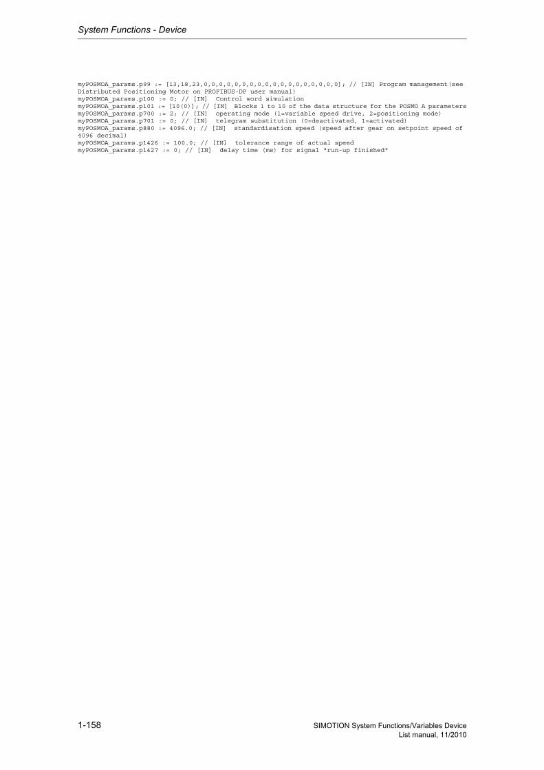
System Functions - Device
1-158 SIMOTION System Functions/Variables DeviceList manual, 11/2010
myPOSMOA_params.p99 := [13,18,23,0,0,0,0,0,0,0,0,0,0,0,0,0,0,0,0,0,0]; // [IN] Program management(see Distributed Positioning Motor on PROFIBUS-DP user manual)myPOSMOA_params.p100 := 0; // [IN] Control word simulationmyPOSMOA_params.p101 := [10(0)]; // [IN] Blocks 1 to 10 of the data structure for the POSMO A parametersmyPOSMOA_params.p700 := 2; // [IN] operating mode (1=variable speed drive, 2=positioning mode)myPOSMOA_params.p701 := 0; // [IN] telegram substitution (0=deactivated, 1=activated)myPOSMOA_params.p880 := 4096.0; // [IN] standardisation speed (speed after gear on setpoint speed of 4096 decimal)myPOSMOA_params.p1426 := 100.0; // [IN] tolerance range of actual speedmyPOSMOA_params.p1427 := 0; // [IN] delay time (ms) for signal "run-up finished"
System Functions - Device
1-159SIMOTION System Functions/Variables DeviceList manual, 11/2010
1.3.1.5 _POSMOA_rwParameter
The _POSMOA_rwParameter function block can be used to assign parameters for the connected SIMODRIVE POSMO A. The functions are as follows: reading parameters, writing parameters, loa-ding factory settings, saving parameters.
Hardware and software requirements :SIMOTION as of V4.1Hardware release status POSMO A 75W : As of OSoftware release status POSMO A 75W : As of V3.0Hardware release status POSMO A 300W : As of GSoftware release status POSMO A 300W : As of V3.0SIMOTION <=V4.0Hardware release status POSMO A 75W : As of JSoftware release status POSMO A 75W : As of V1.3Hardware release status POSMO A 300W : As of ASoftware release status POSMO A 300W : As of V1.4Restrictions:- the functions of software release POSMO A V1.3 are supported
Detailed information
ST: Note:You can import the following program segments into the ST program using Drag & Drop. Additions must be made for executability (see manual, e.g. creating variables, etc.).An executable application example can be found on the "SIMOTION Utilities & Applications" CD-ROM.The "SIMOTION Utilities & Applications" CD-ROM is provided free of charge and is supplied with SIMOTION SCOUT.
// myPOSMOA_rwParameter : _POSMOA_rwParameter; // instance of FB (_POSMOA_rwParameter)myPOSMOA_rwParameter(pkwIn := myPkwIn, // [IN] byte array device (ARRAY[0..7] OF BYTE)enableRead := myEnableRead, // [IN] =1: cyclically read parameters =0/1 read parameters once (BOOL)execWrite := myExecWrite, // [IN] =0/1: write into parameters (BOOL)paraNumber := myParaNumber, // [IN] Parameter number which is to be read or write into (UINT)subindex := mySubindex, // [IN] Subindex = set to 0 for parameters without subindex (USINT)setDefault := mySetDefault, // [IN] =0/1: load factory default to drive (BOOL)saveParameter := mySaveParameter, // [IN] =0/1: save parameter (BOOL)busy := myBusy, // [IN_OUT] Coordination of the drive FB´s (BOOL)pkwOut := myPkwOut, // [IN_OUT] byte array device (ARRAY[0..7] OF BYTE)realValue := myRealValue, // [IN_OUT] write: -> value to be written read: -> read value (REAL)dintValue := myDintValue // [IN_OUT] write: -> value to be written read: -> read value (DINT));
Siemens Industrial

System Functions - Device
1-160 SIMOTION System Functions/Variables DeviceList manual, 11/2010
1.3.1.6 _readDriveFaults
NoteAdditional information is available at:SIMOTION Communication System Manualor in the SIMOTION online help.
This function enables the current fault buffer entry in the drive to be read.
Note• Up to 16 parameter jobs can be executed in parallel (the term parameter job also includes the
functions _readDrive(Multi)ParameterDescription, _readDrive(Multi)Parameter, and _writeDrive(Multi)Parameter).
• Only one parameter job is permitted per planned DP station. A new job to the same DP station is rejected with the error 16#FFFF81C7.
• If the system functions _readRecord and _writeRecord are used in addition to the parameter jobs, you must ensure that they are not to be executed simultaneously by a DP station. Reason: The same communication services are used.
• If a parameter job (only asynchronous calls) is no longer to be processed, then it must be aborted with the ABORT_CURRENT_COMMAND transition condition. Otherwise no new job can be issued.
Parameters can be read out with the following data sets:• Data set 47 is always read out for PROFIBUS (external or integrated), regardless of whether the
function is called with a valid (0>=doId<=254) or invalid 'doId' (doId=255). If the passed 'doID' is invalid, it will be determined by the system itself. This requires the specification of the logical address of the axis.
• Two data sets are available for PROFINET:− Base Mode Parameter Access - local (data set 0xB02E)This data set (DS) is used for SIMOTION if either no 'dold' or an invalid 'dold' (dold=255) is spe-cified in the function. The Parameter Access Point (PAP) is then used to access the relevant DO. Either the PAP address can be specified directly or the log. address of the cyclical data (e.g. 256 for a DO axis) can be given. SIMOTION then determines the corresponding PAP from this address before accessing the correct address.
Note for PROFINETSIMOTION V4.1 SP2: PAP must always be at subslot 1 (HW Config configuration).
− Base Mode Parameter Access - global (data set 0xB02F)This data set is used if a valid 'dold' (0>=doId<=254) is entered. Any valid PAP or address can be specified, as assignment only takes place on the basis of the 'dold'.
Return value: StructRetReadDriveFaults
StructRetReadDriveFaultsReturn parameter for _readDriveFaults
Description of the return values:The return value consists of 'functionResult', 'parameterResult', 'dataLength', and 'data[8]'.
Structure Name Data type Unit
functionResult Total job return value DINT -
parameterResult Parameter-specific return value
DINT -
dataLength Length of data read UDINT -
data Data read from the fault buffer
ARRAY [0..7] OF UINT -

System Functions - Device
1-161SIMOTION System Functions/Variables DeviceList manual, 11/2010
'functionResult'Reports the status of the total job plus errors during the transfer and internal errors.
16#00000000Reading of current fault buffer entry okay,Job completed with positive result. Job okay.
16#00007001Must be repeated in the next program cycle.Initial call, initiation of reading of current fault buffer entry okay (only when command is issued asyn-chronously).
16#00007002Must be repeated in the next program cycle.Intermediate call, reading of current fault buffer entry is still active (only when command is issued asynchronously).
16#00007003Reading the current fault buffer entry aborted.
16#FFFF8190Internal error, job aborted.Specified logical base address invalid:No assignment is available in SDBs, or there is no base address.
16#FFFF8191Internal error, job aborted.The _readDriveFaults function cannot reach the specified logical base address.
16#FFFF8192Internal error, job aborted.Error in response identifier.
16#FFFF819DInternal error, job aborted.An I slave/I device interface is unable to issue a parameter job to the higher-level master/controller.
16#FFFF819EInternal error, job aborted.Attempt to abort a non-active function.
16#FFFF819FInternal error, job aborted.Function not executable.
16#FFFF81C3Error, can be repeated in the next program cycle.Required resources are presently occupied:- in the _readDriveFaults function- In the module
16#FFFF81C5Error, can be repeated in the next program cycle.Distributed I/O not available.
16#FFFF81C7Error, can be repeated in the next program cycle.Another parameter job has already been issued to the DP station. - based on the user program - from a system-internal component (e.g. TO axis executes parameter comparison after station reco-very)
16#FFFF81CFError, can be repeated in the next program cycle.Another parameter job call is currently active under this 'commandId'.
16#FFFF8290Corresponds to the error message 16#FFFF8190.
16#FFFF8291Corresponds to the error message 16#FFFF8191.
Siemens Industrial
System Functions - Device
1-162 SIMOTION System Functions/Variables DeviceList manual, 11/2010
16#FFFF82A2Error during data set transfer, job aborted.Error in Layer2:- Station failure- Timeout
16#FFFF82A3Error during data set transfer, job aborted.Error in user interface/user:- Protocol error- Station failure- Timeout
16#FFFF82A4-A7Error during data set transfer, job aborted.Error numbers according to IEC 61158 reserved- Query the cause at the module's manufacturer
16#FFFF82A8Error during data set transfer, job aborted.Error because of version conflict.
16#FFFF82A9Error during data set transfer, job aborted.Function not supported by the module.
16#FFFF82AA-AFError during data set transfer, job aborted.Error numbers according to IEC 61158 manufacturer-specific- Query the cause at the module's manufacturer
16#FFFF82B0Error during data set transfer, job aborted.Parameter jobs are not supported by the addressed module.
16#FFFF82B2Error during data set transfer, job aborted.Module reports access to an invalid slot/subslot.
16#FFFF82B3Error during data set transfer, job aborted.Module reports type conflict.
16#FFFF82B4Error during data set transfer, job aborted.Module reports access to an invalid area.
16#FFFF82B5Error during data set transfer, can be repeated in the next program cycle.The system function cannot be executed due to an internal operating state of the module.
16#FFFF82B6Error during data set transfer, job aborted.Module rejects access.
16#FFFF82B7Error during data set transfer, job aborted.The job could not be dispatched due to a job message frame error.
16#FFFF82B8Error during data set transfer, job aborted.Module reports an invalid parameter.
16#FFFF82B9Error during data set transfer, job aborted.Module reports an invalid type.
16#FFFF82BA-BFError during data set transfer, job aborted.Error numbers according to IEC 61158 manufacturer-specific- Query the cause at the module's manufacturer

System Functions - Device
1-163SIMOTION System Functions/Variables DeviceList manual, 11/2010
16#FFFF82C0Error during data set transfer, can be repeated in the next program cycle.The module is feeding the data record, but the module does not yet have any read data.
16#FFFF82C2Error during data set transfer, command can be repeated immediately.The module is currently executing the maximum possible jobs for one CPU.
16#FFFF82C3Error during data set transfer, command can be repeated immediately.Required resources are presently occupied:- In the _readRecord function- In the module
16#FFFF82C4Error during data set transfer, command can be repeated immediately.Communication errors:- Parity error- SW Ready not set- Error in block length administration- Checksum error on CPU side- Checksum error on module side
16#FFFF82C5Error during data set transfer,Can be repeated in the next program cycle.Distributed I/O not available.
16#FFFF82C6Error during data set transfer, can be repeated in the next program cycle.Data record transfer has been aborted due to priority class abort (restart or background).
'parameterResult'
Reports parameter-specific errors.
16#FFFF8000Parameter error, job aborted.The selected fault buffer does not exist.
16#FFFF8011Parameter error, job aborted.Job cannot be executed due to operating state.
16#FFFF8019Parameter error, job aborted.Access to a non-existing axis or an invalid drive object.
16#FFFF8020-FFParameter error, job aborted.Manufacturer-specific error.
'dataLength' reports the length of data read.
'data[8]' contains the read data (word array, maximum of 8 words).
Siemens Industrial
System Functions - Device
1-164 SIMOTION System Functions/Variables DeviceList manual, 11/2010
Parameter: ioId (optional)
EnumIoIdType
Input/output assignment of logical base address of the drive.With INPUT, the logical address of the drive is in the input range.With OUTPUT, the logical address of the drive is in the output range.Diagnostic addresses are always of type INPUT.
logAddress
Specifies the logical base address of the drive.
If the optional 'dold' parameter is also used, any station address (preferably the diagnostic address of the station) can be specified.
With PROFINET, parameter access occurs via the parameter access point (PAP) of a DO.As an alternative to the logical base address of the drive, specification of the diagnostic address of the associated PAP is recommended.
doId (optional)
Specifies the DO-ID to address a specific DO directly. 0 to 254 are permitted.The DO-ID can be unspecified or specified as invalid (>254) under the following conditions:- Access via the DO-ID is not supported by the DP slave/IO device (P978 is not implemented).- Data record 0xB02F is not supported (PROFINET only).- Access is to occur via the parameter access point of a DO (PROFINET only).
faultType (optional)
Direction: Input parameter
Data type: EnumIoIdType
Parameter index: 1
System default: INPUT
INPUT (198) Input address
OUTPUT (199) Output address
Direction: Input parameter
Data type: DINT
Parameter index: 2
Direction: Input parameter
Data type: UDINT
Parameter index: 3
System default: 255
Direction: Input parameter
Data type: EnumDriveFaultsType
Parameter index: 4
System default: DRIVE
System Functions - Device
1-165SIMOTION System Functions/Variables DeviceList manual, 11/2010
EnumDriveFaultsType
Specification of the fault buffer type.'faultType' can be used to assign and read out drive- and user-specific parameters.DRIVE reads out the drive-specific fault buffer (parameter 947).USER reads out the user-specific fault buffer (parameter 945). Fault codes of the drive (P947) can be assigned user-specific faults.SAFETY reads out the fault buffer (parameter 9747) relevant for the safety functionality.
NoteThe fault buffer in P9747 relevant for safety is reserved for SINAMICS modules. Other modules could have saved different content in P9747.
nextCommand
EnumNextCommandMode
Specifies the command transition.With IMMEDIATELY, the transition takes place immediately after the command is issued (asynchro-nous call).With WHEN_COMMAND_DONE, the transition takes place when the command has been executed (synchronous call).With ABORT_CURRENT_COMMAND, the active function is aborted immediately.
commandId
CommandIdTypeSystem-wide unique ID
Unique, system-wide 'commandId' to track command status. A 'commandId' is always valid for the duration of a job andan asynchronous job can only be aborted by means of the transition condition ABORT_CURRENT_COMMAND.
DRIVE (0) Drive-specific fault buffer
USER (1) User-specific fault buffer
SAFETY (2) Safety-relevant fault buffer
Direction: Input parameter
Data type: EnumNextCommandMode
Parameter index: 5
IMMEDIATELY (60) Asynchronous
WHEN_COMMAND_DONE (160) Synchronous
ABORT_CURRENT_COMMAND (260) Abort
Direction: Input parameter
Data type: CommandIdType
Parameter index: 6
Structure Name Data type Unit
SystemId_low Low_part of ID UDINT -
SystemId_high High_part of ID UDINT -
Siemens Industrial

System Functions - Device
1-166 SIMOTION System Functions/Variables DeviceList manual, 11/2010
1.3.1.7 _readDriveMultiParameter
NoteAdditional information is available at:SIMOTION Communication System Manualor in the SIMOTION online help.
This function enables up to 39 parameters to be read.
Note• Up to 16 parameter jobs can be executed in parallel (the term parameter job also includes the
functions _readDriveParameter,_readDrive(Multi)ParameterDescription, _writeDrive(Multi)Para-meter, and _readDriveFaults).
• Only one parameter job is permitted per planned DP station. A new job to the same DP station is rejected with the error 16#FFFF81C7.
• If the system functions _readRecord and _writeRecord are used in addition to the parameter jobs, you must ensure that they are not to be executed simultaneously by a DP station. Reason: The same communication services are used.
• If a parameter job (only asynchronous calls) is no longer to be processed, then it must be aborted with the ABORT_CURRENT_COMMAND transition condition. Otherwise no new job can be issued.
Parameters can be read out with the following data sets:• Data set 47 is always read out for PROFIBUS (external or integrated), regardless of whether the
function is called with a valid (0>=doId<=254) or invalid 'doId' (doId=255). If the passed 'doID' is invalid, it will be determined by the system itself. This requires the specification of the logical address of the axis.
• Two data sets are available for PROFINET:− Base Mode Parameter Access - local (data set 0xB02E)This data set (DS) is used for SIMOTION if either no 'dold' or an invalid 'dold' (dold=255) is spe-cified in the function. The Parameter Access Point (PAP) is then used to access the relevant DO. Either the PAP address can be specified directly or the log. address of the cyclical data (e.g. 256 for a DO axis) can be given. SIMOTION then determines the corresponding PAP from this address before accessing the correct address.
Note for PROFINETSIMOTION V4.1 SP2: PAP must always be at subslot 1 (HW Config configuration).
− Base Mode Parameter Access - global (data set 0xB02F)This data set is used if a valid 'dold' (0>=doId<=254) is entered. Any valid PAP or address can be specified, as assignment only takes place on the basis of the 'dold'.
Return value: StructRetReadDriveMultiParameter
StructRetReadDriveMultiParameterReturn parameter for _readDriveMultiParameter
Structure Name Data type Unit
functionResult Total job return value DINT -
parameterResultErr-orExistent
A parameter-specific fault is present in the return value
BOOL -
parameterResult Parameter-specific return value
ARRAY [0..38] OF DINT
-
dataType Data type of the read parameter
ARRAY [0..38] OF UDINT
-
dataLength Length of data read ARRAY [0..38] OF UDINT
-
data Data read from the drive (big endian)
ARRAY [0..233] OF BYTE
-
System Functions - Device
1-167SIMOTION System Functions/Variables DeviceList manual, 11/2010
Description of the return values:The return value consists of 'functionResult', 'parameterResultErrorExistent', 'parameterResult[39]', 'dataType[39]', 'dataLength[39]' and 'data[233]'.
'functionResult'Reports the status of the total job plus errors during the transfer and internal errors.
16#00000000Reading of parameters okay, job completed with positive result. Job okay.
16#00007001Must be repeated in the next program cycle.Initial call, initiation of reading of parameters okay(only when command is issued asynchronously).
16#00007002Must be repeated in the next program cycle.Intermediate call, reading of parameter description is still active(only when command is issued asynchronously).
16#00007003Reading of parameters aborted.
16#FFFF8190Internal error, job aborted.Specified logical base address invalid:No assignment is available in SDBs, or there is no base address.
16#FFFF8191Internal error, job aborted.The _readDriveMultiParameter function cannot reach the specified logical base address.
16#FFFF8192Internal error, job aborted.Error in response identifier.
16#FFFF8193Internal error, job aborted.The number of parameters to be read is not permissible.
16#FFFF819DInternal error, job aborted.An I slave/I device interface is unable to issue a parameter job to the higher-level master/controller.
16#FFFF819EInternal error, job aborted.Attempt to abort a non-active function.
16#FFFF819FInternal error, job aborted.Function not executable.
16#FFFF81C3Error, can be repeated in the next program cycle.Required resources are presently occupied:- In the _readDriveMultiParameter function- In the module
Siemens Industrial
System Functions - Device
1-168 SIMOTION System Functions/Variables DeviceList manual, 11/2010
16#FFFF81C5Error, can be repeated in the next program cycle.Distributed I/O not available.
16#FFFF81C7Error, can be repeated in the next program cycle.Another parameter job has already been issued to the DP station. - based on the user program - from a system-internal component (e.g. TO axis executes parameter comparison after station reco-very)
16#FFFF81CFError, can be repeated in the next program cycle.Another parameter job call is currently active under this 'commandId'.
16#FFFF8290Corresponds to the error message 16#FFFF8190.
16#FFFF8291Corresponds to the error message 16#FFFF8191.
16#FFFF82A2Error during data set transfer, job aborted.Error in Layer2:- Station failure- Timeout
16#FFFF82A3Error during data set transfer, job aborted.Error in user interface/user:- Protocol error- Station failure- Timeout
16#FFFF82A4-A7Error during data set transfer, job aborted.Error numbers according to IEC 61158 reserved- Query the cause at the module's manufacturer
16#FFFF82A8Error during data set transfer, job aborted.Error because of version conflict.
16#FFFF82A9Error during data set transfer, job aborted.Function not supported by the module.
16#FFFF82AA-AFError during data set transfer, job aborted.Error numbers according to IEC 61158 manufacturer-specific- Query the cause at the module's manufacturer
16#FFFF82B0Error during data set transfer, job aborted.Parameter jobs are not supported by the addressed module.
16#FFFF82B2Error during data set transfer, job aborted.Module reports access to an invalid slot/subslot.
16#FFFF82B3Error during data set transfer, job aborted.Module reports type conflict.
16#FFFF82B4Error during data set transfer, job aborted.Module reports access to an invalid area.
16#FFFF82B5Error during data set transfer, can be repeated in the next program cycle.The system function cannot be executed due to an internal operating state of the module.
System Functions - Device
1-169SIMOTION System Functions/Variables DeviceList manual, 11/2010
16#FFFF82B6Error during data set transfer, job aborted.Module rejects access.
16#FFFF82B7Error during data set transfer, job aborted.The job could not be dispatched due to a job error.
16#FFFF82B8Error during data set transfer, job aborted.Module reports an invalid parameter.
16#FFFF82B9Error during data set transfer, job aborted.Module reports an invalid type.
16#FFFF82BA-BFError during data set transfer, job aborted.Error numbers according to IEC 61158 manufacturer-specific- Query the cause at the module's manufacturer
16#FFFF82C0Error during data set transfer, can be repeated in the next program cycle.The module is feeding the data record, but the module does not yet have any read data.
16#FFFF82C2Error during data set transfer, command can be repeated immediately.The module is currently executing the maximum possible jobs for one CPU.
16#FFFF82C3Error during data set transfer, command can be repeated immediately.Required resources are presently occupied:- In the _readRecord function- In the module
16#FFFF82C4Error during data set transfer, command can be repeated immediately.Communication errors:- Parity error- SW Ready not set- Error in block length administration- Checksum error on CPU side- Checksum error on module side
16#FFFF82C5Error during data set transfer,Can be repeated in the next program cycle.Distributed I/O not available.
16#FFFF82C6Error during data set transfer, can be repeated in the next program cycle.Data record transfer has been aborted due to priority class abort (restart or background).
'parameterResultErrorExistent'Returns TRUE when an error is reported in at least one 'parameterResult'.
Siemens Industrial
System Functions - Device
1-170 SIMOTION System Functions/Variables DeviceList manual, 11/2010
'parameterResult'Reports parameter-specific errors.
16#FFFF8000Parameter error, job aborted.Access to a non-existent parameter.
16#FFFF8003Parameter error, job aborted.Access to a non-existent subindex.
16#FFFF8004Parameter error, job aborted.Access with subindex to non-indexed parameter (not an array parameter).
16#FFFF800BParameter error, job aborted.Change access without parameter change rights.
16#FFFF8015Parameter error, job aborted.The length of the current response exceeds the maximum transferable length.The following errors can also be the cause- The DP station provides fewer parameters than requested- The DP station does not support multi-parameter jobs
16#FFFF8016Parameter error, job aborted.Illegal or unsupported value for attribute, number of elements, parameter number, or subindex, or a combination of these.
16#FFFF8017Parameter error, job aborted.Illegal or unsupported parameter format.
16#FFFF8019Parameter error, job aborted.Access to a non-existing axis or an invalid drive object.
16#FFFF8020-FFParameter error, job aborted.Manufacturer-specific error.
'dataType[39]' returns the data type for each parameter.
NoteFurther information on the structure of a data type can be found:- In the SIMOTION Communication System Manual or- At www.profibus.com, in the documentation "Profile Guidelines, Part 2: Data Types, Programming Languages and Platforms".
'dataLength[39]'reports the length of the data read for each parameter.
'data[233]'contains the read data (byte array, maximum of 233 bytes).
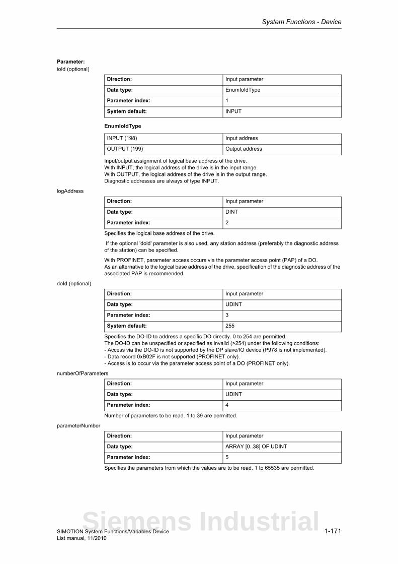
System Functions - Device
1-171SIMOTION System Functions/Variables DeviceList manual, 11/2010
Parameter: ioId (optional)
EnumIoIdType
Input/output assignment of logical base address of the drive.With INPUT, the logical address of the drive is in the input range.With OUTPUT, the logical address of the drive is in the output range.Diagnostic addresses are always of type INPUT.
logAddress
Specifies the logical base address of the drive.
If the optional 'dold' parameter is also used, any station address (preferably the diagnostic address of the station) can be specified.
With PROFINET, parameter access occurs via the parameter access point (PAP) of a DO.As an alternative to the logical base address of the drive, specification of the diagnostic address of the associated PAP is recommended.
doId (optional)
Specifies the DO-ID to address a specific DO directly. 0 to 254 are permitted.The DO-ID can be unspecified or specified as invalid (>254) under the following conditions:- Access via the DO-ID is not supported by the DP slave/IO device (P978 is not implemented).- Data record 0xB02F is not supported (PROFINET only).- Access is to occur via the parameter access point of a DO (PROFINET only).
numberOfParameters
Number of parameters to be read. 1 to 39 are permitted.
parameterNumber
Specifies the parameters from which the values are to be read. 1 to 65535 are permitted.
Direction: Input parameter
Data type: EnumIoIdType
Parameter index: 1
System default: INPUT
INPUT (198) Input address
OUTPUT (199) Output address
Direction: Input parameter
Data type: DINT
Parameter index: 2
Direction: Input parameter
Data type: UDINT
Parameter index: 3
System default: 255
Direction: Input parameter
Data type: UDINT
Parameter index: 4
Direction: Input parameter
Data type: ARRAY [0..38] OF UDINT
Parameter index: 5
Siemens Industrial
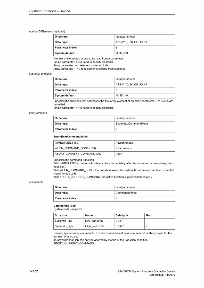
System Functions - Device
1-172 SIMOTION System Functions/Variables DeviceList manual, 11/2010
numberOfElements (optional)
Number of elements that are to be read from a parameter.Single parameter -> No need to specify elements.Array parameter -> 1 element under subindex.Array parameter -> 2 to n elements starting from subindex.
subIndex (optional)
Specifies the subindex that addresses the first array element of an array parameter. 0 to 65535 are permitted.Single parameter -> No need to specify elements.
nextCommand
EnumNextCommandMode
Specifies the command transition.With IMMEDIATELY, the transition takes place immediately after the command is issued (asynchro-nous call).With WHEN_COMMAND_DONE, the transition takes place when the command has been executed (synchronous call).With ABORT_CURRENT_COMMAND, the active function is aborted immediately.
commandId
CommandIdTypeSystem-wide unique ID
Unique, system-wide 'commandId' to track command status. A 'commandId' is always valid for the duration of a job andan asynchronous job can only be aborted by means of the transition condition ABORT_CURRENT_COMMAND.
Direction: Input parameter
Data type: ARRAY [0..38] OF UDINT
Parameter index: 6
System default: [0..38] = 0
Direction: Input parameter
Data type: ARRAY [0..38] OF UDINT
Parameter index: 7
System default: [0..38] = 0
Direction: Input parameter
Data type: EnumNextCommandMode
Parameter index: 8
IMMEDIATELY (60) Asynchronous
WHEN_COMMAND_DONE (160) Synchronous
ABORT_CURRENT_COMMAND (260) Abort
Direction: Input parameter
Data type: CommandIdType
Parameter index: 9
Structure Name Data type Unit
SystemId_low Low_part of ID UDINT -
SystemId_high High_part of ID UDINT -

System Functions - Device
1-173SIMOTION System Functions/Variables DeviceList manual, 11/2010
1.3.1.8 _readDriveMultiParameterDescription
NoteAdditional information is available at:SIMOTION Communication System Manual,Section PROFIdrive-specific data types,Section Rules for SIMOTION _writeDrive.../_readDrive... commandsor in the SIMOTION online help.
This function enables up to four parameter descriptions to be read. The interpretation of the parameter descriptions is contained in the PROFIdrive profile.
Note• Up to 16 parameter jobs can be executed in parallel (the term parameter job also includes the
functions _readDriveParameterDescription, _readDrive(Multi)Parameter, _writeDrive(Multi)Para-meter, and _readDriveFaults).
• Only one parameter job is permitted per planned DP station. A new job to the same DP station is rejected with the error 16#FFFF81C7.
• If the system functions _readRecord and _writeRecord are used in addition to the parameter jobs, you must ensure that they are not to be executed simultaneously by a DP station. Reason: The same communication services are used.
• If a parameter job (only asynchronous calls) is no longer to be processed, then it must be aborted with the ABORT_CURRENT_COMMAND transition condition. Otherwise no new job can be issued.
Parameters can be read out with the following data sets:• Data set 47 is always read out for PROFIBUS (external or integrated), regardless of whether the
function is called with a valid (0>=doId<=254) or invalid 'doId' (doId=255). If the passed 'doID' is invalid, it will be determined by the system itself. This requires the specification of the logical address of the axis.
• Two data sets are available for PROFINET:− Base Mode Parameter Access - local (data set 0xB02E)This data set (DS) is used for SIMOTION if either no 'dold' or an invalid 'dold' (dold=255) is spe-cified in the function. The Parameter Access Point (PAP) is then used to access the relevant DO. Either the PAP address can be specified directly or the log. address of the cyclical data (e.g. 256 for a DO axis) can be given. SIMOTION then determines the corresponding PAP from this address before accessing the correct address.
Note for PROFINETSIMOTION V4.1 SP2: PAP must always be at subslot 1 (HW Config configuration).
− Base Mode Parameter Access - global (data set 0xB02F)This data set is used if a valid 'dold' (0>=doId<=254) is entered. Any valid PAP or address can be specified, as assignment only takes place on the basis of the 'dold'.
Return value: StructRetReadDriveMultiParameterDescription
StructRetReadDriveMultiParameterDescriptionReturn parameter for _readDriveMultiParameterDescription
Structure Name Data type Unit
functionResult Total job return value DINT -
parameterResultErr-orExistent
A parameter-specific fault is present in the return value
BOOL -
parameterResult Parameter-specific return value
ARRAY [0..3] OF DINT -
dataType Parameter data type ARRAY [0..3] OF USINT
-
numberOfElements Number of parameter elements
ARRAY [0..3] OF UINT -
Siemens Industrial
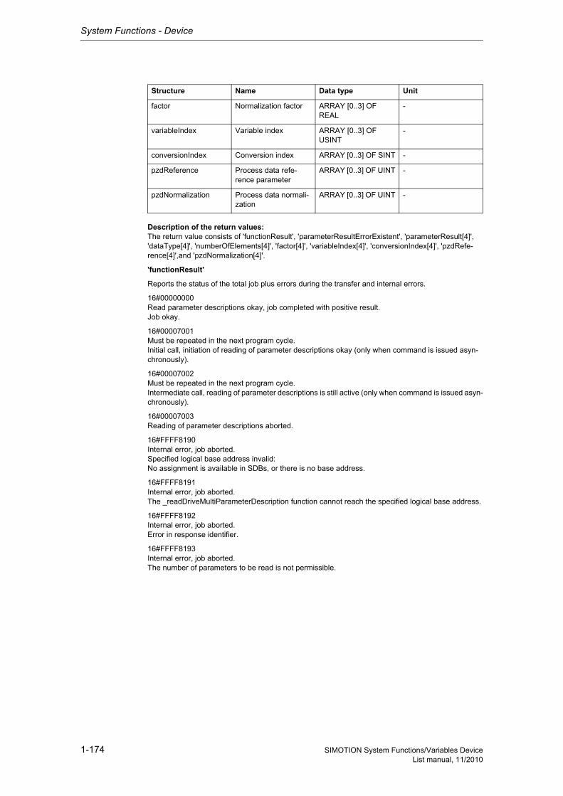
System Functions - Device
1-174 SIMOTION System Functions/Variables DeviceList manual, 11/2010
Description of the return values:The return value consists of 'functionResult', 'parameterResultErrorExistent', 'parameterResult[4]', 'dataType[4]', 'numberOfElements[4]', 'factor[4]', 'variableIndex[4]', 'conversionIndex[4]', 'pzdRefe-rence[4]',and 'pzdNormalization[4]'.
'functionResult'
Reports the status of the total job plus errors during the transfer and internal errors.
16#00000000Read parameter descriptions okay, job completed with positive result.Job okay.
16#00007001Must be repeated in the next program cycle.Initial call, initiation of reading of parameter descriptions okay (only when command is issued asyn-chronously).
16#00007002Must be repeated in the next program cycle.Intermediate call, reading of parameter descriptions is still active (only when command is issued asyn-chronously).
16#00007003Reading of parameter descriptions aborted.
16#FFFF8190Internal error, job aborted.Specified logical base address invalid:No assignment is available in SDBs, or there is no base address.
16#FFFF8191Internal error, job aborted.The _readDriveMultiParameterDescription function cannot reach the specified logical base address.
16#FFFF8192Internal error, job aborted.Error in response identifier.
16#FFFF8193Internal error, job aborted.The number of parameters to be read is not permissible.
factor Normalization factor ARRAY [0..3] OF REAL
-
variableIndex Variable index ARRAY [0..3] OF USINT
-
conversionIndex Conversion index ARRAY [0..3] OF SINT -
pzdReference Process data refe-rence parameter
ARRAY [0..3] OF UINT -
pzdNormalization Process data normali-zation
ARRAY [0..3] OF UINT -
Structure Name Data type Unit
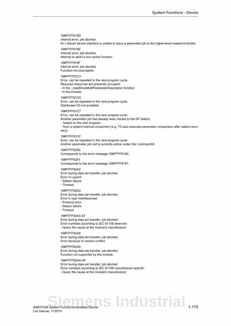
System Functions - Device
1-175SIMOTION System Functions/Variables DeviceList manual, 11/2010
16#FFFF819DInternal error, job aborted.An I slave/I device interface is unable to issue a parameter job to the higher-level master/controller.
16#FFFF819EInternal error, job aborted.Attempt to abort a non-active function.
16#FFFF819FInternal error, job aborted.Function not executable.
16#FFFF81C3Error, can be repeated in the next program cycle.Required resources are presently occupied:- In the _readDriveMultiParameterDescription function- In the module
16#FFFF81C5Error, can be repeated in the next program cycle.Distributed I/O not available.
16#FFFF81C7Error, can be repeated in the next program cycle.Another parameter job has already been issued to the DP station. - based on the user program - from a system-internal component (e.g. TO axis executes parameter comparison after station reco-very)
16#FFFF81CFError, can be repeated in the next program cycle.Another parameter job call is currently active under this 'commandId'.
16#FFFF8290Corresponds to the error message 16#FFFF8190.
16#FFFF8291Corresponds to the error message 16#FFFF8191.
16#FFFF82A2Error during data set transfer, job aborted.Error in Layer2:- Station failure- Timeout
16#FFFF82A3Error during data set transfer, job aborted.Error in user interface/user:- Protocol error- Station failure- Timeout
16#FFFF82A4-A7Error during data set transfer, job aborted.Error numbers according to IEC 61158 reserved- Query the cause at the module's manufacturer
16#FFFF82A8Error during data set transfer, job aborted.Error because of version conflict.
16#FFFF82A9Error during data set transfer, job aborted.Function not supported by the module.
16#FFFF82AA-AFError during data set transfer, job aborted.Error numbers according to IEC 61158 manufacturer-specific- Query the cause at the module's manufacturer
Siemens Industrial

System Functions - Device
1-176 SIMOTION System Functions/Variables DeviceList manual, 11/2010
16#FFFF82B0Error during data set transfer, job aborted.Parameter jobs are not supported by the addressed module.
16#FFFF82B2Error during data set transfer, job aborted.Module reports access to an invalid slot/subslot.
16#FFFF82B3Error during data set transfer, job aborted.Module reports type conflict.
16#FFFF82B4Error during data set transfer, job aborted.Module reports access to an invalid area.
16#FFFF82B5Error during data set transfer, can be repeated in the next program cycle.The system function cannot be executed due to an internal operating state of the module.
16#FFFF82B6Error during data set transfer, job aborted.Module rejects access.
16#FFFF82B7Error during data set transfer, job aborted.The job could not be dispatched due to a job error.
16#FFFF82B8Error during data set transfer, job aborted.Module reports an invalid parameter.
16#FFFF82B9Error during data set transfer, job aborted.Module reports an invalid type.
16#FFFF82BA-BFError during data set transfer, job aborted.Error numbers according to IEC 61158 manufacturer-specific- Query the cause at the module's manufacturer
16#FFFF82C0Error during data set transfer, can be repeated in the next program cycle.The module is feeding the data record, but the module does not yet have any read data.
16#FFFF82C2Error during data set transfer, command can be repeated immediately.The module is currently executing the maximum possible jobs for one CPU.
16#FFFF82C3Error during data set transfer, command can be repeated immediately.Required resources are presently occupied:- In the _readRecord function- In the module
16#FFFF82C4Error during data set transfer, command can be repeated immediately.Communication errors:- Parity error- SW Ready not set- Error in block length administration- Checksum error on CPU side- Checksum error on module side
16#FFFF82C5Error during data set transfer,Can be repeated in the next program cycle.Distributed I/O not available.
16#FFFF82C6Error during data set transfer, can be repeated in the next program cycle.
System Functions - Device
1-177SIMOTION System Functions/Variables DeviceList manual, 11/2010
Data record transfer has been aborted due to priority class abort (restart or background).
'parameterResultErrorExistent'
Returns TRUE when an error is reported in at least one 'parameterResult'.
'parameterResult'
Reports parameter-specific errors.
16#FFFF8000Parameter error, job aborted.Access to a non-existent parameter.
16#FFFF8009Parameter error, job aborted.Access to a non-existent description (parameter does exist).
16#FFFF8011Parameter error, job aborted.Job cannot be executed due to operating state.
16#FFFF8019Parameter error, job aborted.Access to a non-existing axis or an invalid drive object.
16#FFFF8020-FFParameter error, job aborted.Manufacturer-specific error.
'dataType'returns the parameter data type (for the coding, see PROFIdrive profile).
NoteFurther information on the structure of a data type can be found:- In the SIMOTION Communication System Manual or- At www.profibus.com, in the documentation "Profile Guidelines, Part 2: Data Types, Programming Languages and Platforms".
'numberOfElements'supplies the number of elements of an array parameter. The string length is specified here for para-meters of data type "String".
'factor'supplies the normalization factor that converts the (internal) value into an (externally) displayable quantity (see PROFIdrive profile).
'variableIndex'returns the variable index and displays a fixed code for the physical quantity of the parameter value (see PROFIdrive profile).
'conversionIndex'supplies the fixed code of the conversion index (conversion factor + offset) of a parameter (see PRO-FIdrive profile).
'pzdReference'returns the physical reference value for calculating a physical value of a normalized variable (see PROFIdrive profile).
'pzdNormalization'supplies the bit to which the physical reference value refers (see PROFIdrive profile).
Siemens Industrial
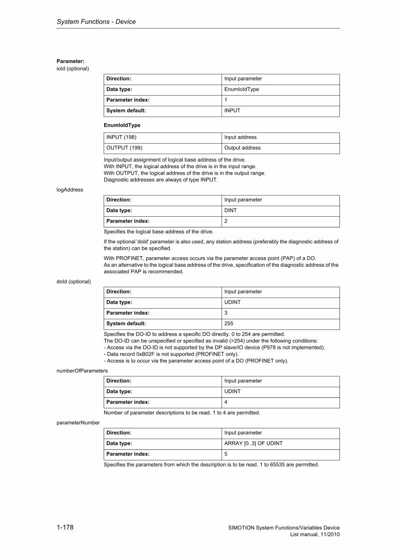
System Functions - Device
1-178 SIMOTION System Functions/Variables DeviceList manual, 11/2010
Parameter: ioId (optional)
EnumIoIdType
Input/output assignment of logical base address of the drive.With INPUT, the logical address of the drive is in the input range.With OUTPUT, the logical address of the drive is in the output range.Diagnostic addresses are always of type INPUT.
logAddress
Specifies the logical base address of the drive.
If the optional 'dold' parameter is also used, any station address (preferably the diagnostic address of the station) can be specified.
With PROFINET, parameter access occurs via the parameter access point (PAP) of a DO.As an alternative to the logical base address of the drive, specification of the diagnostic address of the associated PAP is recommended.
doId (optional)
Specifies the DO-ID to address a specific DO directly. 0 to 254 are permitted.The DO-ID can be unspecified or specified as invalid (>254) under the following conditions:- Access via the DO-ID is not supported by the DP slave/IO device (P978 is not implemented).- Data record 0xB02F is not supported (PROFINET only).- Access is to occur via the parameter access point of a DO (PROFINET only).
numberOfParameters
Number of parameter descriptions to be read. 1 to 4 are permitted.
parameterNumber
Specifies the parameters from which the description is to be read. 1 to 65535 are permitted.
Direction: Input parameter
Data type: EnumIoIdType
Parameter index: 1
System default: INPUT
INPUT (198) Input address
OUTPUT (199) Output address
Direction: Input parameter
Data type: DINT
Parameter index: 2
Direction: Input parameter
Data type: UDINT
Parameter index: 3
System default: 255
Direction: Input parameter
Data type: UDINT
Parameter index: 4
Direction: Input parameter
Data type: ARRAY [0..3] OF UDINT
Parameter index: 5
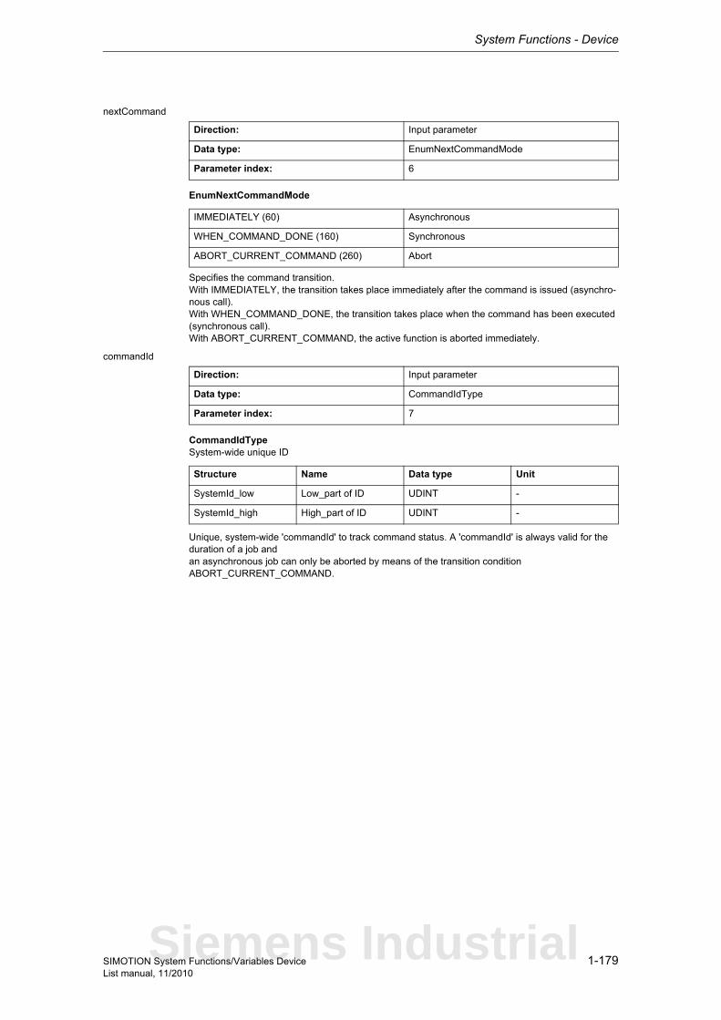
System Functions - Device
1-179SIMOTION System Functions/Variables DeviceList manual, 11/2010
nextCommand
EnumNextCommandMode
Specifies the command transition.With IMMEDIATELY, the transition takes place immediately after the command is issued (asynchro-nous call).With WHEN_COMMAND_DONE, the transition takes place when the command has been executed (synchronous call).With ABORT_CURRENT_COMMAND, the active function is aborted immediately.
commandId
CommandIdTypeSystem-wide unique ID
Unique, system-wide 'commandId' to track command status. A 'commandId' is always valid for the duration of a job andan asynchronous job can only be aborted by means of the transition condition ABORT_CURRENT_COMMAND.
Direction: Input parameter
Data type: EnumNextCommandMode
Parameter index: 6
IMMEDIATELY (60) Asynchronous
WHEN_COMMAND_DONE (160) Synchronous
ABORT_CURRENT_COMMAND (260) Abort
Direction: Input parameter
Data type: CommandIdType
Parameter index: 7
Structure Name Data type Unit
SystemId_low Low_part of ID UDINT -
SystemId_high High_part of ID UDINT -
Siemens Industrial

System Functions - Device
1-180 SIMOTION System Functions/Variables DeviceList manual, 11/2010
1.3.1.9 _readDriveParameter
NoteAdditional information is available at:SIMOTION Communication System Manual,Section PROFIdrive-specific data types,Section Rules for SIMOTION _writeDrive.../_readDrive... commandsor in the SIMOTION online help.
This function enables a drive parameter to be read.
Note• Up to 16 parameter jobs can be executed in parallel (the term parameter job also includes the
functions _readDriveMultiParameter, _readDrive(Multi)ParameterDescription, _writeDrive(Multi)Parameter, and _readDriveFaults).
• Only one parameter job is permitted per planned DP station. A new job to the same DP station is rejected with the error 16#FFFF81C7.
• If the system functions _readRecord and _writeRecord are used in addition to the parameter jobs, you must ensure that they are not to be executed simultaneously by a DP station. Reason: The same communication services are used.
• If a parameter job (only asynchronous calls) is no longer to be processed, then it must be aborted with the ABORT_CURRENT_COMMAND transition condition. Otherwise no new job can be issued.
Parameters can be read out with the following data sets:• Data set 47 is always read out for PROFIBUS (external or integrated), regardless of whether the
function is called with a valid (0>=doId<=254) or invalid 'doId' (doId=255). If the passed 'doId' is invalid, it will be determined by the system itself. This requires the specification of the logical address of the axis.
• Two data sets are available for PROFINET:− Base Mode Parameter Access - local (data set 0xB02E)This data set (DS) is used for SIMOTION if either no 'dold' or an invalid 'dold' (dold=255) is spe-cified in the function. The Parameter Access Point (PAP) is then used to access the relevant DO. Either the PAP address can be specified directly or the log. address of the cyclical data (e.g. 256 for a DO axis) can be given. SIMOTION then determines the corresponding PAP from this address before accessing the correct address.
Note for PROFINETSIMOTION V4.1 SP2: PAP must always be at subslot 1 (HW Config configuration).
− Base Mode Parameter Access - global (data set 0xB02F)This data set is used if a valid 'dold' (0>=doId<=254) is entered. Any valid PAP or address can be specified, as assignment only takes place on the basis of the 'dold'.
Return value: StructRetReadDriveParameter
StructRetReadDriveParameterReturn parameter for _readDriveParameter
Structure Name Data type Unit
functionResult Total job return value DINT -
parameterResult Parameter-specific return value
DINT -
dataType Data type of the read parameter
UDINT -
dataLength Length of read data in bytes
UDINT -
data Data read by the drive (big endian)
ARRAY [0..233] OF BYTE
-

System Functions - Device
1-181SIMOTION System Functions/Variables DeviceList manual, 11/2010
Description of the return values:The return value consists of 'functionResult', 'parameterResult', 'dataType', 'dataLength' and 'data[234].
'functionResult'Reports the status of the total job plus errors during the transfer and internal errors.
16#00000000Reading of parameters okay, job completed with positive result. Job okay.
16#00007001Must be repeated in the next program cycle.Initial call, initiation of reading of parameter description okay(only when command is issued asynchronously).
16#00007002Must be repeated in the next program cycle.Intermediate call, reading of parameter description is still active(only when command is issued asynchronously).
16#00007003Reading of parameters aborted.Job aborted.
16#FFFF8190Internal error, job aborted.Specified logical base address invalid:No assignment is available in SDBs, or there is no base address.
16#FFFF8191Internal error, job aborted.The _readDriveParameter function cannot reach the specified logical base address.
16#FFFF8192Internal error, job aborted.Error in response identifier.
16#FFFF819DInternal error, job aborted.An I slave/I device interface is unable to issue a parameter job to the higher-level master/controller.
16#FFFF819EInternal error, job aborted.Attempt to abort a non-active function.
16#FFFF819FInternal error, job aborted.Function not executable.
16#FFFF81C3Error, can be repeated in the next program cycle.Required resources are presently occupied:- In the _readDriveParameter function- In the module
16#FFFF81C5Error, can be repeated in the next program cycle.Distributed I/O not available.
16#FFFF81C7Error, can be repeated in the next program cycle.Another parameter job has already been issued to the DP station. - based on the user program - from a system-internal component (e.g. TO axis executes parameter comparison after station reco-very)
Siemens Industrial
System Functions - Device
1-182 SIMOTION System Functions/Variables DeviceList manual, 11/2010
16#FFFF81CFError, can be repeated in the next program cycle.Another parameter job call is currently active under this 'commandId'.
16#FFFF8290Corresponds to the error message 16#FFFF8190.
16#FFFF8291Corresponds to the error message 16#FFFF8191.
16#FFFF82A2Error during data set transfer, job aborted.Error in Layer2:- Station failure- Timeout
16#FFFF82A3Error during data set transfer, job aborted.Error in user interface/user:- Protocol error- Station failure- Timeout
16#FFFF82A4-A7Error during data set transfer, job aborted.Error numbers according to IEC 61158 reserved- Query the cause at the module's manufacturer
16#FFFF82A8Error during data set transfer, job aborted.Error because of version conflict.
16#FFFF82A9Error during data set transfer, job aborted.Function not supported by the module.
16#FFFF82AA-AFError during data set transfer, job aborted.Error numbers according to IEC 61158 manufacturer-specific- Query the cause at the module's manufacturer
16#FFFF82B0Error during data set transfer, job aborted.Parameter jobs are not supported by the addressed module.
16#FFFF82B2Error during data set transfer, job aborted.Module reports access to an invalid slot/subslot.
16#FFFF82B3Error during data set transfer, job aborted.Module reports type conflict.
16#FFFF82B4Error during data set transfer, job aborted.Module reports access to an invalid area.
16#FFFF82B5Error during data set transfer, can be repeated in the next program cycle.The system function cannot be executed due to an internal operating state of the module.
16#FFFF82B6Error during data set transfer, job aborted.Module rejects access.
16#FFFF82B7Error during data set transfer, job aborted.The job could not be dispatched due to a job error.
16#FFFF82B8Error during data set transfer, job aborted.Module reports an invalid parameter.

System Functions - Device
1-183SIMOTION System Functions/Variables DeviceList manual, 11/2010
16#FFFF82B9Error during data set transfer, job aborted.Module reports an invalid type.
16#FFFF82BA-BFError during data set transfer, job aborted.Error numbers according to IEC 61158 manufacturer-specific- Query the cause at the module's manufacturer
16#FFFF82C0Error during data set transfer, can be repeated in the next program cycle.The module is feeding the data record, but the module does not yet have any read data.
16#FFFF82C2Error during data set transfer, command can be repeated immediately.The module is currently executing the maximum possible jobs for one CPU.
16#FFFF82C3Error during data set transfer, command can be repeated immediately.Required resources are presently occupied:- In the _readRecord function- In the module
16#FFFF82C4Error during data set transfer, command can be repeated immediately.Communication errors:- Parity error- SW Ready not set- Error in block length administration- Checksum error on CPU side- Checksum error on module side
16#FFFF82C5Error during data set transfer,Can be repeated in the next program cycle.Distributed I/O not available.
16#FFFF82C6Error during data set transfer, can be repeated in the next program cycle.Data record transfer has been aborted due to priority class abort (restart or background).
'parameterResult'
Reports parameter-specific errors.
16#FFFF8000Parameter error, job aborted.Access to a non-existent parameter.
16#FFFF8003Parameter error, job aborted.Access to a non-existent subindex.
16#FFFF8004Parameter error, job aborted.Access with subindex to non-indexed parameter (not an array parameter).
16#FFFF8011Parameter error, job aborted.Job cannot be executed due to operating state.
16#FFFF8015Parameter error, job aborted.The length of the current response exceeds the maximum transferable length.
16#FFFF8016Parameter error, job aborted.Illegal or unsupported value for attribute, number of elements, parameter number, or subindex, or a combination of these.
Siemens Industrial
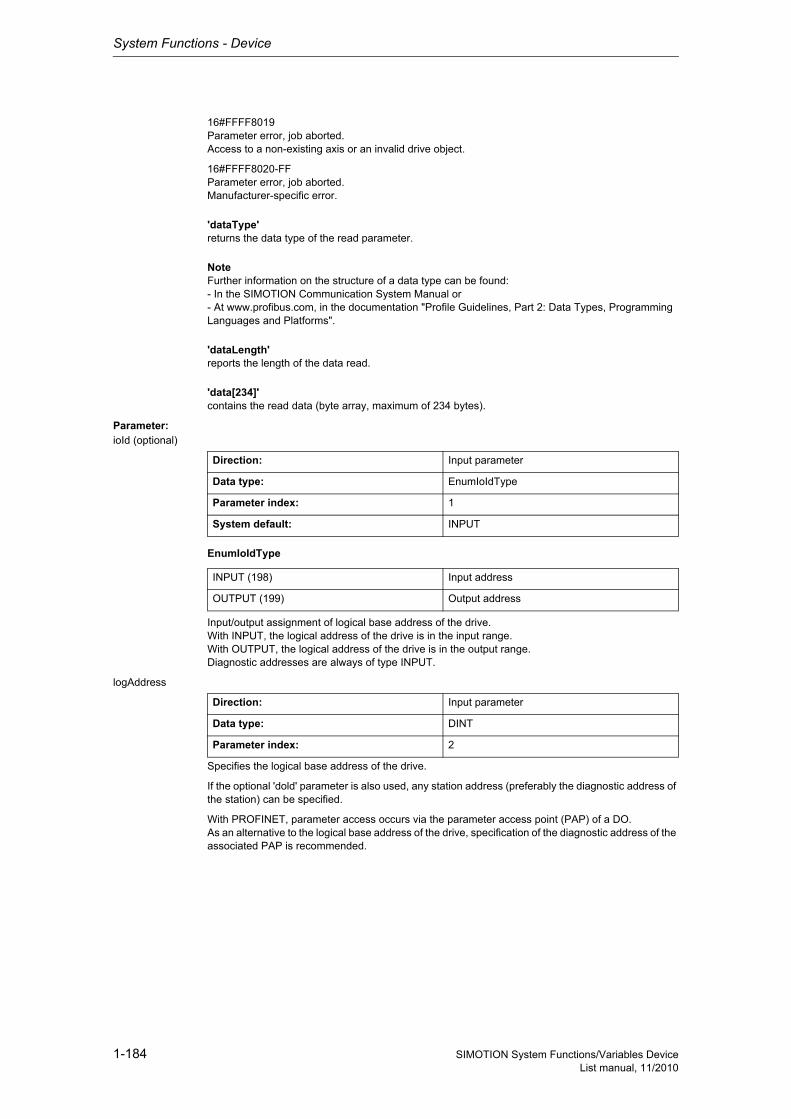
System Functions - Device
1-184 SIMOTION System Functions/Variables DeviceList manual, 11/2010
16#FFFF8019Parameter error, job aborted.Access to a non-existing axis or an invalid drive object.
16#FFFF8020-FFParameter error, job aborted.Manufacturer-specific error.
'dataType'returns the data type of the read parameter.
NoteFurther information on the structure of a data type can be found:- In the SIMOTION Communication System Manual or- At www.profibus.com, in the documentation "Profile Guidelines, Part 2: Data Types, Programming Languages and Platforms".
'dataLength'reports the length of the data read.
'data[234]'contains the read data (byte array, maximum of 234 bytes).
Parameter: ioId (optional)
EnumIoIdType
Input/output assignment of logical base address of the drive.With INPUT, the logical address of the drive is in the input range.With OUTPUT, the logical address of the drive is in the output range.Diagnostic addresses are always of type INPUT.
logAddress
Specifies the logical base address of the drive.
If the optional 'dold' parameter is also used, any station address (preferably the diagnostic address of the station) can be specified.
With PROFINET, parameter access occurs via the parameter access point (PAP) of a DO.As an alternative to the logical base address of the drive, specification of the diagnostic address of the associated PAP is recommended.
Direction: Input parameter
Data type: EnumIoIdType
Parameter index: 1
System default: INPUT
INPUT (198) Input address
OUTPUT (199) Output address
Direction: Input parameter
Data type: DINT
Parameter index: 2
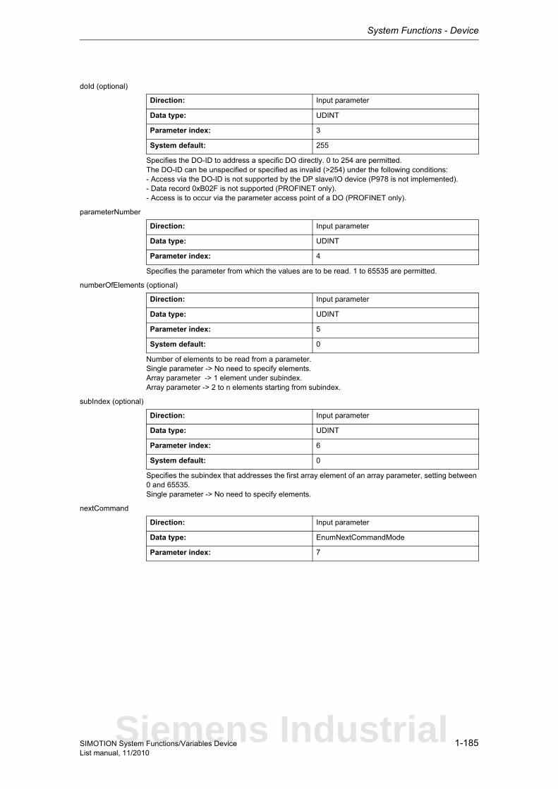
System Functions - Device
1-185SIMOTION System Functions/Variables DeviceList manual, 11/2010
doId (optional)
Specifies the DO-ID to address a specific DO directly. 0 to 254 are permitted.The DO-ID can be unspecified or specified as invalid (>254) under the following conditions:- Access via the DO-ID is not supported by the DP slave/IO device (P978 is not implemented).- Data record 0xB02F is not supported (PROFINET only).- Access is to occur via the parameter access point of a DO (PROFINET only).
parameterNumber
Specifies the parameter from which the values are to be read. 1 to 65535 are permitted.
numberOfElements (optional)
Number of elements to be read from a parameter.Single parameter -> No need to specify elements.Array parameter -> 1 element under subindex.Array parameter -> 2 to n elements starting from subindex.
subIndex (optional)
Specifies the subindex that addresses the first array element of an array parameter, setting between 0 and 65535.Single parameter -> No need to specify elements.
nextCommand
Direction: Input parameter
Data type: UDINT
Parameter index: 3
System default: 255
Direction: Input parameter
Data type: UDINT
Parameter index: 4
Direction: Input parameter
Data type: UDINT
Parameter index: 5
System default: 0
Direction: Input parameter
Data type: UDINT
Parameter index: 6
System default: 0
Direction: Input parameter
Data type: EnumNextCommandMode
Parameter index: 7
Siemens Industrial
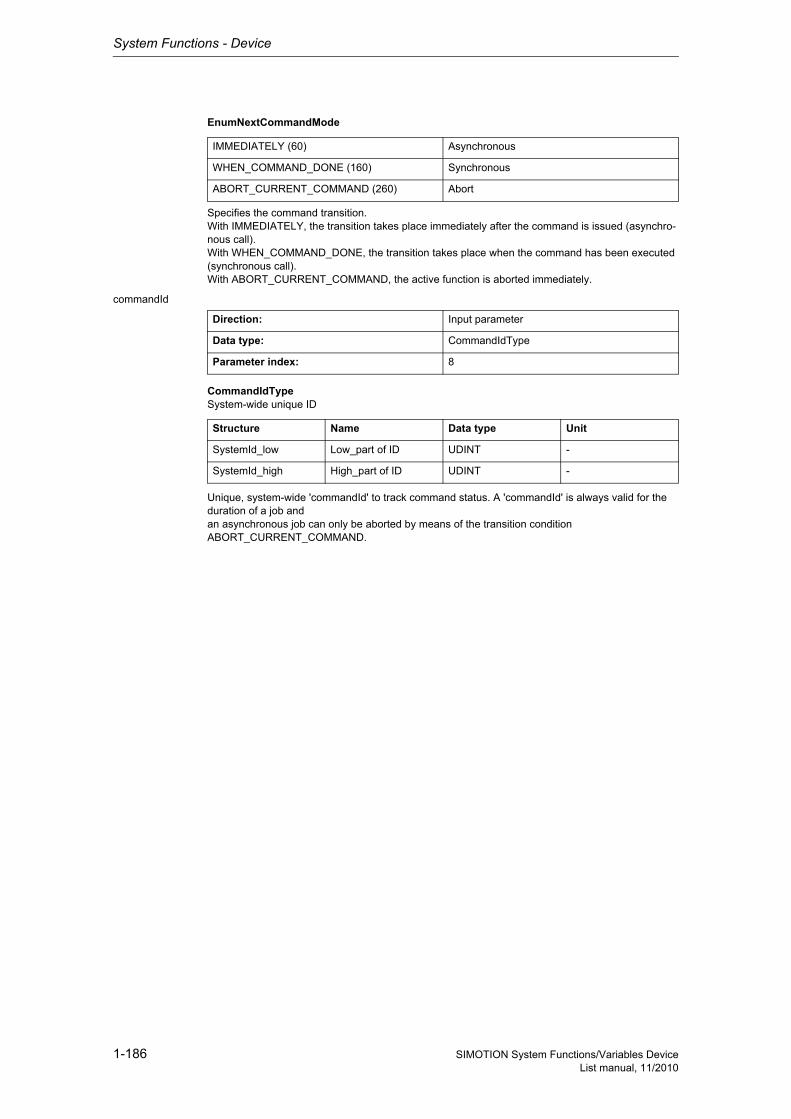
System Functions - Device
1-186 SIMOTION System Functions/Variables DeviceList manual, 11/2010
EnumNextCommandMode
Specifies the command transition.With IMMEDIATELY, the transition takes place immediately after the command is issued (asynchro-nous call).With WHEN_COMMAND_DONE, the transition takes place when the command has been executed (synchronous call).With ABORT_CURRENT_COMMAND, the active function is aborted immediately.
commandId
CommandIdTypeSystem-wide unique ID
Unique, system-wide 'commandId' to track command status. A 'commandId' is always valid for the duration of a job andan asynchronous job can only be aborted by means of the transition condition ABORT_CURRENT_COMMAND.
IMMEDIATELY (60) Asynchronous
WHEN_COMMAND_DONE (160) Synchronous
ABORT_CURRENT_COMMAND (260) Abort
Direction: Input parameter
Data type: CommandIdType
Parameter index: 8
Structure Name Data type Unit
SystemId_low Low_part of ID UDINT -
SystemId_high High_part of ID UDINT -
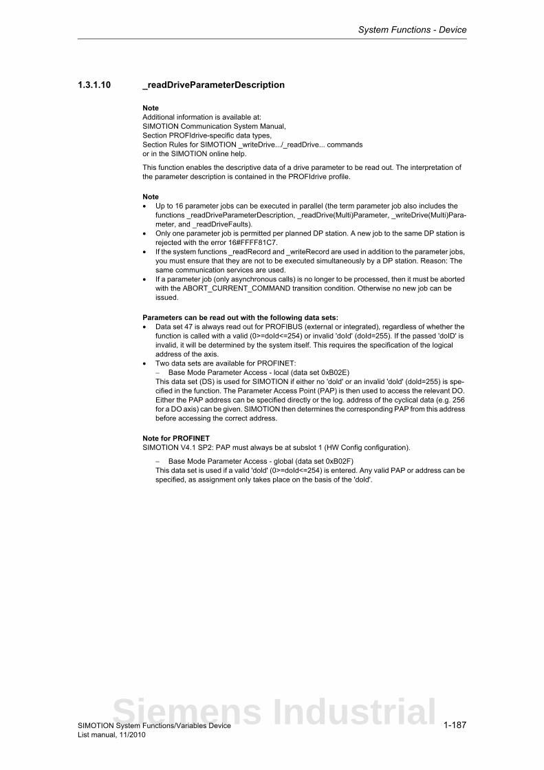
System Functions - Device
1-187SIMOTION System Functions/Variables DeviceList manual, 11/2010
1.3.1.10 _readDriveParameterDescription
NoteAdditional information is available at:SIMOTION Communication System Manual,Section PROFIdrive-specific data types,Section Rules for SIMOTION _writeDrive.../_readDrive... commandsor in the SIMOTION online help.
This function enables the descriptive data of a drive parameter to be read out. The interpretation of the parameter description is contained in the PROFIdrive profile.
Note• Up to 16 parameter jobs can be executed in parallel (the term parameter job also includes the
functions _readDriveParameterDescription, _readDrive(Multi)Parameter, _writeDrive(Multi)Para-meter, and _readDriveFaults).
• Only one parameter job is permitted per planned DP station. A new job to the same DP station is rejected with the error 16#FFFF81C7.
• If the system functions _readRecord and _writeRecord are used in addition to the parameter jobs, you must ensure that they are not to be executed simultaneously by a DP station. Reason: The same communication services are used.
• If a parameter job (only asynchronous calls) is no longer to be processed, then it must be aborted with the ABORT_CURRENT_COMMAND transition condition. Otherwise no new job can be issued.
Parameters can be read out with the following data sets:• Data set 47 is always read out for PROFIBUS (external or integrated), regardless of whether the
function is called with a valid (0>=doId<=254) or invalid 'doId' (doId=255). If the passed 'doID' is invalid, it will be determined by the system itself. This requires the specification of the logical address of the axis.
• Two data sets are available for PROFINET:− Base Mode Parameter Access - local (data set 0xB02E)This data set (DS) is used for SIMOTION if either no 'dold' or an invalid 'dold' (dold=255) is spe-cified in the function. The Parameter Access Point (PAP) is then used to access the relevant DO. Either the PAP address can be specified directly or the log. address of the cyclical data (e.g. 256 for a DO axis) can be given. SIMOTION then determines the corresponding PAP from this address before accessing the correct address.
Note for PROFINETSIMOTION V4.1 SP2: PAP must always be at subslot 1 (HW Config configuration).
− Base Mode Parameter Access - global (data set 0xB02F)This data set is used if a valid 'dold' (0>=doId<=254) is entered. Any valid PAP or address can be specified, as assignment only takes place on the basis of the 'dold'.
Siemens Industrial
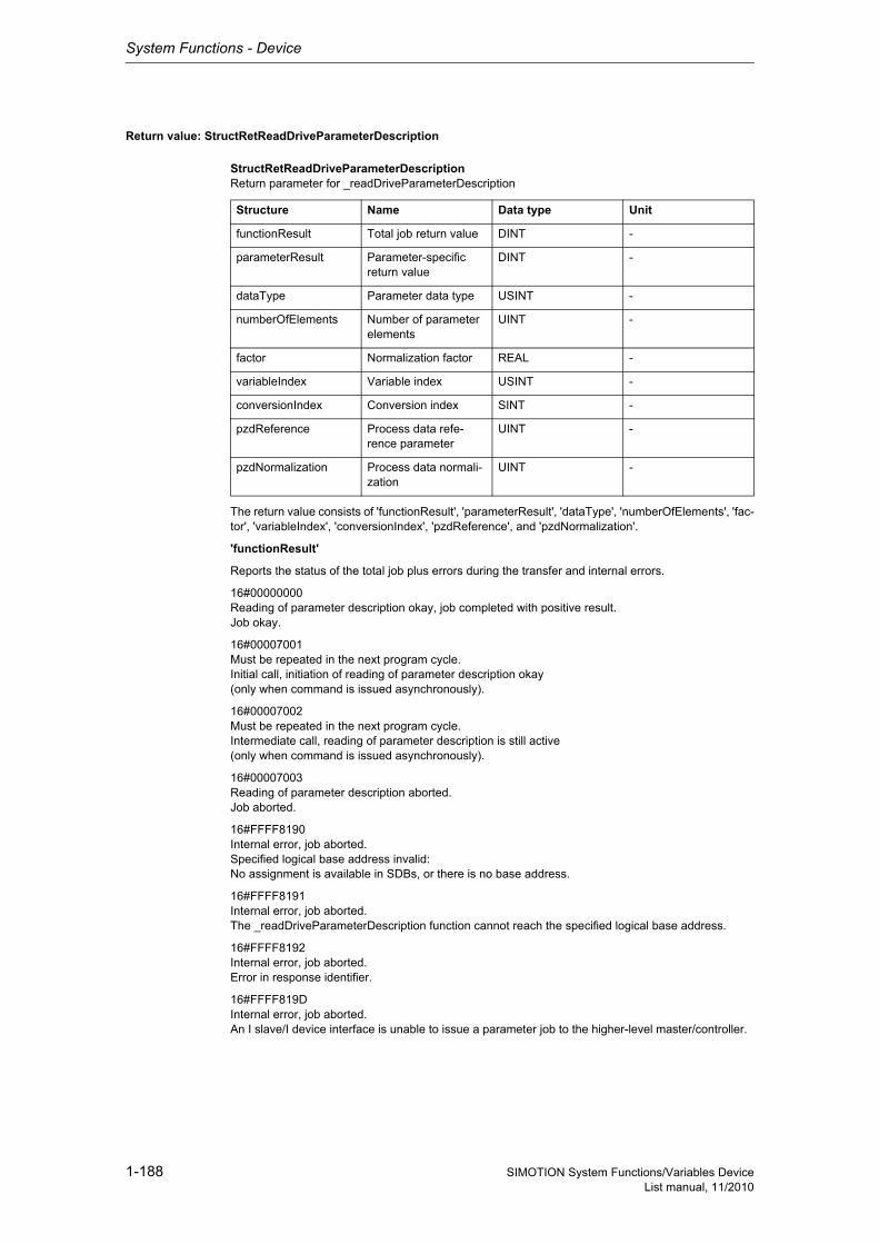
System Functions - Device
1-188 SIMOTION System Functions/Variables DeviceList manual, 11/2010
Return value: StructRetReadDriveParameterDescription
StructRetReadDriveParameterDescriptionReturn parameter for _readDriveParameterDescription
The return value consists of 'functionResult', 'parameterResult', 'dataType', 'numberOfElements', 'fac-tor', 'variableIndex', 'conversionIndex', 'pzdReference', and 'pzdNormalization'.
'functionResult'
Reports the status of the total job plus errors during the transfer and internal errors.
16#00000000Reading of parameter description okay, job completed with positive result.Job okay.
16#00007001Must be repeated in the next program cycle.Initial call, initiation of reading of parameter description okay(only when command is issued asynchronously).
16#00007002Must be repeated in the next program cycle.Intermediate call, reading of parameter description is still active(only when command is issued asynchronously).
16#00007003Reading of parameter description aborted.Job aborted.
16#FFFF8190Internal error, job aborted.Specified logical base address invalid:No assignment is available in SDBs, or there is no base address.
16#FFFF8191Internal error, job aborted.The _readDriveParameterDescription function cannot reach the specified logical base address.
16#FFFF8192Internal error, job aborted.Error in response identifier.
16#FFFF819DInternal error, job aborted.An I slave/I device interface is unable to issue a parameter job to the higher-level master/controller.
Structure Name Data type Unit
functionResult Total job return value DINT -
parameterResult Parameter-specific return value
DINT -
dataType Parameter data type USINT -
numberOfElements Number of parameter elements
UINT -
factor Normalization factor REAL -
variableIndex Variable index USINT -
conversionIndex Conversion index SINT -
pzdReference Process data refe-rence parameter
UINT -
pzdNormalization Process data normali-zation
UINT -

System Functions - Device
1-189SIMOTION System Functions/Variables DeviceList manual, 11/2010
16#FFFF819EInternal error, job aborted.Attempt to abort a non-active function.
16#FFFF819FInternal error, job aborted.Function not executable.
16#FFFF81C3Error, can be repeated in the next program cycle.Required resources are presently occupied:- In the _readDriveParameterDescription function- In the module
16#FFFF81C5Error, can be repeated in the next program cycle.Distributed I/O not available.
16#FFFF81C7Error, can be repeated in the next program cycle.Another parameter job has already been issued to the DP station. - based on the user program - from a system-internal component (e.g. TO axis executes parameter comparison after station reco-very)
16#FFFF81CFError, can be repeated in the next program cycle.Another parameter job call is currently active under this 'commandId'.
16#FFFF8290Corresponds to the error message 16#FFFF8190.
16#FFFF8291Corresponds to the error message 16#FFFF8191.
16#FFFF82A2Error during data set transfer, job aborted.Error in Layer2:- Station failure- Timeout
16#FFFF82A3Error during data set transfer, job aborted.Error in user interface/user:- Protocol error- Station failure- Timeout
16#FFFF82A4-A7Error during data set transfer, job aborted.Error numbers according to IEC 61158 reserved- Query the cause at the module's manufacturer
16#FFFF82A8Error during data set transfer, job aborted.Error because of version conflict.
16#FFFF82A9Error during data set transfer, job aborted.Function not supported by the module.
16#FFFF82AA-AFError during data set transfer, job aborted.Error numbers according to IEC 61158 manufacturer-specific- Query the cause at the module's manufacturer
16#FFFF82B0Error during data set transfer, job aborted.Parameter jobs are not supported by the addressed module.
Siemens Industrial
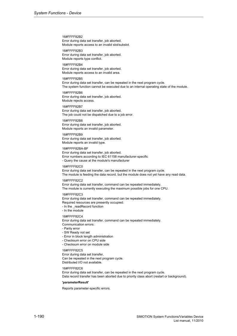
System Functions - Device
1-190 SIMOTION System Functions/Variables DeviceList manual, 11/2010
16#FFFF82B2Error during data set transfer, job aborted.Module reports access to an invalid slot/subslot.
16#FFFF82B3Error during data set transfer, job aborted.Module reports type conflict.
16#FFFF82B4Error during data set transfer, job aborted.Module reports access to an invalid area.
16#FFFF82B5Error during data set transfer, can be repeated in the next program cycle.The system function cannot be executed due to an internal operating state of the module.
16#FFFF82B6Error during data set transfer, job aborted.Module rejects access.
16#FFFF82B7Error during data set transfer, job aborted.The job could not be dispatched due to a job error.
16#FFFF82B8Error during data set transfer, job aborted.Module reports an invalid parameter.
16#FFFF82B9Error during data set transfer, job aborted.Module reports an invalid type.
16#FFFF82BA-BFError during data set transfer, job aborted.Error numbers according to IEC 61158 manufacturer-specific- Query the cause at the module's manufacturer
16#FFFF82C0Error during data set transfer, can be repeated in the next program cycle.The module is feeding the data record, but the module does not yet have any read data.
16#FFFF82C2Error during data set transfer, command can be repeated immediately.The module is currently executing the maximum possible jobs for one CPU.
16#FFFF82C3Error during data set transfer, command can be repeated immediately.Required resources are presently occupied:- In the _readRecord function- In the module
16#FFFF82C4Error during data set transfer, command can be repeated immediately.Communication errors:- Parity error- SW Ready not set- Error in block length administration- Checksum error on CPU side- Checksum error on module side
16#FFFF82C5Error during data set transfer,Can be repeated in the next program cycle.Distributed I/O not available.
16#FFFF82C6Error during data set transfer, can be repeated in the next program cycle.Data record transfer has been aborted due to priority class abort (restart or background).
'parameterResult'
Reports parameter-specific errors.

System Functions - Device
1-191SIMOTION System Functions/Variables DeviceList manual, 11/2010
16#FFFF8000Parameter error, job aborted.Access to a non-existent parameter.
16#FFFF8009Parameter error, job aborted.Access to a non-existent description (parameter does exist).
16#FFFF8011Parameter error, job aborted.Job cannot be executed due to operating state.
16#FFFF8019Parameter error, job aborted.Access to a non-existing axis or an invalid drive object.
16#FFFF8020-FFParameter error, job aborted.Manufacturer-specific error.
'dataType' returns the parameter data type (for the coding, see PROFIdrive profile).
NoteFurther information on the structure of a data type can be found:- In the SIMOTION Communication System Manual or- At www.profibus.com, in the documentation "Profile Guidelines Part 2: Data Types, Programming Languages and Platforms".
'numberOfElements' supplies the number of elements of an array parameter. The string length is spe-cified here for parameters of data type "String".
'factor' supplies the normalization factor that converts the (internal) value into an (externally) displa-yable quantity (see PROFIdrive profile).
'variableIndex' returns the variable index and displays a fixed code for the physical quantity of the parameter value (see PROFIdrive profile).
'conversionIndex' supplies the fixed code of the conversion index (conversion factor + offset) of a parameter (see PROFIdrive profile).
'pzdReference' returns the physical reference value for calculating a physical value of a normalized variable (see PROFIdrive profile).
'pzdNormalization' supplies the bit to which the physical reference value refers (see PROFIdrive pro-file).
Parameter: ioId (optional)
EnumIoIdType
Input/output assignment of logical base address of the drive.With INPUT, the logical address of the drive is in the input range.With OUTPUT, the logical address of the drive is in the output range.Diagnostic addresses are always of type INPUT.
Direction: Input parameter
Data type: EnumIoIdType
Parameter index: 1
System default: INPUT
INPUT (198) Input address
OUTPUT (199) Output address
Siemens Industrial
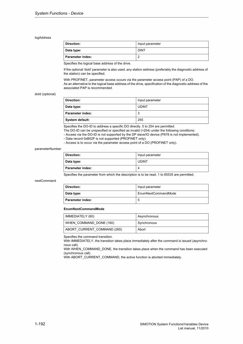
System Functions - Device
1-192 SIMOTION System Functions/Variables DeviceList manual, 11/2010
logAddress
Specifies the logical base address of the drive.
If the optional 'dold' parameter is also used, any station address (preferably the diagnostic address of the station) can be specified.
With PROFINET, parameter access occurs via the parameter access point (PAP) of a DO.As an alternative to the logical base address of the drive, specification of the diagnostic address of the associated PAP is recommended.
doId (optional)
Specifies the DO-ID to address a specific DO directly. 0 to 254 are permitted.The DO-ID can be unspecified or specified as invalid (>254) under the following conditions:- Access via the DO-ID is not supported by the DP slave/IO device (P978 is not implemented).- Data record 0xB02F is not supported (PROFINET only).- Access is to occur via the parameter access point of a DO (PROFINET only).
parameterNumber
Specifies the parameter from which the description is to be read. 1 to 65535 are permitted.
nextCommand
EnumNextCommandMode
Specifies the command transition.With IMMEDIATELY, the transition takes place immediately after the command is issued (asynchro-nous call).With WHEN_COMMAND_DONE, the transition takes place when the command has been executed (synchronous call).With ABORT_CURRENT_COMMAND, the active function is aborted immediately.
Direction: Input parameter
Data type: DINT
Parameter index: 2
Direction: Input parameter
Data type: UDINT
Parameter index: 3
System default: 255
Direction: Input parameter
Data type: UDINT
Parameter index: 4
Direction: Input parameter
Data type: EnumNextCommandMode
Parameter index: 5
IMMEDIATELY (60) Asynchronous
WHEN_COMMAND_DONE (160) Synchronous
ABORT_CURRENT_COMMAND (260) Abort
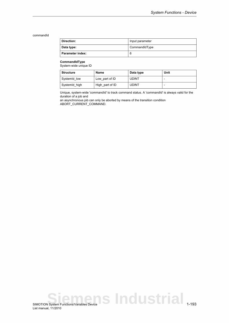
System Functions - Device
1-193SIMOTION System Functions/Variables DeviceList manual, 11/2010
commandId
CommandIdTypeSystem-wide unique ID
Unique, system-wide 'commandId' to track command status. A 'commandId' is always valid for the duration of a job andan asynchronous job can only be aborted by means of the transition condition ABORT_CURRENT_COMMAND.
Direction: Input parameter
Data type: CommandIdType
Parameter index: 6
Structure Name Data type Unit
SystemId_low Low_part of ID UDINT -
SystemId_high High_part of ID UDINT -
Siemens Industrial
System Functions - Device
1-194 SIMOTION System Functions/Variables DeviceList manual, 11/2010
1.3.1.11 _RWPAR_cyclic
The _RWPAR_cyclic function block can be used to read or write the individual parameters from a drive. For this purpose, the relevant drive must support data exchange via the PIV interface.
Detailed information
ST: Note:You can import the following program segments into the ST program using Drag & Drop. Additions must be made for executability (see manual, e.g. creating variables, etc.).An executable application example can be found on the "SIMOTION Utilities & Applications" CD-ROM.The "SIMOTION Utilities & Applications" CD-ROM is provided free of charge and is supplied with SIMOTION SCOUT.
// myRWPAR_cyclic : _RWPAR_cyclic; // instance of FB (_RWPAR_cyclic)myRWPAR_cyclic(periIn := myPeriIn, // [IN] byte array device (ARRAY[0..7] OF BYTE)slotNumber := mySlotNumber, // [IN] number of PKW-Slot (UINT)execute := myExecute, // [IN] starts order with rising edge (BOOL)paraNumber := myParaNumber, // [IN] Parameter number which is to be read or write into (UINT)index := myIndex, // [IN] Subindex = set to 0 for parameters without subindex (USINT)sendParaValue := mySendParaValue, // [IN] value of parameter to send (DWORD)jobIdentification := myJobIdentification // [IN] job identification (SINT));
System Functions - Device
1-195SIMOTION System Functions/Variables DeviceList manual, 11/2010
1.3.1.12 _writeDriveMultiParameter
NoteAdditional information is available at:SIMOTION Communication System Manual,Section PROFIdrive-specific data types, Section Rules for SIMOTION _writeDrive.../_readDrive... commandsor in the SIMOTION online help.
This function enables up to 23 parameters to be written.
Exactly 23 parameters can only be written once every parameter only has a format with the maximum data length = 2 (e.g. WORD).If other formats with data lengths in excess of 2 are written, the maximum number is reduced.The procedure is the same when reading parameters. A maximum of 39 parameters can be read if all parameters have the data length <= 2.
More information is provided in:Profile Drive Technology PROFIdrive, Technical Specification for PROFIBUS and PROFINET, Ver-sion 4.1, May 2006 - Section 7.6.2.4, see Formulas
Note• Up to 16 parameter jobs can be executed in parallel (the term parameter job also includes the
functions _writeDriveParameter, _readDrive(Multi)ParameterDescription, _readDrive(Multi)Para-meter, and _readDriveFaults).
• Only one parameter job is permitted per planned DP station. A new job to the same DP station is rejected with the error 16#FFFF81C7.
• If the system functions _readRecord and _writeRecord are used in addition to the parameter jobs, you must ensure that they are not to be executed simultaneously by a DP station. Reason: The same communication services are being used.
• If a parameter job (only asynchronous calls) is no longer to be processed, then it must be aborted with the ABORT_CURRENT_COMMAND transition condition. Otherwise no new job can be issued.
Parameters can be read out with the following data sets:• Data set 47 is always read out for PROFIBUS (external or integrated), regardless of whether the
function is called with a valid (0>=doId<=254) or invalid 'doId' (doId=255). If the passed 'doId' is invalid, it will be determined by the system itself. This requires the specification of the logical address of the axis.
• Two data sets are available for PROFINET:− Base Mode Parameter Access - local (data set 0xB02E)This data set (DS) is used for SIMOTION if either no 'dold' or an invalid 'dold' (dold=255) is spe-cified in the function. The Parameter Access Point (PAP) is then used to access the relevant DO. Either the PAP address can be specified directly or the log. address of the cyclical data (e.g. 256 for a DO axis) can be given. SIMOTION then determines the corresponding PAP from this address before accessing the correct address.
Note for PROFINETSIMOTION V4.1 SP2: PAP must always be at subslot 1 (HW Config configuration).
− Base Mode Parameter Access - global (data set 0xB02F)This data set is used if a valid 'dold' (0>=doId<=254) is entered. Any valid PAP or address can be specified, as assignment only takes place on the basis of the 'dold'.
Siemens Industrial
System Functions - Device
1-196 SIMOTION System Functions/Variables DeviceList manual, 11/2010
Return value: StructRetWriteDriveMultiParameter
StructRetWriteDriveMultiParameterReturn parameter for _writeDriveMultiParameter
Description of the return values:The return value consists of 'functionResult', 'parameterResultErrorExistent' and 'parameterRe-sult[23]'.
'functionResult'Reports the status of the total job plus errors during the transfer and internal errors.
16#00000000Writing of parameters okay, job completed with positive result. Job okay.
16#00007001Must be repeated in the next program cycle.Initial call, initiation of writing of parameters okay(only when command is issued asynchronously).
16#00007002Must be repeated in the next program cycle.Intermediate call, writing of parameters is still active(only when command is issued asynchronously).
16#00007003Writing of parameters aborted.
16#FFFF8110Internal error, job aborted.The sum of the lengths specified by the user exceeds the maximum transferable length.
16#FFFF8111Internal error, job aborted.The length specified by the user does not match the length calculated from the data type and number of elements in the case of at least one parameter.
16#FFFF8112Internal error, job aborted.A valid format could not be found for at least one parameter.
16#FFFF8190Internal error, job aborted.Specified logical base address invalid:No assignment is available in SDBs, or there is no base address.
16#FFFF8191Internal error, job aborted.The _writeDriveMultiParameter function cannot reach the specified logical base address.
16#FFFF8192Internal error, job aborted.Error in response identifier.
Structure Name Data type Unit
functionResult Total job return value DINT -
parameterResultErr-orExistent
A parameter-specific fault is present in the return value
BOOL -
parameterResult Parameter-specific return value
ARRAY [0..22] OF DINT
-
System Functions - Device
1-197SIMOTION System Functions/Variables DeviceList manual, 11/2010
16#FFFF8193Internal error, job aborted.The number of parameters to be read is not permissible.
16#FFFF819DInternal error, job aborted.An I slave/I device interface is unable to issue a parameter job to the higher-level master/controller.
16#FFFF819EInternal error, job aborted.Attempt to abort a non-active function.
16#FFFF819FInternal error, job aborted.Function not executable.
16#FFFF81C3Error, can be repeated in the next program cycle.Required resources are presently occupied:- In the _writeDriveMultiParameter function- In the module
16#FFFF81C5Error, can be repeated in the next program cycle.Distributed I/O not available.
16#FFFF81C7Error, can be repeated in the next program cycle.Another parameter job has already been issued to the DP station. - based on the user program - from a system-internal component (e.g. TO axis executes parameter comparison after station reco-very)
16#FFFF81CFError, can be repeated in the next program cycle.Another parameter job call is currently active under this 'commandId'.
16#FFFF8290Corresponds to the error message 16#FFFF8190.
16#FFFF8291Corresponds to the error message 16#FFFF8191.
16#FFFF82A2Error during data set transfer, job aborted.Error in Layer2:- Station failure- Timeout
16#FFFF82A3Error during data set transfer, job aborted.Error in user interface/user:- Protocol error- Station failure- Timeout
16#FFFF82A4-A7Error during data set transfer, job aborted.Error numbers according to IEC 61158 reserved- Query the cause at the module's manufacturer
16#FFFF82A8Error during data set transfer, job aborted.Error because of version conflict.
16#FFFF82A9Error during data set transfer, job aborted.Function not supported by the module.
Siemens Industrial
System Functions - Device
1-198 SIMOTION System Functions/Variables DeviceList manual, 11/2010
16#FFFF82AA-AFError during data set transfer, job aborted.Error numbers according to IEC 61158 manufacturer-specific- Query the cause at the module's manufacturer
16#FFFF82B0Error during data set transfer, job aborted.Parameter jobs are not supported by the addressed module.
16#FFFF82B2Error during data set transfer, job aborted.Module reports access to an invalid slot/subslot.
16#FFFF82B3Error during data set transfer, job aborted.Module reports type conflict.
16#FFFF82B4Error during data set transfer, job aborted.Module reports access to an invalid area.
16#FFFF82B5Error during data set transfer, can be repeated in the next program cycle.The system function cannot be executed due to an internal operating state of the module.
16#FFFF82B6Error during data set transfer, job aborted.Module rejects access.
16#FFFF82B7Error during data set transfer, job aborted.The job could not be dispatched due to a job error.
16#FFFF82B8Error during data set transfer, job aborted.Module reports an invalid parameter.
16#FFFF82B9Error during data set transfer, job aborted.Module reports an invalid type.
16#FFFF82BA-BFError during data set transfer, job aborted.Error numbers according to IEC 61158 manufacturer-specific- Query the cause at the module's manufacturer
16#FFFF82C1Error during data set transfer, command can be repeated immediately.Data of the preceding write job on the module for the same data set has not yet been processed by the module.
16#FFFF82C2Error during data set transfer, command can be repeated immediately.The module is currently executing the maximum possible jobs for one CPU.
16#FFFF82C3Error during data set transfer, command can be repeated immediately.Required resources are presently occupied:- In the _writeRecord function- In the module
16#FFFF82C4Error during data set transfer, command can be repeated immediately.Communication errors:- Parity error- SW Ready not set- Error in block length administration- Checksum error on CPU side- Checksum error on module side
System Functions - Device
1-199SIMOTION System Functions/Variables DeviceList manual, 11/2010
16#FFFF82C5Error during data set transfer, can be repeated in the next program cycle.Distributed I/O not available.
16#FFFF82C6Error during data set transfer, can be repeated in the next program cycle.Data record transfer has been aborted due to priority class abort (restart or background).
'parameterResultErrorExistent'Returns TRUE when an error is reported in at least one 'parameterResult'.
'parameterResult'Reports parameter-specific errors.
16#FFFF8000Parameter error, job aborted.Access to a non-existent parameter.
16#FFFF8001Parameter error, job aborted.Change access to a parameter that cannot be modified.
16#FFFF8002Parameter error, job aborted.Change access with value outside value limits.
16#FFFF8003Parameter error, job aborted.Access to a non-existent subindex.
16#FFFF8004Parameter error, job aborted.Access with subindex to non-indexed parameter(not an array parameter).
16#FFFF8005Parameter error, job aborted.Change access with value that does not match the parameter data type.
16#FFFF8006Parameter error, job aborted.Modification access with value other than 0 where this is not allowed.
16#FFFF800BParameter error, job aborted.Change access without parameter change rights.
16#FFFF8011Parameter error, job aborted.Job cannot be executed due to operating state.
16#FFFF8014Parameter error, job aborted.Modification access with value that is within value limits, but illegal for some other sustainable reason (parameter with defined individual values).
16#FFFF8016Parameter error, job aborted.Illegal or unsupported value for attribute, number of elements, parameter number, or subindex, or a combination of these.
16#FFFF8017Parameter error, job aborted.Illegal format.
Siemens Industrial
System Functions - Device
1-200 SIMOTION System Functions/Variables DeviceList manual, 11/2010
16#FFFF8018Parameter error, job aborted.Number of values of parameter data does not match the number of elements in the parameter address.
16#FFFF8019Parameter error, job aborted.Access to a non-existing axis or an invalid drive object.
16#FFFF8020-FFParameter error, job aborted.Manufacturer-specific error.
Parameter: ioId (optional)
EnumIoIdType
Input/output assignment of logical base address of the drive.With INPUT, the logical address of the drive is in the input range.With OUTPUT, the logical address of the drive is in the output range.Diagnostic addresses are always of type INPUT.
logAddress
Specifies the logical base address of the drive.
If the optional 'dold' parameter is also used, any station address (preferably the diagnostic address of the station) can be specified.
With PROFINET, parameter access occurs via the parameter access point (PAP) of a DO.As an alternative to the logical base address of the drive, specification of the diagnostic address of the associated PAP is recommended.
doId (optional)
Specifies the DO-ID to address a specific DO directly. 0 to 254 are permitted.
The DO-ID can be unspecified or specified as invalid (>254) under the following conditions:
• Access via the DO-ID is not supported by the DP slave/IO device (P978 is not implemented).• Data record 0xB02F is not supported (PROFINET only).• Access is to occur via the parameter access point of a DO (PROFINET only).
Direction: Input parameter
Data type: EnumIoIdType
Parameter index: 1
System default: INPUT
INPUT (198) Input address
OUTPUT (199) Output address
Direction: Input parameter
Data type: DINT
Parameter index: 2
Direction: Input parameter
Data type: UDINT
Parameter index: 3
System default: 255
System Functions - Device
1-201SIMOTION System Functions/Variables DeviceList manual, 11/2010
numberOfParameters
Number of parameters to be written.1 to 23 are permitted.
parameterNumber
Specifies the parameters from which the values are to be changed.1 to 65535 are permitted.
numberOfElements (optional)
Number of elements to be modified from a parameter.Single parameter -> No need to specify elements.Array parameter -> 1 element under subindex.Array parameter -> 2 to n elements starting from subindex.
subIndex (optional)
Specifies the subindex that addresses the first array element of an array parameter.0 to 65535 are permitted.Single parameter -> No need to specify elements.
dataType (optional)
Specifies the data type of the parameter to be written.
NoteFurther information on the structure of a data type can be found:- In the SIMOTION Communication System Manual or- At www.profibus.com, in the documentation "Profile Guidelines, Part 2: Data Types, Programming Languages and Platforms".
nextCommand
Direction: Input parameter
Data type: UDINT
Parameter index: 4
Direction: Input parameter
Data type: ARRAY [0..22] OF UDINT
Parameter index: 5
Direction: Input parameter
Data type: ARRAY [0..22] OF UDINT
Parameter index: 6
System default: [0..22] = 0
Direction: Input parameter
Data type: ARRAY [0..22] OF UDINT
Parameter index: 7
System default: [0..22] = 0
Direction: Input parameter
Data type: ARRAY [0..22] OF UDINT
Parameter index: 8
System default: [0..22] = 0
Direction: Input parameter
Data type: EnumNextCommandMode
Parameter index: 9
Siemens Industrial
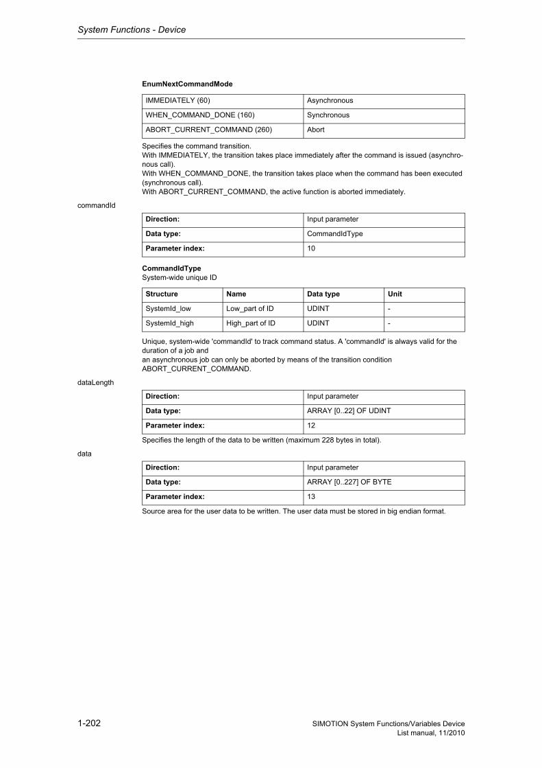
System Functions - Device
1-202 SIMOTION System Functions/Variables DeviceList manual, 11/2010
EnumNextCommandMode
Specifies the command transition.With IMMEDIATELY, the transition takes place immediately after the command is issued (asynchro-nous call).With WHEN_COMMAND_DONE, the transition takes place when the command has been executed (synchronous call).With ABORT_CURRENT_COMMAND, the active function is aborted immediately.
commandId
CommandIdTypeSystem-wide unique ID
Unique, system-wide 'commandId' to track command status. A 'commandId' is always valid for the duration of a job andan asynchronous job can only be aborted by means of the transition condition ABORT_CURRENT_COMMAND.
dataLength
Specifies the length of the data to be written (maximum 228 bytes in total).
data
Source area for the user data to be written. The user data must be stored in big endian format.
IMMEDIATELY (60) Asynchronous
WHEN_COMMAND_DONE (160) Synchronous
ABORT_CURRENT_COMMAND (260) Abort
Direction: Input parameter
Data type: CommandIdType
Parameter index: 10
Structure Name Data type Unit
SystemId_low Low_part of ID UDINT -
SystemId_high High_part of ID UDINT -
Direction: Input parameter
Data type: ARRAY [0..22] OF UDINT
Parameter index: 12
Direction: Input parameter
Data type: ARRAY [0..227] OF BYTE
Parameter index: 13
System Functions - Device
1-203SIMOTION System Functions/Variables DeviceList manual, 11/2010
1.3.1.13 _writeDriveParameter
NoteAdditional information is available at:SIMOTION Communication System Manual,Section PROFIdrive-specific data types, Section Rules for SIMOTION _writeDrive.../_readDrive... commandsor in the SIMOTION online help.
This function enables a drive parameter to be written.
Note• Up to 16 parameter jobs can be executed in parallel (the term parameter job also includes the
functions _writeDriveMultiParameter, _readDrive(Multi)ParameterDescription, _readDrive(Multi)Parameter and _readDriveFaults).
• Only one parameter job is permitted per planned DP station. A new job to the same DP station is rejected with the error 16#FFFF81C7.
• If the system functions _readRecord and _writeRecord are used in addition to the parameter jobs, you must ensure that they are not to be executed simultaneously by a DP station. Reason: The same communication services are used.
• If a parameter job (only asynchronous calls) is no longer to be processed, then it must be aborted with the ABORT_CURRENT_COMMAND transition condition. Otherwise no new job can be issued.
Parameters can be read out with the following data sets:• Data set 47 is always read out for PROFIBUS (external or integrated), regardless of whether the
function is called with a valid (0>=doId<=254) or invalid 'doId' (doId=255). If the passed 'doId' is invalid, it will be determined by the system itself. This requires the specification of the logical address of the axis.
• Two data sets are available for PROFINET:− Base Mode Parameter Access - local (data set 0xB02E)This data set (DS) is used for SIMOTION if either no 'dold' or an invalid 'dold' (dold=255) is spe-cified in the function. The Parameter Access Point (PAP) is then used to access the relevant DO. Either the PAP address can be specified directly or the log. address of the cyclical data (e.g. 256 for a DO axis) can be given. SIMOTION then determines the corresponding PAP from this address before accessing the correct address.
Note for PROFINETSIMOTION V4.1 SP2: PAP must always be at subslot 1 (HW Config configuration).
− Base Mode Parameter Access - global (data set 0xB02F)This data set is used if a valid 'dold' (0>=doId<=254) is entered. Any valid PAP or address can be specified, as assignment only takes place on the basis of the 'dold'.
Return value: StructRetWriteDriveParameter
StructRetWriteDriveParameterReturn parameter for _writeDriveParameter
Description of the return values:The return value consists of 'functionResult' and 'parameterResult'.
Structure Name Data type Unit
functionResult Total job return value DINT -
parameterResult Parameter-specific return value
DINT -
Siemens Industrial
System Functions - Device
1-204 SIMOTION System Functions/Variables DeviceList manual, 11/2010
'functionResult'Reports the status of the total job plus errors during the transfer and internal errors.
16#00000000Writing of parameters okay, job completed with positive result. Job okay.
16#00007001Must be repeated in the next program cycle.Initial call, initiation of reading of parameter description okay(only when command is issued asynchronously).
16#00007002Must be repeated in the next program cycle.Intermediate call, reading of parameter description is still active(only when command is issued asynchronously).
16#00007003Writing of parameters aborted.
16#FFFF8110Internal error, job aborted.The length specified by the user exceeds the maximum transferable length.
16#FFFF8111Internal error, job abortedThe length specified by the user does not match the length calculated from the data type and number of elements.
16#FFFF8112Internal error, job aborted.No valid format could be found.
16#FFFF8190Internal error, job aborted.Specified logical base address invalid:No assignment is available in SDBs, or there is no base address.
16#FFFF8191Internal error, job aborted.The _writeDriveParameter function cannot reach the specified logical base address.
16#FFFF8192Internal error, job aborted.Error in response identifier.
16#FFFF819DInternal error, job aborted.An I slave/I device interface is unable to issue a parameter job to the higher-level master/controller.
16#FFFF819EInternal error, job aborted.Attempt to abort a non-active function.
16#FFFF819FInternal error, job aborted.Function not executable.
16#FFFF81C3Error, can be repeated in the next program cycle.Required resources are presently occupied:- In the _writeDriveParameter function- In the module
16#FFFF81C5Error, can be repeated in the next program cycle.Distributed I/O not available.

System Functions - Device
1-205SIMOTION System Functions/Variables DeviceList manual, 11/2010
16#FFFF81C7Error, can be repeated in the next program cycle.Another parameter job has already been issued to the DP station. - based on the user program - from a system-internal component (e.g. TO axis executes parameter comparison after station reco-very)
16#FFFF81CFError, can be repeated in the next program cycle.Another parameter job call is currently active under this 'commandId'.
16#FFFF8290Corresponds to the error message 16#FFFF8190.
16#FFFF8291Corresponds to the error message 16#FFFF8191.
16#FFFF82A2Error during data set transfer, job aborted.Error in Layer2:- Station failure- Timeout
16#FFFF82A3Error during data set transfer, job aborted.Error in user interface/user:- Protocol error- Station failure- Timeout
16#FFFF82A4-A7Error during data set transfer, job aborted.Error numbers according to IEC 61158 reserved- Query the cause at the module's manufacturer
16#FFFF82A8Error during data set transfer, job aborted.Error because of version conflict.
16#FFFF82A9Error during data set transfer, job aborted.Function not supported by the module.
16#FFFF82AA-AFError during data set transfer, job aborted.Error numbers according to IEC 61158 manufacturer-specific- Query the cause at the module's manufacturer
16#FFFF82B0Error during data set transfer, job aborted.Parameter jobs are not supported by the addressed module.
16#FFFF82B2Error during data set transfer, job aborted.Module reports access to an invalid slot/subslot.
16#FFFF82B3Error during data set transfer, job aborted.Module reports type conflict.
16#FFFF82B4Error during data set transfer, job aborted.Module reports access to an invalid area.
16#FFFF82B5Error during data set transfer, can be repeated in the next program cycle.The system function cannot be executed due to an internal operating state of the module.
16#FFFF82B6Error during data set transfer, job aborted.Module rejects access.
Siemens Industrial

System Functions - Device
1-206 SIMOTION System Functions/Variables DeviceList manual, 11/2010
16#FFFF82B7Error during data set transfer, job aborted.The job could not be dispatched due to a job error.
16#FFFF82B8Error during data set transfer, job aborted.Module reports an invalid parameter.
16#FFFF82B9Error during data set transfer, job aborted.Module reports an invalid type.
16#FFFF82BA-BFError during data set transfer, job aborted.Error numbers according to IEC 61158 manufacturer-specific- Query the cause at the module's manufacturer
16#FFFF82C1Error during data set transfer, command can be repeated immediately.Data of the preceding write job on the module for the same data set has not yet been processed by the module.
16#FFFF82C2Error during data set transfer, command can be repeated immediately.The module is currently executing the maximum possible jobs for one CPU.
16#FFFF82C3Error during data set transfer, command can be repeated immediately.Required resources are presently occupied:- In the _writeRecord function- In the module
16#FFFF82C4Error during data set transfer, command can be repeated immediately.Communication errors:- Parity error- SW Ready not set- Error in block length administration- Checksum error on CPU side- Checksum error on module side
16#FFFF82C5Error during data set transfer, can be repeated in the next program cycle.Distributed I/O not available.
16#FFFF82C6Error during data set transfer, can be repeated in the next program cycle.Data record transfer has been aborted due to priority class abort (restart or background).

System Functions - Device
1-207SIMOTION System Functions/Variables DeviceList manual, 11/2010
'parameterResult'Reports parameter-specific errors.
16#FFFF8000Parameter error, job aborted.Access to a non-existent parameter.
16#FFFF8001Parameter error, job aborted.Change access to a parameter that cannot be modified.
16#FFFF8002Parameter error, job aborted.Change access with value outside value limits.
16#FFFF8003Parameter error, job aborted.Access to a non-existent subindex.
16#FFFF8004Parameter error, job aborted.Access with subindex to non-indexed parameter (not an array parameter).
16#FFFF8005Parameter error, job aborted.Change access with value that does not match the parameter data type.
16#FFFF8006Parameter error, job aborted.Modification access with value other than 0 where this is not allowed.
16#FFFF800BParameter error, job aborted.Change access without parameter change rights.
16#FFFF8011Parameter error, job aborted.Job cannot be executed due to operating state.
16#FFFF8014Parameter error, job aborted.Modification access with value that is within value limits, but illegal for some other sustainable reason(parameter with defined individual values).
16#FFFF8016Parameter error, job aborted.Illegal or unsupported value for attribute, number of elements, parameter number, or subindex, or a combination of these.
16#FFFF8017Parameter error, job aborted.Illegal format.
16#FFFF8018Parameter error, job aborted.Number of values of parameter data does not match the number of elements in the parameter address.
16#FFFF8019Parameter error, job aborted.Access to a non-existing axis or an invalid drive object.
16#FFFF8020-FF Parameter error, job aborted.Manufacturer-specific error.
Siemens Industrial

System Functions - Device
1-208 SIMOTION System Functions/Variables DeviceList manual, 11/2010
Parameter: ioId (optional)
EnumIoIdType
Input/output assignment of logical base address of the drive.With INPUT, the logical address of the drive is in the input range.With OUTPUT, the logical address of the drive is in the output range.Diagnostic addresses are always of type INPUT.
logAddress
Specifies the logical base address of the drive.
If the optional 'dold' parameter is also used, any station address (preferably the diagnostic address of the station) can be specified.
With PROFINET, parameter access occurs via the parameter access point (PAP) of a DO.As an alternative to the logical base address of the drive, specification of the diagnostic address of the associated PAP is recommended.
doId (optional)
Specifies the DO-ID to address a specific DO directly. 0 to 254 are permitted.The DO-ID can be unspecified or specified as invalid (>254) under the following conditions:- Access via the DO-ID is not supported by the DP slave/IO device (P978 is not implemented).- Data record 0xB02F is not supported (PROFINET only).- Access is to occur via the parameter access point of a DO (PROFINET only).
parameterNumber
Specifies the parameter numbers from which the values are to be written.1 to 65535 are permitted.
Direction: Input parameter
Data type: EnumIoIdType
Parameter index: 1
System default: INPUT
INPUT (198) Input address
OUTPUT (199) Output address
Direction: Input parameter
Data type: DINT
Parameter index: 2
Direction: Input parameter
Data type: UDINT
Parameter index: 3
System default: 255
Direction: Input parameter
Data type: UDINT
Parameter index: 4
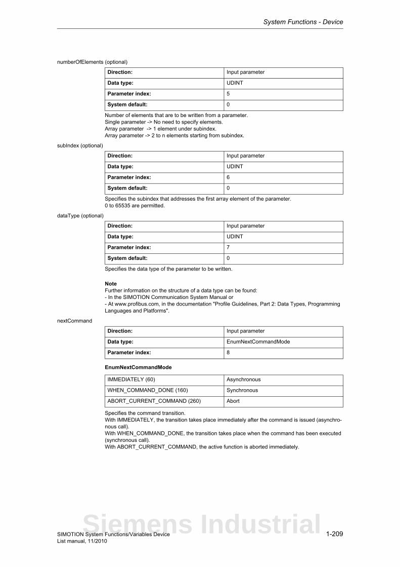
System Functions - Device
1-209SIMOTION System Functions/Variables DeviceList manual, 11/2010
numberOfElements (optional)
Number of elements that are to be written from a parameter.Single parameter -> No need to specify elements.Array parameter -> 1 element under subindex.Array parameter -> 2 to n elements starting from subindex.
subIndex (optional)
Specifies the subindex that addresses the first array element of the parameter.0 to 65535 are permitted.
dataType (optional)
Specifies the data type of the parameter to be written.
NoteFurther information on the structure of a data type can be found:- In the SIMOTION Communication System Manual or- At www.profibus.com, in the documentation "Profile Guidelines, Part 2: Data Types, Programming Languages and Platforms".
nextCommand
EnumNextCommandMode
Specifies the command transition.With IMMEDIATELY, the transition takes place immediately after the command is issued (asynchro-nous call).With WHEN_COMMAND_DONE, the transition takes place when the command has been executed (synchronous call).With ABORT_CURRENT_COMMAND, the active function is aborted immediately.
Direction: Input parameter
Data type: UDINT
Parameter index: 5
System default: 0
Direction: Input parameter
Data type: UDINT
Parameter index: 6
System default: 0
Direction: Input parameter
Data type: UDINT
Parameter index: 7
System default: 0
Direction: Input parameter
Data type: EnumNextCommandMode
Parameter index: 8
IMMEDIATELY (60) Asynchronous
WHEN_COMMAND_DONE (160) Synchronous
ABORT_CURRENT_COMMAND (260) Abort
Siemens Industrial

System Functions - Device
1-210 SIMOTION System Functions/Variables DeviceList manual, 11/2010
commandId
CommandIdTypeSystem-wide unique ID
Unique, system-wide 'commandId' to track command status. A 'commandId' is always valid for the duration of a job andan asynchronous job can only be aborted by means of the transition condition ABORT_CURRENT_COMMAND.
dataLength
Specifies the length of the data to be written (maximum 228 bytes).
data
Source area for the user data to be written. The user data must be stored in big endian format.
Direction: Input parameter
Data type: CommandIdType
Parameter index: 9
Structure Name Data type Unit
SystemId_low Low_part of ID UDINT -
SystemId_high High_part of ID UDINT -
Direction: Input parameter
Data type: UDINT
Parameter index: 11
Direction: Input parameter
Data type: ARRAY [0..227] OF BYTE
Parameter index: 12
System Functions - Device
1-211SIMOTION System Functions/Variables DeviceList manual, 11/2010
1.3.2 SIMOVERT
1.3.2.1 _abortAllReadWriteDriveParameterJobs
Note"Further information can be found in the SIMOTION Communication System Manual (_readDrive and _writeDrive section) and in SIMOTION online help."
This function aborts all parameter jobs currently being processed.The term "parameter job" refers to the functions _readDrive(Multi)ParameterDescription, _readDrive(Multi)Parameter, _writeDrive(Multi)Parameter and _readDriveFaults.
Return value: DINT
Description of the return values:16#00000000Job completed without errors.
16#FFFF819FError, job aborted. Function not executable.
16#FFFF81C5Error, can be repeated in the next program cycle. Function could not be executed.This may have the following reasons:- The function _abortAllReadWriteDriveParameterJobs is already being executed.- A parameter job is currently being called from another task.
Siemens Industrial
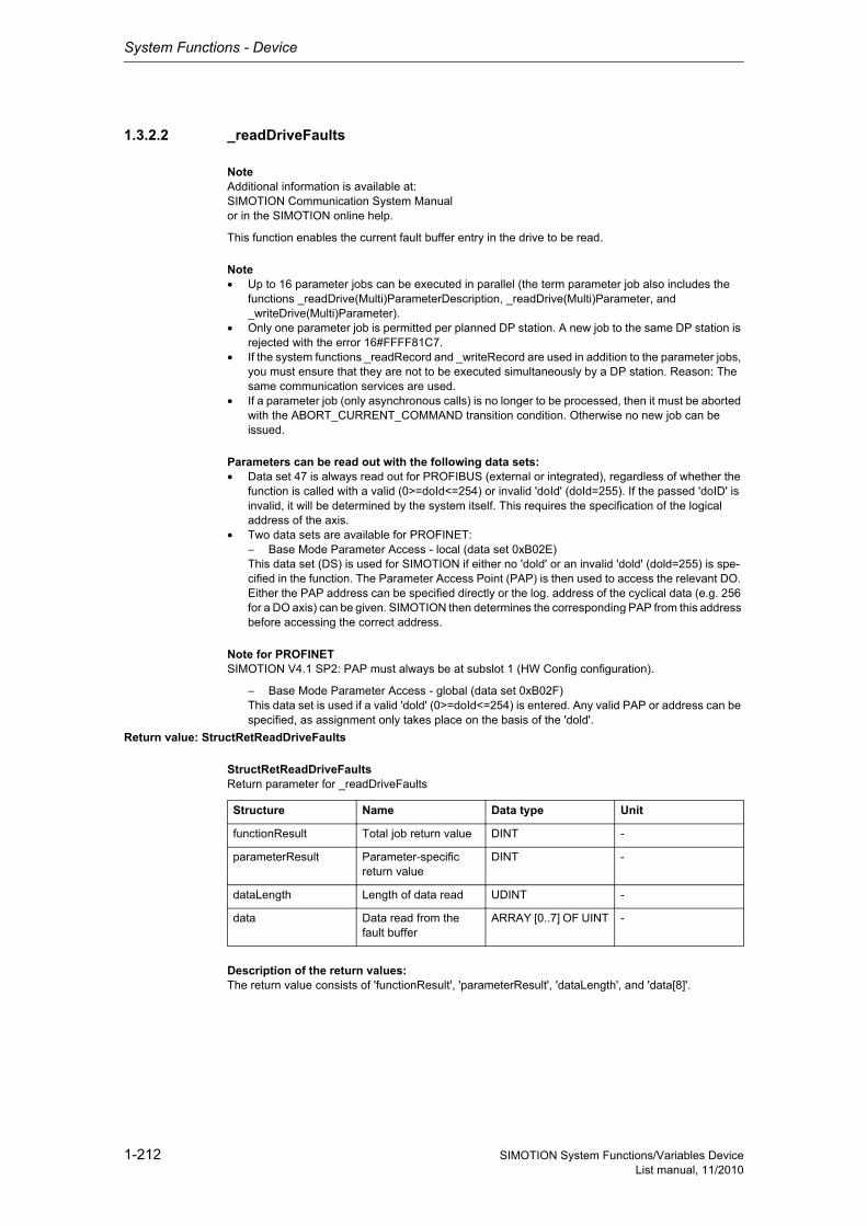
System Functions - Device
1-212 SIMOTION System Functions/Variables DeviceList manual, 11/2010
1.3.2.2 _readDriveFaults
NoteAdditional information is available at:SIMOTION Communication System Manualor in the SIMOTION online help.
This function enables the current fault buffer entry in the drive to be read.
Note• Up to 16 parameter jobs can be executed in parallel (the term parameter job also includes the
functions _readDrive(Multi)ParameterDescription, _readDrive(Multi)Parameter, and _writeDrive(Multi)Parameter).
• Only one parameter job is permitted per planned DP station. A new job to the same DP station is rejected with the error 16#FFFF81C7.
• If the system functions _readRecord and _writeRecord are used in addition to the parameter jobs, you must ensure that they are not to be executed simultaneously by a DP station. Reason: The same communication services are used.
• If a parameter job (only asynchronous calls) is no longer to be processed, then it must be aborted with the ABORT_CURRENT_COMMAND transition condition. Otherwise no new job can be issued.
Parameters can be read out with the following data sets:• Data set 47 is always read out for PROFIBUS (external or integrated), regardless of whether the
function is called with a valid (0>=doId<=254) or invalid 'doId' (doId=255). If the passed 'doID' is invalid, it will be determined by the system itself. This requires the specification of the logical address of the axis.
• Two data sets are available for PROFINET:− Base Mode Parameter Access - local (data set 0xB02E)This data set (DS) is used for SIMOTION if either no 'dold' or an invalid 'dold' (dold=255) is spe-cified in the function. The Parameter Access Point (PAP) is then used to access the relevant DO. Either the PAP address can be specified directly or the log. address of the cyclical data (e.g. 256 for a DO axis) can be given. SIMOTION then determines the corresponding PAP from this address before accessing the correct address.
Note for PROFINETSIMOTION V4.1 SP2: PAP must always be at subslot 1 (HW Config configuration).
− Base Mode Parameter Access - global (data set 0xB02F)This data set is used if a valid 'dold' (0>=doId<=254) is entered. Any valid PAP or address can be specified, as assignment only takes place on the basis of the 'dold'.
Return value: StructRetReadDriveFaults
StructRetReadDriveFaultsReturn parameter for _readDriveFaults
Description of the return values:The return value consists of 'functionResult', 'parameterResult', 'dataLength', and 'data[8]'.
Structure Name Data type Unit
functionResult Total job return value DINT -
parameterResult Parameter-specific return value
DINT -
dataLength Length of data read UDINT -
data Data read from the fault buffer
ARRAY [0..7] OF UINT -
System Functions - Device
1-213SIMOTION System Functions/Variables DeviceList manual, 11/2010
'functionResult'Reports the status of the total job plus errors during the transfer and internal errors.
16#00000000Reading of current fault buffer entry okay,Job completed with positive result. Job okay.
16#00007001Must be repeated in the next program cycle.Initial call, initiation of reading of current fault buffer entry okay (only when command is issued asyn-chronously).
16#00007002Must be repeated in the next program cycle.Intermediate call, reading of current fault buffer entry is still active (only when command is issued asynchronously).
16#00007003Reading the current fault buffer entry aborted.
16#FFFF8190Internal error, job aborted.Specified logical base address invalid:No assignment is available in SDBs, or there is no base address.
16#FFFF8191Internal error, job aborted.The _readDriveFaults function cannot reach the specified logical base address.
16#FFFF8192Internal error, job aborted.Error in response identifier.
16#FFFF819DInternal error, job aborted.An I slave/I device interface is unable to issue a parameter job to the higher-level master/controller.
16#FFFF819EInternal error, job aborted.Attempt to abort a non-active function.
16#FFFF819FInternal error, job aborted.Function not executable.
16#FFFF81C3Error, can be repeated in the next program cycle.Required resources are presently occupied:- in the _readDriveFaults function- In the module
16#FFFF81C5Error, can be repeated in the next program cycle.Distributed I/O not available.
16#FFFF81C7Error, can be repeated in the next program cycle.Another parameter job has already been issued to the DP station. - based on the user program - from a system-internal component (e.g. TO axis executes parameter comparison after station reco-very)
16#FFFF81CFError, can be repeated in the next program cycle.Another parameter job call is currently active under this 'commandId'.
16#FFFF8290Corresponds to the error message 16#FFFF8190.
16#FFFF8291Corresponds to the error message 16#FFFF8191.
Siemens Industrial

System Functions - Device
1-214 SIMOTION System Functions/Variables DeviceList manual, 11/2010
16#FFFF82A2Error during data set transfer, job aborted.Error in Layer2:- Station failure- Timeout
16#FFFF82A3Error during data set transfer, job aborted.Error in user interface/user:- Protocol error- Station failure- Timeout
16#FFFF82A4-A7Error during data set transfer, job aborted.Error numbers according to IEC 61158 reserved- Query the cause at the module's manufacturer
16#FFFF82A8Error during data set transfer, job aborted.Error because of version conflict.
16#FFFF82A9Error during data set transfer, job aborted.Function not supported by the module.
16#FFFF82AA-AFError during data set transfer, job aborted.Error numbers according to IEC 61158 manufacturer-specific- Query the cause at the module's manufacturer
16#FFFF82B0Error during data set transfer, job aborted.Parameter jobs are not supported by the addressed module.
16#FFFF82B2Error during data set transfer, job aborted.Module reports access to an invalid slot/subslot.
16#FFFF82B3Error during data set transfer, job aborted.Module reports type conflict.
16#FFFF82B4Error during data set transfer, job aborted.Module reports access to an invalid area.
16#FFFF82B5Error during data set transfer, can be repeated in the next program cycle.The system function cannot be executed due to an internal operating state of the module.
16#FFFF82B6Error during data set transfer, job aborted.Module rejects access.
16#FFFF82B7Error during data set transfer, job aborted.The job could not be dispatched due to a job message frame error.
16#FFFF82B8Error during data set transfer, job aborted.Module reports an invalid parameter.
16#FFFF82B9Error during data set transfer, job aborted.Module reports an invalid type.
16#FFFF82BA-BFError during data set transfer, job aborted.Error numbers according to IEC 61158 manufacturer-specific- Query the cause at the module's manufacturer
System Functions - Device
1-215SIMOTION System Functions/Variables DeviceList manual, 11/2010
16#FFFF82C0Error during data set transfer, can be repeated in the next program cycle.The module is feeding the data record, but the module does not yet have any read data.
16#FFFF82C2Error during data set transfer, command can be repeated immediately.The module is currently executing the maximum possible jobs for one CPU.
16#FFFF82C3Error during data set transfer, command can be repeated immediately.Required resources are presently occupied:- In the _readRecord function- In the module
16#FFFF82C4Error during data set transfer, command can be repeated immediately.Communication errors:- Parity error- SW Ready not set- Error in block length administration- Checksum error on CPU side- Checksum error on module side
16#FFFF82C5Error during data set transfer,Can be repeated in the next program cycle.Distributed I/O not available.
16#FFFF82C6Error during data set transfer, can be repeated in the next program cycle.Data record transfer has been aborted due to priority class abort (restart or background).
'parameterResult'
Reports parameter-specific errors.
16#FFFF8000Parameter error, job aborted.The selected fault buffer does not exist.
16#FFFF8011Parameter error, job aborted.Job cannot be executed due to operating state.
16#FFFF8019Parameter error, job aborted.Access to a non-existing axis or an invalid drive object.
16#FFFF8020-FFParameter error, job aborted.Manufacturer-specific error.
'dataLength' reports the length of data read.
'data[8]' contains the read data (word array, maximum of 8 words).
Siemens Industrial
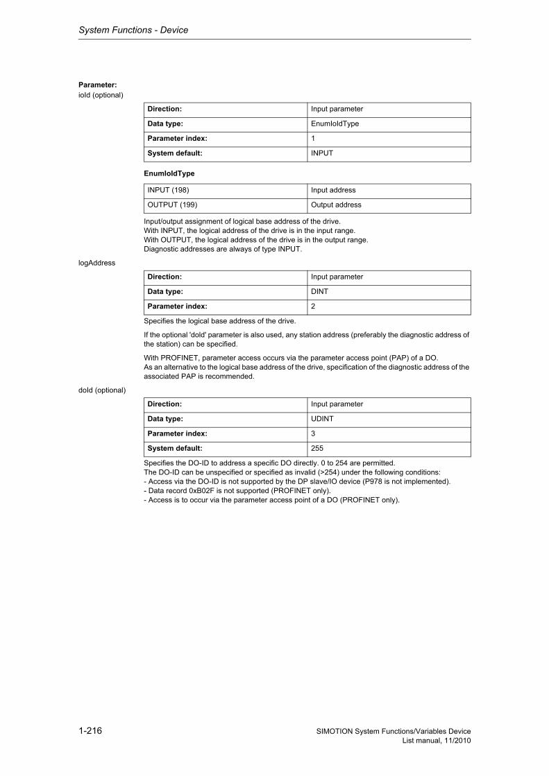
System Functions - Device
1-216 SIMOTION System Functions/Variables DeviceList manual, 11/2010
Parameter: ioId (optional)
EnumIoIdType
Input/output assignment of logical base address of the drive.With INPUT, the logical address of the drive is in the input range.With OUTPUT, the logical address of the drive is in the output range.Diagnostic addresses are always of type INPUT.
logAddress
Specifies the logical base address of the drive.
If the optional 'dold' parameter is also used, any station address (preferably the diagnostic address of the station) can be specified.
With PROFINET, parameter access occurs via the parameter access point (PAP) of a DO.As an alternative to the logical base address of the drive, specification of the diagnostic address of the associated PAP is recommended.
doId (optional)
Specifies the DO-ID to address a specific DO directly. 0 to 254 are permitted.The DO-ID can be unspecified or specified as invalid (>254) under the following conditions:- Access via the DO-ID is not supported by the DP slave/IO device (P978 is not implemented).- Data record 0xB02F is not supported (PROFINET only).- Access is to occur via the parameter access point of a DO (PROFINET only).
Direction: Input parameter
Data type: EnumIoIdType
Parameter index: 1
System default: INPUT
INPUT (198) Input address
OUTPUT (199) Output address
Direction: Input parameter
Data type: DINT
Parameter index: 2
Direction: Input parameter
Data type: UDINT
Parameter index: 3
System default: 255
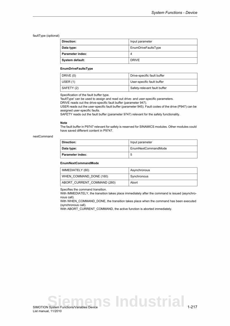
System Functions - Device
1-217SIMOTION System Functions/Variables DeviceList manual, 11/2010
faultType (optional)
EnumDriveFaultsType
Specification of the fault buffer type.'faultType' can be used to assign and read out drive- and user-specific parameters.DRIVE reads out the drive-specific fault buffer (parameter 947).USER reads out the user-specific fault buffer (parameter 945). Fault codes of the drive (P947) can be assigned user-specific faults.SAFETY reads out the fault buffer (parameter 9747) relevant for the safety functionality.
NoteThe fault buffer in P9747 relevant for safety is reserved for SINAMICS modules. Other modules could have saved different content in P9747.
nextCommand
EnumNextCommandMode
Specifies the command transition.With IMMEDIATELY, the transition takes place immediately after the command is issued (asynchro-nous call).With WHEN_COMMAND_DONE, the transition takes place when the command has been executed (synchronous call).With ABORT_CURRENT_COMMAND, the active function is aborted immediately.
Direction: Input parameter
Data type: EnumDriveFaultsType
Parameter index: 4
System default: DRIVE
DRIVE (0) Drive-specific fault buffer
USER (1) User-specific fault buffer
SAFETY (2) Safety-relevant fault buffer
Direction: Input parameter
Data type: EnumNextCommandMode
Parameter index: 5
IMMEDIATELY (60) Asynchronous
WHEN_COMMAND_DONE (160) Synchronous
ABORT_CURRENT_COMMAND (260) Abort
Siemens Industrial
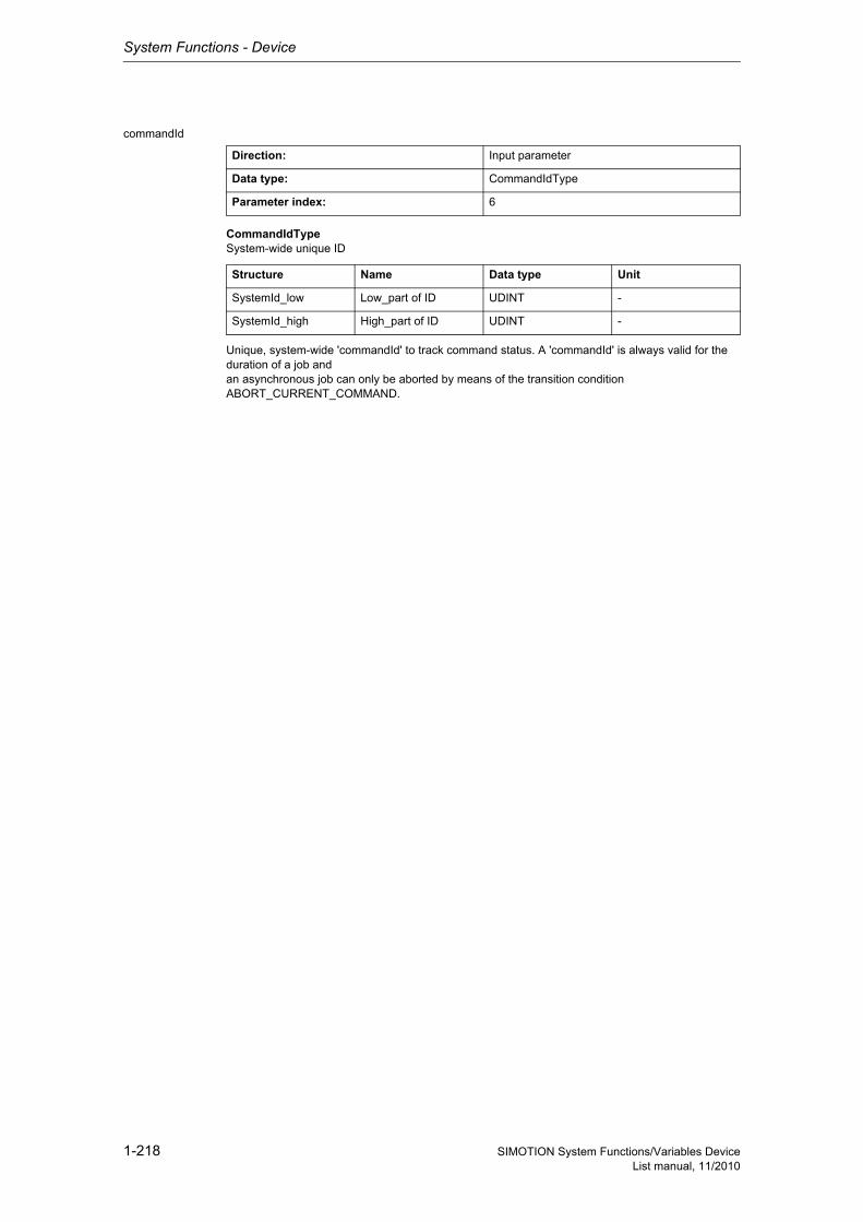
System Functions - Device
1-218 SIMOTION System Functions/Variables DeviceList manual, 11/2010
commandId
CommandIdTypeSystem-wide unique ID
Unique, system-wide 'commandId' to track command status. A 'commandId' is always valid for the duration of a job andan asynchronous job can only be aborted by means of the transition condition ABORT_CURRENT_COMMAND.
Direction: Input parameter
Data type: CommandIdType
Parameter index: 6
Structure Name Data type Unit
SystemId_low Low_part of ID UDINT -
SystemId_high High_part of ID UDINT -
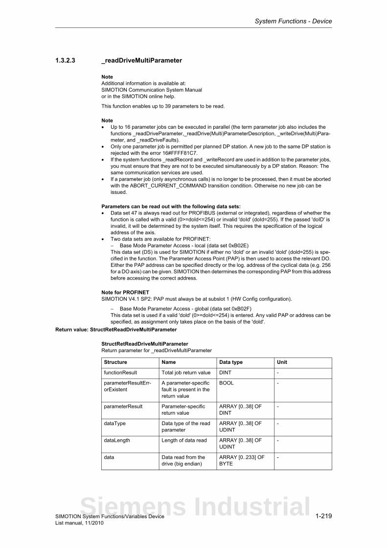
System Functions - Device
1-219SIMOTION System Functions/Variables DeviceList manual, 11/2010
1.3.2.3 _readDriveMultiParameter
NoteAdditional information is available at:SIMOTION Communication System Manualor in the SIMOTION online help.
This function enables up to 39 parameters to be read.
Note• Up to 16 parameter jobs can be executed in parallel (the term parameter job also includes the
functions _readDriveParameter,_readDrive(Multi)ParameterDescription, _writeDrive(Multi)Para-meter, and _readDriveFaults).
• Only one parameter job is permitted per planned DP station. A new job to the same DP station is rejected with the error 16#FFFF81C7.
• If the system functions _readRecord and _writeRecord are used in addition to the parameter jobs, you must ensure that they are not to be executed simultaneously by a DP station. Reason: The same communication services are used.
• If a parameter job (only asynchronous calls) is no longer to be processed, then it must be aborted with the ABORT_CURRENT_COMMAND transition condition. Otherwise no new job can be issued.
Parameters can be read out with the following data sets:• Data set 47 is always read out for PROFIBUS (external or integrated), regardless of whether the
function is called with a valid (0>=doId<=254) or invalid 'doId' (doId=255). If the passed 'doID' is invalid, it will be determined by the system itself. This requires the specification of the logical address of the axis.
• Two data sets are available for PROFINET:− Base Mode Parameter Access - local (data set 0xB02E)This data set (DS) is used for SIMOTION if either no 'dold' or an invalid 'dold' (dold=255) is spe-cified in the function. The Parameter Access Point (PAP) is then used to access the relevant DO. Either the PAP address can be specified directly or the log. address of the cyclical data (e.g. 256 for a DO axis) can be given. SIMOTION then determines the corresponding PAP from this address before accessing the correct address.
Note for PROFINETSIMOTION V4.1 SP2: PAP must always be at subslot 1 (HW Config configuration).
− Base Mode Parameter Access - global (data set 0xB02F)This data set is used if a valid 'dold' (0>=doId<=254) is entered. Any valid PAP or address can be specified, as assignment only takes place on the basis of the 'dold'.
Return value: StructRetReadDriveMultiParameter
StructRetReadDriveMultiParameterReturn parameter for _readDriveMultiParameter
Structure Name Data type Unit
functionResult Total job return value DINT -
parameterResultErr-orExistent
A parameter-specific fault is present in the return value
BOOL -
parameterResult Parameter-specific return value
ARRAY [0..38] OF DINT
-
dataType Data type of the read parameter
ARRAY [0..38] OF UDINT
-
dataLength Length of data read ARRAY [0..38] OF UDINT
-
data Data read from the drive (big endian)
ARRAY [0..233] OF BYTE
-
Siemens Industrial
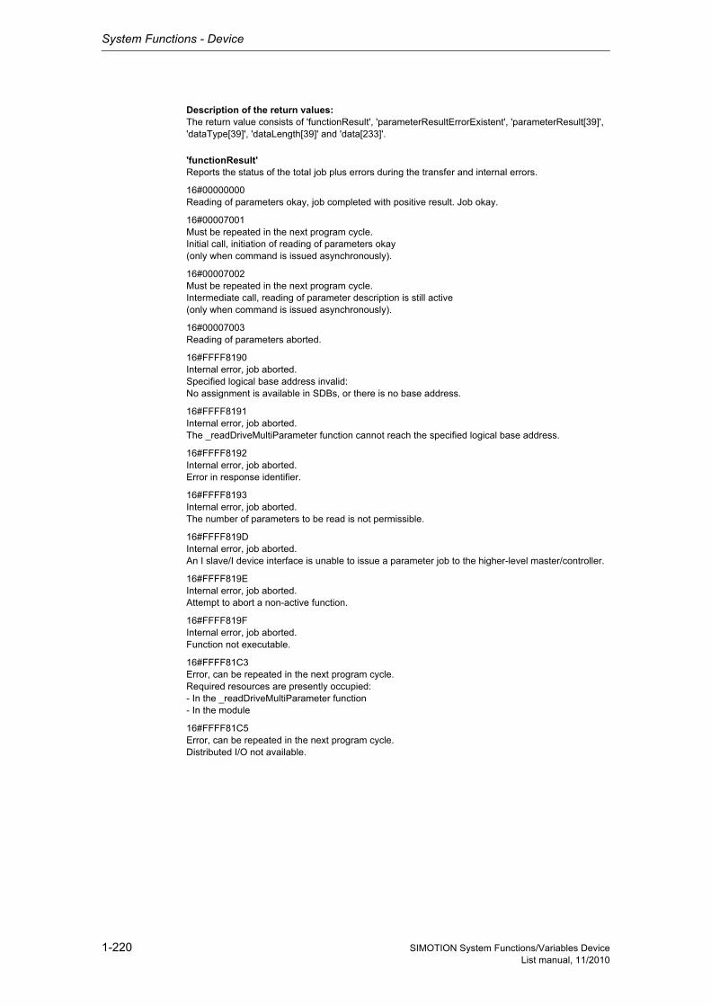
System Functions - Device
1-220 SIMOTION System Functions/Variables DeviceList manual, 11/2010
Description of the return values:The return value consists of 'functionResult', 'parameterResultErrorExistent', 'parameterResult[39]', 'dataType[39]', 'dataLength[39]' and 'data[233]'.
'functionResult'Reports the status of the total job plus errors during the transfer and internal errors.
16#00000000Reading of parameters okay, job completed with positive result. Job okay.
16#00007001Must be repeated in the next program cycle.Initial call, initiation of reading of parameters okay(only when command is issued asynchronously).
16#00007002Must be repeated in the next program cycle.Intermediate call, reading of parameter description is still active(only when command is issued asynchronously).
16#00007003Reading of parameters aborted.
16#FFFF8190Internal error, job aborted.Specified logical base address invalid:No assignment is available in SDBs, or there is no base address.
16#FFFF8191Internal error, job aborted.The _readDriveMultiParameter function cannot reach the specified logical base address.
16#FFFF8192Internal error, job aborted.Error in response identifier.
16#FFFF8193Internal error, job aborted.The number of parameters to be read is not permissible.
16#FFFF819DInternal error, job aborted.An I slave/I device interface is unable to issue a parameter job to the higher-level master/controller.
16#FFFF819EInternal error, job aborted.Attempt to abort a non-active function.
16#FFFF819FInternal error, job aborted.Function not executable.
16#FFFF81C3Error, can be repeated in the next program cycle.Required resources are presently occupied:- In the _readDriveMultiParameter function- In the module
16#FFFF81C5Error, can be repeated in the next program cycle.Distributed I/O not available.

System Functions - Device
1-221SIMOTION System Functions/Variables DeviceList manual, 11/2010
16#FFFF81C7Error, can be repeated in the next program cycle.Another parameter job has already been issued to the DP station. - based on the user program - from a system-internal component (e.g. TO axis executes parameter comparison after station reco-very)
16#FFFF81CFError, can be repeated in the next program cycle.Another parameter job call is currently active under this 'commandId'.
16#FFFF8290Corresponds to the error message 16#FFFF8190.
16#FFFF8291Corresponds to the error message 16#FFFF8191.
16#FFFF82A2Error during data set transfer, job aborted.Error in Layer2:- Station failure- Timeout
16#FFFF82A3Error during data set transfer, job aborted.Error in user interface/user:- Protocol error- Station failure- Timeout
16#FFFF82A4-A7Error during data set transfer, job aborted.Error numbers according to IEC 61158 reserved- Query the cause at the module's manufacturer
16#FFFF82A8Error during data set transfer, job aborted.Error because of version conflict.
16#FFFF82A9Error during data set transfer, job aborted.Function not supported by the module.
16#FFFF82AA-AFError during data set transfer, job aborted.Error numbers according to IEC 61158 manufacturer-specific- Query the cause at the module's manufacturer
16#FFFF82B0Error during data set transfer, job aborted.Parameter jobs are not supported by the addressed module.
16#FFFF82B2Error during data set transfer, job aborted.Module reports access to an invalid slot/subslot.
16#FFFF82B3Error during data set transfer, job aborted.Module reports type conflict.
16#FFFF82B4Error during data set transfer, job aborted.Module reports access to an invalid area.
16#FFFF82B5Error during data set transfer, can be repeated in the next program cycle.The system function cannot be executed due to an internal operating state of the module.
16#FFFF82B6Error during data set transfer, job aborted.Module rejects access.
Siemens Industrial
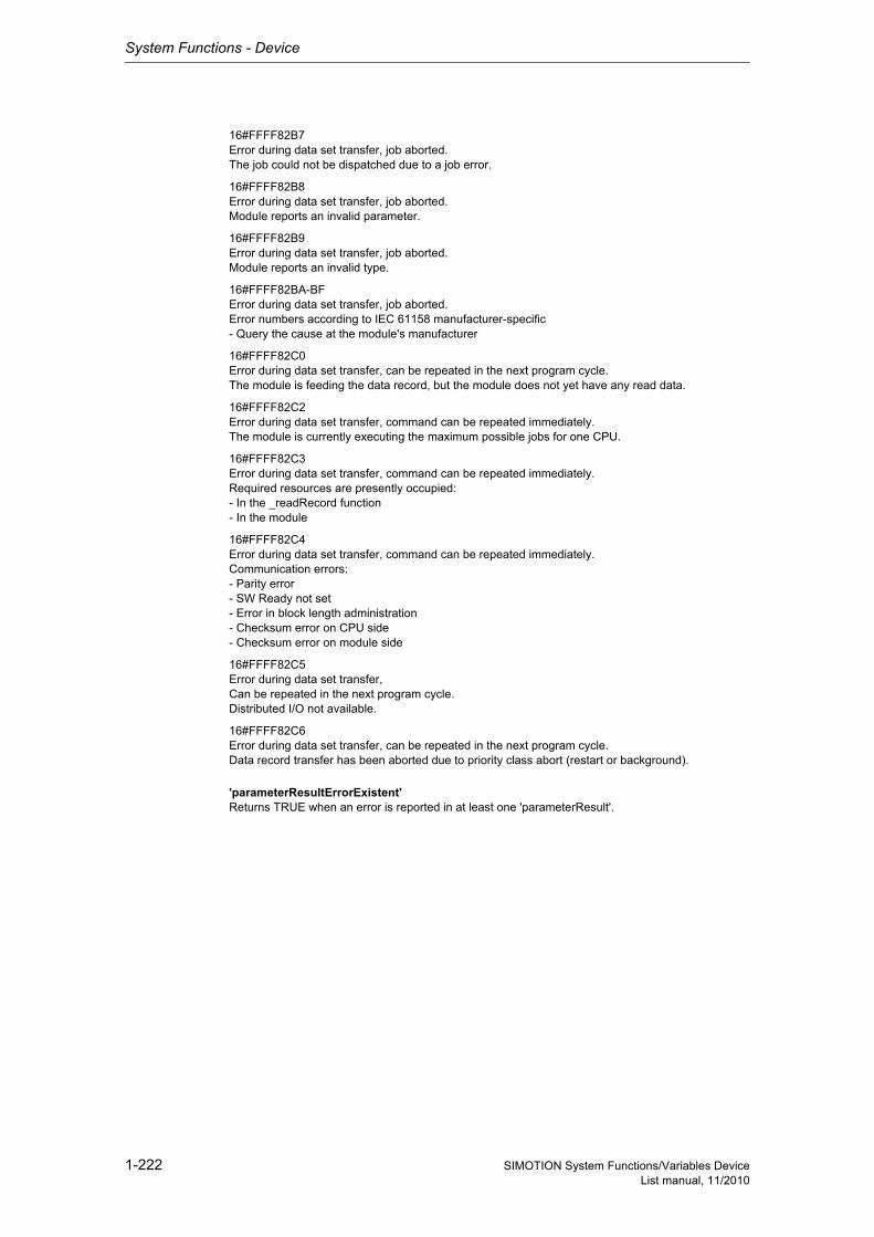
System Functions - Device
1-222 SIMOTION System Functions/Variables DeviceList manual, 11/2010
16#FFFF82B7Error during data set transfer, job aborted.The job could not be dispatched due to a job error.
16#FFFF82B8Error during data set transfer, job aborted.Module reports an invalid parameter.
16#FFFF82B9Error during data set transfer, job aborted.Module reports an invalid type.
16#FFFF82BA-BFError during data set transfer, job aborted.Error numbers according to IEC 61158 manufacturer-specific- Query the cause at the module's manufacturer
16#FFFF82C0Error during data set transfer, can be repeated in the next program cycle.The module is feeding the data record, but the module does not yet have any read data.
16#FFFF82C2Error during data set transfer, command can be repeated immediately.The module is currently executing the maximum possible jobs for one CPU.
16#FFFF82C3Error during data set transfer, command can be repeated immediately.Required resources are presently occupied:- In the _readRecord function- In the module
16#FFFF82C4Error during data set transfer, command can be repeated immediately.Communication errors:- Parity error- SW Ready not set- Error in block length administration- Checksum error on CPU side- Checksum error on module side
16#FFFF82C5Error during data set transfer,Can be repeated in the next program cycle.Distributed I/O not available.
16#FFFF82C6Error during data set transfer, can be repeated in the next program cycle.Data record transfer has been aborted due to priority class abort (restart or background).
'parameterResultErrorExistent'Returns TRUE when an error is reported in at least one 'parameterResult'.
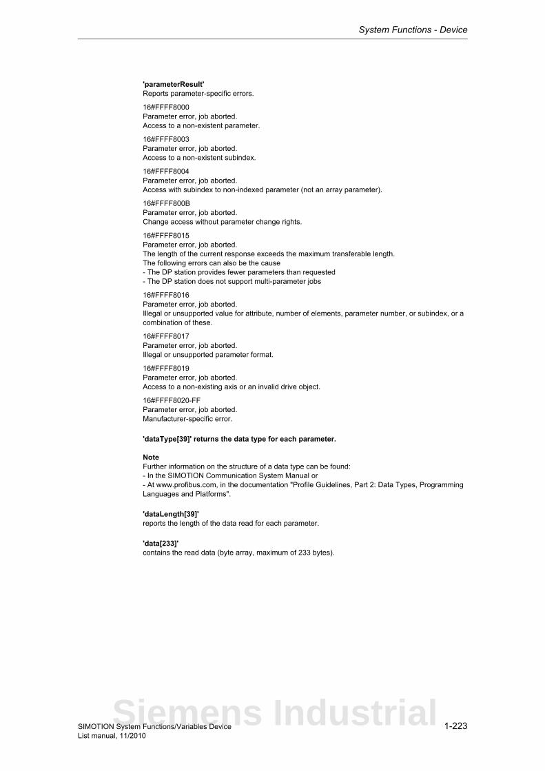
System Functions - Device
1-223SIMOTION System Functions/Variables DeviceList manual, 11/2010
'parameterResult'Reports parameter-specific errors.
16#FFFF8000Parameter error, job aborted.Access to a non-existent parameter.
16#FFFF8003Parameter error, job aborted.Access to a non-existent subindex.
16#FFFF8004Parameter error, job aborted.Access with subindex to non-indexed parameter (not an array parameter).
16#FFFF800BParameter error, job aborted.Change access without parameter change rights.
16#FFFF8015Parameter error, job aborted.The length of the current response exceeds the maximum transferable length.The following errors can also be the cause- The DP station provides fewer parameters than requested- The DP station does not support multi-parameter jobs
16#FFFF8016Parameter error, job aborted.Illegal or unsupported value for attribute, number of elements, parameter number, or subindex, or a combination of these.
16#FFFF8017Parameter error, job aborted.Illegal or unsupported parameter format.
16#FFFF8019Parameter error, job aborted.Access to a non-existing axis or an invalid drive object.
16#FFFF8020-FFParameter error, job aborted.Manufacturer-specific error.
'dataType[39]' returns the data type for each parameter.
NoteFurther information on the structure of a data type can be found:- In the SIMOTION Communication System Manual or- At www.profibus.com, in the documentation "Profile Guidelines, Part 2: Data Types, Programming Languages and Platforms".
'dataLength[39]'reports the length of the data read for each parameter.
'data[233]'contains the read data (byte array, maximum of 233 bytes).
Siemens Industrial
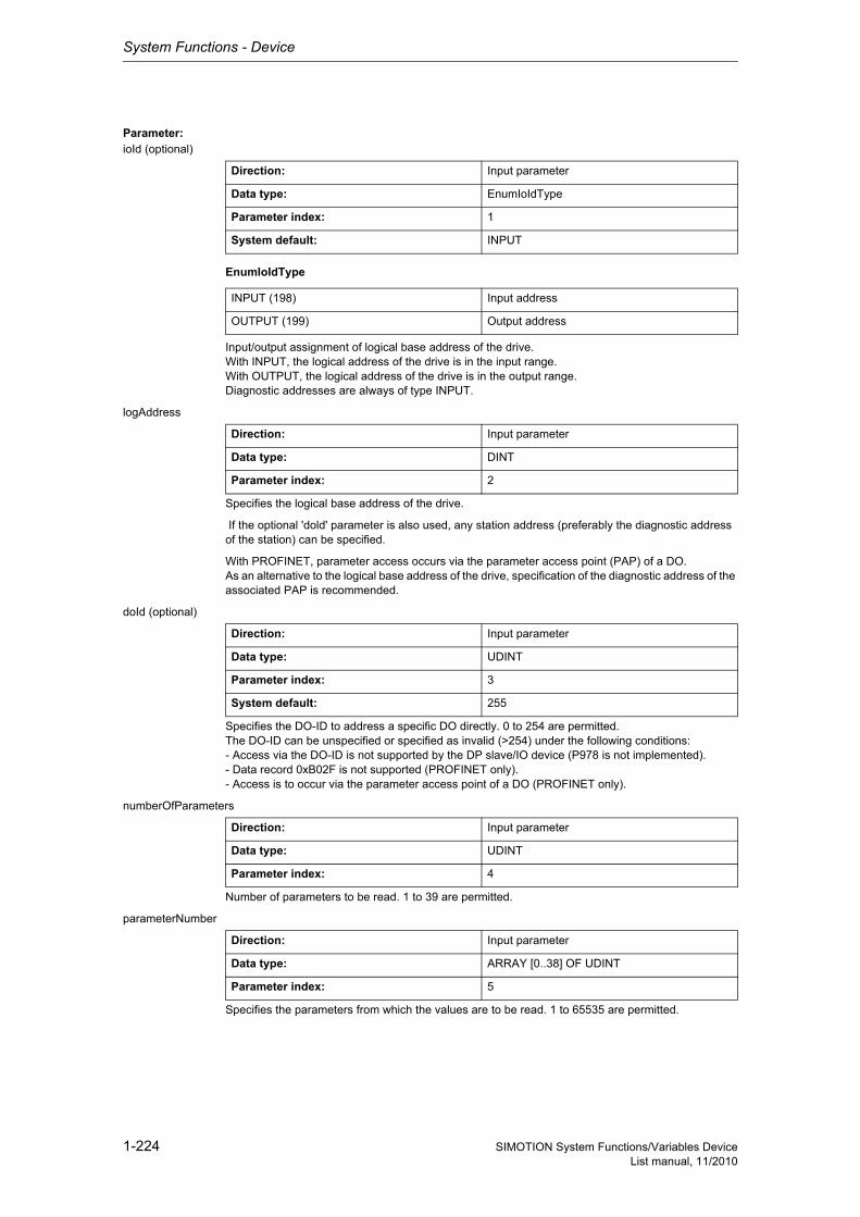
System Functions - Device
1-224 SIMOTION System Functions/Variables DeviceList manual, 11/2010
Parameter: ioId (optional)
EnumIoIdType
Input/output assignment of logical base address of the drive.With INPUT, the logical address of the drive is in the input range.With OUTPUT, the logical address of the drive is in the output range.Diagnostic addresses are always of type INPUT.
logAddress
Specifies the logical base address of the drive.
If the optional 'dold' parameter is also used, any station address (preferably the diagnostic address of the station) can be specified.
With PROFINET, parameter access occurs via the parameter access point (PAP) of a DO.As an alternative to the logical base address of the drive, specification of the diagnostic address of the associated PAP is recommended.
doId (optional)
Specifies the DO-ID to address a specific DO directly. 0 to 254 are permitted.The DO-ID can be unspecified or specified as invalid (>254) under the following conditions:- Access via the DO-ID is not supported by the DP slave/IO device (P978 is not implemented).- Data record 0xB02F is not supported (PROFINET only).- Access is to occur via the parameter access point of a DO (PROFINET only).
numberOfParameters
Number of parameters to be read. 1 to 39 are permitted.
parameterNumber
Specifies the parameters from which the values are to be read. 1 to 65535 are permitted.
Direction: Input parameter
Data type: EnumIoIdType
Parameter index: 1
System default: INPUT
INPUT (198) Input address
OUTPUT (199) Output address
Direction: Input parameter
Data type: DINT
Parameter index: 2
Direction: Input parameter
Data type: UDINT
Parameter index: 3
System default: 255
Direction: Input parameter
Data type: UDINT
Parameter index: 4
Direction: Input parameter
Data type: ARRAY [0..38] OF UDINT
Parameter index: 5
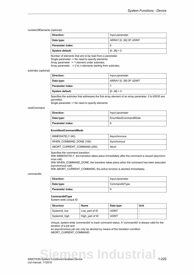
System Functions - Device
1-225SIMOTION System Functions/Variables DeviceList manual, 11/2010
numberOfElements (optional)
Number of elements that are to be read from a parameter.Single parameter -> No need to specify elements.Array parameter -> 1 element under subindex.Array parameter -> 2 to n elements starting from subindex.
subIndex (optional)
Specifies the subindex that addresses the first array element of an array parameter. 0 to 65535 are permitted.Single parameter -> No need to specify elements.
nextCommand
EnumNextCommandMode
Specifies the command transition.With IMMEDIATELY, the transition takes place immediately after the command is issued (asynchro-nous call).With WHEN_COMMAND_DONE, the transition takes place when the command has been executed (synchronous call).With ABORT_CURRENT_COMMAND, the active function is aborted immediately.
commandId
CommandIdTypeSystem-wide unique ID
Unique, system-wide 'commandId' to track command status. A 'commandId' is always valid for the duration of a job andan asynchronous job can only be aborted by means of the transition condition ABORT_CURRENT_COMMAND.
Direction: Input parameter
Data type: ARRAY [0..38] OF UDINT
Parameter index: 6
System default: [0..38] = 0
Direction: Input parameter
Data type: ARRAY [0..38] OF UDINT
Parameter index: 7
System default: [0..38] = 0
Direction: Input parameter
Data type: EnumNextCommandMode
Parameter index: 8
IMMEDIATELY (60) Asynchronous
WHEN_COMMAND_DONE (160) Synchronous
ABORT_CURRENT_COMMAND (260) Abort
Direction: Input parameter
Data type: CommandIdType
Parameter index: 9
Structure Name Data type Unit
SystemId_low Low_part of ID UDINT -
SystemId_high High_part of ID UDINT -
Siemens Industrial
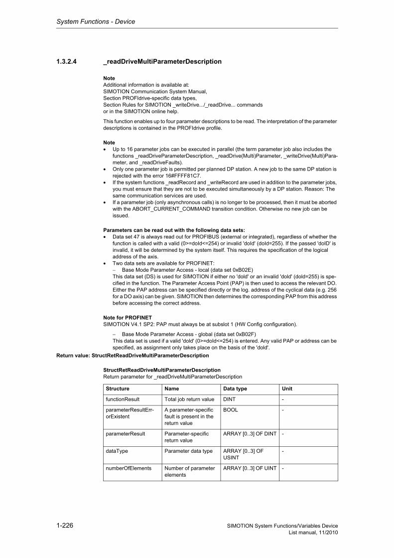
System Functions - Device
1-226 SIMOTION System Functions/Variables DeviceList manual, 11/2010
1.3.2.4 _readDriveMultiParameterDescription
NoteAdditional information is available at:SIMOTION Communication System Manual,Section PROFIdrive-specific data types,Section Rules for SIMOTION _writeDrive.../_readDrive... commandsor in the SIMOTION online help.
This function enables up to four parameter descriptions to be read. The interpretation of the parameter descriptions is contained in the PROFIdrive profile.
Note• Up to 16 parameter jobs can be executed in parallel (the term parameter job also includes the
functions _readDriveParameterDescription, _readDrive(Multi)Parameter, _writeDrive(Multi)Para-meter, and _readDriveFaults).
• Only one parameter job is permitted per planned DP station. A new job to the same DP station is rejected with the error 16#FFFF81C7.
• If the system functions _readRecord and _writeRecord are used in addition to the parameter jobs, you must ensure that they are not to be executed simultaneously by a DP station. Reason: The same communication services are used.
• If a parameter job (only asynchronous calls) is no longer to be processed, then it must be aborted with the ABORT_CURRENT_COMMAND transition condition. Otherwise no new job can be issued.
Parameters can be read out with the following data sets:• Data set 47 is always read out for PROFIBUS (external or integrated), regardless of whether the
function is called with a valid (0>=doId<=254) or invalid 'doId' (doId=255). If the passed 'doID' is invalid, it will be determined by the system itself. This requires the specification of the logical address of the axis.
• Two data sets are available for PROFINET:− Base Mode Parameter Access - local (data set 0xB02E)This data set (DS) is used for SIMOTION if either no 'dold' or an invalid 'dold' (dold=255) is spe-cified in the function. The Parameter Access Point (PAP) is then used to access the relevant DO. Either the PAP address can be specified directly or the log. address of the cyclical data (e.g. 256 for a DO axis) can be given. SIMOTION then determines the corresponding PAP from this address before accessing the correct address.
Note for PROFINETSIMOTION V4.1 SP2: PAP must always be at subslot 1 (HW Config configuration).
− Base Mode Parameter Access - global (data set 0xB02F)This data set is used if a valid 'dold' (0>=doId<=254) is entered. Any valid PAP or address can be specified, as assignment only takes place on the basis of the 'dold'.
Return value: StructRetReadDriveMultiParameterDescription
StructRetReadDriveMultiParameterDescriptionReturn parameter for _readDriveMultiParameterDescription
Structure Name Data type Unit
functionResult Total job return value DINT -
parameterResultErr-orExistent
A parameter-specific fault is present in the return value
BOOL -
parameterResult Parameter-specific return value
ARRAY [0..3] OF DINT -
dataType Parameter data type ARRAY [0..3] OF USINT
-
numberOfElements Number of parameter elements
ARRAY [0..3] OF UINT -
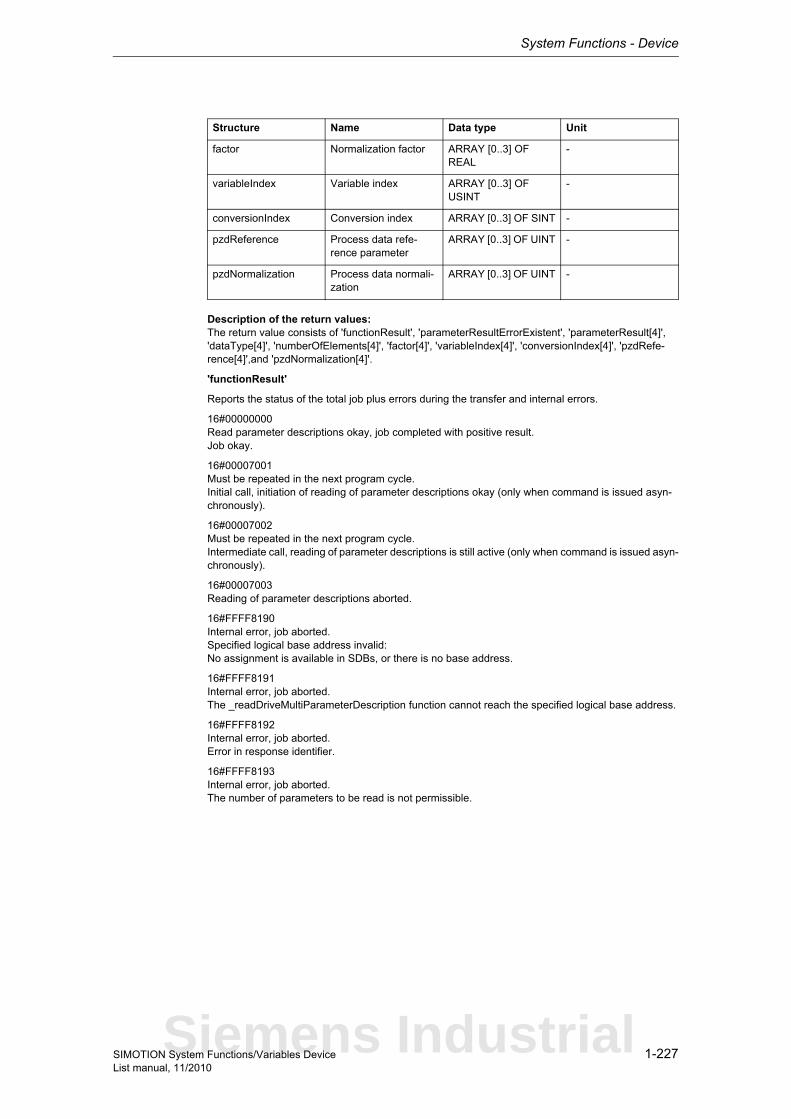
System Functions - Device
1-227SIMOTION System Functions/Variables DeviceList manual, 11/2010
Description of the return values:The return value consists of 'functionResult', 'parameterResultErrorExistent', 'parameterResult[4]', 'dataType[4]', 'numberOfElements[4]', 'factor[4]', 'variableIndex[4]', 'conversionIndex[4]', 'pzdRefe-rence[4]',and 'pzdNormalization[4]'.
'functionResult'
Reports the status of the total job plus errors during the transfer and internal errors.
16#00000000Read parameter descriptions okay, job completed with positive result.Job okay.
16#00007001Must be repeated in the next program cycle.Initial call, initiation of reading of parameter descriptions okay (only when command is issued asyn-chronously).
16#00007002Must be repeated in the next program cycle.Intermediate call, reading of parameter descriptions is still active (only when command is issued asyn-chronously).
16#00007003Reading of parameter descriptions aborted.
16#FFFF8190Internal error, job aborted.Specified logical base address invalid:No assignment is available in SDBs, or there is no base address.
16#FFFF8191Internal error, job aborted.The _readDriveMultiParameterDescription function cannot reach the specified logical base address.
16#FFFF8192Internal error, job aborted.Error in response identifier.
16#FFFF8193Internal error, job aborted.The number of parameters to be read is not permissible.
factor Normalization factor ARRAY [0..3] OF REAL
-
variableIndex Variable index ARRAY [0..3] OF USINT
-
conversionIndex Conversion index ARRAY [0..3] OF SINT -
pzdReference Process data refe-rence parameter
ARRAY [0..3] OF UINT -
pzdNormalization Process data normali-zation
ARRAY [0..3] OF UINT -
Structure Name Data type Unit
Siemens Industrial

System Functions - Device
1-228 SIMOTION System Functions/Variables DeviceList manual, 11/2010
16#FFFF819DInternal error, job aborted.An I slave/I device interface is unable to issue a parameter job to the higher-level master/controller.
16#FFFF819EInternal error, job aborted.Attempt to abort a non-active function.
16#FFFF819FInternal error, job aborted.Function not executable.
16#FFFF81C3Error, can be repeated in the next program cycle.Required resources are presently occupied:- In the _readDriveMultiParameterDescription function- In the module
16#FFFF81C5Error, can be repeated in the next program cycle.Distributed I/O not available.
16#FFFF81C7Error, can be repeated in the next program cycle.Another parameter job has already been issued to the DP station. - based on the user program - from a system-internal component (e.g. TO axis executes parameter comparison after station reco-very)
16#FFFF81CFError, can be repeated in the next program cycle.Another parameter job call is currently active under this 'commandId'.
16#FFFF8290Corresponds to the error message 16#FFFF8190.
16#FFFF8291Corresponds to the error message 16#FFFF8191.
16#FFFF82A2Error during data set transfer, job aborted.Error in Layer2:- Station failure- Timeout
16#FFFF82A3Error during data set transfer, job aborted.Error in user interface/user:- Protocol error- Station failure- Timeout
16#FFFF82A4-A7Error during data set transfer, job aborted.Error numbers according to IEC 61158 reserved- Query the cause at the module's manufacturer
16#FFFF82A8Error during data set transfer, job aborted.Error because of version conflict.
16#FFFF82A9Error during data set transfer, job aborted.Function not supported by the module.
16#FFFF82AA-AFError during data set transfer, job aborted.Error numbers according to IEC 61158 manufacturer-specific- Query the cause at the module's manufacturer

System Functions - Device
1-229SIMOTION System Functions/Variables DeviceList manual, 11/2010
16#FFFF82B0Error during data set transfer, job aborted.Parameter jobs are not supported by the addressed module.
16#FFFF82B2Error during data set transfer, job aborted.Module reports access to an invalid slot/subslot.
16#FFFF82B3Error during data set transfer, job aborted.Module reports type conflict.
16#FFFF82B4Error during data set transfer, job aborted.Module reports access to an invalid area.
16#FFFF82B5Error during data set transfer, can be repeated in the next program cycle.The system function cannot be executed due to an internal operating state of the module.
16#FFFF82B6Error during data set transfer, job aborted.Module rejects access.
16#FFFF82B7Error during data set transfer, job aborted.The job could not be dispatched due to a job error.
16#FFFF82B8Error during data set transfer, job aborted.Module reports an invalid parameter.
16#FFFF82B9Error during data set transfer, job aborted.Module reports an invalid type.
16#FFFF82BA-BFError during data set transfer, job aborted.Error numbers according to IEC 61158 manufacturer-specific- Query the cause at the module's manufacturer
16#FFFF82C0Error during data set transfer, can be repeated in the next program cycle.The module is feeding the data record, but the module does not yet have any read data.
16#FFFF82C2Error during data set transfer, command can be repeated immediately.The module is currently executing the maximum possible jobs for one CPU.
16#FFFF82C3Error during data set transfer, command can be repeated immediately.Required resources are presently occupied:- In the _readRecord function- In the module
16#FFFF82C4Error during data set transfer, command can be repeated immediately.Communication errors:- Parity error- SW Ready not set- Error in block length administration- Checksum error on CPU side- Checksum error on module side
16#FFFF82C5Error during data set transfer,Can be repeated in the next program cycle.Distributed I/O not available.
Siemens Industrial
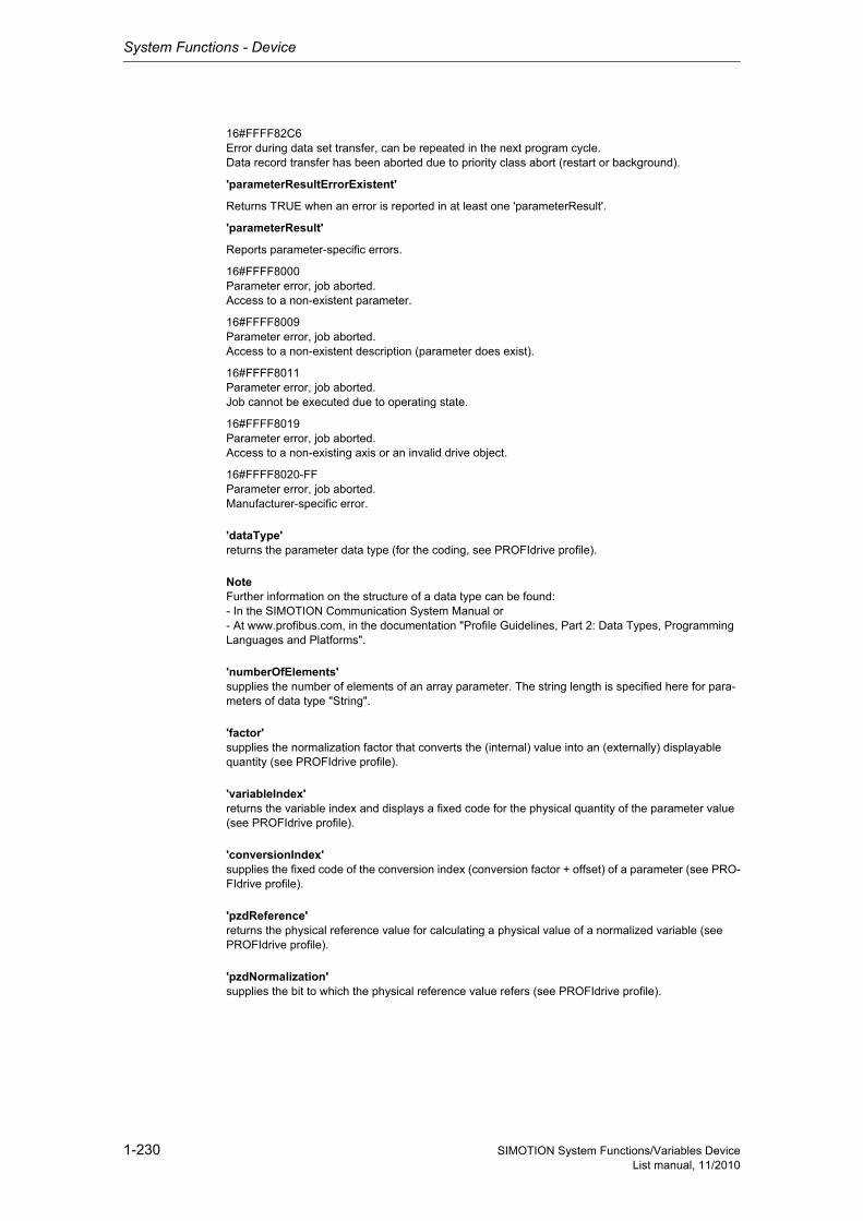
System Functions - Device
1-230 SIMOTION System Functions/Variables DeviceList manual, 11/2010
16#FFFF82C6Error during data set transfer, can be repeated in the next program cycle.Data record transfer has been aborted due to priority class abort (restart or background).
'parameterResultErrorExistent'
Returns TRUE when an error is reported in at least one 'parameterResult'.
'parameterResult'
Reports parameter-specific errors.
16#FFFF8000Parameter error, job aborted.Access to a non-existent parameter.
16#FFFF8009Parameter error, job aborted.Access to a non-existent description (parameter does exist).
16#FFFF8011Parameter error, job aborted.Job cannot be executed due to operating state.
16#FFFF8019Parameter error, job aborted.Access to a non-existing axis or an invalid drive object.
16#FFFF8020-FFParameter error, job aborted.Manufacturer-specific error.
'dataType'returns the parameter data type (for the coding, see PROFIdrive profile).
NoteFurther information on the structure of a data type can be found:- In the SIMOTION Communication System Manual or- At www.profibus.com, in the documentation "Profile Guidelines, Part 2: Data Types, Programming Languages and Platforms".
'numberOfElements'supplies the number of elements of an array parameter. The string length is specified here for para-meters of data type "String".
'factor'supplies the normalization factor that converts the (internal) value into an (externally) displayable quantity (see PROFIdrive profile).
'variableIndex'returns the variable index and displays a fixed code for the physical quantity of the parameter value (see PROFIdrive profile).
'conversionIndex'supplies the fixed code of the conversion index (conversion factor + offset) of a parameter (see PRO-FIdrive profile).
'pzdReference'returns the physical reference value for calculating a physical value of a normalized variable (see PROFIdrive profile).
'pzdNormalization'supplies the bit to which the physical reference value refers (see PROFIdrive profile).
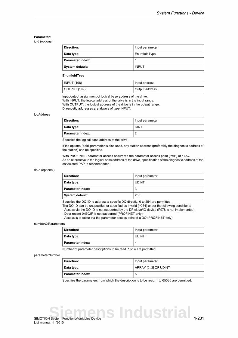
System Functions - Device
1-231SIMOTION System Functions/Variables DeviceList manual, 11/2010
Parameter: ioId (optional)
EnumIoIdType
Input/output assignment of logical base address of the drive.With INPUT, the logical address of the drive is in the input range.With OUTPUT, the logical address of the drive is in the output range.Diagnostic addresses are always of type INPUT.
logAddress
Specifies the logical base address of the drive.
If the optional 'dold' parameter is also used, any station address (preferably the diagnostic address of the station) can be specified.
With PROFINET, parameter access occurs via the parameter access point (PAP) of a DO.As an alternative to the logical base address of the drive, specification of the diagnostic address of the associated PAP is recommended.
doId (optional)
Specifies the DO-ID to address a specific DO directly. 0 to 254 are permitted.The DO-ID can be unspecified or specified as invalid (>254) under the following conditions:- Access via the DO-ID is not supported by the DP slave/IO device (P978 is not implemented).- Data record 0xB02F is not supported (PROFINET only).- Access is to occur via the parameter access point of a DO (PROFINET only).
numberOfParameters
Number of parameter descriptions to be read. 1 to 4 are permitted.
parameterNumber
Specifies the parameters from which the description is to be read. 1 to 65535 are permitted.
Direction: Input parameter
Data type: EnumIoIdType
Parameter index: 1
System default: INPUT
INPUT (198) Input address
OUTPUT (199) Output address
Direction: Input parameter
Data type: DINT
Parameter index: 2
Direction: Input parameter
Data type: UDINT
Parameter index: 3
System default: 255
Direction: Input parameter
Data type: UDINT
Parameter index: 4
Direction: Input parameter
Data type: ARRAY [0..3] OF UDINT
Parameter index: 5
Siemens Industrial

System Functions - Device
1-232 SIMOTION System Functions/Variables DeviceList manual, 11/2010
nextCommand
EnumNextCommandMode
Specifies the command transition.With IMMEDIATELY, the transition takes place immediately after the command is issued (asynchro-nous call).With WHEN_COMMAND_DONE, the transition takes place when the command has been executed (synchronous call).With ABORT_CURRENT_COMMAND, the active function is aborted immediately.
commandId
CommandIdTypeSystem-wide unique ID
Unique, system-wide 'commandId' to track command status. A 'commandId' is always valid for the duration of a job andan asynchronous job can only be aborted by means of the transition condition ABORT_CURRENT_COMMAND.
Direction: Input parameter
Data type: EnumNextCommandMode
Parameter index: 6
IMMEDIATELY (60) Asynchronous
WHEN_COMMAND_DONE (160) Synchronous
ABORT_CURRENT_COMMAND (260) Abort
Direction: Input parameter
Data type: CommandIdType
Parameter index: 7
Structure Name Data type Unit
SystemId_low Low_part of ID UDINT -
SystemId_high High_part of ID UDINT -
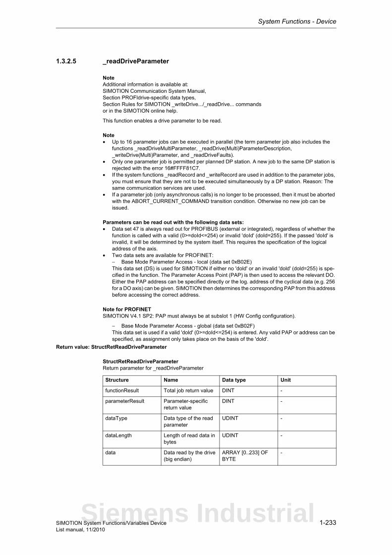
System Functions - Device
1-233SIMOTION System Functions/Variables DeviceList manual, 11/2010
1.3.2.5 _readDriveParameter
NoteAdditional information is available at:SIMOTION Communication System Manual,Section PROFIdrive-specific data types,Section Rules for SIMOTION _writeDrive.../_readDrive... commandsor in the SIMOTION online help.
This function enables a drive parameter to be read.
Note• Up to 16 parameter jobs can be executed in parallel (the term parameter job also includes the
functions _readDriveMultiParameter, _readDrive(Multi)ParameterDescription, _writeDrive(Multi)Parameter, and _readDriveFaults).
• Only one parameter job is permitted per planned DP station. A new job to the same DP station is rejected with the error 16#FFFF81C7.
• If the system functions _readRecord and _writeRecord are used in addition to the parameter jobs, you must ensure that they are not to be executed simultaneously by a DP station. Reason: The same communication services are used.
• If a parameter job (only asynchronous calls) is no longer to be processed, then it must be aborted with the ABORT_CURRENT_COMMAND transition condition. Otherwise no new job can be issued.
Parameters can be read out with the following data sets:• Data set 47 is always read out for PROFIBUS (external or integrated), regardless of whether the
function is called with a valid (0>=doId<=254) or invalid 'doId' (doId=255). If the passed 'doId' is invalid, it will be determined by the system itself. This requires the specification of the logical address of the axis.
• Two data sets are available for PROFINET:− Base Mode Parameter Access - local (data set 0xB02E)This data set (DS) is used for SIMOTION if either no 'dold' or an invalid 'dold' (dold=255) is spe-cified in the function. The Parameter Access Point (PAP) is then used to access the relevant DO. Either the PAP address can be specified directly or the log. address of the cyclical data (e.g. 256 for a DO axis) can be given. SIMOTION then determines the corresponding PAP from this address before accessing the correct address.
Note for PROFINETSIMOTION V4.1 SP2: PAP must always be at subslot 1 (HW Config configuration).
− Base Mode Parameter Access - global (data set 0xB02F)This data set is used if a valid 'dold' (0>=doId<=254) is entered. Any valid PAP or address can be specified, as assignment only takes place on the basis of the 'dold'.
Return value: StructRetReadDriveParameter
StructRetReadDriveParameterReturn parameter for _readDriveParameter
Structure Name Data type Unit
functionResult Total job return value DINT -
parameterResult Parameter-specific return value
DINT -
dataType Data type of the read parameter
UDINT -
dataLength Length of read data in bytes
UDINT -
data Data read by the drive (big endian)
ARRAY [0..233] OF BYTE
-
Siemens Industrial
System Functions - Device
1-234 SIMOTION System Functions/Variables DeviceList manual, 11/2010
Description of the return values:The return value consists of 'functionResult', 'parameterResult', 'dataType', 'dataLength' and 'data[234].
'functionResult'Reports the status of the total job plus errors during the transfer and internal errors.
16#00000000Reading of parameters okay, job completed with positive result. Job okay.
16#00007001Must be repeated in the next program cycle.Initial call, initiation of reading of parameter description okay(only when command is issued asynchronously).
16#00007002Must be repeated in the next program cycle.Intermediate call, reading of parameter description is still active(only when command is issued asynchronously).
16#00007003Reading of parameters aborted.Job aborted.
16#FFFF8190Internal error, job aborted.Specified logical base address invalid:No assignment is available in SDBs, or there is no base address.
16#FFFF8191Internal error, job aborted.The _readDriveParameter function cannot reach the specified logical base address.
16#FFFF8192Internal error, job aborted.Error in response identifier.
16#FFFF819DInternal error, job aborted.An I slave/I device interface is unable to issue a parameter job to the higher-level master/controller.
16#FFFF819EInternal error, job aborted.Attempt to abort a non-active function.
16#FFFF819FInternal error, job aborted.Function not executable.
16#FFFF81C3Error, can be repeated in the next program cycle.Required resources are presently occupied:- In the _readDriveParameter function- In the module
16#FFFF81C5Error, can be repeated in the next program cycle.Distributed I/O not available.
System Functions - Device
1-235SIMOTION System Functions/Variables DeviceList manual, 11/2010
16#FFFF81C7Error, can be repeated in the next program cycle.Another parameter job has already been issued to the DP station. - based on the user program - from a system-internal component (e.g. TO axis executes parameter comparison after station reco-very)
16#FFFF81CFError, can be repeated in the next program cycle.Another parameter job call is currently active under this 'commandId'.
16#FFFF8290Corresponds to the error message 16#FFFF8190.
16#FFFF8291Corresponds to the error message 16#FFFF8191.
16#FFFF82A2Error during data set transfer, job aborted.Error in Layer2:- Station failure- Timeout
16#FFFF82A3Error during data set transfer, job aborted.Error in user interface/user:- Protocol error- Station failure- Timeout
16#FFFF82A4-A7Error during data set transfer, job aborted.Error numbers according to IEC 61158 reserved- Query the cause at the module's manufacturer
16#FFFF82A8Error during data set transfer, job aborted.Error because of version conflict.
16#FFFF82A9Error during data set transfer, job aborted.Function not supported by the module.
16#FFFF82AA-AFError during data set transfer, job aborted.Error numbers according to IEC 61158 manufacturer-specific- Query the cause at the module's manufacturer
16#FFFF82B0Error during data set transfer, job aborted.Parameter jobs are not supported by the addressed module.
16#FFFF82B2Error during data set transfer, job aborted.Module reports access to an invalid slot/subslot.
16#FFFF82B3Error during data set transfer, job aborted.Module reports type conflict.
16#FFFF82B4Error during data set transfer, job aborted.Module reports access to an invalid area.
16#FFFF82B5Error during data set transfer, can be repeated in the next program cycle.The system function cannot be executed due to an internal operating state of the module.
16#FFFF82B6Error during data set transfer, job aborted.Module rejects access.
Siemens Industrial
System Functions - Device
1-236 SIMOTION System Functions/Variables DeviceList manual, 11/2010
16#FFFF82B7Error during data set transfer, job aborted.The job could not be dispatched due to a job error.
16#FFFF82B8Error during data set transfer, job aborted.Module reports an invalid parameter.
16#FFFF82B9Error during data set transfer, job aborted.Module reports an invalid type.
16#FFFF82BA-BFError during data set transfer, job aborted.Error numbers according to IEC 61158 manufacturer-specific- Query the cause at the module's manufacturer
16#FFFF82C0Error during data set transfer, can be repeated in the next program cycle.The module is feeding the data record, but the module does not yet have any read data.
16#FFFF82C2Error during data set transfer, command can be repeated immediately.The module is currently executing the maximum possible jobs for one CPU.
16#FFFF82C3Error during data set transfer, command can be repeated immediately.Required resources are presently occupied:- In the _readRecord function- In the module
16#FFFF82C4Error during data set transfer, command can be repeated immediately.Communication errors:- Parity error- SW Ready not set- Error in block length administration- Checksum error on CPU side- Checksum error on module side
16#FFFF82C5Error during data set transfer,Can be repeated in the next program cycle.Distributed I/O not available.
16#FFFF82C6Error during data set transfer, can be repeated in the next program cycle.Data record transfer has been aborted due to priority class abort (restart or background).
'parameterResult'
Reports parameter-specific errors.
16#FFFF8000Parameter error, job aborted.Access to a non-existent parameter.
16#FFFF8003Parameter error, job aborted.Access to a non-existent subindex.
16#FFFF8004Parameter error, job aborted.Access with subindex to non-indexed parameter (not an array parameter).
16#FFFF8011Parameter error, job aborted.Job cannot be executed due to operating state.
16#FFFF8015Parameter error, job aborted.The length of the current response exceeds the maximum transferable length.
System Functions - Device
1-237SIMOTION System Functions/Variables DeviceList manual, 11/2010
16#FFFF8016Parameter error, job aborted.Illegal or unsupported value for attribute, number of elements, parameter number, or subindex, or a combination of these.
16#FFFF8019Parameter error, job aborted.Access to a non-existing axis or an invalid drive object.
16#FFFF8020-FFParameter error, job aborted.Manufacturer-specific error.
'dataType'returns the data type of the read parameter.
NoteFurther information on the structure of a data type can be found:- In the SIMOTION Communication System Manual or- At www.profibus.com, in the documentation "Profile Guidelines, Part 2: Data Types, Programming Languages and Platforms".
'dataLength'reports the length of the data read.
'data[234]'contains the read data (byte array, maximum of 234 bytes).
Parameter: ioId (optional)
EnumIoIdType
Input/output assignment of logical base address of the drive.With INPUT, the logical address of the drive is in the input range.With OUTPUT, the logical address of the drive is in the output range.Diagnostic addresses are always of type INPUT.
logAddress
Specifies the logical base address of the drive.
If the optional 'dold' parameter is also used, any station address (preferably the diagnostic address of the station) can be specified.
With PROFINET, parameter access occurs via the parameter access point (PAP) of a DO.As an alternative to the logical base address of the drive, specification of the diagnostic address of the associated PAP is recommended.
Direction: Input parameter
Data type: EnumIoIdType
Parameter index: 1
System default: INPUT
INPUT (198) Input address
OUTPUT (199) Output address
Direction: Input parameter
Data type: DINT
Parameter index: 2
Siemens Industrial
System Functions - Device
1-238 SIMOTION System Functions/Variables DeviceList manual, 11/2010
doId (optional)
Specifies the DO-ID to address a specific DO directly. 0 to 254 are permitted.The DO-ID can be unspecified or specified as invalid (>254) under the following conditions:- Access via the DO-ID is not supported by the DP slave/IO device (P978 is not implemented).- Data record 0xB02F is not supported (PROFINET only).- Access is to occur via the parameter access point of a DO (PROFINET only).
parameterNumber
Specifies the parameter from which the values are to be read. 1 to 65535 are permitted.
numberOfElements (optional)
Number of elements to be read from a parameter.Single parameter -> No need to specify elements.Array parameter -> 1 element under subindex.Array parameter -> 2 to n elements starting from subindex.
subIndex (optional)
Specifies the subindex that addresses the first array element of an array parameter, setting between 0 and 65535.Single parameter -> No need to specify elements.
nextCommand
Direction: Input parameter
Data type: UDINT
Parameter index: 3
System default: 255
Direction: Input parameter
Data type: UDINT
Parameter index: 4
Direction: Input parameter
Data type: UDINT
Parameter index: 5
System default: 0
Direction: Input parameter
Data type: UDINT
Parameter index: 6
System default: 0
Direction: Input parameter
Data type: EnumNextCommandMode
Parameter index: 7
System Functions - Device
1-239SIMOTION System Functions/Variables DeviceList manual, 11/2010
EnumNextCommandMode
Specifies the command transition.With IMMEDIATELY, the transition takes place immediately after the command is issued (asynchro-nous call).With WHEN_COMMAND_DONE, the transition takes place when the command has been executed (synchronous call).With ABORT_CURRENT_COMMAND, the active function is aborted immediately.
commandId
CommandIdTypeSystem-wide unique ID
Unique, system-wide 'commandId' to track command status. A 'commandId' is always valid for the duration of a job andan asynchronous job can only be aborted by means of the transition condition ABORT_CURRENT_COMMAND.
IMMEDIATELY (60) Asynchronous
WHEN_COMMAND_DONE (160) Synchronous
ABORT_CURRENT_COMMAND (260) Abort
Direction: Input parameter
Data type: CommandIdType
Parameter index: 8
Structure Name Data type Unit
SystemId_low Low_part of ID UDINT -
SystemId_high High_part of ID UDINT -
Siemens Industrial
System Functions - Device
1-240 SIMOTION System Functions/Variables DeviceList manual, 11/2010
1.3.2.6 _readDriveParameterDescription
NoteAdditional information is available at:SIMOTION Communication System Manual,Section PROFIdrive-specific data types,Section Rules for SIMOTION _writeDrive.../_readDrive... commandsor in the SIMOTION online help.
This function enables the descriptive data of a drive parameter to be read out. The interpretation of the parameter description is contained in the PROFIdrive profile.
Note• Up to 16 parameter jobs can be executed in parallel (the term parameter job also includes the
functions _readDriveParameterDescription, _readDrive(Multi)Parameter, _writeDrive(Multi)Para-meter, and _readDriveFaults).
• Only one parameter job is permitted per planned DP station. A new job to the same DP station is rejected with the error 16#FFFF81C7.
• If the system functions _readRecord and _writeRecord are used in addition to the parameter jobs, you must ensure that they are not to be executed simultaneously by a DP station. Reason: The same communication services are used.
• If a parameter job (only asynchronous calls) is no longer to be processed, then it must be aborted with the ABORT_CURRENT_COMMAND transition condition. Otherwise no new job can be issued.
Parameters can be read out with the following data sets:• Data set 47 is always read out for PROFIBUS (external or integrated), regardless of whether the
function is called with a valid (0>=doId<=254) or invalid 'doId' (doId=255). If the passed 'doID' is invalid, it will be determined by the system itself. This requires the specification of the logical address of the axis.
• Two data sets are available for PROFINET:− Base Mode Parameter Access - local (data set 0xB02E)This data set (DS) is used for SIMOTION if either no 'dold' or an invalid 'dold' (dold=255) is spe-cified in the function. The Parameter Access Point (PAP) is then used to access the relevant DO. Either the PAP address can be specified directly or the log. address of the cyclical data (e.g. 256 for a DO axis) can be given. SIMOTION then determines the corresponding PAP from this address before accessing the correct address.
Note for PROFINETSIMOTION V4.1 SP2: PAP must always be at subslot 1 (HW Config configuration).
− Base Mode Parameter Access - global (data set 0xB02F)This data set is used if a valid 'dold' (0>=doId<=254) is entered. Any valid PAP or address can be specified, as assignment only takes place on the basis of the 'dold'.
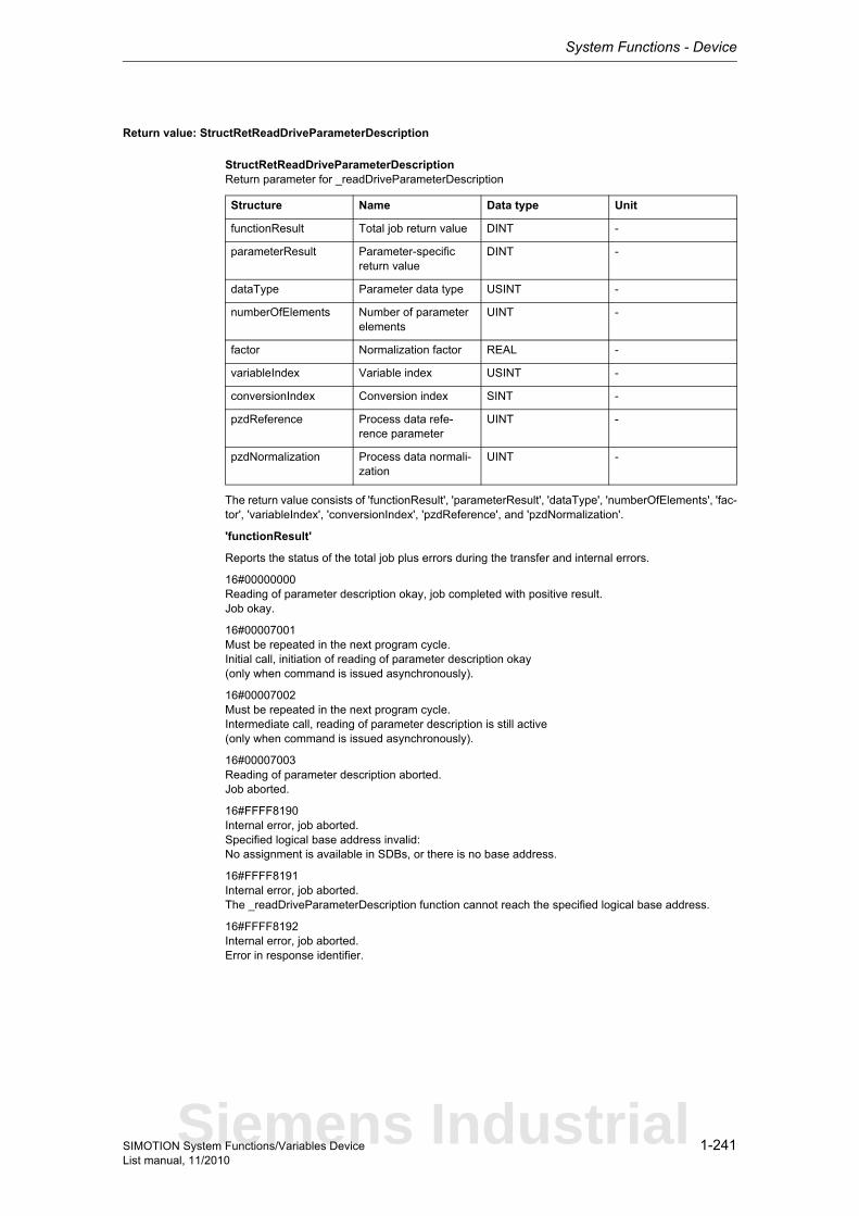
System Functions - Device
1-241SIMOTION System Functions/Variables DeviceList manual, 11/2010
Return value: StructRetReadDriveParameterDescription
StructRetReadDriveParameterDescriptionReturn parameter for _readDriveParameterDescription
The return value consists of 'functionResult', 'parameterResult', 'dataType', 'numberOfElements', 'fac-tor', 'variableIndex', 'conversionIndex', 'pzdReference', and 'pzdNormalization'.
'functionResult'
Reports the status of the total job plus errors during the transfer and internal errors.
16#00000000Reading of parameter description okay, job completed with positive result.Job okay.
16#00007001Must be repeated in the next program cycle.Initial call, initiation of reading of parameter description okay(only when command is issued asynchronously).
16#00007002Must be repeated in the next program cycle.Intermediate call, reading of parameter description is still active(only when command is issued asynchronously).
16#00007003Reading of parameter description aborted.Job aborted.
16#FFFF8190Internal error, job aborted.Specified logical base address invalid:No assignment is available in SDBs, or there is no base address.
16#FFFF8191Internal error, job aborted.The _readDriveParameterDescription function cannot reach the specified logical base address.
16#FFFF8192Internal error, job aborted.Error in response identifier.
Structure Name Data type Unit
functionResult Total job return value DINT -
parameterResult Parameter-specific return value
DINT -
dataType Parameter data type USINT -
numberOfElements Number of parameter elements
UINT -
factor Normalization factor REAL -
variableIndex Variable index USINT -
conversionIndex Conversion index SINT -
pzdReference Process data refe-rence parameter
UINT -
pzdNormalization Process data normali-zation
UINT -
Siemens Industrial

System Functions - Device
1-242 SIMOTION System Functions/Variables DeviceList manual, 11/2010
16#FFFF819DInternal error, job aborted.An I slave/I device interface is unable to issue a parameter job to the higher-level master/controller.
16#FFFF819EInternal error, job aborted.Attempt to abort a non-active function.
16#FFFF819FInternal error, job aborted.Function not executable.
16#FFFF81C3Error, can be repeated in the next program cycle.Required resources are presently occupied:- In the _readDriveParameterDescription function- In the module
16#FFFF81C5Error, can be repeated in the next program cycle.Distributed I/O not available.
16#FFFF81C7Error, can be repeated in the next program cycle.Another parameter job has already been issued to the DP station. - based on the user program - from a system-internal component (e.g. TO axis executes parameter comparison after station reco-very)
16#FFFF81CFError, can be repeated in the next program cycle.Another parameter job call is currently active under this 'commandId'.
16#FFFF8290Corresponds to the error message 16#FFFF8190.
16#FFFF8291Corresponds to the error message 16#FFFF8191.
16#FFFF82A2Error during data set transfer, job aborted.Error in Layer2:- Station failure- Timeout
16#FFFF82A3Error during data set transfer, job aborted.Error in user interface/user:- Protocol error- Station failure- Timeout
16#FFFF82A4-A7Error during data set transfer, job aborted.Error numbers according to IEC 61158 reserved- Query the cause at the module's manufacturer
16#FFFF82A8Error during data set transfer, job aborted.Error because of version conflict.
16#FFFF82A9Error during data set transfer, job aborted.Function not supported by the module.
16#FFFF82AA-AFError during data set transfer, job aborted.Error numbers according to IEC 61158 manufacturer-specific- Query the cause at the module's manufacturer
System Functions - Device
1-243SIMOTION System Functions/Variables DeviceList manual, 11/2010
16#FFFF82B0Error during data set transfer, job aborted.Parameter jobs are not supported by the addressed module.
16#FFFF82B2Error during data set transfer, job aborted.Module reports access to an invalid slot/subslot.
16#FFFF82B3Error during data set transfer, job aborted.Module reports type conflict.
16#FFFF82B4Error during data set transfer, job aborted.Module reports access to an invalid area.
16#FFFF82B5Error during data set transfer, can be repeated in the next program cycle.The system function cannot be executed due to an internal operating state of the module.
16#FFFF82B6Error during data set transfer, job aborted.Module rejects access.
16#FFFF82B7Error during data set transfer, job aborted.The job could not be dispatched due to a job error.
16#FFFF82B8Error during data set transfer, job aborted.Module reports an invalid parameter.
16#FFFF82B9Error during data set transfer, job aborted.Module reports an invalid type.
16#FFFF82BA-BFError during data set transfer, job aborted.Error numbers according to IEC 61158 manufacturer-specific- Query the cause at the module's manufacturer
16#FFFF82C0Error during data set transfer, can be repeated in the next program cycle.The module is feeding the data record, but the module does not yet have any read data.
16#FFFF82C2Error during data set transfer, command can be repeated immediately.The module is currently executing the maximum possible jobs for one CPU.
16#FFFF82C3Error during data set transfer, command can be repeated immediately.Required resources are presently occupied:- In the _readRecord function- In the module
16#FFFF82C4Error during data set transfer, command can be repeated immediately.Communication errors:- Parity error- SW Ready not set- Error in block length administration- Checksum error on CPU side- Checksum error on module side
16#FFFF82C5Error during data set transfer,Can be repeated in the next program cycle.Distributed I/O not available.
Siemens Industrial
System Functions - Device
1-244 SIMOTION System Functions/Variables DeviceList manual, 11/2010
16#FFFF82C6Error during data set transfer, can be repeated in the next program cycle.Data record transfer has been aborted due to priority class abort (restart or background).
'parameterResult'
Reports parameter-specific errors.
16#FFFF8000Parameter error, job aborted.Access to a non-existent parameter.
16#FFFF8009Parameter error, job aborted.Access to a non-existent description (parameter does exist).
16#FFFF8011Parameter error, job aborted.Job cannot be executed due to operating state.
16#FFFF8019Parameter error, job aborted.Access to a non-existing axis or an invalid drive object.
16#FFFF8020-FFParameter error, job aborted.Manufacturer-specific error.
'dataType' returns the parameter data type (for the coding, see PROFIdrive profile).
NoteFurther information on the structure of a data type can be found:- In the SIMOTION Communication System Manual or- At www.profibus.com, in the documentation "Profile Guidelines Part 2: Data Types, Programming Languages and Platforms".
'numberOfElements' supplies the number of elements of an array parameter. The string length is spe-cified here for parameters of data type "String".
'factor' supplies the normalization factor that converts the (internal) value into an (externally) displa-yable quantity (see PROFIdrive profile).
'variableIndex' returns the variable index and displays a fixed code for the physical quantity of the parameter value (see PROFIdrive profile).
'conversionIndex' supplies the fixed code of the conversion index (conversion factor + offset) of a parameter (see PROFIdrive profile).
'pzdReference' returns the physical reference value for calculating a physical value of a normalized variable (see PROFIdrive profile).
'pzdNormalization' supplies the bit to which the physical reference value refers (see PROFIdrive pro-file).
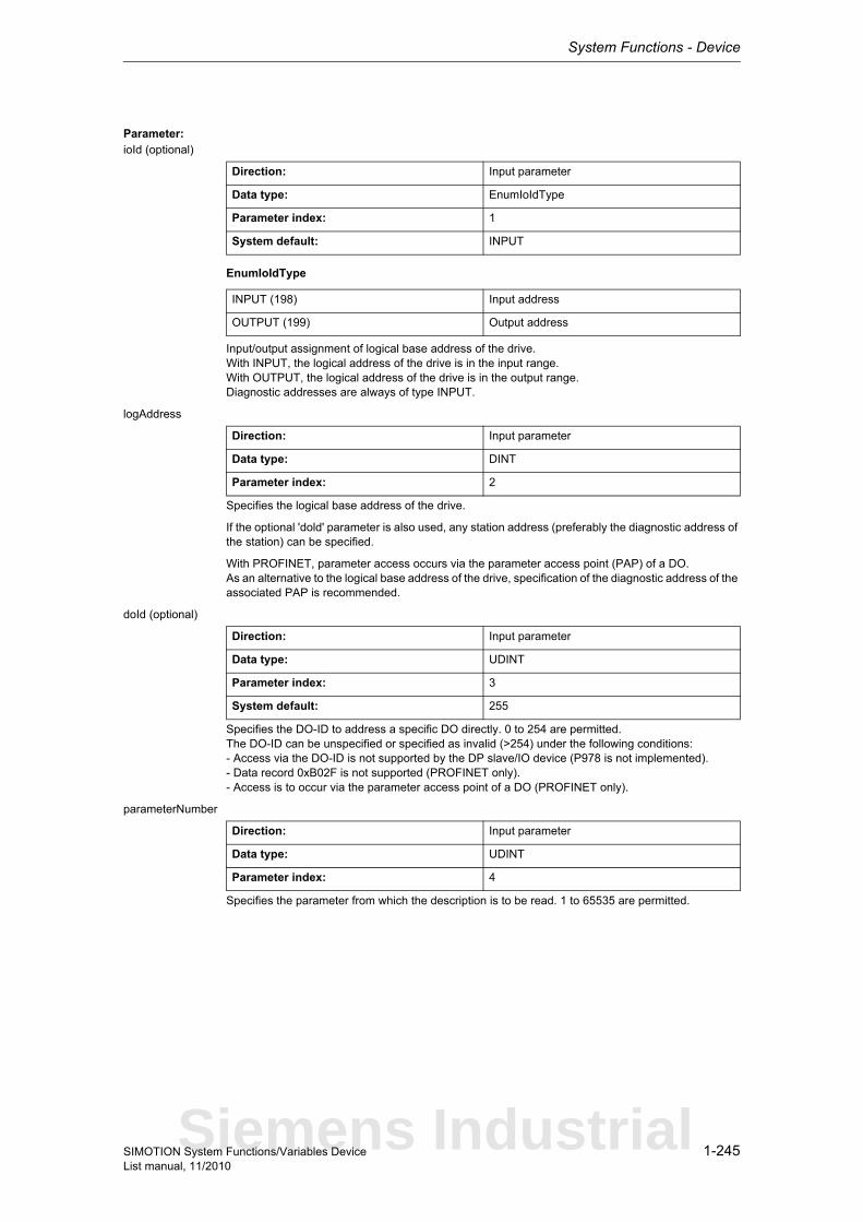
System Functions - Device
1-245SIMOTION System Functions/Variables DeviceList manual, 11/2010
Parameter: ioId (optional)
EnumIoIdType
Input/output assignment of logical base address of the drive.With INPUT, the logical address of the drive is in the input range.With OUTPUT, the logical address of the drive is in the output range.Diagnostic addresses are always of type INPUT.
logAddress
Specifies the logical base address of the drive.
If the optional 'dold' parameter is also used, any station address (preferably the diagnostic address of the station) can be specified.
With PROFINET, parameter access occurs via the parameter access point (PAP) of a DO.As an alternative to the logical base address of the drive, specification of the diagnostic address of the associated PAP is recommended.
doId (optional)
Specifies the DO-ID to address a specific DO directly. 0 to 254 are permitted.The DO-ID can be unspecified or specified as invalid (>254) under the following conditions:- Access via the DO-ID is not supported by the DP slave/IO device (P978 is not implemented).- Data record 0xB02F is not supported (PROFINET only).- Access is to occur via the parameter access point of a DO (PROFINET only).
parameterNumber
Specifies the parameter from which the description is to be read. 1 to 65535 are permitted.
Direction: Input parameter
Data type: EnumIoIdType
Parameter index: 1
System default: INPUT
INPUT (198) Input address
OUTPUT (199) Output address
Direction: Input parameter
Data type: DINT
Parameter index: 2
Direction: Input parameter
Data type: UDINT
Parameter index: 3
System default: 255
Direction: Input parameter
Data type: UDINT
Parameter index: 4
Siemens Industrial
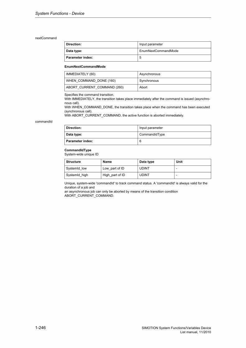
System Functions - Device
1-246 SIMOTION System Functions/Variables DeviceList manual, 11/2010
nextCommand
EnumNextCommandMode
Specifies the command transition.With IMMEDIATELY, the transition takes place immediately after the command is issued (asynchro-nous call).With WHEN_COMMAND_DONE, the transition takes place when the command has been executed (synchronous call).With ABORT_CURRENT_COMMAND, the active function is aborted immediately.
commandId
CommandIdTypeSystem-wide unique ID
Unique, system-wide 'commandId' to track command status. A 'commandId' is always valid for the duration of a job andan asynchronous job can only be aborted by means of the transition condition ABORT_CURRENT_COMMAND.
Direction: Input parameter
Data type: EnumNextCommandMode
Parameter index: 5
IMMEDIATELY (60) Asynchronous
WHEN_COMMAND_DONE (160) Synchronous
ABORT_CURRENT_COMMAND (260) Abort
Direction: Input parameter
Data type: CommandIdType
Parameter index: 6
Structure Name Data type Unit
SystemId_low Low_part of ID UDINT -
SystemId_high High_part of ID UDINT -
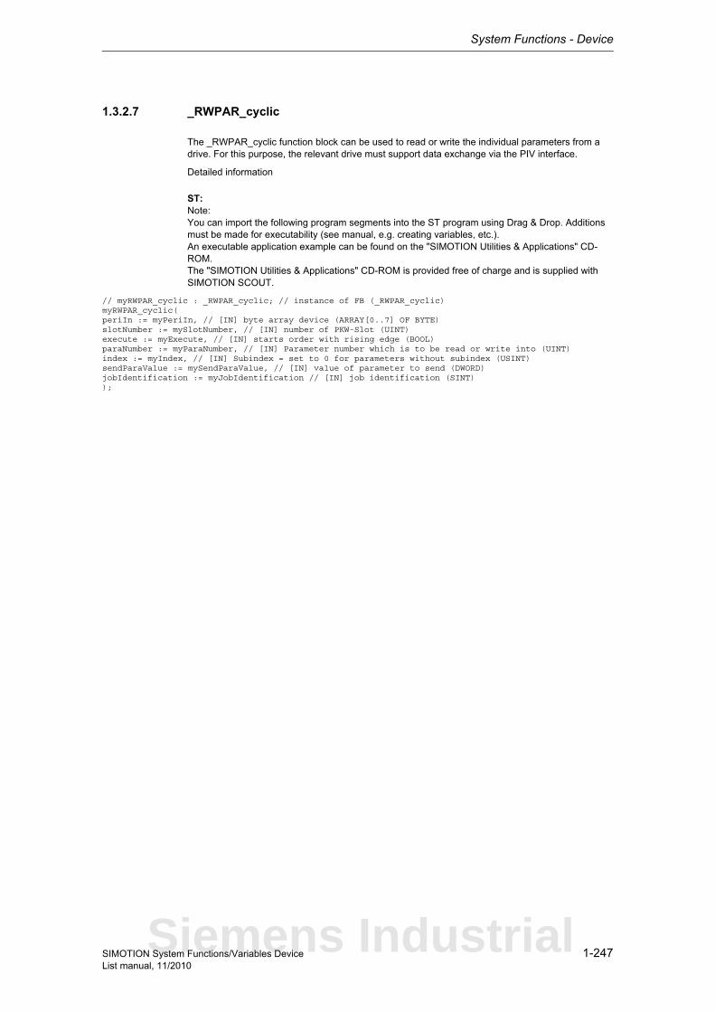
System Functions - Device
1-247SIMOTION System Functions/Variables DeviceList manual, 11/2010
1.3.2.7 _RWPAR_cyclic
The _RWPAR_cyclic function block can be used to read or write the individual parameters from a drive. For this purpose, the relevant drive must support data exchange via the PIV interface.
Detailed information
ST: Note:You can import the following program segments into the ST program using Drag & Drop. Additions must be made for executability (see manual, e.g. creating variables, etc.).An executable application example can be found on the "SIMOTION Utilities & Applications" CD-ROM.The "SIMOTION Utilities & Applications" CD-ROM is provided free of charge and is supplied with SIMOTION SCOUT.
// myRWPAR_cyclic : _RWPAR_cyclic; // instance of FB (_RWPAR_cyclic)myRWPAR_cyclic(periIn := myPeriIn, // [IN] byte array device (ARRAY[0..7] OF BYTE)slotNumber := mySlotNumber, // [IN] number of PKW-Slot (UINT)execute := myExecute, // [IN] starts order with rising edge (BOOL)paraNumber := myParaNumber, // [IN] Parameter number which is to be read or write into (UINT)index := myIndex, // [IN] Subindex = set to 0 for parameters without subindex (USINT)sendParaValue := mySendParaValue, // [IN] value of parameter to send (DWORD)jobIdentification := myJobIdentification // [IN] job identification (SINT));
Siemens Industrial
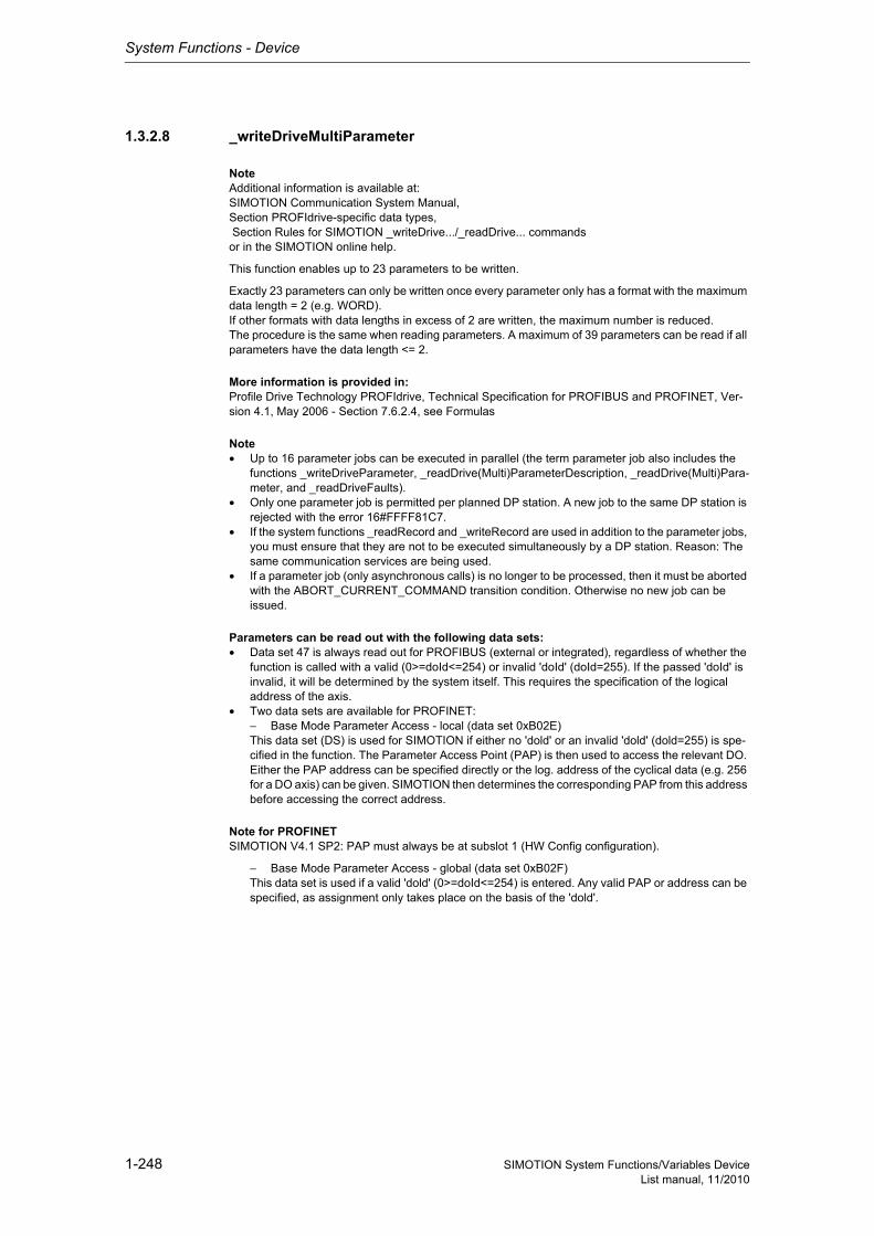
System Functions - Device
1-248 SIMOTION System Functions/Variables DeviceList manual, 11/2010
1.3.2.8 _writeDriveMultiParameter
NoteAdditional information is available at:SIMOTION Communication System Manual,Section PROFIdrive-specific data types, Section Rules for SIMOTION _writeDrive.../_readDrive... commandsor in the SIMOTION online help.
This function enables up to 23 parameters to be written.
Exactly 23 parameters can only be written once every parameter only has a format with the maximum data length = 2 (e.g. WORD).If other formats with data lengths in excess of 2 are written, the maximum number is reduced.The procedure is the same when reading parameters. A maximum of 39 parameters can be read if all parameters have the data length <= 2.
More information is provided in:Profile Drive Technology PROFIdrive, Technical Specification for PROFIBUS and PROFINET, Ver-sion 4.1, May 2006 - Section 7.6.2.4, see Formulas
Note• Up to 16 parameter jobs can be executed in parallel (the term parameter job also includes the
functions _writeDriveParameter, _readDrive(Multi)ParameterDescription, _readDrive(Multi)Para-meter, and _readDriveFaults).
• Only one parameter job is permitted per planned DP station. A new job to the same DP station is rejected with the error 16#FFFF81C7.
• If the system functions _readRecord and _writeRecord are used in addition to the parameter jobs, you must ensure that they are not to be executed simultaneously by a DP station. Reason: The same communication services are being used.
• If a parameter job (only asynchronous calls) is no longer to be processed, then it must be aborted with the ABORT_CURRENT_COMMAND transition condition. Otherwise no new job can be issued.
Parameters can be read out with the following data sets:• Data set 47 is always read out for PROFIBUS (external or integrated), regardless of whether the
function is called with a valid (0>=doId<=254) or invalid 'doId' (doId=255). If the passed 'doId' is invalid, it will be determined by the system itself. This requires the specification of the logical address of the axis.
• Two data sets are available for PROFINET:− Base Mode Parameter Access - local (data set 0xB02E)This data set (DS) is used for SIMOTION if either no 'dold' or an invalid 'dold' (dold=255) is spe-cified in the function. The Parameter Access Point (PAP) is then used to access the relevant DO. Either the PAP address can be specified directly or the log. address of the cyclical data (e.g. 256 for a DO axis) can be given. SIMOTION then determines the corresponding PAP from this address before accessing the correct address.
Note for PROFINETSIMOTION V4.1 SP2: PAP must always be at subslot 1 (HW Config configuration).
− Base Mode Parameter Access - global (data set 0xB02F)This data set is used if a valid 'dold' (0>=doId<=254) is entered. Any valid PAP or address can be specified, as assignment only takes place on the basis of the 'dold'.
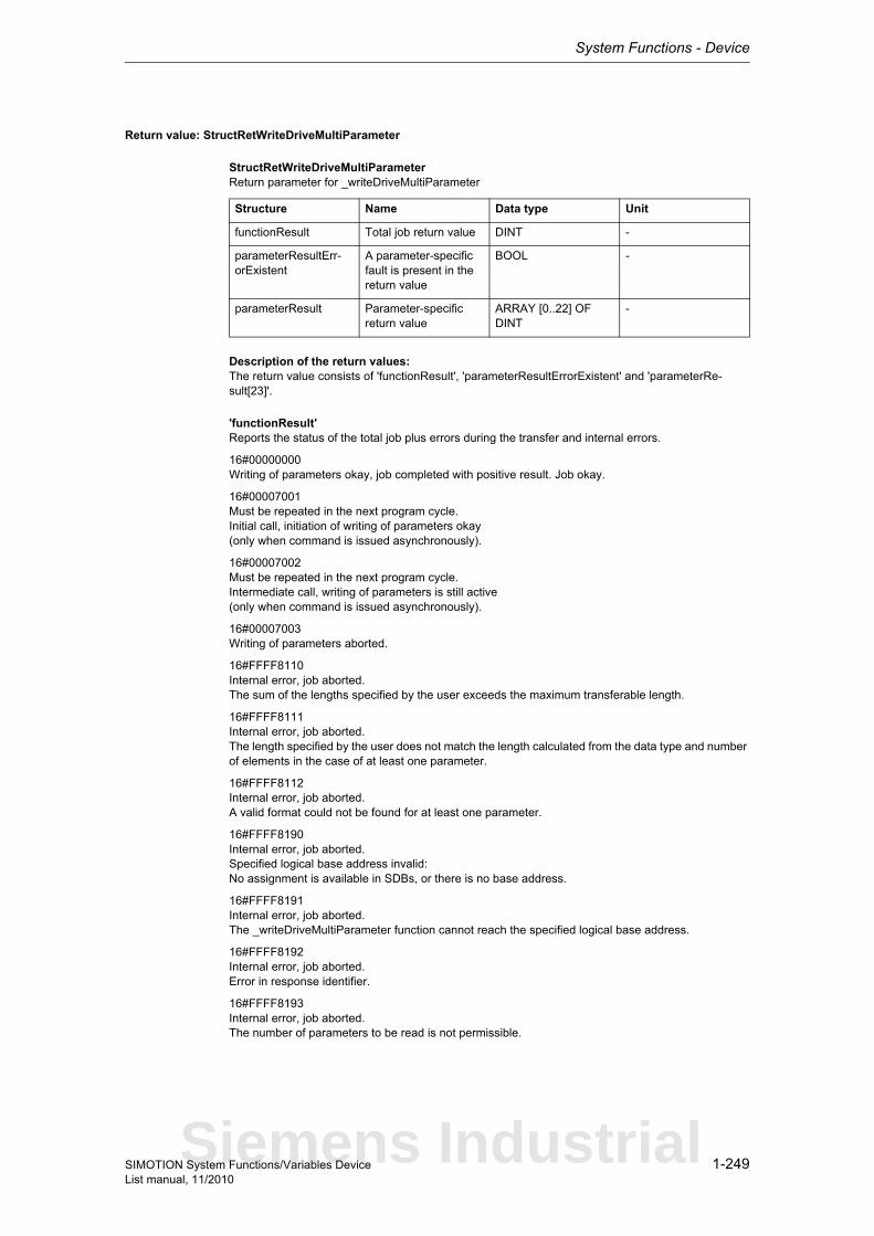
System Functions - Device
1-249SIMOTION System Functions/Variables DeviceList manual, 11/2010
Return value: StructRetWriteDriveMultiParameter
StructRetWriteDriveMultiParameterReturn parameter for _writeDriveMultiParameter
Description of the return values:The return value consists of 'functionResult', 'parameterResultErrorExistent' and 'parameterRe-sult[23]'.
'functionResult'Reports the status of the total job plus errors during the transfer and internal errors.
16#00000000Writing of parameters okay, job completed with positive result. Job okay.
16#00007001Must be repeated in the next program cycle.Initial call, initiation of writing of parameters okay(only when command is issued asynchronously).
16#00007002Must be repeated in the next program cycle.Intermediate call, writing of parameters is still active(only when command is issued asynchronously).
16#00007003Writing of parameters aborted.
16#FFFF8110Internal error, job aborted.The sum of the lengths specified by the user exceeds the maximum transferable length.
16#FFFF8111Internal error, job aborted.The length specified by the user does not match the length calculated from the data type and number of elements in the case of at least one parameter.
16#FFFF8112Internal error, job aborted.A valid format could not be found for at least one parameter.
16#FFFF8190Internal error, job aborted.Specified logical base address invalid:No assignment is available in SDBs, or there is no base address.
16#FFFF8191Internal error, job aborted.The _writeDriveMultiParameter function cannot reach the specified logical base address.
16#FFFF8192Internal error, job aborted.Error in response identifier.
16#FFFF8193Internal error, job aborted.The number of parameters to be read is not permissible.
Structure Name Data type Unit
functionResult Total job return value DINT -
parameterResultErr-orExistent
A parameter-specific fault is present in the return value
BOOL -
parameterResult Parameter-specific return value
ARRAY [0..22] OF DINT
-
Siemens Industrial
System Functions - Device
1-250 SIMOTION System Functions/Variables DeviceList manual, 11/2010
16#FFFF819DInternal error, job aborted.An I slave/I device interface is unable to issue a parameter job to the higher-level master/controller.
16#FFFF819EInternal error, job aborted.Attempt to abort a non-active function.
16#FFFF819FInternal error, job aborted.Function not executable.
16#FFFF81C3Error, can be repeated in the next program cycle.Required resources are presently occupied:- In the _writeDriveMultiParameter function- In the module
16#FFFF81C5Error, can be repeated in the next program cycle.Distributed I/O not available.
16#FFFF81C7Error, can be repeated in the next program cycle.Another parameter job has already been issued to the DP station. - based on the user program - from a system-internal component (e.g. TO axis executes parameter comparison after station reco-very)
16#FFFF81CFError, can be repeated in the next program cycle.Another parameter job call is currently active under this 'commandId'.
16#FFFF8290Corresponds to the error message 16#FFFF8190.
16#FFFF8291Corresponds to the error message 16#FFFF8191.
16#FFFF82A2Error during data set transfer, job aborted.Error in Layer2:- Station failure- Timeout
16#FFFF82A3Error during data set transfer, job aborted.Error in user interface/user:- Protocol error- Station failure- Timeout
16#FFFF82A4-A7Error during data set transfer, job aborted.Error numbers according to IEC 61158 reserved- Query the cause at the module's manufacturer
16#FFFF82A8Error during data set transfer, job aborted.Error because of version conflict.
16#FFFF82A9Error during data set transfer, job aborted.Function not supported by the module.
16#FFFF82AA-AFError during data set transfer, job aborted.Error numbers according to IEC 61158 manufacturer-specific- Query the cause at the module's manufacturer
System Functions - Device
1-251SIMOTION System Functions/Variables DeviceList manual, 11/2010
16#FFFF82B0Error during data set transfer, job aborted.Parameter jobs are not supported by the addressed module.
16#FFFF82B2Error during data set transfer, job aborted.Module reports access to an invalid slot/subslot.
16#FFFF82B3Error during data set transfer, job aborted.Module reports type conflict.
16#FFFF82B4Error during data set transfer, job aborted.Module reports access to an invalid area.
16#FFFF82B5Error during data set transfer, can be repeated in the next program cycle.The system function cannot be executed due to an internal operating state of the module.
16#FFFF82B6Error during data set transfer, job aborted.Module rejects access.
16#FFFF82B7Error during data set transfer, job aborted.The job could not be dispatched due to a job error.
16#FFFF82B8Error during data set transfer, job aborted.Module reports an invalid parameter.
16#FFFF82B9Error during data set transfer, job aborted.Module reports an invalid type.
16#FFFF82BA-BFError during data set transfer, job aborted.Error numbers according to IEC 61158 manufacturer-specific- Query the cause at the module's manufacturer
16#FFFF82C1Error during data set transfer, command can be repeated immediately.Data of the preceding write job on the module for the same data set has not yet been processed by the module.
16#FFFF82C2Error during data set transfer, command can be repeated immediately.The module is currently executing the maximum possible jobs for one CPU.
16#FFFF82C3Error during data set transfer, command can be repeated immediately.Required resources are presently occupied:- In the _writeRecord function- In the module
16#FFFF82C4Error during data set transfer, command can be repeated immediately.Communication errors:- Parity error- SW Ready not set- Error in block length administration- Checksum error on CPU side- Checksum error on module side
16#FFFF82C5Error during data set transfer, can be repeated in the next program cycle.Distributed I/O not available.
Siemens Industrial
System Functions - Device
1-252 SIMOTION System Functions/Variables DeviceList manual, 11/2010
16#FFFF82C6Error during data set transfer, can be repeated in the next program cycle.Data record transfer has been aborted due to priority class abort (restart or background).
'parameterResultErrorExistent'Returns TRUE when an error is reported in at least one 'parameterResult'.
'parameterResult'Reports parameter-specific errors.
16#FFFF8000Parameter error, job aborted.Access to a non-existent parameter.
16#FFFF8001Parameter error, job aborted.Change access to a parameter that cannot be modified.
16#FFFF8002Parameter error, job aborted.Change access with value outside value limits.
16#FFFF8003Parameter error, job aborted.Access to a non-existent subindex.
16#FFFF8004Parameter error, job aborted.Access with subindex to non-indexed parameter(not an array parameter).
16#FFFF8005Parameter error, job aborted.Change access with value that does not match the parameter data type.
16#FFFF8006Parameter error, job aborted.Modification access with value other than 0 where this is not allowed.
16#FFFF800BParameter error, job aborted.Change access without parameter change rights.
16#FFFF8011Parameter error, job aborted.Job cannot be executed due to operating state.
16#FFFF8014Parameter error, job aborted.Modification access with value that is within value limits, but illegal for some other sustainable reason (parameter with defined individual values).
16#FFFF8016Parameter error, job aborted.Illegal or unsupported value for attribute, number of elements, parameter number, or subindex, or a combination of these.
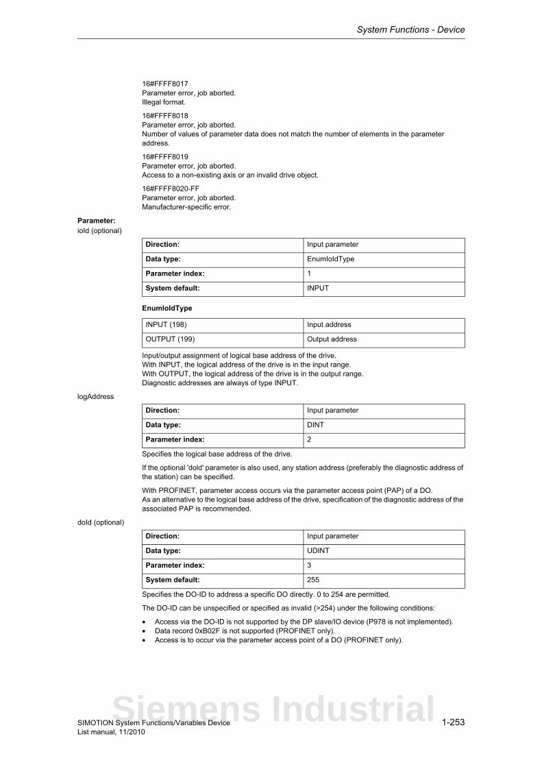
System Functions - Device
1-253SIMOTION System Functions/Variables DeviceList manual, 11/2010
16#FFFF8017Parameter error, job aborted.Illegal format.
16#FFFF8018Parameter error, job aborted.Number of values of parameter data does not match the number of elements in the parameter address.
16#FFFF8019Parameter error, job aborted.Access to a non-existing axis or an invalid drive object.
16#FFFF8020-FFParameter error, job aborted.Manufacturer-specific error.
Parameter: ioId (optional)
EnumIoIdType
Input/output assignment of logical base address of the drive.With INPUT, the logical address of the drive is in the input range.With OUTPUT, the logical address of the drive is in the output range.Diagnostic addresses are always of type INPUT.
logAddress
Specifies the logical base address of the drive.
If the optional 'dold' parameter is also used, any station address (preferably the diagnostic address of the station) can be specified.
With PROFINET, parameter access occurs via the parameter access point (PAP) of a DO.As an alternative to the logical base address of the drive, specification of the diagnostic address of the associated PAP is recommended.
doId (optional)
Specifies the DO-ID to address a specific DO directly. 0 to 254 are permitted.
The DO-ID can be unspecified or specified as invalid (>254) under the following conditions:
• Access via the DO-ID is not supported by the DP slave/IO device (P978 is not implemented).• Data record 0xB02F is not supported (PROFINET only).• Access is to occur via the parameter access point of a DO (PROFINET only).
Direction: Input parameter
Data type: EnumIoIdType
Parameter index: 1
System default: INPUT
INPUT (198) Input address
OUTPUT (199) Output address
Direction: Input parameter
Data type: DINT
Parameter index: 2
Direction: Input parameter
Data type: UDINT
Parameter index: 3
System default: 255
Siemens Industrial
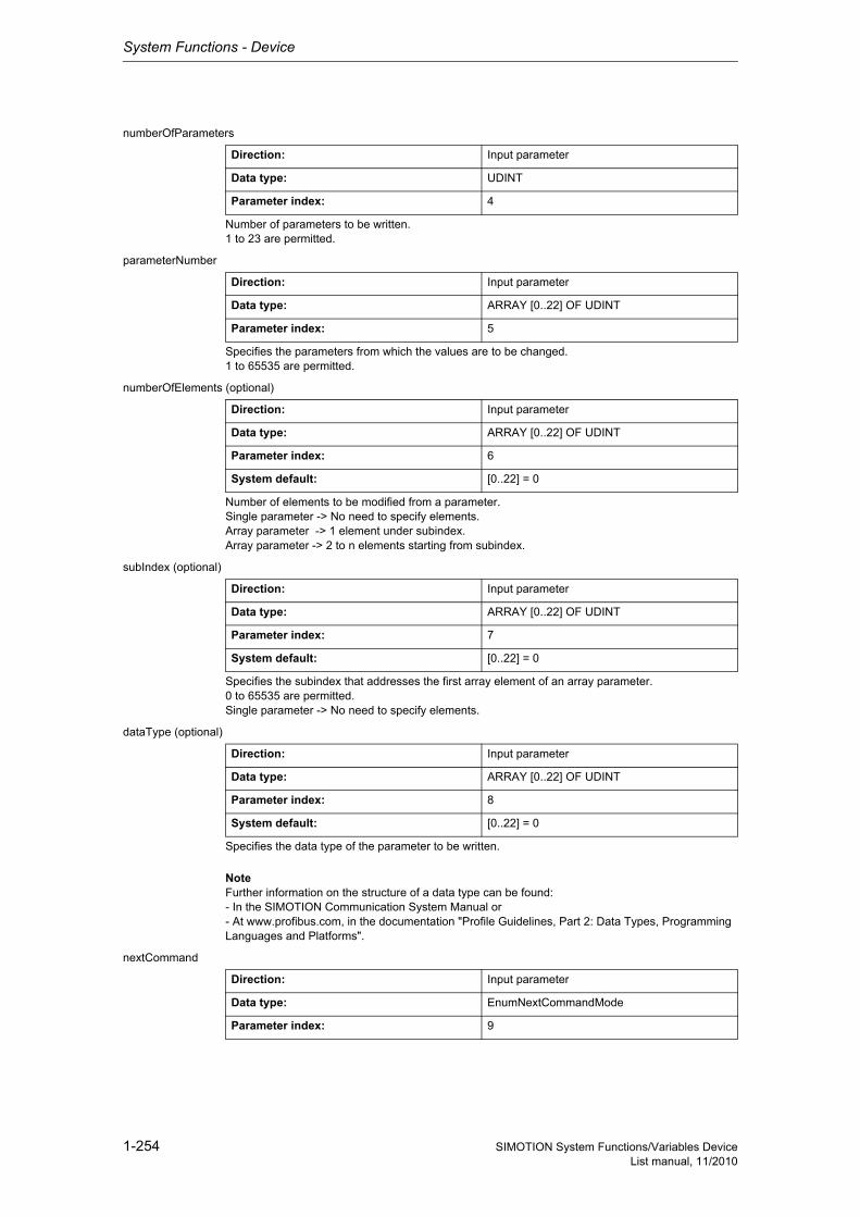
System Functions - Device
1-254 SIMOTION System Functions/Variables DeviceList manual, 11/2010
numberOfParameters
Number of parameters to be written.1 to 23 are permitted.
parameterNumber
Specifies the parameters from which the values are to be changed.1 to 65535 are permitted.
numberOfElements (optional)
Number of elements to be modified from a parameter.Single parameter -> No need to specify elements.Array parameter -> 1 element under subindex.Array parameter -> 2 to n elements starting from subindex.
subIndex (optional)
Specifies the subindex that addresses the first array element of an array parameter.0 to 65535 are permitted.Single parameter -> No need to specify elements.
dataType (optional)
Specifies the data type of the parameter to be written.
NoteFurther information on the structure of a data type can be found:- In the SIMOTION Communication System Manual or- At www.profibus.com, in the documentation "Profile Guidelines, Part 2: Data Types, Programming Languages and Platforms".
nextCommand
Direction: Input parameter
Data type: UDINT
Parameter index: 4
Direction: Input parameter
Data type: ARRAY [0..22] OF UDINT
Parameter index: 5
Direction: Input parameter
Data type: ARRAY [0..22] OF UDINT
Parameter index: 6
System default: [0..22] = 0
Direction: Input parameter
Data type: ARRAY [0..22] OF UDINT
Parameter index: 7
System default: [0..22] = 0
Direction: Input parameter
Data type: ARRAY [0..22] OF UDINT
Parameter index: 8
System default: [0..22] = 0
Direction: Input parameter
Data type: EnumNextCommandMode
Parameter index: 9
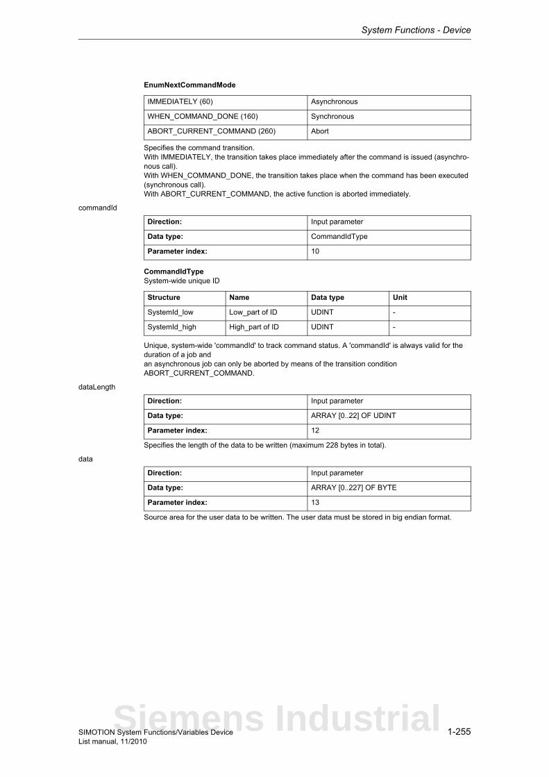
System Functions - Device
1-255SIMOTION System Functions/Variables DeviceList manual, 11/2010
EnumNextCommandMode
Specifies the command transition.With IMMEDIATELY, the transition takes place immediately after the command is issued (asynchro-nous call).With WHEN_COMMAND_DONE, the transition takes place when the command has been executed (synchronous call).With ABORT_CURRENT_COMMAND, the active function is aborted immediately.
commandId
CommandIdTypeSystem-wide unique ID
Unique, system-wide 'commandId' to track command status. A 'commandId' is always valid for the duration of a job andan asynchronous job can only be aborted by means of the transition condition ABORT_CURRENT_COMMAND.
dataLength
Specifies the length of the data to be written (maximum 228 bytes in total).
data
Source area for the user data to be written. The user data must be stored in big endian format.
IMMEDIATELY (60) Asynchronous
WHEN_COMMAND_DONE (160) Synchronous
ABORT_CURRENT_COMMAND (260) Abort
Direction: Input parameter
Data type: CommandIdType
Parameter index: 10
Structure Name Data type Unit
SystemId_low Low_part of ID UDINT -
SystemId_high High_part of ID UDINT -
Direction: Input parameter
Data type: ARRAY [0..22] OF UDINT
Parameter index: 12
Direction: Input parameter
Data type: ARRAY [0..227] OF BYTE
Parameter index: 13
Siemens Industrial
System Functions - Device
1-256 SIMOTION System Functions/Variables DeviceList manual, 11/2010
1.3.2.9 _writeDriveParameter
NoteAdditional information is available at:SIMOTION Communication System Manual,Section PROFIdrive-specific data types, Section Rules for SIMOTION _writeDrive.../_readDrive... commandsor in the SIMOTION online help.
This function enables a drive parameter to be written.
Note• Up to 16 parameter jobs can be executed in parallel (the term parameter job also includes the
functions _writeDriveMultiParameter, _readDrive(Multi)ParameterDescription, _readDrive(Multi)Parameter and _readDriveFaults).
• Only one parameter job is permitted per planned DP station. A new job to the same DP station is rejected with the error 16#FFFF81C7.
• If the system functions _readRecord and _writeRecord are used in addition to the parameter jobs, you must ensure that they are not to be executed simultaneously by a DP station. Reason: The same communication services are used.
• If a parameter job (only asynchronous calls) is no longer to be processed, then it must be aborted with the ABORT_CURRENT_COMMAND transition condition. Otherwise no new job can be issued.
Parameters can be read out with the following data sets:• Data set 47 is always read out for PROFIBUS (external or integrated), regardless of whether the
function is called with a valid (0>=doId<=254) or invalid 'doId' (doId=255). If the passed 'doId' is invalid, it will be determined by the system itself. This requires the specification of the logical address of the axis.
• Two data sets are available for PROFINET:− Base Mode Parameter Access - local (data set 0xB02E)This data set (DS) is used for SIMOTION if either no 'dold' or an invalid 'dold' (dold=255) is spe-cified in the function. The Parameter Access Point (PAP) is then used to access the relevant DO. Either the PAP address can be specified directly or the log. address of the cyclical data (e.g. 256 for a DO axis) can be given. SIMOTION then determines the corresponding PAP from this address before accessing the correct address.
Note for PROFINETSIMOTION V4.1 SP2: PAP must always be at subslot 1 (HW Config configuration).
− Base Mode Parameter Access - global (data set 0xB02F)This data set is used if a valid 'dold' (0>=doId<=254) is entered. Any valid PAP or address can be specified, as assignment only takes place on the basis of the 'dold'.
Return value: StructRetWriteDriveParameter
StructRetWriteDriveParameterReturn parameter for _writeDriveParameter
Description of the return values:The return value consists of 'functionResult' and 'parameterResult'.
Structure Name Data type Unit
functionResult Total job return value DINT -
parameterResult Parameter-specific return value
DINT -
System Functions - Device
1-257SIMOTION System Functions/Variables DeviceList manual, 11/2010
'functionResult'Reports the status of the total job plus errors during the transfer and internal errors.
16#00000000Writing of parameters okay, job completed with positive result. Job okay.
16#00007001Must be repeated in the next program cycle.Initial call, initiation of reading of parameter description okay(only when command is issued asynchronously).
16#00007002Must be repeated in the next program cycle.Intermediate call, reading of parameter description is still active(only when command is issued asynchronously).
16#00007003Writing of parameters aborted.
16#FFFF8110Internal error, job aborted.The length specified by the user exceeds the maximum transferable length.
16#FFFF8111Internal error, job abortedThe length specified by the user does not match the length calculated from the data type and number of elements.
16#FFFF8112Internal error, job aborted.No valid format could be found.
16#FFFF8190Internal error, job aborted.Specified logical base address invalid:No assignment is available in SDBs, or there is no base address.
16#FFFF8191Internal error, job aborted.The _writeDriveParameter function cannot reach the specified logical base address.
16#FFFF8192Internal error, job aborted.Error in response identifier.
16#FFFF819DInternal error, job aborted.An I slave/I device interface is unable to issue a parameter job to the higher-level master/controller.
16#FFFF819EInternal error, job aborted.Attempt to abort a non-active function.
16#FFFF819FInternal error, job aborted.Function not executable.
16#FFFF81C3Error, can be repeated in the next program cycle.Required resources are presently occupied:- In the _writeDriveParameter function- In the module
16#FFFF81C5Error, can be repeated in the next program cycle.Distributed I/O not available.
Siemens Industrial

System Functions - Device
1-258 SIMOTION System Functions/Variables DeviceList manual, 11/2010
16#FFFF81C7Error, can be repeated in the next program cycle.Another parameter job has already been issued to the DP station. - based on the user program - from a system-internal component (e.g. TO axis executes parameter comparison after station reco-very)
16#FFFF81CFError, can be repeated in the next program cycle.Another parameter job call is currently active under this 'commandId'.
16#FFFF8290Corresponds to the error message 16#FFFF8190.
16#FFFF8291Corresponds to the error message 16#FFFF8191.
16#FFFF82A2Error during data set transfer, job aborted.Error in Layer2:- Station failure- Timeout
16#FFFF82A3Error during data set transfer, job aborted.Error in user interface/user:- Protocol error- Station failure- Timeout
16#FFFF82A4-A7Error during data set transfer, job aborted.Error numbers according to IEC 61158 reserved- Query the cause at the module's manufacturer
16#FFFF82A8Error during data set transfer, job aborted.Error because of version conflict.
16#FFFF82A9Error during data set transfer, job aborted.Function not supported by the module.
16#FFFF82AA-AFError during data set transfer, job aborted.Error numbers according to IEC 61158 manufacturer-specific- Query the cause at the module's manufacturer
16#FFFF82B0Error during data set transfer, job aborted.Parameter jobs are not supported by the addressed module.
16#FFFF82B2Error during data set transfer, job aborted.Module reports access to an invalid slot/subslot.
16#FFFF82B3Error during data set transfer, job aborted.Module reports type conflict.
16#FFFF82B4Error during data set transfer, job aborted.Module reports access to an invalid area.
16#FFFF82B5Error during data set transfer, can be repeated in the next program cycle.The system function cannot be executed due to an internal operating state of the module.
16#FFFF82B6Error during data set transfer, job aborted.Module rejects access.
System Functions - Device
1-259SIMOTION System Functions/Variables DeviceList manual, 11/2010
16#FFFF82B7Error during data set transfer, job aborted.The job could not be dispatched due to a job error.
16#FFFF82B8Error during data set transfer, job aborted.Module reports an invalid parameter.
16#FFFF82B9Error during data set transfer, job aborted.Module reports an invalid type.
16#FFFF82BA-BFError during data set transfer, job aborted.Error numbers according to IEC 61158 manufacturer-specific- Query the cause at the module's manufacturer
16#FFFF82C1Error during data set transfer, command can be repeated immediately.Data of the preceding write job on the module for the same data set has not yet been processed by the module.
16#FFFF82C2Error during data set transfer, command can be repeated immediately.The module is currently executing the maximum possible jobs for one CPU.
16#FFFF82C3Error during data set transfer, command can be repeated immediately.Required resources are presently occupied:- In the _writeRecord function- In the module
16#FFFF82C4Error during data set transfer, command can be repeated immediately.Communication errors:- Parity error- SW Ready not set- Error in block length administration- Checksum error on CPU side- Checksum error on module side
16#FFFF82C5Error during data set transfer, can be repeated in the next program cycle.Distributed I/O not available.
16#FFFF82C6Error during data set transfer, can be repeated in the next program cycle.Data record transfer has been aborted due to priority class abort (restart or background).
'parameterResult'Reports parameter-specific errors.
16#FFFF8000Parameter error, job aborted.Access to a non-existent parameter.
16#FFFF8001Parameter error, job aborted.Change access to a parameter that cannot be modified.
16#FFFF8002Parameter error, job aborted.Change access with value outside value limits.
Siemens Industrial
System Functions - Device
1-260 SIMOTION System Functions/Variables DeviceList manual, 11/2010
16#FFFF8003Parameter error, job aborted.Access to a non-existent subindex.
16#FFFF8004Parameter error, job aborted.Access with subindex to non-indexed parameter (not an array parameter).
16#FFFF8005Parameter error, job aborted.Change access with value that does not match the parameter data type.
16#FFFF8006Parameter error, job aborted.Modification access with value other than 0 where this is not allowed.
16#FFFF800BParameter error, job aborted.Change access without parameter change rights.
16#FFFF8011Parameter error, job aborted.Job cannot be executed due to operating state.
16#FFFF8014Parameter error, job aborted.Modification access with value that is within value limits, but illegal for some other sustainable reason(parameter with defined individual values).
16#FFFF8016Parameter error, job aborted.Illegal or unsupported value for attribute, number of elements, parameter number, or subindex, or a combination of these.
16#FFFF8017Parameter error, job aborted.Illegal format.
16#FFFF8018Parameter error, job aborted.Number of values of parameter data does not match the number of elements in the parameter address.
16#FFFF8019Parameter error, job aborted.Access to a non-existing axis or an invalid drive object.
16#FFFF8020-FF Parameter error, job aborted.Manufacturer-specific error.
Parameter: ioId (optional)
EnumIoIdType
Input/output assignment of logical base address of the drive.With INPUT, the logical address of the drive is in the input range.With OUTPUT, the logical address of the drive is in the output range.Diagnostic addresses are always of type INPUT.
Direction: Input parameter
Data type: EnumIoIdType
Parameter index: 1
System default: INPUT
INPUT (198) Input address
OUTPUT (199) Output address
System Functions - Device
1-261SIMOTION System Functions/Variables DeviceList manual, 11/2010
logAddress
Specifies the logical base address of the drive.
If the optional 'dold' parameter is also used, any station address (preferably the diagnostic address of the station) can be specified.
With PROFINET, parameter access occurs via the parameter access point (PAP) of a DO.As an alternative to the logical base address of the drive, specification of the diagnostic address of the associated PAP is recommended.
doId (optional)
Specifies the DO-ID to address a specific DO directly. 0 to 254 are permitted.The DO-ID can be unspecified or specified as invalid (>254) under the following conditions:- Access via the DO-ID is not supported by the DP slave/IO device (P978 is not implemented).- Data record 0xB02F is not supported (PROFINET only).- Access is to occur via the parameter access point of a DO (PROFINET only).
parameterNumber
Specifies the parameter numbers from which the values are to be written.1 to 65535 are permitted.
numberOfElements (optional)
Number of elements that are to be written from a parameter.Single parameter -> No need to specify elements.Array parameter -> 1 element under subindex.Array parameter -> 2 to n elements starting from subindex.
subIndex (optional)
Specifies the subindex that addresses the first array element of the parameter.0 to 65535 are permitted.
Direction: Input parameter
Data type: DINT
Parameter index: 2
Direction: Input parameter
Data type: UDINT
Parameter index: 3
System default: 255
Direction: Input parameter
Data type: UDINT
Parameter index: 4
Direction: Input parameter
Data type: UDINT
Parameter index: 5
System default: 0
Direction: Input parameter
Data type: UDINT
Parameter index: 6
System default: 0
Siemens Industrial
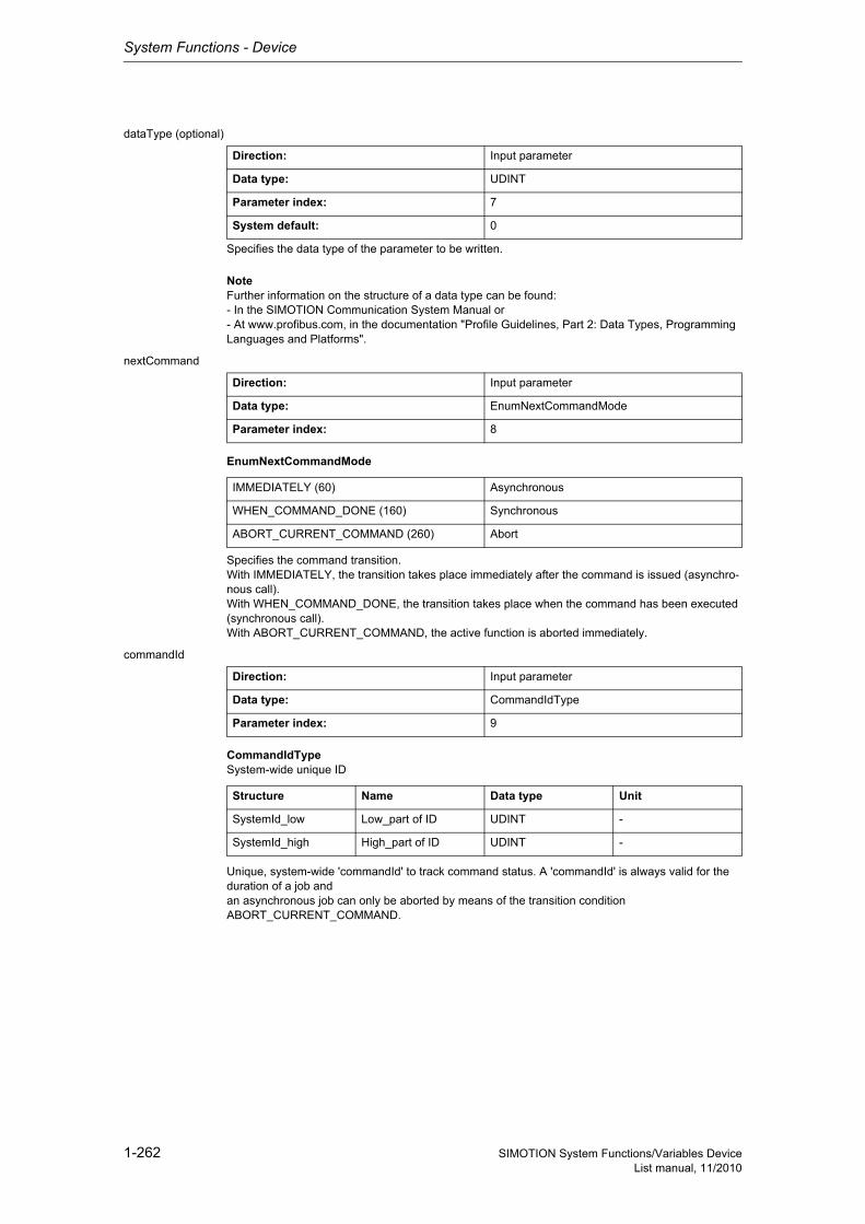
System Functions - Device
1-262 SIMOTION System Functions/Variables DeviceList manual, 11/2010
dataType (optional)
Specifies the data type of the parameter to be written.
NoteFurther information on the structure of a data type can be found:- In the SIMOTION Communication System Manual or- At www.profibus.com, in the documentation "Profile Guidelines, Part 2: Data Types, Programming Languages and Platforms".
nextCommand
EnumNextCommandMode
Specifies the command transition.With IMMEDIATELY, the transition takes place immediately after the command is issued (asynchro-nous call).With WHEN_COMMAND_DONE, the transition takes place when the command has been executed (synchronous call).With ABORT_CURRENT_COMMAND, the active function is aborted immediately.
commandId
CommandIdTypeSystem-wide unique ID
Unique, system-wide 'commandId' to track command status. A 'commandId' is always valid for the duration of a job andan asynchronous job can only be aborted by means of the transition condition ABORT_CURRENT_COMMAND.
Direction: Input parameter
Data type: UDINT
Parameter index: 7
System default: 0
Direction: Input parameter
Data type: EnumNextCommandMode
Parameter index: 8
IMMEDIATELY (60) Asynchronous
WHEN_COMMAND_DONE (160) Synchronous
ABORT_CURRENT_COMMAND (260) Abort
Direction: Input parameter
Data type: CommandIdType
Parameter index: 9
Structure Name Data type Unit
SystemId_low Low_part of ID UDINT -
SystemId_high High_part of ID UDINT -

System Functions - Device
1-263SIMOTION System Functions/Variables DeviceList manual, 11/2010
dataLength
Specifies the length of the data to be written (maximum 228 bytes).
data
Source area for the user data to be written. The user data must be stored in big endian format.
Direction: Input parameter
Data type: UDINT
Parameter index: 11
Direction: Input parameter
Data type: ARRAY [0..227] OF BYTE
Parameter index: 12
Siemens Industrial
System Functions - Device
1-264 SIMOTION System Functions/Variables DeviceList manual, 11/2010
1.3.3 SINAMICS
1.3.3.1 _abortAllReadWriteDriveParameterJobs
Note"Further information can be found in the SIMOTION Communication System Manual (_readDrive and _writeDrive section) and in SIMOTION online help."
This function aborts all parameter jobs currently being processed.The term "parameter job" refers to the functions _readDrive(Multi)ParameterDescription, _readDrive(Multi)Parameter, _writeDrive(Multi)Parameter and _readDriveFaults.
Return value: DINT
Description of the return values:16#00000000Job completed without errors.
16#FFFF819FError, job aborted. Function not executable.
16#FFFF81C5Error, can be repeated in the next program cycle. Function could not be executed.This may have the following reasons:- The function _abortAllReadWriteDriveParameterJobs is already being executed.- A parameter job is currently being called from another task.
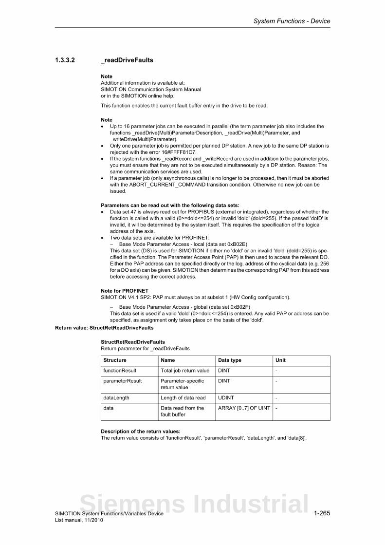
System Functions - Device
1-265SIMOTION System Functions/Variables DeviceList manual, 11/2010
1.3.3.2 _readDriveFaults
NoteAdditional information is available at:SIMOTION Communication System Manualor in the SIMOTION online help.
This function enables the current fault buffer entry in the drive to be read.
Note• Up to 16 parameter jobs can be executed in parallel (the term parameter job also includes the
functions _readDrive(Multi)ParameterDescription, _readDrive(Multi)Parameter, and _writeDrive(Multi)Parameter).
• Only one parameter job is permitted per planned DP station. A new job to the same DP station is rejected with the error 16#FFFF81C7.
• If the system functions _readRecord and _writeRecord are used in addition to the parameter jobs, you must ensure that they are not to be executed simultaneously by a DP station. Reason: The same communication services are used.
• If a parameter job (only asynchronous calls) is no longer to be processed, then it must be aborted with the ABORT_CURRENT_COMMAND transition condition. Otherwise no new job can be issued.
Parameters can be read out with the following data sets:• Data set 47 is always read out for PROFIBUS (external or integrated), regardless of whether the
function is called with a valid (0>=doId<=254) or invalid 'doId' (doId=255). If the passed 'doID' is invalid, it will be determined by the system itself. This requires the specification of the logical address of the axis.
• Two data sets are available for PROFINET:− Base Mode Parameter Access - local (data set 0xB02E)This data set (DS) is used for SIMOTION if either no 'dold' or an invalid 'dold' (dold=255) is spe-cified in the function. The Parameter Access Point (PAP) is then used to access the relevant DO. Either the PAP address can be specified directly or the log. address of the cyclical data (e.g. 256 for a DO axis) can be given. SIMOTION then determines the corresponding PAP from this address before accessing the correct address.
Note for PROFINETSIMOTION V4.1 SP2: PAP must always be at subslot 1 (HW Config configuration).
− Base Mode Parameter Access - global (data set 0xB02F)This data set is used if a valid 'dold' (0>=doId<=254) is entered. Any valid PAP or address can be specified, as assignment only takes place on the basis of the 'dold'.
Return value: StructRetReadDriveFaults
StructRetReadDriveFaultsReturn parameter for _readDriveFaults
Description of the return values:The return value consists of 'functionResult', 'parameterResult', 'dataLength', and 'data[8]'.
Structure Name Data type Unit
functionResult Total job return value DINT -
parameterResult Parameter-specific return value
DINT -
dataLength Length of data read UDINT -
data Data read from the fault buffer
ARRAY [0..7] OF UINT -
Siemens Industrial
System Functions - Device
1-266 SIMOTION System Functions/Variables DeviceList manual, 11/2010
'functionResult'Reports the status of the total job plus errors during the transfer and internal errors.
16#00000000Reading of current fault buffer entry okay,Job completed with positive result. Job okay.
16#00007001Must be repeated in the next program cycle.Initial call, initiation of reading of current fault buffer entry okay (only when command is issued asyn-chronously).
16#00007002Must be repeated in the next program cycle.Intermediate call, reading of current fault buffer entry is still active (only when command is issued asynchronously).
16#00007003Reading the current fault buffer entry aborted.
16#FFFF8190Internal error, job aborted.Specified logical base address invalid:No assignment is available in SDBs, or there is no base address.
16#FFFF8191Internal error, job aborted.The _readDriveFaults function cannot reach the specified logical base address.
16#FFFF8192Internal error, job aborted.Error in response identifier.
16#FFFF819DInternal error, job aborted.An I slave/I device interface is unable to issue a parameter job to the higher-level master/controller.
16#FFFF819EInternal error, job aborted.Attempt to abort a non-active function.
16#FFFF819FInternal error, job aborted.Function not executable.
16#FFFF81C3Error, can be repeated in the next program cycle.Required resources are presently occupied:- in the _readDriveFaults function- In the module
16#FFFF81C5Error, can be repeated in the next program cycle.Distributed I/O not available.
16#FFFF81C7Error, can be repeated in the next program cycle.Another parameter job has already been issued to the DP station. - based on the user program - from a system-internal component (e.g. TO axis executes parameter comparison after station reco-very)
16#FFFF81CFError, can be repeated in the next program cycle.Another parameter job call is currently active under this 'commandId'.
16#FFFF8290Corresponds to the error message 16#FFFF8190.
16#FFFF8291Corresponds to the error message 16#FFFF8191.
System Functions - Device
1-267SIMOTION System Functions/Variables DeviceList manual, 11/2010
16#FFFF82A2Error during data set transfer, job aborted.Error in Layer2:- Station failure- Timeout
16#FFFF82A3Error during data set transfer, job aborted.Error in user interface/user:- Protocol error- Station failure- Timeout
16#FFFF82A4-A7Error during data set transfer, job aborted.Error numbers according to IEC 61158 reserved- Query the cause at the module's manufacturer
16#FFFF82A8Error during data set transfer, job aborted.Error because of version conflict.
16#FFFF82A9Error during data set transfer, job aborted.Function not supported by the module.
16#FFFF82AA-AFError during data set transfer, job aborted.Error numbers according to IEC 61158 manufacturer-specific- Query the cause at the module's manufacturer
16#FFFF82B0Error during data set transfer, job aborted.Parameter jobs are not supported by the addressed module.
16#FFFF82B2Error during data set transfer, job aborted.Module reports access to an invalid slot/subslot.
16#FFFF82B3Error during data set transfer, job aborted.Module reports type conflict.
16#FFFF82B4Error during data set transfer, job aborted.Module reports access to an invalid area.
16#FFFF82B5Error during data set transfer, can be repeated in the next program cycle.The system function cannot be executed due to an internal operating state of the module.
16#FFFF82B6Error during data set transfer, job aborted.Module rejects access.
16#FFFF82B7Error during data set transfer, job aborted.The job could not be dispatched due to a job message frame error.
16#FFFF82B8Error during data set transfer, job aborted.Module reports an invalid parameter.
16#FFFF82B9Error during data set transfer, job aborted.Module reports an invalid type.
16#FFFF82BA-BFError during data set transfer, job aborted.Error numbers according to IEC 61158 manufacturer-specific- Query the cause at the module's manufacturer
Siemens Industrial
System Functions - Device
1-268 SIMOTION System Functions/Variables DeviceList manual, 11/2010
16#FFFF82C0Error during data set transfer, can be repeated in the next program cycle.The module is feeding the data record, but the module does not yet have any read data.
16#FFFF82C2Error during data set transfer, command can be repeated immediately.The module is currently executing the maximum possible jobs for one CPU.
16#FFFF82C3Error during data set transfer, command can be repeated immediately.Required resources are presently occupied:- In the _readRecord function- In the module
16#FFFF82C4Error during data set transfer, command can be repeated immediately.Communication errors:- Parity error- SW Ready not set- Error in block length administration- Checksum error on CPU side- Checksum error on module side
16#FFFF82C5Error during data set transfer,Can be repeated in the next program cycle.Distributed I/O not available.
16#FFFF82C6Error during data set transfer, can be repeated in the next program cycle.Data record transfer has been aborted due to priority class abort (restart or background).
'parameterResult'
Reports parameter-specific errors.
16#FFFF8000Parameter error, job aborted.The selected fault buffer does not exist.
16#FFFF8011Parameter error, job aborted.Job cannot be executed due to operating state.
16#FFFF8019Parameter error, job aborted.Access to a non-existing axis or an invalid drive object.
16#FFFF8020-FFParameter error, job aborted.Manufacturer-specific error.
'dataLength' reports the length of data read.
'data[8]' contains the read data (word array, maximum of 8 words).
System Functions - Device
1-269SIMOTION System Functions/Variables DeviceList manual, 11/2010
Parameter: ioId (optional)
EnumIoIdType
Input/output assignment of logical base address of the drive.With INPUT, the logical address of the drive is in the input range.With OUTPUT, the logical address of the drive is in the output range.Diagnostic addresses are always of type INPUT.
logAddress
Specifies the logical base address of the drive.
If the optional 'dold' parameter is also used, any station address (preferably the diagnostic address of the station) can be specified.
With PROFINET, parameter access occurs via the parameter access point (PAP) of a DO.As an alternative to the logical base address of the drive, specification of the diagnostic address of the associated PAP is recommended.
doId (optional)
Specifies the DO-ID to address a specific DO directly. 0 to 254 are permitted.The DO-ID can be unspecified or specified as invalid (>254) under the following conditions:- Access via the DO-ID is not supported by the DP slave/IO device (P978 is not implemented).- Data record 0xB02F is not supported (PROFINET only).- Access is to occur via the parameter access point of a DO (PROFINET only).
Direction: Input parameter
Data type: EnumIoIdType
Parameter index: 1
System default: INPUT
INPUT (198) Input address
OUTPUT (199) Output address
Direction: Input parameter
Data type: DINT
Parameter index: 2
Direction: Input parameter
Data type: UDINT
Parameter index: 3
System default: 255
Siemens Industrial
System Functions - Device
1-270 SIMOTION System Functions/Variables DeviceList manual, 11/2010
faultType (optional)
EnumDriveFaultsType
Specification of the fault buffer type.'faultType' can be used to assign and read out drive- and user-specific parameters.DRIVE reads out the drive-specific fault buffer (parameter 947).USER reads out the user-specific fault buffer (parameter 945). Fault codes of the drive (P947) can be assigned user-specific faults.SAFETY reads out the fault buffer (parameter 9747) relevant for the safety functionality.
NoteThe fault buffer in P9747 relevant for safety is reserved for SINAMICS modules. Other modules could have saved different content in P9747.
nextCommand
EnumNextCommandMode
Specifies the command transition.With IMMEDIATELY, the transition takes place immediately after the command is issued (asynchro-nous call).With WHEN_COMMAND_DONE, the transition takes place when the command has been executed (synchronous call).With ABORT_CURRENT_COMMAND, the active function is aborted immediately.
Direction: Input parameter
Data type: EnumDriveFaultsType
Parameter index: 4
System default: DRIVE
DRIVE (0) Drive-specific fault buffer
USER (1) User-specific fault buffer
SAFETY (2) Safety-relevant fault buffer
Direction: Input parameter
Data type: EnumNextCommandMode
Parameter index: 5
IMMEDIATELY (60) Asynchronous
WHEN_COMMAND_DONE (160) Synchronous
ABORT_CURRENT_COMMAND (260) Abort

System Functions - Device
1-271SIMOTION System Functions/Variables DeviceList manual, 11/2010
commandId
CommandIdTypeSystem-wide unique ID
Unique, system-wide 'commandId' to track command status. A 'commandId' is always valid for the duration of a job andan asynchronous job can only be aborted by means of the transition condition ABORT_CURRENT_COMMAND.
Direction: Input parameter
Data type: CommandIdType
Parameter index: 6
Structure Name Data type Unit
SystemId_low Low_part of ID UDINT -
SystemId_high High_part of ID UDINT -
Siemens Industrial
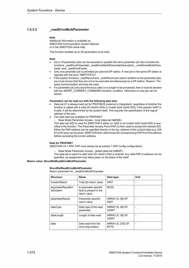
System Functions - Device
1-272 SIMOTION System Functions/Variables DeviceList manual, 11/2010
1.3.3.3 _readDriveMultiParameter
NoteAdditional information is available at:SIMOTION Communication System Manualor in the SIMOTION online help.
This function enables up to 39 parameters to be read.
Note• Up to 16 parameter jobs can be executed in parallel (the term parameter job also includes the
functions _readDriveParameter,_readDrive(Multi)ParameterDescription, _writeDrive(Multi)Para-meter, and _readDriveFaults).
• Only one parameter job is permitted per planned DP station. A new job to the same DP station is rejected with the error 16#FFFF81C7.
• If the system functions _readRecord and _writeRecord are used in addition to the parameter jobs, you must ensure that they are not to be executed simultaneously by a DP station. Reason: The same communication services are used.
• If a parameter job (only asynchronous calls) is no longer to be processed, then it must be aborted with the ABORT_CURRENT_COMMAND transition condition. Otherwise no new job can be issued.
Parameters can be read out with the following data sets:• Data set 47 is always read out for PROFIBUS (external or integrated), regardless of whether the
function is called with a valid (0>=doId<=254) or invalid 'doId' (doId=255). If the passed 'doID' is invalid, it will be determined by the system itself. This requires the specification of the logical address of the axis.
• Two data sets are available for PROFINET:− Base Mode Parameter Access - local (data set 0xB02E)This data set (DS) is used for SIMOTION if either no 'dold' or an invalid 'dold' (dold=255) is spe-cified in the function. The Parameter Access Point (PAP) is then used to access the relevant DO. Either the PAP address can be specified directly or the log. address of the cyclical data (e.g. 256 for a DO axis) can be given. SIMOTION then determines the corresponding PAP from this address before accessing the correct address.
Note for PROFINETSIMOTION V4.1 SP2: PAP must always be at subslot 1 (HW Config configuration).
− Base Mode Parameter Access - global (data set 0xB02F)This data set is used if a valid 'dold' (0>=doId<=254) is entered. Any valid PAP or address can be specified, as assignment only takes place on the basis of the 'dold'.
Return value: StructRetReadDriveMultiParameter
StructRetReadDriveMultiParameterReturn parameter for _readDriveMultiParameter
Structure Name Data type Unit
functionResult Total job return value DINT -
parameterResultErr-orExistent
A parameter-specific fault is present in the return value
BOOL -
parameterResult Parameter-specific return value
ARRAY [0..38] OF DINT
-
dataType Data type of the read parameter
ARRAY [0..38] OF UDINT
-
dataLength Length of data read ARRAY [0..38] OF UDINT
-
data Data read from the drive (big endian)
ARRAY [0..233] OF BYTE
-
System Functions - Device
1-273SIMOTION System Functions/Variables DeviceList manual, 11/2010
Description of the return values:The return value consists of 'functionResult', 'parameterResultErrorExistent', 'parameterResult[39]', 'dataType[39]', 'dataLength[39]' and 'data[233]'.
'functionResult'Reports the status of the total job plus errors during the transfer and internal errors.
16#00000000Reading of parameters okay, job completed with positive result. Job okay.
16#00007001Must be repeated in the next program cycle.Initial call, initiation of reading of parameters okay(only when command is issued asynchronously).
16#00007002Must be repeated in the next program cycle.Intermediate call, reading of parameter description is still active(only when command is issued asynchronously).
16#00007003Reading of parameters aborted.
16#FFFF8190Internal error, job aborted.Specified logical base address invalid:No assignment is available in SDBs, or there is no base address.
16#FFFF8191Internal error, job aborted.The _readDriveMultiParameter function cannot reach the specified logical base address.
16#FFFF8192Internal error, job aborted.Error in response identifier.
16#FFFF8193Internal error, job aborted.The number of parameters to be read is not permissible.
16#FFFF819DInternal error, job aborted.An I slave/I device interface is unable to issue a parameter job to the higher-level master/controller.
16#FFFF819EInternal error, job aborted.Attempt to abort a non-active function.
16#FFFF819FInternal error, job aborted.Function not executable.
16#FFFF81C3Error, can be repeated in the next program cycle.Required resources are presently occupied:- In the _readDriveMultiParameter function- In the module
16#FFFF81C5Error, can be repeated in the next program cycle.Distributed I/O not available.
Siemens Industrial
System Functions - Device
1-274 SIMOTION System Functions/Variables DeviceList manual, 11/2010
16#FFFF81C7Error, can be repeated in the next program cycle.Another parameter job has already been issued to the DP station. - based on the user program - from a system-internal component (e.g. TO axis executes parameter comparison after station reco-very)
16#FFFF81CFError, can be repeated in the next program cycle.Another parameter job call is currently active under this 'commandId'.
16#FFFF8290Corresponds to the error message 16#FFFF8190.
16#FFFF8291Corresponds to the error message 16#FFFF8191.
16#FFFF82A2Error during data set transfer, job aborted.Error in Layer2:- Station failure- Timeout
16#FFFF82A3Error during data set transfer, job aborted.Error in user interface/user:- Protocol error- Station failure- Timeout
16#FFFF82A4-A7Error during data set transfer, job aborted.Error numbers according to IEC 61158 reserved- Query the cause at the module's manufacturer
16#FFFF82A8Error during data set transfer, job aborted.Error because of version conflict.
16#FFFF82A9Error during data set transfer, job aborted.Function not supported by the module.
16#FFFF82AA-AFError during data set transfer, job aborted.Error numbers according to IEC 61158 manufacturer-specific- Query the cause at the module's manufacturer
16#FFFF82B0Error during data set transfer, job aborted.Parameter jobs are not supported by the addressed module.
16#FFFF82B2Error during data set transfer, job aborted.Module reports access to an invalid slot/subslot.
16#FFFF82B3Error during data set transfer, job aborted.Module reports type conflict.
16#FFFF82B4Error during data set transfer, job aborted.Module reports access to an invalid area.
16#FFFF82B5Error during data set transfer, can be repeated in the next program cycle.The system function cannot be executed due to an internal operating state of the module.
16#FFFF82B6Error during data set transfer, job aborted.Module rejects access.
System Functions - Device
1-275SIMOTION System Functions/Variables DeviceList manual, 11/2010
16#FFFF82B7Error during data set transfer, job aborted.The job could not be dispatched due to a job error.
16#FFFF82B8Error during data set transfer, job aborted.Module reports an invalid parameter.
16#FFFF82B9Error during data set transfer, job aborted.Module reports an invalid type.
16#FFFF82BA-BFError during data set transfer, job aborted.Error numbers according to IEC 61158 manufacturer-specific- Query the cause at the module's manufacturer
16#FFFF82C0Error during data set transfer, can be repeated in the next program cycle.The module is feeding the data record, but the module does not yet have any read data.
16#FFFF82C2Error during data set transfer, command can be repeated immediately.The module is currently executing the maximum possible jobs for one CPU.
16#FFFF82C3Error during data set transfer, command can be repeated immediately.Required resources are presently occupied:- In the _readRecord function- In the module
16#FFFF82C4Error during data set transfer, command can be repeated immediately.Communication errors:- Parity error- SW Ready not set- Error in block length administration- Checksum error on CPU side- Checksum error on module side
16#FFFF82C5Error during data set transfer,Can be repeated in the next program cycle.Distributed I/O not available.
16#FFFF82C6Error during data set transfer, can be repeated in the next program cycle.Data record transfer has been aborted due to priority class abort (restart or background).
'parameterResultErrorExistent'Returns TRUE when an error is reported in at least one 'parameterResult'.
Siemens Industrial

System Functions - Device
1-276 SIMOTION System Functions/Variables DeviceList manual, 11/2010
'parameterResult'Reports parameter-specific errors.
16#FFFF8000Parameter error, job aborted.Access to a non-existent parameter.
16#FFFF8003Parameter error, job aborted.Access to a non-existent subindex.
16#FFFF8004Parameter error, job aborted.Access with subindex to non-indexed parameter (not an array parameter).
16#FFFF800BParameter error, job aborted.Change access without parameter change rights.
16#FFFF8015Parameter error, job aborted.The length of the current response exceeds the maximum transferable length.The following errors can also be the cause- The DP station provides fewer parameters than requested- The DP station does not support multi-parameter jobs
16#FFFF8016Parameter error, job aborted.Illegal or unsupported value for attribute, number of elements, parameter number, or subindex, or a combination of these.
16#FFFF8017Parameter error, job aborted.Illegal or unsupported parameter format.
16#FFFF8019Parameter error, job aborted.Access to a non-existing axis or an invalid drive object.
16#FFFF8020-FFParameter error, job aborted.Manufacturer-specific error.
'dataType[39]' returns the data type for each parameter.
NoteFurther information on the structure of a data type can be found:- In the SIMOTION Communication System Manual or- At www.profibus.com, in the documentation "Profile Guidelines, Part 2: Data Types, Programming Languages and Platforms".
'dataLength[39]'reports the length of the data read for each parameter.
'data[233]'contains the read data (byte array, maximum of 233 bytes).
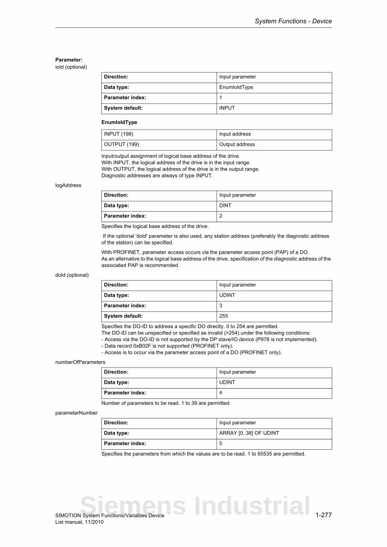
System Functions - Device
1-277SIMOTION System Functions/Variables DeviceList manual, 11/2010
Parameter: ioId (optional)
EnumIoIdType
Input/output assignment of logical base address of the drive.With INPUT, the logical address of the drive is in the input range.With OUTPUT, the logical address of the drive is in the output range.Diagnostic addresses are always of type INPUT.
logAddress
Specifies the logical base address of the drive.
If the optional 'dold' parameter is also used, any station address (preferably the diagnostic address of the station) can be specified.
With PROFINET, parameter access occurs via the parameter access point (PAP) of a DO.As an alternative to the logical base address of the drive, specification of the diagnostic address of the associated PAP is recommended.
doId (optional)
Specifies the DO-ID to address a specific DO directly. 0 to 254 are permitted.The DO-ID can be unspecified or specified as invalid (>254) under the following conditions:- Access via the DO-ID is not supported by the DP slave/IO device (P978 is not implemented).- Data record 0xB02F is not supported (PROFINET only).- Access is to occur via the parameter access point of a DO (PROFINET only).
numberOfParameters
Number of parameters to be read. 1 to 39 are permitted.
parameterNumber
Specifies the parameters from which the values are to be read. 1 to 65535 are permitted.
Direction: Input parameter
Data type: EnumIoIdType
Parameter index: 1
System default: INPUT
INPUT (198) Input address
OUTPUT (199) Output address
Direction: Input parameter
Data type: DINT
Parameter index: 2
Direction: Input parameter
Data type: UDINT
Parameter index: 3
System default: 255
Direction: Input parameter
Data type: UDINT
Parameter index: 4
Direction: Input parameter
Data type: ARRAY [0..38] OF UDINT
Parameter index: 5
Siemens Industrial
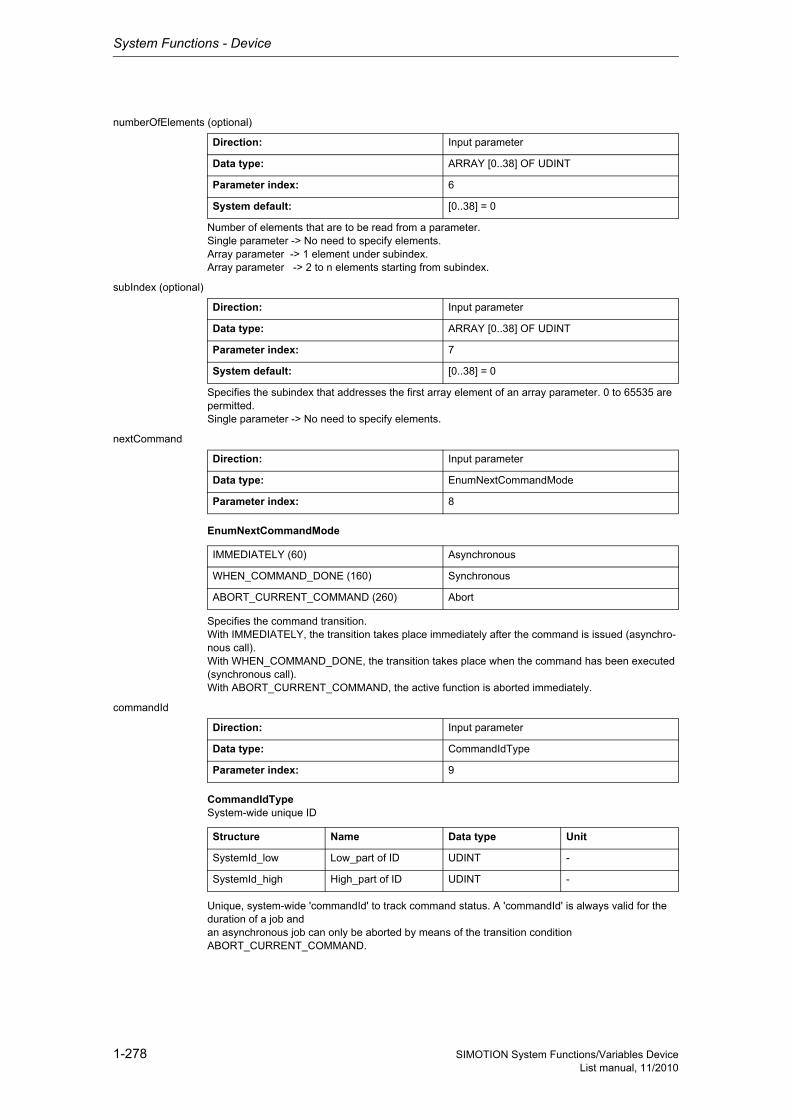
System Functions - Device
1-278 SIMOTION System Functions/Variables DeviceList manual, 11/2010
numberOfElements (optional)
Number of elements that are to be read from a parameter.Single parameter -> No need to specify elements.Array parameter -> 1 element under subindex.Array parameter -> 2 to n elements starting from subindex.
subIndex (optional)
Specifies the subindex that addresses the first array element of an array parameter. 0 to 65535 are permitted.Single parameter -> No need to specify elements.
nextCommand
EnumNextCommandMode
Specifies the command transition.With IMMEDIATELY, the transition takes place immediately after the command is issued (asynchro-nous call).With WHEN_COMMAND_DONE, the transition takes place when the command has been executed (synchronous call).With ABORT_CURRENT_COMMAND, the active function is aborted immediately.
commandId
CommandIdTypeSystem-wide unique ID
Unique, system-wide 'commandId' to track command status. A 'commandId' is always valid for the duration of a job andan asynchronous job can only be aborted by means of the transition condition ABORT_CURRENT_COMMAND.
Direction: Input parameter
Data type: ARRAY [0..38] OF UDINT
Parameter index: 6
System default: [0..38] = 0
Direction: Input parameter
Data type: ARRAY [0..38] OF UDINT
Parameter index: 7
System default: [0..38] = 0
Direction: Input parameter
Data type: EnumNextCommandMode
Parameter index: 8
IMMEDIATELY (60) Asynchronous
WHEN_COMMAND_DONE (160) Synchronous
ABORT_CURRENT_COMMAND (260) Abort
Direction: Input parameter
Data type: CommandIdType
Parameter index: 9
Structure Name Data type Unit
SystemId_low Low_part of ID UDINT -
SystemId_high High_part of ID UDINT -
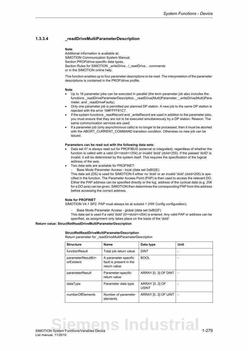
System Functions - Device
1-279SIMOTION System Functions/Variables DeviceList manual, 11/2010
1.3.3.4 _readDriveMultiParameterDescription
NoteAdditional information is available at:SIMOTION Communication System Manual,Section PROFIdrive-specific data types,Section Rules for SIMOTION _writeDrive.../_readDrive... commandsor in the SIMOTION online help.
This function enables up to four parameter descriptions to be read. The interpretation of the parameter descriptions is contained in the PROFIdrive profile.
Note• Up to 16 parameter jobs can be executed in parallel (the term parameter job also includes the
functions _readDriveParameterDescription, _readDrive(Multi)Parameter, _writeDrive(Multi)Para-meter, and _readDriveFaults).
• Only one parameter job is permitted per planned DP station. A new job to the same DP station is rejected with the error 16#FFFF81C7.
• If the system functions _readRecord and _writeRecord are used in addition to the parameter jobs, you must ensure that they are not to be executed simultaneously by a DP station. Reason: The same communication services are used.
• If a parameter job (only asynchronous calls) is no longer to be processed, then it must be aborted with the ABORT_CURRENT_COMMAND transition condition. Otherwise no new job can be issued.
Parameters can be read out with the following data sets:• Data set 47 is always read out for PROFIBUS (external or integrated), regardless of whether the
function is called with a valid (0>=doId<=254) or invalid 'doId' (doId=255). If the passed 'doID' is invalid, it will be determined by the system itself. This requires the specification of the logical address of the axis.
• Two data sets are available for PROFINET:− Base Mode Parameter Access - local (data set 0xB02E)This data set (DS) is used for SIMOTION if either no 'dold' or an invalid 'dold' (dold=255) is spe-cified in the function. The Parameter Access Point (PAP) is then used to access the relevant DO. Either the PAP address can be specified directly or the log. address of the cyclical data (e.g. 256 for a DO axis) can be given. SIMOTION then determines the corresponding PAP from this address before accessing the correct address.
Note for PROFINETSIMOTION V4.1 SP2: PAP must always be at subslot 1 (HW Config configuration).
− Base Mode Parameter Access - global (data set 0xB02F)This data set is used if a valid 'dold' (0>=doId<=254) is entered. Any valid PAP or address can be specified, as assignment only takes place on the basis of the 'dold'.
Return value: StructRetReadDriveMultiParameterDescription
StructRetReadDriveMultiParameterDescriptionReturn parameter for _readDriveMultiParameterDescription
Structure Name Data type Unit
functionResult Total job return value DINT -
parameterResultErr-orExistent
A parameter-specific fault is present in the return value
BOOL -
parameterResult Parameter-specific return value
ARRAY [0..3] OF DINT -
dataType Parameter data type ARRAY [0..3] OF USINT
-
numberOfElements Number of parameter elements
ARRAY [0..3] OF UINT -
Siemens Industrial
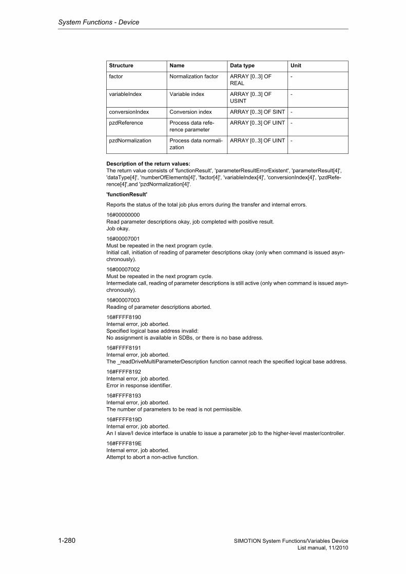
System Functions - Device
1-280 SIMOTION System Functions/Variables DeviceList manual, 11/2010
Description of the return values:The return value consists of 'functionResult', 'parameterResultErrorExistent', 'parameterResult[4]', 'dataType[4]', 'numberOfElements[4]', 'factor[4]', 'variableIndex[4]', 'conversionIndex[4]', 'pzdRefe-rence[4]',and 'pzdNormalization[4]'.
'functionResult'
Reports the status of the total job plus errors during the transfer and internal errors.
16#00000000Read parameter descriptions okay, job completed with positive result.Job okay.
16#00007001Must be repeated in the next program cycle.Initial call, initiation of reading of parameter descriptions okay (only when command is issued asyn-chronously).
16#00007002Must be repeated in the next program cycle.Intermediate call, reading of parameter descriptions is still active (only when command is issued asyn-chronously).
16#00007003Reading of parameter descriptions aborted.
16#FFFF8190Internal error, job aborted.Specified logical base address invalid:No assignment is available in SDBs, or there is no base address.
16#FFFF8191Internal error, job aborted.The _readDriveMultiParameterDescription function cannot reach the specified logical base address.
16#FFFF8192Internal error, job aborted.Error in response identifier.
16#FFFF8193Internal error, job aborted.The number of parameters to be read is not permissible.
16#FFFF819DInternal error, job aborted.An I slave/I device interface is unable to issue a parameter job to the higher-level master/controller.
16#FFFF819EInternal error, job aborted.Attempt to abort a non-active function.
factor Normalization factor ARRAY [0..3] OF REAL
-
variableIndex Variable index ARRAY [0..3] OF USINT
-
conversionIndex Conversion index ARRAY [0..3] OF SINT -
pzdReference Process data refe-rence parameter
ARRAY [0..3] OF UINT -
pzdNormalization Process data normali-zation
ARRAY [0..3] OF UINT -
Structure Name Data type Unit
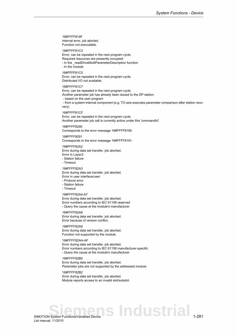
System Functions - Device
1-281SIMOTION System Functions/Variables DeviceList manual, 11/2010
16#FFFF819FInternal error, job aborted.Function not executable.
16#FFFF81C3Error, can be repeated in the next program cycle.Required resources are presently occupied:- In the _readDriveMultiParameterDescription function- In the module
16#FFFF81C5Error, can be repeated in the next program cycle.Distributed I/O not available.
16#FFFF81C7Error, can be repeated in the next program cycle.Another parameter job has already been issued to the DP station. - based on the user program - from a system-internal component (e.g. TO axis executes parameter comparison after station reco-very)
16#FFFF81CFError, can be repeated in the next program cycle.Another parameter job call is currently active under this 'commandId'.
16#FFFF8290Corresponds to the error message 16#FFFF8190.
16#FFFF8291Corresponds to the error message 16#FFFF8191.
16#FFFF82A2Error during data set transfer, job aborted.Error in Layer2:- Station failure- Timeout
16#FFFF82A3Error during data set transfer, job aborted.Error in user interface/user:- Protocol error- Station failure- Timeout
16#FFFF82A4-A7Error during data set transfer, job aborted.Error numbers according to IEC 61158 reserved- Query the cause at the module's manufacturer
16#FFFF82A8Error during data set transfer, job aborted.Error because of version conflict.
16#FFFF82A9Error during data set transfer, job aborted.Function not supported by the module.
16#FFFF82AA-AFError during data set transfer, job aborted.Error numbers according to IEC 61158 manufacturer-specific- Query the cause at the module's manufacturer
16#FFFF82B0Error during data set transfer, job aborted.Parameter jobs are not supported by the addressed module.
16#FFFF82B2Error during data set transfer, job aborted.Module reports access to an invalid slot/subslot.
Siemens Industrial
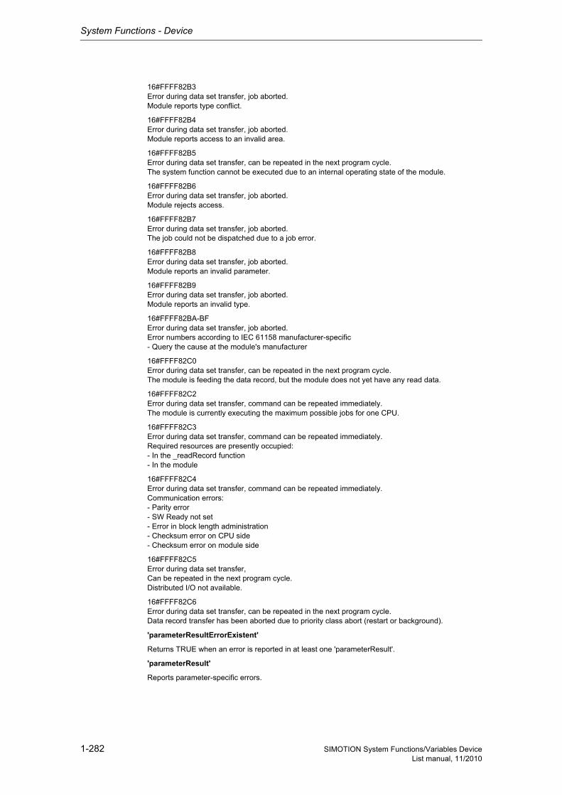
System Functions - Device
1-282 SIMOTION System Functions/Variables DeviceList manual, 11/2010
16#FFFF82B3Error during data set transfer, job aborted.Module reports type conflict.
16#FFFF82B4Error during data set transfer, job aborted.Module reports access to an invalid area.
16#FFFF82B5Error during data set transfer, can be repeated in the next program cycle.The system function cannot be executed due to an internal operating state of the module.
16#FFFF82B6Error during data set transfer, job aborted.Module rejects access.
16#FFFF82B7Error during data set transfer, job aborted.The job could not be dispatched due to a job error.
16#FFFF82B8Error during data set transfer, job aborted.Module reports an invalid parameter.
16#FFFF82B9Error during data set transfer, job aborted.Module reports an invalid type.
16#FFFF82BA-BFError during data set transfer, job aborted.Error numbers according to IEC 61158 manufacturer-specific- Query the cause at the module's manufacturer
16#FFFF82C0Error during data set transfer, can be repeated in the next program cycle.The module is feeding the data record, but the module does not yet have any read data.
16#FFFF82C2Error during data set transfer, command can be repeated immediately.The module is currently executing the maximum possible jobs for one CPU.
16#FFFF82C3Error during data set transfer, command can be repeated immediately.Required resources are presently occupied:- In the _readRecord function- In the module
16#FFFF82C4Error during data set transfer, command can be repeated immediately.Communication errors:- Parity error- SW Ready not set- Error in block length administration- Checksum error on CPU side- Checksum error on module side
16#FFFF82C5Error during data set transfer,Can be repeated in the next program cycle.Distributed I/O not available.
16#FFFF82C6Error during data set transfer, can be repeated in the next program cycle.Data record transfer has been aborted due to priority class abort (restart or background).
'parameterResultErrorExistent'
Returns TRUE when an error is reported in at least one 'parameterResult'.
'parameterResult'
Reports parameter-specific errors.
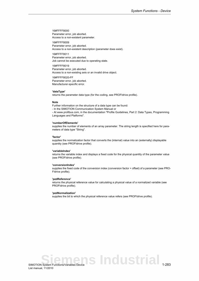
System Functions - Device
1-283SIMOTION System Functions/Variables DeviceList manual, 11/2010
16#FFFF8000Parameter error, job aborted.Access to a non-existent parameter.
16#FFFF8009Parameter error, job aborted.Access to a non-existent description (parameter does exist).
16#FFFF8011Parameter error, job aborted.Job cannot be executed due to operating state.
16#FFFF8019Parameter error, job aborted.Access to a non-existing axis or an invalid drive object.
16#FFFF8020-FFParameter error, job aborted.Manufacturer-specific error.
'dataType'returns the parameter data type (for the coding, see PROFIdrive profile).
NoteFurther information on the structure of a data type can be found:- In the SIMOTION Communication System Manual or- At www.profibus.com, in the documentation "Profile Guidelines, Part 2: Data Types, Programming Languages and Platforms".
'numberOfElements'supplies the number of elements of an array parameter. The string length is specified here for para-meters of data type "String".
'factor'supplies the normalization factor that converts the (internal) value into an (externally) displayable quantity (see PROFIdrive profile).
'variableIndex'returns the variable index and displays a fixed code for the physical quantity of the parameter value (see PROFIdrive profile).
'conversionIndex'supplies the fixed code of the conversion index (conversion factor + offset) of a parameter (see PRO-FIdrive profile).
'pzdReference'returns the physical reference value for calculating a physical value of a normalized variable (see PROFIdrive profile).
'pzdNormalization'supplies the bit to which the physical reference value refers (see PROFIdrive profile).
Siemens Industrial

System Functions - Device
1-284 SIMOTION System Functions/Variables DeviceList manual, 11/2010
Parameter: ioId (optional)
EnumIoIdType
Input/output assignment of logical base address of the drive.With INPUT, the logical address of the drive is in the input range.With OUTPUT, the logical address of the drive is in the output range.Diagnostic addresses are always of type INPUT.
logAddress
Specifies the logical base address of the drive.
If the optional 'dold' parameter is also used, any station address (preferably the diagnostic address of the station) can be specified.
With PROFINET, parameter access occurs via the parameter access point (PAP) of a DO.As an alternative to the logical base address of the drive, specification of the diagnostic address of the associated PAP is recommended.
doId (optional)
Specifies the DO-ID to address a specific DO directly. 0 to 254 are permitted.The DO-ID can be unspecified or specified as invalid (>254) under the following conditions:- Access via the DO-ID is not supported by the DP slave/IO device (P978 is not implemented).- Data record 0xB02F is not supported (PROFINET only).- Access is to occur via the parameter access point of a DO (PROFINET only).
numberOfParameters
Number of parameter descriptions to be read. 1 to 4 are permitted.
parameterNumber
Specifies the parameters from which the description is to be read. 1 to 65535 are permitted.
Direction: Input parameter
Data type: EnumIoIdType
Parameter index: 1
System default: INPUT
INPUT (198) Input address
OUTPUT (199) Output address
Direction: Input parameter
Data type: DINT
Parameter index: 2
Direction: Input parameter
Data type: UDINT
Parameter index: 3
System default: 255
Direction: Input parameter
Data type: UDINT
Parameter index: 4
Direction: Input parameter
Data type: ARRAY [0..3] OF UDINT
Parameter index: 5
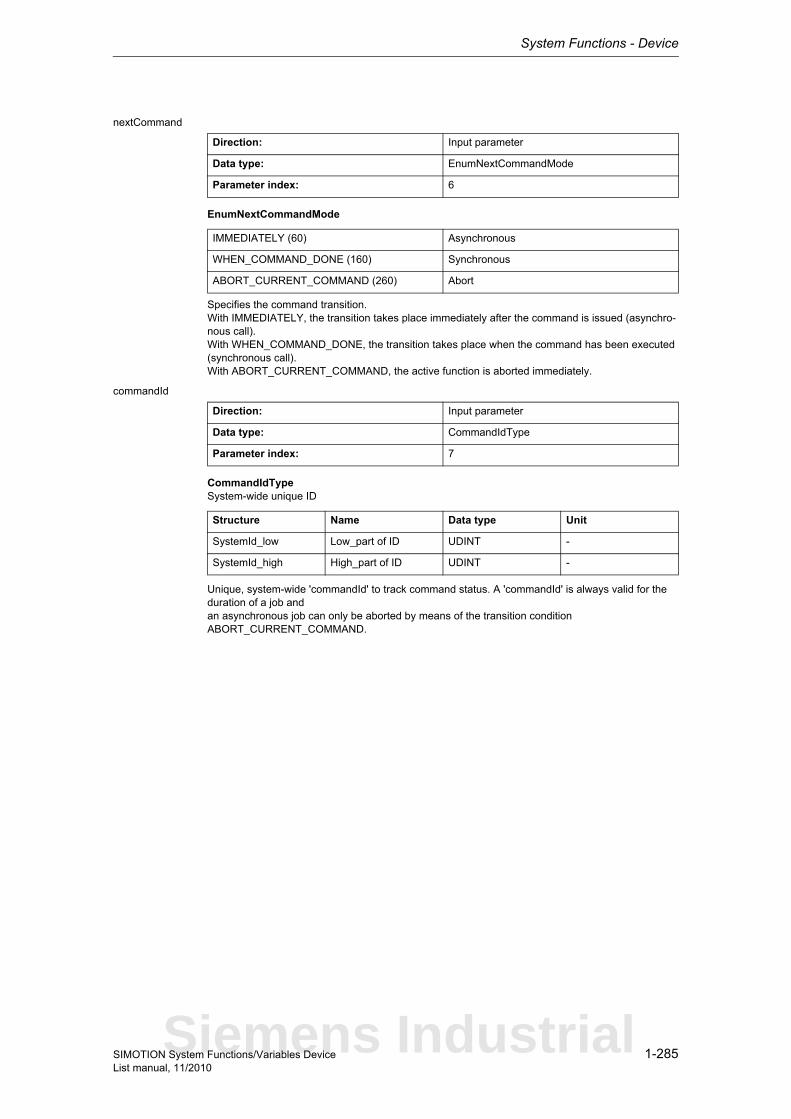
System Functions - Device
1-285SIMOTION System Functions/Variables DeviceList manual, 11/2010
nextCommand
EnumNextCommandMode
Specifies the command transition.With IMMEDIATELY, the transition takes place immediately after the command is issued (asynchro-nous call).With WHEN_COMMAND_DONE, the transition takes place when the command has been executed (synchronous call).With ABORT_CURRENT_COMMAND, the active function is aborted immediately.
commandId
CommandIdTypeSystem-wide unique ID
Unique, system-wide 'commandId' to track command status. A 'commandId' is always valid for the duration of a job andan asynchronous job can only be aborted by means of the transition condition ABORT_CURRENT_COMMAND.
Direction: Input parameter
Data type: EnumNextCommandMode
Parameter index: 6
IMMEDIATELY (60) Asynchronous
WHEN_COMMAND_DONE (160) Synchronous
ABORT_CURRENT_COMMAND (260) Abort
Direction: Input parameter
Data type: CommandIdType
Parameter index: 7
Structure Name Data type Unit
SystemId_low Low_part of ID UDINT -
SystemId_high High_part of ID UDINT -
Siemens Industrial
System Functions - Device
1-286 SIMOTION System Functions/Variables DeviceList manual, 11/2010
1.3.3.5 _readDriveParameter
NoteAdditional information is available at:SIMOTION Communication System Manual,Section PROFIdrive-specific data types,Section Rules for SIMOTION _writeDrive.../_readDrive... commandsor in the SIMOTION online help.
This function enables a drive parameter to be read.
Note• Up to 16 parameter jobs can be executed in parallel (the term parameter job also includes the
functions _readDriveMultiParameter, _readDrive(Multi)ParameterDescription, _writeDrive(Multi)Parameter, and _readDriveFaults).
• Only one parameter job is permitted per planned DP station. A new job to the same DP station is rejected with the error 16#FFFF81C7.
• If the system functions _readRecord and _writeRecord are used in addition to the parameter jobs, you must ensure that they are not to be executed simultaneously by a DP station. Reason: The same communication services are used.
• If a parameter job (only asynchronous calls) is no longer to be processed, then it must be aborted with the ABORT_CURRENT_COMMAND transition condition. Otherwise no new job can be issued.
Parameters can be read out with the following data sets:• Data set 47 is always read out for PROFIBUS (external or integrated), regardless of whether the
function is called with a valid (0>=doId<=254) or invalid 'doId' (doId=255). If the passed 'doId' is invalid, it will be determined by the system itself. This requires the specification of the logical address of the axis.
• Two data sets are available for PROFINET:− Base Mode Parameter Access - local (data set 0xB02E)This data set (DS) is used for SIMOTION if either no 'dold' or an invalid 'dold' (dold=255) is spe-cified in the function. The Parameter Access Point (PAP) is then used to access the relevant DO. Either the PAP address can be specified directly or the log. address of the cyclical data (e.g. 256 for a DO axis) can be given. SIMOTION then determines the corresponding PAP from this address before accessing the correct address.
Note for PROFINETSIMOTION V4.1 SP2: PAP must always be at subslot 1 (HW Config configuration).
− Base Mode Parameter Access - global (data set 0xB02F)This data set is used if a valid 'dold' (0>=doId<=254) is entered. Any valid PAP or address can be specified, as assignment only takes place on the basis of the 'dold'.
Return value: StructRetReadDriveParameter
StructRetReadDriveParameterReturn parameter for _readDriveParameter
Structure Name Data type Unit
functionResult Total job return value DINT -
parameterResult Parameter-specific return value
DINT -
dataType Data type of the read parameter
UDINT -
dataLength Length of read data in bytes
UDINT -
data Data read by the drive (big endian)
ARRAY [0..233] OF BYTE
-
System Functions - Device
1-287SIMOTION System Functions/Variables DeviceList manual, 11/2010
Description of the return values:The return value consists of 'functionResult', 'parameterResult', 'dataType', 'dataLength' and 'data[234].
'functionResult'Reports the status of the total job plus errors during the transfer and internal errors.
16#00000000Reading of parameters okay, job completed with positive result. Job okay.
16#00007001Must be repeated in the next program cycle.Initial call, initiation of reading of parameter description okay(only when command is issued asynchronously).
16#00007002Must be repeated in the next program cycle.Intermediate call, reading of parameter description is still active(only when command is issued asynchronously).
16#00007003Reading of parameters aborted.Job aborted.
16#FFFF8190Internal error, job aborted.Specified logical base address invalid:No assignment is available in SDBs, or there is no base address.
16#FFFF8191Internal error, job aborted.The _readDriveParameter function cannot reach the specified logical base address.
16#FFFF8192Internal error, job aborted.Error in response identifier.
16#FFFF819DInternal error, job aborted.An I slave/I device interface is unable to issue a parameter job to the higher-level master/controller.
16#FFFF819EInternal error, job aborted.Attempt to abort a non-active function.
16#FFFF819FInternal error, job aborted.Function not executable.
16#FFFF81C3Error, can be repeated in the next program cycle.Required resources are presently occupied:- In the _readDriveParameter function- In the module
16#FFFF81C5Error, can be repeated in the next program cycle.Distributed I/O not available.
16#FFFF81C7Error, can be repeated in the next program cycle.Another parameter job has already been issued to the DP station. - based on the user program - from a system-internal component (e.g. TO axis executes parameter comparison after station reco-very)
Siemens Industrial
System Functions - Device
1-288 SIMOTION System Functions/Variables DeviceList manual, 11/2010
16#FFFF81CFError, can be repeated in the next program cycle.Another parameter job call is currently active under this 'commandId'.
16#FFFF8290Corresponds to the error message 16#FFFF8190.
16#FFFF8291Corresponds to the error message 16#FFFF8191.
16#FFFF82A2Error during data set transfer, job aborted.Error in Layer2:- Station failure- Timeout
16#FFFF82A3Error during data set transfer, job aborted.Error in user interface/user:- Protocol error- Station failure- Timeout
16#FFFF82A4-A7Error during data set transfer, job aborted.Error numbers according to IEC 61158 reserved- Query the cause at the module's manufacturer
16#FFFF82A8Error during data set transfer, job aborted.Error because of version conflict.
16#FFFF82A9Error during data set transfer, job aborted.Function not supported by the module.
16#FFFF82AA-AFError during data set transfer, job aborted.Error numbers according to IEC 61158 manufacturer-specific- Query the cause at the module's manufacturer
16#FFFF82B0Error during data set transfer, job aborted.Parameter jobs are not supported by the addressed module.
16#FFFF82B2Error during data set transfer, job aborted.Module reports access to an invalid slot/subslot.
16#FFFF82B3Error during data set transfer, job aborted.Module reports type conflict.
16#FFFF82B4Error during data set transfer, job aborted.Module reports access to an invalid area.
16#FFFF82B5Error during data set transfer, can be repeated in the next program cycle.The system function cannot be executed due to an internal operating state of the module.
16#FFFF82B6Error during data set transfer, job aborted.Module rejects access.
16#FFFF82B7Error during data set transfer, job aborted.The job could not be dispatched due to a job error.
16#FFFF82B8Error during data set transfer, job aborted.Module reports an invalid parameter.
System Functions - Device
1-289SIMOTION System Functions/Variables DeviceList manual, 11/2010
16#FFFF82B9Error during data set transfer, job aborted.Module reports an invalid type.
16#FFFF82BA-BFError during data set transfer, job aborted.Error numbers according to IEC 61158 manufacturer-specific- Query the cause at the module's manufacturer
16#FFFF82C0Error during data set transfer, can be repeated in the next program cycle.The module is feeding the data record, but the module does not yet have any read data.
16#FFFF82C2Error during data set transfer, command can be repeated immediately.The module is currently executing the maximum possible jobs for one CPU.
16#FFFF82C3Error during data set transfer, command can be repeated immediately.Required resources are presently occupied:- In the _readRecord function- In the module
16#FFFF82C4Error during data set transfer, command can be repeated immediately.Communication errors:- Parity error- SW Ready not set- Error in block length administration- Checksum error on CPU side- Checksum error on module side
16#FFFF82C5Error during data set transfer,Can be repeated in the next program cycle.Distributed I/O not available.
16#FFFF82C6Error during data set transfer, can be repeated in the next program cycle.Data record transfer has been aborted due to priority class abort (restart or background).
'parameterResult'
Reports parameter-specific errors.
16#FFFF8000Parameter error, job aborted.Access to a non-existent parameter.
16#FFFF8003Parameter error, job aborted.Access to a non-existent subindex.
16#FFFF8004Parameter error, job aborted.Access with subindex to non-indexed parameter (not an array parameter).
16#FFFF8011Parameter error, job aborted.Job cannot be executed due to operating state.
16#FFFF8015Parameter error, job aborted.The length of the current response exceeds the maximum transferable length.
16#FFFF8016Parameter error, job aborted.Illegal or unsupported value for attribute, number of elements, parameter number, or subindex, or a combination of these.
Siemens Industrial

System Functions - Device
1-290 SIMOTION System Functions/Variables DeviceList manual, 11/2010
16#FFFF8019Parameter error, job aborted.Access to a non-existing axis or an invalid drive object.
16#FFFF8020-FFParameter error, job aborted.Manufacturer-specific error.
'dataType'returns the data type of the read parameter.
NoteFurther information on the structure of a data type can be found:- In the SIMOTION Communication System Manual or- At www.profibus.com, in the documentation "Profile Guidelines, Part 2: Data Types, Programming Languages and Platforms".
'dataLength'reports the length of the data read.
'data[234]'contains the read data (byte array, maximum of 234 bytes).
Parameter: ioId (optional)
EnumIoIdType
Input/output assignment of logical base address of the drive.With INPUT, the logical address of the drive is in the input range.With OUTPUT, the logical address of the drive is in the output range.Diagnostic addresses are always of type INPUT.
logAddress
Specifies the logical base address of the drive.
If the optional 'dold' parameter is also used, any station address (preferably the diagnostic address of the station) can be specified.
With PROFINET, parameter access occurs via the parameter access point (PAP) of a DO.As an alternative to the logical base address of the drive, specification of the diagnostic address of the associated PAP is recommended.
Direction: Input parameter
Data type: EnumIoIdType
Parameter index: 1
System default: INPUT
INPUT (198) Input address
OUTPUT (199) Output address
Direction: Input parameter
Data type: DINT
Parameter index: 2
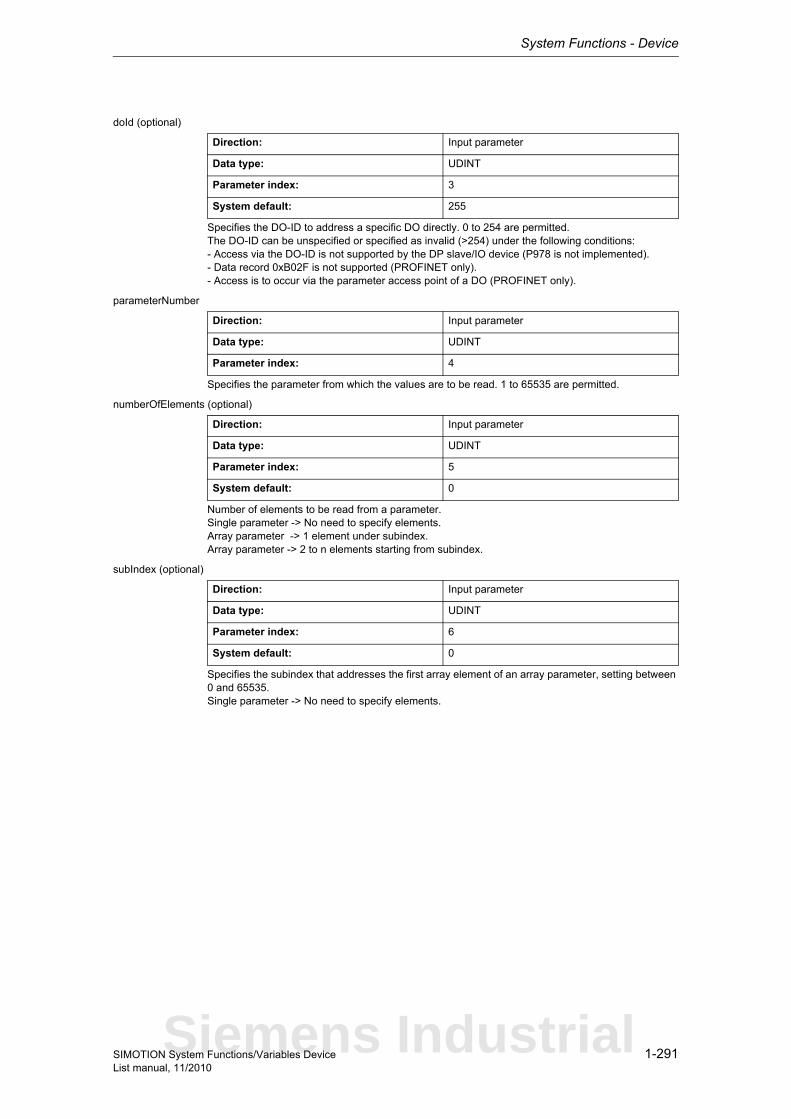
System Functions - Device
1-291SIMOTION System Functions/Variables DeviceList manual, 11/2010
doId (optional)
Specifies the DO-ID to address a specific DO directly. 0 to 254 are permitted.The DO-ID can be unspecified or specified as invalid (>254) under the following conditions:- Access via the DO-ID is not supported by the DP slave/IO device (P978 is not implemented).- Data record 0xB02F is not supported (PROFINET only).- Access is to occur via the parameter access point of a DO (PROFINET only).
parameterNumber
Specifies the parameter from which the values are to be read. 1 to 65535 are permitted.
numberOfElements (optional)
Number of elements to be read from a parameter.Single parameter -> No need to specify elements.Array parameter -> 1 element under subindex.Array parameter -> 2 to n elements starting from subindex.
subIndex (optional)
Specifies the subindex that addresses the first array element of an array parameter, setting between 0 and 65535.Single parameter -> No need to specify elements.
Direction: Input parameter
Data type: UDINT
Parameter index: 3
System default: 255
Direction: Input parameter
Data type: UDINT
Parameter index: 4
Direction: Input parameter
Data type: UDINT
Parameter index: 5
System default: 0
Direction: Input parameter
Data type: UDINT
Parameter index: 6
System default: 0
Siemens Industrial

System Functions - Device
1-292 SIMOTION System Functions/Variables DeviceList manual, 11/2010
nextCommand
EnumNextCommandMode
Specifies the command transition.With IMMEDIATELY, the transition takes place immediately after the command is issued (asynchro-nous call).With WHEN_COMMAND_DONE, the transition takes place when the command has been executed (synchronous call).With ABORT_CURRENT_COMMAND, the active function is aborted immediately.
commandId
CommandIdTypeSystem-wide unique ID
Unique, system-wide 'commandId' to track command status. A 'commandId' is always valid for the duration of a job andan asynchronous job can only be aborted by means of the transition condition ABORT_CURRENT_COMMAND.
Direction: Input parameter
Data type: EnumNextCommandMode
Parameter index: 7
IMMEDIATELY (60) Asynchronous
WHEN_COMMAND_DONE (160) Synchronous
ABORT_CURRENT_COMMAND (260) Abort
Direction: Input parameter
Data type: CommandIdType
Parameter index: 8
Structure Name Data type Unit
SystemId_low Low_part of ID UDINT -
SystemId_high High_part of ID UDINT -
System Functions - Device
1-293SIMOTION System Functions/Variables DeviceList manual, 11/2010
1.3.3.6 _readDriveParameterDescription
NoteAdditional information is available at:SIMOTION Communication System Manual,Section PROFIdrive-specific data types,Section Rules for SIMOTION _writeDrive.../_readDrive... commandsor in the SIMOTION online help.
This function enables the descriptive data of a drive parameter to be read out. The interpretation of the parameter description is contained in the PROFIdrive profile.
Note• Up to 16 parameter jobs can be executed in parallel (the term parameter job also includes the
functions _readDriveParameterDescription, _readDrive(Multi)Parameter, _writeDrive(Multi)Para-meter, and _readDriveFaults).
• Only one parameter job is permitted per planned DP station. A new job to the same DP station is rejected with the error 16#FFFF81C7.
• If the system functions _readRecord and _writeRecord are used in addition to the parameter jobs, you must ensure that they are not to be executed simultaneously by a DP station. Reason: The same communication services are used.
• If a parameter job (only asynchronous calls) is no longer to be processed, then it must be aborted with the ABORT_CURRENT_COMMAND transition condition. Otherwise no new job can be issued.
Parameters can be read out with the following data sets:• Data set 47 is always read out for PROFIBUS (external or integrated), regardless of whether the
function is called with a valid (0>=doId<=254) or invalid 'doId' (doId=255). If the passed 'doID' is invalid, it will be determined by the system itself. This requires the specification of the logical address of the axis.
• Two data sets are available for PROFINET:− Base Mode Parameter Access - local (data set 0xB02E)This data set (DS) is used for SIMOTION if either no 'dold' or an invalid 'dold' (dold=255) is spe-cified in the function. The Parameter Access Point (PAP) is then used to access the relevant DO. Either the PAP address can be specified directly or the log. address of the cyclical data (e.g. 256 for a DO axis) can be given. SIMOTION then determines the corresponding PAP from this address before accessing the correct address.
Note for PROFINETSIMOTION V4.1 SP2: PAP must always be at subslot 1 (HW Config configuration).
− Base Mode Parameter Access - global (data set 0xB02F)This data set is used if a valid 'dold' (0>=doId<=254) is entered. Any valid PAP or address can be specified, as assignment only takes place on the basis of the 'dold'.
Siemens Industrial

System Functions - Device
1-294 SIMOTION System Functions/Variables DeviceList manual, 11/2010
Return value: StructRetReadDriveParameterDescription
StructRetReadDriveParameterDescriptionReturn parameter for _readDriveParameterDescription
The return value consists of 'functionResult', 'parameterResult', 'dataType', 'numberOfElements', 'fac-tor', 'variableIndex', 'conversionIndex', 'pzdReference', and 'pzdNormalization'.
'functionResult'
Reports the status of the total job plus errors during the transfer and internal errors.
16#00000000Reading of parameter description okay, job completed with positive result.Job okay.
16#00007001Must be repeated in the next program cycle.Initial call, initiation of reading of parameter description okay(only when command is issued asynchronously).
16#00007002Must be repeated in the next program cycle.Intermediate call, reading of parameter description is still active(only when command is issued asynchronously).
16#00007003Reading of parameter description aborted.Job aborted.
16#FFFF8190Internal error, job aborted.Specified logical base address invalid:No assignment is available in SDBs, or there is no base address.
16#FFFF8191Internal error, job aborted.The _readDriveParameterDescription function cannot reach the specified logical base address.
16#FFFF8192Internal error, job aborted.Error in response identifier.
16#FFFF819DInternal error, job aborted.An I slave/I device interface is unable to issue a parameter job to the higher-level master/controller.
Structure Name Data type Unit
functionResult Total job return value DINT -
parameterResult Parameter-specific return value
DINT -
dataType Parameter data type USINT -
numberOfElements Number of parameter elements
UINT -
factor Normalization factor REAL -
variableIndex Variable index USINT -
conversionIndex Conversion index SINT -
pzdReference Process data refe-rence parameter
UINT -
pzdNormalization Process data normali-zation
UINT -
System Functions - Device
1-295SIMOTION System Functions/Variables DeviceList manual, 11/2010
16#FFFF819EInternal error, job aborted.Attempt to abort a non-active function.
16#FFFF819FInternal error, job aborted.Function not executable.
16#FFFF81C3Error, can be repeated in the next program cycle.Required resources are presently occupied:- In the _readDriveParameterDescription function- In the module
16#FFFF81C5Error, can be repeated in the next program cycle.Distributed I/O not available.
16#FFFF81C7Error, can be repeated in the next program cycle.Another parameter job has already been issued to the DP station. - based on the user program - from a system-internal component (e.g. TO axis executes parameter comparison after station reco-very)
16#FFFF81CFError, can be repeated in the next program cycle.Another parameter job call is currently active under this 'commandId'.
16#FFFF8290Corresponds to the error message 16#FFFF8190.
16#FFFF8291Corresponds to the error message 16#FFFF8191.
16#FFFF82A2Error during data set transfer, job aborted.Error in Layer2:- Station failure- Timeout
16#FFFF82A3Error during data set transfer, job aborted.Error in user interface/user:- Protocol error- Station failure- Timeout
16#FFFF82A4-A7Error during data set transfer, job aborted.Error numbers according to IEC 61158 reserved- Query the cause at the module's manufacturer
16#FFFF82A8Error during data set transfer, job aborted.Error because of version conflict.
16#FFFF82A9Error during data set transfer, job aborted.Function not supported by the module.
16#FFFF82AA-AFError during data set transfer, job aborted.Error numbers according to IEC 61158 manufacturer-specific- Query the cause at the module's manufacturer
16#FFFF82B0Error during data set transfer, job aborted.Parameter jobs are not supported by the addressed module.
Siemens Industrial
System Functions - Device
1-296 SIMOTION System Functions/Variables DeviceList manual, 11/2010
16#FFFF82B2Error during data set transfer, job aborted.Module reports access to an invalid slot/subslot.
16#FFFF82B3Error during data set transfer, job aborted.Module reports type conflict.
16#FFFF82B4Error during data set transfer, job aborted.Module reports access to an invalid area.
16#FFFF82B5Error during data set transfer, can be repeated in the next program cycle.The system function cannot be executed due to an internal operating state of the module.
16#FFFF82B6Error during data set transfer, job aborted.Module rejects access.
16#FFFF82B7Error during data set transfer, job aborted.The job could not be dispatched due to a job error.
16#FFFF82B8Error during data set transfer, job aborted.Module reports an invalid parameter.
16#FFFF82B9Error during data set transfer, job aborted.Module reports an invalid type.
16#FFFF82BA-BFError during data set transfer, job aborted.Error numbers according to IEC 61158 manufacturer-specific- Query the cause at the module's manufacturer
16#FFFF82C0Error during data set transfer, can be repeated in the next program cycle.The module is feeding the data record, but the module does not yet have any read data.
16#FFFF82C2Error during data set transfer, command can be repeated immediately.The module is currently executing the maximum possible jobs for one CPU.
16#FFFF82C3Error during data set transfer, command can be repeated immediately.Required resources are presently occupied:- In the _readRecord function- In the module
16#FFFF82C4Error during data set transfer, command can be repeated immediately.Communication errors:- Parity error- SW Ready not set- Error in block length administration- Checksum error on CPU side- Checksum error on module side
16#FFFF82C5Error during data set transfer,Can be repeated in the next program cycle.Distributed I/O not available.
16#FFFF82C6Error during data set transfer, can be repeated in the next program cycle.Data record transfer has been aborted due to priority class abort (restart or background).
'parameterResult'
Reports parameter-specific errors.
System Functions - Device
1-297SIMOTION System Functions/Variables DeviceList manual, 11/2010
16#FFFF8000Parameter error, job aborted.Access to a non-existent parameter.
16#FFFF8009Parameter error, job aborted.Access to a non-existent description (parameter does exist).
16#FFFF8011Parameter error, job aborted.Job cannot be executed due to operating state.
16#FFFF8019Parameter error, job aborted.Access to a non-existing axis or an invalid drive object.
16#FFFF8020-FFParameter error, job aborted.Manufacturer-specific error.
'dataType' returns the parameter data type (for the coding, see PROFIdrive profile).
NoteFurther information on the structure of a data type can be found:- In the SIMOTION Communication System Manual or- At www.profibus.com, in the documentation "Profile Guidelines Part 2: Data Types, Programming Languages and Platforms".
'numberOfElements' supplies the number of elements of an array parameter. The string length is spe-cified here for parameters of data type "String".
'factor' supplies the normalization factor that converts the (internal) value into an (externally) displa-yable quantity (see PROFIdrive profile).
'variableIndex' returns the variable index and displays a fixed code for the physical quantity of the parameter value (see PROFIdrive profile).
'conversionIndex' supplies the fixed code of the conversion index (conversion factor + offset) of a parameter (see PROFIdrive profile).
'pzdReference' returns the physical reference value for calculating a physical value of a normalized variable (see PROFIdrive profile).
'pzdNormalization' supplies the bit to which the physical reference value refers (see PROFIdrive pro-file).
Parameter: ioId (optional)
EnumIoIdType
Input/output assignment of logical base address of the drive.With INPUT, the logical address of the drive is in the input range.With OUTPUT, the logical address of the drive is in the output range.Diagnostic addresses are always of type INPUT.
Direction: Input parameter
Data type: EnumIoIdType
Parameter index: 1
System default: INPUT
INPUT (198) Input address
OUTPUT (199) Output address
Siemens Industrial
System Functions - Device
1-298 SIMOTION System Functions/Variables DeviceList manual, 11/2010
logAddress
Specifies the logical base address of the drive.
If the optional 'dold' parameter is also used, any station address (preferably the diagnostic address of the station) can be specified.
With PROFINET, parameter access occurs via the parameter access point (PAP) of a DO.As an alternative to the logical base address of the drive, specification of the diagnostic address of the associated PAP is recommended.
doId (optional)
Specifies the DO-ID to address a specific DO directly. 0 to 254 are permitted.The DO-ID can be unspecified or specified as invalid (>254) under the following conditions:- Access via the DO-ID is not supported by the DP slave/IO device (P978 is not implemented).- Data record 0xB02F is not supported (PROFINET only).- Access is to occur via the parameter access point of a DO (PROFINET only).
parameterNumber
Specifies the parameter from which the description is to be read. 1 to 65535 are permitted.
nextCommand
EnumNextCommandMode
Specifies the command transition.With IMMEDIATELY, the transition takes place immediately after the command is issued (asynchro-nous call).With WHEN_COMMAND_DONE, the transition takes place when the command has been executed (synchronous call).With ABORT_CURRENT_COMMAND, the active function is aborted immediately.
Direction: Input parameter
Data type: DINT
Parameter index: 2
Direction: Input parameter
Data type: UDINT
Parameter index: 3
System default: 255
Direction: Input parameter
Data type: UDINT
Parameter index: 4
Direction: Input parameter
Data type: EnumNextCommandMode
Parameter index: 5
IMMEDIATELY (60) Asynchronous
WHEN_COMMAND_DONE (160) Synchronous
ABORT_CURRENT_COMMAND (260) Abort

System Functions - Device
1-299SIMOTION System Functions/Variables DeviceList manual, 11/2010
commandId
CommandIdTypeSystem-wide unique ID
Unique, system-wide 'commandId' to track command status. A 'commandId' is always valid for the duration of a job andan asynchronous job can only be aborted by means of the transition condition ABORT_CURRENT_COMMAND.
Direction: Input parameter
Data type: CommandIdType
Parameter index: 6
Structure Name Data type Unit
SystemId_low Low_part of ID UDINT -
SystemId_high High_part of ID UDINT -
Siemens Industrial
System Functions - Device
1-300 SIMOTION System Functions/Variables DeviceList manual, 11/2010
1.3.3.7 _resetDriveObjectFault
Note"Further information can be found in the SIMOTION Basic Functions Function Manual and in SIMO-TION online help."
This function acknowledges an existing fault on a drive object. The function can be used on SINAMICS DO1 with the standard message frames 390, 391, 392 (for short: 39x). Axis-type drive objects (SINA-MICS DO-type servo, vector) cannot be accessed by this function and are only supported via the TO axis.
Return value: DINTThe return value reports the job status.
Description of the return values:16#00000000Job completed without errors.The fault has been acknowledged on the drive object with the specified logical address.
16#00000001Job completed without errors, but without effect.The drive object with the specified logical address did not have a fault.
16#FFFF8090Job aborted. Specified logical base address invalid.Possible causes:- The logical address specified does not exist.- The logical address specified exists, but is not the address of a drive object.
16#FFFF8091Job aborted.The function is not supported by the drive object with the specified logical address.
16#FFFF809FJob aborted.Internal error, function cannot be executed.
Parameter: ioId (optional)
EnumIoIdType
Input/output assignment of the logical address.With INPUT, the logical address is in the input range.With OUTPUT, the logical address is in the output range.
logAddress
Specifies the logical base address of the drive.
Direction: Input parameter
Data type: EnumIoIdType
Parameter index: 1
System default: INPUT
INPUT (198) Input address
OUTPUT (199) Output address
Direction: Input parameter
Data type: DINT
Parameter index: 2
System Functions - Device
1-301SIMOTION System Functions/Variables DeviceList manual, 11/2010
1.3.3.8 _setDriveObjectSTW
Note"Further information can be found in the SIMOTION Basic Functions Function Manual and in SIMO-TION online help."
This function can be used to write bits in the control word of an output message frame to a drive object. The function can be used on SINAMICS DO1 on CU_STW in the standard message frames 390, 391, 392 (for short: 39x). Axis-type drive objects (SINAMICS DO-type servo, vector) cannot be accessed by this function and are supported by _setAxisSTW on the TO axis.
Return value: DINTThe return value reports the job status.
Description of the return values:16#00000000Job completed without errors.The bits from STW1BitSet selected via STW1BitMask have been written to the control word of the out-put message frame.
16#FFFF8090Job aborted. Specified logical base address invalid.Possible causes:- The logical address specified does not exist.- The logical address specified is a diagnostic address.- The logical address specified exists, but is not the address of an output message frame for a drive object.- No message frame is configured for the drive object with the logical address specified.- A message frame is configured for the drive object with the logical address specified, but it contains no control word with which this system function is compatible. This may, for example, be message frame 370 for the SINAMICS infeed module or a free message frame for SINAMICS DO1 (P2079 has no 39x) or an axis-type drive object.- There is no entry in the FastIO configuration for the specified logical address. Please check this by exporting the SIMOTION controller's FastIO configuration (FastIO context menu). If the xml file crea-ted does not contain the logical address, please perform the transfer for the relevant SINAMICS CU in accordance with HW Config and reload the project. If this does not produce the desired result, delete the configuration information generated by SCOUT (FastIO context menu). Then perform the transfer in accordance with HW Config in the SINAMICS project for all control units containing a Fas-tIO component (onboard I/O of control unit with standard message frame 39x or TM1x) before reloa-ding the corrected project.
16#FFFF8091Job aborted.The function is not supported by the drive object with the specified logical address. This may, for example, be a TM15 or TM17 IO module.
16#FFFF8093Job aborted.STW1BitSet could not be written to the output message frame due to illegal bits in STW1BitMask.
16#FFFF809FJob aborted.Function cannot be executed in V4.1 and V4.1 SP1.
Parameter: logAddress
Logical base address of the output message frame for the drive object.
Direction: Input parameter
Data type: DINT
Parameter index: 1
Siemens Industrial
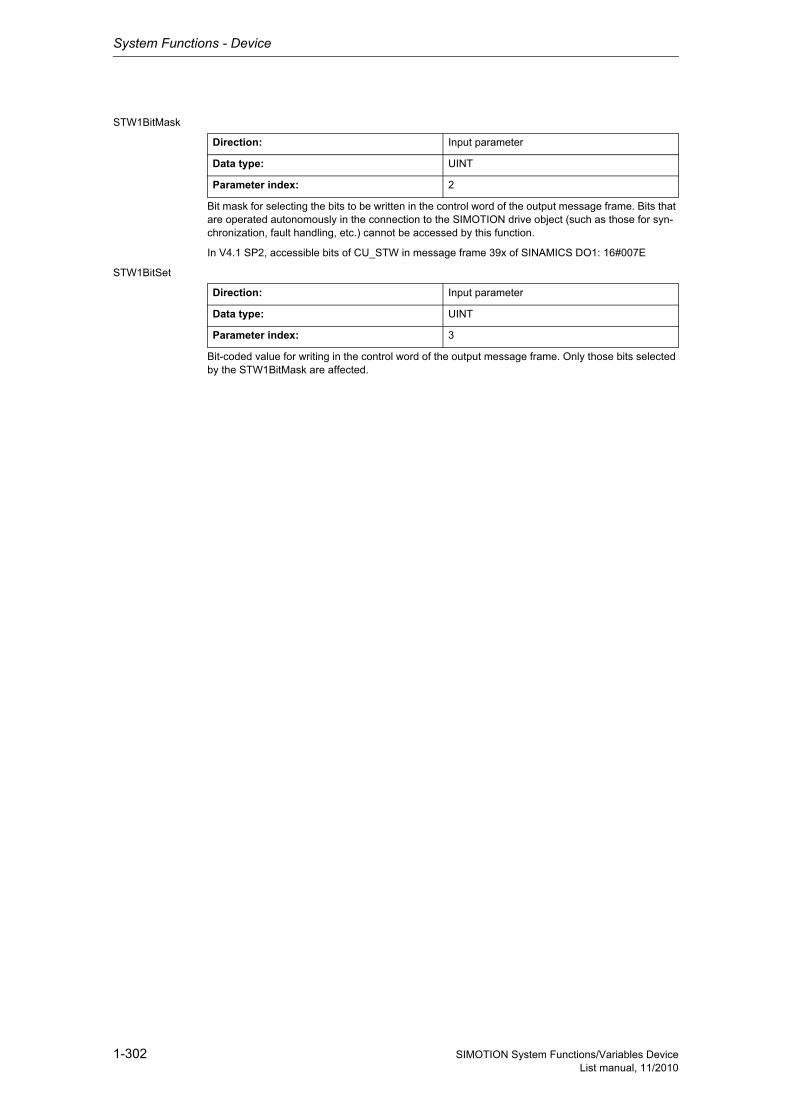
System Functions - Device
1-302 SIMOTION System Functions/Variables DeviceList manual, 11/2010
STW1BitMask
Bit mask for selecting the bits to be written in the control word of the output message frame. Bits that are operated autonomously in the connection to the SIMOTION drive object (such as those for syn-chronization, fault handling, etc.) cannot be accessed by this function.
In V4.1 SP2, accessible bits of CU_STW in message frame 39x of SINAMICS DO1: 16#007E
STW1BitSet
Bit-coded value for writing in the control word of the output message frame. Only those bits selected by the STW1BitMask are affected.
Direction: Input parameter
Data type: UINT
Parameter index: 2
Direction: Input parameter
Data type: UINT
Parameter index: 3

System Functions - Device
1-303SIMOTION System Functions/Variables DeviceList manual, 11/2010
1.3.3.9 _writeDriveMultiParameter
NoteAdditional information is available at:SIMOTION Communication System Manual,Section PROFIdrive-specific data types, Section Rules for SIMOTION _writeDrive.../_readDrive... commandsor in the SIMOTION online help.
This function enables up to 23 parameters to be written.
Exactly 23 parameters can only be written once every parameter only has a format with the maximum data length = 2 (e.g. WORD).If other formats with data lengths in excess of 2 are written, the maximum number is reduced.The procedure is the same when reading parameters. A maximum of 39 parameters can be read if all parameters have the data length <= 2.
More information is provided in:Profile Drive Technology PROFIdrive, Technical Specification for PROFIBUS and PROFINET, Ver-sion 4.1, May 2006 - Section 7.6.2.4, see Formulas
Note• Up to 16 parameter jobs can be executed in parallel (the term parameter job also includes the
functions _writeDriveParameter, _readDrive(Multi)ParameterDescription, _readDrive(Multi)Para-meter, and _readDriveFaults).
• Only one parameter job is permitted per planned DP station. A new job to the same DP station is rejected with the error 16#FFFF81C7.
• If the system functions _readRecord and _writeRecord are used in addition to the parameter jobs, you must ensure that they are not to be executed simultaneously by a DP station. Reason: The same communication services are being used.
• If a parameter job (only asynchronous calls) is no longer to be processed, then it must be aborted with the ABORT_CURRENT_COMMAND transition condition. Otherwise no new job can be issued.
Parameters can be read out with the following data sets:• Data set 47 is always read out for PROFIBUS (external or integrated), regardless of whether the
function is called with a valid (0>=doId<=254) or invalid 'doId' (doId=255). If the passed 'doId' is invalid, it will be determined by the system itself. This requires the specification of the logical address of the axis.
• Two data sets are available for PROFINET:− Base Mode Parameter Access - local (data set 0xB02E)This data set (DS) is used for SIMOTION if either no 'dold' or an invalid 'dold' (dold=255) is spe-cified in the function. The Parameter Access Point (PAP) is then used to access the relevant DO. Either the PAP address can be specified directly or the log. address of the cyclical data (e.g. 256 for a DO axis) can be given. SIMOTION then determines the corresponding PAP from this address before accessing the correct address.
Note for PROFINETSIMOTION V4.1 SP2: PAP must always be at subslot 1 (HW Config configuration).
− Base Mode Parameter Access - global (data set 0xB02F)This data set is used if a valid 'dold' (0>=doId<=254) is entered. Any valid PAP or address can be specified, as assignment only takes place on the basis of the 'dold'.
Siemens Industrial
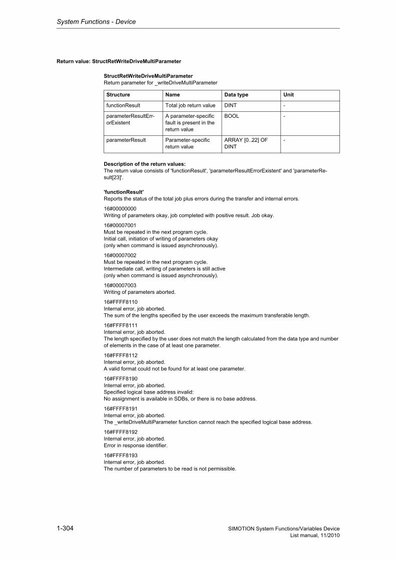
System Functions - Device
1-304 SIMOTION System Functions/Variables DeviceList manual, 11/2010
Return value: StructRetWriteDriveMultiParameter
StructRetWriteDriveMultiParameterReturn parameter for _writeDriveMultiParameter
Description of the return values:The return value consists of 'functionResult', 'parameterResultErrorExistent' and 'parameterRe-sult[23]'.
'functionResult'Reports the status of the total job plus errors during the transfer and internal errors.
16#00000000Writing of parameters okay, job completed with positive result. Job okay.
16#00007001Must be repeated in the next program cycle.Initial call, initiation of writing of parameters okay(only when command is issued asynchronously).
16#00007002Must be repeated in the next program cycle.Intermediate call, writing of parameters is still active(only when command is issued asynchronously).
16#00007003Writing of parameters aborted.
16#FFFF8110Internal error, job aborted.The sum of the lengths specified by the user exceeds the maximum transferable length.
16#FFFF8111Internal error, job aborted.The length specified by the user does not match the length calculated from the data type and number of elements in the case of at least one parameter.
16#FFFF8112Internal error, job aborted.A valid format could not be found for at least one parameter.
16#FFFF8190Internal error, job aborted.Specified logical base address invalid:No assignment is available in SDBs, or there is no base address.
16#FFFF8191Internal error, job aborted.The _writeDriveMultiParameter function cannot reach the specified logical base address.
16#FFFF8192Internal error, job aborted.Error in response identifier.
16#FFFF8193Internal error, job aborted.The number of parameters to be read is not permissible.
Structure Name Data type Unit
functionResult Total job return value DINT -
parameterResultErr-orExistent
A parameter-specific fault is present in the return value
BOOL -
parameterResult Parameter-specific return value
ARRAY [0..22] OF DINT
-

System Functions - Device
1-305SIMOTION System Functions/Variables DeviceList manual, 11/2010
16#FFFF819DInternal error, job aborted.An I slave/I device interface is unable to issue a parameter job to the higher-level master/controller.
16#FFFF819EInternal error, job aborted.Attempt to abort a non-active function.
16#FFFF819FInternal error, job aborted.Function not executable.
16#FFFF81C3Error, can be repeated in the next program cycle.Required resources are presently occupied:- In the _writeDriveMultiParameter function- In the module
16#FFFF81C5Error, can be repeated in the next program cycle.Distributed I/O not available.
16#FFFF81C7Error, can be repeated in the next program cycle.Another parameter job has already been issued to the DP station. - based on the user program - from a system-internal component (e.g. TO axis executes parameter comparison after station reco-very)
16#FFFF81CFError, can be repeated in the next program cycle.Another parameter job call is currently active under this 'commandId'.
16#FFFF8290Corresponds to the error message 16#FFFF8190.
16#FFFF8291Corresponds to the error message 16#FFFF8191.
16#FFFF82A2Error during data set transfer, job aborted.Error in Layer2:- Station failure- Timeout
16#FFFF82A3Error during data set transfer, job aborted.Error in user interface/user:- Protocol error- Station failure- Timeout
16#FFFF82A4-A7Error during data set transfer, job aborted.Error numbers according to IEC 61158 reserved- Query the cause at the module's manufacturer
16#FFFF82A8Error during data set transfer, job aborted.Error because of version conflict.
16#FFFF82A9Error during data set transfer, job aborted.Function not supported by the module.
16#FFFF82AA-AFError during data set transfer, job aborted.Error numbers according to IEC 61158 manufacturer-specific- Query the cause at the module's manufacturer
Siemens Industrial
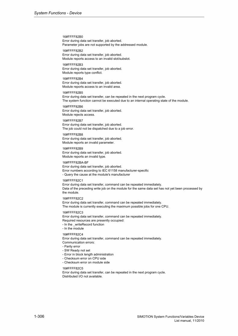
System Functions - Device
1-306 SIMOTION System Functions/Variables DeviceList manual, 11/2010
16#FFFF82B0Error during data set transfer, job aborted.Parameter jobs are not supported by the addressed module.
16#FFFF82B2Error during data set transfer, job aborted.Module reports access to an invalid slot/subslot.
16#FFFF82B3Error during data set transfer, job aborted.Module reports type conflict.
16#FFFF82B4Error during data set transfer, job aborted.Module reports access to an invalid area.
16#FFFF82B5Error during data set transfer, can be repeated in the next program cycle.The system function cannot be executed due to an internal operating state of the module.
16#FFFF82B6Error during data set transfer, job aborted.Module rejects access.
16#FFFF82B7Error during data set transfer, job aborted.The job could not be dispatched due to a job error.
16#FFFF82B8Error during data set transfer, job aborted.Module reports an invalid parameter.
16#FFFF82B9Error during data set transfer, job aborted.Module reports an invalid type.
16#FFFF82BA-BFError during data set transfer, job aborted.Error numbers according to IEC 61158 manufacturer-specific- Query the cause at the module's manufacturer
16#FFFF82C1Error during data set transfer, command can be repeated immediately.Data of the preceding write job on the module for the same data set has not yet been processed by the module.
16#FFFF82C2Error during data set transfer, command can be repeated immediately.The module is currently executing the maximum possible jobs for one CPU.
16#FFFF82C3Error during data set transfer, command can be repeated immediately.Required resources are presently occupied:- In the _writeRecord function- In the module
16#FFFF82C4Error during data set transfer, command can be repeated immediately.Communication errors:- Parity error- SW Ready not set- Error in block length administration- Checksum error on CPU side- Checksum error on module side
16#FFFF82C5Error during data set transfer, can be repeated in the next program cycle.Distributed I/O not available.
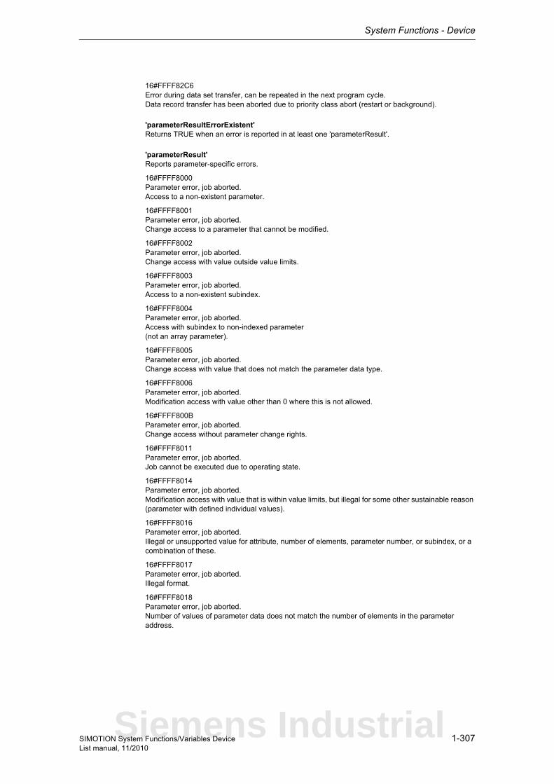
System Functions - Device
1-307SIMOTION System Functions/Variables DeviceList manual, 11/2010
16#FFFF82C6Error during data set transfer, can be repeated in the next program cycle.Data record transfer has been aborted due to priority class abort (restart or background).
'parameterResultErrorExistent'Returns TRUE when an error is reported in at least one 'parameterResult'.
'parameterResult'Reports parameter-specific errors.
16#FFFF8000Parameter error, job aborted.Access to a non-existent parameter.
16#FFFF8001Parameter error, job aborted.Change access to a parameter that cannot be modified.
16#FFFF8002Parameter error, job aborted.Change access with value outside value limits.
16#FFFF8003Parameter error, job aborted.Access to a non-existent subindex.
16#FFFF8004Parameter error, job aborted.Access with subindex to non-indexed parameter(not an array parameter).
16#FFFF8005Parameter error, job aborted.Change access with value that does not match the parameter data type.
16#FFFF8006Parameter error, job aborted.Modification access with value other than 0 where this is not allowed.
16#FFFF800BParameter error, job aborted.Change access without parameter change rights.
16#FFFF8011Parameter error, job aborted.Job cannot be executed due to operating state.
16#FFFF8014Parameter error, job aborted.Modification access with value that is within value limits, but illegal for some other sustainable reason (parameter with defined individual values).
16#FFFF8016Parameter error, job aborted.Illegal or unsupported value for attribute, number of elements, parameter number, or subindex, or a combination of these.
16#FFFF8017Parameter error, job aborted.Illegal format.
16#FFFF8018Parameter error, job aborted.Number of values of parameter data does not match the number of elements in the parameter address.
Siemens Industrial
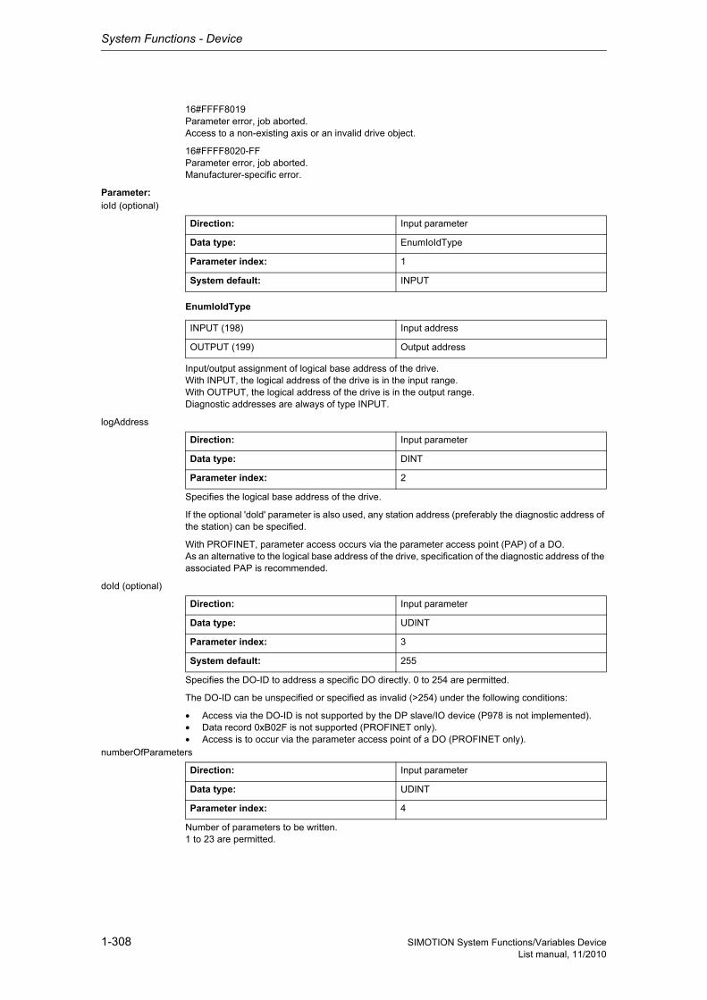
System Functions - Device
1-308 SIMOTION System Functions/Variables DeviceList manual, 11/2010
16#FFFF8019Parameter error, job aborted.Access to a non-existing axis or an invalid drive object.
16#FFFF8020-FFParameter error, job aborted.Manufacturer-specific error.
Parameter: ioId (optional)
EnumIoIdType
Input/output assignment of logical base address of the drive.With INPUT, the logical address of the drive is in the input range.With OUTPUT, the logical address of the drive is in the output range.Diagnostic addresses are always of type INPUT.
logAddress
Specifies the logical base address of the drive.
If the optional 'dold' parameter is also used, any station address (preferably the diagnostic address of the station) can be specified.
With PROFINET, parameter access occurs via the parameter access point (PAP) of a DO.As an alternative to the logical base address of the drive, specification of the diagnostic address of the associated PAP is recommended.
doId (optional)
Specifies the DO-ID to address a specific DO directly. 0 to 254 are permitted.
The DO-ID can be unspecified or specified as invalid (>254) under the following conditions:
• Access via the DO-ID is not supported by the DP slave/IO device (P978 is not implemented).• Data record 0xB02F is not supported (PROFINET only).• Access is to occur via the parameter access point of a DO (PROFINET only).
numberOfParameters
Number of parameters to be written.1 to 23 are permitted.
Direction: Input parameter
Data type: EnumIoIdType
Parameter index: 1
System default: INPUT
INPUT (198) Input address
OUTPUT (199) Output address
Direction: Input parameter
Data type: DINT
Parameter index: 2
Direction: Input parameter
Data type: UDINT
Parameter index: 3
System default: 255
Direction: Input parameter
Data type: UDINT
Parameter index: 4
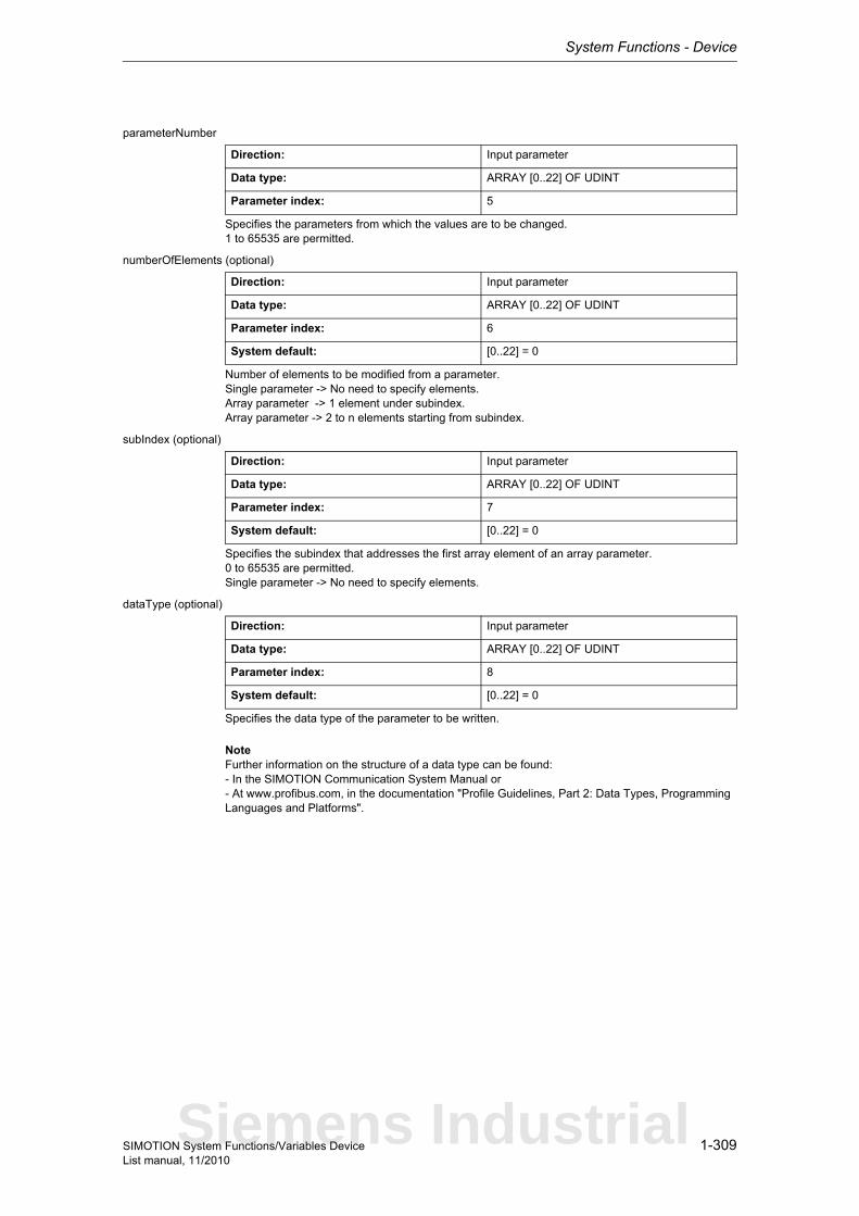
System Functions - Device
1-309SIMOTION System Functions/Variables DeviceList manual, 11/2010
parameterNumber
Specifies the parameters from which the values are to be changed.1 to 65535 are permitted.
numberOfElements (optional)
Number of elements to be modified from a parameter.Single parameter -> No need to specify elements.Array parameter -> 1 element under subindex.Array parameter -> 2 to n elements starting from subindex.
subIndex (optional)
Specifies the subindex that addresses the first array element of an array parameter.0 to 65535 are permitted.Single parameter -> No need to specify elements.
dataType (optional)
Specifies the data type of the parameter to be written.
NoteFurther information on the structure of a data type can be found:- In the SIMOTION Communication System Manual or- At www.profibus.com, in the documentation "Profile Guidelines, Part 2: Data Types, Programming Languages and Platforms".
Direction: Input parameter
Data type: ARRAY [0..22] OF UDINT
Parameter index: 5
Direction: Input parameter
Data type: ARRAY [0..22] OF UDINT
Parameter index: 6
System default: [0..22] = 0
Direction: Input parameter
Data type: ARRAY [0..22] OF UDINT
Parameter index: 7
System default: [0..22] = 0
Direction: Input parameter
Data type: ARRAY [0..22] OF UDINT
Parameter index: 8
System default: [0..22] = 0
Siemens Industrial
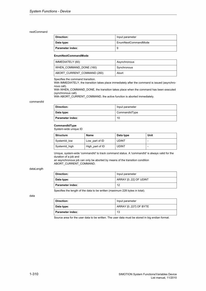
System Functions - Device
1-310 SIMOTION System Functions/Variables DeviceList manual, 11/2010
nextCommand
EnumNextCommandMode
Specifies the command transition.With IMMEDIATELY, the transition takes place immediately after the command is issued (asynchro-nous call).With WHEN_COMMAND_DONE, the transition takes place when the command has been executed (synchronous call).With ABORT_CURRENT_COMMAND, the active function is aborted immediately.
commandId
CommandIdTypeSystem-wide unique ID
Unique, system-wide 'commandId' to track command status. A 'commandId' is always valid for the duration of a job andan asynchronous job can only be aborted by means of the transition condition ABORT_CURRENT_COMMAND.
dataLength
Specifies the length of the data to be written (maximum 228 bytes in total).
data
Source area for the user data to be written. The user data must be stored in big endian format.
Direction: Input parameter
Data type: EnumNextCommandMode
Parameter index: 9
IMMEDIATELY (60) Asynchronous
WHEN_COMMAND_DONE (160) Synchronous
ABORT_CURRENT_COMMAND (260) Abort
Direction: Input parameter
Data type: CommandIdType
Parameter index: 10
Structure Name Data type Unit
SystemId_low Low_part of ID UDINT -
SystemId_high High_part of ID UDINT -
Direction: Input parameter
Data type: ARRAY [0..22] OF UDINT
Parameter index: 12
Direction: Input parameter
Data type: ARRAY [0..227] OF BYTE
Parameter index: 13

System Functions - Device
1-311SIMOTION System Functions/Variables DeviceList manual, 11/2010
1.3.3.10 _writeDriveParameter
NoteAdditional information is available at:SIMOTION Communication System Manual,Section PROFIdrive-specific data types, Section Rules for SIMOTION _writeDrive.../_readDrive... commandsor in the SIMOTION online help.
This function enables a drive parameter to be written.
Note• Up to 16 parameter jobs can be executed in parallel (the term parameter job also includes the
functions _writeDriveMultiParameter, _readDrive(Multi)ParameterDescription, _readDrive(Multi)Parameter and _readDriveFaults).
• Only one parameter job is permitted per planned DP station. A new job to the same DP station is rejected with the error 16#FFFF81C7.
• If the system functions _readRecord and _writeRecord are used in addition to the parameter jobs, you must ensure that they are not to be executed simultaneously by a DP station. Reason: The same communication services are used.
• If a parameter job (only asynchronous calls) is no longer to be processed, then it must be aborted with the ABORT_CURRENT_COMMAND transition condition. Otherwise no new job can be issued.
Parameters can be read out with the following data sets:• Data set 47 is always read out for PROFIBUS (external or integrated), regardless of whether the
function is called with a valid (0>=doId<=254) or invalid 'doId' (doId=255). If the passed 'doId' is invalid, it will be determined by the system itself. This requires the specification of the logical address of the axis.
• Two data sets are available for PROFINET:− Base Mode Parameter Access - local (data set 0xB02E)This data set (DS) is used for SIMOTION if either no 'dold' or an invalid 'dold' (dold=255) is spe-cified in the function. The Parameter Access Point (PAP) is then used to access the relevant DO. Either the PAP address can be specified directly or the log. address of the cyclical data (e.g. 256 for a DO axis) can be given. SIMOTION then determines the corresponding PAP from this address before accessing the correct address.
Note for PROFINETSIMOTION V4.1 SP2: PAP must always be at subslot 1 (HW Config configuration).
− Base Mode Parameter Access - global (data set 0xB02F)This data set is used if a valid 'dold' (0>=doId<=254) is entered. Any valid PAP or address can be specified, as assignment only takes place on the basis of the 'dold'.
Return value: StructRetWriteDriveParameter
StructRetWriteDriveParameterReturn parameter for _writeDriveParameter
Description of the return values:The return value consists of 'functionResult' and 'parameterResult'.
Structure Name Data type Unit
functionResult Total job return value DINT -
parameterResult Parameter-specific return value
DINT -
Siemens Industrial
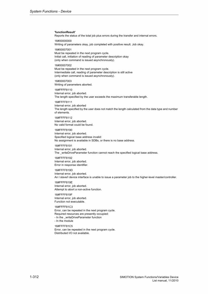
System Functions - Device
1-312 SIMOTION System Functions/Variables DeviceList manual, 11/2010
'functionResult'Reports the status of the total job plus errors during the transfer and internal errors.
16#00000000Writing of parameters okay, job completed with positive result. Job okay.
16#00007001Must be repeated in the next program cycle.Initial call, initiation of reading of parameter description okay(only when command is issued asynchronously).
16#00007002Must be repeated in the next program cycle.Intermediate call, reading of parameter description is still active(only when command is issued asynchronously).
16#00007003Writing of parameters aborted.
16#FFFF8110Internal error, job aborted.The length specified by the user exceeds the maximum transferable length.
16#FFFF8111Internal error, job abortedThe length specified by the user does not match the length calculated from the data type and number of elements.
16#FFFF8112Internal error, job aborted.No valid format could be found.
16#FFFF8190Internal error, job aborted.Specified logical base address invalid:No assignment is available in SDBs, or there is no base address.
16#FFFF8191Internal error, job aborted.The _writeDriveParameter function cannot reach the specified logical base address.
16#FFFF8192Internal error, job aborted.Error in response identifier.
16#FFFF819DInternal error, job aborted.An I slave/I device interface is unable to issue a parameter job to the higher-level master/controller.
16#FFFF819EInternal error, job aborted.Attempt to abort a non-active function.
16#FFFF819FInternal error, job aborted.Function not executable.
16#FFFF81C3Error, can be repeated in the next program cycle.Required resources are presently occupied:- In the _writeDriveParameter function- In the module
16#FFFF81C5Error, can be repeated in the next program cycle.Distributed I/O not available.

System Functions - Device
1-313SIMOTION System Functions/Variables DeviceList manual, 11/2010
16#FFFF81C7Error, can be repeated in the next program cycle.Another parameter job has already been issued to the DP station. - based on the user program - from a system-internal component (e.g. TO axis executes parameter comparison after station reco-very)
16#FFFF81CFError, can be repeated in the next program cycle.Another parameter job call is currently active under this 'commandId'.
16#FFFF8290Corresponds to the error message 16#FFFF8190.
16#FFFF8291Corresponds to the error message 16#FFFF8191.
16#FFFF82A2Error during data set transfer, job aborted.Error in Layer2:- Station failure- Timeout
16#FFFF82A3Error during data set transfer, job aborted.Error in user interface/user:- Protocol error- Station failure- Timeout
16#FFFF82A4-A7Error during data set transfer, job aborted.Error numbers according to IEC 61158 reserved- Query the cause at the module's manufacturer
16#FFFF82A8Error during data set transfer, job aborted.Error because of version conflict.
16#FFFF82A9Error during data set transfer, job aborted.Function not supported by the module.
16#FFFF82AA-AFError during data set transfer, job aborted.Error numbers according to IEC 61158 manufacturer-specific- Query the cause at the module's manufacturer
16#FFFF82B0Error during data set transfer, job aborted.Parameter jobs are not supported by the addressed module.
16#FFFF82B2Error during data set transfer, job aborted.Module reports access to an invalid slot/subslot.
16#FFFF82B3Error during data set transfer, job aborted.Module reports type conflict.
16#FFFF82B4Error during data set transfer, job aborted.Module reports access to an invalid area.
16#FFFF82B5Error during data set transfer, can be repeated in the next program cycle.The system function cannot be executed due to an internal operating state of the module.
16#FFFF82B6Error during data set transfer, job aborted.Module rejects access.
Siemens Industrial
System Functions - Device
1-314 SIMOTION System Functions/Variables DeviceList manual, 11/2010
16#FFFF82B7Error during data set transfer, job aborted.The job could not be dispatched due to a job error.
16#FFFF82B8Error during data set transfer, job aborted.Module reports an invalid parameter.
16#FFFF82B9Error during data set transfer, job aborted.Module reports an invalid type.
16#FFFF82BA-BFError during data set transfer, job aborted.Error numbers according to IEC 61158 manufacturer-specific- Query the cause at the module's manufacturer
16#FFFF82C1Error during data set transfer, command can be repeated immediately.Data of the preceding write job on the module for the same data set has not yet been processed by the module.
16#FFFF82C2Error during data set transfer, command can be repeated immediately.The module is currently executing the maximum possible jobs for one CPU.
16#FFFF82C3Error during data set transfer, command can be repeated immediately.Required resources are presently occupied:- In the _writeRecord function- In the module
16#FFFF82C4Error during data set transfer, command can be repeated immediately.Communication errors:- Parity error- SW Ready not set- Error in block length administration- Checksum error on CPU side- Checksum error on module side
16#FFFF82C5Error during data set transfer, can be repeated in the next program cycle.Distributed I/O not available.
16#FFFF82C6Error during data set transfer, can be repeated in the next program cycle.Data record transfer has been aborted due to priority class abort (restart or background).
System Functions - Device
1-315SIMOTION System Functions/Variables DeviceList manual, 11/2010
'parameterResult'Reports parameter-specific errors.
16#FFFF8000Parameter error, job aborted.Access to a non-existent parameter.
16#FFFF8001Parameter error, job aborted.Change access to a parameter that cannot be modified.
16#FFFF8002Parameter error, job aborted.Change access with value outside value limits.
16#FFFF8003Parameter error, job aborted.Access to a non-existent subindex.
16#FFFF8004Parameter error, job aborted.Access with subindex to non-indexed parameter (not an array parameter).
16#FFFF8005Parameter error, job aborted.Change access with value that does not match the parameter data type.
16#FFFF8006Parameter error, job aborted.Modification access with value other than 0 where this is not allowed.
16#FFFF800BParameter error, job aborted.Change access without parameter change rights.
16#FFFF8011Parameter error, job aborted.Job cannot be executed due to operating state.
16#FFFF8014Parameter error, job aborted.Modification access with value that is within value limits, but illegal for some other sustainable reason(parameter with defined individual values).
16#FFFF8016Parameter error, job aborted.Illegal or unsupported value for attribute, number of elements, parameter number, or subindex, or a combination of these.
16#FFFF8017Parameter error, job aborted.Illegal format.
16#FFFF8018Parameter error, job aborted.Number of values of parameter data does not match the number of elements in the parameter address.
16#FFFF8019Parameter error, job aborted.Access to a non-existing axis or an invalid drive object.
16#FFFF8020-FF Parameter error, job aborted.Manufacturer-specific error.
Siemens Industrial
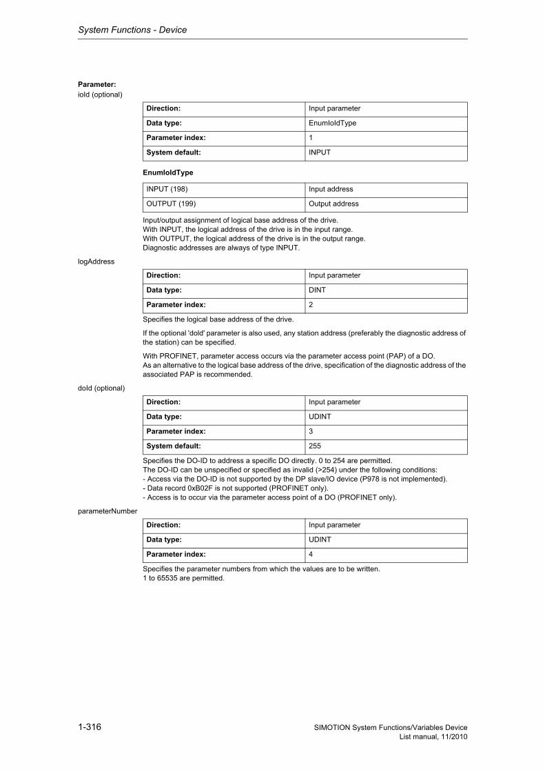
System Functions - Device
1-316 SIMOTION System Functions/Variables DeviceList manual, 11/2010
Parameter: ioId (optional)
EnumIoIdType
Input/output assignment of logical base address of the drive.With INPUT, the logical address of the drive is in the input range.With OUTPUT, the logical address of the drive is in the output range.Diagnostic addresses are always of type INPUT.
logAddress
Specifies the logical base address of the drive.
If the optional 'dold' parameter is also used, any station address (preferably the diagnostic address of the station) can be specified.
With PROFINET, parameter access occurs via the parameter access point (PAP) of a DO.As an alternative to the logical base address of the drive, specification of the diagnostic address of the associated PAP is recommended.
doId (optional)
Specifies the DO-ID to address a specific DO directly. 0 to 254 are permitted.The DO-ID can be unspecified or specified as invalid (>254) under the following conditions:- Access via the DO-ID is not supported by the DP slave/IO device (P978 is not implemented).- Data record 0xB02F is not supported (PROFINET only).- Access is to occur via the parameter access point of a DO (PROFINET only).
parameterNumber
Specifies the parameter numbers from which the values are to be written.1 to 65535 are permitted.
Direction: Input parameter
Data type: EnumIoIdType
Parameter index: 1
System default: INPUT
INPUT (198) Input address
OUTPUT (199) Output address
Direction: Input parameter
Data type: DINT
Parameter index: 2
Direction: Input parameter
Data type: UDINT
Parameter index: 3
System default: 255
Direction: Input parameter
Data type: UDINT
Parameter index: 4

System Functions - Device
1-317SIMOTION System Functions/Variables DeviceList manual, 11/2010
numberOfElements (optional)
Number of elements that are to be written from a parameter.Single parameter -> No need to specify elements.Array parameter -> 1 element under subindex.Array parameter -> 2 to n elements starting from subindex.
subIndex (optional)
Specifies the subindex that addresses the first array element of the parameter.0 to 65535 are permitted.
dataType (optional)
Specifies the data type of the parameter to be written.
NoteFurther information on the structure of a data type can be found:- In the SIMOTION Communication System Manual or- At www.profibus.com, in the documentation "Profile Guidelines, Part 2: Data Types, Programming Languages and Platforms".
nextCommand
EnumNextCommandMode
Specifies the command transition.With IMMEDIATELY, the transition takes place immediately after the command is issued (asynchro-nous call).With WHEN_COMMAND_DONE, the transition takes place when the command has been executed (synchronous call).With ABORT_CURRENT_COMMAND, the active function is aborted immediately.
Direction: Input parameter
Data type: UDINT
Parameter index: 5
System default: 0
Direction: Input parameter
Data type: UDINT
Parameter index: 6
System default: 0
Direction: Input parameter
Data type: UDINT
Parameter index: 7
System default: 0
Direction: Input parameter
Data type: EnumNextCommandMode
Parameter index: 8
IMMEDIATELY (60) Asynchronous
WHEN_COMMAND_DONE (160) Synchronous
ABORT_CURRENT_COMMAND (260) Abort
Siemens Industrial
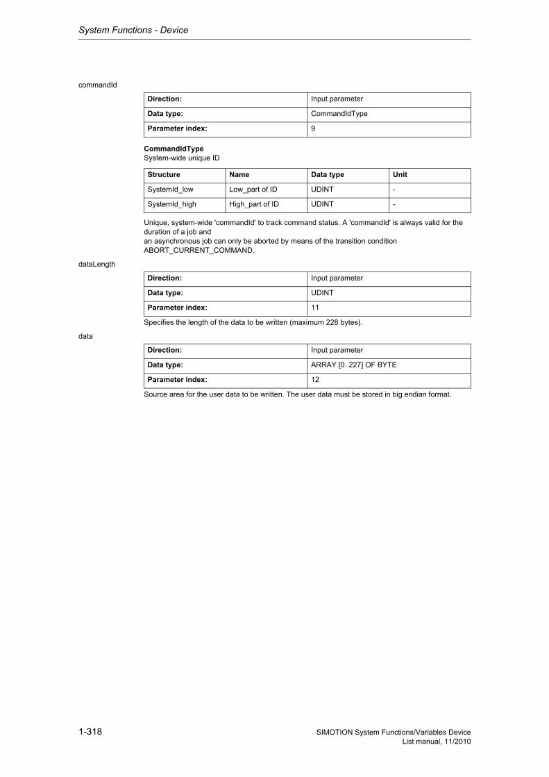
System Functions - Device
1-318 SIMOTION System Functions/Variables DeviceList manual, 11/2010
commandId
CommandIdTypeSystem-wide unique ID
Unique, system-wide 'commandId' to track command status. A 'commandId' is always valid for the duration of a job andan asynchronous job can only be aborted by means of the transition condition ABORT_CURRENT_COMMAND.
dataLength
Specifies the length of the data to be written (maximum 228 bytes).
data
Source area for the user data to be written. The user data must be stored in big endian format.
Direction: Input parameter
Data type: CommandIdType
Parameter index: 9
Structure Name Data type Unit
SystemId_low Low_part of ID UDINT -
SystemId_high High_part of ID UDINT -
Direction: Input parameter
Data type: UDINT
Parameter index: 11
Direction: Input parameter
Data type: ARRAY [0..227] OF BYTE
Parameter index: 12
System Functions - Device
1-319SIMOTION System Functions/Variables DeviceList manual, 11/2010
1.3.4 SIMATIC
1.3.4.1 _ET200S_FC_control
The _ET200S_FC_control function block can be used to exchange cyclical data with the ET200S fre-quency converter. When requested, parameters are read from or written to the ET200S frequency converter and errors acknowledged.NOTE:The FB _ET200S_FC_control can only be used to control ET200S frequency converters with the MLFB 6SL3244-0SA00-1AA0!'The FB _ET200S_FC_control cannot be used for the ET200S frequency converter with the MLFB 6SL3244-0SA00-1AA1. Standard message frame 1 should be used here!
Hardware and software requirements :ICU24 hardware release: Only 6SL3244-0SA00-1AA0ICU24 software release: V1.02 and later
Detailed information
ST: Note:You can import the following program segments into the ST program using Drag & Drop. Additions must be made for executability (see manual, e.g. creating variables, etc.).An executable application example can be found on the "SIMOTION Utilities & Applications" CD-ROM.The "SIMOTION Utilities & Applications" CD-ROM is provided free of charge and is supplied with SIMOTION SCOUT.
// myET200S_FC_control : _ET200S_FC_control; // instance of FB (_ET200S_FC_control)myET200S_FC_control(execute := myExecute, // [IN] Anstoss Datentransfer (BOOL)mode := myMode, // [IN] Voreinstellung (enum_ET200S_FC_mode)pzdIn := myPzdIn, // [IN] Peripherieeingaenge (ARRAY[0..7] OF BYTE)setpoint := mySetpoint, // [IN] Drehzahlsollwert (DINT)ctrlDword := myCtrlDword, // [IN] Steuerwort (DWORD)paraNumber := myParaNumber, // [IN] Parameternummer (UINT)subIndex := mySubIndex, // [IN] Index (UINT)paraValueWr := myParaValueWr // [IN] Parameternummer (REAL));
Siemens Industrial
System Functions - Device
1-320 SIMOTION System Functions/Variables DeviceList manual, 11/2010
1.4 I/O modules
1.4.1 Function modules - FM350-1
1.4.1.1 _FM3501_control2
The _FM3501_control2 function block can be used to control the module and to query the status of the FM 350-1.
Hardware and software requirements :Hardware release status:6ES7 350-1AH02-0AE0 after product release E026ES7 350-1AH03-0AE0 after product release E01Software release : None
Detailed information
ST: Note:You can import the following program segments into the ST program using Drag & Drop. Additions must be made for executability (see manual, e.g. creating variables, etc.).An executable application example can be found on the "SIMOTION Utilities & Applications" CD-ROM.The "SIMOTION Utilities & Applications" CD-ROM is provided free of charge and is supplied with SIMOTION SCOUT.
System Functions - Device
1-321SIMOTION System Functions/Variables DeviceList manual, 11/2010
// myFM3501_control : _FM3501_control2; // instance of FB (_FM3501_control2)myFM3501_control(enableSwGate := myEnableSwGate, // [IN] software gate (BOOL)enableStopGate := myEnableStopGate, // [IN] gate stop (BOOL)execResetOpError := myExecResetOpError, // [IN] operator error acknowledge (BOOL)cntrRange := myCntrRange, // [IN] Range of counter value 0: -2exp31<x<2exp31, 1: 0< x< 2exp32 (BOOL)setOutput0 := mySetOutput0 // [IN] set digital output 0setOutput1 := mySetOutput1 // [IN] set digital output 1periIn := myPeriIn, // [IN] peripheral input (ARRAY[0..15] OF BYTE)data := myFM3501_fmData, // [IN_OUT] datastruct for FM 350-1 - counter module (Struct_FM3501_fmData)setStartValue := mySetStartValue, // [IN_OUT] load direct (BOOL)setPrepStartValue := mySetPrepStartValue, // [IN_OUT] load prepared (BOOL)setCmpValue1 := mySetCmpValue1, // [IN_OUT] transfer comparator value 1 (BOOL)setCmpValue2 := mySetCmpValue2, // [IN_OUT] transfer comparator value 2 (BOOL)resetSyncState := myResetSyncState, // [IN_OUT] reset synchronisation bit (BOOL)resetCntrState := myResetCntrState, // [IN_OUT] reset zero crossing bit (BOOL)setParaOutput := mySetParaOutput // [IN_OUT]set parameter for digital output 0/1periOut := myPeriOut // [IN_OUT] peripheral output (ARRAY[0..15] OF BYTE));// ***********************// Struct_FM3501_fmData// ***********************// myFM3501_fmData : Struct_FM3501_fmData;myFM3501_fmData.moduleAddress := 256; // [IN] module adress (wu)myFM3501_fmData.loadValue1 := 0; // [IN] new load value (wu), count range -2exp31<x<2exp31myFM3501_fmData.cmpValue1_1 := 0; // [IN] new comparator value 1 (wu), count range -2exp31<x<2exp31myFM3501_fmData.cmpValue2_1 := 0; // [IN] new comparator value 2 (wu), count range -2exp31<x<2exp31myFM3501_fmData.loadValue2 := 0; // [IN] new load value (wu), count range 0< x< 2exp32myFM3501_fmData.cmpValue1_2 := 0; // [IN] new comparator value 1 (wu), count range 0< x< 2exp32myFM3501_fmData.cmpValue2_2 := 0; // [IN] new comparator value 2 (wu), count range 0< x< 2exp32myFM3501_fmData.enableTestMode := FALSE; // [IN] test free (internal use)myFM3501_fmData.enableReverseSetting := FALSE; // [IN] enable set direction up (=forward) (wu)myFM3501_fmData.enableForwardSetting := FALSE; // [IN] enable set direction dn (=backward) (wu)myFM3501_fmData.enableOutput0 := FALSE; // [IN] control digital output DQ0 (wu)myFM3501_fmData.enableOutput1 := FALSE; // [IN] control digital output DQ1 (wu)myFM3501_fmData.configMeasOut0 := 0; // [IN] configuration data for digital output0 in operating mode measuringmyFM3501_fmData.configCntrOut0 := 0; // [IN] configuration data for digital output0 in operating mode countingmyFM3501_fmData.configCntrOut1 := 0; // [IN] configuration data for digital output1 in operating mode countingmyFM3501_fmData.setCntrHyst := 0; // [IN] hysteresis in values of countermyFM3501_fmData.setCntrPulse := 0; // [IN] duration of pulse [ms]
Siemens Industrial
System Functions - Device
1-322 SIMOTION System Functions/Variables DeviceList manual, 11/2010
1.4.1.2 _FM3501_diagnostic
The _FM3501_diagnostic function block can be used to read out the complete diagnostic data from the FM 350-1.
Hardware and software requirements :Hardware release status:6ES7 350-1AH02-0AE0 after product release E026ES7 350-1AH03-0AE0 after product release E01Software release : NoneThe following new functions of the FM350-1 module (order no.:6ES7 350-1AH03-0AE0) are not sup-ported:- Isochronous mode- Measuring modes (frequency measurement,speed measurement,time period duration measure-ment)
Detailed information
ST: Note:You can import the following program segments into the ST program using Drag & Drop. Additions must be made for executability (see manual, e.g. creating variables, etc.).An executable application example can be found on the "SIMOTION Utilities & Applications" CD-ROM.The "SIMOTION Utilities & Applications" CD-ROM is provided free of charge and is supplied with SIMOTION SCOUT.
// myFM3501_diagnostic : _FM3501_diagnostic; // instance of FB (_FM3501_diagnostic)myFM3501_diagnostic(data := myFM3501_fmData, // [IN_OUT] datastruct for FM 350-1 - counter module (Struct_FM3501_fmData)execute := myExecute // [IN_OUT] initiate diagnostic interrupt (BOOL));// ***********************// Struct_FM3501_fmData// ***********************// myFM3501_fmData : Struct_FM3501_fmData;myFM3501_fmData.moduleAddress := 256; // [IN] module adress (wu)myFM3501_fmData.loadValue1 := 0; // [IN] new load value (wu), count range -2exp31<x<2exp31myFM3501_fmData.cmpValue1_1 := 0; // [IN] new comparator value 1 (wu), count range -2exp31<x<2exp31myFM3501_fmData.cmpValue2_1 := 0; // [IN] new comparator value 2 (wu), count range -2exp31<x<2exp31myFM3501_fmData.loadValue2 := 0; // [IN] new load value (wu), count range 0< x< 2exp32myFM3501_fmData.cmpValue1_2 := 0; // [IN] new comparator value 1 (wu), count range 0< x< 2exp32myFM3501_fmData.cmpValue2_2 := 0; // [IN] new comparator value 2 (wu), count range 0< x< 2exp32myFM3501_fmData.enableTestMode := FALSE; // [IN] test free (internal use)myFM3501_fmData.enableReverseSetting := FALSE; // [IN] enable set direction up (=forward) (wu)myFM3501_fmData.enableForwardSetting := FALSE; // [IN] enable set direction dn (=backward) (wu)myFM3501_fmData.enableOutput0 := FALSE; // [IN] control digital output DQ0 (wu)myFM3501_fmData.enableOutput1 := FALSE; // [IN] control digital output DQ1 (wu)
System Functions - Device
1-323SIMOTION System Functions/Variables DeviceList manual, 11/2010
1.4.2 Function modules - FM350-2
1.4.2.1 _FM3502_control
The _FM3502_control function block can be used to control the module and to query the status of the FM 350-2.
Hardware and software requirements :Hardware release status:6ES7 350-2AH00-0AE0 after product release E04Software release : None
Detailed information
ST: Note:You can import the following program segments into the ST program using Drag & Drop. Additions must be made for executability (see manual, e.g. creating variables, etc.).An executable application example can be found on the "SIMOTION Utilities & Applications" CD-ROM.The "SIMOTION Utilities & Applications" CD-ROM is provided free of charge and is supplied with SIMOTION SCOUT.
Siemens Industrial

System Functions - Device
1-324 SIMOTION System Functions/Variables DeviceList manual, 11/2010
// myFM3502_control : _FM3502_control; // instance of FB (_FM3502_control)myFM3502_control(periIn := myPeriIn, // [IN] Transfers I/O Inputs of the FM to the FB (ARRAY[0..15] of BYTE)periOut := myPeriOut, // [IN_OUT] Prepared data of the FB for the I/O outputs of the FM (ARRAY[0..15] of BYTE)data := myFM3502_fmData // [IN_OUT] Data structure whith channel-specific data (Struct_FM3502_fmData));// ***************************************// Struct_FM3502_wrJob // write commands// ***************************************myFM3502_fmData.write.execJobNumber :=0; // [IN] number (BYTE)// ***************************************// Struct_FM3502_rdJob // read commands// ***************************************myFM3502_fmData.read.execJobNumber :=0; // [IN] number(BYTE)// *************************************************// Struct_FM3502_controlSignals // control signals// *************************************************myFM3502_fmData.control.enableOutput0 := FALSE; // [IN] control digital output DQ0 (BOOL)myFM3502_fmData.control.enableOutput1 := FALSE; // [IN] control digital output DQ1 (BOOL)myFM3502_fmData.control.enableOutput2 := FALSE; // [IN] control digital output DQ2 (BOOL)myFM3502_fmData.control.enableOutput3 := FALSE; // [IN] control digital output DQ3 (BOOL)myFM3502_fmData.control.enableOutput4 := FALSE; // [IN] control digital output DQ4 (BOOL)myFM3502_fmData.control.enableOutput5 := FALSE; // [IN] control digital output DQ5 (BOOL)myFM3502_fmData.control.enableOutput6 := FALSE; // [IN] control digital output DQ6 (BOOL)myFM3502_fmData.control.enableOutput7 := FALSE; // [IN] control digital output DQ7 (BOOL)myFM3502_fmData.control.setOutput0 := FALSE; // [IN] set digital output DQ0(BOOL)myFM3502_fmData.control.setOutput1 := FALSE; // [IN] set digital output DQ1(BOOL)myFM3502_fmData.control.setOutput2 := FALSE; // [IN] set digital output DQ2(BOOL)myFM3502_fmData.control.setOutput3 := FALSE; // [IN] set digital output DQ3(BOOL)myFM3502_fmData.control.setOutput4 := FALSE; // [IN] set digital output DQ4(BOOL)myFM3502_fmData.control.setOutput5 := FALSE; // [IN] set digital output DQ5(BOOL)myFM3502_fmData.control.setOutput6 := FALSE; // [IN] set digital output DQ6(BOOL)myFM3502_fmData.control.setOutput7 := FALSE; // [IN] set digital output DQ7(BOOL)myFM3502_fmData.control.enableSwGate0 := FALSE; // [IN] software gate 0 (BOOL)myFM3502_fmData.control.enableSwGate1 := FALSE; // [IN] software gate 1 (BOOL)myFM3502_fmData.control.enableSwGate2 := FALSE; // [IN] software gate 2 (BOOL)myFM3502_fmData.control.enableSwGate3 := FALSE; // [IN] software gate 3 (BOOL)myFM3502_fmData.control.enableSwGate4 := FALSE; // [IN] software gate 4 (BOOL)myFM3502_fmData.control.enableSwGate5 := FALSE; // [IN] software gate 5 (BOOL)myFM3502_fmData.control.enableSwGate6 := FALSE; // [IN] software gate 6 (BOOL)myFM3502_fmData.control.enableSwGate7 := FALSE; // [IN] software gate 7 (BOOL)// ***************************************// Struct_FM3502_fmData// ***************************************// myFM3502_fmData : Struct_FM3502_fmData;myFM3502_fmData.moduleAddress :=256; // [IN] module address(INT)myFM3502_fmData.loadValue0 :=0; // [IN] load value counter 0(DINT)myFM3502_fmData.loadValue1 :=0; // [IN] load value counter 1(DINT)myFM3502_fmData.loadValue2 :=0; // [IN] load value counter 2(DINT)myFM3502_fmData.loadValue3 :=0; // [IN] load value counter 3(DINT)myFM3502_fmData.loadValue4 :=0; // [IN] load value counter 4(DINT)myFM3502_fmData.loadValue5 :=0; // [IN] load value counter 5(DINT)myFM3502_fmData.loadValue6 :=0; // [IN] load value counter 6(DINT)myFM3502_fmData.loadValue7 :=0; // [IN] load value counter 7(DINT)myFM3502_fmData.prepValue0 :=0; // [IN] load prepare value counter 0(DINT)myFM3502_fmData.prepValue1 :=0; // [IN] load prepare value counter 1(DINT)myFM3502_fmData.prepValue2 :=0; // [IN] load prepare value counter 2(DINT)myFM3502_fmData.prepValue3 :=0; // [IN] load prepare value counter 3(DINT)myFM3502_fmData.prepValue4 :=0; // [IN] load prepare value counter 4(DINT)myFM3502_fmData.prepValue5 :=0; // [IN] load prepare value counter 5(DINT)myFM3502_fmData.prepValue6 :=0; // [IN] load prepare value counter 6(DINT)myFM3502_fmData.prepValue7 :=0; // [IN] load prepare value counter 7(DINT)myFM3502_fmData.cmpValue0 :=0; // [IN] comparator value 0(DINT)myFM3502_fmData.cmpValue1 :=0; // [IN] comparator value 1(DINT)myFM3502_fmData.cmpValue2 :=0; // [IN] comparator value 2(DINT)myFM3502_fmData.cmpValue3 :=0; // [IN] comparator value 3(DINT)myFM3502_fmData.cmpValue4 :=0; // [IN] comparator value 4(DINT)myFM3502_fmData.cmpValue5 :=0; // [IN] comparator value 5(DINT)myFM3502_fmData.cmpValue6 :=0; // [IN] comparator value 6(DINT)myFM3502_fmData.cmpValue7 :=0; // [IN] comparator value 7(DINT)

System Functions - Device
1-325SIMOTION System Functions/Variables DeviceList manual, 11/2010
1.4.2.2 _FM3502_diagnostic
The _FM3502_diagnostic function block can be used to read out the complete diagnostic data from the FM 350-2.
Hardware and software requirements :Hardware release status:6ES7 350-2AH00-0AE0 after product release E04Software release : None
Detailed information
ST: Note:You can import the following program segments into the ST program using Drag & Drop. Additions must be made for executability (see manual, e.g. creating variables, etc.).An executable application example can be found on the "SIMOTION Utilities & Applications" CD-ROM.The "SIMOTION Utilities & Applications" CD-ROM is provided free of charge and is supplied with SIMOTION SCOUT.
Siemens Industrial

System Functions - Device
1-326 SIMOTION System Functions/Variables DeviceList manual, 11/2010
// myFM3502_diagnostic : _FM3502_diagnostic; // instance of FB (_FM3502_diagnostic)myFM3502_diagnostic(enable := myEnable, // [IN] enable (BOOL)data := myFM3502_fmData // [IN_OUT] Data structure whith channel-specific data (Struct_FM3502_fmData));// ***************************************// Struct_FM3502_wrJob // write commands// ***************************************myFM3502_fmData.write.execJobNumber :=0; // [IN] number (BYTE)// ***************************************// Struct_FM3502_rdJob // read commands// ***************************************myFM3502_fmData.read.execJobNumber :=0; // [IN] number(BYTE)// *************************************************// Struct_FM3502_controlSignals // control signals// *************************************************myFM3502_fmData.control.enableOutput0 := FALSE; // [IN] control digital output DQ0 (BOOL)myFM3502_fmData.control.enableOutput1 := FALSE; // [IN] control digital output DQ1 (BOOL)myFM3502_fmData.control.enableOutput2 := FALSE; // [IN] control digital output DQ2 (BOOL)myFM3502_fmData.control.enableOutput3 := FALSE; // [IN] control digital output DQ3 (BOOL)myFM3502_fmData.control.enableOutput4 := FALSE; // [IN] control digital output DQ4 (BOOL)myFM3502_fmData.control.enableOutput5 := FALSE; // [IN] control digital output DQ5 (BOOL)myFM3502_fmData.control.enableOutput6 := FALSE; // [IN] control digital output DQ6 (BOOL)myFM3502_fmData.control.enableOutput7 := FALSE; // [IN] control digital output DQ7 (BOOL)myFM3502_fmData.control.setOutput0 := FALSE; // [IN] set digital output DQ0(BOOL)myFM3502_fmData.control.setOutput1 := FALSE; // [IN] set digital output DQ1(BOOL)myFM3502_fmData.control.setOutput2 := FALSE; // [IN] set digital output DQ2(BOOL)myFM3502_fmData.control.setOutput3 := FALSE; // [IN] set digital output DQ3(BOOL)myFM3502_fmData.control.setOutput4 := FALSE; // [IN] set digital output DQ4(BOOL)myFM3502_fmData.control.setOutput5 := FALSE; // [IN] set digital output DQ5(BOOL)myFM3502_fmData.control.setOutput6 := FALSE; // [IN] set digital output DQ6(BOOL)myFM3502_fmData.control.setOutput7 := FALSE; // [IN] set digital output DQ7(BOOL)myFM3502_fmData.control.enableSwGate0 := FALSE; // [IN] software gate 0 (BOOL)myFM3502_fmData.control.enableSwGate1 := FALSE; // [IN] software gate 1 (BOOL)myFM3502_fmData.control.enableSwGate2 := FALSE; // [IN] software gate 2 (BOOL)myFM3502_fmData.control.enableSwGate3 := FALSE; // [IN] software gate 3 (BOOL)myFM3502_fmData.control.enableSwGate4 := FALSE; // [IN] software gate 4 (BOOL)myFM3502_fmData.control.enableSwGate5 := FALSE; // [IN] software gate 5 (BOOL)myFM3502_fmData.control.enableSwGate6 := FALSE; // [IN] software gate 6 (BOOL)myFM3502_fmData.control.enableSwGate7 := FALSE; // [IN] software gate 7 (BOOL)// ***************************************// Struct_FM3502_fmData// ***************************************// myFM3502_fmData : Struct_FM3502_fmData;myFM3502_fmData.moduleAddress :=256; // [IN] module address(INT)myFM3502_fmData.loadValue0 :=0; // [IN] load value counter 0(DINT)myFM3502_fmData.loadValue1 :=0; // [IN] load value counter 1(DINT)myFM3502_fmData.loadValue2 :=0; // [IN] load value counter 2(DINT)myFM3502_fmData.loadValue3 :=0; // [IN] load value counter 3(DINT)myFM3502_fmData.loadValue4 :=0; // [IN] load value counter 4(DINT)myFM3502_fmData.loadValue5 :=0; // [IN] load value counter 5(DINT)myFM3502_fmData.loadValue6 :=0; // [IN] load value counter 6(DINT)myFM3502_fmData.loadValue7 :=0; // [IN] load value counter 7(DINT)myFM3502_fmData.prepValue0 :=0; // [IN] load prepare value counter 0(DINT)myFM3502_fmData.prepValue1 :=0; // [IN] load prepare value counter 1(DINT)myFM3502_fmData.prepValue2 :=0; // [IN] load prepare value counter 2(DINT)myFM3502_fmData.prepValue3 :=0; // [IN] load prepare value counter 3(DINT)myFM3502_fmData.prepValue4 :=0; // [IN] load prepare value counter 4(DINT)myFM3502_fmData.prepValue5 :=0; // [IN] load prepare value counter 5(DINT)myFM3502_fmData.prepValue6 :=0; // [IN] load prepare value counter 6(DINT)myFM3502_fmData.prepValue7 :=0; // [IN] load prepare value counter 7(DINT)myFM3502_fmData.cmpValue0 :=0; // [IN] comparator value 0(DINT)myFM3502_fmData.cmpValue1 :=0; // [IN] comparator value 1(DINT)myFM3502_fmData.cmpValue2 :=0; // [IN] comparator value 2(DINT)myFM3502_fmData.cmpValue3 :=0; // [IN] comparator value 3(DINT)myFM3502_fmData.cmpValue4 :=0; // [IN] comparator value 4(DINT)myFM3502_fmData.cmpValue5 :=0; // [IN] comparator value 5(DINT)myFM3502_fmData.cmpValue6 :=0; // [IN] comparator value 6(DINT)myFM3502_fmData.cmpValue7 :=0; // [IN] comparator value 7(DINT)
System Functions - Device
1-327SIMOTION System Functions/Variables DeviceList manual, 11/2010
1.4.2.3 _FM3502_read
The _FM3502_read function block is used to read out the counter values and measured values of the FM 350-2.
Hardware and software requirements :Hardware release status:6ES7 350-2AH00-0AE0 after product release E04Software release : None
Detailed information
ST: Note:You can import the following program segments into the ST program using Drag & Drop. Additions must be made for executability (see manual, e.g. creating variables, etc.).An executable application example can be found on the "SIMOTION Utilities & Applications" CD-ROM.The "SIMOTION Utilities & Applications" CD-ROM is provided free of charge and is supplied with SIMOTION SCOUT.
Siemens Industrial
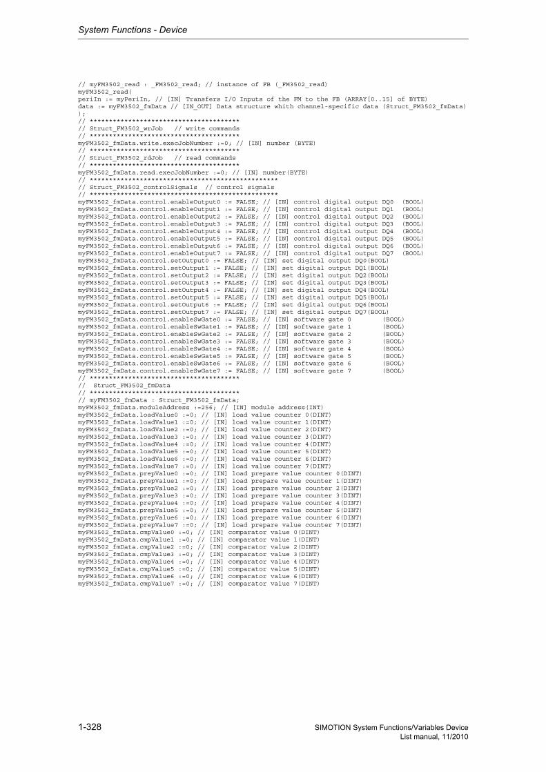
System Functions - Device
1-328 SIMOTION System Functions/Variables DeviceList manual, 11/2010
// myFM3502_read : _FM3502_read; // instance of FB (_FM3502_read)myFM3502_read(periIn := myPeriIn, // [IN] Transfers I/O Inputs of the FM to the FB (ARRAY[0..15] of BYTE)data := myFM3502_fmData // [IN_OUT] Data structure whith channel-specific data (Struct_FM3502_fmData));// ***************************************// Struct_FM3502_wrJob // write commands// ***************************************myFM3502_fmData.write.execJobNumber :=0; // [IN] number (BYTE)// ***************************************// Struct_FM3502_rdJob // read commands// ***************************************myFM3502_fmData.read.execJobNumber :=0; // [IN] number(BYTE)// *************************************************// Struct_FM3502_controlSignals // control signals// *************************************************myFM3502_fmData.control.enableOutput0 := FALSE; // [IN] control digital output DQ0 (BOOL)myFM3502_fmData.control.enableOutput1 := FALSE; // [IN] control digital output DQ1 (BOOL)myFM3502_fmData.control.enableOutput2 := FALSE; // [IN] control digital output DQ2 (BOOL)myFM3502_fmData.control.enableOutput3 := FALSE; // [IN] control digital output DQ3 (BOOL)myFM3502_fmData.control.enableOutput4 := FALSE; // [IN] control digital output DQ4 (BOOL)myFM3502_fmData.control.enableOutput5 := FALSE; // [IN] control digital output DQ5 (BOOL)myFM3502_fmData.control.enableOutput6 := FALSE; // [IN] control digital output DQ6 (BOOL)myFM3502_fmData.control.enableOutput7 := FALSE; // [IN] control digital output DQ7 (BOOL)myFM3502_fmData.control.setOutput0 := FALSE; // [IN] set digital output DQ0(BOOL)myFM3502_fmData.control.setOutput1 := FALSE; // [IN] set digital output DQ1(BOOL)myFM3502_fmData.control.setOutput2 := FALSE; // [IN] set digital output DQ2(BOOL)myFM3502_fmData.control.setOutput3 := FALSE; // [IN] set digital output DQ3(BOOL)myFM3502_fmData.control.setOutput4 := FALSE; // [IN] set digital output DQ4(BOOL)myFM3502_fmData.control.setOutput5 := FALSE; // [IN] set digital output DQ5(BOOL)myFM3502_fmData.control.setOutput6 := FALSE; // [IN] set digital output DQ6(BOOL)myFM3502_fmData.control.setOutput7 := FALSE; // [IN] set digital output DQ7(BOOL)myFM3502_fmData.control.enableSwGate0 := FALSE; // [IN] software gate 0 (BOOL)myFM3502_fmData.control.enableSwGate1 := FALSE; // [IN] software gate 1 (BOOL)myFM3502_fmData.control.enableSwGate2 := FALSE; // [IN] software gate 2 (BOOL)myFM3502_fmData.control.enableSwGate3 := FALSE; // [IN] software gate 3 (BOOL)myFM3502_fmData.control.enableSwGate4 := FALSE; // [IN] software gate 4 (BOOL)myFM3502_fmData.control.enableSwGate5 := FALSE; // [IN] software gate 5 (BOOL)myFM3502_fmData.control.enableSwGate6 := FALSE; // [IN] software gate 6 (BOOL)myFM3502_fmData.control.enableSwGate7 := FALSE; // [IN] software gate 7 (BOOL)// ***************************************// Struct_FM3502_fmData// ***************************************// myFM3502_fmData : Struct_FM3502_fmData;myFM3502_fmData.moduleAddress :=256; // [IN] module address(INT)myFM3502_fmData.loadValue0 :=0; // [IN] load value counter 0(DINT)myFM3502_fmData.loadValue1 :=0; // [IN] load value counter 1(DINT)myFM3502_fmData.loadValue2 :=0; // [IN] load value counter 2(DINT)myFM3502_fmData.loadValue3 :=0; // [IN] load value counter 3(DINT)myFM3502_fmData.loadValue4 :=0; // [IN] load value counter 4(DINT)myFM3502_fmData.loadValue5 :=0; // [IN] load value counter 5(DINT)myFM3502_fmData.loadValue6 :=0; // [IN] load value counter 6(DINT)myFM3502_fmData.loadValue7 :=0; // [IN] load value counter 7(DINT)myFM3502_fmData.prepValue0 :=0; // [IN] load prepare value counter 0(DINT)myFM3502_fmData.prepValue1 :=0; // [IN] load prepare value counter 1(DINT)myFM3502_fmData.prepValue2 :=0; // [IN] load prepare value counter 2(DINT)myFM3502_fmData.prepValue3 :=0; // [IN] load prepare value counter 3(DINT)myFM3502_fmData.prepValue4 :=0; // [IN] load prepare value counter 4(DINT)myFM3502_fmData.prepValue5 :=0; // [IN] load prepare value counter 5(DINT)myFM3502_fmData.prepValue6 :=0; // [IN] load prepare value counter 6(DINT)myFM3502_fmData.prepValue7 :=0; // [IN] load prepare value counter 7(DINT)myFM3502_fmData.cmpValue0 :=0; // [IN] comparator value 0(DINT)myFM3502_fmData.cmpValue1 :=0; // [IN] comparator value 1(DINT)myFM3502_fmData.cmpValue2 :=0; // [IN] comparator value 2(DINT)myFM3502_fmData.cmpValue3 :=0; // [IN] comparator value 3(DINT)myFM3502_fmData.cmpValue4 :=0; // [IN] comparator value 4(DINT)myFM3502_fmData.cmpValue5 :=0; // [IN] comparator value 5(DINT)myFM3502_fmData.cmpValue6 :=0; // [IN] comparator value 6(DINT)myFM3502_fmData.cmpValue7 :=0; // [IN] comparator value 7(DINT)
System Functions - Device
1-329SIMOTION System Functions/Variables DeviceList manual, 11/2010
1.4.2.4 _FM3502_write
The _FM3502_write function block executes write jobs (e.g. loading counter values and comparison values) to the FM 350-2.
Hardware and software requirements :Hardware release status:6ES7 350-2AH00-0AE0 after product release E04Software release : None
Detailed information
ST: Note:You can import the following program segments into the ST program using Drag & Drop. Additions must be made for executability (see manual, e.g. creating variables, etc.).An executable application example can be found on the "SIMOTION Utilities & Applications" CD-ROM.The "SIMOTION Utilities & Applications" CD-ROM is provided free of charge and is supplied with SIMOTION SCOUT.
Siemens Industrial
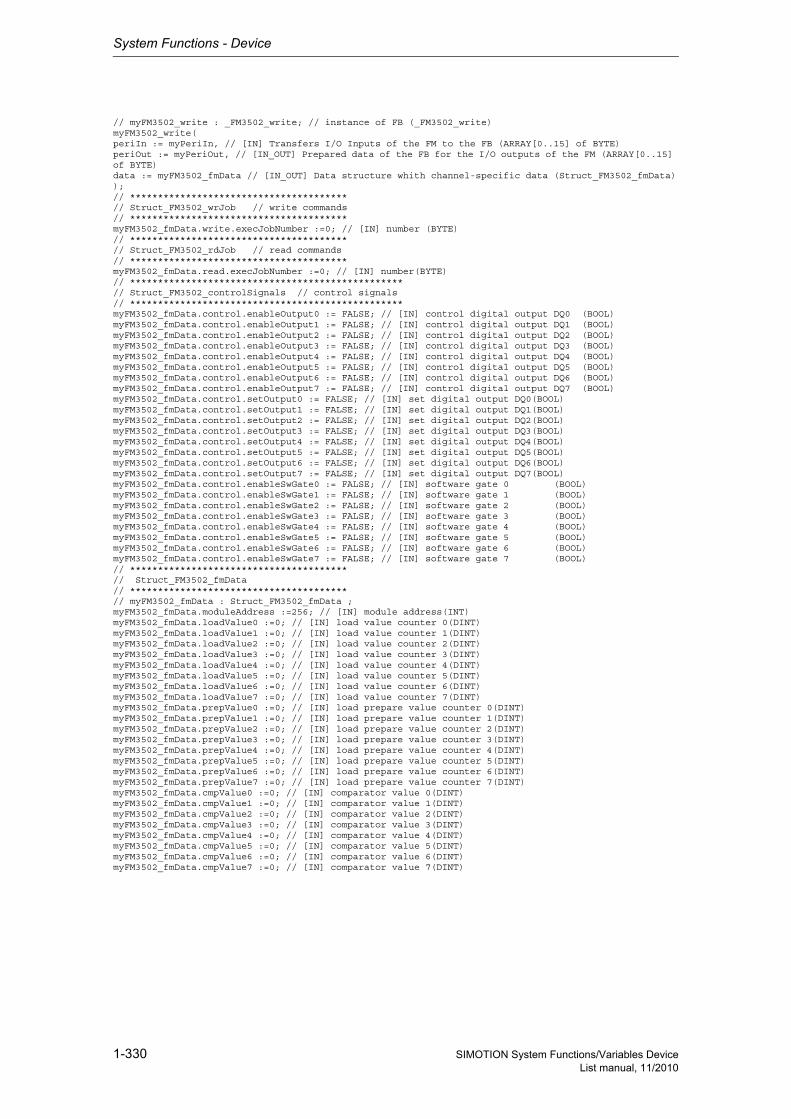
System Functions - Device
1-330 SIMOTION System Functions/Variables DeviceList manual, 11/2010
// myFM3502_write : _FM3502_write; // instance of FB (_FM3502_write)myFM3502_write(periIn := myPeriIn, // [IN] Transfers I/O Inputs of the FM to the FB (ARRAY[0..15] of BYTE)periOut := myPeriOut, // [IN_OUT] Prepared data of the FB for the I/O outputs of the FM (ARRAY[0..15] of BYTE)data := myFM3502_fmData // [IN_OUT] Data structure whith channel-specific data (Struct_FM3502_fmData));// ***************************************// Struct_FM3502_wrJob // write commands// ***************************************myFM3502_fmData.write.execJobNumber :=0; // [IN] number (BYTE)// ***************************************// Struct_FM3502_rdJob // read commands// ***************************************myFM3502_fmData.read.execJobNumber :=0; // [IN] number(BYTE)// *************************************************// Struct_FM3502_controlSignals // control signals// *************************************************myFM3502_fmData.control.enableOutput0 := FALSE; // [IN] control digital output DQ0 (BOOL)myFM3502_fmData.control.enableOutput1 := FALSE; // [IN] control digital output DQ1 (BOOL)myFM3502_fmData.control.enableOutput2 := FALSE; // [IN] control digital output DQ2 (BOOL)myFM3502_fmData.control.enableOutput3 := FALSE; // [IN] control digital output DQ3 (BOOL)myFM3502_fmData.control.enableOutput4 := FALSE; // [IN] control digital output DQ4 (BOOL)myFM3502_fmData.control.enableOutput5 := FALSE; // [IN] control digital output DQ5 (BOOL)myFM3502_fmData.control.enableOutput6 := FALSE; // [IN] control digital output DQ6 (BOOL)myFM3502_fmData.control.enableOutput7 := FALSE; // [IN] control digital output DQ7 (BOOL)myFM3502_fmData.control.setOutput0 := FALSE; // [IN] set digital output DQ0(BOOL)myFM3502_fmData.control.setOutput1 := FALSE; // [IN] set digital output DQ1(BOOL)myFM3502_fmData.control.setOutput2 := FALSE; // [IN] set digital output DQ2(BOOL)myFM3502_fmData.control.setOutput3 := FALSE; // [IN] set digital output DQ3(BOOL)myFM3502_fmData.control.setOutput4 := FALSE; // [IN] set digital output DQ4(BOOL)myFM3502_fmData.control.setOutput5 := FALSE; // [IN] set digital output DQ5(BOOL)myFM3502_fmData.control.setOutput6 := FALSE; // [IN] set digital output DQ6(BOOL)myFM3502_fmData.control.setOutput7 := FALSE; // [IN] set digital output DQ7(BOOL)myFM3502_fmData.control.enableSwGate0 := FALSE; // [IN] software gate 0 (BOOL)myFM3502_fmData.control.enableSwGate1 := FALSE; // [IN] software gate 1 (BOOL)myFM3502_fmData.control.enableSwGate2 := FALSE; // [IN] software gate 2 (BOOL)myFM3502_fmData.control.enableSwGate3 := FALSE; // [IN] software gate 3 (BOOL)myFM3502_fmData.control.enableSwGate4 := FALSE; // [IN] software gate 4 (BOOL)myFM3502_fmData.control.enableSwGate5 := FALSE; // [IN] software gate 5 (BOOL)myFM3502_fmData.control.enableSwGate6 := FALSE; // [IN] software gate 6 (BOOL)myFM3502_fmData.control.enableSwGate7 := FALSE; // [IN] software gate 7 (BOOL)// ***************************************// Struct_FM3502_fmData// ***************************************// myFM3502_fmData : Struct_FM3502_fmData ;myFM3502_fmData.moduleAddress :=256; // [IN] module address(INT)myFM3502_fmData.loadValue0 :=0; // [IN] load value counter 0(DINT)myFM3502_fmData.loadValue1 :=0; // [IN] load value counter 1(DINT)myFM3502_fmData.loadValue2 :=0; // [IN] load value counter 2(DINT)myFM3502_fmData.loadValue3 :=0; // [IN] load value counter 3(DINT)myFM3502_fmData.loadValue4 :=0; // [IN] load value counter 4(DINT)myFM3502_fmData.loadValue5 :=0; // [IN] load value counter 5(DINT)myFM3502_fmData.loadValue6 :=0; // [IN] load value counter 6(DINT)myFM3502_fmData.loadValue7 :=0; // [IN] load value counter 7(DINT)myFM3502_fmData.prepValue0 :=0; // [IN] load prepare value counter 0(DINT)myFM3502_fmData.prepValue1 :=0; // [IN] load prepare value counter 1(DINT)myFM3502_fmData.prepValue2 :=0; // [IN] load prepare value counter 2(DINT)myFM3502_fmData.prepValue3 :=0; // [IN] load prepare value counter 3(DINT)myFM3502_fmData.prepValue4 :=0; // [IN] load prepare value counter 4(DINT)myFM3502_fmData.prepValue5 :=0; // [IN] load prepare value counter 5(DINT)myFM3502_fmData.prepValue6 :=0; // [IN] load prepare value counter 6(DINT)myFM3502_fmData.prepValue7 :=0; // [IN] load prepare value counter 7(DINT)myFM3502_fmData.cmpValue0 :=0; // [IN] comparator value 0(DINT)myFM3502_fmData.cmpValue1 :=0; // [IN] comparator value 1(DINT)myFM3502_fmData.cmpValue2 :=0; // [IN] comparator value 2(DINT)myFM3502_fmData.cmpValue3 :=0; // [IN] comparator value 3(DINT)myFM3502_fmData.cmpValue4 :=0; // [IN] comparator value 4(DINT)myFM3502_fmData.cmpValue5 :=0; // [IN] comparator value 5(DINT)myFM3502_fmData.cmpValue6 :=0; // [IN] comparator value 6(DINT)myFM3502_fmData.cmpValue7 :=0; // [IN] comparator value 7(DINT)
System Functions - Device
1-331SIMOTION System Functions/Variables DeviceList manual, 11/2010
1.4.3 Function modules - FM352
1.4.3.1 _FM352_control
With the function block _FM352_control you can write the control signals and read out the checkback signals from the FM 352 and write and read the parameters of the FM 352.
Hardware and software requirements :Hardware release status:6ES7 352-1AH01-0AE0 after product release E08Software release : NoneThe online functions of the parameter assignment tool in STEP 7 HW Config can only be used for dia-gnostic purposes (read-only access to the module). Write access (control function) has no effect. The parameters set by the program can be read out using the parameter assignment tool.
Detailed information
ST: Note:You can import the following program segments into the ST program using Drag & Drop. Additions must be made for executability (see manual, e.g. creating variables, etc.).An executable application example can be found on the "SIMOTION Utilities & Applications" CD-ROM.The "SIMOTION Utilities & Applications" CD-ROM is provided free of charge and is supplied with SIMOTION SCOUT.
Siemens Industrial
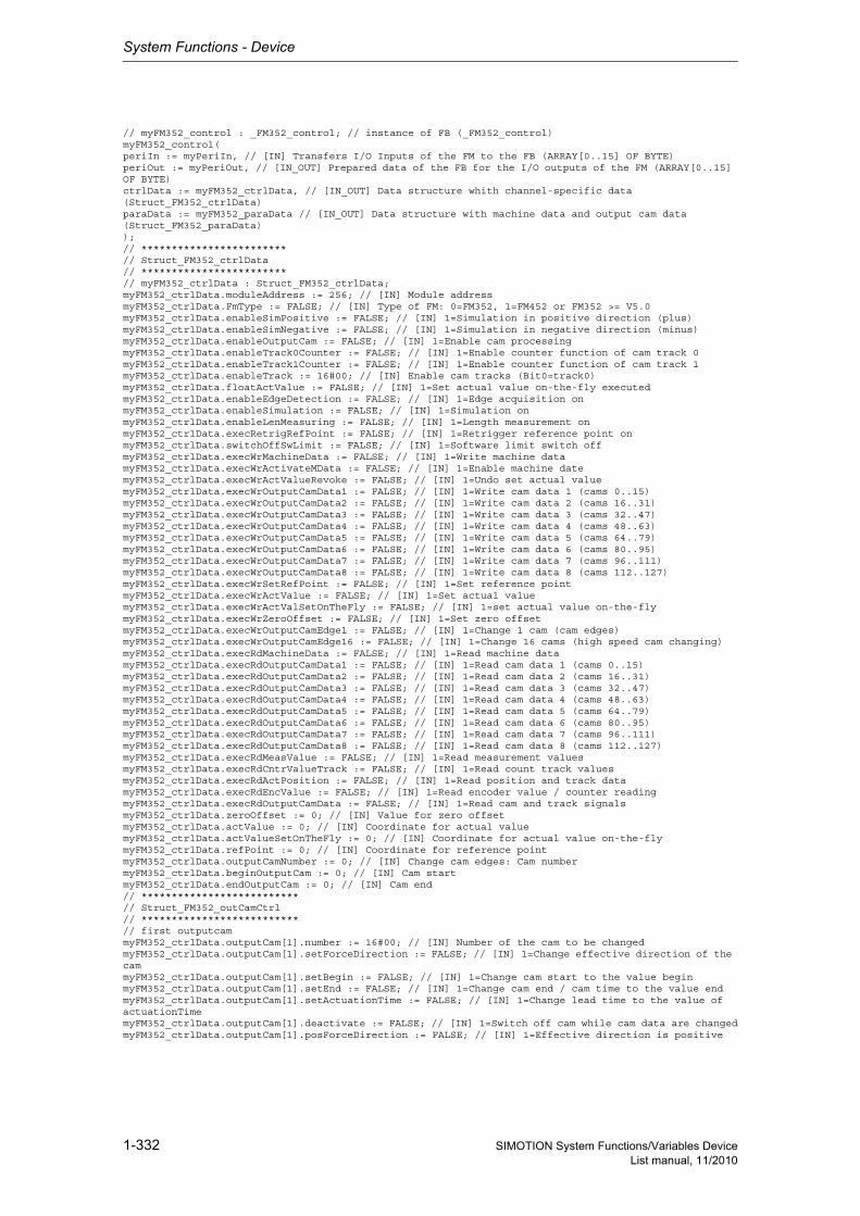
System Functions - Device
1-332 SIMOTION System Functions/Variables DeviceList manual, 11/2010
// myFM352_control : _FM352_control; // instance of FB (_FM352_control)myFM352_control(periIn := myPeriIn, // [IN] Transfers I/O Inputs of the FM to the FB (ARRAY[0..15] OF BYTE)periOut := myPeriOut, // [IN_OUT] Prepared data of the FB for the I/O outputs of the FM (ARRAY[0..15] OF BYTE)ctrlData := myFM352_ctrlData, // [IN_OUT] Data structure whith channel-specific data (Struct_FM352_ctrlData)paraData := myFM352_paraData // [IN_OUT] Data structure with machine data and output cam data (Struct_FM352_paraData));// ************************// Struct_FM352_ctrlData// ************************// myFM352_ctrlData : Struct_FM352_ctrlData;myFM352_ctrlData.moduleAddress := 256; // [IN] Module addressmyFM352_ctrlData.FmType := FALSE; // [IN] Type of FM: 0=FM352, 1=FM452 or FM352 >= V5.0myFM352_ctrlData.enableSimPositive := FALSE; // [IN] 1=Simulation in positive direction (plus)myFM352_ctrlData.enableSimNegative := FALSE; // [IN] 1=Simulation in negative direction (minus)myFM352_ctrlData.enableOutputCam := FALSE; // [IN] 1=Enable cam processingmyFM352_ctrlData.enableTrack0Counter := FALSE; // [IN] 1=Enable counter function of cam track 0myFM352_ctrlData.enableTrack1Counter := FALSE; // [IN] 1=Enable counter function of cam track 1myFM352_ctrlData.enableTrack := 16#00; // [IN] Enable cam tracks (Bit0=track0)myFM352_ctrlData.floatActValue := FALSE; // [IN] 1=Set actual value on-the-fly executedmyFM352_ctrlData.enableEdgeDetection := FALSE; // [IN] 1=Edge acquisition onmyFM352_ctrlData.enableSimulation := FALSE; // [IN] 1=Simulation onmyFM352_ctrlData.enableLenMeasuring := FALSE; // [IN] 1=Length measurement onmyFM352_ctrlData.execRetrigRefPoint := FALSE; // [IN] 1=Retrigger reference point onmyFM352_ctrlData.switchOffSwLimit := FALSE; // [IN] 1=Software limit switch offmyFM352_ctrlData.execWrMachineData := FALSE; // [IN] 1=Write machine datamyFM352_ctrlData.execWrActivateMData := FALSE; // [IN] 1=Enable machine datemyFM352_ctrlData.execWrActValueRevoke := FALSE; // [IN] 1=Undo set actual valuemyFM352_ctrlData.execWrOutputCamData1 := FALSE; // [IN] 1=Write cam data 1 (cams 0..15)myFM352_ctrlData.execWrOutputCamData2 := FALSE; // [IN] 1=Write cam data 2 (cams 16..31)myFM352_ctrlData.execWrOutputCamData3 := FALSE; // [IN] 1=Write cam data 3 (cams 32..47)myFM352_ctrlData.execWrOutputCamData4 := FALSE; // [IN] 1=Write cam data 4 (cams 48..63)myFM352_ctrlData.execWrOutputCamData5 := FALSE; // [IN] 1=Write cam data 5 (cams 64..79)myFM352_ctrlData.execWrOutputCamData6 := FALSE; // [IN] 1=Write cam data 6 (cams 80..95)myFM352_ctrlData.execWrOutputCamData7 := FALSE; // [IN] 1=Write cam data 7 (cams 96..111)myFM352_ctrlData.execWrOutputCamData8 := FALSE; // [IN] 1=Write cam data 8 (cams 112..127)myFM352_ctrlData.execWrSetRefPoint := FALSE; // [IN] 1=Set reference pointmyFM352_ctrlData.execWrActValue := FALSE; // [IN] 1=Set actual valuemyFM352_ctrlData.execWrActValSetOnTheFly := FALSE; // [IN] 1=set actual value on-the-flymyFM352_ctrlData.execWrZeroOffset := FALSE; // [IN] 1=Set zero offsetmyFM352_ctrlData.execWrOutputCamEdge1 := FALSE; // [IN] 1=Change 1 cam (cam edges)myFM352_ctrlData.execWrOutputCamEdge16 := FALSE; // [IN] 1=Change 16 cams (high speed cam changing)myFM352_ctrlData.execRdMachineData := FALSE; // [IN] 1=Read machine datamyFM352_ctrlData.execRdOutputCamData1 := FALSE; // [IN] 1=Read cam data 1 (cams 0..15)myFM352_ctrlData.execRdOutputCamData2 := FALSE; // [IN] 1=Read cam data 2 (cams 16..31)myFM352_ctrlData.execRdOutputCamData3 := FALSE; // [IN] 1=Read cam data 3 (cams 32..47)myFM352_ctrlData.execRdOutputCamData4 := FALSE; // [IN] 1=Read cam data 4 (cams 48..63)myFM352_ctrlData.execRdOutputCamData5 := FALSE; // [IN] 1=Read cam data 5 (cams 64..79)myFM352_ctrlData.execRdOutputCamData6 := FALSE; // [IN] 1=Read cam data 6 (cams 80..95)myFM352_ctrlData.execRdOutputCamData7 := FALSE; // [IN] 1=Read cam data 7 (cams 96..111)myFM352_ctrlData.execRdOutputCamData8 := FALSE; // [IN] 1=Read cam data 8 (cams 112..127)myFM352_ctrlData.execRdMeasValue := FALSE; // [IN] 1=Read measurement valuesmyFM352_ctrlData.execRdCntrValueTrack := FALSE; // [IN] 1=Read count track valuesmyFM352_ctrlData.execRdActPosition := FALSE; // [IN] 1=Read position and track datamyFM352_ctrlData.execRdEncValue := FALSE; // [IN] 1=Read encoder value / counter readingmyFM352_ctrlData.execRdOutputCamData := FALSE; // [IN] 1=Read cam and track signalsmyFM352_ctrlData.zeroOffset := 0; // [IN] Value for zero offsetmyFM352_ctrlData.actValue := 0; // [IN] Coordinate for actual valuemyFM352_ctrlData.actValueSetOnTheFly := 0; // [IN] Coordinate for actual value on-the-flymyFM352_ctrlData.refPoint := 0; // [IN] Coordinate for reference pointmyFM352_ctrlData.outputCamNumber := 0; // [IN] Change cam edges: Cam numbermyFM352_ctrlData.beginOutputCam := 0; // [IN] Cam startmyFM352_ctrlData.endOutputCam := 0; // [IN] Cam end// **************************// Struct_FM352_outCamCtrl// **************************// first outputcammyFM352_ctrlData.outputCam[1].number := 16#00; // [IN] Number of the cam to be changedmyFM352_ctrlData.outputCam[1].setForceDirection := FALSE; // [IN] 1=Change effective direction of the cammyFM352_ctrlData.outputCam[1].setBegin := FALSE; // [IN] 1=Change cam start to the value beginmyFM352_ctrlData.outputCam[1].setEnd := FALSE; // [IN] 1=Change cam end / cam time to the value endmyFM352_ctrlData.outputCam[1].setActuationTime := FALSE; // [IN] 1=Change lead time to the value of actuationTimemyFM352_ctrlData.outputCam[1].deactivate := FALSE; // [IN] 1=Switch off cam while cam data are changedmyFM352_ctrlData.outputCam[1].posForceDirection := FALSE; // [IN] 1=Effective direction is positive
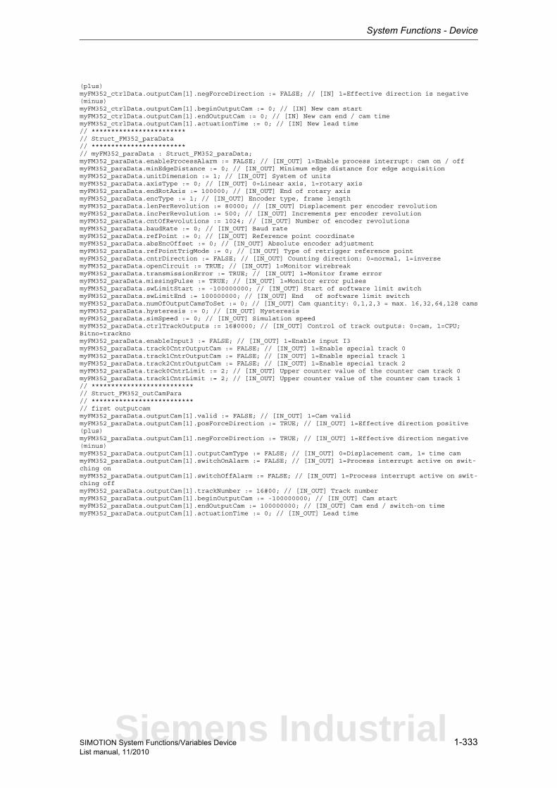
System Functions - Device
1-333SIMOTION System Functions/Variables DeviceList manual, 11/2010
(plus)myFM352_ctrlData.outputCam[1].negForceDirection := FALSE; // [IN] 1=Effective direction is negative (minus)myFM352_ctrlData.outputCam[1].beginOutputCam := 0; // [IN] New cam startmyFM352_ctrlData.outputCam[1].endOutputCam := 0; // [IN] New cam end / cam timemyFM352_ctrlData.outputCam[1].actuationTime := 0; // [IN] New lead time// ************************// Struct_FM352_paraData// ************************// myFM352_paraData : Struct_FM352_paraData;myFM352_paraData.enableProcessAlarm := FALSE; // [IN_OUT] 1=Enable process interrupt: cam on / offmyFM352_paraData.minEdgeDistance := 0; // [IN_OUT] Minimum edge distance for edge acquisitionmyFM352_paraData.unitDimension := 1; // [IN_OUT] System of unitsmyFM352_paraData.axisType := 0; // [IN_OUT] 0=Linear axis, 1=rotary axismyFM352_paraData.endRotAxis := 100000; // [IN_OUT] End of rotary axismyFM352_paraData.encType := 1; // [IN_OUT] Encoder type, frame lengthmyFM352_paraData.lenPerRevolution := 80000; // [IN_OUT] Displacement per encoder revolutionmyFM352_paraData.incPerRevolution := 500; // [IN_OUT] Increments per encoder revolutionmyFM352_paraData.cntOfRevolutions := 1024; // [IN_OUT] Number of encoder revolutionsmyFM352_paraData.baudRate := 0; // [IN_OUT] Baud ratemyFM352_paraData.refPoint := 0; // [IN_OUT] Reference point coordinatemyFM352_paraData.absEncOffset := 0; // [IN_OUT] Absolute encoder adjustmentmyFM352_paraData.refPointTrigMode := 0; // [IN_OUT] Type of retrigger reference pointmyFM352_paraData.cntrDirection := FALSE; // [IN_OUT] Counting direction: 0=normal, 1=inversemyFM352_paraData.openCircuit := TRUE; // [IN_OUT] 1=Monitor wirebreakmyFM352_paraData.transmissionError := TRUE; // [IN_OUT] 1=Monitor frame errormyFM352_paraData.missingPulse := TRUE; // [IN_OUT] 1=Monitor error pulsesmyFM352_paraData.swLimitStart := -100000000; // [IN_OUT] Start of software limit switchmyFM352_paraData.swLimitEnd := 100000000; // [IN_OUT] End of software limit switchmyFM352_paraData.numOfOutputCamsToSet := 0; // [IN_OUT] Cam quantity: 0,1,2,3 = max. 16,32,64,128 camsmyFM352_paraData.hysteresis := 0; // [IN_OUT] HysteresismyFM352_paraData.simSpeed := 0; // [IN_OUT] Simulation speedmyFM352_paraData.ctrlTrackOutputs := 16#0000; // [IN_OUT] Control of track outputs: 0=cam, 1=CPU; Bitno=tracknomyFM352_paraData.enableInput3 := FALSE; // [IN_OUT] 1=Enable input I3myFM352_paraData.track0CntrOutputCam := FALSE; // [IN_OUT] 1=Enable special track 0myFM352_paraData.track1CntrOutputCam := FALSE; // [IN_OUT] 1=Enable special track 1myFM352_paraData.track2CntrOutputCam := FALSE; // [IN_OUT] 1=Enable special track 2myFM352_paraData.track0CntrLimit := 2; // [IN_OUT] Upper counter value of the counter cam track 0myFM352_paraData.track1CntrLimit := 2; // [IN_OUT] Upper counter value of the counter cam track 1// **************************// Struct_FM352_outCamPara// **************************// first outputcammyFM352_paraData.outputCam[1].valid := FALSE; // [IN_OUT] 1=Cam validmyFM352_paraData.outputCam[1].posForceDirection := TRUE; // [IN_OUT] 1=Effective direction positive (plus)myFM352_paraData.outputCam[1].negForceDirection := TRUE; // [IN_OUT] 1=Effective direction negative (minus)myFM352_paraData.outputCam[1].outputCamType := FALSE; // [IN_OUT] 0=Displacement cam, 1= time cammyFM352_paraData.outputCam[1].switchOnAlarm := FALSE; // [IN_OUT] 1=Process interrupt active on swit-ching onmyFM352_paraData.outputCam[1].switchOffAlarm := FALSE; // [IN_OUT] 1=Process interrupt active on swit-ching offmyFM352_paraData.outputCam[1].trackNumber := 16#00; // [IN_OUT] Track numbermyFM352_paraData.outputCam[1].beginOutputCam := -100000000; // [IN_OUT] Cam startmyFM352_paraData.outputCam[1].endOutputCam := 100000000; // [IN_OUT] Cam end / switch-on timemyFM352_paraData.outputCam[1].actuationTime := 0; // [IN_OUT] Lead time
Siemens Industrial
System Functions - Device
1-334 SIMOTION System Functions/Variables DeviceList manual, 11/2010
1.4.3.2 _FM352_diagnostic
The _FM352_diagnostic function block can be used to read out the complete diagnostic data from the FM 352.
Hardware and software requirements :Hardware release status:6ES7 352-1AH01-0AE0 after product release E08Software release : NoneThe online functions of the parameter assignment tool in STEP 7 HW Config can only be used for dia-gnostic purposes (read-only access to the module). Write access (control function) has no effect. The parameters set by the program can be read out using the parameter assignment tool.
Detailed information
ST: Note:You can import the following program segments into the ST program using Drag & Drop. Additions must be made for executability (see manual, e.g. creating variables, etc.).An executable application example can be found on the "SIMOTION Utilities & Applications" CD-ROM.The "SIMOTION Utilities & Applications" CD-ROM is provided free of charge and is supplied with SIMOTION SCOUT.
// myFM352_diagnostic : _FM352_diagnostic; // instance of FB (_FM352_diagnostic)myFM352_diagnostic(enable := myEnable, // [IN] enable (BOOL)periIn := myPeriIn, // [IN] I/O variable for access to I/O inputs from the FM 352 (ARRAY[0..15] OF BYTE)diagData := myFM352_diagData // [IN_OUT] Data structure for diagnostic data (Struct_FM352_diagData));// ************************// Struct_FM352_diagData// ************************// myFM352_diagData : Struct_FM352_diagData;myFM352_diagData.moduleAddress := 256; // [IN] Module addressmyFM352_diagData.diagInformation := FALSE; // [IN] 1=Read dignostic buffer unconditionaly
System Functions - Device
1-335SIMOTION System Functions/Variables DeviceList manual, 11/2010
1.4.3.3 _FM352_initialize
The _FM352_initialize function block can be used to initialize the channel data after startup of the FM 352 module.
Hardware and software requirements :Hardware release status:6ES7 352-1AH01-0AE0 after product release E08Software release : NoneThe online functions of the parameter assignment tool in STEP 7 HW Config can only be used for dia-gnostic purposes (read-only access to the module). Write access (control function) has no effect. The parameters set by the program can be read out using the parameter assignment tool.
Detailed information
ST: Note:You can import the following program segments into the ST program using Drag & Drop. Additions must be made for executability (see manual, e.g. creating variables, etc.).An executable application example can be found on the "SIMOTION Utilities & Applications" CD-ROM.The "SIMOTION Utilities & Applications" CD-ROM is provided free of charge and is supplied with SIMOTION SCOUT.
Siemens Industrial
System Functions - Device
1-336 SIMOTION System Functions/Variables DeviceList manual, 11/2010
// myFM352_initialize : _FM352_initialize; // instance of FB (_FM352_initialize)myFM352_initialize(execute := myExecute, // [IN] execute (BOOL)ctrlData := myFM352_ctrlData // [IN_OUT] Data structure whith channel-specific data (Struct_FM352_ctrlData));// ************************// Struct_FM352_ctrlData// ************************// myFM352_ctrlData : Struct_FM352_ctrlData;myFM352_ctrlData.moduleAddress := 256; // [IN] Module addressmyFM352_ctrlData.FmType := FALSE; // [IN] Type of FM: 0=FM352, 1=FM452 or FM352 >= V5.0myFM352_ctrlData.enableSimPositive := FALSE; // [IN] 1=Simulation in positive direction (plus)myFM352_ctrlData.enableSimNegative := FALSE; // [IN] 1=Simulation in negative direction (minus)myFM352_ctrlData.enableOutputCam := FALSE; // [IN] 1=Enable cam processingmyFM352_ctrlData.enableTrack0Counter := FALSE; // [IN] 1=Enable counter function of cam track 0myFM352_ctrlData.enableTrack1Counter := FALSE; // [IN] 1=Enable counter function of cam track 1myFM352_ctrlData.enableTrack := 16#00; // [IN] Enable cam tracks (Bit0=track0)myFM352_ctrlData.floatActValue := FALSE; // [IN] 1=Set actual value on-the-fly executedmyFM352_ctrlData.enableEdgeDetection := FALSE; // [IN] 1=Edge acquisition onmyFM352_ctrlData.enableSimulation := FALSE; // [IN] 1=Simulation onmyFM352_ctrlData.enableLenMeasuring := FALSE; // [IN] 1=Length measurement onmyFM352_ctrlData.execRetrigRefPoint := FALSE; // [IN] 1=Retrigger reference point onmyFM352_ctrlData.switchOffSwLimit := FALSE; // [IN] 1=Software limit switch offmyFM352_ctrlData.execWrMachineData := FALSE; // [IN] 1=Write machine datamyFM352_ctrlData.execWrActivateMData := FALSE; // [IN] 1=Enable machine datemyFM352_ctrlData.execWrActValueRevoke := FALSE; // [IN] 1=Undo set actual valuemyFM352_ctrlData.execWrOutputCamData1 := FALSE; // [IN] 1=Write cam data 1 (cams 0..15)myFM352_ctrlData.execWrOutputCamData2 := FALSE; // [IN] 1=Write cam data 2 (cams 16..31)myFM352_ctrlData.execWrOutputCamData3 := FALSE; // [IN] 1=Write cam data 3 (cams 32..47)myFM352_ctrlData.execWrOutputCamData4 := FALSE; // [IN] 1=Write cam data 4 (cams 48..63)myFM352_ctrlData.execWrOutputCamData5 := FALSE; // [IN] 1=Write cam data 5 (cams 64..79)myFM352_ctrlData.execWrOutputCamData6 := FALSE; // [IN] 1=Write cam data 6 (cams 80..95)myFM352_ctrlData.execWrOutputCamData7 := FALSE; // [IN] 1=Write cam data 7 (cams 96..111)myFM352_ctrlData.execWrOutputCamData8 := FALSE; // [IN] 1=Write cam data 8 (cams 112..127)myFM352_ctrlData.execWrSetRefPoint := FALSE; // [IN] 1=Set reference pointmyFM352_ctrlData.execWrActValue := FALSE; // [IN] 1=Set actual valuemyFM352_ctrlData.execWrActValSetOnTheFly := FALSE; // [IN] 1=set actual value on-the-flymyFM352_ctrlData.execWrZeroOffset := FALSE; // [IN] 1=Set zero offsetmyFM352_ctrlData.execWrOutputCamEdge1 := FALSE; // [IN] 1=Change 1 cam (cam edges)myFM352_ctrlData.execWrOutputCamEdge16 := FALSE; // [IN] 1=Change 16 cams (high speed cam changing)myFM352_ctrlData.execRdMachineData := FALSE; // [IN] 1=Read machine datamyFM352_ctrlData.execRdOutputCamData1 := FALSE; // [IN] 1=Read cam data 1 (cams 0..15)myFM352_ctrlData.execRdOutputCamData2 := FALSE; // [IN] 1=Read cam data 2 (cams 16..31)myFM352_ctrlData.execRdOutputCamData3 := FALSE; // [IN] 1=Read cam data 3 (cams 32..47)myFM352_ctrlData.execRdOutputCamData4 := FALSE; // [IN] 1=Read cam data 4 (cams 48..63)myFM352_ctrlData.execRdOutputCamData5 := FALSE; // [IN] 1=Read cam data 5 (cams 64..79)myFM352_ctrlData.execRdOutputCamData6 := FALSE; // [IN] 1=Read cam data 6 (cams 80..95)myFM352_ctrlData.execRdOutputCamData7 := FALSE; // [IN] 1=Read cam data 7 (cams 96..111)myFM352_ctrlData.execRdOutputCamData8 := FALSE; // [IN] 1=Read cam data 8 (cams 112..127)myFM352_ctrlData.execRdMeasValue := FALSE; // [IN] 1=Read measurement valuesmyFM352_ctrlData.execRdCntrValueTrack := FALSE; // [IN] 1=Read count track valuesmyFM352_ctrlData.execRdActPosition := FALSE; // [IN] 1=Read position and track datamyFM352_ctrlData.execRdEncValue := FALSE; // [IN] 1=Read encoder value / counter readingmyFM352_ctrlData.execRdOutputCamData := FALSE; // [IN] 1=Read cam and track signalsmyFM352_ctrlData.zeroOffset := 0; // [IN] Value for zero offsetmyFM352_ctrlData.actValue := 0; // [IN] Coordinate for actual valuemyFM352_ctrlData.actValueSetOnTheFly := 0; // [IN] Coordinate for actual value on-the-flymyFM352_ctrlData.refPoint := 0; // [IN] Coordinate for reference pointmyFM352_ctrlData.outputCamNumber := 0; // [IN] Change cam edges: Cam numbermyFM352_ctrlData.beginOutputCam := 0; // [IN] Cam startmyFM352_ctrlData.endOutputCam := 0; // [IN] Cam end// **************************// Struct_FM352_outCamCtrl// **************************// first outputcammyFM352_ctrlData.outputCam[1].number := 16#00; // [IN] Number of the cam to be changedmyFM352_ctrlData.outputCam[1].setForceDirection := FALSE; // [IN] 1=Change effective direction of the cammyFM352_ctrlData.outputCam[1].setBegin := FALSE; // [IN] 1=Change cam start to the value beginmyFM352_ctrlData.outputCam[1].setEnd := FALSE; // [IN] 1=Change cam end / cam time to the value endmyFM352_ctrlData.outputCam[1].setActuationTime := FALSE; // [IN] 1=Change lead time to the value of actuationTimemyFM352_ctrlData.outputCam[1].deactivate := FALSE; // [IN] 1=Switch off cam while cam data are changedmyFM352_ctrlData.outputCam[1].posForceDirection := FALSE; // [IN] 1=Effective direction is positive (plus)myFM352_ctrlData.outputCam[1].negForceDirection := FALSE; // [IN] 1=Effective direction is negative (minus)myFM352_ctrlData.outputCam[1].beginOutputCam := 0; // [IN] New cam start

System Functions - Device
1-337SIMOTION System Functions/Variables DeviceList manual, 11/2010
myFM352_ctrlData.outputCam[1].endOutputCam := 0; // [IN] New cam end / cam timemyFM352_ctrlData.outputCam[1].actuationTime := 0; // [IN] New lead time
Siemens Industrial
System Functions - Device
1-338 SIMOTION System Functions/Variables DeviceList manual, 11/2010
1.4.4 Communication modules - CP340
1.4.4.1 _CP340_byteToPrintData
Entry of a number of data type BYTE in data structure Struct_CP340_printData.
Hardware and software requirements :Hardware release status:6ES7 340-1AH01-0AE0 starting with product release E076ES7 340-1BH00-0AE0 starting with product release E076ES7 340-1CH00-0AE0 starting with product release E07Software release : NoneHardware release status:6ES7340-1AH02-0AE0 starting with product release E016ES7340-1BH02-0AE0 starting with product release E016ES7340-1CH02-0AE0 starting with product release E01Software release : V1.0.2 and later
Detailed information
ST: Note:You can import the following program segments into the ST program using Drag & Drop. Additions must be made for executability (see manual, e.g. creating variables, etc.).An executable application example can be found on the "SIMOTION Utilities & Applications" CD-ROM.The "SIMOTION Utilities & Applications" CD-ROM is provided free of charge and is supplied with SIMOTION SCOUT.
myCP340_byteToPrintData : _CP340_byteToPrintData; // instance of FB (_CP340_byteToPrintData)myCP340_byteToPrintData(execute := myExecute, // [IN] Edge-triggered request activation (BOOL)data := myData, // [IN] Variable/value to be entered in the data structure (BYTE)numVariable := myNumVariable, // [IN] Number of the variable in whitch the entry is to be made 1 <= NumberVariable <=4 (INT)entryFormatString := myEntryFormatString, // [IN] Method of entry in the format string (enumFormstring2)entryAtByteNumber := myEntryAtByteNumber, // [IN] Specifies the byte at which the entry is to begin in the substructure of the format string (USINT)printData := myCP340_printData // [IN_OUT] Data structure for the printer data (Struct_CP340_printData));// *************************// Struct_CP340_printData// *************************// myCP340_printData : Struct_CP340_printData;myCP340_printData.variable := myVariable; // [IN] Variable to be printed (ARRAY [0..3] of Struct_CP340_datRecord )myCP340_printData.format := myFormat; // [IN] Format string (ARRAY [0..150] OF BYTE )// *************************// Struct_CP340_datRecord// *************************// myCP340_datRecord : Struct_CP340_datRecord;myCP340_datRecord.datalength := 0; // [IN] Quantity of data (UDINT )myCP340_datRecord.data := myData; // [IN] Print data (ARRAY [0..31] OF BYTE )

System Functions - Device
1-339SIMOTION System Functions/Variables DeviceList manual, 11/2010
1.4.4.2 _CP340_dintToPrintData
Entry of a number of data type DINT in data structure Struct_CP340_printData.
Hardware and software requirements :Hardware release status:6ES7 340-1AH01-0AE0 starting with product release E076ES7 340-1BH00-0AE0 starting with product release E076ES7 340-1CH00-0AE0 starting with product release E07Software release : NoneHardware release status:6ES7340-1AH02-0AE0 starting with product release E016ES7340-1BH02-0AE0 starting with product release E016ES7340-1CH02-0AE0 starting with product release E01Software release : V1.0.2 and later
Detailed information
ST: Note:You can import the following program segments into the ST program using Drag & Drop. Additions must be made for executability (see manual, e.g. creating variables, etc.).An executable application example can be found on the "SIMOTION Utilities & Applications" CD-ROM.The "SIMOTION Utilities & Applications" CD-ROM is provided free of charge and is supplied with SIMOTION SCOUT.
// myCP340_dintToPrintData : _CP340_dintToPrintData; // instance of FB (_CP340_dintToPrintData)myCP340_dintToPrintData(execute := myExecute, // [IN] Edge-triggered request activation (BOOL)data := myData, // [IN] Variable/value to be entered in the data structure (DINT)numVariable := myNumVariable, // [IN] Number of the variable in whitch the entry is to be made 1 <= NumberVariable <=4 (INT)entryFormatString := myEntryFormatString, // [IN] Method of entry in the format string (enumFormstring3)entryAtByteNumber := myEntryAtByteNumber, // [IN] Specifies the byte at which the entry is to begin in the substructure of the format string (USINT)printData := myCP340_printData // [IN_OUT] Data structure for the printer data (Struct_CP340_printData));// *************************// Struct_CP340_printData// *************************// myCP340_printData : Struct_CP340_printData;myCP340_printData.variable := myVariable; // [IN] Variable to be printed (ARRAY [0..3] of Struct_CP340_datRecord )myCP340_printData.format := myFormat; // [IN] Format string (ARRAY [0..150] OF BYTE )// *************************// Struct_CP340_datRecord// *************************// myCP340_datRecord : Struct_CP340_datRecord;myCP340_datRecord.datalength := 0; // [IN] Quantity of data (UDINT )myCP340_datRecord.data := myData; // [IN] Print data (ARRAY [0..31] OF BYTE )
Siemens Industrial
System Functions - Device
1-340 SIMOTION System Functions/Variables DeviceList manual, 11/2010
1.4.4.3 _CP340_dwordToPrintData
Entry of a number of data type DWORD in data structure Struct_CP340_printData.
Hardware and software requirements :Hardware release status:6ES7 340-1AH01-0AE0 starting with product release E076ES7 340-1BH00-0AE0 starting with product release E076ES7 340-1CH00-0AE0 starting with product release E07Software release : NoneHardware release status:6ES7340-1AH02-0AE0 starting with product release E016ES7340-1BH02-0AE0 starting with product release E016ES7340-1CH02-0AE0 starting with product release E01Software release : V1.0.2 and later
Detailed information
ST: Note:You can import the following program segments into the ST program using Drag & Drop. Additions must be made for executability (see manual, e.g. creating variables, etc.).An executable application example can be found on the "SIMOTION Utilities & Applications" CD-ROM.The "SIMOTION Utilities & Applications" CD-ROM is provided free of charge and is supplied with SIMOTION SCOUT.
// myCP340_dwordToPrintData : _CP340_dwordToPrintData; // instance of FB (_CP340_dwordToPrintData)myCP340_dwordToPrintData(execute := myExecute, // [IN] Edge-triggered request activation (BOOL)data := myData, // [IN] Variable/value to be entered in the data structure (DWORD)numVariable := myNumVariable, // [IN] Number of the variable in whitch the entry is to be made 1 <= NumberVariable <=4 (INT)entryFormatString := myEntryFormatString, // [IN] Method of entry in the format string (enumFormstring2)entryAtByteNumber := myEntryAtByteNumber, // [IN] Specifies the byte at which the entry is to begin in the substructure of the format string (USINT)printData := myCP340_printData // [IN_OUT] Data structure for the printer data (Struct_CP340_printData));// *************************// Struct_CP340_printData// *************************// myCP340_printData : Struct_CP340_printData;myCP340_printData.variable := myVariable; // [IN] Variable to be printed (ARRAY [0..3] of Struct_CP340_datRecord )myCP340_printData.format := myFormat; // [IN] Format string (ARRAY [0..150] OF BYTE )// *************************// Struct_CP340_datRecord// *************************// myCP340_datRecord : Struct_CP340_datRecord;myCP340_datRecord.datalength := 0; // [IN] Quantity of data (UDINT )myCP340_datRecord.data := myData; // [IN] Print data (ARRAY [0..31] OF BYTE )
System Functions - Device
1-341SIMOTION System Functions/Variables DeviceList manual, 11/2010
1.4.4.4 _CP340_getV24Signals
The _CP340_getV24Signals function block reads the RS 232C accompanying signals from the CP 340 and makes them available to the user in the block parameters. The functionality of the _CP340_getV24Signals function block can only be used when an ASCII driver is assigned.
Hardware and software requirements :Hardware release status:6ES7 340-1AH01-0AE0 starting with product release E076ES7 340-1BH00-0AE0 starting with product release E076ES7 340-1CH00-0AE0 starting with product release E07Software release : NoneHardware release status:6ES7340-1AH02-0AE0 starting with product release E016ES7340-1BH02-0AE0 starting with product release E016ES7340-1CH02-0AE0 starting with product release E01Software release : V1.0.2 and later
Detailed information
ST: Note:You can import the following program segments into the ST program using Drag & Drop. Additions must be made for executability (see manual, e.g. creating variables, etc.).An executable application example can be found on the "SIMOTION Utilities & Applications" CD-ROM.The "SIMOTION Utilities & Applications" CD-ROM is provided free of charge and is supplied with SIMOTION SCOUT.
// myCP340_getV24Signals : _CP340_getV24Signals; // instance of FB (_CP340_getV24Signals)myCP340_getV24Signals(enable := myEnable, // [IN] enable (BOOL)periIn := myPeriIn // [IN] I/O inputs of the CP transferred to the FB (ARRAY [0..15] OF BYTE));
Siemens Industrial
System Functions - Device
1-342 SIMOTION System Functions/Variables DeviceList manual, 11/2010
1.4.4.5 _CP340_intToPrintData
Entry of a number of data type INT in data structure Struct_CP340_printData.
Hardware and software requirements :Hardware release status:6ES7 340-1AH01-0AE0 starting with product release E076ES7 340-1BH00-0AE0 starting with product release E076ES7 340-1CH00-0AE0 starting with product release E07Software release : NoneHardware release status:6ES7340-1AH02-0AE0 starting with product release E016ES7340-1BH02-0AE0 starting with product release E016ES7340-1CH02-0AE0 starting with product release E01Software release : V1.0.2 and later
Detailed information
ST: Note:You can import the following program segments into the ST program using Drag & Drop. Additions must be made for executability (see manual, e.g. creating variables, etc.).An executable application example can be found on the "SIMOTION Utilities & Applications" CD-ROM.The "SIMOTION Utilities & Applications" CD-ROM is provided free of charge and is supplied with SIMOTION SCOUT.
// myCP340_intToPrintData : _CP340_intToPrintData; // instance of FB (_CP340_intToPrintData)myCP340_intToPrintData(execute := myExecute, // [IN] Edge-triggered request activation (BOOL)data := myData, // [IN] Variable/value to be entered in the data structure (INT)numVariable := myNumVariable, // [IN] Number of the variable in whitch the entry is to be made 1 <= NumberVariable <=4 (INT)entryFormatString := myEntryFormatString, // [IN] Method of entry in the format string (enumFormstring3)entryAtByteNumber := myEntryAtByteNumber, // [IN] Specifies the byte at which the entry is to begin in the substructure of the format string (USINT)printData := myCP340_printData // [IN_OUT] Data structure for the printer data (Struct_CP340_printData));// *************************// Struct_CP340_printData// *************************// myCP340_printData : Struct_CP340_printData;myCP340_printData.variable := myVariable; // [IN] Variable to be printed (ARRAY [0..3] of Struct_CP340_datRecord )myCP340_printData.format := myFormat; // [IN] Format string (ARRAY [0..150] OF BYTE )// *************************// Struct_CP340_datRecord// *************************// myCP340_datRecord : Struct_CP340_datRecord;myCP340_datRecord.datalength := 0; // [IN] Quantity of data (UDINT )myCP340_datRecord.data := myData; // [IN] Print data (ARRAY [0..31] OF BYTE )
System Functions - Device
1-343SIMOTION System Functions/Variables DeviceList manual, 11/2010
1.4.4.6 _CP340_printer
The CP340_printer function block can be used to send data of type Struct_CP340_printData from the printer memory area to a serial printer. For example, the CP340_printer function block transfers a pro-cess message to the CP 340. The CP 340 prints out the process message on the connected printer.
Hardware and software requirements :Hardware release status:6ES7 340-1AH01-0AE0 starting with product release E076ES7 340-1BH00-0AE0 starting with product release E076ES7 340-1CH00-0AE0 starting with product release E07Software release : NoneHardware release status:6ES7340-1AH02-0AE0 starting with product release E016ES7340-1BH02-0AE0 starting with product release E016ES7340-1CH02-0AE0 starting with product release E01Software release : V1.0.2 and later
Detailed information
ST: Note:You can import the following program segments into the ST program using Drag & Drop. Additions must be made for executability (see manual, e.g. creating variables, etc.).An executable application example can be found on the "SIMOTION Utilities & Applications" CD-ROM.The "SIMOTION Utilities & Applications" CD-ROM is provided free of charge and is supplied with SIMOTION SCOUT.
// myCP340_printer : _CP340_printer; // instance of FB (_CP340_printer)myCP340_printer(execute := myExecute, // [IN] Initiates request on positive edge (BOOL)reset := myReset, // [IN] Aborts request (BOOL)moduleAddress := myModuleAddress, // [IN] Module address of the CP for data set transfer (from HW Config) (DINT)periIn := myPeriIn, // [IN] I/O inputs of the CP transferred to the FB (ARRAY [0..15] OF BYTE)printData := myCP340_printData, // [IN_OUT] Send data array (data to be printed) (Struct_CP340_printData)periOut := myPeriOut // [IN_OUT] Prepared FB data for the I/O outputs of the CP (ARRAY [0..15] OF BYTE));// *************************// Struct_CP340_printData// *************************// myCP340_printData : Struct_CP340_printData;myCP340_printData.format[0] := 16#00; // [IN] Format string (ARRAY [0..150] OF BYTE )// *************************// Struct_CP340_datRecord// *************************//myCP340_printData.variable[0].datalength := 4; // [IN] Quantity of data (UDINT )myCP340_printData.variable[0].data[0] := 16#00; // [IN] Print data (ARRAY [0..31] OF BYTE)
Siemens Industrial
System Functions - Device
1-344 SIMOTION System Functions/Variables DeviceList manual, 11/2010
1.4.4.7 _CP340_printMsgText
Selection of message texts stored in the CP 340.
Hardware and software requirements :Hardware release status:6ES7 340-1AH01-0AE0 starting with product release E076ES7 340-1BH00-0AE0 starting with product release E076ES7 340-1CH00-0AE0 starting with product release E07Software release : NoneHardware release status:6ES7340-1AH02-0AE0 starting with product release E016ES7340-1BH02-0AE0 starting with product release E016ES7340-1CH02-0AE0 starting with product release E01Software release : V1.0.2 and later
Detailed information
ST: Note:You can import the following program segments into the ST program using Drag & Drop. Additions must be made for executability (see manual, e.g. creating variables, etc.).An executable application example can be found on the "SIMOTION Utilities & Applications" CD-ROM.The "SIMOTION Utilities & Applications" CD-ROM is provided free of charge and is supplied with SIMOTION SCOUT.
// myCP340_printMsgText : _CP340_printMsgText; // instance of FB (_CP340_printMsgText)myCP340_printMsgText(execute := myExecute, // [IN] Edge-triggered request activation (BOOL)numMsgText := myNumMsgText, // [IN] Variable/value to be entered in the data structure (USINT)numVariable := myNumVariable, // [IN] Number of the variable in whitch the entry is to be made 1 <= NumberVariable <=4 (INT)entryFormatString := myEntryFormatString, // [IN] Method of entry in the format string (enumFormstring3)entryAtByteNumber := myEntryAtByteNumber, // [IN] Specifies the byte at which the entry is to begin in the substructure of the format string (USINT)printData := myCP340_printData // [IN_OUT] Data structure for the printer data (Struct_CP340_printData));// *************************// Struct_CP340_printData// *************************// myCP340_printData : Struct_CP340_printData;myCP340_printData.variable := myVariable; // [IN] Variable to be printed (ARRAY [0..3] of Struct_CP340_datRecord )myCP340_printData.format := myFormat; // [IN] Format string (ARRAY [0..150] OF BYTE )// *************************// Struct_CP340_datRecord// *************************// myCP340_datRecord : Struct_CP340_datRecord;myCP340_datRecord.datalength := 0; // [IN] Quantity of data (UDINT )myCP340_datRecord.data := myData; // [IN] Print data (ARRAY [0..31] OF BYTE )
System Functions - Device
1-345SIMOTION System Functions/Variables DeviceList manual, 11/2010
1.4.4.8 _CP340_realToPrintData
Entry of a number of data type REAL in data structure Struct_CP340_printData.
Hardware and software requirements :Hardware release status:6ES7 340-1AH01-0AE0 starting with product release E076ES7 340-1BH00-0AE0 starting with product release E076ES7 340-1CH00-0AE0 starting with product release E07Software release : NoneHardware release status:6ES7340-1AH02-0AE0 starting with product release E016ES7340-1BH02-0AE0 starting with product release E016ES7340-1CH02-0AE0 starting with product release E01Software release : V1.0.2 and later
Detailed information
ST: Note:You can import the following program segments into the ST program using Drag & Drop. Additions must be made for executability (see manual, e.g. creating variables, etc.).An executable application example can be found on the "SIMOTION Utilities & Applications" CD-ROM.The "SIMOTION Utilities & Applications" CD-ROM is provided free of charge and is supplied with SIMOTION SCOUT.
// myCP340_realToPrintData : _CP340_realToPrintData; // instance of FB (_CP340_realToPrintData)myCP340_realToPrintData(execute := myExecute, // [IN] Edge-triggered request activation (BOOL)data := myData, // [IN] Variable/value to be entered in the data structure (REAL)numVariable := myNumVariable, // [IN] Number of the variable in whitch the entry is to be made 1 <= NumberVariable <=4 (INT)entryFormatString := myEntryFormatString, // [IN] Method of entry in the format string (enumFormstring1)entryAtByteNumber := myEntryAtByteNumber, // [IN] Specifies the byte at which the entry is to begin in the substructure of the format string (USINT)printData := myCP340_printData // [IN_OUT] Data structure for the printer data (Struct_CP340_printData));// *************************// Struct_CP340_printData// *************************// myCP340_printData : Struct_CP340_printData;myCP340_printData.variable := myVariable; // [IN] Variable to be printed (ARRAY [0..3] of Struct_CP340_datRecord )myCP340_printData.format := myFormat; // [IN] Format string (ARRAY [0..150] OF BYTE )// *************************// Struct_CP340_datRecord// *************************// myCP340_datRecord : Struct_CP340_datRecord;myCP340_datRecord.datalength := 0; // [IN] Quantity of data (UDINT )myCP340_datRecord.data := myData; // [IN] Print data (ARRAY [0..31] OF BYTE )
Siemens Industrial
System Functions - Device
1-346 SIMOTION System Functions/Variables DeviceList manual, 11/2010
1.4.4.9 _CP340_receive
The _CP340_receive function block can be used to receive data from a communication peer in the receive data array. 1024 bytes are available. For the transfer operation, you can use the 3964 (R) pro-tocol or ASCII driver.
Hardware and software requirements :Hardware release status:6ES7 340-1AH01-0AE0 starting with product release E076ES7 340-1BH00-0AE0 starting with product release E076ES7 340-1CH00-0AE0 starting with product release E07Software release : NoneHardware release status:6ES7340-1AH02-0AE0 starting with product release E016ES7340-1BH02-0AE0 starting with product release E016ES7340-1CH02-0AE0 starting with product release E01Software release : V1.0.2 and later
Detailed information
ST: Note:You can import the following program segments into the ST program using Drag & Drop. Additions must be made for executability (see manual, e.g. creating variables, etc.).An executable application example can be found on the "SIMOTION Utilities & Applications" CD-ROM.The "SIMOTION Utilities & Applications" CD-ROM is provided free of charge and is supplied with SIMOTION SCOUT.
// myCP340_receive : _CP340_receive; // instance of FB (_CP340_receive)myCP340_receive(enable := myEnable, // [IN] Receive enable (BOOL)reset := myReset, // [IN] Aborts request (BOOL)moduleAddress := myModuleAddress, // [IN] Module address of the CP for data set transfer(from HW Config) (DINT)dataOffset := myDataOffset, // [IN] Offset of the first element to be received (UDINT)periIn := myPeriIn, // [IN] I/O inputs of the CP transferred to the FB (ARRAY [0..15] OF BYTE)data := myData, // [IN_OUT] Receive data array (ARRAY [0..1023] OF BYTE)periOut := myPeriOut // [IN_OUT] Prepared FB data for the I/O outputs of the CP (ARRAY [0..15] OF BYTE));
System Functions - Device
1-347SIMOTION System Functions/Variables DeviceList manual, 11/2010
1.4.4.10 _CP340_send
The _CP340_send function block can be used to send data from the send data array to a communi-cation peer. 1024 bytes are available. For the transfer operation, you can use the 3964 (R) protocol or ASCII driver.
Hardware and software requirements :Hardware release status:6ES7 340-1AH01-0AE0 starting with product release E076ES7 340-1BH00-0AE0 starting with product release E076ES7 340-1CH00-0AE0 starting with product release E07Software release : NoneHardware release status:6ES7340-1AH02-0AE0 starting with product release E016ES7340-1BH02-0AE0 starting with product release E016ES7340-1CH02-0AE0 starting with product release E01Software release : V1.0.2 and later
Detailed information
ST: Note:You can import the following program segments into the ST program using Drag & Drop. Additions must be made for executability (see manual, e.g. creating variables, etc.).An executable application example can be found on the "SIMOTION Utilities & Applications" CD-ROM.The "SIMOTION Utilities & Applications" CD-ROM is provided free of charge and is supplied with SIMOTION SCOUT.
// myCP340_send : _CP340_send; // instance of FB (_CP340_send)myCP340_send(execute := myExecute, // [IN] Initiates request on positive edge (BOOL)reset := myReset, // [IN] Aborts request (BOOL)moduleAddress := myModuleAddress, // [IN] Module address of the CP for data set transfer (from HW Config) (DINT)dataOffset := myDataOffset, // [IN] Offset of the first element to be sent (UDINT)dataLength := myDataLength, // [IN] Number of elements to be sent (UDINT)periIn := myPeriIn, // [IN] I/O inputs of the CP transferred to the FB (ARRAY [0..15] OF BYTE)data := myData, // [IN_OUT] Send data array (ARRAY [0..1023] OF BYTE)periOut := myPeriOut // [IN_OUT] Prepared FB data for the I/O outputs of the CP (ARRAY [0..15] OF BYTE));
Siemens Industrial
System Functions - Device
1-348 SIMOTION System Functions/Variables DeviceList manual, 11/2010
1.4.4.11 _CP340_setV24Signals
The _CP340_setV24Signals function block can be used to set or reset RS 232C accompanying sig-nals. The functionality of the _CP340_setV24Signals function block can only be used when ASCII dri-ver is assigned.
Hardware and software requirements :Hardware release status:6ES7 340-1AH01-0AE0 starting with product release E076ES7 340-1BH00-0AE0 starting with product release E076ES7 340-1CH00-0AE0 starting with product release E07Software release : NoneHardware release status:6ES7340-1AH02-0AE0 starting with product release E016ES7340-1BH02-0AE0 starting with product release E016ES7340-1CH02-0AE0 starting with product release E01Software release : V1.0.2 and later
Detailed information
ST: Note:You can import the following program segments into the ST program using Drag & Drop. Additions must be made for executability (see manual, e.g. creating variables, etc.).An executable application example can be found on the "SIMOTION Utilities & Applications" CD-ROM.The "SIMOTION Utilities & Applications" CD-ROM is provided free of charge and is supplied with SIMOTION SCOUT.
// myCP340_setV24Signals : _CP340_setV24Signals; // instance of FB (_CP340_setV24Signals)myCP340_setV24Signals(enable := myEnable, // [IN] enable (BOOL)sigDtr := mySigDtr, // [IN] Signal 'Data terminal ready' (BOOL)sigRts := mySigRts, // [IN] Signal 'Request to send' (BOOL)periOut := myPeriOut // [IN_OUT] Prepared FB data for the I/O outputs of the CP (ARRAY [0..15] OF BYTE));

System Functions - Device
1-349SIMOTION System Functions/Variables DeviceList manual, 11/2010
1.4.4.12 _CP340_wordToPrintData
Entry of a number of data type WORD in data structure Struct_CP340_printData.
Hardware and software requirements :Hardware release status:6ES7 340-1AH01-0AE0 starting with product release E076ES7 340-1BH00-0AE0 starting with product release E076ES7 340-1CH00-0AE0 starting with product release E07Software release : NoneHardware release status:6ES7340-1AH02-0AE0 starting with product release E016ES7340-1BH02-0AE0 starting with product release E016ES7340-1CH02-0AE0 starting with product release E01Software release : V1.0.2 and later
Detailed information
ST: Note:You can import the following program segments into the ST program using Drag & Drop. Additions must be made for executability (see manual, e.g. creating variables, etc.).An executable application example can be found on the "SIMOTION Utilities & Applications" CD-ROM.The "SIMOTION Utilities & Applications" CD-ROM is provided free of charge and is supplied with SIMOTION SCOUT.
// myCP340_wordToPrintData : _CP340_wordToPrintData; // instance of FB (_CP340_wordToPrintData)myCP340_wordToPrintData(execute := myExecute, // [IN] Edge-triggered request activation (BOOL)data := myData, // [IN] Variable/value to be entered in the data structure (WORD)numVariable := myNumVariable, // [IN] Number of the variable in whitch the entry is to be made 1 <= NumberVariable <=4 (INT)entryFormatString := myEntryFormatString, // [IN] Method of entry in the format string (enumFormstring2)entryAtByteNumber := myEntryAtByteNumber, // [IN] Specifies the byte at which the entry is to begin in the substructure of the format string (USINT)printData := myCP340_printData // [IN_OUT] Data structure for the printer data (Struct_CP340_printData));// *************************// Struct_CP340_printData// *************************// myCP340_printData : Struct_CP340_printData;myCP340_printData.variable := myVariable; // [IN] Variable to be printed (ARRAY [0..3] of Struct_CP340_datRecord )myCP340_printData.format := myFormat; // [IN] Format string (ARRAY [0..150] OF BYTE )// *************************// Struct_CP340_datRecord// *************************// myCP340_datRecord : Struct_CP340_datRecord;myCP340_datRecord.datalength := 0; // [IN] Quantity of data (UDINT )myCP340_datRecord.data := myData; // [IN] Print data (ARRAY [0..31] OF BYTE )
Siemens Industrial
System Functions - Device
1-350 SIMOTION System Functions/Variables DeviceList manual, 11/2010
1.4.5 Communication modules - CP341
1.4.5.1 _CP341_byteToPrintData
Entry of a number of data type BYTE in data structure Struct_CP341_printData.
Hardware and software requirements :Hardware release status:6ES7 341-1AH02-0AE0 after product release E01Software release : V2.0.0 and later
Detailed information
ST: Note:You can import the following program segments into the ST program using Drag & Drop. Additions must be made for executability (see manual, e.g. creating variables, etc.).An executable application example can be found on the "SIMOTION Utilities & Applications" CD-ROM.The "SIMOTION Utilities & Applications" CD-ROM is provided free of charge and is supplied with SIMOTION SCOUT.
myCP341_byteToPrintData : _CP341_byteToPrintData; // instance of FB (_CP341_byteToPrintData)myCP341_byteToPrintData(execute := myExecute, // [IN] Edge-triggered request activation (BOOL)data := myData, // [IN] Variable/value to be entered in the data structure (BYTE)numVariable := myNumVariable, // [IN] Number of the variable in whitch the entry is to be made 1 <= NumberVariable <=4 (INT)entryFormatString := myEntryFormatString, // [IN] Method of entry in the format string (enumFormstring2)entryAtByteNumber := myEntryAtByteNumber, // [IN] Specifies the byte at which the entry is to begin in the substructure of the format string (USINT)printData := myCP341_printData // [IN_OUT] Data structure for the printer data (Struct_CP341_printData));// *************************// Struct_CP341_printData// *************************// myCP341_printData : Struct_CP341_printData;myCP341_printData.variable := myVariable; // [IN] Variable to be printed (ARRAY [0..3] of Struct_CP341_datRecord )myCP341_printData.format := myFormat; // [IN] Format string (ARRAY [0..150] OF BYTE )// *************************// Struct_CP341_datRecord// *************************// myCP341_datRecord : Struct_CP341_datRecord;myCP341_datRecord.datalength := 0; // [IN] Quantity of data (UDINT )myCP341_datRecord.data := myData; // [IN] Print data (ARRAY [0..31] OF BYTE )
System Functions - Device
1-351SIMOTION System Functions/Variables DeviceList manual, 11/2010
1.4.5.2 _CP341_dintToPrintData
Entry of a number of data type DINT in data structure Struct_CP341_printData.
Hardware and software requirements :Hardware release status:6ES7 341-1AH02-0AE0 after product release E01Software release : V2.0.0 and later
Detailed information
ST: Note:You can import the following program segments into the ST program using Drag & Drop. Additions must be made for executability (see manual, e.g. creating variables, etc.).An executable application example can be found on the "SIMOTION Utilities & Applications" CD-ROM.The "SIMOTION Utilities & Applications" CD-ROM is provided free of charge and is supplied with SIMOTION SCOUT.
// myCP341_dintToPrintData : _CP341_dintToPrintData; // instance of FB (_CP341_dintToPrintData)myCP341_dintToPrintData(execute := myExecute, // [IN] Edge-triggered request activation (BOOL)data := myData, // [IN] Variable/value to be entered in the data structure (DINT)numVariable := myNumVariable, // [IN] Number of the variable in whitch the entry is to be made 1 <= NumberVariable <=4 (INT)entryFormatString := myEntryFormatString, // [IN] Method of entry in the format string (enumFormstring3)entryAtByteNumber := myEntryAtByteNumber, // [IN] Specifies the byte at which the entry is to begin in the substructure of the format string (USINT)printData := myCP341_printData // [IN_OUT] Data structure for the printer data (Struct_CP341_printData));// *************************// Struct_CP341_printData// *************************// myCP341_printData : Struct_CP341_printData;myCP341_printData.variable := myVariable; // [IN] Variable to be printed (ARRAY [0..3] of Struct_CP341_datRecord )myCP341_printData.format := myFormat; // [IN] Format string (ARRAY [0..150] OF BYTE )// *************************// Struct_CP341_datRecord// *************************// myCP341_datRecord : Struct_CP341_datRecord;myCP341_datRecord.datalength := 0; // [IN] Quantity of data (UDINT )myCP341_datRecord.data := myData; // [IN] Print data (ARRAY [0..31] OF BYTE )
Siemens Industrial
System Functions - Device
1-352 SIMOTION System Functions/Variables DeviceList manual, 11/2010
1.4.5.3 _CP341_dwordToPrintData
Entry of a number of data type DWORD in data structure Struct_CP341_printData.
Hardware and software requirements :Hardware release status:6ES7 341-1AH02-0AE0 after product release E01Software release : V2.0.0 and later
Detailed information
ST: Note:You can import the following program segments into the ST program using Drag & Drop. Additions must be made for executability (see manual, e.g. creating variables, etc.).An executable application example can be found on the "SIMOTION Utilities & Applications" CD-ROM.The "SIMOTION Utilities & Applications" CD-ROM is provided free of charge and is supplied with SIMOTION SCOUT.
// myCP341_dwordToPrintData : _CP341_dwordToPrintData; // instance of FB (_CP341_dwordToPrintData)myCP341_dwordToPrintData(execute := myExecute, // [IN] Edge-triggered request activation (BOOL)data := myData, // [IN] Variable/value to be entered in the data structure (DWORD)numVariable := myNumVariable, // [IN] Number of the variable in whitch the entry is to be made 1 <= NumberVariable <=4 (INT)entryFormatString := myEntryFormatString, // [IN] Method of entry in the format string (enumFormstring2)entryAtByteNumber := myEntryAtByteNumber, // [IN] Specifies the byte at which the entry is to begin in the substructure of the format string (USINT)printData := myCP341_printData // [IN_OUT] Data structure for the printer data (Struct_CP341_printData));// *************************// Struct_CP341_printData// *************************// myCP341_printData : Struct_CP341_printData;myCP341_printData.variable := myVariable; // [IN] Variable to be printed (ARRAY [0..3] of Struct_CP341_datRecord )myCP341_printData.format := myFormat; // [IN] Format string (ARRAY [0..150] OF BYTE )// *************************// Struct_CP341_datRecord// *************************// myCP341_datRecord : Struct_CP341_datRecord;myCP341_datRecord.datalength := 0; // [IN] Quantity of data (UDINT )myCP341_datRecord.data := myData; // [IN] Print data (ARRAY [0..31] OF BYTE )
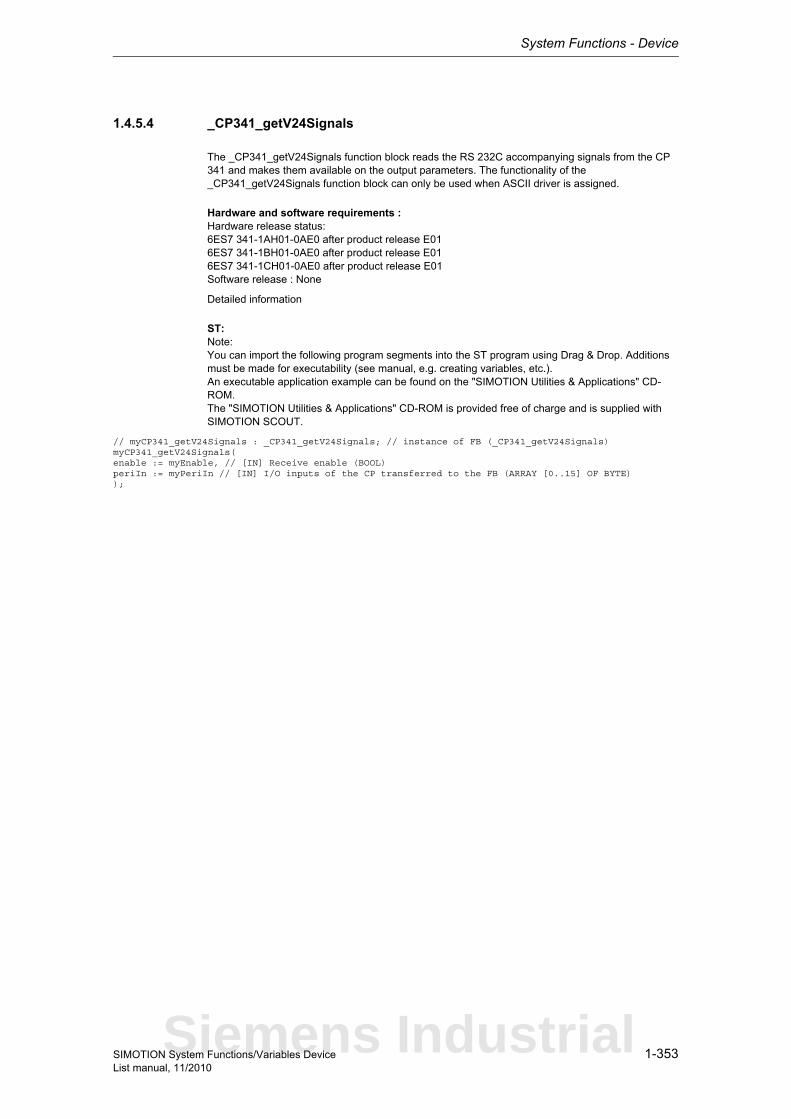
System Functions - Device
1-353SIMOTION System Functions/Variables DeviceList manual, 11/2010
1.4.5.4 _CP341_getV24Signals
The _CP341_getV24Signals function block reads the RS 232C accompanying signals from the CP 341 and makes them available on the output parameters. The functionality of the _CP341_getV24Signals function block can only be used when ASCII driver is assigned.
Hardware and software requirements :Hardware release status:6ES7 341-1AH01-0AE0 after product release E016ES7 341-1BH01-0AE0 after product release E016ES7 341-1CH01-0AE0 after product release E01Software release : None
Detailed information
ST: Note:You can import the following program segments into the ST program using Drag & Drop. Additions must be made for executability (see manual, e.g. creating variables, etc.).An executable application example can be found on the "SIMOTION Utilities & Applications" CD-ROM.The "SIMOTION Utilities & Applications" CD-ROM is provided free of charge and is supplied with SIMOTION SCOUT.
// myCP341_getV24Signals : _CP341_getV24Signals; // instance of FB (_CP341_getV24Signals)myCP341_getV24Signals(enable := myEnable, // [IN] Receive enable (BOOL)periIn := myPeriIn // [IN] I/O inputs of the CP transferred to the FB (ARRAY [0..15] OF BYTE));
Siemens Industrial

System Functions - Device
1-354 SIMOTION System Functions/Variables DeviceList manual, 11/2010
1.4.5.5 _CP341_intToPrintData
Entry of a number of data type INT in data structure Struct_CP341_printData.
Hardware and software requirements :Hardware release status:6ES7 341-1AH02-0AE0 after product release E01Software release : V2.0.0 and later
Detailed information
ST: Note:You can import the following program segments into the ST program using Drag & Drop. Additions must be made for executability (see manual, e.g. creating variables, etc.).An executable application example can be found on the "SIMOTION Utilities & Applications" CD-ROM.The "SIMOTION Utilities & Applications" CD-ROM is provided free of charge and is supplied with SIMOTION SCOUT.
// myCP341_intToPrintData : _CP341_intToPrintData; // instance of FB (_CP341_intToPrintData)myCP341_intToPrintData(execute := myExecute, // [IN] Edge-triggered request activation (BOOL)data := myData, // [IN] Variable/value to be entered in the data structure (INT)numVariable := myNumVariable, // [IN] Number of the variable in whitch the entry is to be made 1 <= NumberVariable <=4 (INT)entryFormatString := myEntryFormatString, // [IN] Method of entry in the format string (enumFormstring3)entryAtByteNumber := myEntryAtByteNumber, // [IN] Specifies the byte at which the entry is to begin in the substructure of the format string (USINT)printData := myCP341_printData // [IN_OUT] Data structure for the printer data (Struct_CP341_printData));// *************************// Struct_CP341_printData// *************************// myCP341_printData : Struct_CP341_printData;myCP341_printData.variable := myVariable; // [IN] Variable to be printed (ARRAY [0..3] of Struct_CP341_datRecord )myCP341_printData.format := myFormat; // [IN] Format string (ARRAY [0..150] OF BYTE )// *************************// Struct_CP341_datRecord// *************************// myCP341_datRecord : Struct_CP341_datRecord;myCP341_datRecord.datalength := 0; // [IN] Quantity of data (UDINT )myCP341_datRecord.data := myData; // [IN] Print data (ARRAY [0..31] OF BYTE )
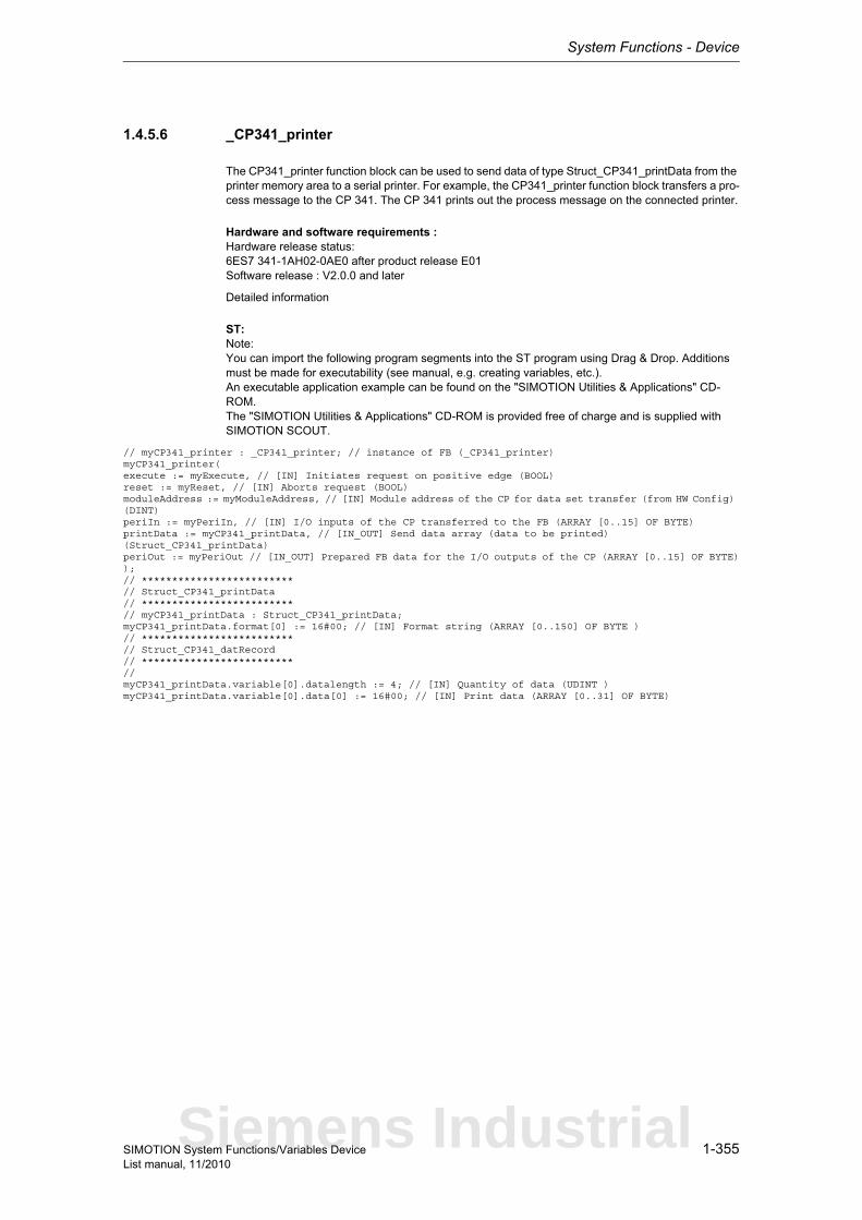
System Functions - Device
1-355SIMOTION System Functions/Variables DeviceList manual, 11/2010
1.4.5.6 _CP341_printer
The CP341_printer function block can be used to send data of type Struct_CP341_printData from the printer memory area to a serial printer. For example, the CP341_printer function block transfers a pro-cess message to the CP 341. The CP 341 prints out the process message on the connected printer.
Hardware and software requirements :Hardware release status:6ES7 341-1AH02-0AE0 after product release E01Software release : V2.0.0 and later
Detailed information
ST: Note:You can import the following program segments into the ST program using Drag & Drop. Additions must be made for executability (see manual, e.g. creating variables, etc.).An executable application example can be found on the "SIMOTION Utilities & Applications" CD-ROM.The "SIMOTION Utilities & Applications" CD-ROM is provided free of charge and is supplied with SIMOTION SCOUT.
// myCP341_printer : _CP341_printer; // instance of FB (_CP341_printer)myCP341_printer(execute := myExecute, // [IN] Initiates request on positive edge (BOOL)reset := myReset, // [IN] Aborts request (BOOL)moduleAddress := myModuleAddress, // [IN] Module address of the CP for data set transfer (from HW Config) (DINT)periIn := myPeriIn, // [IN] I/O inputs of the CP transferred to the FB (ARRAY [0..15] OF BYTE)printData := myCP341_printData, // [IN_OUT] Send data array (data to be printed) (Struct_CP341_printData)periOut := myPeriOut // [IN_OUT] Prepared FB data for the I/O outputs of the CP (ARRAY [0..15] OF BYTE));// *************************// Struct_CP341_printData// *************************// myCP341_printData : Struct_CP341_printData;myCP341_printData.format[0] := 16#00; // [IN] Format string (ARRAY [0..150] OF BYTE )// *************************// Struct_CP341_datRecord// *************************//myCP341_printData.variable[0].datalength := 4; // [IN] Quantity of data (UDINT )myCP341_printData.variable[0].data[0] := 16#00; // [IN] Print data (ARRAY [0..31] OF BYTE)
Siemens Industrial
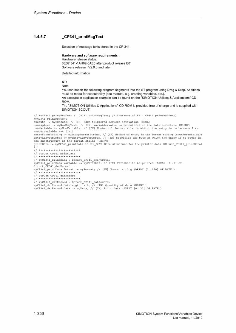
System Functions - Device
1-356 SIMOTION System Functions/Variables DeviceList manual, 11/2010
1.4.5.7 _CP341_printMsgText
Selection of message texts stored in the CP 341.
Hardware and software requirements :Hardware release status:6ES7 341-1AH02-0AE0 after product release E01Software release : V2.0.0 and later
Detailed information
ST: Note:You can import the following program segments into the ST program using Drag & Drop. Additions must be made for executability (see manual, e.g. creating variables, etc.).An executable application example can be found on the "SIMOTION Utilities & Applications" CD-ROM.The "SIMOTION Utilities & Applications" CD-ROM is provided free of charge and is supplied with SIMOTION SCOUT.
// myCP341_printMsgText : _CP341_printMsgText; // instance of FB (_CP341_printMsgText)myCP341_printMsgText(execute := myExecute, // [IN] Edge-triggered request activation (BOOL)numMsgText := myNumMsgText, // [IN] Variable/value to be entered in the data structure (USINT)numVariable := myNumVariable, // [IN] Number of the variable in whitch the entry is to be made 1 <= NumberVariable <=4 (INT)entryFormatString := myEntryFormatString, // [IN] Method of entry in the format string (enumFormstring3)entryAtByteNumber := myEntryAtByteNumber, // [IN] Specifies the byte at which the entry is to begin in the substructure of the format string (USINT)printData := myCP341_printData // [IN_OUT] Data structure for the printer data (Struct_CP341_printData));// *************************// Struct_CP341_printData// *************************// myCP341_printData : Struct_CP341_printData;myCP341_printData.variable := myVariable; // [IN] Variable to be printed (ARRAY [0..3] of Struct_CP341_datRecord )myCP341_printData.format := myFormat; // [IN] Format string (ARRAY [0..150] OF BYTE )// *************************// Struct_CP341_datRecord// *************************// myCP341_datRecord : Struct_CP341_datRecord;myCP341_datRecord.datalength := 0; // [IN] Quantity of data (UDINT )myCP341_datRecord.data := myData; // [IN] Print data (ARRAY [0..31] OF BYTE )

System Functions - Device
1-357SIMOTION System Functions/Variables DeviceList manual, 11/2010
1.4.5.8 _CP341_realToPrintData
Entry of a number of data type REAL in data structure Struct_CP341_printData.
Hardware and software requirements :Hardware release status:6ES7 341-1AH02-0AE0 after product release E01Software release : V2.0.0 and later
Detailed information
ST: Note:You can import the following program segments into the ST program using Drag & Drop. Additions must be made for executability (see manual, e.g. creating variables, etc.).An executable application example can be found on the "SIMOTION Utilities & Applications" CD-ROM.The "SIMOTION Utilities & Applications" CD-ROM is provided free of charge and is supplied with SIMOTION SCOUT.
// myCP341_realToPrintData : _CP341_realToPrintData; // instance of FB (_CP341_realToPrintData)myCP341_realToPrintData(execute := myExecute, // [IN] Edge-triggered request activation (BOOL)data := myData, // [IN] Variable/value to be entered in the data structure (REAL)numVariable := myNumVariable, // [IN] Number of the variable in whitch the entry is to be made 1 <= NumberVariable <=4 (INT)entryFormatString := myEntryFormatString, // [IN] Method of entry in the format string (enumFormstring1)entryAtByteNumber := myEntryAtByteNumber, // [IN] Specifies the byte at which the entry is to begin in the substructure of the format string (USINT)printData := myCP341_printData // [IN_OUT] Data structure for the printer data (Struct_CP341_printData));// *************************// Struct_CP341_printData// *************************// myCP341_printData : Struct_CP341_printData;myCP341_printData.variable := myVariable; // [IN] Variable to be printed (ARRAY [0..3] of Struct_CP341_datRecord )myCP341_printData.format := myFormat; // [IN] Format string (ARRAY [0..150] OF BYTE )// *************************// Struct_CP341_datRecord// *************************// myCP341_datRecord : Struct_CP341_datRecord;myCP341_datRecord.datalength := 0; // [IN] Quantity of data (UDINT )myCP341_datRecord.data := myData; // [IN] Print data (ARRAY [0..31] OF BYTE )
Siemens Industrial
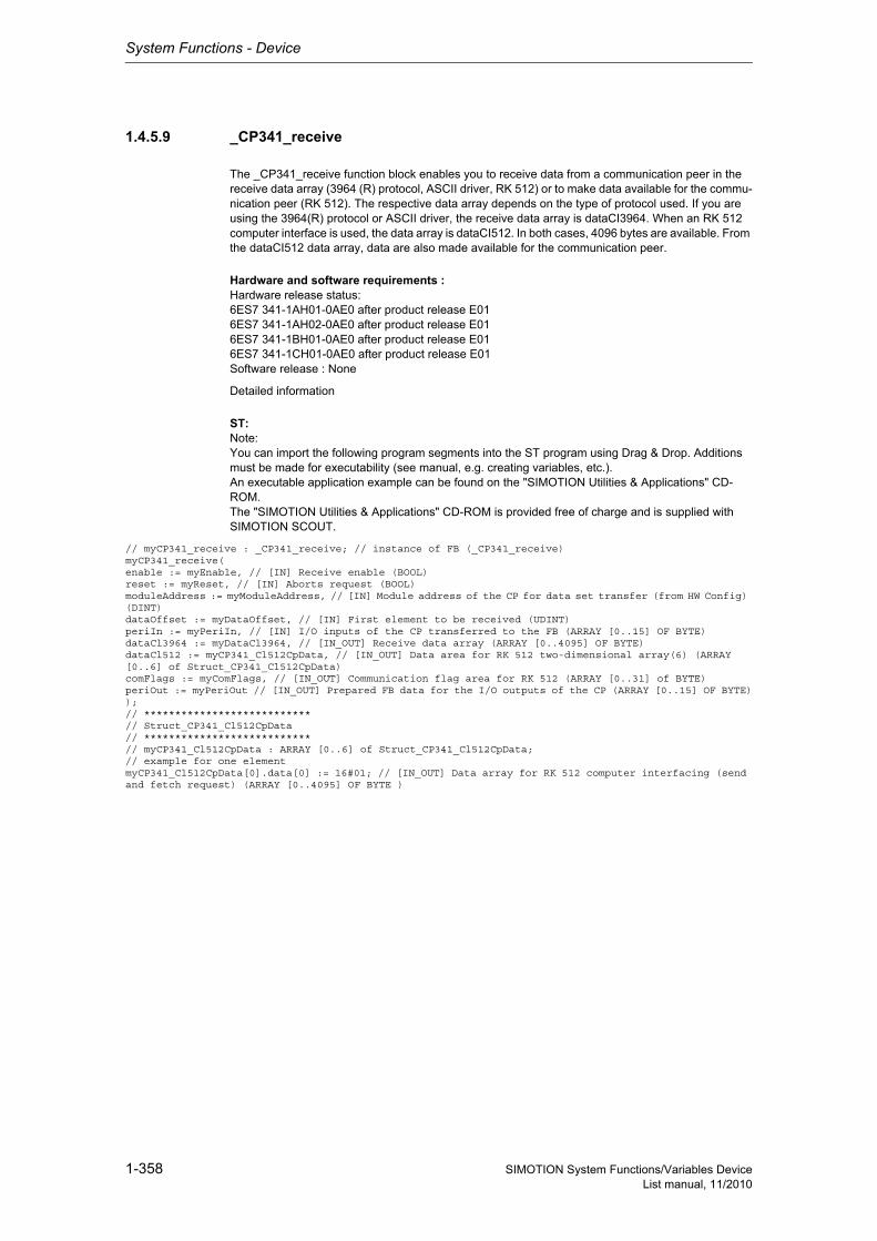
System Functions - Device
1-358 SIMOTION System Functions/Variables DeviceList manual, 11/2010
1.4.5.9 _CP341_receive
The _CP341_receive function block enables you to receive data from a communication peer in the receive data array (3964 (R) protocol, ASCII driver, RK 512) or to make data available for the commu-nication peer (RK 512). The respective data array depends on the type of protocol used. If you are using the 3964(R) protocol or ASCII driver, the receive data array is dataCI3964. When an RK 512 computer interface is used, the data array is dataCI512. In both cases, 4096 bytes are available. From the dataCI512 data array, data are also made available for the communication peer.
Hardware and software requirements :Hardware release status:6ES7 341-1AH01-0AE0 after product release E016ES7 341-1AH02-0AE0 after product release E016ES7 341-1BH01-0AE0 after product release E016ES7 341-1CH01-0AE0 after product release E01Software release : None
Detailed information
ST: Note:You can import the following program segments into the ST program using Drag & Drop. Additions must be made for executability (see manual, e.g. creating variables, etc.).An executable application example can be found on the "SIMOTION Utilities & Applications" CD-ROM.The "SIMOTION Utilities & Applications" CD-ROM is provided free of charge and is supplied with SIMOTION SCOUT.
// myCP341_receive : _CP341_receive; // instance of FB (_CP341_receive)myCP341_receive(enable := myEnable, // [IN] Receive enable (BOOL)reset := myReset, // [IN] Aborts request (BOOL)moduleAddress := myModuleAddress, // [IN] Module address of the CP for data set transfer (from HW Config) (DINT)dataOffset := myDataOffset, // [IN] First element to be received (UDINT)periIn := myPeriIn, // [IN] I/O inputs of the CP transferred to the FB (ARRAY [0..15] OF BYTE)dataCl3964 := myDataCl3964, // [IN_OUT] Receive data array (ARRAY [0..4095] OF BYTE)dataCl512 := myCP341_Cl512CpData, // [IN_OUT] Data area for RK 512 two-dimensional array(6) (ARRAY [0..6] of Struct_CP341_Cl512CpData)comFlags := myComFlags, // [IN_OUT] Communication flag area for RK 512 (ARRAY [0..31] of BYTE)periOut := myPeriOut // [IN_OUT] Prepared FB data for the I/O outputs of the CP (ARRAY [0..15] OF BYTE));// ***************************// Struct_CP341_Cl512CpData// ***************************// myCP341_Cl512CpData : ARRAY [0..6] of Struct_CP341_Cl512CpData;// example for one elementmyCP341_Cl512CpData[0].data[0] := 16#01; // [IN_OUT] Data array for RK 512 computer interfacing (send and fetch request) (ARRAY [0..4095] OF BYTE )
System Functions - Device
1-359SIMOTION System Functions/Variables DeviceList manual, 11/2010
1.4.5.10 _CP341_send
The CP341_send function block can be used to send data from the send data array to a communica-tion peer (3964(R) protocol, RK 512, ASCII driver) or to retrieve data from a communication peer and store it there (RK 512). 4096 bytes are available.
Hardware and software requirements :Hardware release status:6ES7 341-1AH01-0AE0 after product release E016ES7 341-1AH02-0AE0 after product release E016ES7 341-1BH01-0AE0 after product release E016ES7 341-1CH01-0AE0 after product release E01Software release : None
Detailed information
ST: Note:You can import the following program segments into the ST program using Drag & Drop. Additions must be made for executability (see manual, e.g. creating variables, etc.).An executable application example can be found on the "SIMOTION Utilities & Applications" CD-ROM.The "SIMOTION Utilities & Applications" CD-ROM is provided free of charge and is supplied with SIMOTION SCOUT.
// myCP341_send : _CP341_send; // instance of FB (_CP341_send)myCP341_send(mode := myMode, // [IN] SEND_CP: Sends data FETCH_CP: Fetches data from the communication partner (EnumCP341SndFetch)execute := myExecute, // [IN] Initiates request on positive edge (BOOL)reset := myReset, // [IN] Aborts request (BOOL)moduleAddress := myModuleAddress, // [IN] Module address of the CP for data set transfer (from HW Config) (DINT)dataOffset := myDataOffset, // [IN] First element to be sent (UDINT)dataLength := myDataLength, // [IN] Number of elements to be sent (UDINT)remoteCpuId := myRemoteCpuId, // [IN] Number of the remote communication partner (USINT)remoteDataType := myRemoteDataType, // [IN] Area type in the remote communication partner (USINT)remoteMemIndex := myRemoteMemIndex, // [IN] Memory index in the remote communication partner (1 <=remo-teMemoryIndex<= 6) (UINT)remoteDataOffset := myRemoteDataOffset, // [IN] First element in the remote communication partner (UDINT)remoteComFlagByte := myRemoteComFlagByte, // [IN] Communication flag index in the local communication partner (USINT)remoteComFlagBit := myRemoteComFlagBit, // [IN] Communication flag bit no. in the local communication partner (USINT)periIn := myPeriIn, // [IN] I/O inputs of the CP transferred to the FB (ARRAY [0..15] OF BYTE)data := myData, // [IN_OUT] Send data array / Receive data for parameter operatingMode=FETCH_CP (ARRAY [0..4095] OF BYTE)periOut := myPeriOut // [IN_OUT] Prepared FB data for the I/O outputs of the CP (ARRAY [0..15] OF BYTE));
Siemens Industrial
System Functions - Device
1-360 SIMOTION System Functions/Variables DeviceList manual, 11/2010
1.4.5.11 _CP341_setV24Signals
The _CP341_setV24Signals function block can be used to set or reset RS 232C accompanying sig-nals. The functionality of the _CP341_setV24Signals function block can only be used when ASCII dri-ver is assigned.
Hardware and software requirements :Hardware release status:6ES7 341-1AH01-0AE0 after product release E016ES7 341-1BH01-0AE0 after product release E016ES7 341-1CH01-0AE0 after product release E01Software release : None
Detailed information
ST: Note:You can import the following program segments into the ST program using Drag & Drop. Additions must be made for executability (see manual, e.g. creating variables, etc.).An executable application example can be found on the "SIMOTION Utilities & Applications" CD-ROM.The "SIMOTION Utilities & Applications" CD-ROM is provided free of charge and is supplied with SIMOTION SCOUT.
// myCP341_setV24Signals : _CP341_setV24Signals; // instance of FB (_CP341_setV24Signals)myCP341_setV24Signals(enable := myEnable, // [IN] Receive enable (BOOL)sigDtr := mySigDtr, // [IN] Signal 'Data terminal ready' (BOOL)sigRts := mySigRts, // [IN] Signal 'Request to send' (BOOL)periOut := myPeriOut // [IN_OUT] Prepared FB data for the I/O outputs of the CP (ARRAY [0..15] OF BYTE));

System Functions - Device
1-361SIMOTION System Functions/Variables DeviceList manual, 11/2010
1.4.5.12 _CP341_wordToPrintData
Entry of a number of data type WORD in data structure Struct_CP341_printData.
Hardware and software requirements :Hardware release status:6ES7 341-1AH02-0AE0 after product release E01Software release : V2.0.0 and later
Detailed information
ST: Note:You can import the following program segments into the ST program using Drag & Drop. Additions must be made for executability (see manual, e.g. creating variables, etc.).An executable application example can be found on the "SIMOTION Utilities & Applications" CD-ROM.The "SIMOTION Utilities & Applications" CD-ROM is provided free of charge and is supplied with SIMOTION SCOUT.
// myCP341_wordToPrintData : _CP341_wordToPrintData; // instance of FB (_CP341_wordToPrintData)myCP341_wordToPrintData(execute := myExecute, // [IN] Edge-triggered request activation (BOOL)data := myData, // [IN] Variable/value to be entered in the data structure (WORD)numVariable := myNumVariable, // [IN] Number of the variable in whitch the entry is to be made 1 <= NumberVariable <=4 (INT)entryFormatString := myEntryFormatString, // [IN] Method of entry in the format string (enumFormstring2)entryAtByteNumber := myEntryAtByteNumber, // [IN] Specifies the byte at which the entry is to begin in the substructure of the format string (USINT)printData := myCP341_printData // [IN_OUT] Data structure for the printer data (Struct_CP341_printData));// *************************// Struct_CP341_printData// *************************// myCP341_printData : Struct_CP341_printData;myCP341_printData.variable := myVariable; // [IN] Variable to be printed (ARRAY [0..3] of Struct_CP341_datRecord )myCP341_printData.format := myFormat; // [IN] Format string (ARRAY [0..150] OF BYTE )// *************************// Struct_CP341_datRecord// *************************// myCP341_datRecord : Struct_CP341_datRecord;myCP341_datRecord.datalength := 0; // [IN] Quantity of data (UDINT )myCP341_datRecord.data := myData; // [IN] Print data (ARRAY [0..31] OF BYTE )
Siemens Industrial
System Functions - Device
1-362 SIMOTION System Functions/Variables DeviceList manual, 11/2010
1.4.6 Communication modules - ET200S-SI
1.4.6.1 _ET200S_SI04_flowRts
The ET200S_SI04_flowRts function block can be used to modify additional parameters on the module if the module for "RTS/CTS" data flow control has been parameterized. Depending on which data interface you have chosen in the hardware configuration, you use either the _ET200S_SI04_flowRts for the 4-byte data interface, _ET200S_SI08_flowRts for the 8-byte data interface, or _ET200S_SI32_flowRts for the 32-byte data interface of the serial interface module.
Hardware and software requirements :4-byte, 8-byte data interface:Hardware release status:6ES7 138-4DF00-0AB0 after product release E03Software release : None4-byte, 8-byte, 32-byte data interface:Hardware release status:6ES7 138-4DF01-0AB0 after product release E01Software release : V1.0.4
Detailed information
ST: Note:You can import the following program segments into the ST program using Drag & Drop. Additions must be made for executability (see manual, e.g. creating variables, etc.).An executable application example can be found on the "SIMOTION Utilities & Applications" CD-ROM.The "SIMOTION Utilities & Applications" CD-ROM is provided free of charge and is supplied with SIMOTION SCOUT.
// myET200S_SI04_flowRts : _ET200S_SI04_flowRts; // instance of FB (_ET200S_SI04_flowRts)myET200S_SI04_flowRts(execute := myExecute, // [IN] Initiates request on positive edge (BOOL)reset := myReset, // [IN] Aborts request (BOOL)waitForCts := myWaitForCts, // [IN] Delay time for CTS=ON, value range:20 ms<=waitForXON<=655350 ms (DINT)periIn := myPeriIn, // [IN] Transfers I/O inputs of the serial interface module to FB (ARRAY [0..3] OF BYTE)periOut := myPeriOut // [IN_OUT] Prepared data of the FB for the I/O outputs of the serial interface module (ARRAY [0..3] OF BYTE));

System Functions - Device
1-363SIMOTION System Functions/Variables DeviceList manual, 11/2010
1.4.6.2 _ET200S_SI04_flowV24
The _ET200S_SI04_flowV24 function block can be used to modify additional parameters on the module if the module "Automatic use of V24 signals" data flow control has been parameterized. Depending on which data interface you have chosen in the hardware configuration, you use either the _ET200S_SI04_flowV24 for the 4-byte data interface, _ET200S_SI08_flowV24 for the 8-byte data interface, or _ET200S_SI32_flowV24 for the 32-byte data interface of the serial interface module.
Hardware and software requirements :4-byte, 8-byte data interface:Hardware release status:6ES7 138-4DF00-0AB0 after product release E03Software release : None4-byte, 8-byte, 32-byte data interface:Hardware release status:6ES7 138-4DF01-0AB0 after product release E01Software release : V1.0.4
Detailed information
ST: Note:You can import the following program segments into the ST program using Drag & Drop. Additions must be made for executability (see manual, e.g. creating variables, etc.).An executable application example can be found on the "SIMOTION Utilities & Applications" CD-ROM.The "SIMOTION Utilities & Applications" CD-ROM is provided free of charge and is supplied with SIMOTION SCOUT.
// myET200S_SI04_flowV24 : _ET200S_SI04_flowV24; // instance of FB (_ET200S_SI04_flowV24)myET200S_SI04_flowV24(execute := myExecute, // [IN] Initiates request on positive edge (BOOL)reset := myReset, // [IN] Aborts request (BOOL)timeRtsOff := myTimeRtsOff, // [IN] Time that must elapse after the transfer before RTS is disabled, value range:0<=timeRTSOff<=655350 ms (DINT)maxWaitTime := myMaxWaitTime, // [IN] Wait time for CTS=ON by partner after RTS=ON has been set, value range:0<=maxWaitTime<=655350 ms (DINT)periIn := myPeriIn, // [IN] Transfers I/O inputs of the serial interface module to FB (ARRAY [0..3] OF BYTE)periOut := myPeriOut // [IN_OUT] Prepared data of the FB for the I/O outputs of the serial interface module (ARRAY [0..3] OF BYTE));
Siemens Industrial

System Functions - Device
1-364 SIMOTION System Functions/Variables DeviceList manual, 11/2010
1.4.6.3 _ET200S_SI04_flowXon
The ET200S_SI04_flowXon function block can be used to modify parameters on the module indepen-dently of the parameter assignment interface if "XON/XOFF" data flow control has been assigned for the module. Depending on which data interface you have chosen in the hardware configuration, you use either the _ET200S_SI04_flowXon for the 4-byte data interface, _ET200S_SI08_flowXon for the 8-byte data interface, or _ET200S_SI32_flowXon for the 32-byte data interface of the serial interface module.
Hardware and software requirements :4-byte, 8-byte data interface:Hardware release status:6ES7 138-4DF00-0AB0 after product release E03Software release : None4-byte, 8-byte, 32-byte data interface:Hardware release status:6ES7 138-4DF01-0AB0 after product release E01Software release : V1.0.4
Detailed information
ST: Note:You can import the following program segments into the ST program using Drag & Drop. Additions must be made for executability (see manual, e.g. creating variables, etc.).An executable application example can be found on the "SIMOTION Utilities & Applications" CD-ROM.The "SIMOTION Utilities & Applications" CD-ROM is provided free of charge and is supplied with SIMOTION SCOUT.
// myET200S_SI04_flowXon : _ET200S_SI04_flowXon; // instance of FB (_ET200S_SI04_flowXon)myET200S_SI04_flowXon(execute := myExecute, // [IN] Initiates request on positive edge (BOOL)reset := myReset, // [IN] Aborts request (BOOL)sigXon := mySigXon, // [IN] Code for XON characters (BYTE)sigXoff := mySigXoff, // [IN] Code for XOFF characters (BYTE)waitForXon := myWaitForXon, // [IN] Delay time for XON after XOFF, value range:20 ms<=waitForXON<=655350 ms (DINT)periIn := myPeriIn, // [IN] Transfers I/O inputs of the serial interface module to FB (ARRAY [0..3] OF BYTE)periOut := myPeriOut // [IN_OUT] Prepared data of the FB for the I/O outputs of the serial interface module (ARRAY [0..3] OF BYTE));

System Functions - Device
1-365SIMOTION System Functions/Variables DeviceList manual, 11/2010
1.4.6.4 _ET200S_SI04_getV24Sig
When ASCII driver is assigned, the _ET200S_SI04_getV24Sig function block reads the RS 232C accompanying signals and provides them to the user as output parameters. Depending on which data interface you have chosen in the hardware configuration, you use either the _ET200S_SI04_getV24Sig for the 4-byte data interface, _ET200S_SI08_getV24Sig for the 8-byte data interface, or _ET200S_SI32_getV24Sig for the 32-byte data interface of the serial interface module.
Hardware and software requirements :4-byte, 8-byte data interface:Hardware release status:6ES7 138-4DF00-0AB0 after product release E03Software release : None4-byte, 8-byte, 32-byte data interface:Hardware release status:6ES7 138-4DF01-0AB0 after product release E01Software release : V1.0.4
Detailed information
ST: Note:You can import the following program segments into the ST program using Drag & Drop. Additions must be made for executability (see manual, e.g. creating variables, etc.).An executable application example can be found on the "SIMOTION Utilities & Applications" CD-ROM.The "SIMOTION Utilities & Applications" CD-ROM is provided free of charge and is supplied with SIMOTION SCOUT.
// myET200S_SI04_getV24Sig : _ET200S_SI04_getV24Sig; // instance of FB (_ET200S_SI04_getV24Sig)myET200S_SI04_getV24Sig(execute := myExecute, // [IN] Initiates request on positive edge (BOOL)reset := myReset, // [IN] Aborts request (BOOL)periIn := myPeriIn, // [IN] Transfers I/O inputs of the serial interface module to FB (ARRAY [0..3] OF BYTE)periOut := myPeriOut // [IN_OUT] Prepared data of the FB for the I/O outputs of the serial interface module (ARRAY [0..3] OF BYTE));
Siemens Industrial
System Functions - Device
1-366 SIMOTION System Functions/Variables DeviceList manual, 11/2010
1.4.6.5 _ET200S_SI04_receive
The _ET200S_SI04_receive function block can be used to receive data from a communication peer in the receive data array. 1024 bytes are available. Depending on which data interface you have cho-sen in the hardware configuration, you use either the _ET200S_SI04_receive for the 4-byte data inter-face, _ET200S_SI08_receive for the 8-byte data interface, or _ET200S_SI32_receive for the 32-byte data interface of the serial interface module. For the transfer operation, you can use the 3964 (R) pro-tocol or ASCII driver.
Hardware and software requirements :4-byte, 8-byte data interface:Hardware release status:6ES7 138-4DF00-0AB0 after product release E03Software release : None4-byte, 8-byte, 32-byte data interface:Hardware release status:6ES7 138-4DF01-0AB0 after product release E01Software release : V1.0.4
Detailed information
ST: Note:You can import the following program segments into the ST program using Drag & Drop. Additions must be made for executability (see manual, e.g. creating variables, etc.).An executable application example can be found on the "SIMOTION Utilities & Applications" CD-ROM.The "SIMOTION Utilities & Applications" CD-ROM is provided free of charge and is supplied with SIMOTION SCOUT.
// myET200S_SI04_receive : _ET200S_SI04_receive; // instance of FB (_ET200S_SI04_receive)myET200S_SI04_receive(enable := myEnable, // [IN] Receive enable (BOOL)reset := myReset, // [IN] Aborts request (BOOL)dataOffset := myDataOffset, // [IN] Offset of the first element to be received (INT)periIn := myPeriIn, // [IN] Transfers I/O inputs of the serial interface module to FB (ARRAY [0..3] OF BYTE)data := myData, // [IN_OUT] Receive data array (ARRAY [0..1023] OF BYTE)periOut := myPeriOut // [IN_OUT] Prepared data of the FB for the I/O outputs of the serial interface module (ARRAY [0..3] OF BYTE));
System Functions - Device
1-367SIMOTION System Functions/Variables DeviceList manual, 11/2010
1.4.6.6 _ET200S_SI04_send
The _ET200S_SI04_send function block can be used to send data from the send data array to a com-munication peer. 1024 bytes are available. Depending on which data interface you have chosen in the hardware configuration, you use either the _ET200S_SI04_send for the 4-byte data interface, _ET200S_SI08_send for the 8-byte data interface, or _ET200S_SI32_send for the 32-byte data inter-face of the serial interface module. For the transfer operation, you can use the 3964 (R) protocol or ASCII driver.
Hardware and software requirements :4-byte, 8-byte data interface:Hardware release status:6ES7 138-4DF00-0AB0 after product release E03Software release : None4-byte, 8-byte, 32-byte data interface:Hardware release status:6ES7 138-4DF01-0AB0 after product release E01Software release : V1.0.4
Detailed information
ST: Note:You can import the following program segments into the ST program using Drag & Drop. Additions must be made for executability (see manual, e.g. creating variables, etc.).An executable application example can be found on the "SIMOTION Utilities & Applications" CD-ROM.The "SIMOTION Utilities & Applications" CD-ROM is provided free of charge and is supplied with SIMOTION SCOUT.
// myET200S_SI04_send : _ET200S_SI04_send; // instance of FB (_ET200S_SI04_send)myET200S_SI04_send(execute := myExecute, // [IN] Initiates request on positive edge (BOOL)reset := myReset, // [IN] Aborts request (BOOL)dataOffset := myDataOffset, // [IN] Offset of the first element to be sent (INT)datalength := myDatalength, // [IN] Number of elements to be sent 0 = dataLength = 224 (INT)periIn := myPeriIn, // [IN] Transfers I/O inputs of the serial interface module to FB (ARRAY [0..3] OF BYTE)data := myData, // [IN_OUT] Send data array (ARRAY [0..1023] OF BYTE)periOut := myPeriOut // [IN_OUT] Prepared data of the FB for the I/O outputs of the serial interface module (ARRAY [0..3] OF BYTE));
Siemens Industrial
System Functions - Device
1-368 SIMOTION System Functions/Variables DeviceList manual, 11/2010
1.4.6.7 _ET200S_SI04_setV24Sig
The _ET200S_SI04_setV24Sig function block can be used to set or reset RS 232C accompanying signals if ASCII driver is assigned.. Depending on which data interface you have chosen in the hard-ware configuration, you use either the _ET200S_SI04_setV24Sig for the 4-byte data interface, _ET200S_SI08_setV24Sig for the 8-byte data interface, or _ET200S_SI32_setV24Sig for the 32-byte data interface of the serial interface module.
Hardware and software requirements :4-byte, 8-byte data interface:Hardware release status:6ES7 138-4DF00-0AB0 after product release E03Software release : None4-byte, 8-byte, 32-byte data interface:Hardware release status:6ES7 138-4DF01-0AB0 after product release E01Software release : V1.0.4
Detailed information
ST: Note:You can import the following program segments into the ST program using Drag & Drop. Additions must be made for executability (see manual, e.g. creating variables, etc.).An executable application example can be found on the "SIMOTION Utilities & Applications" CD-ROM.The "SIMOTION Utilities & Applications" CD-ROM is provided free of charge and is supplied with SIMOTION SCOUT.
// myET200S_SI04_setV24Sig : _ET200S_SI04_setV24Sig; // instance of FB (_ET200S_SI04_setV24Sig)myET200S_SI04_setV24Sig(execute := myExecute, // [IN] Initiates request on positive edge (BOOL)reset := myReset, // [IN] Aborts request (BOOL)sigRts := mySigRts, // [IN] Signal 'Request to send' (BOOL)sigDtr := mySigDtr, // [IN] Signal 'Data terminal ready' (BOOL)periIn := myPeriIn, // [IN] Transfers I/O inputs of the serial interface module to FB (ARRAY [0..3] OF BYTE)periOut := myPeriOut // [IN_OUT] Prepared data of the FB for the I/O outputs of the serial interface module (ARRAY [0..3] OF BYTE));
System Functions - Device
1-369SIMOTION System Functions/Variables DeviceList manual, 11/2010
1.4.6.8 _ET200S_SI08_flowRts
The ET200S_SI08_flowRts function block can be used to modify additional parameters on the module if the module for "RTS/CTS" data flow control has been parameterized. Depending on which data interface you have chosen in the hardware configuration, you use either the _ET200S_SI04_flowRts for the 4-byte data interface, _ET200S_SI08_flowRts for the 8-byte data interface, or _ET200S_SI32_flowRts for the 32-byte data interface of the serial interface module.
Hardware and software requirements :4-byte, 8-byte data interface:Hardware release status:6ES7 138-4DF00-0AB0 after product release E03Software release : None4-byte, 8-byte, 32-byte data interface:Hardware release status:6ES7 138-4DF01-0AB0 after product release E01Software release : V1.0.4
Detailed information
ST: Note:You can import the following program segments into the ST program using Drag & Drop. Additions must be made for executability (see manual, e.g. creating variables, etc.).An executable application example can be found on the "SIMOTION Utilities & Applications" CD-ROM.The "SIMOTION Utilities & Applications" CD-ROM is provided free of charge and is supplied with SIMOTION SCOUT.
// myET200S_SI08_flowRts : _ET200S_SI08_flowRts; // instance of FB (_ET200S_SI08_flowRts)myET200S_SI08_flowRts(execute := myExecute, // [IN] Initiates request on positive edge (BOOL)reset := myReset, // [IN] Aborts request (BOOL)waitForCts := myWaitForCts, // [IN] Delay time for CTS=ON, value range:20 ms<=waitForXON<=655350 ms (DINT)periIn := myPeriIn, // [IN] Transfers I/O inputs of the serial interface module to FB (ARRAY [0..7] OF BYTE)periOut := myPeriOut // [IN_OUT] Prepared data of the FB for the I/O outputs of the serial interface module (ARRAY [0..7] OF BYTE));
Siemens Industrial
System Functions - Device
1-370 SIMOTION System Functions/Variables DeviceList manual, 11/2010
1.4.6.9 _ET200S_SI08_flowV24
The _ET200S_SI08_flowV24 function block can be used to modify additional parameters on the module if the module "Automatic use of V24 signals" data flow control has been parameterized. Depending on which data interface you have chosen in the hardware configuration, you use either the _ET200S_SI04_flowV24 for the 4-byte data interface, _ET200S_SI08_flowV24 for the 8-byte data interface, or _ET200S_SI32_flowV24 for the 32-byte data interface of the serial interface module.
Hardware and software requirements :4-byte, 8-byte data interface:Hardware release status:6ES7 138-4DF00-0AB0 after product release E03Software release : None4-byte, 8-byte, 32-byte data interface:Hardware release status:6ES7 138-4DF01-0AB0 after product release E01Software release : V1.0.4
Detailed information
ST: Note:You can import the following program segments into the ST program using Drag & Drop. Additions must be made for executability (see manual, e.g. creating variables, etc.).An executable application example can be found on the "SIMOTION Utilities & Applications" CD-ROM.The "SIMOTION Utilities & Applications" CD-ROM is provided free of charge and is supplied with SIMOTION SCOUT.
// myET200S_SI08_flowV24 : _ET200S_SI08_flowV24; // instance of FB (_ET200S_SI08_flowV24)myET200S_SI08_flowV24(execute := myExecute, // [IN] Initiates request on positive edge (BOOL)reset := myReset, // [IN] Aborts request (BOOL)timeRtsOff := myTimeRtsOff, // [IN] Time that must elapse after the transfer before RTS is disabled, value range:0<=timeRTSOff<=655350 ms (DINT)maxWaitTime := myMaxWaitTime, // [IN] Wait time for CTS=ON by partner after RTS=ON has been set, value range:0<=maxWaitTime<=655350 ms (DINT)periIn := myPeriIn, // [IN] Transfers I/O inputs of the serial interface module to FB (ARRAY [0..7] OF BYTE)periOut := myPeriOut // [IN_OUT] Prepared data of the FB for the I/O outputs of the serial interface module (ARRAY [0..7] OF BYTE));
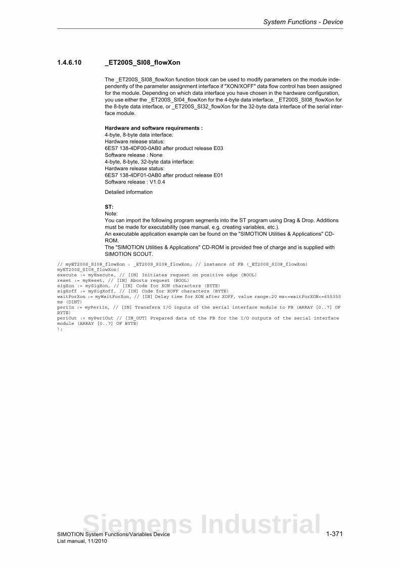
System Functions - Device
1-371SIMOTION System Functions/Variables DeviceList manual, 11/2010
1.4.6.10 _ET200S_SI08_flowXon
The _ET200S_SI08_flowXon function block can be used to modify parameters on the module inde-pendently of the parameter assignment interface if "XON/XOFF" data flow control has been assigned for the module. Depending on which data interface you have chosen in the hardware configuration, you use either the _ET200S_SI04_flowXon for the 4-byte data interface, _ET200S_SI08_flowXon for the 8-byte data interface, or _ET200S_SI32_flowXon for the 32-byte data interface of the serial inter-face module.
Hardware and software requirements :4-byte, 8-byte data interface:Hardware release status:6ES7 138-4DF00-0AB0 after product release E03Software release : None4-byte, 8-byte, 32-byte data interface:Hardware release status:6ES7 138-4DF01-0AB0 after product release E01Software release : V1.0.4
Detailed information
ST: Note:You can import the following program segments into the ST program using Drag & Drop. Additions must be made for executability (see manual, e.g. creating variables, etc.).An executable application example can be found on the "SIMOTION Utilities & Applications" CD-ROM.The "SIMOTION Utilities & Applications" CD-ROM is provided free of charge and is supplied with SIMOTION SCOUT.
// myET200S_SI08_flowXon : _ET200S_SI08_flowXon; // instance of FB (_ET200S_SI08_flowXon)myET200S_SI08_flowXon(execute := myExecute, // [IN] Initiates request on positive edge (BOOL)reset := myReset, // [IN] Aborts request (BOOL)sigXon := mySigXon, // [IN] Code for XON characters (BYTE)sigXoff := mySigXoff, // [IN] Code for XOFF characters (BYTE)waitForXon := myWaitForXon, // [IN] Delay time for XON after XOFF, value range:20 ms<=waitForXON<=655350 ms (DINT)periIn := myPeriIn, // [IN] Transfers I/O inputs of the serial interface module to FB (ARRAY [0..7] OF BYTE)periOut := myPeriOut // [IN_OUT] Prepared data of the FB for the I/O outputs of the serial interface module (ARRAY [0..7] OF BYTE));
Siemens Industrial

System Functions - Device
1-372 SIMOTION System Functions/Variables DeviceList manual, 11/2010
1.4.6.11 _ET200S_SI08_getV24Sig
When ASCII driver is assigned, the _ET200S_SI08_getV24Sig function block reads the RS 232C accompanying signals and provides them to the user as output parameters. Depending on which data interface you have chosen in the hardware configuration, you use either the _ET200S_SI04_getV24Sig for the 4-byte data interface, _ET200S_SI08_getV24Sig for the 8-byte data interface, or _ET200S_SI32_getV24Sig for the 32-byte data interface of the serial interface module.
Hardware and software requirements :4-byte, 8-byte data interface:Hardware release status:6ES7 138-4DF00-0AB0 after product release E03Software release : None4-byte, 8-byte, 32-byte data interface:Hardware release status:6ES7 138-4DF01-0AB0 after product release E01Software release : V1.0.4
Detailed information
ST: Note:You can import the following program segments into the ST program using Drag & Drop. Additions must be made for executability (see manual, e.g. creating variables, etc.).An executable application example can be found on the "SIMOTION Utilities & Applications" CD-ROM.The "SIMOTION Utilities & Applications" CD-ROM is provided free of charge and is supplied with SIMOTION SCOUT.
// myET200S_SI08_getV24Sig : _ET200S_SI08_getV24Sig; // instance of FB (_ET200S_SI08_getV24Sig)myET200S_SI08_getV24Sig(execute := myExecute, // [IN] Initiates request on positive edge (BOOL)reset := myReset, // [IN] Aborts request (BOOL)periIn := myPeriIn, // [IN] Transfers I/O inputs of the serial interface module to FB (ARRAY [0..7] OF BYTE)periOut := myPeriOut // [IN_OUT] Prepared data of the FB for the I/O outputs of the serial interface module (ARRAY [0..7] OF BYTE));
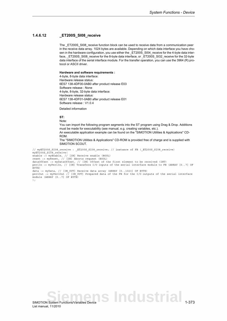
System Functions - Device
1-373SIMOTION System Functions/Variables DeviceList manual, 11/2010
1.4.6.12 _ET200S_SI08_receive
The _ET200S_SI08_receive function block can be used to receive data from a communication peer in the receive data array. 1024 bytes are available. Depending on which data interface you have cho-sen in the hardware configuration, you use either the _ET200S_SI04_receive for the 4-byte data inter-face, _ET200S_SI08_receive for the 8-byte data interface, or _ET200S_SI32_receive for the 32-byte data interface of the serial interface module. For the transfer operation, you can use the 3964 (R) pro-tocol or ASCII driver.
Hardware and software requirements :4-byte, 8-byte data interface:Hardware release status:6ES7 138-4DF00-0AB0 after product release E03Software release : None4-byte, 8-byte, 32-byte data interface:Hardware release status:6ES7 138-4DF01-0AB0 after product release E01Software release : V1.0.4
Detailed information
ST: Note:You can import the following program segments into the ST program using Drag & Drop. Additions must be made for executability (see manual, e.g. creating variables, etc.).An executable application example can be found on the "SIMOTION Utilities & Applications" CD-ROM.The "SIMOTION Utilities & Applications" CD-ROM is provided free of charge and is supplied with SIMOTION SCOUT.
// myET200S_SI08_receive : _ET200S_SI08_receive; // instance of FB (_ET200S_SI08_receive)myET200S_SI08_receive(enable := myEnable, // [IN] Receive enable (BOOL)reset := myReset, // [IN] Aborts request (BOOL)dataOffset := myDataOffset, // [IN] Offset of the first element to be received (INT)periIn := myPeriIn, // [IN] Transfers I/O inputs of the serial interface module to FB (ARRAY [0..7] OF BYTE)data := myData, // [IN_OUT] Receive data array (ARRAY [0..1023] OF BYTE)periOut := myPeriOut // [IN_OUT] Prepared data of the FB for the I/O outputs of the serial interface module (ARRAY [0..7] OF BYTE));
Siemens Industrial
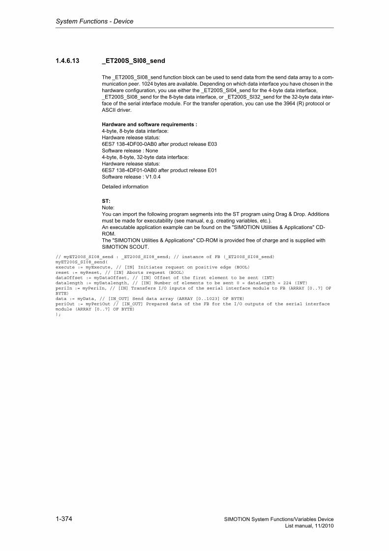
System Functions - Device
1-374 SIMOTION System Functions/Variables DeviceList manual, 11/2010
1.4.6.13 _ET200S_SI08_send
The _ET200S_SI08_send function block can be used to send data from the send data array to a com-munication peer. 1024 bytes are available. Depending on which data interface you have chosen in the hardware configuration, you use either the _ET200S_SI04_send for the 4-byte data interface, _ET200S_SI08_send for the 8-byte data interface, or _ET200S_SI32_send for the 32-byte data inter-face of the serial interface module. For the transfer operation, you can use the 3964 (R) protocol or ASCII driver.
Hardware and software requirements :4-byte, 8-byte data interface:Hardware release status:6ES7 138-4DF00-0AB0 after product release E03Software release : None4-byte, 8-byte, 32-byte data interface:Hardware release status:6ES7 138-4DF01-0AB0 after product release E01Software release : V1.0.4
Detailed information
ST: Note:You can import the following program segments into the ST program using Drag & Drop. Additions must be made for executability (see manual, e.g. creating variables, etc.).An executable application example can be found on the "SIMOTION Utilities & Applications" CD-ROM.The "SIMOTION Utilities & Applications" CD-ROM is provided free of charge and is supplied with SIMOTION SCOUT.
// myET200S_SI08_send : _ET200S_SI08_send; // instance of FB (_ET200S_SI08_send)myET200S_SI08_send(execute := myExecute, // [IN] Initiates request on positive edge (BOOL)reset := myReset, // [IN] Aborts request (BOOL)dataOffset := myDataOffset, // [IN] Offset of the first element to be sent (INT)datalength := myDatalength, // [IN] Number of elements to be sent 0 = dataLength = 224 (INT)periIn := myPeriIn, // [IN] Transfers I/O inputs of the serial interface module to FB (ARRAY [0..7] OF BYTE)data := myData, // [IN_OUT] Send data array (ARRAY [0..1023] OF BYTE)periOut := myPeriOut // [IN_OUT] Prepared data of the FB for the I/O outputs of the serial interface module (ARRAY [0..7] OF BYTE));
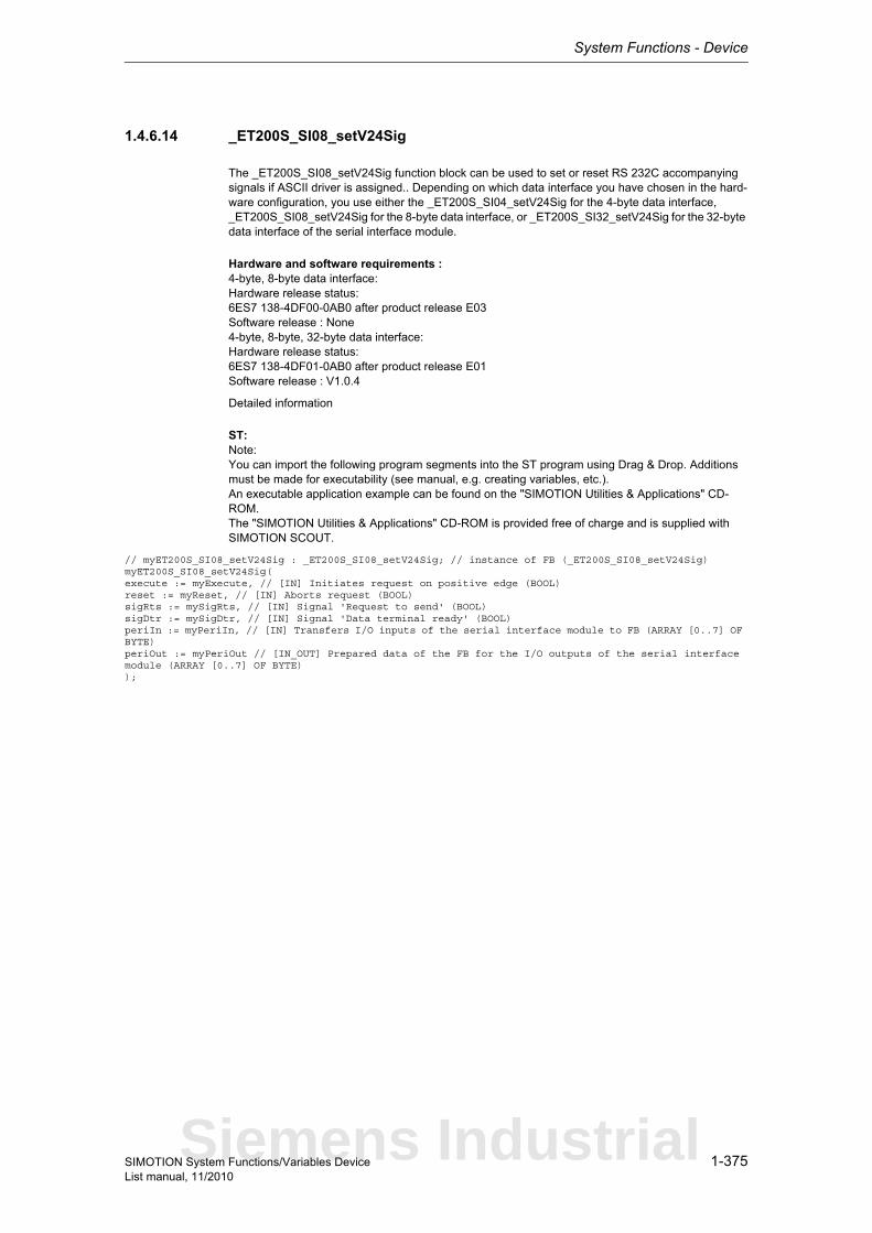
System Functions - Device
1-375SIMOTION System Functions/Variables DeviceList manual, 11/2010
1.4.6.14 _ET200S_SI08_setV24Sig
The _ET200S_SI08_setV24Sig function block can be used to set or reset RS 232C accompanying signals if ASCII driver is assigned.. Depending on which data interface you have chosen in the hard-ware configuration, you use either the _ET200S_SI04_setV24Sig for the 4-byte data interface, _ET200S_SI08_setV24Sig for the 8-byte data interface, or _ET200S_SI32_setV24Sig for the 32-byte data interface of the serial interface module.
Hardware and software requirements :4-byte, 8-byte data interface:Hardware release status:6ES7 138-4DF00-0AB0 after product release E03Software release : None4-byte, 8-byte, 32-byte data interface:Hardware release status:6ES7 138-4DF01-0AB0 after product release E01Software release : V1.0.4
Detailed information
ST: Note:You can import the following program segments into the ST program using Drag & Drop. Additions must be made for executability (see manual, e.g. creating variables, etc.).An executable application example can be found on the "SIMOTION Utilities & Applications" CD-ROM.The "SIMOTION Utilities & Applications" CD-ROM is provided free of charge and is supplied with SIMOTION SCOUT.
// myET200S_SI08_setV24Sig : _ET200S_SI08_setV24Sig; // instance of FB (_ET200S_SI08_setV24Sig)myET200S_SI08_setV24Sig(execute := myExecute, // [IN] Initiates request on positive edge (BOOL)reset := myReset, // [IN] Aborts request (BOOL)sigRts := mySigRts, // [IN] Signal 'Request to send' (BOOL)sigDtr := mySigDtr, // [IN] Signal 'Data terminal ready' (BOOL)periIn := myPeriIn, // [IN] Transfers I/O inputs of the serial interface module to FB (ARRAY [0..7] OF BYTE)periOut := myPeriOut // [IN_OUT] Prepared data of the FB for the I/O outputs of the serial interface module (ARRAY [0..7] OF BYTE));
Siemens Industrial
System Functions - Device
1-376 SIMOTION System Functions/Variables DeviceList manual, 11/2010
1.4.6.15 _ET200S_SI32_flowRts
The ET200S_SI32_flowRts function block can be used to modify additional parameters on the module if the module for "RTS/CTS" data flow control has been parameterized. Depending on which data interface you have chosen in the hardware configuration, you use either the _ET200S_SI04_flowRts for the 4-byte data interface, _ET200S_SI08_flowRts for the 8-byte data interface, or _ET200S_SI32_flowRts for the 32-byte data interface of the serial interface module.
Hardware and software requirements :4-byte, 8-byte data interface:Hardware release status:6ES7 138-4DF00-0AB0 after product release E03Software release : None4-byte, 8-byte, 32-byte data interface:Hardware release status:6ES7 138-4DF01-0AB0 after product release E01Software release : V1.0.4
Detailed information
ST: Note:You can import the following program segments into the ST program using Drag & Drop. Additions must be made for executability (see manual, e.g. creating variables, etc.).An executable application example can be found on the "SIMOTION Utilities & Applications" CD-ROM.The "SIMOTION Utilities & Applications" CD-ROM is provided free of charge and is supplied with SIMOTION SCOUT.
// myET200S_SI32_flowRts : _ET200S_SI32_flowRts; // instance of FB (_ET200S_SI32_flowRts)myET200S_SI32_flowRts(execute := myExecute, // [IN] Initiates request on positive edge (BOOL)reset := myReset, // [IN] Aborts request (BOOL)waitForCts := myWaitForCts, // [IN] Delay time for CTS=ON, value range:20 ms<=waitForXON<=655350 ms (DINT)periIn := myPeriIn, // [IN] Transfers I/O inputs of the serial interface module to FB (ARRAY [0..31] OF BYTE)periOut := myPeriOut // [IN_OUT] Prepared data of the FB for the I/O outputs of the serial interface module (ARRAY [0..31] OF BYTE));
System Functions - Device
1-377SIMOTION System Functions/Variables DeviceList manual, 11/2010
1.4.6.16 _ET200S_SI32_flowV24
The _ET200S_SI32_flowV24 function block can be used to modify additional parameters on the module if the module "Automatic use of V24 signals" data flow control has been parameterized. Depending on which data interface you have chosen in the hardware configuration, you use either the _ET200S_SI04_flowV24 for the 4-byte data interface, _ET200S_SI08_flowV24 for the 8-byte data interface, or _ET200S_SI32_flowV24 for the 32-byte data interface of the serial interface module.
Hardware and software requirements :4-byte, 8-byte data interface:Hardware release status:6ES7 138-4DF00-0AB0 after product release E03Software release : None4-byte, 8-byte, 32-byte data interface:Hardware release status:6ES7 138-4DF01-0AB0 after product release E01Software release : V1.0.4
Detailed information
ST: Note:You can import the following program segments into the ST program using Drag & Drop. Additions must be made for executability (see manual, e.g. creating variables, etc.).An executable application example can be found on the "SIMOTION Utilities & Applications" CD-ROM.The "SIMOTION Utilities & Applications" CD-ROM is provided free of charge and is supplied with SIMOTION SCOUT.
// myET200S_SI32_flowV24 : _ET200S_SI32_flowV24; // instance of FB (_ET200S_SI32_flowV24)myET200S_SI32_flowV24(execute := myExecute, // [IN] Initiates request on positive edge (BOOL)reset := myReset, // [IN] Aborts request (BOOL)timeRtsOff := myTimeRtsOff, // [IN] Time that must elapse after the transfer before RTS is disabled, value range:0<=timeRTSOff<=655350 ms (DINT)maxWaitTime := myMaxWaitTime, // [IN] Wait time for CTS=ON by partner after RTS=ON has been set, value range:0<=maxWaitTime<=655350 ms (DINT)periIn := myPeriIn, // [IN] Transfers I/O inputs of the serial interface module to FB (ARRAY [0..31] OF BYTE)periOut := myPeriOut // [IN_OUT] Prepared data of the FB for the I/O outputs of the serial interface module (ARRAY [0..31] OF BYTE));
Siemens Industrial
System Functions - Device
1-378 SIMOTION System Functions/Variables DeviceList manual, 11/2010
1.4.6.17 _ET200S_SI32_flowXon
The ET200S_SI32_flowXon function block can be used to modify parameters on the module indepen-dently of the parameter assignment interface if "XON/XOFF" data flow control has been assigned for the module. Depending on which data interface you have chosen in the hardware configuration, you use either the _ET200S_SI04_flowXon for the 4-byte data interface, _ET200S_SI08_flowXon for the 8-byte data interface, or _ET200S_SI32_flowXon for the 32-byte data interface of the serial interface module.
Hardware and software requirements :4-byte, 8-byte data interface:Hardware release status:6ES7 138-4DF00-0AB0 after product release E03Software release : None4-byte, 8-byte, 32-byte data interface:Hardware release status:6ES7 138-4DF01-0AB0 after product release E01Software release : V1.0.4
Detailed information
ST: Note:You can import the following program segments into the ST program using Drag & Drop. Additions must be made for executability (see manual, e.g. creating variables, etc.).An executable application example can be found on the "SIMOTION Utilities & Applications" CD-ROM.The "SIMOTION Utilities & Applications" CD-ROM is provided free of charge and is supplied with SIMOTION SCOUT.
// myET200S_SI32_flowXon : _ET200S_SI32_flowXon; // instance of FB (_ET200S_SI32_flowXon)myET200S_SI32_flowXon(execute := myExecute, // [IN] Initiates request on positive edge (BOOL)reset := myReset, // [IN] Aborts request (BOOL)sigXon := mySigXon, // [IN] Code for XON characters (BYTE)sigXoff := mySigXoff, // [IN] Code for XOFF characters (BYTE)waitForXon := myWaitForXon, // [IN] Delay time for XON after XOFF, value range:20 ms<=waitForXON<=655350 ms (DINT)periIn := myPeriIn, // [IN] Transfers I/O inputs of the serial interface module to FB (ARRAY [0..31] OF BYTE)periOut := myPeriOut // [IN_OUT] Prepared data of the FB for the I/O outputs of the serial interface module (ARRAY [0..31] OF BYTE));
System Functions - Device
1-379SIMOTION System Functions/Variables DeviceList manual, 11/2010
1.4.6.18 _ET200S_SI32_getV24Sig
When ASCII driver is assigned, the _ET200S_SI32_getV24Sig function block reads the RS 232C accompanying signals and provides them to the user as output parameters. Depending on which data interface you have chosen in the hardware configuration, you use either the _ET200S_SI04_getV24Sig for the 4-byte data interface, _ET200S_SI08_getV24Sig for the 8-byte data interface, or _ET200S_SI32_getV24Sig for the 32-byte data interface of the serial interface module.
Hardware and software requirements :4-byte, 8-byte data interface:Hardware release status:6ES7 138-4DF00-0AB0 after product release E03Software release : None4-byte, 8-byte, 32-byte data interface:Hardware release status:6ES7 138-4DF01-0AB0 after product release E01Software release : V1.0.4
Detailed information
ST: Note:You can import the following program segments into the ST program using Drag & Drop. Additions must be made for executability (see manual, e.g. creating variables, etc.).An executable application example can be found on the "SIMOTION Utilities & Applications" CD-ROM.The "SIMOTION Utilities & Applications" CD-ROM is provided free of charge and is supplied with SIMOTION SCOUT.
// myET200S_SI32_getV24Sig : _ET200S_SI32_getV24Sig; // instance of FB (_ET200S_SI32_getV24Sig)myET200S_SI32_getV24Sig(execute := myExecute, // [IN] Initiates request on positive edge (BOOL)reset := myReset, // [IN] Aborts request (BOOL)periIn := myPeriIn, // [IN] Transfers I/O inputs of the serial interface module to FB (ARRAY [0..31] OF BYTE)periOut := myPeriOut // [IN_OUT] Prepared data of the FB for the I/O outputs of the serial interface module (ARRAY [0..31] OF BYTE));
Siemens Industrial

System Functions - Device
1-380 SIMOTION System Functions/Variables DeviceList manual, 11/2010
1.4.6.19 _ET200S_SI32_receive
The _ET200S_SI32_receive function block can be used to receive data from a communication peer in the receive data array. 1024 bytes are available. Depending on which data interface you have cho-sen in the hardware configuration, you use either the _ET200S_SI04_receive for the 4-byte data inter-face, _ET200S_SI08_receive for the 8-byte data interface, or _ET200S_SI32_receive for the 32-byte data interface of the serial interface module. For the transfer operation, you can use the 3964 (R) pro-tocol or ASCII driver.
Hardware and software requirements :4-byte, 8-byte data interface:Hardware release status:6ES7 138-4DF00-0AB0 after product release E03Software release : None4-byte, 8-byte, 32-byte data interface:Hardware release status:6ES7 138-4DF01-0AB0 after product release E01Software release : V1.0.4
Detailed information
ST: Note:You can import the following program segments into the ST program using Drag & Drop. Additions must be made for executability (see manual, e.g. creating variables, etc.).An executable application example can be found on the "SIMOTION Utilities & Applications" CD-ROM.The "SIMOTION Utilities & Applications" CD-ROM is provided free of charge and is supplied with SIMOTION SCOUT.
// myET200S_SI32_receive : _ET200S_SI32_receive; // instance of FB (_ET200S_SI32_receive)myET200S_SI32_receive(enable := myEnable, // [IN] Receive enable (BOOL)reset := myReset, // [IN] Aborts request (BOOL)dataOffset := myDataOffset, // [IN] Offset of the first element to be received (INT)periIn := myPeriIn, // [IN] Transfers I/O inputs of the serial interface module to FB (ARRAY [0..31] OF BYTE)data := myData, // [IN_OUT] Receive data array (ARRAY [0..1023] OF BYTE)periOut := myPeriOut // [IN_OUT] Prepared data of the FB for the I/O outputs of the serial interface module (ARRAY [0..31] OF BYTE));
System Functions - Device
1-381SIMOTION System Functions/Variables DeviceList manual, 11/2010
1.4.6.20 _ET200S_SI32_send
The _ET200S_SI32_send function block can be used to send data from the send data array to a com-munication peer. 1024 bytes are available. Depending on which data interface you have chosen in the hardware configuration, you use either the _ET200S_SI04_send for the 4-byte data interface, _ET200S_SI08_send for the 8-byte data interface, or _ET200S_SI32_send for the 32-byte data inter-face of the serial interface module. For the transfer operation, you can use the 3964 (R) protocol or ASCII driver.
Hardware and software requirements :4-byte, 8-byte data interface:Hardware release status:6ES7 138-4DF00-0AB0 after product release E03Software release : None4-byte, 8-byte, 32-byte data interface:Hardware release status:6ES7 138-4DF01-0AB0 after product release E01Software release : V1.0.4
Detailed information
ST: Note:You can import the following program segments into the ST program using Drag & Drop. Additions must be made for executability (see manual, e.g. creating variables, etc.).An executable application example can be found on the "SIMOTION Utilities & Applications" CD-ROM.The "SIMOTION Utilities & Applications" CD-ROM is provided free of charge and is supplied with SIMOTION SCOUT.
// myET200S_SI32_send : _ET200S_SI32_send; // instance of FB (_ET200S_SI32_send)myET200S_SI32_send(execute := myExecute, // [IN] Initiates request on positive edge (BOOL)reset := myReset, // [IN] Aborts request (BOOL)dataOffset := myDataOffset, // [IN] Offset of the first element to be sent (INT)datalength := myDatalength, // [IN] Number of elements to be sent 0 <= dataLength <= 224 (INT)periIn := myPeriIn, // [IN] Transfers I/O inputs of the serial interface module to FB (ARRAY [0..31] OF BYTE)data := myData, // [IN_OUT] Send data array (ARRAY [0..1023] OF BYTE)periOut := myPeriOut // [IN_OUT] Prepared data of the FB for the I/O outputs of the serial interface module (ARRAY [0..31] OF BYTE));
Siemens Industrial

System Functions - Device
1-382 SIMOTION System Functions/Variables DeviceList manual, 11/2010
1.4.6.21 _ET200S_SI32_setV24Sig
The _ET200S_SI32_setV24Sig function block can be used to set or reset RS 232C accompanying signals if ASCII driver is assigned.. Depending on which data interface you have chosen in the hard-ware configuration, you use either the _ET200S_SI04_setV24Sig for the 4-byte data interface, _ET200S_SI08_setV24Sig for the 8-byte data interface, or _ET200S_SI32_setV24Sig for the 32-byte data interface of the serial interface module.
Hardware and software requirements :4-byte, 8-byte data interface:Hardware release status:6ES7 138-4DF00-0AB0 after product release E03Software release : None4-byte, 8-byte, 32-byte data interface:Hardware release status:6ES7 138-4DF01-0AB0 after product release E01Software release : V1.0.4
Detailed information
ST: Note:You can import the following program segments into the ST program using Drag & Drop. Additions must be made for executability (see manual, e.g. creating variables, etc.).An executable application example can be found on the "SIMOTION Utilities & Applications" CD-ROM.The "SIMOTION Utilities & Applications" CD-ROM is provided free of charge and is supplied with SIMOTION SCOUT.
// myET200S_SI32_setV24Sig : _ET200S_SI32_setV24Sig; // instance of FB (_ET200S_SI32_setV24Sig)myET200S_SI32_setV24Sig(execute := myExecute, // [IN] Initiates request on positive edge (BOOL)reset := myReset, // [IN] Aborts request (BOOL)sigRts := mySigRts, // [IN] Signal 'Request to send' (BOOL)sigDtr := mySigDtr, // [IN] Signal 'Data terminal ready' (BOOL)periIn := myPeriIn, // [IN] Transfers I/O inputs of the serial interface module to FB (ARRAY [0..31] OF BYTE)periOut := myPeriOut // [IN_OUT] Prepared data of the FB for the I/O outputs of the serial interface module (ARRAY [0..31] OF BYTE));
System Functions - Device
1-383SIMOTION System Functions/Variables DeviceList manual, 11/2010
1.4.7 Weighing technology - SIWAREX FTA
1.4.7.1 _FTA_control
The _FTA_control function block is used to exchange data with the SIWAREX FTA weighing module. The _FTA_control function block executes commands on the SIWAREX FTA, acknowledges techno-logy messages upon request, and visualizes the weighing status in the output parameters.
Hardware and software requirements :SIWAREX FTAHardware release status: 1.0.0 and higherSoftware release : 2.1.8 and higher
Detailed information
ST: Note:You can import the following program segments into the ST program using Drag & Drop. Additions must be made for executability (see manual, e.g. creating variables, etc.).An executable application example can be found on the "SIMOTION Utilities & Applications" CD-ROM.The "SIMOTION Utilities & Applications" CD-ROM is provided free of charge and is supplied with SIMOTION SCOUT.
Siemens Industrial
System Functions - Device
1-384 SIMOTION System Functions/Variables DeviceList manual, 11/2010
// myFTA_control : _FTA_control; // instance of FB (_FTA_control)myFTA_control(periIn := myPeriIn, // [IN] Positive edge: the command entered in cmdNumber is executed. (ARRAY[0..15] of BYTE)moduleAddress := myModuleAddress, // [IN] Provides the command number, The command start is initiated with the execute parameter. (DINT)execute := myExecute, // [IN] TRUE = error message is acknowledged (BOOL)cmdNumber := myCmdNumber, // [IN] Transfers I/O inputs to _FTA_control FB (UINT)ackErrorFTA := myAckErrorFTA, // [IN] Module address from HW Config (BOOL)simValue := mySimValue, // [IN] Value for weight simulation when simulation is enabled; selection is made in DR7 (REAL)setAO := mySetAO, // [IN] Value specification for analog output of weighing module with control priority of higher-level controller; selection is made in DR7 (REAL)forceDO := myForceDO, // [IN] Specifies digital outputs of weighing module with forced control; selec-tion is made in DR7 (BYTE)transitions := myTransitions, // [IN] Disables and enables weighing steps (BYTE)scaleData := myFTA_scaleData, // [IN_OUT] Data structure for the parameters of the SIWAREX FTA weighing module (Struct_FTA_scaleData)periOut := myPeriOut // [IN_OUT] Prepared FB data for I/O outputs of SIWAREX FTA weighing module (ARRAY[0..15] of BYTE));// *****************// Struct_FTA_DR3// *****************// myFTA_DR3 : Struct_FTA_DR3;myFTA_DR3.calibDigits0 := 1398101; // [IN] Calibration digits for the zero pointmyFTA_DR3.calibDigits1 := 15379113; // [IN] Calibration digits for calibration weight 1myFTA_DR3.calibDigits2 := 0; // [IN] Calibration digits for calibration weight 2myFTA_DR3.calibDigits3 := 0; // [IN] Calibration digits for calibration weight 3myFTA_DR3.calibDigits4 := 0; // [IN] Calibration digits for calibration weight 4myFTA_DR3.calibWeight1 := 100.0; // [IN] Calibration weight 1myFTA_DR3.calibWeight2 := 0.0; // [IN] Calibration weight 2myFTA_DR3.calibWeight3 := 0.0; // [IN] Calibration weight 3myFTA_DR3.calibWeight4 := 0.0; // [IN] Calibration weight 4myFTA_DR3.sigRange := 16#02; // [IN] Characteristic value range,1 = characteristic value to 1 mV/V, 2 = characteristic value to 2 mV/V, 4 = characteristic value to 4 mV/VmyFTA_DR3.filtSequence := 16#00; // [IN] Signal filter sequence, The 8 bits in this byte have the following meaning: Bit 0 = 0: averaging filter before digital filter Bit 0 = 1: digital filter before averaging filter Bits 1-7: not setmyFTA_DR3.filtType := 16#00; // [IN] Low-pass filter type 0 = critically damped 1 = Bessel filter 2 = Butterworth filter Other definitions not permitted.myFTA_DR3.filtCutOffFreq := 16#04; // [IN] Filter cut-off frequency (Hz) Specifies the response time of the scale to a measured-value change 0 = no filter 1 = 20 Hz 2 = 10 Hz 3 = 5 Hz 4 = 2 Hz 5 = 1 Hz 6 = 0.5 Hz 7 = 0.2 Hz 8 = 0.1 Hz 9 = 0.05 Hz Other definitions not permitted.myFTA_DR3.filtDepth := 10; // [IN] Depth of averaging filterm Number of values for averaging [0 to 250] x 2.5 ms 0 = averaging filter deactivatedmyFTA_DR3.scaleId := 'SIWAREXxx'; // [IN] [IN] Scale namemyFTA_DR3.numRanges := 16#01; // [IN] Number of scale rangesmyFTA_DR3.scaleType := FALSE; // [IN] Scale type FALSE = multi-range scale TRUE = multi-resolution scalemyFTA_DR3.setZeroPwrOn := FALSE; // [IN] TRUE = zero setting activated upon weighing module startup (power ON)myFTA_DR3.setZeroTare := FALSE; // [IN] TRUE = zero setting activated upon weighing module startup (power ON) and tare <> 0myFTA_DR3.setZeroAutomatic := FALSE; // [IN] TRUE = automatic zero correction switched onmyFTA_DR3.minWeightRange1 := 1.0; // [IN] Minimum weight for weighing range 1myFTA_DR3.maxWeightRange1 := 100.0; // [IN] Maximum weight for weighing range 1myFTA_DR3.incRange1 := 0.02; // [IN] Numerical increment for weighing range 1 Numerical increment for weighing range 1 (1*10 k, 2*10 k, 5*10 k, -4 = k = 1)myFTA_DR3.minWeightRange2 := 0.0; // [IN] Minimum weight for weighing range 2myFTA_DR3.maxWeightRange2 := 0.0; // [IN] Maximum weight for weighing range 2myFTA_DR3.incRange2 := 0.0; // [IN] Numerical increment for weighing range 2 Numerical increment for weighing range 2 (1*10 k, 2*10 k, 5*10 k, -4 = k = 1)myFTA_DR3.minWeightRange3 := 0.0; // [IN] Minimum weight for weighing range 3myFTA_DR3.maxWeightRange3 := 0.0; // [IN] Maximum weight for weighing range 3myFTA_DR3.incRange3 := 0.0; // [IN] Numerical increment for weighing range 3 Numerical increment for weighing range 3 (1*10 k, 2*10 k, 5*10 k, -4 = k = 1)myFTA_DR3.standStillTime1 := T#1s; // [IN] Standstill time If the fluctuation range of the weight during standstill time is smaller than the fluctuation range defined in the standStillWeight1parameter, the scale standstill signal is set to TRUE.myFTA_DR3.standStillWeight1 := 0.02; // [IN] Fluctuation range of the weight for detection/gene-ration of the scale standstill signalmyFTA_DR3.timeOutStandStill1 := T#2s; // [IN] Maximum wait time for scale standstill If a scale standstill is not detected during this time, a technology alarm is issued.myFTA_DR3.maxPosWeightPwrOn := 16#0A; // [IN] Maximum positive weight in [% of WBmax] for zero setting after Power OnmyFTA_DR3.minNegWeightPwrOn := 16#0A; // [IN] Maximum negative weight in [% of WBmax] for zero setting after Power OnmyFTA_DR3.maxPosWeightZero := 16#01; // [IN] Maximum positive weight in [% of WBmax] for zero setting
System Functions - Device
1-385SIMOTION System Functions/Variables DeviceList manual, 11/2010
myFTA_DR3.minNegWeightZero := 16#03; // [IN] Maximum negative weight in [% of WBmax] for zero settingmyFTA_DR3.maxTare := 16#64; // [IN] Maximum tare capacity in [% of WBmax] with respect to the maximum weighing rangemyFTA_DR3.setLCType := 16#00; // [IN] Selection of load cell typemyFTA_DR3.timeOutDigLC := 80; // [IN] Monitoring time in [ms] for digital load cell If a weight message frame is not received withing the monitoring timeout, the SIWAREX FTA weighing module generates an operating error.myFTA_DR3.setRestriction := '----'; // [IN] The entry 'OIML' activates restrictions/regulations for scales that require official calibrationmyFTA_DR3.weightUnit := 'kg--'; // [IN] Unit of mass (for example, t, kg, g)myFTA_DR3.standStillWeight2 := 0.02; // [IN] Standstill time If the fluctuation range of the weight during standstill time is smaller than the fluctuation range defined in the standStillWeight2parameter, the scale standstill signal is set to TRUE.myFTA_DR3.standStillTime2 := T#1s; // [IN] Fluctuation range of the weight for detection/generation of the scale standstill signalmyFTA_DR3.timeOutStandStill2 := T#2s; // [IN] Maximum wait time for scale standstill If a scale standstill is not detected during this time, a technology alarm is issued.myFTA_DR3.standStillWeight3 := 0.02; // [IN] Fluctuation range of the weight for detection/gene-ration of the scale standstill signalmyFTA_DR3.standStillTime3 := T#1s; // [IN] Standstill time If the fluctuation range of the weight during standstill time is smaller than the fluctuation range defined in the standStillWeight3parameter, the scale standstill signal is set to TRUE.myFTA_DR3.timeOutStandStill3 := T#2s; // [IN] Maximum wait time for scale standstill If a scale standstill is not detected during this time, a technology alarm is issued.myFTA_DR3.minDosingValTot := 100; // [IN] Smallest set weight for weight totalizingmyFTA_DR3.incTotalizing := 0.1; // [IN] Scale interval for weight totalizingmyFTA_DR3.xxxReserve0 := 0.0; // [IN] Reserve (use not permitted)myFTA_DR3.xxxReserve1 := 16#00; // [IN] Reserve (use not permitted)myFTA_DR3.xxxReserve2 := 16#00; // [IN] Reserve (use not permitted)// *****************// Struct_FTA_DR4// *****************// myFTA_DR4 : Struct_FTA_DR4;myFTA_DR4.scaleMode := 16#03; // [IN] Scale mode, selection of weighing program 0 = NAWI: filling pro-cedure 1 = NAWI: emptying procedure 2 = AWI: single/continuous operation filling 3 = AWI: catchw. filling 4 = AWI: catchw. emptying 5 = AWI: check 6 = AWI: totalizing Other definitions are not permitted.myFTA_DR4.xxxReserve0 := 16#00; // [IN] Reserve (use not permitted)myFTA_DR4.xxxReserve1 := 16#0000; // [IN] Reserve (use not permitted)myFTA_DR4.timeOutLogOutput := T#2s; // [IN] Monitoring time in [ms] for output of log data to a connected printer.myFTA_DR4.selectLogOutput := 16#01; // [IN] Selection of device for log output Bit 0 = 0: log output to RS232 interface Bit 0 = 1: log output to micro memory card (MMC)myFTA_DR4.xxxReserve2 := 16#00; // [IN] Reserve (use not permitted)myFTA_DR4.baseWeightLimit1 := FALSE; // [IN] Base weight for limit value 1 TRUE = basis for limit value 1 is gross weight of scale FALSE = basis for limit value 1 is net weight of scalemyFTA_DR4.baseWeightLimit2 := FALSE; // [IN] Base weight for limit value 2 TRUE = basis for limit value 2 is gross weight of scale FALSE = basis for limit value 2 is net weight of scalemyFTA_DR4.xxxReserve3 := FALSE; // [IN] Reserve (use not permitted)myFTA_DR4.baseEmptyRange := FALSE; // [IN] Base weight for empty range monitoring FALSE = basis for empty range is gross weight of scale TRUE = basis for empty range is net weight of scalemyFTA_DR4.xxxReserve4 := 16#00; // [IN] Reserve (use not permitted)myFTA_DR4.emptyRange := 1.0; // [IN] Empty rangemyFTA_DR4.limit1On := 1.0; // [IN] Start-up weight limit value 1myFTA_DR4.limit1Off := 1.1; // [IN] Shut-down weight limit value 1myFTA_DR4.limit2On := 50.0; // [IN] Start-up weight limit value 2myFTA_DR4.limit2Off := 49.0; // [IN] Shut-down weight limit value 2myFTA_DR4.limit3On := 99.0; // [IN] Start-up weight limit value 3myFTA_DR4.limit3Off := 98.0; // [IN] Shut-down weight limit value 3myFTA_DR4.minFlowLimit1 := 0.0; // [IN] Limit value 1 for minimum flow rate 0.0 = no limit value in effect >0.0 = minimum flow rate in [1/s]myFTA_DR4.minFlowLimit2 := 0.0; // [IN] Limit value 2 for minimum flow rate 0.0 = no limit value in effect >0.0 = minimum flow rate in [1/s]myFTA_DR4.filtDepthMinFlow := 16#05; // [IN] Filter depth of mean value filter for flow rate calculation [0 to 255] * 10 msmyFTA_DR4.xxxReserve5 := 16#00; // [IN] Reserve (use not permitted)// *****************// Struct_FTA_DR7// *****************// myFTA_DR7 : Struct_FTA_DR7;myFTA_DR7.xxxReserve0 := 16#00; // [IN] Reserve (use not permitted)myFTA_DR7.srcWeightSim := 16#00; // [IN] Weight simulation source 0 = weight simulation is inactive 1 = weight simulation value from SIMOTION (defined externally via DR 16) 2 = weight simulation value from RS232myFTA_DR7.deciDigitsProcVal := 16#03; // [IN] Number of decimal places/decade used for rounding the decimal places of process values (REAL weight values) 0 = rounding to 0 decimal places 1 = rounding to 1 decimal place 2 = rounding to 2 decimal places 3 = rounding to 3 decimal places 4 = rounding to 4 decimal places 5 = rounding to 5 decimal places 6 = rounding to 6 decimal placmyFTA_DR7.xxxReserve1 := 16#00; // [IN] Reserve (use not permitted)myFTA_DR7.enableForceDO := FALSE; // [IN] TRUE = force control possible in service mode
Siemens Industrial
System Functions - Device
1-386 SIMOTION System Functions/Variables DeviceList manual, 11/2010
myFTA_DR7.indexProcessValue1 := 16#02; // [IN] Selection of process value 1 from list at output para-meter val1Process of function block _FTA_control for fast output to the SIMOTION device (see appendix "Selection List for Process Values")myFTA_DR7.indexProcessValue2 := 16#1E; // [IN] Selection of process value 2 from list at output para-meter val2Process of function block _FTA_control for fast output to the SIMOTION device (see appendix "Selection List for Process Values")myFTA_DR7.xxxReserve2 := 16#00; // [IN] Reserve (use not permitted)myFTA_DR7.defProcessAlarm0 := 16#00; // [IN] Definition of process alarm 0 Value 0 = process alarm is not triggered Value range 1 - 0x0FF: number of technology error Value range 0x100 - 0x13F: 100h+ 0x00 to 0x1F bit no. incoming NAWI status bit 100h+ 0x20 to 0x3F bit no. incoming AWI status bit Value range 0x200 - 0x23F: 0x200+ 0x00 to 0x1Fh bit no. outgoing NAWI status bit 0x2myFTA_DR7.defProcessAlarm1 := 16#00; // [IN] Definition of process alarm 1 (see defProcessAlarm0)myFTA_DR7.defProcessAlarm2 := 16#00; // [IN] Definition of process alarm 2 (see defProcessAlarm0)myFTA_DR7.defProcessAlarm3 := 16#00; // [IN] Definition of process alarm 3 (see defProcessAlarm0)myFTA_DR7.defProcessAlarm4 := 16#00; // [IN] Definition of process alarm 4 (see defProcessAlarm0)myFTA_DR7.defProcessAlarm5 := 16#00; // [IN] Definition of process alarm 5 (see defProcessAlarm0)myFTA_DR7.defProcessAlarm6 := 16#00; // [IN] Definition of process alarm 6 (see defProcessAlarm0)myFTA_DR7.defProcessAlarm7 := 16#00; // [IN] Definition of process alarm 7 (see defProcessAlarm0)myFTA_DR7.timeOutLifeBit := T#0ms; // [IN] Sign-of-life timeout in higher-level control 0 = sign-of-life timeout is switched off 1 to n = timeout duration [ms]myFTA_DR7.weightAOZero := 0.0; // [IN] Weight for zero point (0 or 4 mA)myFTA_DR7.weightAOEnd := 0.0; // [IN] Weight for end value (20 mA)myFTA_DR7.weightAOonOD := 0.0; // [IN] Substitute value for analog output for CPU-STOP (OS, output disable)myFTA_DR7.srcAO := 16#00; // [IN] Source for the analog output 0 = SIMOTION control signals 1 = external default value via DR17 2 = gross 3 = net 4 = coarse/fine default valuesmyFTA_DR7.rangeAO := FALSE; // [IN] Current range for the analog output TRUE = 0 to 20 mA FALSE = 4 to 20 mAmyFTA_DR7.printerBdRate := 16#03; // [IN] RS232 - printer baud rate 0 = 1200 bits/s 1 = 2400 bits/s 2 = 4800 bits/s 3 = 9600 bits/smyFTA_DR7.setXonXoff := TRUE; // [IN] Transfer control for the RS232 interfaces TRUE = XON/XOFF transfer control ON FALSE = XON/XOFF transfer control OFFmyFTA_DR7.setRtsCts := FALSE; // [IN] Transfer control for the RS232 interfaces TRUE = CTS/RTS transfer control ON FALSE = CTS/RTS transfer control OFFmyFTA_DR7.setRS485Prot := 16#00; // [IN] R485 log selection 0 = no device 1 = SIEBERT display S11 2 = reserve 3 = SIEBERT display S102myFTA_DR7.digitsRemDisplay := 16#00; // [IN] Decimal place for remote display (0 to 4)myFTA_DR7.rs485BdRate := 16#03; // [IN] RS485 baud rate 0 = 1200 bits/s 1 = 2400 bits/s 2 = 4800 bits/s 3 = 9600 bits/s 4 = 19200 bits/s 5 = 38400 bits/smyFTA_DR7.rs485Parity := FALSE; // [IN] RS485 bit parity TRUE = odd FALSE = evenmyFTA_DR7.Rs485NumDataBits := TRUE; // [IN] RS485- data bits TRUE = 8 data bits FALSE = 7 data bitsmyFTA_DR7.rs485NumStopBits := FALSE; // [IN] RS485- stop bits TRUE = 1 stop bit FALSE = 2 stop bitsmyFTA_DR7.defDO1 := 16#FF; // [IN] Definition of digital output 1, Value range 0x00 - 0x3F, 0x00 to 0x1F bit no. NAWI status bit, 0x20 to 0x3F bit no. AWI status bit, 0xFD start of cyclic measured value transfer, digital load cell, 0xFE stop of cyclic measured value transfer, digital load cell, 0xFF output always inactive, Value range 0x40 to 0xFC is not permitted.myFTA_DR7.defDO2 := 16#FF; // [IN] Definition of digital output 2 (see defDO1)myFTA_DR7.defDO3 := 16#FF; // [IN] Definition of digital output 3 (see defDO1)myFTA_DR7.defDO4 := 16#FF; // [IN] Definition of digital output 4 (see defDO1)myFTA_DR7.defDO5 := 16#FF; // [IN] Definition of digital output 5 (see defDO1)myFTA_DR7.defDO6 := 16#FF; // [IN] Definition of digital output 6 (see defDO1)myFTA_DR7.defDO7 := 16#FF; // [IN] Definition of digital output 7 (see defDO1)myFTA_DR7.defDO8 := 16#FF; // [IN] Definition of digital output 8 (see defDO1)myFTA_DR7.lowActiveDO1 := FALSE; // [IN] Level definition of digital output 1 TRUE = output low active FALSE = output high activemyFTA_DR7.lowActiveDO2 := FALSE; // [IN] Level definition of digital output 2 TRUE = output low active FALSE = output high activemyFTA_DR7.lowActiveDO3 := FALSE; // [IN] Level definition of digital output 3 TRUE = output low active FALSE = output high activemyFTA_DR7.lowActiveDO4 := FALSE; // [IN] Level definition of digital output 4 TRUE = output low active FALSE = output high activemyFTA_DR7.lowActiveDO5 := FALSE; // [IN] Level definition of digital output 5 TRUE = output low active FALSE = output high activemyFTA_DR7.lowActiveDO6 := FALSE; // [IN] Level definition of digital output 6 TRUE = output low active FALSE = output high activemyFTA_DR7.lowActiveDO7 := FALSE; // [IN] Level definition of digital output 7 TRUE = output low active FALSE = output high activemyFTA_DR7.lowActiveDO8 := FALSE; // [IN] Level definition of digital output 8 TRUE = output low active FALSE = output high activemyFTA_DR7.DO1onOD := FALSE; // [IN] Substitute value for digital output 1 for CPU-STOP (OD) or faultmyFTA_DR7.DO2onOD := FALSE; // [IN] Substitute value for digital output 2 for CPU-STOP (OD) or faultmyFTA_DR7.DO3onOD := FALSE; // [IN] Substitute value for digital output 3 for CPU-STOP (OD) or faultmyFTA_DR7.DO4onOD := FALSE; // [IN] Substitute value for digital output 4 for CPU-STOP (OD) or faultmyFTA_DR7.DO5onOD := FALSE; // [IN] Substitute value for digital output 5 for CPU-STOP (OD) or faultmyFTA_DR7.DO6onOD := FALSE; // [IN] Substitute value for digital output 6 for CPU-STOP (OD) or faultmyFTA_DR7.DO7onOD := FALSE; // [IN] Substitute value for digital output 7 for CPU-STOP (OD) or faultmyFTA_DR7.DO8onOD := FALSE; // [IN] Substitute value for digital output 8 for CPU-STOP (OD) or faultmyFTA_DR7.enableDOonError := FALSE; // [IN] Activate substitute value output for operational fault TRUE = substitute value for operational fault enabled FALSE = substitute value for operational fault disabled
System Functions - Device
1-387SIMOTION System Functions/Variables DeviceList manual, 11/2010
myFTA_DR7.xxxReserve3 := 16#00; // [IN] Reserve (use not permitted)myFTA_DR7.defDI1 := 16#00; // [IN] Definition of digital input 1, 0 = no command, 1 to 254 = command code, 255 = step enabling (see DR23, step control weighing parameters)myFTA_DR7.defDI2 := 16#00; // [IN] Definition of digital input 2 (see defDI1)myFTA_DR7.defDI3 := 16#00; // [IN] Definition of digital input 3 (see defDI1)myFTA_DR7.defDI4 := 16#00; // [IN] Definition of digital input 4 (see defDI1)myFTA_DR7.defDI5 := 16#00; // [IN] Definition of digital input 5 (see defDI1)myFTA_DR7.defDI6 := 16#00; // [IN] Definition of digital input 6 (see defDI1)myFTA_DR7.defDI7 := 16#00; // [IN] Definition of digital input 7 (see defDI1)myFTA_DR7.lowActiveDI1 := FALSE; // [IN] Level definition of digital input 1 TRUE = input low active FALSE = input high activemyFTA_DR7.lowActiveDI2 := FALSE; // [IN] Level definition of digital input 2 (see lowActiveDI1)myFTA_DR7.lowActiveDI3 := FALSE; // [IN] Level definition of digital input 3 (see lowActiveDI1)myFTA_DR7.lowActiveDI4 := FALSE; // [IN] Level definition of digital input 4 (see lowActiveDI1)myFTA_DR7.lowActiveDI5 := FALSE; // [IN] Level definition of digital input 5 (see lowActiveDI1)myFTA_DR7.lowActiveDI6 := FALSE; // [IN] Level definition of digital input 6 (see lowActiveDI1)myFTA_DR7.lowActiveDI7 := FALSE; // [IN] Level definition of digital input 7 (see lowActiveDI1)myFTA_DR7.measTimeForCntr := T#999ms; // [IN] Measuring time for pulse input/counter inputmyFTA_DR7.xxxReserve4 := 16#00; // [IN] Reserve (use not permitted)myFTA_DR7.modeLogOverflow := TRUE; // [IN] Behavior during log overflow (MMC card full) TRUE = overwrite oldest entries when MMC memory is full FALSE = stop logging with MMC memory is fullmyFTA_DR7.modeTraceOverflow := TRUE; // [IN] Behavior during trace overflow (MMC card full) TRUE = over-write oldest trace data when MMC card is full FALSE = trace data cannot be overwrittenmyFTA_DR7.traceDataToMMC := FALSE; // [IN] Trace data memory location TRUE = store trace data on MMC FALSE = store trace data in RAMmyFTA_DR7.traceSizeMMC := 16#32; // [IN] Memory segment on MMC for trace function in [%] Up to 100%; however, the sum of the trace function and logs cannot exceed 100%myFTA_DR7.logSizeMMC := 16#32; // [IN] Memory segment on MMC for logs in [%] Up to 100%; however, the sum of the trace function and logs cannot exceed 100%myFTA_DR7.traceCycle := 16#01; // [IN] Recording cycle for trace function in [ms] 1 to n x 10 ms// *****************// Struct_FTA_DR8// *****************// myFTA_DR8 : Struct_FTA_DR8;myFTA_DR8.dateAndTime := DT#1992-01-01-0:0:0.0; // [IN] Date and time for the SIWAREX FTA weighing module (write)// *****************// Struct_FTA_DR9// *****************// myFTA_DR9 : Struct_FTA_DR9;myFTA_DR9.crcCheckSumFw := 16#00; // [IN] Firmware checksummyFTA_DR9.lenFw := 16#00; // [IN] Firmware length in bytesmyFTA_DR9.moduleInfo := ''; // [IN] Siemens AG module serial numbermyFTA_DR9.moduleName := ''; // [IN] Module namemyFTA_DR9.application[1] := ''; // [IN] Application identificationmyFTA_DR9.application[2] := ''; // [IN] Application identificationmyFTA_DR9.application[3] := ''; // [IN] Application identificationmyFTA_DR9.application[4] := ''; // [IN] Application identificationmyFTA_DR9.application[5] := ''; // [IN] Application identificationmyFTA_DR9.application[6] := ''; // [IN] Application identificationmyFTA_DR9.application[7] := ''; // [IN] Application identificationmyFTA_DR9.application[8] := ''; // [IN] Application identificationmyFTA_DR9.fileName := 'NAWI'; // [IN] File namemyFTA_DR9.typeVersion := 16#00; // [IN] Version type B = Laboratory status P = Pilot R = Release S = Special status V = Version K = Revision statusmyFTA_DR9.fctVersion := 0; // [IN] Function status Major function changes or calibration-related changes (0 to 99)myFTA_DR9.dataStructVersion := 0; // [IN] Data record structure version, Identifies changes in the data record structure (0 to 99)myFTA_DR9.corrVersion := 0; // [IN] Revision status, Small changes or error corrections (0 to 99)myFTA_DR9.dateCreation := ''; // [IN] Creation datemyFTA_DR9.timeCreation := ''; // [IN] Creation timemyFTA_DR9.bootVersion := 16#00; // [IN] Bootloader versionmyFTA_DR9.scaleType := ''; // [IN] AWI - Automatic Weighing Instrument, NAWI - Non Automatic Weighing InstrumentmyFTA_DR9.xxxReserve1 := 16#00; // [IN] Reserve (use not permitted)// ******************// Struct_FTA_DR15// ******************// myFTA_DR15 : Struct_FTA_DR15;myFTA_DR15.tareSetValue := 0.0; // [IN] External tare weight definition// ******************// Struct_FTA_DR16// ******************// myFTA_DR16 : Struct_FTA_DR16;myFTA_DR16.weightSimValue := 0.0; // [IN] Default value for weight simulation, This value is used in place of the gross weight, for example, during testing.// ******************
Siemens Industrial
System Functions - Device
1-388 SIMOTION System Functions/Variables DeviceList manual, 11/2010
// Struct_FTA_DR17// ******************// myFTA_DR17 : Struct_FTA_DR17;myFTA_DR17.setAO := 0.0; // [IN] External definition for the analog output// ******************// Struct_FTA_DR18// ******************// myFTA_DR18 : Struct_FTA_DR18;myFTA_DR18.setValRemDisplay := 0.0; // [IN] External definition for the remote display// ******************// Struct_FTA_DR20// ******************// myFTA_DR20 : Struct_FTA_DR20;myFTA_DR20.dosingSetpoint := 50.0; // [IN] Setpoint weight for the weighing operation// ******************// Struct_FTA_DR21// ******************// myFTA_DR21 : Struct_FTA_DR21;myFTA_DR21.loadingSetpoint := 1000.0; // [IN] Load quantity/total setpoint for loading mode// ******************// Struct_FTA_DR22// ******************// myFTA_DR22 : Struct_FTA_DR22;myFTA_DR22.maxDosingTime := T#0ms; // [IN] Maximum dosing time, 0 = deactivatedmyFTA_DR22.inFlightWeight := 1.0; // [IN] In-flight weight, Amount that is still trailing (in-flight) after the fine signal has been switched offmyFTA_DR22.fineWeight := 20; // [IN] Fine weight,Amount to be dosed during the fine signalmyFTA_DR22.switchOffCorr := 0.0; // [IN] Switch-off compensation value, Additional positive/negative offset of the fine-signal switch-off pointmyFTA_DR22.timePreDosing := T#0ms; // [IN] Pre-dosing time,0 = deactivated,> 0 = pre-dosing timemyFTA_DR22.upperTolValTO1 := 0.2; // [IN] Upper tolerance limit 1 (value of the permissible positive deviation from the setpoint weight)myFTA_DR22.lowerTolValTU1 := 0.2; // [IN] Lower tolerance limit 1 (value of the permissible negative deviation from the setpoint weight)myFTA_DR22.upperTolValTO2 := 0.5; // [IN] Value of upper tolerance limit 2, upperTolValTO2 must be lar-ger than upperTolValTO1myFTA_DR22.lowerTolValTU2 := 0.5; // [IN] Value of lower tolerance limit 2, lowerTolValTU2 must be lar-ger than lowerTolValTU1// ******************// Struct_FTA_DR23// ******************// myFTA_DR23 : Struct_FTA_DR23;myFTA_DR23.selectText := 16#01; // [IN] Text selection for automatic logging, 0 = no automatic logging after weighing, 1 = automatic logging with text 1, 2 = automatic logging with text 2, 3 = automatic logging with text 3, 4 = automatic logging with text 4myFTA_DR23.xxxReserve1 := 16#00; // [IN] Reserve (use not permitted)myFTA_DR23.xxxReserve2 := 16#00; // [IN] Reserve (use not permitted)myFTA_DR23.maxSetpointDosing := 90.0; // [IN] Maximum setpoint weight for single dosingmyFTA_DR23.disableTimeCoarse := T#500ms; // [IN] Disable time coarse, 0 = deactivated, After the coarse signal is switched on, weight evaluation is suspended for the specified time.myFTA_DR23.disableTimeFine := T#500ms; // [IN] Disable time fine, 0 = deactivated, After the coarse signal is switched off, weight evaluation is suspended for the specified time.myFTA_DR23.disableTimeCompare := T#0ms; // [IN] Disable time for setpoint-actual comparison, After the disable time is initiated by command, the current weight monitoring is suspended for the specified time during the weighing procedure.myFTA_DR23.valAOCoarse := 16#3C; // [IN] Default value in [%] for analog output when coarse signal is activemyFTA_DR23.valAOFine := 16#14; // [IN] Default value in [%] for analog output when fine signal is activemyFTA_DR23.filtTypeDosing := 16#00; // [IN] Filter type for dosage control, 0 = critically damped, 1 = Bessel filter, 2 = Butterworth filter, Other definitions not permitted.myFTA_DR23.filtCutOffFreq := 16#04; // [IN] Dosing filter cut-off frequency, 0: no filter, 1: fg = 20 Hz, 2: fg = 10 Hz, 3: fg = 5 Hz, 4: fg = 2 Hz, 5: fg = 1 Hz, 6: fg = 0.5 Hz, 7: fg = 0.2 Hz, 8: fg = 0.1 Hz, 9: fg = 0.05 Hz, Other definitions not permitted.myFTA_DR23.modeZeroTare := 16#02; // [IN] Tare/zeroing mode, 0 = do not tare or zero when staring scale, 1 = zero, 2 = tare, 3 = tare with mean value, 4 = tare with external tare input, Other definitions not permitted.myFTA_DR23.cycleZeroTare := 16#00; // [IN] Tare/zeroing cycle, 0 = each weighing procedure is zeroed or tared, 1 = one fill is not zeroed or tared, 2 to 99 = 2 to 99 fills are not zeroed or tared, Other definitions not permitted.myFTA_DR23.xxxReserve3 := 16#00; // [IN] Reserve (use not permitted)myFTA_DR23.minTareValue := 0.0; // [IN] Minimum tare weight, Taring or external tare input is performed only if gross > minimum tare weight, 0 = minimum tare weight is not monitoredmyFTA_DR23.maxTareValue := 0.0; // [IN] Maximum tare value, Taring or external tare input is performed only if gross < maximum tare weight, 0 = maximum tare weight is not monitoredmyFTA_DR23.timeAutoZeroing := T#5m; // [IN] Cycle time for zeroing, = 0: no time-controlled zeroing, <> 0: time between two zeroing operations, Note: For weighing mode AWI and country code "OIML", zero-ing/taring is performed after 15 min., at the latest.myFTA_DR23.waitDI1InStepX := 16#00; // [IN] Step control via digital input 1, Instead of using definable command codes for the digital inputs, step, enabling for weighing control can also be controlled via
System Functions - Device
1-389SIMOTION System Functions/Variables DeviceList manual, 11/2010
the inputs. The requirement for this is that DR7 (interface parameter) must contain 0xFF.,// [IN] 0 = weighing waits at step 0 if DI1 is active, 1 = weighing waits at step 1 if DI1 is active, 2 = weighing waits at step 2 if DI1 is active...7 = weighing waits at step 7 if DI1 is active, Other definitions not permitted.myFTA_DR23.waitDI2InStepX := 16#00; // [IN] Step control via digital input 2 (see waitDI1InStepX)myFTA_DR23.waitDI3InStepX := 16#00; // [IN] Step control via digital input 3 (see waitDI1InStepX)myFTA_DR23.waitDI4InStepX := 16#00; // [IN] Step control via digital input 4 (see waitDI1InStepX)myFTA_DR23.waitDI5InStepX := 16#00; // [IN] Step control via digital input 5 (see waitDI1InStepX)myFTA_DR23.waitDI6InStepX := 16#00; // [IN] Step control via digital input 6 (see waitDI1InStepX)myFTA_DR23.waitDI7InStepX := 16#00; // [IN] Step control via digital input 7 (see waitDI1InStepX)myFTA_DR23.xxxReserve4 := 16#00; // [IN] Reserve (use not permitted)myFTA_DR23.timeOutOneStep := T#0s; // [IN] Timeout for step control = 0: no timeout, > 0: timeout time is defined, If a transition to the next step does not occur within the defined time, the "transition timeout" technology error is issued.myFTA_DR23.stopAfterStep1 := FALSE; // [IN] Check stop definition, TRUE = weighing goes to check stop after step 1, FALSE = no check stopmyFTA_DR23.stopAfterStep2 := FALSE; // [IN] Check stop definition, TRUE = weighing goes to check stop after step 2, FALSE = no check stopmyFTA_DR23.stopAfterStep3 := FALSE; // [IN] Check stop definition, TRUE = weighing goes to check stop after step 3, FALSE = no check stopmyFTA_DR23.stopAfterStep4 := FALSE; // [IN] Check stop definition, TRUE = weighing goes to check stop after step 4, FALSE = no check stopmyFTA_DR23.stopAfterStep5 := FALSE; // [IN] Check stop definition, TRUE = weighing goes to check stop after step 5, FALSE = no check stopmyFTA_DR23.stopAfterStep6 := FALSE; // [IN] Check stop definition, TRUE = weighing goes to check stop after step 6, FALSE = no check stopmyFTA_DR23.stopAfterStep7 := FALSE; // [IN] Check stop definition, TRUE = weighing goes to check stop after step 7, FALSE = no check stopmyFTA_DR23.xxxReserve5 := 16#00; // [IN] Reserve (use not permitted)myFTA_DR23.autoPostDosing := FALSE; // [IN] Automatic post-dosing, FALSE = no automatic post-dosing, TRUE = automatic post-dosing for deviation from tolerance limitmyFTA_DR23.modePostDosing := FALSE; // [IN] Post-dosing type, FALSE = post-dosing with continuous fine signal, TRUE = post-dosing in pulse inching modemyFTA_DR23.stopTO1Limit := FALSE; // [IN] Default: stop when upper tolerance limit 1 (TO1) violated, FALSE = weighing is not stopped due to tolerance error, TRUE = weighing is stopped due to tolerance error (weight above TO1)myFTA_DR23.stopTO2Limit := FALSE; // [IN] Stop when upper tolerance limit 2 (TO2) violated, FALSE = weighing is not stopped due to tolerance error, TRUE = weighing is stopped due to tolerance error (weight above TO2)myFTA_DR23.stopTU1Limit := FALSE; // [IN] Stop when lower tolerance limit 1 (TU1) violated, FALSE = weighing is not stopped due to tolerance error, TRUE = weighing is stopped due to tolerance error (weight below TU1)myFTA_DR23.stopTU2Limit := FALSE; // [IN] Stop when lower tolerance limit 2 (TU2) violated, FALSE = weighing is not stopped due to tolerance error, TRUE = weighing is stopped due to tolerance error (weight below TU2)myFTA_DR23.continueTolStop := FALSE; // [IN] Continue after stop due to tolerance error, FALSE = cycle cannot be continued if tolerance error exists, TRUE = cycle can be continued despite existing tolerance errormyFTA_DR23.numNoTolCheck := 16#00; // [IN] Check for tolerance deviations, 0 = all weighing operations are checked for tolerance deviations, 1 = one weighing operation is not checked for tolerance deviation, 2 to 99 = 2 to 99 weighing operations are not checked for tolerance deviations, Other definitions not permitted.myFTA_DR23.timePulseInching := T#1s; // [IN] Pulse duration of fine signalmyFTA_DR23.ctrlErrReaction := 16#00; // [IN] Controller response to weighing error Bit 0 = 0: reset controller in response to technology error (weighing error), Bit 0 = 1: limit controller to maximum control action, Bits 1 to 7 not usedmyFTA_DR23.typeController := 16#00; // [IN] Selection of controller type, 0 = no control for switching off coarse/fine signal, 1 = proportional controller without fine signal time controller, 2 = proporti-onal controller with fine signal time controller, 3 = fine signal time controller without proportional controller, Other definitions not permitted.myFTA_DR23.factorController := 16#1E; // [IN] Control factor for proportional controller [0 to 100%]myFTA_DR23.xxxReserve6 := 16#00; // [IN] Reserve (use not permitted)myFTA_DR23.limitController := 1.0; // [IN] Maximum one-time control action, Limitation of maximum one-time control action of proportional controllermyFTA_DR23.optiPlusCtrl := 0.0; // [IN] Optimum plus controllermyFTA_DR23.optiMinusCtrl := 0.0; // [IN] Optimum minus controllermyFTA_DR23.setFineTime := T#3s; // [IN] Fine time setpointmyFTA_DR23.factorFineTime := 16#14; // [IN] Control factor for fine-time controller [0 to 100 %]myFTA_DR23.xxxReserve7 := 16#00; // [IN] Reserve (use not permitted)myFTA_DR23.xxxReserve8 := 16#00; // [IN] Reserve (use not permitted)myFTA_DR23.timeOverlap := T#0s; // [IN] Overlap time, The overlap time (timeOverlap) must be less than the emptying time (timeEmptying). The next weighing operation can be advanced by the overlap time and can begin during the emptying operation, after a predefined time has elapsed.myFTA_DR23.timeEmptying := T#0s; // [IN] Emptying time = 0: emptying depends on the emptying range, > 0: emptying occurs after a predefined timemyFTA_DR23.timeOutEmptying := T#0s; // [IN] Maximum emptying time, = 0: timeout is switched off, > 0: a technology error is issued if the empty range has not been reached by the emptying timeout.myFTA_DR23.modeLoading := 16#00; // [IN] Loading with coarse, 0 = all weighing operations during loading mode are controlled with coarse and fine signals,
Siemens Industrial
System Functions - Device
1-390 SIMOTION System Functions/Variables DeviceList manual, 11/2010
myFTA_DR23.xxxReserve9 := 16#00; // [IN] 1 = only coarse feed is used for weighing; however, the last 5 weighing operations are performed with coarse and fine signals// ******************// Struct_FTA_DR26// ******************// myFTA_DR26 : Struct_FTA_DR26;myFTA_DR26.presetTareActive := FALSE; // [IN] TRUE = tare memory is assigned and activated by an external default valuemyFTA_DR26.xxxReserve1 := 16#00; // [IN] Reserve (use not permitted)myFTA_DR26.xxxReserve2 := 16#00; // [IN] Reserve (use not permitted)myFTA_DR26.internState := 16#00; // [IN] Internal status, Bit 0 = 0: SIMOTION operation activated, Bit 0 = 1: stand-alone mode activated, Bit 1 = 0: recording of digital load cell stopped, Bit 1 = 1: recording of digital load cell activated, Bits 2 to 7 not used (use not permitted)myFTA_DR26.actTareWeight := 0.0; // [IN] Actual tare weight (process value)myFTA_DR26.actAverTareWeight := 0.0; // [IN] Actual tare average (when taring with average value)myFTA_DR26.pwrOnZeroValue := 0.0; // [IN] Zero value Value is set during power-up if "power-on zero value" is activated.myFTA_DR26.zeroValue := 0.0; // [IN] Zero value Value is set during zeroingmyFTA_DR26.zeroCorrValue := 0.0; // [IN] Zero compensation value Value is controlled by automatic zero correctionmyFTA_DR26.impedRefValue := 0; // [IN] Impedance reference valuemyFTA_DR26.actImpedValue := 0; // [IN] Actual impedance value from last measurementmyFTA_DR26.lastMaxWeight := 0.0; // [IN] Last maximum weight valuemyFTA_DR26.numOpMinutes := 0; // [IN] Operating minutes countermyFTA_DR26.maxTemperature := 0; // [IN] Current maximum internal temperature measured since the last loading of default values [0.1°C] If a temperature value is not available: -100.0°C.myFTA_DR26.xxxReserve3 := 16#00; // [IN] Reserve (use not permitted)myFTA_DR26.xxxReserve4 := 16#00; // [IN] Reserve (use not permitted)myFTA_DR26.crc := 16#0000; // [IN] Checksum// ******************// Struct_FTA_DR30// ******************// myFTA_DR30 : Struct_FTA_DR30;// ******************// Struct_FTA_DR31// ******************// myFTA_DR31 : Struct_FTA_DR31;// ******************// Struct_FTA_DR32// ******************// myFTA_DR32 : Struct_FTA_DR32;// ******************// Struct_FTA_DR34// ******************// myFTA_DR34 : Struct_FTA_DR34;// ******************// Struct_FTA_DR35// ******************// myFTA_DR35 : Struct_FTA_DR35;// ******************// Struct_FTA_DR39// ******************// myFTA_DR39 : Struct_FTA_DR39;// ******************// Struct_FTA_DR44// ******************// myFTA_DR44 : Struct_FTA_DR44;// ******************// Struct_FTA_DR45// ******************// myFTA_DR45 : Struct_FTA_DR45;myFTA_DR45.varText1 := ''; // [IN] Variable text (string 1)myFTA_DR45.varText2 := ''; // [IN] Variable text (string 2)myFTA_DR45.varText3 := ''; // [IN] Variable text (string 3)myFTA_DR45.varText4 := ''; // [IN] Variable text (string 4)// ******************// Struct_FTA_DR46// ******************// myFTA_DR46 : Struct_FTA_DR46;myFTA_DR46.selectLogId := 0; // [IN] ID number for read-out, With this setting, the log is read out with its ID number when DR47 is read out. If request last data record (reqLastLog = 1) is activated, the ID number is ignored.myFTA_DR46.reqLastLog := 16#00; // [IN] Request for last data record, If this parameter setting = 1, the last log is output via data record DR47.myFTA_DR46.xxxReserve1 := 16#00; // [IN] xxxReserve1 BYTE 16#00// ******************// Struct_FTA_DR47// ******************// myFTA_DR47 : Struct_FTA_DR47;
System Functions - Device
1-391SIMOTION System Functions/Variables DeviceList manual, 11/2010
// *******************// Struct_FTA_DR123// *******************// myFTA_DR123 : Struct_FTA_DR123;// ***********************// Struct_FTA_scaleData// ***********************// myFTA_scaleData : Struct_FTA_scaleData;myFTA_scaleData.DR3 := myDR3; // [IN_OUT] (Struct_FTA_DR3)myFTA_scaleData.DR4 := myDR4; // [IN_OUT] (Struct_FTA_DR4)myFTA_scaleData.DR7 := myDR7; // [IN_OUT] (Struct_FTA_DR7)myFTA_scaleData.DR8 := myDR8; // [IN_OUT] (Struct_FTA_DR8)myFTA_scaleData.DR9 := myDR9; // [IN_OUT] (Struct_FTA_DR9)myFTA_scaleData.DR15 := myDR15; // [IN_OUT] (Struct_FTA_DR15)myFTA_scaleData.DR16 := myDR16; // [IN_OUT] (Struct_FTA_DR16)myFTA_scaleData.DR17 := myDR17; // [IN_OUT] (Struct_FTA_DR17)myFTA_scaleData.DR18 := myDR18; // [IN_OUT] (Struct_FTA_DR18)myFTA_scaleData.DR20 := myDR20; // [IN_OUT] (Struct_FTA_DR20)myFTA_scaleData.DR21 := myDR21; // [IN_OUT] (Struct_FTA_DR21)myFTA_scaleData.DR22 := myDR22; // [IN_OUT] (Struct_FTA_DR22)myFTA_scaleData.DR23 := myDR23; // [IN_OUT] (Struct_FTA_DR23)myFTA_scaleData.DR26 := myDR26; // [IN_OUT] (Struct_FTA_DR26)myFTA_scaleData.DR30 := myDR30; // [IN_OUT] (Struct_FTA_DR30)myFTA_scaleData.DR31 := myDR31; // [IN_OUT] (Struct_FTA_DR31)myFTA_scaleData.DR32 := myDR32; // [IN_OUT] (Struct_FTA_DR32)myFTA_scaleData.DR34 := myDR34; // [IN_OUT] (Struct_FTA_DR34)myFTA_scaleData.DR35 := myDR35; // [IN_OUT] (Struct_FTA_DR35)myFTA_scaleData.DR44 := myDR44; // [IN_OUT] (Struct_FTA_DR44)myFTA_scaleData.DR45 := myDR45; // [IN_OUT] (Struct_FTA_DR45)myFTA_scaleData.DR46 := myDR46; // [IN_OUT] (Struct_FTA_DR46)myFTA_scaleData.DR47 := myDR47; // [IN_OUT] (Struct_FTA_DR47)myFTA_scaleData.DR123 := myDR123; // [IN_OUT] (Struct_FTA_DR123)
Siemens Industrial
System Functions - Device
1-392 SIMOTION System Functions/Variables DeviceList manual, 11/2010
1.4.8 AS-Interface
1.4.8.1 _ASI_cmdInterface
You can use the _ASI_cmdInterface FB to easily and completely control the AS-Interface master behavior from the user program. The _ASI_cmdInterface FB transfers the commands and data to the AS-Interface master and transfers the provided response data. The calls for reading and writing of data sets are managed in the _ASI_cmdInterface FB.
Hardware and software requirements :Link 20EHardware release status: 6GK1 415-2AA01 after product release 08Software release : V2.37 or laterCP342-2PHardware release status: 6GK7 343-2AH10-0XA0 after product release 03Software release : Version 2.24 or laterDP/AS-i LINK AdvancedHardware release status: 6GK1 415-2BA10 after product release 01Software release : V1.0.5IE/AS-i LINK PN IOHardware release status: 6GK1 411-2BA10 after product release 01Software release : V1.0.0
Detailed information
ST: Note:You can import the following program segments into the ST program using Drag & Drop. Additions must be made for executability (see manual, e.g. creating variables, etc.).An executable application example can be found on the "SIMOTION Utilities & Applications" CD-ROM.The "SIMOTION Utilities & Applications" CD-ROM is provided free of charge and is supplied with SIMOTION SCOUT.
// myASI_cmdInterface : _ASI_cmdInterface; // instance of FB (_ASI_cmdInterface)myASI_cmdInterface(execute := myExecute, // [IN] Initiating a new request with rising edge (BOOL)reset := myReset, // [IN] TRUE = reset/reinitialization with rising edge (BOOL)periIn := myPeriIn, // [IN] Control information of the AS-Interface master for _ASI_cmdInterface FB (see section "Addressing of the AS-Interface Masters (CP 343-2 P, DP/AS-Interface Link 20E)" (BYTE)moduleAddress := myModuleAddress, // [IN] Module address from HW Config (DINT)sendData := mySendData, // [IN] Data to be sent (command number, possibly parameters) (ARRAY[0..239] OF USINT)sendLength := mySendLength // [IN] Length of the data to be sent (depends on the command to be sent) (UDINT));
System Functions - Device
1-393SIMOTION System Functions/Variables DeviceList manual, 11/2010
1.4.8.2 _ASI_rdAsiMonDiagnostic
The _ASI_rdAsiMonDiagnostic FB is a function block for reading out the diagnostic information of the ASIsafe safety monitor. The diagnostic information can be used to determine the status of the enabling circuits of the safety monitor and the safety-oriented slaves. For this purpose, the _ASI_rdAsiMonDiagnostic FB continuously reads out and evaluates the diagnostic information provi-ded by the safety monitor and made available in data structure Struct_ASI_diagAsiMon.
Hardware and software requirements :Link 20EHardware release status: 6GK1 415-2AA01 after product release 08Software release : V2.37 or laterCP342-2PHardware release status: 6GK7 343-2AH10-0XA0 after product release 03Software release : Version 2.24 or laterDP/AS-i LINK AdvancedHardware release status: 6GK1 415-2BA10 after product release 01Software release : V1.0.5IE/AS-i LINK PN IOHardware release status: 6GK1 411-2BA10 after product release 01Software release : V1.0.0ASIsafe Monitor3RK1105-1BE04-2CA0 (Safety Monitor Enhanced, 2 enabling circuits)3RK1105-1BE04-0CA0 (Safety Monitor Enhanced, 2 enabling circuits)3RK1105-1AE04-2CA0 (Safety Monitor Enhanced, 1 enabling circuit)3RK1105-1AE04-0CA0 (Safety Monitor, 1 enabling circuit)
Detailed information
Siemens Industrial
System Functions - Device
1-394 SIMOTION System Functions/Variables DeviceList manual, 11/2010
ST: Note:You can import the following program segments into the ST program using Drag & Drop. Additions must be made for executability (see manual, e.g. creating variables, etc.).An executable application example can be found on the "SIMOTION Utilities & Applications" CD-ROM.The "SIMOTION Utilities & Applications" CD-ROM is provided free of charge and is supplied with SIMOTION SCOUT.
// myASI_rdAsiMonDiagnostic : _ASI_rdAsiMonDiagnostic; // instance of FB (_ASI_rdAsiMonDiagnostic)myASI_rdAsiMonDiagnostic(enable := myEnable, // [IN] TRUE = continuous read out of the diagnostic information, FALSE = the ini-tialization of the ASIsafe safety monitor is run through once (BOOL)reset := myReset, // [IN] Rising edge = reset of FB _ASI_rdAsiMonDiagnostic (BOOL)periIn0 := myPeriIn0, // [IN] I/O variable with bit address of the ASIsafe safety monitor (BOOL)periIn1 := myPeriIn1, // [IN] I/O variable with bit address of the ASIsafe safety monitor (BOOL)periIn2 := myPeriIn2, // [IN] I/O variable with bit address of the ASIsafe safety monitor (BOOL)periIn3 := myPeriIn3, // [IN] I/O variable with bit address of the ASIsafe safety monitor (BOOL)allDevices := myAllDevices, // [IN] Data format of the diagnostics data (depends on the ASIsafe safety monitor version and the asimon configuration program) (BOOL)asiSlaveError := myAsiSlaveError, // [IN] The parameter must be set (TRUE) when an AS-Interface slave has failed. (BOOL)asiPowerError := myAsiPowerError, // [IN] The parameter must be set (TRUE) when the AS-Interface power supply has failed. (BOOL)profibusError := myProfibusError, // [IN] The parameter must be set (TRUE) when the communication with the AS-Interface master has been interrupted. (BOOL)diagStop := myDiagStop, // [IN] TRUE = activation of the diagnosis stop functionality in FB _ASI_rdAsiMonDiagnostic (corresponding to the asimon configuration program) (BOOL)diagStopInvert := myDiagStopInvert, // [IN] TRUE = value on output parameter periOutDiagStop is output inverted (corresponding to the asimon configuration program) (BOOL)freezeAuto := myFreezeAuto, // [IN] TRUE = control of the diagnosis stop condition via FB _ASI_rdAsiMonDiagnostic (BOOL)freezeManual := myFreezeManual, // [IN] TRUE = manual activation of the diagnosis stop condition (BOOL)unfreezeIfCh1Off := myUnfreezeIfCh1Off, // [IN] TRUE = diagnosis stop condition is also deactivated (unfreeze) when the enabling circuit 1 has shut down (independent of the status in enabling circuit 2) (BOOL)unfreezeIfCh2Off := myUnfreezeIfCh2Off, // [IN] TRUE = diagnosis stop condition is also deactivated (unfreeze) when the enabling circuit 2 has shut down (independent of the status in enabling circuit 1) (BOOL)unfreezeIfDeviceWait := myUnfreezeIfDeviceWait, // [IN] TRUE = the diagnosis stop condition is also deactivated periodically (unfreeze) when it is detected in the running diagnostic sequence that at least one device is in the "Wait" state (status = 2) (BOOL)diagDataAsiMonitor := myASI_diagAsiMon, // [IN_OUT] Data structure for storing the diagnostic informa-tion of the ASIsafe safety monitor (struct_ASI_diagAsiMon)ch1Tripped := myCh1Tripped, // [IN_OUT] TRUE = status change from ON to OFF in enabling circuit 1 (BOOL)ch2Tripped := myCh2Tripped // [IN_OUT] TRUE = status change from ON to OFF in enabling circuit 2 (BOOL));
System Functions - Device
1-395SIMOTION System Functions/Variables DeviceList manual, 11/2010
1.4.9 Ident systems
1.4.9.1 _PIB_001KB
The function blocks act as the communication interface between a standard profile RFID system (e.g. ASM 456) and the user program. The FB _PIB_001KB support the following functions:
Channel configuration- Command processing- Reading and writing of data- Diagnostics
Hardware and software requirements :all PNO standard profile RFID devicesASM456 :Hardware release status: after 6GT2002-0ED00Software release : V3.0.0 and later
Detailed information
ST: Note:You can import the following program segments into the ST program using Drag & Drop. Additions must be made for executability (see manual, e.g. creating variables, etc.).An executable application example can be found on the "SIMOTION Utilities & Applications" CD-ROM.The "SIMOTION Utilities & Applications" CD-ROM is provided free of charge and is supplied with SIMOTION SCOUT.
Siemens Industrial
System Functions - Device
1-396 SIMOTION System Functions/Variables DeviceList manual, 11/2010
// myPIB_001KB : _PIB_001KB; // instance of FB (_PIB_001KB)myPIB_001KB(EXECUTE := myEXECUTE, // [IN] rising edge: start of command ( BOOL )ID := myID, // [IN] base address of peripheral device (DWORD )INDEX := myINDEX, // [IN] identification of channel data ( INT )OFFSET := myOFFSET, // [IN] offset of channel to base address ( INT )RPTCMD := myRPTCMD, // [IN] selects command repetition ( BOOL )SRESET := mySRESET, // [IN] soft-reset ( BOOL )INIT := myINIT, // [IN] initializes ident unit ( BOOL )UOUT0 := myUOUT0, // [IN] user output 0 of the ident unit ( BOOL )UOUT1 := myUOUT1, // [IN] user output 1 of the ident unit ( BOOL )UOUT2 := myUOUT2, // [IN] user output 2 of the ident unit ( BOOL )UOUT3 := myUOUT3, // [IN] user output 3 of the ident unit ( BOOL )RDGATE := myRDGATE, // [IN] activates reading gate ( BOOL )CMDDIM := myCMDDIM, // [IN] number of commands in buffer CMDREF ( INT )CMDSEL := myCMDSEL, // [IN] commandselector ( INT )TXBUFLEN := myTXBUFLEN, // [IN] used length of transmitbuffer ( DINT )TXSTART := myTXSTART, // [IN] index of 1st data item in transmitbuffer ( DINT )RXBUFLEN := myRXBUFLEN, // [IN] used length of receivebuffer ( DINT )RXSTART := myRXSTART, // [IN] index of 1st data item in receivebuffer ( DINT )CMDREF := myCMDREF, // [IN_OUT] commandbuffer (ARRAY [1..10] OF _PIB_COMMAND)TXREF := myTXREF, // [IN_OUT] transmitbuffer (ARRAY [1..1024] OF BYTE)RXREF := myRXREF // [IN_OUT] receivebuffer (ARRAY [1..1024] OF BYTE));// ***************// _PIB_COMMAND// ***************// myCMDREF : ARRAY [1..10] OF _PIB_COMMAND; // commandbuffer// index 10 is for example onlymyCMDREF[10].CMD := 16#00; // command-ID (BYTE)myCMDREF[10].Config := 16#00; // configuration byte (BYTE)myCMDREF[10].OffsetBuffer := 0; // relative offset within RXBUF (INT)myCMDREF[10].UID[1] := 16#00; // identifies a single transponder (ARRAY [1..8] OF BYTE)myCMDREF[10].FileName[1] := 16#00; // specifies the file to be accessed (ARRAY [1..8] OF BYTE)myCMDREF[10].Offset := 0; // specifies the relative offset within the specified file (DINT)myCMDREF[10].Length := 0; // specifies the number of bytes to be transmitted (INT)myCMDREF[10].StartAddress := 0; // specifies a physical address within the tag memory (DINT)myCMDREF[10].Attributes := 16#00; // encoded file attributes (BYTE)myCMDREF[10].NextMode := 16#00; // specifies how tags are handled (BYTE)myCMDREF[10].Timeout := 0; // maximum time for barcode to be read (INT)myCMDREF[10].ObjectNumber := 0; // used to concatenate an object with its barcode information (INT)myCMDREF[10].FileType := 16#0000; // groups files according to user specific criteria (WORD)
System Functions - Device
1-397SIMOTION System Functions/Variables DeviceList manual, 11/2010
1.4.9.2 _PIB_016KB
The function blocks act as the communication interface between a standard profile RFID system (e.g. ASM 456) and the user program. The FB _PIB_016KB support the following functions:
Channel configuration- Command processing- Reading and writing of data- Diagnostics
Hardware and software requirements :all PNO standard profile RFID devicesASM456 :Hardware release status: after 6GT2002-0ED00Software release : V3.0.0 and later
Detailed information
ST: Note:You can import the following program segments into the ST program using Drag & Drop. Additions must be made for executability (see manual, e.g. creating variables, etc.).An executable application example can be found on the "SIMOTION Utilities & Applications" CD-ROM.The "SIMOTION Utilities & Applications" CD-ROM is provided free of charge and is supplied with SIMOTION SCOUT.
// myPIB_016KB : _PIB_016KB; // instance of FB (_PIB_016KB)myPIB_016KB(EXECUTE := myEXECUTE, // [IN] rising edge: start of command ( BOOL )ID := myID, // [IN] base address of peripheral device (DWORD )INDEX := myINDEX, // [IN] identification of channel data ( INT )OFFSET := myOFFSET, // [IN] offset of channel to base address ( INT )RPTCMD := myRPTCMD, // [IN] selects command repetition ( BOOL )SRESET := mySRESET, // [IN] soft-reset ( BOOL )INIT := myINIT, // [IN] initializes ident unit ( BOOL )UOUT0 := myUOUT0, // [IN] user output 0 of the ident unit ( BOOL )UOUT1 := myUOUT1, // [IN] user output 1 of the ident unit ( BOOL )UOUT2 := myUOUT2, // [IN] user output 2 of the ident unit ( BOOL )UOUT3 := myUOUT3, // [IN] user output 3 of the ident unit ( BOOL )RDGATE := myRDGATE, // [IN] activates reading gate ( BOOL )CMDDIM := myCMDDIM, // [IN] number of commands in buffer CMDREF ( INT )CMDSEL := myCMDSEL, // [IN] commandselector ( INT )TXBUFLEN := myTXBUFLEN, // [IN] used length of transmitbuffer ( DINT )TXSTART := myTXSTART, // [IN] index of 1st data item in transmitbuffer ( DINT )RXBUFLEN := myRXBUFLEN, // [IN] used length of receivebuffer ( DINT )RXSTART := myRXSTART, // [IN] index of 1st data item in receivebuffer ( DINT )CMDREF := myCMDREF, // [IN_OUT] commandbuffer (ARRAY [1..10] OF _PIB_COMMAND)TXREF := myTXREF, // [IN_OUT] transmitbuffer (ARRAY [1..1024] OF BYTE)RXREF := myRXREF // [IN_OUT] receivebuffer (ARRAY [1..1024] OF BYTE));// ***************// _PIB_COMMAND// ***************// myCMDREF : ARRAY [1..10] OF _PIB_COMMAND; // commandbuffer// index 10 is for example onlymyCMDREF[10].CMD := 16#00; // command-ID (BYTE)myCMDREF[10].Config := 16#00; // configuration byte (BYTE)myCMDREF[10].OffsetBuffer := 0; // relative offset within RXBUF (INT)myCMDREF[10].UID[1] := 16#00; // identifies a single transponder (ARRAY [1..8] OF BYTE)myCMDREF[10].FileName[1] := 16#00; // specifies the file to be accessed (ARRAY [1..8] OF BYTE)myCMDREF[10].Offset := 0; // specifies the relative offset within the specified file (DINT)myCMDREF[10].Length := 0; // specifies the number of bytes to be transmitted (INT)myCMDREF[10].StartAddress := 0; // specifies a physical address within the tag memory (DINT)myCMDREF[10].Attributes := 16#00; // encoded file attributes (BYTE)myCMDREF[10].NextMode := 16#00; // specifies how tags are handled (BYTE)myCMDREF[10].Timeout := 0; // maximum time for barcode to be read (INT)myCMDREF[10].ObjectNumber := 0; // used to concatenate an object with its barcode information (INT)myCMDREF[10].FileType := 16#0000; // groups files according to user specific criteria (WORD)
Siemens Industrial
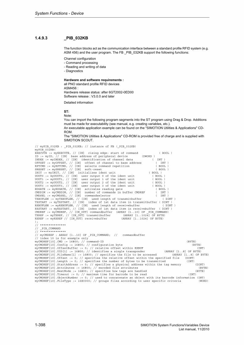
System Functions - Device
1-398 SIMOTION System Functions/Variables DeviceList manual, 11/2010
1.4.9.3 _PIB_032KB
The function blocks act as the communication interface between a standard profile RFID system (e.g. ASM 456) and the user program. The FB _PIB_032KB support the following functions:
Channel configuration- Command processing- Reading and writing of data- Diagnostics
Hardware and software requirements :all PNO standard profile RFID devicesASM456 :Hardware release status: after 6GT2002-0ED00Software release : V3.0.0 and later
Detailed information
ST: Note:You can import the following program segments into the ST program using Drag & Drop. Additions must be made for executability (see manual, e.g. creating variables, etc.).An executable application example can be found on the "SIMOTION Utilities & Applications" CD-ROM.The "SIMOTION Utilities & Applications" CD-ROM is provided free of charge and is supplied with SIMOTION SCOUT.
// myPIB_032KB : _PIB_032KB; // instance of FB (_PIB_032KB)myPIB_032KB(EXECUTE := myEXECUTE, // [IN] rising edge: start of command ( BOOL )ID := myID, // [IN] base address of peripheral device (DWORD )INDEX := myINDEX, // [IN] identification of channel data ( INT )OFFSET := myOFFSET, // [IN] offset of channel to base address ( INT )RPTCMD := myRPTCMD, // [IN] selects command repetition ( BOOL )SRESET := mySRESET, // [IN] soft-reset ( BOOL )INIT := myINIT, // [IN] initializes ident unit ( BOOL )UOUT0 := myUOUT0, // [IN] user output 0 of the ident unit ( BOOL )UOUT1 := myUOUT1, // [IN] user output 1 of the ident unit ( BOOL )UOUT2 := myUOUT2, // [IN] user output 2 of the ident unit ( BOOL )UOUT3 := myUOUT3, // [IN] user output 3 of the ident unit ( BOOL )RDGATE := myRDGATE, // [IN] activates reading gate ( BOOL )CMDDIM := myCMDDIM, // [IN] number of commands in buffer CMDREF ( INT )CMDSEL := myCMDSEL, // [IN] commandselector ( INT )TXBUFLEN := myTXBUFLEN, // [IN] used length of transmitbuffer ( DINT )TXSTART := myTXSTART, // [IN] index of 1st data item in transmitbuffer ( DINT )RXBUFLEN := myRXBUFLEN, // [IN] used length of receivebuffer ( DINT )RXSTART := myRXSTART, // [IN] index of 1st data item in receivebuffer ( DINT )CMDREF := myCMDREF, // [IN_OUT] commandbuffer (ARRAY [1..10] OF _PIB_COMMAND)TXREF := myTXREF, // [IN_OUT] transmitbuffer (ARRAY [1..1024] OF BYTE)RXREF := myRXREF // [IN_OUT] receivebuffer (ARRAY [1..1024] OF BYTE));// ***************// _PIB_COMMAND// ***************// myCMDREF : ARRAY [1..10] OF _PIB_COMMAND; // commandbuffer// index 10 is for example onlymyCMDREF[10].CMD := 16#00; // command-ID (BYTE)myCMDREF[10].Config := 16#00; // configuration byte (BYTE)myCMDREF[10].OffsetBuffer := 0; // relative offset within RXBUF (INT)myCMDREF[10].UID[1] := 16#00; // identifies a single transponder (ARRAY [1..8] OF BYTE)myCMDREF[10].FileName[1] := 16#00; // specifies the file to be accessed (ARRAY [1..8] OF BYTE)myCMDREF[10].Offset := 0; // specifies the relative offset within the specified file (DINT)myCMDREF[10].Length := 0; // specifies the number of bytes to be transmitted (INT)myCMDREF[10].StartAddress := 0; // specifies a physical address within the tag memory (DINT)myCMDREF[10].Attributes := 16#00; // encoded file attributes (BYTE)myCMDREF[10].NextMode := 16#00; // specifies how tags are handled (BYTE)myCMDREF[10].Timeout := 0; // maximum time for barcode to be read (INT)myCMDREF[10].ObjectNumber := 0; // used to concatenate an object with its barcode information (INT)myCMDREF[10].FileType := 16#0000; // groups files according to user specific criteria (WORD)
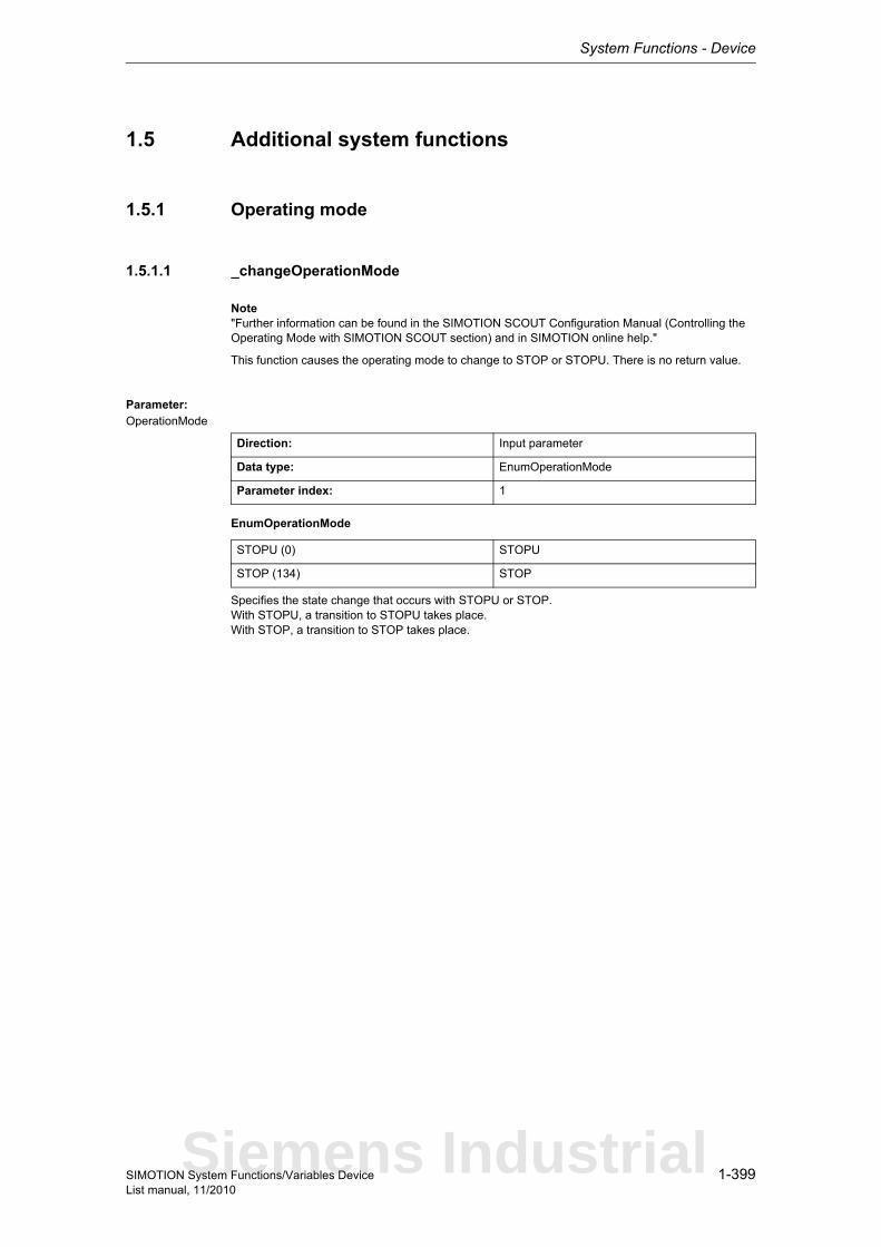
System Functions - Device
1-399SIMOTION System Functions/Variables DeviceList manual, 11/2010
1.5 Additional system functions
1.5.1 Operating mode
1.5.1.1 _changeOperationMode
Note"Further information can be found in the SIMOTION SCOUT Configuration Manual (Controlling the Operating Mode with SIMOTION SCOUT section) and in SIMOTION online help."
This function causes the operating mode to change to STOP or STOPU. There is no return value.
Parameter: OperationMode
EnumOperationMode
Specifies the state change that occurs with STOPU or STOP.With STOPU, a transition to STOPU takes place.With STOP, a transition to STOP takes place.
Direction: Input parameter
Data type: EnumOperationMode
Parameter index: 1
STOPU (0) STOPU
STOP (134) STOP
Siemens Industrial
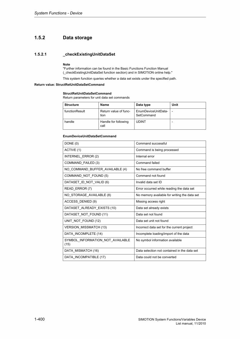
System Functions - Device
1-400 SIMOTION System Functions/Variables DeviceList manual, 11/2010
1.5.2 Data storage
1.5.2.1 _checkExistingUnitDataSet
Note"Further information can be found in the Basic Functions Function Manual (_checkExistingUnitDataSet function section) and in SIMOTION online help."
This system function queries whether a data set exists under the specified path.
Return value: StructRetUnitDataSetCommand
StructRetUnitDataSetCommandReturn parameters for unit data set commands
EnumDeviceUnitDataSetCommand
Structure Name Data type Unit
functionResult Return value of func-tion
EnumDeviceUnitData-SetCommand
-
handle Handle for following call
UDINT -
DONE (0) Command successful
ACTIVE (1) Command is being processed
INTERNEL_ERROR (2) Internal error
COMMAND_FAILED (3) Command failed
NO_COMMAND_BUFFER_AVAILABLE (4) No free command buffer
COMMAND_NOT_FOUND (5) Command not found
DATASET_ID_NOT_VALID (6) Invalid data set ID
READ_ERROR (7) Error occurred while reading the data set
NO_STORAGE_AVAILABLE (8) No memory available for writing the data set
ACCESS_DENIED (9) Missing access right
DATASET_ALREADY_EXISTS (10) Data set already exists
DATASET_NOT_FOUND (11) Data set not found
UNIT_NOT_FOUND (12) Data set unit not found
VERSION_MISSMATCH (13) Incorrect data set for the current project
DATA_INCOMPLETE (14) Incomplete loading/import of the data
SYMBOL_INFORMATION_NOT_AVAILABLE (15)
No symbol information available
DATA_MISMATCH (16) Data selection not contained in the data set
DATA_INCOMPATIBLE (17) Data could not be converted
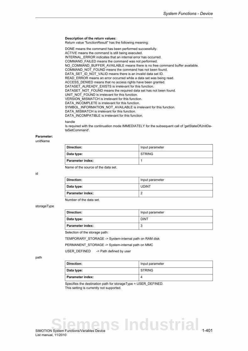
System Functions - Device
1-401SIMOTION System Functions/Variables DeviceList manual, 11/2010
Description of the return values:Return value "functionResult" has the following meaning:
DONE means the command has been performed successfully.ACTIVE means the command is still being executed.INTERNAL_ERROR indicates that an internal error has occurred.COMMAND_FAILED means the command was not performed.NO_COMMAND_BUFFER_AVAILABLE means there is no free command buffer available.COMMAND_NOT_FOUND means the command has not been found.DATA_SET_ID_NOT_VALID means there is an invalid data set ID.READ_ERROR means an error occurred while a data set was being read.ACCESS_DENIED means that no access rights have been granted.DATASET_ALREADY_EXISTS is irrelevant for this function.DATASET_NOT_FOUND means the required data set has not been found.UNIT_NOT_FOUND is irrelevant for this function.VERSION_MISMATCH is irrelevant for this function.DATA_INCOMPLETE is irrelevant for this function.SYMBOL_INFORMATION_NOT_AVAILABLE is irrelevant for this function.DATA_MISMATCH is irrelevant for this function.DATA_INCOMPATIBLE is irrelevant for this function.
handleIs required with the continuation mode IMMEDIATELY for the subsequent call of 'getStateOfUnitDa-taSetCommand'.
Parameter: unitName
Name of the source of the data set.
id
Number of the data set.
storageType
Selection of the storage path:
TEMPORARY_STORAGE -> System-internal path on RAM disk
PERMANENT_STORAGE -> System-internal path on MMC
USER_DEFINED -> Path defined by user
path
Specifies the destination path for storageType = USER_DEFINED.This setting is currently not supported.
Direction: Input parameter
Data type: STRING
Parameter index: 1
Direction: Input parameter
Data type: UDINT
Parameter index: 2
Direction: Input parameter
Data type: DINT
Parameter index: 3
Direction: Input parameter
Data type: STRING
Parameter index: 4
Siemens Industrial

System Functions - Device
1-402 SIMOTION System Functions/Variables DeviceList manual, 11/2010
nextCommand
Continuation mode:
IMMEDIATELY -> Start command only, scan result later.
WHEN_COMMAND_DONE -> Wait for end of command.
Direction: Input parameter
Data type: DINT
Parameter index: 5
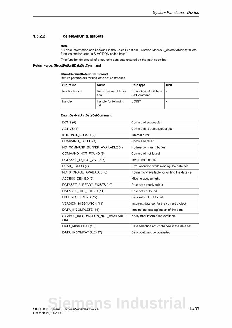
System Functions - Device
1-403SIMOTION System Functions/Variables DeviceList manual, 11/2010
1.5.2.2 _deleteAllUnitDataSets
Note"Further information can be found in the Basic Functions Function Manual (_deleteAllUnitDataSets function section) and in SIMOTION online help."
This function deletes all of a source's data sets entered on the path specified.
Return value: StructRetUnitDataSetCommand
StructRetUnitDataSetCommandReturn parameters for unit data set commands
EnumDeviceUnitDataSetCommand
Structure Name Data type Unit
functionResult Return value of func-tion
EnumDeviceUnitData-SetCommand
-
handle Handle for following call
UDINT -
DONE (0) Command successful
ACTIVE (1) Command is being processed
INTERNEL_ERROR (2) Internal error
COMMAND_FAILED (3) Command failed
NO_COMMAND_BUFFER_AVAILABLE (4) No free command buffer
COMMAND_NOT_FOUND (5) Command not found
DATASET_ID_NOT_VALID (6) Invalid data set ID
READ_ERROR (7) Error occurred while reading the data set
NO_STORAGE_AVAILABLE (8) No memory available for writing the data set
ACCESS_DENIED (9) Missing access right
DATASET_ALREADY_EXISTS (10) Data set already exists
DATASET_NOT_FOUND (11) Data set not found
UNIT_NOT_FOUND (12) Data set unit not found
VERSION_MISSMATCH (13) Incorrect data set for the current project
DATA_INCOMPLETE (14) Incomplete loading/import of the data
SYMBOL_INFORMATION_NOT_AVAILABLE (15)
No symbol information available
DATA_MISMATCH (16) Data selection not contained in the data set
DATA_INCOMPATIBLE (17) Data could not be converted
Siemens Industrial
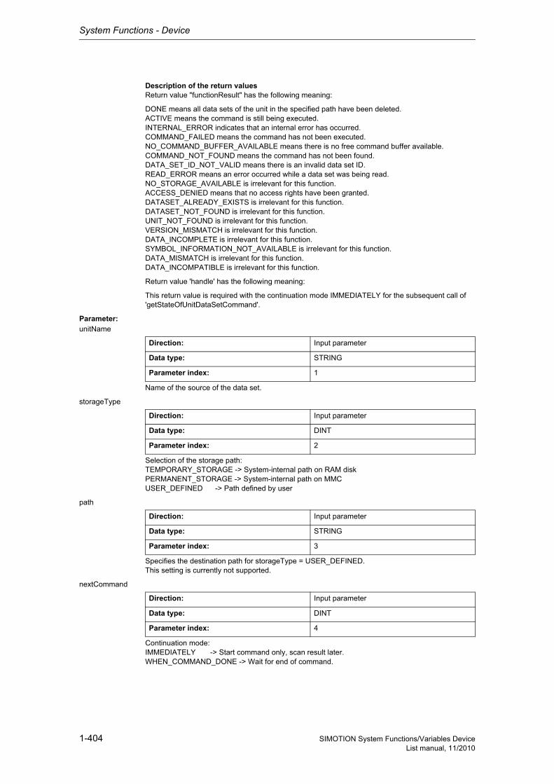
System Functions - Device
1-404 SIMOTION System Functions/Variables DeviceList manual, 11/2010
Description of the return valuesReturn value "functionResult" has the following meaning:
DONE means all data sets of the unit in the specified path have been deleted.ACTIVE means the command is still being executed.INTERNAL_ERROR indicates that an internal error has occurred.COMMAND_FAILED means the command has not been executed.NO_COMMAND_BUFFER_AVAILABLE means there is no free command buffer available.COMMAND_NOT_FOUND means the command has not been found.DATA_SET_ID_NOT_VALID means there is an invalid data set ID.READ_ERROR means an error occurred while a data set was being read.NO_STORAGE_AVAILABLE is irrelevant for this function.ACCESS_DENIED means that no access rights have been granted.DATASET_ALREADY_EXISTS is irrelevant for this function.DATASET_NOT_FOUND is irrelevant for this function.UNIT_NOT_FOUND is irrelevant for this function.VERSION_MISMATCH is irrelevant for this function.DATA_INCOMPLETE is irrelevant for this function.SYMBOL_INFORMATION_NOT_AVAILABLE is irrelevant for this function.DATA_MISMATCH is irrelevant for this function.DATA_INCOMPATIBLE is irrelevant for this function.
Return value 'handle' has the following meaning:
This return value is required with the continuation mode IMMEDIATELY for the subsequent call of 'getStateOfUnitDataSetCommand'.
Parameter: unitName
Name of the source of the data set.
storageType
Selection of the storage path:TEMPORARY_STORAGE -> System-internal path on RAM diskPERMANENT_STORAGE -> System-internal path on MMCUSER_DEFINED -> Path defined by user
path
Specifies the destination path for storageType = USER_DEFINED.This setting is currently not supported.
nextCommand
Continuation mode:IMMEDIATELY -> Start command only, scan result later.WHEN_COMMAND_DONE -> Wait for end of command.
Direction: Input parameter
Data type: STRING
Parameter index: 1
Direction: Input parameter
Data type: DINT
Parameter index: 2
Direction: Input parameter
Data type: STRING
Parameter index: 3
Direction: Input parameter
Data type: DINT
Parameter index: 4

System Functions - Device
1-405SIMOTION System Functions/Variables DeviceList manual, 11/2010
1.5.2.3 _deleteUnitDataSet
Note"Further information can be found in the Basic Functions Function Manual (_deleteUnitDataSet func-tion section) and in SIMOTION online help."
This system function deletes a specific data set from the specified path.
Return value: StructRetUnitDataSetCommand
StructRetUnitDataSetCommandReturn parameters for unit data set commands
EnumDeviceUnitDataSetCommand
Structure Name Data type Unit
functionResult Return value of func-tion
EnumDeviceUnitData-SetCommand
-
handle Handle for following call
UDINT -
DONE (0) Command successful
ACTIVE (1) Command is being processed
INTERNEL_ERROR (2) Internal error
COMMAND_FAILED (3) Command failed
NO_COMMAND_BUFFER_AVAILABLE (4) No free command buffer
COMMAND_NOT_FOUND (5) Command not found
DATASET_ID_NOT_VALID (6) Invalid data set ID
READ_ERROR (7) Error occurred while reading the data set
NO_STORAGE_AVAILABLE (8) No memory available for writing the data set
ACCESS_DENIED (9) Missing access right
DATASET_ALREADY_EXISTS (10) Data set already exists
DATASET_NOT_FOUND (11) Data set not found
UNIT_NOT_FOUND (12) Data set unit not found
VERSION_MISSMATCH (13) Incorrect data set for the current project
DATA_INCOMPLETE (14) Incomplete loading/import of the data
SYMBOL_INFORMATION_NOT_AVAILABLE (15)
No symbol information available
DATA_MISMATCH (16) Data selection not contained in the data set
DATA_INCOMPATIBLE (17) Data could not be converted
Siemens Industrial
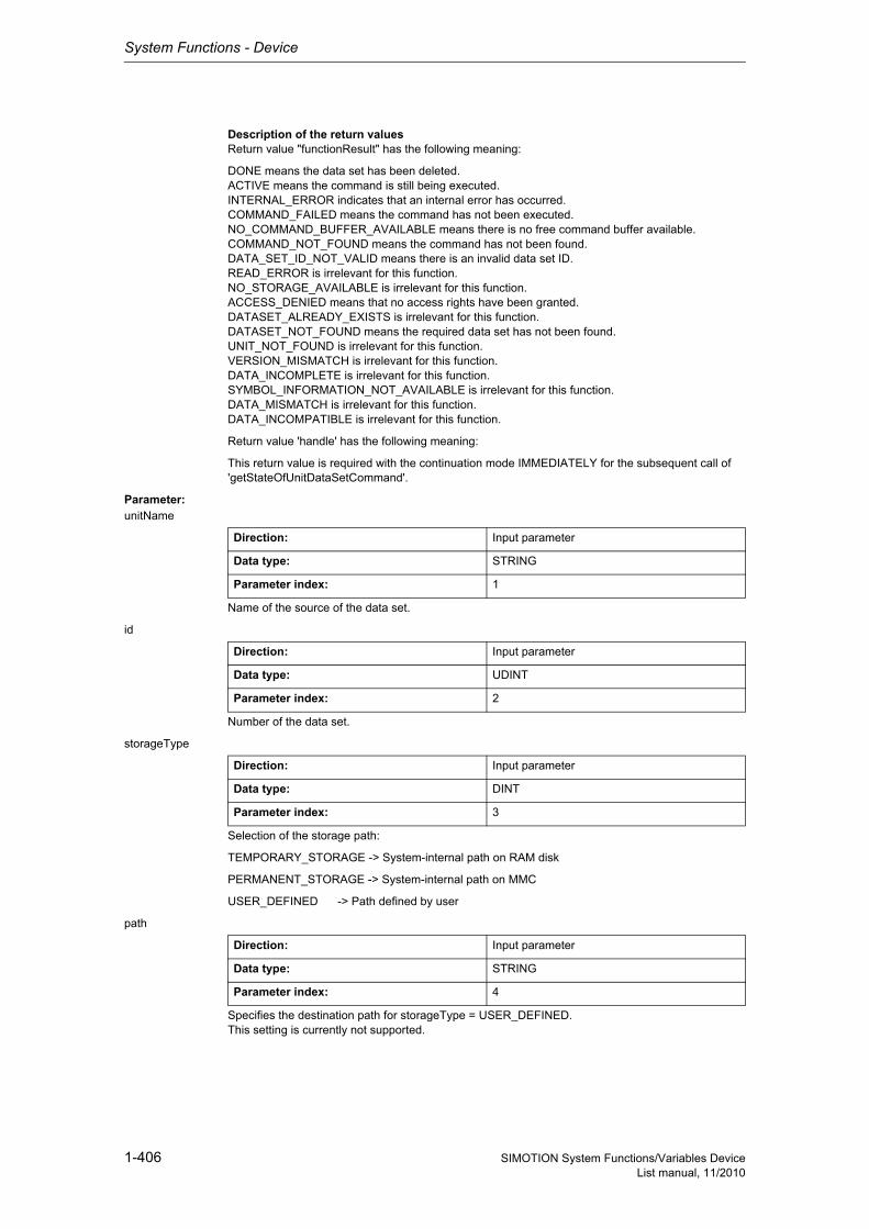
System Functions - Device
1-406 SIMOTION System Functions/Variables DeviceList manual, 11/2010
Description of the return valuesReturn value "functionResult" has the following meaning:
DONE means the data set has been deleted.ACTIVE means the command is still being executed.INTERNAL_ERROR indicates that an internal error has occurred.COMMAND_FAILED means the command has not been executed.NO_COMMAND_BUFFER_AVAILABLE means there is no free command buffer available.COMMAND_NOT_FOUND means the command has not been found.DATA_SET_ID_NOT_VALID means there is an invalid data set ID.READ_ERROR is irrelevant for this function.NO_STORAGE_AVAILABLE is irrelevant for this function.ACCESS_DENIED means that no access rights have been granted.DATASET_ALREADY_EXISTS is irrelevant for this function.DATASET_NOT_FOUND means the required data set has not been found.UNIT_NOT_FOUND is irrelevant for this function.VERSION_MISMATCH is irrelevant for this function.DATA_INCOMPLETE is irrelevant for this function.SYMBOL_INFORMATION_NOT_AVAILABLE is irrelevant for this function.DATA_MISMATCH is irrelevant for this function.DATA_INCOMPATIBLE is irrelevant for this function.
Return value 'handle' has the following meaning:
This return value is required with the continuation mode IMMEDIATELY for the subsequent call of 'getStateOfUnitDataSetCommand'.
Parameter: unitName
Name of the source of the data set.
id
Number of the data set.
storageType
Selection of the storage path:
TEMPORARY_STORAGE -> System-internal path on RAM disk
PERMANENT_STORAGE -> System-internal path on MMC
USER_DEFINED -> Path defined by user
path
Specifies the destination path for storageType = USER_DEFINED.This setting is currently not supported.
Direction: Input parameter
Data type: STRING
Parameter index: 1
Direction: Input parameter
Data type: UDINT
Parameter index: 2
Direction: Input parameter
Data type: DINT
Parameter index: 3
Direction: Input parameter
Data type: STRING
Parameter index: 4

System Functions - Device
1-407SIMOTION System Functions/Variables DeviceList manual, 11/2010
nextCommand
Continuation mode:
IMMEDIATELY -> Start command only, scan result later.
WHEN_COMMAND_DONE -> Wait for end of command.
Direction: Input parameter
Data type: DINT
Parameter index: 5
Siemens Industrial
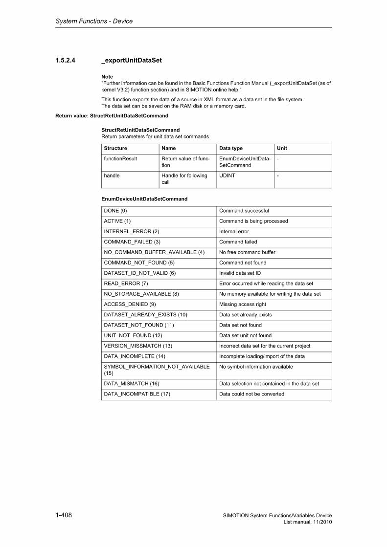
System Functions - Device
1-408 SIMOTION System Functions/Variables DeviceList manual, 11/2010
1.5.2.4 _exportUnitDataSet
Note"Further information can be found in the Basic Functions Function Manual (_exportUnitDataSet (as of kernel V3.2) function section) and in SIMOTION online help."
This function exports the data of a source in XML format as a data set in the file system.The data set can be saved on the RAM disk or a memory card.
Return value: StructRetUnitDataSetCommand
StructRetUnitDataSetCommandReturn parameters for unit data set commands
EnumDeviceUnitDataSetCommand
Structure Name Data type Unit
functionResult Return value of func-tion
EnumDeviceUnitData-SetCommand
-
handle Handle for following call
UDINT -
DONE (0) Command successful
ACTIVE (1) Command is being processed
INTERNEL_ERROR (2) Internal error
COMMAND_FAILED (3) Command failed
NO_COMMAND_BUFFER_AVAILABLE (4) No free command buffer
COMMAND_NOT_FOUND (5) Command not found
DATASET_ID_NOT_VALID (6) Invalid data set ID
READ_ERROR (7) Error occurred while reading the data set
NO_STORAGE_AVAILABLE (8) No memory available for writing the data set
ACCESS_DENIED (9) Missing access right
DATASET_ALREADY_EXISTS (10) Data set already exists
DATASET_NOT_FOUND (11) Data set not found
UNIT_NOT_FOUND (12) Data set unit not found
VERSION_MISSMATCH (13) Incorrect data set for the current project
DATA_INCOMPLETE (14) Incomplete loading/import of the data
SYMBOL_INFORMATION_NOT_AVAILABLE (15)
No symbol information available
DATA_MISMATCH (16) Data selection not contained in the data set
DATA_INCOMPATIBLE (17) Data could not be converted
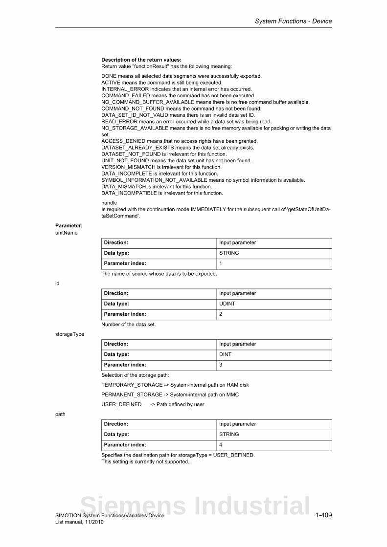
System Functions - Device
1-409SIMOTION System Functions/Variables DeviceList manual, 11/2010
Description of the return values:Return value "functionResult" has the following meaning:
DONE means all selected data segments were successfully exported.ACTIVE means the command is still being executed.INTERNAL_ERROR indicates that an internal error has occurred.COMMAND_FAILED means the command has not been executed.NO_COMMAND_BUFFER_AVAILABLE means there is no free command buffer available.COMMAND_NOT_FOUND means the command has not been found.DATA_SET_ID_NOT_VALID means there is an invalid data set ID.READ_ERROR means an error occurred while a data set was being read.NO_STORAGE_AVAILABLE means there is no free memory available for packing or writing the data set.ACCESS_DENIED means that no access rights have been granted.DATASET_ALREADY_EXISTS means the data set already exists.DATASET_NOT_FOUND is irrelevant for this function.UNIT_NOT_FOUND means the data set unit has not been found.VERSION_MISMATCH is irrelevant for this function.DATA_INCOMPLETE is irrelevant for this function.SYMBOL_INFORMATION_NOT_AVAILABLE means no symbol information is available.DATA_MISMATCH is irrelevant for this function.DATA_INCOMPATIBLE is irrelevant for this function.
handleIs required with the continuation mode IMMEDIATELY for the subsequent call of 'getStateOfUnitDa-taSetCommand'.
Parameter: unitName
The name of source whose data is to be exported.
id
Number of the data set.
storageType
Selection of the storage path:
TEMPORARY_STORAGE -> System-internal path on RAM disk
PERMANENT_STORAGE -> System-internal path on MMC
USER_DEFINED -> Path defined by user
path
Specifies the destination path for storageType = USER_DEFINED.This setting is currently not supported.
Direction: Input parameter
Data type: STRING
Parameter index: 1
Direction: Input parameter
Data type: UDINT
Parameter index: 2
Direction: Input parameter
Data type: DINT
Parameter index: 3
Direction: Input parameter
Data type: STRING
Parameter index: 4
Siemens Industrial
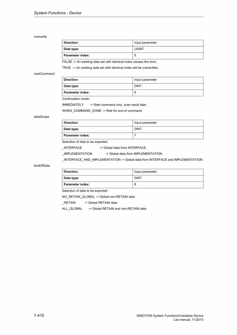
System Functions - Device
1-410 SIMOTION System Functions/Variables DeviceList manual, 11/2010
overwrite
FALSE -> An existing data set with identical index causes the error.
TRUE -> An existing data set with identical index will be overwritten.
nextCommand
Continuation mode:
IMMEDIATELY -> Start command only, scan result later.
WHEN_COMMAND_DONE -> Wait for end of command.
dataScope
Selection of data to be exported:
_INTERFACE -> Global data from INTERFACE.
_IMPLEMENTATION -> Global data from IMPLEMENTATION.
_INTERFACE_AND_IMPLEMENTATION -> Global data from INTERFACE and IMPLEMENTATION.
kindOfData
Selection of data to be exported:
NO_RETAIN_GLOBAL -> Global non-RETAIN data
_RETAIN -> Global RETAIN data
ALL_GLOBAL -> Global RETAIN and non-RETAIN data
Direction: Input parameter
Data type: USINT
Parameter index: 5
Direction: Input parameter
Data type: DINT
Parameter index: 6
Direction: Input parameter
Data type: DINT
Parameter index: 7
Direction: Input parameter
Data type: DINT
Parameter index: 8
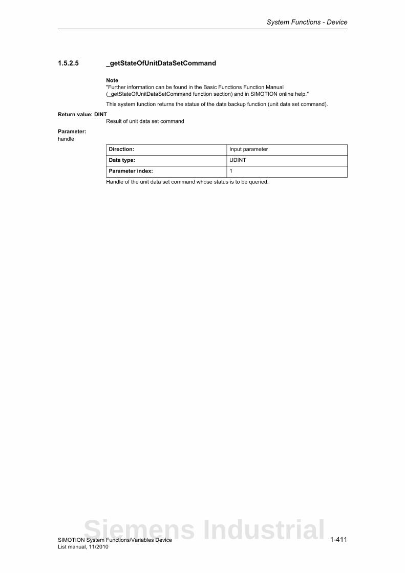
System Functions - Device
1-411SIMOTION System Functions/Variables DeviceList manual, 11/2010
1.5.2.5 _getStateOfUnitDataSetCommand
Note"Further information can be found in the Basic Functions Function Manual (_getStateOfUnitDataSetCommand function section) and in SIMOTION online help."
This system function returns the status of the data backup function (unit data set command).
Return value: DINTResult of unit data set command
Parameter: handle
Handle of the unit data set command whose status is to be queried.
Direction: Input parameter
Data type: UDINT
Parameter index: 1
Siemens Industrial
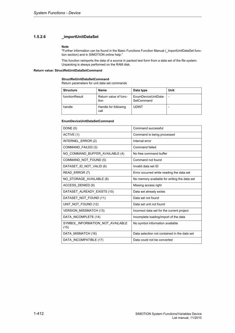
System Functions - Device
1-412 SIMOTION System Functions/Variables DeviceList manual, 11/2010
1.5.2.6 _importUnitDataSet
Note"Further information can be found in the Basic Functions Function Manual (_importUnitDataSet func-tion section) and in SIMOTION online help."
This function reimports the data of a source in packed text form from a data set of the file system.Unpacking is always performed on the RAM disk.
Return value: StructRetUnitDataSetCommand
StructRetUnitDataSetCommandReturn parameters for unit data set commands
EnumDeviceUnitDataSetCommand
Structure Name Data type Unit
functionResult Return value of func-tion
EnumDeviceUnitData-SetCommand
-
handle Handle for following call
UDINT -
DONE (0) Command successful
ACTIVE (1) Command is being processed
INTERNEL_ERROR (2) Internal error
COMMAND_FAILED (3) Command failed
NO_COMMAND_BUFFER_AVAILABLE (4) No free command buffer
COMMAND_NOT_FOUND (5) Command not found
DATASET_ID_NOT_VALID (6) Invalid data set ID
READ_ERROR (7) Error occurred while reading the data set
NO_STORAGE_AVAILABLE (8) No memory available for writing the data set
ACCESS_DENIED (9) Missing access right
DATASET_ALREADY_EXISTS (10) Data set already exists
DATASET_NOT_FOUND (11) Data set not found
UNIT_NOT_FOUND (12) Data set unit not found
VERSION_MISSMATCH (13) Incorrect data set for the current project
DATA_INCOMPLETE (14) Incomplete loading/import of the data
SYMBOL_INFORMATION_NOT_AVAILABLE (15)
No symbol information available
DATA_MISMATCH (16) Data selection not contained in the data set
DATA_INCOMPATIBLE (17) Data could not be converted
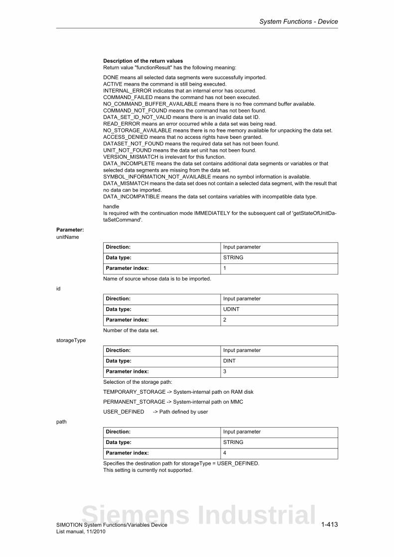
System Functions - Device
1-413SIMOTION System Functions/Variables DeviceList manual, 11/2010
Description of the return valuesReturn value "functionResult" has the following meaning:
DONE means all selected data segments were successfully imported.ACTIVE means the command is still being executed.INTERNAL_ERROR indicates that an internal error has occurred.COMMAND_FAILED means the command has not been executed.NO_COMMAND_BUFFER_AVAILABLE means there is no free command buffer available.COMMAND_NOT_FOUND means the command has not been found.DATA_SET_ID_NOT_VALID means there is an invalid data set ID.READ_ERROR means an error occurred while a data set was being read.NO_STORAGE_AVAILABLE means there is no free memory available for unpacking the data set.ACCESS_DENIED means that no access rights have been granted.DATASET_NOT_FOUND means the required data set has not been found.UNIT_NOT_FOUND means the data set unit has not been found.VERSION_MISMATCH is irrelevant for this function.DATA_INCOMPLETE means the data set contains additional data segments or variables or that selected data segments are missing from the data set.SYMBOL_INFORMATION_NOT_AVAILABLE means no symbol information is available.DATA_MISMATCH means the data set does not contain a selected data segment, with the result that no data can be imported.DATA_INCOMPATIBLE means the data set contains variables with incompatible data type.
handleIs required with the continuation mode IMMEDIATELY for the subsequent call of 'getStateOfUnitDa-taSetCommand'.
Parameter: unitName
Name of source whose data is to be imported.
id
Number of the data set.
storageType
Selection of the storage path:
TEMPORARY_STORAGE -> System-internal path on RAM disk
PERMANENT_STORAGE -> System-internal path on MMC
USER_DEFINED -> Path defined by user
path
Specifies the destination path for storageType = USER_DEFINED.This setting is currently not supported.
Direction: Input parameter
Data type: STRING
Parameter index: 1
Direction: Input parameter
Data type: UDINT
Parameter index: 2
Direction: Input parameter
Data type: DINT
Parameter index: 3
Direction: Input parameter
Data type: STRING
Parameter index: 4
Siemens Industrial
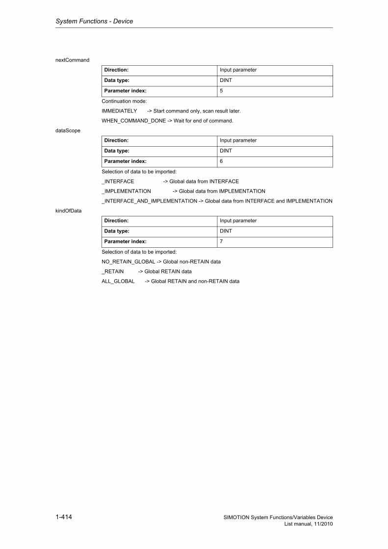
System Functions - Device
1-414 SIMOTION System Functions/Variables DeviceList manual, 11/2010
nextCommand
Continuation mode:
IMMEDIATELY -> Start command only, scan result later.
WHEN_COMMAND_DONE -> Wait for end of command.
dataScope
Selection of data to be imported:
_INTERFACE -> Global data from INTERFACE
_IMPLEMENTATION -> Global data from IMPLEMENTATION
_INTERFACE_AND_IMPLEMENTATION -> Global data from INTERFACE and IMPLEMENTATION
kindOfData
Selection of data to be imported:
NO_RETAIN_GLOBAL -> Global non-RETAIN data
_RETAIN -> Global RETAIN data
ALL_GLOBAL -> Global RETAIN and non-RETAIN data
Direction: Input parameter
Data type: DINT
Parameter index: 5
Direction: Input parameter
Data type: DINT
Parameter index: 6
Direction: Input parameter
Data type: DINT
Parameter index: 7
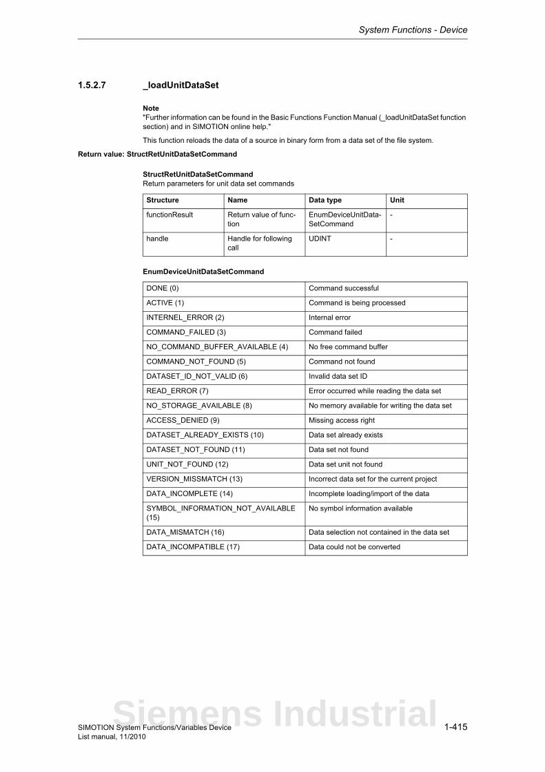
System Functions - Device
1-415SIMOTION System Functions/Variables DeviceList manual, 11/2010
1.5.2.7 _loadUnitDataSet
Note"Further information can be found in the Basic Functions Function Manual (_loadUnitDataSet function section) and in SIMOTION online help."
This function reloads the data of a source in binary form from a data set of the file system.
Return value: StructRetUnitDataSetCommand
StructRetUnitDataSetCommandReturn parameters for unit data set commands
EnumDeviceUnitDataSetCommand
Structure Name Data type Unit
functionResult Return value of func-tion
EnumDeviceUnitData-SetCommand
-
handle Handle for following call
UDINT -
DONE (0) Command successful
ACTIVE (1) Command is being processed
INTERNEL_ERROR (2) Internal error
COMMAND_FAILED (3) Command failed
NO_COMMAND_BUFFER_AVAILABLE (4) No free command buffer
COMMAND_NOT_FOUND (5) Command not found
DATASET_ID_NOT_VALID (6) Invalid data set ID
READ_ERROR (7) Error occurred while reading the data set
NO_STORAGE_AVAILABLE (8) No memory available for writing the data set
ACCESS_DENIED (9) Missing access right
DATASET_ALREADY_EXISTS (10) Data set already exists
DATASET_NOT_FOUND (11) Data set not found
UNIT_NOT_FOUND (12) Data set unit not found
VERSION_MISSMATCH (13) Incorrect data set for the current project
DATA_INCOMPLETE (14) Incomplete loading/import of the data
SYMBOL_INFORMATION_NOT_AVAILABLE (15)
No symbol information available
DATA_MISMATCH (16) Data selection not contained in the data set
DATA_INCOMPATIBLE (17) Data could not be converted
Siemens Industrial
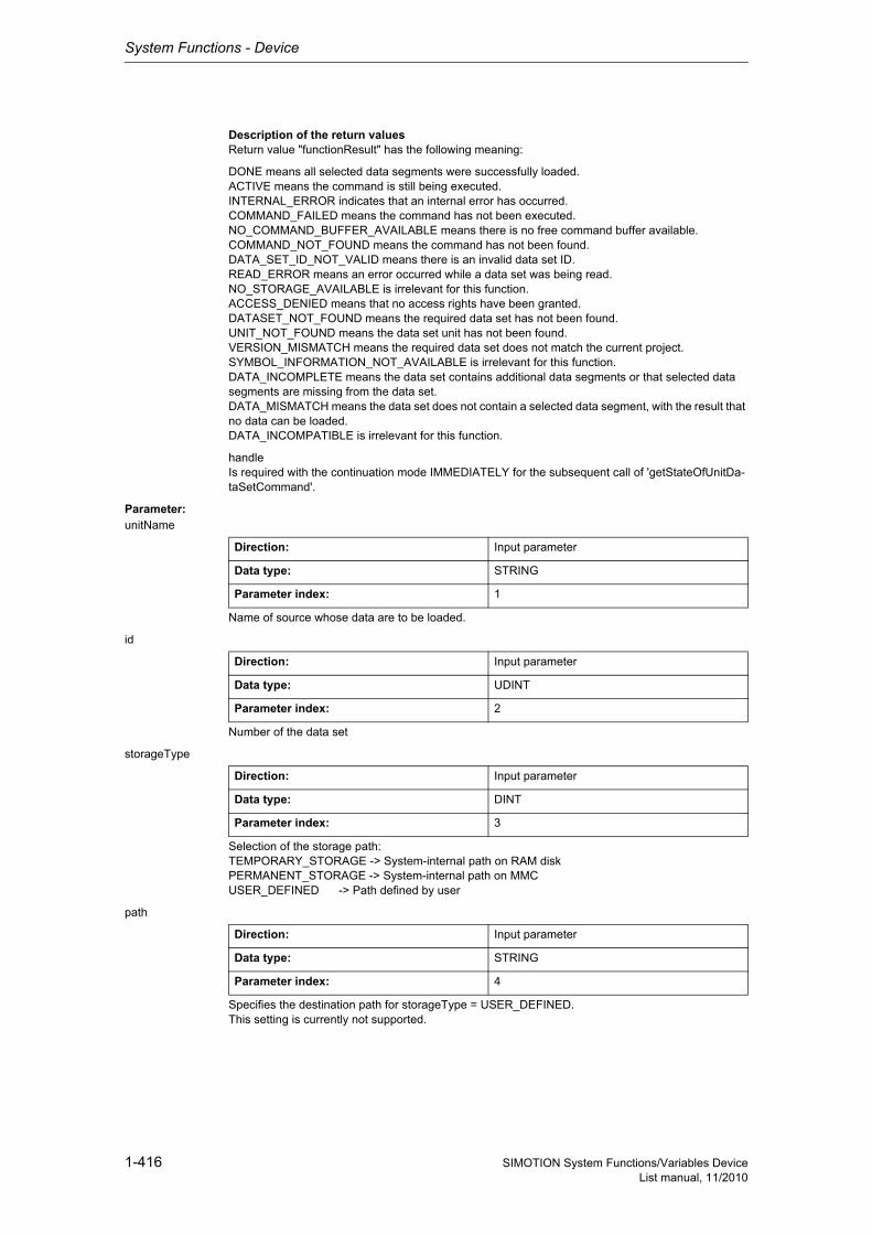
System Functions - Device
1-416 SIMOTION System Functions/Variables DeviceList manual, 11/2010
Description of the return valuesReturn value "functionResult" has the following meaning:
DONE means all selected data segments were successfully loaded.ACTIVE means the command is still being executed.INTERNAL_ERROR indicates that an internal error has occurred.COMMAND_FAILED means the command has not been executed.NO_COMMAND_BUFFER_AVAILABLE means there is no free command buffer available.COMMAND_NOT_FOUND means the command has not been found.DATA_SET_ID_NOT_VALID means there is an invalid data set ID.READ_ERROR means an error occurred while a data set was being read.NO_STORAGE_AVAILABLE is irrelevant for this function.ACCESS_DENIED means that no access rights have been granted.DATASET_NOT_FOUND means the required data set has not been found.UNIT_NOT_FOUND means the data set unit has not been found.VERSION_MISMATCH means the required data set does not match the current project.SYMBOL_INFORMATION_NOT_AVAILABLE is irrelevant for this function.DATA_INCOMPLETE means the data set contains additional data segments or that selected data segments are missing from the data set.DATA_MISMATCH means the data set does not contain a selected data segment, with the result that no data can be loaded.DATA_INCOMPATIBLE is irrelevant for this function.
handleIs required with the continuation mode IMMEDIATELY for the subsequent call of 'getStateOfUnitDa-taSetCommand'.
Parameter: unitName
Name of source whose data are to be loaded.
id
Number of the data set
storageType
Selection of the storage path:TEMPORARY_STORAGE -> System-internal path on RAM diskPERMANENT_STORAGE -> System-internal path on MMCUSER_DEFINED -> Path defined by user
path
Specifies the destination path for storageType = USER_DEFINED.This setting is currently not supported.
Direction: Input parameter
Data type: STRING
Parameter index: 1
Direction: Input parameter
Data type: UDINT
Parameter index: 2
Direction: Input parameter
Data type: DINT
Parameter index: 3
Direction: Input parameter
Data type: STRING
Parameter index: 4
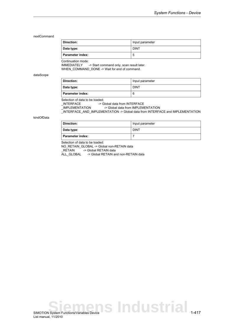
System Functions - Device
1-417SIMOTION System Functions/Variables DeviceList manual, 11/2010
nextCommand
Continuation mode:IMMEDIATELY -> Start command only, scan result later.WHEN_COMMAND_DONE -> Wait for end of command.
dataScope
Selection of data to be loaded:_INTERFACE -> Global data from INTERFACE_IMPLEMENTATION -> Global data from IMPLEMENTATION_INTERFACE_AND_IMPLEMENTATION -> Global data from INTERFACE and IMPLEMENTATION
kindOfData
Selection of data to be loaded:NO_RETAIN_GLOBAL -> Global non-RETAIN data_RETAIN -> Global RETAIN dataALL_GLOBAL -> Global RETAIN and non-RETAIN data
Direction: Input parameter
Data type: DINT
Parameter index: 5
Direction: Input parameter
Data type: DINT
Parameter index: 6
Direction: Input parameter
Data type: DINT
Parameter index: 7
Siemens Industrial
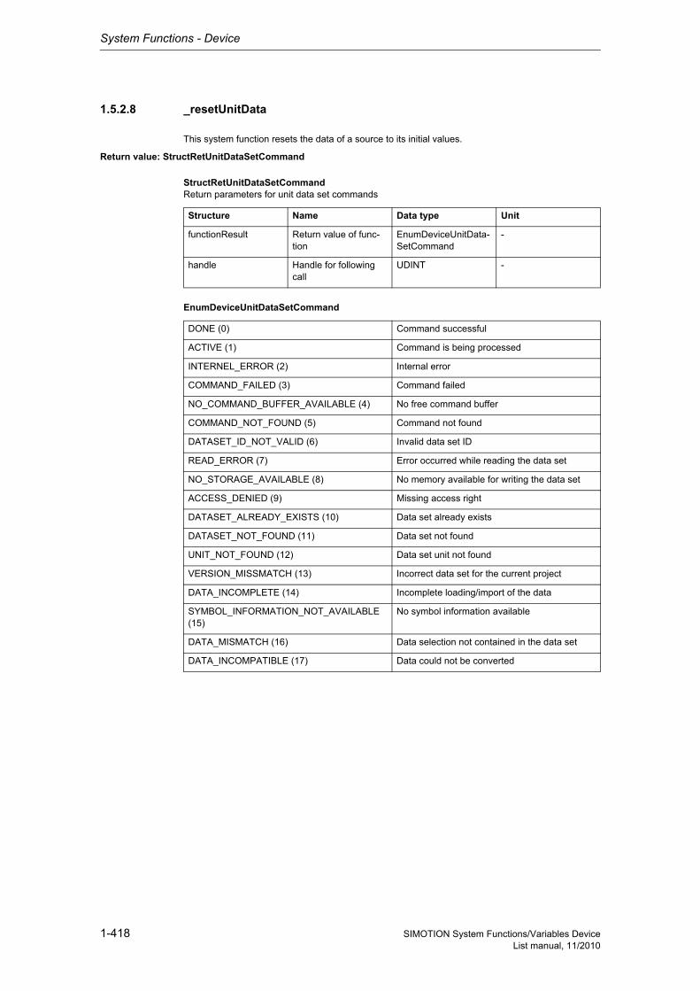
System Functions - Device
1-418 SIMOTION System Functions/Variables DeviceList manual, 11/2010
1.5.2.8 _resetUnitData
This system function resets the data of a source to its initial values.
Return value: StructRetUnitDataSetCommand
StructRetUnitDataSetCommandReturn parameters for unit data set commands
EnumDeviceUnitDataSetCommand
Structure Name Data type Unit
functionResult Return value of func-tion
EnumDeviceUnitData-SetCommand
-
handle Handle for following call
UDINT -
DONE (0) Command successful
ACTIVE (1) Command is being processed
INTERNEL_ERROR (2) Internal error
COMMAND_FAILED (3) Command failed
NO_COMMAND_BUFFER_AVAILABLE (4) No free command buffer
COMMAND_NOT_FOUND (5) Command not found
DATASET_ID_NOT_VALID (6) Invalid data set ID
READ_ERROR (7) Error occurred while reading the data set
NO_STORAGE_AVAILABLE (8) No memory available for writing the data set
ACCESS_DENIED (9) Missing access right
DATASET_ALREADY_EXISTS (10) Data set already exists
DATASET_NOT_FOUND (11) Data set not found
UNIT_NOT_FOUND (12) Data set unit not found
VERSION_MISSMATCH (13) Incorrect data set for the current project
DATA_INCOMPLETE (14) Incomplete loading/import of the data
SYMBOL_INFORMATION_NOT_AVAILABLE (15)
No symbol information available
DATA_MISMATCH (16) Data selection not contained in the data set
DATA_INCOMPATIBLE (17) Data could not be converted
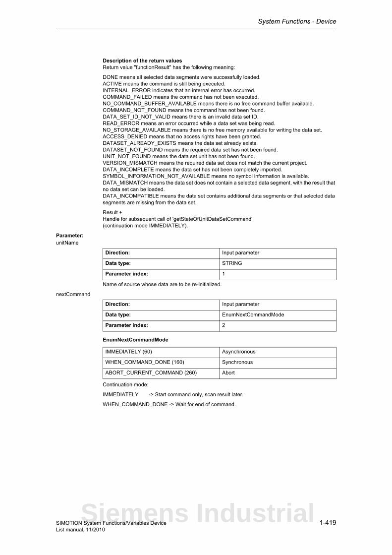
System Functions - Device
1-419SIMOTION System Functions/Variables DeviceList manual, 11/2010
Description of the return valuesReturn value "functionResult" has the following meaning:
DONE means all selected data segments were successfully loaded.ACTIVE means the command is still being executed.INTERNAL_ERROR indicates that an internal error has occurred.COMMAND_FAILED means the command has not been executed.NO_COMMAND_BUFFER_AVAILABLE means there is no free command buffer available.COMMAND_NOT_FOUND means the command has not been found.DATA_SET_ID_NOT_VALID means there is an invalid data set ID.READ_ERROR means an error occurred while a data set was being read.NO_STORAGE_AVAILABLE means there is no free memory available for writing the data set.ACCESS_DENIED means that no access rights have been granted.DATASET_ALREADY_EXISTS means the data set already exists.DATASET_NOT_FOUND means the required data set has not been found.UNIT_NOT_FOUND means the data set unit has not been found.VERSION_MISMATCH means the required data set does not match the current project.DATA_INCOMPLETE means the data set has not been completely imported.SYMBOL_INFORMATION_NOT_AVAILABLE means no symbol information is available.DATA_MISMATCH means the data set does not contain a selected data segment, with the result that no data set can be loaded.DATA_INCOMPATIBLE means the data set contains additional data segments or that selected data segments are missing from the data set.
Result +Handle for subsequent call of 'getStateOfUnitDataSetCommand'(continuation mode IMMEDIATELY).
Parameter: unitName
Name of source whose data are to be re-initialized.
nextCommand
EnumNextCommandMode
Continuation mode:
IMMEDIATELY -> Start command only, scan result later.
WHEN_COMMAND_DONE -> Wait for end of command.
Direction: Input parameter
Data type: STRING
Parameter index: 1
Direction: Input parameter
Data type: EnumNextCommandMode
Parameter index: 2
IMMEDIATELY (60) Asynchronous
WHEN_COMMAND_DONE (160) Synchronous
ABORT_CURRENT_COMMAND (260) Abort
Siemens Industrial
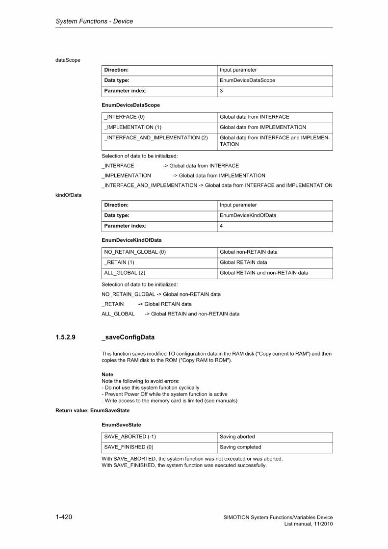
System Functions - Device
1-420 SIMOTION System Functions/Variables DeviceList manual, 11/2010
dataScope
EnumDeviceDataScope
Selection of data to be initialized:
_INTERFACE -> Global data from INTERFACE
_IMPLEMENTATION -> Global data from IMPLEMENTATION
_INTERFACE_AND_IMPLEMENTATION -> Global data from INTERFACE and IMPLEMENTATION
kindOfData
EnumDeviceKindOfData
Selection of data to be initialized:
NO_RETAIN_GLOBAL -> Global non-RETAIN data
_RETAIN -> Global RETAIN data
ALL_GLOBAL -> Global RETAIN and non-RETAIN data
1.5.2.9 _saveConfigData
This function saves modified TO configuration data in the RAM disk ("Copy current to RAM") and then copies the RAM disk to the ROM ("Copy RAM to ROM").
NoteNote the following to avoid errors:- Do not use this system function cyclically- Prevent Power Off while the system function is active- Write access to the memory card is limited (see manuals)
Return value: EnumSaveState
EnumSaveState
With SAVE_ABORTED, the system function was not executed or was aborted.With SAVE_FINISHED, the system function was executed successfully.
Direction: Input parameter
Data type: EnumDeviceDataScope
Parameter index: 3
_INTERFACE (0) Global data from INTERFACE
_IMPLEMENTATION (1) Global data from IMPLEMENTATION
_INTERFACE_AND_IMPLEMENTATION (2) Global data from INTERFACE and IMPLEMEN-TATION
Direction: Input parameter
Data type: EnumDeviceKindOfData
Parameter index: 4
NO_RETAIN_GLOBAL (0) Global non-RETAIN data
_RETAIN (1) Global RETAIN data
ALL_GLOBAL (2) Global RETAIN and non-RETAIN data
SAVE_ABORTED (-1) Saving aborted
SAVE_FINISHED (0) Saving completed
System Functions - Device
1-421SIMOTION System Functions/Variables DeviceList manual, 11/2010
1.5.2.10 _savePersistentMemoryData
Note"Further information can be found in the SIMOTION SCOUT Configuration Manual (Further Informa-tion About Saving and Restoring Variables from the Device section) and in SIMOTION online help."
The '_savePersistentMemoryData' system function is used to save the contents of non-volatile data to the memory card. This backup prevents the retain variables and the absolute encoder position from being lost if a component is replaced.
The contents are saved to the "PMEMORY.XML" file in the "USER/SIMOTION" directory.
The file contents are copied back to the SRAM when the controller ramps up if any of the following conditions have occurred:
• SRAM content lost due to a discharged battery. In this case, the entire contents of the SRAM are restored from the file.
• After an overall reset. The portions of the SRAM affected by the overall reset are restored from the file.
If consistency is required for certain applicative data, the user must ensure that this data is not chan-ged while the backup is running.A file that was saved can be deleted either using an external card reader or through the SCOUT func-tion 'Target system > Delete user data on card'.
On the system side, this system function ensures that a consistent overall image of the non-volatile data is always available the next time the unit is powered on, even if there is a power failure during backup. To this end, before a new backup file is created, any existing backup file is renamed as 'PME-MORY.BAK'. If the save operation to the new backup file fails (e.g. because the capacity of the CF card is insufficient), this backup copy of the backup file is used the next time an attempt is made to restore the contents of the non-volatile data. If the new file is successfully created, the backup copy of the backup file is deleted.
The origin of the current SRAM content can be determined from system variable "persistentDataPo-werMonitoring.persistentDataState".
Because the function is not called synchronously, it can only be used in a Motion Task.
RemarkIn earlier versions of SIMOTION, the 'PMEMORY.DAT' file was generated by calling 'savePersistent-MemoryData'.
In Version 3.2 and higher, the generated file is called 'PMEMORY.XML'.This file has a fundamentally different structure. Any existing'PMEMORY.DAT' is ignored as of V3.2.
NoticeIf you do not save the data to the CF card, it will be lost if a spare part must be used (defective module).If an absolute encoder overflow occurs after _savePersistentMemoryData, the actual position value will no longer be correct after the non-volatile data have been restored. In this case, homing (absolute encoder adjustment) must be repeated.
Return value: EnumSaveState
EnumSaveState
With SAVE_ABORTED, the system function was not executed or was aborted.With SAVE_FINISHED, the system function was executed successfully.
In addition to the _savePersistentMemoryData function, the non-volatile data can also be saved via the switch position as of V4.1 SP2 of the SIMOTION D4xx (for further information see SIMOTION D410 and SIMOTION D4x5 Commissioning Manuals).
SAVE_ABORTED (-1) Saving aborted
SAVE_FINISHED (0) Saving completed
Siemens Industrial
System Functions - Device
1-422 SIMOTION System Functions/Variables DeviceList manual, 11/2010
1.5.2.11 _saveUnitDataSet
NoteAdditional information is available at:Basic Functions Function Manual, _saveUnitDataSet function section SIMOTION SCOUT Configuration Manual, Saving and Restoring Variables from the Device sectionor in the online help
This function stores the data of a source in binary form as a data set in the file system.
Further information on the _saveUnitDataSet function and the compiler option 'Only create program instance data once' can be found in the SIMOTION Basic Function Manual and in the SIMOTION Pro-gramming and Operating Manuals.
Return value: StructRetUnitDataSetCommand
StructRetUnitDataSetCommandReturn parameters for unit data set commands
EnumDeviceUnitDataSetCommand
Structure Name Data type Unit
functionResult Return value of func-tion
EnumDeviceUnitData-SetCommand
-
handle Handle for following call
UDINT -
DONE (0) Command successful
ACTIVE (1) Command is being processed
INTERNEL_ERROR (2) Internal error
COMMAND_FAILED (3) Command failed
NO_COMMAND_BUFFER_AVAILABLE (4) No free command buffer
COMMAND_NOT_FOUND (5) Command not found
DATASET_ID_NOT_VALID (6) Invalid data set ID
READ_ERROR (7) Error occurred while reading the data set
NO_STORAGE_AVAILABLE (8) No memory available for writing the data set
ACCESS_DENIED (9) Missing access right
DATASET_ALREADY_EXISTS (10) Data set already exists
DATASET_NOT_FOUND (11) Data set not found
UNIT_NOT_FOUND (12) Data set unit not found
VERSION_MISSMATCH (13) Incorrect data set for the current project
DATA_INCOMPLETE (14) Incomplete loading/import of the data
SYMBOL_INFORMATION_NOT_AVAILABLE (15)
No symbol information available
DATA_MISMATCH (16) Data selection not contained in the data set
DATA_INCOMPATIBLE (17) Data could not be converted

System Functions - Device
1-423SIMOTION System Functions/Variables DeviceList manual, 11/2010
Description of the return valuesReturn value "functionResult" has the following meaning:
DONE means all selected data segments were successfully saved.ACTIVE means the command is still being executed.INTERNAL_ERROR indicates that an internal error has occurred.COMMAND_FAILED means the command has not been executed.NO_COMMAND_BUFFER_AVAILABLE means there is no free command buffer available.COMMAND_NOT_FOUND means the command has not been found.DATA_SET_ID_NOT_VALID means there is an invalid data set ID.READ_ERROR is irrelevant for this function.NO_STORAGE_AVAILABLE means there is no free memory available for writing the data set.ACCESS_DENIED means that no access rights have been granted.DATASET_ALREADY_EXISTS means the data set already exists.DATASET_NOT_FOUND is irrelevant for this function.UNIT_NOT_FOUND means the data set unit has not been found.VERSION_MISMATCH is irrelevant for this function.DATA_INCOMPLETE is irrelevant for this function.SYMBOL_INFORMATION_NOT_AVAILABLE is irrelevant for this function.DATA_MISMATCH is irrelevant for this function.DATA_INCOMPATIBLE is irrelevant for this function.
handleIs required with the continuation mode IMMEDIATELY for the subsequent call of 'getStateOfUnitDa-taSetCommand'.
Parameter: unitName
Name of source whose data are to be stored.
id
Number of the data set
storageType
Selection of the storage path:TEMPORARY_STORAGE -> System-internal path on RAM diskPERMANENT_STORAGE -> System-internal path on MMCUSER_DEFINED -> Path defined by user
path
Specifies the destination path for storageType = USER_DEFINED.This setting is currently not supported.
Direction: Input parameter
Data type: STRING
Parameter index: 1
Direction: Input parameter
Data type: UDINT
Parameter index: 2
Direction: Input parameter
Data type: DINT
Parameter index: 3
Direction: Input parameter
Data type: STRING
Parameter index: 4
Siemens Industrial
System Functions - Device
1-424 SIMOTION System Functions/Variables DeviceList manual, 11/2010
overwrite
FALSE -> An existing data set with identical index causes an errorTRUE -> An existing data set with identical index is overwritten
nextCommand
Continuation mode:IMMEDIATELY -> Start command only, scan result later.WHEN_COMMAND_DONE -> Wait for end of command.
dataScope
Selection of data to be stored:_INTERFACE -> Global data from INTERFACE_IMPLEMENTATION -> Global data from IMPLEMENTATION_INTERFACE_AND_IMPLEMENTATION -> Global data from INTERFACE and IMPLEMENTATION
kindOfData
Selection of data to be stored:NO_RETAIN_GLOBAL -> Global non-RETAIN data_RETAIN -> Global RETAIN dataALL_GLOBAL -> Global RETAIN and non-RETAIN data
Direction: Input parameter
Data type: USINT
Parameter index: 5
Direction: Input parameter
Data type: DINT
Parameter index: 6
Direction: Input parameter
Data type: DINT
Parameter index: 7
Direction: Input parameter
Data type: DINT
Parameter index: 8
System Functions - Device
1-425SIMOTION System Functions/Variables DeviceList manual, 11/2010
1.5.3 Modular machines
1.5.3.1 _activateConfiguration
Note"Further information can be found in the Basic Functions for Modular Machines Function Manual (Acti-vating a Configuration section, Activating a Kernel section) and in SIMOTION online help."
This system function activates the configurations specified in the parameters.
Return value: StructRetConfiguration
StructRetConfigurationStructure for the return of the system function results _activateConfiguration _setFallBackConfiturationActive _setFallBackConfigurationInactive
StructDeviceDataActivationStateActivation state of the configurations
EnumDeviceDataActivationState
Structure Name Data type Unit
result Display of the system function
UDINT -
stateActivationState Activation state StructDeviceDataActi-vationState
-
Structure Name Data type Unit
projectData Current status for pro-ject data activation
EnumDeviceDataActi-vationState
-
technologicalPackage Current status for tech-nology package acti-vation
EnumDeviceDataActi-vationState
-
driveData Current status for drive data activation
EnumDeviceDataActi-vationState
-
kernel Current status for ker-nel activation
EnumDeviceDataActi-vationState
-
NOT_ACTIVATED (0) Configuration not activated
ACTIVATED (1) The configuration is effective
NO_REQUEST_TO_ACTIVATE (2) Desired configuration is not designated as the configuration to be activated
NO_VALID_CONFIGURATION_ID (3) The configuration identification is outside of the permissible limits
CONFIGURATION_ID_NOT_FOUND (4) Configuration identification not available on memory card
NOT_ENOUGH_RAM (5) Insufficient RAM memory to take the configura-tion
RAM_DISK_FULL (6) RAM disk is full
MEMORY_CARD_FULL (7) Memory card is full
TIME_OUT (8) Monitoring time has expired
INTERNAL_ERROR (9) Internal error
Siemens Industrial
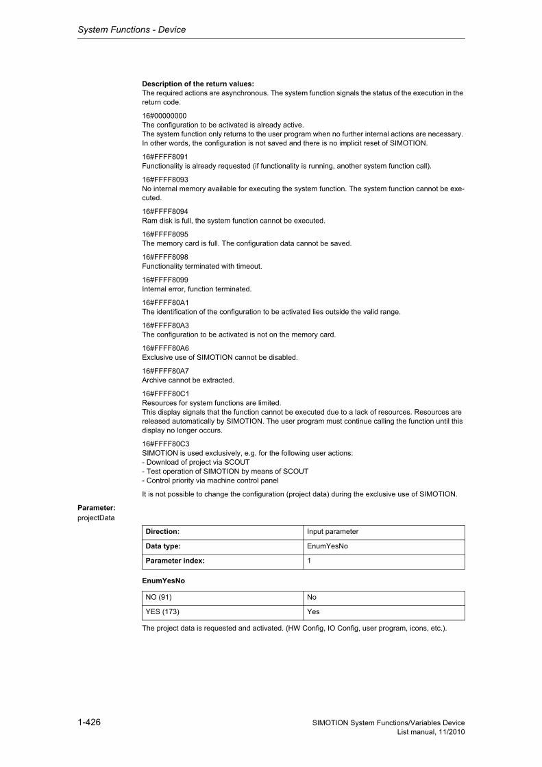
System Functions - Device
1-426 SIMOTION System Functions/Variables DeviceList manual, 11/2010
Description of the return values:The required actions are asynchronous. The system function signals the status of the execution in the return code.
16#00000000The configuration to be activated is already active.The system function only returns to the user program when no further internal actions are necessary. In other words, the configuration is not saved and there is no implicit reset of SIMOTION.
16#FFFF8091Functionality is already requested (if functionality is running, another system function call).
16#FFFF8093No internal memory available for executing the system function. The system function cannot be exe-cuted.
16#FFFF8094Ram disk is full, the system function cannot be executed.
16#FFFF8095The memory card is full. The configuration data cannot be saved.
16#FFFF8098Functionality terminated with timeout.
16#FFFF8099Internal error, function terminated.
16#FFFF80A1The identification of the configuration to be activated lies outside the valid range.
16#FFFF80A3The configuration to be activated is not on the memory card.
16#FFFF80A6Exclusive use of SIMOTION cannot be disabled.
16#FFFF80A7Archive cannot be extracted.
16#FFFF80C1Resources for system functions are limited.This display signals that the function cannot be executed due to a lack of resources. Resources are released automatically by SIMOTION. The user program must continue calling the function until this display no longer occurs.
16#FFFF80C3SIMOTION is used exclusively, e.g. for the following user actions:- Download of project via SCOUT- Test operation of SIMOTION by means of SCOUT- Control priority via machine control panel
It is not possible to change the configuration (project data) during the exclusive use of SIMOTION.
Parameter: projectData
EnumYesNo
The project data is requested and activated. (HW Config, IO Config, user program, icons, etc.).
Direction: Input parameter
Data type: EnumYesNo
Parameter index: 1
NO (91) No
YES (173) Yes
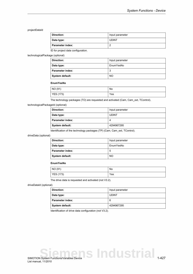
System Functions - Device
1-427SIMOTION System Functions/Variables DeviceList manual, 11/2010
projectDataId
ID for project data configuration.
technologicalPackage (optional)
EnumYesNo
The technology packages (TO) are requested and activated (Cam, Cam_ext, TControl).
technologicalPackageId (optional)
Identification of the technology packages (TP) (Cam, Cam_ext, TControl).
driveData (optional)
EnumYesNo
The drive data is requested and activated (not V3.2).
driveDataId (optional)
Identification of drive data configuration (not V3.2).
Direction: Input parameter
Data type: UDINT
Parameter index: 2
Direction: Input parameter
Data type: EnumYesNo
Parameter index: 3
System default: NO
NO (91) No
YES (173) Yes
Direction: Input parameter
Data type: UDINT
Parameter index: 4
System default: 4294967295
Direction: Input parameter
Data type: EnumYesNo
Parameter index: 5
System default: NO
NO (91) No
YES (173) Yes
Direction: Input parameter
Data type: UDINT
Parameter index: 6
System default: 4294967295
Siemens Industrial
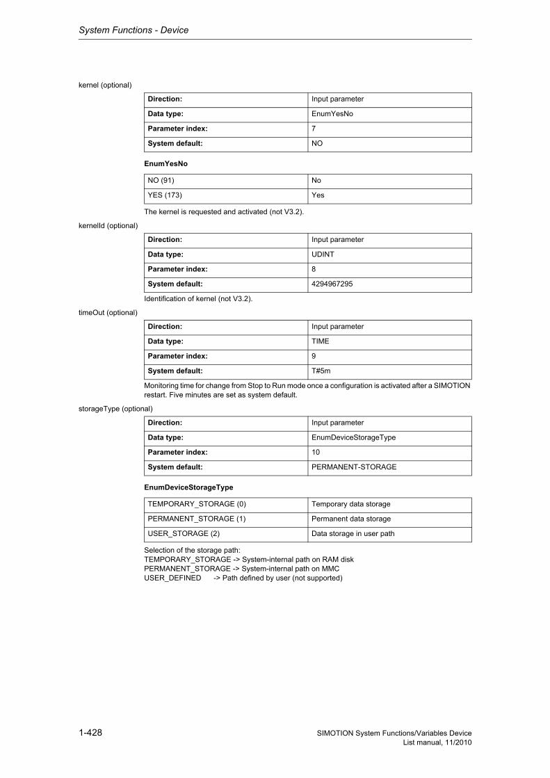
System Functions - Device
1-428 SIMOTION System Functions/Variables DeviceList manual, 11/2010
kernel (optional)
EnumYesNo
The kernel is requested and activated (not V3.2).
kernelId (optional)
Identification of kernel (not V3.2).
timeOut (optional)
Monitoring time for change from Stop to Run mode once a configuration is activated after a SIMOTION restart. Five minutes are set as system default.
storageType (optional)
EnumDeviceStorageType
Selection of the storage path:TEMPORARY_STORAGE -> System-internal path on RAM diskPERMANENT_STORAGE -> System-internal path on MMCUSER_DEFINED -> Path defined by user (not supported)
Direction: Input parameter
Data type: EnumYesNo
Parameter index: 7
System default: NO
NO (91) No
YES (173) Yes
Direction: Input parameter
Data type: UDINT
Parameter index: 8
System default: 4294967295
Direction: Input parameter
Data type: TIME
Parameter index: 9
System default: T#5m
Direction: Input parameter
Data type: EnumDeviceStorageType
Parameter index: 10
System default: PERMANENT-STORAGE
TEMPORARY_STORAGE (0) Temporary data storage
PERMANENT_STORAGE (1) Permanent data storage
USER_STORAGE (2) Data storage in user path
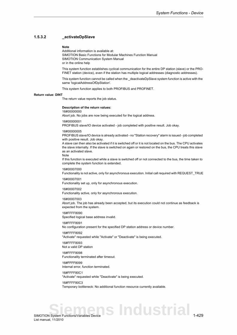
System Functions - Device
1-429SIMOTION System Functions/Variables DeviceList manual, 11/2010
1.5.3.2 _activateDpSlave
NoteAdditional information is available at:SIMOTION Basic Functions for Modular Machines Function ManualSIMOTION Communication System Manualor in the online help
This system function establishes cyclical communication for the entire DP station (slave) or the PRO-FINET station (device), even if the station has multiple logical addresses (diagnostic addresses).
This system function cannot be called when the _deactivateDpSlave system function is active with the same 'logicalAddressOfDpStation'.
This system function applies to both PROFIBUS and PROFINET.
Return value: DINTThe return value reports the job status.
Description of the return values:16#00000000Abort job. No jobs are now being executed for the logical address.
16#00000001PROFIBUS slave/IO device activated - job completed with positive result. Job okay.
16#00000005PROFIBUS slave/IO device is already activated - no "Station recovery" alarm is issued - job completed with positive result. Job okay.A slave can then also be activated if it is switched off or it is not located on the bus. The CPU activates the slave internally. If the slave is switched on again or restored on the bus, the CPU treats this slave as an activated slave.NoteIf this function is executed while a slave is switched off or not connected to the bus, the time taken to complete the system function is extended.
16#00007000Functionality is not active, only for asynchronous execution. Initial call required with REQUEST_TRUE
16#00007001Functionality set up, only for asynchronous execution.
16#00007002Functionality active, only for asynchronous execution.
16#00007003Abort job. The job has already been accepted, but its execution could not continue as feedback is expected from the system.
16#FFFF8090Specified logical base address invalid.
16#FFFF8091No configuration present for the specified DP station address or device number.
16#FFFF8092"Activate" requested while "Activate" or "Deactivate" is being executed.
16#FFFF8093Not a valid DP station
16#FFFF8098Functionality terminated after timeout.
16#FFFF8099Internal error, function terminated.
16#FFFF80C1"Activate" requested while "Deactivate" is being executed.
16#FFFF80C3Temporary bottleneck: No additional function resource currently available.
Siemens Industrial
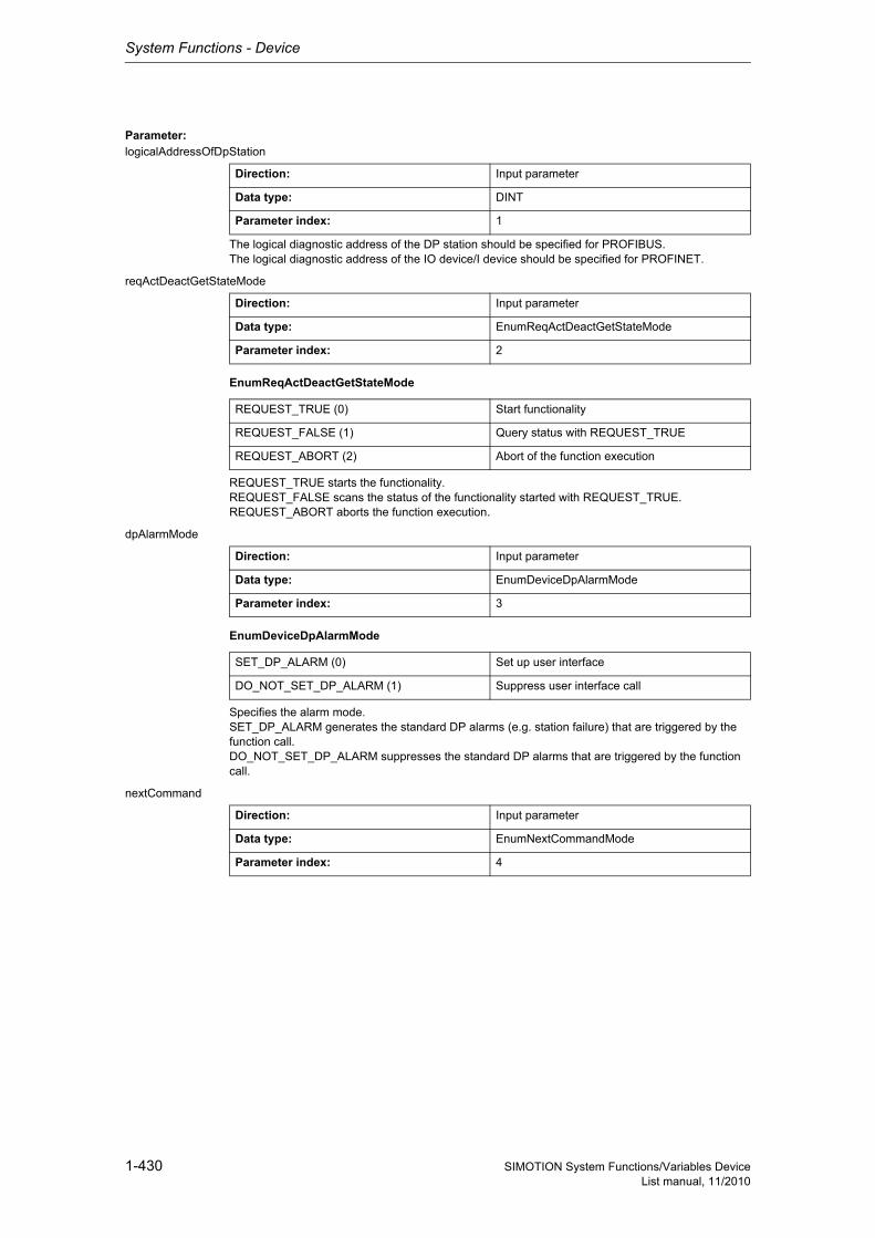
System Functions - Device
1-430 SIMOTION System Functions/Variables DeviceList manual, 11/2010
Parameter: logicalAddressOfDpStation
The logical diagnostic address of the DP station should be specified for PROFIBUS.The logical diagnostic address of the IO device/I device should be specified for PROFINET.
reqActDeactGetStateMode
EnumReqActDeactGetStateMode
REQUEST_TRUE starts the functionality.REQUEST_FALSE scans the status of the functionality started with REQUEST_TRUE.REQUEST_ABORT aborts the function execution.
dpAlarmMode
EnumDeviceDpAlarmMode
Specifies the alarm mode.SET_DP_ALARM generates the standard DP alarms (e.g. station failure) that are triggered by the function call.DO_NOT_SET_DP_ALARM suppresses the standard DP alarms that are triggered by the function call.
nextCommand
Direction: Input parameter
Data type: DINT
Parameter index: 1
Direction: Input parameter
Data type: EnumReqActDeactGetStateMode
Parameter index: 2
REQUEST_TRUE (0) Start functionality
REQUEST_FALSE (1) Query status with REQUEST_TRUE
REQUEST_ABORT (2) Abort of the function execution
Direction: Input parameter
Data type: EnumDeviceDpAlarmMode
Parameter index: 3
SET_DP_ALARM (0) Set up user interface
DO_NOT_SET_DP_ALARM (1) Suppress user interface call
Direction: Input parameter
Data type: EnumNextCommandMode
Parameter index: 4
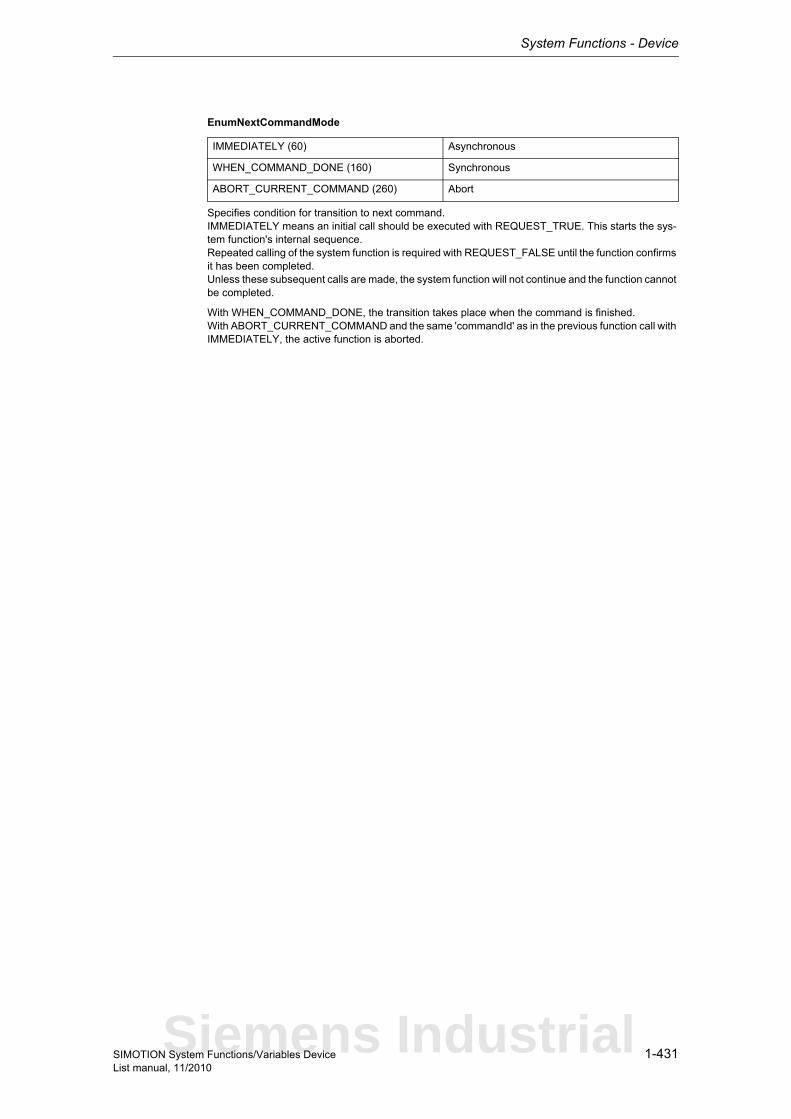
System Functions - Device
1-431SIMOTION System Functions/Variables DeviceList manual, 11/2010
EnumNextCommandMode
Specifies condition for transition to next command.IMMEDIATELY means an initial call should be executed with REQUEST_TRUE. This starts the sys-tem function's internal sequence.Repeated calling of the system function is required with REQUEST_FALSE until the function confirms it has been completed.Unless these subsequent calls are made, the system function will not continue and the function cannot be completed.
With WHEN_COMMAND_DONE, the transition takes place when the command is finished.With ABORT_CURRENT_COMMAND and the same 'commandId' as in the previous function call with IMMEDIATELY, the active function is aborted.
IMMEDIATELY (60) Asynchronous
WHEN_COMMAND_DONE (160) Synchronous
ABORT_CURRENT_COMMAND (260) Abort
Siemens Industrial
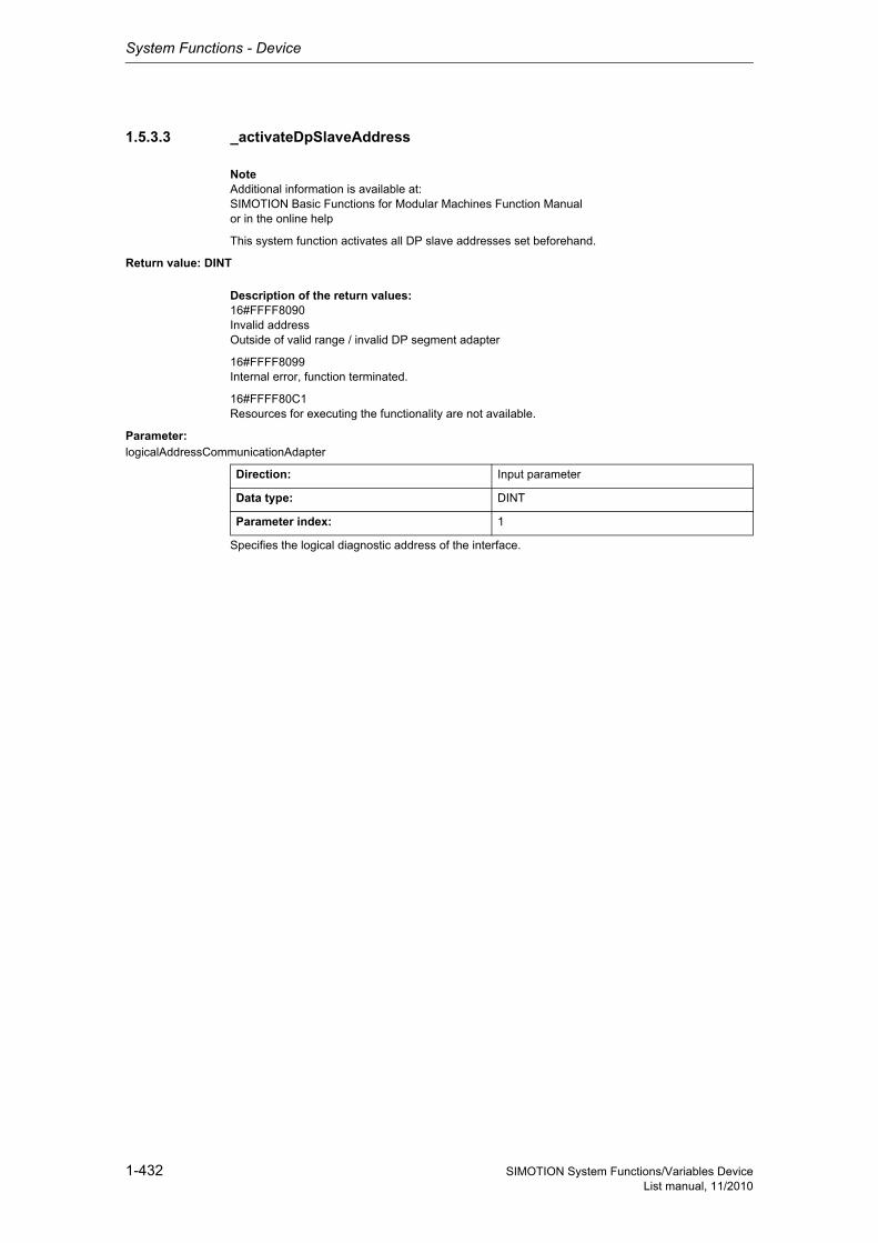
System Functions - Device
1-432 SIMOTION System Functions/Variables DeviceList manual, 11/2010
1.5.3.3 _activateDpSlaveAddress
NoteAdditional information is available at:SIMOTION Basic Functions for Modular Machines Function Manualor in the online help
This system function activates all DP slave addresses set beforehand.
Return value: DINT
Description of the return values:16#FFFF8090Invalid addressOutside of valid range / invalid DP segment adapter
16#FFFF8099Internal error, function terminated.
16#FFFF80C1Resources for executing the functionality are not available.
Parameter: logicalAddressCommunicationAdapter
Specifies the logical diagnostic address of the interface.
Direction: Input parameter
Data type: DINT
Parameter index: 1
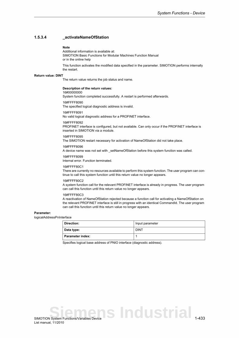
System Functions - Device
1-433SIMOTION System Functions/Variables DeviceList manual, 11/2010
1.5.3.4 _activateNameOfStation
NoteAdditional information is available at:SIMOTION Basic Functions for Modular Machines Function Manualor in the online help
This function activates the modified data specified in the parameter. SIMOTION performs internally the restart.
Return value: DINTThe return value returns the job status and name.
Description of the return values:16#00000000System function completed successfully. A restart is performed afterwards.
16#FFFF8090The specified logical diagnostic address is invalid.
16#FFFF8091No valid logical diagnostic address for a PROFINET interface.
16#FFFF8092PROFINET interface is configured, but not available. Can only occur if the PROFINET interface is inserted in SIMOTION via a module.
16#FFFF8095The SIMOTION restart necessary for activation of NameOfStation did not take place.
16#FFFF8096A device name was not set with _setNameOfStation before this system function was called.
16#FFFF8099Internal error. Function terminated.
16#FFFF80C1There are currently no resources available to perform this system function. The user program can con-tinue to call this system function until this return value no longer appears.
16#FFFF80C2A system function call for the relevant PROFINET interface is already in progress. The user program can call this function until this return value no longer appears.
16#FFFF80C3A reactivation of NameOfStation rejected because a function call for activating a NameOfStation on the relevant PROFINET interface is still in progress with an identical CommandId. The user program can call this function until this return value no longer appears.
Parameter: logicalAddressPnInterface
Specifies logical base address of PNIO interface (diagnostic address).
Direction: Input parameter
Data type: DINT
Parameter index: 1
Siemens Industrial
System Functions - Device
1-434 SIMOTION System Functions/Variables DeviceList manual, 11/2010
1.5.3.5 _activateTo
This system function enables activation of technology objects (TO). The functions of a technology object (e.g. _enableAxis on the TO axis) cannot be used until the object is ready for operation.
NoteThe functions _activateTo, _deactivateTo and _getStateOfTo belong to a function pool. Maximum 50 active calls from this pool can be processed simultaneously.The return value '16#FFFF80C3' is signaled when the maximum number is exceeded. Each running instance requires additional computation time in the technology object environment (in the cyclic levels); therefore it is more efficient to first query the respective state and then to set the required desi-red state by means of _activateTo and _deactivateTo.
NoteMore detailed information on this system function can be found inthe Function Manual titled "Motion Control Basic Functions for Modular Machines".
Return value: DINT
Description of the return values:The required actions are asynchronous. The system function signals the status of the execution in the return code.
16#00000000The technology object is activated.
16#00007000The system function is in 'Idle' status.
16#00007001The system function is started (only reported when execution is asynchronous).
16#00007002The system function is running (only reported when execution is asynchronous, a new call in the con-trol program is required until the functionality ends).
16#FFFF8090Technology object not available.
16#FFFF8092'"Activate TO" system function requested while "Deactivate TO" system function is running.
16#FFFF8098Functionality terminated with timeout.
16#FFFF8099Internal error, function terminated.
16#FFFF80C1'Activate TO' is already starteddue to a new call of the system function with call parameter 'requestMode:=REQUEST_TRUE'.
16#FFFF80C3Temporary bottleneck (internal resources for executing the function not currently available). The maxi-mum number of 50 calls active simultaneously has been exceeded. Wait until an active call is com-pleted.
Parameter: TO_Instance
Reference to the technology object to be activated.
Direction: Input parameter
Data type: AnyObject
Parameter index: 1
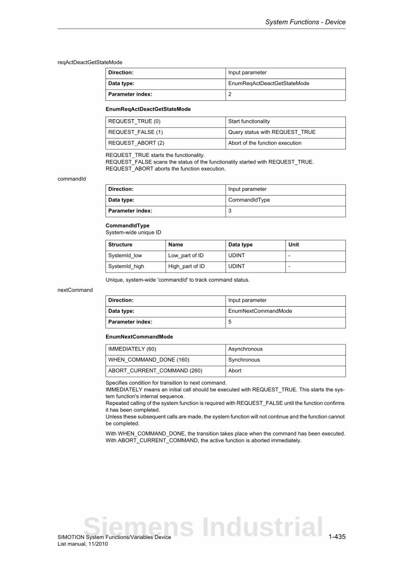
System Functions - Device
1-435SIMOTION System Functions/Variables DeviceList manual, 11/2010
reqActDeactGetStateMode
EnumReqActDeactGetStateMode
REQUEST_TRUE starts the functionality.REQUEST_FALSE scans the status of the functionality started with REQUEST_TRUE.REQUEST_ABORT aborts the function execution.
commandId
CommandIdTypeSystem-wide unique ID
Unique, system-wide 'commandId' to track command status.
nextCommand
EnumNextCommandMode
Specifies condition for transition to next command.IMMEDIATELY means an initial call should be executed with REQUEST_TRUE. This starts the sys-tem function's internal sequence.Repeated calling of the system function is required with REQUEST_FALSE until the function confirms it has been completed.Unless these subsequent calls are made, the system function will not continue and the function cannot be completed.
With WHEN_COMMAND_DONE, the transition takes place when the command has been executed.With ABORT_CURRENT_COMMAND, the active function is aborted immediately.
Direction: Input parameter
Data type: EnumReqActDeactGetStateMode
Parameter index: 2
REQUEST_TRUE (0) Start functionality
REQUEST_FALSE (1) Query status with REQUEST_TRUE
REQUEST_ABORT (2) Abort of the function execution
Direction: Input parameter
Data type: CommandIdType
Parameter index: 3
Structure Name Data type Unit
SystemId_low Low_part of ID UDINT -
SystemId_high High_part of ID UDINT -
Direction: Input parameter
Data type: EnumNextCommandMode
Parameter index: 5
IMMEDIATELY (60) Asynchronous
WHEN_COMMAND_DONE (160) Synchronous
ABORT_CURRENT_COMMAND (260) Abort
Siemens Industrial
System Functions - Device
1-436 SIMOTION System Functions/Variables DeviceList manual, 11/2010
1.5.3.6 _deactivateDpSlave
NoteAdditional information is available at:SIMOTION Basic Functions for Modular Machines Function ManualSIMOTION Communication System Manualor in the online help
This system function aborts cyclical communication for the entire DP station (slave) or the PROFINET station (device), even if the station has multiple logical addresses (diagnostic addresses).
This system function cannot be called when the _activateDpSlave system function is active with the same 'logicalAddressOfDpStation'.This system function applies to both PROFIBUS and PROFINET.
Return value: DINTThe return value reports the job status.
Description of the return values:16#00000000Abort job. No jobs are now being executed for the logical address.
16#00000002PROFIBUS slave/IO device deactivated. Job completed with positive result. Job okay.
16#00000005PROFIBUS slave/IO device already deactivated. No "station failure" alarm occurs. Job completed with positive result. Job okay.
16#00000006DP station already deactivated: No "station failure" alarm occurs.A slave can be deactivated even if it is switched off or is not located on the bus. The CPU deactivates the slave internally.The function then reports this return value.If the slave is switched on again or restored on the bus, the CPU treats this slave as a deactivated slave.
16#00007000Functionality is not active, only for asynchronous execution.
16#00007001Functionality initiated, only for asynchronous execution.
16#00007002Functionality active, only for asynchronous execution.
16#00007003Abort job. The job has already been accepted, but its execution could not continue as feedback is expected from the system.
16#FFFF8090Specified logical base address invalid.
16#FFFF8091No configuration present for the specified DP station address or device number.
16#FFFF8092"Deactivate" requested while "Activate" or "Deactivate" is being executed.
16#FFFF8093Not a valid DP station
16#FFFF8098Functionality of system function has been terminated with timeout.
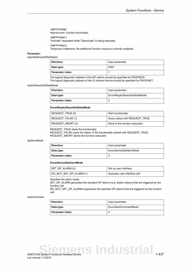
System Functions - Device
1-437SIMOTION System Functions/Variables DeviceList manual, 11/2010
16#FFFF8099Internal error, function terminated.
16#FFFF80C1"Activate" requested while "Deactivate" is being executed.
16#FFFF80C3Temporary bottleneck: No additional function resource currently available.
Parameter: logicalAddressOfDpStation
The logical diagnostic address of the DP station should be specified for PROFIBUS.The logical diagnostic address of the IO device/I device should be specified for PROFINET.
reqActDeactGetStateMode
EnumReqActDeactGetStateMode
REQUEST_TRUE starts the functionality.REQUEST_FALSE scans the status of the functionality started with REQUEST_TRUE.REQUEST_ABORT aborts the function execution.
dpAlarmMode
EnumDeviceDpAlarmMode
Specifies the alarm mode.SET_DP_ALARM generates the standard DP alarms (e.g. station failure) that are triggered by the function call.DO_NOT_SET_DP_ALARM suppresses the standard DP alarms that are triggered by the function call.
nextCommand
Direction: Input parameter
Data type: DINT
Parameter index: 1
Direction: Input parameter
Data type: EnumReqActDeactGetStateMode
Parameter index: 2
REQUEST_TRUE (0) Start functionality
REQUEST_FALSE (1) Query status with REQUEST_TRUE
REQUEST_ABORT (2) Abort of the function execution
Direction: Input parameter
Data type: EnumDeviceDpAlarmMode
Parameter index: 3
SET_DP_ALARM (0) Set up user interface
DO_NOT_SET_DP_ALARM (1) Suppress user interface call
Direction: Input parameter
Data type: EnumNextCommandMode
Parameter index: 4
Siemens Industrial

System Functions - Device
1-438 SIMOTION System Functions/Variables DeviceList manual, 11/2010
EnumNextCommandMode
Specifies condition for transition to next command.IMMEDIATELY means an initial call should be executed with REQUEST_TRUE. This starts the sys-tem function's internal sequence.Repeated calling of the system function is required with REQUEST_FALSE until the function confirms it has been completed.Unless these subsequent calls are made, the system function will not continue and the function cannot be completed.
With WHEN_COMMAND_DONE, the transition takes place when the command is finished.With ABORT_CURRENT_COMMAND and the same 'commandId' as in the previous function call with IMMEDIATELY, the active function is aborted.
IMMEDIATELY (60) Asynchronous
WHEN_COMMAND_DONE (160) Synchronous
ABORT_CURRENT_COMMAND (260) Abort

System Functions - Device
1-439SIMOTION System Functions/Variables DeviceList manual, 11/2010
1.5.3.7 _deactivateTo
This system function deactivates technology objects (TO).
You must also ensure that all technology objects that are dependent on the deactivated technology object are also deactivated.
For example:A slave axis always requires a synchronous object. Therefore both technology objects must be deac-tivated.
The deactivation sequence should always start with the technology objects that are not dependent on other technology objects.
NoteThe functions _activateTo, _deactivateTo and _getStateOfTo belong to a function pool. Maximum 50 active calls from this pool can be processed simultaneously.The return value '16#FFFF80C3' is signaled when the maximum number is exceeded. Each running instance requires additional computation time in the technology object environment (in the cyclic levels); therefore it is more efficient to first query the respective state and then to set the required desi-red state by means of _activateTo and _deactivateTo.
NoteMore detailed information on this system function can be found inthe Function Manual titled "Motion Control Basic Functions for Modular Machines".
Return value: DINT
Description of the return values:The required actions are asynchronous. The system function signals the status of the execution in the return code.
16#00000000The technology object (TO) is deactivated.
16#00007000The system function is in 'Idle' status (inactive).
16#00007001The system function is started (only reported in asynchronous execution).
16#00007002The system function is running (only reported when execution is asynchronous, a new call in the con-trol program is required until the functionality ends).
16#FFFF8090Invalid technology object reference.
16#FFFF8092"Deactivate TO" requested while "Activate TO" is running.
16#FFFF8098Functionality terminated with timeout.
16#FFFF8099Internal error, function terminated.
16#FFFF80C1'Deactivate TO' is already started.due to a new call of the system function with call parameter 'requestMode:=REQUEST_TRUE'.
16#FFFF80C3Temporary bottleneck (internal resources for executing the function not currently available). The maxi-mum number of 50 calls active simultaneously has been exceeded. Wait until an active call is com-pleted.
Siemens Industrial
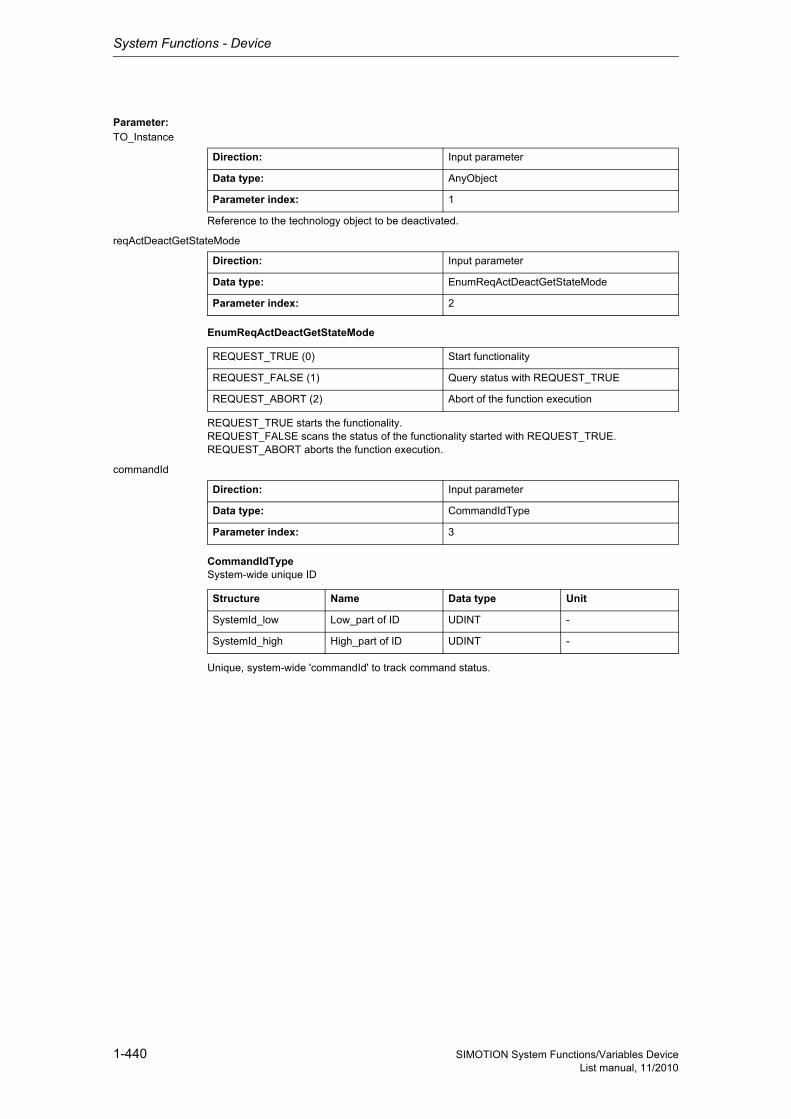
System Functions - Device
1-440 SIMOTION System Functions/Variables DeviceList manual, 11/2010
Parameter: TO_Instance
Reference to the technology object to be deactivated.
reqActDeactGetStateMode
EnumReqActDeactGetStateMode
REQUEST_TRUE starts the functionality.REQUEST_FALSE scans the status of the functionality started with REQUEST_TRUE.REQUEST_ABORT aborts the function execution.
commandId
CommandIdTypeSystem-wide unique ID
Unique, system-wide 'commandId' to track command status.
Direction: Input parameter
Data type: AnyObject
Parameter index: 1
Direction: Input parameter
Data type: EnumReqActDeactGetStateMode
Parameter index: 2
REQUEST_TRUE (0) Start functionality
REQUEST_FALSE (1) Query status with REQUEST_TRUE
REQUEST_ABORT (2) Abort of the function execution
Direction: Input parameter
Data type: CommandIdType
Parameter index: 3
Structure Name Data type Unit
SystemId_low Low_part of ID UDINT -
SystemId_high High_part of ID UDINT -
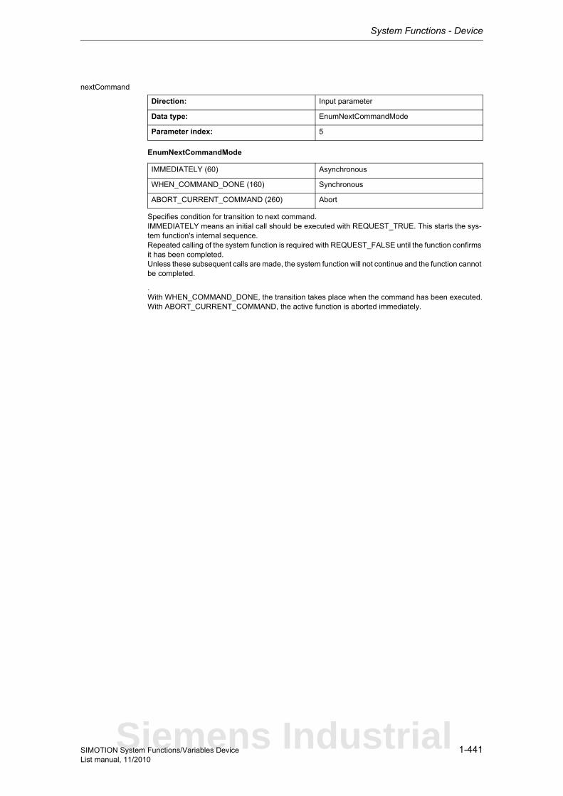
System Functions - Device
1-441SIMOTION System Functions/Variables DeviceList manual, 11/2010
nextCommand
EnumNextCommandMode
Specifies condition for transition to next command.IMMEDIATELY means an initial call should be executed with REQUEST_TRUE. This starts the sys-tem function's internal sequence.Repeated calling of the system function is required with REQUEST_FALSE until the function confirms it has been completed.Unless these subsequent calls are made, the system function will not continue and the function cannot be completed.
.With WHEN_COMMAND_DONE, the transition takes place when the command has been executed.With ABORT_CURRENT_COMMAND, the active function is aborted immediately.
Direction: Input parameter
Data type: EnumNextCommandMode
Parameter index: 5
IMMEDIATELY (60) Asynchronous
WHEN_COMMAND_DONE (160) Synchronous
ABORT_CURRENT_COMMAND (260) Abort
Siemens Industrial
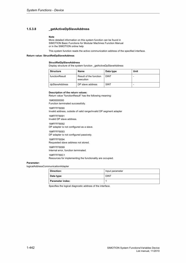
System Functions - Device
1-442 SIMOTION System Functions/Variables DeviceList manual, 11/2010
1.5.3.8 _getActiveDpSlaveAddress
NoteMore detailed information on this system function can be found inSIMOTION Basic Functions for Modular Machines Function Manualor in the SIMOTION online help
This system function reads the active communication address of the specified interface.
Return value: StructRetDpSlaveAddress
StructRetDpSlaveAddressDisplay structure of the system function _getActiveDpSlaveAddress
Description of the return values:Return value "functionResult" has the following meaning:
16#00000000Function terminated successfully.
16#FFFF8090Invalid address, outside of valid range/invalid DP segment adapter
16#FFFF8091Invalid DP slave address.
16#FFFF8092DP adapter is not configured as a slave.
16#FFFF8093DP adapter is not configured passively.
16#FFFF8094Requested slave address not stored.
16#FFFF8099Internal error, function terminated.
16#FFFF80C1Resources for implementing the functionality are occupied.
Parameter: logicalAddressCommunicationAdapter
Specifies the logical diagnostic address of the interface.
Structure Name Data type Unit
functionResult Result of the function execution
DINT -
dpSlaveAddress DP slave address SINT -
Direction: Input parameter
Data type: DINT
Parameter index: 1

System Functions - Device
1-443SIMOTION System Functions/Variables DeviceList manual, 11/2010
1.5.3.9 _getActiveNameOfStation
NoteMore detailed information on this system function can be found inSIMOTION Basic Functions for Modular Machines Function Manualor in the online help
The system function reads the currently active NameOfStation. This originates from the configuration or was set with the DCP service using 'TcpIp' or with the _setNameOfStation system function.
A maximum of 239 characters is returned. According to the standard, 240 characters are permitted, but this is not currently supported by SIMOTION.
If NameOfStation is not available, a string with a length of 0 is returned.In pnPortNumber, 16#FFFFFFFF is always returned.In pnSlotNumber, 16#FFFFFFFF is always returned.
Return value: StructRetDeviceNameOfStation
StructRetDeviceNameOfStationReturn values for _getPnInterfacePortNeighbour and _getActiveNameOfStation
Description of the return values:The return value returns the job status and name.
Structure Name Data type Unit
functionResult Result of the execution of the system function
DINT -
nameOfStation nameOfStation of own device (_getActivNameOfStation) or neighboring device (_getPnInterfacePortNeighbour)
STRING -
pnPortNumber pnPortNumber of the neighboring device, with which this is con-nected to the local device.
UDINT -
pnSlotNumber pnSlotNumber of the neighboring device, with which this is con-nected to the local device.
UDINT -
Siemens Industrial

System Functions - Device
1-444 SIMOTION System Functions/Variables DeviceList manual, 11/2010
functionResult16#00000000System function completed successfully. NameOfStation is contained in the return value.
16#00007000The system function is in inactive status. The functionality associated with the system function is not active. An initial call with REQUEST_TRUE is required.
16#00007001The system function is started with REQUEST_TRUE. A new call in the user program until completion of the system function is required with REQUEST_FALSE. This return value is reported only for asyn-chronous execution.
16#00007002The system function is still running. A new call in the user program until completion of the system func-tion is required with REQUEST_FALSE. This return value is reported only for asynchronous execu-tion.
16#00007003System function aborted successfully. If an abort is not possible, the system function returns 16#FFFF8094.
16#FFFF8090The specified logical diagnostic address is invalid.
16#FFFF8091No valid logical diagnostic address for a PROFINET interface.
16#FFFF8092PROFINET interface is configured, but not available. Can only occur if the PROFINET interface is inserted in SIMOTION via a module.
16#FFFF8094An abort is no longer possible in the current system function status.
16#FFFF8097Readout of active device name is not supported by the PROFINET interface.
16#FFFF8099Internal error. Function terminated.
16#FFFF809AThe PROFINET interface does not support this service. Function terminated.
16#FFFF80C1There are currently no resources available to perform this system function. The user program can con-tinue to call this system function until this return value no longer appears.
16#FFFF80C2A system function call for the relevant PROFINET interface is already in progress. The user program can continue to call this system function until this return value no longer appears.
16#FFFF80C3A re-read of the current device name with REQUEST_TRUE was rejected because a function call for reading the current device name on the relevant PROFINET interface is still in progress with an iden-tical CommandId. The user program can call this function until this return value no longer appears.
nameOfStation: Device name of relevant PROFINET interface. A maximum of 239 characters is retur-ned. According to thestandard, 240 characters are permitted, but this is not currently supported by SIMOTION.
If NameOfStation is not available, a string with a length of 0 is returned.
pnPortNumber: 16#FFFFFFFF is always returned.
pnSlotNumber: 16#FFFFFFFF is always returned.
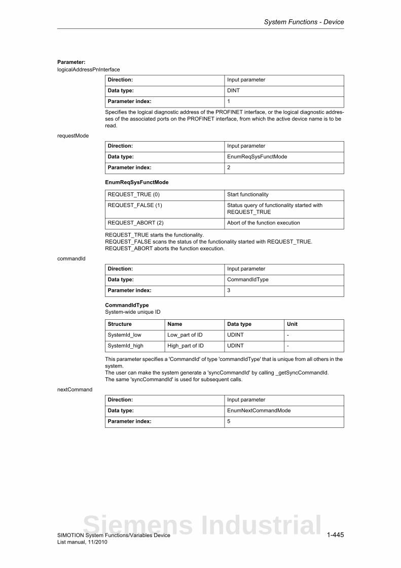
System Functions - Device
1-445SIMOTION System Functions/Variables DeviceList manual, 11/2010
Parameter: logicalAddressPnInterface
Specifies the logical diagnostic address of the PROFINET interface, or the logical diagnostic addres-ses of the associated ports on the PROFINET interface, from which the active device name is to be read.
requestMode
EnumReqSysFunctMode
REQUEST_TRUE starts the functionality.REQUEST_FALSE scans the status of the functionality started with REQUEST_TRUE.REQUEST_ABORT aborts the function execution.
commandId
CommandIdTypeSystem-wide unique ID
This parameter specifies a 'CommandId' of type 'commandIdType' that is unique from all others in the system.The user can make the system generate a 'syncCommandId' by calling _getSyncCommandId.The same 'syncCommandId' is used for subsequent calls.
nextCommand
Direction: Input parameter
Data type: DINT
Parameter index: 1
Direction: Input parameter
Data type: EnumReqSysFunctMode
Parameter index: 2
REQUEST_TRUE (0) Start functionality
REQUEST_FALSE (1) Status query of functionality started with REQUEST_TRUE
REQUEST_ABORT (2) Abort of the function execution
Direction: Input parameter
Data type: CommandIdType
Parameter index: 3
Structure Name Data type Unit
SystemId_low Low_part of ID UDINT -
SystemId_high High_part of ID UDINT -
Direction: Input parameter
Data type: EnumNextCommandMode
Parameter index: 5
Siemens Industrial
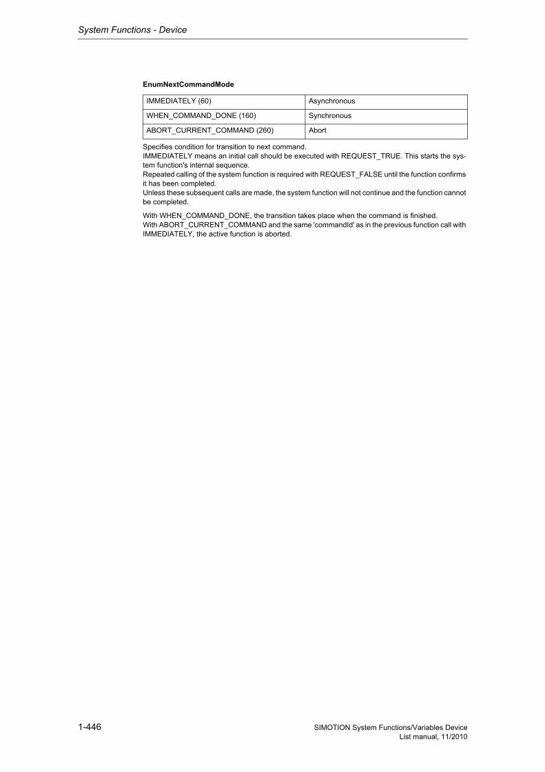
System Functions - Device
1-446 SIMOTION System Functions/Variables DeviceList manual, 11/2010
EnumNextCommandMode
Specifies condition for transition to next command.IMMEDIATELY means an initial call should be executed with REQUEST_TRUE. This starts the sys-tem function's internal sequence.Repeated calling of the system function is required with REQUEST_FALSE until the function confirms it has been completed.Unless these subsequent calls are made, the system function will not continue and the function cannot be completed.
With WHEN_COMMAND_DONE, the transition takes place when the command is finished.With ABORT_CURRENT_COMMAND and the same 'commandId' as in the previous function call with IMMEDIATELY, the active function is aborted.
IMMEDIATELY (60) Asynchronous
WHEN_COMMAND_DONE (160) Synchronous
ABORT_CURRENT_COMMAND (260) Abort
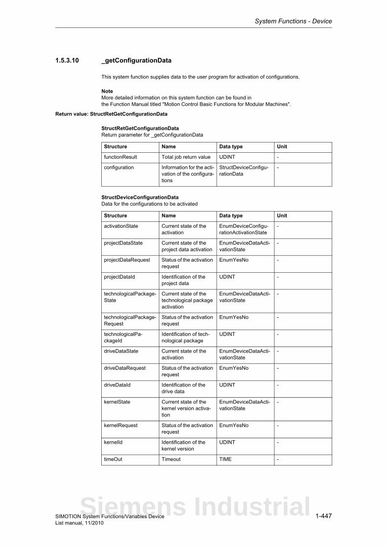
System Functions - Device
1-447SIMOTION System Functions/Variables DeviceList manual, 11/2010
1.5.3.10 _getConfigurationData
This system function supplies data to the user program for activation of configurations.
NoteMore detailed information on this system function can be found inthe Function Manual titled "Motion Control Basic Functions for Modular Machines".
Return value: StructRetGetConfigurationData
StructRetGetConfigurationDataReturn parameter for _getConfigurationData
StructDeviceConfigurationDataData for the configurations to be activated
Structure Name Data type Unit
functionResult Total job return value UDINT -
configuration Information for the acti-vation of the configura-tions
StructDeviceConfigu-rationData
-
Structure Name Data type Unit
activationState Current state of the activation
EnumDeviceConfigu-rationActivationState
-
projectDataState Current state of the project data activation
EnumDeviceDataActi-vationState
-
projectDataRequest Status of the activation request
EnumYesNo -
projectDataId Identification of the project data
UDINT -
technologicalPackage-State
Current state of the technological package activation
EnumDeviceDataActi-vationState
-
technologicalPackage-Request
Status of the activation request
EnumYesNo -
technologicalPa-ckageId
Identification of tech-nological package
UDINT -
driveDataState Current state of the activation
EnumDeviceDataActi-vationState
-
driveDataRequest Status of the activation request
EnumYesNo -
driveDataId Identification of the drive data
UDINT -
kernelState Current state of the kernel version activa-tion
EnumDeviceDataActi-vationState
-
kernelRequest Status of the activation request
EnumYesNo -
kernelId Identification of the kernel version
UDINT -
timeOut Timeout TIME -
Siemens Industrial
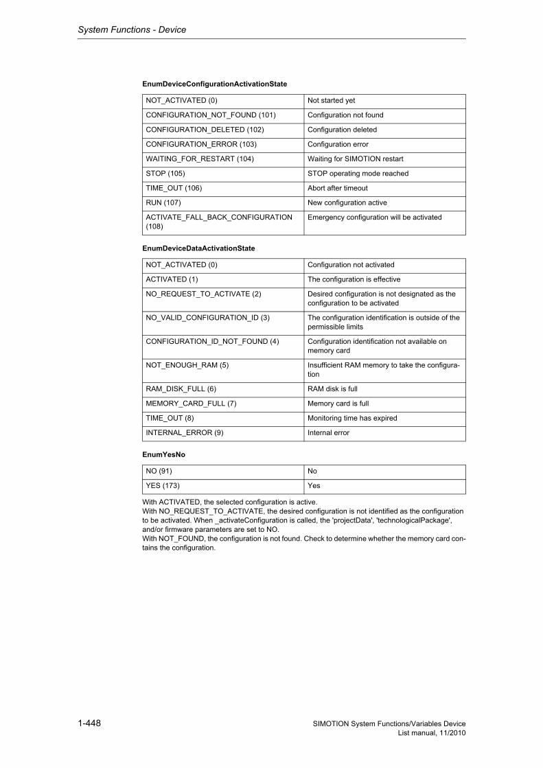
System Functions - Device
1-448 SIMOTION System Functions/Variables DeviceList manual, 11/2010
EnumDeviceConfigurationActivationState
EnumDeviceDataActivationState
EnumYesNo
With ACTIVATED, the selected configuration is active.With NO_REQUEST_TO_ACTIVATE, the desired configuration is not identified as the configuration to be activated. When _activateConfiguration is called, the 'projectData', 'technologicalPackage', and/or firmware parameters are set to NO.With NOT_FOUND, the configuration is not found. Check to determine whether the memory card con-tains the configuration.
NOT_ACTIVATED (0) Not started yet
CONFIGURATION_NOT_FOUND (101) Configuration not found
CONFIGURATION_DELETED (102) Configuration deleted
CONFIGURATION_ERROR (103) Configuration error
WAITING_FOR_RESTART (104) Waiting for SIMOTION restart
STOP (105) STOP operating mode reached
TIME_OUT (106) Abort after timeout
RUN (107) New configuration active
ACTIVATE_FALL_BACK_CONFIGURATION (108)
Emergency configuration will be activated
NOT_ACTIVATED (0) Configuration not activated
ACTIVATED (1) The configuration is effective
NO_REQUEST_TO_ACTIVATE (2) Desired configuration is not designated as the configuration to be activated
NO_VALID_CONFIGURATION_ID (3) The configuration identification is outside of the permissible limits
CONFIGURATION_ID_NOT_FOUND (4) Configuration identification not available on memory card
NOT_ENOUGH_RAM (5) Insufficient RAM memory to take the configura-tion
RAM_DISK_FULL (6) RAM disk is full
MEMORY_CARD_FULL (7) Memory card is full
TIME_OUT (8) Monitoring time has expired
INTERNAL_ERROR (9) Internal error
NO (91) No
YES (173) Yes
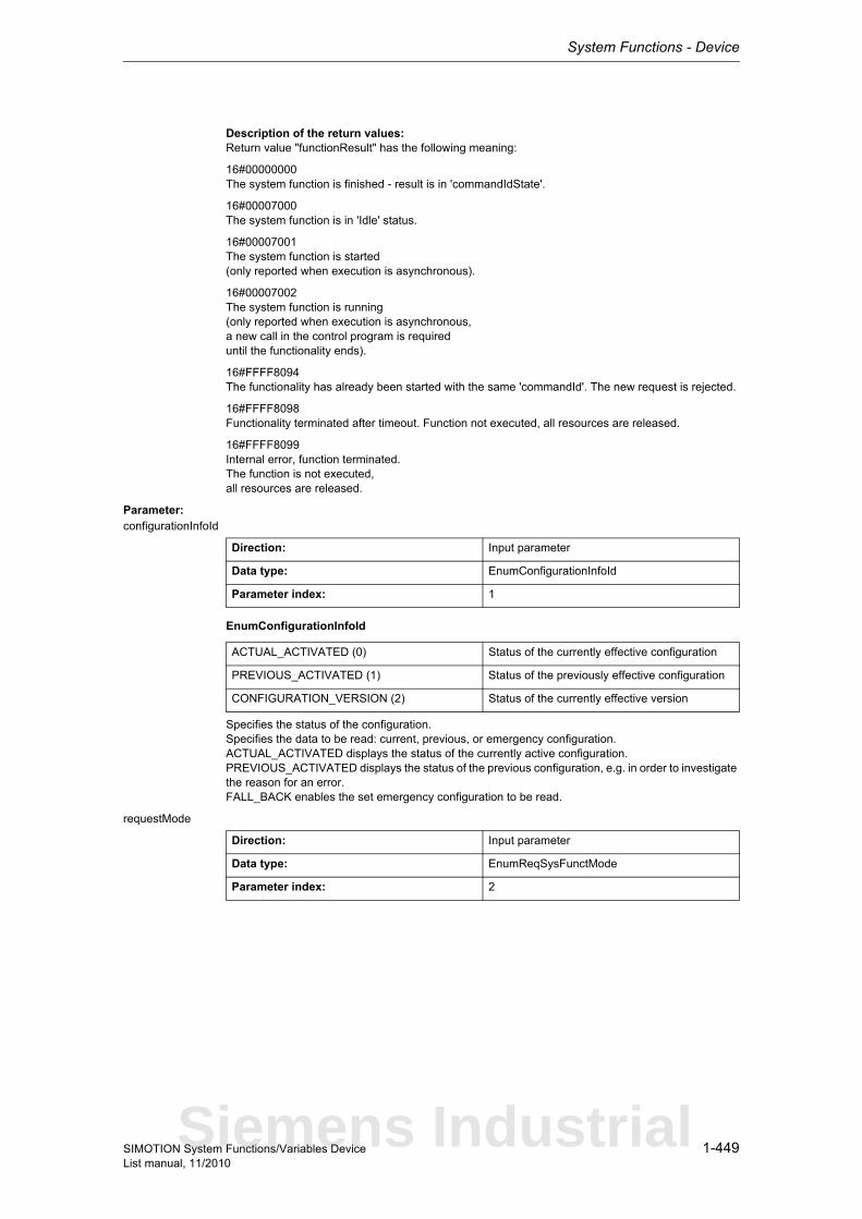
System Functions - Device
1-449SIMOTION System Functions/Variables DeviceList manual, 11/2010
Description of the return values:Return value "functionResult" has the following meaning:
16#00000000The system function is finished - result is in 'commandIdState'.
16#00007000The system function is in 'Idle' status.
16#00007001The system function is started(only reported when execution is asynchronous).
16#00007002The system function is running(only reported when execution is asynchronous,a new call in the control program is requireduntil the functionality ends).
16#FFFF8094The functionality has already been started with the same 'commandId'. The new request is rejected.
16#FFFF8098Functionality terminated after timeout. Function not executed, all resources are released.
16#FFFF8099Internal error, function terminated.The function is not executed,all resources are released.
Parameter: configurationInfoId
EnumConfigurationInfoId
Specifies the status of the configuration.Specifies the data to be read: current, previous, or emergency configuration.ACTUAL_ACTIVATED displays the status of the currently active configuration.PREVIOUS_ACTIVATED displays the status of the previous configuration, e.g. in order to investigate the reason for an error.FALL_BACK enables the set emergency configuration to be read.
requestMode
Direction: Input parameter
Data type: EnumConfigurationInfoId
Parameter index: 1
ACTUAL_ACTIVATED (0) Status of the currently effective configuration
PREVIOUS_ACTIVATED (1) Status of the previously effective configuration
CONFIGURATION_VERSION (2) Status of the currently effective version
Direction: Input parameter
Data type: EnumReqSysFunctMode
Parameter index: 2
Siemens Industrial
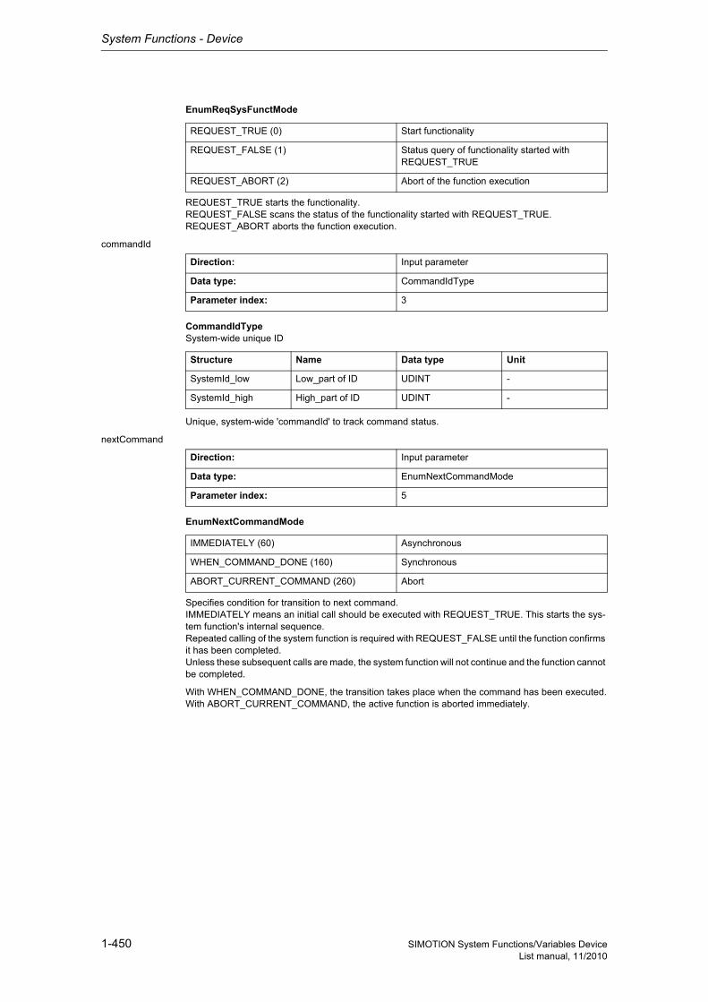
System Functions - Device
1-450 SIMOTION System Functions/Variables DeviceList manual, 11/2010
EnumReqSysFunctMode
REQUEST_TRUE starts the functionality.REQUEST_FALSE scans the status of the functionality started with REQUEST_TRUE.REQUEST_ABORT aborts the function execution.
commandId
CommandIdTypeSystem-wide unique ID
Unique, system-wide 'commandId' to track command status.
nextCommand
EnumNextCommandMode
Specifies condition for transition to next command.IMMEDIATELY means an initial call should be executed with REQUEST_TRUE. This starts the sys-tem function's internal sequence.Repeated calling of the system function is required with REQUEST_FALSE until the function confirms it has been completed.Unless these subsequent calls are made, the system function will not continue and the function cannot be completed.
With WHEN_COMMAND_DONE, the transition takes place when the command has been executed.With ABORT_CURRENT_COMMAND, the active function is aborted immediately.
REQUEST_TRUE (0) Start functionality
REQUEST_FALSE (1) Status query of functionality started with REQUEST_TRUE
REQUEST_ABORT (2) Abort of the function execution
Direction: Input parameter
Data type: CommandIdType
Parameter index: 3
Structure Name Data type Unit
SystemId_low Low_part of ID UDINT -
SystemId_high High_part of ID UDINT -
Direction: Input parameter
Data type: EnumNextCommandMode
Parameter index: 5
IMMEDIATELY (60) Asynchronous
WHEN_COMMAND_DONE (160) Synchronous
ABORT_CURRENT_COMMAND (260) Abort
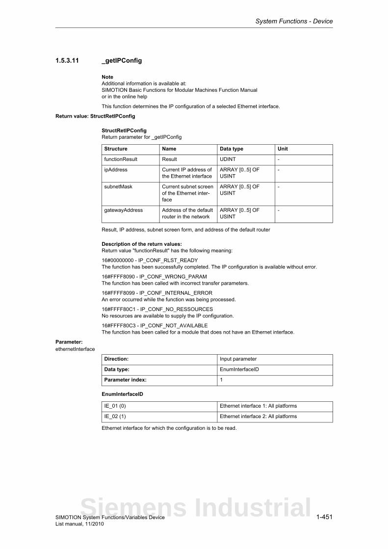
System Functions - Device
1-451SIMOTION System Functions/Variables DeviceList manual, 11/2010
1.5.3.11 _getIPConfig
NoteAdditional information is available at:SIMOTION Basic Functions for Modular Machines Function Manualor in the online help
This function determines the IP configuration of a selected Ethernet interface.
Return value: StructRetIPConfig
StructRetIPConfigReturn parameter for _getIPConfig
Result, IP address, subnet screen form, and address of the default router
Description of the return values:Return value "functionResult" has the following meaning:
16#00000000 - IP_CONF_RLST_READYThe function has been successfully completed. The IP configuration is available without error.
16#FFFF8090 - IP_CONF_WRONG_PARAMThe function has been called with incorrect transfer parameters.
16#FFFF8099 - IP_CONF_INTERNAL_ERRORAn error occurred while the function was being processed.
16#FFFF80C1 - IP_CONF_NO_RESSOURCESNo resources are available to supply the IP configuration.
16#FFFF80C3 - IP_CONF_NOT_AVAILABLEThe function has been called for a module that does not have an Ethernet interface.
Parameter: ethernetInterface
EnumInterfaceID
Ethernet interface for which the configuration is to be read.
Structure Name Data type Unit
functionResult Result UDINT -
ipAddress Current IP address of the Ethernet interface
ARRAY [0..5] OF USINT
-
subnetMask Current subnet screen of the Ethernet inter-face
ARRAY [0..5] OF USINT
-
gatewayAddress Address of the default router in the network
ARRAY [0..5] OF USINT
-
Direction: Input parameter
Data type: EnumInterfaceID
Parameter index: 1
IE_01 (0) Ethernet interface 1: All platforms
IE_02 (1) Ethernet interface 2: All platforms
Siemens Industrial
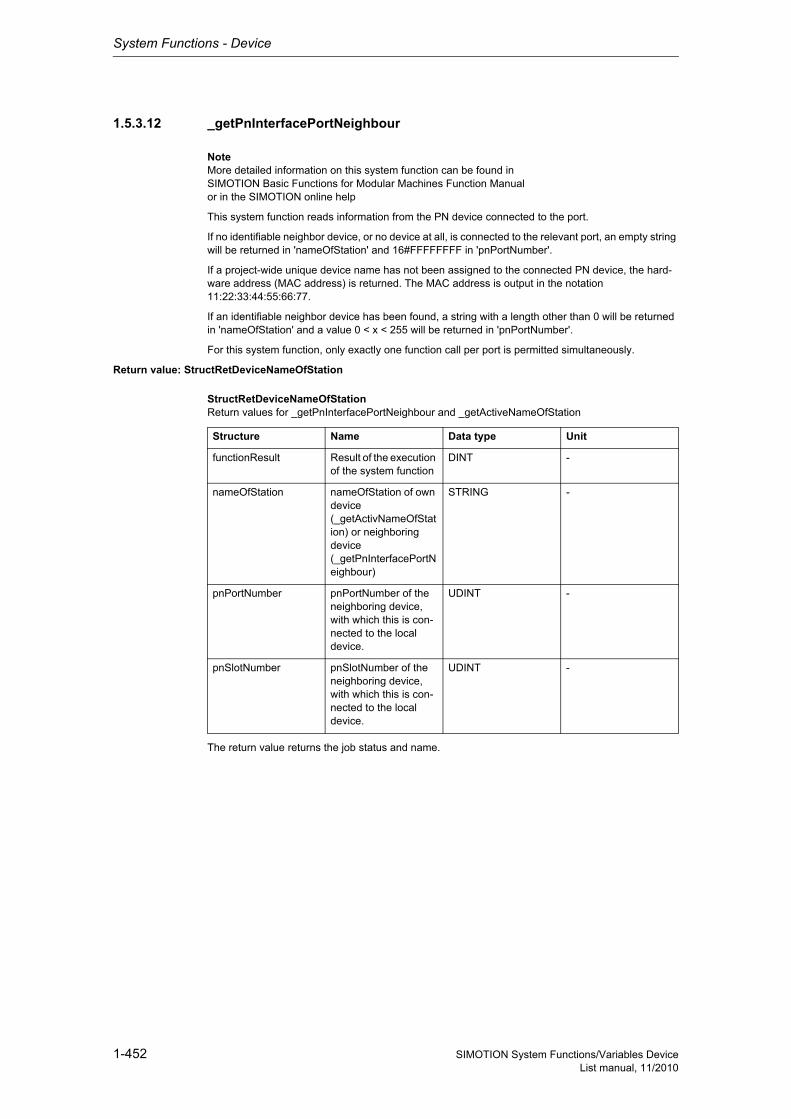
System Functions - Device
1-452 SIMOTION System Functions/Variables DeviceList manual, 11/2010
1.5.3.12 _getPnInterfacePortNeighbour
NoteMore detailed information on this system function can be found inSIMOTION Basic Functions for Modular Machines Function Manualor in the SIMOTION online help
This system function reads information from the PN device connected to the port.
If no identifiable neighbor device, or no device at all, is connected to the relevant port, an empty string will be returned in 'nameOfStation' and 16#FFFFFFFF in 'pnPortNumber'.
If a project-wide unique device name has not been assigned to the connected PN device, the hard-ware address (MAC address) is returned. The MAC address is output in the notation 11:22:33:44:55:66:77.
If an identifiable neighbor device has been found, a string with a length other than 0 will be returned in 'nameOfStation' and a value 0 < x < 255 will be returned in 'pnPortNumber'.
For this system function, only exactly one function call per port is permitted simultaneously.
Return value: StructRetDeviceNameOfStation
StructRetDeviceNameOfStationReturn values for _getPnInterfacePortNeighbour and _getActiveNameOfStation
The return value returns the job status and name.
Structure Name Data type Unit
functionResult Result of the execution of the system function
DINT -
nameOfStation nameOfStation of own device (_getActivNameOfStation) or neighboring device (_getPnInterfacePortNeighbour)
STRING -
pnPortNumber pnPortNumber of the neighboring device, with which this is con-nected to the local device.
UDINT -
pnSlotNumber pnSlotNumber of the neighboring device, with which this is con-nected to the local device.
UDINT -
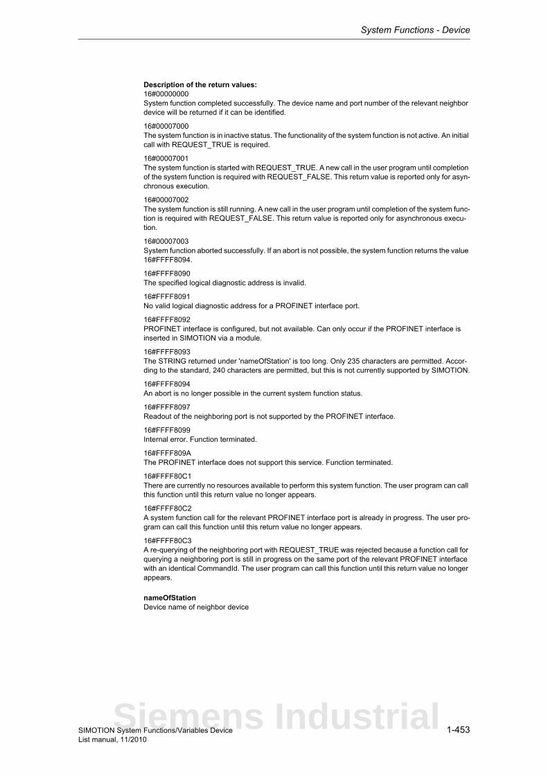
System Functions - Device
1-453SIMOTION System Functions/Variables DeviceList manual, 11/2010
Description of the return values:16#00000000System function completed successfully. The device name and port number of the relevant neighbor device will be returned if it can be identified.
16#00007000The system function is in inactive status. The functionality of the system function is not active. An initial call with REQUEST_TRUE is required.
16#00007001The system function is started with REQUEST_TRUE. A new call in the user program until completion of the system function is required with REQUEST_FALSE. This return value is reported only for asyn-chronous execution.
16#00007002The system function is still running. A new call in the user program until completion of the system func-tion is required with REQUEST_FALSE. This return value is reported only for asynchronous execu-tion.
16#00007003System function aborted successfully. If an abort is not possible, the system function returns the value 16#FFFF8094.
16#FFFF8090The specified logical diagnostic address is invalid.
16#FFFF8091No valid logical diagnostic address for a PROFINET interface port.
16#FFFF8092PROFINET interface is configured, but not available. Can only occur if the PROFINET interface is inserted in SIMOTION via a module.
16#FFFF8093The STRING returned under 'nameOfStation' is too long. Only 235 characters are permitted. Accor-ding to the standard, 240 characters are permitted, but this is not currently supported by SIMOTION.
16#FFFF8094An abort is no longer possible in the current system function status.
16#FFFF8097Readout of the neighboring port is not supported by the PROFINET interface.
16#FFFF8099Internal error. Function terminated.
16#FFFF809AThe PROFINET interface does not support this service. Function terminated.
16#FFFF80C1There are currently no resources available to perform this system function. The user program can call this function until this return value no longer appears.
16#FFFF80C2A system function call for the relevant PROFINET interface port is already in progress. The user pro-gram can call this function until this return value no longer appears.
16#FFFF80C3A re-querying of the neighboring port with REQUEST_TRUE was rejected because a function call for querying a neighboring port is still in progress on the same port of the relevant PROFINET interface with an identical CommandId. The user program can call this function until this return value no longer appears.
nameOfStationDevice name of neighbor device
Siemens Industrial
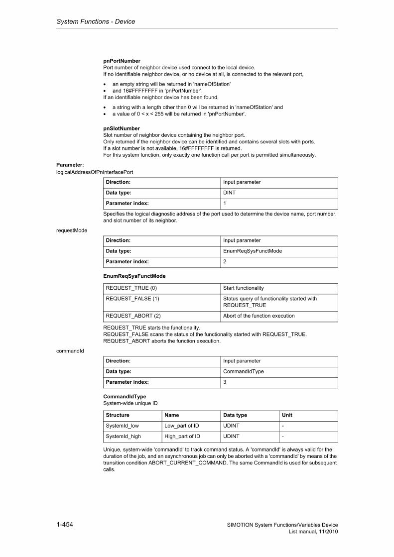
System Functions - Device
1-454 SIMOTION System Functions/Variables DeviceList manual, 11/2010
pnPortNumberPort number of neighbor device used connect to the local device.If no identifiable neighbor device, or no device at all, is connected to the relevant port,
• an empty string will be returned in 'nameOfStation'• and 16#FFFFFFFF in 'pnPortNumber'.If an identifiable neighbor device has been found,
• a string with a length other than 0 will be returned in 'nameOfStation' and• a value of 0 < x < 255 will be returned in 'pnPortNumber'.
pnSlotNumberSlot number of neighbor device containing the neighbor port.Only returned if the neighbor device can be identified and contains several slots with ports.If a slot number is not available, 16#FFFFFFFF is returned.For this system function, only exactly one function call per port is permitted simultaneously.
Parameter: logicalAddressOfPnInterfacePort
Specifies the logical diagnostic address of the port used to determine the device name, port number, and slot number of its neighbor.
requestMode
EnumReqSysFunctMode
REQUEST_TRUE starts the functionality.REQUEST_FALSE scans the status of the functionality started with REQUEST_TRUE.REQUEST_ABORT aborts the function execution.
commandId
CommandIdTypeSystem-wide unique ID
Unique, system-wide 'commandId' to track command status. A 'commandId' is always valid for the duration of the job, and an asynchronous job can only be aborted with a 'commandId' by means of the transition condition ABORT_CURRENT_COMMAND. The same CommandId is used for subsequent calls.
Direction: Input parameter
Data type: DINT
Parameter index: 1
Direction: Input parameter
Data type: EnumReqSysFunctMode
Parameter index: 2
REQUEST_TRUE (0) Start functionality
REQUEST_FALSE (1) Status query of functionality started with REQUEST_TRUE
REQUEST_ABORT (2) Abort of the function execution
Direction: Input parameter
Data type: CommandIdType
Parameter index: 3
Structure Name Data type Unit
SystemId_low Low_part of ID UDINT -
SystemId_high High_part of ID UDINT -

System Functions - Device
1-455SIMOTION System Functions/Variables DeviceList manual, 11/2010
nextCommand
EnumNextCommandMode
Specifies condition for transition to next command.IMMEDIATELY means an initial call should be executed with REQUEST_TRUE. This starts the sys-tem function's internal sequence.Repeated calling of the system function is required with REQUEST_FALSE until the function confirms it has been completed.Unless these subsequent calls are made, the system function will not continue and the function cannot be completed.
With WHEN_COMMAND_DONE, the transition takes place when the command has been executed (synchronous call).With ABORT_CURRENT_COMMAND, the active function is aborted immediately.
Direction: Input parameter
Data type: EnumNextCommandMode
Parameter index: 5
IMMEDIATELY (60) Asynchronous
WHEN_COMMAND_DONE (160) Synchronous
ABORT_CURRENT_COMMAND (260) Abort
Siemens Industrial
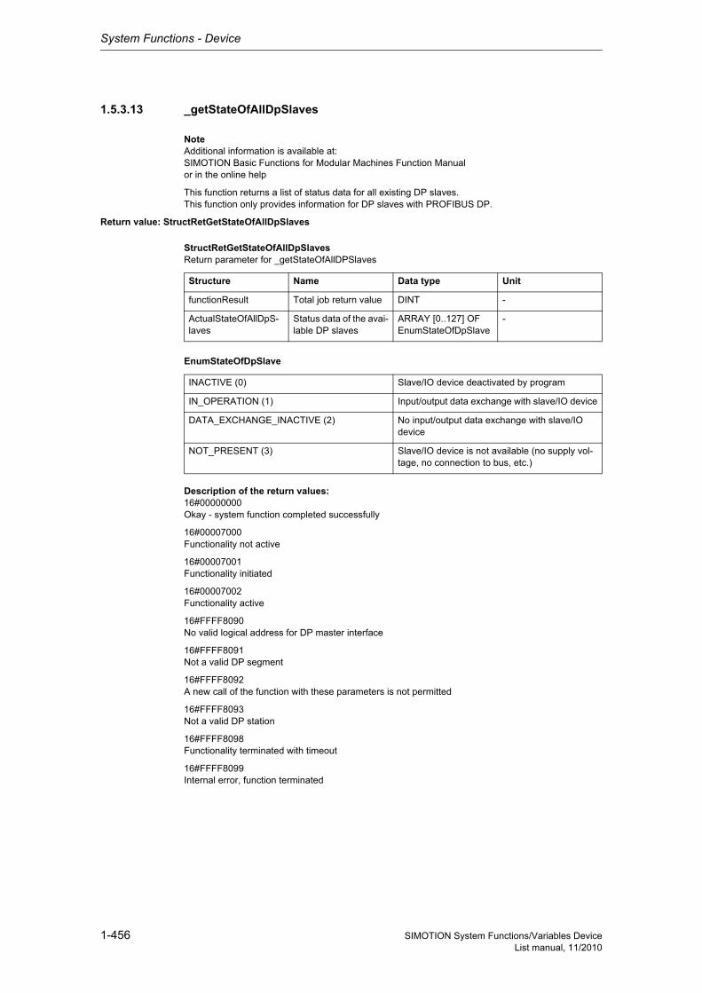
System Functions - Device
1-456 SIMOTION System Functions/Variables DeviceList manual, 11/2010
1.5.3.13 _getStateOfAllDpSlaves
NoteAdditional information is available at:SIMOTION Basic Functions for Modular Machines Function Manualor in the online help
This function returns a list of status data for all existing DP slaves.This function only provides information for DP slaves with PROFIBUS DP.
Return value: StructRetGetStateOfAllDpSlaves
StructRetGetStateOfAllDpSlavesReturn parameter for _getStateOfAllDPSlaves
EnumStateOfDpSlave
Description of the return values:16#00000000Okay - system function completed successfully
16#00007000Functionality not active
16#00007001Functionality initiated
16#00007002Functionality active
16#FFFF8090No valid logical address for DP master interface
16#FFFF8091Not a valid DP segment
16#FFFF8092A new call of the function with these parameters is not permitted
16#FFFF8093Not a valid DP station
16#FFFF8098Functionality terminated with timeout
16#FFFF8099Internal error, function terminated
Structure Name Data type Unit
functionResult Total job return value DINT -
ActualStateOfAllDpS-laves
Status data of the avai-lable DP slaves
ARRAY [0..127] OF EnumStateOfDpSlave
-
INACTIVE (0) Slave/IO device deactivated by program
IN_OPERATION (1) Input/output data exchange with slave/IO device
DATA_EXCHANGE_INACTIVE (2) No input/output data exchange with slave/IO device
NOT_PRESENT (3) Slave/IO device is not available (no supply vol-tage, no connection to bus, etc.)
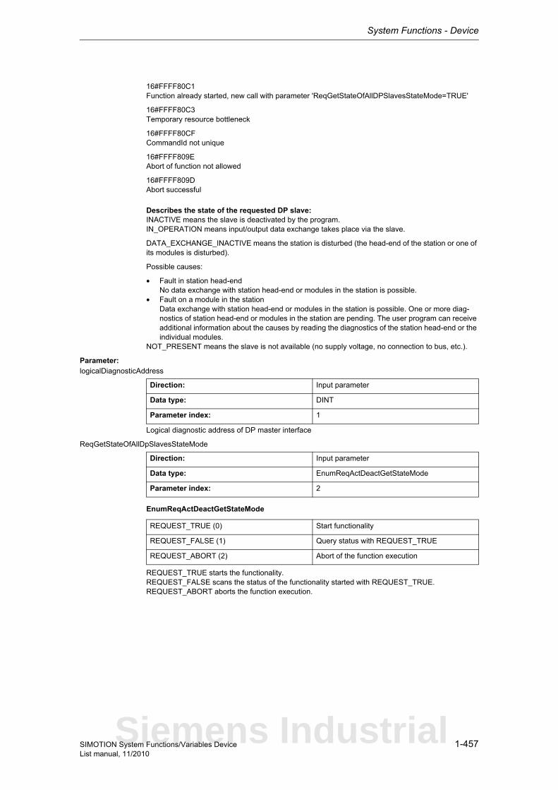
System Functions - Device
1-457SIMOTION System Functions/Variables DeviceList manual, 11/2010
16#FFFF80C1Function already started, new call with parameter 'ReqGetStateOfAllDPSlavesStateMode=TRUE'
16#FFFF80C3Temporary resource bottleneck
16#FFFF80CFCommandId not unique
16#FFFF809EAbort of function not allowed
16#FFFF809DAbort successful
Describes the state of the requested DP slave:INACTIVE means the slave is deactivated by the program.IN_OPERATION means input/output data exchange takes place via the slave.
DATA_EXCHANGE_INACTIVE means the station is disturbed (the head-end of the station or one of its modules is disturbed).
Possible causes:
• Fault in station head-endNo data exchange with station head-end or modules in the station is possible.
• Fault on a module in the stationData exchange with station head-end or modules in the station is possible. One or more diag-nostics of station head-end or modules in the station are pending. The user program can receive additional information about the causes by reading the diagnostics of the station head-end or the individual modules.
NOT_PRESENT means the slave is not available (no supply voltage, no connection to bus, etc.).
Parameter: logicalDiagnosticAddress
Logical diagnostic address of DP master interface
ReqGetStateOfAllDpSlavesStateMode
EnumReqActDeactGetStateMode
REQUEST_TRUE starts the functionality.REQUEST_FALSE scans the status of the functionality started with REQUEST_TRUE.REQUEST_ABORT aborts the function execution.
Direction: Input parameter
Data type: DINT
Parameter index: 1
Direction: Input parameter
Data type: EnumReqActDeactGetStateMode
Parameter index: 2
REQUEST_TRUE (0) Start functionality
REQUEST_FALSE (1) Query status with REQUEST_TRUE
REQUEST_ABORT (2) Abort of the function execution
Siemens Industrial
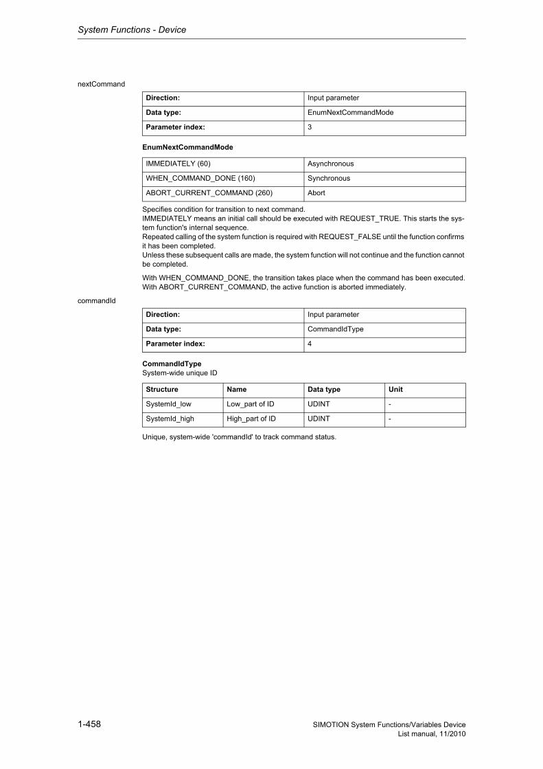
System Functions - Device
1-458 SIMOTION System Functions/Variables DeviceList manual, 11/2010
nextCommand
EnumNextCommandMode
Specifies condition for transition to next command.IMMEDIATELY means an initial call should be executed with REQUEST_TRUE. This starts the sys-tem function's internal sequence.Repeated calling of the system function is required with REQUEST_FALSE until the function confirms it has been completed.Unless these subsequent calls are made, the system function will not continue and the function cannot be completed.
With WHEN_COMMAND_DONE, the transition takes place when the command has been executed.With ABORT_CURRENT_COMMAND, the active function is aborted immediately.
commandId
CommandIdTypeSystem-wide unique ID
Unique, system-wide 'commandId' to track command status.
Direction: Input parameter
Data type: EnumNextCommandMode
Parameter index: 3
IMMEDIATELY (60) Asynchronous
WHEN_COMMAND_DONE (160) Synchronous
ABORT_CURRENT_COMMAND (260) Abort
Direction: Input parameter
Data type: CommandIdType
Parameter index: 4
Structure Name Data type Unit
SystemId_low Low_part of ID UDINT -
SystemId_high High_part of ID UDINT -

System Functions - Device
1-459SIMOTION System Functions/Variables DeviceList manual, 11/2010
1.5.3.14 _getStateOfAllDpStations
NoteAdditional information is available at:SIMOTION Basic Functions for Modular Machines Function ManualCommunication System Manualor in the online help
The system function determines the status of the communication to cyclical communications partners (device - PROFINET, slave - PROFIBUS, sender or recipient controller-controller internode commu-nication - PROFINET).
This system function provides the status of configured PROFIBUS slaves/IO devices only, unlike the _getStateOfAllDpSlaves system function which usually returns the status for all possible PROFIBUS DP addresses. The system function provides the information for both PROFIBUS DP and PROFINET.
The user program calls the system function the first time with 'RequestMode = REQUEST_TRUE'. This call returns a maximum of 10 results.In the 'functionResult', 0x00000001 signals that other status options are available.
The user program then calls the system function with the identifier 'RequestMode = REQUEST_FALSE'. The call is repeated until all status values have been read out. This is signaled with 'functionResult' 0x00000000.
NoteWhere further function calls are made with 'RequestMode = REQUEST_FALSE', the same Comman-dID must be used as when calling with 'REQUEST_TRUE'. Unless the same CommandId is used, the function will continue to be restarted and only the first 10 status values will be displayed.
If the process of reading out the status values is to be aborted, the system function must be called with 'RequestMode = REQUEST_ABORT'.
Return value: StructRetDeviceGetStateOfAllDpStations
StructRetDeviceGetStateOfAllDpStationsReturn value for _getStateOfAllDpStations
StructStateOfDpStationsReturn parameters of the individual devices
Structure Name Data type Unit
functionResult Result DINT -
NumberResultsDpSta-tions
Number of states that are signaled in actual-StateOfDpStations
UDINT -
StructStateOfDpStati-ons
Status data of the avai-lable DP slaves / IO devices
ARRAY [0..9] OF StructStateOfDpStati-ons
-
Structure Name Data type Unit
logicalDiagnosti-cAddressDpStations
Diagnostics address of the PROFIBUS slave or IO device
DINT -
actualStateOfDpSta-tion
Status of the relevant PROFIBUS slave or IO device
EnumStateOfDpSta-tion
-
Siemens Industrial
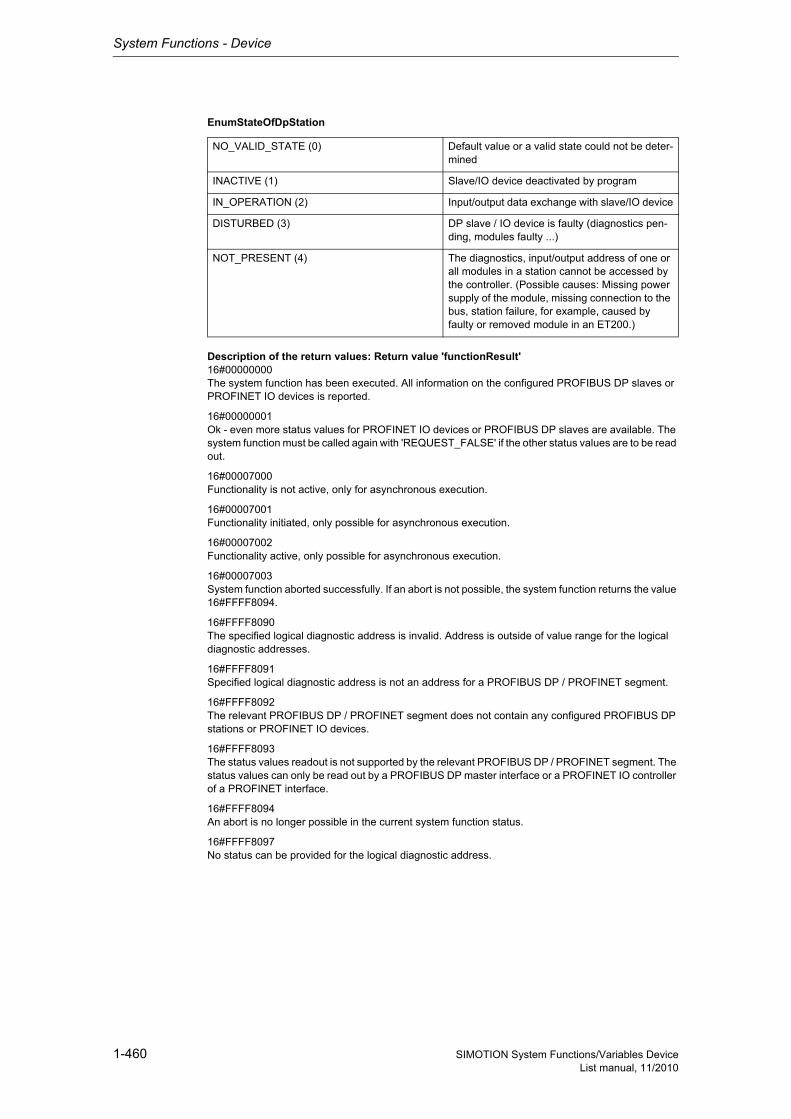
System Functions - Device
1-460 SIMOTION System Functions/Variables DeviceList manual, 11/2010
EnumStateOfDpStation
Description of the return values: Return value 'functionResult'16#00000000The system function has been executed. All information on the configured PROFIBUS DP slaves or PROFINET IO devices is reported.
16#00000001Ok - even more status values for PROFINET IO devices or PROFIBUS DP slaves are available. The system function must be called again with 'REQUEST_FALSE' if the other status values are to be read out.
16#00007000Functionality is not active, only for asynchronous execution.
16#00007001Functionality initiated, only possible for asynchronous execution.
16#00007002Functionality active, only possible for asynchronous execution.
16#00007003System function aborted successfully. If an abort is not possible, the system function returns the value 16#FFFF8094.
16#FFFF8090The specified logical diagnostic address is invalid. Address is outside of value range for the logical diagnostic addresses.
16#FFFF8091Specified logical diagnostic address is not an address for a PROFIBUS DP / PROFINET segment.
16#FFFF8092The relevant PROFIBUS DP / PROFINET segment does not contain any configured PROFIBUS DP stations or PROFINET IO devices.
16#FFFF8093The status values readout is not supported by the relevant PROFIBUS DP / PROFINET segment. The status values can only be read out by a PROFIBUS DP master interface or a PROFINET IO controller of a PROFINET interface.
16#FFFF8094An abort is no longer possible in the current system function status.
16#FFFF8097No status can be provided for the logical diagnostic address.
NO_VALID_STATE (0) Default value or a valid state could not be deter-mined
INACTIVE (1) Slave/IO device deactivated by program
IN_OPERATION (2) Input/output data exchange with slave/IO device
DISTURBED (3) DP slave / IO device is faulty (diagnostics pen-ding, modules faulty ...)
NOT_PRESENT (4) The diagnostics, input/output address of one or all modules in a station cannot be accessed by the controller. (Possible causes: Missing power supply of the module, missing connection to the bus, station failure, for example, caused by faulty or removed module in an ET200.)
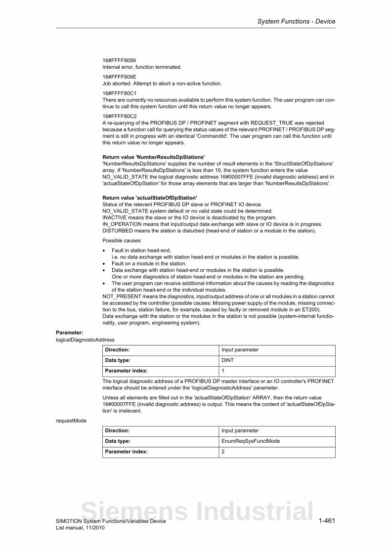
System Functions - Device
1-461SIMOTION System Functions/Variables DeviceList manual, 11/2010
16#FFFF8099Internal error, function terminated.
16#FFFF809EJob aborted. Attempt to abort a non-active function.
16#FFFF80C1There are currently no resources available to perform this system function. The user program can con-tinue to call this system function until this return value no longer appears.
16#FFFF80C2A re-querying of the PROFIBUS DP / PROFINET segment with REQUEST_TRUE was rejected because a function call for querying the status values of the relevant PROFINET / PROFIBUS DP seg-ment is still in progress with an identical 'CommandId'. The user program can call this function until this return value no longer appears.
Return value 'NumberResultsDpStations''NumberResultsDpStations' supplies the number of result elements in the 'StructStateOfDpStations' array. If 'NumberResultsDpStations' is less than 10, the system function enters the value NO_VALID_STATE the logical diagnostic address 16#00007FFE (invalid diagnostic address) and in 'actualStateOfDpStation' for those array elements that are larger than 'NumberResultsDpStations'.
Return value 'actualStateOfDpStation'Status of the relevant PROFIBUS DP slave or PROFINET IO device.NO_VALID_STATE system default or no valid state could be determined.INACTIVE means the slave or the IO device is deactivated by the program.IN_OPERATION means that input/output data exchange with slave or IO device is in progress.DISTURBED means the station is disturbed (head-end of station or a module in the station).
Possible causes:
• Fault in station head-end,i.e. no data exchange with station head-end or modules in the station is possible.
• Fault on a module in the station.• Data exchange with station head-end or modules in the station is possible.
One or more diagnostics of station head-end or modules in the station are pending.• The user program can receive additional information about the causes by reading the diagnostics
of the station head-end or the individual modules.NOT_PRESENT means the diagnostics, input/output address of one or all modules in a station cannot be accessed by the controller (possible causes: Missing power supply of the module, missing connec-tion to the bus, station failure, for example, caused by faulty or removed module in an ET200).Data exchange with the station or the modules in the station is not possible (system-internal functio-nality, user program, engineering system).
Parameter: logicalDiagnosticAddress
The logical diagnostic address of a PROFIBUS DP master interface or an IO controller's PROFINET interface should be entered under the 'logicalDiagnosticAddress' parameter.
Unless all elements are filled out in the 'actualStateOfDpStation' ARRAY, then the return value 16#00007FFE (invalid diagnostic address) is output. This means the content of 'actualStateOfDpSta-tion' is irrelevant.
requestMode
Direction: Input parameter
Data type: DINT
Parameter index: 1
Direction: Input parameter
Data type: EnumReqSysFunctMode
Parameter index: 2
Siemens Industrial
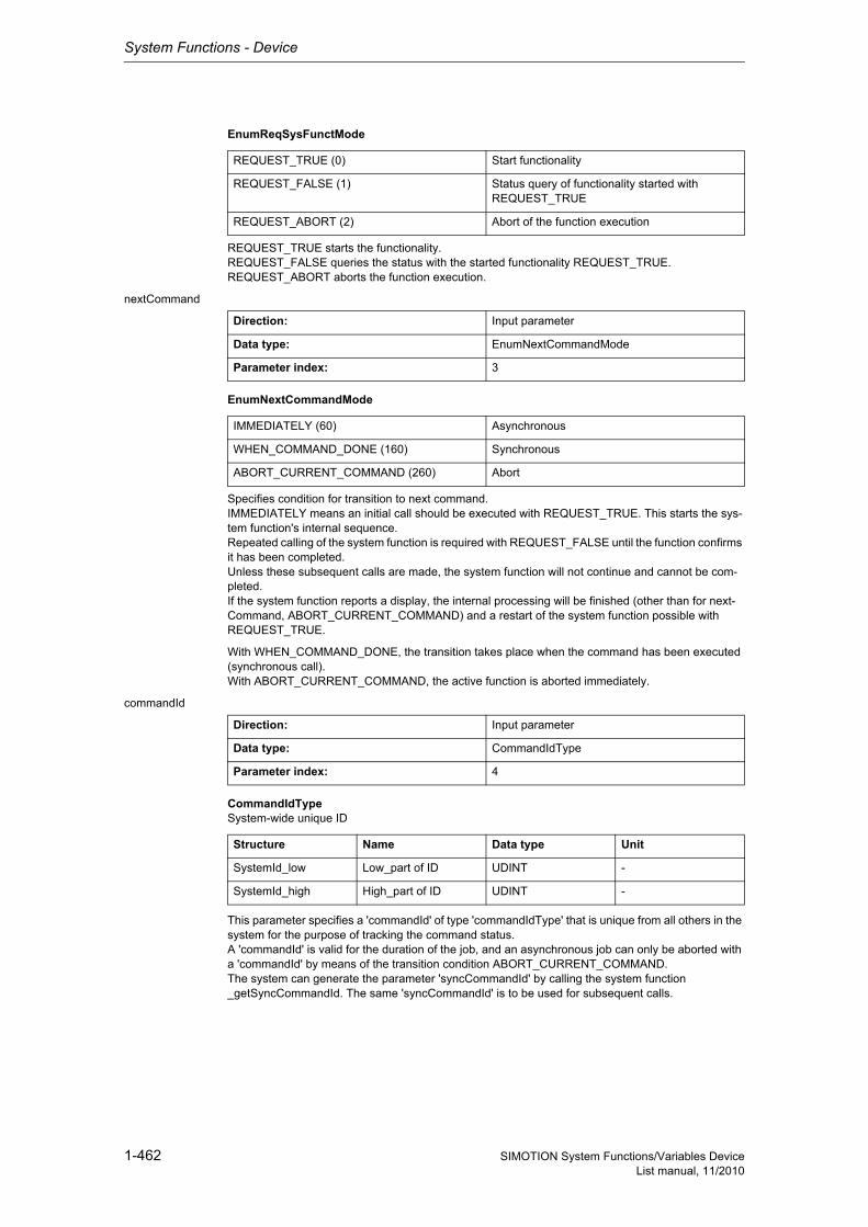
System Functions - Device
1-462 SIMOTION System Functions/Variables DeviceList manual, 11/2010
EnumReqSysFunctMode
REQUEST_TRUE starts the functionality.REQUEST_FALSE queries the status with the started functionality REQUEST_TRUE.REQUEST_ABORT aborts the function execution.
nextCommand
EnumNextCommandMode
Specifies condition for transition to next command.IMMEDIATELY means an initial call should be executed with REQUEST_TRUE. This starts the sys-tem function's internal sequence.Repeated calling of the system function is required with REQUEST_FALSE until the function confirms it has been completed.Unless these subsequent calls are made, the system function will not continue and cannot be com-pleted.If the system function reports a display, the internal processing will be finished (other than for next-Command, ABORT_CURRENT_COMMAND) and a restart of the system function possible with REQUEST_TRUE.
With WHEN_COMMAND_DONE, the transition takes place when the command has been executed (synchronous call).With ABORT_CURRENT_COMMAND, the active function is aborted immediately.
commandId
CommandIdTypeSystem-wide unique ID
This parameter specifies a 'commandId' of type 'commandIdType' that is unique from all others in the system for the purpose of tracking the command status.A 'commandId' is valid for the duration of the job, and an asynchronous job can only be aborted with a 'commandId' by means of the transition condition ABORT_CURRENT_COMMAND.The system can generate the parameter 'syncCommandId' by calling the system function _getSyncCommandId. The same 'syncCommandId' is to be used for subsequent calls.
REQUEST_TRUE (0) Start functionality
REQUEST_FALSE (1) Status query of functionality started with REQUEST_TRUE
REQUEST_ABORT (2) Abort of the function execution
Direction: Input parameter
Data type: EnumNextCommandMode
Parameter index: 3
IMMEDIATELY (60) Asynchronous
WHEN_COMMAND_DONE (160) Synchronous
ABORT_CURRENT_COMMAND (260) Abort
Direction: Input parameter
Data type: CommandIdType
Parameter index: 4
Structure Name Data type Unit
SystemId_low Low_part of ID UDINT -
SystemId_high High_part of ID UDINT -
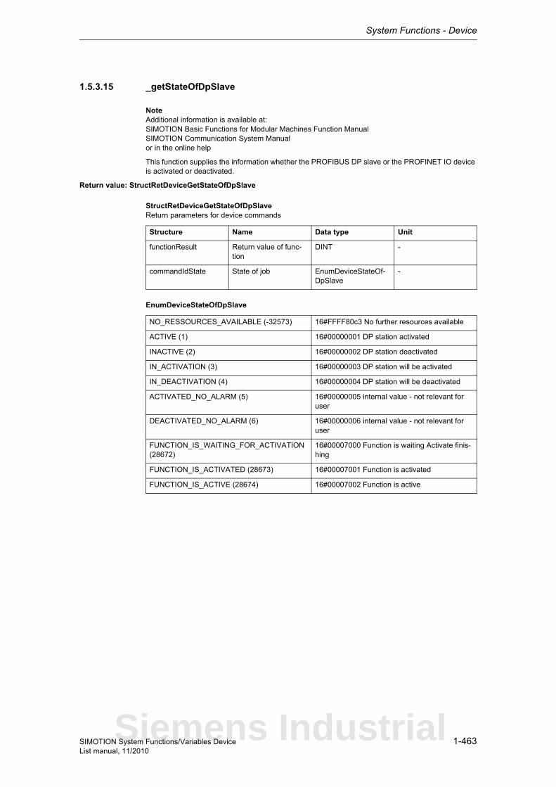
System Functions - Device
1-463SIMOTION System Functions/Variables DeviceList manual, 11/2010
1.5.3.15 _getStateOfDpSlave
NoteAdditional information is available at:SIMOTION Basic Functions for Modular Machines Function ManualSIMOTION Communication System Manualor in the online help
This function supplies the information whether the PROFIBUS DP slave or the PROFINET IO device is activated or deactivated.
Return value: StructRetDeviceGetStateOfDpSlave
StructRetDeviceGetStateOfDpSlaveReturn parameters for device commands
EnumDeviceStateOfDpSlave
Structure Name Data type Unit
functionResult Return value of func-tion
DINT -
commandIdState State of job EnumDeviceStateOf-DpSlave
-
NO_RESSOURCES_AVAILABLE (-32573) 16#FFFF80c3 No further resources available
ACTIVE (1) 16#00000001 DP station activated
INACTIVE (2) 16#00000002 DP station deactivated
IN_ACTIVATION (3) 16#00000003 DP station will be activated
IN_DEACTIVATION (4) 16#00000004 DP station will be deactivated
ACTIVATED_NO_ALARM (5) 16#00000005 internal value - not relevant for user
DEACTIVATED_NO_ALARM (6) 16#00000006 internal value - not relevant for user
FUNCTION_IS_WAITING_FOR_ACTIVATION (28672)
16#00007000 Function is waiting Activate finis-hing
FUNCTION_IS_ACTIVATED (28673) 16#00007001 Function is activated
FUNCTION_IS_ACTIVE (28674) 16#00007002 Function is active
Siemens Industrial
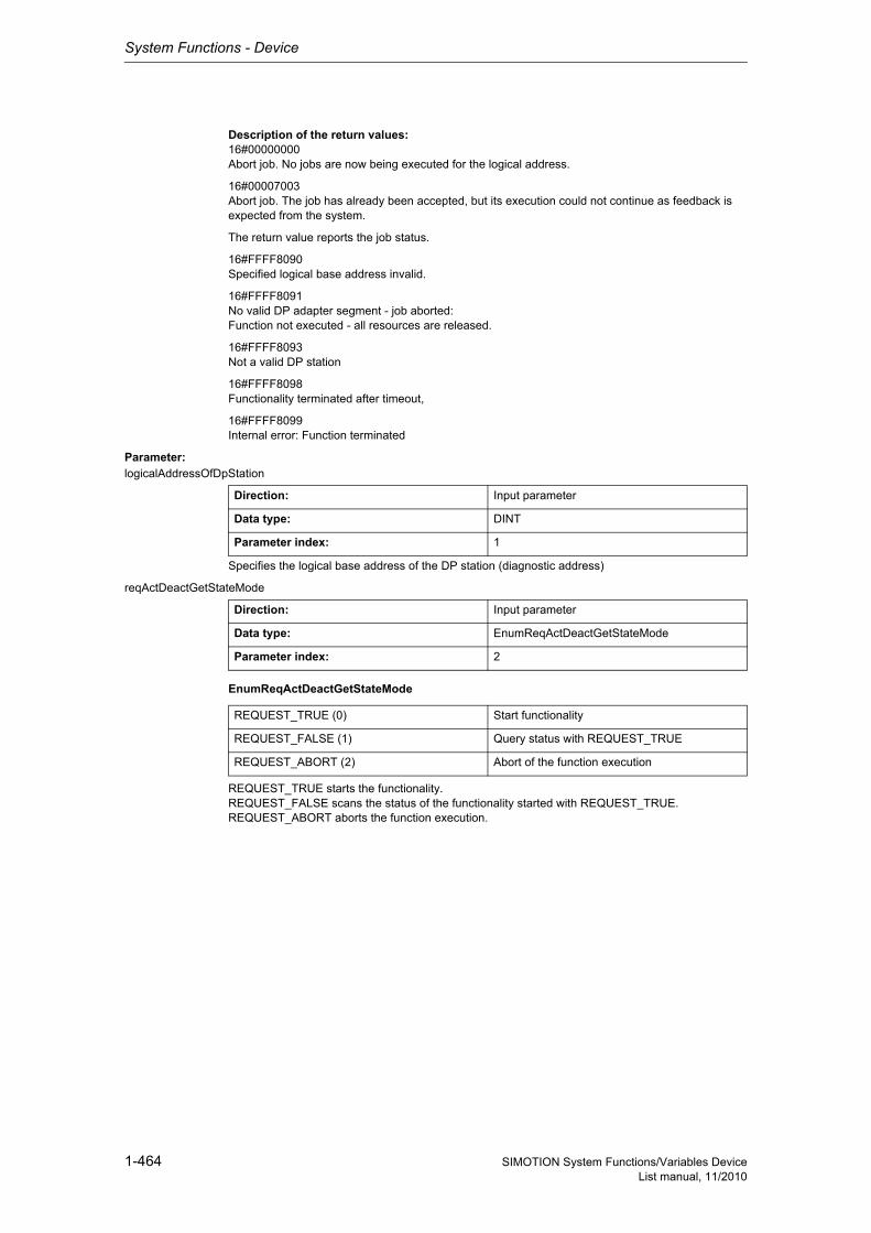
System Functions - Device
1-464 SIMOTION System Functions/Variables DeviceList manual, 11/2010
Description of the return values:16#00000000Abort job. No jobs are now being executed for the logical address.
16#00007003Abort job. The job has already been accepted, but its execution could not continue as feedback is expected from the system.
The return value reports the job status.
16#FFFF8090Specified logical base address invalid.
16#FFFF8091No valid DP adapter segment - job aborted:Function not executed - all resources are released.
16#FFFF8093Not a valid DP station
16#FFFF8098Functionality terminated after timeout,
16#FFFF8099Internal error: Function terminated
Parameter: logicalAddressOfDpStation
Specifies the logical base address of the DP station (diagnostic address)
reqActDeactGetStateMode
EnumReqActDeactGetStateMode
REQUEST_TRUE starts the functionality.REQUEST_FALSE scans the status of the functionality started with REQUEST_TRUE.REQUEST_ABORT aborts the function execution.
Direction: Input parameter
Data type: DINT
Parameter index: 1
Direction: Input parameter
Data type: EnumReqActDeactGetStateMode
Parameter index: 2
REQUEST_TRUE (0) Start functionality
REQUEST_FALSE (1) Query status with REQUEST_TRUE
REQUEST_ABORT (2) Abort of the function execution
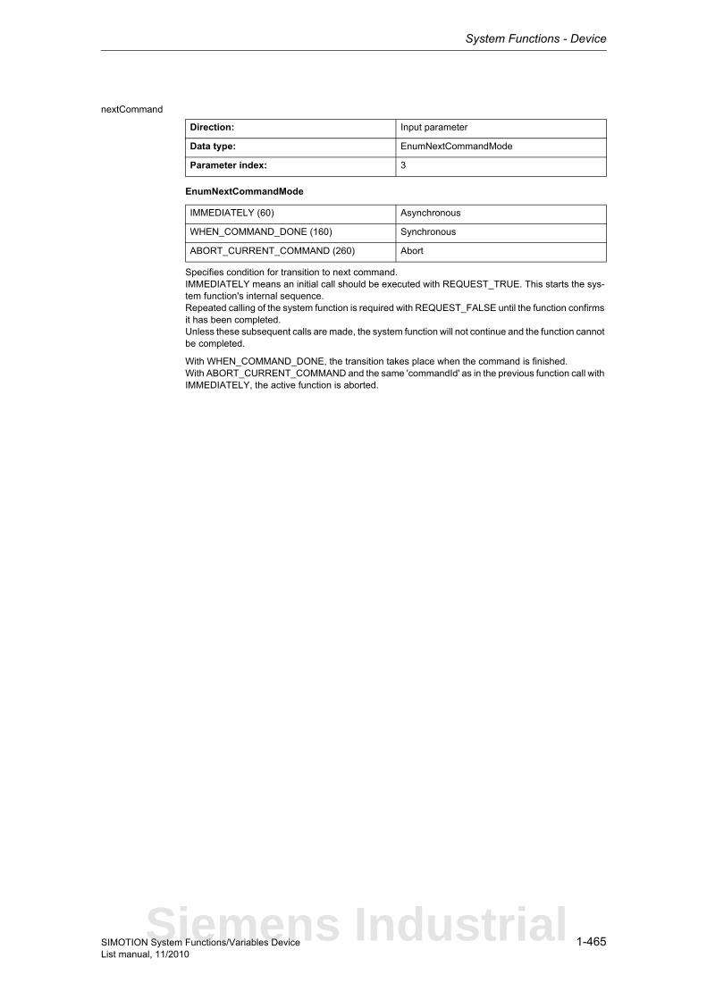
System Functions - Device
1-465SIMOTION System Functions/Variables DeviceList manual, 11/2010
nextCommand
EnumNextCommandMode
Specifies condition for transition to next command.IMMEDIATELY means an initial call should be executed with REQUEST_TRUE. This starts the sys-tem function's internal sequence.Repeated calling of the system function is required with REQUEST_FALSE until the function confirms it has been completed.Unless these subsequent calls are made, the system function will not continue and the function cannot be completed.
With WHEN_COMMAND_DONE, the transition takes place when the command is finished.With ABORT_CURRENT_COMMAND and the same 'commandId' as in the previous function call with IMMEDIATELY, the active function is aborted.
Direction: Input parameter
Data type: EnumNextCommandMode
Parameter index: 3
IMMEDIATELY (60) Asynchronous
WHEN_COMMAND_DONE (160) Synchronous
ABORT_CURRENT_COMMAND (260) Abort
Siemens Industrial
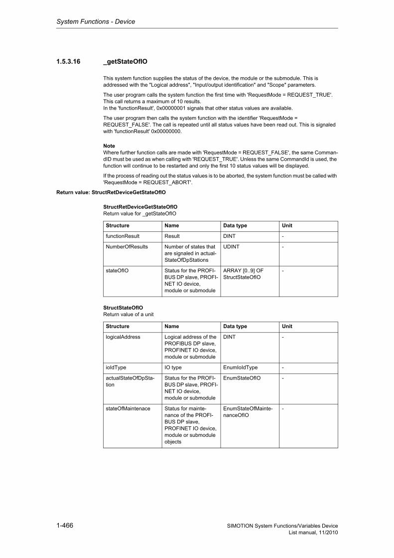
System Functions - Device
1-466 SIMOTION System Functions/Variables DeviceList manual, 11/2010
1.5.3.16 _getStateOfIO
This system function supplies the status of the device, the module or the submodule. This is addressed with the "Logical address", "Input/output identification" and "Scope" parameters.
The user program calls the system function the first time with 'RequestMode = REQUEST_TRUE'. This call returns a maximum of 10 results.In the 'functionResult', 0x00000001 signals that other status values are available.
The user program then calls the system function with the identifier 'RequestMode = REQUEST_FALSE'. The call is repeated until all status values have been read out. This is signaled with 'functionResult' 0x00000000.
NoteWhere further function calls are made with 'RequestMode = REQUEST_FALSE', the same Comman-dID must be used as when calling with 'REQUEST_TRUE'. Unless the same CommandId is used, the function will continue to be restarted and only the first 10 status values will be displayed.
If the process of reading out the status values is to be aborted, the system function must be called with 'RequestMode = REQUEST_ABORT'.
Return value: StructRetDeviceGetStateOfIO
StructRetDeviceGetStateOfIOReturn value for _getStateOfIO
StructStateOfIOReturn value of a unit
Structure Name Data type Unit
functionResult Result DINT -
NumberOfResults Number of states that are signaled in actual-StateOfDpStations
UDINT -
stateOfIO Status for the PROFI-BUS DP slave, PROFI-NET IO device, module or submodule
ARRAY [0..9] OF StructStateOfIO
-
Structure Name Data type Unit
logicalAddress Logical address of the PROFIBUS DP slave, PROFINET IO device, module or submodule
DINT -
ioIdType IO type EnumIoIdType -
actualStateOfDpSta-tion
Status for the PROFI-BUS DP slave, PROFI-NET IO device, module or submodule
EnumStateOfIO -
stateOfMaintenace Status for mainte-nance of the PROFI-BUS DP slave, PROFINET IO device, module or submodule objects
EnumStateOfMainte-nanceOfIO
-
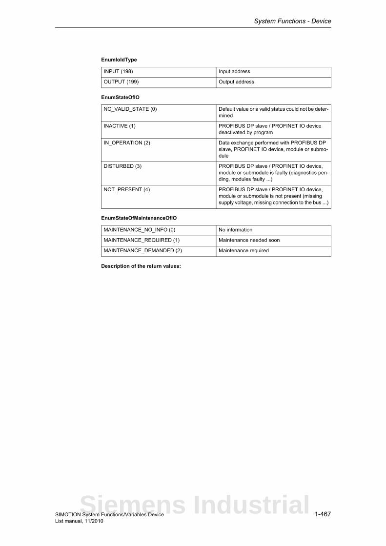
System Functions - Device
1-467SIMOTION System Functions/Variables DeviceList manual, 11/2010
EnumIoIdType
EnumStateOfIO
EnumStateOfMaintenanceOfIO
Description of the return values:
INPUT (198) Input address
OUTPUT (199) Output address
NO_VALID_STATE (0) Default value or a valid status could not be deter-mined
INACTIVE (1) PROFIBUS DP slave / PROFINET IO device deactivated by program
IN_OPERATION (2) Data exchange performed with PROFIBUS DP slave, PROFINET IO device, module or submo-dule
DISTURBED (3) PROFIBUS DP slave / PROFINET IO device, module or submodule is faulty (diagnostics pen-ding, modules faulty ...)
NOT_PRESENT (4) PROFIBUS DP slave / PROFINET IO device, module or submodule is not present (missing supply voltage, missing connection to the bus ...)
MAINTENANCE_NO_INFO (0) No information
MAINTENANCE_REQUIRED (1) Maintenance needed soon
MAINTENANCE_DEMANDED (2) Maintenance required
Siemens Industrial
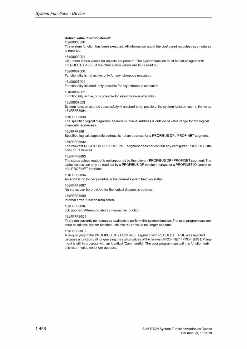
System Functions - Device
1-468 SIMOTION System Functions/Variables DeviceList manual, 11/2010
Return value 'functionResult'16#00000000The system function has been executed. All information about the configured modules / submodules is reported.
16#00000001OK - other status values for objects are present. The system function must be called again with 'REQUEST_FALSE' if the other status values are to be read out.
16#00007000Functionality is not active, only for asynchronous execution.
16#00007001Functionality initiated, only possible for asynchronous execution.
16#00007002Functionality active, only possible for asynchronous execution.
16#00007003System function aborted successfully. If an abort is not possible, the system function returns the value 16#FFFF8094.
16#FFFF8090The specified logical diagnostic address is invalid. Address is outside of value range for the logical diagnostic addresses.
16#FFFF8091Specified logical diagnostic address is not an address for a PROFIBUS DP / PROFINET segment.
16#FFFF8092The relevant PROFIBUS DP / PROFINET segment does not contain any configured PROFIBUS sta-tions or IO devices.
16#FFFF8093The status values readout is not supported by the relevant PROFIBUS DP / PROFINET segment. The status values can only be read out by a PROFIBUS DP master interface or a PROFINET IO controller of a PROFINET interface.
16#FFFF8094An abort is no longer possible in the current system function status.
16#FFFF8097No status can be provided for the logical diagnostic address.
16#FFFF8099Internal error, function terminated.
16#FFFF809EJob aborted. Attempt to abort a non-active function.
16#FFFF80C1There are currently no resources available to perform this system function. The user program can con-tinue to call this system function until this return value no longer appears.
16#FFFF80C2A re-querying of the PROFIBUS DP / PROFINET segment with REQUEST_TRUE was rejected because a function call for querying the status values of the relevant PROFINET / PROFIBUS DP seg-ment is still in progress with an identical 'CommandId'. The user program can call this function until this return value no longer appears.
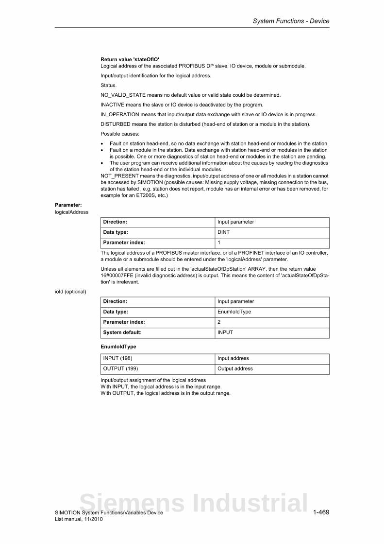
System Functions - Device
1-469SIMOTION System Functions/Variables DeviceList manual, 11/2010
Return value 'stateOfIO'Logical address of the associated PROFIBUS DP slave, IO device, module or submodule.
Input/output identification for the logical address.
Status.
NO_VALID_STATE means no default value or valid state could be determined.
INACTIVE means the slave or IO device is deactivated by the program.
IN_OPERATION means that input/output data exchange with slave or IO device is in progress.
DISTURBED means the station is disturbed (head-end of station or a module in the station).
Possible causes:
• Fault on station head-end, so no data exchange with station head-end or modules in the station.• Fault on a module in the station. Data exchange with station head-end or modules in the station
is possible. One or more diagnostics of station head-end or modules in the station are pending.• The user program can receive additional information about the causes by reading the diagnostics
of the station head-end or the individual modules.NOT_PRESENT means the diagnostics, input/output address of one or all modules in a station cannot be accessed by SIMOTION (possible causes: Missing supply voltage, missing connection to the bus, station has failed , e.g. station does not report, module has an internal error or has been removed, for example for an ET200S, etc.)
Parameter: logicalAddress
The logical address of a PROFIBUS master interface, or of a PROFINET interface of an IO controller, a module or a submodule should be entered under the 'logicalAddress' parameter.
Unless all elements are filled out in the 'actualStateOfDpStation' ARRAY, then the return value 16#00007FFE (invalid diagnostic address) is output. This means the content of 'actualStateOfDpSta-tion' is irrelevant.
ioId (optional)
EnumIoIdType
Input/output assignment of the logical addressWith INPUT, the logical address is in the input range.With OUTPUT, the logical address is in the output range.
Direction: Input parameter
Data type: DINT
Parameter index: 1
Direction: Input parameter
Data type: EnumIoIdType
Parameter index: 2
System default: INPUT
INPUT (198) Input address
OUTPUT (199) Output address
Siemens Industrial
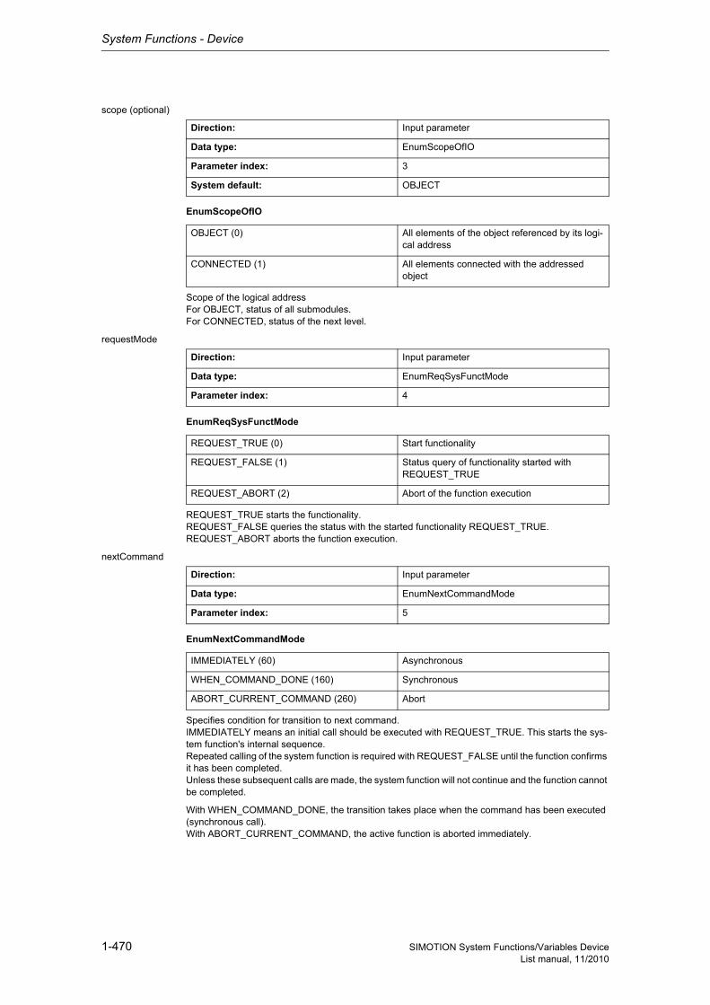
System Functions - Device
1-470 SIMOTION System Functions/Variables DeviceList manual, 11/2010
scope (optional)
EnumScopeOfIO
Scope of the logical addressFor OBJECT, status of all submodules.For CONNECTED, status of the next level.
requestMode
EnumReqSysFunctMode
REQUEST_TRUE starts the functionality.REQUEST_FALSE queries the status with the started functionality REQUEST_TRUE.REQUEST_ABORT aborts the function execution.
nextCommand
EnumNextCommandMode
Specifies condition for transition to next command.IMMEDIATELY means an initial call should be executed with REQUEST_TRUE. This starts the sys-tem function's internal sequence.Repeated calling of the system function is required with REQUEST_FALSE until the function confirms it has been completed.Unless these subsequent calls are made, the system function will not continue and the function cannot be completed.
With WHEN_COMMAND_DONE, the transition takes place when the command has been executed (synchronous call).With ABORT_CURRENT_COMMAND, the active function is aborted immediately.
Direction: Input parameter
Data type: EnumScopeOfIO
Parameter index: 3
System default: OBJECT
OBJECT (0) All elements of the object referenced by its logi-cal address
CONNECTED (1) All elements connected with the addressed object
Direction: Input parameter
Data type: EnumReqSysFunctMode
Parameter index: 4
REQUEST_TRUE (0) Start functionality
REQUEST_FALSE (1) Status query of functionality started with REQUEST_TRUE
REQUEST_ABORT (2) Abort of the function execution
Direction: Input parameter
Data type: EnumNextCommandMode
Parameter index: 5
IMMEDIATELY (60) Asynchronous
WHEN_COMMAND_DONE (160) Synchronous
ABORT_CURRENT_COMMAND (260) Abort
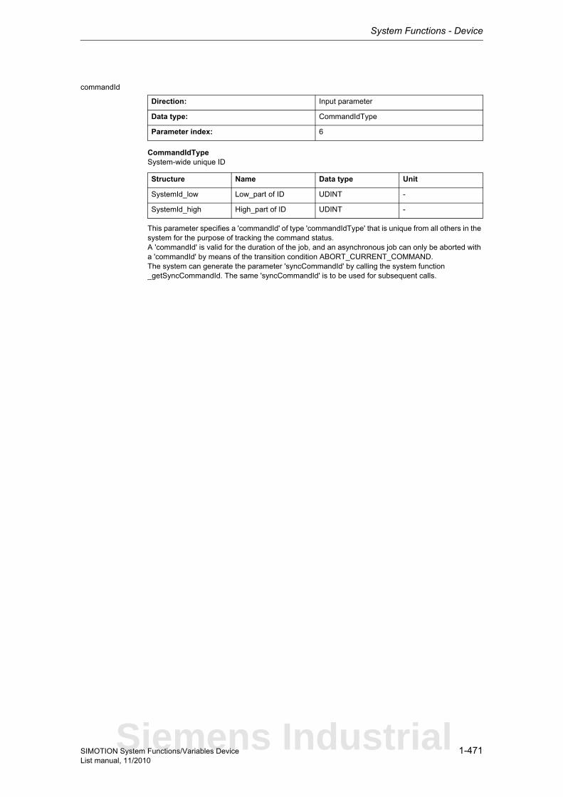
System Functions - Device
1-471SIMOTION System Functions/Variables DeviceList manual, 11/2010
commandId
CommandIdTypeSystem-wide unique ID
This parameter specifies a 'commandId' of type 'commandIdType' that is unique from all others in the system for the purpose of tracking the command status.A 'commandId' is valid for the duration of the job, and an asynchronous job can only be aborted with a 'commandId' by means of the transition condition ABORT_CURRENT_COMMAND.The system can generate the parameter 'syncCommandId' by calling the system function _getSyncCommandId. The same 'syncCommandId' is to be used for subsequent calls.
Direction: Input parameter
Data type: CommandIdType
Parameter index: 6
Structure Name Data type Unit
SystemId_low Low_part of ID UDINT -
SystemId_high High_part of ID UDINT -
Siemens Industrial
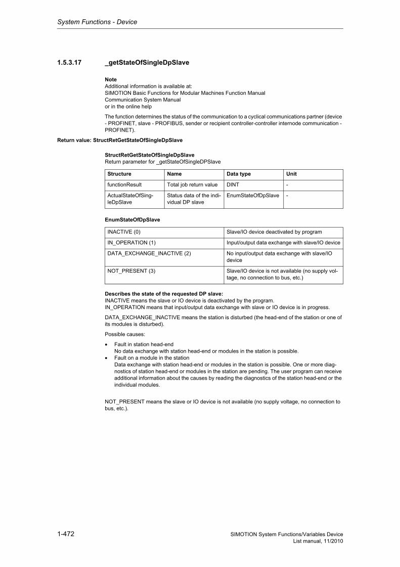
System Functions - Device
1-472 SIMOTION System Functions/Variables DeviceList manual, 11/2010
1.5.3.17 _getStateOfSingleDpSlave
NoteAdditional information is available at:SIMOTION Basic Functions for Modular Machines Function ManualCommunication System Manualor in the online help
The function determines the status of the communication to a cyclical communications partner (device - PROFINET, slave - PROFIBUS, sender or recipient controller-controller internode communication - PROFINET).
Return value: StructRetGetStateOfSingleDpSlave
StructRetGetStateOfSingleDpSlaveReturn parameter for _getStateOfSingleDPSlave
EnumStateOfDpSlave
Describes the state of the requested DP slave:INACTIVE means the slave or IO device is deactivated by the program.IN_OPERATION means that input/output data exchange with slave or IO device is in progress.
DATA_EXCHANGE_INACTIVE means the station is disturbed (the head-end of the station or one of its modules is disturbed).
Possible causes:
• Fault in station head-endNo data exchange with station head-end or modules in the station is possible.
• Fault on a module in the stationData exchange with station head-end or modules in the station is possible. One or more diag-nostics of station head-end or modules in the station are pending. The user program can receive additional information about the causes by reading the diagnostics of the station head-end or the individual modules.
NOT_PRESENT means the slave or IO device is not available (no supply voltage, no connection to bus, etc.).
Structure Name Data type Unit
functionResult Total job return value DINT -
ActualStateOfSing-leDpSlave
Status data of the indi-vidual DP slave
EnumStateOfDpSlave -
INACTIVE (0) Slave/IO device deactivated by program
IN_OPERATION (1) Input/output data exchange with slave/IO device
DATA_EXCHANGE_INACTIVE (2) No input/output data exchange with slave/IO device
NOT_PRESENT (3) Slave/IO device is not available (no supply vol-tage, no connection to bus, etc.)
System Functions - Device
1-473SIMOTION System Functions/Variables DeviceList manual, 11/2010
Description of the return values:16#00000000System function completed successfully.
16#00007000Functionality is not active, only for asynchronous execution.
16#00007001Functionality initiated, only for asynchronous execution.
16#00007002Functionality active, only for asynchronous execution.
16#FFFF8090No valid PROFIBUS or PROFINET segment.
16#FFFF8091No configuration present for the specified DP station address or device number.
16#FFFF8092A new call of the function with these parameters is not permitted.
16#FFFF8093No valid logical diagnostic address of a DP station or an IO device.
16#FFFF8098The automated status of the system function terminated with timeout.
16#FFFF8099Internal error, terminate function.
16#FFFF80C1Function already started, new call with parameter 'ReqGetStateOfSingleDPSlaveStateMode=TRUE'.
16#FFFF80C3Temporary resource bottleneck.
16#FFFF80CFCommandId not unique.
16#FFFF809EAbort of function not allowed.
16#FFFF809DAbort successful.
Parameter: logicalDiagnosticAddress
Diagnostic address of the communications partner or the receive connection of the internode commu-nication.
NoteSeveral connections are possible at the receiver side of the controller-controller internode communi-cation. Each connection is represented as communications partner.
ReqGetStateOfSingleDPSlaveStateMode
Direction: Input parameter
Data type: DINT
Parameter index: 1
Direction: Input parameter
Data type: EnumReqActDeactGetStateMode
Parameter index: 2
Siemens Industrial
System Functions - Device
1-474 SIMOTION System Functions/Variables DeviceList manual, 11/2010
EnumReqActDeactGetStateMode
REQUEST_TRUE starts the functionality.REQUEST_FALSE scans the status of the functionality started with REQUEST_TRUE.REQUEST_ABORT aborts the function execution.
nextCommand
EnumNextCommandMode
Specifies condition for transition to next command.IMMEDIATELY means an initial call should be executed with REQUEST_TRUE. This starts the sys-tem function's internal sequence.Repeated calling of the system function is required with REQUEST_FALSE until the function confirms it has been completed.Unless these subsequent calls are made, the system function will not continue and the function cannot be completed.
With WHEN_COMMAND_DONE, the transition takes place when the command has been executed.With ABORT_CURRENT_COMMAND, the active function is aborted immediately.
commandId
CommandIdTypeSystem-wide unique ID
Unique, system-wide 'commandId' to track command status.
REQUEST_TRUE (0) Start functionality
REQUEST_FALSE (1) Query status with REQUEST_TRUE
REQUEST_ABORT (2) Abort of the function execution
Direction: Input parameter
Data type: EnumNextCommandMode
Parameter index: 3
IMMEDIATELY (60) Asynchronous
WHEN_COMMAND_DONE (160) Synchronous
ABORT_CURRENT_COMMAND (260) Abort
Direction: Input parameter
Data type: CommandIdType
Parameter index: 4
Structure Name Data type Unit
SystemId_low Low_part of ID UDINT -
SystemId_high High_part of ID UDINT -
System Functions - Device
1-475SIMOTION System Functions/Variables DeviceList manual, 11/2010
1.5.3.18 _getStateOfTo
This function supplies information on whether the technology object (TO) is activated or deactivated.It can be executed both synchronously and asynchronously.
NoteThe functions _activateTo, _deactivateTo and _getstateOfTo belong to a function pool. Maximum 50 active calls from this pool can be processed simultaneously.The return value '16#FFFF80C3' is signaled when the maximum number is exceeded. Each running instance requires additional computation time in the technology object environment (in the cyclic levels); therefore it is more efficient to first query the respective state and then to set the required desi-red state by means of _activateTo and _deactivateTo.
NoteMore detailed information on this system function can be found inthe Function Manual titled "Motion Control Basic Functions for Modular Machines".
Return value: StructRetGetStateOfTo
StructRetGetStateOfToReturn parameters for device commands
EnumStateOfTo
EnumToSetStateOfTo
Structure Name Data type Unit
functionResult Return value of func-tion
DINT -
commandIdState Current state of the technology object
EnumStateOfTo -
setState Desired state of the TO: ACTIVATED / DEACTIVATED
EnumToSetStateOfTo -
ACTIVE (1) 16#00000001 TO activated
INACTIVE (2) 16#00000002 TO deactivated
IN_ACTIVATION (3) 16#00000003 TO will be activated
IN_DEACTIVATION (4) 16#00000004 TO will be deactivated
ACTIVATED (1) 16#00000001 TO activated
DEACTIVATED (2) 16#00000002 TO deactivated
Siemens Industrial
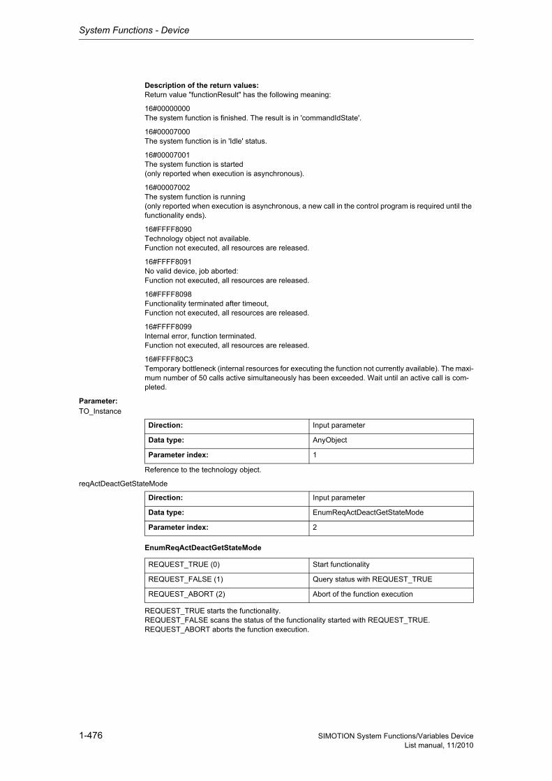
System Functions - Device
1-476 SIMOTION System Functions/Variables DeviceList manual, 11/2010
Description of the return values:Return value "functionResult" has the following meaning:
16#00000000The system function is finished. The result is in 'commandIdState'.
16#00007000The system function is in 'Idle' status.
16#00007001The system function is started(only reported when execution is asynchronous).
16#00007002The system function is running(only reported when execution is asynchronous, a new call in the control program is required until the functionality ends).
16#FFFF8090Technology object not available.Function not executed, all resources are released.
16#FFFF8091No valid device, job aborted:Function not executed, all resources are released.
16#FFFF8098Functionality terminated after timeout,Function not executed, all resources are released.
16#FFFF8099Internal error, function terminated.Function not executed, all resources are released.
16#FFFF80C3Temporary bottleneck (internal resources for executing the function not currently available). The maxi-mum number of 50 calls active simultaneously has been exceeded. Wait until an active call is com-pleted.
Parameter: TO_Instance
Reference to the technology object.
reqActDeactGetStateMode
EnumReqActDeactGetStateMode
REQUEST_TRUE starts the functionality.REQUEST_FALSE scans the status of the functionality started with REQUEST_TRUE.REQUEST_ABORT aborts the function execution.
Direction: Input parameter
Data type: AnyObject
Parameter index: 1
Direction: Input parameter
Data type: EnumReqActDeactGetStateMode
Parameter index: 2
REQUEST_TRUE (0) Start functionality
REQUEST_FALSE (1) Query status with REQUEST_TRUE
REQUEST_ABORT (2) Abort of the function execution
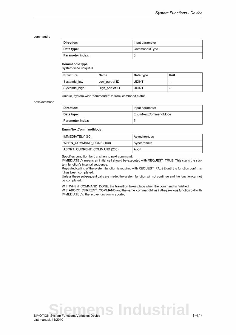
System Functions - Device
1-477SIMOTION System Functions/Variables DeviceList manual, 11/2010
commandId
CommandIdTypeSystem-wide unique ID
Unique, system-wide 'commandId' to track command status.
nextCommand
EnumNextCommandMode
Specifies condition for transition to next command.IMMEDIATELY means an initial call should be executed with REQUEST_TRUE. This starts the sys-tem function's internal sequence.Repeated calling of the system function is required with REQUEST_FALSE until the function confirms it has been completed.Unless these subsequent calls are made, the system function will not continue and the function cannot be completed.
With WHEN_COMMAND_DONE, the transition takes place when the command is finished.With ABORT_CURRENT_COMMAND and the same 'commandId' as in the previous function call with IMMEDIATELY, the active function is aborted.
Direction: Input parameter
Data type: CommandIdType
Parameter index: 3
Structure Name Data type Unit
SystemId_low Low_part of ID UDINT -
SystemId_high High_part of ID UDINT -
Direction: Input parameter
Data type: EnumNextCommandMode
Parameter index: 5
IMMEDIATELY (60) Asynchronous
WHEN_COMMAND_DONE (160) Synchronous
ABORT_CURRENT_COMMAND (260) Abort
Siemens Industrial
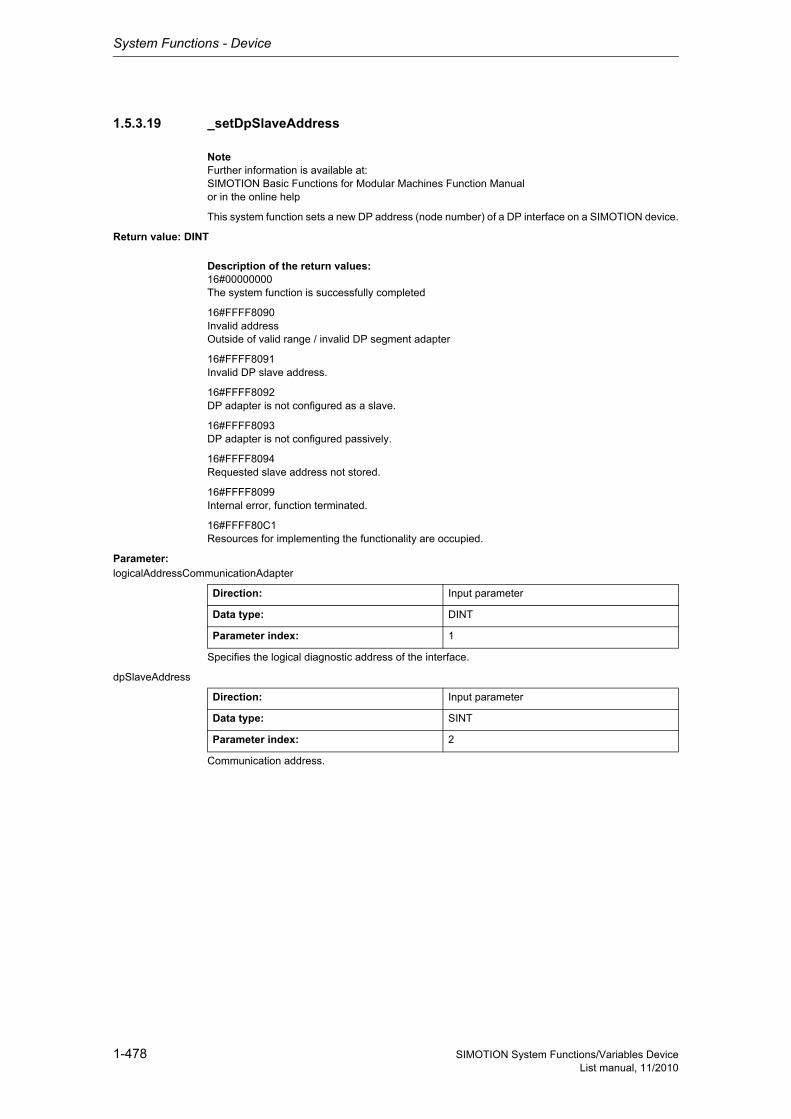
System Functions - Device
1-478 SIMOTION System Functions/Variables DeviceList manual, 11/2010
1.5.3.19 _setDpSlaveAddress
NoteFurther information is available at:SIMOTION Basic Functions for Modular Machines Function Manualor in the online help
This system function sets a new DP address (node number) of a DP interface on a SIMOTION device.
Return value: DINT
Description of the return values:16#00000000The system function is successfully completed
16#FFFF8090Invalid addressOutside of valid range / invalid DP segment adapter
16#FFFF8091Invalid DP slave address.
16#FFFF8092DP adapter is not configured as a slave.
16#FFFF8093DP adapter is not configured passively.
16#FFFF8094Requested slave address not stored.
16#FFFF8099Internal error, function terminated.
16#FFFF80C1Resources for implementing the functionality are occupied.
Parameter: logicalAddressCommunicationAdapter
Specifies the logical diagnostic address of the interface.
dpSlaveAddress
Communication address.
Direction: Input parameter
Data type: DINT
Parameter index: 1
Direction: Input parameter
Data type: SINT
Parameter index: 2
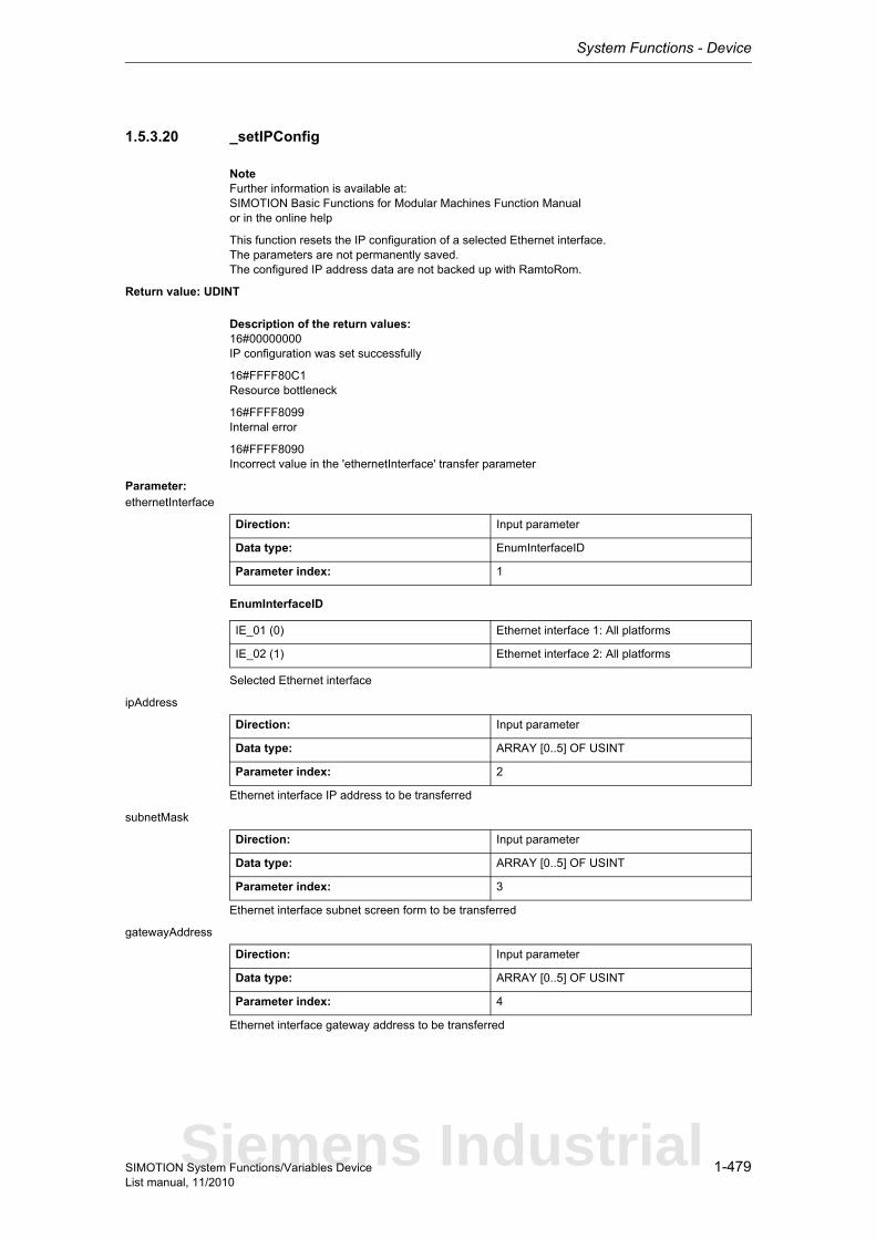
System Functions - Device
1-479SIMOTION System Functions/Variables DeviceList manual, 11/2010
1.5.3.20 _setIPConfig
NoteFurther information is available at:SIMOTION Basic Functions for Modular Machines Function Manualor in the online help
This function resets the IP configuration of a selected Ethernet interface.The parameters are not permanently saved.The configured IP address data are not backed up with RamtoRom.
Return value: UDINT
Description of the return values:16#00000000IP configuration was set successfully
16#FFFF80C1Resource bottleneck
16#FFFF8099Internal error
16#FFFF8090Incorrect value in the 'ethernetInterface' transfer parameter
Parameter: ethernetInterface
EnumInterfaceID
Selected Ethernet interface
ipAddress
Ethernet interface IP address to be transferred
subnetMask
Ethernet interface subnet screen form to be transferred
gatewayAddress
Ethernet interface gateway address to be transferred
Direction: Input parameter
Data type: EnumInterfaceID
Parameter index: 1
IE_01 (0) Ethernet interface 1: All platforms
IE_02 (1) Ethernet interface 2: All platforms
Direction: Input parameter
Data type: ARRAY [0..5] OF USINT
Parameter index: 2
Direction: Input parameter
Data type: ARRAY [0..5] OF USINT
Parameter index: 3
Direction: Input parameter
Data type: ARRAY [0..5] OF USINT
Parameter index: 4
Siemens Industrial
System Functions - Device
1-480 SIMOTION System Functions/Variables DeviceList manual, 11/2010
1.5.3.21 _setModeSelfAdaptingConfiguration
This system function sets the mode to ON or OFF.
NoteMore detailed information on this system function can be found inthe Function Manual titled "Motion Control Basic Functions for Modular Machines".
Return value: DINTThis system function sets the mode if storage for this mode is available in SIMOTION.
Description of the return values:16#00000000 OK - the system function is finished - the mode has been saved.
16#00000001 Storage not available for this information.
16#FFFF8099 Internal error, function terminated.
16#FFFF80C1 The resources to execute this functionality are missing.
16#FFFF80C3 Access to the mode storage location disabled.
Parameter: mode
EnumModeSelfAdaptingConfiguration
Value "ON" or "OFF" to be set.
Direction: Input parameter
Data type: EnumModeSelfAdaptingConfiguration
Parameter index: 1
OFF (0) Switched off
ON (1) Switched on

System Functions - Device
1-481SIMOTION System Functions/Variables DeviceList manual, 11/2010
1.5.3.22 _setNameOfStation
NoteAdditional information is available at:SIMOTION Basic Functions for Modular Machines Function Manualor in the online help
This function saves the transferred NameOfStation.The stored 'NameOfStation' only then takes effect using _activateNameOfStation.
Return value: DINTThe return value returns the job status and name.
Description of the return values:16#0000000System function completed successfully. 'NameOfStation' is successfully set during the next activa-tion using _activateNameOfStation.
16#FFFF8090The specified logical diagnostic address is invalid.
16#FFFF8091No valid logical diagnostic address for a PROFINET interface.
16#FFFF8092PROFINET interface is configured, but not available.Can only occur if the PROFINET interface is inserted in SIMOTION via a module.
16#FFFF8093The STRING specified in the 'nameOfStation'' parameter is too long.Only 239 characters are permitted. According to the standard, 240 characters are permitted, but this is not currently supported by SIMOTION.
16#FFFF8094An abort is no longer possible in the current system function status.
16#FFFF8097Setting the 'NameOfStation' is not supported by the PROFINET interface.
16#FFFF8098The contents of the STRING specified under the parameter 'nameOfStation' do not respect the usual 'NameOfStation' conventions.
16#FFFF8099Internal error. Function terminated.
16#FFFF80A0The functionality "Obtain device names in another way" is deselected in the HW Config. Please amend the HW Config accordingly. Function terminated.
16#FFFF80C1There are currently no resources available to perform this system function.The user program can call this function until this return value no longer appears.
16#FFFF80C2A system function call for the relevant PROFINET interface is already in progress.The user program can call this function until this return value no longer appears.
16#FFFF80C3An attempt to reset 'NameOfStation' with REQUEST_TRUE was rejected because a function call for setting a 'NameOfStation' on the relevant PROFINET interface is still in progress with an identical CommandId.The user program can call this function until this return value no longer appears.
Siemens Industrial

System Functions - Device
1-482 SIMOTION System Functions/Variables DeviceList manual, 11/2010
Parameter: logicalAddressPnInterface
Specifies the logical diagnostic address of the PROFINET interface, or the logical diagnostic addres-ses of the associated ports on the PROFINET interface, from which the active device name is to be read.
The ports' logical diagnostic addresses clearly identify the PROFINET interface.The requested active 'NameOfStation' is supplied.
NameOfStation
Specification of the station name.
requestMode
EnumReqSysFunctMode
REQUEST_TRUE starts the functionality.REQUEST_FALSE scans the status of the functionality started with REQUEST_TRUE.REQUEST_ABORT aborts the function execution.
commandId
CommandIdTypeSystem-wide unique ID
This parameter specifies a 'CommandId' of type 'commandIdType' that is unique from all others in the system.The user can make the system generate a 'syncCommandId' by calling _getSyncCommandId.The same syncCommandId is used for subsequent calls.
Direction: Input parameter
Data type: DINT
Parameter index: 1
Direction: Input parameter
Data type: STRING
Parameter index: 2
Direction: Input parameter
Data type: EnumReqSysFunctMode
Parameter index: 3
REQUEST_TRUE (0) Start functionality
REQUEST_FALSE (1) Status query of functionality started with REQUEST_TRUE
REQUEST_ABORT (2) Abort of the function execution
Direction: Input parameter
Data type: CommandIdType
Parameter index: 4
Structure Name Data type Unit
SystemId_low Low_part of ID UDINT -
SystemId_high High_part of ID UDINT -

System Functions - Device
1-483SIMOTION System Functions/Variables DeviceList manual, 11/2010
nextCommand
EnumNextCommandMode
Specifies condition for transition to next command.IMMEDIATELY means an initial call should be executed with REQUEST_TRUE. This starts the sys-tem function's internal sequence.Repeated calling of the system function is required with REQUEST_FALSE until the function confirms it has been completed.Unless these subsequent calls are made, the system function will not continue and the function cannot be completed.
With WHEN_COMMAND_DONE, the transition takes place when the command is finished.With ABORT_CURRENT_COMMAND and the same 'commandId' as in the previous function call with IMMEDIATELY, the active function is aborted.
Direction: Input parameter
Data type: EnumNextCommandMode
Parameter index: 6
IMMEDIATELY (60) Asynchronous
WHEN_COMMAND_DONE (160) Synchronous
ABORT_CURRENT_COMMAND (260) Abort
Siemens Industrial
System Functions - Device
1-484 SIMOTION System Functions/Variables DeviceList manual, 11/2010
1.5.3.23 _synchronizeDpInterfaces
NoteAdditional information is available at:SIMOTION Basic Functions for Modular Machines Function Manualor in the online help
This function synchronizes the DP master interface with the DP slave interface.This requires a corresponding interface configuration.
The function is complete when the interfaces are synchronous or if synchronization is not possible.This function can be called multiple times (using the same 'commandId') to scan the execution status.
This function can only be active once at any given time. Multiple starts (multiple calls using a different 'commandId') cause an error message.
If the operating mode is switched from RUN to STOP while the function is being executed, the function is aborted. After the transition from STOP to RUN, the function can be called again.
Return value: DINT
Description of the return values:Asynchronous start:
(in addition to return values for synchronous call)
16#00007000DP synchronization started:Return value signals that the function has been started.
Synchronous call:
16#00007010DP interfaces synchronized:The return value signals that the interfaces are synchronized.The internal state machine is advanced to DP_INTERFACES_SYNCHRONIZED.NoteWith PROFIBUS, the function must be started when RUN is reached, with PROFINET, the call for PROFINET can be made during startup.With PROFINET, the call only functions when the system variable StateOfDpInterfaceSynchronization is at DP_CLOCK_DETECTED when the function is called.
16#00007080DP synchronization active:Return value signals that the function is still being executed.
16#FFFF805xDP synchronization not enabled:Return value signals that synchronization was ended unsuccessfully.The internal state machine is advanced to WAIT_FOR_DP_CLOCK.Details x:0 This error is set if the _enableDpInterfaceSynchronizationMode function was not called with para-meter MASTER_SLAVE_ALARMMESSAGES_1.1 This error is set if the interfaces could not be synchronized. One possible cause is interference in the clock signal.2 Temporary internal synchronization problem. The user state machine must be advanced.
16#FFFF8080DP synchronization not enabled:It is not permissible to call the function in the current system state.The internal state machine is not advanced.
System Functions - Device
1-485SIMOTION System Functions/Variables DeviceList manual, 11/2010
16#FFFF8081DP_Synchronization already active:Return value signals that the function has already been called with another 'commandId'.The new call was aborted or rejected.The internal state machine is not advanced.
16#FFFF8082Function cannot be called synchronously due to resource bottleneck:The return value signals that the function cannot be called synchronously at the moment for resource reasons (no semaphore available).The internal state machine is not advanced.
16#FFFF8083Required alarm messages are not enabled:The function has been called, although the alarm messages required for sequential control have not been activated or the C230-2 has not been configured as an isochronous slave(see also _enableDpInterfaceSynchronizationMode function).The internal state machine is not advanced.
16#FFFF8090DP synchronization not supported:Return value signals that the function is not supported by the platform.The internal state machine is not advanced.
Parameter: nextCommand
EnumNextCommandMode
Specifies condition for transition to next command.IMMEDIATELY means an initial call should be executed with REQUEST_TRUE. This starts the sys-tem function's internal sequence.Repeated calling of the system function is required with REQUEST_FALSE until the function confirms it has been completed.Unless these subsequent calls are made, the system function will not continue and the function cannot be completed.
With WHEN_COMMAND_DONE, the transition takes place when the command is finished.With ABORT_CURRENT_COMMAND and the same 'commandId' as in the previous function call with IMMEDIATELY, the active function is aborted.
commandId
CommandIdTypeSystem-wide unique ID
Unique, system-wide 'commandId' to track command status.
Direction: Input parameter
Data type: EnumNextCommandMode
Parameter index: 1
IMMEDIATELY (60) Asynchronous
WHEN_COMMAND_DONE (160) Synchronous
ABORT_CURRENT_COMMAND (260) Abort
Direction: Input parameter
Data type: CommandIdType
Parameter index: 2
Structure Name Data type Unit
SystemId_low Low_part of ID UDINT -
SystemId_high High_part of ID UDINT -
Siemens Industrial
System Functions - Device
1-486 SIMOTION System Functions/Variables DeviceList manual, 11/2010
1.5.4 Controller
1.5.4.1 _CTRL_pid
The _CTRL_pid function block is used to control technical processes with continuous input and output variables on SIMOTION systems. Via parameter assignment, you can enable or disable subfunctions of the PID controller and thus adapt it to the controlled system in question.
Detailed information
ST: Note:You can import the following program segments into the ST program using Drag & Drop. Additions must be made for executability (see manual, e.g. creating variables, etc.).An executable application example can be found on the "SIMOTION Utilities & Applications" CD-ROM.The "SIMOTION Utilities & Applications" CD-ROM is provided free of charge and is supplied with SIMOTION SCOUT.
// myCTRL_pid : _CTRL_pid; // instance of FB (_CTRL_pid)myCTRL_pid(enable := myEnable, // [IN] enable (BOOL)dataPid := myCTRL_dataPid // [IN_OUT] dataPid (Struct_CTRL_dataPid));// **********************// Struct_CTRL_dataPid// **********************// myCTRL_dataPid : Struct_CTRL_dataPid;myCTRL_dataPid.reset := FALSE; // [IN] complete restartmyCTRL_dataPid.manualMode := TRUE; // [IN] manual value onmyCTRL_dataPid.actValueType := FALSE; // [IN] process variable peripherie onmyCTRL_dataPid.setPController := TRUE; // [IN] proportional action onmyCTRL_dataPid.setIController := TRUE; // [IN] integral action onmyCTRL_dataPid.holdIValue := FALSE; // [IN] integral action holdmyCTRL_dataPid.setIValue := FALSE; // [IN] initialization of the integral actionmyCTRL_dataPid.setDController := FALSE; // [IN] derivative action onmyCTRL_dataPid.cycleTime := 1000; // [IN] sample time in msmyCTRL_dataPid.setpointValue := 0.0; // [IN] internal setpointmyCTRL_dataPid.numericActValue := 0.0; // [IN] process variable inmyCTRL_dataPid.binActValue := 0; // [IN] process variable peripheriemyCTRL_dataPid.manualValue := 0.0; // [IN] manual valuemyCTRL_dataPid.propGain := 2.0; // [IN] proportional gainmyCTRL_dataPid.integTime := 20000; // [IN] integration time in msmyCTRL_dataPid.derivativeTime := 10000; // [IN] derivative time in msmyCTRL_dataPid.delayTime := 2000; // [IN] time lag of the derivative action in msmyCTRL_dataPid.deadBand := 0.0; // [IN] dead band widthmyCTRL_dataPid.upperLimit := 100.0; // [IN] manipulated value high limitmyCTRL_dataPid.lowerLimit := 0.0; // [IN] manipulated value low limitmyCTRL_dataPid.actValueFactor := 1.0; // [IN] process variable factormyCTRL_dataPid.actValueOffset := 0.0; // [IN] process variable offsetmyCTRL_dataPid.outValueFactor := 1.0; // [IN] manipulated value factormyCTRL_dataPid.outValueOffset := 0.0; // [IN] manipulated value offsetmyCTRL_dataPid.initialIValue := 0.0; // [IN] initialization value of the integral actionmyCTRL_dataPid.disturbValue := 0.0; // [IN] disturbance variable
System Functions - Device
1-487SIMOTION System Functions/Variables DeviceList manual, 11/2010
1.5.4.2 _CTRL_piStep
The _CTRL_piStep function block is used to control technical processes with binary manipulated vari-able output signals for integrating actuators on SIMOTION systems. Via parameter assignment, you can enable or disable subfunctions of the PI step controller and thus adapt it to the controlled system in question.
Detailed information
ST: Note:You can import the following program segments into the ST program using Drag & Drop. Additions must be made for executability (see manual, e.g. creating variables, etc.).An executable application example can be found on the "SIMOTION Utilities & Applications" CD-ROM.The "SIMOTION Utilities & Applications" CD-ROM is provided free of charge and is supplied with SIMOTION SCOUT.
// myCTRL_piStep : _CTRL_piStep; // instance of FB (_CTRL_piStep)myCTRL_piStep(enable := myEnable, // [IN] enable (BOOL)dataPiStep := myCTRL_dataPiStep // [IN_OUT] dataPiStep (Struct_CTRL_dataPiStep));// *************************// Struct_CTRL_dataPiStep// *************************// myCTRL_dataPiStep : Struct_CTRL_dataPiStep;myCTRL_dataPiStep.reset := FALSE; // [IN] complete restartmyCTRL_dataPiStep.upperLimit := FALSE; // [IN] high limit signal of repeated manipulated valuemyCTRL_dataPiStep.lowerLimit := FALSE; // [IN] low limit signal of repeated manipulated valuemyCTRL_dataPiStep.manualMode := TRUE; // [IN] manipulated signals valuemyCTRL_dataPiStep.setOutHigh := FALSE; // [IN] manipulated value signals upmyCTRL_dataPiStep.setOutLow := FALSE; // [IN] manipulated signals downmyCTRL_dataPiStep.actValueType := FALSE; // [IN] process variable peripherie onmyCTRL_dataPiStep.cycleTime := 1000; // [IN] sample time in msmyCTRL_dataPiStep.setPointValue := 0.0; // [IN] internal setpointmyCTRL_dataPiStep.numericActValue := 0.0; // [IN] process variable inmyCTRL_dataPiStep.binActValue := 16#0000; // [IN] process variable periphery W#16#0000myCTRL_dataPiStep.propGain := 2.0; // [IN] proportional gainmyCTRL_dataPiStep.integTime := 20000; // [IN] integration time in msmyCTRL_dataPiStep.deadBand := 1.0; // [IN] dead band widthmyCTRL_dataPiStep.actValueFactor := 1.0; // [IN] process variable factormyCTRL_dataPiStep.actValueOffset := 0.0; // [IN] process variable offsetmyCTRL_dataPiStep.minPulseTime := 3000; // [IN] minimum pulse time in msmyCTRL_dataPiStep.minIdleTime := 3000; // [IN] minimum break time in msmyCTRL_dataPiStep.actuatingTime := 30000; // [IN] motor manipulated value in msmyCTRL_dataPiStep.disturbanceValue := 0.0; // [IN] disturbance variable
Siemens Industrial
System Functions - Device
1-488 SIMOTION System Functions/Variables DeviceList manual, 11/2010
1.5.4.3 _CTRL_pwm
The _CTRL_pwm function block is used to set up a PID controller with pulse output for proportional actuators.
Detailed information
ST: Note:You can import the following program segments into the ST program using Drag & Drop. Additions must be made for executability (see manual, e.g. creating variables, etc.).An executable application example can be found on the "SIMOTION Utilities & Applications" CD-ROM.The "SIMOTION Utilities & Applications" CD-ROM is provided free of charge and is supplied with SIMOTION SCOUT.
// myCTRL_pwm : _CTRL_pwm; // instance of FB (_CTRL_pwm)myCTRL_pwm(enable := myEnable, // [IN] enable (BOOL)dataPwm := myCTRL_dataPwm // [IN_OUT] dataPwm (Struct_CTRL_dataPwm));// **********************// Struct_CTRL_dataPwm// **********************// myCTRL_dataPwm : Struct_CTRL_dataPwm;myCTRL_dataPwm.reset := FALSE; // [IN] complete restartmyCTRL_dataPwm.inValue := 0.0; // [IN] input variablemyCTRL_dataPwm.periodTime := 1000; // [IN] period time in msmyCTRL_dataPwm.minPulseIdleTime := 0; // [IN] minimum break time in msmyCTRL_dataPwm.ratioFactor := 1.0; // [IN] ratio factormyCTRL_dataPwm.set3StepControl := TRUE; // [IN] three step signal onmyCTRL_dataPwm.set2StepControl := FALSE; // [IN] two step signal for bipolar manipulated value onmyCTRL_dataPwm.setManualMode := FALSE; // [IN] manual mode onmyCTRL_dataPwm.setPosPulse := FALSE; // [IN] positiv pulse onmyCTRL_dataPwm.setNegPulse := FALSE; // [IN] negativ pulse onmyCTRL_dataPwm.cycleTime := 10; // [IN] sample Time in ms
System Functions - Device
1-489SIMOTION System Functions/Variables DeviceList manual, 11/2010
1.5.5 System time
1.5.5.1 _getInternalTimeStamp
This function returns an internal timestamp which can be used for high-resolution runtime measure-ments. The value depends on the CPU and can only be interpreted by the _getTimeDifferenceOfInternalTimeStamps function for the purpose of calculating a period of time.
Return value: UDINTThe return value is the internal timestamp at the time of the function call.
Siemens Industrial
System Functions - Device
1-490 SIMOTION System Functions/Variables DeviceList manual, 11/2010
1.5.5.2 _getPNSyncCounter
This function provides the user with the current counter value of a counter synchronized via PROFI-NET, which is read from the PN module. For modules with several PN modules (e.g. CBE and switch module), the logical address or diagnostics address is used to distinguish the PN modules.
Return value: StructPNSyncCounter
StructPNSyncCounterIdentification of the configurations to be activated
The return parameter contains the current 64-bit counter value as a field with two 32-bit values (low-order component and high-order component).
Parameter: ioId (optional)
EnumIoIdType
Input/output assignment of logical address of the I/O module.INPUT - the logical address is in the input rangeOUTPUT - the logical address is in the output range
logAddress (optional)
Specifies the logical address or the diagnostics address of the PN module.If an address is not specified, the switch module counter is read out for modules with more than one PN module (D4x5-2). The CBE module counter is used as the basis for all other modules.
Structure Name Data type Unit
PNSyncCounterLow Low part of 64-bit counter
UDINT -
PNSyncCounterHigh High part of 64-bit counter
UDINT -
Direction: Input parameter
Data type: EnumIoIdType
Parameter index: 1
System default: INPUT
INPUT (198) Input address
OUTPUT (199) Output address
Direction: Input parameter
Data type: DINT
Parameter index: 2
System default: 0
System Functions - Device
1-491SIMOTION System Functions/Variables DeviceList manual, 11/2010
1.5.5.3 _getTimeDifferenceOfInternalTimeStamps
This function calculates the time gap between two time stamps, usually determined via _getInternalTimeStamp, in microseconds. The maximum length of a measurement interval should not exceed 60 seconds; otherwise the result may remain undefined.
NoteThe sequence of the time stamp parameters must be taken into account when calling the function to determine the time difference.The numeric values of the time stamp are not significant for this.
Return value: UDINTThe return value is the runtime of t1 to t2 in microseconds.
Parameter: t1
The first (i.e. older) time stamp for time measurement. It indicates the start of the interval.
t2
The second (i.e. more recent) time stamp for time measurement. It indicates the end of the interval.
Direction: Input parameter
Data type: UDINT
Parameter index: 1
Direction: Input parameter
Data type: UDINT
Parameter index: 2
Siemens Industrial
System Functions - Device
1-492 SIMOTION System Functions/Variables DeviceList manual, 11/2010
1.5.6 Device functions
1.5.6.1 _changeOperationMode
Note"Further information can be found in the SIMOTION SCOUT Configuration Manual (Controlling the Operating Mode with SIMOTION SCOUT section) and in SIMOTION online help."
This function causes the operating mode to change to STOP or STOPU. There is no return value.
Parameter: OperationMode
EnumOperationMode
Specifies the state change that occurs with STOPU or STOP.With STOPU, a transition to STOPU takes place.With STOP, a transition to STOP takes place.
Direction: Input parameter
Data type: EnumOperationMode
Parameter index: 1
STOPU (0) STOPU
STOP (134) STOP
System Functions - Device
1-493SIMOTION System Functions/Variables DeviceList manual, 11/2010
1.6 Task system
1.6.1 Diagnostics
1.6.1.1 _taskTraceStart
Note"Further information can be found in the Basic Functions Function Manual (Control of the Task Tracer section) and in SIMOTION online help."
This function starts the Task Trace recording.
Return value: UDINT
Description of the return values:16#00000000The Task Tracer has been started.
16#FFFF80E2The write task to the memory card is still active. The Task Tracer has not been started.
1.6.1.2 _taskTraceStop
Note"Further information can be found in the Basic Functions Function Manual (Control of the Task Tracer section) and in SIMOTION online help."
This function stops an active Task Tracer recording.
Return value: UDINT
Description of the return values:16#00000000The Task Tracer has been stopped.
16#FFFF8111The Task Tracer was already in the STOP status.
Siemens Industrial
System Functions - Device
1-494 SIMOTION System Functions/Variables DeviceList manual, 11/2010
1.6.1.3 _taskTraceUserEvent
Note"Further information can be found in the Basic Functions Function Manual (Control of the Task Tracer section) and in SIMOTION online help."
This functions enters an event with a user-defined ID from 0 to 255 in the buffer of the SIMOTION Task Tracer.
Return value: UDINT
Description of the return values:16#00000000A user event has been entered.
16#FFFF8101A user event outside the valid range of 0 to 255 has been entered.
16#FFFF8102The Task Tracer is not active. No user event has been entered in the buffer.
Parameter: userevent
The ID flag of the trace event.
1.6.1.4 _taskTraceWriteout
Note"Further information can be found in the Basic Functions Function Manual (Control of the Task Tracer section) and in SIMOTION online help."
The function stops a running Task Tracer recording and saves the trace data to the memory card.
Return value: UDINT
Description of the return values:16#00000000The data has been successfully written to the memory card.
16#00007001The write task for the data backup to the memory card has been started.
16#00007002The write task for the data backup to the memory card is still active.
16#FFFF80E3An error occurred while writing to the memory card.Check whether sufficient free space is available on the memory card.
Direction: Input parameter
Data type: UDINT
Parameter index: 1
System Functions - Device
1-495SIMOTION System Functions/Variables DeviceList manual, 11/2010
1.6.2 _disableScheduler
Note"Further information can be found in the Basic Functions Function Manual (Overview of the Task Con-trol Commands section) and in SIMOTION online help."
This function enables commands within a task to be executed in succession without being interrupted by the task system sequence.
The function disables all user tasks (except IPOsynchronousTask, IPOsynchronousTask_2, and the task for TController) until '_enableScheduler' is called.
It does not, however, affect system tasks.
The programs assigned to the disabled tasks are no longer executed.
The watchdog timer for cyclic tasks is not suspended.
This system function also prevents a switch to 'SystemInterruptTasks' and 'UserInterruptTasks'.
Return value: DINTThis function is always executable; the return value = 0.
1.6.3 _enableScheduler
Note"Further information can be found in the Basic Functions Function Manual (Overview of the Task Con-trol Commands section) and in SIMOTION online help."
This function cancels the effect of '_disableScheduler'.
The disabled tasks are included in the task succession again.
Return value: DINTThis function is always executable; the return value = 0.
Siemens Industrial
System Functions - Device
1-496 SIMOTION System Functions/Variables DeviceList manual, 11/2010
1.7 Technology
1.7.1 Shared functions
1.7.1.1 BEGIN_SYNC
Note"Further information can be found in the Basic Functions Function Manual (Synchronous Start section) and in SIMOTION online help."
This function is used to tag functions for synchronous execution up to the END_SYNC call. Synchro-nous execution is started with _startSyncCommands.
Parameter: SyncId
CommandIdTypeSystem-wide unique ID
This parameter specifies a 'syncCommandId' of type 'commandId' that is unique from all others in the system.The user can make the system generate a 'syncCommandId' by calling _getSyncCommandId.The same syncCommandId is used in the _startSyncCommands command.
1.7.1.2 END_SYNC
Note"Further information can be found in the Basic Functions Function Manual (Synchronous Start section) and in SIMOTION online help."
This function ends a command sequence intended for synchronous execution. Synchronous execu-tion is started with _startSyncCommands.
Direction: Input parameter
Data type: CommandIdType
Parameter index: 1
Structure Name Data type Unit
SystemId_low Low_part of ID UDINT -
SystemId_high High_part of ID UDINT -
System Functions - Device
1-497SIMOTION System Functions/Variables DeviceList manual, 11/2010
1.7.1.3 _activateTo
This system function enables activation of technology objects (TO). The functions of a technology object (e.g. _enableAxis on the TO axis) cannot be used until the object is ready for operation.
NoteThe functions _activateTo, _deactivateTo and _getStateOfTo belong to a function pool. Maximum 50 active calls from this pool can be processed simultaneously.The return value '16#FFFF80C3' is signaled when the maximum number is exceeded. Each running instance requires additional computation time in the technology object environment (in the cyclic levels); therefore it is more efficient to first query the respective state and then to set the required desi-red state by means of _activateTo and _deactivateTo.
NoteMore detailed information on this system function can be found inthe Function Manual titled "Motion Control Basic Functions for Modular Machines".
Return value: DINT
Description of the return values:The required actions are asynchronous. The system function signals the status of the execution in the return code.
16#00000000The technology object is activated.
16#00007000The system function is in 'Idle' status.
16#00007001The system function is started (only reported when execution is asynchronous).
16#00007002The system function is running (only reported when execution is asynchronous, a new call in the con-trol program is required until the functionality ends).
16#FFFF8090Technology object not available.
16#FFFF8092'"Activate TO" system function requested while "Deactivate TO" system function is running.
16#FFFF8098Functionality terminated with timeout.
16#FFFF8099Internal error, function terminated.
16#FFFF80C1'Activate TO' is already starteddue to a new call of the system function with call parameter 'requestMode:=REQUEST_TRUE'.
16#FFFF80C3Temporary bottleneck (internal resources for executing the function not currently available). The maxi-mum number of 50 calls active simultaneously has been exceeded. Wait until an active call is com-pleted.
Parameter: TO_Instance
Reference to the technology object to be activated.
Direction: Input parameter
Data type: AnyObject
Parameter index: 1
Siemens Industrial
System Functions - Device
1-498 SIMOTION System Functions/Variables DeviceList manual, 11/2010
reqActDeactGetStateMode
EnumReqActDeactGetStateMode
REQUEST_TRUE starts the functionality.REQUEST_FALSE scans the status of the functionality started with REQUEST_TRUE.REQUEST_ABORT aborts the function execution.
commandId
CommandIdTypeSystem-wide unique ID
Unique, system-wide 'commandId' to track command status.
nextCommand
EnumNextCommandMode
Specifies condition for transition to next command.IMMEDIATELY means an initial call should be executed with REQUEST_TRUE. This starts the sys-tem function's internal sequence.Repeated calling of the system function is required with REQUEST_FALSE until the function confirms it has been completed.Unless these subsequent calls are made, the system function will not continue and the function cannot be completed.
With WHEN_COMMAND_DONE, the transition takes place when the command has been executed.With ABORT_CURRENT_COMMAND, the active function is aborted immediately.
Direction: Input parameter
Data type: EnumReqActDeactGetStateMode
Parameter index: 2
REQUEST_TRUE (0) Start functionality
REQUEST_FALSE (1) Query status with REQUEST_TRUE
REQUEST_ABORT (2) Abort of the function execution
Direction: Input parameter
Data type: CommandIdType
Parameter index: 3
Structure Name Data type Unit
SystemId_low Low_part of ID UDINT -
SystemId_high High_part of ID UDINT -
Direction: Input parameter
Data type: EnumNextCommandMode
Parameter index: 5
IMMEDIATELY (60) Asynchronous
WHEN_COMMAND_DONE (160) Synchronous
ABORT_CURRENT_COMMAND (260) Abort
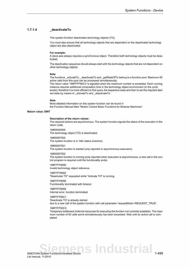
System Functions - Device
1-499SIMOTION System Functions/Variables DeviceList manual, 11/2010
1.7.1.4 _deactivateTo
This system function deactivates technology objects (TO).
You must also ensure that all technology objects that are dependent on the deactivated technology object are also deactivated.
For example:A slave axis always requires a synchronous object. Therefore both technology objects must be deac-tivated.
The deactivation sequence should always start with the technology objects that are not dependent on other technology objects.
NoteThe functions _activateTo, _deactivateTo and _getStateOfTo belong to a function pool. Maximum 50 active calls from this pool can be processed simultaneously.The return value '16#FFFF80C3' is signaled when the maximum number is exceeded. Each running instance requires additional computation time in the technology object environment (in the cyclic levels); therefore it is more efficient to first query the respective state and then to set the required desi-red state by means of _activateTo and _deactivateTo.
NoteMore detailed information on this system function can be found inthe Function Manual titled "Motion Control Basic Functions for Modular Machines".
Return value: DINT
Description of the return values:The required actions are asynchronous. The system function signals the status of the execution in the return code.
16#00000000The technology object (TO) is deactivated.
16#00007000The system function is in 'Idle' status (inactive).
16#00007001The system function is started (only reported in asynchronous execution).
16#00007002The system function is running (only reported when execution is asynchronous, a new call in the con-trol program is required until the functionality ends).
16#FFFF8090Invalid technology object reference.
16#FFFF8092"Deactivate TO" requested while "Activate TO" is running.
16#FFFF8098Functionality terminated with timeout.
16#FFFF8099Internal error, function terminated.
16#FFFF80C1'Deactivate TO' is already started.due to a new call of the system function with call parameter 'requestMode:=REQUEST_TRUE'.
16#FFFF80C3Temporary bottleneck (internal resources for executing the function not currently available). The maxi-mum number of 50 calls active simultaneously has been exceeded. Wait until an active call is com-pleted.
Siemens Industrial
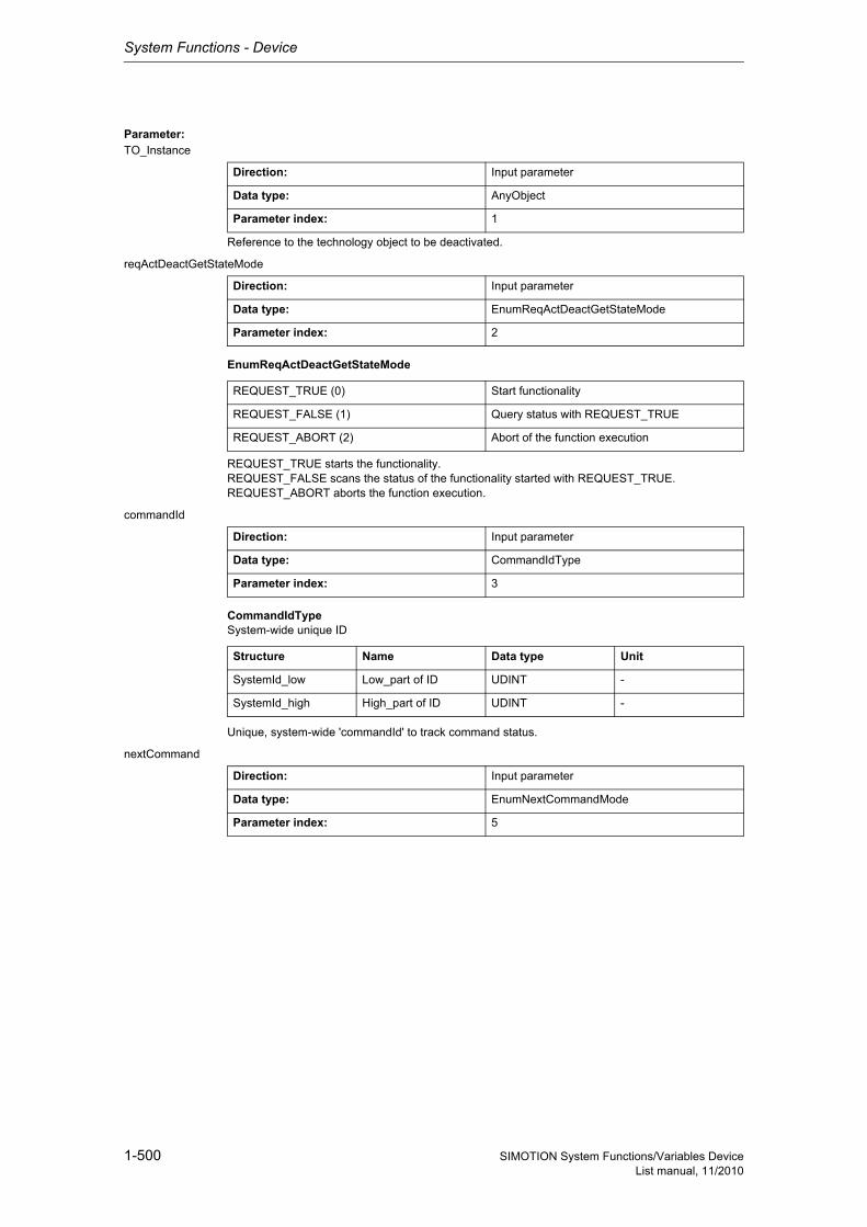
System Functions - Device
1-500 SIMOTION System Functions/Variables DeviceList manual, 11/2010
Parameter: TO_Instance
Reference to the technology object to be deactivated.
reqActDeactGetStateMode
EnumReqActDeactGetStateMode
REQUEST_TRUE starts the functionality.REQUEST_FALSE scans the status of the functionality started with REQUEST_TRUE.REQUEST_ABORT aborts the function execution.
commandId
CommandIdTypeSystem-wide unique ID
Unique, system-wide 'commandId' to track command status.
nextCommand
Direction: Input parameter
Data type: AnyObject
Parameter index: 1
Direction: Input parameter
Data type: EnumReqActDeactGetStateMode
Parameter index: 2
REQUEST_TRUE (0) Start functionality
REQUEST_FALSE (1) Query status with REQUEST_TRUE
REQUEST_ABORT (2) Abort of the function execution
Direction: Input parameter
Data type: CommandIdType
Parameter index: 3
Structure Name Data type Unit
SystemId_low Low_part of ID UDINT -
SystemId_high High_part of ID UDINT -
Direction: Input parameter
Data type: EnumNextCommandMode
Parameter index: 5
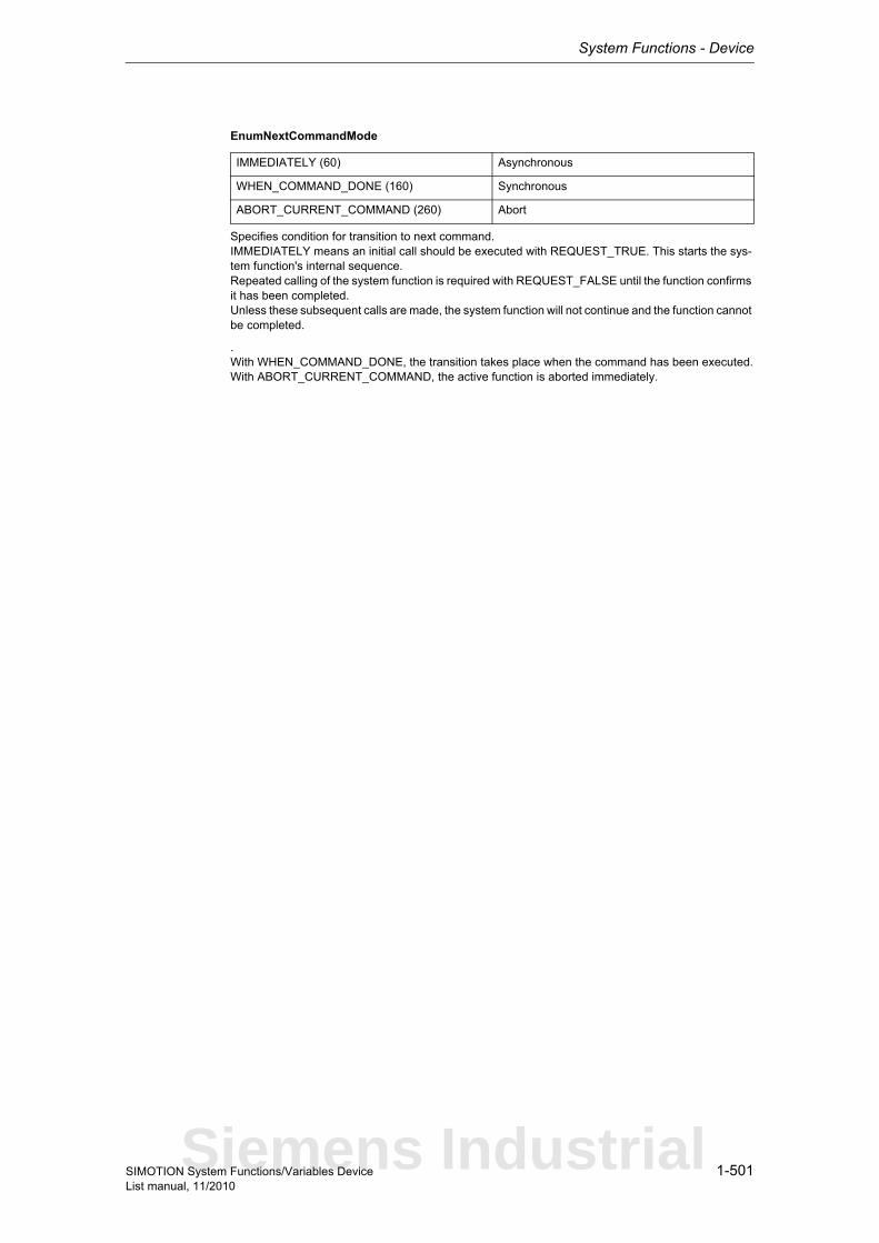
System Functions - Device
1-501SIMOTION System Functions/Variables DeviceList manual, 11/2010
EnumNextCommandMode
Specifies condition for transition to next command.IMMEDIATELY means an initial call should be executed with REQUEST_TRUE. This starts the sys-tem function's internal sequence.Repeated calling of the system function is required with REQUEST_FALSE until the function confirms it has been completed.Unless these subsequent calls are made, the system function will not continue and the function cannot be completed.
.With WHEN_COMMAND_DONE, the transition takes place when the command has been executed.With ABORT_CURRENT_COMMAND, the active function is aborted immediately.
IMMEDIATELY (60) Asynchronous
WHEN_COMMAND_DONE (160) Synchronous
ABORT_CURRENT_COMMAND (260) Abort
Siemens Industrial
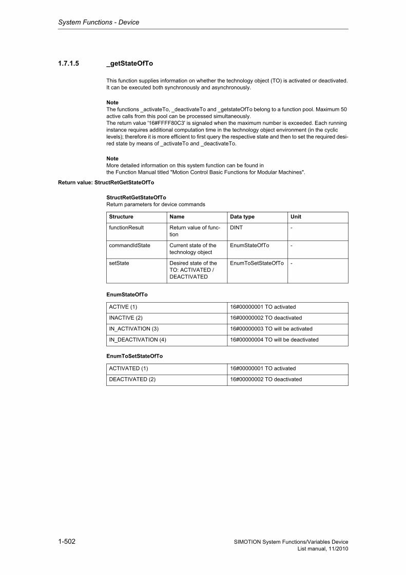
System Functions - Device
1-502 SIMOTION System Functions/Variables DeviceList manual, 11/2010
1.7.1.5 _getStateOfTo
This function supplies information on whether the technology object (TO) is activated or deactivated.It can be executed both synchronously and asynchronously.
NoteThe functions _activateTo, _deactivateTo and _getstateOfTo belong to a function pool. Maximum 50 active calls from this pool can be processed simultaneously.The return value '16#FFFF80C3' is signaled when the maximum number is exceeded. Each running instance requires additional computation time in the technology object environment (in the cyclic levels); therefore it is more efficient to first query the respective state and then to set the required desi-red state by means of _activateTo and _deactivateTo.
NoteMore detailed information on this system function can be found inthe Function Manual titled "Motion Control Basic Functions for Modular Machines".
Return value: StructRetGetStateOfTo
StructRetGetStateOfToReturn parameters for device commands
EnumStateOfTo
EnumToSetStateOfTo
Structure Name Data type Unit
functionResult Return value of func-tion
DINT -
commandIdState Current state of the technology object
EnumStateOfTo -
setState Desired state of the TO: ACTIVATED / DEACTIVATED
EnumToSetStateOfTo -
ACTIVE (1) 16#00000001 TO activated
INACTIVE (2) 16#00000002 TO deactivated
IN_ACTIVATION (3) 16#00000003 TO will be activated
IN_DEACTIVATION (4) 16#00000004 TO will be deactivated
ACTIVATED (1) 16#00000001 TO activated
DEACTIVATED (2) 16#00000002 TO deactivated
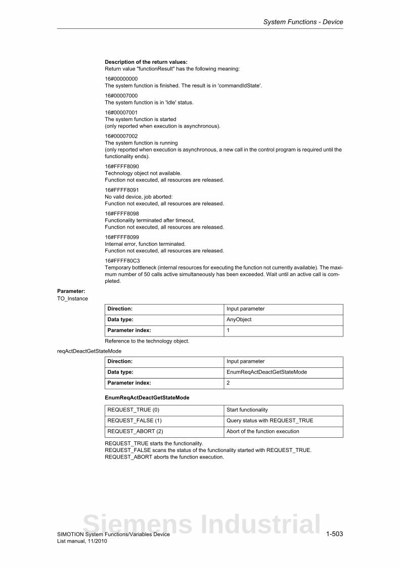
System Functions - Device
1-503SIMOTION System Functions/Variables DeviceList manual, 11/2010
Description of the return values:Return value "functionResult" has the following meaning:
16#00000000The system function is finished. The result is in 'commandIdState'.
16#00007000The system function is in 'Idle' status.
16#00007001The system function is started(only reported when execution is asynchronous).
16#00007002The system function is running(only reported when execution is asynchronous, a new call in the control program is required until the functionality ends).
16#FFFF8090Technology object not available.Function not executed, all resources are released.
16#FFFF8091No valid device, job aborted:Function not executed, all resources are released.
16#FFFF8098Functionality terminated after timeout,Function not executed, all resources are released.
16#FFFF8099Internal error, function terminated.Function not executed, all resources are released.
16#FFFF80C3Temporary bottleneck (internal resources for executing the function not currently available). The maxi-mum number of 50 calls active simultaneously has been exceeded. Wait until an active call is com-pleted.
Parameter: TO_Instance
Reference to the technology object.
reqActDeactGetStateMode
EnumReqActDeactGetStateMode
REQUEST_TRUE starts the functionality.REQUEST_FALSE scans the status of the functionality started with REQUEST_TRUE.REQUEST_ABORT aborts the function execution.
Direction: Input parameter
Data type: AnyObject
Parameter index: 1
Direction: Input parameter
Data type: EnumReqActDeactGetStateMode
Parameter index: 2
REQUEST_TRUE (0) Start functionality
REQUEST_FALSE (1) Query status with REQUEST_TRUE
REQUEST_ABORT (2) Abort of the function execution
Siemens Industrial
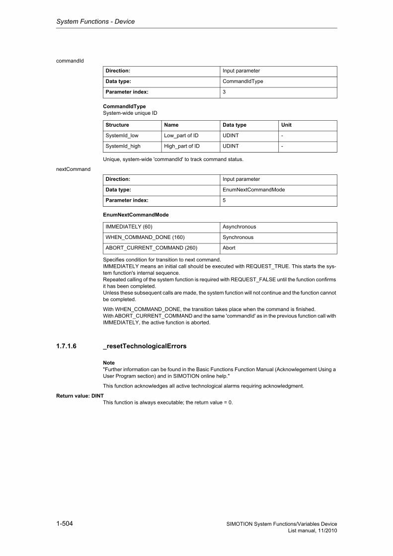
System Functions - Device
1-504 SIMOTION System Functions/Variables DeviceList manual, 11/2010
commandId
CommandIdTypeSystem-wide unique ID
Unique, system-wide 'commandId' to track command status.
nextCommand
EnumNextCommandMode
Specifies condition for transition to next command.IMMEDIATELY means an initial call should be executed with REQUEST_TRUE. This starts the sys-tem function's internal sequence.Repeated calling of the system function is required with REQUEST_FALSE until the function confirms it has been completed.Unless these subsequent calls are made, the system function will not continue and the function cannot be completed.
With WHEN_COMMAND_DONE, the transition takes place when the command is finished.With ABORT_CURRENT_COMMAND and the same 'commandId' as in the previous function call with IMMEDIATELY, the active function is aborted.
1.7.1.6 _resetTechnologicalErrors
Note"Further information can be found in the Basic Functions Function Manual (Acknowlegement Using a User Program section) and in SIMOTION online help."
This function acknowledges all active technological alarms requiring acknowledgment.
Return value: DINTThis function is always executable; the return value = 0.
Direction: Input parameter
Data type: CommandIdType
Parameter index: 3
Structure Name Data type Unit
SystemId_low Low_part of ID UDINT -
SystemId_high High_part of ID UDINT -
Direction: Input parameter
Data type: EnumNextCommandMode
Parameter index: 5
IMMEDIATELY (60) Asynchronous
WHEN_COMMAND_DONE (160) Synchronous
ABORT_CURRENT_COMMAND (260) Abort
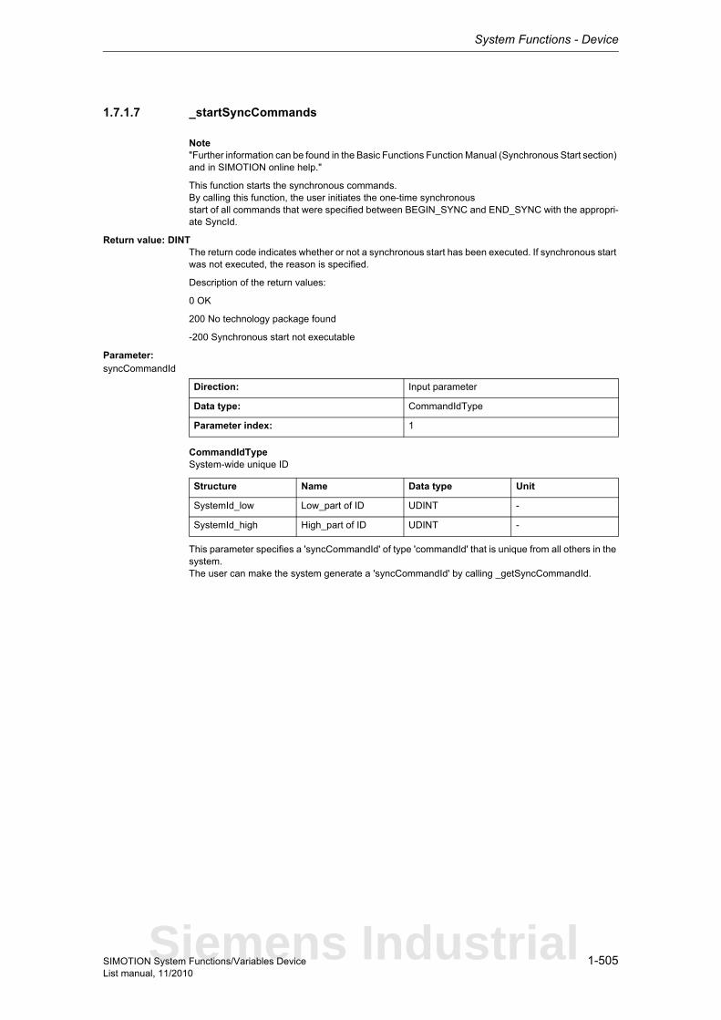
System Functions - Device
1-505SIMOTION System Functions/Variables DeviceList manual, 11/2010
1.7.1.7 _startSyncCommands
Note"Further information can be found in the Basic Functions Function Manual (Synchronous Start section) and in SIMOTION online help."
This function starts the synchronous commands.By calling this function, the user initiates the one-time synchronousstart of all commands that were specified between BEGIN_SYNC and END_SYNC with the appropri-ate SyncId.
Return value: DINTThe return code indicates whether or not a synchronous start has been executed. If synchronous start was not executed, the reason is specified.
Description of the return values:
0 OK
200 No technology package found
-200 Synchronous start not executable
Parameter: syncCommandId
CommandIdTypeSystem-wide unique ID
This parameter specifies a 'syncCommandId' of type 'commandId' that is unique from all others in the system.The user can make the system generate a 'syncCommandId' by calling _getSyncCommandId.
Direction: Input parameter
Data type: CommandIdType
Parameter index: 1
Structure Name Data type Unit
SystemId_low Low_part of ID UDINT -
SystemId_high High_part of ID UDINT -
Siemens Industrial

System Functions - Device
1-506 SIMOTION System Functions/Variables DeviceList manual, 11/2010

2-507SIMOTION System Functions/Variables DeviceList manual, 11/2010
System Variables - Device 2
Siemens Industrial
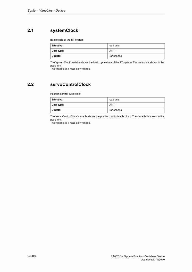
System Variables - Device
2-508 SIMOTION System Functions/Variables DeviceList manual, 11/2010
2.1 systemClock
Basic cycle of the RT system
The 'systemClock' variable shows the basic cycle clock of the RT system. The variable is shown in the µsec. unit.The variable is a read-only variable.
2.2 servoControlClock
Position control cycle clock
The 'servoControlClock' variable shows the position control cycle clock. The variable is shown in the µsec. unit.The variable is a read-only variable.
Effective: read only
Data type: DINT
Update: For change
Effective: read only
Data type: DINT
Update: For change
System Variables - Device
2-509SIMOTION System Functions/Variables DeviceList manual, 11/2010
2.3 servoControlClock_fast
Fast position control cycle clock!!The 'servoControlClock_fast' variable shows the fast position control
cycle clock. The variable is shown in the µsec. unit. The variable is a read-only variable.
2.4 ipoClock
Interpolation cycle clock
The 'ipoClock' variable shows the interpolator cycle clock. The variable is shown in the µsec. unit.The variable is a read-only variable.
Effective: read only
Data type: DINT
Effective: read only
Data type: DINT
Update: For change
Siemens Industrial
System Variables - Device
2-510 SIMOTION System Functions/Variables DeviceList manual, 11/2010
2.5 ipoClock_fast
Fast interpolation cycle clock!!The 'ipoClock_fast' variable shows the fast interpolation cycle clock.
The variable is shown in the µsec. unit. The variable is a read-only variable.
2.6 servoTaskCycle
Position controller cycle number
The 'servoTaskCycle' variable shows the position controller cycle number within an IPO cycle clock.The variable is a read-only variable.
2.7 servoTaskCycle_fast
Fast position controller cycle number
The 'servoTaskCycle_fast' variable shows the fast position controller cycle number within a fast IPO cycle clock.The variable is a read-only variable.
Effective: read only
Data type: DINT
Effective: read only
Data type: UDINT
Update: For change
Effective: read only
Data type: UDINT
Update: For change
System Variables - Device
2-511SIMOTION System Functions/Variables DeviceList manual, 11/2010
2.8 traceControl
TIO functions control
Note"Further information about trace can be found in the SIMOTION MCC Programming and Operating Manual and in the online help."
StructTraceControlTIO functions control
EnumEnableDisable
EnumFctGenStartStop
EnumStartStop
The function generator is controlled by means of the variables of 'trace Control'.The parameters in the function generator are set during configuration.'fctGenStart:=ENABLE' enables the function generator.'fctGenStart:=DISABLE' disables or cancels the function generator.'fctGenStart:=FCTGEN_START' starts the function generator.'fctGenStart:=FCTGEN_STOP' stops or cancels the function generator.'fctGenStart:=FCT_GEN_START_FG1' starts the function generator 2 synchronously to function generator 1.Function generator 1 is started synchronously with function generator 2 with 'fctGenStart:= FCT_GEN_START_FG2'.The 'traceStart' variable is no longer supported.The stop-start edge of the 'traceTrigger' variable can be selected in the SIMOTION SCOUT trace tool as the trigger condition for the trace recording.The variables can be read and written.
Effective: immediately
Data type: ARRAY [0..1] OF StructTraceControl
Update: For change
Structure Name Data type Unit
fctGenEnable Enable function gene-rator
EnumEnableDisable -
fctGenStart Start function genera-tor
EnumFctGenStartStop -
traceStart - EnumStartStop -
traceTrigger Trace trigger signal EnumStartStop -
DISABLE (42) Enable reset
ENABLE (48) Enable set
FCTGEN_START (1) Start
FCTGEN_START_FG1 (2) Synchronous start with function generator 1
FCTGEN_START_FG2 (3) Synchronous start with function generator 2
FCTGEN_STOP (134) Stop
START (1) Start
STOP (134) Stop
Siemens Industrial
System Variables - Device
2-512 SIMOTION System Functions/Variables DeviceList manual, 11/2010
2.9 traceState
TIO functions status
Note"Further information about trace can be found in the SIMOTION MCC Programming and Operating Manual and in the online help."
StructTraceStateTIO functions status
EnumFctGenState
Effective: read only
Data type: ARRAY [0..1] OF StructTraceState
Update: For change
Structure Name Data type Unit
fctGenState Function generator status
EnumFctGenState -
traceState - EnumTraceState -
FCTGEN_DISABLED (0) The function generator is waiting for a paramete-rization
FCTGEN_PARAM_VALID (1) The function generator is correctly parameteri-zed and is now waiting for enable
FCTGEN_ENABLED (2) The function generator is ready to start
FCTGEN_WAIT_FG1 (3) The function generator is waiting for function generator 1 to start
FCTGEN_WAIT_FG2 (4) The function generator is waiting for function generator 2 to start
FCTGEN_RUNNING (5) The function generator is running
FCTGEN_STARTING (6) The function generator travels the offset ramp (0 -> offset)
FCTGEN_STOPPING (7) The function generator travels the offset ramp (offset -> 0)
FCTGEN_LIMIT_EXCEEDED (8) The function generator was cancelled because the system variable limits were exceeded
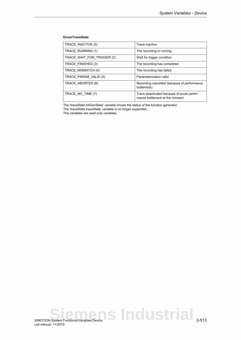
System Variables - Device
2-513SIMOTION System Functions/Variables DeviceList manual, 11/2010
EnumTraceState
The 'traceState.fctGenState' variable shows the status of the function generator.The 'traceState.traceState' variable is no longer supported.The variables are read-only variables.
TRACE_INACTIVE (0) Trace inactive
TRACE_RUNNING (1) The recording is running
TRACE_WAIT_FOR_TRIGGER (2) Wait for trigger condition
TRACE_FINISHED (3) The recording has completed
TRACE_MISMATCH (4) The recording has failed
TRACE_PARAM_VALID (5) Parameterization valid
TRACE_ABORTED (6) Recording cancelled (because of performance bottleneck)
TRACE_NO_TIME (7) Trace deactivated because of acute perfor-mance bottleneck at the moment
Siemens Industrial
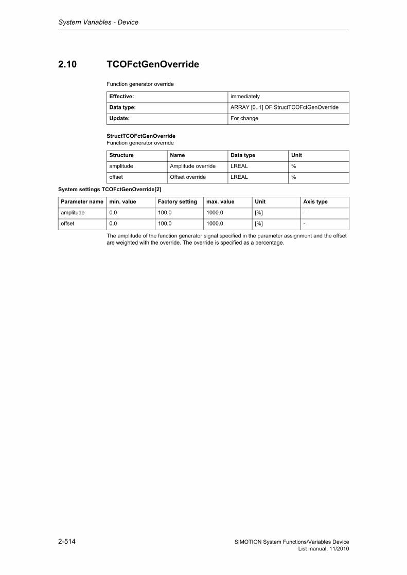
System Variables - Device
2-514 SIMOTION System Functions/Variables DeviceList manual, 11/2010
2.10 TCOFctGenOverride
Function generator override
StructTCOFctGenOverrideFunction generator override
System settings TCOFctGenOverride[2]
The amplitude of the function generator signal specified in the parameter assignment and the offset are weighted with the override. The override is specified as a percentage.
Effective: immediately
Data type: ARRAY [0..1] OF StructTCOFctGenOverride
Update: For change
Structure Name Data type Unit
amplitude Amplitude override LREAL %
offset Offset override LREAL %
Parameter name min. value Factory setting max. value Unit Axis type
amplitude 0.0 100.0 1000.0 [%] -
offset 0.0 100.0 1000.0 [%] -
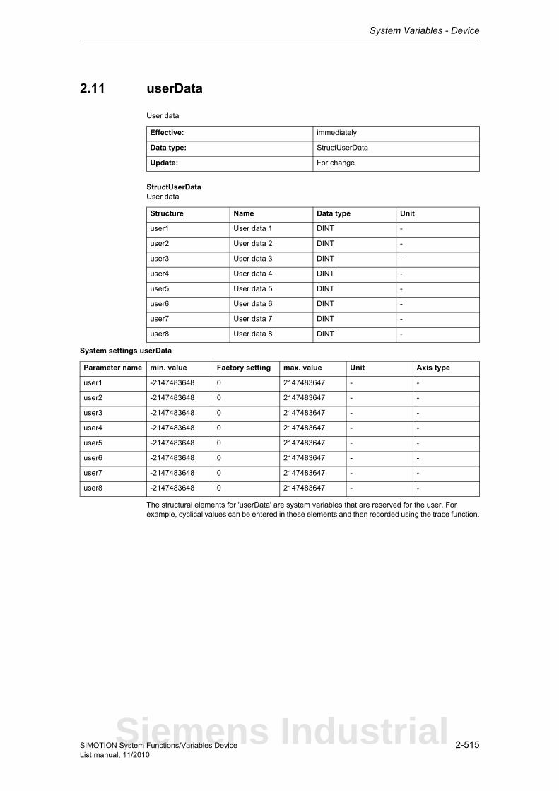
System Variables - Device
2-515SIMOTION System Functions/Variables DeviceList manual, 11/2010
2.11 userData
User data
StructUserDataUser data
System settings userData
The structural elements for 'userData' are system variables that are reserved for the user. For example, cyclical values can be entered in these elements and then recorded using the trace function.
Effective: immediately
Data type: StructUserData
Update: For change
Structure Name Data type Unit
user1 User data 1 DINT -
user2 User data 2 DINT -
user3 User data 3 DINT -
user4 User data 4 DINT -
user5 User data 5 DINT -
user6 User data 6 DINT -
user7 User data 7 DINT -
user8 User data 8 DINT -
Parameter name min. value Factory setting max. value Unit Axis type
user1 -2147483648 0 2147483647 - -
user2 -2147483648 0 2147483647 - -
user3 -2147483648 0 2147483647 - -
user4 -2147483648 0 2147483647 - -
user5 -2147483648 0 2147483647 - -
user6 -2147483648 0 2147483647 - -
user7 -2147483648 0 2147483647 - -
user8 -2147483648 0 2147483647 - -
Siemens Industrial
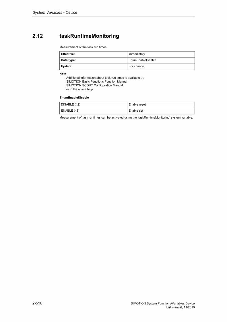
System Variables - Device
2-516 SIMOTION System Functions/Variables DeviceList manual, 11/2010
2.12 taskRuntimeMonitoring
Measurement of the task run times
Note Additional information about task run times is available at: SIMOTION Basic Functions Function Manual SIMOTION SCOUT Configuration Manual or in the online help
EnumEnableDisable
Measurement of task runtimes can be activated using the 'taskRuntimeMonitoring' system variable.
Effective: immediately
Data type: EnumEnableDisable
Update: For change
DISABLE (42) Enable reset
ENABLE (48) Enable set
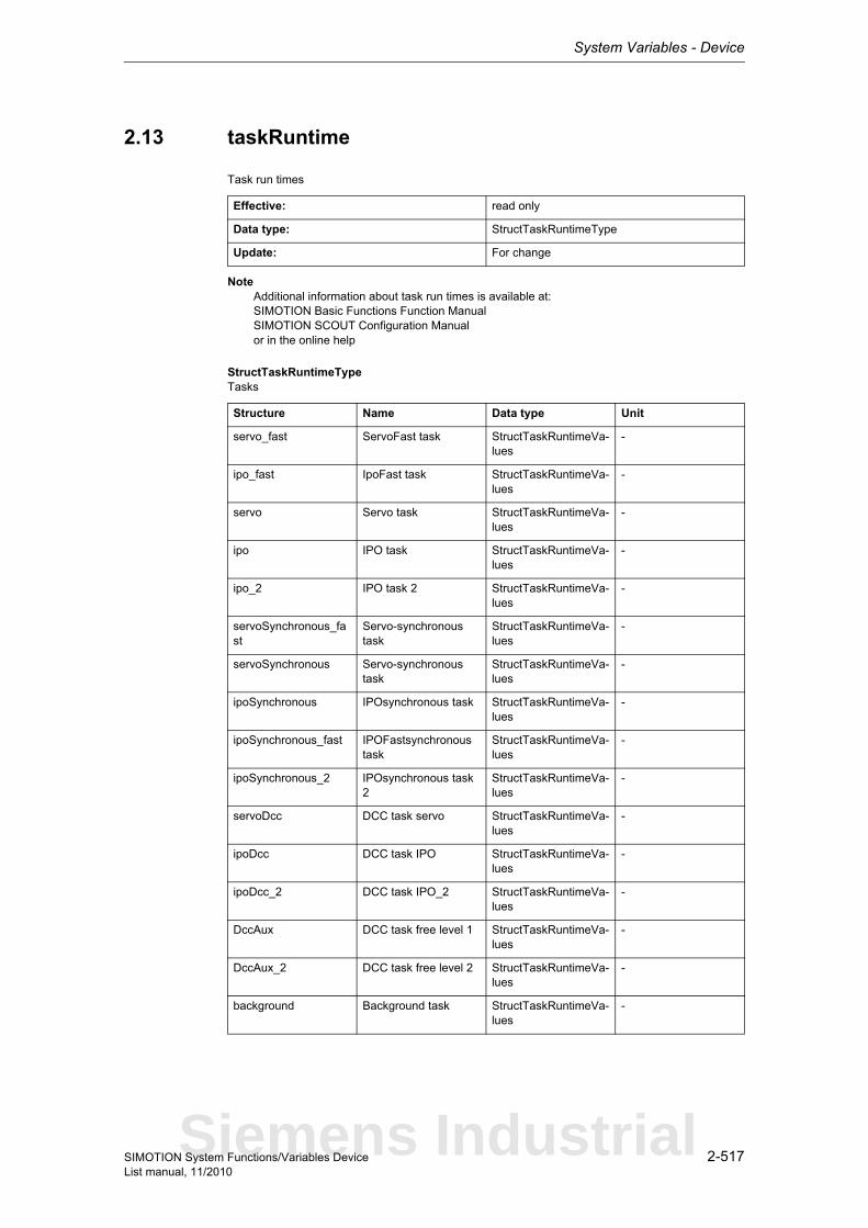
System Variables - Device
2-517SIMOTION System Functions/Variables DeviceList manual, 11/2010
2.13 taskRuntime
Task run times
Note Additional information about task run times is available at: SIMOTION Basic Functions Function Manual SIMOTION SCOUT Configuration Manual or in the online help
StructTaskRuntimeTypeTasks
Effective: read only
Data type: StructTaskRuntimeType
Update: For change
Structure Name Data type Unit
servo_fast ServoFast task StructTaskRuntimeVa-lues
-
ipo_fast IpoFast task StructTaskRuntimeVa-lues
-
servo Servo task StructTaskRuntimeVa-lues
-
ipo IPO task StructTaskRuntimeVa-lues
-
ipo_2 IPO task 2 StructTaskRuntimeVa-lues
-
servoSynchronous_fast
Servo-synchronous task
StructTaskRuntimeVa-lues
-
servoSynchronous Servo-synchronous task
StructTaskRuntimeVa-lues
-
ipoSynchronous IPOsynchronous task StructTaskRuntimeVa-lues
-
ipoSynchronous_fast IPOFastsynchronous task
StructTaskRuntimeVa-lues
-
ipoSynchronous_2 IPOsynchronous task 2
StructTaskRuntimeVa-lues
-
servoDcc DCC task servo StructTaskRuntimeVa-lues
-
ipoDcc DCC task IPO StructTaskRuntimeVa-lues
-
ipoDcc_2 DCC task IPO_2 StructTaskRuntimeVa-lues
-
DccAux DCC task free level 1 StructTaskRuntimeVa-lues
-
DccAux_2 DCC task free level 2 StructTaskRuntimeVa-lues
-
background Background task StructTaskRuntimeVa-lues
-
Siemens Industrial
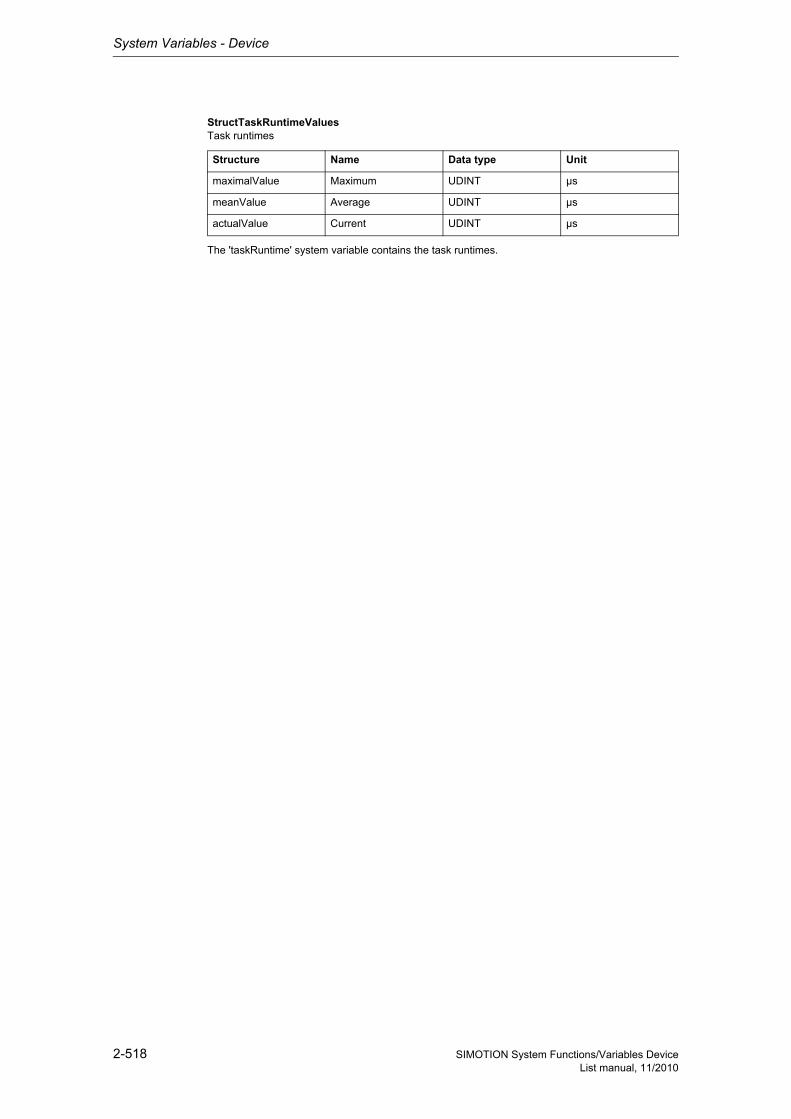
System Variables - Device
2-518 SIMOTION System Functions/Variables DeviceList manual, 11/2010
StructTaskRuntimeValuesTask runtimes
The 'taskRuntime' system variable contains the task runtimes.
Structure Name Data type Unit
maximalValue Maximum UDINT µs
meanValue Average UDINT µs
actualValue Current UDINT µs
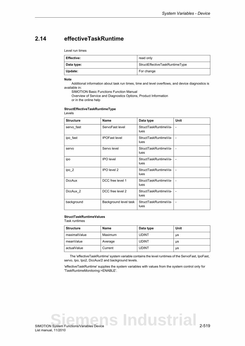
System Variables - Device
2-519SIMOTION System Functions/Variables DeviceList manual, 11/2010
2.14 effectiveTaskRuntime
Level run times
Note Additional information about task run times, time and level overflows, and device diagnostics is available in: SIMOTION Basic Functions Function Manual Overview of Service and Diagnostics Options, Product Information or in the online help
StructEffectiveTaskRuntimeTypeLevels
StructTaskRuntimeValuesTask runtimes
The 'effectiveTaskRuntime' system variable contains the level runtimes of the ServoFast, IpoFast, servo, Ipo, Ipo2, DccAux/2 and background levels.
'effectiveTaskRuntime' supplies the system variables with values from the system control only for 'TaskRuntimeMonitoring:=ENABLE'.
Effective: read only
Data type: StructEffectiveTaskRuntimeType
Update: For change
Structure Name Data type Unit
servo_fast ServoFast level StructTaskRuntimeVa-lues
-
ipo_fast IPOFast level StructTaskRuntimeVa-lues
-
servo Servo level StructTaskRuntimeVa-lues
-
ipo IPO level StructTaskRuntimeVa-lues
-
ipo_2 IPO level 2 StructTaskRuntimeVa-lues
-
DccAux DCC free level 1 StructTaskRuntimeVa-lues
-
DccAux_2 DCC free level 2 StructTaskRuntimeVa-lues
-
background Background level task StructTaskRuntimeVa-lues
-
Structure Name Data type Unit
maximalValue Maximum UDINT µs
meanValue Average UDINT µs
actualValue Current UDINT µs
Siemens Industrial
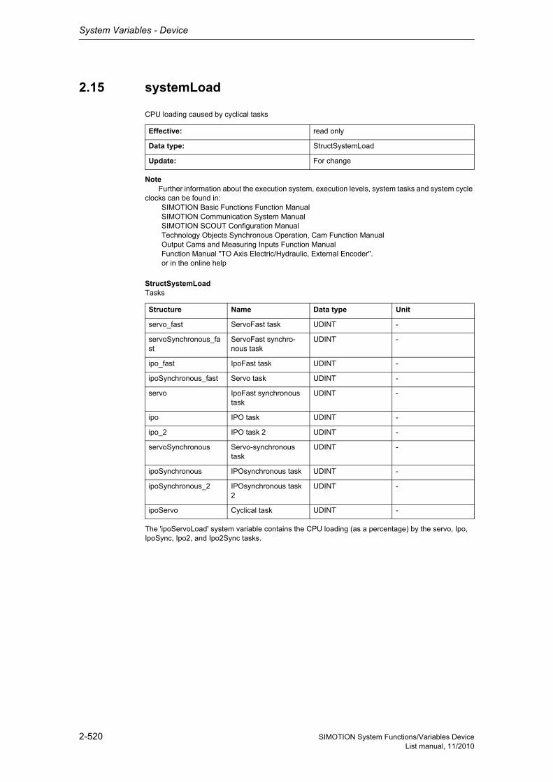
System Variables - Device
2-520 SIMOTION System Functions/Variables DeviceList manual, 11/2010
2.15 systemLoad
CPU loading caused by cyclical tasks
Note Further information about the execution system, execution levels, system tasks and system cycle clocks can be found in: SIMOTION Basic Functions Function Manual SIMOTION Communication System Manual SIMOTION SCOUT Configuration Manual Technology Objects Synchronous Operation, Cam Function Manual Output Cams and Measuring Inputs Function Manual Function Manual "TO Axis Electric/Hydraulic, External Encoder". or in the online help
StructSystemLoadTasks
The 'ipoServoLoad' system variable contains the CPU loading (as a percentage) by the servo, Ipo, IpoSync, Ipo2, and Ipo2Sync tasks.
Effective: read only
Data type: StructSystemLoad
Update: For change
Structure Name Data type Unit
servo_fast ServoFast task UDINT -
servoSynchronous_fast
ServoFast synchro-nous task
UDINT -
ipo_fast IpoFast task UDINT -
ipoSynchronous_fast Servo task UDINT -
servo IpoFast synchronous task
UDINT -
ipo IPO task UDINT -
ipo_2 IPO task 2 UDINT -
servoSynchronous Servo-synchronous task
UDINT -
ipoSynchronous IPOsynchronous task UDINT -
ipoSynchronous_2 IPOsynchronous task 2
UDINT -
ipoServo Cyclical task UDINT -
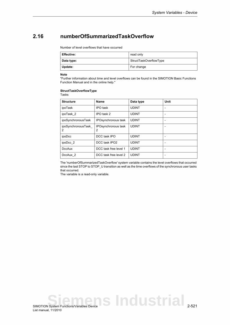
System Variables - Device
2-521SIMOTION System Functions/Variables DeviceList manual, 11/2010
2.16 numberOfSummarizedTaskOverflow
Number of level overflows that have occurred
Note"Further information about time and level overflows can be found in the SIMOTION Basic Functions Function Manual and in the online help."
StructTaskOverflowTypeTasks
The 'numberOfSummarizedTaskOverflow' system variable contains the level overflows that occurred since the last STOP to STOP_U transition as well as the time overflows of the synchronous user tasks that occurred.The variable is a read-only variable.
Effective: read only
Data type: StructTaskOverflowType
Update: For change
Structure Name Data type Unit
ipoTask IPO task UDINT -
ipoTask_2 IPO task 2 UDINT -
ipoSynchronousTask IPOsynchronous task UDINT -
ipoSynchronousTask_2
IPOsynchronous task 2
UDINT -
ipoDcc DCC task IPO UDINT -
ipoDcc_2 DCC task IPO2 UDINT -
DccAux DCC task free level 1 UDINT -
DccAux_2 DCC task free level 2 UDINT -
Siemens Industrial
System Variables - Device
2-522 SIMOTION System Functions/Variables DeviceList manual, 11/2010
2.17 ipoClock_2
Interpolation cycle clock 2
The 'ipoClock_2' variable shows interpolator cycle clock 2. The variable is shown in the µsec. unit.The variable is a read-only variable.
Effective: read only
Data type: DINT
Update: For change
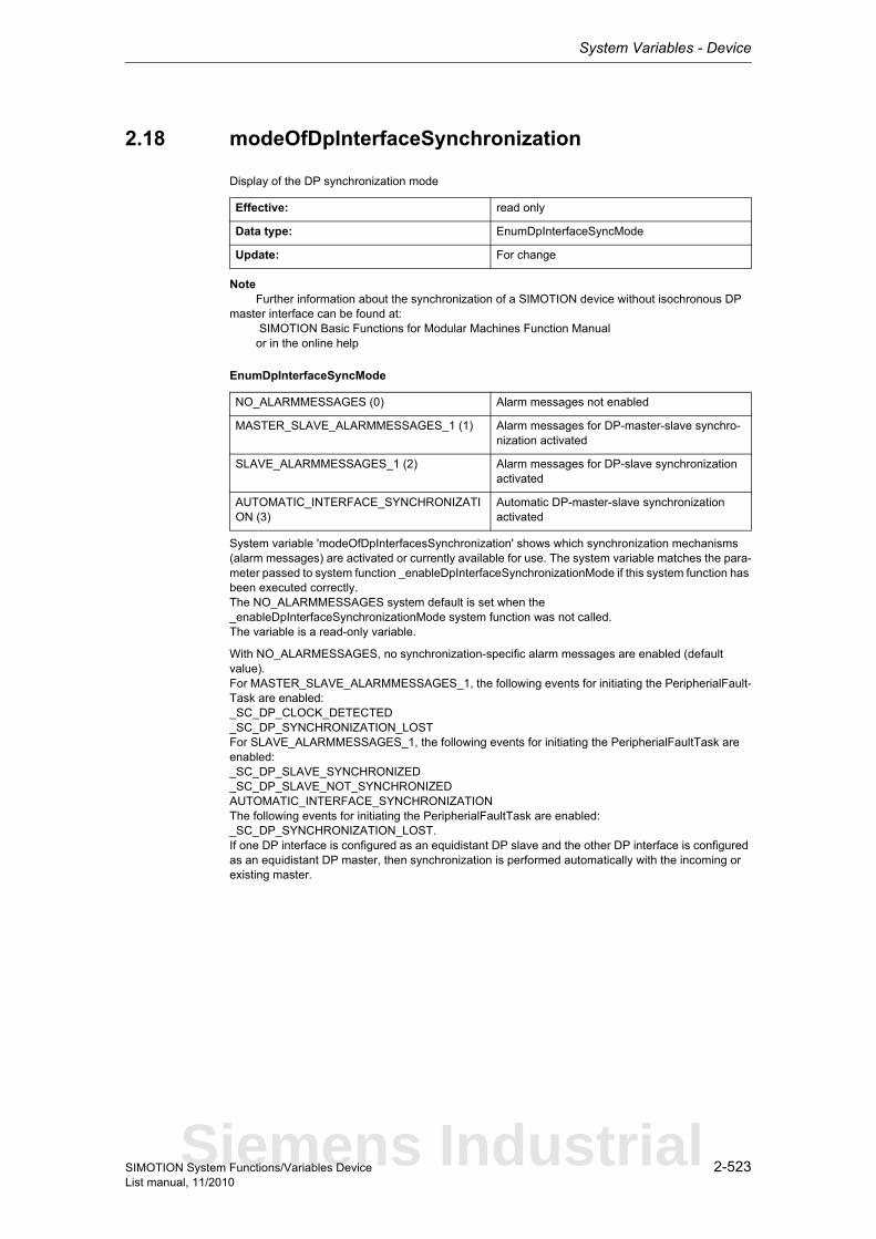
System Variables - Device
2-523SIMOTION System Functions/Variables DeviceList manual, 11/2010
2.18 modeOfDpInterfaceSynchronization
Display of the DP synchronization mode
Note Further information about the synchronization of a SIMOTION device without isochronous DP master interface can be found at: SIMOTION Basic Functions for Modular Machines Function Manual or in the online help
EnumDpInterfaceSyncMode
System variable 'modeOfDpInterfacesSynchronization' shows which synchronization mechanisms (alarm messages) are activated or currently available for use. The system variable matches the para-meter passed to system function _enableDpInterfaceSynchronizationMode if this system function has been executed correctly.The NO_ALARMMESSAGES system default is set when the _enableDpInterfaceSynchronizationMode system function was not called.The variable is a read-only variable.
With NO_ALARMESSAGES, no synchronization-specific alarm messages are enabled (default value).For MASTER_SLAVE_ALARMMESSAGES_1, the following events for initiating the PeripherialFault-Task are enabled:_SC_DP_CLOCK_DETECTED_SC_DP_SYNCHRONIZATION_LOSTFor SLAVE_ALARMMESSAGES_1, the following events for initiating the PeripherialFaultTask are enabled:_SC_DP_SLAVE_SYNCHRONIZED_SC_DP_SLAVE_NOT_SYNCHRONIZEDAUTOMATIC_INTERFACE_SYNCHRONIZATIONThe following events for initiating the PeripherialFaultTask are enabled:_SC_DP_SYNCHRONIZATION_LOST.If one DP interface is configured as an equidistant DP slave and the other DP interface is configured as an equidistant DP master, then synchronization is performed automatically with the incoming or existing master.
Effective: read only
Data type: EnumDpInterfaceSyncMode
Update: For change
NO_ALARMMESSAGES (0) Alarm messages not enabled
MASTER_SLAVE_ALARMMESSAGES_1 (1) Alarm messages for DP-master-slave synchro-nization activated
SLAVE_ALARMMESSAGES_1 (2) Alarm messages for DP-slave synchronization activated
AUTOMATIC_INTERFACE_SYNCHRONIZATION (3)
Automatic DP-master-slave synchronization activated
Siemens Industrial
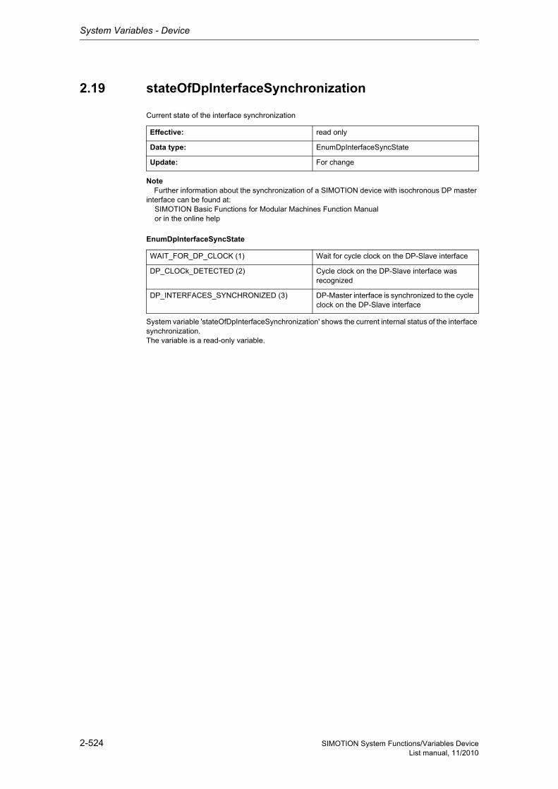
System Variables - Device
2-524 SIMOTION System Functions/Variables DeviceList manual, 11/2010
2.19 stateOfDpInterfaceSynchronization
Current state of the interface synchronization
Note Further information about the synchronization of a SIMOTION device with isochronous DP master interface can be found at: SIMOTION Basic Functions for Modular Machines Function Manual or in the online help
EnumDpInterfaceSyncState
System variable 'stateOfDpInterfaceSynchronization' shows the current internal status of the interface synchronization.The variable is a read-only variable.
Effective: read only
Data type: EnumDpInterfaceSyncState
Update: For change
WAIT_FOR_DP_CLOCK (1) Wait for cycle clock on the DP-Slave interface
DP_CLOCk_DETECTED (2) Cycle clock on the DP-Slave interface was recognized
DP_INTERFACES_SYNCHRONIZED (3) DP-Master interface is synchronized to the cycle clock on the DP-Slave interface
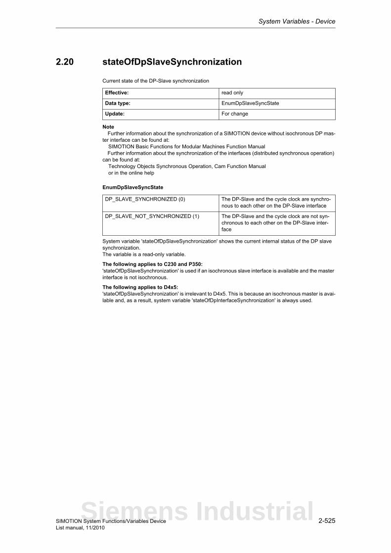
System Variables - Device
2-525SIMOTION System Functions/Variables DeviceList manual, 11/2010
2.20 stateOfDpSlaveSynchronization
Current state of the DP-Slave synchronization
Note Further information about the synchronization of a SIMOTION device without isochronous DP mas-ter interface can be found at: SIMOTION Basic Functions for Modular Machines Function Manual Further information about the synchronization of the interfaces (distributed synchronous operation) can be found at: Technology Objects Synchronous Operation, Cam Function Manual or in the online help
EnumDpSlaveSyncState
System variable 'stateOfDpSlaveSynchronization' shows the current internal status of the DP slave synchronization.The variable is a read-only variable.
The following applies to C230 and P350:'stateOfDpSlaveSynchronization' is used if an isochronous slave interface is available and the master interface is not isochronous.
The following applies to D4x5:'stateOfDpSlaveSynchronization' is irrelevant to D4x5. This is because an isochronous master is avai-lable and, as a result, system variable 'stateOfDpInterfaceSynchronization' is always used.
Effective: read only
Data type: EnumDpSlaveSyncState
Update: For change
DP_SLAVE_SYNCHRONIZED (0) The DP-Slave and the cycle clock are synchro-nous to each other on the DP-Slave interface
DP_SLAVE_NOT_SYNCHRONIZED (1) The DP-Slave and the cycle clock are not syn-chronous to each other on the DP-Slave inter-face
Siemens Industrial
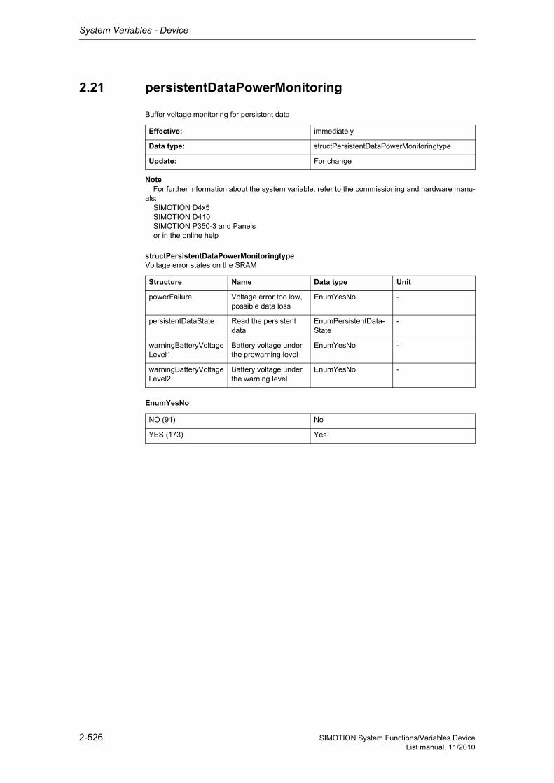
System Variables - Device
2-526 SIMOTION System Functions/Variables DeviceList manual, 11/2010
2.21 persistentDataPowerMonitoring
Buffer voltage monitoring for persistent data
Note For further information about the system variable, refer to the commissioning and hardware manu-als: SIMOTION D4x5 SIMOTION D410 SIMOTION P350-3 and Panels or in the online help
structPersistentDataPowerMonitoringtypeVoltage error states on the SRAM
EnumYesNo
Effective: immediately
Data type: structPersistentDataPowerMonitoringtype
Update: For change
Structure Name Data type Unit
powerFailure Voltage error too low, possible data loss
EnumYesNo -
persistentDataState Read the persistent data
EnumPersistentData-State
-
warningBatteryVoltageLevel1
Battery voltage under the prewarning level
EnumYesNo -
warningBatteryVoltageLevel2
Battery voltage under the warning level
EnumYesNo -
NO (91) No
YES (173) Yes
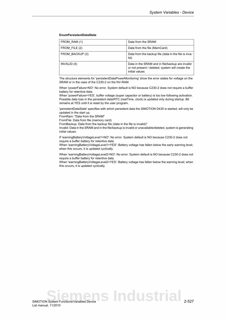
System Variables - Device
2-527SIMOTION System Functions/Variables DeviceList manual, 11/2010
EnumPersistentDataState
The structure elements for 'persistentDataPowerMonitoring' show the error states for voltage on the SRAM or in the case of the C230-2 on the NV-RAM.
When 'powerFailure=NO': No error. System default is NO because C230-2 does not require a buffer battery for retentive data.When 'powerFailure=YES', buffer voltage (super capacitor or battery) is too low following activation. Possible data loss in the persistent data/RTC (realTime, clock) is updated only during startup. Bit remains at YES until it is reset by the user program.
'persistentDataState' specifies with which persistent data the SIMOTION D435 is started; will only be updated in the start up.FromRam: "Data from the SRAM"FromFile: Data from file (memory card)FromBackup: Data from the backup file (data in the file is invalid)"Invalid: Data in the SRAM and in the file/backup is invalid or unavailable/deleted, system is generating initial values.
If 'warningBatteryVoltageLevel1=NO': No error. System default is NO because C230-2 does not require a buffer battery for retentive data.When 'warningBatteryVoltageLevel1=YES': Battery voltage has fallen below the early warning level; when this occurs, it is updated cyclically.
When 'warningBatteryVoltageLevel2=NO': No error. System default is NO because C230-2 does not require a buffer battery for retentive data.When 'warningBatteryVoltageLevel2=YES': Battery voltage has fallen below the warning level; when this occurs, it is updated cyclically.
FROM_RAM (1) Data from the SRAM
FROM_FILE (2) Data from the file (MemCard)
FROM_BACKUP (3) Data from the backup file (data in the file is inva-lid)
INVALID (4) Data in the SRAM and in file/backup are invalid or not present / deleted, system will create the initial values
Siemens Industrial
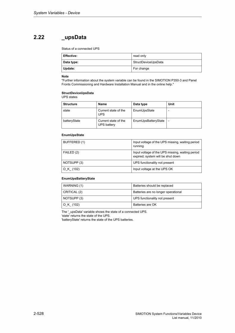
System Variables - Device
2-528 SIMOTION System Functions/Variables DeviceList manual, 11/2010
2.22 _upsData
Status of a connected UPS
Note"Further information about the system variable can be found in the SIMOTION P350-3 and Panel Fronts Commissioning and Hardware Installation Manual and in the online help."
StructDeviceUpsDataUPS states
EnumUpsState
EnumUpsBatteryState
The '_upsData' variable shows the state of a connected UPS.'state' returns the state of the UPS.'batteryState' returns the state of the UPS batteries.
Effective: read only
Data type: StructDeviceUpsData
Update: For change
Structure Name Data type Unit
state Current state of the UPS
EnumUpsState -
batteryState Current state of the UPS battery
EnumUpsBatteryState -
BUFFERED (1) Input voltage of the UPS missing, waiting period running
FAILED (2) Input voltage of the UPS missing, waiting period expired; system will be shut down
NOTSUPP (3) UPS functionality not present
O_K_ (102) Input voltage at the UPS OK
WARNING (1) Batteries should be replaced
CRITICAL (2) Batteries are no longer operational
NOTSUPP (3) UPS functionality not present
O_K_ (102) Batteries are OK
System Variables - Device
2-529SIMOTION System Functions/Variables DeviceList manual, 11/2010
2.23 _cpuData
CPU-relevant data
Note For further information about the system variable, refer to the commissioning and hardware manu-als: SIMOTION P350-3 and Panels SIMOTION P320-3 and Panel Fronts or in the online help
StructDeviceCpuDataCPU states (read-only, relevant only for SIMOTION P350)
The variable '_cpuData' is relevant for SIMOTION P320 and SIMOTION P350. It indicates the follo-wing values:'fanRpm' displays the current constant fan speed. If the value 0 is displayed, the fan has failed (SIMO-TION P350 only).'temperature' shows the current temperature of the processor.'moduletemperature' indicates the current temperature inside the HW module.
The variable is a read-only variable.
Effective: read only
Data type: StructDeviceCpuData
Update: For change
Structure Name Data type Unit
fanRpm Current fan speed DINT -
temperature Current CPU tempera-ture
DINT -
moduletemperature Current temperature in the HW module
DINT -
Siemens Industrial
System Variables - Device
2-530 SIMOTION System Functions/Variables DeviceList manual, 11/2010
2.24 _cpuDataRW
CPU-relevant data
StructDeviceCpuDataRWCPU states
EnumYesNo
The 'cpuData' variable shows the CPU-relevant data.'fanWarning' indicates whether or not the current processor fan speed has fallen below a minimum (HW dependent) value (value changes to YES). The value must be reset to NO by the application.
The variables can be read and written.
Effective: immediately
Data type: StructDeviceCpuDataRW
Update: For change
Structure Name Data type Unit
fanWarning Current state of the processor fan
EnumYesNo -
redundantFanWarning Current state of the redundant processor fan
EnumYesNo -
NO (91) No
YES (173) Yes
System Variables - Device
2-531SIMOTION System Functions/Variables DeviceList manual, 11/2010
2.25 fanbattery
Battery and fan states (read-write)
StructDeviceFanBatteryBattery and fan states (read-only)
EnumFanBattery
The variable 'fanbattery' indicates whether the battery and the fan are required and whether they are installed.
Effective: immediately
Data type: StructDeviceFanBattery
Update: For change
Structure Name Data type Unit
fannecessary Fan required EnumFanBattery -
fanexisting Fan present EnumFanBattery -
batterynecessary Battery required EnumFanBattery -
batteryexisting Battery present EnumFanBattery -
MANDATORY (0) Required
OPTIONAL (1) Optional
OPTIONAL_RTC (2) Optional for the RTC buffering
SINGLE (3) Present once
REDUNDANT (4) Present redundant
EXISTING (5) Present
NOT_EXISTING (6) Not present
NOT_MANDATORY (7) Not required
Siemens Industrial
System Variables - Device
2-532 SIMOTION System Functions/Variables DeviceList manual, 11/2010
2.26 _startupData
Settings for startup behavior - including operating mode after a power on / restart of SIMOTION
StructDeviceStartUpSettings for startup behavior - including operating mode after a power on/restart of SIMOTION
EnumDeviceStartupOperationMode
The '_startup' (structure) system variable contains the configuration of the device functionality in SIMOTION.
The variable can be changed in SIMOTION SCOUT when it is in the "Offline" mode. The values set there and stored in the project are downloaded to the SIMOTION device. Write accesses (from the user program or via online accesses from SIMOTION SCOUT/OP/HMI) do not change the contents of the variable; no exceptions occur either.
Effective: immediately
Data type: StructDeviceStartUp
Update: For change
Structure Name Data type Unit
operationMode Operating state after power on / SIMOTION restart
EnumDeviceStartupO-perationMode
-
LAST_OPERATION_MODE (0) Last operating state in SIMOTION
RUN (1) Automatically switch SIMOTION to RUN
System Variables - Device
2-533SIMOTION System Functions/Variables DeviceList manual, 11/2010
2.27 _configurationManagement
Device functionality of SIMOTION configuration
Note Further information about the retention of permanent data for a configuration change can be found at: SIMOTION Basic Functions for Modular Machines Function Manual or in the online help
StructDeviceConfigurationManagementConfigure device behavior structure
EnumYesNo
The '_configurationManagement' (structure) system variable contains the configuration of the device functionality in SIMOTION.
The variable can be changed in SIMOTION SCOUT when it is in the "Offline" mode. The values set there and stored in the project are downloaded to the SIMOTION device.
Write accesses (from the user program or via online accesses from SIMOTION SCOUT/OP/HMI) do not change the contents of the variable; no exceptions occur either.
Effective: immediately
Data type: StructDeviceConfigurationManagement
Update: For change
Structure Name Data type Unit
preserveToRetainData Test whether Retain-Data TO after loading new Configurations TO must be initialized to Names TO
EnumYesNo -
NO (91) No
YES (173) Yes
Siemens Industrial
System Variables - Device
2-534 SIMOTION System Functions/Variables DeviceList manual, 11/2010
2.28 modeOfOperation
Indication of the operating state
Note Further information about CPU entering STOP - display and change mode can be found at: SIMOTION Basic Functions Function Manual or in the online help
EnumDeviceModeOfOperation
The 'modeOfOperation' system variable indicates the current operating mode. The mode can be chan-ged by writing to the variables. The values _STOP, _STOPU, and _RUN are permitted.
Effective: immediately
Data type: EnumDeviceModeOfOperation
Update: For change
_STOP (0) STOP mode
_STOPU (1) STOPU mode
_STARTUP (2) STARTUP mode
_RUN (3) RUN mode
_SHUTDOWN (4) SHUTDOWN mode
_MRES (5) MRES mode
_SERVICE (6) SERVICE mode
System Variables - Device
2-535SIMOTION System Functions/Variables DeviceList manual, 11/2010
2.29 dccAuxClock
DccAux clock
The 'dccAuxClock' variable shows the DccAux clock. The variable is shown in the µsec. unit.The variable is a read-only variable.
2.30 dccAux_2Clock
Display of the DccAux_2 clock
The 'dccAux_2 clock' variable shows dccAux clock 2. The variable is shown in the µsec. unit.The variable is a read-only variable.
Effective: read only
Data type: DINT
Update: For change
Effective: read only
Data type: DINT
Update: For change
Siemens Industrial
System Variables - Device
2-536 SIMOTION System Functions/Variables DeviceList manual, 11/2010
2.31 _imData
IM data of device
StructDeviceImDataIM parameter on device
StructDeviceIm0IM0 parameter on device
The 'hardwareRevision' variable can only be specified for SIMOTION D4xx and SIMOTION C.The 'hardwareRevision' variable is not relevant for SIMOTION P350.SIMOTION P350 does not have a HW Info block and therefore 0 is always returned.The revision number can be read directly from the label on the device.
StructDeviceIm0SoftwareversionIM0 parameter on device
StructDeviceIm0VersionIM0 version parameter on device
The variables are read-only variables.
Effective: read only
Data type: StructDeviceImData
Update: For change
Structure Name Data type Unit
im0 IM0 parameter StructDeviceIm0 -
Structure Name Data type Unit
manufacturerId Manufacturer ID UINT -
hardwareRevision HW version UINT -
softwareRevision SW version StructDeviceIm0Softwareversion
-
revisionCounter CM stamp UDINT -
imVersion Specification version StructDeviceIm0Version
-
imSupported IM support UINT -
Structure Name Data type Unit
typeRecognition 1. Letter in the version name (e.g. 'V' as ASCII)
USINT -
functionalEnhance-ment
Major version number USINT -
bugfix Minor version number USINT -
internalChange Internal number USINT -
Structure Name Data type Unit
majorVersionNumber majorVersionNumber USINT -
minorVersionNumber minorVersionNumber USINT -
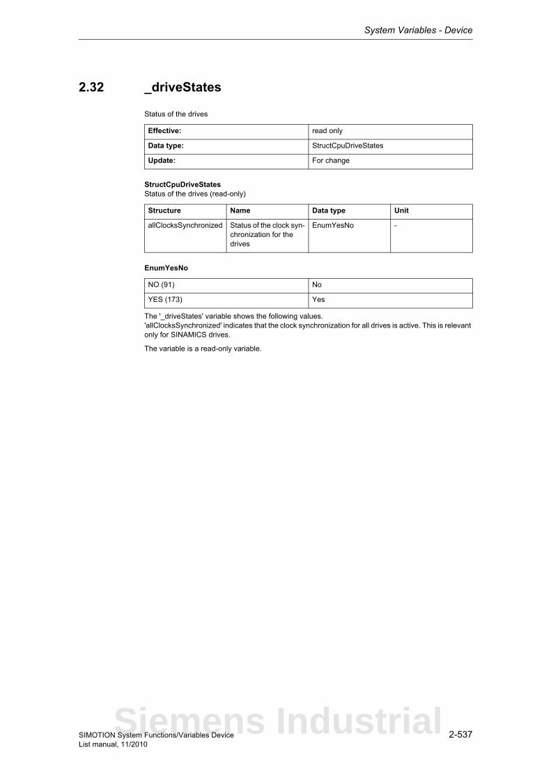
System Variables - Device
2-537SIMOTION System Functions/Variables DeviceList manual, 11/2010
2.32 _driveStates
Status of the drives
StructCpuDriveStatesStatus of the drives (read-only)
EnumYesNo
The '_driveStates' variable shows the following values.'allClocksSynchronized' indicates that the clock synchronization for all drives is active. This is relevant only for SINAMICS drives.
The variable is a read-only variable.
Effective: read only
Data type: StructCpuDriveStates
Update: For change
Structure Name Data type Unit
allClocksSynchronized Status of the clock syn-chronization for the drives
EnumYesNo -
NO (91) No
YES (173) Yes
Siemens Industrial
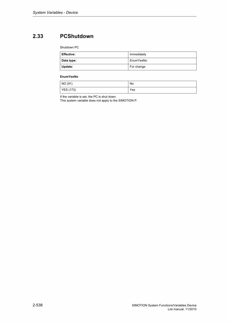
System Variables - Device
2-538 SIMOTION System Functions/Variables DeviceList manual, 11/2010
2.33 PCShutdown
Shutdown PC
EnumYesNo
If the variable is set, the PC is shut down.This system variable does not apply to the SIMOTION P.
Effective: immediately
Data type: EnumYesNo
Update: For change
NO (91) No
YES (173) Yes