Embed Size (px)
Citation preview
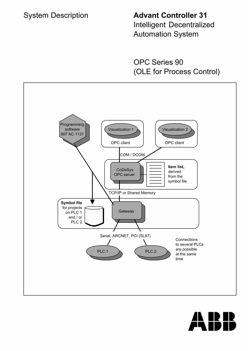
System Description Advant Controller 31Intelligent DecentralizedAutomation System
OPC Series 90(OLE for Process Control)
Programmingsoftware
907 AC 1131Visualization 1
OPC client
Visualization 2
OPC client
CoDeSysOPC server
Item list,derivedfrom thesymbol file
Gateway
Symbol filefor projects
on PLC 1and / or
PLC 2
PLC 1 PLC 2
Serial, ARCNET, PCI (SL97)Connectionsto several PLCsare possibleat the same time
TCP/IP or Shared Memory
COM / DCOM

1907 AC 1131/Issued: 06/02 OPC Server Documentation 12
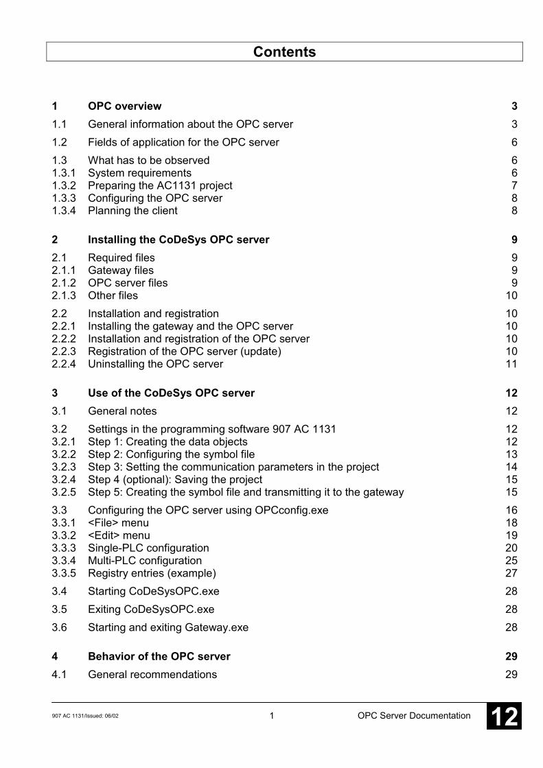
Contents
1 OPC overview 31.1 General information about the OPC server 31.2 Fields of application for the OPC server 61.3 What has to be observed 61.3.1 System requirements 61.3.2 Preparing the AC1131 project 71.3.3 Configuring the OPC server 81.3.4 Planning the client 8
2 Installing the CoDeSys OPC server 92.1 Required files 92.1.1 Gateway files 92.1.2 OPC server files 92.1.3 Other files 102.2 Installation and registration 102.2.1 Installing the gateway and the OPC server 102.2.2 Installation and registration of the OPC server 102.2.3 Registration of the OPC server (update) 102.2.4 Uninstalling the OPC server 11
3 Use of the CoDeSys OPC server 123.1 General notes 123.2 Settings in the programming software 907 AC 1131 123.2.1 Step 1: Creating the data objects 123.2.2 Step 2: Configuring the symbol file 133.2.3 Step 3: Setting the communication parameters in the project 143.2.4 Step 4 (optional): Saving the project 153.2.5 Step 5: Creating the symbol file and transmitting it to the gateway 153.3 Configuring the OPC server using OPCconfig.exe 163.3.1 <File> menu 183.3.2 <Edit> menu 193.3.3 Single-PLC configuration 203.3.4 Multi-PLC configuration 253.3.5 Registry entries (example) 273.4 Starting CoDeSysOPC.exe 283.5 Exiting CoDeSysOPC.exe 283.6 Starting and exiting Gateway.exe 28
4 Behavior of the OPC server 294.1 General recommendations 29
2 907 AC 1131/Issued: 06/02OPC Server Documentation12
4.2 Timing behavior of the OPC server 29
5 Connection with an OPC server on another computer 315.1 DCOMCNFG.EXE 31
6 Example of an ini file for the OPC server configuration 326.1 Example for a multi-PLC configuration 32
7 Brief checklist 347.1 Brief checklist 34
8 Index I
3907 AC 1131/Issued: 06/02 OPC Server Documentation 12
1 OPC overview
1.1 General information about the OPC server
OPC1 is a standardized interface for the access to process data. It is based on the MicrosoftCOM/DCOM2 standard and was extended according to the needs for data access in theautomation technology. Here, it is primarily used to read and write values from the controller.Typical OPC clients are visualizations or programs for the acquisition of operating data, etc.OPC servers are normally used for PLC systems and field bus cards.
The OPC server is not a passive subprogram library, but an executable program which isstarted when the connection between client and server is established. This is why it is able tonotify the client when the value or status of a variable has changed.
Due to the characteristics of DCOM, even an OPC server can be accessed which is running onanother computer. Furthermore, using OPC a data source can be simultaneously accessed bymore than one client. Another advantage OPC gains by the usage of COM is that differentprogramming languages (C++, Visual Basic, Delphi, Java) can be used. However, a resultingdisadvantage is the considerably higher usage of resources (memory and CPU time).
Note:CoDeSys OPC server V2.0 is able to communicate with the controllers mentioned insection 1.2 Fields of application for the OPC server. It meets the requirements of OPCstandard V2.0.
1 OPC = OLE for Process Control; OLE = Object Linking and Embedding
See also www.opcfoundation.org and www.opc_europe.org for further information.
2 COM = Component Object Model (basis for OLE); DCOM = Distributed Component Object Model
4 907 AC 1131/Issued: 06/02OPC Server Documentation12
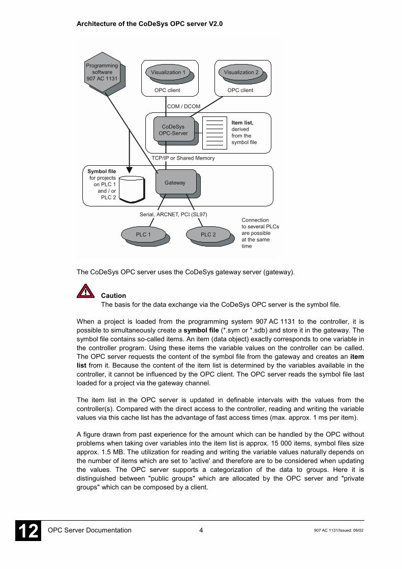
Architecture of the CoDeSys OPC server V2.0
Programmingsoftware
907 AC 1131Visualization 1
OPC client
Visualization 2
OPC client
CoDeSysOPC-Server
Item list,derivedfrom thesymbol file
Gateway
Symbol filefor projects
on PLC 1and / or
PLC 2
PLC 1 PLC 2
Serial, ARCNET, PCI (SL97)Connectionto several PLCsare possibleat the same time
TCP/IP or Shared Memory
COM / DCOM
The CoDeSys OPC server uses the CoDeSys gateway server (gateway).
CautionThe basis for the data exchange via the CoDeSys OPC server is the symbol file.
When a project is loaded from the programming system 907 AC 1131 to the controller, it ispossible to simultaneously create a symbol file (*.sym or *.sdb) and store it in the gateway. Thesymbol file contains so-called items. An item (data object) exactly corresponds to one variable inthe controller program. Using these items the variable values on the controller can be called.The OPC server requests the content of the symbol file from the gateway and creates an itemlist from it. Because the content of the item list is determined by the variables available in thecontroller, it cannot be influenced by the OPC client. The OPC server reads the symbol file lastloaded for a project via the gateway channel.
The item list in the OPC server is updated in definable intervals with the values from thecontroller(s). Compared with the direct access to the controller, reading and writing the variablevalues via this cache list has the advantage of fast access times (max. approx. 1 ms per item).
A figure drawn from past experience for the amount which can be handled by the OPC withoutproblems when taking over variables into the item list is approx. 15 000 items, symbol files sizeapprox. 1.5 MB. The utilization for reading and writing the variable values naturally depends onthe number of items which are set to 'active' and therefore are to be considered when updatingthe values. The OPC server supports a categorization of the data to groups. Here it isdistinguished between "public groups" which are allocated by the OPC server and "privategroups" which can be composed by a client.
5907 AC 1131/Issued: 06/02 OPC Server Documentation 12
If the corresponding option is activated in the configuration, the OPC server groups the items(i.e. the variables of a project) in a block wise way. Then, one 'public group' is created per block.
'Private groups' can be combined of individual items as desired in the client. First, they do notaffect the grouping in the OPC server but if required they can be made to 'public groups'. Forexample, private groups are suitable to activate or deactivate specific variable groups with onlyone command depending on whether they are to be accessed or not.
Grouped data should be read by the OPC server in a consistent way, i.e. all variables at thesame time. Please note that this is not always possible for target systems with limitedcommunication buffers!
NoteIt is possible to operate an OPC server which is running on another computer in thenetwork even if an OPC server is also running on the local computer.
What's new compared to CoDeSys OPC server V1.0:
• The symbol list can be updated without the need to stop a client.
• Multi-PLC configuration is possible, i.e. simultaneous connection of one client to severalcontrollers.
• Exporting and importing OPC configurations is possible (text file *.ini).
6 907 AC 1131/Issued: 06/02OPC Server Documentation12
1.2 Fields of application for the OPC server
The OPC server represents the connection between the client (e.g. the visualization software)and the controller. The data (items) are read from the controller via the gateway server. TheOPC server makes all read items available for the clients. The client software (visualization)displays the required items.
The following AC31 controllers can be operated via the OPC server using the correspondingdrivers:
• 07KT95 serial• 07KT96 serial• 07KT97 serial• 07KT97 ARCNET• 07KT98 serial• 07KT98 ARCNET• 07SL97 serial• 07SL97 ARCNET• 07SL97 PCI• ARCNET routed via 07SL97 PCI
NoteFor more detailed information please refer to the 907 AC 1131 documentation / volume10 / chapter 4 "The individual components" / "Online communication parameters for theuse of gateways" as well as volume 15 / "System technology of the basic units" /"Programming and testing".
NoteOnly the listed controllers and drivers can be used. All controllers with EBS (e.g.07 KR 91, 07 KT 92-94, series 40/50) cannot be operated with the OPC server.
1.3 What has to be observed
1.3.1 System requirements
When using the OPC server, the used PC plays a major role. Particularly for extensiveconfigurations (multiple users, many items (variables)) a fast PC should be used in order toguarantee rapid communication and stable function.
The PC should meet the following minimum requirements:
• Pentium II• Clock frequency: 500 MHz• 128 MB RAM memory• Operating system: WinNT 4.0 Service Pack 5 or higher
NoteThe better the system, the faster and more stable the communication with the OPCserver is. Particularly for extensive configurations with multiple users and many items afast PC should be used. Fast systems also guarantee that the transmission times listedin section 4.2 Timing behavior of the OPC server are met.
7907 AC 1131/Issued: 06/02 OPC Server Documentation 12
1.3.2 Preparing the AC1131 project
First, the OPC variables (items) must be defined in the AC1131 project. For this, either allvariables of the entire project can be defined or the variables of individual program parts (e.g.programs, defined functions and function blocks) can be enabled.
NoteParticularly for extensive systems the selection of the variables which are to be enabledis important. The more variables are enabled the higher is the load to the system andthe slower becomes the communication. In order not to load the system with anunnecessarily high utilization only those variables (items) should be enabled which areused in the visualization software (client). The corresponding variables must be groupedduring the project planning (e.g. Var_Global: visualization or in individual subgroups,functions or function blocks).
The definition of the OPC variables is described in section 3.2 Settings in the programmingsoftware 907 AC 1131.
During this process, a file named <projectname>.sym is created which contains all enabledOPC variables (items). Now this project must be sent via the current gateway to the PLC andstored there in the Flash memory.
NoteIt is important to meet this procedure because the OPC server compares the projectsettings in the gateway with the settings in the PLC. If there are any differences, theitems are not displayed or updated in the OPC server.
CautionSome libraries for earlier versions of 907 AC 1131 have too many symbol entries. Usingthese libraries would result in a definition of too many items in the OPC server.Therefore, only use the libraries listed below for your OPC project:
- ABB-Bib4.lib- ANAI4_20.lib- ARCNET_S90_V41.lib- Base_S90_V41.lib- COM_S90_V42.lib- Coupler_S90_V41.lib- CS31_S90_V41.lib- Datenablage_S90_V41.lib- DeviceNet_Master_S90_V43.lib- IEC_S90_V42.lib- IECSFC_S90_V41.lib- Interbus_Master_S90_V43.lib- PROFIBUS_Master_S90_V43.lib- Profibus_S90_V41.lib- Profibus_S90_V42.lib- PROFIBUS_Slave_S90_V43.lib- RCOM_S90_V41.lib- Systeminfo_S90_V41.lib
8 907 AC 1131/Issued: 06/02OPC Server Documentation12
1.3.3 Configuring the OPC server
In the OPC configuration (OPCConfig.exe) all subscribers are defined from which the itemsshall be read. Here, it is important that the program name matches the set gateway driver (e.g.node address). If this is not the case, no items can be read.
In the OPC configuration also the transmission rate for the items is set. For each subscriber anindividual timeout can be set.
CautionThe following settings must be observed in any case for the AC31 controllers.Otherwise communication is not possible.
- Buffer size = 4800- No login service = enabled- For multi-PLC configurations a mixed usage of a local gateway and TCP/IP is not
possible.
NoteFor more detailed information refer to section 3.3 Configuring the OPC server usingOPCconfig.exe.
NoteIf the project name and the gateway driver do not match, no items are available for theclient.If the transmission rate and the timeout settings are not correct, the items cannot beupdated. The status BAD is displayed.
1.3.4 Planning the client
For the client, either a client test software (for testing the availability of the items) or avisualization software supporting OPC can be used.
The OPC server is automatically started when the client software is started and thecommunication is established. The corresponding variables are selected from the item list.
When planning the client (visualization software) the communication must be optimized. Forthis, the items are divided into individual groups. These groups are defined this way that theyonly contain items which have to be updated at the same time. The groups are only activatedwhen they are needed.
Example:
- Group 1: all failure messages * always active- Group 2: measurement data (e.g. diagram) * always active- Group 3: variables fig. 1 * only active, if fig. 1 is displayed- Group 4: variables fig. 2 * only active, if fig. 2 is displayed- ...- Group n: variables fig. n * only active, if fig. n is displayed
9907 AC 1131/Issued: 06/02 OPC Server Documentation 12
2 Installing the CoDeSys OPC server
2.1 Required files
2.1.1 Gateway files
The gateway files are automatically installed together with the programming software907 AC 1131. All corresponding files are located in the system directory WINNT\system32:
• Arcnet32.dll ARCNET DLL for Windows NT4.0• ArcnetN.dll• Commsym.dll Communication DLL• Commusr.dll Communication DLL• GArcnet3F4F.dll ARCNET DLL ARCNET route driver
(is suitable for use with several ARCNET participants)• Gateway.exe Gateway for communication protocol• GatewayDDE.dll• Gclient.dll Communication DLL• GDrvABBArcnet.dll ABB ARCNET driver DLL
(can be used only with one ARCNET participant)• GDrvABBRS232.dll ABB RS232 driver DLL• GDrvABBRS232Route.dll ABB RS232(routed) driver DLL• GDrvBase.dll Communication DLL• GDrvSL97.dll ABB SL97 PCI driver DLL• GDrvStd.dll Communication DLL• Ghandle.dll Communication DLL• Gsymbol.dll Communication DLL• Gutil.dll Communication DLL
The OPC server 2.0 requires the gateway from the 907 AC 1131 CD-ROM, version V4.3 orhigher.
After the first start of the gateway the path for the 'Gateway Files' directory is set in the registry(default: C:\WINNT\Gateway Files). When the connection to the controller is established, thesymbol files created by 907 AC 1131 and stored in the project directory are copied to thisdirectory. These files are either the symbol files *.sym or their binary version *.sdb. The lattercan be read faster by the OPC server.
2.1.2 OPC server files
The OPC server is installed via the installation menu of the 907 AC 1131 CD-ROM. The filescan be saved to any directory where the DLLs and the file OPCenum.exe must be kept in asubdirectory named REDIST.
• CoDeSysOPC.EXE OPC server• DiagnosticOPCClient.exe Client test software• OPCCommonSetup.EXE Setup for the files listed below• OPCConfig.exe Configuration of the OPC server• OPCConfig_e.exe Configuration of the OPC server
10 907 AC 1131/Issued: 06/02OPC Server Documentation12
Subdirectory REDIST (standard OPC 2.0 files):
• CALLRPROXY.DLL• OCSDAAuto.DLL• OCSSpy_PS.DLL• OPCCOMN_PS.DLL• OPCenum.EXE• OPCPROXY.DLL
2.1.3 Other files
DCOMCNFG.EXE (C:\WinNT\System32):This file is used to establish a connection to an OPC server which is installed on anothercomputer (refer to OPC documentation, chapter 4 Behavior of the OPC server).
2.2 Installation and registration
2.2.1 Installing the gateway and the OPC server
The gateway is automatically installed and registered together with the programming software907 AC 1131. The OPC server is installed and registered by clicking on the button "InstallationOPC Server" in the installation menu of the 907 AC 1131 CD-ROM. Follow the instructionsgiven in the setup.
2.2.2 Installation and registration of the OPC server
If you are installing the OPC server afterwards, make sure that the correct gateway server isused (from 907 AC 1131 CD-ROM, version V4.3 or higher). On the computer, a separatedirectory path is created for the program files of the OPC server (e.g.C:\Programs\AC1131\OPC). All OPC server files (including the subdirectory REDIST) must bestored to this path.
Using the command
"CoDeSysOPC /Install" (if necessary, the path to the exe file must be entered)
in the 'Run' dialog box, a setup program is started which executes the installation of the OPCfiles. Follow the instructions given on the screen. Then the OPC server performs an automaticregistration. A message is displayed, which informs you about the success of the registrationprocess.
2.2.3 Registration of the OPC server (update)
The possibility of a separate registration is important for program updates or the creation of asetup. All files of the OPC server update are copied to the present program path.
Using the command
"CoDeSysOPC /RegServer" (if necessary, the path to the exe file must be entered)
only the registration of the OPC server is initiated. The installation of the required files musthave been finished before. If no message is displayed, the registration was carried outsuccessfully.
(For more information refer to section 3.3.5 Registry entries (example))
11907 AC 1131/Issued: 06/02 OPC Server Documentation 12
2.2.4 Uninstalling the OPC server
The registration of the OPC server is deleted using the following command:
"CoDeSysOPC /UnRegServer" or "CoDeSysOPC /DeInstall".
This deletes the entries in the registry. However, the installed files are not deleted by thiscommand!
12 907 AC 1131/Issued: 06/02OPC Server Documentation12
3 Use of the CoDeSys OPC server
3.1 General notes
After the OPC server is installed, it should be offered by the OPC client (e.g. visualization) forselection.
The gateway and the OPC server are automatically started by the operating system as soon asone of the clients (visualization software) establishes a connection. The OPC server isautomatically exited as soon as all clients have cleared the connection. The gateway stays stillopen, but it is inactive.
The steps 3.2.1 to 3.2.3 described below must be carried out to make data objects of a projectin the programming system 907 AC 1131 available for the OPC server and to establish aconnection via OPC.
3.2 Settings in the programming software 907 AC 1131
To enable the OPC server to access the data objects of a project, a symbol file must be created.For this, start the programming software 907 AC 1131 and open the project.
3.2.1 Step 1: Creating the data objects
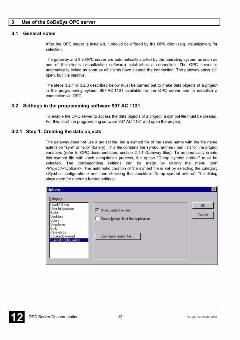
The gateway does not use a project file, but a symbol file of the same name with the file nameextension "sym" or "sdb" (binary). This file contains the symbol entries (item list) for the projectvariables (refer to OPC documentation, section 2.1.1 Gateway files). To automatically createthis symbol file with each compilation process, the option "Dump symbol entries" must beselected. The corresponding settings can be made by calling the menu item<Project><Options>. The automatic creation of the symbol file is set by selecting the category<Symbol configuration> and then checking the checkbox 'Dump symbol entries'. The dialogstays open for entering further settings.
13907 AC 1131/Issued: 06/02 OPC Server Documentation 12
3.2.2 Step 2: Configuring the symbol file
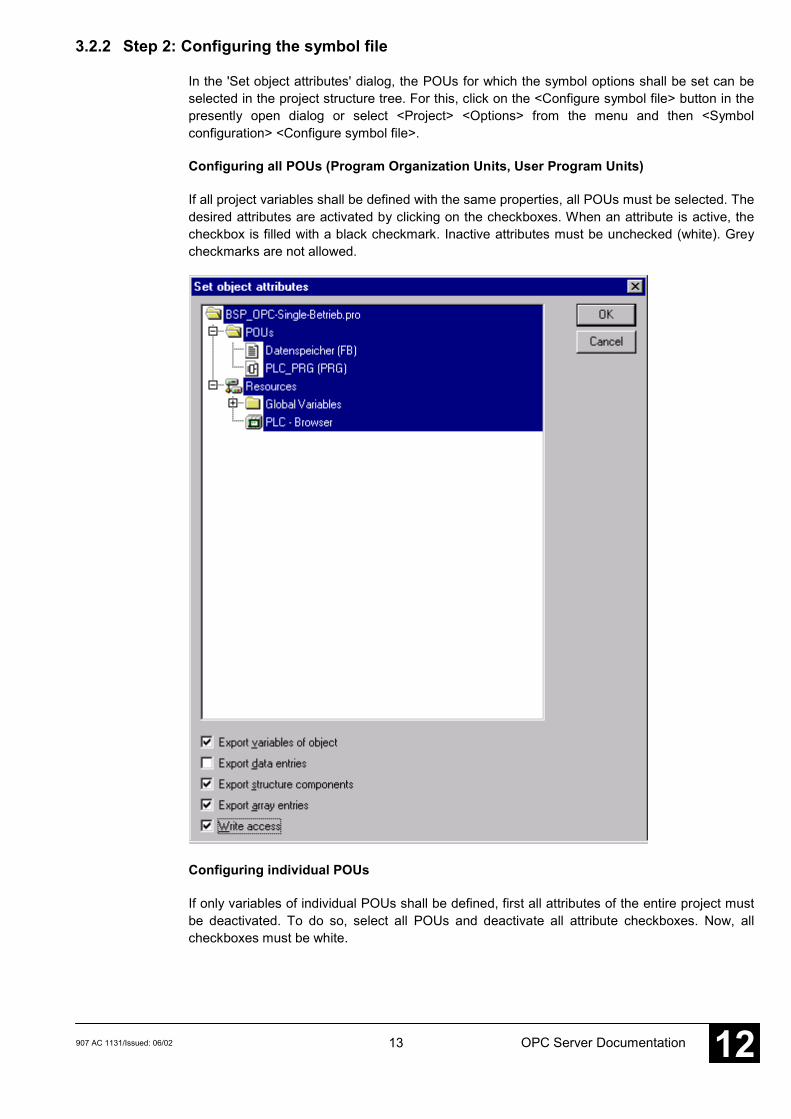
In the 'Set object attributes' dialog, the POUs for which the symbol options shall be set can beselected in the project structure tree. For this, click on the <Configure symbol file> button in thepresently open dialog or select <Project> <Options> from the menu and then <Symbolconfiguration> <Configure symbol file>.
Configuring all POUs (Program Organization Units, User Program Units)
If all project variables shall be defined with the same properties, all POUs must be selected. Thedesired attributes are activated by clicking on the checkboxes. When an attribute is active, thecheckbox is filled with a black checkmark. Inactive attributes must be unchecked (white). Greycheckmarks are not allowed.
Configuring individual POUs
If only variables of individual POUs shall be defined, first all attributes of the entire project mustbe deactivated. To do so, select all POUs and deactivate all attribute checkboxes. Now, allcheckboxes must be white.
14 907 AC 1131/Issued: 06/02OPC Server Documentation12
CautionThe deletion of object attributes becomes only effective after it is confirmed with the<OK> button. Each deletion must be confirmed with the <OK> button before furthersettings can be made. Otherwise, the object attributes are not deleted.
The dialog 'Set object attributes' must be opened again. Now, the individual project POUs canbe selected and set with the desired attributes.
The following attributes can be set:
Export variables ofobject:
The variables of the desired object are written to the symbol file.
Export data entries: Entries for accessing the total variables are created for structuresand arrays of the object. Assumption: "Export variables of object" isactivated.
Export structurecomponents:
For the structures of the object one entry is created for eachcomponent of the variable. Assumption: "Export variables ofobject" is activated.
Export array entries: For the arrays of the object one entry is created for eachcomponent of the variable. Assumption: "Export variables ofobject" is activated.
Write access: The OPC server can modify the variables of the object.
3.2.3 Step 3: Setting the communication parameters in the project
The channel of the used gateway is set in the dialog <Online> <Communication Parameters>.(For more detailed information about the gateway configuration please refer to the 907 AC 1131documentation / volume 10 / chapter 4 "The individual components" / "Online communicationparameters for the use of gateways" as well as volume 15 / "System technology of the basicunits" / "Programming and testing".) This setting must match the setting configured in the OPCserver (refer to section 3.3 Configuring the OPC server using OPCconfig.exe).
NoteFor single PLC configuration:The OPC server automatically starts with the connection settings last used (thesesettings are kept in the registry). These settings can be verified or changed in the fileOPCconfig.exe prior to the start of the OPC server. This means that the setting of thegateway is automatically updated in the configuration. Each time a project is sent to thePLC, the corresponding gateway settings are applied.
The gateway connection can be set to local or TCP/IP. A local connection is used, if the OPCserver and the used gateway reside on the same computer. A TCP/IP connection is used, if thegateway of another computer is accessed by the OPC server via a network.
15907 AC 1131/Issued: 06/02 OPC Server Documentation 12
NoteA TCP/IP connection can also be used, if the OPC server and the gateway reside onthe same computer. However, with this setting, raised transmission times must beexpected compared to the setting 'local'.
CautionThe following must be observed for multi-PLC configuration:If the variable values on several controllers shall be accessed via the OPC server, thecorresponding projects must be loaded to these controllers using the same gatewaychannel (either local or TCP/IP). A parallel usage of local connection and TCP/IPconnection is not allowed!
CautionWith multi-PLC configuration via ARCNET the following must be considered:The driver GDrvABBArcnet.dll (ARCNET-Treiber) can only be used for one ARCNETparticipant. If several ARCNET participants are employed, the driver GArcnet3f4f.dll(ARCNET Route) must be used, as it is a multi-PLC driver.
CautionIt is important, that the drivers GDrvABBArcnet.dll (ARCNET) and GArcnet3f4f.dll(ARCNET Route driver) never can be used at the same time (e.g. GDrvABBArcnet.dll inthe OPC configuration and GArcnet3f4f.dll in the 907AC1131). In this situation, asystem breakdown will occur.
3.2.4 Step 4 (optional): Saving the project
The communication parameters are saved with the project and, after a login, also in thegateway.
3.2.5 Step 5: Creating the symbol file and transmitting it to the gateway
When compiling the project, the symbol file is created and stored to the project directory. Whendownloading the project (<Online> <Login> -> 'Download'), the symbol file (*.sym or *.sdb) withthe present settings is additionally loaded to the gateway (directory 'Gateway Files'). Thecommunication with the OPC server uses the settings of the symbol file located in the path\WinNT\Gateway Files\, for example.
The number of symbols should not exceed approx. 15 000 (corresponds to a symbol filesize (*.sym) of approx. 1.5 MB). Please refer to chapter 4 Behavior of the OPC server.
The representation of the variables in the symbol file is the same as in the watch window.
Example:
PLC_PRG.APLC_PRG.Struktur.X[4].GlobVar1
CautionDirect addresses cannot be accessed.
16 907 AC 1131/Issued: 06/02OPC Server Documentation12
3.3 Configuring the OPC server using OPCconfig.exe
With the configuration it is determined which controllers shall read the symbol entries. For this,the gateway channel must be determined, the project name must be entered and the individualparameters (e.g. transmission rate, timeout values, etc.) must be defined. The OPC standarddoes not include an interface for the transmission of this information. This is why the projectidentifier is written to the registry on each download of a project (refer to section 3.3.5 Registryentries (example)). The OPC server reads this identifier and searches the symbol file with thesame name.
CautionPrimarily it is important that in the OPC server configuration the project namecorresponds to the used communication driver (i.e. if the communication channel is setto ARCNET_Node1 and the project name is OPC_Test_program, the ARCNETsubscriber with the Node 1 must have the project OPC_Test_program).
CautionThe following must be observed for a multi-PLC configuration:If the variable values on several controllers shall be accessed via the OPC server, thecorresponding projects must be loaded to these controllers using the same gatewaychannel (either local or TCP/IP). A parallel usage of local connection and TCP/IPconnection is not allowed.
For information about the setting refer to section 3.2.3 Step 3: Setting the communicationparameters in the project or refer to the 907 AC 1131 documentation.
First, it must be determined which mode is used: single PLC or multi PLC. The mode ofoperation depends on the following factors:
Mode of operation Factors
Single PLC - This mode is used, if the symbol entries are read by only onecontroller.
NoteIn the single-PLC mode the configuration of the gatewaychannel is adapted automatically, i.e. each time a project issent to the PLC, the corresponding gateway settings areapplied to the OPC configuration.
CautionSingle-PLC mode should only be used if it is wanted that theconfiguration is automatically adapted.
- Generally, we recommend to use the setting multi PLC.
17907 AC 1131/Issued: 06/02 OPC Server Documentation 12
Multi PLC - Multi PLC must always be used, if the symbol entries are read byat least 2 controllers.
- Multi-PLC mode is also used if the symbol entries are only readby one controller but the configuration shall not be adaptedautomatically, i.e. if the OPC configuration settings shall beadapted manually. For instance, this is important if you have setup an ARCNET network with several controllers and the symbolfile shall only be read by one controller (head controller).Otherwise, if the programming of the other controllers isperformed via the same gateway, the OPC configuration waschanged with each program download.
The following notes should be observed for the use:
NoteA download of the desired project to the corresponding target controller should beperformed immediately before using the OPC server.
NoteWhen adding or deleting variables in the project, the item list can be updated withoutthe need to exit the OPC client and OPC server by carrying out a download once again(with the activated option 'Dump symbol entries'). For instance, the client then receivesa corresponding message (status "bad") when it tries to access a deleted variable.
NotePlease note that a possibly existing boot project does no longer match a project whichwas changed and downloaded again. This is why it is recommended to store theprogram in the Flash memory of the PLC each time it is downloaded.
For the configuration of the OPC server and the modification of the registry entries of the server,the configurator OPCconfig.exe is started (refer to OPC documentation 3.3.5 Registry entries(example)).
The following sections describe the commands of the <File> and <Edit> menus as well as thespecific dialogs for the single-PLC or multi-PLC configuration.
18 907 AC 1131/Issued: 06/02OPC Server Documentation12
3.3.1 <File> menu
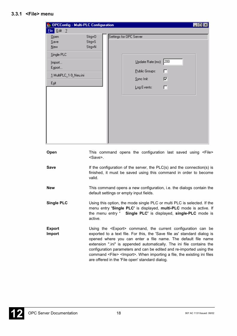
Open This command opens the configuration last saved using <File><Save>.
Save If the configuration of the server, the PLC(s) and the connection(s) isfinished, it must be saved using this command in order to becomevalid.
New This command opens a new configuration, i.e. the dialogs contain thedefault settings or empty input fields.
Single PLC Using this option, the mode single PLC or multi PLC is selected. If themenu entry 'Single PLC' is displayed, multi-PLC mode is active. Ifthe menu entry ' Single PLC' is displayed, single-PLC mode isactive.
ExportImport
Using the <Export> command, the current configuration can beexported to a text file. For this, the 'Save file as' standard dialog isopened where you can enter a file name. The default file nameextension ".ini" is appended automatically. The ini file contains theconfiguration parameters and can be edited and re-imported using thecommand <File> <Import>. When importing a file, the existing ini filesare offered in the 'File open' standard dialog.
19907 AC 1131/Issued: 06/02 OPC Server Documentation 12
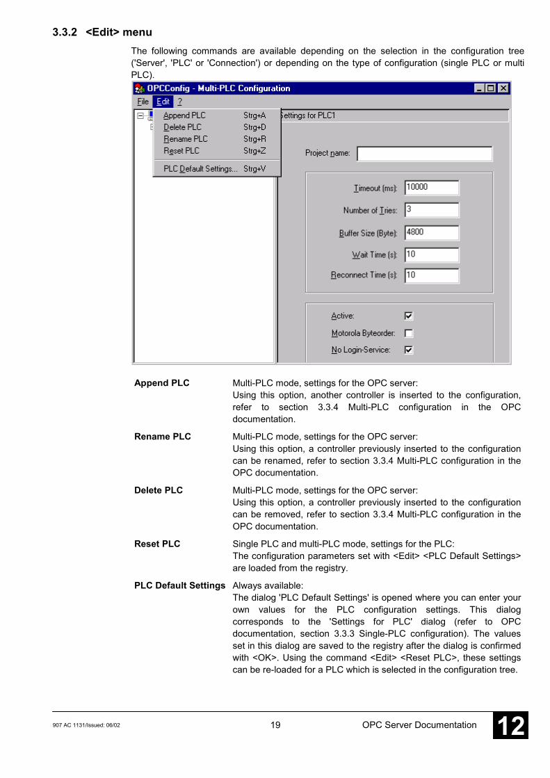
3.3.2 <Edit> menuThe following commands are available depending on the selection in the configuration tree('Server', 'PLC' or 'Connection') or depending on the type of configuration (single PLC or multiPLC).
Append PLC Multi-PLC mode, settings for the OPC server:Using this option, another controller is inserted to the configuration,refer to section 3.3.4 Multi-PLC configuration in the OPCdocumentation.
Rename PLC Multi-PLC mode, settings for the OPC server:Using this option, a controller previously inserted to the configurationcan be renamed, refer to section 3.3.4 Multi-PLC configuration in theOPC documentation.
Delete PLC Multi-PLC mode, settings for the OPC server:Using this option, a controller previously inserted to the configurationcan be removed, refer to section 3.3.4 Multi-PLC configuration in theOPC documentation.
Reset PLC Single PLC and multi-PLC mode, settings for the PLC:The configuration parameters set with <Edit> <PLC Default Settings>are loaded from the registry.
PLC Default Settings Always available:The dialog 'PLC Default Settings' is opened where you can enter yourown values for the PLC configuration settings. This dialogcorresponds to the 'Settings for PLC' dialog (refer to OPCdocumentation, section 3.3.3 Single-PLC configuration). The valuesset in this dialog are saved to the registry after the dialog is confirmedwith <OK>. Using the command <Edit> <Reset PLC>, these settingscan be re-loaded for a PLC which is selected in the configuration tree.
20 907 AC 1131/Issued: 06/02OPC Server Documentation12
3.3.3 Single-PLC configuration
Generally, we recommend to use the setting multi PLC. Proceed as follows to configure an OPCserver for single PLC mode:
NotePossibly appearing dialogs for saving are not mentioned in the following procedure.
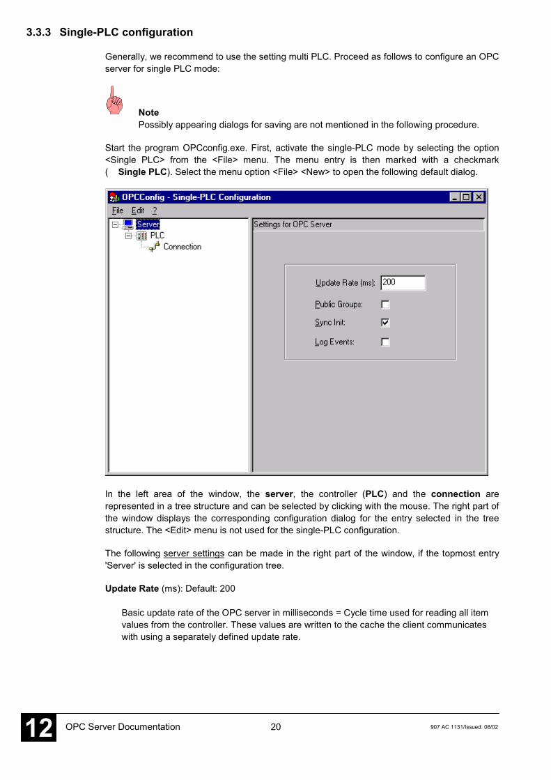
Start the program OPCconfig.exe. First, activate the single-PLC mode by selecting the option<Single PLC> from the <File> menu. The menu entry is then marked with a checkmark( Single PLC). Select the menu option <File> <New> to open the following default dialog.
In the left area of the window, the server, the controller (PLC) and the connection arerepresented in a tree structure and can be selected by clicking with the mouse. The right part ofthe window displays the corresponding configuration dialog for the entry selected in the treestructure. The <Edit> menu is not used for the single-PLC configuration.
The following server settings can be made in the right part of the window, if the topmost entry'Server' is selected in the configuration tree.
Update Rate (ms): Default: 200
Basic update rate of the OPC server in milliseconds = Cycle time used for reading all itemvalues from the controller. These values are written to the cache the client communicateswith using a separately defined update rate.
21907 AC 1131/Issued: 06/02 OPC Server Documentation 12
CautionIf the update rate is set too low, no communication can be established to thecontroller. The status of the items is displayed as BAD in the client. Also refer tochapter 4 Behavior of the OPC server.
Public Groups: Default: deactivated (no checkmark)
The OPC server establishes one public group for each IEC block as well as for the globalvariables.
Sync Init: Default: activated (checkmark)
Synchronous initialization: When starting, the OPC server does not react until the symbolconfiguration is loaded.
Log Events: Default: deactivated (no checkmark)
When this option is activated, the actions performed and the errors occurred at the OPCserver are logged and saved to a log file. The file is saved to the project directory andnamed OPCServer.log. The messages of several OPC sessions are subsequently listed ina log file.
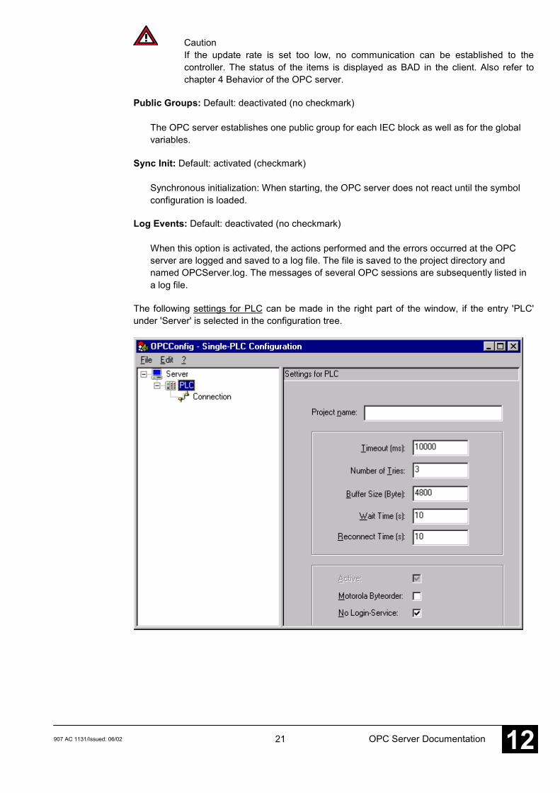
The following settings for PLC can be made in the right part of the window, if the entry 'PLC'under 'Server' is selected in the configuration tree.
22 907 AC 1131/Issued: 06/02OPC Server Documentation12
Project name:
Name of the project currently loaded. For single-PLC mode, this entry is not mandatory.
NoteIf the communication with the OPC server is performed via the gateway channelwhich was used for downloading the program to the PLC, no project name must beentered. The project name must be entered here, if another gateway channel isused for the OPC server.
Timeout (ms): Default: 10000
The OPC server exits automatically after this time period if it does not receive an answerfrom the controller to a transmitted service.
Number of Tries: Default: 3
Number of attempts the OPC server tries to re-establish the connection to the controllerafter a timeout. The time interval between the re-establishment attempts is defined at'Reconnect Time'.
Buffer Size [Bytes]: Default: 4800
Communication buffer size on the target system. For all AC31 controllers, a buffer size of< 5000 must be entered.
Wait Time [s]: Default: 10
Time in seconds that the OPC server waits until the controller is ready (important forcontroller autostart).After the OPC server is started, it tries to communicate with the configured controllers. Thenit notifies the client whether communication to the controllers is possible or not. Thecontrollers must log in within the set wait time, otherwise the status is passed to the client.
NoteThe wait time must be set long enough to enable all subscribers to log in. If this timeis set too short it could happen that some subscribers cannot log in during the start.In this case, the wait time setting should be increased.
This time depends on the number of subscribers and the number of items defined in thesymbol file.
23907 AC 1131/Issued: 06/02 OPC Server Documentation 12
NoteIf the AC1131 project is modified and new items are added to the symbolconfiguration, it can happen that the previously set parameters are no longercorrect. In this case the parameters must be adapted (i.e. the wait time must beincreased).
Reconnect Time [s]: Default: 10
Time interval during which the OPC server attempts (as often as set at 'Number of Tries') tore-establish the connection to the controller via the gateway after a communication break-off.
Active: Not available (only available in multi-PLC mode)
Motorola Byteorder: Default: deactivated (no checkmark)
The target system of the project does not use the Motorola byte order.
NoteThis function is not active for all AC31 controllers.
No Login-Service: Default: activated (checkmark)
This option must be deactivated for specific target systems which require the transmissionof a login service.
NoteThe login service may not be transmitted for all ABB controllers. This function mustbe activated.
24 907 AC 1131/Issued: 06/02OPC Server Documentation12
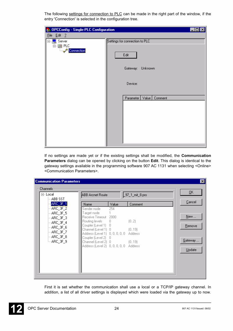
The following settings for connection to PLC can be made in the right part of the window, if theentry 'Connection' is selected in the configuration tree.
If no settings are made yet or if the existing settings shall be modified, the CommunicationParameters dialog can be opened by clicking on the button Edit. This dialog is identical to thegateway settings available in the programming software 907 AC 1131 when selecting <Online><Communication Parameters>.
First it is set whether the communication shall use a local or a TCP/IP gateway channel. Inaddition, a list of all driver settings is displayed which were loaded via the gateway up to now.
25907 AC 1131/Issued: 06/02 OPC Server Documentation 12
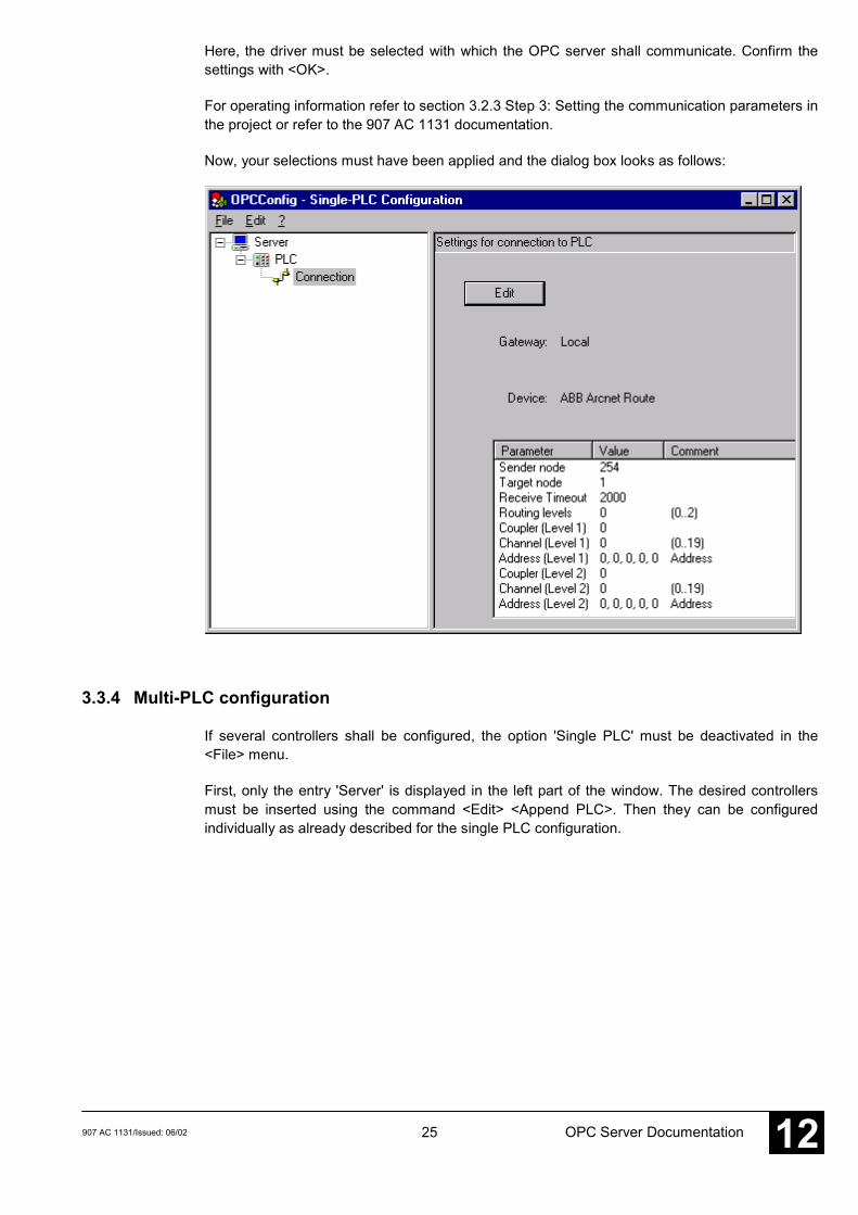
Here, the driver must be selected with which the OPC server shall communicate. Confirm thesettings with <OK>.
For operating information refer to section 3.2.3 Step 3: Setting the communication parameters inthe project or refer to the 907 AC 1131 documentation.
Now, your selections must have been applied and the dialog box looks as follows:
3.3.4 Multi-PLC configuration
If several controllers shall be configured, the option 'Single PLC' must be deactivated in the<File> menu.
First, only the entry 'Server' is displayed in the left part of the window. The desired controllersmust be inserted using the command <Edit> <Append PLC>. Then they can be configuredindividually as already described for the single PLC configuration.
26 907 AC 1131/Issued: 06/02OPC Server Documentation12
Differences compared to the single PLC configuration:
In the Edit menu, the following commands are additionally available for the PLC currentlyselected in the configuration tree:
Append PLC A new 'PLC' entry is inserted. Additional PLCs are always insertedbelow the currently highlighted entry. The name "PLC<n>" isautomatically assigned, where n is counted up beginning with 1.
Delete PLC The highlighted entry is removed from the configuration.
Rename PLC Each PLC can be assigned a user defined name. To do so, highlightthe desired PLC entry and then select <Edit> <Rename PLC>. Anediting field is opened where you can enter the name.
The name of the project which was downloaded to this controller via the gateway can beentered to the Project name input field of the 'Settings for PLC' dialog.
NoteIf the communication with the OPC server is performed via the gateway channel whichwas used for downloading the program to the PLC, it is not required to assign a projectname. The project name must be entered, if another gateway channel is used for theOPC server.
By selecting or deselecting the option Active in the 'Settings for PLC' dialog it can be definedwhether the controller shall be considered by the OPC server or not.
CautionIt must be observed that the communication is not performed via different gatewayconnections. If the variable values on several controllers shall be accessed via the OPCserver, the corresponding projects must be loaded to these controllers using the samegateway channel (either local or TCP/IP). A parallel usage of local connection andTCP/IP connection is not allowed.
CautionWith multi-PLC configuration via ARCNET the following must be considered:The driver GDrvABBArcnet.dll (ARCNET-Treiber) can only be used for one ARCNETparticipant. If several ARCNET participants are employed, the driver GArcnet3f4f.dll(ARCNET Route) must be used, as it is a multi-PLC driver.
CautionIt is important, that the drivers GDrvABBArcnet.dll (ARCNET) and GArcnet3f4f.dll(ARCNET Route driver) never can be used at the same time (e.g. GDrvABBArcnet.dll inthe OPC configuration and GArcnet3f4f.dll in the 907AC1131). In this situation, asystem breakdown will occur.
27907 AC 1131/Issued: 06/02 OPC Server Documentation 12
3.3.5 Registry entries (example)
The registry can be displayed using the command "regedit" in the command prompt.
Entries for the 'Settings for OPC server' dialog of the OPC configurator:
[HKEY_CURRENT_USER\Software\3S-Smart Software Solutions GmbH\CoDeSysOPC\Connections]* corresponds to the values set in the 'Settings for PLC dialog' of the OPC configurator (refer tosections 3.3.3 Single-PLC configuration and 3.3.4 Multi-PLC configuration in the OPCdocumentation). *
- "Buffersize"="0x000012c0 (4800)"- "Instances"="00 00 00 00 00 00 00 00- "Motorola0"="No"- "Name0"=""- "NoLogin0"="No"- "Project0"=hex (current communication parameters for the OPC server and project
identification)- "Timeout0"="0x00002710 (1000)"- "Tries0"="0x00000003 (3)"
[HKEY_LOKAL_MACHINE\SOFTWARE\3S-Smart Software Solutions GmbH\CoDeSysOPC\Config]* corresponds to the values set in the 'Settings for OPC server' dialog of the OPC configurator(refer to section 3.3.3 Single-PLC configuration in the OPC documentation). *
- "LogEvents"="No"- "Multi"="no"- "Public groups"="No"- "Reconnect Interval"="0x00000005 (5)"- "Sync startup"="yes"- "Updaterate"="0x00000064 (100)"- "Wait for target"="0x0000000a (10)"
[HKEY_LOCAL_MACHINE\SOFTWARE\3S-Smart Software Solutions GmbH\CoDeSysOPC\PLCDefaults]* corresponds to the values set under <Edit> <PLC Default Settings> in the OPC configurator(refer to section 3.3.2 <Edit> menu) *
- "Activ"="true"- "Buffersize"="4800"- "Motorola"="false"- "Nologin"="true"- "project"=""- "Reconnecttime"=10"- "Timeout"="10000"- "Tries"="3"- "Waittime"="10"
28 907 AC 1131/Issued: 06/02OPC Server Documentation12
3.4 Starting CoDeSysOPC.exe
The OPC server (and the gateway server) is automatically started by the operating system assoon as one of the clients establishes a connection. It is not necessary to start it explicitly. If anOPC server has already been started manually, the client connects automatically to the runningserver.
The server is automatically exited again as soon as all clients have cleared the connection.
While the OPC server is running, the icon is displayed on the right side of the status bar onthe bottom of the screen.
Right-clicking on this icon displays information about the version of the OPC server.
Starting in test mode:
The connection between the OPC server and the client can also be tested if no controller islinked. For this purpose, the OPC server must be started explicitly using the command
CoDeSysOPC.exe /TestMode
Then it runs in test mode and automatically generates a series of test items which are used totest the communication to the client.
CautionThe items generated in test mode are only test variables. They are not the variablesfrom the symbol file of your project.
The OPC icon in the status bar is also displayed while the simulation mode is running.
3.5 Exiting CoDeSysOPC.exe
The OPC server is automatically exited as soon as all clients have cleared the connection.
3.6 Starting and exiting Gateway.exe
The gateway is automatically started by the operating system as soon as one of the subscribers(e.g. 907 AC 1131, OPC server, OPCConfig or similar) tries to access the gateway server.
The icon on the right side of the status bar on the bottom of the screen indicates that thegateway was started and whether it is in use or not.
Once the gateway is started, it stays opened. However, it is indicated whether it is in use or not.When the gateway is inactive, the icon is shaded in gray . It is not necessary to close thegateway.
If required, the gateway can be exited manually. To do so, right-click on the gateway icon toopen the context menu. Select <Exit> to close the gateway server.
29907 AC 1131/Issued: 06/02 OPC Server Documentation 12
4 Behavior of the OPC server
4.1 General recommendations
The configuration should be optimized as well as possible to enable shortest possible updatetimes. This is influenced by the following:
- Number of subscribers (controllers):This setting is performed in the OPC configuration. The lower the number of subscribers,the faster the communication.
- Number of items:This setting is performed in the 907 AC 1131 project (creation of symbol file). Only variableswhich can be visualized later should be added to the symbol file. The lower the number ofvariables, the faster the configuration.
- Number of active items:This setting is performed in the client (visualization software). The items should be assignedto individual groups which are updated at the same time. The groups are only releasedwhen they are needed, i.e. not all items of the project must be updated simultaneously. As aresult, only the currently needed items are read.
- Correct parameter assignment when setting the OPC configuration:*The setting of the following parameters is absolutely necessary for AC31 controllers: - Buffer Size: 4800 - Motorola Byteorder: deactivated - No Login Service: activated - The gateway channels for multi PLC mode may not be mixed (do not use local and TCP/IP in parallel)* Parameters to be set in order to optimize the communication: In order to reach a stable communication, the following parameters must be set high enough. - Update rate - Timeout value - Wait time - Reconnect time
4.2 Timing behavior of the OPC server
For serial connection it is recommended to use the single-PLC mode.
For ARCNET connections generally the multi PLC mode could be used (this depends on thefunction of the automatic configuration adaptation, refer to section 3.3 Configuring the OPCserver using OPCconfig.exe). The more subscribers and items are configured, the slower is thecommunication.
CautionIf the transmission rate is set too low in the configuration, the communication becomesconsiderably slower or is no longer performed. The transmission rate should be setapproximately to the value which can be reached.
30 907 AC 1131/Issued: 06/02OPC Server Documentation12
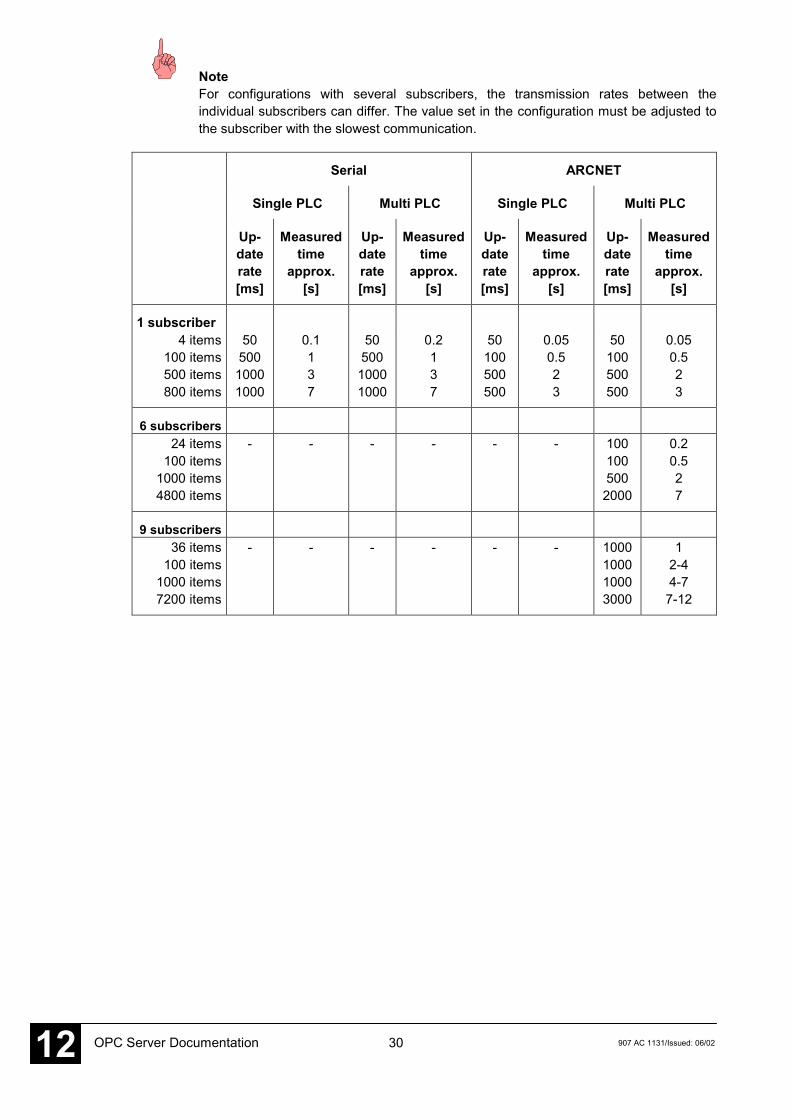
NoteFor configurations with several subscribers, the transmission rates between theindividual subscribers can differ. The value set in the configuration must be adjusted tothe subscriber with the slowest communication.
Serial ARCNET
Single PLC Multi PLC Single PLC Multi PLC
Up-daterate[ms]
Measuredtime
approx.[s]
Up-daterate[ms]
Measuredtime
approx.[s]
Up-daterate[ms]
Measuredtime
approx.[s]
Up-daterate[ms]
Measuredtime
approx.[s]
1 subscriber4 items
100 items500 items800 items
5050010001000
0.1137
5050010001000
0.2137
50100500500
0.050.523
50100500500
0.050.523
6 subscribers24 items
100 items1000 items4800 items
- - - - - - 1001005002000
0.20.527
9 subscribers36 items
100 items1000 items7200 items
- - - - - - 1000100010003000
12-44-77-12
31907 AC 1131/Issued: 06/02 OPC Server Documentation 12
5 Connection with an OPC server on another computer
5.1 DCOMCNFG.EXE
Using DCOMCNFG.EXE from the system directory, a connection to an OPC server on anothercomputer can be established. For this purpose, select the entry 'OPC server for CoDeSys...' inthe 'Applications' tab and then click on the 'Properties' button. In the properties dialog, open the'Location' tab, activate the option 'Run application on the following computer' and then enter thedesired computer.
For such a connection it is assumed that an OPC server is also running on the local computer.
32 907 AC 1131/Issued: 06/02OPC Server Documentation12
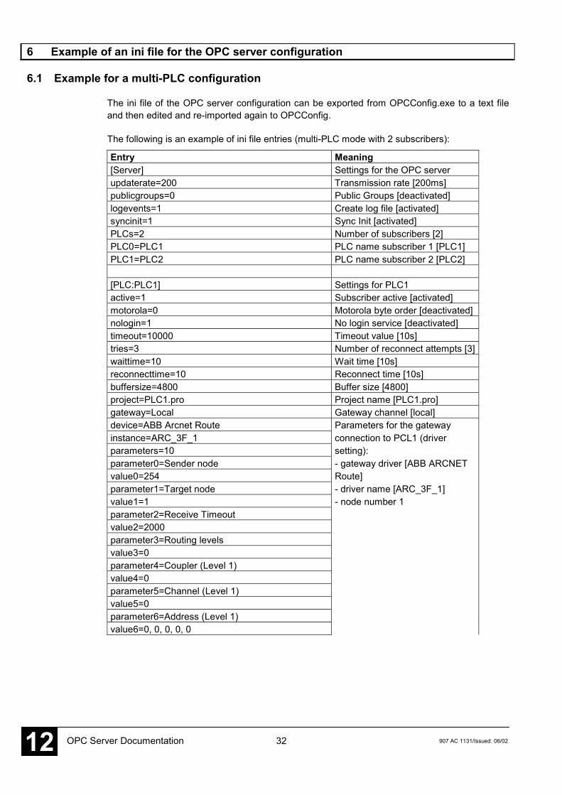
6 Example of an ini file for the OPC server configuration
6.1 Example for a multi-PLC configuration
The ini file of the OPC server configuration can be exported from OPCConfig.exe to a text fileand then edited and re-imported again to OPCConfig.
The following is an example of ini file entries (multi-PLC mode with 2 subscribers):
Entry Meaning[Server] Settings for the OPC serverupdaterate=200 Transmission rate [200ms]publicgroups=0 Public Groups [deactivated]logevents=1 Create log file [activated]syncinit=1 Sync Init [activated]PLCs=2 Number of subscribers [2]PLC0=PLC1 PLC name subscriber 1 [PLC1]PLC1=PLC2 PLC name subscriber 2 [PLC2]
[PLC:PLC1] Settings for PLC1active=1 Subscriber active [activated]motorola=0 Motorola byte order [deactivated]nologin=1 No login service [deactivated]timeout=10000 Timeout value [10s]tries=3 Number of reconnect attempts [3]waittime=10 Wait time [10s]reconnecttime=10 Reconnect time [10s]buffersize=4800 Buffer size [4800]project=PLC1.pro Project name [PLC1.pro]gateway=Local Gateway channel [local]device=ABB Arcnet Route Parameters for the gatewayinstance=ARC_3F_1 connection to PCL1 (driverparameters=10 setting):parameter0=Sender node - gateway driver [ABB ARCNETvalue0=254 Route]parameter1=Target node - driver name [ARC_3F_1]value1=1 - node number 1parameter2=Receive Timeoutvalue2=2000parameter3=Routing levelsvalue3=0parameter4=Coupler (Level 1)value4=0parameter5=Channel (Level 1)value5=0parameter6=Address (Level 1)value6=0, 0, 0, 0, 0

33907 AC 1131/Issued: 06/02 OPC Server Documentation 12
Entry Meaningparameter7=Coupler (Level 2)value7=0parameter8=Channel (Level 2)value8=0parameter9=Address (Level 2)value9=0, 0, 0, 0, 0
[PLC:PLC2] Settings for PLC2active=1 Subscriber active [activated]motorola=0 Motorola byte order [deactivated]nologin=1 No login service [deactivated]timeout=10000 Timeout value [10s]tries=3 Number of reconnect attempts [3]waittime=10 Wait time [10s]reconnecttime=10 Reconnect time [10s]buffersize=4800 Buffer size [4800]project=PLC2.pro Project name [PLC2.pro]gateway=Local Gateway channel [local]device=ABB Arcnet Route Parameters for the gatewayinstance=ARC_3F_2 connection to PLC1 (driverparameters=10 setting):parameter0=Sender node - gateway driver [ABB ARCNETvalue0=254 Route]parameter1=Target node - driver name [ARC_3F_2]value1=2 - node number 2parameter2=Receive Timeoutvalue2=2000parameter3=Routing levelsvalue3=0parameter4=Coupler (Level 1)value4=0parameter5=Channel (Level 1)value5=0parameter6=Address (Level 1)value6=0, 0, 0, 0, 0parameter7=Coupler (Level 2)value7=0parameter8=Channel (Level 2)value8=0parameter9=Address (Level 2)value9=0, 0, 0, 0, 0
34 907 AC 1131/Issued: 06/02OPC Server Documentation12
7 Brief checklist
7.1 Brief checklist
Please check the following if the communication via OPC does not work:
1. Gateway installed and running? Icon in the taskbar (right side on the bottom) active?
2. Installation and registration of the OPC server ok?Is automatically performed when "CoDeSysOPC /Install" (installation + registration) or"CoDeSysOPC /RegServer" (registration only) are executed.
3. Project preparation / settings in the AC1131 programming system ok?<Project> <Options>: 'Dump symbol entries' selected?Communication parameters: Selected gateway channel ok?Project saved, compiled and download performed?The symbol files *.sym and *.sdb must exist in the path WinNT\Gateway Files.
4. If OPC shall be used on another computer (only possible if the OPC server is also runningon the local computer and if the AC1131 project is not additionally accessed (currentlylogged in) on the other computer):Establish a connection to the other computer using DCOMCNFG.EXE (in the systemdirectory):- select the entry 'OPC server for CoDeSys...' in the 'Applications' tab,- click on the 'Properties' button, open the 'Location' tab, activate 'Run application on the following computer' and then enter the desired computer.
5. Verify the connection and the server settings: OPCCFG.EXE:- Connection: (entry must correspond to the valid gateway channel set in the AC1131 communication parameters)- Usual server settings: Update Rate 200ms, Public Groups: No, Sync Init: No Usual PLC settings: Communication Timeout 10 s (10000) Number of (Reconnect) Tries: 3, Buffer Size: 4800, Wait Time (target system): 10s Reconnect Time: 10s, Active: yes, Motorola Byteorder: no, No Login Service: yes Connection settings for PLC: Caution: For multi PLC mode, local and TCP/IP cannot be mixed, verify driver settings- Save -> The new configuration becomes effective when a new connection to the OPC server is established.
6. Verify whether symbol entries are available: DiagnosticOPCClient.exeEstablish connection (Connect OPC-Server) -> in the right-hand window, right-click onPrivate Groups, confirm the dialog with OK, right-click on the created group entry -> add allitems -> all created symbol entries (variables) should be displayed now.
The OPC server is automatically exited as soon as all clients have cleared the connection to it.
The OPC server is displayed in the Task Manager as a process.

I907 AC 1131/Issued: 06/02 OPC Server Documentation 12
8 Index
Aactive 23
Bbuffer size 22
Cclient 3communication parameters 14configuration 16, 29controllers 6
Ddrivers 6
Ggateway 9, 10, 14, 15, 26, 28
Iitem 4items 7, 12, 13
Llibraries 7local 14log events 21login service 23
MMotorola Byteorder 23multi PLC 15, 16, 17, 18, 25
Nno login service 23number of tries 22
OOPC 3OPC server 3, 6, 9, 10, 28, 29
Pparameters 8
PC 6project name 22, 26
Rreconnect time 23registry 27
Ssingle PLC 14, 16, 18, 20symbol file 4, 7, 12, 13, 15synchronous initialization 21system requirements 6
TTCP/IP 14timeout 22
Uupdate rate 20
Wwait time 22

ABB STOTZ-KONTAKT GmbHEppelheimer Straße 82 Postfach 10168069123 Heidelberg 69006 HeidelbergGermany Germany
Telephone +49 6221 701-0Telefax +49 6221 701-1111E-Mail [email protected] http://www.abb.de/stotz-kontakt
Man
ual N
o.:
2CD
C 1
20 0
70 M
020
2