Embed Size (px)
Citation preview

■Updated shaft wall heights ■Updated abP ffor the system W635.de
NEW
W62.deSystem Data Sheet
Drywall Systems
Knauf Installation Shaft WallsW628A.de – Installation Shaft Wall – Free-spanningW630.de – Installation Shaft Wall – Stud crossbars with CW profilesW628B.de – Installation Shaft Wall – Stud construction with CW profilesW629.de – Installation Shaft Wall – Stud construction with CW double profilesK251.de – Fireboard Installation Shaft Wall – Stud construction with CW double profilesW635.de – Installation Shaft Wall – Stud construction with UW double profiles
2020-03
Note on English translation / Hinweise zur englischen FassungThis is a translation of the System Data Sheet valid in Germany. All stated details and properties are in compliance with the regulations of the German standards and building regulations. They are only applicable for the specified products, system components, application rules, and construction details in connection with the specifications of the respective certificates and approvals.Knauf Gips KG denies any liability for applications outside of Germany as this requires changes acc. to the respective national standards and building regulations.
Dies ist eine Übersetzung des in Deutschland gültigen Detailblattes. Alle angegebenen Werte und Eigenschaften ent-sprechen den in Deutschland gültigen Normen und bauaufsichtlichen Regelungen. Sie gelten nur bei Verwendung der angegebenen Produkte, Systemkomponenten, Anwendungsregeln und Konstruktionsdetails in Verbindung mit den Vorgaben der bauaufsichtlichen Nachweise.Die Knauf Gips KG lehnt jegliche Haftung für Einsatz und Anwendung außerhalb Deutschlands ab, da in diesem Fall eine Anpassung an nationale Normen und bauaufsichtliche Regelungen notwendig ist.

2 W62.de Knauf Installation Shaft Walls
ContentsUsage Instructions
Notes ................................................................................................................................................................................................4Notes on the document ...............................................................................................................................................................4References to other documents ..................................................................................................................................................4Symbols in the system data sheet ..............................................................................................................................................4Intended use of Knauf systems ...................................................................................................................................................4General instructions ....................................................................................................................................................................4Notes on fire resistance ..............................................................................................................................................................4Installation zones acc. to DIN 4103-1 .........................................................................................................................................4Construction notes ......................................................................................................................................................................4Notes on sound insulation ...........................................................................................................................................................5
Proofs of Usability ..........................................................................................................................................................................5
IntroductionSystem overview .............................................................................................................................................................................6
Data for planningW628A.de Installation Shaft Wall – Free-spanning ......................................................................................................................8
System variants ...........................................................................................................................................................................8Wall heights ................................................................................................................................................................................9
W630.de Installation Shaft Wall stud crossbars with CW studs ..............................................................................................10System variants .........................................................................................................................................................................10Wall heights ............................................................................................................................................................................... 11
W628B.de Installation Shaft Wall with single stud profile ........................................................................................................12System variants .........................................................................................................................................................................12Wall heights ...............................................................................................................................................................................13
W629.de Installation Shaft Wall with double stud profiles .......................................................................................................14System variants .........................................................................................................................................................................14Wall heights ...............................................................................................................................................................................15
K251.de Fireboard Installation Shaft Wall with double stud profiles .......................................................................................16System variants .........................................................................................................................................................................16Wall heights ...............................................................................................................................................................................17
W635.de Installation Shaft Wall with double stud profiles .......................................................................................................18System variants .........................................................................................................................................................................18Wall heights ...............................................................................................................................................................................19
Construction detailsW628A.de Installation Shaft Wall – Free-spanning ....................................................................................................................20W630.de Installation Shaft Wall stud crossbars with CW profiles ...........................................................................................22W628B.de Installation Shaft Wall with single stud profile ........................................................................................................24W629.de Installation Shaft Wall with double stud profiles .......................................................................................................26K251.de Fireboard Installation Shaft Wall with double stud profiles .......................................................................................28W635.de Installation Shaft Wall with double stud profiles .......................................................................................................30Special details ...............................................................................................................................................................................32
Special versionsUpgrading of installation shaft walls ..........................................................................................................................................37Cable lead-throughs .....................................................................................................................................................................38

3W62.de Knauf Installation Shaft Walls
Installation and applicationStud frame .....................................................................................................................................................................................40Stud frame I Insulation layer ........................................................................................................................................................41Cladding ........................................................................................................................................................................................42Jointing ..........................................................................................................................................................................................44Coatings and linings ....................................................................................................................................................................45
Information on the sustainabilityKnauf Installation Shaft Walls .....................................................................................................................................................48
Information on sustainability of Knauf Installation Shaft Walls ....................................................................................................................................................48

4 W62.de Knauf Installation Shaft Walls
Usage InstructionsNotes
Notes on the documentKnauf system data sheets are the planning and application basis for the planners and professional installers with the application of Knauf systems. The contained information and specifications, constructions, details and stated products are based, unless otherwise stated, on the certificates of usability (e.g. National Technical Test Certificate (abP) valid at the date they are published as well as on the applicable standards. In addition, design and structural requirements and those regarding building physics (fire protection and sound insulation) are considered. The contained construction details are examples and can be used in a similar way for various cladding variants of the respective system. At the same time, the demands made on fire resistance and/or sound insulation as well as any necessary additional measures and/or limitations must be observed.
References to other documentsSystem data sheets
■ For application of furring (without fire resistance) refer to system data sheet Knauf Furring W61.de (German only)
Product data sheets ■ Observe the product data sheets of the Knauf system components
Symbols in the system data sheetThe following symbols are used in this document:Insulation layersG Mineral wool insulation layer acc. to EN 13162
non-combustible (insulating material, e.g. from Knauf Insulation)
S Mineral wool insulation layer acc. to EN 13162 non-combustible melting point ≥ 1000 °C acc. to DIN 4102‑17 (insulating material, e.g. from Knauf Insulation)
Intended use of Knauf systemsPlease observe the following:
Caution
Knauf systems may only be used in the applications as described in the Knauf documents. In case of third-party products or components, they must be recommended or approved by Knauf. Flawless application of products/systems assumes proper transport, storage, assembly, installation and maintenance.
General instructionsArea of applicationThe specifications in this system data sheet apply for installation shaft walls in interiors.
Notes on fire resistanceThe system specifications must be observed to achieve the stated fire resistance. Fire protection is effective from the room side and from the shaft cavity side for all Knauf Installation Shaft Walls.
Shaft side
Room side
e.g. F90
e.g. F90
Reinforcing and supporting connection components must at least feature the same fire resistance class.Installation of access panels in Knauf Installation Shaft Walls is possible. It must be considered that during the installation of an access panel seals in installation shaft walls that the classification of partition “F…” changes to Installation Shaft Wall “I…”. The specifications of the respective system data sheet of the access panel or the respective abP for I-classified Installation Shaft Walls must be considered.
Installation zones acc. to DIN 4103-1Installation zone 1Partitions in rooms where low numbers of persons gather, e.g. dwellings, hotels, office and hospital rooms including corridors and halls or similar.Installation zone 2Partitions in rooms where large numbers of persons gather, e.g. meeting halls, school classrooms, auditoria, exhibition halls and sales rooms as well as rooms with similar usages.Unless otherwise stated, the value in the table is the maximum permissible partition height for installation zone 2.
Construction notesMovement jointsMovement joints of the main structure should be integrated into the construction of the installation shaft walls. Movement joints are to be installed about every 15 m on continuous installation shaft walls.
W63
5.de
K251
.de
W62
9.de
W62
8B.d
eW
630.d
eW
628A
.de

5W62.de Knauf Installation Shaft Walls
Usage InstructionsProofs of Usability
Proof of UsabilityKnauf System Fire resistance Sound insulation Structural engineering
Taking the respective fire protection abP (National Technical Test Certificate) into consideration
W628A.de AbP P-3969/2222-MPA BS
Knauf sound insulation proof L 020-08.09
Knauf calculationW630.de AbP P-3969/2222-MPA BS Knauf calculation
W628B.de AbP P-3393/172/08-MPA BSAbP P-SAC-02/III-797
AbP P-1403/355/12-MPA BSAbP P-1100/490/15-MPA BS
W629.de AbP P-3393/172/08-MPA BSAbP P-SAC-02/III-797
AbP P-1403/355/12-MPA BSAbP P-1100/490/15-MPA BS
K251.de AbP P-3393/172/08-MPA BS AbP P-1403/355/12-MPA BSW635.de AbP P-3320/194/09-MPA BS Knauf calculation
The stated constructional and structural properties, and characteristic building physics of Knauf systems can solely be ensured with the exclusive use of Knauf system components, or other products expressly recommended by Knauf. The validity and up-to-datedness of the stated proofs have to be considered.Notes on fire resistanceThe specifications marked with offer additional application options, which are not directly included in the Proof of Usability. On the basis of our technical assessments, we assume that these marked design solutions can be assessed as a non-significant divergence. On request, we can make the documentation on which this assessment is based, such as experts opinions or technical assessments, available to you together with the Certificate of Usability. We recommend that a non-significant divergence be coordinated and authorised in advance in consultation between the persons responsible for fire resistance and/or the relevant authorities.
Notes on sound insulationRequirements for the insulation layer: Mineral wool insulation layer acc. to EN 13162; length-related flow resistance acc. to EN 29053: r ≥ 5 kPa • s/m², e.g. from Knauf Insulation.Rw = Weighted sound reduction index in dB without sound
transmission via flanking building componentsRw,R = Calculation value of the weighted apparent sound reduction
index without sound transmission via flanking building components
Index R = Used to differentiate between the calculation value and the test values.
Note
The verification according to DIN 4109-2:2018-01 is no longer according to calculation values Rw,R, but rather with the values obtained on the test rig Rw, rounded off to a single position following the decimal point. Only at the end of the forecast after consideration of all the perimeter surfaces (flanking surfaces) involved in the transmission of sound is an element of forecast uncertainty included in dependence on the type of separating constructional component.For a transition period, the Knauf system data sheets will specify both the test stand values as well as the calculated values used up to now.
Note
Avoid air leaks. For deflection heads, sealing with permanently elastic sealant material (recommendation: Knauf Insulation LDS Solimur) is necessary.
W63
5.de
K251
.de
W62
9.de
W62
8B.d
eW
630.d
eW
628A
.de
6 W62.de Knauf Installation Shaft Walls
IntroductionSystem overview
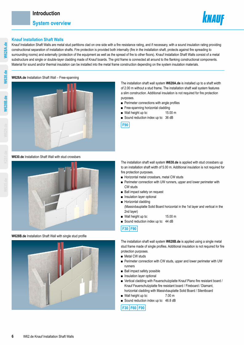
Knauf Installation Shaft Walls Knauf Installation Shaft Walls are metal stud partitions clad on one side with a fire resistance rating, and if necessary, with a sound insulation rating providing constructional separation of installation shafts. Fire protection is provided both internally (fire in the installation shaft, protects against fire spreading to surrounding rooms) and externally (protection of the equipment as well as the spread of fire to other floors). Knauf Installation Shaft Walls consist of a metal substructure and single or double-layer cladding made of Knauf boards. The grid frame is connected all around to the flanking constructional components. Material for sound and/or thermal insulation can be installed into the metal frame construction depending on the system insulation materials.
W628A.de Installation Shaft Wall – Free-spanning
W630.de Installation Shaft Wall with stud crossbars
W628B.de Installation Shaft Wall with single stud profile
The installation shaft wall system W628A.de is installed up to a shaft width of 2.00 m without a stud frame. The installation shaft wall system features a slim construction. Additional insulation is not required for fire protection purposes.
■ Perimeter connections with angle profiles ■ Free-spanning horizontal cladding ■ Wall height up to: 15.00 m ■ Sound reduction index up to: 36 dB
F90
The installation shaft wall system W630.de is applied with stud crossbars up to an installation shaft width of 5.00 m. Additional insulation is not required for fire protection purposes.
■ Horizontal metal crossbars, metal CW studs ■ Perimeter connection with UW runners, upper and lower perimeter with CW studs
■ Ball impact safety on request ■ Insulation layer optional ■ Horizontal cladding (Massivbauplatte Solid Board horizontal in the 1st layer and vertical in the 2nd layer)
■ Wall height up to: 15.00 m ■ Sound reduction index up to: 44 dB
F30 F90
The installation shaft wall system W628B.de is applied using a single metal stud frame made of single profiles. Additional insulation is not required for fire protection purposes.
■ Metal CW studs ■ Perimeter connection with CW studs, upper and lower perimeter with UW runners
■ Ball impact safety possible ■ Insulation layer optional ■ Vertical cladding with Feuerschutzplatte Knauf Piano fire resistant board / Knauf Feuerschutzplatte fire resistant board / Fireboard / Diamant, horizontal cladding with Massivbauplatte Solid Board / Silentboard
■ Wall height up to: 7.00 m ■ Sound reduction index up to: 46.8 dB
F30 F60 F90
W63
5.de
K251
.de
W62
9.de
W62
8B.d
eW
630.d
eW
628A
.de

7W62.de Knauf Installation Shaft Walls
W629.de Installation Shaft Wall with double stud profiles
K251.de Fireboard Installation Shaft Wall with double stud profiles
W635.de Installation Shaft Wall with double stud profiles
The installation shaft wall system W629.de is applied using a single metal stud frame made of double profiles. This facilitates particularly slim solutions.
■ CW metal stud as a double profile ■ Perimeter connection with CW studs, upper and lower perimeter with UW runners
■ Ball impact safety possible ■ Insulation layer optional depending on the system variant ■ Vertical cladding with Feuerschutzplatte Knauf Piano fire resistant board / Knauf Feuerschutzplatte fire resistant board / Fireboard / Diamant, horizontal cladding with Massivbauplatte Solid Board / Silentboard
■ Wall height up to: 7.00 m ■ Sound reduction index up to: 46.8 dB
F30 F60 F90
The installation shaft wall system K251.de features premium fire protection properties with reaction to fire A1, non-combustible and single-layer cladding made of Knauf Fireboard.
■ Metal stud partition CW as a double profile without/with Fireboard covering strips on the shaft side
■ Perimeter connection with CW studs, upper and lower perimeter with UW runners
■ Ball impact safety on request ■ Insulation layer required ■ Vertical cladding ■ Wall height up to: 5.00 m ■ Sound reduction index up to: 41.8 dB
F90
The installation shaft wall system W635.de is specially designed for sound installation requirements as a slim system with specially constructed additional board layer on the shaft side.
■ Metal stud partition UW as a double profile with installed 12.5 mm layer of Feuerschutzplatte Knauf Piano fire resistant board on the shaft side.
■ Surrounding perimeter connections with UW runners ■ Ball impact safety on request ■ Insulation layer required ■ Horizontal cladding ■ Wall height up to: 5.00 m ■ Sound reduction index up to: 54 dB
F90
IntroductionSystem overview
W62
8B.d
eW
630.d
eW
628A
.de
W62
9.de
K251
.de
W63
5.de

8 W62.de Knauf Installation Shaft Walls
NoteApplication of the connection to wall with angle profile 50/35,CW stud or UW runner alternative possible. Observe the notes on page 4.
Data for planningW628A.de Installation Shaft Wall – Free-spanning
System variantsWithout substructure, free-spanning across shaft width, double-layer cladding
Knauf system
Fire
resis
tanc
e clas
s
Cladding Weight Wallthick-ness
Knaufangle profile50/35
Insulation layerFireresistancepermissible
Sound insulation
Scheme drawings
Dth
Knau
f Pian
o fir
e-re
sista
nt b
oard
Knau
f fire
-resis
tant
boa
rdMa
ssivb
aupl
atte
Sol
id B
oard
Fire
boar
dDi
aman
tSi
lentb
oard
Mini-mum thick-ness
Withoutinsulationlayer
Mini-mum thick-ness
Min. density
tmm
approx.kg/m²
Dmm
hmm mm kg/m³
RwdB
Rw,RdB
W628A.de Installation Shaft Wall, free-spanning Without substructure, free-spanning across shaft width, double-layer cladding
Shaft width
F90 ● 2x 25 46 50 ― Without 36 33
W63
5.de
K251
.de
W62
9.de
W62
8B.d
eW
630.d
eW
628A
.de

9W62.de Knauf Installation Shaft Walls
Note Maximum permissible spacings with edge fixing see page 40.
Extension of the fire resistance Proof of Usability ■ In case wall heights exceeding 3.00 m are used ■ With 2-, 3- or 4-sided application
Prior consultation in acc. to page 4 is recommended.
Data for planningW628A.de Installation Shaft Wall – Free-spanning
Wall heights Wall heights with 1-sided application
Maximum shaft widthb
Maximum permissible wall height Increased wall heightsmaximum permissible
Dimensions
m m m
2.00 3.00 15.00 b
Wall heights with multiple-sided application with simplified corner detail
Corner configuration Design Maximum internal dimension
Maximum installa-tion shaft wall surface execution
Maximum permissible wall height
Internal dimension
a bm m m m
Angle profile 50/35
Angle profile 50/35as perimeter connectionto floor and ceiling
2-sided 0.50 0.50 a + b ≤ 0.50 4.00
a
b
3-sided 0.50 0.50 a + b ≤ 0.75 4.00 a
b
4-sided 0.50 0.50 a + b ≤ 1.00 3.00 a
b
Wall heights with multiple-side application
Corner configuration Design Maximum installation shaft wall surface executionexternal dimensions
Maximum permissible wall height
External dimensions
m m
CW stud /UW runner
UW perimeterprofile on floorand ceiling
2-sided a + b ≤ 2.00 5.00
a
b
3-sided 2 a + b ≤ 2.00 5.00 a
b
W63
5.de
K251
.de
W62
9.de
W62
8B.d
eW
630.d
eW
628A
.de

10 W62.de Knauf Installation Shaft Walls
Data for planningW630.de Installation Shaft Wall stud crossbars with CW studs
System variantsMetal crossbars with CW Studs, double-layer cladding
Knauf system
Fire
resis
tanc
e clas
s
Cladding Weight Wallthick-ness
Pro-fileKnauf CW
Insulation layerFire resistance permissible
Sound insulation
Scheme drawings
Dt
h
Knau
f Pian
o fir
e-re
sista
nt b
oard
Knau
f fire
-resis
tant
boa
rdMa
ssivb
aupl
atte
Sol
id B
oard
Fire
boar
dDi
aman
tSi
lentb
oard
Min. thick-ness
Withoutinsula-tionlayer
Cav-ity
Min. thick-ness
Min. den-sity
Minimum insulation layer thickness― 40 mm 60 mm 80 mm
tmm
approx.kg/m²
Dmm
hmm mm kg/m³
RwdB
Rw,RdB
RwdB
Rw,RdB
RwdB
Rw,RdB
RwdB
Rw,RdB
W630.de Installation Shaft Wall with metal crossbars Metal crossbars with CW studs, double-layer cladding
Shaft width
F30
● 2x 12.5 26
75 50 Without ormineral woolG
32 30 38 36 ≥ 38 ≥ 36 ≥ 38 ≥ 36100 75
125 100
● 2x 12.5 30
75 50 Without ormineral woolG
34 31 39 37 ≥ 39 ≥ 37 43 40100 75
125 100
Shaft width
F90 ● 2x 20 40
90 50
Without ormineral woolG
35 33 43 41 44 42 ≥ 44 ≥ 42115 75
140 100
Sound reduction index values represented in italics are derived values from measurements on divergent constructions.
Note Observe the notes on page 4 .
Extension of the fire resistance Proof of Usability ■ When applied with insulation layer G
Prior consultation in acc. to page 5 is recommended.
W63
5.de
K251
.de
W62
9.de
W62
8B.d
eW
628A
.de
W63
0.de

11W62.de Knauf Installation Shaft Walls
Data for planningW630.de Installation Shaft Wall stud crossbars with CW studs
Extension of the fire resistance Proof of Usability ■ In case the enhanced shaft widths are used ■ In case the enhanced wall heights are used
Prior consultation in acc. to page 5 is recommended.
Wall heightsDouble-layer cladding, Feuerschutzplatte Knauf Piano fire-resistant board / Diamant 2x 12.5 mm
Knauf profile
Maximum crossbarspacing
Shaft widthsmaximum permissible
Maximum permissible increased shaft widths
Wall heightsmaximum permissible
Increased wall heightsmaximum permissible
Metal gauge0.6 mm mm m m m m
CW 50 312.5 3.00 3.00 3.00 15.00
CW 75 312.5 3.00 4.50 3.00 15.00
CW 100 312.5 3.00 5.00 3.00 15.00
Double-layer cladding, Massivbauplatte Solid Board 2x 20 mm
Knauf profile
Maximum crossbarspacing
Shaft widthsmaximum permissible
Maximum permissible increased shaft widths
Wall heightsmaximum permissible
Increased wall heightsmaximum permissible
Metal gauge0.6 mm mm m m m m
CW 50 312.51) 3.00 3.00 3.00 15.00
CW 75 312.5 1) 4.00 4.50 3.00 15.00
CW 100 312.51) 4.00 5.00 3.00 15.00
1) Alternative crossbar spacing 625 mm possible with CW double profile possible up to shaft width 4.00 m and shaft height 3.00 m
Crossbar frame spacing ■ CW profile as crossbar ■ CW double profile as crossbar
Cros
sbar
spac
ing≤
312.5
mm
≤ 31
2.5 m
m
Cros
sbar
spac
ing≤
625 m
m
CW double profile preferred variant with installation of insulation layerNot permissible with board thickness 2x 12.5 mm
Note Maximum permissible spacings with edge fixing see page 40.
W63
5.de
K251
.de
W62
9.de
W62
8B.d
eW
628A
.de
W63
0.de

12 W62.de Knauf Installation Shaft Walls
Data for planningW628B.de Installation Shaft Wall with single stud profile
System variantsSingle metal stud frame with CW single studs, double-layer cladding
Knauf system
Fire
resis
tanc
e clas
s
Cladding Weight Wallthick-ness
Pro-fileKnauf CW
Insulation layerFire resistancepermissible
Sound insulation
Scheme drawings
Dt
h
Knau
f Pian
o fir
e-re
sista
nt b
oard
Knau
f fire
-resis
tant
boa
rdMa
ssivb
aupl
atte
Sol
id B
oard
Fire
boar
dDi
aman
tSi
lentb
oard
Min. thick-ness
Withoutinsula-tionlayer
Cavity Min. thick-ness
Min. den-sity
Minimum insulation layer thickness― 40 mm 60 mm 80 mm
tmm
approx.kg/m²
Dmm
hmm mm kg/m³
RwdB
Rw,RdB
RwdB
Rw,RdB
RwdB
Rw,RdB
RwdB
Rw,RdB
W628B.de Installation Shaft Wall with single stud profile Single metal stud frame with CW single studs, double-layer cladding
Stud spacinga
F30
● 2x 12.5 25
75 50 Without ormineral woolG
32 30 38 36 ≥ 38 ≥ 36 ≥ 38 ≥ 36100 75
125 100
● 2x 12.5 29
75 50 Without ormineral woolG
34 31 39 37 ≥ 39 ≥ 37 43 40100 75
125 100
F30● 2x 12.5 40
75 50 Without ormineral woolG
38.4 36 42.9 40 44.8 42 46.8 44100 75
125 100
Stud spacinga
F60
● 2x 15 29
80 50 Without ormineral woolG
32 30 38 36 38 36 ≥ 38 ≥ 36105 75
130 100
● 2x 15 34
80 50 Without ormineral woolG
32 30 38 36 38 36 ≥ 38 ≥ 36105 75
130 100
Stud spacinga
F90
● 2x 20 39
90 50Without ormineral woolG
35 33 43 41 44 42 ≥ 44 ≥ 42115 75
140 100
Stud spacinga
● 2x 25 47
100 50Without ormineral woolG
36 33 43 41 44 42 ≥ 44 ≥ 42125 75
150 100
Stud spacinga
● 2x 20 36
115 75 Without ormineral woolG
35 33 43 41 44 42 ≥ 44 ≥ 42
140 100
Sound reduction index values represented in italics are derived values from measurements on divergent constructions.
Note Observe the notes on page 4.
Extension of the fire resistance Proof of Usability ■ When applied with insulation layer G ■ For variant with Silentboard
Prior consultation in acc. to page 5 is recommended.
W63
5.de
K251
.de
W62
9.de
W63
0.de
W62
8A.d
eW
628B
.de

13W62.de Knauf Installation Shaft Walls
Data for planningW628B.de Installation Shaft Wall with single stud profile
Wall heightsKnauf profile
Metal gauge0.6 mm
Max. spacingsa
Maximum permissible wall heightFeuer-schutzplatte Knauf Piano fire-resistant board 2x 12.5 mm
Diamant2x 12.5 mm
Silentboard2x 12.5 mm
Knauf fire-resistant board 2x 15 mm
Diamant2x 15 mm
Massivbauplatte Solid Board 2x 20 mm
Fireboard 2x 20 mm
Massivbauplatte Solid Board 2x 25 mm
mm m m m m m m m mDouble-layer cladding
CW 501000 – – – – – – – 3.001)
625 2.951) 2.951) – 3.001) 3.001) – – 3.00312.5 3.00 3.00 – 3.00 3.00 – – 3.00
CW 751000 – – – – – – – 3.00625 3.00 3.00 – 3.00 3.00 – 3.00 3.00312.5 3.00 3.00 – 3.00 3.00 – 3.00 3.00
CW 1001000 – – – – – – – 3.00625 3.00 3.00 – 3.00 3.00 – 3.00 3.00312.5 3.00 3.00 – 3.00 3.00 – 3.00 3.00
Increased wall heights, double-layer cladding
CW 501000 – – – – – – – 3.10625 2.95 2.65 / 3.351) 2.65 / 3.351) 3.10 3.25 2.80 2.80 4.00312.5 4.00 4.00 4.00 4.00 4.00 4.00 4.00 4.05
CW 751000 – – – ― – – – 4.00625 4.00 4.00 4.00 4.00 4.00 4.00 4.00 4.05312.5 4.55 4.95 4.95 4.75 5.25 5.20 5.20 5.70
CW 1001000 – – – – – – – 4.10625 4.50 4.95 4.95 5.20 5.20 5.00 5.00 5.40312.5 6.15 6.65 6.65 6.95 6.95 6.90 6.90 7.00
1) only for installation zone 1With wall height > 3.00 m Construction of edge fixing(See page 25 and page 40)
Backing of the perimeterprofile web with board strips
With wall heights > 5.00 m Fix CW studs to UW runners on ceiling and floor at the shaft side with rivets, crimps or screws. (See page 40)
Ball impact safetyAcc. to DIN 18032‑3 with spacing of studs ≤ 625 mm
Installation zones 1 and 2
Extension of the fire resistance Proof of Usability ■ In case the enhanced wall heights are used
Prior consultation in acc. to page 5 is recommended. Note Maximum permissible spacings with edge fixing see page 40.
W63
5.de
K251
.de
W62
9.de
W63
0.de
W62
8A.d
eW
628B
.de

14 W62.de Knauf Installation Shaft Walls
Data for planningW629.de Installation Shaft Wall with double stud profiles
System variantsSingle metal stud frame with CW double studs, double-layer cladding
Knauf system
Fire
resis
tanc
e clas
s
Cladding Weight Wallthick-ness
Pro-fileKnauf CW
Insulation layerFire resistancepermissible
Sound insulation
Scheme drawings
Dt
h
Knau
f Pian
o fir
e-re
sista
nt b
oard
Knau
f fire
-resis
tant
boa
rdMa
ssivb
aupl
atte
Sol
id B
oard
Fire
boar
dDi
aman
tSi
lentb
oard
Min. thick-ness
Withoutinsula-tionlayer
Cavity Min. thick-ness
Min. den-sity
Minimum insulation layer thickness― 40 mm 60 mm 80 mm
tmm
approx.kg/m²
Dmm
hmm mm kg/m³
RwdB
Rw,RdB
RwdB
Rw,RdB
RwdB
Rw,RdB
RwdB
Rw,RdB
W629.de Installation Shaft Wall with double stud profiles Single metal stud frame with CW double profiles, double-layer cladding
Stud spacinga
F30
● 2x 12.5 26
75 50 Without ormineral woolG
32 30 38 36 ≥ 38 ≥ 36 ≥ 38 ≥ 36100 75
125 100
● 2x 12.5 30
75 50 Without ormineral woolG
34 31 39 37 ≥ 39 ≥ 37 43 40100 75
125 100
F30● 2x 12.5 41
75 50 Without ormineral woolG
38.4 36 42.9 40 44.8 42 46.8 44100 75
125 100
Stud spacinga
F60
● 2x 15 31
80 50 Without ormineral woolG
32 30 38 36 38 36 ≥ 38 ≥ 36105 75
130 100
● 2x 15 36
80 50 Without ormineral woolG
32 30 38 36 38 36 ≥ 38 ≥ 36105 75
130 100
Stud spacinga
F90
● 2x 20 40
90 50Without ormineral woolG
35 33 43 41 44 42 ≥ 44 ≥ 42115 75
140 100
Stud spacinga
● 2x 25 49
100 50Without ormineral woolG
36 33 43 41 44 42 ≥ 44 ≥ 42125 75
150 100
Stud spacinga
● 2x 20 37
90 50Without ormineral woolG
35 33 43 41 44 42 ≥ 44 ≥ 42115 75
140 100
Sound reduction index values represented in italics are derived values from measurements on divergent constructions.
Note Observe the notes on page 4.
Extension of the fire resistance Proof of Usability ■ When applied with insulation layer G ■ For variant with Silentboard
Prior consultation in acc. to page 5 is recommended.
W63
5.de
K251
.de
W62
8B.d
eW
630.d
eW
628A
.de
W62
9.de

15W62.de Knauf Installation Shaft Walls
Data for planningW629.de Installation Shaft Wall with double stud profiles
Wall heightsKnauf profile
Max. spacingsa
Maximum permissible wall heightKnauf Piano fire-resistant board
2x 12.5 mm
Diamant2x 12.5 mm
Silentboard2x 12.5 mm
Knauf fire resistant Board 2x 15 mm
Diamant2x 15 mm
Massivbauplatte Solid Board 2x 20 mm
Fireboard 2x 20 mm
Massivbauplatte Solid Board 2x 25 mm
Metal gauge 0.6 mm mm m m m m m m m mDouble-layer cladding
CW 501000 – – – – – – – 3.00625 3.00 3.00 – 3.00 3.00 – 3.00 3.00312.5 3.00 3.00 – 3.00 3.00 – 3.00 3.00
CW 751000 – – – – – – – 3.00625 3.00 3.00 – 3.00 3.00 – 3.00 3.00312.5 3.00 3.00 – 3.00 3.00 – 3.00 3.00
CW 1001000 – – – – – – – 3.00625 3.00 3.00 – 3.00 3.00 – 3.00 3.00312.5 3.00 3.00 – 3.00 3.00 – 3.00 3.00
Increased wall heights, double-layer cladding
CW 501000 – – – – – – – 4.00625 4.00 4.00 4.00 4.00 4.00 4.00 4.00 4.05312.5 4.05 4.45 4.45 4.30 4.75 4.80 4.80 5.45
CW 751000 – – ― – – – 4.55625 4.55 4.95 4.95 4.75 5.25 5.20 5.20 5.70312.5 6.00 6.45 6.45 6.30 6.80 6.90 6.90 7.00
CW 1001000 – – – – – – – 5.00625 6.15 6.65 6.65 6.40 6.95 6.90 6.90 7.00312.5 7.00 7.00 7.00 7.00 7.00 7.00 7.00 7.00
With wall height > 3.00 m Construction of edge fixing(See page 27 and page 40)
Backing of the perimeterprofile with board strip
With wall heights > 5.00 m Fix CW double studs to UW runners on ceiling and floor at the shaft side with rivets, crimps or screws. (See page 40)
Ball impact safetyAcc. to DIN 18032‑3 with spacing of studs ≤ 625 mm
Extension of the fire resistance Proof of Usability ■ In case the enhanced wall heights are used
Prior consultation in acc. to page 5 is recommended. Note Maximum permissible spacings with edge fixing see page 40.
Installation zones 1 and 2
W63
5.de
K251
.de
W62
8B.d
eW
630.d
eW
628A
.de
W62
9.de

16 W62.de Knauf Installation Shaft Walls
Data for planningK251.de Fireboard Installation Shaft Wall with double stud profiles
System variantsSingle metal stud frame with CW double stud frame, single-layer cladding
Knauf system
Fire
resis
tanc
e clas
s
Cladding Weight Wallthick-ness
ProfileKnauf CW
Insulation layerFire resistancerequired
Sound insulation
Scheme drawings
Dt
th
Knau
f Pian
o fir
e-re
sista
nt b
oard
Knau
f fire
-resis
tant
boa
rdMa
ssivb
aupl
atte
Sol
id B
oard
Fire
boar
dDi
aman
tSi
lentb
oard
Min. thickness
Withoutinsula-tionlayer
Cavity Min. thick-ness
Min. density
Minimum insulation layer thickness40 mm 60 mm
tmm
approx.kg/m²
Dmm
hmm mm kg/m³
RwdB
Rw,RdB
RwdB
Rw,RdB
K251.de Fireboard Installation Shaft Wall height ≤ 3.00 m Single metal stud frame with CW double stud frame, single-layer cladding
Stud spacinga
Wall height: ≤ 3.00 m
F90 ● 30 31
80 50
Mineral wool S 40 40
40 38 41.8 39105 75
130 100
K251.de Fireboard Installation Shaft Wall height > 3.00 m to 5.00 m Single metal stud frame with CW double stud frame, single-layer cladding
Stud spacinga
Wall height > 3.00 m
F90
●
●
30+12.5Stud covering
32
92.5 50
Mineral wool S 40 40
40 38 41 39117.5 75
142.5 100
Apply backing to front edge joints using profiles or Fireboard strips
Note Observe the notes on page 4.
Extension of the fire resistance Proof of Usability ■ With wall heights exceeding 3.00 m
Prior consultation in acc. to page 5 is recommended.
W63
5.de
W62
9.de
W62
8B.d
eW
630.d
eW
628A
.de
K251
.de
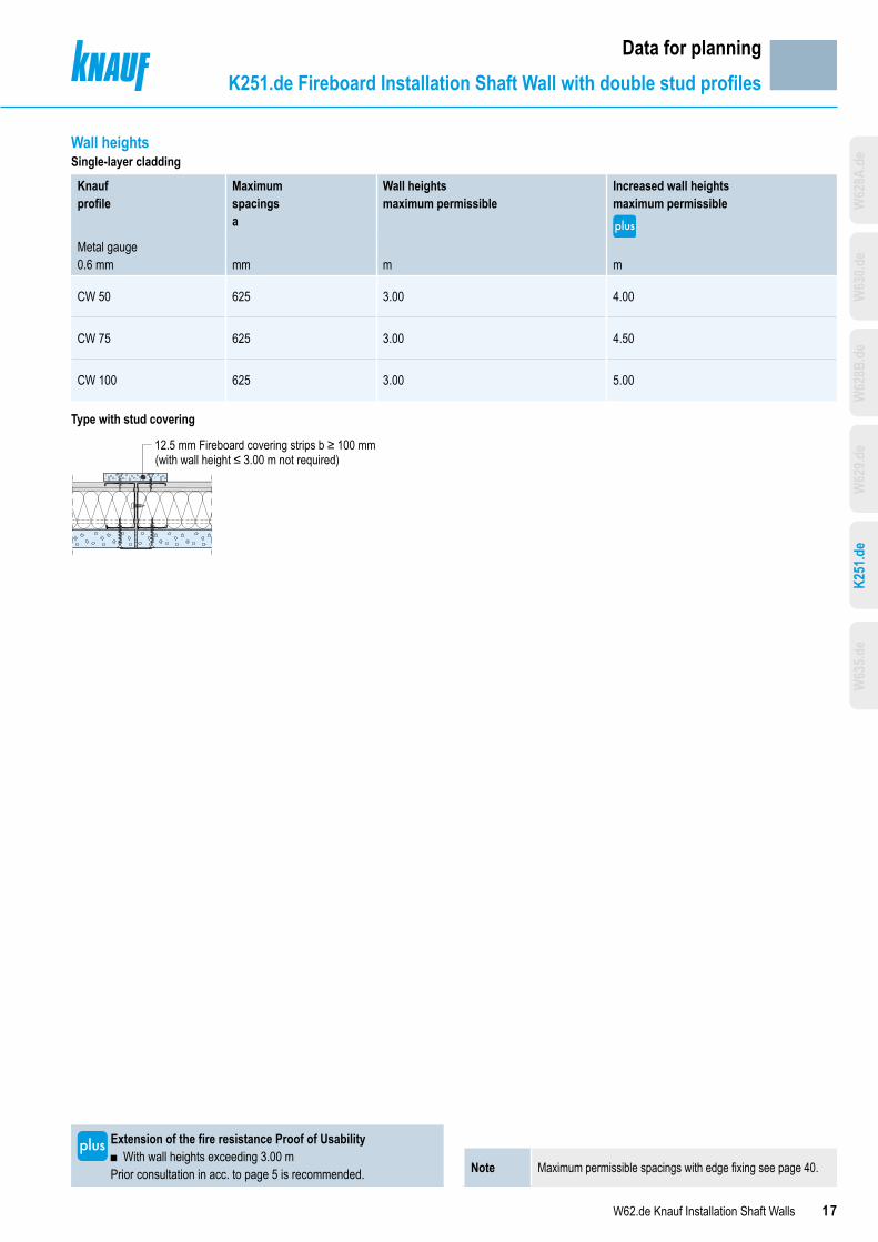
17W62.de Knauf Installation Shaft Walls
Data for planningK251.de Fireboard Installation Shaft Wall with double stud profiles
Note Maximum permissible spacings with edge fixing see page 40.
Extension of the fire resistance Proof of Usability ■ With wall heights exceeding 3.00 m
Prior consultation in acc. to page 5 is recommended.
Wall heightsSingle-layer cladding
Knauf profile
Maximum spacingsa
Wall heightsmaximum permissible
Increased wall heightsmaximum permissible
Metal gauge0.6 mm mm m m
CW 50 625 3.00 4.00
CW 75 625 3.00 4.50
CW 100 625 3.00 5.00
Type with stud covering
12.5 mm Fireboard covering strips b ≥ 100 mm(with wall height ≤ 3.00 m not required)
W63
5.de
W62
9.de
W62
8B.d
eW
630.d
eW
628A
.de
K251
.de

18 W62.de Knauf Installation Shaft Walls
Note Observe the notes on page 4.
Note With intermediate vertical board layer, one horizontal board joint per section is permissible.
Data for planningW635.de Installation Shaft Wall with double stud profiles
System variantsSingle metal stud frame with UW double runners, double-layer cladding + intermediate board layer
Knauf system
Fire
resis
tanc
e clas
s
Cladding Weight Wallthick-ness
ProfileKnauf UW
Insulation layerFireresistancerequired
Sound insulation
Scheme drawings
Dt
h
t
Knau
f Pian
o fir
e-re
sista
nt b
oard
Knau
f fire
-resis
tant
boa
rdMa
ssivb
aupl
atte
Sol
id B
oard
Fire
boar
dDi
aman
tSi
lentb
oard
Min. thick-ness
Withoutinsula-tionlayer
Cavity Min. thick-ness
Min. density
Minimum insulation layer thickness40 mm 80 mm
tmm
approx.kg/m²
Dmm
hmm mm kg/m³
RwdB
Rw,RdB
RwdB
Rw,RdB
W635.de Installation Shaft Wall Single metal stud frame with UW double runners, double-layer cladding + intermediate board layer
Stud spacinga
F90 ●
● 2x 15+12.5Inter-mediate
46
80 50
Mineral wool S40 28
49 47 54 52105 75
130 100
Extension of the fire resistance Proof of Usability ■ With board width > 625 mm■ In case of perimerter connection without insulation strip
backingPrior consultation in acc. to page 5 is recommended.
K251
.de
W62
9.de
W62
8B.d
eW
630.d
eW
628A
.de
W63
5.de

19W62.de Knauf Installation Shaft Walls
Data for planningW635.de Installation Shaft Wall with double stud profiles
Extension of the fire resistance Proof of Usability ■ In case the enhanced wall heights are used ■ With board width > 625 mm ■ In case of perimerter connection without insulation strip backing
Prior consultation in acc. to page 5 is recommended.
Wall heightsDouble-layer cladding + intermediate board layer
Knauf profile
Maximum spacingsa
Maximum per-missible wall height
Maximum permissible increased wall heights
Metal gauge0.6 mm mm m m
UW 50 625 3.00 4.00
UW 75 625 3.00 4.50
UW 100 625 3.00 5.00
Note Maximum permissible spacings with edge fixing see page 40.
K251
.de
W62
9.de
W62
8B.d
eW
630.d
eW
628A
.de
W63
5.de
20 W62.de Knauf Installation Shaft Walls
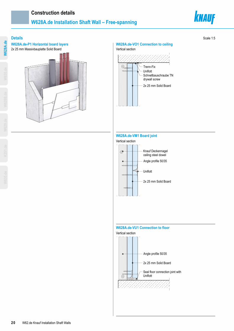
Details Scale 1:5
W628A.de-P1 Horizontal board layers W628A.de-VO1 Connection to ceiling2x 25 mm Massivbauplatte Solid Board Vertical section
Trenn-FixUniflottSchnellbauschraube TNdrywall screw
2x 25 mm Solid Board
W628A.de-VM1 Board jointVertical section
Knauf Deckennagelceiling steel dowel
Angle profile 50/35
Uniflott
2x 25 mm Solid Board
W628A.de-VU1 Connection to floorVertical section
Angle profile 50/35
2x 25 mm Solid Board
Seal floor connection joint withUniflott
Construction detailsW628A.de Installation Shaft Wall – Free-spanning
W63
5.de
K251
.de
W62
9.de
W62
8B.d
eW
630.d
eW
628A
.de

21W62.de Knauf Installation Shaft Walls
Details Scale 1:5
W628A.de-D1 Corner W628A.de-VO2 Connection to ceiling with corner detailHorizontal section Vertical section
UW runnerCW studMetal screw LN 3.5 x 11;a ≤ 500 mmSchnellbauschraube TNdrywall screw; a ≤ 250 mmFlex profile 100 mmCW studFill board joint
Corner trim if requiredor corner trim Dallas 90°
Schnellbauschraube TN drywall screw;a ≤ 250 mm
Observe maximum partition heights.
Trenn-Fix
UniflottTrennwandkitt acoustical sealantUW runnerKnauf Deckennagel ceilingsteel dowel; a ≤ 500 mmCW stud2x 25 mm Solid Board
Observe maximum partition heights.Extension of the fire resistance Certificate of Usability Prior consultation in acc. to page 5 recommended
Extension of the fire resistance Certificate of Usability Prior consultation in acc. to page 5 recommended
W628A.de-D2 Corner W628A.de-VU2 Connection to floor with corner detailHorizontal section (Simplified corner detail) Vertical section (Simplified corner detail)
Uniflott
Corner trim if requiredor corner trim Dallas 90°
2x 25 mm Solid BoardAngle profile 50/35or CW stud/UW runnerSchnellbauschraube TNdrywall screwBoard butt joint
Observe maximum partition heights.
Angle profile 50/352x 25 mm Solid Board
Seal floor connection joint with africtional bond using Uniflott
Trennwandkitt acoustical sealantKnauf Deckennagel ceiling steeldowel; a ≤ 500 mm
Observe maximum partition heights.Extension of the fire resistance Certificate of Usability Prior consultation in acc. to page 5 recommended
Extension of the fire resistance Certificate of Usability Prior consultation in acc. to page 5 recommended
W628A.de-A1 Connection to solid wallHorizontal section
Acoustical sealant if required
Angle profile 50/35
2x 25 mm Solid BoardSchnellbauschraube TN drywall screwUniflott + Trenn-Fix
Knauf Deckennagel ceiling steel dowel
Construction detailsW628A.de Installation Shaft Wall – Free-spanning
W63
5.de
K251
.de
W62
9.de
W62
8B.d
eW
630.d
eW
628A
.de

22 W62.de Knauf Installation Shaft Walls
Details Scale 1:5
W630.de-P1 Horizontal board layers W630.de-VO1 Connection to ceilinge.g. 2x 12.5 mm Diamant Vertical section
Trenn-FixUniflottTrennwandkitt acoustical sealantCW studKnauf Deckennagelceiling steel dowelUW runner2x 12.5 mmKnauf Pianofire-resistant board
W630.de-P4 Board layer 1 horizontal, board layer 2 vertical W630.de-VM4 Board joint CW double profile2x 20 mm Massivbauplatte Solid Board Vertical section
Cros
sbar
spac
ing
UW runner2x 20 mm Solid BoardCW stud (rivet, crimp or screw fixto UW runner)Uniflott + Fugendeck-streifen Kurt joint tapeMetal screwLN 3.5 x 11;a ≤ 750 mm
W630.de-VU4 Connection to floorVertical section
2x 20 mm Solid BoardUW runnerCW studKnauf Deckennagelceiling steel dowelDrywall screw TNUniflott
Construction detailsW630.de Installation Shaft Wall stud crossbars with CW profiles
W63
5.de
K251
.de
W62
9.de
W62
8B.d
eW
628A
.de
W63
0.de

23W62.de Knauf Installation Shaft Walls
Details Scale 1:5
W630.de-A1 Connection to solid wall W630.de-B4 Board jointHorizontal section Horizontal section
Trennwandkitt acousticalsealantKnauf Deckennagel
2x 12.5 mm DiamantDiamant screw XTNUniflott + Trenn-Fix
UniflottDrywall screw TN
CW stud
2x 20 mm Solid Board
W630.de-VM1 Board joint CW single profileVertical section
Cros
sbar
spac
ing
UW runnerCW studUniflottDrywall screw TN2x 12.5 mmKnauf Pianofire-resistantboard
Construction detailsW630.de Installation Shaft Wall stud crossbars with CW profiles
W63
5.de
K251
.de
W62
9.de
W62
8B.d
eW
628A
.de
W63
0.de

24 W62.de Knauf Installation Shaft Walls
Details Scale 1:5
W628B.de-P2 Vertical board layers W628B.de-VO2 Connection to ceiling e.g. 2x 12.5 mm Diamant Vertical section
Trenn-FixUniflottTrennwandkitt acoustical sealantUW runnerKnauf Deckennagel ceilingsteel dowelCW stud2x 12.5 mm Knauf Pianofire-resistant board
W628B.de-P6 Horizontal board layers W628B.de-VM6 Board jointe.g. 2x 20 mm Massivbauplatte Solid Board Vertical section
CW stud2x 20 mm Solid Board
UniflottDrywall screw TN
W628B.de-P4 Vertical board layers W628B.de-VU4 Connection to floore.g. 2x 20 mm Fireboard Vertical section
2x 20 mm FireboardCW studKnauf DeckennagelUW runnerTrennwandkitt acoustical sealantDrywall screw TNFireboard filler
Construction detailsW628B.de Installation Shaft Wall with single stud profile
W63
5.de
K251
.de
W62
9.de
W63
0.de
W62
8A.d
eW
628B
.de

25W62.de Knauf Installation Shaft Walls
Details Scale 1:5
W628B.de-A2 Connection to solid wall W628B.de-A21 Connection to solid wallHorizontal section Horizontal section
CW studKnauf Deckennagel ceiling steel dowelsTrennwandkitt acoustical sealant
2x 12.5 mm Knauf Piano fire-resistant boardUniflott + Trenn-Fix
Trennwandkitt acoustical sealant≥ 12.5 mm Knauf Piano fire-resistant boardCW stud
2x 12.5 mm Knauf Piano fire-resistant boardNon-combustible fasteners suitablefor the substrateUniflott + Trenn-Fix
With wall height ≤ 3.00 m no backing of the CW perimeter connection profile on the web side required.
With wall height > 3.00 m backing of the CW perimeter connection profile on the web side required.
Extension of the fire resistance Certificate of Usability Prior consultation in acc. to page 5 recommended.
W628B.de-A3 Connection to solid wall W628B.de-B4 Board jointHorizontal section Horizontal section
CW studKnauf Deckennagel ceiling steel dowelTrennwandkitt acoustical sealant
2x 25 mm Solid BoardUniflott + Trenn-Fix
CW studUW runner
Fireboard filler + fibre glassjoint tape
2x 20 mmFireboard
With wall height ≤ 3.00 m no backing of the CW perimeter connection profile on the web side required.
W628B.de-SO4 Connection to metal stud partition W628B.de-D3 CornerHorizontal section Horizontal section
Drywall screw TN orKnauf multi-purpose screw FN
2x 25 mm Solid BoardCW stud
Uniflott +Trenn-FixW112.de
2x 25 mm Solid BoardMetal screw LN 3.5 x 11;a ≤ 500 mm
CW studDrywall screw TN 3.5 x 35;a ≤ 250 mm (only with corner)Drywall screw TN 4.5 x 70Fill board joint
If necessary use corner trim or corner profile Dallas 90°
UW runnerCW stud
With wall height ≤ 3.00 m no backing of the CW perimeter connection profile on the web side required. Extension of the fire resistance Certificate of Usability
Prior consultation in acc. to page 5 recommended.Extension of the fire resistance Certificate of Usability Prior consultation in acc. to page 5 recommended.
Construction detailsW628B.de Installation Shaft Wall with single stud profile
W63
5.de
K251
.de
W62
9.de
W63
0.de
W62
8A.d
eW
628B
.de

26 W62.de Knauf Installation Shaft Walls
Details Scale 1:5
W629.de-P2 Vertical board layers W629.de-VO2 Connection to ceilinge.g. 2x 12.5 mm Diamant Vertical section
Trenn-FixUniflottTrennwandkitt acoustical sealantUW runnerKnauf Deckennagel ceiling steel dowelCW stud2x 12.5 mm Knauf Pianofire-resistant board
W629.de-P5 Horizontal board layers W629.de-VM5 Board jointe.g. 2x 20 mm Massivbauplatte Solid Board Vertical section
CW stud2x 20 mm Solid Board
UniflottDrywall screw TN
W629.de-P6 Horizontal board layers W629.de-VU6 Connection to floore.g. 2x 25 mm Massivbauplatte Solid Board Vertical section
2x 25 mm Solid BoardCW studUW runnerKnauf Deckennagelceiling steel dowelTrennwandkitt acoustical sealantDrywall screw TNUniflott
Construction detailsW629.de Installation Shaft Wall with double stud profiles
W63
5.de
K251
.de
W62
8B.d
eW
630.d
eW
628A
.de
W62
9.de

27W62.de Knauf Installation Shaft Walls
Details Scale 1:5
W629.de-A2 Connection to solid wall W629.de-A21 Connection to solid wallHorizontal section Horizontal section
CW studKnauf Deckennagel ceiling steel dowelTrennwandkitt acoustical sealant
2x 12.5 mm DiamantUniflott + Trenn-Fix
Trennwandkitt acoustical sealant≥ 12.5 mm DiamantCW stud
2x 12.5 mm DiamantNon-combustible fasteners suitablefor the substrateUniflott + Trenn-Fix
With wall height ≤ 3.00 m no backing of the CW perimeter connection profile on the web side required.
With wall height > 3.00 m backing of the CW perimeter connection profile on the web side required.
Extension of the fire resistance Certificate of Usability Prior consultation in acc. to page 5 recommended
W629.de-A51 Connection to solid wall W629.de-B5 Board jointHorizontal section Horizontal section
Trennwandkitt acoustical sealant≥ 20 mm Solid BoardCW stud
2x 20 mm Solid BoardNon-combustible fasteners suitablefor the substrateUniflott + Trenn-Fix
UW runner
Uniflott + Fugendeckstreifen Kurt joint tape2x 20 mm Solid Board
CW stud Metal screw LN 3.5 x 11;a ≤ 500 mm
With wall height > 3.00 m backing of the CW perimeter connection profile on the web side required.
Extension of the fire resistance Certificate of Usability Prior consultation in acc. to page 5 recommended
Extension of the fire resistance Certificate of Usability Prior consultation in acc. to page 5 recommended
W629.de-SO5 Connection to metal stud partition W629.de-D6 CornerHorizontal section Horizontal section
Trennwandkitt acoustical sealantKnauf Hartmut cavity dowel;a ≤ 500 mm
CW studDrywall Screw TN
2x 20 mm Solid Board
W112.de
2x 25 mm Solid BoardMetal Screw LN 3.5 x 11;a ≤ 500 mm
CW studDrywall screw TN 3.5 x 35;a ≤ 250 mm (only for corner)Drywall screw TN 4.5 x 70Fill board joint
If necessaryuse corner trim or corner profile Dallas 90°
UW runnerCW stud
With wall height ≤ 3.00 m no backing of the CW perimeter connection profile on the web side required.
Extension of the fire resistance Certificate of Usability Prior consultation in acc. to page 5 recommended
Extension of the fire resistance Certificate of Usability Prior consultation in acc. to page 5 recommended
Construction detailsW629.de Installation Shaft Wall with double stud profiles
W63
5.de
K251
.de
W62
8B.d
eW
630.d
eW
628A
.de
W62
9.de

28 W62.de Knauf Installation Shaft Walls
Details Scale 1:5
K251.de-P6 Vertical board layers K251.de-VO6 Connection to ceiling30 mm Fireboard Vertical section
Trenn-FixFireboard fillerTrennwandkitt acoustical sealantUW runnerKnauf Deckennagel ceiling steel dowel30 mm Fireboard
With wall height ≤ 3.00 m With wall height ≤ 3.00 m
K251.de-P5 Vertical board layers + stud covering K251.de-VM6 Board joint30 mm Fireboard + 12.5 mm Fireboard covering strip Vertical section
S
CW stud jointbackingDrywall screw TNFireboard filler + fibre glassjoint tape30 mm Fireboard
CW stud
Mineral wool
With wall height > 3.00 m With wall height ≤ 3.00 m
K251.de-VU6 Connection to floorVertical section
S30 mm FireboardMineral woolKnauf Deckennagel ceiling steel dowelUW runnerTrennwandkitt acoustical sealantDrywall screw TNFireboard filler
With wall height ≤ 3.00 m
Construction detailsK251.de Fireboard Installation Shaft Wall with double stud profiles
W63
5.de
W62
9.de
W62
8B.d
eW
630.d
eW
628A
.de
K251
.de

29W62.de Knauf Installation Shaft Walls
Details Scale 1:5
K251.de-A6 Connection to solid wall K251.de-B6 Board jointHorizontal section Horizontal section
S
CW studKnauf Deckennagel ceiling steel dowelTrennwandkitt acoustical sealant
Mineral wool
30 mm FireboardFireboard fillerTrenn-Fix
S
CW stud
Metal screw LN 3.5 x 11a ≤ 500 mm
Mineral wool
Fireboard filler +fibre glass joint
tapeDrywall screw TN
30 mm Fireboard
With wall height ≤ 3.00 m With wall height ≤ 3.00 m
K251.de-D6 Corner K251.de-D5 CornerHorizontal section Horizontal section
30 mm FireboardMetal screw LN 3.5 x 11;a ≤ 500 mmCW stud
Fireboard filler + fibre glassjoint strips30 mm Fireboard
CW stud
Drywall screw TN
30 mm FireboardMetal screw LN 3.5 x 11;a ≤ 500 mmCW studDrywall screw TN
Fireboard filler + fibre glassjoint tape30 mm Fireboard
CW stud
Drywall screw TN;a ≤ 250 mm
Boardstrips
≥ 50 mmwide
With wall height ≤ 3.00 mExtension of the fire resistance Certificate of Usability Prior consultation in acc. to page 5 recommended
With wall height > 3.00 mExtension of the fire resistance Certificate of Usability Prior consultation in acc. to page 5 recommended
K251.de-VU5 Connection to floor K251.de-B5 Board jointVertical section Horizontal section
S
30 mm Fireboard
Mineral wool
Profile backing boardstrip ≥ 12.5 mm Fireboard
Knauf Deckennagel ceiling steel dowelUW profileTrennwandkitt acoustical sealantDrywall screw TNFireboard filler
SMineral wool
Drywall screws TNoffset screw fixing
CW studDrywall screw TN
≥ 12.5 mm Fireboard
30 mmFireboard
Board strips≥ 100 mm
With wall height > 3.00 mExtension of the fire resistance Certificate of Usability Prior consultation in acc. to page 5 recommended
With wall height > 3.00 mExtension of the fire resistance Certificate of Usability Prior consultation acc. to page 5 recommended
Construction detailsK251.de Fireboard Installation Shaft Wall with double stud profiles
W63
5.de
W62
9.de
W62
8B.d
eW
630.d
eW
628A
.de
K251
.de

30 W62.de Knauf Installation Shaft Walls
Details Scale 1:5
W635.de-P1 Horizontal board layers W635.de-VO1 Connection to ceiling2x 15 mm Diamant + intermediate Knauf Piano fire-resistant board vertical Vertical section
S
Trenn-FixUniflottTrennwandkitt acoustical sealantUW runnerKnauf Deckennagel ceiling steel dowel2x 15 mm Diamant12.5 mm Knauf Piano fire-resistant boardMineral wool
W635.de-VM1 Board jointVertical section
S
Diamant screw XTN
UW runnerDiamant screw XTN2x 15 mm Diamant12.5 mm Knauf Piano fire-resistant boardMineral wool
W635.de-VU1 Connection to floorVertical section
12.5 mm Knauf Piano fire-resistant board2x 15 mm DiamantTrennwandkitt acoustical sealantUW runnerKnauf Deckennagel ceiling steel dowelsDiamant screw XTNTrennwandkitt acoustical sealantUniflott
Construction detailsW635.de Installation Shaft Wall with double stud profiles
Note With intermediate vertical board layer, one horizontal board joint per section is permissible.
K251
.de
W62
9.de
W62
8B.d
eW
630.d
eW
628A
.de
W63
5.de

31W62.de Knauf Installation Shaft Walls
Details Scale 1:5
W635.de-A1 Connection to solid wall W635.de-B1 Board jointHorizontal section Horizontal section
S
Knauf Deckennagel ceiling steel dowelUW runner
Trennwandkitt acoustical sealant12.5 mm Knauf Piano fire resistant board
2x 15 mm DiamantDiamant screw XTN
Uniflott + Trenn-Fix
Mineral wool
12.5 mm Knauf Pianofire-resistant board
Metal screwLN 3.5 x 11; a ≤ 750 mm
2x 15 mm DiamantUniflott + Joint
tape Kurt
UW runnerTrennwandkitt
acousticalsealant
Diamant screw XTN
UW runner
W635.de-D1 Corner W635.de-D2 CornerHorizontal section Horizontal section
S
S
Uniflott
If necessary,use corner trim or cornerprofile Dallas 90°
12.5 mm Knauf Pianofire-resistant board2x 15 mm Diamant
Diamant screw XTNMetal screwLN 3.5 x 11; a ≤ 500 mmUW runnerAdditional insulation strips
Mineral wool
S
12.5 mm Knauf Pianofire-resistant board2x 15 mm Diamant
Diamant screw XTNMetal screwLN 3.5 x 11; a ≤ 500 mmUW runnerUniflottIf necessary, use cornertrim or corner profileDallas 90°
Mineral wool
Extension of the fire resistance Certificate of Usability Prior consultation in acc. to page 5 recommended
Extension of the fire resistance Certificate of Usability Prior consultation in acc. to page 5 recommended
Construction detailsW635.de Installation Shaft Wall with double stud profiles
Note With intermediate vertical board layer, one horizontal board joint per section is permissible.
K251
.de
W62
9.de
W62
8B.d
eW
630.d
eW
628A
.de
W63
5.de

32 W62.de Knauf Installation Shaft Walls
Scale 1:5DetailW629.de-SO2 Installation shaftHorizontal section
e.g. W112.de (with same fire resistanceclass as installation shaft wall)
Knauf Deckennagelceiling steeldowel; a ≤ 500 mm
2x 12.5 mm Diamant
Metal screw LN 3.5 x 11; a ≤ 500 mm
Diamant screw XTN;a ≤ 250 mm2x 12.5 mm Diamant
Metal screw LN 3.5 x 11;a ≤ 500 mmDiamant screw XTNCW stud
Knauf Hartmut cavitydowel; a ≤ 500 mm
UW runner
CW stud
CW stud
Extension of the fire resistance Certificate of Usability Prior consultation in acc. to page 5 recommended
Construction detailsSpecial details
W63
5.de
K251
.de
W62
8B.d
eW
630.d
eW
628A
.de
W62
9.de

33W62.de Knauf Installation Shaft Walls
Details Dimensions in mm I Scale 1:5
Construction detailsSpecial details
Note The power sockets must be encased in at least cladding thickness t by Knauf GKF/Fireboard boards.
W628B.de-SO1 Power sockets with runner frame W629.de-VO3 Connection to ceiling – deflection headHorizontal section Vertical section
e.g. W628B.de Profile frame CW 50 or UW 50
Power socketKnauf boards
≥ t
t
≥ t
a ≤ 20 mm
Edge trim,if requiredNon-combustible fastenerssuitable for the substrate;a ≤ 500 mmKnauf filling compoundKnauf board strips
Permanently elastic sealantUW runner
CW stud coveringboard strips20 mm Solid Board≥ 100 mm x 400 mm
CW stud
Extension of the fire resistance Certificate of Usability Prior consultation in acc. to page 5 recommended
W628B.de-SO2 Power sockets with runner frameVertical section
Knauf boardsProfile frame
Extension of the fire resistance Certificate of Usability Prior consultation in acc. to page 5 recommended
Extension of the fire resistance Certificate of Usability Prior consultation in acc. to page 5 recommended
W629.de-SO6 Power sockets with board backingHorizontal section
Glue all boardlayerse.g. W629.de
Frame corresponding to thedepth of the power socket
Knauf gypsumboard screws
≥ t≥ 40 ≥ 200/200
≥ 280/280≥ 40
tt
Extension of the fire resistance Certificate of Usability Prior consultation in acc. to page 5 recommended
W63
5.de
K251
.de
W63
0.de
W62
8A.d
eW
629.d
eW
628B
.de

34 W62.de Knauf Installation Shaft Walls
Details Scale 1:5
Construction detailsSpecial details
W628B.de-SO6 Ceiling connection to board ceiling W629.de-SO10 Ceiling connection to board ceilingVertical section Vertical section
Extension of the fire resistance Certificate of Usability Prior consultation in acc. to page 5 recommended.
Extension of the fire resistance Certificate of Usability Prior consultation in acc. to page 5 recommended.
W628B.de-SO7 Ceiling connection to free-spanning ceiling W629.de-SO11 Ceiling connection to free-spanning ceilingVertical section Vertical section
Extension of the fire resistance Certificate of Usability Prior consultation in acc. to page 5 recommended.
Extension of the fire resistance Certificate of Usability Prior consultation in acc. to page 5 recommended.
Technical fire resistance classified suspended ceiling solely frombelow with same fire resistance as the Installation Shaft Wall
Uniflott + Trenn-FixTrennwandkitt acoustical sealantUW runnerKnauf multi-purpose screw FN;a ≤ 500 mm2x 20 mm Solid Board
Technical fire resistance classified suspended ceiling solely frombelow with same fire resistance as the Installation Shaft Wall
Uniflott + Trenn-FixTrennwandkitt acoustical sealantUW runnerKnauf multi-purpose screw FN;a ≤ 500 mm2x 12.5 mm Knauf Pianofire-resistant board
Technical fire resistance classified suspended ceiling solely frombelow with same fire resistance as the Installation Shaft Wall
CW double stud asfurring channelUniflott + Trenn-FixTrennwandkitt acoustical sealantUW runnerKnauf multi-purpose screw FN;a ≤ 500 mm
Technical fire resistance classified suspended ceiling solely frombelow with same fire resistance as the Installation Shaft Wall
CW double stud as a furring channelUniflott + Trenn-Fix Trennwandkitt acoustical sealant UW runnerKnauf multi-purpose screw FN; a ≤ 625 mm
NoteRefer to the system data sheets for suspended ceiling application
■ Knauf Free-Spanning Ceilings D13.de
W63
5.de
K251
.de
W63
0.de
W62
8A.d
eW
629.d
eW
628B
.de
35W62.de Knauf Installation Shaft Walls
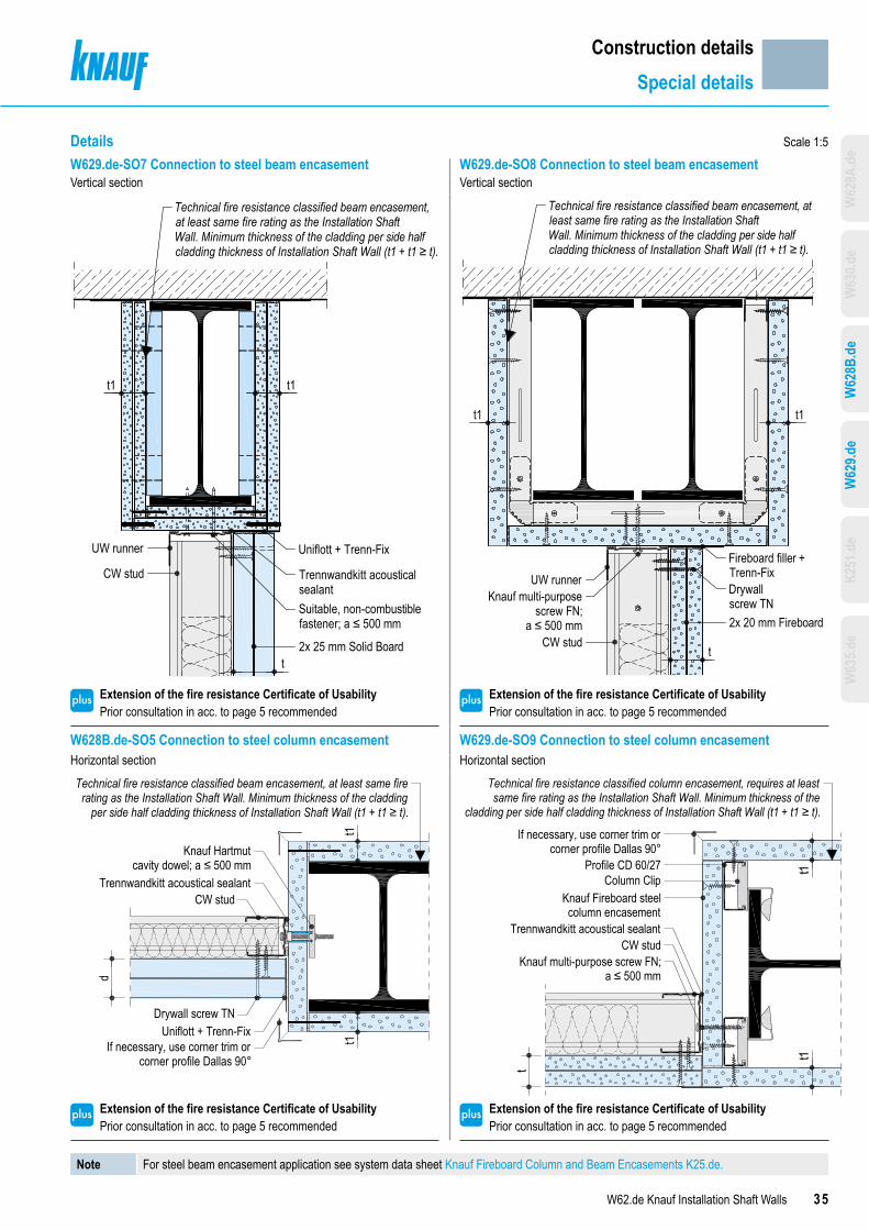
Details
Construction detailsSpecial details
Scale 1:5W629.de-SO7 Connection to steel beam encasement W629.de-SO8 Connection to steel beam encasementVertical section Vertical section
Technical fire resistance classified beam encasement,at least same fire rating as the Installation ShaftWall. Minimum thickness of the cladding per side halfcladding thickness of Installation Shaft Wall (t1 + t1 ≥ t).
Uniflott + Trenn-Fix
Trennwandkitt acousticalsealantSuitable, non-combustiblefastener; a ≤ 500 mm
2x 25 mm Solid Board
UW runner
CW stud
t1t1
t
Technical fire resistance classified beam encasement, atleast same fire rating as the Installation ShaftWall. Minimum thickness of the cladding per side halfcladding thickness of Installation Shaft Wall (t1 + t1 ≥ t).
Fireboard filler +Trenn-FixDrywallscrew TN2x 20 mm Fireboard
Knauf multi-purposescrew FN;
a ≤ 500 mmCW stud
UW runner
t1t1
t
Extension of the fire resistance Certificate of Usability Prior consultation in acc. to page 5 recommended
Extension of the fire resistance Certificate of Usability Prior consultation in acc. to page 5 recommended
W628B.de-SO5 Connection to steel column encasement W629.de-SO9 Connection to steel column encasementHorizontal section Horizontal section
Extension of the fire resistance Certificate of Usability Prior consultation in acc. to page 5 recommended
Extension of the fire resistance Certificate of Usability Prior consultation in acc. to page 5 recommended
Technical fire resistance classified beam encasement, at least same firerating as the Installation Shaft Wall. Minimum thickness of the cladding
per side half cladding thickness of Installation Shaft Wall (t1 + t1 ≥ t).
t1t1
Knauf Hartmutcavity dowel; a ≤ 500 mm
Trennwandkitt acoustical sealantCW stud
Drywall screw TNUniflott + Trenn-Fix
If necessary, use corner trim orcorner profile Dallas 90°
d
Technical fire resistance classified column encasement, requires at leastsame fire rating as the Installation Shaft Wall. Minimum thickness of the
cladding per side half cladding thickness of Installation Shaft Wall (t1 + t1 ≥ t).
If necessary, use corner trim orcorner profile Dallas 90°
Profile CD 60/27Column Clip
Knauf Fireboard steelcolumn encasement
Trennwandkitt acoustical sealantCW stud
Knauf multi-purpose screw FN;a ≤ 500 mm
Note For steel beam encasement application see system data sheet Knauf Fireboard Column and Beam Encasements K25.de.
W63
5.de
K251
.de
W63
0.de
W62
8A.d
eW
629.d
eW
628B
.de

36 W62.de Knauf Installation Shaft Walls
DetailsW628B.de-SO8 Corner – connection to metal stud partition W629.de-SO13 Connection to floor – undercut plinthHorizontal section Vertical section
Extension of the fire resistance Certificate of Usability Prior consultation acc. to page 5 recommended
Extension of the fire resistance Certificate of Usability Prior consultation acc. to page 5 recommended
W629.de-SO12 T connection Installation Shaft Wall W628B.de-SO9 Movement jointHorizontal section Horizontal section
Extension of the fire resistance Certificate of Usability Prior consultation acc. to page 5 recommended
Extension of the fire resistance Certificate of Usability Prior consultation acc. to page 5 recommended
W112.deCW studDrywall screw TN;a ≤ 250 mm
Drywall screw TN orKnauf multi-purpose screw FN;a ≤ 250 mmCW studFill butt jointCorner trim orcorner profile Dallas 90°
2x 25 mm Solid Board
≥ 25 Knauf board strips GKF
Drywall screw TNUW runnerKnauf Deckennagel ceiling steel dowelTrennwandkitt acoustical sealantUniflott
t
≥ t
CW stud
Drywall screw TN
Metal screw LN 3.5 x 11;a ≤ 750 mm
2x 12.5 mm Knauf Pianofire-resistant board
CW studTrennwandkitt acousticalsealant
≥a ≤ 20 mm
Board stripse.g. UW 75 runnere.g. CW 75 stud
Metal screw LN 3.5 x 11; a ≤ 500 mme.g. CW 75 stud
≤ 312.5
a ≥ 100 a 20 a
Construction detailsSpecial details
Dimensions in mm I Scale 1:5
W63
5.de
K251
.de
W63
0.de
W62
8A.d
eW
629.d
eW
628B
.de
37W62.de Knauf Installation Shaft Walls
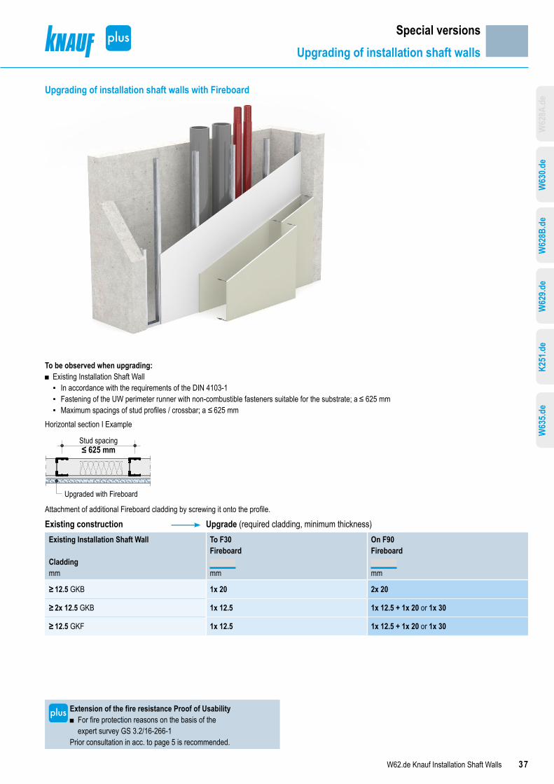
Upgrading of installation shaft walls with Fireboard
To be observed when upgrading: ■ Existing Installation Shaft Wall
▪ In accordance with the requirements of the DIN 4103-1 ▪ Fastening of the UW perimeter runner with non‑combustible fasteners suitable for the substrate; a ≤ 625 mm ▪ Maximum spacings of stud profiles / crossbar; a ≤ 625 mm
Horizontal section I Example
Upgraded with Fireboard
Stud spacing≤ 625 mm
Attachment of additional Fireboard cladding by screwing it onto the profile.
Existing construction Upgrade (required cladding, minimum thickness)Existing Installation Shaft Wall
Claddingmm
To F30 On F90Fireboard
mm
Fireboard
mm
≥ 12.5 GKB 1x 20 2x 20
≥ 2x 12.5 GKB 1x 12.5 1x 12.5 + 1x 20 or 1x 30
≥ 12.5 GKF 1x 12.5 1x 12.5 + 1x 20 or 1x 30
Special versionsUpgrading of installation shaft walls
Extension of the fire resistance Proof of Usability ■ For fire protection reasons on the basis of the expert survey GS 3.2/16-266-1
Prior consultation in acc. to page 5 is recommended.
W62
8A.d
eW
635.d
eK2
51.d
eW
629.d
eW
628B
.de
W63
0.de

38 W62.de Knauf Installation Shaft Walls
Lead-through for individual electrical cablesBasicsIn accordance with paragraph 40 of the MBO (Model building code), “pipes passing through space-enclosing components for which a fire resistance duration is specified, may only be passed through if the spread of fire need not be feared for a sufficiently long time”.Application options without any particular fire protection measure in acc. to Model Conduit Systems Directive (German designation MLAR), section. 4.3.2 for individual cables a - b - c (see below) should be taken from the solution examples on this page.When leading through bundled electrical cables, approved bulkhead systems are required for non-flammable conduits > 160 mm or flammable conduits > 32 mm.Drywalling approved bulkheads can only be conditionally used in installation shaft walls. The prerequisite is that the installation shaft wall is compliant with the stipulations of the abP/abZ (National Technical Test Certificate/Approval) in the area where the cable lead-throughs are located. This shaft wall section should feature the stability of one of the partition walls. An application option for this feature can be found on “Lead-through for several electrical cables” on page 39.For applying the cable lead-through's as shown on pages 38 and 39, the specifications and notes in Knauf “Brandschutz mit Knauf” (BS1) section “Lead-through for individual electrical cables” or “Lead-through for several electrical cables” in the section “Knauf cable and pipe penetrations” must be observed (German only).Minimum thickness D
■ Fire resistant walls (fh) D ≥ 60 mm ■ Highly fire resistant walls (hfh) D ≥ 70 mm ■ Fire proof walls (fb) D ≥ 80 mm
Cable type acc. to Model Conduit Systems Directive (German designation MLAR)a Individual electrical cablesb Conduits of non‑flammable (nbr) building materials ≤ 160 mmc Conduits of flammable (br) building materials ≤ 32 mm
Horizontal sectionsLead through of single electrical cables
≥ D
≥ 100 mm
e
circumferential
approx. 5 mm Gypsum filler
a aDoubling up to minimum thicknessD, glued using gypsum filler
Lead through of non-insulated / insulated single cables
≤ 50 mm
≥ D
≥ 100 mmcircumferential
≤ 50 mm
Stone wool tamped insulation rigid stone wool shellor
Tamped stone woolmelting point ≥ 1000 °C
building material classA1/A2, density ≥ 90 kg/m³(non-combustible conduit,
if it is required)
a - b - c
Plaster in the rigid stonewool shell, meltngpoint ≥ 1000 °C,building material classA1/A2,density ≥ 150 kg/m³
Non-combustible withcontinuous insulationDoubled up to minimumthickness D, gluedusing gypsum filler
Lead through of non-insulated single cables
≤ 15 mm ≤ 15 mm
≥ 100 mmcircumferential
≥ D
Plaster in the conduit
a - b - c
Fill the non-combustible conduit with a building material that willfoam in the event of fire (approval required)
Doubled up to minimum thickness D,glued using gypsum filler
Special versionsCable lead-throughs
Note
For technically correct implementation, the minimum cable spacings e must be observed. Detailed specifications for applying the indicated solution examples as well as further solutions can be found at Knauf “Brandschutz mit Knauf” (BS1) section “Lead-through for individual electrical cables” or “Lead-through for several electrical cables” in the section “Knauf cable and pipe penetrations” (German only).
W63
5.de
K251
.de
W62
9.de
W62
8B.d
eW
630.d
eW
628A
.de

39W62.de Knauf Installation Shaft Walls
Lead-through for several electrical cablesBulkhead systems - partial upgrading of the shaft sideIn order to apply approved bulkhead systems in Knauf Installation Shaft Walls, a partial upgrade to a light partition with double sided cladding, and a component thickness of ≥ 100 mm, is necessary.The width of at least one section and a height H = bulkhead height + 2x 100 mm (H ≥ 500 mm) is required on the installation shaft wall.The thickness of the Knauf board GKF to be applied to the shaft side must be ≥ 20 mm. The constructional component thickness in the upgrade area must be ≥ 100 mm.Required brace in upgraded installation shaft walls
■ Installation when assembling the installation shaft wall ▪ After upgrading the installation shaft wall to accept the installation of
the respective bulkhead system, the brace and reveal cladding must be applied as shown in the drawing opposite.
■ Reveal aperture ▪ Cladding with Knauf boards minimum in the cladding thickness of the
installation shaft wall unless the abZ/abP on the individual bulkheads specifies otherwise
▪ Screw centres ≤ 150 mm ▪ Apply board width in the reveal area acc. to abZ / abP but at least to
min. partition thickness ▪ Fill the joints with a gypsum filler ▪ Install the bulkhead systems acc. to abZ / abP of the bulkhead
manufacturerFire protection F30 to F90Required fire protection cladding / mineral wool acc. to the respective systems. Horizontal section
≥ 10
0 mm
Stud spacing ≤ 625 mm≥ 100 mm
Room side
Upgrading
Reveal boards Trimmer
Shaftside
≥ 100 mm
Caution Consultation with the bulkhead manufacturer required.
Shaft side view
Vertical section
≥ 100 mm
≥ 10
0 mm
H ≥
500 m
m
Shaft
side
Room
side
Upgrading
Reveal boards
Trimmer ≥ 10
0 mm
Special versionsCable lead-throughs
Note
Detailed specifications for applying the indicated solution examples as well as further solutions can be found at Knauf “Brandschutz mit Knauf” (BS1) section “Lead-through for individual electrical cables” or “Lead-through for several electrical cables” in the section “Knauf cable and pipe penetrations” (German only).
Extension of the fire resistance Proof of Usability ■ Due to partial upgrading of installation shaft walls
Prior consultation in acc. to page 5 is recommended.
W63
5.de
K251
.de
W62
9.de
W62
8B.d
eW
630.d
eW
628A
.de

40 W62.de Knauf Installation Shaft Walls
Installation and applicationStud frame
Stud frameGeneralIn case of connection to flanking building components, apply a suitable sealing material analogue to the specifications of the DIN 4109-33:2016-07 section 4.1.1.3 (e.g. 2 beads of Trennwandkitt acoustical sealant) as a backing to the rear of the profiles.
Trennwandkittacoustical sealant(for sound insulationrequirements)
Sealing tape
Fix perimeter runners to the floor and ceiling. Anchor wall perimeter runners with suitable dowels/anchors to flanking walls. Use suitable fasteners:
■ Knauf ceiling steel dowel (reinforced concrete without board strip backing) ■ Fasteners for the building materials that are specially suitable and non-combustible
Partition height Maximum fastening spacingWall perimeter runner Ceiling and floor
connection profilesm mm mm
W628A.deUp to 15.00 500 ―W630.de≤ 3.00 625 6252)
> 3.00 to 15.00 500 6252)
W628B.deUp to 7.00 5001) 500W629.deUp to 7.00 5001) 500K251.deUp to 5.00 10002) 1000W635.deUp to 5.00 10002) 1000
1) With wall height > 3.00 m backing of the CW perimeter connection profile on the web side required. Contact surfaces of the board strips with flanking component provided with acoustical sealant (2 beads).
Backing of the perimeterprofile web with board strips
2) Structural connection, at least 3 anchoring points per connection
W630.de Installation Shaft Wall stud crossbars with CW profilesCW studs, as metal crossbars with spacings of 312.5 mm / double CW studs as crossbars with spacings of 625 mm (625 mm with 2x 12.5 mm cladding not permissible installation shaft width and wall height see page 11); rivet, crimp or apply with screws to UW wall connection profiles.
NoteThe permissible wall heights vary depending on the system variant. Please observe the table in section “Data for planning” on pages 8 to 19.Note Alternative fastening possible using nails. Construction on
request.
CW crossbar profiles may not be joined or extended.
Crimping pliersfor crimpconnection
■ CW profile as crossbar ■ CW double profile as crossbar
Cros
sbar
spac
ing≤
312.5
mm
≤ 31
2.5 m
m
Cros
sbar
spac
ing≤
625 m
m
CW double profile preferred variant with installation of insulation layer
W628B.de Installation Shaft Wall – Stud construction with CW profilesApply and align CW Studs as stud frame profiles in the perimeter connection profiles at appropriate spacings.With wall heights > 5.00 m fix CW studs to UW runners on ceiling and floor at the shaft side with rivets, crimps or screws.
W629.de Installation Shaft Wall – Stud construction with CW double profilesScrew two CW profiles to one another on the web side at centres ≤ 500 mm using Metal Screws LN 3.5x11.Apply and align stud frame profiles in the perimeter connection profiles at appropriate spacings.With wall heights > 5.00 m fix double CW studs to UW runners on ceiling and floor at the shaft side with rivets, crimps or screws.
W63
5.de
K251
.de
W62
9.de
W62
8B.d
eW
630.d
eW
628A
.de

41W62.de Knauf Installation Shaft Walls
Installation and applicationStud frame I Insulation layer
K251.de Fireboard Installation Shaft Wall – Stud construction with CW double profilesScrew two CW profiles to one another on the web side at centres ≤ 500 mm using Metal Screws LN 3.5x11. With wall heights > 3.00 m on the shaft side, screw fix alternating 12.5 mm Fireboard covering strips of width ≥ 100 mm and on the wall perimeter runner of width ≥ 50 mm at a spacing of ≤ 250 mm. Apply and align stud frame profiles in the perimeter connection profiles at appropriate spacings.
≤ 25
0 mm
Fireboard cover stripsWidth ≥ 100 mm
W635.de Installation Shaft Wall – Stud construction with UW double profilesScrew two UW profiles to one another on the web side at centres ≤ 750 mm using Metal Screws LN 3.5x11. Apply and align stud frame profiles in the perimeter connection profiles at appropriate spacings.Apply Acoustical Sealant to the inner surface of the shaft sided flange of the double UW runner and apply and push on a 12.5 mm layer of Knauf Piano fire resistant board.Vertical profile extensionsDimensions in mmAlternative 1 Alternative 22 CW profiles connected to form a box.
2 CW profiles butt jointed, connected with additional UW runner.
5050
Knauf CW stud 1
Knauf CW stud 2
ü
5050
5050
üü
AdditionalKnauf UW runner
Knauf CWstud 1
Knauf CWstud 2
Profile extensionsKnauf profiles Overlap ü
CW 50 ≥ 500 mmCW 75 ≥ 750 mmCW 100 ≥ 1000 mm
■ Stagger the heights of the profile joints (alternating upper and lower wall half).
■ Crimp, screw fix or, if possible, crimp the profiles in the overlapping area.
Insulation layerGeneralDepending on the requirements for fire protection, sound insulation and thermal insulation, secure the insulation against sliding (compress up to approx. 10 mm) and tightly joint in the grid (or if necessary install insulation strips as to prevent sliding in the stud profiles).Additional insulation strips for deviation of the insulation material thickness > 20 mm from the stud web width.W629.de Installation Shaft Wall – Stud construction with CW double profiles
≥ 50 mm
Additionalinsulation strips
K251.de Fireboard Installation Shaft Wall – Stud construction with CW double profiles
S≥ 50 mm
With wall height ≤ 3.00 mcovering strips not required
Additionalinsulationstrips
W635.de Installation Shaft Wall – Stud construction with UW double profilesFill the UW 75 / UW 100 runners completely with additional insulation S strips.
S≥ 40 mm
Additionalinsulationstrips
W63
5.de
K251
.de
W62
9.de
W62
8B.d
eW
630.d
eW
628A
.de

42 W62.de Knauf Installation Shaft Walls
Installation and applicationCladding
Installation schemesW630.de Horizontal board layers
■ Feuerschutzplatte Knauf Piano fire resistant board / Diamant (board width 1250 mm)
■ Crossbar spacing 312.5 mm
Fron
t edg
e
Long edge
Lower/upper layer: ■ Offset front edge joint by at least 500 mm. ■ Arrange the long edge joints on the crossbar.
Offset between lower and upper layer: ■ Stagger long edge joints by 625 mm. ■ Stagger the front edge joints between board layers.
W630.de Board layer 1 horizontal, board layer 2 vertical ■ 2x 20 mm Massivbauplatte Solid Board (board width 625 mm) ■ Crossbar spacing 312.5 mm
Long
edge
Front edge
Lower layer: ■ Offset front edge joint by at least 625 mm. ■ Arrange the long edge joints on the crossbar.
Upper layer: ■ Arrange the front edge joints on the crossbar and stagger by 625 mm.
Offset between lower and upper layer: ■ Stagger the board joints of the upper layer by approx 312.5 mm to the board joints of the lower layer.
Scheme drawings I Dimensions in mmW628B.de/W629.de/W635.de Horizontal board layers
■ Silentboard / Massivbauplatte Solid Board (board width 625 mm) ■ W635.de: Diamant (board width 1250 mm) ■ Stud spacing 625 mm
Long edge
Fron
t edg
e
Lower/upper layer: ■ Recommendation: Board length 2500 mm ■ Front edge joints must be staggered by at least one stud spacing. ■ Stagger the long joints between the cladding layers by at least half a board width.
W628B.de/W629.de/K251.de Vertical board layers ■ Feuerschutzplatte Knauf Piano Fire Resistant Board / Diamant / Knauf Feuerschutzplatte Fire Resistant Board / Fireboard (board width 1250 mm)
■ Stud spacing 625 mm
Front edgeLo
ng ed
ge
Lower/upper layer: ■ Stagger long edge joints by 625 mm (one stud spacing) ■ If non floor-to-ceiling high boards are used, stagger the front edge joints ≥ 500 mm (for K251.de ≥ 1000 mm) in a cladding layer.
■ For K251.de apply backing to front joints using profiles or Fireboard strips. ■ Stagger the front edge joints between board layers in case of multi-level cladding.
W62
8A.d
eW
635.d
eK2
51.d
eW
629.d
eW
628B
.de
W63
0.de

43W62.de Knauf Installation Shaft Walls
Installation and applicationCladding
Fastening of the cladding to the stud frame with Knauf drywall screwsCladding Metal stud frame (penetration ≥ 10 mm)
Metal gauge s ≤ 0.7 mmMaximum spacings Fastener
Board type Thicknessmm
Drywall screwsTN
Diamant screwsXTN
1st layermm
2nd layermm
W628A.deMassivbauplatte Solid Board 2x 25 TN 3.5 x 35 + TN 4.5 x 70 – 300 200W630.deKnauf Piano fire-resistant board 2x 12.5 TN 3.5 x 25 + TN 3.5 x 35 – 750 250Diamant 2x 12.5 – XTN 3.9 x 23 + XTN 3.9 x 38 750 250Massivbauplatte Solid Board 2x 20 TN 3.5 x 35 + TN 3.5 x 55 – 600 200W628B.de / W629.deKnauf Piano fire-resistant board 2x 12.5 TN 3.5 x 25 + TN 3.5 x 35 – 750 250Diamant 2x 12.5 – XTN 3.9 x 23 + XTN 3.9 x 38 750 250Silentboard 2x 12.5 – XTN 3.9 x 23 + XTN 3.9 x 38 600 200Knauf fire-resistant board 2x 15 TN 3.5 x 25 + TN 3.5 x 45 – 750 250Diamant 2x 15 – XTN 3.9 x 33 + XTN 3.9 x 55 750 250Massivbauplatte Solid Board 2x 20 TN 3.5 x 35 + TN 3.5 x 55 – 600 200Fireboard 2x 20 TN 3.5 x 35 + TN 3.5 x 55 – 750 250Massivbauplatte Solid Board 2x 25 TN 3.5 x 35 + TN 4.5 x 70 – 300 200K251.deFireboard covering strips 12.5 TN 3.5 x 25 – 250 –Fireboard 30 TN 3.5 x 45 – 250 –W635.deDiamant 2x 15 – XTN 3.9 x 33 + XTN 3.9 x 55 600 250
Note Alternative fastening possible using nails. Construction on request.
W63
5.de
K251
.de
W62
9.de
W62
8B.d
eW
630.d
eW
628A
.de

44 W62.de Knauf Installation Shaft Walls
Installation and applicationJointing
Quality levels
Jointing Long edge HRAK or HRK
JointingFront edge SFK
DescriptionWorking steps
Q1 ■ Fill the joints with Uniflott or Uniflott imprägniert ■ Fill all visible fastener parts.
Q2 ■ Preliminary jointing in acc. with quality level Q1 ■ Finish (fine finish compound) to achieve a smooth transition to the board surface e.g. with Uniflott, Uniflott imprägniert, Spritzspachtel Plus, Fill & Finish Light or Super Finish
No application marks or ridges may remain visible. Sand off the areas concerned if necessary.
Q3 ■ Jointing in acc. with quality level Q2 ■ Wide jointing of the joints as well as clean and accurate removal of the remaining board liner filling the pores, e.g. with Fill & Finish Light or Super Finish or Spritzspachtel Plus
If necessary, i.e. physical ridges and grooves are not acceptable and must be sanded.
Q4 ■ Jointing in acc. with quality level Q2 ■ Complete surface covering of skim coat with a layer thickness of at least 1 mm, e.g. with Fill & Finish Light, Super Finish or Spritzspachtel Plus
JointingJointing of the boards in the required quality level Q1 to Q4 in accordance with Code of Practice no. 2 “Verspachtelung von Gipsplatten, Oberflächengüten”1).Fill in visible screw heads.With Fireboard, a skim coating of the entire surface, e.g. with Fireboard Filler is additionally required before application of direct coatings or linings.Suitable jointing materials
■ Uniflott Hand filling without joint tape strips in the long joint edges
■ Uniflott imprägniert Hand filling of impregnated boards without joint tape in the long joint edges; water-repellent, green colour for easy identification
■ Fugenfüller Leicht Hand filling with joint tape, preferably Fugendeckstreifen Kurt joint tape
■ Fireboard Filler Hand filling of Fireboard with Fibre Glass Joint Tape
Suitable finish jointing compounds ■ Q2, application by hand Uniflott, Uniflott imprägniert, Fill & Finish Light, Super Finish
■ Q3/Q4, application by hand Spritzspachtel Plus, Super Finish, Fill & Finish Light
■ Q3/Q4, machine application Spritzspachtel Plus (preferably Q3)
■ Fireboard-Spachtel filler for full surface skimming of FireboardFilling of the gypsum board jointsFor multi-layer cladding, fill the lower layers with filler; fill the joints of the visible layer. Filling the joints of covered cladding layers with multi-layer cladding is necessary to provide technical fire protection and sound
insulation properties as well as the structural properties.RecommendationFront edge and cut edge joints as well as mixed joints (e.g. half-rounded tapered edge + cut edge) of the visible cladding layers filled using Uniflott with joint tape Kurt as well.Jointing of connection jointsApply Trenn-Fix or joint tape Kurt when filling joints to adjacent drywall constructions, depending on the conditions and requirements for crack safety.Observe code of practice no. 3 “Gipsplattenkonstruktionen - Fugen und Anschlüsse” 1) (German only)Apply Trenn-Fix when filling joints to adjacent solid construction or timber components.SandingLightly sand visible surfaces after drying of the filler material, if required.Application temperature/climateFilling and covering of joints should only take place when no more longitudinal changes can be expected, i.e. expansion or contraction due to humidity or temperature changes. Do not apply jointing at room or substrate temperatures below approx. +10 °C.In case of mastic asphalt screed, cementitious screed and self-levelling screed, fill in board joints after screed has been applied.Observe code of practice no. 1 “Baustellenbedingungen” 1).1) (German only), issued by the Bundesverband der Gipsindustrie e.V.
W63
5.de
K251
.de
W62
9.de
W62
8B.d
eW
630.d
eW
628A
.de

45W62.de Knauf Installation Shaft Walls
Installation and applicationCoatings and linings
Coatings and liningsCoating / lining Recommended jointing
Gypsum boardsEN 5201)
Fireboard
Tiles or similar Q1 JointingLinings with coarse textures (e.g. wood chip wallpaper) Q2 Full surface
skimming
Finely textured wallpapers Q3/Q4 Full surface skimming
Matt, textured coats Q3/Q4 Full surface skimming
Glossy, smooth coats Q4 Full surface skimming
Plasters (grain size < 1 mm) Q3/Q4 Full surface skimming
Plasters (grain size ≥ 1 mm) Q2 Jointing
PretreatmentBefore further coating or lining is applied, the filled surface must be free of dust. Always prime gypsum board surfaces in compliance with the Code of Practice no. 6 “Vorbehandlung von Trockenbauflächen aus Gipsplatten zur weitergehenden Oberflächenbeschichtung bzw. -bekleidung” (German only)
1).Ensure that the primer is compatible with the coating / paint / lining.In order to compensate for the differences in absorption of surfaces, coatings of primer such as Knauf Tiefengrund primer is suitable.Where a wallpaper lining is used, a primer that facilitates easier removal of wallpaper for redecoration is recommended.
Note
Gypsum board surfaces that have constantly been exposed to light without any protection can cause yellowing. Therefore, a trial coat is recommended that will extend across several boards including all joints. Yellowing can, however, be successfully avoided only by using a special primer, e.g. Knauf Aton Sperrgrund for finishing plasters, Knauf Sperrgrund for coatings.
Suitable coatings and liningsThe following coatings/linings can be applied to Knauf boards:
■ Wallpapers ▪ Paper, fleece, textile and synthetic wallpapers
Use only adhesives made of methyl cellulose according to Code of Practice no. 16, “Technische Richtlinien für Tapezier- und Spannarbeiten innen” 2).
■ Plaster and filler materials ▪ Finishing plasters (e.g. Noblo, Raumklima Spritzputz, Rotkalk Filz) ▪ Full surface plaster (e.g. Spritzspachtel Plus).
Application of plaster layers only in conjunction with Fugendeckstreifen Kurt joint tape.
■ Decorative coats ▪ Dispersion paints (e.g. Intol E.L.F., Malerweiss E.L.F.) ▪ Silicate-based emulsion paints with suitable primer. ▪ Others on request
■ Ceramic tiles ▪ System W628A.de only up to 1.00 m installation shaft width ▪ Minimum cladding thickness 18 mm (Diamant: 15 mm), e.g. 2x 12.5 mm
with stud spacing 625 mm
▪ With narrower cladding thickness, reduce the stud spacing to max. 500 mm (417 mm with vertical cladding) .
▪ Tile weights up to 25 kg/m2 (one-sided) with a max. surface per tile of 1800 cm2 (e.g. 60 x 30 cm) have proven to be uncritical (compare to code of practice 8:2019-12 Partition heights of lightweight partitions 1)).
Unsuitable coatings and linings ■ Alkaline coats such as lime, water glass paints and silicate-based paints.
Notes
After wallpapering or after application of plasters, quick drying must be ensured through adequate airing.Other coatings or layers and vapour barriers up to about 0.5 mm thickness as well as claddings (with the exception of sheet steel), do not have any influence on the technical fire resistance classification of Knauf Installation Shaft Walls.
1) (German only), issued by the Bundesverband der Gipsindustrie e.V.2) (German only), issued by the Bundesausschuss Farbe und
Sachwertschutz
W63
5.de
K251
.de
W62
9.de
W62
8B.d
eW
630.d
eW
628A
.de

46 W62.de Knauf Installation Shaft Walls
► The right systems for your requirementsRange of applications: Interior walls, installation shaft walls, furrings, dry lining, suspended ceilings, free-spanning ceil-ings and attic cladding
► The appropriate system in just four steps ■ Select your desired drywalling category. ■ Enter your requirements. ■ The Knauf system finder shows you a selection
of appropriate systems, including downloads and tender specifications.
■ Refine the results with further filter settings.
knauf.de/systemfinder
Knauf Drywall SystemfinderThe right systems for your applications

47W62.de Knauf Installation Shaft Walls
Technical adviceYou ask. We answer. Competent advice and informationOur extensive long-standing expertise for your safety and peace of mind – advice “just in time”. Knauf Direkt is a team of technically competent employees with a wíde skill base. Architects, building physicists, master timber construction craftsmen and many other areas assist you with professional advisory services in the areas of timber construction, drywalling, plastering/stucco work and architecture.Competent building consultancy advice assures the use of efficient systems and avoids the cost of additional materials or overly complex constructions. Furthermore, the assurance you receive often saves multiples of the avoided building damage and compensation claimsHow to contact usThe right partner for every technical query.
Availability CETMonday to Thursday 7:00 – 18:00Friday 7:00 – 17:00 Email:[email protected]
Technical adviceYou ask. We answer. Knauf DirektCompetent advice and informationOur extensive long-standing expertise for your safety and peace of mind – advice “just in time”. Knauf Direkt is a team of technically competent employees with a wíde skill base. Architects, building physicists, master timber construction craftsmen and many other areas assist you with professional advisory services in the areas of timber construction, drywalling, plastering/stucco work and architecture.Competent building consultancy advice assures the use of efficient systems and avoids the cost of additional materials or overly complex constructions. Furthermore, the assurance you receive often saves multiples of the avoided building damage and compensation claims.The Knauf Direkt employees can direct you to a Knauf system consultant for on-site consultation on building projects. They offer you support for your building projects including personal consultation on the building site - quickly, competently and free-of-charge.We know you. It pays off.We offer listed customers or partners telephone advice at a reduced tariff on a German land line. Furthermore, you are automatically directed to the next free colleague.How to contact usThe right partner for every technical query.
■ For questions on drywalling and floor systems Tel.: 09001 31-1000
■ For questions on plaster and façade systems Tel.: 09001 31-2000
A call to Knauf Direkt is charged at € 0.39/min in Germany. Callers whose phone numbers are not registered within the Knauf address data base, e.g. private builders or non-customers, will be charged a rate of € 1.69 per min within Germany. Calls from mobiles will be charged depending on the tariffs of the network operator.Availability CETMonday to Thursday 7:00 – 18:00Friday 7:00 – 17:00

The iPad App Knauf Infothek now provides all the currentinformation and documents from Knauf Gips KG at any time andin every location in a clear and comfortable way.Knauf Infothek
Find the systems to meet your requirements!knauf.de/systemfinder
Videos for Knauf systems and products can be found under the following link:www.youtube.com/knaufEPD
All technical changes reserved. Only the current printed instructions are valid. The stated information represents current state-of-the-art Knauf technology. The entire state of approved engineering rules, appropriate standards, guidelines, and rules of crafts-manship are not included herewith. These and all application instructions have to be adhered to separately by the installer. Our warranty is expressly limited to our products in flawless condition. All application quantities and delivery amounts are based on empirical data that are not easily transferable to other deviating areas.All rights reserved. All amendments, reprints and photocopies, including those of excerpts, require our expressed permission.
The stated constructional and structural design specifications and characteristics of building physics of Knauf systems can only be ensured with the exclusive use of Knauf system components, or other products expressly recommended by Knauf.
Knauf Gips KG Am Bahnhof 7, 97346 Iphofen, GermanyKnauf DirectTechnical Advisory Service:
www.knauf.de
W62.de/eng/03.20/0/Dbl
Information on the sustainabilityKnauf Installation Shaft Walls
Information on sustainability of Knauf Installation Shaft WallsBuilding assessment systems ensure the sustainable quality of buildings and constructional structures by a detailed assessment of ecological, economic, social, functional and technical aspects.The following certification systems have a particular relevance in Germany
■ DGNB System Deutsches Gütesiegel Nachhaltiges Bauen der DGNB (German Association for Sustainable Building )
■ BNB (Bewertungssystem Nachhaltiges Bauen)
■ LEED (Leadership in Energy and Environmental Design).
Knauf products and Knauf Installation Shaft Walls can positively influence many of these criteria.DGNB/BNBEcological quality
■ Criterion: Risks for the local environment The relevant environmental data are contained in the EPD for gypsum products
Economic quality ■ Criterion: Building related life-cycle costs Cost-effective Knauf Drywalling
Sociocultural and functional quality ■ Criterion: Space efficiency Slim, floor-space enhancing Knauf Installation Shaft Walls
■ Criterion: Suitability for conversion Flexible Knauf Drywalling
Technical quality ■ Criterion: Sound insulation Exceeding the demands of the standard with Knauf sound protection
■ Criteria: Ease of dismantling and recycling Knauf Drywalling is fully compliant
LEEDMaterials and resources
■ Credit: Recycled Content Recycled content in Knauf boards, e.g. FGD gypsum
■ Credit: Regional Materials Short transport routes provided by the extensive network of Knauf manufacturing facilities