Embed Size (px)
Citation preview
SGQ_ATS Automatic Transfer Switch
Smartgen Technology

Smartgen Technology Co., Ltd.
No.28 Jinsuo Road
Zhengzhou City
Henan Province
P. R. China
Tel: 0086-371-67988888/67981888
0086-371-67991553/67992951
0086-371-67981000(overseas)
Fax: 0086-371-67992952
Web: http://www.smartgen.com.cn
http://www.smartgen.cn
Email: [email protected]
All rights reserved. No part of this publication may be reproduced in any material form
(including photocopying or storing in any medium by electronic means or other)
without the written permission of the copyright holder.
Applications for the copyright holder’s written permission to reproduce any part of this
publication should be addressed to Smartgen Technology at the address above.
Any reference to trademarked product names used within this publication is owned by
their respective companies.
Smartgen Technology reserves the right to change the contents of this document
without prior notice.
If there are any differences between the contents of the instruction and the product,
please regard the actual product as the truth.
Software Version log
Version Date Note
1.0 2006-03-18 Original release
2.0 2010-10-19 Revision
2.1 2011-06-08 Modify the wiring diagram of N type, T type and M
type.
2.2 2011-11-22 Modify the technical data of N type, T type and M type.
2.3 2012-06-29 Lines of wiring diagram are bold.
2.4 2012-11-08 Format Modification
SGQ_ATS Automatic Transfer Switch
SGQ_ATS Automatic Transfer Switch ISSUE 2012-11-08 Version 2.4 Page 3 of 11
CONTENTS
1 SUMMARY ........................................................................................................................................................... 4
2 STRUCTURE AND CHARACTERISTICS ............................................................................................................ 4
3 APPEARANCE AND CLASSIFICATION .............................................................................................................. 4
3.1 N TYPE CASE DIMENSIONS AND TECHNICAL DATA ..................................................................................... 5
3.2 T TYPE CASE DIMENSIONS AND TECHNICAL DATA ...................................................................................... 6
3.3 M TYPE CASE DIMENSIONS AND TECHNICAL DATA ................................................................................................... 7
4. WORKING REQUIREMENTS ................................................................................................................................ 8
5. ATS WIRING CONNECTION DIAGRAM ............................................................................................................... 9
5.1 “N” AND “T” TYPE WIRING CONNECTION DIAGRAM ................................................................................................ 9
5.2 “M” TYPE WIRING CONNECTION DIAGRAM .......................................................................................................... 10
6. INSTALLATION AND DEBUGGING ................................................................................................................... 10
7. PURCHASE MODEL EXPLANATION ................................................................................................................ 11
SGQ_ATS Automatic Transfer Switch
SGQ_ATS Automatic Transfer Switch ISSUE 2012-11-08 Version 2.4 Page 4 of 11
1 SUMMARY
SGQ Automatic Transfer Switch (ATS) is used in conditions from AC660V 50/60HZ to DC250V
which under electromagnetism drive structure and two-stage PC class type. SGQ ATS can
make fast load transfer (transfer time ≤80ms) of two ways power supply. Also ATS can be widely
used in high buildings, post, telecommunications, coal mines, ships, industry, health care,
military facilities and so on. 2-way power supply can be grid, auto start genset, storage battery
and etc..
2 STRUCTURE AND CHARACTERISTICS
SGQ Automatic Transfer Switch (ATS) adopts structure of magnet coil driving and interlocking
of electric and mechanical. The structure of major loop contact terminal consists of one dynamic
and two static contacts. And the dynamic contact is in “V” type design, in order to ensure there is
no short circuit of the 2-way power supply. “N” and “T” type use structure of double coils while
“M” type use single coil operation. The coil only energized while it is transferred which can
extremely extend the using life of switch. The control power of coil is supplied from priority
AC/DC power, so there is no use to add another control power. The switch has electrical and
mechanical close indication by itself and also offers 2 way NO/NC voltage free auxiliary
contacts at the same time.
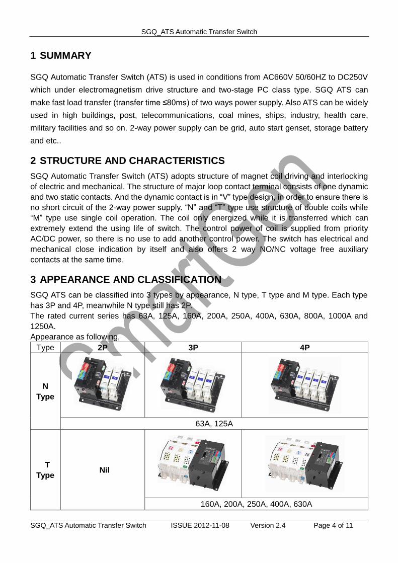
3 APPEARANCE AND CLASSIFICATION
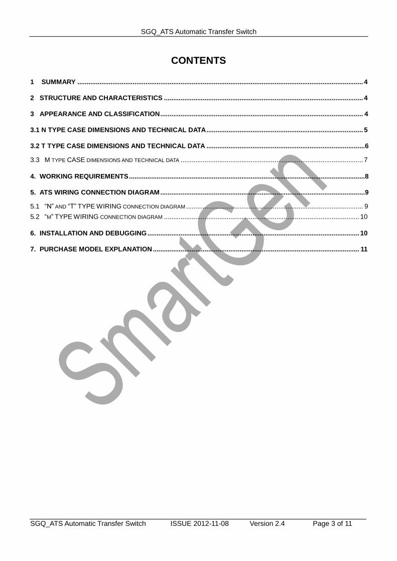
SGQ ATS can be classified into 3 types by appearance, N type, T type and M type. Each type
has 3P and 4P, meanwhile N type still has 2P.
The rated current series has 63A, 125A, 160A, 200A, 250A, 400A, 630A, 800A, 1000A and
1250A.
Appearance as following,
Type 2P 3P 4P
N
Type
63A, 125A
T
Type Nil
160A, 200A, 250A, 400A, 630A
SGQ_ATS Automatic Transfer Switch
SGQ_ATS Automatic Transfer Switch ISSUE 2012-11-08 Version 2.4 Page 5 of 11
M
Type Nil
630A, 800A, 1000A, 1250A
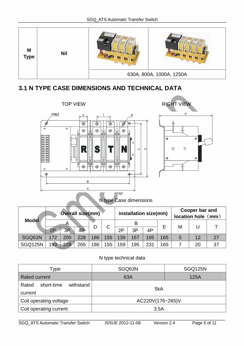
3.1 N TYPE CASE DIMENSIONS AND TECHNICAL DATA
TOP VIEW RIGHT VIEW
N type Case dimensions
Model
Overall size(mm) installation size(mm) Cooper bar and
location hole(mm)
A D C
B E M U T
2P 3P 4P 2P 3P 4P
SGQ63N 172 200 228 186 155 139 167 195 165 5 12 27
SGQ125N 193 228 265 186 155 159 195 231 165 7 20 37
N type technical data
Type SGQ63N SGQ125N
Rated current 63A 125A
Rated short-time withstand
current 5kA
Coil operating voltage AC220V(176~265)V
Coil operating current 3.5A
SGQ_ATS Automatic Transfer Switch
SGQ_ATS Automatic Transfer Switch ISSUE 2012-11-08 Version 2.4 Page 6 of 11
Secondary contact 1A 250VAC, N/O, FREE VOLTAGE, EACH SIDE HAS
2PCS
OPERATION
TIME
Mechanical 5000 TIMES
Electrical 1000 TIMES
Number of poles 2P 3P 4P 2P 3P 4P
Net weight (kg) 4 4.5 4.7 4.5 5 5.65
Operation cycle 15 seconds/ time
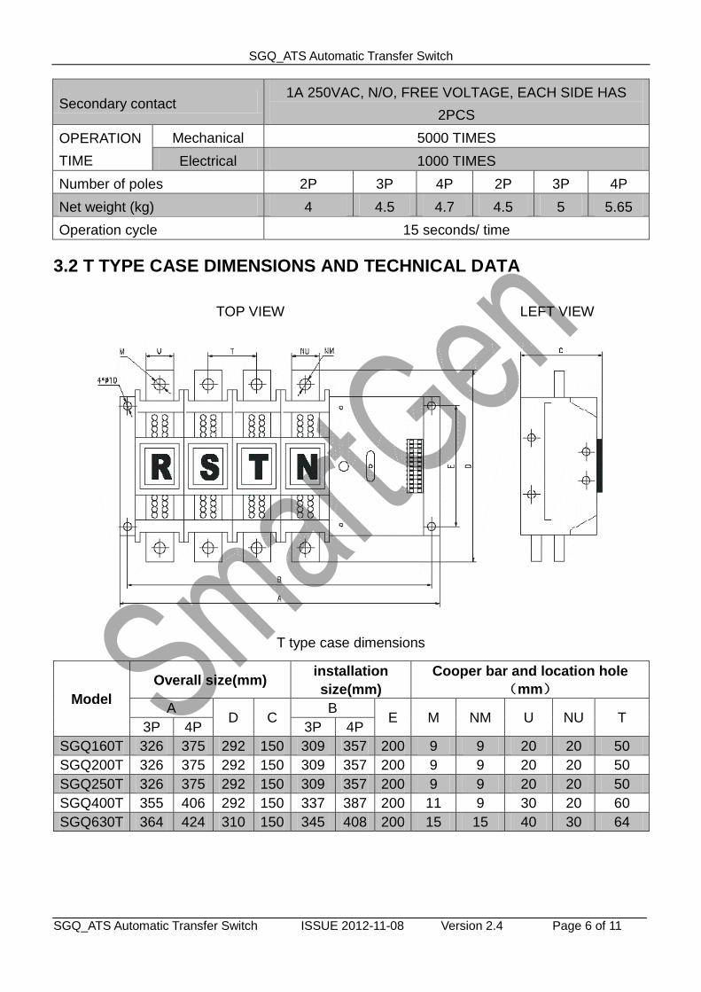
3.2 T TYPE CASE DIMENSIONS AND TECHNICAL DATA
TOP VIEW LEFT VIEW
T type case dimensions
Model
Overall size(mm) installation
size(mm)
Cooper bar and location hole
(mm)
A D C
B E M NM U NU T
3P 4P 3P 4P
SGQ160T 326 375 292 150 309 357 200 9 9 20 20 50
SGQ200T 326 375 292 150 309 357 200 9 9 20 20 50
SGQ250T 326 375 292 150 309 357 200 9 9 20 20 50
SGQ400T 355 406 292 150 337 387 200 11 9 30 20 60
SGQ630T 364 424 310 150 345 408 200 15 15 40 30 64
SGQ_ATS Automatic Transfer Switch
SGQ_ATS Automatic Transfer Switch ISSUE 2012-11-08 Version 2.4 Page 7 of 11
T type Technical data
Type SGQ160T SGQ200T SGQ250T SGQ400T SGQ630T
Rated current 160A 200A 250A 400A 630A
Rated short-time withstand
current 10kA
Coil operating voltage AC220V (176~265)V
Coil operating current 7A
Auxiliary contact 1A 250VAC, N/O, FREE VOLTAGE, EACH SIDE HAS 2PCS
OPERATION
TIME
Mechanical 5000 times 3000 times 2500
times
Electrical 1000 times 1000 times 500 times
Number of poles 3P 4P 3P 4P 3P 4P 3P 4P 3P 4P
Net weight (kg) 16.5 18.5 16.5 18.5 16.5 18.5 18 20 20 22
Operation cycle 15 seconds/ time
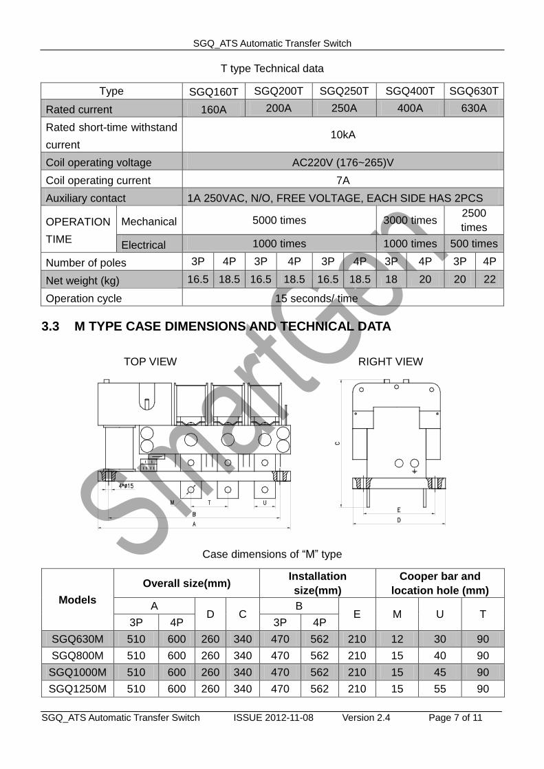
3.3 M TYPE CASE DIMENSIONS AND TECHNICAL DATA
TOP VIEW RIGHT VIEW
Case dimensions of “M” type
Models
Overall size(mm) Installation
size(mm)
Cooper bar and
location hole (mm)
A D C
B E M U T
3P 4P 3P 4P
SGQ630M 510 600 260 340 470 562 210 12 30 90
SGQ800M 510 600 260 340 470 562 210 15 40 90
SGQ1000M 510 600 260 340 470 562 210 15 45 90
SGQ1250M 510 600 260 340 470 562 210 15 55 90
SGQ_ATS Automatic Transfer Switch
SGQ_ATS Automatic Transfer Switch ISSUE 2012-11-08 Version 2.4 Page 8 of 11
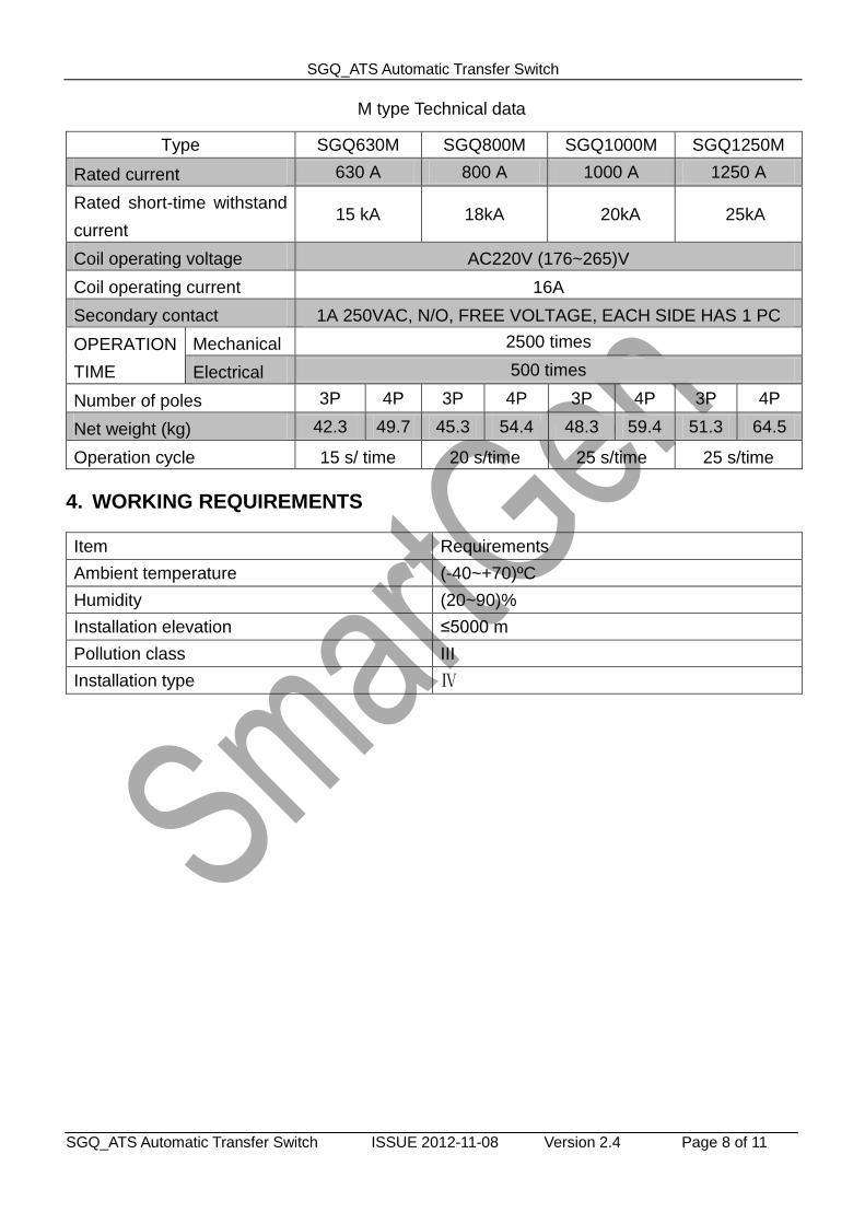
M type Technical data
Type SGQ630M SGQ800M SGQ1000M SGQ1250M
Rated current 630 A 800 A 1000 A 1250 A
Rated short-time withstand
current 15 kA 18kA 20kA 25kA
Coil operating voltage AC220V (176~265)V
Coil operating current 16A
Secondary contact 1A 250VAC, N/O, FREE VOLTAGE, EACH SIDE HAS 1 PC
OPERATION
TIME
Mechanical 2500 times
Electrical 500 times
Number of poles 3P 4P 3P 4P 3P 4P 3P 4P
Net weight (kg) 42.3 49.7 45.3 54.4 48.3 59.4 51.3 64.5
Operation cycle 15 s/ time 20 s/time 25 s/time 25 s/time
4. WORKING REQUIREMENTS
Item Requirements
Ambient temperature (-40~+70)ºC
Humidity (20~90)%
Installation elevation ≤5000 m
Pollution class III
Installation type Ⅳ
SGQ_ATS Automatic Transfer Switch
SGQ_ATS Automatic Transfer Switch ISSUE 2012-11-08 Version 2.4 Page 9 of 11
5. ATS WIRING CONNECTION DIAGRAM
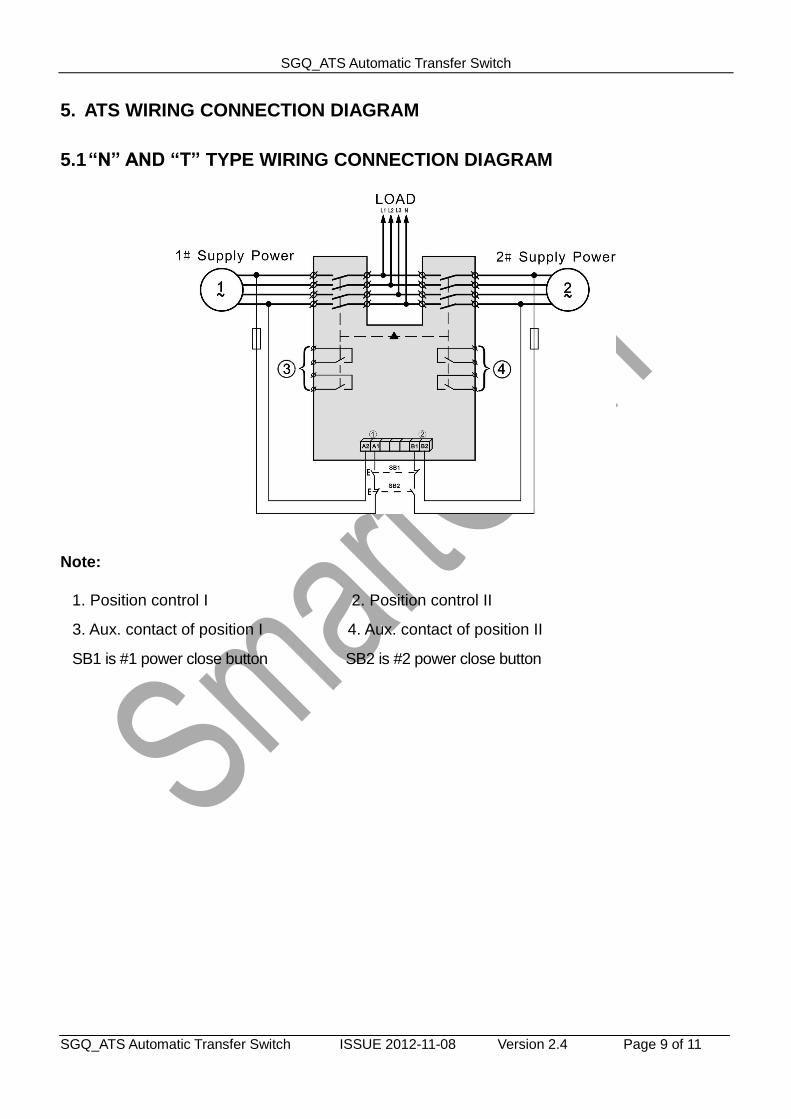
5.1 “N” AND “T” TYPE WIRING CONNECTION DIAGRAM
Note:
1. Position control I 2. Position control II
3. Aux. contact of position I 4. Aux. contact of position II
SB1 is #1 power close button SB2 is #2 power close button
SGQ_ATS Automatic Transfer Switch
SGQ_ATS Automatic Transfer Switch ISSUE 2012-11-08 Version 2.4 Page 10 of 11
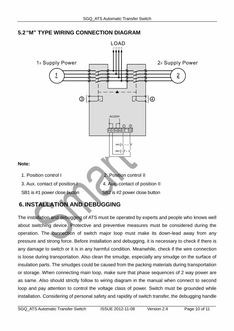
5.2 “M” TYPE WIRING CONNECTION DIAGRAM
Note:
1. Position control I 2. Position control II
3. Aux. contact of position I 4. Aux. contact of position II
SB1 is #1 power close button SB2 is #2 power close button
6. INSTALLATION AND DEBUGGING
The installation and debugging of ATS must be operated by experts and people who knows well
about switching device. Protective and preventive measures must be considered during the
operation. The connection of switch major loop must make its down-lead away from any
pressure and strong force. Before installation and debugging, it is necessary to check if there is
any damage to switch or it is in any harmful condition. Meanwhile, check if the wire connection
is loose during transportation. Also clean the smudge, especially any smudge on the surface of
insulation parts. The smudges could be caused from the packing materials during transportation
or storage. When connecting main loop, make sure that phase sequences of 2 way power are
as same. Also should strictly follow to wiring diagram in the manual when connect to second
loop and pay attention to control the voltage class of power. Switch must be grounded while
installation. Considering of personal safety and rapidity of switch transfer, the debugging handle
SGQ_ATS Automatic Transfer Switch
SGQ_ATS Automatic Transfer Switch ISSUE 2012-11-08 Version 2.4 Page 11 of 11
should only used for testing and user should never operate it with load. While debugging, use
the handle to operate the switch firstly. If everything goes well, user can start the power-driven
operation with manual button. ATS enters into normal running when there is no error.
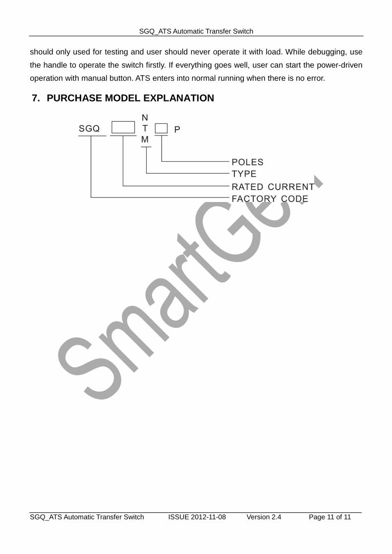
7. PURCHASE MODEL EXPLANATION