Embed Size (px)
Citation preview

AD-A083 371 FORiEIGN TECHNOLOGY DIV WRIGHT-PATTERSON AFS OH F/6 17/9THE PROBLEM OF APERTURE SYNTHESIS OF ANTENNAS WHICH ARE MOUNTED--ETC U)JUL 79 S 6 RUONEVA
UNCLASSIFIEO FTD-ID(RS)T-1036-79 NL
*mmmmmmm
4L
MICROCOPY RESOLUTION TEST CHARTNA1:ONAL BUJR[AU M STANDARO6 ]9b3-.,
PHOTOGRAPH THIS SHEET
LEVEL INVENTORY
~FT D -1; D C&)-f -103t- <DOCUMENT IDENTIFICATION
DISTRIBUTION STATEMENT A
Approved for public release;Distribution Unlimited
DISTRIBUTION STATEMENT
ACCESSION FORNTIS GRA! El
DTAC DTICUNANNOUNCED Ql E T ICJUSTIFICATION
_____ _____ _____ _____APR 24 18
BYDISTRIBUTION /DAVAILABILITY CODESDIST AVAIL AND/OR SPECIAL DATE ACCESSIONED
DISTRIBUTION STAMP
'9 11 13 158DATE RECEIVED IN DTIC
PHOTOGRAPH THIS SHEET AND RETURN TO DTIC-DDA-2
OTIC FORM 70A DOCUMENT PROCESSING SHEETCToc 7970
.". . .

FTD-ID (RS)T-1036-79
FOREIGN TECHNOLOGY DIVISION
THE PROBLEM OF APERTURE SYNTHESIS OF ANTENNAS
WHICH ARE MOUNTED ON MOVING OBJECTS
By
S. G. Rudneva
Approved for public release;distribution unlimited.
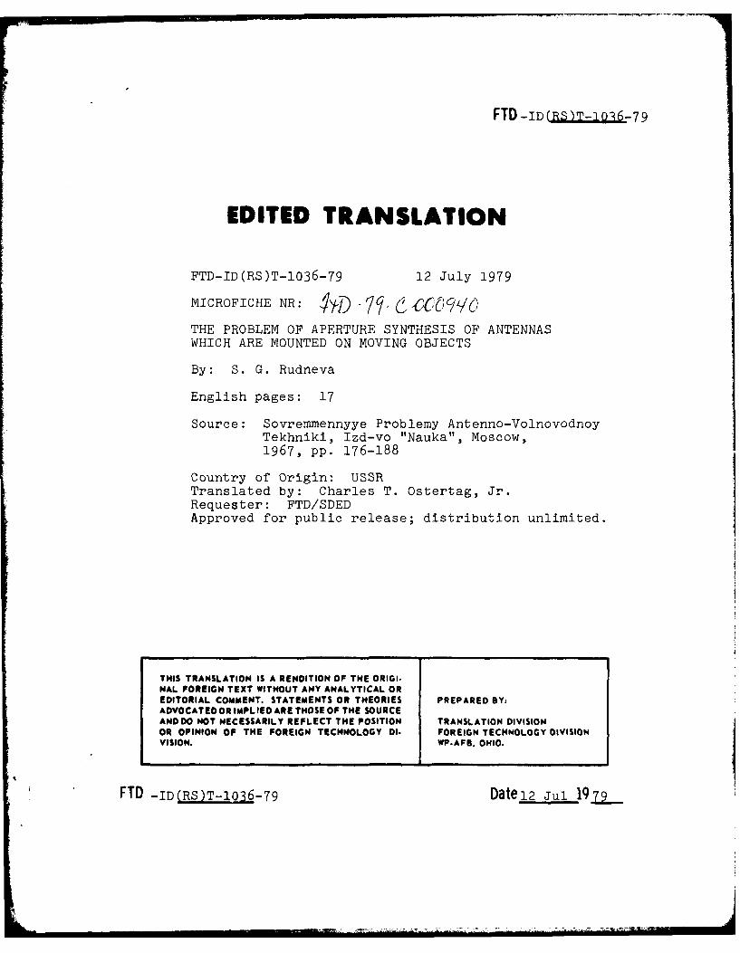
FTD -ID (.)T-103. -79
EDITED TRANSLATION
FTD-ID(RS)T-1036-79 12 July 1979
MICROFICHE NR: 41-D -Th. ( -ccO//CoTHE PROBLEM OF APERTURE SYNTHESIS OF ANTENNASWHICH ARE MOUNTED ON MOVING OBJECTS
By: S. G. Rudneva
English pages: 17
Source: Sovremmennyye Problemy Antenno-VolnovodnoyTekhniki, Izd-vo "Nauka", Moscow,1967, pp. 176-188
Country of Origin: USSRTranslated by: Charles T. Ostertag, Jr.Requester: FTD/SDEDApproved for public release; distribution unlimited.
THIS TRANSLATION IS A RENDITION OF THE ORIGI.NAL FOREIGN TEXT WITHOUT ANY ANALYTICAL OREDITORIAL COMMENT. STATEMENTS OR THEORIES PREPARED BY:ADVOCATEDOR IMPLIED ARE THOSE OF THE SOURCEAND DO NOT NECESSARILY REFLECT THE POSITION TRANSLATION DIVISIONOR OPINION OF THE FOREIGN TECHNOLOGY DI. FOREIGN TECHNOLOGY DIVISIONVISION. WP.AFB, OHIO.
FTD -ID(RS)T-1036-79 Datel2 Jul 1979
I
U. :, bOARD ON GEOGRAPHIC NAMES TRANSLITERATION LY.2TE:.,.
,* , tul'c Transliteration Block Italic Tru, ,.
* A a A,a P p P p
56 B, b C C
B V, v T T T m -7,.
r G , C y y Y y
7 a D, d r 0 ;
E a Ye, y ; E, e* X x X x Vh,
3Z, 4 H LH Li
K Mu -Ii W w IL/u CL:,.H U LU L LU, R 87 Y, y WL4 X I hek :.:
K K K, k b
7B L, i b,
Mm b
Hn L , a ,
0 o 0,0 U C 1 0 1 Yu, y.;
n n P, p H-i R H Ya,
% Initially, after vowels, and after b, b, e uisewinire..,, wr>;ten as b in Russian, transliterate as ye or e.
RUSSIAN AND Li GISii TRIGONOMETRIC FUNCTIOD'S
,En E1nglish Russian English Russian
sir sh sinh arc eh i..c h cosh arc ch'
tan th tanh arccot, cth coth arc cthc.C sch sech arc sc-
ccc Cscil csch arc csch
R Issian Lnglish
r)t crlI ; log
i
THE PROBLEM OF APERTURE SYNTHESIS OF ANTENNAS
WHICH ARE MOUNTED ON MOVING OBJECTS
S. G. Rudneva
The directional effect of a large receiving antenna, consisting
of a number of identical elements, is the result of summation with
the appropriate phases of signals which are received by the individ-
ual elements. The signal on the output of such an antenna can be
viewed as the result of the simultaneous (parallel) processing of
the information which is received by the elements of the antenna.
In the process of development of antenna technology a question
was posed relative to the realization of a directional antenna at
the expense of the sequential processing of information which is
received by the individual elements of the antenna. In this case
we gain the possibility of replacing a number of the identical
elements, dipoles for example, with one movable element, fulfilling
the role in sequence of each of the elements of the antenna [1, 2].
Such a synthesized antenna is very promising for moving objects
(aircraft, satellites), on which it is not deemed possible to install
antennas of large dimensions.
The problem of development of the described antenna has been
solved at the present time for radar stations in which a high degree
of stability of the frequency of the transmitter has been ensured.
This stability is necessary for the sequential processing of the
reflected signals which are received by the on-board antenna.
1.
Such stations with a synthesized antenna which possess extremely
high resolution are being used at present for making radar maps
of the terrain.
Artificial Earth satellites and space rockets are opening up
new possibilities for using the principle of an artificial antenna
aperture. In particular the use of stations based on this principle
has not been excluded for the investigation of the surface of planets
which are covered with an atmosphere which is opaque for the eye
(Venus, Jupiter).
In the present article we will consider a number of questions
which are connected with the realization of this method.
1. Principle of formation of an artificial aperture
We will consider the process of realization of an artificial
aperture, having accepted a number of initial assumptions.
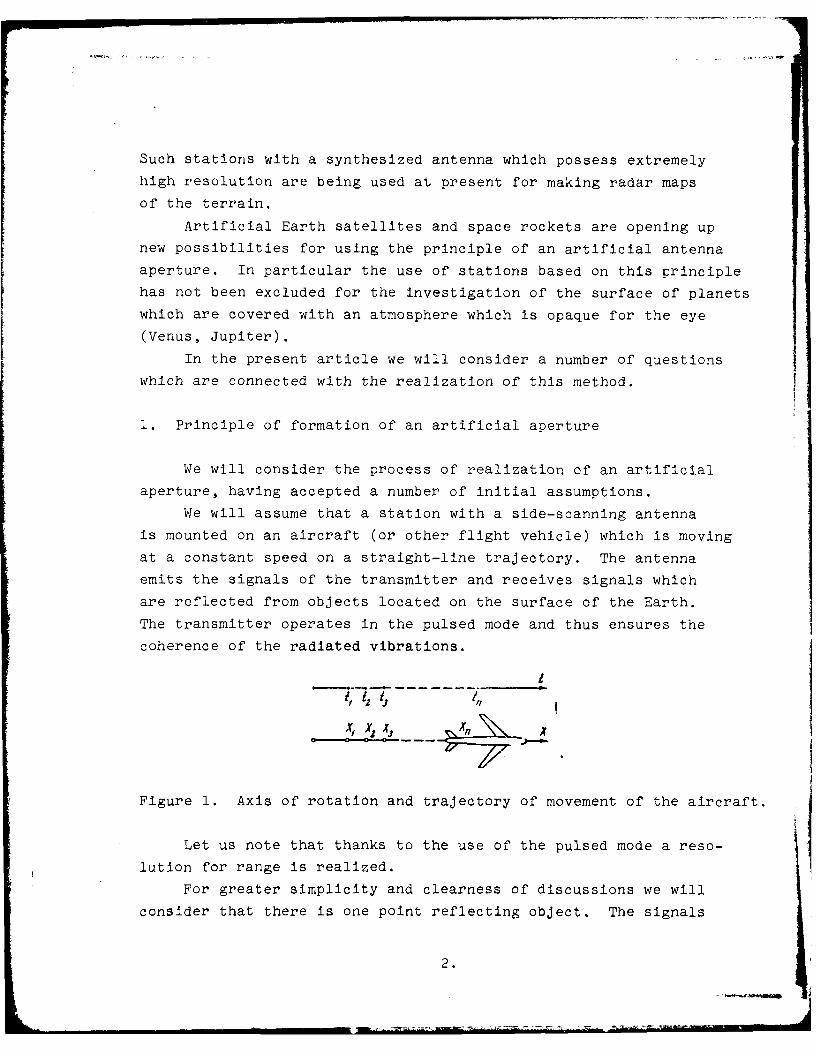
We will assume that a station with a side-scanning antenna
is mounted on an aircraft (or other flight vehicle) which is moving
at a constant speed on a straight-line trajectory. The antenna
emits the signals of the transmitter and receives signals which
are reflected from objects located on the surface of the Earth.
The transmitter operates in the pulsed mode and thus ensures the
coherence of the radiated vibrations.
!I 11s __ 7_X
Figure 1. Axis of rotation and trajectory of movement of the aircraft.
Let us note that thanks to the use of the pulsed mode a reso-
lution for range is realized.
For greater simplicity and clearness of discussions we will
consider that there is one point reflecting object. The signals
2.
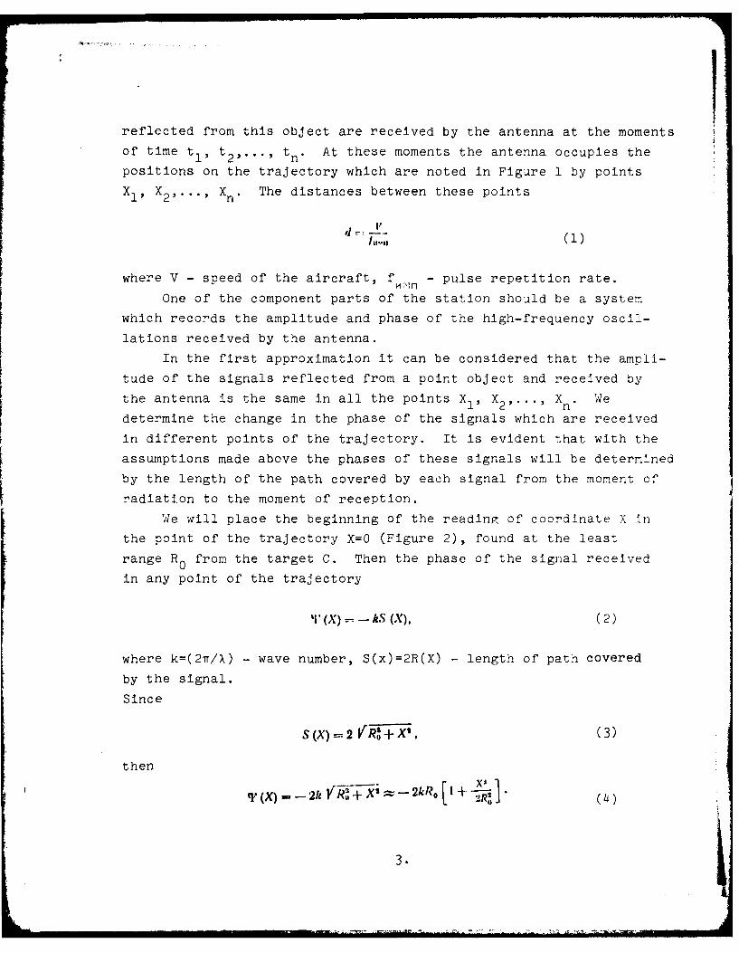
reflected from this object are received by the antenna at the moments
of time tl, t2 ,..., tn . At these moments the antenna occupies the
positions on the trajectory which are noted in Figure 1 by points
X1 , X2 ,..., Xn . The distances between these points
d =h,.,,(1 )
where V - speed of the aircraft, f - pulse repetition rate.
One of the component parts of the station should be a system
which records the amplitude and phase of the high-frequency oscil-
lations received by the antenna.
In the first approximation it can be considered that the ampli-
tude of the signals reflected from a point object and received by
the antenna is the same in all the points X1, X2 ,... , Xn. Wedetermine the change in the phase of the signals which are received
in different points of the trajectory. It is evident that with the
assumptions made above the phases of these signals will be determined
by the length of the path covered by each signal from the moment of
radiation to the moment of reception.
We will place the beginning of the reading of coordinate X in
the point of the trajectory X=O (Figure 2), found at the least
range R0 from the target C. Then the phase of the signal received
in any point of the trajectory
'I (X) - kS (X), (2)
where k=(2Tr/X) - wave number, S(x)=2R(X) - length of path covered
by the signal.
Since
S (X) =2 ('+X, (3)
then
S3.
L'R' 4
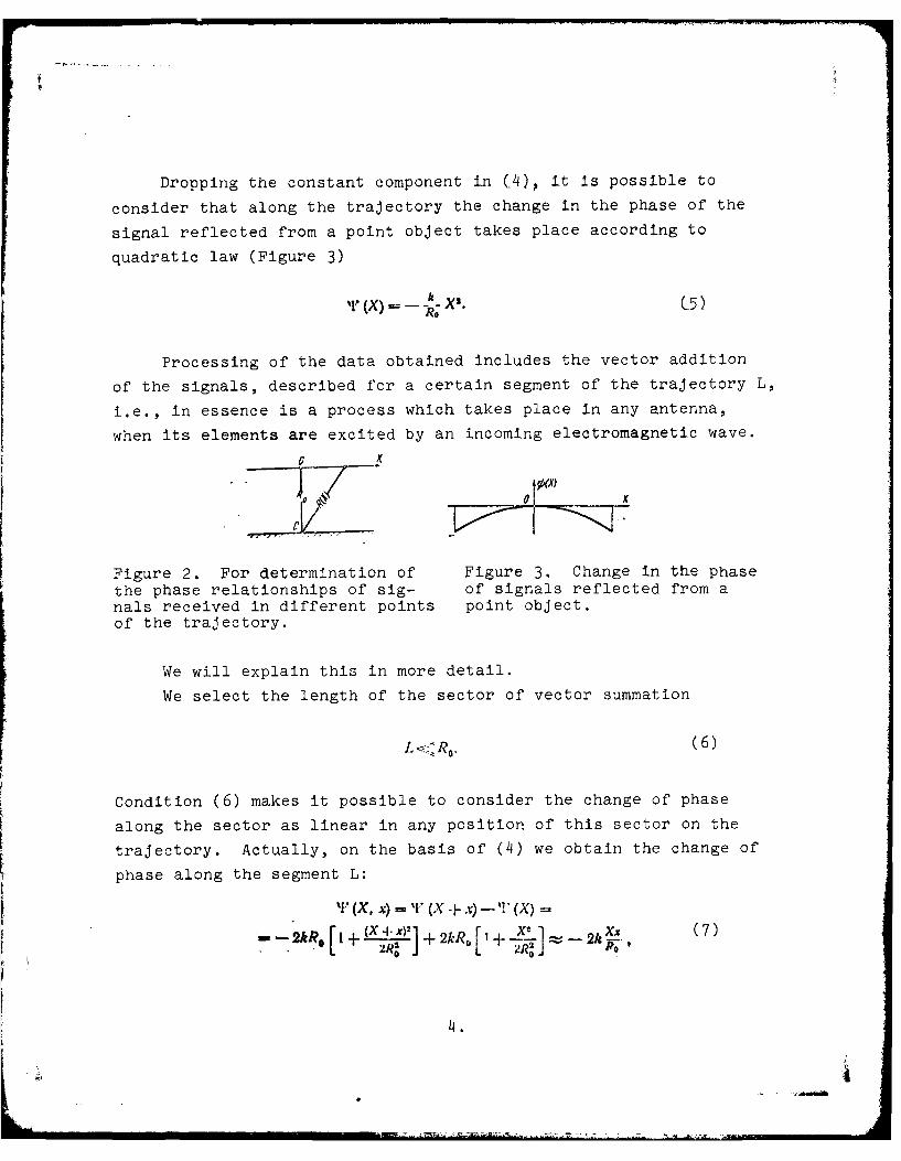
Dropping the constant component in C4), it is possible to
consider that along the trajectory the change in the phase of the
signal reflected from a point object takes place according to
quadratic law (Figure 3)
" (X) k X'. C5)Re
Processing of the data obtained includes the vector addition
of the signals, described for a certain segment of the trajectory L,
i.e., in essence is a process which takes place in any antenna,
when its elements are excited by an incoming electromagnetic wave.
~b(X)
Figure 2. For determination of Figure 3. Change in the phase
the phase relationships of sig- of signals reflected from anals received in different points point object.of the trajectory.
We will explain this in more detail.
We select the length of the sector of vector summation
L < RO. (6)
Condition (6) makes it possible to consider the change of phase
along the sector as linear in any position of this sector on the
trajectory. Actually, on the basis of (4) we obtain the change of
phase along the segment L:
%' (X, x) = I, (X + x) -- " (X) -
-2R I + (X + )2] + 2kPRD +~ 2L 2(7)
4.
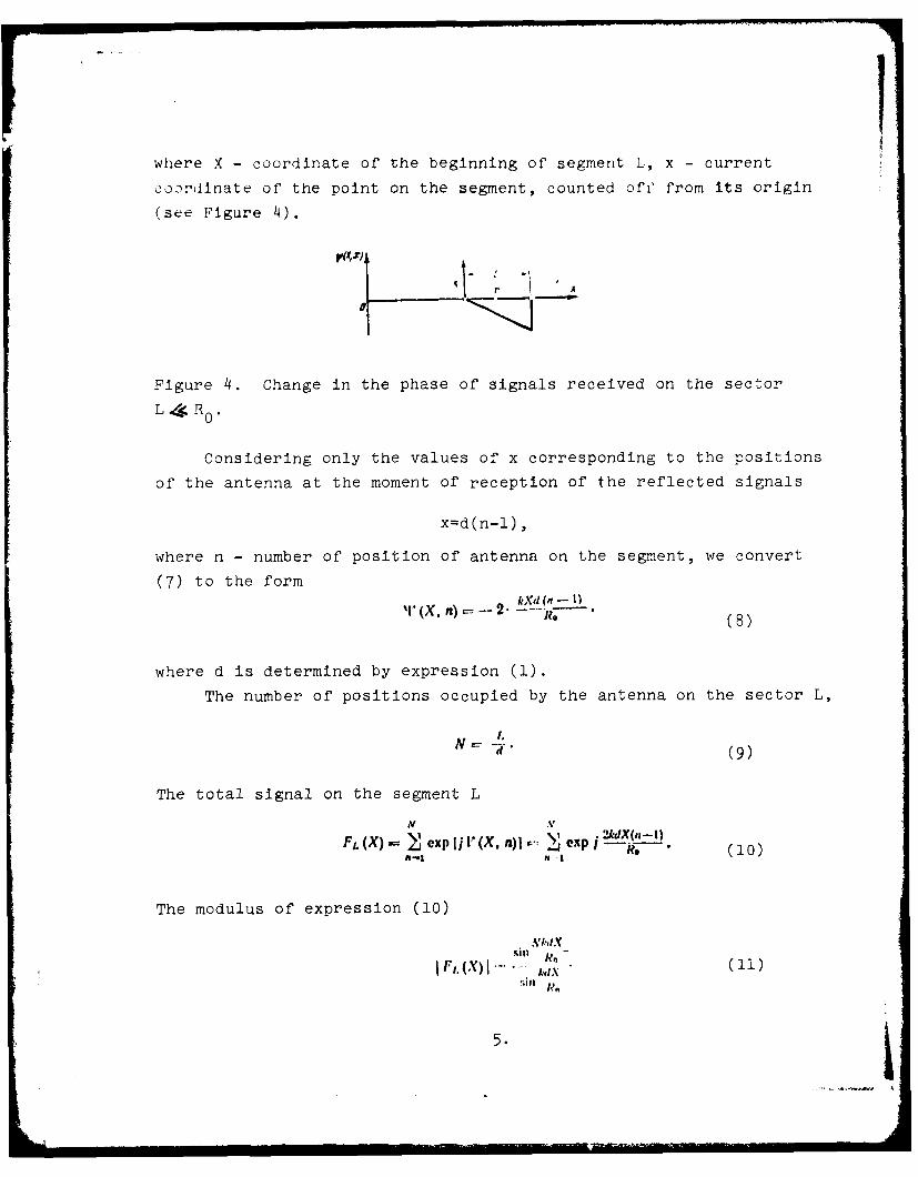
where X - coordinate of the beginning of segment L, x - current
coordinate of the point on the segment, counted off from its origin
(see Figure 4).
Figure 4. Change in the phase of signals received on the sector
L 4 R0 .
Considering only the values of x corresponding to the positions
of the antenna at the moment of reception of the reflected signals
x-d(n-l),
where n - number of position of antenna on the segment, we convert
(7) to the form
r (X, n) -2. -(8)
where d is determined by expression (1).
The number of positions occupied by the antenna on the sector L,
N= -'. (9)
The total signal on the segment L
N V
Fl. (X)= exp Ij r (X,n) exp 1 ". (10)M-1 ,- I
The modulus of expression (10)
A'.',IX
I I,.(X)I . (11). I '
5.
I
characterizes the amplitude of the total signal on the sector L.
The total process of processing the data obtained during opera-
tion of the station on one point object amounts to the determination
of the amplitude of the total signal for a large number of positions
of segment L on the trajectory. Each following position of segment
L differs from the previous one by rejection from the left and
addition from the right, this means that the beginning of segment
L is shifted each time by one position (i.e., by d= V
We convert (11), introducing the substitution 1 4 *"n
1and using the normalized multiplier , and we obtain
sin Nkd sin*F'L (0)(12)
Function 12 determines the dependence of total signal on the
angle %- between a normal to sector L and the direction to the
point object C.
Expression (12) can be considered an effective diagram of a
synthesized aperture with a length L. It has the same form as the
expression for a diagram of a cophasal antenna array made out of
N nondirectional elerrents with a distance of 2d between them.
The artificial antenna obtained in this manner is equivalent
to a linear array with a distance between elements equal to 2d.
Why does the distance between elements of an equivalent array
turn out to be double the distance between the points in which the
signals are received?
The fact is that the elements of the artificial aperture func-
tion independent of each other, and the signal emitted by an indi-
vidual element is returned to this same element, covering a path
equal to the doubled distance from the point of the aperture to the
object. This circumstance found reflection in the derivation of
the function of phase distribution (7). In a conventional antenna
the signals are emitted by all the elements simultaneously, and as
a result of the interference of these signals the radiation pattern
6.

is formed already in the mode of transmission. Therefore tht
phase distribution, caused by the reflected wave, is determined by
the lengths of the paths covered by the signals in one direction
(from the object to the elements of the aperture).
In connection with this the function of phase distribution
for an artificial aperture has a doubled characteristic slope in
comparison with a conventional antenna, and the effective pattern
of the artificial aperture is narrower than the pattern of a conven-
tional antenna of the same length.
The width of the pattern for the artificial aperture on a
level of 0.7 from the maximum level for the field is equal to
0 •(13)
2. Linear resolution on coordinate X and its limiting value
Thus we obtained a pattern with a width 0, stipulated by
the length of the synthesized aperture L. In this case the linear
resolution on coordinate X
A X= l.'a - (14)
here R0 - distance to the object being resolved.
The length of sector L we selected from the condition that the
resolved object was found in the far zone of the antenna. However,
such a case of realization of an artificial aperture is quite rare
and not very interesting, since in this case the possibilities of
the method are not revealed completely. With a considerable increase
of the dimension L, when condition (6) ceases to be fulfilled, the
phase distribution along L acquires a quadratic component.
Actually in this case the change of phase along the sector L
7.
'(X, x) . '(X) . 2hR, I i ( . .
-- 2k R ,, I X ,1~"'* ~ "(15)
In the case of vector addition of the signals the quadratic
component eliminates the effect of the increase in the dimensions
of the artificial aperture, but the influence of the quadratic
component can be compensated for, if during the processing the
corresponding quadratic function of the reverse sign is introduced.
Under the condition of introduction of a compensating function
there is a basic possibility of realizing such a large dimension of
the artificial aperture, when the object is found practically in
the near zone.
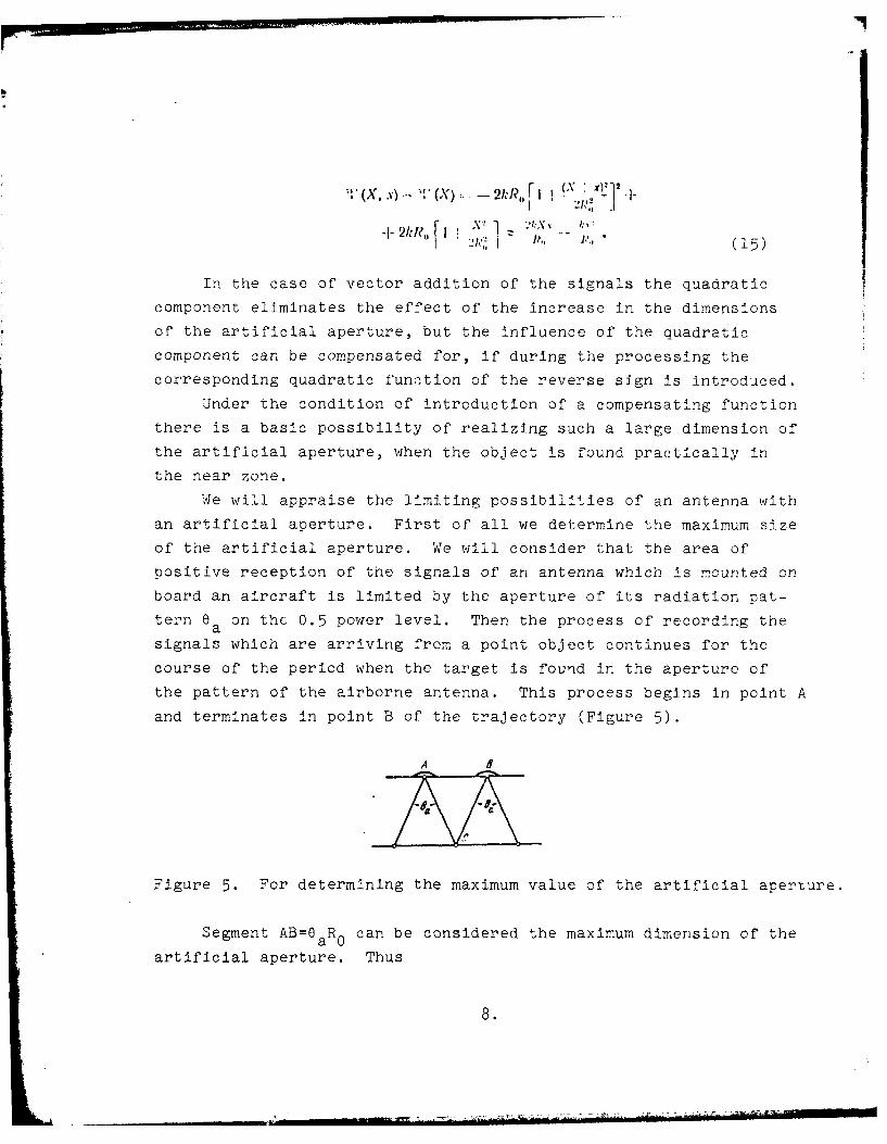
We will appraise the limiting possibilities of an antenna with
an artificial aperture. First of all we determine the maximum size
of the artificial aperture. We will consider that the area of
positive reception of the signals of an antenna which is mounted on
board an aircraft is limited by the aperture of its radiation pat-
tern 0a on the 0.5 power level. Then the process of recording the
signals which are arriving from a point object continues for the
course of the period when the target is found in the aperture of
the pattern of the airborne antenna. This process begins in point A
and terminates in point B of the trajectory (Figure 5).
A I
Figure 5. For determining the maximum value of the artificial aperture.
Segment AB=8aR0 can be considered the maximum dimension of the
artificial aperture. Thus
8.
Il, ,I Q. (16 )
If in the case of addition of signals which are recorded onthe sector L the quadratic component of phase distribution is
maxcompensated for, then the effective width of the radiation pattern
of the artificial aperture
,,,, ----.. . (1 7 )
From here it is possible to obtain the value of the extreme linear
resolution
4X,11.1 flCiuiR 0. (18)
Using (17) and (16), we obtain
dx.,,, 2O4.,-- ,, R --,: (19 )
Considering that O";Z T.) (where da- length of airborne antenna),
we have
A X -(20)
It follows to turn attention to two remarkable features of an
artificial aperture.
First of all, the extreme value of linear resolution (AX mi n )
does not depend on the distance to the object being resolved, and,
secondly, the extreme linear resolution is improved with a lessening
of the size of the antenna which is mounted on board the aircraft.
The first peculiarity is explained by the fact that with an
increase in range according to (16) there is an increase in the
magnitude of Lmax, consequently in the corresponding manner the
effective pattern of the artificial aperture is narrowed.
9.
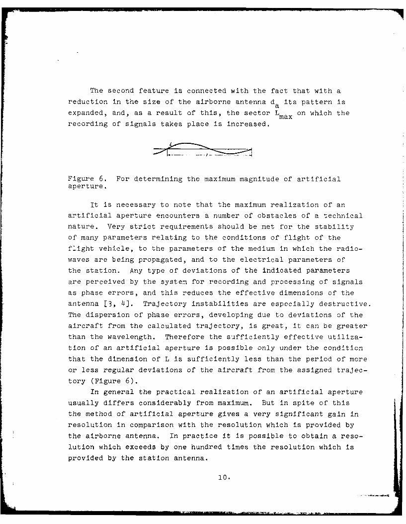
The second feature is connected with the fact that with a
reduction in the size of the airborne antenna d its pattern is~aexpanded, and, as a result of this, the sector Lmax on which the
recording of signals takes place is increased.
Figure 6. For determining the maximum magnitude of artificialaperture.
It is necessary to note that the maximum realization of an
artificial aperture encounters a number of obstacles of a technical
nature. Very strict requirements should be met for the stability
of many parameters relating to the conditions of flight of the
flight vehicle, to the parameters of the medium in which the radio-
waves are being propagated, and to the electrical parameters of
the station. Any type of deviations of the indicated parameters
are perceived by the system for recording and processing of signals
as phase errors, and this reduces the effective dimensions of the
antenna [3, 4]. Trajectory instabilities are especially destructive.
The dispersion of phase errors, developing due to deviations of the
aircraft from the calculated trajectory, is great, it can be greater
than the wavelength. Therefore the sufficiently effective utiliza-
tion of an artificial aperture is possible only under the condition
that the dimension of L is sufficiently less than the period of more
or less regular deviations of the aircraft from the assigned trajec-
tory (Figure 6).
In general the practical realization of an artificial aperture
usually differs considerably from maximum. But in spite of this
the method of artificial aperture gives a very significant gain in
resolution in comparison with the resolution which is provided by
the airborne antenna. In practice it is possible to obtain a reso-
lution which exceeds by one hundred times the resolution which is
provided by the station antenna.
10.

3. Condition of unambiguous determination of coordinates with the
help of an artificial aperture
It was shown above that a synthesized antenna can be consid-
ered as a linear array with a distance between elements equal to
2.V/f mn . This distance, as a rule, is considerably greater than
wavelength, as a result of which a many-lobed pattern (12) is
obtained with interference maximums in the direction t, for which
kd sini=mr, (m=O; +1; +2;...), see Figure 7.
The disposition of these maximums on the Z3 axis depends on
the variable d/X. With an increase of this ratio the distances
between the interference maximums is reduced. The presence of a
large number of maximums in the pattern of a synthesized antenna
is extremely undesirable. They are the cause of ambiguity in the
determination of coordinates. The suppression of secondary maximums
(directed not on a normal to the linear array) is one of the most
important problems which develop in the realization of the principle
of an artificial aperture.
We will dwell on it in more detail.
In the derivation of (12) it was assumed that the synthesized
array consists of point (nondirectional) elements. Actually the
elements of this array possess directivity. The beam pattern of an
element is nothing but the pattern of the airborne antenna of the
station - F a(e).
It has been accepted to call function (12), describing the
beam pattern of the array, consisting of point emitters, the array
multiplier. The array radiation pattern, consisting of similar
directional elements, represents the product of the array multiplier
(12) by the radiation pattern of the individual element
lN '( )ll , 'i lif (21)
In many cases of realization of an artificial aperture the
problem of suppression of secondary interference maximums is solved
thanks to the directional properties of the elements, i.e., with
11.
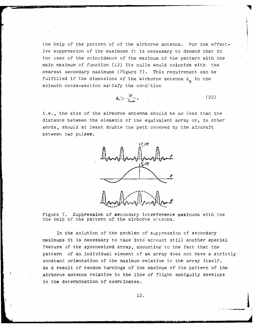
the help of the pattern of of the airborne antenna. For the effect-
ive suppression of the maximums it is necessary to demand that in
the case of the coincidence of the maximum of the pattern with the
main maximum of function (12) its nulls would coincide with the
nearest secondary maximums (Figure 7). This requirement can be
fulfilled if the dimensions of the airborne antenna da in the
azimuth cross-section satisfy the condition
d V (22)
i.e., the size of the airborne antenna should be no less than the
distance between the elements of the equivalent array or, in other
words, should at least double the path covered by the aircraft
between two pulses.
41pp
Figure 7. Suppression of secondary Interference maximums with thethe help of the pattern of the airborne antenna.
In the solution of the problem of suppression of secondary
maximums it is necessary to take into account still another special
feature of the synthesized array, amounting to the fact that the
pattern of an individual element of an array does not have a strictly
constant orientation of the maximum relative to the array itself.
As a result of random turnings of the maximum of the pattern of the
airborne antenna relative to the line of flight ambiguity develops
in the determination of coorCinates.
12.
In connection with this, in addition to the fulfillment of
condition (22), stabilization of the pattern of the airborne antenna
relative to the vector of ground speed mainly in an azimuth plane
should be ensured.
Thus the suppression of the secondary interference maximums
of a synthesized array can be carried out with the help of the
radiation pattern of the airborne antenna of the radar, if its
dimensions are twice those of the segment of path flown over by the
aircraft in the time between two pulses, and if the pattern is
stabilized relative to the vector of ground speed.
But it has to be stated that such a path is not always feasible.
Thus in the case of a very high speed of the flight vehicle and a
sufficiently low pulse repetition rate for the suppression of inter
ference maximums it may require antenna dimensions which in practice
are difficult to realize. Thus with the mounting of a station on
a satellite (or space ship) the antenna dimensions must be 50-80 m.
In such cases it is expedient to make use of the possibility of the
principle, which is known in antenna theory, of non-equidistant arrays.
It is known that interference maximums develop due to the periodicity
of the array, i.e., due to the equality of the distances between ele-
ments. If this periodicity is disrupted, then the secondary maxi-
mums (not coinciding with a normal to the array) are broken up.
The practical realization of a synthesized antenna based on
a model of a non-equidistant array means that the sounding pulses of
the transmitter are emitted not regularly, but according to a
specific law. The law of distribution of sounding pulses on the
axis of time is the same as the law of distribution of elements of
the synthesized array. The problem is reduced to a search for the
law of spacing of the elements of the array which would ensure a
sufficient lowering of the level of interference maximums. In this
case it is required, first of all, that the condition of suppression
of maximums be preserved for any realization (i.e., for any position
of the aperture on the X axis), and, secondly, that the distances
between elements of the array satisfy the inequality
13.
b L . . .... . ...... . .. __. . .4
I.I
l " ,,,,, - V7", ... ( 2 3)
where Tmax - the time, necessary for propagation of the radiated
signal to the object which is furthest avay and back.
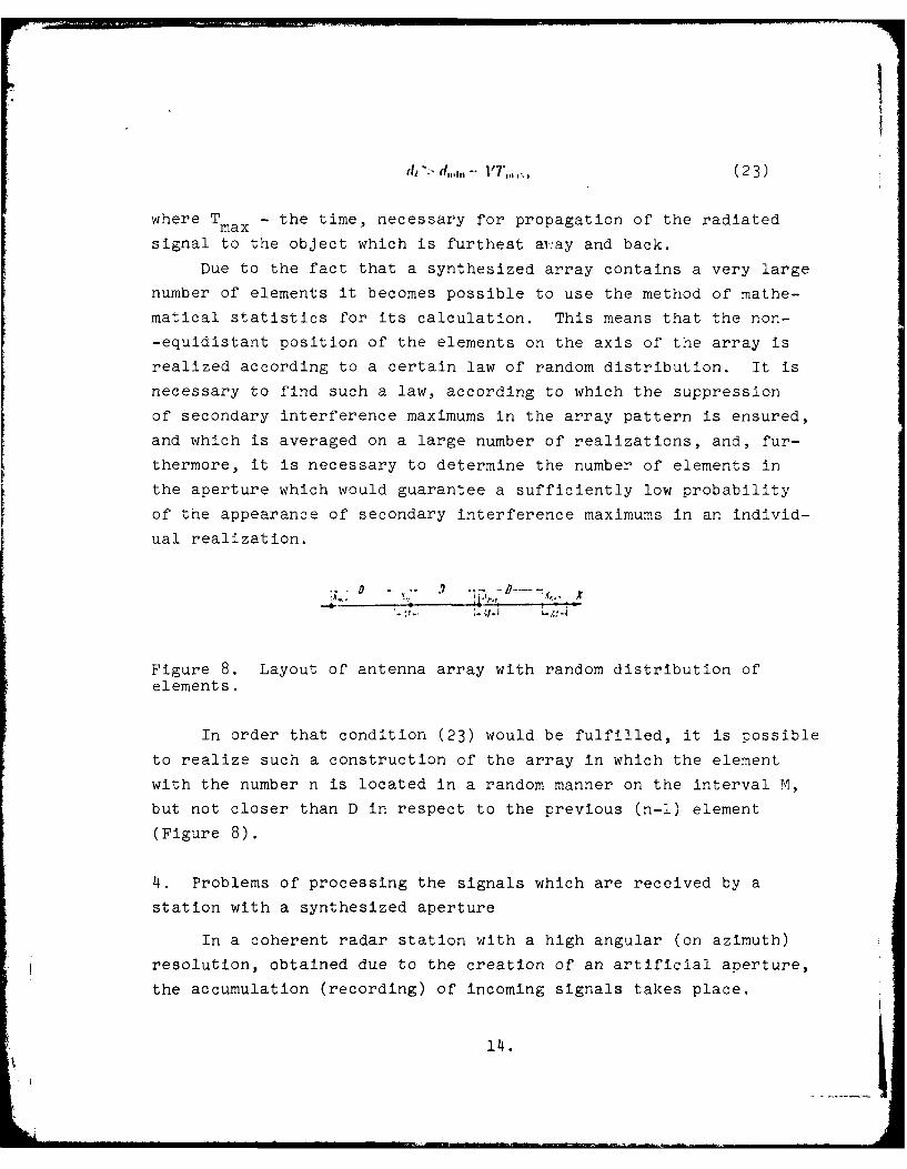
Due to the fact that a synthesized array contains a very large
number of elements it becomes possible to use the method of mathe-
matical statistics for its calculation. This means that the non-
-equidistant position of the elements on the axis of the array is
realized according to a certain law of random distribution. It is
necessary to find such a law, according to which the suppression
of secondary interference maximums in the array pattern is ensured,
and which is averaged on a large number of realizations, and, fur-
thermore, it is necessary to determine the number of elements in
the aperture which would guarantee a sufficiently low probability
of the appearance of secondary interference maximums in an individ-
ual realization.
.. - .. . '1 B i
Figure 8. Layout of antenna array with random distribution ofelements.
In order that condition (23) would be fulfilled, it is possible
to realize such a construction of the array in which the element
with the number n is located in a random manner on the interval M,
but not closer than D in respect to the previous (n-l) element
(Figure 8).
4. Problems of processing the signals which are received by a
station with a synthesized aperture
In a coherent radar station with a high angular (on azimuth)
resolution, obtained due to the creation of an artificial aperture,
the accumulation (recording) of incoming signals takes place.
14.
We recall that resolution for range is realized in such a sta-
tion due to the time lag of signals which are reflected from objects
which are at different distances away. Therefore each pulse of the
transmitter is recorded on reception in the form of a series of
signals arriving from different points of the Earth's surface along
the beam of the airborne antenna. The following pulse gives the
corresponding series of signals for the antenna beam which is dis-
placed in parallel, etc. Thus the problem is reduced to the record-
ing and processing of signals which are arriving at the receiver
from a large area. This requirement is satisfied by the optical
processing of signals, since optical devices by their nature are
two-dimensional [5-7].
~0000000 000D~000
00001
. . . . . . . . . . . . . . . ...... .. 00 0 UU
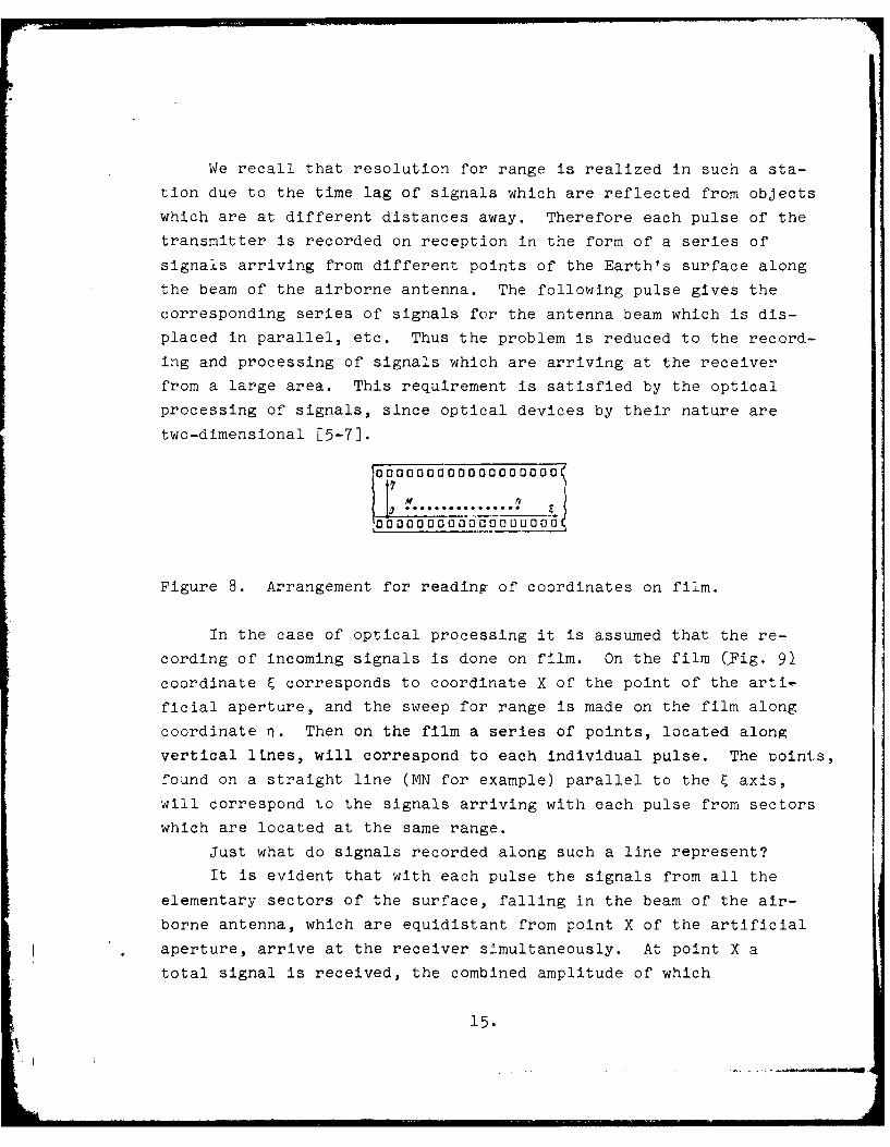
Figure 8. Arrangement for reading of coordinates on film.
In the case of optical processing it is assumed that the re-
cording of incoming signals is done on film. On the film CFig. 91
coordinate E corresponds to coordinate X of the point of the arti-
ficial aperture, and the sweep for range is made on the film along
coordinate r. Then on the film a series of points, located along
vertical lLnes, will correspond to each individual pulse. The Doints,
found on a straight line (MN for example) parallel to the E axis,
will correspond to the signals arriving with each pulse from sectors
which are located at the same range.
Just what do signals recorded along such a line represent?
It is evident that with each pulse the signals from all the
elementary sectors of the surface, falling in the beam of the air-
borne antenna, which are equidistant from point X of the artificial
aperture, arrive at the receiver simultaneously. At point X a
total signal is received, the combined amplitude of which
15.
A f I i i i
Oi
M(X) A(O)ex(jkXsin 0)R),l()4A_,,
(24)
where A (L) - intensity of reflection from an object, located at
a given distance at an angle of 9 relative to the artificial
aperture.
The signal (24) arrives at the input of the phase detector.
The signal which is obtained on the output of the phase detector
represents the real part of (24). The brightness of exposure of
the film in the corresponding point is proportional to the magni-
tude of the signal on the output of the phase detector.
~ \ ( Key:
'7777777 (1) Plane Y;
(2) Plane Z.
Figure 10. Layout for optical processing.
The task of the subsequent optical processing is the restora-
tion, based on the data recorded on the film, of a picture of dis-
tribution of intensity of reflections along the band of the Earth's
surface being investigated. In other words, we have to find the
function A (4), which is the spectrum of function M(X). Mathemati-
cally this problem is solved by means of a Fourier transformation.
In practice this can be realized by the appropriate optical
processing, in the process of which it is required to switch from
radar signals, recorded through the variable brightness of the film,
to light [signals].
16.
The light signals are obtained as a result of modulation of
light flux by the variable brightness of the film. For this the
film is illuminated with a pl-ne wave of monochromatic light. If
in this case the film is placed in the focal plane Y of converging
lens L2 (Figure 10), then in the other focal plane Z of this same
lens the Fourier transform of the function, recorded on the film.
will be reflected:
2 25
where K(E)=ReM(X), L2 - lens opening. Then in the corresponding
points of plane Z the signals, proportional to the intensity of
reflections from the elementary sectors of the terrain, will be
reproduced.
The circumstance that the Fourier transformation was applied
to the active part of the signal M(X) creates the necessity of
certain additional operations for the purpoEe of obtaining an
unambiguous and correct picture of the terrain on the film. We
will not consider these operations here.
REFERENCES
l. Cutrona L..1., VivianW W. 1., L.eilhi E. N., HallG. O. IRETrans., 1961, Apr.i. %TL-(,, N 2, 127-131'ricpcoo C13p)-lrofoliR 1 .ioa'< ~ik~~,I962. .N1 10).
2. M cC or d It. L.., IRE T 9r:6,., 1962. April, M1 6.i, N 2, 116-119.3. H eim i I I e r R. C.. ME Trans., 1962, April. Mv'L-6, N 2. 122-129.4. D e v e I e t J. A. IRE Travi., 1962, April, MfL-6, N 2, 204.5. H o e Icr V. G. iR F Tra :s., 1962, 'Ipril, MiL-6, N 2. 174-178.6. D ow S in it h. Applied Optics, 1963, N 4, 335-350.
(nepeao: e3apyt~emman p iIna1XcI'Tpu1MtKa%, 1964, XN 4).7. v a n H t e r d e n P. J. Applied Optics, 1963, N 4, 387-392.
17.
DISTRIBUTION LIST
DISTRIBUTION DIRECT TO RECIPIENT
ORGANIZATION MICROFICHE ORGANIZATION MICROFICHE
A205 DMATC 1 E053 AF/INAKA 1A210 DMAAC 2 E017 AF/RDXTR-W 1B344 DIA/RDS-3C 9 E403 AFSC/INA 1C043 USAMIIA 1 E404 AEDC 1C509 BALLISTIC RES LABS 1 E408 AFWL 1C510 AIR MOBILITY R&D 1 E410 ADTC 1
LAB/FI0C513 PICATINNY ARSENAL 1 FTDC535 AVIATION SYS COMD 1 CCN 1C591 FSTC 5 ASD/FTD/NIIS 3C619 MIA REDSTONE 1 NIA/PHS 1D008 NISC 1 NIIS 211300 USAICE (USAREUR) 1P005 DOE 1P050 CIA/CRB/.A=,D/SD 2NAVORDSTA (50L) 1NASA/NST-44 1AFIT/LD 1I.LI/Code L-389 INS7%/2I 3/-DL 2
FTD-ID(RS)T-1036-79


![FILTERING ANTENNAS: SYNTHESIS AND DESIGN Type 1 Filtering Antenna In this design, we have studied the synthesis and design of new printed Filtering antenna. Fig. 1[1] contains the](https://img.pdfslide.us/doc/110x75/5b03160e7f8b9a2d518ba164/filtering-antennas-synthesis-and-design-type-1-filtering-antenna-in-this-design.jpg)

![Constrained Pole-Zero Synthesis of Phase-Oriented RFID Sensor Antennas · 2016-04-08 · Constrained Pole-Zero Synthesis of Phase-Oriented ... The basic operation principle[8]](https://img.pdfslide.us/doc/110x75/5b2688fa7f8b9a12168b4bb9/constrained-pole-zero-synthesis-of-phase-oriented-rfid-sensor-2016-04-08.jpg)