Embed Size (px)
Citation preview

SynFrame Accessand Retractor SystemASSEMBLY GUIDE
Instruments and implants approved by the AO Foundation

SynFrame Access and Retractor System
System Overview
The SynFrame Access and Retractor Systemallows direct visualization and stable retractionfor less invasive spine surgery, eliminating theneed for large hand-held retractors. The systemis easily assembled from both sides of the operating table up to the retractor ring. Oncethe ring is positioned over the surgical site,retractors can be secured in any configuration.

1
SynFrame Components
SynFrame InsulatedTable Clamp [387.346]
SynFrame Angled Rod Holder [387.343]
SynFrame Tube-to-Tube Clamp[387.353]
Star-grind allows relativepositioning between rods
SynFrame Angled Rod [387.344]
SynFrame Connecting Rod [387.345]
Large HexagonalScrewdriver [314.27]
Socket Wrench with Straight Handle [388.14]

SynFrame Components (continued)
2
SynFrame Lengtheners[387.338]
Allow increased retractionarea by elongating ring
SynFrame Holding Ring [387.336]
• Retractors attach to Holding Ring forcustomized retraction
• Two-piece ring, 300 mm diameter
• Consists of two Half Rings [387.337](also additionally available)
SynFrame Ring Clamp [387.347]
• Snaps onto Holding Ring without tightening
• Permits flexible retractor positioning
SynFrame Guide Rod [387.358]
• Finger loop aids in positioning retractor blades
• Swiveling tip allows blade angulation

3
Light Guide [387.362]
• Connects to light source via ACMI connector(Wolf and Storz adaptors included)
• Attaches to Ring Clamp, allowing visualizationof tissues
SynFrame Retractors
Insert into Guide Rod and rotate 90° for secure fit
387.391 60 mm
387.392 80 mm
387.393 100 mm
387.394 120 mm
387.395 140 mm
387.396 160 mm
Longer blade for specialized needs(additionally available)
387.397 180 mm
ACMIConnector
Wolf Adaptor
Storz Adaptor

SynFrame Assembly Guide
4
Sterile Assembly of SynFrame
The use of a sterile sleeve is recommended for separating the sterile fromnon-sterile areas. Since the Insulated Table Clamp can be sterilized, it canbe used in the sterile field (for example, on top of the sterile cover).
Note: The assembly instructions are designed to facilitate the use of SynFramebut do not provide guidance on surgical technique. Failure to comply withinstructions or precautionary measures can result in damage to the system, risks during the procedure or injury to the patient. Refer to package insert forspecific safety directions and special cleaning and sterilization instructions.
Insertion of Angled Rod Holder intoInsulated Table Clamp (attached tooperating table)
Position Insulated Table Clampson operating table
Frame Assembly
Secure Table Clamp
First, loosen the knob on the table clamp. Then,attach the table clamp to the guide rail by the top and bottom jaws. “TOP” must be visible on the clamp surface. Tighten the knob at the desired location.Repeat installation steps on the opposite side.
Locate the table clamps laterally so that:
a. The 300 mm Holding Ring can be attached cranially and caudally between the table clamps (recommended minimum craniocaudal distance: 400 mm).
b. The surgeon’s movement within the operating field is not restricted.
Ensure the table clamps are securely fixed to the guide rails of the operating table.
Insert Angled Rod Holder into Table Clamp
Insert the Angled Rod Holder into the Insulated TableClamp and tighten the knob to secure it. Repeat onthe opposite side at the same height.
Note: The Insulated Table Clamp and the Angled Rod Holder are designed to insulate the system from the operating table. This configuration should be maintained throughout the procedure.
2
1
Note: An adaptor may be required for use with a Jackson table.

5
Secure Angled Rod in Angled RodHolder
Insert an Angled Rod into the Angled Rod Holder on each side of the operating table. Secure theAngled Rods approximately 5–10 cm above thepatient.
Assemble Holding Ring
The Holding Ring consists of two Half Rings.Assemble the Holding Ring by pushing the two Half Rings together over the guide pins. Tightenthe set screws using the Screwdriver. This stepmay be completed prior to assembly of the side supports.
Note: The round 300 mm Holding Ring may beextended to a 400 mm oblong ring, using twoLengtheners.
6
Insert Connecting Rod
Slide the Connecting Rod through the Tube-to-TubeClamp. Tighten the clamp at desired position. Repeaton the opposite side.
5
Attach Tube-to-Tube Clamp to Angled Rod
Loosely slide the Tube-to-Tube Clamp onto the Angled Rod. Repeat on the opposite side.
4
Insertion of Tube-to-Tube Clamponto Angled Rod
Insertion of Connecting Rodonto Tube-to-Tube Clamp
Assembly of Holding Ring
Insertion of Angled Rod into AngledRod Holder
3
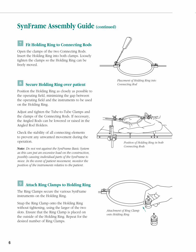
Fit Holding Ring to Connecting Rods
Open the clamps of the two Connecting Rods.Insert the Holding Ring into both clamps. Looselytighten the clamps so the Holding Ring can befreely moved.
Secure Holding Ring over patient
Position the Holding Ring as closely as possible to the operating field, minimizing the gap betweenthe operating field and the instruments to be usedon the Holding Ring.
Adjust and tighten the Tube-to-Tube Clamps andthe clamps of the Connecting Rods. If necessary,the Angled Rods can be lowered or raised in theAngled Rod Holders.
Check the stability of all connecting elements to prevent any unwanted movement during theoperation.
Note: Do not rest against the SynFrame Basic System as this can put an excessive load on the construction,possibly causing individual parts of the SynFrame tomove. In the event of patient movement, monitor theposition of the instruments relative to the patient.
Attach Ring Clamps to Holding Ring
The Ring Clamps secure the various SynFrameinstruments on the Holding Ring.
Snap the Ring Clamp onto the Holding Ring without tightening, using the larger of the twoslots. Ensure that the Ring Clamp is placed on the outside of the Holding Ring. Repeat for thedesired number of Ring Clamps.
7
9
8
6
SynFrame Assembly Guide (continued)
Placement of Holding Ring intoConnecting Rod
Position of Holding Ring in bothConnecting Rods
Attachment of Ring Clamponto Holding Ring

7
RetractionMount SynFrame Retractor to Guide Rod
Laterally insert a Retractor into the end of theGuide Rod and rotate 90°. Tighten the swivelingclamp of the Guide Rod using the socket wrench.This allows the Retractor to be held in the GuideRod mechanism while remaining adjustable.
Position Retractors
Snap the Retractor and Guide Rod assembly into the smaller slot of the Ring Clamp. Until the clamp is tightened, the Retractor remainsfreely movable in all directions on the HoldingRing. Once the Retractor is in position, secure by tightening the Ring Clamp. Repeat for thedesired number of Retractors.
Note: Always align the Retractor directly with the direction of pull of the Guide Rod, ensuring the full width of the Retractor rests against the soft tissue, rather than on a single point.
Enlarge operating area
Loosen the swiveling clamp of the Guide Rodusing the socket wrench. This allows the swivelingclamp of the secured Retractor to swivel in its axisand thus enlarge the visible operating area. TheRetractor should be guided by hand to protectthe soft tissue. Tighten the Guide Rod Clampusing the socket wrench to secure Retractor.
Note: Do not use the socket wrench as a lever arm to adjust the Retractor as this may exert a large forceon the Retractor, possibly leading to injury.
1
3
2
Insertion of Retractor into Guide Rod
Secure Retractor andGuide Rod assemblyonto Ring Clamp

8
Position Light Guide
To use the Light Guide, a separate light sourceis required. The Light Guide has an ACMI connector. If necessary, attach an adapter (Wolf or Storz) to the ACMI connector.
Snap the Light Guide into the small slot of theRing Clamp. Fasten the Light Guide securely to the frame by tightening the Ring Clamp.
Note: Avoid direct tissue contact and keep the distal end of the rod at least 10 mm away from the tissues when securing the Light Guide. Refer to package insert for further safety instructions.
Example of completedSynFrame assembly
SynFrame Assembly Guide (continued)
Dismantling SynFrame
The SynFrame is dismantled in thereverse sequence. The Holding Ringand Connecting Rods can be rapidlyremoved from the operating area byloosening and removing the Tube-to-Tube Clamps on the Angled Rods.
9
SynFrame Access and Retractor System
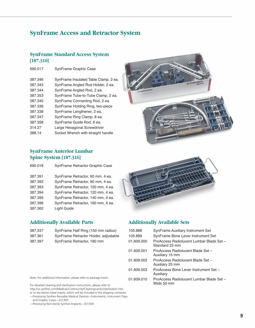
SynFrame Standard Access System [187.310]
690.017 SynFrame Graphic Case
387.346 SynFrame Insulated Table Clamp, 2 ea.387.343 SynFrame Angled Rod Holder, 2 ea.387.344 SynFrame Angled Rod, 2 ea.387.353 SynFrame Tube-to-Tube Clamp, 2 ea.387.345 SynFrame Connecting Rod, 2 ea.387.336 SynFrame Holding Ring, two-piece387.338 SynFrame Lengthener, 2 ea.387.347 SynFrame Ring Clamp, 8 ea.387.358 SynFrame Guide Rod, 6 ea.314.27 Large Hexagonal Screwdriver388.14 Socket Wrench with straight handle
SynFrame Anterior Lumbar Spine System [187.316]
690.018 SynFrame Retractor Graphic Case
387.391 SynFrame Retractor, 60 mm, 4 ea.387.392 SynFrame Retractor, 80 mm, 4 ea.387.393 SynFrame Retractor, 100 mm, 4 ea.387.394 SynFrame Retractor, 120 mm, 4 ea.387.395 SynFrame Retractor, 140 mm, 4 ea.387.396 SynFrame Retractor, 160 mm, 4 ea.387.362 Light Guide
Additionally Available Parts
387.337 SynFrame Half Ring (150 mm radius)387.361 SynFrame Retractor Holder, adjustable387.397 SynFrame Retractor, 180 mm
Additionally Available Sets
105.888 SynFrame Auxiliary Instrument Set105.889 SynFrame Bone Lever Instrument Set01.609.000 ProAccess Radiolucent Lumbar Blade Set –
Standard 25 mm01.609.001 ProAccess Radiolucent Blade Set –
Auxiliary 15 mm01.609.002 ProAccess Radiolucent Blade Set –
Auxiliary 25 mm01.609.003 ProAccess Bone Lever Instrument Set –
Auxiliary01.609.010 ProAccess Radiolucent Lumbar Blade Set –
Wide 50 mm
Note: For additional information, please refer to package insert.
For detailed cleaning and sterilization instructions, please refer tohttp://us.synthes.com/Medical+Community/Cleaning+and+Sterilization.htmor to the below listed inserts, which will be included in the shipping container:—Processing Synthes Reusable Medical Devices—Instruments, Instrument Trays
and Graphic Cases—DJ1305—Processing Non-sterile Synthes Implants—DJ1304

Synthes Spine1302 Wrights Lane EastWest Chester, PA 19380Telephone: (610) 719-5000To order: (800) 523-0322Fax: (610) 251-9056
Synthes (Canada) Ltd.2566 Meadowpine BoulevardMississauga, Ontario L5N 6P9Telephone: (905) 567-0440To order: (800) 668-1119Fax: (905) 567-3185
© 1999 Synthes, Inc. or its affiliates. All rights reserved. Synthes and ASIF are trademarks of Synthes, Inc. or its affiliates. Printed in U.S.A. 8/10 J2887-E
www.synthes.com