Embed Size (px)
Citation preview
L07 – FSMs 16.004 – Fall 2002 9/26/02
(Synchronous)Finite State Machines
Lab 2 is due tonight
Great - Theory!
WARD &HALSTEAD
NERD KIT6.004
Finally! Some ENGINEERING!
L07 – FSMs 26.004 – Fall 2002 9/26/02
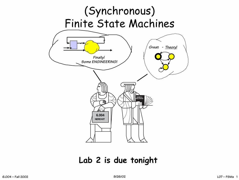
Our New Machine
CombinationalLogic
CurrentState
NewState
Input Output
Clock
StateRegisters
kk
m n
• Acyclic graph• Obeys static discipline• Can be exhaustively enumerated
by a truth table of 2k+m rows and k+n output columns
•Engineered cycles•Works only if dynamic discipline obeyed•Remembers k bits for a total of 2k unique combinations
L07 – FSMs 36.004 – Fall 2002 9/26/02
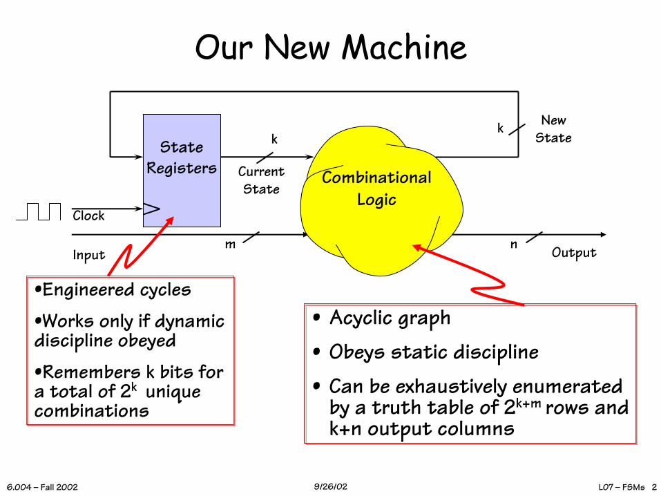
Must Respect Timing Assumptions!
Questions:
• Constraints on TCD for the logic?
• Minimum clock period?
• Setup, Hold times for Inputs?
CombinationalLogic
CurrentState
NewState
Input Output
Clock tCD,L = ?tPD,L = 5ns
tCD,R = 1nstPD,R = 3nstS,R = 2nstH,R = 2ns
tCD,L > 1 ns
tS = tPD,L + tS,R = 7 nStH = tH,R - tCD,L= 1 nS
We know how fast it goes… But what can it do?
tCD,R (1 ns) + tCD,L(?) > tH,R(2 ns)
tCLK > tPD,R+tPD,L+ tS,R > 10nS
L07 – FSMs 46.004 – Fall 2002 9/26/02
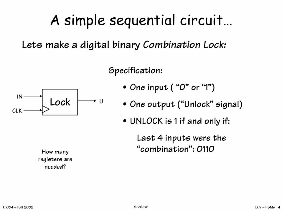
A simple sequential circuit…Lets make a digital binary Combination Lock:
Specification:
• One input ( “0” or “1”)
• One output (“Unlock” signal)
• UNLOCK is 1 if and only if:
Last 4 inputs were the “combination”: 0110How many
registers areneeded?
LockINU
CLK

L07 – FSMs 56.004 – Fall 2002 9/26/02
Abstraction du jour:Finite State Machines
• A FINITE STATE MACHINE has
Clocked FSM
m n
• k STATES S1 … Sk (one is “initial” state)
• m INPUTS I1 … Im• n OUTPUTS O1 … On
• Transition Rules s’(s, I) for each state s and input I
• Output Rules Out(s) for each state s
L07 – FSMs 66.004 – Fall 2002 9/26/02
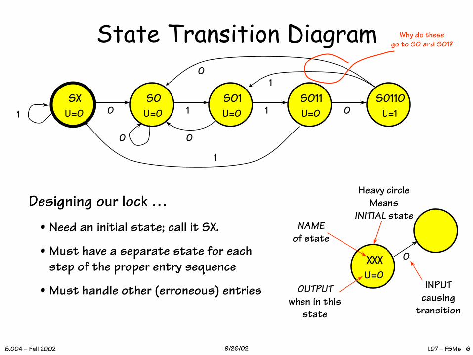
State Transition Diagram
SXU=0
S0U=00
S01U=01
S011U=01
S0110U=101
00
01
1
XXXU=0
NAMEof state
OUTPUTwhen in this
state
0
INPUTcausing
transition
Heavy circleMeans
INITIAL stateDesigning our lock …
• Need an initial state; call it SX.
• Must have a separate state for each step of the proper entry sequence
• Must handle other (erroneous) entries
Why do thesego to S0 and S01?
L07 – FSMs 76.004 – Fall 2002 9/26/02
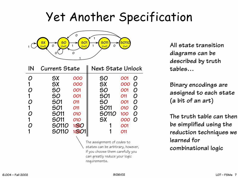
Yet Another Specification
SXU=0
S0U=00
S01U=01
S011U=01
S0110U=101
00
01
1
IN Current State Next State Unlock0 SX S0 01 SX SX 00 S0 S0 01 S0 S01 00 S01 S0 01 S01 S011 00 S011 S0110 01 S011 SX 00 S0110 S0 11 S0110 S01 1
All state transitiondiagrams can bedescribed by truth tables…
Binary encodings are assigned to each state (a bit of an art)
The truth table can then be simplified using the reduction techniques we learned for combinational logic
000000001001011011010010100100
001000001011001010100000001011
The assignment of codes tostates can be arbitrary, however,if you choose them carefully youcan greatly reduce your logicrequirements.
L07 – FSMs 86.004 – Fall 2002 9/26/02
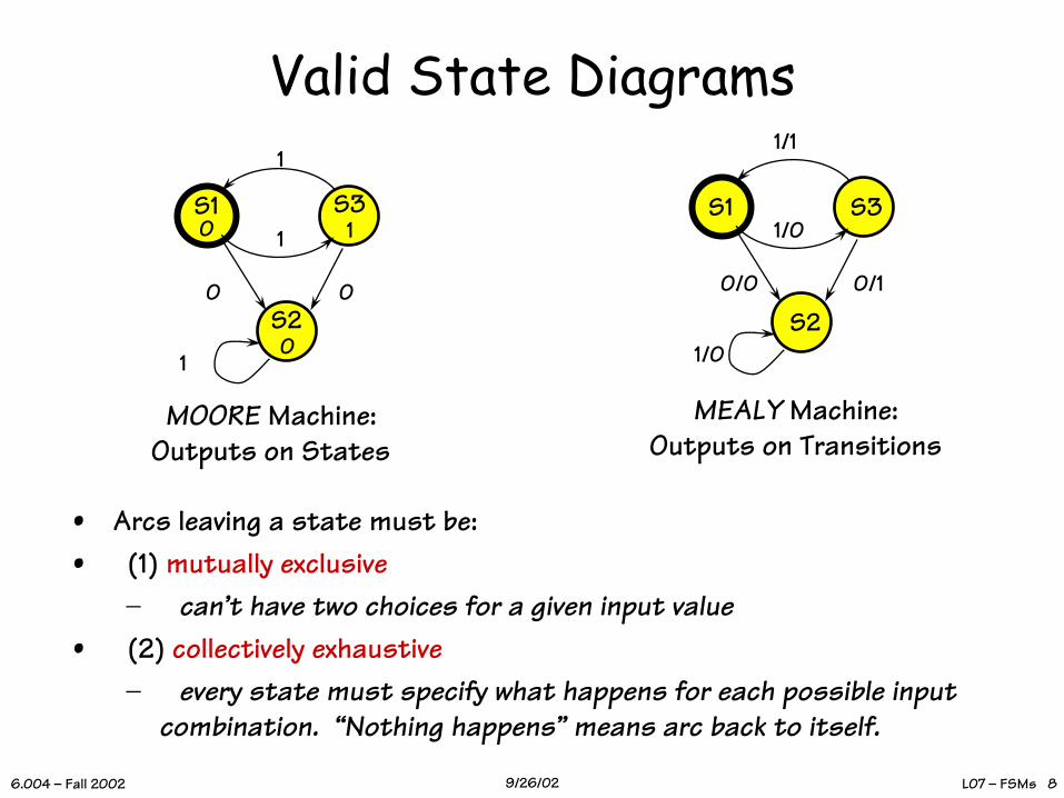
Valid State Diagrams
• Arcs leaving a state must be:• (1) mutually exclusive
– can’t have two choices for a given input value• (2) collectively exhaustive
– every state must specify what happens for each possible input combination. “Nothing happens” means arc back to itself.
S1 S3
0 0S2
1
1
10 1
0
MOORE Machine:Outputs on States
S1 S3
0/0 0/1
S21/0
1/1
1/0
MEALY Machine:Outputs on Transitions

L07 – FSMs 96.004 – Fall 2002 9/26/02
Now put it in Hardware!
ROM16x4
unlock
Next stateCurrent state
IN
Trigger update periodically (“clock”)
33
4 inputs →24 locationseach location supplies 4 bits
We assumeinputs are
synchronizedwith clock…
L07 – FSMs 106.004 – Fall 2002 9/26/02
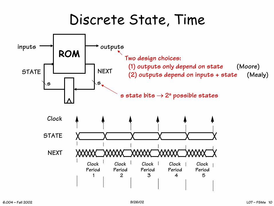
Discrete State, Time
Clock
STATE
NEXTClock Period
1
Clock Period
2
Clock Period
3
Clock Period
4
Clock Period
5
ROM
NEXTSTATE
inputs outputs
ss
s state bits → 2s possible states
Two design choices:(1) outputs only depend on state(2) outputs depend on inputs + state
(Moore)(Mealy)

L07 – FSMs 116.004 – Fall 2002 9/26/02
1110
Asynchronous Inputs - IOur example assumed a single clock transition per input. What if the “button pusher” is unaware of, or not synchronized with, the clock?
SXU=0
S0U=0
S01U=0
S011U=0
U=0
B0 B0
U=0
B1 B1
U=0
B1 B1
U=0
B1 B1
What if each button input is an asynchronous 0/1 level? How do we prevent a single button press, e.g., from making several transitions?
LockB1 UB0
010
1
Use intervening states to synchronize button presses!
But whatAbout theDynamic
Discipline?
L07 – FSMs 126.004 – Fall 2002 9/26/02
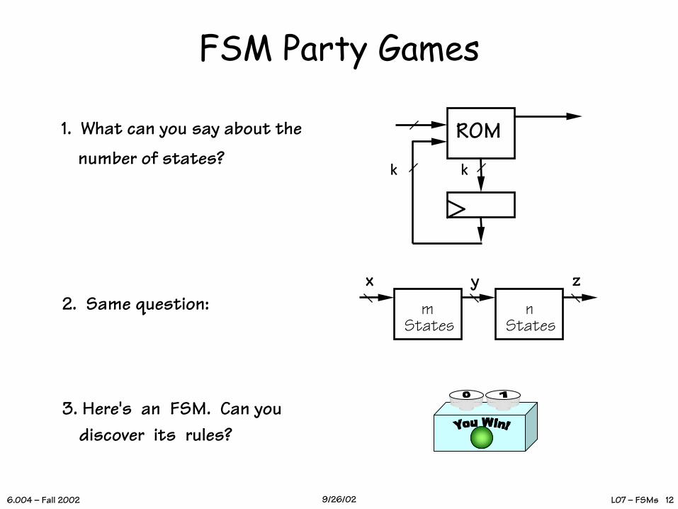
FSM Party Games
ROM
kk
1. What can you say about the
number of states?
2. Same question: m States
n States
x y z
3. Here's an FSM. Can you discover its rules?

L07 – FSMs 136.004 – Fall 2002 9/26/02
What’s My Transition Diagram?
1
0
1
01
01 1
0
1
0
1
00
vs.0=OFF,1=ON?
"1111" =Surprise!
• If you know NOTHING about the FSM, you’re never sure!
• If you have a BOUND on the number of states, you can discover its behavior:
K-state FSM: Every (reachable) state can bereached in < k steps.
BUT ... states may be equivalent!
1

L07 – FSMs 146.004 – Fall 2002 9/26/02
FSM Equivalence
101
01 0
1 1
0
1
0
1
00vs.
ARE THEY DIFFERENT?NOT in any practical sense! They are EXTERNALLY INDISTINGUISHABLE, hence interchangeable.
FSMs EQUIVALENT iff every input sequence yields identical output sequences.
ENGINEERING GOAL:• HAVE an FSM which works...• WANT simplest (ergo cheapest) equivalent FSM.
L07 – FSMs 156.004 – Fall 2002 9/26/02
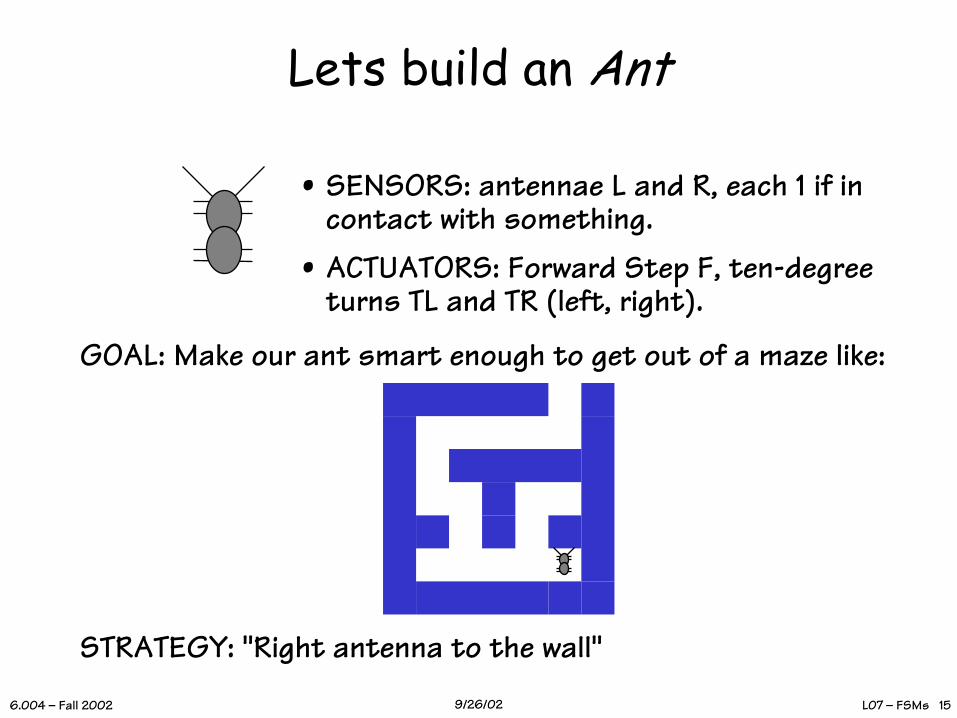
Lets build an Ant
• SENSORS: antennae L and R, each 1 if in contact with something.
• ACTUATORS: Forward Step F, ten-degree turns TL and TR (left, right).
GOAL: Make our ant smart enough to get out of a maze like:
STRATEGY: "Right antenna to the wall"
L07 – FSMs 166.004 – Fall 2002 9/26/02
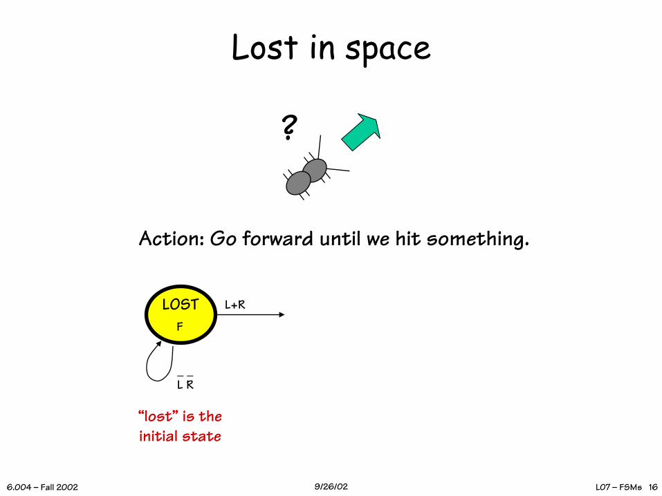
Lost in space
?
LOSTF
L+R
_ _L R
“lost” is theinitial state
Action: Go forward until we hit something.
L07 – FSMs 176.004 – Fall 2002 9/26/02
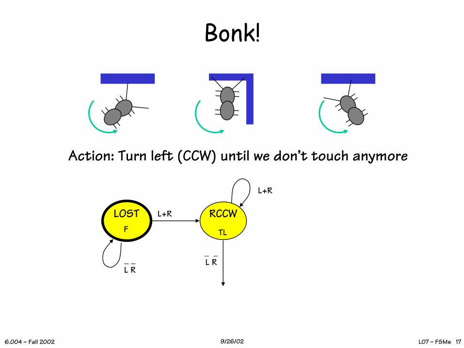
Bonk!
LOSTF
L+R
_ _L R
RCCW
L+R
TL
_ _L R
Action: Turn left (CCW) until we don’t touch anymore
L07 – FSMs 186.004 – Fall 2002 9/26/02
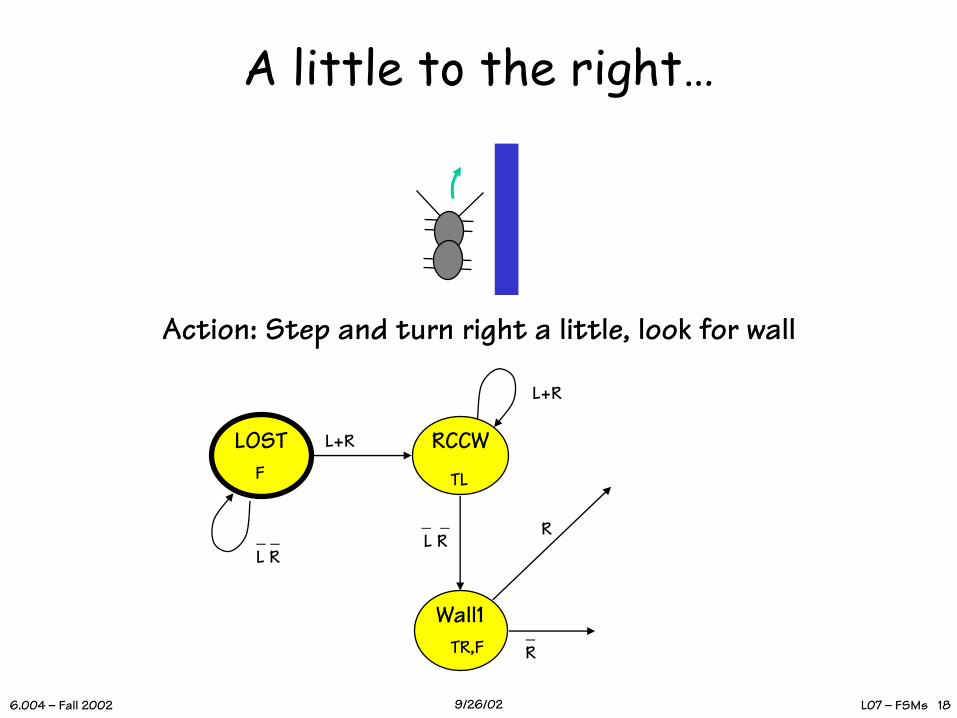
A little to the right…
LOSTF
RCCWL+R
L+R
Wall1TR,F
R
_R
TL
_ _L R
_ _L R
Action: Step and turn right a little, look for wall
L07 – FSMs 196.004 – Fall 2002 9/26/02
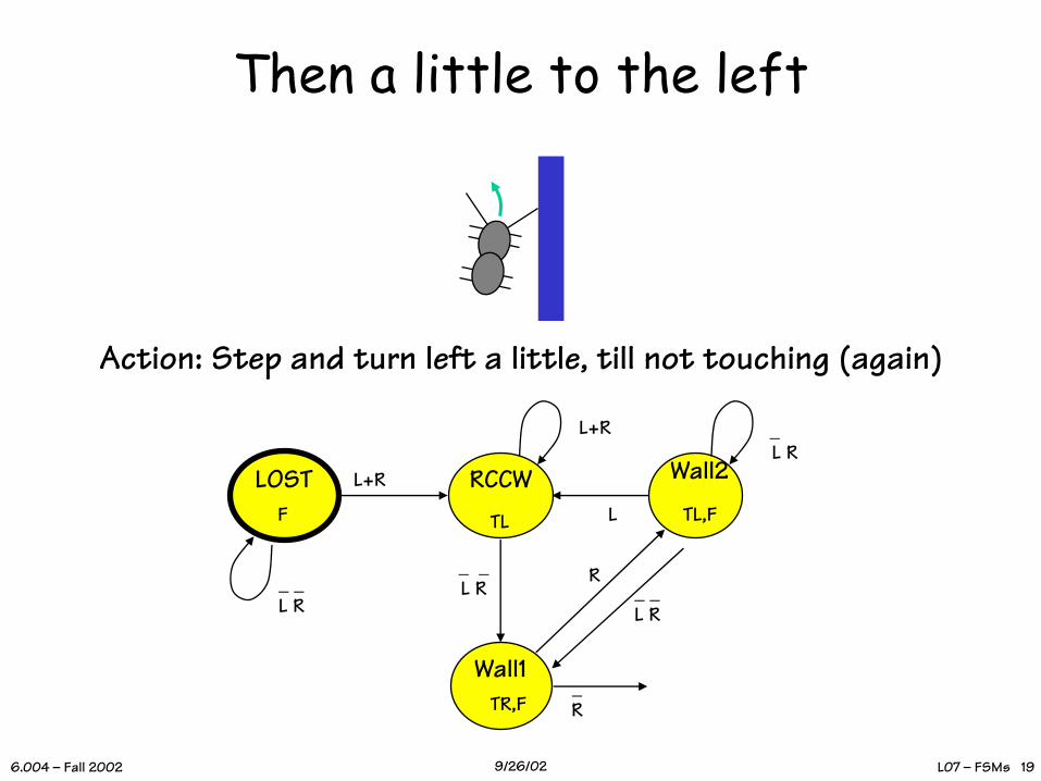
Then a little to the left
LOSTF
Wall1TR,F
RCCW
R
L+R
L+R
_R
TL
_ _L R
_ _L R _ _
L R
Wall2
TL,FL
_ L R
Action: Step and turn left a little, till not touching (again)
L07 – FSMs 206.004 – Fall 2002 9/26/02
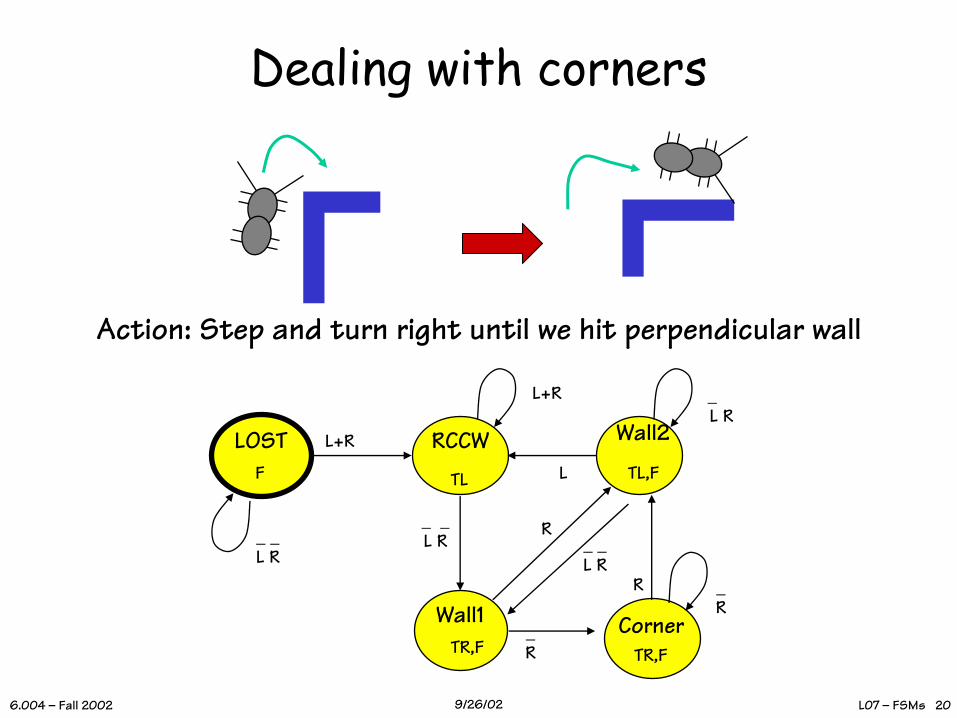
Dealing with corners
LOSTF
Wall2
TL,F
Wall1TR,F
RCCW
R
L+R
L+R
_R
LTL
_ _L R
_ _L R _ _
L R
_ L R
TR,FCorner
R _R
Action: Step and turn right until we hit perpendicular wall

L07 – FSMs 216.004 – Fall 2002 9/26/02
Equivalent State ReductionObservation: Si ≡ Sj if
1. States have identical outputs; AND2. Every input →equivalent states.
Reduction Strategy:Find pairs of equivalent states, MERGE them.
LOSTF
Wall2
TL,F
Wall1TR,F
RCCW
R
L+R
L+R
_R
LTL
_ _L R
_ _L R _ _
L R
_ L R
TR,F
CornerR _
R

L07 – FSMs 226.004 – Fall 2002 9/26/02
An Evolutionary Step
Behaves exactly as previous (5-state) FSM, but requires half the ROM in its implementation!
Merge equivalent states Wall1 and Corner into a single new, combined state.
LOSTF
Wall2
TL,F
Wall1TR,F
RCCW
R
L+R
L+R
_R
LTL
_ _L R
_ _L R _ _
L R
_ L R

L07 – FSMs 236.004 – Fall 2002 9/26/02
00 1 - 01 0 0 100 0 1 01 0 0 1
L+R RCCW
L+R
01 1 - | 01 0 1 001 0 1 | 01 0 1 0
TL
Building the Transition Table
S L R | S’ TR TL F-------+-----------00 0 0 | 00 0 0 1
| | | | || | |||
LOSTF
_ _L R
L07 – FSMs 246.004 – Fall 2002 9/26/02
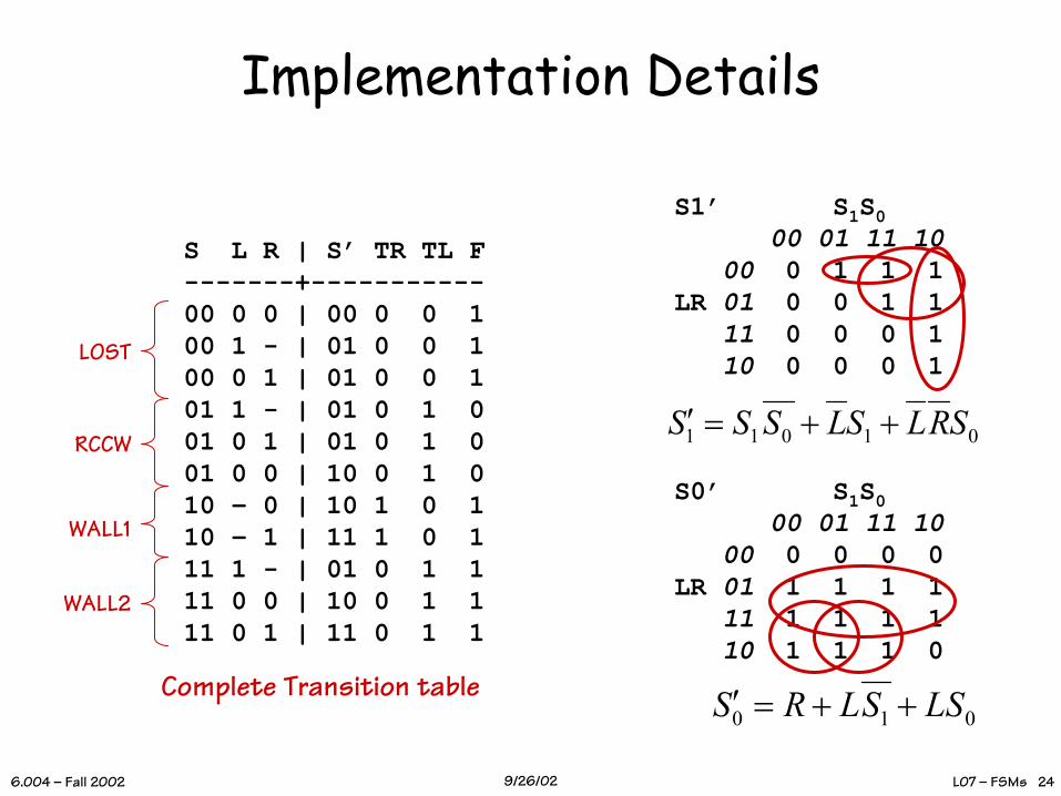
Implementation Details
S L R | S’ TR TL F-------+-----------00 0 0 | 00 0 0 100 1 - | 01 0 0 100 0 1 | 01 0 0 101 1 - | 01 0 1 001 0 1 | 01 0 1 001 0 0 | 10 0 1 010 – 0 | 10 1 0 110 – 1 | 11 1 0 111 1 - | 01 0 1 111 0 0 | 10 0 1 111 0 1 | 11 0 1 1
LOST
RCCW
WALL1
WALL2
S1’ S1S000 01 11 10
00 0 1 1 1LR 01 0 0 1 1
11 0 0 0 110 0 0 0 1
S0’ S1S000 01 11 10
00 0 0 0 0LR 01 1 1 1 1
11 1 1 1 110 1 1 1 0
01011 SRLSLSSS ++=′
Complete Transition table010 LSSLRS ++=′
L07 – FSMs 256.004 – Fall 2002 9/26/02
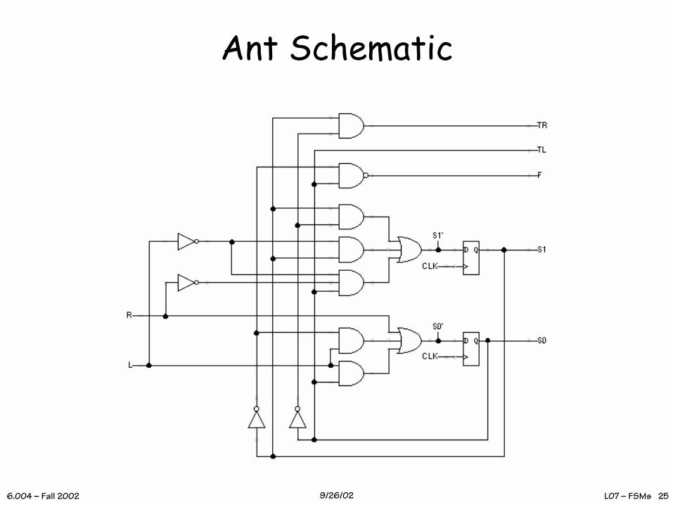
Ant Schematic

L07 – FSMs 266.004 – Fall 2002 9/26/02
Roboant®
Maze selectionFSM state
table
Status display
Plan viewof maze
Simulation controls
Featuring the new Mark-II ant: can add (M),erase (E), and sense (S) marks along its path.
L07 – FSMs 276.004 – Fall 2002 9/26/02
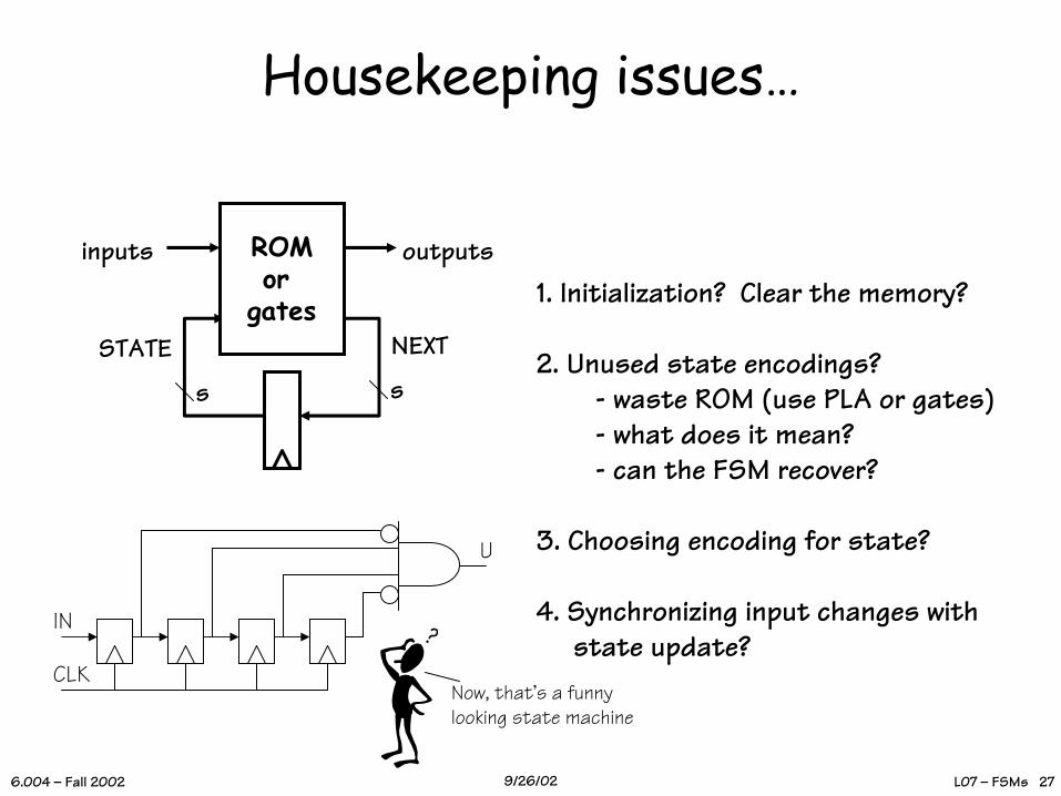
Housekeeping issues…
ROMor
gatesNEXTSTATE
inputs outputs
ss
1. Initialization? Clear the memory?
2. Unused state encodings?- waste ROM (use PLA or gates)- what does it mean?- can the FSM recover?
3. Choosing encoding for state?
4. Synchronizing input changes withstate update?
IN
CLK
U
Now, that’s a funny looking state machine

L07 – FSMs 286.004 – Fall 2002 9/26/02
Twisting you Further…• MORE THAN ANTS:
Swarming, flocking, and schooling can result from collections of very simple FSMs
• PERHAPS MOST PHYSICS: Cellular automata, arrays of simple FSMs, can more accurately model fluilds than numerical solutions to PDEs
• WHAT IF:We replaced the ROM with a RAM and have outputs that modify the RAM?
... You'll see FSMs for the rest of your life!(Every computer we have built so far is just
an FSM)
WARD &HALSTEAD
NERD KIT6.004
I transition therefore I am
Are we just big, hairy FSMs?