Embed Size (px)
Citation preview

Synchronization of Digital Signals --- 1
To understand the concepts and details of SONET correctly, it is important to be clear about the meaning of synchronous, asynchronous, and plesiochronous.
In a set of synchronous signals, the digital transitions in the signals occur at exactly the same rate. There may, however, be a phase difference between the transitions of the two signals, and this would lie within specified limits. These phase differences may be due to propagation time delays or jitter introduced into the transmission network. In a synchronous network, all the clocks are traceable to one primary reference clock (PRC). The accuracy of the PRC is better than ±1 in 1011 and is derived from a cesium atomic standard.
If two digital signals are plesiochronous, their transitions occur at almost the same rate, with any variation being constrained within tight limits. For example, if two networks must interwork, their clocks may be derived from two different PRCs. Although these clocks are extremely accurate, there is a difference between one clock and the other. This is known as a plesiochronous difference.
In a set of asynchronous signals, the transitions of the signals do not necessarily occur at the same nominal rate. Asynchronous, in this case, means that the difference between two clocks is much greater than a plesiochronous difference. For example, if two clocks are derived from free-running quartz oscillators, they could be described as asynchronous.
Introduction to Synchronization
Synchronous versus AsynchronousTraditionally, transmission systems have been asynchronous, with each terminal in the network running on its own recovered clock timing. In Digital transmission, “timing” is one of the most fundamental operations.Since these clocks are not synchronized, large variations can occur in the clock rate and thus the signal bit rate. For example, an E3 signal specified at 34 Mbit/s ±20 ppm (parts per million) can produce a timing difference of up to 1789 bit/s between one incoming E3 signal and another.
Asynchronous multiplexing uses multiple stages. Signals such as asynchronous E1s (2 Mbit/s) are multiplexed (bit-interleaving), extra bits are added (bit-stuffing) to account for the timing variations of each individual stream and are combined with other bits (framing bits) to form an E2 (8 Mbit/s) stream. Bit-interleaving and bit-stuffing is used again to multiplex up to E3 (34 Mbit/s). The E1s are neither visible nor accessible within an E3 frame.E3s are multiplexed up to higher rates in the same manner. At the higher Asynchronous rate, they cannot be accessed without demultiplexing. In a synchronous system, such as SDH, the average frequency of all clocks in the system is the same. Every slave clock can be traced back to a highly stable reference clock. Thus, the STM-1 rate remains at a
1

nominal 155.52 Mbit/s, allowing many synchronous STM-1 signals to be multiplexed without any bit-stuffing. Thus, the STM-1s are easily accessed at a higher STM-N rate.Low-speed synchronous virtual container (VC) signals are also simple to interleave and transport at higher rates. At low speeds, 2.048 Mbit/s E1 signals are transported within synchronous VC-12 signals which run at a constant rate of 2.304 Mbit/s. Single-step multiplexing up to STM-1 requires no bit-stuffing and VCs are easily accessed.A mechanism known as “pointers,” operating in conjunction with buffers, accommodates differences in the reference source frequencies and phase wander, and so prevents data loss during synchronization failures.
Synchronizations Hierarchy
Digital switches and digital cross-connect systems are commonly employed in the digital network synchronizations hierarchy. The network is organized with a master-slave relationship with clocks of the higher level nodes feeding timing signals to clocks of the lower-level nodes. All nodes can be traced up to a Primary Reference Clock (PRC).
Jitter
Jitter in technical terms is the deviation in or displacement of some aspect of the pulses in a high-frequency digital signal. As the name suggests, jitter can be thought of as shaky pulses. The deviation can be in terms of amplitude, phase timing, or the width of the signal pulse. Another definition is that it is "the period frequency displacement of the signal from its ideal location." Among the causes of jitter are electromagnetic interference (EMI) and crosstalk with other signals. Jitter can cause a display monitor to flicker; affect the ability of the processor in a personal computer to perform as intended; introduce clicks or other undesired effects in audio signals, and loss of transmitted data between network devices. The amount of allowable jitter depends greatly on the application.
Jitter is the time variation of a periodic signal in electronics and telecommunications, often in relation to a reference clock source. Jitter may be observed in characteristics such as the frequency of successive pulses, the signal amplitude, or phase of periodic signals. Jitter is a significant, and usually undesired, factor in the design of almost all communications links (e.g., USB, PCI-e, SATA, OC-48).
Jitter period is the interval between two times of maximum effect (or minimum effect) of a signal characteristic that varies regularly with time. Jitter frequency, the more commonly quoted figure, is its inverse. Generally, very low jitter frequency is not of interest in designing systems, and the low-frequency cutoff for jitter is typically specified at 1 Hz.
2
Types
[edit] Random jitter
Random Jitter, also called Gaussian jitter, is unpredictable electronic timing noise
Deterministic jitter
Deterministic jitter is a type of clock timing jitter or data signal jitter that is predictable and reproducible. The peak-to-peak value of this jitter is bounded, and the bounds can easily be observed and predicted.
Total jitter
Total jitter (T) is the combination of random jitter (R) and deterministic jitter (D):
T = Dpeak-to-peak + 2× n×Rrms,
in which the value of n is based on the bit error rate (BER) required of the link.
A common bit error rate used in communication standards such as Ethernet is 10−12.
Dejitterizer
A dejitterizer is a device that reduces jitter in a digital signal. A dejitterizer usually consists of an elastic buffer in which the signal is temporarily stored and then retransmitted at a rate based on the average rate of the incoming signal. A dejitterizer is usually ineffective in dealing with low-frequency jitter, such as waiting-time jitter.
Buffer:
In computing, a buffer is a region of memory used to temporarily hold data while it is being moved from one place to another. Typically, the data is stored in a buffer as it is retrieved from an input device (such as a keyboard) or just before it is sent to an output device (such as a printer)
Telecommunication buffer
A buffer routine or storage medium used in telecommunications compensates for a difference in rate of flow of data, or time of occurrence of events, when transferring data from one device to another.
Buffers are used for many purposes, such as
interconnecting two digital circuits operating at different rates, holding data for use at a later time,
3

allowing timing corrections to be made on a data stream, collecting binary data bits into groups that can then be operated on as a unit, Delaying the transit time of a signal in order to allow other operations to occur.
Wander
In telecommunication, wander are long-term low-frequency random variations of the significant instants of a digital signal from their ideal positions. Phase variations with frequency content above 10 Hertz are considered jitter, while those with a frequency below 10 Hz are referred to as wander.[1] Wander variations are those that occur over a period greater than 1 s (second).
Introduction
The Transmission System is traditionally seen as the link between main WAN switching centers. These Transmission Systems consist of large bandwidth highways that form the backbone to the network. They typically serve many customers each with their own requirements so the systems have to be reliable, resilient and flexible.
Rather than have two wires for every voice or data conversation, Time Division Multiplexing is used. ITU-T G.704 defines 32 channels of 64Kb/s to form 2.048Mb/s where channel 0 is used for framing. You will often see the standard G.703 mentioned with G.704, this is because G.703 defines the unframed physical interface coaxial (75 ohm) or RJ48 (120 ohm) used for the E1/T1 connection at the client premises. Channel 0 is for timing used to synchronize the multiplexers at each end of the link. Channels 1 to 15 and 17 to 31 are for voice or data whilst channel 16 is used for Common Channel Signaling (CCS) or Channel Associated Signaling (CAS). Every 3.91 microseconds 8 bits from one channel is sent down the line followed by 8 bits from the next channel during the next 3.91 microseconds and so on in a round robin fashion throughout all the channels, thus 32 channels are used once every 125 microseconds. The connection at the end is either a 75 ohm coax, 120 ohm coax or a 150 ohm UTP/STP.
Plesiochronous Digital Hierarchy (PDH)
As bandwidth demand grew the technology called Plesiochronous Digital Hierarchy PDH) was developed by ITU-T G.702, whereby the basic primary multiplexer 2.048Mb/s trunks were joined together by adding bits (bit stuffing) which synchronized the trunks at each level of the PDH. 2.048Mb/s was called E1 and the hierarchy is based on multiples of 4 E1s.
E2, 4 x E1 - 8Mb/s E3, 4 x E2 - 34Mb/s
4

E4, 4 x E3 - 140Mb/s E5, 4 x E4 - 565Mb/s
The E3 tributaries are faster than the E2 tributaries; E2 tributaries are faster than the E1 tributaries and so on. These needs to be synchronized with other tributaries, so extra bits are added called Justification bits. These tell the multiplexers which bits are data and which are spare. Multiplexers on the same level of the hierarchy remove the spare bits and are synchronized with each other at that level only. Multiplexers on one level operate on a different timing from multiplexers on another level. For instance, the timing between Primary Rate Muxes (combines 30 x 64Kb/s channels into 2.048Mb/s E1) will be different from the timing between 8Mbit muxes (combines up to 4 x 2Mb/s into 8Mb/s).
Inserting and dropping out traffic from different customers can only happen at the level at which the customer is receiving the traffic. This means that if a 140Mb/s fiber is near a particular site and a new customer requires a 2Mb/s link, then a whole set of demultiplexers are required to do this.
Plesiochronous Digital Hierarchy (PDH)Traditionally, digital transmission systems and hierarchies have been based on multiplexing signals which are plesiochronous (running at almost the same speed). Also, various parts of the world use different hierarchies which lead to problems of international interworking; for example, between those countries using 1.544 Mbit/s systems (U.S.A. and Japan) and those using the 2.048 Mbit/s systems.
5

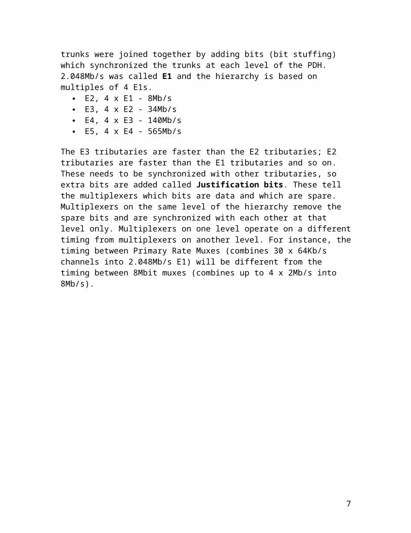
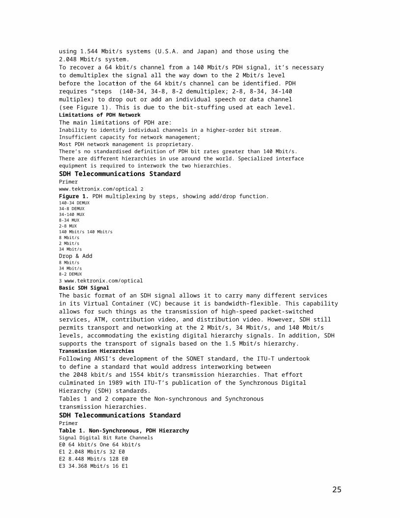
To recover a 64 Kbit/s channel from a 140 Mbit/s PDH signal, it’s necessary to demultiplex the signal all the way down to the 2 Mbit/s level before the location of the 64 Kbit/s channel can be identified. PDH requires “steps” (140-34, 34-8, 8-2 demultiplex; 2-8, 8-34, 34-140 multiplex) to drop out or add an individual speech or data channel (see Figure 1). This is due to the bit-stuffing used at each level.
Limitations of PDH Network:
The main limitations of PDH are:Inability to identify individual channels in a higher-order bit stream.Insufficient capacity for network management;Most PDH network management is proprietary.There’s no standardized definition of PDH bit rates greater than 140 Mbit/s.There are different hierarchies in use around the world. Specialized interface equipment is required to interwork the two hierarchies.
Plesiochronous Transmission.
Digital data and voice transmission is based on a 2.048Mbit/s bearer consisting of 30 time division multiplexed (TDM) voice channels, each running at 64Kbps (known as E1 and described by the CCITT G.703 specification). At the E1 level, timing is controlled to an accuracy of 1 in 1011 by synchronizing to a master Cesium clock. Increasing traffic over the past decade has demanded that more and more of these basic E1 bearers be multiplexed together to provide increased capacity. During this time rates have increased through 8, 34, and 140Mbit/s. The highest capacity
6
commonly encountered today for inter-city fiber optic links is 565Mbit/s, with each link carrying 7,680 base channels, and now even this is insufficient.
Unlike E1 2.048Mbit/s bearers, higher rate bearers in the hierarchy are operated plesiochronously, with tolerances on an absolute bit-rate ranging from 30ppm (parts per million) at 8Mbit/s to 15ppm at 140Mbit/s. Multiplexing such bearers (known as tributaries in SDH speak) to a higher aggregate rate (e.g. 4 x 8Mbit/s to 1 x 34Mbit/s) requires the padding of each tributary by adding bits such that their combined rate together with the addition of control bits matches the final aggregate rate. Plesiochronous transmission is now often referred to as plesiochronous digital hierarchy (PDH).
Transmission Hierarchies
Following ANSI’s development of the SONET standard, the ITU-T undertook to define a standard that would address interworking between the 2048 Kbit/s and 1554 Kbit/s transmission hierarchies. That effortculminated in 1989 with ITU-T’s publication of the Synchronous Digital Hierarchy (SDH) standards.
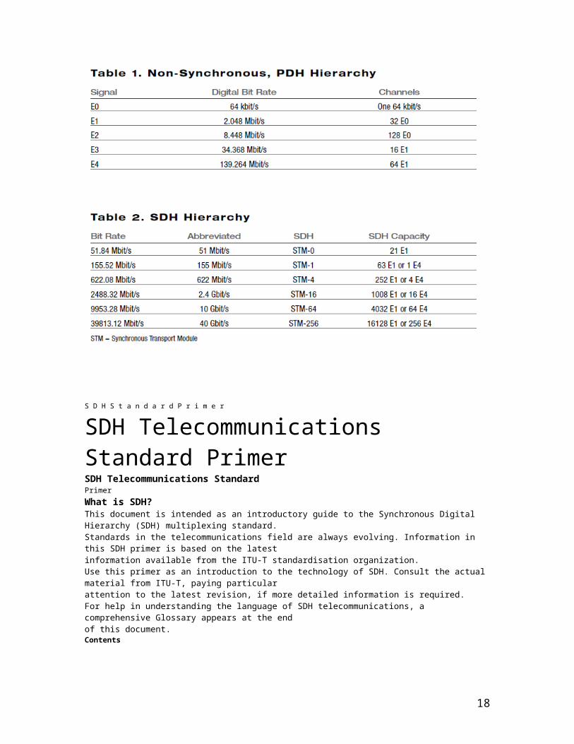
Tables 1 and 2 compare the Non-synchronous and Synchronous transmission hierarchies.
7

Synchronous Digital Hierarchy (SDH)
Management is very inflexible in PDH, so SDH was developed. Synchronous Digital Hierarchy (SDH) originates from Synchronous Optical Network (SONET) in the US. It includes capabilities for bandwidth on demand and is also made up of multiples of E1. STM-1 (155Mb/s) is 63 x E1, STM-4 (622Mb/s) is 4 x STM-1 and STM-16 (2.5 GB/s) is 4 x STM-4.
The benefits of SDH are: Different interfaces or different bandwidths can connect (G708, G781). Network topologies are more flexible. There is flexibility for growth. The optical interface is standard (G957). Network Management is easier to perform (G774 and G784).
Existing PDH can interface into SDH. There are three G transmission series recommendations that are very important:
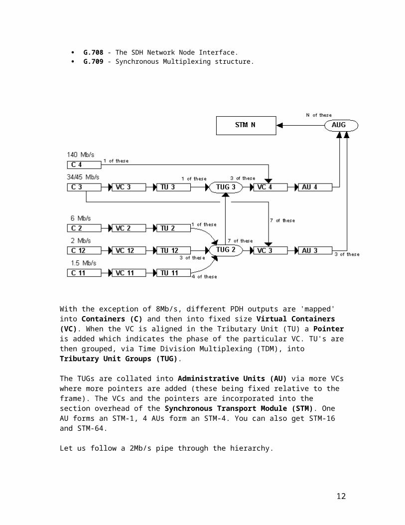
G.707 - SDH Bit Rates G.708 - The SDH Network Node Interface. G.709 - Synchronous Multiplexing structure.
With the exception of 8Mb/s, different PDH outputs are 'mapped' into Containers (C) and then into fixed size Virtual Containers (VC). When the VC is aligned in the Tributary Unit (TU) a Pointer is added which indicates the phase of the particular VC. TU's are then grouped, via Time Division Multiplexing (TDM), into Tributary Unit Groups (TUG).
8
The TUGs are collated into Administrative Units (AU) via more VCs where more pointers are added (these being fixed relative to the frame). The VCs and the pointers are incorporated into the section overhead of the Synchronous Transport Module (STM). One AU forms an STM-1, 4 AUs form an STM-4. You can also get STM-16 and STM-64.
Let us follow a 2Mb/s pipe through the hierarchy.
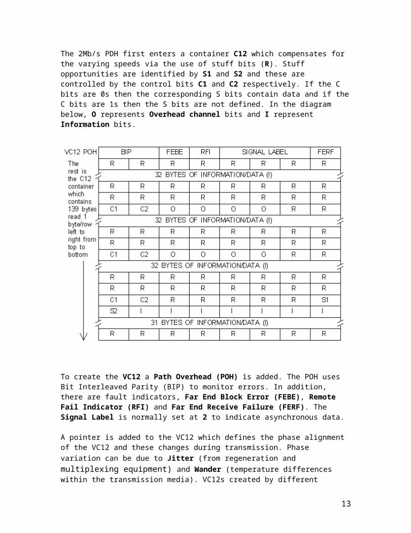
The 2Mb/s PDH first enters a container C12 which compensates for the varying speeds via the use of stuff bits (R). Stuff opportunities are identified by S1 and S2 and these are controlled by the control bits C1 and C2 respectively. If the C bits are 0s then the corresponding S bits contain data and if the C bits are 1s then the S bits are not defined. In the diagram below, O represents Overhead channel bits and I represent Information bits.
To create the VC12 a Path Overhead (POH) is added. The POH uses Bit Interleaved Parity (BIP) to monitor errors. In addition, there are fault indicators, Far End Block Error (FEBE), Remote Fail Indicator (RFI) and Far End Receive Failure (FERF). The Signal Label is normally set at 2 to indicate asynchronous data.
A pointer is added to the VC12 which defines the phase alignment of the VC12 and these changes during transmission. Phase variation can be due to Jitter (from regeneration and multiplexing equipment) and Wander (temperature differences within the transmission media). VC12s created by different multiplexers may not be synchronous so the TU adds a pointer at a fixed
9

position within the TU. The value of the pointer indicates the start of the VC12. If the phase of the VC12 changes then the value of the pointer changes such that if data is running faster than the TU then the pointer value is increased and if the data speed is slower then the pointer value is decreased. This difference in speed can be up to one byte per frame in SDH.
The following diagram illustrates three TU12s entering a TUG2 at three different times with the VC12 pointers indicating where the POH is for each:
The TU12 is multiplexed into a TUG 2 along with 2 other TU12s. This is achieved by interleaving the bytes of each TU12 in turn. Next, seven TUG 2s are byte interleaved into a TUG 3 and then three TUG 3s can be byte interleaved to form the VC4 (see the SDH diagram above). You can see that 3 x 7 x 3 = 63 2Mb/s circuits can be contained in VC 4.
Synchronizing SDH
The internal clock of an SDH terminal may derive its timing signal from a Synchronization Supply Unit (SSU) used by switching systems and other equipment. Thus, this terminal can serve as a master for otherSDH nodes, providing timing on its outgoing STM-N signal. Other SDH nodes will operate in a slave mode with their internal clocks timed by the incoming STM-N signal. Present standards specify that an SDHnetwork must ultimately be able to derive its timing from a PRC.
Introduction to SDH
10

SDH (Synchronous Digital Hierarchy) is a standard for telecommunications transport formulated by the International Telecommunication Union (ITU), previously called the International Telegraph and Telephone Consultative Committee (CCITT). SDH was first introduced into the telecommunications network in 1992.
11
12
13

S D H S t a n d a r d P r i m e r
SDH TelecommunicationsStandard PrimerSDH Telecommunications StandardPrimerWhat is SDH?This document is intended as an introductory guide to the Synchronous Digital Hierarchy (SDH) multiplexing standard.Standards in the telecommunications field are always evolving. Information in this SDH primer is based on the latestinformation available from the ITU-T standardisation organization.Use this primer as an introduction to the technology of SDH. Consult the actual material from ITU-T, paying particularattention to the latest revision, if more detailed information is required.For help in understanding the language of SDH telecommunications, a comprehensive Glossary appears at the endof this document.ContentsWhat is SDH? . . . . . . . . . . . . . . . . . . . . . . . . . . . . . . . . . . . . . . . . . . . . . . . . . . . . . . . . . . . . . . . . . . . . . . . . iIntroduction To SDH . . . . . . . . . . . . . . . . . . . . . . . . . . . . . . . . . . . . . . . . . . . . . . . . . . . . . . . . . . . . . . . . . . . 1Background . . . . . . . . . . . . . . . . . . . . . . . . . . . . . . . . . . . . . . . . . . . . . . . . . . . . . . . . . . . . . . . . . . . . . . . . . . . . . . . . . . . 1
14
Synchronisation of Digital Signals . . . . . . . . . . . . . . . . . . . . . . . . . . . . . . . . . . . . . . . . . . . . . . . . . . . . . . . . . . . . . . . . . . . . 1SDH Advantages . . . . . . . . . . . . . . . . . . . . . . . . . . . . . . . . . . . . . . . . . . . . . . . . . . . . . . . . . . . . . . . . . . . . . . . . . . . . . . . . 2Plesiochronous Digital Hierarchy (PDH) . . . . . . . . . . . . . . . . . . . . . . . . . . . . . . . . . . . . . . . . . . . . . . . . . . . . . . . . . . . . . . . . 2Limitations of PDH Network . . . . . . . . . . . . . . . . . . . . . . . . . . . . . . . . . . . . . . . . . . . . . . . . . . . . . . . . . . . . . . . . . . . . . . . . 2Basic SDH Signal . . . . . . . . . . . . . . . . . . . . . . . . . . . . . . . . . . . . . . . . . . . . . . . . . . . . . . . . . . . . . . . . . . . . . . . . . . . . . . . 3Transmission Hierarchies . . . . . . . . . . . . . . . . . . . . . . . . . . . . . . . . . . . . . . . . . . . . . . . . . . . . . . . . . . . . . . . . . . . . . . . . . . 3Introduction to Synchronisation . . . . . . . . . . . . . . . . . . . . . . . . . . . . . . . . . . . . . . . . . . . . . . . . . . . . . . . . . . . 4Synchronous versus Asynchronous . . . . . . . . . . . . . . . . . . . . . . . . . . . . . . . . . . . . . . . . . . . . . . . . . . . . . . . . . . . . . . . . . . . 4Synchronisation Hierarchy . . . . . . . . . . . . . . . . . . . . . . . . . . . . . . . . . . . . . . . . . . . . . . . . . . . . . . . . . . . . . . . . . . . . . . . . . 4Synchronising SDH . . . . . . . . . . . . . . . . . . . . . . . . . . . . . . . . . . . . . . . . . . . . . . . . . . . . . . . . . . . . . . . . . . . . . . . . . . . . . . 4Evolution of Timing and Synchronisation . . . . . . . . . . . . . . . . . . . . . . . . . . . . . . . . . . . . . . . . . . . . . . . . . . . . . . . . . . . . . . . . 4SDH Frame Structure . . . . . . . . . . . . . . . . . . . . . . . . . . . . . . . . . . . . . . . . . . . . . . . . . . . . . . . . . . . . . . . . . . 5Virtual Container . . . . . . . . . . . . . . . . . . . . . . . . . . . . . . . . . . . . . . . . . . . . . . . . . . . . . . . . . . . . . . . . . . . . . . . . . . . . . . . 5SDH Overhead . . . . . . . . . . . . . . . . . . . . . . . . . . . . . . . . . . . . . . . . . . . . . . . . . . . . . . . . . . . . . . . . . . . . . . . 7Regenerator Section Overhead . . . . . . . . . . . . . . . . . . . . . . . . . . . . . . . . . . . . . . . . . . . . . . . . . . . . . . . . . . . . . . . . . . . . . . 7Multiplex Section Overhead . . . . . . . . . . . . . . . . . . . . . . . . . . . . . . . . . . . . . . . . . . . . . . . . . . . . . . . . . . . . . . . . . . . . . . . . 8Higher-Order Path Overhead (VC-4/VC-3) . . . . . . . . . . . . . . . . . . . . . . . . . . . . . . . . . . . . . . . . . . . . . . . . . . . . . . . . . . . . . . . 10Lower-Order Path Overhead (VC-2/VC-1) . . . . . . . . . . . . . . . . . . . . . . . . . . . . . . . . . . . . . . . . . . . . . . . . . . . . . . . . . . . . . . . 13SDH Anomalies, Defects, Failures, and Alarms . . . . . . . . . . . . . . . . . . . . . . . . . . . . . . . . . . . . . . . . . . . . . . . . 15Definitions . . . . . . . . . . . . . . . . . . . . . . . . . . . . . . . . . . . . . . . . . . . . . . . . . . . . . . . . . . . . . . . . . . . . . . . . . . . . . . . . . . . . 15SDH Error Performance Monitoring . . . . . . . . . . . . . . . . . . . . . . . . . . . . . . . . . . . . . . . . . . . . . . . . . . . . . . . . . . . . . . . . . . . 15SDH Pointers . . . . . . . . . . . . . . . . . . . . . . . . . . . . . . . . . . . . . . . . . . . . . . . . . . . . . . . . . . . . . . . . . . . . . . . . 17Payload Pointers . . . . . . . . . . . . . . . . . . . . . . . . . . . . . . . . . . . . . . . . . . . . . . . . . . . . . . . . . . . . . . . . . . . . . . . . . . . . . . . 17Positive Pointer Justification . . . . . . . . . . . . . . . . . . . . . . . . . . . . . . . . . . . . . . . . . . . . . . . . . . . . . . . . . . . . . . . . . . . . . . . . 17Negative Pointer Justification . . . . . . . . . . . . . . . . . . . . . . . . . . . . . . . . . . . . . . . . . . . . . . . . . . . . . . . . . . . . . . . . . . . . . . . 18
15

SDH Multiplexing . . . . . . . . . . . . . . . . . . . . . . . . . . . . . . . . . . . . . . . . . . . . . . . . . . . . . . . . . . . . . . . . . . . . . 19SDH Tributary Multiplexing . . . . . . . . . . . . . . . . . . . . . . . . . . . . . . . . . . . . . . . . . . . . . . . . . . . . . . . . . . . . . . 21Tributary Unit Group . . . . . . . . . . . . . . . . . . . . . . . . . . . . . . . . . . . . . . . . . . . . . . . . . . . . . . . . . . . . . . . . . . . . . . . . . . . . . 21TU Multiframe . . . . . . . . . . . . . . . . . . . . . . . . . . . . . . . . . . . . . . . . . . . . . . . . . . . . . . . . . . . . . . . . . . . . . . . . . . . . . . . . . 21SDH Telecommunications StandardPrimerSDH Telecommunications StandardPrimerTU Payload Pointer . . . . . . . . . . . . . . . . . . . . . . . . . . . . . . . . . . . . . . . . . . . . . . . . . . . . . . . . . . . . . . . . . . . . . . . . . . . . . . 22Automatic Protection Switching . . . . . . . . . . . . . . . . . . . . . . . . . . . . . . . . . . . . . . . . . . . . . . . . . . . . . . . . . . 23Multiplex Section Protection, K1/K2 Bytes . . . . . . . . . . . . . . . . . . . . . . . . . . . . . . . . . . . . . . . . . . . . . . . . . . . . . . . . . . . . . . 231+1 Protection . . . . . . . . . . . . . . . . . . . . . . . . . . . . . . . . . . . . . . . . . . . . . . . . . . . . . . . . . . . . . . . . . . . . . . . . . . . . . . . . 231:N Protection . . . . . . . . . . . . . . . . . . . . . . . . . . . . . . . . . . . . . . . . . . . . . . . . . . . . . . . . . . . . . . . . . . . . . . . . . . . . . . . . . 24SDH Network Elements . . . . . . . . . . . . . . . . . . . . . . . . . . . . . . . . . . . . . . . . . . . . . . . . . . . . . . . . . . . . . . . . . 25Terminal Multiplexer . . . . . . . . . . . . . . . . . . . . . . . . . . . . . . . . . . . . . . . . . . . . . . . . . . . . . . . . . . . . . . . . . . . . . . . . . . . . . 25Regenerator . . . . . . . . . . . . . . . . . . . . . . . . . . . . . . . . . . . . . . . . . . . . . . . . . . . . . . . . . . . . . . . . . . . . . . . . . . . . . . . . . . . 25Add/Drop Multiplexer . . . . . . . . . . . . . . . . . . . . . . . . . . . . . . . . . . . . . . . . . . . . . . . . . . . . . . . . . . . . . . . . . . . . . . . . . . . . 25Wideband Digital Cross-connect . . . . . . . . . . . . . . . . . . . . . . . . . . . . . . . . . . . . . . . . . . . . . . . . . . . . . . . . . . . . . . . . . . . . . 26Broadband Digital Cross-connect . . . . . . . . . . . . . . . . . . . . . . . . . . . . . . . . . . . . . . . . . . . . . . . . . . . . . . . . . . . . . . . . . . . . 26Flexible Multiplexer . . . . . . . . . . . . . . . . . . . . . . . . . . . . . . . . . . . . . . . . . . . . . . . . . . . . . . . . . . . . . . . . . . . . . . . . . . . . . . 27SDH Network Configurations . . . . . . . . . . . . . . . . . . . . . . . . . . . . . . . . . . . . . . . . . . . . . . . . . . . . . . . . . . . . . 27Point-to-Point . . . . . . . . . . . . . . . . . . . . . . . . . . . . . . . . . . . . . . . . . . . . . . . . . . . . . . . . . . . . . . . . . . . . . . . . . . . . . . . . . 27Point-to-Multipoint . . . . . . . . . . . . . . . . . . . . . . . . . . . . . . . . . . . . . . . . . . . . . . . . . . . . . . . . . . . . . . . . . . . . . . . . . . . . . . 27Mesh Architecture . . . . . . . . . . . . . . . . . . . . . . . . . . . . . . . . . . . . . . . . . . . . . . . . . . . . . . . . . . . . . . . . . . . . . . . . . . . . . . 28Ring Architecture . . . . . . . . . . . . . . . . . . . . . . . . . . . . . . . . . . . . . . . . . . . . . . . . . . . . . . . . . . . . . . . . . . . . . . . . . . . . . . . 28Benefits of SDH – Conclusions . . . . . . . . . . . . . . . . . . . . . . . . . . . . . . . . . . . . . . . . . . . . . . . . . . . . . . . . . . . 29
16

Pointers, MUX/DEMUX . . . . . . . . . . . . . . . . . . . . . . . . . . . . . . . . . . . . . . . . . . . . . . . . . . . . . . . . . . . . . . . . . . . . . . . . . . . . 29Reduced Back-to-Back Multiplexing . . . . . . . . . . . . . . . . . . . . . . . . . . . . . . . . . . . . . . . . . . . . . . . . . . . . . . . . . . . . . . . . . . 29Optical Interconnect . . . . . . . . . . . . . . . . . . . . . . . . . . . . . . . . . . . . . . . . . . . . . . . . . . . . . . . . . . . . . . . . . . . . . . . . . . . . . 29Multi-point Configurations . . . . . . . . . . . . . . . . . . . . . . . . . . . . . . . . . . . . . . . . . . . . . . . . . . . . . . . . . . . . . . . . . . . . . . . . . 29Grooming . . . . . . . . . . . . . . . . . . . . . . . . . . . . . . . . . . . . . . . . . . . . . . . . . . . . . . . . . . . . . . . . . . . . . . . . . . . . . . . . . . . . 29Enhanced OAM . . . . . . . . . . . . . . . . . . . . . . . . . . . . . . . . . . . . . . . . . . . . . . . . . . . . . . . . . . . . . . . . . . . . . . . . . . . . . . . . 29Enhanced Performance Monitoring . . . . . . . . . . . . . . . . . . . . . . . . . . . . . . . . . . . . . . . . . . . . . . . . . . . . . . . . . . . . . . . . . . . 30Convergence, ATM, Video, and SDH . . . . . . . . . . . . . . . . . . . . . . . . . . . . . . . . . . . . . . . . . . . . . . . . . . . . . . . . . . . . . . . . . . . 30SONET Reference . . . . . . . . . . . . . . . . . . . . . . . . . . . . . . . . . . . . . . . . . . . . . . . . . . . . . . . . . . . . . . . . . . . . . 31SONET and SDH Hierarchies . . . . . . . . . . . . . . . . . . . . . . . . . . . . . . . . . . . . . . . . . . . . . . . . . . . . . . . . . . . . . . . . . . . . . . . 31Further Information . . . . . . . . . . . . . . . . . . . . . . . . . . . . . . . . . . . . . . . . . . . . . . . . . . . . . . . . . . . . . . . . . . . . . . . . . . . . . . 31Glossary . . . . . . . . . . . . . . . . . . . . . . . . . . . . . . . . . . . . . . . . . . . . . . . . . . . . . . . . . . . . . . . . . . . . . . . . . . . 32SDH Reference Materials . . . . . . . . . . . . . . . . . . . . . . . . . . . . . . . . . . . . . . . . . . . . . . . . . . . . . . . . . . . . . . . 37ITU-T: . . . . . . . . . . . . . . . . . . . . . . . . . . . . . . . . . . . . . . . . . . . . . . . . . . . . . . . . . . . . . . . . . . . . . . . . . . . . . . . . . . . . . . . 37www.tektronix.com/optical iii1 www.tektronix.com/opticalSDH Telecommunications StandardPrimerIntroduction To SDHSDH (Synchronous Digital Hierarchy) is a standard for telecommunicationstransport formulated by the International Telecommunication Union(ITU), previously called the International Telegraph and TelephoneConsultative Committee (CCITT).SDH was first introduced into the telecommunications network in 1992and has been deployed at rapid rates since then. It’s deployed at alllevels of the network infrastructure, including the access network andthe long-distance trunk network. It’s based on overlaying a synchronousmultiplexed signal onto a light stream transmitted over fibre-optic cable.SDH is also defined for use on radio relay links, satellite links, and atelectrical interfaces between equipment.The comprehensive SDH standard is expected to provide the transportinfrastructure for worldwide telecommunications for at least the next twoor three decades.The increased configuration flexibility and bandwidth availability of SDHprovides significant advantages over the older telecommunications system.These advantages include:A reduction in the amount of equipment and an increase in network reliability.The provision of overhead and payload bytes – the overhead bytes permittingmanagement of the payload bytes on an individual basis and facilitating centralisedfault sectionalisation.The definition of a synchronous multiplexing format for carrying lower-leveldigital signals (such as 2 Mbit/s, 34 Mbit/s, 140 Mbit/s) which greatly simplifiesthe interface to digital switches, digital cross-connects, and add-dropmultiplexers.
17
The availability of a set of generic standards, which enable multi-vendorinteroperability.The definition of a flexible architecture capable of accommodating futureapplications, with a variety of transmission rates.In brief, SDH defines synchronous transport modules (STMs) for thefibre-optic based transmission hierarchy.BackgroundBefore SDH, the first generations of fibre-optic systems in the publictelephone network used proprietary architectures, equipment line codes,multiplexing formats, and maintenance procedures. The users of thisequipment wanted standards so they could mix and match equipmentfrom different suppliers.The task of creating such a standard was taken up in 1984 by theExchange Carriers Standards Association (ECSA) in the U.S. to establisha standard for connecting one fibre system to another. In the late stagesof the development, the CCITT became involved so that a single internationalstandard might be developed for fibre interconnect between telephonenetworks of different countries. The resulting international standardis known as Synchronous Digital Hierarchy (SDH).Synchronisation of Digital SignalsTo correctly understand the concepts and details of SDH, it’s importantto be clear about the meaning of Synchronous, Plesiochronous, andAsynchronous.In a set of Synchronous signals, the digital transitions in the signalsoccur at exactly the same rate. There may however be a phase differencebetween the transitions of the two signals, and this would lie withinspecified limits. These phase differences may be due to propagationtime delays, or low-frequency wander introduced in the transmissionnetwork. In a synchronous network, all the clocks are traceable to oneStratum 1 Primary Reference Clock (PRC). The accuracy of the PRC isbetter than ±1 in 1011 and is derived from a cesium atomic standard.If two digital signals are Plesiochronous, their transitions occur at“almost” the same rate, with any variation being constrained within tightlimits. These limits are set down in ITU-T recommendation G.811. Forexample, if two networks need to interwork, their clocks may be derivedfrom two different PRCs. Although these clocks are extremely accurate,there’s a small frequency difference between one clock and the other.This is known as a plesiochronous difference.In the case of Asynchronous signals, the transitions of the signals don’t necessarilyoccur at the same nominal rate. Asynchronous, in this case, meansthat the difference between two clocks is much greater than a plesiochronousdifference. For example, if two clocks are derived from free-running quartzoscillators, they could be described as asynchronous.SDH AdvantagesThe primary reason for the creation of SDH was to provide a long-termsolution for an optical mid-span meet between operators; that is, toallow equipment from different vendors to communicate with each other.This ability is referred to as multi-vendor interworking and allows oneSDH-compatible network element to communicate with another, and toreplace several network elements, which may have previously existedsolely for interface purposes.The second major advantage of SDH is the fact that it’s synchronous.Currently, most fibre and multiplex systems are plesiochronous. Thismeans that the timing may vary from equipment to equipment becausethey are synchronised from different network clocks. In order to multiplexthis type of signal, a process known as bit-stuffing is used. Bit-stuffingadds extra bits to bring all input signals up to some common bit-rate,thereby requiring multi-stage multiplexing and demultiplexing. BecauseSDH is synchronous, it allows single-stage multiplexing and demultiplexing.This single-stage multiplexing eliminates hardware complexity, thusdecreasing the cost of equipment while improving signal quality.In plesiochronous networks, an entire signal had to be demultiplexed in
18
order to access a particular channel; then the non-accessed channels hadto be re-multiplexed back together in order to be sent further along thenetwork to their proper destination. In SDH format, only those channelsthat are required at a particular point are demultiplexed, thereby eliminatingthe need for back-to-back multiplexing. In other words, SDH makesindividual channels “visible” and they can easily be added and dropped.Plesiochronous Digital Hierarchy (PDH)Traditionally, digital transmission systems and hierarchies have been basedon multiplexing signals which are plesiochronous (running at almost the samespeed). Also, various parts of the world use different hierarchies which lead toproblems of international interworking; for example, between those countriesusing 1.544 Mbit/s systems (U.S.A. and Japan) and those using the2.048 Mbit/s system.To recover a 64 kbit/s channel from a 140 Mbit/s PDH signal, it’s necessaryto demultiplex the signal all the way down to the 2 Mbit/s levelbefore the location of the 64 kbit/s channel can be identified. PDHrequires “steps” (140-34, 34-8, 8-2 demultiplex; 2-8, 8-34, 34-140multiplex) to drop out or add an individual speech or data channel(see Figure 1). This is due to the bit-stuffing used at each level.Limitations of PDH NetworkThe main limitations of PDH are:Inability to identify individual channels in a higher-order bit stream.Insufficient capacity for network management;Most PDH network management is proprietary.There’s no standardised definition of PDH bit rates greater than 140 Mbit/s.There are different hierarchies in use around the world. Specialized interfaceequipment is required to interwork the two hierarchies.SDH Telecommunications StandardPrimerwww.tektronix.com/optical 2Figure 1. PDH multiplexing by steps, showing add/drop function.140-34 DEMUX34-8 DEMUX34-140 MUX8-34 MUX2-8 MUX140 Mbit/s 140 Mbit/s8 Mbit/s2 Mbit/s34 Mbit/s
Drop & Add8 Mbit/s34 Mbit/s8-2 DEMUX3 www.tektronix.com/opticalBasic SDH SignalThe basic format of an SDH signal allows it to carry many different servicesin its Virtual Container (VC) because it is bandwidth-flexible. This capabilityallows for such things as the transmission of high-speed packet-switchedservices, ATM, contribution video, and distribution video. However, SDH stillpermits transport and networking at the 2 Mbit/s, 34 Mbit/s, and 140 Mbit/slevels, accommodating the existing digital hierarchy signals. In addition, SDHsupports the transport of signals based on the 1.5 Mbit/s hierarchy.Transmission HierarchiesFollowing ANSI’s development of the SONET standard, the ITU-T undertookto define a standard that would address interworking betweenthe 2048 kbit/s and 1554 kbit/s transmission hierarchies. That effortculminated in 1989 with ITU-T’s publication of the Synchronous DigitalHierarchy (SDH) standards.Tables 1 and 2 compare the Non-synchronous and Synchronoustransmission hierarchies.SDH Telecommunications StandardPrimerTable 1. Non-Synchronous, PDH HierarchySignal Digital Bit Rate ChannelsE0 64 kbit/s One 64 kbit/sE1 2.048 Mbit/s 32 E0
19

E2 8.448 Mbit/s 128 E0E3 34.368 Mbit/s 16 E1E4 139.264 Mbit/s 64 E1Table 2. SDH HierarchyBit Rate Abbreviated SDH SDH Capacity51.84 Mbit/s 51 Mbit/s STM-0 21 E1155.52 Mbit/s 155 Mbit/s STM-1 63 E1 or 1 E4622.08 Mbit/s 622 Mbit/s STM-4 252 E1 or 4 E42488.32 Mbit/s 2.4 Gbit/s STM-16 1008 E1 or 16 E49953.28 Mbit/s 10 Gbit/s STM-64 4032 E1 or 64 E439813.12 Mbit/s 40 Gbit/s STM-256 16128 E1 or 256 E4STM = Synchronous Transport Module
Introduction to SynchronisationSynchronous versus AsynchronousTraditionally, transmission systems have been asynchronous, with eachterminal in the network running on its own recovered clock timing. Indigital transmission, “timing” is one of the most fundamental operations.Since these clocks are not synchronised, large variations can occur in theclock rate and thus the signal bit rate. For example, an E3 signal specifiedat 34 Mbit/s ±20 ppm (parts per million) can produce a timing differenceof up to 1789 bit/s between one incoming E3 signal and another.Asynchronous multiplexing uses multiple stages. Signals such as asynchronousE1s (2 Mbit/s) are multiplexed (bit-interleaving), extra bits are added(bit-stuffing) to account for the timing variations of each individual streamand are combined with other bits (framing bits) to form an E2 (8 Mbit/s)stream. Bit-interleaving and bit-stuffing is used again to multiplex up to E3(34 Mbit/s). The E1s are neither visible nor accessible within an E3 frame.E3s are multiplexed up to higher rates in the same manner. At the higherasynchronous rate, they cannot be accessed without demultiplexing.In a synchronous system, such as SDH, the average frequency of allclocks in the system is the same. Every slave clock can be traced backto a highly stable reference clock. Thus, the STM-1 rate remains at anominal 155.52 Mbit/s, allowing many synchronous STM-1 signals to bemultiplexed without any bit-stuffing. Thus, the STM-1s are easily accessedat a higher STM-N rate.Low-speed synchronous virtual container (VC) signals are also simple tointerleave and transport at higher rates. At low speeds, 2.048 Mbit/s E1signals are transported within synchronous VC-12 signals which run ata constant rate of 2.304 Mbit/s. Single-step multiplexing up to STM-1requires no bit-stuffing and VCs are easily accessed.A mechanism known as “pointers,” operating in conjunction with buffers,accommodates differences in the reference source frequencies andphase wander, and so prevents data loss during synchronisation failures.This is discussed in more detail later in this primer.Synchronisation HierarchyDigital switches and digital cross-connect systems are commonlyemployed in the digital network synchronisation hierarchy. The networkis organized with a master-slave relationship with clocks of the higherlevelnodes feeding timing signals to clocks of the lower-level nodes.All nodes can be traced up to a Primary Reference Clock (PRC).Synchronising SDHThe internal clock of an SDH terminal may derive its timing signal froma Synchronisation Supply Unit (SSU) used by switching systems andother equipment. Thus, this terminal can serve as a master for otherSDH nodes, providing timing on its outgoing STM-N signal. Other SDHnodes will operate in a slave mode with their internal clocks timed bythe incoming STM-N signal. Present standards specify that an SDHnetwork must ultimately be able to derive its timing from a PRC.Evolution of Timing and SynchronisationThis is a time of great change for Timing and Synchronisation in thenetwork and there are many challenges for operators and suppliers –and many issues to resolve:Synchronisation networks are changing with the introduction of SDH;
20
the historical PDH-based sync network will be replaced by an SDH-basedarchitecture.New equipment, network timing, and sync standards have been developed(Tektronix is contributing expertise at ITU and ETSI).Transport networks are evolving and hybrid SDH/PDH has specific problemsdue to the quantisation of network phase variation as pointer justifications.New services such as video and ATM depend on excellent timing andnetwork sync to deliver good Quality of Service.Jitter/Wander measurement technology is changing from analogue to digital,leading to dramatically new instrument capabilities.New test equipment standards are being developed (Tektronix is taking aleading role at ITU).These and many other timing and sync issues are addressed in anotherpublication from Tektronix: Performance Assessment of Timing andSynchronisation in Broadband Networks. Copies can be requestedfrom Tektronix offices or by visiting www.tektronix.com.SDH Telecommunications StandardPrimerwww.tektronix.com/optical 45 www.tektronix.com/opticalSDH Frame StructureThe STM-1 frame is the basic transmission format for SDH. The framelasts for 125 microseconds, therefore, there are 8000 frames per second.The STM-1 frame consists of overhead plus a virtual container capacity(see Figure 2). The first nine columns of each frame make up theSection Overhead, and the last 261 columns make up the VirtualContainer (VC) capacity. The VC plus the pointers (H1, H2, H3 bytes)is called the AU (Administrative Unit).Carried within the VC capacity, which has its own frame structure of nine rowsand 261 columns, is the Path Overhead and the Container (see Figure 3). Thefirst column is for Path Overhead; it’s followed by the payload container, whichcan itself carry other containers.Virtual Containers can have any phase alignment within the AdministrativeUnit, and this alignment is indicated by the Pointer in row four, as describedlater in the Pointers section. Within the Section Overhead, the first threerows are used for the Regenerator Section Overhead, and the last five rowsare used for the Multiplex Section Overhead.The STM frame is transmitted in a byte-serial fashion, row-by-row, andis scrambled immediately prior to transmission to ensure adequate clocktiming content for downstream regenerators.Virtual ContainerSDH supports a concept called virtual containers (VC). Through the useof pointers and offset values, VCs can be carried in the SDH payload asindependent data packages. VCs are used to transport lower-speed tributarysignals. Figure 3 illustrates the location of a VC-4 within the STM-1 frame. Note that it can start (indicated by the J1 path overhead byte)at any point within the STM-1 frame. The start location of the J1 byte isindicated by the pointer byte values.Virtual containers can also be concatenated to provide more capacityin a flexible fashion.Table 3 lists the names and some of the parameters of the virtualcontainers.SDH Telecommunications StandardPrimerTable 3. Virtual Containers (VC)SDH Digital Bit Rate Size of VCVC-11 1.728 Mbit/s 9 rows, 3 columnsVC-12 2.304 Mbit/s 9 rows, 4 columnsVC-2 6.912 Mbit/s 9 rows, 12 columnsVC-3 48.960 Mbit/s 9 rows, 85 columnsVC-4 150.336 Mbit/s 9 rows, 261 columnswww.tektronix.com/optical 6SDH Telecommunications StandardPrimer
21
Figure 2. STM-1 frame structure.9 Rows
Administrative UnitCapacity of theVirtual Container123456789RegeneratorSectionOverheadMultiplexSectionOverhead
Pointers H1 H2 H3STM-1 = 270 Columns (2430 bytes)1 byte = One 64 kbit/s channelH1H1H1 H2H2H2 H3H3H3
Frame = 125 s Frame = 125 s Frame = 125 sOverhead width = 9 columnsFigure 3. Virtual container structure showing VC-4.9 RowsSTM-1 = 270 ColumnsRegeneratorSectionOverheadMultiplexSectionOverhead123456789PointersB2D4D7K2A1B1D1H1A1B2A1B2A2E1D2H2A2H2A2H2J 0 /Z0F1D3H3 H3D10D5 D6D8 D9D11 D12S1 M1 E2
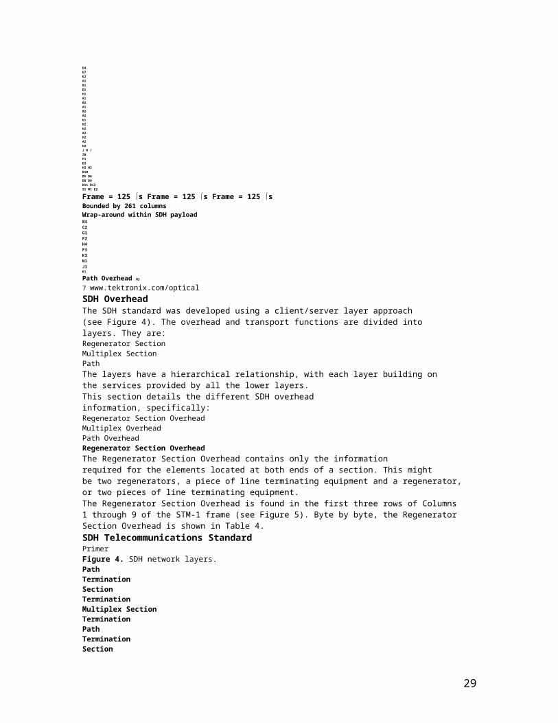
Frame = 125 s Frame = 125 s Frame = 125 sBounded by 261 columnsWrap-around within SDH payloadB3C2G1F2H4F3K3N1J1K1
Path Overhead H3
7 www.tektronix.com/opticalSDH OverheadThe SDH standard was developed using a client/server layer approach(see Figure 4). The overhead and transport functions are divided intolayers. They are:Regenerator Section
22
Multiplex SectionPathThe layers have a hierarchical relationship, with each layer building onthe services provided by all the lower layers.This section details the different SDH overheadinformation, specifically:Regenerator Section OverheadMultiplex OverheadPath OverheadRegenerator Section OverheadThe Regenerator Section Overhead contains only the informationrequired for the elements located at both ends of a section. This mightbe two regenerators, a piece of line terminating equipment and a regenerator,or two pieces of line terminating equipment.The Regenerator Section Overhead is found in the first three rows of Columns1 through 9 of the STM-1 frame (see Figure 5). Byte by byte, the RegeneratorSection Overhead is shown in Table 4.SDH Telecommunications StandardPrimerFigure 4. SDH network layers.PathTerminationSectionTerminationMultiplex SectionTerminationPathTerminationSectionTerminationService (2 Mbit/s, 140 Mbit/s...)MappingDemappingPTEPathMultiplex SectionRegenerator Section Regenerator SectionMultiplex SectionREGServiceMappingDemappingLegend:PTE = Path Terminating ElementREG = RegeneratorADM = Add/Drop MultiplexerREGADM PTEFigure 5. STM-1 Regenerator section overhead.STM-1123456789A1B1D1H1B2D4
23

D6D10S1A1H1B2A1H1B2A2E1D2H2K1D5D8D11A2H2A2H2M1J0F1D3H3K2D6D9D12E2H3 H3RegeneratorSection= Media-dependent byteswww.tektronix.com/optical 8Multiplex Section OverheadThe Multiplex Section Overhead contains the information requiredbetween the multiplex section termination equipment at each end of theMultiplex section (that is, between consecutive network elementsexcluding the regenerators).The Multiplex Section Overhead is found in Rows 5 to 9 of Columns 1through 9 of the STM-1 frame (see Figure 6). Byte by byte, the MultiplexSection Overhead is shown in Table 5.SDH Telecommunications StandardPrimerTable 4. Regenerator Section OverheadByte DescriptionA1 and A2 Framing bytes – These two bytes indicate the beginning of the STM-N frame. The A1, A2 bytes are unscrambled. A1 has the binary value 11110110,and A2 has the binary value 00101000. The frame alignment word of an STM-N frame is composed of (3 x N) A1 bytes followed by (3 x N) A2 bytes.J0 Regenerator Section (RS) Trace message – It’s used to transmit a Section Access Point Identifier so that a section receiver can verify its continuedconnection to the intended transmitter. The coding of the J0 byte is the same as for J1 and J2 bytes. This byte is defined only for STM-1 number 1of an STM-N signal.Z0 These bytes, which are located at positions S[1,6N+2] to S[1,7N] of an STM-N signal (N > 1), are reserved for future international standardisation.B1 RS bit interleaved parity code (BIP-8) byte – This is a parity code (even parity), used to check for transmission errors over a regenerator section.Its value is calculated over all bits of the previous STM-N frame after scrambling, then placed in the B1 byte of STM-1 before scrambling. Therefore,
24
this byte is defined only for STM-1 number 1 of an STM-N signal.E1 RS orderwire byte – This byte is allocated to be used as a local orderwire channel for voice communication between regenerators.F1 RS user channel byte – This byte is set aside for the user’s purposes; it can be read and/or written to at each section terminating equipmentin that line.D1, D2, D3 RS Data Communications Channel (DCC) bytes – These three bytes form a 192 kbit/s message channel providing a message-based channel forOperations, Administration and Maintenance (OAM) between pieces of section terminating equipment. The channel can be used from a central locationfor control, monitoring, administration, and other communication needs.Figure 6. STM-1 Multiplex section overhead.STM-1Multiplex Section123456789A1B1D1H1B2D4D6D10S1A1H1B2A1H1B2A2E1D2H2K1D5D8D11A2H2A2H2M1J0F1D3H3K2D6D9D12E2H3 H39 www.tektronix.com/opticalSDH Telecommunications StandardPrimerTable 5. Multiplex Section Overhead
25

Byte DescriptionB2 Multiplex Section (MS) bit interleaved parity code (MS BIP-24) byte – This bit interleaved parity N x 24 code is used to determine if a transmission error hasoccurred over a multiplex section. It’s even parity, and is calculated overall bits of the MS Overhead and the STM-N frame of the previous STM-N frame beforescrambling. The value is placed in the three B2 bytes of the MS Overhead before scrambling. These bytes are provided for all STM-1 signals in an STM-N signal.K1 and K2 Automatic Protection Switching (APS channel) bytes – These two bytes are used for MSP (Multiplex Section Protection) signaling between multiplex levelentities for bi-directional automatic protection switching and for communicating Alarm Indication Signal (AIS) and Remote Defect Indication (RDI) conditions.The Multiplex Section Remote Defect Indication (MS-RDI) is used to return an indication to the transmit end that the received end has detected an incomingsection defect or is receiving MS-AIS. MS-RDI is generated by inserting a “110” code in positions 6, 7, and 8 of the K2 byte before scrambling.K1 Byte K2 ByteBits 1-4 Type of request Bits 1-4 Selects channel number1111 Lock out of Protection Bit 5 Indication of architecture1110 Forced Switch 0 1+11101 Signal Fail – High Priority 1 1:n1100 Signal Fail – Low Priority Bits 6-8 Indicate mode of operation1011 Signal Degrade – High Priority 111 MS-AIS1010 Signal Degrade – Low Priority 110 MS-RDI1001 (not used) 101 Provisioned mode is bi-directional1000 Manual Switch 100 Provisioned mode is unidirectional0111 (not used) 011 Future use0110 Wait-to-Restore 010 Future use0101 (not used) 001 Future use0100 Exercise 000 Future use0011 (not used)0010 Reverse Request0001 Do Not Revert0000 No RequestBits 5-8 Indicate the number of the channel requestedD4 to D12 MS Data Communications Channel (DCC) bytes – These nine bytes form a 576 kbit/s message channel from a central location for OAM information(control, maintenance, remote provisioning, monitoring, administration and other communication needs).S1 Synchronisation status message byte (SSMB) – Bits 5 to 8 of this S1 byte are used to carry the synchronisation messages. Following is the assignmentof bit patterns to the four synchronisation levels agreed to within ITU-T (other values are reserved):Bits 5-80000 Quality unknown (existing sync. network)0010 G.811 PRC0100 SSU-A (G.812 transit)1000 SSU-B (G.812 local)1011 G.813 Option 1 Synchronous Equipment Timing Clock (SEC)1111 Do not use for synchronisation. This message may be emulated by equipment failures and will be emulated by a Multiplex Section AIS signal.M1 MS remote error indication – The M1 byte of an STM-1 or the first STM-1 of an STM-N is used for a MS layer remote error indication (MS-REI).Bits 2 to 8 of the M1 byte are used to carry the error count of the interleaved bit blocks that the MS BIP-24xN has detected to be in error at the far endof the section. This value is truncated at 255 for STM-N >4.E2 MS orderwire byte – This orderwire byte provides a 64 kbit/s channel between multiplex entities for an express orderwire. It’s a voice channel for use bycraftspersons and can be accessed at multiplex section terminations.www.tektronix.com/optical 10Higher-Order Path Overhead(VC-4/VC-3)The Path Overhead is assigned to, and transportedwith the Virtual Container from the timeit’s created by path terminating equipment untilthe payload is demultiplexed at the terminationpoint in a piece of path terminating equipment.The Path Overhead is found in Rows 1 to 9of the first column of the VC-4 or VC-3(see Figure 7). Byte by byte, the HigherOrder Path Overhead is shown in Table 6.
26

SDH Telecommunications StandardPrimerTable 6. Higher-Order Path OverheadByte DescriptionJ1 Higher-Order VC-N path trace byte – This user-programmable byte repetitively transmits a 15-byte, E.64 format string plus 1-byte CRC-7.A 64-byte free-format string is also permitted for this Access Point Identifier. This allows the receiving terminal in a path to verify its continued connectionto the intended transmitting terminal.B3 Path bit interleaved parity code (Path BIP-8) byte – This is a parity code (even), used to determine if a transmission error has occurred over a path.Its value is calculated over all the bits of the previous virtual container before scrambling and placed in the B3 byte of the current frame.C2 Path signal label byte – This byte specifies the mapping type in the VC-N. Standard binary values for C2 are:MSB LSB Hex Code InterpretationBits 1-4 Bits 5-80000 0000 00 Unequipped or supervisory-unequipped0000 0001 01 Equipped – non-specific0000 0010 02 TUG structure0000 0011 03 Locked TU-n0000 0100 04 Asynchronous mapping of 34,368 kbit/s or 44,736 kbit/s into the Container-30001 0010 12 Asynchronous mapping of 139,264 kbit/s into the Container-40001 0011 13 ATM mapping0001 0100 14 MAN DQDB (IEEE Standard 802.6) mapping0001 0101 15 FDDI (ISO Standard 9314) mapping0001 0110 16 Mapping of HDLC/PPP (Internet Standard 51) framed signal0001 0111 17 Mapping of Simple Data Link (SDL) with SDH self synchronising scrambler0001 1000 18 Mapping of HDLC/LAP-S framed signals0001 1001 19 Mapping of Simple Data Link (SDL) with set-reset scrambler0001 1010 1A Mapping of 10 Gbit/s Ethernet frames (IEEE 802.3)1100 1111 CF Obsolete mapping of HDLC/PPP framed signal1110 0001 E1 Reserved for national use: : : :1111 1100 FC Reserved for national use1111 1110 FE Test signal, O.181 specific mapping1111 1111 FF VC-AISFigure 7. Higher-order path overhead (VC-4/VC-3).J1 J1 VC-n Path TraceB3 B3 Path BIP-8C2 C2 Path Signal LabelG1 G1 Path StatusF2 F2 Path User ChannelH4 H4 TU Multiframe IndicatorF3 F3 Path User ChannelK3 K3 Automatic Protection SwitchingN1 N1 Network Operator (TCM)123456789Section Overhead Path Overhead11 www.tektronix.com/opticalSDH Telecommunications StandardPrimerByte DescriptionG1 Path status byte – This byte is used to convey the path terminating status and performance back to the originating path terminating equipment.Therefore the bi-directional path in its entirety can be monitored, from either end of the path.Byte G1 is allocated to convey back to a VC-4-Xc/VC-4/VC-3 trail termination source the status and performance of the complete trail. Bits 5 to 7 may beused to provide an enhanced remote defect indication with additional differentiation between the payload defect (PLM), server defects (AIS, LOP)
27

and connectivity defects (TIM, UNEQ). The following codes are used:Bits 5-7 Meaning Triggers001 No remote defect No remote defect010 E-RDI Payload defect PLM101 E-RDI Server defect AIS, LOP110 E-RDI Connectivity defect TIM, UNEQThe E-RDI G1 (bits 5-7) code interpretation provides for interworking with equipment which supports RDI. It is not necessary for the interpretation to identifyif the equipment supports RDI or E-RDI. For the E-RDI codes, bit 7 is set to the inverse of bit 6. Following is the E-RDI G1 (bits 5-7) code interpretation:Bits 5-7 E-RDI Interpretation000 No remote defect (Note 1)001 No remote defect010 E-RDI Payload defect (Note 2)011 No remote defect (Note 1)100 E-RDI Server defect (Note 1)101 Remote E-RDI Server defect110 Remote E-RDI Connectivity defect111 Remote E-RDI Server Defect (Note 1)NOTE 1: These codes are generated by RDI supporting equipment and are interpreted by E-RDI supporting equipment as shown. For equipment supportingRDI, clause 9.3.1.4/G.707, this code is triggered by the presence or absence of one of the following defects: AIS, LOP, TIM, or UNEQ. Equipment conforming toan earlier version of this standard may include PLM as a trigger condition. ATM equipment complying with the 1993 version of ITU-T Recommendation I.432may include LCD as a trigger condition. Note that for some national networks, this code was triggered only by an AIS or LOP defect.NOTE 2: ATM equipment complying with the 08/96 version of ITU-T Recommendation I.432.2 may include LCD as a trigger condition.F2 Path user channel byte – This byte is used for user communication between path elements.H4 Position and Sequence Indicator byte – This byte provides a multi frame and sequence indicator for virtual VC-3/4 concatenation and a generalized positionindicator for payloads. In the latter case, the content is payload specific (e.g., H4 can be used as a multiframe indicator for VC-2/1 payload). For mapping ofDQDB in VC-4, the H4 byte carries the slot boundary information and the Link Status Signal (LSS). Bits 1-2 are used for the LSS code as described in IEEEStandard 802.6. Bits 3-8 form the slot offset indicator. The slot offset indicator contains a binary number indicating the offset in octets between the H4 octetand the first slot boundary following the H4 octet. The valid range of the slot offset indicator value is 0 to 52. A received value of 53 to 63 corresponds to anerror condition.F3 Path user channel byte – This byte is allocated for communication purposes between path elements and is payload dependent.K3 APS signalling is provided in K3 bits 1-4, allocated for protection at the VC-4/3 path levels. K3 bits 5-8 are allocated for future use. These bits have nodefined value. The receiver is required to ignore their content.1 2 3 4 5 6 7 8REI RDI Reserved SpareTable 6 (contd)www.tektronix.com/optical 12
SDH Telecommunications StandardPrimerByte DescriptionN1 Network operator byte – This byte is allocated to provide a Higher-Order Tandem Connection Monitoring (HO-TCM) function. N1 is allocated forTandem Connection Monitoring for contiguous concatenated VC-4, the VC-4 and VC-3 levels.Bits 1-4 Incoming Error Count (IEC).1001 00001 10010 20011 30100 40101 50110 60111 71000 81110 Incoming AISNOTE: To guarantee a non all-zeroes N1 byte independent of the incoming signal status, it is required that the IEC code field contains at least one “1”.
28
When zero errors in the BIP-8 of the incoming signal are detected, an IEC code is inserted with “1”s in it. In this manner, it is possible for the TandemConnection sink at the tail end of the Tandem Connection link to use the IEC code field to distinguish between unequipped conditions started withinor before the Tandem Connection.Bit 5 Operates as the TC-REI of the Tandem Connection to indicate errored blocks caused within the Tandem Connection.Bit 6 Operates as the OEI to indicate errored blocks of the egressing VC-n.Bits 7-8 Operate in a 76 multiframe as:– Access point identifier of the Tandem Connection (TC-APId); it complies with the generic 16-byte string format given in 9.2.2.2.– TC-RDI, indicating to the far end that defects have been detected within the Tandem Connection at the near endTandem Connection sink.– ODI, indicating to the far end that AU/TU-AIS has been inserted into the egressing AU-n/TU-n at the TC-sink due to defectsbefore or within the Tandem Connection.– Reserved capacity (for future standardization).Frame # Bits 7-8 definition1-8 Frame Alignment Signal: 1111 1111 1111 11109-12 TC-APId byte #1 [ 1 C1C2C3C4C5C6C7 ]13-16 TC-APId byte #2 [ 0 X X X X X X X ]17-20 TC-APId byte #3 [ 0 X X X X X X X ]: :65-68 TC-APId byte #15 [ 0 X X X X X X X ]69-72 TC-APId byte #16 [ 0 X X X X X X X ]73-76 TC-RDI, ODI and Reserved (see following)Frame # Bit 7 definition Bit 8 definition73 Reserved (default = “0”) TC-RDI74 ODI Reserved (default = “0”)75 Reserved (default = “0”) Reserved (default = “0”)76 Reserved (default = “0”) Reserved (default = “0”)1 2 3 4 5 6 7 8IEC TC-REI OEITC-APId, TC-RDI,ODI, reservedTable 6 (contd)13 www.tektronix.com/opticalLower-Order Path Overhead (VC-2/VC-1)The bytes V5, J2, N2, and K4 are allocated to the VC-2/VC-1 POH. TheV5 byte is the first byte of the multiframe and its position is indicatedby the TU-2/TU-1 pointer. The V5 byte provides the functions of errorchecking, signal label, and path status of the VC-2/VC-1 paths. The bitassignments for the V5 byte and the byte-by-byte Lower Order PathOverhead is shown in Table 7.SDH Telecommunications StandardPrimerTable 7. Lower-Order Path OverheadByte DescriptionV5 VT path overhead byte.Bits 1-2 Allocated for error performance monitoring. A Bit Interleaved Parity (BIP-2) scheme is specified. Includes POH bytes,but excludes V1, V2, V3, and V4.Bit 3 A VC-2/VC-1 path Remote Error Indication (LP-REI) that is set to one and sent back towards a VC-2/VC-1 path originatorif one or more errors were detected by the BIP-2; otherwise set to zero.Bit 4 A VC-2/VC-1 path Remote Failure Indication (LP-RFI). This bit is set to one if a failure is declared, otherwise it is set to zero.A failure is a defect that persists beyond the maximum time allocated to the transmission system protection mechanisms.Bits 5-7 Provide a VC-2/VC-1 signal label. The Virtual Container path Signal Label coding is:000 Unequipped or supervisory-unequipped001 Equipped – non-specific010 Asynchronous011 Bit synchronous100 Byte synchronous101 Reserved for future use110 Test signal, O.181 specific mapping111 VC-AIS
29

Bit 8 Set to 1 to indicate a VC-2/VC-1 path Remote Defect Indication (LP-RDI); otherwise set to zero.J2 Used to repetitively transmit a Lower-Order Access Path Identifier so that a path receiving terminal can verify its continued connection to the intendedtransmitter. A 16-byte frame is defined for the transmission of Path Access Point Identifiers. This 16-byte frame is identical to the 16-byte frame of theJ1 and J0 bytes.1 2 3 4 5 6 7 8BIP-2 REI RF I Signal Label RDIwww.tektronix.com/optical 14
SDH Telecommunications StandardPrimerTable 7 (contd)Byte DescriptionN2 Allocated for Tandem Connection Monitoring for the VC2, VC-12, and VC-11 level.Bits 1-2 Used as an even BIP-2 for the Tandem Connection.Bit 3 Fixed to “1”. This guarantees that the contents of N2 is not all zeroes at the TC-source. This enables the detection of an unequippedor supervisory unequipped signal at the Tandem Connection sink without the need of monitoring further OH-bytes.Bit 4 Operates as an “incoming AIS” indicator.Bit 5 Operates as the TC-REI of the Tandem Connection to indicate errored blocks caused within the Tandem Connection.Bit 6 Operates as the OEI to indicate errored blocks of the egressing VC-n.Bits 7-8 Operate in a 76 multiframe as:– The access point identifier of the Tandem Connection (TC-APId); it complies with the generic 16-byte string format given in 9.2.2.2.– The TC-RDI, indicating to the far end that defects have been detected within the Tandem Connection at the near endTandem Connection sink.– The ODI, indicating to the far end that TU-AIS has been inserted at the TC-sink into the egressing TU-n due to defectsbefore or within the Tandem Connection.– Reserved capacity (for future standardization).Frame # Bits 7-8 definition1-8 Frame Alignment Signal: 1111 1111 1111 11109-12 TC-APId byte #1 [ 1 C1C2C3C4C5C6C7 ]13-16 TC-APId byte #2 [ 0 X X X X X X X ]17-20 TC-APId byte #3 [ 0 X X X X X X X ]: :65-68 TC-APId byte #15 [ 0 X X X X X X X ]69-72 TC-APId byte #16 [ 0 X X X X X X X ]73-76 TC-RDI, ODI and Reserved (see following)Frame # Bit 7 definition Bit 8 definition73 Reserved (default = “0”) TC-RDI74 ODI Reserved (default = “0”)75 Reserved (default = “0”) Reserved (default = “0”)76 Reserved (default = “0”) Reserved (default = “0”)K4 Bits 1-4 are allocated for APS signalling for protection at the Lower-Order path level. Bits 5-7 are reserved for optional use.Bit 8 is reserved for future use and has no defined value.b1 b2 b3 b4 b5 b6 b7 b8BIP-2 "1" TC-REI OEITC-APId, TC-RDI,ODI, reservedIncomingAIS15 www.tektronix.com/opticalSDH Anomalies, Defects,Failures, and AlarmsThe SDH frame structure has been designed to contain a large amountof overhead information. The overhead information provides for a varietyof management and other functions such as:Alarm Indication Signals (AIS)Error Performance Monitoring using BIP-NPointer Adjustment InformationPath StatusPath TraceSection TraceRemote Defect, Error, and Failure Indications
30

Signal LabelsNew Data Flag IndicationsData Communications Channels (DCC)Automatic Protection Switching (APS) ControlOrderwireSynchronisation Status MessageMuch of this overhead information is involved with alarm and in-servicemonitoring of the particular SDH sections. Table 8 and Figure 9, that followthe definitions, list the criteria for errors and the performance monitoringfor errors.DefinitionsAlarm – The maintenance signal used in the digital network to alert downstreamequipment that a defect or equipment failure has been detected.Anomaly – The smallest discrepancy which can be observed betweenthe actual and desired characteristics of an item. The occurrence of asingle anomaly does not constitute an interruption in the ability to performa required function. Examples of SDH anomalies are:B1 BIPB2 BIPPath B3 BIPREIPattern Bit (OOS test)Defect – The density of anomalies has reached a level where the abilityto perform a required function has been interrupted. Defects are used asinput for performance monitoring, the control of consequent actions, andthe determination of fault cause. Examples of SDH Defects are:OOFAISRDILOFLOPLOMFailure – The inability of a function to perform a required action whichhas persisted beyond a maximum time allocated.SDH Error Performance MonitoringError performance monitoring in the SDH is based on Bit-Interleaved-Parity (BIP) checks calculated on a frame-by-frame basis. These BIPchecks are inserted in the RegeneratorSection Overhead, Multiplex SectionOverhead, and Path Overheads.In addition, Higher-Order PathTerminating Equipment (HO PTE) andLower-Order Path TerminatingEquipment (LO PTE) produce RemoteError Indications (REI) based on errorsdetected in the HO Path and LO PathBIP respectively. The REI signals aresent back to the equipment at the originatingend of a path. All defects listedin Figure 8 are described in Table 8.SDH Telecommunications StandardPrimerFigure 8. Interaction between defects in forward and backward directions, according to the different SDH levels.LO PTE HO PTE MSTE RSTE RSTE RSTE MSTE HO PTE LO PTERegenerator Section (RSOH)Multiplex Section (MSOH)Higher Order PathLower Order PathAlarm TransmissionAlarm DetectionRDI(V5)RDI(G1)RDI(K2)RDI(K2)RDI(G1)RDI
31

(V5)MSAISLOPLOSLOFAU-AISLOPTU-AIS(V1,V2)MSAISLOSLOFLOSLOF TributaryAIS(H1,H2)
www.tektronix.com/optical 16
SDH Telecommunications StandardPrimerTable 8. Anomalies, Defects, Failures, AlarmsAbbreviation Description CriteriaLOS Loss of Signal LOS is raised when the synchronous signal (STM-N) level drops below the threshold at which a BER of 1 in 103 ispredicted. It could be due to a cut cable, excessive attenuation of the signal, or equipment fault.The LOS state will clear when two consecutive framing patterns are received and no new LOS condition is detected.OOF Out of Frame Alignment OOF state occurs when several consecutive SDH frames are received with invalid (errored) framing patterns (A1 andA2 bytes). The maximum time to detect OOF is 625 microseconds. OOF state clears within 250 microseconds when twoconsecutive SDH frames are received with valid framing patterns.LOF Loss of Frame LOF state occurs when the OOF state exists for a specified time in microseconds. The LOF state clears whenAlignment an in-frame condition exists continuously for a specified time in microseconds. The time for detection and clearanceis normally 3 milliseconds.LOP Loss of Pointer LOP state occurs when N consecutive invalid pointers are received or N consecutive New Data Flags (NDF) are received(other than in a concatenation indicator), where N = 8, 9, or 10. LOP state is cleared when three equal valid pointersor three consecutive AIS indications are received.LOP can be identified as:• AU-LOP (Administrative Unit Loss of Pointer)• TU-LOP (Tributary Unit Loss of Pointer)AIS Alarm Indication AIS is an all-ONES characteristic or adapted information signal. It’s generated to replace the normal traffic signal when itSignal contains a defect condition in order to prevent consequential downstream failures being declared or alarms being raised.AIS can be identified as:• MS-AIS (Multiplex Section Alarm Indication Signal)• AU-AIS (Administrative Unit Alarm Indication Signal)• TU-AIS (Tributary Unit Alarm Indication Signal)REI Remote Error An indication returned to a transmitting node (source) that an errored block has been detected at the receiving node (sink).Indication This indication was previously known as FEBE (Far End Block Error).REI can be identified as:• MS-REI (Multiplex Section Remote Error Indication)• HP-REI (Higher-order Path Remote Error Indication)• LP-REI (Lower-order Path Remote Error Indication)RDI Remote Defect A signal returned to the transmitting Terminating Equipment upon detecting a Loss of Signal, Loss of Frame, or AIS defect.Indication RDI was previously known as FERF (Far End Receiver Failure).RDI can be identified as:• MS-RDI (Multiplex Section Remote Defect Indication)• HP-RDI (Higher-order Path Remote Defect Indication)• LP-RDI (Lower-order Path Remote Defect Indication)RFI Remote Failure A failure is a defect that persists beyond the maximum time allocated to the transmission system protection mechanisms.Indication When this situation occurs, an RFI is sent to the far end and will initiate a path protection switch if this function hasbeen provisioned.RFI can be identified as:• LP-RFI (Lower-order Path Remote Failure Indication)B1 error B1 error Parity errors evaluated by byte B1 (BIP-8) of an STM-N shall be monitored. If any of the eight parity checks fail,
32

the corresponding block is assumed to be in error.B2 error B2 error Parity errors evaluated by byte B2 (BIP-24 x N) of an STM-N shall be monitored. If any of the N x 24 parity checks fail,the corresponding block is assumed to be in error.B3 error B3 error Parity errors evaluated by byte B3 (BIP-8) of a VC-N (N = 3,4) shall be monitored. If any of the eight parity checks fail,the corresponding block is assumed to be in error.BIP-2 error BIP-2 error Parity errors contained in bits 1 and 2 (BIP-2) of byte V5 of a VC-m (m=11,12,2) shall be monitored. If any of the twoparity checks fail, the corresponding block is assumed to be in error.LSS Loss of Sequence Out-of-service bit error measurements using pseudo-random sequences can only be performed if the reference sequenceSynchronisation produced on the receiving side of the test set-up is correctly synchronised to the sequence coming from the objectunder test. In order to achieve compatible measurement results, it’s necessary that the sequence synchronisationcharacteristics are specified. The following requirement is applicable to all ITU-T O.150 Recommendations dealingwith error performance measurements using pseudo-random sequences.Sequence synchronisation shall be considered to be lost and re-synchronisation shall be started if:• The bit error ratio is ≥0.20 during an integration interval of 1 second; or• It can be unambiguously identified that the test sequence and the reference sequence are out of phase.17 www.tektronix.com/opticalSDH PointersSDH provides payload pointers to permit differences in the phase andfrequency of the Virtual Containers (VC-N) with respect to the STM-Nframe. Lower-order pointers are also provided to permit phase differencesbetween VC-1/VC-2 and the higher-order VC-3/VC-4.On a frame-by-frame basis, the payload pointer indicates the offsetbetween the VC payload and the STM-N frame by identifying the locationof the first byte of the VC in the payload. In other words, the VC isallowed to “float” within the STM-1 frame capacity.To make this possible, within each STM-N frame, there’s a pointer,known as the VC Payload Pointer, that indicates where the actual payloadcontainer starts. For a VC-4 payload, this pointer is located incolumns 1 and 4 of the fourth row of the Section Overhead. The bytesH1 and H2 (two 8-bit bytes) of the Overhead can be viewed as one value(see Figure 9).The pointer value indicates the offset in bytes from the pointer to thefirst byte of the VC, which is the J1 byte. Because the Section Overheadbytes are not counted, and starting points are at 3-byte increments for aVC-4 payload, the possible range is:Total STM-1 bytes – Section Overhead bytes = Pointer value rangeFor example:(2430 – 81)/3 = 783 valid pointer positionsThat is, the value of the pointer has a range of 0 to 782. For example, ifthe VC-4 Payload Pointer has a value of 0, then the VC-4 begins in thebyte adjacent to the H3 byte of the Overhead; if the Payload Pointer hasa value of 87, then the VC-4 begins in the byte adjacent to the K2 byteof the Overhead in the next row.The pointer value, which is a binary number, is carried in bits 7 through16 of the H1-H2 pointer word. The first four bits of the VC-4 payloadpointer make provision for indicating a change in the VC, and thus anarbitrary change in the value of the pointer. These four bits, the N-bits,are known as the New Data Flag. The VC pointer value that accompaniesthe New Data Flag will indicate the new offset.Payload PointersWhen there’s a difference in phase or frequency, the pointer value isadjusted. To accomplish this, a process known as byte stuffing is used.In other words, the VC payload pointer indicates where in the containercapacity a VC starts, and the byte stuffing process allows dynamic alignmentof the VC in case it slips in time.Positive Pointer JustificationWhen the data rate of the VC is too slow in relation to the rate of the
33

STM-1 frame, bits 7, 9, 11, 13, and 15 of the pointer word are invertedin one frame, thus allowing 5-bit majority voting at the receiver (thesebits are known as the I-bits or Increment bits). Periodically, when the VCis about one byte off, these bits are inverted, indicating that positivestuffing must occur.An additional byte is stuffed in, allowingthe alignment of the container to slipback in time. This is known as positivestuffing, and the stuff byte is made upof non-information bits. The actual positivestuff byte immediately follows theH3 byte (that is, the stuff byte is withinthe VC portion). The pointer is incrementedby one in the next frame, andthe subsequent pointers contain thenew value.SDH Telecommunications StandardPrimerTable 9. SDH PointersByte DescriptionH1 and H2 Pointer bytes – These two bytes, the VC payload pointer, specify the location of the VC frame.It’s used to align the VC and STM-1 Section Overheads in an STM-N signal, to perform frequencyjustification, and to indicate STM-1 concatenation.H3 Pointer action byte – This byte is used for frequency justification. Depending on the pointer value,the byte is used to adjust the fill input buffers. The byte only carries valid information in the event ofnegative justification, otherwise it’s not defined.Figure 9. Pointer 9-byte structure.3 X AU-3 H1 H1 H1 H2 H2 H2 H3 H3 H31 X AU-4 H1 Y Y H 2 1 1 H 3 H 3 H 31 = All 1sY = 1001SS11(S bits unspecified)www.tektronix.com/optical 18
Simply put, if the VC is running more slowly than the STM-1 frame,every now and then “stuffing” an extra byte in the flow gives the VCa one-byte delay (see Figure 10).Negative Pointer JustificationConversely, when the data rate of the VC is too fast in relation to therate of the STM-1 frame, bits 8, 10, 12, 14, and 16 of the pointer wordare inverted, thus allowing 5-bit majority voting at the receiver (thesebits are known as the D-bits, or Decrement bits). Periodically, when theVC is about one byte off, these bits are inverted, indicating that negativestuffing must occur.Because the alignment of the container advances in time, the payloadcapacity must be moved forward. Thus, actual data is written in the H3byte, the negative stuff opportunity within the Overhead; this is knownas negative stuffing. The pointer is decremented by one in the next frame,and the subsequent pointers contain the new value. Simply put, if theVC is running more quickly than the STM-1 frame, every now and thenpulling an extra byte from the flow and stuffing it into the Overheadcapacity (the H3 byte) gives the VC a one-byte advance (see Figure 11).In both positive or negative cases, there must be at least three framesin which the pointer remains constant before another stuffing operation(and, therefore a pointer value change) can occur.SDH Telecommunications StandardPrimerFigure 10. Payload pointer – positive justification.H1 H2 H3H1 H2 H3H1 H2 H3H1 H2 H3
Frame N + 1Frame NFrame N + 2
34
Frame N + 3PPP + 1
500 selapsedJ1J1J1J1Extra bytes allow the VC to slip back in time.A positive stuff byte immediately follows the H3 byte.I-bitsFigure 11. Payload pointer – positive justification.H1 H2 H3H1 H2 H3H1 H2H1 H2 H3
Frame N + 1Frame NFrame N + 2Frame N + 3PPP – 1
500 selapsedJ1J1J1J1The VC moves forward in time when a data bytehas been stuffed into the H3 byte.Actual payload data is written in the H3 byte.H3 D-bits19 www.tektronix.com/opticalSDH MultiplexingThe multiplexing principles of SDH follow, using these termsand definitions:Mapping – A process used when tributaries are adapted into VirtualContainers (VCs) by adding justification bits and Path Overhead (POH)information.Aligning – This process takes place when a pointer is included in a TributaryUnit (TU) or an Administrative Unit (AU), to allow the first byte of the VirtualContainer to be located.Multiplexing – This process is used when multiple lower-order path layersignals are adapted into a higher-order path signal, or when the higher-orderpath signals are adapted into a Multiplex Section.Stuffing – As the tributary signals are multiplexed and aligned, some sparecapacity has been designed into the SDH frame to provide enough space forall the various tributary rates. Therefore, at certain points in the multiplexinghierarchy, this space capacity is filled with “fixed stuffing” bits that carry noinformation, but are required to fill up the particular frame.Figure 12 illustrates the ITU-T SDH multiplexing structure defined inRec. G.707. The notations in the boxes, such as C-1, VC-3, and AU-4, areexplained in Table 10.At the lowest level, containers (C) are input to virtual containers (VC).The purpose of this function is to create a uniform VC payload byusing bit-stuffing to bring all inputs to a common bit-rate ready forsynchronous multiplexing. Various containers (ranging from VC-11 at1.728 Mbit/s to VC-4 at 150.336 Mbit/s) are covered by the SDH hierarchy.Next, VCs are aligned into tributary units (TUs), where pointer processingoperations are implemented.These initial functions allow the payload to be multiplexed into TU groups(TUGs). As Figure 12 illustrates, the xN label indicates the multiplexinginteger used to multiplex the TUs to the TUGs. The next step is themultiplexing of the TUGs to higher level VCs, and TUG-2 and TUG-3 aremultiplexed into VC-3 (ANSI mappings) and VC-4. These VCs are multiplexed
35

with fixed byte-stuffing to form administration units (AUs) whichare finally multiplexed into the AU group (AUG). This payload then ismultiplexed into the Synchronous Transport Module (STM).SDH Telecommunications StandardPrimerFigure 12. SDH multiplexing structure.TU-11 VC-11 C-11AligningMappingx1 x1x3x3x1x1x3x4x7x7STM-1 AUG-1 AU-4 VC-4AU-3 VC-3C-4C-3C-2C-12VC-3VC-2VC-12TU-3TU-2TU-12TUG-2TUG-3Pointer processingMultiplexingx4x1 x1STM-16 AUG-16 VC-4-16cVC-4-4cx1x4STM-64 AUG-64x1 x1x4STM-4C-4-4cC-4-16cx1STM-0x1 x1STM-256 VC-4-256c C-4-256cx1VC-4-64c C-4-64cAU-4-256cAU-4-64cAU-4-16cAU-4-4cAUG-256AUG-4x4
www.tektronix.com/optical 20
SDH Telecommunications StandardPrimerTable 10. SDH Multiplexing StructureTerm Contents UserC-N N = 1 to 4 Payload at lowest multiplexing levelVC-N N = 1, 2 (Lower-Order) Single C-n plus VC POHVC-N N = 3, 4 (Higher-Order) C-N, TUG-2s, or TUG-3s, plus POH for the specific levelTU-N N = 1 to 3 VC-N plus tributary unit pointerTUG-2 1, 3 or 4 (TU-N) Multiplex of various TU-NsTUG-3 TU-3 or 7 TUG-2s TU-3 or multiplex of 7 TUG-2sAU-N N = 3, 4 VC-N plus AU pointerAUG 1, 3 (AU-n) Either 1 AU-4 or multiplex of 3 AU-3sSTM-N N = 1, 4, 16, 64 AUGs N synchronously-multiplexed STM-1 signalsPOH = Path OverheadC = ContainerTU = Tributary UnitAU = Administrative UnitVC = Virtual ContainerTUG = Tributary Unit GroupSTM = Synchronous Transport Module21 www.tektronix.com/opticalSDH Tributary MultiplexingIn order to accommodate mixes of different TU types within a VC-4,the TUs are grouped together (refer to the previous SDH MultiplexingHierarchy diagram – Figure 12). A VC-4 that is carrying Tributary Units is
36
divided into three TUG-3, each of which may contain seven TUG-2s or asingle TU-3. There can be a mix of the different TU Groups. For example,the first TUG-3 could contain twelve TU-12 and three TU-2, making atotal of seven TUG-2 groups. The TU groups have no overhead or pointers;they are just a way of multiplexing and organizing the different TUswithin the VC-4 of a STM-1.The columns in a TU Group are not consecutive within the VC; they arebyte-interleaved column-by-column with respect to the other TU groups(see Figure 13).This figure also shows several columns allocated for fixed stuffing. NPI(Null Pointer Indicators) are used to indicate when a TUG-2 structure isbeing carried, rather than a TU-3 with its associated TU-3 pointer.Tributary Unit GroupThe first TUG-2 Group within a TUG-3, called Group 1, is found in everyseventh column, skipping columns 1 and 2 of the TUG-3, and startingwith column 3.The Tributary Unit columns within a group are not placed in consecutivecolumns within that group (Figure 14). The columns of the individual TUswithin the TU Group are byte-interleaved as well.Tributary Units are optimized in different sizes to accommodate differentsignals. Each size of TU is known as a “type” of TU. A 36-byte structure,or 4 columns by 9 rows, could accommodate the 2.048 Mbit/s signal.This particular TU is simply designated a TU-12. In this case the fourcolumns provide a signal rate of 2.304 Mbit/s, allowing capacity foroverhead. Other signals require TUs of different sizes.With each TU Group using 12 columns of the VC-4, note that thenumber of columns in each of the different Lower-Order TU types areall factors of 12. As a result, a TU group could contain one of the followingcombinations:Three TU-12s (with four columns per TU-12)One TU-2 (with twelve columns per TU-2)TU MultiframeIn the floating TU mode, four consecutive 125-microsecond frames of the VC-4 are combined intoone 500-microsecond structure, called a TU Multiframe.In other words, the 500-microsecond multiframe isoverwritten on, and aligned to the 125-microsecondVC-4s. The occurrence of the TU Multiframe and itsphase is indicated in the VC-N Path Overhead, by theMultiframe Indicator byte (H4). A value XXXXXX00 inthe Multiframe Indicator byte indicates that the nextSTM frame contains the first frame in the TU Multiframe;a value XXXXXX01 in the Multiframe Indicator byte indicatesthat the next VC-4 contains the second frame inthe TU Multiframe, and so on. (Only the last two bits ofthe H4 byte have a value of 0 or 1 assigned; the firstsix bits are unassigned and this is denoted by the X.)SDH Telecommunications StandardPrimerFigure 13. SDH tributary structure showing TUG-3 multiplexing in VC-4.STM-1 VC-4 Virtual Container261 Columnsof 9 Rows1 140 Mb/sor3 TUG-3Path Overhead2 StuffColumnsPointer for TU-3or NPI for TUG-2Path Overhead VC-3or Stuffing for TUG-2TUG-3 Group 1made up of
37
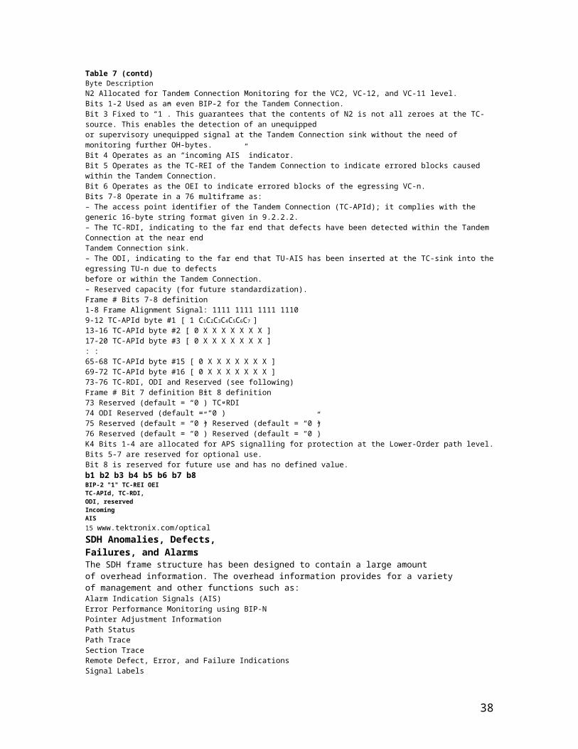
7 TUG-2 Groupsor1TU-3 34 Mb/s13A B C A B C A C A B C1 3 4 5 6 7 1 2 3 – – 1 2 3 4 5 6 7– – –Figure 14. Tributary unit structures.Pointer for TU-3or NPI for TUG-2Path Overhead VC-3or Stuffing for TUG-2TUG-3 Group 1made up of7 TUG-2 Groupsor1TU-3 34 Mb/s1 3 4 5 6 7 1 2 3 – – 1 2 3 4 5 6 7TUG-2 Group 2(made up of 12 columns)TU-12 TU-12 TU-12TU-12www.tektronix.com/optical 22
The Tributary Units also contain payload pointers to allow for flexible anddynamic alignment of the VC. In this case, the TU pointer value indicatesthe offset from the TU to the first byte of the VC. TU pointers allow AUand TU payloads to differ in phase with respect to each other and thenetwork while still allowing AUs and TUs to be synchronously multiplexed.The TU Multiframe overhead consists of four bytes: V1, V2, V3, and V4(see Figure 15). Each of these four bytes, V1 to V4, is located in the firstbyte of the respective TU frame in the TU Multiframe. The payload pointersV1 and V2 indicate the start of the payload within the multiframeand V3 provides a 64 kbit/s channel for a payload pointer movementopportunity. The V4 byte is reserved. The remaining bytes in the TUMultiframe define the TU container capacity which carries the VirtualContainer, and the Path Overhead. The container capacity differs for thedifferent TU types because their size varies according to the number ofcolumns in each type.The container capacity for each type of TU is shown in Table 11.TU Payload PointerThe TU Payload Pointer allows dynamic alignment of the lower-orderVC-M within the TU Multiframe in much the same fashion as describedfor the higher-order VC-N. The alignment of any one lower-order VC-Mis independent of the other VC-Ms; in other words, all VCs within anSTM can float independently of each other.This payload pointer, which is located in positions V1 and V2 of the TUMultiframe, is made up of two 8-bit bytes, and it can be viewed as oneword. The value of the pointer is a binary number found in bits 7 to 16of V1 and V2. This value indicates the offset in bytes from the end of thepointer (byte V2) to the first byte of the VC; the V3 and V4 bytes are notcounted. The range of the offset differs for each TU type (see Table 12).That is, the value of the pointer for a TU-12 has a range of 0 to 140.For example, if the TU Payload Pointer has a value of 0, then the VC-Mbegins in the byte adjacent to the V2 byte; if the TU Payload Pointer hasa value of 35, then the VC-M begins in the byte adjacent to the V3 byte.The V5 byte is the first byte of the VC-M in the first multiframe.SDH Telecommunications StandardPrimerFigure 15. TU multiframe structure.Four consecutive framesTU Superframe4 *125 s = 500 sIndication in H4(multiframe indication byTU Pointers consist ofV1 and V2Frame 1H4 byte
38

00105
V1---139 125 sFrame 2010
V2---34 250 sFrame 31035
V3---69 375 sFrame 41170
V4---104 500 sTable 12. TU Container Pointer ValuesTU Type Total TU bytes V1 to V4 PointerValue RangeTU-11 108 4 104TU-12 144 4 140TU-2 432 4 428Table 11. TU Container CapacityTU Type TU Capacity TU Pointer TU ContainerCalculation * CapacityTU-11 3 x 9 x 4 4 bytes 104 bytesTU-12 4 x 9 x 4 4 bytes 140 bytesTU-2 12 x 9 x 4 4 bytes 428 bytes* Columns x rows x framesFour consecutive frames form aTU Superframe4 *125 s = 500 sIndication in H4(multiframe indication byte)TU Pointers consist ofV1 and V223 www.tektronix.com/opticalAutomatic Protection SwitchingAutomatic Protection Switching (APS) is the capability of a transmissionsystem to detect a failure on a working facility and to switch to a standbyfacility to recover the traffic. This capability has a positive effect on theoverall system availability.Only the Multiplex Section in SDH is protected in this automatic fashion.The Multiplex Section protection mechanisms are coordinated by theK1 and K2 bytes in the Multiplex Section Overhead. Path protection ismanaged at a higher level by network management functions.Multiplex Section Protection, K1/K2 BytesIn SDH, the transmission is protected on optical sections from the NearEnd (the point at which the MS Overhead is inserted) to the Far End(the point where the MS Overhead is terminated).Bytes K1 and K2 in the MS Overhead of the STM-1 signal carry aMultiplex Section Protection (MSP) protocol used to coordinate protectionswitching between the Near End and the Far End.Protection switching is initiated as a result of one of the followingsituations:Signal failureSignal degradationIn response to commands from a local craft terminalor a remote network managerTwo modes of APS are provided: 1+1 protection switchingand 1:N protection switching.The K1 byte (see Figure 16) contains both the switching pre-emption priorities(in bits 1 to 4), and the channel number of the channel requesting action (inbits 5 to 8).
39

The K2 byte contains the channel number of the channel that is bridgedonto protection (bits 1 to 4), and the mode type (bit 5); as well, bits 6to 8 contain various conditions such as MS-AIS, MS-RDI, indication ofuni-directional or bi-directional switching.1+1 ProtectionIn 1+1 protection switching, there is a protection facility (backup line)for each working facility (see Figure 17).At the Near End of the section, the optical signal isbridged permanently (split into two signals) and sentover both the working and the protection facilitiessimultaneously, producing a working signal and aprotection signal that are identical.At the Far End of the section, both signals are monitoredindependently for failures. The receiving equipmentselects either the working or the protectionsignal. This selection is based on the switch initiationcriteria which are either a signal fail (hard failuresuch as the loss of frame (LOF) within an opticalsignal), or a signal degrade (soft failure caused bythe error rate exceeding some pre-defined value).SDH Telecommunications StandardPrimerFigure 16. APS/ MSP, K1/K2 byte functions.K1 K21 2 3 4 5 6 7 8 1 2 3 4 5 6 7 8Switch Priority S w i t ch Action Channel Number ProvisionedChannel Request Bridged bi-directional switchuni-directional switchMS-AISProvisioned MS-RDI1:n/1+1Figure 17. 1+1 protection switching.Near End Far EndSource DestinationNormal Condition:one signal is chosen per pairFailure Condition:the “best” signal is chosenWorking FacilityProtection FacilityWorking FacilityProtection FacilityWorking FacilityProtection Facility
www.tektronix.com/optical 24
Normally, 1+1 protection switching is uni-directional, although if the lineterminating equipment at both ends support bi-directional switching, theuni-directional default can be overridden.Switching can be either revertive (the flow reverts to the working facilityas soon as the failure has been corrected) or non-revertive (the protectionfacility is treated as the working facility).In 1+1 protection architecture, all communication from the Near End tothe Far End is carried out over the APS channel, using the K1 and K2bytes. In 1:1 bi-directional switching, the K-byte signaling indicates tothe Near End that a facility has been switched so that it can start toreceive on the now active facility.1:N ProtectionIn 1:N protection switching, there is one protection facility for severalworking facilities (the range is from 1 to 14). In 1:N protection architecture,all communication from the Near End to the Far End is carried outover the APS channel, using the K1 and K2 bytes. All switching isrevertive; that is, the traffic reverts to the working facility as soon asthe failure has been corrected.In 1:N protection switching, optical signals are normally sent only overthe working facilities, with the protection facility being kept free until aworking facility fails. Let’s look at a failure in a bi-directional architecture
40
(see Figure 18). Suppose the Far End detects a failure on workingfacility 2. The Far End sends a message in bits 5 to 8 of the K1 byte tothe Near End over the protection facility requesting switch action. TheNear End can act directly, or if there’s more than one problem, the NearEnd decides which is top priority. On a decision to act on the problemon working facility 2, the Near End carries out the following steps:1. Bridges working facility 2 at the Near End to the protection facility.2. Returns a message on the K2 byte indicating the channel number ofthe traffic on the protection channel to the Far End.3. Sends a Reverse Request to the Far End via the K1 byte to initiatebi-directional switch.On receipt of this message, the Far End carries out the following steps:1. Switches to the protection facility to receive.2. Bridges working facility 2 to the protection facility to transmit back.Now transmission is carried out over the new working facility.SDH Telecommunications StandardPrimerFigure 18. 1:N protection switching.Near End Far EndSource DestinationNormal Condition:protection on channel emptyFailure Condition:protection channel containsfailed lineWorking FacilityProtection FaciltyWorking FacilityProtection Facility
25 www.tektronix.com/opticalSDH Network ElementsTerminal MultiplexerThe path terminating element (PTE) acts as a concentrator of E1s aswell as other tributary signals (see Figure 19).Its simplest deployment would involve two terminal multiplexers linkedby fibre with or without a regenerator in the link. This implementationrepresents the simplest SDH link (Regenerator Section, MultiplexSection, and Path, all in one link).One of the main benefits of SDH as seen by the network operator is the networksimplification brought about through the use of synchronous equipment.A single synchronous node can perform the function of an entire plesiochronous“multiplexing by steps”, leading to significant reductions in the amountof equipment used and consequently space and energy savings.RegeneratorA regenerator (see Figure 20) is needed when, due to the long distancebetween multiplexers, the signal level in the fibre becomes too low.The regenerator recovers timing from the received signaland replaces the Regenerator Section overhead bytesbefore re-transmitting the signal; the Multiplex Sectionoverhead, path overhead, and payload are not altered.Add/Drop MultiplexerOne of the major advantages of SDH is its ability to Addand Drop tributaries directly from higher-order aggregatebit streams.Although network elements (NEs) are compatible at theSTM-N level, they may differ in features from vendor tovendor. SDH does not restrict manufacturers from providinga single type of product, nor require them to provide alltypes. For example, one vendor might offer an add/dropmultiplexer with access at E1 only, whereas another mightoffer simultaneous access at E1 and E4 rates (see Figure 21).A single-stage multiplexer/demultiplexer can multiplexvarious inputs into an STM-N signal. At an add/drop site,only those signals that need to be accessed are droppedor inserted. The remaining traffic continues through the
41
network element without requiring special pass-throughunits or other signal processing.In rural applications, an ADM can be deployed at a terminalsite or any intermediate location for consolidating trafficfrom widely separated locations. Several ADMs can alsobe configured as a survivable ring.SDH Telecommunications StandardPrimerFigure 19. Terminal multiplexer example.E1E3STM-NVCSTM-1E1E3STM-NSTM-1Terminal ConfigurationSTM-1Figure 20. Regenerator.STM-N STM-NFigure 21. Add/Drop multiplexer example.STM-NSTM-NSTM-N E1 E42 Mb/s 140 Mb/sTU AU-4STM-N STM-NSTM-NSTM-Nwww.tektronix.com/optical 26
SDH enables drop-and-continue, a key capability in both telephony and cableTV applications. With drop-and-continue, a signal terminates at one node, isduplicated, and is then sent to the next node and to subsequent nodes.In ring-survivability applications, drop-and-continue provides alternaterouting for traffic passing through interconnecting rings in a “matchednodes”configuration. If the connection cannot be made through one ofthe nodes, the signal is repeated and passed along an alternate route tothe destination node.In multi-node distribution applications, one transport channel can efficientlycarry traffic between multiple distribution nodes. When transporting video, forexample, each programming channel is delivered (dropped) at the node andrepeated for delivery to the next and subsequent nodes. Not all bandwidth (programchannels) need be terminated at all the nodes. Channels not terminatingat a node can be passed through without physical intervention to other nodes.Wideband Digital Cross-connectAn SDH cross-connect accepts various SDH rates, accesses the STM-1signals, and connects payloads, for example, at a TU-12 level (seeFigure 22). One major difference between a cross-connect and an adddropmultiplexer is that a cross-connect may be used to interconnecta much larger number of STM-1s. The cross-connect can be used forgrooming (consolidating or segregating) of STM-1s or for broadbandtraffic management. For example, it may be used to segregate highbandwidthfrom low-bandwidth traffic and send them separately to thehigh-bandwidth (for example video) switch and a low-bandwidth (voice)switch. It supports hubbed network architectures.This type of cross-connect is similar to the broadband cross-connectexcept that the switching is done at TU-12 level. It is suitable for E1level grooming applications at cross-connect locations. One majoradvantage of wideband digital cross-connects is that lessdemultiplexing and multiplexing is required because onlythe required tributaries are accessed and switched.
42

Broadband Digital Cross-connectThe Broadband Digital Cross-connect interfaces SDHsignals and possibly high-rate tributaries (see Figure 23).It accesses the STM-N signals, and typically switches atan AU-4 level.It’s best used as an SDH cross-connect, where it can be usedfor grooming STM-1s, for broadband restoration purposes,or for routing traffic.SDH Telecommunications StandardPrimerFigure 22. Wideband digital cross-connect example.STM-N STM-N STM-1 2 Mb/s 140 Mb/sSTM-N STM-1 E1 E4TU-12 TU-12 TU-12 TU-12TU-12 Switch MatrixFigure 23. Broadband digital cross-connect example.STM-N 140 Mb/sSTM-N STM-N E1 E4AU-4 AU-4Transparent Switch MatrixSTM-N STM-1 2 Mb/sAU-4 AU-427 www.tektronix.com/opticalFlexible MultiplexerThe Flexible Multiplexer (see Figure 24) may be considered a concentratorof low-speed services before they are brought into the local exchangefor distribution. If this concentration were not done, the number of subscribers(or lines) that an exchange could serve would be limited by thenumber of lines served by the exchange. The Flexible Multiplexer itselfis actually a system of multiplexers and switches designed to performsome traffic concentration and limited switching at a remote location.SDH Network ConfigurationsPoint-to-PointThe simplest network configuration involves two terminal multiplexerslinked by fibre with or without a regenerator in the link (see Figure 25).In this configuration, the SDH path and the Service path (for example,E1 or E3 links end-to-end) are identical and this synchronous island canexist within an asynchronous network world. In the future, point-to-pointservice path connections will span across the whole network and willalways originate and terminate in a multiplexer.Point-to-MultipointA point-to-multipoint (linear add/drop) architectureincludes adding and dropping circuits alongthe way (see Figure 26). The SDH ADM (add/dropmultiplexer) is a unique network element specificallydesigned for this task. It avoids the currentcumbersome network architecture of demultiplexing,cross-connecting, adding and droppingchannels, and then re-multiplexing. The ADMtypically is placed in an SDH link to facilitateadding and dropping tributary channels at intermediatepoints in the network.SDH Telecommunications StandardPrimerFigure 25. Point-to-point.PTE REG PTEFigure 26. Point-to-multipoint.PTE REG ADM REG PTEFigure 24. Flexible multiplexer example.ExchangeSwitch64 kb/sSTM-1Remote
43

Locations(subscribers)64 kb/sSDHConcentratorSDHConcentratorExchangeVoiceDataISDNPublic Phonewww.tektronix.com/optical 28Mesh ArchitectureThe meshed network architecture accommodates unexpected growthand change more easily than simple point-to-point networks. A crossconnectfunction concentrates traffic at a central site and allows easyre-provisioning of the circuits (see Figure 27).There are two possible implementations of this type of network function:1. Cross-connection at higher-order path levels, for example, using AU-4granularity in the switching matrix.2. Cross-connection at lower-order path levels, for example, using TU-12granlarity in the switching matrix.Ring ArchitectureThe SDH building block for a ring architecture is the ADM (see Figure 28).Multiple ADMs can be put into a ring configuration for either Bi-directionalor Uni-directional traffic. The main advantage of the ring topologyis its survivability; if a fibre cable is cut, for example, the multiplexershave the local intelligence to send the services affected via an alternatepath through the ring without a lengthy interruption.The demand for survivable services, diverse routing of fibre facilities,flexibility to rearrange services to alternate serving nodes, as well asautomatic restoration within seconds, have made rings a popularSDH topology.SDH Telecommunications StandardPrimerFigure 27. Mesh architecture.MUXMUXMUXDCS MUXREGREG REGREG
Figure 28. Ring architecture.ADMADMADMADM29 www.tektronix.com/opticalBenefits of SDH – ConclusionsA transport network using SDH provides much more powerful networkingcapabilities than existing asynchronous systems. The key benefits providedby SDH are the following.Pointers, MUX/DEMUXAs a result of SDH transmission, the network clocks are referenced toa highly stable reference point; so the need to align the data streamsusing non-deterministic bit-stuffing is unnecessary. Therefore, a lowerrate channel such as E1 is directly accessible, and intermediate demultiplexingis not needed to access the bitstreams.For those situations in which synchronisation reference frequency andphase may vary, SDH uses pointers to allow the streams to “float” withinthe payload. Pointers are the key to synchronous timing; they allow avery flexible allocation and alignment of the payload within the transmissionframe.Reduced Back-to-Back Multiplexing
44

In the asynchronous PDH systems, care must be taken when routingcircuits in order to avoid multiplexing and demultiplexing too many timessince electronics (and their associated capital cost) are required everytime an E1 signal is processed. With SDH, E1s can be multiplexeddirectly to the STM-N rate. Because of synchronisation, an entire opticalsignal doesn’t have to be demultiplexed – only the individual VC or STMsignals that need to be accessed.Optical InterconnectA major SDH benefit is that it allows mid-span meet with multi-vendorcompatibility. Today’s SDH standards contain definitions for fibre-to-fibreinterfaces at the physical level. They determine the optical line rate,wavelength, power levels, pulse shapes, and coding. The current standardsalso fully define the frame structure, overhead, and payload mappings.Enhancements are being developed to define the messages in the overheadchannels to provide increased OAM functionality.SDH allows optical interconnection between network providers regardlessof who makes the equipment. The network provider can purchase onevendor’s equipment and conveniently interface with other vendors’ SDHequipment at either operator locations or customer premises. Users maynow obtain the STM-N equipment of their choice and meet with theirnetwork provider of choice at that STM-N level.Multi-point ConfigurationsMost existing asynchronous transmission systems are only economicfor point-to-point applications, whereas SDH can efficiently support amulti-point or cross-connected configuration.The cross-connect allows many nodes or sites to communicate as asingle network instead of as separate systems. Cross-connectingreduces requirements for back-to-back multiplexing and demultiplexing,and helps realize the benefits of traffic grooming.Network providers no longer need to own and maintain customer-locatedequipment. A multi-point implementation permits STM-N interconnectsand mid-span meets, allowing network providers and their customers tooptimize their shared use of the SDH infrastructure.GroomingGrooming refers to either consolidating or segregating traffic to makemore efficient use of the network facilities. Consolidation means combiningtraffic from different locations onto one facility, while segregation isthe separation of traffic.Grooming eliminates inefficient techniques such as back-hauling. It’spossible to groom traffic on asynchronous systems, however to do sorequires expensive back-to-back configurations and manual or electroniccross-connects. By contrast, an SDH system can segregate traffic ateither an STM-1 or VC level to send it to the appropriate nodes.Grooming can also provide segregation of services. For example, at aninterconnect point, an incoming SDH line may contain different types oftraffic, such as switched voice, leased circuits for data, or video. An SDHnetwork can conveniently segregate the switched and non-switched traffic.Enhanced OAMSDH allows integrated network OAM, in accordance with the philosophyof single-ended maintenance. In other words, one connection can reachall network elements within a given architecture; separate links arenot required for each network element. Remote provisioning providescentralized maintenance and reduced travel for maintenance personnel –which translates to expense savings.Note: OAM is sometimes referred to as OAM&P.SDH Telecommunications StandardPrimerwww.tektronix.com/optical 30Enhanced Performance MonitoringSubstantial overhead information is provided in SDH to allow quickertroubleshooting and detection of failures before they degrade toserious levels.
45

Convergence, ATM, IP, Video, and SDHConvergence is the trend toward delivery of voice, data, images, andvideo through diverse transmission and switching systems that supplyhigh-speed transportation over any medium to any location. Tektronix ispursuing new opportunities to lead the market by providing test andmeasurement equipment to users who process or transport voice, data,image, and video signals over high-speed networks.Some broadband services may use Asynchronous Transfer Mode (ATM) –a fast packet-switching technique using short, fixed-length packetscalled cells. Asynchronous Transfer Mode multiplexes a service into cellsthat may be combined and routed as necessary. Because of the capacityand flexibility that it offers, SDH is a logical transport mechanism forATM. As local and wide area networks converge, Packet over SDH (PoS)technologies allow the transport of IP packets at SDH rates.In principle, ATM is quite similar to other packet-switching techniques;however, the detail of ATM operation is somewhat different. Each ATMcell is made up of 53 octets, or bytes (see Figure 29). Of these, 48octets make up the user-information field and five octets make up theheader. The cell header identifies the “virtual path” to be used in routingthe cell through the network. The virtual path defines the connectionsthrough which the cell is routed to reach its destination (see Figure 30).A Packet-based network is bandwidth-flexible, which allows handlingof a dynamically variable mixture of services at different bandwidths.Packet networks also easily accommodate traffic of variable speeds.An example of a service that realizes the benefits of a variable-rateinterface is that of a video service, where video can be digitally codedand packetised within ATM or IP cells.The rate at which cells can be transmitted through the network isdependent upon the physical layer of the network used for transportof the cells. The interface rate presented to the user may vary betweena minimum and maximum rate, which ensures a much more efficientuse of the bandwidth made available to the end user.SDH Telecommunications StandardPrimerFigure 29. ATM cell structure.The ATM cell consists of two parts: a five-byteheader and a 48-byte information field.GFC (UNI) orVPI (NNI) VPIVPI VCI5VCIByteVCI PT CLPHeaderHEC(48 bytes) (Payload) USERINFOGFC:VCI: Virtual Channel Identifier PTI: Payload Type IndicatorVPI: Virtual Path Identifier CLP: Cell Loss PriorityHEC: Header Error Check Generic Flow ControlFigure 30. ATM SDH mapping.261AU-49Transport VC-4OverheadTransportOverheadAU-4 Pointer53 Byte ATM CellVC-4 POHJ1B3C2G1
46

F2H4F3K3N13531 www.tektronix.com/opticalSONET ReferenceTransmission standards in the U.S., Canada, Korea, Taiwan, and Hong Kong(ANSI) and the rest of the world (ITU-T) evolved from different basic-rate signalsin the non-synchronous hierarchy. ANSI Time Division Multiplexing (TDM)combines twenty four 64 kbit/s channels (DS0) into one 1.544 Mbit/s DS1signal. ITU TDM multiplexes thirty 64 kbit/s channels (E0) into one 2.048 Mbit/sE1 signal (an extra two channels provide frame alignment and signalling,making 32 total).An important issue for the ITU-T to resolve was how to efficiently accommodateboth the 1.5 Mbit/s and the 2 Mbit/s non-synchronous hierarchies in asingle network standard. The agreement reached specified a basic transmissionrate of 51 Mbit/s for SONET and a basic rate of 155 Mbit/s for SDH.Synchronous and non-synchronous line rates and the relationshipsbetween each are shown in Tables 13 and 14.SONET and SDH HierarchiesSONET and SDH converge at SDH’s 155 Mbit/s base level, defined as STM-1or “Synchronous Transport Module-1.” The base level for SONET is STS-1(or OC-1) and is equivalent to 51.84 Mbit/s. Thus, SDH’s STM-1 is equivalentto SONET’s STS-3 (3 x 51.84 Mbit/s = 155.52 Mbit/s). Higher SDH rates ofSTM-4 (622 Mbit/s), STM-16 (2.4 Gbit/s), and STM-64 (10 Gbit/s) have alsobeen defined.Multiplexing is accomplished by combining – or interleaving – multiplelower-order signals (1.5 Mbit/s, 2 Mbit/s, etc.) into higher-speed circuits(51 Mbit/s, 155 Mbit/s, etc.). By changing the SONET standard from bitinterleavingto byte-interleaving, it became possible for SDH to accommodateboth transmission hierarchies. This modification allows an STM-1 signalto carry multiple 1.5 Mbit/s or 2 Mbit/s signals – and multiple STM signalsto be aggregated to carry higher orders of SONET or SDH tributaries.Further InformationAnother publication from Tektronix, SONET TelecommunicationsStandard Primer reviews the SONET network standard. Copies can berequested from Tektronix offices, or visit our website at www.tektronix.com.SDH Telecommunications StandardPrimerTable 13. SONET/SDH Digital HierarchiesSONET Bit Rate SDH SONET Capacity SDH CapacitySTS-1, OC-1 51.84 Mbit/s STM-0 28 DS1 or 1 DS3 21 E1STS-3, OC-3 155.52 Mbit/s STM-1 84 DS1 or 3 DS3 63 E1 or 1 E4STS-12, OC-12 622.08 Mbit/s STM-4 336 DS1 or 12 DS3 252 E1 or 4 E4STS-48, OC-48 2488.32 Mbit/s STM-16 1344 DS1 or 48 DS3 1008 E1 or 16 E4STS-192, OC-192 9953.28 Mbit/s STM-64 5376 DS1 or 192 DS3 4032 E1 or 64 E4STS-768, OC-768 39812.12 Mbit/s STM-256 21504 DS1s or 768 DS3s 16128 E1 or 256 E4Note: Although an SDH STM-1 has the same bit rate as the SONET STS-3, the two signals contain different frame structures.STM = Synchronous Transport Module (ITU-T)STS = Synchronous Transport Signal (ANSI)OC = Optical Carrier (ANSI)Table 14. Non-Synchronous Digital HierarchiesANSI Rate ITU RateSignal Digital Bit Rate Channels Signal Digital Bit Rate ChannelsDS0 64 kbit/s 1 DS0 E0 64 kbit/s 64 kbit/sDS1 1.544 Mbit/s 24 DS0 E1 2.048 Mbit/s 32 E0DS2 6.312 Mbit/s 96 DS0 E2 8.448 Mbit/s 128 E0DS3 44.736 Mbit/s 28 DS1 E3 34.368 Mbit/s 16 E1not defined E4 139.264 Mbit/s 64 E1www.tektronix.com/optical 32
GlossaryAdd/Drop
47
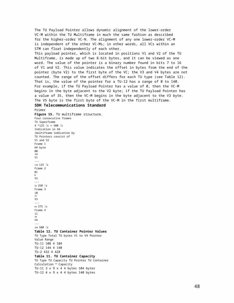
The process where a part of the information carried in a transmissionsystem is extracted (dropped) at an intermediate point and differentinformation is inserted (added) for subsequent transmission. Theremaining traffic passes straight through the multiplexer withoutadditional processing.Add/Drop Multiplexer (ADM)A multiplexer capable of extracting and inserting lower-rate signalsfrom a higher-rate multiplexed signal without completely demultiplexingthe signal.Administrative Unit (AU)An Administrative Unit is the information structure which providesadaptation between the Higher-Order path layer and the MultiplexSection layer. The Virtual Container (VC) plus the pointers (H1, H2, H3bytes) is called the Administrative Unit (AU).AIS (Alarm Indication Signal)A code sent downstream indicating an upstream failure has occurred.AMIAlternate Mark Inversion. The line-coding format in transmissionsystems where successive ones (marks) are alternatively inverted(sent with polarity opposite that of the preceding mark).ANSIAmerican National Standards Institute. A standards-setting, nongovernmentorganization, which develops and publishes standardsfor “voluntary” use in the United States.AsynchronousA network where transmission system payloads are not synchronisedand each network terminal runs on its own clock.Asynchronous Transfer Mode (ATM)A multiplexing/switching technique in which information is organizedinto fixed-length cells with each cell consisting of an identificationheader field and an information field. The transfer mode is asynchronousin the sense that the use of the cells depends on the requiredor instantaneous bit rate.AttenuationReduction of signal magnitude or signal loss, usually expressedin decibels.Automatic Protection Switching (APS)The ability of a network element to detect a failed working line andswitch the service to a spare (protection) line. 1+1 APS pairs a protectionline with each working line. 1:N APS provides one protectionline for every N working lines.BackhaulingCumbersome traffic management technique used to reduce theexpense of multiplexing/demultiplexing.BandwidthInformation-carrying capacity of a communication channel. Analogbandwidth is the range of signal frequencies that can be transmittedby a communication channel or network.Bi-directionalOperating in both directions. Bi-directional APS allows protectionswitching to be initiated by either end of the line.Binary N-Zero Suppression (BNZS)Line coding system that replaces N number of zeros with a specialcode to maintain pulse density required for clock recovery. N istypically 3, 6, or 8.SDH Telecommunications StandardPrimerThree sets of terms are often used interchangeablyto describe SDH processes.However, it’s important to recognize that theseterms are not equivalent; each has a distinct
48
meaning:Add/Drop – The process where a part of theinformation carried in a transmission systemis extracted (dropped) at an intermediate pointand different information is inserted (added)for subsequent transmission. The remainingtraffic passes straight through the multiplexerwithout additional processing.Map/Demap – A term for multiplexing, implyingmore visibility inside the resultant multiplexed bitstream than available with conventional asynchronoustechniques.Multiplex/Demultiplex – Multiplex (MUX)allows the transmission of two or more signals overa single channel. Demultiplex (DEMUX) is theprocess of separating two or more signals previouslycombined by compatible multiplexing equipment torecover signals combined within it and for restoringthe distinct individual channels of the signals.Don’t Confuse The Terms33 www.tektronix.com/opticalBIP-8 (Bit Interleaved Parity-8)A method of error checking in SDH which allows in-service performancemonitoring. For example, a BIP-8 creates eight-bit (one-byte)groups, then does a parity check for each of the eight bit positionsin the byte.B-ISDN (Broadband Integrated Services Digital Network)A single ISDN network which can handle voice, data, and eventuallyvideo services.BitOne binary digit; a pulse of data.Bit Error Rate (BER)The number of bit errors detected in a unit of time, usually onesecond. Bit Error rate (BER) is calculated with the formula:BER = errored bits received/total bits sentBlock Error rate (BLER)One of the underlying concepts of error performance is the notionof Errored Blocks; i.e., blocks in which one or more bits are in error.A block is a set of consecutive bits associated with the path or sectionmonitored by means of an Error Detection Code (EDC), such as BitInterleaved Parity (BIP). Block Error rate (BLER) is calculated withthe formula:BLER = errored blocks received/total blocks sentBit-Interleaved Parity (BIP)A parity check that groups all the bits in a block into units (such asbyte), then performs a parity check for each bit position in the group.Bit-StuffingIn asynchronous systems, a technique used to synchronise asynchronoussignals to a common rate before multiplexing.Bits per second (bit/s)The number of bits passing a point every second. The transmissionrate for digital information.BroadbandServices requiring over 2 Mbit/s transport capacity.CCITTFormer name of ITU.ChannelThe smallest subdivision of a circuit that provides a type of communicationservice; usually a path with only one direction.CircuitA communications path or network; usually a pair of channels
49
providing bi-directional communication.Circuit SwitchingBasic switching process whereby a circuit between two users isopened on demand and maintained for their exclusive use for theduration of the transmission.Coding Violation (CV)A transmission error detected by the difference between thetransmitted line code and that expected at the receive end by thelogical coding rules.ConcatenationThe linking together of various data structures, for example twochannels joined to form a single channel. In SDH, a number (M) ofTUs can be linked together to produce a concatenated container, Mtimes the size of the TU. An example of this is the concatenation offive TU-2s to carry a 32 Mbit/s video signal, known as VC-2-5c.Once assembled, any concatenated VC structure is multiplexed,switched, and transported through the network as a single entity.Cyclic Redundancy Check (CRC)A technique for using overhead bits to detect transmission errors.Data Communications Channel (DCC)Data channels in SDH that enable OAM communications betweenintelligent controllers and individual network nodes as well as internodecommunications.DefectA limited interruption in the ability of an item to perform a requiredfunction. Persistence of a defect can cause a failure.Demultiplex (DEMUX)To separate two or more signals previously combined by compatiblemultiplexing equipment to recover signals combined within it and forrestoring the distinct individual channels of the signals.Dense Wavelength Division Multiplexing (DWDM)DWDM is the higher capacity version of WDM, which is a meansof increasing the capacity of fibre-optic data transmission systemsthrough the multiplexing of multiple wavelengths of light. Commerciallyavailable DWDM systems support the multiplexing of from 8 to 40wavelengths of light.Digital Cross-connect (DCS)An electronic cross-connect which has access to lower-rate channelsin higher-rate multiplexed signals and can electronically rearrange(cross-connect) those channels.Digital SignalAn electrical or optical signal that varies in discrete steps. Electricalsignals are coded as voltages, optical signals are coded as pulsesof light.SDH Telecommunications StandardPrimerwww.tektronix.com/optical 34
ETSI (European Telecommunications Standards Institute)Organization responsible for defining and maintaining Europeanstandards, including SDH.FailureA termination of the ability of an item to perform a required function.A failure is caused by the persistence of a defect.FEBE (Far End Block Error)See Remote Error Indication (REI).FERF (Far End Receive Failure)See Remote Defect Indication (RDI).Fixed StuffA bit or byte whose function is reserved. Fixed stuff locations, sometimescalled reserved locations, do not carry overhead or payload.
50

Floating ModeA tributary mode that allows the synchronous payload to begin anywherein the VC. Pointers identify the starting location of the LO-VC.LO-VCs in different multiframes may begin at different locations.FramingMethod of distinguishing digital channels that have been multiplexedtogether.FrequencyThe number of cycles of periodic activity that occur in a discreteamount of time.GroomingConsolidating or segregating traffic for efficiency.HDB3High Density Bipolar 3. A bipolar coding method that does not allowmore than three consecutive zeros.ITU (International Telecommunication Union)An agency of the United Nations responsible for the regulation,standardization, coordination, and development of internationaltelecommunications as well as the harmonization of national policies.It functions through international committees of telecommunicationsadministrations, operators, manufacturers, and scientific/industrialorganizations.JitterThe short-term variations of the significant instants of a timing signalfrom their ideal positions in time (where short term implies that thesevariations are of frequency greater than or equal to 10 Hz).Locked ModeA virtual tributary mode that fixes the starting location of the VC.Locked mode has less pointer processing than floating mode.Map/DemapA term for multiplexing, implying more visibility inside the resultantmultiplexed bit stream than available with conventional asynchronoustechniques.MappingThe process of associating each bit transmitted by a service into theSDH payload structure that carries the service. For example, mappingan E1 service into an SDH VC-12 associates each bit of the E1 with alocation in the VC-12.MultiframeAny structure made up of multiple frames. SDH has facilities torecognize multiframes at the E1 level and at the VC-N level.Multiplex Section Alarm Indication Signal (MS-AIS)MS-AIS is generated by Section Terminating Equipment (STE) uponthe detection of a Loss of Signal or Loss of Frame defect, on anequipment failure. MS-AIS maintains operation of the downstreamregenerators, and therefore prevents generation of unnecessaryalarms. At the same time, data and orderwire communication isretained with the downstream equipment.Multiplex Section Remote Defect Indication (MS-RDI)A signal returned to the transmitting equipment upon detecting aLoss of Signal, Loss of Frame, or MS-AIS defect. MS-RDI was previouslyknown as Multiplex Section FERF.Multiplex Section Overhead (MSOH)18 bytes of overhead accessed, generated, and processed by MSterminating equipment. This overhead supports functions such aslocating the payload in the frame, multiplexing or concatenatingsignals, performance monitoring, automatic protection switching,and line maintenance.Multiplex (MUX)To transmit two or more signals over a single channel.
51

MultiplexerA device for combining several channels to be carried by a singlephysical channel.NarrowbandServices requiring up to 2 Mbit/s transport capacity.SDH Telecommunications StandardPrimer35 www.tektronix.com/opticalNetwork Element (NE)Any device which is part of an SDH transmission path and servesone or more of the section, line and path-terminating functions.In SDH, the five basic network elements are:Add/drop multiplexerBroadband digital cross-connectWideband digital cross-connectFlexible multiplexerRegeneratorOAMOperations, Administration, and Maintenance. Also called OAM&P.OAM&P (Operations, Administration, Maintenance,and Provisioning)Provides the facilities and personnel required to manage a network.Optical AmplifierA device to amplify an optical signal without converting the signalfrom optical to electrical and back again to optical energy. The twomost common optical amplifiers are erbium-doped fibre amplifiers(EDFAs), which amplify with a laser pump diode and a section oferbium-doped fibre, and semiconductor laser amplifiers.OrderwireA dedicated voice channel used by installers to expedite theprovisioning of lines.OS (Operations System)Sophisticated applications software that manages operationof the entire network.OSI Seven-layer ModelA standard architecture for data communications. Layers define hardwareand software required for multi-vendor information processingequipment to be mutually compatible. The seven layers from lowestto highest are: physical, link, network, transport, session, presentation,and application.OverheadExtra bits in a digital stream used to carry information besidestraffic signals. Orderwire, for example, would be considered overheadinformation.Packet SwitchingAn efficient method for breaking down and handling high-volume trafficin a network. A transmission technique that segments and routesinformation into discrete units. Packet switching allows for efficientsharing of network resources as packets from different sources canall be sent over the same channel in the same bitstream.Parity CheckAn error-checking scheme which examines the number of transmittedbits in a block which hold the value of “one.” For even parity, an overheadparity bit is set to either one or zero to make the total numberof transmitted ones in the data block plus parity bit an even number.For odd parity, the parity bit is set to make the total number of onesin the block an odd number.PathA logical connection between a point where a service in a VC ismultiplexed to the point where it is demultiplexed.Path Overhead (POH)
52

Overhead accessed, generated, and processed by path-terminatingequipment.Path Terminating Equipment (PTE)Network elements such as fibre optic terminating systems whichcan access, generate, and process Path Overhead.PayloadThe portion of the SDH signal available to carry service signalssuch as E1 and E3. The contents of a VC.Payload PointerIndicates the beginning of a Virtual Container.Payload CapacityThe number of bytes the payload of a single frame can carry.PlesiochronousA network with nodes timed by separate clock sources with almostthe same timing.PointerA part of the SDH overhead that locates a floating payload structure.AU-N pointers locate the payload. TU-M pointers locate floating modetributaries. All SDH frames use AU pointers; only floating mode virtualcontainers use TU pointers.POP (Point-of-Presence)A point in the U.S. network where inter-exchange carrier facilitiesmeet with access facilities managed by telephone companies or otherservice providers.PRC (Primary Reference Clock)In a synchronous network, all the clocks are traceable to one highlystable reference supply, the Primary Reference Clock (PRC). The accuracyof the PRC is better than ±1 in 1011 and is derived from acesium atomic standard.SDH Telecommunications StandardPrimerwww.tektronix.com/optical 36
Remote Alarm Indication (RAI)A code sent upstream on an En circuit as a notification that a failurecondition has been declared downstream. (RAI signals were previouslyreferred to as Yellow signals.)Remote Defect Indication (RDI)A signal returned to the transmitting Terminating Equipment when thereceiving Terminating Equipment detects a Loss of Signal, Loss ofFrame, or AIS defect. RDI was previously known as Far End ReceiveFailure (FERF).Remote Error Indication (REI)An indication returned to a transmitting node (source) that an erroredblock has been detected at the receiving node (sink). REI was previouslyknown as Far End Block Error (FEBE).Remote Failure Indication (RFI)A failure is a defect that persists beyond the maximum time allocatedto the transmission system protection mechanisms. When this situationoccurs, an RFI is sent to the far end and will initiate a protectionswitch if this function has been enabled.RegeneratorDevice that restores a degraded digital signal for continued transmission;also called a repeater.SDH (Synchronous Digital Hierarchy)The ITU-defined international networking standard whose basetransmission level is 155 Mbit/s (STM-1). SDH standards were firstpublished in 1989 to address interworking between the ITU and ANSItransmission hierarchies.SEC (Synchronous Equipment Clock)G.813 slave clock contained within an SDH network element.
53
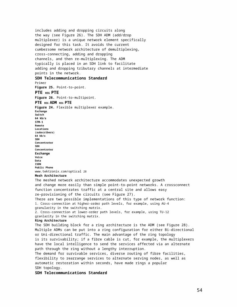
SectionThe span between two SDH network elements capable of accessing,generating, and processing only SDH Section overhead.Section OverheadNine columns of SDH overhead accessed, generated, and processedby section terminating equipment. This overhead supports functionssuch as framing the signal and performance monitoring.Section Terminating Equipment (STE)Equipment that terminates the SDH Section layer. STE interpretsand modifies or creates the Section Overhead.SlipAn overflow (deletion) or underflow (repetition) of one frameof a signal in a receiving buffer.SONET (Synchronous Optical Network)A standard for optical transport in the United States, Canada, Korea,and Hong Kong that defines optical carrier levels and their electricallyequivalent synchronous transport signals. SONET allows for a multivendorenvironment and positions the network for transport of newservices, synchronous networking, and enhanced OAM&P.SSM (Synchronisation Status Message)Bits 5 to 8 of SDH overhead byte S1 are allocated for SynchronisationStatus Messages. For further details on the assignment of bit patternsfor byte S1, see the section of this primer on Multiplex Section Overhead.StuffingSee bit-stuffing.SynchronousA network where transmission system payloads are synchronisedto a master (network) clock and traceable to a reference clock.A network where all clocks have the same long term accuracy undernormal operating conditions.Synchronisation Supply Unit (SSU)A G.812 network equipment clock.Synchronous Transport Module (STM)A structure in the SDH transmission hierarchy. STM-1 is SDH’sbase-level transmission rate equal to 155.52 Mbit/s. Higher ratesof STM-4, STM-16, and STM-64 are also defined.Tributary Unit (TU)A Tributary Unit is an information structure which provides adaptationbetween the Lower-Order path layer and the Higher-Order path layer.It contains the Virtual Container (VC) plus a tributary unit pointer.Tributary Unit Group (TUG)Contains several Tributary Units.Virtual Container (VC)A signal designed for transport and switching of sub-SDH payloads.WanderThe long-term variations of the significant instants of a digital signalfrom their ideal position in time (where long term implies that thesevariations are of frequency less than 10 Hz).Wavelength Division Multiplexing (WDM)WDM is a means of increasing the capacity of fibre-optic data transmissionsystems through the multiplexing of multiple wavelengths oflight. WDM systems support the multiplexing of as many as fourwavelengths.Yellow SignalSee Remote Alarm Indication (RAI).SDH Telecommunications StandardPrimer37 www.tektronix.com/opticalSDH Reference MaterialsITU-T:G.701 – Vocabulary of digital transmission and multiplexing and PCM terms
54
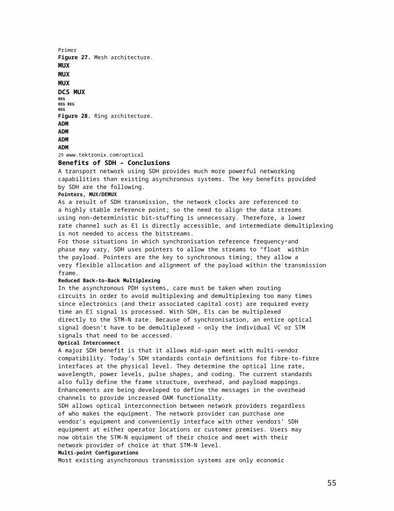
G.702 – Digital Hierarchy bit ratesG.703 – Physical/electrical characteristics of hierarchical digital interfacesG.704 – Synchronous frame structures used at 1544, 6312, 2048, 8448,and 44736 kbit/s hierarchical levelsG.706 – Frame alignment and cyclic redundancy check (CRC) proceduresrelating to basic frame structures defined in Recommendation G.704G.707 – Network Node Interface for the SDHG.772 – Protected monitoring points provided on digital transmission systemsG.780 – Vocabulary of terms for SDH networks and equipmentG.783 – Characteristics of SDH equipment functional blocksG.784 – SDH managementG.803 – Architecture of transport networks based on the SDHG.823 – Control of jitter and wander in PDH systemsG.825 – Control of jitter and wander in SDH systemsG.826 – Error performance parameters and objectives for international,constant bit rate digital paths at or above the primary rateG.827 – Availability parameters and objectives for path elements ofinternational constant bit-rate digital paths at or above the primary rateG.831 – Management capabilities of transport network based on SDHG.841 – Types and characteristics of SDH network protection architecturesG.861 – Principles and guidelines for the integration of satellite andradio systems in SDHG.957 – Optical interfaces for equipment and systems relating to the SDHG.958 – Digital line systems based on SDH for use on optical fibre cablesI.432 – B-ISDN user-network interface – Physical layer specificationM.2100 – Performance limits for bringing-into-service and maintenanceof international digital paths, sections, and transmission systemsM.2101 – Performance limits for BIS and maintenance of SDH pathsand multiplex sectionsO.150 – General requirements for instrumentation for performancemeasurements on digital transmission equipmentO.172 – Jitter and wander measuring equipment for digital systemswhich are based on the Synchronous Digital Hierarchy (SDH)O.181 – Equipment to assess error performance on STM-N interfacesF.750 (ITU-R) – Architectures and functional aspects of radio-relay systemsfor SDH-based networks
Introduction to SONET/SDH (continued …):
Synchronous optical network (SONET) is a standard for optical telecommunications transport. It was formulated by the ECSA for ANSI, which sets industry standards in the United States for telecommunications and other industries. The comprehensive SONET/synchronous digital hierarchy (SDH) standard is expected to provide the transport infrastructure for worldwide telecommunications for at least the next two or three decades.
The increased configuration flexibility and bandwidth availability of SONET provides significant advantages over the older telecommunications system. These advantages include the following:
reduction in equipment requirements and an increase in network reliability
provision of overhead and payload bytes—the overhead bytes permit management of the payload bytes on an individual basis and facilitate centralized fault sectionalization
definition of a synchronous multiplexing format for carrying lower level digital signals (such as DS–1, DS–3) and a synchronous structure that greatly simplifies
55

the interface to digital switches, digital cross-connect switches, and add-drop multiplexers
availability of a set of generic standards that enable products from different vendors to be connected
definition of a flexible architecture capable of accommodating future applications, with a variety of transmission rates
In brief, SONET defines optical carrier (OC) levels and electrically equivalent synchronous transport signals (STSs) for the fiber-optic–based transmission hierarchy.
Background
Before SONET, the first generations of fiber-optic systems in the public telephone network used proprietary architectures, equipment, line codes, multiplexing formats, and maintenance procedures. The users of this equipment—regional Bell operating companies and interexchange carriers (IXCs) in the United States, Canada, Korea, Taiwan, and Hong Kong—wanted standards so that they could mix and match equipment from different suppliers. The task of creating such a standard was taken up in 1984 by the ECSA to establish a standard for connecting one fiber system to another. This standard is called SONET.
Basic SONET Signal
SONET defines a technology for carrying many signals of different capacities through a synchronous, flexible, optical hierarchy. This is accomplished by means of a byte-interleaved multiplexing scheme. Byte-interleaving simplifies multiplexing and offers end-to-end network management.
The first step in the SONET multiplexing process involves the generation of the lowest level or base signal. In SONET, this base signal is referred to as synchronous transport signal–level 1, or simply STS–1, which operates at 51.84 Mbps. Higher-level signals are integer multiples of STS–1, creating the family of STS–N signals in Table 1. An STS–N signal is composed of N byte-interleaved STS–1 signals. This table also includes the optical counterpart for each STS–N signal, designated optical carrier level N (OC–N).
Synchronous and nonsynchronous line rates and the relationships between each are shown in Tables 1 and 2.
Table 1. SONET Hierarchy
Signal Bit Rate (Mbps) Capacity
STS–1, OC–1 51.840 28 DS–1s or 1 DS–3
56

STS–3, OC–3 155.520 84 DS–1s or 3 DS–3s
STS–12, OC–12 622.080 336 DS–1s or 12 DS–3s
STS–48, OC–48 2,488.320 1,344 DS–1s or 48 DS–3s
STS–192, OC–192 9,953.280 5,376 DS–1s or 192 DS–3s
Note: STS = synchronous transport signal; OC = optical carrier
Table 2. Non synchronous Hierarchy
Signal Bit Rate (Mbps) Channels
DS–0 0.064 1 DS–0
DS–1 1.544 24 DS–0s
DS–2 6.312 96 DS–0s
DS–3 44.736 28 DS–1s
What is e1?In: Electronics Engineering [Edit categories]
[Improve] e1 the basic data rate of communication in telecom( europeon ,india as well)... It is made up to 32 channels of 64 kbps each ... so i e1=2.048Mbps....
E-carrier:
In digital telecommunications, where a single physical wire pair can be used to carry many simultaneous voice conversations by time-division multiplexing, worldwide standards have been created and deployed. The European Conference of Postal and Telecommunications Administrations (CEPT) originally standardized the E-carrier system, which revised and improved the earlier American T-carrier technology, and this has now been adopted by the International Telecommunication Union Telecommunication Standardization Sector (ITU-T). This is now widely used in almost all countries outside the USA, Canada and Japan.
57

The E-carrier standards [1][2] form part of the Plesiochronous Digital Hierarchy (PDH) where groups of E1 circuits may be bundled onto higher capacity E3 links between telephone exchanges or countries. This allows a network operator to provide a private end-to-end E1 circuit between customers in different countries that share single high capacity links in between.
In practice, only E1 and E3 versions are used. Physically E1 is transmitted as 32 timeslots and E3 512 timeslots, but one is used for framing and typically one allocated for signalling call setup and tear down. Unlike Internet data services, E-carrier systems permanently allocate capacity for a voice call for its entire duration. This ensures high call quality because the transmission arrives with the same short delay (latency) and capacity at all times.
E1 circuits are very common in most telephone exchanges and are used to connect to medium and large companies, to remote exchanges and in many cases between exchanges. E3 lines are used between exchanges, operators and/or countries, and have a transmission speed of 34.368 Mbit/s.
E1
An E1 link operates over two separate sets of wires, usually twisted pair cable. A nominal 3 Volt peak signal is encoded with pulses using a method that avoids long periods without polarity changes. The line data rate is 2.048 Mbit/s (full duplex, i.e. 2.048 Mbit/s downstream and 2.048 Mbit/s upstream) which is split into 32 timeslots, each being allocated 8 bits in turn. Thus each timeslot sends and receives an 8-bit PCM sample, usually encoded according to A-law algorithm, 8000 times per second (8 x 8000 x 32 = 2,048,000). This is ideal for voice telephone calls where the voice is sampled into an 8 bit number at that data rate and reconstructed at the other end. The timeslots are numbered from 0 to 31.
One timeslot (TS0) is reserved for framing purposes, and alternately transmits a fixed pattern. This allows the receiver to lock onto the start of each frame and match up each channel in turn. The standards allow for a full Cyclic Redundancy Check to be performed across all bits transmitted in each frame, to detect if the circuit is losing bits (information), but this is not always used.
One timeslot (TS16) is often reserved for signalling purposes, to control call setup and teardown according to one of several standard telecommunications protocols. This includes Channel Associated Signaling (CAS) where a set of bits is used to replicate opening and closing the circuit (as if picking up the telephone receiver and pulsing digits on a rotary phone), or using tone signalling which is passed through on the voice circuits themselves. More recent systems used Common Channel Signaling (CCS) such as ISDN or Signalling System 7 (SS7) which send short encoded messages with more information about the call including caller ID, type of transmission required etc. ISDN is often used
58
between the local telephone exchange and business premises, whilst SS7 is almost exclusively used between exchanges and operators. In theory, a single SS7 signaling timeslot can control up to 4096 circuits per signalling channel using a 12-bit Channel Identification Code (CIC)[3], thus allowing slightly more efficient use of the overall transmission bandwidth because additional E1 links would use all 31 voice channels. ANSI uses a larger 14-bit CIC and so can accommodate up to 16,384 circuits. In most environments, multiple signalling channels would be used to provide redundancy in case of faults or outages.
Unlike the earlier T-carrier systems developed in North America, all 8 bits of each sample are available for each call. This allows the E1 systems to be used equally well for circuit switch data calls, without risking the loss of any information.
While the original CEPT standard G.703 specifies several options for the physical transmission, almost exclusively HDB3 format is used.
Definition
Link An unidirectional channel residing in one timeslot of a E1 or T1 Line, carrying 64 kbit/s (64'000 bit/s) raw digital data.
Line An unidirectional E1 or T1 physical connection.
Trunk A bidirectional E1 or T1 physical connection.
Hierarchy levels
The PDH based on the E0 signal rate is designed so that each higher level can multiplex a set of lower level signals. Framed E1 is designed to carry 30 E0 data channels + 1 signalling channel, all other levels are designed to carry 4 signals from the level below. Because of the necessity for overhead bits, and justification bits to account for rate differences between sections of the network, each subsequent level has a capacity greater than would be expected from simply multiplying the lower level signal rate (so for example E2 is 8.448 Mbit/s and not 8.192 Mbit/s as one might expect when multiplying the E1 rate by 4).
Note, because bit interleaving is used, it is very difficult to demultiplex low level tributaries directly, requiring equipment to individually demultiplex every single level down to the one that is required.
Signal RateE0 64 kbit/sE1 2.048 Mbit/sE2 8.448 Mbit/sE3 34.368 Mbit/s
59
E4 139.264 Mbit/sE5 564.992 Mbit/s
Historical Note on E1 and T1
In 1972, some 10 years following the commercial success of T1 in the US, Europe decided to develop its own digital transmission technology. As expected, CEPT wanted to design a different transmission format, named E for Europe. (To have their own standard was a European fetish then, as for example their TV formats, size of letter paper, shape of electric plugs, and at one time different rail gauge for each country.) With the hindsight learned from the T1 system, E1 is indeed a much superior design.
The differences are as follows.
1. 32 8-bit time slots per frame, all numbers powers of 2, compared to the 193-bit frame of T1, which requires hiccups in counting.
2. 30 voice channels for E1 vs. 24 for T1. Since telephone equipment are grouped in 12, the number 30 results in acceptable "misalignment" of office wiring plan. Conversion between E1 and T1 results in idle channels except for 5 T1 to 4 E1 conversion.
3. One 8-bit timeslot reserved for OA&M for E1. The single bit for T1 proved inadequate.
4. One 8-bit timeslot reserved for signaling, available for CAS, SS7, or ISDN. The T1 format resorted to robbed bit signaling for CAS, and reassign a voice timeslot for SS7 and ISDN, resulting in a 23 channel system. Horrors!
5. Clear 64 Kbit/s data capacity for E1. T1 has to cope with robbed bit.
In fairness, T1 fully met the goals of voice transmission at the time. It was a victim of its own success, namely it spawned the digital transmission revolution, for which the T1 format was then found wanting. LoopTel 02:51, 1 December 2006 (UTC)
[edit] Unfinished Business
For all the careful planning and design of the E1 format, one item remained unfinished, namely the remote terminal command syntax. A basic tool for troubleshooting a failed line is to do loopbacks a section at a time. If one person from one end of a line segment can send a command to a remote end to effect a loopback, then this obviates the need to send a second person to the remote end, saving a "truck roll".
For T1, this command structure was dictated by AT&T, then in control of all T1 systems. For E1, CEPT had set aside certain bits in TS0 for this purpose, called SA bits. However, the committee could not agree on the exact format of the commands. As a result, each manufacturer determined its own proprietary command codes. An E1 terminal of one brand could not communicate with a terminal of another brand in the troubleshooting
60

procedure. This of course leads to brand loyalty, which is exactly what the manufacturers desired.LoopTel 02:22, 2 December 2006 (UTC)
E1 lines which are used in Europe are formed when 32 digitized phone lines are combined into a single digital data stream. The resulting data stream has a rate of 2.048Mbps. Europe does not us the DS designation.
61


![[Masami Kihara] Digital Clocks for Synchronization](https://img.pdfslide.us/doc/110x75/5466ee74af795992368b5390/masami-kihara-digital-clocks-for-synchronization.jpg)