Embed Size (px)
Citation preview
Progress In Electromagnetics Research, PIER 75, 225–237, 2007
A NEW ARCHITECTURE OF UWB RADAR UTILIZINGMICROWAVE CHAOTIC SIGNALS AND CHAOSSYNCHRONIZATION
S. Qiao †, Z. G. Shi, and K. S. Chen
Department of Information and Electronic EngineeringZhejiang UniversityHangzhou, 310027, China
W. Z. Cui and W. Ma
Xi’an Institute of Space Radio TechnologyXi’an, 710000, China
T. Jiang and L. X. Ran
The Electromagnetics Academy at Zhejiang UniversityZhejiang UniversityHangzhou, 310058, China
Abstract—In this paper, we present a new scheme for therealization of a wide-band chaotic RADAR system. The remarkablecharacteristics of such scheme are: (1) Wide-band chaotic signalgenerated from microwave chaotic Colpitts oscillator is directly usedas the RADAR signal; (2) Chaos synchronization is used to recoverthe chaotic signal from the back-scattered signal by targets; (3) Theintrinsic sensitivities of the chaotic signal to the parameters of thechaotic circuit and to the initial conditions are used to realize the“multi-user” property. System simulations show that such RADARcan still work in an environment when the signal-to-noise ratio (SNR)is lower than −20 dB.
† Also with Zhejiang University City College, Hangzhou, 310025, China.
226 Qiao et al.
1. INTRODUCTION
RADAR, abbreviated from “Radio Detection and Ranging”, mightbe the most important technical invention of human in the area ofmicrowave engineering. From the invention of a primitive anti-collisionmarine RADAR by a Germany Christian Husmeyer in 1903, RADARhas gone through a history for more than 100 years. With therapid development of microelectronics and advanced manufacturingtechnics from 1960s, new techniques are continuously applied in variousRADAR systems [1–3].
Nowadays, modern RADAR systems have been regarded to bevery “mature” in all the aspects like performance, manufacturingtechnics and reliability, and have been widely applied in either militaryand civil uses. However, the development of RADAR is far fromits end. The coming forth of the “electric war” and the issues ofthe electromagnetic compatibility (EMC) raised new requirements toRADAR systems. For military RADAR, it would be better if theRADAR signal is more difficult to be detected or interfered, whilefor civil RADAR, EMC performance is more emphasized. A typicalexample is the anti-collision vehicle-borne RADAR: since the vehicle-borne RADAR on one car can not avoid the luminance from theadjacent lane, it has to work under the interference in a same frequencyband. The number of cars is innumerous, meaning that for a vehicle-borne RADAR, it has to be co-existent with a number of RADARswith the same schemes, or it should be with the property of “multi-user”, similar to a large-volume wireless communication system, suchas a cellular system. The key requirement for modern military andcivil RADARs is actually the same, i.e., how to let RADAR signalslook more like wide-band noise. As the spread-spectrum technique hasbeen widely used in military and civil communications, using ultra-wide band, noise-like signals in modern RADAR systems is also atrend.
In recent years, chaos has been applied in various communicationsystems. In 2005, a chaos-based communication system at high bitrates using commercial fibre-optic links has been reported in [4, 5].For radar systems using chaotic signals or pesudo random signals,there are also several literatures published [6–11]. In this paper, wepresent a new scheme for the realization of a wide-band RADAR usingchaos. Different from those published literatures listed above, thecharacteristics of this new scheme are: (1) Wide-band signal generatedfrom microwave chaotic circuits is directly used as the RADAR signal;(2) Chaos synchronization is used to recover the chaotic signal fromthe back-scattered signal by targets, based on the ideas in [12–14]; (3)
Progress In Electromagnetics Research, PIER 75, 2007 227
The intrinsic sensitivities of the chaotic signal to the parameters ofthe chaotic circuit and to the initial conditions are used to realize the“multi-user” property. By utilizing microwave chaotic RADAR signaland using chaos synchronization, such a RADAR scheme is differentfor known RADAR schemes, and is with some unique characteristics.
The paper is organized as following: (1) Deterministic chaos andmicrowave chaotic circuits are briefly introduced; (2) The new chaosbased RADAR scheme is described; (3) System simulations are run toillustrate how the system works; (4) A brief discussion is given.
2. MICROWAVE CHAOTIC CIRCUITS
Deterministic chaos has been widely studied in various scientific areas,especially in circuits and systems. It has been known that deterministicchaos can be described by definite dynamic equations but still withun-predictable long term behaviors. Chaos is a status different fromthe equilibrium, period or quasi-period of a dynamic system. Chaoticsignals generated by chaotic circuits exhibit noise-like waveforms intime domain and continuous spectra in frequency domain. Differentfrom real noise, chaotic signals can be controlled or synchronized. Sofar, various chaotic circuits and systems have been extensively studiedto illustrate the evolution from DC to chaos. One typical exampleis the famous Chua’s circuit. In early researches, chaotic circuitsrealized in laboratory only generated chaos spectra with kilohertz tomegahertz bandwidth, but till now, chaotic Colpitts circuits operatingat microwave frequencies have been reported [15, 16].
BJT
L
R
Vcc
C1
C2
IL
I0
VC1
VC2
+
−
−
+
B
E
C IEVBE
IEIC
C
B
E+
−
RE
+ −VCE
(a) (b)
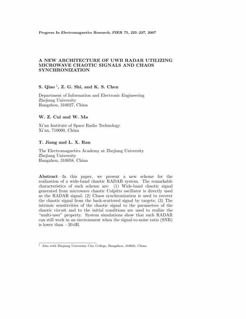
Figure 1. (a) Colpitts circuit and (b) Equivalent circuit model of theBJT in (a).
228 Qiao et al.
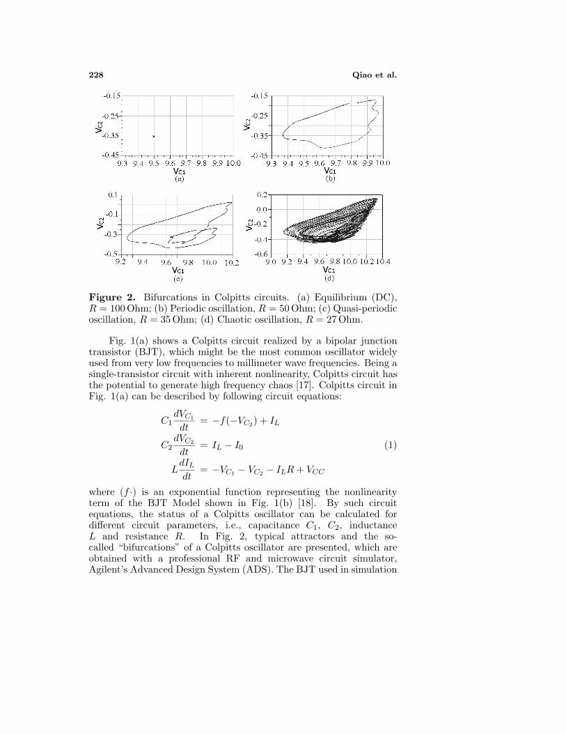
Figure 2. Bifurcations in Colpitts circuits. (a) Equilibrium (DC),R = 100 Ohm; (b) Periodic oscillation, R = 50 Ohm; (c) Quasi-periodicoscillation, R = 35 Ohm; (d) Chaotic oscillation, R = 27 Ohm.
Fig. 1(a) shows a Colpitts circuit realized by a bipolar junctiontransistor (BJT), which might be the most common oscillator widelyused from very low frequencies to millimeter wave frequencies. Being asingle-transistor circuit with inherent nonlinearity, Colpitts circuit hasthe potential to generate high frequency chaos [17]. Colpitts circuit inFig. 1(a) can be described by following circuit equations:
C1dVC1
dt= −f(−VC2) + IL
C2dVC2
dt= IL − I0 (1)
LdIL
dt= −VC1 − VC2 − ILR + VCC
where (f ·) is an exponential function representing the nonlinearityterm of the BJT Model shown in Fig. 1(b) [18]. By such circuitequations, the status of a Colpitts oscillator can be calculated fordifferent circuit parameters, i.e., capacitance C1, C2, inductanceL and resistance R. In Fig. 2, typical attractors and the so-called “bifurcations” of a Colpitts oscillator are presented, which areobtained with a professional RF and microwave circuit simulator,Agilent’s Advanced Design System (ADS). The BJT used in simulation
Progress In Electromagnetics Research, PIER 75, 2007 229
is Philips’ BFG425W with a threshold frequency of 25 GHz andthe circuit parameters are C1 = 5 pF, C2 = 5 pF, L = 6 mH,I0 = 5.26 mA and VCC = 10 V. We see that with the variation ofthe resistance R from 100 Ohm to 27 Ohm, the Colpitts oscillatorexperiences sequentially the equilibrium, periodic, quasi-periodic andchaotic status. We see that in the case of chaos, the Lissajous patternformed by VC1 and VC2 constructs the so-called “strange attractor”, inwhich trajectory never intersects with itself, corresponding to a non-periodic oscillation.
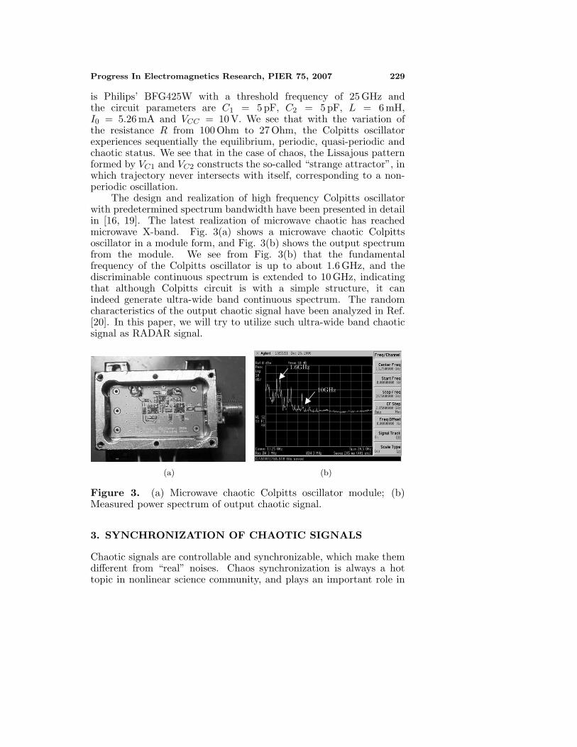
The design and realization of high frequency Colpitts oscillatorwith predetermined spectrum bandwidth have been presented in detailin [16, 19]. The latest realization of microwave chaotic has reachedmicrowave X-band. Fig. 3(a) shows a microwave chaotic Colpittsoscillator in a module form, and Fig. 3(b) shows the output spectrumfrom the module. We see from Fig. 3(b) that the fundamentalfrequency of the Colpitts oscillator is up to about 1.6 GHz, and thediscriminable continuous spectrum is extended to 10 GHz, indicatingthat although Colpitts circuit is with a simple structure, it canindeed generate ultra-wide band continuous spectrum. The randomcharacteristics of the output chaotic signal have been analyzed in Ref.[20]. In this paper, we will try to utilize such ultra-wide band chaoticsignal as RADAR signal.
1.6GHz
10GHz
(a) (b)
Figure 3. (a) Microwave chaotic Colpitts oscillator module; (b)Measured power spectrum of output chaotic signal.
3. SYNCHRONIZATION OF CHAOTIC SIGNALS
Chaotic signals are controllable and synchronizable, which make themdifferent from “real” noises. Chaos synchronization is always a hottopic in nonlinear science community, and plays an important role in
230 Qiao et al.
chaotic communications because it offers a potential advantage overnon-coherent detection in terms of noise performance and data ratewhen the information is recovered from a noisy distorted signal [21].There are several kinds of chaos synchronization, such as identicalsynchronization and phase synchronization. In most cases the identicalsynchronization is used in chaotic communication. Generally there aretwo synchronization schemes for identical synchronization: Pecora-Carroll (or drive-response) synchronization [22] and error feedbacksynchronization which is based on nonlinear observer method [23,24]. The synchronization performance comparison of chaotic colpittsoscillators using the two schemes have been discussed in Ref. [25],where both the mathematical derivation and numeric simulationsindicate that the error feedback synchronization scheme outperformsthe former one when the chaotic signal is transmitted over a noisychannel with an additive white Gaussian noise and a channel filter.
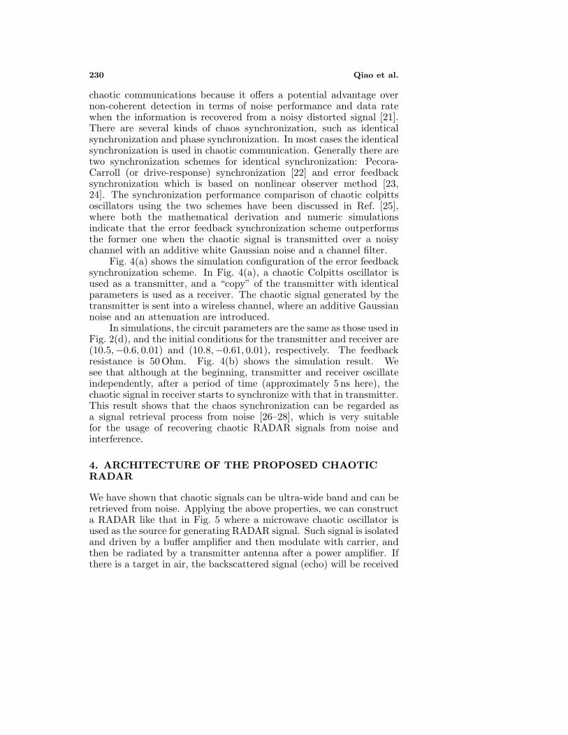
Fig. 4(a) shows the simulation configuration of the error feedbacksynchronization scheme. In Fig. 4(a), a chaotic Colpitts oscillator isused as a transmitter, and a “copy” of the transmitter with identicalparameters is used as a receiver. The chaotic signal generated by thetransmitter is sent into a wireless channel, where an additive Gaussiannoise and an attenuation are introduced.
In simulations, the circuit parameters are the same as those used inFig. 2(d), and the initial conditions for the transmitter and receiver are(10.5,−0.6, 0.01) and (10.8,−0.61, 0.01), respectively. The feedbackresistance is 50 Ohm. Fig. 4(b) shows the simulation result. Wesee that although at the beginning, transmitter and receiver oscillateindependently, after a period of time (approximately 5 ns here), thechaotic signal in receiver starts to synchronize with that in transmitter.This result shows that the chaos synchronization can be regarded asa signal retrieval process from noise [26–28], which is very suitablefor the usage of recovering chaotic RADAR signals from noise andinterference.
4. ARCHITECTURE OF THE PROPOSED CHAOTICRADAR
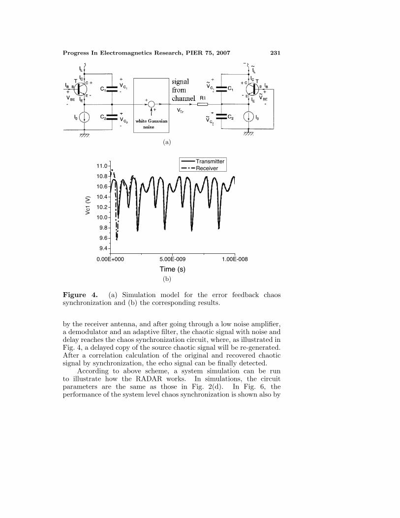
We have shown that chaotic signals can be ultra-wide band and can beretrieved from noise. Applying the above properties, we can constructa RADAR like that in Fig. 5 where a microwave chaotic oscillator isused as the source for generating RADAR signal. Such signal is isolatedand driven by a buffer amplifier and then modulate with carrier, andthen be radiated by a transmitter antenna after a power amplifier. Ifthere is a target in air, the backscattered signal (echo) will be received
Progress In Electromagnetics Research, PIER 75, 2007 231
(a)
0.00E+000 5.00E-009 1.00E-008
9.4
9.6
9.8
10.0
10.2
10.4
10.6
10.8
11.0
Vc1
(V
)
Time (s)
Transmitter Receiver
(b)
Figure 4. (a) Simulation model for the error feedback chaossynchronization and (b) the corresponding results.
by the receiver antenna, and after going through a low noise amplifier,a demodulator and an adaptive filter, the chaotic signal with noise anddelay reaches the chaos synchronization circuit, where, as illustrated inFig. 4, a delayed copy of the source chaotic signal will be re-generated.After a correlation calculation of the original and recovered chaoticsignal by synchronization, the echo signal can be finally detected.
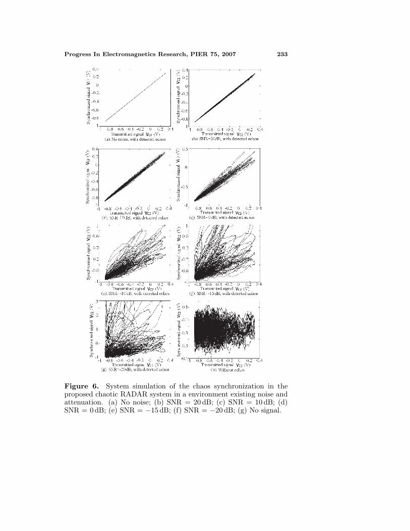
According to above scheme, a system simulation can be runto illustrate how the RADAR works. In simulations, the circuitparameters are the same as those in Fig. 2(d). In Fig. 6, theperformance of the system level chaos synchronization is shown also by
232 Qiao et al.
the Lissajous pattern, in which the horizontal axis represent the VC2
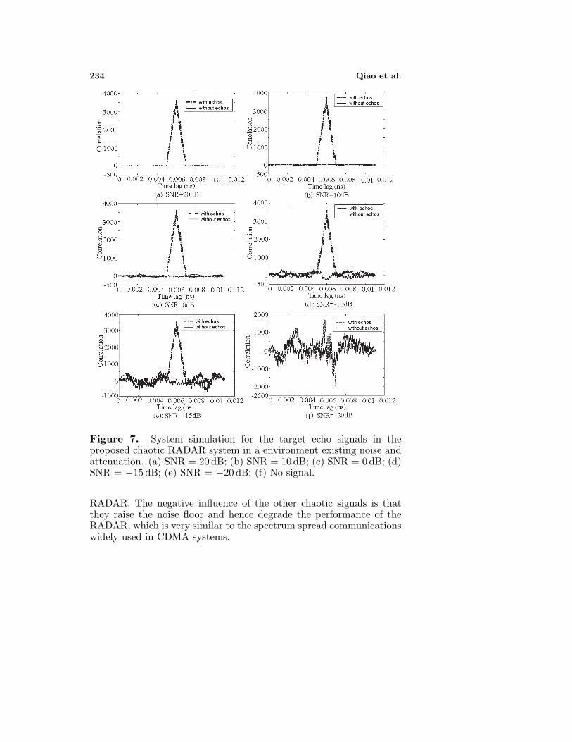
signal of the source chaotic Colpitts oscillator while the vertical axisrepresent the VC2 signal in the synchronization module. To show thesynchronization performance comparison in a clear way, the time delaybetween the transmitter and the receiver is omitted. Fig. 6(a) show theperfect synchronization case, corresponding to an infinite large signal-to-noise ratio (SNR). We see that in such case, the Lissajous patternis just a straight line. When SNR decreases, the Lissajous pattern isexpanded. However, we see that even when SNR is −20 dB, meaningthat the noise power is 100 times larger than signal’s, we can stilldistinguish this case from that when SNR is minus infinity in Fig. 6(f),which corresponding to the case of no target. Fig. 7 shows the outputof the correlation calculation. Again we see that the echo signal canbe distinguished even when SNR is −20 dB.
Another interesting property of chaotic signals is the “butterflyeffect”, or the sensitivity to the initial conditions. For two chaoticcircuits, even with identical circuit structures and parameters, theiroutput can be irrelevant, or in other words, the signals are orthogonalwith each other theoretically, for they can hardly have identical initialconditions. Since circuit parameters, i.e., capacitance, inductance andresistance, can be continuously tuned in wide ranges, the number oforthogonal chaotic signals can be infinite. This means for a correlationreceiver, multiple chaotic signals are permitted to co-exist in a samechannel. Thus, when there are multiple chaotic RADARs in onearea simultaneously, since the chaotic signals generated from differentchaotic sources are irrelevant, therefore it could be filtered by the chaossynchronization circuit, and will not influence the basic function of the
MicrowaveChaotic
OscillationSource
TransmitterAntenna
DriveCircuit
ModulationCircuit
PowerAmp
(Sinusoid)Carrier Source
DemodulationCircuit
ReceiverAntenna
High-gainAmp
AdaptiveFilter
ChaosSync.
CorrelationOutput
Object
Figure 5. Architecture of the proposed RADAR.
Progress In Electromagnetics Research, PIER 75, 2007 233
Figure 6. System simulation of the chaos synchronization in theproposed chaotic RADAR system in a environment existing noise andattenuation. (a) No noise; (b) SNR = 20 dB; (c) SNR = 10 dB; (d)SNR = 0 dB; (e) SNR = −15 dB; (f) SNR = −20 dB; (g) No signal.
234 Qiao et al.
Figure 7. System simulation for the target echo signals in theproposed chaotic RADAR system in a environment existing noise andattenuation. (a) SNR = 20 dB; (b) SNR = 10 dB; (c) SNR = 0 dB; (d)SNR = −15 dB; (e) SNR = −20 dB; (f) No signal.
RADAR. The negative influence of the other chaotic signals is thatthey raise the noise floor and hence degrade the performance of theRADAR, which is very similar to the spectrum spread communicationswidely used in CDMA systems.
Progress In Electromagnetics Research, PIER 75, 2007 235
5. DISCUSSION
In this paper, the possibility of applying microwave chaotic signals andchaos synchronization in constructing a new kind of UWB RADARis investigated. The system simulations show that such a RADARsystem can work under severe interference and with a “multi-user”property like a public wireless communication systems. However, thereare also challenges have to be overcome before these advantages canbe realized, in which the most difficult one might be the realization ofchaos synchronization in microwave band. Fortunately, researches inRef. [26] have demonstrated the feasibility of the realization of chaossynchronization at very high frequencies.
ACKNOWLEDGMENT
This work was supported by National Key Laboratory Foundation (No.9140C5304020704), National Natural Science Foundation of China(No. 60671003, No. 60531020), Zhejiang Provincial Natural ScienceFoundation (No. R105253), China Post Doctoral Science Foundation(No. 20060400313) and partly by Zhejiang Post Doctoral ScienceFoundation of China (No. 2006-bsh-25).
REFERENCES
1. Wang, S., X. Guan, D. Wang, X. Ma, and Y. Su, “Fast calculationof wide-band responses of complex radar targets,” Progress InElectromagnetics Research, PIER 68, 185–196, 2007.
2. Alyt, O. M., A. S. Omar, and A. Z. Elsherbeni, “Detectionand localization of RF radar pulses in noise environments usingwavelet packet transform and higher order statistics,” Progress InElectromagnetics Research, PIER 58, 301–317, 2006.
3. Zang, W., Z. G. Shi, S. C. Du, and K. S. Chen, “Novel rougheningmethod for reentry vehicle tracking using particle filter,” J. ofElectromagn. Waves and Appl., Vol. 21, No. 14, 1969–1981, 2007.
4. Roy, R., “Chaos down the line,” Nature, Vol. 438, 298, 2005.5. Argyris, A., et al., “Chaos-based communications at high bit rates
using commercial fibre-optic links,” Nature, Vol. 438, 343–346,2005.
6. Shen, Y., W. H. Shang, and G. S. Liu, “Ambiguity functionof chaotic phase modulated radar signals,” IEEE FourthInternational Conference on Signal Processing Proceedings, Vol. 2,1574–1577, 1998.
236 Qiao et al.
7. Liu, G. S., H. Gu, and W. M. Su, “Development of random signalradars,” IEEE Transactions on Aerospace and Electronic Systems,Vol. 35, No. 3, 770–777, 1999.
8. Weinberg, G. V. and A. Alexopoulos, “Examples of a classof chaotic radar signals,” Defence Science and TechnologyOrganisation, August 2005.
9. Hara, Y., et al., “Development of a chaotic signal radar systemfor vehicular collision-avoidance,” Proceeding of IEEE RadarConference, 227–232, 2002.
10. Lin, F. Y. and J. M. Liu, “Chaotic radar using nonlinear laserdynamics,” IEEE J. Quantum Electron., Vol. 40, No. 6, 815–820,2004.
11. Fortuna, L., M. Frasca, and A. Rizzo, “Chaotic pulse positionmodulation to improve the efficiency of sonar sensors,” IEEETransactions on Instrumentation and Measurement , Vol. 52,No. 6, 1809–1814, 2003.
12. Barahona, M. and C. S. Pooh, “Detection of nonlinear dynamicsin short, noisy time series,” Nature, Vol. 381, 215–217, 1996.
13. Tsonis, A. A. and J. B. Elsner, “Nonlinear prediction as a wayof distinguishing chaos from random fractal sequences,” Nature,Vol. 358, 217–220, 1992.
14. Haykin, S. and X. B. Li, “Detection of signals in chaos,”Proceedings of the IEEE , Vol. 83, No. 1, 94–122, 1995.
15. Mykolaitis, G., A. Tamasevicius, and S. Bumeliene, “Experimen-tal demonstration of chaos from Colpitts oscillator in VHF andUHF ranges,” Electronics Letters, Vol. 40, No. 2, 91–92, 2004.
16. Shi, Z. G. and L. X. Ran, “Microwave chaotic Colpitts resonator:design, implementation and applications,” J. of Electromagn.Waves and Appl., Vol. 20, No. 10, 1335–1349, 2006.
17. Kennedy, M. P., “Chaos in the Colpitts oscillator,” IEEETransactions on Circuits and Systems, Vol. 41, No. 11, 771–774,1994.
18. Maggio, G. M., O. D. Feo, and M. P. Kennedy, “Nonlinear analysisof the Colpitts oscillator and applications to design,” IEEE Trans.Circuits and Systems-I , Vol. 46, No. 9, 1118–1130, 1999.
19. Shi, Z. G. and L. X. Ran, “Design of chaotic Colpitts oscillatorwith prescribed frequency distribution,” International Journal ofNonlinear Science and Numerical Simulation, Vol. 5, No. 1, 89–94,2004.
20. Shi, Z. G., Y. Zhang, H. W. Liu, and L. X. Ran, “Randomnesstest of signal generated by microwave chaotic Colpitts oscillator,”
Progress In Electromagnetics Research, PIER 75, 2007 237
Microwave and Optical Technology Letters, Vol. 49, No. 8, 1981–1984, 2007.
21. Kolumban, G., M. P. Kennedy, and L. O.Chua, “The role ofsynchronization in digital communication using chaos - part II,”IEEE Trans. Circuits and Systems-I , Vol. 45, No. 11, 1129–1140,1998.
22. Pecora, L. M. and T. L. Carroll, “Driving systems with chaoticsignals,” Physical Review A, Vol. 44, No. 4, 2374–2383, 1991.
23. Shi, Z. G., L. X. Ran, and K. S. Chen, “Error feedbacksynchronization of chaotic Colpitts Circuit,” the 46th IEEEMWSCAS , Vol. 1, 225–228, 2003.
24. Shi, Z. G., L. X. Ran, and K. S. Chen, “Multiplexing chaoticsignals generated by Colpitts oscillator and Chua circuit usingdual synchronization,” Chinese Physics Letters, Vol. 22, No. 6,1336–1339, 2005.
25. Shi, Z. G., J. T. Huangfu, and L. X. Ran, “Performancecomparison of two synchronization schemes for Colpitts circuitsbased chaotic communication system over noisy channel,” The 5thWorld Congress on Intelligent Control and Automation, Vol. 6,1276–1279, 2004.
26. Myneni, K. and T. A.Thomas, “New method for the control offast chaotic oscillations,” Physical Review Letters, Vol. 83, No. 11,175–2178, 1999.
27. Sharma, N. and E. Ott, “Synchronization-based noise reductionmethod for communication,” Physical Review E , Vol. 58, No. 6,8005–8008, 1998.
28. Li, Y. and B. J. Yang, Introduction to Detection of ChaoticAttractors, Publishing House of Electronics Industry, 2004 (inChinese).