Embed Size (px)
Citation preview
Abstract— Formal Verification (FV) is widely acknowledged
for improving validation effectiveness. Usually formal
verification has been used to supplement more traditional
coverage oriented testing activities. Arithmetic Data-path FV has
matured over the time to completely replace traditional dynamic
validation methodologies. Moreover, it gives an additional
promise of 100% data-space coverage. Symbolic Trajectory
Evaluation (STE) is the best proven method of FV on Intel®
data-path designs. The Floating Point Units (FPUs) are generally
very data-path intensive. In the next generation Intel Processor
Graphics design, the FPU was completely re-architected and this
necessitated a methodology which could guarantee complete
verification in a tight verification schedule. STE was brought in
to meet this formidable target. This paper discusses the efficient
application of this methodology to achieve convincing results.
More than 201 bugs were caught in a very short verification cycle
using STE.
I. INTRODUCTION
VER since Intel graphics moved from chipset to CPU,
there is an ever-increasing demand on the graphics design
to make the combination of CPU and graphics more
compelling for the end user. The current generation graphics
processor unit (GPU) is not just solely used for image
rendering but also to share the workload with core-CPU
processor [1, 2]. Graphics processor designs have very short
design cycles to cope with the market requirements. In this
paper, we address the problem of verifying large arithmetic
data-path circuits using formal verification techniques in such
short design cycles.
Intel microprocessor design cycles follow a uniform
methodology over successive generations, known as “tick-tock
cadence” [3]. In a typical “tock” part of this cadence, major
innovative architectural changes are introduced in the
microprocessor design. In a typical “tick” part of this cadence,
relatively less architectural changes are introduced while
design is moved to the next generation semi-conductor
manufacturing process technology. This cadence effectively
allows consistently improving next generation microprocessor
capabilities and performance.
The latest “tick” CPU processor of Intel encases a graphics
engine that can be called “tock” taking into account the
number of architectural changes that went into the design.
Such aggressive architectural changes were introduced to
provide significantly increased graphics performance. This
presented a huge challenge to the verification team to verify
these architectural changes in a relatively shorter time. STE-
based formal verification methodology was used to tackle this
challenge providing a high degree of confidence in the
correctness of this design.
Execution units performing arithmetic computation inside
graphics microprocessors are becoming more available to end
users for high-performance computing using general purpose
graphics processor unit (GPGPU) programming methodology.
This makes it much more critical to ensure that the next
generation Intel Processor Graphics design implements the
arithmetic standards faithfully and the stakes are much higher
than previous generation graphics designs if a really tricky bug
were to be missed in the graphics execution unit [4, 5, 6].
This paper talks about how this challenging task of validating
“tock” features in “tick” timeline, was simplified and
successfully accomplished by making use of STE. We
describe how STE was used to establish correctness of
floating-point data-path circuits which resulted in discovery of
201 bugs. Many of these bugs were truly “FV-quality” bugs
which would have never been found by other forms of
validation or discovered much later in the project cycle.
Similar bugs were discovered very late in the post-silicon
phase in previous generation graphics design where STE-
based formal verification was not applied. Discovery of these
bugs in the latest graphics design has greatly contributed to
achieving higher RTL quality way ahead of tape-out1 and
significantly reducing the risk of encountering them in the
post-silicon verification.
A. Related Work
STE based formal verification approach has been widely
used at Intel in the past for various microprocessor designs to
formally verify data-path designs [7, 8, 9, 10, 11, 12]. It has
been proven very effective at handling large arithmetic circuits
and establishing their correctness against a formal
specification and discovering very difficult to find bugs in the
1 Sending design for semi-conductor manufacturing production is referred
to as tape-out.
Symbolic Trajectory Evaluation:
The Primary Validation Vehicle for Next
Generation Intel® Processor Graphics FPU M Achutha KiranKumar V, Aarti Gupta, and Rajnish Ghughal
Intel Corporation
{achutha.kirankumar.v.m, aarti.gupta, rajnish.ghughal}@intel.com
E
Proceedings of the 12th Conference on Formal Methods in Computer-Aided Design (FMCAD 2012)
149149978-1-4673-4831-7/12/$31.00 ©2012 IEEE978-0-9835678-2-0/12/$31.00 ©2012 IEEE 149978-0-9835678-2-0/12/$31.00 ©2012 FMCAD Inc.
process which would have been undetected by any other form
of validation. For example, STE-based formal verification was
used in an execution cluster of Intel microarchitecture code
named Nehalem to replace traditional simulation [7].
At Intel, FV techniques have also been applied to formally
verify designs other than arithmetic data-path in
microprocessor using other forms of formal verification, e.g.,
pipeline scheduler verification, cache coherence protocol
verification etc. [19, 20, 21]. These formal techniques
typically involve using explicit state model-checking,
symbolic model checking or bounded model checking using
SAT. In our experience, these techniques are not as suitable as
STE for verifying industrial scale floating point arithmetic
data-path designs.
Formal verification of floating-point arithmetic designs is a
well-studied problem both at Intel and elsewhere in the
industry [7, 8, 9, 10, 23, 24, 25, 26, 27] due to the critical need
of correctness of floating-point arithmetic. Majority of these
work [7, 8, 9, 10, 24, 25, 26] concentrate on verifying floating-
point addition, multiplier or divider operation but do not
address floating-point fused multiply addition operation which
presents a lot of unique challenges of its own.
In [23], formal verification of FMA operation is done by
excluding multiplier from the cone of influence and hence the
proof of the correctness of multiplication is missing. In our
experience, proof of the correctness of multiplication,
especially for double precision floating-point arithmetic is a
very challenging task and is critical to verify. In [23], a key
assumption was to disallow other operations in the pipeline
before or after the FMA operation. Our work allows arbitrary
operations to come before and after the FMA operation in
pipeline. In fact, some of the most interesting bugs that we
found involved interaction between FMA and other operations
in the pipeline. Such bugs are near impossible to discover by
any other forms of validation and hence it is critical that such
limiting assumptions should not be employed in formal
verification of floating-point arithmetic designs. One of the
many such bugs discovered by our work is described in a later
sub-section of this paper (see Complex Interaction Bugs).
In [27], Slobodova describes a FMA formal verification
proof developed at Intel previously using STE. This approach
mirrors closely with the approach used by us with some key
differences. FMA design implementation described in [27]
was significantly simpler than the FMA design in the next
generation Intel graphics, which uses an approach known as
“sea of multipliers” to implement very power-efficient and
latency-optimized multiplication. Such a FMA design
challenged us to approach the problem of verifying booth-
encoded partial products generation completely differently
than similar efforts in the past. Also in [27], FMA operation
on denormal floating-point numbers was not formally verified
due to limited hardware support of denormal floating-point
numbers in the design under consideration. In the next
generation of Intel graphics design, FMA operation fully
supports denormal floating-point numbers in the hardware.
This significantly expanded the data-space of the problem and
required us to completely rethink the traditional case-split
strategy employed in floating-point addition operation from
ground-up. In addition, a lot more floating-point precisions are
supported in the next generation Intel graphics design than the
design under consideration in [27].
Despite STE’s success in formally verifying arithmetic
designs in microprocessors previously, its application to
graphics design projects has been limited. This paper presents
first such application to large-scale industrial graphics design
where formal verification was used as a primary method of
validation resulting in a very large number of high quality
bugs found in the process.
II. WHAT IS STE?
Symbolic Trajectory Evaluation (STE) is a formal
verification method originally developed by Seger & Bryant in
1995 [13]. It is a high-performance model checking technique
using a symbolic simulation-based approach [14, 15, 16]. It
works over binary decision diagrams (BDDs), which are
symbolic Boolean expressions. STE is particularly well suited
to handle data-path properties, and it is used to verify gate-
level models against more abstract reference models.
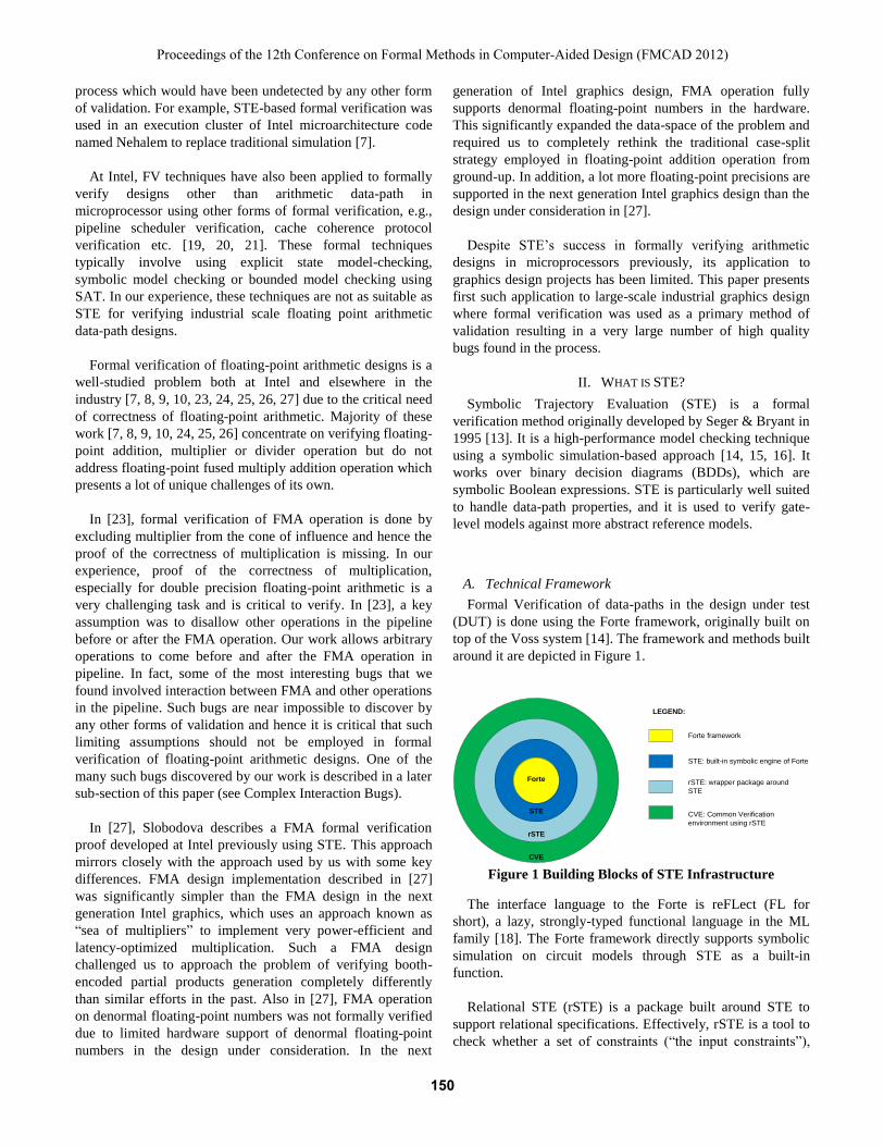
A. Technical Framework
Formal Verification of data-paths in the design under test
(DUT) is done using the Forte framework, originally built on
top of the Voss system [14]. The framework and methods built
around it are depicted in Figure 1.
Figure 1 Building Blocks of STE Infrastructure
The interface language to the Forte is reFLect (FL for
short), a lazy, strongly-typed functional language in the ML
family [18]. The Forte framework directly supports symbolic
simulation on circuit models through STE as a built-in
function.
Relational STE (rSTE) is a package built around STE to
support relational specifications. Effectively, rSTE is a tool to
check whether a set of constraints (“the input constraints”),
Forte
rSTE
STE
CVE
LEGEND:
Forte framework
STE: built-in symbolic engine of Forte
rSTE: wrapper package around
STE
CVE: Common Verification
environment using rSTE
Proceedings of the 12th Conference on Formal Methods in Computer-Aided Design (FMCAD 2012)
150150150
implies another set of constraints (“the output constraints”)
over all traces of the circuit. It provides sophisticated debug
support, breakpoints etc. It also provides a number of
capabilities to manage the complexity of the formal
verification tasks.
The Common Verification Environment (CVE) was
developed to create a standard, uniform methodology for
writing specifications and carrying out verification tasks using
STE. The CVE is built upon a generic abstract model of the
DUT (design under test). The CVE combines proof
engineering and software engineering to create a standard,
uniform methodology for writing specifications and carrying
out verification tasks. The aim of the effort is to support reuse
and code maintenance over a constantly changing design, and
separate common and project-specific parts to allow shared
code to be written only once. The CVE collects all verification
code to a single common directory structure and provides a
platform to share code across projects.
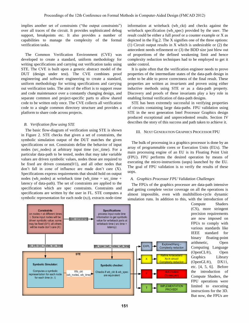
B. Verification flow using STE
The basic flow-diagram of verification using STE is shown
in Figure 2. STE checks that given a set of constraints, the
symbolic simulation output of the DUT matches the given
specifications or not. Constraints define the behavior of input
nodes (src_nodes) at arbitrary input time (src_time). For a
particular data-path to be tested, nodes that may take variable
values are driven symbolic values, nodes those are required to
be fixed are driven constants(0/1), and all other nodes that
don’t fall in cone of influence are made don’t care (X).
Specifications express requirements that should hold on output
nodes (wb_nodes) at writeback time (wb_time = src_time +
latency of data-path). The set of constraints are applied to the
specification which are spec constraints. Constraints and
specifications are written by the user in FL. STE computes a
symbolic representation for each node (n,t), extracts node-time
information at writeback (wb_ckt) and checks against the
writeback specification (wb_spec) provided by the user. The
result could be either a full proof or a counter example or X as
depicted in the Fig.2. The X signifies one of the three options:
(1) Circuit output results in X which is undesirable or (2) the
antecedent needs refinement or (3) the BDD size just blew out
of proportions of the defined weakening limit and hence
complexity reduction techniques had to be employed to get it
under control.
It is quite often that the verification engineer needs to prove
properties of the intermediate states of the data-path design in
order to be able to prove correctness of the final result. These
properties are written as invariants and proven using either
inductive methods using STE or as a data-path property.
Discovery and proofs of these invariants play a key role in
enabling formal verification of data-path designs.
STE has been extremely successful in verifying properties
of circuits containing large data-paths. FPU validation using
STE in the next generation Intel Processor Graphics design
produced exceptional and unprecedented results. Section IV
describes the story of this success and path taken to achieve it.
III. NEXT GENERATION GRAPHICS PROCESSOR FPU
The bulk of processing in a graphics processor is done by an
array of programmable cores or Execution Units (EUs). The
main processing engine of an EU is its Floating Point Unit
(FPU). FPU performs the desired operation by means of
executing the micro-instructions (uops) launched by the EU.
The goal of FPU validation is to verify the results of these
uops.
A. Graphics Processor FPU Validation Challenges
The FPUs of the graphics processor are data-path intensive
and getting complete vector coverage on all the operations is
almost impossible, even with multibillion-cycle dynamic
simulation runs. In addition to this, with the introduction of
Compute Shaders
(CS), more stringent
precision requirements
are now imposed on
FPUs to comply with
various standards like
IEEE standard for
binary floating-point
arithmetic, Open
Computing Language
(OpenCL®), Open
Graphics Library
(OpenGL®), DX11,
etc. [4, 5, 6]. Before
the introduction of
Compute Shaders, the
FPU operations were
limited to executing
instructions for the 3D.
But now, the FPUs are
Figure 2 Basic flow diagram of verification methodology using STE
Proceedings of the 12th Conference on Formal Methods in Computer-Aided Design (FMCAD 2012)
151151151
exposed to general purpose applications similar to the CPU
cores and the accuracy/precision requirements have become
more exacting. The challenge in validating the FPU data-path
is to get 100% coverage while meeting the precision/accuracy
requirements.
Though the CVE provides a common base and
methodology for implementing uops, the implementations
vary from project to project and design-specific intricacies had
to be taken care of. The graphics instruction set2 is compact
but has a complex format. The instruction format had a
number of qualifiers which were not present in a CPU
instruction. Challenges faced due to these additional qualifiers
for the implementation of the GT STE are explained in the
Table1 below.
Table 1: GT Specific challenges for STE deployment
GT intricacy Brief description
Support for
Various Dsizes
Unequal Dsizes for
sources/destinations
Flag Generation/
interpretation
In addition to IEEE flags, GT also
supports flag output based on outputs
Source modifiers Negation, absolute, negation of
absolute
Saturation Floating point saturation allowed for
GT
Accumulator
Source
Allows implicit/explicit accumulator
source
Accumulator
Destination
Allows implicit/explicit accumulator
destination
Denorm Handling Non uniform for different precisions
ALT mode Support for non-IEEE compliant mode
NaN Handling Fixed NaN output for some operations
Rounding modes Instruction specific rounding
Channel enables Selective enabling of FPU pipelines
Apart from the above common validation challenges of any
graphics processor validation, the next generation Intel
graphics processor faced a new set of validation changes due
to huge architectural changes done for better graphics
performance. Performance improvement of graphics directly
translates to enhancing the raw execution power source of the
graphics engine i.e. EU. FPU which is the main data-cruncher
of EU was completely re-designed for the next generation
Intel Processor Graphics design to get the desired performance
improvement and area-reduction per EU. This overhaul of
design and architecture imposed a lot of validation challenges.
Some of the major design change categories in FPU are
described in Table 2.
Due to the complete redesigning of FPU in latest GPU
2 Graphics instruction set is for internal consumption and not exposed for
external reference.
design, validation was considered as a high risk to be
completed with high confidence level. Data-path formal
verification using STE was brought in to the rescue.
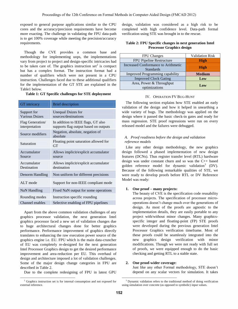
Table 2: FPU Specific changes in next generation Intel
Processor Graphics design
FPU Changes Validation Risk
FPU Pipeline Restructure High
Increased Conformance to Arithmetic
Standards High
Improved Programming capability Medium
Improved Clock Gating Low
Area, Power & Throughput
optimizations Low
IV. OPERATION FV BUG-HUNT
The following section explains how STE enabled an early
validation of the design and how it helped in unearthing a
wide variety of bugs. The methodology was applied on the
design where it passed the basic check-in gates and ready for
mass regression. STE proof regressions were run on every
released model and the failures were debugged.
A. Proof readiness before the design and validation
reference models
Like any other design methodology, the new graphics
design followed a phased implementation of new design
features (DCNs). Thus register transfer level (RTL) hardware
design was under constant churn and so was the C++ based
golden reference model for dynamic validation3 (DV).
Because of the following remarkable qualities of STE, we
were ready to develop proofs before RTL or DV Reference
Model was ready:
1. One proof – many projects:
The beauty of CVE is the specification code reusability
across projects. The specification of processor micro-
operations doesn’t change much over the generations of
design. As most of the proofs are agnostic to the
implementation details, they are easily portable to any
project with/without minor changes. Many graphics-
specific integer and floating-point (FP) STE proofs
were developed during the previous generation Intel
Processor Graphics verification timeframe. Most of
these proofs could be seamlessly integrated into the
new graphics design verification with minor
modifications. Though we were not ready with full set
of proofs, we were equipped enough to do the basic
checking and getting RTL to a stable state.
2. One proof-wider coverage:
Just like any other Formal methodology, STE doesn’t
depend on any scalar vectors for simulation. It takes
3 Dynamic validation refers to the traditional method of doing verification
using simulation over concrete (as opposed to symbolic) input values.
Proceedings of the 12th Conference on Formal Methods in Computer-Aided Design (FMCAD 2012)
152152152
into account all the control signals and results in a
comprehensive coverage. Just one proof can provide
the control space coverage for all signals in the cone of
influence of the operation being checked, in addition to
the comprehensive data space checking. During the
first month of verification cycle, we focused on
developing and regressing formal proofs to check
correctness for simple operations (For example, logical
operations like OR, AND, integer add, etc.), to get the
RTL healthy. This simple operation checking itself
unearthed much more number of bugs in different areas
of the design as compared to the dynamic validation
which was being run in parallel on the full instruction
set of FPU. Once the basic proofs started passing, we
embarked on proving the formal proofs for more
complex operations (like floating point conversions to
integer/floats, floating point add, mul, mad, etc.).
Regressions were run on every new model and the
failures were debugged and reported out. A passing
proof guarantees 100% coverage of the input data space
within the defined constraints of control logic.
3. Capability to mask unimplemented features:
During Front End Development all the new design
features are implemented in a phase-wise manner.
Validation needs to be in close tandem with the design
implementation to verify only the implemented
features. STE provides the user with the capability of
selectively masking the unimplemented features
through addition of simple constraints. This enabled us
to make uninterrupted forward progress in validation.
Once the proofs are passing, the constraints are phased
out as the RTL matured with the planned
implementation.
4. Ease of debugging:
The counter examples provided by the tool were very
intuitive and could easily help in reproducing the
failure in dynamic simulation. The in-house developed
AGM viewer utility aids in debugging through
waveforms and schematics and was of great help in
debugging.
B. STE as monster bug-hunter
STE could help in stabilizing the RTL quality by regressing
over every design iteration and point out the failures in
different areas. A wide range of bugs varying in both quantity
and quality were unearthed in the process. The bugs ranged
from bugs on controls related to data-path, instruction
interaction bugs, clock gating bugs to deep corner case
scenarios. Some of these bugs are mentioned below to
highlight the uniqueness of the bugs found:
1. Clock-gating Bugs:
The new graphics design implements very aggressive
clock gating and bugs were found on logic with flops
gated with incorrect pipeline signals, unintended gating
and non-uniform gating across the data.
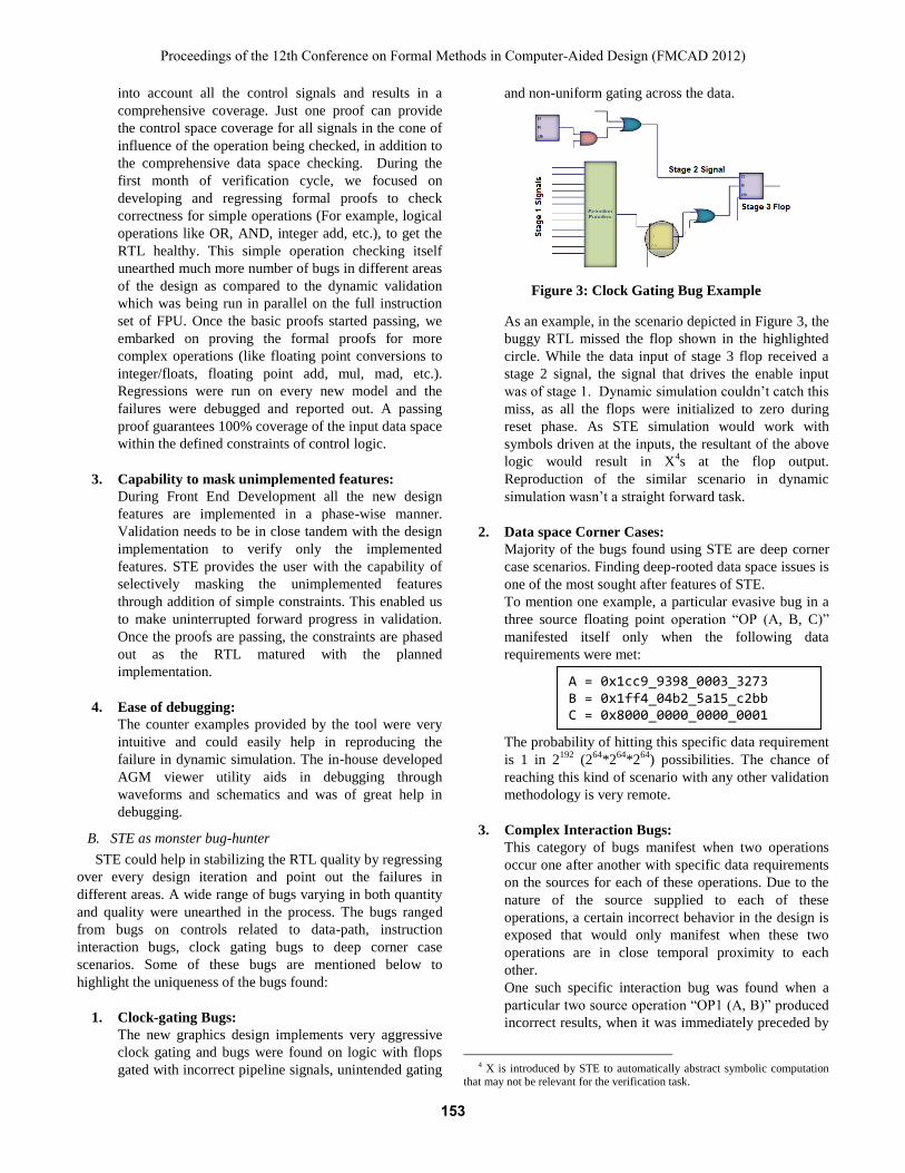
Figure 3: Clock Gating Bug Example
As an example, in the scenario depicted in Figure 3, the
buggy RTL missed the flop shown in the highlighted
circle. While the data input of stage 3 flop received a
stage 2 signal, the signal that drives the enable input
was of stage 1. Dynamic simulation couldn’t catch this
miss, as all the flops were initialized to zero during
reset phase. As STE simulation would work with
symbols driven at the inputs, the resultant of the above
logic would result in X4s at the flop output.
Reproduction of the similar scenario in dynamic
simulation wasn’t a straight forward task.
2. Data space Corner Cases:
Majority of the bugs found using STE are deep corner
case scenarios. Finding deep-rooted data space issues is
one of the most sought after features of STE.
To mention one example, a particular evasive bug in a
three source floating point operation “OP (A, B, C)”
manifested itself only when the following data
requirements were met:
The probability of hitting this specific data requirement
is 1 in 2192
(264
*264
*264
) possibilities. The chance of
reaching this kind of scenario with any other validation
methodology is very remote.
3. Complex Interaction Bugs:
This category of bugs manifest when two operations
occur one after another with specific data requirements
on the sources for each of these operations. Due to the
nature of the source supplied to each of these
operations, a certain incorrect behavior in the design is
exposed that would only manifest when these two
operations are in close temporal proximity to each
other.
One such specific interaction bug was found when a
particular two source operation “OP1 (A, B)” produced
incorrect results, when it was immediately preceded by
4 X is introduced by STE to automatically abstract symbolic computation
that may not be relevant for the verification task.
A = 0x1cc9_9398_0003_3273 B = 0x1ff4_04b2_5a15_c2bb C = 0x8000_0000_0000_0001
Proceedings of the 12th Conference on Formal Methods in Computer-Aided Design (FMCAD 2012)
153153153
a particular three source operation “OP2 (C,D,E)” and
the input data of both these uops followed the data
requirements given below:
This was a rare combination of “Instruction
Interaction” and “Data space Corner-case” issue. Such
scenario with specific data requirements on current and
previous operations is almost impossible to be caught
by any other validation methodology.
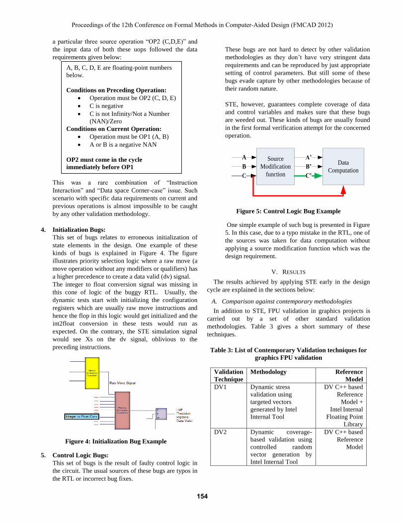
4. Initialization Bugs:
This set of bugs relates to erroneous initialization of
state elements in the design. One example of these
kinds of bugs is explained in Figure 4. The figure
illustrates priority selection logic where a raw move (a
move operation without any modifiers or qualifiers) has
a higher precedence to create a data valid (dv) signal.
The integer to float conversion signal was missing in
this cone of logic of the buggy RTL. Usually, the
dynamic tests start with initializing the configuration
registers which are usually raw move instructions and
hence the flop in this logic would get initialized and the
int2float conversion in these tests would run as
expected. On the contrary, the STE simulation signal
would see Xs on the dv signal, oblivious to the
preceding instructions.
Figure 4: Initialization Bug Example
5. Control Logic Bugs:
This set of bugs is the result of faulty control logic in
the circuit. The usual sources of these bugs are typos in
the RTL or incorrect bug fixes.
These bugs are not hard to detect by other validation
methodologies as they don’t have very stringent data
requirements and can be reproduced by just appropriate
setting of control parameters. But still some of these
bugs evade capture by other methodologies because of
their random nature.
STE, however, guarantees complete coverage of data
and control variables and makes sure that these bugs
are weeded out. These kinds of bugs are usually found
in the first formal verification attempt for the concerned
operation.
Source
Modification
function
Data
Computation
A
B
C
A’
B’
C’
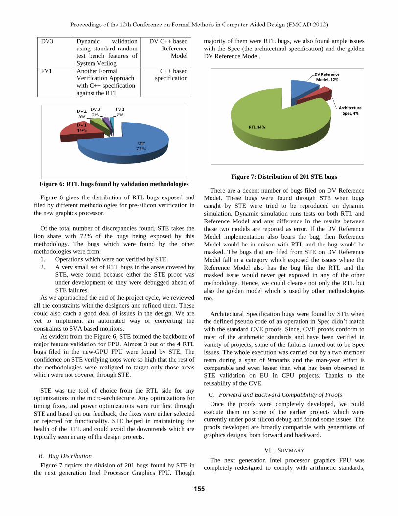
Figure 5: Control Logic Bug Example
One simple example of such bug is presented in Figure
5. In this case, due to a typo mistake in the RTL, one of
the sources was taken for data computation without
applying a source modification function which was the
design requirement.
V. RESULTS
The results achieved by applying STE early in the design
cycle are explained in the sections below:
A. Comparison against contemporary methodologies
In addition to STE, FPU validation in graphics projects is
carried out by a set of other standard validation
methodologies. Table 3 gives a short summary of these
techniques.
Table 3: List of Contemporary Validation techniques for
graphics FPU validation
Validation
Technique
Methodology Reference
Model
DV1 Dynamic stress
validation using
targeted vectors
generated by Intel
Internal Tool
DV C++ based
Reference
Model +
Intel Internal
Floating Point
Library
DV2 Dynamic coverage-
based validation using
controlled random
vector generation by
Intel Internal Tool
DV C++ based
Reference
Model
A, B, C, D, E are floating-point numbers
below.
Conditions on Preceding Operation:
Operation must be OP2 (C, D, E)
C is negative
C is not Infinity/Not a Number
(NAN)/Zero
Conditions on Current Operation:
Operation must be OP1 (A, B)
A or B is a negative NAN
OP2 must come in the cycle
immediately before OP1
Proceedings of the 12th Conference on Formal Methods in Computer-Aided Design (FMCAD 2012)
154154154
DV3 Dynamic validation
using standard random
test bench features of
System Verilog
DV C++ based
Reference
Model
FV1 Another Formal
Verification Approach
with C++ specification
against the RTL
C++ based
specification
Figure 6: RTL bugs found by validation methodologies
Figure 6 gives the distribution of RTL bugs exposed and
filed by different methodologies for pre-silicon verification in
the new graphics processor.
Of the total number of discrepancies found, STE takes the
lion share with 72% of the bugs being exposed by this
methodology. The bugs which were found by the other
methodologies were from:
1. Operations which were not verified by STE.
2. A very small set of RTL bugs in the areas covered by
STE, were found because either the STE proof was
under development or they were debugged ahead of
STE failures.
As we approached the end of the project cycle, we reviewed
all the constraints with the designers and refined them. These
could also catch a good deal of issues in the design. We are
yet to implement an automated way of converting the
constraints to SVA based monitors.
As evident from the Figure 6, STE formed the backbone of
major feature validation for FPU. Almost 3 out of the 4 RTL
bugs filed in the new-GPU FPU were found by STE. The
confidence on STE verifying uops were so high that the rest of
the methodologies were realigned to target only those areas
which were not covered through STE.
STE was the tool of choice from the RTL side for any
optimizations in the micro-architecture. Any optimizations for
timing fixes, and power optimizations were run first through
STE and based on our feedback, the fixes were either selected
or rejected for functionality. STE helped in maintaining the
health of the RTL and could avoid the downtrends which are
typically seen in any of the design projects.
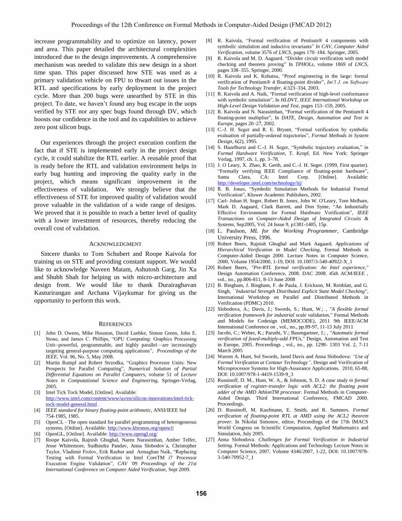
B. Bug Distribution
Figure 7 depicts the division of 201 bugs found by STE in
the next generation Intel Processor Graphics FPU. Though
majority of them were RTL bugs, we also found ample issues
with the Spec (the architectural specification) and the golden
DV Reference Model.
Figure 7: Distribution of 201 STE bugs
There are a decent number of bugs filed on DV Reference
Model. These bugs were found through STE when bugs
caught by STE were tried to be reproduced on dynamic
simulation. Dynamic simulation runs tests on both RTL and
Reference Model and any difference in the results between
these two models are reported as error. If the DV Reference
Model implementation also bears the bug, then Reference
Model would be in unison with RTL and the bug would be
masked. The bugs that are filed from STE on DV Reference
Model fall in a category which exposed the issues where the
Reference Model also has the bug like the RTL and the
masked issue would never get exposed in any of the other
methodology. Hence, we could cleanse not only the RTL but
also the golden model which is used by other methodologies
too.
Architectural Specification bugs were found by STE when
the defined pseudo code of an operation in Spec didn’t match
with the standard CVE proofs. Since, CVE proofs conform to
most of the arithmetic standards and have been verified in
variety of projects, some of the failures turned out to be Spec
issues. The whole execution was carried out by a two member
team during a span of 9months and the man-year effort is
comparable and even lesser than what has been observed in
STE validation on EU in CPU projects. Thanks to the
reusability of the CVE.
C. Forward and Backward Compatibility of Proofs
Once the proofs were completely developed, we could
execute them on some of the earlier projects which were
currently under post silicon debug and found some issues. The
proofs developed are broadly compatible with generations of
graphics designs, both forward and backward.
VI. SUMMARY
The next generation Intel processor graphics FPU was
completely redesigned to comply with arithmetic standards,
DV Reference Model , 12%
Architectural Spec, 4%
RTL, 84%
Proceedings of the 12th Conference on Formal Methods in Computer-Aided Design (FMCAD 2012)
155155155
increase programmability and to optimize on latency, power
and area. This paper detailed the architectural complexities
introduced due to the design improvements. A comprehensive
mechanism was needed to validate this new design in a short
time span. This paper discussed how STE was used as a
primary validation vehicle on FPU to thwart out issues in the
RTL and specifications by early deployment in the project
cycle. More than 200 bugs were unearthed by STE in this
project. To date, we haven’t found any bug escape in the uops
verified by STE nor any spec bugs found through DV, which
boosts our confidence in the tool and its capabilities to achieve
zero post silicon bugs.
Our experiences through the project execution confirm the
fact that if STE is implemented early in the project design
cycle, it could stabilize the RTL earlier. A reusable proof that
is ready before the RTL and validation environment helps in
early bug hunting and improving the quality early in the
project, which means significant improvement in the
effectiveness of validation. We strongly believe that the
effectiveness of STE for improved quality of validation would
prove valuable in the validation of a wide range of designs.
We proved that it is possible to reach a better level of quality
with a lower investment of resources, thereby reducing the
overall cost of validation.
ACKNOWLEDGMENT
Sincere thanks to Tom Schubert and Roope Kaivola for
training us on STE and providing constant support. We would
like to acknowledge Naveen Matam, Ashutosh Garg, Jin Xu
and Shubh Shah for helping us with micro-architecture and
design front. We would like to thank Durairaghavan
Kasturirangan and Archana Vijaykumar for giving us the
opportunity to perform this work.
REFERENCES
[1] John D. Owens, Mike Houston, David Luebke, Simon Green, John E. Stone, and James C. Phillips, “GPU Computing: Graphics Processing
Unit--powerful, programmable, and highly parallel—are increasingly
targeting general-purpose computing applications”, Proceedings of the IEEE, Vol. 96, No. 5, May 2008.
[2] Martin Rumpf and Robert Strzodka, “Graphics Processor Units: New
Prospects for Parallel Computing”, Numerical Solution of Partial Differential Equations on Parallel Computers, volume 51 of Lecture
Notes in Computational Science and Engineering, Springer-Verlag,
2005. [3] Intel Tick Tock Model, [Online]. Available:
http://www.intel.com/content/www/us/en/silicon-innovations/intel-tick-
tock-model-general.html . [4] IEEE standard for binary floating-point arithmetic, ANSI/IEEE Std
754-1985, 1985.
[5] OpenCL - The open standard for parallel programming of heterogeneous systems, [Online]. Available: http://www.khronos.org/opencl/
[6] OpenGL, [Online]. Available: http://www.opengl.org/
[7] Roope Kaivola, Rajnish Ghughal, Naren Narasimhan, Amber Telfer, Jesse Whittemore, Sudhindra Pandav, Anna Slobodov´a, Christopher
Taylor, Vladimir Frolov, Erik Reeber and Armaghan Naik, “Replacing
Testing with Formal Verification in Intel CoreTM i7 Processor Execution Engine Validation”, CAV '09 Proceedings of the 21st
International Conference on Computer Aided Verification, Sept 2009.
[8] R. Kaivola, “Formal verification of Pentium® 4 components with
symbolic simulation and inductive invariants” In CAV, Computer Aided Verification, volume 3576 of LNCS, pages 170–184. Springer, 2005.
[9] R. Kaivola and M. D. Aagaard. “Divider circuit verification with model
checking and theorem proving” In TPHOLs, volume 1869 of LNCS, pages 338–355. Springer, 2000.
[10] R. Kaivola and K. Kohatsu, “Proof engineering in the large: formal
verification of Pentium® 4 floating-point divider”, Int’l J. on Software Tools for Technology Transfer, 4:323–334, 2003.
[11] R. Kaivola and A. Naik, “Formal verification of high-level conformance
with symbolic simulation”, In HLDVT, IEEE International Workshop on High-Level Design Validation and Test, pages 153–159, 2005.
[12] R. Kaivola and N. Narasimhan, “Formal verification of the Pentium® 4
floating-point multiplier”, In DATE, Design, Automation and Test in Europe, pages 20–27, 2002.
[13] C.-J. H. Seger and R. E. Bryant, “Formal verification by symbolic
evaluation of partially-ordered trajectories”, Formal Methods in System Design, 6(2), 1995.
[14] S. Hazelhurst and C.-J. H. Seger, “Symbolic trajectory evaluation,” in
Formal Hardware Verification, T. Kropf, Ed. New York: Springer Verlag, 1997, ch. 1, pp. 3–78.
[15] J. O Leary, X. Zhao, R. Gerth, and C.-J. H. Seger. (1999, First quarter).
“Formally verifying IEEE Compliance of floating-point hardware”, Santa Clara, CA: Intel Corp. [Online]. Available:
http://developer.intel.com/technology/itj/
[16] R. B. Jones, “Symbolic Simulation Methods for Industrial Formal Verification”, Kluwer Academic Publishers, 2002.
[17] Carl- Johan H. Seger, Robert B. Jones, John W. O'Leary, Tom Melham, Mark D. Aagaard, Clark Barrett, and Don Syme, “An Industrially
Effective Environment for Formal Hardware Verification”, IEEE
Transactions on Computer-Aided Design of Integrated Circuits & Systems, Sep2005, Vol. 24 Issue 9, p1381-1405, 15p.
[18] L. Paulson, ML for the Working Programmer, Cambridge
University Press, 1996. [19] Robert Beers, Rajnish Ghughal and Mark Aagaard. Applications of
Hierarchical Verification in Model Checking, Formal Methods in
Computer-Aided Design 2000. Lecture Notes in Computer Science,
2000, Volume 1954/2000, 1-19, DOI: 10.1007/3-540-40922-X_1 [20] Robert Beers, "Pre-RTL formal verification: An Intel experience,"
Design Automation Conference, 2008. DAC 2008. 45th ACM/IEEE ,
vol., no., pp.806-811, 8-13 June 2008 [21] B. Bingham, J. Bingham, F. de Paula, J. Erickson, M. Reitblatt, and G.
Singh, ``Industrial Strength Distributed Explicit State Model Checking'',
International Workshop on Parallel and Distributed Methods in Verification (PDMC) 2010.
[22] Slobodova, A.; Davis, J.; Swords, S.; Hunt, W.; , "A flexible formal
verification framework for industrial scale validation," Formal Methods and Models for Codesign (MEMOCODE), 2011 9th IEEE/ACM
International Conference on , vol., no., pp.89-97, 11-13 July 2011
[23] Jacobi, C.; Weber, K.; Paruthi, V.; Baumgartner, J.; , "Automatic formal verification of fused-multiply-add FPUs," Design, Automation and Test
in Europe, 2005. Proceedings , vol., no., pp. 1298- 1303 Vol. 2, 7-11 March 2005
[24] Warren A. Hunt, Sol Swords, Jared Davis and Anna Slobodova: “Use of
Formal Verification at Centaur Technology”. Design and Verification of Microprocessor Systems for High-Assurance Applications. 2010, 65-88,
DOI: 10.1007/978-1-4419-1539-9_3
[25] Russinoff, D. M., Hunt, W. A., & Johnson, S. D. A case study in formal
verification of register-transfer logic with ACL2: the floating point
adder of the AMD AthlonTM processor. Formal Methods in Computer-
Aided Design. Third International Conference, FMCAD 2000. Proceedings.
[26] D. Russinoff, M. Kaufmann, E. Smith, and R. Sumners. Formal
verification of floating-point RTL at AMD using the ACL2 theorem prover. In Nikolai Simonov, editor, Proceedings of the 17th IMACS
World Congress on Scientific Computation, Applied Mathematics and
Simulation, July 2005. [27] Anna Slobodova. Challenges for Formal Verification in Industrial
Setting. Formal Methods: Applications and Technology Lecture Notes in
Computer Science, 2007, Volume 4346/2007, 1-22, DOI: 10.1007/978-3-540-70952-7_1
Proceedings of the 12th Conference on Formal Methods in Computer-Aided Design (FMCAD 2012)
156156156