Embed Size (px)
Citation preview
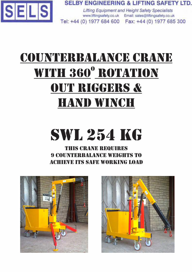
counterbalance craneowith 360 rotation
out riggers & Hand winch
SWL 254 KgTHIS CRANE Requires
9 Counterbalance weights to achieve its safe working load
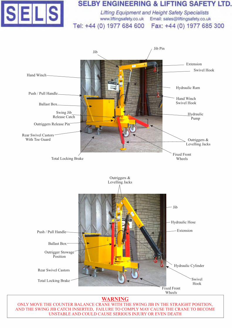
HydraulicPump
Rear Swivel CastorsWith Toe Guard
Push / Pull Handle
WARNINGONLY MOVE THE COUNTER BALANCE CRANE WITH THE SWING JIB IN THE STRAIGHT POSITION,
AND THE SWING JIB CATCH INSERTED, FAILURE TO COMPLY MAY CAUSE THE CRANE TO BECOME UNSTABLE AND COULD CAUSE SERIOUS INJURY OR EVEN DEATH
Total Locking Brake
Hydraulic Ram
Extension
Jib
Outriggers &Levelling Jacks
Outriggers &Levelling Jacks
Fixed FrontWheels
Fixed FrontWheels
Extension
Swivel Hook
Jib
Push / Pull Handle
Hydraulic CylinderRear Swivel Castors
Total Locking Brake
Outrigger StowagePosition
Ballast Box
Ballast Box
Jib Pin
Hydraulic Hose
Hand Winch Swivel Hook
Hand Winch
Swing JibRelease Catch
Outriggers Release Pin
SwivelHook
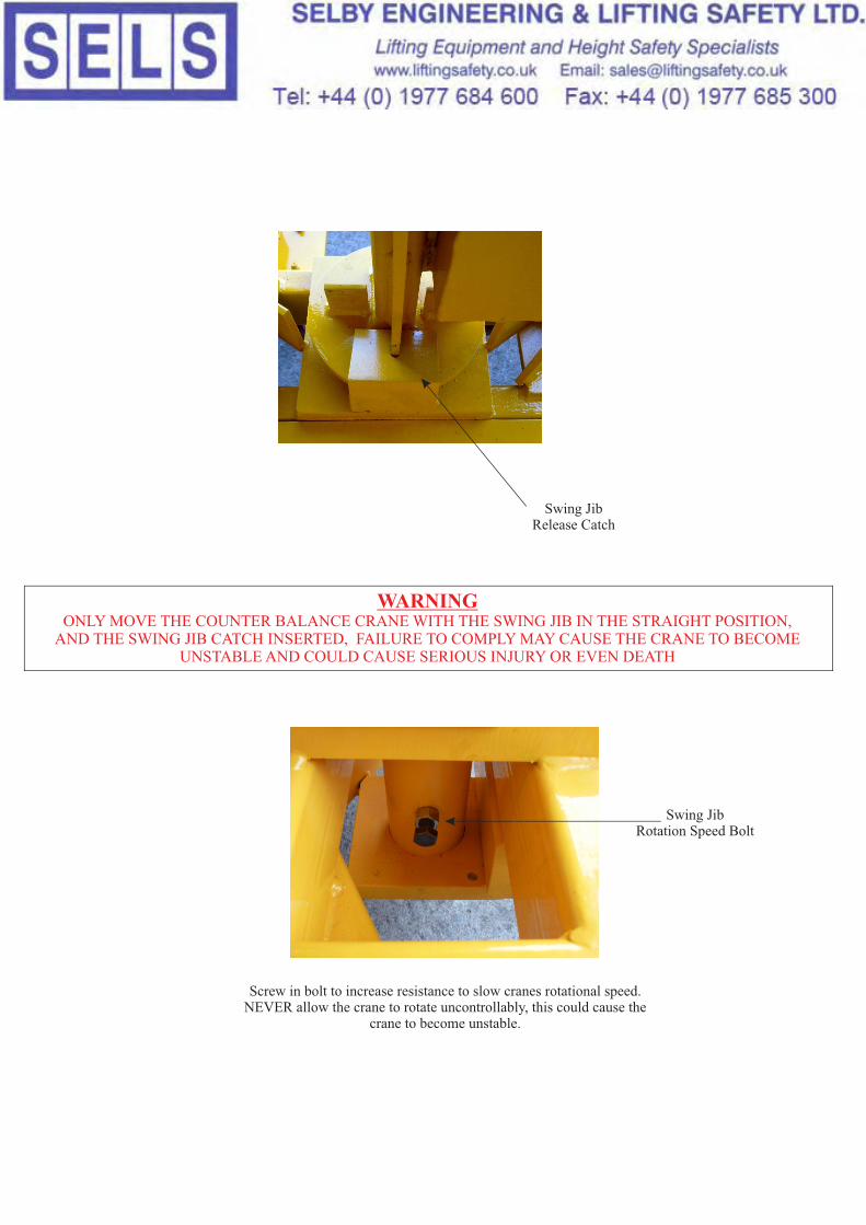
WARNINGONLY MOVE THE COUNTER BALANCE CRANE WITH THE SWING JIB IN THE STRAIGHT POSITION,
AND THE SWING JIB CATCH INSERTED, FAILURE TO COMPLY MAY CAUSE THE CRANE TO BECOME UNSTABLE AND COULD CAUSE SERIOUS INJURY OR EVEN DEATH
Swing JibRelease Catch
Swing JibRotation Speed Bolt
Screw in bolt to increase resistance to slow cranes rotational speed.NEVER allow the crane to rotate uncontrollably, this could cause the
crane to become unstable.
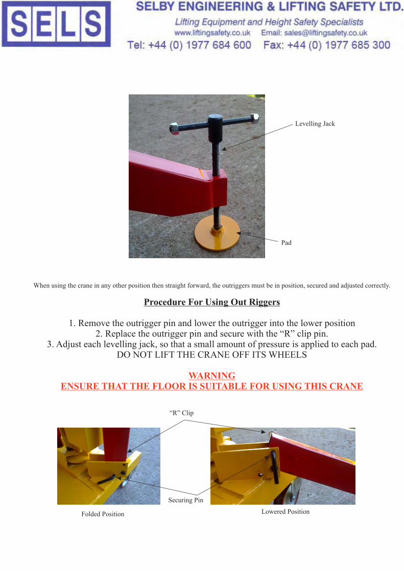
When using the crane in any other position then straight forward, the outriggers must be in position, secured and adjusted correctly.
Procedure For Using Out Riggers
1. Remove the outrigger pin and lower the outrigger into the lower position2. Replace the outrigger pin and secure with the “R” clip pin.
3. Adjust each levelling jack, so that a small amount of pressure is applied to each pad.DO NOT LIFT THE CRANE OFF ITS WHEELS
WARNINGENSURE THAT THE FLOOR IS SUITABLE FOR USING THIS CRANE
Securing Pin
Pad
Levelling Jack
Folded Position Lowered Position
“R” Clip

ALWAYS READ THE INSTRUCTIONS BEFORE USING THIS EQUIPMENT
Ensure the correct amount of ballast is used before counterbalance crane/ equipment is put into service or any load is lifted.
ALWAYS use a Mobile Crane/Lifting Equipment on a firm level surface.
NEVER use a Mobile Crane/Lifting Equipment on a sloping surface due to the danger of the Mobile Crane/Lifting Equipment moving or the load not being lifted correctly, i.e. off-centre loads could cause structural damage to the equipment and possible injury to Operator.
ALWAYS apply the brakes (when fitted) before commencing lifting operation.
NEVER lift off centre loads.
ALWAYS use the correct lifting tackle and use Lifting Hook/Hooks as directed on the enclosed instructions. ALWAYS use certified lifting aids.
NEVER move a crane with a high suspended load. Cranes with a suspended load should only be moved with the suspended load just clear of the floor. Move the crane slowly and avoid sudden crane stops which could cause the load to swing violently.
NEVER use the full length of the Hydraulic Ram this could cause damage to the Hydraulic Unit and make the load unstable.
Any modification to the Equipment or Hydraulic Pump/Ram will make this declaration of conformity invalid.
NEVER continue to exhaust the Safety Valve as this could cause the load to become unstable and damage the Safety Release Valve.
Hydraulic Oil should be changed ever 12 months. NEVER mixed different brands of Hydraulic Oil or use different viscosity.
A suspended load should only be lowered slowly and in a controlled manner.
ALWAYS move Equipment/Crane with the handle attached to the Equipment/Crane.NEVER use the Hydraulic Pump handle to move or position Equipment/Crane.
NEVER leave a suspended load for long periods. Lower loads onto a Supporting Frame.
NEVER allow any person to stand in such a position that the load could fall on them or cause a person injury. '
ONLY adjust the Telescopic Jib with the main Support Jib in the horizontal position. This is to ensure that the Telescopic Jib will not inadvertently slide out. NEVER adjust the Telescopic Jib with a load attached.
DO NOT use the Equipment/Crane if any defect is observed, report to a competent person.
ENSURE that all Spring Clips are in place.
NEVER EXCEED THE SAFE WORKING LOAD OF THE EQUIPMENT/CRANE.THE MAXIMUM LOAD ONLY APPLIES WHEN THE INNER JIB IS FULLY RETRACTED
(I.E. POSITION 1)

IMPORTANT Date: 16-6-99
WORK EQUIPMENT
Virtually the whole of the UK industry was affected when the provision and use of Work Equipment Regulations 1998 (PUWER 98)(LOWLER 98) came into force on the 5 December 1998.The two sets of regulations- which implemented the requirements of theEuropean Commissions Amending Directive to use of Work Equipment Directive (AUWED) apply to the majority of workplaces in the UK and include several new provisions relating to safety of work equipment. PUWER 98- which replaced the existing PUWER 1992 and the Power Press Regulations 1965 and 1972-included new provisions for management and the use of MOBILE Work Equipment and also introduced new regulations specific to power presses.Under PUWER 98, the definition of work equipment include the following: * Lifting Equipment-such as hoists, lift trucks, elevating work platforms and lifting slings including floor cranes and installations.PUWER 98 completely replace the requirements of PUWER 1992, which was originally implemented into UK law as part of the six-pack, of health and safety legislation.
THE MAIN REQUIREMENTS
While the requirements of PUWER 1992 were carried forward in full, in parts 1 and 11 of PUWER 98, the new regulations also contained a number of important additions.These included: a requirement to inspect work equipment where significant risk could result from incorrect use/installation or relocation, deterioration, or as a result of exceptional circumstances.A requirement to record the results of those inspections. An extension of the duty holder application to include a duty on people who have control of work equipment, such as plant hire companies.New guidance and ACoP material on the control of specific risks.Meanwhile, part 111 of PUWER 98 comprised of six completely new regulations which deal with risks arising from mobile work equipment including lift trucks, floor cranes ect.These include, minimising risks from roll-over, preventing start-up by unauthorised persons, providing a device for braking,
LIFTING EQUIPMENT
LOLER 98 replace most of the existing sector-specifc legislation on lifting equipment, creating a single set of regulations that apply to all sectors of industry.LOLER 98 applies over and above the general requirements of PUWER 98 in dealing with specific hazards and risks associated with lifting equipment and lifting operations.
WARNING
The regulations require employers to carry out a risk assessment of lifting operations- including the selection-suitability of equipment and the use of lifting equipment.
Continued

The regulations require employers to carry out suitable training of staff in the safe use of the lifting equipment, including operatingand safety maintenance-inspection.Employers need to consider a number of factors when selecting lifting equipment, these include- the load to be lifted-its weight, shape and centre of gravity and the availability of lifting points.How often the lifting equipment will be used to carry out the task. The environment in which the lifting equipment is being used, the personnel available and their training and experience.The regulations also require lifting equipment to have adequate strength and stability for its proposed use.In addition, the risk from positioning and installing lifting equipment need to be minimised and equipment must be marked to indicate its safe working load.The regulations also require certain types of lifting equipment for example, hooks, eye-bolts and shackles-to be examined every six months.Any other lifting equipment must be examined every 12 months.However under the regulations an alternative examination scheme can be drawn up and in-tervals set for examinations based on the results of risk assessments.In addition, the regulations cover pre-use checks and the steps that employers must take to prevent lifting equipment overturning or being overloaded.They also cover how lifting equipment should be positioned and installed and the use of equipment to lift people-for example, a lift truck must include a purpose-built working platform to carry an employee.
FINAL CHECKLIST
Under health and safety law, employers have a legal duty to ensure the health, safety and welfare of employees and people not in their employment who may be affected by their work activities.The six-pack of health and safety legislation-which came into force in January1993-includes the management of Health and Safety at WorkRegulations 1992, this requires all employers to carry out a risk assessment in the workplaces to eliminate or reduce any risks found.The Lifting Equipment and Lifting Operations Regulations 1998 (LOLER 98) require lifting equipment to have adequate strength and stability for its proposed use. In addition, the risks from positioning and installing lifting equipment need to be minimised and equipment must also be marked to indicate its safe working load.
IMPORTANT
Under Health and Safety Law, Employers and Self Employed Personnel have a legal duty to ensure the Safe Working Conditions for all employees and personnel that may come .into contact with the equipment, E-G. Workshop Presses, moving and Fixed Cranes, Scissor Lift Trolleys and all types of equipment that could or may present a potential danger to an employee or persons present in the vicinity,must carry out a specific risk and hazard assessment of all equipment in the workplace to eliminate or reduce any risk found, and to record and update the results of this inspection, and to keep records at all times.

Manufactured to a high standard, this product will, if used in accordance with the instruction, and is properly maintained give years of trouble free service.
IMPORTANT
BEFORE USING THIS PRODUCT, PLEASE READ THE INSTRUCTION CAREFULLY. MAKE CAREFUL NOTE OF SAFETY INSTRUCTIONS, WARNINGS AND CAUTIONS.THIS PRODUCT SHOULD ONLY BE USED FOR ITS INTENDED PURPOSE. FAILURE TO DO SO MAY CAUSE DAMAGE OR PERSONAL INJURY, AND WILL INVALIDATE THE WARRANTY.
The use of symbols and adhesive labels in this document and attached to the product is to attract your attention to possible DANGER and REMINDERS, the symbols labels and warnings, themselves do not ELIMINATE the DANGER, nor are they a substitute for proper accident prevention measures.
SAFETY INSTRUCTIONS
1) Familiarise yourself with this products application, as well as the limitations and specific potential hazards.
2) Ensure that the product is stable and suitable for the application.
3) The floor must be stable and solid so that the equipment will not cause injury during use.
4) Take special care to avoid trapping hands or feet.
6) Check regularly for damaged parts, broken or damaged parts should be replaced immediately.
7) Ensure the space required for use and maintenance of the equipment is adequate, and with good lighting.
8) Keep unauthorised persons and children away from the working area at all times.
9) Maintain the equipment in top condition at all times.
10) Do not use the equipment for anything other than its intended purpose.
11) Do not exceed the maximum safe working capacity of the equipment.
12) Do not modify or alter this equipment in any way.
13) Do not allow children or untrained persons to operate this equipment
14) Do not wear loose or ill-fitting clothing, ties, watches, rings, and any other jewellery, tie up or cover long Hair.
15) Do not stand on the equipment.
16) Do not use this equipment whilst under the influence of drugs, alcohol or any other intoxicating medication.
17) Do not use this equipment if you are fatigued.
INSTRUCTIONS FOR THE SAFE WORKING
5) Use only genuine spare parts, non-recommended parts may be dangerous.
IMPORTANT
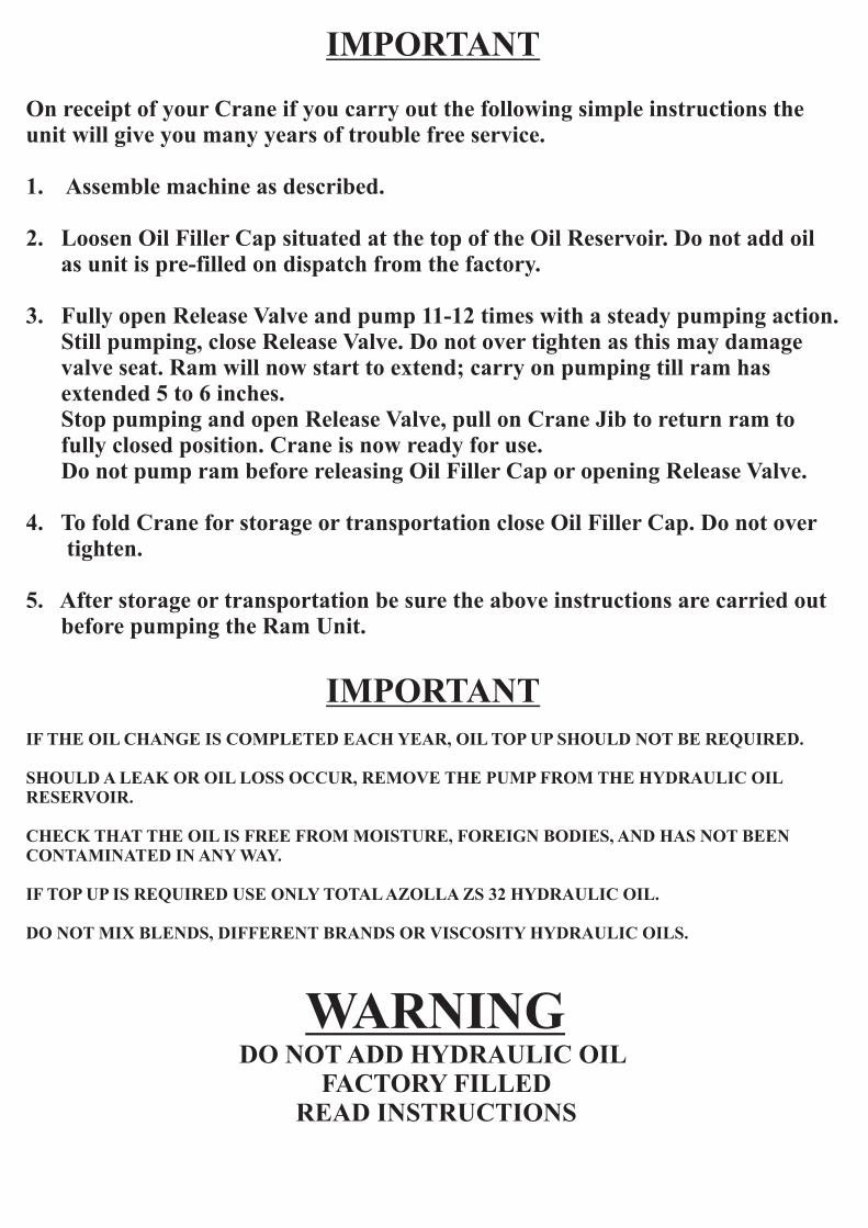
On receipt of your Crane if you carry out the following simple instructions theunit will give you many years of trouble free service.
1. Assemble machine as described.
2. Loosen Oil Filler Cap situated at the top of the Oil Reservoir. Do not add oil as unit is pre-filled on dispatch from the factory.
3. Fully open Release Valve and pump 11-12 times with a steady pumping action. Still pumping, close Release Valve. Do not over tighten as this may damage valve seat. Ram will now start to extend; carry on pumping till ram has extended 5 to 6 inches. Stop pumping and open Release Valve, pull on Crane Jib to return ram to fully closed position. Crane is now ready for use. Do not pump ram before releasing Oil Filler Cap or opening Release Valve.
4. To fold Crane for storage or transportation close Oil Filler Cap. Do not over tighten.
5. After storage or transportation be sure the above instructions are carried out before pumping the Ram Unit.
IMPORTANTIF THE OIL CHANGE IS COMPLETED EACH YEAR, OIL TOP UP SHOULD NOT BE REQUIRED.
SHOULD A LEAK OR OIL LOSS OCCUR, REMOVE THE PUMP FROM THE HYDRAULIC OIL RESERVOIR.
CHECK THAT THE OIL IS FREE FROM MOISTURE, FOREIGN BODIES, AND HAS NOT BEEN CONTAMINATED IN ANY WAY.
IF TOP UP IS REQUIRED USE ONLY TOTAL AZOLLA ZS 32 HYDRAULIC OIL.
DO NOT MIX BLENDS, DIFFERENT BRANDS OR VISCOSITY HYDRAULIC OILS.
WARNINGDO NOT ADD HYDRAULIC OIL
FACTORY FILLED READ INSTRUCTIONS

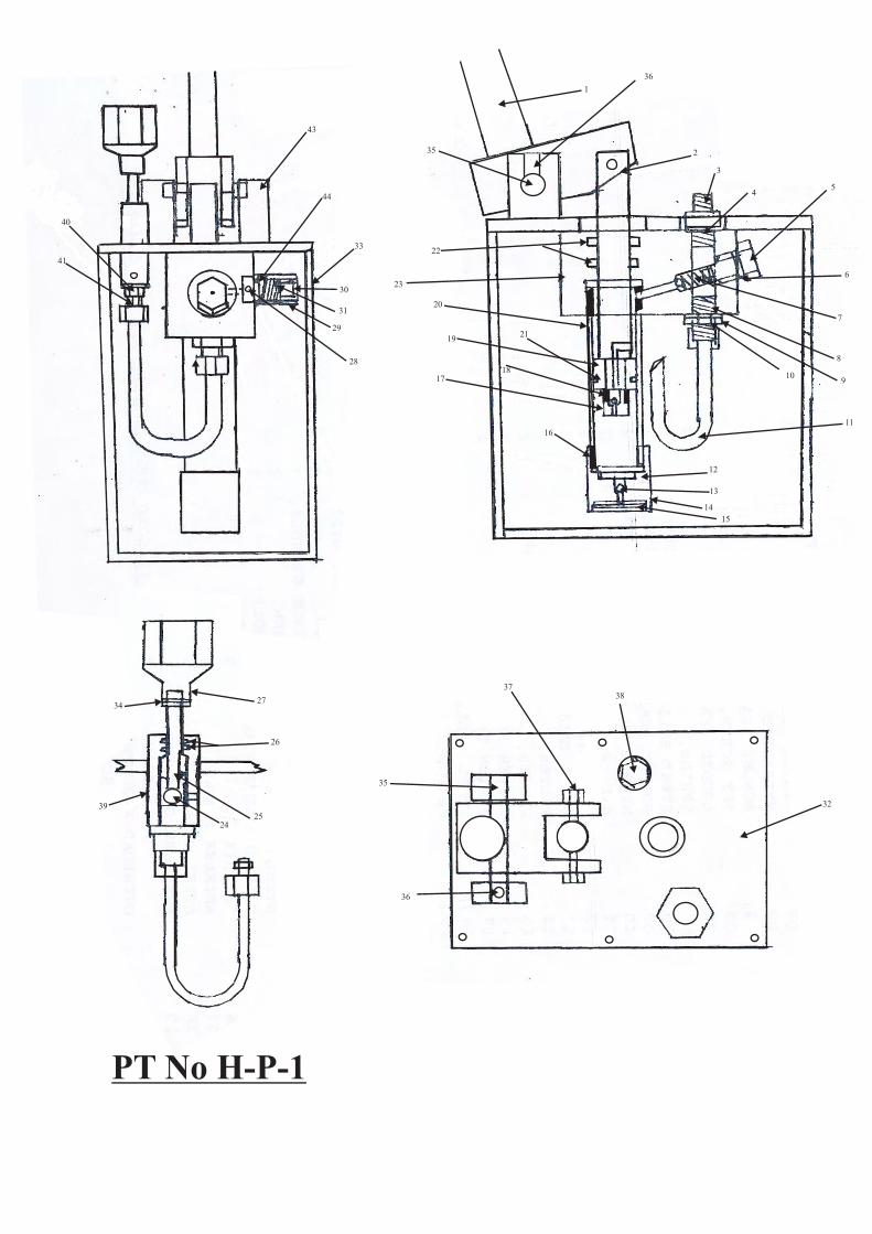
PART NO.0102030405060708091011121314151617181920212223242526272829
30
3132333435363738
DESCRIPTIONHandle assemblyPiston rodHydraulic connectorBonded sealSet screwBonded sealSpring Steel ballBonded seal Hydraulic connector Hyd. Fluid pipe Pump cyl. End capSteel ballFilterWasherCopper seal Piston end cap Steel ballPiston Pump cylinderPiston seal Seal Pump bodySteel ballRelease valve shaft“O” ringRelease handle Steel ball Pressure overload BodyOverload adjustment ScrewSpring Top plate Reservoir (Hyd. Oil)Spring pinHandle pivot spindle Allan screw Nut and BoltFiller cap
QTY11111111111112211111221112111
1
11111111
Please note: Seal kit for hydraulic pump is sold only as full kit Part number H-P-1
When ordering spare parts. Quote Model number of crane and parts list number. E.g. Crane CBFC-508 Parts list number 5, set screw. Order CBFC508-5
40
41
43
44
33
31
30
29
28
27
26
2524
39
34
1
36
2
3
45
6
7
8
910
11
12
13
15
14
16
1718
2119
20
22
23
35
3738
32
36
35
PT No H-P-1