Embed Size (px)
Citation preview
Pos: 2 /D okumentati on allgemein/Ei nband/Ei nband H andbuch - Deckbl att ohne Variantenfel d (Standar d) @ 9\mod_1285229289866_0.doc @ 64941 @ @ 1
Manual
EPSITRON® Switched-Mode Power Supply with Integrated
UPS Charger and Controller 787-1675
Version 1.0.0
Pos: 3 /Alle Serien (Allgemeine M odule) /Hinweise zur Dokumentati on/Impressum für Standardhandbücher - allg. Ang aben, Anschrif ten, Tel efonnummer n und E-Mail-Adressen @ 3\mod_1219151118203_21.doc @ 21060 @ @ 1
2 EPSITRON® 787-1675 Switched-Mode Power Supply with Integrated UPS Charger and Controller
Manual Version 1.0.0
© 2013 by WAGO Kontakttechnik GmbH & Co. KG All rights reserved.
WAGO Kontakttechnik GmbH & Co. KG
Hansastraße 27 D-32423 Minden
Phone: +49 (0) 571/8 87 – 0 Fax: +49 (0) 571/8 87 – 1 69
E-Mail: [email protected]
Web: http://www.wago.com
Technical Support
Phone: +49 (0) 571/8 87 – 5 55 Fax: +49 (0) 571/8 87 – 85 55
E-Mail: [email protected]
Every conceivable measure has been taken to ensure the accuracy and completeness of this documentation. However, as errors can never be fully excluded, we always appreciate any information or suggestions for improving the documentation.
E-Mail: [email protected]
We wish to point out that the software and hardware terms as well as the trademarks of companies used and/or mentioned in the present manual are generally protected by trademark or patent.
=== Ende der Liste für Textmar ke Ei nband_vorne ===

EPSITRON® Table of Contents 3 787-1675 Switched-Mode Power Supply with Integrated UPS Charger and Controller
Manual Version 1.0.0
Pos: 5 /D okumentati on allgemein/Verzeichnisse/Inhaltsverzeichnis - Ü berschrif t oG und Verzeichnis @ 3\mod_1219151230875_21.doc @ 21063 @ @ 1
Table of Contents
1 Notes about this Documentation ................................................................. 5 1.1 Copyright ................................................................................................... 5 1.2 Symbols ..................................................................................................... 6 1.3 Number Notation ....................................................................................... 8 1.4 Font Conventions ...................................................................................... 8
2 Important Notes ........................................................................................... 9 2.1 Legal Bases ............................................................................................... 9 2.1.1 Subject to Changes ............................................................................... 9 2.1.2 Personnel Qualifications ....................................................................... 9 2.1.3 Use of the 787 Series in Compliance with Underlying Provisions ...... 9 2.1.4 Technical Condition of Specified Devices ......................................... 10 2.2 Safety Advice (Precautions) .................................................................... 11
3 Device Description ..................................................................................... 13 3.1 View ........................................................................................................ 14 3.2 Connectors ............................................................................................... 15 3.2.1 Supply ................................................................................................. 15 3.2.2 Load .................................................................................................... 15 3.2.3 Battery, Control and Signaling Contacts ............................................ 16 3.2.4 RS-232 Interface ................................................................................. 16 3.3 Display Elements .................................................................................... 17 3.4 Operating Elements ................................................................................. 18 3.4.1 Rotary Switch for Output Voltage ...................................................... 18 3.4.2 Rotary Switch for Timed Buffer Mode .............................................. 18 3.5 Technical Data ........................................................................................ 19 3.5.1 Device Data ........................................................................................ 19 3.5.2 Technical Data "Input" ....................................................................... 19 3.5.3 Technical Data "Output" .................................................................... 20 3.5.3.1 Technical Data for the Output during Operation with Mains System20 3.5.3.2 Technical Data for the Output during Battery Mode ..................... 20 3.5.4 Technical Data "Signaling" ................................................................ 22 3.5.5 Technical Data "Interface" ................................................................. 22 3.5.6 Technical Data "Ambient Conditions" ............................................... 23 3.5.7 Miscellaneous Data ............................................................................ 23 3.6 Approvals ................................................................................................ 24 3.7 Standards and Guidelines ........................................................................ 25
4 Mounting ..................................................................................................... 26 4.1 Mounting the EPSITRON® Device on the DIN 35 Rail .......................... 26 4.2 Removing the EPSITRON® Device from the DIN 35 Rail ..................... 26
5 Connect Devices ......................................................................................... 27 5.1 Connection Example ............................................................................... 27
6 Function Description ................................................................................. 28 6.1 Tripping of Circuit Breakers ................................................................... 28 6.2 Signaling via LEDs ................................................................................. 29 6.3 Signaling via the Signal Outputs ............................................................. 29
4 Table of Contents EPSITRON® 787-1675 Switched-Mode Power Supply with Integrated UPS Charger and Controller
Manual Version 1.0.0
6.4 Automatic Detection of Battery Modules ............................................... 30 6.4.1 Battery Charging ................................................................................ 30 6.4.1.1 Connecting the 787 Series Battery Modules ................................. 30 6.4.1.2 Connecting a Battery Module from a Third-Party Manufacturer .. 31 6.5 Battery Testing ........................................................................................ 31 6.5.1 Charging ............................................................................................. 31 6.5.2 Presence Test ...................................................................................... 31 6.5.3 Quality Test ........................................................................................ 32 6.5.4 Replacement ....................................................................................... 32 6.6 Battery Mode ........................................................................................... 32 6.6.1 Switch-On Threshold for Battery Mode ............................................. 33 6.6.2 Timed Battery Mode........................................................................... 33 6.6.3 Battery Mode in the IPC Mode ("PC Mode") .................................... 33 6.6.3.1 Delay Time .................................................................................... 34 6.6.3.2 Shut Down PC ............................................................................... 35 6.6.3.3 PC Idle (Off) Time ......................................................................... 35 6.6.4 Deactivating the Battery Mode ........................................................... 36 6.6.5 Deep Discharge Protection during Battery Mode .............................. 36 6.6.6 Recommended Battery Modules ........................................................ 37
List of Figures ...................................................................................................... 38
List of Tables ........................................................................................................ 39
=== Ende der Liste für Textmar ke Verzeichnis_vor ne ===
EPSITRON® Notes about this Documentation 5 787-1675 Switched-Mode Power Supply with Integrated UPS Charger and Controller
Manual Version 1.0.0
Pos: 7 /Alle Serien (Allgemeine M odule) /Überschriften für alle Serien/Hi nweis zur Dokumentati on/Hinweise zur D okumentation - Ü berschrif t 1 @ 4\mod_1237987661750_21.doc @ 29029 @ 1 @ 1
1 Notes about this Documentation Pos: 8 /Alle Serien (Allgemeine M odule) /Hinweise zur Dokumentati on/Hinweis: Dokumentation aufbewahr en @ 4\mod_1237987339812_21.doc @ 29026 @ @ 1
Keep this documentation! The operating instructions are part of the product and shall be kept for the entire lifetime of the device. They shall be transferred to each subsequent owner or user of the device. Care must also be taken to ensure that any supplement to these instructions are included, if applicable.
Pos: 9 /Seri e 787 ( EPSITR ON)/Hinweise zur Dokumentation/Gültig keit D okumentation U nterbr echungsfrei e Str omversorgung 787- 1675 @ 13\mod_1346059075423_21.doc @ 101963 @ @ 1
This documentation applies to the switched-mode power supply with integrated ups charger and controller 787-1675.
Pos: 10.1 /All e Serien ( Allgemei ne Module)/Hi nweise zur D okumentati on/Urheberschutz aus führlich @ 4\mod_1235565145234_21.doc @ 27691 @ 2 @ 1
1.1 Copyright This Manual, including all figures and illustrations, is copyright-protected. Any further use of this Manual by third parties that violate pertinent copyright provisions is prohibited. Reproduction, translation, electronic and phototechnical filing/archiving (e.g., photocopying) as well as any amendments require the written consent of WAGO Kontakttechnik GmbH & Co. KG, Minden, Germany. Non-observance will involve the right to assert damage claims.
Pos: 10.2 /Dokumentation allgemei n/Glieder ungselemente/---Seitenwechsel--- @ 3\mod_1221108045078_0.doc @ 21810 @ @ 1
6 Notes about this Documentation EPSITRON® 787-1675 Switched-Mode Power Supply with Integrated UPS Charger and Controller
Manual Version 1.0.0
Pos: 10.3 /All e Serien ( Allgemei ne Module)/Ü berschriften für alle Serien/Hinweis zur D okumentation/Symbol e - Ü berschrif t 2 @ 13\mod_1351068042408_21.doc @ 105270 @ 2 @ 1
1.2 Symbols Pos: 10.4.1 /All e Serien ( Allgemei ne Module)/Wichtige Erläuterungen/Sicherheits- und sonstig e Hinweise/Gefahr/Gefahr : _Warnung vor Personenschäden allgemei n_ - Erläuterung @ 13\mod_1343309450020_21.doc @ 101029 @ @ 1
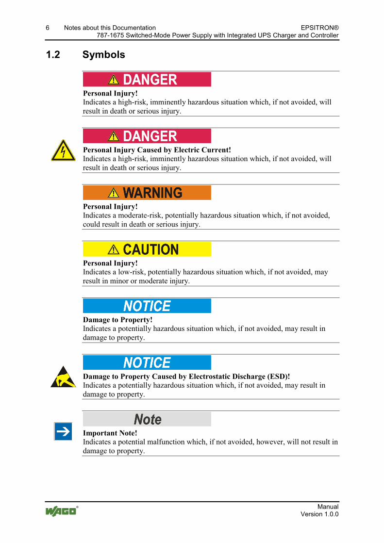
Personal Injury! Indicates a high-risk, imminently hazardous situation which, if not avoided, will result in death or serious injury.
Pos: 10.4.2 /All e Serien ( Allgemei ne Module)/Wichtige Erläuterungen/Sicherheits- und sonstig e Hinweise/Gefahr/Gefahr : _Warnung vor Personenschäden durch elektrischen Strom_ - Erläuterung @ 13\mod_1343309694914_21.doc @ 101030 @ @ 1
Personal Injury Caused by Electric Current! Indicates a high-risk, imminently hazardous situation which, if not avoided, will result in death or serious injury.
Pos: 10.4.3 /All e Serien ( Allgemei ne Module)/Wichtige Erläuterungen/Sicherheits- und sonstig e Hinweise/War nung/Warnung: _Warnung vor Personenschäden allgemein_ - Erläuterung @ 13\mod_1343309877041_21.doc @ 101035 @ @ 1
Personal Injury! Indicates a moderate-risk, potentially hazardous situation which, if not avoided, could result in death or serious injury.
Pos: 10.4.4 /All e Serien ( Allgemei ne Module)/Wichtige Erläuterungen/Sicherheits- und sonstig e Hinweise/Vorsicht/Vorsicht: _War nung vor Personenschäden allgemei n_ - Erl äuter ung @ 13\mod_1343310028762_21.doc @ 101038 @ @ 1
Personal Injury! Indicates a low-risk, potentially hazardous situation which, if not avoided, may result in minor or moderate injury.
Pos: 10.4.5 /All e Serien ( Allgemei ne Module)/Wichtige Erläuterungen/Sicherheits- und sonstig e Hinweise/Achtung/Achtung: _War nung vor Sachschäden allgemein_ - Erläuterung @ 13\mod_1343310134623_21.doc @ 101041 @ @ 1
Damage to Property! Indicates a potentially hazardous situation which, if not avoided, may result in damage to property.
Pos: 10.4.6 /All e Serien ( Allgemei ne Module)/Wichtige Erläuterungen/Sicherheits- und sonstig e Hinweise/Achtung/Achtung: _War nung vor Sachschäden durch el ektr ostatische Aufl adung_ - Erläuterung @ 13\mod_1343310227702_21.doc @ 101044 @ @ 1
Damage to Property Caused by Electrostatic Discharge (ESD)! Indicates a potentially hazardous situation which, if not avoided, may result in damage to property.
Pos: 10.4.7 /All e Serien ( Allgemei ne Module)/Wichtige Erläuterungen/Sicherheits- und sonstig e Hinweise/Hinweis/Hi nweis: _Wichtiger Hinweis allgemein_ - Eräuterung @ 13\mod_1343310326906_21.doc @ 101047 @ @ 1
Important Note! Indicates a potential malfunction which, if not avoided, however, will not result in damage to property.
Pos: 10.4.8 /All e Serien ( Allgemei ne Module)/Wichtige Erläuterungen/Sicherheits- und sonstig e Hinweise/Infor mation/Infor mation: _Wei ter e Infor mati on allgemei n_ - Erläuterung @ 13\mod_1343310439814_21.doc @ 101051 @ @ 1
EPSITRON® Notes about this Documentation 7 787-1675 Switched-Mode Power Supply with Integrated UPS Charger and Controller
Manual Version 1.0.0
Additional Information: Refers to additional information which is not an integral part of this documentation (e.g., the Internet).
Pos: 10.5 /Dokumentation allgemei n/Glieder ungselemente/---Seitenwechsel--- @ 3\mod_1221108045078_0.doc @ 21810 @ @ 1
8 Notes about this Documentation EPSITRON® 787-1675 Switched-Mode Power Supply with Integrated UPS Charger and Controller
Manual Version 1.0.0
Pos: 10.6 /All e Serien ( Allgemei ne Module)/Hi nweise zur D okumentati on/Zahlensys teme @ 3\mod_1221059454015_21.doc @ 21711 @ 2 @ 1
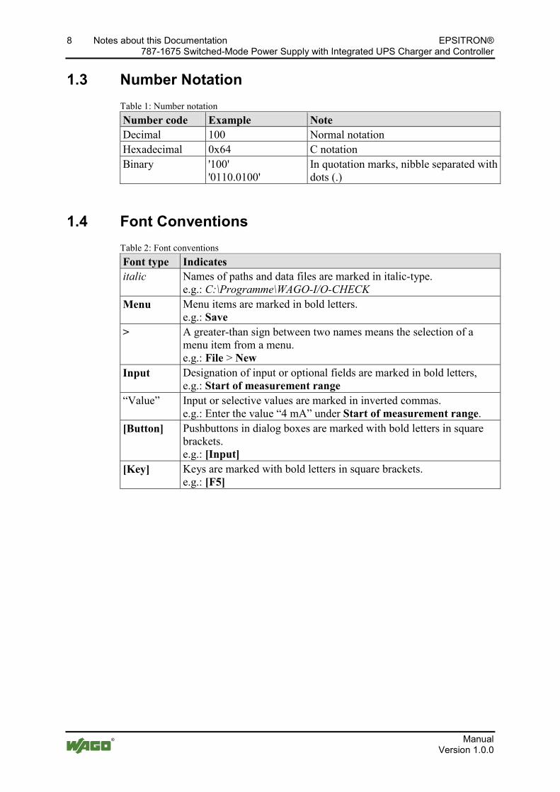
1.3 Number Notation Table 1: Number notation Number code Example Note Decimal 100 Normal notation Hexadecimal 0x64 C notation Binary '100'
'0110.0100' In quotation marks, nibble separated with dots (.)
Pos: 10.7 /All e Serien ( Allgemei ne Module)/Hi nweise zur D okumentati on/Schriftkonventi onen @ 3\mod_1221059521437_21.doc @ 21714 @ 2 @ 1
1.4 Font Conventions Table 2: Font conventions Font type Indicates italic Names of paths and data files are marked in italic-type.
e.g.: C:\Programme\WAGO-I/O-CHECK Menu Menu items are marked in bold letters.
e.g.: Save > A greater-than sign between two names means the selection of a
menu item from a menu. e.g.: File > New
Input Designation of input or optional fields are marked in bold letters, e.g.: Start of measurement range
“Value” Input or selective values are marked in inverted commas. e.g.: Enter the value “4 mA” under Start of measurement range.
[Button] Pushbuttons in dialog boxes are marked with bold letters in square brackets. e.g.: [Input]
[Key] Keys are marked with bold letters in square brackets. e.g.: [F5]
Pos: 11 /D okumentation allgemei n/Glieder ungselemente/---Seitenwechsel--- @ 3\mod_1221108045078_0.doc @ 21810 @ @ 1
EPSITRON® Important Notes 9 787-1675 Switched-Mode Power Supply with Integrated UPS Charger and Controller
Manual Version 1.0.0
Pos: 12 /All e Seri en ( Allgemei ne Module)/Ü berschriften für alle Serien/Wichtige Erläuter ung en/Wichtige Erläuter ung en - Überschrift 1 @ 4\mod_1241428899156_21.doc @ 32170 @ 1 @ 1
2 Important Notes Pos: 13.1 /All e Serien ( Allgemei ne Module)/Wichtige Erläuterungen/Einl eitung Wichtige Erläuterungen @ 3\mod_1221059818031_21.doc @ 21717 @ @ 1
This section includes an overall summary of the most important safety requirements and notes that are mentioned in each individual section. To protect your health and prevent damage to devices as well, it is imperative to read and carefully follow the safety guidelines.
Pos: 13.2 /All e Serien ( Allgemei ne Module)/Ü berschriften für alle Serien/Wichtige Erläuter ung en/Rechtliche Gr undlag en - Überschrift 2 @ 3\mod_1221060626343_21.doc @ 21726 @ 2 @ 1
2.1 Legal Bases Pos: 13.3 /All e Serien ( Allgemei ne Module)/Wichtige Erläuterungen/Änderungsvor behal t - Ü berschrift 3 und Inhalt @ 3\mod_1221060036484_21.doc @ 21720 @ 3 @ 1
2.1.1 Subject to Changes
WAGO Kontakttechnik GmbH & Co. KG reserves the right to provide for any alterations or modifications that serve to increase the efficiency of technical progress. WAGO Kontakttechnik GmbH & Co. KG owns all rights arising from the granting of patents or from the legal protection of utility patents. Third-party products are always mentioned without any reference to patent rights. Thus, the existence of such rights cannot be excluded.
Pos: 13.4 /Serie 787 (EPSITRON)/Wichtige Erläuterungen/Personalqualifi kation 787- xxxx @ 11\mod_1317113061338_21.doc @ 79692 @ 3 @ 1
2.1.2 Personnel Qualifications
All sequences implemented on 787 Series devices may only be carried out by electrical specialists with sufficient knowledge in automation. The specialists must be familiar with the current norms and guidelines for the devices and automated environments.
Pos: 13.5 /Serie 787 (EPSITRON)/Wichtige Erläuterungen/Besti mmungsgemäße Ver wendung 787-xxxx @ 11\mod_1317113060572_21.doc @ 79688 @ 3 @ 1
2.1.3 Use of the 787 Series in Compliance with Underlying Provisions
The EPSITRON® 787 Series power supply system provides direct current to electric or electronic devices, such as industrial control systems or display, communication and measuring devices.
The devices have been developed for use in an environment that meets the IP20 protection class criteria. Protection against finger injury and solid impurities up to 12.5 mm diameter is assured; protection against water damage is not ensured. Unless otherwise specified, operation of the components in wet and dusty environments is prohibited.
The devices are designed for installation in an enclosure. Under no circumstances may they be used in control systems for planes or nuclear facilities, as any malfunction in these applications could result in severe injuries or risk of death.
Pos: 13.6 /Dokumentation allgemei n/Glieder ungselemente/---Seitenwechsel--- @ 3\mod_1221108045078_0.doc @ 21810 @ @ 1
10 Important Notes EPSITRON® 787-1675 Switched-Mode Power Supply with Integrated UPS Charger and Controller
Manual Version 1.0.0
Pos: 13.7 /All e Serien ( Allgemei ne Module)/Wichtige Erläuterungen/Technischer Zustand der Geräte - Ü berschrif t 3 und Inhal t @ 3\mod_1221060446109_21.doc @ 21723 @ 3 @ 1
2.1.4 Technical Condition of Specified Devices
The components to be supplied Ex Works, are equipped with hardware and software configurations, which meet the individual application requirements. WAGO Kontakttechnik GmbH & Co. KG will be exempted from any liability in case of changes in hardware or software as well as to non-compliant usage of components.
Please send your request for modified and new hardware or software configurations directly to WAGO Kontakttechnik GmbH & Co. KG.
Pos: 13.8 /Dokumentation allgemei n/Glieder ungselemente/---Seitenwechsel--- @ 3\mod_1221108045078_0.doc @ 21810 @ @ 1
EPSITRON® Important Notes 11 787-1675 Switched-Mode Power Supply with Integrated UPS Charger and Controller
Manual Version 1.0.0
Pos: 13.9 /All e Serien ( Allgemei ne Module)/Ü berschriften für alle Serien/Wichtige Erläuter ung en/Sicher heitshi nweise - Überschrift 2 @ 6\mod_1260180299987_21.doc @ 46724 @ 2 @ 1
2.2 Safety Advice (Precautions) Pos: 13.10 /Alle Serien (Allgemeine M odul e)/Wichtige Erläuter ung en/Sicherheits- und sonstige Hinweise/Ei nleitung Sicher hei tshi nweise Har dwar e @ 6\mod_1260180170493_21.doc @ 46720 @ @ 1
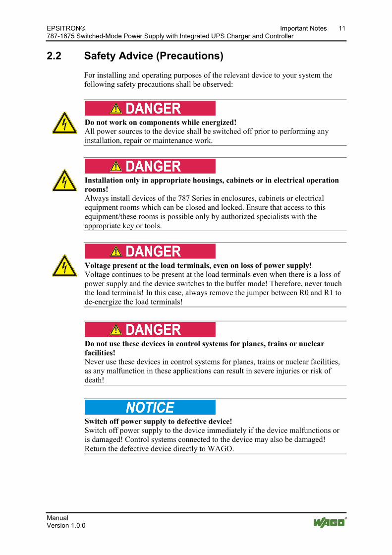
For installing and operating purposes of the relevant device to your system the following safety precautions shall be observed:
Pos: 13.11 /Alle Serien (Allgemeine M odul e)/Wichtige Erläuter ung en/Sicherheits- und sonstige Hinweise/Gefahr/Gefahr: Nicht an Geräten unter Spannung arbeiten! @ 6\mod_1260180365327_21.doc @ 46727 @ @ 1
Do not work on components while energized! All power sources to the device shall be switched off prior to performing any installation, repair or maintenance work.
Pos: 13.12 /Serie 787 ( EPSITR ON)/Wichtige Erläuterungen/Sicherheits- und sonstige Hinweise/Gefahr /Gefahr: Ei nbau 787- xxxx nur in Gehäusen, Schr änken oder elektrischen Betriebsr äumen! @ 11\mod_1317113246230_21.doc @ 79696 @ @ 1
Installation only in appropriate housings, cabinets or in electrical operation rooms! Always install devices of the 787 Series in enclosures, cabinets or electrical equipment rooms which can be closed and locked. Ensure that access to this equipment/these rooms is possible only by authorized specialists with the appropriate key or tools.
Pos: 13.13 /Serie 787 ( EPSITR ON)/Wichtige Erläuterungen/Sicherheits- und sonstige Hinweise/Gefahr /Gefahr: Spannung an den Ausgängen auch bei Aus fall der Netzspannung! @ 14\mod_1363599131481_21.doc @ 114650 @ @ 1
Voltage present at the load terminals, even on loss of power supply! Voltage continues to be present at the load terminals even when there is a loss of power supply and the device switches to the buffer mode! Therefore, never touch the load terminals! In this case, always remove the jumper between R0 and R1 to de-energize the load terminals!
Pos: 13.14 /Alle Serien (Allgemeine M odul e)/Wichtige Erläuter ung en/Sicherheits- und sonstige Hinweise/Gefahr/Gefahr: Unfall verhütungsvorschriften beachten! @ 6\mod_1260180657000_21.doc @ 46735 @ @ 1
Pos: 13.15 /Serie 787 ( EPSITR ON)/Wichtige Erläuterungen/Sicherheits- und sonstige Hinweise/Gefahr /Gefahr: Geräte nicht i n Steuerungsanl agen verwenden! @ 13\mod_1346400862576_21.doc @ 102180 @ @ 1
Do not use these devices in control systems for planes, trains or nuclear facilities! Never use these devices in control systems for planes, trains or nuclear facilities, as any malfunction in these applications can result in severe injuries or risk of death!
Pos: 13.16 /Alle Serien (Allgemeine M odul e)/Wichtige Erläuter ung en/Sicherheits- und sonstige Hinweise/Gefahr/Gefahr: Auf normg erechten Anschluss achten! @ 6\mod_1260180753479_21.doc @ 46739 @ @ 1
Pos: 13.17 /Serie 787 ( EPSITR ON)/Wichtige Erläuterungen/Sicherheits- und sonstige Hinweise/Achtung/Achtung: Versorgungsspannung bei defektem Ger ät abschalten! @ 13\mod_1346401405605_21.doc @ 102187 @ @ 1
Switch off power supply to defective device! Switch off power supply to the device immediately if the device malfunctions or is damaged! Control systems connected to the device may also be damaged! Return the defective device directly to WAGO.
Pos: 13.18 /Alle Serien (Allgemeine M odul e)/Wichtige Erläuter ung en/Sicherheits- und sonstige Hinweise/Achtung/Achtung: Geräte vor kri echenden und isolier enden Stoffen schützen! @ 6\mod_1260181036216_21.doc @ 46747 @ @ 1
12 Important Notes EPSITRON® 787-1675 Switched-Mode Power Supply with Integrated UPS Charger and Controller
Manual Version 1.0.0
Protect the components against materials having seeping and insulating properties! The components are not resistant to materials having seeping and insulating properties such as: aerosols, silicones and triglycerides (found in some hand creams). If you cannot exclude that such materials will appear in the component environment, then install the components in an enclosure being resistant to the above-mentioned materials. Clean tools and materials are imperative for handling devices/modules.
Pos: 13.19 /Alle Serien (Allgemeine M odul e)/Wichtige Erläuter ung en/Sicherheits- und sonstige Hinweise/Achtung/Achtung: Rei nigung nur mit zul ässigen M aterialien! @ 6\mod_1260181203293_21.doc @ 46751 @ @ 1
Cleaning only with permitted materials! Clean soiled contacts using oil-free compressed air or with ethyl alcohol and leather cloths.
Pos: 13.20 /Alle Serien (Allgemeine M odul e)/Wichtige Erläuter ung en/Sicherheits- und sonstige Hinweise/Achtung/Achtung: Kein Kontaktspray ver wenden! @ 6\mod_1260181290808_21.doc @ 46755 @ @ 1
Do not use any contact spray! Do not use any contact spray. The spray may impair contact area functionality in connection with contamination.
Pos: 13.21 /Alle Serien (Allgemeine M odul e)/Wichtige Erläuter ung en/Sicherheits- und sonstige Hinweise/Achtung/Achtung: Verpolung ver mei den! @ 6\mod_1260184045744_21.doc @ 46767 @ @ 1
Do not reverse the polarity of connection lines! Avoid reverse polarity of data and power supply lines, as this may damage the devices involved.
Pos: 13.22 /Alle Serien (Allgemeine M odul e)/Wichtige Erläuter ung en/Sicherheits- und sonstige Hinweise/Achtung/Achtung: El ektr ostatische Entl adung vermeiden! @ 6\mod_1260181364729_21.doc @ 46759 @ @ 1
Avoid electrostatic discharge! The devices are equipped with electronic components that you may destroy by electrostatic discharge when you touch. Pay attention while handling the devices to good grounding of the environment (persons, job and packing).
Pos: 14 /D okumentation allgemei n/Glieder ungselemente/---Seitenwechsel--- @ 3\mod_1221108045078_0.doc @ 21810 @ @ 1
EPSITRON® Device Description 13 787-1675 Switched-Mode Power Supply with Integrated UPS Charger and Controller
Manual Version 1.0.0
Pos: 15 /All e Seri en ( Allgemei ne Module)/Ü berschriften für alle Serien/Gerätebeschr eibung/Gerätebeschr eibung - Ü berschrif t 1 @ 3\mod_1233756084656_21.doc @ 27096 @ 1 @ 1
3 Device Description Pos: 16.1 /Serie 787 (EPSITRON)/Ger ätebeschrei bung/Beschr eibung/Anwendung/Anwendung 787-1675 @ 13\mod_1342439897257_21.doc @ 100336 @ @ 1
The switched-mode power supply with integrated ups charger and controller 787-1675, in the following named as uninterruptible power supply system (UPS), ensures that power is always supplied. If the mains power is lost, all of the electrical loads connected to the system will continue to operate reliably.
Pos: 16.2 /Serie 787 (EPSITRON)/Ger ätebeschrei bung/Beschr eibung/Funkti on/Funkti on 787-1675: Funktionsei nheiten @ 13\mod_1342599274535_21.doc @ 100540 @ @ 1
The system consists of two function units:
• an AC/DC power supply unit with an integrated charger and controller and
• a 24V DC battery module for buffering (not included in the scope of supply).
Pos: 16.3 /Serie 787 (EPSITRON)/Ger ätebeschrei bung/Beschr eibung/Funkti on/Funkti on 787-1675: Wirkungsweise der Komponenten @ 13\mod_1342600188912_21.doc @ 100544 @ @ 1
All of the components that can be used to set up an uninterruptible power supply system are optimally matched to and compatible with one another. These components can be quickly installed and are immediately ready for operation.
Any 787-87x Series battery modules that are connected to the system are detected automatically by the UPS.
Battery module not included in the scope of supply! The scope of supply for this device does not include the battery module. The device will only continue to operate properly when at least one battery module is connected. The WAGO range of products includes compatible EPSITRON® 787-87x Series battery modules.
The system can also be integrated into an existing topology via several signaling contacts and a serial interface.
Critical operating states are signaled at an early stage, before the 24 V system power collapses and the device shuts down.
Pos: 17 /D okumentation allgemei n/Glieder ungselemente/---Seitenwechsel--- @ 3\mod_1221108045078_0.doc @ 21810 @ @ 1
14 Device Description EPSITRON® 787-1675 Switched-Mode Power Supply with Integrated UPS Charger and Controller
Manual Version 1.0.0
Pos: 18 /All e Seri en ( Allgemei ne Module)/Ü berschriften für alle Serien/Gerätebeschr eibung/Ansicht - Ü berschrif t 2 @ 4\mod_1240984217343_21.doc @ 31958 @ 2 @ 1
3.1 View Pos: 19 /Serie 787 (EPSITRON)/Ger ätebeschrei bung/Ansi cht/Ansicht 787- 1675 @ 13\mod_1345791639239_21.doc @ 101944 @ @ 1
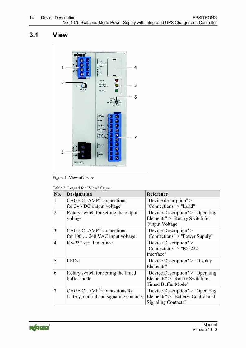
Figure 1: View of device
Table 3: Legend for "View" figure No. Designation Reference 1 CAGE CLAMP® connections
for 24 VDC output voltage "Device description" > "Connections" > "Load"
2 Rotary switch for setting the output voltage
"Device Description" > "Operating Elements" > "Rotary Switch for Output Voltage"
3 CAGE CLAMP® connections for 100 … 240 VAC input voltage
"Device Description" > "Connections" > "Power Supply"
4 RS-232 serial interface "Device Description" > "Connections" > "RS-232 Interface"
5 LEDs "Device Description" > "Display Elements"
6 Rotary switch for setting the timed buffer mode
"Device Description" > "Operating Elements" > "Rotary Switch for Timed Buffer Mode"
7 CAGE CLAMP® connections for battery, control and signaling contacts
"Device Description" > "Operating Elements" > "Battery, Control and Signaling Contacts"
Pos: 20 /D okumentation allgemei n/Glieder ungselemente/---Seitenwechsel--- @ 3\mod_1221108045078_0.doc @ 21810 @ @ 1
EPSITRON® Device Description 15 787-1675 Switched-Mode Power Supply with Integrated UPS Charger and Controller
Manual Version 1.0.0
Pos: 21 /All e Seri en ( Allgemei ne Module)/Ü berschriften für alle Serien/Gerätebeschr eibung/Anschlüsse - Überschrift 2 @ 4\mod_1240984262656_21.doc @ 31961 @ 2 @ 1
3.2 Connectors Pos: 22.1 /Serie 787 (EPSITRON)/Ger ätebeschrei bung/Anschl üsse/Anschl üsse 787-1675 - Versorgung @ 13\mod_1347952219203_21.doc @ 102916 @ 3 @ 1
3.2.1 Supply
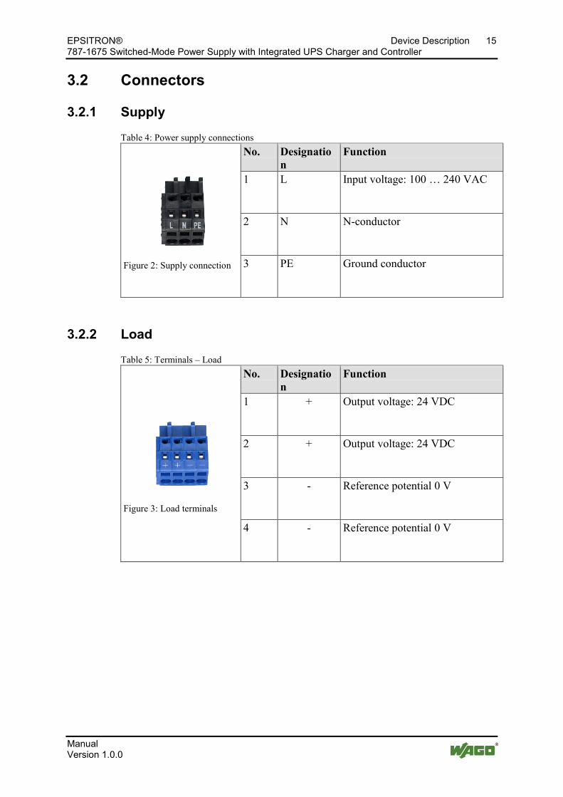
Table 4: Power supply connections
Figure 2: Supply connection
No. Designation
Function
1 L Input voltage: 100 … 240 VAC
2 N N-conductor
3 PE Ground conductor
Pos: 22.2 /Serie 787 (EPSITRON)/Ger ätebeschrei bung/Anschl üsse/Anschl üsse 787-1675 - Last @ 13\mod_1347884939616_21.doc @ 102884 @ 3 @ 1
3.2.2 Load
Table 5: Terminals – Load
Figure 3: Load terminals
No. Designation
Function
1 + Output voltage: 24 VDC
2 + Output voltage: 24 VDC
3 - Reference potential 0 V
4 - Reference potential 0 V
Pos: 22.3 /Serie 787 (EPSITRON)/Ger ätebeschrei bung/Anschl üsse/Anschl üsse 787-1675 - Batterie-, Steuer- und Signal kontakte @ 13\mod_1347958740665_21.doc @ 102950 @ 3 @ 1
16 Device Description EPSITRON® 787-1675 Switched-Mode Power Supply with Integrated UPS Charger and Controller
Manual Version 1.0.0
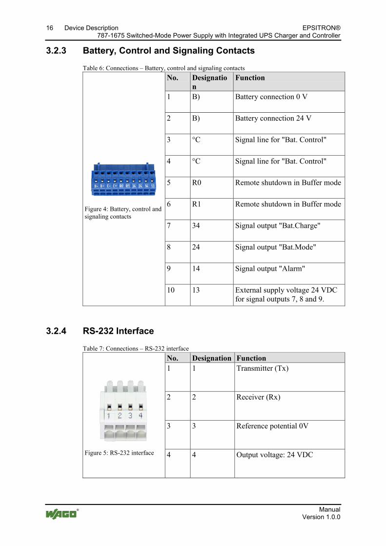
3.2.3 Battery, Control and Signaling Contacts
Table 6: Connections – Battery, control and signaling contacts
Figure 4: Battery, control and signaling contacts
No. Designation
Function
1 B) Battery connection 0 V
2 B) Battery connection 24 V
3 °C Signal line for "Bat. Control"
4 °C Signal line for "Bat. Control"
5 R0 Remote shutdown in Buffer mode
6 R1 Remote shutdown in Buffer mode
7 34 Signal output "Bat.Charge"
8 24 Signal output "Bat.Mode"
9 14 Signal output "Alarm"
10 13 External supply voltage 24 VDC for signal outputs 7, 8 and 9.
Pos: 22.4 /Serie 787 (EPSITRON)/Ger ätebeschrei bung/Anschl üsse/Anschl üsse 787-1675 - RS- 232-Schnitts telle @ 13\mod_1347962772871_21.doc @ 102970 @ 3 @ 1
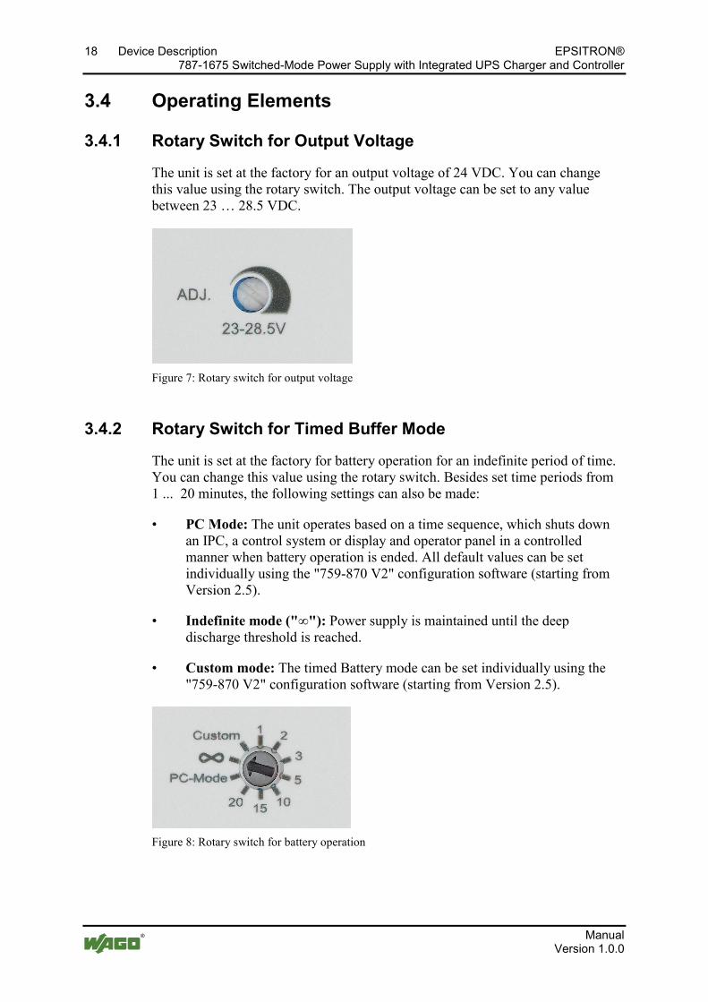
3.2.4 RS-232 Interface
Table 7: Connections – RS-232 interface
Figure 5: RS-232 interface
No. Designation Function 1 1 Transmitter (Tx)
2 2 Receiver (Rx)
3 3 Reference potential 0V
4 4 Output voltage: 24 VDC
Pos: 23 /All e Seri en ( Allgemei ne Module)/Ü berschriften für alle Serien/Gerätebeschr eibung/Anzeigeel emente - Ü berschrif t 2 @ 4\mod_1240984390875_21.doc @ 31964 @ 2 @ 1

EPSITRON® Device Description 17 787-1675 Switched-Mode Power Supply with Integrated UPS Charger and Controller
Manual Version 1.0.0
3.3 Display Elements Pos: 24 /Serie 787 (EPSITRON)/Ger ätebeschrei bung/Anzeigeelemente/Anzeigeelemente 787- 1675 @ 13\mod_1346060933352_21.doc @ 101967 @ @ 1
The unit is equipped with three LEDs, which indicate the following statuses:
Figure 6: Display elements
Table 8: Legend for "Indicators" figure No. LED Designation Explanation: 1 red Alarm The unit is faulted, or the Battery mode is
being terminated. 2 yellow Charge/
Bat. Mode The unit is charging the batteries, or is operating in the Battery mode.
3 green DC OK The unit is ready for use.
Further signaling possible! Other statuses can also be indicated if an error occurs. For information about this, refer to the "Operating Statuses" table given in this manual.
Pos: 25 /D okumentation allgemei n/Glieder ungselemente/---Seitenwechsel--- @ 3\mod_1221108045078_0.doc @ 21810 @ @ 1
18 Device Description EPSITRON® 787-1675 Switched-Mode Power Supply with Integrated UPS Charger and Controller
Manual Version 1.0.0
Pos: 26 /All e Seri en ( Allgemei ne Module)/Ü berschriften für alle Serien/Gerätebeschr eibung/Bedi enel emente - Ü berschrift 2 @ 4\mod_1239191655456_21.doc @ 30439 @ 2 @ 1
3.4 Operating Elements Pos: 27 /Serie 787 (EPSITRON)/Ger ätebeschrei bung/Bedienelemente/Bedi enel emente 787-1675 @ 13\mod_1346060971825_21.doc @ 101981 @ 33 @ 1
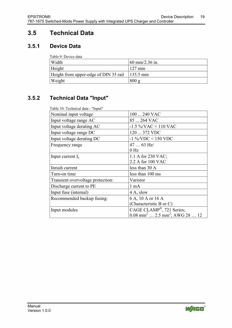
3.4.1 Rotary Switch for Output Voltage
The unit is set at the factory for an output voltage of 24 VDC. You can change this value using the rotary switch. The output voltage can be set to any value between 23 … 28.5 VDC.
Figure 7: Rotary switch for output voltage
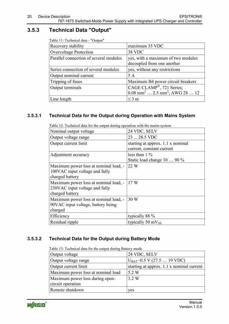
3.4.2 Rotary Switch for Timed Buffer Mode
The unit is set at the factory for battery operation for an indefinite period of time. You can change this value using the rotary switch. Besides set time periods from 1 ... 20 minutes, the following settings can also be made:
• PC Mode: The unit operates based on a time sequence, which shuts down an IPC, a control system or display and operator panel in a controlled manner when battery operation is ended. All default values can be set individually using the "759-870 V2" configuration software (starting from Version 2.5).
• Indefinite mode ("∞"): Power supply is maintained until the deep discharge threshold is reached.
• Custom mode: The timed Battery mode can be set individually using the "759-870 V2" configuration software (starting from Version 2.5).
Figure 8: Rotary switch for battery operation Pos: 28 /D okumentation allgemei n/Glieder ungselemente/---Seitenwechsel--- @ 3\mod_1221108045078_0.doc @ 21810 @ @ 1
EPSITRON® Device Description 19 787-1675 Switched-Mode Power Supply with Integrated UPS Charger and Controller
Manual Version 1.0.0
Pos: 29 /All e Seri en ( Allgemei ne Module)/Ü berschriften für alle Serien/Gerätebeschr eibung/Technische Daten - Ü berschrift 2 @ 3\mod_1232967587687_21.doc @ 26924 @ 2 @ 1
3.5 Technical Data Pos: 30 /Serie 787 (EPSITRON)/Ger ätebeschrei bung/Technische D aten/Technische Daten 787-1675 @ 13\mod_1342438358691_21.doc @ 100320 @ 333443333 @ 1
3.5.1 Device Data
Table 9: Device data Width 60 mm/2.36 in. Height 127 mm Height from upper-edge of DIN 35 rail 135.5 mm Weight 800 g
3.5.2 Technical Data "Input"
Table 10: Technical data - "Input" Nominal input voltage 100 ... 240 VAC Input voltage range AC 85 ... 264 VAC Input voltage derating AC -1.5 %/VAC < 110 VAC Input voltage range DC 120 ... 372 VDC Input voltage derating DC -1 %/VDC < 150 VDC Frequency range 47 … 63 Hz/
0 Hz Input current Ie 1.1 A for 230 VAC;
2.2 A for 100 VAC Inrush current less than 30 A Turn-on time less than 100 ms Transient overvoltage protection: Varistor Discharge current to PE 1 mA Input fuse (internal) 4 A, slow Recommended backup fusing: 6 A, 10 A or 16 A
(Characteristic B or C) Input modules CAGE CLAMP®, 721 Series;
0.08 mm2 … 2.5 mm2; AWG 28 … 12
20 Device Description EPSITRON® 787-1675 Switched-Mode Power Supply with Integrated UPS Charger and Controller
Manual Version 1.0.0
3.5.3 Technical Data "Output"
Table 11: Technical data - "Output" Recovery stability maximum 35 VDC Overvoltage Protection 38 VDC Parallel connection of several modules yes, with a maximum of two modules
decoupled from one another Series connection of several modules yes, without any restrictions Output nominal current 5 A Tripping of fuses Maximum B4 power circuit breakers Output terminals CAGE CLAMP®, 721 Series;
0.08 mm2 … 2.5 mm2; AWG 28 … 12 Line length ≤ 3 m
3.5.3.1 Technical Data for the Output during Operation with Mains System
Table 12: Technical data for the output during operation with the mains system Nominal output voltage 24 VDC, SELV Output voltage range 23 ... 28.5 VDC Output current limit starting at approx. 1.1 x nominal
current, constant current Adjustment accuracy less than 1 %
Static load change 10 … 90 % Maximum power loss at nominal load, -100VAC input voltage and fully charged battery
22 W
Maximum power loss at nominal load, -230VAC input voltage and fully charged battery
17 W
Maximum power loss at nominal load, -90VAC input voltage, battery being charged
30 W
Efficiency typically 88 % Residual ripple typically 50 mVSS
3.5.3.2 Technical Data for the Output during Battery Mode
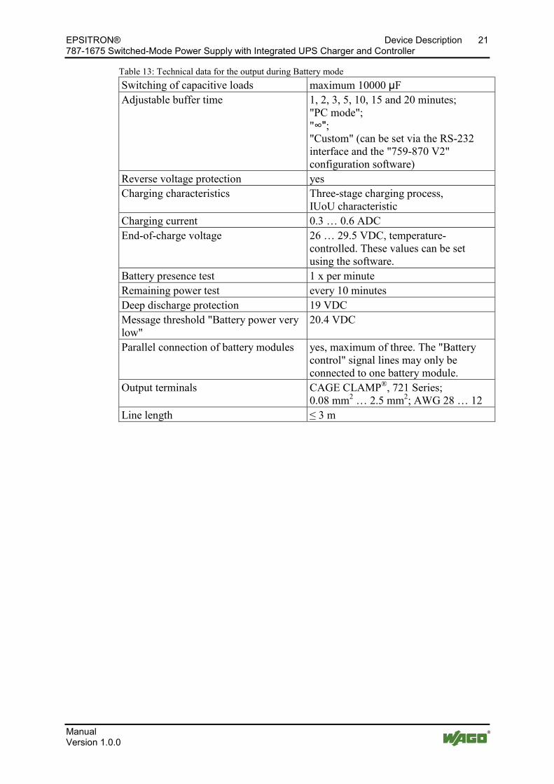
Table 13: Technical data for the output during Battery mode Output voltage 24 VDC, SELV Output voltage range UBAT -0.5 V (27.5 … 19 VDC) Output current limit starting at approx. 1.1 x nominal current Maximum power loss at nominal load 5.2 W Maximum power loss during open-circuit operation
3.2 W
Remote shutdown yes
EPSITRON® Device Description 21 787-1675 Switched-Mode Power Supply with Integrated UPS Charger and Controller
Manual Version 1.0.0
Table 13: Technical data for the output during Battery mode Switching of capacitive loads maximum 10000 µF Adjustable buffer time 1, 2, 3, 5, 10, 15 and 20 minutes;
"PC mode"; "∞"; "Custom" (can be set via the RS-232 interface and the "759-870 V2" configuration software)
Reverse voltage protection yes Charging characteristics Three-stage charging process,
IUoU characteristic Charging current 0.3 … 0.6 ADC End-of-charge voltage 26 … 29.5 VDC, temperature-
controlled. These values can be set using the software.
Battery presence test 1 x per minute Remaining power test every 10 minutes Deep discharge protection 19 VDC Message threshold "Battery power very low"
20.4 VDC
Parallel connection of battery modules yes, maximum of three. The "Battery control" signal lines may only be connected to one battery module.
Output terminals CAGE CLAMP®, 721 Series; 0.08 mm2 … 2.5 mm2; AWG 28 … 12
Line length ≤ 3 m
22 Device Description EPSITRON® 787-1675 Switched-Mode Power Supply with Integrated UPS Charger and Controller
Manual Version 1.0.0
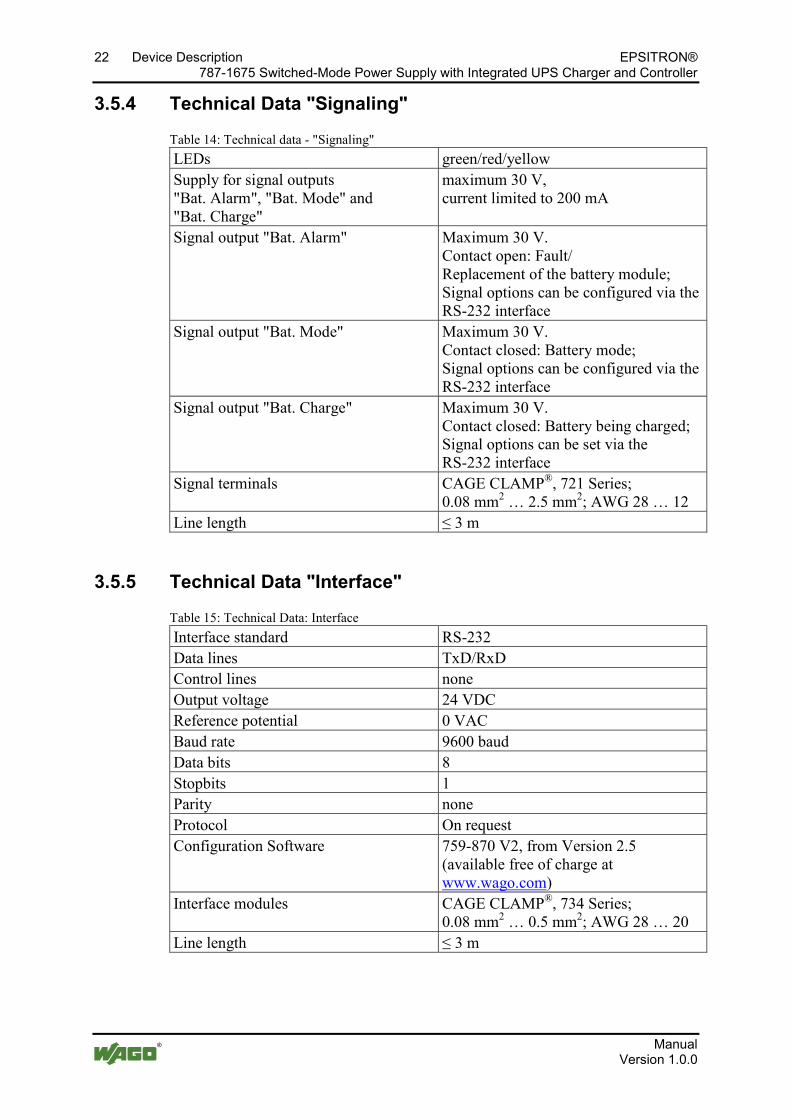
3.5.4 Technical Data "Signaling"
Table 14: Technical data - "Signaling" LEDs green/red/yellow Supply for signal outputs "Bat. Alarm", "Bat. Mode" and "Bat. Charge"
maximum 30 V, current limited to 200 mA
Signal output "Bat. Alarm" Maximum 30 V. Contact open: Fault/ Replacement of the battery module; Signal options can be configured via the RS-232 interface
Signal output "Bat. Mode" Maximum 30 V. Contact closed: Battery mode; Signal options can be configured via the RS-232 interface
Signal output "Bat. Charge" Maximum 30 V. Contact closed: Battery being charged; Signal options can be set via the RS-232 interface
Signal terminals CAGE CLAMP®, 721 Series; 0.08 mm2 … 2.5 mm2; AWG 28 … 12
Line length ≤ 3 m
3.5.5 Technical Data "Interface"
Table 15: Technical Data: Interface Interface standard RS-232 Data lines TxD/RxD Control lines none Output voltage 24 VDC Reference potential 0 VAC Baud rate 9600 baud Data bits 8 Stopbits 1 Parity none Protocol On request Configuration Software 759-870 V2, from Version 2.5
(available free of charge at www.wago.com)
Interface modules CAGE CLAMP®, 734 Series; 0.08 mm2 … 0.5 mm2; AWG 28 … 20
Line length ≤ 3 m
EPSITRON® Device Description 23 787-1675 Switched-Mode Power Supply with Integrated UPS Charger and Controller
Manual Version 1.0.0
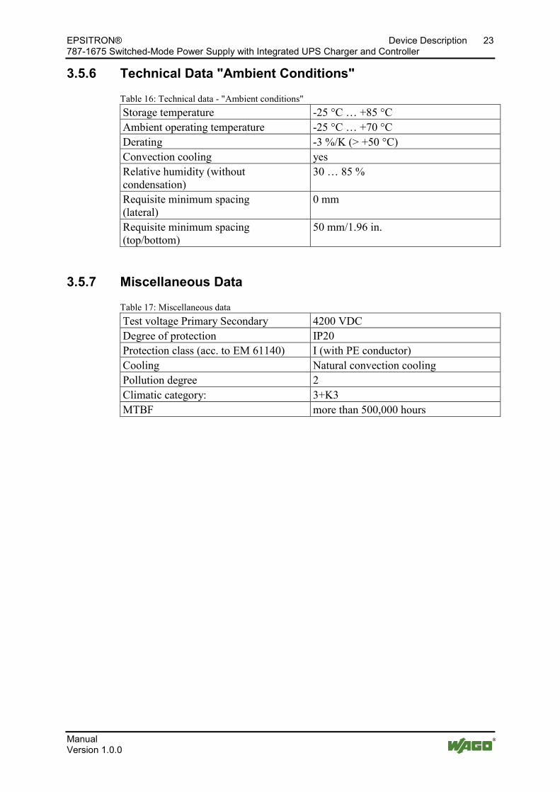
3.5.6 Technical Data "Ambient Conditions"
Table 16: Technical data - "Ambient conditions" Storage temperature -25 °C … +85 °C Ambient operating temperature -25 °C … +70 °C Derating -3 %/K (> +50 °C) Convection cooling yes Relative humidity (without condensation)
30 … 85 %
Requisite minimum spacing (lateral)
0 mm
Requisite minimum spacing (top/bottom)
50 mm/1.96 in.
3.5.7 Miscellaneous Data
Table 17: Miscellaneous data Test voltage Primary Secondary 4200 VDC Degree of protection IP20 Protection class (acc. to EM 61140) I (with PE conductor) Cooling Natural convection cooling Pollution degree 2 Climatic category: 3+K3 MTBF more than 500,000 hours
Pos: 31 /D okumentation allgemei n/Glieder ungselemente/---Seitenwechsel--- @ 3\mod_1221108045078_0.doc @ 21810 @ @ 1
24 Device Description EPSITRON® 787-1675 Switched-Mode Power Supply with Integrated UPS Charger and Controller
Manual Version 1.0.0
Pos: 32 /All e Seri en ( Allgemei ne Module)/Ü berschriften für alle Serien/Gerätebeschr eibung/Zul assung en - Überschrift 2 @ 3\mod_1224055364109_21.doc @ 24030 @ 2 @ 1
3.6 Approvals Pos: 33 /Serie 787 (EPSITRON)/Ger ätebeschrei bung/Zulassungen/Zulassungen U nterbr echungsfrei e Stromversorgung 787- xxxx allgemein, ohne Variantenangabe - Ei nlei tun @ 13\mod_1347518988157_21.doc @ 102690 @ @ 1
The following approvals have been awarded to the uninterruptible power supply system 787-1675:
Pos: 34 /All e Seri en ( Allgemei ne Module)/Zulassungen/Standardzulassungen/C E (Konformitätskennzeichnung) @ 3\mod_1224494777421_21.doc @ 24276 @ @ 1
Conformity Marking Pos : 35 /D okumentation allgemei n/Glieder ungselemente/---Seitenwechsel--- @ 3\mod_1221108045078_0.doc @ 21810 @ @ 1
EPSITRON® Device Description 25 787-1675 Switched-Mode Power Supply with Integrated UPS Charger and Controller
Manual Version 1.0.0
Pos: 36 /All e Seri en ( Allgemei ne Module)/Ü berschriften für alle Serien/Gerätebeschr eibung/Nor men und Richtlini en - Überschrift 2 @ 4\mod_1242804031875_21.doc @ 33646 @ 2 @ 1
3.7 Standards and Guidelines Pos: 37 /Serie 787 (EPSITRON)/Ger ätebeschrei bung/N ormen und Richtli nien/N ormen und Richtli nien U nterbrechungs freie Stromversorgung 787- xxxx, ohne Variantenangabe - Ei nl @ 13\mod_1347519108515_21.doc @ 102694 @ @ 1
The uninterruptible power supply system 787-1675 complies with the following standards and guidelines:
Pos: 38 /All e Seri en ( Allgemei ne Module)/N or men und Richtli nien/Sicherheit: DIN EN 61204:2000 @ 13\mod_1346665870671_21.doc @ 102249 @ @ 1
Low-voltage power supplies, IEC 61204-3:2000 DC output Part 3: Electromagnetic compatibility (EMC)
Pos: 39 /All e Seri en ( Allgemei ne Module)/N or men und Richtli nien/Sicherheit: DIN EN 61558- 2-16:2009 @ 13\mod_1346665322780_21.doc @ 102246 @ @ 1
Safety of transformers, reactors, IEC 61558-2-16:2009 power supply units and similar products for supply voltages up to 1100 V – Part 2-16: Particular requirements and tests for switch mode power supply units and transformers for switch mode power supply units
Pos: 40 /All e Seri en ( Allgemei ne Module)/N or men und Richtli nien/Sicherheit: DIN EN 60950- 1:2006 @ 13\mod_1346664940957_21.doc @ 102243 @ @ 1
Information technology IEC 60950-1:2009 equipment – Safety – Part 1: General requirements
Pos: 41 /All e Seri en ( Allgemei ne Module)/N or men und Richtli nien/EG-EM V-Richtlini e 2004/108/EG @ 7\mod_1274262373820_21.doc @ 56628 @ @ 1
EC EMC Directive 2004/108/EC Pos: 42 /All e Seri en ( Allgemei ne Module)/N or men und Richtli nien/EG-Niederspannungsrichtlini e 2006/ 95/ EG @ 7\mod_1274262383272_21.doc @ 56632 @ @ 1
EC Low Voltage directive (LVD) 2006/95/EC Pos: 43 /D okumentation allgemei n/Glieder ungselemente/---Seitenwechsel--- @ 3\mod_1221108045078_0.doc @ 21810 @ @ 1
26 Mounting EPSITRON® 787-1675 Switched-Mode Power Supply with Integrated UPS Charger and Controller
Manual Version 1.0.0
Pos: 44 /All e Seri en ( Allgemei ne Module)/Ü berschriften für alle Serien/Monti eren - D emonti eren/M ontier en - Überschrift 1 @ 3\mod_1225446744750_21.doc @ 24900 @ 1 @ 1
4 Mounting Pos: 45 /Serie 787 (EPSITRON)/M ontier en/Montage 787- xxxx @ 11\mod_1317296048899_21.doc @ 80170 @ 22 @ 1
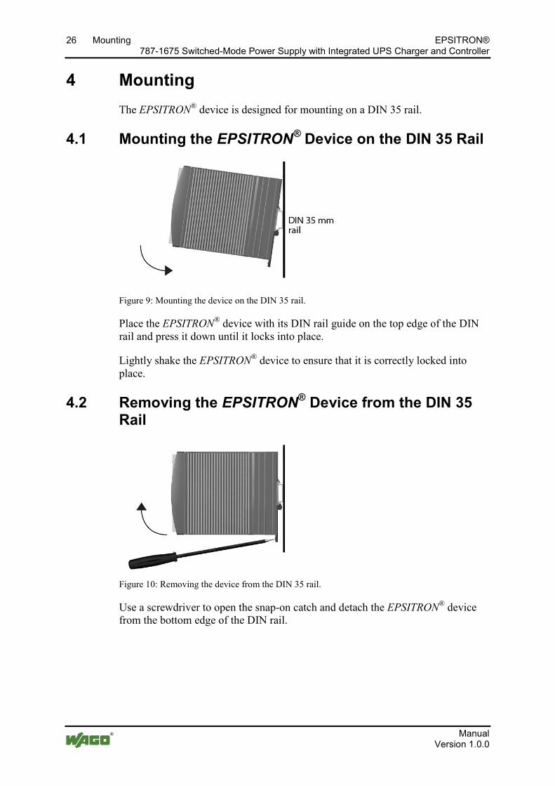
The EPSITRON® device is designed for mounting on a DIN 35 rail.
4.1 Mounting the EPSITRON® Device on the DIN 35 Rail
Figure 9: Mounting the device on the DIN 35 rail.
Place the EPSITRON® device with its DIN rail guide on the top edge of the DIN rail and press it down until it locks into place.
Lightly shake the EPSITRON® device to ensure that it is correctly locked into place.
4.2 Removing the EPSITRON® Device from the DIN 35 Rail
Figure 10: Removing the device from the DIN 35 rail.
Use a screwdriver to open the snap-on catch and detach the EPSITRON® device from the bottom edge of the DIN rail.
Pos: 46 /D okumentation allgemei n/Glieder ungselemente/---Seitenwechsel--- @ 3\mod_1221108045078_0.doc @ 21810 @ @ 1
EPSITRON® Connect Devices 27 787-1675 Switched-Mode Power Supply with Integrated UPS Charger and Controller
Manual Version 1.0.0
Pos: 47 /All e Seri en ( Allgemei ne Module)/Ü berschriften für alle Serien/Anschließen/Geräte anschließen - Ü berschrift 1 @ 3\mod_1234172889468_21.doc @ 27460 @ 1 @ 1
5 Connect Devices Pos: 48 /All e Seri en ( Allgemei ne Module)/Ü berschriften für alle Serien/Anschließen/Anschl ussbeispiel - Überschrift 2 @ 4\mod_1242621672468_21.doc @ 33293 @ 2 @ 1
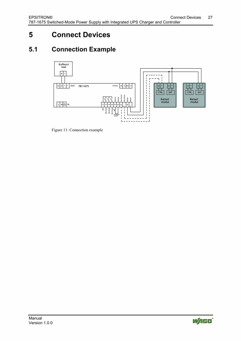
5.1 Connection Example Pos: 49 /Serie 787 (EPSITRON)/Anschli eßen/Anschlussbeispi el 787-1675 @ 13\mod_1346146843608_21.doc @ 102040 @ @ 1
Figure 11: Connection example Pos: 50 /D okumentation allgemei n/Glieder ungselemente/---Seitenwechsel--- @ 3\mod_1221108045078_0.doc @ 21810 @ @ 1
28 Function Description EPSITRON® 787-1675 Switched-Mode Power Supply with Integrated UPS Charger and Controller
Manual Version 1.0.0
Pos: 51 /All e Seri en ( Allgemei ne Module)/Ü berschriften für alle Serien/Funktionsbeschr eibung - Ü berschrif t 1 @ 4\mod_1239025975389_21.doc @ 30003 @ 1 @ 1
6 Function Description Pos: 52 /Serie 787 (EPSITRON)/Funkti onsbeschrei bung/Ausl ösen von Lei tungsschutzschalter n 787-1675 @ 13\mod_1342614840028_21.doc @ 100547 @ 2 @ 1
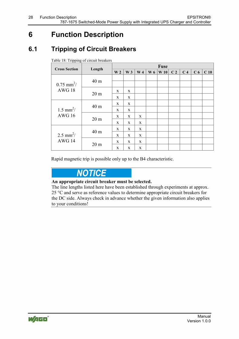
6.1 Tripping of Circuit Breakers Table 18: Tripping of circuit breakers
Cross Section Length Fuse W 2 W 3 W 4 W 6 W 10 C 2 C 4 C 6 C 10
0.75 mm2/ AWG 18
40 m
20 m x x x x
1.5 mm2/ AWG 16
40 m x x x x
20 m x x x x x x
2.5 mm2/ AWG 14
40 m x x x x x x
20 m x x x x x x
Rapid magnetic trip is possible only up to the B4 characteristic.
An appropriate circuit breaker must be selected. The line lengths listed here have been established through experiments at approx. 25 °C and serve as reference values to determine appropriate circuit breakers for the DC side. Always check in advance whether the given information also applies to your conditions!
Pos: 53 /D okumentation allgemei n/Glieder ungselemente/---Seitenwechsel--- @ 3\mod_1221108045078_0.doc @ 21810 @ @ 1
EPSITRON® Function Description 29 787-1675 Switched-Mode Power Supply with Integrated UPS Charger and Controller
Manual Version 1.0.0
Pos: 54 /Serie 787 (EPSITRON)/Funkti onsbeschrei bung/Signalisier ung über LEDs 787-1675 @ 13\mod_1342616079771_21.doc @ 100550 @ 2 @ 1
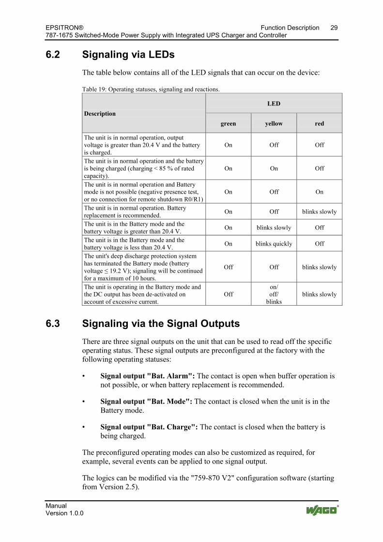
6.2 Signaling via LEDs The table below contains all of the LED signals that can occur on the device:
Table 19: Operating statuses, signaling and reactions.
Description LED
green yellow red
The unit is in normal operation, output voltage is greater than 20.4 V and the battery is charged.
On Off Off
The unit is in normal operation and the battery is being charged (charging < 85 % of rated capacity).
On On Off
The unit is in normal operation and Battery mode is not possible (negative presence test, or no connection for remote shutdown R0/R1)
On Off On
The unit is in normal operation. Battery replacement is recommended. On Off blinks slowly
The unit is in the Battery mode and the battery voltage is greater than 20.4 V. On blinks slowly Off
The unit is in the Battery mode and the battery voltage is less than 20.4 V. On blinks quickly Off
The unit's deep discharge protection system has terminated the Battery mode (battery voltage ≤ 19.2 V); signaling will be continued for a maximum of 10 hours.
Off Off blinks slowly
The unit is operating in the Battery mode and the DC output has been de-activated on account of excessive current.
Off on/ off/
blinks blinks slowly
Pos: 55 /Serie 787 (EPSITRON)/Funkti onsbeschrei bung/Signalisier ung über di e Sig nal ausg äng e 787-1675 @ 13\mod_1342679887850_21.doc @ 100570 @ 2 @ 1
6.3 Signaling via the Signal Outputs There are three signal outputs on the unit that can be used to read off the specific operating status. These signal outputs are preconfigured at the factory with the following operating statuses:
• Signal output "Bat. Alarm": The contact is open when buffer operation is not possible, or when battery replacement is recommended.
• Signal output "Bat. Mode": The contact is closed when the unit is in the Battery mode.
• Signal output "Bat. Charge": The contact is closed when the battery is being charged.
The preconfigured operating modes can also be customized as required, for example, several events can be applied to one signal output.
The logics can be modified via the "759-870 V2" configuration software (starting from Version 2.5).
30 Function Description EPSITRON® 787-1675 Switched-Mode Power Supply with Integrated UPS Charger and Controller
Manual Version 1.0.0
Pos: 56 /Serie 787 (EPSITRON)/Funkti onsbeschrei bung/Batteriemodul e 787-1675 @ 13\mod_1342686258943_21.doc @ 100573 @ 2344 @ 1
6.4 Automatic Detection of Battery Modules The unit automatically detects 787-87x Series battery modules connected to the system, provided the "Bat. Control" (C+/C-) signal lines are connected. The internal temperature sensor can also be evaluated with these modules. The charging voltage can be re-adjusted as required during the float charge phase based on the measured temperature.
Extend the service life of the battery modules used! The service life of the battery modules used is reduced if the ambient conditions are not favorable. Always ensure therefore that the batteries are not used in excessive ambient temperatures. Information on this is given in the battery manufacturer's data sheet.
6.4.1 Battery Charging
The 787-87x Series battery modules are equipped with an internal temperature sensor of type NTC K164 (4.7 kΩ), which measures the temperature of the module. It is installed directly in each battery module.
6.4.1.1 Connecting the 787 Series Battery Modules
1. Ensure that the unit is not live by removing the power supply and the fuse in the battery module.
2. Connect the "Battery" (B+/B-) terminal of the unit to the "Battery" (+/-) terminal of the battery Ensure that the polarity is correct!
3. Connect the "Bat. Control" (C+/C-) terminal of the unit to the "CTRL" (Ctrl+/Ctrl-) terminal of the battery. Again, ensure proper connection of the correct terminals (polarity)!
4. Re-install the fuse in its receptacle on the battery module.
5. Connect the power supply.
The green LED on the unit will then light up; the yellow LED may also light up.
The red LED lights up when applying the power supply! A fault is present is the red LED remains lit after power has been applied. If this happens, refer to the table "Signaling via LEDs" given in this manual!
EPSITRON® Function Description 31 787-1675 Switched-Mode Power Supply with Integrated UPS Charger and Controller
Manual Version 1.0.0
6.4.1.2 Connecting a Battery Module from a Third-Party Manufacturer
Before connecting, check whether the battery module you wish to use is a rechargeable
• lead cell battery,
• lead-gel battery or
• lead-acid absorbed glass mat (AGM) battery
with a nominal voltage of 24 VDC. The unit may only be operated with these types of batteries!
1. Ensure that the unit is not live by removing the power supply and any fuse which may be present in the battery module.
2. Connect the "Battery" (B+/B-) terminal of the unit to the "Battery" (+/-) terminal of the battery Ensure that the polarity is correct!
3. Re-install the fuse in its receptacle on the battery module.
4. Connect the power supply.
The green LED on the unit will then light up; the yellow LED may also light up.
The red LED lights up when applying the power supply! A fault is present is the red LED remains lit after power has been applied. If this happens, refer to the table "Signaling via LEDs" given in this manual!
Pos: 57 /Serie 787 (EPSITRON)/Funkti onsbeschrei bung/Batteriepr üfungen 787- 1675 @ 13\mod_1343027870471_21.doc @ 100680 @ 23333 @ 1
6.5 Battery Testing Different battery tests are carried out, depending on the operating status of the batteries. Corresponding alarms or messages are generated if the unit detects any abnormal conditions.
6.5.1 Charging
Batteries are charged during normal operation. The charge level is checked for this every 60 seconds. If the charge level for the batteries is less than 85 % the yellow LED lights up and the signal output "Bat. Charge" is activated.
6.5.2 Presence Test
The unit performs a presence test automatically every 60 seconds. This test checks whether the battery module is properly connected and operational. A brief and slight load is applied to the batteries during this test. This test is only performed when the unit is in normal operation.
32 Function Description EPSITRON® 787-1675 Switched-Mode Power Supply with Integrated UPS Charger and Controller
Manual Version 1.0.0
If the unit determines negative results for the test, it is repeated again after only 30 seconds. The red LED lights up and the signal output "Bat. Alarm" is activated.
6.5.3 Quality Test
The service life of batteries is limited and can be between 2 - 5 years, depending on the ambient temperature. The residual service life of batteries of the 787 Series connected to the unit is calculated dynamically. A load is also applied to the batteries in defined cycles to ensure that the permissible voltage drop is not exceeded. This test thus ensures that the batteries being used are always ready for operation.
If the unit determines negative results for the test, the red LED flashes and the signal output "Bat. Alarm" is activated.
Replace any defective battery module at once! Always replace any defective battery module at once! Proper, reliable operation of the connected loads can only be continued on a loss of power supply when intact, fault-free battery modules are used!
6.5.4 Replacement
If the battery service life has expired, the batteries used in the module must be replaced either in pairs, or the complete module must be replaced. Consult the instruction manual for this that came with your battery module.
Pos: 58 /Serie 787 (EPSITRON)/Funkti onsbeschrei bung/Batteriebetrieb 787- 1675 @ 13\mod_1343043516683_21.doc @ 100683 @ 2333444333 @ 1
6.6 Battery Mode The unit switches over "bumplessly" to the Battery mode when there is a loss of power supply. The required 24 VDC power supply is then taken directly from the battery. The level of the output voltage depends on the charging level and the capacity of the battery.
Voltage present at the load terminals, even on loss of power supply! Voltage continues to be present at the load terminals even when there is a loss of power supply and the device switches to the buffer mode! Therefore, never touch the load terminals! In this case, always remove the jumper between R0 and R1 to de-energize the load terminals!
When the unit is in the Battery mode the yellow LED blinks slowly and the signal output "Bat. Mode" is activated.
In the Battery mode the unit is designed to
EPSITRON® Function Description 33 787-1675 Switched-Mode Power Supply with Integrated UPS Charger and Controller
Manual Version 1.0.0
• maintain power supply for a set time period and
• to shut down an industrial PC connected to the system in a controlled manner and restart it.
The Windows software "759-870 V2" can be installed free of charge for individual configuration. The UPS and the PC are connected via the 787-892 communication cable.
Observe the information given in the Help function for the "759-870 V2" configuration software! Follow the information given in the Help function in the software to properly install the "759-870 V2" configuration software and use it for individually configuring your system. You can download the softare free of charge at www.wago.com.
6.6.1 Switch-On Threshold for Battery Mode
Power supply is drawn from the battery when the output voltage drops below the set switch-on threshold. The factory default setting for the switch-on threshold is 22 V. You can also set this threshold using the "759-870 V2" configuration software, starting from Version 2.5, to custom values between 20 … 25.5 V.
6.6.2 Timed Battery Mode
The unit is set at the factory for battery operation for an indefinite period of time. At this setting, the entire battery capacity is set to maintain the 24 V power supply. These values can, however, be changed. The following settings are possible:
• timed Battery mode from 1 − 20 minutes,
• indefinite Battery mode,
• individually defined (custom) Battery mode via the "759-870 V2" software
• Battery mode in the IPC mode (see following section).
6.6.3 Battery Mode in the IPC Mode ("PC Mode")
In the IPC mode the unit operates according to a defined time sequence in which an industrial PC, a control system or a display and operator panel is shut down in a controlled manner and then restarted. All of the set values can be changed (customized) using the "759-870 V2" configuration software. The following values can be set:
• Delay time: 1 – 7200 seconds
34 Function Description EPSITRON® 787-1675 Switched-Mode Power Supply with Integrated UPS Charger and Controller
Manual Version 1.0.0
• Shut down PC: 1 – 600 seconds
• PC idle (off) time: 1 – 60 seconds
The time sequence for the individual actions is permanently defined.
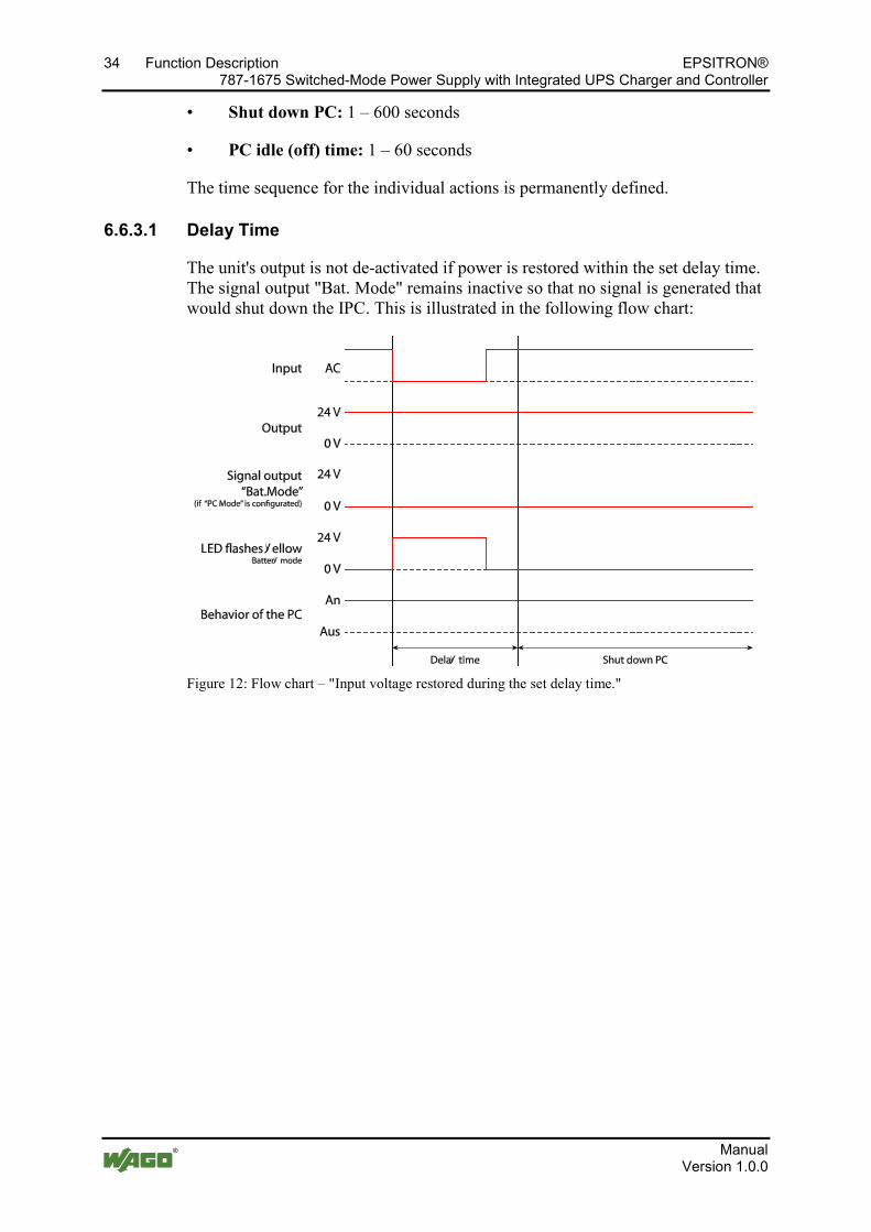
6.6.3.1 Delay Time
The unit's output is not de-activated if power is restored within the set delay time. The signal output "Bat. Mode" remains inactive so that no signal is generated that would shut down the IPC. This is illustrated in the following flow chart:
Figure 12: Flow chart – "Input voltage restored during the set delay time."

EPSITRON® Function Description 35 787-1675 Switched-Mode Power Supply with Integrated UPS Charger and Controller
Manual Version 1.0.0
If the set delay time expires before power is restored, the output voltage and signal output are switched as shown in the flow chart below:
Figure 13: Flow chart – "Input voltage not restored before set delay time expires."
6.6.3.2 Shut Down PC
The signal output "Bat. Mode" is activated when the set delay time expires. This signal must be routed to an IPC connected to the system, a control system or a display and operator panel so that the device in question can be shut down in a controlled manner. The signal output remains activated until the time set in the field "Shut down PC" expires. Ample time should be allowed for by this time setting.
6.6.3.3 PC Idle (Off) Time
The output voltage is de-activated when the time set in the field "Shut down PC" expires. The time at which the output is re-activated depends on whether power supply has been restored:
• If voltage is restored before the time set in the field "Shut down PC" expires, the output is re-activated when the idle time has also expired. This ensures that the devices connected to the system cannot be restarted immediately after shutdown, even when power has been restored in the meantime.
• If voltage has not been restored before the time set in the field "Shut down PC" expires, the output is not re-activated until the voltage is restored.
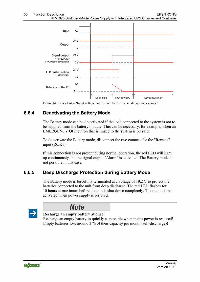
36 Function Description EPSITRON® 787-1675 Switched-Mode Power Supply with Integrated UPS Charger and Controller
Manual Version 1.0.0
Figure 14: Flow chart – "Input voltage not restored before the set delay time expires."
6.6.4 Deactivating the Battery Mode
The Battery mode can be de-activated if the load connected to the system is not to be supplied from the battery module. This can be necessary, for example, when an EMERGENCY OFF button that is linked to the system is pressed.
To de-activate the Battery mode, disconnect the two contacts for the "Remote" input (R0/R1).
If this connection is not present during normal operation, the red LED will light up continuously and the signal output "Alarm" is activated. The Battery mode is not possible in this case.
6.6.5 Deep Discharge Protection during Battery Mode
The Battery mode is forcefully terminated at a voltage of 19.2 V to protect the batteries connected to the unit from deep discharge. The red LED flashes for 10 hours at maximum before the unit is shut down completely. The output is re-activated when power supply is restored.
Recharge an empty battery at once! Recharge an empty battery as quickly as possible when mains power is restored! Empty batteries lose around 3 % of their capacity per month (self-discharge)!

EPSITRON® Function Description 37 787-1675 Switched-Mode Power Supply with Integrated UPS Charger and Controller
Manual Version 1.0.0
6.6.6 Recommended Battery Modules
WAGO offers a battery module designed especially for EPSITRON® devices. These are listed below:
Table 20: Recommended battery modules Battery module
Capacity Maximum output current*
Internal fuse
Maximum wire size
787-876 1.2 Ah 7.5 A 15 A, slow 1.5 mm2/AWG 16 787-871 3.2 Ah 20 A 25 A, slow 1.5 mm2/AWG 16 787-872 7.0 Ah 40 A 25 A, slow 2.5 mm2/AWG 14 787-873 12 Ah 40 A 25 A, slow 2.5 mm2/AWG 14
* Please note that the permanent output current at the unit is limited! For more detailed information refer to the technical data. Regardless of the recommended battery modules, any type of lead-gel or lead-acid absorbed glass mat (AGM) battery can be used.
Observe the data sheet! Always observe the battery manufacturer's data sheet before purchasing a battery module. The data sheet contains more in-depth information and describes whether the corresponding module is suited for your use.
=== Ende der Liste für Textmar ke Inhalt_mitte ===
38 List of Figures EPSITRON® 787-1675 Switched-Mode Power Supply with Integrated UPS Charger and Controller
Manual Version 1.0.0
Pos: 60 /D okumentation allgemei n/Verzeichnisse/Abbil dungsverzeichnis - Überschrift oG und Verzeichnis @ 3\mod_1219222916765_21.doc @ 21080 @ @ 1
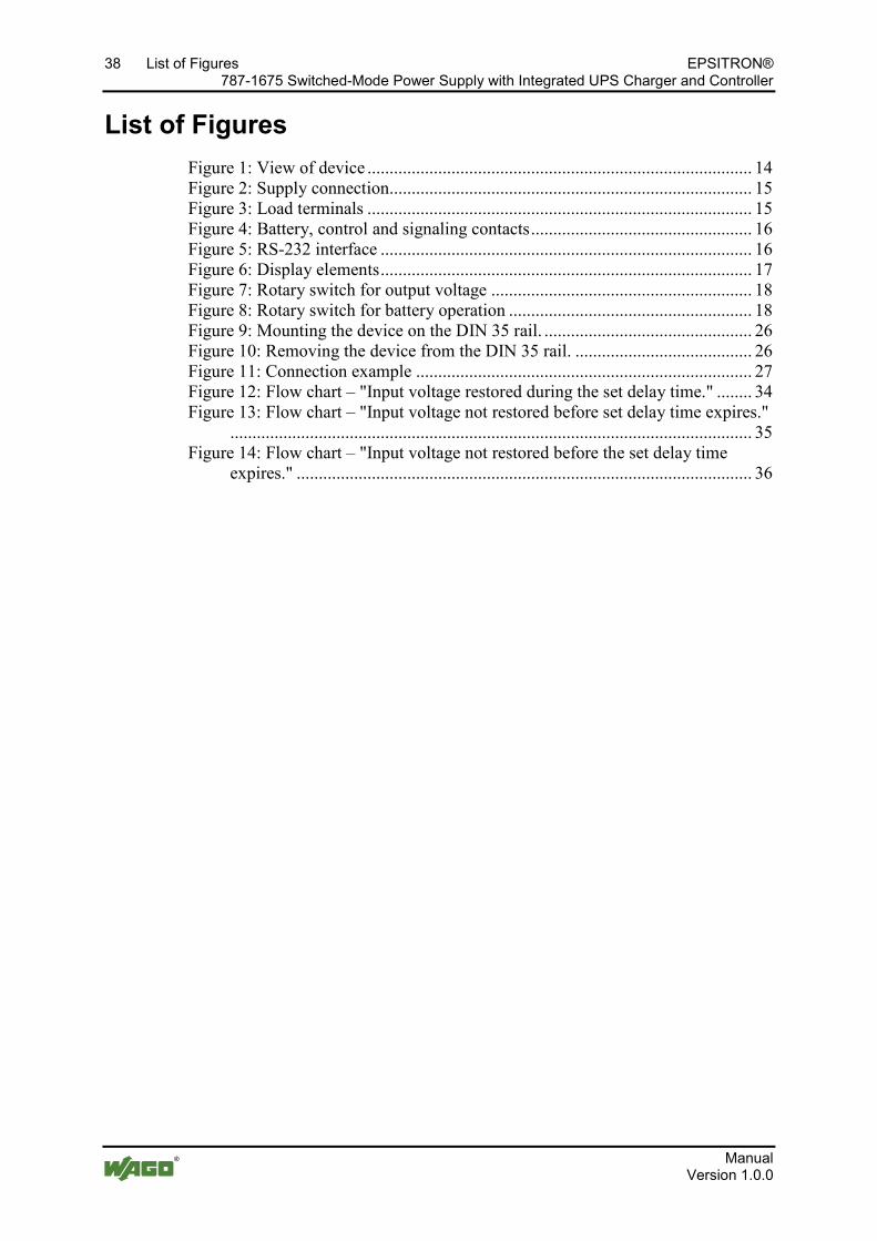
List of Figures Figure 1: View of device ....................................................................................... 14 Figure 2: Supply connection .................................................................................. 15 Figure 3: Load terminals ....................................................................................... 15 Figure 4: Battery, control and signaling contacts .................................................. 16 Figure 5: RS-232 interface .................................................................................... 16 Figure 6: Display elements .................................................................................... 17 Figure 7: Rotary switch for output voltage ........................................................... 18 Figure 8: Rotary switch for battery operation ....................................................... 18 Figure 9: Mounting the device on the DIN 35 rail. ............................................... 26 Figure 10: Removing the device from the DIN 35 rail. ........................................ 26 Figure 11: Connection example ............................................................................ 27 Figure 12: Flow chart – "Input voltage restored during the set delay time." ........ 34 Figure 13: Flow chart – "Input voltage not restored before set delay time expires."
...................................................................................................................... 35 Figure 14: Flow chart – "Input voltage not restored before the set delay time
expires." ....................................................................................................... 36
Pos: 61 /D okumentation allgemei n/Glieder ungselemente/---Seitenwechsel--- @ 3\mod_1221108045078_0.doc @ 21810 @ @ 1

EPSITRON® List of Tables 39 787-1675 Switched-Mode Power Supply with Integrated UPS Charger and Controller
Manual Version 1.0.0
Pos: 62 /D okumentation allgemei n/Verzeichnisse/Tabell enverzeichnis - Ü berschrif t oG - und Verzeichnis @ 3\mod_1219222958703_21.doc @ 21084 @ @ 1
List of Tables Table 1: Number notation ........................................................................................ 8 Table 2: Font conventions ....................................................................................... 8 Table 3: Legend for "View" figure ........................................................................ 14 Table 4: Power supply connections ....................................................................... 15 Table 5: Terminals – Load .................................................................................... 15 Table 6: Connections – Battery, control and signaling contacts ........................... 16 Table 7: Connections – RS-232 interface .............................................................. 16 Table 8: Legend for "Indicators" figure ................................................................ 17 Table 9: Device data .............................................................................................. 19 Table 10: Technical data - "Input" ........................................................................ 19 Table 11: Technical data - "Output" ...................................................................... 20 Table 12: Technical data for the output during operation with the mains system 20 Table 13: Technical data for the output during Battery mode .............................. 20 Table 14: Technical data - "Signaling" ................................................................. 22 Table 15: Technical Data: Interface ...................................................................... 22 Table 16: Technical data - "Ambient conditions" ................................................. 23 Table 17: Miscellaneous data ................................................................................ 23 Table 18: Tripping of circuit breakers ................................................................... 28 Table 19: Operating statuses, signaling and reactions. ......................................... 29 Table 20: Recommended battery modules ............................................................ 37
=== Ende der Liste für Textmar ke Verzeichnis_hinten ===

Pos: 64 /D okumentation allgemei n/Einband/Einband H andbuch - R ückseite @ 9\mod_1285229376516_21.doc @ 64944 @ @ 1
WAGO Kontakttechnik GmbH & Co. KG Postfach 2880 • D-32385 Minden Hansastraße 27 • D-32423 Minden Phone: +49/5 71/8 87 – 0 Fax: +49/5 71/8 87 – 1 69 E-Mail: [email protected] Internet: http://www.wago.com
=== Ende der Liste für Textmar ke Ei nband_hinten ===