Embed Size (px)
Citation preview
1
Switch Mode Power Supply (120/240/480/960 W Models)
S8VK-TRenewal of 400 V, 3-phase standard type.480 W/960 W feature PFC for lower input current and higher efficiency (93% typ.) than conventional products• Wide input range for worldwide applications:
380 to 480 VAC (3-phase, 320 to 576 VAC)• Wide operation temperature range: –40 to 70°C• Power Boost function at 120%• Conforms to various safety and noise standards *1• Three years Warranty *2*1.For details on conformance standards, refer to Standards under Ratings,
Characteristics, and Functions on page 3 to 4.*2.For details, refer to Recommended Replacement Periods and Periodic
Replacement for Preventive Maintenance on page 18.
For the most recent information on models that have been certified for safety standards, refer to your local OMRON website.! Refer to Safety Precautions for All Power Supplies
and Safety Precautions on page 13.
Related ProductsDC Electronic Circuit ProtectorS8V-CP
Note: Refer to the S8V-CP Datasheet (Cat. No. T226-E1) for details.
S8VK-T
2
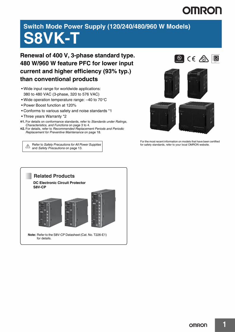
Model Number StructureModel Number Legend
Ordering InformationNote: For details on normal stock models, contact your nearest OMRON representative.
Power ratings Rated Input voltage Rated Output Voltage Rated Output current Maximum Boost Current Model number
120 W 2-phase and 3-phase380 to 480 VAC450 to 600 VDC
24 V 5 A 6 A S8VK-T12024
240 W 24 V 10 A 12 A S8VK-T24024480 W 24 V 20 A 24 A S8VK-T48024
960 W 3-phase, 2-phase380 to 480 VAC 24 V 40 A 48 A S8VK-T96024
1 2S8VK- T@@@@@
1. Power Ratings120: 120 W240: 240 W480: 480 W960: 960 W
2. Output voltage24: 24 V
S8VK-T
3
SpecificationsRatings, Characteristics, and Functions
Note: Refer to page 5 for notes 1 to 16.
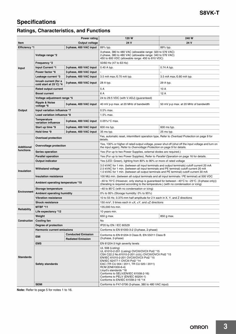
Power rating 120 W 240 W
Item Output voltage 24 V 24 VEfficiency *1 3-phase, 400 VAC input 89% typ. 89% typ.
Input
Voltage range *23-phase, 380 to 480 VAC (allowable range: 320 to 576 VAC) 2-phase, 380 to 480 VAC (allowable range: 340 to 576 VAC)450 to 600 VDC (allowable range: 450 to 810 VDC)
Frequency *2 50/60 Hz (47 to 63 Hz)
Input Current *1 3-phase, 400 VAC input 0.40 A typ. 0.74 A typ.
Power factor *6 3-phase, 400 VAC input - -
Leakage current *3 3-phase, 400 VAC input 3.5 mA max./0.70 mA typ. 3.5 mA max./0.80 mA typ.
Inrush current (for a cold start at 25°C) *4 3-phase, 400 VAC input 28 A typ. 29 A typ.
Output
Rated output current 5 A 10 A
Boost current 6 A 12 A
Voltage adjustment range *5 24 to 29.5 VDC (with V.ADJ) (guaranteed)
Ripple & Noise voltage *6 3-phase, 400 VAC input 40 mV p-p max. at 20 MHz of bandwidth 50 mV p-p max. at 20 MHz of bandwidth
Input variation influence *7 0.5% max.
Load variation influence *8 1.5% max.
Temperature variation influence 3-phase, 400 VAC input 0.05%/°C max.
Start up time *9 3-phase, 400 VAC input 600 ms typ. 600 ms typ.
Hold time *9 3-phase, 400 VAC input 35 ms typ. 25 ms typ.
Additional functions
Overload protection Yes, automatic reset, intermittent operation type, Refer to Overload Protection on page 9 for details.
Overvoltage protection Yes, 130% or higher of rated output voltage, power shut off (shut off the input voltage and turn on the input again), Refer to Overvoltage Protection on page 9 for details.
Series operation Yes (For up to two Power Supplies, external diodes are required.)
Parallel operation Yes (For up to two Power Supplies), Refer to Parallel Operation on page 16 for details.
Output indicator Yes (LED: Green), lighting from 80% to 90% or more of rated voltage
InsulationWithstand voltage
3.0 kVAC for 1 min. (between all input terminals and output terminals) cutoff current 20 mA2.5 kVAC for 1 min. (between all input terminals and PE terminal) cutoff current 20 mA1.0 kVAC for 1 min. (between all output terminals and PE terminal) cutoff current 30 mA
Insulation resistance 100 MΩ min. (between all output terminals and all input terminals / PE terminal) at 500 VDC
Environment
Ambient operating temperature *10 –40 to 70°C (However, only startup is guaranteed for between –40°C to –25°C. (3-phase only)) (Derating is required according to the temperature.) (with no condensation or icing)
Storage temperature –40 to 85°C (with no condensation or icing)
Ambient operating humidity 0% to 95% (Storage humidity: 0% to 95%)
Vibration resistance 10 to 55 Hz, 0.375-mm half amplitude for 2 h each in X, Y, and Z directions
Shock resistance 150 m/s2, 3 times each in ±X, ±Y, and ±Z directions
ReliabilityMTBF *11 135,000 hrs min.
Life expectancy *12 10 years min.
Construction
Weight 650 g max. 850 g max.
Cooling fan No
Degree of protection IP20 by EN / IEC 60529
Standards
Harmonic current emissions Conforms to EN 61000-3-2 (3-phase, 2-phase)
EMIConducted Emission Conforms to EN 61204-3 Class B, EN 55011 Class B
(3-phase, 2-phase)Radiated Emission
EMS EN 61204-3 high severity levels
Safety standards
UL 508 (Listing)UL 61010-2-201 (Listing) OVCIII/OVCII Pol2 *15CSA C22.2 No.61010-2-201 (cUL) OVCIII/OVCII Pol2 *15EN/IEC 61010-2-201 OVCIII/OVCII Pol2 *15EN/IEC 62477-1 OVCIII Pol2 *14EAC (TR CU 004 / 2011, TR CU 020 / 2011)RCM (EN61000-6-4)Lloyd’s standards *16Conforms to SELV(EN/IEC 61558-2-16) Conforms to PELV (EN/IEC 60204-1)Conforms to EN/IEC 61558-2-16 *14
SEMI Conforms to F47-0706 (3-phase, 380 to 480 VAC input)
S8VK-T
4
Note: Refer to page 5 for notes 1 to 16.
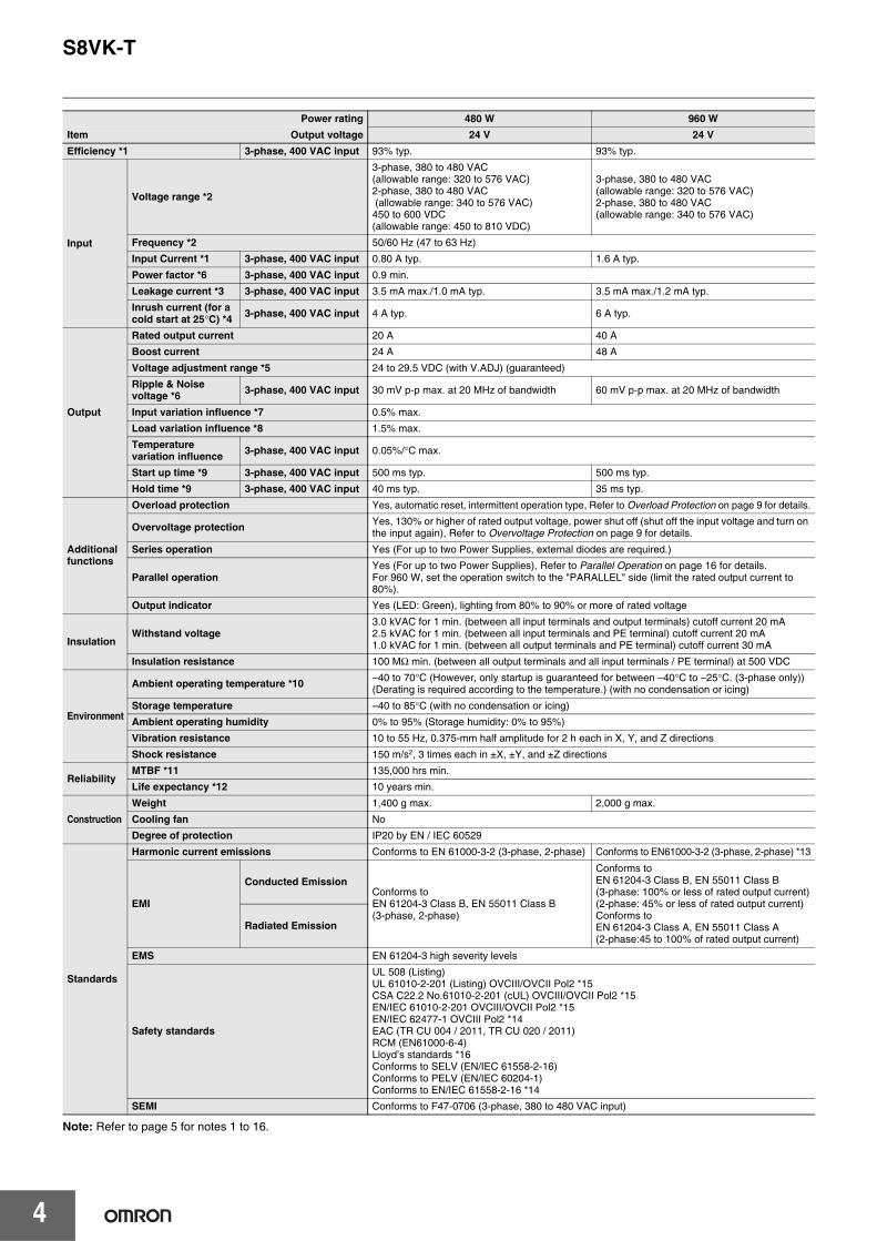
Power rating 480 W 960 WItem Output voltage 24 V 24 VEfficiency *1 3-phase, 400 VAC input 93% typ. 93% typ.
Input
Voltage range *2
3-phase, 380 to 480 VAC (allowable range: 320 to 576 VAC) 2-phase, 380 to 480 VAC (allowable range: 340 to 576 VAC)450 to 600 VDC (allowable range: 450 to 810 VDC)
3-phase, 380 to 480 VAC (allowable range: 320 to 576 VAC) 2-phase, 380 to 480 VAC (allowable range: 340 to 576 VAC)
Frequency *2 50/60 Hz (47 to 63 Hz)
Input Current *1 3-phase, 400 VAC input 0.80 A typ. 1.6 A typ.
Power factor *6 3-phase, 400 VAC input 0.9 min.
Leakage current *3 3-phase, 400 VAC input 3.5 mA max./1.0 mA typ. 3.5 mA max./1.2 mA typ.
Inrush current (for a cold start at 25°C) *4 3-phase, 400 VAC input 4 A typ. 6 A typ.
Output
Rated output current 20 A 40 A
Boost current 24 A 48 A
Voltage adjustment range *5 24 to 29.5 VDC (with V.ADJ) (guaranteed)
Ripple & Noise voltage *6 3-phase, 400 VAC input 30 mV p-p max. at 20 MHz of bandwidth 60 mV p-p max. at 20 MHz of bandwidth
Input variation influence *7 0.5% max.
Load variation influence *8 1.5% max.
Temperature variation influence 3-phase, 400 VAC input 0.05%/°C max.
Start up time *9 3-phase, 400 VAC input 500 ms typ. 500 ms typ.
Hold time *9 3-phase, 400 VAC input 40 ms typ. 35 ms typ.
Additional functions
Overload protection Yes, automatic reset, intermittent operation type, Refer to Overload Protection on page 9 for details.
Overvoltage protection Yes, 130% or higher of rated output voltage, power shut off (shut off the input voltage and turn on the input again), Refer to Overvoltage Protection on page 9 for details.
Series operation Yes (For up to two Power Supplies, external diodes are required.)
Parallel operationYes (For up to two Power Supplies), Refer to Parallel Operation on page 16 for details.For 960 W, set the operation switch to the "PARALLEL" side (limit the rated output current to 80%).
Output indicator Yes (LED: Green), lighting from 80% to 90% or more of rated voltage
InsulationWithstand voltage
3.0 kVAC for 1 min. (between all input terminals and output terminals) cutoff current 20 mA2.5 kVAC for 1 min. (between all input terminals and PE terminal) cutoff current 20 mA1.0 kVAC for 1 min. (between all output terminals and PE terminal) cutoff current 30 mA
Insulation resistance 100 MΩ min. (between all output terminals and all input terminals / PE terminal) at 500 VDC
Environment
Ambient operating temperature *10 –40 to 70°C (However, only startup is guaranteed for between –40°C to –25°C. (3-phase only)) (Derating is required according to the temperature.) (with no condensation or icing)
Storage temperature –40 to 85°C (with no condensation or icing)
Ambient operating humidity 0% to 95% (Storage humidity: 0% to 95%)
Vibration resistance 10 to 55 Hz, 0.375-mm half amplitude for 2 h each in X, Y, and Z directions
Shock resistance 150 m/s2, 3 times each in ±X, ±Y, and ±Z directions
ReliabilityMTBF *11 135,000 hrs min.
Life expectancy *12 10 years min.
ConstructionWeight 1,400 g max. 2,000 g max.
Cooling fan No
Degree of protection IP20 by EN / IEC 60529
Standards
Harmonic current emissions Conforms to EN 61000-3-2 (3-phase, 2-phase) Conforms to EN61000-3-2 (3-phase, 2-phase) *13
EMI
Conducted EmissionConforms to EN 61204-3 Class B, EN 55011 Class B(3-phase, 2-phase)
Conforms to EN 61204-3 Class B, EN 55011 Class B (3-phase: 100% or less of rated output current)(2-phase: 45% or less of rated output current)Conforms to EN 61204-3 Class A, EN 55011 Class A(2-phase:45 to 100% of rated output current)
Radiated Emission
EMS EN 61204-3 high severity levels
Safety standards
UL 508 (Listing)UL 61010-2-201 (Listing) OVCIII/OVCII Pol2 *15CSA C22.2 No.61010-2-201 (cUL) OVCIII/OVCII Pol2 *15EN/IEC 61010-2-201 OVCIII/OVCII Pol2 *15EN/IEC 62477-1 OVCIII Pol2 *14EAC (TR CU 004 / 2011, TR CU 020 / 2011)RCM (EN61000-6-4)Lloyd’s standards *16Conforms to SELV (EN/IEC 61558-2-16) Conforms to PELV (EN/IEC 60204-1)Conforms to EN/IEC 61558-2-16 *14
SEMI Conforms to F47-0706 (3-phase, 380 to 480 VAC input)
S8VK-T
5
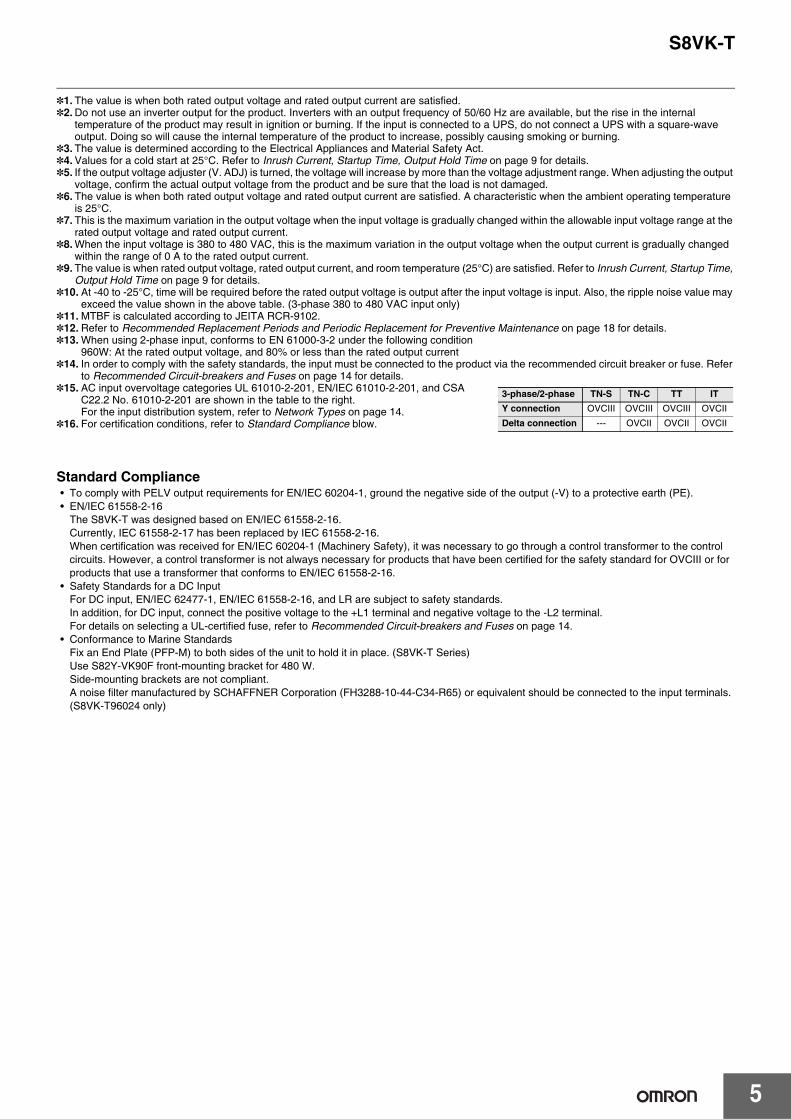
*1. The value is when both rated output voltage and rated output current are satisfied.*2.Do not use an inverter output for the product. Inverters with an output frequency of 50/60 Hz are available, but the rise in the internal
temperature of the product may result in ignition or burning. If the input is connected to a UPS, do not connect a UPS with a square-wave output. Doing so will cause the internal temperature of the product to increase, possibly causing smoking or burning.
*3. The value is determined according to the Electrical Appliances and Material Safety Act.*4.Values for a cold start at 25°C. Refer to Inrush Current, Startup Time, Output Hold Time on page 9 for details.*5. If the output voltage adjuster (V. ADJ) is turned, the voltage will increase by more than the voltage adjustment range. When adjusting the output
voltage, confirm the actual output voltage from the product and be sure that the load is not damaged.*6. The value is when both rated output voltage and rated output current are satisfied. A characteristic when the ambient operating temperature
is 25°C.*7. This is the maximum variation in the output voltage when the input voltage is gradually changed within the allowable input voltage range at the
rated output voltage and rated output current.*8.When the input voltage is 380 to 480 VAC, this is the maximum variation in the output voltage when the output current is gradually changed
within the range of 0 A to the rated output current.*9. The value is when rated output voltage, rated output current, and room temperature (25°C) are satisfied. Refer to Inrush Current, Startup Time,
Output Hold Time on page 9 for details.*10. At -40 to -25°C, time will be required before the rated output voltage is output after the input voltage is input. Also, the ripple noise value may
exceed the value shown in the above table. (3-phase 380 to 480 VAC input only)*11. MTBF is calculated according to JEITA RCR-9102.*12. Refer to Recommended Replacement Periods and Periodic Replacement for Preventive Maintenance on page 18 for details.*13. When using 2-phase input, conforms to EN 61000-3-2 under the following condition
960W: At the rated output voltage, and 80% or less than the rated output current*14. In order to comply with the safety standards, the input must be connected to the product via the recommended circuit breaker or fuse. Refer
to Recommended Circuit-breakers and Fuses on page 14 for details.*15. AC input overvoltage categories UL 61010-2-201, EN/IEC 61010-2-201, and CSA
C22.2 No. 61010-2-201 are shown in the table to the right.For the input distribution system, refer to Network Types on page 14.
*16. For certification conditions, refer to Standard Compliance blow.
Standard Compliance• To comply with PELV output requirements for EN/IEC 60204-1, ground the negative side of the output (-V) to a protective earth (PE).• EN/IEC 61558-2-16
The S8VK-T was designed based on EN/IEC 61558-2-16.Currently, IEC 61558-2-17 has been replaced by IEC 61558-2-16.When certification was received for EN/IEC 60204-1 (Machinery Safety), it was necessary to go through a control transformer to the control circuits. However, a control transformer is not always necessary for products that have been certified for the safety standard for OVCIII or for products that use a transformer that conforms to EN/IEC 61558-2-16.
• Safety Standards for a DC InputFor DC input, EN/IEC 62477-1, EN/IEC 61558-2-16, and LR are subject to safety standards.In addition, for DC input, connect the positive voltage to the +L1 terminal and negative voltage to the -L2 terminal.For details on selecting a UL-certified fuse, refer to Recommended Circuit-breakers and Fuses on page 14.
• Conformance to Marine StandardsFix an End Plate (PFP-M) to both sides of the unit to hold it in place. (S8VK-T Series)Use S82Y-VK90F front-mounting bracket for 480 W.Side-mounting brackets are not compliant.A noise filter manufactured by SCHAFFNER Corporation (FH3288-10-44-C34-R65) or equivalent should be connected to the input terminals. (S8VK-T96024 only)
3-phase/2-phase TN-S TN-C TT ITY connection OVCIII OVCIII OVCIII OVCII
Delta connection --- OVCII OVCII OVCII
S8VK-T
6
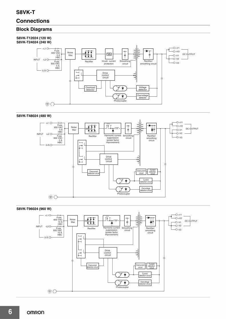
ConnectionsBlock Diagrams
Photocoupler
Voltagedetector
Drive control circuit
Overvoltagedetector
Overloaddetector
-V3
-V1
-V2
+V1
+V2DC OUTPUT
+L1
(L3)
Noise filter
Rectifier/smoothing circuit
600 VAC
Smoothing circuit
lnrush currentprotection
Rectifier-L2
HBC
Fuse
5 A HBC
INPUT
600 VAC 5 A
Fuse
S8VK-T12024 (120 W)S8VK-T24024 (240 W)
S8VK-T48024 (480 W)
Photocoupler
Currentdetection circuit
Overvoltagedetection circuit
Overcurrentdetection circuit
Drive control circuit
-V3
-V1
-V2
+V1
+V2DC OUTPUT
+L1
(L3)
Currentdetection
circuitOvercurrent
circuit
Harmonic currentsuppression(power factorimprovement)
600 VAC
-L2
HBC
Fuse
5 A HBC
INPUT
600 VAC 5 A
Fuse
Noise filter
Rectifier/smoothing
circuit
Smoothing circuit
Rectifier
S8VK-T96024 (960 W)
Photocoupler
Currentdetection circuit
Overvoltagedetection circuit
Overcurrentdetection circuit
Drive control circuit
-V3
-V1
-V2
+V1
+V2DC OUTPUT
600 VAC
HBC
Fuse
10 A HBC
600 VAC10 A
Fuse
+L1
(L3)
-L2INPUT
Currentdetection
circuitOvercurrent
circuit
Harmonic currentsuppression(power factorimprovement)
Noise filter
Rectifier/smoothing
circuit
Smoothing circuit
Rectifier
S8VK-T
7
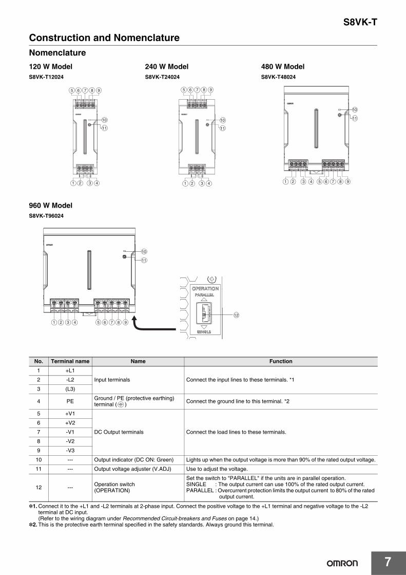
Construction and NomenclatureNomenclature
*1.Connect it to the +L1 and -L2 terminals at 2-phase input. Connect the positive voltage to the +L1 terminal and negative voltage to the -L2 terminal at DC input.(Refer to the wiring diagram under Recommended Circuit-breakers and Fuses on page 14.)
*2. This is the protective earth terminal specified in the safety standards. Always ground this terminal.
120 W Model 240 W Model 480 W ModelS8VK-T12024 S8VK-T24024 S8VK-T48024
960 W ModelS8VK-T96024
No. Terminal name Name Function
1 +L1
Input terminals Connect the input lines to these terminals. *12 -L2
3 (L3)
4 PE Ground / PE (protective earthing) terminal ( ) Connect the ground line to this terminal. *2
5 +V1
DC Output terminals Connect the load lines to these terminals.
6 +V2
7 -V1
8 -V2
9 -V3
10 --- Output indicator (DC ON: Green) Lights up when the output voltage is more than 90% of the rated output voltage.
11 --- Output voltage adjuster (V.ADJ) Use to adjust the voltage.
12 --- Operation switch (OPERATION)
Set the switch to "PARALLEL" if the units are in parallel operation.SINGLE : The output current can use 100% of the rated output current.PARALLEL : Overcurrent protection limits the output current to 80% of the rated
output current.
65 8 97
10
11
321 4
65 8 97
10
11
321 4 65 8 97
10
11
321 4
65 8 97321 4
10
11
12
S8VK-T
8
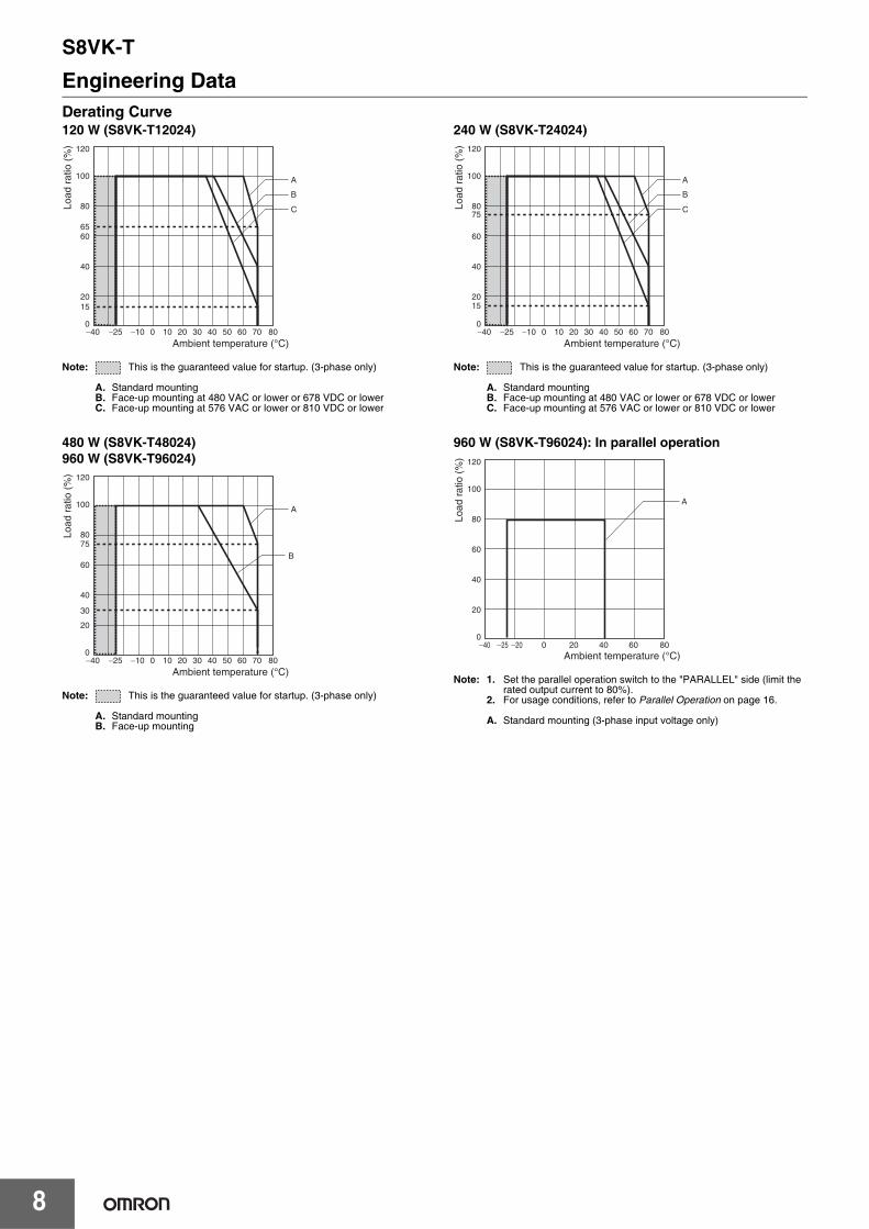
Engineering DataDerating Curve120 W (S8VK-T12024)
Note: This is the guaranteed value for startup. (3-phase only)
A. Standard mountingB. Face-up mounting at 480 VAC or lower or 678 VDC or lowerC. Face-up mounting at 576 VAC or lower or 810 VDC or lower
480 W (S8VK-T48024)960 W (S8VK-T96024)
Note: This is the guaranteed value for startup. (3-phase only)
A. Standard mountingB. Face-up mounting
240 W (S8VK-T24024)
Note: This is the guaranteed value for startup. (3-phase only)
A. Standard mountingB. Face-up mounting at 480 VAC or lower or 678 VDC or lowerC. Face-up mounting at 576 VAC or lower or 810 VDC or lower
960 W (S8VK-T96024): In parallel operation
Note: 1. Set the parallel operation switch to the "PARALLEL" side (limit the rated output current to 80%).
2. For usage conditions, refer to Parallel Operation on page 16.
A. Standard mounting (3-phase input voltage only)
�40 �25 �10 0 10 20 30 40 50 60 70 80
120
100
80
60
40
20
0
A
B
C
65
15
Load
rat
io (
%)
Ambient temperature (°C)
�40 �25 �10 0 10 20 30 40 50 60 70 80
120
100
80
60
40
20
0
A
B
75
30
Load
rat
io (
%)
Ambient temperature (°C)
�40 �25 �10 0 10 20 30 40 50 60 70 80
120
100
80
60
40
20
0
A
B
C75
15
Load
rat
io (
%)
Ambient temperature (°C)
�40 �25 �20 0 20 40 60 80
120
100
80
60
40
20
0
A
Load
rat
io (
%)
Ambient temperature (°C)
S8VK-T
9
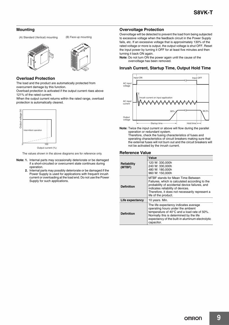
Mounting
Overload ProtectionThe load and the product are automatically protected from overcurrent damage by this function.Overload protection is activated if the output current rises above 121% of the rated current.When the output current returns within the rated range, overload protection is automatically cleared.
Note: 1. Internal parts may occasionally deteriorate or be damaged if a short-circuited or overcurrent state continues during operation.
2. Internal parts may possibly deteriorate or be damaged if the Power Supply is used for applications with frequent inrush current or overloading at the load end. Do not use the Power Supply for such applications.
Overvoltage ProtectionOvervoltage will be detected to prevent the load from being subjected to excessive voltage when the feedback circuit in the Power Supply fails, etc. If an excessive voltage that is approximately 130% of the rated voltage or more is output, the output voltage is shut OFF. Reset the input power by turning it OFF for at least five minutes and then turning it back ON again.Note: Do not turn ON the power again until the cause of the
overvoltage has been removed.
Inrush Current, Startup Time, Output Hold Time
Note: Twice the input current or above will flow during the parallel operation or redundant system.Therefore, check the fusing characteristics of fuses and operating characteristics of circuit breakers making sure that the external fuses will not burn out and the circuit breakers will not be activated by the inrush current.
Reference Value
(B) Face-up mounting(A) Standard (Vertical) mounting
The values shown in the above diagrams are for reference only.
Output current (%)
Out
put v
olta
ge (
V)
Intermittent operation
0 100
Reliability (MTBF)
Value120 W: 330,000h240 W: 330,000h480 W: 180,000h960 W: 150,000h
Definition
MTBF stands for Mean Time Between Failures, which is calculated according to the probability of accidental device failures, and indicates reliability of devices.Therefore, it does not necessarily represent a life of the product.
Life expectancy 10 years. Min.
Definition
The life expectancy indicates average operating hours under the ambient temperature of 40°C and a load rate of 50%. Normally this is determined by the life expectancy of the built-in aluminum electrolytic capacitor.
90% 96.5%
Startup time
AC input voltage
AC input current
Output voltage
Inrush current on input application
Input OFF Input ON
Hold time
S8VK-T
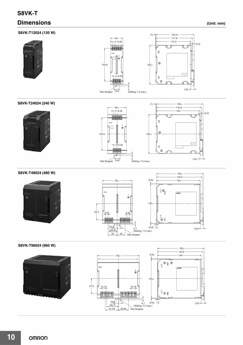
10
Dimensions (Unit: mm)
117.8
(3.2)112.2
(1)
(10)
6.35
6.35
19.85(Sliding: 7.5 max.)Rail Stopper
40±1
104.6 125±1
122.2±1S8VK-T12024 (120 W)
104.6
(10)
6.35
5(Sliding: 7.5 max.)19.8Rail Stopper
6.35
60±1
125±1
145.6
(3.2)140
(1) 150±1S8VK-T24024 (240 W)
6.35 6.35
30 25
19.8
(26.8)
Rail Stopper
4.7(Sliding: 7.5 max.)
(10)(0.6)
(0.6)
125±1
145.6
140
(1)
150±1
52.3
95±1
S8VK-T48024 (480 W)
10.1647.9 10.16
140
145.6
4.7(Sliding: 7.5 max.)
(10)
125±1
(1)
(0.6)
(0.6)
135±1
41.78 32.95
19.8
(36.7)
Rail Stopper
150±1
S8VK-T96024 (960 W)
S8VK-T
11
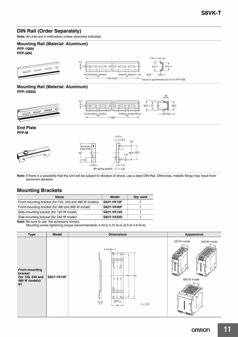
DIN Rail (Order Separately)Note: All units are in millimeters unless otherwise indicated.
Mounting Rail (Material: Aluminum)PFP-100N PFP-50N
Mounting Rail (Material: Aluminum)PFP-100N2
End PlatePFP-M
Note: If there is a possibility that the Unit will be subject to vibration or shock, use a steel DIN Rail. Otherwise, metallic filings may result from aluminum abrasion.
Mounting Brackets
Note: Be sure to use the accessory screws.Mounting screw tightening torque (recommended): 4.43 to 5.31 lb-in (0.5 to 0.6 N·m)
Name Model Qty usedFront-mounting bracket (for 120, 240 and 480 W models) S82Y-VK10F 1
Front-mounting bracket (for 480 and 960 W model) S82Y-VK90F 1
Side-mounting bracket (for 120 W model) S82Y-VK10S 1
Side-mounting bracket (for 240 W model) S82Y-VK20S 1
Type Model Dimensions Appearance
Front-mounting bracket (for 120, 240 and 480 W models) *1
S82Y-VK10F
4.5
15 25 2510 10
1,000 (500) *
25 25 15(5) *
35±0.3
7.3±0.15
27±0.15
1
* Values in parentheses are for the PFP-50N.
4.5
15 25 2510 10
1,000
25 25 15 1 1.5
29.2242735±0.3
16
1.3
4.8
35.5 35.51.8
1.8
106.2
1
50
11.5
10M4 spring washer
M4×8 pan-head screw
38
150140±0.1
25±0.1
4-4.5 dia.±0.1
5.4 t = 2.0
120 W model 240 W model
480 W model
S8VK-T
12
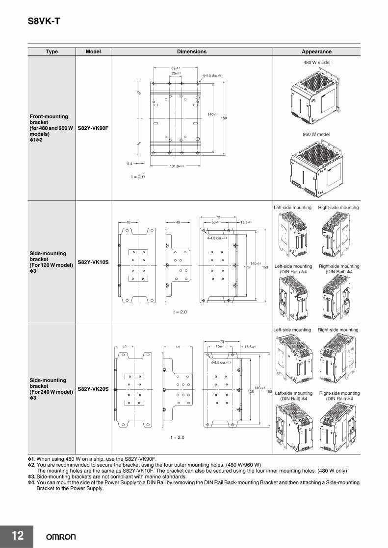
*1.When using 480 W on a ship, use the S82Y-VK90F.*2.You are recommended to secure the bracket using the four outer mounting holes. (480 W/960 W)
The mounting holes are the same as S82Y-VK10F. The bracket can also be secured using the four inner mounting holes. (480 W only)*3.Side-mounting brackets are not compliant with marine standards.*4.You can mount the side of the Power Supply to a DIN Rail by removing the DIN Rail Back-mounting Bracket and then attaching a Side-mounting
Bracket to the Power Supply.
Front-mounting bracket (for 480 and 960 W models)*1*2
S82Y-VK90F
Side-mounting bracket (For 120 W model) *3
S82Y-VK10S
Side-mounting bracket (For 240 W model) *3
S82Y-VK20S
Type Model Dimensions Appearance
150140±0.1
101.6±0.3
25±0.1
89±0.1
5.4
4-4.5 dia.±0.1
t = 2.0
480 W model
960 W model
140±0.1
50±0.1 15.5±0.1
150125
73
4-4.5 dia.±0.1
4940
t = 2.0
Left-side mounting Right-side mounting
Left-side mounting(DIN Rail) *4
Right-side mounting(DIN Rail) *4
140±0.1
50±0.1 15.5±0.1
150125
73
5940
4-4.5 dia.±0.1
t = 2.0
Left-side mounting Right-side mounting
Left-side mounting(DIN Rail) *4
Right-side mounting(DIN Rail) *4
S8VK-T
13
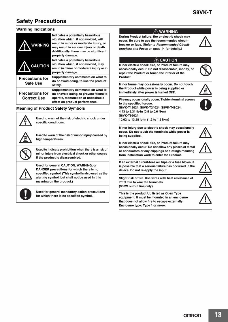
Safety PrecautionsWarning Indications
Meaning of Product Safety Symbols
!WARNINGDuring Product failure, fire or electric shock may occur. Be sure to use the recommended circuit-breaker or fuse. (Refer to Recommended Circuit-breakers and Fuses on page 14 for details.)
!CAUTIONMinor electric shock, fire, or Product failure may occasionally occur. Do not disassemble, modify, or repair the Product or touch the interior of the Product.
Minor burns may occasionally occur. Do not touch the Product while power is being supplied or immediately after power is turned OFF.
Fire may occasionally occur. Tighten terminal screws to the specified torque.S8VK-T12024, S8VK-T24024, S8VK-T48024: 4.43 to 5.31 lb-in (0.5 to 0.6 N•m)S8VK-T96024: 10.62 to 13.28 lb-in (1.2 to 1.5 N•m)
Minor injury due to electric shock may occasionally occur. Do not touch the terminals while power is being supplied.
Minor electric shock, fire, or Product failure may occasionally occur. Do not allow any pieces of metal or conductors or any clippings or cuttings resulting from installation work to enter the Product.
If an external circuit-breaker trips or a fuse blows, it is possible that a serious failure has occurred in the device. Do not re-apply the input.
Slight risk of fire. Use wires with heat resistance of 75°C min to wire the terminals. (960W output line only)
This is the product UL listed as Open Type equipment. It must be mounted in an enclosurethat does not allow fire to escape externally.Enclosure type: Type 1 or more.
WARNING
Indicates a potentially hazardous situation which, if not avoided, will result in minor or moderate injury, or may result in serious injury or death. Additionally, there may be significant property damage.
CAUTIONIndicates a potentially hazardous situation which, if not avoided, may result in minor or moderate injury or in property damage.
Precautions for Safe Use
Supplementary comments on what to do or avoid doing, to use the product safely.
Precautions for Correct Use
Supplementary comments on what to do or avoid doing, to prevent failure to operate, malfunction or undesirable effect on product performance.
Used to warn of the risk of electric shock under specific conditions.
Used to warn of the risk of minor injury caused by high temperatures.
Used to indicate prohibition when there is a risk of minor injury from electrical shock or other source if the product is disassembled.
Used for general CAUTION, WARNING, or DANGER precautions for which there is no specified symbol. (This symbol is also used as the alerting symbol, but shall not be used in this meaning on the product.)
Used for general mandatory action precautions for which there is no specified symbol.
S8VK-T
14
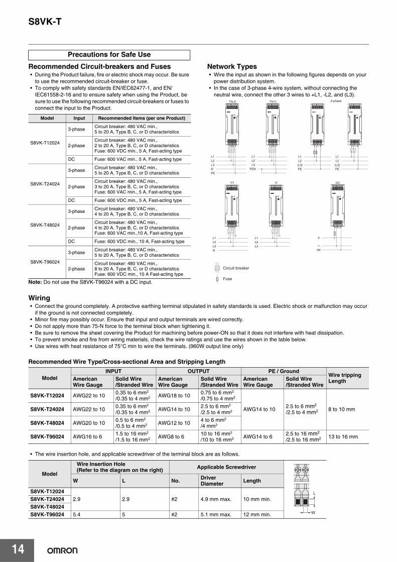
Recommended Circuit-breakers and Fuses• During the Product failure, fire or electric shock may occur. Be sure
to use the recommended circuit-breaker or fuse.• To comply with safety standards EN/IEC62477-1, and EN/
IEC61558-2-16 and to ensure safety when using the Product, be sure to use the following recommended circuit-breakers or fuses to connect the input to the Product.
Note: Do not use the S8VK-T96024 with a DC input.
Network Types• Wire the input as shown in the following figures depends on your
power distribution system. • In the case of 3-phase 4-wire system, without connecting the
neutral wire, connect the other 3 wires to +L1, -L2, and (L3).
Wiring• Connect the ground completely. A protective earthing terminal stipulated in safety standards is used. Electric shock or malfunction may occur
if the ground is not connected completely.• Minor fire may possibly occur. Ensure that input and output terminals are wired correctly.• Do not apply more than 75-N force to the terminal block when tightening it.• Be sure to remove the sheet covering the Product for machining before power-ON so that it does not interfere with heat dissipation. • To prevent smoke and fire from wiring materials, check the wire ratings and use the wires shown in the table below.• Use wires with heat resistance of 75°C min to wire the terminals. (960W output line only)
Recommended Wire Type/Cross-sectional Area and Stripping Length
• The wire insertion hole, and applicable screwdriver of the terminal block are as follows.
Precautions for Safe Use
Model Input Recommended Items (per one Product)
S8VK-T12024
3-phase Circuit breaker: 480 VAC min., 5 to 20 A, Type B, C, or D characteristics
2-phaseCircuit breaker: 480 VAC min., 2 to 20 A, Type B, C, or D characteristicsFuse: 600 VDC min., 5 A, Fast-acting type
DC Fuse: 600 VAC min., 5 A, Fast-acting type
S8VK-T24024
3-phase Circuit breaker: 480 VAC min., 5 to 20 A, Type B, C, or D characteristics
2-phaseCircuit breaker: 480 VAC min., 3 to 20 A, Type B, C, or D characteristicsFuse: 600 VAC min., 5 A, Fast-acting type
DC Fuse: 600 VDC min., 5 A, Fast-acting type
S8VK-T48024
3-phase Circuit breaker: 480 VAC min., 4 to 20 A, Type B, C, or D characteristics
2-phaseCircuit breaker: 480 VAC min., 4 to 20 A, Type B, C, or D characteristicsFuse: 600 VAC min.,10 A, Fast-acting type
DC Fuse: 600 VDC min., 10 A, Fast-acting type
S8VK-T96024
3-phase Circuit breaker: 480 VAC min., 5 to 20 A, Type B, C, or D characteristics
2-phaseCircuit breaker: 480 VAC min., 8 to 20 A, Type B, C, or D characteristicsFuse: 600 VDC min., 10 A Fast-acting type
2-phase
L1
TN-S
L2L3NPE
L1
TN-C
L2L3
PEN
L1L2
(L3)PE
L1L2
(L3)PE
L1
TT
L2L3N
L1
Circuit breaker
Fuse
IT
L2L3
+
DC
-PE
ModelINPUT OUTPUT PE / Ground
Wire tripping LengthAmerican
Wire GaugeSolid Wire/Stranded Wire
AmericanWire Gauge
Solid Wire/Stranded Wire
AmericanWire Gauge
Solid Wire/Stranded Wire
S8VK-T12024 AWG22 to 10 0.35 to 6 mm2
/0.35 to 4 mm2 AWG18 to 10 0.75 to 6 mm2
/0.75 to 4 mm2
AWG14 to 10 2.5 to 6 mm2 /2.5 to 4 mm2 8 to 10 mmS8VK-T24024 AWG22 to 10 0.35 to 6 mm2
/0.35 to 4 mm2 AWG14 to 10 2.5 to 6 mm2
/2.5 to 4 mm2
S8VK-T48024 AWG20 to 10 0.5 to 6 mm2
/0.5 to 4 mm2 AWG12 to 10 4 to 6 mm2
/4 mm2
S8VK-T96024 AWG16 to 6 1.5 to 16 mm2
/1.5 to 16 mm2 AWG8 to 6 10 to 16 mm2
/10 to 16 mm2 AWG14 to 6 2.5 to 16 mm2 /2.5 to 16 mm2 13 to 16 mm
Model
Wire Insertion Hole (Refer to the diagram on the right) Applicable Screwdriver
W L No. Driver Diameter Length
S8VK-T120242.9 2.9 #2 4.9 mm max. 10 mm min.S8VK-T24024
S8VK-T48024S8VK-T96024 5.4 5 #2 5.1 mm max. 12 mm min. W
L
S8VK-T
15
Installation Environment• Avoid places subject to shock or vibration. A device such as a
contact breaker may be a vibration source. Install the Product away from contactors and other parts and devices that are sources of vibration.
• For usage onboard a ship, always attach an End Plate (PFP-M) to both sides of the Power Supply to hold the Power Supply in place.Use a S82Y-VK90F bracket to front-mount the 480 W.Side-mounting brackets are not compliant with marine standards.
• Install the Power Supply well away from any sources of strong, high-frequency noise and surge.
Ambient Operating and Storage Environments • Store the Power Supply at a temperature of −40 to 85°C and a
humidity of 95% or less.• Do not use the product beyond the range of the derating curve for
the installation direction, internal parts may occasionally deteriorate or be damaged.
• Use the Power Supply at a humidity of 0% to 95%.• Do not use the Power Supply in locations subject to direct sunlight.• Do not use the Power Supply in locations where liquids, foreign
matter, or corrosive gases may enter the interior of Products.
Mounting• Take adequate measures to ensure proper heat dissipation to
increase the long-term reliability of the Product. Be sure to allow convection in the atmosphere around the product when mounting. Do not use in locations where the ambient temperature exceeds the range of the derating curve.
• Improper mounting will interfere with heat dissipation and may occasionally result in deterioration or damage of internal parts. Use the Product within the derating curve for the mounting direction that is used.
• When cutting out holes for mounting, make sure that cuttings do not enter the interior of the Products.
• The internal parts may occasionally deteriorate and be broken due to adverse heat radiation. Do not loosen the screws on the Product.
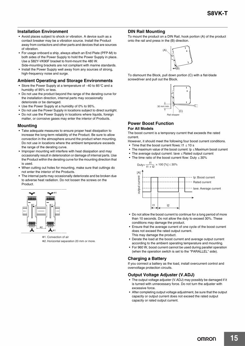
DIN Rail MountingTo mount the product on a DIN Rail, hook portion (A) of the product onto the rail and press in the (B) direction.
To dismount the Block, pull down portion (C) with a flat-blade screwdriver and pull out the Block.
Power Boost FunctionFor All ModelsThe boost current is a temporary current that exceeds the rated current.However, it should meet the following four boost current conditions.• Time that the boost current flows: t1 ≤ 10 s• The maximum value of the boost current: lp ≤ Maximum boost current• The average output current: Iave ≤ Rated output current• The time ratio of the boost current flow: Duty ≤ 30%
• Do not allow the boost current to continue for a long period of more than 10 seconds. Do not allow the duty to exceed 30%. These conditions may damage the product.
• Ensure that the average current of one cycle of the boost current does not exceed the rated output current.This may damage the product.
• Derate the load at the boost current and average output current according to the ambient operating temperature and mounting.
• For 960 W, boost current cannot be used during parallel operation (when the operation switch is set to the "PARALLEL" side).
Charging a BatteryIf you connect a battery as the load, install overcurrent control and overvoltage protection circuits.
Output Voltage Adjuster (V.ADJ)• The output voltage adjuster (V.ADJ) may possibly be damaged if it
is turned with unnecessary force. Do not turn the adjuster with excessive force.
• After completing output voltage adjustment, be sure that the output capacity or output current does not exceed the rated output capacity or rated output current.
*1. Convection of air*2. Horizontal separation 20 mm or more.
*1
*1
*2
(B)
(A)
(C)
30 mm min.
Rail stopper
Duty=t1 + t2
t1 × 100 [%] ��30%
[A]
Ip: Boost current
Rated current
lave: Average current
t2 t1
outp
ut c
urre
nt
S8VK-T
16
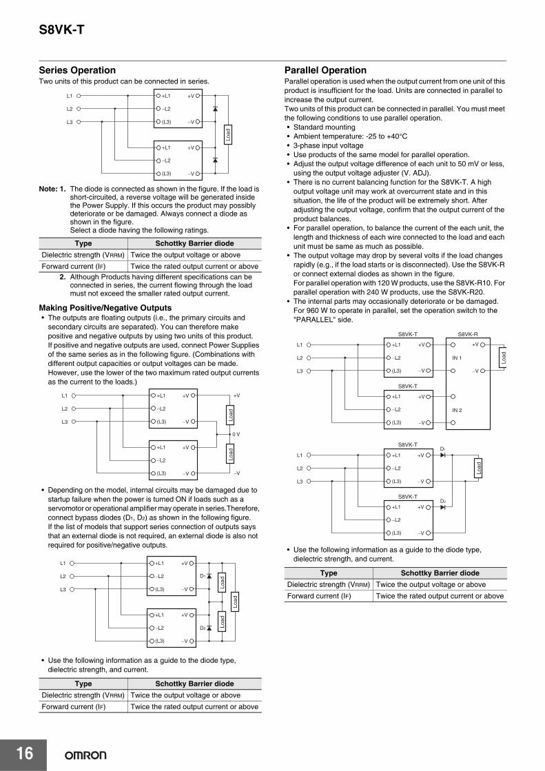
Series OperationTwo units of this product can be connected in series.
Note: 1. The diode is connected as shown in the figure. If the load is short-circuited, a reverse voltage will be generated inside the Power Supply. If this occurs the product may possibly deteriorate or be damaged. Always connect a diode as shown in the figure. Select a diode having the following ratings.
2. Although Products having different specifications can be connected in series, the current flowing through the load must not exceed the smaller rated output current.
Making Positive/Negative Outputs• The outputs are floating outputs (i.e., the primary circuits and
secondary circuits are separated). You can therefore make positive and negative outputs by using two units of this product.If positive and negative outputs are used, connect Power Supplies of the same series as in the following figure. (Combinations with different output capacities or output voltages can be made. However, use the lower of the two maximum rated output currents as the current to the loads.)
• Depending on the model, internal circuits may be damaged due to startup failure when the power is turned ON if loads such as a servomotor or operational amplifier may operate in series.Therefore, connect bypass diodes (D1, D2) as shown in the following figure.If the list of models that support series connection of outputs says that an external diode is not required, an external diode is also not required for positive/negative outputs.
• Use the following information as a guide to the diode type, dielectric strength, and current.
Parallel OperationParallel operation is used when the output current from one unit of this product is insufficient for the load. Units are connected in parallel to increase the output current. Two units of this product can be connected in parallel. You must meet the following conditions to use parallel operation.• Standard mounting• Ambient temperature: -25 to +40°C• 3-phase input voltage• Use products of the same model for parallel operation.• Adjust the output voltage difference of each unit to 50 mV or less,
using the output voltage adjuster (V. ADJ).• There is no current balancing function for the S8VK-T. A high
output voltage unit may work at overcurrent state and in this situation, the life of the product will be extremely short. After adjusting the output voltage, confirm that the output current of the product balances.
• For parallel operation, to balance the current of the each unit, the length and thickness of each wire connected to the load and each unit must be same as much as possible.
• The output voltage may drop by several volts if the load changes rapidly (e.g., if the load starts or is disconnected). Use the S8VK-R or connect external diodes as shown in the figure. For parallel operation with 120 W products, use the S8VK-R10. For parallel operation with 240 W products, use the S8VK-R20.
• The internal parts may occasionally deteriorate or be damaged. For 960 W to operate in parallel, set the operation switch to the "PARALLEL" side.
• Use the following information as a guide to the diode type, dielectric strength, and current.
Type Schottky Barrier diodeDielectric strength (VRRM) Twice the output voltage or above
Forward current (IF) Twice the rated output current or above
Type Schottky Barrier diodeDielectric strength (VRRM) Twice the output voltage or above
Forward current (IF) Twice the rated output current or above
+V
�V
+V
�V
+L1
�L2
(L3)
�L2
+L1
(L3)
L1
L2
L3
Load
+V
0 V
�V
+V
�V
+V
�V
�L2
�L2
+L1
(L3)
+L1
(L3)
L1
L2
L3 Load
Load
+V
�V
+V
�V
�L2
�L2
+L1
(L3)
+L1
(L3)
L1
L2
L3
D2
D1
Load
Load
Load
Type Schottky Barrier diodeDielectric strength (VRRM) Twice the output voltage or above
Forward current (IF) Twice the rated output current or above
+V
�V
+V
�V
+V
�V
�L2
�L2
+L1
(L3)
+L1
(L3)
L1
L2
L3
S8VK-RS8VK-T
S8VK-T
IN 1
IN 2
Load
+V
�V
+V
�V
�L2
�L2
+L1
(L3)
+L1
(L3)
D1
D2
L1
L2
L3
S8VK-T
S8VK-T
Load
S8VK-T
17
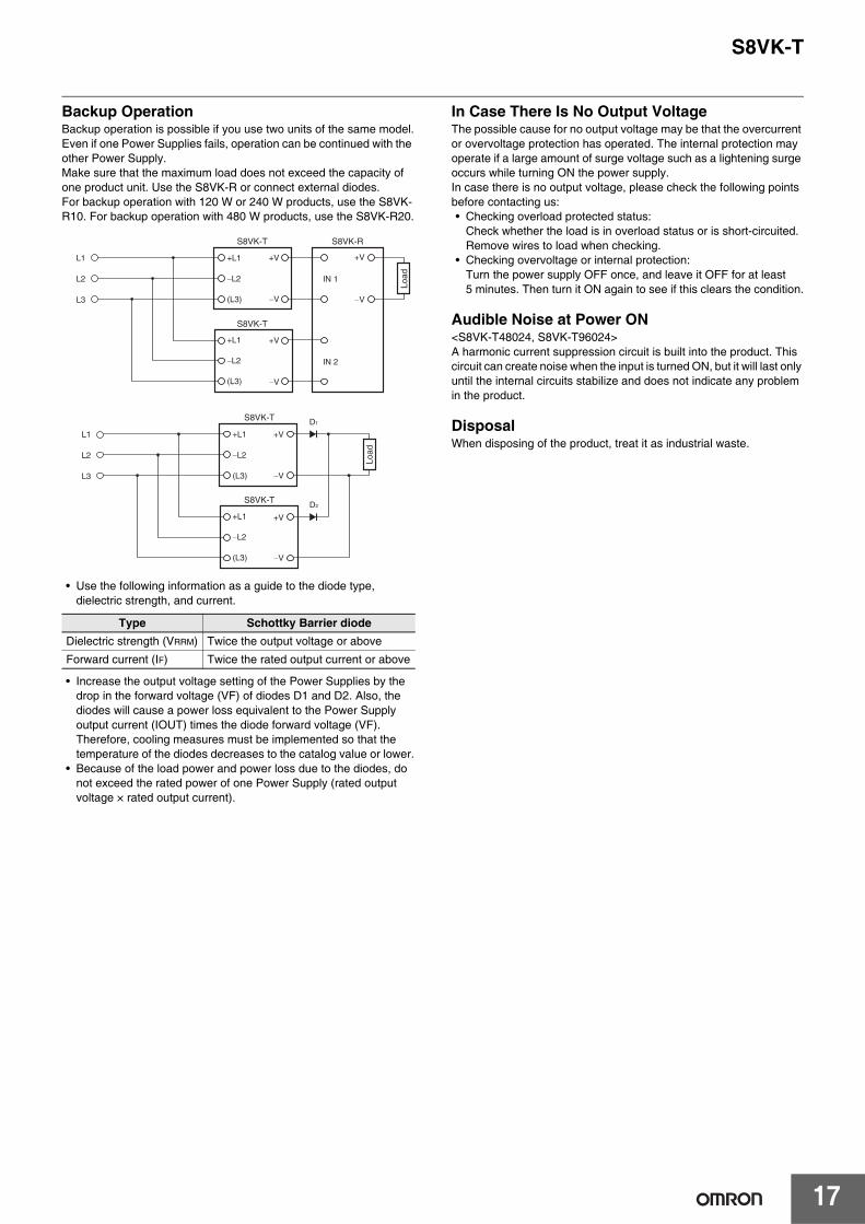
Backup OperationBackup operation is possible if you use two units of the same model.Even if one Power Supplies fails, operation can be continued with the other Power Supply.Make sure that the maximum load does not exceed the capacity of one product unit. Use the S8VK-R or connect external diodes.For backup operation with 120 W or 240 W products, use the S8VK-R10. For backup operation with 480 W products, use the S8VK-R20.
• Use the following information as a guide to the diode type, dielectric strength, and current.
• Increase the output voltage setting of the Power Supplies by the drop in the forward voltage (VF) of diodes D1 and D2. Also, the diodes will cause a power loss equivalent to the Power Supply output current (IOUT) times the diode forward voltage (VF). Therefore, cooling measures must be implemented so that the temperature of the diodes decreases to the catalog value or lower.
• Because of the load power and power loss due to the diodes, do not exceed the rated power of one Power Supply (rated output voltage × rated output current).
In Case There Is No Output VoltageThe possible cause for no output voltage may be that the overcurrent or overvoltage protection has operated. The internal protection may operate if a large amount of surge voltage such as a lightening surge occurs while turning ON the power supply.In case there is no output voltage, please check the following points before contacting us:• Checking overload protected status:
Check whether the load is in overload status or is short-circuited. Remove wires to load when checking.
• Checking overvoltage or internal protection: Turn the power supply OFF once, and leave it OFF for at least 5 minutes. Then turn it ON again to see if this clears the condition.
Audible Noise at Power ON<S8VK-T48024, S8VK-T96024>A harmonic current suppression circuit is built into the product. This circuit can create noise when the input is turned ON, but it will last only until the internal circuits stabilize and does not indicate any problem in the product.
DisposalWhen disposing of the product, treat it as industrial waste.
Type Schottky Barrier diodeDielectric strength (VRRM) Twice the output voltage or above
Forward current (IF) Twice the rated output current or above
+V
�V
+V
�V
+V
�V
�L2
�L2
+L1
(L3)
+L1
(L3)
L1
L2
L3
S8VK-RS8VK-T
S8VK-T
IN 1
IN 2
Load
+V
�V
+V
�V
�L2
�L2
D1
D2
+L1
(L3)
+L1
(L3)
L1
L2
L3
S8VK-T
S8VK-T
Load
S8VK-T
18
Period and Terms of WarrantyWarranty PeriodThe product warranty is valid for a period of three years from the date of shipment from the factory.
Terms of WarrantyThe warranty is valid only for the following operating conditions.1. Average ambient operating temperature of the product: 40°C max.2. Average load rate: 80% max.3. Mounting method: Standard mounting* The maximum ratings must be within the derating curve.
If the product fails for reasons attributable to OMRON within the above warranty period, OMRON will repair or replace the faulty part of the product at the place of purchase or the place where the product delivered without charge.This warranty does not cover the following types of failures.
Recommended Replacement Periods and Periodic Replacement for Preventive MaintenanceThe recommended replacement period for preventive maintenance is greatly influenced by the application environment of the product. As a guideline, the recommended replacement period is 7 to 10 years.*To prevent failures or accidents that can be caused by using a product beyond its service live, we recommend that you replace the product as early as possible within the recommended replacement period.However, bear in mind that the recommended replacement period is for reference only and does not guarantee the life of the product.
Many electronic components are used in the product and the product depends on the correct operation of these components to achieve the original product functions and performance.However, the influence of the ambient temperature on aluminum electrolytic capacitors is large, and the service life is reduced by half for each 10°C rise in temperature (Arrhenius law).When the capacity reduction life of the electrolytic capacitor is reached, the product failures or accidents may occur.We therefore recommend that you replace the product periodically to minimize product failures or accidents in advance.* The recommended replacement period applies under the following conditions: rated input voltage, load rate of 50% max., ambient temperature
of 40°C max., and the standard mounting method. (The fan is excluded for models with fans.)
This product model is designed with a service life of 10 years minimum under the above conditions.
(1) Failures that result from handling or operation of the product under conditions or in environments that are not given in this document and not given in any other specifications exchanged between OMRON and the customer
(2) Failures that originate in causes other than the delivered product itself(3) Failures caused by disassembly, modification, or repair of the product by anyone other than OMRON(4) Failures caused by applications or uses for which the product was not originally intended(5) Failures caused by factors that could not be anticipated with the scientific or technical knowledge available when the product was shipped(6) Failures caused by other causes for which OMRON is not responsible, such as natural disasters and other acts of God
This warranty is limited to the individual product that was delivered and does not cover any secondary, subsequent, or related damages.
Terms and Conditions AgreementRead and understand this catalog.
Please read and understand this catalog before purchasing the products. Please consult your OMRON representative if you have any questions or comments.
Warranties.(a) Exclusive Warranty. Omron’s exclusive warranty is that the Products will be free from defects in materials and workmanship
for a period of twelve months from the date of sale by Omron (or such other period expressed in writing by Omron). Omron disclaims all other warranties, express or implied.
(b) Limitations. OMRON MAKES NO WARRANTY OR REPRESENTATION, EXPRESS OR IMPLIED, ABOUT NON-INFRINGEMENT, MERCHANTABILITY OR FITNESS FOR A PARTICULAR PURPOSE OF THE PRODUCTS. BUYER ACKNOWLEDGES THAT IT ALONE HAS DETERMINED THAT THE PRODUCTS WILL SUITABLY MEET THE REQUIREMENTS OF THEIR INTENDED USE.
Omron further disclaims all warranties and responsibility of any type for claims or expenses based on infringement by the Products or otherwise of any intellectual property right. (c) Buyer Remedy. Omron’s sole obligation hereunder shall be, at Omron’s election, to (i) replace (in the form originally shipped with Buyer responsible for labor charges for removal or replacement thereof) the non-complying Product, (ii) repair the non-complying Product, or (iii) repay or credit Buyer an amount equal to the purchase price of the non-complying Product; provided that in no event shall Omron be responsible for warranty, repair, indemnity or any other claims or expenses regarding the Products unless Omron’s analysis confirms that the Products were properly handled, stored, installed and maintained and not subject to contamination, abuse, misuse or inappropriate modification. Return of any Products by Buyer must be approved in writing by Omron before shipment. Omron Companies shall not be liable for the suitability or unsuitability or the results from the use of Products in combination with any electrical or electronic components, circuits, system assemblies or any other materials or substances or environments. Any advice, recommendations or information given orally or in writing, are not to be construed as an amendment or addition to the above warranty.
See http://www.omron.com/global/ or contact your Omron representative for published information.
Limitation on Liability; Etc.OMRON COMPANIES SHALL NOT BE LIABLE FOR SPECIAL, INDIRECT, INCIDENTAL, OR CONSEQUENTIAL DAMAGES, LOSS OF PROFITS OR PRODUCTION OR COMMERCIAL LOSS IN ANY WAY CONNECTED WITH THE PRODUCTS, WHETHER SUCH CLAIM IS BASED IN CONTRACT, WARRANTY, NEGLIGENCE OR STRICT LIABILITY.
Further, in no event shall liability of Omron Companies exceed the individual price of the Product on which liability is asserted.
Suitability of Use.Omron Companies shall not be responsible for conformity with any standards, codes or regulations which apply to the combination of the Product in the Buyer’s application or use of the Product. At Buyer’s request, Omron will provide applicable third party certification documents identifying ratings and limitations of use which apply to the Product. This information by itself is not sufficient for a complete determination of the suitability of the Product in combination with the end product, machine, system, or other application or use. Buyer shall be solely responsible for determining appropriateness of the particular Product with respect to Buyer’s application, product or system. Buyer shall take application responsibility in all cases.
NEVER USE THE PRODUCT FOR AN APPLICATION INVOLVING SERIOUS RISK TO LIFE OR PROPERTY OR IN LARGE QUANTITIES WITHOUT ENSURING THAT THE SYSTEM AS A WHOLE HAS BEEN DESIGNED TO ADDRESS THE RISKS, AND THAT THE OMRON PRODUCT(S) IS PROPERLY RATED AND INSTALLED FOR THE INTENDED USE WITHIN THE OVERALL EQUIPMENT OR SYSTEM.
Programmable Products.Omron Companies shall not be responsible for the user’s programming of a programmable Product, or any consequence thereof.
Performance Data.Data presented in Omron Company websites, catalogs and other materials is provided as a guide for the user in determining suitability and does not constitute a warranty. It may represent the result of Omron’s test conditions, and the user must correlate it to actual application requirements. Actual performance is subject to the Omron’s Warranty and Limitations of Liability.
Change in Specifications.Product specifications and accessories may be changed at any time based on improvements and other reasons. It is our practice to change part numbers when published ratings or features are changed, or when significant construction changes are made. However, some specifications of the Product may be changed without any notice. When in doubt, special part numbers may be assigned to fix or establish key specifications for your application. Please consult with your Omron’s representative at any time to confirm actual specifications of purchased Product.
Errors and Omissions.Information presented by Omron Companies has been checked and is believed to be accurate; however, no responsibility is assumed for clerical, typographical or proofreading errors or omissions.

Authorized Distributor:
In the interest of product improvement, specifications are subject to change without notice.
Cat. No. T061-E1-06 0621 (0414)
© OMRON Corporation 2014-2021 All Rights Reserved.
OMRON Corporation Industrial Automation Company
OMRON ELECTRONICS LLC2895 Greenspoint Parkway, Suite 200 Hoffman Estates, IL 60169 U.S.A.Tel: (1) 847-843-7900/Fax: (1) 847-843-7787
Regional HeadquartersOMRON EUROPE B.V.Wegalaan 67-69, 2132 JD HoofddorpThe NetherlandsTel: (31)2356-81-300/Fax: (31)2356-81-388
Contact: www.ia.omron.comKyoto, JAPAN
OMRON ASIA PACIFIC PTE. LTD.No. 438A Alexandra Road # 05-05/08 (Lobby 2), Alexandra Technopark, Singapore 119967Tel: (65) 6835-3011/Fax: (65) 6835-2711
OMRON (CHINA) CO., LTD.Room 2211, Bank of China Tower, 200 Yin Cheng Zhong Road, PuDong New Area, Shanghai, 200120, ChinaTel: (86) 21-5037-2222/Fax: (86) 21-5037-2200