Embed Size (px)
Citation preview
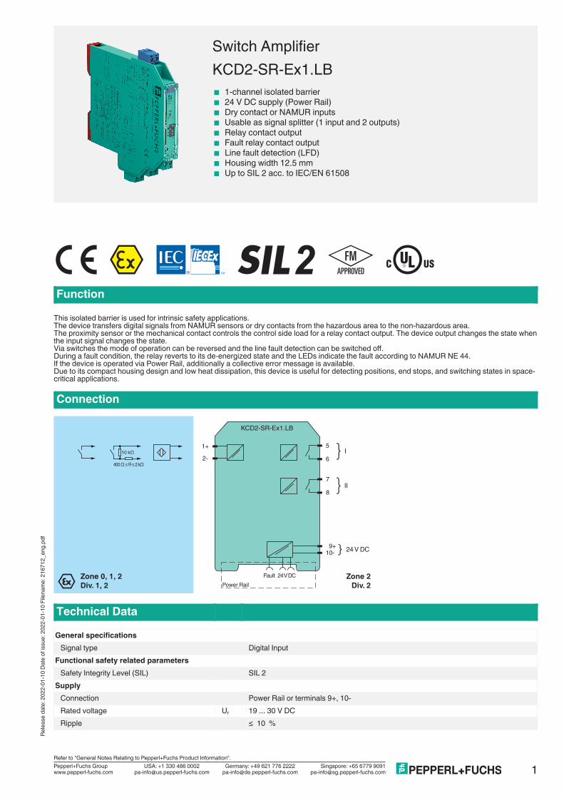
Switch AmplifierKCD2-SR-Ex1.LB< 1-channel isolated barrier< 24 V DC supply (Power Rail)< Dry contact or NAMUR inputs< Usable as signal splitter (1 input and 2 outputs)< Relay contact output< Fault relay contact output< Line fault detection (LFD)< Housing width 12.5 mm< Up to SIL 2 acc. to IEC/EN 61508
Function
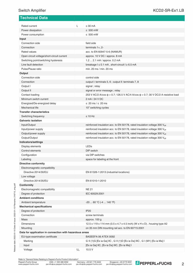
This isolated barrier is used for intrinsic safety applications.The device transfers digital signals from NAMUR sensors or dry contacts from the hazardous area to the non-hazardous area.The proximity sensor or the mechanical contact controls the control side load for a relay contact output. The device output changes the state whenthe input signal changes the state.Via switches the mode of operation can be reversed and the line fault detection can be switched off.During a fault condition, the relay reverts to its de-energized state and the LEDs indicate the fault according to NAMUR NE 44.If the device is operated via Power Rail, additionally a collective error message is available.Due to its compact housing design and low heat dissipation, this device is useful for detecting positions, end stops, and switching states in space-critical applications.
Connection
5
6
1+
2-
7
8
I
II
Zone 0, 1, 2
Div. 1, 2
Zone 2
Div. 2
24 V DC9+
10-
Power Rail
24 V DCFault
KCD2-SR-Ex1.LB
10 kΩ
400 Ω ≤ R ≤ 2 kΩ
Technical Data
General specificationsSignal type Digital Input
Functional safety related parametersSafety Integrity Level (SIL) SIL 2
SupplyConnection Power Rail or terminals 9+, 10-Rated voltage Ur 19 ... 30 V DCRipple ≤ 10 %
1
Rele
ase
date
:20
22-0
1--
10 D
ate
of
Rele
ase
date
: 202
2-01
-10
Dat
e of
issu
e: 2
022-
01-1
0 Fi
lena
me:
216
712_
eng.
Germany: +49 621 776 2222Pepperl+Fuchs Group
Refer to "General Notes Relating to Pepperl+Fuchs Product Information".
USA: +1 330 486 0002 Singapore: +65 6779 9091www.pepperl-fuchs.com [email protected] [email protected]@de.pepperl-fuchs.com
Technical Data
Rated current Ir ≤ 30 mAPower dissipation ≤ 500 mWPower consumption ≤ 500 mW
InputConnection side field sideConnection terminals 1+, 2-Rated values acc. to EN 60947-5-6 (NAMUR)Open circuit voltage/short-circuit current approx. 10 V DC / approx. 8 mASwitching point/switching hysteresis 1.2 ... 2.1 mA / approx. 0.2 mALine fault detection breakage I ≤ 0.1 mA , short-circuit I ≥ 6.5 mAPulse/Pause ratio min. 20 ms / min. 20 ms
OutputConnection side control sideConnection output I: terminals 5, 6 ; output II: terminals 7, 8Output I signal ; relayOutput II signal or error message ; relayContact loading 253 V AC/2 A/cos φ > 0.7; 126.5 V AC/4 A/cos φ > 0.7; 30 V DC/2 A resistive loadMinimum switch current 2 mA / 24 V DCEnergized/De-energized delay ≤ 20 ms / ≤ 20 msMechanical life 107 switching cycles
Transfer characteristicsSwitching frequency ≤ 10 Hz
Galvanic isolationInput/Output reinforced insulation acc. to EN 50178, rated insulation voltage 300 Veff
Input/power supply reinforced insulation acc. to EN 50178, rated insulation voltage 300 Veff
Output/power supply reinforced insulation acc. to EN 50178, rated insulation voltage 300 Veff
Output/Output reinforced insulation acc. to EN 50178, rated insulation voltage 300 Veff
Indicators/settingsDisplay elements LEDsControl elements DIP switchConfiguration via DIP switchesLabeling space for labeling at the front
Directive conformityElectromagnetic compatibility
Directive 2014/30/EU EN 61326-1:2013 (industrial locations)Low voltage
Directive 2014/35/EU EN 61010-1:2010Conformity
Electromagnetic compatibility NE 21Degree of protection IEC 60529:2001
Ambient conditionsAmbient temperature -20 ... 60 °C (-4 ... 140 °F)
Mechanical specificationsDegree of protection IP20Connection screw terminalsMass approx. 100 gDimensions 12.5 x 119 x 114 mm (0.5 x 4.7 x 4.5 inch) (W x H x D) , housing type A2Mounting on 35 mm DIN mounting rail acc. to EN 60715:2001
Data for application in connection with hazardous areasEU-type examination certificate BASEEFA 06 ATEX 0092
Marking 1 II (1)G [Ex ia Ga] IIC , 1 II (1)D [Ex ia Da] IIIC , 1 I (M1) [Ex ia Ma] IInput [Ex ia Ga] IIC, [Ex ia Da] IIIC, [Ex ia Ma] IVoltage Uo 10.5 V
Switch Amplifier KCD2-SR-Ex1.LBRe
leas
e da
te: 2
022-
01-1
0 D
ate
of is
sue:
202
2-01
-10
File
nam
e: 2
1671
2_en
g.pd
f
2Germany: +49 621 776 2222Pepperl+Fuchs Group
Refer to "General Notes Relating to Pepperl+Fuchs Product Information".
USA: +1 330 486 0002 Singapore: +65 6779 9091www.pepperl-fuchs.com [email protected] [email protected]@de.pepperl-fuchs.com
Technical Data
Current Io 17.1 mAPower Po 45 mW (linear characteristic)
SupplyMaximum safe voltage Um 253 V AC (Attention! Um is no rated voltage.)
Output I, IIMaximum safe voltage Um 253 V AC (Attention! Um is no rated voltage.)Contact loading 253 V AC/2 A/cos φ > 0.7; 126.5 V AC/4 A/cos φ > 0.7; 30 V DC/2 A resistive load
Certificate PF 06 CERT 0972 XMarking 1 II 3G Ex nA nC IIC T4 Gc
Output I, IIContact loading 50 V AC/2 A/cos φ > 0.7; 30 V DC/2 A resistive load
Galvanic isolationInput/Output safe electrical isolation acc. to IEC/EN 60079-11, voltage peak value 375 VInput/power supply safe electrical isolation acc. to IEC/EN 60079-11, voltage peak value 375 V
Directive conformityDirective 2014/34/EU EN 60079-0:2012+A11:2013 , EN 60079-11:2012 , EN 60079-15:2010
International approvalsFM approval
Control drawing 116-0419 (cFMus)UL approval
Control drawing 116-0420 (cULus)IECEx approval
IECEx certificate IECEx BAS 06.0025IECEx marking [Ex ia Ga] IIC
[Ex ia Da] IIIC[Ex ia Ma] I
General informationSupplementary information Observe the certificates, declarations of conformity, instruction manuals, and manuals
where applicable. For information see www.pepperl-fuchs.com.
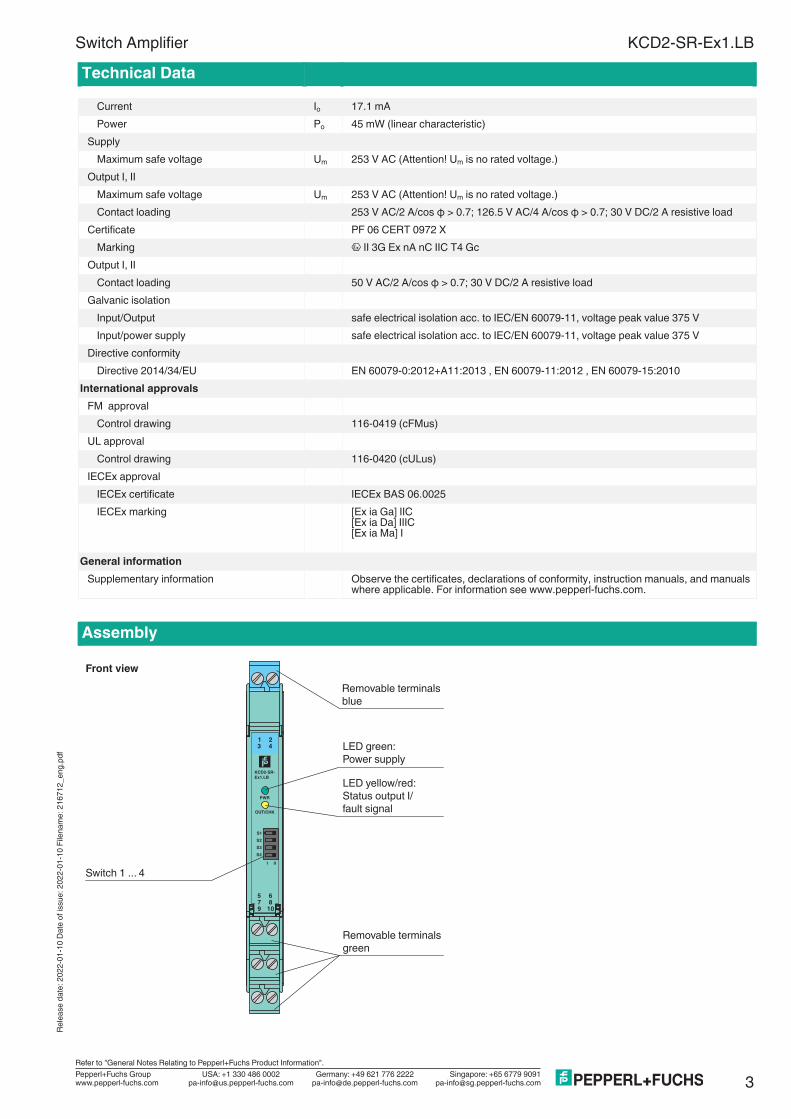
Assembly
PWR
OUT/CHK
KCD2-SR-
Ex1.LB
9 10
8
6
7
5
S1
S3
S4
S2
III
1 2
3 4
Removable terminals
green
Removable terminals
blue
Front view
Switch 1 ... 4
LED yellow/red:
Status output I/
fault signal
LED green:
Power supply
Switch Amplifier KCD2-SR-Ex1.LBRe
leas
e da
te: 2
022-
01-1
0 D
ate
of is
sue:
202
2-01
-10
File
nam
e: 2
1671
2_en
g.pd
f
3Germany: +49 621 776 2222Pepperl+Fuchs Group
Refer to "General Notes Relating to Pepperl+Fuchs Product Information".
USA: +1 330 486 0002 Singapore: +65 6779 9091www.pepperl-fuchs.com [email protected] [email protected]@de.pepperl-fuchs.com
Matching System Components
KFD2-EB2 Power Feed Module
UPR-03 Universal Power Rail with end caps and cover, 3 conductors, length: 2 m
UPR-03-M Universal Power Rail with end caps and cover, 3 conductors, length: 1,6 m
UPR-03-S Universal Power Rail with end caps and cover, 3 conductors, length: 0.8 m
K-DUCT-BU Profile rail, wiring comb field side, blue
K-DUCT-BU-UPR-03 Profile rail with UPR-03- * insert, 3 conductors, wiring comb field side, blue
Accessories
F-NR3-Ex1 NAMUR Resistor Network
KC-ST-5GN Terminal block for KC modules, 2-pin screw terminal, green
KC-ST-5BU Terminal block for KC modules, 2-pin screw terminal, blue
KF-CP Red coding pins, packaging unit: 20 x 6
Switch Amplifier KCD2-SR-Ex1.LBRe
leas
e da
te: 2
022-
01-1
0 D
ate
of is
sue:
202
2-01
-10
File
nam
e: 2
1671
2_en
g.pd
f
4Germany: +49 621 776 2222Pepperl+Fuchs Group
Refer to "General Notes Relating to Pepperl+Fuchs Product Information".
USA: +1 330 486 0002 Singapore: +65 6779 9091www.pepperl-fuchs.com [email protected] [email protected]@de.pepperl-fuchs.com
Relea
se da
te: 20
22-01
-10 D
ate of
issu
e: 20
22-01
-10 F
ilena
me: 2
1671
2_en
g.pdf
KCD2-SR-Ex1.LB
5Germany: +49 621 776 2222Pepperl+Fuchs GroupRefer to "General Notes Relating to Pepperl+Fuchs Product Information".
USA: +1 330 486 0002 Singapore: +65 6779 9091www.pepperl-fuchs.com [email protected] [email protected]@de.pepperl-fuchs.com
Switch Amplifier
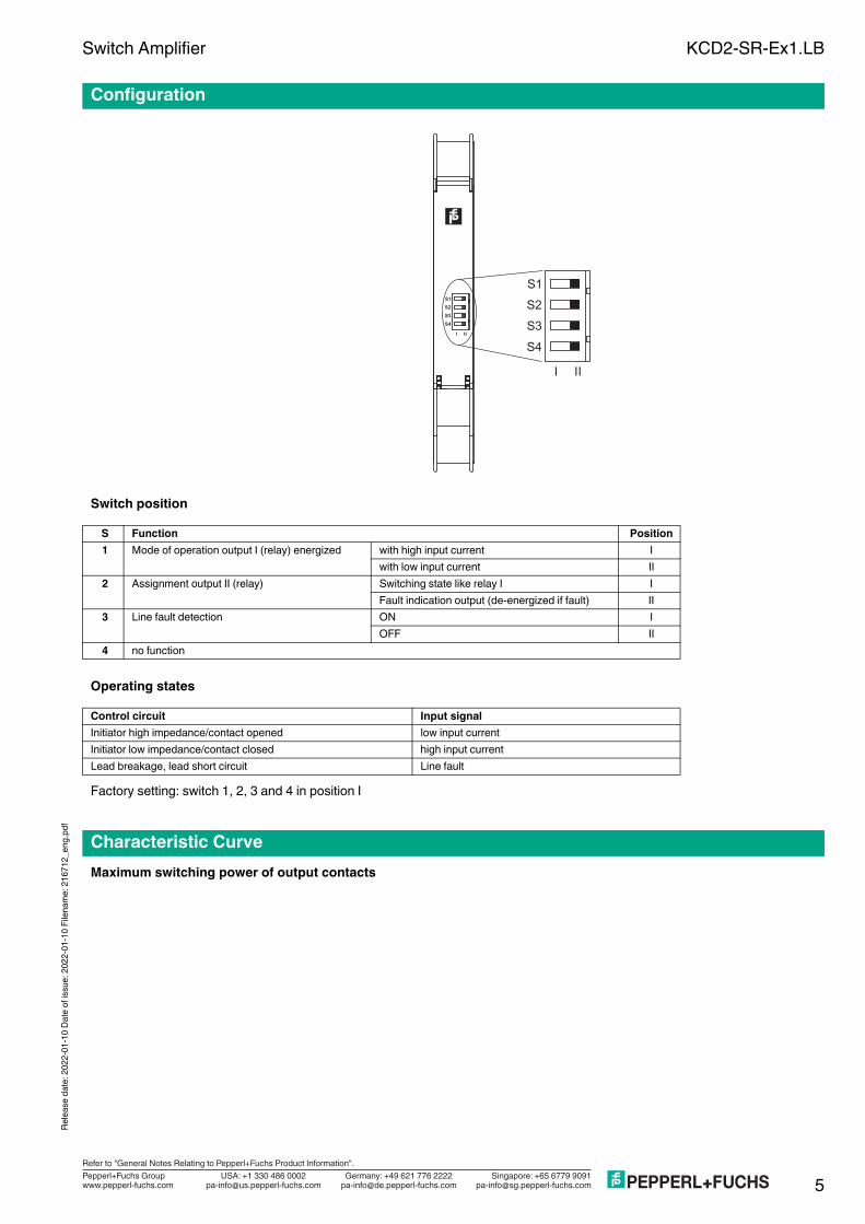
Switch position
Operating states
Factory setting: switch 1, 2, 3 and 4 in position I
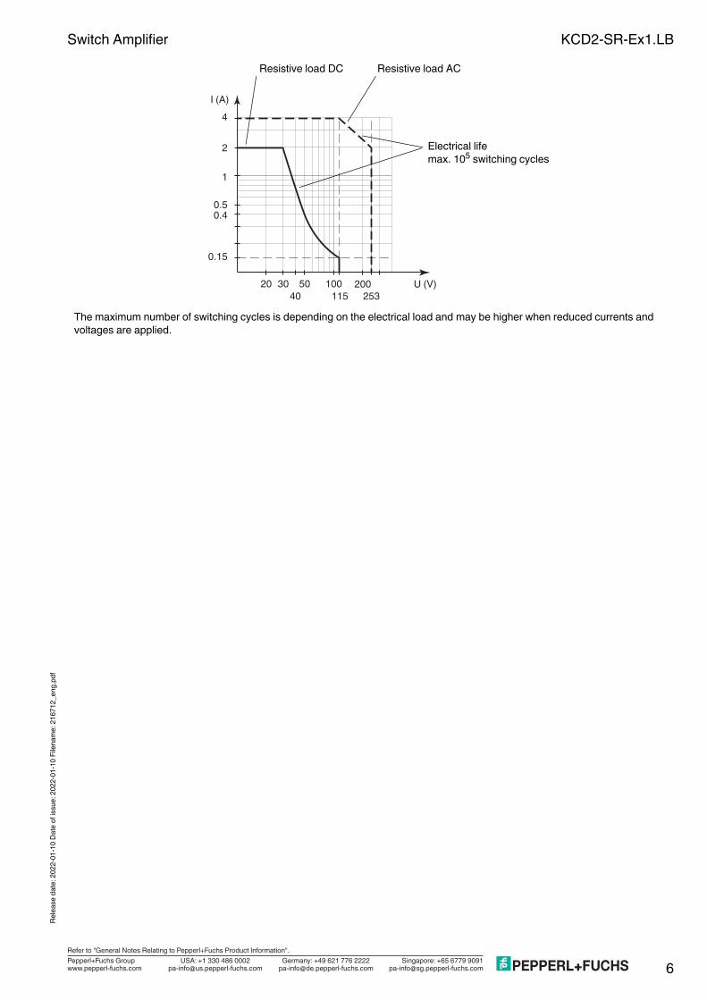
Maximum switching power of output contacts
Configuration
S Function Position1 Mode of operation output I (relay) energized with high input current I
with low input current II2 Assignment output II (relay) Switching state like relay I I
Fault indication output (de-energized if fault) II3 Line fault detection ON I
OFF II4 no function
Control circuit Input signalInitiator high impedance/contact opened low input currentInitiator low impedance/contact closed high input currentLead breakage, lead short circuit Line fault
Characteristic Curve
S1
S3S4
II
S2
I
S1
S3S4
II
S2
I
Relea
se da
te: 20
22-01
-10 D
ate of
issu
e: 20
22-01
-10 F
ilena
me: 2
1671
2_en
g.pdf
KCD2-SR-Ex1.LB
6Germany: +49 621 776 2222Pepperl+Fuchs GroupRefer to "General Notes Relating to Pepperl+Fuchs Product Information".
USA: +1 330 486 0002 Singapore: +65 6779 9091www.pepperl-fuchs.com [email protected] [email protected]@de.pepperl-fuchs.com
Switch Amplifier
The maximum number of switching cycles is depending on the electrical load and may be higher when reduced currents and voltages are applied.
1
I (A)
2
4
4010030 50 200
115 253U (V)20
0.50.4
0.15
Resistive load DC Resistive load AC
Electrical lifemax. 105 switching cycles