Embed Size (px)
Citation preview
SWIR CALIBRATION OF SPECTRALON REFLECTANCE FACTOR Georgi T. Georgieva, James J. Butlerb, Catherine Cookseyc, Leibo Dinga, Kurtis J. Thomeb
aSigma Space Corp., Lanham, MD 20706, e-mail: [email protected] bNASA Goddard Space Flight Center, Greenbelt, MD 20771
cNational Institute of Standards and Technology, Gaithersburg, MD 20899
ABSTRACT
Satellite instruments operating in the reflective solar wavelength region require accurate and precise determination of the Bidirectional Reflectance Factor (BRF) of laboratory-based diffusers used in their pre-flight and on-orbit radiometric calibrations. BRF measurements are required throughout the reflected-solar spectrum from the ultraviolet through the shortwave infrared. Spectralon diffusers are commonly used as a reflectance standard for bidirectional and hemispherical geometries. The Diffuser Calibration Laboratory (DCaL) at NASA’s Goddard Space Flight Center is a secondary calibration facility with reflectance measurements traceable to those made by the Spectral Tri-function Automated Reference Reflectometer (STARR) facility at the National Institute of Standards and Technology (NIST). For more than two decades, the DCaL has provided numerous NASA projects with BRF data in the ultraviolet (UV), visible (VIS) and the Near InfraRed (NIR) spectral regions. Presented in this paper are measurements of BRF from 1475 nm to 1625 nm obtained using an indium gallium arsenide detector and a tunable coherent light source. The sample was a 50.8 mm (2 in) diameter, 99% white Spectralon target. The BRF results are discussed and compared to empirically generated data from a model based on NIST certified values of 6o directional-hemispherical spectral reflectance factors from 900 nm to 2500 nm. Employing a new NIST capability for measuring bidirectional reflectance using a cooled, extended InGaAs detector, BRF calibration measurements of the same sample were also made using NIST’s STARR from 1475 nm to 1625 nm at an incident angle of 0o and at viewing angle of 45o. The total combined uncertainty for BRF in this ShortWave Infrared (SWIR) range is less than 1%. This measurement capability will evolve into a BRF calibration service in SWIR region in support of NASA remote sensing missions.
Keywords: BRF, BRDF, Calibration, Spectralon, Reflectance, Remote Sensing.
1. INTRODUCTION
The global nature of Earth’s processes requires consistent long-term calibration of all instruments involved in the retrieval of data used in the production of geophysical processes1. Due to an increasing importance of monitoring the Earth’s energy budget, space-borne remote sensing instruments require the ability to monitor Earth reflected solar radiation in the UV, VIS, NIR and SWIR wavelength regions. Traditionally, diffuser standards are used for pre-flight and on-orbit calibration of the radiance responsivity of satellite instruments through measurements of their Bidirectional Reflectance Distribution Function (BRDF). The BRDF is a function of wavelength and geometry and reflects the structural and optical properties of the surface. Various space and airborne radiometric and imaging remote sensing instruments use diffuse scatter standards as calibration sources. Laboratory-based diffusers are used for pre-flight instrument radiance calibrations. On-board diffusers are used to trend on-orbit instrument radiance or reflectance calibration.
The Diffuser Calibration Laboratory (DCaL) at NASA’s Goddard Space Flight Center Calibration Facility has supported numerous NASA flight projects over the past two decades with BRDF data in the UV, Visible and the NIR spectral regions. However the requirements to support current and planned Decadal Survey satellite missions has made it necessary to expand the DCaL measurement capabilities into the Short-wave infrared (SWIR). For example, the National Polar Orbiting Environmental Satellite System (NPOESS) Preparatory Project (NPP) and the Joint Polar Satellite System (JPSS), Visible Infrared Imager Radiometer Suite (VIIRS) and the Landsat Data Continuity Mission (LDCM) Operational Land Imager (OLI) include SWIR bands which require on-orbit radiometric calibration.
Sensors, Systems, and Next-Generation Satellites XV, edited by Roland Meynart, Steven P. Neeck, Haruhisa Shimoda,Proc. of SPIE Vol. 8176, 81760W · © 2011 SPIE · CCC code: 0277-786X/11/$18 · doi: 10.1117/12.898325
Proc. of SPIE Vol. 8176 81760W-1
Downloaded from SPIE Digital Library on 13 Oct 2011 to 128.183.108.105. Terms of Use: http://spiedl.org/terms
The perfect diffuser is defined as a Lambertian diffuser reflecting the incident radiation in all angles equally or near-equally. Such a material has to have diffuse reflectance properties from the UV to the IR spectral region, to be highly opaque and have no fluorescence. There are no real materials with such properties; however, Spectralon, which is one of the trademarks of polytetrafluoroethylene (PTFE), approaches a Lambertian diffuser and is widely used as a reflectance standard for remote sensing instrument calibration.
2. INSTRUMENTATION
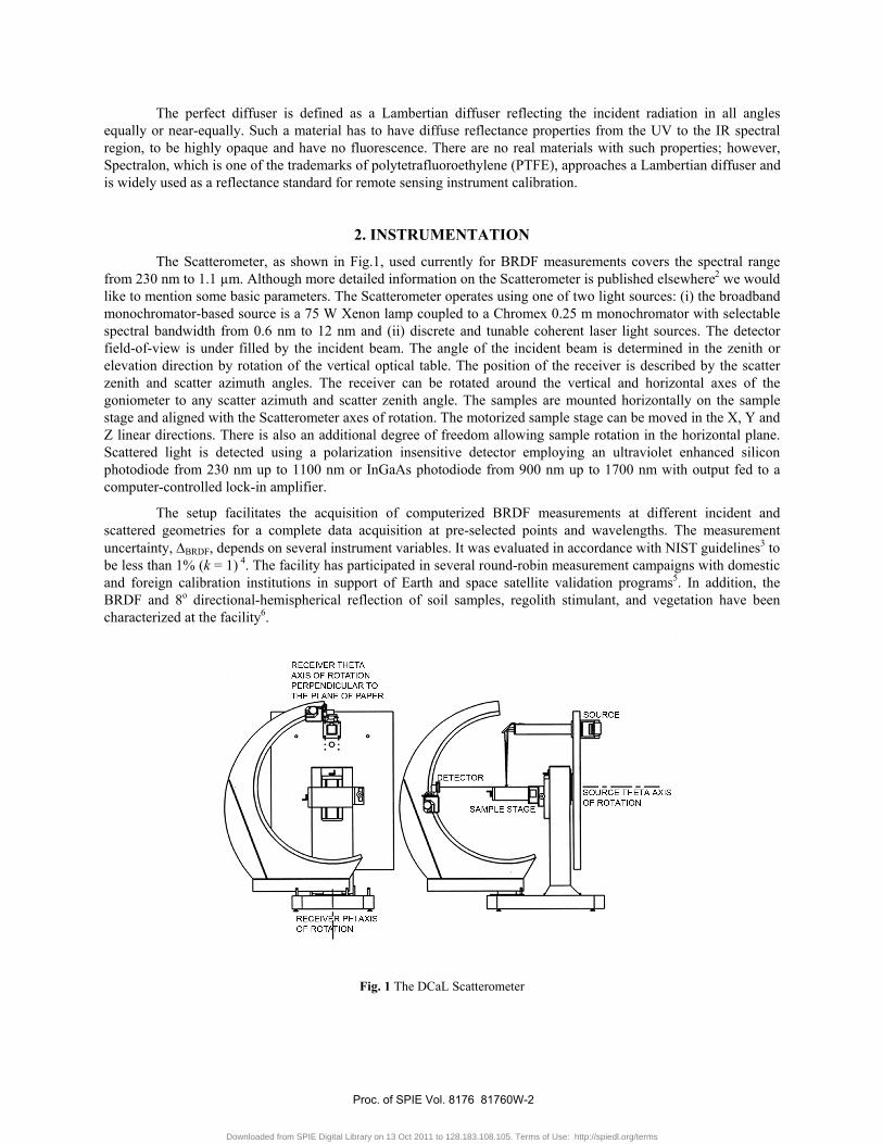
The Scatterometer, as shown in Fig.1, used currently for BRDF measurements covers the spectral range from 230 nm to 1.1 µm. Although more detailed information on the Scatterometer is published elsewhere2 we would like to mention some basic parameters. The Scatterometer operates using one of two light sources: (i) the broadband monochromator-based source is a 75 W Xenon lamp coupled to a Chromex 0.25 m monochromator with selectable spectral bandwidth from 0.6 nm to 12 nm and (ii) discrete and tunable coherent laser light sources. The detector field-of-view is under filled by the incident beam. The angle of the incident beam is determined in the zenith or elevation direction by rotation of the vertical optical table. The position of the receiver is described by the scatter zenith and scatter azimuth angles. The receiver can be rotated around the vertical and horizontal axes of the goniometer to any scatter azimuth and scatter zenith angle. The samples are mounted horizontally on the sample stage and aligned with the Scatterometer axes of rotation. The motorized sample stage can be moved in the X, Y and Z linear directions. There is also an additional degree of freedom allowing sample rotation in the horizontal plane. Scattered light is detected using a polarization insensitive detector employing an ultraviolet enhanced silicon photodiode from 230 nm up to 1100 nm or InGaAs photodiode from 900 nm up to 1700 nm with output fed to a computer-controlled lock-in amplifier.
The setup facilitates the acquisition of computerized BRDF measurements at different incident and scattered geometries for a complete data acquisition at pre-selected points and wavelengths. The measurement uncertainty, ΔBRDF, depends on several instrument variables. It was evaluated in accordance with NIST guidelines3 to be less than 1% (k = 1) 4. The facility has participated in several round-robin measurement campaigns with domestic and foreign calibration institutions in support of Earth and space satellite validation programs5. In addition, the BRDF and 8o directional-hemispherical reflection of soil samples, regolith stimulant, and vegetation have been characterized at the facility6.
Fig. 1 The DCaL Scatterometer
Proc. of SPIE Vol. 8176 81760W-2
Downloaded from SPIE Digital Library on 13 Oct 2011 to 128.183.108.105. Terms of Use: http://spiedl.org/terms
3. METHODOLOGY
The directional-hemispherical reflectance is the total fraction of light scattered into the hemisphere above the sample by illumination with a collimated source surface. The bidirectional reflectance corresponds to directional-directional reflectance and ideally means both incident and scattered light beams are collimated. Although perfect collimation and diffuseness are rarely achieved in practice, they can be used as very useful approximations for reflectance measurements.
We are following the NIST definition of BRDF, according to Nicodemus7, in our laboratory calibration measurements. In this case, the BRDF is referred to as the ratio of the scattered radiance, Ls, scattered by a surface into the direction (θs, φs) to the collimated irradiance, Ei, incident on a unit area of the surface:
( )
( )λφθλφθφθ
,,,,,,
iii
ssiis
ELBRDF = , (1)
where θ is the zenith angle, φ is the azimuth angle, the subscripts i and s represent incident and scattered directions, respectively, and λ is the wavelength. Nicodemus further assumed that the beam has a uniform cross section, the illuminated area on the sample is isotropic, and all scatter comes from the sample surface.
In practice, we are dealing with real sample surfaces which are not isotropic, and the optical beams used to measure the reflectance are not perfectly uniform. Hence, from practical considerations, the BRDF can be defined, according to Stover8, as the scattered power per unit solid angle normalized by the incident power and the cosine of the detector zenith angle. It is expressed in terms of incident power, scattered power and the geometry of incident and reflected light:
si
s
P
PBRDF
θcosΩ= , (2)
where Ps is the scatter power, Ω is the solid angle determined by the detector aperture, A, and the radius from the sample to the detector, R, or Ω = A/R2, Pi is the incident power, and θs is the scatter zenith angle.
The BRDF, fr, has units of inverse steradians and can range from small numbers (e.g. off-specular black samples) to large values (e.g. highly reflective samples at specular reflectance geometries). The bidirectional reflectance factor (BRF), Rλ, is dimensionless and can be defined in terms of the BRDF as
rfR .πλ = (3)
BRF, Rλ, is also often expressed as following van de Hulst9 formulation:
Rλ(θ,θ0,Φ) =πIλ θ,θ0,Φ( )
μ0Fλ
, (4)
where Iλ is the measured reflected intensity (radiance), Fλ is the solar flux density (irradiance) incident on the top of the atmosphere, θ and θ0 are respectively the viewing and incident zenith angles, Φ is the azimuthal angle between the viewing and incident light directions, and µ0 = cosθ0.
3. MEASUREMENTS
3.1. Measurement challenges
The determination of a sample’s BRDF requires the measurement of low intensities of scattered light with low uncertainty. Since Spectralon, which we assume to be a nearly perfect diffuser for the UV-VIS-NIR-SWIR
Proc. of SPIE Vol. 8176 81760W-3
Downloaded from SPIE Digital Library on 13 Oct 2011 to 128.183.108.105. Terms of Use: http://spiedl.org/terms
spectral range, scatters incident radiation into a hemisphere, only a small portion on the scattered light can be collected in BRDF measurements. InGaAs photodiode with low noise, high shunt resistance and linearity operating in the spectral range from 900 nm to 1700 nm was used for BRDF measurements in the SWIR. In addition, as a first approximation, it was assumed that the ratio between the BRDF and a 6o directional-hemispherical reflectance from 300 nm to 900 nm at 0o/45o measurement geometry could be related to the 6o directional-hemispherical reflectance from 900 nm to 1700 nm to produce SWIR BRDF values capable of being compared to our BRDF measurements.
Two approaches for extending the measurement capabilities of the DCaL into the SWIR are being implemented. These include the use of a (i) laser based tunable source and (ii) an incoherent monochromator-based source. The laser based approach is presented in this paper since the broadband based one is still under development.
SWIR BRDF measurements were made on the DCaL Scatterometer allowed by replacing the existing detector assembly and updating the software. However, a major obstacle for realizing the BRDF calibration of Spectralon diffusers with coherent light sources is the speckle. The difficulties are due to the surface roughness of the Spectralon. A complex speckle pattern is formed when coherent light reflects from a surface which has a roughness dimensionally larger compared to the incident optical wavelength. The speckle is a result of the interference among the scattered wavelets, each arising from a different microscopic element of the rough surface. According to the conventional theory of laser speckle patterns these speckles are not related, and the variations in intensity on a speckle pattern are of the same value as the average intensity itself. The speckle limits the Signal-to-Noise Ratio (SNR) at BRDF measurements when the light source is coherent. The surface roughness of Spectralon diffuse targets is usually dimensionally higher than the wavelength; therefore, a speckle pattern is formed which can limit or influence the measurement SNR. A study of speckle noise effect on BRDF measurements of Spectralon is presented in a separate work10. The techniques used to minimize the speckle effect on BRDF measurements can be grouped as illumination-based, sample-based and optical arrangement-based. The intensity at any point in the speckle pattern can always be considered as the integrated sum of number independent intensities. Any movement of the detector by a distance equal or larger to the speckle lobe dimension causes a different set of speckle lobes to be seen by the detector and a different intensity level detected. Two approaches were taken to reduce the speckle limitation on the SNR. The stripped optical fiber with an adjustable aperture collimator set to 10 mm was submerged in an ultrasonic bath. Also the built-in coherence control of the tunable sources was enabled increasing the linewidth of the optical output signal to approximately 500 MHz. This way we effectively increased the SNR in the SWIR spectral range.
Measuring the low signals with low uncertainty is difficult to achieve using traditional detectors such as PbS since these measurements require low noise and high shunt resistance detectors. We used Hamamatsu standard configuration InGaAs photodiode with an operating spectral range from 900 nm to 1.7 µm. The shunt resistance depends on the detector area so we choose the 3 mm diameter active area photodiode. Going with a smaller active area is not feasible for BRDF calibration applications because of difficulties collecting all the light in incident and scattered light mode. Another important consideration when choosing the detector is the low polarization dependency or Polarization Dependence Loss (PDL). The shunt resistance of the chosen detector is 10 MΩ at room temperature.
An additional design challenge was to incorporate the new SWIR source and detector assembly with related optics into the existing enhanced Si photodiode based optical setup without affecting the normal calibration operation of the Scatterometer. It was important to keep the geometrical parameters of the Scatterometer intact not altering the alignment and position of the detector assembly into the coordinate system. Addressing these concerns, the new SWIR detector assembly housing was chosen to be mechanically compatible with the Si photodiode-based one.
All measurements are made for polarizations of the illumination beam both parallel, P, and perpendicular, S, to the plane of incidence. The BRDF is fitted for each polarization by dividing the net signal from the reflected radiant flux by the product of the incident flux and the projected solid angle from the calibration item to the limiting aperture of the detector.
Proc. of SPIE Vol. 8176 81760W-4
Downloaded from SPIE Digital Library on 13 Oct 2011 to 128.183.108.105. Terms of Use: http://spiedl.org/terms
3.2. Optical source
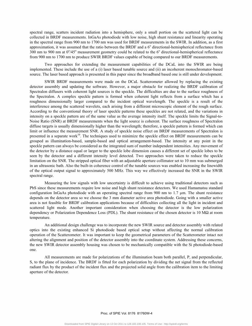
We developed the BRDF calibration capability in the SWIR using a tunable coherent light source with a 1465 nm to 1630 nm spectral range, Fig.2. The source consists of two tunable lasers. The first one is tunable from 1465 nm to 1575 nm and the second one from 1520 nm to 1630 nm. The maximum output power could be as high as 23 mW; however we applied 10 mW to 14 mW so as not to saturate the detector. The SWIR spectral range from 900 nm to 2500 nm will be covered at a later date by a broadband source under development and a tunable quasi-continuous optical parametric oscillator-based laser system.
Fig. 2: The Agilent 8163B mainframe with 81989A and 81949 tunable lasers
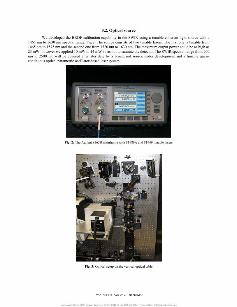
Fig. 3: Optical setup on the vertical optical table
Proc. of SPIE Vol. 8176 81760W-5
Downloaded from SPIE Digital Library on 13 Oct 2011 to 128.183.108.105. Terms of Use: http://spiedl.org/terms
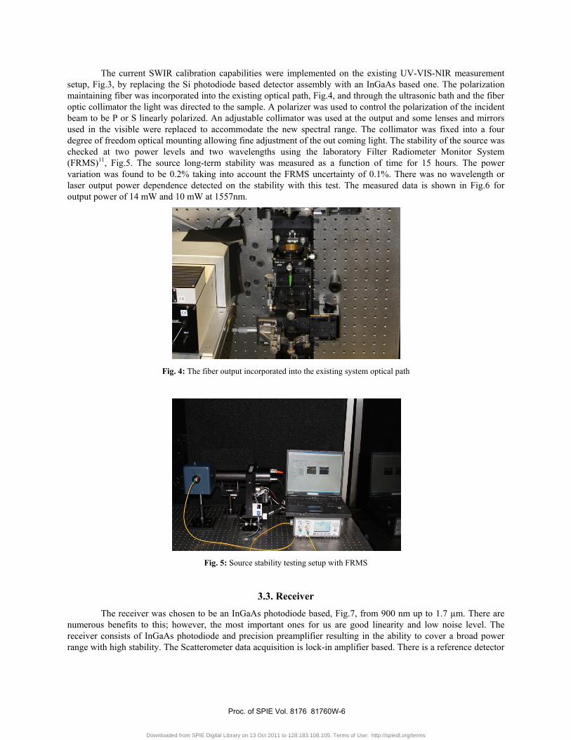
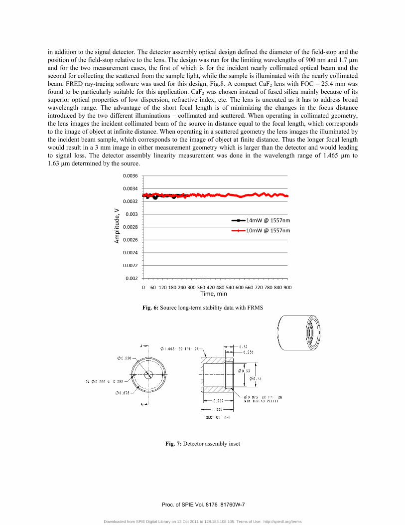
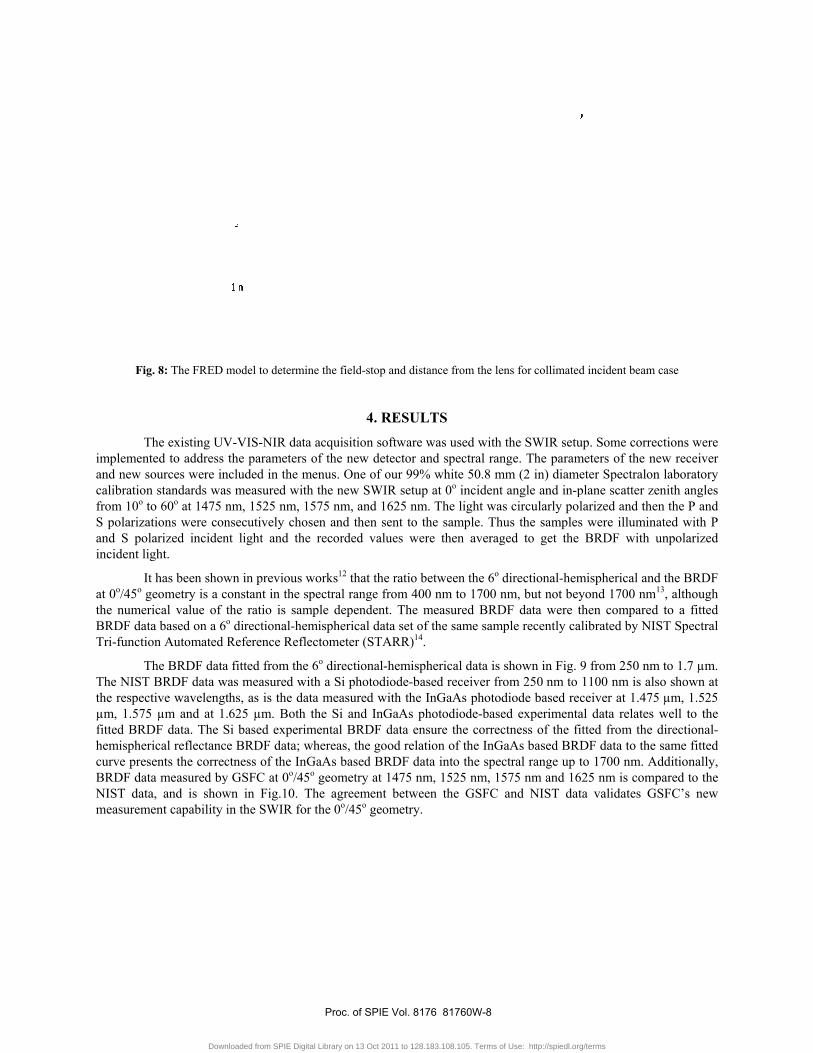
The current SWIR calibration capabilities were implemented on the existing UV-VIS-NIR measurement setup, Fig.3, by replacing the Si photodiode based detector assembly with an InGaAs based one. The polarization maintaining fiber was incorporated into the existing optical path, Fig.4, and through the ultrasonic bath and the fiber optic collimator the light was directed to the sample. A polarizer was used to control the polarization of the incident beam to be P or S linearly polarized. An adjustable collimator was used at the output and some lenses and mirrors used in the visible were replaced to accommodate the new spectral range. The collimator was fixed into a four degree of freedom optical mounting allowing fine adjustment of the out coming light. The stability of the source was checked at two power levels and two wavelengths using the laboratory Filter Radiometer Monitor System (FRMS)11, Fig.5. The source long-term stability was measured as a function of time for 15 hours. The power variation was found to be 0.2% taking into account the FRMS uncertainty of 0.1%. There was no wavelength or laser output power dependence detected on the stability with this test. The measured data is shown in Fig.6 for output power of 14 mW and 10 mW at 1557nm.
Fig. 4: The fiber output incorporated into the existing system optical path
Fig. 5: Source stability testing setup with FRMS
3.3. Receiver
The receiver was chosen to be an InGaAs photodiode based, Fig.7, from 900 nm up to 1.7 µm. There are numerous benefits to this; however, the most important ones for us are good linearity and low noise level. The receiver consists of InGaAs photodiode and precision preamplifier resulting in the ability to cover a broad power range with high stability. The Scatterometer data acquisition is lock-in amplifier based. There is a reference detector
Proc. of SPIE Vol. 8176 81760W-6
Downloaded from SPIE Digital Library on 13 Oct 2011 to 128.183.108.105. Terms of Use: http://spiedl.org/terms
in addition to the signal detector. The detector assembly optical design defined the diameter of the field-stop and the position of the field-stop relative to the lens. The design was run for the limiting wavelengths of 900 nm and 1.7 µm and for the two measurement cases, the first of which is for the incident nearly collimated optical beam and the second for collecting the scattered from the sample light, while the sample is illuminated with the nearly collimated beam. FRED ray-tracing software was used for this design, Fig.8. A compact CaF2 lens with FOC = 25.4 mm was found to be particularly suitable for this application. CaF2 was chosen instead of fused silica mainly because of its superior optical properties of low dispersion, refractive index, etc. The lens is uncoated as it has to address broad wavelength range. The advantage of the short focal length is of minimizing the changes in the focus distance introduced by the two different illuminations – collimated and scattered. When operating in collimated geometry, the lens images the incident collimated beam of the source in distance equal to the focal length, which corresponds to the image of object at infinite distance. When operating in a scattered geometry the lens images the illuminated by the incident beam sample, which corresponds to the image of object at finite distance. Thus the longer focal length would result in a 3 mm image in either measurement geometry which is larger than the detector and would leading to signal loss. The detector assembly linearity measurement was done in the wavelength range of 1.465 µm to 1.63 µm determined by the source.
Fig. 6: Source long-term stability data with FRMS
Fig. 7: Detector assembly inset
0.002
0.0022
0.0024
0.0026
0.0028
0.003
0.0032
0.0034
0.0036
0 60 120 180 240 300 360 420 480 540 600 660 720 780 840 900
Am
plitu
de, V
Time, min
14mW @ 1557nm
10mW @ 1557nm
Proc. of SPIE Vol. 8176 81760W-7
Downloaded from SPIE Digital Library on 13 Oct 2011 to 128.183.108.105. Terms of Use: http://spiedl.org/terms
Fig
Thimplementand new socalibrationfrom 10o toS polarizatand S polaincident lig
It at 0o/45o gthe numeriBRDF dataTri-functio
ThThe NIST the respectµm, 1.575 fitted BRDhemisphericurve preseBRDF dataNIST datameasureme
. 8: The FRED m
he existing UVted to address ources were in
n standards waso 60o at 1475 ntions were conarized incidenght.
has been showeometry is a coical value of ta based on a 6o
on Automated R
he BRDF data BRDF data wa
tive wavelengt µm and at 1.
DF data. The Sical reflectanceents the correca measured bya, and is showent capability i
model to determ
V-VIS-NIR datthe parameters
ncluded in the ms measured witnm, 1525 nm, nsecutively chont light and th
wn in previous onstant in the sthe ratio is samo directional-heReference Refl
fitted from theas measured wths, as is the da625 µm. Both
Si based experie BRDF data; wctness of the In GSFC at 0o/45
wn in Fig.10. in the SWIR fo
mine the field-stop
4.
ta acquisition ss of the new demenus. One ofth the new SW1575 nm, and osen and then he recorded va
works12 that thspectral range mple dependenemispherical daflectometer (ST
e 6o directionalwith a Si photodata measured w
h the Si and Inimental BRDFwhereas, the g
nGaAs based B5o geometry atThe agreemen
or the 0o/45o ge
p and distance fr
RESULTS
software was uetector and spe
f our 99% whitWIR setup at 0o
1625 nm. The sent to the sam
alues were the
he ratio betweefrom 400 nm t
nt. The measuata set of the s
TARR)14.
l-hemisphericadiode-based rewith the InGaAnGaAs photodiF data ensure thgood relation ofBRDF data intot 1475 nm, 152nt between theeometry.
from the lens for
used with the SWectral range. Tte 50.8 mm (2 incident anglelight was circu
mple. Thus theen averaged to
en the 6o directto 1700 nm, bu
ured BRDF datame sample re
al data is showneceiver from 25As photodiode iode-based exphe correctnessf the InGaAs bo the spectral r25 nm, 1575 nme GSFC and N
collimated incid
WIR setup. SoThe parameters
in) diameter Se and in-plane ularly polarizee samples wereo get the BRD
tional-hemisphut not beyond ta were then c
ecently calibrat
n in Fig. 9 from50 nm to 1100 based receiver
perimental dat of the fitted f
based BRDF darange up to 170m and 1625 nmNIST data val
dent beam case
ome corrections of the new reSpectralon labo
scatter zenith d and then thee illuminated w
DF with unpol
erical and the B1700 nm13, altcompared to ated by NIST Sp
m 250 nm to 1.nm is also sho
r at 1.475 µm, ta relates well from the directata to the same00 nm. Additiom is compared lidates GSFC’
s were eceiver oratory angles P and with P larized
BRDF though a fitted pectral
.7 µm. own at 1.525 to the tional-e fitted onally, to the s new
Proc. of SPIE Vol. 8176 81760W-8
Downloaded from SPIE Digital Library on 13 Oct 2011 to 128.183.108.105. Terms of Use: http://spiedl.org/terms
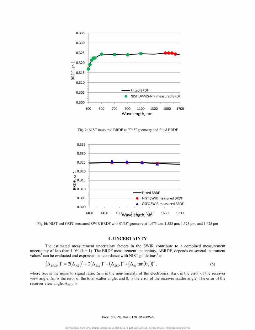
Fig. 9: NIST measured BRDF at 0o/45o geometry and fitted BRDF
Fig.10: NIST and GSFC measured SWIR BRDF with 0o/45o geometry at 1.475 µm, 1.525 µm, 1.575 µm, and 1.625 µm
4. UNCERTAINTY The estimated measurement uncertainty factors in the SWIR contribute to a combined measurement uncertainty of less than 1.0% (k = 1). The BRDF measurement uncertainty, ΔBRDF, depends on several instrument values4 can be evaluated and expressed in accordance with NIST guidelines3 as
( ) ( ) ( ) ( ) ( )( )22222 tan22 ssSLDLINNSBRDF θΔ+Δ+Δ+Δ=Δ θ , (5)
where ΔNS is the noise to signal ratio, ΔLIN is the non-linearity of the electronics, ΔSLD is the error of the receiver view angle, Δθs is the error of the total scatter angle, and θs is the error of the receiver scatter angle. The error of the receiver view angle, ΔSLD, is
0.300
0.305
0.310
0.315
0.320
0.325
0.330
0.335
300 500 700 900 1100 1300 1500 1700
BRD
F, s
r-1
Wavelength, nm
Fitted BRDF
NIST UV-VIS-NIR measured BRDF
0.300
0.305
0.310
0.315
0.320
0.325
0.330
0.335
1400 1450 1500 1550 1600 1650 1700
BRD
F, s
r-1
Wavelength, nm
Fitted BRDF
NIST SWIR measured BRDF
GSFC SWIR measured BRDF
Proc. of SPIE Vol. 8176 81760W-9
Downloaded from SPIE Digital Library on 13 Oct 2011 to 128.183.108.105. Terms of Use: http://spiedl.org/terms
( ) ( ) ( ) ( )2222 222 RARZRMSLD Δ+Δ+Δ=Δ , (6)
where ΔRM is the error in the goniometer receiver arm radius, ΔRZ is the error of the receiver arm radius due to sample Z direction misalignment, and ΔRA is the error of the receiver aperture radius. The total scatter angle error, Δθs, is
( ) ( ) ( ) ( )2222TZMs θθθθ Δ+Δ+Δ=Δ , (7)
where ΔθM is the error of the goniometer scatter angle, ΔθZ is the error due to sample Z direction misalignment, and ΔθT is the sample tilt error.
5. CONCLUSIONS
The implementation of SWIR BRDF calibration capabilities at the Diffuser Calibration Lab of NASA’s Goddard Space Flight Center is presented. The Scatterometer was upgraded with a new receiver based on InGaAs photodiode in the spectral range from 900 nm up to 1.7 µm. Tunable laser sources were purchased to cover the 1465 nm to 1630 nm spectral range. The sources long-term stability was verified. The available on the market photodiodes were analyzed and the 3 mm diameter active area InGaAs photodiode was found to be most appropriate for this application. Optical design was performed to determine the size of the field-stop and the distance from the lens for two limiting wavelengths and two illumination cases for each of it. The lens was also chosen based on measurement considerations and verified through the optical design. The receiver assembly linearity was tested. Both the coherent sources and the receiver assembly were incorporated into the existing Scatterometer optical, mechanical and electronic setup. The Scatterometer software was updated with the parameters of the new sources and receiver. White 2 inch diameter Spectralon (99% reflectance) was measured at normal incidence and from 10o to 60o scatter azimuth angles at 1475 nm, 1525 nm, 1575 nm and 1625 nm. The results at 0o/45o geometry are compared to fitted BRDF based on NIST 6o directional-hemispherical measurements. Excellent agreement is shown.
The development efforts reported here are related to the laser based BRDF calibration capabilities although a breadboard for in-plane monochromator-based measurement system is also under development. As a next step expanding the measurement capabilities up to 2.5 µm is expected.
ACKNOWLEDGEMENTS
The authors wish to acknowledge the support of Spencer Disque for his help with the mechanical design, Dennis Skelton for the optical design both of Sigma Space Corp., and Jon Ranson of NASA Goddard Space Flight Center for his encouragement and fruitfully discussions, also John Cooper of Sigma Space Corp. for his consistent laboratory help on measurement setups and discussions. At last but not at least the invaluable help provided by Chris Staats of Schmidt Measurement Systems, Inc., Portland, OR.
REFERENCES
1 J.J. Butler, B.C. Johnson, R.A. Barnes, “The calibration and characterization of Earth remote sensing and environmental monitoring instruments”, in Optical Radiometry, Ed. A.C. Parr, R.U. Datla, J.L. Gardner, Academic Press, New York (2005), 2 G.T. Georgiev, J.J. Butler, “Laboratory-based Bidirectional reflectance distribution functions of radiometric tarps”, Applied Optics, 47, 18, 3313-3323 (2008) 3 Taylor B.N., Kuyatt C. E., "A guidelines for evaluating and expressing the uncertainty of NIST measurement results", NIST Technical Note 1297, U.S. Department of Commerce, National Institute of Standards and Technology, Sep. 1997,
Proc. of SPIE Vol. 8176 81760W-10
Downloaded from SPIE Digital Library on 13 Oct 2011 to 128.183.108.105. Terms of Use: http://spiedl.org/terms
4 Schiff T.F., Knighton M.W., Wilson D.J., Cady F.M., Stover J.C., Butler J.J., "A design review of a high accuracy UV to near infrared Scatterometer", Proc. SPIE, 1993, 1995, 121-130, 5 Early E.A., Barnes P.Y., Johnson B.C., Butler J.J., Bruegge C.J., Biggar S.F., Spyak P.S., Pavlov M.M., “Bidirectional reflectance round-robin in support of the Earth observing system program”, J. Atmospheric and Oceanic Technology, 2000, 17, 1077-1091, 6 Georgiev G.T., Butler J.J., “Bidirectional reflectance distribution function and directional-hemispherical reflectance of a Martian regolith simulant”, Optical Engineering, 2005, 44, 036202-1-11. 7 Nicodemus F.E., Richmond J.C., Hsia J.J., Ginsburg I.W., Limperis T., "Geometrical considerations and nomenclature for reflectance", National Bureau of Standards, NBS monograph 160, Oct. 1977, 8 Stover J.C., "Optical scattering: measurement and analysis", SPIE Press, Bellingham, Washington, 1995, 9 H.C. van de Hulst, Multiple light scattering, Tables, Formulas, and Applications, vol. 1, San Diego: Academic Press, 1980. 10 Georgiev G.T., Butler J.J., “The effect of speckle on BRDF measurements”, Proc. SPIE, Vol. 5882, 588203-1-12, 2005. 11 Ding L., Kowalewski M.G., Cooper J.W., Smith G.R., Butler J.J., Development of a Filter Radiometer Monitor System for integrating sphere sources, Proceedings of SPIE, Vol. 7452, 745206-1-11, 2009. 12 M. E. Nadal and P. Y. Barnes, “Near infrared 45°/0° reflectance factor of pressed polytetrafluoroethylene (PTFE) powder”, J. Res. Natl. Inst. Stand. Technol. 104, 185-188, 1999. 13 H.W. Yoon, D.W. Allen, G.P. Eppeldauer, B.K. Tsai, “The Extension of the NIST BRDF Scale from 1100 nm to 2500 nm”, Proc. SPIE, Vol. 7452, 745204-1-12 14 J. R. Proctor and P. Y. Barnes, ‘‘NIST high accuracy reference reflectometer–spectrophotometer,’’ J. Res. Natl. Inst. Stand. Technol. 101, 619–627, 1996.
Proc. of SPIE Vol. 8176 81760W-11
Downloaded from SPIE Digital Library on 13 Oct 2011 to 128.183.108.105. Terms of Use: http://spiedl.org/terms