Embed Size (px)
Citation preview
Reflectance Characteristics of Accuflect™ Light Reflecting Ceramic
Copyright July 2010 Accuratus Corporation 35 Howard Street Phillipsburg, NJ 08865 USA +1.908.213.7070 http://accuratus.com
Copyright 2010 Accuratus Corporation Page 2
SUMMARY
Accuflect is a ceramic material developed for efficient visible and near infrared light reflection.
Two grades are offered with slightly different reflection characteristics. Accuflect B6 has a native
ceramic surface with nearly perfect diffuse reflection characteristics. Accuflect G6 has a glazed surface
for protection in wet environments and easy cleaning. Typical of ceramics, the material is refractory and
corrosion resistant, tolerant of extreme application environments.
INTRODUCTION
Accuflect light reflecting ceramic is used in demanding diffuse light applications including high
temperature infrared process heating, optically pumped laser reflectors and light sources for aesthetic
medicine procedures.
Accuflect is a ceramic material with low optical losses in the visible to near infrared light
spectrum. Light interacting with the ceramic microstructure results in a high quality diffuse reflector.
Significant scattering and minimal penetration of the light into the ceramic body produces an efficient and
nearly lambertian reflecting ceramic.
ACCUFLECT MATERIALS
Accuflect material is manufactured using very carefully controlled processing parameters. The
result of the carefully controlled processing is a ceramic body composed of ceramic grains on the order of
10 to 15 microns diameter and 15% porosity. Table 1 lists the typical physical properties of Accuflect.
ACCUFLECT MATERIAL PROPERTIES
Density g/cc 2.3
Porosity % 15
Flexural Strength MPa 27.5
Compressive Strength MPa 62
Maximum Use Temperature °C 1200
Thermal Conductivity W/m°K 5.8
Thermal Expansion Coefficient 10-6
/°C 7.7
Dielectric Strength kV/mm 3
Dielectric Constant - 5.5
Loss Tangent - .003 Table 1
Copyright 2010 Accuratus Corporation Page 3
Two grades of Accuflect are available. Accuflect B6 is the native ceramic material. It has a
nearly perfect diffuse reflectance. It is ideal for use where high temperatures are encountered and the
surface is not subject to contamination or liquid ingress.
Accuflect G6 is the same ceramic material as Accuflect B6 but it has an applied glaze layer 150
to 200 microns thick. The glaze provides an easy to clean, protective layer. There is a specular
component in addition to the diffuse reflection and a slight decrease in reflectance especially at shorter
wavelengths. The maximum use temperature is limited to 700° C due to the lower melting point of the
glaze layer.
ACCUFLECT REFLECTED LIGHT CHARACTERISTICS
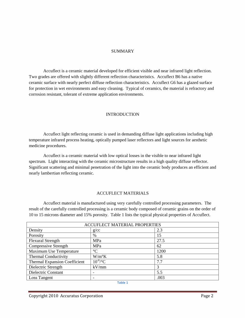
Accuflect is a ceramic comprised of mixed oxides selected for their low absorption over visible
and NIR wavelengths. The high refractive index of the ceramic grains limits light penetration into the
ceramic body and maximizes lambertian behavior with enhanced scattering, reflection and refraction
between the ceramic grains and their surroundings. Figure 5 is a series of data plots of % Total
Reflectance versus Accuflect thickness. The high efficiency of the Accuflect backscatter is evidenced by
the indiscernable differences in % total reflectance at 3 mm and 10 mm thicknesses.
Figure 1
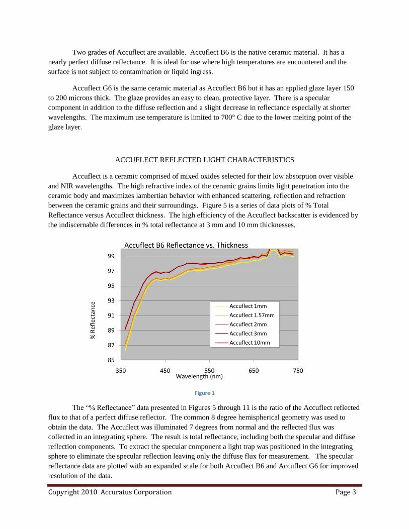
The “% Reflectance” data presented in Figures 5 through 11 is the ratio of the Accuflect reflected
flux to that of a perfect diffuse reflector. The common 8 degree hemispherical geometry was used to
obtain the data. The Accuflect was illuminated 7 degrees from normal and the reflected flux was
collected in an integrating sphere. The result is total reflectance, including both the specular and diffuse
reflection components. To extract the specular component a light trap was positioned in the integrating
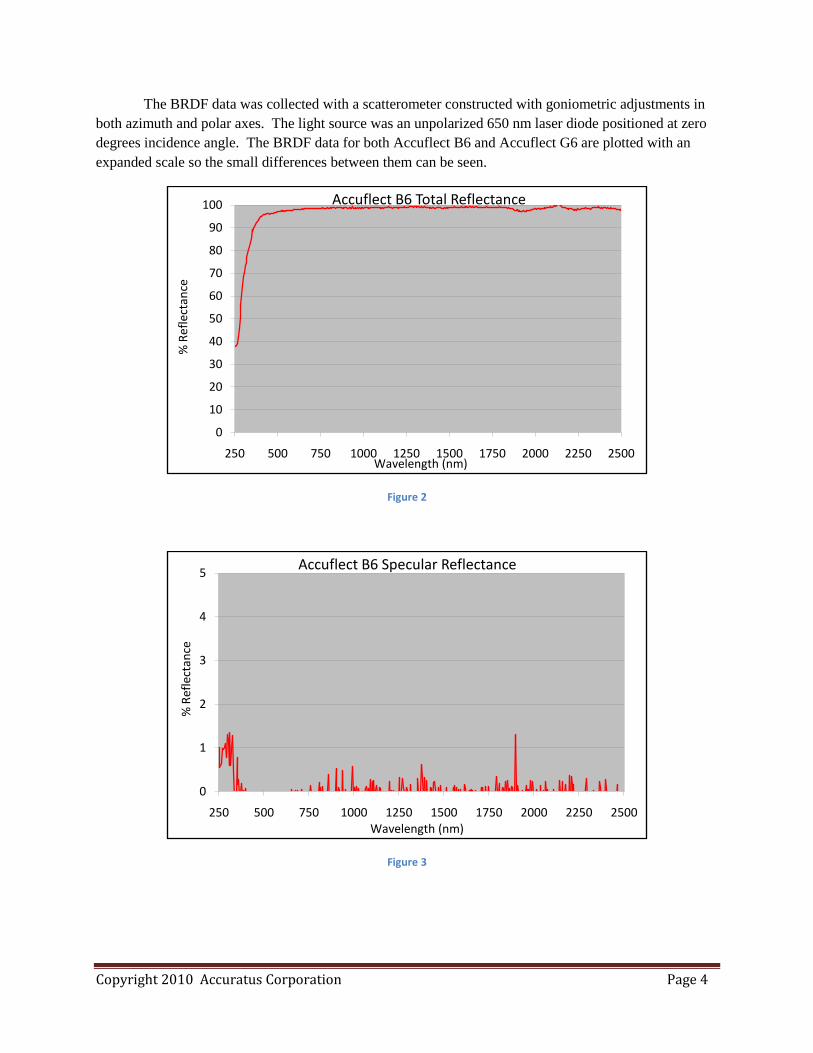
sphere to eliminate the specular reflection leaving only the diffuse flux for measurement. The specular
reflectance data are plotted with an expanded scale for both Accuflect B6 and Accuflect G6 for improved
resolution of the data.
85
87
89
91
93
95
97
99
350 450 550 650 750
% R
efle
ctan
ce
Wavelength (nm)
Accuflect B6 Reflectance vs. Thickness
Accuflect 1mm
Accuflect 1.57mm
Accuflect 2mm
Accuflect 3mm
Accuflect 10mm
Copyright 2010 Accuratus Corporation Page 4
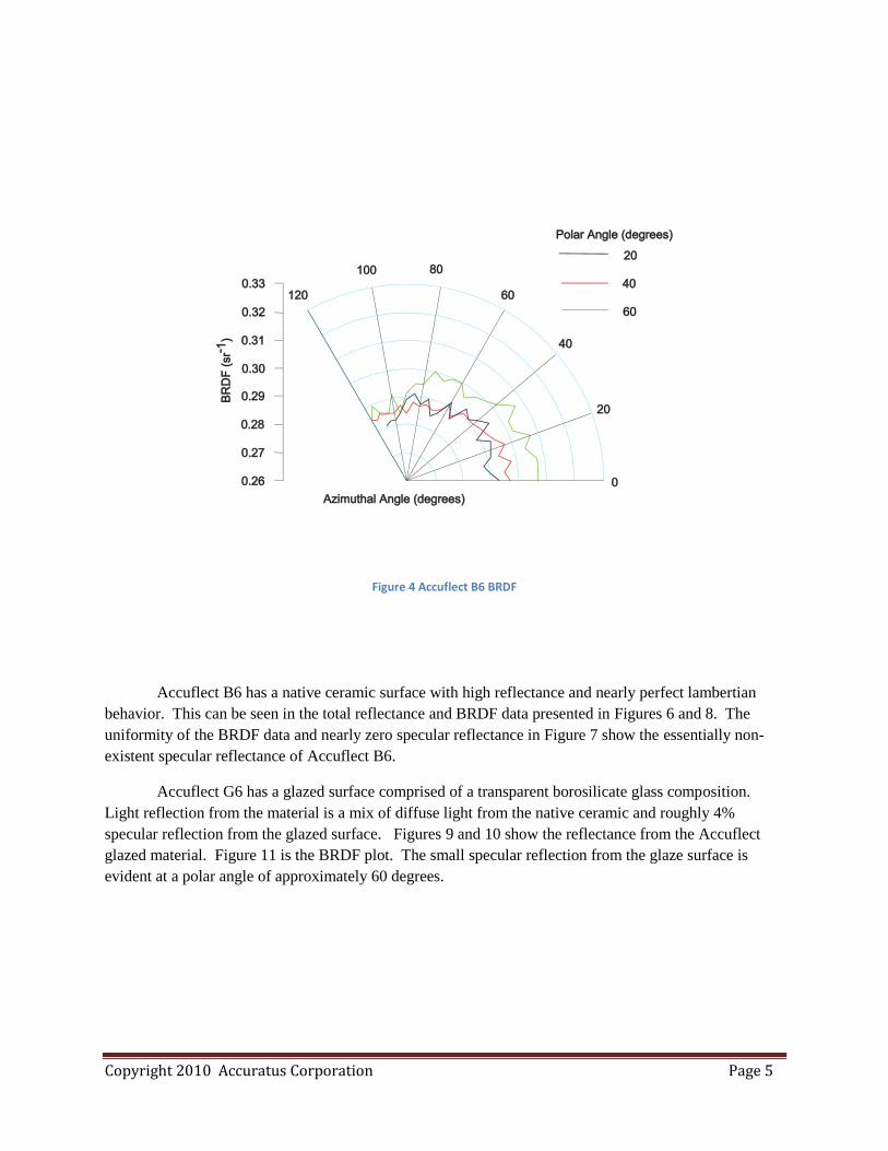
The BRDF data was collected with a scatterometer constructed with goniometric adjustments in
both azimuth and polar axes. The light source was an unpolarized 650 nm laser diode positioned at zero
degrees incidence angle. The BRDF data for both Accuflect B6 and Accuflect G6 are plotted with an
expanded scale so the small differences between them can be seen.
Figure 2
Figure 3
0
10
20
30
40
50
60
70
80
90
100
250 500 750 1000 1250 1500 1750 2000 2250 2500
% R
efle
ctan
ce
Wavelength (nm)
Accuflect B6 Total Reflectance
0
1
2
3
4
5
250 500 750 1000 1250 1500 1750 2000 2250 2500
% R
efle
ctan
ce
Wavelength (nm)
Accuflect B6 Specular Reflectance
Copyright 2010 Accuratus Corporation Page 5
Figure 4 Accuflect B6 BRDF
Accuflect B6 has a native ceramic surface with high reflectance and nearly perfect lambertian
behavior. This can be seen in the total reflectance and BRDF data presented in Figures 6 and 8. The
uniformity of the BRDF data and nearly zero specular reflectance in Figure 7 show the essentially non-
existent specular reflectance of Accuflect B6.
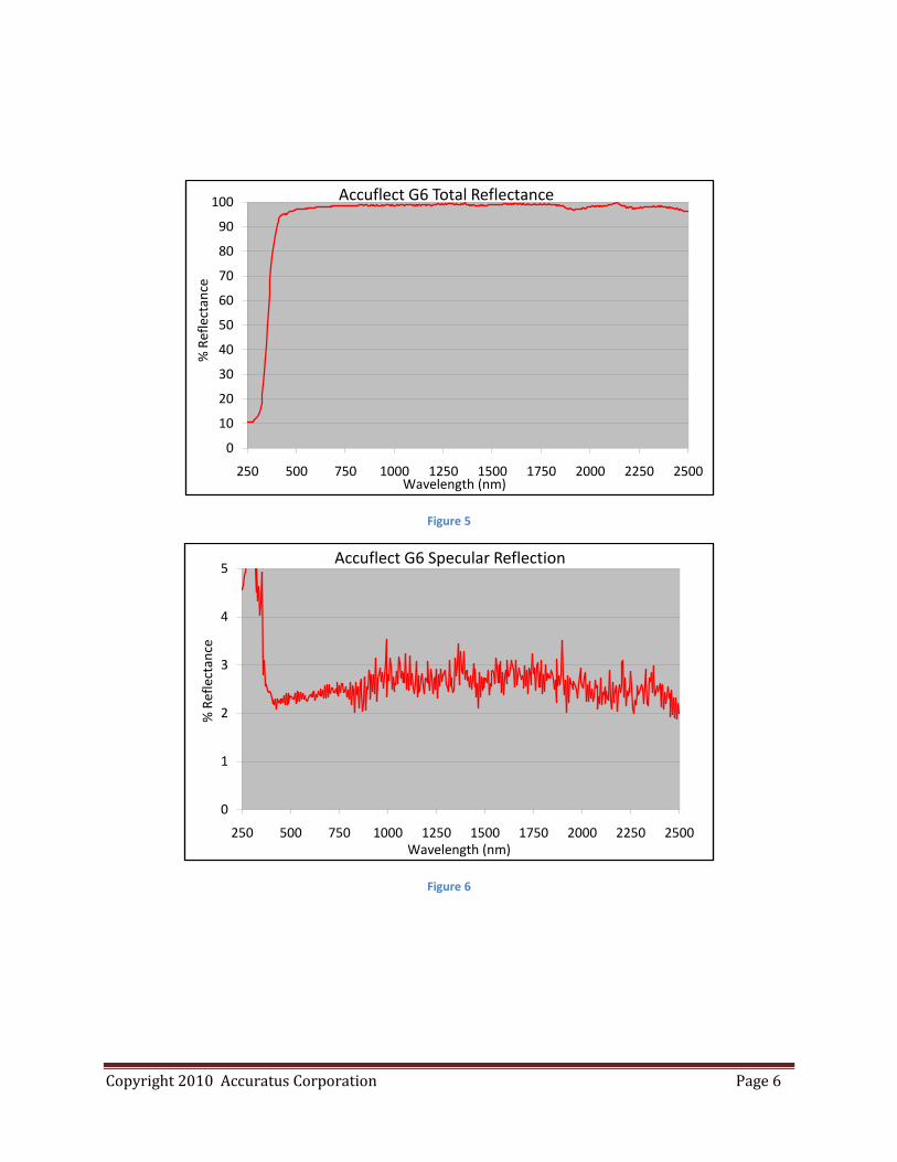
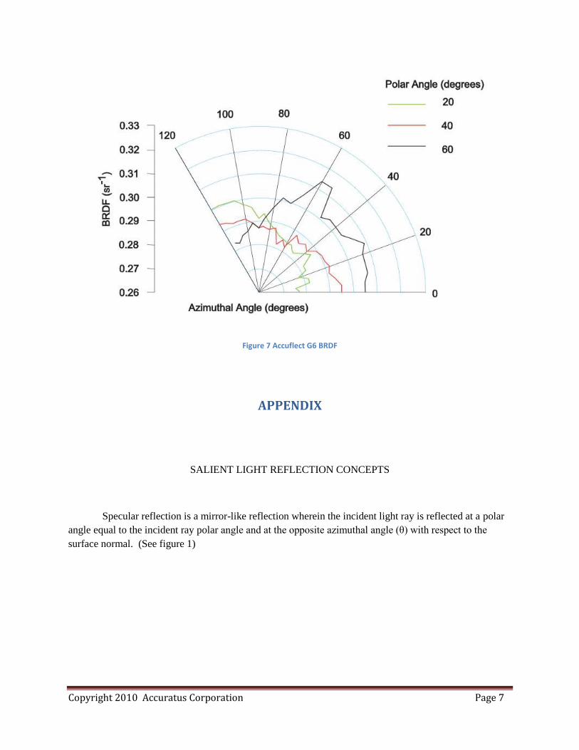
Accuflect G6 has a glazed surface comprised of a transparent borosilicate glass composition.
Light reflection from the material is a mix of diffuse light from the native ceramic and roughly 4%
specular reflection from the glazed surface. Figures 9 and 10 show the reflectance from the Accuflect
glazed material. Figure 11 is the BRDF plot. The small specular reflection from the glaze surface is
evident at a polar angle of approximately 60 degrees.
Copyright 2010 Accuratus Corporation Page 6
Figure 5
Figure 6
0
10
20
30
40
50
60
70
80
90
100
250 500 750 1000 1250 1500 1750 2000 2250 2500
% R
efle
ctan
ce
Wavelength (nm)
Accuflect G6 Total Reflectance
0
1
2
3
4
5
250 500 750 1000 1250 1500 1750 2000 2250 2500
% R
efle
ctan
ce
Wavelength (nm)
Accuflect G6 Specular Reflection
Copyright 2010 Accuratus Corporation Page 7
Figure 7 Accuflect G6 BRDF
APPENDIX
SALIENT LIGHT REFLECTION CONCEPTS
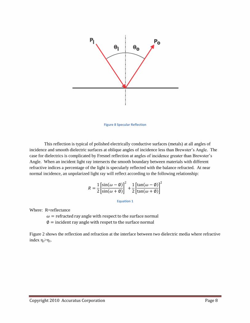
Specular reflection is a mirror-like reflection wherein the incident light ray is reflected at a polar
angle equal to the incident ray polar angle and at the opposite azimuthal angle (θ) with respect to the
surface normal. (See figure 1)
Copyright 2010 Accuratus Corporation Page 8
Figure 8 Specular Reflection
This reflection is typical of polished electrically conductive surfaces (metals) at all angles of
incidence and smooth dielectric surfaces at oblique angles of incidence less than Brewster’s Angle. The
case for dielectrics is complicated by Fresnel reflection at angles of incidence greater than Brewster’s
Angle. When an incident light ray intersects the smooth boundary between materials with different
refractive indices a percentage of the light is specularly reflected with the balance refracted. At near
normal incidence, an unpolarized light ray will reflect according to the following relationship:
𝑅 =1
2 sin 𝜔 − ∅
sin 𝜔 + ∅
2
+1
2 tan 𝜔 − ∅
tan 𝜔 + ∅
2
Equation 1
Where: R=reflectance
𝜔 = refracted ray angle with respect to the surface normal
∅ = incident ray angle with respet to the surface normal
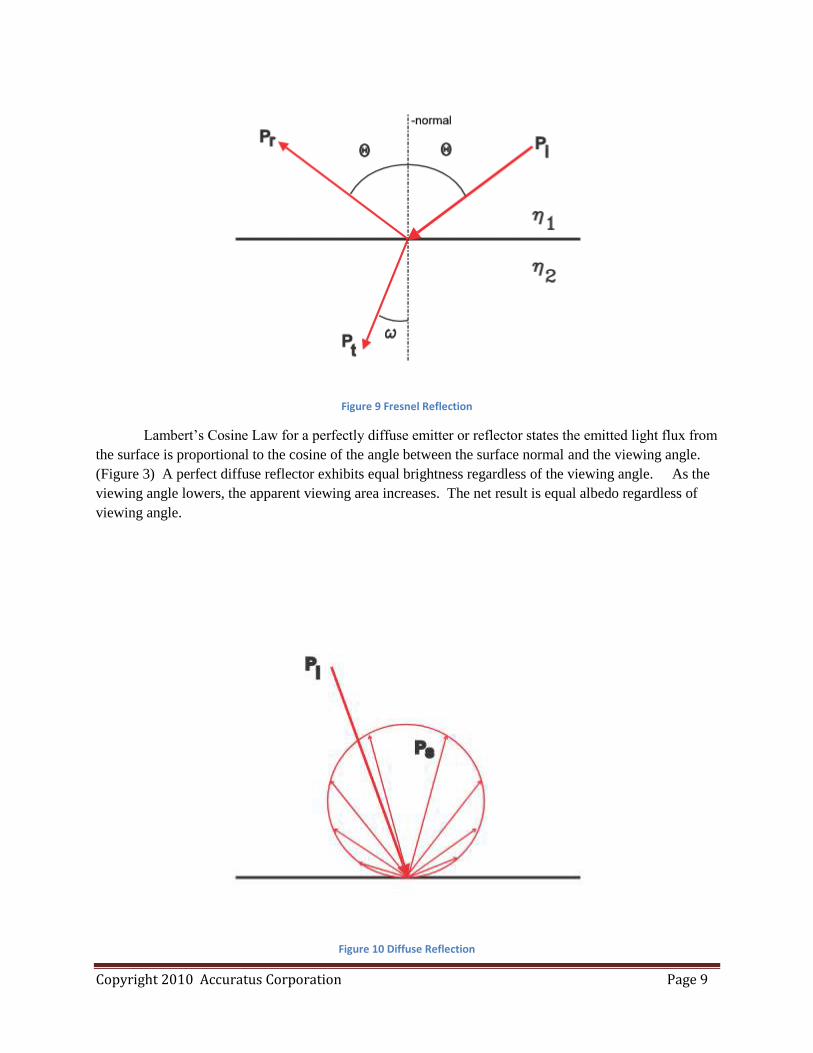
Figure 2 shows the reflection and refraction at the interface between two dielectric media where refractive
index η2>η1.
Copyright 2010 Accuratus Corporation Page 9
Figure 9 Fresnel Reflection
Lambert’s Cosine Law for a perfectly diffuse emitter or reflector states the emitted light flux from
the surface is proportional to the cosine of the angle between the surface normal and the viewing angle.
(Figure 3) A perfect diffuse reflector exhibits equal brightness regardless of the viewing angle. As the
viewing angle lowers, the apparent viewing area increases. The net result is equal albedo regardless of
viewing angle.
Figure 10 Diffuse Reflection
Copyright 2010 Accuratus Corporation Page 10
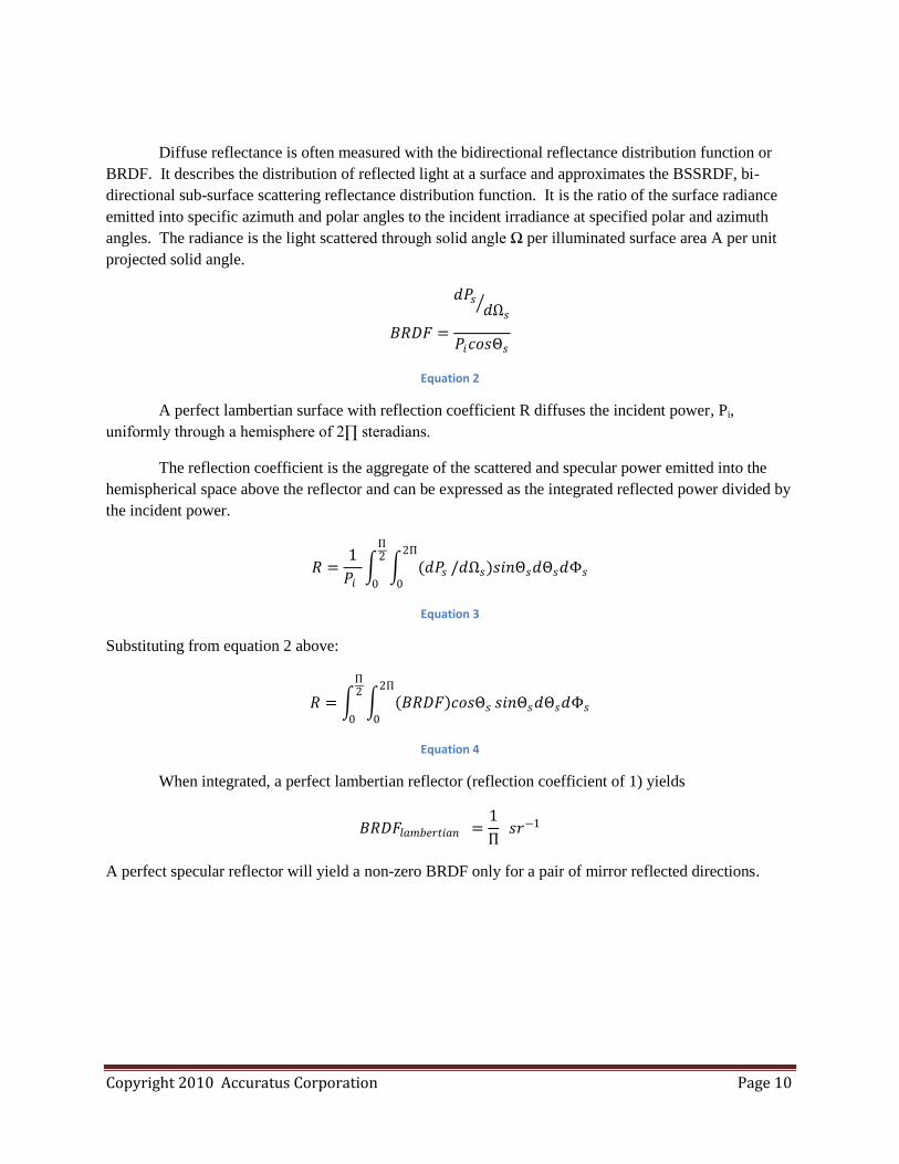
Diffuse reflectance is often measured with the bidirectional reflectance distribution function or
BRDF. It describes the distribution of reflected light at a surface and approximates the BSSRDF, bi-
directional sub-surface scattering reflectance distribution function. It is the ratio of the surface radiance
emitted into specific azimuth and polar angles to the incident irradiance at specified polar and azimuth
angles. The radiance is the light scattered through solid angle Ω per illuminated surface area A per unit
projected solid angle.
𝐵𝑅𝐷𝐹 =
𝑑𝑃𝑠𝑑Ω𝑠
𝑃𝑖𝑐𝑜𝑠Θ𝑠
Equation 2
A perfect lambertian surface with reflection coefficient R diffuses the incident power, Pi,
uniformly through a hemisphere of 2∏ steradians.
The reflection coefficient is the aggregate of the scattered and specular power emitted into the
hemispherical space above the reflector and can be expressed as the integrated reflected power divided by
the incident power.
𝑅 =1
𝑃𝑖 (𝑑𝑃𝑠
2Π
0
Π2
0
/𝑑Ω𝑠)𝑠𝑖𝑛Θ𝑠𝑑Θ𝑠𝑑Φ𝑠
Equation 3
Substituting from equation 2 above:
𝑅 = 𝐵𝑅𝐷𝐹 𝑐𝑜𝑠Θ𝑠
2Π
0
Π2
0
𝑠𝑖𝑛Θ𝑠𝑑Θ𝑠𝑑Φ𝑠
Equation 4
When integrated, a perfect lambertian reflector (reflection coefficient of 1) yields
𝐵𝑅𝐷𝐹𝑙𝑎𝑚𝑏𝑒𝑟𝑡𝑖𝑎𝑛 =1
Π 𝑠𝑟−1
A perfect specular reflector will yield a non-zero BRDF only for a pair of mirror reflected directions.
Copyright 2010 Accuratus Corporation Page 11
Figure 11 BRDF
BIBLIOGRAPHY
A GUIDE TO REFLECTANCE COATINGS AND MATERIALS. Labsphere.
Fejer, M.M., A. Alexandrovski and R.K. Route. “Absorption Studies in Sapphire.” LIGO-G010152-00-
Z. E.L. Ginzton Laboratory. Stanford University.
Zhang, Hao and Kenneth Voss. “Bidirectional Reflectance of Dry and Submerged Spectralon Plaque”.
Optical Society of America. 2006.
Nayar, Shree K., Katsushi Ikeuchi and Takeo Kanade. “Surface Reflection: Physical and Geometrical
Perspectives”. CMU-RI-TR-89-7. Carnegie Mellon University. 1989.
Cohen, Michael R. and Louis J. Small III. “Tech Note 3: Diffuse Reflectance Measurement of Standard
Diffusers”. www.4physics.com/tn3/lambertian.htm. 2005.
Stover, John C. “Optical Scattering Measurement and Analysis”. 2nd
ed. SPIE. 1995.