Embed Size (px)
Citation preview
Service Guide SW-5.1 3005
Version : 1.0 Page 1 of 17
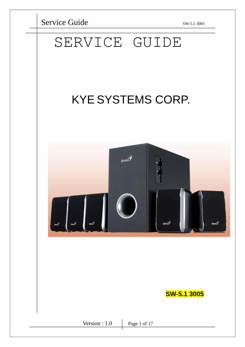
SERVICE GUIDE
KYE SYSTEMS CORP.
SW-5.1 3005
Service Guide SW-5.1 3005
Version : 1.0 Page 2 of 17
Revision History
Version Date Change
1.0 1/19/2009
Service Guide SW-5.1 3005
Version : 1.0 Page 3 of 17
Table of Contents Revision History …………………………………………………………………….2
Table of Contents ……………………………………………………………………3
Getting Started ………………………………………………………………………4
Conventions Used in this Guide ……………………………………….4
Safety Precautions ……………………………………………………..4
Chapter 1. How to Handle Defective Returns……………………………………..5
1.1 Overview …………………………………………………………..5
1.2 Problems …………………………………………………………...6
1.2.1 One or more channels no sound ………………..…7
1.2.2 Power LED (indicator) no light………………....…8
1.2.3 Volume , Bass no function...……..……….………..8
Chapter 2. Specifications ………………………………………….………………9
Chapter 3. Block Diagram …………………………………………….………….10
Chapter 4. Exploded View ………………………………………….………….11~12
Chapter 5. Part List …………………………………………….………………13~14
Chapter 6. Schematic Diagram ………….……………………...………….…..15~16
Chapter 7. Important Notes ……………………………………………….………17
7.1 Packing Requirement for Sending the PCB Assembly by Post. …..17
7.2 Short of Spare Parts while Repairing a Speaker System ………..…17
Service Guide SW-5.1 3005
Version : 1.0 Page 4 of 17
Getting Started Conventions Used in this Guide
Pay Special Attention : Instructions that are important to remember and
may prevent mistakes .
Caution : Information that, if not followed, may result in damage to the
product .
Safety Precautions
The following precautions should be observed in handling the speaker
Described in this guide :
Place the speakers on a flat, level and stable surface.
Do not place the speakers in environments subject to mist, smoke,
vibration, excessive dust, salty or greasy air, or other corrosive gases
and fumes.
Do not drop or jolt the speakers.
Do not allow anything to drop into the subwoofer case through its
ventilator, as it could result in fatal electric shock or fire .
Place the unit far enough from other equipments for good heat
dissipation .
Disconnect the AC power cord from the AC outlet before performing
any maintenance on the speakers .
Do not perform any maintenance with wet hand .
Prevent foreign substances, such as water, other liquids or chemicals ,
From entering the speakers while performing maintenance procedures
on the speakers .
Service Guide SW-5.1 3005
Version : 1.0 Page 5 of 17
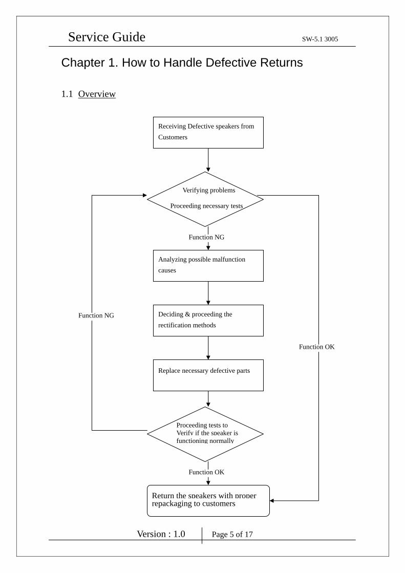
Chapter 1. How to Handle Defective Returns
1.1 Overview
Verifying problems
Proceeding necessary tests
Receiving Defective speakers from Customers
Analyzing possible malfunction causes
Deciding & proceeding the rectification methods
Replace necessary defective parts
Proceeding tests to Verify if the speaker is functioning normally
Return the speakers with properrepackaging to customers
Function NG
Function OK
Function OK
Function NG
Service Guide SW-5.1 3005
Version : 1.0 Page 6 of 17
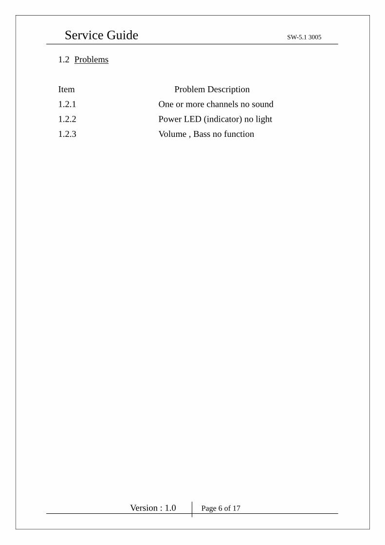
1.2 Problems
Item Problem Description
1.2.1 One or more channels no sound
1.2.2 Power LED (indicator) no light
1.2.3 Volume , Bass no function

Service Guide SW-5.1 3005
Version : 1.0 Page 7 of 17
Attention
1.2.1 One or more channels no sound
Problem
Solutions
Please follow the numbered sequence marked within parenthesis given in individual
Flow chat, in that this is the best-recommended sequence to rectify the problems.
One or more channels no sound
Broken or short circuit Defective IC1, IC2, IC3, IC4, IC6, VR2 , VR6 ,
PCBA connect cable
Speaker cable dis-connect or speaker damaged
Check solder points on PCB
Check and Replace defective IC
Re-connect speaker cable or replace
defective speaker(s)
Analyzer and
Identify the Causes
Service Guide SW-5.1 3005
Version : 1.0 Page 8 of 17
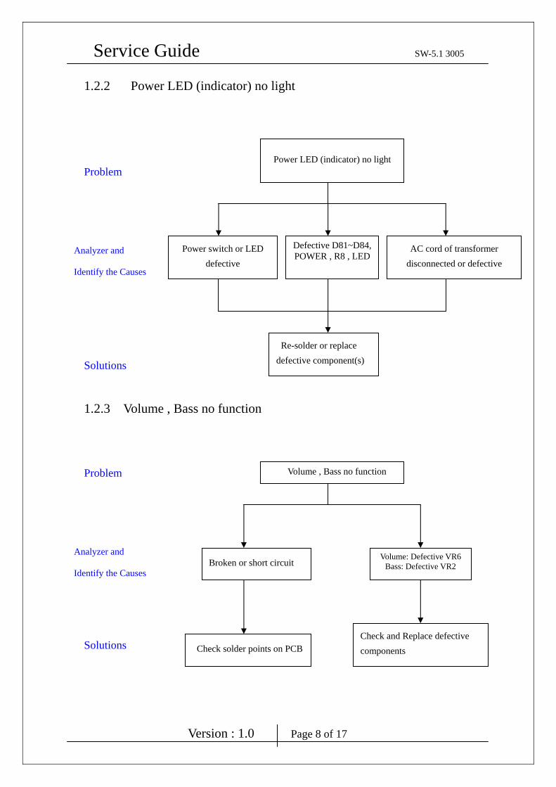
1.2.2 Power LED (indicator) no light
Problem
Solutions
1.2.3 Volume , Bass no function
Problem
Solutions
Power LED (indicator) no light
Power switch or LED defective
Defective D81~D84,POWER , R8 , LED
AC cord of transformer disconnected or defective
Re-solder or replace defective component(s)
Analyzer and
Identify the Causes
Volume , Bass no function
Broken or short circuit Volume: Defective VR6
Bass: Defective VR2
Check solder points on PCB
Analyzer and
Identify the Causes
Check and Replace defective components

Service Guide SW-5.1 3005
Version : 1.0 Page 9 of 17
Chapter 2. Specifications Woofer
NO. Description Unit Specifications
1 Out Power at THD 10% W ≧ 25
2 Sensitivity mV 130 ± 30
3 Freq. Response (Top -3dB) Hz 20 ~ 166 ± 10%
4 S/N ratio dB ≧ 70
5 Hum & Noise (Vol.: max) mV ≦ 2
Center
NO. Description Unit Specifications
1 Out Power at THD 10% W ≧ 14
2 Sensitivity mV 570 ± 50
3 Freq. Response (Top -3dB) Hz 50 ~ 20K ± 10%
4 Separation dB ≧ 40
5 S/N ratio dB ≧ 70
6 Hum & Noise (Vol.: max) mV ≦ 2
Satellite
NO. Description Unit Specifications
1 Out Power at THD 10% W ≧ 9
2 Sensitivity mV FL,FR=700 ± 50
SL,SR=520 ± 50
3 Freq. Response (Top -3dB) Hz 100 ~ 20K ± 10%
4 Separation dB ≧ 40
5 S/N ratio dB ≧ 70
6 Hum & Noise (Vol.: max) mV ≦ 2
Service Guide SW-5.1 3005
Version : 1.0 Page 10 of 17
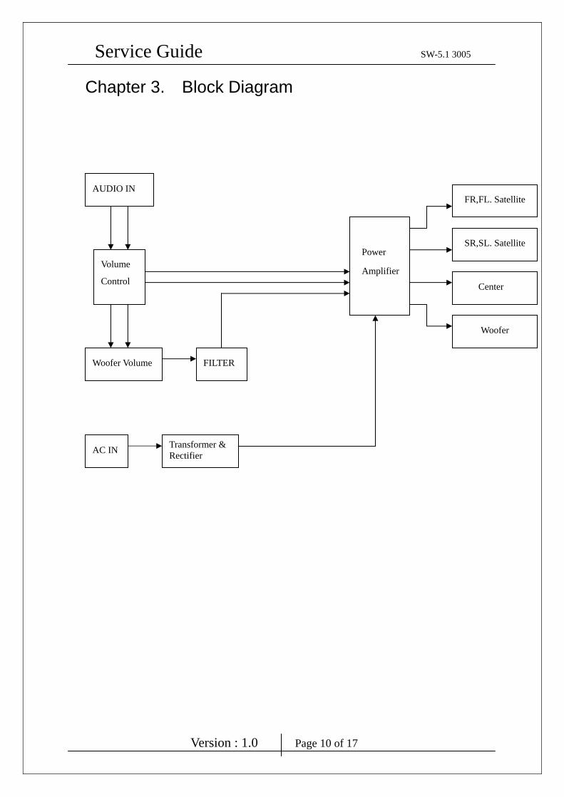
Chapter 3. Block Diagram
AUDIO IN
Volume
Control
Power
Amplifier
FR,FL. Satellite
SR,SL. Satellite
Woofer
Woofer Volume
AC IN Transformer & Rectifier
FILTER
Center
Service Guide SW-5.1 3005
Version : 1.0 Page 11 of 17
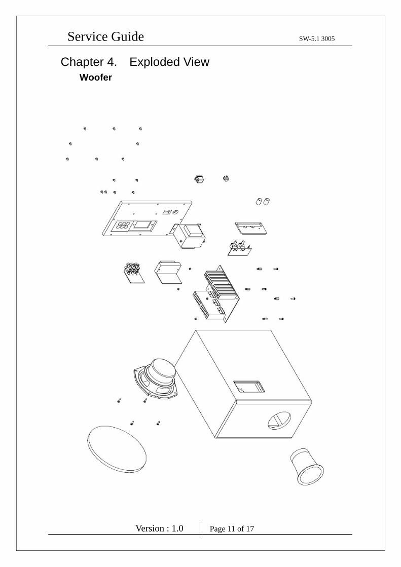
Chapter 4. Exploded View Woofer
Service Guide SW-5.1 3005
Version : 1.0 Page 12 of 17
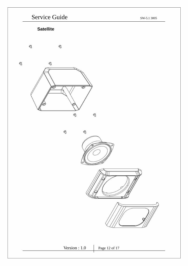
Satellite
Service Guide SW-5.1 3005
Version : 1.0 Page 13 of 17
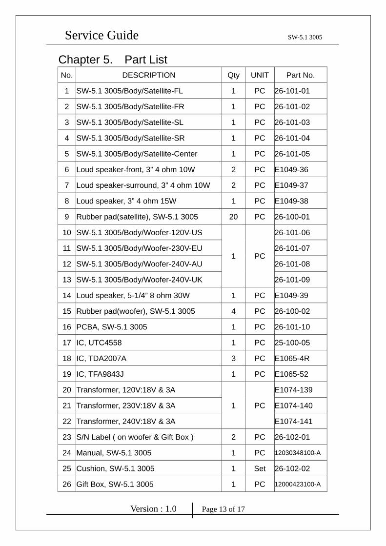
Chapter 5. Part List No. DESCRIPTION Qty UNIT Part No.
1 SW-5.1 3005/Body/Satellite-FL 1 PC 26-101-01
2 SW-5.1 3005/Body/Satellite-FR 1 PC 26-101-02
3 SW-5.1 3005/Body/Satellite-SL 1 PC 26-101-03
4 SW-5.1 3005/Body/Satellite-SR 1 PC 26-101-04
5 SW-5.1 3005/Body/Satellite-Center 1 PC 26-101-05
6 Loud speaker-front, 3” 4 ohm 10W 2 PC E1049-36
7 Loud speaker-surround, 3” 4 ohm 10W 2 PC E1049-37
8 Loud speaker, 3” 4 ohm 15W 1 PC E1049-38
9 Rubber pad(satellite), SW-5.1 3005 20 PC 26-100-01
10 SW-5.1 3005/Body/Woofer-120V-US
1 PC
26-101-06
11 SW-5.1 3005/Body/Woofer-230V-EU 26-101-07
12 SW-5.1 3005/Body/Woofer-240V-AU 26-101-08
13 SW-5.1 3005/Body/Woofer-240V-UK 26-101-09
14 Loud speaker, 5-1/4” 8 ohm 30W 1 PC E1049-39
15 Rubber pad(woofer), SW-5.1 3005 4 PC 26-100-02
16 PCBA, SW-5.1 3005 1 PC 26-101-10
17 IC, UTC4558 1 PC 25-100-05
18 IC, TDA2007A 3 PC E1065-4R
19 IC, TFA9843J 1 PC E1065-52
20 Transformer, 120V:18V & 3A
1 PC
E1074-139
21 Transformer, 230V:18V & 3A E1074-140
22 Transformer, 240V:18V & 3A E1074-141
23 S/N Label ( on woofer & Gift Box ) 2 PC 26-102-01
24 Manual, SW-5.1 3005 1 PC 12030348100-A
25 Cushion, SW-5.1 3005 1 Set 26-102-02
26 Gift Box, SW-5.1 3005 1 PC 12000423100-A
Service Guide SW-5.1 3005
Version : 1.0 Page 14 of 17
27 Carton, SW-5.1 3005 0.5 PC 12100298100-A
Chapter 6. Schematic Diagram
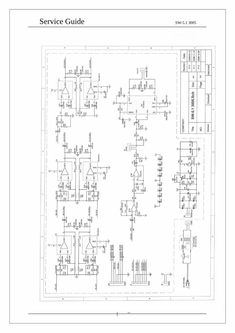
Service Guide SW-5.1 3005
Version : 1.0 Page 15 of 17
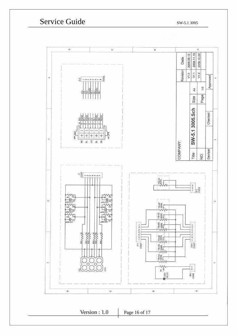
Service Guide SW-5.1 3005
Version : 1.0 Page 16 of 17
Service Guide SW-5.1 3005
Version : 1.0 Page 17 of 17
Chapter 7. Important Notes 7.1 Packing Requirement for Sending the PCB Assembly by Post
PCB assembly is a kind of sophisticated electronic circuit board. Well
packing will be required when sending them by post.
* Some sophisticated IC components are mounted on the PCB assembly,
hence it is necessary to pack each PCB assembly with a separate static
protecting bag, in order to avoid static electricity.
* Reliable external packing is also very important when sending PCB
assembly by post, in that it would avoid unnecessarily lost or damage.
7.2 Short of Spare Parts while Repairing a Speaker System
If you are short of spare parts when you have some speaker systems waiting
to be repaired, it would be recommended to take the necessary parts form
one speaker system, so that you may have the as many speaker systems.