Embed Size (px)
Citation preview

LICENSE RENEWAL APPLICATION
SUSQUEHANNA STEAM ELECTRIC STATION
UNITS 1 AND 2
Susquehanna Steam Electric Station Units 1 & 2 License Renewal Application Administrative Information
Preface Page i September 2006
PREFACE
The following describes the content of the Susquehanna Steam Electric Station (SSES) License Renewal Application (LRA).
Section 1 provides the administrative information required by 10 CFR 54.17 and 10 CFR 54.19.
Section 2 describes and justifies the methodology used to determine the systems, structures, and components within the scope of license renewal and the structures and components subject to an aging management review. The results of applying the scoping methodology are provided in Tables 2.2-1, 2.2-2, and 2.2-3. These tables provide listings of the mechanical systems, structures, and electrical/instrumentation and control systems within the scope of license renewal. Section 2 also provides a description of the systems and structures and their intended functions and tables identifying the system and structure components/commodities requiring aging management review and their intended functions. The descriptions also identify the applicable license renewal boundary drawings for mechanical systems. The drawings are included with the submittal, but are not part of the formal application. A discussion of the Nuclear Regulatory Commission (NRC) Interim Staff Guidance topics for license renewal is included in Section 2.1.3.
Section 3 describes the results of aging management reviews of structures and components requiring aging management review. Section 3 is divided into six sections that address the areas of: (3.1) Reactor Vessel, Internals, and Reactor Coolant System, (3.2) Engineered Safety Features, (3.3) Auxiliary Systems, (3.4) Steam and Power Conversion Systems, (3.5) Containments, Structures, and Component Supports, and (3.6) Electrical and Instrumentation and Controls. The tables in Section 3 provide a summary of information concerning aging effects requiring management and applicable aging management programs for structures and components. The information presented in the tables is based on industry guidance for format and content of applications that rely on NUREG-1800, “Standard Review Plan for the Review of License Renewal Applications for Nuclear Power Plants,” U.S. Nuclear Regulatory Commission, Revision 1, (the SRP-LR). The tables provide a discussion of the applicability of the component commodity groups to SSES and information regarding the degree to which proposed aging management programs are consistent with those recommended in NUREG-1801, “Generic Aging Lessons Learned (GALL),” U.S. Nuclear Regulatory Commission, Revision 1, (the GALL Report).
Section 4 addresses Time-Limited Aging Analyses, as defined by 10 CFR 54.3, and includes the identification of the component or subject, and an explanation of the time-dependent aspects of the calculation or analysis. Section 4 demonstrates whether (1) the analyses remain valid for the period of extended operation, or (2) the analyses have been projected to the end of the period of extended operation, or (3) the effects of aging on the intended function(s) will be adequately managed for the period of extended
Susquehanna Steam Electric Station Units 1 & 2 License Renewal Application Administrative Information
Preface Page ii September 2006
operation. Section 4 also provides the results of a review of exemptions issued pursuant to 10 CFR 50.12 to determine if any involve a Time-Limited Aging Analysis.
Appendix A, Final Safety Analysis Report Supplement, provides a summary description of the programs and activities for managing the effects of aging during the period of extended operation. A summary description of the evaluation of Time-Limited Aging Analyses for the period of extended operation is also included. In addition, Appendix A contains a listing of commitments associated with license renewal.
Appendix B, Aging Management Programs, describes the programs and activities that are credited to assure the effects of aging of components and structures will be managed such that they will continue to perform their intended functions consistent with the current licensing basis for the period of extended operation. Appendix B also addresses programs that are credited in the evaluation of Time-Limited Aging Analyses.
Appendix C, Response to BWRVIP Applicant Action Items, provides the requested responses to applicant action items contained in the NRC safety evaluation reports associated with NRC-approved Boiling Water Reactor Vessel and Internals Program reports.
Appendix D, Technical Specification Changes, concludes that no technical specification changes are necessary to manage the effects of aging during the period of extended operation.
A supplement to the Environmental Report is provided in Appendix E, entitled, “Applicant’s Environmental Report – Operating License Renewal Stage.”
The information in Section 2, Section 3, and Appendix B fulfills the requirements in 10 CFR 54.21(a). Section 1.4 discusses how the requirements of 10 CFR 54.21(b) will be met. The information in Section 4 fulfills the requirements in 10 CFR 54.21(c). The information in Appendix A and Appendix D fulfills the requirements in 10 CFR 54.21(d) and 10 CFR 54.22, respectively. Appendix E provides the environmental information required by 10 CFR 54.23.
Susquehanna Steam Electric Station Units 1 & 2 License Renewal Application Administrative Information
Preface Page iii September 2006
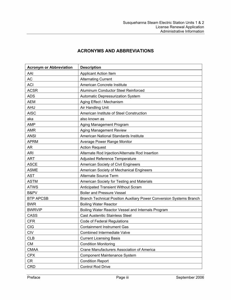
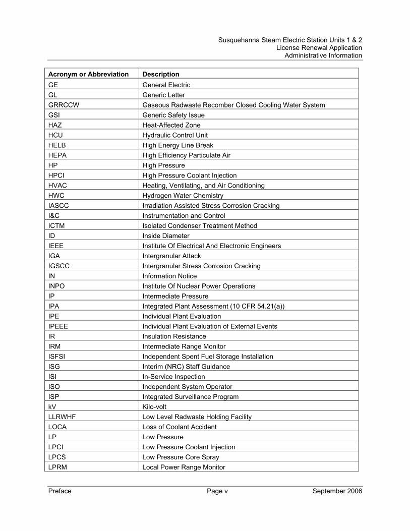
ACRONYMS AND ABBREVIATIONS Acronym or Abbreviation Description AAI Applicant Action Item AC Alternating Current ACI American Concrete Institute ACSR Aluminum Conductor Steel Reinforced ADS Automatic Depressurization System AEM Aging Effect / Mechanism AHU Air Handling Unit AISC American Institute of Steel Construction aka also known as AMP Aging Management Program AMR Aging Management Review ANSI American National Standards Institute APRM Average Power Range Monitor AR Action Request ARI Alternate Rod Injection/Alternate Rod Insertion ART Adjusted Reference Temperature ASCE American Society of Civil Engineers ASME American Society of Mechanical Engineers AST Alternate Source Term ASTM American Society for Testing and Materials ATWS Anticipated Transient Without Scram B&PV Boiler and Pressure Vessel BTP APCSB Branch Technical Position Auxiliary Power Conversion Systems Branch BWR Boiling Water Reactor BWRVIP Boiling Water Reactor Vessel and Internals Program CASS Cast Austenitic Stainless Steel CFR Code of Federal Regulations CIG Containment Instrument Gas CIV Combined Intermediate Valve CLB Current Licensing Basis CM Condition Monitoring CMAA Crane Manufacturers Association of America CPX Component Maintenance System CR Condition Report CRD Control Rod Drive
Susquehanna Steam Electric Station Units 1 & 2 License Renewal Application Administrative Information
Preface Page iv September 2006
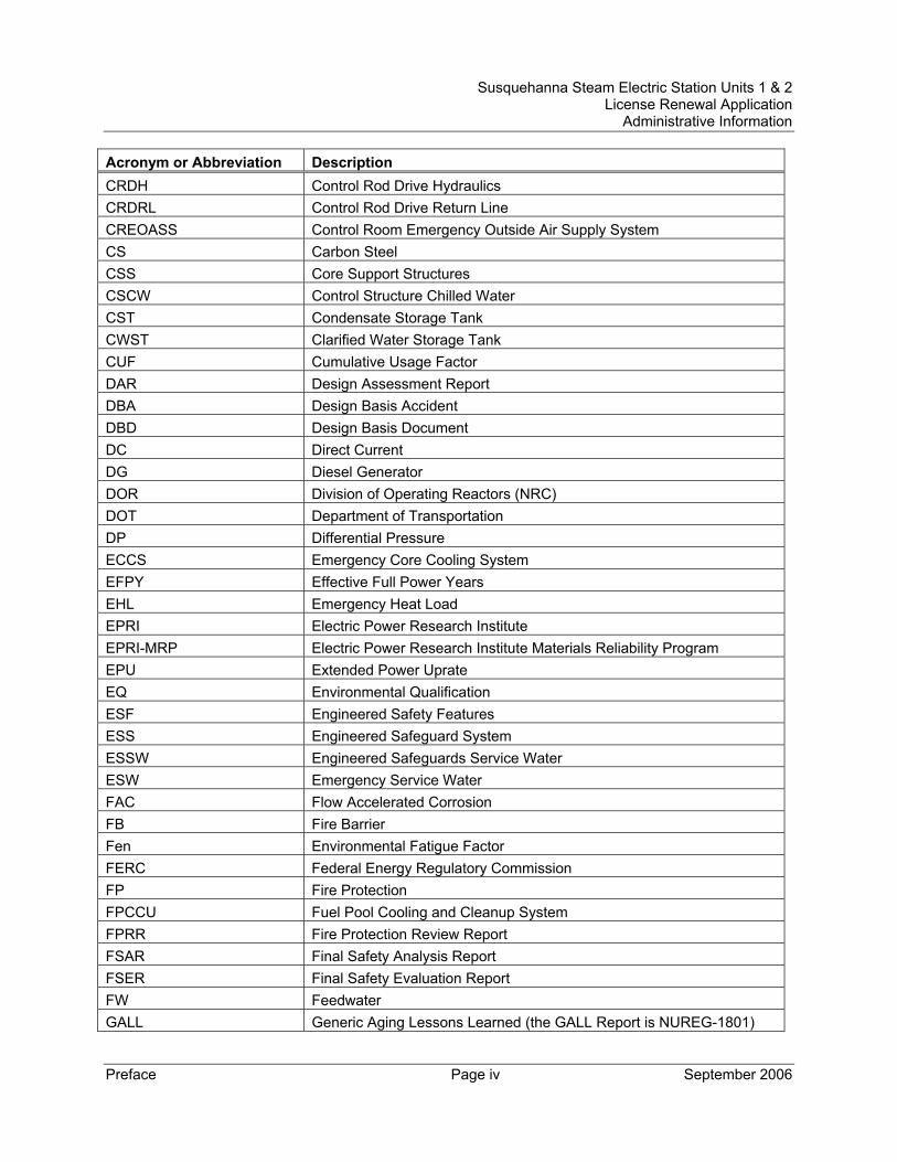
Acronym or Abbreviation Description CRDH Control Rod Drive Hydraulics CRDRL Control Rod Drive Return Line CREOASS Control Room Emergency Outside Air Supply System CS Carbon Steel CSS Core Support Structures CSCW Control Structure Chilled Water CST Condensate Storage Tank CWST Clarified Water Storage Tank CUF Cumulative Usage Factor DAR Design Assessment Report DBA Design Basis Accident DBD Design Basis Document DC Direct Current DG Diesel Generator DOR Division of Operating Reactors (NRC) DOT Department of Transportation DP Differential Pressure ECCS Emergency Core Cooling System EFPY Effective Full Power Years EHL Emergency Heat Load EPRI Electric Power Research Institute EPRI-MRP Electric Power Research Institute Materials Reliability Program EPU Extended Power Uprate EQ Environmental Qualification ESF Engineered Safety Features ESS Engineered Safeguard System ESSW Engineered Safeguards Service Water ESW Emergency Service Water FAC Flow Accelerated Corrosion FB Fire Barrier Fen Environmental Fatigue Factor FERC Federal Energy Regulatory Commission FP Fire Protection FPCCU Fuel Pool Cooling and Cleanup System FPRR Fire Protection Review Report FSAR Final Safety Analysis Report FSER Final Safety Evaluation Report FW Feedwater GALL Generic Aging Lessons Learned (the GALL Report is NUREG-1801)
Susquehanna Steam Electric Station Units 1 & 2 License Renewal Application Administrative Information
Preface Page v September 2006
Acronym or Abbreviation Description GE General Electric GL Generic Letter GRRCCW Gaseous Radwaste Recomber Closed Cooling Water System GSI Generic Safety Issue HAZ Heat-Affected Zone HCU Hydraulic Control Unit HELB High Energy Line Break HEPA High Efficiency Particulate Air HP High Pressure HPCI High Pressure Coolant Injection HVAC Heating, Ventilating, and Air Conditioning HWC Hydrogen Water Chemistry IASCC Irradiation Assisted Stress Corrosion Cracking I&C Instrumentation and Control ICTM Isolated Condenser Treatment Method ID Inside Diameter IEEE Institute Of Electrical And Electronic Engineers IGA Intergranular Attack IGSCC Intergranular Stress Corrosion Cracking IN Information Notice INPO Institute Of Nuclear Power Operations IP Intermediate Pressure IPA Integrated Plant Assessment (10 CFR 54.21(a)) IPE Individual Plant Evaluation IPEEE Individual Plant Evaluation of External Events IR Insulation Resistance IRM Intermediate Range Monitor ISFSI Independent Spent Fuel Storage Installation ISG Interim (NRC) Staff Guidance ISI In-Service Inspection ISO Independent System Operator ISP Integrated Surveillance Program kV Kilo-volt LLRWHF Low Level Radwaste Holding Facility LOCA Loss of Coolant Accident LP Low Pressure LPCI Low Pressure Coolant Injection LPCS Low Pressure Core Spray LPRM Local Power Range Monitor
Susquehanna Steam Electric Station Units 1 & 2 License Renewal Application Administrative Information
Preface Page vi September 2006
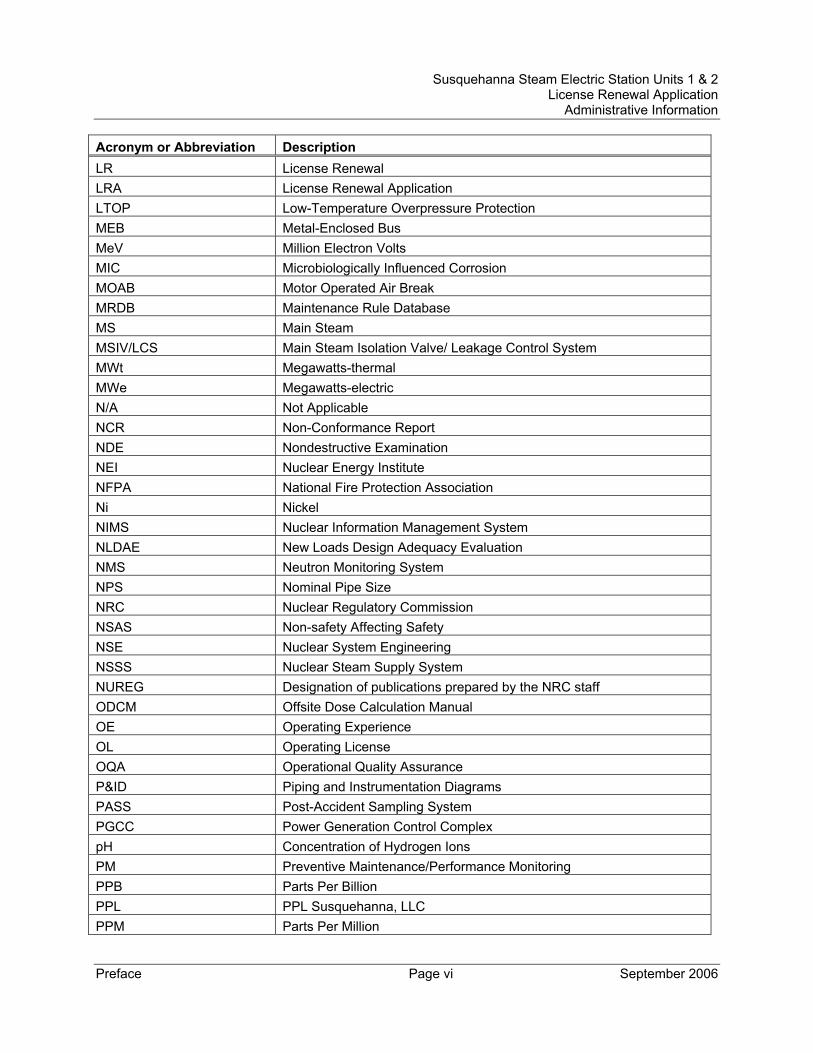
Acronym or Abbreviation Description LR License Renewal LRA License Renewal Application LTOP Low-Temperature Overpressure Protection MEB Metal-Enclosed Bus MeV Million Electron Volts MIC Microbiologically Influenced Corrosion MOAB Motor Operated Air Break MRDB Maintenance Rule Database MS Main Steam MSIV/LCS Main Steam Isolation Valve/ Leakage Control System MWt Megawatts-thermal MWe Megawatts-electric N/A Not Applicable NCR Non-Conformance Report NDE Nondestructive Examination NEI Nuclear Energy Institute NFPA National Fire Protection Association Ni Nickel NIMS Nuclear Information Management System NLDAE New Loads Design Adequacy Evaluation NMS Neutron Monitoring System NPS Nominal Pipe Size NRC Nuclear Regulatory Commission NSAS Non-safety Affecting Safety NSE Nuclear System Engineering NSSS Nuclear Steam Supply System NUREG Designation of publications prepared by the NRC staff ODCM Offsite Dose Calculation Manual OE Operating Experience OL Operating License OQA Operational Quality Assurance P&ID Piping and Instrumentation Diagrams PASS Post-Accident Sampling System PGCC Power Generation Control Complex pH Concentration of Hydrogen Ions PM Preventive Maintenance/Performance Monitoring PPB Parts Per Billion PPL PPL Susquehanna, LLC PPM Parts Per Million
Susquehanna Steam Electric Station Units 1 & 2 License Renewal Application Administrative Information
Preface Page vii September 2006
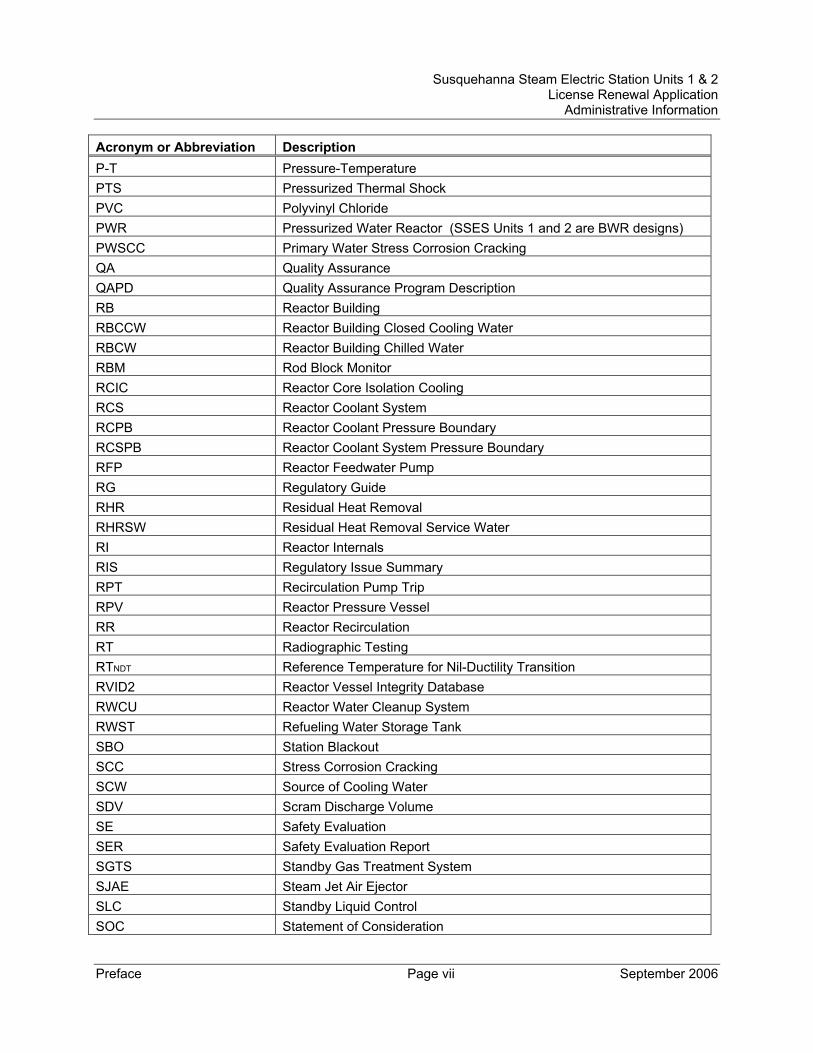
Acronym or Abbreviation Description P-T Pressure-Temperature PTS Pressurized Thermal Shock PVC Polyvinyl Chloride PWR Pressurized Water Reactor (SSES Units 1 and 2 are BWR designs) PWSCC Primary Water Stress Corrosion Cracking QA Quality Assurance QAPD Quality Assurance Program Description RB Reactor Building RBCCW Reactor Building Closed Cooling Water RBCW Reactor Building Chilled Water RBM Rod Block Monitor RCIC Reactor Core Isolation Cooling RCS Reactor Coolant System RCPB Reactor Coolant Pressure Boundary RCSPB Reactor Coolant System Pressure Boundary RFP Reactor Feedwater Pump RG Regulatory Guide RHR Residual Heat Removal RHRSW Residual Heat Removal Service Water RI Reactor Internals RIS Regulatory Issue Summary RPT Recirculation Pump Trip RPV Reactor Pressure Vessel RR Reactor Recirculation RT Radiographic Testing RTNDT Reference Temperature for Nil-Ductility Transition RVID2 Reactor Vessel Integrity Database RWCU Reactor Water Cleanup System RWST Refueling Water Storage Tank SBO Station Blackout SCC Stress Corrosion Cracking SCW Source of Cooling Water SDV Scram Discharge Volume SE Safety Evaluation SER Safety Evaluation Report SGTS Standby Gas Treatment System SJAE Steam Jet Air Ejector SLC Standby Liquid Control SOC Statement of Consideration
Susquehanna Steam Electric Station Units 1 & 2 License Renewal Application Administrative Information
Preface Page viii September 2006
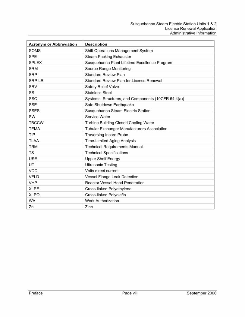
Acronym or Abbreviation Description SOMS Shift Operations Management System SPE Steam Packing Exhauster SPLEX Susquehanna Plant Lifetime Excellence Program SRM Source Range Monitoring SRP Standard Review Plan SRP-LR Standard Review Plan for License Renewal SRV Safety Relief Valve SS Stainless Steel SSC Systems, Structures, and Components (10CFR 54.4(a)) SSE Safe Shutdown Earthquake SSES Susquehanna Steam Electric Station SW Service Water TBCCW Turbine Building Closed Cooling Water TEMA Tubular Exchanger Manufacturers Association TIP Traversing Incore Probe TLAA Time-Limited Aging Analysis TRM Technical Requirements Manual TS Technical Specifications USE Upper Shelf Energy UT Ultrasonic Testing VDC Volts direct current VFLD Vessel Flange Leak Detection VHP Reactor Vessel Head Penetration XLPE Cross-linked Polyethylene XLPO Cross-linked Polyolefin WA Work Authorization Zn Zinc
Susquehanna Steam Electric Station Units 1 & 2 License Renewal Application Administrative Information
Preface Page ix September 2006
TABLE OF CONTENTS
Preface............................................................................................................................. i
Acronyms and Abbreviations........................................................................................... iii
1.0 ADMINISTRATIVE INFORMATION............................................................... 1.0-1
1.1 GENERAL INFORMATION ............................................................................... 1.1-1
1.1.1 Name of Applicant............................................................................. 1.1-1
1.1.2 Address of Applicant ......................................................................... 1.1-1
1.1.3 Description of Business of Applicant ................................................. 1.1-2
1.1.4 Organization and Management of Applicant ..................................... 1.1-2
1.1.5 Class and Period of License Sought ................................................. 1.1-5
1.1.6 Alteration Schedule ........................................................................... 1.1-5
1.1.7 Regulatory Agencies and Local News Publications .......................... 1.1-6
1.1.8 Conforming Changes to Standard Indemnity Agreement.................. 1.1-6
1.1.9 Restricted Data Agreement ............................................................... 1.1-7
1.2 DESCRIPTION OF SUSQUEHANNA STEAM ELECTRIC STATION........................... 1.2-1
2.0 SCOPING AND SCREENING METHODOLOGY FOR IDENTIFYING STRUCTURES AND COMPONENTS SUBJECT TO AGING MANAGEMENT REVIEW AND IMPLEMENTATION RESULTS................... 2.0-1
2.1 SCOPING AND SCREENING METHODOLOGY.................................................... 2.1-1
2.1.1 Scoping Methodology........................................................................ 2.1-1
2.1.1.1 Safety-Related Scoping ............................................................ 2.1-3
2.1.1.2 Nonsafety-Related SSCs Affecting Safety-Related SSCs Scoping ..................................................................................... 2.1-4
2.1.1.3 Regulated Events Scoping........................................................ 2.1-8
Susquehanna Steam Electric Station Units 1 & 2 License Renewal Application Administrative Information
Preface Page x September 2006
2.1.1.4 Scoping Boundary Determination............................................ 2.1-12
2.1.2 Screening Methodology .................................................................. 2.1-14
2.1.2.1 Screening of Mechanical Systems .......................................... 2.1-14
2.1.2.2 Screening of Structures........................................................... 2.1-16
2.1.2.3 Screening of Electrical and Instrumentation and Control Systems .................................................................................. 2.1-17
2.1.2.4 Treatment of Consumables..................................................... 2.1-18
2.1.2.5 Treatment of Stored Equipment .............................................. 2.1-19
2.1.2.6 Treatment of Insulation ........................................................... 2.1-19
2.1.3 Interim Staff Guidance Discussion .................................................. 2.1-21
2.1.4 Generic Safety Issues ..................................................................... 2.1-23
2.1.5 Conclusion ...................................................................................... 2.1-24
2.1.6 References for Section 2.1.............................................................. 2.1-25
2.2 PLANT-LEVEL SCOPING RESULTS ................................................................. 2.2-1
2.3 SCOPING AND SCREENING RESULTS: MECHANICAL SYSTEMS......................... 2.3-1
2.3.1 Reactor Vessel, Internals, and Reactor Coolant System .................. 2.3-2
2.3.1.1 Reactor Pressure Vessel .......................................................... 2.3-2
2.3.1.2 Reactor Vessel Internals ........................................................... 2.3-7
2.3.1.3 Reactor Coolant System Pressure Boundary.......................... 2.3-10
2.3.2 Engineered Safety Features ........................................................... 2.3-14
2.3.2.1 Residual Heat Removal (RHR) System .................................. 2.3-15
2.3.2.2 Reactor Core Isolation Cooling (RCIC) System ...................... 2.3-18
2.3.2.3 Core Spray System................................................................. 2.3-21
2.3.2.4 High Pressure Coolant Injection (HPCI) System..................... 2.3-23
Susquehanna Steam Electric Station Units 1 & 2 License Renewal Application Administrative Information
Preface Page xi September 2006
2.3.2.5 Containment and Suppression System................................... 2.3-26
2.3.2.6 Containment Atmospheric Control System ............................. 2.3-28
2.3.2.7 Standby Gas Treatment System (SGTS) ................................ 2.3-30
2.3.3 Auxiliary Systems............................................................................ 2.3-33
2.3.3.1 Building Drains Nonradioactive System .................................. 2.3-35
2.3.3.2 Containment Instrument Gas System ..................................... 2.3-37
2.3.3.3 Control Rod Drive Hydraulics System..................................... 2.3-39
2.3.3.4 Control Structure Chilled Water System.................................. 2.3-41
2.3.3.5 Control Structure HVAC Systems ........................................... 2.3-45
2.3.3.6 Cooling Tower System ............................................................ 2.3-50
2.3.3.7 Diesel Fuel Oil System............................................................ 2.3-52
2.3.3.8 Diesel Generator Buildings HVAC Systems............................ 2.3-55
2.3.3.9 Diesel Generators System ...................................................... 2.3-58
2.3.3.10 Domestic Water System.......................................................... 2.3-65
2.3.3.11 Emergency Service Water System.......................................... 2.3-67
2.3.3.12 ESSW Pumphouse HVAC System.......................................... 2.3-69
2.3.3.13 Fire Protection System............................................................ 2.3-71
2.3.3.14 Fuel Pool Cooling and Cleanup System and Fuel Pools and Auxiliaries......................................................................... 2.3-75
2.3.3.15 Neutron Monitoring System..................................................... 2.3-78
2.3.3.16 Nitrogen and Hydrogen System .............................................. 2.3-80
2.3.3.17 Primary Containment Atmosphere Circulation System ........... 2.3-81
2.3.3.18 Process and Area Radiation Monitoring System..................... 2.3-83
2.3.3.19 Radwaste Liquid System......................................................... 2.3-85

Susquehanna Steam Electric Station Units 1 & 2 License Renewal Application Administrative Information
Preface Page xii September 2006
2.3.3.20 Radwaste Solids Handling System ......................................... 2.3-87
2.3.3.21 Raw Water Treatment System ................................................ 2.3-89
2.3.3.22 Reactor Building Chilled Water System .................................. 2.3-91
2.3.3.23 Reactor Building Closed Cooling Water System ..................... 2.3-93
2.3.3.24 Reactor Building HVAC System.............................................. 2.3-95
2.3.3.25 Reactor Nonnuclear Instrumentation System........................ 2.3-100
2.3.3.26 Reactor Water Cleanup System............................................ 2.3-102
2.3.3.27 RHR Service Water System.................................................. 2.3-105
2.3.3.28 Sampling System .................................................................. 2.3-107
2.3.3.29 Sanitary Drainage System .................................................... 2.3-109
2.3.3.30 Service Air System................................................................ 2.3-111
2.3.3.31 Service Water System........................................................... 2.3-113
2.3.3.32 Standby Liquid Control (SLC) System................................... 2.3-115
2.3.3.33 Turbine Building Closed Cooling Water System ................... 2.3-117
2.3.4 Steam and Power Conversion Systems........................................ 2.3-119
2.3.4.1 Auxiliary Boiler System ......................................................... 2.3-120
2.3.4.2 Bypass Steam System.......................................................... 2.3-122
2.3.4.3 Condensate Transfer and Storage System ........................... 2.3-124
2.3.4.4 Condenser and Air Removal System .................................... 2.3-127
2.3.4.5 Feedwater System ................................................................ 2.3-129
2.3.4.6 Main Steam System.............................................................. 2.3-132
2.3.4.7 Main Turbine System ............................................................ 2.3-135
2.3.4.8 Makeup Demineralizer System ............................................. 2.3-137
2.3.4.9 Makeup Transfer and Storage System.................................. 2.3-139
Susquehanna Steam Electric Station Units 1 & 2 License Renewal Application Administrative Information
Preface Page xiii September 2006
2.3.4.10 Reactor Feed Pump Turbines System .................................. 2.3-141
2.3.4.11 Refueling Water Transfer and Storage System..................... 2.3-143
2.4 SCOPING AND SCREENING RESULTS: STRUCTURES....................................... 2.4-1
2.4.1 Primary Containment ........................................................................... 2.4-2
2.4.2 Reactor Building .................................................................................. 2.4-7
2.4.3 Engineered Safeguards Service Water Pumphouse and Spray Pond .................................................................................................. 2.4-11
2.4.4 Circulating Water Pumphouse and Water Treatment Building........... 2.4-15
2.4.5 Control Structure................................................................................ 2.4-17
2.4.6 Diesel Generator ‘A, B, C, and D’ Building......................................... 2.4-20
2.4.7 Diesel Generator ‘E’ Building ............................................................. 2.4-23
2.4.8 Turbine Building................................................................................. 2.4-25
2.4.9 Yard Structures.................................................................................. 2.4-28
2.4.9.1 Clarified Water Storage Tank Foundation ............................... 2.4-28
2.4.9.2 Condensate Storage Tank Foundation and Retention Basin .. 2.4-28
2.4.9.3 Diesel Generator Fuel Oil Storage Tank ‘A, B, C, D, and E’ Foundations and Vaults .......................................................... 2.4-29
2.4.9.4 Refueling Water Storage Tank Foundation ............................. 2.4-30
2.4.9.5 Station Blackout Component Foundations and Structures in the Yard (Startup Transformers T-10 and T-20 and Associated Disconnect Switches, and ESS Transformers ..... 2.4-31
2.4.9.6 Cooling Tower Basins ............................................................. 2.4-32
2.4.9.7 Duct Banks, Manholes, Valve Vaults, Instrument Pits, and Piping Trenches in the Yard.................................................... 2.4-32
2.4.10 Bulk Commodities ........................................................................... 2.4-36
Susquehanna Steam Electric Station Units 1 & 2 License Renewal Application Administrative Information
Preface Page xiv September 2006
2.5 SCOPING AND SCREENING RESULTS: ELECTRICAL AND INSTRUMENTATION AND CONTROLS SYSTEMS ............................................................................ 2.5-1
2.5.1 Electrical/I&C Screening Process ........................................................ 2.5-1
2.5.2 Application of Screening Criterion 10 CFR 54.21(a)(1)(i) to Electrical/I&C Component Commodity Groups .................................... 2.5-1
2.5.3 Elimination of Component Commodity Groups with no License Renewal Intended Functions ............................................................... 2.5-3
2.5.3.1 Uninsulated Ground Conductors ............................................... 2.5-3
2.5.3.2 Switchyard Bus and Connections.............................................. 2.5-3
2.5.4 Application of Screening Criterion 10 CFR 54.21(a)(1)(ii) to Electrical/I&C Component Commodity Groups .................................... 2.5-3
2.5.4.1 Electrical Portions of Electrical and I&C Penetration Assemblies................................................................................ 2.5-4
2.5.4.2 Insulated Cables and Connections in the EQ Program............. 2.5-4
2.5.5 Electrical/I&C Component Commodity Groups Requiring an Aging Management Review ................................................................. 2.5-4
2.5.5.1 Non-EQ Insulated Cables and Connections.............................. 2.5-4
2.5.5.2 Non-Segregated Metal-Enclosed (Phase) Bus ......................... 2.5-5
2.5.5.3 High-Voltage Insulators............................................................. 2.5-6
2.5.5.4 Transmission Conductors and Connections.............................. 2.5-7
2.5.6 Evaluation Boundaries ...................................................................... 2.5-7
2.5.6.1 System Evaluation Boundaries ................................................. 2.5-7
2.5.6.2 Station Blackout Evaluation Boundaries ................................... 2.5-7
3.0 AGING MANAGEMENT REVIEW RESULTS................................................ 3.0-1
3.1 AGING MANAGEMENT OF REACTOR VESSEL, INTERNALS, AND REACTOR COOLANT SYSTEM....................................................................................... 3.1-1
3.1.1 Introduction .......................................................................................... 3.1-1
Susquehanna Steam Electric Station Units 1 & 2 License Renewal Application Administrative Information
Preface Page xv September 2006
3.1.2 Results................................................................................................. 3.1-1
3.1.2.1 Materials, Environments, Aging Effects Requiring Management, and Aging Management Programs..................... 3.1-2
3.1.2.2 Further Evaluation of Aging Management as Recommended by NUREG-1801 ....................................................................... 3.1-8
3.1.2.3 Time-Limited Aging Analysis ................................................... 3.1-12
3.1.3 Conclusions ....................................................................................... 3.1-12
3.2 AGING MANAGEMENT OF ENGINEERED SAFETY FEATURES ............................. 3.2-1
3.2.1 Introduction .......................................................................................... 3.2-1
3.2.2 Results................................................................................................. 3.2-1
3.2.2.1 Materials, Environments, Aging Effects Requiring Management, and Aging Management Programs..................... 3.2-2
3.2.2.2 Further Evaluation of Aging Management as Recommended by NUREG-1801 ..................................................................... 3.2-10
3.2.2.3 Time-Limited Aging Analysis ................................................... 3.2-14
3.2.3 Conclusions..................................................................................... 3.2-14
3.3 AGING MANAGEMENT OF AUXILIARY SYSTEMS ............................................... 3.3-1
3.3.1 Introduction ....................................................................................... 3.3-1
3.3.2 Results .............................................................................................. 3.3-2
3.3.2.1 Materials, Environments, Aging Effects Requiring Management, and Aging Management Programs..................... 3.3-4
3.3.2.2 Further Evaluation of Aging Management as Recommended by NUREG-1801 ..................................................................... 3.3-41
3.3.2.3 Time-Limited Aging Analysis ................................................... 3.3-48
3.3.3 Conclusions..................................................................................... 3.3-48
3.4 AGING MANAGEMENT OF STEAM AND POWER CONVERSION SYSTEMS .......... 3.4-1
Susquehanna Steam Electric Station Units 1 & 2 License Renewal Application Administrative Information
Preface Page xvi September 2006
3.4.1 Introduction ....................................................................................... 3.4-1
3.4.2 Results .............................................................................................. 3.4-1
3.4.2.1 Materials, Environments, Aging Effects Requiring Management, and Aging Management Programs..................... 3.4-2
3.4.2.2 Further Evaluation of Aging Management as Recommended by NUREG-1801 ..................................................................... 3.4-12
3.4.2.3 Time-Limited Aging Analysis .................................................. .3.4-15
3.4.3 Conclusions..................................................................................... 3.4-16
3.5 AGING MANAGEMENT OF CONTAINMENTS, STRUCTURES, AND COMPONENT SUPPORTS............................................................................ 3.5-1
3.5.1 Introduction ....................................................................................... 3.5-1
3.5.2 Results .............................................................................................. 3.5-1
3.5.2.1 Materials, Environments, Aging Effects Requiring Management, and Aging Management Programs ....................... 3.5-2
3.5.2.2 Further Evaluation of Aging Management as Recommended by NUREG-1801........................................................................ 3.5-16
3.5.2.3 Time-Limited Aging Analysis...................................................... 3.5-34
3.5.3 Conclusions..................................................................................... 3.5-34
3.6 AGING MANAGEMENT OF ELECTRICAL AND INSTRUMENTATION AND CONTROLS ............................................................................................... 3.6-1
3.6.1 Introduction ....................................................................................... 3.6-1
3.6.2 Results .............................................................................................. 3.6-1
3.6.2.1 Materials, Environments, Aging Effects Requiring Management, and Aging Management Programs..................... 3.6-1
3.6.2.2 Further Evaluation of Aging Management as Recommended by NUREG-1801 ....................................................................... 3.6-6
3.6.2.3 Aging Management Review Results Not Consistent with NUREG-1801............................................................................ 3.6-8
Susquehanna Steam Electric Station Units 1 & 2 License Renewal Application Administrative Information
Preface Page xvii September 2006
3.6.2.4 Time-Limited Aging Analysis ..................................................... 3.6-9
3.6.3 Conclusions....................................................................................... 3.6-9
4.0 TIME-LIMITED AGING ANALYSES............................................................ 4.0-1
4.1 IDENTIFICATION OF TIME-LIMITED AGING ANALYSES..................................... 4.1-1
4.1.1 Time-Limited Aging Analyses Identification Process......................... 4.1-1
4.1.2 Evaluation of Time-Limited Aging Analyses ...................................... 4.1-2
4.1.3 Identification of Exemptions .............................................................. 4.1-2
4.2 REACTOR VESSEL NEUTRON EMBRITTLEMENT ............................................ 4.2-1
4.2.1 Neutron Fluence................................................................................ 4.2-1
4.2.2 Upper Shelf Energy Evaluation ......................................................... 4.2-4
4.2.3 Adjusted Reference Temperature (ART) Analysis ............................ 4.2-9
4.2.4 Pressure-Temperature (P-T) Limits................................................. 4.2-12
4.2.5 Reactor Vessel Circumferential Weld Examination Relief ............... 4.2-12
4.2.6 Reactor Vessel Axial Weld Failure Probability ................................ 4.2-13
4.2.7 Reflood Thermal Shock Analysis .................................................... 4.2-13
4.3 METAL FATIGUE........................................................................................ 4.3-1
4.3.1 Reactor Pressure Vessel Fatigue Analyses ...................................... 4.3-1
4.3.2 Reactor Vessel Internals Fatigue Analyses....................................... 4.3-7
4.3.3 Effects of Reactor Coolant Environment on Fatigue Life of Components and Piping (GSI-190) ................................................... 4.3-8
4.3.4 Reactor Coolant Pressure Boundary Piping and Component Fatigue Analyses............................................................................. 4.3-11
4.3.5 Non-Class 1 Component Fatigue Analyses .................................... 4.3-12
4.4 ENVIRONMENTAL QUALIFICATION OF ELECTRIC EQUIPMENT ......................... 4.4-1
4.4.1 Environmental Qualification Program Background............................ 4.4-1
Susquehanna Steam Electric Station Units 1 & 2 License Renewal Application Administrative Information
Preface Page xviii September 2006
4.4.2 EQ Component Reanalysis Attributes............................................... 4.4-2
4.4.3 Conclusion ........................................................................................ 4.4-4
4.5 CONCRETE CONTAINMENT TENDON PRESTRESS ......................................... 4.5-1
4.6 CONTAINMENT LINER PLATE, METAL CONTAINMENTS, AND PENETRATIONS FATIGUE ANALYSES ........................................................... 4.6-1
4.6.1 ASME Class MC Components............................................................. 4.6-1
4.6.2 Downcomer Vents and Safety Relief Valve Discharge Piping ............. 4.6-1
4.6.3 Safety Relief Valve Quenchers ............................................................ 4.6-3
4.7 OTHER PLANT-SPECIFIC TIME-LIMITED AGING ANALYES .............................. 4.7-1
4.7.1 Main Steam Line Flow Restrictor Erosion Analyses.......................... 4.7-1
4.7.2 High Energy Line Break Cumulative Fatigue Usage Factors ............ 4.7-2
4.7.3 Core Plate Rim Hold-Down Bolts ...................................................... 4.7-3
4.8 REFERENCES ........................................................................................... 4.8-1
LIST OF APPENDICES
Appendix A - FINAL SAFETY ANALYSIS REPORT SUPPLEMENT ...........................A-1
Appendix B - AGING MANAGEMENT PROGRAMS....................................................B-1
Appendix C – RESPONSE TO BWRVIP APPLICANT ACTION ITEMS...................... C-1
Appendix D - TECHNICAL SPECIFICATION CHANGES ........................................... D-1
Appendix E - APPLICANT’S ENVIRONMENTAL REPORT – OPERATING LICENSE RENEWAL STAGE...........................................E-1
Susquehanna Steam Electric Station Units 1 & 2 License Renewal Application Administrative Information
Preface Page xix September 2006
LIST OF TABLES Table 2.0-1 Intended Functions: Abbreviations and Definitions ..................... 2.0-2
Table 2.2-1 License Renewal Scoping Results for Mechanical Systems........ 2.2-2
Table 2.2-2 License Renewal Scoping Results for Electrical/I&C Systems .... 2.2-6
Table 2.2-3 License Renewal Scoping Results for Structures ........................ 2.2-8
Table 2.3.1-1 Reactor Pressure Vessel Components Subject to Aging Management Review................... 2.3-5
Table 2.3.1-2 Reactor Vessel Internals Components Subject to Aging Management Review................... 2.3-8
Table 2.3.1-3 Reactor Coolant System Pressure Boundary Components Subject to Aging Management Review................. 2.3-13
Table 2.3.2-1 Residual Heat Removal System Components Subject to Aging Management Review................. 2.3-17
Table 2.3.2-2 Reactor Core Injection Cooling System Components Subject to Aging Management Review................. 2.3-20
Table 2.3.2-3 Core Spray System Components Subject to Aging Management Review................. 2.3-22
Table 2.3.2-4 High Pressure Coolant Injection System Components Subject to Aging Management Review................. 2.3-24
Table 2.3.2-5 Containment and Suppression System Components Subject to Aging Management Review................. 2.3-27
Table 2.3.2-6 Containment Atmosphere Control System Components Subject to Aging Management Review................. 2.3-29
Table 2.3.2-7 Standby Gas Treatment System Components Subject to Aging Management Review................. 2.3-31
Table 2.3.3-1 Building Drains Nonradioactive System Components Subject to Aging Management Review................. 2.3-36
Table 2.3.3-2 Containment Instrument Gas System Components Subject to Aging Management Review................. 2.3-38
Susquehanna Steam Electric Station Units 1 & 2 License Renewal Application Administrative Information
Preface Page xx September 2006
Table 2.3.3-3 Control Rod Drive Hydraulics System Components Subject to Aging Management Review................. 2.3-40
Table 2.3.3-4 Control Structure Chilled Water System Components Subject to Aging Management Review................. 2.3-42
Table 2.3.3-5 Control Structure HVAC Systems Components Subject to Aging Management Review................. 2.3-47
Table 2.3.3-6 Cooling Tower System Components Subject to Aging Management Review................. 2.3-51
Table 2.3.3-7 Diesel Fuel Oil System Components Subject to Aging Management Review................. 2.3-53
Table 2.3.3-8 Diesel Generator Buildings HVAC Systems Components Subject to Aging Management Review................. 2.3-56
Table 2.3.3-9 Diesel Generators System Components Subject to Aging Management Review................. 2.3-61
Table 2.3.3-10 Domestic Water System Components Subject to Aging Management Review................. 2.3-66
Table 2.3.3-11 Emergency Service Water System Components Subject to Aging Management Review................. 2.3-68
Table 2.3.3-12 ESSW Pumphouse HVAC System Components Subject to Aging Management Review................. 2.3-70
Table 2.3.3-13 Fire Protection System Components Subject to Aging Management Review................. 2.3-73
Table 2.3.3-14 Fuel Pool Cooling and Cleanup System and Fuel Pools and Auxiliaries Components Subject to Aging Management Review....................................................................................... 2.3-77
Table 2.3.3-15 Neutron Monitoring System Components Subject to Aging Management Review................. 2.3-79
Table 2.3.3-16 Primary Containment Atmosphere Circulation System Components Subject to Aging Management Review................. 2.3-82
Table 2.3.3-17 Process and Area Radiation Monitoring System Components Subject to Aging Management Review................. 2.3-84
Susquehanna Steam Electric Station Units 1 & 2 License Renewal Application Administrative Information
Preface Page xxi September 2006
Table 2.3.3-18 Radwaste Liquid System Components Subject to Aging Management Review................. 2.3-86
Table 2.3.3-19 Radwaste Solids Handling System Components Subject to Aging Management Review................. 2.3-88
Table 2.3.3-20 Raw Water Treatment System Components Subject to Aging Management Review................. 2.3-90
Table 2.3.3-21 Reactor Building Chilled Water System Components Subject to Aging Management Review................. 2.3-92
Table 2.3.3-22 Reactor Building Closed Cooling Water System Components Subject to Aging Management Review................. 2.3-94
Table 2.3.3-23 Reactor Building HVAC System Components Subject to Aging Management Review................. 2.3-97
Table 2.3.3-24 Reactor Nonnuclear Instrumentation System Components Subject to Aging Management Review............... 2.3-101
Table 2.3.3-25 Reactor Water Cleanup System Components Subject to Aging Management Review............... 2.3-104
Table 2.3.3-26 RHR Service Water System Components Subject to Aging Management Review............... 2.3-106
Table 2.3.3-27 Sampling System Components Subject to Aging Management Review............... 2.3-108
Table 2.3.3-28 Sanitary Drainage System Components Subject to Aging Management Review............... 2.3-110
Table 2.3.3-29 Service Air System Components Subject to Aging Management Review............... 2.3-112
Table 2.3.3-30 Service Water System Components Subject to Aging Management Review............... 2.3-114
Table 2.3.3-31 Standby Liquid Control System Components Subject to Aging Management Review............... 2.3-116
Table 2.3.3-32 Turbine Building Closed Cooling Water System Components Subject to Aging Management Review............... 2.3-118
Susquehanna Steam Electric Station Units 1 & 2 License Renewal Application Administrative Information
Preface Page xxii September 2006
Table 2.3.4-1 Auxiliary Boiler System Components Subject to Aging Management Review............... 2.3-121
Table 2.3.4-2 Bypass Steam System Components Subject to Aging Management Review............... 2.3-123
Table 2.3.4-3 Condensate Transfer and Storage System Components Subject to Aging Management Review............... 2.3-126
Table 2.3.4-4 Condenser and Air Removal System Components Subject to Aging Management Review............... 2.3-128
Table 2.3.4-5 Feedwater System Components Subject to Aging Management Review............... 2.3-131
Table 2.3.4-6 Main Steam System Components Subject to Aging Management Review............... 2.3-134
Table 2.3.4-7 Main Turbine System Components Subject to Aging Management Review............... 2.3-136
Table 2.3.4-8 Makeup Demineralizer System Components Subject to Aging Management Review............... 2.3-138
Table 2.3.4-9 Makeup Transfer and Storage System Components Subject to Aging Management Review............... 2.3-140
Table 2.3.4-10 Refueling Water Transfer and Storage System Components Subject to Aging Management Review............... 2.3-144
Table 2.4-1 Primary Containment Components Subject to Aging Management Review................... 2.4-5
Table 2.4-2 Reactor Building Components Subject to Aging Management Review................... 2.4-9
Table 2.4-3 ESSW Pumphouse and Spray Pond Components Subject to Aging Management Review................. 2.4-14
Table 2.4-4 Circulating Water Pumphouse and Water Treatment Building Components Subject to Aging Management Review................. 2.4-16
Table 2.4-5 Control Structure Components Subject to Aging Management Review................. 2.4-19
Susquehanna Steam Electric Station Units 1 & 2 License Renewal Application Administrative Information
Preface Page xxiii September 2006
Table 2.4-6 Diesel Generator ‘A, B, C, and D’ Building Components Subject to Aging Management Review................. 2.4-22
Table 2.4-7 Diesel Generator ‘E’ Building Components Subject to Aging Management Review................. 2.4-24
Table 2.4-8 Turbine Building Components Subject to Aging Management Review................. 2.4-27
Table 2.4-9 Yard Structures Components Subject to Aging Management Review................. 2.4-35
Table 2.4-10 Bulk Commodities Components Subject to Aging Management Review................. 2.4-37
Table 2.5.2-1 Industry Standard List of Passive Electrical Commodities ........... 2.5-2
Table 2.5-1 Electrical and Instrumentation and Control Systems Components Subject to Aging Management Review................. 2.5-11
Table 3.0-1 Internal Service Environments ..................................................... 3.0-6
Table 3.0-2 External Service Environments.................................................... 3.0-9
Table 3.1.1 Summary of Aging Management Programs for Reactor Vessel, Internals, and Reactor Coolant System Evaluated in Chapter IV of the GALL Report ............................. 3.1-14
Table 3.1.2-1 Aging Management Review Results - Reactor Pressure Vessel ........................................................... 3.1-37
Table 3.1.2-2 Aging Management Review Results - Reactor Vessel Internals............................................................ 3.1-56
Table 3.1.2-3 Aging Management Review Results - Reactor Coolant System Pressure Boundary ............................ 3.1-74
Table 3.2.1 Summary of Aging Management Programs for Engineered Safety Features Evaluated in Chapter V of the GALL Report .............................. 3.2-15
Table 3.2.2-1 Aging Management Review Results - Residual Heat Removal System ................................................ 3.2-33
Table 3.2.2-2 Aging Management Review Results - Reactor Core Isolation Cooling System ..................................... 3.2-45
Susquehanna Steam Electric Station Units 1 & 2 License Renewal Application Administrative Information
Preface Page xxiv September 2006
Table 3.2.2-3 Aging Management Review Results - Core Spray System.................................................................... 3.2-64
Table 3.2.2-4 Aging Management Review Results - High Pressure Coolant Injection System ................................... 3.2-70
Table 3.2.2-5 Aging Management Review Results - Containment and Suppression System...................................... 3.2-88
Table 3.2.2-6 Aging Management Review Results - Containment Atmosphere Control System................................. 3.2-94
Table 3.2.2-7 Aging Management Review Results - Standby Gas Treatment System................................................ 3.2-97
Table 3.3.1 Summary of Aging Management Programs for Auxiliary Systems Evaluated in Chapter VII of the GALL Report ............................ 3.3-49
Table 3.3.2-1 Aging Management Review Results - Building Drains Nonradioactive System..................................... 3.3-96
Table 3.3.2-2 Aging Management Review Results - Containment Instrument Gas System ........................................ 3.3-98
Table 3.3.2-3 Aging Management Review Results - Control Rod Drive Hydraulics System...................................... 3.3-102
Table 3.3.2-4 Aging Management Review Results - Control Structure Chilled Water System .................................. 3.3-110
Table 3.3.2-5 Aging Management Review Results - Control Structure HVAC Systems ............................................ 3.3-130
Table 3.3.2-6 Aging Management Review Results - Cooling Tower System............................................................. 3.3-144
Table 3.3.2-7 Aging Management Review Results - Diesel Fuel Oil System............................................................. 3.3-146
Table 3.3.2-8 Aging Management Review Results - Diesel Generator Buildings HVAC Systems............................. 3.3-168
Table 3.3.2-9 Aging Management Review Results - Diesel Generators System....................................................... 3.3-171
Susquehanna Steam Electric Station Units 1 & 2 License Renewal Application Administrative Information
Preface Page xxv September 2006
Table 3.3.2-10 Aging Management Review Results - Domestic Water System .......................................................... 3.3-216
Table 3.3.2-11 Aging Management Review Results - Emergency Service Water System .......................................... 3.3-218
Table 3.3.2-12 Aging Management Review Results - ESSW Pumphouse HVAC System .......................................... 3.3-226
Table 3.3.2-13 Aging Management Review Results - Fire Protection System ............................................................ 3.3-228
Table 3.3.2-14 Aging Management Review Results - Fuel Pool Cooling and Cleanup System and Fuel Pools and Auxiliaries........................................................ 3.3-252
Table 3.3.2-15 Aging Management Review Results - Neutron Monitoring System ..................................................... 3.3-262
Table 3.3.2-16 Aging Management Review Results - Primary Containment Atmosphere Circulation System ............ 3.3-264
Table 3.3.2-17 Aging Management Review Results - Process and Area Radiation Monitoring System...................... 3.3-268
Table 3.3.2-18 Aging Management Review Results - Radwaste Liquid System ......................................................... 3.3-271
Table 3.3.2-19 Aging Management Review Results - Radwaste Solids Handling System .......................................... 3.3-273
Table 3.3.2-20 Aging Management Review Results - Raw Water Treatment System................................................. 3.3-275
Table 3.3.2-21 Aging Management Review Results - Reactor Building Chilled Water System ................................... 3.3-279
Table 3.3.2-22 Aging Management Review Results - Reactor Building Closed Cooling Water System...................... 3.3-287
Table 3.3.2-23 Aging Management Review Results - Reactor Building HVAC System............................................... 3.3-291
Table 3.3.2-24 Aging Management Review Results - Reactor Nonnuclear Instrumentation System .......................... 3.3-308
Susquehanna Steam Electric Station Units 1 & 2 License Renewal Application Administrative Information
Preface Page xxvi September 2006
Table 3.3.2-25 Aging Management Review Results - Reactor Water Cleanup System .............................................. 3.3-310
Table 3.3.2-26 Aging Management Review Results - RHR Service Water System..................................................... 3.3-319
Table 3.3.2-27 Aging Management Review Results - Sampling System..................................................................... 3.3-329
Table 3.3.2-28 Aging Management Review Results - Sanitary Drainage System ....................................................... 3.3-335
Table 3.3.2-29 Aging Management Review Results - Service Air System .................................................................. 3.3-336
Table 3.3.2-30 Aging Management Review Results - Service Water System ............................................................. 3.3-337
Table 3.3.2-31 Aging Management Review Results - Standby Liquid Control System................................................ 3.3-339
Table 3.3.2-32 Aging Management Review Results - Turbine Building Closed Cooling Water System ...................... 3.3-343
Table 3.3.2-33 Aging Management Review Results - Reactor Recirculation System (NSAS Portions) ...................... 3.3-344
Table 3.3.2-34 Aging Management Review Results - Reactor Vessel and Auxiliaries System (NSAS Portions) ........ 3.3-345
Table 3.4.1 Summary of Aging Management Programs for Steam and Power Conversion Systems Evaluated in Chapter VIII of the GALL Report ........................... 3.4-17
Table 3.4.2-1 Aging Management Review Results - Auxiliary Boiler System .............................................................. 3.4-35
Table 3.4.2-2 Aging Management Review Results - Bypass Steam System............................................................... 3.4-36
Table 3.4.2-3 Aging Management Review Results - Condensate Transfer and Storage System................................ 3.4-37
Table 3.4.2-4 Aging Management Review Results - Condenser and Air Removal System......................................... 3.4-47
Susquehanna Steam Electric Station Units 1 & 2 License Renewal Application Administrative Information
Preface Page xxvii September 2006
Table 3.4.2-5 Aging Management Review Results - Feedwater System..................................................................... 3.4-49
Table 3.4.2-6 Aging Management Review Results - Main Steam System................................................................... 3.4-54
Table 3.4.2-7 Aging Management Review Results - Main Turbine System................................................................. 3.4-63
Table 3.4.2-8 Aging Management Review Results - Makeup Demineralizer System.................................................. 3.4-64
Table 3.4.2-9 Aging Management Review Results - Makeup Transfer and Storage System ...................................... 3.4-65
Table 3.4.2-10 Aging Management Review Results - Refueling Water Transfer and Storage System ......................... 3.4-67
Table 3.5.1 Summary of Aging Management Programs for Structures and Component Supports Evaluated in Chapters II and III of the GALL Report.................. 3.5-35
Table 3.5.2-1 Aging Management Review Results - Primary Containment ................................................................. 3.5-72
Table 3.5.2-2 Aging Management Review Results - Reactor Building ........................................................................ 3.5-79
Table 3.5.2-3 Aging Management Review Results - Engineered Safeguards Service Water Pumphouse and Spray Pond ......................................................................... 3.5-86
Table 3.5.2-4 Aging Management Review Results - Circulating Water Pumphouse and Water Treatment Building...................................................................................... 3.5-90
Table 3.5.2-5 Aging Management Review Results - Control Structure........................................................................ 3.5-93
Table 3.5.2-6 Aging Management Review Results - Diesel Generator ‘A, B, C, and D’ Building................................. 3.5-96
Table 3.5.2-7 Aging Management Review Results - Diesel Generator ‘E’ Building ..................................................... 3.5-99
Susquehanna Steam Electric Station Units 1 & 2 License Renewal Application Administrative Information
Preface Page xxviii September 2006
Table 3.5.2-8 Aging Management Review Results - Turbine Building....................................................................... 3.5-101
Table 3.5.2-9 Aging Management Review Results - Yard Structures........................................................................ 3.5-105
Table 3.5.2-10 Aging Management Review Results - Bulk Commodities.................................................................... 3.5-110
Table 3.6.1 Summary of Aging Management Programs for Electrical and I&C Components Evaluated in Chapter VI of the GALL Report ............................. 3.6-10
Table 3.6.2-1 Aging Management Review Results - Electrical and I&C Components ................................................. 3.6-14
Table 4.1-1 Time-Limited Aging Analyses ...................................................... 4.1-3
Table 4.1-2 Review of Generic TLAA Listed in Tables 4.1-2 and 4.1-3 of NUREG-1800 ................................................................. 4.1-5
Table 4.2-1 Unit 1 RPV Beltline Fluence Values for 54 EFPY ........................ 4.2-2
Table 4.2-2 Unit 2 RPV Beltline Fluence Values for 54 EFPY ........................ 4.2-3
Table 4.2-3 Unit 1 RPV Beltline Weld USE Equivalent Margin Analysis for 54 EFPY................................................................... 4.2-5
Table 4.2-4 Unit 1 RPV Beltline Plate USE Equivalent Margin Analysis for 54 EFPY................................................................... 4.2-6
Table 4.2-5 Unit 2 RPV Beltline Weld USE Equivalent Margin Analysis for 54 EFPY................................................................... 4.2-7
Table 4.2-6 Unit 2 RPV Beltline Plate USE Equivalent Margin Analysis for 54 EFPY................................................................... 4.2-8
Table 4.2-7 Unit 1 ART Values for 54 EFPY................................................. 4.2-10
Table 4.2-8 Unit 2 ART Values for 54 EFPY................................................. 4.2-11
Table 4.3-1 Reactor Design Transients and 60-Year Cycle Projections ......... 4.3-4
Table 4.3-2 Fatigue Usage for Limiting RCPB Locations................................ 4.3-5
Susquehanna Steam Electric Station Units 1 & 2 License Renewal Application Administrative Information
Preface Page xxix September 2006
Table 4.3-3 CUFs Including Environmental Effects for NUREG/CR-6260 Locations ...................................................... 4.3-10
Table 4.6-1 Maximum Cumulative Usage Factors for Downcomers ............... 4.6-2
Table 4.6-2 Maximum Cumulative Usage Factors for SRV Discharge Piping in the Suppression Pool Area .......................... 4.6-3
Table 4.6-3 Projected Quencher Cycles and CUFs ........................................ 4.6-4
Table A-1 SSES License Renewal Commitments.........................................A-34
Table B-1 Correlation of NUREG-1801 and SSES Aging Management Programs ........................................................................................B-8
Table B-2 Consistency of SSES Aging Management Programs with NUREG-1801................................................................................B-14
LIST OF FIGURES Figure 2.5-1 Graphical Representation of the SSES SBO License
Renewal Boundary .................................................................... 2.5-10
Susquehanna Steam Electric Station Units 1 & 2 License Renewal Application
Administrative Information Page 1.0-1 September 2006
1.0 ADMINISTRATIVE INFORMATION
Pursuant to Part 54 of Title 10 of the Code of Federal Regulations (10 CFR 54), this application seeks renewal, for an additional 20-year term, of the facility operating licenses for Susquehanna Steam Electric Station (SSES), Units 1 and 2. The current Unit 1 facility operating license (NPF-14) expires at midnight on July 17, 2022. The current Unit 2 facility operating license (NPF-22) expires at midnight on March 23, 2024. This application also seeks renewal of the source material, special nuclear material, and by-product material licenses that are subsumed in or combined with each of the facility operating licenses.
This application is organized in accordance with Regulatory Guide 1.188, Standard Format and Content for Applications to Renew Nuclear Power Plant Operating Licenses, Revision 1, and is consistent with guidance provided by Nuclear Energy Institute (NEI) 95-10, Industry Guideline for Implementing the Requirements of 10 CFR Part 54 – The License Renewal Rule, Revision 6. In addition, a summary of those Nuclear Regulatory Commission (NRC) Interim Staff Guidance documents (LR-ISGs) that remain open is presented in the application.
This application is intended to provide sufficient information for the NRC to complete its technical and environmental reviews pursuant to 10 CFR 54, Requirements for Renewal of Operating Licenses for Nuclear Power Plants, and 10 CFR 51, Environmental Protection Regulations for Domestic Licensing and Related Regulatory Functions, respectively.
This application is designed to allow the NRC to make the findings required by 10 CFR 54.29, “Standards for issuance of a renewed license,” in support of the issuance of renewed facility operating licenses for SSES Units 1 and 2.
Susquehanna Steam Electric Station Units 1 & 2 License Renewal Application
Administrative Information Page 1.1-1 September 2006
1.1 GENERAL INFORMATION
The following is the general information required by 10 CFR 54.17 and 10 CFR 54.19.
1.1.1 Name of Applicant
PPL Susquehanna, LLC, the current licensee and renewal applicant, is a subsidiary of PPL Generation, LLC. PPL Generation, LLC is a subsidiary of PPL Energy Supply, LLC, which is an indirect, wholly owned subsidiary of PPL Corporation.
PPL Susquehanna, LLC owns 90 percent of Susquehanna Steam Electric Station and operates the station; Allegheny Electric Cooperative, Inc. owns 10 percent.
1.1.2 Address of Applicant
PPL Susquehanna, LLC Two North Ninth Street Allentown, Pennsylvania 18101-1179 Address of Susquehanna Steam Electric Station and Principal Location of Business Susquehanna Steam Electric Station 769 Salem Boulevard Berwick, Pennsylvania 18603-0467 Address of PPL Generation, LLC PPL Generation, LLC Two North Ninth Street Allentown, Pennsylvania 18101-1179 Address of PPL Energy Supply, LLC PPL Energy Supply, LLC Two North Ninth Street Allentown, Pennsylvania 18101-1179 Address of PPL Corporation PPL Corporation Two North Ninth Street Allentown, Pennsylvania 18101-1179
Susquehanna Steam Electric Station Units 1 & 2 License Renewal Application
Administrative Information Page 1.1-2 September 2006
1.1.3 Description of Business of Applicant
PPL Susquehanna, LLC, the licensee for SSES, is a subsidiary of PPL Generation, LLC, which is a subsidiary of PPL Energy Supply, LLC, which is an indirect wholly owned subsidiary of PPL Corporation, an energy and utility holding company. Through its subsidiaries, PPL Corporation generates electricity from power plants in the northeastern and western U.S.; markets wholesale or retail energy primarily in the northeastern and western portions of the U.S.; delivers electricity to approximately 5.1 million customers in Pennsylvania, the U.K. and Latin America; and provides energy services for businesses in the mid-Atlantic and northeastern U.S. PPL Susquehanna, LLC is one of those subsidiaries that generates electricity.
PPL has generation assets that are focused on the eastern and western markets. The eastern generation assets are focused on the Northeast/Mid-Atlantic energy markets – including PJM, the New York Independent System Operator (ISO), ISO New England and the Mid-American Interconnection Network. PPL’s western generating capacity is focused on the markets within the Western Electricity Coordinating Council. PPL Generation had a total generating capacity of 11,830 MW at December 31, 2005. Through subsidiaries, PPL Generation owns and operates power plants in Pennsylvania, Montana, Maine, Connecticut, Arizona, Illinois, and New York.
1.1.4 Organization and Management of Applicant
PPL Susquehanna, LLC is an exempt wholesale generator incorporated under the laws of the State of Delaware. PPL Corporation is an investor-owned energy and utility holding company incorporated under the laws of the State of Pennsylvania. Neither PPL Susquehanna, LLC, PPL Generation, LLC, PPL Energy Supply, LLC, nor PPL Corporation is owned, controlled, or dominated by an alien, a foreign corporation, or a foreign government.
The names and business addresses of PPL Corporation’s directors and principal officers, all of whom are citizens of the United States, are as follows:
Directors (PPL Corporation)
Frederick M. Bernthal Chair, Nuclear Oversight Committee
PPL Corporation Two North Ninth Street Allentown, Pennsylvania 18101-1179
John W. Conway Director
PPL Corporation Two North Ninth Street Allentown, Pennsylvania 18101-1179
Susquehanna Steam Electric Station Units 1 & 2 License Renewal Application
Administrative Information Page 1.1-3 September 2006
Directors (PPL Corporation) continued
E. Allen Deaver Chair, Compensation and Corporate Governance Committee
PPL Corporation Two North Ninth Street Allentown, Pennsylvania 18101-1179
Louise K. Goeser Director
PPL Corporation Two North Ninth Street Allentown, Pennsylvania 18101-1179
Stuart Heydt Chair, Audit Committee
PPL Corporation Two North Ninth Street Allentown, Pennsylvania 18101-1179
W. Keith Smith Chair, Finance Committee
PPL Corporation Two North Ninth Street Allentown, Pennsylvania 18101-1179
Susan M. Stalnecker Director
PPL Corporation Two North Ninth Street Allentown, Pennsylvania 18101-1179
William F. Hecht Chair, Executive Committee
PPL Corporation Two North Ninth Street Allentown, Pennsylvania 18101-1179
John R. Biggar Director
PPL Corporation Two North Ninth Street Allentown, Pennsylvania 18101-1179
James H. Miller Director
PPL Corporation Two North Ninth Street Allentown, Pennsylvania 18101-1179
Craig A. Rogerson Director
PPL Corporation Two North Ninth Street Allentown, Pennsylvania 18101-1179
Keith H. Williamson Director
PPL Corporation Two North Ninth Street Allentown, Pennsylvania 18101-1179
Susquehanna Steam Electric Station Units 1 & 2 License Renewal Application
Administrative Information Page 1.1-4 September 2006
Principal Officers (PPL Corporation)
William F. Hecht Chairman, Chief Executive Officer
PPL Corporation Two North Ninth Street Allentown, Pennsylvania 18101-1179
James H. Miller President Chief Operating Officer
PPL Corporation Two North Ninth Street Allentown, Pennsylvania 18101-1179
John R. Biggar Executive Vice President Chief Financial Officer
PPL Corporation Two North Ninth Street Allentown, Pennsylvania 18101-1179
Robert J. Grey Senior Vice President General Council and Secretary
PPL Corporation Two North Ninth Street Allentown, Pennsylvania 18101-1179
Paul A. Farr Senior Vice President - Financial and Controller
PPL Corporation Two North Ninth Street Allentown, Pennsylvania 18101-1179
James E. Abel Vice President – Finance and Treasurer
PPL Corporation Two North Ninth Street Allentown, Pennsylvania 18101-1179
Matt Simmons Vice President and Controller
PPL Corporation Two North Ninth Street Allentown, Pennsylvania 18101-1179
Elizabeth Stevens Duane Assistant Secretary
PPL Corporation Two North Ninth Street Allentown, Pennsylvania 18101-1179
Diane M. Koch Assistant Secretary
PPL Corporation Two North Ninth Street Allentown, Pennsylvania 18101-1179
Susquehanna Steam Electric Station Units 1 & 2 License Renewal Application
Administrative Information Page 1.1-5 September 2006
Principal Officers (PPL Susquehanna, LLC)
Britt T. McKinney Senior Vice President and Chief Nuclear Officer
Susquehanna Steam Electric Station 769 Salem Boulevard Berwick, Pennsylvania 18603-0467
Robert A. Saccone Vice President- Nuclear Operations
Susquehanna Steam Electric Station 769 Salem Boulevard Berwick, Pennsylvania 18603-0467
George T. Jones Vice President – Special Projects
PPL Corporation Two North Ninth Street Allentown, Pennsylvania 18101-1179
1.1.5 Class and Period of License Sought
PPL Susquehanna, LLC requests renewal of the Class 103 facility operating license for SSES Unit 1 (facility operating license NPF-14) for a period of 20 years beyond the expiration of the current license term. License renewal would extend the facility operating license from midnight on July 17, 2022, to midnight on July 17, 2042.
PPL Susquehanna, LLC requests renewal of the Class 103 facility operating license for SSES Unit 2 (facility operating license NPF-22) for a period of 20 years beyond the expiration of the current license term. License renewal would extend the facility operating license from midnight on March 23, 2024, to midnight on March 23, 2044.
This application also includes a request for renewal of the source material, special nuclear material, and by-product material licenses that are subsumed in or combined with the current facility operating licenses.
1.1.6 Alteration Schedule
PPL Susquehanna, LLC does not propose to construct or alter any production or utilization facility in connection with this application.
Susquehanna Steam Electric Station Units 1 & 2 License Renewal Application
Administrative Information Page 1.1-6 September 2006
1.1.7 Regulatory Agencies and Local News Publications
The following regulatory agencies have jurisdiction over PPL Susquehanna, LLC’s rates:
Federal Energy Regulatory Commission 888 First Street, NE Washington, DC 20426-0002
The following news publications are in circulation near the SSES site and are considered appropriate to give reasonable notice of this application:
Citizens Voice 75 North Washington Street Wilkes-Barre, PA 18701
Press Enterprise 3185 Lackawanna Avenue Bloomsburg, PA 17815
Standard Speaker 21 North Wyoming Street Hazleton, PA 18201
Times Leader 15 North Main Street Wilkes-Barre, PA 18711
1.1.8 Conforming Changes to Standard Indemnity Agreement
10 CFR 54.19(b) requires that license renewal applications include, “conforming changes to the standard indemnity agreement, 10 CFR 140.92, Appendix B, to account for the expiration term of the proposed renewed license.” The current indemnity agreement (No. B-90) for SSES states, in Article VII, that the agreement shall terminate at the time of expiration of the license specified in Item 3 of the Attachment to the agreement, which is the last to expire.
Item 3 of the Attachment to the indemnity agreement, as revised by Amendment No. 3, lists SSES operating licenses NPF-14 and NPF-22. PPL Susquehanna, LLC requests that conforming changes be made to Article VII of the indemnity agreement, and Item 3 of the Attachment to that agreement, specifying the extension of agreement to the expiration date of the renewed SSES facility operating licenses sought in this application.
Susquehanna Steam Electric Station Units 1 & 2 License Renewal Application
Administrative Information Page 1.1-7 September 2006
In addition, should the license numbers be changed upon issuance of the renewal license, PPL Susquehanna, LLC requests that conforming changes be made to Item 3 of the Attachment to the indemnity agreement, and to other sections of the agreement as deemed appropriate.
1.1.9 Restricted Data Agreement
This application does not contain any Restricted Data, Safeguards Information, or National Security Information. PPL Susquehanna, LLC does not expect that any activity or review requisite to issuance of the renewed license for SSES will involve such information. However, if such information were to become involved, PPL Susquehanna, LLC agrees to appropriately safeguard such information and not permit any individual to have access to, or any facility to possess, such information until the individual or facility has been approved under the provisions of 10 CFR 25 or 10 CFR 95, respectively.
Susquehanna Steam Electric Station Units 1 & 2 License Renewal Application
Administrative Information Page 1.2-1 September 2006
1.2 DESCRIPTION OF SUSQUEHANNA STEAM ELECTRIC STATION
The SSES site encompasses approximately 2,355 acres. The site is located in Salem Township, Luzerne County, Pennsylvania; about 5 miles northeast of Berwick, Pennsylvania.
The two-unit plant is operated by PPL Susquehanna, LLC. Each unit employs a boiling water reactor (BWR) nuclear steam supply system (NSSS) furnished by General Electric Company. The Unit 1 reactor is currently licensed for a power output of 3489 megawatts-thermal (MWt), and the Unit 2 reactor is currently licensed for a power output of 3489 MWt. The approximate gross electrical outputs of Unit 1 and Unit 2 are currently 1190 megawatts-electric (MWe) and 1190 MWe, respectively.
PPL Susquehanna, LLC is currently pursuing approval for an extended power uprate. With the power uprate, the power outputs for Units 1 and 2 will each be 3952 MWt with an expected gross output of up to 1300 MWe for each unit. The relevant evaluations documented in this License Renewal Application (LRA) have been performed at the extended power conditions.
Descriptive information about Unit 1, Unit 2, and common systems and structures is provided in Section 2 of this application. Additional descriptions of SSES systems and structures can be found in the Final Safety Analysis Report (FSAR).
Susquehanna Steam Electric Station Units 1 & 2 License Renewal Application
Technical Information
Scoping and Screening Methodology Page 2.0-1 September 2006
2.0 SCOPING AND SCREENING METHODOLOGY FOR IDENTIFYING STRUCTURES AND COMPONENTS SUBJECT TO AGING MANAGEMENT REVIEW AND IMPLEMENTATION RESULTS
This section describes the process for identification of structures and components subject to aging management review in the Susquehanna Steam Electric Station (SSES) integrated plant assessment (IPA). For those systems, structures, and components (SSCs) within the scope of license renewal, 10 CFR 54.21(a)(1) requires the license renewal applicant to identify and list structures and components subject to aging management review. Furthermore, 10 CFR 54.21(a)(2) requires that methods used to identify these structures and components be described and justified. Technical information in this section serves to satisfy these requirements.
The scoping and screening methodology is described in Section 2.1. This methodology is implemented in accordance with NEI 95-10, Industry Guideline for Implementing the Requirements of 10 CFR Part 54 - The License Renewal Rule, Revision 6 (Reference 2.1-1). The results of the assessment to identify systems and structures within the scope of license renewal (plant-level scoping) are provided in Section 2.2. The results of the identification of the structures and components subject to aging management review (screening) are contained in the following sections:
• Section 2.3 for mechanical systems
• Section 2.4 for structures
• Section 2.5 for electrical and instrumentation and controls (I&C) systems
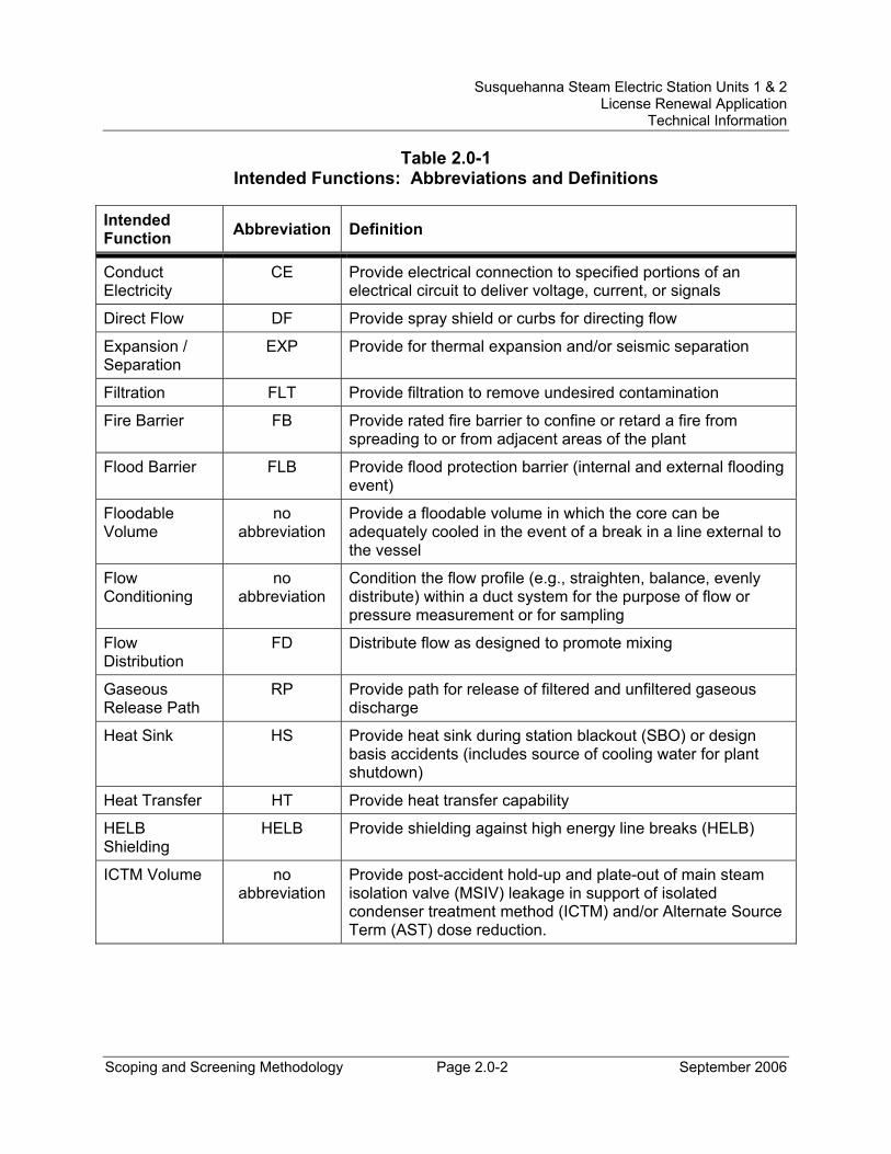
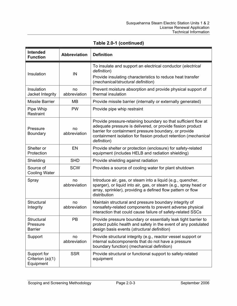
Table 2.0-1 provides the expanded definitions of the intended functions used for structures and components in this application. The pertinent tables in the application may refer to either the intended function name or the corresponding abbreviation defined in Table 2.0-1.
Susquehanna Steam Electric Station Units 1 & 2 License Renewal Application
Technical Information
Scoping and Screening Methodology Page 2.0-2 September 2006
Table 2.0-1 Intended Functions: Abbreviations and Definitions
Intended Function Abbreviation Definition
Conduct Electricity
CE Provide electrical connection to specified portions of an electrical circuit to deliver voltage, current, or signals
Direct Flow DF Provide spray shield or curbs for directing flow
Expansion / Separation
EXP Provide for thermal expansion and/or seismic separation
Filtration FLT Provide filtration to remove undesired contamination
Fire Barrier FB Provide rated fire barrier to confine or retard a fire from spreading to or from adjacent areas of the plant
Flood Barrier FLB Provide flood protection barrier (internal and external flooding event)
Floodable Volume
no abbreviation
Provide a floodable volume in which the core can be adequately cooled in the event of a break in a line external to the vessel
Flow Conditioning
no abbreviation
Condition the flow profile (e.g., straighten, balance, evenly distribute) within a duct system for the purpose of flow or pressure measurement or for sampling
Flow Distribution
FD Distribute flow as designed to promote mixing
Gaseous Release Path
RP Provide path for release of filtered and unfiltered gaseous discharge
Heat Sink HS Provide heat sink during station blackout (SBO) or design basis accidents (includes source of cooling water for plant shutdown)
Heat Transfer HT Provide heat transfer capability
HELB Shielding
HELB Provide shielding against high energy line breaks (HELB)
ICTM Volume no abbreviation
Provide post-accident hold-up and plate-out of main steam isolation valve (MSIV) leakage in support of isolated condenser treatment method (ICTM) and/or Alternate Source Term (AST) dose reduction.
Susquehanna Steam Electric Station Units 1 & 2 License Renewal Application
Technical Information
Scoping and Screening Methodology Page 2.0-3 September 2006
Table 2.0-1 (continued)
Intended Function Abbreviation Definition
Insulation IN
To insulate and support an electrical conductor (electrical definition) Provide insulating characteristics to reduce heat transfer (mechanical/structural definition)
Insulation Jacket Integrity
no abbreviation
Prevent moisture absorption and provide physical support of thermal insulation
Missile Barrier MB Provide missile barrier (internally or externally generated)
Pipe Whip Restraint
PW Provide pipe whip restraint
Pressure Boundary
no abbreviation
Provide pressure-retaining boundary so that sufficient flow at adequate pressure is delivered, or provide fission product barrier for containment pressure boundary, or provide containment isolation for fission product retention (mechanical definition)
Shelter or Protection
EN Provide shelter or protection (enclosure) for safety-related equipment (includes HELB and radiation shielding)
Shielding SHD Provide shielding against radiation
Source of Cooling Water
SCW Provides a source of cooling water for plant shutdown
Spray no abbreviation
Introduce air, gas, or steam into a liquid (e.g., quencher, sparger), or liquid into air, gas, or steam (e.g., spray head or array, sprinkler), providing a defined flow pattern or flow distribution
Structural Integrity
no abbreviation
Maintain structural and pressure boundary integrity of nonsafety-related components to prevent adverse physical interaction that could cause failure of safety-related SSCs
Structural Pressure Barrier
PB Provide pressure boundary or essentially leak tight barrier to protect public health and safety in the event of any postulated design basis events (structural definition)
Support no abbreviation
Provide structural integrity (e.g., reactor vessel support or internal subcomponents that do not have a pressure boundary function) (mechanical definition)
Support for Criterion (a)(1) Equipment
SSR Provide structural or functional support to safety-related equipment
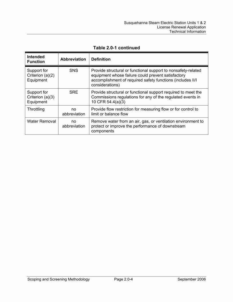
Susquehanna Steam Electric Station Units 1 & 2 License Renewal Application
Technical Information
Scoping and Screening Methodology Page 2.0-4 September 2006
Table 2.0-1 continued
Intended Function Abbreviation Definition
Support for Criterion (a)(2) Equipment
SNS Provide structural or functional support to nonsafety-related equipment whose failure could prevent satisfactory accomplishment of required safety functions (includes II/I considerations)
Support for Criterion (a)(3) Equipment
SRE Provide structural or functional support required to meet the Commissions regulations for any of the regulated events in 10 CFR 54.4(a)(3)
Throttling no abbreviation
Provide flow restriction for measuring flow or for control to limit or balance flow
Water Removal no abbreviation
Remove water from an air, gas, or ventilation environment to protect or improve the performance of downstream components
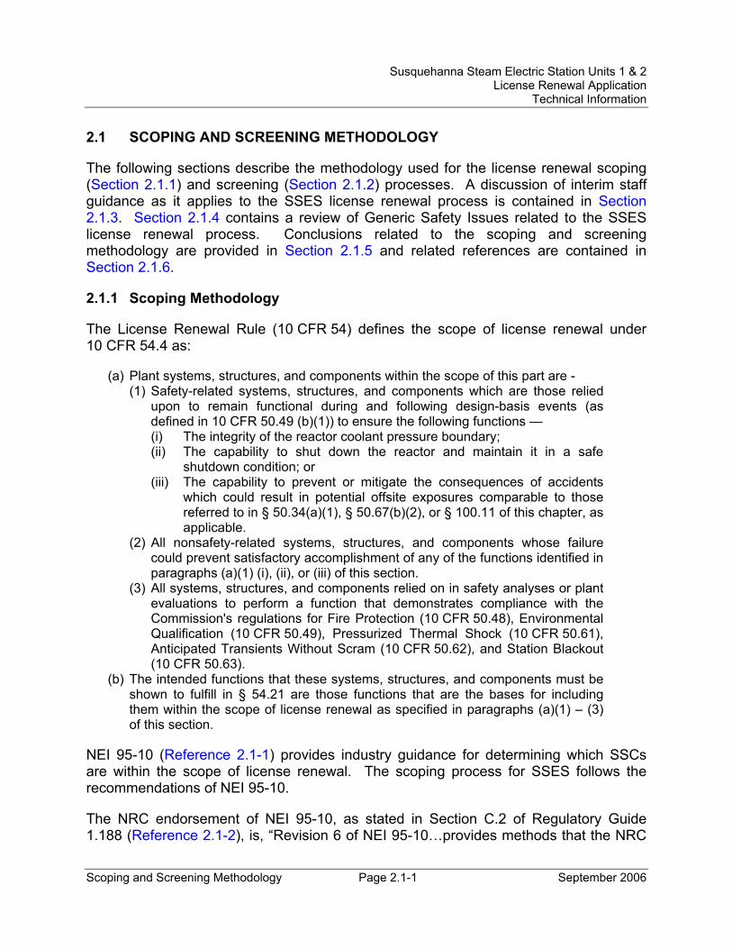
Susquehanna Steam Electric Station Units 1 & 2 License Renewal Application
Technical Information
Scoping and Screening Methodology Page 2.1-1 September 2006
2.1 SCOPING AND SCREENING METHODOLOGY
The following sections describe the methodology used for the license renewal scoping (Section 2.1.1) and screening (Section 2.1.2) processes. A discussion of interim staff guidance as it applies to the SSES license renewal process is contained in Section 2.1.3. Section 2.1.4 contains a review of Generic Safety Issues related to the SSES license renewal process. Conclusions related to the scoping and screening methodology are provided in Section 2.1.5 and related references are contained in Section 2.1.6.
2.1.1 Scoping Methodology
The License Renewal Rule (10 CFR 54) defines the scope of license renewal under 10 CFR 54.4 as:
(a) Plant systems, structures, and components within the scope of this part are - (1) Safety-related systems, structures, and components which are those relied
upon to remain functional during and following design-basis events (as defined in 10 CFR 50.49 (b)(1)) to ensure the following functions — (i) The integrity of the reactor coolant pressure boundary; (ii) The capability to shut down the reactor and maintain it in a safe
shutdown condition; or (iii) The capability to prevent or mitigate the consequences of accidents
which could result in potential offsite exposures comparable to those referred to in § 50.34(a)(1), § 50.67(b)(2), or § 100.11 of this chapter, as applicable.
(2) All nonsafety-related systems, structures, and components whose failure could prevent satisfactory accomplishment of any of the functions identified in paragraphs (a)(1) (i), (ii), or (iii) of this section.
(3) All systems, structures, and components relied on in safety analyses or plant evaluations to perform a function that demonstrates compliance with the Commission's regulations for Fire Protection (10 CFR 50.48), Environmental Qualification (10 CFR 50.49), Pressurized Thermal Shock (10 CFR 50.61), Anticipated Transients Without Scram (10 CFR 50.62), and Station Blackout (10 CFR 50.63).
(b) The intended functions that these systems, structures, and components must be shown to fulfill in § 54.21 are those functions that are the bases for including them within the scope of license renewal as specified in paragraphs (a)(1) – (3) of this section.
NEI 95-10 (Reference 2.1-1) provides industry guidance for determining which SSCs are within the scope of license renewal. The scoping process for SSES follows the recommendations of NEI 95-10.
The NRC endorsement of NEI 95-10, as stated in Section C.2 of Regulatory Guide 1.188 (Reference 2.1-2), is, “Revision 6 of NEI 95-10…provides methods that the NRC
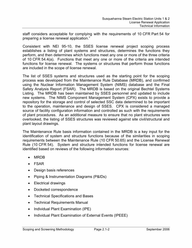
Susquehanna Steam Electric Station Units 1 & 2 License Renewal Application
Technical Information
Scoping and Screening Methodology Page 2.1-2 September 2006
staff considers acceptable for complying with the requirements of 10 CFR Part 54 for preparing a license renewal application.”
Consistent with NEI 95-10, the SSES license renewal project scoping process establishes a listing of plant systems and structures, determines the functions they perform, and then determines which functions meet any one or more of the three criteria of 10 CFR 54.4(a). Functions that meet any one or more of the criteria are intended functions for license renewal. The systems or structures that perform those functions are included in the scope of license renewal.
The list of SSES systems and structures used as the starting point for the scoping process was developed from the Maintenance Rule Database (MRDB), and confirmed using the Nuclear Information Management System (NIMS) database and the Final Safety Analysis Report (FSAR). The MRDB is based on the original Bechtel Systems Listing. The MRDB has been maintained by SSES personnel and updated to include new systems. The NIMS Component Management System (CPX) exists to provide a repository for the storage and control of selected SSC data determined to be important to the operation, maintenance and design of SSES. CPX is considered a managed source of facility configuration information and controlled as such with the requirements of plant procedures. As an additional measure to ensure that no plant structures were overlooked, the listing of SSES structures was reviewed against site civil/structural and plant layout drawings.
The Maintenance Rule basis information contained in the MRDB is a key input for the identification of system and structure functions because of the similarities in scoping requirements between the Maintenance Rule (10 CFR 50.65) and the License Renewal Rule (10 CFR 54). System and structure intended functions for license renewal are identified based on reviews of the following information sources:
• MRDB
• FSAR
• Design basis references
• Piping & Instrumentation Diagrams (P&IDs)
• Electrical drawings
• Docketed correspondence
• Technical Specifications and Bases
• Technical Requirements Manual
• Individual Plant Examination (IPE)
• Individual Plant Examination of External Events (IPEEE)
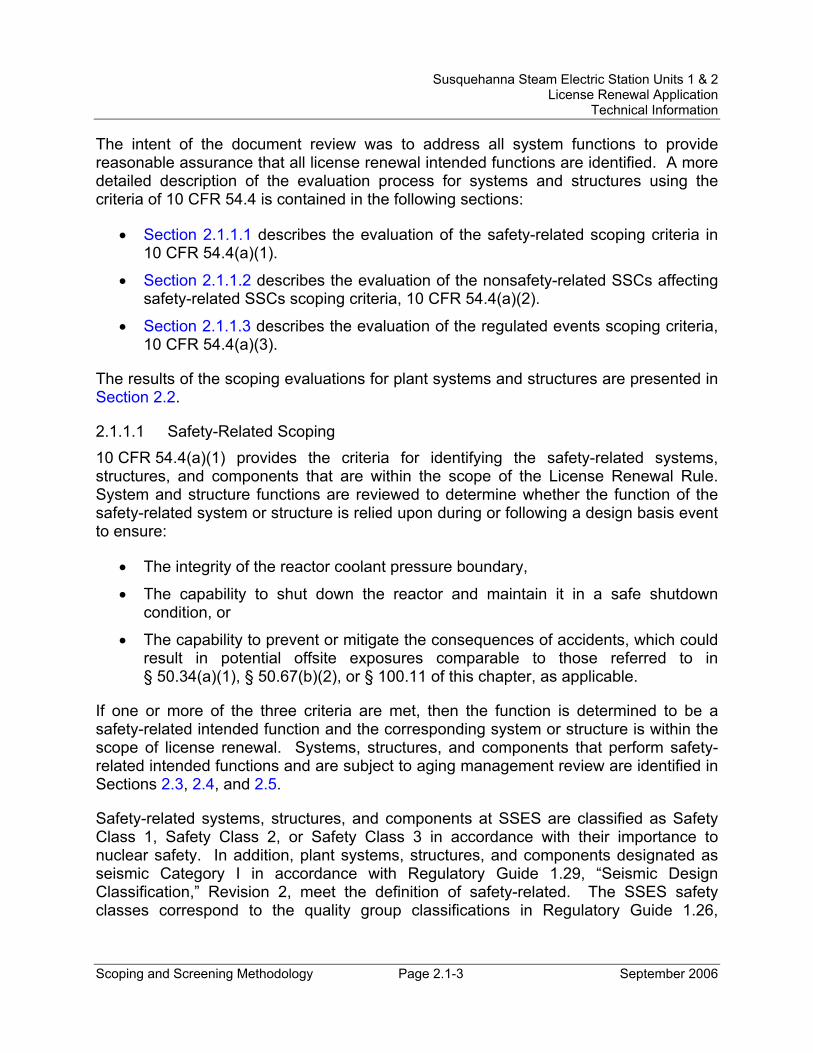
Susquehanna Steam Electric Station Units 1 & 2 License Renewal Application
Technical Information
Scoping and Screening Methodology Page 2.1-3 September 2006
The intent of the document review was to address all system functions to provide reasonable assurance that all license renewal intended functions are identified. A more detailed description of the evaluation process for systems and structures using the criteria of 10 CFR 54.4 is contained in the following sections:
• Section 2.1.1.1 describes the evaluation of the safety-related scoping criteria in 10 CFR 54.4(a)(1).
• Section 2.1.1.2 describes the evaluation of the nonsafety-related SSCs affecting safety-related SSCs scoping criteria, 10 CFR 54.4(a)(2).
• Section 2.1.1.3 describes the evaluation of the regulated events scoping criteria, 10 CFR 54.4(a)(3).
The results of the scoping evaluations for plant systems and structures are presented in Section 2.2.
2.1.1.1 Safety-Related Scoping 10 CFR 54.4(a)(1) provides the criteria for identifying the safety-related systems, structures, and components that are within the scope of the License Renewal Rule. System and structure functions are reviewed to determine whether the function of the safety-related system or structure is relied upon during or following a design basis event to ensure:
• The integrity of the reactor coolant pressure boundary,
• The capability to shut down the reactor and maintain it in a safe shutdown condition, or
• The capability to prevent or mitigate the consequences of accidents, which could result in potential offsite exposures comparable to those referred to in § 50.34(a)(1), § 50.67(b)(2), or § 100.11 of this chapter, as applicable.
If one or more of the three criteria are met, then the function is determined to be a safety-related intended function and the corresponding system or structure is within the scope of license renewal. Systems, structures, and components that perform safety-related intended functions and are subject to aging management review are identified in Sections 2.3, 2.4, and 2.5.
Safety-related systems, structures, and components at SSES are classified as Safety Class 1, Safety Class 2, or Safety Class 3 in accordance with their importance to nuclear safety. In addition, plant systems, structures, and components designated as seismic Category I in accordance with Regulatory Guide 1.29, “Seismic Design Classification,” Revision 2, meet the definition of safety-related. The SSES safety classes correspond to the quality group classifications in Regulatory Guide 1.26,
Susquehanna Steam Electric Station Units 1 & 2 License Renewal Application
Technical Information
Scoping and Screening Methodology Page 2.1-4 September 2006
“Quality Group Classifications and Standards for Water-, Steam-, and Radioactive-Waste-Containing Components of Nuclear Power Plants,” Revision 3.
Safety-related as defined in Section 17.2.2 of the SSES FSAR are those systems, structures, and components that meet one or more of the following requirements:
• Maintain the integrity of the Reactor Coolant System Pressure Boundary (RCSPB).
• Assure the capability to prevent or mitigate the consequences of accidents that could cause the release of radioactivity in excess of 10 CFR 100 limits.
• Preclude failures that could cause or increase the severity of postulated accidents or could cause undue risk to the health and safety of the public due to the release of radioactive material.
• Provide for safe reactor shutdown and immediate or long-term post-accident control.
The SSES definition of safety-related is consistent with 10 CFR54.4(a)(1) with the exception that the Rule includes reference to 10 CFR 50.34(a)(1) and 10 CFR 50.67(b). The dose guidelines of 10 CFR 50.34(a)(1) are associated with facilities seeking a construction permit and therefore are not applicable to SSES license renewal. The dose guidelines of 10 CFR 50.67(b) are associated with accident source term limits. PPL Susquehanna, LLC has submitted a license amendment request to the NRC to authorize the use of Alternate Source Term (AST) under 50.67(b)(2) in support of the ongoing SSES Extended Power Uprate Project (Reference 2.1-3). Consistent with the AST license amendment request, license renewal scoping impacts arising from the use of nonsafety-related equipment to support the use of an AST are evaluated against the criteria of 10 CFR 54.4(a)(2) and are addressed in the following section.
Systems and structures meeting the safety-related criteria for SSES were determined based on review of the FSAR, Maintenance Rule database, P&ID line class designations, and equipment classifications in the NIMS database.
2.1.1.2 Nonsafety-Related SSCs Affecting Safety-Related SSCs Scoping 10 CFR 54.4(a)(2) requires that all nonsafety-related systems, structures, and components (SSCs) whose failure could prevent satisfactory accomplishment of a safety function, referred to as “non-safety affecting safety” (NSAS1), be included in the scope of license renewal. In order to provide reasonable assurance that all such SSCs are identified, it is necessary to consider the impact of failures of nonsafety-related SSCs as either functional or spatial. Appendix F of NEI 95-10 (Reference 2.1-1) contains guidance on scoping for NSAS. 1 NSAS is also referred to as ‘Criterion 2’, ‘C2’, ‘II/I’, ‘(a)(2)’, and/or ‘A2’ in various industry documents, and includes Safety Impact Items (SIIs) at SSES.
Susquehanna Steam Electric Station Units 1 & 2 License Renewal Application
Technical Information
Scoping and Screening Methodology Page 2.1-5 September 2006
In a functional failure, the failure of a nonsafety-related SSC to perform its normal function adversely impacts the successful accomplishment of a safety function. In a spatial failure, the loss of structural or pressure boundary integrity of a nonsafety-related structure or component in physical proximity to a safety-related component impacts a safety function of the safety-related component. The evaluation of functional failures and spatial failures with respect to license renewal is described further in the sections below.
2.1.1.2.1 Functional Failures of Nonsafety-Related SSCs At SSES, SSCs required to perform a function in support of safety-related components are classified as safety-related and are included in the scope of license renewal per Section 2.1.1.1. Where nonsafety-related equipment is required to remain functional in support of a safety function, the supporting systems are included in the scope of license renewal under 10 CFR 54.4(a)(2). Systems, and corresponding functions, are also included in this category as a result of a pending change to the AST methodology, as presented in Regulatory Guide 1.183 with respect to control room habitability.
Engineering and licensing documents were reviewed to determine the appropriate systems and structures in this category. The applicable sections of the FSAR, MRDB, and design basis references provide the system and structure functional information to address these considerations. Systems, structures, and components that perform nonsafety-related intended functions credited in the current licensing basis and are subject to aging management review are identified in Sections 2.3, 2.4, and 2.5.
2.1.1.2.2 Spatial Failures of Nonsafety-Related SSCs Nonsafety-related systems and nonsafety-related portions of safety-related systems are identified as in scope under 10 CFR 54.4(a)(2) if there is a potential for spatial interactions with safety-related equipment. Spatial failures are defined as failures of nonsafety-related SSCs that are connected to or located in the vicinity (i.e., same building) of safety-related SSCs creating the potential for interaction between the SSCs due to physical impact, harsh environment, flooding, spray or leakage that could impede or prevent the accomplishment of the safety-related function(s) of a safety-related SSC. Spatial failures that meet the NSAS scoping criterion include both nonsafety-related SSCs in the general vicinity of, but not connected to, safety-related equipment and nonsafety-related SSCs directly connected to safety-related SSCs.
Certain mitigative features, such as missile barriers, flood barriers, and spray shields, are credited in the current licensing basis for the protection of safety-related SSCs from spatial interaction. These protective features are included in the scope of license renewal per Section 2.1.1.2.1 and evaluated as structural components. In addition, the preventive option described in Appendix F of NEI 95-10 (Reference 2.1-1) is used to determine the scope of license renewal with respect to the protection of safety-related SSCs from spatial interactions that are not addressed in the current licensing basis. This scoping process requires an evaluation based on equipment location and the
Susquehanna Steam Electric Station Units 1 & 2 License Renewal Application
Technical Information
Scoping and Screening Methodology Page 2.1-6 September 2006
consequences of a nonsafety-related component failure, rather than on the equipment function itself. A conservative “spaces” approach is used that is focused on an entire structure (e.g., Reactor Building) rather than being limited to specific areas inside a structure. In this manner all fluid (liquid or steam) containing components and components associated with safety-related to nonsafety-related interfaces are evaluated for potential spatial interactions, with no rooms/areas or area-to-area transitions overlooked.
Structures consisting of the Reactor Building, Control Structure, Diesel Generator Buildings, and Engineered Safeguards Service Water Pumphouse are seismic Category I and contain safety-related components. Except as noted below, nonsafety-related components located in these structures that are connected to safety-related SSCs or that contain a liquid/steam have the potential for spatial interaction, satisfy the 10 CFR 54.4(a)(2) criterion and the systems are in scope for license renewal.
The Primary Containment is also seismic Category I and contains safety-related components. Nonsafety-related systems, and nonsafety-related portions of safety-related systems, located in Primary Containment are not in scope for license renewal because safety-related systems in the structure are specifically designed for spatial interactions. This includes qualification for service in harsh environments that bound any potential spray, leakage or flooding and protection from pipe whip or jet impingement by separation, barriers and pipe whip restraints. Furthermore, high-energy lines inside containment are safety-related, satisfy the 10 CFR 54.4(a)(1) criteria, and are included in the scope of license renewal.
An important aspect in the scope of spatial failures of nonsafety-related SSCs for SSES is the fact that there are no components located in the Turbine Building that either perform or would prevent a safety-related function from occurring. This is documented in the current licensing bases and confirmed through evaluation for license renewal. This means that:
1) Nonsafety-related systems located only in the Turbine Building and not connected to safety-related systems do not satisfy the 10 CFR 54.4(a)(2) criterion and are not in the scope of license renewal.
2) Nonsafety-related portions of systems that are directly connected to safety-related piping and in the Turbine Building are included in the scope of license renewal up to the first seismic restraint, or anchor to plant structure, beyond the seismic Category I structure, as described below.
Nonsafety-related structural components such as hangers, supports, barriers and other protective features are included in the scope of license renewal if they are located in a plant structure that contains systems or components that satisfy one or more of the license renewal scoping criteria. Nonsafety-related SSCs are included in the scope of license renewal due to the potential for spatial failures if directly connected to safety-
Susquehanna Steam Electric Station Units 1 & 2 License Renewal Application
Technical Information
Scoping and Screening Methodology Page 2.1-7 September 2006
related SSCs and if fluid-filled system components are located in the same building or miscellaneous area as safety-related equipment, unless justification is provided that failures would not impact a safety function. Consistent with the related industry discussions in NEI 95-10 (Reference 2.1-1), Appendix F, failure of nonsafety-related components that do not contain a fluid (liquid or steam) will not result in spatial interaction as there is no fluid to leak or spray onto safety-related SSCs and system pressure is such that there is no force that could cause significant movement of the failed component. This conclusion is confirmed by review of SSES and industry operating experience.
Section 3.13 of the SSES FSAR addresses compliance with Regulatory Guide 1.29, Seismic Design Classification. With respect to nonsafety-related piping that is directly connected to safety-related piping, the seismic Category I design requirements are extended ‘to the first seismic restraint beyond the defined boundaries.’ The seismic design is extended to the first point in the system which can be treated as an anchor to the plant structure. An anchor support is defined in SSES piping design specifications as a rigid support that restrains all 6 degrees of motion of the piping system. Anchors can include large fixed equipment such as pumps, tanks, heat exchangers, and in some cases, larger piping. The nonsafety-related structural components in the scope of license renewal include those that comprise seismic anchors. As such, and since the “spaces” approach is conservative (focusing on the structure rather than on specific areas within the structure), all seismic anchors and the associated piping and components for nonsafety-related to safety-related interfaces are in the scope of license renewal under 10 CFR 54.4(a)(2) using the base-mounted equipment and flexible connection options from NEI 95-10 (Reference 2.1-1), Appendix F, as well as including the entire length of piping that is connected on both ends to safety-related piping.
However, unique identification and description of these interfaces is obviated by this conservative approach and not required for license renewal unless the first seismic restraint, or anchor to plant structure, extends beyond the safety-related structures. Instances of a nonsafety-related to safety-related interface that extends to locations outside of safety-related structures are determined through review of the pertinent drawing/document or by physical walkdown. Otherwise, the structure-based “spaces” approach bounds the determination of nonsafety-related to safety-related interface boundaries. Systems, structures, and components that perform nonsafety-related intended functions for spatial considerations are identified in Sections 2.3 and 2.4.
2.1.1.2.3 Alternate Source Terms PPL Susquehanna, LLC has submitted a license amendment request to implement the use of Alternate Source Terms for evaluation of accident consequences in accordance with 10 CFR 50.67. This activity, undertaken in support of the SSES Extended Power Uprate (EPU) project, makes use of an NRC approved methodology for evaluation of a nonsafety-related alternate leakage treatment path from the main steam line isolation valves (MSIVs) to the main condenser. Since the license amendment request credits
Susquehanna Steam Electric Station Units 1 & 2 License Renewal Application
Technical Information
Scoping and Screening Methodology Page 2.1-8 September 2006
the use of nonsafety-related SSCs in alternate source term analyses, these have been brought into scope under 10 CFR 54.4(a)(2).
2.1.1.3 Regulated Events Scoping Per 10 CFR 54.4(a)(3), the scope of license renewal includes all SSCs relied on in safety analyses or plant evaluations to perform a function that demonstrates compliance with the Commission's regulations for any of the following regulated events:
• Fire Protection (FP) (10 CFR 50.48)
• Environmental Qualification (EQ) (10 CFR 50.49)
• Pressurized Thermal Shock (PTS) (10 CFR 50.61)
• Anticipated Transients Without Scram (ATWS) (10 CFR 50.62)
• Station Blackout (SBO) (10 CFR 50.63)
The SSCs that are required for compliance with one or more of the above regulated events are determined by review of plant engineering documents and the pertinent current licensing basis documents, including the FSAR, Fire Protection Review Report (FPRR) (Reference 2.1-4), and the applicable docketed correspondence between PPL and the NRC. The evaluation method for each regulated event is described further below.
This section discusses the approach used to identify the systems and structures within the scope of license renewal based on the regulated events criteria. Systems, structures, and components that perform intended functions required for compliance with a regulated event and are subject to aging management review are identified in Sections 2.3, 2.4, and 2.5.
2.1.1.3.1 Fire Protection (10 CFR 50.48) SSES was licensed after January 1, 1979 and is therefore not bound to the provisions of 10 CFR 50.48(b). However, as a result of licensing commitments and the standard fire protection licensing condition for plants licensed after the January 1, 1979 date, SSES has a FPRR (Reference 2.1-4) which addresses compliance with the pertinent regulations. In addition, the SSES fire protection system is addressed specifically in Section 9.5.1 of NUREG-0776, “Safety Evaluation Report related to the Operation of Susquehanna Steam Electric Station Units 1 and 2” and the applicable supplements (Reference 2.1-5).
The FPRR, submitted by PPL to the NRC, describes the fire protection features that ensure the capability to achieve and maintain the cold (safe) shutdown of SSES Units 1 and 2 and demonstrates compliance to the requirements of Appendix A to Branch Technical Position Auxiliary Power Conversion Systems Branch 9.5-1 (BTP APCSB 9.5-1); 10 CFR 50 Appendix R Sections III.G, III.J, III.L and III.O; 10 CFR 50.48;
Susquehanna Steam Electric Station Units 1 & 2 License Renewal Application
Technical Information
Scoping and Screening Methodology Page 2.1-9 September 2006
and General Design Criterion 3 of Appendix A to 10 CFR 50. The FPRR includes a safe shutdown analysis (to demonstrate compliance with Appendix R), description of the fire protection system (including requirements for compliance), the Fire Hazard Analysis (demonstrates that a single postulated fire will not affect the ability of both units to be brought to and maintained in cold shutdown condition), and any deviation requests.
Based on review of the SSES current licensing bases for fire protection, systems and structures relied on for fire protection, as well as the corresponding intended functions, are determined. This determination includes both the features required for fire protection of safety-related equipment and any system function that was included in, or provides necessary support for, one or more of the three (3) safe shutdown paths credited for compliance with Appendix R. SSCs that perform an intended function for fire protection are included in the scope of license renewal.
2.1.1.3.2 Environmental Qualification (10 CFR 50.49) Electrical components relied upon in safety analyses or plant evaluations to perform a function that requires demonstrated compliance with 10 CFR 50.49 are within the scope of license renewal per 10 CFR 54.4(a)(3).
The components in the Environmental Qualification (EQ) program, required by 10 CFR 50.49, include both safety-related and nonsafety-related electrical components required for accident mitigation, post-accident monitoring, and safe shutdown.
Environmental qualification at SSES applies to electrical equipment installed in mechanical systems, such as instruments or valve operators in a fluid system, and electrical equipment installed in electrical systems. Electrical equipment that is required to be environmentally qualified, in both mechanical and electrical systems, is identified. In this way, no electrical components are overlooked. EQ does not apply to structures or structural components.
The electrical equipment at SSES, which is required to be environmentally qualified for a “harsh” environment by 10 CFR 50.49, is identified in the SSES Nuclear Information Management System (NIMS) database. Electrical components, excluding cables, and mechanical components that receive electrical power or signals are assigned to a system and have a component identification number in the database. Thereby, the electrical components, and electrical portions of mechanical components, required to demonstrate compliance with 10 CFR 50.49 can be associated with a system. Systems that include environmentally-qualified components satisfy the EQ scoping criterion of 10 CFR 54.4(a)(3) and are in the scope of license renewal.
The basic function of EQ is to ensure that electrical equipment located in a harsh environment is qualified to operate in that environment in order to perform the safety functions of accident mitigation, post-accident monitoring, and safe shutdown. Based on a review of the SSES current licensing basis for EQ, the intended functions for each
Susquehanna Steam Electric Station Units 1 & 2 License Renewal Application
Technical Information
Scoping and Screening Methodology Page 2.1-10 September 2006
system supporting the 10 CFR 50.49 requirements are determined. SSCs that perform an intended function for EQ are included in the scope of license renewal.
2.1.1.3.3 Pressurized Thermal Shock (10 CFR 50.61) As defined in 10 CFR 50.61, a pressurized thermal shock event means an event or transient in a pressurized water reactor (PWR) causing severe overcooling (thermal shock) concurrent with or followed by significant pressure in the reactor vessel. Because SSES Units 1 and 2 are boiling water reactor (BWR) designs, the regulation is not applicable and further evaluation of the related scoping criteria is not required for SSES license renewal.
2.1.1.3.4 Anticipated Transients Without Scram (10 CFR 50.62) An anticipated transient without scram (ATWS) event is an anticipated operational occurrence that is accompanied by a failure of the reactor trip portion of the Reactor Protection System to shut down the reactor. 10 CFR 50.62 requires specific improvements in the design and operation of commercial nuclear power facilities to reduce the probability of failure to shut down the reactor following anticipated transients and to mitigate the consequences of an ATWS event. SSES FSAR Section 15.8 addresses the evaluation of ATWS transients, with FSAR Appendix 15A providing historical evaluation information.
In April 1987, PPL provided the NRC with a report that describes the specific ATWS design for Susquehanna Units 1 and 2. The report demonstrates the adequacy of the Standby Liquid Control (SLC), Alternate Rod Injection (ARI), and Reactor Recirculation Pump Trip (RPT) systems to meet the requirements of 10 CFR 50.62. The NRC issued its safety evaluation documenting the acceptability of these SSES systems on October 18, 1988 (Reference 2.1-6). PPL responded to NRC staff items regarding verification of ARI testing and Technical Specification for minimum SLC boron concentration in the October 18, 1988 safety evaluation report via a letter dated March 20, 1989 (Reference 2.1-7).
Subsequently in July of 1996, PPL informed the NRC of an ATWS reanalysis using stretch (~4.5 percent) power uprate conditions. The PPL analysis of ATWS performance for power uprate conditions evaluates seven different ATWS scenarios and describes the sequences of events for these scenarios, including the identification of automatic and manual operations of the ATWS mitigation systems and of any other safety system functions credited in the evaluation.
FSAR Section 15.8 was updated based on this reanalysis and considers the seven initiating events (operational transients) required by Regulatory Guide (RG) 1.70 Revision 2 and three additional initiating events examined as part of the SSES power uprate.
Susquehanna Steam Electric Station Units 1 & 2 License Renewal Application
Technical Information
Scoping and Screening Methodology Page 2.1-11 September 2006
Most recently, in 2005, PPL revised the ATWS analysis in anticipation of Maximum Extended Load Line Limit Analysis (MELLLA) operating domain. In addition, a revised analysis has been performed in anticipation of an extended power uprate initiative. These reanalyses were performed consistent with the guidelines provided in General Electric (GE) analyses which have been reviewed and accepted by the staff. These analyses assumed the same equipment failures, as well as automatic and manual operations of the ATWS mitigation systems, as used for the previous analysis.
Based on a review of the SSES current and proposed licensing basis for ATWS, the intended functions for each system and structure supporting the 10 CFR 50.62 requirements are determined. SSCs that perform an intended function for ATWS are included in the scope of license renewal.
2.1.1.3.5 Station Blackout (10 CFR 50.63) 10 CFR 50.63 requires that each light-water-cooled nuclear power plant be able to withstand and recover from a station blackout. A station blackout (SBO) is defined in the regulations as the loss of offsite and onsite alternating current (AC) electric power to the essential and nonessential switchgear buses in a nuclear power plant. It does not include the loss of AC power fed from inverters powered by station batteries. The objective of this requirement is to assure that nuclear power plants are capable of withstanding an SBO and maintaining adequate reactor core cooling and containment integrity for a required duration.
In response to the issuance of the SBO Rule, PPL evaluated SSES against the applicable regulatory requirements in 10 CFR 50.63. The SBO evaluation is documented in an SSES coping assessment, which demonstrates the capability of installed equipment at SSES to operate systems necessary for coping with an SBO event, and to bring the plant to, and maintain it in, a safe shutdown condition.
The SSES coping assessment has been reviewed and accepted by the NRC in the Safety Evaluation Report (SER) dated January 14, 1992 (Reference 2.1-8), and an SER supplement dated June 16, 1992 (Reference 2.1-9).
At SSES, all plant equipment (i.e., systems and instrumentation) necessary to cope with SBO, recover from SBO, and ensure Primary Containment isolations was identified and investigated to assure that all items necessary for the equipment to function would be available for at least four hours. This is the equipment relied upon for compliance with 10 CFR 50.63.
NUREG-1800, Revision 1, contains additional considerations related to the determination of SBO scoping boundaries for license renewal. The NUREG addresses the determination of the boundaries of the plant system portion of the offsite power system relied upon to restore the offsite power for license renewal considerations.
Susquehanna Steam Electric Station Units 1 & 2 License Renewal Application
Technical Information
Scoping and Screening Methodology Page 2.1-12 September 2006
Based on a review of the SSES current licensing basis for SBO, the intended functions for each system and structure supporting the 10 CFR 50.63 requirements are determined. The guidance in NUREG-1800 is used to identify any additional systems and structures performing an intended function for SBO. SSCs that perform an intended function for SBO are included in the scope of license renewal.
2.1.1.4 Scoping Boundary Determination The license renewal evaluation boundaries include those portions of the SSCs that are necessary to ensure that the intended functions will be performed. Structures and components needed to support each of the system/structure-level intended functions identified in the scoping process are included within the evaluation boundary.
2.1.1.4.1 Mechanical Systems Determination of the mechanical system evaluation boundary requires an understanding of system operations in support of intended functions. This process is based on review of the following information sources:
• Piping & Instrumentation Diagrams (P&IDs)
• Design basis references
• Maintenance Rule basis documents
• Component databases
• SSES current licensing basis documents
Of the documents that form the current licensing basis for SSES, those documents that are applicable for license renewal are the Design Assessment Report (DAR)/Design Basis Document (DBD) 046, “Design Basis Document for Seismic & Hydrodynamic Loads,” docketed regulatory commitment correspondence, the Environmental Protection Plan (EPP), the Final Safety Analysis Report (FSAR), the Fire Protection Review Report (FPRR), the Offsite Dose Calculation Manual (ODCM), the Operating License(s) (OL), the Quality Assurance Program Description (QAPD), the Technical Requirements Manual (TRM), and the Technical Specifications (TS) and Bases.
The evaluation boundaries for mechanical systems are documented on license renewal boundary drawings created by marking mechanical piping and instrumentation diagrams to indicate the components within the scope of license renewal.
There are no nonsafety-related to safety-related interfaces for which the seismic restraint, or anchor to plant structure, is located in a building that is not in the scope of license renewal or in buried locations in the yard. The evaluation boundaries do include instances where the seismic restraint, or anchor to plant structure, for a nonsafety-related to safety-related interface is located in the Turbine Building.
Susquehanna Steam Electric Station Units 1 & 2 License Renewal Application
Technical Information
Scoping and Screening Methodology Page 2.1-13 September 2006
2.1.1.4.2 Structures Structural components that are attached to a structure or reside within a structure are categorized as either component supports (mechanical or electrical) or as other structural members.
Component Supports – Mechanical Components The evaluation boundaries for mechanical component supports are established in accordance with rules governing inspection of component supports (i.e., ASME Section XI, Subsection IWF). Component support examination boundaries for integral and non-integral (i.e., mechanically attached) supports are defined in Article IWF-1300, Figure IWF-1300-1. In general, the support boundary extends to the surface of the building structure, but does not include the building structure. Furthermore, the support boundary extends to include non-integral attachments to piping and equipment, but excludes integral attachments to the same. Component support examination boundaries for non-ASME in-scope components include the structural component and the associated attachment to the building structure (example: structural component supports for heating, ventilating, and air conditioning (HVAC) ducts include HVAC duct support members, baseplate and anchorage.)
Component Supports – Electrical Components Supports for electrical components include cable trays and conduit supports, electrical panels, racks, cabinets, and other enclosures. The evaluation boundary for these items includes all supporting elements, including mechanical or integral attachments to the building structure.
Other Structural Members Evaluation boundaries for other structural members whose function is to carry dynamic loads caused by postulated design basis events are consistent with the method for establishing boundaries for supports specified above. That is, the boundary includes the structural component and the associated attachment to the building structure. The portion of the attachment embedded in the building structure is considered part of the structure.
2.1.1.4.3 Electrical and Instrumentation and Control Systems A bounding scoping approach is used for electrical equipment. All electrical components are subject to aging management review unless they are scoped out at the system level or are screened out at the component level by commodity group, as described in Section 2.1.2.3 below. Therefore, detailed evaluation boundaries are not depicted for electrical scoping.
Susquehanna Steam Electric Station Units 1 & 2 License Renewal Application
Technical Information
Scoping and Screening Methodology Page 2.1-14 September 2006
2.1.2 Screening Methodology
Screening is the process for determining the structures and components that are subject to aging management review. The requirement for screening is found in 10 CFR 54.21(a), which states:
(1) For those systems, structures, and components within the scope of this part, as delineated in § 54.4, identify and list those structures and components subject to an aging management review. Structures and components subject to an aging management review shall encompass those structures and components— (i) That perform an intended function, as described in § 54.4, without moving parts or
without a change in configuration or properties. These structures and components include, but are not limited to, the reactor vessel, the reactor coolant system pressure boundary, steam generators, the pressurizer, piping, pump casings, valve bodies, the core shroud, component supports, pressure retaining boundaries, heat exchangers, ventilation ducts, the containment, the containment liner, electrical and mechanical penetrations, equipment hatches, seismic Category I structures, electrical cables and connections, cable trays, and electrical cabinets, excluding, but not limited to, pumps (except casing), valves (except body), motors, diesel generators, air compressors, snubbers, the control rod drive, ventilation dampers, pressure transmitters, pressure indicators, water level indicators, switchgears, cooling fans, transistors, batteries, breakers, relays, switches, power inverters, circuit boards, battery chargers, and power supplies; and
(ii) That are not subject to replacement based on a qualified life or specified time period.
(2) Describe and justify the methods used in paragraph (a)(1) of this section. (3) For each structure and component identified in paragraph (a)(1) of this section,
demonstrate that the effects of aging will be adequately managed so that the intended function(s) will be maintained consistent with the CLB for the period of extended operation.
NUREG-1800, “Standard Review Plan for Review of License Renewal Applications for Nuclear Power Plants” (Reference 2.1-10) and NEI 95-10, Appendix B (Reference 2.1-1) were used as the basis for the identification of passive structures and components. Most passive structures and components are long-lived. Although the requirements for the IPA are the same for all systems and structures, in practice the screening process differed for each of the mechanical, structural, and electrical disciplines. The screening process for each discipline meets the requirements of 10 CFR 54.21(a) and is described below.
2.1.2.1 Screening of Mechanical Systems For each mechanical system within the scope of license renewal, the screening process identifies those components that are subject to aging management review. Section 2.3 presents the results for mechanical systems from a functional standpoint and from a spatial interaction standpoint.
Susquehanna Steam Electric Station Units 1 & 2 License Renewal Application
Technical Information
Scoping and Screening Methodology Page 2.1-15 September 2006
2.1.2.1.1 Mechanical Component Groups Mechanical components are grouped, where practical, by component type. For example valves are evaluated as a component group. Unique mechanical components such as pumps, tanks, and heat exchangers are individually evaluated. Piping is evaluated as a component group and includes components that form part of the piping boundary such as fittings, couplings, reducers, elbows, thermowells, flanges, and welded attachments. Piping components such as tubing, expansion joints, and orifices are typically broken out into their own component groups based on materials and function. Bolting is treated as a component group and includes components such as bolts, studs, nuts, and washers.
2.1.2.1.2 Mechanical Component Intended Functions Components within the evaluation boundary are reviewed to determine whether they perform an intended function. Typically, components in mechanical systems perform a pressure boundary function. Some components may perform other functions such as heat transfer, filtration, or flow control. Intended functions are established based on whether a particular function of a component is necessary to support the system functions that meet the scoping criteria. Table 2.0-1 provides definitions of component and structure intended functions identified in this application.
Components that perform an intended function are evaluated to determine whether the function is performed in an active or passive manner. Only those components that perform an intended function in a passive manner (i.e., the component intended function is performed without moving parts or a change in configuration or properties) are subject to aging management review. Active portions of components are excluded from aging management review. For example, in the case of pumps, valves, fans, and dampers, the associated pump casings, valve bodies, fan housings, and damper housings may perform the component intended function of maintaining system pressure boundary integrity and therefore be subject to aging management review. The pump impellers, valve discs, and fan/damper blades are moving parts (i.e., active) and not subject to aging management review.
If the component is not subject to replacement based on a qualified life or specified time period, then it is considered long-lived. Components that are subject to replacement are addressed in replacement programs, which may be based on vendor recommendations, plant experience, or other means that establish a service life, qualified life, or replacement frequency.
Components that perform an intended function and are passive and long-lived are subject to aging management review. Components are evaluated with the system to which they are assigned on plant drawings, for example, both the shell and tubes sides of heat exchangers are evaluated with the system in which the heat exchanger is depicted on the piping and instrumentation diagrams.
Susquehanna Steam Electric Station Units 1 & 2 License Renewal Application
Technical Information
Scoping and Screening Methodology Page 2.1-16 September 2006
2.1.2.1.3 Mechanical Components NSAS Functions The process for screening of nonsafety-related components that are in the scope of license renewal due to the potential for spatial interactions with safety-related equipment is consistent with, and based upon, the more traditional screening process for mechanical components described above. However, the primary factor for evaluation of nonsafety-related components with the potential for spatial interaction with safety-related equipment is component location rather than specific function. Furthermore, the pertinent plant systems and components do not have unique functions, but rather share the common intended function of “structural integrity,” as defined in Table 2.0-1. This common function is assigned to nonsafety-related components that are connected to and provide support for safety-related SSCs as well as to those containing liquid/steam that are in the same building as safety-related SSCs.
As such, screening of nonsafety-related mechanical components with the potential for adverse spatial interaction with safety-related components is performed on a component group basis similar to the screening of structural members and components described in Section 2.1.2.2 below. For example, component groups for NSAS include valves, pumps, tubing, and other in-line components as piping and piping components. Because the process is based on the traditional mechanical screening, only passive and long-lived component groups are identified. Components in the scope of license renewal under 10 CFR 54.4(a)(2) for spatial interaction considerations are subject to aging management review, unless it can be reasonably demonstrated that degradation will not result in adverse impact to safety-related components.
2.1.2.2 Screening of Structures For each structure within the scope of license renewal, the screening process identifies those structural components that are subject to aging management review. Section 2.4 presents the results for structures.
The screening process for structural components involves a review of design documents (FSAR, drawings, etc.) to identify the specific structural components that make up the structure.
2.1.2.2.1 Structural Commodity Groups Structural components typically do not have unique identifiers similar to those provided for mechanical components. Therefore, grouping structural components and commodities first based on materials of construction and then subdividing them based on component design and function provides a practical means of categorizing them for aging management review.
Commodity groups are based on materials of construction, such as steel, concrete, elastomers, or earthen. Once the structural commodity groups are identified within an in-scope structure or building the commodity groups are subdivided into discrete
Susquehanna Steam Electric Station Units 1 & 2 License Renewal Application
Technical Information
Scoping and Screening Methodology Page 2.1-17 September 2006
structural component types based on design, such as walls, floors, fire doors, and equipment supports.
2.1.2.2.2 Identifying Components Subject to Aging Management Review Structures contain inherently passive, long-lived structural components. Therefore, the structural components within the scope of license renewal that perform an intended function are identified as subject to aging management review.
2.1.2.3 Screening of Electrical and Instrumentation and Control Systems For each electrical system within the scope of license renewal, the screening process identifies those electrical components and commodities that are subject to aging management review. Electrical components in mechanical systems are included in the scope of license renewal and are addressed under the electrical screening process. Section 2.5 presents the results for electrical systems.
The process of electrical screening differs from the mechanical and structural processes because the electrical components are addressed completely within their respective commodity groups. Each electrical component within the scope of license renewal is assigned to an electrical component commodity group for the screening evaluation.
2.1.2.3.1 Electrical Commodity Groups The screening of electrical components for license renewal is performed utilizing a commodity group basis. An electrical commodity group is a group of electrical components grouped by type of equipment and/or function.
The listing of electrical component commodity groups included in Appendix B to NEI 95-10 is used as the starting point for establishing commodity groups. Review of SSES documents (e.g., FSAR, single-line drawings, and electrical layout drawings) is used to validate the listing as complete.
2.1.2.3.2 Identifying Commodities Subject to Aging Management Review For the electrical equipment within the scope of license renewal, the passive, long-lived components that perform or support an intended function are subject to aging management review.
NEI 95-10, Appendix B, identifies the electrical commodities considered to be passive and potentially requiring aging management review. For SSES, electrical commodity groups are identified and cross-referenced to the appropriate NEI 95-10 commodity, which identifies the passive commodity groups. Electrical commodities determined to be active are not subject to aging management review.
Electrical commodities that are not subject to replacement based on a qualified life or specified time period are considered long-lived. Components that are subject to
Susquehanna Steam Electric Station Units 1 & 2 License Renewal Application
Technical Information
Scoping and Screening Methodology Page 2.1-18 September 2006
replacement are addressed in replacement programs, such as the Environmental Qualification Program, or other controlled programs that establish a specific service life, qualified life, or replacement frequency. Components that are not long-lived are not subject to aging management review.
2.1.2.4 Treatment of Consumables Consumables, as defined in Section 4.1 of NEI 95-10, comprise the following four categories: (a) packing, gaskets, component seals, o-rings; (b) structural sealants; (c) oil, grease, component filters; and (d) system filters, fire extinguishers, fire hoses, and air packs. Each category, as it applies to SSES license renewal, is discussed below. An additional category of mechanical sealants is also discussed.
2.1.2.4.1 Packing, Gaskets, Component Seals, and O-Rings Packing, gaskets, component seals, and o-rings are treated as subcomponents of pressure-retaining components (e.g., valves). These subcomponents are not relied upon by ASME Section III for maintaining system pressure boundary. This position is also applied to non-ASME piping and components for SSES. These subcomponents are intended to provide leak-proof seals when components are mechanically joined together, but are not required to support the intended function of the parent component. Therefore, packing, gaskets, component seals, and o-rings are not subject to aging management review.
2.1.2.4.2 Structural Sealants Structural sealants may perform an intended function without moving parts or change in configuration and are not typically replaced. Therefore, structural sealants are subject to aging management review.
2.1.2.4.3 Oil, Grease, and Component Filters Oil, grease, and component filter media are subcomponents and are by definition short-lived because either (1) a program for periodic replacement exists, or (2) a monitoring program (e.g., predictive analysis activities, condition monitoring) exists that replaces these consumables, based on established performance criteria, when their condition begins to degrade but before there is a loss of intended function. Therefore, oil, grease, and component filter media are not subject to aging management review.
2.1.2.4.4 System Filters, Fire Extinguishers, Fire Hoses, and Air Packs System filter media, fire extinguishers, fire hoses, and air packs that are periodically inspected and replaced are short-lived and not subject to aging management review. Compressed gas cylinders have been included in this category for SSES, since they are likewise periodically inspected and replaced. The applicable standards that specify performance or condition monitoring programs, such as National Fire Protection
Susquehanna Steam Electric Station Units 1 & 2 License Renewal Application
Technical Information
Scoping and Screening Methodology Page 2.1-19 September 2006
Association (NFPA) or Department of Transportation (DOT) standards, are credited for these components.
2.1.2.4.5 Mechanical Sealants Mechanical sealants used in HVAC systems may perform an intended function without moving parts or change in configuration and are not typically replaced. Therefore, mechanical sealants in HVAC systems are subject to aging management review.
2.1.2.5 Treatment of Stored Equipment Equipment that is stored on-site for installation in response to a design basis event is considered to be within the scope of license renewal. At SSES, a review of design basis documentation and procedures for emergency and off-normal operation did not identify any reliance on long-lived stored equipment. In particular, the SSES Appendix R Safe Shutdown Analysis does not rely on repairs to achieve or maintain safe shutdown. Therefore, there is no stored equipment subject to aging management review.
2.1.2.6 Treatment of Insulation Thermal insulation provides nonsafety-related insulating characteristics and personnel protection for both safety-related and nonsafety-related mechanical components that contain fluid (liquid or steam). The following materials are specified for piping and components outside the containment (inside containment, only stainless steel reflective metal or stainless steel jacketed insulation is used):
• Calcium Silicate (with aluminum jacketing)
• Fiberglass (with aluminum jacketing)
• Flexible “Min-K” (a microporous (ceramic) core encapsulated between layers of high temperature cloth) used for pipe whip restraints and hot piping where reduced insulation thickness is necessary.
• “Temp-mat” woven glass fiber (alternate material to calcium silicate)
• “Fibrefrax” ceramic fiber (with aluminum jacketing or alternate cloth jacketing)
Control of insulation materials at SSES include limits on fibrous insulation inside containment and chlorine, fluorine, and sulfur content.
Piping and equipment insulation is not classified as safety-related and is required to maintain its structural integrity for nonsafety affecting safety considerations. Insulating materials that function to limit heat transfer, serve as fire barriers, or are required to maintain their structural integrity are addressed as structural commodities.
Susquehanna Steam Electric Station Units 1 & 2 License Renewal Application
Technical Information
Scoping and Screening Methodology Page 2.1-20 September 2006
For nuclear service, thermal insulation includes an appropriate combination of insulating material and a weather barrier, vapor barrier, condensate barrier, or other covering for the specific service. Weather barriers may be constructed of metal jackets with suitable vapor vents and are included with insulation for hot equipment. Vapor barriers are used to prevent moisture in the atmosphere, in the form of vapor, from entering insulation installed on surfaces of components with lower than ambient temperatures and are, therefore, used in cold and dual service applications. An outer covering (or weather barrier) protects mass insulation from the weather, solar/UV radiation, or any airborne atmospheric contaminants, and mechanical damage but permits the evaporation of any internal moisture vapor. Mechanical damage of the protective barriers and/or coverings of insulation is not considered to be a passive aging mechanism. Other design considerations for insulation include the expected thermal expansion and contraction of the insulated metals, shrinkage in insulation for high temperature systems, and vibration. These design considerations are not considered to be passive aging mechanisms.
Degradation of insulation becomes a concern only when that degradation could affect the intended function, could result in degradation/failure of the safety-related components to which it is affixed, or could result in the insulation falling onto safety-related components such that their function is impaired. Insulation materials used at SSES are properly designed, selected and installed for the specific service and conditions in which they are used. As such, the plausible aging effects that could result in degradation and failure, affecting the intended function or creating a potential for spatial interaction are those which may cause reaction or corrosion of barriers and coverings or that could impact the insulating materials themselves. Insulation is addressed as a bulk commodity in Section 2.4.10.
Susquehanna Steam Electric Station Units 1 & 2 License Renewal Application
Technical Information
Scoping and Screening Methodology Page 2.1-21 September 2006
2.1.3 Interim Staff Guidance Discussion
Improved license renewal guidance documents, such as the Generic Aging Lessons Learned (GALL) Report (NUREG-1801 Revision 1), Standard Review Plan for License Renewal (SRP-LR) (NUREG-1800 Revision 1), Regulatory Guide 1.188 (Revision 1), and NEI 95-10 (Revision 6) have been developed to enhance the license renewal application process. As lessons are learned during license renewal application (LRA) reviews, the NRC expects that these guidance documents may need to be revised to capture new insights or address emerging issues. To document these lessons learned the staff has developed an Interim Staff Guidance (ISG) process that involves the industry and other stakeholders. The ISG process will improve the efficiency and effectiveness of the license renewal process by providing guidance to future license renewal applicants and other interested stakeholders, until the emerging issues can be incorporated into the next revision of the improved license renewal guidance documents.
As discussed in NEI 95-10 ( Reference 2.1-1), the NRC encourages applicants for license renewal to address proposed ISGs in the LRA. The NRC staff has identified several issues for which additional staff and industry guidance clarification may be necessary. However, with the exception of LR-ISGs 19B, 23, and 2006-1, these ISGs have been closed, as indicated on the NRC License Renewal Guidance Documents web page. Where necessary, additional guidance has been incorporated into revised NRC license renewal guidance documents. ISGs that remain open and have not been incorporated into license renewal guidance documents should be considered by applicants.
The remaining ISGs are discussed below.
LR-ISG-19B Proposed Aging Management Program XI.M11-B, ‘Nickel-alloy Base-metal Components and Welds in the Reactor Coolant Pressure Boundary,’ for License Renewal
The issue of primary water stress corrosion cracking (PWSCC) is specific to pressurized water reactor (PWR) designs. SSES Units 1 and 2 are boiling water reactor (BWR) designs. Therefore, this ISG is not applicable to SSES.
LR-ISG-23 Replacement Parts Necessary to Meet 10 CFR 50.48 (Fire Protection)
The staff is in the process of determining if an ISG is necessary to provide guidance on how to handle replacement parts for 10 CFR 50.48. The Appendix R Safe Shutdown Analysis for SSES does not rely upon repairs to achieve or maintain safe shutdown. Therefore, no replacement parts are credited to meet 10 CFR 50.48 for SSES.
Susquehanna Steam Electric Station Units 1 & 2 License Renewal Application
Technical Information
Scoping and Screening Methodology Page 2.1-22 September 2006
LR-ISG-2006-01 Corrosion of the Mark I Steel Containment Drywell Shell
This ISG addresses concerns related to corrosion of a Mark I design steel containment drywell shell. SSES Units 1 and 2 utilize a Mark II containment design. Therefore, this ISG is not applicable to SSES.
Susquehanna Steam Electric Station Units 1 & 2 License Renewal Application
Technical Information
Scoping and Screening Methodology Page 2.1-23 September 2006
2.1.4 Generic Safety Issues
In accordance with the guidance in NEI 95-10 (Reference 2.1-1) and Appendix A.3 (Branch Technical Position RLSB-2) of NUREG-1800 (Reference 2.1-10), review of NRC Generic Safety Issues (GSIs) as part of the license renewal process is required to satisfy a finding per 10 CFR 54.29. GSIs that involve issues related to license renewal aging management reviews or time-limited aging analyses are to be addressed in the license renewal application. Based on review of NUREG-0933 (Reference 2.1-11), the following GSIs were identified to be addressed.
GSI-168, Environmental Qualification of Electrical Equipment This GSI is related to aging concerns for equipment that is subject to the environmental qualification (EQ) requirements of 10 CFR 50.49. In accordance with NRC Regulatory Issue Summary (RIS) 2003-09, “Environmental Qualification of Low-Voltage Instrumentation and Control Cables,” GSI-168 has been resolved. Consistent with the guidance in RIS 2003-09, no additional information is required to address GSI-168. EQ evaluations of electrical equipment are identified as a Time-Limited Aging Analysis (TLAA) for SSES and are addressed in Section 4.4 of this application.
GSI-190, Fatigue Evaluation of Metal Components for 60-Year Plant Life This GSI addresses fatigue life of metal components and was closed by the NRC (Reference 2.1-12). In the closure letter, the NRC concluded that licensees should address the effects of reactor coolant environment on component fatigue life as aging management programs (AMPs) are formulated in support of license renewal. Accordingly, the issue of environmental effects on component fatigue life is addressed in Section 4.3.3 of this application.
Based on the above, GSIs involving either aging effects for structures or components subject to aging management review or time-limited aging analyses are addressed in this application.
Susquehanna Steam Electric Station Units 1 & 2 License Renewal Application
Technical Information
Scoping and Screening Methodology Page 2.1-24 September 2006
2.1.5 Conclusion
The methods described in Sections 2.1.1 and 2.1.2 are used to identify the SSCs that are within the scope of license renewal and to identify those structures and components requiring aging management review. The methods are consistent with, and satisfy the requirements of, 10 CFR 54.4 and 10 CFR 54.21(a)(1).
Susquehanna Steam Electric Station Units 1 & 2 License Renewal Application
Technical Information
Scoping and Screening Methodology Page 2.1-25 September 2006
2.1.6 References for Section 2.1
2.1-1 NEI 95-10, Industry Guideline for Implementing the Requirements of 10 CFR Part 54 - The License Renewal Rule, Nuclear Energy Institute, Revision 6.
2.1-2 Regulatory Guide 1.188, Standard Format and Content for Applications to Renew Nuclear Power Plant Operating Licenses, U. S. Nuclear Regulatory Commission, Revision 1.
2.1-3 PLA-5963, PPL Letter to NRC Document Control Desk, “Proposed Amendment No. 281 to License NPF-14 and Proposed Amendment No. 251 to License NPF-22: Application for License Amendment and Related Technical Specification Changes to Implement Full-Scope Alternate Source Term in Accordance with 10 CFR 50.67,” October 13, 2005.
2.1-4 SSES Fire Protection Review Report (FPRR), Revision 15. 2.1-5 NUREG-0776, “Safety Evaluation Report Related to the Operation of
Susquehanna Steam Electric Station Units 1 and 2 – Docket Nos. 50-387 and 50-388,” April 1981 (including supplements 1, 2, 3, 4, and 6).
2.1-6 NRC Letter to PPL, “Safety Evaluation Related to Compliance with ATWS Rule 10 CFR 50.62,” October 18, 1988.
2.1-7 PLA-3171, PPL Letter to NRC, “SSES Anticipated Transient without Scram (ATWS),” March 20, 1989.
2.1-8 NRC Letter to PPL, “Response to the Station Blackout Rule for Susquehanna Steam Electric Station, Units 1 and 2,” January 14, 1992.
2.1-9 NRC Letter to PPL, “Supplemental Safety Evaluation (SSE) on the Station Blackout Rule for Susquehanna Steam Electric Station, Units 1 and 2,” June 16, 1992.
2.1-10 NUREG-1800, Standard Review Plan for Review of License Renewal Applications for Nuclear Power Plants, U. S. Nuclear Regulatory Commission, Revision 1.
2.1-11 NUREG-0933, Supplement 29, A Prioritization of Generic Safety Issues, U. S. Nuclear Regulatory Commission, July 2005.
2.1-12 NRC memorandum from A. C. Thadani, Director, Office of Nuclear Regulatory Research, to W. D. Travers, Executive Director of Operations, “Closeout of Generic Safety Issue 190, ‘Fatigue Evaluation of Metal Components for 60-Year Plant Life,’” dated December 26, 1999.
Susquehanna Steam Electric Station Units 1 & 2 License Renewal Application
Technical Information
Scoping and Screening Methodology Page 2.2-1 September 2006
2.2 PLANT-LEVEL SCOPING RESULTS
The SSES license renewal review methodology consists of three distinct processes: scoping, screening, and aging management review. This section provides the results of the scoping process described in Section 2.1.1.
Table 2.2-1, Table 2.2-2, and Table 2.2-3 provide the results of applying the license renewal scoping criteria to the mechanical systems, electrical/I&C systems, and structures, respectively. If a system or structure, in whole or in part, meets one or more of the license renewal scoping criteria, the system or structure is considered to be within the scope of license renewal for SSES. The tables include a reference to the section of the application that discusses the screening results for each system and structure within the scope of license renewal.
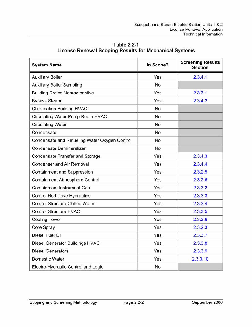
Susquehanna Steam Electric Station Units 1 & 2 License Renewal Application
Technical Information
Scoping and Screening Methodology Page 2.2-2 September 2006
Table 2.2-1 License Renewal Scoping Results for Mechanical Systems
System Name In Scope? Screening Results Section
Auxiliary Boiler Yes 2.3.4.1
Auxiliary Boiler Sampling No
Building Drains Nonradioactive Yes 2.3.3.1
Bypass Steam Yes 2.3.4.2
Chlorination Building HVAC No
Circulating Water Pump Room HVAC No
Circulating Water No
Condensate No
Condensate and Refueling Water Oxygen Control No
Condensate Demineralizer No
Condensate Transfer and Storage Yes 2.3.4.3
Condenser and Air Removal Yes 2.3.4.4
Containment and Suppression Yes 2.3.2.5
Containment Atmosphere Control Yes 2.3.2.6
Containment Instrument Gas Yes 2.3.3.2
Control Rod Drive Hydraulics Yes 2.3.3.3
Control Structure Chilled Water Yes 2.3.3.4
Control Structure HVAC Yes 2.3.3.5
Cooling Tower Yes 2.3.3.6
Core Spray Yes 2.3.2.3
Diesel Fuel Oil Yes 2.3.3.7
Diesel Generator Buildings HVAC Yes 2.3.3.8
Diesel Generators Yes 2.3.3.9
Domestic Water Yes 2.3.3.10
Electro-Hydraulic Control and Logic No
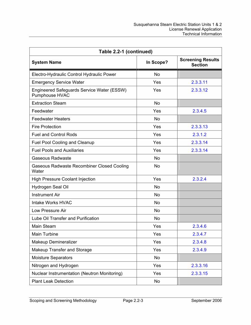
Susquehanna Steam Electric Station Units 1 & 2 License Renewal Application
Technical Information
Scoping and Screening Methodology Page 2.2-3 September 2006
Table 2.2-1 (continued)
System Name In Scope? Screening Results Section
Electro-Hydraulic Control Hydraulic Power No
Emergency Service Water Yes 2.3.3.11
Engineered Safeguards Service Water (ESSW) Pumphouse HVAC
Yes 2.3.3.12
Extraction Steam No
Feedwater Yes 2.3.4.5
Feedwater Heaters No
Fire Protection Yes 2.3.3.13
Fuel and Control Rods Yes 2.3.1.2
Fuel Pool Cooling and Cleanup Yes 2.3.3.14
Fuel Pools and Auxiliaries Yes 2.3.3.14
Gaseous Radwaste No
Gaseous Radwaste Recombiner Closed Cooling Water
No
High Pressure Coolant Injection Yes 2.3.2.4
Hydrogen Seal Oil No
Instrument Air No
Intake Works HVAC No
Low Pressure Air No
Lube Oil Transfer and Purification No
Main Steam Yes 2.3.4.6
Main Turbine Yes 2.3.4.7
Makeup Demineralizer Yes 2.3.4.8
Makeup Transfer and Storage Yes 2.3.4.9
Moisture Separators No
Nitrogen and Hydrogen Yes 2.3.3.16
Nuclear Instrumentation (Neutron Monitoring) Yes 2.3.3.15
Plant Leak Detection No
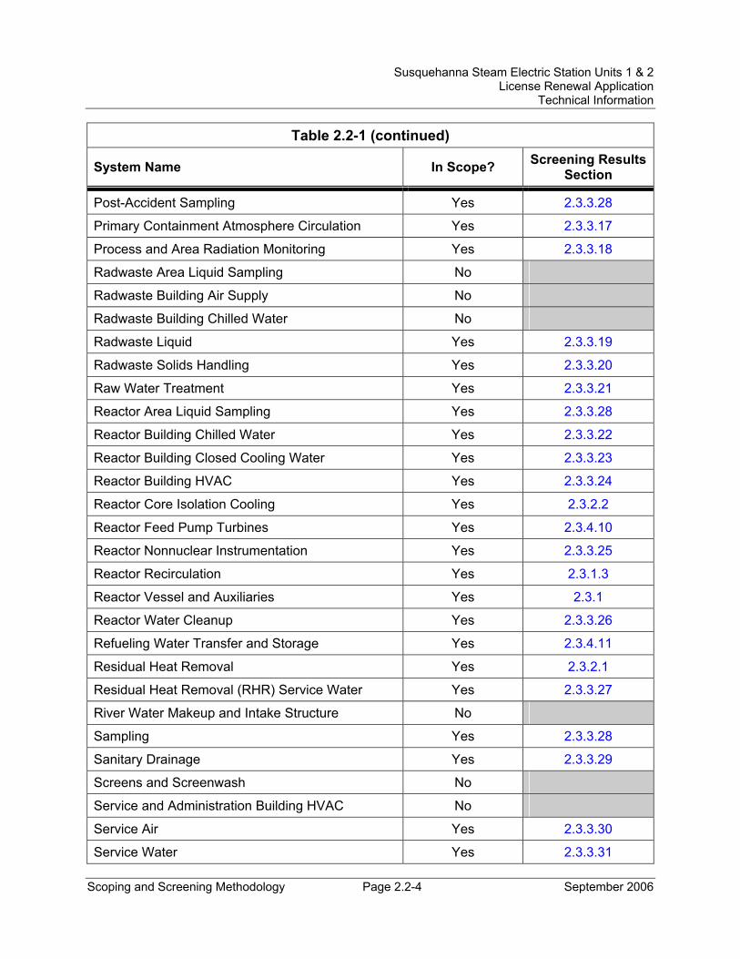
Susquehanna Steam Electric Station Units 1 & 2 License Renewal Application
Technical Information
Scoping and Screening Methodology Page 2.2-4 September 2006
Table 2.2-1 (continued)
System Name In Scope? Screening Results Section
Post-Accident Sampling Yes 2.3.3.28
Primary Containment Atmosphere Circulation Yes 2.3.3.17
Process and Area Radiation Monitoring Yes 2.3.3.18
Radwaste Area Liquid Sampling No
Radwaste Building Air Supply No
Radwaste Building Chilled Water No
Radwaste Liquid Yes 2.3.3.19
Radwaste Solids Handling Yes 2.3.3.20
Raw Water Treatment Yes 2.3.3.21
Reactor Area Liquid Sampling Yes 2.3.3.28
Reactor Building Chilled Water Yes 2.3.3.22
Reactor Building Closed Cooling Water Yes 2.3.3.23
Reactor Building HVAC Yes 2.3.3.24
Reactor Core Isolation Cooling Yes 2.3.2.2
Reactor Feed Pump Turbines Yes 2.3.4.10
Reactor Nonnuclear Instrumentation Yes 2.3.3.25
Reactor Recirculation Yes 2.3.1.3
Reactor Vessel and Auxiliaries Yes 2.3.1
Reactor Water Cleanup Yes 2.3.3.26
Refueling Water Transfer and Storage Yes 2.3.4.11
Residual Heat Removal Yes 2.3.2.1
Residual Heat Removal (RHR) Service Water Yes 2.3.3.27
River Water Makeup and Intake Structure No
Sampling Yes 2.3.3.28
Sanitary Drainage Yes 2.3.3.29
Screens and Screenwash No
Service and Administration Building HVAC No
Service Air Yes 2.3.3.30
Service Water Yes 2.3.3.31
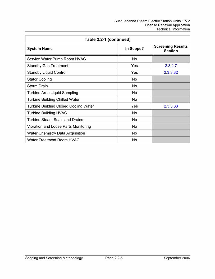
Susquehanna Steam Electric Station Units 1 & 2 License Renewal Application
Technical Information
Scoping and Screening Methodology Page 2.2-5 September 2006
Table 2.2-1 (continued)
System Name In Scope? Screening Results Section
Service Water Pump Room HVAC No
Standby Gas Treatment Yes 2.3.2.7
Standby Liquid Control Yes 2.3.3.32
Stator Cooling No
Storm Drain No
Turbine Area Liquid Sampling No
Turbine Building Chilled Water No
Turbine Building Closed Cooling Water Yes 2.3.3.33
Turbine Building HVAC No
Turbine Steam Seals and Drains No
Vibration and Loose Parts Monitoring No
Water Chemistry Data Acquisition No
Water Treatment Room HVAC No
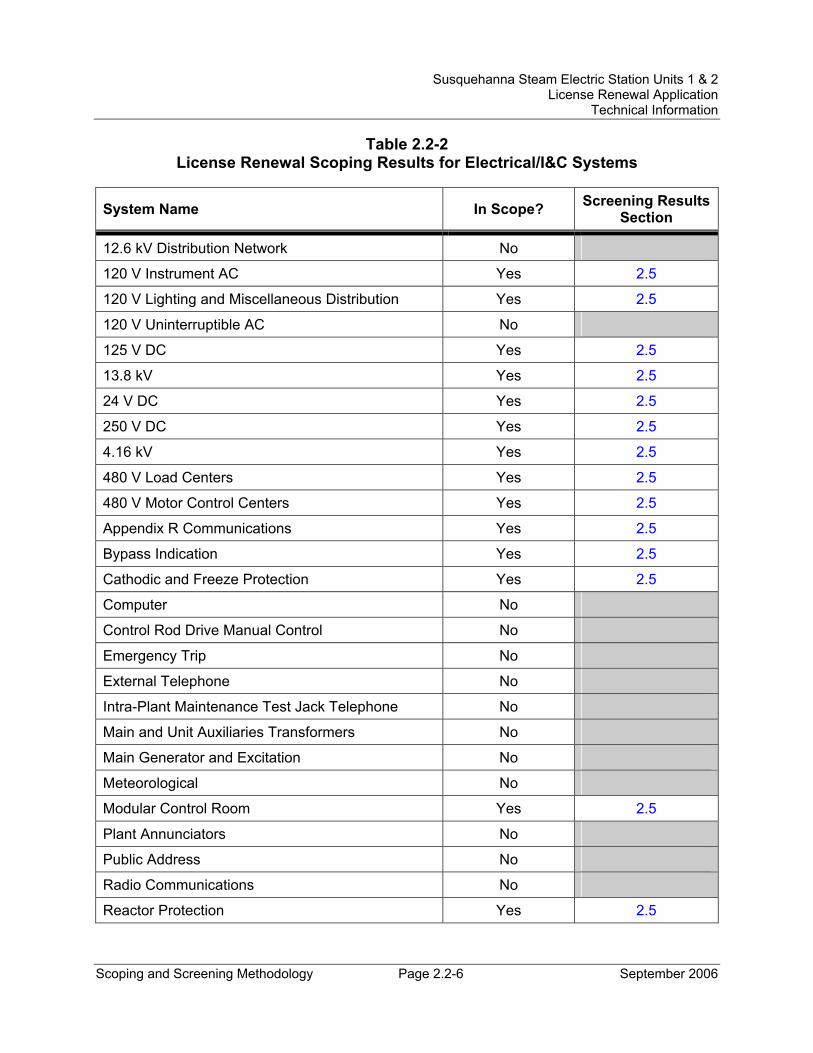
Susquehanna Steam Electric Station Units 1 & 2 License Renewal Application
Technical Information
Scoping and Screening Methodology Page 2.2-6 September 2006
Table 2.2-2 License Renewal Scoping Results for Electrical/I&C Systems
System Name In Scope? Screening Results Section
12.6 kV Distribution Network No
120 V Instrument AC Yes 2.5
120 V Lighting and Miscellaneous Distribution Yes 2.5
120 V Uninterruptible AC No
125 V DC Yes 2.5
13.8 kV Yes 2.5
24 V DC Yes 2.5
250 V DC Yes 2.5
4.16 kV Yes 2.5
480 V Load Centers Yes 2.5
480 V Motor Control Centers Yes 2.5
Appendix R Communications Yes 2.5
Bypass Indication Yes 2.5
Cathodic and Freeze Protection Yes 2.5
Computer No
Control Rod Drive Manual Control No
Emergency Trip No
External Telephone No
Intra-Plant Maintenance Test Jack Telephone No
Main and Unit Auxiliaries Transformers No
Main Generator and Excitation No
Meteorological No
Modular Control Room Yes 2.5
Plant Annunciators No
Public Address No
Radio Communications No
Reactor Protection Yes 2.5
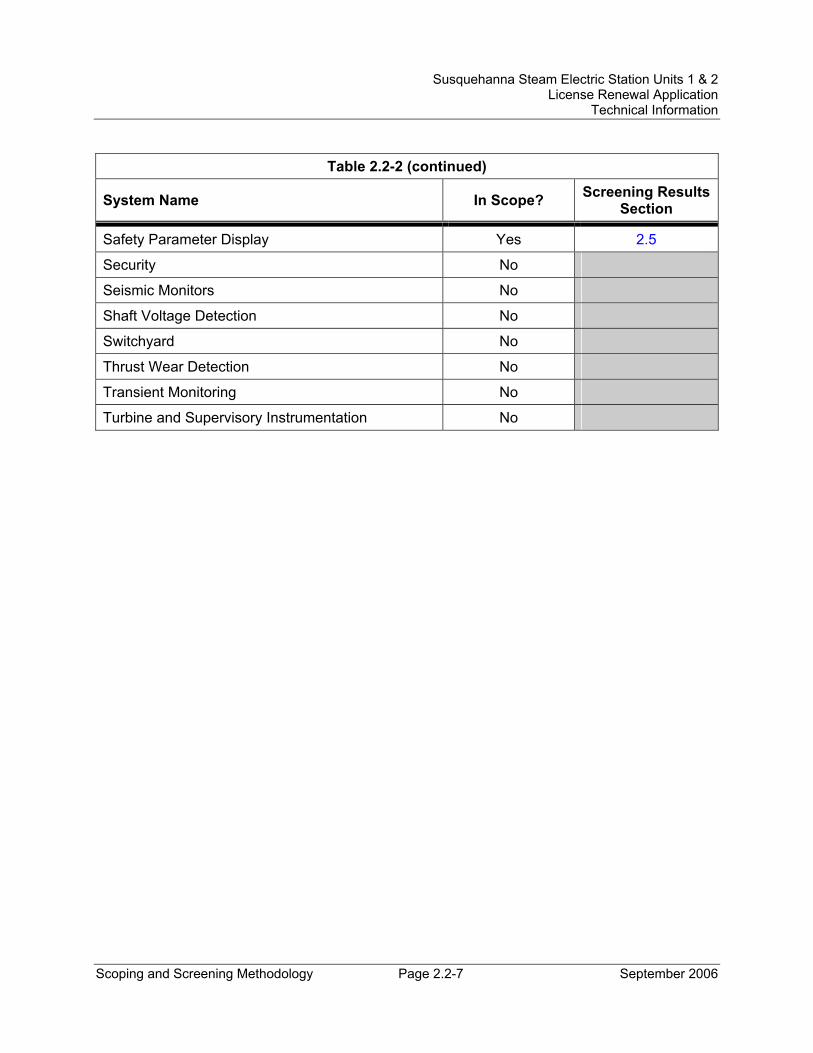
Susquehanna Steam Electric Station Units 1 & 2 License Renewal Application
Technical Information
Scoping and Screening Methodology Page 2.2-7 September 2006
Table 2.2-2 (continued)
System Name In Scope? Screening Results Section
Safety Parameter Display Yes 2.5
Security No
Seismic Monitors No
Shaft Voltage Detection No
Switchyard No
Thrust Wear Detection No
Transient Monitoring No
Turbine and Supervisory Instrumentation No
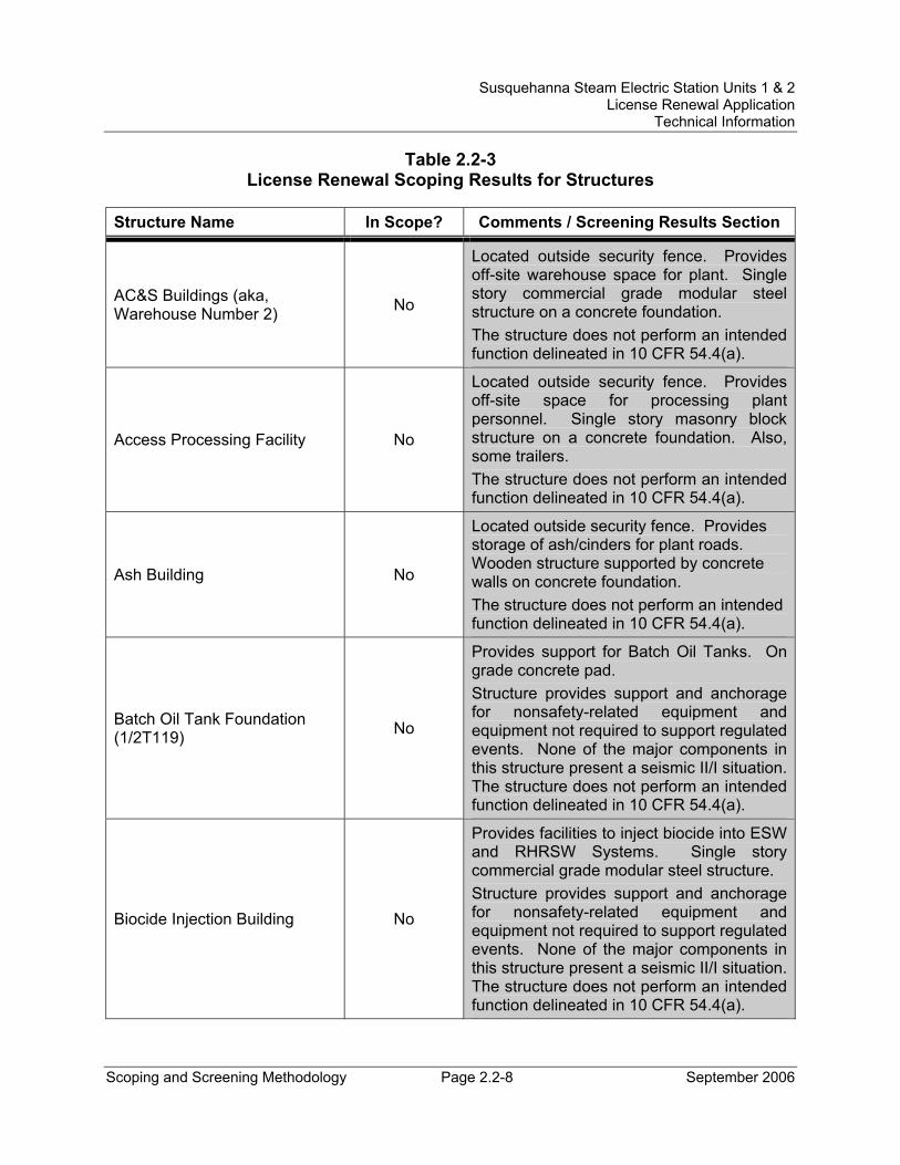
Susquehanna Steam Electric Station Units 1 & 2 License Renewal Application
Technical Information
Scoping and Screening Methodology Page 2.2-8 September 2006
Table 2.2-3 License Renewal Scoping Results for Structures
Structure Name In Scope? Comments / Screening Results Section
AC&S Buildings (aka, Warehouse Number 2) No
Located outside security fence. Provides off-site warehouse space for plant. Single story commercial grade modular steel structure on a concrete foundation. The structure does not perform an intended function delineated in 10 CFR 54.4(a).
Access Processing Facility No
Located outside security fence. Provides off-site space for processing plant personnel. Single story masonry block structure on a concrete foundation. Also, some trailers. The structure does not perform an intended function delineated in 10 CFR 54.4(a).
Ash Building No
Located outside security fence. Provides storage of ash/cinders for plant roads. Wooden structure supported by concrete walls on concrete foundation. The structure does not perform an intended function delineated in 10 CFR 54.4(a).
Batch Oil Tank Foundation (1/2T119) No
Provides support for Batch Oil Tanks. On grade concrete pad. Structure provides support and anchorage for nonsafety-related equipment and equipment not required to support regulated events. None of the major components in this structure present a seismic II/I situation. The structure does not perform an intended function delineated in 10 CFR 54.4(a).
Biocide Injection Building No
Provides facilities to inject biocide into ESW and RHRSW Systems. Single story commercial grade modular steel structure. Structure provides support and anchorage for nonsafety-related equipment and equipment not required to support regulated events. None of the major components in this structure present a seismic II/I situation. The structure does not perform an intended function delineated in 10 CFR 54.4(a).
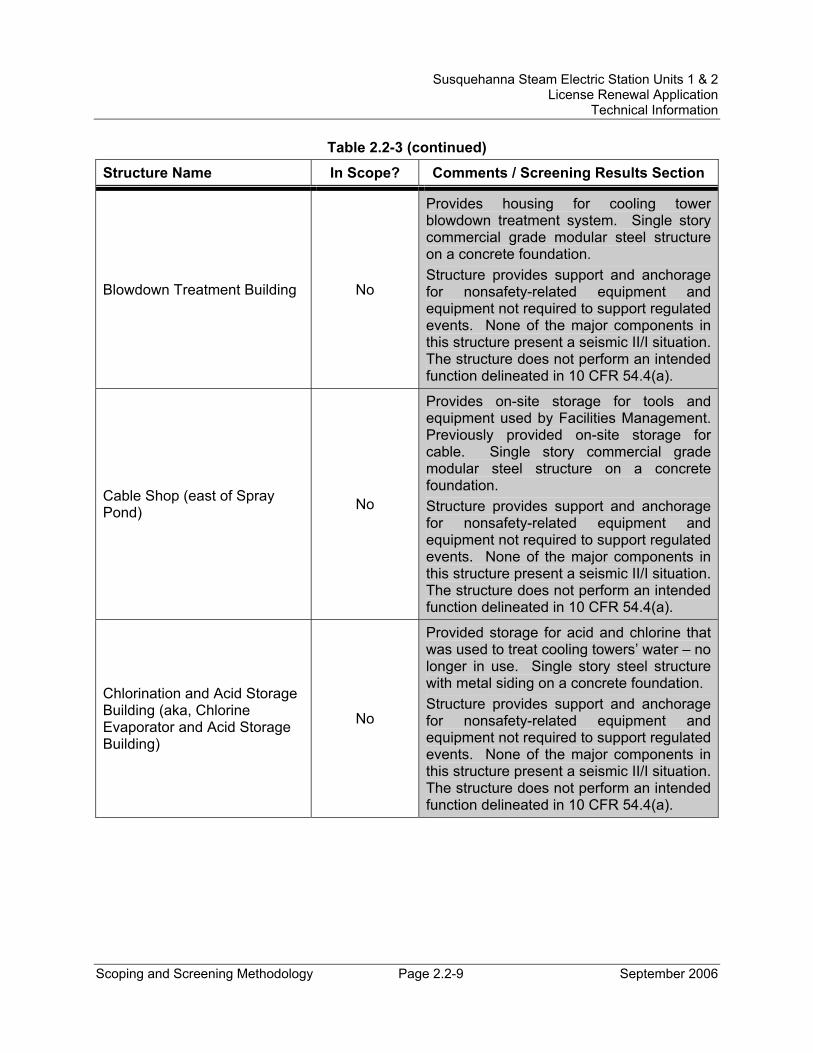
Susquehanna Steam Electric Station Units 1 & 2 License Renewal Application
Technical Information
Scoping and Screening Methodology Page 2.2-9 September 2006
Table 2.2-3 (continued)
Structure Name In Scope? Comments / Screening Results Section
Blowdown Treatment Building No
Provides housing for cooling tower blowdown treatment system. Single story commercial grade modular steel structure on a concrete foundation. Structure provides support and anchorage for nonsafety-related equipment and equipment not required to support regulated events. None of the major components in this structure present a seismic II/I situation. The structure does not perform an intended function delineated in 10 CFR 54.4(a).
Cable Shop (east of Spray Pond) No
Provides on-site storage for tools and equipment used by Facilities Management. Previously provided on-site storage for cable. Single story commercial grade modular steel structure on a concrete foundation. Structure provides support and anchorage for nonsafety-related equipment and equipment not required to support regulated events. None of the major components in this structure present a seismic II/I situation. The structure does not perform an intended function delineated in 10 CFR 54.4(a).
Chlorination and Acid Storage Building (aka, Chlorine Evaporator and Acid Storage Building)
No
Provided storage for acid and chlorine that was used to treat cooling towers’ water – no longer in use. Single story steel structure with metal siding on a concrete foundation. Structure provides support and anchorage for nonsafety-related equipment and equipment not required to support regulated events. None of the major components in this structure present a seismic II/I situation. The structure does not perform an intended function delineated in 10 CFR 54.4(a).
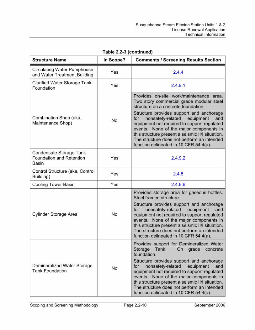
Susquehanna Steam Electric Station Units 1 & 2 License Renewal Application
Technical Information
Scoping and Screening Methodology Page 2.2-10 September 2006
Table 2.2-3 (continued)
Structure Name In Scope? Comments / Screening Results Section
Circulating Water Pumphouse and Water Treatment Building Yes 2.4.4
Clarified Water Storage Tank Foundation Yes 2.4.9.1
Combination Shop (aka, Maintenance Shop) No
Provides on-site work/maintenance area. Two story commercial grade modular steel structure on a concrete foundation. Structure provides support and anchorage for nonsafety-related equipment and equipment not required to support regulated events. None of the major components in this structure present a seismic II/I situation. The structure does not perform an intended function delineated in 10 CFR 54.4(a).
Condensate Storage Tank Foundation and Retention Basin
Yes 2.4.9.2
Control Structure (aka, Control Building) Yes 2.4.5
Cooling Tower Basin Yes 2.4.9.6
Cylinder Storage Area No
Provides storage area for gaseous bottles. Steel framed structure. Structure provides support and anchorage for nonsafety-related equipment and equipment not required to support regulated events. None of the major components in this structure present a seismic II/I situation. The structure does not perform an intended function delineated in 10 CFR 54.4(a).
Demineralized Water Storage Tank Foundation No
Provides support for Demineralized Water Storage Tank. On grade concrete foundation. Structure provides support and anchorage for nonsafety-related equipment and equipment not required to support regulated events. None of the major components in this structure present a seismic II/I situation. The structure does not perform an intended function delineated in 10 CFR 54.4(a).
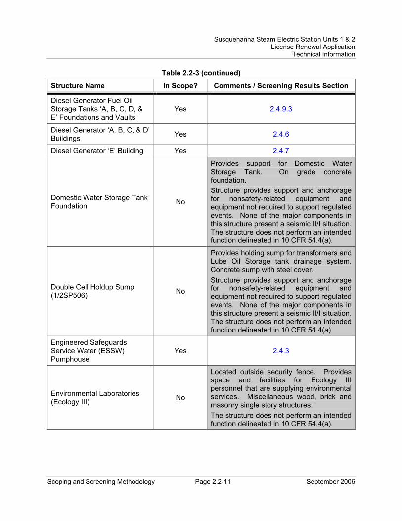
Susquehanna Steam Electric Station Units 1 & 2 License Renewal Application
Technical Information
Scoping and Screening Methodology Page 2.2-11 September 2006
Table 2.2-3 (continued)
Structure Name In Scope? Comments / Screening Results Section
Diesel Generator Fuel Oil Storage Tanks ‘A, B, C, D, & E’ Foundations and Vaults
Yes 2.4.9.3
Diesel Generator ‘A, B, C, & D’ Buildings Yes 2.4.6
Diesel Generator ‘E’ Building Yes 2.4.7
Domestic Water Storage Tank Foundation No
Provides support for Domestic Water Storage Tank. On grade concrete foundation. Structure provides support and anchorage for nonsafety-related equipment and equipment not required to support regulated events. None of the major components in this structure present a seismic II/I situation. The structure does not perform an intended function delineated in 10 CFR 54.4(a).
Double Cell Holdup Sump (1/2SP506) No
Provides holding sump for transformers and Lube Oil Storage tank drainage system. Concrete sump with steel cover. Structure provides support and anchorage for nonsafety-related equipment and equipment not required to support regulated events. None of the major components in this structure present a seismic II/I situation. The structure does not perform an intended function delineated in 10 CFR 54.4(a).
Engineered Safeguards Service Water (ESSW) Pumphouse
Yes 2.4.3
Environmental Laboratories (Ecology III) No
Located outside security fence. Provides space and facilities for Ecology III personnel that are supplying environmental services. Miscellaneous wood, brick and masonry single story structures. The structure does not perform an intended function delineated in 10 CFR 54.4(a).
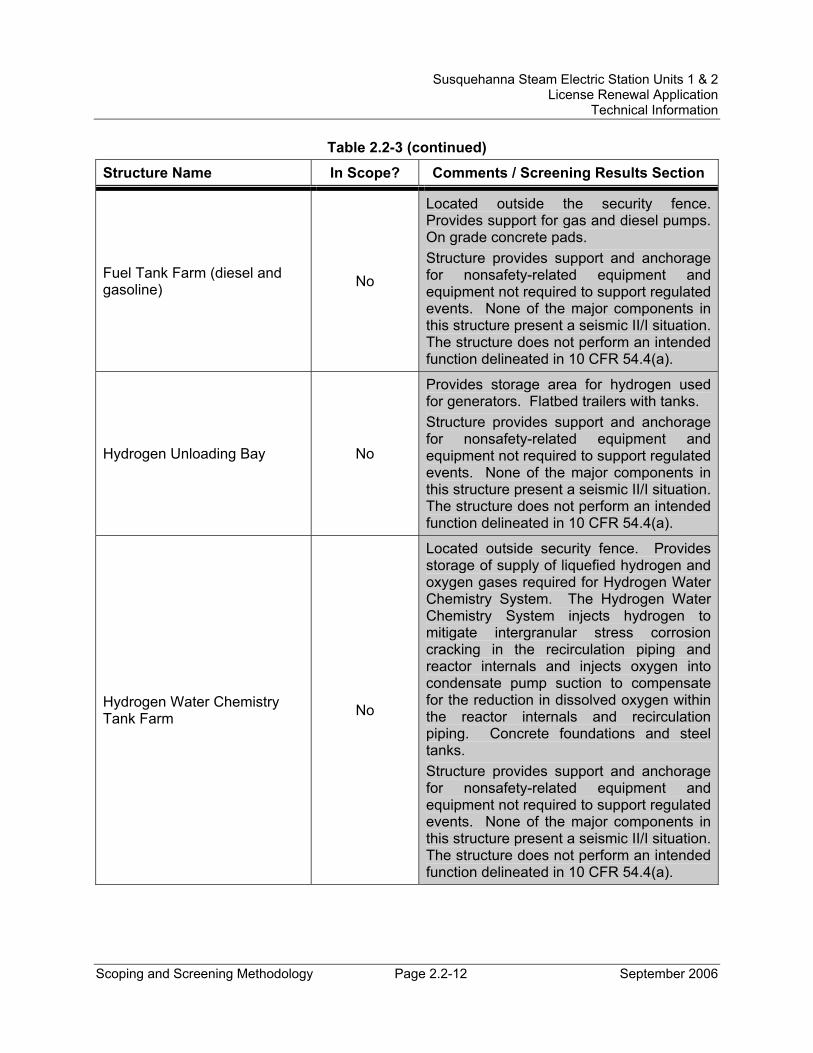
Susquehanna Steam Electric Station Units 1 & 2 License Renewal Application
Technical Information
Scoping and Screening Methodology Page 2.2-12 September 2006
Table 2.2-3 (continued)
Structure Name In Scope? Comments / Screening Results Section
Fuel Tank Farm (diesel and gasoline) No
Located outside the security fence. Provides support for gas and diesel pumps. On grade concrete pads. Structure provides support and anchorage for nonsafety-related equipment and equipment not required to support regulated events. None of the major components in this structure present a seismic II/I situation. The structure does not perform an intended function delineated in 10 CFR 54.4(a).
Hydrogen Unloading Bay No
Provides storage area for hydrogen used for generators. Flatbed trailers with tanks. Structure provides support and anchorage for nonsafety-related equipment and equipment not required to support regulated events. None of the major components in this structure present a seismic II/I situation. The structure does not perform an intended function delineated in 10 CFR 54.4(a).
Hydrogen Water Chemistry Tank Farm No
Located outside security fence. Provides storage of supply of liquefied hydrogen and oxygen gases required for Hydrogen Water Chemistry System. The Hydrogen Water Chemistry System injects hydrogen to mitigate intergranular stress corrosion cracking in the recirculation piping and reactor internals and injects oxygen into condensate pump suction to compensate for the reduction in dissolved oxygen within the reactor internals and recirculation piping. Concrete foundations and steel tanks. Structure provides support and anchorage for nonsafety-related equipment and equipment not required to support regulated events. None of the major components in this structure present a seismic II/I situation. The structure does not perform an intended function delineated in 10 CFR 54.4(a).
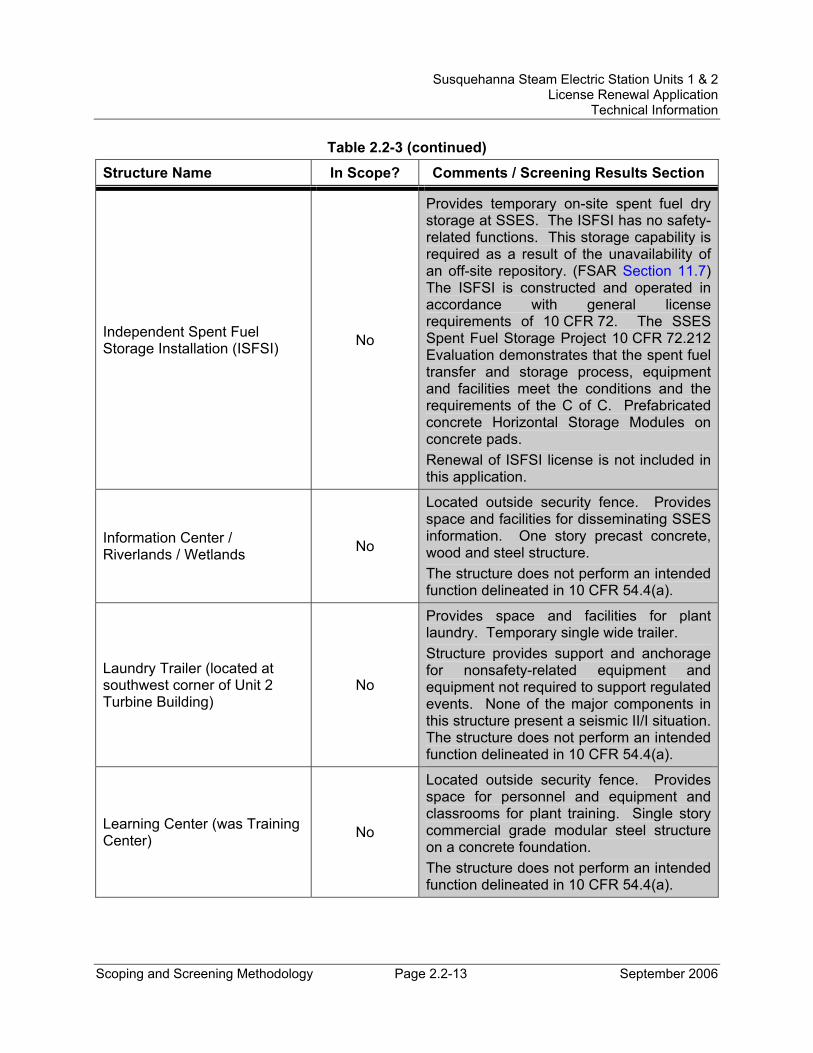
Susquehanna Steam Electric Station Units 1 & 2 License Renewal Application
Technical Information
Scoping and Screening Methodology Page 2.2-13 September 2006
Table 2.2-3 (continued)
Structure Name In Scope? Comments / Screening Results Section
Independent Spent Fuel Storage Installation (ISFSI) No
Provides temporary on-site spent fuel dry storage at SSES. The ISFSI has no safety-related functions. This storage capability is required as a result of the unavailability of an off-site repository. (FSAR Section 11.7) The ISFSI is constructed and operated in accordance with general license requirements of 10 CFR 72. The SSES Spent Fuel Storage Project 10 CFR 72.212 Evaluation demonstrates that the spent fuel transfer and storage process, equipment and facilities meet the conditions and the requirements of the C of C. Prefabricated concrete Horizontal Storage Modules on concrete pads. Renewal of ISFSI license is not included in this application.
Information Center / Riverlands / Wetlands No
Located outside security fence. Provides space and facilities for disseminating SSES information. One story precast concrete, wood and steel structure. The structure does not perform an intended function delineated in 10 CFR 54.4(a).
Laundry Trailer (located at southwest corner of Unit 2 Turbine Building)
No
Provides space and facilities for plant laundry. Temporary single wide trailer. Structure provides support and anchorage for nonsafety-related equipment and equipment not required to support regulated events. None of the major components in this structure present a seismic II/I situation. The structure does not perform an intended function delineated in 10 CFR 54.4(a).
Learning Center (was Training Center) No
Located outside security fence. Provides space for personnel and equipment and classrooms for plant training. Single story commercial grade modular steel structure on a concrete foundation. The structure does not perform an intended function delineated in 10 CFR 54.4(a).
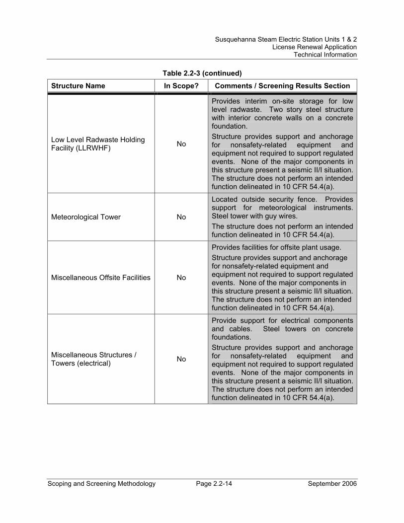
Susquehanna Steam Electric Station Units 1 & 2 License Renewal Application
Technical Information
Scoping and Screening Methodology Page 2.2-14 September 2006
Table 2.2-3 (continued)
Structure Name In Scope? Comments / Screening Results Section
Low Level Radwaste Holding Facility (LLRWHF) No
Provides interim on-site storage for low level radwaste. Two story steel structure with interior concrete walls on a concrete foundation. Structure provides support and anchorage for nonsafety-related equipment and equipment not required to support regulated events. None of the major components in this structure present a seismic II/I situation. The structure does not perform an intended function delineated in 10 CFR 54.4(a).
Meteorological Tower No
Located outside security fence. Provides support for meteorological instruments. Steel tower with guy wires. The structure does not perform an intended function delineated in 10 CFR 54.4(a).
Miscellaneous Offsite Facilities No
Provides facilities for offsite plant usage. Structure provides support and anchorage for nonsafety-related equipment and equipment not required to support regulated events. None of the major components in this structure present a seismic II/I situation. The structure does not perform an intended function delineated in 10 CFR 54.4(a).
Miscellaneous Structures / Towers (electrical) No
Provide support for electrical components and cables. Steel towers on concrete foundations. Structure provides support and anchorage for nonsafety-related equipment and equipment not required to support regulated events. None of the major components in this structure present a seismic II/I situation. The structure does not perform an intended function delineated in 10 CFR 54.4(a).
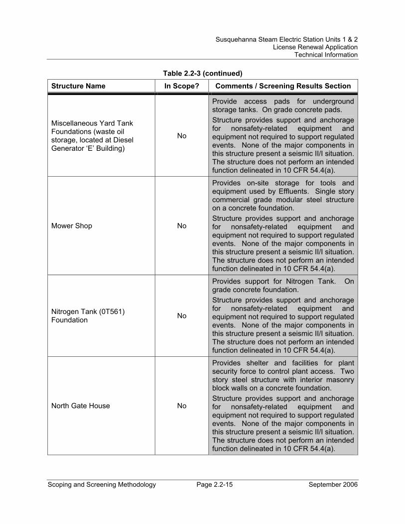
Susquehanna Steam Electric Station Units 1 & 2 License Renewal Application
Technical Information
Scoping and Screening Methodology Page 2.2-15 September 2006
Table 2.2-3 (continued)
Structure Name In Scope? Comments / Screening Results Section
Miscellaneous Yard Tank Foundations (waste oil storage, located at Diesel Generator ‘E’ Building)
No
Provide access pads for underground storage tanks. On grade concrete pads. Structure provides support and anchorage for nonsafety-related equipment and equipment not required to support regulated events. None of the major components in this structure present a seismic II/I situation. The structure does not perform an intended function delineated in 10 CFR 54.4(a).
Mower Shop No
Provides on-site storage for tools and equipment used by Effluents. Single story commercial grade modular steel structure on a concrete foundation. Structure provides support and anchorage for nonsafety-related equipment and equipment not required to support regulated events. None of the major components in this structure present a seismic II/I situation. The structure does not perform an intended function delineated in 10 CFR 54.4(a).
Nitrogen Tank (0T561) Foundation No
Provides support for Nitrogen Tank. On grade concrete foundation. Structure provides support and anchorage for nonsafety-related equipment and equipment not required to support regulated events. None of the major components in this structure present a seismic II/I situation. The structure does not perform an intended function delineated in 10 CFR 54.4(a).
North Gate House No
Provides shelter and facilities for plant security force to control plant access. Two story steel structure with interior masonry block walls on a concrete foundation. Structure provides support and anchorage for nonsafety-related equipment and equipment not required to support regulated events. None of the major components in this structure present a seismic II/I situation. The structure does not perform an intended function delineated in 10 CFR 54.4(a).
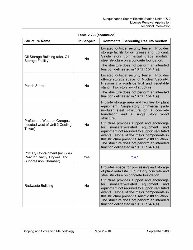
Susquehanna Steam Electric Station Units 1 & 2 License Renewal Application
Technical Information
Scoping and Screening Methodology Page 2.2-16 September 2006
Table 2.2-3 (continued)
Structure Name In Scope? Comments / Screening Results Section
Oil Storage Building (aka, Oil Storage Facility) No
Located outside security fence. Provides storage facility for oil, grease and lubricant. Single story commercial grade modular steel structure on a concrete foundation. The structure does not perform an intended function delineated in 10 CFR 54.4(a).
Peach Stand No
Located outside security fence. Provides off-site storage space for Nuclear Security. Previously a roadside fruit and vegetable stand. Two story wood structure. The structure does not perform an intended function delineated in 10 CFR 54.4(a).
Prefab and Wooden Garages (located west of Unit 2 Cooling Tower)
No
Provide storage area and facilities for plant equipment. Single story commercial grade modular steel structure on a concrete foundation and a single story wood structure. Structure provides support and anchorage for nonsafety-related equipment and equipment not required to support regulated events. None of the major components in this structure present a seismic II/I situation. The structure does not perform an intended function delineated in 10 CFR 54.4(a).
Primary Containment (includes Reactor Cavity, Drywell, and Suppression Chamber)
Yes 2.4.1
Radwaste Building No
Provides space for processing and storage of plant radwaste. Four story concrete and steel structure on concrete foundation. Structure provides support and anchorage for nonsafety-related equipment and equipment not required to support regulated events. None of the major components in this structure present a seismic II/I situation. The structure does not perform an intended function delineated in 10 CFR 54.4(a).
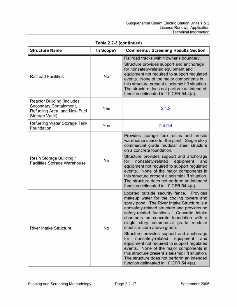
Susquehanna Steam Electric Station Units 1 & 2 License Renewal Application
Technical Information
Scoping and Screening Methodology Page 2.2-17 September 2006
Table 2.2-3 (continued)
Structure Name In Scope? Comments / Screening Results Section
Railroad Facilities No
Railroad tracks within owner’s boundary. Structure provides support and anchorage for nonsafety-related equipment and equipment not required to support regulated events. None of the major components in this structure present a seismic II/I situation. The structure does not perform an intended function delineated in 10 CFR 54.4(a).
Reactor Building (includes Secondary Containment, Refueling Area, and New Fuel Storage Vault)
Yes 2.4.2
Refueling Water Storage Tank Foundation Yes 2.4.9.4
Resin Storage Building / Facilities Storage Warehouse No
Provides storage fore resins and on-site warehouse space for the plant. Single story commercial grade modular steel structure on a concrete foundation. Structure provides support and anchorage for nonsafety-related equipment and equipment not required to support regulated events. None of the major components in this structure present a seismic II/I situation. The structure does not perform an intended function delineated in 10 CFR 54.4(a).
River Intake Structure No
Located outside security fence. Provides makeup water for the cooling towers and spray pond. The River Intake Structure is a nonsafety-related structure and provides no safety-related functions. Concrete intake chambers on concrete foundation with a single story commercial grade modular steel structure above grade. Structure provides support and anchorage for nonsafety-related equipment and equipment not required to support regulated events. None of the major components in this structure present a seismic II/I situation. The structure does not perform an intended function delineated in 10 CFR 54.4(a).
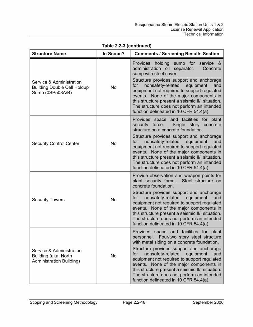
Susquehanna Steam Electric Station Units 1 & 2 License Renewal Application
Technical Information
Scoping and Screening Methodology Page 2.2-18 September 2006
Table 2.2-3 (continued)
Structure Name In Scope? Comments / Screening Results Section
Service & Administration Building Double Cell Holdup Sump (0SP508A/B)
No
Provides holding sump for service & administration oil separator. Concrete sump with steel cover. Structure provides support and anchorage for nonsafety-related equipment and equipment not required to support regulated events. None of the major components in this structure present a seismic II/I situation. The structure does not perform an intended function delineated in 10 CFR 54.4(a).
Security Control Center No
Provides space and facilities for plant security force. Single story concrete structure on a concrete foundation. Structure provides support and anchorage for nonsafety-related equipment and equipment not required to support regulated events. None of the major components in this structure present a seismic II/I situation. The structure does not perform an intended function delineated in 10 CFR 54.4(a).
Security Towers No
Provide observation and weapon points for plant security force. Steel structure on concrete foundation. Structure provides support and anchorage for nonsafety-related equipment and equipment not required to support regulated events. None of the major components in this structure present a seismic II/I situation. The structure does not perform an intended function delineated in 10 CFR 54.4(a).
Service & Administration Building (aka, North Administration Building)
No
Provides space and facilities for plant personnel. Four/two story steel structure with metal siding on a concrete foundation. Structure provides support and anchorage for nonsafety-related equipment and equipment not required to support regulated events. None of the major components in this structure present a seismic II/I situation. The structure does not perform an intended function delineated in 10 CFR 54.4(a).
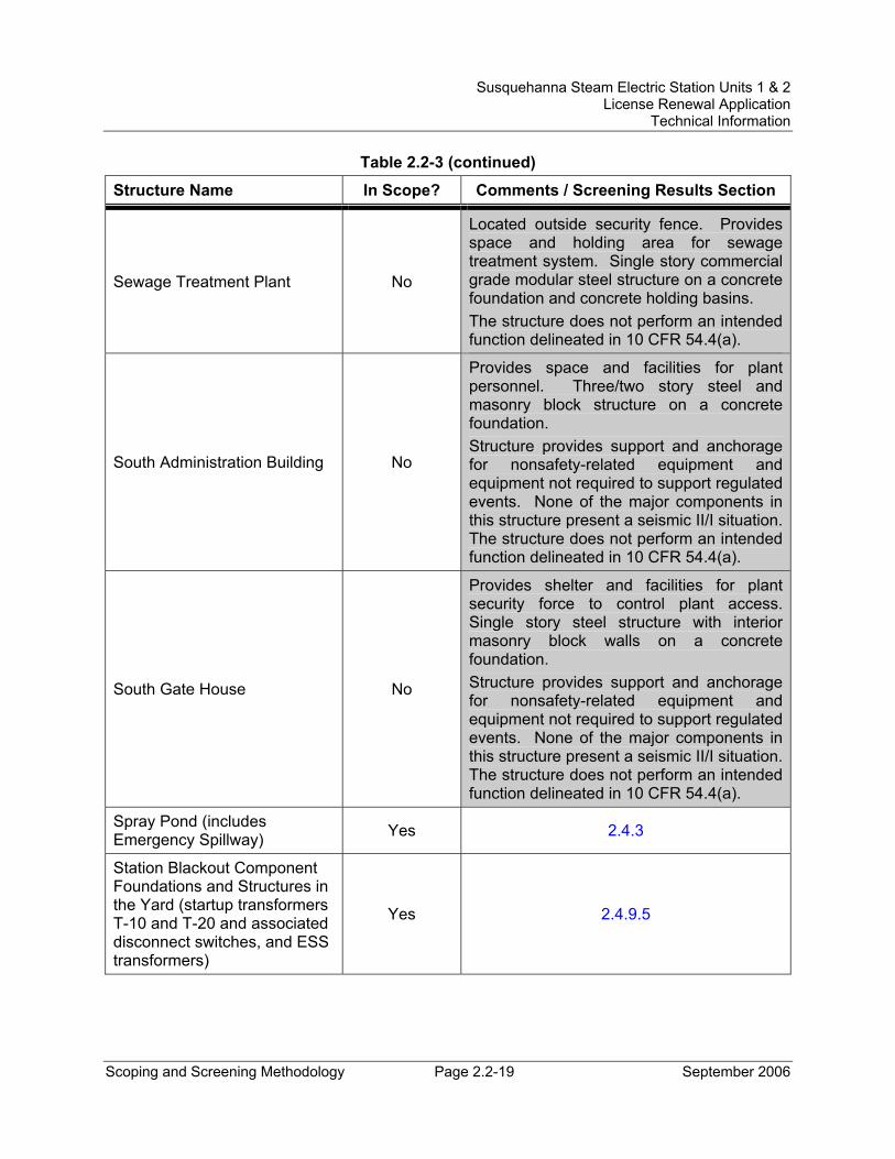
Susquehanna Steam Electric Station Units 1 & 2 License Renewal Application
Technical Information
Scoping and Screening Methodology Page 2.2-19 September 2006
Table 2.2-3 (continued)
Structure Name In Scope? Comments / Screening Results Section
Sewage Treatment Plant No
Located outside security fence. Provides space and holding area for sewage treatment system. Single story commercial grade modular steel structure on a concrete foundation and concrete holding basins. The structure does not perform an intended function delineated in 10 CFR 54.4(a).
South Administration Building No
Provides space and facilities for plant personnel. Three/two story steel and masonry block structure on a concrete foundation. Structure provides support and anchorage for nonsafety-related equipment and equipment not required to support regulated events. None of the major components in this structure present a seismic II/I situation. The structure does not perform an intended function delineated in 10 CFR 54.4(a).
South Gate House No
Provides shelter and facilities for plant security force to control plant access. Single story steel structure with interior masonry block walls on a concrete foundation. Structure provides support and anchorage for nonsafety-related equipment and equipment not required to support regulated events. None of the major components in this structure present a seismic II/I situation. The structure does not perform an intended function delineated in 10 CFR 54.4(a).
Spray Pond (includes Emergency Spillway) Yes 2.4.3
Station Blackout Component Foundations and Structures in the Yard (startup transformers T-10 and T-20 and associated disconnect switches, and ESS transformers)
Yes 2.4.9.5
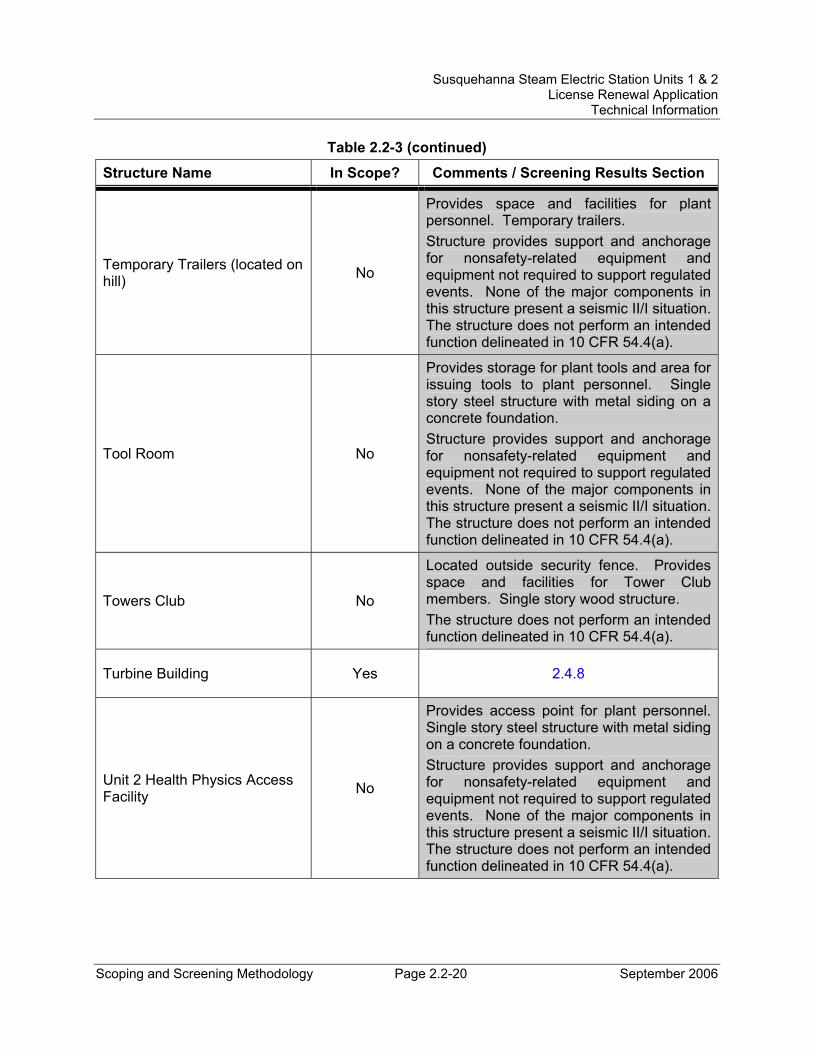
Susquehanna Steam Electric Station Units 1 & 2 License Renewal Application
Technical Information
Scoping and Screening Methodology Page 2.2-20 September 2006
Table 2.2-3 (continued)
Structure Name In Scope? Comments / Screening Results Section
Temporary Trailers (located on hill) No
Provides space and facilities for plant personnel. Temporary trailers. Structure provides support and anchorage for nonsafety-related equipment and equipment not required to support regulated events. None of the major components in this structure present a seismic II/I situation. The structure does not perform an intended function delineated in 10 CFR 54.4(a).
Tool Room No
Provides storage for plant tools and area for issuing tools to plant personnel. Single story steel structure with metal siding on a concrete foundation. Structure provides support and anchorage for nonsafety-related equipment and equipment not required to support regulated events. None of the major components in this structure present a seismic II/I situation. The structure does not perform an intended function delineated in 10 CFR 54.4(a).
Towers Club No
Located outside security fence. Provides space and facilities for Tower Club members. Single story wood structure. The structure does not perform an intended function delineated in 10 CFR 54.4(a).
Turbine Building Yes 2.4.8
Unit 2 Health Physics Access Facility No
Provides access point for plant personnel. Single story steel structure with metal siding on a concrete foundation. Structure provides support and anchorage for nonsafety-related equipment and equipment not required to support regulated events. None of the major components in this structure present a seismic II/I situation. The structure does not perform an intended function delineated in 10 CFR 54.4(a).
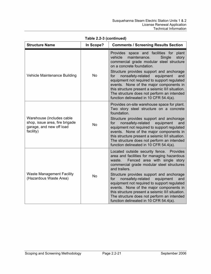
Susquehanna Steam Electric Station Units 1 & 2 License Renewal Application
Technical Information
Scoping and Screening Methodology Page 2.2-21 September 2006
Table 2.2-3 (continued)
Structure Name In Scope? Comments / Screening Results Section
Vehicle Maintenance Building No
Provides space and facilities for plant vehicle maintenance. Single story commercial grade modular steel structure on a concrete foundation. Structure provides support and anchorage for nonsafety-related equipment and equipment not required to support regulated events. None of the major components in this structure present a seismic II/I situation. The structure does not perform an intended function delineated in 10 CFR 54.4(a).
Warehouse (includes cable shop, issue area, fire brigade garage, and new off load facility)
No
Provides on-site warehouse space for plant. Two story steel structure on a concrete foundation. Structure provides support and anchorage for nonsafety-related equipment and equipment not required to support regulated events. None of the major components in this structure present a seismic II/I situation. The structure does not perform an intended function delineated in 10 CFR 54.4(a).
Waste Management Facility (Hazardous Waste Area) No
Located outside security fence. Provides area and facilities for managing hazardous waste. Fenced area with single story commercial grade modular steel structures and trailers. Structure provides support and anchorage for nonsafety-related equipment and equipment not required to support regulated events. None of the major components in this structure present a seismic II/I situation. The structure does not perform an intended function delineated in 10 CFR 54.4(a).
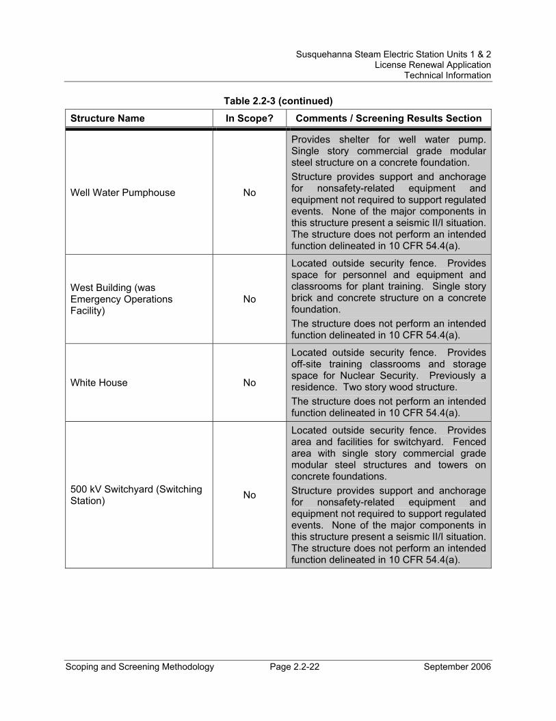
Susquehanna Steam Electric Station Units 1 & 2 License Renewal Application
Technical Information
Scoping and Screening Methodology Page 2.2-22 September 2006
Table 2.2-3 (continued)
Structure Name In Scope? Comments / Screening Results Section
Well Water Pumphouse No
Provides shelter for well water pump. Single story commercial grade modular steel structure on a concrete foundation. Structure provides support and anchorage for nonsafety-related equipment and equipment not required to support regulated events. None of the major components in this structure present a seismic II/I situation. The structure does not perform an intended function delineated in 10 CFR 54.4(a).
West Building (was Emergency Operations Facility)
No
Located outside security fence. Provides space for personnel and equipment and classrooms for plant training. Single story brick and concrete structure on a concrete foundation. The structure does not perform an intended function delineated in 10 CFR 54.4(a).
White House No
Located outside security fence. Provides off-site training classrooms and storage space for Nuclear Security. Previously a residence. Two story wood structure. The structure does not perform an intended function delineated in 10 CFR 54.4(a).
500 kV Switchyard (Switching Station) No
Located outside security fence. Provides area and facilities for switchyard. Fenced area with single story commercial grade modular steel structures and towers on concrete foundations. Structure provides support and anchorage for nonsafety-related equipment and equipment not required to support regulated events. None of the major components in this structure present a seismic II/I situation. The structure does not perform an intended function delineated in 10 CFR 54.4(a).
Susquehanna Steam Electric Station Units 1 & 2 License Renewal Application
Technical Information
Scoping and Screening Methodology Page 2.3-1 September 2006
2.3 SCOPING AND SCREENING RESULTS: MECHANICAL SYSTEMS
The determination of mechanical systems within the scope of license renewal is made through the application of the process described in Section 2.1. The results of the mechanical systems scoping review are in Section 2.2.
Section 2.1 also provides the methodology for determining the components within the scope of 10 CFR 54.4 that meet the requirements of 10 CFR 54.21(a)(1). The components that meet these screening requirements are identified in this section.
The screening results for mechanical systems consist of lists of components and component types that require aging management review. Brief descriptions of mechanical systems within the scope of license renewal are provided as background information. Mechanical system intended functions are described for in-scope systems.
The screening results are provided below in four sections:
• Reactor Vessel, Internals, and Reactor Coolant System (Section 2.3.1),
• Engineered Safety Features Systems (Section 2.3.2),
• Auxiliary Systems (Section 2.3.3), and
• Steam and Power Conversion Systems (Section 2.3.4).
Unless otherwise stated, the system and component descriptions provided in this section are applicable to both Units 1 and 2.
Susquehanna Steam Electric Station Units 1 & 2 License Renewal Application
Technical Information
Scoping and Screening Methodology Page 2.3-2 September 2006
2.3.1 Reactor Vessel, Internals, and Reactor Coolant System
The reactor pressure vessel, reactor vessel internals, and the reactor coolant system pressure boundary consist of components designed to contain and support the nuclear fuel, contain the reactor coolant, and transfer the heat produced in the reactor to the steam and power conversion systems for the production of electricity. The following systems are included in this section:
• Reactor Pressure Vessel (Section 2.3.1.1)
• Reactor Vessel Internals (Section 2.3.1.2)
• Reactor Coolant System Pressure Boundary (Section 2.3.1.3)
A brief system description, reason for scope determination, associated FSAR reference(s), associated license renewal drawings, and components subject to aging management review (AMR) information is provided for each system.
2.3.1.1 Reactor Pressure Vessel System Description The reactor pressure vessel is not a unique system in the plant NIMS database. The Reactor Vessel and Auxiliaries System in NIMS includes what is evaluated for license renewal as the reactor pressure vessel, reactor vessel internals, and the reactor coolant system pressure boundary. The reactor vessel internals are discussed in detail in Section 2.3.1.2. The reactor coolant system pressure boundary is discussed in detail in Section 2.3.1.3.
The reactor pressure vessel contains the nuclear fuel core, core support structures, control rods, and other parts directly associated with the core. The reactor pressure vessel is a vertical, cylindrical pressure vessel of welded construction. The reactor pressure vessel is made of a cylindrical shell, bottom head, and top head. The cylindrical shell and bottom head sections of the reactor pressure vessel are fabricated of low alloy steel, the interior of which is clad with stainless steel weld overlay. The upper head is also made of low alloy steel, but is not clad. The upper head and the upper shell each have a forged flange welded to them for vessel closure.
The reactor pressure vessel closure head (flange) is fastened to the reactor pressure vessel shell (flange) by multiple sets of threaded studs and nuts. The vessel flanges are sealed with two concentric metal seal-rings. To detect seal failure, a leak tap is located between the two seal-rings. A monitor line is attached to the tap to provide an indication of leakage from the inner seal-ring seal.
The vessel nozzle forgings are either low alloy steel or nickel based alloy. Safe ends are carbon steel, stainless steel, or nickel based alloy.
Susquehanna Steam Electric Station Units 1 & 2 License Renewal Application
Technical Information
Scoping and Screening Methodology Page 2.3-3 September 2006
The recirculation inlet, feedwater inlet, and core spray inlet have thermal sleeves to protect the reactor pressure vessel and nozzle forgings from sudden temperature transients. The standby liquid control nozzle has no thermal sleeves, but the pipe is designed to minimize thermal shock effects on the reactor pressure vessel in the event that use of the standby liquid control system is required.
Nozzle and nozzle weld zones are unclad except for those low alloy steel nozzle forgings mating to stainless steel piping systems, which have safe ends made of stainless steel. These safe ends are welded to the nozzle forgings. The vessel top head nozzles are flanged. The control rod drive hydraulic return line nozzle is capped. The cap is connected to the nozzle forging with a full penetration weld.
The bottom head of the reactor pressure vessel has a 6 inch penetration for each of the 185 control rod drive penetrations. A partial penetration stub tube is inserted into each penetration inside the vessel, and then welded to the vessel. A drive housing is raised into position inside each penetration and fastened by welding to the stub tube. The drive is raised into the drive housing and bolted to a flange at the bottom of the housing.
There are 55 stainless steel incore monitor housings inserted in nominal 2 inch penetrations in the bottom head of the reactor pressure vessel. Each housing is used for either a source range monitor, intermediate range monitor, or local power range monitor. Traveling incore probes travel in guide tubes inside the local power range monitors. The source and intermediate range monitors travel inside an incore dry tube, which forms the reactor coolant pressure boundary. The dry tube is sealed to the incore housing with an o-ring and capscrews. The power range monitors do not use dry tubes, and the detector housing itself is the pressure boundary. The power range monitor detector housing is also attached to the incore housing with an o-ring and capscrews.
There are multiple attachments to the reactor pressure vessel for supporting internal components. These internal attachments include the dryer holddown brackets, guide rod brackets, steam dryer support brackets, feedwater support brackets, core spray brackets, surveillance specimen brackets, shroud support ring pad, shroud support feet, and jet pump riser support pads. There are also multiple external attachments to the reactor pressure vessel. Vessel stabilizers are connected between the reactor pressure vessel stabilizer brackets and the top of the shield wall surrounding the vessel. The reactor pressure vessel is supported by a carbon steel skirt. The top of the skirt is welded to the bottom of the vessel. The skirt flange is bolted to a ring girder that is anchored to a concrete and steel pedestal, which carries the load through the drywell to the Reactor Building foundation slab. The remaining external attachments include the top head lifting lugs, name plate pads, insulation supports, insulation brackets, and thermocouple pads. All reactor pressure vessel insulation is the stainless steel, reflective type.
Susquehanna Steam Electric Station Units 1 & 2 License Renewal Application
Technical Information
Scoping and Screening Methodology Page 2.3-4 September 2006
Reason for Scope Determination The reactor pressure vessel is within the scope of license renewal as a safety-related component. The reactor pressure vessel provides a high integrity barrier against the leakage of radioactive materials, contains and supports the reactor core, reactor vessel internals, and coolant moderator, and provides a floodable volume in which the core can be adequately cooled in the event of a break in a line external to the vessel. These safety functions meet the scoping criteria of 10 CFR 54.4(a)(1).
All subcomponents of the reactor pressure vessel are safety-related, and thus there are no nonsafety-related portions to adversely affect safety-related systems or components. Therefore, the reactor pressure vessel does not meet the scoping criteria of 10 CFR 54.4(a)(2).
The reactor pressure vessel is not relied upon to demonstrate compliance with, nor satisfy the 10 CFR 54.4(a)(3) scoping criteria for, any regulated event.
FSAR References Section 5.3 of the SSES FSAR describes the reactor pressure vessel.
License Renewal Drawings There are no license renewal drawings that depict the evaluation boundaries for the reactor pressure vessel components within the scope of license renewal because there are no piping and instrumentation diagrams (P&IDs) that display the subcomponents in sufficient detail.
The reactor pressure vessel evaluation boundary includes the reactor pressure vessel shell, heads, cladding, flanges, vessel closure bolting, nozzles, safe ends, nozzle caps, thermal sleeves, penetrations, internal and external attachments, stabilizer brackets, support skirt and ring girder, control rod drive stub tubes and housings, incore instrument housings, other associated pressure boundary bolting and blank flanges.
Components Subject to AMR The feedwater thermal sleeves are not welded to the nozzles and are therefore not part of the pressure boundary and are not subject to aging management review. Reactor vessel thermal insulation is evaluated as a structural component in Section 2.4.1.
Table 2.3.1-1 lists the component types that require aging management review and their intended functions.
Table 3.1.2-1, Aging Management Review Results – Reactor Pressure Vessel, provides the results of the aging management review.
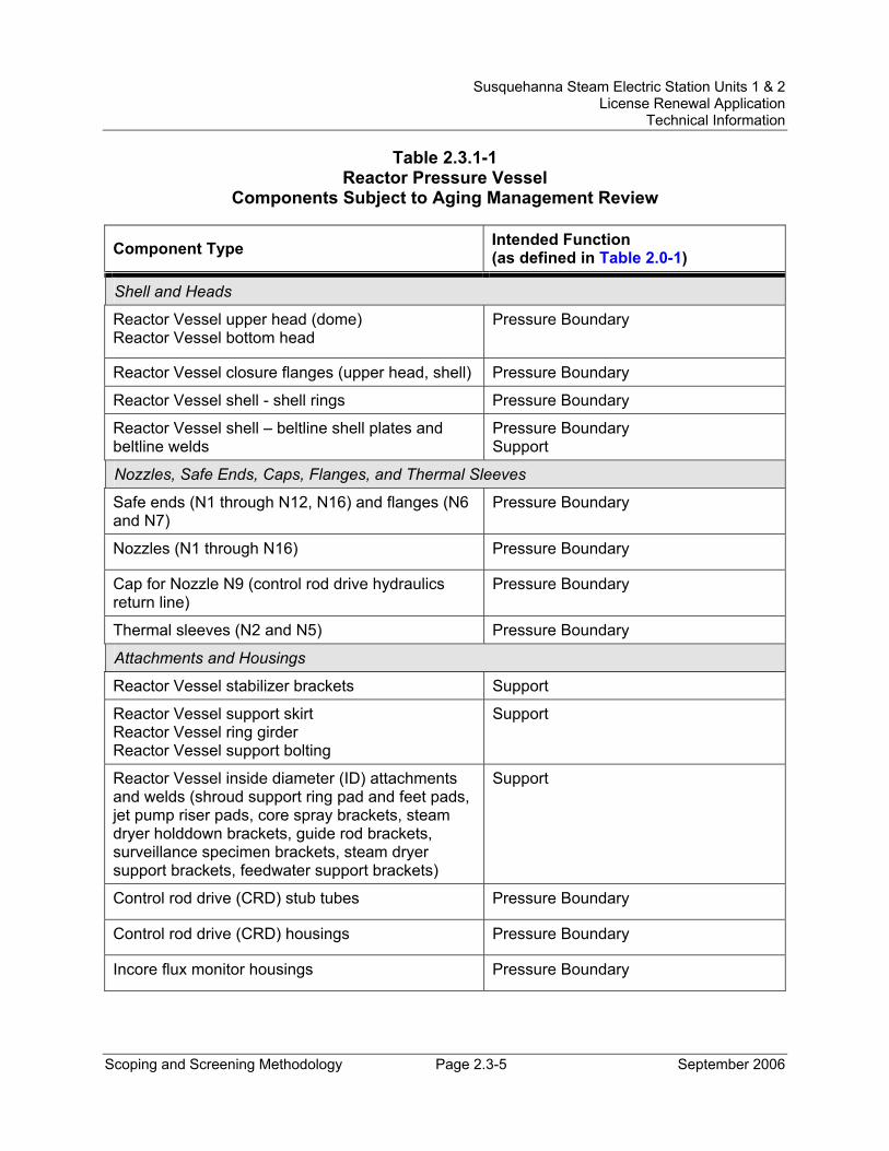
Susquehanna Steam Electric Station Units 1 & 2 License Renewal Application
Technical Information
Scoping and Screening Methodology Page 2.3-5 September 2006
Table 2.3.1-1 Reactor Pressure Vessel
Components Subject to Aging Management Review
Component Type Intended Function (as defined in Table 2.0-1)
Shell and Heads
Reactor Vessel upper head (dome) Reactor Vessel bottom head
Pressure Boundary
Reactor Vessel closure flanges (upper head, shell) Pressure Boundary
Reactor Vessel shell - shell rings Pressure Boundary
Reactor Vessel shell – beltline shell plates and beltline welds
Pressure Boundary Support
Nozzles, Safe Ends, Caps, Flanges, and Thermal Sleeves
Safe ends (N1 through N12, N16) and flanges (N6 and N7)
Pressure Boundary
Nozzles (N1 through N16) Pressure Boundary
Cap for Nozzle N9 (control rod drive hydraulics return line)
Pressure Boundary
Thermal sleeves (N2 and N5) Pressure Boundary
Attachments and Housings
Reactor Vessel stabilizer brackets Support
Reactor Vessel support skirt Reactor Vessel ring girder Reactor Vessel support bolting
Support
Reactor Vessel inside diameter (ID) attachments and welds (shroud support ring pad and feet pads, jet pump riser pads, core spray brackets, steam dryer holddown brackets, guide rod brackets, surveillance specimen brackets, steam dryer support brackets, feedwater support brackets)
Support
Control rod drive (CRD) stub tubes Pressure Boundary
Control rod drive (CRD) housings Pressure Boundary
Incore flux monitor housings Pressure Boundary
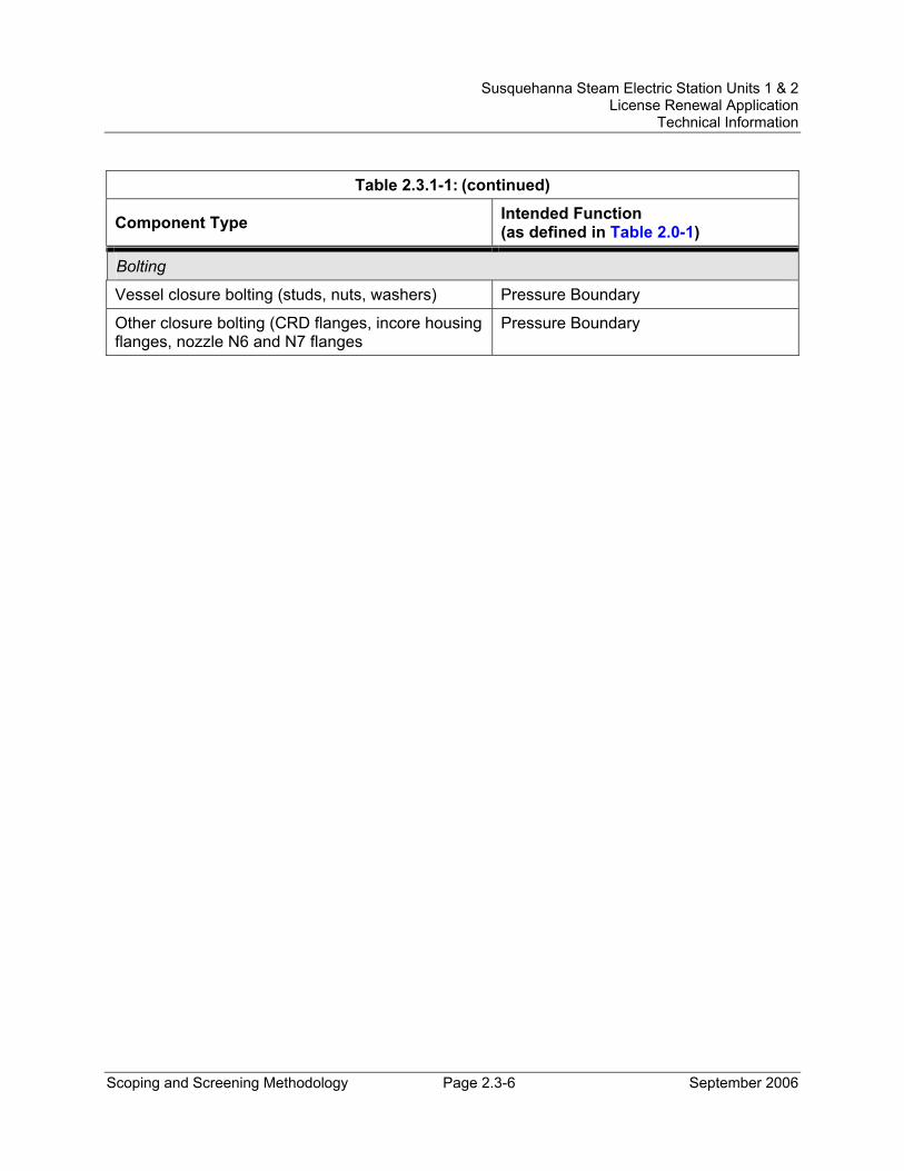
Susquehanna Steam Electric Station Units 1 & 2 License Renewal Application
Technical Information
Scoping and Screening Methodology Page 2.3-6 September 2006
Table 2.3.1-1: (continued)
Component Type Intended Function (as defined in Table 2.0-1)
Bolting
Vessel closure bolting (studs, nuts, washers) Pressure Boundary
Other closure bolting (CRD flanges, incore housing flanges, nozzle N6 and N7 flanges
Pressure Boundary
Susquehanna Steam Electric Station Units 1 & 2 License Renewal Application
Technical Information
Scoping and Screening Methodology Page 2.3-7 September 2006
2.3.1.2 Reactor Vessel Internals System Description The reactor vessel internals are not a unique system in the plant NIMS database. The Reactor Vessel and Auxiliaries System in NIMS includes what is evaluated for license renewal as the reactor pressure vessel, reactor vessel internals, and the reactor coolant system pressure boundary. The reactor pressure vessel is discussed in detail in Section 2.3.1.1. The reactor coolant system pressure boundary is discussed in detail in Section 2.3.1.3.
The reactor vessel internals include the core support structures and other reactor vessel internal components. The main subcomponents of the reactor vessel internal core supports are the shroud, shroud support, core plate, top guide, fuel supports, control rod guide tubes, and control rod drive housings. The other reactor vessel internals are the jet pump assemblies and instrumentation, feedwater spargers, vessel head spray line, standby liquid control line, incore flux monitor tubes (incore guide tubes, incore dry tubes, and local power range monitor assemblies), surveillance sample holders, core spray lines and spargers, incore flux monitor housings, steam dryer, shroud head and steam separator assembly, guide rods, and control rod drive thermal sleeves. The fuel assemblies and control rod assemblies are included with the reactor vessel internals. The control rod drive housings and incore flux monitor housings are evaluated with the reactor pressure vessel. Jet pump instrumentation outside the vessel is evaluated with the reactor coolant system pressure boundary.
Reason for Scope Determination The reactor vessel internals are within the scope of license renewal as a safety-related system. Reactor vessel internals provide a high integrity barrier against the leakage of radioactive materials, support the reactor core and reactor vessel internals, provide a floodable volume in which the core can be adequately cooled in the event of a break in a line external to the vessel, and distribute flow as designed to promote mixing. These safety functions meet the scoping criteria of 10 CFR 54.4(a)(1).
The steam dryer is required to maintain structural integrity to prevent adverse physical interaction with safety-related components. This function meets the scoping criteria of 10 CFR 54.4(a)(2).
The standby liquid control line within the reactor vessel is credited for boron mixing in response to an ATWS event. The reactor vessel internals are relied upon to demonstrate compliance with, and meet the 10 CFR 54.4(a)(3) scoping criteria for, the Anticipated Transients Without Scram (10 CFR 50.62) regulated event.
FSAR References Section 3.9.5 of the SSES FSAR describes the reactor vessel internals.
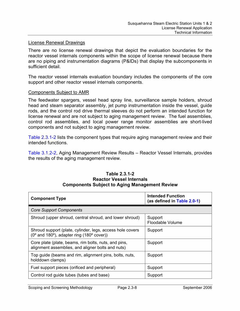
Susquehanna Steam Electric Station Units 1 & 2 License Renewal Application
Technical Information
Scoping and Screening Methodology Page 2.3-8 September 2006
License Renewal Drawings There are no license renewal drawings that depict the evaluation boundaries for the reactor vessel internals components within the scope of license renewal because there are no piping and instrumentation diagrams (P&IDs) that display the subcomponents in sufficient detail.
The reactor vessel internals evaluation boundary includes the components of the core support and other reactor vessel internals components.
Components Subject to AMR The feedwater spargers, vessel head spray line, surveillance sample holders, shroud head and steam separator assembly, jet pump instrumentation inside the vessel, guide rods, and the control rod drive thermal sleeves do not perform an intended function for license renewal and are not subject to aging management review. The fuel assemblies, control rod assemblies, and local power range monitor assemblies are short-lived components and not subject to aging management review.
Table 2.3.1-2 lists the component types that require aging management review and their intended functions.
Table 3.1.2-2, Aging Management Review Results – Reactor Vessel Internals, provides the results of the aging management review.
Table 2.3.1-2
Reactor Vessel Internals Components Subject to Aging Management Review
Component Type Intended Function (as defined in Table 2.0-1)
Core Support Components
Shroud (upper shroud, central shroud, and lower shroud) Support Floodable Volume
Shroud support (plate, cylinder, legs, access hole covers (0º and 180º), adapter ring (180º cover))
Support
Core plate (plate, beams, rim bolts, nuts, and pins, alignment assemblies, and aligner bolts and nuts)
Support
Top guide (beams and rim, alignment pins, bolts, nuts, holddown clamps)
Support
Fuel support pieces (orificed and peripheral) Support
Control rod guide tubes (tubes and base) Support
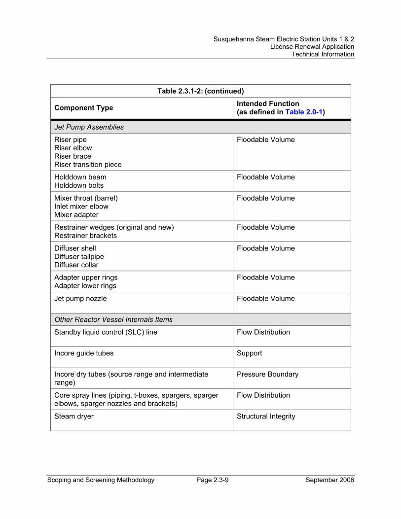
Susquehanna Steam Electric Station Units 1 & 2 License Renewal Application
Technical Information
Scoping and Screening Methodology Page 2.3-9 September 2006
Table 2.3.1-2: (continued)
Component Type Intended Function (as defined in Table 2.0-1)
Jet Pump Assemblies
Riser pipe Riser elbow Riser brace Riser transition piece
Floodable Volume
Holddown beam Holddown bolts
Floodable Volume
Mixer throat (barrel) Inlet mixer elbow Mixer adapter
Floodable Volume
Restrainer wedges (original and new) Restrainer brackets
Floodable Volume
Diffuser shell Diffuser tailpipe Diffuser collar
Floodable Volume
Adapter upper rings Adapter lower rings
Floodable Volume
Jet pump nozzle Floodable Volume
Other Reactor Vessel Internals Items
Standby liquid control (SLC) line Flow Distribution
Incore guide tubes Support
Incore dry tubes (source range and intermediate range)
Pressure Boundary
Core spray lines (piping, t-boxes, spargers, sparger elbows, sparger nozzles and brackets)
Flow Distribution
Steam dryer Structural Integrity
Susquehanna Steam Electric Station Units 1 & 2 License Renewal Application
Technical Information
Scoping and Screening Methodology Page 2.3-10 September 2006
2.3.1.3 Reactor Coolant System Pressure Boundary System Description As described in Section 5.1 of the FSAR, the Reactor Coolant System includes those systems and components that contain or transport fluids coming from or going to the reactor core. The Reactor Coolant System is not a unique system in the plant NIMS database. The Reactor Vessel and Auxiliaries System in NIMS includes what is evaluated for license renewal as the reactor pressure vessel, reactor vessel internals, and the reactor coolant system pressure boundary. The reactor pressure vessel is discussed in detail in Section 2.3.1.1. The reactor vessel internals are discussed in detail in Section 2.3.1.2.
The reactor coolant system pressure boundary (RCSPB) as evaluated for license renewal includes the ASME Code Class 1 portions of the systems listed below. In addition, the in-scope portions of the Reactor Recirculation System are included in the RCSPB for the purpose of license renewal evaluation. The components of the Reactor Vessel and Auxiliaries System included in the RCSPB and not associated with any other system are the reactor vessel vent lines and the flange leak detection line. The vent lines are intended for use only during outages and are not normally in service. The flange leak detection line indicates leakage between the double seals used for the reactor vessel head closure. This line would only contain reactor coolant if the inner seal is leaking.
As part of the RCSPB, the following systems are addressed in this section. The non-Class 1 in-scope portions of the listed systems, except for the Reactor Recirculation System and the Reactor Vessel and Auxiliaries, are discussed in Sections 2.3.2, 2.3.3, and 2.3.4.
• Control Rod Drive Hydraulic System (Class 1 portions only)
• Core Spray System (Class 1 portions only)
• Feedwater System (Class 1 portions only)
• High Pressure Coolant Injection System (Class 1 portions only)
• Main Steam System (Class 1 portions only)
• Reactor Core Isolation Cooling System (Class 1 portions only)
• Reactor Nonnuclear Instrumentation System (Class 1 portions only)
• Reactor Recirculation System
• Reactor Vessel and Auxiliaries (vent line and flange leak detection line only)
• Residual Heat Removal System (Class 1 portions only)
• Reactor Water Cleanup System (Class 1 portions only)
Susquehanna Steam Electric Station Units 1 & 2 License Renewal Application
Technical Information
Scoping and Screening Methodology Page 2.3-11 September 2006
• Standby Liquid Control System (Class 1 portions only)
The Reactor Recirculation System pumps reactor coolant through the core to remove the heat generated in the fuel. This is accomplished by two recirculation loops external to the reactor vessel but inside the primary containment. Each loop has one motor-driven recirculation pump. Recirculation pump speed can be varied to allow some control of reactor power level through the effects of coolant flow rate on moderator void content.
Reason for Scope Determination The RCSPB provides a high integrity barrier against the leakage of radioactive materials and provides containment isolation via closure of containment isolation valves and excess flow check valves. The Reactor Recirculation System provides a closed supply path from the reactor to the RHR System and from the RHR System to the jet pump nozzles for reactor shutdown cooling. These safety functions meet the scoping criteria of 10 CFR 54.4(a)(1).
The reactor recirculation water sample line is required to be isolated on high main steam line radiation in support of alternate source term dose reduction. The Reactor Recirculation System is required to maintain the integrity of nonsafety-related components that have the potential to adversely affect safety-related equipment through spatial interaction and nonsafety-related piping components required to support the safety-related functional boundary of the system. These functions meet the scoping criteria of 10 CFR 54.4(a)(2).
The Reactor Recirculation System supports the Reactor Protection System during an ATWS event by means of recirculation pump trip. The Reactor Recirculation System is required to isolate the recirculation pump and provide a flow path for RHR shutdown cooling in support of fire protection events. The RCSPB is relied upon to demonstrate compliance with, and meets the 10 CFR 54.4(a)(3) scoping criteria for, the Fire Protection (10 CFR 50.48), Environmental Qualification (10 CFR 50.49), Anticipated Transient Without Scram (10 CFR 50.62), and Station Blackout (10 CFR 50.63) regulated events.
FSAR References Section 5.1 of the SSES FSAR describes the Reactor Coolant System.
Susquehanna Steam Electric Station Units 1 & 2 License Renewal Application
Technical Information
Scoping and Screening Methodology Page 2.3-12 September 2006
License Renewal Drawings The following license renewal drawings depict the evaluation boundaries for the system components within the scope of license renewal:
Unit 1: LR-M-141 sheets 1 and 2, LR-M-142 sheets 1 and 2, LR-M-143 sheets 1 and 2, LR-M-144 sheet 1, LR-M-146 sheet 1, LR-M-147 sheet 2, LR-M-148 sheet 1, LR-M-149 sheet 1, LR-M-151 sheets 1 and 3, LR-M-152 sheet 1, LR-M-155 sheet 1
Unit 2: LR-M-2141 sheets 1 and 2, LR-M-2142 sheets 1, 2, and 3, LR-M-2143 sheets 1 and 2, LR-M-2144 sheet 1, LR-M-2146 sheet 1, LR-M-2147 sheet 2, LR-M-2148 sheet 1, LR-M-2149 sheet 1, LR-M-2151 sheets 1 and 3, LR-M-2152 sheet 1, LR-M-2155 sheet 1
Components Subject to AMR The control rod drive mechanisms are active components and are not subject to aging management review.
Table 2.3.1-3 lists the component types that require aging management review and their intended functions.
Table 3.1.2-3, Aging Management Review Results – Reactor Coolant System Pressure Boundary, provides the results of the aging management review.
Table 3.3.2-33, Aging Management Review Results – Reactor Recirculation System (NSAS Portions), provides the results of the aging management review for the NSAS portions.
Table 3.3.2-34, Aging Management Review Results – Reactor Vessel and Auxiliaries System (NSAS Portions), provides the results of the aging management review for the NSAS portions.
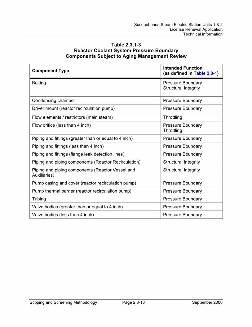
Susquehanna Steam Electric Station Units 1 & 2 License Renewal Application
Technical Information
Scoping and Screening Methodology Page 2.3-13 September 2006
Table 2.3.1-3 Reactor Coolant System Pressure Boundary
Components Subject to Aging Management Review
Component Type Intended Function (as defined in Table 2.0-1)
Bolting Pressure Boundary Structural Integrity
Condensing chamber Pressure Boundary
Driver mount (reactor recirculation pump) Pressure Boundary
Flow elements / restrictors (main steam) Throttling
Flow orifice (less than 4 inch) Pressure Boundary Throttling
Piping and fittings (greater than or equal to 4 inch) Pressure Boundary
Piping and fittings (less than 4 inch) Pressure Boundary
Piping and fittings (flange leak detection lines) Pressure Boundary
Piping and piping components (Reactor Recirculation) Structural Integrity
Piping and piping components (Reactor Vessel and Auxiliaries)
Structural Integrity
Pump casing and cover (reactor recirculation pump) Pressure Boundary
Pump thermal barrier (reactor recirculation pump) Pressure Boundary
Tubing Pressure Boundary
Valve bodies (greater than or equal to 4 inch) Pressure Boundary
Valve bodies (less than 4 inch) Pressure Boundary
Susquehanna Steam Electric Station Units 1 & 2 License Renewal Application
Technical Information
Scoping and Screening Methodology Page 2.3-14 September 2006
2.3.2 Engineered Safety Features
The engineered safety features (ESF) of the SSES plant, as defined in Section 6.0 of the SSES FSAR, are those structures, systems and/or components provided to prevent, limit, or mitigate the release of energy and radioactive material in excess of 10 CFR 100 limits in the event of a design basis accident. The following ESF systems are addressed in this section:
• Residual Heat Removal (RHR) System (Section 2.3.2.1)
• Reactor Core Isolation Cooling (RCIC) System (Section 2.3.2.2)
• Core Spray System (Section 2.3.2.3)
• High Pressure Coolant Injection (HPCI) System (Section 2.3.2.4)
• Containment and Suppression System (Section 2.3.2.5)
• Containment Atmosphere Control System (Section 2.3.2.6)
• Standby Gas Treatment System (SGTS) (Section 2.3.2.7)
The Automatic Depressurization System (ADS) is evaluated as part of the Main Steam System in Section 2.3.4.6.
A brief system description, reason for scope determination, associated FSAR references, associated license renewal drawings, and components subject to AMR information is provided for each system.
Susquehanna Steam Electric Station Units 1 & 2 License Renewal Application
Technical Information
Scoping and Screening Methodology Page 2.3-15 September 2006
2.3.2.1 Residual Heat Removal (RHR) System System Description The RHR System is comprised of two independent loops. Each loop contains two motor-driven pumps, a heat exchanger, piping, valves, instrumentation, and controls. The RHR heat exchangers are cooled by RHR service water. Each loop takes suction from the suppression pool and is capable of discharging water to the reactor vessel via a connection to the reactor recirculation loop, or back to the suppression pool via a full flow test line. Each loop can also take suction from a common line from one reactor recirculation loop. Each loop can take suction from and discharge to the fuel pool cooling system. Both loops can discharge to wetwell and drywell spray spargers. Also, one loop can discharge to the reactor vessel head spray line.
The RHR System has five subsystems or modes, each of which has its own functional requirements, including Shutdown Cooling, Low Pressure Coolant Injection, Suppression Pool Cooling, Containment Spray Cooling, and Fuel Pool Cooling. The Shutdown Cooling mode is nonsafety-related and does not support an intended function. The other modes are discussed under Reason for Scope Determination below.
The major components of the RHR System are the RHR pumps, the RHR pump motor oil coolers, and the RHR heat exchangers.
Reason for Scope Determination The RHR System provides containment isolation upon receipt of a containment isolation signal; auto-initiates in an Emergency Core Cooling System (ECCS) mode to flood the reactor core when the reactor water level is low or when drywell pressure is high; provides coolant to the suppression pool in a manually-initiated mode to ensure that the long-term peak suppression pool temperature following a design basis loss of coolant accident (LOCA) remains within design basis limits (may also be used during normal plant operation or during a transient); provides coolant to the suppression pool vapor space in the containment spray cooling mode to provide a redundant means of condensing vapor and controlling the containment pressure within design limits; provides coolant to the Fuel Pool Cooling and Cleanup (FPCCU) System to maintain fuel pool temperature at or below 125ºF when the Emergency Heat Load (EHL) is resident in an isolated fuel pool, and prevent fuel pool boiling during a seismic event. All of these design basis functions are safety-related functions. These safety functions meet the scoping criteria of 10 CFR 54.4(a)(1).
The RHR System is required to maintain the integrity of nonsafety-related components that have the potential to adversely affect safety-related equipment through spatial interaction and nonsafety-related piping components required to support the safety-related functional boundary of the system. This function meets the scoping criteria of 10 CFR 54.4(a)(2).
Susquehanna Steam Electric Station Units 1 & 2 License Renewal Application
Technical Information
Scoping and Screening Methodology Page 2.3-16 September 2006
The RHR System is also relied upon to demonstrate compliance with, and meets the 10 CFR 54.4(a)(3) scoping criteria for, the Fire Protection (10 CFR 50.48), Environmental Qualification (10 CFR 50.49), and Anticipated Transients Without Scram (10 CFR 50.62) regulated events.
FSAR References Section 5.4.7 of the SSES FSAR describes the Residual Heat Removal System.
License Renewal Drawings The following license renewal drawings depict the evaluation boundaries for the system components within the scope of license renewal:
Unit 1: LR-M-111 sheets 2 and 3, LR-M-112 sheet 1, LR-M-123 sheet 12, LR-M-149 sheet 1, LR-M-151 sheets 1, 2, 3, 4, and 5, LR-M-157 sheet 1
Unit 2: LR-M-2111 sheets 1 and 2, LR-M-2112 sheet 1, LR-M-2123 sheet 10, LR-M-2149 sheet 1, LR-M-2151 sheets 1, 2, 3, 4, and 5, LR-M-2157 sheet 1
Components Subject to AMR Table 2.3.2-1 lists the component types that require aging management review and their intended functions.
Table 3.2.2-1, Aging Management Review Results – Residual Heat Removal System, provides the results of the aging management review.
Class 1 components in the reactor coolant pressure boundary are evaluated with the Reactor Coolant System Pressure Boundary (see Section 2.3.1.3).
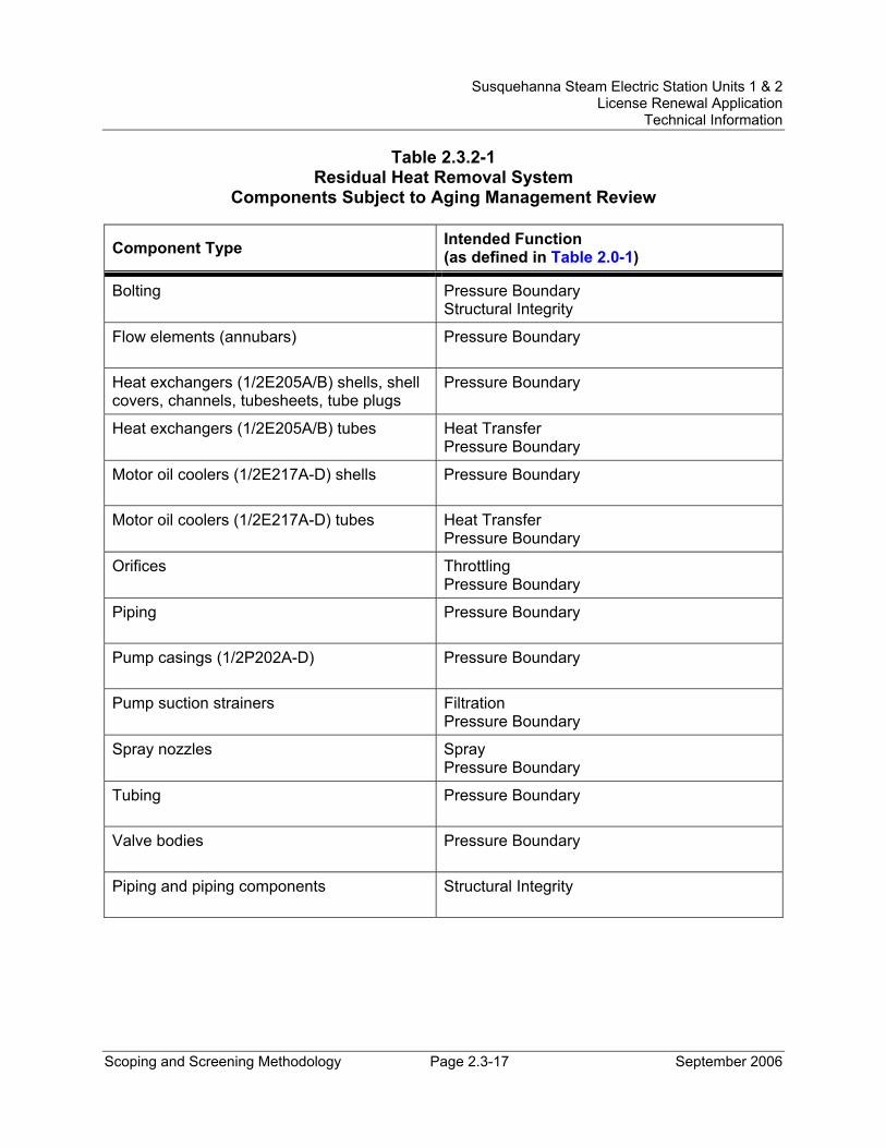
Susquehanna Steam Electric Station Units 1 & 2 License Renewal Application
Technical Information
Scoping and Screening Methodology Page 2.3-17 September 2006
Table 2.3.2-1 Residual Heat Removal System
Components Subject to Aging Management Review
Component Type Intended Function (as defined in Table 2.0-1)
Bolting Pressure Boundary Structural Integrity
Flow elements (annubars) Pressure Boundary
Heat exchangers (1/2E205A/B) shells, shell covers, channels, tubesheets, tube plugs
Pressure Boundary
Heat exchangers (1/2E205A/B) tubes Heat Transfer Pressure Boundary
Motor oil coolers (1/2E217A-D) shells Pressure Boundary
Motor oil coolers (1/2E217A-D) tubes Heat Transfer Pressure Boundary
Orifices Throttling Pressure Boundary
Piping Pressure Boundary
Pump casings (1/2P202A-D) Pressure Boundary
Pump suction strainers Filtration Pressure Boundary
Spray nozzles Spray Pressure Boundary
Tubing Pressure Boundary
Valve bodies Pressure Boundary
Piping and piping components Structural Integrity
Susquehanna Steam Electric Station Units 1 & 2 License Renewal Application
Technical Information
Scoping and Screening Methodology Page 2.3-18 September 2006
2.3.2.2 Reactor Core Isolation Cooling (RCIC) System System Description In accordance with the SSES Technical Specification Bases, the RCIC System is not part of the Emergency Core Cooling System (ECCS), is not an Engineered Safety Feature (ESF) system, and is not credited for its operation in plant safety analyses. The RCIC System is, however, included with ECCS and ESF systems because of its similar functions and its contribution to the reduction of overall plant risk.
The RCIC System consists of a steam-driven turbine-pump unit and associated valves and piping capable of delivering water from either the condensate storage tank (CST) or the suppression pool to the reactor vessel via one of the feedwater lines.
The steam supply driving the RCIC turbine comes from a main steam line upstream of the main steam isolation valves and the steam exhaust from the turbine is directed to the suppression pool. Cooling water for the RCIC turbine lube oil cooler is supplied from the discharge of the pump.
The RCIC injection to the vessel occurs through the feedwater line. A test path exists that directs the pump discharge back to the CST. A minimum bypass flow line directs flow to the suppression pool to protect the pump during low flow conditions.
The major components of the RCIC System are the RCIC pump, the RCIC pump turbine, and the RCIC turbine lube oil system consisting of a lube oil cooler, pump, filter, and tank.
Reason for Scope Determination The RCIC System provides cooling water to the reactor vessel following reactor vessel isolation and loss of feedwater flow. The RCIC System has sufficient capacity to prevent the reactor vessel level from dropping to “Level 1” so as to prevent low-pressure ECCS initiation. The RCIC System is not designed with functional redundancy, and the function described above is nonsafety-related. The safety-related functions of the RCIC System are to maintain containment integrity through containment isolation, provide input signals to the bypass indication system, and provide the start signal to the RCIC room coolers. These safety functions meet the scoping criteria of 10 CFR 54.4(a)(1).
The RCIC System is required to maintain the integrity of nonsafety-related components that have the potential to adversely affect safety-related equipment through spatial interaction and nonsafety-related piping components required to support the safety-related functional boundary of the system. This function meets the scoping criteria of 10 CFR 54.4(a)(2).
The RCIC System is relied upon to demonstrate compliance with, and meets the 10 CFR 54.4(a)(3) scoping criteria for, the Fire Protection (10 CFR 50.48),
Susquehanna Steam Electric Station Units 1 & 2 License Renewal Application
Technical Information
Scoping and Screening Methodology Page 2.3-19 September 2006
Environmental Qualification (10 CFR 50.49), Anticipated Transients Without Scram (10 CFR 50.62), and Station Blackout (10 CFR 50.63) regulated events.
FSAR References Section 5.4.6 of the SSES FSAR describes the Reactor Core Isolation Cooling System.
License Renewal Drawings The following license renewal drawings depict the evaluation boundaries for the system components within the scope of license renewal:
Unit 1: LR-M-149 sheet 1, LR-M-150 sheet 1, LR-M1-E51-95
Unit 2: LR-M-2149 sheet 1, LR-M-2150 sheet 1, LR-M1-E51-95
Components Subject to AMR Table 2.3.2-2 lists the component types that require aging management review and their intended functions.
Table 3.2.2-2, Aging Management Review Results – Reactor Core Isolation Cooling System, provides the results of the aging management review.
Class 1 components in the reactor coolant pressure boundary are evaluated with the Reactor Coolant System Pressure Boundary (see Section 2.3.1.3).
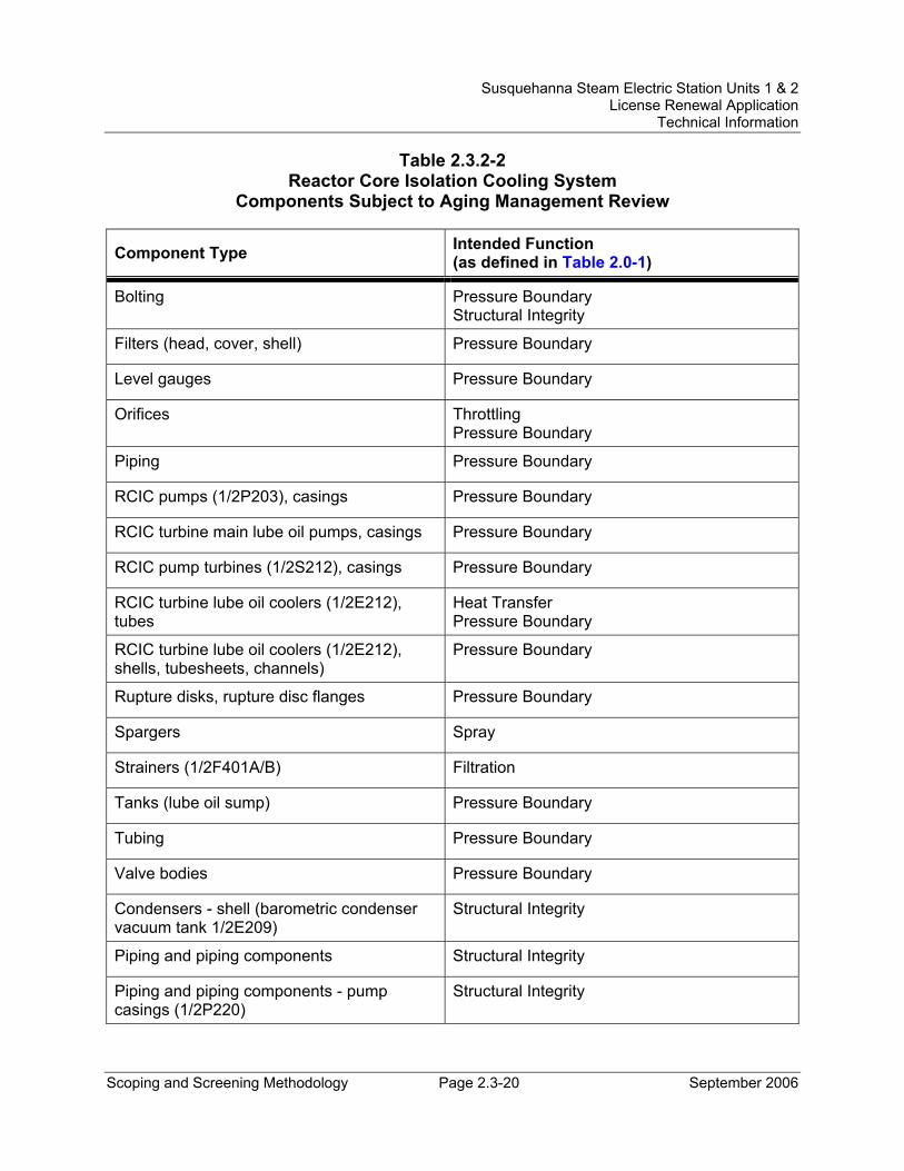
Susquehanna Steam Electric Station Units 1 & 2 License Renewal Application
Technical Information
Scoping and Screening Methodology Page 2.3-20 September 2006
Table 2.3.2-2 Reactor Core Isolation Cooling System
Components Subject to Aging Management Review
Component Type Intended Function (as defined in Table 2.0-1)
Bolting Pressure Boundary Structural Integrity
Filters (head, cover, shell) Pressure Boundary
Level gauges Pressure Boundary
Orifices Throttling Pressure Boundary
Piping Pressure Boundary
RCIC pumps (1/2P203), casings Pressure Boundary
RCIC turbine main lube oil pumps, casings Pressure Boundary
RCIC pump turbines (1/2S212), casings Pressure Boundary
RCIC turbine lube oil coolers (1/2E212), tubes
Heat Transfer Pressure Boundary
RCIC turbine lube oil coolers (1/2E212), shells, tubesheets, channels)
Pressure Boundary
Rupture disks, rupture disc flanges Pressure Boundary
Spargers Spray
Strainers (1/2F401A/B) Filtration
Tanks (lube oil sump) Pressure Boundary
Tubing Pressure Boundary
Valve bodies Pressure Boundary
Condensers - shell (barometric condenser vacuum tank 1/2E209)
Structural Integrity
Piping and piping components Structural Integrity
Piping and piping components - pump casings (1/2P220)
Structural Integrity
Susquehanna Steam Electric Station Units 1 & 2 License Renewal Application
Technical Information
Scoping and Screening Methodology Page 2.3-21 September 2006
2.3.2.3 Core Spray System System Description The Core Spray System, as part of the overall Emergency Core Cooling System (ECCS), is designed to provide cooling to the reactor core only when the reactor vessel pressure is low, as is the case for a large break Loss of Coolant Accident (LOCA). However, when the Core Spray System operates in conjunction with the Automatic Depressurization System (ADS), the effective core cooling capability of the Core Spray System is extended to all break sizes as the ADS will rapidly reduce the reactor vessel pressure to the Core Spray System operating range.
The major components of the Core Spray System are the core spray pumps and the core spray suction and discharge headers.
Reason for Scope Determination The Core Spray System provides sufficient coolant to the fuel bundles via in-vessel spargers to prevent excessive fuel cladding temperatures in the event of a design basis LOCA, and maintains the integrity and requirements of the reactor coolant pressure boundary and primary containment. These safety functions meet the scoping criteria of 10 CFR 54.4(a)(1).
The Core Spray System is required to maintain the integrity of nonsafety-related components that have the potential to adversely affect safety-related equipment through spatial interaction and nonsafety-related piping components required to support the safety-related functional boundary of the system. This function meets the scoping criteria of 10 CFR 54.4(a)(2).
The Core Spray System is also relied upon to demonstrate compliance with, and meets the 10 CFR 54.4(a)(3) scoping criteria for, the Fire Protection (10 CFR 50.48) and Environmental Qualification (10 CFR 50.49) regulated events.
FSAR References Section 6.3.2.2.3 of the SSES FSAR describes the Core Spray System.
License Renewal Drawings The following license renewal drawings depict the evaluation boundaries for the system components within the scope of license renewal:
Unit 1: LR-M-152 sheet 1
Unit 2: LR-M-2152 sheet 1
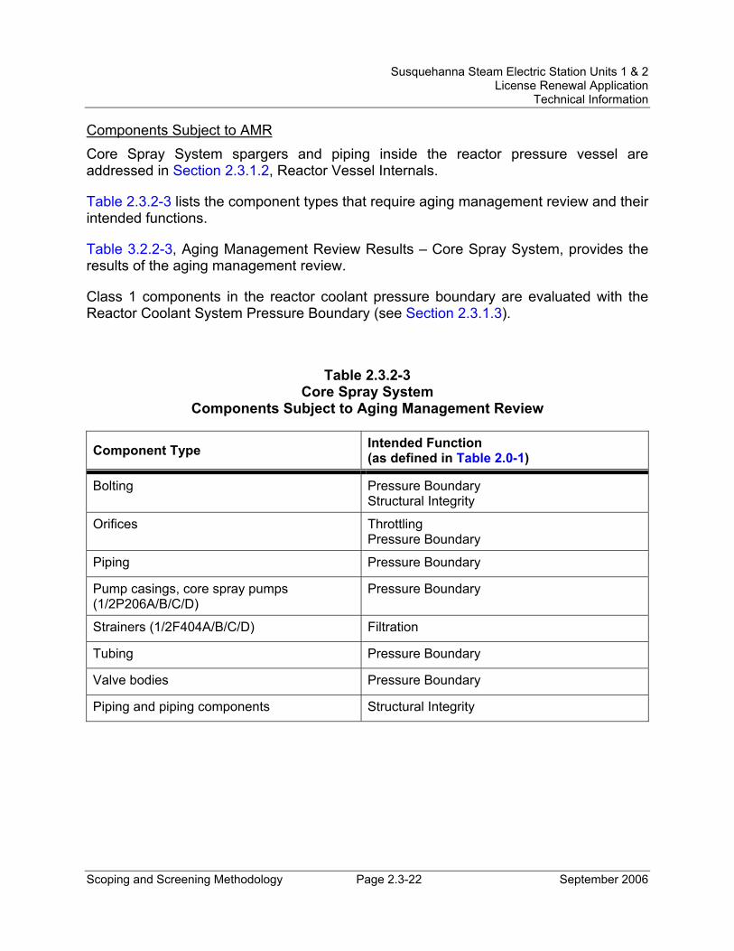
Susquehanna Steam Electric Station Units 1 & 2 License Renewal Application
Technical Information
Scoping and Screening Methodology Page 2.3-22 September 2006
Components Subject to AMR Core Spray System spargers and piping inside the reactor pressure vessel are addressed in Section 2.3.1.2, Reactor Vessel Internals.
Table 2.3.2-3 lists the component types that require aging management review and their intended functions.
Table 3.2.2-3, Aging Management Review Results – Core Spray System, provides the results of the aging management review.
Class 1 components in the reactor coolant pressure boundary are evaluated with the Reactor Coolant System Pressure Boundary (see Section 2.3.1.3).
Table 2.3.2-3 Core Spray System
Components Subject to Aging Management Review
Component Type Intended Function (as defined in Table 2.0-1)
Bolting Pressure Boundary Structural Integrity
Orifices Throttling Pressure Boundary
Piping Pressure Boundary
Pump casings, core spray pumps (1/2P206A/B/C/D)
Pressure Boundary
Strainers (1/2F404A/B/C/D) Filtration
Tubing Pressure Boundary
Valve bodies Pressure Boundary
Piping and piping components Structural Integrity
Susquehanna Steam Electric Station Units 1 & 2 License Renewal Application
Technical Information
Scoping and Screening Methodology Page 2.3-23 September 2006
2.3.2.4 High Pressure Coolant Injection (HPCI) System System Description The HPCI System consists of a steam-driven turbine-pump unit and associated valves and piping capable of delivering water from the condensate storage tank (CST) or from the suppression pool to the reactor vessel via one of the feedwater lines.
The steam supply driving the HPCI turbine comes from a main steam line upstream of the main steam isolation valves (MSIVs) and the steam exhaust from the turbine is directed to the suppression pool. Cooling water for the lube oil coolers associated with the HPCI turbines is supplied from the discharge of the HPCI booster pump.
The HPCI injection to the vessel occurs through the feedwater line. A test path exists that directs the pump discharge back to the CST. A minimum bypass flow line directs flow to the suppression pool to protect the pump during low flow conditions.
The major components of the HPCI System are the HPCI pump, the HPCI booster pump, the HPCI pump turbine, and the HPCI lubricating and control oil subsystem including the turbine-driven main lube oil pump, the auxiliary oil pump, the lube oil cooler, the lube oil duplex filter, and the lube oil reservoir.
Reason for Scope Determination The HPCI System is an Emergency Core Cooling System (ECCS). The primary mechanical function of the system is to provide sufficient coolant to the reactor vessel to prevent excessive fuel clad temperatures in the event of a small break loss-of-coolant accident (LOCA) that does not result in rapid depressurization of the reactor vessel. A portion of the system also provides containment isolation upon receipt of a containment isolation signal, while another portion provides isolation of the steam drain upon HPCI Pump Turbine initiation. A portion of the HPCI System also maintains the integrity of the reactor coolant pressure boundary. These are all safety-related system functions. These safety functions meet the scoping criteria of 10 CFR 54.4(a)(1).
The HPCI System is required to maintain the integrity of nonsafety-related components that have the potential to adversely affect safety-related equipment through spatial interaction and nonsafety-related piping components required to support the safety-related functional boundary of the system. This function meets the scoping criteria of 10 CFR 54.4(a)(2).
The HPCI System is relied upon to demonstrate compliance with, and meets the 10 CFR 54.4(a)(3) scoping criteria for, the Fire Protection (10 CFR 50.48), Environmental Qualification (10 CFR 50.49), Anticipated Transients Without Scram (10 CFR 50.62), and Station Blackout (10 CFR 50.63) regulated events.
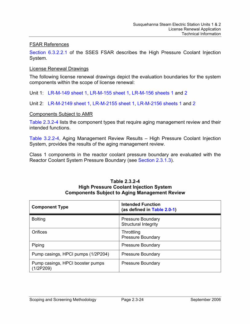
Susquehanna Steam Electric Station Units 1 & 2 License Renewal Application
Technical Information
Scoping and Screening Methodology Page 2.3-24 September 2006
FSAR References Section 6.3.2.2.1 of the SSES FSAR describes the High Pressure Coolant Injection System.
License Renewal Drawings The following license renewal drawings depict the evaluation boundaries for the system components within the scope of license renewal:
Unit 1: LR-M-149 sheet 1, LR-M-155 sheet 1, LR-M-156 sheets 1 and 2
Unit 2: LR-M-2149 sheet 1, LR-M-2155 sheet 1, LR-M-2156 sheets 1 and 2
Components Subject to AMR Table 2.3.2-4 lists the component types that require aging management review and their intended functions.
Table 3.2.2-4, Aging Management Review Results – High Pressure Coolant Injection System, provides the results of the aging management review.
Class 1 components in the reactor coolant pressure boundary are evaluated with the Reactor Coolant System Pressure Boundary (see Section 2.3.1.3).
Table 2.3.2-4 High Pressure Coolant Injection System
Components Subject to Aging Management Review
Component Type Intended Function (as defined in Table 2.0-1)
Bolting Pressure Boundary Structural Integrity
Orifices Throttling Pressure Boundary
Piping Pressure Boundary
Pump casings, HPCI pumps (1/2P204) Pressure Boundary
Pump casings, HPCI booster pumps (1/2P209)
Pressure Boundary
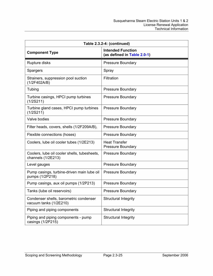
Susquehanna Steam Electric Station Units 1 & 2 License Renewal Application
Technical Information
Scoping and Screening Methodology Page 2.3-25 September 2006
Table 2.3.2-4: (continued)
Component Type Intended Function (as defined in Table 2.0-1)
Rupture disks Pressure Boundary
Spargers Spray
Strainers, suppression pool suction (1/2F402A/B)
Filtration
Tubing Pressure Boundary
Turbine casings, HPCI pump turbines (1/2S211)
Pressure Boundary
Turbine gland cases, HPCI pump turbines (1/2S211)
Pressure Boundary
Valve bodies Pressure Boundary
Filter heads, covers, shells (1/2F209A/B), Pressure Boundary
Flexible connections (hoses) Pressure Boundary
Coolers, lube oil cooler tubes (1/2E213) Heat Transfer Pressure Boundary
Coolers, lube oil cooler shells, tubesheets, channels (1/2E213)
Pressure Boundary
Level gauges Pressure Boundary
Pump casings, turbine-driven main lube oil pumps (1/2P218)
Pressure Boundary
Pump casings, aux oil pumps (1/2P213) Pressure Boundary
Tanks (lube oil reservoirs) Pressure Boundary
Condenser shells, barometric condenser vacuum tanks (1/2E210)
Structural Integrity
Piping and piping components Structural Integrity
Piping and piping components - pump casings (1/2P215)
Structural Integrity
Susquehanna Steam Electric Station Units 1 & 2 License Renewal Application
Technical Information
Scoping and Screening Methodology Page 2.3-26 September 2006
2.3.2.5 Containment and Suppression System System Description The Containment and Suppression System maintains the structural and functional integrity of the primary containment during and following a design basis loss of coolant accident (LOCA). The design features of the system prevent over-pressurization of the containment structure to ensure the integrity of the protective barrier between the Reactor Coolant System and the secondary containment. Through the five wetwell vacuum breakers, the system limits the differential pressure and allows for the distribution of noncondensable gases between the drywell and the suppression chamber following the reactor vessel depressurization phase of a LOCA. The system also provides for suppression pool level, pressure, and temperature monitoring, and provides for suppression pool cleanup.
The major components of the Containment and Suppression System are the downcomers.
Reason for Scope Determination The Containment and Suppression System contains and suppresses the steam and steam pressure resulting from a LOCA; provides direct containment isolation (e.g., suppression pool cleanup line valves) and containment isolation signals to containment isolation valves in other systems; provides a means of equalizing pressure across the drywell floor through the use of downcomers and wetwell vacuum breakers; provides a protective barrier to limit radiological releases; and provides for suppression pool level and temperature monitoring. These safety functions meet the scoping criteria of 10 CFR 54.4(a)(1).
The Containment and Suppression System is required to maintain the integrity of nonsafety-related components that have the potential to adversely affect safety-related equipment through spatial interaction and nonsafety-related piping components required to support the safety-related functional boundary of the system. This function meets the scoping criteria of 10 CFR 54.4(a)(2).
The Containment and Suppression System is relied upon to demonstrate compliance with, and meets the 10 CFR 54.4(a)(3) scoping criteria for, the Fire Protection (10 CFR 50.48), Environmental Qualification (10 CFR 50.49), Anticipated Transients Without Scram (10 CFR 50.62), and Station Blackout (10 CFR 50.63) regulated events.
FSAR References Section 6.2.1 of the SSES FSAR describes the pressure suppression containment system, identified for license renewal as the Containment and Suppression System.
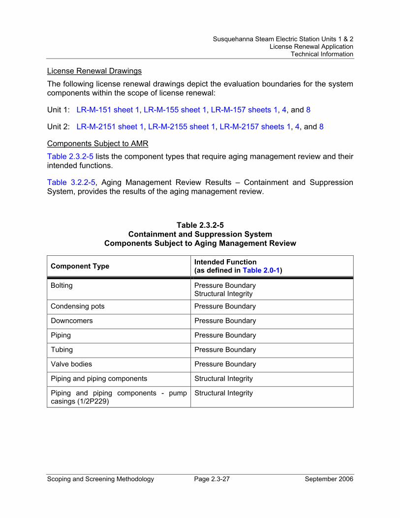
Susquehanna Steam Electric Station Units 1 & 2 License Renewal Application
Technical Information
Scoping and Screening Methodology Page 2.3-27 September 2006
License Renewal Drawings The following license renewal drawings depict the evaluation boundaries for the system components within the scope of license renewal:
Unit 1: LR-M-151 sheet 1, LR-M-155 sheet 1, LR-M-157 sheets 1, 4, and 8
Unit 2: LR-M-2151 sheet 1, LR-M-2155 sheet 1, LR-M-2157 sheets 1, 4, and 8
Components Subject to AMR Table 2.3.2-5 lists the component types that require aging management review and their intended functions.
Table 3.2.2-5, Aging Management Review Results – Containment and Suppression System, provides the results of the aging management review.
Table 2.3.2-5 Containment and Suppression System
Components Subject to Aging Management Review
Component Type Intended Function (as defined in Table 2.0-1)
Bolting Pressure Boundary Structural Integrity
Condensing pots Pressure Boundary
Downcomers Pressure Boundary
Piping Pressure Boundary
Tubing Pressure Boundary
Valve bodies Pressure Boundary
Piping and piping components Structural Integrity
Piping and piping components - pump casings (1/2P229)
Structural Integrity
Susquehanna Steam Electric Station Units 1 & 2 License Renewal Application
Technical Information
Scoping and Screening Methodology Page 2.3-28 September 2006
2.3.2.6 Containment Atmosphere Control System System Description The Containment Atmosphere Control System is designed to control the concentration of hydrogen within the primary containment following a loss-of-coolant accident (LOCA). To accomplish this function, the system monitors the concentrations of hydrogen and oxygen within the containment, maintains the hydrogen concentration below combustible limits using hydrogen recombiner systems (primary) and hydrogen purging systems (back-up), and provides containment mixing to prevent local hydrogen concentration buildup.
The major components of the Containment Atmosphere Control System are the hydrogen recombiners and the hydrogen and oxygen analyzers which include diaphragm pumps, heat exchangers, and moisture separators.
Reason for Scope Determination The Containment Atmosphere Control System provides hydrogen and oxygen analyzers to monitor the containment atmosphere, heats a continuous stream of containment atmosphere following a LOCA for the spontaneous recombination of hydrogen and oxygen, and monitors drywell and suppression chamber pressure and temperature. These safety functions meet the scoping criteria of 10 CFR 54.4(a)(1).
The Containment Atmosphere Control System is required to maintain the integrity of nonsafety-related components that have the potential to adversely affect safety-related equipment through spatial interaction and nonsafety piping/ducting components required to support the safety-related functional boundary of the system. This function meets the scoping criteria of 10 CFR 54.4(a)(2).
The Containment Atmosphere Control System is relied upon to demonstrate compliance with, and meets the 10 CFR 54.4(a)(3) scoping criteria for, the Fire Protection (10 CFR 50.48), Environmental Qualification (10 CFR 50.49), and Station Blackout (10 CFR 50.63) regulated events.
FSAR References Section 6.2.5 of the SSES FSAR describes the combustible gas control system, identified for license renewal as the Containment Atmosphere Control System.
License Renewal Drawings The following license renewal drawings depict the evaluation boundaries for the system components within the scope of license renewal:
Unit 1: LR-M-123 sheet 12, LR-M-155 sheet 1, LR-M-157 sheets 1, 2, 3, 4, 5, 6, 7, and 8, LR-M-159 sheet 1
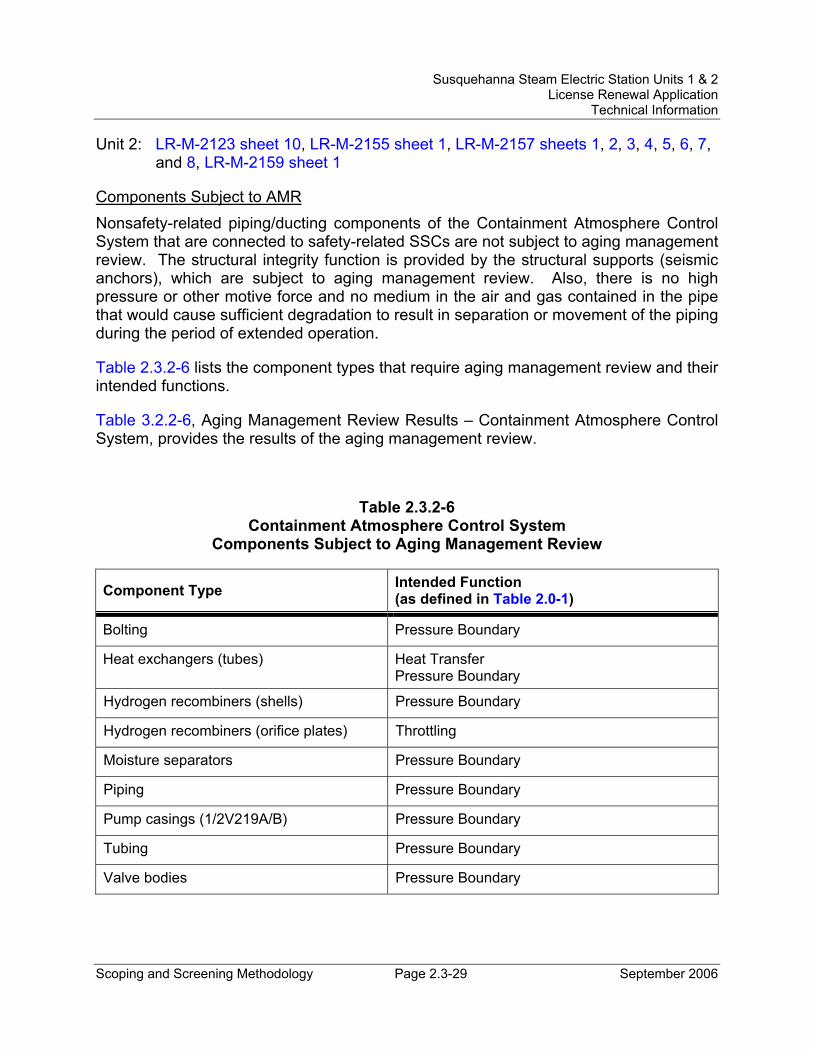
Susquehanna Steam Electric Station Units 1 & 2 License Renewal Application
Technical Information
Scoping and Screening Methodology Page 2.3-29 September 2006
Unit 2: LR-M-2123 sheet 10, LR-M-2155 sheet 1, LR-M-2157 sheets 1, 2, 3, 4, 5, 6, 7, and 8, LR-M-2159 sheet 1
Components Subject to AMR Nonsafety-related piping/ducting components of the Containment Atmosphere Control System that are connected to safety-related SSCs are not subject to aging management review. The structural integrity function is provided by the structural supports (seismic anchors), which are subject to aging management review. Also, there is no high pressure or other motive force and no medium in the air and gas contained in the pipe that would cause sufficient degradation to result in separation or movement of the piping during the period of extended operation.
Table 2.3.2-6 lists the component types that require aging management review and their intended functions.
Table 3.2.2-6, Aging Management Review Results – Containment Atmosphere Control System, provides the results of the aging management review.
Table 2.3.2-6 Containment Atmosphere Control System
Components Subject to Aging Management Review
Component Type Intended Function (as defined in Table 2.0-1)
Bolting Pressure Boundary
Heat exchangers (tubes) Heat Transfer Pressure Boundary
Hydrogen recombiners (shells) Pressure Boundary
Hydrogen recombiners (orifice plates) Throttling
Moisture separators Pressure Boundary
Piping Pressure Boundary
Pump casings (1/2V219A/B) Pressure Boundary
Tubing Pressure Boundary
Valve bodies Pressure Boundary
Susquehanna Steam Electric Station Units 1 & 2 License Renewal Application
Technical Information
Scoping and Screening Methodology Page 2.3-30 September 2006
2.3.2.7 Standby Gas Treatment System (SGTS) System Description The Standby Gas Treatment System (SGTS), common to both units, is designed to exhaust filtered air from the Reactor Building to maintain a negative pressure in the affected volumes following secondary containment isolation for a spent fuel handling accident or for a LOCA; and, to filter the exhausted air to remove radioactive particulates and both radioactive and non-radioactive forms of iodine to limit offsite dose.
The SGTS consists of two redundant filter trains, each of which includes a mist eliminator, an electric air heater, a bank of prefilters, two banks of high efficiency particulate (HEPA) filters, and a charcoal adsorber bed.
The major components of the SGTS are the SGTS exhaust fans, the Reactor Building recirculation fans, the supply and return plenums, and the SGTS filter units consisting of mist eliminators, heaters, pre-filters, upstream HEPA filters, high efficiency charcoal adsorber filters, downstream HEPA filters, and enclosures.
Reason for Scope Determination The SGTS functions to filter exhaust air to remove particulates and iodine to maintain offsite radiation dose within the limits, maintain secondary containment at negative pressure for LOCA and fuel handling accident, and provides mixing of secondary containment atmosphere. These safety functions meet the scoping criteria of 10 CFR 54.4(a)(1).
The SGTS does not have the potential to adversely affect safety-related systems or components through spatial interaction. Therefore, the SGTS does not meet the scoping criteria of 10 CFR 54.4(a)(2).
The SGTS is relied upon to demonstrate compliance with, and meets the 10 CFR 54.4(a)(3) scoping criteria for, the Environmental Qualification (10 CFR 50.49) regulated event.
FSAR References Section 6.5.1.1 of the SSES FSAR describes the Standby Gas Treatment System.
License Renewal Drawings The following license renewal drawings depict the evaluation boundaries for the system components within the scope of license renewal:
Unit 1: LR-M-175 sheets 1 and 2, LR-M-176 sheet 1, LR-M-178 sheet 1, LR-M-183 sheet 1, LR-VC-175 sheet 1
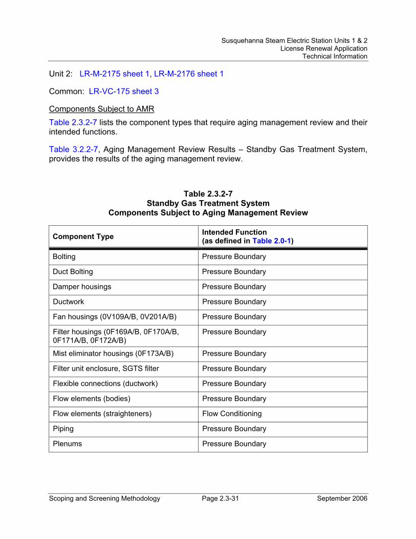
Susquehanna Steam Electric Station Units 1 & 2 License Renewal Application
Technical Information
Scoping and Screening Methodology Page 2.3-31 September 2006
Unit 2: LR-M-2175 sheet 1, LR-M-2176 sheet 1
Common: LR-VC-175 sheet 3
Components Subject to AMR Table 2.3.2-7 lists the component types that require aging management review and their intended functions.
Table 3.2.2-7, Aging Management Review Results – Standby Gas Treatment System, provides the results of the aging management review.
Table 2.3.2-7 Standby Gas Treatment System
Components Subject to Aging Management Review
Component Type Intended Function (as defined in Table 2.0-1)
Bolting Pressure Boundary
Duct Bolting Pressure Boundary
Damper housings Pressure Boundary
Ductwork Pressure Boundary
Fan housings (0V109A/B, 0V201A/B) Pressure Boundary
Filter housings (0F169A/B, 0F170A/B, 0F171A/B, 0F172A/B)
Pressure Boundary
Mist eliminator housings (0F173A/B) Pressure Boundary
Filter unit enclosure, SGTS filter Pressure Boundary
Flexible connections (ductwork) Pressure Boundary
Flow elements (bodies) Pressure Boundary
Flow elements (straighteners) Flow Conditioning
Piping Pressure Boundary
Plenums Pressure Boundary

Susquehanna Steam Electric Station Units 1 & 2 License Renewal Application
Technical Information
Scoping and Screening Methodology Page 2.3-32 September 2006
Table 2.3.2-7: (continued)
Component Type Intended Function (as defined in Table 2.0-1)
Tubing (and fittings) Pressure Boundary
Valve bodies Pressure Boundary
Susquehanna Steam Electric Station Units 1 & 2 License Renewal Application
Technical Information
Scoping and Screening Methodology Page 2.3-33 September 2006
2.3.3 Auxiliary Systems
The auxiliary systems are those systems used to support normal and emergency plant operations. The systems provide cooling, ventilation, sampling, and other required functions. The following SSES systems are addressed in this section:
• Building Drains Nonradioactive System (Section 2.3.3.1)
• Containment Instrument Gas System (Section 2.3.3.2)
• Control Rod Drive Hydraulics System (Section 2.3.3.3)
• Control Structure Chilled Water System (Section 2.3.3.4)
• Control Structure HVAC Systems (Section 2.3.3.5)
• Cooling Tower System (Section 2.3.3.6)
• Diesel Fuel Oil System (Section 2.3.3.7)
• Diesel Generator Buildings HVAC Systems (Section 2.3.3.8)
• Diesel Generators System (Section 2.3.3.9)
• Domestic Water System (Section 2.3.3.10)
• Emergency Service Water System (Section 2.3.3.11)
• ESSW Pumphouse HVAC System (Section 2.3.3.12)
• Fire Protection System (Section 2.3.3.13)
• Fuel Pool Cooling and Cleanup System and Fuel Pools and Auxiliaries (Section 2.3.3.14)
• Neutron Monitoring System (Section 2.3.3.15)
• Nitrogen and Hydrogen System (Section 2.3.3.16)
• Primary Containment Atmosphere Circulation System (Section 2.3.3.17)
• Process and Area Radiation Monitoring System (Section 2.3.3.18)
• Radwaste Liquid System (Section 2.3.3.19)
• Radwaste Solids Handling System (Section 2.3.3.20)
• Raw Water Treatment System (Section 2.3.3.21)
• Reactor Building Chilled Water System (Section 2.3.3.22)
• Reactor Building Closed Cooling Water System (Section 2.3.3.23)
• Reactor Building HVAC System (Section 2.3.3.24)
• Reactor Nonnuclear Instrumentation System (Section 2.3.3.25)
Susquehanna Steam Electric Station Units 1 & 2 License Renewal Application
Technical Information
Scoping and Screening Methodology Page 2.3-34 September 2006
• Reactor Water Cleanup System (Section 2.3.3.26)
• RHR Service Water System (Section 2.3.3.27)
• Sampling System (Section 2.3.3.28)
• Sanitary Drainage System (Section 2.3.3.29)
• Service Air System (Section 2.3.3.30)
• Service Water System (Section 2.3.3.31)
• Standby Liquid Control System (Section 2.3.3.32)
• Turbine Building Closed Cooling Water System (Section 2.3.3.33)
A brief system description, reason for scope determination, associated FSAR references, associated license renewal drawings, and components subject to AMR information is provided for each system.
Susquehanna Steam Electric Station Units 1 & 2 License Renewal Application
Technical Information
Scoping and Screening Methodology Page 2.3-35 September 2006
2.3.3.1 Building Drains Nonradioactive System System Description The Building Drains Nonradioactive System is provided throughout the plant. The oily waste drainage subsystems collect liquid wastes from the non-radioactive equipment areas in which oil is expected to be present, such as the Circulating Water Pumphouse, Diesel Generator Buildings, transformer areas, lube and diesel oil storage tank areas, oil circuit breaker areas, and auxiliary buildings. Acid waste drainage subsystems collect liquid wastes containing non-radioactive chemicals and corrosive substances from equipment and floor drains in the chlorine evaporator and Sulfuric Acid Storage Building and the Water Treatment Building.
Reason for Scope Determination The Building Drains Nonradioactive System does not perform any functions that satisfy the scoping criteria of 10 CFR 54.4(a)(1).
The Building Drains Nonradioactive System is required to maintain the integrity of nonsafety-related components that have the potential to adversely affect safety-related equipment through spatial interaction. This function meets the scoping criteria of 10 CFR 54.4(a)(2).
The Building Drains Nonradioactive System is not relied upon to demonstrate compliance with, nor satisfy the 10 CFR 54.4(a)(3) scoping criteria for, any regulated event.
FSAR References Section 9.3.3 of the SSES FSAR describes the Equipment and Floor Drainage System, evaluated for license renewal as the Building Drains Nonradioactive System.
License Renewal Drawings The following license renewal drawings depict the evaluation boundaries for the system components within the scope of license renewal:
Common: LR-M-160 sheet 2
Components Subject to AMR Table 2.3.3-1 lists the component types that require aging management review and their intended functions.
Table 3.3.2-1, Aging Management Review Results – Building Drains Nonradioactive System, provides the results of the aging management review.
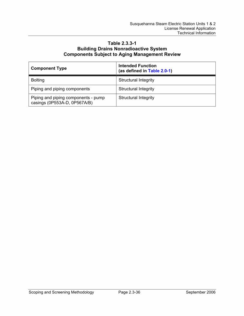
Susquehanna Steam Electric Station Units 1 & 2 License Renewal Application
Technical Information
Scoping and Screening Methodology Page 2.3-36 September 2006
Table 2.3.3-1 Building Drains Nonradioactive System
Components Subject to Aging Management Review
Component Type Intended Function (as defined in Table 2.0-1)
Bolting Structural Integrity
Piping and piping components Structural Integrity
Piping and piping components - pump casings (0P553A-D, 0P567A/B)
Structural Integrity
Susquehanna Steam Electric Station Units 1 & 2 License Renewal Application
Technical Information
Scoping and Screening Methodology Page 2.3-37 September 2006
2.3.3.2 Containment Instrument Gas System System Description The Containment Instrument Gas (CIG) System is designed to provide filtered, dry, oil-free instrument gas to the pneumatic devices located inside the drywell and suppression chamber. The safety-related portions of the system are the containment penetrations, the emergency backup nitrogen storage system, and the gas distribution piping to the six main steam relief valves that are part of the Automatic Depressurization System. The nonsafety-related portions of the Containment Instrument Gas System include the gas compressors and the associated equipment for filtering, drying, and storage.
Reason for Scope Determination The Containment Instrument Gas System has a safety function to provide a supply of instrument gas for operation of the main steam relief valves that are part of the Automatic Depressurization System. The CIG containment penetrations have a safety function of maintaining primary containment integrity through containment isolation. These safety functions meet the scoping criteria of 10 CFR 54.4(a)(1).
The CIG System is required to maintain the integrity of nonsafety-related components that have the potential to adversely affect safety-related equipment through spatial interaction and nonsafety-related piping components required to support the safety-related functional boundary of the system. This function meets the scoping criteria of 10 CFR 54.4(a)(2).
The CIG System is relied upon to demonstrate compliance with, and meets the 10 CFR 54.4(a)(3) scoping criteria for, the Fire Protection (10 CFR 50.48), Environmental Qualification (10 CFR 50.49), and Station Blackout (10 CFR 50.63) regulated events.
FSAR References Section 9.3.1.5 of the SSES FSAR describes the Containment Instrument Gas System.
License Renewal Drawings The following license renewal drawings depict the evaluation boundaries for the system components within the scope of license renewal:
Unit 1: LR-M-126 sheets 1 and 2, LR-M-176 sheet 1
Unit 2: LR-M-2126 sheets 1 and 2, LR-M-2176 sheet 1
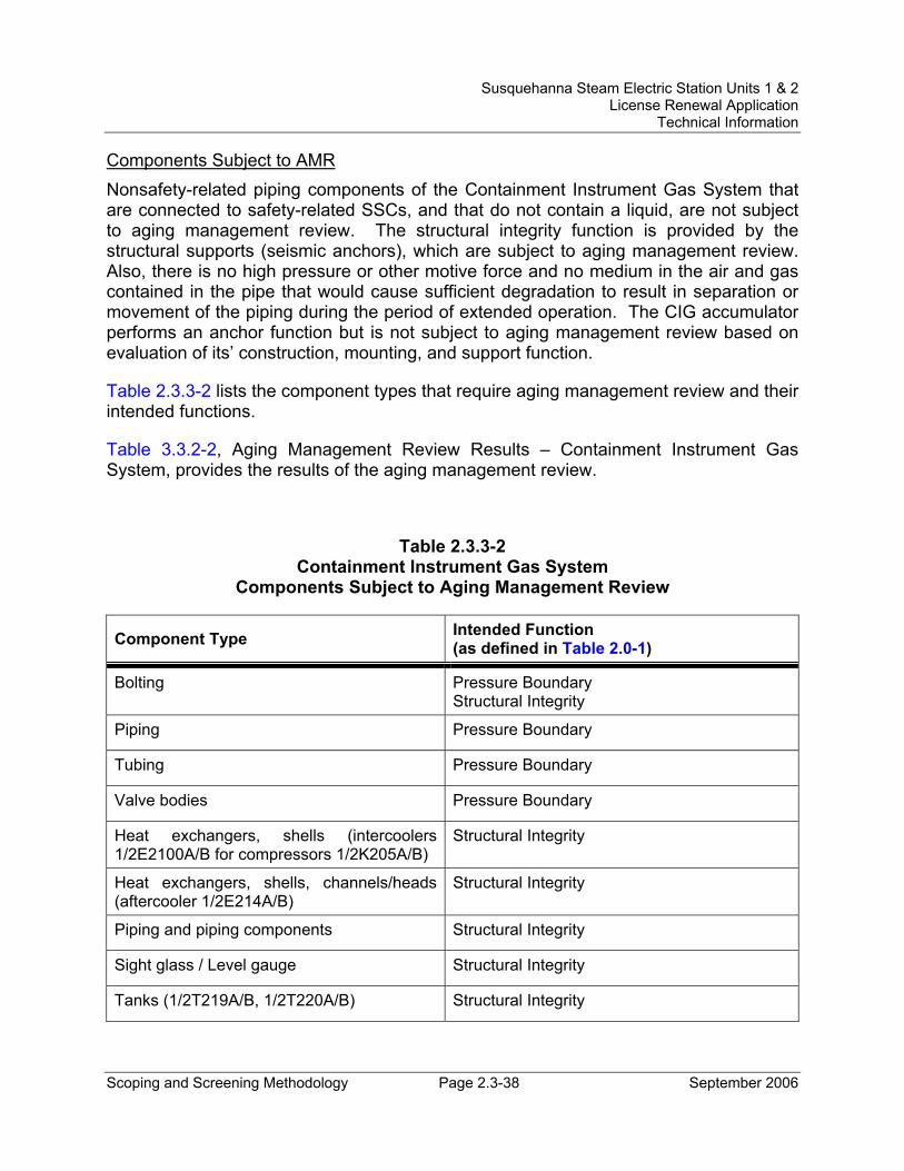
Susquehanna Steam Electric Station Units 1 & 2 License Renewal Application
Technical Information
Scoping and Screening Methodology Page 2.3-38 September 2006
Components Subject to AMR Nonsafety-related piping components of the Containment Instrument Gas System that are connected to safety-related SSCs, and that do not contain a liquid, are not subject to aging management review. The structural integrity function is provided by the structural supports (seismic anchors), which are subject to aging management review. Also, there is no high pressure or other motive force and no medium in the air and gas contained in the pipe that would cause sufficient degradation to result in separation or movement of the piping during the period of extended operation. The CIG accumulator performs an anchor function but is not subject to aging management review based on evaluation of its’ construction, mounting, and support function.
Table 2.3.3-2 lists the component types that require aging management review and their intended functions.
Table 3.3.2-2, Aging Management Review Results – Containment Instrument Gas System, provides the results of the aging management review.
Table 2.3.3-2 Containment Instrument Gas System
Components Subject to Aging Management Review
Component Type Intended Function (as defined in Table 2.0-1)
Bolting Pressure Boundary Structural Integrity
Piping Pressure Boundary
Tubing Pressure Boundary
Valve bodies Pressure Boundary
Heat exchangers, shells (intercoolers 1/2E2100A/B for compressors 1/2K205A/B)
Structural Integrity
Heat exchangers, shells, channels/heads (aftercooler 1/2E214A/B)
Structural Integrity
Piping and piping components Structural Integrity
Sight glass / Level gauge Structural Integrity
Tanks (1/2T219A/B, 1/2T220A/B) Structural Integrity
Susquehanna Steam Electric Station Units 1 & 2 License Renewal Application
Technical Information
Scoping and Screening Methodology Page 2.3-39 September 2006
2.3.3.3 Control Rod Drive Hydraulics System System Description The Control Rod Drive Hydraulics (CRDH) System provides the means to control gross changes in core reactivity by incrementally positioning neutron absorbing control rods within the reactor core in response to manual control signals. This is accomplished by commands initiated by the Reactor Manual Control System. The CRDH System is also required to quickly shutdown the reactor (scram) in emergency situations by rapidly inserting withdrawn control rods into the core in response to manual or automatic signals. The CRDH System supplies and controls water pressure and flow to and from the control rod drives (CRDs) through hydraulic control units (HCUs). There is one HCU associated with each CRD. The water discharged from the CRDs during a scram flows through the HCUs to the scram discharge volume (SDV). The water discharged from a CRD during normal control rod positioning operation flows through the HCU into the exhaust header, through the other HCUs and into the withdraw lines, and through the CRDs into the reactor vessel.
During normal power operation the CRDH System provides the motive force to move the CRDs to position the control rods and provides cooling water flow to the CRDs via the HCUs. During emergency conditions, the CRDH System provides the motive force to quickly shutdown the reactor by rapidly inserting withdrawn control rods into the core.
Reason for Scope Determination The CRDH System is a safety-related system that is designed to provide for a sufficiently rapid control rod insertion such that no fuel damage results from any abnormal operating transient. The CRDH System safety function is to provide rapid control rod insertion in the core when a reactor scram is initiated. In association with the control rod insertion, the system provides scram discharge volume isolation. These safety functions meet the scoping criteria of 10 CFR 54.4(a)(1).
The CRDH System is required to maintain the integrity of nonsafety-related components that have the potential to adversely affect safety-related equipment through spatial interaction and nonsafety-related piping components required to support the safety-related functional boundary of the system. This function meets the scoping criteria of 10 CFR 54.4(a)(2).
The CRDH System is relied upon to demonstrate compliance with, and meets the 10 CFR 54.4(a)(3) scoping criteria for, the Fire Protection (10 CFR 50.48), Environmental Qualification (10 CFR 50.49), and Anticipated Transients Without Scram (10 CFR 50.62) regulated events.
FSAR References Section 4.6.1.1.2 of the SSES FSAR describes the Control Rod Drive Hydraulics System.
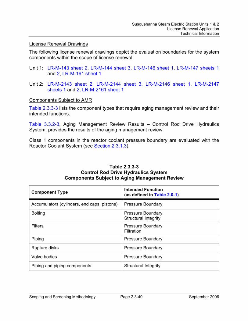
Susquehanna Steam Electric Station Units 1 & 2 License Renewal Application
Technical Information
Scoping and Screening Methodology Page 2.3-40 September 2006
License Renewal Drawings The following license renewal drawings depict the evaluation boundaries for the system components within the scope of license renewal:
Unit 1: LR-M-143 sheet 2, LR-M-144 sheet 3, LR-M-146 sheet 1, LR-M-147 sheets 1 and 2, LR-M-161 sheet 1
Unit 2: LR-M-2143 sheet 2, LR-M-2144 sheet 3, LR-M-2146 sheet 1, LR-M-2147 sheets 1 and 2, LR-M-2161 sheet 1
Components Subject to AMR Table 2.3.3-3 lists the component types that require aging management review and their intended functions.
Table 3.3.2-3, Aging Management Review Results – Control Rod Drive Hydraulics System, provides the results of the aging management review.
Class 1 components in the reactor coolant pressure boundary are evaluated with the Reactor Coolant System (see Section 2.3.1.3).
Table 2.3.3-3 Control Rod Drive Hydraulics System
Components Subject to Aging Management Review
Component Type Intended Function (as defined in Table 2.0-1)
Accumulators (cylinders, end caps, pistons) Pressure Boundary
Bolting Pressure Boundary Structural Integrity
Filters Pressure Boundary Filtration
Piping Pressure Boundary
Rupture disks Pressure Boundary
Valve bodies Pressure Boundary
Piping and piping components Structural Integrity
Susquehanna Steam Electric Station Units 1 & 2 License Renewal Application
Technical Information
Scoping and Screening Methodology Page 2.3-41 September 2006
2.3.3.4 Control Structure Chilled Water System System Description The Control Structure Chilled Water (CSCW) System supplies chilled water to the cooling coils in the control room floor cooling unit, computer room floor cooling unit and Control Structure heating and ventilation unit. These cooling units maintain design air temperatures inside the Control Structure Building during all modes of plant operation.
The CSCW System also provides chilled water to the emergency cooling coils in the Unit 1 emergency switchgear and load center room air handling units (AHUs), located in the Reactor Building. Chilled water is supplied by the CSCW System whenever the Reactor Building Chilled Water (RBCW) System is not available, including during design basis accident (DBA) conditions for Unit 1. The Unit 2 emergency switchgear and load center room AHUs are normally cooled by chilled water supplied by the RBCW System; and during DBA conditions, direct expansion type refrigeration units cooled by the Emergency Service Water (ESW) System provide the cooling source.
The CSCW System is common to Units 1 and 2, and consists of two (2) identical, 100 percent capacity, closed-loop chilled water trains. During normal plant operation, one train is in service while the other train is placed in automatic standby. Heat from various spaces is transferred to the circulating chilled water in the AHU cooling coils. Circulating chilled water passes through the chiller evaporators, transfers heat to the refrigeration cycle, which then conveys heat to the condenser water. During normal plant operation, the nonsafety-related Service Water (SW) System is the source of condenser cooling water; while during emergency plant operation, the safety-related ESW System is the source of condenser cooling water. The emergency spray pond provides the ultimate heat sink.
Reason for Scope Determination The CSCW System is designed to supply chilled water to cooling coils in the Control Structure and Reactor Building. The system safety functions are to provide chilled water to cooling coils in the control room floor cooling unit, computer room floor cooling unit, and Control Structure heating and ventilation unit and to provide chilled water to cooling coils in the Unit 1 emergency switchgear and load center room air handling units. These safety functions meet the scoping criteria of 10 CFR 54.4(a)(1).
The CSCW System is required to maintain the integrity of nonsafety-related components that have the potential to adversely affect safety-related equipment through spatial interaction and nonsafety-related piping components required to support the safety-related functional boundary of the system. This function meets the scoping criteria of 10 CFR 54.4(a)(2).
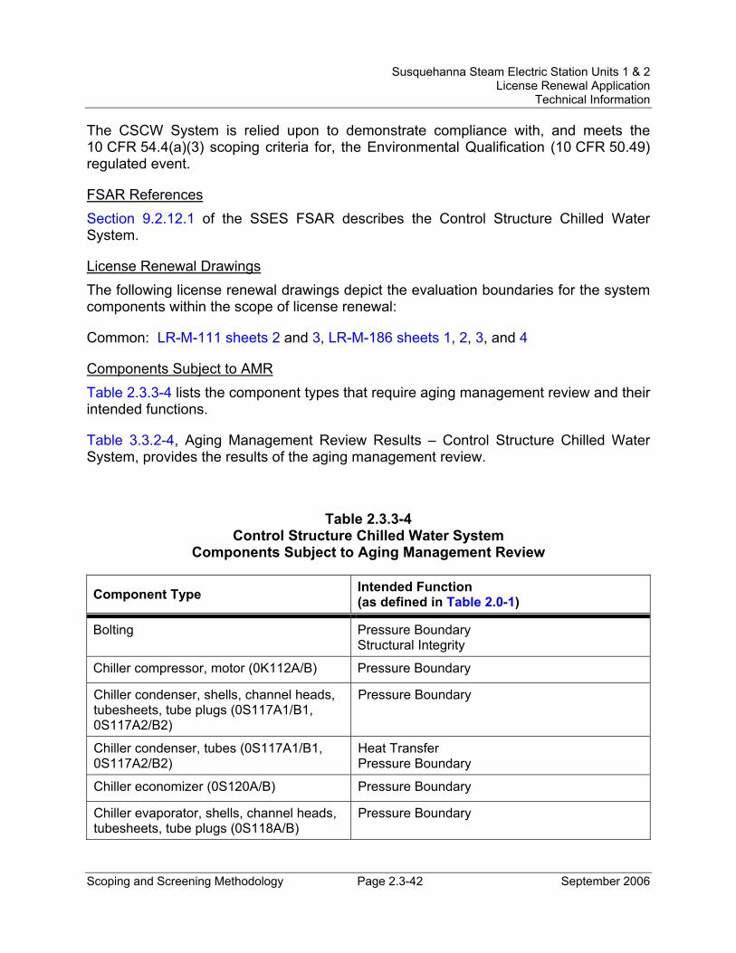
Susquehanna Steam Electric Station Units 1 & 2 License Renewal Application
Technical Information
Scoping and Screening Methodology Page 2.3-42 September 2006
The CSCW System is relied upon to demonstrate compliance with, and meets the 10 CFR 54.4(a)(3) scoping criteria for, the Environmental Qualification (10 CFR 50.49) regulated event.
FSAR References Section 9.2.12.1 of the SSES FSAR describes the Control Structure Chilled Water System.
License Renewal Drawings The following license renewal drawings depict the evaluation boundaries for the system components within the scope of license renewal:
Common: LR-M-111 sheets 2 and 3, LR-M-186 sheets 1, 2, 3, and 4
Components Subject to AMR Table 2.3.3-4 lists the component types that require aging management review and their intended functions.
Table 3.3.2-4, Aging Management Review Results – Control Structure Chilled Water System, provides the results of the aging management review.
Table 2.3.3-4 Control Structure Chilled Water System
Components Subject to Aging Management Review
Component Type Intended Function (as defined in Table 2.0-1)
Bolting Pressure Boundary Structural Integrity
Chiller compressor, motor (0K112A/B) Pressure Boundary
Chiller condenser, shells, channel heads, tubesheets, tube plugs (0S117A1/B1, 0S117A2/B2)
Pressure Boundary
Chiller condenser, tubes (0S117A1/B1, 0S117A2/B2)
Heat Transfer Pressure Boundary
Chiller economizer (0S120A/B) Pressure Boundary
Chiller evaporator, shells, channel heads, tubesheets, tube plugs (0S118A/B)
Pressure Boundary
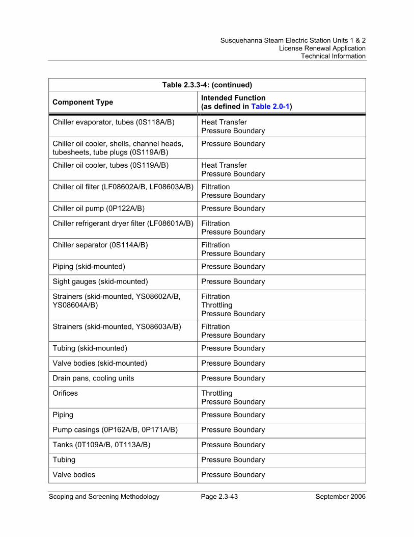
Susquehanna Steam Electric Station Units 1 & 2 License Renewal Application
Technical Information
Scoping and Screening Methodology Page 2.3-43 September 2006
Table 2.3.3-4: (continued)
Component Type Intended Function (as defined in Table 2.0-1)
Chiller evaporator, tubes (0S118A/B) Heat Transfer Pressure Boundary
Chiller oil cooler, shells, channel heads, tubesheets, tube plugs (0S119A/B)
Pressure Boundary
Chiller oil cooler, tubes (0S119A/B) Heat Transfer Pressure Boundary
Chiller oil filter (LF08602A/B, LF08603A/B) Filtration Pressure Boundary
Chiller oil pump (0P122A/B) Pressure Boundary
Chiller refrigerant dryer filter (LF08601A/B) Filtration Pressure Boundary
Chiller separator (0S114A/B) Filtration Pressure Boundary
Piping (skid-mounted) Pressure Boundary
Sight gauges (skid-mounted) Pressure Boundary
Strainers (skid-mounted, YS08602A/B, YS08604A/B)
Filtration Throttling Pressure Boundary
Strainers (skid-mounted, YS08603A/B) Filtration Pressure Boundary
Tubing (skid-mounted) Pressure Boundary
Valve bodies (skid-mounted) Pressure Boundary
Drain pans, cooling units Pressure Boundary
Orifices Throttling Pressure Boundary
Piping Pressure Boundary
Pump casings (0P162A/B, 0P171A/B) Pressure Boundary
Tanks (0T109A/B, 0T113A/B) Pressure Boundary
Tubing Pressure Boundary
Valve bodies Pressure Boundary
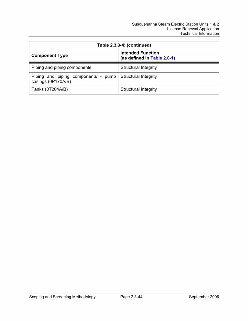
Susquehanna Steam Electric Station Units 1 & 2 License Renewal Application
Technical Information
Scoping and Screening Methodology Page 2.3-44 September 2006
Table 2.3.3-4: (continued)
Component Type Intended Function (as defined in Table 2.0-1)
Piping and piping components Structural Integrity
Piping and piping components - pump casings (0P170A/B)
Structural Integrity
Tanks (0T204A/B) Structural Integrity
Susquehanna Steam Electric Station Units 1 & 2 License Renewal Application
Technical Information
Scoping and Screening Methodology Page 2.3-45 September 2006
2.3.3.5 Control Structure HVAC Systems System Description The Control Structure Heating, Ventilation and Air Conditioning (HVAC) Systems are comprised of the following subsystems and components: access area general exhaust system, access control and laboratory area supply unit, access control area toilet exhaust system, battery rooms exhaust system, computer room floor cooling unit, contaminated filter units and laboratory fume hoods exhaust systems, control room floor cooling unit, control room kitchen and toilet exhaust systems, control room emergency outside air supply system (CREOASS) unit, Control Structure heating and ventilation (H&V) unit, laboratory fume hoods makeup air supply unit, smoke removal system, Standby Gas Treatment System (SGTS) equipment room H&V unit.
All Control Structure HVAC Systems are common to Units 1 and 2. The Control Structure and control room HVAC systems have three basic modes of operation: (1) Normal - Normal outside air is processed throughout the Control Structure envelope, with the Control Structure being maintained at a positive pressure over outside air pressure; (2) Filtration (pressurization) - Outside air is processed through the CREOASS units before circulating in the Control Structure envelope; radioactive material is removed from outside air (via filters) so that the Control Structure remains habitable; the Control Structure is maintained at a positive pressure over outside air pressure; and (3) Recirculation (isolation) - The Control Structure HVAC Systems are isolated from outside air, with all ventilation being recirculated throughout the Control Structure envelope.
Reason for Scope Determination The Control Structure HVAC Systems are designed to perform the following functions during normal, upset and DBA conditions of plant operation: 1) maintain temperatures in various spaces served by these HVAC systems within specified design limits, 2) maintain positive pressure above atmosphere to inhibit air leakage into the Control Structure envelope during normal and filtration modes, 3) provide for ventilation requirements within the Control Structure envelope, including makeup air for the battery room exhaust system, and 4) divert outside air supply through the CREOASS units during emergency conditions. These safety functions meet the scoping criteria of 10 CFR 54.4(a)(1).
The Control Structure HVAC Systems is required to maintain the integrity of nonsafety-related piping/ducting components to support the safety-related functional boundary of the system. This function meets the scoping criteria of 10 CFR 54.4(a)(2).
The Control Structure HVAC Systems are relied upon to demonstrate compliance with, and meet the 10 CFR 54.4(a)(3) scoping criteria for, the Environmental Qualification (10 CFR 50.49) regulated event.
Susquehanna Steam Electric Station Units 1 & 2 License Renewal Application
Technical Information
Scoping and Screening Methodology Page 2.3-46 September 2006
FSAR References Section 9.4.1 of the SSES FSAR describes the Control Room and Control Structure HVAC Systems.
License Renewal Drawings The following license renewal drawings depict the evaluation boundaries for the system components within the scope of license renewal:
Common: LR-M-178 sheets 1 and 2, LR-VC-178 sheets 1, 2, and 3, LR-M-183 sheet 1, LR-M-186 sheets 1 and 2
Components Subject to AMR Nonsafety-related piping/ducting components of the Control Structure HVAC Systems that are connected to safety-related SSCs are not subject to aging management review. The structural integrity function is provided by the structural supports (seismic anchors), which are subject to aging management review. Also, there is no high pressure or other motive force and no medium in the air and gas contained in the pipe that would cause sufficient degradation to result in separation or movement of the piping during the period of extended operation. The heating and ventilation units, filter units, and exhaust fans perform an anchor function but are not subject to aging management review based on evaluation of their construction, mounting, and support function.
Table 2.3.3-5 lists the component types that require aging management review and their intended functions.
Table 3.3.2-5, Aging Management Review Results – Control Structure HVAC Systems, provides the results of the aging management review.
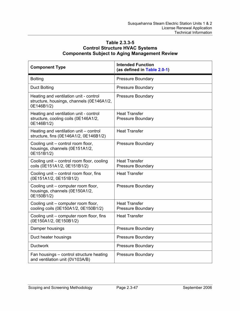
Susquehanna Steam Electric Station Units 1 & 2 License Renewal Application
Technical Information
Scoping and Screening Methodology Page 2.3-47 September 2006
Table 2.3.3-5 Control Structure HVAC Systems
Components Subject to Aging Management Review
Component Type Intended Function (as defined in Table 2.0-1)
Bolting Pressure Boundary
Duct Bolting Pressure Boundary
Heating and ventilation unit - control structure, housings, channels (0E146A1/2, 0E146B1/2)
Pressure Boundary
Heating and ventilation unit - control structure, cooling coils (0E146A1/2, 0E146B1/2)
Heat Transfer Pressure Boundary
Heating and ventilation unit – control structure, fins (0E146A1/2, 0E146B1/2)
Heat Transfer
Cooling unit – control room floor, housings, channels (0E151A1/2, 0E151B1/2)
Pressure Boundary
Cooling unit – control room floor, cooling coils (0E151A1/2, 0E151B1/2)
Heat Transfer Pressure Boundary
Cooling unit – control room floor, fins (0E151A1/2, 0E151B1/2)
Heat Transfer
Cooling unit – computer room floor, housings, channels (0E150A1/2, 0E150B1/2)
Pressure Boundary
Cooling unit – computer room floor, cooling coils (0E150A1/2, 0E150B1/2)
Heat Transfer Pressure Boundary
Cooling unit – computer room floor, fins (0E150A1/2, 0E150B1/2)
Heat Transfer
Damper housings Pressure Boundary
Duct heater housings Pressure Boundary
Ductwork Pressure Boundary
Fan housings – control structure heating and ventilation unit (0V103A/B)
Pressure Boundary
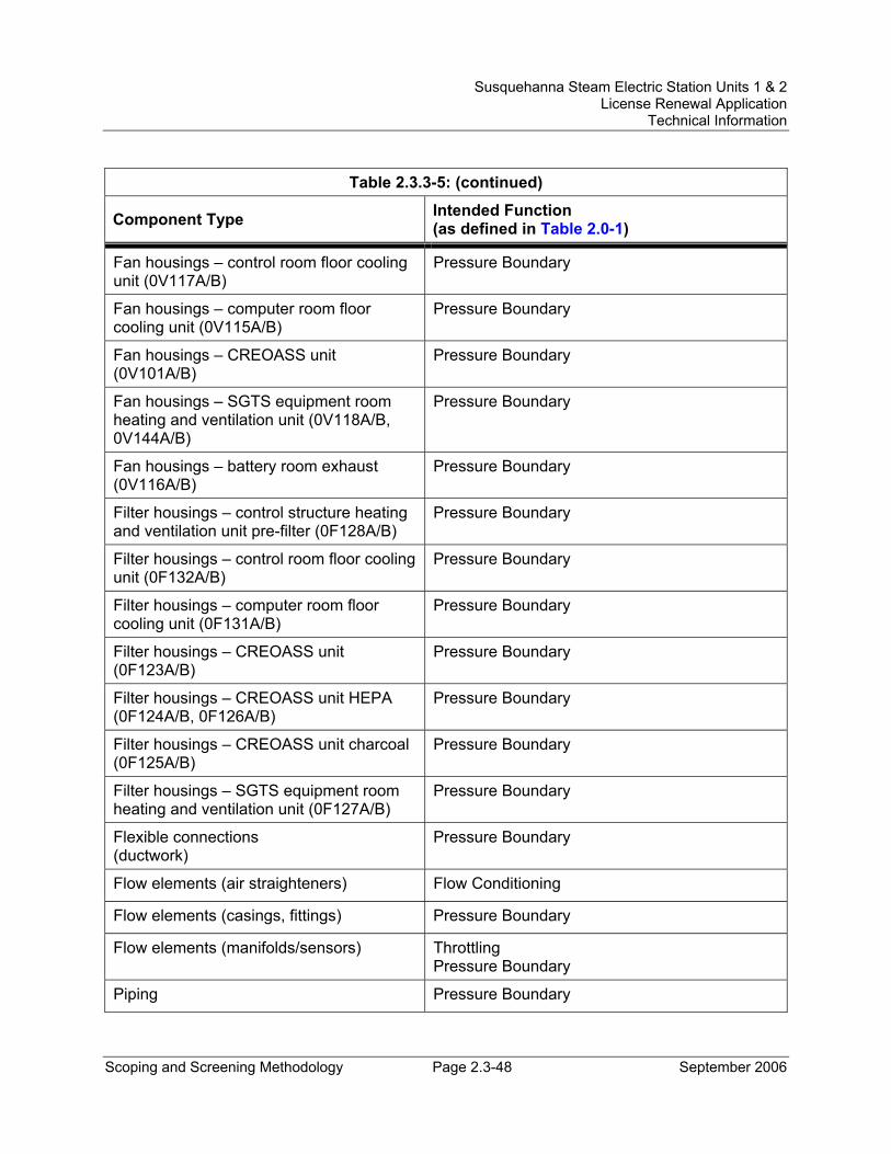
Susquehanna Steam Electric Station Units 1 & 2 License Renewal Application
Technical Information
Scoping and Screening Methodology Page 2.3-48 September 2006
Table 2.3.3-5: (continued)
Component Type Intended Function (as defined in Table 2.0-1)
Fan housings – control room floor cooling unit (0V117A/B)
Pressure Boundary
Fan housings – computer room floor cooling unit (0V115A/B)
Pressure Boundary
Fan housings – CREOASS unit (0V101A/B)
Pressure Boundary
Fan housings – SGTS equipment room heating and ventilation unit (0V118A/B, 0V144A/B)
Pressure Boundary
Fan housings – battery room exhaust (0V116A/B)
Pressure Boundary
Filter housings – control structure heating and ventilation unit pre-filter (0F128A/B)
Pressure Boundary
Filter housings – control room floor cooling unit (0F132A/B)
Pressure Boundary
Filter housings – computer room floor cooling unit (0F131A/B)
Pressure Boundary
Filter housings – CREOASS unit (0F123A/B)
Pressure Boundary
Filter housings – CREOASS unit HEPA (0F124A/B, 0F126A/B)
Pressure Boundary
Filter housings – CREOASS unit charcoal (0F125A/B)
Pressure Boundary
Filter housings – SGTS equipment room heating and ventilation unit (0F127A/B)
Pressure Boundary
Flexible connections (ductwork)
Pressure Boundary
Flow elements (air straighteners) Flow Conditioning
Flow elements (casings, fittings) Pressure Boundary
Flow elements (manifolds/sensors) Throttling Pressure Boundary
Piping Pressure Boundary
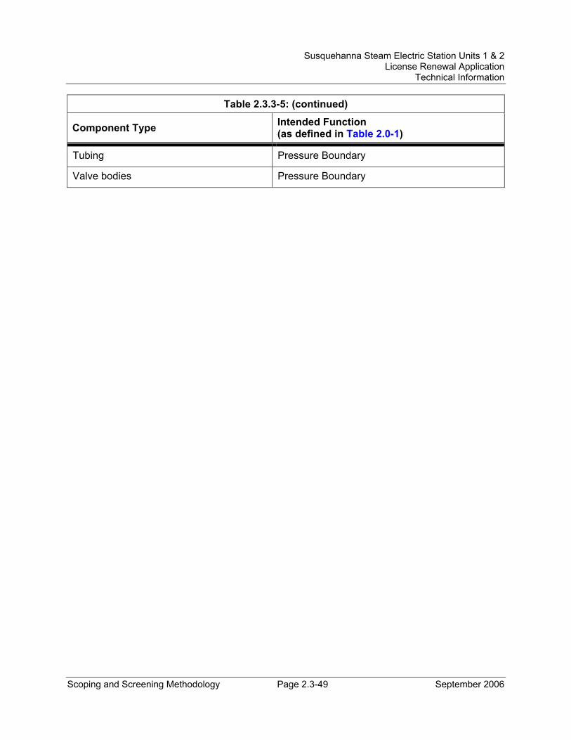
Susquehanna Steam Electric Station Units 1 & 2 License Renewal Application
Technical Information
Scoping and Screening Methodology Page 2.3-49 September 2006
Table 2.3.3-5: (continued)
Component Type Intended Function (as defined in Table 2.0-1)
Tubing Pressure Boundary
Valve bodies Pressure Boundary
Susquehanna Steam Electric Station Units 1 & 2 License Renewal Application
Technical Information
Scoping and Screening Methodology Page 2.3-50 September 2006
2.3.3.6 Cooling Tower System System Description The Cooling Tower System is a single loop system consisting of a hyperbolic natural draft cooling tower, cooling tower basin, blowdown and makeup water systems, and chemical and blowdown treatment systems. The cooling tower system is designed to dissipate both latent heat from the main condenser and sensible heat from the service water system.
The Unit 1 and Unit 2 cooling towers are both constructed of non-combustible, structural components. Each cooling tower basin contains 6,000,000 gallons of water. This source of water is capable of meeting the largest expected water demands of the fire protection system.
Reason for Scope Determination The Cooling Tower System does not perform any functions that satisfy the scoping criteria of 10 CFR 54.4(a)(1).
The Cooling Tower System does not have the potential to adversely affect safety-related systems or components through spatial interaction. Therefore, the Cooling Tower System does not meet the scoping criteria of 10 CFR 54.4(a)(2).
The Unit 1 and Unit 2 cooling tower basins along with associated Cooling Tower System piping supply water to the Fire Protection System and are, therefore, relied upon to demonstrate compliance with, and meet the 10 CFR 54.4(a)(3) scoping criteria for, the Fire Protection (10 CFR 50.48) regulated event.
FSAR References Sections 9.2.1 and 10.4.5 of the SSES FSAR describe the cooling towers in conjunction with the descriptions of the Service Water System and the Circulating Water System.
License Renewal Drawings The following license renewal drawings depict the evaluation boundaries for the system components within the scope of license renewal:
Unit 1: LR-M-115 sheet 1, LR-M-109 sheet 1
Unit 2: LR-M-2115 sheet 1
Components Subject to AMR Table 2.3.3-6 lists the component types that require aging management review and their intended functions.
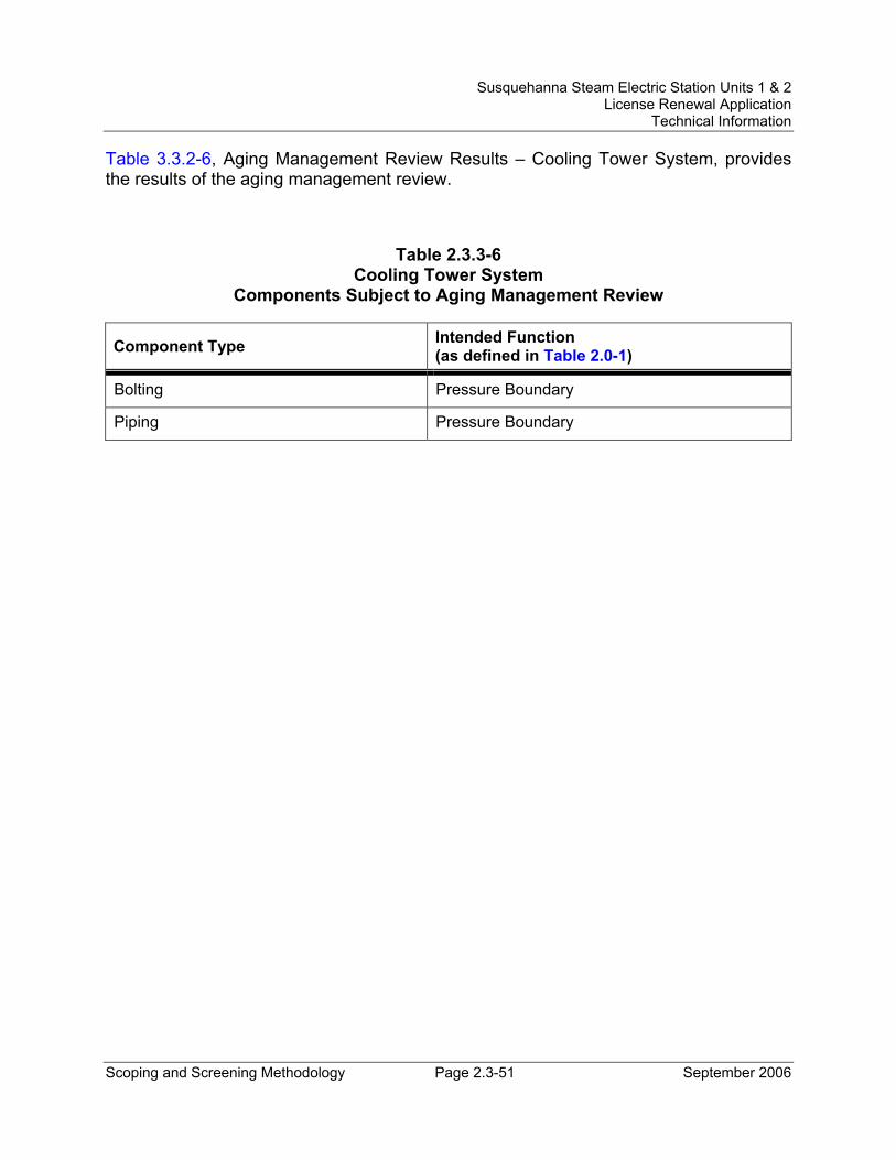
Susquehanna Steam Electric Station Units 1 & 2 License Renewal Application
Technical Information
Scoping and Screening Methodology Page 2.3-51 September 2006
Table 3.3.2-6, Aging Management Review Results – Cooling Tower System, provides the results of the aging management review.
Table 2.3.3-6 Cooling Tower System
Components Subject to Aging Management Review
Component Type Intended Function (as defined in Table 2.0-1)
Bolting Pressure Boundary
Piping Pressure Boundary
Susquehanna Steam Electric Station Units 1 & 2 License Renewal Application
Technical Information
Scoping and Screening Methodology Page 2.3-52 September 2006
2.3.3.7 Diesel Fuel Oil System System Description The Diesel Fuel Oil System provides onsite storage and delivery of fuel oil to the diesel generators for at least seven days of operation. The fuel oil system consists of storage tanks, transfer pumps, day tanks, booster pumps, and associated piping and valves. There are five diesel generators (0G501A, B, C, D, and E). Each diesel generator has an associated storage tank, transfer pump, day tank, and two booster pumps, one motor-driven and one engine-driven. The motor-driven fuel oil booster pump is used to start the diesel engine and bring it up to speed. The engine-driven fuel oil booster pump supplies the fuel oil during engine operation. The transfer pumps take suction from the fuel oil storage tank and pump fuel oil to the day tank. The booster pumps take suction from the day tank and pump fuel oil to the fuel injection pumps on the diesel engine.
The fuel oil return line from the “E” diesel generator to the day tank contains a fuel oil cooler. A fuel oil head tank is provided for the “E” diesel generator to allow the engine to start without the motor-driven booster pump.
Reason for Scope Determination The Diesel Fuel Oil System has a safety function to provide onsite storage and delivery of fuel oil to the diesel generators for at least seven days of operation. This provides emergency power to meet the load requirements for the engineered safety features following loss of offsite power and a design basis accident. This safety function meets the scoping criteria of 10 CFR 54.4(a)(1).
The Diesel Fuel Oil System is required to maintain the integrity of nonsafety-related piping components required to support the safety-related functional boundary of the system. This function meets the scoping criteria of 10 CFR 54.4(a)(2).
The Diesel Fuel Oil System is relied upon to demonstrate compliance with, and meets the 10 CFR 54.4(a)(3) scoping criteria for, the Fire Protection (10 CFR 50.48), Anticipated Transients Without Scram (10 CFR 50.62), and Station Blackout (10 CFR 50.63) regulated events.
FSAR References Section 9.5.4 of the SSES FSAR describes the Diesel Fuel Oil Storage and Transfer System, identified for license renewal as the Diesel Fuel Oil System.
License Renewal Drawings The following license renewal drawings depict the evaluation boundaries for the system components within the scope of license renewal:
Common: LR-M-120 sheets 1, 2, and 3, LR-M-134 sheets 1 and 7
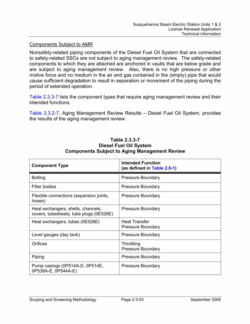
Susquehanna Steam Electric Station Units 1 & 2 License Renewal Application
Technical Information
Scoping and Screening Methodology Page 2.3-53 September 2006
Components Subject to AMR Nonsafety-related piping components of the Diesel Fuel Oil System that are connected to safety-related SSCs are not subject to aging management review. The safety-related components to which they are attached are anchored in vaults that are below grade and are subject to aging management review. Also, there is no high pressure or other motive force and no medium in the air and gas contained in the (empty) pipe that would cause sufficient degradation to result in separation or movement of the piping during the period of extended operation.
Table 2.3.3-7 lists the component types that require aging management review and their intended functions.
Table 3.3.2-7, Aging Management Review Results – Diesel Fuel Oil System, provides the results of the aging management review.
Table 2.3.3-7 Diesel Fuel Oil System
Components Subject to Aging Management Review
Component Type Intended Function (as defined in Table 2.0-1)
Bolting Pressure Boundary
Filter bodies Pressure Boundary
Flexible connections (expansion joints, hoses)
Pressure Boundary
Heat exchangers, shells, channels, covers, tubesheets, tube plugs (0E526E)
Pressure Boundary
Heat exchangers, tubes (0E526E) Heat Transfer Pressure Boundary
Level gauges (day tank) Pressure Boundary
Orifices Throttling Pressure Boundary
Piping Pressure Boundary
Pump casings (0P514A-D, 0P514E, 0P538A-E, 0P544A-E)
Pressure Boundary
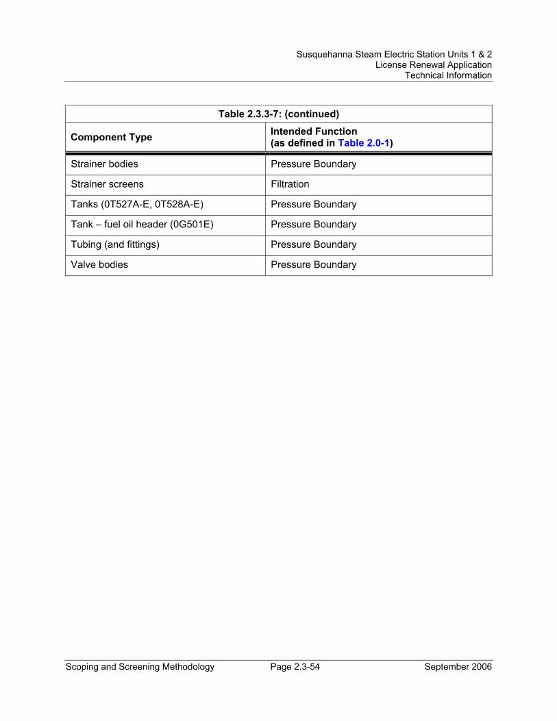
Susquehanna Steam Electric Station Units 1 & 2 License Renewal Application
Technical Information
Scoping and Screening Methodology Page 2.3-54 September 2006
Table 2.3.3-7: (continued)
Component Type Intended Function (as defined in Table 2.0-1)
Strainer bodies Pressure Boundary
Strainer screens Filtration
Tanks (0T527A-E, 0T528A-E) Pressure Boundary
Tank – fuel oil header (0G501E) Pressure Boundary
Tubing (and fittings) Pressure Boundary
Valve bodies Pressure Boundary
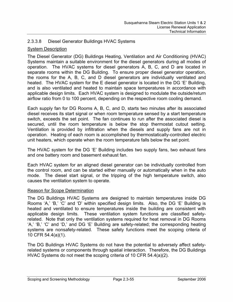
Susquehanna Steam Electric Station Units 1 & 2 License Renewal Application
Technical Information
Scoping and Screening Methodology Page 2.3-55 September 2006
2.3.3.8 Diesel Generator Buildings HVAC Systems System Description The Diesel Generator (DG) Buildings Heating, Ventilation and Air Conditioning (HVAC) Systems maintain a suitable environment for the diesel generators during all modes of operation. The HVAC systems for diesel generators A, B, C, and D are located in separate rooms within the DG Building. To ensure proper diesel generator operation, the rooms for the A, B, C, and D diesel generators are individually ventilated and heated. The HVAC system for the E diesel generator is located in the DG ‘E’ Building, and is also ventilated and heated to maintain space temperatures in accordance with applicable design limits. Each HVAC system is designed to modulate the outside/return airflow ratio from 0 to 100 percent, depending on the respective room cooling demand.
Each supply fan for DG Rooms A, B, C, and D, starts two minutes after its associated diesel receives its start signal or when room temperature sensed by a start temperature switch, exceeds the set point. The fan continues to run after the associated diesel is secured, until the room temperature is below the stop thermostat cutout setting. Ventilation is provided by infiltration when the diesels and supply fans are not in operation. Heating of each room is accomplished by thermostatically-controlled electric unit heaters, which operate when the room temperature falls below the set point.
The HVAC system for the DG ‘E’ Building includes two supply fans, two exhaust fans and one battery room and basement exhaust fan.
Each HVAC system for an aligned diesel generator can be individually controlled from the control room, and can be started either manually or automatically when in the auto mode. The diesel start signal, or the tripping of the high temperature switch, also causes the ventilation system to operate.
Reason for Scope Determination The DG Buildings HVAC Systems are designed to maintain temperatures inside DG Rooms ‘A,’ ‘B,’ ‘C’ and ‘D’ within specified design limits. Also, the DG ‘E’ Building is heated and ventilated to ensure temperatures inside the building are consistent with applicable design limits. These ventilation system functions are classified safety-related. Note that only the ventilation systems required for heat removal in DG Rooms ‘A,’ ‘B,’ ‘C’ and ‘D,’ and DG ‘E’ Building are safety-related; the corresponding heating systems are nonsafety-related. These safety functions meet the scoping criteria of 10 CFR 54.4(a)(1).
The DG Buildings HVAC Systems do not have the potential to adversely affect safety-related systems or components through spatial interaction. Therefore, the DG Buildings HVAC Systems do not meet the scoping criteria of 10 CFR 54.4(a)(2).
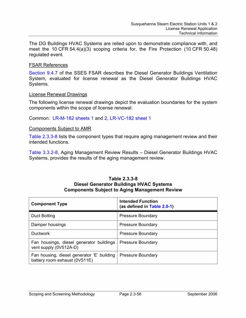
Susquehanna Steam Electric Station Units 1 & 2 License Renewal Application
Technical Information
Scoping and Screening Methodology Page 2.3-56 September 2006
The DG Buildings HVAC Systems are relied upon to demonstrate compliance with, and meet the 10 CFR 54.4(a)(3) scoping criteria for, the Fire Protection (10 CFR 50.48) regulated event.
FSAR References Section 9.4.7 of the SSES FSAR describes the Diesel Generator Buildings Ventilation System, evaluated for license renewal as the Diesel Generator Buildings HVAC Systems.
License Renewal Drawings The following license renewal drawings depict the evaluation boundaries for the system components within the scope of license renewal:
Common: LR-M-182 sheets 1 and 2, LR-VC-182 sheet 1
Components Subject to AMR Table 2.3.3-8 lists the component types that require aging management review and their intended functions.
Table 3.3.2-8, Aging Management Review Results – Diesel Generator Buildings HVAC Systems, provides the results of the aging management review.
Table 2.3.3-8 Diesel Generator Buildings HVAC Systems
Components Subject to Aging Management Review
Component Type Intended Function (as defined in Table 2.0-1)
Duct Bolting Pressure Boundary
Damper housings Pressure Boundary
Ductwork Pressure Boundary
Fan housings, diesel generator buildings vent supply (0V512A-D)
Pressure Boundary
Fan housing, diesel generator ‘E’ building battery room exhaust (0V511E)
Pressure Boundary
Susquehanna Steam Electric Station Units 1 & 2 License Renewal Application
Technical Information
Scoping and Screening Methodology Page 2.3-57 September 2006
Table 2.3.3-8: (continued)
Component Type Intended Function (as defined in Table 2.0-1)
Fan housings, diesel generator ‘E’ building vent supply (0V512E1/E2)
Pressure Boundary
Fan housings, diesel generator ‘E’ building vent exhaust (0V512E3/E4)
Pressure Boundary
Flexible connections (ductwork) Pressure Boundary
Tubing Pressure Boundary
Susquehanna Steam Electric Station Units 1 & 2 License Renewal Application
Technical Information
Scoping and Screening Methodology Page 2.3-58 September 2006
2.3.3.9 Diesel Generators System System Description The standby power supply (Diesel Generators System) for each safety-related load group consists of one diesel generator complete with its accessories and fuel storage and transfer systems. An additional diesel generator (0G501E) complete with its accessories and fuel oil storage and transfer system can be substituted for any one of the four normally aligned diesel generators (0G501A, B, C or D) and aligned to the safety-related load group. The diesel generators are shared by the two units. There are a total of five diesel generators, only four of which can be aligned to the safety-related load groups. When a diesel generator is aligned, it is connected to the 4.16 kV bus of the assigned load group per unit. The capacity of the aligned diesel generators (assuming one of the aligned diesels fails) is sufficient to operate the engineered safety features loads of one unit and those systems required for concurrent safe shutdown of the second unit.
Each diesel generator consists of a diesel engine directly connected to an AC generator and can be broken down by the following major subsystems:
Diesel Engines - The A, B, C, and D diesel engines have sixteen cylinders arranged in a “V” bank configuration. The E diesel engine has twenty cylinders arranged in a “V” bank configuration. The crankshaft of each engine is mated directly to the generator rotor at the flywheel. Each diesel engine consists of an engine, intake and exhaust manifolds, lube oil sump (crankcase), and engine controls including the governor.
Generators - The electric generators are AC synchronous 12 pole generators producing 4160 volts at 60 Hz for three phase distribution. Each generator consists of a stator, rotor, housing, shaft, and exciter.
Lube Oil Subsystem - Each diesel engine contains its own lubricating oil system to lubricate and cool the internal moving parts during engine operation. The lube oil is heated when the engine is in standby service and circulated by a motor-driven prelube oil pump. During operation lube oil is circulated by an engine-driven lube oil pump. A standby motor-driven lube oil pump acts as a backup during engine operation. The lube oil pumps take suction from the engine sump and circulate the lube oil through strainers and filters prior to lube oil entering the engine and turbocharger. The lube oil is cooled during engine operation in an oil cooler. An oil cooler is also provided for the engine governor. Lube oil storage tanks and transfer and return pumps are provided for maintenance purposes and shared by the five diesels.
Fuel Oil Subsystem - The fuel oil system stores and delivers fuel oil for the operation of the diesel engine. The fuel oil system and its components are discussed in Section 2.3.3.7.
Susquehanna Steam Electric Station Units 1 & 2 License Renewal Application
Technical Information
Scoping and Screening Methodology Page 2.3-59 September 2006
Intake Air and Exhaust Subsystem - The diesel engines each have a system to supply combustion air and remove exhaust gases. Fresh air is drawn through an air intake filter and a silencer by a turbocharger. The turbocharger is used to compress the intake air in order to boost engine power. The compressed air from each turbocharger is cooled in an intercooler before being distributed to the cylinders by the air intake manifold. Following combustion, the hot exhaust gases leaving the cylinders through the exhaust manifold are used to drive the turbochargers and are then discharged through a silencer and the exhaust piping.
Cooling Water Subsystem - Two separate systems are used to cool the various engine components and subsystems. The jacket water system is a closed system using demineralized water as the coolant. The jacket water system both cools the engine when the engine is operating, and maintains the engine warm when the engine is in standby. The jacket water system provides cooling water to the governor lube oil coolers. The jacket water system includes a standpipe that acts as a reservoir, deaerator, and an expansion tank. The Emergency Service Water system (ESW) supplies cooling water to the tube side of the jacket water heat exchangers, the lube oil heat exchangers, and the intercoolers. On the E diesel, ESW also supplies cooling water to the tube side of its fuel oil heat exchanger. The boundaries with the ESW system are at the inlets to the diesel heat exchangers and intercoolers cooled by ESW. Jacket water drain tanks and transfer and return pumps are provided on the E diesel for maintenance purposes.
Starting Air Subsystem - An air start system is utilized to start the diesel engine. Each diesel engine has two independent air starting systems that include two air compressors, two air receiver tanks for the A, B, C, and D diesels and four air receiver tanks for the E diesel, two entrainment separators, piping, valves, strainers, air dryers, pressure switches, safety valves and controls, and accessories as required. Each tank is normally replenished by one of the two compressors. On leaving the tanks, the starting air passes to the starting air valves and the air distributor. For the A, B, C, and D diesels, a strainer is provided between the tanks and starting air valves. Filters are provided upstream of the air distributor on all engines.
Reason for Scope Determination The Diesel Generators System provides a standby power supply in the event of total loss of the preferred and alternate power supplies. The diesel generators have a safety function of providing sufficient power for the electrical loads required for simultaneous shutdown of both reactors. This includes the loads required to mitigate the effects of a design basis Loss of Coolant Accident (LOCA) on one unit with a complete loss of offsite power plus a single failure in the onsite power system (e.g., failure of a diesel generator), concurrent with a safe shutdown on the other unit. This safety function meets the scoping criteria of 10 CFR 54.4(a)(1).
Susquehanna Steam Electric Station Units 1 & 2 License Renewal Application
Technical Information
Scoping and Screening Methodology Page 2.3-60 September 2006
The Diesel Generators System is required to maintain the integrity of nonsafety-related components that have the potential to adversely affect safety-related equipment through spatial interaction and nonsafety-related piping components required to support the safety-related functional boundary of the system. This function meets the scoping criteria of 10 CFR 54.4(a)(2).
The Diesel Generators System is relied upon to demonstrate compliance with, and meets the 10 CFR 54.4(a)(3) scoping criteria for, the Fire Protection (10 CFR 50.48), Environmental Qualification (10 CFR 50.49), Anticipated Transients Without Scram (10 CFR 50.62), and Station Blackout (10 CFR 50.63) regulated events.
FSAR References Sections 8.3.1.4, 9.5.5, 9.5.6, 9.5.7, and 9.5.8 of the SSES FSAR describe the Standby Power Supply, the Diesel Generator Cooling Water System, the Diesel Generator Starting System, the Diesel Generator Lubrication System, and the Diesel Generator Combustion Air Intake and Exhaust System, respectively. These combined systems are evaluated for license renewal as the Diesel Generators System.
License Renewal Drawings The following license renewal drawings depict the evaluation boundaries for the system components within the scope of license renewal:
Common: LR-M-111 sheets 1 and 4, LR-M-134 sheets 1, 2, 3, 4, 5, 6, and 7
Components Subject to AMR Nonsafety-related piping components of the air start subsystem of the Diesel Generators System that are connected to safety-related SSCs are not subject to aging management review. The structural integrity function is provided by the structural supports (seismic anchors), which are subject to aging management review. Also, there is no high pressure or other motive force and no medium in the compressed air contained in the pipe that would cause sufficient degradation to result in separation or movement of the piping during the period of extended operation. The diesel air start compressors and aftercoolers perform an anchor function but are not subject to aging management review based on evaluation of their construction, mounting, and support function.
Table 2.3.3-9 lists the component types that require aging management review and their intended functions.
Table 3.3.2-9, Aging Management Review Results – Diesel Generators System, provides the results of the aging management review.
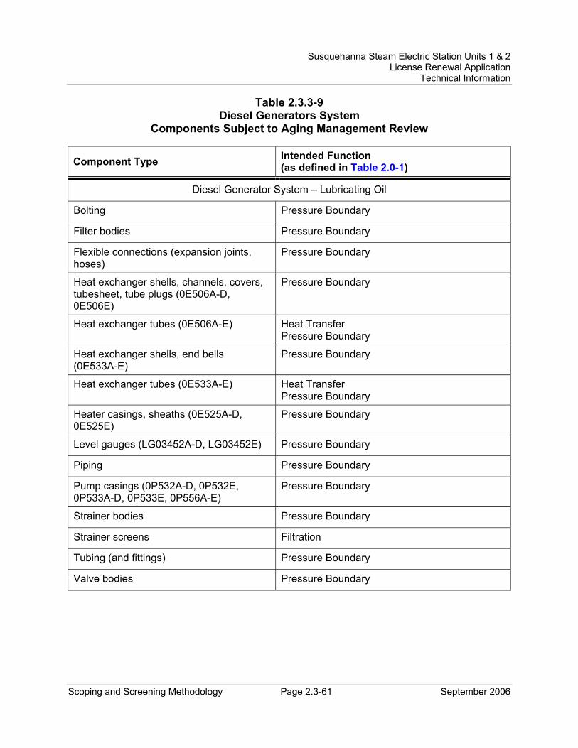
Susquehanna Steam Electric Station Units 1 & 2 License Renewal Application
Technical Information
Scoping and Screening Methodology Page 2.3-61 September 2006
Table 2.3.3-9 Diesel Generators System
Components Subject to Aging Management Review
Component Type Intended Function (as defined in Table 2.0-1)
Diesel Generator System – Lubricating Oil
Bolting Pressure Boundary
Filter bodies Pressure Boundary
Flexible connections (expansion joints, hoses)
Pressure Boundary
Heat exchanger shells, channels, covers, tubesheet, tube plugs (0E506A-D, 0E506E)
Pressure Boundary
Heat exchanger tubes (0E506A-E) Heat Transfer Pressure Boundary
Heat exchanger shells, end bells (0E533A-E)
Pressure Boundary
Heat exchanger tubes (0E533A-E) Heat Transfer Pressure Boundary
Heater casings, sheaths (0E525A-D, 0E525E)
Pressure Boundary
Level gauges (LG03452A-D, LG03452E) Pressure Boundary
Piping Pressure Boundary
Pump casings (0P532A-D, 0P532E, 0P533A-D, 0P533E, 0P556A-E)
Pressure Boundary
Strainer bodies Pressure Boundary
Strainer screens Filtration
Tubing (and fittings) Pressure Boundary
Valve bodies Pressure Boundary
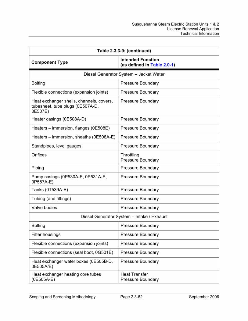
Susquehanna Steam Electric Station Units 1 & 2 License Renewal Application
Technical Information
Scoping and Screening Methodology Page 2.3-62 September 2006
Table 2.3.3-9: (continued)
Component Type Intended Function (as defined in Table 2.0-1)
Diesel Generator System – Jacket Water
Bolting Pressure Boundary
Flexible connections (expansion joints) Pressure Boundary
Heat exchanger shells, channels, covers, tubesheet, tube plugs (0E507A-D, 0E507E)
Pressure Boundary
Heater casings (0E508A-D) Pressure Boundary
Heaters – immersion, flanges (0E508E) Pressure Boundary
Heaters – immersion, sheaths (0E508A-E) Pressure Boundary
Standpipes, level gauges Pressure Boundary
Orifices Throttling Pressure Boundary
Piping Pressure Boundary
Pump casings (0P530A-E, 0P531A-E, 0P557A-E)
Pressure Boundary
Tanks (0T539A-E) Pressure Boundary
Tubing (and fittings) Pressure Boundary
Valve bodies Pressure Boundary
Diesel Generator System – Intake / Exhaust
Bolting Pressure Boundary
Filter housings Pressure Boundary
Flexible connections (expansion joints) Pressure Boundary
Flexible connections (seal boot, 0G501E) Pressure Boundary
Heat exchanger water boxes (0E505B-D, 0E505A/E)
Pressure Boundary
Heat exchanger heating core tubes (0E505A-E)
Heat Transfer Pressure Boundary
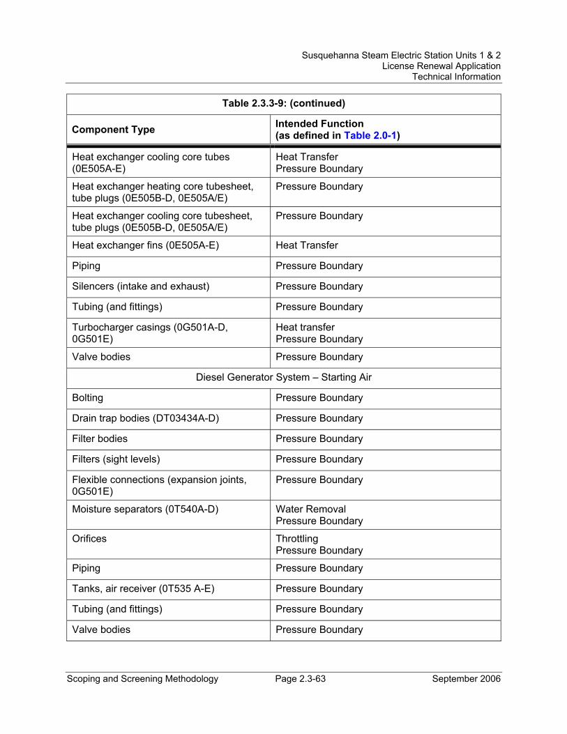
Susquehanna Steam Electric Station Units 1 & 2 License Renewal Application
Technical Information
Scoping and Screening Methodology Page 2.3-63 September 2006
Table 2.3.3-9: (continued)
Component Type Intended Function (as defined in Table 2.0-1)
Heat exchanger cooling core tubes (0E505A-E)
Heat Transfer Pressure Boundary
Heat exchanger heating core tubesheet, tube plugs (0E505B-D, 0E505A/E)
Pressure Boundary
Heat exchanger cooling core tubesheet, tube plugs (0E505B-D, 0E505A/E)
Pressure Boundary
Heat exchanger fins (0E505A-E) Heat Transfer
Piping Pressure Boundary
Silencers (intake and exhaust) Pressure Boundary
Tubing (and fittings) Pressure Boundary
Turbocharger casings (0G501A-D, 0G501E)
Heat transfer Pressure Boundary
Valve bodies Pressure Boundary
Diesel Generator System – Starting Air
Bolting Pressure Boundary
Drain trap bodies (DT03434A-D) Pressure Boundary
Filter bodies Pressure Boundary
Filters (sight levels) Pressure Boundary
Flexible connections (expansion joints, 0G501E)
Pressure Boundary
Moisture separators (0T540A-D) Water Removal Pressure Boundary
Orifices Throttling Pressure Boundary
Piping Pressure Boundary
Tanks, air receiver (0T535 A-E) Pressure Boundary
Tubing (and fittings) Pressure Boundary
Valve bodies Pressure Boundary
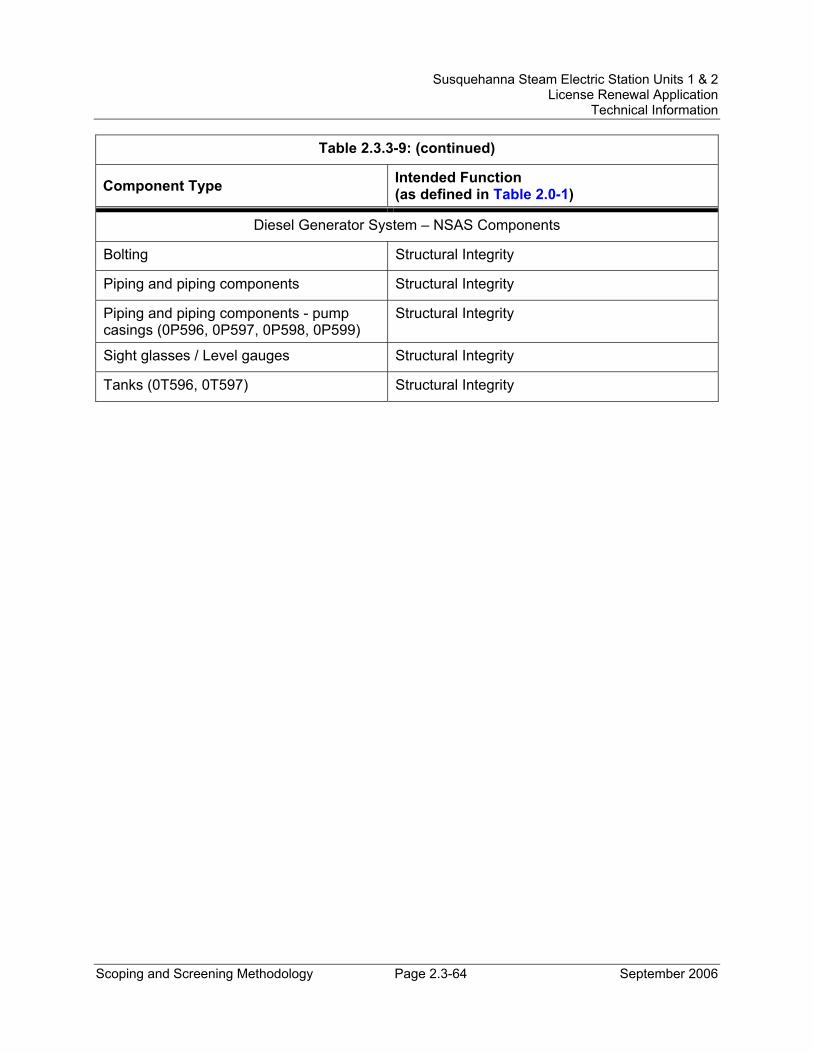
Susquehanna Steam Electric Station Units 1 & 2 License Renewal Application
Technical Information
Scoping and Screening Methodology Page 2.3-64 September 2006
Table 2.3.3-9: (continued)
Component Type Intended Function (as defined in Table 2.0-1)
Diesel Generator System – NSAS Components
Bolting Structural Integrity
Piping and piping components Structural Integrity
Piping and piping components - pump casings (0P596, 0P597, 0P598, 0P599)
Structural Integrity
Sight glasses / Level gauges Structural Integrity
Tanks (0T596, 0T597) Structural Integrity
Susquehanna Steam Electric Station Units 1 & 2 License Renewal Application
Technical Information
Scoping and Screening Methodology Page 2.3-65 September 2006
2.3.3.10 Domestic Water System System Description The Domestic Water System provides cold and hot water of a quality acceptable for human consumption to plumbing fixtures for the entire plant. The well water system is the primary source of potable water for the Susquehanna site. The water is chlorinated and filtered to remove iron. The system is not designated as seismic Category I (with the exception of piping inside the Diesel Generator 'E' Building, which was analyzed to seismic Category I requirements).
Reason for Scope Determination The Domestic Water System does not perform any functions that satisfy the scoping criteria of 10 CFR 54.4(a)(1).
The Domestic Water System is required to maintain the integrity of nonsafety-related components that have the potential to adversely affect safety-related equipment through spatial interaction. This function meets the scoping criteria of 10 CFR 54.4(a)(2).
The Domestic Water System is not relied upon to demonstrate compliance with, nor satisfy the 10 CFR 54.4(a)(3) scoping criteria for, any regulated event.
FSAR References Section 9.2.11 of the SSES FSAR describes the Potable Water System, evaluated for license renewal as the Domestic Water System.
License Renewal Drawings The following license renewal drawings depict the evaluation boundaries for the system components within the scope of license renewal:
Common: LR-M-117 sheets 4 and 5
Components Subject to AMR Table 2.3.3-10 lists the component types that require aging management review and their intended functions.
Table 3.3.2-10, Aging Management Review Results – Domestic Water System, provides the results of the aging management review.
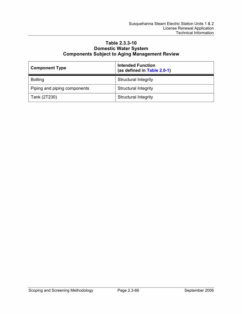
Susquehanna Steam Electric Station Units 1 & 2 License Renewal Application
Technical Information
Scoping and Screening Methodology Page 2.3-66 September 2006
Table 2.3.3-10 Domestic Water System
Components Subject to Aging Management Review
Component Type Intended Function (as defined in Table 2.0-1)
Bolting Structural Integrity
Piping and piping components Structural Integrity
Tank (2T230) Structural Integrity
Susquehanna Steam Electric Station Units 1 & 2 License Renewal Application
Technical Information
Scoping and Screening Methodology Page 2.3-67 September 2006
2.3.3.11 Emergency Service Water System System Description The Emergency Service Water (ESW) System consists of two loops, each of which is designed to supply 100 percent of the ESW requirements to both units and the common emergency diesel generators simultaneously. Each loop has two 50 percent capacity, vertical, turbine-type, single stage pumps. The pumps are located in the ESSW Pumphouse located at the edge of the spray pond. The emergency service water flows through the tube side of all heat exchangers returning to the spray pond in return headers combined with the RHR service water return headers.
During normal power generation, the ESW System is not operating, but is available for shutdown cooling, suppression pool cooling, surveillance testing, or emergencies. The ESW System also provides the safety-related source of makeup water to the spent fuel pool.
Reason for Scope Determination The ESW System is a safety-related system that is designed to provide a reliable source of cooling water to support operation of the ECCS, RCIC, diesel generators, the Unit 2 emergency switchgear and load center room coolers (direct expansion units), and the common unit Control Structure chillers as needed during normal plant operation, transient plant operation, and under plant accident conditions. The ESW System safety function is to provide cooling water to the safety-related equipment described above following any credible accident, including the Design Basis Loss of Coolant Accident (LOCA), coincident with a loss of offsite power and any active single failure. This safety function meets the scoping criteria of 10 CFR 54.4(a)(1).
The ESW System is required to maintain the integrity of nonsafety-related components that have the potential to adversely affect safety-related equipment through spatial interaction and nonsafety-related piping components required to support the safety-related functional boundary of the system. This function meets the scoping criteria of 10 CFR 54.4(a)(2).
The ESW System is relied upon to demonstrate compliance with, and meets the 10 CFR 54.4(a)(3) scoping criteria for, the Fire Protection (10 CFR 50.48), Environmental Qualification (10 CFR 50.49), Anticipated Transients Without Scram (10 CFR 50.62), and Station Blackout (10 CFR 50.63) regulated events.
FSAR References Section 9.2.5 of the SSES FSAR describes the Emergency Service Water System.
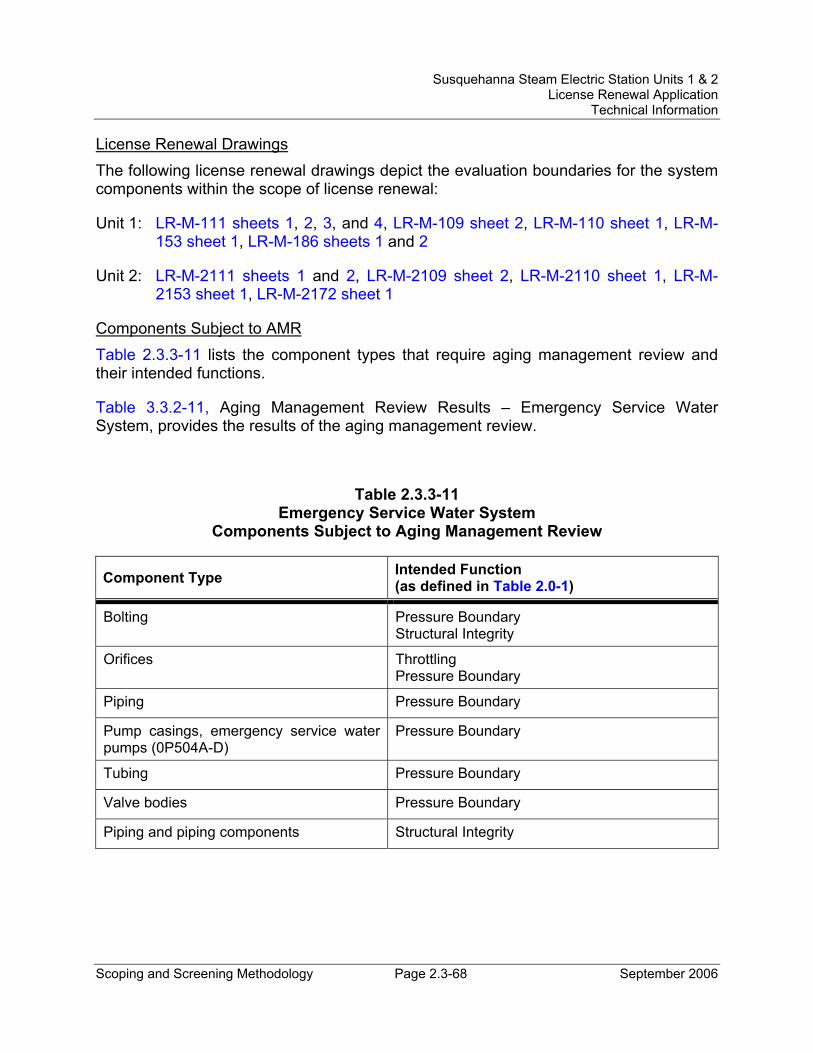
Susquehanna Steam Electric Station Units 1 & 2 License Renewal Application
Technical Information
Scoping and Screening Methodology Page 2.3-68 September 2006
License Renewal Drawings The following license renewal drawings depict the evaluation boundaries for the system components within the scope of license renewal:
Unit 1: LR-M-111 sheets 1, 2, 3, and 4, LR-M-109 sheet 2, LR-M-110 sheet 1, LR-M-153 sheet 1, LR-M-186 sheets 1 and 2
Unit 2: LR-M-2111 sheets 1 and 2, LR-M-2109 sheet 2, LR-M-2110 sheet 1, LR-M-2153 sheet 1, LR-M-2172 sheet 1
Components Subject to AMR Table 2.3.3-11 lists the component types that require aging management review and their intended functions.
Table 3.3.2-11, Aging Management Review Results – Emergency Service Water System, provides the results of the aging management review.
Table 2.3.3-11 Emergency Service Water System
Components Subject to Aging Management Review
Component Type Intended Function (as defined in Table 2.0-1)
Bolting Pressure Boundary Structural Integrity
Orifices Throttling Pressure Boundary
Piping Pressure Boundary
Pump casings, emergency service water pumps (0P504A-D)
Pressure Boundary
Tubing Pressure Boundary
Valve bodies Pressure Boundary
Piping and piping components Structural Integrity
Susquehanna Steam Electric Station Units 1 & 2 License Renewal Application
Technical Information
Scoping and Screening Methodology Page 2.3-69 September 2006
2.3.3.12 ESSW Pumphouse HVAC System System Description The Engineered Safeguards Service Water (ESSW) Pumphouse Heating, Ventilation and Air Conditioning (HVAC) System maintains a suitable environment in the pumphouse for the Emergency Service Water (ESW) and Residual Heat Removal Service Water (RHRSW) System pumps, and also, their associated appurtenances. To ensure proper pump operation, each ESW and RHRSW System pump is provided with a separate ventilation system that is designed to modulate the outside/return airflow ratio from 0 to 100 percent, depending on the cooling demand. Each ESSW Pumphouse HVAC System can be individually controlled from the control room, and can be started either manually or automatically.
Each supply fan starts coincident with its associated pump or when room temperature sensed by a start temperature switch exceeds an upper temperature limit. The fan continues to run after the pump is secured until the room temperature is below the stop thermostat cutout setting. Ventilation of the pumphouse, when the pumps are not in operation, is provided by infiltration. Heating of each room is accomplished by thermostatically-controlled electric unit heaters, which operate to maintain the room temperature.
Reason for Scope Determination The ESSW Pumphouse HVAC System is designed to maintain temperatures inside the pumphouse within specified design limits. This system function is classified safety-related. Note that only the ventilation system required for heat removal to ensure that the room temperature does not exceed a maximum design temperature is safety-related. The heating system is nonsafety-related. This safety function meets the scoping criteria of 10 CFR 54.4(a)(1).
The ESSW Pumphouse HVAC System does not have the potential to adversely affect safety-related systems or components through spatial interaction. Therefore, the ESSW Pumphouse HVAC System does not meet the scoping criteria of 10 CFR 54.4(a)(2).
The ESSW Pumphouse HVAC System is relied upon to demonstrate compliance with, and meet the 10 CFR 54.4(a)(3) scoping criteria for, the Fire Protection (10 CFR 50.48) regulated event.
FSAR References Section 9.4.8 of the SSES FSAR describes the Engineered Safeguards Service Water Pumphouse Ventilation System, evaluated for license renewal as the ESSW Pumphouse HVAC System.
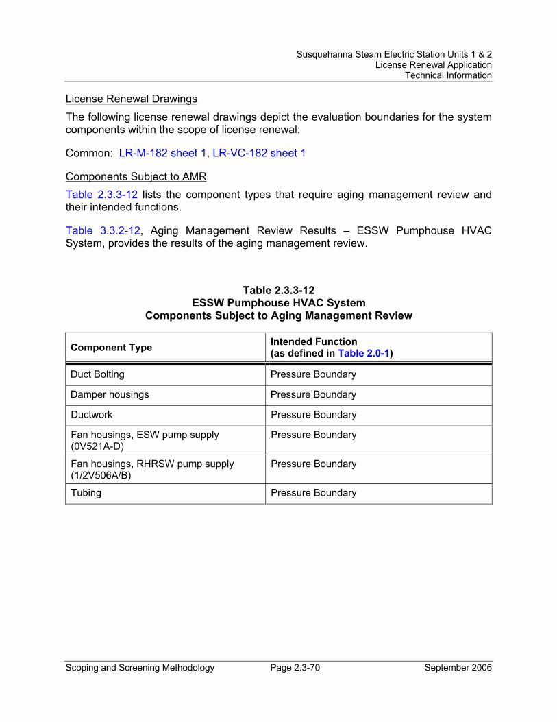
Susquehanna Steam Electric Station Units 1 & 2 License Renewal Application
Technical Information
Scoping and Screening Methodology Page 2.3-70 September 2006
License Renewal Drawings The following license renewal drawings depict the evaluation boundaries for the system components within the scope of license renewal:
Common: LR-M-182 sheet 1, LR-VC-182 sheet 1
Components Subject to AMR Table 2.3.3-12 lists the component types that require aging management review and their intended functions.
Table 3.3.2-12, Aging Management Review Results – ESSW Pumphouse HVAC System, provides the results of the aging management review.
Table 2.3.3-12 ESSW Pumphouse HVAC System
Components Subject to Aging Management Review
Component Type Intended Function (as defined in Table 2.0-1)
Duct Bolting Pressure Boundary
Damper housings Pressure Boundary
Ductwork Pressure Boundary
Fan housings, ESW pump supply (0V521A-D)
Pressure Boundary
Fan housings, RHRSW pump supply (1/2V506A/B)
Pressure Boundary
Tubing Pressure Boundary
Susquehanna Steam Electric Station Units 1 & 2 License Renewal Application
Technical Information
Scoping and Screening Methodology Page 2.3-71 September 2006
2.3.3.13 Fire Protection System System Description The primary purpose of the Fire Protection System is to minimize both the probability and consequences of postulated fires. This is accomplished by: (1) using fire resistant materials and minimizing the use of combustibles, (2) detecting fires quickly and annunciating alarms in the Control Room, (3) suppressing and extinguishing fires in the shortest time possible in order to minimize damage, and (4) preventing the spread of fire by installing fire barriers between fire hazards. The Fire Protection System is operational (in standby) during all periods of normal plant operation and shutdown conditions.
The Fire Protection System comprises the following systems and components: fire protection water supply system; fire detection and smoke alarm systems; automatic pre-action sprinkler systems; deluge systems; dry pipe and wet pipe sprinkler systems; wet standpipes and hose stations; carbon dioxide and halon suppression systems; fire hydrants; portable fire extinguishers; fire barriers, dampers, doors and penetration seals.
The fire protection water supply system is further described below.
Pumps - An electric motor driven fire pump and diesel engine driven fire pump, both located in the Circulating Water Pumphouse, furnish the main source of water for fire protection. The largest single demand can be satisfied by one fire pump. A jockey fire pump maintains system pressure within a pre-determined range to prevent frequent operation of the main fire pumps and also provides makeup water to the supply system. The electric motor driven and diesel engine driven fire pumps start sequentially on decreasing pressure, to restore system pressure. Both fire pumps continue running until manually secured.
Water Supplies - The plant’s two main automatic fire pumps have three different suction sources. The primary source of water supply is the clarified water storage tank, which is included in the Raw Water Treatment System (Section 2.3.3.21). The jockey fire pump takes suction from the clarified water storage tank to satisfy makeup requirements and maintain system pressure. The suction line from the clarified water storage tank is common to both the electric motor driven and diesel engine driven fire pumps, as well as the jockey fire pump. The second and third sources of water supply are the Unit 1 and Unit 2 cooling tower basins, respectively. The basins are part of the Cooling Tower System (Section 2.3.3.6). The water inventory in the clarified water storage tank, along with the contents of one of the cooling tower basins, is normally available to satisfy the water demands of the fire protection system. The other cooling tower basin is isolated by means of a normally-closed valve in the suction line to the fire pump. The Technical Requirements Manual (TRM) requires that two sources of water supply be aligned to the fire protection water supply system at all times.
Susquehanna Steam Electric Station Units 1 & 2 License Renewal Application
Technical Information
Scoping and Screening Methodology Page 2.3-72 September 2006
Underground Piping and Valves - The fire protection water supply system supplies pressurized water to plant sprinkler and deluge systems, fire hydrants and hose stations. A continuous, underground primary piping loop distributes the pressurized water around and through the plant power block, with a secondary loop surrounding the site support buildings. The primary and secondary loops both have several supply legs. The cement-lined, ductile-iron yard loop is buried below frost level. The design of the yard loop layout includes post indicator valves that are used for sectional control. The valves, along with cross-connecting piping, provide the capability to isolate a damaged fire yard main.
Reason for Scope Determination The Fire Protection System has no safety-related functions, nor is any section and/or component of the system classified safety-related. The Fire Protection System does not perform any functions that meet the scoping criteria of 10 CFR 54.4(a)(1).
The Fire Protection System is required to maintain the integrity of nonsafety-related components that have the potential to adversely affect safety-related equipment through spatial interaction and are required to support the safety-related functional boundary of the interfacing safety-related system. This function meets the scoping criteria of 10 CFR 54.4(a)(2).
The Fire Protection System is relied upon to demonstrate compliance with, and meets the 10 CFR 54.4(a)(3) scoping criteria for, the Fire Protection (10 CFR 50.48) regulated event.
FSAR References Section 9.5.1 of the SSES FSAR references the Fire Protection Review Report for information on the Fire Protection System.
License Renewal Drawings The following license renewal drawings depict the evaluation boundaries for the system components within the scope of license renewal:
Unit 1: LR-M-151 sheet 1, LR-VC-175 sheet 3
Unit 2: LR-M-2151 sheet 1
Common: LR-M-122 sheets 1, 2, 3, 4, 5, 9, 10, 12, 13, 14, 15, LR-VC-178 sheet 1
Components Subject to AMR Table 2.3.3-13 lists the component types that require aging management review and their intended functions.
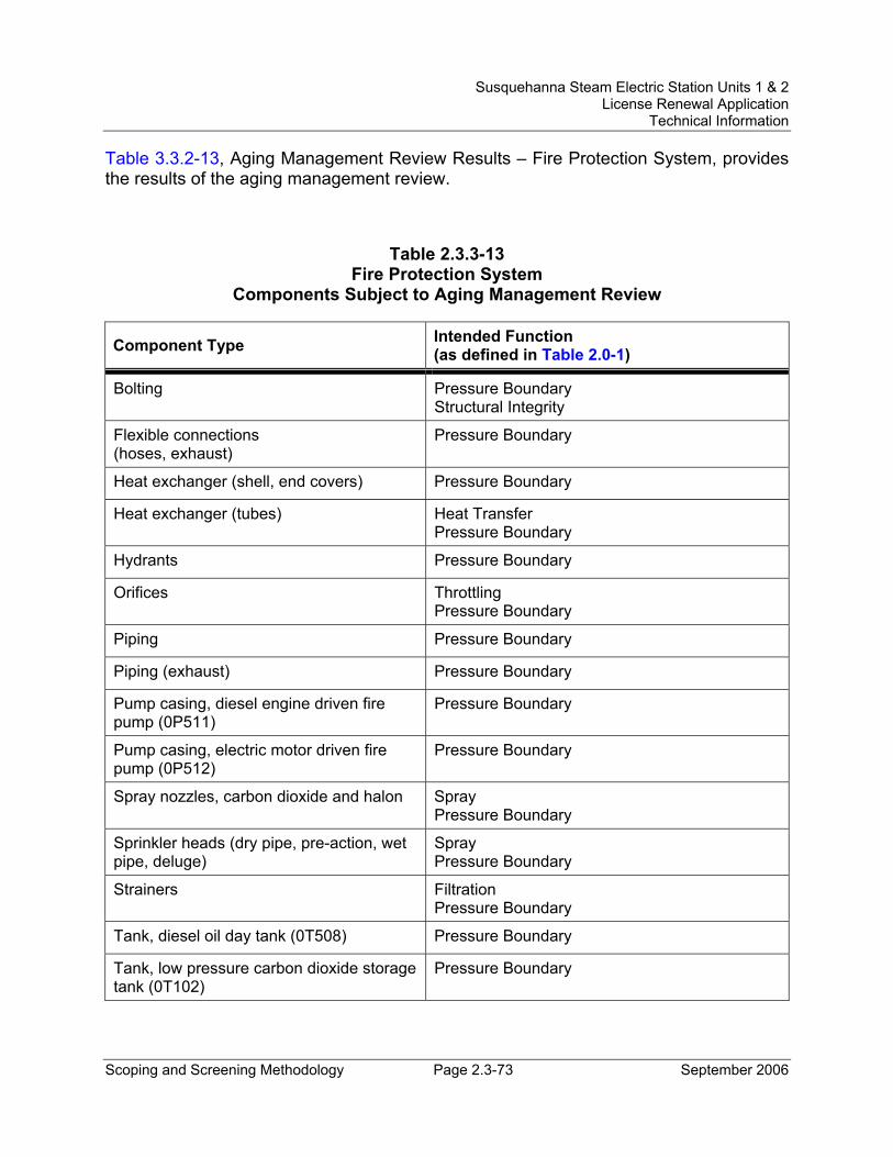
Susquehanna Steam Electric Station Units 1 & 2 License Renewal Application
Technical Information
Scoping and Screening Methodology Page 2.3-73 September 2006
Table 3.3.2-13, Aging Management Review Results – Fire Protection System, provides the results of the aging management review.
Table 2.3.3-13 Fire Protection System
Components Subject to Aging Management Review
Component Type Intended Function (as defined in Table 2.0-1)
Bolting Pressure Boundary Structural Integrity
Flexible connections (hoses, exhaust)
Pressure Boundary
Heat exchanger (shell, end covers) Pressure Boundary
Heat exchanger (tubes) Heat Transfer Pressure Boundary
Hydrants Pressure Boundary
Orifices Throttling Pressure Boundary
Piping Pressure Boundary
Piping (exhaust) Pressure Boundary
Pump casing, diesel engine driven fire pump (0P511)
Pressure Boundary
Pump casing, electric motor driven fire pump (0P512)
Pressure Boundary
Spray nozzles, carbon dioxide and halon Spray Pressure Boundary
Sprinkler heads (dry pipe, pre-action, wet pipe, deluge)
Spray Pressure Boundary
Strainers Filtration Pressure Boundary
Tank, diesel oil day tank (0T508) Pressure Boundary
Tank, low pressure carbon dioxide storage tank (0T102)
Pressure Boundary
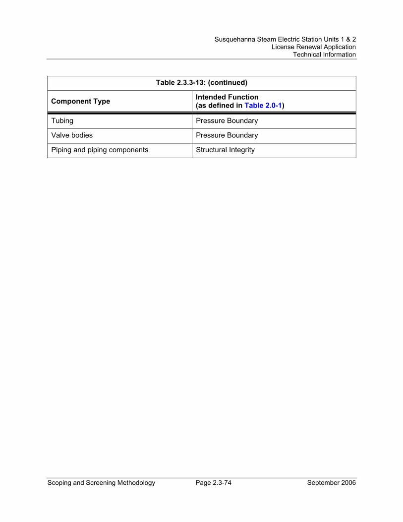
Susquehanna Steam Electric Station Units 1 & 2 License Renewal Application
Technical Information
Scoping and Screening Methodology Page 2.3-74 September 2006
Table 2.3.3-13: (continued)
Component Type Intended Function (as defined in Table 2.0-1)
Tubing Pressure Boundary
Valve bodies Pressure Boundary
Piping and piping components Structural Integrity
Susquehanna Steam Electric Station Units 1 & 2 License Renewal Application
Technical Information
Scoping and Screening Methodology Page 2.3-75 September 2006
2.3.3.14 Fuel Pool Cooling and Cleanup System and Fuel Pools and Auxiliaries System Description The Fuel Pool Cooling and Cleanup (FPCCU) System, supported by components of the Fuel Pools and Auxiliaries, cools the fuel storage pool water by transferring the decay heat of the irradiated fuel through heat exchangers to the service water system. During refueling outages, when the service water system is shutdown, the decay heat is transferred through the fuel pool cooling heat exchangers to the temporary cooling towers/chillers located outside the units or by circulating river water through the heat exchangers. Water clarity and quality in the fuel storage pools, transfer canals, reactor wells, dryer-separator pools, and shipping cask pit are maintained by filtering and demineralizing.
One skimmer surge tank for each unit collects overflow water from skimmer drain openings with adjustable weirs at the water surface elevation of each pool and well. The common shipping cask pit water overflows to both units' skimmer surge tanks. Wave suppression scuppers along the working side of the fuel pools also drain to the tanks. The skimmer openings in the pool liners are protected with a wire mesh screen to prevent floating objects such as the surface breaker viewing aids from entering the tanks. The adjustable weir plates are set according to the required cooling flow, desired flow pattern, and water shielding needs.
During periods when the heat in the pool is greater than the capacity of the fuel pool cooling system (e.g., storing of a full core of irradiated fuel shortly after shutdown), the Residual Heat Removal (RHR) System can be used to dissipate the decay heat. One RHR pump takes suction from an intertie line to the skimmer surge tank and discharges through one RHR heat exchanger to two independent diffusers at the fuel pool bottom. With the spent fuel pools filled above the weirs, the skimmer surge tank provides sufficient suction head for an RHR pump in the RHR fuel pool cooling mode. The safety-related source of makeup water to the spent fuel pool is provided by the Emergency Service Water System.
Reason for Scope Determination The FPCCU System and the supporting components of the Fuel Pools and Auxiliaries do not perform any safety-related functions. However, the RHR System provides cooling to the seismic Category I fuel pool to prevent boiling following a design basis accident. All FPCCU System piping and components shared with or connecting to the RHR inter-tie loop are seismic Category I Quality Group C, or equivalent, and can be isolated from any piping associated with the Quality Group C fuel pool cooling system which is not seismic Category I. This function meets the scoping criteria of 10 CFR 54.4(a)(1).
The FPCCU System is required to maintain the integrity of nonsafety-related components that have the potential to adversely affect safety-related equipment through
Susquehanna Steam Electric Station Units 1 & 2 License Renewal Application
Technical Information
Scoping and Screening Methodology Page 2.3-76 September 2006
spatial interaction and nonsafety-related piping components required to support the safety-related functional boundary of the system. This function meets the scoping criteria of 10 CFR 54.4(a)(2).
The FPCCU System, including the supporting components of the Fuel Pools and Auxiliaries, is not relied upon to demonstrate compliance with, and does not meet the 10 CFR 54.4(a)(3) scoping criteria for, any of the regulated events.
FSAR References Section 9.1.3 of the SSES FSAR describes the Spent Fuel Pool Cooling and Cleanup System. Section 9.1.2 of the SSES FSAR describes Spent Fuel Storage, which includes the portions of the leak detection system evaluated as Fuel Pools and Auxiliaries under the mechanical scope.
License Renewal Drawings The following license renewal drawings depict the evaluation boundaries for the system components within the scope of license renewal:
Unit 1: LR-M-110 sheet 1, LR-M-151 sheets 1 and 3, LR-M-153 sheets 1 and 2, LR-M-154 sheet 1
Unit 2: LR-M-2110 sheet 1, LR-M-2151 sheets 1 and 3, LR-M-2153 sheets 1 and 2
Common: LR-M-166 sheet 2
Components Subject to AMR Table 2.3.3-14 lists the component types that require aging management review and their intended functions.
Table 3.3.2-14, Aging Management Review Results – Fuel Pool Cooling and Cleanup System and Fuel Pools and Auxiliaries, provides the results of the aging management review.
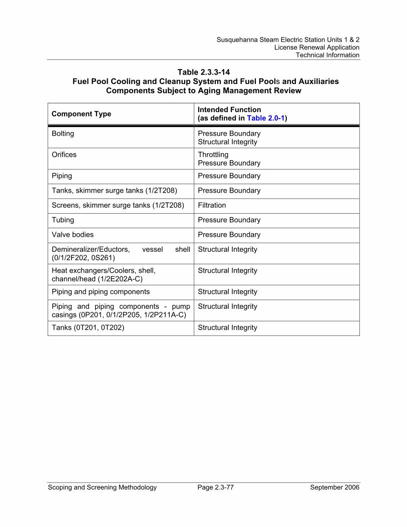
Susquehanna Steam Electric Station Units 1 & 2 License Renewal Application
Technical Information
Scoping and Screening Methodology Page 2.3-77 September 2006
Table 2.3.3-14 Fuel Pool Cooling and Cleanup System and Fuel Pools and Auxiliaries
Components Subject to Aging Management Review
Component Type Intended Function (as defined in Table 2.0-1)
Bolting Pressure Boundary Structural Integrity
Orifices Throttling Pressure Boundary
Piping Pressure Boundary
Tanks, skimmer surge tanks (1/2T208) Pressure Boundary
Screens, skimmer surge tanks (1/2T208) Filtration
Tubing Pressure Boundary
Valve bodies Pressure Boundary
Demineralizer/Eductors, vessel shell (0/1/2F202, 0S261)
Structural Integrity
Heat exchangers/Coolers, shell, channel/head (1/2E202A-C)
Structural Integrity
Piping and piping components Structural Integrity
Piping and piping components - pump casings (0P201, 0/1/2P205, 1/2P211A-C)
Structural Integrity
Tanks (0T201, 0T202) Structural Integrity
Susquehanna Steam Electric Station Units 1 & 2 License Renewal Application
Technical Information
Scoping and Screening Methodology Page 2.3-78 September 2006
2.3.3.15 Neutron Monitoring System System Description The Neutron Monitoring System consists of six major subsystems: (1) source range monitor subsystem (SRM), (2) intermediate range monitor subsystem (IRM), (3) local power range monitor subsystem (LPRM), (4) average power range monitor subsystem (APRM), (5) rod block monitor subsystem (RBM), and (6) traversing incore probe subsystem (TIP).
The purpose of the Neutron Monitoring System is to monitor the power level in the core and provide signals to the Reactor Protection System and the rod block portion of the reactor manual control system. The system also provides information for operation and control of the reactor and for post-accident conditions. The Neutron Monitoring System primarily consists of electrical and instrumentation and control components that are included within the electrical discipline boundaries.
Portions of the TIP subsystem are within the mechanical discipline evaluation boundaries. The TIP subsystem allows calibration of LRPM signals by correlating TIP signals to LRPM signals as the TIP is positioned in various radial and axial locations in the core. The TIP system equipment is located outside containment. In order to ensure containment integrity, a valve system is provided on each guide tube entering the drywell. A ball valve and a cable shearing valve are mounted in the guide tubing just outside the drywell. They maintain the leak tightness integrity of the drywell. A guide tube ball valve opens only when the TIP is being inserted. The shear valve is used only if a leak occurs when the TIP is beyond the ball valve and power to the TIP fails. The shear valve can cut the cable and close off the guide tube.
Reason for Scope Determination The Neutron Monitoring System has a safety function to provide reactor scram initiation during all normal plant operation, anticipated operational occurrences, and accident conditions. The traversing incore probe subsystem has a safety function of maintaining primary containment integrity through containment isolation. These safety functions meet the scoping criteria of 10 CFR 54.4(a)(1).
The Neutron Monitoring System does not have the potential to adversely affect safety-related systems or components through spatial interaction. Therefore, the Neutron Monitoring System does not meet the scoping criteria of 10 CFR 54.4(a)(2).
The Neutron Monitoring System is relied upon to demonstrate compliance with, and meets the 10 CFR 54.4(a)(3) scoping criteria for, the Environmental Qualification (10 CFR 50.49) and Anticipated Transient Without Scram (10 CFR 50.62) regulated events.
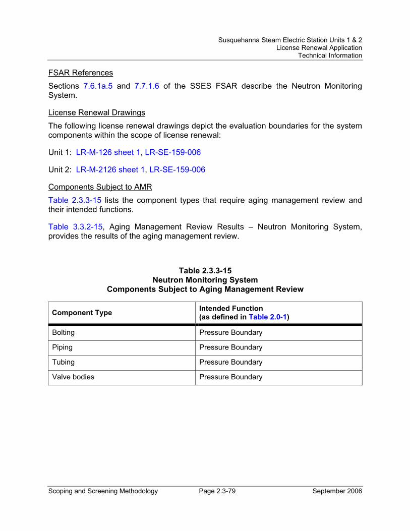
Susquehanna Steam Electric Station Units 1 & 2 License Renewal Application
Technical Information
Scoping and Screening Methodology Page 2.3-79 September 2006
FSAR References Sections 7.6.1a.5 and 7.7.1.6 of the SSES FSAR describe the Neutron Monitoring System.
License Renewal Drawings The following license renewal drawings depict the evaluation boundaries for the system components within the scope of license renewal:
Unit 1: LR-M-126 sheet 1, LR-SE-159-006
Unit 2: LR-M-2126 sheet 1, LR-SE-159-006
Components Subject to AMR Table 2.3.3-15 lists the component types that require aging management review and their intended functions.
Table 3.3.2-15, Aging Management Review Results – Neutron Monitoring System, provides the results of the aging management review.
Table 2.3.3-15 Neutron Monitoring System
Components Subject to Aging Management Review
Component Type Intended Function (as defined in Table 2.0-1)
Bolting Pressure Boundary
Piping Pressure Boundary
Tubing Pressure Boundary
Valve bodies Pressure Boundary
Susquehanna Steam Electric Station Units 1 & 2 License Renewal Application
Technical Information
Scoping and Screening Methodology Page 2.3-80 September 2006
2.3.3.16 Nitrogen and Hydrogen System System Description The nitrogen storage and supply subsystem of the Nitrogen and Hydrogen System provides gaseous nitrogen for containment makeup. The bulk hydrogen subsystem of the Nitrogen and Hydrogen System provides hydrogen for cooling the main generator during normal plant operation.
Reason for Scope Determination The Nitrogen and Hydrogen System does not perform any functions that satisfy the scoping criteria of 10 CFR 54.4(a)(1).
The Nitrogen and Hydrogen System is required to maintain the integrity of non-safety piping components required to support the safety-related functional boundary of the interfacing system. This function meets the scoping criteria of 10 CFR 54.4(a)(2).
The Nitrogen and Hydrogen System is not relied upon to demonstrate compliance with, nor satisfy the 10 CFR 54.4(a)(3) scoping criteria for, any regulated event.
FSAR References The Nitrogen and Hydrogen System is not described in the SSES FSAR.
License Renewal Drawings The following license renewal drawings depict the evaluation boundaries for the system components within the scope of license renewal:
Unit 1: LR-M-157 sheet 1
Unit 2: LR-M-2157 sheet 1
Components Subject to AMR Although connected to safety-related components for makeup and purge of the nitrogen in containment, there are no mechanical components of the Nitrogen and Hydrogen System that are subject to aging management review. The structural integrity function is provided by the structural supports (seismic anchors), which are subject to aging management review. Also, there is no high pressure or other motive force and no medium in the air and gas contained in the pipe that would cause sufficient degradation to result in separation or movement of the piping during the period of extended operation.
Susquehanna Steam Electric Station Units 1 & 2 License Renewal Application
Technical Information
Scoping and Screening Methodology Page 2.3-81 September 2006
2.3.3.17 Primary Containment Atmosphere Circulation System System Description The Primary Containment Atmosphere Circulation System (drywell air flow system) in each unit contains seven pairs of unit coolers, with one fan and one cooling coil per cooler. Each cooler has an individually ducted supply system. During normal operation, the coolers maintain temperatures in the various spaces within specified limits. During post-LOCA (loss-of-cooling accident) conditions, selected drywell air cooler recirculation fan systems are designed to mix the drywell atmosphere to prevent hydrogen concentration build-up. This is the only safety function performed by the drywell unit coolers.
In addition, the drywell air flow system contains two recirculation fans serving the reactor under vessel control rod drive (CRD) area. During post-accident conditions, the reactor under vessel CRD area recirculation fan system is designed to mix the drywell atmosphere to prevent hydrogen concentration build-up. This is the only safety function performed by the reactor under vessel CRD area recirculation fans.
Reason for Scope Determination The Primary Containment Atmosphere Circulation System has a safety function of providing mixing of the drywell atmosphere during post-LOCA conditions to prevent hydrogen concentration build-up. This is the only safety-related function performed by the drywell unit coolers and the reactor under vessel CRD area recirculation fans. This safety function meets the scoping criteria of 10 CFR 54.4(a)(1).
The Primary Containment Atmosphere Circulation System does not have the potential to adversely affect safety-related systems or components through spatial interaction. Therefore, the Primary Containment Atmosphere Circulation System does not meet the scoping criteria of 10 CFR 54.4(a)(2).
The Primary Containment Atmosphere Circulation System is relied upon to demonstrate compliance with, and meets the 10 CFR 54.4(a)(3) scoping criteria for, the Environmental Qualification (10 CFR 50.49) regulated event.
FSAR References Section 9.4.5 of the SSES FSAR describes the Primary Containment Atmosphere Recirculation and Cooling System, evaluated for license renewal as the Primary Containment Atmosphere Circulation System.
License Renewal Drawings The following license renewal drawings depict the evaluation boundaries for the system components within the scope of license renewal:
Unit 1: LR-M-177 sheet 1
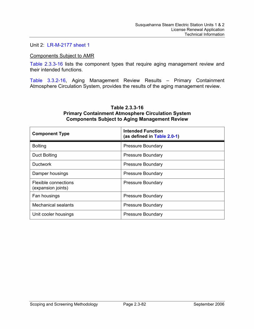
Susquehanna Steam Electric Station Units 1 & 2 License Renewal Application
Technical Information
Scoping and Screening Methodology Page 2.3-82 September 2006
Unit 2: LR-M-2177 sheet 1
Components Subject to AMR Table 2.3.3-16 lists the component types that require aging management review and their intended functions.
Table 3.3.2-16, Aging Management Review Results – Primary Containment Atmosphere Circulation System, provides the results of the aging management review.
Table 2.3.3-16 Primary Containment Atmosphere Circulation System
Components Subject to Aging Management Review
Component Type Intended Function (as defined in Table 2.0-1)
Bolting Pressure Boundary
Duct Bolting Pressure Boundary
Ductwork Pressure Boundary
Damper housings Pressure Boundary
Flexible connections (expansion joints)
Pressure Boundary
Fan housings Pressure Boundary
Mechanical sealants Pressure Boundary
Unit cooler housings Pressure Boundary
Susquehanna Steam Electric Station Units 1 & 2 License Renewal Application
Technical Information
Scoping and Screening Methodology Page 2.3-83 September 2006
2.3.3.18 Process and Area Radiation Monitoring System System Description The Process Radiation Monitoring System is provided to monitor releases of radioactive material in the plant gaseous and liquid process and effluent streams in order to detect, alarm, indicate and generate appropriate automatic actions where predetermined limits are exceeded, to control these releases. The Area Radiation Monitoring System provides continuous monitoring to detect abnormal radiation levels in the plant for the protection of personnel; provides local indication and alarms to warn personnel of substantial changes in radiation levels; and provides indication and alarms in the control room of high radiation levels in monitored areas of the plant.
Reason for Scope Determination Those portions of the Process and Area Radiation Monitoring System that are in the scope of license renewal provide monitoring of the radiation levels in the containment atmosphere (normal and accident levels), various intake and exhaust ducts, and in main steam lines. The monitors also provide associated indication, alarm, and isolation signals. These safety functions meet the scoping criteria of 10 CFR 54.4(a)(1).
The Process and Area Radiation Monitoring System is required to maintain the integrity of nonsafety-related components that have the potential to adversely affect safety-related equipment through spatial interaction and nonsafety-related piping components required to support the safety-related functional boundary of the interfacing systems. This function meets the scoping criteria of 10 CFR 54.4(a)(2).
The Process and Area Radiation Monitoring System is relied upon to demonstrate compliance with, and meets the 10 CFR 54.4(a)(3) scoping criteria for, the Environmental Qualification (10 CFR 50.49) regulated event.
FSAR References Sections 7.6 and 11.5 of the SSES FSAR describe the Process and Effluent Radiological Monitoring and Sampling Systems, evaluated for license renewal as the Process and Area Radiation Monitoring System. Section 12.3.4 of the SSES FSAR describes the Area Radiation Monitoring System, evaluated for license renewal as the Process and Area Radiation Monitoring System.
License Renewal Drawings The following license renewal drawings depict the evaluation boundaries for the system components within the scope of license renewal:
Unit 1: LR-M-112 sheet 1, LR-M-157 sheets 6 and 7, LR-M-178 sheet 1
Unit 2: LR-M-2112 sheet 1, LR-M-2157 sheets 6 and 7
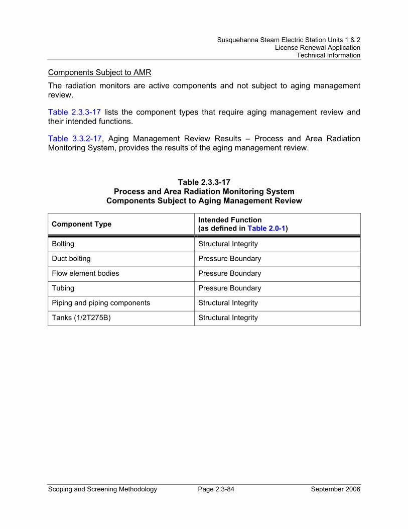
Susquehanna Steam Electric Station Units 1 & 2 License Renewal Application
Technical Information
Scoping and Screening Methodology Page 2.3-84 September 2006
Components Subject to AMR The radiation monitors are active components and not subject to aging management review.
Table 2.3.3-17 lists the component types that require aging management review and their intended functions.
Table 3.3.2-17, Aging Management Review Results – Process and Area Radiation Monitoring System, provides the results of the aging management review.
Table 2.3.3-17 Process and Area Radiation Monitoring System
Components Subject to Aging Management Review
Component Type Intended Function (as defined in Table 2.0-1)
Bolting Structural Integrity
Duct bolting Pressure Boundary
Flow element bodies Pressure Boundary
Tubing Pressure Boundary
Piping and piping components Structural Integrity
Tanks (1/2T275B) Structural Integrity
Susquehanna Steam Electric Station Units 1 & 2 License Renewal Application
Technical Information
Scoping and Screening Methodology Page 2.3-85 September 2006
2.3.3.19 Radwaste Liquid System System Description The purpose of the Radwaste Liquid System is to collect, process, store, and monitor, for reuse and disposal, the radioactive liquid wastes generated as a result of plant operation. The Radwaste Liquid System serves both units and consists of liquid radwaste (high and low purity wastewater principally from equipment and floor drains), chemical waste, and laundry drain subsystems. Waste influent to each of the subsystems is collected in batch tanks to allow for quality and volume monitoring before processing.
Reason for Scope Determination Those portions of the Radwaste Liquid System that are in the scope of license renewal perform a safety-related function of containment isolation upon receipt of a containment isolation signal. This function meets the scoping criteria of 10 CFR 54.4(a)(1).
The Radwaste Liquid System is required to maintain the integrity of nonsafety-related components that have the potential to adversely affect safety-related equipment through spatial interaction and nonsafety-related piping components required to support the safety-related functional boundary of the interfacing systems. This function meets the scoping criteria of 10 CFR 54.4(a)(2).
The Radwaste Liquid System is relied upon to demonstrate compliance with, and meets the 10 CFR 54.4(a)(3) scoping criteria for, the Environmental Qualification (10 CFR 50.49) regulated event.
FSAR References Section 11.2 of the SSES FSAR describes the Liquid Waste Management System, evaluated for license renewal as the Radwaste Liquid System.
License Renewal Drawings The following license renewal drawings depict the evaluation boundaries for the system components within the scope of license renewal:
Unit 1: LR-M-113 sheet 1, LR-M-143 sheet 2, LR-M-144 sheet 2, LR-M-147 sheet 1, LR-M-151 sheet 1, LR-M-153 sheet 2, LR-M-161 sheets 1, 2, and 3, LR-M-162 sheet 1, LR-VC-175 sheet 3
Unit 2: LR-M-2113 sheet 1, LR-M-2143 sheet 2, LR-M-2144 sheet 2, LR-M-2147 sheet 1, LR-M-2151 sheet 1, LR-M-2153 sheet 2, LR-M-2161 sheets 1, 2, and 3
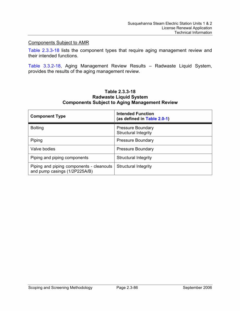
Susquehanna Steam Electric Station Units 1 & 2 License Renewal Application
Technical Information
Scoping and Screening Methodology Page 2.3-86 September 2006
Components Subject to AMR Table 2.3.3-18 lists the component types that require aging management review and their intended functions.
Table 3.3.2-18, Aging Management Review Results – Radwaste Liquid System, provides the results of the aging management review.
Table 2.3.3-18 Radwaste Liquid System
Components Subject to Aging Management Review
Component Type Intended Function (as defined in Table 2.0-1)
Bolting Pressure Boundary Structural Integrity
Piping Pressure Boundary
Valve bodies Pressure Boundary
Piping and piping components Structural Integrity
Piping and piping components - cleanouts and pump casings (1/2P225A/B)
Structural Integrity
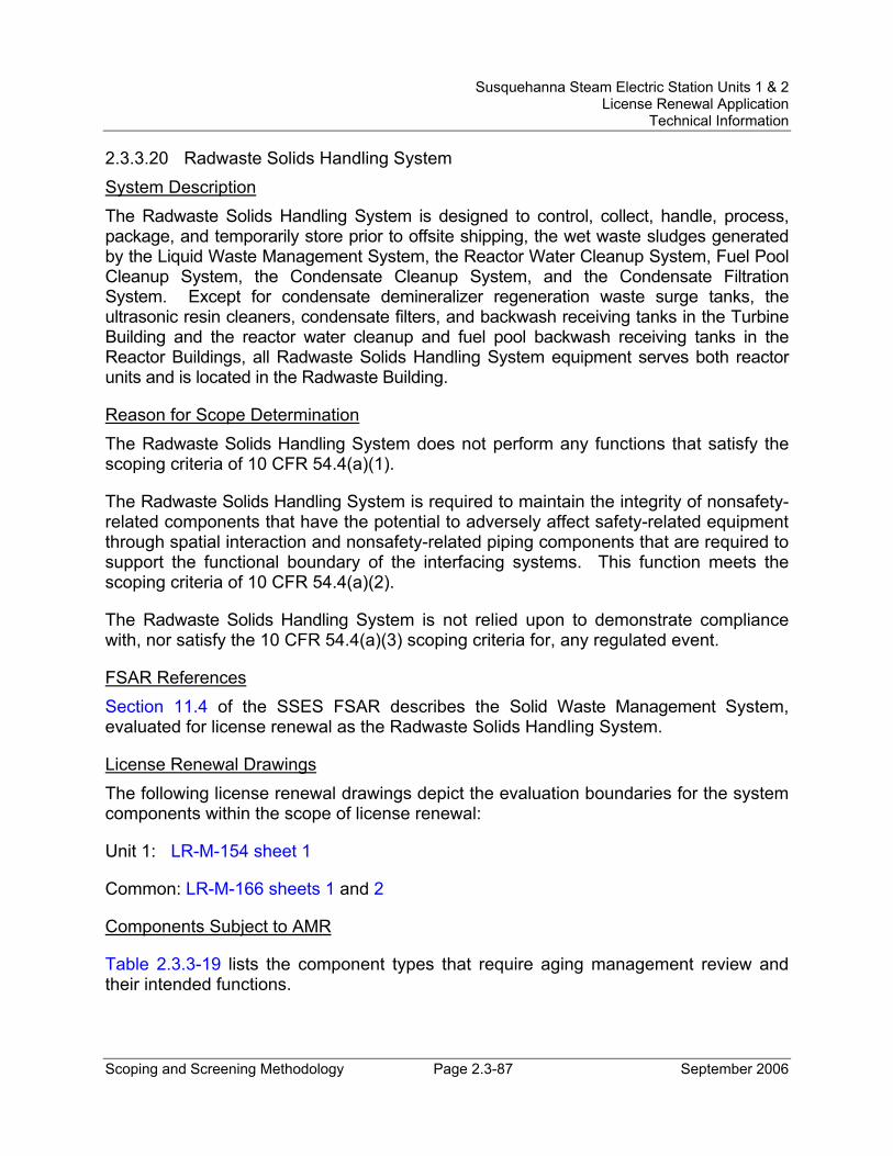
Susquehanna Steam Electric Station Units 1 & 2 License Renewal Application
Technical Information
Scoping and Screening Methodology Page 2.3-87 September 2006
2.3.3.20 Radwaste Solids Handling System System Description The Radwaste Solids Handling System is designed to control, collect, handle, process, package, and temporarily store prior to offsite shipping, the wet waste sludges generated by the Liquid Waste Management System, the Reactor Water Cleanup System, Fuel Pool Cleanup System, the Condensate Cleanup System, and the Condensate Filtration System. Except for condensate demineralizer regeneration waste surge tanks, the ultrasonic resin cleaners, condensate filters, and backwash receiving tanks in the Turbine Building and the reactor water cleanup and fuel pool backwash receiving tanks in the Reactor Buildings, all Radwaste Solids Handling System equipment serves both reactor units and is located in the Radwaste Building.
Reason for Scope Determination The Radwaste Solids Handling System does not perform any functions that satisfy the scoping criteria of 10 CFR 54.4(a)(1).
The Radwaste Solids Handling System is required to maintain the integrity of nonsafety-related components that have the potential to adversely affect safety-related equipment through spatial interaction and nonsafety-related piping components that are required to support the functional boundary of the interfacing systems. This function meets the scoping criteria of 10 CFR 54.4(a)(2).
The Radwaste Solids Handling System is not relied upon to demonstrate compliance with, nor satisfy the 10 CFR 54.4(a)(3) scoping criteria for, any regulated event.
FSAR References Section 11.4 of the SSES FSAR describes the Solid Waste Management System, evaluated for license renewal as the Radwaste Solids Handling System.
License Renewal Drawings The following license renewal drawings depict the evaluation boundaries for the system components within the scope of license renewal:
Unit 1: LR-M-154 sheet 1
Common: LR-M-166 sheets 1 and 2
Components Subject to AMR
Table 2.3.3-19 lists the component types that require aging management review and their intended functions.
Susquehanna Steam Electric Station Units 1 & 2 License Renewal Application
Technical Information
Scoping and Screening Methodology Page 2.3-88 September 2006
Table 3.3.2-19, Aging Management Review Results – Radwaste Solids Handling System, provides the results of the aging management review.
Table 2.3.3-19 Radwaste Solids Handling System
Components Subject to Aging Management Review
Component Type Intended Function (as defined in Table 2.0-1)
Bolting Structural Integrity
Piping and piping components Structural Integrity
Tanks (0T203, 1/2T225) Structural Integrity
Susquehanna Steam Electric Station Units 1 & 2 License Renewal Application
Technical Information
Scoping and Screening Methodology Page 2.3-89 September 2006
2.3.3.21 Raw Water Treatment System System Description The Raw Water Treatment System includes a clarified water storage tank that is the primary source of water for the Fire Protection System. This tank has a total capacity of 500,000 gallons; however, the tank is designed with an internal standpipe that terminates at the 300,000 gallon level, thereby ensuring that a minimum of 300,000 gallons of clarified water is dedicated to and available for fire protection purposes.
Reason for Scope Determination The Raw Water Treatment System does not perform any functions that satisfy the scoping criteria of 10 CFR 54.4(a)(1).
The Raw Water Treatment System does not have the potential to adversely affect safety-related systems or components through spatial interaction. Therefore, the Raw Water Treatment System does not meet the scoping criteria of 10 CFR 54.4(a)(2).
The clarified water storage tank and associated piping and valves of the Raw Water Treatment System supply water to the Fire Protection System and are, therefore, relied upon to demonstrate compliance with, and meet the 10 CFR 54.4(a)(3) scoping criteria for, the Fire Protection (10 CFR 50.48) regulated event.
FSAR References Section 9.2.8 of the SSES FSAR describes the Raw Water Treatment System.
License Renewal Drawings The following license renewal drawings depict the evaluation boundaries for the system components within the scope of license renewal:
Common: LR-M-117 sheet 2
Components Subject to AMR Table 2.3.3-20 lists the component types that require aging management review and their intended functions.
Table 3.3.2-20, Aging Management Review Results – Raw Water Treatment System, provides the results of the aging management review.
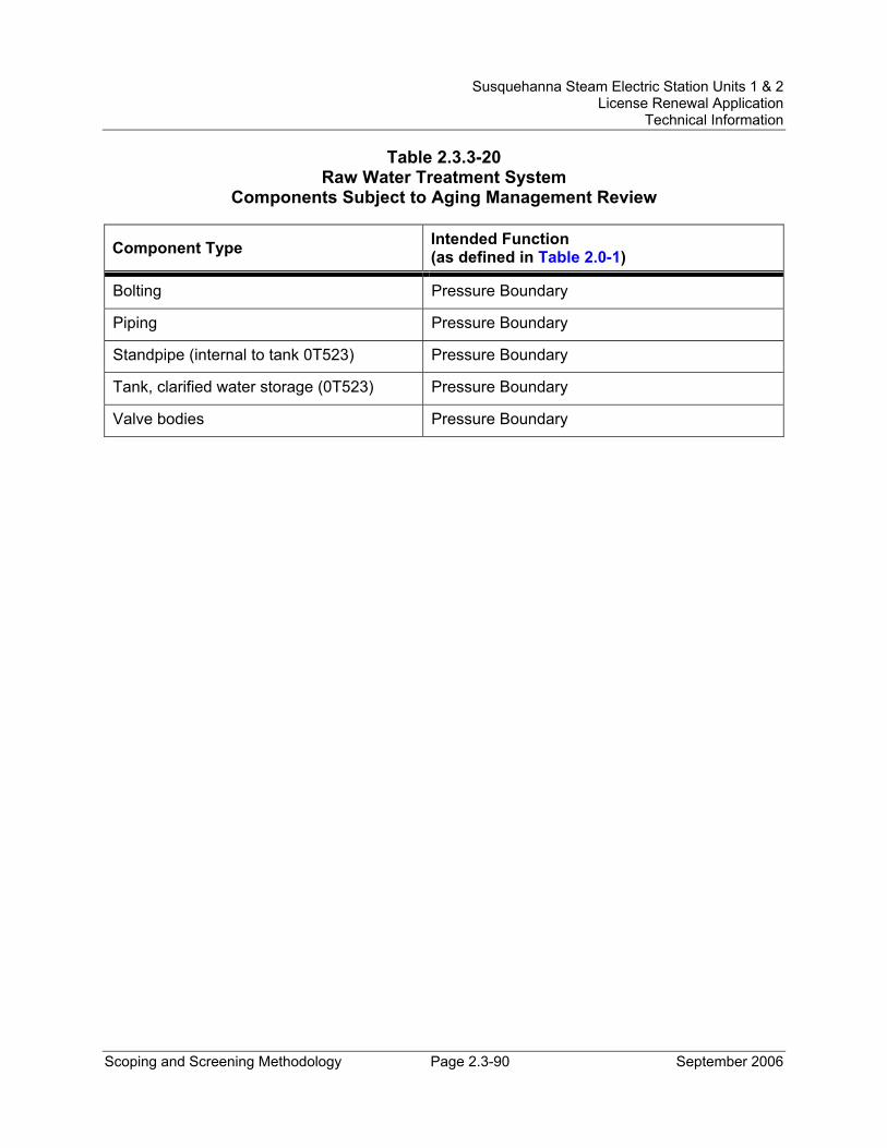
Susquehanna Steam Electric Station Units 1 & 2 License Renewal Application
Technical Information
Scoping and Screening Methodology Page 2.3-90 September 2006
Table 2.3.3-20 Raw Water Treatment System
Components Subject to Aging Management Review
Component Type Intended Function (as defined in Table 2.0-1)
Bolting Pressure Boundary
Piping Pressure Boundary
Standpipe (internal to tank 0T523) Pressure Boundary
Tank, clarified water storage (0T523) Pressure Boundary
Valve bodies Pressure Boundary
Susquehanna Steam Electric Station Units 1 & 2 License Renewal Application
Technical Information
Scoping and Screening Methodology Page 2.3-91 September 2006
2.3.3.22 Reactor Building Chilled Water System System Description The Reactor Building Chilled Water (RBCW) System supplies chilled water during normal plant operation to coolers in various areas in the Reactor Building (including the Unit 1 and Unit 2 emergency switchgear and load center rooms) and drywell, and to the reactor recirculation pump motor coolers. The RBCW System maintains normal design air temperatures inside these plant areas and ensures that pump motor temperatures remain within allowable limits.
The RBCW System is a single train, closed-loop chilled water system. The RBCW System for each unit consists of redundant chilled water circulating pumps and redundant chiller unit equipment skids. During normal plant operation, the RBCW System operates continuously. A single water chiller, chilled water loop circulating pump, evaporator chilled water circulating pump and condenser water pump are in service, while the corresponding, redundant equipment in the train is placed in automatic standby. Heat is transferred to the Service Water System.
Reason for Scope Determination The RBCW System is designed to supply chilled water to cooling coils in the Reactor Building and drywell. The operation of the RBCW System has no safety-related functions. However, the containment penetrations and containment isolation portions (piping and valves) of the RBCW System are classified safety-related. This safety function meets the scoping criteria of 10 CFR 54.4(a)(1).
The RBCW System is required to maintain the integrity of nonsafety-related components that have the potential to adversely affect safety-related equipment through spatial interaction and nonsafety-related piping components required to support the safety-related functional boundary of the interfacing systems. This function meets the scoping criteria of 10 CFR 54.4(a)(2).
The RBCW System is relied upon to demonstrate compliance with, and meets the 10 CFR 54.4(a)(3) scoping criteria for, the Environmental Qualification (10 CFR 50.49) regulated event.
FSAR References Section 9.2.12.3 of the SSES FSAR describes the Reactor Building Chilled Water System.
License Renewal Drawings The following license renewal drawings depict the evaluation boundaries for the system components within the scope of license renewal:
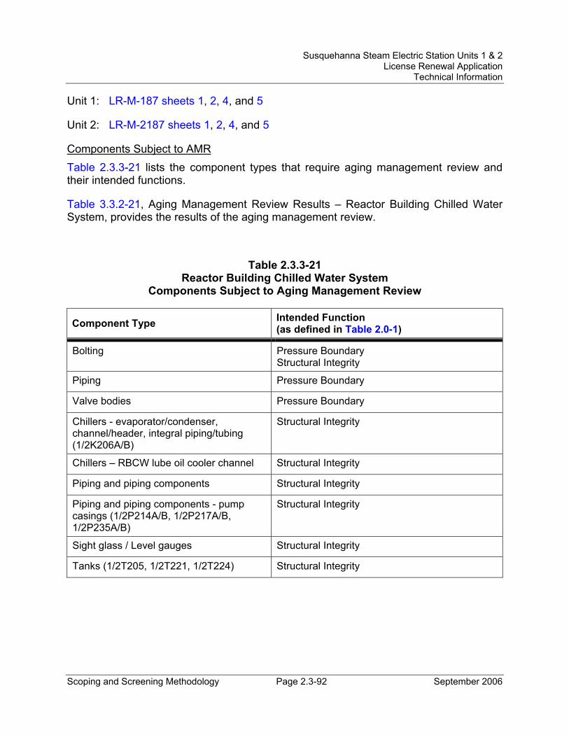
Susquehanna Steam Electric Station Units 1 & 2 License Renewal Application
Technical Information
Scoping and Screening Methodology Page 2.3-92 September 2006
Unit 1: LR-M-187 sheets 1, 2, 4, and 5
Unit 2: LR-M-2187 sheets 1, 2, 4, and 5
Components Subject to AMR Table 2.3.3-21 lists the component types that require aging management review and their intended functions.
Table 3.3.2-21, Aging Management Review Results – Reactor Building Chilled Water System, provides the results of the aging management review.
Table 2.3.3-21 Reactor Building Chilled Water System
Components Subject to Aging Management Review
Component Type Intended Function (as defined in Table 2.0-1)
Bolting Pressure Boundary Structural Integrity
Piping Pressure Boundary
Valve bodies Pressure Boundary
Chillers - evaporator/condenser, channel/header, integral piping/tubing (1/2K206A/B)
Structural Integrity
Chillers – RBCW lube oil cooler channel Structural Integrity
Piping and piping components Structural Integrity
Piping and piping components - pump casings (1/2P214A/B, 1/2P217A/B, 1/2P235A/B)
Structural Integrity
Sight glass / Level gauges Structural Integrity
Tanks (1/2T205, 1/2T221, 1/2T224) Structural Integrity
Susquehanna Steam Electric Station Units 1 & 2 License Renewal Application
Technical Information
Scoping and Screening Methodology Page 2.3-93 September 2006
2.3.3.23 Reactor Building Closed Cooling Water System System Description The Reactor Building Closed Cooling Water (RBCCW) System provides cooling water to nonsafety-related equipment located in the reactor and Radwaste Buildings that has the potential to carry radioactive fluids or which requires a clean water supply to minimize long-term corrosion. The service water in the heat exchanger tube side is maintained by the service water pumps at a higher pressure than the closed loop system in the heat exchanger shell side. In the event of tube failure, the service water would leak into the closed loop system to preclude the possibility of radioactive release to the environment.
The RBCCW System consists of two 100 percent capacity cooling water pumps, two 100 percent capacity heat exchangers, one head tank, and one chemical addition tank. During normal operation, one cooling water pump and one heat exchanger are in service, the heat load being transferred from the closed cooling water system to the service water system in the heat exchanger. The second pump is on automatic standby. The head tank, which is located at the highest point in the system, accommodates thermal expansion and provides ample net positive suction head to the cooling water pumps.
Reason for Scope Determination The RBCCW System performs a safety-related function of containment isolation upon receipt of a containment isolation signal. This safety function meets the scoping criteria of 10 CFR 54.4(a)(1).
The RBCCW System is required to maintain the integrity of nonsafety-related components that have the potential to adversely affect safety-related equipment through spatial interaction and nonsafety-related piping components required to support the safety-related functional boundary of the interfacing systems. This function meets the scoping criteria of 10 CFR 54.4(a)(2).
The RBCCW System is relied upon to demonstrate compliance with, and meets the 10 CFR 54.4(a)(3) scoping criteria for, the Environmental Qualification (10 CFR 50.49) regulated event.
FSAR References Section 9.2.2 of the SSES FSAR describes the Reactor Building Closed Cooling Water System.
License Renewal Drawings The following license renewal drawings depict the evaluation boundaries for the system components within the scope of license renewal:
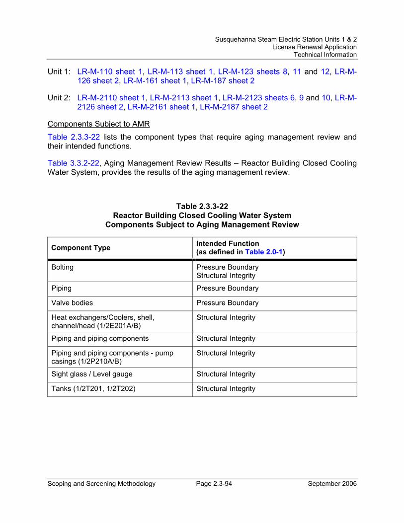
Susquehanna Steam Electric Station Units 1 & 2 License Renewal Application
Technical Information
Scoping and Screening Methodology Page 2.3-94 September 2006
Unit 1: LR-M-110 sheet 1, LR-M-113 sheet 1, LR-M-123 sheets 8, 11 and 12, LR-M-126 sheet 2, LR-M-161 sheet 1, LR-M-187 sheet 2
Unit 2: LR-M-2110 sheet 1, LR-M-2113 sheet 1, LR-M-2123 sheets 6, 9 and 10, LR-M-2126 sheet 2, LR-M-2161 sheet 1, LR-M-2187 sheet 2
Components Subject to AMR Table 2.3.3-22 lists the component types that require aging management review and their intended functions.
Table 3.3.2-22, Aging Management Review Results – Reactor Building Closed Cooling Water System, provides the results of the aging management review.
Table 2.3.3-22 Reactor Building Closed Cooling Water System
Components Subject to Aging Management Review
Component Type Intended Function (as defined in Table 2.0-1)
Bolting Pressure Boundary Structural Integrity
Piping Pressure Boundary
Valve bodies Pressure Boundary
Heat exchangers/Coolers, shell, channel/head (1/2E201A/B)
Structural Integrity
Piping and piping components Structural Integrity
Piping and piping components - pump casings (1/2P210A/B)
Structural Integrity
Sight glass / Level gauge Structural Integrity
Tanks (1/2T201, 1/2T202) Structural Integrity
Susquehanna Steam Electric Station Units 1 & 2 License Renewal Application
Technical Information
Scoping and Screening Methodology Page 2.3-95 September 2006
2.3.3.24 Reactor Building HVAC System System Description The Reactor Building (RB) Heating, Ventilation and Air Conditioning (HVAC) System serves RB areas during normal plant operation that consist of three ventilation zones. Zones I and II surround Units 1 and 2 primary containments respectively, below floor elevation 779 ft - 1 in, with each zone having a supply, exhaust and filtered exhaust system. Zone III consists of two systems, one for Unit 1 and one for Unit 2 secondary containments above floor elevation 779 ft - 1 in, including the refueling floors. The RB HVAC System also serves the heating and ventilation equipment rooms in Units 1 and 2 during normal plant operation.
Each supply system provides the respective zone with conditioned outdoor air. It consists of two fans (one normally operating and one in standby), outside air intake louvers, radiant heaters, filter bank, electric heating coil bank, and a chilled water cooling bank.
Each equipment compartment filtered exhaust system removes air from the respective zone equipment compartments and from rooms with a higher potential for radioactive contamination. It consists of two fans and two filter trains connected to common exhaust and discharge duct systems. Both filter trains are normally in service, with each train containing prefilters, upstream HEPA filter, charcoal absorber bed and a downstream HEPA filter. Equipment compartments and other high potential contamination areas of the RB are exhausted through these filter trains prior to being discharged to the outside atmosphere via the RB exhaust vent.
Each exhaust system consists of two fans in a common plenum of the RB. A common exhaust and discharge duct system provides a means of exhausting all remaining zone areas via the RB exhaust vent.
In addition to supplying ventilation air to three separate zones during normal plant operation, the RB HVAC System also serves various air cooling systems during DBA conditions of plant operation. This includes the following subsystems and supporting equipment: Unit 1 and Unit 2 residual heat removal, high pressure coolant injection, reactor core isolation cooling, and core spray system pump rooms unit coolers, Unit 1 and Unit 2 emergency switchgear cooling units and associated ductwork, Unit 2 emergency switchgear refrigeration system.
Reason for Scope Determination The RB HVAC System, along with other supporting air cooling systems, are designed to provide cooling for emergency switchgear rooms, maintain temperatures in ECCS and RCIC system pump rooms within specified design limits, and maintain secondary containment isolation during normal, emergency and post DBA conditions of plant
Susquehanna Steam Electric Station Units 1 & 2 License Renewal Application
Technical Information
Scoping and Screening Methodology Page 2.3-96 September 2006
operation. These ventilation system functions are classified safety-related. These safety functions meet the scoping criteria of 10 CFR 54.4(a)(1).
The RB HVAC System provides cooling during normal plant operation to the Unit 1 remote shutdown panel room ventilation system to ensure room temperatures are maintained within specified design limits. This ventilation system is also used during plant shutdown when a control room evacuation is necessary, and shutdown is initiated from the remote shutdown panel. Under this mode of operation, a loss of offsite power (LOOP) is assumed. The RB HVAC System is required to maintain the integrity of nonsafety-related components that have the potential to adversely affect safety-related equipment through spatial interaction and nonsafety-related piping/ducting components required to support the safety-related functional boundary of the system. These functions meet the scoping criteria of 10 CFR 54.4(a)(2).
The RB HVAC System is relied upon to demonstrate compliance with, and meets the 10 CFR 54.4(a)(3) scoping criteria for, the Fire Protection (10 CFR 50.48) and Environmental Qualification (10 CFR 50.49) regulated events.
FSAR References Section 9.4.2 of the SSES FSAR describes the Reactor Building Ventilation System, evaluated for license renewal as the Reactor Building HVAC System.
License Renewal Drawings The following license renewal drawings depict the evaluation boundaries for the system components within the scope of license renewal:
Unit 1: LR-M-110 sheet 1, LR-M-111 sheets 2 and 3, LR-M-157 sheet 1, LR-M-175 sheets 1 and 2, LR-M-176 sheet 1, LR-M-183 sheet 1, LR-M-187 sheet 2, LR-VC-175 sheet 1
Unit 2: LR-M-2110 sheet 1, LR-M-2111 sheets 1 and 2, LR-M-2157 sheet 1, LR-M-2161 sheet 1, LR-M-2172 sheet 1, LR-M-2175 sheet 1, LR-M-2176 sheet 1, LR-M-2187 sheet 2, LR-VC-2175 sheets 1 and 2
Common: LR-M-161 sheet 1, LR-M-166 sheet 1, LR-VC-175 sheet 2
Components Subject to AMR Nonsafety-related piping/ducting components of the RB HVAC System that are connected to safety-related SSCs, but that do not contain a liquid, are not subject to aging management review. The structural integrity function for these components is provided by the structural supports (seismic anchors), which are subject to aging management review. Also, there is no high pressure or other motive force and no medium in the air and gas contained in the pipe that would cause sufficient degradation to result in separation or movement of the piping during the period of extended
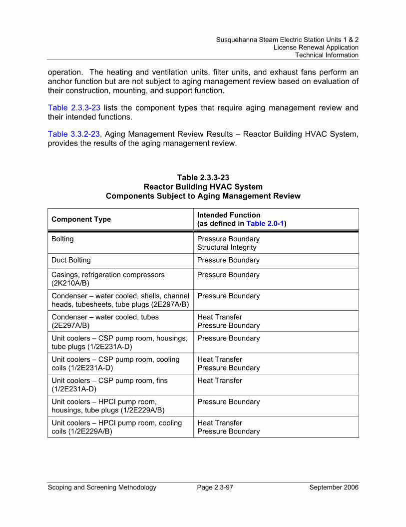
Susquehanna Steam Electric Station Units 1 & 2 License Renewal Application
Technical Information
Scoping and Screening Methodology Page 2.3-97 September 2006
operation. The heating and ventilation units, filter units, and exhaust fans perform an anchor function but are not subject to aging management review based on evaluation of their construction, mounting, and support function.
Table 2.3.3-23 lists the component types that require aging management review and their intended functions.
Table 3.3.2-23, Aging Management Review Results – Reactor Building HVAC System, provides the results of the aging management review.
Table 2.3.3-23 Reactor Building HVAC System
Components Subject to Aging Management Review
Component Type Intended Function (as defined in Table 2.0-1)
Bolting Pressure Boundary Structural Integrity
Duct Bolting Pressure Boundary
Casings, refrigeration compressors (2K210A/B)
Pressure Boundary
Condenser – water cooled, shells, channel heads, tubesheets, tube plugs (2E297A/B)
Pressure Boundary
Condenser – water cooled, tubes (2E297A/B)
Heat Transfer Pressure Boundary
Unit coolers – CSP pump room, housings, tube plugs (1/2E231A-D)
Pressure Boundary
Unit coolers – CSP pump room, cooling coils (1/2E231A-D)
Heat Transfer Pressure Boundary
Unit coolers – CSP pump room, fins (1/2E231A-D)
Heat Transfer
Unit coolers – HPCI pump room, housings, tube plugs (1/2E229A/B)
Pressure Boundary
Unit coolers – HPCI pump room, cooling coils (1/2E229A/B)
Heat Transfer Pressure Boundary
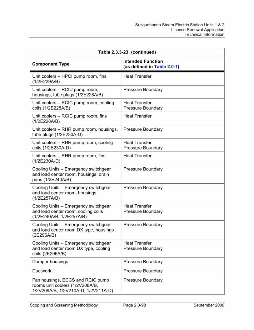
Susquehanna Steam Electric Station Units 1 & 2 License Renewal Application
Technical Information
Scoping and Screening Methodology Page 2.3-98 September 2006
Table 2.3.3-23: (continued)
Component Type Intended Function (as defined in Table 2.0-1)
Unit coolers – HPCI pump room, fins (1/2E229A/B)
Heat Transfer
Unit coolers – RCIC pump room, housings, tube plugs (1/2E228A/B)
Pressure Boundary
Unit coolers – RCIC pump room, cooling coils (1/2E228A/B)
Heat Transfer Pressure Boundary
Unit coolers – RCIC pump room, fins (1/2E228A/B)
Heat Transfer
Unit coolers – RHR pump room, housings, tube plugs (1/2E230A-D)
Pressure Boundary
Unit coolers – RHR pump room, cooling coils (1/2E230A-D)
Heat Transfer Pressure Boundary
Unit coolers – RHR pump room, fins (1/2E230A-D)
Heat Transfer
Cooling Units – Emergency switchgear and load center room, housings, drain pans (1/2E240A/B)
Pressure Boundary
Cooling Units – Emergency switchgear and load center room, housings (1/2E257A/B)
Pressure Boundary
Cooling Units – Emergency switchgear and load center room, cooling coils (1/2E240A/B, 1/2E257A/B)
Heat Transfer Pressure Boundary
Cooling Units – Emergency switchgear and load center room DX type, housings (2E296A/B)
Pressure Boundary
Cooling Units – Emergency switchgear and load center room DX type, cooling coils (2E296A/B)
Heat Transfer Pressure Boundary
Damper housings Pressure Boundary
Ductwork Pressure Boundary
Fan housings, ECCS and RCIC pump rooms unit coolers (1/2V208A/B, 1/2V209A/B, 1/2V210A-D, 1/2V211A-D)
Pressure Boundary
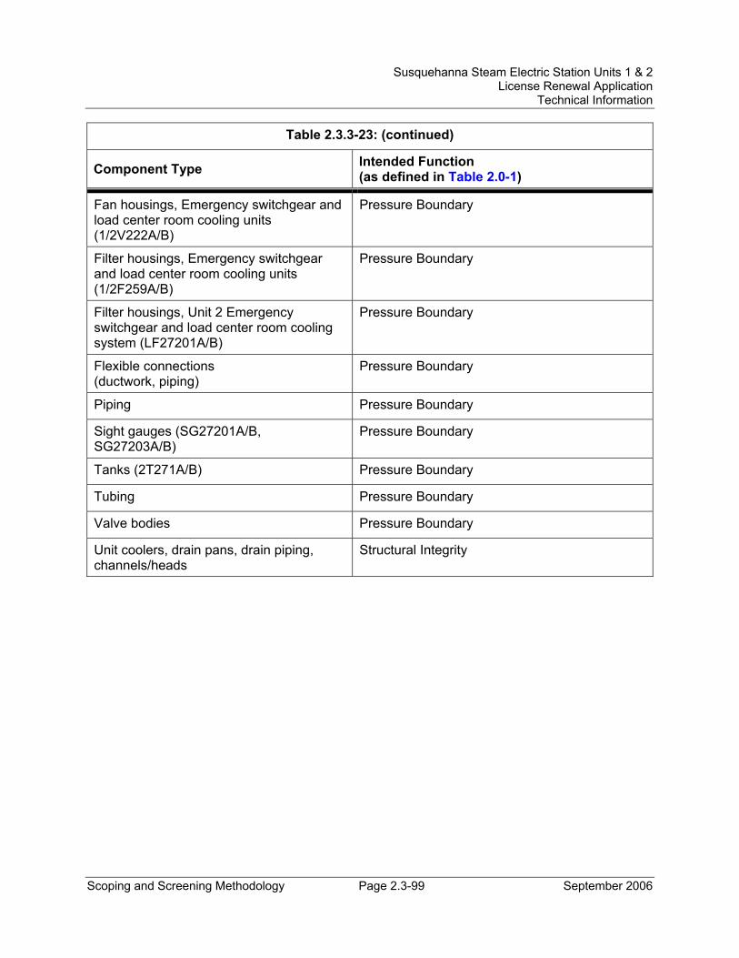
Susquehanna Steam Electric Station Units 1 & 2 License Renewal Application
Technical Information
Scoping and Screening Methodology Page 2.3-99 September 2006
Table 2.3.3-23: (continued)
Component Type Intended Function (as defined in Table 2.0-1)
Fan housings, Emergency switchgear and load center room cooling units (1/2V222A/B)
Pressure Boundary
Filter housings, Emergency switchgear and load center room cooling units (1/2F259A/B)
Pressure Boundary
Filter housings, Unit 2 Emergency switchgear and load center room cooling system (LF27201A/B)
Pressure Boundary
Flexible connections (ductwork, piping)
Pressure Boundary
Piping Pressure Boundary
Sight gauges (SG27201A/B, SG27203A/B)
Pressure Boundary
Tanks (2T271A/B) Pressure Boundary
Tubing Pressure Boundary
Valve bodies Pressure Boundary
Unit coolers, drain pans, drain piping, channels/heads
Structural Integrity
Susquehanna Steam Electric Station Units 1 & 2 License Renewal Application
Technical Information
Scoping and Screening Methodology Page 2.3-100 September 2006
2.3.3.25 Reactor Nonnuclear Instrumentation System System Description The Reactor Nonnuclear Instrumentation System consists of the instrumentation associated with the operation of the nuclear boiler for normal power generation, shutdown and refueling operations, and for transient and accident conditions. This instrumentation provides for sensing, monitoring, and indication of the temperature, pressure, and water level of the reactor pressure vessel.
The mechanical portions of the Reactor Nonnuclear Instrumentation System that are in the scope of license renewal monitor the pressure and water level in the reactor pressure vessel.
Reason for Scope Determination Those portions of the Reactor Nonnuclear Instrumentation System that are in the scope of license renewal monitor the pressure and water level in the reactor pressure vessel, and provide indication in the control room and at the remote shutdown panel. They also provide high-level trip signals (e.g., HPCI, RCIC, Reactor Feed Pumps); low-level isolation signals (e.g., primary and secondary containment, main steam lines, RHR-Shutdown Cooling, RWCU); and low-level actuation signals (e.g., Residual Heat Removal-Low Pressure Coolant Injection (RHR-LPCI), Core Spray, HPCI, RCIC, ADS). These are all safety-related functions. These safety functions meet the scoping criteria of 10 CFR 54.4(a)(1).
The Reactor Nonnuclear Instrumentation System does not have the potential to adversely affect safety-related systems or components through spatial interaction. Therefore, the Reactor Nonnuclear Instrumentation System does not meet the scoping criteria of 10 CFR 54.4(a)(2).
The Reactor Nonnuclear Instrumentation System is also relied upon to demonstrate compliance with, and meets the 10 CFR 54.4(a)(3) scoping criteria for, the Fire Protection (10 CFR 50.48), Environmental Qualification (10 CFR 50.49), Anticipated Transients Without Scram (10 CFR 50.62), and Station Blackout (10 CFR 50.63) regulated events.
FSAR References Sections 6.2 and 7.0 of the SSES FSAR describe the instrumentation evaluated for license renewal as the Reactor Nonnuclear Instrumentation System.
License Renewal Drawings The following license renewal drawings depict the evaluation boundaries for the system components within the scope of license renewal:
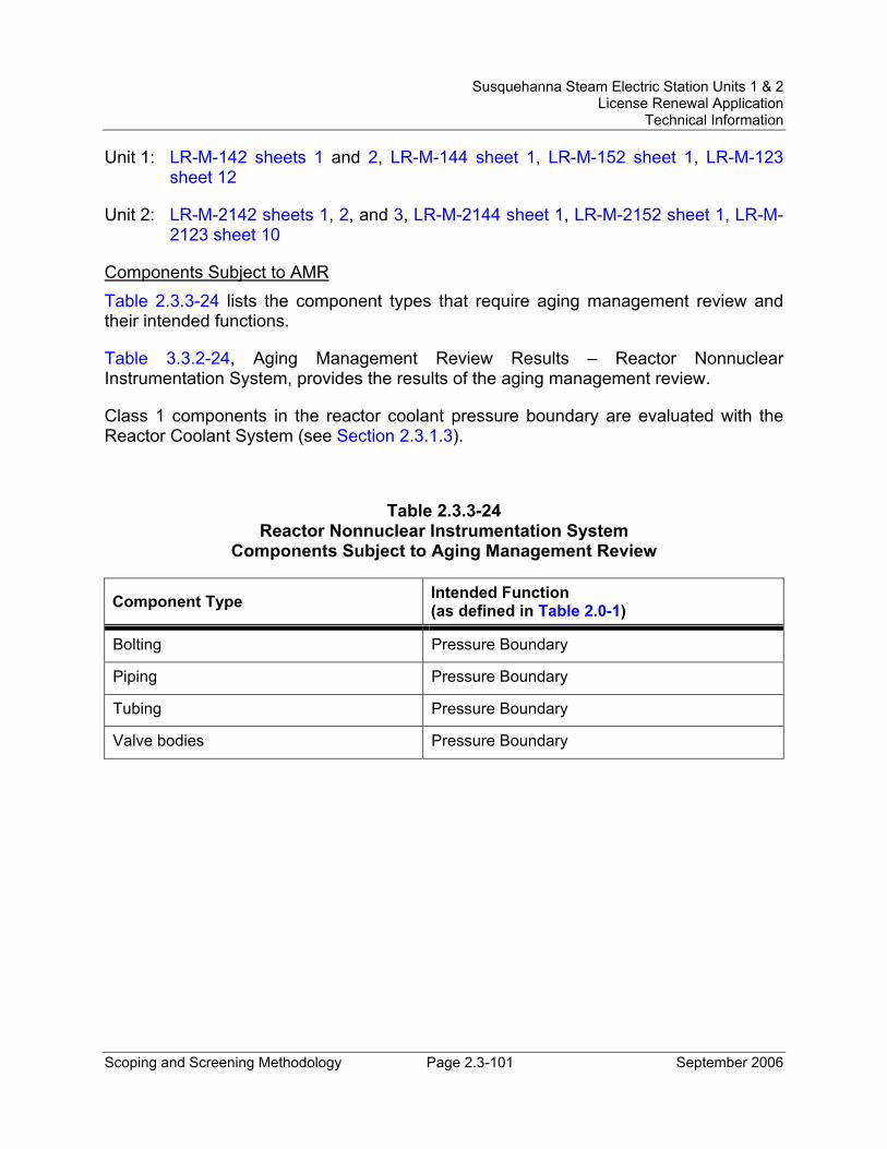
Susquehanna Steam Electric Station Units 1 & 2 License Renewal Application
Technical Information
Scoping and Screening Methodology Page 2.3-101 September 2006
Unit 1: LR-M-142 sheets 1 and 2, LR-M-144 sheet 1, LR-M-152 sheet 1, LR-M-123 sheet 12
Unit 2: LR-M-2142 sheets 1, 2, and 3, LR-M-2144 sheet 1, LR-M-2152 sheet 1, LR-M-2123 sheet 10
Components Subject to AMR Table 2.3.3-24 lists the component types that require aging management review and their intended functions.
Table 3.3.2-24, Aging Management Review Results – Reactor Nonnuclear Instrumentation System, provides the results of the aging management review.
Class 1 components in the reactor coolant pressure boundary are evaluated with the Reactor Coolant System (see Section 2.3.1.3).
Table 2.3.3-24 Reactor Nonnuclear Instrumentation System
Components Subject to Aging Management Review
Component Type Intended Function (as defined in Table 2.0-1)
Bolting Pressure Boundary
Piping Pressure Boundary
Tubing Pressure Boundary
Valve bodies Pressure Boundary
Susquehanna Steam Electric Station Units 1 & 2 License Renewal Application
Technical Information
Scoping and Screening Methodology Page 2.3-102 September 2006
2.3.3.26 Reactor Water Cleanup System System Description The Reactor Water Cleanup (RWCU) System continuously purifies the reactor water. The system takes its suction from the inlet of each reactor recirculation pump and from the reactor pressure vessel bottom head. The processed water is returned to the reactor pressure vessel via the Feedwater System or can be routed to the main condenser or the Radwaste System, as necessary.
The RWCU System operates in various modes during normal operation, most commonly in normal recirculation mode. The RWCU System is not used to mitigate the consequences of any design basis event. The RWCU System suction line containment isolation valves will, however, automatically close in response to an isolation signal. Valves in the RWCU return line to the Feedwater System can be manually closed to isolate the RWCU System from the Feedwater System and provide containment isolation.
Reason for Scope Determination The RWCU System has a safety-related function to maintain the integrity of the reactor coolant pressure boundary up to and including the outermost containment isolation valve. The RWCU System safety functions are to provide containment isolation upon receipt of a containment isolation signal, and to provide RWCU isolation on RWCU high flow, RWCU area high temperature, low reactor vessel water level, or Standby Liquid Control System initiation. The system also has a safety function to isolate the RWCU System from the Feedwater System when RWCU is shutdown. These safety functions meet the scoping criteria of 10 CFR 54.4(a)(1).
The RWCU System is required to maintain the integrity of nonsafety-related components that have the potential to adversely affect safety-related equipment through spatial interaction and nonsafety-related piping components required to support the safety-related functional boundary of the system. This function meets the scoping criteria of 10 CFR 54.4(a)(2).
The RWCU System is relied upon to demonstrate compliance with, and meets the 10 CFR 54.4(a)(3) scoping criteria for, the Fire Protection (10 CFR 50.48), Anticipated Transients Without Scram (10 CFR 50.62), and Environmental Qualification (10 CFR 50.49) regulated events.
FSAR References Section 5.4.8 of the SSES FSAR describes the Reactor Water Cleanup System.
Susquehanna Steam Electric Station Units 1 & 2 License Renewal Application
Technical Information
Scoping and Screening Methodology Page 2.3-103 September 2006
License Renewal Drawings The following license renewal drawings depict the evaluation boundaries for the system components within the scope of license renewal:
Unit 1: LR-M-113 sheet 1, LR-M-141 sheet 2, LR-M-144 sheets 1, 2, and 3, LR-M-145 sheet 1, LR-M-166 sheet 1
Unit 2: LR-M-2113 sheet 1, LR-M-2141 sheet 2, LR-M-2144 sheets 1, 2, and 3, LR-M-2145 sheet 1
Components Subject to AMR Table 2.3.3-25 lists the component types that require aging management review and their intended functions.
Table 3.3.2-25, Aging Management Review Results – Reactor Water Cleanup System, provides the results of the aging management review.
Class 1 components in the reactor coolant pressure boundary are evaluated with the Reactor Coolant System (see Section 2.3.1.3).
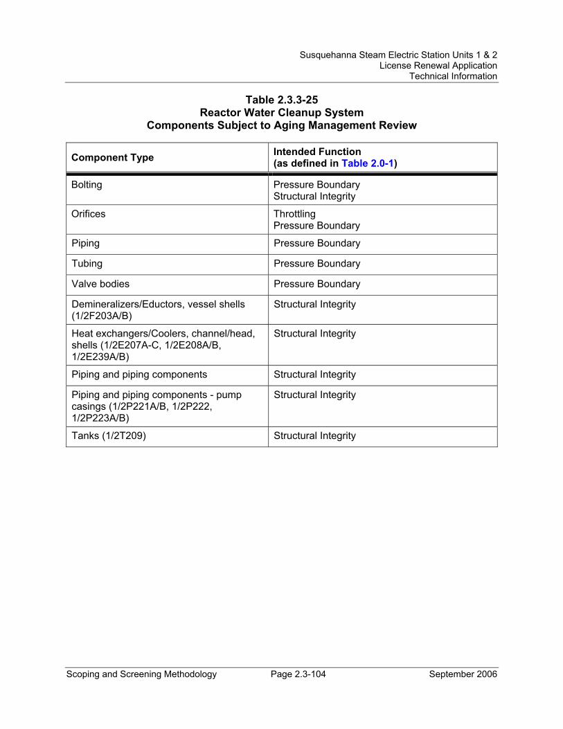
Susquehanna Steam Electric Station Units 1 & 2 License Renewal Application
Technical Information
Scoping and Screening Methodology Page 2.3-104 September 2006
Table 2.3.3-25 Reactor Water Cleanup System
Components Subject to Aging Management Review
Component Type Intended Function (as defined in Table 2.0-1)
Bolting Pressure Boundary Structural Integrity
Orifices Throttling Pressure Boundary
Piping Pressure Boundary
Tubing Pressure Boundary
Valve bodies Pressure Boundary
Demineralizers/Eductors, vessel shells (1/2F203A/B)
Structural Integrity
Heat exchangers/Coolers, channel/head, shells (1/2E207A-C, 1/2E208A/B, 1/2E239A/B)
Structural Integrity
Piping and piping components Structural Integrity
Piping and piping components - pump casings (1/2P221A/B, 1/2P222, 1/2P223A/B)
Structural Integrity
Tanks (1/2T209) Structural Integrity
Susquehanna Steam Electric Station Units 1 & 2 License Renewal Application
Technical Information
Scoping and Screening Methodology Page 2.3-105 September 2006
2.3.3.27 RHR Service Water System System Description The RHR Service Water (RHRSW) System consists of two loops (A and B) per unit. Each loop has a 100 percent capacity, vertical turbine-type two-stage pump. The Unit 1A and Unit 2A pumps are cross-connected so that they can supply cooling water to either the Unit 1A or the Unit 2A loop heat exchanger. The same is true for the Unit 1B and Unit 2B pumps. The four RHRSW pumps are located in the Engineered Safeguards Service Water (ESSW) Pumphouse at the edge of the spray pond. The RHR service water flows through the tube-side of the RHR heat exchangers, returning to the spray pond through a common header shared with the Emergency Service Water System. During normal power operation, the RHRSW System is not operating, but is available for normal shutdown or emergencies.
Reason for Scope Determination The RHRSW System is a safety-related system that is designed to provide a reliable source of cooling water to support RHR system operation and for post-accident core and containment flooding. The RHRSW System safety function is to provide cooling water to the RHR heat exchangers in support of RHR system operations following any credible accident, including the Design Basis Loss of Coolant Accident (LOCA), coincident with a loss of offsite power and any active single failure. The system also provides a reliable source of water for post-accident containment flooding. These safety functions meet the scoping criteria of 10 CFR 54.4(a)(1).
The spray piping drain pumps and associated piping and valves are classified as nonsafety-related but are relied upon to drain the spray headers during freezing weather conditions. The RHRSW System is required to maintain the integrity of nonsafety-related components that have the potential to adversely affect safety-related equipment through spatial interaction and nonsafety-related piping components required to support the safety-related functional boundary of the system. These functions meet the scoping criteria of 10 CFR 54.4(a)(2).
The RHRSW System is relied upon to demonstrate compliance with, and meets the 10 CFR 54.4(a)(3) scoping criteria for the Fire Protection (10 CFR 50.48), Environmental Qualification (10 CFR 50.49), and Anticipated Transients Without Scram (10 CFR 50.62) regulated events.
FSAR References Section 9.2.6 of the SSES FSAR describes the RHR Service Water System.
License Renewal Drawings The following license renewal drawings depict the evaluation boundaries for the system components within the scope of license renewal:
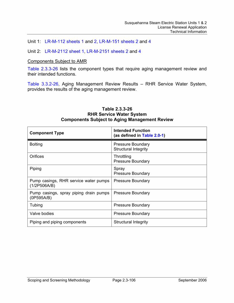
Susquehanna Steam Electric Station Units 1 & 2 License Renewal Application
Technical Information
Scoping and Screening Methodology Page 2.3-106 September 2006
Unit 1: LR-M-112 sheets 1 and 2, LR-M-151 sheets 2 and 4
Unit 2: LR-M-2112 sheet 1, LR-M-2151 sheets 2 and 4
Components Subject to AMR Table 2.3.3-26 lists the component types that require aging management review and their intended functions.
Table 3.3.2-26, Aging Management Review Results – RHR Service Water System, provides the results of the aging management review.
Table 2.3.3-26 RHR Service Water System
Components Subject to Aging Management Review
Component Type Intended Function (as defined in Table 2.0-1)
Bolting Pressure Boundary Structural Integrity
Orifices Throttling Pressure Boundary
Piping Spray Pressure Boundary
Pump casings, RHR service water pumps (1/2P506A/B)
Pressure Boundary
Pump casings, spray piping drain pumps (0P595A/B)
Pressure Boundary
Tubing Pressure Boundary
Valve bodies Pressure Boundary
Piping and piping components Structural Integrity

Susquehanna Steam Electric Station Units 1 & 2 License Renewal Application
Technical Information
Scoping and Screening Methodology Page 2.3-107 September 2006
2.3.3.28 Sampling System System Description The Sampling System is provided to monitor the operation of plant equipment and to provide information needed to make operational decisions. The Sampling System provides remote sampling facilities and the capability for sampling fluids of various process systems during normal plant power operation and shutdown conditions. The Reactor and Turbine Building sample stations are operationally independent systems with the exception of the fuel pool filter demineralizer outlet-common sample, which is located in the Unit 1 Reactor Building station.
Reason for Scope Determination The Sampling System does not perform any functions that satisfy the scoping criteria of 10 CFR 54.4(a)(1).
The Sampling System is required to maintain the integrity of nonsafety-related components that have the potential to adversely affect safety-related equipment through spatial interaction and nonsafety-related piping components required to support the safety-related functional boundary of the interfacing systems. This function meets the scoping criteria of 10 CFR 54.4(a)(2).
The Sampling System is not relied upon to demonstrate compliance with, nor satisfy the 10 CFR 54.4(a)(3) scoping criteria for, any regulated event.
FSAR References Section 9.3.2 of the SSES FSAR describes the Process Sampling System, evaluated for license renewal as the Sampling System.
License Renewal Drawings The following license renewal drawings depict the evaluation boundaries for the system components within the scope of license renewal:
Unit 1: LR-M-113 sheet 1, LR-M-123 sheets 8, 9, 10, 11 and 12, LR-M-141 sheet 2, LR-M-143 sheet 1, LR-M-144 sheet 2, LR-M-146 sheet 1, LR-M-151 sheets 2 and 4, LR-M-153 sheet 1
Unit 2: LR-M-2113 sheet 1, LR-M-2123 sheets 6, 7, 8, 9, and 10, LR-M-2141 sheet 2, LR-M-2143 sheet 1, LR-M-2144 sheet 2, LR-M-2146 sheet 1, LR-M-2151 sheets 2 and 4, LR-M-2153 sheet 1
Components Subject to AMR Table 2.3.3-27 lists the component types that require aging management review and their intended functions.
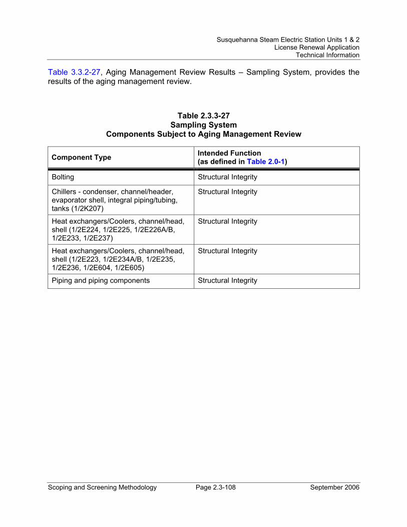
Susquehanna Steam Electric Station Units 1 & 2 License Renewal Application
Technical Information
Scoping and Screening Methodology Page 2.3-108 September 2006
Table 3.3.2-27, Aging Management Review Results – Sampling System, provides the results of the aging management review.
Table 2.3.3-27 Sampling System
Components Subject to Aging Management Review
Component Type Intended Function (as defined in Table 2.0-1)
Bolting Structural Integrity
Chillers - condenser, channel/header, evaporator shell, integral piping/tubing, tanks (1/2K207)
Structural Integrity
Heat exchangers/Coolers, channel/head, shell (1/2E224, 1/2E225, 1/2E226A/B, 1/2E233, 1/2E237)
Structural Integrity
Heat exchangers/Coolers, channel/head, shell (1/2E223, 1/2E234A/B, 1/2E235, 1/2E236, 1/2E604, 1/2E605)
Structural Integrity
Piping and piping components Structural Integrity
Susquehanna Steam Electric Station Units 1 & 2 License Renewal Application
Technical Information
Scoping and Screening Methodology Page 2.3-109 September 2006
2.3.3.29 Sanitary Drainage System System Description The Sanitary Drainage System collects liquid wastes from all plumbing fixtures of the plant outside the restricted access areas. The Sanitary Drainage System collects liquid wastes and some entrained solids discharged by all plumbing fixtures located in areas with no sources of potentially radioactive, oily, or acid wastes and conveys them to a sewage treatment facility. The drain lines were designed to accommodate Fire Protection System design flow when actuated.
Reason for Scope Determination The Sanitary Drainage System does not perform any functions that satisfy the scoping criteria of 10 CFR 54.4(a)(1).
The Sanitary Drainage System is required to maintain the integrity of nonsafety-related components that have the potential to adversely affect safety-related equipment through spatial interaction. This function meets the scoping criteria of 10 CFR 54.4(a)(2).
The Sanitary Drainage System is not relied upon to demonstrate compliance with, nor satisfy the 10 CFR 54.4(a)(3) scoping criteria for, any regulated event.
FSAR References Section 9.3.3 of the SSES FSAR describes the Sanitary Drainage System.
License Renewal Drawings The following license renewal drawings depict the evaluation boundaries for the system components within the scope of license renewal:
Common: LR-M-160 sheet 2
Components Subject to AMR Table 2.3.3-28 lists the component types that require aging management review and their intended functions.
Table 3.3.2-28, Aging Management Review Results – Sanitary Drainage System, provides the results of the aging management review.

Susquehanna Steam Electric Station Units 1 & 2 License Renewal Application
Technical Information
Scoping and Screening Methodology Page 2.3-110 September 2006
Table 2.3.3-28 Sanitary Drainage System
Components Subject to Aging Management Review
Component Type Intended Function (as defined in Table 2.0-1)
Bolting Structural Integrity
Piping and piping components Structural Integrity
Susquehanna Steam Electric Station Units 1 & 2 License Renewal Application
Technical Information
Scoping and Screening Methodology Page 2.3-111 September 2006
2.3.3.30 Service Air System System Description The Service Air System has no safety-related function. It is designed to provide compressed air for service air outlets located throughout the plant and as a backup system for instrument air.
Reason for Scope Determination The Service Air System does not perform any functions that satisfy the scoping criteria of 10 CFR 54.4(a)(1).
The Service Air System is required to maintain the integrity of nonsafety-related components that have the potential to adversely affect safety-related equipment through spatial interaction. This function meets the scoping criteria of 10 CFR 54.4(a)(2).
The Service Air System is not relied upon to demonstrate compliance with, nor satisfy the 10 CFR 54.4(a)(3) scoping criteria for, any regulated event.
FSAR References Section 9.3.1.2 of the SSES FSAR describes the Service Air System.
License Renewal Drawings The following license renewal drawings depict the evaluation boundaries for the system components within the scope of license renewal:
Unit 1: LR-M-125 sheet 30
Unit 2: LR-M-2125 sheet 16
Components Subject to AMR Table 2.3.3-29 lists the component types that require aging management review and their intended functions.
Table 3.3.2-29, Aging Management Review Results – Service Air System, provides the results of the aging management review.
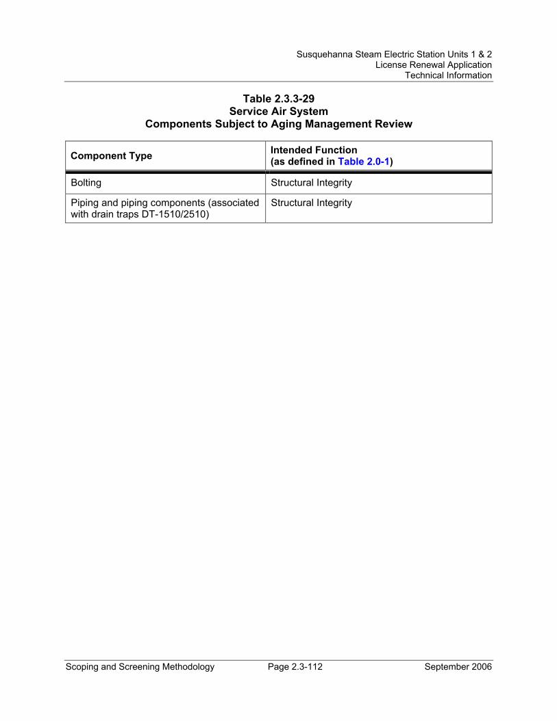
Susquehanna Steam Electric Station Units 1 & 2 License Renewal Application
Technical Information
Scoping and Screening Methodology Page 2.3-112 September 2006
Table 2.3.3-29 Service Air System
Components Subject to Aging Management Review
Component Type Intended Function (as defined in Table 2.0-1)
Bolting Structural Integrity
Piping and piping components (associated with drain traps DT-1510/2510)
Structural Integrity
Susquehanna Steam Electric Station Units 1 & 2 License Renewal Application
Technical Information
Scoping and Screening Methodology Page 2.3-113 September 2006
2.3.3.31 Service Water System System Description The Service Water System has no safety-related function and is designed to remove heat from heat exchangers in the Control Structure and Turbine, Reactor, and Radwaste Buildings, and to transfer this heat to the cooling towers where it is dissipated. The Service Water System is designed to operate during normal plant operation and plant shutdown with offsite power available. The system will not operate on loss of offsite power concurrent with a LOCA. The Service Water System pumps take suction from the cooling tower basin via the circulating water system inlet header, circulate water through service water system heat exchangers and discharge it back to the tower by way of the circulating water piping. In most cases, the service water flows through the heat exchangers' tubes. The Service Water System also provides keepfill of the Emergency Service Water System, and makeup to the Standby Gas Treatment System loop seals during normal plant operation.
Reason for Scope Determination The Service Water System does not perform any functions that satisfy the scoping criteria of 10 CFR 54.4(a)(1).
The Service Water System is required to maintain the integrity of nonsafety-related components that have the potential to adversely affect safety-related equipment through spatial interaction and nonsafety-related piping components required to support the safety-related functional boundary of the system. This function meets the scoping criteria of 10 CFR 54.4(a)(2).
The Service Water System is not relied upon to demonstrate compliance with, nor satisfy the 10 CFR 54.4(a)(3) scoping criteria for, any regulated event.
FSAR References Section 9.2.1.2 of the SSES FSAR describes the Service Water System.
License Renewal Drawings The following license renewal drawings depict the evaluation boundaries for the system components within the scope of license renewal:
Unit 1: LR-M-109 sheet 2, LR-M-110 sheet 1, LR-M-111 sheets 1, 2 and 3, LR-M-186 sheets 1, 3 and 4, LR-M-187 sheets 1, 4 and 5, LR-VC-175-3
Unit 2: LR-M-2109 sheet 2, LR-M-2110 sheet 1, LR-M-2111 sheets 1 and 2, LR-M-2187 sheets 1, 4 and 5
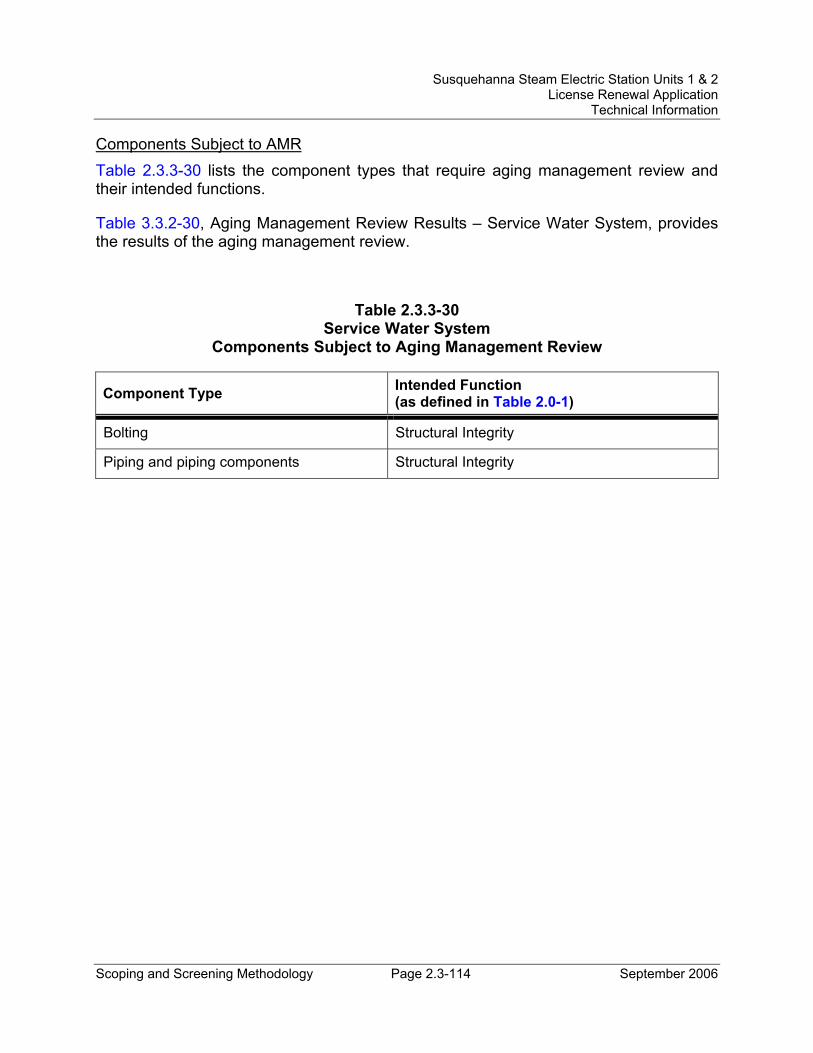
Susquehanna Steam Electric Station Units 1 & 2 License Renewal Application
Technical Information
Scoping and Screening Methodology Page 2.3-114 September 2006
Components Subject to AMR Table 2.3.3-30 lists the component types that require aging management review and their intended functions.
Table 3.3.2-30, Aging Management Review Results – Service Water System, provides the results of the aging management review.
Table 2.3.3-30 Service Water System
Components Subject to Aging Management Review
Component Type Intended Function (as defined in Table 2.0-1)
Bolting Structural Integrity
Piping and piping components Structural Integrity
Susquehanna Steam Electric Station Units 1 & 2 License Renewal Application
Technical Information
Scoping and Screening Methodology Page 2.3-115 September 2006
2.3.3.32 Standby Liquid Control (SLC) System System Description The Standby Liquid Control (SLC) System is an independent, diverse backup system to the Control Rod Drive (CRD) System. The function of the SLC System is to inject a neutron absorbing solution into the reactor to achieve and maintain sub-criticality in the event that control rods cannot be manually inserted. The neutron absorber used in the SLC System is an aqueous solution of sodium pentaborate decahydrate.
Reason for Scope Determination The SLC System functions to inject a neutron absorbing solution into the reactor to achieve and maintain reactor core sub-criticality in the event that control rods cannot be manually inserted and maintains the integrity and requirements of the reactor coolant pressure boundary and reactor containment. These are safety-related functions. These safety functions meet the scoping criteria of 10 CFR 54.4(a)(1).
The SLC System maintains the SLC piping and tank at sufficiently high temperature to keep sodium pentaborate above saturation temperature. This function is performed by electric heat tracing and electric heaters; no mechanical components are required. The SLC System is also credited to provide suppression pool pH control as a dose reduction mechanism in the alternate source term (AST) analyses. The SLC System is required to maintain the integrity of nonsafety-related components that have the potential to adversely affect safety-related equipment through spatial interaction and nonsafety-related piping components required to support the safety-related functional boundary of the system. These functions meet the scoping criteria of 10 CFR 54.4(a)(2).
The SLC System is relied upon to demonstrate compliance with, and meets the 10 CFR 54.4(a)(3) scoping criteria for, the Anticipated Transients Without Scram (10 CFR 50.62) and Environmental Qualification (10 CFR 50.49) regulated events.
FSAR References Section 9.3.5 of the SSES FSAR describes the Standby Liquid Control System.
License Renewal Drawings The following license renewal drawings depict the evaluation boundaries for the system components within the scope of license renewal:
Unit 1: LR-M-148 sheet 1
Unit 2: LR-M-2148 sheet 1
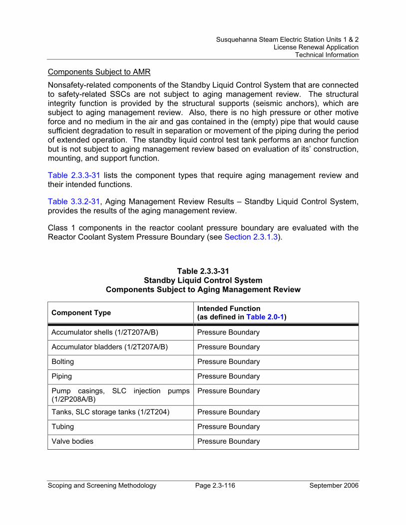
Susquehanna Steam Electric Station Units 1 & 2 License Renewal Application
Technical Information
Scoping and Screening Methodology Page 2.3-116 September 2006
Components Subject to AMR Nonsafety-related components of the Standby Liquid Control System that are connected to safety-related SSCs are not subject to aging management review. The structural integrity function is provided by the structural supports (seismic anchors), which are subject to aging management review. Also, there is no high pressure or other motive force and no medium in the air and gas contained in the (empty) pipe that would cause sufficient degradation to result in separation or movement of the piping during the period of extended operation. The standby liquid control test tank performs an anchor function but is not subject to aging management review based on evaluation of its’ construction, mounting, and support function.
Table 2.3.3-31 lists the component types that require aging management review and their intended functions.
Table 3.3.2-31, Aging Management Review Results – Standby Liquid Control System, provides the results of the aging management review.
Class 1 components in the reactor coolant pressure boundary are evaluated with the Reactor Coolant System Pressure Boundary (see Section 2.3.1.3).
Table 2.3.3-31 Standby Liquid Control System
Components Subject to Aging Management Review
Component Type Intended Function (as defined in Table 2.0-1)
Accumulator shells (1/2T207A/B) Pressure Boundary
Accumulator bladders (1/2T207A/B) Pressure Boundary
Bolting Pressure Boundary
Piping Pressure Boundary
Pump casings, SLC injection pumps (1/2P208A/B)
Pressure Boundary
Tanks, SLC storage tanks (1/2T204) Pressure Boundary
Tubing Pressure Boundary
Valve bodies Pressure Boundary
Susquehanna Steam Electric Station Units 1 & 2 License Renewal Application
Technical Information
Scoping and Screening Methodology Page 2.3-117 September 2006
2.3.3.33 Turbine Building Closed Cooling Water System System Description The Turbine Building Closed Cooling Water (TBCCW) System has no safety-related function. The system is a closed loop cooling system that transfers heat from miscellaneous turbine plant components to the Service Water System through the TBCCW heat exchangers.
Reason for Scope Determination The Turbine Building Closed Cooing Water System does not perform any functions that satisfy the scoping criteria of 10 CFR 54.4(a)(1).
The Turbine Building Closed Cooing Water System is required to maintain the integrity of nonsafety-related piping components required to support the safety-related functional boundary of the interfacing system. This function meets the scoping criteria of 10 CFR 54.4(a)(2).
The Turbine Building Closed Cooling Water System is not relied upon to demonstrate compliance with, nor satisfy the 10 CFR 54.4(a)(3) scoping criteria for, any regulated event.
FSAR References Section 9.2.3 of the SSES FSAR describes the Turbine Building Closed Cooling Water System.
License Renewal Drawings The following license renewal drawings depict the evaluation boundaries for the system components within the scope of license renewal:
Unit 1: LR-M-109 sheet 2
Unit 2: LR-M-2109 sheet 2
Components Subject to AMR Table 2.3.3-32 lists the component types that require aging management review and their intended functions.
Table 3.3.2-32, Aging Management Review Results – Turbine Building Closed Cooling Water System, provides the results of the aging management review.
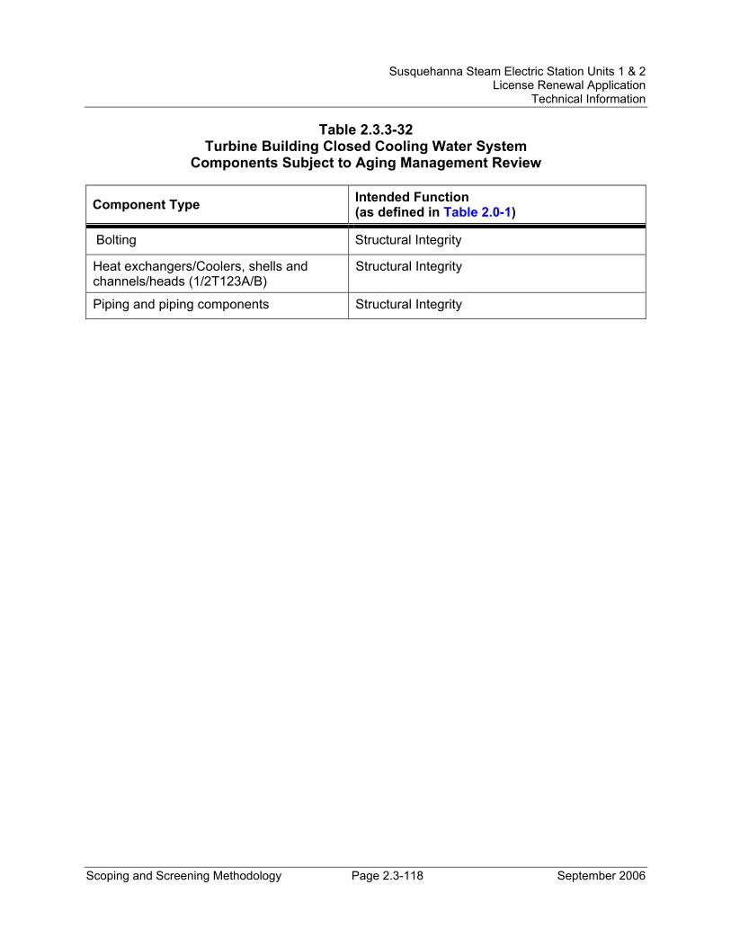
Susquehanna Steam Electric Station Units 1 & 2 License Renewal Application
Technical Information
Scoping and Screening Methodology Page 2.3-118 September 2006
Table 2.3.3-32 Turbine Building Closed Cooling Water System
Components Subject to Aging Management Review
Component Type Intended Function (as defined in Table 2.0-1)
Bolting Structural Integrity
Heat exchangers/Coolers, shells and channels/heads (1/2T123A/B)
Structural Integrity
Piping and piping components Structural Integrity
Susquehanna Steam Electric Station Units 1 & 2 License Renewal Application
Technical Information
Scoping and Screening Methodology Page 2.3-119 September 2006
2.3.4 Steam and Power Conversion Systems
The steam and power conversion systems are those systems used as a heat sink to remove heat from the reactor and convert the heat generated in the reactor to the electrical output produced by the plant. The following SSES systems are addressed in this section:
• Auxiliary Boiler System (Section 2.3.4.1)
• Bypass Steam System (Section 2.3.4.2)
• Condensate Transfer and Storage System (Section 2.3.4.3)
• Condenser and Air Removal System (Section 2.3.4.4)
• Feedwater System (Section 2.3.4.5)
• Main Steam System (Section 2.3.4.6)
• Main Turbine System (Section 2.3.4.7)
• Makeup Demineralizer System (Section 2.3.4.8)
• Makeup Transfer and Storage System (Section 2.3.4.9)
• Reactor Feed Pump Turbines System (Section 2.3.4.10)
• Refueling Water Transfer and Storage System (Section 2.3.4.11)
A brief system description, reason for scope determination, associated FSAR references, associated license renewal drawings, and components subject to AMR information is provided for each system.
Susquehanna Steam Electric Station Units 1 & 2 License Renewal Application
Technical Information
Scoping and Screening Methodology Page 2.3-120 September 2006
2.3.4.1 Auxiliary Boiler System System Description The Auxiliary Boiler System contains two steam boilers that provide steam to various plant processes. The connections between the Auxiliary Boiler System and seismic Category I systems such as HPCI, RCIC and Reactor Feedwater Pump (RFP) turbines were used for preoperational testing and continue to be used during every startup subsequent to refueling for retesting. The connections are made through removable pipe spools, installation and removal of which is controlled by a written procedure. Before startup, the pipe spools are removed and the Auxiliary Boiler System is disconnected from any seismic Category I systems. The connections between the Auxiliary Boiler System and portions of the Main Steam System which are not seismic Category I are protected by normally closed valves.
Reason for Scope Determination The Auxiliary Boiler System does not perform any functions that satisfy the scoping criteria in 10 CFR 54.4(a)(1).
The Auxiliary Boiler System is required to maintain the integrity of nonsafety-related components that have the potential to adversely affect safety-related equipment through spatial interaction. This function meets the scoping criteria of 10 CFR 54.4(a)(2).
The Auxiliary Boiler System is not relied upon to demonstrate compliance with, and does not meet the 10 CFR 54.4(a)(3) scoping criteria for, any of the regulated events.
FSAR References Section 10.4.11 of the SSES FSAR describes the Auxiliary Steam System, identified for license renewal as the Auxiliary Boiler System.
License Renewal Drawings The following license renewal drawings depict the evaluation boundaries for the system components within the scope of license renewal:
Unit 1: LR-M-121 sheet 1, LR-M-150 sheet 1, LR-M-155 sheet 1
Unit 2: LR-M-2150 sheet 1, LR-M-2155 sheet 1
Components Subject to AMR Table 2.3.4-1 lists the component types that require aging management review and their intended functions.
Table 3.4.2-1, Aging Management Review Results – Auxiliary Boiler System, provides the results of the aging management review.
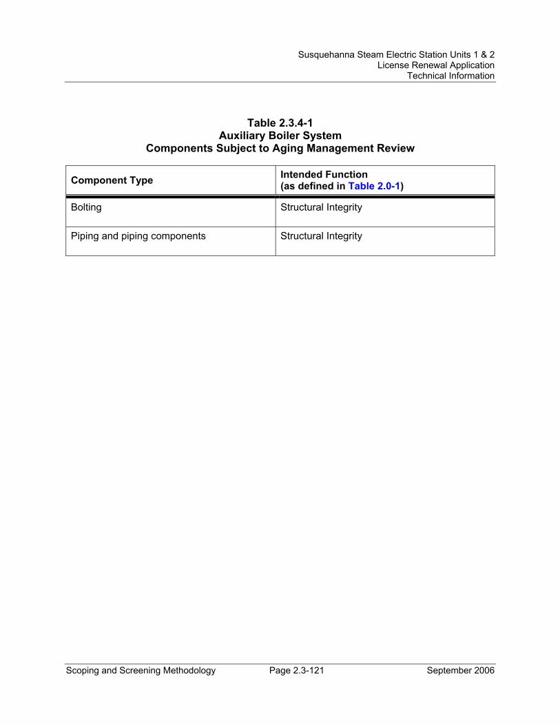
Susquehanna Steam Electric Station Units 1 & 2 License Renewal Application
Technical Information
Scoping and Screening Methodology Page 2.3-121 September 2006
Table 2.3.4-1 Auxiliary Boiler System
Components Subject to Aging Management Review
Component Type Intended Function (as defined in Table 2.0-1)
Bolting Structural Integrity
Piping and piping components Structural Integrity
Susquehanna Steam Electric Station Units 1 & 2 License Renewal Application
Technical Information
Scoping and Screening Methodology Page 2.3-122 September 2006
2.3.4.2 Bypass Steam System System Description The Bypass Steam System is designed to bypass main steam directly to the condenser to control the pressure in the reactor under certain normal operating conditions. The bypass valve chest consists of five separate bypass control valves mounted in individual compartments of a common valve chest. Bypass steam flows from the main steam lines through a 24-inch header, which is upstream of the bypass valves, divides into two 18-inch headers each of which is connected to the valve chest at opposite ends. The discharge connections of the bypass valves are piped individually to the condensers in 10-inch lines. A pressure reducer assembly is installed in each bypass valve discharge line to reduce the pressure at which the bypassed steam enters the respective condenser.
Reason for Scope Determination The Bypass Steam System does not perform any functions that satisfy the scoping criteria in 10 CFR 54.4(a)(1).
The Bypass Steam System contains nonsafety-related components but is not associated with the support of safety-related components (connected to the Main Steam System) and does not have the potential to adversely affect safety-related equipment through spatial interaction. Although not specifically credited in either the primary or the alternate pathways in support of the MSIV Leakage Isolated Condenser Treatment Method (ICTM), the bypass valves in the Bypass Steam System are connected to the alternate pathway through the 12-inch drip leg to the main condenser and conservatively included as part of the ICTM volume. The Bypass Steam System, therefore, performs the function to provide post-accident hold-up and plate-out of MSIV leakage in support of ICTM and/or AST does reduction. This function meets the scoping criteria of 10 CFR 54.4(a)(2).
The Bypass Steam System is not relied upon to demonstrate compliance with, and does not meet the 10 CFR 54.4(a)(3) scoping criteria for, any of the regulated events.
FSAR References Section 10.4.4 of the SSES FSAR describes the Turbine Bypass System, identified for license renewal as the Bypass Steam System.
License Renewal Drawings The following license renewal drawings depict the evaluation boundaries for the system components within the scope of license renewal:
Unit 1: LR-M-101 sheet 3
Unit 2: LR-M-2101 sheet 3
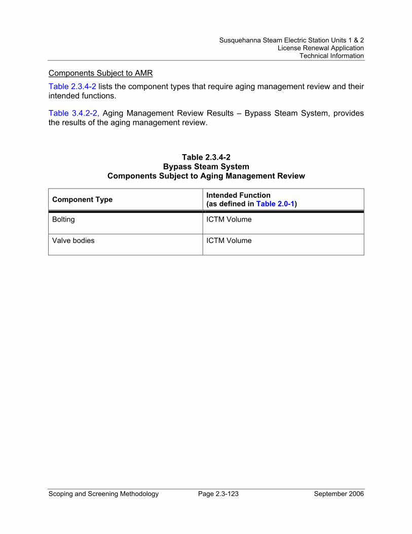
Susquehanna Steam Electric Station Units 1 & 2 License Renewal Application
Technical Information
Scoping and Screening Methodology Page 2.3-123 September 2006
Components Subject to AMR Table 2.3.4-2 lists the component types that require aging management review and their intended functions.
Table 3.4.2-2, Aging Management Review Results – Bypass Steam System, provides the results of the aging management review.
Table 2.3.4-2 Bypass Steam System
Components Subject to Aging Management Review
Component Type Intended Function (as defined in Table 2.0-1)
Bolting ICTM Volume
Valve bodies ICTM Volume
Susquehanna Steam Electric Station Units 1 & 2 License Renewal Application
Technical Information
Scoping and Screening Methodology Page 2.3-124 September 2006
2.3.4.3 Condensate Transfer and Storage System System Description The Condensate Transfer and Storage System consists of an atmospheric condensate storage tank for each unit, two condensate transfer pumps, an atmospheric refueling water storage tank common to both units, and two refueling water pumps. The condensate storage tanks are the preferred source of water for HPCI and RCIC pump operation. The condensate transfer pumps take suction from the condensate storage tanks to provide water for various services in the plant. The refueling water storage tank is used to store water necessary for refueling operations. The refueling water pumps transfer water from the refueling water storage tanks during refueling activities. In addition, the emergency core cooling system (ECCS) keepfill tanks have been included in the evaluation boundaries of the Condensate Transfer and Storage System.
Reason for Scope Determination The Condensate Transfer and Storage System does not perform any safety function. The condensate storage tanks are the preferred source of water for the HPCI and RCIC pumps but are not the credited source of water for accident mitigation. Therefore, providing a water supply for the HPCI and RCIC pumps is not a safety function for the Condensate Transfer and Storage System. This function does not satisfy the scoping criteria of 10 CFR 54.4(a)(1).
The Condensate Transfer and Storage System performs a nonsafety-related function to supply the ECCS and RCIC keep-fill system to prevent water hammer. The Condensate Transfer and Storage System is required to maintain the integrity of nonsafety-related components that have the potential to adversely affect safety-related equipment through spatial interaction and nonsafety-related piping components required to support the safety-related functional boundary of the interfacing system(s). These functions meet the scoping criteria of 10 CFR 54.4(a)(2).
The Condensate Transfer and Storage System is relied upon to demonstrate compliance with, and meets the 10 CFR 54.4(a)(3) scoping criteria for the Fire Protection (10 CFR 50.48), Anticipated Transients Without Scram (ATWS) (10 CFR 50.62), and Station Blackout (SBO) (10 CFR 50.63) regulated events. The function of the Condensate Transfer and Storage System in response to the ATWS and SBO regulated events is to provide a supply of water to the RCIC and HPCI pumps. The Condensate Transfer and Storage System provides a passive keep-fill function to the ECCS and RCIC pump discharge lines in response to a Fire Protection regulated event.
FSAR References Section 9.2.10 of the SSES FSAR describes the Condensate Storage and Transfer System, identified for license renewal as the Condensate Transfer and Storage System.
Susquehanna Steam Electric Station Units 1 & 2 License Renewal Application
Technical Information
Scoping and Screening Methodology Page 2.3-125 September 2006
License Renewal Drawings The following license renewal drawings depict the evaluation boundaries for the system components within the scope of license renewal:
Unit 1: LR-M-105 sheet 2, LR-M-107 sheet 3, LR-M-108 sheets 1 and 2, LR-M-136 sheet 1, LR-M-145 sheet 1, LR-M-149 sheet 1, LR-M-151 sheets 1 and 3, LR-M-152 sheet 1, LR-M-153 sheet 1, LR-M-154 sheet 1, LR-M-155 sheet 1, LR-M-161 sheet 2, LR-M-166 sheet 1
Unit 2: LR-M-2105 sheet 2, LR-M-2107 sheet 3, LR-M-2145 sheet 1, LR-M-2149 sheet 1, LR-M-2151 sheets 1 and 3, LR-M-2152 sheet 1, LR-M-2153 sheet 1, LR-M-2155 sheet 1, LR-M-2161 sheet 2
Components Subject to AMR Table 2.3.4-3 lists the component types that require aging management review and their intended functions.
Table 3.4.2-3, Aging Management Review Results – Condensate Transfer and Storage System, provides the results of the aging management review.
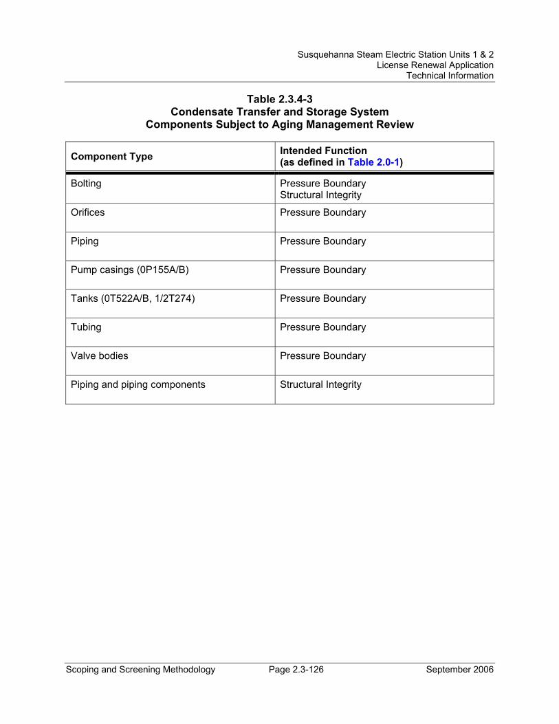
Susquehanna Steam Electric Station Units 1 & 2 License Renewal Application
Technical Information
Scoping and Screening Methodology Page 2.3-126 September 2006
Table 2.3.4-3 Condensate Transfer and Storage System
Components Subject to Aging Management Review
Component Type Intended Function (as defined in Table 2.0-1)
Bolting Pressure Boundary Structural Integrity
Orifices Pressure Boundary
Piping Pressure Boundary
Pump casings (0P155A/B) Pressure Boundary
Tanks (0T522A/B, 1/2T274) Pressure Boundary
Tubing Pressure Boundary
Valve bodies Pressure Boundary
Piping and piping components Structural Integrity
Susquehanna Steam Electric Station Units 1 & 2 License Renewal Application
Technical Information
Scoping and Screening Methodology Page 2.3-127 September 2006
2.3.4.4 Condenser and Air Removal System System Description The main condenser is a triple-shell, single-pass, multi-pressure, tube and shell type condenser comprising three separate shells, which are referred to as the High Pressure (HP), Intermediate Pressure (IP) and Low Pressure (LP) shells. The combination of the three shells makes up the main condenser. Each of these shells is connected to the exhaust of one of the three low pressure turbines by a rubber expansion joint, which is secured between two steel frames, one being welded to the turbine exhaust and the other to the condenser. Condensate and steam equalizer lines connect the HP shell to the IP shell, and the IP shell to the LP shell. The steam exhausted to the condenser is condensed by water, which is circulated through the condenser tubes by pumps that take their suction from the cooling tower basin.
The main condenser functions to condense and deaerate exhaust steam from the main turbine. A mechanical vacuum pump is used during startup to establish a vacuum in the condenser once the turbine glands have been sealed with clean steam, and to discharge the air drawn from the condenser to atmosphere through the plant ventilation stack. Once a vacuum has been established by the mechanical vacuum pump, steam jet air ejectors are placed in service to maintain vacuum conditions and the mechanical vacuum pump is secured. The four first-stage steam jet ejectors continuously remove noncondensible gases and some steam from the condenser, and discharge them to the intercondenser, where the carryover steam is condensed and returned to the condenser. The gases are then removed from the intercondenser by the second-stage ejector and discharged to the off gas recombiner system together with the second-stage ejector motive steam.
The Condenser and Air Removal System functions (together with the Main Steam System) to support the main steam isolation valve (MSIV) leakage Isolated Condenser Treatment Method (ICTM) by directing any leakage through a closed MSIV to the main condenser. The Condenser and Air Removal Systems functions to provide hold-up and plate-out of fission products.
Reason for Scoping Determination The Condenser and Air Removal System does not perform any functions that satisfy the scoping criteria in 10 CFR 54.4(a)(1).
The Condenser and Air Removal System contains nonsafety-related components that provide support for safety-related components, connected to the Main Steam System, and are required to support the safety-related functional boundary of that interfacing system to preclude an adverse affect on safety-related equipment through spatial interaction. The Condenser and Air Removal System also performs a nonsafety-related function of supporting the MSIV leakage ICTM by providing hold-up and plate-out of fission products. These functions meet the scoping criteria of 10 CFR 54.4(a)(2).
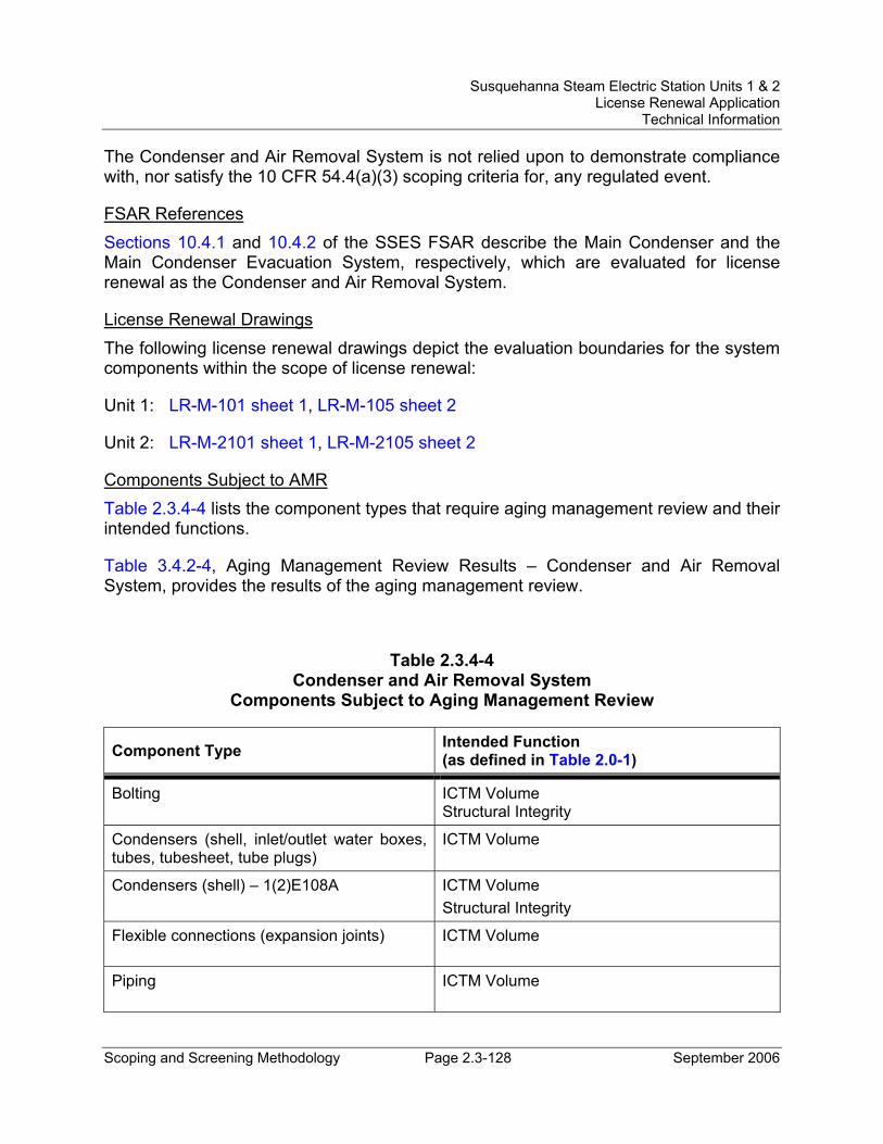
Susquehanna Steam Electric Station Units 1 & 2 License Renewal Application
Technical Information
Scoping and Screening Methodology Page 2.3-128 September 2006
The Condenser and Air Removal System is not relied upon to demonstrate compliance with, nor satisfy the 10 CFR 54.4(a)(3) scoping criteria for, any regulated event.
FSAR References Sections 10.4.1 and 10.4.2 of the SSES FSAR describe the Main Condenser and the Main Condenser Evacuation System, respectively, which are evaluated for license renewal as the Condenser and Air Removal System.
License Renewal Drawings The following license renewal drawings depict the evaluation boundaries for the system components within the scope of license renewal:
Unit 1: LR-M-101 sheet 1, LR-M-105 sheet 2
Unit 2: LR-M-2101 sheet 1, LR-M-2105 sheet 2
Components Subject to AMR Table 2.3.4-4 lists the component types that require aging management review and their intended functions.
Table 3.4.2-4, Aging Management Review Results – Condenser and Air Removal System, provides the results of the aging management review.
Table 2.3.4-4 Condenser and Air Removal System
Components Subject to Aging Management Review
Component Type Intended Function (as defined in Table 2.0-1)
Bolting ICTM Volume Structural Integrity
Condensers (shell, inlet/outlet water boxes, tubes, tubesheet, tube plugs)
ICTM Volume
Condensers (shell) – 1(2)E108A ICTM Volume Structural Integrity
Flexible connections (expansion joints) ICTM Volume
Piping ICTM Volume
Susquehanna Steam Electric Station Units 1 & 2 License Renewal Application
Technical Information
Scoping and Screening Methodology Page 2.3-129 September 2006
2.3.4.5 Feedwater System System Description The Feedwater System provides a supply of high purity, preheated feedwater to the reactor vessel. It provides the required flow and pressure to maintain the desired reactor vessel water level throughout the entire operating range, from startup to full load to shutdown. The Feedwater System provides sufficient margin to maintain adequate flow under transient conditions.
The feedwater flow branches into two separate lines inside the Reactor Building. Primary containment isolation in each branch is provided by a motor operated stop check valve for the outermost containment valve and a check valve just outside the containment wall. A check valve and motor operated gate valve are located just inside the containment. Feedwater piping from the outermost primary containment isolation valve up to but not including the valve just outside the containment is designed in accordance with ASME, Section III, Class 2.
Feedwater System piping designated as ASME Class 2 forms part of the reactor coolant pressure boundary. The Feedwater System Class 2 piping provides an injection path for both the High Pressure Coolant Injection (HPCI) System and for the Reactor Core Isolation (RCIC) System. Class 2 piping that is associated with a demineralized water service connection is included with the Feedwater System and functions as part of the reactor coolant pressure boundary and provides containment isolation. Feedwater piping from the containment isolation valve to the reactor is designed in accordance with ASME, Section III, Class 1.
Reason for Scoping Determination The Feedwater System safety-related functions are to maintain the reactor coolant pressure boundary and to maintain the primary containment pressure boundary. The Feedwater System has no other safety-related functions. While the SSES FSAR confirms that, overall, the Feedwater System has no safety-related function, it also indicates that the portion of the system from the outermost primary containment isolation valve to the reactor is safety-related. Since the safety-related HPCI injection water (as well as RCIC injection water) is piped to the feedwater lines, that portion of the Feedwater System is also required for the corresponding safety-related HPCI (as well as RCIC) functions. Additionally, safety-related containment isolation components associated with the primary containment penetration for a demineralized water service connection are included in the Feedwater System. These are all safety-related system functions. These safety functions meet the scoping criteria of 10 CFR 54.4(a)(1).
The Feedwater System is required to maintain the integrity of nonsafety-related components that have the potential to adversely affect safety-related equipment through spatial interaction and nonsafety-related piping components required to support the
Susquehanna Steam Electric Station Units 1 & 2 License Renewal Application
Technical Information
Scoping and Screening Methodology Page 2.3-130 September 2006
safety-related functional boundary of the system. This function meets the scoping criteria of 10 CFR 54.4(a)(2).
The Feedwater System is relied upon to demonstrate compliance with, and satisfies the 10 CFR 54.4(a)(3) scoping criteria for, the Fire Protection (10 CFR 50.48), Environmental Qualification (10 CFR 50.49), Anticipated Transients Without Scram (10 CFR 50.62), and Station Blackout (10 CFR 50.63) regulated events.
FSAR References Section 10.4.7 of the SSES FSAR describes the Feedwater System.
License Renewal Drawings The following license renewal drawings depict the evaluation boundaries for the system components within the scope of license renewal:
Unit 1: LR-M-106 sheets 2, 3 and 4, LR-M-141 sheet 2, LR-M-149 sheet 1, LR-M-155 sheet 1
Unit 2: LR-M-2106 sheets 2, 3 and 4, LR-M-2141 sheet 2, LR-M-2149 sheet 1, LR-M-2155 sheet 1
Components Subject to AMR Table 2.3.4-5 lists the component types that require aging management review and their intended functions.
Table 3.4.2-5, Aging Management Review Results – Feedwater System, provides the results of the aging management review.
Class 1 components in the reactor coolant pressure boundary are evaluated with the Reactor Coolant System (see Section 2.3.1.3).
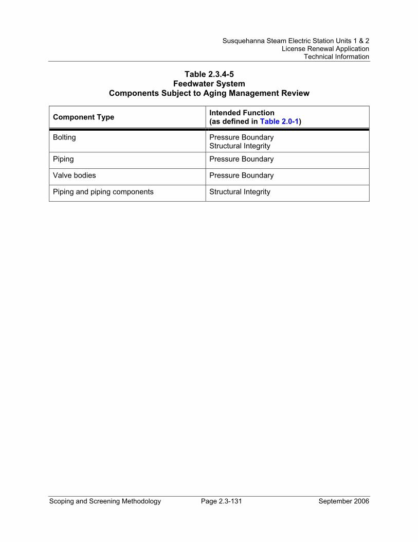
Susquehanna Steam Electric Station Units 1 & 2 License Renewal Application
Technical Information
Scoping and Screening Methodology Page 2.3-131 September 2006
Table 2.3.4-5 Feedwater System
Components Subject to Aging Management Review
Component Type Intended Function (as defined in Table 2.0-1)
Bolting Pressure Boundary Structural Integrity
Piping Pressure Boundary
Valve bodies Pressure Boundary
Piping and piping components Structural Integrity
Susquehanna Steam Electric Station Units 1 & 2 License Renewal Application
Technical Information
Scoping and Screening Methodology Page 2.3-132 September 2006
2.3.4.6 Main Steam System System Description The Main Steam System transports high pressure steam generated in the reactor pressure vessel (RPV) to the main turbine through four main steam lines, each line containing a main stop and turbine control valve. Safety/relief valves are mounted on the main steam lines to provide protection against over-pressurization of the reactor vessel during abnormal pressure transients. Two main steam isolation valves (MSIVs) are installed in each main steam line, one inside and one outside primary containment. Between the outermost isolation valves and the turbine stop valves, the four main steam lines are routed within the confines of a tunnel.
In addition to the high pressure turbine, the Main Steam System also directs steam to the turbine bypass valves, high pressure coolant injection (HPCI) pump turbine, reactor core isolation cooling (RCIC) pump turbine, reactor feed pump turbines, steam jet air ejectors, steam seal evaporator, and condenser shells.
To protect the RPV from over-pressurization, the Main Steam System contains 16 safety/relief valves (SRVs) that are mounted on the main steam lines inside the primary containment. Six of these valves are part of the Automatic Depressurization System (ADS), and they are dual purpose, in that they will relieve pressure by normal mechanical action (SRV function) or by automatic action of an electric-pneumatic control system (ADS function). The ADS is considered to be part of the Emergency Core Cooling System, but is evaluated with the Main Steam System for license renewal.
The Main Steam System (together with the Condenser and Air Removal System) supports the main steam isolation valve (MSIV) leakage Isolated Condenser Treatment Method (ICTM) by directing any leakage through a closed MSIV to the main condenser. The primary pathway involves the four main steam line drains that are routed to the main condenser. Alternate pathways include the four drain lines from the main steam line 8-inch drip legs to the condenser, and the single drain line from the main steam line 12-inch drip leg to the condenser.
Reason for Scoping Determination The Main Steam System, including the Automatic Depressurization System (ADS), functions to supply steam to the HPCI pump turbine, provide over-pressure protection of the reactor coolant pressure boundary by means of the SRVs, provide a high quality supply of nitrogen for long-term operation of ADS valves, provide containment isolation by means of MSIVs and the main steam line drain penetration outboard isolation valve, and provide means (via ADS) of manually or automatically depressurizing the RPV during events that reduce reactor water inventory. These safety functions meet the scoping criteria of 10 CFR 54.4(a)(1).
Susquehanna Steam Electric Station Units 1 & 2 License Renewal Application
Technical Information
Scoping and Screening Methodology Page 2.3-133 September 2006
The Main Steam System performs the nonsafety-related function of supporting the MSIV leakage ICTM by providing alternate pathways to the main condenser, as well as minimal hold-up and plate-out. The Main Steam System is required to maintain the integrity of nonsafety-related components that have the potential to adversely affect safety-related equipment through spatial interaction and nonsafety-related piping components required to support the safety-related functional boundary of the system. These functions meet the scoping criteria of 10 CFR 54.4(a)(2).
The Main Steam System is relied upon to demonstrate compliance with, and satisfies the 10 CFR 54.4(a)(3) scoping criteria for, the Fire Protection (10 CFR 50.48), Environmental Qualification (10 CFR 50.49), Anticipated Transients Without Scram (10 CFR 50.62), and Station Blackout (10 CFR 50.63) regulated events.
FSAR References Section 10.3 of the SSES FSAR describes the Main Steam Supply System, evaluated for license renewal as the Main Steam System.
License Renewal Drawings The following license renewal drawings depict the evaluation boundaries for the system components within the scope of license renewal:
Unit 1: LR-M-101 sheets 1, 2, and 3, LR-M-126 sheet 1, LR-M-139 sheet 1, LR-M-141 sheet 1, LR-M-149 sheet 1, LR-M-155 sheet 1
Unit 2: LR-M-2101 sheets 1, 2, and 3, LR-M-2126 sheet 1, LR-M-2139 sheet 1, LR-M-2141 sheet 1, LR-M-2149 sheet 1, LR-M-2155 sheet 1
Components Subject to AMR Table 2.3.4-6 lists the component types that require aging management review and their intended functions.
Table 3.4.2-6, Aging Management Review Results – Main Steam System, provides the results of the aging management review.
Class 1 components in the reactor coolant pressure boundary are evaluated with the Reactor Coolant System (see Section 2.3.1.3).
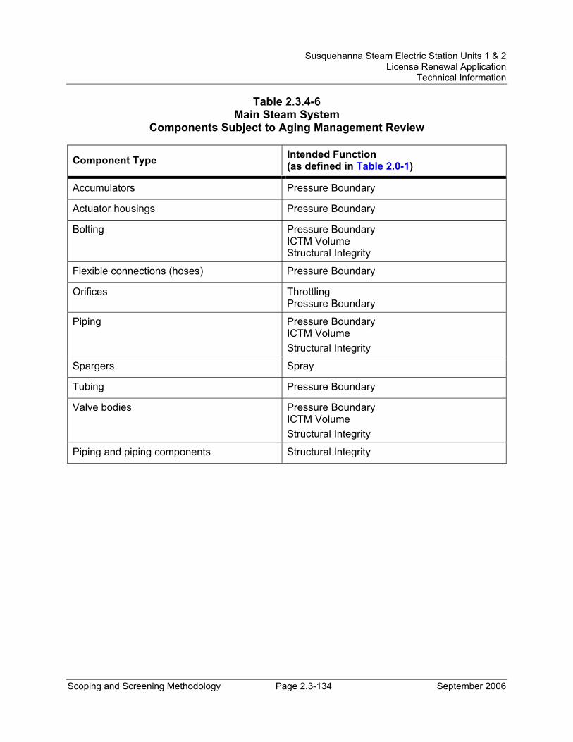
Susquehanna Steam Electric Station Units 1 & 2 License Renewal Application
Technical Information
Scoping and Screening Methodology Page 2.3-134 September 2006
Table 2.3.4-6 Main Steam System
Components Subject to Aging Management Review
Component Type Intended Function (as defined in Table 2.0-1)
Accumulators Pressure Boundary
Actuator housings Pressure Boundary
Bolting Pressure Boundary ICTM Volume Structural Integrity
Flexible connections (hoses) Pressure Boundary
Orifices Throttling Pressure Boundary
Piping Pressure Boundary ICTM Volume Structural Integrity
Spargers Spray
Tubing Pressure Boundary
Valve bodies Pressure Boundary ICTM Volume Structural Integrity
Piping and piping components Structural Integrity
Susquehanna Steam Electric Station Units 1 & 2 License Renewal Application
Technical Information
Scoping and Screening Methodology Page 2.3-135 September 2006
2.3.4.7 Main Turbine System System Description The main turbine unit consists of one double flow high pressure turbine and three double exhaust flow low pressure turbines. Steam from the reactor enters the power conversion system through four main steam lines. Each of the four main steam lines to the high pressure turbine is connected to a main steam stop valve and a main steam control valve. The four stop valves and four control valves are combined to form a single valve chest. A pressure equalizing line connects the stop valves together just below the valve seats. A five valve bypass valve chest is connected to the main steam lines at the crosstie header to remove excess flow to the condenser.
Reason for Scope Determination The Main Turbine System does not perform any functions that satisfy the scoping criteria in 10 CFR 54.4(a)(1).
The Main Turbine System is required to maintain the integrity of nonsafety-related components required to support the safety-related functional boundary of an interfacing system (Main Steam). Although not specifically credited in either the primary or the alternate pathways in support of the MSIV Leakage Isolated Condenser Treatment Method (ICTM), the low-pressure turbine exhaust hoods in the Main Turbine System are connected to the main condenser and are conservatively included as part of the ICTM volume. The Main Turbine System, therefore, performs the function to provide post-accident hold-up and plate-out of MSIV leakage in support of ICTM and/or AST does reduction. These functions meet the scoping criteria of 10 CFR 54.4(a)(2).
The Main Turbine System is not relied upon to demonstrate compliance with, and does not meet the 10 CFR 54.4(a)(3) scoping criteria for, any of the regulated events.
FSAR References Section 10.2 of the SSES FSAR describes the Turbine-Generator, identified for license renewal as the Main Turbine System.
License Renewal Drawings The following license renewal drawings depict the evaluation boundaries for the system components within the scope of license renewal:
Unit 1: LR-M-101 sheet 2, LR-M-105 sheet 2
Unit 2: LR-M-2101 sheet 2, LR-M-2105 sheet 2
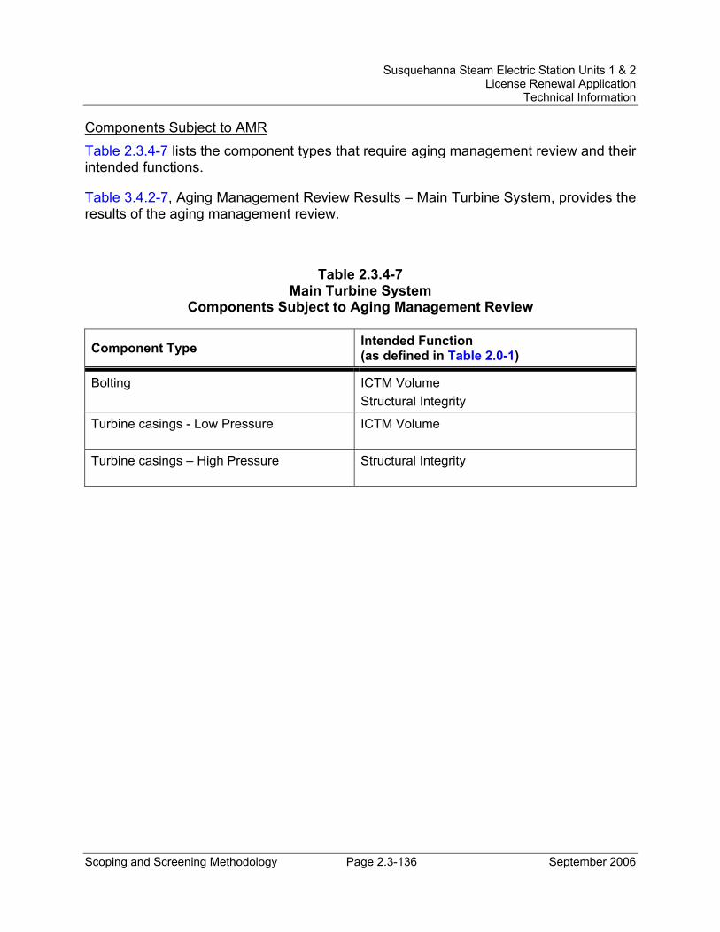
Susquehanna Steam Electric Station Units 1 & 2 License Renewal Application
Technical Information
Scoping and Screening Methodology Page 2.3-136 September 2006
Components Subject to AMR Table 2.3.4-7 lists the component types that require aging management review and their intended functions.
Table 3.4.2-7, Aging Management Review Results – Main Turbine System, provides the results of the aging management review.
Table 2.3.4-7 Main Turbine System
Components Subject to Aging Management Review
Component Type Intended Function (as defined in Table 2.0-1)
Bolting ICTM Volume Structural Integrity
Turbine casings - Low Pressure ICTM Volume
Turbine casings – High Pressure Structural Integrity
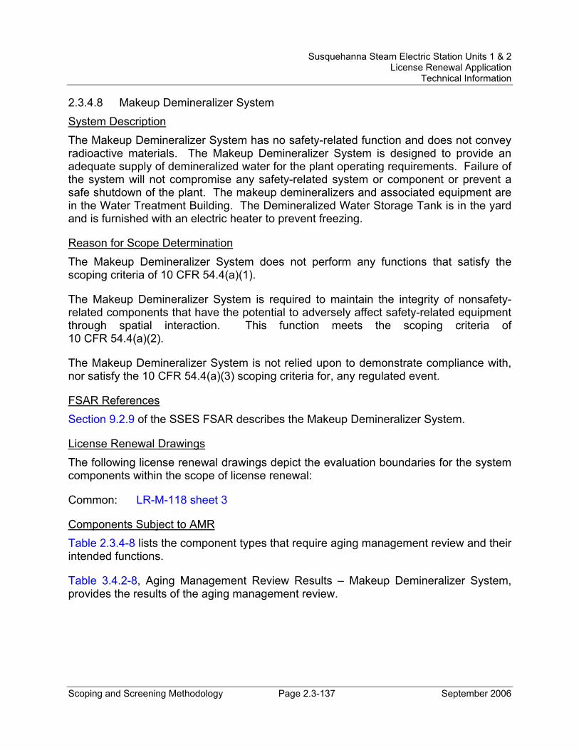
Susquehanna Steam Electric Station Units 1 & 2 License Renewal Application
Technical Information
Scoping and Screening Methodology Page 2.3-137 September 2006
2.3.4.8 Makeup Demineralizer System System Description The Makeup Demineralizer System has no safety-related function and does not convey radioactive materials. The Makeup Demineralizer System is designed to provide an adequate supply of demineralized water for the plant operating requirements. Failure of the system will not compromise any safety-related system or component or prevent a safe shutdown of the plant. The makeup demineralizers and associated equipment are in the Water Treatment Building. The Demineralized Water Storage Tank is in the yard and is furnished with an electric heater to prevent freezing.
Reason for Scope Determination The Makeup Demineralizer System does not perform any functions that satisfy the scoping criteria of 10 CFR 54.4(a)(1).
The Makeup Demineralizer System is required to maintain the integrity of nonsafety-related components that have the potential to adversely affect safety-related equipment through spatial interaction. This function meets the scoping criteria of 10 CFR 54.4(a)(2).
The Makeup Demineralizer System is not relied upon to demonstrate compliance with, nor satisfy the 10 CFR 54.4(a)(3) scoping criteria for, any regulated event.
FSAR References Section 9.2.9 of the SSES FSAR describes the Makeup Demineralizer System.
License Renewal Drawings The following license renewal drawings depict the evaluation boundaries for the system components within the scope of license renewal:
Common: LR-M-118 sheet 3
Components Subject to AMR Table 2.3.4-8 lists the component types that require aging management review and their intended functions.
Table 3.4.2-8, Aging Management Review Results – Makeup Demineralizer System, provides the results of the aging management review.
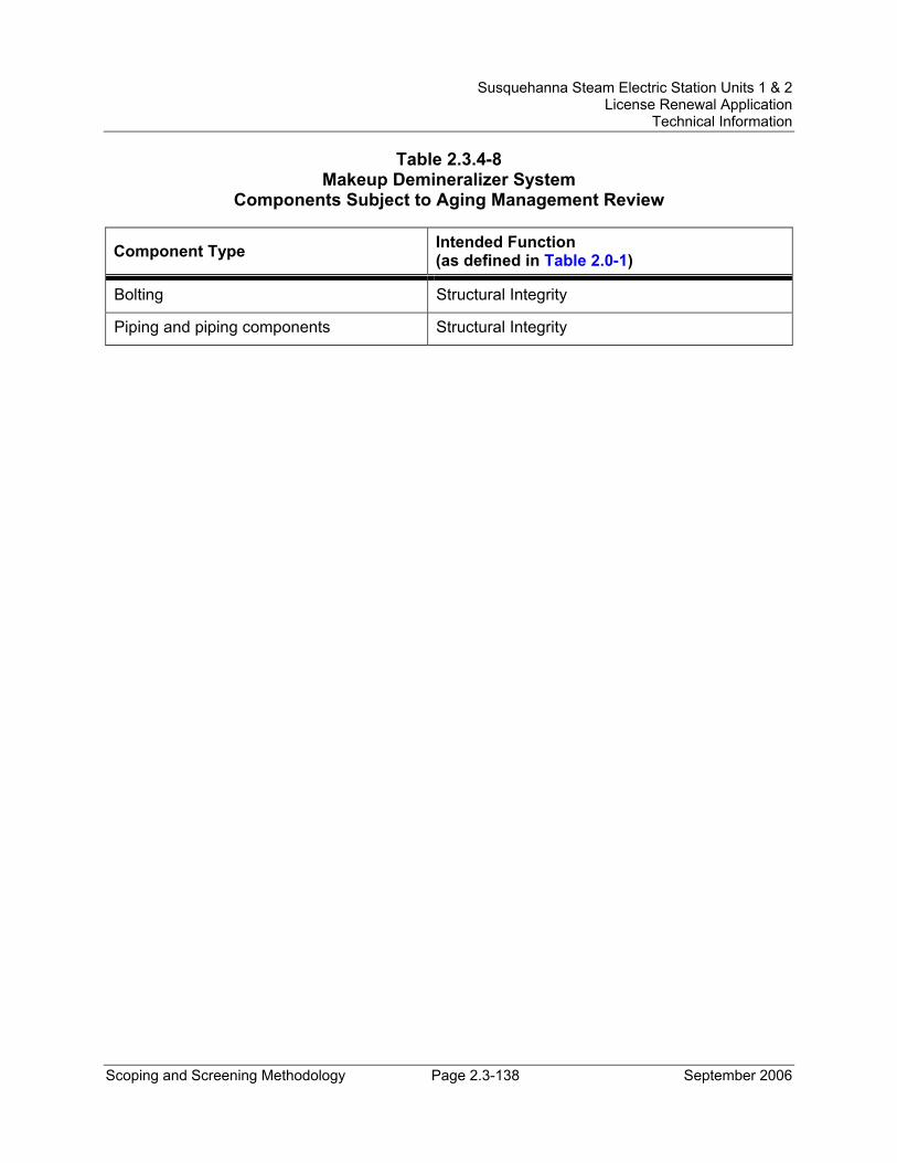
Susquehanna Steam Electric Station Units 1 & 2 License Renewal Application
Technical Information
Scoping and Screening Methodology Page 2.3-138 September 2006
Table 2.3.4-8 Makeup Demineralizer System
Components Subject to Aging Management Review
Component Type Intended Function (as defined in Table 2.0-1)
Bolting Structural Integrity
Piping and piping components Structural Integrity
Susquehanna Steam Electric Station Units 1 & 2 License Renewal Application
Technical Information
Scoping and Screening Methodology Page 2.3-139 September 2006
2.3.4.9 Makeup Transfer and Storage System System Description The Makeup Transfer and Storage System provides demineralized water makeup to various plant services from the Makeup Demineralizer System. A single header from the demineralized water storage tank supplies the demineralized water jockey pump and transfer pumps at a positive suction pressure. The jockey pump is in continuous operation and is controlled by an on-off hand switch. A recirculation line back to the demineralized water storage tank is provided to prevent pump overheating on low system demands.
Reason for Scope Determination The Makeup Transfer and Storage System does not perform any functions that satisfy the scoping criteria of 10 CFR 54.4(a)(1).
The Makeup Transfer and Storage System is required to maintain the integrity of nonsafety-related components that have the potential to adversely affect safety-related equipment through spatial interaction and nonsafety-related piping components required to support the safety-related functional boundary of the system. This function meets the scoping criteria of 10 CFR 54.4(a)(2).
The Makeup Transfer and Storage System is not relied upon to demonstrate compliance with, nor satisfy the 10 CFR 54.4(a)(3) scoping criteria for, any regulated event.
FSAR References Section 9.2.9.2 of the SSES FSAR describes the Makeup Transfer and Storage System.
License Renewal Drawings The following license renewal drawings depict the evaluation boundaries for the system components within the scope of license renewal:
Unit 1: LR-M-108 sheet 2, LR-M-112 sheet 1, LR-M-113 sheet 1, LR-M-118 sheet 3, LR-M-123 sheet 8, LR-M-134 sheet 1, LR-M-141 sheet 2, LR-M-148 sheet 1, LR-M-186 sheet 1, LR-M-187 sheet 1
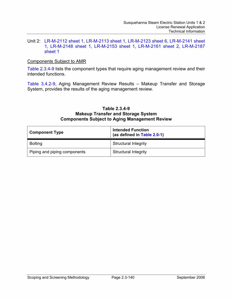
Susquehanna Steam Electric Station Units 1 & 2 License Renewal Application
Technical Information
Scoping and Screening Methodology Page 2.3-140 September 2006
Unit 2: LR-M-2112 sheet 1, LR-M-2113 sheet 1, LR-M-2123 sheet 6, LR-M-2141 sheet 1, LR-M-2148 sheet 1, LR-M-2153 sheet 1, LR-M-2161 sheet 2, LR-M-2187 sheet 1
Components Subject to AMR Table 2.3.4-9 lists the component types that require aging management review and their intended functions.
Table 3.4.2-9, Aging Management Review Results – Makeup Transfer and Storage System, provides the results of the aging management review.
Table 2.3.4-9 Makeup Transfer and Storage System
Components Subject to Aging Management Review
Component Type Intended Function (as defined in Table 2.0-1)
Bolting Structural Integrity
Piping and piping components Structural Integrity
Susquehanna Steam Electric Station Units 1 & 2 License Renewal Application
Technical Information
Scoping and Screening Methodology Page 2.3-141 September 2006
2.3.4.10 Reactor Feed Pump Turbines System System Description The reactor feed pumps are driven by variable speed, multistage turbines that receive steam from either the main steam cross-connection header or the crossover piping downstream of the moisture separators. During normal full power operation the turbine drivers use low pressure crossover steam. High pressure main steam is used during startup, low load, or transient conditions when crossover steam is either not available or is of insufficient pressure. The exhaust steam from each turbine is piped to the main condenser.
The high pressure and low pressure stop valves are credited for isolation of the reactor feed pump turbines as part of the alternate safe shutdown path for fire protection. Closure of the stop valves to trip the turbines is an active function.
Reason for Scoping Determination The Reactor Feed Pump Turbines System does not perform any functions that satisfy the scoping criteria in 10 CFR 54.4(a)(1).
The Reactor Feed Pump Turbines System does not contain any nonsafety-related components that have the potential to adversely affect safety-related systems or components through spatial interaction. Therefore, the Reactor Feed Pump Turbines System does not meet the scoping criteria of 10 CFR 54.4(a)(2).
The Reactor Feed Pump Turbines System is relied upon to demonstrate compliance with, and satisfies the 10 CFR 54.4(a)(3) scoping criteria for, the fire protection (10 CFR 50.48) regulated event.
FSAR References Section 10.4.7 of the SSES FSAR describes the reactor feed pump turbines in association with the Condensate and Feedwater Systems.
License Renewal Drawings The following license renewal drawings depict the evaluation boundaries for the system components within the scope of license renewal:
Unit 1: LR-M-127 sheets 1, 2 and 3
Unit 2: LR-M-2127 sheets 1, 2 and 3
Components Subject to AMR The only components of the Reactor Feed Pump Turbines System within the scope of license renewal are the reactor feed pump turbine low pressure and high pressure stop
Susquehanna Steam Electric Station Units 1 & 2 License Renewal Application
Technical Information
Scoping and Screening Methodology Page 2.3-142 September 2006
valves. Isolation of the stop valves is an active function involving moving parts that is independent of the pressure boundary of the valve bodies. Loss of valve body pressure boundary could result in leakage but would not prevent isolation of flow and consequent trip of the reactor feed pump turbines. The valve bodies and associated internal pilot valves and oil piping/tubing do not perform a passive intended function. Therefore, there are no components of the Reactor Feed Pump Turbines System subject to aging management review.
Susquehanna Steam Electric Station Units 1 & 2 License Renewal Application
Technical Information
Scoping and Screening Methodology Page 2.3-143 September 2006
2.3.4.11 Refueling Water Transfer and Storage System System Description The Refueling Water Transfer and Storage System has no safety-related function. The refueling water storage tank stores the water that is used to fill the reactor well and dryer-separator pool of either Unit 1 or 2. During refueling operations, water inventory is transferred from the storage tank to the respective reactor well and dryer-separator pool. The refueling water pumps are started and stopped manually to support this evolution. Each pump can be controlled from either the main control room or the refueling floor, thus permitting an operator at either of these locations to operate the pumps. During refueling fill evolutions, both pumps are typically run in parallel. When refueling is complete, the water in the reactor well and dryer-separator pool can be emptied to the refueling water storage tank through a condensate filter-demineralizer. Makeup for the refueling water storage tank is supplied by the demineralized water transfer pumps taking suction from the demineralized water storage tank.
Reason for Scope Determination The Refueling Water Transfer and Storage System does not perform any functions that satisfy the scoping criteria of 10 CFR 54.4(a)(1).
The Refueling Water Transfer and Storage System is required to maintain the integrity of nonsafety-related components that have the potential to adversely affect safety-related equipment through spatial interaction and nonsafety-related piping components required to support the safety-related functional boundary of the interfacing system(s). This function meets the scoping criteria of 10 CFR 54.4(a)(2).
The Refueling Water Transfer and Storage System is not relied upon to demonstrate compliance with, nor satisfy the 10 CFR 54.4(a)(3) scoping criteria for, any regulated event.
FSAR References Section 9.2.10 of the SSES FSAR describes the Refueling Water Transfer and Storage System.
License Renewal Drawings The following license renewal drawings depict the evaluation boundaries for the system components within the scope of license renewal:
Unit 1: LR-M-108 sheets 1 and 2, LR-M-153 sheet 2
Unit 2: LR-M-2153 sheet 2
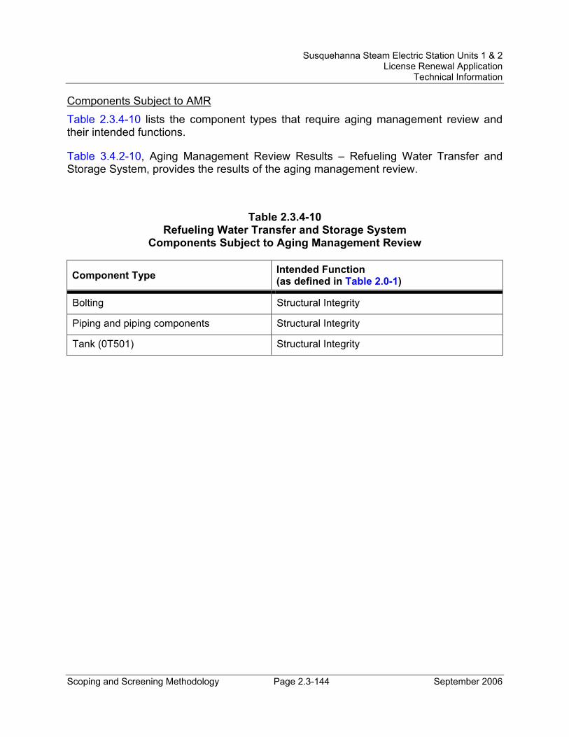
Susquehanna Steam Electric Station Units 1 & 2 License Renewal Application
Technical Information
Scoping and Screening Methodology Page 2.3-144 September 2006
Components Subject to AMR Table 2.3.4-10 lists the component types that require aging management review and their intended functions.
Table 3.4.2-10, Aging Management Review Results – Refueling Water Transfer and Storage System, provides the results of the aging management review.
Table 2.3.4-10 Refueling Water Transfer and Storage System
Components Subject to Aging Management Review
Component Type Intended Function (as defined in Table 2.0-1)
Bolting Structural Integrity
Piping and piping components Structural Integrity
Tank (0T501) Structural Integrity
Susquehanna Steam Electric Station Units 1 & 2 License Renewal Application
Technical Information
Scoping and Screening Methodology Page 2.4-1 September 2006
2.4 SCOPING AND SCREENING RESULTS: STRUCTURES
The determination of the structures within the scope of license renewal is made through the application of the process described in Section 2.1. The results of the structural scoping review are in Section 2.2.
Section 2.1 also provides the methodology for determining the components within the scope of 10 CFR 54.4 that meet the requirements contained in 10 CFR 54.21(a)(1). The components that meet these screening requirements are identified in this section.
The screening results for structures consist of lists of components and commodities that require aging management review. Brief descriptions of the structures within the scope of license renewal are provided as background information. Structural intended functions are described for in-scope structures.
The major structures in the scope of license renewal are the:
• Primary Containment (Section 2.4.1)
• Reactor Building (Section 2.4.2)
• Engineered Safeguards Service Water Pumphouse and Spray Pond (Section 2.4.3)
• Circulating Water Pumphouse and Water Treatment Building (Section 2.4.4)
• Control Structure (Section 2.4.5)
• Diesel Generator ‘A, B, C, and D’ Building (Section 2.4.6)
• Diesel Generator ‘E’ Building (Section 2.4.7)
• Turbine Building (Section 2.4.8)
• Yard Structures (Section 2.4.9)
Structural components for in-scope structures are addressed in the structure reviews (Section 2.4.1 through 2.4.9).
Structural commodities (e.g., supports, trays, conduit, panels, enclosures, doors, platforms, anchors, equipment pads, sealants, etc.) are addressed in the bulk commodities review (Section 2.4.10).
Susquehanna Steam Electric Station Units 1 & 2 License Renewal Application
Technical Information
Scoping and Screening Methodology Page 2.4-2 September 2006
2.4.1 Primary Containment
Structure Description The SSES Units 1 and 2 Primary Containments are GE boiling water reactor, Mark II (over/under) type seismic Category I structures. The Primary Containment is an enclosure for the reactor vessel, the reactor coolant recirculation loops, and branch connections of the reactor coolant system. Essential elements of the Primary Containment are the drywell, the suppression chamber that stores a large volume of water, the drywell floor that separates the drywell and the suppression chamber, the connecting vent pipe system between the drywell and the suppression chamber, isolation valves, the vacuum relief system, and the containment cooling systems and other service equipment.
The Primary Containment is in the form of a truncated cone over a cylindrical section, with the drywell in the upper conical section and the suppression chamber in the lower cylindrical section. These two sections comprise a structurally integrated reinforced concrete pressure vessel, lined with welded steel plate and provided with a steel domed head for closure at the top of the drywell. The drywell floor is a reinforced concrete slab structurally connected to the containment wall.
The Primary Containment is structurally separated from the surrounding Reactor Building except at the base foundation slabs where a cold joint between the two adjoining foundation slabs is provided.
The Primary Containment consists of the following major structural components:
• Access Hatches - Access hatches providing access into the Primary Containment are equipment hatches, personnel airlock, suppression chamber access hatches, and the control rod drive removal hatch.
• Base Foundation Mat – The containment base foundation slab is a 7 feet 9 inch thick reinforced concrete mat founded on bedrock. The top of the base foundation slab is lined with a carbon steel liner plate (i.e., suppression pool base liner or base foundation slab liner plate).
• Containment Liner - The steel liner plate is ¼ inch thick and is anchored to the concrete wall by structural tee vertical stiffeners. Horizontal plate stiffeners and horizontal structural channels provide additional stiffening.
• Containment Wall - The containment wall (i.e., drywell wall) is a 6 feet thick reinforced concrete wall. The inside surface of the containment wall is lined with a carbon steel liner plate.
• Drywell Floor - The drywell floor (i.e., diaphragm floor) serves as a barrier between the drywell and suppression chamber. It is a reinforced concrete circular slab with a thickness of 3 feet 6 inches. The drywell floor is supported by
Susquehanna Steam Electric Station Units 1 & 2 License Renewal Application
Technical Information
Scoping and Screening Methodology Page 2.4-3 September 2006
the reactor pedestal, the containment wall, and twelve steel columns. The drywell floor is penetrated by 87 vent pipes.
• Drywell Floor Liner - A ¼ inch thick carbon steel liner plate is provided on top of the drywell floor and anchored to it.
• Drywell Head - The drywell head assembly consists of a hemi-ellipsoidal head and a cylindrical lower flange. The lower flange is supported on the top of the drywell wall. The head is made of 1-½ inch thick plate and is secured with bolts at the mating flange.
• Drywell Sumps - Drywell floor drain sumps are located in the Primary Containment for collection of leakage which flows by gravity down the slab surface into the floor drain sumps.
• Penetrations - Penetration types include mechanical penetrations and electrical penetrations. Penetrations consist of a pipe with a flange welded to it. The plate flange is embedded in the concrete wall and provides an anchorage for the penetration. The pipe is also welded to the containment liner plate to provide a leak tight penetration. The mechanical (process line) penetrations are of welded steel construction without expansion bellows, gaskets, or sealing compounds and are an integral part of the construction. Mechanical penetrations do not contain thermal insulation. Electrical penetration assemblies are used to extend electrical conductors through the containment. The assembly is sized to be inserted in penetration nozzles that are furnished as part of the containment. The penetrations are hermetically sealed and provide for leak testing at design pressure.
• Reactor Pedestal - The reactor pedestal is an 82 feet high, upright cylindrical reinforced concrete shell that rests on the containment base foundation slab and supports the drywell floor, reactor vessel, and reactor shield wall as well as drywell platforms, pipe restraints, and recirculation pumps.
• Reactor Pedestal Liner – A ¼ inch thick carbon steel form plate is provided on the inside and outside surfaces of the reactor pedestal below the drywell floor.
• Reactor Shield Wall - The reactor shield wall (i.e., bioshield wall) is a 49 feet high upright cylindrical shell which rests on top of the reactor pedestal and provides primary radiation shielding as well as supports for pipe restraints and drywell platforms. The reactor shield wall is constructed of inner and outer carbon steel plates and un-reinforced concrete between the two plates. The concrete is used for radiation shielding only and is not relied upon as a structural element.
• Reactor Vessel Thermal Insulation - The reflective metallic insulation consists of large assemblies held in place by stainless steel latches with positive locking devices.
Susquehanna Steam Electric Station Units 1 & 2 License Renewal Application
Technical Information
Scoping and Screening Methodology Page 2.4-4 September 2006
• Seismic Truss and Seismic Stabilizer - The seismic truss spans between the containment wall and the reactor shield wall. The seismic stabilizer spans between the reactor shield wall and the reactor vessel. The seismic truss and the seismic stabilizer provide lateral support for the reactor vessel.
• Suppression Chamber Column - Twelve hollow steel pipe columns are furnished to support the drywell floor. Each column is 42 inches in diameter with a 1-¼ inch wall thickness. The columns are connected to the base foundation slab at the bottom and to the drywell at the top.
• Suppression Chamber - The suppression chamber (i.e., suppression pool or wetwell) is a steel lined full-circle annular pool located below the drywell floor that stores a large volume of water providing a heat sink. A leak chase system is provided on liner plate seam welds less than ½ inch thick on the base foundation slab liner plate and on portions of the suppression chamber wall liner plate below the suppression pool water level.
Reason for Scope Determination The Primary Containment is within the scope of license renewal as a safety-related structure, which meets the criterion of 10 CFR 54.4(a)(1). The functions of the Primary Containment are to control the release of radioactivity to the environment, to provide support and protection for equipment, and to provide the ability to maintain required temperatures for operation.
The Primary Containment is relied upon to demonstrate compliance with the Station Blackout (10 CFR 50.63) regulated event and meets the 10 CFR 54.4(a)(3) scoping criteria.
In addition, the Primary Containment is in the scope of license renewal because it contains:
• Structural components that are safety-related and are relied upon to remain functional during and following design basis events.
• Structural components that are nonsafety-related whose failure could prevent satisfactory accomplishment of safety-related functions.
• Structural components that are relied on during station blackout events.
FSAR References Section 3.8.1 of the SSES FSAR describes the Primary Containment.
Components Subject to AMR Table 2.4-1 lists the component types that require aging management review and their intended functions.
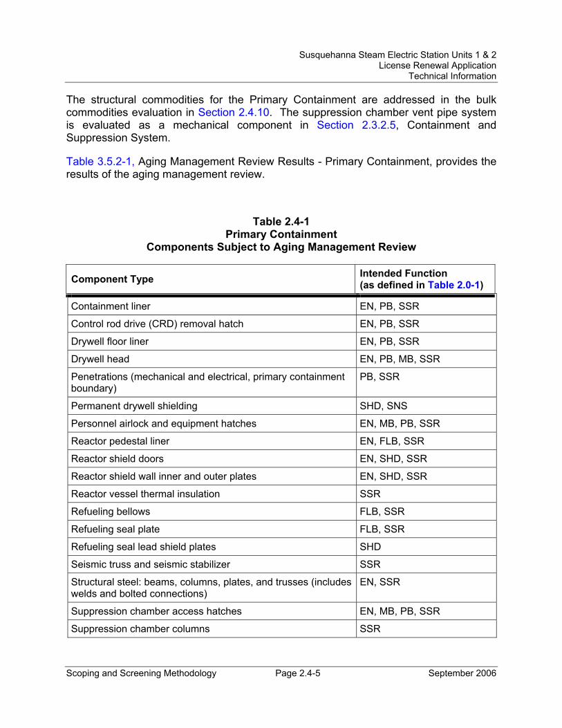
Susquehanna Steam Electric Station Units 1 & 2 License Renewal Application
Technical Information
Scoping and Screening Methodology Page 2.4-5 September 2006
The structural commodities for the Primary Containment are addressed in the bulk commodities evaluation in Section 2.4.10. The suppression chamber vent pipe system is evaluated as a mechanical component in Section 2.3.2.5, Containment and Suppression System.
Table 3.5.2-1, Aging Management Review Results - Primary Containment, provides the results of the aging management review.
Table 2.4-1 Primary Containment
Components Subject to Aging Management Review
Component Type Intended Function (as defined in Table 2.0-1)
Containment liner EN, PB, SSR
Control rod drive (CRD) removal hatch EN, PB, SSR
Drywell floor liner EN, PB, SSR
Drywell head EN, PB, MB, SSR
Penetrations (mechanical and electrical, primary containment boundary)
PB, SSR
Permanent drywell shielding SHD, SNS
Personnel airlock and equipment hatches EN, MB, PB, SSR
Reactor pedestal liner EN, FLB, SSR
Reactor shield doors EN, SHD, SSR
Reactor shield wall inner and outer plates EN, SHD, SSR
Reactor vessel thermal insulation SSR
Refueling bellows FLB, SSR
Refueling seal plate FLB, SSR
Refueling seal lead shield plates SHD
Seismic truss and seismic stabilizer SSR
Structural steel: beams, columns, plates, and trusses (includes welds and bolted connections)
EN, SSR
Suppression chamber access hatches EN, MB, PB, SSR
Suppression chamber columns SSR
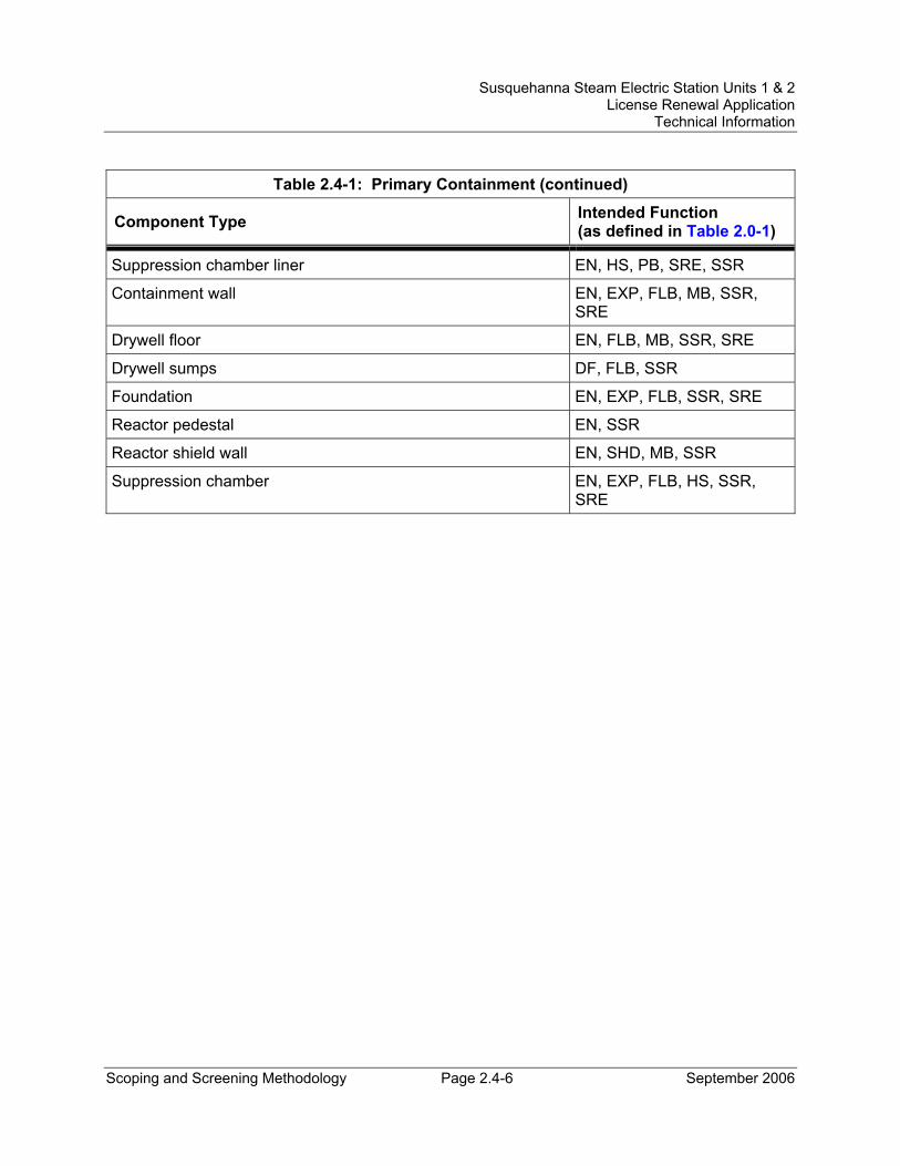
Susquehanna Steam Electric Station Units 1 & 2 License Renewal Application
Technical Information
Scoping and Screening Methodology Page 2.4-6 September 2006
Table 2.4-1: Primary Containment (continued)
Component Type Intended Function (as defined in Table 2.0-1)
Suppression chamber liner EN, HS, PB, SRE, SSR
Containment wall EN, EXP, FLB, MB, SSR, SRE
Drywell floor EN, FLB, MB, SSR, SRE
Drywell sumps DF, FLB, SSR
Foundation EN, EXP, FLB, SSR, SRE
Reactor pedestal EN, SSR
Reactor shield wall EN, SHD, MB, SSR
Suppression chamber EN, EXP, FLB, HS, SSR, SRE
Susquehanna Steam Electric Station Units 1 & 2 License Renewal Application
Technical Information
Scoping and Screening Methodology Page 2.4-7 September 2006
2.4.2 Reactor Building
Structure DescriptionThe Reactor Building is a seismic Category I structure that encloses the Primary Containment, and provides secondary containment when the Primary Containment is in service during power operation. It also serves as containment during reactor refueling and maintenance operations, when the Primary Containment is open. It houses the auxiliary systems of the nuclear steam supply system, new fuel storage vaults, the refueling facility, and equipment essential to the safe shutdown of the reactor.
The Reactor Building consists of the following major structural components:
• Foundation Mat - The Reactor Building foundation mat rests on bedrock and is separated from the Primary Containment by a gap, except at the foundation level, where a cold joint is provided between the two mats. A gap is also provided at the interface of the Reactor Building with the Diesel Generator and Turbine Buildings.
• Walls - The Reactor Building walls are of reinforced concrete and are designed as shear walls to resist lateral loads. Where structurally permissible, concrete block masonry walls are used at certain locations to provide better access for erection and installation of equipment.
• Floors - The Reactor Building floors are of reinforced concrete supported by a steel beam and column framing system. The steel columns are supported by base plates on the foundation mat.
• Superstructure – The Reactor Building superstructure above the operating floor is a steel structure. The structural steel framing supports the roof, metal siding, and overhead cranes. The framing consists of a series of rigid frames connected by roof and wall bracing systems.
• Refuel Floor - The Reactor Building refueling facility is located above the containment structure. The refuel floor consists of the spent fuel pool, fuel shipping cask storage pool, steam dryer and separator storage pool, reactor cavity, skimmer surge tank vault, and load center room. The roof consists of built up roofing on metal deck. The walls and slabs of the spent fuel pool, the fuel shipping cask storage pool, the reactor cavity, and the steam dryer and separator storage pool are lined on the inside with a stainless steel liner plate.
Reason for Scope Determination The Reactor Building is within the scope of license renewal as a safety-related structure, which meets the criterion of 10 CFR 54.4(a)(1). The functions of the Reactor Building are to control the release of radioactivity to the environment, to provide support
Susquehanna Steam Electric Station Units 1 & 2 License Renewal Application
Technical Information
Scoping and Screening Methodology Page 2.4-8 September 2006
and protection for equipment, and to provide the ability to maintain required temperatures for operation.
The Reactor Building is relied upon to demonstrate compliance with the Fire Protection (10 CFR 50.48), Anticipated Transients Without Scram (10 CFR 50.62), and Station Blackout (10 CFR 50.63) regulated events and meets the 10 CFR 54.4(a)(3) scoping criteria.
In addition, the Reactor Building is in the scope of license renewal because it contains:
• Structural components that are safety-related and are relied upon to remain functional during and following design basis events.
• Structural components which are nonsafety-related whose failure could prevent satisfactory accomplishment of safety-related functions.
• Structural components that are relied on during postulated fires, anticipated transients without scram, and station blackout events.
FSAR References Section 3.8.4 of the SSES FSAR describes the Reactor Building.
Components Subject to AMR Table 2.4-2 lists the component types that require aging management review and their intended functions.
The structural commodities for the Reactor Building are addressed in the bulk commodities evaluation in Section 2.4.10.
Table 3.5.2-2, Aging Management Review Results - Reactor Building, provides the results of the aging management review.
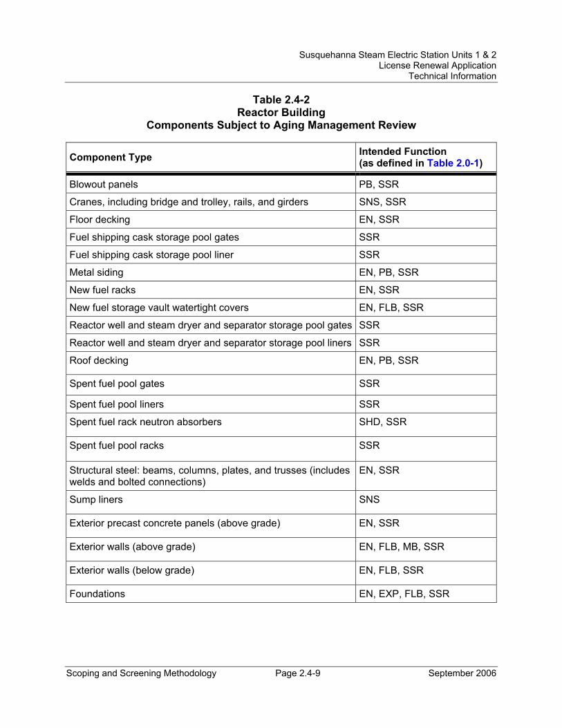
Susquehanna Steam Electric Station Units 1 & 2 License Renewal Application
Technical Information
Scoping and Screening Methodology Page 2.4-9 September 2006
Table 2.4-2 Reactor Building
Components Subject to Aging Management Review
Component Type Intended Function (as defined in Table 2.0-1)
Blowout panels PB, SSR
Cranes, including bridge and trolley, rails, and girders SNS, SSR
Floor decking EN, SSR
Fuel shipping cask storage pool gates SSR
Fuel shipping cask storage pool liner SSR
Metal siding EN, PB, SSR
New fuel racks EN, SSR
New fuel storage vault watertight covers EN, FLB, SSR
Reactor well and steam dryer and separator storage pool gates SSR
Reactor well and steam dryer and separator storage pool liners SSR
Roof decking EN, PB, SSR
Spent fuel pool gates SSR
Spent fuel pool liners SSR
Spent fuel rack neutron absorbers SHD, SSR
Spent fuel pool racks SSR
Structural steel: beams, columns, plates, and trusses (includes welds and bolted connections)
EN, SSR
Sump liners SNS
Exterior precast concrete panels (above grade) EN, SSR
Exterior walls (above grade) EN, FLB, MB, SSR
Exterior walls (below grade) EN, FLB, SSR
Foundations EN, EXP, FLB, SSR
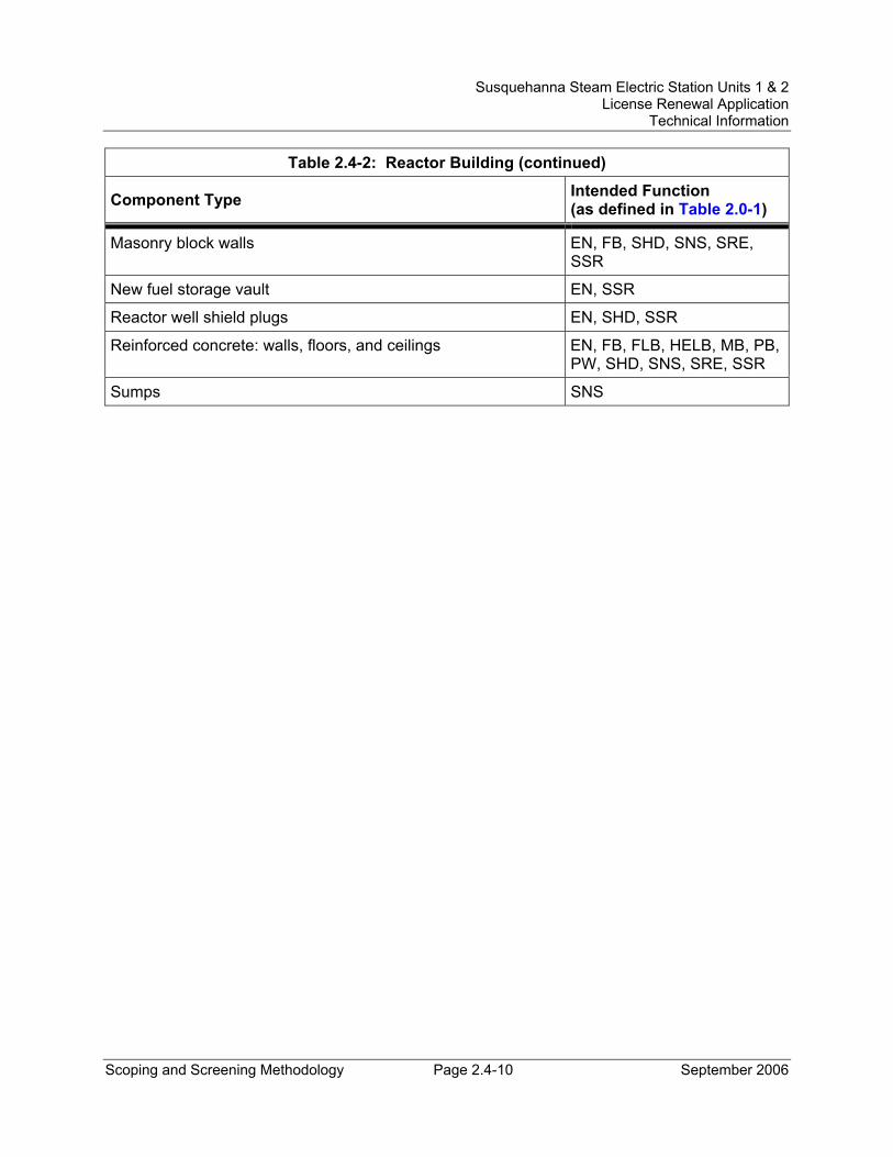
Susquehanna Steam Electric Station Units 1 & 2 License Renewal Application
Technical Information
Scoping and Screening Methodology Page 2.4-10 September 2006
Table 2.4-2: Reactor Building (continued)
Component Type Intended Function (as defined in Table 2.0-1)
Masonry block walls EN, FB, SHD, SNS, SRE, SSR
New fuel storage vault EN, SSR
Reactor well shield plugs EN, SHD, SSR
Reinforced concrete: walls, floors, and ceilings EN, FB, FLB, HELB, MB, PB, PW, SHD, SNS, SRE, SSR
Sumps SNS
Susquehanna Steam Electric Station Units 1 & 2 License Renewal Application
Technical Information
Scoping and Screening Methodology Page 2.4-11 September 2006
2.4.3 Engineered Safeguards Service Water Pumphouse and Spray Pond
Engineered Safeguards Service Water Pumphouse Structure Description The Engineered Safeguards Service Water (ESSW) Pumphouse is a seismic Category I structure that contains the Emergency Service Water and Residual Heat Removal Service Water pumps and the weir and discharge conduit for the spray pond. It is a two story reinforced concrete structure on a mat foundation. The first level of the structure is located below grade and consists of the following major compartments: pump intake chambers, overflow weir, and discharge header compartments. Pumps, valving, and associated electrical switchgear are located in the second level of the structure, which is at grade. HVAC equipment is located on a steel framed mezzanine level. A mezzanine floor is provided to support the heating and ventilating equipment.
The ESSW Pumphouse consists of the following major structural components:
• Foundation Mat - The reinforced concrete foundation mat is founded on soil. The depth of soil below the mat foundation varies from 35 to 60 feet. The soil is predominantly sand, gravel, cobbles, and boulders.
• Floors - The operating floor is of reinforced concrete supported by steel beams. The mezzanine floor is composed of grating over steel beams.
• Roof - The roof is of reinforced concrete supported by steel beams.
• Walls - The bearing walls are of reinforced concrete and are designed as shear walls to resist lateral loads.
• Chambers - The pump intake chambers and the overflow weir chamber are continuously flooded by the spray pond.
Reason for Scope Determination The ESSW Pumphouse is within the scope of license renewal as a safety-related structure, which meets the criterion of 10 CFR 54.4(a)(1). The functions of the ESSW Pumphouse are to provide support and protection for equipment, and to provide the ability to maintain required temperatures for operation.
The ESSW Pumphouse is relied upon to demonstrate compliance with the Fire Protection (10 CFR 50.48), Anticipated Transients Without Scram (10 CFR 50.62), and Station Blackout (10 CFR 50.63) regulated events and meets the 10 CFR 54.4(a)(3) scoping criteria.
In addition, the ESSW Pumphouse is in the scope of license renewal because it contains:
Susquehanna Steam Electric Station Units 1 & 2 License Renewal Application
Technical Information
Scoping and Screening Methodology Page 2.4-12 September 2006
• Structural components that are safety-related and are relied upon to remain functional during and following design basis events.
• Structural components which are nonsafety-related whose failure could prevent satisfactory accomplishment of safety-related functions.
• Structural components that are relied on during postulated fires, anticipated transients without scram, and station blackout events.
Spray Pond Structure Description The Spray Pond (ultimate heat sink) is a seismic Category I structure that provides cooling water to support operation of the ESW and RHRSW systems during system testing, during a normal shutdown, and during accident conditions. The ultimate heat sink is capable of providing sufficient cooling water without makeup to the Spray Pond for at least 30 days to permit simultaneous safe shutdown and cooldown of both reactor units and maintain them in a safe shutdown condition. The Spray Pond is capable of providing enough cooling water without makeup, for a design basis loss of coolant accident (LOCA) in one unit with the simultaneous shutdown of the other unit, for 30 days while assuming a concurrent safe shutdown earthquake (SSE), single failure, and loss of offsite power.
The Spray Pond consists of the following major structural components:
• Spray Pond Liner - The Spray Pond is concrete lined to minimize seepage. Vertical expansion joints containing waterstops are located at regular intervals around the circumference of the pond. The eastern end of the Spray Pond is founded on bedrock. The remaining western end is founded on sand and gravel soils which are stable against liquefaction failure during a safe shutdown earthquake.
• Spillway - An emergency spillway is provided at the east end of the pond. The only anticipated use of this spillway will be either during a malfunction of the discharge conduit leading out of the ESSW Pumphouse or during certain postulated flood conditions.
• Spray System - The spray system for the pond consists of one network for each ESW service water train. The ESW and RHRSW pipes enter the south side of the pond and traverse to the spray bank areas buried in 18 inches of concrete that is provided as missile protection. Concrete columns support the riser pipes in the spray bank areas.
• Earthen Embankment - Embankments are provided to ensure a minimum freeboard of 3 feet and to direct flood water away from safety-related facilities in a controlled manner.
Susquehanna Steam Electric Station Units 1 & 2 License Renewal Application
Technical Information
Scoping and Screening Methodology Page 2.4-13 September 2006
Reason for Scope Determination The Spray Pond is within the scope of license renewal as a safety-related structure, which meets the criterion of 10 CFR 54.4(a)(1). The function of the Spray Pond is to impound and provide cooling water for use in the ESW and RHRSW systems.
In addition, the Spray Pond is in the scope of license renewal because it contains:
• Structural components that are safety-related and are relied upon to remain functional during and following design basis events.
FSAR References Section 3.8.4 of the SSES FSAR describes the ESSW Pumphouse. Sections 3.8.4 and 9.2.7 of the SSES FSAR describe the spray pond.
Components Subject to AMR Table 2.4-3 lists the component types that require aging management review and their intended functions.
The structural commodities for the ESSW Pumphouse are addressed in the bulk commodities evaluation in Section 2.4.10. The piping trenches, valve vaults, and instrument pits located in the yard are addressed in the yard structures evaluation in Section 2.4.9.
Table 3.5.2-3, Aging Management Review Results – Engineered Safeguards Service Water Pumphouse and Spray Pond, provides the results of the aging management review.
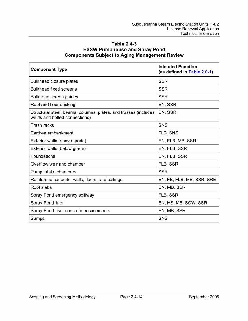
Susquehanna Steam Electric Station Units 1 & 2 License Renewal Application
Technical Information
Scoping and Screening Methodology Page 2.4-14 September 2006
Table 2.4-3 ESSW Pumphouse and Spray Pond
Components Subject to Aging Management Review
Component Type Intended Function (as defined in Table 2.0-1)
Bulkhead closure plates SSR
Bulkhead fixed screens SSR
Bulkhead screen guides SSR
Roof and floor decking EN, SSR
Structural steel: beams, columns, plates, and trusses (includes welds and bolted connections)
EN, SSR
Trash racks SNS
Earthen embankment FLB, SNS
Exterior walls (above grade) EN, FLB, MB, SSR
Exterior walls (below grade) EN, FLB, SSR
Foundations EN, FLB, SSR
Overflow weir and chamber FLB, SSR
Pump intake chambers SSR
Reinforced concrete: walls, floors, and ceilings EN, FB, FLB, MB, SSR, SRE
Roof slabs EN, MB, SSR
Spray Pond emergency spillway FLB, SSR
Spray Pond liner EN, HS, MB, SCW, SSR
Spray Pond riser concrete encasements EN, MB, SSR
Sumps SNS
Susquehanna Steam Electric Station Units 1 & 2 License Renewal Application
Technical Information
Scoping and Screening Methodology Page 2.4-15 September 2006
2.4.4 Circulating Water Pumphouse and Water Treatment Building
Structure Description The Circulating Water Pumphouse and Water Treatment Building is not a seismic Category I structure. The Water Treatment Building is a smaller, attached portion of the Circulating Water Pumphouse. The Circulating Water Pumphouse houses the electric and diesel driven fire water pumps which are separated by a structural fire barrier. The Water Treatment Building does not contain any equipment that is within the scope of license renewal. The Water Treatment Building shares a common wall, foundation, and roof with the Circulating Water Pumphouse. As such, the structural components associated with this wall, foundation, and roof are in the scope of license renewal, whereas the remainder of the Water Treatment Building is not.
The Circulating Water Pumphouse and Water Treatment Building consists of the following major structural components:
• Foundation Mat - The Circulating Water Pumphouse and Water Treatment Building have a reinforced concrete foundation mat, which is founded on bedrock.
• Floors - The Circulating Water Pumphouse and Water Treatment Building floors are reinforced concrete.
• Walls - The Circulating Water Pumphouse and Water Treatment Building exterior walls are a combination of precast concrete panels and metal siding. The interior walls are reinforced concrete and masonry block.
• Roof - The Circulating Water Pumphouse and Water Treatment Building has a built-up roof that is supported by a sheet metal decking.
Reason for Scope Determination The Circulating Water Pumphouse and Water Treatment Building is relied upon to demonstrate compliance with the Fire Protection (10 CFR 50.48) regulated event and meets the 10 CFR 54.4(a)(3) scoping criteria. The Circulating Water Pumphouse and Water Treatment Building provides physical support and protection to the fire water pumps.
In addition, the Circulating Water Pumphouse and Water Treatment Building is in the scope of license renewal because it contains:
• Structural components that are relied on during postulated fires.
FSAR References The Circulating Water Pumphouse and Water Treatment Building is not described in the SSES FSAR.
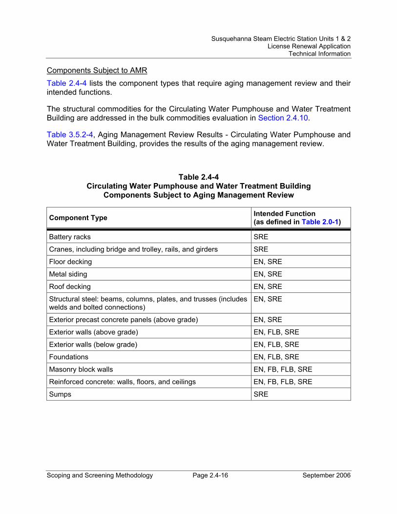
Susquehanna Steam Electric Station Units 1 & 2 License Renewal Application
Technical Information
Scoping and Screening Methodology Page 2.4-16 September 2006
Components Subject to AMR Table 2.4-4 lists the component types that require aging management review and their intended functions.
The structural commodities for the Circulating Water Pumphouse and Water Treatment Building are addressed in the bulk commodities evaluation in Section 2.4.10.
Table 3.5.2-4, Aging Management Review Results - Circulating Water Pumphouse and Water Treatment Building, provides the results of the aging management review.
Table 2.4-4 Circulating Water Pumphouse and Water Treatment Building
Components Subject to Aging Management Review
Component Type Intended Function (as defined in Table 2.0-1)
Battery racks SRE
Cranes, including bridge and trolley, rails, and girders SRE
Floor decking EN, SRE
Metal siding EN, SRE
Roof decking EN, SRE
Structural steel: beams, columns, plates, and trusses (includes welds and bolted connections)
EN, SRE
Exterior precast concrete panels (above grade) EN, SRE
Exterior walls (above grade) EN, FLB, SRE
Exterior walls (below grade) EN, FLB, SRE
Foundations EN, FLB, SRE
Masonry block walls EN, FB, FLB, SRE
Reinforced concrete: walls, floors, and ceilings EN, FB, FLB, SRE
Sumps SRE
Susquehanna Steam Electric Station Units 1 & 2 License Renewal Application
Technical Information
Scoping and Screening Methodology Page 2.4-17 September 2006
2.4.5 Control Structure
Structure Description The Control Structure is a seismic Category I structure that houses the control room, the cable spreading rooms, computer and relay room, the battery room, heating and ventilation equipment room, off gas treatment room, and the visitors' gallery for the control room. (Note: Elevation 656’-0” that is within the Control Structure envelope is considered part of the Turbine Building.)
The Control Structure consists of the following major structural components:
• Foundation Mat - The Control Structure is structurally integrated with the Reactor Building. The Control Structure is a reinforced concrete structure on a mat foundation. The Control Structure foundation mat is approximately 2 feet 6 inches thick. The Control Structure is separated from the Turbine Building by a gap, except at the foundation level, where a cold joint is provided between the two mats.
• Walls - The bearing walls are of reinforced concrete and are designed as shear walls to resist lateral loads. Where structurally permissible, concrete block masonry walls are used at certain locations to provide better access for erection and installation of equipment.
• Floors and Roof - The floors and roof are of reinforced concrete supported by steel beams, and are designed as diaphragms to resist lateral loads.
• Power Generation Control Complex (PGCC) - The upper relay room, lower relay room, and computer room in the Control Structure form the PGCC. The PGCC has a halon extinguishing system where halon is discharged under the PGCC flooring system or into the PGCC modules. The flooring support members, as well as all duct covers, are made of steel. The PGCC flooring panels are of two types, a steel flooring system and an Arboron flooring system. The steel flooring system panels consist of two steel plates with honeycomb sandwiched between them. The Arboron flooring system panels consist of cellulose-based laminate impregnated with thermosetting resins.
Reason for Scope Determination The Control Structure is within the scope of license renewal as a safety-related structure, which meets the criterion of 10 CFR 54.4(a)(1). The functions of the Control Structure are to provide support and protection for equipment, and to provide the ability to maintain required temperatures for operation.
The Control Structure is relied upon to demonstrate compliance with the Fire Protection (10 CFR 50.48), Anticipated Transients Without Scram (10 CFR 50.62), and Station
Susquehanna Steam Electric Station Units 1 & 2 License Renewal Application
Technical Information
Scoping and Screening Methodology Page 2.4-18 September 2006
Blackout (10 CFR 50.63) regulated events and meets the 10 CFR 54.4(a)(3) scoping criteria.
In addition, the Control Structure is in the scope of license renewal because it contains:
• Structural components that are safety-related and are relied upon to remain functional during and following design basis events.
• Structural components that are nonsafety-related whose failure could prevent satisfactory accomplishment of safety-related functions.
• Structural components that are relied on during postulated fires, anticipated transients without scram, and station blackout events.
FSAR References Section 3.8.4 of the SSES FSAR describes the Control Structure.
Components Subject to AMR Table 2.4-5 lists the component types that require aging management review and their intended functions.
The structural commodities for the Control Structure are addressed in the bulk commodities evaluation in Section 2.4.10.
Table 3.5.2-5, Aging Management Review Results - Control Structure, provides the results of the aging management review.
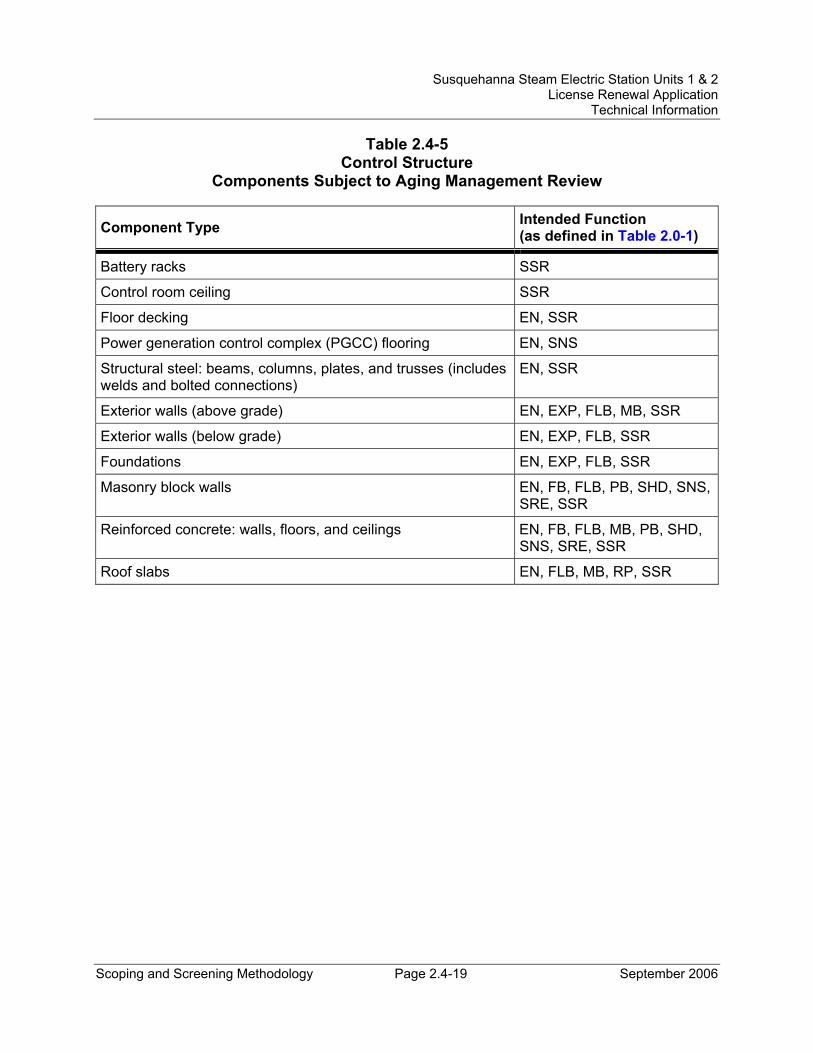
Susquehanna Steam Electric Station Units 1 & 2 License Renewal Application
Technical Information
Scoping and Screening Methodology Page 2.4-19 September 2006
Table 2.4-5 Control Structure
Components Subject to Aging Management Review
Component Type Intended Function (as defined in Table 2.0-1)
Battery racks SSR
Control room ceiling SSR
Floor decking EN, SSR
Power generation control complex (PGCC) flooring EN, SNS
Structural steel: beams, columns, plates, and trusses (includes welds and bolted connections)
EN, SSR
Exterior walls (above grade) EN, EXP, FLB, MB, SSR
Exterior walls (below grade) EN, EXP, FLB, SSR
Foundations EN, EXP, FLB, SSR
Masonry block walls EN, FB, FLB, PB, SHD, SNS, SRE, SSR
Reinforced concrete: walls, floors, and ceilings EN, FB, FLB, MB, PB, SHD, SNS, SRE, SSR
Roof slabs EN, FLB, MB, RP, SSR
Susquehanna Steam Electric Station Units 1 & 2 License Renewal Application
Technical Information
Scoping and Screening Methodology Page 2.4-20 September 2006
2.4.6 Diesel Generator ‘A, B, C, and D’ Building
Structure Description The Diesel Generator ’A, B, C, and D’ Building is a seismic Category I structure that houses diesel generators A, B, C, and D, which are essential for safe shutdown of the plant. The diesel generators are separated from each other by concrete walls. A concrete overhang on the east side of the building serves as an air intake plenum. A concrete plenum for diesel exhaust is located on the roof.
The Diesel Generator ’A, B, C and D’ Building consists of the following major structural components:
• Foundation Mat - The Diesel Generator ’A, B, C and D’ Building is a reinforced concrete structure on a foundation mat. The foundation mat is approximately 2 feet 6 inches thick. Cold joints are provided between the diesel generator pedestals and the foundation mat. There is a 2 inch seismic separation gap between the Diesel Generator 'A, B, C, and D' Building and the Unit 1 Reactor Building.
• Walls - The bearing walls are of reinforced concrete and are designed as shear walls to resist lateral loads. The south side of the building interfaces with the Reactor Building, a reinforced concrete wall is provided from foundation up to the design high water table level and a steel frame is provided up to the roof. Where structurally permissible, concrete block masonry walls are used at certain locations to provide better access for erection and installation of equipment.
• Floors and Roof - The floors and roof are of reinforced concrete supported by steel beams, and are designed as diaphragms to resist lateral loads.
Reason for Scope Determination The Diesel Generator ’A, B, C and D’ Building is within the scope of license renewal as a safety-related structure, which meets the criterion of 10 CFR 54.4(a)(1). The functions of the Diesel Generator ’A, B, C and D’ Building are to provide support and protection for equipment, and to provide the ability to maintain required temperatures for operation.
The Diesel Generator ’A, B, C and D’ Building is relied upon to demonstrate compliance with the Fire Protection (10 CFR 50.48) and Station Blackout (10 CFR 50.63) regulated events and meets the 10 CFR 54.4(a)(3) scoping criteria.
In addition, the Diesel Generator ’A, B, C and D’ Building is in the scope of license renewal because it contains:
• Structural components that are safety-related and are relied upon to remain functional during and following design basis events.
Susquehanna Steam Electric Station Units 1 & 2 License Renewal Application
Technical Information
Scoping and Screening Methodology Page 2.4-21 September 2006
• Structural components that are nonsafety-related whose failure could prevent satisfactory accomplishment of safety-related functions.
• Structural components that are relied on during postulated fires and station blackout events.
FSAR References Section 3.8.4 of the SSES FSAR describes the Diesel Generator ‘A, B, C, and D’ Building.
Components Subject to AMR Table 2.4-6 lists the component types that require aging management review and their intended functions.
The structural commodities for the Diesel Generator ‘A, B, C, and D’ Building are addressed in the bulk commodities evaluation in Section 2.4.10.
Table 3.5.2-6, Aging Management Review Results - Diesel Generator ‘A, B, C, and D’ Building, provides the results of the aging management review.
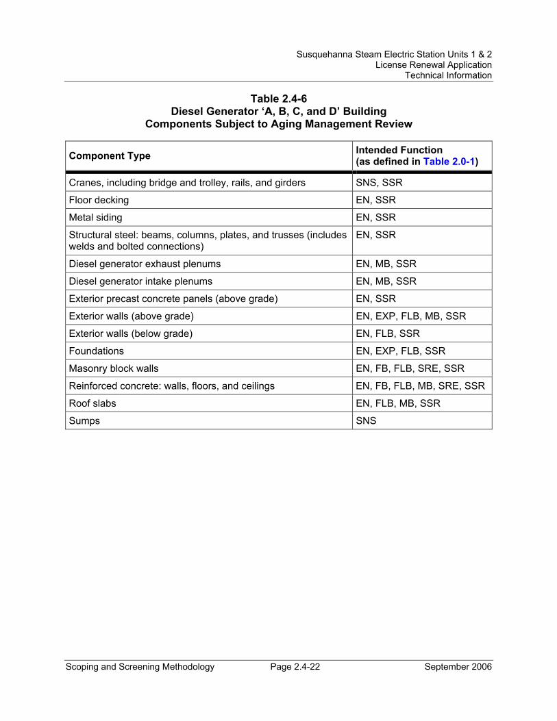
Susquehanna Steam Electric Station Units 1 & 2 License Renewal Application
Technical Information
Scoping and Screening Methodology Page 2.4-22 September 2006
Table 2.4-6 Diesel Generator ‘A, B, C, and D’ Building
Components Subject to Aging Management Review
Component Type Intended Function (as defined in Table 2.0-1)
Cranes, including bridge and trolley, rails, and girders SNS, SSR
Floor decking EN, SSR
Metal siding EN, SSR
Structural steel: beams, columns, plates, and trusses (includes welds and bolted connections)
EN, SSR
Diesel generator exhaust plenums EN, MB, SSR
Diesel generator intake plenums EN, MB, SSR
Exterior precast concrete panels (above grade) EN, SSR
Exterior walls (above grade) EN, EXP, FLB, MB, SSR
Exterior walls (below grade) EN, FLB, SSR
Foundations EN, EXP, FLB, SSR
Masonry block walls EN, FB, FLB, SRE, SSR
Reinforced concrete: walls, floors, and ceilings EN, FB, FLB, MB, SRE, SSR
Roof slabs EN, FLB, MB, SSR
Sumps SNS
Susquehanna Steam Electric Station Units 1 & 2 License Renewal Application
Technical Information
Scoping and Screening Methodology Page 2.4-23 September 2006
2.4.7 Diesel Generator ‘E’ Building
Structure Description The Diesel Generator 'E' Building is a seismic Category I structure that houses diesel generator E, which is used to replace one of the ’A, B, C, and D’ diesel generators. Openings for air intake and diesel exhaust are flush with the north and south exterior walls, respectively. Interior plenums are provided for missile protection.
The Diesel Generator 'E' Building consists of the following major structural components:
• Foundation Mat - The Diesel Generator 'E' Building is a reinforced concrete structure on a foundation mat. The foundation mat is approximately 3 feet 10 inches thick. Cold joints are provided between the diesel generator pedestal and the Diesel Generator ‘E’ Building foundation mat.
• Walls - The bearing walls are of reinforced concrete and are designed as shear walls to resist lateral loads. The building is a free standing detached structure with no other building in the immediate vicinity.
• Floors and Roof - The floors and roof are of reinforced concrete and are designed as diaphragms to resist lateral loads.
Reason for Scope Determination The Diesel Generator ’E’ Building is within the scope of license renewal as a safety-related structure, which meets the criterion of 10 CFR 54.4(a)(1). The functions of the Diesel Generator ’E’ Building are to provide support and protection for equipment, and to provide the ability to maintain required temperatures for operation.
The Diesel Generator ’E’ Building is relied upon to demonstrate compliance with the Fire Protection (10 CFR 50.48) and Station Blackout (10 CFR 50.63) regulated events and meets the 10 CFR 54.4(a)(3) scoping criteria.
In addition, the Diesel Generator ‘E’ Building is in the scope of license renewal because it contains:
• Structural components that are safety-related and are relied upon to remain functional during and following design basis events.
• Structural components that are nonsafety-related whose failure could prevent satisfactory accomplishment of safety-related functions.
• Structural components that are relied on during postulated fires and station blackout events.
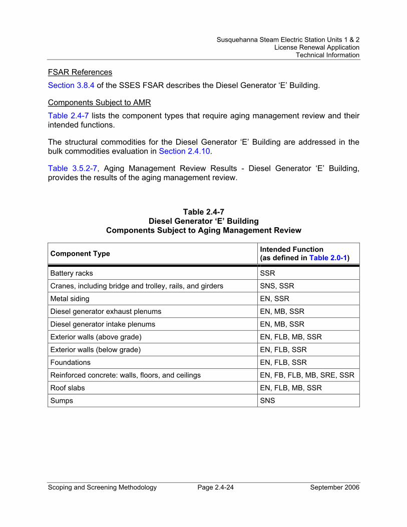
Susquehanna Steam Electric Station Units 1 & 2 License Renewal Application
Technical Information
Scoping and Screening Methodology Page 2.4-24 September 2006
FSAR References Section 3.8.4 of the SSES FSAR describes the Diesel Generator ‘E’ Building.
Components Subject to AMR Table 2.4-7 lists the component types that require aging management review and their intended functions.
The structural commodities for the Diesel Generator ‘E’ Building are addressed in the bulk commodities evaluation in Section 2.4.10.
Table 3.5.2-7, Aging Management Review Results - Diesel Generator ‘E’ Building, provides the results of the aging management review.
Table 2.4-7 Diesel Generator ‘E’ Building
Components Subject to Aging Management Review
Component Type Intended Function (as defined in Table 2.0-1)
Battery racks SSR
Cranes, including bridge and trolley, rails, and girders SNS, SSR
Metal siding EN, SSR
Diesel generator exhaust plenums EN, MB, SSR
Diesel generator intake plenums EN, MB, SSR
Exterior walls (above grade) EN, FLB, MB, SSR
Exterior walls (below grade) EN, FLB, SSR
Foundations EN, FLB, SSR
Reinforced concrete: walls, floors, and ceilings EN, FB, FLB, MB, SRE, SSR
Roof slabs EN, FLB, MB, SSR
Sumps SNS
Susquehanna Steam Electric Station Units 1 & 2 License Renewal Application
Technical Information
Scoping and Screening Methodology Page 2.4-25 September 2006
2.4.8 Turbine Building
Structure Description The Turbine Building is a not a seismic Category I structure and is divided into two units with an expansion joint separating the two units. It houses two in-line turbine generator units and auxiliary equipment including condensers, condensate pumps, moisture separators, air ejectors, feedwater heaters, reactor feed pumps, motor generator sets for reactor recirculation pumps, recombiners, interconnecting piping and valves, and switchgears. (Note: The basement elevation (656 feet) of the Turbine Building is an area whose walls, floor, and foundation belong to the Control Structure, but which is not part of the Control Structure pressurization envelope and is accessed through the Turbine Building.)
The Turbine Building consists of the following major structural components:
• Foundation Mat - The Turbine Building rests on a reinforced concrete mat foundation. The foundation mat is approximately 2 feet 6 inches thick. A cold joint is provided between the turbine pedestal mat and the Turbine Building foundation mat. A seismic separation gap, also serving as an expansion joint, is provided near the center of the building between the two units. Seismic separation gaps are also provided at the interface of Turbine Building with the Reactor, Control, and Radwaste Buildings.
• Walls - The superstructure is framed with structural steel and reinforced concrete. Two 220 ton overhead cranes, supported by rigid steel frames, are provided above the operating floor for service of both turbine generator units. Exterior walls are precast reinforced concrete panels, except for the upper 30 feet, which are metal siding. Interior walls required for radiation shielding or fire protection are constructed of reinforced concrete block.
• Floors and Roof - The floors of the Turbine Building are of reinforced concrete on structural steel beams. They are designed as diaphragms for lateral load transfer to the shear walls. The roof is built-up roofing on metal decking.
• Main Steam Tunnel - Reinforced concrete tunnels are provided for the main steam lines below the operating floor from the Reactor Building to the condenser areas of the turbine generators.
• Turbine Generator Pedestals – The pedestals are of reinforced concrete. Separation joints exist between the turbine pedestals and turbine floors and walls to prevent transfer of vibration to the building. Steel beams supported by the turbine pedestal are isolated with a structural bearing pad (slide bearing assemblies) installed between the steel beams and the concrete pedestal structure.
Susquehanna Steam Electric Station Units 1 & 2 License Renewal Application
Technical Information
Scoping and Screening Methodology Page 2.4-26 September 2006
Reason for Scope Determination The Turbine Building provides structural or functional support to nonsafety-related equipment whose failure could prevent satisfactory accomplishment of required safety functions. These functions meet the scoping criteria of 10 CFR 54.4(a)(2).
The Turbine Building is relied upon to demonstrate compliance with the Fire Protection (10 CFR 50.48) and Station Blackout (10 CFR 50.63) regulated events and meets the 10 CFR 54.4(a)(3) scoping criteria.
In addition, the Turbine Building is in the scope of license renewal because it contains:
• Structural components that are safety-related and are relied upon to remain functional during and following design basis events.
• Structural components which are nonsafety-related whose failure could prevent satisfactory accomplishment of safety-related functions.
• Structural components that are relied on during postulated fires and anticipated station blackout events.
FSAR References Section 3.8.4 of the SSES FSAR describes the Turbine Building.
Components Subject to AMR Table 2.4-8 lists the component types that require aging management review and their intended functions.
The structural commodities for the Turbine Building are addressed in the bulk commodities evaluation in Section 2.4.10.
Table 3.5.2-8, Aging Management Review Results - Turbine Building, provides the results of the aging management review.
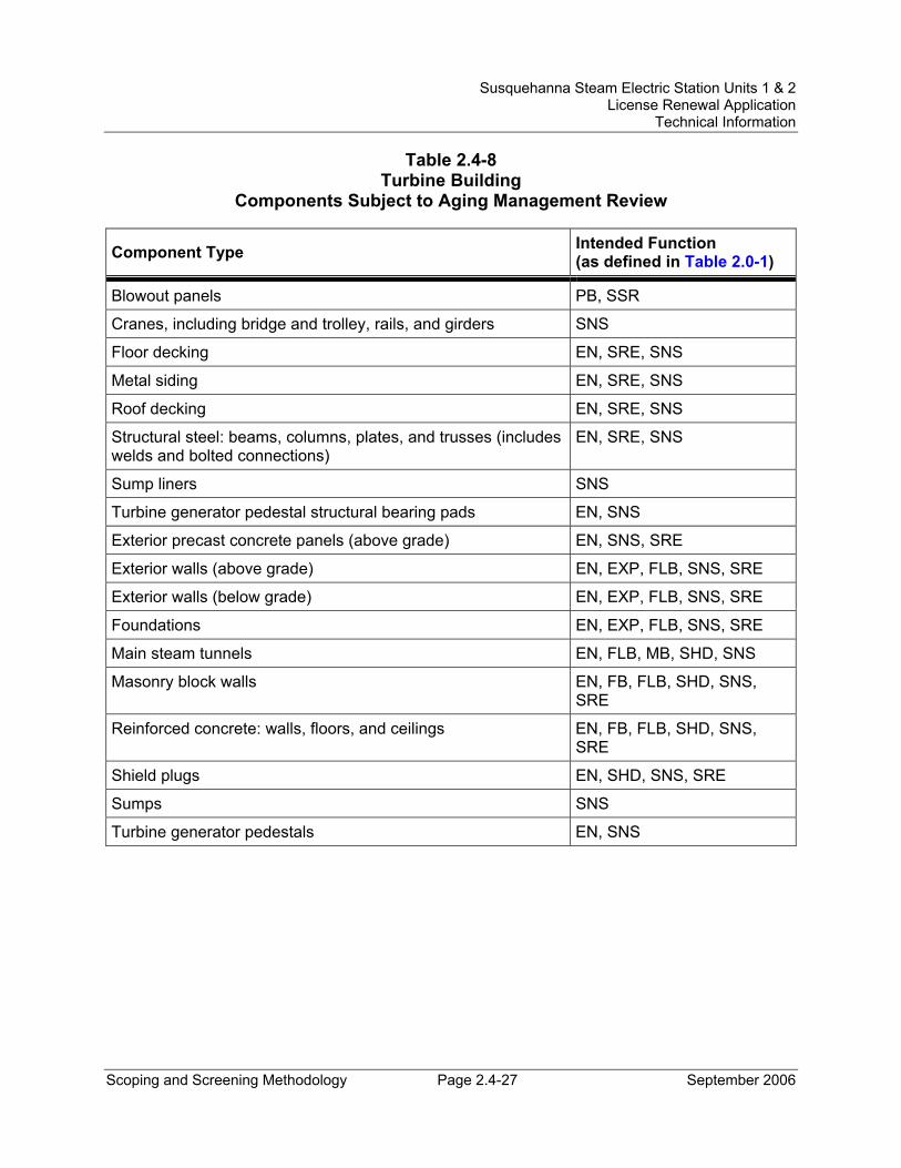
Susquehanna Steam Electric Station Units 1 & 2 License Renewal Application
Technical Information
Scoping and Screening Methodology Page 2.4-27 September 2006
Table 2.4-8 Turbine Building
Components Subject to Aging Management Review
Component Type Intended Function (as defined in Table 2.0-1)
Blowout panels PB, SSR
Cranes, including bridge and trolley, rails, and girders SNS
Floor decking EN, SRE, SNS
Metal siding EN, SRE, SNS
Roof decking EN, SRE, SNS
Structural steel: beams, columns, plates, and trusses (includes welds and bolted connections)
EN, SRE, SNS
Sump liners SNS
Turbine generator pedestal structural bearing pads EN, SNS
Exterior precast concrete panels (above grade) EN, SNS, SRE
Exterior walls (above grade) EN, EXP, FLB, SNS, SRE
Exterior walls (below grade) EN, EXP, FLB, SNS, SRE
Foundations EN, EXP, FLB, SNS, SRE
Main steam tunnels EN, FLB, MB, SHD, SNS
Masonry block walls EN, FB, FLB, SHD, SNS, SRE
Reinforced concrete: walls, floors, and ceilings EN, FB, FLB, SHD, SNS, SRE
Shield plugs EN, SHD, SNS, SRE
Sumps SNS
Turbine generator pedestals EN, SNS
Susquehanna Steam Electric Station Units 1 & 2 License Renewal Application
Technical Information
Scoping and Screening Methodology Page 2.4-28 September 2006
2.4.9 Yard Structures
Yard structures at SSES are structures not contained within or attached to major buildings such as the Reactor Building, Turbine Building, Diesel Generator Buildings, or Control Structure. The yard structures evaluated for license renewal include foundations and structural arrangements for outside tanks, basins, vaults, duct banks, manholes, pits, and trenches. The following yard structures were determined to be within the scope of license renewal:
2.4.9.1 Clarified Water Storage Tank Foundation Structure Description The Clarified Water Storage Tank foundation is not a seismic Category I structure. The 500,000 gallon Clarified Water Storage Tank is located in the yard. The storage tank acts as the primary water source for fire protection with a standpipe in the tank which reserves 300,000 gallons of the stored water for fire protection. The tank also provides a source of domestic water to the plant site.
The Clarified Water Storage Tank foundation is a reinforced concrete slab that supports the tank. The Clarified Water Storage Tank bottom rests on an oiled sand pad.
Reason for Scope Determination The Clarified Water Storage Tank foundation is relied upon to demonstrate compliance with the Fire Protection (10 CFR 50.48) regulated event and meets the 10 CFR 54.4(a)(3) scoping criteria.
In addition, the Clarified Water Storage Tank foundation is in the scope of license renewal because it contains:
• Structural components that are relied on during postulated fires.
2.4.9.2 Condensate Storage Tank Foundation and Retention Basin Structure Description The Condensate Storage Tank foundation and retention basin are not seismic Category I structures. The Condensate Storage Tanks are the preferred source of water for the high pressure coolant injection (HPCI) and reactor core isolation cooling (RCIC) pumps for both operational use and testing. In addition, they supply water to the core spray pumps for testing. Each Condensate Storage Tank maintains a minimum storage of 135,000 gallons to service the associated HPCI and RCIC pumps during plant operation by use of standpipes and locked closed valves on all other lines.
The Condensate Storage Tank foundation is a reinforced concrete slab that supports the tank and is approximately 3 feet thick. Waterstops are provided in construction
Susquehanna Steam Electric Station Units 1 & 2 License Renewal Application
Technical Information
Scoping and Screening Methodology Page 2.4-29 September 2006
joints abutting the retention basin slab. The Condensate Storage Tank bottom rests on an oiled sand pad.
The Condensate Storage Tank is surrounded by reinforced concrete walls (i.e., retention basin) designed to retain the total volume of water in the tank if it ruptures. The retention basin for the Unit 1 Condensate Storage Tank consists of a portion of Turbine Building wall, Reactor Building wall, Diesel Generator Building wall, and a free-standing reinforced concrete retaining wall. The retention basin for the Unit 2 Condensate Storage Tank consists of a portion of Turbine Building wall, Reactor Building wall, and two sides of reinforced concrete retaining walls. The retention basin slab is constructed of reinforced concrete with an integral sump. A 2 inch separation gap with waterstop is provided against all building walls.
Reason for Scope Determination The Condensate Storage Tank foundation and retention basin provides structural or functional support to nonsafety-related equipment whose failure could prevent satisfactory accomplishment of required safety functions. These functions meet the scoping criteria of 10 CFR 54.4(a)(2).
The Condensate Storage Tank foundation and retention basin is relied upon to demonstrate compliance with the Anticipated Transients Without Scram (10 CFR 50.62) and Station Blackout (10 CFR 50.63) regulated events and meets the 10 CFR 54.4(a)(3) scoping criteria.
In addition, the Condensate Storage Tank foundation and retention basin are in the scope of license renewal because they contain:
• Structural components that are nonsafety-related whose failure could prevent satisfactory accomplishment of safety-related functions.
• Structural components that are relied on during anticipated transients without scram and station blackout events.
2.4.9.3 Diesel Generator Fuel Oil Storage Tank ‘A, B, C, D, and E’ Foundations and Vaults
Structure Description The Diesel Generator Fuel Oil Storage Tank ‘A, B, C, D, and E’ foundations and vaults are seismic Category I structures. Four 50,000 gallon nominal capacity fuel oil storage tanks are provided for diesel generators ‘A, B, C and D’ and one 80,000 gallon nominal capacity fuel oil storage tank is provided for diesel generator 'E'. The tanks for diesel generators ‘A, B, C, and D’ are buried underground adjacent to the Diesel Generator Building. The tank for diesel generator 'E' is buried underground adjacent to the Diesel Generator 'E' Building.
Susquehanna Steam Electric Station Units 1 & 2 License Renewal Application
Technical Information
Scoping and Screening Methodology Page 2.4-30 September 2006
A common reinforced concrete slab foundation is shared between Diesel Generator Fuel Oil Storage Tanks ‘A, B, C and D’. Diesel Generator Fuel Oil Storage Tank ‘E’ is situated on its own reinforced concrete slab foundation. The concrete tank foundation slab for Diesel Generator Fuel )Oil Storage Tanks ‘A, B, C and D’ is approximately 2 feet 6 inches thick. The concrete tank foundation slab for Diesel Generator Fuel Oil Storage Tank ‘E’ is approximately 5 feet thick. A concrete vault is provided for each tank from grade to the tank connections for access, maintenance, inspection, and repair and to provide missile protection of the tank connections. The vault cover at grade level is made of steel plate.
Reason for Scope Determination The Diesel Generator Fuel Oil Storage Tank ‘A, B, C, D, and E’ foundations and vaults provide physical support and protection for the safety-related Diesel Generator Fuel Oil Storage Tanks. These functions meet the criterion of 10 CFR 54.4(a)(1).
The Diesel Generator Fuel Oil Storage Tank ‘A, B, C, D, and E’ foundations and vaults are relied upon to demonstrate compliance with the Station Blackout (10 CFR 50.63) regulated event and meet the 10 CFR 54.4(a)(3) scoping criteria.
In addition, the Diesel Generator Fuel Oil Storage Tank ‘A, B, C, D, and E’ foundations and vaults are in the scope of license renewal because they contain:
• Structural components that are safety-related and are relied upon to remain functional during and following design basis events.
• Structural components that are relied on during station blackout events.
2.4.9.4 Refueling Water Storage Tank Foundation Structure Description The Refueling Water Storage Tank foundation is a not a seismic Category I structure. One 680,000 gallon Refueling Water Storage Tank common to both units stores the water that is used to fill the reactor well and dryer separator pool of either Unit 1 or 2.
The Refueling Water Storage Tank foundation is a reinforced concrete slab that supports the tank and is approximately 3 feet thick. Waterstops are provided in construction joints abutting the retention basin slab. The Refueling Water Storage Tank bottom rests on an oiled sand pad.
The Refueling Water Storage Tank and the Unit 1 Condensate Storage Tank are surrounded by a reinforced concrete wall designed to retain the total volume of water in the tanks if they rupture. Water that collects within the retaining walls can be processed to the liquid radwaste system, discharged to the cooling tower blowdown outfall via a tanker or drained directly to the storm sewer. Berm area water discharged to plant outfalls is sampled for radiation and water quality prior to release.
Susquehanna Steam Electric Station Units 1 & 2 License Renewal Application
Technical Information
Scoping and Screening Methodology Page 2.4-31 September 2006
Reason for Scope Determination The Refueling Water Storage Tank foundation provides physical support to the Refueling Water Storage Tank, which has to maintain sufficient structural and pressure boundary integrity to prevent adverse physical interaction, such as wetting, with safety-related components. This meets the scoping criteria of 10 CFR 54.4(a)(2).
In addition, the Refueling Water Storage Tank foundation is in the scope of license renewal because it contains:
• Structural components that are nonsafety-related whose failure could prevent satisfactory accomplishment of safety-related functions.
2.4.9.5 Station Blackout Component Foundations and Structures in the Yard (Startup Transformers T-10 and T-20 and Associated Disconnect Switches, and ESS Transformers)
Structure Description The station blackout component foundations and structures in the yard (startup transformers T-10 and T-20 and associated disconnect switches, and Engineered Safeguards Systems (ESS) transformers) are not seismic Category I structures. Startup transformers T-10 and T-20 and associated disconnect switches (motor-operated air switches 1R105 and 2R105) define the physical boundary that provides an offsite alternating current (AC) source for recovery from a station blackout (SBO) regulated event.
The startup transformers and associated disconnect switches, as well as the ESS Transformers, are supported by reinforced concrete pads. Disconnect switches are supported by steel frame structures, electrical cables are supported by tapered steel transmission towers.
Reason for Scope Determination The station blackout component foundations and structures in the yard (startup transformers T-10 and T-20 and associated disconnect switches, and ESS transformers) provide physical support for equipment relied upon to demonstrate compliance with the Station Blackout (10 CFR 50.63) regulated event. This meets the 10 CFR 54.4(a)(3) scoping criteria.
In addition, the station blackout component foundations and structures in the yard (startup transformers T-10 and T-20 and associated disconnect switches, and ESS transformers) are in the scope of license renewal because they contain:
• Structural components that are relied on during station blackout events.
Susquehanna Steam Electric Station Units 1 & 2 License Renewal Application
Technical Information
Scoping and Screening Methodology Page 2.4-32 September 2006
2.4.9.6 Cooling Tower Basins Structure Description The Cooling Tower Basins are not seismic Category I structures. The basins are designed to be completely watertight, with a capacity of six million gallons of water. The two basins are a secondary source of water for the plant's two main automatic fire pumps.
The Cooling Tower Basins have a minimum depth of 7 feet 6 inches and the top of the basin is approximately 2 feet above the finished grade. The Cooling Tower Basins are constructed with reinforced concrete. The Cooling Tower Basin foundations are situated on bedrock.
The Cooling Tower Basin outlet structure walls are constructed to contain dual ¼ inch mesh screens and guides, together with recesses for stop logs. Precast concrete covers are used over the dual screens and stop logs.
Reason for Scope Determination The Cooling Tower Basins function to impound a water supply available as a secondary source relied upon during a Fire Protection (10 CFR 50.48) regulated event and meet the 10 CFR 54.4(a)(3) scoping criteria.
In addition, the Cooling Tower Basins are in the scope of license renewal because they contain:
• Structural components that are relied on during postulated fires.
2.4.9.7 Duct Banks, Manholes, Valve Vaults, Instrument Pits, and Piping Trenches in the Yard
Structure Description Duct banks, manholes, valve vaults (includes Spray Pond valve vault), instrument pits, and piping trenches are installed and routed in the yard to provide physical support and shelter for in-scope mechanical components such as piping and valves and in-scope electrical components such as electric cables and conduits. The duct banks, manholes, valve vaults, instrument pits, and piping trenches are seismic Category I when they function to support or contain safety-related equipment. They are not seismic Category I when they function to support or contain equipment required for regulated events.
Buried seismic Category I electrical duct banks are composed of reinforced concrete encasements around plastic or metal ducting; the concrete encasement is cast directly against the excavated grade.
Susquehanna Steam Electric Station Units 1 & 2 License Renewal Application
Technical Information
Scoping and Screening Methodology Page 2.4-33 September 2006
Reason for Scope Determination The duct banks, manholes, valve vaults (includes Spray Pond valve vault), instrument pits, and piping trenches located in the yard are in scope because they contain or support safety-related equipment and therefore meet the criterion of 10 CFR 54.4(a)(1).
The duct banks, manholes, valve vaults (includes Spray Pond valve vault), instrument pits, and piping trenches located in the yard are in scope because they contain or support equipment relied upon to demonstrate compliance with the Station Blackout (10 CFR 50.63) regulated event and therefore meet the 10 CFR 54.4(a)(3) scoping criteria.
In addition, the duct banks, manholes, valve vaults (includes Spray Pond valve vault), instrument pits, and piping trenches located in the yard are in the scope of license renewal because they contain:
• Structural components that are safety-related and are relied upon to remain functional during and following design basis events.
• Structural components that are nonsafety-related whose failure could prevent satisfactory accomplishment of safety-related functions.
• Structural components that are relied on during station blackout events.
FSAR References Section 9.2.8.2 of the SSES FSAR describes the Clarified Water Storage Tank. The structural details of the foundation are not described.
Section 9.2.10 of the SSES FSAR describes the Condensate Storage Tank and the retention basin. The structural details of the foundation and retention basin are not described.
Section 9.5.4 of the SSES FSAR describes the Diesel Fuel Oil Storage Tanks and the vault. The structural details of the foundation and vault are not described.
The structural details of the SBO component foundations and structures are not described in the SSES FSAR.
The structural details of the Cooling Tower Basins are not described in the SSES FSAR.
The structural details of the duct banks, manholes, valve vaults, instrument pits, and piping trenches are not described in the SSES FSAR.
Susquehanna Steam Electric Station Units 1 & 2 License Renewal Application
Technical Information
Scoping and Screening Methodology Page 2.4-34 September 2006
Components Subject to AMR Table 2.4-9 lists the component types that require aging management review and their intended functions.
Field erected tanks are evaluated in Section 2.3 as mechanical components within their corresponding system. The structural commodities for the yard structures are addressed in the bulk commodities evaluation in Section 2.4.10.
Table 3.5.2-9, Aging Management Review Results - Yard Structures, provides the results of the aging management review.
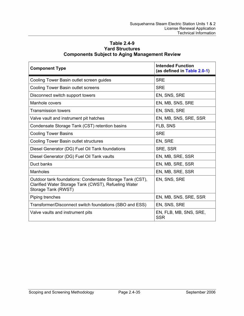
Susquehanna Steam Electric Station Units 1 & 2 License Renewal Application
Technical Information
Scoping and Screening Methodology Page 2.4-35 September 2006
Table 2.4-9 Yard Structures
Components Subject to Aging Management Review
Component Type Intended Function (as defined in Table 2.0-1)
Cooling Tower Basin outlet screen guides SRE
Cooling Tower Basin outlet screens SRE
Disconnect switch support towers EN, SNS, SRE
Manhole covers EN, MB, SNS, SRE
Transmission towers EN, SNS, SRE
Valve vault and instrument pit hatches EN, MB, SNS, SRE, SSR
Condensate Storage Tank (CST) retention basins FLB, SNS
Cooling Tower Basins SRE
Cooling Tower Basin outlet structures EN, SRE
Diesel Generator (DG) Fuel Oil Tank foundations SRE, SSR
Diesel Generator (DG) Fuel Oil Tank vaults EN, MB, SRE, SSR
Duct banks EN, MB, SRE, SSR
Manholes EN, MB, SRE, SSR
Outdoor tank foundations: Condensate Storage Tank (CST), Clarified Water Storage Tank (CWST), Refueling Water Storage Tank (RWST)
EN, SNS, SRE
Piping trenches EN, MB, SNS, SRE, SSR
Transformer/Disconnect switch foundations (SBO and ESS) EN, SNS, SRE
Valve vaults and instrument pits EN, FLB, MB, SNS, SRE, SSR
Susquehanna Steam Electric Station Units 1 & 2 License Renewal Application
Technical Information
Scoping and Screening Methodology Page 2.4-36 September 2006
2.4.10 Bulk Commodities
Structure Description Bulk commodities are structural component groups that support in-scope structures and mechanical/electrical systems (e.g., anchorages, embedments, instrument panels, racks, cable trays, conduits, fire seals, fire doors, hatches, monorails, equipment and component supports). They are common to multiple SSCs and share material and environment properties which allow a common program or inspection to manage their aging effects.
Reason for Scope Determination Bulk commodities are in scope based on the equipment that they support or protect. Bulk commodities that support or protect safety-related equipment meet the criterion of 10 CFR 54.4(a)(1).
Bulk commodities are in scope based on the equipment that they support or protect. Bulk commodities that support or protect nonsafety-related equipment meet the criterion of 10 CFR 54.4(a)(2).
Bulk commodities are in scope based on the equipment that they support or protect. Bulk commodities that support or protect equipment are relied upon to demonstrate compliance with the Fire Protection (10 CFR 50.48), Anticipated Transients Without Scram (10 CFR 50.62), or Station Blackout (10 CFR 50.63) regulated events and meet the 10 CFR 54.4(a)(3) scoping criteria.
In addition, bulk commodities are in the scope of license renewal because they contain:
• Structural components that are safety-related and are relied upon to remain functional during and following design basis events.
• Structural components that are nonsafety-related whose failure could prevent satisfactory accomplishment of safety-related functions.
• Structural components that are relied on during postulated fires, anticipated transients without scram, and station blackout events.
FSAR References The SSES FSAR contains numerous mentions of these commodities, but does not specifically discuss or describe commodities.
Components Subject to AMR Table 2.4-10 lists the component types that require aging management review and their intended functions.
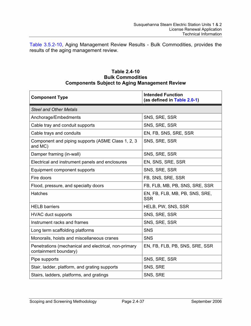
Susquehanna Steam Electric Station Units 1 & 2 License Renewal Application
Technical Information
Scoping and Screening Methodology Page 2.4-37 September 2006
Table 3.5.2-10, Aging Management Review Results - Bulk Commodities, provides the results of the aging management review.
Table 2.4-10 Bulk Commodities
Components Subject to Aging Management Review
Component Type Intended Function (as defined in Table 2.0-1)
Steel and Other Metals
Anchorage/Embedments SNS, SRE, SSR
Cable tray and conduit supports SNS, SRE, SSR
Cable trays and conduits EN, FB, SNS, SRE, SSR
Component and piping supports (ASME Class 1, 2, 3 and MC)
SNS, SRE, SSR
Damper framing (in-wall) SNS, SRE, SSR
Electrical and instrument panels and enclosures EN, SNS, SRE, SSR
Equipment component supports SNS, SRE, SSR
Fire doors FB, SNS, SRE, SSR
Flood, pressure, and specialty doors FB, FLB, MB, PB, SNS, SRE, SSR
Hatches EN, FB, FLB, MB, PB, SNS, SRE, SSR
HELB barriers HELB, PW, SNS, SSR
HVAC duct supports SNS, SRE, SSR
Instrument racks and frames SNS, SRE, SSR
Long term scaffolding platforms SNS
Monorails, hoists and miscellaneous cranes SNS
Penetrations (mechanical and electrical, non-primary containment boundary)
EN, FB, FLB, PB, SNS, SRE, SSR
Pipe supports SNS, SRE, SSR
Stair, ladder, platform, and grating supports SNS, SRE
Stairs, ladders, platforms, and gratings SNS, SRE
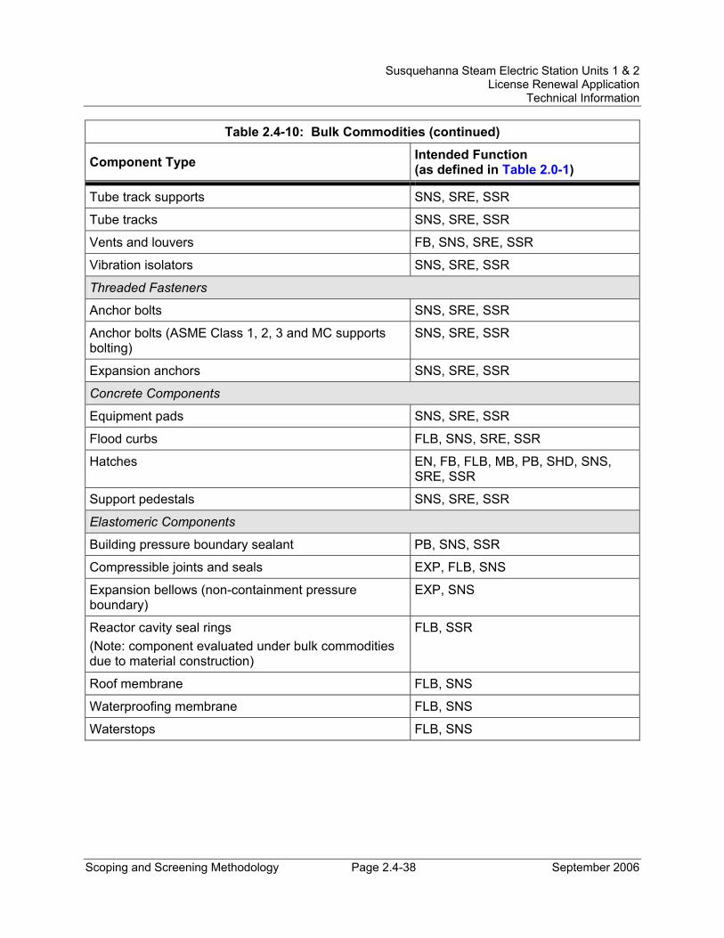
Susquehanna Steam Electric Station Units 1 & 2 License Renewal Application
Technical Information
Scoping and Screening Methodology Page 2.4-38 September 2006
Table 2.4-10: Bulk Commodities (continued)
Component Type Intended Function (as defined in Table 2.0-1)
Tube track supports SNS, SRE, SSR
Tube tracks SNS, SRE, SSR
Vents and louvers FB, SNS, SRE, SSR
Vibration isolators SNS, SRE, SSR
Threaded Fasteners
Anchor bolts SNS, SRE, SSR
Anchor bolts (ASME Class 1, 2, 3 and MC supports bolting)
SNS, SRE, SSR
Expansion anchors SNS, SRE, SSR
Concrete Components
Equipment pads SNS, SRE, SSR
Flood curbs FLB, SNS, SRE, SSR
Hatches EN, FB, FLB, MB, PB, SHD, SNS, SRE, SSR
Support pedestals SNS, SRE, SSR
Elastomeric Components
Building pressure boundary sealant PB, SNS, SSR
Compressible joints and seals EXP, FLB, SNS
Expansion bellows (non-containment pressure boundary)
EXP, SNS
Reactor cavity seal rings (Note: component evaluated under bulk commodities due to material construction)
FLB, SSR
Roof membrane FLB, SNS
Waterproofing membrane FLB, SNS
Waterstops FLB, SNS
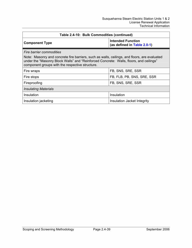
Susquehanna Steam Electric Station Units 1 & 2 License Renewal Application
Technical Information
Scoping and Screening Methodology Page 2.4-39 September 2006
Table 2.4-10: Bulk Commodities (continued)
Component Type Intended Function (as defined in Table 2.0-1)
Fire barrier commodities Note: Masonry and concrete fire barriers, such as walls, ceilings, and floors, are evaluated under the “Masonry Block Walls” and “Reinforced Concrete: Walls, floors, and ceilings” component groups with the respective structure.
Fire wraps FB, SNS, SRE, SSR
Fire stops FB, FLB, PB, SNS, SRE, SSR
Fireproofing FB, SNS, SRE, SSR
Insulating Materials
Insulation Insulation
Insulation jacketing Insulation Jacket Integrity
Susquehanna Steam Electric Station Units 1 & 2 License Renewal Application
Technical Information
Scoping and Screening Methodology Page 2.5-1 September 2006
2.5 SCOPING AND SCREENING RESULTS: ELECTRICAL AND INSTRUMENTATION AND CONTROLS SYSTEMS
The determination of electrical and instrumentation and controls (I&C) systems within the scope of license renewal is made through the application of the process described in Section 2.1. The results of the electrical and I&C systems scoping review are contained in Section 2.2.
Section 2.1 also provides the methodology for determining the components within the scope of 10 CFR 54.4 that meet the requirements contained in 10 CFR 54.21(a)(1). The components that meet these screening requirements are identified in this section. These identified components consequently require an aging management review for license renewal.
The screening for electrical and I&C components is performed on a component (commodity group) basis for the in-scope electrical/I&C systems listed in Table 2.2-2, as well as the electrical and I&C component types associated with in-scope mechanical systems listed in Table 2.2-1.
Components that support or interface with electrical and I&C components, for example, instrument racks, panels, cabinets, cable trays, conduit, and their supports, are included in the civil/structural assessment documented in Section 2.4.
Information on the SSES electrical and I&C systems can be found in FSAR Chapter 7 for the instrumentation and control systems, Chapter 8 for the electrical power systems, and Section 8.2 for the station offsite power system.
2.5.1 Electrical/I&C Screening Process
The screening process identifies the electrical component commodity groups that are subject to aging management review (for in-scope plant systems including electrical and I&C components). This identification is performed by following the requirements of 10 CFR 54.21(a) and the guidance of NEI 95-10, Appendix B. Electrical components that are active and electrical components which are replaced on a specified time schedule are excluded. Only long-lived and passive components that are within the scope of license renewal and which perform a license renewal intended function are subject to aging management review.
2.5.2 Application of Screening Criterion 10 CFR 54.21(a)(1)(i) to Electrical/I&C Component Commodity Groups
The screening determination with respect to the passive criterion is taken directly from NEI 95-10. It is important to note that the definitions of active and passive with respect to license renewal may not correspond to the definitions typically used for these terms in
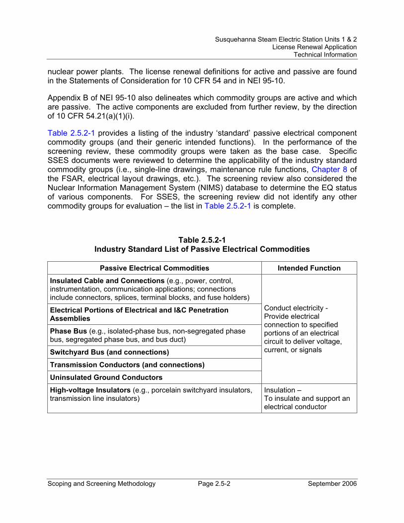
Susquehanna Steam Electric Station Units 1 & 2 License Renewal Application
Technical Information
Scoping and Screening Methodology Page 2.5-2 September 2006
nuclear power plants. The license renewal definitions for active and passive are found in the Statements of Consideration for 10 CFR 54 and in NEI 95-10.
Appendix B of NEI 95-10 also delineates which commodity groups are active and which are passive. The active components are excluded from further review, by the direction of 10 CFR 54.21(a)(1)(i).
Table 2.5.2-1 provides a listing of the industry ‘standard’ passive electrical component commodity groups (and their generic intended functions). In the performance of the screening review, these commodity groups were taken as the base case. Specific SSES documents were reviewed to determine the applicability of the industry standard commodity groups (i.e., single-line drawings, maintenance rule functions, Chapter 8 of the FSAR, electrical layout drawings, etc.). The screening review also considered the Nuclear Information Management System (NIMS) database to determine the EQ status of various components. For SSES, the screening review did not identify any other commodity groups for evaluation – the list in Table 2.5.2-1 is complete.
Table 2.5.2-1 Industry Standard List of Passive Electrical Commodities
Passive Electrical Commodities Intended Function
Insulated Cable and Connections (e.g., power, control, instrumentation, communication applications; connections include connectors, splices, terminal blocks, and fuse holders)
Electrical Portions of Electrical and I&C Penetration Assemblies
Phase Bus (e.g., isolated-phase bus, non-segregated phase bus, segregated phase bus, and bus duct)
Switchyard Bus (and connections)
Transmission Conductors (and connections)
Uninsulated Ground Conductors
Conduct electricity - Provide electrical connection to specified portions of an electrical circuit to deliver voltage, current, or signals
High-voltage Insulators (e.g., porcelain switchyard insulators, transmission line insulators)
Insulation – To insulate and support an electrical conductor
Susquehanna Steam Electric Station Units 1 & 2 License Renewal Application
Technical Information
Scoping and Screening Methodology Page 2.5-3 September 2006
2.5.3 Elimination of Component Commodity Groups with no License Renewal Intended Functions
The following electrical/I&C component commodity groups were eliminated from aging management review in accordance with 10 CFR 54.21(a)(1)(i) because they do not perform a license renewal intended function at SSES.
2.5.3.1 Uninsulated Ground Conductors Uninsulated ground conductors are electrical conductors (e.g., copper cable, copper bar, steel bar, etc.) that are uninsulated (bare) and are used to make ground connections to electrical equipment. Uninsulated ground conductors are connected to electrical equipment housings and electrical enclosures as well as to metal structures such as the cable tray system and building structural steel. Uninsulated ground conductors are isolated or insulated from the electrical operating circuits. Uninsulated ground conductors enhance the capability of the electrical system to withstand electrical system disturbances (e.g., electrical faults, lightning, etc.) for electrical components and also for personnel protection.
Uninsulated ground conductors are not safety-related and their failure cannot cause the loss of a safety-related function. They are not required for any fire protection commitment, and they are not part of the SBO or ATWS evaluations at SSES. They are not included in the SSES EQ program. Uninsulated ground conductors are not relied upon in safety analyses or plant evaluations to perform any function consistent with the requirements of 10 CFR 54.4(a)(3). Therefore, uninsulated ground conductors do not perform a license renewal intended function as described in 10 CFR 54.4 and are excluded from further license renewal evaluation. This exclusion also applies (for the same reasons) to the station grounding grid.
2.5.3.2 Switchyard Bus and Connections Switchyard bus is uninsulated, unenclosed, rigid electrical conductor used in plant switchyards and switching stations to connect two or more elements of an electrical power circuit. There is no switchyard bus within the license renewal scope at SSES.
2.5.4 Application of Screening Criterion 10 CFR 54.21(a)(1)(ii) to Electrical/I&C Component Commodity Groups
The next step in the electrical screening process is to segregate the ‘long-lived’ electrical components from those that are subject to replacement based on a qualified life or a specified time schedule. Electrical components included in the plant environmental qualification (EQ) program have qualified lives and are replaced based on their qualified life determination. Therefore, EQ components do not meet the ‘long-lived’ criterion of 10 CFR 54.21(a)(1)(ii) and are excluded from further evaluation. EQ evaluations are time-limited aging analyses (TLAAs) and are addressed in Section 4.4.
Susquehanna Steam Electric Station Units 1 & 2 License Renewal Application
Technical Information
Scoping and Screening Methodology Page 2.5-4 September 2006
2.5.4.1 Electrical Portions of Electrical and I&C Penetration Assemblies The electrical penetration assembly commodity group is excluded from aging management review because all of the SSES electrical penetrations are part of the EQ program. The electrical penetration assemblies are addressed by EQ analyses. Therefore, the electrical penetration assemblies are not subject to aging management review at SSES, because they do not meet the long-lived criterion of the Rule.
2.5.4.2 Insulated Cables and Connections in the EQ Program The insulated cables and connections that are included in the plant EQ Program have qualified lives and are replaced based on their qualified life determination. Therefore, insulated cables and connections that are included in the SSES EQ program do not meet the long-lived criterion of 10 CFR 54.21(a)(1)(ii) and are excluded from further evaluation.
2.5.5 Electrical/I&C Component Commodity Groups Requiring an Aging Management Review
The electrical/I&C component commodity groups that require aging management review are listed in Table 2.5-1, along with their intended functions. Intended functions are defined in Table 2.0-1.
Table 3.6.2-1, Aging Management Review Results - Electrical and I&C Components, provides the results of the aging management review.
Each of the electrical/I&C component commodity groups that require an aging management review is discussed in the following sections.
2.5.5.1 Non-EQ Insulated Cables and Connections The non-EQ insulated cables and connections commodity group includes all in-scope electric power cables, control cables, and instrumentation cables that are not addressed by the EQ program, and those in-scope connections (splices, terminal blocks, fuse holders, and electrical connectors) that are not addressed by the EQ program.
An insulated cable is an assembly consisting of a conductor (aluminum or copper) with an insulated covering, along with fillers and a jacket to cover the entire assembly. The assembly may also include a metallic shield. The jacket and any of the internal filler subcomponents are not evaluated for the purpose of license renewal; the insulation is the only portion subject to evaluation.
Cable connectors are used to connect the cable conductors with other cables or with a variety of electrical devices, such as motors or instruments. Splices are used to connect cable conductors to penetration pigtails or to motor leads, and also to connect sections of cable during repair or replacement. Splices may also have been utilized during original cable installation (e.g., for long runs of cable). A terminal block consists
Susquehanna Steam Electric Station Units 1 & 2 License Renewal Application
Technical Information
Scoping and Screening Methodology Page 2.5-5 September 2006
of an insulating base with fixed metallic points for landing wires (conductors) or for connecting terminal rings (lugs). Terminal blocks are installed in an enclosure such as a panel, control board, motor control center, terminal box, or junction box. With respect to license renewal, only those terminal blocks in passive enclosures are subject to aging management review; terminal blocks in enclosures containing active electrical devices are excluded.
Fuse holders are constructed of blocks of rigid insulating material, such as phenolic resins. Metallic clamps are attached to the blocks to hold each end of the fuse. The clamps can be spring-loaded clips that allow the fuse ferrules or blades to slip in, or they can be bolt lugs, to which the fuse ends are bolted. With respect to license renewal, only those fuse holders in passive enclosures are subject to aging management review; fuse holders in enclosures containing active electrical devices are excluded.
The function of insulated cables and connections is to provide electrical connection to specified portions of an electrical circuit to deliver voltage, current, or signals. Non-EQ insulated cables and connections are passive, long-lived components. Therefore, non-EQ insulated cables and connections meet the criteria of 10 CFR 54.21(a)(1)(ii) and are subject to an aging management review.
2.5.5.2 Non-Segregated Metal-Enclosed (Phase) Bus The metal-enclosed bus commodity group includes non-segregated metal-enclosed bus in the 13.8 kV and 4 kV electrical systems. The in-scope non-segregated metal-enclosed bus is found in the 13.8 kV system related to the SSES offsite power sources (buses 0A106, 0A107, 0A108, and 0A110), and in the 4 kV system (buses 0A205, 0A206, 0A207, and 0A208). The in-scope non-segregated metal-enclosed bus is of a rigid metallic construction, with very short cable connections at the bus/switchgear.
The isolated metal-enclosed bus associated with the unit main transformers and the 13.8 kV non-segregated metal-enclosed bus (1A109 and 2A109) associated with the unit auxiliary transformers are not within the scope of license renewal at SSES because back-feed through the main transformers is not credited for SBO recovery. Segregated metal-enclosed bus is not used at SSES.
The non-segregated metal-enclosed bus under review for license renewal is that bus which is enclosed within its own passive enclosure and is not part of an active component, such as switchgear, a load center, or a motor control center. According to Institute of Electrical and Electronic Engineers (IEEE) 100-1984, “The IEEE Standard Dictionary of Electrical and Electronics Terms,” non-segregated phase bus (described in this document [the license renewal application] as metal-enclosed bus) is electrical bus constructed with all phase conductors in a common metal enclosure without barriers (i.e., with only air space) between the phases.
Susquehanna Steam Electric Station Units 1 & 2 License Renewal Application
Technical Information
Scoping and Screening Methodology Page 2.5-6 September 2006
Non-segregated metal-enclosed bus connects two or more elements of an electric power circuit and is used to connect active electrical components such as switchgear, transformers, and switches. The license renewal review of non-segregated metal-enclosed bus includes only the bus sections between the active electrical components. The distribution bus and the connections inside the enclosures of the active components are inspected and maintained as part of the active components and are therefore excluded from aging management review.
The function of a non-segregated metal-enclosed bus is to provide electrical connection to specified portions of an electrical circuit to deliver voltage and current. Non-segregated metal-enclosed bus is a passive, long-lived component. Therefore, non-segregated metal-enclosed bus meets the criteria of 10 CFR 54.21(a)(1)(ii) and is subject to an aging management review.
2.5.5.3 High-Voltage Insulators A high-voltage insulator is a component uniquely designed to physically support a high-voltage conductor and to separate the conductor electrically from another conductor or object. The high-voltage insulators evaluated for license renewal at SSES include those used to support and insulate high-voltage electrical components (i.e., transmission conductors and connections, in particular those associated with Start-Up Transformers T10 and T20).
There are two basic types of insulators: station post insulators and strain (or suspension) insulators. Station post insulators are large and rigid. They are used to support stationary equipment such as short lengths of transmission conductors and disconnect switches. Strain insulators are used in applications where movement of the supported conductor is expected and allowed. This includes maintaining tensional support of transmission conductors between transmission towers or other supporting structures.
At SSES, the high-voltage insulators within the license renewal scope are the station post insulators associated with Start-Up Transformers T10 and T20 (to support the short lengths of transmission conductors connecting the start-up transformers to the motor-operated air break switches, and to support the motor-operated air break switches 1R105 and 2R105). High-voltage insulators in the switchyards are not in the license renewal scope.
The function of high-voltage insulators is to insulate and support an electrical conductor. High voltage insulators are passive, long-lived components. Therefore, high voltage insulators meet the criteria of 10 CFR 54.21(a)(1)(ii) and are subject to an aging management review.
Susquehanna Steam Electric Station Units 1 & 2 License Renewal Application
Technical Information
Scoping and Screening Methodology Page 2.5-7 September 2006
2.5.5.4 Transmission Conductors and Connections Transmission conductors are category aluminum conductor steel reinforced (ACSR), stranded aluminum conductors wrapped around a steel core and are constructed of aluminum and steel. They are uninsulated, high-voltage conductors used to carry loads in plant switchyards and in distribution applications. The transmission conductor connections are cast aluminum.
The sections of transmission-type conductors at SSES within the scope of license renewal are located at Start-Up Transformers T10 and T20; they connect the transformers with motor-operated air break switches 1R105 and 2R105. The sections of transmission conductor are approximately 22 feet and 12 feet long, respectively. These sections of transmission conductors are included to meet the guidance of Revision 1 of NUREG-1800 with respect to off-site power restoration after a station blackout (SBO) event.
The function of transmission conductors is to provide electrical connection to specified portions of an electrical circuit to deliver voltage and current. Transmission conductors are passive, long-lived components. Therefore, transmission conductors meet the criteria of 10 CFR 54.21(a)(1)(ii) and are subject to an aging management review.
2.5.6 Evaluation Boundaries
2.5.6.1 System Evaluation Boundaries The evaluation boundaries for the electrical/I&C systems within the scope of license renewal include the entire system. Electrical/I&C component types within the boundaries of in-scope mechanical systems are also included within the electrical/I&C evaluation boundaries.
2.5.6.2 Station Blackout Evaluation Boundaries 10 CFR 54.4(a)(3) requires that plant systems, structures, and components (SSCs) relied on for compliance with the 10 CFR 50.63 regulations on Station Blackout (SBO), be included in the scope of license renewal. The NRC issued additional guidance on the scoping of equipment relied on to meet the requirements of the Station Blackout rule in the form of an Interim Staff Guidance document (ISG-02). Subsequently, this guidance was incorporated into NUREG-1800, Revision 1.
Using the requirements of the License Renewal Rule, the guidance provided in NUREG-1800, the insights of ISG-02, and SSES design basis and current licensing basis documentation, the in-scope SSCs for SBO (and the appropriate SBO license renewal scoping boundary) were identified. The following paragraphs describe the SBO license renewal boundary definition for SSES.
Susquehanna Steam Electric Station Units 1 & 2 License Renewal Application
Technical Information
Scoping and Screening Methodology Page 2.5-8 September 2006
Two independent offsite power sources are supplied to SSES via Start-Up Transformers T10 and T20 and are shared by both units. The source connected through transformer T10 is supplied from the T10 230 kV switchyard located to the west of the plant. The offsite source connected through transformer T20 is supplied at 230 kV from the yard tie circuit between the Susquehanna 500 kV and 230 kV switchyards. The tie line runs from the 230 kV switchyard (located across the Susquehanna River from the plant) to the 500 kV switchyard (located south of the plant). The 500 kV switchyard contains a 500/230 kV transformer (for the tie line). None of these switchyards are within the SSES site boundary (i.e., the owner controlled area). The switchyards are not under the control (operational or administrative) of SSES. See Figure 2.5-1 for further detail, and a simplified graphical representation of the SSES SBO license renewal boundary.
Per the guidance of NUREG-1800, the plant system portion of the offsite power system used to connect the plant to the offsite power source needs to be included in the scope of license renewal. For SSES, the power sources supplied to the plant via Start-Up Transformers T10 and T20 provide the SBO recovery path from the offsite power system. To ensure inclusion of all the appropriate SSCs within the scope of license renewal, the boundary between the offsite power system (the grid) and the plant system portion of the offsite power system must be identified.
The boundary points for the SBO license renewal boundary are the motor-operated air break (MOAB) switches, 1R105 and 2R105, located just downstream of Transformers T10 (switch 1R105) and T20 (switch 2R105). These switches were selected as the boundary points because they are the last (and the only) SBO recovery-related active components in the 230 kV transmission system that are under the control of the plant control room operator. All other SBO recovery-related transmission system breakers and switches are under the control of offsite agencies. The motor-operated air break switches are shown in Figure 2.5-1.
NUREG-1800 states that the boundary of the plant portion of the offsite power system is typically established at the circuit breakers in the switchyard. While not at a circuit breaker in the switchyard, the SBO boundary established for SSES is equivalent to that described in NUREG-1800 for the following reasons.
At SSES, no transmission system switchyard equipment is included within the license renewal SBO scoping boundary. The Start-Up Transformers and associated MOABs are not located in the transmission system switchyards. A separate transformer yard inside the plant security fence is provided for each of the Start-Up Transformers (T10 and T20). The connection to the transmission system via the MOAB is made in these transformer yards. All of the equipment needed to connect to the offsite transmission system (for SBO recovery) and to provide protection for the Start-Up Transformers is in the scope of license renewal and is located in these transformer yards or inside plant buildings. Back feed through the unit main transformers is not credited as an SBO
Susquehanna Steam Electric Station Units 1 & 2 License Renewal Application
Technical Information
Scoping and Screening Methodology Page 2.5-9 September 2006
recovery path for SSES, so no transmission switchyard equipment is brought into the license renewal scope for this situation.
The MOABs (1R105 and 2R105) are equivalent to a circuit breaker in this application because of their service requirements. Under SBO conditions and during offsite power restoration, these MOABs are not required to switch full load current. During an SBO, the offsite 230 kV power sources will be de-energized, so the MOABs do not need to switch load current. When offsite power is lost, breakers on the secondary side of the Start-Up Transformers disconnect them from their load. The procedurally controlled process for reconnecting the load requires that the MOAB be closed prior to reconnecting the secondary side of the transformer to its load. In this case, the MOAB is switching only transformer inrush current and is operating well within its design ratings. The MOABs allow the plant operators the flexibility to disconnect the plant from the grid under SBO conditions and to control when connections to the grid are re-established, in order to ensure protection of the Start-Up Transformers and preservation of the plant portion of the SBO recovery path. The control circuits for the MOABs are powered from the plant 125 VDC system. All components (control relays, power supplies, and cables) are within the scope of license renewal.
The SSES design does not rely on the MOABs for interruption of fault current to protect the Start-Up Transformers. Any transformer faults are detected by transformer-mounted instruments or protective relays located in the plant switchgear rooms. As described in the SSES FSAR, upon detection of a transformer fault, a trip of the appropriate transmission line remote breakers is initiated. Although this direct transfer trip is the primary protection scheme, full reliance is not placed on this scheme to de-energize the line. Backup protection is provided by a high-speed ground switch located in the transformer yard. This switch closes a few cycles after the transformer fault is detected to place a positive fault on the 230 kV transmission line to ensure that the remote breakers trip to de-energize the line. The MOAB automatically opens after the 230 kV system is de-energized to isolate the applicable Start-Up Transformer from the transmission system. The MOAB is not relied upon to disconnect the faulted Start-Up Transformer and the fault current switching capability that would be provided by a circuit breaker is not required in this application. The transformer protective relays and the controls for the high-speed ground switch are powered from the plant 125 VDC system. All of the components required to protect the Start-Up Transformers (protective relays, high-speed ground switch, and associated cables) are within the scope of license renewal at SSES.
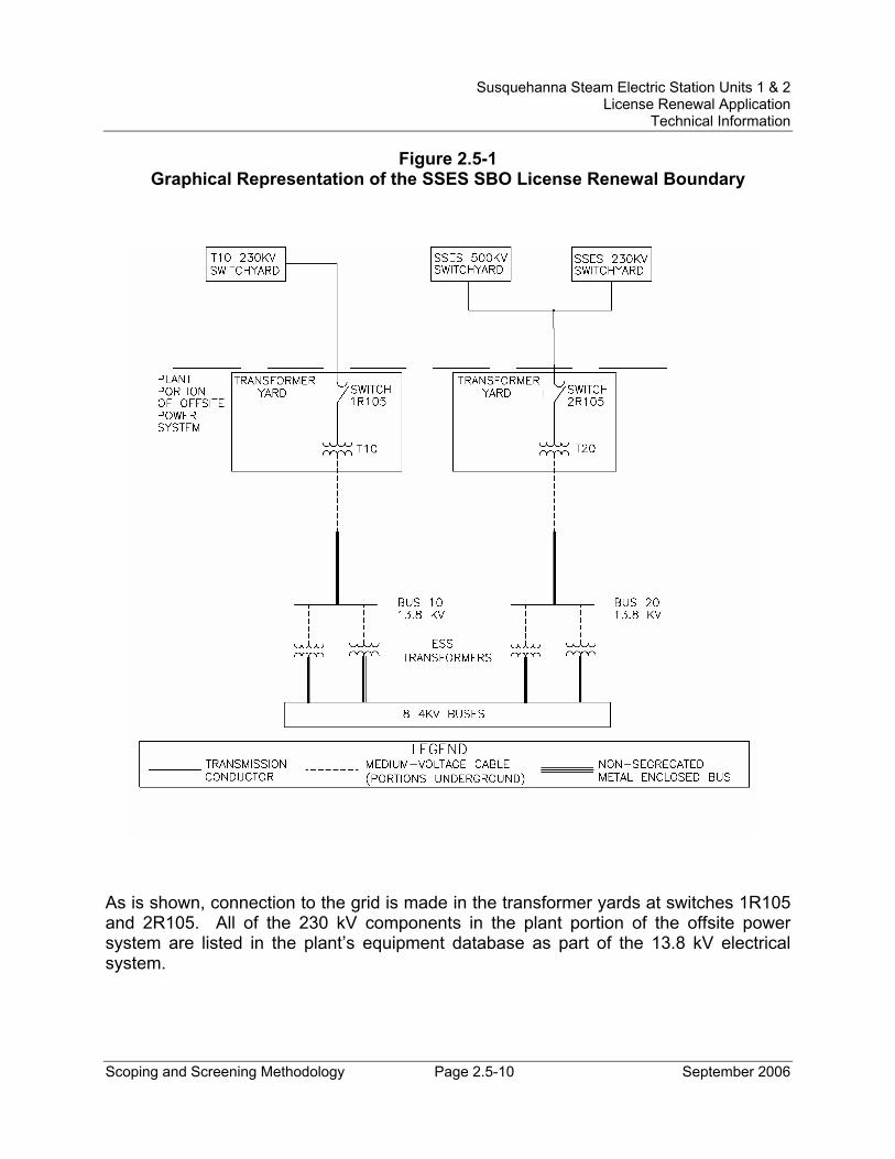
Susquehanna Steam Electric Station Units 1 & 2 License Renewal Application
Technical Information
Scoping and Screening Methodology Page 2.5-10 September 2006
Figure 2.5-1 Graphical Representation of the SSES SBO License Renewal Boundary
As is shown, connection to the grid is made in the transformer yards at switches 1R105 and 2R105. All of the 230 kV components in the plant portion of the offsite power system are listed in the plant’s equipment database as part of the 13.8 kV electrical system.
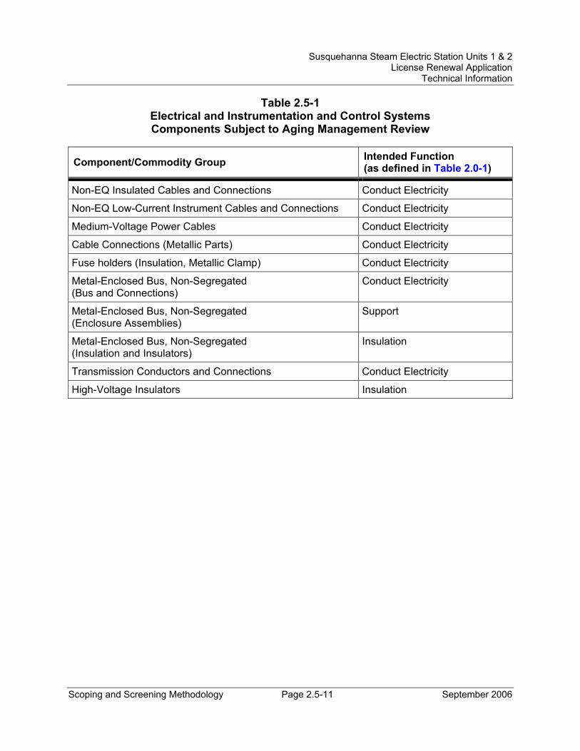
Susquehanna Steam Electric Station Units 1 & 2 License Renewal Application
Technical Information
Scoping and Screening Methodology Page 2.5-11 September 2006
Table 2.5-1 Electrical and Instrumentation and Control Systems Components Subject to Aging Management Review
Component/Commodity Group Intended Function (as defined in Table 2.0-1)
Non-EQ Insulated Cables and Connections Conduct Electricity
Non-EQ Low-Current Instrument Cables and Connections Conduct Electricity
Medium-Voltage Power Cables Conduct Electricity
Cable Connections (Metallic Parts) Conduct Electricity
Fuse holders (Insulation, Metallic Clamp) Conduct Electricity
Metal-Enclosed Bus, Non-Segregated (Bus and Connections)
Conduct Electricity
Metal-Enclosed Bus, Non-Segregated (Enclosure Assemblies)
Support
Metal-Enclosed Bus, Non-Segregated (Insulation and Insulators)
Insulation
Transmission Conductors and Connections Conduct Electricity
High-Voltage Insulators Insulation