Embed Size (px)
Citation preview
9/27/2017
1
1
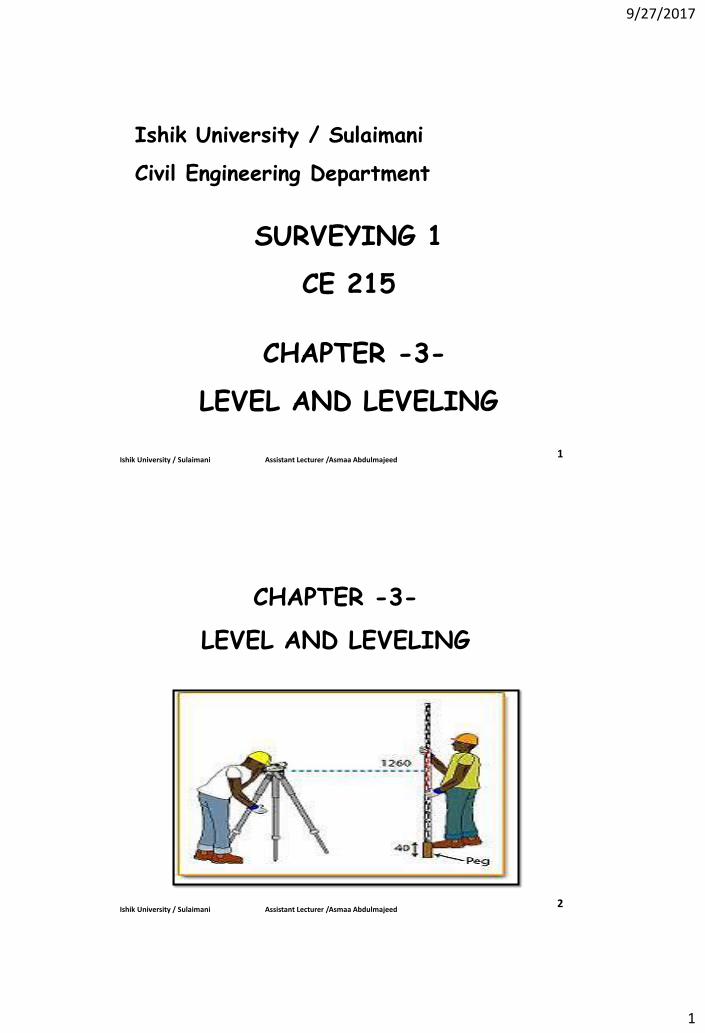
Ishik University / Sulaimani
Civil Engineering Department
SURVEYING 1
CE 215
CHAPTER -3-
LEVEL AND LEVELING
Ishik University / Sulaimani Assistant Lecturer /Asmaa Abdulmajeed
2 Ishik University / Sulaimani Assistant Lecturer /Asmaa Abdulmajeed
CHAPTER -3-
LEVEL AND LEVELING
9/27/2017
2
3
CONTENTS
1. Level instrument
2. Bubble
3. Tripod
4. Leveling staff
5. Definitions
6. Reading a staff
7. Finding the target
8. Basic rules for leveling
9. Field notes
10. Procedure of leveling
11. Leveling errors
12. Types of leveling
Ishik University / Sulaimani Assistant Lecturer /Asmaa Abdulmajeed
1. Level instrument
9/27/2017
3
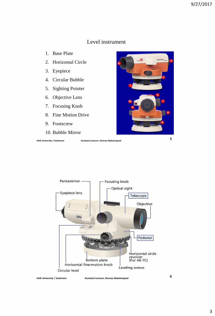
1. Base Plate
2. Horizontal Circle
3. Eyepiece
4. Circular Bubble
5. Sighting Pointer
6. Objective Lens
7. Focusing Knob
8. Fine Motion Drive
9. Footscrew
10. Bubble Mirror
Ishik University / Sulaimani Assistant Lecturer /Asmaa Abdulmajeed 5
Level instrument
Ishik University / Sulaimani Assistant Lecturer /Asmaa Abdulmajeed 6
9/27/2017
4
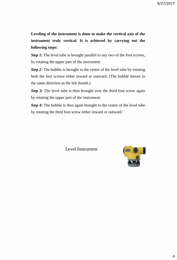
Leveling of the instrument is done to make the vertical axis of the
instrument truly vertical. It is achieved by carrying out the
following steps:
Step 1: The level tube is brought parallel to any two of the foot screws,
by rotating the upper part of the instrument.
Step 2: The bubble is brought to the centre of the level tube by rotating
both the foot screws either inward or outward. (The bubble moves in
the same direction as the left thumb.)
Step 3: The level tube is then brought over the third foot screw again
by rotating the upper part of the instrument.
Step 4: The bubble is then again brought to the centre of the level tube
by rotating the third foot screw either inward or outward.
Level Instrument
9/27/2017
5
Level Instrument
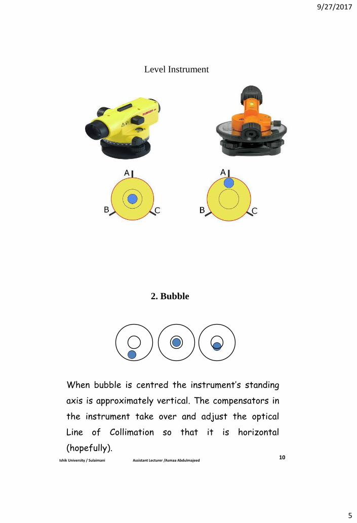
2. Bubble
When bubble is centred the instrument’s standing
axis is approximately vertical. The compensators in
the instrument take over and adjust the optical
Line of Collimation so that it is horizontal
(hopefully). Ishik University / Sulaimani Assistant Lecturer /Asmaa Abdulmajeed
10
9/27/2017
6
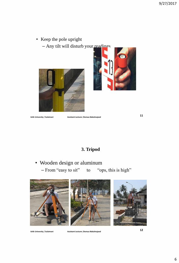
• Keep the pole upright
– Any tilt will disturb your readings
Ishik University / Sulaimani Assistant Lecturer /Asmaa Abdulmajeed 11
3. Tripod
• Wooden design or aluminum
– From “easy to sit” to “ops, this is high”
Ishik University / Sulaimani Assistant Lecturer /Asmaa Abdulmajeed 12
9/27/2017
7
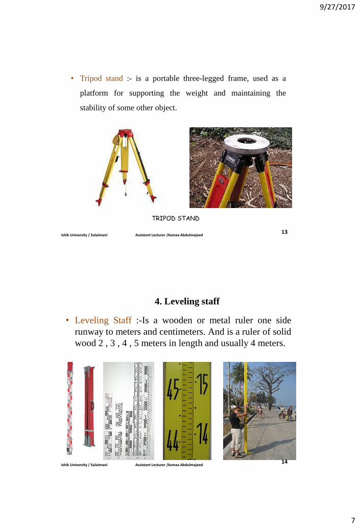
• Tripod stand :- is a portable three-legged frame, used as a
platform for supporting the weight and maintaining the
stability of some other object.
TRIPOD STAND
Ishik University / Sulaimani Assistant Lecturer /Asmaa Abdulmajeed 13
4. Leveling staff
• Leveling Staff :-Is a wooden or metal ruler one side
runway to meters and centimeters. And is a ruler of solid
wood 2 , 3 , 4 , 5 meters in length and usually 4 meters.
Ishik University / Sulaimani Assistant Lecturer /Asmaa Abdulmajeed 14
9/27/2017
8
Ishik University / Sulaimani Assistant Lecturer /Asmaa Abdulmajeed 15
Ishik University / Sulaimani Assistant Lecturer /Asmaa Abdulmajeed 16
9/27/2017
9
Ishik University / Sulaimani Assistant Lecturer /Asmaa Abdulmajeed 17
Ishik University / Sulaimani Assistant Lecturer /Asmaa Abdulmajeed 18

9/27/2017
10
Ishik University / Sulaimani Assistant Lecturer /Asmaa Abdulmajeed 19
5. Definitions
1. Datum line (M.S.L.) :- Is the level (line), which are
attributed to it points levels on the surface of the Earth.
Which is the average sea level.
2. Reduced level (R.L) :- Is the high point from datum line.
3. Benchmark (B.M.) :- Are fixed points information site and
attributed placed in different places until you start racing
them when conducting settlement.
4. Back sight (B.S.) :- Is the first reading taken after placing
the device in any position so that we see the greatest possible
number of points required to find the elevation.
9/27/2017
11
6. Change Point (CP) :- The point on which both the
foresight and back sight are taken during the operation of
levelling is called change point.
7. Fore sight (F.S) :- Is the last reading taken before
the transfer device.
8. Intermediate sight (I.S.) :- Is reading taken between
the back sight and fore sight reading.
9. Elevation of line of sight (H.I) :- Is the imaginary
vertical level determined by the line of sight to the amount
of increase or decrease for sea level (Height of
Instrument).
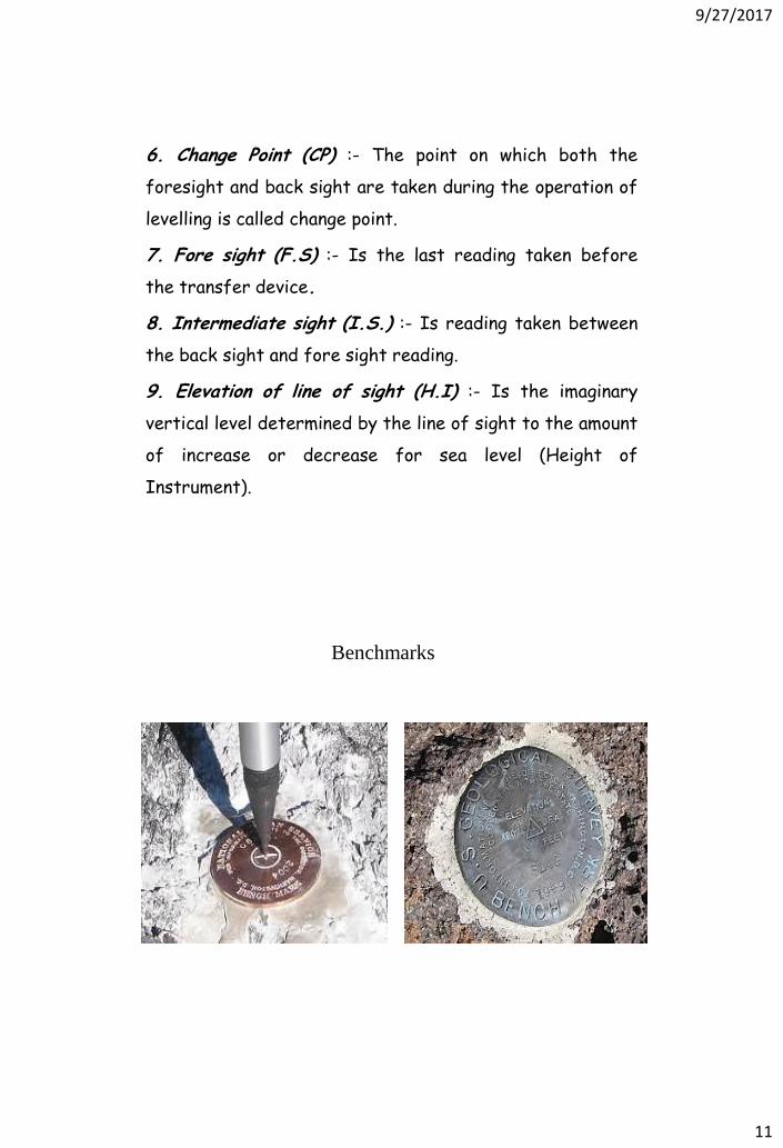
Benchmarks
9/27/2017
12
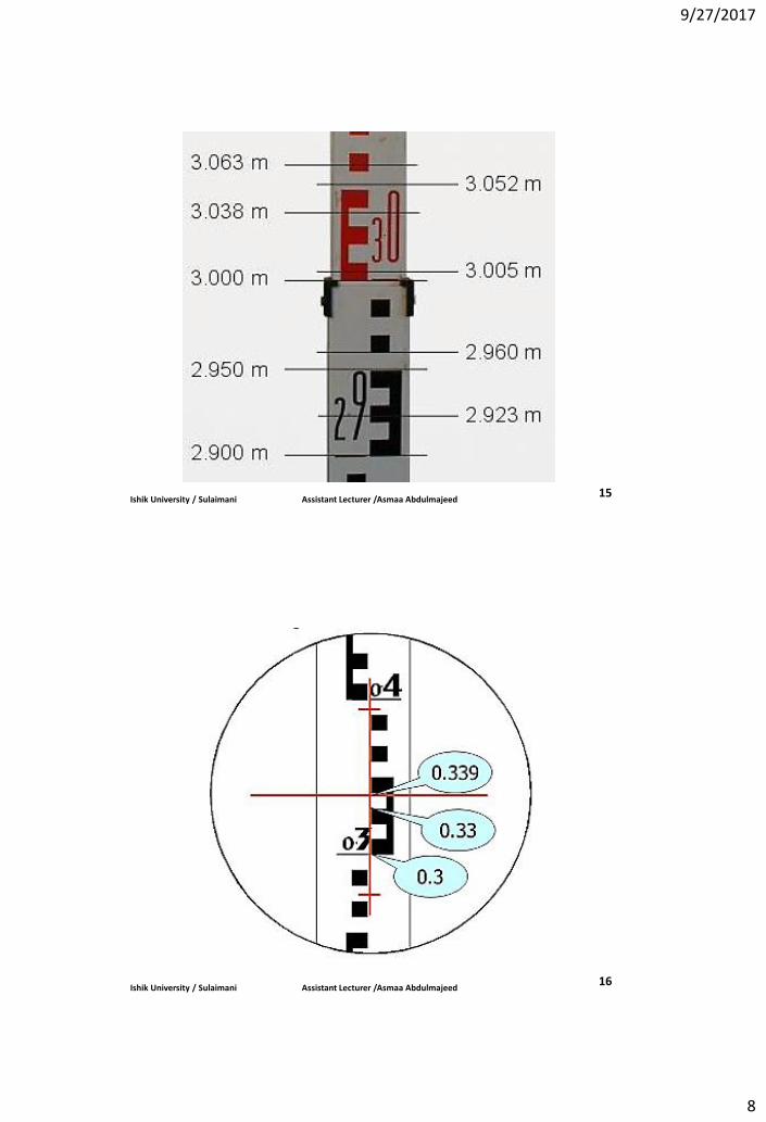
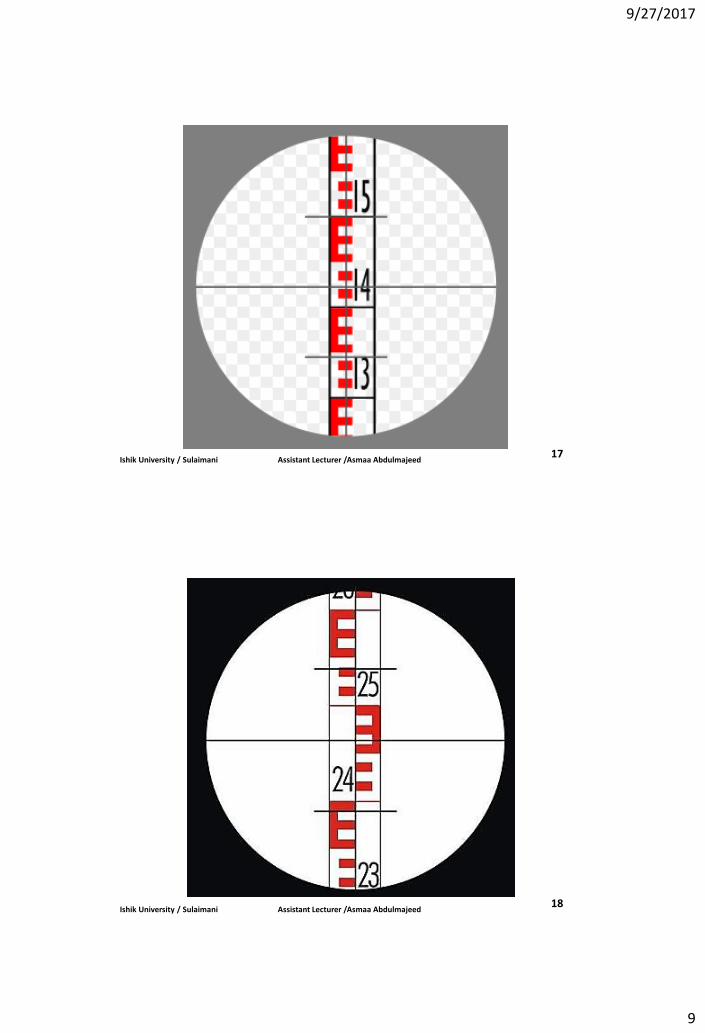
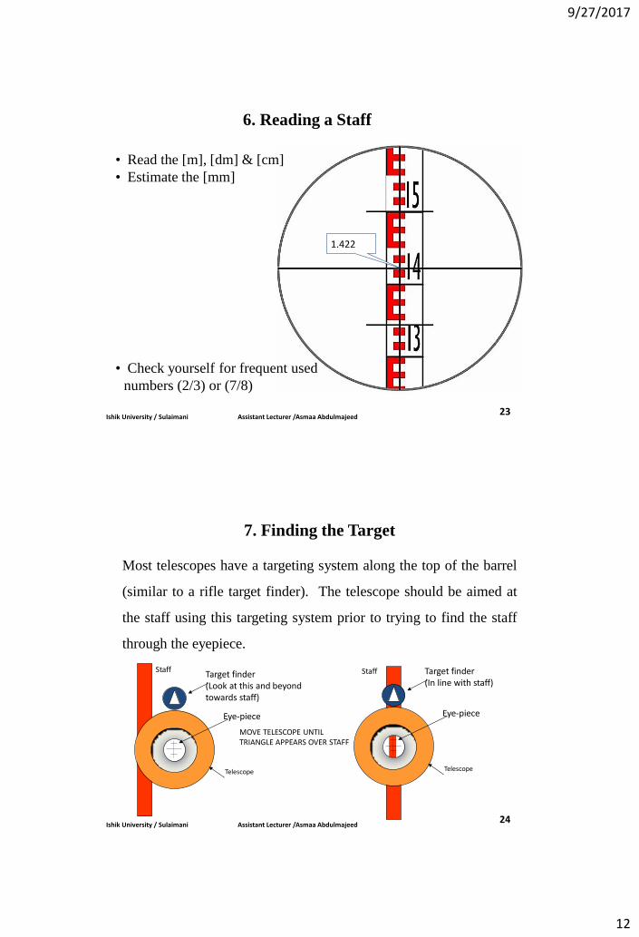
6. Reading a Staff
1.422
• Read the [m], [dm] & [cm]
• Estimate the [mm]
• Check yourself for frequent used
numbers (2/3) or (7/8)
Ishik University / Sulaimani Assistant Lecturer /Asmaa Abdulmajeed 23
7. Finding the Target
Most telescopes have a targeting system along the top of the barrel
(similar to a rifle target finder). The telescope should be aimed at
the staff using this targeting system prior to trying to find the staff
through the eyepiece.
MOVE TELESCOPE UNTIL TRIANGLE APPEARS OVER STAFF
Target finder (Look at this and beyond towards staff)
Eye-piece
Telescope
Staff Target finder (In line with staff)
Eye-piece
Telescope
Staff
Ishik University / Sulaimani Assistant Lecturer /Asmaa Abdulmajeed 24
9/27/2017
13
8. Basic Rules for Leveling
• Always start and finish a leveling run on a Benchmark (BM or
TGBM) and close the loops.
• Keep fore sight and back sight distances as equal as possible.
• Keep lines of sight short (normally < 50m).
• Never read below 0.5m on a staff (refraction).
• Use stable, well defined change points.
• Beware of shadowing effects and crossing waters.
Ishik University / Sulaimani Assistant Lecturer /Asmaa Abdulmajeed 25
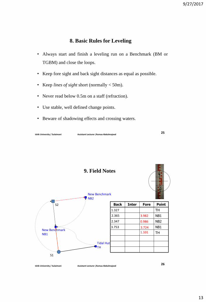
9. Field Notes
Back Inter Fore Point
TH
NB1
NB2
NB1
TH
1.327
3.982
S2
S1
New Benchmark NB1
Tidal Hut TH
New Benchmark NB2
2.365
0.986 2.347
3.724 3.753
1.101
Ishik University / Sulaimani Assistant Lecturer /Asmaa Abdulmajeed 26
9/27/2017
14
10. Procedure of leveling
1. The instrument must be check before use!
2. The instrument and level must be stable settled-up
3. The bubble tube must be leveled before the reading
• Beware of sun exposure (will wander)
• Ensure the instruments pendulum is in-limit
4. The instrument must be set up in the middle between two staffs
• Prevents curvature effects
• If impossible, use the same distances, but opposite for the next readings
5. You must not use the parallax screw between the backsight and
foresight readings
Ishik University / Sulaimani Assistant Lecturer /Asmaa Abdulmajeed 27
6. Readings must be taken 30-50 cm above the ground
• Surface refractions
• Beware also of temperature gradients (inside/outside buildings).
7. Staff should be set up vertically
8. A change plate should be used
9. Leveling must be done in two opposite directions but the same
line (beware of gravity gradients)
10. Staff should be calibrated, especially if INVAR
11. Be careful when crossing rivers (large water surfaces)
• Use “same-time” (mutual) observations
• Repeat it during different times of the day
Ishik University / Sulaimani Assistant Lecturer /Asmaa Abdulmajeed 28
9/27/2017
15
• There are a large number of potential sources of errors in leveling.
Many of these are only significant for precise leveling over long
distances. For the short segments of leveling that will occur in
connecting a TGBM to nearby benchmarks there are only four
worth mentioning:
a. Collimation Error
b. Error due to Earth Curvature
c. Error due to Parallax Error
d. Error due to Refraction
11. Leveling Errors
Ishik University / Sulaimani Assistant Lecturer /Asmaa Abdulmajeed 29
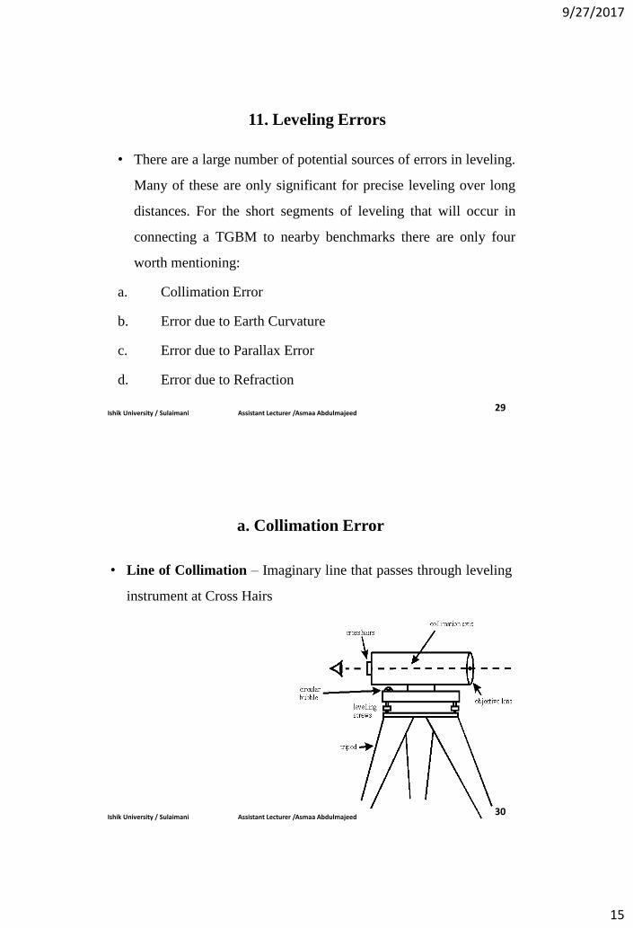
• Line of Collimation – Imaginary line that passes through leveling
instrument at Cross Hairs
a. Collimation Error
Ishik University / Sulaimani Assistant Lecturer /Asmaa Abdulmajeed 30
9/27/2017
16
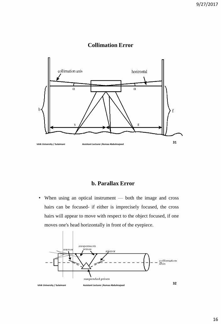
Collimation Error
Ishik University / Sulaimani Assistant Lecturer /Asmaa Abdulmajeed 31
• When using an optical instrument — both the image and cross
hairs can be focused- if either is imprecisely focused, the cross
hairs will appear to move with respect to the object focused, if one
moves one's head horizontally in front of the eyepiece.
b. Parallax Error
Ishik University / Sulaimani Assistant Lecturer /Asmaa Abdulmajeed 32
9/27/2017
17
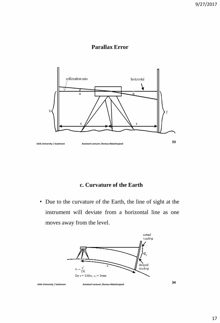
Parallax Error
Ishik University / Sulaimani Assistant Lecturer /Asmaa Abdulmajeed 33
• Due to the curvature of the Earth, the line of sight at the
instrument will deviate from a horizontal line as one
moves away from the level.
c. Curvature of the Earth
Ishik University / Sulaimani Assistant Lecturer /Asmaa Abdulmajeed 34
9/27/2017
18
35 Ishik University / Sulaimani Assistant Lecturer /Asmaa Abdulmajeed
12. Types of Levelling
1) Simple levelling
2) Differential levelling
3) Fly levelling
4) Profile levelling
5) Cross sectional levelling
6) Reciprocal levelling
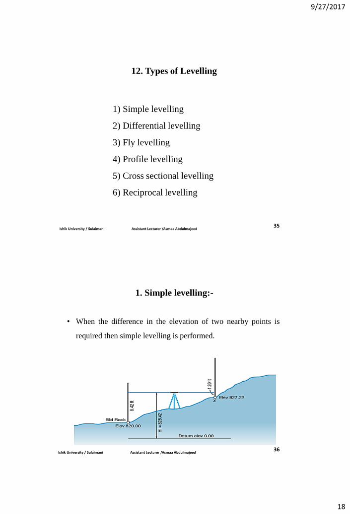
1. Simple levelling:-
• When the difference in the elevation of two nearby points is
required then simple levelling is performed.
Ishik University / Sulaimani Assistant Lecturer /Asmaa Abdulmajeed 36
9/27/2017
19
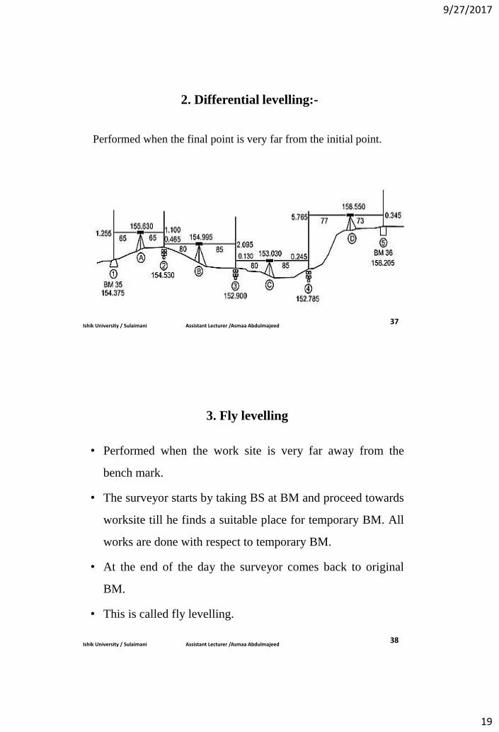
2. Differential levelling:-
Performed when the final point is very far from the initial point.
Ishik University / Sulaimani Assistant Lecturer /Asmaa Abdulmajeed 37
3. Fly levelling
• Performed when the work site is very far away from the
bench mark.
• The surveyor starts by taking BS at BM and proceed towards
worksite till he finds a suitable place for temporary BM. All
works are done with respect to temporary BM.
• At the end of the day the surveyor comes back to original
BM.
• This is called fly levelling.
Ishik University / Sulaimani Assistant Lecturer /Asmaa Abdulmajeed 38
9/27/2017
20
4. Profile levelling:-
•Profile levelling, which yields elevations at definite points along a
reference line, provides the needed data for designing facilities such
as highways, railroads, transmission lines.
•Reduced levels at various points at regular interval along the line is
calculated.
•After getting the RL of various points the profile is drawn. Normally
vertical scale is much larger than horizontal scale for the clear view of
the profile.
Ishik University / Sulaimani Assistant Lecturer /Asmaa Abdulmajeed 39
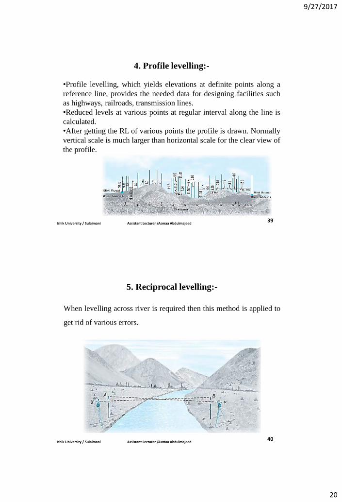
5. Reciprocal levelling:-
When levelling across river is required then this method is applied to
get rid of various errors.
Ishik University / Sulaimani Assistant Lecturer /Asmaa Abdulmajeed 40