Embed Size (px)
Citation preview

Surveillance

ABOUT THE TECHNOLOGY ASSESSMENT PROGhw N(
The Technology Assessment Program is sponsored by the Office of Development, .veting, and Dissembtion of the National Institute of Justice (NU), U.S. Department of Justice. The pro- responds to the mandate of the Justia System Improvement Act of 1979, which created NU and dircch #..it tp
encourage research and development to improve the criminal justice system and to disseminate the results to Federal, State, and local agencies.
The Technology Assessment Program is an applied research effort that determines the technological needs of justice system agencies, sets minimum performance standards for specific devices, tests commercially available equipment against those standards, and disseminates the standards and the test results to criminal justice agencies nationwide and internationally.
The program operates through: The Technology hessment Progmm Advisbrp Cwncil (TAPAC) consisting of nationally recognized
criminal justice practitioners from Federal, State, and local agencies, which assesses technological needs and sets priorities for research programs and items to be evaluated and tested.
The Law Enfirenrent Standards Lobomtory (LESL) at the National Bureau of Standards, which develops voluntary national performance standards for compliance testing to ensure that individual items of equipment are suitable for use by criminal justice agencies. The standards, are based upon laboratory testing and evaluation of representative samples of each item of equipment to determine the key attributes, develop test methods, and establish minimum performance requirements for each essential attribute. In addition to the highly technical standards, LESL also produces user guides that explain in nontechnical terms the capabilities of available equipment.
The Technology ICrresmrent mrn Information Center (TAPIC) operated by the International Association of Chiefs of Police (IACP), which supervises a national compliance testing program conducted by independent agencies. The standards developed by LESL serve as performance benchmarks against which commercial equipment is measured. The facilities, personnel, and testing capabilities of the independent laboratories arc evaluated by LESL prior to testing each item of equipment, and LESL helps the Information Center staff review and analyze data Test results are published in Consumer Product Reports designed to help justice systcm procurement officials make informed purchasing decisions.
Publications issued by the National Institute of Justice, including those of the Technology Assessment Program, are available from the National Criminal Justice Reference Service (NCJRS), which serves as a central information and reference source for the Nation's criminal justice community. For information, on how to order or to register with NCTRS, write to the National Institute of Justice, National Criminal Justice Reference Service, Washington, DC 2053 1.
James & Stewart, Director National Lnstitute of Justice

Techno@ Assessment Program
Nw Standard for
Surveillance ReceiverIRecorders
A Voluntary National Standard Promulgated by the National Institute of justice
June 1984
U.S. Department of Justice National Institute of Justice

U.S. DEPARTMENT OF JUSTICE National Institute of Justice
James K. Stewart, Director
ACKNOWLEDGMENTS
T h ~ s standard was formulated by the Law Enforcement Standards Laboratory of the National Bureau of Standards under the direction of Marshall J. Treado. Program Manager for Communications Systems, and Lawrence K. Eliason, Chief of LESL. NBS Electromagnetic Fields D ~ v ~ s ~ o n staff members responsible for the preparation of the standard were Harold E. Taggan and John F. Shafer. The preparation of t h ~ s standard was sponsored by the National Institute of Justice. Lester D. Shubin. Standards Program Manager. The standard has been rev~ewed and approved by the Technology Assessment Program Advisory Council and adopted by the lnternat~onal Assoc~ation of Ch~efs of Police (IACP) as an I A C P standard.

This document, NIJ Standard-022200, Surveillance Receiver/Recorders, is an equipment standard developed by the Law Enforcement Standards Laboratory of the National Bureau of Standards. It is produced as part of the Technology Assessment Program of the National Institute of Justice. A brief description of the program appears on the inside front cover.
This standard is a technical document that specifies performance and other requirements equipment should meet to satisfy the needs of criminal justice agencies for high quality service. Purchasers can use the test methods described in this standard themselves to determine whether a particular piece of equipment meets the essential requirements, or they may have the tests conducted on their behalf by a qualified testing laboratory. Procurement oficials may also refer to this standard in their purchasing documents and require that equipment offered for purchase meet the requirements. Compliance with the requirements of the standard may be attested to by an independent laboratory or guaranteed by the vendor.
Because this NIJ standard is designed as a procurement aid, it is necessarily highly technical. For those who seek general guidance concerning the selection and application of law enforcement equipment. user guides have also been published. The guides explain in nontechnical language how to select equipment capable of the performance required by an agency.
NIJ standards are subjected to continuing review. Technical comments and recommended revisions are welcome. Please send suggestions to the Program Manager for Standards, National Institute of Justice, U.S. Department of Justice, Washington, DC 2053 1.
Before citing this or any other NIJ standard in a contract document, users should verify that the most recent edition of the standard is used. Write to: Chief, Law Enforcement Standards Laboratory, National Bureau of Standards, Washington, DC 20234.
Lester D. Shubin Program Manager for Standards National Institute of Justice
NIJ STANDARD FOR
SURVEILLANCE RECEIVER/RECORDERS
1. PURPOSE
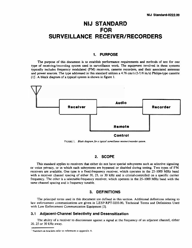
The purpose of this document is to establish performance requirements and methods of test for one type of receiving/recording system used in surveillance work. The equipment involved in these systems typically includes frequency modulated (FM) receivers, cassette recorders, and their associated antennas and power sources. The type addressed in this standard utilizes a 4.76 c d s (1-7/8 i d s ) Philipstype cassette (11'. A block diagram of a typical system is shown in figure 1.
Control FIGURE 1. Block diagram for a typic01 ~urveiIfance meiver/rcmnlcr system.
Receiver
2. SCOPE
This standard applies to receivers that either do not have special subsystems such as selective signaling or voice privacy, or in which such subsystems are bypassed or disabled during testing. Two types of FM receivers are available. One type is a fixed-frequency receiver, which operates in the 25-1000 MHz band with a receiver channel spacing of either 20, 25, or 30 kHz and is crystalcontrolled on a specific carrier frequency. The other is a selectable-frequency receiver, which operates in the 25-1000 MHz band with the same channel spacing and is frequency tunable.
Remote I
Audio
3. DEFINITIONS
Recorder
The principal terms used in this document are defined in this section. Additional definitions relating to law enforcement communications are given in LESP-RPT-0203.00. Technical Terms and Definitions Used with Law Enforcement Communication Equipment [2].
3.1 Adjacent-Channel Selectivity and Desensitization
The ability of a receiver to discriminate against a signal at t h e frequency of an adjacent channel, either 20. 25 or 30 kHz away.
: Numben In brackets refer to references In appendix A.

3.2 Audio Distortion
Nonlinear distortion in which the relative magnitude of different frequency components of a signal waveform are changed on either a phase o r amplitude basis.
3.3 Audio Hum and Noise Power
The average audiofrequency power dissipated in a load across the output terminals of an unsquelched receiver having no radiofrequency (rf) signal input.
3.4 Audio Noise Output Power
The average audiofrequency power dissipated in a load across the output terminals of an unsquelched receiver having no rf signal input.
3.5 Audio Output Power
The audiofrequency power dissipated in a load across the receiver output terminals of an unsquelched receiver having a modulated rf signal input.
3.6 Audio Response of a Receiver
The variation in the output of a receiver as a function of frequency within a specific audiofrequency bandwidth.
3.7 Fast Forward Mode
A tape transport operating mode in which the tape moves at high speed in the same direction used for recording.
3.8 Frequency Deviation
In frequency modulation, the difference between the instantaneous frequency of the modulated carrier and the unmodulated carrier frequency.
3.9 lntermodulation Attenuation
The ratio, expressed in decibels (dB), of (1) the level of specified signals that produces an intermodulation response2 under specified conditions to (2) the receiver's SINAD sensitivity.
3.1 0 lntermodulation Response
The response resulting from the mixing of two or more frequencies. in the nonlinear elements of a receiver, in which a resulting frequency is generated that falls within the range of frequencies passed by the receiver.
3.1 1 Memory Retention
The ability of a scanning receiver to remain tuned to its manually selected channel when the ac power source is momentarily interrupted.
3.12 Noise Quieting
The reduction of audio noise output caused by the presence of an rf signal.
3.13 Nominal Value
The numerical value of a device characteristic as specified by the manufacturer.
! Iralic~zed phrases In [he Definir~ons sectton arc also ~lefined.

3.14 Playback Mode
A tape transport operating mode in which the tape passes cver the playback head in the same direction as in the record mode, and recorded signals are sensed and amplified to drive the speaker.
3.15 Rated System Deviation
The maximum carrier frequency deviation permitted by the Federal Communications Commission (FCC?. For law enforcement communications systems, it is + 5 kHz.
3.16 Receiver Attack Time
The time required for the receiver to produce a specified audio output power level upon application of a specified rf input signal, when the squelch control is in the threshold squelch position.
3.17 Record Mode
A tape transport operating mode in which the tape passes over the erase head, where any previously recorded signals are erased, then passes over the record head where new signals are transferred to the tape.
3.18 Rewind Mode
A tape transport operating mode in which the tape is returned to its initial position at high speed.
3.19 Selectivity
The extent to which a receiver is capable of differentiating between the desired signal and signals at other frequencies.
3.20 SlNAD Ratio
The ratio, expressed in decibels, of (1) signal plus noise plus distortion to (2) noise plus distortion produced at the output of a receiver; from SIgnal Noise And Distortion Ratio.
3.21 SlNAD Sensitivity
The minimum modulated rf signal input level required to produce a specified SINAD ratio at a specified audio output power level.
3.22 Spurious Response
The output of a receiver caused by a signal at a frequency other than that to which the receiver is tuned.
3.23 Squelch
A circuit function for preventing a receiver from producing audio output power in the absence of an rf input signal.
3.24 Squelch Block
A squelched condition resulting from excessive frequency deviation due to the presence of a specified rf input signal.
3.25 Standby Mode
The condition of a receiver when it is energized but not receiving.
3.26 1 hreshold Squelch Position
The adjustment of a squelch control, starting from the maximum unsquelched position, that first reduces the audio noise outpur power by a specified amount.

3.27 Threshold Squelch Sensitivity
The minimum standard modulated rf signal input level required to unsquelch a receiver when the squelch control is in the threshold squelch position.
3.28 Tight Squelch Sensitivity
The minimum standard modulated rf signal input level required to unsquelch a receiver when the squelch control is in the maximum squelch position.
3.29 Usable Bandwidth
The frequency deviation of an input signal that is 6 dB above the 12-dB SINAD sensitivity voltage and which produces a 12dB SINAD ratio.
4. REQUIREMENTS
4.1 Minimum Performance
The performance of the surveillance receiverhecorder shall meet or exceed the requirement for each characteristic listed in table 1. The performance requirements listed in table 1 meet those given in the Rules and Regulations published by the FCC [3].
4.2 User Information
4.2.1 Receivers
A nominal value for each receiver characteristic listed in table 1 shall be included in the information supplied to the purchaser by the manufacturer or distributor. In addition, the distributor shall provide:
a) The range of temperatures within which the receiver is designed to be operated. b) The receiver operating frequencies or range of frequencies. c) Nominal values for receiver audio output impedance, standard supply voltage, and the current
drain of the receiver in both the receive and standby modes.
4.2.2 Recorders
The nominal value for each recorder characteristic shall be included in the information supplied to the purchaser by the manufacturer or distributor'. These characteristics shall include:
a) The size and number of batteries required for operation. b) The audio input impedance and audio output impedanse of the recorder. c ) The remote control switching requirements. d) The current drain of the recorder in both the record and playback modes.
4.3 Receiver SlNAD Sensitivity
When measured in accordance with section 5.3, the SINAD sensitivity of the receiver shall be 0.5 pV (item A, table 1) o r less at a SINAD ratio of 12 dB and an audio output power of at least 250 mW. When the standard supply voltage is varied + 10 percent and -20 percent, the SINAD sensitivity shall be 0.7 pV or less.
4.4 Receiver Selectivity Characteristics
The selectivity characteristics of usable bandwidth. adjacent-channel selectivity and desensitization, spurious response attenuation, and intermodulation attenuation shall be measured in accordance with section 5.4.
4.4.1 Usable Bandwidth
The usable bandwidth of the receiver shall be at least 5 kHz for an applied rf signal 6 dB above the measured 12-dB SINAD sensitivity value.

TABLE I . .Uinimum performance requirements for FM receivers and recorders used in surveillance systems.
Minimum requirement 25-1000 MHz frequency Test method
Receiver characteristic band section No.
Sensitivity Characteristics A. S l N A D Sensitivity B. S I N A D Sensitivity Variance
(Supply Voltage Varied + 10% and -20%)
Selectivity Characteristics C. Usable Bandwidth D. Adjacent-Channel Selectivity
and Desensitization E. Spunous Response Attenuation
5 kHz
F. Intermodulation Attenuatton
Squelch Characteristics G. Threshold Squelch Sensitivity H. Tight Squelch Sensitivity I. Threshold Squelch Sensitivity
Variance (Supply Voltage Varied c 10% and -2040)
1. Squelch Block K. Receiver Attack Time
0.6 pV 2 5 kHz l SO ms
Audiofrequency Characteristics M. Audio Output Power
(Loudspeaker) N. Audio Output Power
(Earphones) 0. Audio Output Power Variance
(Supply Voltage Varied + 10% and -20%)
P Audio Distortion Q. Audio Response (Loudspeaker) R. Audio Response (Earphones) S. Audio Hum and Noise
(Unsquelched) T . Audio Hum and Noise
(Squelched)
Temperature Stability U. S l N A D Sensitivity V. Usable Bandwidth w. Adjacent Channel Selecttvlty
and Desensittzation X. Tight Squelch Sensitivity Y. Threshold Squelch Sensitivity Z. Audio Output Power
AA. Audio Hum and Noise .4B. .!. ~ d i o Distorrlon
Recorder Characreristics .AC. Fast Forward Time .AD. Rewind Time A E . Tape Speed Tolerance
Recetver/Recorder Charactertct~cs 4 F Rece~ver/Recorder System
Audlo Utcrortlon A G Recelver/Recorder System
A u d ~ o Response 4 H Battery Servlce L ~ f e
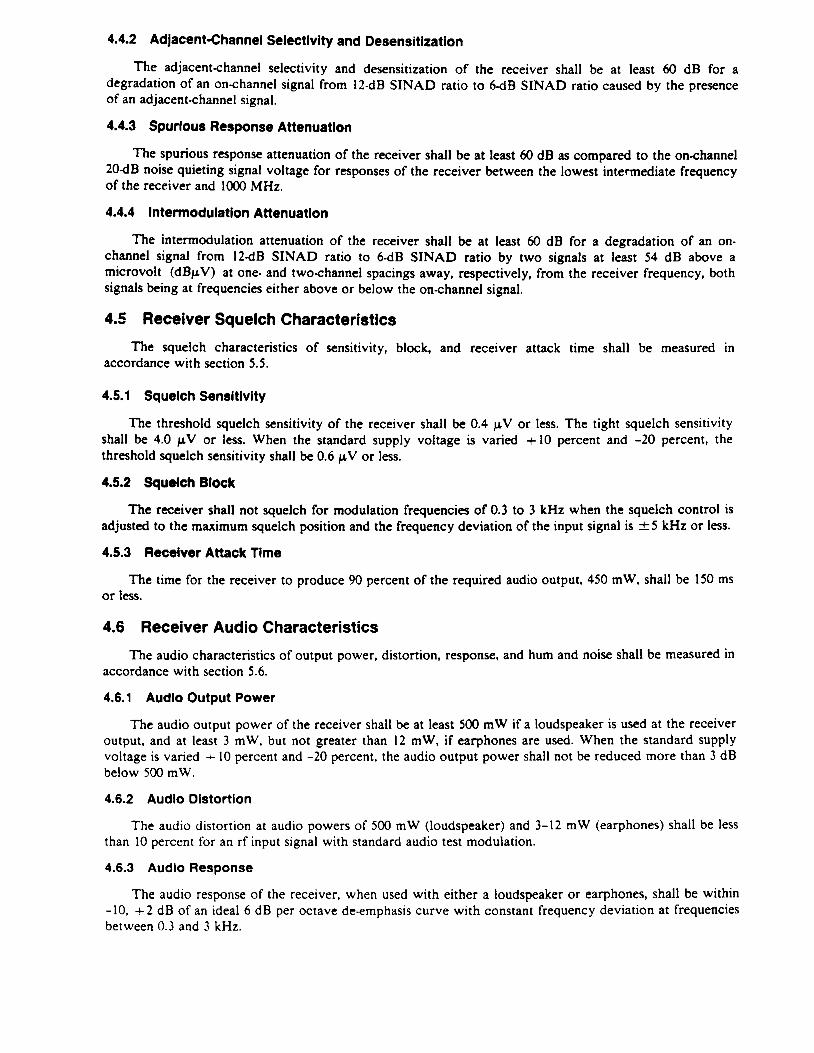
4.4.2 Adjacent-Channel Selectlvity and Desensitization
The adjacent-channel selectivity and desensitization of the receiver shall be at least 60 dB for a degradation of an on-channel signal from 12-dB SINAD ratio to 6-dB SINAD ratio caused by the presence of an adjacent-channel signal.
4.4.3 Spurious Response Attenuation
The spurious response attenuation of the receiver shall be at least 60 dB as compared to the on-channel 2OdB noise quieting signal voltage for responses of the receiver between the lowest intermediate frequency of the receiver and 1000 MHz.
4.4.4 Intermodulation Attenuation
The intermodulation attenuation of the receiver shall be at least 60 dB for a degradation of an on- channel signal from 12-dB SINAD ratio to 6-dB SINAD ratio by two signals at least 54 dB above a microvolt (dBpV) at one- and two-channel spacings away, respectively, from the receiver frequency, both signals being at frequencies either above or below the on-channel signal.
4.5 Receiver Squelch Characteristics
The squelch characteristics of sensitivity, block, and receiver attack time shall be measured in accordance with section 5.5.
4.5.1 Squelch Sensitivity
The threshold squelch sensitivity of the receiver shall be 0.4 p V or less. The tight squelch sensitivity shall be 4.0 p V or less. When the standard supply voltage is varied + 10 percent and -20 percent, the threshold squelch sensitivity shall be 0.6 p V or less.
4.5.2 Squdch Block
The receiver shall not squelch for modulation frequencies of 0.3 to 3 kHz when the squelch control is adjusted to the maximum squelch position and the frequency deviation of the input signal is f 5 kHz or less.
4.5.3 Receiver Attack Time
The time for the receiver to produce 90 percent of the required audio output, 450 mW, shall be 150 ms or less.
4.6 Receiver Audio Characteristics
The audio characteristics of output power, distortion, response, and hum and noise shall be measured in accordance with section 5.6.
4.6.1 Audio Output Power
The audio output power of the receiver shall be at least 500 mW if a loudspeaker is used at the receiver output, and at least 3 mW, but not greater than 12 mW, if earphones are used. When the standard supply voltage is varied + 10 percent and -20 percent, the audio output power shall not be reduced more than 3 dB below 500 mW.
4.6.2 Audio Distortion
The audio distortion at audio powers of 500 mW (loudspeaker) and 3-12 mW (earphones) shall be less than 10 percent for an rf input signal with standard audio test modulation.
4.6.3 Audio Response
The audio response of the receiver, when used with either a loudspeaker or earphones, shall be within -10, + 2 dB of an ideal 6 dB per octave de-emphasis curve with constant frequency deviation at frequencies between 0.3 and 3 kHz.

4.6.4 Audio Hum and Noise
The audio hum and noise output power from the receiver in the unsquelched condition shall be at least JO dB below, and in the maximum squelched condition shall be at least 50 dB below, an audio output power of 500 mW.
4.7 Receiver Performance at Temperature Extremes
The ability of the receiver to operate in temperature extremes shall be determined using the test method described in section 5.7.
Low temperature tests shall be conducted at -10 "C (14 "F) or the lowest temperature at which the manufacturer states that the receiver will operate properly, whichever is lower, and high temperature tests shall be conducted at +60 "C (140 OF) or the highest temperature at which the manufacturer states that the unit will operate properly, whichever is higher (sec. 4.2.1).
When the receiver is operated at low and high temperatures, as defined above, its performance shall not vary, with respect to the appropriate values in table 1 (items A through T), more than items U through AA for the characteristics listed. In addition, the receiver audio distortion at an audio output power of 500 m W shall be less than 18 percent for an rf signal with standard modulation.
4.8 Receiver Memory Retention
When tested in accordance with section 5.8, the receiver shall remain tuned to its operating frequency when the rf signal to the receiver input is temporarily interrupted during operation. The receiver shall also remain tuned to its operating frequency when the power is interrupted during operation.
4.9 Recorder Performance
The cassette recorder characteristics of fast forward and rewind, tape speed and anti-erase feature shall be measured in accordance with section 5.9.
4.9.1 Type of Cassette and Tape
The recorder system shall employ a Philips-type cassette [1,4] and magnetic tapes with ferric oxide coatings.
Note: Tapes which have other metallic coatings do not perform as well as ferric oxide on cassette recorders intended for ferric oxide tapes because of the higher bias requiremenn of these lopes.
4.9.2 Operating Modes and Controls
Each recorder shall have the following distinct operating modes: Record. Playback, Fast Forward, Rewind, and Stop. All controls essential to the operation of the recorder shall be plainly identified in English or universal symbols. The tape recorder shall have one external jack connector that allows the recorder to be started and stopped while in the record mode. The recorder shall also be equipped with a visual audio input indicator that corresponds to an acceptable range of input signals and a relative tape position counter. If the latter is digital, a reset capability should also be provided.
4.9.3 Fast Forward and Rewind
The time required to advance or rewind a 30-min length of tape shall not exceed 90 s.
4.9.4 Tape Speed
The recorder tape speed shall be within 2 2 percent of 4.76 cm/s (1-7/8 i d s ) .
4.9.5 Anti-Erase Feature
Each recorder shall be equipped with an anti-erase mechanism that prevents the record lever from being energized if either of the two breakout tabs or sliding plate covers on the cassette are removed or placed in the open position.
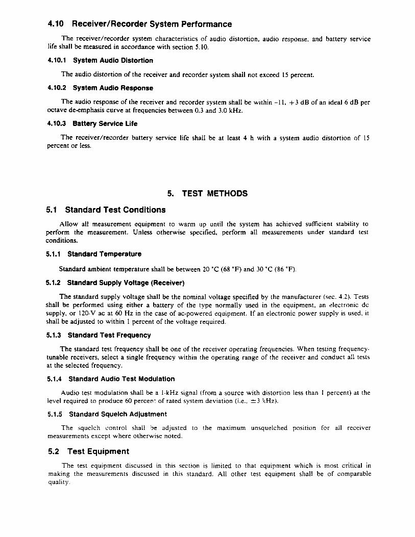
4.10 ReceiverIRecorder System Performance
The receiver/recorder system characteristics of audio distortion, audio response, and battery service life shall be measured in accordance with section 5.10.
4.10.1 System Audio Distortion
The audio distortion of the receiver and recorder system shall not exceed 15 percent.
4.10.2 System Audio Response
The audio response of the receiver and recorder system shall be w~thin -1 1. + 3 dB of an ideal 6 dB per octave de-emphasis curve at frequencies between 0.3 and 3.0 kHz.
4.10.3 Battery Service Life
The receiver/recorder battery service life shall be at least 4 h with a system audio distortion of 15 percent or less.
5. TEST METHODS
5.1 Standard Test Conditions
Allow all measurement equipment to warm up until the system has achieved sufficient stability to perform the measurement. Unless otherwise specified, perform all measurements under standard test conditions.
5.1.1 Standard Temperature
Standard ambient temperature shall be between 20 "C (68 OF) and 30 "C (86 OF).
5.1.2 Standard Supply Voltage (Receiver)
The standard supply voltage shall be the nominal voltage specified by the manufacturer (sec. 4.2). Tests shall be performed using either a battery of the type normally used in the equipment, an electronic dc supply, or 120-V ac at 60 Hz in the case of ac-powered equipment. If an electronic power supply is used. it shall be adjusted to within 1 percent of the voltage required.
5.1.3 Standard Test Frequency
The standard test frequency shall be one of the receiver operating frequencies. When testing frequency- I . tests tunable receivers, select a single frequency within the operating range of the receiver and conduct a"
at the selected frequency.
5.1.4 Standard Audio Test Modulation
Audio test modulation shall be a I-kHz signal (from a source with distortion less than 1 percent) at the level required to produce 60 percept of rated system deviation (i.t., 2 3 '(Hz).
5.1.5 Standard Squelch Adjustment
The squelch control shall be adjusted to the maximum unsquelched position for all receiver measurements except where otherwise noted.
5.2 Test Equipment
The test equipment discussed in this section is limited to that equipment which is most critical in making the measurements discussed in this standard. All other test equipment shall be of comparable quality.

5.2.1 FM Signai Generator
The FM signal generator shall have a frequency range from 25-1000 MHz, a 50-ohm output impedance, a maximum standing-wave ratio of 1.2, and a calibrated variable output level accurate to k 2 dB when terminated in a 50-ohm load. The generator should include a digital frequency counter having an uncertainty no greater than 1 ppm and a deviation monitor or calibrated control for determining the peak frequency deviation with an uncertainty of no greater than 5 percent. If an integral frequency counter is not included, a separate frequency counter having the required accuracy shall be provided.
5.2.2 CW Signai Generator
The CW signal generator shall have the characteristics described in section 5.2.1, except that the FM capability is not required.
5.2.3 Standard RF Input Load (Receiver)
The standard rf input load shall consist of a shielded 50-ohm resistor whose standing wave ratio is less than 1.05.
5.2.4 Standard Audio Output Load (Receiver)
The standard audio output load shall be a resistor having a resistance equal to the nominal output impedance of the receiver and a power rating equal to or exceeding the nominal audio output power of the receiver. A filter network shall not be used between the audio output terminals and the audio output load. If an external monitor is used, it shall have an input impedance of at least 10,000 ohms.
5.2.5 Audiofrequency Voltmeter
The audiofrequency voltmeter shall measure rms voltage rather than average or peak voltage. Its measurement uncertainty shall be 1 percent or less.
5.2.6 Signal Combiner
The signal combiner shall have an amplitude imbalance no greater than 0.2 dB, its standing wave ratio shall be no greater than 1.3, and the isolation between input terminals shall be a minimum of 30 dB. A variety of multiport devices may be used as signal combiners, including power dividers, directional couplers, and hybrid junctions.
5.2.7 Environmental Chamber
The environmental chamber shall produce air temperatures from -3C to 60 "C (-22 to 140 O F ) . The test item shall be shielded from air currents blowing directly from heating or cooling elements in the chamber. The temperature of the test item shall be measured with a thermometer separate from the sensor used to control the chamber air temperature.
5.2.8 Distortion Analyzer
The distortion analyzer shall have a required input level of between 1- and 5-V rms, an input impedance of at least 50,000 ohms shunted by less than 100 pF, and an accuracy of at least k I dB for the SINAD measurements. It shall have the capability to measure both audio distortion and the voltage of audio signals to within 2 3 percent. The analyzer shall incorporate a 1000 Hz band elimination filter for the audio distortion measurements.
5.3 Receiver SlNAD Sensitivity Test
Connect the receiver and test equipment as shown In figure 2. Set the squelch control to the standard squelch adjustment. Adjust the FM signal generator to the standard test frequency with standard audio test modulation. Set the generator for a I-mV output and the receiver volume control for a loudspeaker audio output power of 500 mW. Do not readjust the volume control for the remainder of the measurement. Decrease the output level of the generator until the SINAD ratio of the receiver is 12 dB, as determined with the distortion analyzer. Measure the audio output power to make certain it is at least 250 mW and record the generator output voltage for convenience in resetting to a 12-dB SINAD ratio, as required by

FIGURE 2. Block diagmm for SINAD sensitiviry. usabIc bandwidth, squelch sensitivity, squelch block, audio distorrion. and memory retention measurrments.
FM Signal Gonerator
some of the following tests. Repeat the above using + I0 percent and -20 percent changes in standard supply voltage.
5.4 Receiver Selectivity Tests
Receiver Under Test
h
5.4.1 Usable Bandwidth Test
i
Connect the receiver and test equipment as shown in figure 2. Adjust the receiver and FM generator in accordance with section 5.3 until a 12dB SINAD ratio is reached. With the generator still set for standard audio test modulation, increase the generator rf output by 6 dB. Adjust the frequency of the generator above the test frequency until the 1 2 4 8 SINAD signal ratio is again obtained. Record the generator frequency. Repeat this measurement by adjusting the generator frequency below the test frequency and record the generator frequency. The smaller displacement from the test frequency plus 3 kHz (standard audio test modulation) is the receiver usable bandwidth.
T
Oistortion Analyzer
5.4.2 Adjacent-Channel Selectivity and Desensitization Test
Standard Audlo Output
Load ..
Connect the receiver and test equipment as shown in figure 3. With the output of generator No. 2 set to zero. adjust the receiver and signal generator No. 1 in accordance with section 5.3 until a 12-dB SINAD ratio is reached. Adjust signal generator No. 2 for 3 kHz with a modulation frequency of 400 Hz, and set it to a frequency corresponding to the center of the next higher adjacent channel. Then adjust the output of signal generator No. 2 to produce a 6 d B SINAD ratio with both signals present. The ratio, in decibels, of the output voltage of signal generator No. 2 to that of signal generator No. 1 is the adjacent-channel selectivity for the upper channel. Repeat the above procedure for the next lower adjacent channel. The smaller of the two ratios is the value sought.
t
FM Signal Generator
FIGCRE 3. Block diagram jor adjacenr.channel wlectrvrrv and desensrtizanon measurement.
i
I No. 1 I 1
Receiver Standard
Under Test Audio Output Load
7
4
1
FM Signal Generator
No. 2
Signal Combiner
I Distortion Analyzer

5.4.3 Spurious Response Attenuation Tes t
Connect the receiver and test equipment as shown in figure 4. Adjust the unmodulated (CW) signal generator to the standard test frequency. With the generator adjusted for zero output, adjust the receiver volume control to produce 125 mW. This output power is entirely noise power. Do not readjust the volume control for the remainder of the measurement. Increase the output of the generator until the audio noise output power of the receiver is decreased by 20 dB, i.e., 20 dB of noise quieting. Note the generator output in dBpV at this frequency. Then increase the output of the generator to approximately 0.1 V, and slowly vary the generator frequency continuously from just below the lowest intermediate frequency of the receiver to 1000 MHz. Note each frequency that produces a response as indicated by noise quieting in the receiver's audio output. Ignore harmonic frequencies of the generator that fall within the channel to which the receiver is tuned. For each response, adjust the generator output to produce 20 dB of noise quieting. Record the generator output in dBpV. The generator output at the spurious response frequency minus the generator output at the standard test frequency is the spurious response attenuation. Repeat for all spurious responses. The smallest attenuation is the value sought.
FIGURE 4. Block diagmm for spurious response arrenuarion measurement.
C W S l g n a l G e n e r a t o r
5.4.4 lntermodulatlon Attenuatlon Tes t
Connect the receiver and test equipment as shown in figure 5. With the output levels of signal generators No. 2 and No. 3 set to zero, adjust the receiver and FM signal generator No. 1 in accordance with section 5.3 until a 12-dB SINAD ratio is reached. Adjust unmodulated generator No. 2 to the center frequency of the next higher adjacent channel (see sec. 2). Adjust generator No. 3 for 3-kHz frequency deviation at 400 Hz, and set it to the center frequency of the second higher adjacent channel, i.e., two channels above the standard test frequency. Then adjust the output levels of generator Nos. 2 and 3 to produce a 6-dB SINAD ratio with all three signals present. Maintain generator Nos. 2 and 3 at equal output voltage throughout the measurement. Slightly adjust the frequency of generator No. 3 to obtain the 6-dB SINAD ratio with the minimum signal levels from generator Nos. 2 and 3 unchanged. The ratio, in decibels, of the output voltage of generator No. 2 (or No. 3) to that of generator No. 1 is the intermodulation attenuation for the upper channels. Repeat the above procedures for the lower two adjacent channels, with generator No. 3 set to the lowest channel. The smaller of the two ratios is the value sought.
h
AF V o l t m e t e r or
Power M e t e r
L
R e c e i v e r Under T e s t
*
- Standard A u d i o O u t p u t
L o a d

Standard Audio Output
FM Signal Generator
No. 1 i
C W Signal Generator
No. 2 .
FIGURE 5 . Block diagmm for inrermadularion orrenuorion measuremenr.
i
5.5 Receiver Squelch Tests
FM Signal Generator
No. 3
Distortion Analyzer
5.5.1 Squelch Sensitivity Tests
-
Connect the receiver and test equipment as shown in figure 2. Adjust the receiver and FM signal generator in accordance with section 5.3 until a 12-dB SINAD ratio is reached. Set the output level of the generator to zero, and measure the audio noise output power. Slowly adjust the squelch control until the audio noise output power drops abruptly (40 dB or more). Do not adjust the squelch control any further. This is the threshold squelch position. Increase the output level of the signal generator until the measured audio output power is within 10 dB of an audio output power of 500 mW. The signal generator output voltage is the value for threshold squelch sensitivity. Repeat using + 10 percent and -20 percent standard supply voltages.
Repeat the above procedure with the squelch control in the maximum squelch position. The resultant signal generator output voltage is the value for tight squelch sensitivity.
- L
Signal Combiner
5.5.2 Squelch Block Test
Receiver Under Test
Connect the receiver and test equipment as shown in figure 2. Adjust the receiver and FM signal generator in accordance with section 5.3 until a 12-dB SINAD ratio is reached. Set the output level of the signal generator to zero, and measure the audio noise output power. Then set the squelch control to the maximum squelch position. Adjust the output level of the generator to 12 dR above the measured value of the receiver's tight squelch sensitivity voltage as determined in 5.5.1. Then increase the frequency deviation of the generator until the audio output power drops abruptly (40 dB or more). Repeat the above procedure with modulation frequencies of 0.3, 0.5, 2.5, and 3 kHz. The frequency deviations of signal generator. modulation are the values sought.
5.5.3 Receiver Attack Time Test
Connect the equipment as shown in figure 6a. Open and close the SPST switch to trigger the oscilloscope trace. Connect the dc output of the coaxial diode detector to the vertical input of the oscilloscope and adjust the horizontal centering controls so that the start of the detector output begins at the left graticule of the oscilloscope screen. Do not adjust the oscilloscope trigger or centering controls any further.
Connect the transceiver recelver and test equipment as shown in figure 6b. With the SPST switch closed, adjust the FM signal generator in accordance with section 5.3 until a 12-dB SINAD ratio is reached. Set the s~gnal generator to zero and measure the audio noise output power. Slowly adjust the squelch control until the audio output power drops abruptly (40 dB or more). Do not adjust the squelch any further. Adjust the generator output level to 12 dB above the measured vaiue of the receiver threshold squelch sensit~vity voltage. With the oscilloscope on recurrent sweep, adjust the oscilloscope vertical controls for

full-scale deflection. D o not adjust the trigger. Return the oscilloscope to external trigger and open and then close the SPST switch and photograph the trace. The time required for the sweep to travel from the left side of the oscilloxope graticule until the audio output power level reaches 450 m W is the value of receiver attack time.
FIGURE 68. Block diagram for setting oscilloscope [rigger.
,
S t a n d a r d R F lnput Load
C o a x i a l D i o d e
t D e t e c t o r . FM Signal Osci l loscope G e n e r a t o r
DC P o w e r O\ Supply S P S T
Switch *
FIGCPE 6b. Block diagram for receiver attack time veasuremenr.
lnput
0 Trigger Input
*
Receiver Under Test
5.6 Receiver Audio Tests
AF Voltmeter or
Power Meter
5.6.1 Audio Output Power Test
Connect the receiver and test equipment as shown in figure 7. Modulate the FM signal generator with standard audio test modulation and set i t to the standard test frequency. With the signal generator adjusted for I -mV output, set the receiver volume control to the maximum position, and measure the audio output power. Repeat using + 10 percent and -20 percent standard supply voltages (both ac and dc).
osc i~~oscope
0 Vertical lnput
0 Trigger , lnput
C
1 1 - Generator Isolation Standard
Audio Output Load
DC Power
-

FIGURE 7. Block d i a ~ m m for audio ourput power, audio response. and audio hum and noise rneasuremenrs.
FM Slgnal Generator
5.6.2 Audio Distortion Test
Connect the receiver and test equipment as shown in figure 2. Modulate the FM signal generator with standard audio test modulation and set it to the standard test frequency. With the signal generator adjusted for I-mV output, adjust the receiver volume control for an audio output power of 500 mW and measure the audio distortion. Repeat at an audio output power of 3-12 mW for those receivers equipped with earphones.
I
5.6.3 Audio Response Test
Connect the receiver and test equipment as shown in figure 7. Modulate the FM' signal generator with standard audio test modulation and set it to the standard test frequency. With the signal generator adjusted for 1-mV output, adjust the receiver volume control to an audio output power of 250 mW. Do not readjust the volume control for the remainder of the measurement. Reduce the generator frequency deviation to 1 kHz and measure the audio output power. Repeat for modulating frequencies of 0.3, 0.5, 2, and 3 kHz. Calculate the ratio, in decibels, of each of these latter power levels to the output power at 1 kHz.
Recelver Standard - Under Test Audlo Output load
AF Voltmeter or
Power Meter
5.6.4 Audio Hum and Noise Tests
b
Connect the receiver and test equipment as shown in figure 7. Modulate the FM signal generator with standard audio test modulation and set it to the standard test frequency. With the signal generator adjusted for 1-mV output, adjust the receiver volume control for an audio output power of 500 mW. Do not readjust the volume control for the remainder of the measurement. Remove the modulation from the signal generator and measure the audio hum and noise output power. Calculate the ratio, in decibels, of the audio output power to the hum and noise output power. This is the value for audio hum and noise (unsquelched).
Set the squelch control to its maximum squelch position. Set the output level of the generator to zero and measure the audio hum and noise output power. Calculate the ratio, in decibels, of the audio output power to the hum and noise output power. This is the value for audio hum and noise (squelched).
5.7 Receiver Environmental Temperature Test
Place the receiver, with the power turned off, in the environmental chamber. Adjust the chamber to the required low temperature 2 2 "C (23.6 OF). Allow the receiver to reach temperature equilibrium as indicated by the internal thermometer, and maintain it at this temperature for 30 min. With the receiver still in the chamber, connect it to the standard supply voltage. Fifteen minutes after turn-on, test the receiver to determine whether i t meets the requirements of section 4.7, following the procedures of sections 5.3 through 5.6. Return the receiver to room temperature and repeat the above procedure at the required high temperature 2 2 "C ( k3 .6 OF).

5.8 Receiver Memory Retention Tests
5.8.1 Memory Retention Test for Loss of RF Signal
Connect the receiver and test equipment as shown in figure 2 and set the squelch control to the maximum unsquelched position. Adjust the FM signal generator to the standard test frequency and set it for l-mV output. Observe the receiver output. Decrease the generator signal to minimum output and disconnect the generator from the receiver. Reconnect the generator to the receiver and set its output to 1 mV. The receiver meets the requirement if it does not change frequency and indicates the correct rf signal from the generator.
5.82 Memory Retention Test for Loss of Power Supply
Connect the receiver and test equipment as shown in figure 2 and set the squelch control to the maximum unsquelched position. Adjust the FM signal generator to the standard test frequency and set it for 1-mV output. Observe the receiver output. Disconnect the supply voltage, either ac or dc, from the receiver. Reconnect the supply voltage to the receiver. The receiver meets the requirement if it does not change frequency and indicates the correct rf signal from the generator.
5.9 Recorder Tests
Visually inspect the cassette recorder, cassette, and tape to insure that the requirements of sections 4.9.1 and 4.9.2 are met.
5.9.1 Fast Forward and Rewind Tests
Load a 30-min cassette tape in the tape recorder, set it to fast forward, and measure the time required to run the entire tape through the recorder in the fast-forward mode. Reset the recorder to rewind and measure the time required to run the entire tape through the machine in the rewind mode.
5.9.2 Tape Speed Test
Measure the diameter of the spindle of the tape recorder to k0.005 in using a micrometer or similar device. Connect the stroboscope accessory to the tape recorder capstan. Load the cassette tape in the recorder, place it in the record mode, and run for 1 h. Using a stroboscope with an accuracy of 1 percent or better, measure the speed of the capstan during the first 10 min. Calculate the tape speed using the equation
ndr s= - 60
where n is the ratio needed to convert the spindle diameter to circumference, d is the spindle diameter in inches, r is the average capstan angular velocity in revolutions per min over the 10-min period, and S becomes the tape speed in inches per second.
Repeat the calculation using a capstan angular velocity measured during the last 10 min of the test period.
5.9.3 Anti-Erase Feature Test
Load a cassette tape in the tape recorder and record a typical segment of speech. Rewind the tape to its starting point, remove the cassette and activate the anti-erase mechanism. Replace the cassette in the recorder and attempt to place the recorder in the record mode.
5.10 Receiver/Recorder System Tests
When a receiver is connected to a recorder, proper shielding should be utilized and the manufacturer's instructions regarding capacitive coupling between the audio and remote control circuits should be followed.
5.10.1 System Audio Distortion Test
Connect the receiver, tape recorder, and test equipment as shown in figure 8. Modulate the FM generator with standard audio test modulation and set i t to the standard test frequency. Record the signal using the tape recorder. Upon completion of 3 min of standard audio test modulation, rewind the recorded

cassette and play the recorded signal into the distortion analyzer at a suitable audio input level as observed on the visual audio indicator of the recorder. Measure the audio distortion.
FIGURE 8. Block dhgmrn /or system audio distortion measuremenr
FM Signal Generator
5.10.2 System Audio Response Test
Connect the receiver, tape recorder, and test equipment as shown in figure 9. Set the FM signal generator to the standard test frequency and modulate it with standard audio test modulation with the generator output adjusted to 1 mV. Reduce the generator frequency deviation to I kHz and record 3 min of standard audio test modulation on the recorder. Do not make any adjustment, except on the FM signal generator, for the remainder of the measurement. Repeat the measurement using modulating frequencies of 0.3, 0.5, 1.5, 2.0, 2.5, and 3.0 kHz. Rewind the recorded tape and replay the tape, measuring the audio output power at each of the modulating frequencies. Compute the ratio, expressed in decibels, of each of these latter voltage levels to the voltage level at 1 kHz.
r
Standard Audio Output
Load
-
FIGURE 9. Block diagram/or system audio response measurement.
Receiver Under Test
Distortion Analyzer -
Recorder Under Test
I
FM Signal Generator
- =
J
'
- Standard
Audio Output Load
T
1
I
AF Voltmeter 0 r
Power Meter
Recorder Under Test
Receiver Under Test
'

5.10.3 Battery Service Life Test
Connect the receiver, tape recorder, and test equipment as shown in figure 10. Install a fully-charged set of batteries and load a new C 120 cassette tape in the recorder. If the receiver is not ac powered, install a fully-charged set of batteries in the receiver. Place the receiver in the unsquelched mode with the audio output power adjusted to a level suitable for recording as indicated by the recorder. Place the recorder in the record mode and note the starting time. Record for 4 h, rep!acing with a new cassette at the end of each hour. Remove the cassette tape and conduct the system audio distortion test (sec. 5.10.1) using a new cassette tape to insure that the system audio distortion is 15 percent or less.
FIGURE 10. Block diagmm for hrrery service lqe measuremenr.
Receiver Recorder
Under Test r
Distortion Analyzer

APPENDIX A-REFERENCES
I l l Magnetic tape cassettes for information interchange. ANSI X3.48-1977. 16-23. [21 Technical terms and definitions used with law enforcement communication equipment (radio antennas,
transmitters and receivers). LESP-RPT-0203.00. National Institute of Justice, U.S. Department of Justice. Washington. D C 2053 1; 1973.
[3] Private land mobile radio services. Federal Communications Commission, Rules and Regulations, Vol. 5, Part 90. U.S. Government Printing Office, Washington, DC 20402.
[4] Cassettes, magnetic tape, audio recording (twin-hub, coplanar). Federal Specification H-C-1984 (GSA- FSS); 4 April 1977, and amendment dated 12 January 1978.

APPENDIX 6-BIBLIOGRAPHY
(11 King, Gordon J. Audio equipment tests. Chapters 3 and 4, Newness-Butterworths; 1979. 12) Salm, Walter G. Cassette tape recorders, how they work-care and repair. Tab Books: 1973. (31 Lowrnan, Charles E. Magnetic recording. Chapter 12: 223, McGraw-Hill, Inc.; 1972. [4! Magnetic recording review. Part 1. J. Moir, F.I.E.E., Wireless World: 54-58; 1981 March. [ 5 ] Magnetic recording review. Part 2. J. Moir, F.I.E.E., Wireless World: 74-76; 1981 April. [6] Mobile FM receivers. NILECJ-STD-0207.00. National Institute of Justice, U.S. Department of Justice,
Washington, DC 20531; 1975 June. [7] Personal FM transceivers. NILECJ-STD-0209.00. National Institute of Justice, U.S. Department of
Justice, Washington, DC 20531; 1978 December.

National Institute of Justice James K. Stewart
mectcf
Nafonal InstJtute of Justla A d v l q Board
Dean Wm. Roach, Chairman George D. Halmbaugh, Jr. Commissioner Robinson Professor of Law Pennsytvania University of South Carolina
Crime Commission Law S c W St. Davids, Pa Columbia S.C.
Danrld Baldwin, Mce Chairman Richard L Jorandby Executive Director Public Defender National Law Enforcement Fifteenth Judicial Circuit
Counal of Florida Washington. D.C. West Palm Beach, fla.
Jim Duke Cameron Justice Arizona Supreme Court Phoenix. Arir
Fnnk Cwrlngton Executive Direct01 V i m s ' Assistance
Legal Organization Virginia Beach, Va.
Donald L Coillns Attorney Collins and Alexander Birmingham, Ah.
Harold Daitch Attorney, partner Leon. Weill and Mahony New York City
Gavln do Becker Public Figure Protection
Consultant Los Angeles, Calif.
Priscilla H. Douglas Managci, Quality Systems Pontiac Motor Division General Motors Corporation Pontiac. Mich.
John buffy Sher~ff San Diego. Calif.
Kenneth L Khachlglan Public Alfaks Consultant formerly Spedal Consultant
to the President San Clernente. Calif.
Yltch McConndl County JudgeIExecuthre Jefferson County Louisville, Ky.
Gwdalupe Qulntanilla Assistant Provost University of Houston Houston. Texas
Fmnk K. Richardson Assodate Justice California Supreme Court San Frandsco, Calif.
Bishop L Roblnson Deputy Commissioner Baltimore Police Department Baltimore, Md.
James B. Roche U.S. Marshal Boston. Mass.
Judy Baar Topinka Member Illinois State Legislature
H. Robert Wientzen Manager Field Advertising Department Procter and Gamble Cincinnati. Ohio