Embed Size (px)
Citation preview

1
Surge Protection Module
LSP05 and LSP10 Series
New Product Introduction
April 2016

2 Confidential and Proprietary to Littelfuse. Littelfuse, Inc. © 2016 PROTECT | CONTROL | SENSE
Lightning strikes are traveling electrostatic discharges, usually coming
from clouds to the ground with a magnitude of millions of volts.
Surges up to thousands of volts are applied to copper wires carrying
induced current from lightning strikes occurring up to a few miles away.
These indirect strikes usually occur in exposed outdoor wires,
transmitting surges to devices like streetlights or traffic lights.
The Surge Protection Module, at the upstream of the circuitry, is
directly facing surge interference coming from the power line. It diverts
or absorbs surge energy, minimizing surge threats to downstream
devices like the AC/DC power supply unit in an LED lighting fixture.
Transient Surge Threats to Outdoor Devices

3 Confidential and Proprietary to Littelfuse. Littelfuse, Inc. © 2016 PROTECT | CONTROL | SENSE
Structure Simple Highly complex
Cost Low High – larger investment
Overcurrent / Short Circuit Robust assembly May cause fire or explosion / safety risk
Overvoltage (Surge, EFT, ESD) Ballast is robust Sensitive Semiconductor Components can fail
Reliability/Lifetime Medium Very high
Comparison
High Pressure Sodium
vs
LED Retrofit Lamp
The Problem with LED Lights Installed Outdoors

4 Confidential and Proprietary to Littelfuse. Littelfuse, Inc. © 2016 PROTECT | CONTROL | SENSE
Street Light Protection Scheme
5 Confidential and Proprietary to Littelfuse. Littelfuse, Inc. © 2016 PROTECT | CONTROL | SENSE
Protecting LED Luminaire in Product Design
SPD Module
Also known as Surge Arrestor

6 Confidential and Proprietary to Littelfuse. Littelfuse, Inc. © 2016 PROTECT | CONTROL | SENSE
Protection Module Maximum Lightning Surge Current
- LSP10 Series - 20,000 Amps
- LSP05 Series - 10,000 Amps
Meets ANSI 136.2/IEEE C62.41.2 Location Category C High Exposure
Thermally protected Varistor technology
Parallel connected and series connected SPD options
IP66 water-proof and dust-proof
Indication wire lead options for parallel connected modules
Certified to meet UL1449/IEC61643-11
Compact form factor (48x48x30mm) with mounting tabs
Product Overview

7 Confidential and Proprietary to Littelfuse. Littelfuse, Inc. © 2016 PROTECT | CONTROL | SENSE
LSP05 & LSP10 Features and Benefits
Key Features
• Maximum Lightning Surge Current
20kA
• Thermally protected varistor
technology
• Wide operation voltage
120Vac~480Vac
• Ingress protection IP66
• Series connected and parallel
connected SPD options
• Certified to meet
UL1449/IEC61643-11
Benefits
• Optimized surge immunity solution to protect the
outdoor LED fixture investment to get the long term
reduction in maintenance costs and energy savings.
Without surge protection, the value proposition of LED
lighting is at risk
• Thermal fail-safe protection to prevent a hazard to the
light or facility due to 'end-of-life' or extreme failure
conditions of internal components
• Flexibility to select optimal protection for each lighting
installation input voltage
• Surge protector is less susceptible to damage from
water or environment
• Series – Clear indication for SPD module replacement
by turning luminaire off when the thermal fail-safe
protection is activated
• Parallel – External wire option for LED indication or
adaptive lighting circuit
• Confidence in the quality and integrity of
specifications will be met since it is subjected to
regular, independent 3rd party analysis

8 Confidential and Proprietary to Littelfuse. Littelfuse, Inc. © 2016 PROTECT | CONTROL | SENSE
LED SPD Module Value Proposition
L
N
Thermal
disconnect
springs
PS
U MOVs Before and after the conversion to LED street lighting. Credit: Los Angeles Bureau of Street Lighting
Technology
Up to 20kA lightning surge protection
MOV thermal protection for end of life
SPD replacement indication
LED fixture investment protected

9 Confidential and Proprietary to Littelfuse. Littelfuse, Inc. © 2016 PROTECT | CONTROL | SENSE
Value Proposition Explained
SAFETY
LED lights are electronic appliances – failures in electronic appliances are the
number one reason for fire in households
Carefully selected FUSES provide the necessary SAFETY
RELIABILITY
Customer expectations are very high
LED Lights promise extremely long lifetimes (20,000 to 50,000 hours)
Suitable overvoltage protection MOV technologies help increase reliability
External, replaceable, surge protection modules
Protect the overall LED lighting fixture investment
Municipality is paying 2-4X the price when replacing legacy lighting;
they need to recoup the investment but cannot accomplish this if
LED lighting fixture is damaged by surge event during its prescribed
lifetime.
Reduce maintenance costs by providing real-time, clear indication that
protection module needs to be replaced due to end of life.

10 Confidential and Proprietary to Littelfuse. Littelfuse, Inc. © 2016 PROTECT | CONTROL | SENSE
AC/DC Power Supply
LED Module
SPD
LSP10
Series Connection
If SPD that has activated its thermal
protection is not replaced, subsequent surge
events can damage luminaire.
Series connected SPD cuts luminaire power
off to provide a clearly visible indication that
SPD replacement is required.
Thermal protection prevents MOV
fire hazard caused by unstable line
voltage and end-of-life failure
Transient voltage
from lightning or
load switching in the
neighborhood LSP10 Series
The world’s first series connected, 20kA capable
indicating surge arrestor

11 Confidential and Proprietary to Littelfuse. Littelfuse, Inc. © 2016 PROTECT | CONTROL | SENSE
LSP05 & LSP10
Parallel Connection
AC/DC Power Supply
LED Module
SPD
LED indicator shows when
to replace the SPD
Thermal protection prevents MOV fire hazard caused
by unstable line voltage and end-of-life failure
Transient voltage from lightning or load
switching in the neighborhood
Parallel connection, the
most common method of
SPD installation to protect
PSU from transient strikes
LSP05 Series

12 Confidential and Proprietary to Littelfuse. Littelfuse, Inc. © 2016 PROTECT | CONTROL | SENSE
LSP10 Series
Parallel Connection & Series Connection
L
N
G
AC/DCPowerSupply
SPD
LED Module
L
L
N/G
or
L
N
+
-
LSP10xxxS
Series Connection
L
N
G
SPD
L
L
N/G
or
AC/DCPowerSupply LED Module
L
N
+
-
Parallel Connection
LSP10xxxP
Design Schematic Circuit and Application Examples

13 Confidential and Proprietary to Littelfuse. Littelfuse, Inc. © 2016 PROTECT | CONTROL | SENSE
LSP10
Parallel Connection with End-of-Life Indication
L
N
G
SPD
L
L
N/G
or
AC/DCPowerSupply LED Module
L
N
+
-
R
LED normally on
Parallel ConnectionWith LED indicating SPD status-ON (green): SPD is online-OFF: SPD needs replacement LSP10xxxS
Take series connection models (with suffix S) and apply as parallel connection
in the lighting fixture.
Use the output wires as end-of-life indication.
Connected to a current limiting resistor and a green LED to form an external
indicator of module status. When green LED is on, the module is working
normally. When green LED is off, the module is disconnected from power
circuit and not providing surge protection to downstream devices. It must be
replaced with a new one.

14 Confidential and Proprietary to Littelfuse. Littelfuse, Inc. © 2016 PROTECT | CONTROL | SENSE
LSP05
Parallel Connection and Indication Options
L
N
G
SPD
L
L
N/G
or
AC/DCPowerSupply LED Module
L
N
+
-
R
LED normally on
Parallel ConnectionWith LED indicating SPD status-ON (green): SPD is online-OFF: SPD needs replacement LSP05xxxPM
R1R2R3
NC
L
N
G
SPD
L
L
N/G
or
AC/DCPowerSupply LED Module
L
N
+
-
R
LED normally offParallel ConnectionWith LED indicating SPD status-OFF: SPD is online-ON (red): SPD needs replacement LSP05xxxPM
R1
R2R3
L
N
G
SPD
L
L
N/G
or
AC/DCPowerSupply LED Module
L
N
+
-
Parallel Connection
LSP05xxxP
Indication wires (R1/R2/R3) could be
connected to current limiting resistor and
LED to form normally-on or normally-off
indicator.
Design Schematic Circuit and Application Examples

15 Confidential and Proprietary to Littelfuse. Littelfuse, Inc. © 2016 PROTECT | CONTROL | SENSE
Series Connection Provides More Value
Series connection turns lighting off as an obvious indication to maintenance
personnel of the need for surge protection module replacement
Until the end-of-life surge protection module is replaced, the lighting fixture is
separated from the power line and immune to subsequent surge events

16 Confidential and Proprietary to Littelfuse. Littelfuse, Inc. © 2016 PROTECT | CONTROL | SENSE
LSP05 & LSP10 Outline Dimension

17 Confidential and Proprietary to Littelfuse. Littelfuse, Inc. © 2016 PROTECT | CONTROL | SENSE
Tunnel Lighting Street Lighting Digital Signage Flood Lighting
Traffic Lighting Wash wall Lighting Parking Garage Lighting Roadway Lighting
LSP05 & LSP10 Series
Surge Protection Module Key Applications

18 Confidential and Proprietary to Littelfuse. Littelfuse, Inc. © 2016 PROTECT | CONTROL | SENSE
Product Availability & Contacts
Samples and pricing are available by contacting your Littelfuse sales
representative
Standard lead time: 10 weeks
Please contact your local Littelfuse sales representative for fast
support.
Additional Contacts:
– Product Manager – Johnny Chang ([email protected]);
Contact for sample availability & initial pricing
– Product Engineer: Kite Hou ([email protected]); Contact for
general technical issues, qualification data
Commercial and Industrial LED Lighting Sample Kit
– Ivy Spidale ([email protected])

19 Confidential and Proprietary to Littelfuse. Littelfuse, Inc. © 2016 PROTECT | CONTROL | SENSE
Commercial and Outdoor LED Lighting
Application Reference

20 Confidential and Proprietary to Littelfuse. Littelfuse, Inc. © 2016 PROTECT | CONTROL | SENSE
Rapidly increasing demands for LED-based light sources for outdoor applications
bring new challenges to system durability. In order to maximize the durability and
reliability of LED lighting systems, it is critical to protect them from damage due to
high current surges on the main lines.
Background

21 Confidential and Proprietary to Littelfuse. Littelfuse, Inc. © 2016 PROTECT | CONTROL | SENSE
Global Regulatory Overview
Surge Immunity (Combo wave) 1.2x50us Voc/ 8x20us Isc
United States Europe South America
Asia
Integrated LED light bulbs (E27 Base Europe / E26 Base USA) LED Luminaires (indoor commercial)
Energy Star (Based on IEEE C62.41.2 Catetory A) Ring wave 2.5kV 100kHz
IEC/EN 61547 IEC/EN 61000-4-5 500V/250A 1kV/500A
LED Outdoor Luminaires (Street Lighting, Parking Lot Lighting)
DOE MSSLC V1.0 (Based on IEEE C62.41.2) Cat C Low 6kV/3kA Cat C High 20kV/10kA ANSI/NEMA C136.2
IEC/EN 61643-11 IEEE C62.41.2 6kV/3kA 10kV/5kA
Safety UL 8750, UL 1310, UL 1993, UL 1598
IEC/EN 62560 bulb IEC/EN 60598 general IEC/EN 61347 control IEC/EN 62031 general

22 Confidential and Proprietary to Littelfuse. Littelfuse, Inc. © 2016 PROTECT | CONTROL | SENSE
US Dept of Energy (DOE) New Model Specification
for LED Roadway Lighting
LED roadway lighting model specification, effective from December 2011, calls
out surge immunity requirements for outdoor lighting systems.
Model specification may become mandatory ANSI/NEMA requirement.
Cities, municipalities and utilities in North America are adopting this model
specification in their Requests for Quotes (RFQs) for lighting retrofit projects.
Municipal Street Solid State Lighting Consortium
23 Confidential and Proprietary to Littelfuse. Littelfuse, Inc. © 2016 PROTECT | CONTROL | SENSE
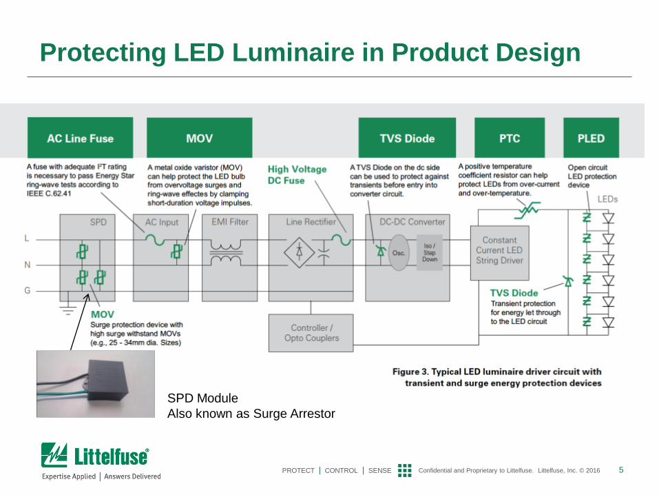
North America - Commercial and Industrial Outdoor LED lighting
Dept of Energy Surge Requirements with reference
to IEEE C.62.41-2002
Category A: parts of the installation at
some distance from the service
entrance
Category B: Between Cat A and Cat C
Category C: External part of structure,
extending some distance into the
building.

24 Confidential and Proprietary to Littelfuse. Littelfuse, Inc. © 2016 PROTECT | CONTROL | SENSE
DOE Spec Surge Testing Requirements for High Exposure Levels
Table 2: 1.2/50µS – 8/20 µS Combination Wave Specification
Parameter Test Level/ Configuration
1.2/50 µS Open Circuit Voltage Peak Low: 6 kV High: 10kV †
8/20 µS Short Circuit Current Peak Low: 3 kA High: 10kA
Coupling Modes L1 to PE, L2 to PE, L1 to L2
Polarity and Phase Angle Positive at 90° and Negative at 270°
Test Strikes 5 for each Coupling Mode and Polarity/Phase Angle combination
Time Between Strikes 1 minute
Total Number of Strikes = 5 strikes x 3 coupling modes x 2 polarity/phase angles
= 30 total strikes
† This is a MINIMUM requirement. Note that for most combination wave generators, which have a source impedance of 2Ω, the generator charging voltage will need to be raised above the specified level (to somewhere in the vicinity of 20kV) to obtain the specified current peak.
Waveform: 1.2x50µs open
circuit voltage/8x20µs
short circuit current
combination wave

25 Confidential and Proprietary to Littelfuse. Littelfuse, Inc. © 2016 PROTECT | CONTROL | SENSE
Europe/Brazil/Asia Outdoor LED Surge Requirement Suggested 10kV/5kA Level Surge Immunity
IEEE C62.41.2 Recommended Practice on
Characterization of Surges on Low Voltage
(1000V and less) AC Power Circuits
+ IEC 61643 Surge Protective Devices Connected
to Low Voltage Power Systems
10kV/5kA

26 Confidential and Proprietary to Littelfuse. Littelfuse, Inc. © 2016 PROTECT | CONTROL | SENSE
MOV End-of-Life Failure Mode
MOVs tend to degrade gradually after a large surge or multiple small
surges. The degradation leads to increasing MOV leakage current,
in turn raising its temperature under normal conditions like
120Vac/240Vac operating voltage
A proper thermal disconnect will sense the increase in MOV
temperature as it continues to degrade to its end-of-life condition, at
which point it will open, removing the degraded MOV from the circuit
and preventing its catastrophic failure

27 Confidential and Proprietary to Littelfuse. Littelfuse, Inc. © 2016 PROTECT | CONTROL | SENSE
Why Thermal Protection in Surge Protection
Module – Continuous Overvoltage
Metal Oxide Varistors (MOVs) are commonly used to suppress transients in
Surge Protection Modules
MOVs can also be subjected to continuous abnormal overvoltage
conditions rather than short duration transients. Continuous abnormal
overvoltage faults are usually caused by poor power grid quality or loss of
neutral-to-ground connection in power transformer wiring. The
abnormal conditions may last for minutes, even hours
If an MOV is subjected to a sustained abnormal
overvoltage, the MOV may go into thermal runaway,
resulting in overheating, smoke, and potentially fire. In
many cases, it requires surge protection module makers
to include a thermal disconnect for an MOV. That
thermal disconnect has traditionally been a thermal fuse
or Thermal Cut-Off (TCO) device. It disconnects the MOV
from the power line when over-temperature is detected

28 Confidential and Proprietary to Littelfuse. Littelfuse, Inc. © 2016 PROTECT | CONTROL | SENSE
Abnormal Overvoltage (UL1449) Condition
In AC line applications, the loss of a Neutral-Ground connection can occur .
Loss can lead to a sustained over-voltage, affecting an MOV that is rated for a
much lower continuous voltage
If tied to the AC line that limits current flow, MOV can overheat, causing the SPD
module to overheat, resulting in smoke, out-gassing, and eventually fire
Ex: U.S. 120V AC Line application, two 120V AC power lines (180° out of phase)
are commonly fed from a center-tapped 240V transformer, assuming 150V rated
MOV is present in the top 120V circuit, and some load exists on the bottom 120V
circuit
Both the MOV and load share the center tap, which is the Neutral-Ground
connection. If a break occurs on the center tap (X—X), then the load in the bottom
phase acts as a current limiter and the line fuse may not clear
Thermally self-protected MOVs can help protect against TOV conditions and
sustained abnormal over-voltage limited current testing as itemized in
UL1449. (Typically up to 10A fault current at about double the line voltage)

29 Confidential and Proprietary to Littelfuse. Littelfuse, Inc. © 2016 PROTECT | CONTROL | SENSE
Line Swells & Oscillatory Transients
Besides impulsive transient, oscillatory transients are a concern for lighting manufacturers
Caused by power quality problem on the feeder lines caused by transformers energizing or capacitor banks switching.
Are of long duration, 3 cycles or more, temporary overvoltage that can last a few seconds.
Up to 2 times normal operating voltage
Can lead to equipment damage or failure surge protection
IEEE 1159 (Recommended Practice for Monitoring
Electric Power Quality)
•Spec defines such a temporary overvoltage as an
oscillatory transient is a sudden, non-power
frequency change in the steady state condition of
voltage, current or both, that includes both positive
and negative polarity values.
•For frequencies below 5 kHz in power line sub-
transmission and distribution, capacitor banks being
energized can create an oscillatory voltage transient
with voltages reaching 2 times the normal operating
voltage and last 0.5-3 cycles

30 Confidential and Proprietary to Littelfuse. Littelfuse, Inc. © 2016 PROTECT | CONTROL | SENSE
AC Input
Coordination Recommendations Between MOVs
in SPD and in LED Driver
L
N
G
Engineers must account for enough line impedance
to direct a majority of the surge current through the
primary MOV (MOV1 in the diagram above) and limit
the surge current through the secondary MOV
(MOV2 in the figure abo ve) to a level within its
surge rating.
1. MOV1 and MOV2 need to be coordinated so that
most of surge current/energy flows through
MOV1.
2. VM (Maximum Continuous Operating Voltage)
Select MOVs with VM(MOV1) ≦ VM(MOV2)
3. VC (Maximum Clamping Voltage)
Select MOVs with VC(MOV1) ≦ VC(MOV2)
4. Inductance L may be added in series connection
SPD. Increasing inductance L will result in better
coordination as MOV1 absorbing higher surge
energy. VMOV1 = VMOV2 + L * di/dt
L
N
G
L
AC Input
LED DRIVER
SPD
SPD
Parallel Connection
Series Connection
LED DRIVER
MOV1
MOV1 MOV2 MOV2
The coordination between the MOVs used in the surge
protection module and in the LED driver is also of
important consideration. These MOVs must be
coordinated such that the larger disc MOVs residing in the
surge protection module should clamp before the smaller
MOV used in the LED driver power supply. If the driver
MOV voltage rating is lower, it will take the brunt of the
transient since it will likely turn on first. That could result
in a catastrophic event. Impedance between the primary
SPD and the driver, perhaps a few uHs will help in
ensuring proper coordination.

31 Confidential and Proprietary to Littelfuse. Littelfuse, Inc. © 2016 PROTECT | CONTROL | SENSE
Residual Surge Energy Passing Through Surge
Protection Module
L
N
G AC Input
LED DRIVER
SPD MOV1
MOV2
R1 F1
Residual Voltage
– Determined by MOV1; thus, fast-response-time and low-clamping-voltage varistor is
preferred
Residual Current
– MOV2 is suggested as higher clamping voltage than MOV1 to maximize I1 and minimize
I2 so that fuse F1 is not damaged by residual current
– R1, the equivalent resistance of primary circuitry including NTC, EMI filter, rectifier, PFC,
transformer, transistor, etc., could be adjusted higher if necessary to minimize I3 and
component damage in primary circuitry
I3 I2 I1
Surge protection module absorbs
most of surge energy; however,
there is still residual energy going
into LED driver and causing
damage to components inside.
To minimize the damage, the LED
driver should coordinate with the
surge protection module so that
less energy enters the LED driver
“Coordination makes better protection and
less damage”
32 Confidential and Proprietary to Littelfuse. Littelfuse, Inc. © 2016 PROTECT | CONTROL | SENSE
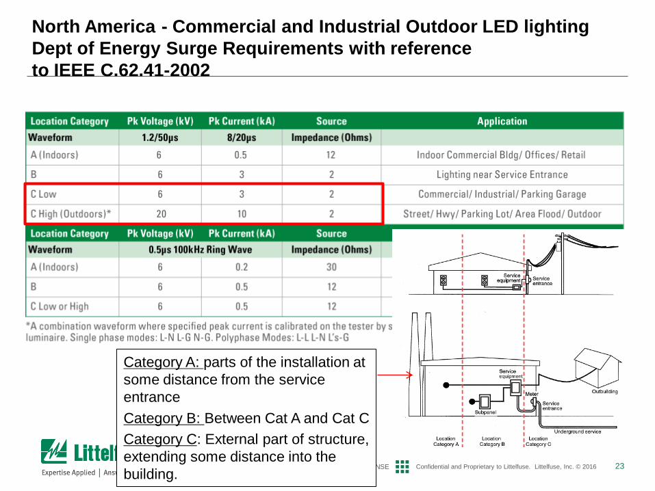
Use TVS Diode as Second-Level Transient
Suppression
DC-DC
Converter Line Rectifier
EMI
Filter AC Input
L
N
G
Osc.
TVS Diode
Constant
Current
LED
String
Driver
Iso /
Step
Dow
n
TVS Diode
TVS Diode
For components sensitive to and easily damaged by surge voltage or current,
place TVS Diodes next to them to absorb “let-through” energy from surge
protection module.