Embed Size (px)
Citation preview
J. Micromech. Microeng. 1 (1991) 73-85. Printed in the UK
Surface micromachi ned mechanisms and micromotors
Mehran Mehreganyt and Yu-Chong TaiS tElectronics Design Center, Department of Electrical Engineering and Applied Physics, Case Western Reserve University, Cleveland. OH 44106, USA' *Department of Electrical Engineering, California Institute of Technology. Pasadena, CA 91125, USA
Received 20 February 1997. accepted for publication 7 April 7991
Abstract. Electric micromotors are sub-millimeter sized actuators capable of unrestrained motion in at least one degree of freedom. Polysilicon surface micromachining using heavily phosphorus-doped LPCVO polysilicon for the structural material, LPCVO silicon nitride for the electrical isolation and deposited Siiicon dioxide for ihe sacriiiciai maieriai has iormed ihe iabricaiion iechnoiogy base for the development of these micromotors. Two polysilicon surface micromachining processes, referred to here a s the center-pin and flange, have been demonstrated for the fabrication of passive mechanisms and micromotors. Passive mechanisms such as gear trains, cranks and manipulators have been implemented on silicon. Reported operational micromotors have been of the rotary variable-capacitance salient-pole and harmonic (or wobble) side-drive designs. These micromotors are capable of motive torques in the 10 pN m order of magnitude range. Preliminary progress has been made in studying the operational. friction and wear characteristics of these micromechanical devices. Typical operational voltages have been as low as 3 7 V and 26V across 1.5pm air gap salient-pole and harmonic micromotors. These excitations correspond to electric I I ~ I V ~ ~ ~ ~ c i i i s i i i e s auuw I U- v r v wobble micromotors have been reported to operate at speeds as high as 15000 rpm and 700 rpm, respectively. Micromotor lifetimes of at least many milions of cycles over a period of Several days have been reported. Friction and wear are important in micromotors: studies aimed in understanding them are discussed in the paper. New designs, materials, fabrication techniques, and applications are expected to play a key role in the future development and progress of the micromotor technology described here.
I.-,> :._.--I_I-- . L . ~ . .,.- .,-. -! . in ihe iiiicion~ioior air gaps. Saiieni-poie and
1. Introduction
A necessary precursor to the development of monolithic micromechanical systems is the fabrication of micro- mechanical components and devices. Microfabrication provides a powerful tool for batch processing and miniaturization of mechanical systems into a dimen- sional domain not accessible by conventional machining. Furthermore, microfabrication provides the potential for integration oi mechanicai systems with the associated electronics required for closed-loop control. Integrated fabrication techniques eliminate the need for discrete component assembly as has been required in other studies [l-41; hence, further dimensional control, includ- ing component size and intercomponent clearance, is limited only by the processing technology.
Integrated fabrication techniques for passive micro- mechanisms using polysilicon surface micromachining were first demonstrated by the authors and their col-
leagues at AT & T-Bell Laboratories [S, 61 and at the University of California-Berkeley [7,8]. Similar research at MIT 19-11] identified many potential problems en- countered in the development of an electric micro- actuator (micromotor) technology. The initial work at Berkeley led to the development of the first operational electric micromotor [12,13].
This paper presents a review of the electric micro- motor technology from the start to the present. We begin with the deveioped microiabrication technoiogy base by describing the basic polysilicon surface micromachining processes for the fabrication of passive polysilicon mech- anisms. Next, the electric micromotor technology is discussed and reported micromotor designs are de- scribed. Critical issues related to the fabrication of micromotors as well as micromotor operational, friction and wear characteristics are discussed. Finally, a brief discussion of current limitations and future trends is presented.
0960-1317/91/02073+13 1603.50 0 1991 IOP Publishing Ltd 73
M Mehregany and Y-C Tai
2. Passive mechanisms
Traditionally, hulk and surface micromachining of silicon have been used to fabricate a variety of micro- mechanical structures such as thin silicon diaphragms [14,15], beams [16-181 and other suspended structures [19-221 in single-crystal silicon or in films deposited on a silicon substrate. These micromechanical structures are generally limited in motion to small deformations and are physically attached to the substrate. Such elastic components may be used occasionally as flexible joints, but their overall usefulness in the design of mechanisms is limited. A 'mechanism' as used here is a means for transmitting, controlling or constraining relative move- ment and is considered as a collection of rigid bodies connected together by joints.
This section describes the extension of conventional surface micromachining techniques to the integrated fabrication of passive planar polysilicon mechanisms incorporating lower and higher kinematic pairs. The surface micromachining technology described here pro- vides the hasis for the fabrication of the electric micro- motors below. Two variations of,a two-level polysilicon process, referred to as the center-pin and the flange processes, are described that are appropriate for the implementation of the two lower kinematic pairs (i.e., revolute and prismatic) commonly used in macroscopic mechanical systems. In this paper, we have used the term bearing when a lower kinematic pair is used to support continuous motion.
2.1. Surface micromachining
Surface micromachining relies on encasing specific device structural parts in layers of a sacrificial material during the fabrication process. The sacrificial material is then dissolved away in a chemical etchant that does not attack the structural parts. This technique was first demon- strated by Nathanson et a1 [23] in building a free standing metal-gate field-effect transistor.
Surface micromachining requires a compatible set of structural materials, sacrificial materials and chemical etchants [17,24,25]. The structural materials must possess the desired electrical and mechanical properties Ccr the app!ica!icn ifi rrind. The sacrificla! rr.aterk!s mcst possess the proper mechanical properties so as not to cause device failure during the fabrication process. The chemical etchants must he able to preferentially etch the sacrificial materials with respect to the structural parts, must have proper viscosity and surface tension character- istics to enable them to fully remove the sacrificial layers, and must not leave residues behind.
For monolithic micromechanical systems, it is de- sirable to have structural materials with good mechanical
modulus, high fracture strain, very low frictional coeffi- cient and high wear resistance. Due to the actuator requirements, good conductors and good insulators are required for the structural materials; however, it is more desirable to be able to tailor the material conductivity in
piopeiezs ii;cpfi*ing no --^:A..-, "trD"" .,a.... high I r D I Y Y ' l , O L L C I I , " 'LJ
the range of these two extremes. Finally, the material candidates should be compatible with integrated circuit (IC) technology.
Polysilicon surface micromachining using doped or undoped polysilicon as the structural material and silicon dioxide as the sacrificial material forms the backbone of the technology described in this paper. Polysilicon surface micromachining is the hest docum- ented [16-18,26] surface micromachining technique which most closely meets many of the requirements described above. Two variations of a two-level poly- silicon process, referred to as the center-pin and the flange processes, are described helow and have been used for successful fabrication of mechanisms and micro- motors on silicon. These basic processes (or minor modifications of them) can also he used in conjunction with structural materials other than polysilicon.
2.2. The center-pin process
The center-pin process is described here in its general form. To demonstrate the general center-pin design, consider the implementation of a rotor which is free to turn about a center bearing. The basic process uses two plysilicon and two silicon diclxide deposi!ions as we!! as four photolithography steps [6, 81.
Figure 1 shows cross-sectional views of a rotor on a center-pin bearing during the fabrication process. After a blanket deposition of silicon dioxide, the hushing molds are time etched to a desired depth in the oxide (figure l(a)). After a blanket deposition of polysilicon, the rotor
(a)
Bushing
(b)
2nd Oxiqe Bearing AnchPr ?emhg Clearance . .
(d)
Figure 1 . The general center-pin fabrication process: (a) After the bushing mold is patterned; (b) after the rotor is patterned; (c) after the bearing anchor is patterned; and (d) completed device.
74
is patterned (figure l(h)) by reactive-ion etching (RE). Note that the bushings are formed automatically. The bushings are an integral part of the center-pin bearing design and eliminate rotor to substrate stiction problems in the final device 161. After a second blanket deposition of silicon dioxide, the hearing anchor is opened (figure l(c)). After a second blanket deposition of polysilicon, the center-pin bearing is defined (figure l(d)). At this point, the sacrificial silicon dioxide is dissolved in hydrofluoric acid (HF) to release the rotor. When released, the bushing rests on the silicon substrate, reducing the surface area of contact between the rotor and the substrate. During operation, the bushing slides on the substrate.
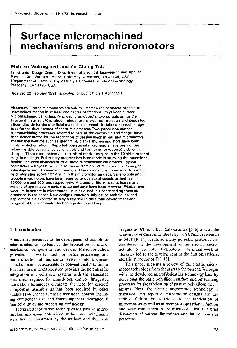
Figure 2 is a SEM photograph of a gear-train with 1.4: 1.0: 1.0 gear ratios, fabricated in the center-pin pro- cess, after it has been released. The smaller gears are 125ym in diameter. The first and second polysilicon layers are 4.5 pm and 3 pm thick, respectively. The first and second sacrificial oxide are 4ym and 1 pm thick, respectively. The hushing mold is etched to a depth of 2 pm.
The center-pin process has the capability of produc- ing a self-aligned or a non-self-aligned hearing. Let s1 and s2 denote the thicknesses of the first and second oxide sacrificial layers, respectively. Let p , and b denote the thickness of the first polysilicon layer and the height of the bushing. Then if p1 + b < s, +s,, the rotor can slide under the bearing, resulting in a non-self-aligned bearing. The hearing clearance for the non-self-aligned case, is the difference between the radius of the top of the hearing anchor opening and the rotor inner radius. This clearance can he large and is governed by the mask dimensions as well as the slope of the bearing anchor sidewalls produced by the fabrication process. If p1 f b > s1 +s,, the hearing clearance is specified by the oxide thickness on the sidewalls of the rotor inner radius. This results in a self-aligned hearing, which is the type used for all of the center-pin bearing micromotors to date.
Surface micromachined mechanisms and micromotors
2.3. The flange process
The flange process is described here in its general form. T o demonstrate the general flange design, consider the implementation of a rotor which is free to turn about a center hearing. The basic process uses two polysilicon and two silicon dioxide depositions as well as four photolithography steps [SI. The overall process is very similar to the center-pin process and uses only minor modifications to accomplish the flange hearing. For the same number of film depositions, the flange process provides more flexibility in design as compared with the center-pin process. However, the center-pin process is somewhat simpler.
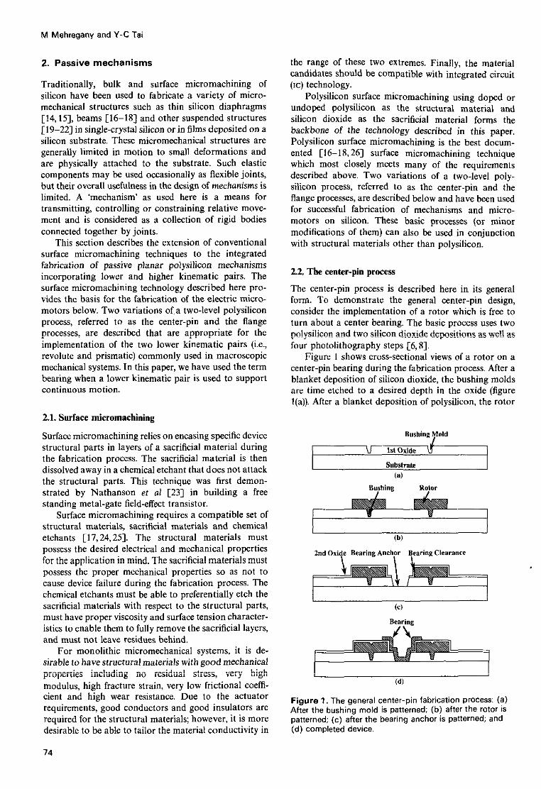
Figure 3 shows cross-sectional views of the rotor on a flange bearing during the fabrication process. After a blanket deposition of silicon dioxide, a blanket layer of polysilicon is deposited. The rotor is patterned into that polysilicon layer (figure 3(a)) by RIE. At this point, the oxide at the inner radius of the rotor is underetched (figure 3(h)). After a second blanket deposition of silicon dioxide, the bearing anchor is opened (figure 3(c)). After a second blanket deposition of polysilicon, the hearing is defined (figure 3(d)). Note that the flange in the bearing forms automatically and functions in a similar manner to the bushings in the center-pin bearing design. At this point, the sacrificial silicon dioxide is dissolved in HF to release the rotor. When released, the rotor rests on the bearing flange and does not contact the substrate, reduc- ing surface area of contact. During operation, the rotor slides on the flange. Note that the flange bearing is
Figure 3. The general flange fabrication process: (a) After the rotor is patterned; (b) after the oxide underetch; (c) after t h e bearing anchor is patterned; and (d) completed device.
M Mehregany and Y-C Tai
cesses are based on the center-pin and flange processes of sections 2.2 and 2.3.
3.1. Principles of operation
In general, in an electric actuator, the attractive and repulsive forces generated by electric charge distributions are used to convert electrical to mechanical energy. By proper commutation of these charge distributions on a set of stationary electrodes, known as the stator, and a set of moving electrodes, known as the rotor, continuous motion of the rotor can be achieved. Similar to their magnetic counterparts, electric motors can be categorized based on the specific mechanism of electric actuation. For example, electric induction motors [30] are the counterparts of magnetic induction motors while permanent electret motors are the counterparts of per- manent magnet motors. For a more detailed discussion of this topic and an extended bibliography, the reader is referred to [9,31].
To date, only rotary variable-capacitance micro- motors (which are the counterpart of variable-reluctance magnetic motors) have been reported because of their design and material requirement simplicity. The opera- tion of these micromotors relies on the storage of electrical energy in a variable rotor-stator capacitance. The change in this capacitance in the direction of motion is proportional to the output torque of the micromotor. In terms of design, one endeavors for optimum torque generation by enhancing the capacitance change in the direction of motion. In terms of material requirements, only good conductors and insulators are required. The
3. Electric micromotors material requirements are compatible with polysilicon surface micromachining which has been used almost
The previous section described polysilicon surface micro- exclusively for micromotor fabrication so far. However, machining techniques suitable for the fabrication of other fabrication processes are now starting to emerge passive mechanisms on silicon. However, microelectro- [32]. Rotary instead of linear designs have been em- mechanical systems require large-motion actuators to phasized so far because rotary motors provide force-to- power the linkages. Electric, as opposed to magnetic, torque leverage as compared with linear ones. drive has been argued as being preferable in the micro- Furthermore, rotary motion is more suitable for motor scopic scale [9,28]. This is mainly due to two factors. diagnostic and characterization studies. For example, First, the electric breakdown limit in air increases drast- rotary micromotors can be spun with an air jet as well as ically for microscopic (order of 1 pm) air-gap sizes. electricity. Typically, the electric field breakdown limit in air is near 3 x IO" V m for macroscopic dimensions and increases to 3.2. Reported designs above I O 8 Vm for microscopic air-gap sizes 1291. However, for magnetic actuators, the magnetic satura- Reported micromotors have so far been based on tion limit is independent of actuator size. Therefore, for variable-capacitance designs. For the sake of brevity, we microscopic sizes, the stored energy density limits for will drop the variable-capacitance term in describing the electric and magnetic actuators become comparable and micromotors below. Two micromotor designs based on a are of the order of 105-106 Jm-'. Second, required top-drive [9,10,33] and a side-drive [12,13,33,34] materials for electric actuators, namely conductors and configuration have been reported. Initially, the top-drive insulators, are available in the IC industry while those for design was considered because of its superior motive magnetic actuators (i.e., magnetic materials) seldom are. torque characteristics. However, top-drive micromotors This section concentrates on the electric micromotor demonstrated significant design and fabrication short- technology. The micromotors under discussion are sur- comings, namely rotor instability problems and face micromachined using heavily phosphorus-doped planarization requirements [33]. These shortcomings LPCW polysilicon for the structural material, deposited motivated the development of side-drive micromotors oxide for the sacrificial layers, and LPCW silicon nitride [12,13,33,34]. The side-drive design eliminates the rotor for electrical isolation. The micromotor fabrication pro- instability problems and the need for planarization.
76
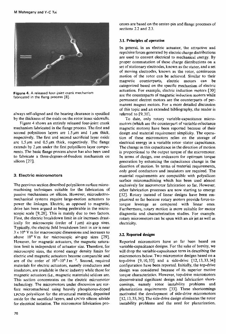
Figure 4. A released four-joint crank mechanism fabricated in the flang process [81.
always self-aligned and the bearing clearance is specified by the thickness of the oxide on the rotor inner sidewalls.
Figure 4 shows an entirely released four-joint crank mechanism fabricated in the flange process. The first and second polysilicon layers are 1.5 pm and 1 pm thick, respectively. The first and second sacrificial layer oxide are 1.5 pm and 0.5 pm thick, respectively. The flange extends by 2 pm under the first polysilicon layer compo- nents. The basic flange process above has also been used to fabricate a three-degrees-of-freedom mechanism on silicon [27].

Figure 5. A 300 pm-diameter. salient-pole, top-drive micromotor [39]. The air gaps are 2 pm wide.
However, this is achieved at the expense of sacrificing motive torque.
Figure 5 is a SEM photograph of a typical three-phase, salient-pole, top-drive micromotor. This micromotor is fabricated using a two-level center-pin polysilicon pro- cess identical to that in section 2.2 with one added step. The added step is a blanket deposition of a LPCVD silicon nitride isolation layer on the starting silicon substrate. The silicon nitride addition is required for electrical isolation of the stator poles. Note that the stator is fabricated from the second polysilicon deposition and does not require additional process steps. For the micro- motor in figure 5, both polysilicon layers are 2.5 pm and are heavily doped (i.e., a sheet resistivity of 7C2 per square) with phosphorus. The sacrificial layers are de- posited from low-temperature oxide (LTO). The first LTO
thickness is 2.3pm, while the second LTO thickness is 1 pm; the bushing height is 1.8 pm.
In the top-drive micromotor design, electric energy is stored in the air gap which is typically 1-2pm and is formed by the overlap of the stator and rotor poles. The air gap in the top-drive micromotor is defined by the two LTO thicknesses and the rotor bushing depth, all of which are easy parameters to control. The micromotor opera- tion relies on tangential electrostatic forces tending to align the rotor poles under the excited stator poles. For micromotor operation, the substrate is electrically grounded while a three-phase hi-polar excitation is applied to the stator. In bi-polar excitation, opposite stator poles of the same phase are excited with equal voltage magnitudes but opposite polarities.
Due to its significantly larger rotor-stator capaci- tance changes with rotor position, the top-drive micro- motor design can provide a large motive torque as compared with that provided by the side-drive designs
Surface micromachined mechanisms and micromotors Surface micromachined mechanisms and micromotors
presented below. However, associated with the rotor- stator and the rotor-substrate capacitances, there are large vertical forces tending to clamp the rotor up to the stator poles or down to the substrate. In the former case, the micromotor is destroyed by the large current through the rotor due to the shorting out of the stator. In the latter case, the micromotor will not operate due to the large frictional forces associated with rotor-substrate clamping. Rotor instability is a severe limitation of this design.
Furthermore, since the stator poles are not all located over rotor poles during device fabrication, they are not at the same height (see figure 5). To resolve this problem, an excessively thick second LTO deposition and a subsequent planarization would be required. Otherwise, the stator poles fabricated over rotor poles are at a higher elevation than the remaining stator poles. The planarization re- quirement is another severe limitation of the top-drive micromotor design. These dificulties have proved the top-drive micromotor design to be impractical. There- fore, research has focused on the design, fabrication and characterization of salient-pole and harmonic (also known as wobble) side-drive micromotors. These side- drive micromotor designs overcome the design and fabrication difficulties associated with the top-drive
However, this is achieved at the expense of sacrificing micromotors but at the cost of sacrificing output torque. motive torque. The salient-pole and harmonic side-drive micro-
Figure 5 is a SEM photograph of a typical three-phase, motors are hereafter referred to as salient-pole and salient-pole, top-drive micromotor. This micromotor is wobble micromotors. For the sake of brevity, the side- fabricated using a two-level center-pin polysilicon pro- drive term is dropped since all operational micromotors cess identical to that in section 2.2 with one added step. to date have been of the side-drive design. We will, The added step is a blanket deposition of a LPCVD silicon however, use the term side-drive micromotors to refer to nitride isolation layer on the starting silicon substrate. both the salient-pole and wobble micromotors collective- The silicon nitride addition is required for electrical ly. Figure 6 is a SBM photograph of a three-phase, salient- isolation of the stator poles. Note that the stator is pole micromotor. Figure 7 is a SEM photograph of a fabricated from the second polysilicon deposition and wobble micromotor. The micromotor in figure 6 does not require additional process steps. For the micro- [13,35,36] is fabricated using the basic flange process of motor in figure 5, both polysilicon layers are 2.5 pm and section 2.3, while that in figure 7 [37-391 is fabricated are heavily doped (i.e., a sheet resistivity of 7 C2 per using the basic center-pin process of section 2.2. In both square) with phosphorus. The sacrificial layers are de- cases, substrate isolation process steps have been added posited from low-temperature oxide (LTO). The first LTO
thickness is 2.3pm, while the second LTO thickness is 1 pm; the bushing height is 1.8 pm.
In the top-drive micromotor design, electric energy is stored in the air gap which is typically 1-2pm and is formed by the overlap of the stator and rotor poles. The air gap in the top-drive micromotor is defined by the two LTO thicknesses and the rotor bushing depth, all of which are easy parameters to control. The micromotor opera- tion relies on tangential electrostatic forces tending to align the rotor poles under the excited stator poles. For micromotor operation, the substrate is electrically grounded while a three-phase hi-polar excitation is applied to the stator. In bi-polar excitation, opposite stator poles of the same phase are excited with equal voltage magnitudes but opposite polarities.
Due to its significantly larger rotor-stator capaci- tance changes with rotor position, the top-drive micro- motor design can provide a large motive torque as compared with that provided by the side-drive designs
Figure 5. A 300 pm-diameter. salient-pole, top-drive micromotor [39]. The air gaps are 2 pm wide.
presented below. However, associated with the rotor- stator and the rotor-substrate capacitances, there are large vertical forces tending to clamp the rotor up to the stator poles or down to the substrate. In the former case, the micromotor is destroyed by the large current through the rotor due to the shorting out of the stator. In the latter case, the micromotor will not operate due to the large frictional forces associated with rotor-substrate clamping. Rotor instability is a severe limitation of this design.
Furthermore, since the stator poles are not all located over rotor poles during device fabrication, they are not at the same height (see figure 5). To resolve this problem, an excessively thick second LTO deposition and a subsequent planarization would be required. Otherwise, the stator poles fabricated over rotor poles are at a higher elevation than the remaining stator poles. The planarization re- quirement is another severe limitation of the top-drive micromotor design. These dificulties have proved the top-drive micromotor design to be impractical. There- fore, research has focused on the design, fabrication and characterization of salient-pole and harmonic (also known as wobble) side-drive micromotors. These side- drive micromotor designs overcome the design and fabrication difficulties associated with the top-drive micromotors but at the cost of sacrificing output torque.
The salient-pole and harmonic side-drive micro- motors are hereafter referred to as salient-pole and wobble micromotors. For the sake of brevity, the side- drive term is dropped since all operational micromotors to date have been of the side-drive design. We will, however, use the term side-drive micromotors to refer to both the salient-pole and wobble micromotors collective- ly. Figure 6 is a SBM photograph of a three-phase, salient- pole micromotor. Figure 7 is a SEM photograph of a wobble micromotor. The micromotor in figure 6 [ 13,35,36] is fabricated using the basic flange process of section 2.3, while that in figure 7 [37-391 is fabricated using the basic center-pin process of section 2.2. In both cases, substrate isolation process steps have been added
Figure 6. A 1 201r"iameter. salient-pole, side-drive micromotor [36]; the air gaps are 2 pm wide.
77
Figure 6. A 1 201r"iameter. salient-pole, side-drive micromotor [36]; the air gaps are 2 pm wide.
77
M Mehregany and Y-C Tai
Figure 8. A cross-sectional schematic of the micromotor in tigure 7.
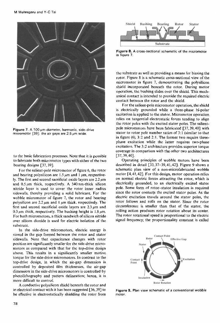
the substrate as well as providing a means for biasing the rotor. Figure 8 is a schematic cross-sectional view of the micromotor in figure 7, demonstrating the polysilicon shield incorporated beneath the rotor. During motor operation, t k hushing slides over the shield. This mech- anical contact is intended to provide the required electric contact between the rotor and the shield.
For the salient-pole micromotor operation, the shield is electrically grounded while a three-phase hi-polar excitation is applied to the stator. Micromotor operation relies on tangential electrostatic forces tending to align the rotor poles with the excited stator poles. The salient- pole micromotors have been fabricated [37,39,40] with stator to rotor pole number ratios of 3: 1 (similar to that in figure (6), 3:2 and 2: 1. The former two require three- phase excitation while the latter requires two-phase excitation. The 3:2 architecture provides superior torque coverage in comparison with the other two architectures C37.39,401.
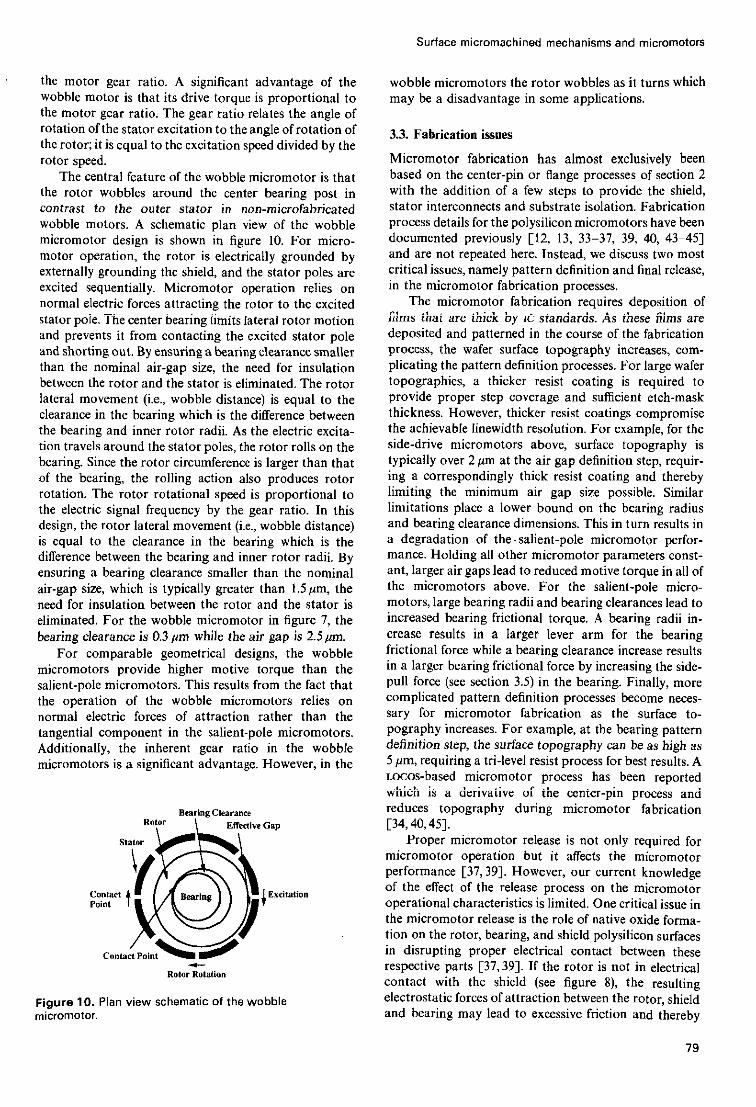
Operating principles of wobble motors have been described in detail [33,37-39,41,42]. Figure 9 shows a schematic plan view of a non-microfabricated wobble motor C4,41,421. For this design, motor operation relies on normal electric forces attracting the rotor, which is electrically grounded, to an electrically excited stator pole. Some form of rotor-stator insulation is required since the rotor contacts the excited stator poles. As the electric excitation travels around the stator poles, the rotor follows and rolls on the stator. Since the rotor circumference is smaller than that of the stator, the rolling action produces rotor rotation about its center. The rotor rotational speed is proportional to the electric Signal frequency; the proportionality constant is called
Figure 7. A l00pm-diameter. harmonic, side-drive micromotor [39]: the air gaps are 2 . 5 p n wide.
to the basic fabrication processes. Note that i t is possible to fabricate both micromotor types with either of the two hearing designs [37,39].
F~~ the salient-pole micromotor of figure 6, the rOtor and bearing polysilicon are 1.5 pm and 1 pm, respective- ly. The first and second sacrificial oxide layers are 2.2 pm and 0.5 I'm thick, respectively. A 340 nm-thick silicon ,,itride layer is used to cOver the rOtor inner radius sidewalls, thereby providing a solid lubricant. F~~ the wobble micromotor of figure 7, the rotor and bearing polysilicon are 2.2pm and 1 pm thick, resFctively. The first and second sacrificial oxide layers are 2.3 pm and 0.3 pm thick, respective~y. The bushing height is 1.8 pm, F~~ both micromotorS. a thick sandwich ofsilicon ,,itride over silicon dioxide is used for electric isolation of the substrate.
In the side-drive micromotors, electric energy is stored in the gap formed between the rotor and stator sidewalls. Note that capacitance changes with rotor position are significantly smaller for the side-drive micro- motors as compared with that for the top-drive design above. This results in a significantly smaller motive torque for the side-drive micromotors. In contrast to the top-drive design, in which the air-gap dimension is controlled by deposited film thicknesses, the air-gap dimension in the side-drive micromotors is controlled by photolithography and pattern delineation; hence, it is more difficult to control.
A conductive polysilicon shield beneath the rotor and in electrical contact with it has been suggested 136,391 to be effective in electrostatically shielding the rotor from
Figure 9. Plan view schematic of a conventional wobble motor.
i a
Surface micromachined mechanisms and micromotors
the motor gear ratio. A significant advantage of the wobble motor is that its drive torque is proportional to the motor gear ratio. The gear ratio relates the angle of rotation of the stator excitation to the angle of rotation of the rotor; it is equal to the excitation speed divided by the rotor speed.
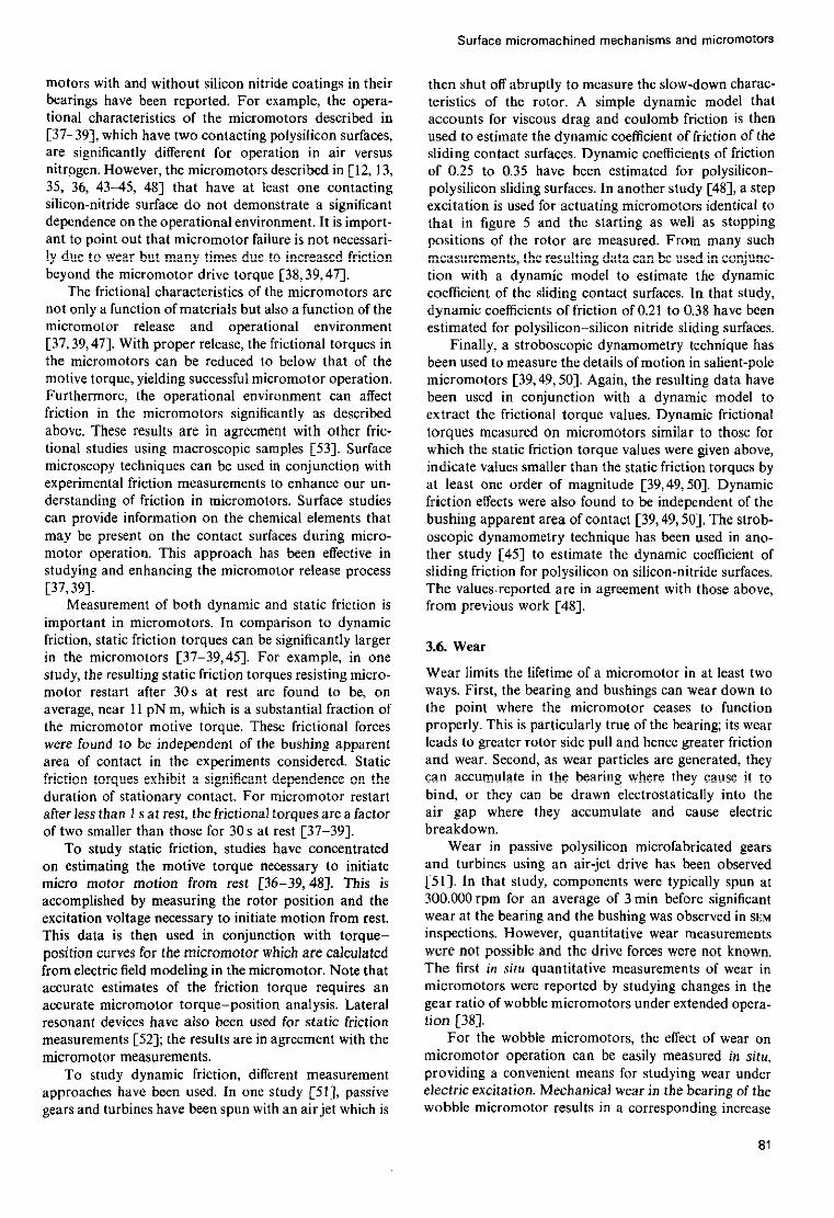
The central feature of the wobble micromotor is that the rotor wobbles around the center bearing post in contrast to the outer stator in non-microfabricated wobble motors. A schematic plan view of the wobble micromotor design is shown in figure 10. For micro- motor operation, the rotor is electrically grounded by externally grounding the shield, and the stator poles are excited sequentially. Micromotor operation relies on normal electric forces attracting the rotor to the excited stator poie. The center bearing limits lateral rotor motion and prevents it from contacting the excited stator pole and shorting out. By ensuring a bearing clearance smaller than the nominal air-gap size, the need for insulation between the rotor and the stator is eliminated. The rotor lateral movement (i.e., wobble distance) is equal to the clearance in the bearing which is the difference between the bearing and inner rotor radii. As the electric excita- tion travels around the stator poles, the rotor rolls on the bearing. Since the rotor circumference is larger than that of the bearing, the roiling action also produces rotor rotation. The rotor rotational speed is proportional to the electric signal frequency by the gear ratio. In this design, the rotor lateral movement (i.e., wobble distance) is equal to the clearance in the bearing which is the difference between the bearing and inner rotor radii. By ensuring a bearing clearance smaller than the nominal air-gap size, which is typically greater than 1.5pm, the need for insulation between the rotor and the stator is eliminated. For the wobble micromotor in figure 7, the bearing ciearance is 0.3 pm whiie the air gap is 2.5 pm.
For comparable geometrical designs, the wobble micromotors provide higher motive torque than the salient-pole micromotors. This results from the fact that the operation of the wobble micromotors relies on normal electric forces of attraction rather than the tangential component in the salient-pole micromotors. Additionally, the inherent gear ratio in the wobble micromotors is a significant advantage. However, in the
Bearing Clearance \ Eileelive Gap
Figure I O . Plan view schematic of the wobble micromotor.
wobble micromotors the rotor wobbles as it turns which may be a disadvantage in some applications.
3.3. Fabrication issues
ivIicruinoior iaoricauon has aimosi exciusiveiy based on the center-pin or flange processes of section 2 with the addition of a few steps to provide the shield, stator interconnects and substrate isolation. Fabrication process details for the polysilicon micromotors have been documented previously [12, 13, 33-37, 39, 40, 43-45] and are not repeated here. Instead, we discuss two most critical issues, namely pattern definition and final release, in the micromotor fabrication processes.
The micromotor fabrication requires deposition of f i ims that are thick by ic standards. As ihese iiims are deposited and patterned in the course of the fabrication process, the wafer surface topography increases, com- plicating the pattern definition processes. For large wafer topographies, a thicker resist coating is required to provide proper step coverage and sufficient etch-mask thickness. However, thicker resist coatings compromise the achievable linewidth resolution. For example, for the side-drive micromotors above, surface topography is typically over 2 pm at the air gap definition step, requir- ing a correspondingly i’nick resisi coaiing and thereby limiting the minimum air gap size possible. Similar limitations place a lower bound on the bearing radius and bearing clearance dimensions. This in turn results in a degradation of the. salient-pole micromotor perfor- mance. Holding all other micromotor parameters const- ant, larger air gaps lead to reduced motive torque in all of the micromotors above. For the salient-pole micro- motors, large bearing radii and bearing clearances lead to increased bearing frictional torque. A bearing radii in- crease resuits in a larger lever arm for the bearing frictional force while a bearing clearance increase results in a larger bearing frictional force by increasing the side- pull force (see section 3.5) in the bearing. Finally, more complicated pattern definition processes become neces- sary for micromotor fabrication as the surface to- pography increases. For example, at the bearing pattern definition step, the surface topography can be as high as 5 pm, requiring a tri-level resist process for best results. A Locos-based micromotor process has been reported wmcn is a derivaiive of ihe cenier-pin process and reduces topography during micromotor fabrication [34,40,45].
Proper micromotor release is not only required for micromotor operation but it affects the micromotor performance [37,39]. However, our current knowledge of the effect of the release process on the micromotor operational characteristics is limited. One critical issue in the micromotor release is the role of native oxide forma- tion on the rotor, bearing, and shield polysilicon surfaces iii disiupiing proper eiectrical coniaci beiween these respective parts 137,391. If the rotor is not in electrical contact with the shield (see figure 8), the resulting electrostatic forces of attraction between the rotor, shield and bearing may lead to excessive friction and thereby
79
11,: ..._. ~.~ ~ P - 1 ~ ~ ~ : - - . : - ~ ~
~ ~ . , L . , .

M Mehregany and Y-C Tai
prevent micromotor operation. A possible model for this mechanism is described in [46]. In conjunction with the release process, micromotor operational characteristics may also be affected by the environment in which the micromotors operate [37,39,47]. For example, for micromotors with polysilicon/polysilicon mechanical contacts, operation in nitrogen rather than air enhances micromotor lifetime significantly [38,39]. However, for micromotors with a t least one nitride/polysilicon mech- anical contact [13,35,36,45], lifetime is comparatively short and is not affected by operation in air or nitrogen. The effect of release and operational environment on micromotor performance requires further research to identify the competing mechanisms that affect friction, stiction and failure in these devices.
3.4. Operational characteristics
The overall operational characteristics of the side-drive micromotors reported to date are similar. However, the specific performance characteristics vary for the different micromotors. In general, the operational excitation vol- tages range from a few tens of volts for some micro- motors [37-391 to near 1OOV for others [12-13, 35, 36, 43, 451. For the lpm to 3pm air gaps used in the micromotors, the above excitation voltages correspond to electric field intensities above IO8 Vm-’, which cor- roborates the initial estimates of breakdown in micro- scopic air gaps as discussed in section 3. The motive torque of the side-drive micromotors is typically of the order of IO pN m (i.e. ten pic0 Newton meters).
Micromotor operation has only been studied under open-loop excitation. Under open-loop operation, a square-wave electric excitation is commutated on the stator; the stator phases are turned on one at a time. The excitation switching time is chosen to be larger than the settling time of the rotor transient. Therefore, micro- motor operation has been of a stepping rather than continuous motion. For the different salient-pole micro- motors reported to date, both underdamped C48-501 and overdamped [45] rotor transients have been observed. The rotor transient settling time has typically been under 250ps for these micromotors. For the salient-pole micro- motors, open-loop stepping operational speeds of up to 15000rpm have been reported [37,39]. For the wobble micromotors, the rotor transient motion has not been measured; however, the open-loop stepping operational speeds have been as high as 700rpm [38,39]. Typical wobble micromotor gear ratios have been in the range of 70 to 90. In both cases; the maximum attainable speed has been limited by the power supply and not the micromotor.
For the micromotors reported to date, micromotor performance and life-time have varied significantly. For the first operational salient-pole micromotor [ 121, only a very slow stepping operation could be achieved at excitation voltages above 100 V. This shortcoming was attributed to large electric forces attracting the rotor to the substrate. A conductive plate beneath the rotor and in c!e&ca! cantac! with has bCCfi .sed in !ater designs
80
to electrostatically shield the rotor from the substrate (as schematically demonstrated in figure 8). In these later micromotors, both performance and life-time have been improved significantly over time. Excitation voltages as low as 37 V and 26 V have been sufficient in operating some of the current salient-pole [37,391 and wobble [38,39] micromotors, respectively. The open-loop opera- tional speeds have been improved significantly as de- scribed above. Furthermore, micromotor life-time has been extended to many millions of cycles over a period of several days [38,39]; for these micromotors, a clear failure point has not yet been identified. Finally, re- peatable micromotor operation has been achieved in the current micromotors [37-391. However, both repeata- bility and reliability of micromotor operation are largely compromised by a lack of fundamental understanding of the mechanisms that affect micromotor operation.
3.5. Friction
Friction presents serious limitations to the performance and life-time of a micromotor; it presents a load to the micromotor which directly opposes useful work. During micromotor operation, the dynamic mechanical contacts at the hearing and the bushing (or the flange) result in friction. The bearing surfaces are subject to rolling contacts for the wobble micromotors and to sliding contacts for the salient-pole micromotors. For both micromotor types, the bushing surfaces are subject to sliding contacts. It is now well-documented that the bushing normal contact force is too large to he accounted for by the weight of the rotor alone [33,36,37,39,44,45]. This contact force is believed to be of electrostatic origin; an assertion which is corroborated by a comparison of results from frictional measurements in which no electric excitation is used [SI]. In the latter case, rotor weight does account for the bushing normal contact force.
During wobble micromotor operation, the rotor is pulled against the bearing due to the normal electric force and rolls on the bearing. In this case, the resulting friction at the bearing contact is critical to the micromotor operation. However, for the salient-pole micromotors, hearing frictional forces are detrimental to micromotor performance. For the salient-pole micromotors, when the rotor is electrically grounded and is symmetrically cen- tered in between a set ofexcited stator poles, the resultant of the radial forces on the rotor due to each excited stator pole is zero. However, when the rotor displaces radially, a net radial electric force (commonly referred to as a side- pull force [45,48-50]) develops which pushes the rotor into the bearing post. The side-pull force can result in significant friction in the bearing of salient-pole micro- motors [45,48-501.
Several studies have contributed to the understand- ing of friction in micromotors [31, 37-39, 45, 48-521. These reported studies have so far focused almost exclusively on the friction of two polysilicon or polysilicon/silicon nitride surfaces sliding in contact with one another in an air or nitrogen environment. Differences between the frictional behavior of micro-
Surface micromachined mechanisms and micromOtorS
motors with and without silicon nitride coatings in their bearings have been reported. For example, the opera- tional characteristics of the micromotors described in C37-391, which have two contacting polysilicon surfaces, are significantly different for operation in air versus nitrogen. However, the micromotors described in [12, 13, 35, 36, 43-45, 481 that have at least one contacting silicon-nitride surface do not demonstrate a significant dependence on the operational environment. It is import- ant to point out that micromotor failure is not necessari- !y &e to wear bc! many t h e s dce !D increaed fricticr? beyond the micromotor drive torque [38,39,47].
The frictional characteristics of the micromotors are not only a function of materials but also a function of the micromotor release and operational environment [37,39,47]. With proper release, the frictional torques in the micromotors can be reduced to below that of the motive torque, yielding successful micromotor operation. Furthermore, the operational environment can affect friction in the micromotors significantly as described above. These resc!ts z e in ~greenxnt with other fric- tional studies using macroscopic samples [53]. Surface microscopy techniques can be used in conjunction with experimental friction measurements to enhance our un- derstanding of friction in micromotors. Surface studies can provide information on the chemical elements that may be present on the contact surfaces during micro- motor operation. This approach has been effective in studying and enhancing the micromotor release process [37,39].
important in micromotors. In comparison to dynamic friction, static friction torques can be significantly larger in the micromotors [37-39,451. For example, in one study, the resulting static friction torques resisting micro- motor restart after 30s at rest are found to be, on average, near 11 pN m, which is a substantial fraction of the micromotor motive torque. These frictional forces were found to be independent of the bushing apparent area of contact in the experiments considered. Static friction !orqces exhibl! !! signifkin! dependence on the duration of stationary contact. For micromotor restart after less than I s a t rest, the frictional torquesare a factor of two smaller than those for 30 s at rest [37-393.
To study static friction, studies have concentrated on estimating the motive torque necessary to initiate micro motor motion from rest [36-39,481. This is accomplished by measuring the rotor position and the excitation voltage necessary to initiate motion from rest. This data is then used in conjunction with torque-
from electric field modeling in the micromotor. Note that accurate estimates of the friction torque requires an accurate micromotor torque-position analysis. Lateral resonant devices have also been used for static friction measurements [S2]; the results are in agreement with the micromotor measurements.
To study dynamic friction, different measurement approaches have been used. In one study [SI], passive gears and turbines have been spun with an airjet which is
..._I" Meirnrement of hnth i_ rlvngmir 2nd r f i t i r frictinn is
p0sltio.l curves for thc micn.??c!cr %?hick "p Ci?!CII!B!PCI
then shut off abruptly to measure the slow-down charac- teristics of the rotor. A simple dynamic model that accounts for viscous drag and coulomb friction is then used to estimate the dynamic coefficient of friction of the sliding contact surfaces. Dynamic coefficients of friction of 0.25 to 0.35 have been estimated for polysilicon- polysilicon sliding surfaces. In another study [48], a step excitation is used for actuating micromotors identical to that in figure S and the starting as well as stopping positions of the rotor are measured. From many such
tion with a dynamic model to estimate the dynamic coefficient of the sliding contact surfaces. In that study, dynamic coefficients of friction of 0.21 to 0.38 have been estimated for polysilicon-silicon nitride sliding surfaces.
Finally, a stroboscopic dynamometry technique has been used to measure the details ofmotion in salient-pole micromotors [39,49,50]. Again, the resulting data have been used in conjunction with a dynamic model to extract the frictional torque values. Dynamic frictional
which the static friction torque values were given above, indicate values smaller than the static friction torques by at least one order of magnitude [39,49,50]. Dynamic friction effects were also found to be independent of the bushing apparent area of contact [39,49,50]. The strob- oscopic dynamometry technique has been used in ano- ther study 1451 to estimate the dynamic coefficient of sliding friction for polysilicon on silicon-nitride surfaces. The values.reported are in agreement with those above, frG- previous lJJork r A m
measuremens, the resu!!ixg da:a cax be nsed ix cafi;cfic=
t r r i n i i n c mnnr . .mA ne - ;c-n-~+n.c s i m ; l o * + A +hnm Fnr L Y . y Y U . 7 L I L I U . , Y I I " "11 I I I I I L Y I I I V L " , . , .,,ll.llPl L" ,,."OI I",
L-"J'
3.6. Wear
Wear limits the lifetime of a micromotor in at least two ways. First, the bearing and bushings can wear down to the point where the micromotor ceases to function properly. This is particularly true of the bearing; its wear leads to greater rotor side pull and hence greater friction and wear. Second, as wear particles are generated, they
bind, or they can be drawn electrostatically into the air gap where they accumulate and cause electric breakdown.
Wear in passive polysilicon microfabricated gears and turbines using an air-jet drive has been observed [SI]. In that study, components were typically spun at 300.000 rpm for an average of 3 min before significant wear at the bearing and the bushing was observed in SEM inspections. However, quantitative wear measurements
The first in situ quantitative measurements of wear in micromotors were reported by studying changes in the gear ratio of wobble micromotors under extended opera- tion [38].
For the wobble micromotors, the effect of wear on micromotor operation can be easily measured in situ, providing a convenient means for studying wear under electric excitation. Mechanical wear in the bearing of the wobble micromotor results in a corresponding increase
81
can accumulate in !he hearing where they cause it to
were not possihle and the drive forces were not known,
M Mehregany and Y - C Tai
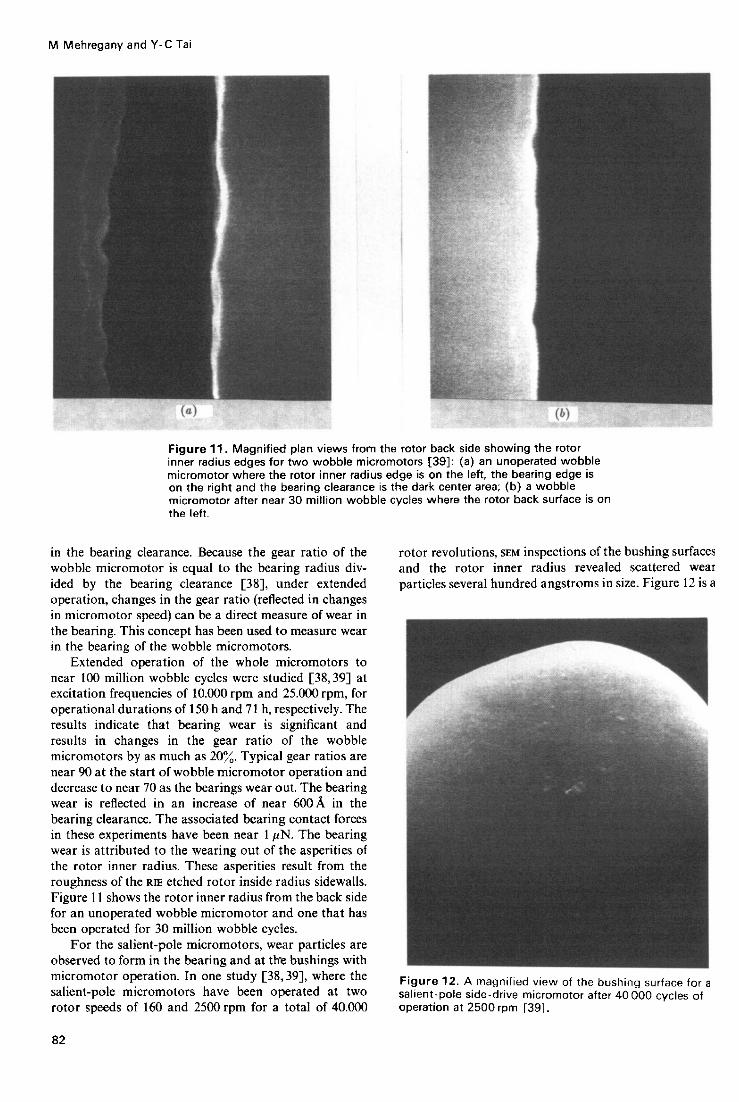
Figure 11. Magnified plan views from the rotor back side showing t h e rotor inner radius edges for two wobble micromotors 1391: (a) an unoperated wobble micromotor where t h e rotor inner radius edge is on t h e left, the bearing edge is on the right and the bearing clearance is the dart center area; (b) a wobble micromotor after near 30 million wobble cycles where the rotor back surface is on the left.
in the hearing clearance. Because the gear ratio of the wobble micromotor is equal to the hearing radius div- ided by the bearing clearance [SS], under extended operation, changes in the gear ratio (reflected in changes in micromotor speed) can he a direct measure of wear in the bearing. This concept has been used to measure wear in the bearing of the wobble micromotors.
Extended operation of the whole micromotors to near 100 million wobble cycles were studied [38,39] at excitation frequencies of 10.000 rpm and 25.000 rpm, for operational durations of 150 h and 71 h, respectively. The results indicate that bearing wear is significant and results in changes in the gear ratio of the wobble micromotors by as much as 20%. Typical gear ratios are near 90 at the start of wobble micromotor operation and decrease to near 70 as the bearings wear out. The hearing wear is reflected in an increase of near 600A in the hearing clearance. The associated hearing contact forces in these experiments have been near 1 pN. The hearing wear is attributed to the wearing out of the asperities of the rotor inner radius. These asperities result from the roughness of the RE etched rotor inside radius sidewalls. Figure I 1 shows the rotor inner radius from the back side for an unoperated wobble micromotor and one that has been operated for 30 million wobble cycles.
For the salient-pole micromotors, wear particles are observed to form in the hearing and at ttre bushings with micromotor operation. In one study [38,39], where the salient-pole micromotors have been operated at two rotor speeds of 160 and 2500 rpm for a total of 40.000
82
rotor revolutions, SEM inspections of the hushing surfaces and the rotor inner radius revealed scattered wear particles several hundred angstroms in size. Figure 12 is a
Figure 12. A magnified view of the bushing surface for a salient-pole side-drive micromotor after 40000 cycles of operation at 2500rpm [39].

Surface micromachined mechanisms and micromotors
Both new materials and fabrication techniques can play a key role in the future progress of micromotor technology. New materials may be used to improve the friction and wear characteristics of the micromotors. At the same time, new fabrication techniques can provide a potential for new micromotor designs as well as improve- ments of the current designs. In one study, single- crystalline silicon is being used in conjunction with silicon-glass bonding to fabricate micromotors [32]. The use of tungsten as a structural material in surface micromachining processes similar to those above is also emerging [SS]. Alternatively, the LIGA [59] and LIGA-type [60] processes provide a potential for fabrication of metallic micromotors that are significantly larger in the axial dimension than the surface micromachined micro- motors hut maintain comparable air-gap sizes. There- fore, micromotors with significantly larger motive tor- ques can be produced.
Clearly, a necessary requirement for the future ad- vance of the electric micromotor technology is a funda- mental understanding of the operational, friction and wear characteristics. Without it, clear definition of future rz""-d. - -> -.-.... -..- _. . ... r .... ~.. :z =ot possible. Toward the goal of establishing the fundamental knowledge neces- sary, theoretical modeling and experimental measure- ment techniques are required. Accurate modeling of the electric fields in the micromotor is needed for estimating the torque-position characteristics as well as the contact
SEM photo showing a magnified view of the hushing forces of electrostatic origin. The contact friction models surface which slides on the shield. Note the wear particles must be refined to accurately predict the frictional which adhere to the bushing surface. Wear on the behavior of the micromotors. Additional experimental polysilicon shield, which the bushings slide over during measurement techniques as well as improvements of micromotor operation, could not be detected. Figure 13 the currently documented experiments are necessary is a SEM photo showing a portion of the rotor inner radius for further understanding of friction and wear in from the back side. Again, wear particles are observed micromotors. adhering to the area adjacent to the hearing surface. Finally, the electric micromotor technology can be Micromotors which have not yet been operated, when applied to the fabrication of monolithic microrobotic dismantled for SEM inspection, exhibit clean surfaces with systems. The micromotors can be incorporated in no particles. already existing micromechanisms to investigate the
implementation of microrobotic systems [27]. A critical issue to be addressed in this area would be the mechan- ical coupling of the micromotors to other mechanisms on or off of the silicon wafer.
_)^..^I ^-I-- t '
Figure 13. A portion of the rotor inner radius from the back side for the same micromotor a s in figure 12 [39].
4. Discussion
Even though the electric micromotor technology has progressed rapidly, a number of micromotor perfor- mance limitations still exist. The most important of these 5. Conclusion performance limitations are small motive torque, friction problems and mechanical coupling. The micromotor The brief review of the electric micromotor technology technology is expected to expand in several directions provided above indicates the rapid pace at which this including new designs, materials, fabrication techniques technology is developing. In the past three to four years, and applications. With the progress of the surface micro- the basic fabrication techniques, preliminary designs, machining technology, it will become possible to imple- operational characteristics, frictional behavior and ment new micromotor designs which improve motive wear properties have been studied. Reported opera- torque and reduce the frictional torques. At the same tional micromotors have been of the rotary variahle- time, the surface micromachining techniques being devel- capacitance salient-pole and harmonic (or wobble) side- oped for the micromotor technology are being applied to drive designs. These micromotors are capable of motive the development of alternative electric microactuators. torques in the 10 pN m order-of-magnitude range. Pre- One class of such microactuators has been the lateral liminary progress has been made in studying the opera- resonant (or suspended) structures [22,54,55]; other tional, friction and wear characteristics of these devices. microactuator designs are emerging [56,57]. Typical operational voltages have been as low as 37 V
83
M Mehregany and Y-C Tai
and 26V across 1.5pm air-gap salient-pole and har- monic micromotors. These excitations correspond to electric field intensities above 10’ V m-’ in the air gaps. Salient-pole and wobble micromotors have been re- ported to operate at speeds as high as 15.000rpm and 700 rpm, respectively. As described in section 3.6, micro- motor life-times of a t least many millions of cycles over a period of several days have been achieved. Friction and wear are important in micromotors and several tech- niques have been developed to experimentally measure them.
The progress made in the last three to four years has provided the foundation for future work toward improv- ing and expanding the current micromotor technology. The micromotor technology is expected t o expand in several directions including new designs, materials, fabrication techniques and applications. Progress in these areas is expected to improve the micromotor motive torque, friction and wear characteristics and mechanical coupling capabilities.
References
[I] Feury A M, Poteat T L and Trimmer W S 1986 A micromachined manipulator for submicron positioning of optical fibers IEEE Solid-State Sensor Workshop (Hilton Head, SC, 1986) Technical digest
[2] Mehregany M, Gabriel K J and Trimmer W S N 1987 Micro gears and turbines etched from silicon Sensors and Actuators 12 341-8
considerations for a practical electrostatic micro motor Sensors and %Actuators 11 189-206
[4] Fujita H and Omodaka A 1988 The fahrication of an electrostatic linear actuator by silicon micromachining IEEE Trans. Electron Deuices ED- 35 731-4
gears and turbines etched from silicon 4th Int . Conf on Solid-State Sensors and Actuators (Tokvo. Jauan,
[3] Trimmer W S N and Gabriel K J 1987 Design
[5] Gabriel K J, Trimmer W S and Mehregany M Micro
1987) Technical digest pp 853-6 r61 Mehreeanv M. Gabriel K J and Trimmer W S N 1988 - - _ I .
Integrated fahrication of polysilicon mechanisms IEEE Trans. Electron Devices ED-35 719-23
[7] Fan, L S, Tai Y C and Muller R S Pin joints, gears, springs, cranks, and other novel micromechanical structures 4th Int . Con$ on Solid-State Sensors and Actuators (Tokyo, Japan. 1987) Technical digest pp 849-52
movable micromechanical structures for sensors and actuators IEEE Tran. Electron Devices ED-35 724- 30
Schlecht M F 1988 Design considerations for micromachined electric actuators Sensors and Actuators 14 269-92
process for electrostatic microactuator fabrication IEEE Solid-State Sensor and Actuator Workshop (Hilton Head, SC, 1988) Technical digest pp 59-62
[ I l l Lober T A 1988 A microfabricated electrostatic motor design and process MSc Thesis Massachusetts Institute of Technology, Cambridge, MA
[8] Fan L S, Tai Y C and Muller R S 1988 Integrated
[9] Bart S F, Lober T A, Howe R T, Lang J H and
[IO] Loher T A and Howe R T Surface-micromachining
a4
Cl21 Fan L S, Tai Y C and Muller R S ic-processed electrostatic micro-motors IEEE Int. Electron Devices MeetinR (San Francisco, CA, 1988) Technical digest pp 666-9
1131 Tai Y C, Fan L S and Muller R S IC-processed micro- me!ors: desig~, !ech~o!ogg, and teskng P;oc. !COL’ Micro Electro Mechanical Systems Workshop (Salt Luke City, UT, 1989) pp 1-6
Cl41 Guckel H, Larsen S, Lagally M G and Wiley J D 1977 Electromechanical devices utilizing thin silicon diaphragms Appl. Phys. Lett. 31 618-9
[l5] Lee Y S and Wise K D 1982 A batch-fabricated silicon capacitive pressure transducer with low temperature sensitivity IEEE Trans. Electron Devices ED-29 42-8
1161 Howe R T and Muller R S 1983 Polycrystalline silicon micromechanical beams J . Electrochem. Soc. 130 1420-3
[!7] HDWC R T 1984 !n!egra!cd Si!iron Micromechanical Vapor Sensor PhD Thesis University of California, Berkeley
[IS] Guckel H, Randazzo T and Burns D W 1985 A simple tecbniaue for the determination of mechanical strain in thin’films with applications to polysilicon J . Appl. Phvs. 57 1671
Cl91 Greenwood J C 1984 Etched silicon vibrating sensor J .
[20] Mehregany M, Howe R T and Senturia S D 1987 Phys. E: Sci. Instrum 17 650-2
Novel microstructures for the in-situ measurement of mechanical properties of thin films J . Appl. Phys. 62 3579-84
Haritonidis J H 1988 Design and calibration of a microfabricated Roatinc-element shear-stress sensor
[21] Schmidt M A, Howe R T, Senturia S D and
IEEE Trans. Electron Deuices ED-35 750-7 r221 Tang W C. Nauven T H and Howe R T 1989 Laterallv . . . _ .
driven polysilicon resonant microstructures Sensors- and Actuators 20 25-32
[231 Nathanson H C, Newell W E, Wickstrom R A and Davis J R Jr 1967 The resonant gafe transistor I E E E Trans. on Electron Deuices ED-14 117-33
and technologies Proc. IEEE Micro Robots and Teleoperators Workshop (Hyannis, MA, 1987)
of Shear Forces in Turbulent Boundary Layers PhD Thesis Massachusetts Institute of Technoloav.
[24] Muller R S 1987 From ics to microstructures: materials
1251 Schmidt M A 1988 Microsensors for the Measurement
_. Cambridge, MA
r261 Guckel H, Burns D W and Rutinliano C R 1986 . . Design and construction tecLniques for planar polysilicon pressure transducers with piezoresistive read-out IEEE Solid-State Sensor Workshop (Hilton Head, SC, 1986) Technical digest
microfabricated three-degree-of-freedom parallel mechanism Proc. IEEE Micro Electro Mechanical Systems Workshop (Napa Valley, CA, 1990) pp 159-65
micromotors: electromechanical characteristics Proc. IEEE Micro Robots and Teleoperators Workshop (Hyannis, MA, 1987) (reprinted in Proc. ASME Annual Winter Meeting (Boston. MA, 1987) DSC-6 pp 403-10)
[29] Paschen F 1889 Ueber die zum Funkenubergang in Luft, Wasserstofl und Kohlensaure hei verschiedenen Drucken erforderliche Potentialdillerenr Ann. Phys. Lpz 37 69-96
electroquasistatic induction micromotors Sensors and Actuators 20 97-106
electroquasistatic microactuators PhD Thesis
[27] Behi F, Mehregany M and Gabriel K J A
[28] Lang J H, Schlecht M F and Howe R T Electric
[30] Bart S F and Lang J H 1989 An analysis of
[31] Bart S F 1990 Modeling and design of
Surface micromachined mechanisms and micromotorS
Massachusetts Institute of Technology, Cambridge, MA
[32] Suzuki K and Tanigawa H 1991 Single crystal silicon rotational micromotors Proc. IEEE Micro Electro Mechnnical Systems Workshop (Nara, Japan. 1991) pp 15-20
Senturia S D and Schlecht M F 1990 A study of three microfabricated variable-capacitance motors Sensors and Actuators All-23 173-9
1990 A LOCOS process for an electrostatic microfabricated motor Sensors and Actuators All- 23 893-8
[35] Tai Y C and Muller R S 1989 Ic-processed electrostatic synchronous micromotors Sensors and Actuators 20 49-55
[36] Tai Y C 1989 ic-processed polysilicon micromechanics: technology, material, and devices PhD Thesis University of California, Berkeley, CA
H Operation of microfabricated harmonic and ordinary side-drive motors Proc. IEEE Micro Electro Mechanical Systems Workshop (Napa Valley, C A 1990) pp 1-8
[38] Mehregany M, Senturia S D and Lang J H Friction and wear in microfabricated harmonic side-drive motors IEEE Solid-State Sensor and Actuator Workshop (Hilton Head, SC, 1990) Technical digest pp 17-22
Mechanisms PhD Thesis Massachusetts Institute of Technology, Cambridge, MA
Senturia S D 1990 Principles of design and fabrication of variable-capacitance side-drive micromotors J . Vac. Sci. Techno!. A8 3614-24
[41] Trimmer W and Jehens R 1989 Harmonic electrostatic motors Sensors and Actuators 20 17-24
[42] Jacobsen S C, Price R H, Wood J E, Rytting T H and Rafaelof M 1989 A design overview of an eccentric- motion electrostatic microactuator Sensors and
[33] Mehregany M, Bart S F, Tavrow L S, Lang J H,
[34] Tavrow L S, Bart S F, Lang J H and Schlecht M F
[37] Mehregany M, Nagarkar P, Senturia S D and Lang J
[39] Mehregany M 1990 Microfabricated Silicon Electric
[40] Mehregany M, Bart S F, Tavrow L S, Lang J H and
Actuators 20 1-16 1431 Fan L S. Tai Y C and Muller R S 1989 ic-vrocessed _ _
electrostatic micromotors Sensors and Actuators 20 41-7
structures on silicon chips PhD Thesis University of California, Berkeley, CA
Radial-Gap Electric Motor PhD Thesis Massachusetts Institute of Technology, Cambridge, MA
[46] Lang J H 1989 Initial thoughts on the dynamics and control of electric micromotors Proc. 3rd Toyota Conference on Inregrated Micro Morion Systems (Nissin, Aichi, Japnn. 1989) pp 9/1-9/14
[47] Mehregany M, Phillips S M, Hsu E T and Lang J H 199 1 Operation of harmonic side-drive micromotors
[44] Fan L S 1989 Integrated micromachinary: moving
[45] Tavrow L S 1991 A Locos-Based Microfabricated
studied through gear ratio measurements 6th Inl. Con5 Solid-State Sensors and Actuators (San Francisco, C A , 1991) Technical digest
[48] Tai Y C and Muller R S 1990 Frictional study of IC- processed micromotors Sensors and Actuators All- 23 180-3
Senturia S D 1990 Measurements of electric micromotor dynamics Proc. A S M E Winter Annual Meeting (Dollas, T X , 1990) DSC 19 19-29
[SO] Bart S F, Mehregany M, Tavrow L S, Lang J H and Senturia S D 1991 Electric micromotor dynamics Trans. Electron Devices at press
1990 In situ measurements of friction and wear in integrated volvsilicon microstructures Sensors and
[49] Bart S F, Mehregany M, Tavrow L S, Lang J H and
[SI] Gabriel K J, Behi F, Mahadevan R and Mehregany M
Actuators A2f-23 184-8 r521 Lim M G. Chanr I C. Schultz D P. Howe R T and _ _
White'R M 1990 Polysilicon microstructures to characterize static friction Proc. IEEE Micro Electro Mechanical Systems Workshop (Nupa Valley, CA 1990) pp 82-8
[53] Deng K, KO W H and Michal G A preliminary study on friction measurements in MEMS 6th Int. Conf: Solid-State Sensors and Acruators (San Francisco, C A , 1991) Technical digest
[54] Tang W C, Nguyen T H, Judy M W and Howe R T 1990 Electrostatic-comb drive of lateral polysilicon resonators Sensors and Actuators All-23 328-31
Multiple mode micromechanical resonators Proc. IEEE Micro Electro Mechonicol Systems Workshop ( N a p Valley, CA, 1990) pp 9-14
[56] Kim C J, Pisano A P, Muller R S and Lim M G Polysilicon microgripper IEEE Solid-State Sensor and Actuator Workshop (Hilton Head, SC. 1990) Technical digest pp 48-51
Ultrasonic micromotors: physics and applications Proc. IEEE Micro Electro Mechanical Systems Workshop (Napo Valley, C A 1990) pp 182-7
[58] Chen L Y, Zhang 2 L, Yao I J, Thomas D C and MacDonald N C Selective chemical vapor deposition of tungsten for microdynamic structures Proc. IEEE Micro Electro Mechanical Systems Workshop (Salt Lake Ciry, U T , 1989) pp 82-7
E591 Ehrfeld W, Bley P, Got2 F, Hagmann P, Maner A, Mohr J, Moser H 0, Munchmeyer D, Schelh W, Schmidt D and Becker E B 1987 Fabrication of microstructures using the LIGA process Proc. IEEE Microrobots md Teleoperators Workshop (Hyannia, M A , 1987)
1601 Guckel H, Christenson T R, Skrobis K I, Denton D D, Choi B, Lovell E G, Lee J W, Bajikar S S and Chapman T W Deep X-ray and uv lithographies for micromechanics IEEE Solid-State Sensor and Actuator Workshop (Hilton Hend, SC, 19901 Technical digest pp 118-22
[55] Brennan R A, Pisano A P and Tang W C 1990
[57] Moroney R M, White R M and Howe R T 1990
85


![Piezoelectric Ultrasonic Micromotors - [email protected]](https://img.pdfslide.us/doc/110x75/6204ee814c89d3190e0cabb2/piezoelectric-ultrasonic-micromotors-emailprotected.jpg)